DESIGN AND PERFORMANCE STUDY OF AN ALPHA V-TYPE
STIRLING ENGINE CONVERTED FROM DIESEL ENGINE
MOHAMAD YUSOF BIN IDROAS
UNIVERSITI TEKNOLOGI MALAYSIA
DESIGN AND PERFORMANCE STUDY OF AN ALPHA V-TYPE
STIRLING ENGINE CONVERTED FROM DIESEL ENGINE
MOHAMAD YUSOF BIN IDROAS
A thesis submitted in fulfilment of the
requirements for the award of the degree of
Doctor of Philosophy (Mechanical Engineering)
Faculty of Mechanical Engineering
Universiti Teknologi Malaysia
APRIL 2012

iii
To my beloved family,
The lover in you who brings my dreams comes true.
To my beloved wife, Nurhayati Sharifuddin and kids, Farah Ameera
Adam Airil and Danish Hakim who have brought a new level of love, patience
and understanding into our lives.
iv
ACKNOWLEDGEMENT
“In the name of Allah that the most Gracious, the most Merciful”
Foremost, my greatest gratitude goes to ALLAH SWT for giving me the
energy, strength and spirit to make it possible to complete the thesis under the title of
“Development and Performance Characterization of an Alpha V-Type Stirling
Engine Converted Diesel Engine (SCDE)”.
In particular, I wish to express my deepest appreciation to my main
supervisor, Prof. Ir. Dr. Farid Nasir Ani from Faculty of Mechanical Engineering,
Universiti Teknologi Malaysia (UTM) for encouragement, guidance and valuable
critics. I am also very thankful to my co-supervisor, Associate Professor Dr. Zainal
Alimuddin Zainal Alauddin from School of Mechanical Engineering, Universiti
Sains Malaysia (USM) for his guidance, advices and motivation. Without their
continued support and interest, this thesis would not have been the same as presented
here.
My gratefulness especially to Mr. Azman Miskam, Mr. Noriman Kamaruddin
and to all technical staffs of both universities for their consistent support with some
helpful discussions and ideas. Finally, I owed an immense debt of gratitude to my
families for their love to me. To someone who always stays beside me in worse and
better time, thanks for your advice, guidance and support.
THANK YOU
v
ABSTRACT
The design of an alpha V-type Stirling engine converted from Yamaha four-
stroke diesel engine was realized with few major modifications on the engine
housing, heater head, swirl burner, regenerator, oil lubrication system, auxiliary
cooler and flywheel. The methodology of developing a 25 W alpha V-type Stirling
engine that is simple in design, low cost and multi-fuel potential due to its easy
integration with external heat sources had been successfully established and it is
proven practicable. The engine can be marked as a closed regenerative cycle engine
that pioneers the research of high temperature differential (HTD) alpha V-type
Stirling engine operating in self-pressurized mode using air as a working gas. The
engine is featured with 90o phase angle, bore and stroke of 53 mm and 44 mm
respectively, total swept volume of 194 cc., total dead volume of 115 cc., volume
compression ratio of 2.2, 4 mm spherical bed regenerator and Liquefied Petroleum
Gas (LPG) as fuel. At heat input of 1100 J/s, the engine performance was
successfully tested. For mechanical shaft power assessment, torque, output-power
and thermal efficiency variations were obtained at different engine speeds, hot and
cold cylinder temperatures. The engine approximately produced a maximum brake
power of 7 Watt, brake thermal efficiency of 0.6% at 717 rpm speed, 811oC hot
cylinder temperature and 96oC cold cylinder temperature. For electrical power
assessment, the engine is capable of generating a maximum electrical output power
of 1.7 Watt, system thermal efficiency of 0.15% at 657 rpm, 855oC hot cylinder
temperature and 98oC cold cylinder temperature. The investigation of engine seal, oil
lubricant, flywheel size and configuration, regenerator tube diameter, total dead
volume and auxiliary cooler have significantly contributed to a successful
performance of the engine in self-pressurized mode.
vi
ABSTRAK
Rekabentuk bagi enjin Stirling jenis-V alpha diubahsuai dari enjin Yamaha
disel empat-lejang direalisasikan dengan pengubahsuaian utama pada rumah enjin,
kepala pemanas, pembakar pusar, penukar haba, sistem minyak pelincir, pendingin
tambahan dan roda tenaga. Metodologi pembangunan bagi enjin Stirling jenis-V
alpha 25 W yang berciri ringkas dalam rekabentuk, murah dan berupaya dalam
penggunaan pelbagai bahan api disebabkan penyambungannya yang mudah dengan
sumber haba luaran telah berjaya dibentuk dan ianya terbukti berkesan.. Enjin ini
ditanda-aras sebagai enjin kitaran penukaran haba tertutup sebenar sebagai pelopor
terhadap kajian enjin Stirling jenis-V alpha bersuhu bezaan tinggi yang beroperasi
dalam mod bertekanan-diri menggunakan udara sebagai gas bekerja. Enjin ini
diperincikan dengan sudut fasa 90o, 53 mm x 44 mm lubang dan lejang, 194 cc.
jumlah isipadu sapuan, 115 cc. jumlah isipadu mati, 2.2 nisbah mampatan isipadu, 4
mm penukar haba lapisan sfera dan Gas Petroleum Cecair sebagai bahan bakar. Pada
haba masukan 1100 J/s, prestasi enjin berjaya diuji. Untuk penilaian kuasa aci
mekanik, variasi tork, kuasa terhasil dan kecekapan terma diperolehi pada kelajuan
enjin, suhu silinder panas dan suhu silinder sejuk yang berbeza. Enjin menghasilkan
7 Watt kuasa brek maksimum, 0.6% kecekapan terma brek pada kelajuan 717 ppm,
suhu silinder panas 811oC dan suhu silinder sejuk 96
oC. Untuk penilaian kuasa
elektrik, enjin mampu menghasilkan 1.7 Watt kuasa terhasil elektrik maksimum dan
0.15% kecekapan terma sistem pada kelajuan 657 ppm, suhu silinder panas 855oC
dan suhu silinder sejuk 98oC. Penyelidikan terhadap penutup enjin, minyak pelincir,
saiz dan bentuk roda tenaga, diameter tiub penukar haba, jumlah isipadu mati dan
pendingin tambahan secara ketara telah menyumbang pada kejayaan operasi enjin ini
dalam mod bertekanan-diri.
vii
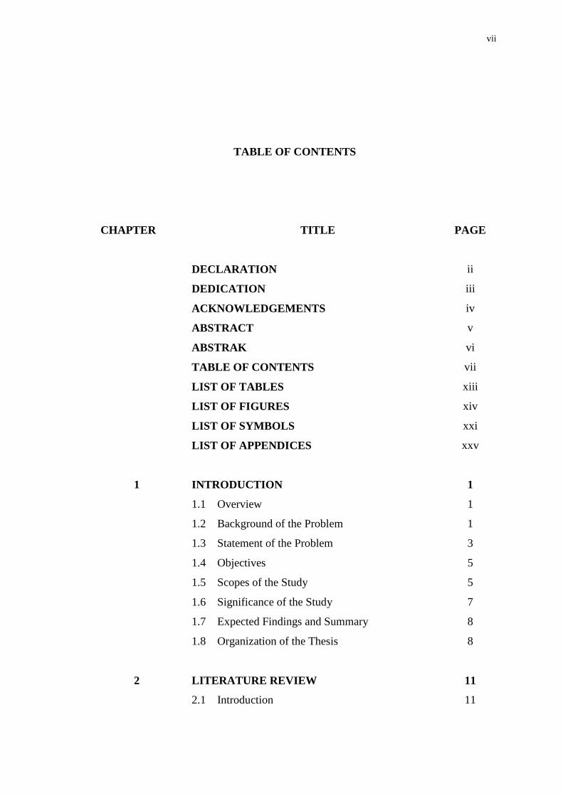
TABLE OF CONTENTS
CHAPTER TITLE
PAGE
DECLARATION ii
DEDICATION iii
ACKNOWLEDGEMENTS iv
ABSTRACT v
ABSTRAK vi
TABLE OF CONTENTS vii
LIST OF TABLES xiii
LIST OF FIGURES xiv
LIST OF SYMBOLS xxi
LIST OF APPENDICES xxv
1 INTRODUCTION 1
1.1 Overview 1
1.2 Background of the Problem 1
1.3 Statement of the Problem 3
1.4 Objectives 5
1.5
1.6
1.7
1.8
Scopes of the Study
Significance of the Study
Expected Findings and Summary
Organization of the Thesis
5
7
8
8
2 LITERATURE REVIEW 11
2.1 Introduction 11
viii
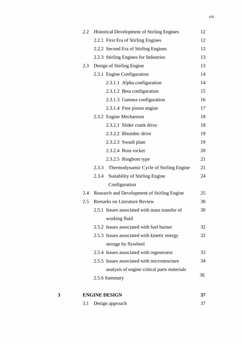
2.2 Historical Development of Stirling Engines
2.2.1 First Era of Stirling Engines
2.2.2 Second Era of Stirling Engines
2.2.3 Stirling Engines for Industries
12
12
12
13
2.3 Design of Stirling Engine
2.3.1 Engine Configuration
2.3.1.1 Alpha configuration
2.3.1.2 Beta configuration
2.3.1.3 Gamma configuration
2.3.1.4 Free piston engine
13
14
14
15
16
17
2.3.2 Engine Mechanism
2.3.2.1 Slider crank drive
2.3.2.2 Rhombic drive
2.3.2.3 Swash plate
2.3.2.4 Ross rocker
2.3.2.5 Ringbom type
18
18
19
19
20
21
2.3.3 Thermodynamic Cycle of Stirling Engine
2.3.4 Suitability of Stirling Engine
Configuration
21
24
2.4 Research and Development of Stirling Engine 25
2.5 Remarks on Literature Review 30
2.5.1 Issues associated with mass transfer of
working fluid
2.5.2 Issues associated with fuel burner
2.5.3 Issues associated with kinetic energy
storage by flywheel
2.5.4 Issues associated with regenerator
2.5.5 Issues associated with microstructure
analysis of engine critical parts materials
2.5.6 Summary
30
32
32
33
34
36
3 ENGINE DESIGN 37
3.1 Design approach 37

ix
3.1.1 Schmidt Analysis
3.1.2 Beale Formula
3.1.3 Engine overall design
3.1.4 Heater head
3.1.5 Swirl burner
3.1.5.1 Swirl number
3.1.5.2 Flow characteristics
3.1.5.3 Fabrication
3.1.6 Regenerator
3.1.7 Seals
3.1.8 Lubrication system
37
40
41
43
45
45
48
48
50
55
55
3.2 Engine specification
3.2.1 Engine configuration
3.2.2 Engine speed
3.2.3 Bore and stroke
3.2.4 Dead volume
3.2.5 Volume compression ratio
3.2.6 Heater temperature
3.2.7 Cooler temperature
3.2.8 Working gas
3.2.9 Fuel source
3.2.10 Overall engine assembly
57
57
58
58
58
60
60
61
61
62
63
3.3
3.4
Preliminary test
3.3.1 Cooling capability of water-cooling jacket
3.3.2 Heating capability of swirl burner
3.3.3 Heat combustion of Liquefied Petroleum
Gas (LPG)
3.3.4 Heat input
Performance estimation
3.4.1 Power output
3.4.2 Thermal efficiency
3.4.3 Regenerator effectiveness
3.4.4 Kinematics analysis of slider crank
65
65
67
69
72
73
73
74
74
75
x
3.5
3.6
3.7
mechanism
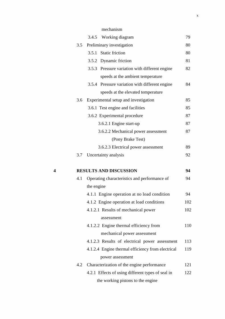
3.4.5 Working diagram
Preliminary investigation
3.5.1 Static friction
3.5.2 Dynamic friction
3.5.3 Pressure variation with different engine
speeds at the ambient temperature
3.5.4 Pressure variation with different engine
speeds at the elevated temperature
Experimental setup and investigation
3.6.1 Test engine and facilities
3.6.2 Experimental procedure
3.6.2.1 Engine start-up
3.6.2.2 Mechanical power assessment
(Pony Brake Test)
3.6.2.3 Electrical power assessment
Uncertainty analysis
79
80
80
81
82
84
85
85
87
87
87
89
92
4 RESULTS AND DISCUSSION 94
4.1 Operating characteristics and performance of
the engine
94
4.1.1 Engine operation at no load condition 94
4.1.2 Engine operation at load conditions 102
4.1.2.1 Results of mechanical power
assessment
4.1.2.2 Engine thermal efficiency from
mechanical power assessment
102
110
4.2
4.1.2.3 Results of electrical power assessment
4.1.2.4 Engine thermal efficiency from electrical
power assessment
Characterization of the engine performance
113
119
121
4.2.1 Effects of using different types of seal in
the working pistons to the engine
122

xi
performance
4.2.2 Effects of using different types of oil
lubricant on engine performance
4.2.3 Effects of using different sizes and
configurations of flywheel on engine
performance
4.2.4 Effects of using different sizes of
regenerator tube on engine performance
4.2.5 Effects of using different types of auxiliary
cooling system on engine performance
4.2.6 Effects of hot cylinder temperature on
microstructure properties of the engine
critical components
131
132
140
143
146
5 CONCLUSION AND RECOMMENDATIONS 152
5.1 Conclusion 152
5.2 Recommendations 155
5.2.1 Experimental work 156
5.2.2 Theoretical work 157
REFERENCES 158
Appendices A - F 164 - 198
xii
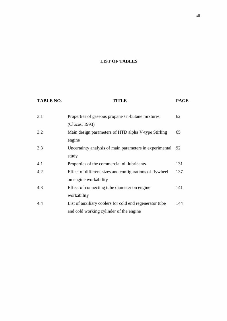
LIST OF TABLES
TABLE NO. TITLE
PAGE
3.1
3.2
3.3
Properties of gaseous propane / n-butane mixtures
(Clucas, 1993)
Main design parameters of HTD alpha V-type Stirling
engine
Uncertainty analysis of main parameters in experimental
study
62
65
92
4.1 Properties of the commercial oil lubricants 131
4.2 Effect of different sizes and configurations of flywheel
on engine workability
137
4.3 Effect of connecting tube diameter on engine
workability
141
4.4 List of auxiliary coolers for cold end regenerator tube
and cold working cylinder of the engine
144
xiii
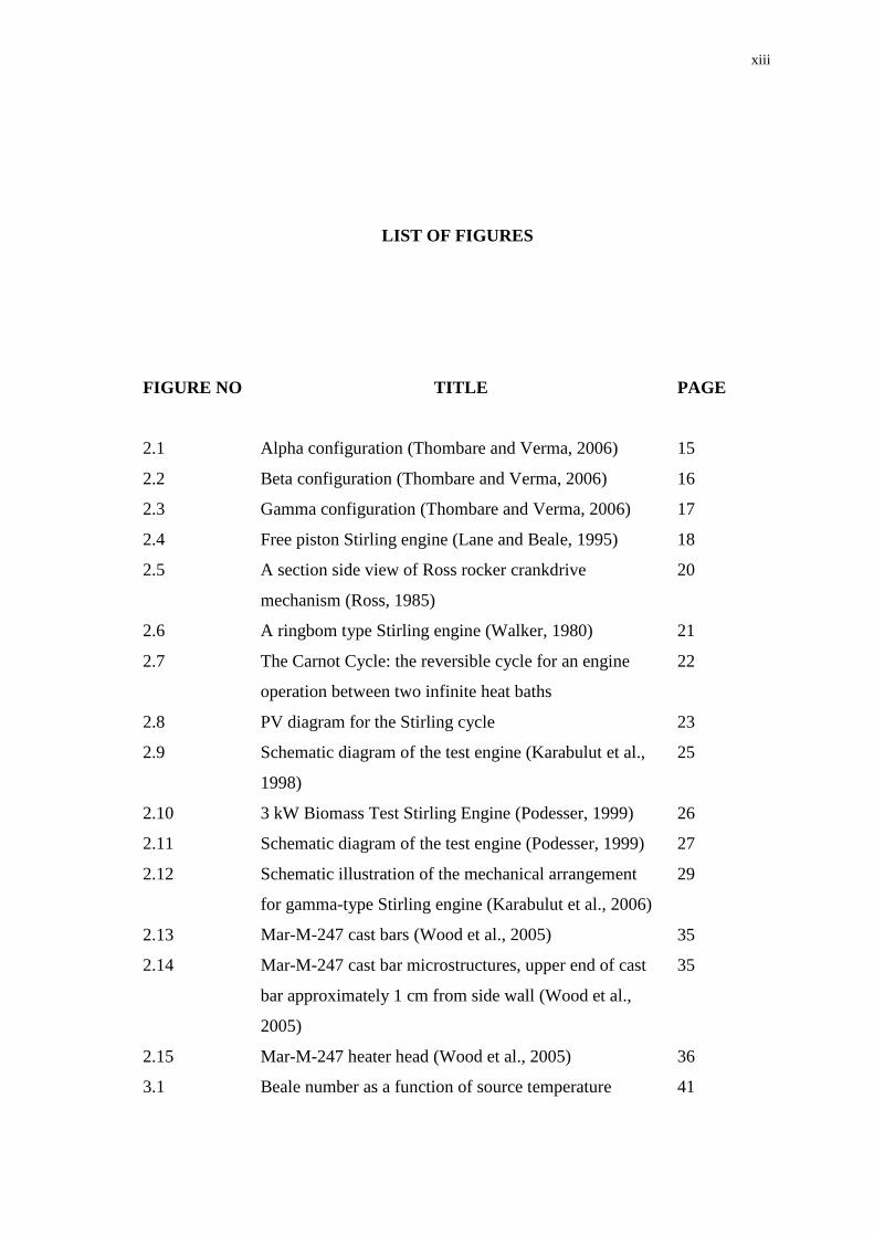
LIST OF FIGURES
FIGURE NO TITLE
PAGE
2.1 Alpha configuration (Thombare and Verma, 2006) 15
2.2 Beta configuration (Thombare and Verma, 2006) 16
2.3 Gamma configuration (Thombare and Verma, 2006) 17
2.4
2.5
2.6
2.7
2.8
2.9
2.10
2.11
2.12
2.13
Free piston Stirling engine (Lane and Beale, 1995)
A section side view of Ross rocker crankdrive
mechanism (Ross, 1985)
A ringbom type Stirling engine (Walker, 1980)
The Carnot Cycle: the reversible cycle for an engine
operation between two infinite heat baths
PV diagram for the Stirling cycle
Schematic diagram of the test engine (Karabulut et al.,
1998)
3 kW Biomass Test Stirling Engine (Podesser, 1999)
Schematic diagram of the test engine (Podesser, 1999)
Schematic illustration of the mechanical arrangement
for gamma-type Stirling engine (Karabulut et al., 2006)
Mar-M-247 cast bars (Wood et al., 2005)
18
20
21
22
23
25
26
27
29
35
2.14 Mar-M-247 cast bar microstructures, upper end of cast
bar approximately 1 cm from side wall (Wood et al.,
2005)
35
2.15 Mar-M-247 heater head (Wood et al., 2005) 36
3.1 Beale number as a function of source temperature 41
xiv
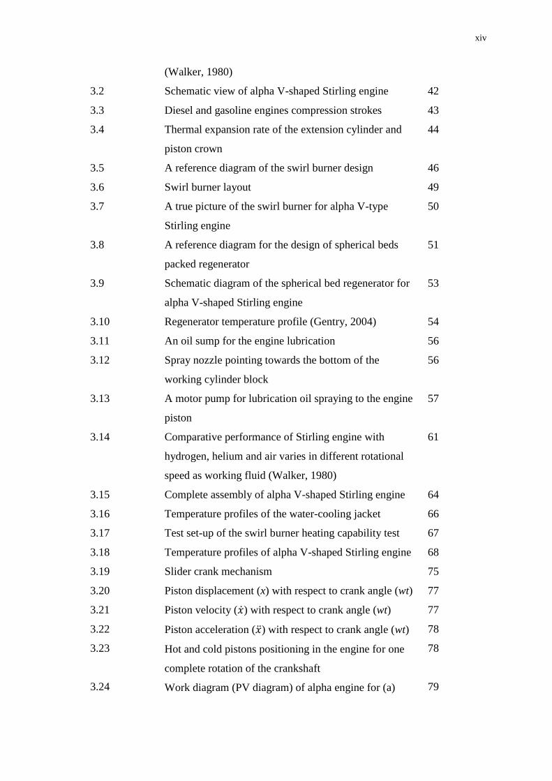
(Walker, 1980)
3.2 Schematic view of alpha V-shaped Stirling engine 42
3.3
3.4
3.5
Diesel and gasoline engines compression strokes
Thermal expansion rate of the extension cylinder and
piston crown
A reference diagram of the swirl burner design
43
44
46
3.6
3.7
3.8
3.9
3.10
3.11
3.12
3.13
3.14
3.15
3.16
3.17
3.18
3.19
3.20
3.21
3.22
3.23
3.24
Swirl burner layout
A true picture of the swirl burner for alpha V-type
Stirling engine
A reference diagram for the design of spherical beds
packed regenerator
Schematic diagram of the spherical bed regenerator for
alpha V-shaped Stirling engine
Regenerator temperature profile (Gentry, 2004)
An oil sump for the engine lubrication
Spray nozzle pointing towards the bottom of the
working cylinder block
A motor pump for lubrication oil spraying to the engine
piston
Comparative performance of Stirling engine with
hydrogen, helium and air varies in different rotational
speed as working fluid (Walker, 1980)
Complete assembly of alpha V-shaped Stirling engine
Temperature profiles of the water-cooling jacket
Test set-up of the swirl burner heating capability test
Temperature profiles of alpha V-shaped Stirling engine
Slider crank mechanism
Piston displacement (x) with respect to crank angle (wt)
Piston velocity ( ̇) with respect to crank angle (wt)
Piston acceleration ( ̈) with respect to crank angle (wt)
Hot and cold pistons positioning in the engine for one
complete rotation of the crankshaft
Work diagram (PV diagram) of alpha engine for (a)
49
50
51
53
54
56
56
57
61
64
66
67
68
75
77
77
78
78
79

xv
3.25
3.26
3.27
3.28
3.29
3.30
3.31
3.32
3.33
3.34
3.35
expansion volume, (b) compression volume and (c) net
volume
Set-up for static friction test
Test set-up for dynamic friction test
Friction torque variation with engine speed
Test set-up for pressure versus speed measurement at
ambient temperature
Pressure variation with different engine speeds at
ambient temperature
Test set-up for pressure versus speed measurement at
the elevated temperature
Mean pressure variation with different engine speed at
the elevated temperature
Experiment set-up for the alpha V-type Stirling engine
Schematic diagram of the alpha V-shaped Stirling
engine performance test
Coil alternator set-up for the engine
Electrical control panel set-up for the engine
80
81
82
83
83
84
85
86
88
90
91
4.1 Variation of hot cylinder temperature with engine speed
at no load condition
96
4.2 Variation of cold cylinder temperature with engine
speed at no load condition
96
4.3 Variation of temperature difference of hot and cold
cylinder temperature with engine speed at no load
condition
97
4.4
4.5
4.6
4.7
Variation of hot end regenerator temperature with
engine speed at no load condition
Variation of cold end regenerator temperature with
engine speed at no load condition
Variation of temperature difference between hot and
cold end regenerator temperature with engine speed at
no load condition
Variation of hot cylinder temperature with operation
97
98
98
99
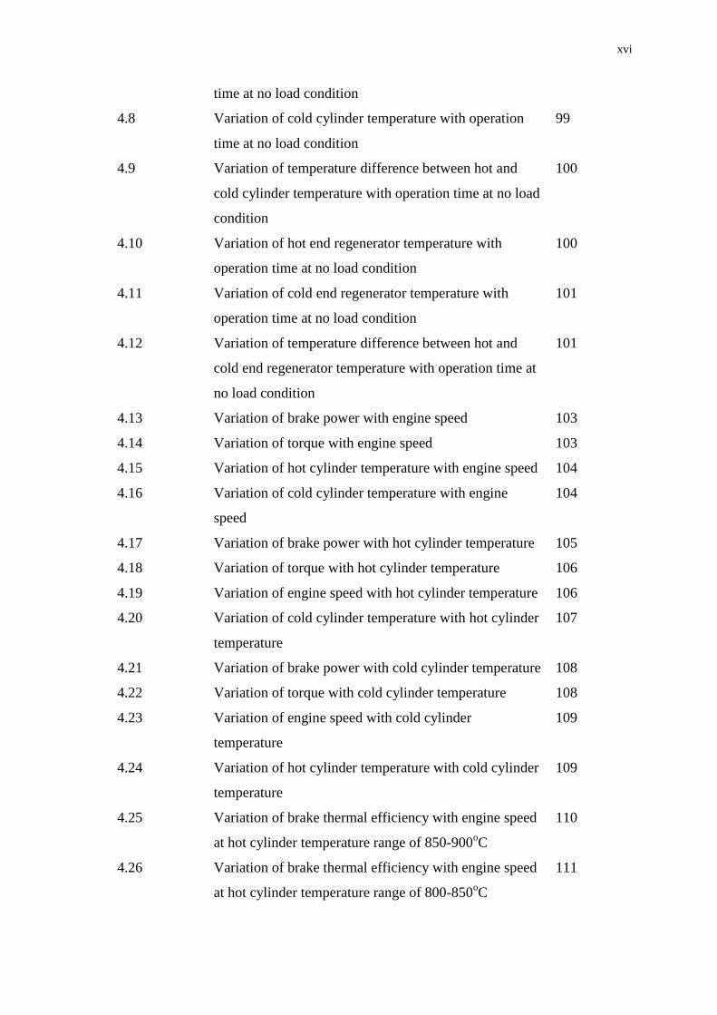
xvi
4.8
4.9
4.10
4.11
4.12
4.13
4.14
4.15
4.16
4.17
4.18
4.19
4.20
4.21
4.22
4.23
4.24
4.25
4.26
time at no load condition
Variation of cold cylinder temperature with operation
time at no load condition
Variation of temperature difference between hot and
cold cylinder temperature with operation time at no load
condition
Variation of hot end regenerator temperature with
operation time at no load condition
Variation of cold end regenerator temperature with
operation time at no load condition
Variation of temperature difference between hot and
cold end regenerator temperature with operation time at
no load condition
Variation of brake power with engine speed
Variation of torque with engine speed
Variation of hot cylinder temperature with engine speed
Variation of cold cylinder temperature with engine
speed
Variation of brake power with hot cylinder temperature
Variation of torque with hot cylinder temperature
Variation of engine speed with hot cylinder temperature
Variation of cold cylinder temperature with hot cylinder
temperature
Variation of brake power with cold cylinder temperature
Variation of torque with cold cylinder temperature
Variation of engine speed with cold cylinder
temperature
Variation of hot cylinder temperature with cold cylinder
temperature
Variation of brake thermal efficiency with engine speed
at hot cylinder temperature range of 850-900oC
Variation of brake thermal efficiency with engine speed
at hot cylinder temperature range of 800-850oC
99
100
100
101
101
103
103
104
104
105
106
106
107
108
108
109
109
110
111

xvii
4.27
4.28
4.29
4.30
4.31
4.32
4.33
4.34
4.35
4.36
4.37
4.38
4.39
4.40
4.41
4.42
4.43
4.44
4.45
Variation of brake thermal efficiency with engine speed
at hot cylinder temperature range of 750-800oC
Variation of brake thermal efficiency with hot cylinder
temperature
Variation of brake thermal efficiency with cold cylinder
temperature
Variation of electrical load with engine speed
Variation of voltage output with engine speed
Variation of total electrical output power with engine
speed
Variation of electrical load with hot cylinder
temperature
Variation of voltage output with hot cylinder
temperature
Variation of total electrical output power with hot
cylinder temperature
Variation of electrical load with cold cylinder
temperature
Variation of voltage output with cold cylinder
temperature
Variation of total electrical output power with cold
cylinder temperature
Variation of system thermal efficiency with engine
speed
Variation of system thermal efficiency with hot cylinder
temperature
Variation of system thermal efficiency with cold
cylinder temperature
The original piston with two piston rings
Piston ring made from Teflon in the original piston
Fabricated Teflon piston
Variation of friction torque with time at 10 Hz cycle
frequency for different types of seal used in the engine
111
112
112
114
114
115
116
116
117
118
118
119
120
120
121
123
123
124
125
xviii
4.46
4.47
4.48
4.49
4.50
4.51
4.52
4.53
4.54
4.55
4.56
4.57
4.58
4.59
4.60
4.61
4.62
4.63
Variation of friction torque with time at 15 Hz cycle
frequency for different types of seal used in the engine
Variation of friction torque with time at 20 Hz cycle
frequency for different types of seal used in the engine
Variation of friction power with time at 10 Hz cycle
frequency for different types of seal used in the engine
Variation of friction power with time at 15 Hz cycle
frequency for different types of seal used in the engine
Variation of friction power with time at 20 Hz cycle
frequency for different types of seal used in the engine
Manufactured solid disk flywheel
Manufactured webbed solid disk flywheel
Commercial four-spoke pulley as engine flywheel
Variation of engine speed with operation time for both
7 kg and 8 kg spoke flywheels
Relationship of connecting tube diameters with total
dead volume of the engine
SEM-Micrograph of the cross-sectioned piston material
without head load (500X)
SEM-Micrograph of the cross-sectioned piston material
subjected to hot cylinder temperature of 200oC (500X)
SEM-Micrograph of the cross-sectioned piston material
subjected to hot cylinder temperature of 400oC (500X)
SEM-Micrograph of the cross-sectioned piston material
subjected to hot cylinder temperature of 600oC (500X)
SEM-Micrograph of the cross-sectioned ball bearing
without head load (500X)
SEM-Micrograph of the cross-sectioned ball bearing
subjected to hot cylinder temperature of 200oC (500X)
SEM-Micrograph of the cross-sectioned ball bearing
subjected to hot cylinder temperature of 400oC (500X)
SEM-Micrograph of the cross-sectioned ball bearing
subjected to hot cylinder temperature of 600oC (500X)
126
126
127
127
128
134
135
136
139
142
147
147
148
148
149
149
150
150
xix
LIST OF SYMBOLS AND ACRONYMS
a
ae
-
-
Inner radius of solid disk flywheel, m
Coefficient of linear expansion, m/oC
A
Ab
Awg
-
-
-
Area, m2
Surface area of spherical ball, m2
Wetted area, m2
b
b1
b2
-
-
-
Outer radius of solid disk flywheel, m
Outer radius of webbed solid disk flywheel, m
Radius of web, m
B
BDC
c
-
-
-
Constant
Bottom dead center
Central bore of flywheel, m
Cv
Cp
-
-
Specific volume
Specific heat, kJkg-1
K-1
d
dg
dRT
dvessel
D
De
Di
Do
DVC
DVH
DVRT
-
-
-
-
-
-
-
-
-
-
-
Diameter of spherical ball, m
Grain diameter, m
Diameter of regenerator tube, m
Diameter of regenerator vessel, m
Diameter, m
Exit diameter, equivalent diameter, m
Inner diameter, m
Outer diameter, m
Dead volume of cold cylinder, m3
Dead volume of hot cylinder, m3
Dead volume of regenerator tube, m3
xx
DVR
DVtotal
-
-
Void volume inside regenerator, m3
Total dead volume, m3
Ek
Fr
f
g
G
Gф
-
-
-
-
-
-
Kinetic energy storage, J
Friction force, N
Cycle frequency, Hz
Gravitational acceleration
Working gas mass flow, kg/m2s
Flux of angular momentum, kgm2/s
2
Gx - Flux of linear momentum, kgm/s2
HTD
I
-
-
High temperature differential
Moment of inertia, Nms2
K
l
l1
l2
lRT
lvessel
L
L0
Lf
-
-
-
-
-
-
-
-
-
Equilibrium constant
Length, m
Thickness of flywheel, m
Thickness of web, m
Length of regenerator tube, m
Length of regenerator vessel, m
Length of stroke, m
Original length of material, m
Final length of material, m
LTD
LPG
-
-
Low temperature differential
Liquefied Petroleum Gas
m
M
N
NB
n
-
-
-
-
-
-
Mass, kg
Mass flow rate, kg/s
Mass of flywheel, kg
Engine speed, rpm
Beale number
Number of heat input channel
p
pm
P
Pel
Patm
-
-
-
-
-
Pressure, bar or Mpa
Mean pressure, bar or Mpa
Power, W
Electrical output power, W
Atmospheric pressure, bar or Mpa
�̇�
xxi
Pmin
Pmax
PTFE
-
-
-
Minimum pressure, bar or Mpa
Maximum pressure, bar or Mpa
Polytetrafluoroethylene (Teflon)
Q
QSOURCE
QHEAD
-
-
-
Amount of heat, J/s or W
Amount of heat source, J/s or W
Amount of heat input to engine head, J/s or W
R
Re
r
-
-
-
Universal gas constant
Reynolds number
Radius, m
S
Sg
SgT
-
-
-
Swirl number, Constant, Spring load, N
Geometric swirl number
Non-isothermal geometric swirl number
T
TDV
TDC
U
Umax
u
-
-
-
-
-
-
Temperature, oC or Kelvin
Total dead volume, m3
Top dead center
Average exit velocity, m/s
Maximum torque, Nm
Rubbing velocity, m/s
V
V0
Vb
Ve
Vc
VD
Vm
Vswept
Vvessel
VCR
Vmax
Vmin
-
-
-
-
-
-
-
-
-
-
-
-
-
Volume, m3
Displacement volume, m3
Volume of spherical ball, m3
Volume of the expansion space, m3
Volume of the compression space, m3
Dead volume, m3
Matrix metal volume, m3
Swept volume, cm3
Volume of regenerator vessel, m3
Volume compression ratio
Maximum volume, m3
Minimum volume, m3
Volume flow rate, m3/s
W
w
X
-
-
-
Amount of work, J; Weight, kg
Angular speed, rad/s
Dead-volume ratio
�̇�
xxii
x
-
-
-
Piston displacement, m
Piston velocity, m/s
Piston acceleration, m/s2
τ
λ
v
-
-
-
Temperature ratio
Engine stroke, mm
Kinematics viscosity
k
ψ
ε
-
-
-
Swept-volume ratio
Regenerator matrix porosity
Regenerator effectiveness
ρ
γ
μ
-
-
-
Density, kg/m3
Material density, N/m3
Coefficient of friction
η
ηbt
ηst
ηhs
ηC
ηS
-
-
-
-
-
-
Efficiency of heat engine, %
Brake thermal efficiency, %
System thermal efficiency, %
Combustion system efficiency, %
Carnot efficiency, %
Stirling engine efficiency, %
δ
δL
θ
∆T
∆R
σy
σ0
ky
-
-
-
-
-
-
-
-
Constant
Thermal expansion rate
Crank angle
Temperature difference
Uncertainty limit, %
Yield strength
Material constant
Material constant
�̇� �̈�
xxiii
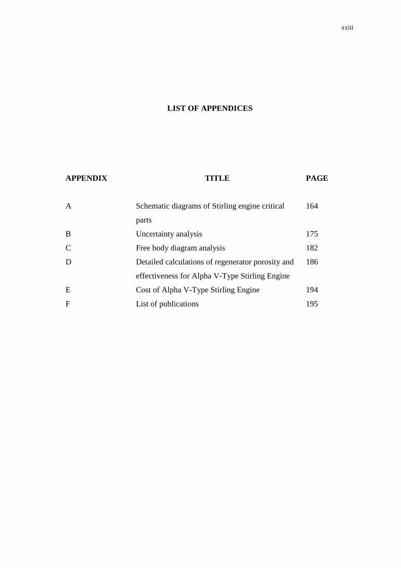
LIST OF APPENDICES
APPENDIX TITLE
PAGE
A Schematic diagrams of Stirling engine critical
parts
164
B Uncertainty analysis 175
C
D
E
F
Free body diagram analysis
Detailed calculations of regenerator porosity and
effectiveness for Alpha V-Type Stirling Engine
Cost of Alpha V-Type Stirling Engine
List of publications
182
186
194
195

CHAPTER 1
INTRODUCTION
1.1 Overview
Since its conception in the early 1800s, the Stirling engine has periodically
enchanted engineers and physicists since theoretically, Stirling engines have the
same efficiency as the Carnot engines. Today, interest in the Stirling engine is again
on the rise. Among the reasons for this are great advances in materials technology,
inherent environmental advantages of Stirling engine and the fact that, as an
externally heated engine, it can be powered by a number of energy sources [Blank
and Wu, 1995].
1.2 Background of the problem
Stirling engines are eminent for their prospect of high efficiency, safe
operation, long life, fuel flexibility, low emissions, low pollution, low vibration and
low noise level (Scott et al., 2003) compared to internal combustion engine.
2
However, a wide spread utilization of Stirling engines has not yet become a reality
due to commercial and economical factors (Raggi et al., 1997). Issues such as low
specific power and high manufacturing cost of Stirling engines are main challenges
that make mass production of Stirling engines not feasible at present. Up-to-date, the
cost of 1 kW free piston Stirling engine as reported by Sun Power Inc. is about
USD120,000 or equivalent to RM480,000 (Crawford, 2007). The cheapest and
nearest available Stirling engine within Asia is 3HP ST5 beta-type Stirling engine
from Stirling Technology, Japan at the cost of USD45,000 or equivalent to
RM180,000. (Tezuka, 2007). Apparently, the unit cost of both beta-type and free
piston Stirling engine is 4 to 10 times higher than the cost of four-stroke diesel or
gasoline engines in the market.
Modifying an internal combustion engine into the Stirling engine has been the
preferred alternative especially for academic and experimental purposes (Raggi et al.,
1997). Apparently, the manufacturing cost of the modified engine can be very much
reduced since the ready engine components have the quality in terms of material
strength and parts precision. The engineering time (design and fabrication) can be
shortened and the spare parts can be easily sourced if the engine is subjected to wear
and tear. The numerous investigations made by scientists and engineers since the
invention of the engine have made good base line information for designing engine
system, but more insight is essential to design systems together for thermo-fluid-
mechanical approach. It is seen that for successful operation of such system a careful
selection of drive mechanism and engine configuration is essential. An additional
development is needed to produce a practical engine by selection of suitable
configuration; adoption of good working fluid and development of better seal may
make Stirling engine a real practical alternative for power generation (Thombare and
Verma, 2006). Due to the cost factor and simplicity in design, alpha-type Stirling
engine is typically selected because many parts from the industrial mass production
can be used. The necessary maintenance and repair work of this engine can also be
done by a standard car workshop (Podesser, 1999).
3
In developing practical Stirling engines, the design consideration of efficient
fuel burning system is very important. Efficiency of the fuel burning system will be
determined by the capability of the external heat source system to provide sufficient
heat input and the capability of the engine heater head to store the heat supply for the
working cylinder and to minimize heat loss. Many researchers had incorporated
electrical heater as part of the engine pre-heating or heating head section, particularly
for the alpha V-type Stirling engine, since it is easier to assemble the electrical heater
to the engine body as compared to other means of heating systems due to its sloped
position. The electrical heater acts as heat interface between fuel burner and the
engine hot working cylinder. Undeniably, it is good for continuous, stable and easy
to regulate heating purposes but there are a few other alternatives that can also
potentially be utilized especially in the development of a low cost and multi-fueled
Stirling engine for power production.
1.3 Statement of the problem
Alpha engines have two pistons in separate cylinders, which are connected in
series by a heater, regenerator and cooler. Alpha engine is conceptually the simplest
Stirling engine configuration; however, it suffers from the disadvantage that both
pistons need to have seals to contain the working gas (Thombare and Verma, 2006).
Development of alpha-configuration Stirling engine is rarely seen in the most recent
publications particularly due to its sealing problem that affects the engine
performance. Technical problems arise when the working gas inside the cylinders is
not sealed properly. Firstly, pressure inside the hot working cylinder will reduce as
gas leaks out from the engine. Secondly, engine power will drop with decrease of
internal pressure and eventually, stop the engine. Numerous efforts had been done by
many researchers to overcome sealing problem on alpha-configuration Stirling
engine. Among them are; the use of moving sealer in the gap clearance between
piston and cylinder wall and the manufacture of a highly precise piston to cylinder
wall materials with a gap clearance less than 0.1 mm. Typically, these types of
4
sealing requirements substantially increase manufacturing cost of the engine and the
use of piston and cylinder with the nearest gap clearance is still insufficient to
overcome pressure drop inside the engine (Walker, 1980). And the use of moving
sealer or sliding seal in high pressure, high temperature engine working cylinder is
rather difficult to maintain. Many companies and individual researchers have
declared their successful Stirling engines operations by operating their engines at
some degree of pressurization of the working fluid where the flow is controlled by
valves. In fact, only a few experimental investigations of Stirling engines deal with
working fluid charging into the engine (pressurization of working fluid) for both
assessment and improvement of the engine performance. Conceptually, these engines
are no longer closed regenerative cycle engines and referring them as ‘Stirling
engine’ is rather misleading. Walker (1980) stated that distinction between a closed
regenerative cycle engine and an open regenerative cycle engine is not widely
established in practice and the name ‘Stirling engine’ is frequently indiscriminately
applied to all types of regenerative machines. He emphasized that clear distinction
should always be made between Stirling engines that apply constant volume system
and Ericsson engines that apply constant pressure system, because they have
radically different characteristics.
Stirling engine designs including alpha-configuration require a regenerator
for heat storage (input) and heat release (output), and these must contain the pressure
of the working gas, where the pressure is proportional to the engine power output. In
addition, the engine heater head section and hot end regenerator are continuously at
very high temperature. Thus, the part materials must require resistance to corrosive
effects of the heat source and must have low thermal creep effect due to successive
heating and cooling processes. Again, requirements of such materials considerably
escalate manufacturing cost. As an evidence, sintered wire screens made of material
typically stainless steel make a good regenerator for high performance engines, with
a typical effectiveness of 95%-98%, but the unit is expensive to build (West, 1986).
There are other alternatives and less costly regenerators have been sought including
knitted wires (Spatz, 1981), ceramic sponge (Vincent et al., 1982) and quartz tubes or
plates (Schneider et al., 1984), but they are hardly available in the local market and
5
must be custom made. Therefore, an exploration of a low cost, readily and easily
available regenerator material is desired.
1.4 Objectives
The objectives of this research are:
1. To develop an external combustion system for the Stirling engine operation.
2. To design 53 mm bore x 44 mm stroke with 97 cc., develop and operate an alpha
V-type Stirling engine converted from diesel engine for 25 Watt power.
3. To determine the power and torque of high temperature differential (HTD)
Stirling engine operation in self-pressurization mode and to profile critical
operating parameters such as temperatures of hot cylinder, cold cylinder,
regenerator and fuel burner.
4. To analyze the optimum operating parameters and correlation for design engine
for an optimal power production.
1.5 Scopes of the study
The purpose of this study is to develop a simple, portable, low-cost, multi-
fueled characteristic and high temperature differential (HTD) alpha V-shaped Stirling
engine by using custom-made components of YAMAHA four-stroke diesel engine
and industrial mass production materials. An in-depth understanding of Stirling cycle
and its working principle is demanded in developing converted diesel to Stirling
engine since internal combustion engine applies a totally different cycle from Stirling
engine. Pure experimental investigations are critical to study both characteristics and
6
performance of the engine in self-pressurization mode. Finally, the engine
performance will be characterized and optimized in order to fulfill the expectation of
delivering a small-scale power production.
Scope 1: The research will commence with the selection process of the most suitable
type or configuration of the Stirling engine to be developed. At this stage,
understanding of thermodynamics principle of the Stirling cycle is demanded. The
main criteria for the selection process include the engine cylinder
layout/arrangement, drive mechanism, type of heater or burner, cylinder and piston
forms of coupling, type and size of regenerator and crankcase construction. Design
considerations of the Stirling engine to be developed must also notice major output
characteristics such as net power output, thermal and mechanical efficiency, cost-
effectiveness and simplicity in design.
Scope 2: The research will proceed with design, fabrication and development of
Stirling engine based on the most suitable configuration to be developed. The
expectation of low manufacturing cost Stirling engine will be realized by utilizing
common materials from the local foundries and by adopting common spare parts of
internal combustion engines. Technical specifications of the manufactured Stirling
engine that complies with the thermodynamics principle of Stirling engine cycle will
be originated at the end of this stage via preliminary investigations.
Scope 3: The research will then continue with the performance testing of the Stirling
engine workability and operation. At this stage, critical design features of the Stirling
engine such as crank mechanism, heater or burner, cylinder-piston coupling and
sealing, regenerator, flywheel, working gas etc. will be examined for their
operability. Measurement of critical operating parameters such as heater temperature,
hot temperature of the expansion working cylinder, cold temperature of the
compression working cylinder, regenerator temperature, cooling temperature of the
cooling system and so forth will be measured and profiled. Thermal heat input into
the engine heater head section will be controlled via a fuel flow rate measurement.
7
The engine power output (both mechanical shaft power and electrical power) will be
determined experimentally via various tests.
Scope 4: The final stage of this research will cope with the performance
characterization of the Stirling engine operation. Specifically, size and/or type of
material for the engine critical parts such as flywheel, piston, piston ring or sealer,
regenerator, lubrication oil etc. will be characterized for determining any significant
effect on the engine output characteristics. Variation study of the engine critical
operating parameters such as fuel flow rate, heater and cooling temperature will be
performed as well to determine any potential improvement on the engine power
production. Ultimately, Stirling engine performance curves will be established.
1.6 Significance of the study
A successful development of a small-scale, portable, low cost, self-pressurized
and fuel flexible Stirling engine will help to contribute another alternative for power
generation system particularly in rural or remote areas. The Stirling engine with
multi-fueled capability will create options in utilizing lower cost and highly available
source of fuel. Consequently, it will help to reduce operational cost of the Stirling
engine. Using common materials from local foundries and common spare parts from
internal combustion engines will help to minimize manufacturing cost and to realize
commercialization of Stirling engines.
8
1.7 Expected findings and summary
The possible outcomes of the research project are as per following:-
Capability of Stirling engine to produce a small-scale power output can be
demonstrated.
Understanding of the effect or relationship of each process parameters in
contributing a successful operation of the Stirling engine to produce power can
be accomplished.
Performance characterization of the overall Stirling engine system including the
external combustion process can be established.
Potential application of the overall Stirling engine system for a small-scale power
generation can be analyzed and corroborated.
1.8 Organization of the thesis
The thesis is organized in such a way that it provides a continuous and
smooth flow of information to the reader in regards to development and performance
characterization of alpha V-Stirling engine converted diesel engine for a small scale
power production.
Chapter 1 presents a brief background of Stirling engine development, its
major problems that hinder mass production of the engine for active
commercialization and challenges for solving the problems.
9
Chapter 2 deals with literature review pertaining to both historical and
technological development of Stirling engine in various configurations, the pros and
cons of different types of Stirling engine configuration with respect to both specific
power and thermal efficiency, selection process of Stirling engine critical parts and
components and decision making of the suitable Stirling engine to be developed.
Chapter 3 describes the methodology for design, development and operation
of the Stirling engine. Key considerations in designing the Stirling engine are
elaborated and that includes material selection for the engine critical components,
dimensioning of the engine size and volume, dimensioning of the engine critical
parts, setting-up of the external combustion system, cooling system and heat
regeneration system, selection of flywheel for the energy storage system, selection of
the working medium, selection of the engine lubricant and so forth. All the relevant
mathematical formulations for designing and operating the Stirling engine are
presented and discussed in this chapter.
Chapter 4 presents the Stirling engine performance curves at both no load and
load conditions. The engine performance at load condition consists of two main
sections. The first section presents and discusses the experimental results of the
engine mechanical shaft power assessment. In this section, variation of engine
characteristics as a function of the critical operating parameters comprises of engine
speed, hot cylinder temperature, cold cylinder temperature and operation time are
presented and discussed. The second section deals with experimental results of the
engine electrical power assessment where variation of engine characteristics
primarily current load, voltage output and electrical power at different engine speeds,
hot cylinder temperatures and cold cylinder temperatures are elaborated.
Characterization of critical parameters of the engine for its optimal performance is
also discussed in this chapter that affects the engine performance significantly.
Chapter 5 accentuates key achievements of the study with reference to the set
of objectives outlined in Chapter 1. Both theoretical and experimental results as

10
discussed in the previous chapters are justified in this chapter. One of the objectives
of this study is to identify areas where more research work is needed in order to
improve methodology and techniques for overall performance and power production
capability of the developed engine. These potential areas are pointed up under work
recommendations.
158
REFERENCES
Adams, T. M., (2002). Estimation of Measurement Uncertainty in Testing. G104-
A2LA Guide; pp. 1-42.
Ataer, O. E., (2002). Numerical Analysis of Regenerators of Piston Type Stirling
Engines using Lagrangian Formulation. Int. J. Refrig., 25: 640-52.
Backhaus S. and Swift, G., (2001). Fabrication and Use of Parallel Plate
Regenerators in Thermoacoustic Engines. Proceedings of IECEC '01, 36th
Intersociety Energy Conversion Engineering Conference, Jul. 29-Aug. 2,
Savannah, GA, pp. 1-5.
Batmaz, İ. and Üstün, S., (2008). Design and Manufacturing of A V-Type Stirling
Engine with Double Heaters. Applied Energy, 85: 1041-1049.
Beale, W., (1984). Understanding Stirling Engines. VITA, ISBN: 0-86619-200-X.
Beale, W. T., Wood, J. G. and Chagnot, B. F., (1980). Stirling Engines for
Developing Countries. American Institute of Aeronautics and Astronautics.
809399: 1971-5.
Callister, Jr., W. D., (1996). Material Science and Engineering: An Introduction.
4th
ed. John Wiley & Sons, Inc. ISBN 0-471-13459-7.
Cavendish, M., (2003). How It Works: Science and Technology, 3rd ed. Brown
Reference Group ptc., ISBN 0-7614-7314-9.
159
Çengel, Y.A., (1998). Heat Transfer A Practical Approach. International Edition.
The McGraw-Hill Companies Inc., New Jersey. QC320.C46, ISBN 0-07-
011505-2.
Cinar, C., Yüsecu, S., Topgul, T. and Okur, (2004). Beta-Type Stirling Engine
Operating at Atmospheric Pressure. Applied Energy, 81: 351-357.
Clucas, D. M., (1993). Development of A Stirling Engine: Battery Charger based on
A Low Cost Wobble Mechanism. University of Canterbury: Ph.D. Thesis.
Crawford, J. G., (2007). 1 kW Free-Piston Stirling Engine. Sun Power Inc., USA
(Email correspondence with Crawford, J. G.: [email protected] on
1st March 2007).
Gentry, T., (2004). Spherical Bed Regenerators. Ohio: Stirling Engine Society USA.
Hirata, K., Kagawa, N., Takeuchi, M., Yamashita, I., Isshiki, N. and Hamaguchi, K.,
(1996). Test Results of Applicative 100 W Stirling Engine. Proceedings
IEEE, p.1259-1264.
Holman, J. P., (1989). Experimental Methods for Engineers. 6th
Ed. McGraw Hill.
T57-37.
Karabulut, H., Yüsecu, H. S. and Koca, A., (1998). Manufacturing and Testing of A
V-Type Stirling Engine. Turk. J. Environ. Sci., 24: 71-80.
Karabulut, H., Yücesu, H. S. and Cinar, C., (2006). Nodal Analysis of A Stirling
Engine with Concentric Piston and Displacer. Renewable Energy, 31; pp.
2188-2197.
Karabulut, H., Cinar, C., Oztürk, E. and Yücesu, H. S., (2010). Torque and Power
Characteristics of A Helium Charged Stirling Engine with A Lever
Controlled Displacer Driving Mechanism. Renewable Energy, 35: 138-143.
160
Kongtragool, B. and Wongwises, S., (2006). Thermodynamic Analysis of A Stirling
Engine including Dead Volumes of Hot Space, Cold Space and Regenerator.
Renewable Energy, 31: 345-359.
Kongtragool, B. and Wongwises, S., (2007). Performance of A Twin Power Piston
Low Temperature Differential Stirling Engine Powered by A Solar Simulator.
Solar Energy, 81: 884-895.
Kongtragool, B. and Wongwises, S., (2008). A Four Power-Piston Low-Temperature
Differential Stirling Engine Powered using Simulated Solar Energy as A Heat
Source. Solar Energy: 1-8.
Kostic, M., 2003. Error or Uncertainty Analysis of Measurement Results. NASA
Glenn Research Center; pp. 1-11.
Lane, N. W. and Beale, W. T., (1995). A 5 kW Electric Free-Piston Stirling Engine.
7th
International Conference on Stirling Cycle Machines, Tokyo, Japan, pp.
1-6.
Lane, N. W. and Beale, W. T., (1999). A Biomass-Fired 1 kWe Stirling Engine
Generator and Its Applications in South Africa. Future Engine Technology
Series-Biowatt, 76: 1-7.
Meijer, R. J., (1958). Hot Gas Reciprocating Engine. US Patent no. 2828601.
Philip, N. V., (1987). A Report of Philip Stirling Engine Program. Eindhovan.
Podesser, E., (1999). Electricity Production in Rural Villages with A Biomass
Stirling Engine. Renewable Energy, 16: 1049-1052.
Raggi, L., Katsuka, M. and Sekiya, H., (1997). Design of A 1 kW Class Gamma
Type Stirling Engine. IECEC, 97180: 991.
Ross, M. A., (1985). Compact Crank Drive Mechanism. (U.S. Patent 4.532.819).
161
Schmidt G., (1871). Classical Analysis of Operation of Stirling Engine. A report
published in German Engineering Union (Original German), vol. XV; pp.
1-12.
Schneider, J. A., Holl, S. L. and Schlansky, C. P., (1984). A Miniature TES Powered
Stirling Cycle Engine. Pap. 849118, Proc. 19th
IECEC.
Scott, S. J., Holcomb, F. H. and Josefik, N. M., (2003). Distributed Electrical Power
Generation. Summary of Alternative Available. ERDC/CERL SR-03-18, U.S.
Army Corps of Engineers, Washington, DC 20314-1000, September, pp:82.
Senft, J., (2000). Extended Mechanical Efficiency Theorem for Engines and Heat
Pump. J Energy, 107: 679-93.
Senft, J.R., (1993). Ringbom Stirling Engines. New York: Oxford University Press,
TJ765 .S46 1993, ISBN: 0-19-507798-9.
Shoureshi, R., (1982). General Method for Optimization of Stirling Engine.
Seventeenth Intersociety Energy Conversion Engineering Conference, vol.
829279: pp. 1688-93.
Skjoedt, M., Butts, R., Assanis, D. N. and Bohac, S. V., (2008). Effects of Oil
Properties on Spark-Ignition Gasoline Engine Friction. Tribology
International, 41: 556-563.
Solero, G. and Coghe, A., (2000). Experimental Analysis on Turbulent Mixing in A
Swirl Burner. Open Meeting on Combustion, Ischia, May 22-25., pp:1-4.
Spatz, M. W., (1981). Regenerator Matrices for Stirling Engines. Proc. Automotive
Technology Development Contractor Coordination Meeting.
Spotts, M. F., Shoup, T. E. and Hornberger, L. E., (2004). Design of Machine
Elements. 8th
Ed. Prentice Hall. ISBN-13: 9780130489890.
162
Syred, N. and Beér, J. M., (1974). Combustion in Swirling Flows: A Review.
Combustion and Flame, 23(2): 143-201.
Tezuka, N., (2007). 3HP ST5 Beta-Type Stirling Engine. Stirling Technology, Japan
(Email correspondence with Tezuka, N.: [email protected] on 4th
July 2007).
Thombare, D. G. and Verma, S. K., (2006). Technological Development in The
Stirling Cycle Engines. Renewable and Sustainable Energy Reviews,
doi:10.1016/j.rser.2006.07.001.
Timoumi, Y., Tlili, I. and Nasrallah, S. B., (2008). Performance Optimization of
Stirling Engines. Renewable Energy, 33: 2134-2144.
Tlili, I., (2007). Analysis and Design Consideration of Mean Temperature
Differential Stirling Engine for Solar Application. Renewable Energy, doi:
10.1016/j.renene.2007.09.024.
Tlili, S., (2002). Modeling of Stirling Engines. DEA Thesis, Ecole National
of Engineers of Monastir, Tunisia.
Urieli, I. and Berchowitz, D. M., (1984). Stirling Cycle Engine Analysis. UK: Adam
Hilger Ltd.
Vincent, R. J., Rifkin, D. W. and Benson, G. M., (1982). Test Results of High
Efficiency Stirling Machine Components. Pap. 829362, Proc. 17th
IECEC.
Yuan, Z. S., (1993). Oscillatory Flow and Heat Transfer in A Stirling-Engine
Regenerator. PhD Thesis. Department of Mechanical and Aerospace
Engineering, Case Western Reserve University.
Van Arsdell, BH., (2001). Stirling engines. In: Zumerchik J, editor. Macmillan
Encyclopedia of Energy, Macmillan Reference USA, Vol. 3; pp. 1090-5.
163
Walker, G., (1980). Stirling Engines. 1st Ed. The Clarendon Press, Oxford.
TJ765.W35 1980, ISBN - 0-19-856209-8.
West, C. D., (1986). Principles and Applications of Stirling Engines. Van Nostrand
Reinhold Company Inc., New York. TJ765.W48, ISBN-0-442-29273-2.
Wood, J. G., Caroll, C., Matejczyk, D. and Penswick, L. B., (2005). Advanced
80 We Stirling Convertor Phase II Development Progress. 3rd
International
Energy Conversion Engineering Conference, San Francisco, USA, pp. 4-8.
Wood, J. G., Lane, N. W. and Beale W. T., (2001). Preliminary Design of a 7 kWe
Free-Piston Stirling Engine with Rotary Generator Output. 10th
International
Stirling Engine Conference (10th
ISEC), Osnabrück, Germany, pp. 3-5.
Wood, J. G., Chagnot, B. J. and Penswick, L. B., (1982). Design of A Low Pressure
Air Engine for Third World Use. Seventeenth Intersociety Energy Conversion
Engineering Conference, vol. 829298: pp. 1744-48.
Recommended