DCN Next GenerationInterpretation System Data Brochure
Communication you can rely on
DCN Next Generation Interpretation System Data Brochure | 1
1. Introduction 3
2. Interpretation and Language Distribution 8
3. Headphones 12
4. Central Control Equipment 14
5. Application Software 17
6. DCN Network 19
7. Optical Network 21
8. Technical Data 24
DCN Next GenerationInterpretation System
Data Brochure

2 | DCN Next Generation Interpretation System Data Brochure
Modular system approachBy simply daisy chaining the modular DCN Next
Generation Interpreter and language channel selector units,
any configuration can be put together. The modular struc-
ture of the system means any level of conferencing can be
created without difficulty. Systems can be easily expanded by
adding components and PC control with software modules.
Range of equipmentThe range of DCN Next Generation Interpretation System
products include central control units, simultaneous inter-
pretation and language distribution equipment, application-
specific software modules, information provisions, and
installation equipment. This can be complemented by
external equipment such as PCs, video screens, booster
amplifiers, and loudspeakers, all of which are fully compati-
ble and easily integrated into the DCN Next Generation
Interpretation System.
DCN Next Generation Interpretation System Data Brochure | Introduction | 3
1. Introduction
Digital Congress Network
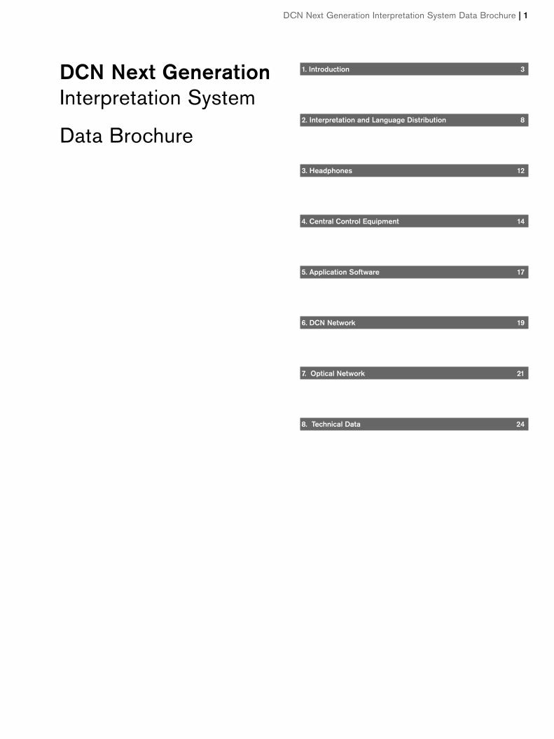
World’s first digital congress interpretation system,upgraded for even higher performanceThe Bosch DCN Next Generation Interpretation System
brings the benefits of innovative digital technology to inter-
pretation systems. Digital signal processing and transmission
via a simple network system greatly improves audio quality
and simplifies operation and installation.
DCN Next Generation Interpretation System provides flexi-
ble management of facilities from small gatherings with only
a few languages to large assemblies with as many as 32 lan-
guages. The system offers versatility, high audio quality with
20 kHz audio bandwidth, and data transmission security
while providing complete control over conference proceed-
ings.
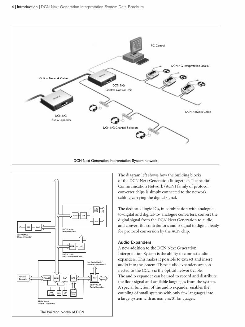
The diagram left shows how the building blocks of the DCN Next Generation fit together. The AudioCommunication Network (ACN) family of protocol converter chips is simply connected to the networkcabling carrying the digital signal.
The dedicated logic ICs, in combination with analogue-to-digital and digital-to- analogue converters, convert thedigital signal from the DCN Next Generation to audio,and convert the contributor’s audio signal to digital, readyfor protocol conversion by the ACN chip.
Audio ExpandersA new addition to the DCN Next GenerationInterpretation System is the ability to connect audioexpanders. This makes it possible to extract and insertaudio into the system. These audio expanders are con-nected to the CCU via the optical network cable.The audio expander can be used to record and distributethe floor signal and available languages from the system.A special function of the audio expander enables the coupling of small systems with only few languages into a large system with as many as 31 languages.
4 | Introduction | DCN Next Generation Interpretation System Data Brochure
ControlPanel
µP
µP
ram
DSP DSPDAPACN 2
ACN 1
DUART
flashEPROM
LBB 4402/00 Audio Expanders
LBB 4100/00 Central Control Unit
e.g. Audio Matrix/ Remote Interpretation
Personal Computer
LBB 4112/00 Data Distribution Board
LBB 4120/00 Interpreter Desk
LBB 4124/00 Channel Selector
DAP
DAC
DAPACN1
DACADC
DAC
The building blocks of DCN
DCN Next Generation Interpretation System network
DCN NGAudio Expander
PC Control
DCN NG Interpretation Desks
DCN NG Channel Selectors
DCN NG Central Control Unit
Optical Network Cable
DCN Network Cable
DCN Next Generation Interpretation System Data Brochure | Introduction | 5
Excellent audio qualityThe result of this advanced digital technology is excellentaudio performance with no loss in signal quality or levelduring transmission. Each unit receives a consistentlyhigh quality audio signal. This significantly enhances theintelligibility of speech. DCN Next Generation virtuallyeliminates the problems usually associated with conven-tional systems, such as background noise, interference,distortion, and cross talk.
Reduced installation costsFast, cost-saving installation is an important benefit ofDCN Next Generation digital technology. Thin, flexible,twin-coaxial cable and twin-optical fiber carry all the system’s digital signals. This eliminates the need for thecostly and vulnerable multi-core cables used in conven-tional analogue installations. The twin-coaxial cable andtwin-optical fiber can easily be run through existing ducting and cable conduits. These can simultaneouslycarry up to 32 high-quality contribution channels and 32 high-quality distribution channels.
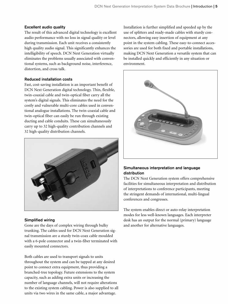
Simplified wiringGone are the days of complex wiring through bulkytrunking. The cables used for DCN Next Generation sig-nal transmission are a sturdy twin-coax cable mouldedwith a 6-pole connector and a twin-fiber terminated witheasily mounted connectors.
Both cables are used to transport signals to unitsthroughout the system and can be tapped at any desiredpoint to connect extra equipment, thus providing abranched-tree topology. Future extensions to the systemcapacity, such as adding extra units or increasing thenumber of language channels, will not require alterationsto the existing system cabling. Power is also supplied to allunits via two wires in the same cable, a major advantage.
Installation is further simplified and speeded up by theuse of splitters and ready-made cables with sturdy con-nectors, allowing easy insertion of equipment at anypoint in the system cabling. These easy-to-connect acces-sories are used for both fixed and portable installations,making DCN Next Generation a versatile system that canbe installed quickly and efficiently in any situation orenvironment.
Simultaneous interpretation and language distributionThe DCN Next Generation system offers comprehensivefacilities for simultaneous interpretation and distributionof interpretations to conference participants, meeting the stringent demands of international, multi-lingualconferences and congresses.
The system enables direct or auto-relay interpretationmodes for less well-known languages. Each interpreterdesk has an output for the normal (primary) languageand another for alternative languages.
6 | Introduction | DCN Next Generation Interpretation System Data Brochure
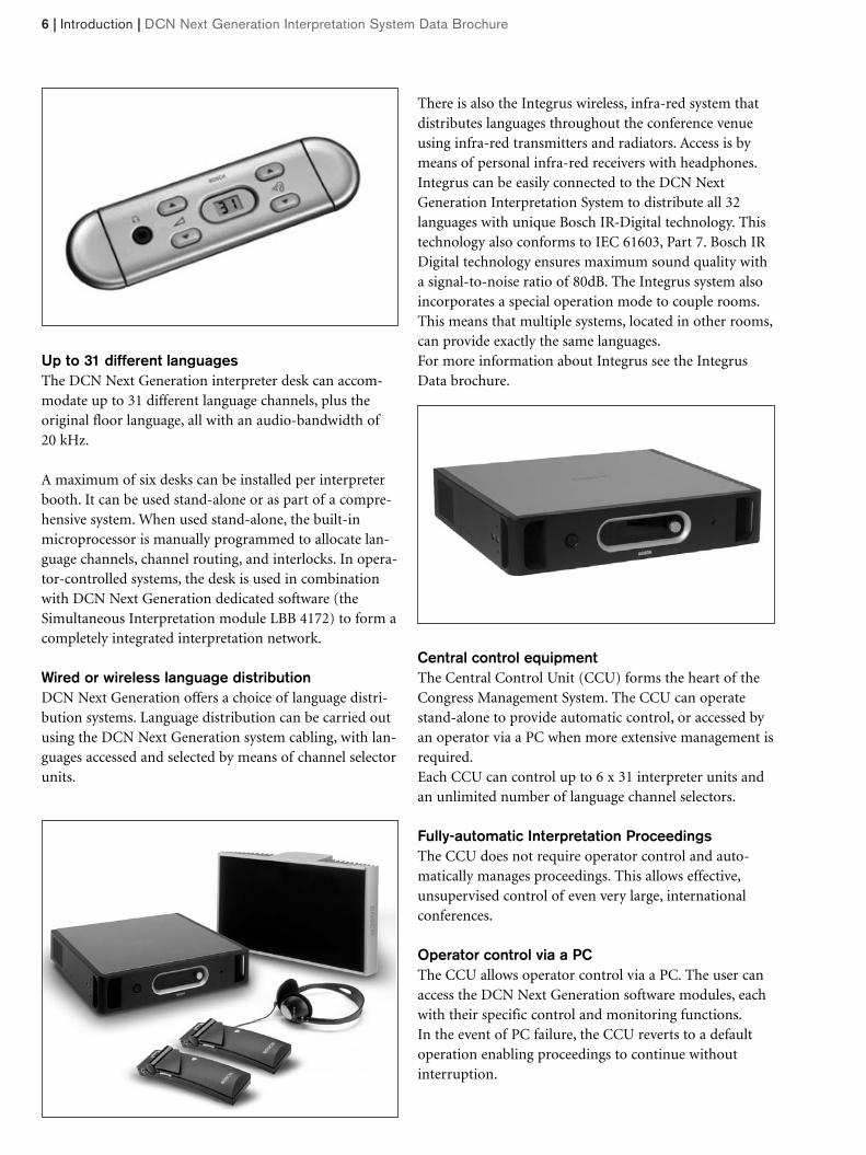
Up to 31 different languagesThe DCN Next Generation interpreter desk can accom-modate up to 31 different language channels, plus theoriginal floor language, all with an audio-bandwidth of20 kHz.
A maximum of six desks can be installed per interpreterbooth. It can be used stand-alone or as part of a compre-hensive system. When used stand-alone, the built-inmicroprocessor is manually programmed to allocate lan-guage channels, channel routing, and interlocks. In opera-tor-controlled systems, the desk is used in combinationwith DCN Next Generation dedicated software (theSimultaneous Interpretation module LBB 4172) to form acompletely integrated interpretation network.
Wired or wireless language distributionDCN Next Generation offers a choice of language distri-bution systems. Language distribution can be carried outusing the DCN Next Generation system cabling, with lan-guages accessed and selected by means of channel selectorunits.
There is also the Integrus wireless, infra-red system thatdistributes languages throughout the conference venueusing infra-red transmitters and radiators. Access is bymeans of personal infra-red receivers with headphones.Integrus can be easily connected to the DCN Next Generation Interpretation System to distribute all 32 languages with unique Bosch IR-Digital technology. Thistechnology also conforms to IEC 61603, Part 7. Bosch IRDigital technology ensures maximum sound quality witha signal-to-noise ratio of 80dB. The Integrus system alsoincorporates a special operation mode to couple rooms.This means that multiple systems, located in other rooms,can provide exactly the same languages.For more information about Integrus see the IntegrusData brochure.
Central control equipmentThe Central Control Unit (CCU) forms the heart of theCongress Management System. The CCU can operatestand-alone to provide automatic control, or accessed byan operator via a PC when more extensive management isrequired.Each CCU can control up to 6 x 31 interpreter units andan unlimited number of language channel selectors.
Fully-automatic Interpretation ProceedingsThe CCU does not require operator control and auto-matically manages proceedings. This allows effective,unsupervised control of even very large, internationalconferences.
Operator control via a PCThe CCU allows operator control via a PC. The user canaccess the DCN Next Generation software modules, eachwith their specific control and monitoring functions.In the event of PC failure, the CCU reverts to a defaultoperation enabling proceedings to continue withoutinterruption.
DCN Next Generation Interpretation System Data Brochure | Introduction | 7
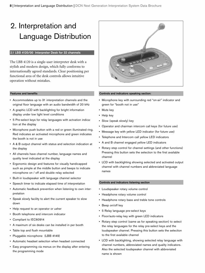
2.1 LBB 4120/00 Interpreter Desk for 32 channels
The LBB 4120 is a single-user interpreter desk with a stylish and modern design, which fully conforms to internationally agreed standards. Clear positioning perfunctional area of the desk controls allows intuitive operation without mistakes.
Features and benefits
• Accommodates up to 31 interpretation channels and theoriginal floor language with an audio bandwidth of 20 kHz
• A graphic LCD with backlighting for bright information display under low light level conditions
• 5 Pre-select keys for relay languages with actvation indica-tion at the display
• Microphone push button with a red or green illuminated ring.Red indicates an activated microphone and green indicatesthe booth is not in use
• A & B output channel with status and selection indication atthe display
• All channels have channel number, language names andquality level indicated at the display
• Ergonomic design and features for visually handicappedsuch as pimple at the middle button and beeps to indicatemicrophone on / off and double relay selected
• Built-in loudspeaker with language channel selector
• Speech timer to indicate elapsed time of interpretation
• Automatic feedback prevention when listening to own inter-pretation
• Speak slowly facility to alert the current speaker to slowdown
• Help request to an operator or usher
• Booth telephone and intercom indicator
• Compliant to IEC60914
• A maximum of six desks can be installed in per booth
• Table top and flush mountable
• Pluggable microphone (LBB 4149)
• Automatic headset selection when headset connected
• Easy programming via menus on the display after enteringthe programming mode
Controls and indicators speaking section:
• Microphone key with surrounding red “on-air” indicator andgreen for “booth not in use”
• Mute key
• Help key
• Slow (speak slowly) key
• Operator and chairman intercom call keys (for future use)
• Message key with yellow LED indicator (for future use)
• Telephone and Intercom call yellow LED indicators
• A and B channel engaged yellow LED indicators
• Rotary step control for channel settings (and other functions)Pressing this button sets the selection to the first availablechannel
• LCD with backlighting showing selected and activated outputchannel with channel numbers and abbreviated languagenames
Controls and indicators listening section
• Loudspeaker rotary volume control
• Headphone rotary volume control
• Headphone rotary bass and treble tone controls
• Beep on/off key
• 5 Relay language pre-select keys
• Floor/auto-relay key with green LED indicators
• Rotary step control (same as for speaking section) to selectthe relay languages for the relay pre-select keys and theloudspeaker channel. Pressing this button sets the selectionto the first available channel
• LCD with backlighting, showing selected relay language withchannel numbers, abbreviated names and quality indicators.Also the selected loudspeaker channel with abbreviatedname is shown
8 | Interpretation and Language Distribution | DCN Next Generation Interpretation System Data Brochure
2. Interpretation and Language Distribution
Interconnection
• 6-pole microphone socket
• Headphone or headset connector (5-pole 180° Din typesocket wired according to IEC 574-3)
• 6.3 mm (0.25 in) and 3.5 mm (0.14 in) stereo jack head-phone connectors
• 2 m (6 ft 6 in) DCN cable with moulded 6-pole circular connector
• 6-pole circular socket for loop-through connection to theDCN network
• 8-pole modular jack connector for connection to booth telephone, intercom and booth on-air sign
Electrical characteristics
Supply voltage 17- 40 V d.c. via DCN network cable
Power consumption 3.5 W
Performance
Headphone connection
Frequency response 30 Hz – 20 kHz
Load impedance > 32 ohm
Output power 60 mW/32 ohm
Headset connection
Frequency response 30 Hz – 20 kHz
Load impedance > 32 ohm
Output power 60 mW/32 ohm
Nominal microphone input
level 7 mVrms
Overload microphone input
level >124 mVrms
Physical characteristics
Mounting Free-standing or mounted on a table
Dimensions (H x W x D) 82 x 330 x 170 mm (3.2 x 13 x 6.7 in)
(with microphone)
Slope 25 degrees
Weight 1.3 kg (2.87 lbs)
Color top Silver (RAL 9022)
Color base Light Grey (RAL 000 7500)
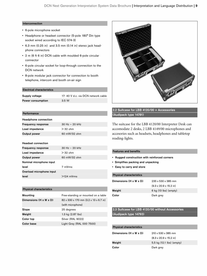
2.2 Suitcase for LBB 4120/00 + Accessories (Audipack type 14781)
The suitcase for the LBB 4120/00 Interpreter Desk canaccomodate 2 desks, 2 LBB 4149/00 microphones andaccesories such as headsets, headphones and tabletopreading-lights.
Features and benefits
• Rugged construction with reinforced corners
• Simplifies packing and unpacking
• Easy to carry and store
Physical characteristics
Dimensions (H x W x D) 235 x 530 x 385 mm
(9.3 x 20.9 x 15.2 in)
Weight 6 kg (13 lbs) (empty)
Color Dark grey
2.3 Suitcase for LBB 4120/00 without Accessories (Audipack type 14793)
Physical characteristics
Dimensions (H x W x D) 210 x 530 x 385 mm
(8.3 x 20.9 x 15.2 in)
Weight 5,5 kg (12.1 lbs) (empty)
Color Dark grey
DCN Next Generation Interpretation System Data Brochure | Interpretation and Language Distribution | 9
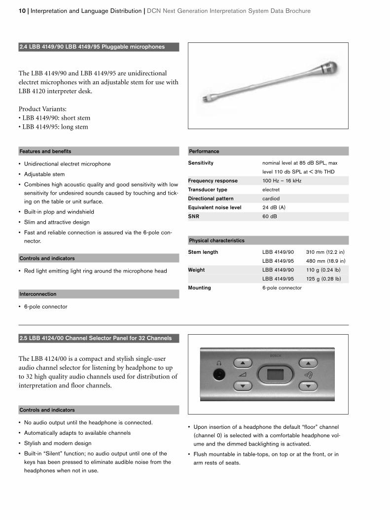
2.4 LBB 4149/90 LBB 4149/95 Pluggable microphones
The LBB 4149/90 and LBB 4149/95 are unidirectionalelectret microphones with an adjustable stem for use withLBB 4120 interpreter desk.
Product Variants:• LBB 4149/90: short stem• LBB 4149/95: long stem
Features and benefits
• Unidirectional electret microphone
• Adjustable stem
• Combines high acoustic quality and good sensitivity with lowsensitivity for undesired sounds caused by touching and tick-ing on the table or unit surface.
• Built-in plop and windshield
• Slim and attractive design
• Fast and reliable connection is assured via the 6-pole con-nector.
Controls and indicators
• Red light emitting light ring around the microphone head
Interconnection
• 6-pole connector
Performance
Sensitivity nominal level at 85 dB SPL, max
level 110 db SPL at < 3% THD
Frequency response 100 Hz – 16 kHz
Transducer type electret
Directional pattern cardiod
Equivalent noise level 24 dB (A)
SNR 60 dB
Physical characteristics
Stem length LBB 4149/90 310 mm (12.2 in)
LBB 4149/95 480 mm (18.9 in)
Weight LBB 4149/90 110 g (0.24 lb)
LBB 4149/95 125 g (0.28 lb)
Mounting 6-pole connector
10 | Interpretation and Language Distribution | DCN Next Generation Interpretation System Data Brochure
2.5 LBB 4124/00 Channel Selector Panel for 32 Channels
The LBB 4124/00 is a compact and stylish single-useraudio channel selector for listening by headphone to upto 32 high quality audio channels used for distribution ofinterpretation and floor channels.
Controls and indicators
• No audio output until the headphone is connected.
• Automatically adapts to available channels
• Stylish and modern design
• Built-in “Silent” function; no audio output until one of thekeys has been pressed to eliminate audible noise from theheadphones when not in use.
• Upon insertion of a headphone the default “floor” channel(channel 0) is selected with a comfortable headphone vol-ume and the dimmed backlighting is activated.
• Flush mountable in table-tops, on top or at the front, or inarm rests of seats.
DCN Next Generation Interpretation System Data Brochure | Interpretation and Language Distribution | 11
Controls and indicators
• Two push-buttons (up/down) for channel selection
• Two push-buttons (up/down) for headphone volume control
• Backlit 2-digit LCD for channel number indication
Interconnection
• 3.5 (0.14 in) mm stereo jack headphone connector
• Connector for external headphone
• 2 m (6 ft 6 in) cable with a moulded 6-pole circular connector
• 6-pole circular connector for loop-through interconnection
Electrical characteristics
Supply voltage 17- 40 V d.c. via DCN network cable
Power consumption 0.8 W
Performance
Headphone
Load impedance > 32 ohm < 1 kΩ
Physical characteristics
Mounting Flush mounted
Dimensions (H x W x D) 40 x 100 x 100 mm (1.6 x 3.9 x 3.9 in)
Weight 0.3 kg (0.66 lb)
Color Silver (RAL 9022)
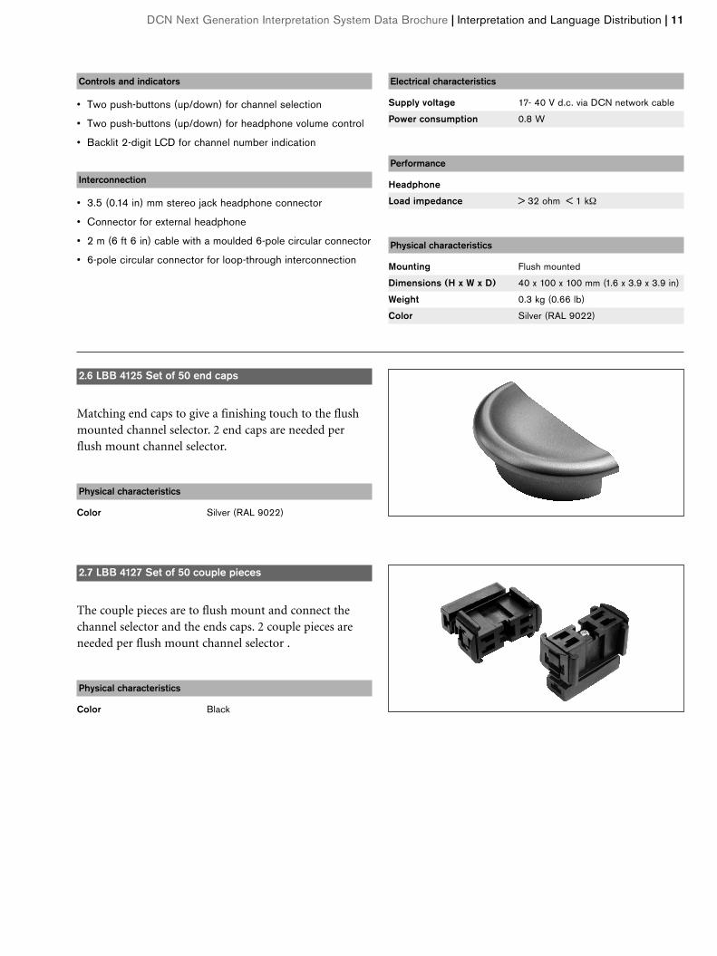
2.6 LBB 4125 Set of 50 end caps
Matching end caps to give a finishing touch to the flushmounted channel selector. 2 end caps are needed perflush mount channel selector.
Physical characteristics
Color Silver (RAL 9022)
2.7 LBB 4127 Set of 50 couple pieces
The couple pieces are to flush mount and connect thechannel selector and the ends caps. 2 couple pieces areneeded per flush mount channel selector .
Physical characteristics
Color Black
12 | Headphones | DCN Next Generation Interpretation System Data Brochure
A range of headphones is available for use with the DCNNext Generation Interpretation System. This rangeincludes Interpreter Headphones (LBB 9095/30) ,Lightweight Stereo Headphones (LBB 3443/00),Stethoscopic Headphones (LBB 3441/10),Single Earphones (LBB 3442/00) and High-QualityDynamic Headphones (LBB 3015/04).
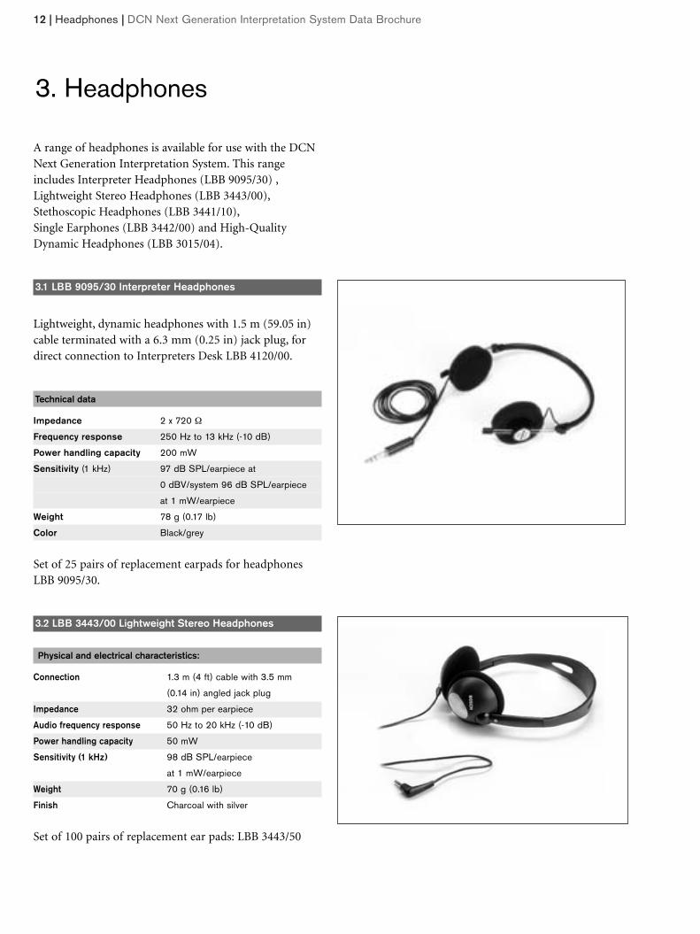
3.1 LBB 9095/30 Interpreter Headphones
Lightweight, dynamic headphones with 1.5 m (59.05 in)cable terminated with a 6.3 mm (0.25 in) jack plug, fordirect connection to Interpreters Desk LBB 4120/00.
Technical data
Impedance 2 x 720 Ω
Frequency response 250 Hz to 13 kHz (-10 dB)
Power handling capacity 200 mW
Sensitivity (1 kHz) 97 dB SPL/earpiece at
0 dBV/system 96 dB SPL/earpiece
at 1 mW/earpiece
Weight 78 g (0.17 lb)
Color Black/grey
Set of 25 pairs of replacement earpads for headphonesLBB 9095/30.
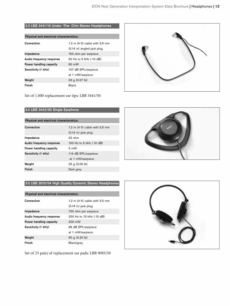
3.2 LBB 3443/00 Lightweight Stereo Headphones
Physical and electrical characteristics:
Connection 1.3 m (4 ft) cable with 3.5 mm
(0.14 in) angled jack plug
Impedance 32 ohm per earpiece
Audio frequency response 50 Hz to 20 kHz (-10 dB)
Power handling capacity 50 mW
Sensitivity (1 kHz) 98 dB SPL/earpiece
at 1 mW/earpiece
Weight 70 g (0.16 lb)
Finish Charcoal with silver
Set of 100 pairs of replacement ear pads: LBB 3443/50
3. Headphones
3.3 LBB 3441/10 Under -The- Chin Stereo Headphones
Physical and electrical characteristics:
Connection 1.2 m (4 ft) cable with 3.5 mm
(0.14 in) angled jack plug
Impedance 150 ohm per earpiece
Audio frequency response 50 Hz to 5 kHz (-10 dB)
Power handling capacity 60 mW
Sensitivity (1 kHz) 107 dB SPL/earpiece
at 1 mW/earpiece
Weight 33 g (0.07 lb)
Finish Black
Set of 1.000 replacement ear tips: LBB 3441/50
2.8 LBB 3.4 LBB 3442/00 Single Earphone
Physical and electrical characteristics:
Connection 1.2 m (4 ft) cable with 3.5 mm
(0.14 in) jack plug
Impedance 32 ohm
Audio frequency response 100 Hz to 5 kHz (-10 dB)
Power handling capacity 5 mW
Sensitivity (1 kHz) 114 dB SPL/earpiece
at 1 mW/earpiece
Weight 25 g (0.06 lb)
Finish Dark grey
3.5 LBB 3015/04 High Quality Dynamic Stereo Headphones
Physical and electrical characteristics:
Connection 1.2 m (4 ft) cable with 3.5 mm
(0.14 in) jack plug
Impedance 720 ohm per earpiece
Audio frequency response 250 Hz to 13 kHz (-10 dB)
Power handling capacity 200 mW
Sensitivity (1 kHz) 96 dB SPL/earpiece
at 1 mW/earpiece
Weight 90 g (0.20 lb)
Finish Black/grey
Set of 25 pairs of replacement ear pads: LBB 9095/50
DCN Next Generation Interpretation System Data Brochure | Headphones | 13
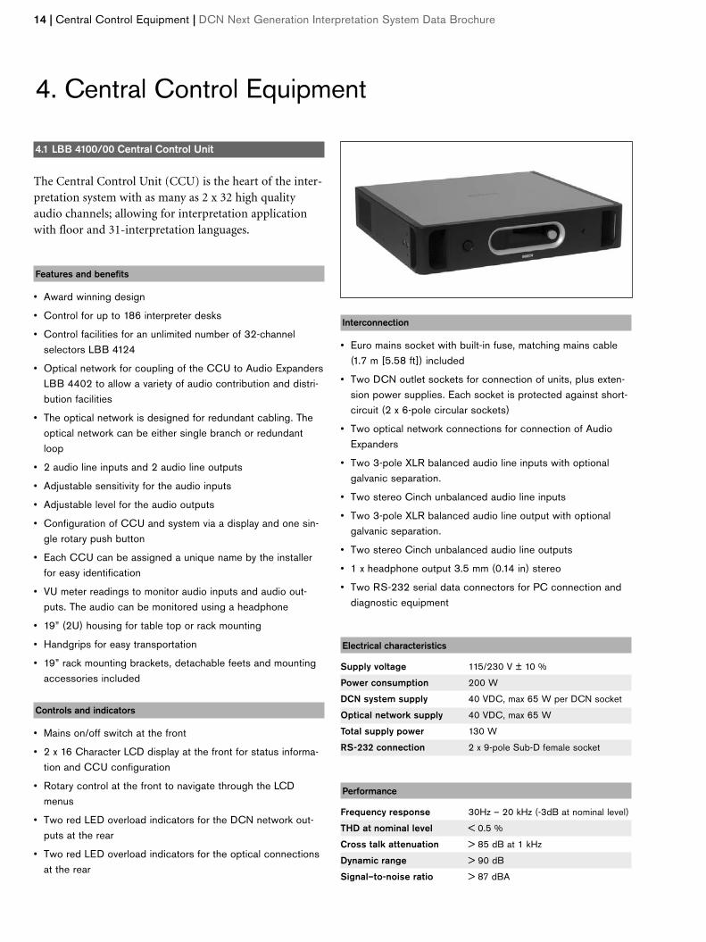
4.1 LBB 4100/00 Central Control Unit
The Central Control Unit (CCU) is the heart of the inter-pretation system with as many as 2 x 32 high qualityaudio channels; allowing for interpretation applicationwith floor and 31-interpretation languages.
Features and benefits
• Award winning design
• Control for up to 186 interpreter desks
• Control facilities for an unlimited number of 32-channelselectors LBB 4124
• Optical network for coupling of the CCU to Audio ExpandersLBB 4402 to allow a variety of audio contribution and distri-bution facilities
• The optical network is designed for redundant cabling. Theoptical network can be either single branch or redundantloop
• 2 audio line inputs and 2 audio line outputs
• Adjustable sensitivity for the audio inputs
• Adjustable level for the audio outputs
• Configuration of CCU and system via a display and one sin-gle rotary push button
• Each CCU can be assigned a unique name by the installerfor easy identification
• VU meter readings to monitor audio inputs and audio out-puts. The audio can be monitored using a headphone
• 19” (2U) housing for table top or rack mounting
• Handgrips for easy transportation
• 19” rack mounting brackets, detachable feets and mountingaccessories included
Controls and indicators
• Mains on/off switch at the front
• 2 x 16 Character LCD display at the front for status informa-tion and CCU configuration
• Rotary control at the front to navigate through the LCDmenus
• Two red LED overload indicators for the DCN network out-puts at the rear
• Two red LED overload indicators for the optical connectionsat the rear
Interconnection
• Euro mains socket with built-in fuse, matching mains cable(1.7 m [5.58 ft]) included
• Two DCN outlet sockets for connection of units, plus exten-sion power supplies. Each socket is protected against short-circuit (2 x 6-pole circular sockets)
• Two optical network connections for connection of AudioExpanders
• Two 3-pole XLR balanced audio line inputs with optional galvanic separation.
• Two stereo Cinch unbalanced audio line inputs
• Two 3-pole XLR balanced audio line output with optional galvanic separation.
• Two stereo Cinch unbalanced audio line outputs
• 1 x headphone output 3.5 mm (0.14 in) stereo
• Two RS-232 serial data connectors for PC connection anddiagnostic equipment
Electrical characteristics
Supply voltage 115/230 V ± 10 %
Power consumption 200 W
DCN system supply 40 VDC, max 65 W per DCN socket
Optical network supply 40 VDC, max 65 W
Total supply power 130 W
RS-232 connection 2 x 9-pole Sub-D female socket
Performance
Frequency response 30Hz – 20 kHz (-3dB at nominal level)
THD at nominal level < 0.5 %
Cross talk attenuation > 85 dB at 1 kHz
Dynamic range > 90 dB
Signal–to-noise ratio > 87 dBA
14 | Central Control Equipment | DCN Next Generation Interpretation System Data Brochure
4. Central Control Equipment
DCN Next Generation Interpretation System Data Brochure | Central Control Equipment | 15
Audio inputs/outputs:
XLR nominal input - 12 dBV (±6 dB)
XLR maximum input +12 dBV
Cinch nominal input -24 dBV (± 6 dB)
Cinch maximum input +0 dBV
XLR nominal output - 12 dBV (+6/- 24 dB)
XLR maximum output +12 dBV
Cinch nominal output -24 dBV (+6/- 24 dB)
Cinch maximum output +0 dBV
Physical characteristics
Mounting Free-standing or mounted in a 19”-rack
Dimensions (H x W x D) 88 x 483 x 350 mm
(3.5 x 19 x 13.8 in)
(with brackets, without feet)
92 x 440 x 350 mm
(3.6 x 17.3 x 13.8 in)
(without brackets, with feet)
Weight 7 kg (17 lbs)
Color Charcoal with silver
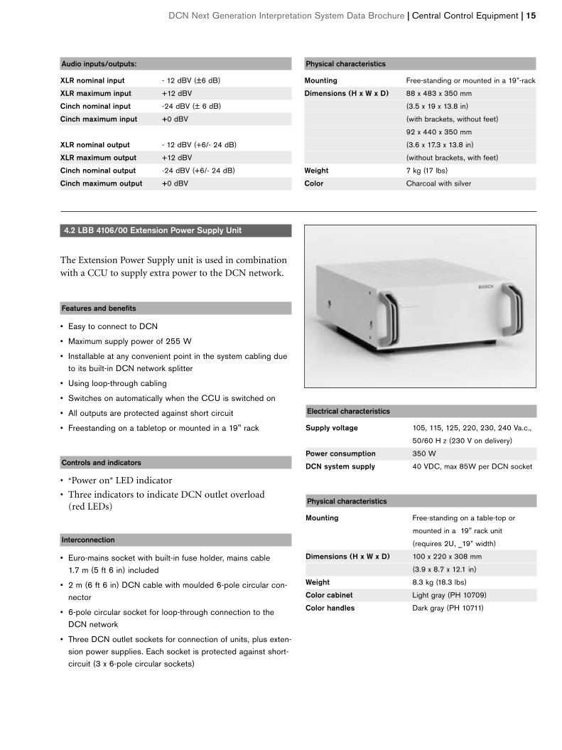
4.2 LBB 4106/00 Extension Power Supply Unit
The Extension Power Supply unit is used in combinationwith a CCU to supply extra power to the DCN network.
Features and benefits
• Easy to connect to DCN
• Maximum supply power of 255 W
• Installable at any convenient point in the system cabling dueto its built-in DCN network splitter
• Using loop-through cabling
• Switches on automatically when the CCU is switched on
• All outputs are protected against short circuit
• Freestanding on a tabletop or mounted in a 19" rack
Controls and indicators
• “Power on” LED indicator
• Three indicators to indicate DCN outlet overload (red LEDs)
Interconnection
• Euro-mains socket with built-in fuse holder, mains cable1.7 m (5 ft 6 in) included
• 2 m (6 ft 6 in) DCN cable with moulded 6-pole circular con-nector
• 6-pole circular socket for loop-through connection to theDCN network
• Three DCN outlet sockets for connection of units, plus exten-sion power supplies. Each socket is protected against short-circuit (3 x 6-pole circular sockets)
Electrical characteristics
Supply voltage 105, 115, 125, 220, 230, 240 Va.c.,
50/60 H z (230 V on delivery)
Power consumption 350 W
DCN system supply 40 VDC, max 85W per DCN socket
Physical characteristics
Mounting Free-standing on a table-top or
mounted in a 19" rack unit
(requires 2U, _19” width)
Dimensions (H x W x D) 100 x 220 x 308 mm
(3.9 x 8.7 x 12.1 in)
Weight 8.3 kg (18.3 lbs)
Color cabinet Light gray (PH 10709)
Color handles Dark gray (PH 10711)
16 | Central Control Equipment | DCN Next Generation Interpretation System Data Brochure
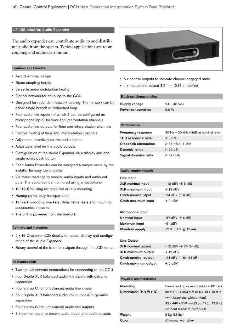
4.3 LBB 4402/00 Audio Expander
The audio expander can contribute audio to and distrib-ute audio from the system. Typical applications are roomcoupling and audio distribution.
Features and benefits
• Award winning design
• Room coupling facility
• Versatile audio distribution facility
• Optical network for coupling to the CCU
• Designed for redundant network cabling. The network can beeither single branch or redundant loop
• Four audio line inputs (of which 2 can be configured asmicrophone input) for floor and interpretation channels
• Four audio line outputs for floor and interpretation channels
• Flexible routing of floor and interpretation channels
• Adjustable sensitivity for the audio inputs
• Adjustable level for the audio outputs
• Configuration of the Audio Expander via a display and onesingle rotary push button
• Each Audio Expander can be assigned a unique name by theinstaller for easy identification
• VU meter readings to monitor audio inputs and audio out-puts. The audio can be monitored using a headphone
• 19” (2U) housing for table top or rack mounting
• Handgrips for easy transportation
• 19” rack mounting brackets, detachable feets and mountingaccessories included
• The unit is powered from the network
Controls and indicators
• 2 x 16 Character LCD display for status display and configu-ration of the Audio Expander
• Rotary control at the front to navigate through the LCD menus
Interconnection
• Two optical network connections for connecting to the CCU
• Four 3-pole XLR balanced audio line inputs with galvanicseparation
• Four stereo Cinch unbalanced audio line inputs
• Four 3-pole XLR balanced audio line output with galvanicseparation
• Four stereo Cinch unbalanced audio line outputs
• 8 x control inputs to enable audio inputs and audio outputs
• 5 x control outputs to indicate channel engaged state
• 1 x headphone output 3.5 mm (0.14 in) stereo
Electrical characteristics
Supply voltage 24 – 48 Vdc
Power consumption 5.6 W
Performance
Frequency response 30 Hz – 20 kHz (-3dB at nominal level)
THD at nominal level < 0.5 %
Cross talk attenuation > 85 dB at 1 kHz
Dynamic range > 90 dB
Signal–to-noise ratio > 87 dBA
Audio inputs/outputs
Line Input
XLR nominal input - 12 dBV (± 6 dB)
XLR maximum input + 12 dBV
Cinch nominal input -24 dBV (± 6 dB)
Cinch maximum input + 0 dBV
Microphone Input
Nominal input -57 dBV (± 6 dB)
Maximum input -51 dBV
Phantom supply 12 V ± 1 V @ 15 mA
Line Output
XLR nominal output - 12 dBV (+ 6/- 24 dB)
XLR maximum output + 12 dBV
Cinch nominal output -24 dBV (+ 6/- 24 dB)
Cinch maximum output + 0 dBV
Physical characteristics
Mounting Free-standing or mounted in a 19”-rack
Dimensions (H x W x D) 88 x 483 x 350 mm (3.5 x 19 x 13.8 in)
(with brackets, without feet)
92 x 440 x 350 mm (3.6 x 17.3 x 13.8 in)
(without brackets, with feet)
Weight 6 kg (13 lbs)
Color Charcoal with silver
DCN Next Generation Interpretation System Data Brochure | Application Software | 17
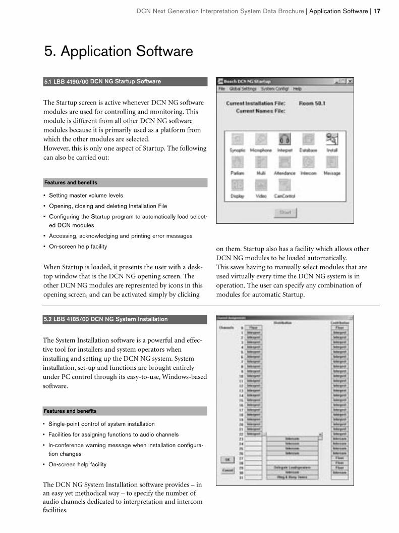
5.1 LBB 4190/00 DCN NG Startup Software
The Startup screen is active whenever DCN NG softwaremodules are used for controlling and monitoring. Thismodule is different from all other DCN NG softwaremodules because it is primarily used as a platform fromwhich the other modules are selected.However, this is only one aspect of Startup. The followingcan also be carried out:
Features and benefits
• Setting master volume levels
• Opening, closing and deleting Installation File
• Configuring the Startup program to automatically load select-ed DCN modules
• Accessing, acknowledging and printing error messages
• On-screen help facility
When Startup is loaded, it presents the user with a desk-top window that is the DCN NG opening screen. Theother DCN NG modules are represented by icons in thisopening screen, and can be activated simply by clicking
5. Application Software
5.2 LBB 4185/00 DCN NG System Installation
The System Installation software is a powerful and effec-tive tool for installers and system operators wheninstalling and setting up the DCN NG system. Systeminstallation, set-up and functions are brought entirelyunder PC control through its easy-to-use, Windows-basedsoftware.
Features and benefits
• Single-point control of system installation
• Facilities for assigning functions to audio channels
• In-conference warning message when installation configura-tion changes
• On-screen help facility
The DCN NG System Installation software provides – inan easy yet methodical way – to specify the number ofaudio channels dedicated to interpretation and intercomfacilities.
on them. Startup also has a facility which allows otherDCN NG modules to be loaded automatically.This saves having to manually select modules that areused virtually every time the DCN NG system is in operation. The user can specify any combination ofmodules for automatic Startup.
18 | Application Software | DCN Next Generation Interpretation System Data Brochure
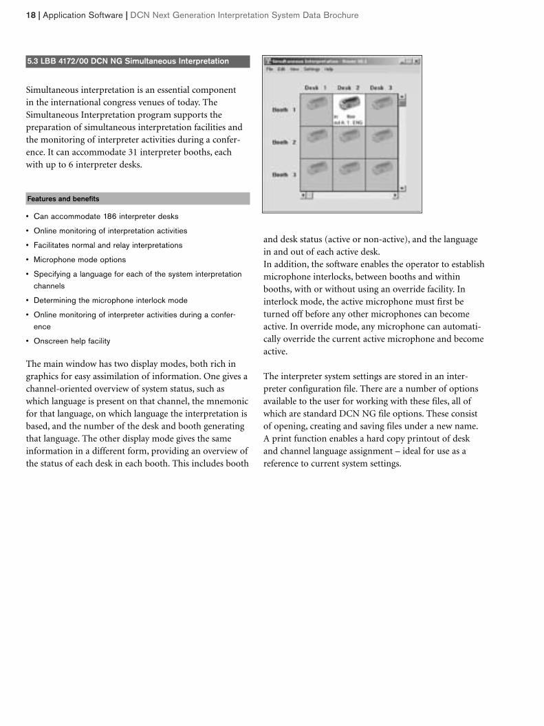
5.3 LBB 4172/00 DCN NG Simultaneous Interpretation
Simultaneous interpretation is an essential component in the international congress venues of today. TheSimultaneous Interpretation program supports the preparation of simultaneous interpretation facilities andthe monitoring of interpreter activities during a confer-ence. It can accommodate 31 interpreter booths, eachwith up to 6 interpreter desks.
Features and benefits
• Can accommodate 186 interpreter desks
• Online monitoring of interpretation activities
• Facilitates normal and relay interpretations
• Microphone mode options
• Specifying a language for each of the system interpretationchannels
• Determining the microphone interlock mode
• Online monitoring of interpreter activities during a confer-ence
• Onscreen help facility
The main window has two display modes, both rich ingraphics for easy assimilation of information. One gives achannel-oriented overview of system status, such aswhich language is present on that channel, the mnemonicfor that language, on which language the interpretation isbased, and the number of the desk and booth generatingthat language. The other display mode gives the sameinformation in a different form, providing an overview ofthe status of each desk in each booth. This includes booth
and desk status (active or non-active), and the languagein and out of each active desk.In addition, the software enables the operator to establishmicrophone interlocks, between booths and withinbooths, with or without using an override facility. In interlock mode, the active microphone must first beturned off before any other microphones can becomeactive. In override mode, any microphone can automati-cally override the current active microphone and becomeactive.
The interpreter system settings are stored in an inter-preter configuration file. There are a number of optionsavailable to the user for working with these files, all ofwhich are standard DCN NG file options. These consistof opening, creating and saving files under a new name.A print function enables a hard copy printout of deskand channel language assignment – ideal for use as a reference to current system settings.
DCN Next Generation Interpretation System Data Brochure | DCN Network | 19
6.2 LBB 4115/00 Tap-Off Unit
• Short-circuit proof tap-off points at the system cable
The LBB 4115/00 is used to create short-circuit proof tap-off points on the trunk line cabling. Each tap-off pointallows for connection of up to four channel selector pan-els or up to two tabletop contribution units such as dele-gate-, chairman- or interpreter desks. A Tap-Off Unitconsists of two tap-off points. The Tap-Off Unit comescomplete with cable restraining clamps and includesmounting holes for fixing purposes.
Interconnection
• 2 m (6 ft 6 in) long cable terminated with a moulded 6-polecircular connector
• 6-pole circular connector for loop-through connections
• 2 x 6-pole circular connector for trunk cable splitting andpulse regeneration purposes
Electrical characteristics
Supply voltage 17- 40 V d.c. via DCN system cable
Power consumption 1.4 W
Max power at Tap-offs 3.5 W each
Physical characteristics
Mounting Floor, cable duct or wall mounting
Dimensions (H x W x D) 35 x 49 x 140 mm (1.4 x 1.9 x 5.5 in)
Weight 0.3 kg (0.66 lb)
Color Charcoal (PH 10736)
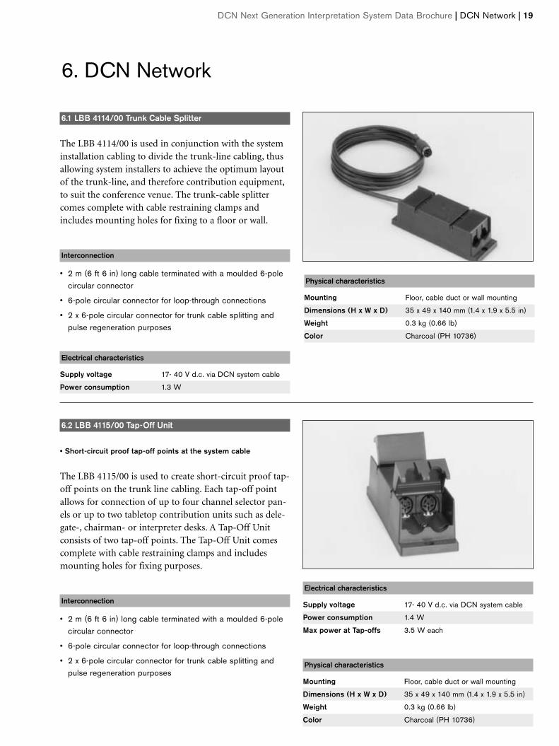
6.1 LBB 4114/00 Trunk Cable Splitter
The LBB 4114/00 is used in conjunction with the systeminstallation cabling to divide the trunk-line cabling, thusallowing system installers to achieve the optimum layoutof the trunk-line, and therefore contribution equipment,to suit the conference venue. The trunk-cable splittercomes complete with cable restraining clamps andincludes mounting holes for fixing to a floor or wall.
Interconnection
• 2 m (6 ft 6 in) long cable terminated with a moulded 6-polecircular connector
• 6-pole circular connector for loop-through connections
• 2 x 6-pole circular connector for trunk cable splitting andpulse regeneration purposes
Electrical characteristics
Supply voltage 17- 40 V d.c. via DCN system cable
Power consumption 1.3 W
Physical characteristics
Mounting Floor, cable duct or wall mounting
Dimensions (H x W x D) 35 x 49 x 140 mm (1.4 x 1.9 x 5.5 in)
Weight 0.3 kg (0.66 lb)
Color Charcoal (PH 10736)
6. DCN Network
20 | DCN Network | DCN Next Generation Interpretation System Data Brochure
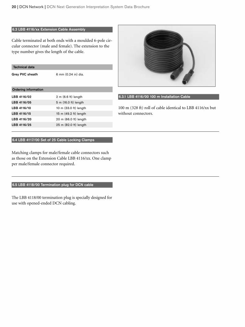
6.3 LBB 4116/xx Extension Cable Assembly
Cable terminated at both ends with a moulded 6-pole cir-cular connector (male and female). The extension to thetype number gives the length of the cable.
Technical data
Grey PVC sheath 6 mm (0.24 in) dia.
Ordering information
LBB 4116/02 2 m (6.6 ft) length
LBB 4116/05 5 m (16.0 ft) length
LBB 4116/10 10 m (33.0 ft) length
LBB 4116/15 15 m (49.2 ft) length
LBB 4116/20 20 m (66.0 ft) length
LBB 4116/25 25 m (82.0 ft) length
6.3.1 LBB 4116/00 100 m Installation Cable
100 m (328 ft) roll of cable identical to LBB 4116/xx butwithout connectors.
6.4 LBB 4117/00 Set of 25 Cable Locking Clamps
Matching clamps for male/female cable connectors suchas those on the Extension Cable LBB 4116/xx. One clampper male/female connector required.
6.5 LBB 4118/00 Termination plug for DCN cable
The LBB 4118/00 termination plug is specially designed foruse with opened-ended DCN cabling.
DCN Next Generation Interpretation System Data Brochure | Optical Network | 21
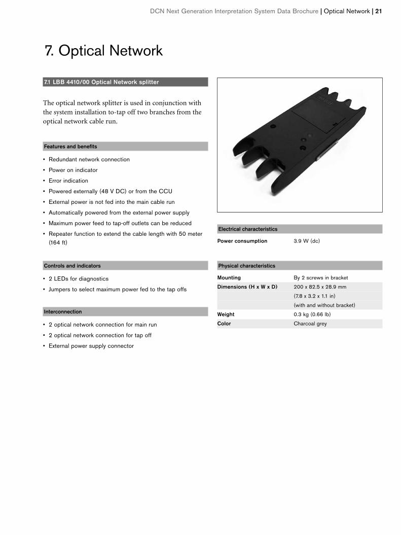
7.1 LBB 4410/00 Optical Network splitter
The optical network splitter is used in conjunction withthe system installation to-tap off two branches from theoptical network cable run.
Features and benefits
• Redundant network connection
• Power on indicator
• Error indication
• Powered externally (48 V DC) or from the CCU
• External power is not fed into the main cable run
• Automatically powered from the external power supply
• Maximum power feed to tap-off outlets can be reduced
• Repeater function to extend the cable length with 50 meter(164 ft)
Controls and indicators
• 2 LEDs for diagnostics
• Jumpers to select maximum power fed to the tap offs
Interconnection
• 2 optical network connection for main run
• 2 optical network connection for tap off
• External power supply connector
Electrical characteristics
Power consumption 3.9 W (dc)
Physical characteristics
Mounting By 2 screws in bracket
Dimensions (H x W x D) 200 x 82.5 x 28.9 mm
(7.8 x 3.2 x 1.1 in)
(with and without bracket)
Weight 0.3 kg (0.66 lb)
Color Charcoal grey
7. Optical Network
22 | Optical Network | DCN Next Generation Interpretation System Data Brochure
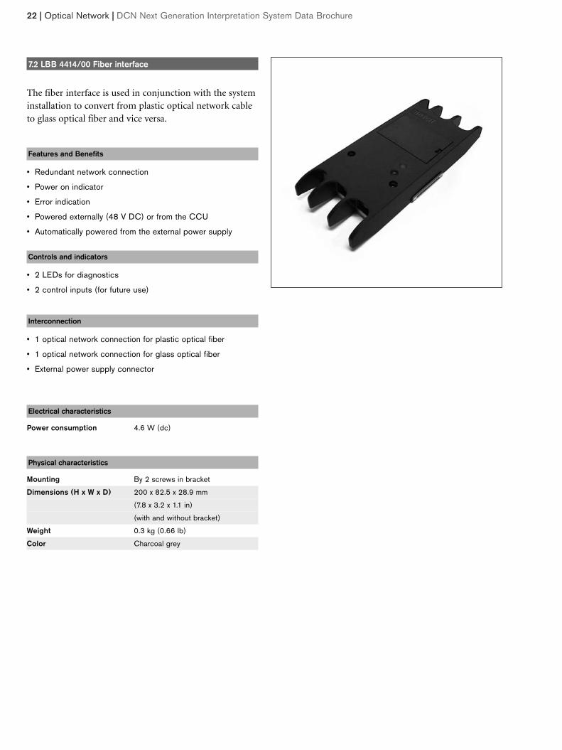
7.2 LBB 4414/00 Fiber interface
The fiber interface is used in conjunction with the systeminstallation to convert from plastic optical network cableto glass optical fiber and vice versa.
Features and Benefits
• Redundant network connection
• Power on indicator
• Error indication
• Powered externally (48 V DC) or from the CCU
• Automatically powered from the external power supply
Controls and indicators
• 2 LEDs for diagnostics
• 2 control inputs (for future use)
Interconnection
• 1 optical network connection for plastic optical fiber
• 1 optical network connection for glass optical fiber
• External power supply connector
Electrical characteristics
Power consumption 4.6 W (dc)
Physical characteristics
Mounting By 2 screws in bracket
Dimensions (H x W x D) 200 x 82.5 x 28.9 mm
(7.8 x 3.2 x 1.1 in)
(with and without bracket)
Weight 0.3 kg (0.66 lb)
Color Charcoal grey
DCN Next Generation Interpretation System Data Brochure | Optical Network | 23
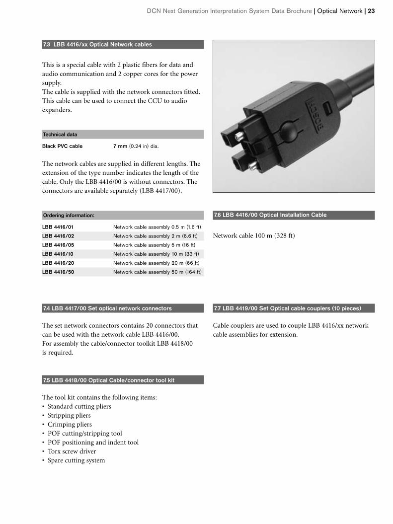
7.3 LBB 4416/xx Optical Network cables
This is a special cable with 2 plastic fibers for data andaudio communication and 2 copper cores for the powersupply.The cable is supplied with the network connectors fitted.This cable can be used to connect the CCU to audioexpanders.
Technical data
Black PVC cable 7 mm (0.24 in) dia.
The network cables are supplied in different lengths. Theextension of the type number indicates the length of thecable. Only the LBB 4416/00 is without connectors. Theconnectors are available separately (LBB 4417/00).
Ordering information:
LBB 4416/01 Network cable assembly 0.5 m (1.6 ft)
LBB 4416/02 Network cable assembly 2 m (6.6 ft)
LBB 4416/05 Network cable assembly 5 m (16 ft)
LBB 4416/10 Network cable assembly 10 m (33 ft)
LBB 4416/20 Network cable assembly 20 m (66 ft)
LBB 4416/50 Network cable assembly 50 m (164 ft)
7.4 LBB 4417/00 Set optical network connectors
The set network connectors contains 20 connectors thatcan be used with the network cable LBB 4416/00.For assembly the cable/connector toolkit LBB 4418/00 is required.
7.5 LBB 4418/00 Optical Cable/connector tool kit
The tool kit contains the following items:• Standard cutting pliers• Stripping pliers• Crimping pliers• POF cutting/stripping tool• POF positioning and indent tool• Torx screw driver• Spare cutting system
7.7 LBB 4419/00 Set Optical cable couplers (10 pieces)
Cable couplers are used to couple LBB 4416/xx networkcable assemblies for extension.
7.6 LBB 4416/00 Optical Installation Cable
Network cable 100 m (328 ft)
8. Technical DataConforms to the international standard IEC 60914, theinternational standard for conference systems.
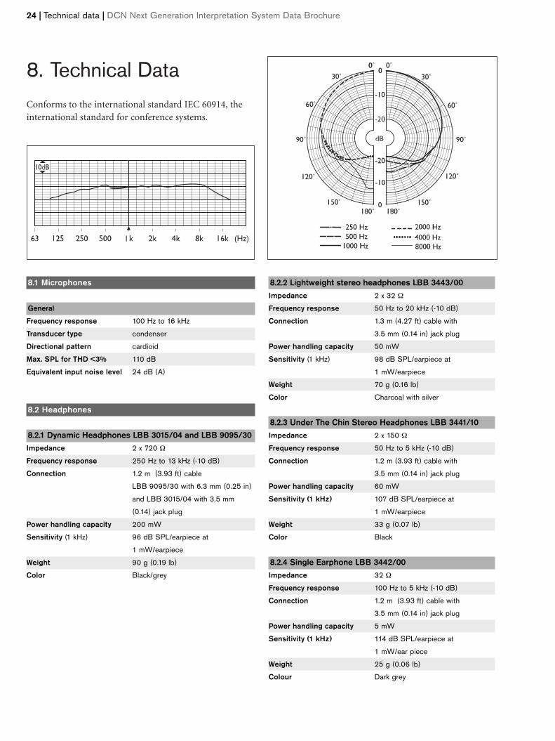
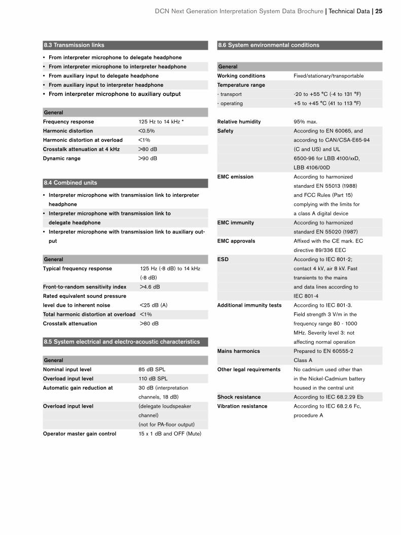
8.1 Microphones
General
Frequency response 100 Hz to 16 kHz
Transducer type condenser
Directional pattern cardioid
Max. SPL for THD <3% 110 dB
Equivalent input noise level 24 dB (A)
8.2 Headphones
8.2.1 Dynamic Headphones LBB 3015/04 and LBB 9095/30Impedance 2 x 720 Ω
Frequency response 250 Hz to 13 kHz (-10 dB)
Connection 1.2 m (3.93 ft) cable
LBB 9095/30 with 6.3 mm (0.25 in)
and LBB 3015/04 with 3.5 mm
(0.14) jack plug
Power handling capacity 200 mW
Sensitivity (1 kHz) 96 dB SPL/earpiece at
1 mW/earpiece
Weight 90 g (0.19 lb)
Color Black/grey
8.2.2 Lightweight stereo headphones LBB 3443/00Impedance 2 x 32 Ω
Frequency response 50 Hz to 20 kHz (-10 dB)
Connection 1.3 m (4.27 ft) cable with
3.5 mm (0.14 in) jack plug
Power handling capacity 50 mW
Sensitivity (1 kHz) 98 dB SPL/earpiece at
1 mW/earpiece
Weight 70 g (0.16 lb)
Color Charcoal with silver
8.2.3 Under The Chin Stereo Headphones LBB 3441/10Impedance 2 x 150 Ω
Frequency response 50 Hz to 5 kHz (-10 dB)
Connection 1.2 m (3.93 ft) cable with
3.5 mm (0.14 in) jack plug
Power handling capacity 60 mW
Sensitivity (1 kHz) 107 dB SPL/earpiece at
1 mW/earpiece
Weight 33 g (0.07 lb)
Color Black
8.2.4 Single Earphone LBB 3442/00 Impedance 32 Ω
Frequency response 100 Hz to 5 kHz (-10 dB)
Connection 1.2 m (3.93 ft) cable with
3.5 mm (0.14 in) jack plug
Power handling capacity 5 mW
Sensitivity (1 kHz) 114 dB SPL/earpiece at
1 mW/ear piece
Weight 25 g (0.06 lb)
Colour Dark grey
24 | Technical data | DCN Next Generation Interpretation System Data Brochure
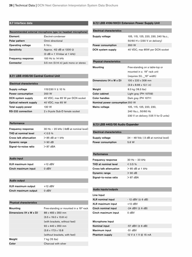
8.3 Transmission links
• From interpreter microphone to delegate headphone
• From interpreter microphone to interpreter headphone
• From auxiliary input to delegate headphone
• From auxiliary input to interpreter headphone
• From interpreter microphone to auxiliary output
General
Frequency response 125 Hz to 14 kHz *
Harmonic distortion <0.5%
Harmonic distortion at overload <1%
Crosstalk attenuation at 4 kHz >80 dB
Dynamic range >90 dB
8.4 Combined units
• Interpreter microphone with transmission link to interpreter
headphone
• Interpreter microphone with transmission link to
delegate headphone
• Interpreter microphone with transmission link to auxiliary out-
put
General
Typical frequency response 125 Hz (-8 dB) to 14 kHz
(-8 dB)
Front-to-random sensitivity index >4.6 dB
Rated equivalent sound pressure
level due to inherent noise <25 dB (A)
Total harmonic distortion at overload <1%
Crosstalk attenuation >80 dB
8.5 System electrical and electro-acoustic characteristics
General
Nominal input level 85 dB SPL
Overload input level 110 dB SPL
Automatic gain reduction at 30 dB (interpretation
channels, 18 dB)
Overload input level (delegate loudspeaker
channel)
(not for PA-floor output)
Operator master gain control 15 x 1 dB and OFF (Mute)
8.6 System environmental conditions
General
Working conditions Fixed/stationary/transportable
Temperature range
- transport -20 to +55 °C (-4 to 131 °F)
- operating +5 to +45 °C (41 to 113 °F)
Relative humidity 95% max.
Safety According to EN 60065, and
according to CAN/CSA-E65-94
(C and US) and UL
6500-96 for LBB 4100/xxD,
LBB 4106/00D
EMC emission According to harmonized
standard EN 55013 (1988)
and FCC Rules (Part 15)
complying with the limits for
a class A digital device
EMC immunity According to harmonized
standard EN 55020 (1987)
EMC approvals Affixed with the CE mark. EC
directive 89/336 EEC
ESD According to IEC 801-2;
contact 4 kV, air 8 kV. Fast
transients to the mains
and data lines according to
IEC 801-4
Additional immunity tests According to IEC 801-3.
Field strength 3 V/m in the
frequency range 80 - 1000
MHz. Severity level 3: not
affecting normal operation
Mains harmonics Prepared to EN 60555-2
Class A
Other legal requirements No cadmium used other than
in the Nickel-Cadmium battery
housed in the central unit
Shock resistance According to IEC 68.2.29 Eb
Vibration resistance According to IEC 68.2.6 Fc,
procedure A
DCN Next Generation Interpretation System Data Brochure | Technical Data | 25
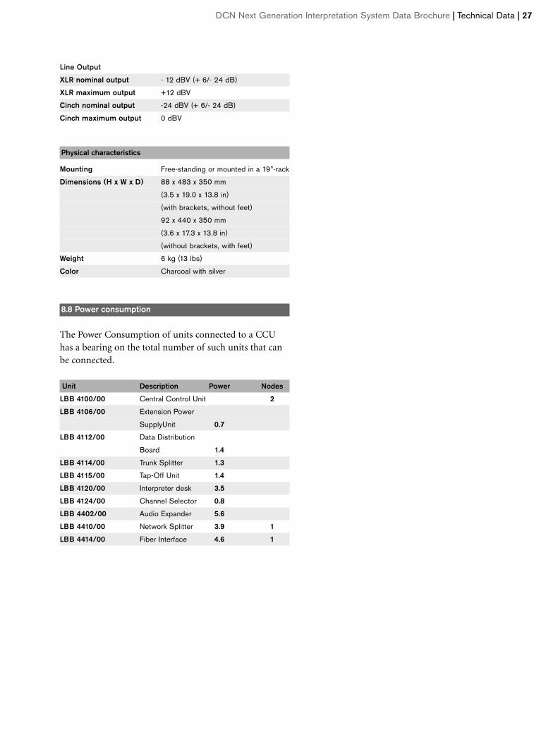
8.7 Interface data
Recommended external microphone type (or headset microphone)
Element: Electret-condenser
Polar pattern Omni directional
Operating voltage 5 Vd.c.
Sensitivity Approx. -62 dB at 1200 Ω
(0 dB = 1 V/mbar at 1 kHz)
Frequency response 100 Hz to 14 kHz
Connector 3.5 mm (0.14 in) jack mono or stereo
8.7.1 LBB 4100/00 Central Control Unit
Electrical characteristics
Supply voltage 115/230 V ± 10 %
Power consumption 200 W
DCN system supply 40 VDC, max 65 W per DCN socket
Optical network supply 40 VDC, max 65 W
Total supply power 130 W
RS-232 connection 2 x 9-pole Sub-D female socket
Performance
Frequency response 30 Hz – 20 kHz (-3dB at nominal level)
THD at nominal level < 0.5 %
Cross talk attenuation > 85 dB at 1 kHz
Dynamic range > 90 dB
Signal–to-noise ratio > 87 dBA
Audio input
XLR maximum input +12 dBV
Cinch maximum input 0 dBV
Audio output
XLR maximum output +12 dBV
Cinch maximum output 0 dBV
Physical characteristics
Mounting Free-standing or mounted in a 19”-rack
Dimensions (H x W x D) 88 x 483 x 350 mm
(3.5 x 19.0 x 13.8 in)
(with brackets, without feet)
92 x 440 x 350 mm
(3.6 x 17.3 x 13.8
(without brackets, with feet)
Weight 7 kg (15 lbs)
Color Charcoal with silver
8.7.2 LBB 4106/00(D) Extension Power Supply Unit
Electrical characteristics
Supply voltage 105, 115, 125, 220, 230, 240 Va.c.,
50/60 H z (230 V on delivery)
Power consumption 350 W
DCN system supply 40 VDC, max 85W per DCN socket
Physical characteristics
Mounting Free-standing on a table-top or
mounted in a 19" rack unit
(requires 2U, _19” width)
Dimensions (H x W x D) 100 x 220 x 308 mm
(3.9 x 8.66 x 12.1 in)
Weight 8.3 kg (18.3 lbs)
Color cabinet Light gray (PH 10709)
Color handles Dark gray (PH 10711
Nominal power consumption 350 W
Mains voltage 105, 115, 125, 220, 230,
240 Va.c., 50/60 Hz
230 V on delivery (125 V for D units)
8.7.3 LBB 4402/00 Audio Expander
Electrical characteristics
Supply voltage 24 – 48 Vdc (-3 dB at nominal level)
Power consumption 5.6 W
Performance
Frequency response 30 Hz – 20 kHz
THD at nominal level < 0.5 %
Cross talk attenuation > 85 dB at 1 kHz
Dynamic range > 90 dB
Signal–to-noise ratio > 87 dBA
Audio inputs/outputs
Line Input
XLR nominal input - 12 dBV (± 6 dB)
XLR maximum input +12 dBV
Cinch nominal input -24 dBV (± 6 dB)
Cinch maximum input 0 dBV
Microphone Input
Nominal input -57 dBV (± 6 dB)
Maximum input -51 dBV
Phantom supply 12 V ± 1 V @ 15 mA
26 | Technical Data | DCN Next Generation Interpretation System Data Brochure
Line Output
XLR nominal output - 12 dBV (+ 6/- 24 dB)
XLR maximum output +12 dBV
Cinch nominal output -24 dBV (+ 6/- 24 dB)
Cinch maximum output 0 dBV
Physical characteristics
Mounting Free-standing or mounted in a 19”-rack
Dimensions (H x W x D) 88 x 483 x 350 mm
(3.5 x 19.0 x 13.8 in)
(with brackets, without feet)
92 x 440 x 350 mm
(3.6 x 17.3 x 13.8 in)
(without brackets, with feet)
Weight 6 kg (13 lbs)
Color Charcoal with silver
8.8 Power consumption
The Power Consumption of units connected to a CCUhas a bearing on the total number of such units that canbe connected.D
Unit Description Power Nodes
LBB 4100/00 Central Control Unit 2
LBB 4106/00 Extension Power
SupplyUnit 0.7
LBB 4112/00 Data Distribution
Board 1.4
LBB 4114/00 Trunk Splitter 1.3
LBB 4115/00 Tap-Off Unit 1.4
LBB 4120/00 Interpreter desk 3.5
LBB 4124/00 Channel Selector 0.8
LBB 4402/00 Audio Expander 5.6
LBB 4410/00 Network Splitter 3.9 1
LBB 4414/00 Fiber Interface 4.6 1
ı
DCN Next Generation Interpretation System Data Brochure | Technical Data | 27
7.9 System Limits
• The total DCN cable length (using standardLBB 4116/xx cable) between the central control unitand the last unit in any branch of the system must notexceed 250 m (820 ft 2 in). This includes all extensioncables and the 2 m (78.74 in) long cable attached toeach system unit
• The total number of units from the central controlLBB 4100/00 unit to the first regenerative tap-off (i.e.,from Trunk Cable Splitter LBB 4114/00 or ExtensionPower Supply Unit LBB 4106/00) must not exceed50 pieces (100 m [328 ft 1 in])
• The total length of the extension cable between regen-erative tap-offs outputs must not exceed 100 m (328 ft1 in)
• The maximum distance between units is normally160 cm (62.99 in). This distance can be increased byusing the LBB 4116/xx Extension Cable
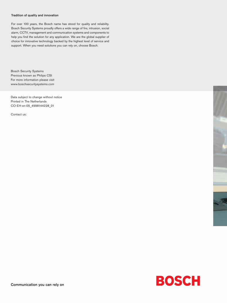
• The total Plastic Optical Fiber (POF) length (usingstandard LBB 4416/xx cable) between two units is 50 m.When more than 50 and less than 1500 meter isrequired, fiber interfaces LBB 4414/00 and GlassOptical Fiber (GOF) must be used. Only multimodeGOF with a maximum attenuation of 2 dB/km and awavelength of 1300 and terminated with SC connectorsis supported.It is also possible to increase the 50 m by inserting anetwork splitter LBB 4410/00 every 50 m or less.
• The maximum length of all optical fibers together (POF& GOF) depends on the number of nodes in the sys-tem. The graph below shows the relation between thenumber of nodes and the fiber lengths.
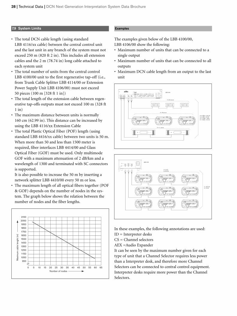
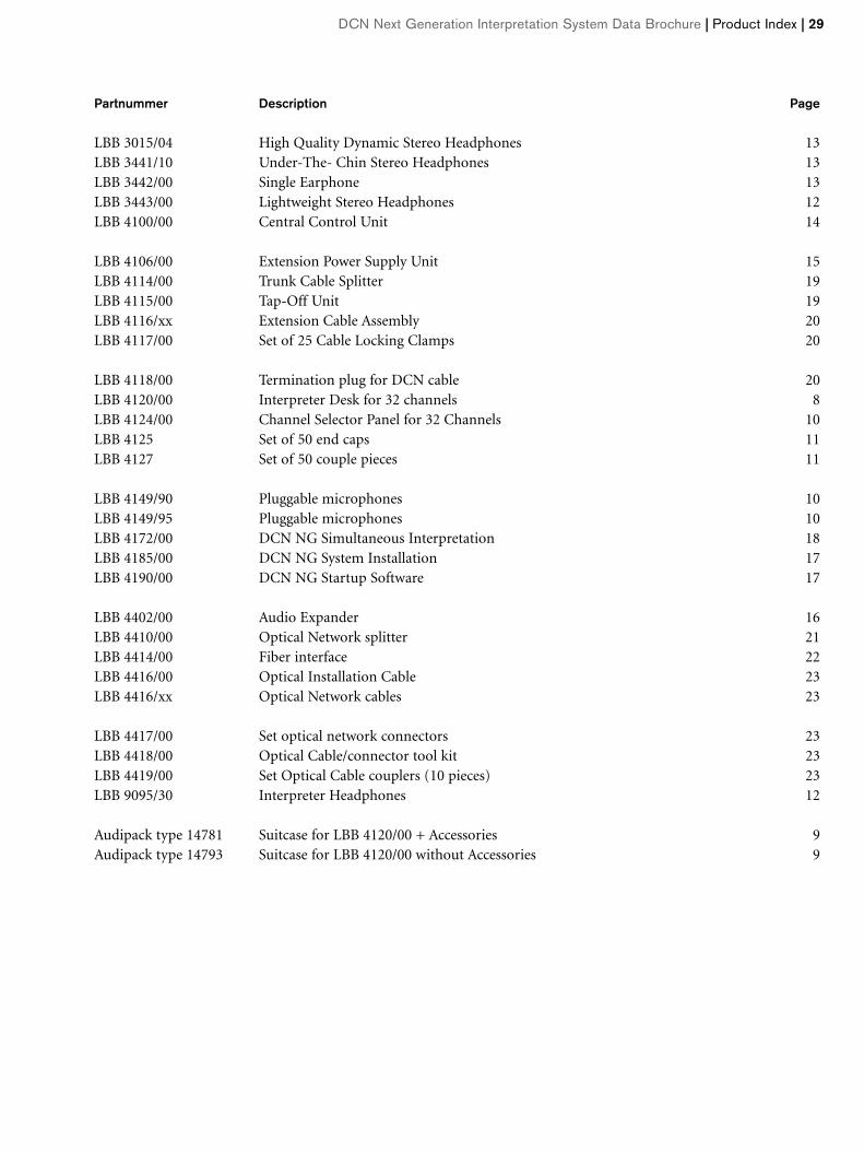
Examples
The examples given below of the LBB 4100/00,LBB 4106/00 show the following:• Maximum number of units that can be connected to a
single output• Maximum number of units that can be connected to all
outputs• Maximum DCN cable length from an output to the last
unit
In these examples, the following annotations are used:ID = Interpreter desksCS = Channel selectorsAEX =Audio ExpanderIt can be seen by the maximum number given for eachtype of unit that a Channel Selector requires less powerthan a Interpreter desk, and therefore more ChannelSelectors can be connected to central control equipment.Interpreter desks require more power than the ChannelSelectors.
28 | Technical Data | DCN Next Generation Interpretation System Data Brochure
OK Fail
Fault
RS 232
Network
1 2
Audio In 1 Audio Out 1 Audio In 2 Audio Out 2
Mains
Port 2
115: 100-120V 50-60Hz T2.5A 250V 230: 220-240V 50-60Hz T2A H 250V
RS 232 Port 1
Trunk
1 2
Avis
CautionRisk of electric shock.
Do not open.
Risk of electric shock.Do not open.
230
<= 18 pieces
<= 50 pieces
LBB 4100
<= 11 pieces
<= 0 AEX + 100 CS<= 0 AEX + 36 ID<= 11 AEX + 18 ID<= 11AEX + 50 CS
Floor
a b c d e A B
Auto-relay
Micro Mute
Engaged
PhoneIntercom
Help
Slow
Chair
Call
Floor
a b c d e A B
Auto-relay
Micro Mute
Engaged
PhoneIntercom
Help
Slow
Chair
Call
Floor
a b c d e A B
Auto-relay
Micro Mute
Engaged
PhoneIntercom
Help
Slow
Chair
Call
OutOutOutIn
Tap-offTrunk
LBB 4106
<= 24 ID<= 50 CS
<= 150 CS<= 72 ID
Floor
a b c d e A B
Auto-relay
Micro Mute
Engaged
PhoneIntercom
Help
Slow
Chair
Call
Floor
a b c d e A B
Auto-relay
Micro Mute
Engaged
PhoneIntercom
Help
Slow
Chair
Call
Floor
a b c d e A B
Auto-relay
Micro Mute
Engaged
PhoneIntercom
Help
Slow
Chair
Call
Floor
a b c d e A B
Auto-relay
Micro Mute
Engaged
PhoneIntercom
Help
Slow
Chair
Call
Floor
a b c d e A B
Auto-relay
Micro Mute
Engaged
PhoneIntercom
Help
Slow
Chair
Call
Floor
a b c d e A B
Auto-relay
Micro Mute
Engaged
PhoneIntercom
Help
Slow
Chair
Call
Floor
a b c d e A B
Auto-relay
Micro Mute
Engaged
PhoneIntercom
Help
Slow
Chair
Call
Floor
a b c d e A B
Auto-relay
Micro Mute
Engaged
PhoneIntercom
Help
Slow
Chair
Call
Floor
a b c d e A B
Auto-relay
Micro Mute
Engaged
PhoneIntercom
Help
Slow
Chair
Call
2150
2050
1950
1850
1750
1650
1550
1450
1350
1250
1150
1050
950
0 5 10 15 20 25
Number of nodes
30 35 40 45 50 55 60 65
Max
imum
cab
le le
nght
(m
)
DCN Next Generation Interpretation System Data Brochure | Product Index | 29
Partnummer Description Page
LBB 3015/04 High Quality Dynamic Stereo Headphones 13LBB 3441/10 Under-The- Chin Stereo Headphones 13LBB 3442/00 Single Earphone 13LBB 3443/00 Lightweight Stereo Headphones 12LBB 4100/00 Central Control Unit 14
LBB 4106/00 Extension Power Supply Unit 15LBB 4114/00 Trunk Cable Splitter 19LBB 4115/00 Tap-Off Unit 19LBB 4116/xx Extension Cable Assembly 20LBB 4117/00 Set of 25 Cable Locking Clamps 20
LBB 4118/00 Termination plug for DCN cable 20LBB 4120/00 Interpreter Desk for 32 channels 8LBB 4124/00 Channel Selector Panel for 32 Channels 10LBB 4125 Set of 50 end caps 11LBB 4127 Set of 50 couple pieces 11
LBB 4149/90 Pluggable microphones 10LBB 4149/95 Pluggable microphones 10LBB 4172/00 DCN NG Simultaneous Interpretation 18LBB 4185/00 DCN NG System Installation 17LBB 4190/00 DCN NG Startup Software 17
LBB 4402/00 Audio Expander 16LBB 4410/00 Optical Network splitter 21LBB 4414/00 Fiber interface 22LBB 4416/00 Optical Installation Cable 23LBB 4416/xx Optical Network cables 23
LBB 4417/00 Set optical network connectors 23LBB 4418/00 Optical Cable/connector tool kit 23LBB 4419/00 Set Optical Cable couplers (10 pieces) 23LBB 9095/30 Interpreter Headphones 12
Audipack type 14781 Suitcase for LBB 4120/00 + Accessories 9Audipack type 14793 Suitcase for LBB 4120/00 without Accessories 9
Communication you can rely on
Bosch Security SystemsPrevious known as Philips CSIFor more information please visitwww.boschsecuritysystems.com
Data subject to change without noticePrinted in The NetherlandsCO-EH-en-05_4998144228_01
Contact us:
Tradition of quality and innovation
For over 100 years, the Bosch name has stood for quality and reliability.Bosch Security Systems proudly offers a wide range of fire, intrusion, socialalarm, CCTV, management and communication systems and components tohelp you find the solution for any application. We are the global supplier ofchoice for innovative technology backed by the highest level of service andsupport. When you need solutions you can rely on, choose Bosch.
Recommended