The University of Texas at Austin
Department of Aerospace Engineering and Engineering Mechanics
CubeSat Based Solar Sail Testing Platform Final Design Review
Submitted to: Dr. Wallace Fowler
for the purpose of partial fulfillment of the requirements for ASE 274L/174M
Submitted by: Phillip Hempel Daniel Parcher Paul Mears Taffy Tingley
December 7, 2001

Page i
Executive Summary
Objectives
To design a 10cm sided cubic picosatellite for the purposes of solar sail testing while maintaining compliance with the Stanford sponsored CubeSat program. This objective will be carried out in the following manner:
?? Determine the size and material of the solar sail to be used. ?? Design a picosatellite capable of housing the solar sail. ?? Determine necessary packing configuration of the sail. ?? Determine the impact that the packing configuration has on the sail’s efficiency. ?? Design the necessary deployment apparatus ?? Design apparatus for identifying the orientation and position of the satellite. ?? Create an orbital trajectory simulation for the satellite design
Design Restrictions Adopted ?? The satellite will have no attitude control ?? The satellite will have no communication systems ?? The satellite will require no power in addition to the power requirements
prescribed by the CubeSat program ?? Position, velocity and orientation will be performed from ground stations by
analyzing light reflected from corner cube reflectors on the solar sail. Status
?? Completed Tasks o Satellite system and mission conceptual design o Satellite system integration
??Weight / Volume Budget Analysis ??Component Configuration
o Analysis of failure modes and reliability
Proposed Budget Expense Item Predicted Expense (dollars) Expenses to Date Personnel (based on an estimated 150 hrs. worked, 14 hrs. for consultants)
15,653 14,080
Materials / Electronics 5,000 7,050 Testing 2,000 2,000 Launch 50,000 50,000 Total 72,653 73,130
Team Members
Phillip Hempel – Mechanical Specialist Paul Mears – Orbit Trajectory Specialist Daniel Parcher – Team Leader Taffy Tingley – Solar Sail Specialist
Page ii
Table of Contents
Executive Summary..............................................................................................................i Table of Tables.....................................................................................................................v 1.0 Introduction................................................................................................................... 1
1.1 Problem Statement .................................................................................................... 1 1.2 Purpose...................................................................................................................... 2
2.0 Design Factors............................................................................................................... 3 2.1 Design Restrictions ................................................................................................... 3 2.2 Satellite Component Evaluation Criteria .................................................................. 4
3.0 Satellite Systems ........................................................................................................... 6 3.1 Satellite Tracking Systems........................................................................................ 7
3.1.1 Optical Ranging Principles ................................................................................ 7 3.1.2 Design Impact .................................................................................................. 10 3.1.3 Optical Tracking Hardware Specifications ...................................................... 11
3.2 Electrical System..................................................................................................... 13 3.3 Mechanical Systems and Deployment .................................................................... 15
3.3.1 Satellite Components ....................................................................................... 16 3.3.2 Component Placement and Overview............................................................. 21 3.3.3 Satellite Construction Summary ...................................................................... 22 3.3.4 Solar Sail Deployment Summary..................................................................... 23
3.4 Propulsion Systems ................................................................................................. 26 3.4.1 Solar Sail Historical Survey............................................................................. 26 3.4.2 Solar Sail Material Structure............................................................................ 29 3.4.3 Solar Sail Material Selection Criteria and Design Constraints ........................ 30 3.4.4 Aluminized Mylar............................................................................................ 32 3.4.5 Finite Element Analysis – Model Description................................................. 33 3.4.6 Finite Element Analysis Results ...................................................................... 35 3.4.7 Propulsion Analysis Conclusions .................................................................... 41
4.0 Orbital Trajectory Analysis......................................................................................... 43 4.1 Background and Motivation ................................................................................... 43 4.2 Physics Models and Simulation Techniques........................................................... 44
4.2.1 Orbital Mechanics............................................................................................ 44 4.2.2 Newton’s Law of Gravitation........................................................................... 48
4.3 Solar Radiation Pressure ......................................................................................... 50 4.3.1 How Solar Radiation Pressure Creates Thrust ................................................. 50
4.4 Orbital Initial Conditions ........................................................................................ 52 4.5 Umbra and Penumbra Effects ................................................................................. 53 4.5 Matlab Technique for Orbit Simulation.................................................................. 54 4.6 Simulation Results .................................................................................................. 55
4.6.1 Introduction to Plot Information: Two-Body Problem .................................... 55 4.6.2 Sun and Moon Perturbations: Four-Body Problem ......................................... 56

Page iii
4.6.3 Thrust as a Perturbing Force: Four-Body Problem with Thrust ...................... 58 4.6.4 Displaying Thrust: Non-Rotating Thrust Vectors............................................ 59 4.6.5 Dynamic Thrust: Rotating Thrust Vectors....................................................... 60 4.6.6 How Thrust Can Change an Orbit: Magnified Thrust Vectors ........................ 61
4.7 Measuring Thrust .................................................................................................... 64 5.0 Schedule ...................................................................................................................... 65 6.0 Management Organization.......................................................................................... 66
6.1 Company Management Structure ........................................................................... 66 6.2 Design Conflict Resolution Procedure.................................................................... 68
7.0 Project Budget............................................................................................................. 69 7.1 Budget Item Description......................................................................................... 69
7.1.1 Personnel Budget Description.......................................................................... 69 7.1.2 Materials and Electronics Budget Description ................................................ 69 7.1.3 Testing Budget Description ............................................................................. 69 7.1.4 Launch Budget Description ............................................................................. 70 7.1.5 Implementation Costs / Manufacturability ...................................................... 70
7.2 Budget Summary .................................................................................................... 72 7.3 Cost Overrun Analysis ............................................................................................ 73
8.0 Sustainability............................................................................................................... 74 8.1 Environmental impact............................................................................................. 75 8.2 Ethics, Health and Safety........................................................................................ 75
9.0 Future Work ................................................................................................................ 77 10.0 Conclusion ................................................................................................................ 79 11.0 References ................................................................................................................ 80 Appendix A – PaperSat Team Appendix B – CubeSat Frame Appendix C – PaperSat Schedule Appendix D – Orbital Simulation Code

Page iv
Table of Figures
Figure 1 - Satellite Systems ................................................................................................ 6 Figure 2 - Corner Cube Reflector Concept ......................................................................... 7 Figure 3 – Sample Corner Cube Reflector Array from Banner Engineering [2] .............. 12 Figure 4 - RDAS Compact Timer / Accelerometer Board [3] ......................................... 13 Figure 5 - Ultralife Lithium Ion Battery Schematic [4].................................................... 14 Figure 6 - Compressed Nitrogen Canister ........................................................................ 20 Figure 7 - Satellte Cut-Away............................................................................................ 22 Figure 8 - Weight Budget for the Satellite ........................................................................ 24 Figure 9 - Volume Budget for the Satellite....................................................................... 25 Figure 10 - Halley’s Comet Solar Sail Design Concept [7].............................................. 27 Figure 11 - Current Solar Sail Projects. (a) Encounter Satellite [9] (b) Solar Blade
Solar Sail [8] (c) Star of Tollerance [10] (d) Cosmos I [11].................................... 28 Figure 12 - Solar Sail Material Layers: (a) Layers of Conventional Solar Sail Material
(b) Layers of Solar Sail Material for this project...................................................... 29 Figure 13 - Solar Sail Finite Element Mesh...................................................................... 34 Figure 14 - Final Deployed Solar Sail Configuration....................................................... 36 Figure 15 - Thermally Coupled Loading on the Solar Sail............................................... 38 Figure 16 - Non-Thermally Loaded Solar Sail ................................................................. 39 Figure 17 - Parallel Loading on Solar Sail........................................................................ 40 Figure 18 - Unevenly Distributed Load of Solar Sail ....................................................... 41 Figure 19 - Position Vector Schematic ............................................................................. 45 Figure 20 - Sail Normal Orientation in the ECI Coordinate System [16] ........................ 47 Figure 21 - Incidental and Reflected Light and Force Vectors Acting on the Sail........... 50 Figure 22 - Obit Diagram.................................................................................................. 52 Figure 23 - Earth's Shadow............................................................................................... 53 Figure 24 -Two Body Orbit .............................................................................................. 55 Figure 25 - Close up of Two-Body Orbit at Apogee ........................................................ 56 Figure 26 - Four-Body Problem without Thrust ............................................................... 57 Figure 27 - Close Up of Four Body Problem without Thrust ........................................... 58 Figure 28 - Four Body Problem with Magnified Thrust ................................................... 59 Figure 29 - Orbit with Thrust Vector for a Constant Sail Attitude ................................... 60 Figure 30 - Rotating Thrust Vector................................................................................... 61 Figure 31 - Magnified Thrust Vector ................................................................................ 62 Figure 32 - Magnified Thrust Vector Side View .............................................................. 62 Figure 33 - Magnified Thrust Vector with 3D Rotation................................................... 63 Figure 34 - Magnified Thrust Vector with 3D Rotation (side view) ................................ 63 Figure 35 - PaperSat Engineering Management Structure ............................................... 66 Figure 36 - Analysis of Proposed Budget ......................................................................... 72

Page v
Table of Tables Table 1 - Summary of Elements Used .............................................................................. 33 Table 2 - Contract Deliverables ........................................................................................ 65 Table 3 - PaperSat Personnel Responsibilities.................................................................. 67 Table 4 - Proposed Budget................................................................................................ 72
Page 1
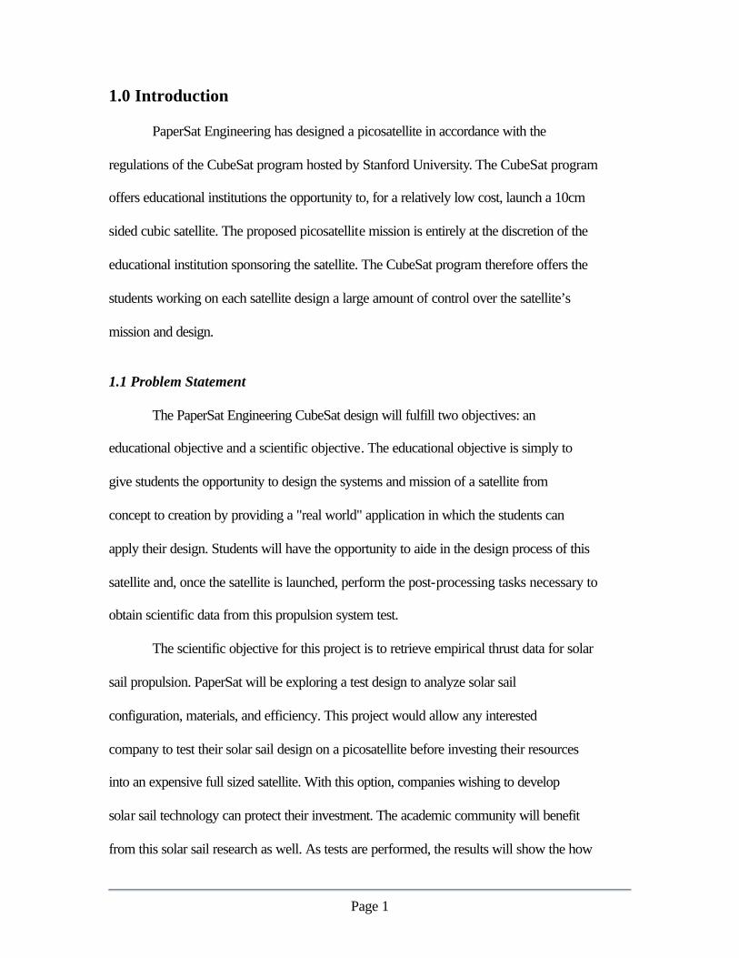
1.0 Introduction
PaperSat Engineering has designed a picosatellite in accordance with the
regulations of the CubeSat program hosted by Stanford University. The CubeSat program
offers educational institutions the opportunity to, for a relatively low cost, launch a 10cm
sided cubic satellite. The proposed picosatellite mission is entirely at the discretion of the
educational institution sponsoring the satellite. The CubeSat program therefore offers the
students working on each satellite design a large amount of control over the satellite’s
mission and design.
1.1 Problem Statement
The PaperSat Engineering CubeSat design will fulfill two objectives: an
educational objective and a scientific objective. The educational objective is simply to
give students the opportunity to design the systems and mission of a satellite from
concept to creation by providing a "real world" application in which the students can
apply their design. Students will have the opportunity to aide in the design process of this
satellite and, once the satellite is launched, perform the post-processing tasks necessary to
obtain scientific data from this propulsion system test.
The scientific objective for this project is to retrieve empirical thrust data for solar
sail propulsion. PaperSat will be exploring a test design to analyze solar sail
configuration, materials, and efficiency. This project would allow any interested
company to test their solar sail design on a picosatellite before investing their resources
into an expensive full sized satellite. With this option, companies wishing to develop
solar sail technology can protect their investment. The academic community will benefit
from this solar sail research as well. As tests are performed, the results will show the how

Page 2
certain materials reflect light, how that property can be used to navigate a spacecraft, and
how to implement that technology. Solar sails have not been successfully used as a major
propulsion system by any spacecraft to date and, as a result, the technology is largely
theoretical. Testing of this technology may prove to be an important step in space flight,
and small satellites are an excellent testing platform for this technology.
1.2 Purpose
The purpose of this solar sail CubeSat design will be to test solar sail capabilities
in an inexpensive manner. To achieve that purpose, PaperSat will design a small satellite
that complies with CubeSat regulations and that can deploy a solar sail to achieve thrust.
Once deployment is achieved, the spacecraft's position, velocity and attitude will be
monitored from the ground so that the acceleration provided by energy transferred from
light striking the surface of the sail to the spacecraft can be measured.

Page 3
2.0 Design Factors
To achieve the goals outlined in the previous section, it was necessary to adopt
several design constraints. The restrictions listed below allow this satellite design to
maintain accordance with CubeSat regulations and maintain simplicity reliability.
2.1 Design Restrictions
The PaperSat team (Appendix A) has adopted the following design restrictions for
this satellite design. Some design restrictions are imposed by the CubeSat program,
others were imposed by the design team.
?? Weight – The satellite must weigh less than a total of 1 kg. (CubeSat Restriction)
?? Volume – The satellite must be a cube with sides 10cm or less. (CubeSat Restriction)
?? Shell – A shell similar to the CubeSat recommended shell design made of 7075
aluminum was adopted for this satellite design and will house the satellite
components.
?? Timer/Kill Switch – In effort to assure that the solar sail does not deploy during
the injection phase of the satellite orbit, a timing mechanism is required. The kill
switch will activate the timer upon release from the pod. The timer will then send
a deployment command after a specified time has passed. A previous CubeSat
team has already investigated different timers. Their recommendation has been
adopted for this project.
?? Power Sources - A battery is required for powering the timer. The battery will
not be rechargeable as it will only need to function until the solar sail is deployed.
Aside from timer requirements, no additional power requirements or systems are
needed.

Page 4
?? Attitude Control - There will be no independent attitude control system.
PaperSat will not make special provisions to control attitude. However, limited
efforts may be taken to stabilize the rotations, such as geometry modifications.
?? Tracking - Corner cube reflectors will be used to aid in orbit and attitude
determination. Laser ranging will be performed by ground stations.
2.2 Satellite Component Evaluation Criteria
The following list summarizes the constraints used to aid in evaluating all
candidate solutions:
?? Weight. Pursuant to the CubeSat regulations, a single CubeSat must weigh no
more than 1 kg. Weight is therefore a crucial evaluation criteria for each candidate
satellite component.
?? Volume . The pods that deploy the CubeSat can fit three 10 cm cubes per pod.
This stringent restriction ensures that component volume is also a crucial
evaluation criteria.
?? Rigidity. The thrust a solar sail produces is a function of its surface area exposed
to direct sunlight. To ensure that the maximum surface area is exposed to the sun,
it is important that the sail not fold and flex, thereby covering part of its surface.
To this end, the solar sail must be kept as rigid as possible. In addition, data
reduction and orbital trajectory calculations are greatly simplified under a rigid
sail assumption. This criteria is applied to deployment components such as solar
sail capillaries and hardening strips.

Page 5
?? Cost. The major cost for this project is in the actual launch of the satellite.
Component costs therefore do not effect the overall budget for this project greatly.
Material costs for the systems aboard the satellite will be considered, but
reliability will not be greatly sacrificed to spare materials costs.
?? Reliability. It is key to this project that all of the internal components aboard the
satellite be very reliable. To that end, many of the components we have chosen for
this design are simple and require few moving parts. Reliability is therefore also
an important evaluation criteria for all components.
Each of the components selected for the design of this satellite were selected bearing
the above restrictions and evaluation criteria in mind.

Page 6
3.0 Satellite Systems
In light of the design constrictions outlined in the previous section, this CubeSat
design will require the following systems:
?? Tracking – Consisting of hardware used for tracking of the satellite.
?? Electrical – Composed of the required timer and batteries.
?? Structural – Including the satellite frame, the walls enclosing the interior satellite
components, the solar sail deployment components, and solar sail hardening and
tear strips.
?? Propulsion – Consists only of the solar sail.
The satellite systems have been kept to a minimum for this project to facilitate
compliance with the design constraints for weight and volume. The satellite systems and
how they interact with each other are displayed in Figure 1.
Figure 1 - Satellite Systems

Page 7
3.1 Satellite Tracking Systems So that the thrust produced by the solar sail can be measured, the satellite’s
position must be tracked over time. The tracking system must be able to determine the
satellite’s orientation and position at a given time.
3.1.1 Optical Ranging Principles
Optical ranging is currently used in satellite applications for position
determination. The technique is passive, using only resources on ground stations, and
requires only that the satellite have small hardware devices known as corner cube
reflectors mounted in such a way that they maintain line-of-sight with the earth.
Figure 2 - Corner Cube Reflector Concept
A corner cube reflector is a set of three orthogonal mirrors that are geometrically
arranged such that they reflect light from any source location directly back to that
location. Because of this property, if a laser were directed toward a corner cube reflector
it would be reflected directly back to the source. If the time of travel of the laser light is
recorded, the distance between the source and the reflector can be determined. If the
position of the laser light source is known in three dimensions and the azimuth and
elevation of the laser light pulse are known with respect to that source location, then once
the distance between the source and the satellite is determined, the orientation of the
Page 8
satellite in three-dimensional space can be determined. This technique requires that the
satellite position be known approximately before the optical ranging can be performed.
Since laser light can be sent in pulses that have set widths, laser pulses from ground
stations can effectively search a range of sky for a satellite. Knowledge of the satellite's
approximate location should be easy to obtain, since the CubeSat program will provide
the initial conditions of launch. In addition, the size of the solar sail involved with this
project will allow the satellite to be observed from the earth and easily identified.
Measuring small thrust aboard this satellite requires that the satellite’s position in its orbit
be known very accurately. Laser ranging has the capability to determine satellite position
to an accuracy of up to 1 cm [1].
If there are several corner cube reflectors aboard the satellite and the geometry of
these corner cube reflectors is known, then with the information received from optical
ranging, the orientation of the satellite can be determined. Since the corner cube
reflectors will only reflect the laser pulses from the earth, they cannot be distinguished
from each other. The corner cube reflector geometry that will be implemented for this
project requires a minimum three corner cube reflectors oriented in the plane of the solar
sail. Each the reflector coordinates are received by the ground station will define the
plane of the solar sail. Since the reflectors cannot be distinguished from each other they
will not contain any information about the rotation of the solar sail about the axis
perpendicular to the solar sail, an axis of rotation that is not of any particular interest to
this project. The only other piece of satellite orientation information that cannot be
determined from the corner cube reflector orientation described is which side of the solar

Page 9
sail is facing the sun. Since the solar sail is doubly reflective, the sides will be identical
and will not need to be distinguished.
If several measurements of the satellite position are recorded, the satellite’s
rotation rate and orbit can be determined. If the orbit is then analyzed, the accelerations
acting on the satellite can be determined (for more details see Section 4). The result is
knowledge of the forces acting on the satellite, when applied to this project, the ranging
technique allows the satellite's thrust to be calculated.
Optical ranging offers a post-processing intensive solution to satellite position and
orientation determination. The solution is particularly attractive for CubeSat
implementation due to the size and weight restrictions on the satellite. Optical ranging
allows for the lack of any communications systems, power systems (in excess of the
timer battery), and micro processing systems aboard the satellite. The result is a
substantial size and weight savings. The ranging technique also has the benefit of
requiring no moving parts or electrical systems, offering a very reliable solution to
satellite position determination.
To maintain knowledge of how the satellite's orbit is being perturbed, a series of
position fixes is required. Five to ten position measurements per orbit period should be
sufficient to determine how the satellite’s orbit is changing over time. If several
measurements of the satellite are taken over a small time interval for each of those
position fixes, the rotation rate of the satellite can be determined. In total, if five
measurements are taken for the purpose of determining rotation rates of the satellite, then
five to ten bursts of five measurements per orbital period would provide sufficient
information about the spacecraft. One ground station should be adequate for these

Page 10
purposes. It will be sufficient to track the satellite for the times that it has a positive
elevation with respect to the McDonald Observatory laser ranging facility in west Texas.
For a four day propagation of the predicted orbit, the satellite maintained a positive
elevation over west Texas for up to almost half a day, corresponding to a full orbital
period of the satellite. Positioning over a full orbital period will not be required, however,
as the portion of the orbit that is of most interest is the portion farthest from the earth
because there will be fewer perturbations. Measurements will also not be required during
the short time each period that the satellite is in the earth's shadow as the thrust would not
be acting on the satellite during that time. The satellite will likely be at its closest
approach to the earth while the satellite is out of the sunlight. If the position, velocity and
orientation of the satellite were measured as the satellite entered the earth's shadow and as
the satellite exited the earth's shadow, information regarding the drag on the satellite from
the earth's atmosphere could also be obtained.
3.1.2 Design Impact
The impact of implementation of laser ranging hardware for this CubeSat project
is minimal. Small lightweight panel corner cube reflector arrays will be used as walls for
the CubeSat while it is in its launch configuration. The corner cube reflectors will
therefore provide service as walls and laser ranging devices. When the solar sail is
deployed (for more details see Section 3.3), the corner cube reflector panels will be
detached from the sides of the satellite and will deploy with the sails until they reach their
final configuration at the edges of the sail. The reflectors do take up a substantial amount

Page 11
of space and weight, but when compared to an electronic ranging solution, the weight and
volume requirements are reasonable.
3.1.3 Optical Tracking Hardware Specifications
The optical tracking hardware will consist of four corner cube reflector arrays
purchased from an optical ranging equipment vendor such as the Banner Engineering
Corporation. The reflector arrays will need to have a large operational temperature range,
as they will be in shadows at times, and at other times be exposed to direct sunlight.
Banner Engineering has one design of reflector array that can operate at 900oF.
Unfortunately corner cube reflector models with high operational temperatures have
lower reflectivity. For final determination of the corner cube reflector to be designed, a
mission submission to the International Laser Ranging Service (ILRS), of which
McDonald observatory in west Texas is a part, should be completed. The ILRS can then
supply detailed information with regards to cost of operation and reflectivity
requirements of the corner cube reflectors. A “middle ground” must be reached with
respect to operational temperature, cost, and ILRS capabilities. For the purposes of this
design, a custom glass corner cube reflector array will be used.

Page 12
Figure 3 – Sample Corner Cube Reflector Array from Banner Engineering [2]
Banner Engineering merchandise similar to that shown in Figure 3 was used as a
template for the corner cube reflector specifications. The reflector shown in Figure 3 is
made of Acrylic, which will most likely not be able to handle the operating temperatures
required for space. Banner has glass corner cube reflectors which do not require the
backing plate seen in Figure 3, allowing them to be thinner. The glass retroreflector will
be 7mm in thickness, accounting for a 3mm thickness reflector array on both sides of
component and 1mm of glass in between. The four double-sided reflectors for the
satellite will weigh a total of approximately 44 grams, require a total of approximately 77
cm3 and will be 41 mm in diameter. The estimated total price for the corner cube
reflectors through Banner Engineering is $6000.

Page 13
3.2 Electrical System
As previously stated, the necessary electrical systems for this satellite only
include a timer to delay deployment of the satellite systems and batteries for the timer. A
kill switch must activate the timer so that the timing system becomes active once the
satellite has been launched from the CubeSat pod launcher.
Figure 4 - RDAS Compact Timer / Accelerometer Board [3]
The RDAS Compact timer model shown in the above figure, provided by
Aerocon Systems will cost $211. The timer is capable of supplying voltages at different
times to trigger events during deployment. The timer requires 9-11 V of power to operate
and draws 70-90 mA of current. The board requires a volume of 90x36 mm2 x 17 mm
and weights 31 grams. To ensure that the board capable recording time for the 5 hours
between kill switch activation and satellite system deployment, the board requires
roughly 500 mAh of current. Three lithium Ion batteries will be stacked within the
satellite to provide the timer’s power and current requirements.
Page 14
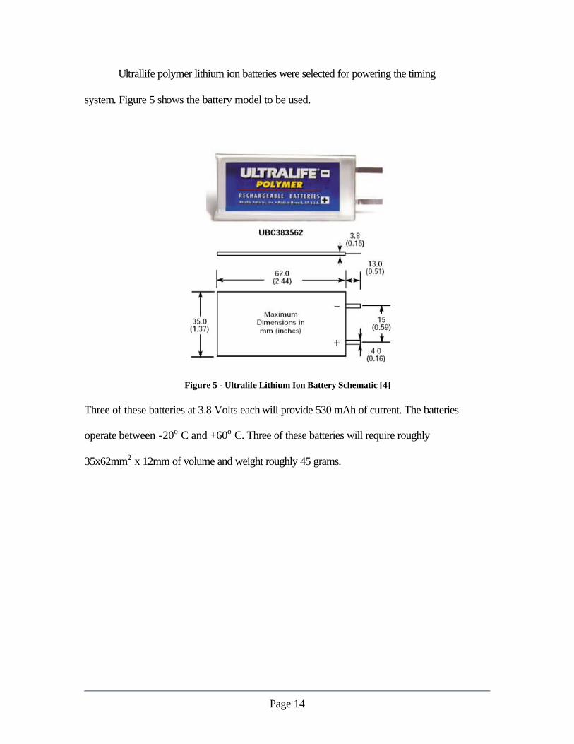
Ultrallife polymer lithium ion batteries were selected for powering the timing
system. Figure 5 shows the battery model to be used.
Figure 5 - Ultralife Lithium Ion Battery Schematic [4] Three of these batteries at 3.8 Volts each will provide 530 mAh of current. The batteries
operate between -20o C and +60o C. Three of these batteries will require roughly
35x62mm2 x 12mm of volume and weight roughly 45 grams.

Page 15
3.3 Mechanical Systems and Deployment
The satellite structural design must support and house all of the satellite’s internal
components as well as providing for deployment of the solar sail. To accomplish this, it is
necessary to define each component and discuss the component’s weight, volume, and
attachment needs.
The kill switch, timer, batteries, and frame are the CubeSat program required
components of our satellite design. Other components specific to this satellite design
include the corner cube reflector panels, the solar sail, nitrogen capillaries, the
compressed nitrogen canister, and the hardening strips. Each of these components play a
vital role in the sequence required for a successful deployment and will be discussed in
detail. In addition to having each vital component in the satellite, it is also necessary to
have each of these components placed strategically to maximize the working volume. To
aide in understanding where each satellite component will be placed, placement will be
mentioned for each component along with a cut-away view of the final satellite and
placement description in this section. To understand how much volume each component
occupies along with what portion of the weight each component composes, the volume
and weight of each component will be mentioned and discussed in a volume and weight
budget. This section ends with a walk-through of the entire installation and deployment
process.

Page 16
3.3.1 Satellite Components
Kill Switch
The kill switch is a required item for PaperSat, as set up in the CubeSat
requirements provided by Stanford University. According to Stanford, every CubeSat
must be in an “off” mode before actual deployment. The kill switch performs this
operation. The kill switch consists of a simple spring-loaded button that is mounted to
the exterior of the satellite. The kill switch will be placed in a corner of the satellite and,
including wires, should consume 2cm3 and weigh 10 grams. Upon placement of the
CubeSat into the main satellite before launch, the button on the kill switch is pushed in
and held in by the rails on the deployment device. The kill switch will not allow power
to travel from onboard batteries to the timer while it is in a depressed state. As the
satellite is released from the deployment device, the button is allowed to spring out,
deactivating the kill switch and allowing electricity to get to the timer, which will then
start a countdown for the deployment of the solar sail.
Timer
The timer is the brain of the satellite and controls the timing and sequencing of all
onboard activities. Once the kill switch is deactivated, the timer begins to count towards
the time at which the deployment of the solar sail will begin. Once the time for solar sail
deployment has arrived, the timer will coordinate each of the individual tasks required for
successful deployment. The timing system will be as described in Section 3.2. Since the
final timing system has not been selected, the current estimate for the space and weight of

Page 17
the timer is for the R-DAS compact model timer. The timer, with timing board, should
occupy 45.9 cm3, weigh 32 grams, and will be placed on a timing board mounted parallel
and directly next to one of the permanent sides of the satellite. The tasks the timer will
be given will be to control the time for the release of the satellite side panels, set for 5
hours after the timer activation at deployment, and to control the time for the release of
the compressed nitrogen from the onboard capsule, set for 5 hours 2 minutes after the
timer activation at deployment.
Batteries
The batteries in the CubeSat will be used to power both the timer and the servos
that release the side panels. The batteries used will be three Lithium Ion batteries placed
directly next to the timer. They occupy 45 grams and 31.5 cm3 of space.
Frame
The frame of PaperSat is what all the other components of the program are to be
mounted on. The frame will appear as the one seen in Appendix B and will be composed
of 7075 Aluminum beams and sheets attached together. Each beam will be
approximately 10 cm in length with a square cross-section 0.2 cm on a side. The sheet
sections on the ends will be 10 cm square and will be .5 mm thick. In combination with
the attached side panel parts not associated with the corner cube reflectors, this brings the
total weight of the frame to 43.43 grams and the volume to 16 cm3. The frame is also the
base upon which the corner cube reflector panels are to be placed.

Page 18
Corner-Cube Reflector Panels
The corner cube reflector panels are the basis for the ground-based tracking
system that will be employed to track the CubeSat. The corner cube reflector panels
being used are 6 cm in diameter circular reflector panels mounted in the center of the side
walls. The total weight of the panels will be 43.39 grams and the volume will be 75.6
cm3. Each of these corner cube reflector panels is double sided, allowing reflectivity on
both sides of the panel with the mounting of only one reflector. The four panels will be
placed on the four of the sides of the CubeSat. Prior to the inflation of the solar sail, the
four side panels with the reflectors will be released. The four corner cube reflector panels
that will be released from the frame will also be attached to the edge of the solar sail and
will expand outward with the sail as it deploys. When the solar sail is in its final rigid
form, the released panels will be rigidly attached to the solar sail in the plane of the sail.
Solar Sail
The solar sail is the where CubeSat derives all of its propulsion and is the most
important component of the program. The solar sail will be constructed of 6 micron thick
Aluminized Mylar. The solar sail will be circular in shape, will have a total area of 100
m2 (5.64 m radius), and will have a final weight of approximately 720 grams. For
packing into the satellite, the solar sail will be folded in an accordion manner from the
ends towards the center utilizing 7.5 cm folds. Once the two sides meet in the middle, the
two remaining lengths of the sail will be folded into the satellite using similar 7.5 cm
folds, beginning at the center around the compressed Nitrogen canister, and working out

Page 19
to the ends of the sail. Employing this folding method, the packed solar sail should take
up 700 cm3.
Capillaries
The capillaries being used for this project are responsible for containing the
Nitrogen being used to inflate the solar sail throughout the surface of the sail to strategic
locations for maximum rigid deployment in the minimum deployment time. The
capillaries that will be used on the solar sail are 1.27 cm diameter tubes made of the same
Aluminized Mylar used to make the solar sail. The total volume of these tubes is
negligible and is considered to be a part of the volume of the solar sail. The tubes will be
placed on the solar sail so that when the Nitrogen is released, the sail will first separate
the two arms of the sail folded into the center, followed by the full expansion of the solar
sail utilizing capillaries placed in the middle and along the edges of the sail. The
capillaries will be inflated with the Nitrogen at a rate of 3.5 cm3 per second. This will
make the total inflation time three minutes and will leave a final pressure in the
capillaries of 0.5 psi.
Compressed Nitrogen Canister
The compressed Nitrogen canister is what will hold the compressed Nitrogen used to
inflate the capillaries, and thus inflate the solar sail. The canister will be similar to the
one seen in Figure 6, will be 7.6 cm long, 3.8 cm in diameter, and have a volume of 86
cm3. The volume used to specify internal satellite arrangement will be 90 cm3 and the

Page 20
canister will be placed in the very center of the satellite. The total weight of the canister,
containing the compressed Nitrogen, will be 75 grams. The Nitrogen in the canister will
be stored at 60.5 psi. Once the Nitrogen is released from the canister at 3.5 cm3 per
second, it will take three minutes for the canister to extinguish the Nitrogen supply. This
will leave a final pressure in the canister, and in the capillaries, of 0.5 psi. The papersat
development team was unable to find a CubeSat program regulation prohibiting the use
of compressed gasses. However, if CubeSat does have such a regulation, we are confident
that through testing we can convince them that use of this canister will be safe for our
satellite and satellites to be deployed nearby.
Figure 6 - Compressed Nitrogen Canister
Hardening Strips
Hardening strips are a new technology that will be used to make the solar sail a
permanently rigid circle after the sail has been deployed. It is necessary to make sure that
the sail remains a perfect circle in order to have maximum correlation between the
deployed solar sail and the theoretical solar sail being used in the computer simulations

Page 21
for the PaperSat program. Hardening strips must be added to the sail due to the fact that
over the time span the CubeSat would be in orbit, the Nitrogen will leak from the thin
capillary walls, leaving the sail with no rigid internal structure. The hardening strips to
be used will consist of a tape-like substance that has the unique property that the tape will
remain pliable and tape-like until it is exposed to solar radiation. When the strips are
exposed to solar radiation, they will begin to harden and will permanently cure in
approximately 15 minutes. The hardening strips will be placed on the solar sail in a
spider web pattern and along the outer rim to minimize any warping or shape changing of
the sail after deployment.
3.3.2 Component Placement and Overview
The placement of each of the components has been described above and will now
be shown pieced together in a cut-away view in Figure 7. As can be seen in the figure,
the corner cube reflector panels make up the exterior of the satellite and are incorporated
with the frame. The timer board and batteries are installed on the bottom of the satellite
as close as possible to each other on the permanently mounted base panel. The
compressed Nitrogen canister can be seen in the center of the satellite with a
representation of the solar sail shown in folds coming away from the canister. Using the
components discussed above, the satellite will have used 958 of the available 1000 cm3.
This leaves an available 42 cm3 that can be used to maximize the size of our solar sail or
space-harden some of the components. The total weight of the components is 968 grams

Page 22
out of our available 1000. This gives the current design an extra 32 grams that can be
used for increasing the size of the solar sail or space-hardening some of the components.
Figure 7 - Satellte Cut-Away
3.3.3 Satellite Construction Summary
Upon completion of the frame, the kill switch (activated), timer board, and
nitrogen canister will be installed. After the sail is folded, it too will be installed and
attached to the canister. Finally, the corner-cube-reflector panels will be installed on the
sides of the satellite, completing the satellite housing. Once the satellite construction has
been completed, it will be placed in the CubeSat P-Pod deployment mechanism. The
satellite will not become active until after the CubeSat has been released in the designated
orbit.

Page 23
3.3.4 Solar Sail Deployment Summary
Once the satellite is deployed from the deployment mechanism, the kill switch is
deactivated and the timer begins counting toward the deployment time. Five hours from
deployment, the four side panels containing the doubly reflective corner cube reflectors
are released from the frame. At 5 hours, 2 minutes after the satellite was inserted into its
orbit, the nitrogen will be released from the canister and inflate capillaries. Once the
capillaries have fully inflated, the hardening strips will begin to cure, making the sail
permanently rigid. Each stage of this deployment will be triggered by the timing system.
3.3.5 Weight and Volume Budgets The two most important regulations to be met in the CubeSat program are to
ensure that the total weight and volume of the satellite and the internal components does
not exceed the respective limits of 1 kilogram and 1000 cm3. In order to see how each of
the components fits in the weight and volume budget for the CubeSat, the following
sections explain each topic in detail.
The total weight allowed in the CubeSat can not exceed one kilogram, or 1000
grams. Each of the components to be used for the CubeSat has been broken down to
show how much each of the components weighs. Each of these components is then
placed into the pie chart in Figure 8 in order to show how each of the components fits
into the whole picture.
Figure 8 shows that the sail comprises most of the weight budget for the satellite.
This is reasonable since the sail is the most important component of the satellite. The
frame, corner cube reflectors, timer, and other components don’t take up much of the

Page 24
weight volume, but are still vital components for the successful deployment of the solar
sail.
There are 42 grams remaining in the weight budget of the CubeSat. This means
that there are still 42 grams that can be used for maintaining environmental conditions for
the internal components of the satellite if necessary or for increasing the size of the solar
sail.
Figure 8 - Weight Budget for the Satellite
The total volume allowed for the housing and components of the CubeSat can not
exceed the designated 1,000 cm3. Each of the components to be used in the CubeSat has
been broken down to show how much volume each of the components will use. Figure 9
shows that the sail comprises most of the volume budget for the satellite. This is
reasonable since the sail is the most important component in the satellite. The frame,

Page 25
corner cube reflectors, timer, and other components necessary for the successful
deployment of the sail combined take up about 25% of the volume.
There are 42 cm3 remaining empty in the volume budget of the CubeSat. This
remaining space can be used for increasing the size of the solar sail or bulking up some of
the internal components.
Figure 9 - Volume Budget for the Satellite

Page 26
3.4 Propulsion Systems
The satellite design for this project will use only solar sail propulsion. As a result,
this section will concentrate only on an analysis of the solar sail design including solar
sail material selection, and stress analysis. A finite element modeling program was used
to analysis the effects of predicted stresses on the solar sail and aid in optimizing solar
sail thickness specification and hardening strip placement while modeling the impact of
the corner cube reflector arrays and satellite shell.
3.4.1 Solar Sail Historical Survey
One of the most crucial steps in the design process is to research the previous
work conducted in the product’s field. From research, a database of solar sail properties
was established, and served as a design aid. This section summarizes the research
performed in the area of previous solar sails for this project.
The concept of a solar sail, or a spacecraft that uses reflected light to provide
continuous thrust, was conceived in the 1920’s [6]. The first serious attempt to fabricate
a solar sail was in the 1970’s, when a proposal was developed by NASA to send a solar
sail satellite out to rendezvous with Halley’s Comet. A picture of one of the Halley’s
Comet design concepts is shown in Figure 10 below. Due to the unproven nature of solar
sails, this proposal was rejected [7].

Page 27
Figure 10 - Halley’s Comet Solar Sail Design Concept [7]
In the 1980’s, an international solar sail race to the Moon in honor of Christopher
Columbus’s journeys sparked additional interest in the solar sail concept. However, this
competition faded due to lack of funding [7]. As time went by, the demand for
inexpensive propulsion methods increased. In addition, advancements in solar sail
material technology greatly reduced the weight of solar sail designs, making the solar sail
concept even more feasible.
At the present date, a new breed of solar sails is emerging. These concepts use
current material technologies to shrink the thickness of the solar sail down from the 80
micron thick Halley’s Comet solar sail to a only few microns [8]. Figure 11 features a
few of these new concepts. The Encounter satellite is a privately funded project (a) [9].
The Solar Blade Solar Sail (b), with 30-meter blades, is being developed by Carnegie
Mellon University [8]. The European Space Agency and German Space Agency have
combined resources in the development of the Star of Tolerance (c) [10]. Figure 11 (d)
shows the infamous Cosmos I, which was designed and constructed by the Planetary
Society in conjunction with the Russian space agency. The Cosmos I actually launched

Page 28
in July of 2001, but due to a software malfunction, the sail never deployed. A relaunch is
scheduled for early 2002 [11].
(a) (b)
(c) (d)
Figure 11 - Current Solar Sail Projects. (a) Encounter Satellite [9] (b) Solar Blade Solar Sail [8] (c) Star of Tollerance [10] (d) Cosmos I [11]
Solar sail material technology is changing at a fast rate. Future solar sails are
likely to resemble a completely different form. For example NASA is currently
investigating a new material made of carbon fibers. This material is 200 times thicker
than the solar sail materials shown in Figure 11, but weighs about the same as these sails
Page 29
at only 5 grams per square meter. The carbon fiber mesh, however, is many times
tougher than the current materials and much more rigid [12].
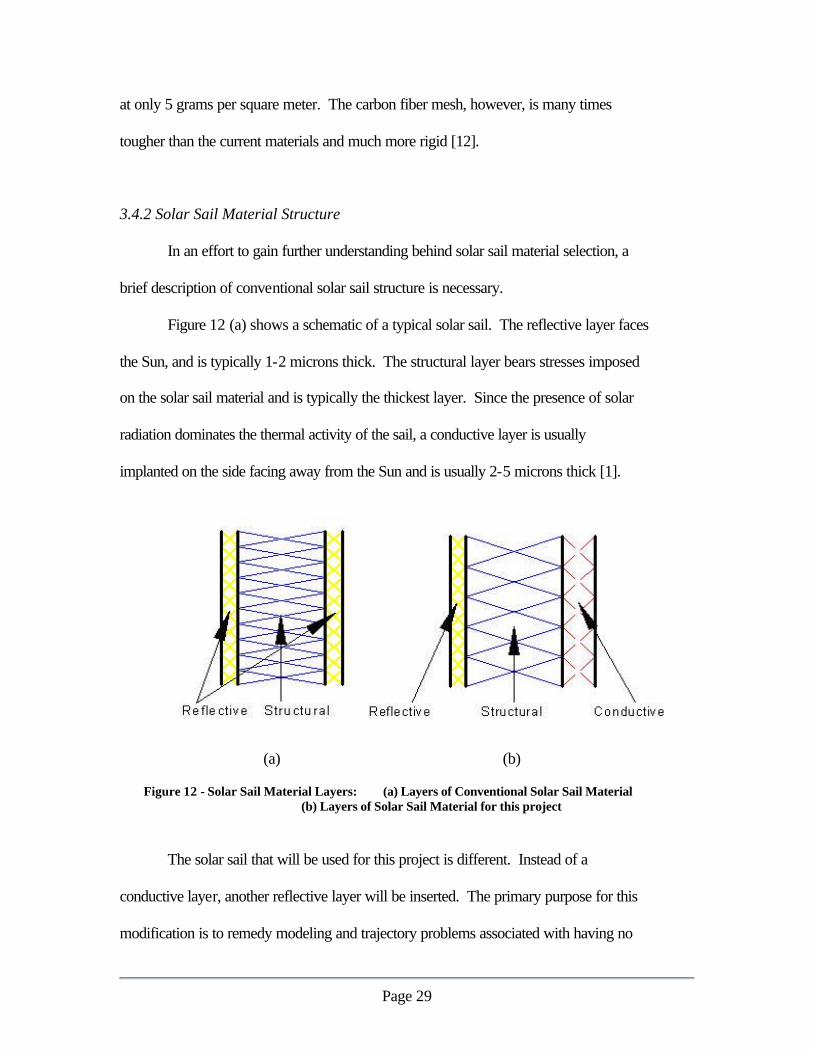
3.4.2 Solar Sail Material Structure In an effort to gain further understanding behind solar sail material selection, a
brief description of conventional solar sail structure is necessary.
Figure 12 (a) shows a schematic of a typical solar sail. The reflective layer faces
the Sun, and is typically 1-2 microns thick. The structural layer bears stresses imposed
on the solar sail material and is typically the thickest layer. Since the presence of solar
radiation dominates the thermal activity of the sail, a conductive layer is usually
implanted on the side facing away from the Sun and is usually 2-5 microns thick [1].
(a) (b)
Figure 12 - Solar Sail Material Layers: (a) Layers of Conventional Solar Sail Material
(b) Layers of Solar Sail Material for this project
The solar sail that will be used for this project is different. Instead of a
conductive layer, another reflective layer will be inserted. The primary purpose for this
modification is to remedy modeling and trajectory problems associated with having no

Page 30
attitude control system. This satellite will be unable to control whether or not the
reflective side is facing the Sun. Creating a double-reflective sail surface assures that
there is continuous thrust regardless of the satellite’s orientation. In addition, the corner-
cube attitude/location determination system is simplified by using double-reflective solar
sail material, because there is no need to differentiate which side is facing the Sun if
double reflectivity is assumed. To ensure that the missing thermal layer does not cause
thermal problems with this solar sail design, thermal stresses will be discussed in the
thermal loading portion of the finite element analysis section of this report.
3.4.3 Solar Sail Material Selection Criteria and Design Constraints
In this section, the process of selecting a material that will be suitable for the solar
sail itself is documented. A historical database of solar sail materials was developed to
aid in selection. The database was then tested under a set of criteria, and the best solar
sail material was extracted. At the end of this process, Aluminized Mylar was chosen as
the solar sail material.
The following list summarizes the design constraints imposed on the material
selection process:
?? Double Reflectivity - Since PaperSat has no attitude control, the ability to
produce thrust if the satellite is facing toward or away from the sun increases the
amount of thrust produced. In addition, the orbital simulation is simplified by
imposing this design constraint.
?? Space Flown - Pursuant to CubeSat requirements, the solar sail material should
be composed of materials that are approved for space flight.

Page 31
?? Foldable - The material should not be brittle enough to tear when folded.
?? Temperature Resistance - The material selected must withstand both the heat of
direct Sun exposure and the extreme cold when in Earth’s umbra.
?? UV Life - Exposure to UV rays from the sun can be highly corrosive. The solar
sail material must withstand UV light for a reasonable duration (1 year).
The following list describes the material evaluation criteria used to select the solar sail
materials:
?? Density - CubeSat program regulations state that the total satellite weight must be
less than 1 kg. In addition, the solar sail size depends on the sail weight. Since it
is desirable to construct the largest sail possible, minimizing the sail density
optimizes sail size.
?? Strength - Stresses are imposed on the sail due to solar pressure, deployment
mechanisms, and component attachments. A strong sail is essential to
withstanding these stresses. Also, minimizing the weight implies minimizing the
sail thickness. At such a thin dimension, the sail’s strength may be compromised.
A balance between a light and strong solar sail must be attained.
?? Cost - In all designs, cost is always a key limitation in the design process and
construction. Specific costs were unavailable during the selection process.
However, including this criterion eliminates inherently expensive material
candidates such as gold or silver.

Page 32
3.4.4 Aluminized Mylar The criteria outlined in Section 3.4.3 were applied to the database of previous
solar sail materials. Aluminized Mylar (AM) was selected as the best PaperSat Material.
Aluminized Mylar has been used in a variety of products, including fire blankets,
balloons, and photography. In the space industry, AM is used as a reflective material in a
variety of spacecraft, both solar sail and non-solar sail related. The following list
summarizes how well Aluminized Mylar meets the design constraints:
?? Double Reflectivity. The structural layer for AM is Mylar, and the reflective
layers will be aluminum film.
?? Space Flown. AM is being used in several NASA projects, including the
International Space Station and Ariel 2 (which tested AM films in space) [13, 14].
?? Foldable. AM is used in other solar sail projects that require folding.
?? Temperature Resistance. Ariel 2 used AM films to measure micrometeoroids in
a near-earth environment. The temperatures AM was exposed to during this
mission will be comparable to the range required for this project [14].
?? UV Life. With respect to the other solar sails, AM has an average UV life [5].
The duration will be within the constraint limits.
The following list describes how well AM meets the design criteria developed in
section 3.4.3 for solar sails materials:
?? Density. The AM sample to be used by PaperSat will have a thickness of 6
microns and a weight per area of 1.38 g/m2, which is the lowest weight per area of
all solar sail materials in the database.

Page 33
?? Strength. The yield stress of the AM to be used in PaperSat is 172 GPa, which is
an average strength for solar sail materials.
?? Cost. With its widespread use, AM is not considered an exotic material.
Aluminized Mylar has a well-documented and researched material, which will
further reduce cost.
3.4.5 Finite Element Analysis – Model Description The completion of the material selection process marked the beginning of the
finite element analysis. ABAQUS Explicit was used to assist in the modeling. The
analysis was limited to the fully deployed satellite configuration. The following table
summarizes all components integrated into the finite element model:
Table 1 - Summary of Elements Used
Component Element Type Description
Solar Sail Material
m3d4r 3D four node membrane elements with reduced integration – 2D elements in 3 space
Corner Cubes *mass A rigid body point mass. Capillary elements close to the point were stiffened to simulate the connection
Capillaries b31 3D 2 node beam elements – one dimensional elements in 3 space
Hardening Strips
b31 Same as capillaries, but smaller cross sectional area and different stiffness
Middle Components
*mass A rigid body point mass.
The mesh of the finite element model is shown in Figure 13. The solar sail
membrane elements are visible, and a circular hardening strip can be seen between two of
the membrane element boundaries. The capillaries and the remaining hardening strips
are located along the membrane element boundaries and cannot be seen. Because the

Page 34
corner cube reflectors and the middle components are points, they are not visually present
in the FE model.
Figure 13 - Solar Sail Finite Element Mesh
In addition to representing the geometry of the deployed solar sail, the finite
element representation also models the following properties:
?? Young’s modulus
?? Poisson’s ratio
?? Yield Strength
?? Ultimate Strength
?? Conductivity
?? Density

Page 35
Since the hardening strips are made of such an exotic material, PaperSat was
unable to locate a complete set of material properties. Since the hardening strips were
developed for the purpose of reinforcing the solar sail structure, it was assumed that it
had higher stiffness than the solar sail material. The other material properties were
assigned default values by the ABAQUS program. However, the hardening strips are
structural components, and an adequate estimation of the stiffness is inputted. The
effects of the rest of the default values should be negligible the small volume with respect
to the solar sail is taken into account.
3.4.6 Finite Element Analysis Results
The resulting output produced a large amount of data including deformations at
any node or section point in the model. This output can be graphically represented using
the ABAQUS Viewer program as series of animations. The user can choose to model
any data set as either a contour plot, mesh plot, or Cartesian plot of various variables
versus time or another variable. The initial goal of the finite element simulation was to
use the model as a design tool to aid in determining solar sail geometries. Since PaperSat
completed this project goal early, a limited preliminary structural analysis of the solar sail
was performed.
ABAQUS Explicit models structures in a dynamic environment. All tests were
conducted in only a .5 or 1 second time duration. Each successful ABAQUS rendering
generated between 10 to 20 megabytes of data and took up to 12 hours to render.
Because of the massive amount of data generated, there will be no raw data presented in
this report. Instead, results and observations will be included in this report. The full

Page 36
time history of this simulation fully animated plots is located the CD included in the
PaperSat design package.
Design Results
Figure 13 shows a schematic of the final solar sail in the fully deployed mode.
The finite element simulation served as a tool for determining the final configuration.
Through running the FE model under several different thicknesses for the solar sail, a
minimal thickness of 6 µm was deduced. This thickness both conserves weight and
retains strength. In addition, several hardening strip configurations were tested in the FE
script. The configuration shown in Figure 10 shows the best solution, which produced
the least amount of deflection, minimized amount of material, and maintained simplicity
for ease of manufacturing.
Figure 14 - Final Deployed Solar Sail Configuration

Page 37
The diameter of the circumferential capillary was also minimized with the aid of
finite element analysis. The CubeSat was subjected to a load parallel to the plane of the
solar sail along a concentrated area along the capillary. The magnitude of the load was
500000 times greater than the theoretical maximum thrust of the solar sail, or
approximately .5 Newtons. The diameter of the capillary was then incrementally
minimized until visible deflection was observed. The value for this diameter was then
rounded up to the nearest “convenient” number so that it is easier to manufacture.
Preliminary Analysis Results:
After the final solar sail configuration was determined, a limited preliminary
analysis was performed. All tests contain a 90 µN distributed load applied perpendicular
to the surface of the solar sail. Since the model simulates dynamic conditions, the load is
applied as a .1 second ramp function. The following pages describe the scenarios and
results of this analysis.
Test 1: Thermal Loading
In addition to stresses acting on the sail surface due to the light collisions, stresses
due to the increased temperature are acting on the sail. The first test imposes a 1400
w/m2 flux on the sail [7]. The flux is allowed to heat the sail for 1 second before the
distributed load acts on the sail. Figure 14 shows the final time step of this simulation,
showing a maximum deformation of approximately 1.5 mm.

Page 38
Figure 15 - Thermally Coupled Loading on the Solar Sail
Test 2: No Thermal Loading
In order to isolate the effects of thermal stresses, another test was performed in
the finite element environment without a heat flux. With exception to the heat flux, the
conditions in the first test were exactly the same. Figure 15 shows the final time step for
this test. The maximum deflection for this test is of the same order of magnitude as the
thermally loaded test – 1.5 mm.
Data files were accessed to clarify the difference between the non-thermal and
thermal cases. The data shows a disparity of only 5 - 9% between the two cases
(depending on which node is measured). Additionally, the thermal case requires
approximately 6 hours to fully render, whereas the non-thermal case requires less than 2

Page 39
hours. Considering that little accuracy is gained in the thermal case under a gross cost
penalty, further analysis will not include thermal effects.
Figure 16 - Non-Thermally Loaded Solar Sail
Test 3: Parallel Loading
A load applied on the edge of the solar sail directed parallel to the sail is a “worst
case scenario.” Although unlikely, this loading is applied in a direction that offers little
resistance to compression. A concentrated load over a finite area was applied to the sail
parallel to the solar sail in addition to the perpendicular load. The magnitude of the
parallel load is .5 Newtons. Figure 13 shows that the maximum deflection in this case is
about 2 mm. Most importantly, no dents can be seen on the figure.

Page 40
Figure 17 - Parallel Loading on Solar Sail
Test 4: Unevenly Distributed Load
The purpose of this test is to illustrate the versatility of the finite element analysis.
In this test, an additional ramp load of 90 µN is applied on a 1/8th portion of the solar sail,
as shown in Figure 18. The resulting deflection plot maintains a reasonable amount of
rigidity, with a maximum deflection of 5.3 mm.

Page 41
Figure 18 - Unevenly Distributed Load of Solar Sail
Test 5: Entering Direct Sunlight
The final test simulated the solar sail entering direct exposure to the Sun from the
penumbra of the Earth. An initial distributed load of 45 µN is applied to the entire sail.
After .5 seconds, a ramp load of an additional 90 µN is applied to the top half of the solar
sail. The maximum deflection observed in this simulation was approximately 7 mm.
3.4.7 Propulsion Analysis Conclusions
The following list summarizes the geometry of the solar sail, which was
determined with the assistance of finite element modeling:

Page 42
?? Thickness: 6 µm
?? Solar sail area: 100 m2
?? Number of hardening strips: 7
?? Capillary diameter: .25 inches
The following list summarizes the results of the finite element analysis (using
ABAQUS Explicit) performed on the CubeSat in its fully deployed mode:
?? The finite element model successfully integrated all solar sail components.
?? Thermal coupled stresses were modeled in the ABAQUS finite element. The cost
of rendering a thermal model is far greater than the added accuracy. Thermal
modeling should only be used when accuracy is essential.
?? No yielding was observed on all tests conducted on the solar sail. All deflections
were less than 1 cm, which constitutes an adequately rigid solar sail.
?? The finite element model will serve as a good tool for future analysis of this
satellite design. One of ABAQUS Explicit’s strengths lies in its capability to
model crack propagation and imperfections. It is recommended that this analysis
be performed to determine how much collision damage the sail could endure.
?? More detailed material properties for the hardening strips is required to obtain a
more accurate model of the satellite.
Page 43
4.0 Orbital Trajectory Analysis
4.1 Background and Motivation
An accurate model of a satellite in orbit around the Earth is a useful tool for
understanding solar sail performance. Analysis of sail performance in a simulated space
environment will inform sail designers about what sail properties to focus on. From an
orbital mechanics standpoint, solar sail performance is measured by thrust, drag, and
stability. The purpose of this orbital trajectory analysis is to better understand how thrust
can influence solar sail performance. Drag would definitely effect the satellite due to its
huge frontal area (100 m2) and stability would also be a factor near the orbit perigee.
Since drag and stability are not major concerns for this project and can be greatly
influenced with the presence of an attitude control system, they will not be modeled in
this simulation. The purpose of this project is to measure the thrust produced by a solar
sail and the most import reason that the satellite’s orbit must be simulated is that the
comparison of the observed satellite’s orbit with the orbit simulation allows the thrust
generated by the solar sail to be measured.
Many forces act on a satellite that is in orbit around the Earth. To simulate an
orbit accurately, gravitational forces must be modeled as a foundation for applying other
perturbing forces. Newton’s Law of Gravitation for two bodies predicts how a satellite
would orbit if the gravitational attraction between the satellite and the Earth was the only
force to act on the satellite. This two-body system does not exist in space. There are
always more forces acting on an orbiting body that perturb the shape of the orbit from its
two-body version. The perturbing forces must be included in an orbit simulation to give
a more accurate model of the system.

Page 44
4.2 Physics Models and Simulation Techniques
The theory behind the simulation is based on the principles of orbital mechanics,
Newton’s Law of Gravitation, and solar radiation pressure. These principles will be
combined to develop a physics model of the four-body problem with thrust. The four
bodies to be included are the satellite, the Earth, the Sun, and the Moon. Thrust is
generated by solar radiation pressure. The physical model will then be coded into Matlab
software to produce a working simulation based on initial conditions such as initial
position, velocity, and the period for which the simulation will be evaluated.
4.2.1 Orbital Mechanics
The orbital mechanics of the model consist of the coordinate system, the planets,
the satellite, and how the body’s positions and velocities are defined relative to one
another. Umbra and Penumbra effects will also be considered. Refer to Figures 19 and
20 (on the following pages) for better understanding of the vectors to be defined.
Coordinate System The model uses an Earth Centered Inertial (ECI) coordinate system. The origin is at the
center of the earth. The fundamental plane is the equatorial plane, and the x-axis points
constantly to the vernal equinox, which is a fixed point in space for this application. The
y-axis points 90° to the East in the equatorial plane. The z-axis extends through the
North Pole. The coordinate system isn’t rotating with respect to the earth, and the Earth’s
rotation is not considered in the simulation.

Page 45
Position Vectors
To account for the gravitational forces of the major gravitational bodies acting on
the satellite, it is necessary to know where these bodies are with respect to the satellite.
Figure 19 shows the position vectors between each body.
Figure 19 - Position Vector Schematic
Including the Sun, Earth, Satellite and Moon Positions (left to right)
1r?
- Position vector from Earth to satellite.
The plot of this position vector with time traces the three-dimensional orbit of the satellite in the ECI coordinate system. This time dependent vector is used to define all other vectors relative to the satellite. The force of Earth’s gravity acts along this vector. Since the Earth’s gravity is considered the largest and most important force on the satellite, no perturbing forces act along this vector.
s?
- Position vector from Earth to Sun.
The Sun position vector describes where the Sun is relative to the earth at any time. It is calculated using an algorithm from Reference 15. The algorithm can also be found in the Matlab code SPV in Appendix D.
m? - Position vector from Earth to Moon.

Page 46
The Moon position vector describes where the Moon is relative to the earth at any time. It is calculated using an algorithm from Reference 15. The algorithm can also be found in the Matlab code SPV in Appendix D.
2r?
- Position vector from Sun to satellite. srr 12
?????
This vector is used to calculate the direction and magnitude of the gravitational force between the Sun and the satellite. Vector 2r
? is also used to calculate the
magnitude of the thrust on the satellite due to solar radiation pressure. These forces are considered perturbing forces on the satellite.
3r?
- Position vector from Moon to satellite.
mrr 13???
?? This vector is used to calculate the direction and magnitude of the gravitational force between the Moon and the satellite. This force is also considered a perturbing force.
NS?
- unit vector from center of mass of the satellite, normal to the plane of the sail.
The sail normal vector is used to define the attitude of the sail. The sail has the geometry of a thin disk, and attitude is vital for calculating thrust from solar radiation pressure and atmospheric drag forces.

Page 47
Figure 20 - Sail Normal Orientation in the ECI Coordinate System [16]
Figure 20 shows how the sail normal is oriented in the ECI coordinate system.
The sail normal can be in a constant direction, or it can be rotating in a manner defined
by a(t) and ß(t) . Definitions of NS?
, a(t) , and ß(t) follow:
tt?
?? ??? 0)(
tt?
?? ??? 0)( where 0? = initial angle from the x-axis, in the xy-plane at time t0.
?? = angular velocity of the sail normal.
0? = initial angle from the xy-plane to the sail normal vector at time t0.
?? = angular velocity of the sail normal.
???
?
?
???
?
?
???
??
?)]t(sin[
)]t(cos[)]t(sin[
)]t(cos[)]t(cos[
SN
?

Page 48
4.2.2 Newton’s Law of Gravitation
Newton’s Law of Gravitation describes the force vector between two bodies. To
illustrate the law, a simple two-body system consisting of the Earth and the satellite will
be analyzed. Figure 19 shows the Earth, the satellite, their masses, and the vector from
the Earth to the satellite ( 1r?
). Newton’s Law of Gravitation for the two-body problem
takes the form:
131
SE1 r
r
mGmF
??
??? (1)
where 2010673.6G ??? km3/kg-s2 The equation is negative because the force acts in the direction opposite to 1r
?. To
simulate the orbit, acceleration vectors are used instead of forces. The acceleration due to
the force of Earth’s gravity is:
131
SE1 r
r
)mm(Gr
??
? ???
??
(2)
By assuming that the mass of the satellite is small in comparison to the mass of the Earth,
the following equation can be made to obtain the Earth’s gravitational constant:
5
EESE 10986004.3Gm)mm(G ?????? km3/s2 (3) Equation (2) now becomes:
131
E1 r
rr
??
? ???
??
(4)

Page 49
Equation (4) is the equation of Newton’s Law of Gravitation for the two-body problem in
terms of acceleration. This is the form used to calculate the position vector 1r?
in Matlab.
The four-body problem is similar to the two-body problem. The gravitational
forces of the Earth, Sun, and Moon all act on the satellite in the same way. The
acceleration experienced by the satellite (relative to ECI) is the sum of the three
gravitational forces:
333
M23
2
S13
1
E1 r
rr
rr
rr
??
??
??
? ??
??
???
??
(5)
where 11
S 10327124.1 ??? km3/s2
799.4902M ?? km3/s2 This concludes the derivation of Newton’s Law of Gravitation for the four-body problem. (note: Derivation developed from several equations located in References 15 and 16)

Page 50
4.3 Solar Radiation Pressure 4.3.1 How Solar Radiation Pressure Creates Thrust
The Sun’s light is electromagnetic energy that carries linear momentum in the
form of high-energy photons. These photons are reflected off the surface of the solar sail.
“Since photons carry momentum, the reflection of the photons changes their momentum
and a resultant force is exerted against the reflecting surface” [5].
Figure 21 - Incidental and Reflected Light and Force Vectors Acting on the Sail
Figure 21 shows a useful diagram how the photons strike the sail surface. The
surface experiences incidental light and reflected light. Momentum is exchanged under
both conditions just as a ball bouncing elastically off of a wall. The millions of photons
bouncing off the surface at the same angle ? exert uniform pressure over the sail area.
The force exerted on the sail surface is the vector sum of both incidental and reflective
forces.
RIT FFF
????? (6)
The magnitude of the thrust produced by a solar sail depends on many variables [17].

Page 51
)(cos2cos21(AcS
T 22r ???
???? ??????
? (7)
rS The first is the power output of the sun. The sun emits an equal amount of
photons at all times. (For analysis purposes only. The Sun generates large energy fluctuations and so does the solar wind that our ship would sail on.) The power output of the Sun is a function of 2r
? (the vector from the Sun to the satellite). In
equation (7), the power has been scaled by c2, the speed of light squared.
A The second is the area exposed to photons. Although the surface area of the sail is constant, the area exposed to light depends on the angle ? between 2r
? (position
vector from Sun to satellite) and the sail normal. When ? = 0? or 180???the area exposed to pressure will be zero.
? The reflectivity effects how much momentum is exchanged during photon
collision. It is similar to the elasticity of the ball hitting the wall analogy.
? = 2N
2N
rS
)rScos(a??
???
Figure 21 shows that TF
?begins at the center of mass, and it is always pointing in the
direction of NS
? at any angle ? . It follows that all thrust created by solar radiation
pressure is always directed along the sail normal such that:
NSTT
????? (8)

Page 52
4.4 Orbital Initial Conditions
The CubeSat program is expected to launch a LEO to GEO, elliptic orbit mission
in the near future. The high altitude of the orbit will benefit observation, and tracking of
the satellite. The CubeSat insertion velocity was assumed to be at perigee of the LEO to
GEO orbit. Using basic orbital mechanics, the initial conditions and some of the orbital
elements for a sample LEO to GEO orbit are listed below and are shown in Figure 22.
Also note that the simulated orbit has no inclination, argument of perigee, or right
ascension. These elements were reduced to zero for simplicity. The Matlab code for
calculating these initial conditions is in Appendix D.
Rp = 7178.14 km Vp = 10.19 km/s2
Ra = 48619.23 km Va = 3.04 km/s2 a = 55797.37 km e = 0.743 i = 0° w = 0° ? ????°
Figure 22 - Obit Diagram
Sun Track
Moon Track
Apogee Ra – GEO circular Va – Lowest vel.
Perigee Rp – LEO circular Vp – Highest vel.
a

Page 53
4.5 Umbra and Penumbra Effects The effects of the Earth blocking the Sun’s light from the satellite occurs in a
region called the umbra. This region behaves similarly to a lunar eclipse, when the moon
blocks the Sun’s light from striking certain parts of the earth. When the satellite passes
into the umbra, no sunlight can reach the sail to generate thrust. Therefore, it is necessary
to account for umbra effects to properly model sail thrust. The penumbra is a region
where the amount of sunlight is greatly reduced due to Earth’s atmosphere. Thrust would
be reduced from maximum in the penumbra, but it’s effects are neglected in this
simulation. Figure 23 shows the geometry of the umbra and penumbra. Calculation of
when the satellite is in the umbra requires using several vectors. The Matlab code for
determining umbra affects can be found in Appendix D.
Figure 23 - Earth's Shadow

Page 54
4.5 Matlab Technique for Orbit Simulation
The Matlab simulation consisted of several m-files working together. Each file
will be briefly described.
n_bodyproblem.m – This program facilitates user input, initial conditions, and plotting
commands for the satellite position vector. Also contained is the Matlab command ode45. This command executes a fourth order Runge-Kutta numerical integration. This command produces two vectors, t and x, with the same number of rows. At every row, x is defined for that t. For example, at time t=0, x=[xo; yo; zo; xdo; zdo]. As time is incremented, a new x vector is defined by the function n_bodyorbit.m. The time limit is defined by the statement [0:500:T]; where 0 is the starting time, 500 is the time step, and T is the ending time.
n_bodyorbit.m – This function is called every time new t and x vectors are needed.
Vectors t and x are sent into the file. Next, the Sun position vector, the Moon position vector, the sail normal, and the thrust vector are calculated. Using definitions in the theory section, the accelerations in the x, y, and z direction that the satellite experiences are calculated. Ode45 then uses the accelerations to calculate the position vector and sends it back to the file n_bodyproblem.m.
JD.m - The Julian Date is calculated at every time t. The Julian Date is
used to calculate the Sun position vector and the Moon position vector.
SPV.m, MPV.m, and Plot_SMPV.m –
These files calculate where the Sun and Moon are relative to earth at every time t. The position of the Sun and the Moon is then plotted in Plot_SMPV.m.
Sail_Normal.m and Thrust Vector.m – The sail normal is generated from the sail’s initial conditions for
attitude. The magnitude of the thrust is calculated based on the distance between the Sun and the satellite and the angle theta between the sail normal and the sun position vector. The Thrust is then pointed along the sail normal and included in the equations of motion for the satellite in n_bodyorbit.

Page 55
4.6 Simulation Results 4.6.1 Introduction to Plot Information: Two-Body Problem
The results of the orbit simulation are in graphical form. The analysis of the plots
obtained will show how perturbing gravitational forces and thrust can change the orbit’s
shape. The first plot of the orbit can be found in Figure 24. This orbit was simulated
using only the force of Earth’s gravity. This two-body simulation is how the satellite
would fly without any perturbing forces or thrust. Other important elements in the plot
Figure 24 -Two Body Orbit
include the Moons orbit and the Sun’s Orbit. The long, dark blue arc around the Earth
indicates where the Moon would be relative to the Earth during the four-day integration
period. The magnitude of the Moon position vector has been scaled down by 10-1 so that

Page 56
it would fit on the plot and give a basic understanding of the Moons position. The
shorter, light blue arc is a scaled down version of the Sun’s orbit over the four-day
integration period. The Sun Position vector was scaled by 10-4 for the purpose display
within the figure. Figure 25 is a close-up of the orbit at apogee. It has a maximum radius
at apogee of 10.5?104 km.
Figure 25 - Close up of Two-Body Orbit at Apogee
4.6.2 Sun and Moon Perturbations: Four-Body Problem
The four-body problem without thrust is plotted over a four-day period in Figure
26. The changes are subtle, so it is best to examine the close-up of apogee of the four-
body orbit. Figure 27 shows the close-up of apogee. Here the maximum radius at apogee
is 10.6?104 km: 1,000 km more than the two-body orbit.

Page 57
Figure 26 - Four-Body Problem without Thrust

Page 58
Figure 27 - Close Up of Four Body Problem without Thrust
4.6.3 Thrust as a Perturbing Force: Four-Body Problem with Thrust
Figure 28 shows a highly perturbed orbit. This is due to the application of a
constant direction thrust vector. The direction is held constant for simplicity, and the
magnitude of the thrust has been magnified 100 times to better display its perturbing
effects.

Page 59
Figure 28 - Four Body Problem with Magnified Thrust
4.6.4 Displaying Thrust: Non-Rotating Thrust Vectors Displaying the thrust vector that is applied to the satellite as it orbits was
accomplished using a Matlab command called quiver3.m. This command shows the
thrust vector (T?
) at different position vectors ( 1r?
) of the orbit. In Figure 29, you can see
the thrust vectors as blue arrows pointing to the right. The sail is given constant attitude
in the positive x-direction so that the thrust is always in the same direction. Umbra
effects are not included.

Page 60
Figure 29 - Orbit with Thrust Vector for a Constant Sail Attitude
4.6.5 Dynamic Thrust: Rotating Thrust Vectors Figure 30 shows how the thrust vector changes direction with time. Since the
thrust vector is rotated in the xy-plane only (angle ? and rate?? ), the thrust vector is
always in the plane of the orbit.

Page 61
Figure 30 - Rotating Thrust Vector
4.6.6 How Thrust Can Change an Orbit: Magnified Thrust Vectors Magnifying the thrust is accomplished by increasing the power output of the sun.
By doing this, it can be seen how thrust changes an orbit. Figure 31 shows a magnified
thrust vector. Thrust is always pointed along the positive x-axis. The effects of the thrust
are now obvious. Each elliptical orbit has rotated around the earth (clockwise due to the
pos. x-dir. of thrust). This is the equivalent of a changing argument of perigee (?? ).
Again, the thrust vector was rotated only in the xy-plane. Since the orbit is also in the xy-
plane, no out-of-plane forces occur. This is proven in Figure 32, a side view of the same
orbit. If out-of-plane forces were at work, an inclination change would be observed.

Page 62
Figure 31 - Magnified Thrust Vector
Figure 32 - Magnified Thrust Vector Side View

Page 63
Figure 33 shows a magnified thrust vector that is also being rotated in three
dimensions (? , ? , ?? ,
?? ). Here forces act very dynamically on the system. In-plane
forces change orbital elements such as argument of perigee and semi-major axis. Out-of-
plane forces change the inclination of the orbit, as can be seen in Figure 34.
Figure 33 - Magnified Thrust Vector with 3D Rotation
Figure 34 - Magnified Thrust Vector with 3D Rotation (side view)

Page 64
4.7 Measuring Thrust
Once the solar-sail-propelled satellite has been tracked, the difference between the
orbit observed and the orbit predicted should be almost entirely due to variations in the
thrust acting on the solar sail. Since attitude and rotation information about the satellite
will be obtained through observation, the magnitude of the thrust vector is the only
unknown left and can be solved for via a reversal of the process used here to predict the
satellite motion. That reversal process, however, should not be necessary as the solar sail
manufacturer should have theoretical thrust predictions for the solar sail. If those
predictions are accurate, the observed orbit of the satellite will be very close to the
predicted orbit. It is in this manner that this project provides testing capability for solar
sail manufacturers and the capability to provide some empirical data for solar sail
propulsion technology.

Page 65
5.0 Schedule
Table 2 outlines the deliverables the contractor will receive from PaperSat
engineering this semester. The completion dates associated with these items are also
indicated.
Table 2 - Contract Deliverables Item to be Delivered Date Delivered Status Proposal for Contract 10/03/01 Completed Presentation for the Departmental Visiting Committee 10/11/01 Completed First Preliminary Design Review Presentation 11/02/01 Completed First Preliminary Design Review Formal Report 11/12/01 Completed Second Preliminary Design Review Presentation 12/05/01 Completed Second Preliminary Design Review Formal Report 12/12/01 Completed Orbital Trajectory Simulation 12/12/01 Completed Picosatellite Model 12/12/01 Completed Project Poster 12/12/01 Completed Project Records 12/12/01 Completed
(* indicates that the date is subject to change by the contractor)
In addition to the deliverables listed in Table 2 PaperSat has established additional
requirements with respect to the content of the preliminary design reviews. The schedule
chart included in the Appendix C indicates that the solar sail material would be selected
and sized and the thrust analysis would be computed. The schedule also indicates that
that the solar sail deployment apparatus would be selected and sized and that the required
CubeSat systems would be selected and integrated. These tasks have been accomplished.
In addition, the PaperSat development teams have investigated the solar sail material,
solar sail deployment, and corner cube reflector integration. The project poser and
records have also been submitted with this final design review.

Page 66
6.0 Management Organization
To ensure that engineering tasks were appropriately assigned, and design conflicts
and issues could be resolved efficiently PaperSat adopted a detailed management
structure.
6.1 Company Management Structure
The PaperSat Engineering Company consists of a system design branch and a
systems integration branch. The Figure 35 shows how the branches are divided.
System Design Branch Systems Integration Branch
Figure 35 - PaperSat Engineering Management Structure
With the exception of the orbital trajectory department, which will remain active
throughout the contract, the two branches are not scheduled to be active simultaneously.
The project schedule (Appendix E) shows how the system design branch was only active
until PDR1 is submitted. After PDR1 was complete, the systems integration branch
became active so that the design could be further refined for construction purposes. Once
the systems integration branch produced PDR2, the contract requirements were fulfilled.
Table 3 shows each of the team members’ responsibilities and the corresponding branch.
Project Manager
Propulsion Integration Dept. Mngr.
Mechanical Integration Dept. Mngr.
Comm. and Tracking Implementation Dept.
Electronics Integration Dept. Mngr.
Propulsion Systems R&D Dept. Mngr.
Mechanical Systems R&D Dept. Mngr.
Tracking Systems Dept. Mngr.
Electrical Systems Dept. Mngr.
Orbital Trajectory Dept. Mngr.

Page 67
Table 3 - PaperSat Personnel Responsibilities PaperSat Personnel
System Design Branch Titles Systems Integration Branch Titles
Phillip Hempel Mechanical Systems R&D Dept. Mngr. Mechanical Integration Dept. Mngr.
Paul Mears Orbital Trajectory Dept. Mngr.
Daniel Parcher Project Manager Electronic Systems Dept. Mngr. Tracking Systems Dept. Mngr.
Project Manager Electronics Integration Dept. Mngr. Comm. and Tracking Implementation Dept. Mngr.
Taffy Tingly Propulsion Systems R&D Dept. Mngr. Orbital Trajectory Dept. Engineer
Propulsion Integration Dept. Mngr.
The project manager will serve as a point of contact for each of the other
managers. The project manager is responsible for maintaining the group notebook,
moderating evaluation of design conflict solutions, and maintaining the project schedule.
Each of the other managers is responsible for ensuring that the work their department is
responsible for is completed by the appropriate deadline.

Page 68
6.2 Design Conflict Resolution Procedure
The managers of each department of PaperSat Engineering will caucus on
Monday, Wednesday and Friday of each workweek while under contract. At each
Monday caucus, the managers of each department must present a summary of their
objectives for the coming week, completed tasks for the previous week, and any concerns
or issues they have with their department’s progress and tasks. The Wednesday and
Friday caucuses will be reserved for troubleshooting of issues and concerns. (Note:
Summaries do not need to be provided by managers of inactive departments). Once issues
are presented, each department manager will present at least one potential solution to the
conflict. The candidate solutions will be discussed and an agreement of all departments
must be reached before the candidate solution is adopted by department raising the issue.
Each department must agree on the proposed solution to the conflict, as many conflicts
may impact portions of the project for which other departments are responsible. In this
manner, engineering conflicts will be quickly identified and resolved. Weekly reports
submitted by the department managers and a log of issues and concerns will be
maintained and filed by the project manager in the PaperSat engineering notebook.
In the event of an emergency conflict requiring immediate solution, the project
manager will decide a course of action until the next management caucus.
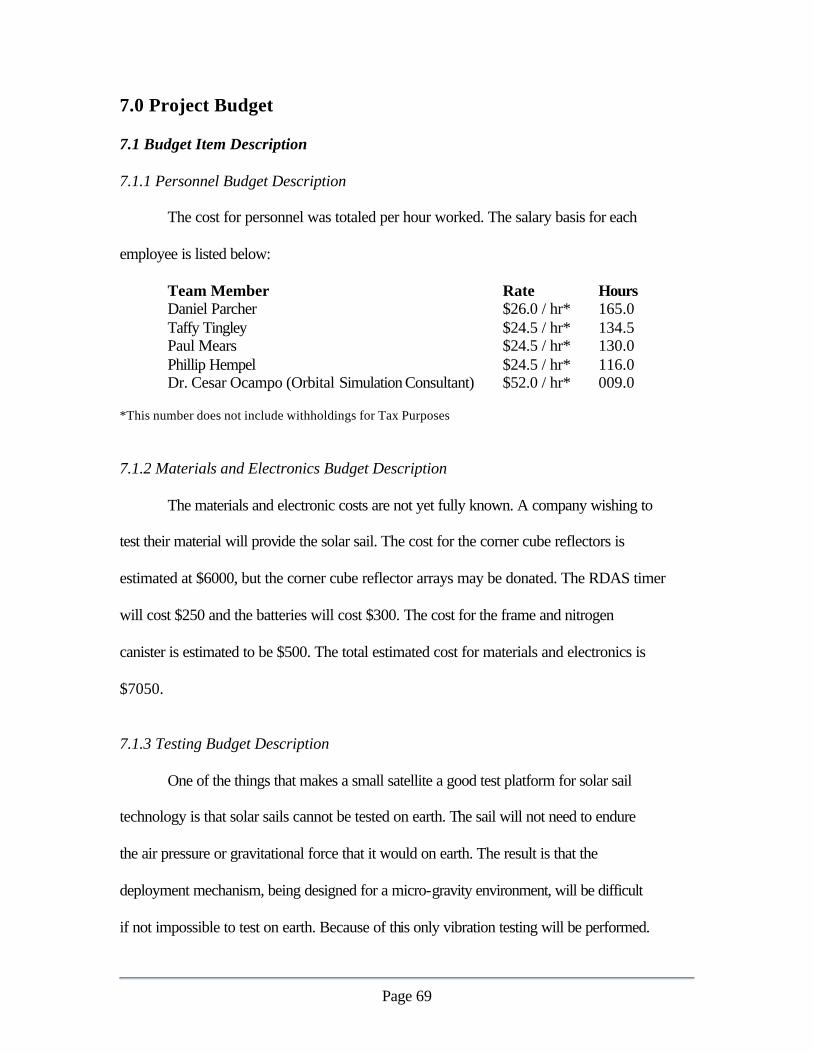
Page 69
7.0 Project Budget 7.1 Budget Item Description 7.1.1 Personnel Budget Description
The cost for personnel was totaled per hour worked. The salary basis for each
employee is listed below:
Team Member Rate Hours Daniel Parcher $26.0 / hr* 165.0 Taffy Tingley $24.5 / hr* 134.5 Paul Mears $24.5 / hr* 130.0 Phillip Hempel $24.5 / hr* 116.0 Dr. Cesar Ocampo (Orbital Simulation Consultant) $52.0 / hr* 009.0 *This number does not include withholdings for Tax Purposes 7.1.2 Materials and Electronics Budget Description
The materials and electronic costs are not yet fully known. A company wishing to
test their material will provide the solar sail. The cost for the corner cube reflectors is
estimated at $6000, but the corner cube reflector arrays may be donated. The RDAS timer
will cost $250 and the batteries will cost $300. The cost for the frame and nitrogen
canister is estimated to be $500. The total estimated cost for materials and electronics is
$7050.
7.1.3 Testing Budget Description
One of the things that makes a small satellite a good test platform for solar sail
technology is that solar sails cannot be tested on earth. The sail will not need to endure
the air pressure or gravitational force that it would on earth. The result is that the
deployment mechanism, being designed for a micro-gravity environment, will be difficult
if not impossible to test on earth. Because of this only vibration testing will be performed.

Page 70
After vibration testing, the systems will be inspected for damage. The estimate for
vibration testing cost is roughly $2000 and will be conducted by CalPoly.
7.1.4 Launch Budget Description
The CubeSat launch costs are roughly $50,000 per satellite launched. That cost is
expected to increase in the future, but PaperSat will estimate its final budget for one
CubeSat launched for the current cost.
7.1.5 Implementation Costs / Manufacturability
There will be little implementation cost for this project. A company wishing to
test their solar sail design will manufacture the sail. The only cost involved with
implementation of the sail will be the cost of folding it in the proper method for
deployment. The compressed nitrogen will be purchased and only requires fastening to
the satellite shell. The satellite timer, batteries and corner-cube reflectors will also be
purchased fully assembled and will need only to be fastened to the satellite shell. Break-
away joints for the shell walls, wiring for the timing system, and duct work for the
nitrogen canister will require a minimum of effort and cost to implement. The incidental
costs of manufacturing should stay below $1000.
Once the satellite is constructed, it will need to be tested for structural stability
under vibration. These tests will be conducted at Calpoly. The satellite will need to be
transported to the launch site. The cost of transportation should be minimal and will
possibly be donated by the University of Texas, especially if the launch site is within the
United States. The costs for launching the satellite are already incorporated into the

Page 71
budget. Ground station time for laser ranging of the satellite will be required, that time
will be provided from the ILRS after the application for laser ranging support for this
project has been submitted. Finally, student volunteers will need to perform post-
processing of the data received from the ground station.

Page 72
7.2 Budget Summary
The Table 4 contains a complete summary of the predicted expenses for the
PaperSat Engineering company’s work on this project.
Table 4 - Proposed Budget Expense Item Predicted
Expenses (dollars)
Expenses Realized (dollars)
Personnel (based on an estimated 150 hrs. worked, 14 hrs. for consultants) 15,653 14,080 Materials / Electronics 5,000 7,050 Testing 2,000 2,000 Launch 50,000 50,000 Total 72,653 73,130
It is easy to see from the Figure 36 below, that the majority of the expense for this
project lies with the launch cost.
Analysis of Proposed Budget
22%
7%
3%
68%
Personnel
Materials/ ElectronicsTesting
Launch
Figure 36 - Analysis of Proposed Budget

Page 73
7.3 Cost Overrun Analysis
The corner-cube reflector arrays will be of custom design. The estimated price for
the reflectors is $6000, based partially on the glass reflector design in the Banner
Engineering products catalog. The estimate is conservative for this design, but hidden
costs of construction of these arrays may cause the price of the reflectors to increase
above the estimated value.
The launch cost is subject to change for the CubeSat program. This not something
that PaperSat can control and could increase the cost of this project substantially. The
launch cost has the capability to change the cost of this project far more easily than any
other expense.

Page 74
8.0 Sustainability
There are no recourses aboard the spacecraft that must be replenished. The
spacecraft design relies on nitrogen and electricity for deployment, these resources will
not be replenished during the mission, but the satellite should not need these resources
once deployment has been completed. These non-replenishable resources need to last for
five hours after the satellite is inserted into its LEO to GEO orbit.
Once the satellite is deployed it needs only to stay in its deployed configuration to
provide empirical solar sail thrust data. However, the satellite needs only to remain in this
configuration for a few orbital periods so that thrust can be measured, if it is damaged
after that time, or re-enters the earth’s atmosphere, it will have already fulfilled its
mission.

Page 75
8.0 Social and Political Issues
This space mission will has several social and political issues associated with it.
This satellite design will test an untested type of space propulsion, a type of space
propulsion that has the capability to change the possibilities of spacecrafts travel. The
mission will enhance the United States’ presence at the forefront of space propulsion
technology.
8.1 Environmental impact
The environmental impact of a satellite operating a solar sail is almost non-
existent. The satellite will require a rocket to launch it to orbit. The launch does have the
potential to impact the environment, but not significantly. This project should be
considered environmentally safe.
The project does, however have the potential to impact the environment of the
University of Texas substantially. Should this project be implemented, the university will
receive attention from the media. Since no previous spacecraft have relied on solar
power, the university would very likely receive a substantial amount of publicity.
8.2 Ethics, Health and Safety There is one ethical, health and safety issue concerning this project. This satellite
could remain in orbit for an extended period of time. If the satellite continues to orbit the
earth for a long time after it has completed its mission, it will pose a collision threat to
other orbiting spacecraft. The solar sail should be very easy to see and track, so it is likely
that other spacecraft will be launched in such a way that they will not come into contact

Page 76
with this satellite. It is possible, however, that the solar sail, effectively space debris after
it has completed its mission, will collide with another satellite.
The solution to this issue is to ensure that other space missions are aware of this
satellite and can avoid it until the solar sail powered craft has the opportunity to re-enter
the earth’s atmosphere.

Page 77
9.0 Future Work The corner cube reflector specifications must still be determined. The glass corner
cube reflectors designed for this satellite are most likely within specifications and can be
used as designed. However, the reflectivity and target area requirements of the ILRS are
not yet known as they require a laser ranging support application which must be
reviewed. The ILRS offered by McDonald observatory is funded by NASA and must
evaluate each mission to be supported on a case by case basis. If the project, though the
University of Texas, is determined to be of worthy scientific value, then the laser ranging
services available for use on this particular project can be discussed. For example,
McDonald observatory my have the means to perform laser ranging with satellites that
have relatively low reflectivity corner cube reflector arrays, but not consider the project
of significant scientific value to spend a significant portion of their budget on laser
ranging for this mission. The amount of compensation they will require, if any and the
specifications of the corner cube reflectors they require can therefore not be completely
determined until a mission application has been submitted and reviewed. The glass corner
cube reflector designs will, however, most likely be sufficient for use with the ILRS
system.
A detailed thermal analysis of the satellite must also be preformed so that the
internal component specifications prescribed. If the internal components currently
selected do not meet the thermal requirements then environmental conditioning can be
added to the satellite design, or new components should be selected.

Page 78
Finally, an analysis of crack propagation for the solar sail, in the event that the
sail is damaged, would be useful for determining how well the solar sail can handle small
particles it may encounter.

Page 79
10.0 Conclusion
PaperSat Engineering has designed a CubeSat based solar sail testing platform.
The satellite design incorporates a compressed gas deployment system for the
Aluminized Mylar double reflective solar sail, corner cube reflector based optical
tracking, and an electronic timer that can supply triggers for events coordinated at
specific times. The orbital perturbations of the satellite will be measured periodically
from laser positioning supplied by the International Laser Ranging Service. The
magnitude of the solar sail thrust will be obtained from analysis of those perturbing
forces.
Companies wishing to test their solar sail design can employ PaperSat to integrate
their sail design into a picosatellite. The solar sail design will give education institutions
and their students the opportunity to participate in a complete satellite development
project, and the academic community can benefit from research of the cutting edge
propulsion technology.

Page 80
11.0 References 1. The University of Texas, “McDonald Laser Ranging Station”,
http://almagest.as.utexas.edu/~rlr/mlrs.html Site Accessed November 26, 2001 2. Banner Engineering Corp., “Retroreflector Products”
http://www.bannerengineering.com/products/accessories/retroreflectors/ Site Accessed September 17, 2001
3. Aerocon Systems Co. “RDAS Flight Electronics” http://www.fortunepaint.com/aerocon_interim/rdas.htm/ Site Accessed September 17, 2001
4. Ultralife Batteries, “Lithium Ion Polymer Batteries” http://www.ultralifebatteries.com/product-display.asp?ID=39 Site Accessed November 7, 2001
5. [1] Wright, Jerome. Space Sailing. Gordon and Breach Science Publishers, Langehorne, Pennsylvania 1992., pp. 2
6. Faust, Jeff. “Solar Sail Scheduled to Launch Early Next Year.” Spaceflight Now. August 23, 2001. http://www.spaceflightnow.com/news/n0108/23cosmos/ site accessed 1 Nov 2001.
7. Diedrich, Benjamin. “3 Axis Stabilized Solar Sails.” http://www.ugcs.caltech.edu/~diedrich/solarsails/types/3-axis.html. Site accessed October 14, 2001.
8. Solar Blade Solar Sail. http://www.frc.ri.cmu.edu/projects/blade/index2.html. Site accessed October 14, 2001.
9. Team Encounter Site. http://www.encounter2001.com/index.html. Site accessed October 14, 2001.
10. The Star of Tolerance. http://www.star-tolerance.com/english/index.htm. Site accessed October 14, 2001.
11. The Planetary Society: Cosmos I: The First Solar Sail. http://www.planetary.org/solarsail/index2.html. Site Accessed November 6, 2001
12. Clark, Greg. Space.com Exclusive: Breakthrough in Solar Sail Technology.” http://www.space.com/businesstechnology/technology/carbonsail_000302.html. Site accessed October 14, 2001.
13. “Staying Cool on the ISS.” http://www.geocities.com/beyondearth2001/view15.htm. Site accessed November 6, 2001.
14. “Ariel 2.” Space Science. http://www.nasm.edu/nasm/dsh/artifacts/SS-ariel2.htm. Site accessed November 6, 2001.
15. Vallado, David A. Fundamentals of Astrodynamics and Applications. McGraw-Hill 1997 pp. 7,38,101-105
16. Dr. Ocampo, Cesar. Supplemental Instruction and Lectures, Weekly Mtgs. September though November 2001.
17. Polyakhova, Yalena Nikolayevna. Space Flight Using a Solar Sail: The Problems and Prospects. Leningrad State U, Department of Celestial Mechanics, July 1986

Page 81
Appendix A – PaperSat Team Appendix B – CubeSat Frame Appendix C – Orbital Simulation Code Appendix D – PaperSat Schedule
Recommended