July 2007
CA08101001E For more information visit:
www.eaton.com
Contents
Group Metering & Meter Breakers 5-1
5
Gro
up
Mete
rin
g &
Mete
r B
reakers
Description Page
Single Meter Sockets . . . . . . . . . . . . . . . . . . . . . . . . . . . . . . . . . . . . . . . . . . . . 5-2
Group Metering . . . . . . . . . . . . . . . . . . . . . . . . . . . . . . . . . . . . . . . . . . . . . . . . . 5-8
Meter Packs. . . . . . . . . . . . . . . . . . . . . . . . . . . . . . . . . . . . . . . . . . . . . . . . . .
5-10
Main Service Modules . . . . . . . . . . . . . . . . . . . . . . . . . . . . . . . . . . . . . . . . .
5-16
Main Circuit Breakers . . . . . . . . . . . . . . . . . . . . . . . . . . . . . . . . . . . . . . . . . .
5-19
Main Fusible Switches . . . . . . . . . . . . . . . . . . . . . . . . . . . . . . . . . . . . . . . . .
5-20
Surge Metering. . . . . . . . . . . . . . . . . . . . . . . . . . . . . . . . . . . . . . . . . . . . . . .
5-28
Residential Meter Stacks . . . . . . . . . . . . . . . . . . . . . . . . . . . . . . . . . . . . . . .
5-29
Commercial Meter Stacks . . . . . . . . . . . . . . . . . . . . . . . . . . . . . . . . . . . . . .
5-38
Accessories . . . . . . . . . . . . . . . . . . . . . . . . . . . . . . . . . . . . . . . . . . . . . . . . . .
5-44
Phase Balancing . . . . . . . . . . . . . . . . . . . . . . . . . . . . . . . . . . . . . . . . . . . . . .
5-48
Series Combination Short Circuit Ratings . . . . . . . . . . . . . . . . . . . . . . . . .
5-49
Technical Specifications. . . . . . . . . . . . . . . . . . . . . . . . . . . . . . . . . . . . . . . .
5-52
Meter Breakers
Residential . . . . . . . . . . . . . . . . . . . . . . . . . . . . . . . . . . . . . . . . . . . . . . . . . .
5-53
House Panels . . . . . . . . . . . . . . . . . . . . . . . . . . . . . . . . . . . . . . . . . . . . . . . .
5-80
Commercial Safety Sockets. . . . . . . . . . . . . . . . . . . . . . . . . . . . . . . . . . . . .
5-87
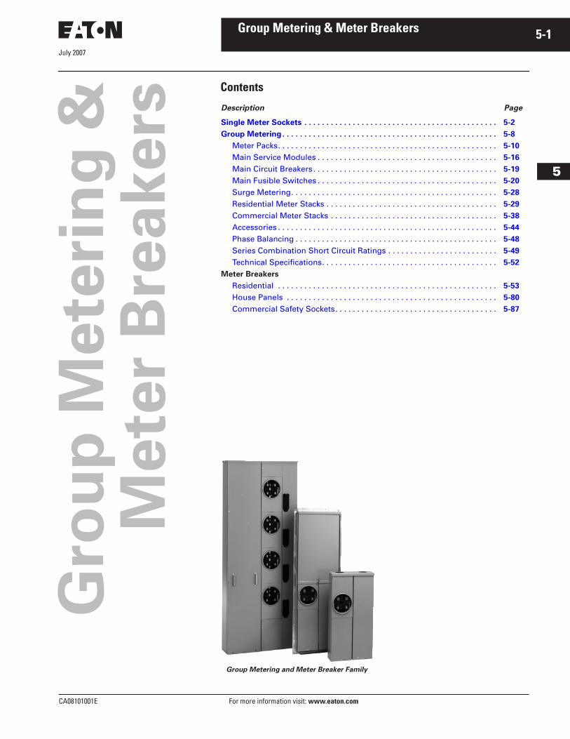
Group Metering and Meter Breaker Family
August 2007
5-2
For more information visit:
www.eaton.com
CA08101001E
Group Metering & Meter Breakers
5
Single Meter Sockets
Product Selection
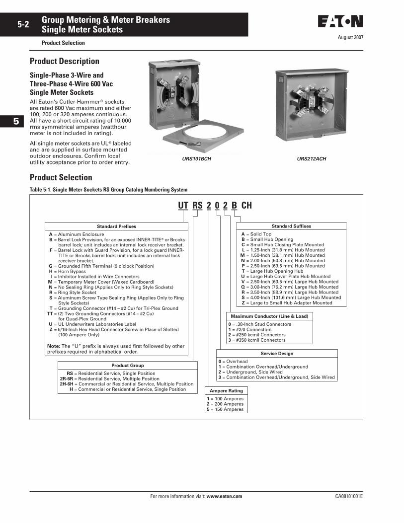
Product Description
Single-Phase 3-Wire and Three-Phase 4-Wire 600 Vac Single Meter Sockets
All Eaton’s Cutler-Hammer
�
sockets are rated 600 Vac maximum and either 100, 200 or 320 amperes continuous. All have a short circuit rating of 10,000 rms symmetrical amperes (watthour meter is not included in rating).
All single meter sockets are UL
�
labeled and are supplied in surface mounted outdoor enclosures. Confirm local utility acceptance prior to order entry.
URS101BCH URS212ACH
Product Selection
Table 5-1. Single Meter Sockets RS Group Catalog Numbering System
UT RS 2 0 2 B CH
Standard Prefixes
A = Aluminum EnclosureB = Barrel Lock Provision, for an exposed INNER-TITE� or Brooks
barrel lock; unit includes an internal lock receiver bracket.F = Barrel Lock with Guard Provision, for a lock guard INNER-
TITE or Brooks barrel lock; unit includes an internal lock receiver bracket.
G = Grounded Fifth Terminal (9 o’clock Position)H = Horn BypassI = Inhibitor Installed in Wire Connectors
M = Temporary Meter Cover (Waxed Cardboard)N = No Sealing Ring (Applies Only to Ring Style Sockets)R = Ring Style SocketS = Aluminum Screw Type Sealing Ring (Applies Only to Ring
Style Sockets)T = Grounding Connector (#14 – #2 Cu) for Tri-Plex Ground
TT = (2) Two Grounding Connectors (#14 – #2 Cu) for Quad-Plex Ground
U = UL Underwriters Laboratories LabelZ = 5/16-Inch Hex Head Connector Screw in Place of Slotted
(100 Ampere Only)
Note: The “U” prefix is always used first followed by other prefixes required in alphabetical order.
Standard Suffixes
A = Solid TopB = Small Hub OpeningC = Small Hub Closing Plate MountedL = 1.25-Inch (31.8 mm) Hub Mounted
M = 1.50-Inch (38.1 mm) Hub MountedN = 2.00-Inch (50.8 mm) Hub MountedP = 2.50-Inch (63.5 mm) Hub MountedT = Large Hub Opening HubU = Large Hub Cover Plate Hub MountedV = 2.50-Inch (63.5 mm) Large Hub MountedQ = 3.00-Inch (76.2 mm) Large Hub MountedR = 3.50-Inch (88.9 mm) Large Hub MountedS = 4.00-Inch (101.6 mm) Large Hub MountedZ = Large to Small Hub Adapter Mounted
Ampere Rating
1 = 100 Amperes2 = 200 Amperes5 = 150 Amperes
Maximum Conductor (Line & Load)
0 = .38-Inch Stud Connectors1 = #2/0 Connectors2 = #250 kcmil Connectors3 = #350 kcmil Connectors
Service Design
0 = Overhead1 = Combination Overhead/Underground2 = Underground, Side Wired3 = Combination Overhead/Underground, Side Wired
Product Group
RS = Residential Service, Single Position2R-6R = Residential Service, Multiple Position2H-6H = Commercial or Residential Service, Multiple Position
H = Commercial or Residential Service, Single Position
August 2007
CA08101001E For more information visit:
www.eaton.com
5-3Group Metering & Meter Breakers
5
Single Meter Sockets
Product Selection
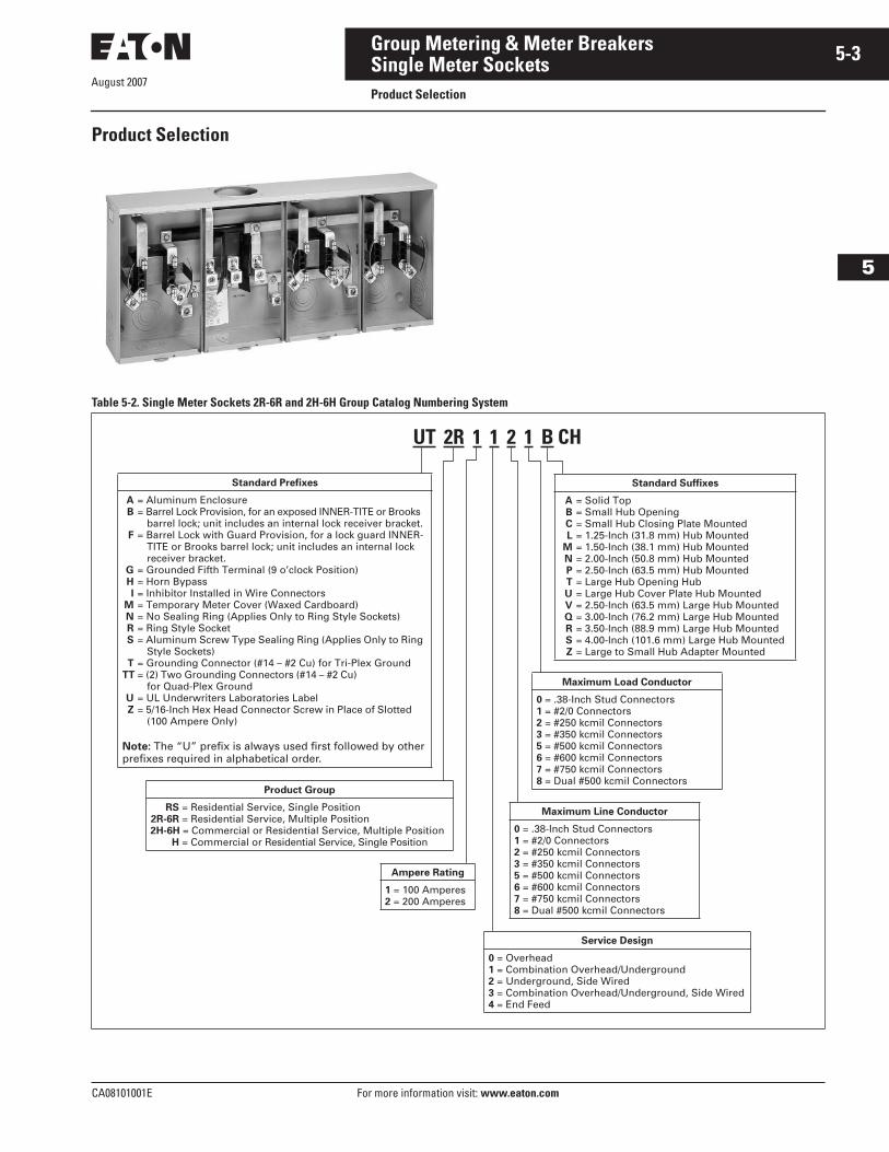
Product Selection
Table 5-2. Single Meter Sockets 2R-6R and 2H-6H Group Catalog Numbering System
UT 2R 1 1 2 1 B CH
Standard Prefixes
A = Aluminum EnclosureB = Barrel Lock Provision, for an exposed INNER-TITE or Brooks
barrel lock; unit includes an internal lock receiver bracket.F = Barrel Lock with Guard Provision, for a lock guard INNER-
TITE or Brooks barrel lock; unit includes an internal lock receiver bracket.
G = Grounded Fifth Terminal (9 o’clock Position)H = Horn BypassI = Inhibitor Installed in Wire Connectors
M = Temporary Meter Cover (Waxed Cardboard)N = No Sealing Ring (Applies Only to Ring Style Sockets)R = Ring Style SocketS = Aluminum Screw Type Sealing Ring (Applies Only to Ring
Style Sockets)T = Grounding Connector (#14 – #2 Cu) for Tri-Plex Ground
TT = (2) Two Grounding Connectors (#14 – #2 Cu) for Quad-Plex Ground
U = UL Underwriters Laboratories LabelZ = 5/16-Inch Hex Head Connector Screw in Place of Slotted
(100 Ampere Only)
Note: The “U” prefix is always used first followed by other prefixes required in alphabetical order.
Standard Suffixes
A = Solid TopB = Small Hub OpeningC = Small Hub Closing Plate MountedL = 1.25-Inch (31.8 mm) Hub Mounted
M = 1.50-Inch (38.1 mm) Hub MountedN = 2.00-Inch (50.8 mm) Hub MountedP = 2.50-Inch (63.5 mm) Hub MountedT = Large Hub Opening HubU = Large Hub Cover Plate Hub MountedV = 2.50-Inch (63.5 mm) Large Hub MountedQ = 3.00-Inch (76.2 mm) Large Hub MountedR = 3.50-Inch (88.9 mm) Large Hub MountedS = 4.00-Inch (101.6 mm) Large Hub MountedZ = Large to Small Hub Adapter Mounted
Ampere Rating
1 = 100 Amperes2 = 200 Amperes
Maximum Load Conductor
0 = .38-Inch Stud Connectors1 = #2/0 Connectors2 = #250 kcmil Connectors3 = #350 kcmil Connectors5 = #500 kcmil Connectors6 = #600 kcmil Connectors7 = #750 kcmil Connectors8 = Dual #500 kcmil Connectors
Service Design
0 = Overhead1 = Combination Overhead/Underground2 = Underground, Side Wired3 = Combination Overhead/Underground, Side Wired4 = End Feed
Product Group
RS = Residential Service, Single Position2R-6R = Residential Service, Multiple Position2H-6H = Commercial or Residential Service, Multiple Position
H = Commercial or Residential Service, Single Position
Maximum Line Conductor
0 = .38-Inch Stud Connectors1 = #2/0 Connectors2 = #250 kcmil Connectors3 = #350 kcmil Connectors5 = #500 kcmil Connectors6 = #600 kcmil Connectors7 = #750 kcmil Connectors8 = Dual #500 kcmil Connectors
August 2007
5-4
For more information visit:
www.eaton.com
CA08101001E
Group Metering & Meter Breakers
5
Single Meter SocketsProduct Selection
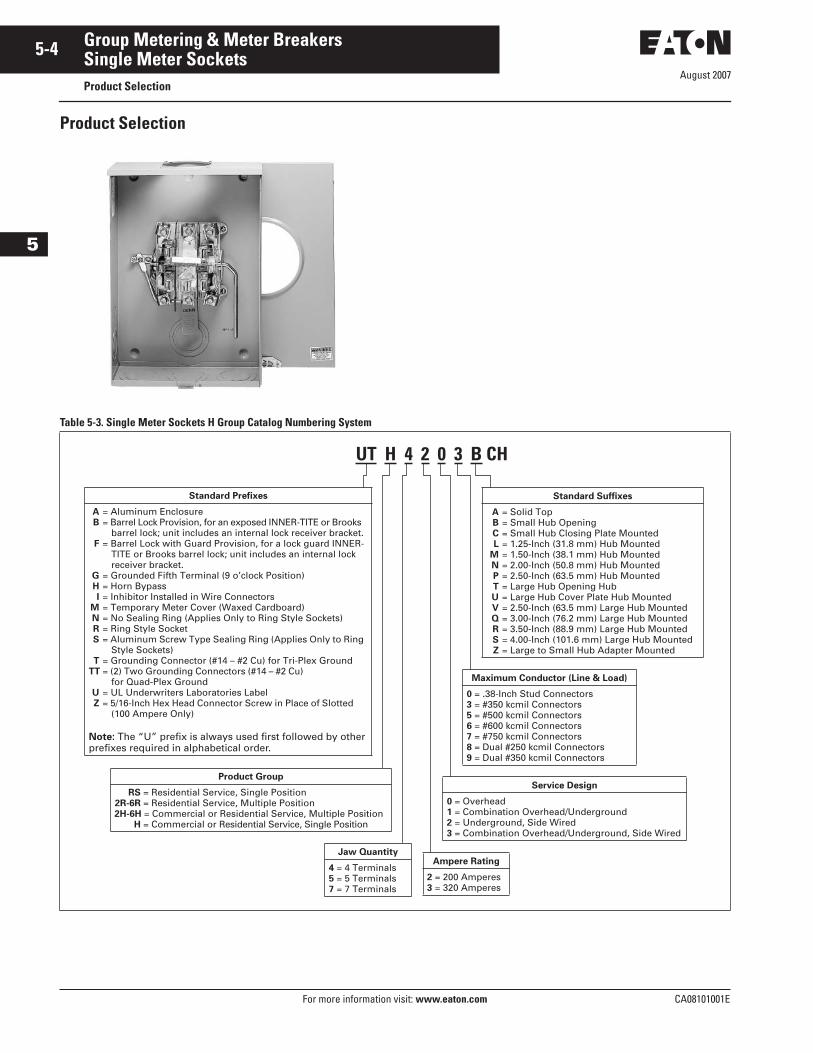
Product Selection
Table 5-3. Single Meter Sockets H Group Catalog Numbering System
UT H 4 2 0 3 B CH
Standard Prefixes
A = Aluminum EnclosureB = Barrel Lock Provision, for an exposed INNER-TITE or Brooks
barrel lock; unit includes an internal lock receiver bracket.F = Barrel Lock with Guard Provision, for a lock guard INNER-
TITE or Brooks barrel lock; unit includes an internal lock receiver bracket.
G = Grounded Fifth Terminal (9 o’clock Position)H = Horn BypassI = Inhibitor Installed in Wire Connectors
M = Temporary Meter Cover (Waxed Cardboard)N = No Sealing Ring (Applies Only to Ring Style Sockets)R = Ring Style SocketS = Aluminum Screw Type Sealing Ring (Applies Only to Ring
Style Sockets)T = Grounding Connector (#14 – #2 Cu) for Tri-Plex Ground
TT = (2) Two Grounding Connectors (#14 – #2 Cu) for Quad-Plex Ground
U = UL Underwriters Laboratories LabelZ = 5/16-Inch Hex Head Connector Screw in Place of Slotted
(100 Ampere Only)
Note: The “U” prefix is always used first followed by other prefixes required in alphabetical order.
Standard Suffixes
A = Solid TopB = Small Hub OpeningC = Small Hub Closing Plate MountedL = 1.25-Inch (31.8 mm) Hub Mounted
M = 1.50-Inch (38.1 mm) Hub MountedN = 2.00-Inch (50.8 mm) Hub MountedP = 2.50-Inch (63.5 mm) Hub MountedT = Large Hub Opening HubU = Large Hub Cover Plate Hub MountedV = 2.50-Inch (63.5 mm) Large Hub MountedQ = 3.00-Inch (76.2 mm) Large Hub MountedR = 3.50-Inch (88.9 mm) Large Hub MountedS = 4.00-Inch (101.6 mm) Large Hub MountedZ = Large to Small Hub Adapter Mounted
Ampere Rating
2 = 200 Amperes3 = 320 Amperes
Maximum Conductor (Line & Load)
0 = .38-Inch Stud Connectors3 = #350 kcmil Connectors5 = #500 kcmil Connectors6 = #600 kcmil Connectors7 = #750 kcmil Connectors8 = Dual #250 kcmil Connectors9 = Dual #350 kcmil Connectors
Service Design
0 = Overhead1 = Combination Overhead/Underground2 = Underground, Side Wired3 = Combination Overhead/Underground, Side Wired
Product Group
RS = Residential Service, Single Position2R-6R = Residential Service, Multiple Position2H-6H = Commercial or Residential Service, Multiple Position
H = Commercial or Residential Service, Single Position
Jaw Quantity
4 = 4 Terminals5 = 5 Terminals7 = 7 Terminals
August 2007
CA08101001E For more information visit: www.eaton.com
5-5Group Metering & Meter Breakers
5
Single Meter SocketsProduct Selection
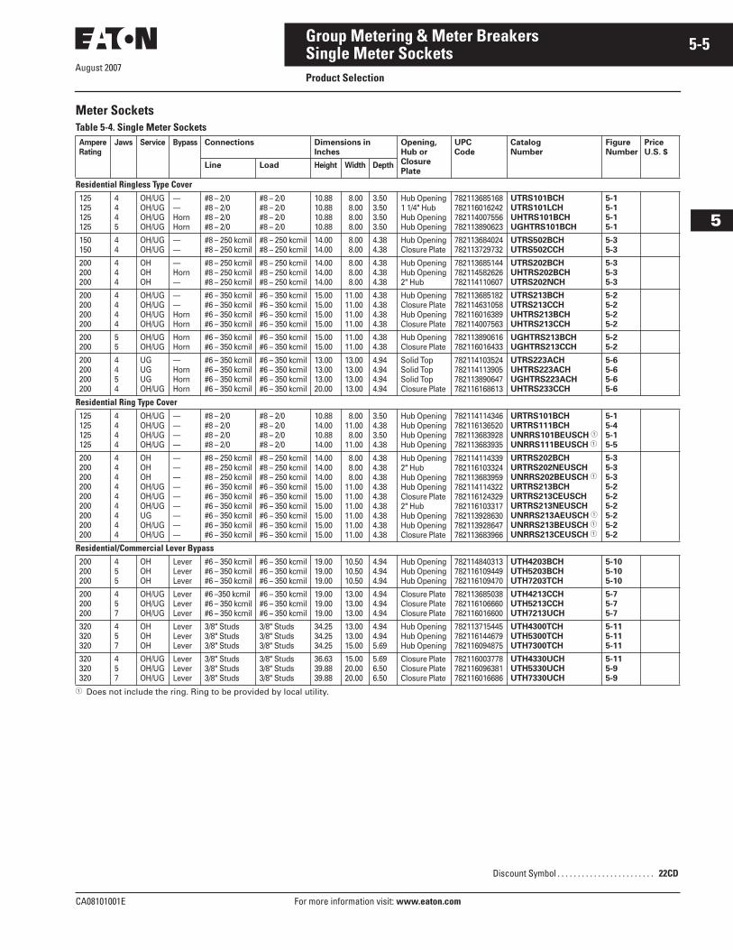
Meter SocketsTable 5-4. Single Meter Sockets
� Does not include the ring. Ring to be provided by local utility.
AmpereRating
Jaws Service Bypass Connections Dimensions in Inches
Opening,Hub orClosure Plate
UPCCode
CatalogNumber
FigureNumber
PriceU.S. $
Line Load Height Width Depth
Residential Ringless Type Cover125125125125
4445
OH/UGOH/UGOH/UGOH/UG
——HornHorn
#8 – 2/0#8 – 2/0#8 – 2/0#8 – 2/0
#8 – 2/0#8 – 2/0#8 – 2/0#8 – 2/0
10.8810.8810.8810.88
8.00 8.00 8.00 8.00
3.503.503.503.50
Hub Opening1 1/4" HubHub OpeningHub Opening
782113685168782116016242782114007556782113890623
UTRS101BCHUTRS101LCHUHTRS101BCHUGHTRS101BCH
5-15-15-15-1
150150
44
OH/UGOH/UG
——
#8 – 250 kcmil#8 – 250 kcmil
#8 – 250 kcmil#8 – 250 kcmil
14.0014.00
8.00 8.00
4.384.38
Hub OpeningClosure Plate
782113684024782113729732
UTRS502BCHUTRS502CCH
5-35-3
200200200
444
OHOHOH
—Horn—
#8 – 250 kcmil#8 – 250 kcmil#8 – 250 kcmil
#8 – 250 kcmil#8 – 250 kcmil#8 – 250 kcmil
14.0014.0014.00
8.00 8.00 8.00
4.384.384.38
Hub OpeningHub Opening2" Hub
782113685144782114582626782114110607
UTRS202BCHUHTRS202BCHUTRS202NCH
5-35-35-3
200200200200
4444
OH/UGOH/UGOH/UGOH/UG
——HornHorn
#6 – 350 kcmil#6 – 350 kcmil#6 – 350 kcmil#6 – 350 kcmil
#6 – 350 kcmil#6 – 350 kcmil#6 – 350 kcmil#6 – 350 kcmil
15.0015.0015.0015.00
11.0011.0011.0011.00
4.384.384.384.38
Hub OpeningClosure PlateHub OpeningClosure Plate
782113685182782114631058782116016389782114007563
UTRS213BCHUTRS213CCHUHTRS213BCHUHTRS213CCH
5-25-25-25-2
200200
55
OH/UGOH/UG
HornHorn
#6 – 350 kcmil#6 – 350 kcmil
#6 – 350 kcmil#6 – 350 kcmil
15.0015.00
11.0011.00
4.384.38
Hub OpeningClosure Plate
782113890616782116016433
UGHTRS213BCHUGHTRS213CCH
5-25-2
200200200200
4454
UGUGUGOH/UG
—HornHornHorn
#6 – 350 kcmil#6 – 350 kcmil#6 – 350 kcmil#6 – 350 kcmil
#6 – 350 kcmil#6 – 350 kcmil#6 – 350 kcmil#6 – 350 kcmil
13.0013.0013.0020.00
13.0013.0013.0013.00
4.944.944.944.94
Solid TopSolid TopSolid TopClosure Plate
782114103524782114113905782113890647782116168613
UTRS223ACHUHTRS223ACHUGHTRS223ACHUHTRS233CCH
5-65-65-65-6
Residential Ring Type Cover125125125125
4444
OH/UGOH/UGOH/UGOH/UG
————
#8 – 2/0#8 – 2/0#8 – 2/0#8 – 2/0
#8 – 2/0#8 – 2/0#8 – 2/0#8 – 2/0
10.8814.0010.8814.00
8.0011.00 8.0011.00
3.504.383.504.38
Hub OpeningHub OpeningHub OpeningHub Opening
782114114346782116136520782113683928782113683935
URTRS101BCHURTRS111BCHUNRRS101BEUSCH �
UNRRS111BEUSCH �
5-15-45-15-5
200200200200200200200200200
444444444
OHOHOHOH/UGOH/UGOH/UGUGOH/UGOH/UG
—————————
#8 – 250 kcmil#8 – 250 kcmil#8 – 250 kcmil#6 – 350 kcmil#6 – 350 kcmil#6 – 350 kcmil#6 – 350 kcmil#6 – 350 kcmil#6 – 350 kcmil
#8 – 250 kcmil#8 – 250 kcmil#8 – 250 kcmil#6 – 350 kcmil#6 – 350 kcmil#6 – 350 kcmil#6 – 350 kcmil#6 – 350 kcmil#6 – 350 kcmil
14.0014.0014.0015.0015.0015.0015.0015.0015.00
8.00 8.00 8.0011.0011.0011.0011.0011.0011.00
4.384.384.384.384.384.384.384.384.38
Hub Opening2" HubHub OpeningHub OpeningClosure Plate2" HubHub OpeningHub OpeningClosure Plate
782114114339782116103324782113683959782114114322782116124329782116103317782113928630782113928647782113683966
URTRS202BCHURTRS202NEUSCHUNRRS202BEUSCH �
URTRS213BCHURTRS213CEUSCHURTRS213NEUSCHUNRRS213AEUSCH �
UNRRS213BEUSCH �
UNRRS213CEUSCH �
5-35-35-35-25-25-25-25-25-2
Residential/Commercial Lever Bypass200200200
455
OHOHOH
LeverLeverLever
#6 – 350 kcmil#6 – 350 kcmil#6 – 350 kcmil
#6 – 350 kcmil#6 – 350 kcmil#6 – 350 kcmil
19.0019.0019.00
10.5010.5010.50
4.944.944.94
Hub OpeningHub OpeningHub Opening
782114840313782116109449782116109470
UTH4203BCHUTH5203BCHUTH7203TCH
5-105-105-10
200200200
457
OH/UGOH/UGOH/UG
LeverLeverLever
#6 –350 kcmil#6 – 350 kcmil#6 – 350 kcmil
#6 – 350 kcmil#6 – 350 kcmil#6 – 350 kcmil
19.0019.0019.00
13.0013.0013.00
4.944.944.94
Closure PlateClosure PlateClosure Plate
782113685038782116106660782116016600
UTH4213CCHUTH5213CCHUTH7213UCH
5-75-75-7
320320320
457
OHOHOH
LeverLeverLever
3/8" Studs3/8" Studs3/8" Studs
3/8" Studs3/8" Studs3/8" Studs
34.2534.2534.25
13.0013.0015.00
4.944.945.69
Hub OpeningHub OpeningHub Opening
782113715445782116144679782116094875
UTH4300TCHUTH5300TCHUTH7300TCH
5-115-115-11
320320320
457
OH/UGOH/UGOH/UG
LeverLeverLever
3/8" Studs3/8" Studs3/8" Studs
3/8" Studs3/8" Studs3/8" Studs
36.6339.8839.88
15.0020.0020.00
5.696.506.50
Closure PlateClosure PlateClosure Plate
782116003778782116096381782116016686
UTH4330UCHUTH5330UCHUTH7330UCH
5-115-95-9
Discount Symbol . . . . . . . . . . . . . . . . . . . . . . . . 22CD
August 2007
5-6
For more information visit: www.eaton.com CA08101001E
Group Metering & Meter Breakers
5
Single Meter SocketsProduct Selection
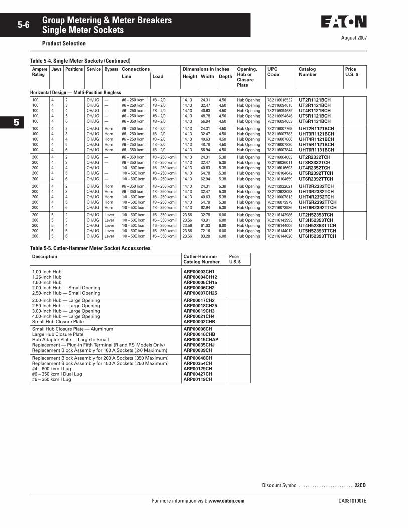
Table 5-4. Single Meter Sockets (Continued)
Table 5-5. Cutler-Hammer Meter Socket Accessories
AmpereRating
Jaws Positions Service Bypass Connections Dimensions in Inches Opening, Hub or Closure Plate
UPCCode
CatalogNumber
PriceU.S. $Line Load Height Width Depth
Horizontal Design — Multi-Position Ringless100100100100100
44444
23456
OH/UGOH/UGOH/UGOH/UGOH/UG
—————
#6 – 250 kcmil#6 – 250 kcmil#6 – 250 kcmil#6 – 250 kcmil#6 – 350 kcmil
#8 – 2/0#8 – 2/0#8 – 2/0#8 – 2/0#8 – 2/0
14.1314.1314.1314.1314.13
24.3132.4740.6348.7856.94
4.504.504.504.504.50
Hub OpeningHub OpeningHub OpeningHub OpeningHub Opening
782116016532782116094615782116094639782116094646782116094653
UT2R1121BCHUT3R1121BCHUT4R1121BCHUT5R1121BCHUT6R1131BCH
100100100100100
44444
23456
OH/UGOH/UGOH/UGOH/UGOH/UG
HornHornHornHornHorn
#6 – 250 kcmil#6 – 250 kcmil#6 – 250 kcmil#6 – 250 kcmil#6 – 350 kcmil
#8 – 2/0#8 – 2/0#8 – 2/0#8 – 2/0#8 – 2/0
14.1314.1314.1314.1314.13
24.3132.4740.6348.7856.94
4.504.504.504.504.50
Hub OpeningHub OpeningHub OpeningHub OpeningHub Opening
782116007769782116007783782116007806782116007820782116007844
UHT2R1121BCHUHT3R1121BCHUHT4R1121BCHUHT5R1121BCHUHT6R1131BCH
200200200200200
44444
23456
OH/UGOH/UGOH/UGOH/UGOH/UG
—————
#6 – 350 kcmil#6 – 350 kcmil1/0 – 500 kcmil1/0 – 500 kcmil1/0 – 500 kcmil
#8 – 250 kcmil#8 – 250 kcmil#8 – 250 kcmil#8 – 250 kcmil#8 – 250 kcmil
14.1314.1314.1314.1314.13
24.3132.4740.6354.7862.94
5.385.385.385.385.38
Hub OpeningHub OpeningHub OpeningHub OpeningHub Opening
782116064083782116036011782116016693782116104642782116104659
UT2R2332TCHUT3R2332TCHUT4R2352TCHUT5R2392TTCHUT6R2392TTCH
200200200200200
44444
23456
OH/UGOH/UGOH/UGOH/UGOH/UG
HornHornHornHornHorn
#6 – 350 kcmil#6 – 350 kcmil1/0 – 500 kcmil1/0 – 500 kcmil1/0 – 500 kcmil
#8 – 250 kcmil#8 – 250 kcmil#8 – 250 kcmil#8 – 250 kcmil#8 – 250 kcmil
14.1314.1314.1314.1314.13
24.3132.4740.6354.7862.94
5.385.385.385.385.38
Hub OpeningHub OpeningHub OpeningHub OpeningHub Opening
782113922621782113923093782116007813782116073979782116073986
UHT2R2332TCHUHT3R2332TCHUHT4R2352TCHUHT5R2392TTCHUHT6R2392TTCH
200200200200200
55555
23456
OH/UGOH/UGOH/UGOH/UGOH/UG
LeverLeverLeverLeverLever
1/0 – 500 kcmil1/0 – 500 kcmil1/0 – 500 kcmil1/0 – 500 kcmil1/0 – 500 kcmil
#6 – 350 kcmil#6 – 350 kcmil#6 – 350 kcmil#6 – 350 kcmil#6 – 350 kcmil
23.5623.5623.5623.5623.56
32.7843.9161.0372.1683.28
6.006.006.006.006.00
Hub OpeningHub OpeningHub OpeningHub OpeningHub Opening
782116143986782116143993782116144006782116144013782116144020
UT2H52353TCHUT3H52353TCHUT4H52393TTCHUT5H52393TTCHUT6H52393TTCH
Description Cutler-HammerCatalog Number
PriceU.S. $
1.00-Inch Hub 1.25-Inch Hub 1.50-Inch Hub2.00-Inch Hub — Small Opening2.50-Inch Hub — Small Opening
ARP00003CH1ARP00004CH12ARP00005CH15ARP00006CH2ARP00007CH25
2.00-Inch Hub — Large Opening2.50-Inch Hub — Large Opening3.00-Inch Hub — Large Opening4.00-Inch Hub — Large OpeningSmall Hub Closure Plate
ARP00017CH2ARP00018CH25ARP00019CH3ARP00021CH4ARP00002CHB
Small Hub Closure Plate — AluminumLarge Hub Closure PlateHub Adapter Plate — Large to SmallReplacement — Plug-in Fifth Terminal (R and RS Models Only)Replacement Block Assembly for 100 A Sockets (2/0 Maximum)
ARP00008CHARP00016CHBARP00015CHAPARP00035CHJARP00039CH
Replacement Block Assembly for 200 A Sockets (350 Maximum)Replacement Block Assembly for 150 A Sockets (250 Maximum)#4 – 600 kcmil Lug#6 – 350 kcmil Dual Lug#6 – 350 kcmil Lug
ARP00048CHARP00354CHARP00129CHARP00427CHARP00119CH
Discount Symbol . . . . . . . . . . . . . . . . . . . . . . . . 22CD
CA08101001E For more information visit: www.eaton.com
5-7Group Metering & Meter Breakers
August 2007
5
Single Meter SocketsProduct Selection
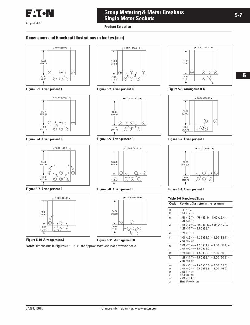
Dimensions and Knockout Illustrations in Inches (mm)
Note: Dimensions in Figures 5-1 – 5-11 are approximate and not drawn to scale.
Figure 5-1. Arrangement A
dd d
f c
a
8.00 (203.1)
10.88(276.1)
3.50(88.9) c
Figure 5-2. Arrangement B
4.38(111.1)
g g
k k
ab
15.00(380.8)
11.00 (279.3)
g
k
Figure 5-4. Arrangement D
m m
k kk
ab
11.00 (279.3)
14.00(355.5)
4.38(111.1)
m
Figure 5-5. Arrangement E
4.38(111.1)
g g
h h
ab
14.00(355.5)
11.00 (279.3)
g
h
Figure 5-7. Arrangement G
e e
13.00 (330.2)
19.00(482.6)
5.00(127.0)
pbag
n
n
n n
Figure 5-8. Arrangement H
15.00 (381.0)
36.63(930.2)
5.69(144.5)
rrr
r r r
ab
Figure 5-10. Arrangement J
e
19.00(482.6)
ba n
n
10.50 (266.7)
4.94(125.5)
g
e
Table 5-6. Knockout SizesCode Conduit Diameter in Inches (mm)
ab
.31 (7.9) .50 (12.7)
c .50 (12.7) – .75 (19.1) – 1.00 (25.4) – 1.25 (31.7)
d .50 (12.7) – .75 (19.1) – 1.00 (25.4) – 1.25 (31.7) – 1.50 (38.1)
e .75 (19.1)
f 1.00 (25.4) – 1.25 (31.7) – 1.50 (38.1) – 2.00 (50.8)
g 1.00 (25.4) – 1.25 (31.7) – 1.50 (38.1) – 2.00 (50.8) – 2.50 (63.5)
h 1.25 (31.7) – 1.50 (38.1) – 2.00 (50.8)
k 1.25 (31.7) – 1.50 (38.1) – 2.00 (50.8) – 2.50 (63.5)
mnprsx
1.50 (38.1) – 2.00 (50.8) – 2.50 (63.5)2.00 (50.8) – 2.50 (63.5) – 3.00 (76.2)3.00 (76.2)3.50 (88.9)4.00 (101.6)Hub Provision
Figure 5-3. Arrangement C
4.38(111.1) m
a
b
8.00 (203.1)
14.00(355.5)
m m m
Figure 5-6. Arrangement F
ab
g
g
n
g
13.00 (330.1)
13.00(330.1)
4.94(125.4)
Figure 5-9. Arrangement I
20.00 (508.0)
39.88(1012.8)
6.50(165.1)
ss
s s s
ba
Figure 5-11. Arrangement K
13.00 (330.2)
5.69(144.5)
b a
n
n
n n
n
34.50(876.3)
August 2007
5-8
For more information visit: www.eaton.com CA08101001E
Group Metering & Meter Breakers
5
Group MeteringProduct Selection
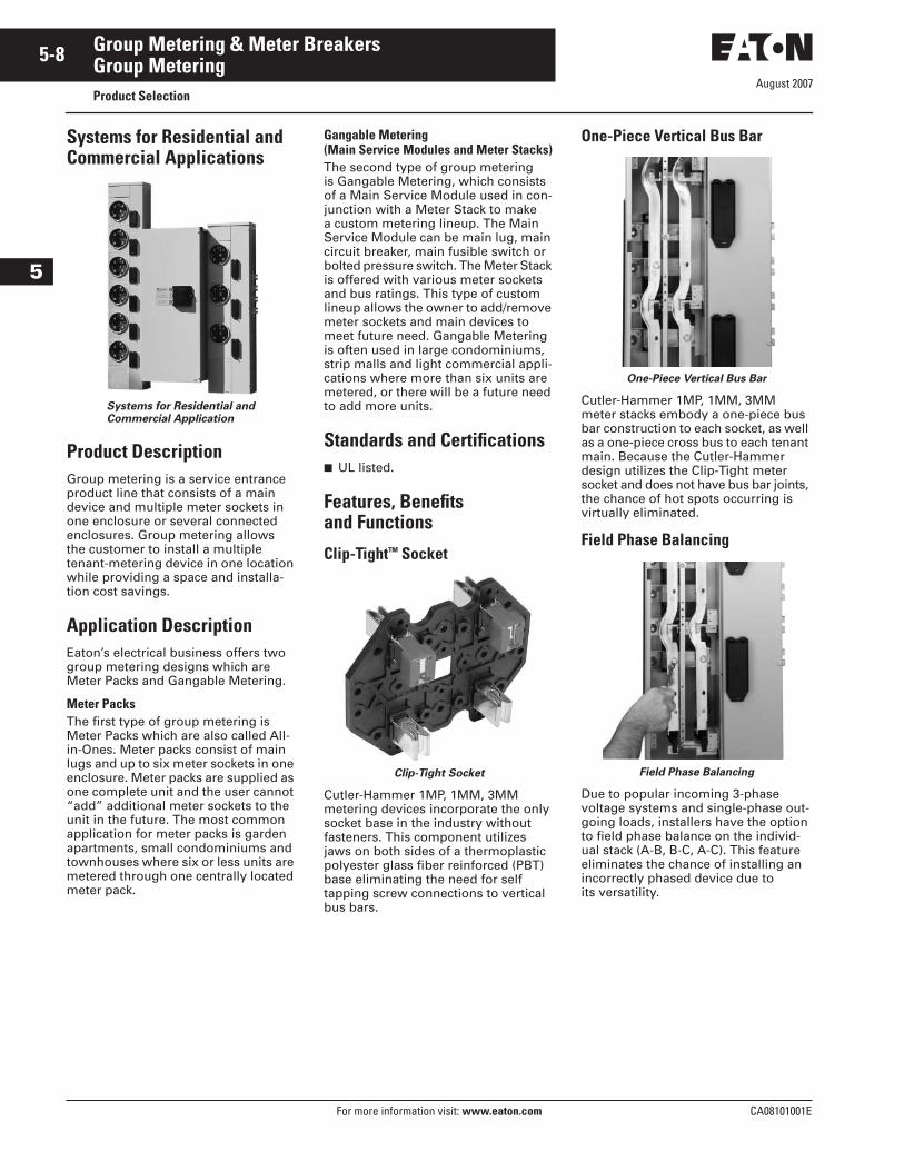
Systems for Residential and Commercial Applications
Systems for Residential and Commercial Application
Product DescriptionGroup metering is a service entrance product line that consists of a main device and multiple meter sockets in one enclosure or several connected enclosures. Group metering allows the customer to install a multiple tenant-metering device in one location while providing a space and installa-tion cost savings.
Application DescriptionEaton’s electrical business offers two group metering designs which are Meter Packs and Gangable Metering.
Meter PacksThe first type of group metering is Meter Packs which are also called All-in-Ones. Meter packs consist of main lugs and up to six meter sockets in one enclosure. Meter packs are supplied as one complete unit and the user cannot “add” additional meter sockets to the unit in the future. The most common application for meter packs is garden apartments, small condominiums and townhouses where six or less units are metered through one centrally located meter pack.
Gangable Metering(Main Service Modules and Meter Stacks)The second type of group metering is Gangable Metering, which consists of a Main Service Module used in con-junction with a Meter Stack to make a custom metering lineup. The Main Service Module can be main lug, main circuit breaker, main fusible switch or bolted pressure switch. The Meter Stack is offered with various meter sockets and bus ratings. This type of custom lineup allows the owner to add/remove meter sockets and main devices to meet future need. Gangable Metering is often used in large condominiums, strip malls and light commercial appli-cations where more than six units are metered, or there will be a future need to add more units.
Standards and Certifications■ UL listed.
Features, Benefits and Functions
Clip-Tight™ Socket
Clip-Tight Socket
Cutler-Hammer 1MP, 1MM, 3MM metering devices incorporate the only socket base in the industry without fasteners. This component utilizes jaws on both sides of a thermoplastic polyester glass fiber reinforced (PBT) base eliminating the need for self tapping screw connections to vertical bus bars.
One-Piece Vertical Bus Bar
One-Piece Vertical Bus Bar
Cutler-Hammer 1MP, 1MM, 3MM meter stacks embody a one-piece bus bar construction to each socket, as well as a one-piece cross bus to each tenant main. Because the Cutler-Hammer design utilizes the Clip-Tight meter socket and does not have bus bar joints, the chance of hot spots occurring is virtually eliminated.
Field Phase Balancing
Field Phase Balancing
Due to popular incoming 3-phase voltage systems and single-phase out-going loads, installers have the option to field phase balance on the individ-ual stack (A-B, B-C, A-C). This feature eliminates the chance of installing an incorrectly phased device due to its versatility.
August 2007
CA08101001E For more information visit: www.eaton.com
5-9Group Metering & Meter Breakers
5
Group MeteringProduct Selection
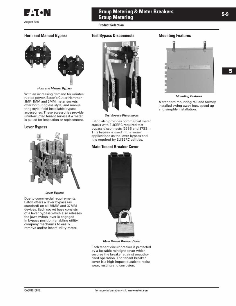
Horn and Manual Bypass
Horn and Manual Bypass
With an increasing demand for uninter-rupted power, Eaton’s Cutler-Hammer 1MP, 1MM and 3MM meter sockets offer horn (ringless style) and manual (ring style) field-installable bypass accessories. These accessories provide uninterrupted tenant service if a meter is pulled for inspection or replacement.
Lever Bypass
Lever Bypass
Due to commercial requirements, Eaton offers a lever bypass (as standard) on all 35MM and 37MM devices. Each socket base consists of a lever bypass which also releases the jaws (when lever is engaged in bypass position) enabling utility company mechanics to easily remove and/or insert utility meter.
Test Bypass Disconnects
Test Bypass Disconnects
Eaton also provides commercial meter stacks with EUSERC required test-bypass disconnects (35SS and 37SS). This bypass is used in the same applications as the lever bypass and it is required by EUSERC utilities.
Main Tenant Breaker Cover
Main Tenant Breaker Cover
Each tenant circuit breaker is protected by a lockable raintight cover which secures the breaker against unautho-rized operation. The tenant breaker cover is a high impact plastic to resist wear, rusting and corrosion.
Mounting Features
Mounting Features
A standard mounting rail and factory installed swing away feet, speed up and simplify installation.
August 2007
5-10
For more information visit: www.eaton.com CA08101001E
Group Metering & Meter Breakers
5
Group MeteringMeter Packs
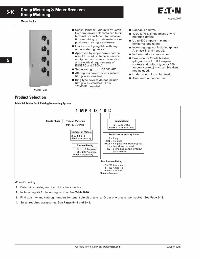
Meter Pack
■ Cutler-Hammer 1MP units by Eaton Corporation are self-contained (main terminal box included) for installa-tions requiring up to six meter socket positions in a single enclosure.
■ Units are not gangable with any other metering device.
■ Approved by major power compa-nies, UL listed, suitable as service equipment and meets the service and electrical requirements of EUSERC and CECHA.
■ Series rating up to 100,000 AIC.■ All ringless cover devices include
fifth jaw as standard.■ Ring type devices do not include
fifth jaw as standard. Order 1MM5JK if needed.
■ Bondable neutral.■ 120/240 Vac, single-phase 3-wire
metering device.■ Up to 600 ampere maximum
horizontal bus rating.■ Incoming lugs not included (phase
A, phase B, and neutral).■ Indoor/outdoor construction.■ Provision for 2-pole breaker
(plug-on type for 125 ampere sockets and bolt-on type for 200 ampere sockets) — circuit breakers not included.
■ Underground incoming feed.■ Aluminum or copper bus.
Product SelectionTable 5-7. Meter Pack Catalog Numbering System
When Ordering:
1. Determine catalog number of the basic device.
2. Include Lug Kit for incoming section. See Table 5-10.
3. Find quantity and catalog numbers for tenant circuit breakers. (Order one breaker per socket.) See Page 5-13.
4. Select required accessories. See Pages 5-44 and 5-45.
Bus Material
C = Copper BusBlank = Aluminum Bus
1 M P 4 12 4 R C
Single-Phase Type of Metering
MP = Meter Pack
Number of Meters
2, 3, 4, 5 or 6Blank = Accessory
Bus Ampere Rating
2 = 200 Amperes4 = 400 Amperes6 = 600 Amperes
Blank = Accessory
Ampere Rating
12 = 125 Amperes20 = 200 Amperes
Blank = Accessory
Security or Accessory Code
R = RingRRL = Ringless
RRLB = Ringless with Horn BypassLK = Lug Kit (Accessory)SC = Crimp Lug Landing Pad Kit
(Accessory)
August 2007
CA08101001E For more information visit: www.eaton.com
5-11Group Metering & Meter Breakers
5
Group MeteringMeter Packs
Product Selection
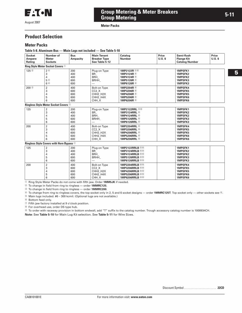
Meter PacksTable 5-8. Aluminum Bus — Main Lugs not included — See Table 5-10
� Ring Style Meter Packs do not come with fifth jaw. Order 1MM5JK if needed.� To change in field from ring to ringless — order 1MMRC125.� To change in field from ring to ringless — order 1MMRC200.� To change from ring to ringless covers, the top socket only in 2, 5 and 6 socket designs — order 1MMRC125T. Top socket only — other sockets see �.� Main lugs included. #6 – 300 kcmil. (Optional lugs are not available.)� Bottom feed only.� Fifth jaw factory installed at 9 o’clock position.� For overhead use, order DS type hub. To order with raceway provision in bottom endwall, add “T” suffix to the catalog number. Trough accessory catalog number is 1008934CH.Note: See Table 5-10 for Main Lug Kit selection. See Table 5-11 for Wire Sizes.
SocketAmpereRating
Number of MeterSockets
BusAmpacity
Main Tenant Breaker TypeSee Table 5-12
CatalogNumber
PriceU.S. $
Semi-flushFlange KitCatalog Number
PriceU.S. $
Ring Style Meter Socket Covers �
125 � 2 �345 �6 �
200400400600600
Plug-on TypeBR_BRH_BRHH_—
1MP2122R ��
1MP3124R �
1MP4124R �
1MP5126R �
1MP6126R �
1MPSFK11MPSFK21MPSFK21MPSFK31MPSFK3
200 � 23456
400600600600600
Bolt-on TypeCC2_XCHH2_H2XCHH2_H4XCHH_X
1MP2204R �
1MP3206R �
1MP4206R �
1MP5206R �
1MP6206R �
1MPSFK41MPSFK51MPSFK51MPSFK61MPSFK6
Ringless Style Meter Socket Covers �
125 23456
200400400600600
Plug-on TypeBR_BRH_BRHH_—
1MP2122RRL ��
1MP3124RRL �
1MP4124RRL �
1MP5126RRL �
1MP6126RRL �
1MPSFK11MPSFK21MPSFK21MPSFK31MPSFK3
200 23456
400600600600600
Bolt-on TypeCC2_XCHH2_H2XCHH2_H4XCHH_X
1MP2204RRL �
1MP3206RRL �
1MP4206RRL �
1MP5206RRL �
1MP6206RRL �
1MPSFK41MPSFK51MPSFK51MPSFK61MPSFK6
Ringless Style Covers with Horn Bypass �
125 23456
200400400600600
Plug-on TypeBR_BRH_BRHH_—
1MP2122RRLB ��
1MP3124RRLB �
1MP4124RRLB �
1MP5126RRLB �
1MP6126RRLB �
1MPSFK11MPSFK21MPSFK21MPSFK31MPSFK3
200 23456
400600600600600
Bolt-on TypeCC2_XCHH2_H2XCHH2_H4XCHH_X
1MP2204RRLB �
1MP3206RRLB �
1MP4206RRLB �
1MP5206RRLB �
1MP6206RRLB �
1MPSFK41MPSFK51MPSFK51MPSFK61MPSFK6
Discount Symbol . . . . . . . . . . . . . . . . . . . . . . . . 22CD
August 2007
5-12
For more information visit: www.eaton.com CA08101001E
Group Metering & Meter Breakers
5
Group MeteringMeter Packs
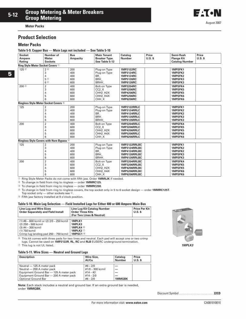
Product SelectionMeter PacksTable 5-9. Copper Bus — Main Lugs not included — See Table 5-10
� Ring Style Meter Packs do not come with fifth jaw. Order 1MM5JK if needed.� To change in field from ring to ringless — order 1MMRC125.� To change in field from ring to ringless — order 1MMRC200.� To change in field from ring to ringless covers, the top socket only in 5 to 6 socket design — order 1MMRC125T.
Top socket only — other sockets see �.� Fifth jaw factory installed at 9 o’clock position.
Table 5-10. Main Lug Selection — Field Installed Lugs for Either 400 or 600 Ampere Main Bus
Table 5-11. Wire Sizes — Neutral and Ground Lugs
Note: Each stack includes a neutral and ground bar. If an extra ground bar is needed, order 1MMGBK.
SocketAmpereRating
Number ofMeterSockets
BusAmpacity
Main Tenant Breaker Type.See Table 5-12
CatalogNumber
PriceU.S. $
Semi-flushFlange KitCatalog Number
PriceU.S. $
Ring Style Meter Socket Covers �
125 � 2 �345 �6 �
200400400600600
Plug-on TypePlug-on TypeBR_BRH_BRHH_
1MP2122RC1MP3124RC1MP4124RC1MP5126RC1MP6126RC
1MPSFK11MPSFK21MPSFK21MPSFK31MPSFK3
200 � 23456
400600600600600
Bolt-on TypeCC2_XCHH2_H2XCHH2_H4XCHH_X
1MP2204RC1MP3206RC1MP4206RC1MP5206RC1MP6206RC
1MPSFK41MPSFK51MPSFK51MPSFK61MPSFK6
Ringless Style Meter Socket Covers �
125 2345 6
200400400600600
Plug-on TypePlug-on TypeBR_BRH_BRHH_
1MP2122RRLC1MP3124RRLC1MP4124RRLC1MP5126RRLC1MP6126RRLC
1MPSFK11MPSFK21MPSFK21MPSFK31MPSFK3
200 23456
400600600600600
Bolt-on TypeCC2_XCHH2_H2XCHH2_H4XCHH_X
1MP2204RRLC1MP3206RRLC1MP4206RRLC1MP5206RRLC1MP6206RRLC
1MPSFK41MPSFK51MPSFK51MPSFK61MPSFK6
Ringless Style Covers with Horn Bypass �
125 23456
200400400600600
Plug-on TypePlug-on TypeBR_BRH_BRHH_
1MP2122RRLBC1MP3124RRLBC1MP4124RRLBC1MP5126RRLBC1MP6126RRLBC
1MPSFK11MPSFK21MPSFK21MPSFK31MPSFK3
200 23456
400600600600600
Bolt-on TypeCC2_XCHH2_H2XCHH2_H4XCHH_X
1MP2204RRLBC1MP3206RRLBC1MP4206RRLBC1MP5206RRLBC1MP6206RRLBC
1MPSFK41MPSFK51MPSFK51MPSFK61MPSFK6
Line Lug and Wire SizesOrder Separately and Field Install
Line Lug Kit Catalog NumberOrder Three Kits(For Two Lines & Neutral)
Price Per KitU.S. $
(1) #6 – 600 kcmil or (2) 2/0 – 250 kcmil(2) 250 – 500 kcmil(3) #4 – 300 kcmil(1) 750 kcmilCrimp lug landing pad 250 – 750 kcmil
1MPLK11MPLK31MPLK4 �
1MPLK2 �
1MPSC1 �
� This kit comes with three pads for two lines and neutral. Each pad will accept one or two crimplugs. Cannot be used on 1MP2122R, RL, RC and RLB EUSERC underground termination.
� This lug is not UL listed.
Description Wire Size, Al/Cu
CatalogNumber
PriceU.S. $
Neutral — 125 A meter packNeutral — 200 A meter packEquipment Ground Bar — 125 A meter packEquipment Ground Bar — 200 A meter packOptional Ground Bar
#6 – 2/0#1/0 – 300 kcmil#14 – #2#14 – 2/0#6 – 2/0
————1MMGBK
Discount Symbol . . . . . . . . . . . . . . . . . . . . . . . . . 22CD
1MPLK3
August 2007
CA08101001E For more information visit: www.eaton.com
5-13Group Metering & Meter Breakers
5
Group MeteringMeter Packs
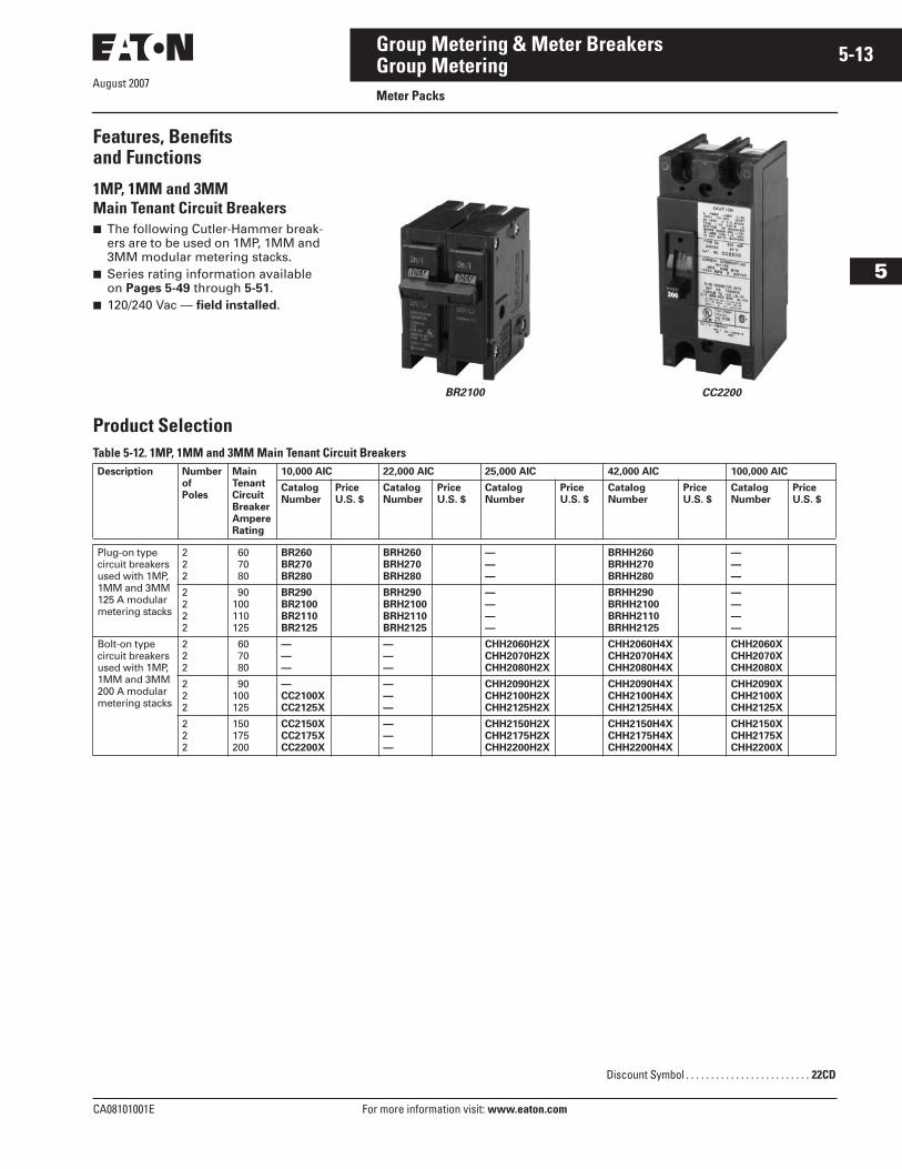
Features, Benefits and Functions
1MP, 1MM and 3MMMain Tenant Circuit Breakers■ The following Cutler-Hammer break-
ers are to be used on 1MP, 1MM and 3MM modular metering stacks.
■ Series rating information available on Pages 5-49 through 5-51.
■ 120/240 Vac — field installed.
BR2100 CC2200
Product SelectionTable 5-12. 1MP, 1MM and 3MM Main Tenant Circuit BreakersDescription Number
ofPoles
MainTenantCircuitBreakerAmpereRating
10,000 AIC 22,000 AIC 25,000 AIC 42,000 AIC 100,000 AIC
CatalogNumber
PriceU.S. $
CatalogNumber
PriceU.S. $
CatalogNumber
PriceU.S. $
CatalogNumber
PriceU.S. $
CatalogNumber
PriceU.S. $
Plug-on typecircuit breakersused with 1MP,1MM and 3MM125 A modularmetering stacks
222
60 70 80
BR260BR270BR280
BRH260BRH270BRH280
———
BRHH260BRHH270BRHH280
———
2222
90100110125
BR290BR2100BR2110BR2125
BRH290BRH2100BRH2110BRH2125
————
BRHH290BRHH2100BRHH2110BRHH2125
————
Bolt-on typecircuit breakersused with 1MP,1MM and 3MM200 A modularmetering stacks
222
60 70 80
———
———
CHH2060H2XCHH2070H2XCHH2080H2X
CHH2060H4XCHH2070H4XCHH2080H4X
CHH2060XCHH2070XCHH2080X
222
90100125
—CC2100XCC2125X
———
CHH2090H2XCHH2100H2XCHH2125H2X
CHH2090H4XCHH2100H4XCHH2125H4X
CHH2090XCHH2100XCHH2125X
222
150175200
CC2150XCC2175XCC2200X
———
CHH2150H2XCHH2175H2XCHH2200H2X
CHH2150H4XCHH2175H4XCHH2200H4X
CHH2150XCHH2175XCHH2200X
Discount Symbol . . . . . . . . . . . . . . . . . . . . . . . . . 22CD
August 2007
5-14
For more information visit: www.eaton.com CA08101001E
Group Metering & Meter Breakers
5
Group MeteringMeter Packs
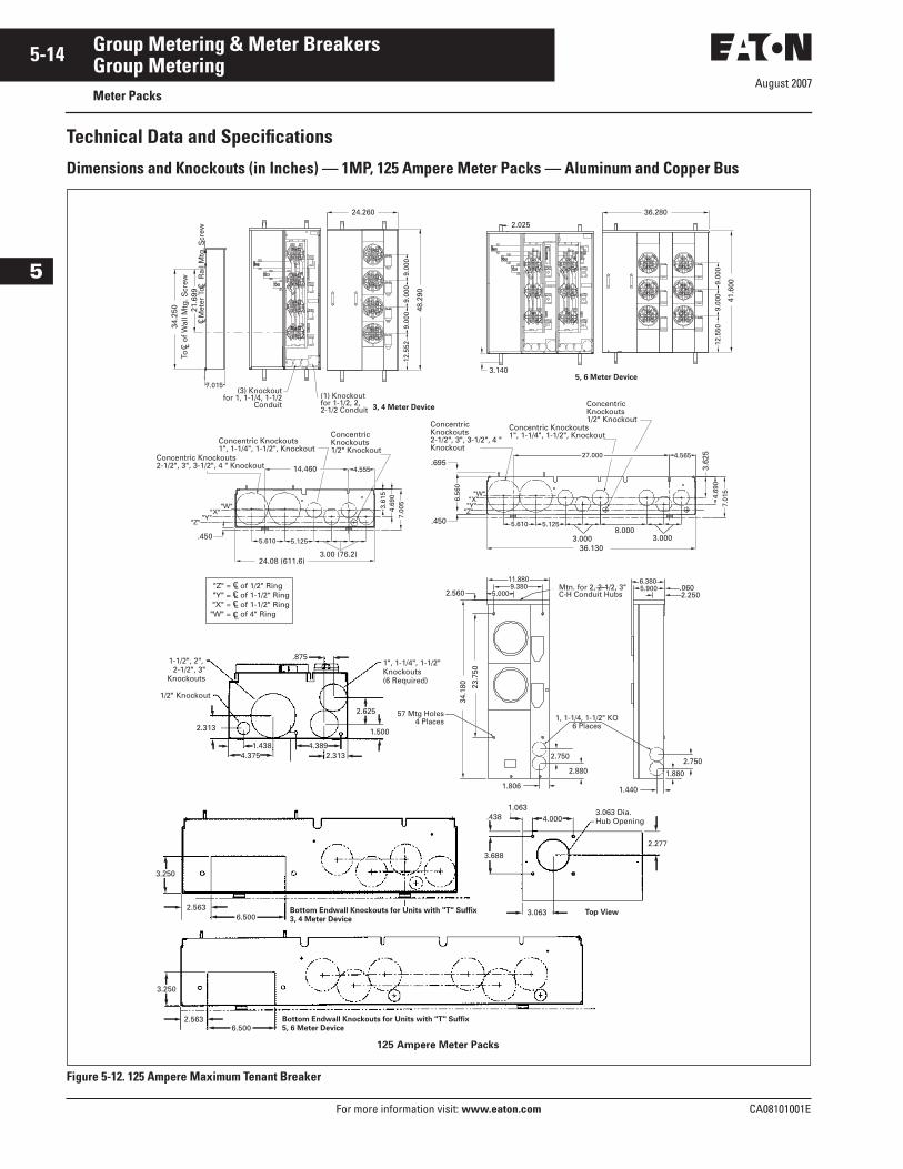
Technical Data and Specifications
Dimensions and Knockouts (in Inches) — 1MP, 125 Ampere Meter Packs — Aluminum and Copper Bus
Figure 5-12. 125 Ampere Maximum Tenant Breaker
3, 4 Meter Device12
.552
9.00
09.
000
9.00
0
48.2
90
24.260
To
of W
all M
tg. S
crew
C L
Met
er T
o
Rai
l Mtg
. Scr
ewC L
C L
21
.699
7.015(3) Knockout
for 1, 1-1/4, 1-1/2Conduit
(1) Knockout for 1-1/2, 2, 2-1/2 Conduit
34.2
50
2.025
3.1405, 6 Meter Device
12.5
509.
000
9.00
0
41.6
00
36.280
3.00 (76.2)
.450
"Z""Y"
"X""W"
Concentric Knockouts2-1/2", 3", 3-1/2", 4 " Knockout
Concentric Knockouts1", 1-1/4", 1-1/2", Knockout
ConcentricKnockouts1/2" Knockout
4.55514.460
7.00
54.
690
3.61
5
24.08 (611.6)
5.1255.610
of 1/2" Ringof 1-1/2" Ringof 1-1/2" Ringof 4" Ring
CLCL
CL
CL
"Z" ="Y" ="X" =
"W" =
3.62
5
7.01
5
Concentric Knockouts2-1/2", 3", 3-1/2", 4 " Knockout
Concentric Knockouts1", 1-1/4", 1-1/2", Knockout
Concentric Knockouts1/2" Knockout
.450
4.565
8.0003.000 3.000
36.130
6.56
0
"Z""Y""X"
"W"
.69527.000
4.69
0
5.610 5.125
2.560 5.0009.380
11.880Mtn. for 2, 2-1/2, 3"C-H Conduit Hubs
1, 1-1/4, 1-1/2" KO6 Places
2.750
2.880
57 Mtg Holes4 Places
34.1
80 23.7
50
1.806
6.3805.900 .060
2.250
2.750
1.440
1.880
3.250
2.5636.500
3.250
2.5636.500
3.063 Dia.Hub Opening
2.277
4.0001.063
.438
3.688
3.063
.8751", 1-1/4", 1-1/2"Knockouts(6 Required)
2.625
1.500
1-1/2", 2", 2-1/2", 3"
Knockouts
1/2" Knockout
4.3892.313
2.313
1.4384.375
Bottom Endwall Knockouts for Units with "T" Suffix3, 4 Meter Device
Bottom Endwall Knockouts for Units with "T" Suffix5, 6 Meter Device
Top View
125 Ampere Meter Packs
August 2007
CA08101001E For more information visit: www.eaton.com
5-15Group Metering & Meter Breakers
5
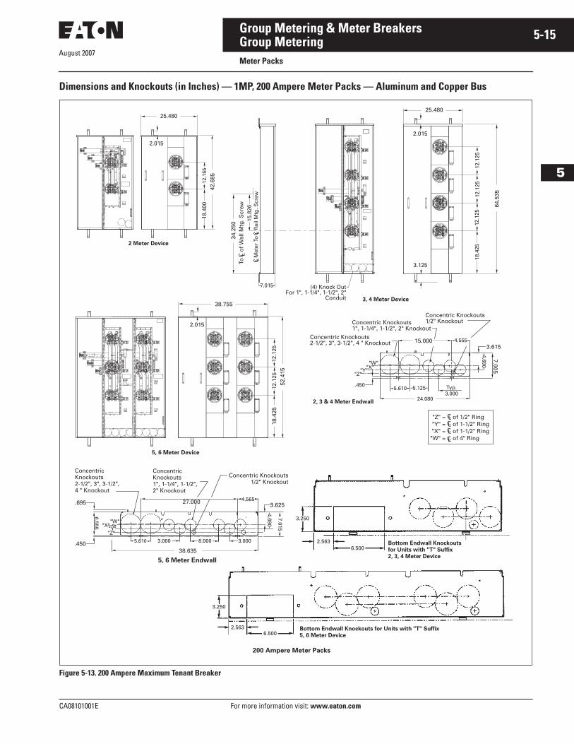
Group MeteringMeter Packs
Dimensions and Knockouts (in Inches) — 1MP, 200 Ampere Meter Packs — Aluminum and Copper Bus
Figure 5-13. 200 Ampere Maximum Tenant Breaker
4.690
7.005
Concentric Knockouts2-1/2", 3", 3-1/2", 4 " Knockout
Concentric Knockouts1", 1-1/4", 1-1/2", 2" Knockout
Concentric Knockouts1/2" Knockout
5.610.450
4.555
3.0005.125
"Z""Y""X"
"W"
3.615
Typ.
15.000
24.080
of 1/2" Ringof 1-1/2" Ringof 1-1/2" Ringof 4" Ring
CLCL
CL
CL
"Z" ="Y" ="X" ="W" =
7.015 (4) Knock OutFor 1", 1-1/4", 1-1/2", 2"
Conduit 3, 4 Meter Device
15.8
26
2.015
25.480
3.125
18.4
2512
.125
12.1
2512
.125
64.5
35
To
of W
all M
tg. S
crew
C L Met
er T
o
Rai
l Mtg
. Scr
ewC L
C L
34.2
50
2 Meter Device
25.480
2.015
42.6
8512
.155
18.4
00
38.755
2.015
12.1
2512
.125
18.4
2552
.415
5, 6 Meter Device
2, 3 & 4 Meter Endwall
3.0003.000.450
"Z""Y"
"X""W"
Concentric Knockouts2-1/2", 3", 3-1/2",4 " Knockout
ConcentricKnockouts1", 1-1/4", 1-1/2",2" Knockout
Concentric Knockouts1/2" Knockout
4.565
4.690
6.555
.695 3.625
38.635
27.000
7.015
8.0005.610
3.250
2.5636.500
3.250
2.5636.500
Bottom Endwall Knockoutsfor Units with "T" Suffix2, 3, 4 Meter Device
Bottom Endwall Knockouts for Units with "T" Suffix5, 6 Meter Device
5, 6 Meter Endwall
200 Ampere Meter Packs
August 2007
5-16
For more information visit: www.eaton.com CA08101001E
Group Metering & Meter Breakers
5
Group MeteringMain Service Modules
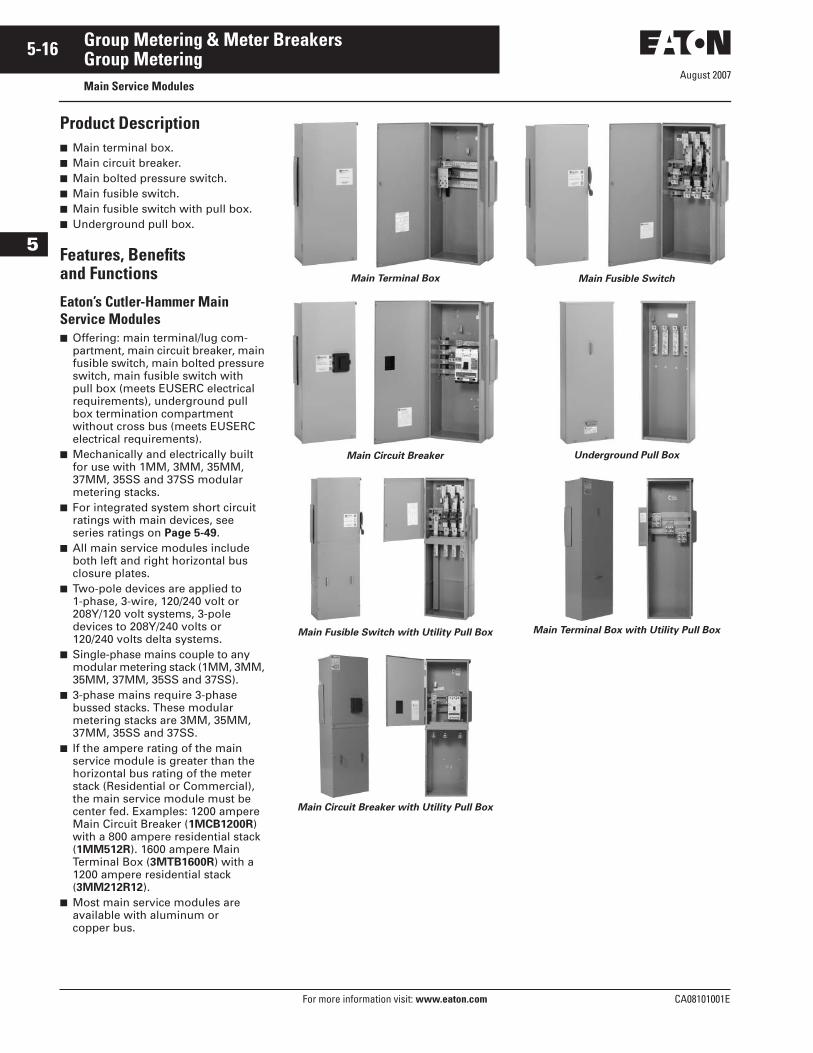
Product Description■ Main terminal box.■ Main circuit breaker.■ Main bolted pressure switch.■ Main fusible switch.■ Main fusible switch with pull box.■ Underground pull box.
Features, Benefitsand Functions
Eaton’s Cutler-Hammer Main Service Modules■ Offering: main terminal/lug com-
partment, main circuit breaker, main fusible switch, main bolted pressure switch, main fusible switch with pull box (meets EUSERC electrical requirements), underground pull box termination compartment without cross bus (meets EUSERC electrical requirements).
■ Mechanically and electrically built for use with 1MM, 3MM, 35MM, 37MM, 35SS and 37SS modular metering stacks.
■ For integrated system short circuit ratings with main devices, see series ratings on Page 5-49.
■ All main service modules include both left and right horizontal bus closure plates.
■ Two-pole devices are applied to 1-phase, 3-wire, 120/240 volt or 208Y/120 volt systems, 3-pole devices to 208Y/240 volts or 120/240 volts delta systems.
■ Single-phase mains couple to any modular metering stack (1MM, 3MM, 35MM, 37MM, 35SS and 37SS).
■ 3-phase mains require 3-phase bussed stacks. These modular metering stacks are 3MM, 35MM, 37MM, 35SS and 37SS.
■ If the ampere rating of the main service module is greater than the horizontal bus rating of the meter stack (Residential or Commercial), the main service module must be center fed. Examples: 1200 ampere Main Circuit Breaker (1MCB1200R) with a 800 ampere residential stack (1MM512R). 1600 ampere Main Terminal Box (3MTB1600R) with a 1200 ampere residential stack (3MM212R12).
■ Most main service modules are available with aluminum or copper bus.
Main Terminal Box
Main Circuit Breaker
Main Fusible Switch with Utility Pull Box
Main Circuit Breaker with Utility Pull Box
Main Fusible Switch
Underground Pull Box
Main Terminal Box with Utility Pull Box
August 2007
CA08101001E For more information visit: www.eaton.com
5-17Group Metering & Meter Breakers
5
Group MeteringMain Service Modules
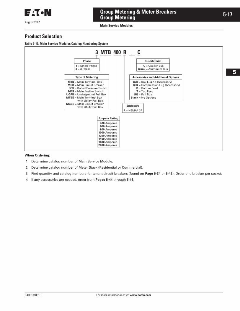
Product SelectionTable 5-13. Main Service Modules Catalog Numbering System
When Ordering:
1. Determine catalog number of Main Service Module.
2. Determine catalog number of Meter Stack (Residential or Commercial).
3. Find quantity and catalog numbers for tenant circuit breakers (found on Page 5-34 or 5-42). Order one breaker per socket.
4. If any accessories are needed, order from Pages 5-44 through 5-46.
Phase
1 = Single-Phase3 = 3-Phase
3 MTB 400 R C
Ampere Rating
400 Amperes600 Amperes800 Amperes
1000 Amperes1200 Amperes1400 Amperes1600 Amperes2000 Amperes
Accessories and Additional Options
BLK = Box Lug Kit (Accessory)CLK = Compression Lug (Accessory)
B = Bottom FeedT = Top Feed
UG = Pull BoxBlank = No Options
Type of Metering
MTB = Main Terminal BoxMCB = Main Circuit BreakerBPS = Bolted Pressure SwitchMFS = Main Fusible Switch
UGPB = Underground Pull BoxMTBE = Main Terminal Box
with Utility Pull BoxMCBE = Main Circuit Breaker
with Utility Pull Box
Bus Material
C = Copper BusBlank = Aluminum Bus
Enclosure
R = NEMA� 3R
August 2007
5-18
For more information visit: www.eaton.com CA08101001E
Group Metering & Meter Breakers
5
Group MeteringMain Service Modules
Features, Benefits and Functions
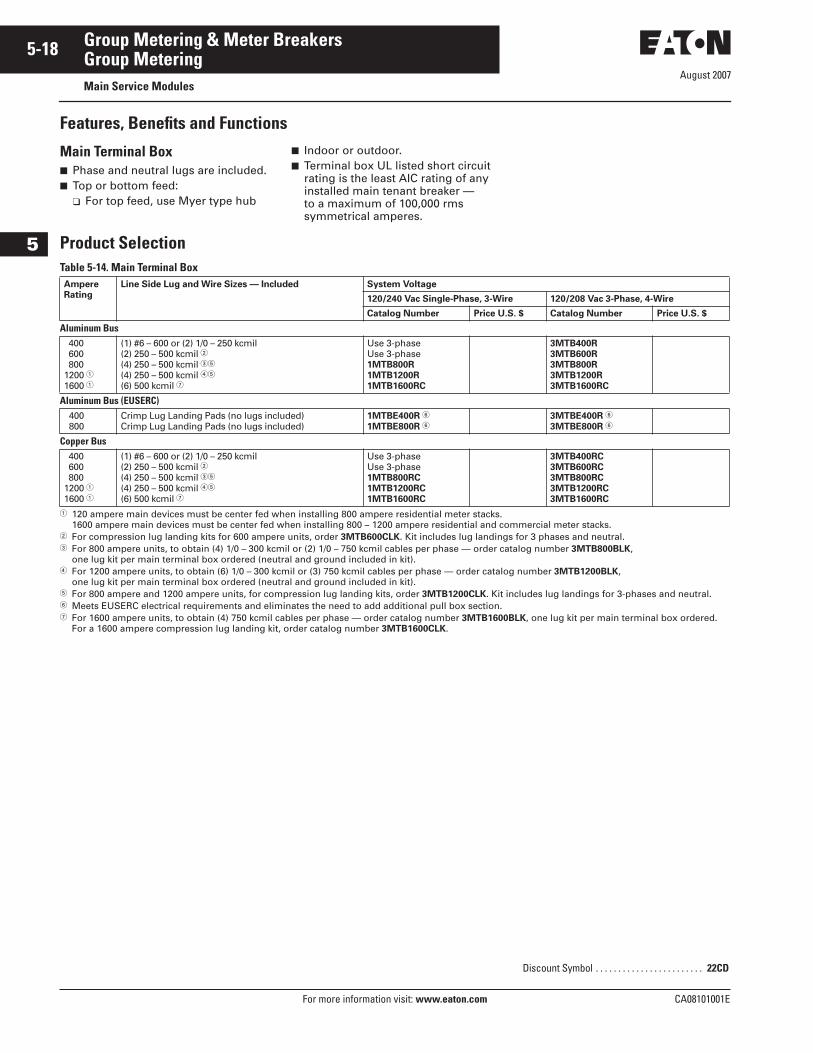
Main Terminal Box■ Phase and neutral lugs are included.■ Top or bottom feed:
❑ For top feed, use Myer type hub
■ Indoor or outdoor.■ Terminal box UL listed short circuit
rating is the least AIC rating of any installed main tenant breaker — to a maximum of 100,000 rms symmetrical amperes.
Product SelectionTable 5-14. Main Terminal Box
� 120 ampere main devices must be center fed when installing 800 ampere residential meter stacks. 1600 ampere main devices must be center fed when installing 800 – 1200 ampere residential and commercial meter stacks.
� For compression lug landing kits for 600 ampere units, order 3MTB600CLK. Kit includes lug landings for 3 phases and neutral.� For 800 ampere units, to obtain (4) 1/0 – 300 kcmil or (2) 1/0 – 750 kcmil cables per phase — order catalog number 3MTB800BLK,
one lug kit per main terminal box ordered (neutral and ground included in kit).� For 1200 ampere units, to obtain (6) 1/0 – 300 kcmil or (3) 750 kcmil cables per phase — order catalog number 3MTB1200BLK,
one lug kit per main terminal box ordered (neutral and ground included in kit).� For 800 ampere and 1200 ampere units, for compression lug landing kits, order 3MTB1200CLK. Kit includes lug landings for 3-phases and neutral.� Meets EUSERC electrical requirements and eliminates the need to add additional pull box section.� For 1600 ampere units, to obtain (4) 750 kcmil cables per phase — order catalog number 3MTB1600BLK, one lug kit per main terminal box ordered.
For a 1600 ampere compression lug landing kit, order catalog number 3MTB1600CLK.
AmpereRating
Line Side Lug and Wire Sizes — Included System Voltage
120/240 Vac Single-Phase, 3-Wire 120/208 Vac 3-Phase, 4-Wire
Catalog Number Price U.S. $ Catalog Number Price U.S. $
Aluminum Bus 400 600 8001200 �1600 �
(1) #6 – 600 or (2) 1/0 – 250 kcmil(2) 250 – 500 kcmil �(4) 250 – 500 kcmil ��
(4) 250 – 500 kcmil ��
(6) 500 kcmil �
Use 3-phaseUse 3-phase1MTB800R1MTB1200R1MTB1600RC
3MTB400R3MTB600R3MTB800R3MTB1200R3MTB1600RC
Aluminum Bus (EUSERC)400800
Crimp Lug Landing Pads (no lugs included)Crimp Lug Landing Pads (no lugs included)
1MTBE400R �
1MTBE800R �3MTBE400R �
3MTBE800R �
Copper Bus 400 600 8001200 �1600 �
(1) #6 – 600 or (2) 1/0 – 250 kcmil(2) 250 – 500 kcmil �(4) 250 – 500 kcmil ��
(4) 250 – 500 kcmil ��
(6) 500 kcmil �
Use 3-phaseUse 3-phase1MTB800RC1MTB1200RC1MTB1600RC
3MTB400RC3MTB600RC3MTB800RC3MTB1200RC3MTB1600RC
Discount Symbol . . . . . . . . . . . . . . . . . . . . . . . . 22CD
August 2007
CA08101001E For more information visit: www.eaton.com
5-19Group Metering & Meter Breakers
5
Group MeteringMain Circuit Breakers
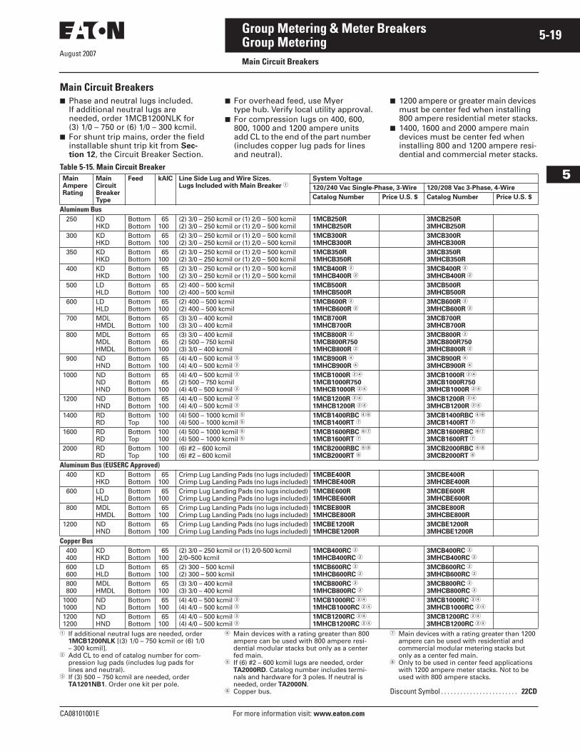
Main Circuit Breakers■ Phase and neutral lugs included.
If additional neutral lugs are needed, order 1MCB1200NLK for (3) 1/0 – 750 or (6) 1/0 – 300 kcmil.
■ For shunt trip mains, order the field installable shunt trip kit from Sec-tion 12, the Circuit Breaker Section.
■ For overhead feed, use Myer type hub. Verify local utility approval.
■ For compression lugs on 400, 600, 800, 1000 and 1200 ampere units add CL to the end of the part number (includes copper lug pads for lines and neutral).
■ 1200 ampere or greater main devices must be center fed when installing 800 ampere residential meter stacks.
■ 1400, 1600 and 2000 ampere main devices must be center fed when installing 800 and 1200 ampere resi-dential and commercial meter stacks.
Table 5-15. Main Circuit Breaker
� If additional neutral lugs are needed, order 1MCB1200NLK [(3) 1/0 – 750 kcmil or (6) 1/0 – 300 kcmil].
� Add CL to end of catalog number for com-pression lug pads (includes lug pads for lines and neutral).
� If (3) 500 – 750 kcmil are needed, order TA1201NB1. Order one kit per pole.
� Main devices with a rating greater than 800 ampere can be used with 800 ampere resi-dential modular stacks but only as a center fed main.
� If (6) #2 – 600 kcmil lugs are needed, order TA2000RD. Catalog number includes termi-nals and hardware for 3 poles. If neutral is needed, order TA2000N.
� Copper bus.
� Main devices with a rating greater than 1200 ampere can be used with residential and commercial modular metering stacks but only as a center fed main.
� Only to be used in center feed applications with 1200 ampere meter stacks. Not to be used with 800 ampere stacks.
MainAmpereRating
MainCircuitBreakerType
Feed kAIC Line Side Lug and Wire Sizes.Lugs Included with Main Breaker �
System Voltage
120/240 Vac Single-Phase, 3-Wire 120/208 Vac 3-Phase, 4-Wire
Catalog Number Price U.S. $ Catalog Number Price U.S. $
Aluminum Bus 250 KD
HKDBottomBottom
65100
(2) 3/0 – 250 kcmil or (1) 2/0 – 500 kcmil(2) 3/0 – 250 kcmil or (1) 2/0 – 500 kcmil
1MCB250R1MHCB250R
3MCB250R3MHCB250R
300 KDHKD
BottomBottom
65100
(2) 3/0 – 250 kcmil or (1) 2/0 – 500 kcmil(2) 3/0 – 250 kcmil or (1) 2/0 – 500 kcmil
1MCB300R1MHCB300R
3MCB300R3MHCB300R
350 KDHKD
BottomBottom
65100
(2) 3/0 – 250 kcmil or (1) 2/0 – 500 kcmil(2) 3/0 – 250 kcmil or (1) 2/0 – 500 kcmil
1MCB350R1MHCB350R
3MCB350R3MHCB350R
400 KDHKD
BottomBottom
65100
(2) 3/0 – 250 kcmil or (1) 2/0 – 500 kcmil(2) 3/0 – 250 kcmil or (1) 2/0 – 500 kcmil
1MCB400R �
1MHCB400R �3MCB400R �
3MHCB400R �
500 LDHLD
BottomBottom
65100
(2) 400 – 500 kcmil(2) 400 – 500 kcmil
1MCB500R1MHCB500R
3MCB500R3MHCB500R
600 LDHLD
BottomBottom
65100
(2) 400 – 500 kcmil(2) 400 – 500 kcmil
1MCB600R �
1MHCB600R �3MCB600R �
3MHCB600R �
700 MDLHMDL
BottomBottom
65100
(3) 3/0 – 400 kcmil(3) 3/0 – 400 kcmil
1MCB700R1MHCB700R
3MCB700R3MHCB700R
800 MDLMDLHMDL
BottomBottomBottom
65 65100
(3) 3/0 – 400 kcmil(2) 500 – 750 kcmil(3) 3/0 – 400 kcmil
1MCB800R �
1MCB800R7501MHCB800R �
3MCB800R �
3MCB800R7503MHCB800R �
900 NDHND
BottomBottom
65100
(4) 4/0 – 500 kcmil �(4) 4/0 – 500 kcmil �
1MCB900R �
1MHCB900R �3MCB900R �
3MHCB900R �
1000 NDNDHND
BottomBottomBottom
65 65100
(4) 4/0 – 500 kcmil �(2) 500 – 750 kcmil(4) 4/0 – 500 kcmil �
1MCB1000R ��
1MCB1000R7501MHCB1000R ��
3MCB1000R ��
3MCB1000R7503MHCB1000R ��
1200 ND HND
BottomBottom
65100
(4) 4/0 – 500 kcmil �(4) 4/0 – 500 kcmil �
1MCB1200R ��
1MHCB1200R ��3MCB1200R ��
3MHCB1200R ��
1400 RDRD
BottomTop
100100
(4) 500 – 1000 kcmil �(4) 500 – 1000 kcmil �
1MCB1400RBC ��
1MCB1400RT �3MCB1400RBC ��
3MCB1400RT �
1600 RDRD
BottomTop
100100
(4) 500 – 1000 kcmil �(4) 500 – 1000 kcmil �
1MCB1600RBC ��
1MCB1600RT �3MCB1600RBC ��
3MCB1600RT �
2000 RDRD
BottomTop
100100
(6) #2 – 600 kcmil(6) #2 – 600 kcmil
1MCB2000RBC ��
1MCB2000RT �3MCB2000RBC ��
3MCB2000RT �
Aluminum Bus (EUSERC Approved) 400 KD
HKDBottomBottom
65100
Crimp Lug Landing Pads (no lugs included)Crimp Lug Landing Pads (no lugs included)
1MCBE400R1MHCBE400R
3MCBE400R3MHCBE400R
600 LDHLD
BottomBottom
65100
Crimp Lug Landing Pads (no lugs included)Crimp Lug Landing Pads (no lugs included)
1MCBE600R1MHCBE600R
3MCBE600R3MHCBE600R
800 MDLHMDL
BottomBottom
65100
Crimp Lug Landing Pads (no lugs included)Crimp Lug Landing Pads (no lugs included)
1MCBE800R1MHCBE800R
3MCBE800R3MHCBE800R
1200 ND HND
BottomBottom
65100
Crimp Lug Landing Pads (no lugs included)Crimp Lug Landing Pads (no lugs included)
1MCBE1200R1MHCBE1200R
3MCBE1200R3MHCBE1200R
Copper Bus 400 400
KDHKD
BottomBottom
65100
(2) 3/0 – 250 kcmil or (1) 2/0-500 kcmil2/0–500 kcmil
1MCB400RC �
1MHCB400RC �3MCB400RC �
3MHCB400RC �
600 600
LDHLD
BottomBottom
65100
(2) 300 – 500 kcmil(2) 300 – 500 kcmil
1MCB600RC �
1MHCB600RC �3MCB600RC �
3MHCB600RC �
800 800
MDLHMDL
BottomBottom
65100
(3) 3/0 – 400 kcmil(3) 3/0 – 400 kcmil
1MCB800RC �
1MHCB800RC �3MCB800RC �
3MHCB800RC �
10001000
NDND
BottomBottom
65100
(4) 4/0 – 500 kcmil �(4) 4/0 – 500 kcmil �
1MCB1000RC ��
1MHCB1000RC ��3MCB1000RC ��
3MHCB1000RC ��
12001200
NDHND
BottomBottom
65100
(4) 4/0 – 500 kcmil �(4) 4/0 – 500 kcmil �
1MCB1200RC ��
1MHCB1200RC ��3MCB1200RC ��
3MHCB1200RC ��
Discount Symbol . . . . . . . . . . . . . . . . . . . . . . . . 22CD
August 2007
5-20
For more information visit: www.eaton.com CA08101001E
Group Metering & Meter Breakers
5
Group MeteringMain Fusible Switches
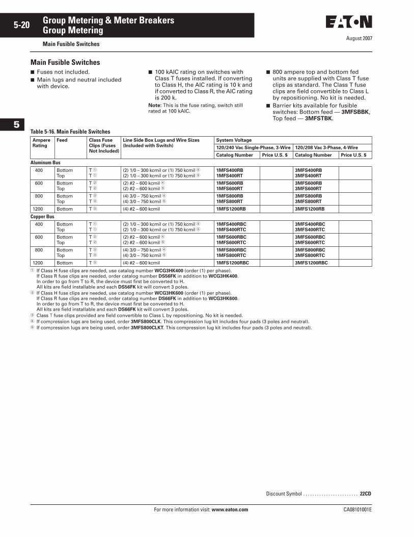
Main Fusible Switches■ Fuses not included.■ Main lugs and neutral included
with device.
■ 100 kAIC rating on switches with Class T fuses installed. If converting to Class H, the AIC rating is 10 k and if converted to Class R, the AIC rating is 200 k.
Note: This is the fuse rating, switch still rated at 100 kAIC.
■ 800 ampere top and bottom fed units are supplied with Class T fuse clips as standard. The Class T fuse clips are field convertible to Class L by repositioning. No kit is needed.
■ Barrier kits available for fusible switches: Bottom feed — 3MFSBBK, Top feed — 3MFSTBK.
Table 5-16. Main Fusible Switches
� If Class H fuse clips are needed, use catalog number WCG3HK400 (order (1) per phase). If Class R fuse clips are needed, order catalog number DS56FK in addition to WCG3HK400. In order to go from T to R, the device must first be converted to H. All kits are field installable and each DS56FK kit will convert 3 poles.
� If Class H fuse clips are needed, use catalog number WCG3HK600 (order (1) per phase). If Class R fuse clips are needed, order catalog number DS66FK in addition to WCG3HK600. In order to go from T to R, the device must first be converted to H. All kits are field installable and each DS66FK kit will convert 3 poles.
� Class T fuse clips provided are field convertible to Class L by repositioning. No kit is needed.� If compression lugs are being used, order 3MFS800CLK. This compression lug kit includes four pads (3 poles and neutral).� If compression lugs are being used, order 3MFS800CLKT. This compression lug kit includes four pads (3 poles and neutral).
AmpereRating
Feed Class FuseClips (FusesNot Included)
Line Side Box Lugs and Wire Sizes (Included with Switch)
System Voltage
120/240 Vac Single-Phase, 3-Wire 120/208 Vac 3-Phase, 4-Wire
Catalog Number Price U.S. $ Catalog Number Price U.S. $
Aluminum Bus 400 Bottom
TopT �T �
(2) 1/0 – 300 kcmil or (1) 750 kcmil �(2) 1/0 – 300 kcmil or (1) 750 kcmil �
1MFS400RB1MFS400RT
3MFS400RB3MFS400RT
600 BottomTop
T �T �
(2) #2 – 600 kcmil �(2) #2 – 600 kcmil �
1MFS600RB1MFS600RT
3MFS600RB3MFS600RT
800 BottomTop
T �T �
(4) 3/0 – 750 kcmil �(4) 3/0 – 750 kcmil �
1MFS800RB1MFS800RT
3MFS800RB3MFS800RT
1200 Bottom T � (4) #2 – 600 kcmil 1MFS1200RB 3MFS1200RB
Copper Bus 400 Bottom
TopT �T �
(2) 1/0 – 300 kcmil or (1) 750 kcmil �(2) 1/0 – 300 kcmil or (1) 750 kcmil �
1MFS400RBC1MFS400RTC
3MFS400RBC3MFS400RTC
600 BottomTop
T �T �
(2) #2 – 600 kcmil �(2) #2 – 600 kcmil �
1MFS600RBC1MFS600RTC
3MFS600RBC3MFS600RTC
800 BottomTop
T �T �
(4) 3/0 – 750 kcmil �(4) 3/0 – 750 kcmil �
1MFS800RBC1MFS800RTC
3MFS800RBC3MFS800RTC
1200 Bottom T � (4) #2 – 600 kcmil 1MFS1200RBC 3MFS1200RBC
Discount Symbol . . . . . . . . . . . . . . . . . . . . . . . . 22CD
August 2007
CA08101001E For more information visit: www.eaton.com
5-21Group Metering & Meter Breakers
5
Group MeteringMain Fusible Switches
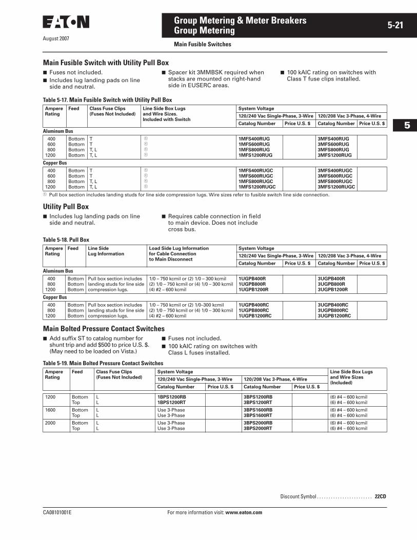
Main Fusible Switch with Utility Pull Box ■ Fuses not included.■ Includes lug landing pads on line
side and neutral.
■ Spacer kit 3MMBSK required when stacks are mounted on right-hand side in EUSERC areas.
■ 100 kAIC rating on switches with Class T fuse clips installed.
Table 5-17. Main Fusible Switch with Utility Pull Box
� Pull box section includes landing studs for line side compression lugs. Wire sizes refer to fusible switch line side connection.
Utility Pull Box■ Includes lug landing pads on line
side and neutral.■ Requires cable connection in field
to main device. Does not include cross bus.
Table 5-18. Pull Box
Main Bolted Pressure Contact Switches■ Add suffix ST to catalog number for
shunt trip and add $500 to price U.S. $.(May need to be loaded on Vista.)
■ Fuses not included.■ 100 kAIC rating on switches with
Class L fuses installed.
Table 5-19. Main Bolted Pressure Contact Switches
AmpereRating
Feed Class Fuse Clips(Fuses Not Included)
Line Side Box Lugsand Wire Sizes.Included with Switch
System Voltage
120/240 Vac Single-Phase, 3-Wire 120/208 Vac 3-Phase, 4-Wire
Catalog Number Price U.S. $ Catalog Number Price U.S. $
Aluminum Bus 400 600 8001200
BottomBottomBottomBottom
T T T, LT, L
� � � �
1MFS400RUG1MFS600RUG1MFS800RUG1MFS1200RUG
3MFS400RUG3MFS600RUG3MFS800RUG3MFS1200RUG
Copper Bus 400 600 8001200
BottomBottomBottomBottom
T T T, LT, L
� � � �
1MFS400RUGC1MFS600RUGC1MFS800RUGC1MFS1200RUGC
3MFS400RUGC3MFS600RUGC3MFS800RUGC3MFS1200RUGC
AmpereRating
Feed Line SideLug Information
Load Side Lug Informationfor Cable Connectionto Main Disconnect
System Voltage
120/240 Vac Single-Phase, 3-Wire 120/208 Vac 3-Phase, 4-Wire
Catalog Number Price U.S. $ Catalog Number Price U.S. $
Aluminum Bus 400 8001200
BottomBottomBottom
Pull box section includes landing studs for line side compression lugs.
1/0 – 750 kcmil or (2) 1/0 – 300 kcmil(2) 1/0 – 750 kcmil or (4) 1/0 – 300 kcmil(4) #2 – 600 kcmil
1UGPB400R1UGPB800R1UGPB1200R
3UGPB400R3UGPB800R3UGPB1200R
Copper Bus 400 8001200
BottomBottomBottom
Pull box section includes landing studs for line side compression lugs.
1/0 – 750 kcmil or (2) 1/0–300 kcmil(2) 1/0 – 750 kcmil or (4) 1/0 – 300 kcmil(4) #2 – 600 kcmil
1UGPB400RC1UGPB800RC1UGPB1200RC
3UGPB400RC3UGPB800RC3UGPB1200RC
AmpereRating
Feed Class Fuse Clips (Fuses Not Included)
System Voltage Line Side Box Lugsand Wire Sizes(Included)
120/240 Vac Single-Phase, 3-Wire 120/208 Vac 3-Phase, 4-Wire
Catalog Number Price U.S. $ Catalog Number Price U.S. $
1200 BottomTop
LL
1BPS1200RB1BPS1200RT
3BPS1200RB3BPS1200RT
(6) #4 – 600 kcmil(6) #4 – 600 kcmil
1600 BottomTop
LL
Use 3-PhaseUse 3-Phase
3BPS1600RB3BPS1600RT
(6) #4 – 600 kcmil(6) #4 – 600 kcmil
2000 BottomTop
LL
Use 3-PhaseUse 3-Phase
3BPS2000RB3BPS2000RT
(6) #4 – 600 kcmil(6) #4 – 600 kcmil
Discount Symbol . . . . . . . . . . . . . . . . . . . . . . . . 22CD
August 2007
5-22
For more information visit: www.eaton.com CA08101001E
Group Metering & Meter Breakers
5
Group MeteringMain Service Modules
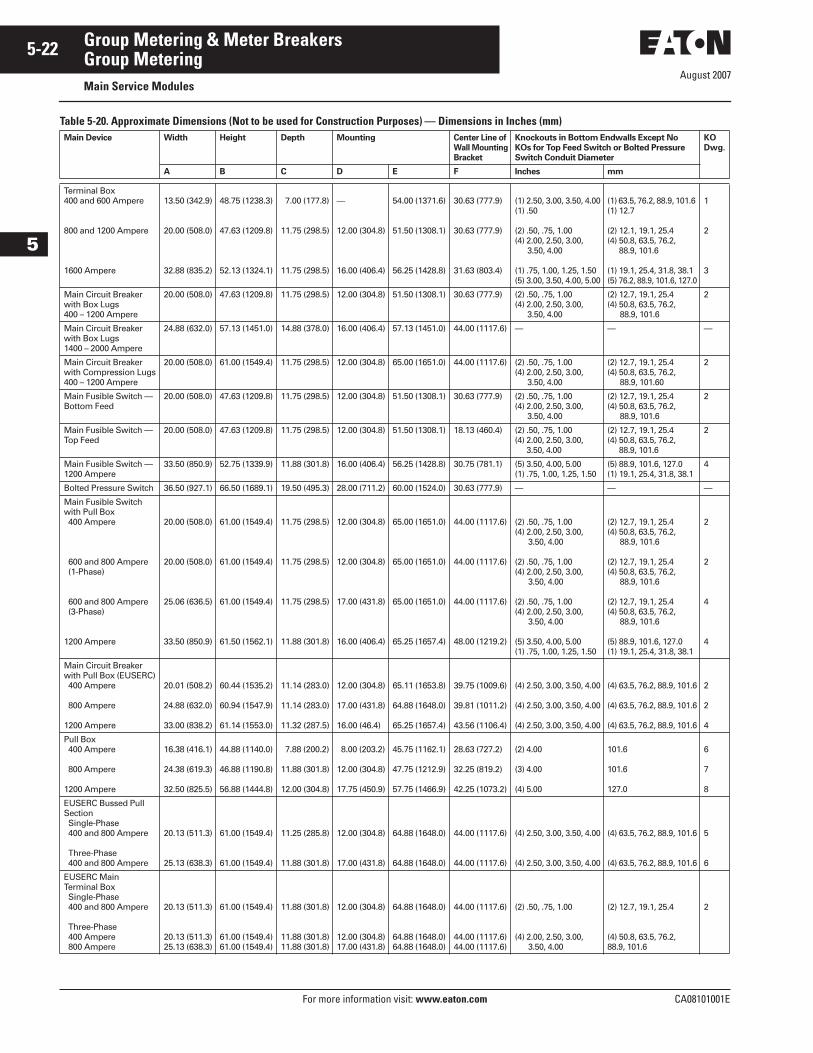
Table 5-20. Approximate Dimensions (Not to be used for Construction Purposes) — Dimensions in Inches (mm)Main Device Width Height Depth Mounting Center Line of
Wall Mounting
Bracket
Knockouts in Bottom Endwalls Except No
KOs for Top Feed Switch or Bolted Pressure
Switch Conduit Diameter
KO
Dwg.
A B C D E F Inches mm
Terminal Box400 and 600 Ampere
800 and 1200 Ampere
1600 Ampere
13.50 (342.9)
20.00 (508.0)
32.88 (835.2)
48.75 (1238.3)
47.63 (1209.8)
52.13 (1324.1)
7.00 (177.8)
11.75 (298.5)
11.75 (298.5)
—
12.00 (304.8)
16.00 (406.4)
54.00 (1371.6)
51.50 (1308.1)
56.25 (1428.8)
30.63 (777.9)
30.63 (777.9)
31.63 (803.4)
(1) 2.50, 3.00, 3.50, 4.00(1) .50
(2) .50, .75, 1.00(4) 2.00, 2.50, 3.00,
3.50, 4.00
(1) .75, 1.00, 1.25, 1.50(5) 3.00, 3.50, 4.00, 5.00
(1) 63.5, 76.2, 88.9, 101.6 (1) 12.7
(2) 12.1, 19.1, 25.4 (4) 50.8, 63.5, 76.2,
88.9, 101.6
(1) 19.1, 25.4, 31.8, 38.1(5) 76.2, 88.9, 101.6, 127.0
1
2
3
Main Circuit Breaker with Box Lugs400 – 1200 Ampere
20.00 (508.0) 47.63 (1209.8) 11.75 (298.5) 12.00 (304.8) 51.50 (1308.1) 30.63 (777.9) (2) .50, .75, 1.00(4) 2.00, 2.50, 3.00,
3.50, 4.00
(2) 12.7, 19.1, 25.4(4) 50.8, 63.5, 76.2,
88.9, 101.6
2
Main Circuit Breaker with Box Lugs1400 – 2000 Ampere
24.88 (632.0) 57.13 (1451.0) 14.88 (378.0) 16.00 (406.4) 57.13 (1451.0) 44.00 (1117.6) — — —
Main Circuit Breaker with Compression Lugs400 – 1200 Ampere
20.00 (508.0) 61.00 (1549.4) 11.75 (298.5) 12.00 (304.8) 65.00 (1651.0) 44.00 (1117.6) (2) .50, .75, 1.00(4) 2.00, 2.50, 3.00,
3.50, 4.00
(2) 12.7, 19.1, 25.4 (4) 50.8, 63.5, 76.2,
88.9, 101.60
2
Main Fusible Switch — Bottom Feed
20.00 (508.0) 47.63 (1209.8) 11.75 (298.5) 12.00 (304.8) 51.50 (1308.1) 30.63 (777.9) (2) .50, .75, 1.00(4) 2.00, 2.50, 3.00,
3.50, 4.00
(2) 12.7, 19.1, 25.4 (4) 50.8, 63.5, 76.2,
88.9, 101.6
2
Main Fusible Switch — Top Feed
20.00 (508.0) 47.63 (1209.8) 11.75 (298.5) 12.00 (304.8) 51.50 (1308.1) 18.13 (460.4) (2) .50, .75, 1.00(4) 2.00, 2.50, 3.00,
3.50, 4.00
(2) 12.7, 19.1, 25.4 (4) 50.8, 63.5, 76.2,
88.9, 101.6
2
Main Fusible Switch —1200 Ampere
33.50 (850.9) 52.75 (1339.9) 11.88 (301.8) 16.00 (406.4) 56.25 (1428.8) 30.75 (781.1) (5) 3.50, 4.00, 5.00(1) .75, 1.00, 1.25, 1.50
(5) 88.9, 101.6, 127.0(1) 19.1, 25.4, 31.8, 38.1
4
Bolted Pressure Switch 36.50 (927.1) 66.50 (1689.1) 19.50 (495.3) 28.00 (711.2) 60.00 (1524.0) 30.63 (777.9) — — —
Main Fusible Switch with Pull Box 400 Ampere
600 and 800 Ampere (1-Phase)
600 and 800 Ampere (3-Phase)
1200 Ampere
20.00 (508.0)
20.00 (508.0)
25.06 (636.5)
33.50 (850.9)
61.00 (1549.4)
61.00 (1549.4)
61.00 (1549.4)
61.50 (1562.1)
11.75 (298.5)
11.75 (298.5)
11.75 (298.5)
11.88 (301.8)
12.00 (304.8)
12.00 (304.8)
17.00 (431.8)
16.00 (406.4)
65.00 (1651.0)
65.00 (1651.0)
65.00 (1651.0)
65.25 (1657.4)
44.00 (1117.6)
44.00 (1117.6)
44.00 (1117.6)
48.00 (1219.2)
(2) .50, .75, 1.00(4) 2.00, 2.50, 3.00,
3.50, 4.00
(2) .50, .75, 1.00(4) 2.00, 2.50, 3.00,
3.50, 4.00
(2) .50, .75, 1.00(4) 2.00, 2.50, 3.00,
3.50, 4.00
(5) 3.50, 4.00, 5.00(1) .75, 1.00, 1.25, 1.50
(2) 12.7, 19.1, 25.4 (4) 50.8, 63.5, 76.2,
88.9, 101.6
(2) 12.7, 19.1, 25.4 (4) 50.8, 63.5, 76.2,
88.9, 101.6
(2) 12.7, 19.1, 25.4 (4) 50.8, 63.5, 76.2,
88.9, 101.6
(5) 88.9, 101.6, 127.0 (1) 19.1, 25.4, 31.8, 38.1
2
2
4
4
Main Circuit Breaker with Pull Box (EUSERC) 400 Ampere
800 Ampere
1200 Ampere
20.01 (508.2)
24.88 (632.0)
33.00 (838.2)
60.44 (1535.2)
60.94 (1547.9)
61.14 (1553.0)
11.14 (283.0)
11.14 (283.0)
11.32 (287.5)
12.00 (304.8)
17.00 (431.8)
16.00 (46.4)
65.11 (1653.8)
64.88 (1648.0)
65.25 (1657.4)
39.75 (1009.6)
39.81 (1011.2)
43.56 (1106.4)
(4) 2.50, 3.00, 3.50, 4.00
(4) 2.50, 3.00, 3.50, 4.00
(4) 2.50, 3.00, 3.50, 4.00
(4) 63.5, 76.2, 88.9, 101.6
(4) 63.5, 76.2, 88.9, 101.6
(4) 63.5, 76.2, 88.9, 101.6
2
2
4
Pull Box 400 Ampere
800 Ampere
1200 Ampere
16.38 (416.1)
24.38 (619.3)
32.50 (825.5)
44.88 (1140.0)
46.88 (1190.8)
56.88 (1444.8)
7.88 (200.2)
11.88 (301.8)
12.00 (304.8)
8.00 (203.2)
12.00 (304.8)
17.75 (450.9)
45.75 (1162.1)
47.75 (1212.9)
57.75 (1466.9)
28.63 (727.2)
32.25 (819.2)
42.25 (1073.2)
(2) 4.00
(3) 4.00
(4) 5.00
101.6
101.6
127.0
6
7
8
EUSERC Bussed Pull Section Single-Phase 400 and 800 Ampere
Three-Phase 400 and 800 Ampere
20.13 (511.3)
25.13 (638.3)
61.00 (1549.4)
61.00 (1549.4)
11.25 (285.8)
11.88 (301.8)
12.00 (304.8)
17.00 (431.8)
64.88 (1648.0)
64.88 (1648.0)
44.00 (1117.6)
44.00 (1117.6)
(4) 2.50, 3.00, 3.50, 4.00
(4) 2.50, 3.00, 3.50, 4.00
(4) 63.5, 76.2, 88.9, 101.6
(4) 63.5, 76.2, 88.9, 101.6
5
6
EUSERC Main Terminal Box Single-Phase 400 and 800 Ampere
Three-Phase 400 Ampere 800 Ampere
20.13 (511.3)
20.13 (511.3)25.13 (638.3)
61.00 (1549.4)
61.00 (1549.4)61.00 (1549.4)
11.88 (301.8)
11.88 (301.8)11.88 (301.8)
12.00 (304.8)
12.00 (304.8)17.00 (431.8)
64.88 (1648.0)
64.88 (1648.0)64.88 (1648.0)
44.00 (1117.6)
44.00 (1117.6)44.00 (1117.6)
(2) .50, .75, 1.00
(4) 2.00, 2.50, 3.00, 3.50, 4.00
(2) 12.7, 19.1, 25.4
(4) 50.8, 63.5, 76.2, 88.9, 101.6
2
August 2007
CA08101001E For more information visit: www.eaton.com
5-23Group Metering & Meter Breakers
5
Group MeteringMain Service Modules
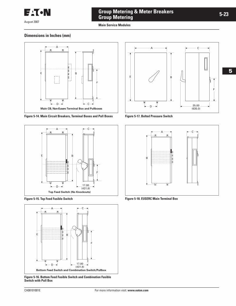
Dimensions in Inches (mm)
Figure 5-14. Main Circuit Breakers, Terminal Boxes and Pull Boxes
Figure 5-15. Top Feed Fusible Switch
Figure 5-16. Bottom Feed Fusible Switch and Combination Fusible Switch with Pull Box
Figure 5-17. Bolted Pressure Switch
Figure 5-18. EUSERC Main Terminal Box
C
B
A
E
D
Main CB, Non-Euserc Terminal Box and Pullboxes
F
C
17.00(431.8)
A
E B
D
Top Feed Switch (No Knockouts)
F
Bottom Feed Switch and Combination Switch/Pullbox
A
E B
D
C
17.00(431.8)
F
D
BE
A
25.00(635.0)
F
C
A
B
C
August 2007
5-24
For more information visit: www.eaton.com CA08101001E
Group Metering & Meter Breakers
5
Group MeteringMain Service Modules
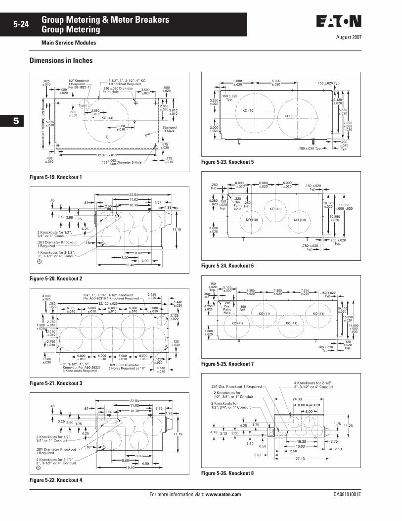
Dimensions in Inches
Figure 5-19. Knockout 1
Figure 5-20. Knockout 2
Figure 5-21. Knockout 3
Figure 5-22. Knockout 4
Figure 5-23. Knockout 5
Figure 5-24. Knockout 6
Figure 5-25. Knockout 7
Figure 5-26. Knockout 8
.875±.020
.169+.003–.000 Diameter 5 Hole
.175±.010
StampedID Mark
5.375±.010 3.500
±.010
2.880±.010
KO (44)
KO (1)
12.375 ±.010
3.010±.010
2.880±.030
2-1/2”, 3”, 3-1/2”, 4” KO1 Knockout Required
1/2”Knockout1 RequiredPer 50-1827-1 .080
±.0202.500±.020
.310 ±.030 Diameter Paint Hole
.080±.020
.438±.010
.800±.030
.625±.010
6.500 Ou
tside ±.010 CL
8.00
2 Knockouts for 1/2”,3/4” or 1” Conduit
4 Knockouts for 2-1/2”, 3”, 3-1/2” or 4” Conduit
.281 Diameter Knockout1 Required
A
.45
3.25 2.50 1.75
4.25
.16
22.5411.62
10.382.503.75
1.93.61
19.40
8.004.00
11.19
2.125±.020
6.000±.010
6.000±.010
6.000±.010
6.000±.010
6.000±.010
6.000±.010
6.000±.010
6.000±.010
6.000±.010
3/4”, 1”, 1-1/4”, 1-1/2” KnockoutPer A50-26319 1 Knockout Required
32.120 ±.020
3”, 3-1/2”, 4”, 5” Knockout Per A50-263275 Knockouts Required
.380±.020
2.750±.010
2.750±.010
2.750±.010
4.000±.020
7.500±.020
2.125±.020
1.440±.020
.169 ±.002 Diameter5 Holes Required at ”X”
1.500±.020
.130±.030
.125±.030
4.440±.020
8.00
22.5411.62
10.382.50
19.40
8.004.00
3.751.93
.61
11.19
.45
3.25 2.50 1.75
4.252 Knockouts for 1/2”,3/4” or 1” Conduit
4 Knockouts for 2-1/2”, 3”, 3-1/2” or 4” Conduit
.281 Diameter Knockout1 Required
.16
B
6.000±.020
KO (10)
KO (10)
5.000±.020
.150 ±.020Typ.3.250
±.020
3.000±.020
.150 ±.020 Typ.
6.120±.020
6.850±.020
7.000+.000–.030
.780 ±.020 Typ.
.200±.020Typ.
KO (10)
.150 ±.020Typ.
KO (10)
KO (10)
6.000±.020
6.000±.020
6.000±.020
.250Ref.
.150±.020Typ.
4.000±.020
4.250±.020
.250Ref.
.220Dia.
PaintHole
10.120±.020
10.850±.020
11.000+.000 -.030
.200 ±.020Typ.
.780 ±.020Typ.
7.250±.020
7.250±.020
7.250±.020
5.125±.020
.350Ref.
.150±.020Typ.
4.000±.020
4.250±.020
.350Ref.
.220Dia.
PaintHole
.150 ±.020Typ.
KO (11)
KO (11)
KO (11)
KO (11)
10.140±.020
10.850±.020
11.000+.000–.030
.120±.020Typ..685 ±.020
Typ.
4 Knockouts for 2-1/2", 3", 3-1/2" or 4" Conduit
8.00 4.00
8.00
24.38
11.251.75
2.13
15.38 3.7516.63
27.13
2.503.63
0.50
4.75 3.13 2.50
1.50
4.25 1.75
.281 Dia. Knockout 1 Required
2 Knockouts for 1/2", 3/4", or 1" Conduit
2 Knockouts for 1/2", 3/4", or 1" Conduit
CA08101001E For more information visit: www.eaton.com
5-25Group Metering & Meter Breakers
August 2007
5
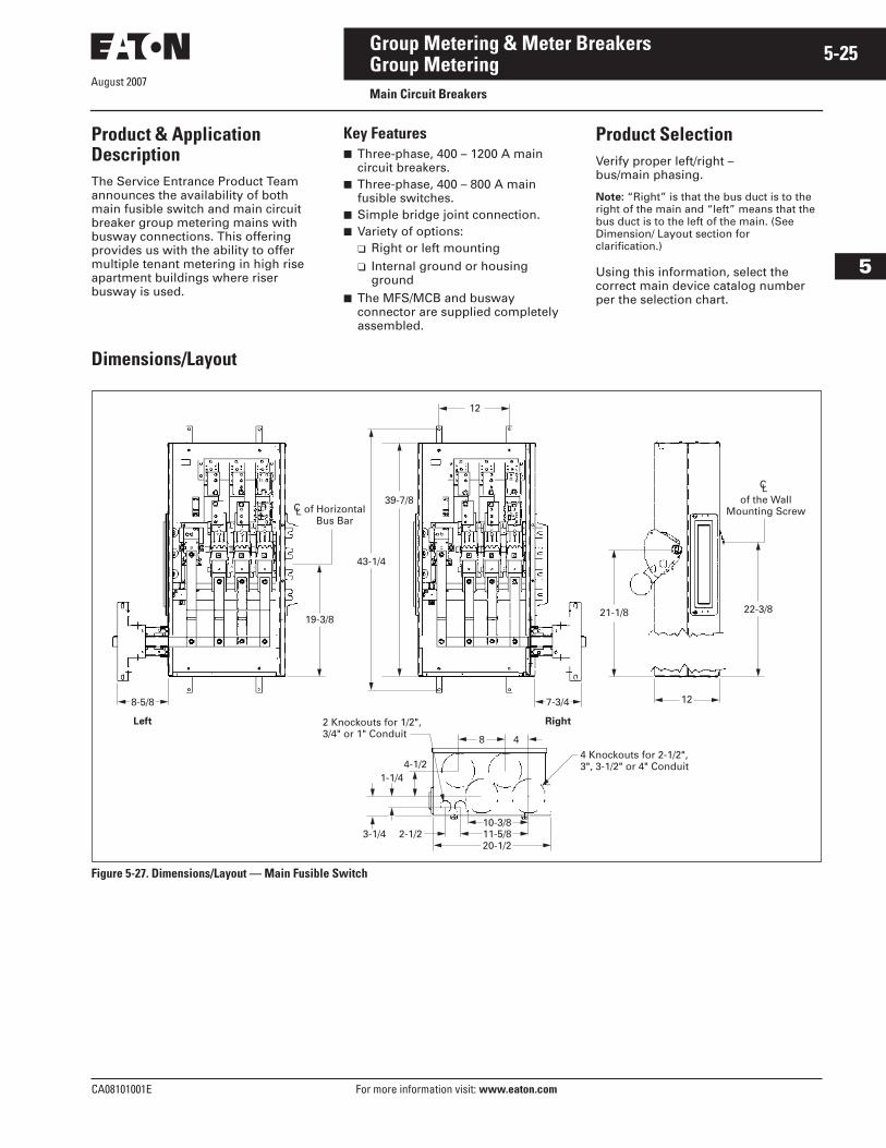
Group MeteringMain Circuit Breakers
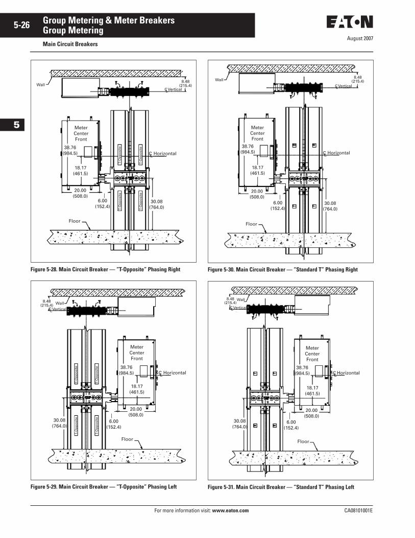
Product & Application DescriptionThe Service Entrance Product Team announces the availability of both main fusible switch and main circuit breaker group metering mains with busway connections. This offering provides us with the ability to offer multiple tenant metering in high rise apartment buildings where riser busway is used.
Key Features■ Three-phase, 400 – 1200 A main
circuit breakers.■ Three-phase, 400 – 800 A main
fusible switches.■ Simple bridge joint connection.■ Variety of options:
❑ Right or left mounting❑ Internal ground or housing
ground■ The MFS/MCB and busway
connector are supplied completely assembled.
Dimensions/Layout
Figure 5-27. Dimensions/Layout — Main Fusible Switch
8-5/8
Left Right
19-3/8
43-1/4
39-7/8
12
of HorizontalBus Bar
CLof the Wall
Mounting Screw
CL
7-3/4
21-1/8 22-3/8
12
8 4
10-3/811-5/82-1/2
1-1/44-1/2
2 Knockouts for 1/2",3/4" or 1" Conduit
4 Knockouts for 2-1/2",3", 3-1/2" or 4" Conduit
3-1/420-1/2
Product SelectionVerify proper left/right – bus/main phasing.
Note: “Right” is that the bus duct is to the right of the main and “left” means that the bus duct is to the left of the main. (See Dimension/ Layout section for clarification.)
Using this information, select the correct main device catalog number per the selection chart.
August 2007
5-26
For more information visit: www.eaton.com CA08101001E
Group Metering & Meter Breakers
5
Group MeteringMain Circuit Breakers
Figure 5-28. Main Circuit Breaker — “T-Opposite” Phasing Right
Figure 5-29. Main Circuit Breaker — “T-Opposite” Phasing Left
Figure 5-30. Main Circuit Breaker — “Standard T” Phasing Right
Figure 5-31. Main Circuit Breaker — “Standard T” Phasing Left
Meter Center Front
CL Horizontal
CL
Floor
WallVertical
8.48 (215.4)
38.76 (984.5)
18.17 (461.5)
20.00 (508.0)
30.08 (764.0)
T-O
pp
osi
te
T-O
pp
osi
te
T-O
pp
osi
te
T-O
pp
osi
te
6.00 (152.4)
Meter Center Front
CL Horizontal
20.00 (508.0)
Floor
WallCLVertical
38.76 (984.5)
18.17 (461.5)
30.08 (764.0)
8.48 (215.4)
T-O
pp
osi
te
T-O
pp
osi
te
T-O
pp
osi
te
T-O
pp
osi
te 6.00 (152.4)
Meter Center Front
CL Horizontal
CL
20.00 (508.0)
Floor
Wall
Vertical
8.48 (215.4)
38.76 (984.5)
18.17 (461.5)
30.08 (764.0)
6.00 (152.4)
Meter Center Front
CLHorizontal
CL
38.76 (984.5)
18.17 (461.5)
20.00 (508.0)
30.08 (764.0)
Floor
8.48 (215.4)
Wall
Vertical
6.00 (152.4)

August 2007
CA08101001E For more information visit: www.eaton.com
5-27Group Metering & Meter Breakers
5
Group MeteringMain Circuit Breakers
Table 5-21. Product Selection Table 5-21. Product Selection (Continued)Ampere Rating
Feed System Voltage 120/208 Vac 3-Phase, 4-Wire Catalog Number
Internal Ground or Housing Ground
Standard T or TO Opposite Phasing
Right or Left Side
400 600 800
BottomBottomBottom
3MFS400BCRGTO3MFS600BCRGTO3MFS800BCRGTO
InternalInternalInternal
TOTOTO
RightRightRight
400 600 800
BottomBottomBottom
3MFS400BCLGTO3MFS600BCLGTO3MFS800BCLGTO
InternalInternalInternal
TOTOTO
LeftLeftLeft
400 600 800
BottomBottomBottom
3MFS400BCRGT3MFS600BCRGT3MFS800BCRGT
InternalInternalInternal
TTT
RightRightRight
400 600 800
BottomBottomBottom
3MFS400BCLGT3MFS600BCLGT3MFS800BCLGT
InternalInternalInternal
TTT
LeftLeftLeft
400 600 800
BottomBottomBottom
3MFS400BCRNTO3MFS600BCRNTO3MFS800BCRNTO
HousingHousingHousing
TOTOTO
RightRightRight
400 600 800
BottomBottomBottom
3MFS400BCLNTO3MFS600BCLNTO3MFS800BCLNTO
HousingHousingHousing
TOTOTO
LeftLeftLeft
400 600 800
BottomBottomBottom
3MFS400BCRNT3MFS600BCRNT3MFS800BCRNT
HousingHousingHousing
TTT
RightRightRight
400 600 800
BottomBottomBottom
3MFS400BCLNT3MFS600BCLNT3MFS800BCLNT
HousingHousingHousing
TTT
LeftLeftLeft
400 400 600
BottomBottomBottom
3MCB400BCRGT3HMCB400BCRGT3MCB600BCRGT
InternalInternalInternal
TTT
RightRightRight
600 800 800
BottomBottomBottom
3HMCB600BCRGT3MCB800BCRGT3HMCB800BCRGT
InternalInternalInternal
TTT
RightRightRight
100010001200
BottomBottomBottom
3MCB1000BCRGT3HMCB1000BCRGT3MCB1200BCRGT
InternalInternalInternal
TTT
RightRightRight
1200 400 400
BottomBottomBottom
3HMCB1200BCRGT3MCB400BCLGT3HMCB400BCLGT
InternalInternalInternal
TTT
RightLeftLeft
600 600 800
BottomBottomBottom
3MCB600BCLGT3HMCB600BCLGT3MCB800BCLGT
InternalInternalInternal
TTT
LeftLeftLeft
80010001000
BottomBottomBottom
3HMCB800BCLGT3MCB1000BCLGT3HMCB1000BCLGT
InternalInternalInternal
TTT
LeftLeftLeft
12001200 400
BottomBottomBottom
3MCB1200BCLGT3HMCB1200BCLGT3MCB400BCRNT
InternalInternalHousing
TTT
LeftLeftRight
400 600 600
BottomBottomBottom
3HMCB400BCRNT3MCB600BCRNT3HMCB600BCRNT
HousingHousingHousing
TTT
RightRightRight
800 8001000
BottomBottomBottom
3MCB800BCRNT3HMCB800BCRNT3MBC1000BCRNT
HousingHousingHousing
TTT
RightRightRight
Amperes Rating
Feed System Voltage 120/208 Vac 3-Phase, 4-Wire Catalog Number
Internal Ground or Housing Ground
Standard T or TO Opposite Phasing
Right or Left Side
100012001200
BottomBottomBottom
3HMBC1000BCRNT3MCB1200BCRNT3HMCB1200BCRNT
HousingHousingHousing
TTT
RightRightRight
400 400 600
BottomBottomBottom
3MCB400BCLNT3HMCB400BCLNT3MCB600BCLNT
HousingHousingHousing
TTT
LeftLeftLeft
600 800 800
BottomBottomBottom
3HMCB600BCLNT3MCB800BCLNT3HMCB800BCLNT
HousingHousingHousing
TTT
LeftLeftLeft
100010001200
BottomBottomBottom
3MCB1000BCLNT3HMCB1000BCLNT3MCB1200BCLNT
HousingHousingHousing
TTT
LeftLeftLeft
1200 400 400
BottomBottomBottom
3HMCB1200BCLNT3MCB400BCRGTO3HMCB400BCRGTO
HousingInternalInternal
TTOTO
LeftRightRight
600 600 800
BottomBottomBottom
3MCB600BCRGTO3HMCB600BCRGTO3MCB800BCRGTO
InternalInternalInternal
TOTOTO
RightRightRight
80010001000
BottomBottomBottom
3HMCB800BCRGTO3MCB1000BCRGTO3HMCB1000BCRGTO
InternalInternalInternal
TOTOTO
RightRightRight
12001200 400
BottomBottomBottom
3MCB1200BCRGTO3HMCB1200BCRGTO3MCB400BCLGTO
InternalInternalInternal
TOTOTO
RightRightLeft
400 600 600
BottomBottomBottom
3HMCB400BCLGTO3MCB600BCLGTO3HMCB600BCLGTO
InternalInternalInternal
TOTOTO
LeftLeftLeft
800 8001000
BottomBottomBottom
3MCB800BCLGTO3HMCB800BCLGTO3MCB1000BCLGTO
InternalInternalInternal
TOTOTO
LeftLeftLeft
100012001200
BottomBottomBottom
3HMCB1000BCLGTO3MCB1200BCLGTO3HMCB1200BCLGTO
InternalInternalInternal
TOTOTO
LeftLeftLeft
400 400 600
BottomBottomBottom
3MCB400BCRNTO3HMCB400BCRNTO3MCB600BCRNTO
HousingHousingHousing
TOTOTO
RightRightRight
600 800 800
BottomBottomBottom
3HMCB600BCRNTO3MCB800BCRNTO3HMCB800BCRNTO
HousingHousingHousing
TOTOTO
RightRightRight
100010001200
BottomBottomBottom
3MCB1000BCRNTO3HMCB1000BCRNTO3MCB1200BCRNTO
HousingHousingHousing
TOTOTO
RightRightRight
1200 400 400
BottomBottomBottom
3HMCB1200BCRNTO3MCB400BCLNTO3HMCB400BCLNTO
HousingHousingHousing
TOTOTO
RightLeftLeft
600 600 800
BottomBottomBottom
3MCB600BCLNTO3HMCB600BCLNTO3HMCB800BCLNTO
HousingHousingHousing
TOTOTO
LeftLeftLeft
80010001000
BottomBottomBottom
3HMCB800BCLNTO3MCB1000BCLNTO3HMCB1000BCLNTO
HousingHousingHousing
TOTOTO
LeftLeftLeft
12001200
BottomBottom
3MCB1200BCLNTO3HMCB1200BCLNTO
HousingHousing
TOTO
LeftLeft
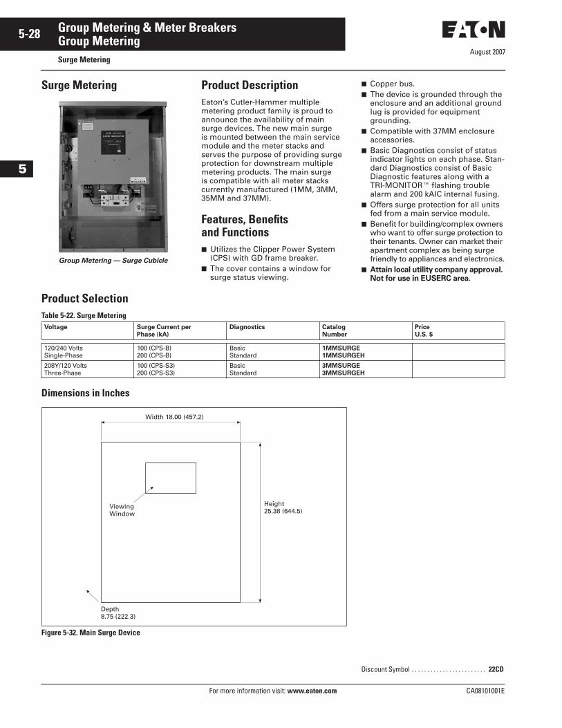
August 2007
5-28
For more information visit: www.eaton.com CA08101001E
Group Metering & Meter Breakers
5
Group MeteringSurge Metering
Surge Metering
Group Metering — Surge Cubicle
Product DescriptionEaton’s Cutler-Hammer multiple metering product family is proud to announce the availability of main surge devices. The new main surge is mounted between the main service module and the meter stacks and serves the purpose of providing surge protection for downstream multiple metering products. The main surge is compatible with all meter stacks currently manufactured (1MM, 3MM, 35MM and 37MM).
Features, Benefits and Functions■ Utilizes the Clipper Power System
(CPS) with GD frame breaker. ■ The cover contains a window for
surge status viewing.
■ Copper bus.■ The device is grounded through the
enclosure and an additional ground lug is provided for equipment grounding.
■ Compatible with 37MM enclosure accessories.
■ Basic Diagnostics consist of status indicator lights on each phase. Stan-dard Diagnostics consist of Basic Diagnostic features along with a TRI-MONITOR� flashing trouble alarm and 200 kAIC internal fusing.
■ Offers surge protection for all units fed from a main service module.
■ Benefit for building/complex owners who want to offer surge protection to their tenants. Owner can market their apartment complex as being surge friendly to appliances and electronics.
■ Attain local utility company approval. Not for use in EUSERC area.
Product SelectionTable 5-22. Surge Metering
Dimensions in Inches
Figure 5-32. Main Surge Device
Voltage Surge Current per Phase (kA)
Diagnostics Catalog Number
Price U.S. $
120/240 VoltsSingle-Phase
100 (CPS-B)200 (CPS-B)
BasicStandard
1MMSURGE1MMSURGEH
208Y/120 VoltsThree-Phase
100 (CPS-S3)200 (CPS-S3)
BasicStandard
3MMSURGE3MMSURGEH
Width 18.00 (457.2)
ViewingWindow
Height25.38 (644.5)
Depth8.75 (222.3)
Discount Symbol . . . . . . . . . . . . . . . . . . . . . . . . 22CD
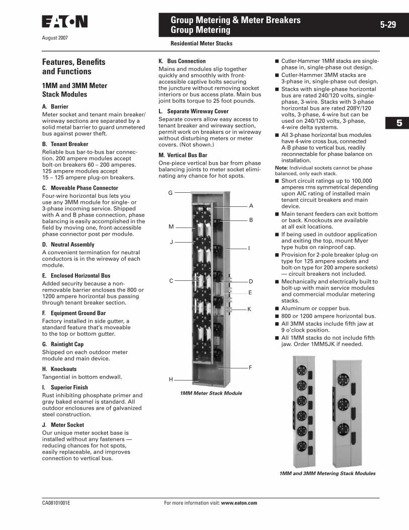
August 2007
CA08101001E For more information visit: www.eaton.com
5-29Group Metering & Meter Breakers
5
Group MeteringResidential Meter Stacks
Features, Benefitsand Functions
1MM and 3MM Meter Stack Modules
A. BarrierMeter socket and tenant main breaker/wireway sections are separated by a solid metal barrier to guard unmetered bus against power theft.
B. Tenant BreakerReliable bus bar-to-bus bar connec-tion. 200 ampere modules accept bolt-on breakers 60 – 200 amperes. 125 ampere modules accept 15 – 125 ampere plug-on breakers.
C. Moveable Phase ConnectorFour-wire horizontal bus lets you use any 3MM module for single- or 3-phase incoming service. Shipped with A and B phase connection, phase balancing is easily accomplished in the field by moving one, front-accessible phase connector post per module.
D. Neutral AssemblyA convenient termination for neutral conductors is in the wireway of each module.
E. Enclosed Horizontal BusAdded security because a non-removable barrier encloses the 800 or 1200 ampere horizontal bus passing through tenant breaker section.
F. Equipment Ground BarFactory installed in side gutter, a standard feature that’s moveable to the top or bottom gutter.
G. Raintight CapShipped on each outdoor meter module and main device.
H. KnockoutsTangential in bottom endwall.
I. Superior FinishRust inhibiting phosphate primer and gray baked enamel is standard. All outdoor enclosures are of galvanized steel construction.
J. Meter SocketOur unique meter socket base is installed without any fasteners — reducing chances for hot spots, easily replaceable, and improves connection to vertical bus.
K. Bus ConnectionMains and modules slip together quickly and smoothly with front-accessible captive bolts securing the juncture without removing socket interiors or bus access plate. Main bus joint bolts torque to 25 foot pounds.
L. Separate Wireway CoverSeparate covers allow easy access to tenant breaker and wireway section, permit work on breakers or in wireway without disturbing meters or meter covers. (Not shown.)
M. Vertical Bus BarOne-piece vertical bus bar from phase balancing joints to meter socket elimi-nating any chance for hot spots.
1MM Meter Stack Module
■ Cutler-Hammer 1MM stacks are single-phase in, single-phase out design.
■ Cutler-Hammer 3MM stacks are 3-phase in, single-phase out design.
■ Stacks with single-phase horizontal bus are rated 240/120 volts, single-phase, 3-wire. Stacks with 3-phase horizontal bus are rated 208Y/120 volts, 3-phase, 4-wire but can be used on 240/120 volts, 3-phase, 4-wire delta systems.
■ All 3-phase horizontal bus modules have 4-wire cross bus, connected A-B phase to vertical bus, readily reconnectable for phase balance on installation.
Note: Individual sockets cannot be phase balanced, only each stack.■ Short circuit ratings up to 100,000
amperes rms symmetrical depending upon AIC rating of installed main tenant circuit breakers and main device.
■ Main tenant feeders can exit bottom or back. Knockouts are available at all exit locations.
■ If being used in outdoor application and exiting the top, mount Myer type hubs on rainproof cap.
■ Provision for 2-pole breaker (plug-on type for 125 ampere sockets and bolt-on type for 200 ampere sockets) — circuit breakers not included.
■ Mechanically and electrically built to bolt-up with main service modules and commercial modular metering stacks.
■ Aluminum or copper bus.■ 800 or 1200 ampere horizontal bus.■ All 3MM stacks include fifth jaw at
9 o’clock position. ■ All 1MM stacks do not include fifth
jaw. Order 1MM5JK if needed.
1MM and 3MM Metering Stack Modules
K
F
E
A
B
G
M
J
C
H
D
I
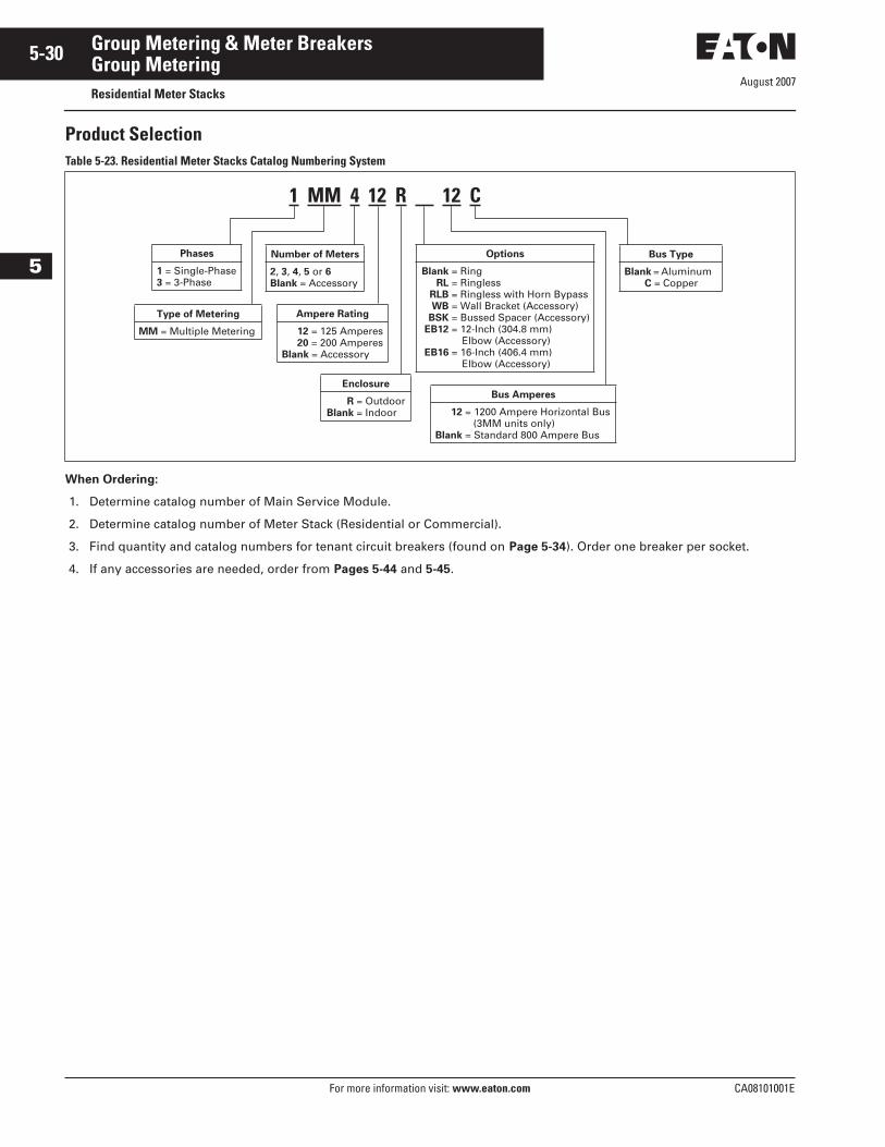
August 2007
5-30
For more information visit: www.eaton.com CA08101001E
Group Metering & Meter Breakers
5
Group MeteringResidential Meter Stacks
Product SelectionTable 5-23. Residential Meter Stacks Catalog Numbering System
When Ordering:
1. Determine catalog number of Main Service Module.
2. Determine catalog number of Meter Stack (Residential or Commercial).
3. Find quantity and catalog numbers for tenant circuit breakers (found on Page 5-34). Order one breaker per socket.
4. If any accessories are needed, order from Pages 5-44 and 5-45.
1 MM 4 12 R 12 C
Phases
1 = Single-Phase3 = 3-Phase
Options
Blank = RingRL = Ringless
RLB = Ringless with Horn BypassWB = Wall Bracket (Accessory)
BSK = Bussed Spacer (Accessory)EB12 = 12-Inch (304.8 mm)
Elbow (Accessory)EB16 = 16-Inch (406.4 mm)
Elbow (Accessory)
Enclosure
R = OutdoorBlank = Indoor
Ampere Rating
12 = 125 Amperes20 = 200 Amperes
Blank = Accessory
Number of Meters
2, 3, 4, 5 or 6Blank = Accessory
Type of Metering
MM = Multiple Metering
Bus Type
Blank = Aluminum C = Copper
Bus Amperes
12 = 1200 Ampere Horizontal Bus(3MM units only)
Blank = Standard 800 Ampere Bus
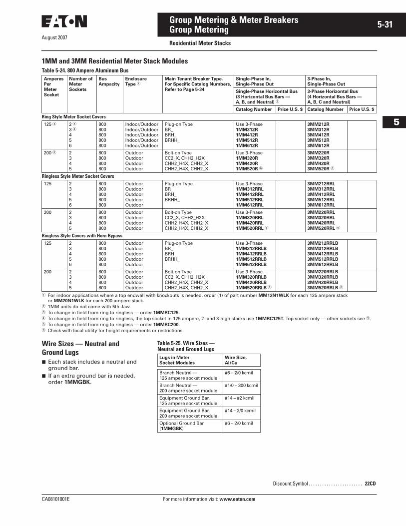
August 2007
CA08101001E For more information visit: www.eaton.com
5-31Group Metering & Meter Breakers
5
Group MeteringResidential Meter Stacks
1MM and 3MM Residential Meter Stack ModulesTable 5-24. 800 Ampere Aluminum Bus
� For indoor applications where a top endwall with knockouts is needed, order (1) of part number MM12N1WLK for each 125 ampere stack or MM20N1WLK for each 200 ampere stack.
� 1MM units do not come with 5th Jaw.� To change in field from ring to ringless — order 1MMRC125.� To change in field from ring to ringless, the top socket in 125 ampere, 2- and 3-high stacks use 1MMRC125T. Top socket only — other sockets see �.� To change in field from ring to ringless — order 1MMRC200.� Check with local utility for height requirements or restrictions.
Wire Sizes — Neutral and Ground Lugs■ Each stack includes a neutral and
ground bar.■ If an extra ground bar is needed,
order 1MMGBK.
Table 5-25. Wire Sizes — Neutral and Ground Lugs
AmperesPerMeterSocket
Number ofMeterSockets
BusAmpacity
Enclosure Type �
Main Tenant Breaker Type. For Specific Catalog Numbers,Refer to Page 5-34
Single-Phase In, Single-Phase Out
3-Phase In, Single-Phase Out
Single-Phase Horizontal Bus(3 Horizontal Bus Bars — A, B, and Neutral) �
3-Phase Horizontal Bus(4 Horizontal Bus Bars — A, B, C and Neutral)
Catalog Number Price U.S. $ Catalog Number Price U.S. $
Ring Style Meter Socket Covers125 � 2 �
3 �456
800800800800800
Indoor/OutdoorIndoor/OutdoorIndoor/OutdoorIndoor/OutdoorIndoor/Outdoor
Plug-on TypeBR_BRH_BRHH_
Use 3-Phase1MM312R1MM412R1MM512R1MM612R
3MM212R3MM312R3MM412R3MM512R3MM612R
200 � 2345
800800800800
OutdoorOutdoorOutdoorOutdoor
Bolt-on TypeCC2_X, CHH2_H2XCHH2_H4X, CHH2_XCHH2_H4X, CHH2_X
Use 3-Phase1MM320R1MM420R1MM520R �
3MM220R3MM320R3MM420R3MM520R �
Ringless Style Meter Socket Covers125 2
3456
800800800800800
OutdoorOutdoorOutdoorOutdoorOutdoor
Plug-on TypeBR_BRH_BRHH_
Use 3-Phase1MM312RRL1MM412RRL1MM512RRL1MM612RRL
3MM212RRL3MM312RRL3MM412RRL3MM512RRL3MM612RRL
200 2345
800800800800
OutdoorOutdoorOutdoorOutdoor
Bolt-on TypeCC2_X, CHH2_H2XCHH2_H4X, CHH2_XCHH2_H4X, CHH2_X
Use 3-Phase1MM320RRL1MM420RRL1MM520RRL �
3MM220RRL3MM320RRL3MM420RRL3MM520RRL �
Ringless Style Covers with Horn Bypass125 2
3456
800800800800800
OutdoorOutdoorOutdoorOutdoorOutdoor
Plug-on TypeBR_BRH_BRHH_
Use 3-Phase1MM312RRLB1MM412RRLB1MM512RRLB1MM612RRLB
3MM212RRLB3MM312RRLB3MM412RRLB3MM512RRLB3MM612RRLB
200 2345
800800800800
OutdoorOutdoorOutdoorOutdoor
Bolt-on TypeCC2_X, CHH2_H2XCHH2_H4X, CHH2_XCHH2_H4X, CHH2_X
Use 3-Phase1MM320RRLB1MM420RRLB1MM520RRLB �
3MM220RRLB3MM320RRLB3MM420RRLB3MM520RRLB �
Lugs in Meter Socket Modules
Wire Size, Al/Cu
Branch Neutral — 125 ampere socket module
#6 – 2/0 kcmil
Branch Neutral — 200 ampere socket module
#1/0 – 300 kcmil
Equipment Ground Bar, 125 ampere socket module
#14 – #2 kcmil
Equipment Ground Bar, 200 ampere socket module
#14 – 2/0 kcmil
Optional Ground Bar (1MMGBK)
#6 – 2/0 kcmil
Discount Symbol . . . . . . . . . . . . . . . . . . . . . . . . 22CD
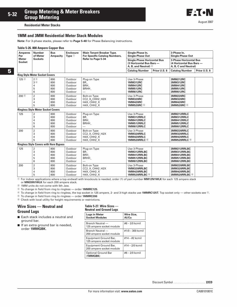
August 2007
5-32
For more information visit: www.eaton.com CA08101001E
Group Metering & Meter Breakers
5
Group MeteringResidential Meter Stacks
1MM and 3MM Residential Meter Stack ModulesNote: For 3-phase stacks, please refer to Page 5-48 for Phase Balancing instructions.
Table 5-26. 800 Ampere Copper Bus
� For indoor applications where a top endwall with knockouts is needed, order (1) of part number MM12N1WLK for each 125 ampere stack or MM20N1WLK for each 200 ampere stack.
� 1MM units do not come with 5th Jaw.� To change in field from ring to ringless — order 1MMRC125.� To change in field from ring to ringless, the top socket in 125 ampere, 2- and 3-high stacks use 1MMRC125T. Top socket only — other sockets see �.� To change in field from ring to ringless — order 1MMRC200� Check with local utility for height requirements or restrictions.
Wire Sizes — Neutral and Ground Lugs■ Each stack includes a neutral and
ground bar.■ If an extra ground bar is needed,
order 1MMGBK.
Table 5-27. Wire Sizes — Neutral and Ground Lugs
AmperesPerMeterSocket
Number of MeterSockets
BusAmpacity
Enclosure Type �
Main Tenant Breaker Type. For Specific Catalog Numbers,Refer to Page 5-34
Single-Phase In, Single-Phase Out
3-Phase In, Single-Phase Out
Single-Phase Horizontal Bus(3 Horizontal Bus Bars — A, B, and Neutral) �
3-Phase Horizontal Bus(4 Horizontal Bus Bars — A, B, C and Neutral)
Catalog Number Price U.S. $ Catalog Number Price U.S. $
Ring Style Meter Socket Covers125 � 2 �
3 �456
800800800800800
OutdoorOutdoorOutdoorOutdoorOutdoor
Plug-on TypeBR_BRH_BRHH_—
Use 3-Phase1MM312RC1MM412RC1MM512RC1MM612RC
3MM212RC3MM312RC3MM412RC3MM512RC3MM612RC
200 � 2345
800800800800
OutdoorOutdoorOutdoorOutdoor
Bolt-on TypeCC2_X, CHH2_H2XH4X, CHH2_XH4X, CHH2_X
Use 3-Phase1MM320RC1MM420RC1MM520RC �
3MM220RC3MM320RC3MM420RC3MM520RC �
Ringless Style Meter Socket Covers125 2
3456
800800800800800
OutdoorOutdoorOutdoorOutdoorOutdoor
Plug-on TypeBR_BRH_BRHH_—
Use 3-Phase1MM312RRLC1MM412RRLC1MM512RRLC1MM612RRLC
3MM212RRLC3MM312RRLC3MM412RRLC3MM512RRLC3MM612RRLC
200 2345
800800800800
OutdoorOutdoorOutdoorOutdoor
Bolt-on TypeCC2_X, CHH2_H2XH4X, CHH2_XH4X, CHH2_X
Use 3-Phase1MM320RRLC1MM420RRLC1MM520RRLC �
3MM220RRLC3MM320RRLC3MM420RRLC3MM520RRLC �
Ringless Style Covers with Horn Bypass125 2
3456
800800800800800
OutdoorOutdoorOutdoorOutdoorOutdoor
Plug-on TypeBR_BRH_BRHH_—
Use 3-Phase1MM312RRLBC1MM412RRLBC1MM512RRLBC1MM612RRLBC
3MM212RRLBC3MM312RRLBC3MM412RRLBC3MM512RRLBC3MM612RRLBC
200 2345
800800800800
OutdoorOutdoorOutdoorOutdoor
Bolt-on TypeCC2_X, CHH2_H2XH4X, CHH2_XH4X, CHH2_X
Use 3-Phase1MM320RRLBC1MM420RRLBC1MM520RRLBC �
3MM220RRLBC3MM320RRLBC3MM420RRLBC3MM520RRLBC �
Lugs in Meter Socket Modules
Wire Size, Al/Cu
Branch Neutral — 125 ampere socket module
#6 – 2/0 kcmil
Branch Neutral — 200 ampere socket module
#1/0 – 300 kcmil
Equipment Ground Bar, 125 ampere socket module
#14 – #2 kcmil
Equipment Ground Bar, 200 ampere socket module
#14 – 2/0 kcmil
Optional Ground Bar (1MMGBK)
#6 – 2/0 kcmil
Discount Symbol . . . . . . . . . . . . . . . . . . . . . . . . 22CD
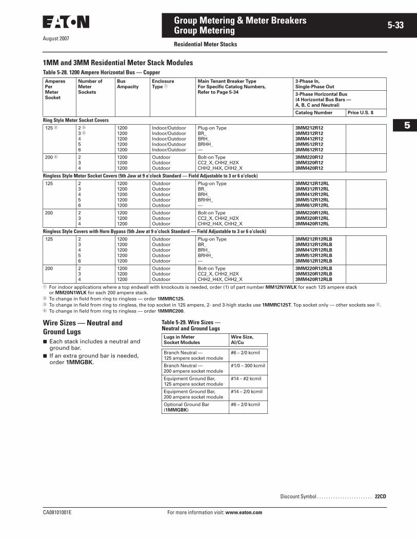
August 2007
CA08101001E For more information visit: www.eaton.com
5-33Group Metering & Meter Breakers
5
Group MeteringResidential Meter Stacks
1MM and 3MM Residential Meter Stack ModulesTable 5-28. 1200 Ampere Horizontal Bus — Copper
� For indoor applications where a top endwall with knockouts is needed, order (1) of part number MM12N1WLK for each 125 ampere stack or MM20N1WLK for each 200 ampere stack.
� To change in field from ring to ringless — order 1MMRC125.� To change in field from ring to ringless, the top socket in 125 ampere, 2- and 3-high stacks use 1MMRC125T. Top socket only — other sockets see �.� To change in field from ring to ringless — order 1MMRC200.
Wire Sizes — Neutral and Ground Lugs■ Each stack includes a neutral and
ground bar.■ If an extra ground bar is needed,
order 1MMGBK.
Table 5-29. Wire Sizes — Neutral and Ground Lugs
AmperesPerMeterSocket
Number ofMeterSockets
BusAmpacity
Enclosure Type �
Main Tenant Breaker TypeFor Specific Catalog Numbers, Refer to Page 5-34
3-Phase In, Single-Phase Out
3-Phase Horizontal Bus(4 Horizontal Bus Bars — A, B, C and Neutral)
Catalog Number Price U.S. $
Ring Style Meter Socket Covers125 � 2 �
3 �456
12001200120012001200
Indoor/OutdoorIndoor/OutdoorIndoor/OutdoorIndoor/OutdoorIndoor/Outdoor
Plug-on TypeBR_BRH_BRHH_—
3MM212R123MM312R123MM412R123MM512R123MM612R12
200 � 234
120012001200
OutdoorOutdoorOutdoor
Bolt-on TypeCC2_X, CHH2_H2XCHH2_H4X, CHH2_X
3MM220R123MM320R123MM420R12
Ringless Style Meter Socket Covers (5th Jaw at 9 o’clock Standard — Field Adjustable to 3 or 6 o’clock)125 2
3456
12001200120012001200
OutdoorOutdoorOutdoorOutdoorOutdoor
Plug-on TypeBR_BRH_BRHH_—
3MM212R12RL3MM312R12RL3MM412R12RL3MM512R12RL3MM612R12RL
200 234
120012001200
OutdoorOutdoorOutdoor
Bolt-on TypeCC2_X, CHH2_H2XCHH2_H4X, CHH2_X
3MM220R12RL3MM320R12RL3MM420R12RL
Ringless Style Covers with Horn Bypass (5th Jaw at 9 o’clock Standard — Field Adjustable to 3 or 6 o’clock)125 2
3456
12001200120012001200
OutdoorOutdoorOutdoorOutdoorOutdoor
Plug-on TypeBR_BRH_BRHH_—
3MM212R12RLB3MM312R12RLB3MM412R12RLB3MM512R12RLB3MM612R12RLB
200 234
120012001200
OutdoorOutdoorOutdoor
Bolt-on TypeCC2_X, CHH2_H2XCHH2_H4X, CHH2_X
3MM220R12RLB3MM320R12RLB3MM420R12RLB
Lugs in Meter Socket Modules
Wire Size, Al/Cu
Branch Neutral — 125 ampere socket module
#6 – 2/0 kcmil
Branch Neutral — 200 ampere socket module
#1/0 – 300 kcmil
Equipment Ground Bar, 125 ampere socket module
#14 – #2 kcmil
Equipment Ground Bar, 200 ampere socket module
#14 – 2/0 kcmil
Optional Ground Bar (1MMGBK)
#6 – 2/0 kcmil
Discount Symbol . . . . . . . . . . . . . . . . . . . . . . . . 22CD
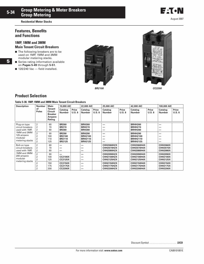
August 2007
5-34
For more information visit: www.eaton.com CA08101001E
Group Metering & Meter Breakers
5
Group MeteringResidential Meter Stacks
Features, Benefitsand Functions
1MP, 1MM and 3MMMain Tenant Circuit Breakers■ The following breakers are to be
used on 1MP, 1MM and 3MM modular metering stacks.
■ Series rating information available on Pages 5-49 through 5-51.
■ 120/240 Vac — field installed.
BR2100 CC2200
Product SelectionTable 5-30. 1MP, 1MM and 3MM Main Tenant Circuit BreakersDescription Number
of Poles
MainTenantCircuitBreakerAmpere Rating
10,000 AIC 22,000 AIC 25,000 AIC 42,000 AIC 100,000 AIC
Catalog Number
PriceU.S. $
Catalog Number
PriceU.S. $
CatalogNumber
PriceU.S. $
CatalogNumber
PriceU.S. $
CatalogNumber
PriceU.S. $
Plug-on type circuit breakers used with 1MP, 1MM and 3MM 125 ampere modularmetering stacks
222
60 70 80
BR260BR270BR280
BRH260BRH270BRH280
———
BRHH260BRHH270BRHH280
———
2222
90100110125
BR290BR2100BR2110BR2125
BRH290BRH2100BRH2110BRH2125
————
BRHH290BRHH2100BRHH2110BRHH2125
————
Bolt-on type circuit breakers used with 1MP, 1MM and 3MM 200 ampere modularmetering stacks
222
60 70 80
———
———
CHH2060H2XCHH2070H2XCHH2080H2X
CHH2060H4XCHH2070H4XCHH2080H4X
CHH2060XCHH2070XCHH2080X
222
90100125
—CC2100XCC2125X
———
CHH2090H2XCHH2100H2XCHH2125H2X
CHH2090H4XCHH2100H4XCHH2125H4X
CHH2090XCHH2100XCHH2125X
222
150175200
CC2150XCC2175XCC2200X
———
CHH2150H2XCHH2175H2XCHH2200H2X
CHH2150H4XCHH2175H4XCHH2200H4X
CHH2150XCHH2175XCHH2200X
Discount Symbol . . . . . . . . . . . . . . . . . . . . . . . . 22CD
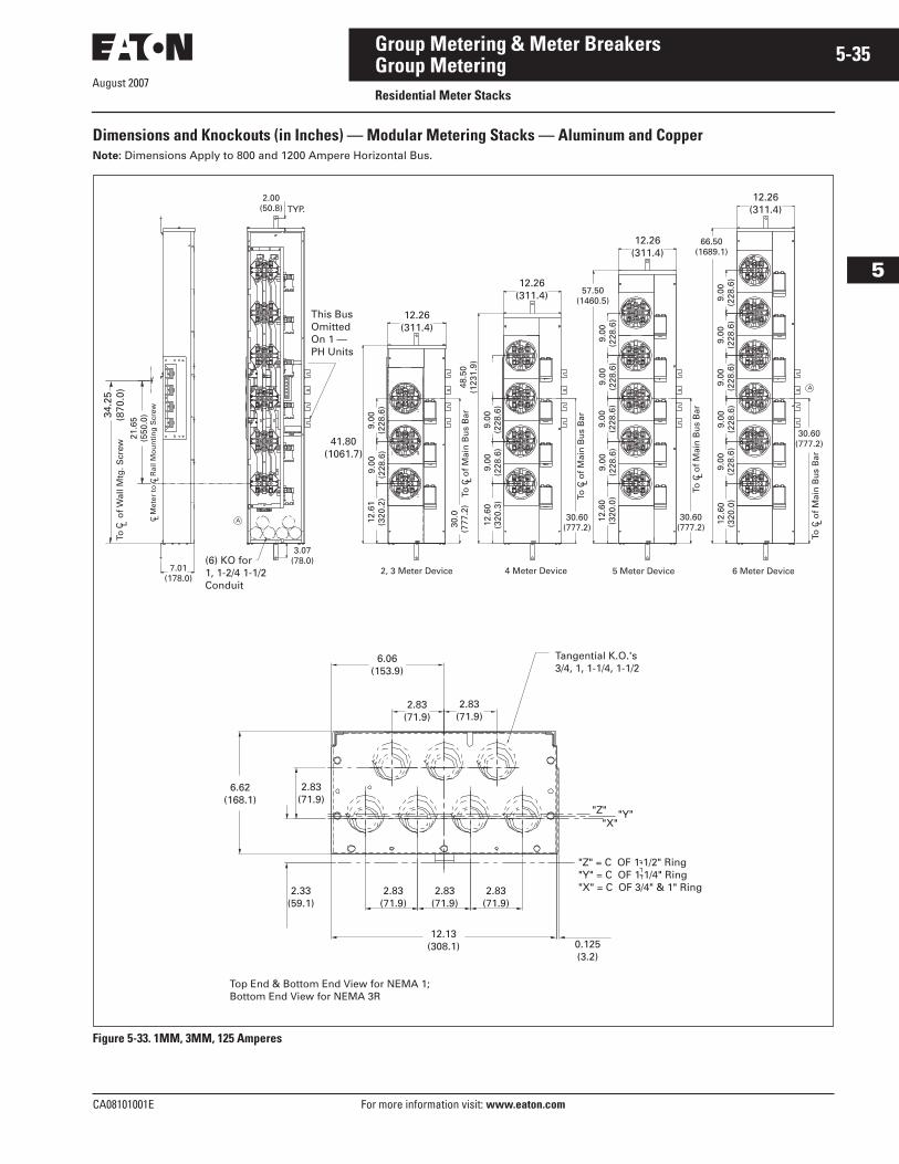
August 2007
CA08101001E For more information visit: www.eaton.com
5-35Group Metering & Meter Breakers
5
Group MeteringResidential Meter Stacks
Dimensions and Knockouts (in Inches) — Modular Metering Stacks — Aluminum and CopperNote: Dimensions Apply to 800 and 1200 Ampere Horizontal Bus.
Figure 5-33. 1MM, 3MM, 125 Amperes
This Bus Omitted On 1 — PH Units
41.80 (1061.7)
9.00
(2
28.6
)9.
00
(228
.6)
12.6
1 (3
20.2
)
3.07 (78.0)(6) KO for
1, 1-2/4 1-1/2 Conduit
A
7.01 (178.0)
34.2
5 (8
70.0
)To
o
f W
all M
tg. S
crew
C L21
.65
(550
.0)
C M
eter
to
C R
ail M
ou
nti
ng
Scr
ewL
L
2.00 (50.8) TYP.
2, 3 Meter Device 4 Meter Device
30.0
(7
77.2
)To
C o
f M
ain
Bu
s B
arL
48.5
0 (1
231.
9)
12.6
0 (3
20.3
)9.
00
(228
.6)
9.00
(2
28.6
)
9.00
(2
28.6
)
30.60 (777.2)
To C
of
Mai
n B
us
Bar
L
57.50 (1460.5)
9.00
(2
28.6
)9.
00
(228
.6)
9.00
(2
28.6
)12
.60
(320
.0)
To C
of
Mai
n B
us
Bar
L
30.60 (777.2)
5 Meter Device 6 Meter Device
12.6
0 (3
20.0
)9.
00
(228
.6)
9.00
(2
28.6
)9.
00
(228
.6)
9.00
(2
28.6
)9.
00
(228
.6)
66.50 (1689.1)
A
30.60 (777.2)
To C
of
Mai
n B
us
Bar
L
Top End & Bottom End View for NEMA 1; Bottom End View for NEMA 3R
Tangential K.O.'s3/4, 1, 1-1/4, 1-1/2
"Z" = C OF 1-1/2" Ring"Y" = C OF 1-1/4" Ring"X" = C OF 3/4" & 1" Ring
LLL
0.125 (3.2)
12.13 (308.1)
2.83 (71.9)
2.83 (71.9)
2.83 (71.9)
2.33 (59.1)
6.62 (168.1)
2.83 (71.9)
6.06 (153.9)
2.83 (71.9)
2.83 (71.9)
12.26 (311.4)
12.26 (311.4)
12.26 (311.4)
12.26 (311.4)
"X""Y""Z"
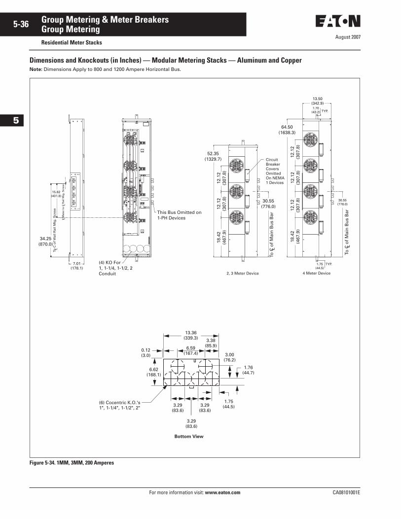
August 2007
5-36
For more information visit: www.eaton.com CA08101001E
Group Metering & Meter Breakers
5
Group MeteringResidential Meter Stacks
Dimensions and Knockouts (in Inches) — Modular Metering Stacks — Aluminum and CopperNote: Dimensions Apply to 800 and 1200 Ampere Horizontal Bus.
Figure 5-34. 1MM, 3MM, 200 Amperes
4 Meter Device2, 3 Meter Device
34.25 (870.0)
To C
of
Wal
l Rai
l Mtg
. Scr
ewL
15.82 (401.8)
C M
eter
to
C R
ail M
tg. S
crew
LL
7.01 (178.1)
(4) KO For 1, 1-1/4, 1-1/2, 2 Conduit
This Bus Omitted on 1-PH Devices
52.35 (1329.7)
12.1
2 (3
07.8
)12
.12
(307
.8)
18.4
2 (4
67.9
)
30.55 (776.0)
To C
of
Mai
n B
us
Bar
L
18.4
2 (4
67.9
)12
.12
(307
.8)
12.1
2 (3
07.8
)12
.12
(307
.8)
64.50 (1638.3)
Circuit Breaker Covers Omitted On NEMA 1 Devices
13.50 (342.9)1.70
(43.2) TYP.
30.55 (776.0)
To C
of
Mai
n B
us
Bar
L
1.75 (44.5)
TYP.
Bottom View
3.29 (83.6)
0.12 (3.0)
6.59 (167.4)
13.36 (339.3)
3.29 (83.6)
3.29 (83.6)
3.38 (85.9)
1.75 (44.5)
6.62 (168.1)
(6) Cocentric K.O.'s1", 1-1/4", 1-1/2", 2"
1.76 (44.7)
3.00 (76.2)
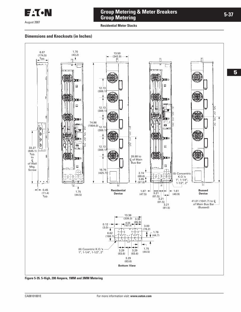
August 2007
CA08101001E For more information visit: www.eaton.com
5-37Group Metering & Meter Breakers
5
Group MeteringResidential Meter Stacks
Dimensions and Knockouts (in Inches)
Figure 5-35. 5-High, 200 Ampere, 1MM and 3MM Metering
L
33.27 (845.1)
Typ.toC
of WallMtg.
Screw
L41.01 (1041.7) to Cof Main Bus Bar
(Bussed)
13.50 (342.9)
1.70 (43.2)
0.45 (11.4)Typ.
3.21 (81.5)
3.21 (81.5)
1.61 (40.9)
(5) ConcentricK.O.'s
1", 1-1/4",1-1/2", 2"
ResidentialDevice
BussedDevice
6.87 (174.5)
Typ.
1.87 (47.5)
2.74 (69.6)3.85
(97.8)
16.76 (425.7)
28.88 toC of MainBus Bar
12.13 (308.1)
12.13 (308.1)
74.96 (1904.0)
12.13 (308.1)
12.13 (308.1)
1.75 (44.5)
3.21 (81.5)
L
Bottom View
3.29 (83.6)
0.12 (3.0)
6.59 (167.4)
13.36 (339.3)
3.29 (83.6)
3.29 (83.6)
3.38 (85.9)
1.75 (44.5)
6.62 (168.1)
(6) Cocentric K.O.'s1", 1-1/4", 1-1/2", 2"
1.76 (44.7)
3.00 (76.2)
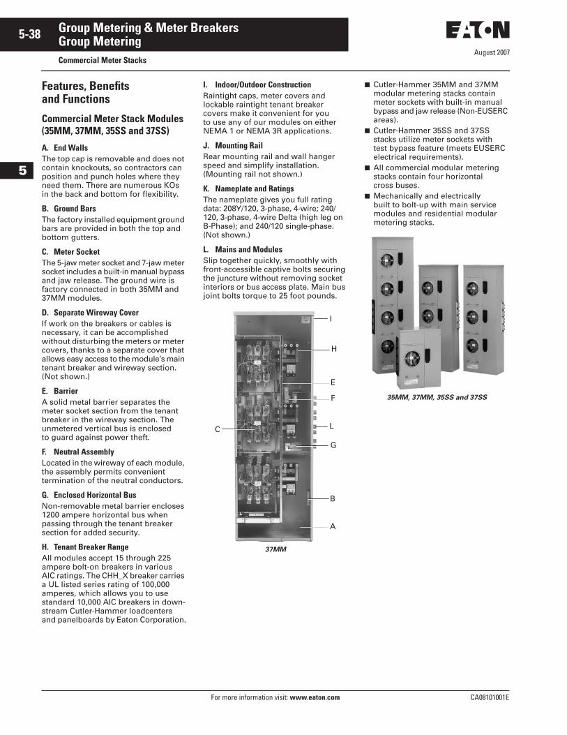
August 2007
5-38
For more information visit: www.eaton.com CA08101001E
Group Metering & Meter Breakers
5
Group MeteringCommercial Meter Stacks
Features, Benefits and Functions
Commercial Meter Stack Modules(35MM, 37MM, 35SS and 37SS)
A. End WallsThe top cap is removable and does not contain knockouts, so contractors can position and punch holes where they need them. There are numerous KOs in the back and bottom for flexibility.
B. Ground BarsThe factory installed equipment ground bars are provided in both the top and bottom gutters.
C. Meter SocketThe 5-jaw meter socket and 7-jaw meter socket includes a built-in manual bypass and jaw release. The ground wire is factory connected in both 35MM and 37MM modules.
D. Separate Wireway CoverIf work on the breakers or cables is necessary, it can be accomplished without disturbing the meters or meter covers, thanks to a separate cover that allows easy access to the module’s main tenant breaker and wireway section. (Not shown.)
E. BarrierA solid metal barrier separates the meter socket section from the tenant breaker in the wireway section. The unmetered vertical bus is enclosed to guard against power theft.
F. Neutral AssemblyLocated in the wireway of each module, the assembly permits convenient termination of the neutral conductors.
G. Enclosed Horizontal BusNon-removable metal barrier encloses 1200 ampere horizontal bus when passing through the tenant breaker section for added security.
H. Tenant Breaker RangeAll modules accept 15 through 225 ampere bolt-on breakers in various AIC ratings. The CHH_X breaker carries a UL listed series rating of 100,000 amperes, which allows you to use standard 10,000 AIC breakers in down-stream Cutler-Hammer loadcenters and panelboards by Eaton Corporation.
I. Indoor/Outdoor ConstructionRaintight caps, meter covers and lockable raintight tenant breaker covers make it convenient for you to use any of our modules on either NEMA 1 or NEMA 3R applications.
J. Mounting RailRear mounting rail and wall hanger speed and simplify installation. (Mounting rail not shown.)
K. Nameplate and RatingsThe nameplate gives you full rating data: 208Y/120, 3-phase, 4-wire; 240/120, 3-phase, 4-wire Delta (high leg on B-Phase); and 240/120 single-phase. (Not shown.)
L. Mains and Modules Slip together quickly, smoothly with front-accessible captive bolts securing the juncture without removing socket interiors or bus access plate. Main bus joint bolts torque to 25 foot pounds.
37MM
■ Cutler-Hammer 35MM and 37MM modular metering stacks contain meter sockets with built-in manual bypass and jaw release (Non-EUSERC areas).
■ Cutler-Hammer 35SS and 37SS stacks utilize meter sockets with test bypass feature (meets EUSERC electrical requirements).
■ All commercial modular metering stacks contain four horizontal cross buses.
■ Mechanically and electrically built to bolt-up with main service modules and residential modular metering stacks.
35MM, 37MM, 35SS and 37SS
L
B
G
F
E
H
C
I
A
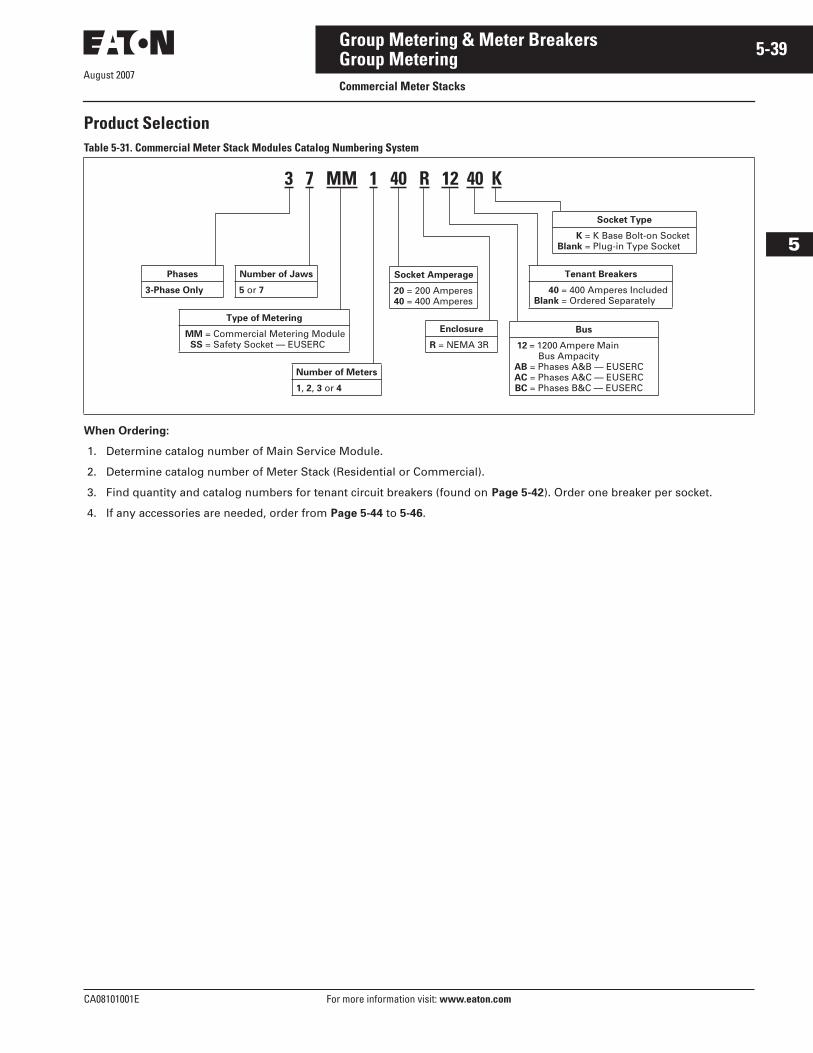
August 2007
CA08101001E For more information visit: www.eaton.com
5-39Group Metering & Meter Breakers
5
Group MeteringCommercial Meter Stacks
Product SelectionTable 5-31. Commercial Meter Stack Modules Catalog Numbering System
When Ordering:
1. Determine catalog number of Main Service Module.
2. Determine catalog number of Meter Stack (Residential or Commercial).
3. Find quantity and catalog numbers for tenant circuit breakers (found on Page 5-42). Order one breaker per socket.
4. If any accessories are needed, order from Page 5-44 to 5-46.
Type of Metering
MM = Commercial Metering ModuleSS = Safety Socket — EUSERC
3 7 MM 1 40 R 12 40 K
Phases
3-Phase Only
Number of Jaws
5 or 7
Socket Amperage
20 = 200 Amperes40 = 400 Amperes
Bus
12 = 1200 Ampere Main Bus Ampacity
AB = Phases A&B — EUSERCAC = Phases A&C — EUSERCBC = Phases B&C — EUSERC
Enclosure
R = NEMA 3R
Number of Meters
1, 2, 3 or 4
Tenant Breakers
40 = 400 Amperes IncludedBlank = Ordered Separately
Socket Type
K = K Base Bolt-on SocketBlank = Plug-in Type Socket
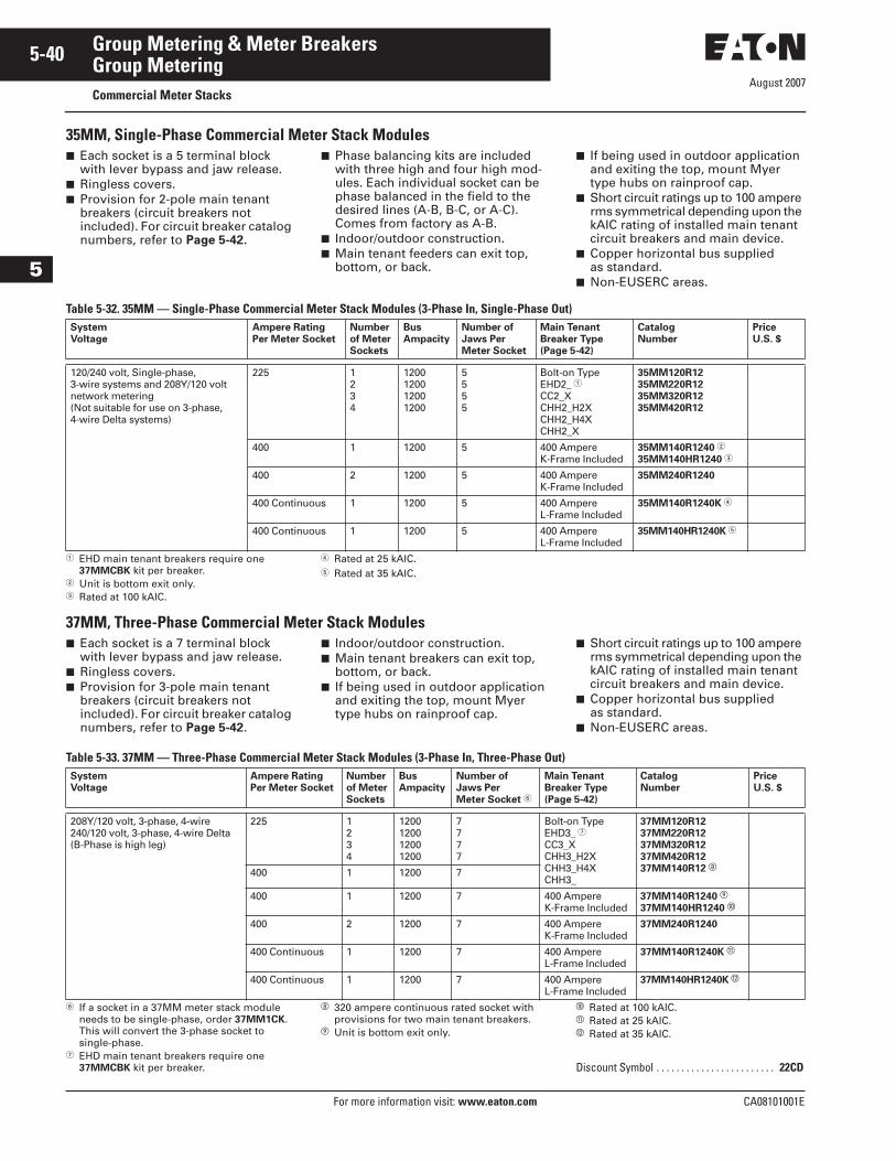
August 2007
5-40
For more information visit: www.eaton.com CA08101001E
Group Metering & Meter Breakers
5
Group MeteringCommercial Meter Stacks
35MM, Single-Phase Commercial Meter Stack Modules■ Each socket is a 5 terminal block
with lever bypass and jaw release.■ Ringless covers.■ Provision for 2-pole main tenant
breakers (circuit breakers not included). For circuit breaker catalog numbers, refer to Page 5-42.
■ Phase balancing kits are included with three high and four high mod-ules. Each individual socket can be phase balanced in the field to the desired lines (A-B, B-C, or A-C). Comes from factory as A-B.
■ Indoor/outdoor construction.■ Main tenant feeders can exit top,
bottom, or back.
■ If being used in outdoor application and exiting the top, mount Myer type hubs on rainproof cap.
■ Short circuit ratings up to 100 ampere rms symmetrical depending upon the kAIC rating of installed main tenant circuit breakers and main device.
■ Copper horizontal bus supplied as standard.
■ Non-EUSERC areas.
Table 5-32. 35MM — Single-Phase Commercial Meter Stack Modules (3-Phase In, Single-Phase Out)
� EHD main tenant breakers require one 37MMCBK kit per breaker.
� Unit is bottom exit only.� Rated at 100 kAIC.
� Rated at 25 kAIC.� Rated at 35 kAIC.
37MM, Three-Phase Commercial Meter Stack Modules■ Each socket is a 7 terminal block
with lever bypass and jaw release.■ Ringless covers.■ Provision for 3-pole main tenant
breakers (circuit breakers not included). For circuit breaker catalog numbers, refer to Page 5-42.
■ Indoor/outdoor construction.■ Main tenant breakers can exit top,
bottom, or back.■ If being used in outdoor application
and exiting the top, mount Myer type hubs on rainproof cap.
■ Short circuit ratings up to 100 ampere rms symmetrical depending upon the kAIC rating of installed main tenant circuit breakers and main device.
■ Copper horizontal bus supplied as standard.
■ Non-EUSERC areas.
Table 5-33. 37MM — Three-Phase Commercial Meter Stack Modules (3-Phase In, Three-Phase Out)
� If a socket in a 37MM meter stack module needs to be single-phase, order 37MM1CK. This will convert the 3-phase socket to single-phase.
� EHD main tenant breakers require one 37MMCBK kit per breaker.
� 320 ampere continuous rated socket with provisions for two main tenant breakers.
� Unit is bottom exit only.
� Rated at 100 kAIC.� Rated at 25 kAIC.� Rated at 35 kAIC.
SystemVoltage
Ampere RatingPer Meter Socket
Numberof MeterSockets
BusAmpacity
Number ofJaws PerMeter Socket
Main TenantBreaker Type(Page 5-42)
Catalog Number
Price U.S. $
120/240 volt, Single-phase, 3-wire systems and 208Y/120 volt network metering(Not suitable for use on 3-phase,4-wire Delta systems)
225 1234
1200120012001200
5555
Bolt-on TypeEHD2_ �CC2_XCHH2_H2XCHH2_H4XCHH2_X
35MM120R1235MM220R1235MM320R1235MM420R12
400 1 1200 5 400 Ampere K-Frame Included
35MM140R1240 �
35MM140HR1240 �
400 2 1200 5 400 Ampere K-Frame Included
35MM240R1240
400 Continuous 1 1200 5 400 Ampere L-Frame Included
35MM140R1240K �
400 Continuous 1 1200 5 400 Ampere L-Frame Included
35MM140HR1240K �
SystemVoltage
Ampere RatingPer Meter Socket
Numberof MeterSockets
BusAmpacity
Number ofJaws PerMeter Socket �
Main TenantBreaker Type(Page 5-42)
Catalog Number
Price U.S. $
208Y/120 volt, 3-phase, 4-wire240/120 volt, 3-phase, 4-wire Delta(B-Phase is high leg)
225 1234
1200120012001200
7777
Bolt-on TypeEHD3_ �CC3_XCHH3_H2XCHH3_H4XCHH3_
37MM120R1237MM220R1237MM320R1237MM420R1237MM140R12 �400 1 1200 7
400 1 1200 7 400 Ampere K-Frame Included
37MM140R1240 �
37MM140HR1240 �
400 2 1200 7 400 Ampere K-Frame Included
37MM240R1240
400 Continuous 1 1200 7 400 Ampere L-Frame Included
37MM140R1240K �
400 Continuous 1 1200 7 400 Ampere L-Frame Included
37MM140HR1240K �
Discount Symbol . . . . . . . . . . . . . . . . . . . . . . . . 22CD
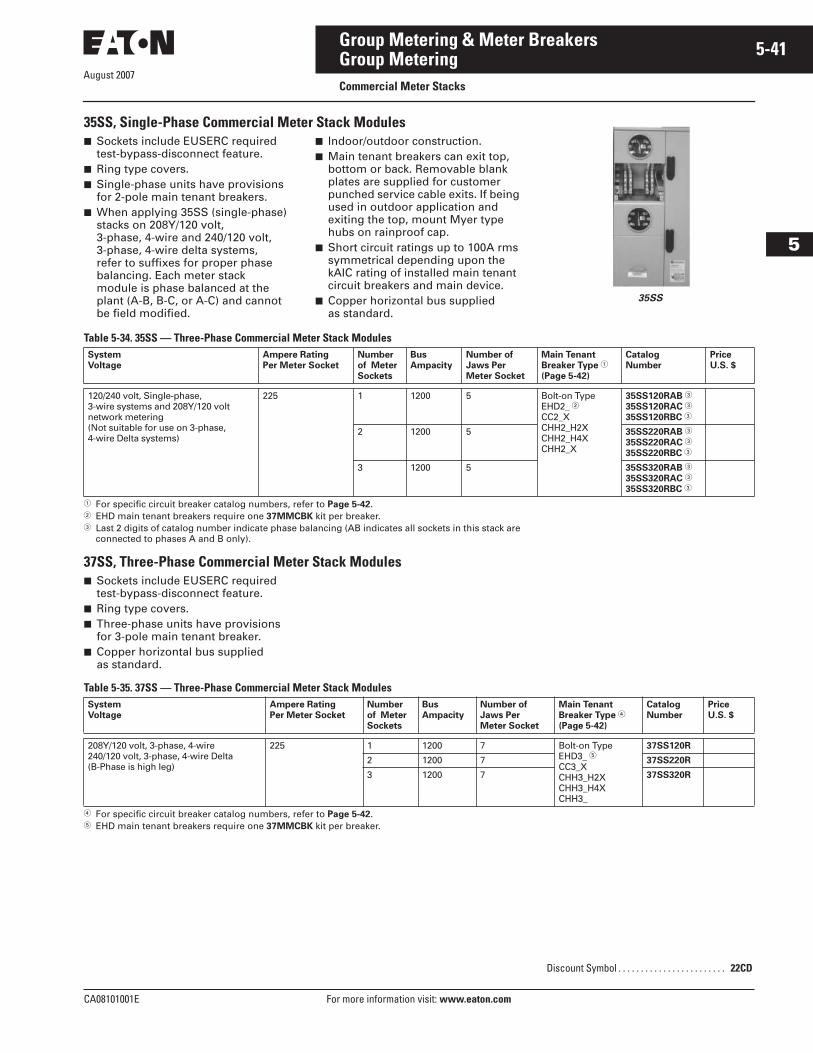
CA08101001E For more information visit: www.eaton.com
5-41Group Metering & Meter Breakers
August 2007
5
Group MeteringCommercial Meter Stacks
35SS, Single-Phase Commercial Meter Stack Modules■ Sockets include EUSERC required
test-bypass-disconnect feature.■ Ring type covers.■ Single-phase units have provisions
for 2-pole main tenant breakers.■ When applying 35SS (single-phase)
stacks on 208Y/120 volt, 3-phase, 4-wire and 240/120 volt, 3-phase, 4-wire delta systems, refer to suffixes for proper phase balancing. Each meter stack module is phase balanced at the plant (A-B, B-C, or A-C) and cannot be field modified.
■ Indoor/outdoor construction.■ Main tenant breakers can exit top,
bottom or back. Removable blank plates are supplied for customer punched service cable exits. If being used in outdoor application and exiting the top, mount Myer type hubs on rainproof cap.
■ Short circuit ratings up to 100A rms symmetrical depending upon the kAIC rating of installed main tenant circuit breakers and main device.
■ Copper horizontal bus supplied as standard.
Table 5-34. 35SS — Three-Phase Commercial Meter Stack Modules
� For specific circuit breaker catalog numbers, refer to Page 5-42.� EHD main tenant breakers require one 37MMCBK kit per breaker.� Last 2 digits of catalog number indicate phase balancing (AB indicates all sockets in this stack are
connected to phases A and B only).
37SS, Three-Phase Commercial Meter Stack Modules■ Sockets include EUSERC required
test-bypass-disconnect feature.■ Ring type covers.■ Three-phase units have provisions
for 3-pole main tenant breaker.■ Copper horizontal bus supplied
as standard.
Table 5-35. 37SS — Three-Phase Commercial Meter Stack Modules
� For specific circuit breaker catalog numbers, refer to Page 5-42.� EHD main tenant breakers require one 37MMCBK kit per breaker.
SystemVoltage
Ampere RatingPer Meter Socket
Numberof MeterSockets
BusAmpacity
Number ofJaws PerMeter Socket
Main TenantBreaker Type �
(Page 5-42)
CatalogNumber
Price U.S. $
120/240 volt, Single-phase, 3-wire systems and 208Y/120 volt network metering(Not suitable for use on 3-phase,4-wire Delta systems)
225 1 1200 5 Bolt-on TypeEHD2_ �CC2_XCHH2_H2XCHH2_H4XCHH2_X
35SS120RAB �
35SS120RAC �
35SS120RBC �
2 1200 5 35SS220RAB �
35SS220RAC �
35SS220RBC �
3 1200 5 35SS320RAB �
35SS320RAC �
35SS320RBC �
SystemVoltage
Ampere RatingPer Meter Socket
Numberof MeterSockets
BusAmpacity
Number ofJaws PerMeter Socket
Main TenantBreaker Type �
(Page 5-42)
CatalogNumber
Price U.S. $
208Y/120 volt, 3-phase, 4-wire240/120 volt, 3-phase, 4-wire Delta(B-Phase is high leg)
225 1 1200 7 Bolt-on TypeEHD3_ �CC3_XCHH3_H2XCHH3_H4XCHH3_
37SS120R
2 1200 7 37SS220R
3 1200 7 37SS320R
35SS
Discount Symbol . . . . . . . . . . . . . . . . . . . . . . . . 22CD
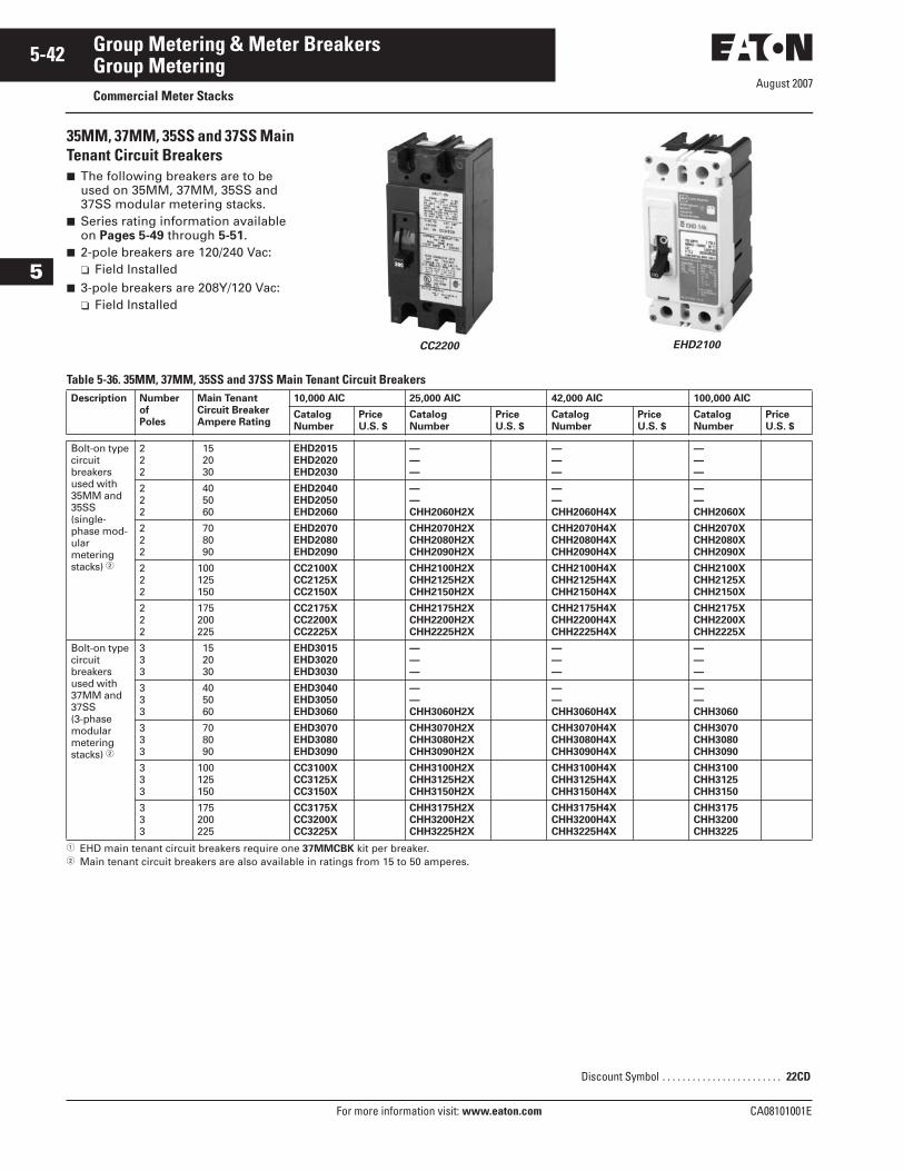
August 2007
5-42
For more information visit: www.eaton.com CA08101001E
Group Metering & Meter Breakers
5
Group MeteringCommercial Meter Stacks
35MM, 37MM, 35SS and 37SS Main Tenant Circuit Breakers■ The following breakers are to be
used on 35MM, 37MM, 35SS and 37SS modular metering stacks.
■ Series rating information available on Pages 5-49 through 5-51.
■ 2-pole breakers are 120/240 Vac:❑ Field Installed
■ 3-pole breakers are 208Y/120 Vac:❑ Field Installed
CC2200 EHD2100
Table 5-36. 35MM, 37MM, 35SS and 37SS Main Tenant Circuit Breakers
� EHD main tenant circuit breakers require one 37MMCBK kit per breaker.� Main tenant circuit breakers are also available in ratings from 15 to 50 amperes.
Description Numberof Poles
Main TenantCircuit BreakerAmpere Rating
10,000 AIC 25,000 AIC 42,000 AIC 100,000 AIC
Catalog Number
Price U.S. $
Catalog Number
Price U.S. $
Catalog Number
Price U.S. $
Catalog Number
Price U.S. $
Bolt-on type circuit breakers used with 35MM and 35SS (single-phase mod-ular metering stacks) �
222
15 20 30
EHD2015EHD2020EHD2030
———
———
———
222
40 50 60
EHD2040EHD2050EHD2060
——CHH2060H2X
——CHH2060H4X
——CHH2060X
222
70 80 90
EHD2070EHD2080EHD2090
CHH2070H2XCHH2080H2XCHH2090H2X
CHH2070H4XCHH2080H4XCHH2090H4X
CHH2070XCHH2080XCHH2090X
222
100125150
CC2100XCC2125XCC2150X
CHH2100H2XCHH2125H2XCHH2150H2X
CHH2100H4XCHH2125H4XCHH2150H4X
CHH2100XCHH2125XCHH2150X
222
175200225
CC2175XCC2200XCC2225X
CHH2175H2XCHH2200H2XCHH2225H2X
CHH2175H4XCHH2200H4XCHH2225H4X
CHH2175XCHH2200XCHH2225X
Bolt-on type circuit breakers used with 37MM and 37SS (3-phase modular metering stacks) �
333
15 20 30
EHD3015EHD3020EHD3030
———
———
———
333
40 50 60
EHD3040EHD3050EHD3060
——CHH3060H2X
——CHH3060H4X
——CHH3060
333
70 80 90
EHD3070EHD3080EHD3090
CHH3070H2XCHH3080H2XCHH3090H2X
CHH3070H4XCHH3080H4XCHH3090H4X
CHH3070CHH3080CHH3090
333
100125150
CC3100XCC3125XCC3150X
CHH3100H2XCHH3125H2XCHH3150H2X
CHH3100H4XCHH3125H4XCHH3150H4X
CHH3100CHH3125CHH3150
333
175200225
CC3175XCC3200XCC3225X
CHH3175H2XCHH3200H2XCHH3225H2X
CHH3175H4XCHH3200H4XCHH3225H4X
CHH3175CHH3200CHH3225
Discount Symbol . . . . . . . . . . . . . . . . . . . . . . . . 22CD
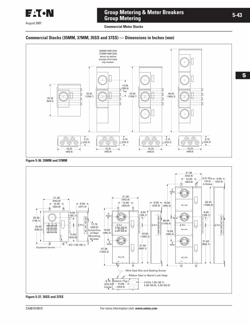
August 2007
CA08101001E For more information visit: www.eaton.com
5-43Group Metering & Meter Breakers
5
Group MeteringCommercial Meter Stacks
Commercial Stacks (35MM, 37MM, 35SS and 37SS) — Dimensions in Inches (mm)
Figure 5-36. 35MM and 37MM
Figure 5-37. 35SS and 37SS
(489.0)
66.63(1692.3)
25.38(644.5)
14.00(355.6)
Typ.52.63
(1336.7)52.63
(1336.7)
8.75(222.3)
35MM140R1240 37MM140R1240same as below
except eliminatetop socket.
(463.6)
8.75(222.3)
18.25(463.6)
8.75(222.3)
18.25(463.6)
8.75(222.3)
3 KOs 1.50 (38.1), 2.00 (50.8), 2.50 (63.5)
Bottom (Typ.)13.56
(344.5)
8.75(222.3)Inside
Wire Seal Slot and Sealing Screw
Ribbon Seal or Barrel Lock Hasp
21.38(542.9)12.00
(304.8)
29.38(746.1)
25.00(635.0)
13.50(342.9)
6.50(165.1)
KO 1.50 (38.1)
2.00 (50.8), 2.50 (63.5)
9.50(241.3)
17.75(450.9)
Centerlineof Wall
MountingScrews
47.38(1203.3)
19.50(495.3)
21.38(542.9)12.00
(304.8)
6.50(165.1)
31.50(800.1)
43.00(1092.2)
9.56(242.9)
19.50(495.3)
19.50(495.3)
68.88(1749.4)
6.50(165.1)
62.44(1585.9)
31.50(800.1)
0.41 Dia.(10.3)
4-Holes
9.56(242.9)
12.00(304.8)
21.38(542.9)
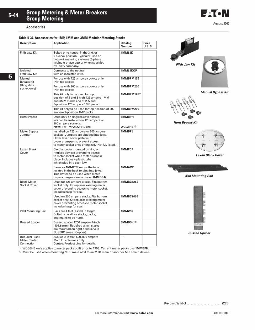
August 2007
5-44
For more information visit: www.eaton.com CA08101001E
Group Metering & Meter Breakers
5
Group MeteringAccessories
Table 5-37. Accessories for 1MP, 1MM and 3MM Modular Metering Stacks
� WCG8HB only applies to meter packs built prior to 1998. Current meter packs use 1MMBPH.� Must be used when mounting MCB main next to an MTB main or another MCB main device.
Description Application Catalog Number
PriceU.S. $
Fifth Jaw Kit Bolted onto neutral in the 3, 6, or 9 o’clock position. Typically used on network metering systems (3-phase in/single-phase out) or when specified by utility company.
1MM5JK
Isolated Fifth Jaw Kit
Connects to the neutral with an insolated wire.
1MM5JKOP
Manual Bypass Kit(Ring style socket only)
For use with 125 ampere sockets only. (Not top socket.)
1MMBPM125
For use with 200 ampere sockets only. (Not top socket.)
1MMBPM200
This kit only to be used for top position of 2 and 3 high 125 ampere 1MM and 3MM stacks and of 2, 5 and 6-position 125 ampere 1MP packs.
1MMBPM125T
This kit only to be used for top position of 200 ampere 2-position 1MP packs.
1MMBPM200T
Horn Bypass Used only on ringless cover stacks, kits can be installed on 125 ampere or 200 ampere sockets.Note: For 1MP2122RRL use:
1MMBPH
WCG8HB �
Meter Bypass Jumper
Installed on 125 ampere or 200 ampere sockets. Jumpers are plugged into jaws. Order lexan cover plate with bypass jumpers to prevent access to meter socket once energized. (Not UL listed.)
1MMBPJ
Lexan Blank Cover
Circular cover mounted on ring or ringless devices preventing access to meter socket while meter is not in place. Includes 4 plastic tabs which plug into each jaw.
1MMPCP
Same as 1MMPCP minus the tabs located in the back to plug into jaws. This device to be used while meter bypass jumpers are in place (1MMBPJ).
1MMACP
Blank Meter Socket Cover
Used for 125 ampere stacks. Fits bottom socket only. Kit replaces existing meter cover preventing access to meter socket.Includes hasp for seal.
1MMBC125B
Used on 200 ampere stacks. Fits bottom socket only. Kit replaces existing meter cover preventing access to meter socket.Includes hasp for seal.
1MMBC200B
Wall Mounting Rail Rails are 4 feet (1.2 m) in length. Bolted on wall for stacks, packs, and mains to be hung.
1MMWB
Bussed Spacer Bussed spacer 1200 ampere 4-inch (101.6 mm). Required when stacks are mounted on right-hand side in EUSERC areas. (Copper)
3MMBSK �
Bus Duct Riser/Meter Center Connection
Available in 400, 600, 800 ampere Main Fusible units only.Contact Product Line for details.
—
Discount Symbol . . . . . . . . . . . . . . . . . . . . . . . . 22CD
Bussed Spacer
Wall Mounting Rail
Horn Bypass Kit
Fifth Jaw Kit
Lexan Blank Cover
Manual Bypass Kit
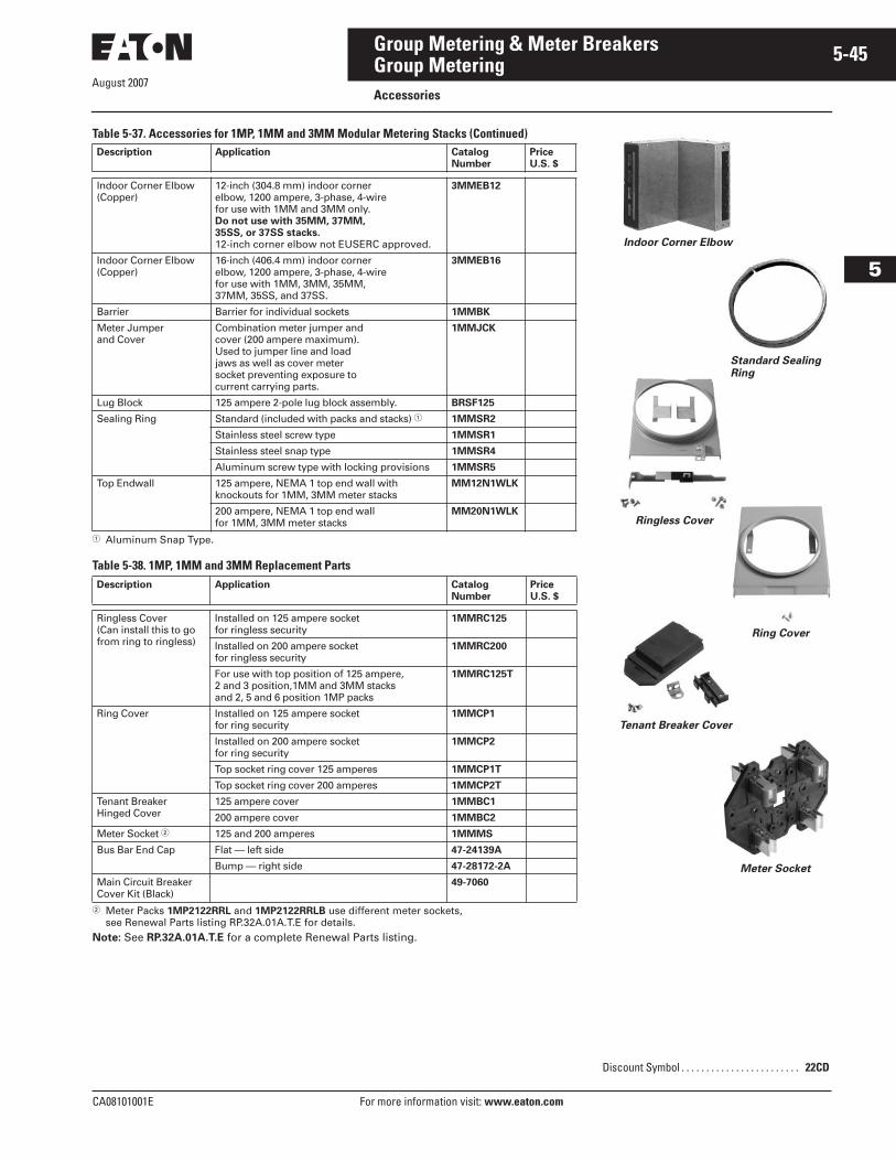
CA08101001E For more information visit: www.eaton.com
5-45Group Metering & Meter Breakers
August 2007
5
Group MeteringAccessories
Table 5-37. Accessories for 1MP, 1MM and 3MM Modular Metering Stacks (Continued)
� Aluminum Snap Type.
Table 5-38. 1MP, 1MM and 3MM Replacement Parts
� Meter Packs 1MP2122RRL and 1MP2122RRLB use different meter sockets, see Renewal Parts listing RP.32A.01A.T.E for details.
Note: See RP.32A.01A.T.E for a complete Renewal Parts listing.
Description Application Catalog Number
PriceU.S. $
Indoor Corner Elbow(Copper)
12-inch (304.8 mm) indoor corner elbow, 1200 ampere, 3-phase, 4-wire for use with 1MM and 3MM only. Do not use with 35MM, 37MM, 35SS, or 37SS stacks.12-inch corner elbow not EUSERC approved.
3MMEB12
Indoor Corner Elbow(Copper)
16-inch (406.4 mm) indoor corner elbow, 1200 ampere, 3-phase, 4-wire for use with 1MM, 3MM, 35MM, 37MM, 35SS, and 37SS.
3MMEB16
Barrier Barrier for individual sockets 1MMBK
Meter Jumper and Cover
Combination meter jumper and cover (200 ampere maximum). Used to jumper line and load jaws as well as cover meter socket preventing exposure to current carrying parts.
1MMJCK
Lug Block 125 ampere 2-pole lug block assembly. BRSF125
Sealing Ring Standard (included with packs and stacks) � 1MMSR2
Stainless steel screw type 1MMSR1
Stainless steel snap type 1MMSR4
Aluminum screw type with locking provisions 1MMSR5
Top Endwall 125 ampere, NEMA 1 top end wall with knockouts for 1MM, 3MM meter stacks
MM12N1WLK
200 ampere, NEMA 1 top end wall for 1MM, 3MM meter stacks
MM20N1WLK
Description Application Catalog Number
PriceU.S. $
Ringless Cover(Can install this to go from ring to ringless)
Installed on 125 ampere socket for ringless security
1MMRC125
Installed on 200 ampere socket for ringless security
1MMRC200
For use with top position of 125 ampere, 2 and 3 position,1MM and 3MM stacks and 2, 5 and 6 position 1MP packs
1MMRC125T
Ring Cover Installed on 125 ampere socket for ring security
1MMCP1
Installed on 200 ampere socket for ring security
1MMCP2
Top socket ring cover 125 amperes 1MMCP1T
Top socket ring cover 200 amperes 1MMCP2T
Tenant BreakerHinged Cover
125 ampere cover 1MMBC1
200 ampere cover 1MMBC2
Meter Socket � 125 and 200 amperes 1MMMS
Bus Bar End Cap Flat — left side 47-24139A
Bump — right side 47-28172-2A
Main Circuit Breaker Cover Kit (Black)
49-7060
Discount Symbol . . . . . . . . . . . . . . . . . . . . . . . . 22CD
Meter Socket
Tenant Breaker Cover
Ring Cover
Standard Sealing Ring
Indoor Corner Elbow
Ringless Cover
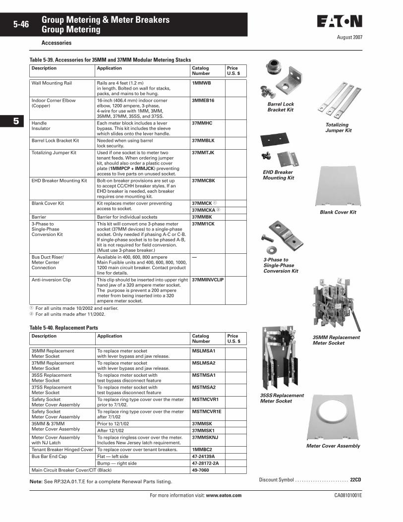
August 2007
5-46
For more information visit: www.eaton.com CA08101001E
Group Metering & Meter Breakers
5
Group MeteringAccessories
Table 5-39. Accessories for 35MM and 37MM Modular Metering Stacks
� For all units made 10/2002 and earlier.� For all units made after 11/2002.
Table 5-40. Replacement Parts
Note: See RP.32A.01.T.E for a complete Renewal Parts listing.
Description Application Catalog Number
PriceU.S. $
Wall Mounting Rail Rails are 4 feet (1.2 m) in length. Bolted on wall for stacks, packs, and mains to be hung.
1MMWB
Indoor Corner Elbow(Copper)
16-inch (406.4 mm) indoor corner elbow, 1200 ampere, 3-phase, 4-wire for use with 1MM, 3MM, 35MM, 37MM, 35SS, and 37SS.
3MMEB16
HandleInsulator
Each meter block includes a lever bypass. This kit includes the sleeve which slides onto the lever handle.
37MMHC
Barrel Lock Bracket Kit Needed when using barrel lock security.
37MMBLK
Totalizing Jumper Kit Used if one socket is to meter two tenant feeds. When ordering jumper kit, should also order a plastic cover plate (1MMPCP + IMMJCK) preventing access to live parts on unused socket.
37MMTJK
EHD Breaker Mounting Kit Bolt-on breaker provisions are set up to accept CC/CHH breaker styles. If an EHD breaker is needed, each breaker requires one mounting kit.
37MMCBK
Blank Cover Kit Kit replaces meter cover preventing access to socket.
37MMCK �
37MMCKA �
Barrier Barrier for individual sockets 37MMBK
3-Phase toSingle-PhaseConversion Kit
This kit will convert one 3-phase meter socket (37MM devices) to a single-phase socket. Only needed if phasing A-C or C-B. If single-phase socket is to be phased A-B, kit is not required for field conversion.(Must use 3-phase breaker.)
37MM1CK
Bus Duct Riser/Meter Center Connection
Available in 400, 600, 800 ampere Main Fusible units and 400, 600, 800, 1000,1200 main circuit breaker. Contact productline for details.
—
Anti-inversion Clip This clip should be inserted into upper right hand jaw of a 320 ampere meter socket. The purpose is prevent a 200 ampere meter from being inserted into a 320 ampere meter socket.
37MMINVCLIP
Description Application Catalog Number
PriceU.S. $
35MM Replacement Meter Socket
To replace meter socket with lever bypass and jaw release.
MSLMSA1
37MM ReplacementMeter Socket
To replace meter socket with lever bypass and jaw release.
MSLMSA2
35SS ReplacementMeter Socket
To replace meter socket with test bypass disconnect feature
MSTMSA1
37SS ReplacementMeter Socket
To replace meter socket with test bypass disconnect feature
MSTMSA2
Safety Socket Meter Cover Assembly
To replace ring type cover over the meter prior to 7/1/02.
MSTMCVR1
Safety Socket Meter Cover Assembly
To replace ring type cover over the meter after 7/1/02
MSTMCVR1E
35MM & 37MM Meter Cover Assembly
Prior to 12/1/02 37MMSK
After 12/1/02 37MMSK1
Meter Cover Assemblywith NJ Latch
To replace ringless cover over the meter.Includes New Jersey latch requirement.
37MMSKNJ
Tenant Breaker Hinged Cover To replace cover over tenant breakers. 1MMBC2
Bus Bar End Cap Flat — left side 47-24139A
Bump — right side 47-28172-2A
Main Circuit Breaker Cover/CIT (Black) 49-7060
Discount Symbol . . . . . . . . . . . . . . . . . . . . . . . . 22CD
Barrel LockBracket Kit
Totalizing Jumper Kit
EHD Breaker Mounting Kit
Blank Cover Kit
3-Phase to Single-Phase Conversion Kit
35MM ReplacementMeter Socket
35SS Replacement Meter Socket
Meter Cover Assembly
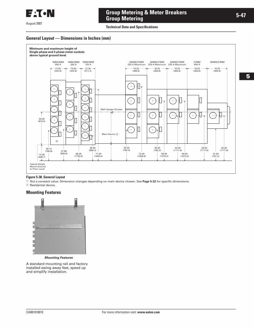
August 2007
CA08101001E For more information visit: www.eaton.com
5-47Group Metering & Meter Breakers
5
Group MeteringTechnical Data and Specifications
General Layout — Dimensions in Inches (mm)
Figure 5-38. General Layout� Not a constant value. Dimension changes depending on main device chosen. See Page 5-22 for specific dimensions.� Residential device.
Mounting Features
Mounting Features
A standard mounting rail and factory installed swing away feet, speed up and simplify installation.
1MM/3MM200 A
1MM/3MM200 A
34.25(870.0)
13.38(339.7)
Typical HeightAbove Groundor Floor Level
31.88(809.6) 68.25
(1733.6)
26.00(660.4)
30.14(765.6)
71.00(1803.4)
30.00(762.0)
72.00(1828.8)
58.00(1473.2)
30.00(762.0)
44.00(1117.6)
58.00(1473.2)
44.00(1117.6)
31.00(787.4)
44.00(1117.6)
13.50(342.9)
13.50(342.9)
12.25(311.2)
19.25(488.8)
18.25(463.6)
18.25(463.6)
18.25(463.6)
18.25(463.6)
Wall Hanger ScrewsLC
1MM/3MM125 A
35MM/37MM225 A Maximum
35MM/37MM225 A Maximum
35MM/37MM225 A Maximum
37MM400 A
35MM/37MM
Main Device �
�
Minimum and maximum height of Single-phase and 3-phase meter sockets above typical ground level.
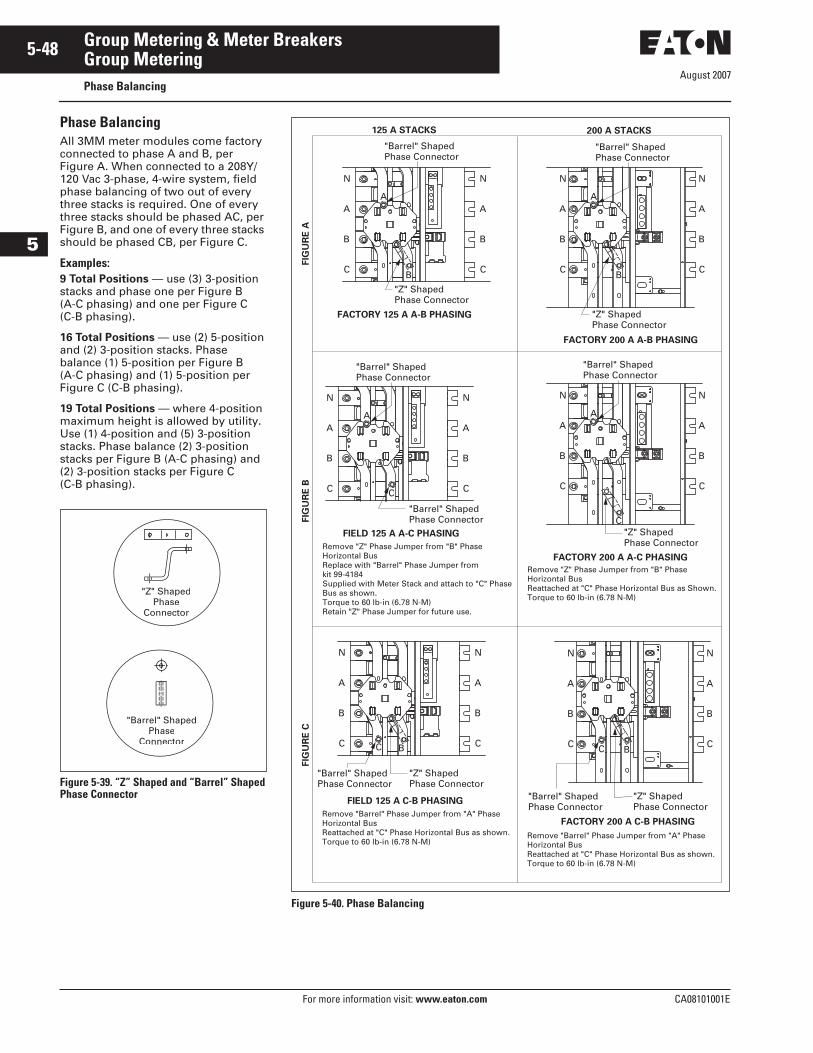
August 2007
5-48
For more information visit: www.eaton.com CA08101001E
Group Metering & Meter Breakers
5
Group MeteringPhase Balancing
Phase BalancingAll 3MM meter modules come factory connected to phase A and B, per Figure A. When connected to a 208Y/120 Vac 3-phase, 4-wire system, field phase balancing of two out of every three stacks is required. One of every three stacks should be phased AC, per Figure B, and one of every three stacks should be phased CB, per Figure C.
Examples:9 Total Positions — use (3) 3-position stacks and phase one per Figure B (A-C phasing) and one per Figure C (C-B phasing).
16 Total Positions — use (2) 5-position and (2) 3-position stacks. Phase balance (1) 5-position per Figure B (A-C phasing) and (1) 5-position per Figure C (C-B phasing).
19 Total Positions — where 4-position maximum height is allowed by utility. Use (1) 4-position and (5) 3-position stacks. Phase balance (2) 3-position stacks per Figure B (A-C phasing) and (2) 3-position stacks per Figure C (C-B phasing).
Figure 5-39. “Z” Shaped and “Barrel” Shaped Phase Connector
"Barrel" ShapedPhase
Connector
"Z" ShapedPhase
Connector
Figure 5-40. Phase Balancing
A
C
B
N
A
C
B
N
A
B
A
C
B
C
N
AA
C
B
N
A
C
B
B
N
C
A
C
B
N
FACTORY 125 A A-B PHASING
125 A STACKS
FIG
UR
E A
FIG
UR
E B
FIG
UR
E C
200 A STACKS
FIELD 125 A A-C PHASING
FIELD 125 A C-B PHASING
FACTORY 200 A A-B PHASING
FACTORY 200 A A-C PHASING
A
C
B
N
A
C
B
N
A
B
A
C
B
N
A
C
B
N
FACTORY 200 A C-B PHASING
A
C
B
N
A
C
B
N
C B
A
C
Remove "Z" Phase Jumper from "B" Phase Horizontal BusReattached at "C" Phase Horizontal Bus as Shown.Torque to 60 lb-in (6.78 N-M)
Remove "Barrel" Phase Jumper from "A" Phase Horizontal BusReattached at "C" Phase Horizontal Bus as shown.Torque to 60 lb-in (6.78 N-M)
Remove "Z" Phase Jumper from "B" Phase Horizontal BusReplace with "Barrel" Phase Jumper from kit 99-4184Supplied with Meter Stack and attach to "C" Phase Bus as shown.Torque to 60 lb-in (6.78 N-M)Retain "Z" Phase Jumper for future use.
Remove "Barrel" Phase Jumper from "A" PhaseHorizontal BusReattached at "C" Phase Horizontal Bus as shown.Torque to 60 lb-in (6.78 N-M)
"Barrel" ShapedPhase Connector
"Barrel" ShapedPhase Connector
"Z" ShapedPhase Connector
"Z" ShapedPhase Connector
"Z" ShapedPhase Connector
"Barrel" ShapedPhase Connector
"Barrel" ShapedPhase Connector
"Barrel" ShapedPhase Connector
"Barrel" ShapedPhase Connector
"Z" ShapedPhase Connector
"Barrel" ShapedPhase Connector
"Z" ShapedPhase Connector
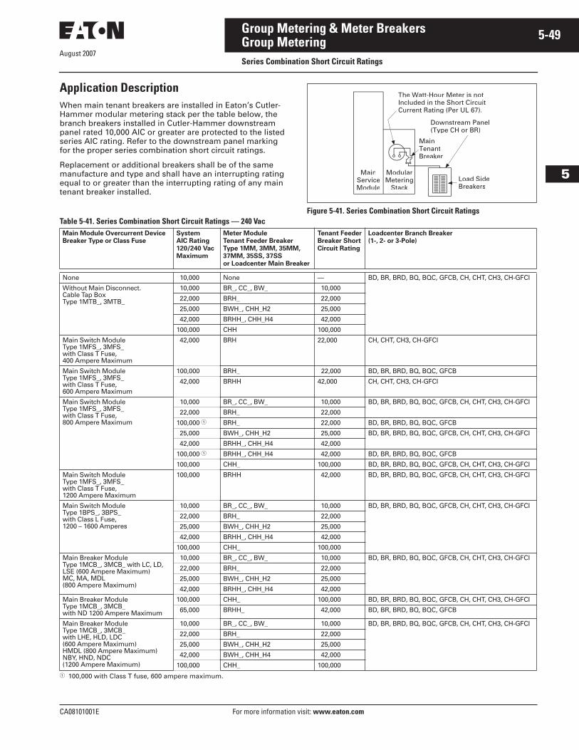
August 2007
CA08101001E For more information visit: www.eaton.com
5-49Group Metering & Meter Breakers
5
Group MeteringSeries Combination Short Circuit Ratings
Application DescriptionWhen main tenant breakers are installed in Eaton’s Cutler-Hammer modular metering stack per the table below, the branch breakers installed in Cutler-Hammer downstream panel rated 10,000 AIC or greater are protected to the listed series AIC rating. Refer to the downstream panel marking for the proper series combination short circuit ratings.
Replacement or additional breakers shall be of the same manufacture and type and shall have an interrupting rating equal to or greater than the interrupting rating of any main tenant breaker installed.
Figure 5-41. Series Combination Short Circuit RatingsTable 5-41. Series Combination Short Circuit Ratings — 240 Vac
� 100,000 with Class T fuse, 600 ampere maximum.
ModularMetering
Stack
MainServiceModule
Load SideBreakers
MainTenantBreaker
Downstream Panel(Type CH or BR)
The Watt-Hour Meter is notIncluded in the Short CircuitCurrent Rating (Per UL 67).
Main Module Overcurrent DeviceBreaker Type or Class Fuse
System AIC Rating120/240 VacMaximum
Meter Module Tenant Feeder Breaker Type 1MM, 3MM, 35MM, 37MM, 35SS, 37SSor Loadcenter Main Breaker
Tenant FeederBreaker ShortCircuit Rating
Loadcenter Branch Breaker(1-, 2- or 3-Pole)
None 10,000 None — BD, BR, BRD, BQ, BQC, GFCB, CH, CHT, CH3, CH-GFCI
Without Main Disconnect.Cable Tap Box Type 1MTB_, 3MTB_
10,000 BR_, CC_, BW_ 10,000
22,000 BRH_ 22,000
25,000 BWH_, CHH_H2 25,000
42,000 BRHH_, CHH_H4 42,000
100,000 CHH 100,000
Main Switch ModuleType 1MFS_, 3MFS_ with Class T Fuse, 400 Ampere Maximum
42,000 BRH 22,000 CH, CHT, CH3, CH-GFCI
Main Switch ModuleType 1MFS_, 3MFS_ with Class T Fuse, 600 Ampere Maximum
100,000 BRH_ 22,000 BD, BR, BRD, BQ, BQC, GFCB
42,000 BRHH 42,000 CH, CHT, CH3, CH-GFCI
Main Switch ModuleType 1MFS_, 3MFS_ with Class T Fuse, 800 Ampere Maximum
10,000 BR_, CC_, BW_ 10,000 BD, BR, BRD, BQ, BQC, GFCB, CH, CHT, CH3, CH-GFCI
22,000 BRH_ 22,000
100,000 � BRH_ 22,000 BD, BR, BRD, BQ, BQC, GFCB
25,000 BWH_, CHH_H2 25,000 BD, BR, BRD, BQ, BQC, GFCB, CH, CHT, CH3, CH-GFCI
42,000 BRHH_, CHH_H4 42,000
100,000 � BRHH_, CHH_H4 42,000 BD, BR, BRD, BQ, BQC, GFCB
100,000 CHH_ 100,000 BD, BR, BRD, BQ, BQC, GFCB, CH, CHT, CH3, CH-GFCI
Main Switch Module Type 1MFS_, 3MFS_ with Class T Fuse, 1200 Ampere Maximum
100,000 BRHH 42,000 BD, BR, BRD, BQ, BQC, GFCB, CH, CHT, CH3, CH-GFCI
Main Switch ModuleType 1BPS_, 3BPS_with Class L Fuse, 1200 – 1600 Amperes
10,000 BR_, CC_, BW_ 10,000 BD, BR, BRD, BQ, BQC, GFCB, CH, CHT, CH3, CH-GFCI
22,000 BRH_ 22,000
25,000 BWH_, CHH_H2 25,000
42,000 BRHH_, CHH_H4 42,000
100,000 CHH_ 100,000
Main Breaker ModuleType 1MCB_, 3MCB_ with LC, LD, LSE (600 Ampere Maximum)MC, MA, MDL (800 Ampere Maximum)
10,000 BR_, CC_, BW_ 10,000 BD, BR, BRD, BQ, BQC, GFCB, CH, CHT, CH3, CH-GFCI
22,000 BRH_ 22,000
25,000 BWH_, CHH_H2 25,000
42,000 BRHH_, CHH_H4 42,000
Main Breaker Module Type 1MCB_, 3MCB_ with ND 1200 Ampere Maximum
100,000 CHH_ 100,000 BD, BR, BRD, BQ, BQC, GFCB, CH, CHT, CH3, CH-GFCI
65,000 BRHH_ 42,000 BD, BR, BRD, BQ, BQC, GFCB
Main Breaker ModuleType 1MCB_, 3MCB_ with LHE, HLD, LDC (600 Ampere Maximum)HMDL (800 Ampere Maximum)NBY, HND, NDC (1200 Ampere Maximum)
10,000 BR_, CC_, BW_ 10,000 BD, BR, BRD, BQ, BQC, GFCB, CH, CHT, CH3, CH-GFCI
22,000 BRH_ 22,000
25,000 BWH_, CHH_H2 25,000
42,000 BWH_, CHH_H4 42,000
100,000 CHH_ 100,000
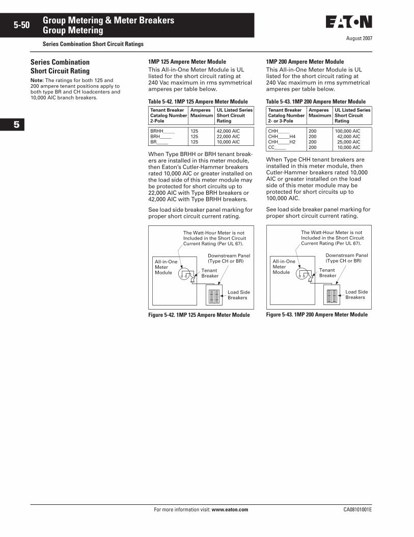
August 2007
5-50
For more information visit: www.eaton.com CA08101001E
Group Metering & Meter Breakers
5
Group MeteringSeries Combination Short Circuit Ratings
Series Combination Short Circuit Rating Note: The ratings for both 125 and 200 ampere tenant positions apply to both type BR and CH loadcenters and 10,000 AIC branch breakers.
1MP 125 Ampere Meter ModuleThis All-in-One Meter Module is UL listed for the short circuit rating at 240 Vac maximum in rms symmetrical amperes per table below.
Table 5-42. 1MP 125 Ampere Meter Module
When Type BRHH or BRH tenant break-ers are installed in this meter module, then Eaton’s Cutler-Hammer breakers rated 10,000 AIC or greater installed on the load side of this meter module may be protected for short circuits up to 22,000 AIC with Type BRH breakers or 42,000 AIC with Type BRHH breakers.
See load side breaker panel marking for proper short circuit current rating.
Figure 5-42. 1MP 125 Ampere Meter Module
Tenant BreakerCatalog Number2-Pole
AmperesMaximum
UL Listed SeriesShort CircuitRating
BRHH_____BRH_____BR_____
125125125
42,000 AIC22,000 AIC10,000 AIC
Load SideBreakers
TenantBreaker
Downstream Panel(Type CH or BR)
The Watt-Hour Meter is notIncluded in the Short CircuitCurrent Rating (Per UL 67).
All-in-OneMeterModule
1MP 200 Ampere Meter ModuleThis All-in-One Meter Module is UL listed for the short circuit rating at 240 Vac maximum in rms symmetrical amperes per table below.
Table 5-43. 1MP 200 Ampere Meter Module
When Type CHH tenant breakers are installed in this meter module, then Cutler-Hammer breakers rated 10,000 AIC or greater installed on the load side of this meter module may be protected for short circuits up to 100,000 AIC.
See load side breaker panel marking for proper short circuit current rating.
Figure 5-43. 1MP 200 Ampere Meter Module
Tenant Breaker Catalog Number2- or 3-Pole
AmperesMaximum
UL Listed SeriesShort CircuitRating
CHH_____CHH_____H4CHH_____H2CC_____
200200200200
100,000 AIC42,000 AIC25,000 AIC10,000 AIC
Load SideBreakers
TenantBreaker
Downstream Panel(Type CH or BR)
The Watt-Hour Meter is notIncluded in the Short CircuitCurrent Rating (Per UL 67).
All-in-OneMeterModule
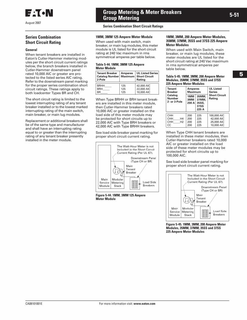
CA08101001E For more information visit: www.eaton.com
5-51Group Metering & Meter Breakers
August 2007
5
Group MeteringSeries Combination Short Circuit Ratings
Series CombinationShort Circuit Rating
GeneralWhen tenant breakers are installed in Eaton’s Cutler-Hammer metering mod-ules per the short circuit current ratings below, the branch breakers installed in Cutler-Hammer downstream panel rated 10,000 AIC or greater are pro-tected to the listed series AIC rating. Refer to the downstream panel marking for the proper series combination short circuit ratings. These ratings apply to both loadcenter Types BR and CH.
The short circuit rating is limited to the lowest interrupting rating of any tenant breaker installed or to the lowest marked interrupting rating of the main switch, main breaker, or main lug modules.
Replacement or additional breakers shall be of the same type and manufacturer and shall have an interrupting rating equal to or greater than the interrupting rating of any tenant breaker presently installed in the meter module.
1MM, 3MM 125 Ampere Meter ModuleWhen used with main switch, main breaker, or main lug modules, this meter module is UL listed for the short circuit rating at 240 Vac maximum in rms symmetrical amperes per table below.
Table 5-44. 1MM, 3MM 125 Ampere Meter Module
When Type BRHH or BRH tenant break-ers are installed in this meter module, then Cutler-Hammer breakers rated 10,000 AIC or greater installed on the load side of this meter module may be protected for short circuits up to 22,000 AIC with Type BRH breakers or 42,000 AIC with Type BRHH breakers.
See load side breaker panel marking for proper short circuit current rating.
Figure 5-44. 1MM, 3MM 125 Ampere Meter Module
Tenant BreakerCatalog Number2-Pole
AmperesMaximum
UL Listed SeriesShort CircuitRating
BRHH_____BRH_____BR_____
125125125
42,000 AIC22,000 AIC10,000 AIC
ModularMetering
Stack
MainServiceModule
Load SideBreakers
MainTenantBreaker
Downstream Panel(Type CH or BR)
The Watt-Hour Meter is notIncluded in the Short CircuitCurrent Rating (Per UL 67).
1MM, 3MM, 200 Ampere Meter Modules, 35MM, 37MM, 35SS and 37SS 225 Ampere Meter ModulesWhen used with Main Switch, main breaker, or main lug modules, these meter modules are UL listed for the short circuit rating at 240 Vac maximum in rms symmetrical amperes per table below.
Table 5-45. 1MM, 3MM, 200 Ampere Meter Modules, 35MM, 37MM, 35SS and 37SS 225 Ampere Meter Modules
When Type CHH tenant breakers are installed in these meter modules, then Cutler-Hammer breakers rated 10,000 AIC or greater installed on the load side of these meter modules may be protected for short circuits up to 100,000 AIC.
See load side breaker panel marking for proper short circuit current rating.
Figure 5-45. 1MM, 3MM, 200 Ampere Meter Modules, 35MM, 37MM, 35SS and 37SS 225 Ampere Meter Modules
Tenant BreakerCatalog Number2- or 3-Pole
AmperesMaximum
UL ListedSeriesShort CircuitRating
1MM3MM200 A
35MM,37MM,35SS,37SS225 A
CHHCHH_____H4CHH_____H2CC
200200200200
225225225225
100,000 AIC42,000 AIC25,000 AIC10,000 AIC
ModularMetering
Stack
MainServiceModule
Load SideBreakers
MainTenantBreaker
Downstream Panel(Type CH or BR)
The Watt-Hour Meter is notIncluded in the Short CircuitCurrent Rating (Per UL 67).
August 2007
5-52
For more information visit: www.eaton.com CA08101001E
Group Metering & Meter Breakers
5
Group MeteringTechnical Specifications
Product SpecificationsRatingsA. The assembly shall be rated to
withstand mechanical forces exerted during short circuit condi-tions when connected directly to a power source having available fault current [22,000] [42,000] [65,000] [100,000] amperes symmetrical at rated voltage.
ConstructionA. The entire assembly shall be front
accessible and shall include [main lugs] [a main disconnect device].
B. Tenant disconnects shall be wired for cold sequence and shall be molded case circuit breakers.
C. The meter sockets shall be [ring-] [ringless-] type rated [125 amperes] [200 amperes] [as shown on the plans] and a bypass [shall be] [shall not be] required. If required, the bypass shall be a [slider-] [horn-] [lever-] [disconnect block-] type. The meter sockets and associated branch protective device positions shall be completely prewired and shipped ready for installation of the meters and tenant main breakers. Meter sockets shall include covers with sealing positions.
BusA. All bus bars shall be [tin-plated
aluminum or copper]. Main horizontal bus bars shall be mounted with all three phases arranged in the same vertical plane. Bus sizing shall be based on UL standard temperature rise criteria for multiple metering equipment.
B. Provide a full capacity neutral bus where a neutral bus is indicated on the drawings.
C. All hardware used for bus bar connections shall be high-tensile strength, zinc-plated. Provide Belleville-type spring washers for all bus joints.
Wiring/TerminationsA. [Mechanical-type terminals]
[Crimp-type termination provisions] shall be provided for all line terminations suitable for copper or aluminum cable and rated at 75ºC.
B. Lugs shall be provided in the incoming line section for connection of the main grounding conductor.
Main Circuit Protective DevicesA. Main protective devices shall be
[molded case circuit breakers] [bolted pressure switches] [quick-make/quick-break fusible switches].
Molded Case Circuit BreakersA. [Main] [Feeder] [All] protective
devices shall be molded case circuit breakers with inverse time and instantaneous tripping characteristics.
B. Circuit breakers shall be operated by a toggle-type handle and shall have a quick-make/quick-break over-center switching mechanism that is mechanically trip-free. Automatic tripping of the breaker shall be clearly indicated by the handle position. Contacts shall be nonwelding silver alloy and arc extension shall be accomplished by means of DE-ION� arc chutes.
C. Circuit breakers shall have a minimum symmetrical interrupt-ing capacity as indicated on the drawings.
D. Circuit breakers [250-] [400-] [600-] [1200-] ampere frame and below shall be manufactured by Eaton with thermal-magnetic or elec-tronic trip units having inverse time-current characteristics.
E. Circuit breakers shall be UL listed for series application.
Bolted Pressure SwitchesA. Main protective devices shall be
bolted pressure contact type and shall be UL listed.
B. Fusible switches shall be furnished with class L fuse clips. Switch contact interrupting capacity shall be 12 times the continuous rating of the switch.
C. Fuse access door shall be mech-anically interlocked with the operating handle and shall have provisions for padlocking the switch in the open position.
D. The switch shall utilize a stored energy deadfront operating mechanism compressed and released by the operating handle, to provide quick positive switching action, independent of the operating handle.
E. Switches shall be manually operated.
Quick-Make/Quick-Break Fusible SwitchesA. Fusible switches 30 ampere
through 1200 ampere frames shall be furnished with 300 volt Class T-type fuse clips unless otherwise scheduled.
B. Switches shall incorporate safety cover interlocks to prevent open-ing the cover with the switch in the ON position.
C. Provide defeater for authorized personnel.
D. Handles shall have provisions for padlocking and shall clearly indicate the ON or OFF position.
E. Front cover doors shall be pad-lockable in the closed position.
F. Main protective devices shall be quick-make/quick-break fusible switches as manufactured by Eaton.
Tenant Utility MeteringA. For EUSERC serviced areas, meter
centers shall incorporate meter-ing sections with tenant feeder circuits using ring-type meter sockets rated [125] [200] amperes to meet local utility and/or customer requirements.
B. The self-contained meter sockets shall include a test bypass/disconnect block per EUSERC requirements,
– OR – A. For non-EUSERC serviced areas,
meter centers shall incorporate metering sections with tenant feeder circuits using [ring-] [ringless-] type meter sockets rated [125] [200] [320] amperes to meet local utility or customer requirements. Provide meter sockets with individual covers having sealing provisions.
B. Meter sockets shall have manual bypass and optional internal barriers.
EnclosuresA. NEMA 1 Enclosure
– OR – A. Outdoor NEMA 3R Surface-
Mounted Enclosure
FinishA. Boxes and trims shall be bonder-
ized and finished with ANSI 61 light gray enamel.
For a complete product specification in CSI format, see Cutler-Hammer Product Specification Guide. . . . . . . . . . . . . . Section 16432
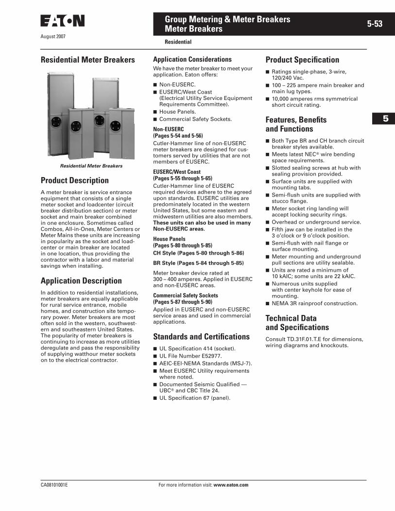
August 2007
CA08101001E For more information visit: www.eaton.com
5-53Group Metering & Meter Breakers
5
Meter BreakersResidential
Residential Meter Breakers
Residential Meter Breakers
Product DescriptionA meter breaker is service entrance equipment that consists of a single meter socket and loadcenter (circuit breaker distribution section) or meter socket and main breaker combined in one enclosure. Sometimes called Combos, All-in-Ones, Meter Centers or Meter Mains these units are increasing in popularity as the socket and load-center or main breaker are located in one location, thus providing the contractor with a labor and material savings when installing.
Application DescriptionIn addition to residential installations, meter breakers are equally applicable for rural service entrance, mobile homes, and construction site tempo-rary power. Meter breakers are most often sold in the western, southwest-ern and southeastern United States. The popularity of meter breakers is continuing to increase as more utilities deregulate and pass the responsibility of supplying watthour meter sockets on to the electrical contractor.
Application ConsiderationsWe have the meter breaker to meet your application. Eaton offers:
■ Non-EUSERC.■ EUSERC/West Coast
(Electrical Utility Service Equipment Requirements Committee).
■ House Panels.■ Commercial Safety Sockets.
Non-EUSERC (Pages 5-54 and 5-56)Cutler-Hammer line of non-EUSERC meter breakers are designed for cus-tomers served by utilities that are not members of EUSERC.
EUSERC/West Coast (Pages 5-55 through 5-65)Cutler-Hammer line of EUSERC required devices adhere to the agreed upon standards. EUSERC utilities are predominately located in the western United States, but some eastern and midwestern utilities are also members. These units can also be used in many Non-EUSERC areas.
House Panels (Pages 5-80 through 5-85)CH Style (Pages 5-80 through 5-86)
BR Style (Pages 5-84 through 5-85)
Meter breaker device rated at 300 – 400 amperes. Applied in EUSERC and non-EUSERC areas.
Commercial Safety Sockets (Pages 5-87 through 5-90)Applied in EUSERC and non-EUSERC service areas and used in commercial applications.
Standards and Certifications■ UL Specification 414 (socket).■ UL File Number E52977.■ AEIC-EEI-NEMA Standards (MSJ-7).■ Meet EUSERC Utility requirements
where noted.■ Documented Seismic Qualified —
UBC� and CBC Title 24.■ UL Specification 67 (panel).
Product Specification■ Ratings single-phase, 3-wire,
120/240 Vac.■ 100 – 225 ampere main breaker and
main lug types.■ 10,000 amperes rms symmetrical
short circuit rating.
Features, Benefits and Functions■ Both Type BR and CH branch circuit
breaker styles available.■ Meets latest NEC� wire bending
space requirements.■ Slotted sealing screws at hub with
sealing provision provided.■ Surface units are supplied with
mounting tabs.■ Semi-flush units are supplied with
stucco flange.■ Meter socket ring landing will
accept locking security rings.■ Overhead or underground service.■ Fifth jaw can be installed in the
3 o’clock or 9 o’clock position.■ Semi-flush with nail flange or
surface mounting.■ Meter mounting and underground
pull sections are utility sealable.■ Units are rated a minimum of
10 kAIC; some units are 22 kAIC.■ Numerous units supplied
with center keyhole for ease of mounting.
■ NEMA 3R rainproof construction.
Technical Data and SpecificationsConsult TD.31F.01.T.E for dimensions, wiring diagrams and knockouts.
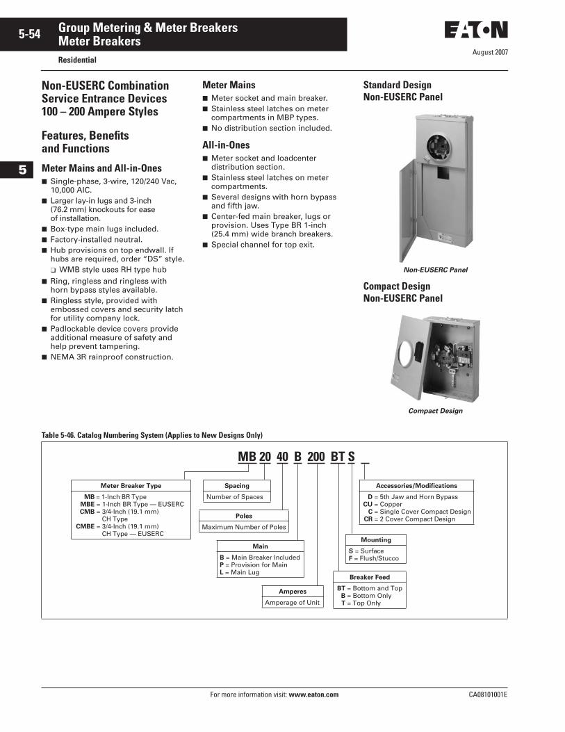
August 2007
5-54
For more information visit: www.eaton.com CA08101001E
Group Metering & Meter Breakers
5
Meter BreakersResidential
Non-EUSERC Combination Service Entrance Devices 100 – 200 Ampere Styles
Features, Benefits and Functions
Meter Mains and All-in-Ones■ Single-phase, 3-wire, 120/240 Vac,
10,000 AIC.■ Larger lay-in lugs and 3-inch
(76.2 mm) knockouts for ease of installation.
■ Box-type main lugs included.■ Factory-installed neutral.■ Hub provisions on top endwall. If
hubs are required, order “DS” style.❑ WMB style uses RH type hub
■ Ring, ringless and ringless with horn bypass styles available.
■ Ringless style, provided with embossed covers and security latch for utility company lock.
■ Padlockable device covers provide additional measure of safety and help prevent tampering.
■ NEMA 3R rainproof construction.
Meter Mains■ Meter socket and main breaker.■ Stainless steel latches on meter
compartments in MBP types.■ No distribution section included.
All-in-Ones■ Meter socket and loadcenter
distribution section.■ Stainless steel latches on meter
compartments.■ Several designs with horn bypass
and fifth jaw.■ Center-fed main breaker, lugs or
provision. Uses Type BR 1-inch (25.4 mm) wide branch breakers.
■ Special channel for top exit.
Standard DesignNon-EUSERC Panel
Non-EUSERC Panel
Compact DesignNon-EUSERC Panel
Compact Design
Table 5-46. Catalog Numbering System (Applies to New Designs Only)
MB 20 40 B 200 BT S
Meter Breaker Type
MB = 1-Inch BR Type MBE = 1-Inch BR Type — EUSERCCMB = 3/4-Inch (19.1 mm)
CH TypeCMBE = 3/4-Inch (19.1 mm)
CH Type — EUSERC
Main
B = Main Breaker IncludedP = Provision for MainL = Main Lug
Poles
Maximum Number of Poles
Spacing
Number of Spaces
Mounting
S = SurfaceF = Flush/Stucco
Breaker Feed
BT = Bottom and TopB = Bottom OnlyT = Top Only
Amperes
Amperage of Unit
Accessories/Modifications
D = 5th Jaw and Horn BypassCU = Copper
C = Single Cover Compact DesignCR = 2 Cover Compact Design
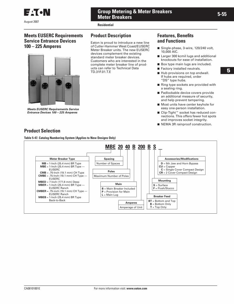
August 2007
CA08101001E For more information visit: www.eaton.com
5-55Group Metering & Meter Breakers
5
Meter BreakersResidential
Meets EUSERC Requirements Service Entrance Devices 100 – 225 Amperes
Meets EUSERC Requirements Service Entrance Devices 100 – 225 Amperes
Product DescriptionEaton is proud to introduce a new line of Cutler-Hammer West Coast/EUSERC Meter Breaker units. The new EUSERC devices complement the existing standard meter breaker devices. Customers who are interested in the complete meter breaker line of prod-ucts can refer to Technical Data TD.31F.01.T.E
Features, Benefits and Functions■ Single-phase, 3-wire, 120/240 volt,
10,000 AIC.■ Larger 300 kcmil lugs and additional
knockouts for ease of installation.■ Box type main lugs are included.■ Factory installed neutrals.■ Hub provisions on top endwall.
If hubs are required, order “DS” type hubs.
■ Ring type sockets are provided with a sealing ring.
■ Padlockable device covers provide an additional measure of security, and help prevent tampering.
■ Most units have center keyhole for easy one-person installation.
■ Clip-Tight� socket has reduced con-nections. This offers fewer hot spots and improves socket integrity.
■ NEMA 3R rainproof construction.
Product SelectionTable 5-47. Catalog Numbering System (Applies to New Designs Only)
MBE 20 40 B 200 B S
Meter Breaker Type
MB = 1-Inch (25.4 mm) BR Type MBE = 1-Inch (25.4 mm) BR Type —
EUSERCCMB = .75-Inch (19.1 mm) CH Type
CMBE = .75-Inch (19.1 mm) CH Type — EUSERC
MBED = 7-Inch (177.8 mm) DeepMBER = 1-Inch (25.4 mm) BR Type —
EUSERC RanchCMBER = .75-inch (19.1 mm) CH Type —
EUSERC RanchMBEB = 1-Inch (25.4 mm) BR Type
Back-to-Back
Main
B = Main Breaker IncludedP = Provision for MainL = Main Lug
Poles
Maximum Number of Poles
Spacing
Number of Spaces
Mounting
S = SurfaceF = Flush/Stucco
Breaker Feed
BT = Bottom and TopB = Bottom OnlyT = Top Only
Amperes
Amperage of Unit
Accessories/Modifications
D = 5th Jaw and Horn BypassCU = Copper
C = Single Cover Compact DesignCR = 2 Cover Compact Design
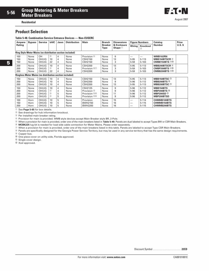
August 2007
5-56
For more information visit: www.eaton.com CA08101001E
Group Metering & Meter Breakers
5
Meter BreakersResidential
Product SelectionTable 5-48. Combination Service Entrance Devices — Non-EUSERC
� See Page 5-65 for box details.� See drawings for hub information knockout.� Per installed main breaker rating.� Provision for main is provided. WMB style devices accept Main Breaker style BR, 2-Pole. � When a provision for main is provided, order one of the main breakers listed in Table 5-49. Panels are dual labeled to accept Types BW or CSR Main Breakers.� MCBK225 lug kit is needed for load side cable connection for Meter Mains. Please order separately.� When a provision for main is provided, order one of the main breakers listed in this table. Panels are labeled to accept Type CSR Main Breakers.� Panels are specifically designed for the Georgia Power Service Territory, but may be used in any service territory that has the same design requirements. Copper bus.� One-piece cover on utility side, Florida approved.� Single cover design.� Xcel approved.
AmpereRating
Bypass Service kAIC Jaws Distribution Main BranchBreakerType
Dimensions & EnclosureShape �
Figure Numbers Catalog Number
PriceU.S. $Wiring Knockout
�
Ring Style Meter Mains (no distribution section included)100150150
NoneNoneNone
OHOH/UGOH/UG
�
1022
444
NoneNoneNone
Provision �CSH2150CSH2150
NoneNoneNone
813 3
—5-955-59
—5-1135-103
WMB102RNMBB150BTSCR �
CMBB150BTS �
200200200
NoneNoneNone
OH/UGOH/UGOH/UG
10�
22
444
NoneNoneNone
CSH2200Provision ��
CSH2200
NoneNoneNone
13 3 3
5-955-595-59
5-1135-1035-103
MBB200BTSCR �
CMBP200BTS �
CMBB200BTS �
Ringless Meter Mains (no distribution section included)150200200
NoneNoneNone
OH/UGOH/UGOH/UG
101010
444
NoneNoneNone
CSH2150CSH2200CSH2200
NoneNoneNone
13 913
5-955-965-95
5-1135-1125-113
MBB150BTSC �
MBB200BTS �
MBB200BTSC �
150200200200
NoneNoneHornHorn
OH/UGOH/UGOH/UGOH/UG
10�
�
�
4455
NoneNoneNoneNone
CSH2125Provision �Provision ��
Provision ��
NoneNoneNoneNone
9 911 9
5-965-965-965-96
5-1125-1125-1125-112
MBB150BTSMBP200BTS �
MBP200SD �
MBP200BTSD
100150200
HornHornHorn
OH/UGOH/UGOH/UG
101010
555
NoneNoneNone
ProvisionBWH2150BWH2200
NoneNoneNone
151616
———
5-1145-1155-115
CHMMB100BTSCHMMB150BTSCHMMB200BTS
Discount Symbol . . . . . . . . . . . . . . . . . . . . . . . . 22CD
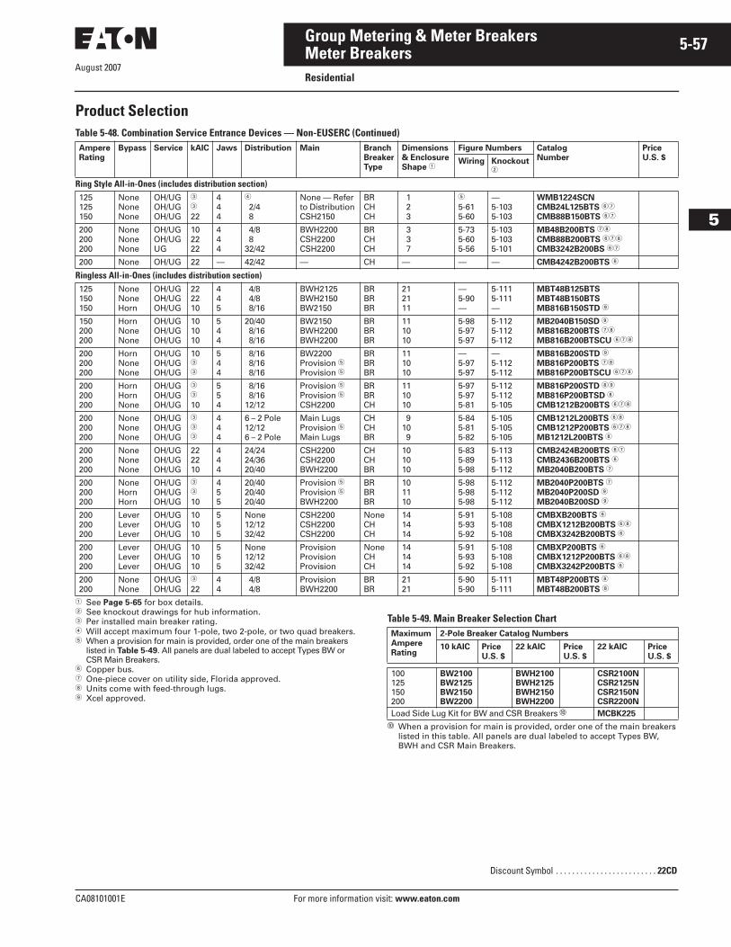
August 2007
CA08101001E For more information visit: www.eaton.com
5-57Group Metering & Meter Breakers
5
Meter BreakersResidential
Product SelectionTable 5-48. Combination Service Entrance Devices — Non-EUSERC (Continued)
� See Page 5-65 for box details.� See knockout drawings for hub information.� Per installed main breaker rating.� Will accept maximum four 1-pole, two 2-pole, or two quad breakers.� When a provision for main is provided, order one of the main breakers
listed in Table 5-49. All panels are dual labeled to accept Types BW or CSR Main Breakers.
� Copper bus.� One-piece cover on utility side, Florida approved.� Units come with feed-through lugs. Xcel approved.
Table 5-49. Main Breaker Selection Chart
� When a provision for main is provided, order one of the main breakers listed in this table. All panels are dual labeled to accept Types BW, BWH and CSR Main Breakers.
AmpereRating
Bypass Service kAIC Jaws Distribution Main BranchBreakerType
Dimensions & EnclosureShape �
Figure Numbers Catalog Number
PriceU.S. $Wiring Knockout
�
Ring Style All-in-Ones (includes distribution section)125125150
NoneNoneNone
OH/UGOH/UGOH/UG
�
�
22
444
�
2/4 8
None — Refer to DistributionCSH2150
BRCHCH
1 2 3
�
5-615-60
—5-1035-103
WMB1224SCNCMB24L125BTS ��
CMB88B150BTS ��
200200200
NoneNoneNone
OH/UGOH/UGUG
102222
444
4/8 832/42
BWH2200CSH2200CSH2200
BRCHCH
3 3 7
5-735-605-56
5-1035-1035-101
MB48B200BTS ��
CMB88B200BTS ���
CMB3242B200BS ��
200 None OH/UG 22 — 42/42 — CH — — — CMB4242B200BTS �
Ringless All-in-Ones (includes distribution section)125150150
NoneNoneHorn
OH/UGOH/UGOH/UG
222210
445
4/8 4/8 8/16
BWH2125BWH2150BW2150
BRBRBR
212111
—5-90—
5-1115-111—
MBT48B125BTSMBT48B150BTSMB816B150STD
150200200
HornNoneNone
OH/UGOH/UGOH/UG
101010
544
20/40 8/16 8/16
BW2150BWH2200BWH2200
BRBRBR
111010
5-985-975-97
5-1125-1125-112
MB2040B150SD
MB816B200BTS ��
MB816B200BTSCU ���
200200200
HornNoneNone
OH/UGOH/UGOH/UG
10�
�
544
8/16 8/16 8/16
BW2200Provision �Provision �
BRBRBR
111010
—5-975-97
—5-1125-112
MB816B200STD
MB816P200BTS ��
MB816P200BTSCU ���
200200200
HornHornNone
OH/UGOH/UGOH/UG
�
�
10
554
8/16 8/1612/12
Provision �Provision �CSH2200
BRBRCH
111010
5-975-975-81
5-1125-1125-105
MB816P200STD �
MB816P200BTSD �
CMB1212B200BTS ���
200200200
NoneNoneNone
OH/UGOH/UGOH/UG
�
�
�
444
6 – 2 Pole12/126 – 2 Pole
Main LugsProvision �Main Lugs
CHCHBR
910 9
5-845-815-82
5-1055-1055-105
CMB1212L200BTS ��
CMB1212P200BTS ���
MB1212L200BTS �
200200200
NoneNoneNone
OH/UGOH/UGOH/UG
222210
444
24/2424/3620/40
CSH2200CSH2200BWH2200
CHCHBR
101010
5-835-895-98
5-1135-1135-112
CMB2424B200BTS ��
CMB2436B200BTS �
MB2040B200BTS �
200200200
NoneHornHorn
OH/UGOH/UGOH/UG
�
�
10
455
20/4020/4020/40
Provision �Provision �BWH2200
BRBRBR
101110
5-985-985-98
5-1125-1125-112
MB2040P200BTS �
MB2040P200SD
MB2040B200SD
200200200
LeverLeverLever
OH/UGOH/UGOH/UG
101010
555
None12/1232/42
CSH2200CSH2200CSH2200
NoneCHCH
141414
5-915-935-92
5-1085-1085-108
CMBXB200BTS �
CMBX1212B200BTS ��
CMBX3242B200BTS �
200200200
LeverLeverLever
OH/UGOH/UGOH/UG
101010
555
None12/1232/42
ProvisionProvisionProvision
NoneCHCH
141414
5-915-935-92
5-1085-1085-108
CMBXP200BTS �
CMBX1212P200BTS ��
CMBX3242P200BTS �
200200
NoneNone
OH/UGOH/UG
�
2244
4/8 4/8
ProvisionBWH2200
BRBR
2121
5-905-90
5-1115-111
MBT48P200BTS �
MBT48B200BTS �
MaximumAmpereRating
2-Pole Breaker Catalog Numbers
10 kAIC PriceU.S. $
22 kAIC PriceU.S. $
22 kAIC PriceU.S. $
100125150200
BW2100BW2125BW2150BW2200
BWH2100BWH2125BWH2150BWH2200
CSR2100NCSR2125NCSR2150NCSR2200N
Load Side Lug Kit for BW and CSR Breakers � MCBK225
Discount Symbol . . . . . . . . . . . . . . . . . . . . . . . . . 22CD
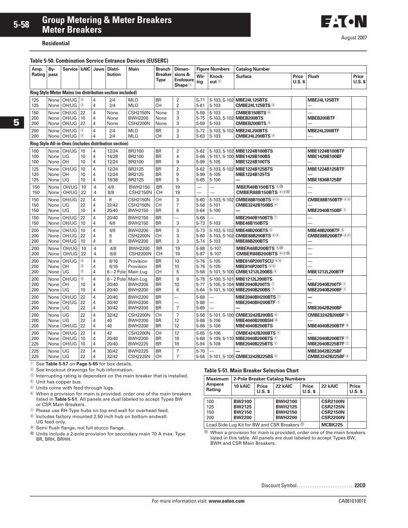
August 2007
5-58
For more information visit: www.eaton.com CA08101001E
Group Metering & Meter Breakers
5
Meter BreakersResidential
Table 5-50. Combination Service Entrance Devices (EUSERC)
� See Table 5-57 on Page 5-65 for box details.� See knockout drawings for hub information.� Interrupting rating is dependent on the main breaker that is installed.� Unit has copper bus.� Units come with feed-through lugs.� When a provision for main is provided, order one of the main breakers
listed in Table 5-51. All panels are dual labeled to accept Types BW or CSR Main Breakers.
� Please use RH-Type hubs on top end wall for overhead feed.� Includes factory mounted 2.50 inch hub on bottom endwall.
UG feed only. Semi flush flange, not full stucco flange.� Units include a 2-pole provision for secondary main 70 A max. Type
BR, BRH, BRHH.
Table 5-51. Main Breaker Selection Chart
� When a provision for main is provided, order one of the main breakers listed in this table. All panels are dual labeled to accept Types BW, BWH and CSR Main Breakers.
Amp.Rating
By-pass
Service kAIC Jaws Distri-bution
Main BranchBreakerType
Dimen-sions &EnclosureShape �
Figure Numbers Catalog Number
Wir-ing
Knock-out �
Surface PriceU.S. $
Flush PriceU.S. $
Ring Style Meter Mains (no distribution section included)125125
NoneNone
OH/UGOH/UG
�
�44
2/4 2/4
MLOMLO
BRCH
2 2
5-715-61
5-103, 5-1025-103
MBE24L125BTSCMBE24L125BTS �
MBE24L125BTF—
150200200
NoneNoneNone
OH/UGOH/UGOH/UG
221022
444
NoneNoneNone
CSH2150NBWH2200CSH2200N
NoneNoneNone
3 3 3
5-595-755-59
5-1035-103, 5-1025-103
CMBEB150BTS �
MBEB200BTSCMBEB200BTS �
—MBEB200BTF—
200200
NoneNone
OH/UGOH/UG
�
�44
2/4 2/4
MLOMLO
BRCH
3 3
5-725-63
5-103, 5-1025-103
MBE24L200BTSCMBE24L200BTS �
MBE24L200BTF—
Ring Style All-in-Ones (includes distribution section)100100100
NoneNoneNone
OH/UGUGOH
101010
444
12/2414/2812/24
BR2100BR2100BR2100
BRBRBR
2 4 9
5-625-665-99
5-103, 5-1025-101, 5-1005-105
MBE1224B100BTSMBE1428B100BSMBE1224B100TS
MBE1224B100BTFMBE1428B100BF—
125125125
NoneNoneNone
OH/UGOHUG
101010
444
12/2412/2418/36
BR2125BR2125BR2125
BRBRBR
2 9 5
5-625-995-65
5-103, 5-1025-1055-100
MBE1224B125BTSMBE1224B125TS—
MBE1224B125BTF—MBE1836B125BF
150150
NoneNone
OH/UGOH/UG
1022
44
4/88/8
BWH2150CSH2150N
BRCH
1919
——
——
MBER48B150BTS ��
CMBER88B150BTS ���——
150150150
NoneNoneNone
OH/UGUGUG
222210
444
832/4220/40
CSH2150NCSH2150NBWH2150
CHCHBR
3 7 6
5-605-565-64
5-103, 5-1025-1015-100
CMBE88B150BTS ��
CMBE3242B150BS �
—
CMBE88B150BTF ��
—MBE2040B150BF �
150150
NoneNone
OH/UGOH/UG
2210
44
20/40 4/8
BWH2150BWH2150
BRBR
— 3
5-685-73
—5-103
MBE2040B150BTS �
MBE48B150BTS— —
200200200
NoneNoneNone
OH/UGOH/UGOH/UG
102210
444
4/8 8 8
BWH2200CSH2200NBWH2200
BRCHBR
3 3 3
5-735-605-74
5-103, 5-1025-103, 5-1025-103
MBE48B200BTS �
CMBE88B200BTS ��
MBE88B200BTS
MBE48B200BTF �
CMBE88B200BTF ��
—
200200
NoneNone
OH/UGOH/UG
1022
44
4/8 8/8
BWH2200CSH2200N
BRCH
1919
5-885-87
5-1075-107
MBER48B200BTS ��
CMBER88B200BTS ���——
200200200
NoneNoneNone
OH/UGOHUG
�
�
�
444
8/16 8/166 – 2 Pole
ProvisionProvisionMain Lug
BRBRCH
1010 5
5-765-765-58
5-1055-1055-101, 5-100
MBE816P200TSCU ��
MBE816P200TS ��
CMBE1212L200BS �
——MBE1212L200BTF
200200200
NoneNoneNone
OH/UGOHUG
�
1010
444
6 – 2 Pole20/4020/40
Main LugBWH2200BWH2200
BRBRBR
910 6
5-785-775-64
5-100, 5-1015-105, 5-1045-101, 5-100
MBE1212L200BTSMBE2040B200TS �
MBE2040B200BS �
—MBE2040B200TF �
MBE2040B200BF �
200200200
NoneNoneNone
OH/UGOH/UGUG
222222
444
20/4020/4030/42
BWH2200BWH2200BWH2200
BRBRBR
—— 7
5-685-685-69
———
MBE2040BH200BTS �
MBE2040BH200BTF �
—
——MBE3042B200BF
200200200
NoneNoneNone
UGUGOH/UG
222222
444
32/424040
CSH2200NBWH2200BWH2200
CHBRBR
71212
5-565-865-86
5-101, 5-1005-1065-106
CMBE3242B200BS �
MBE4040B200BSH �
MBE4040B200BTS
CMBE3242B200BF �
—MBE4040B200BTF
200200225
NoneNoneNone
OH/UGOH/UGOH/UG
221010
444
4220/4020/40
CSH2200NBWH2200BWH2225
CHBRBR
121818
5-855-685-94
5-1065-109, 5-1105-109
CMBE4242B200BTS �
MBE2040B200BTS �
MBE2040B225BTS �
—MBE2040B200BTF �
MBE2040B225BTF �
225225
NoneNone
UGUG
2222
44
30/4232/42
BWH2225CSH2225N
BRCH
7 7
5-705-56
—5-101, 5-100
—CMBE3242B225BS �
MBE3042B225BFCMBE3242B225BF �
MaximumAmpereRating
2-Pole Breaker Catalog Numbers
10 kAIC PriceU.S. $
22 kAIC PriceU.S. $
22 kAIC PriceU.S. $
100125150200
BW2100BW2125BW2150BW2200
BWH2100BWH2125BWH2150BWH2200
CSR2100NCSR2125NCSR2150NCSR2200N
Load Side Lug Kit for BW and CSR Breakers � MCBK225
Discount Symbol. . . . . . . . . . . . . . . . . . . . . . . . . 22CD
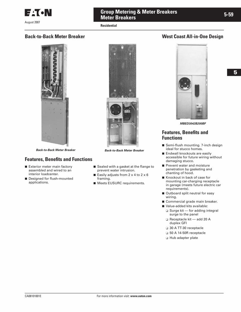
CA08101001E For more information visit: www.eaton.com
5-59Group Metering & Meter Breakers
August 2007
5
Meter BreakersResidential
Back-to-Back Meter Breaker
Back-to-Back Meter Breaker Back-to-Back Meter Breaker
Features, Benefits and Functions■ Exterior meter main factory
assembled and wired to an interior loadcenter.
■ Designed for flush-mounted applications.
■ Sealed with a gasket at the flange to prevent water intrusion.
■ Easily adjusts from 2 x 4 to 2 x 6 framing.
■ Meets EUSURC requirements.
West Coast All-in-One Design
MBED3042B200BF
Features, Benefits and Functions■ Semi-flush mounting. 7-inch design
ideal for stucco homes.■ Endwall knockouts are easily
accessible for future wiring without damaging stucco.
■ Prevent water and moisture penetration by gasketing and chanting of hood.
■ Knockout in back of case for mounting car-charging receptacle in garage (meets future electric car requirements).
■ Outboard split neutral for easy wiring.
■ Commercial grade main breaker.■ Value-added kits available:
❑ Surge kit — for adding integral surge to the panel
❑ Receptacle kit — add 20 A duplex GFI
❑ 30 A TT-30 receptacle❑ 50 A 14-50R receptacle❑ Hub adapter plate
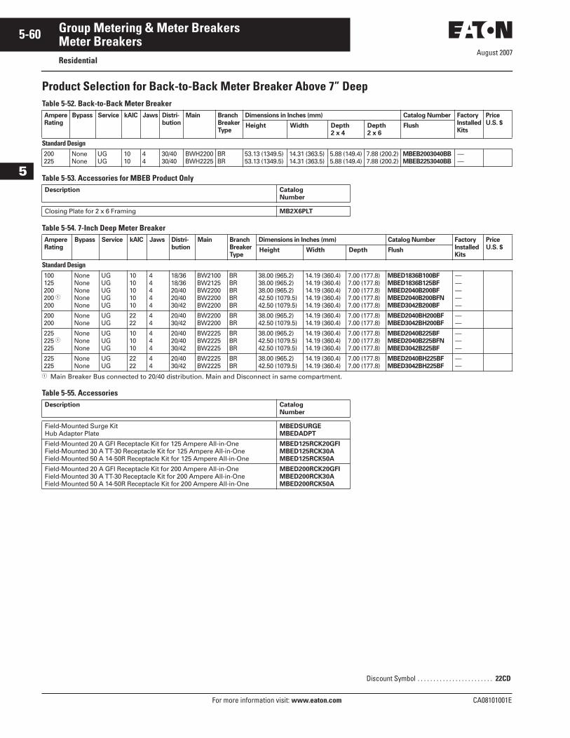
August 2007
5-60
For more information visit: www.eaton.com CA08101001E
Group Metering & Meter Breakers
5
Meter BreakersResidential
Product Selection for Back-to-Back Meter Breaker Above 7” DeepTable 5-52. Back-to-Back Meter Breaker
Table 5-53. Accessories for MBEB Product Only
Table 5-54. 7-Inch Deep Meter Breaker
� Main Breaker Bus connected to 20/40 distribution. Main and Disconnect in same compartment.
Table 5-55. Accessories
AmpereRating
Bypass Service kAIC Jaws Distri-bution
Main BranchBreakerType
Dimensions in Inches (mm) Catalog Number FactoryInstalledKits
PriceU.S. $Height Width Depth
2 x 4Depth2 x 6
Flush
Standard Design200225
NoneNone
UGUG
1010
44
30/4030/40
BWH2200BWH2225
BRBR
53.13 (1349.5)53.13 (1349.5)
14.31 (363.5)14.31 (363.5)
5.88 (149.4)5.88 (149.4)
7.88 (200.2)7.88 (200.2)
MBEB2003040BBMBEB2253040BB
——
Description CatalogNumber
Closing Plate for 2 x 6 Framing MB2X6PLT
AmpereRating
Bypass Service kAIC Jaws Distri-bution
Main BranchBreakerType
Dimensions in Inches (mm) Catalog Number FactoryInstalledKits
PriceU.S. $Height Width Depth Flush
Standard Design100125200200 �200
NoneNoneNoneNoneNone
UGUGUGUGUG
1010101010
44444
18/3618/3620/4020/4030/42
BW2100BW2125BW2200BW2200BW2200
BRBRBRBRBR
38.00 (965.2)38.00 (965.2)38.00 (965.2)42.50 (1079.5)42.50 (1079.5)
14.19 (360.4)14.19 (360.4)14.19 (360.4)14.19 (360.4)14.19 (360.4)
7.00 (177.8)7.00 (177.8)7.00 (177.8)7.00 (177.8)7.00 (177.8)
MBED1836B100BFMBED1836B125BFMBED2040B200BFMBED2040B200BFNMBED3042B200BF
—————
200200
NoneNone
UGUG
2222
44
20/4030/42
BW2200BW2200
BRBR
38.00 (965.2)42.50 (1079.5)
14.19 (360.4)14.19 (360.4)
7.00 (177.8)7.00 (177.8)
MBED2040BH200BFMBED3042BH200BF
——
225225 �225
NoneNoneNone
UGUGUG
101010
444
20/4020/4030/42
BW2225BW2225BW2225
BRBRBR
38.00 (965.2)42.50 (1079.5)42.50 (1079.5)
14.19 (360.4)14.19 (360.4)14.19 (360.4)
7.00 (177.8)7.00 (177.8)7.00 (177.8)
MBED2040B225BFMBED2040B225BFN MBED3042B225BF
———
225225
NoneNone
UGUG
2222
44
20/4030/42
BW2225BW2225
BRBR
38.00 (965.2)42.50 (1079.5)
14.19 (360.4)14.19 (360.4)
7.00 (177.8)7.00 (177.8)
MBED2040BH225BFMBED3042BH225BF
——
Description CatalogNumber
Field-Mounted Surge KitHub Adapter Plate
MBEDSURGEMBEDADPT
Field-Mounted 20 A GFI Receptacle Kit for 125 Ampere All-in-OneField-Mounted 30 A TT-30 Receptacle Kit for 125 Ampere All-in-OneField-Mounted 50 A 14-50R Receptacle Kit for 125 Ampere All-in-One
MBED125RCK20GFIMBED125RCK30AMBED125RCK50A
Field-Mounted 20 A GFI Receptacle Kit for 200 Ampere All-in-OneField-Mounted 30 A TT-30 Receptacle Kit for 200 Ampere All-in-OneField-Mounted 50 A 14-50R Receptacle Kit for 200 Ampere All-in-One
MBED200RCK20GFIMBED200RCK30AMBED200RCK50A
Discount Symbol . . . . . . . . . . . . . . . . . . . . . . . . 22CD
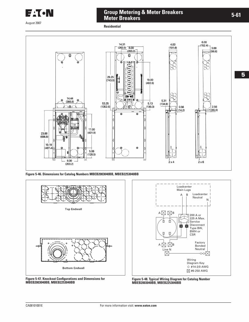
August 2007
CA08101001E For more information visit: www.eaton.com
5-61Group Metering & Meter Breakers
5
Meter BreakersResidential
Figure 5-46. Dimensions for Catalog Numbers MBEB2003040BB, MBEB2253040BB
Figure 5-47. Knockout Configurations and Dimensions for MBEB2003040BB, MBEB2253040BB
Figure 5-48. Typical Wiring Diagram for Catalog Number MBEB2003040BB, MBEB2253040BB
#14-2/0 AWG #6-250 AWG
WiringDiagram Key
200 A or 225 A Max.ServiceDisconnectType BW,BWH or CSR
LoadcenterMain Lugs
LoadcenterNeutral
A B
A B
N
A
Line N
FactoryBondedNeutral
B
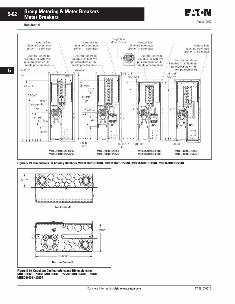
August 2007
5-62
For more information visit: www.eaton.com CA08101001E
Group Metering & Meter Breakers
5
Meter BreakersResidential
Figure 5-49. Dimensions for Catalog Numbers MBED3042BH200BF, MBED3042BH225BF, MBED2040BH200BF, MBED2040BH225BF
Figure 5-50. Knockout Configurations and Dimensions for MBED3042BH200BF, MBED3042BH225BF, MBED2040BH200BF, MBED2040BH225BF
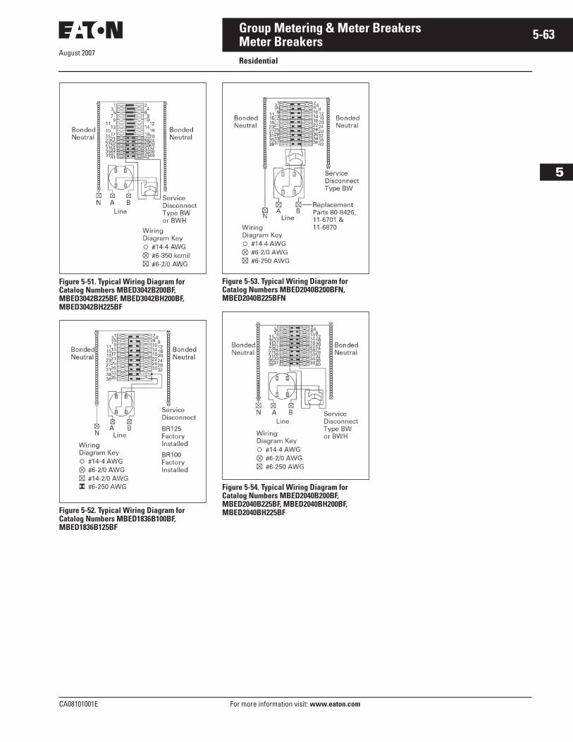
CA08101001E For more information visit: www.eaton.com
5-63Group Metering & Meter Breakers
August 2007
5
Meter BreakersResidential
Figure 5-51. Typical Wiring Diagram for Catalog Numbers MBED3042B200BF, MBED3042B225BF, MBED3042BH200BF, MBED3042BH225BF
Figure 5-52. Typical Wiring Diagram for Catalog Numbers MBED1836B100BF, MBED1836B125BF
Figure 5-53. Typical Wiring Diagram for Catalog Numbers MBED2040B200BFN, MBED2040B225BFN
Figure 5-54. Typical Wiring Diagram for Catalog Numbers MBED2040B200BF, MBED2040B225BF, MBED2040BH200BF, MBED2040BH225BF
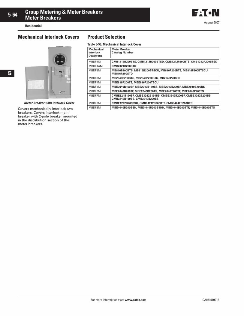
August 2007
5-64
For more information visit: www.eaton.com CA08101001E
Group Metering & Meter Breakers
5
Meter BreakersResidential
Mechanical Interlock Covers
Meter Breaker with Interlock Cover
Covers mechanically interlock two breakers. Covers interlock main breaker with 2-pole breaker mounted in the distribution section of the meter breakers.
Product SelectionTable 5-56. Mechanical Interlock CoverMechanical Interlock Deadfront
Meter Breaker Catalog Number
MBDF1M CMB1212B200BTS, CMB1212B200BTSD, CMB1212P200BTS, CMB1212P200BTSD
MBDF1AM CMB2424B200BTS
MBDF2M MB816B200BTS, MB816B200BTSCU, MB816P200BTS, MB816P200BTSCU, MB816P200STD
MBDF3M MB2040B200BTS, MB2040P200BTS, MB2040P200SD
MBDF4M MBE816P200TS, MBE816P200TSCU
MBDF5M MBE2040B150BF, MBE2040B150BS, MBE2040B200BF, MBE2040B200BS
MBDF6M MBE2040B200TF, MBE2040B200TS, MBE2040T200TF, MBE2040P200TS
MBDF7M CMBE324B150BF, CMBE3242B150BS, CMBE3242B200BF, CMBE3242B200BS, CMB3242B150BS, CMB3242B200BS
MBDF8M CMBE4242B200BSH, CMBE4242B200BTF, CMBE4242B200BTS
MBDF9M MBE4040B200BSH, MBE4040B200BSHH, MBE4040B200BTF, MBE4040B200BTS
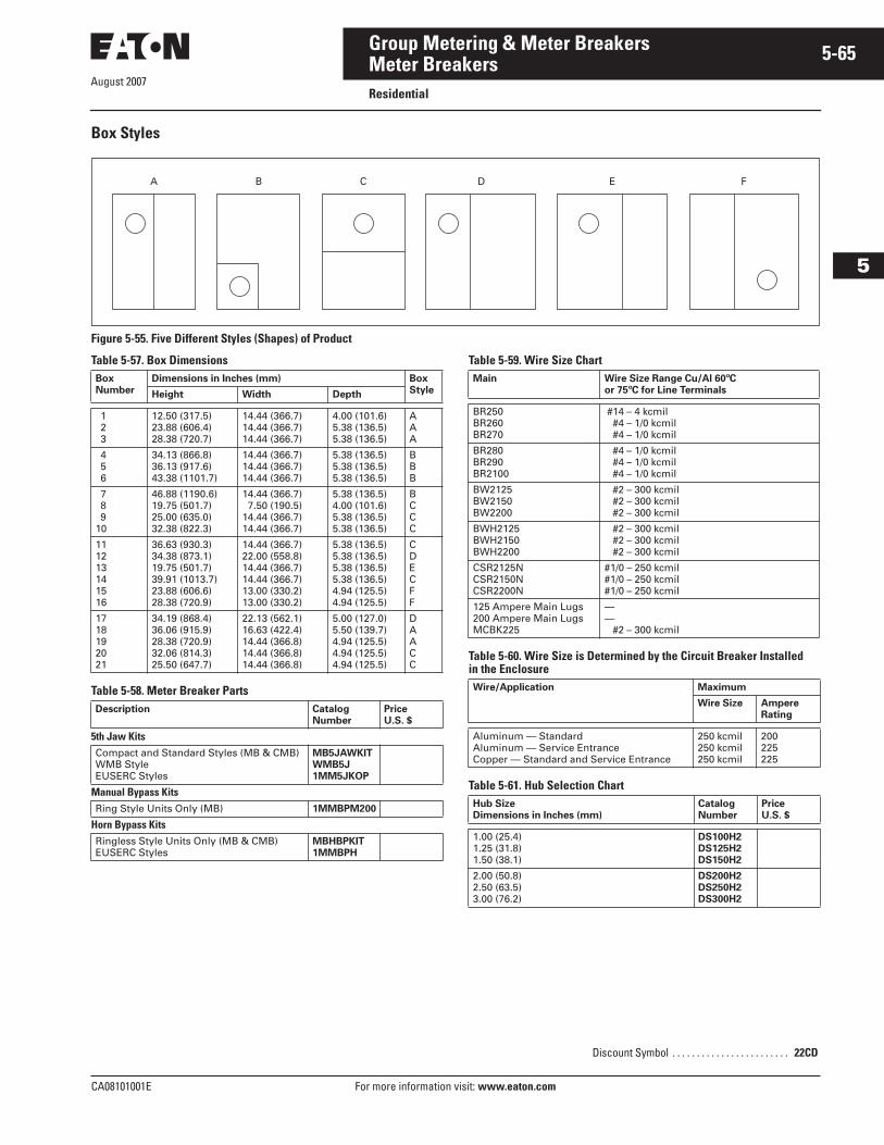
August 2007
CA08101001E For more information visit: www.eaton.com
5-65Group Metering & Meter Breakers
5
Meter BreakersResidential
Box Styles
Figure 5-55. Five Different Styles (Shapes) of Product
Table 5-57. Box Dimensions
Table 5-58. Meter Breaker Parts
Table 5-59. Wire Size Chart
Table 5-60. Wire Size is Determined by the Circuit Breaker Installed in the Enclosure
Table 5-61. Hub Selection Chart
A B C D E F
BoxNumber
Dimensions in Inches (mm) BoxStyleHeight Width Depth
1 2 3
12.50 (317.5)23.88 (606.4)28.38 (720.7)
14.44 (366.7)14.44 (366.7)14.44 (366.7)
4.00 (101.6)5.38 (136.5)5.38 (136.5)
AAA
4 5 6
34.13 (866.8)36.13 (917.6)43.38 (1101.7)
14.44 (366.7)14.44 (366.7)14.44 (366.7)
5.38 (136.5)5.38 (136.5)5.38 (136.5)
BBB
7 8 910
46.88 (1190.6)19.75 (501.7)25.00 (635.0)32.38 (822.3)
14.44 (366.7)7.50 (190.5)
14.44 (366.7)14.44 (366.7)
5.38 (136.5)4.00 (101.6)5.38 (136.5)5.38 (136.5)
BCCC
111213141516
36.63 (930.3)34.38 (873.1)19.75 (501.7)39.91 (1013.7)23.88 (606.6)28.38 (720.9)
14.44 (366.7)22.00 (558.8)14.44 (366.7)14.44 (366.7)13.00 (330.2)13.00 (330.2)
5.38 (136.5)5.38 (136.5)5.38 (136.5)5.38 (136.5)4.94 (125.5)4.94 (125.5)
CDECFF
1718192021
34.19 (868.4)36.06 (915.9)28.38 (720.9)32.06 (814.3)25.50 (647.7)
22.13 (562.1)16.63 (422.4)14.44 (366.8)14.44 (366.8)14.44 (366.8)
5.00 (127.0)5.50 (139.7)4.94 (125.5)4.94 (125.5)4.94 (125.5)
DAACC
Description CatalogNumber
PriceU.S. $
5th Jaw KitsCompact and Standard Styles (MB & CMB)WMB StyleEUSERC Styles
MB5JAWKITWMB5J1MM5JKOP
Manual Bypass KitsRing Style Units Only (MB) 1MMBPM200
Horn Bypass KitsRingless Style Units Only (MB & CMB)EUSERC Styles
MBHBPKIT1MMBPH
Main Wire Size Range Cu/Al 60ºC or 75ºC for Line Terminals
BR250BR260BR270
#14 – 4 kcmil #4 – 1/0 kcmil #4 – 1/0 kcmil
BR280BR290BR2100
#4 – 1/0 kcmil #4 – 1/0 kcmil #4 – 1/0 kcmil
BW2125BW2150BW2200
#2 – 300 kcmil #2 – 300 kcmil #2 – 300 kcmil
BWH2125BWH2150BWH2200
#2 – 300 kcmil #2 – 300 kcmil #2 – 300 kcmil
CSR2125NCSR2150NCSR2200N
#1/0 – 250 kcmil#1/0 – 250 kcmil#1/0 – 250 kcmil
125 Ampere Main Lugs 200 Ampere Main LugsMCBK225
—— #2 – 300 kcmil
Wire/Application Maximum
Wire Size AmpereRating
Aluminum — StandardAluminum — Service EntranceCopper — Standard and Service Entrance
250 kcmil250 kcmil250 kcmil
200225225
Hub SizeDimensions in Inches (mm)
Catalog Number
PriceU.S. $
1.00 (25.4)1.25 (31.8)1.50 (38.1)
DS100H2DS125H2DS150H2
2.00 (50.8)2.50 (63.5)3.00 (76.2)
DS200H2DS250H2DS300H2
Discount Symbol . . . . . . . . . . . . . . . . . . . . . . . . 22CD
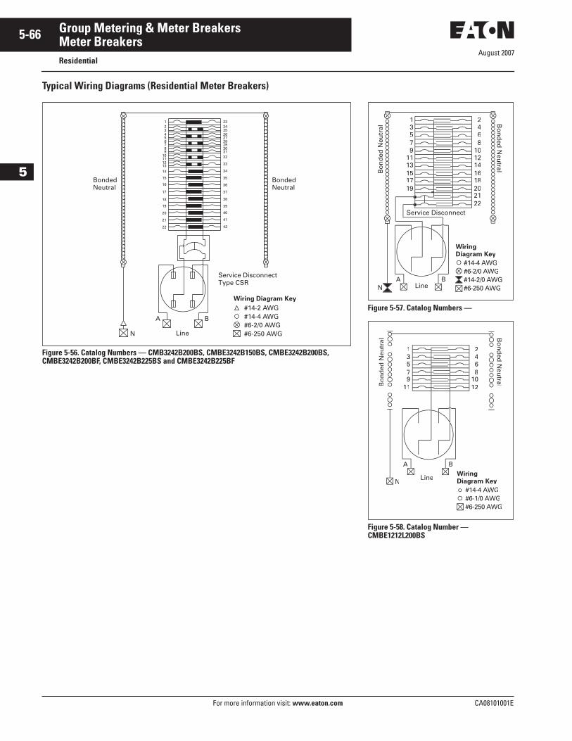
August 2007
5-66
For more information visit: www.eaton.com CA08101001E
Group Metering & Meter Breakers
5
Meter BreakersResidential
Typical Wiring Diagrams (Residential Meter Breakers)
Figure 5-56. Catalog Numbers — CMB3242B200BS, CMBE3242B150BS, CMBE3242B200BS, CMBE3242B200BF, CMBE3242B225BS and CMBE3242B225BF
#14-2 AWG#14-4 AWG#6-2/0 AWG#6-250 AWG
Wiring Diagram Key
Service DisconnectType CSR
N
BondedNeutral
BondedNeutral
123456789
10111213
14
15
16
17
18
19
20
21
22
23242526272829303132
33
34
35
36
37
38
39
40
41
42
Line
A B
Figure 5-57. Catalog Numbers —
Figure 5-58. Catalog Number — CMBE1212L200BS
1416
22
9111315
10
468
1357
2
1820
1719
NA B
Line
#14-4 AWG#6-2/0 AWG
#6-250 AWG
Wiring Diagram Key
4
8
12
13
7
11
2
A B
NLine
Bo
nd
ed N
eutr
al
Bo
nd
ed N
eutral
#14-4 AWG#6-1/0 AWG#6-250 AWG
Wiring Diagram Key
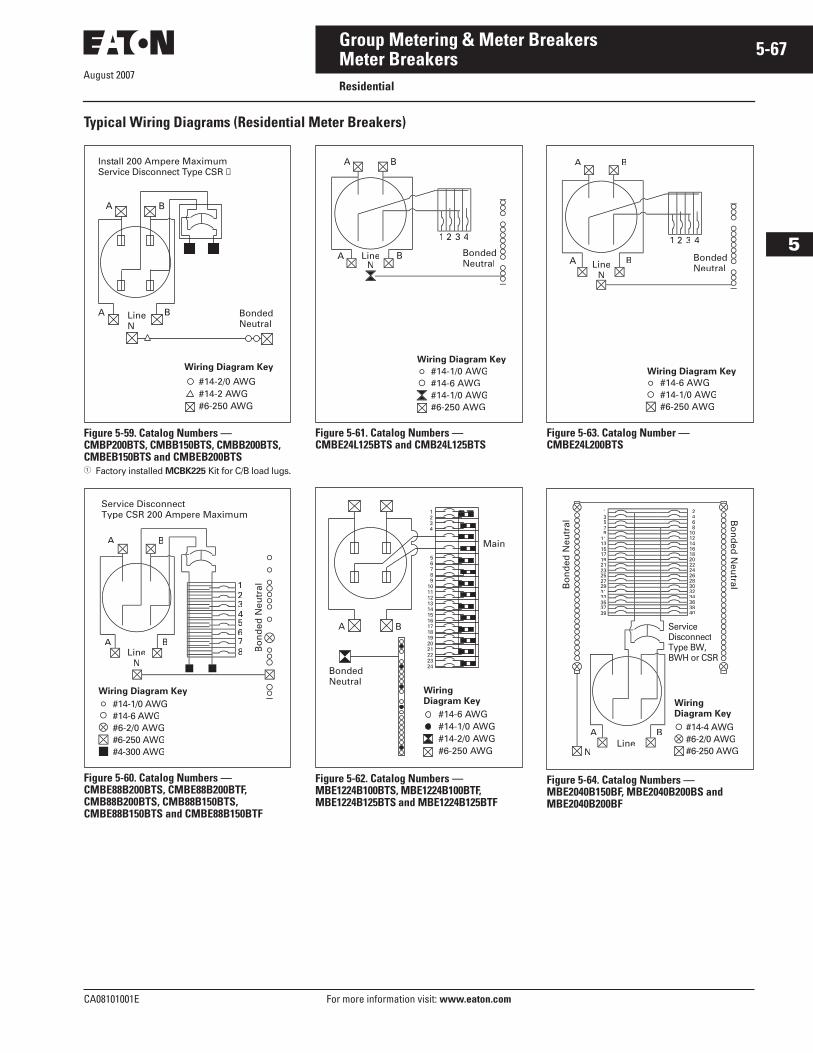
August 2007
CA08101001E For more information visit: www.eaton.com
5-67Group Metering & Meter Breakers
5
Meter BreakersResidential
Typical Wiring Diagrams (Residential Meter Breakers)
Figure 5-59. Catalog Numbers — CMBP200BTS, CMBB150BTS, CMBB200BTS, CMBEB150BTS and CMBEB200BTS� Factory installed MCBK225 Kit for C/B load lugs.
Figure 5-60. Catalog Numbers — CMBE88B200BTS, CMBE88B200BTF, CMB88B200BTS, CMB88B150BTS, CMBE88B150BTS and CMBE88B150BTF
Figure 5-61. Catalog Numbers — CMBE24L125BTS and CMB24L125BTS
Figure 5-62. Catalog Numbers — MBE1224B100BTS, MBE1224B100BTF, MBE1224B125BTS and MBE1224B125BTF
Figure 5-63. Catalog Number — CMBE24L200BTS
Figure 5-64. Catalog Numbers — MBE2040B150BF, MBE2040B200BS and MBE2040B200BF
A B
BondedNeutral
LineN
A B
Install 200 Ampere MaximumService Disconnect Type CSR ➀
Wiring Diagram Key
#14-2/0 AWG#14-2 AWG#6-250 AWG
A B
1234
A B
5678
Wiring Diagram Key
#14-1/0 AWG#14-6 AWG#6-2/0 AWG#6-250 AWG#4-300 AWG
Service DisconnectType CSR 200 Ampere Maximum
Bo
nd
ed N
eutr
al
LineN
A B
BondedNeutral
LineN
A B
#14-1/0 AWG#14-6 AWG#14-1/0 AWG#6-250 AWG
1 3 4
Wiring Diagram Key
1234
#14-6 AWG#14-1/0 AWG#14-2/0 AWG#6-250 AWG
WiringDiagram Key
A
BondedNeutral
B
Main56789
101112131415161718192021222324
A B
BondedNeutralLine
N
A B
#14-6 AWG#14-1/0 AWG#6-250 AWG
1 3 4
Wiring Diagram Key
N
A B
142
35 6
91113151719
323133 34
374038
39
DisconnectType BW,BWH or CSR
Line
#14-4 AWG#6-2/0 AWG#6-250 AWG
Wiring Diagram Key
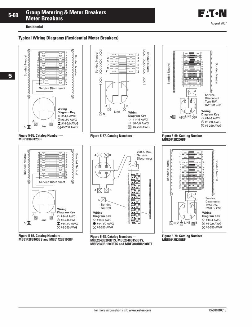
August 2007
5-68
For more information visit: www.eaton.com CA08101001E
Group Metering & Meter Breakers
5
Meter BreakersResidential
Typical Wiring Diagrams (Residential Meter Breakers)
Figure 5-65. Catalog Number — MBE1836B125BF
Figure 5-66. Catalog Numbers — MBE1428B100BS and MBE1428B100BF
Figure 5-67. Catalog Numbers —
Figure 5-68. Catalog Numbers — MBE2040B200BTS, MBE2040B150BTS, MBE2040BH200BTS and MBE2040BH200BTF
Figure 5-69. Catalog Number — MBE3042B200BF
Figure 5-70. Catalog Number — MBE3042B225BF
135
91113151719
23
3635
25272931
N Line
A B
Service Disconnect
Wiring Diagram Key
#14-4 AWG#6-2/0 AWG
#6-250 AWG
135
911131517192123
NLine
A B
Bo
nd
ed N
eutr
al
Bo
nd
ed N
eutral
Wiring Diagram Key
#14-4 AWG#6-2/0 AWG
#6-250 AWG
68
1012
13579
11
2
Line
A B
N
Bo
nd
ed N
eutr
al
#14-6 AWG#6-1/0 AWG#6-250 AWG
Bo
nd
ed N
eutral
Wiring Diagram Key
BondedNeutral
1516171819202122
1314
2324
1112
910
34
12
78
56
N
2728293031323334
2526
353637383940
A B
A B200 A Max.ServiceDisconnect
Wiring Diagram Key
#14-6 AWG#14-1/0 AWG#6-250 AWG
Bo
nd
ed N
eutral
LINEN A B
414042
3937
3638
3533
3234
3129
2830
2725
2426
23
181715
1416
13
111012
9
7
6
8
53
2
4
1
Service DisconnectType BW, BWH or CSR
Bo
nd
ed N
eutr
al
212022
19
Wiring Diagram Key
#14-4 AWG#6-2/0 AWG#6-250 AWG
Bo
nd
ed N
eutral
Service DisconnectType BW, BWH or CSR
Bo
nd
ed N
eutr
al
LINEN A B
414042
3937
3638
3533
3234
3129
2830
2725
2426
23
181715
1416
1311
1012
9
7
6
8
53
2
4
1
212022
19
Wiring Diagram Key
#14-4 AWG#6-2/0 AWG#6-250 AWG
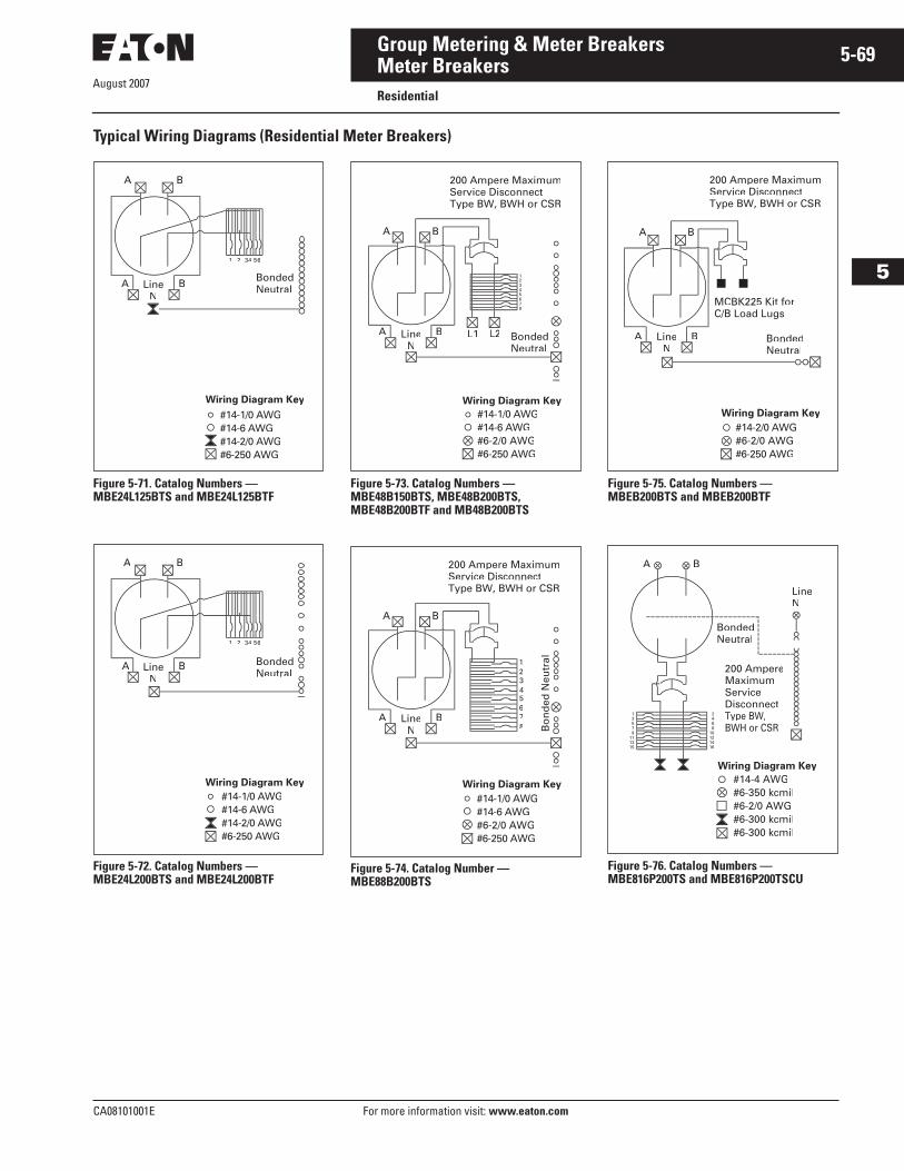
August 2007
CA08101001E For more information visit: www.eaton.com
5-69Group Metering & Meter Breakers
5
Meter BreakersResidential
Typical Wiring Diagrams (Residential Meter Breakers)
Figure 5-71. Catalog Numbers — MBE24L125BTS and MBE24L125BTF
Figure 5-72. Catalog Numbers — MBE24L200BTS and MBE24L200BTF
Figure 5-73. Catalog Numbers — MBE48B150BTS, MBE48B200BTS, MBE48B200BTF and MB48B200BTS
Figure 5-74. Catalog Number — MBE88B200BTS
Figure 5-75. Catalog Numbers — MBEB200BTS and MBEB200BTF
Figure 5-76. Catalog Numbers — MBE816P200TS and MBE816P200TSCU
A B
1
NeutralLineN
A B
2 34 56
#14-1/0 AWG#14-6 AWG#14-2/0 AWG#6-250 AWG
Wiring Diagram Key
A B
1
NeutralLine
NA B
2 34 56
#14-1/0 AWG#14-6 AWG#14-2/0 AWG#6-250 AWG
Wiring Diagram Key
A B
200 Ampere MaximumService DisconnectType BW, BWH or CSR
A B L2L1 BondedNeutral
LineN
#14-1/0 AWG#14-6 AWG#6-2/0 AWG#6-250 AWG
Wiring Diagram Key
678
A B
200 Ampere MaximumService DisconnectType BW, BWH or CSR
A BLineN
Wiring Diagram Key
#14-1/0 AWG#14-6 AWG#6-2/0 AWG#6-250 AWG
A B
A B
MCBK225 Kit forC/B Load Lugs
Wiring Diagram Key
#14-2/0 AWG#6-2/0 AWG#6-250 AWG
200 Ampere MaximumService DisconnectType BW, BWH or CSR
BondedNeutral
LineN
A B
#14-4 AWG#6-350 kcmil#6-2/0 AWG#6-300 kcmil#6-300 kcmil
LineN
BondedNeutral
200 AmpereMaximumServiceDisconnectType BW,
Wiring Diagram Key
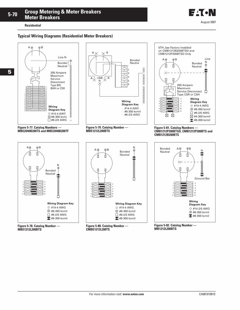
August 2007
5-70
For more information visit: www.eaton.com CA08101001E
Group Metering & Meter Breakers
5
Meter BreakersResidential
Typical Wiring Diagrams (Residential Meter Breakers)
Figure 5-77. Catalog Numbers — MBE2040B200TS and MBE2040B200TF
Figure 5-78. Catalog Number —MBE1212L200BTS
Figure 5-79. Catalog Number — MBE1212L200BTS
Figure 5-80. Catalog Number — CMBE1212L200TS
Figure 5-81. Catalog Numbers — CMB1212P200BTSD, CMB1212P200BTS and CMB1212B200BTS
Figure 5-82. Catalog Number — MB1212L200BTS
A B
Line N
BondedNeutral
200 Ampere MaximumService DisconnectType BW,
13
24
8
#14-4 AWG#6-350 kcmil#6-2/0 AWG
1
3
5
7
9
11
BondedNeutral
N
A B
#14-4 AWG#6-350 kcmil#6-2/0 AWG#6-300 kcmil
2
4
6
8
10
12
Wiring Diagram Key
A B
1
2
LINEN
A B 4
5
BondedNeutral
#14-4 AWG#6-350 kcmil#6-2/0 AWG
Wiring Diagram Key
1
3
5
7
9
11
#14-4 AWG#6-350 kcmil#6-2/0 AWG#6-300 kcmil
BondedNeutral
A BN
2
4
6
8
10
12
Wiring Diagram Key
5TH Jaw Factory Installedon CMB1212B200BTSD andCMB1212P200BTSD Only
1
3
5
7
9
11
200 AmpereMaximumService DisconnectType CSR or CSH
BondedNeutral
LineN
A B
2
4
6
8
10
12
#14-4 AWG#6-350 kcmil#6-2/0 AWG#4-300 kcmil#6-300 kcmil
WiringDiagram Key
1
3
5
7
9
11
BondedNeutral N
A B
Ground Bar
#14-2/0 AWG#6-350 kcmil#6-300 kcmil
2
4
6
8
10
12
WiringDiagram Key
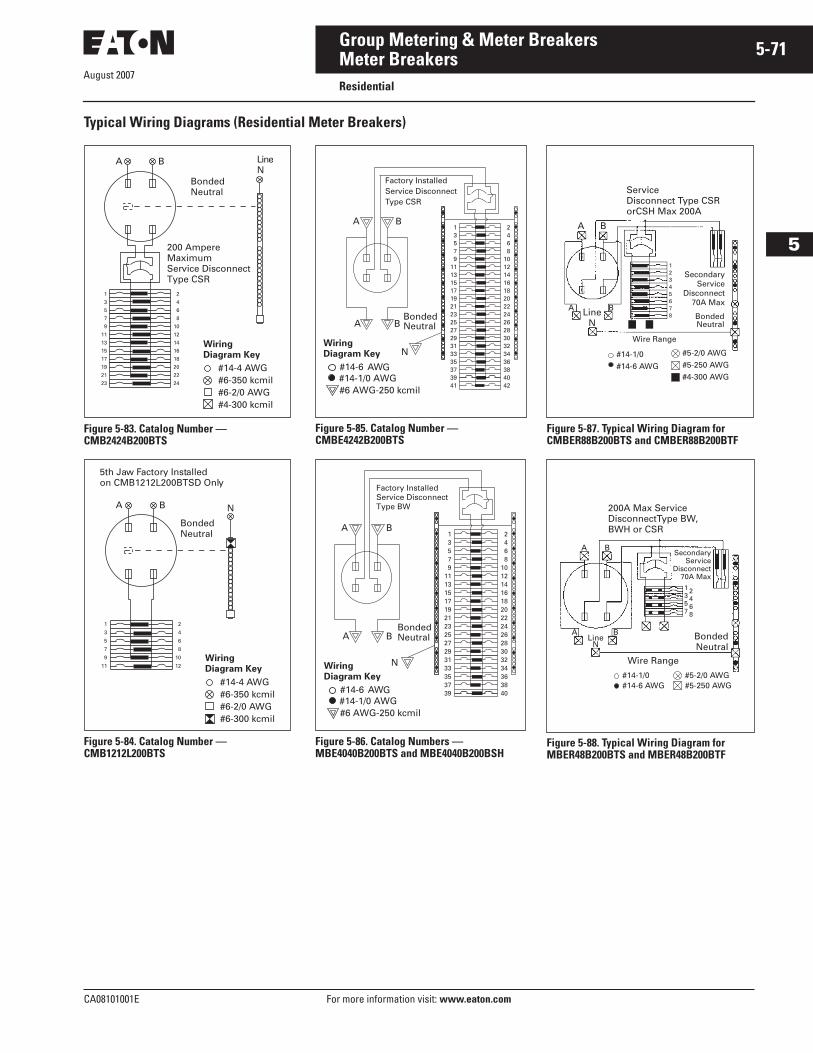
August 2007
CA08101001E For more information visit: www.eaton.com
5-71Group Metering & Meter Breakers
5
Meter BreakersResidential
Typical Wiring Diagrams (Residential Meter Breakers)
Figure 5-83. Catalog Number — CMB2424B200BTS
Figure 5-84. Catalog Number — CMB1212L200BTS
Figure 5-85. Catalog Number — CMBE4242B200BTS
Figure 5-86. Catalog Numbers — MBE4040B200BTS and MBE4040B200BSH
Figure 5-87. Typical Wiring Diagram for CMBER88B200BTS and CMBER88B200BTF
Figure 5-88. Typical Wiring Diagram for MBER48B200BTS and MBER48B200BTF
1
3
5
7
9
11
13
15
17
19
21
23
#14-4 AWG#6-350 kcmil#6-2/0 AWG#4-300 kcmil
200 AmpereMaximumService DisconnectType CSR
BondedNeutral
LineN
A B
2
4
6
8
10
12
14
16
18
20
22
24
WiringDiagram Key
1
3
5
7
9
11
N
BondedNeutral
A B
#14-4 AWG#6-350 kcmil#6-2/0 AWG#6-300 kcmil
5th Jaw Factory Installedon CMB1212L200BTSD Only
2
4
6
8
10
12WiringDiagram Key
13579
11131517192123252729313335373941
A B
A B
BondedNeutral
2468
1012141618202224262830323436384042
#14-6 AWG
WiringDiagram Key
Factory InstalledService DisconnectType CSR
#14-1/0 AWG#6 AWG-250 kcmil
N
13579
111315171921232527293133353739
N
A B
A B
BondedNeutral
2468
10121416182022242628303234363840#14-6 AWG
WiringDiagram Key
#14-1/0 AWG#6 AWG-250 kcmil
Factory InstalledService DisconnectType BW
LineN
BA
B
ServiceDisconnect Type CSR orCSH Max 200A
12345678
SecondaryService
Disconnect70A Max
BondedNeutral
Wire Range
#14-1/0
#14-6 AWG
#5-2/0 AWG
#5-250 AWG
#4-300 AWG
A
LineN
BA
B
200A Max ServiceDisconnectType BW, BWH or CSR
SecondaryService
Disconnect70A Max
BondedNeutral
Wire Range
#14-1/0#14-6 AWG
#5-2/0 AWG#5-250 AWG
A
1357
2468
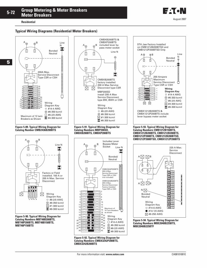
August 2007
5-72
For more information visit: www.eaton.com CA08101001E
Group Metering & Meter Breakers
5
Meter BreakersResidential
Typical Wiring Diagrams (Residential Meter Breakers)
Figure 5-89. Typical Wiring Diagram for Catalog Number CMB2436B200BTS
Figure 5-90. Typical Wiring Diagram for Catalog Numbers MBT48B200BTS, MBT48P200BTS, MBT48B150BTS, MBT48P150BTS
Figure 5-91. Typical Wiring Diagram for Catalog Numbers MBP200SD, CMBXB200BTS, CMBXP200BTS
Figure 5-92. Typical Wiring Diagram for Catalog Numbers CMBX3242P200BTS, CMBX3242B200BTS
Figure 5-93. Typical Wiring Diagram for Catalog Numbers CMB1212B150BTS, CMBX1212B200BTS, CMB1212B200BTS, CMB1212P200BTS, CMB1212B200BTSD, CMB1212P200BTSD, CMBX1212P200BTS
Figure 5-94. Typical Wiring Diagram for Catalog Numbers MBE2040B225BTS, MBE2040B225BTF
200A Max.Service DisconnectType CSR or CSH
BondedNeutral
A B LineN
2019
212223
1234
65
24252726
2928
3130
3332
353436
79 8
1110
1312
1514
171618
Maximum of 12 twinBreakers as Shown
#14-4 AWG#6-350 kcmil#6-2/0 AWG#4-300 kcmil
WiringDiagram Key
12 34 56 78 #6-2/0 AWG #6-350 kcmil#1-300 kcmil#6-300 kcmil
Wiring
Factory or Fieldinstalled. 150 A or200 A Max. ServiceDisconnect
Line N
A B
Diagram Key
#6-2/0 AWG #6-350 kcmil#1-300 kcmil#6-300 kcmil
Wiring
CMBXB200BTSfactory installed 200 A Max ServiceDisconnect type CSR
MBP200SDinstall 200 A Max Service Disconnect type BW, BWH or CSR
CMBXB200BTS &CMBXP200BTSincluded lever bypass meter socket
Line N
A B
Diagram Key
1
3
5
7
9
1113
1517
19
2123252729313335
3937
2
4
6
8
10
1214
161820
2428
22
32
26
3638
34
30
40
4241
#14-4 AWG #6-350 kcmil#6-2/0 AWG#6-300 kcmil
Wiring
Line N
Bonded/Neutral
CMBX3242P200BTS200 A Max.Service DisconnectType CSR or CSH(not included)
CMBX3242B200BTS200 A Max.Service DisconnectFactory InstalledType CSR or CSH
Maximum of10 Twin Breakers as shown
A B
Diagram Key
Includes LeverBypass MeterSocket
5TH Ja
CMBX1212B200BTS &CMBX1212P200BTS include lever bypass meter socket
w Factory Installedon CMB1212B200BTSD andCMB1212P200BTSD Only
1
3
5
7
9
11
200 AmpereMaximumService DisconnectType CSR or CSH
BondedNeutral
LineN
A B
2
4
6
8
10
12
#14-4 AWG#6-350 kcmil#6-2/0 AWG#4-300 kcmil#6-300 kcmil
WiringDiagram Key
#14-6 AWG #14-1/0 AWG#6-250 AWG
WiringDiagram Key
225 A Max.ServiceDisconnect
A B
A
N
BondedNeutral
B
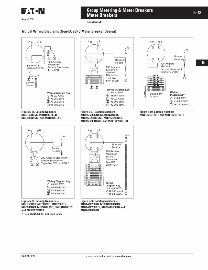
August 2007
CA08101001E For more information visit: www.eaton.com
5-73Group Metering & Meter Breakers
5
Meter BreakersResidential
Typical Wiring Diagrams (Non-EUSERC Meter Breaker Design)
Figure 5-95. Catalog Numbers — MBB150BTSC, MBB150BTSCR, MBB200BTSCR and MBB200BTSC
Figure 5-96. Catalog Numbers — MBB150BTS, MBP200SD, MBB200BTS, MBP200BTS, MBP200BTSD, CMBXB200BTS and CMBXP200BTS� Use MCBK225 for C/B Load Lugs.
Figure 5-97. Catalog Numbers — MB816P200STD, MB816B200BTS, MB816B200BTSCU, MB816P200BTS, MB816P200BTSCU and MB816P200BTSD
Figure 5-98. Catalog Numbers — MB2040P200SD, MB2040B200BTS, MB2040P200BTS, MB2040B150SD and MB2040B200SD
Figure 5-99. Catalog Numbers — MBE1224B125TS and MBE1224B100TS
A B
200 Ampere MaximumService DisconnectType CSR
BondedNeutral
Line N
#6-2/0 AWG#6-350 kcmil#6-250 kcmil#1-300 kcmil
Included inMBB150BTSCR
Wiring Diagram Key
A B
#6-2/0 AWG#6-350 kcmil#1-300 kcmil#6-300 kcmil
LineN
BondedNeutral
200 Ampere MaximumService DisconnectType BW, BWH or CSR ➀
Wiring Diagram Key
A B
13
24
15 16
#14-4 AWG#6-350 kcmil#6-2/0 AWG#6-300 kcmil#6-300 kcmil
LineN
BondedNeutral
200 Ampere Maximum
Disconnect
Wiring Diagram Key
A B
13
24
810121416182022
262830
34363840
32
LineN
BondedNeutral
200 Ampere MaximumService DisconnectType BW, BWH or CSR
#14-4 AWG#6-350 kcmil#6-2/0 AWG
Wiring
#14-4 AWG#14-1/0 AWG#6-350 kcmil
WiringDiagram Key
13579
11131517192123
125 AmpereMaximumService DisconnectType BR, or BRH
BondedNeutral
LineN
A B
EquipmentGround
2468
1012141618202224
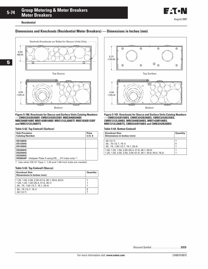
August 2007
5-74
For more information visit: www.eaton.com CA08101001E
Group Metering & Meter Breakers
5
Meter BreakersResidential
Dimensions and Knockouts (Residential Meter Breakers) — Dimensions in Inches (mm)
Figure 5-100. Knockouts for Stucco and Surface Units Catalog Numbers — CMBE3242B200BF, CMBE3242B225BF, MBE2040B200BF, MBE2040B150BF, MBE1428B100BF, MBE1212L200BTF, MBE1836B125BF and MBE1212L200BTS
Table 5-62. Top Endwall (Surface)
� Use when DS H1 Type 1, 1.25 and 1.50-inch hubs are needed.
Table 5-63. Top Endwall (Stucco)
Figure 5-101. Knockouts for Stucco and Surface Units Catalog Numbers — CMBE3242B150BS, CMBE3242B200BS, CMBE3242B225BS, CMBE1212L200BS, MBE2040B200BS, MBE1428B100BS, MBE1212L200BTS, CMB3242B150BS and CMB3242B200BS
Table 5-64. Bottom EndwallHub ProvisionCatalog Number
PriceU.S. $
DS100H2DS125H2DS150H2
DS200H2DS250H2DS300H2DS900AP (Adapter Plate if using DS___H1 hubs only) �
Knockout Size Dimensions in Inches (mm)
Quantity
1.25, 1.50, 2.00, 2.50 (31.8, 38.1, 50.8, 63.5)1.00, 1.25, 1.50 (25.4, 31.8, 38.1).50, .75, 1.00 (12.7, 19.1, 25.4)
111
.50, .75 (12.7, 19.1)
.50 (12.7)57
3.50(88.9)
Keyhole Knockouts on Sides for Stucco Units Only.
Top Stucco
4.94(125.4)
Bottom
Knockout Size Dimensions in Inches (mm)
Quantity
.50 (12.7)
.50, .75 (12.7, 19.1)
.50, .75, 1.00 (12.7, 19.1, 25.4)
741
1.00, 1.25, 1.50, 2.00 (25.4, 31.8, 38.1, 50.8)1.25, 1.50, 2.00, 2.50, 3.00 (31.8, 38.1, 50.8, 63.5, 76.2)
11
Discount Symbol. . . . . . . . . . . . . . . . . . . . . . . . . 22CD
5.31(134.9)
Top Surface
Bottom
4.94(125.4)
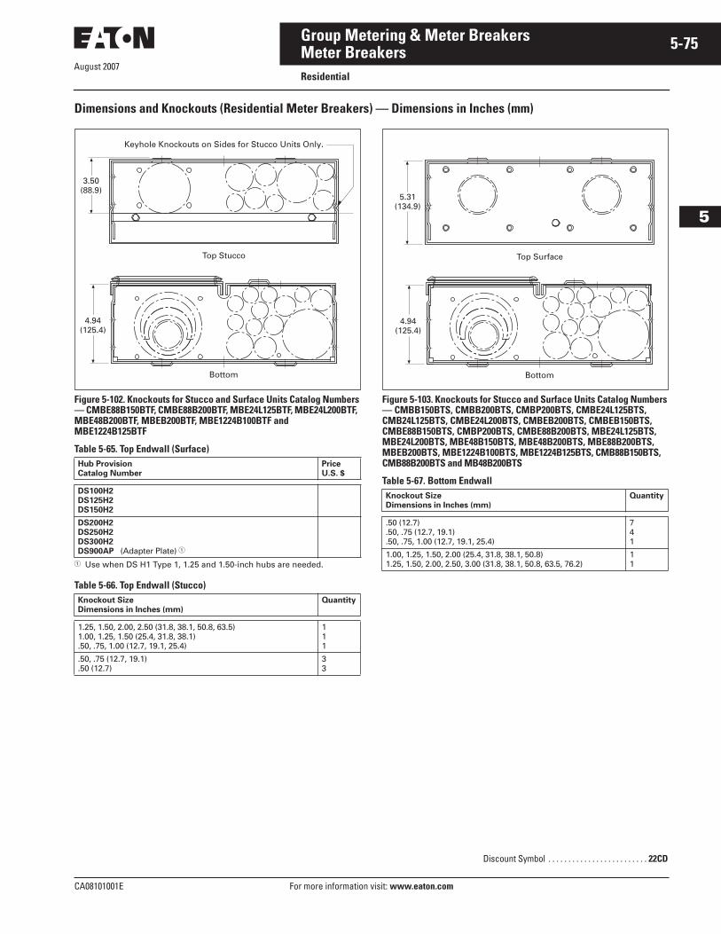
August 2007
CA08101001E For more information visit: www.eaton.com
5-75Group Metering & Meter Breakers
5
Meter BreakersResidential
Dimensions and Knockouts (Residential Meter Breakers) — Dimensions in Inches (mm)
Figure 5-102. Knockouts for Stucco and Surface Units Catalog Numbers — CMBE88B150BTF, CMBE88B200BTF, MBE24L125BTF, MBE24L200BTF, MBE48B200BTF, MBEB200BTF, MBE1224B100BTF and MBE1224B125BTF
Table 5-65. Top Endwall (Surface)
� Use when DS H1 Type 1, 1.25 and 1.50-inch hubs are needed.
Table 5-66. Top Endwall (Stucco)
Figure 5-103. Knockouts for Stucco and Surface Units Catalog Numbers — CMBB150BTS, CMBB200BTS, CMBP200BTS, CMBE24L125BTS, CMB24L125BTS, CMBE24L200BTS, CMBEB200BTS, CMBEB150BTS, CMBE88B150BTS, CMBP200BTS, CMBE88B200BTS, MBE24L125BTS, MBE24L200BTS, MBE48B150BTS, MBE48B200BTS, MBE88B200BTS, MBEB200BTS, MBE1224B100BTS, MBE1224B125BTS, CMB88B150BTS, CMB88B200BTS and MB48B200BTS
Table 5-67. Bottom Endwall
Hub ProvisionCatalog Number
PriceU.S. $
DS100H2DS125H2DS150H2
DS200H2DS250H2DS300H2DS900AP (Adapter Plate) �
Knockout Size Dimensions in Inches (mm)
Quantity
1.25, 1.50, 2.00, 2.50 (31.8, 38.1, 50.8, 63.5)1.00, 1.25, 1.50 (25.4, 31.8, 38.1).50, .75, 1.00 (12.7, 19.1, 25.4)
111
.50, .75 (12.7, 19.1)
.50 (12.7)33
Keyhole Knockouts on Sides for Stucco Units Only.
Top Stucco
Bottom
3.50(88.9)
4.94(125.4)
Knockout Size Dimensions in Inches (mm)
Quantity
.50 (12.7)
.50, .75 (12.7, 19.1)
.50, .75, 1.00 (12.7, 19.1, 25.4)
741
1.00, 1.25, 1.50, 2.00 (25.4, 31.8, 38.1, 50.8)1.25, 1.50, 2.00, 2.50, 3.00 (31.8, 38.1, 50.8, 63.5, 76.2)
11
Discount Symbol . . . . . . . . . . . . . . . . . . . . . . . . . 22CD
Top Surface
Bottom
5.31(134.9)
4.94(125.4)
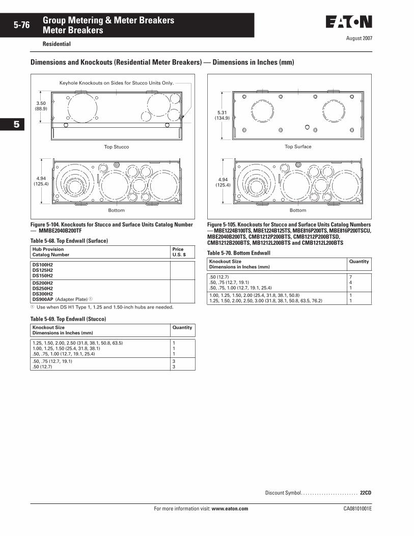
August 2007
5-76
For more information visit: www.eaton.com CA08101001E
Group Metering & Meter Breakers
5
Meter BreakersResidential
Dimensions and Knockouts (Residential Meter Breakers) — Dimensions in Inches (mm)
Figure 5-104. Knockouts for Stucco and Surface Units Catalog Number — MMBE2040B200TF
Table 5-68. Top Endwall (Surface)
� Use when DS H1 Type 1, 1.25 and 1.50-inch hubs are needed.
Table 5-69. Top Endwall (Stucco)
Figure 5-105. Knockouts for Stucco and Surface Units Catalog Numbers — MBE1224B100TS, MBE1224B125TS, MBE816P200TS, MBE816P200TSCU, MBE2040B200TS, CMB1212P200BTS, CMB1212P200BTSD, CMB1212B200BTS, MB1212L200BTS and CMB1212L200BTS
Table 5-70. Bottom EndwallHub ProvisionCatalog Number
PriceU.S. $
DS100H2DS125H2DS150H2
DS200H2DS250H2DS300H2DS900AP (Adapter Plate) �
Knockout Size Dimensions in Inches (mm)
Quantity
1.25, 1.50, 2.00, 2.50 (31.8, 38.1, 50.8, 63.5)1.00, 1.25, 1.50 (25.4, 31.8, 38.1).50, .75, 1.00 (12.7, 19.1, 25.4)
111
.50, .75 (12.7, 19.1)
.50 (12.7)33
Keyhole Knockouts on Sides for Stucco Units Only.
Top Stucco
Bottom
3.50(88.9)
4.94(125.4)
Knockout Size Dimensions in Inches (mm)
Quantity
.50 (12.7)
.50, .75 (12.7, 19.1)
.50, .75, 1.00 (12.7, 19.1, 25.4)
741
1.00, 1.25, 1.50, 2.00 (25.4, 31.8, 38.1, 50.8)1.25, 1.50, 2.00, 2.50, 3.00 (31.8, 38.1, 50.8, 63.5, 76.2)
11
Discount Symbol. . . . . . . . . . . . . . . . . . . . . . . . . 22CD
Top Surface
Bottom
5.31(134.9)
4.94(125.4)
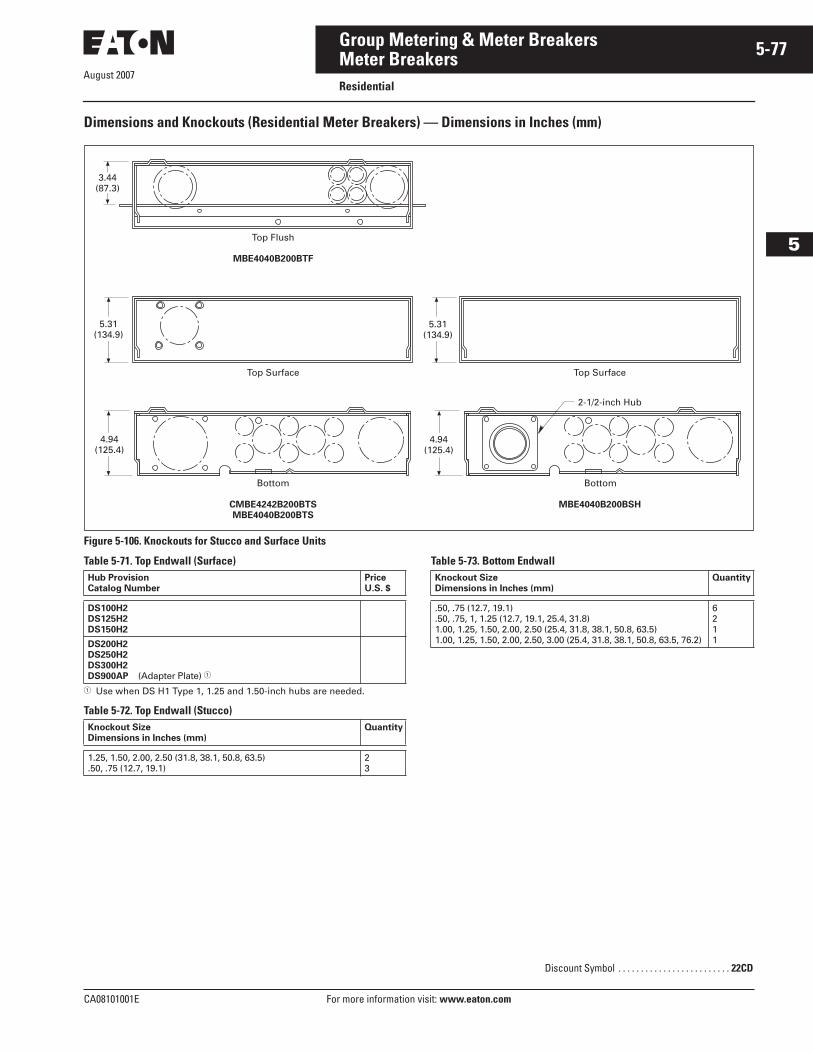
August 2007
CA08101001E For more information visit: www.eaton.com
5-77Group Metering & Meter Breakers
5
Meter BreakersResidential
Dimensions and Knockouts (Residential Meter Breakers) — Dimensions in Inches (mm)
Figure 5-106. Knockouts for Stucco and Surface Units
Table 5-71. Top Endwall (Surface)
� Use when DS H1 Type 1, 1.25 and 1.50-inch hubs are needed.
Table 5-72. Top Endwall (Stucco)
Table 5-73. Bottom Endwall
3.44(87.3)
Top Surface
Top Flush
MBE4040B200BTF
Top Surface
Bottom Bottom
2-1/2-inch Hub
CMBE4242B200BTSMBE4040B200BTS
MBE4040B200BSH
5.31(134.9)
4.94(125.4)
5.31(134.9)
4.94(125.4)
Hub ProvisionCatalog Number
PriceU.S. $
DS100H2DS125H2DS150H2
DS200H2DS250H2DS300H2DS900AP (Adapter Plate) �
Knockout Size Dimensions in Inches (mm)
Quantity
1.25, 1.50, 2.00, 2.50 (31.8, 38.1, 50.8, 63.5).50, .75 (12.7, 19.1)
23
Knockout Size Dimensions in Inches (mm)
Quantity
.50, .75 (12.7, 19.1)
.50, .75, 1, 1.25 (12.7, 19.1, 25.4, 31.8)1.00, 1.25, 1.50, 2.00, 2.50 (25.4, 31.8, 38.1, 50.8, 63.5)1.00, 1.25, 1.50, 2.00, 2.50, 3.00 (25.4, 31.8, 38.1, 50.8, 63.5, 76.2)
6211
Discount Symbol . . . . . . . . . . . . . . . . . . . . . . . . . 22CD
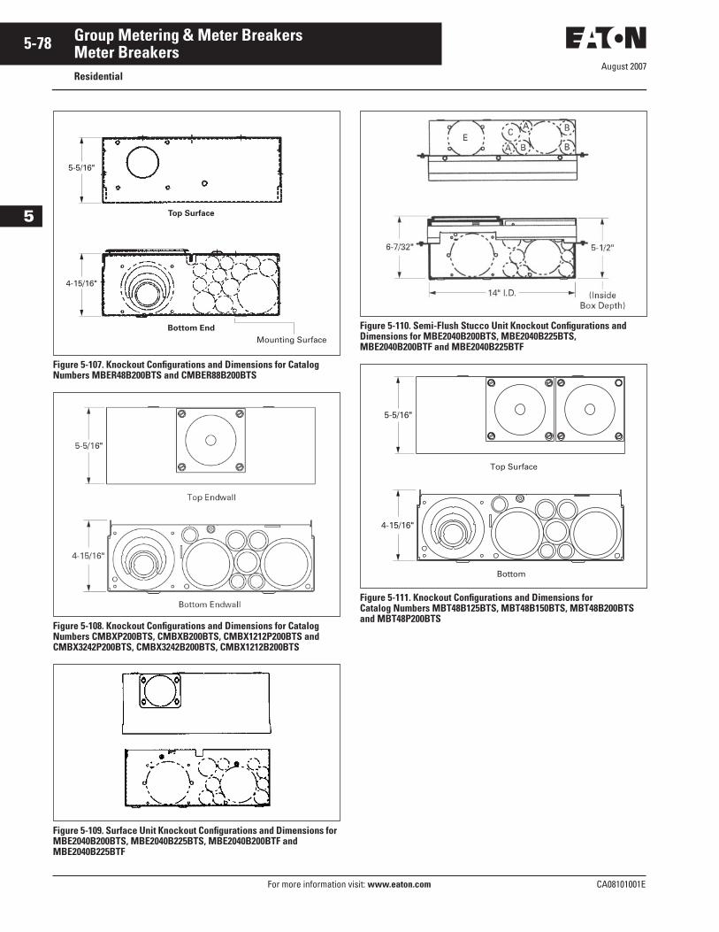
August 2007
5-78
For more information visit: www.eaton.com CA08101001E
Group Metering & Meter Breakers
5
Meter BreakersResidential
Figure 5-107. Knockout Configurations and Dimensions for Catalog Numbers MBER48B200BTS and CMBER88B200BTS
Figure 5-108. Knockout Configurations and Dimensions for Catalog Numbers CMBXP200BTS, CMBXB200BTS, CMBX1212P200BTS and CMBX3242P200BTS, CMBX3242B200BTS, CMBX1212B200BTS
Figure 5-109. Surface Unit Knockout Configurations and Dimensions for MBE2040B200BTS, MBE2040B225BTS, MBE2040B200BTF and MBE2040B225BTF
Figure 5-110. Semi-Flush Stucco Unit Knockout Configurations and Dimensions for MBE2040B200BTS, MBE2040B225BTS, MBE2040B200BTF and MBE2040B225BTF
Figure 5-111. Knockout Configurations and Dimensions for Catalog Numbers MBT48B125BTS, MBT48B150BTS, MBT48B200BTS and MBT48P200BTS
4-15/16"
Top Surface
Bottom End
Mounting Surface
5-5/16"
Bottom
Top Surface
4-15/16"
5-5/16"
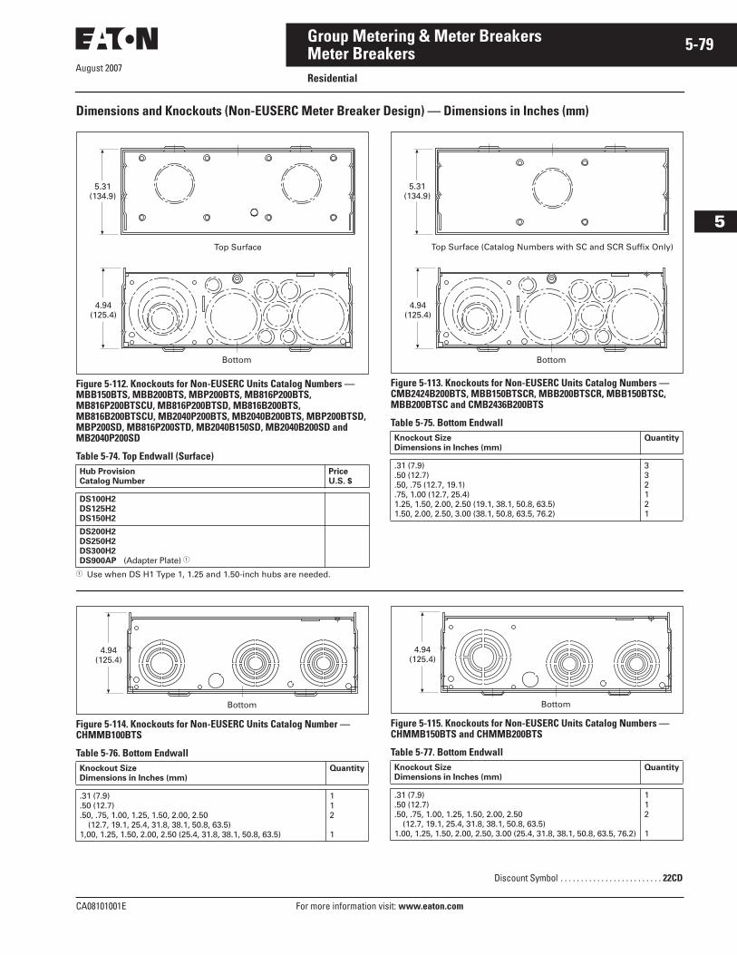
August 2007
CA08101001E For more information visit: www.eaton.com
5-79Group Metering & Meter Breakers
5
Meter BreakersResidential
Dimensions and Knockouts (Non-EUSERC Meter Breaker Design) — Dimensions in Inches (mm)
Figure 5-112. Knockouts for Non-EUSERC Units Catalog Numbers — MBB150BTS, MBB200BTS, MBP200BTS, MB816P200BTS, MB816P200BTSCU, MB816P200BTSD, MB816B200BTS, MB816B200BTSCU, MB2040P200BTS, MB2040B200BTS, MBP200BTSD, MBP200SD, MB816P200STD, MB2040B150SD, MB2040B200SD and MB2040P200SD
Table 5-74. Top Endwall (Surface)
� Use when DS H1 Type 1, 1.25 and 1.50-inch hubs are needed.
Figure 5-113. Knockouts for Non-EUSERC Units Catalog Numbers — CMB2424B200BTS, MBB150BTSCR, MBB200BTSCR, MBB150BTSC, MBB200BTSC and CMB2436B200BTS
Table 5-75. Bottom Endwall
Figure 5-114. Knockouts for Non-EUSERC Units Catalog Number — CHMMB100BTS
Table 5-76. Bottom Endwall
Figure 5-115. Knockouts for Non-EUSERC Units Catalog Numbers — CHMMB150BTS and CHMMB200BTS
Table 5-77. Bottom Endwall
Hub ProvisionCatalog Number
PriceU.S. $
DS100H2DS125H2DS150H2
DS200H2DS250H2DS300H2DS900AP (Adapter Plate) �
5.31(134.9)
Top Surface
Bottom
4.94(125.4)
Knockout Size Dimensions in Inches (mm)
Quantity
.31 (7.9)
.50 (12.7)
.50, .75 (12.7, 19.1)
.75, 1.00 (12.7, 25.4)1.25, 1.50, 2.00, 2.50 (19.1, 38.1, 50.8, 63.5)1.50, 2.00, 2.50, 3.00 (38.1, 50.8, 63.5, 76.2)
332121
Bottom
4.94(125.4)
5.31(134.9)
Top Surface (Catalog Numbers with SC and SCR Suffix Only)
Knockout Size Dimensions in Inches (mm)
Quantity
.31 (7.9)
.50 (12.7)
.50, .75, 1.00, 1.25, 1.50, 2.00, 2.50 (12.7, 19.1, 25.4, 31.8, 38.1, 50.8, 63.5)1,00, 1.25, 1.50, 2.00, 2.50 (25.4, 31.8, 38.1, 50.8, 63.5)
112
1
Bottom
4.94(125.4)
Knockout Size Dimensions in Inches (mm)
Quantity
.31 (7.9)
.50 (12.7)
.50, .75, 1.00, 1.25, 1.50, 2.00, 2.50 (12.7, 19.1, 25.4, 31.8, 38.1, 50.8, 63.5)1.00, 1.25, 1.50, 2.00, 2.50, 3.00 (25.4, 31.8, 38.1, 50.8, 63.5, 76.2)
112
1
Discount Symbol . . . . . . . . . . . . . . . . . . . . . . . . . 22CD
Bottom
4.94(125.4)
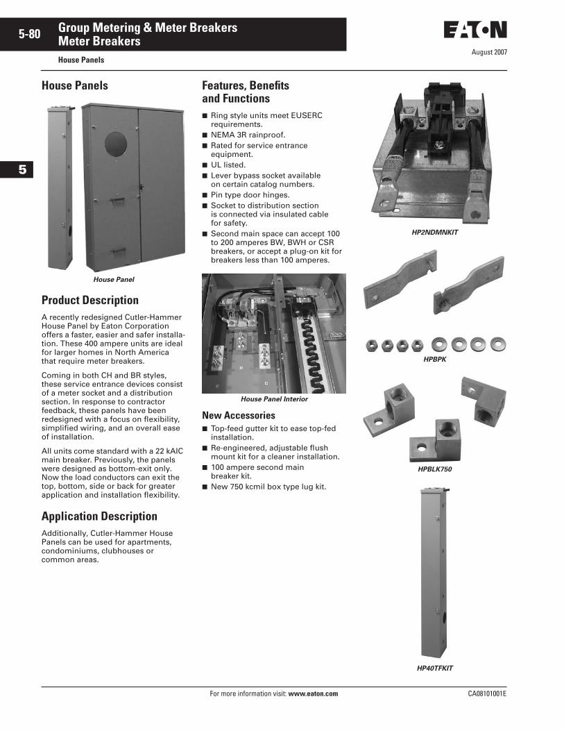
August 2007
5-80
For more information visit: www.eaton.com CA08101001E
Group Metering & Meter Breakers
5
Meter BreakersHouse Panels
House Panels
House Panel
Product DescriptionA recently redesigned Cutler-Hammer House Panel by Eaton Corporation offers a faster, easier and safer installa-tion. These 400 ampere units are ideal for larger homes in North America that require meter breakers.
Coming in both CH and BR styles, these service entrance devices consist of a meter socket and a distribution section. In response to contractor feedback, these panels have been redesigned with a focus on flexibility, simplified wiring, and an overall ease of installation.
All units come standard with a 22 kAIC main breaker. Previously, the panels were designed as bottom-exit only. Now the load conductors can exit the top, bottom, side or back for greater application and installation flexibility.
Application DescriptionAdditionally, Cutler-Hammer House Panels can be used for apartments, condominiums, clubhouses or common areas.
Features, Benefits and Functions■ Ring style units meet EUSERC
requirements.■ NEMA 3R rainproof.■ Rated for service entrance
equipment.■ UL listed.■ Lever bypass socket available
on certain catalog numbers.■ Pin type door hinges.■ Socket to distribution section
is connected via insulated cable for safety.
■ Second main space can accept 100 to 200 amperes BW, BWH or CSR breakers, or accept a plug-on kit for breakers less than 100 amperes.
House Panel Interior
New Accessories■ Top-feed gutter kit to ease top-fed
installation.■ Re-engineered, adjustable flush
mount kit for a cleaner installation.■ 100 ampere second main
breaker kit.■ New 750 kcmil box type lug kit.
HP2NDMNKIT
HPBPK
HPBLK750
HP40TFKIT
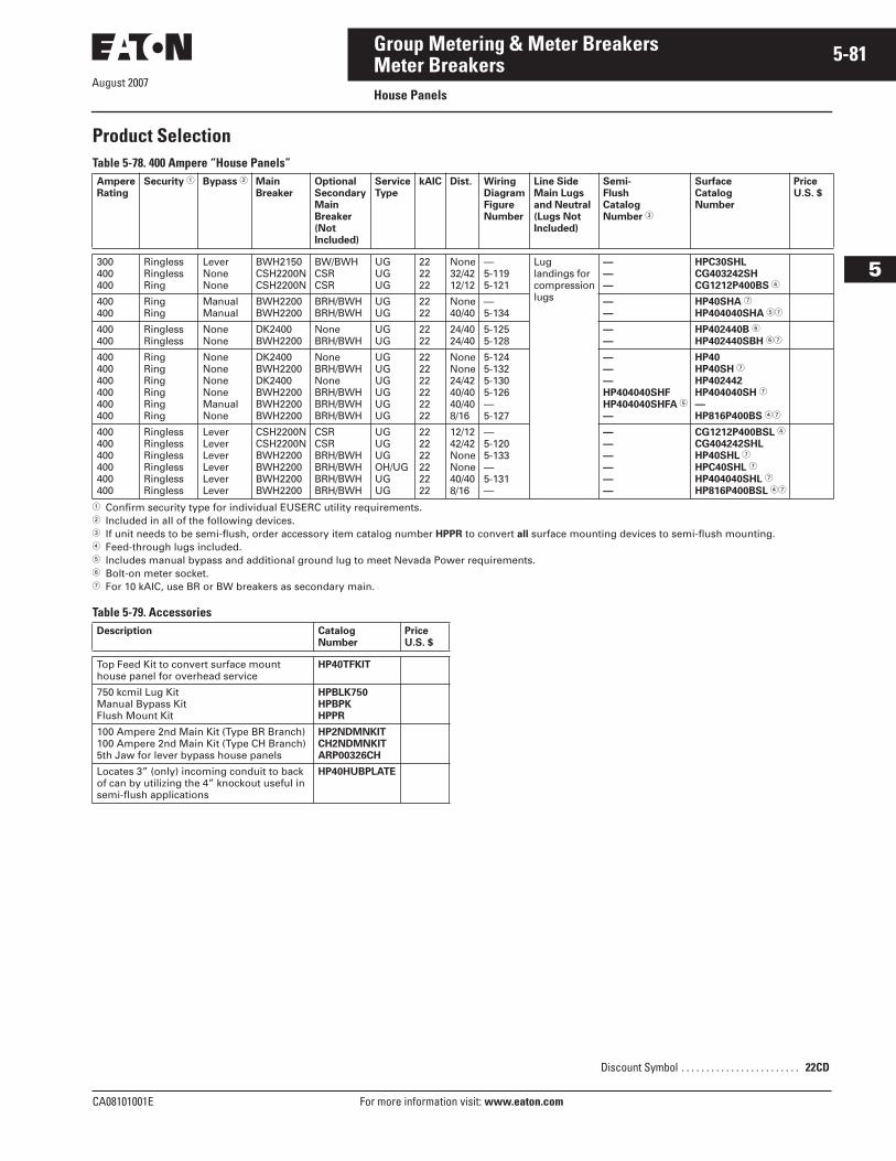
August 2007
CA08101001E For more information visit: www.eaton.com
5-81Group Metering & Meter Breakers
5
Meter BreakersHouse Panels
Product SelectionTable 5-78. 400 Ampere “House Panels”
� Confirm security type for individual EUSERC utility requirements.� Included in all of the following devices.� If unit needs to be semi-flush, order accessory item catalog number HPPR to convert all surface mounting devices to semi-flush mounting.� Feed-through lugs included.� Includes manual bypass and additional ground lug to meet Nevada Power requirements.� Bolt-on meter socket.� For 10 kAIC, use BR or BW breakers as secondary main.
Table 5-79. Accessories
AmpereRating
Security � Bypass � MainBreaker
OptionalSecondaryMainBreaker(NotIncluded)
ServiceType
kAIC Dist. WiringDiagramFigureNumber
Line SideMain Lugsand Neutral(Lugs Not Included)
Semi-FlushCatalogNumber �
SurfaceCatalogNumber
PriceU.S. $
300400400
RinglessRinglessRing
LeverNoneNone
BWH2150CSH2200NCSH2200N
BW/BWHCSRCSR
UGUGUG
222222
None32/4212/12
—5-1195-121
Luglandings forcompressionlugs
———
HPC30SHLCG403242SHCG1212P400BS �
400400
RingRing
ManualManual
BWH2200BWH2200
BRH/BWHBRH/BWH
UGUG
2222
None40/40
—5-134
——
HP40SHA �
HP404040SHA ��
400400
RinglessRingless
NoneNone
DK2400BWH2200
NoneBRH/BWH
UGUG
2222
24/4024/40
5-1255-128
——
HP402440B �
HP402440SBH ��
400400400400400400
RingRingRingRingRingRing
NoneNoneNoneNoneManualNone
DK2400BWH2200DK2400BWH2200BWH2200BWH2200
NoneBRH/BWHNoneBRH/BWHBRH/BWHBRH/BWH
UGUGUGUGUGUG
222222222222
NoneNone24/4240/4040/408/16
5-1245-1325-1305-126—5-127
———HP404040SHFHP404040SHFA �
—
HP40HP40SH �
HP402442HP404040SH �
—HP816P400BS ��
400400400400400400
RinglessRinglessRinglessRinglessRinglessRingless
LeverLeverLeverLeverLeverLever
CSH2200NCSH2200NBWH2200BWH2200BWH2200BWH2200
CSRCSRBRH/BWHBRH/BWHBRH/BWHBRH/BWH
UGUGUGOH/UGUGUG
222222222222
12/1242/42NoneNone40/408/16
—5-1205-133—5-131—
——————
CG1212P400BSL �
CG404242SHLHP40SHL �
HPC40SHL �
HP404040SHL �
HP816P400BSL ��
Description CatalogNumber
PriceU.S. $
Top Feed Kit to convert surface mount house panel for overhead service
HP40TFKIT
750 kcmil Lug KitManual Bypass KitFlush Mount Kit
HPBLK750HPBPKHPPR
100 Ampere 2nd Main Kit (Type BR Branch)100 Ampere 2nd Main Kit (Type CH Branch)5th Jaw for lever bypass house panels
HP2NDMNKITCH2NDMNKITARP00326CH
Locates 3” (only) incoming conduit to back of can by utilizing the 4” knockout useful in semi-flush applications
HP40HUBPLATE
Discount Symbol . . . . . . . . . . . . . . . . . . . . . . . . 22CD
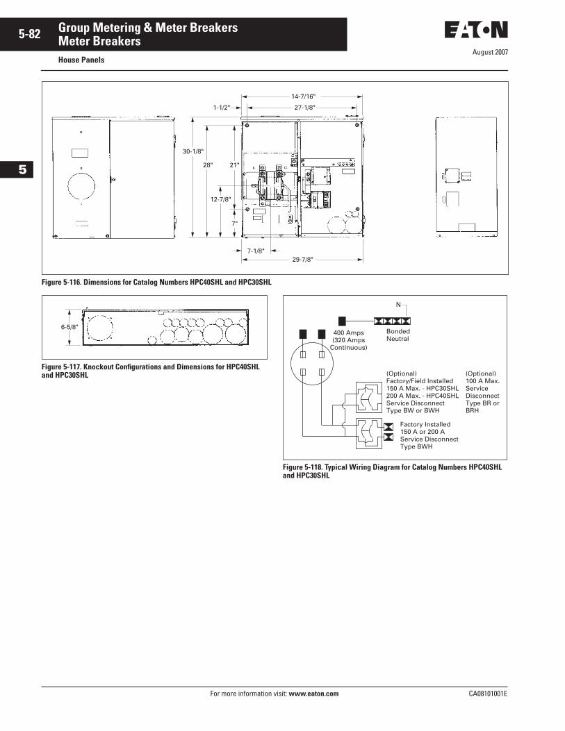
August 2007
5-82
For more information visit: www.eaton.com CA08101001E
Group Metering & Meter Breakers
5
Meter BreakersHouse Panels
Figure 5-116. Dimensions for Catalog Numbers HPC40SHL and HPC30SHL
Figure 5-117. Knockout Configurations and Dimensions for HPC40SHL and HPC30SHL
Figure 5-118. Typical Wiring Diagram for Catalog Numbers HPC40SHL and HPC30SHL
14-7/16"
27-1/8"1-1/2"
21"28"
30-1/8"
12-7/8"
7"
7-1/8"29-7/8"
6-5/8"
N
BondedNeutral
(Optional)Factory/Field Installed150 A Max. - HPC30SHL200 A Max. - HPC40SHLService DisconnectType BW or BWH
Factory Installed150 A or 200 AService DisconnectType BWH
(Optional)100 A Max.ServiceDisconnectType BR or BRH
400 Amps(320 Amps
Continuous)
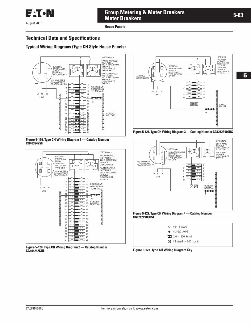
August 2007
CA08101001E For more information visit: www.eaton.com
5-83Group Metering & Meter Breakers
5
Meter BreakersHouse Panels
Technical Data and Specifications
Typical Wiring Diagrams (Type CH Style House Panels)
Figure 5-119. Type CH Wiring Diagram 1 — Catalog Number CG403242SH
Figure 5-120. Type CH Wiring Diagram 2 — Catalog Number CG404242SHL
Figure 5-121. Type CH Wiring Diagram 3 — Catalog Number CG1212P400BS
Figure 5-122. Type CH Wiring Diagram 4 — Catalog Number CG1212P400BSL
Figure 5-123. Type CH Wiring Diagram Key
1 2
3 4
5 6
11
9
7
12
10
8
13 14
15 1617 18
19 20
2321
25
22
27
24
29
26
31
28
33
30
35
32
37
34
39
36
41
384042
A
BONDEDNEUTRAL
EQUIPMENTGROUNDINGTERMINALS
400 AMPERES(320 AMPERES CONTINUOUS)
FACTORYINSTALLED200 ASERVICEDISCONNECT
N B
LINE
FACTORY/FIELDINSTALLED200 A MAXIMUMSERVICEDISCONNECTTYPE CSR
(OPTIONAL)
FACTORY/FIELDINSTALLED100 A MAXIMUMSERVICEDISCONNECTTYPE CH
1 2
3 4
5 6
11
9
7
12
10
8
13 14
15 1617 18
19 20
21 22
23 24
25 26
27 28
29 30
31 32
33 34
35 36
37 38
39 40
41 42
A
BONDEDNEUTRAL
EQUIPMENTGROUNDINGTERMINALS
400 AMPERES(320 AMPERES CONTINUOUS)
FACTORYINSTALLED200 ASERVICEDISCONNECTTYPE CSR
N B
LINE
(OPTIONAL)
FACTORY/FIELDINSTALLED200 A MAXIMUMSERVICEDISCONNECT
FACTORY/FIELDINSTALLED100 A MAXIMUMSERVICEDISCONNECTTYPE CH
A
BONDEDNEUTRAL
AMPERES
200 A MAXIMUMSERVICEDISCONNECTTYPE BW, BWHOR CSR
N B
LINE
200 A MAX.SERVICEDISCONNECTTYPE CSR
1 2
3 4
5 6
11
9
7
12
10
8
OPTIONAL
OPTIONAL
100 A MAX.SERVICEDISCONNECTTYPE CH
(CONTINUOUS)
A
BONDEDNEUTRAL
N B
LINE
1 23 45 6
1197
12108
200 A MAXIMUMSERVICEDISCONNECTTYPE BW, BWHOR CSR
OPTIONAL
200 A MAX.SERVICEDISCONNECTTYPE CSR
OPTIONAL
100 A MAX.SERVICEDISCONNECTTYPE CH
400 AMPERES(320 AMPERES CONTINUOUS)
#14-6 AWG
#14-1/0 AWG
1/0 – 300 kcmil
#4 AWG – 300 kcmil
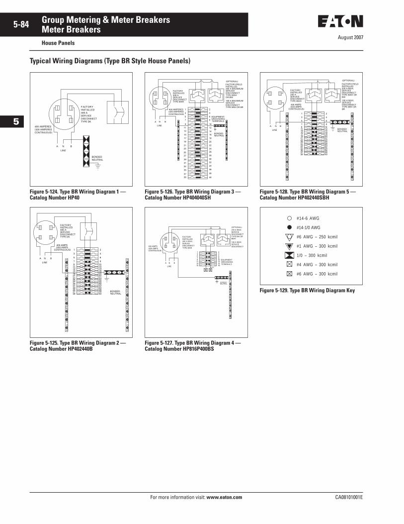
August 2007
5-84
For more information visit: www.eaton.com CA08101001E
Group Metering & Meter Breakers
5
Meter BreakersHouse Panels
Typical Wiring Diagrams (Type BR Style House Panels)
Figure 5-124. Type BR Wiring Diagram 1 —Catalog Number HP40
Figure 5-125. Type BR Wiring Diagram 2 —Catalog Number HP402440B
Figure 5-126. Type BR Wiring Diagram 3 —Catalog Number HP404040SH
Figure 5-127. Type BR Wiring Diagram 4 —Catalog Number HP816P400BS
Figure 5-128. Type BR Wiring Diagram 5 —Catalog Number HP402440SBH
Figure 5-129. Type BR Wiring Diagram Key
A
BONDEDNEUTRAL
400 AMPERES(320 AMPERES CONTINUOUS)
FACTORYINSTALLED400 ASER VICEDISCONNECTTYPE DK
N B
LINE
A
BONDEDNEUTRAL
400 AMPS(320 AMPS
CONTINUOUS)
FACTORYINSTALLED400 ASERVICEDISCONNECTTYPE DK
N B
LINE
1 2
3 4
5 6
1197
12108
13 1415 1617 1819 2021 2223 2425 2627 2829 3031 3233 3435 3637 3839 40
A
BONDEDNEUTRAL
EQUIPMENTGROUNDINGTERMINALS
400 AMPERES(320 AMPERES CONTINUOUS)
FACTORYINSTALLED200 ASERVICEDISCONNECTTYPE BWH
N B
LINE
FACTORY/FIELDINSTALLED200 A MAXIMUMSERVICEDISCONNECTTYPE BWHOR BW
100 A MAXIMUMSERVICEDISCONNECTTYPE BRH OR BR
1 2
3 4
5 6
7 8
9
11
13
15
10
12
14
16
17
19
21
23
18
20
22
24
25
27
29
31
33
35
37
26
28
30
32
34
36
38
4039
(OPTIONAL)
BONDEDNEUTRAL
A
EQUIPMENTGROUNDINGTERMINALS
400 AMPS(320 AMPS CONTINUOUS)
FACTORYINSTALLED200 A MAX.SERVICEDISCONNECTTYPE BWH
N B
LINE
1
(OPTIONAL)
324
57
68
911
1012
1315
1416
200 A MAX.SERVICEDISCONNECTTYPE BW ORBWH
100 A MAX.SERVICEDISCONNECT
BONDEDNEUTRAL
400 AMPS(320 AMPS
CONTINUOUS)
FACTORY/FIELDINSTALLED200 A MAX.SERVICEDISCONNECTTYPE BWH ORBW
FACTORYINSTALLED200 ASERVICEDISCONNECTTYPE BWH
(OPTIONAL)
A N B
LINE
1
3
5
1197
1315171921232527293133353739
2
4
6
12108
1416182022242628303234363840
100 A MAX.SERVICEDISCONNECTTYPE BRH ORBR
#14-6 AWG
#14-1/0 AWG
#6 AWG – 250 kcmil
#1 AWG – 300 kcmil
1/0 – 300 kcmil
#4 AWG – 300 kcmil
#6 AWG – 300 kcmil
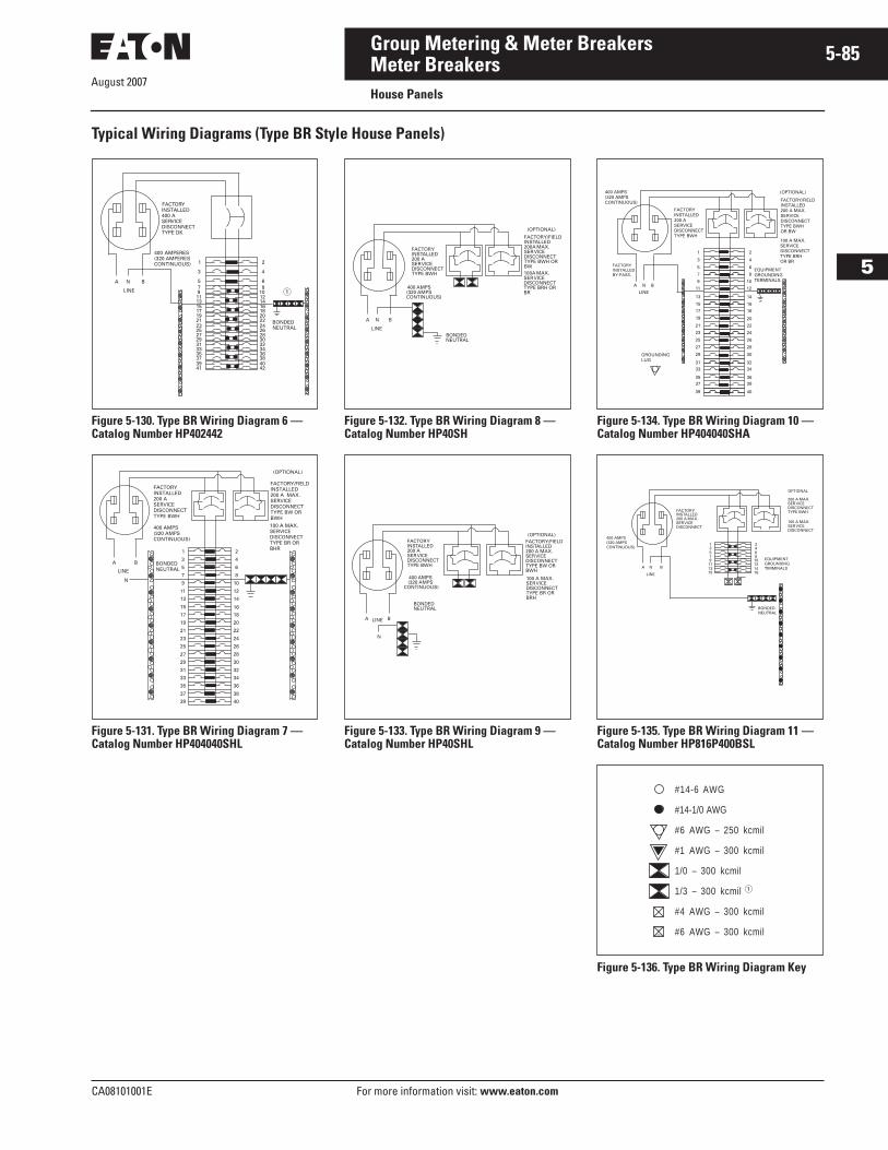
August 2007
CA08101001E For more information visit: www.eaton.com
5-85Group Metering & Meter Breakers
5
Meter BreakersHouse Panels
Typical Wiring Diagrams (Type BR Style House Panels)
Figure 5-130. Type BR Wiring Diagram 6 —Catalog Number HP402442
Figure 5-131. Type BR Wiring Diagram 7 —Catalog Number HP404040SHL
Figure 5-132. Type BR Wiring Diagram 8 —Catalog Number HP40SH
Figure 5-133. Type BR Wiring Diagram 9 —Catalog Number HP40SHL
Figure 5-134. Type BR Wiring Diagram 10 —Catalog Number HP404040SHA
Figure 5-135. Type BR Wiring Diagram 11 —Catalog Number HP816P400BSL
Figure 5-136. Type BR Wiring Diagram Key
A
BONDEDNEUTRAL
400 AMPERES(320 AMPERES
CONTINUOUS)
FACTORYINSTALLED400 ASERVICEDISCONNECTTYPE DK
N B
LINE
1 2
3 4
5 6
1197
12108
13 1415 1617 1819 2021 2223 2425 2627 2829 3031 3233 3435 3637 3839 4041 42
�
1 2
3 4
5 6
11
9
7
12
10
8
13 14
15 1617 18
19 20
21 22
23 24
25 26
27 28
29 30
31 32
33 34
35 36
37 38
39 40
A BONDEDNEUTRAL
FACTORYINSTALLED200 ASERVICEDISCONNECTTYPE BWH
400 AMPS(320 AMPSCONTINUOUS)
N
B
LINE
(OPTIONAL)
FACTORY/FIELDINSTALLED200 A MAX.SERVICEDISCONNECTTYPE BW ORBWH
100 A MAX.SERVICEDISCONNECTTYPE BR ORBHR
(OPTIONAL)
A
BONDEDNEUTRAL
400 AMPS(320 AMPS
CONTINUOUS)
FACTORYINSTALLED200 ASERVICEDISCONNECTTYPE BWH
N B
LINE
FACTORY/FIELDINSTALLED200A MAX.SERVICEDISCONNECTTYPE BWH ORBW100A MAX.SERVICEDISCONNECTTYPE BRH ORBR
A
BONDEDNEUTRAL
400 AMPS(320 AMPS
CONTINUOUS)
FACTORYINSTALLED200 ASERVICEDISCONNECTTYPE BWH
N
BLINE
FACTORY/FIELDINSTALLED200 A MAX.SERVICEDISCONNECTTYPE BW ORBWH
(OPTIONAL)
100 A MAX.SERVICEDISCONNECTTYPE BR ORBRH
A
EQUIPMENTGROUNDINGTERMINALS
400 AMPS(320 AMPSCONTINUOUS)
FACTORYINSTALLED200 ASERVICEDISCONNECTTYPE BWH
N B
LINE
1 2
3 4
5 6
9
7
10
8
FACTORYINSTALLEDBY-PASS.
FACTORY/FIELDINSTALLED200 A MAX.SERVICEDISCONNECTTYPE BWHOR BW
20
28
36
40
34
38
24
32
26
30
22
16
18
12
14
27
35
39
33
37
23
31
25
29
21
15
11
13
19
17
GROUNDINGLUG
100 A MAX.SERVICEDISCONNECTTYPE BRHOR BR
(OPTIONAL)
BONDEDNEUTRAL
A
EQUIPMENTGROUNDINGTERMINALS
400 AMPS(320 AMPSCONTINUOUS)
FACTORYINSTALLED200 A MAX.SERVICEDISCONNECT
N B
LINE
200 A MAX.SERVICEDISCONNECTTYPE BWH
1
OPTIONAL
324
57
68
911
1012
1315
1416
100 A MAX.SERVICEDISCONNECT
#14-6 AWG
#14-1/0 AWG
#6 AWG – 250 kcmil
#1 AWG – 300 kcmil
1/0 – 300 kcmil
1/3 – 300 kcmil
#4 AWG – 300 kcmil
#6 AWG – 300 kcmil
�
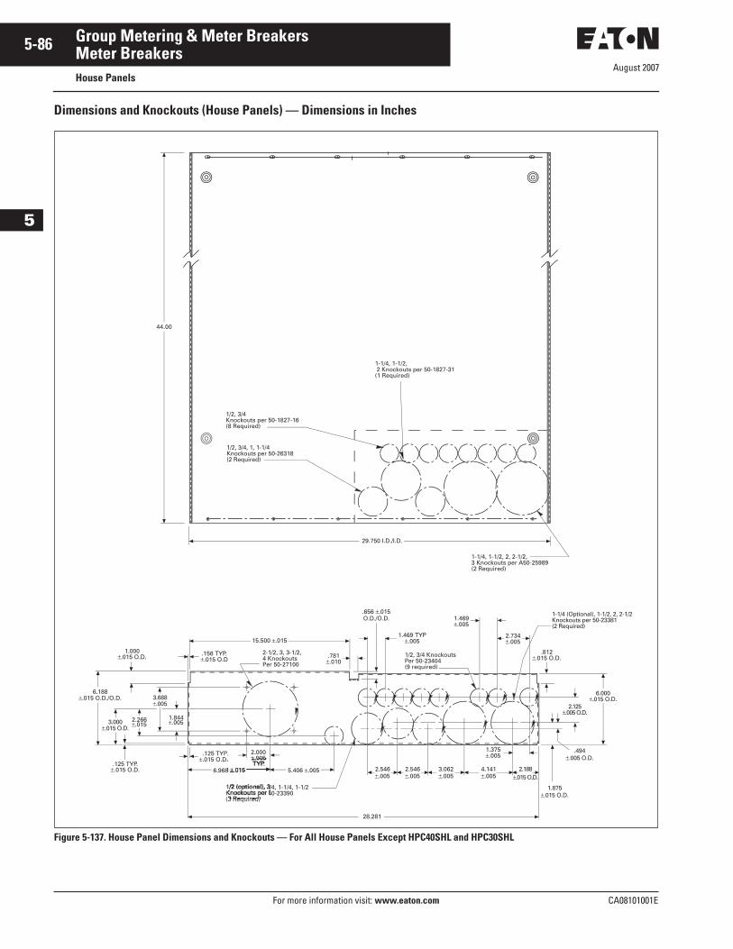
August 2007
5-86
For more information visit: www.eaton.com CA08101001E
Group Metering & Meter Breakers
5
Meter BreakersHouse Panels
Dimensions and Knockouts (House Panels) — Dimensions in Inches
Figure 5-137. House Panel Dimensions and Knockouts — For All House Panels Except HPC40SHL and HPC30SHL
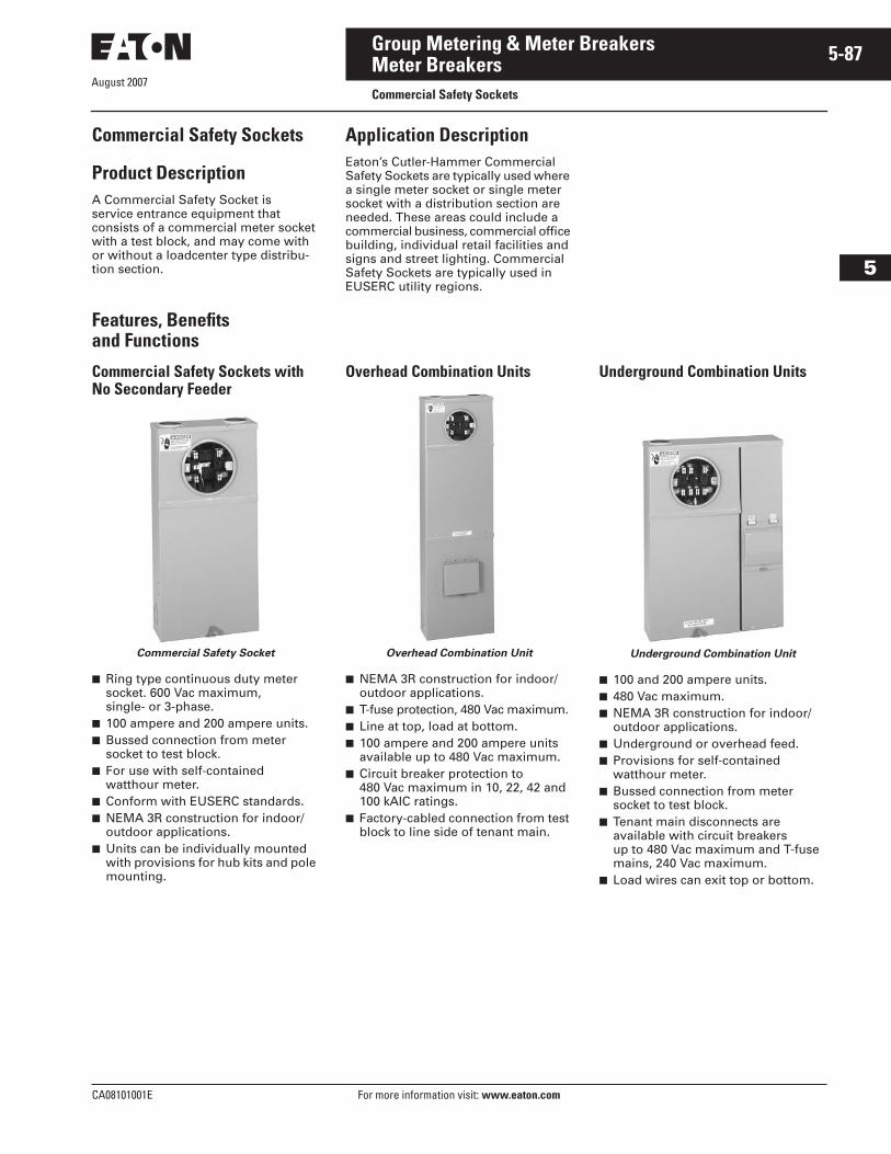
August 2007
CA08101001E For more information visit: www.eaton.com
5-87Group Metering & Meter Breakers
5
Meter BreakersCommercial Safety Sockets
Commercial Safety Sockets
Product DescriptionA Commercial Safety Socket is service entrance equipment that consists of a commercial meter socket with a test block, and may come with or without a loadcenter type distribu-tion section.
Application DescriptionEaton’s Cutler-Hammer Commercial Safety Sockets are typically used where a single meter socket or single meter socket with a distribution section are needed. These areas could include a commercial business, commercial office building, individual retail facilities and signs and street lighting. Commercial Safety Sockets are typically used in EUSERC utility regions.
Features, Benefits and Functions
Commercial Safety Sockets with No Secondary Feeder
Commercial Safety Socket
■ Ring type continuous duty meter socket. 600 Vac maximum, single- or 3-phase.
■ 100 ampere and 200 ampere units.■ Bussed connection from meter
socket to test block.■ For use with self-contained
watthour meter.■ Conform with EUSERC standards.■ NEMA 3R construction for indoor/
outdoor applications.■ Units can be individually mounted
with provisions for hub kits and pole mounting.
Overhead Combination Units
Overhead Combination Unit
■ NEMA 3R construction for indoor/outdoor applications.
■ T-fuse protection, 480 Vac maximum.■ Line at top, load at bottom.■ 100 ampere and 200 ampere units
available up to 480 Vac maximum.■ Circuit breaker protection to
480 Vac maximum in 10, 22, 42 and 100 kAIC ratings.
■ Factory-cabled connection from test block to line side of tenant main.
Underground Combination Units
Underground Combination Unit
■ 100 and 200 ampere units.■ 480 Vac maximum.■ NEMA 3R construction for indoor/
outdoor applications.■ Underground or overhead feed.■ Provisions for self-contained
watthour meter.■ Bussed connection from meter
socket to test block.■ Tenant main disconnects are
available with circuit breakers up to 480 Vac maximum and T-fuse mains, 240 Vac maximum.
■ Load wires can exit top or bottom.
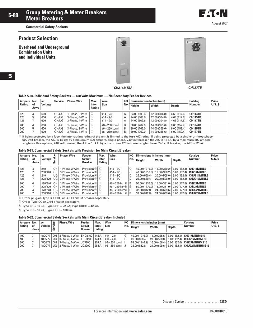
August 2007
5-88
For more information visit: www.eaton.com CA08101001E
Group Metering & Meter Breakers
5
Meter BreakersCommercial Safety Sockets
Product Selection
Overhead and Underground Combination Units and Individual Units
CH214MTBP CH127TB
Table 5-80. Individual Safety Sockets — 600 Volts Maximum — Ne Secondary Feeder Devices
� If being protected by a fuse, the interrupting rating of the unit is limited to the fuse AIC rating. If being protected by a single- or three-phase, 600 volt breaker, the AIC is 14 kA; by a maximum 400 ampere, single-phase, 240 volt breaker, the AIC is 18 kA; by a maximum 200 ampere, single- or three-phase, 240 volt breaker, the AIC is 18 kA; by a maximum 125 ampere, single-phase, 240 volt breaker, the AIC is 22 kA.
Table 5-81. Commercial Safety Sockets with Provision for Main Circuit Breaker
� Order plug-on Type BR, BRH or BRHH circuit breaker separately.� Order Type CC or CHH breaker separately.� Type BR = 10 kA; Type BRH = 22 kA; Type BRHH = 42 kA.� Type CC = 10 kA; Type CHH = 100 kA.
Table 5-82. Commercial Safety Sockets with Main Circuit Breaker Included
AmpereRating
No.ofJaws
acVoltage
Service Phase, Wire Max.Inter.Rating
WireSize
KONo.
Dimensions in Inches (mm) CatalogNumber
PriceU.S. $Height Width Depth
125125125
457
600600600
OH/UGOH/UGOH/UG
1-Phase, 3-Wire3-Phase, 3-Wire3-Phase, 4-Wire
�
�
�
#14 – 2/0#14 – 2/0#14 – 2/0
AAA
24.00 (609.6)24.00 (609.6)24.00 (609.6)
12.00 (304.8)12.00 (304.8)12.00 (304.8)
4.63 (117.6)4.63 (117.6)4.63 (117.6)
CH114TBCH115TBCH117TB
200200200
457
600600600
OH/UGOH/UGOH/UG
1-Phase, 3-Wire3-Phase, 3-Wire3-Phase, 4-Wire
�
�
�
#6 – 250 kcmil#6 – 250 kcmil#6 – 250 kcmil
BBB
30.00 (762.0)30.00 (762.0)30.00 (762.0)
14.00 (355.6)14.00 (355.6)14.00 (355.6)
6.00 (152.4)6.00 (152.4)6.00 (152.4)
CH124TBCH125TBCH127TB
AmpereRating
No.ofJaws
acVoltage
Serv
ice Phase, Wire Feeder
CircuitBreaker
Max.Inter.Rating
WireSize
KONo.
Dimensions in Inches (mm) CatalogNumber
PriceU.S. $Height Width Depth
125125125125
4747
240208/120240208/120
OHOHUGUG
1-Phase, 3-Wire3-Phase, 4-Wire1-Phase, 3-Wire3-Phase, 4-Wire
Provision �Provision �Provision �Provision �
�
�
�
�
#14 – 2/0#14 – 2/0#14 – 2/0#14 – 2/0
CCDD
40.00 (1016.0)40.00 (1016.0)26.00 (660.4)26.00 (660.4)
13.00 (330.2)13.00 (330.2)20.00 (508.0)20.00 (508.0)
6.00 (152.4)6.00 (152.4)6.00 (152.4)6.00 (152.4)
CH214MTBLBCH217MTBLBCHU214MTBLBCHU217MTBLB
200200200200
4747
120/240208/120120/240208/120
OHOHUGUG
1-Phase, 3-Wire3-Phase, 4-Wire1-Phase, 3-Wire3-Phase, 4-Wire
Provision �Provision �Provision �Provision �
�
�
�
�
#6 – 250 kcmil#6 – 250 kcmil#6 – 250 kcmil#6 – 250 kcmil
EEFF
50.00 (1270.0)50.00 (1270.0)32.00 (812.8)32.00 (812.8)
15.00 (381.0)15.00 (381.0)24.00 (609.6)24.00 (609.6)
7.00 (177.8)7.00 (177.8)7.00 (177.8)7.00 (177.8)
CH224MTBLBCH227MTBLBCHU224MTBLBCHU227MTBLB
AmpereRating
No.ofJaws
acVoltage
Serv
ice Phase, Wire Feeder
CircuitBreaker
Max.Inter.Rating
WireSize
KONo.
Dimensions in Inches (mm) CatalogNumber
PriceU.S. $Height Width Depth
100100200200
7777
480/277480/277480/277480/277
OHUGOHUG
3-Phase, 4-Wire3-Phase, 4-Wire3-Phase, 4-Wire3-Phase, 4-Wire
EHD3100EHD3100JD3200JD3200
14 kA14 kA25 kA25 kA
#14 – 2/0#14 – 2/0#6 – 250 kcmil#6 – 250 kcmil
GHIJ
40.00 (1016.0)26.00 (660.4)53.00 (1346.2)32.00 (812.8)
14.00 (355.6)20.00 (508.0)16.00 (406.4)24.00 (609.6)
6.00 (152.4)6.00 (152.4)6.00 (152.4)6.00 (152.4)
CH217MTBM515CHU217MTBMS15CH227MTBHMS15CHU227MTBHMS15
Discount Symbol . . . . . . . . . . . . . . . . . . . . . . . . 22CD
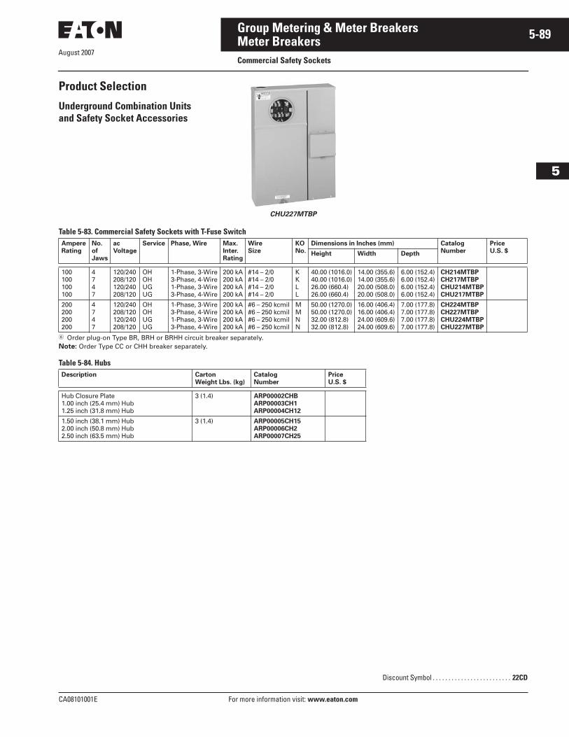
August 2007
CA08101001E For more information visit: www.eaton.com
5-89Group Metering & Meter Breakers
5
Meter BreakersCommercial Safety Sockets
Product Selection
Underground Combination Units and Safety Socket Accessories
CHU227MTBP
Table 5-83. Commercial Safety Sockets with T-Fuse Switch
� Order plug-on Type BR, BRH or BRHH circuit breaker separately.Note: Order Type CC or CHH breaker separately.
Table 5-84. Hubs
AmpereRating
No.of Jaws
acVoltage
Service Phase, Wire Max.Inter.Rating
WireSize
KONo.
Dimensions in Inches (mm) CatalogNumber
PriceU.S. $Height Width Depth
100100100100
4747
120/240208/120120/240208/120
OHOHUGUG
1-Phase, 3-Wire3-Phase, 4-Wire1-Phase, 3-Wire3-Phase, 4-Wire
200 kA200 kA200 kA200 kA
#14 – 2/0#14 – 2/0#14 – 2/0#14 – 2/0
KKLL
40.00 (1016.0)40.00 (1016.0)26.00 (660.4)26.00 (660.4)
14.00 (355.6)14.00 (355.6)20.00 (508.0)20.00 (508.0)
6.00 (152.4)6.00 (152.4)6.00 (152.4)6.00 (152.4)
CH214MTBPCH217MTBPCHU214MTBPCHU217MTBP
200200200200
4747
120/240208/120120/240208/120
OHOHUGUG
1-Phase, 3-Wire3-Phase, 4-Wire1-Phase, 3-Wire3-Phase, 4-Wire
200 kA200 kA200 kA200 kA
#6 – 250 kcmil#6 – 250 kcmil#6 – 250 kcmil#6 – 250 kcmil
MMNN
50.00 (1270.0)50.00 (1270.0)32.00 (812.8)32.00 (812.8)
16.00 (406.4)16.00 (406.4)24.00 (609.6)24.00 (609.6)
7.00 (177.8)7.00 (177.8)7.00 (177.8)7.00 (177.8)
CH224MTBPCH227MTBPCHU224MTBPCHU227MTBP
Description Carton Weight Lbs. (kg)
CatalogNumber
Price U.S. $
Hub Closure Plate1.00 inch (25.4 mm) Hub1.25 inch (31.8 mm) Hub
3 (1.4) ARP00002CHBARP00003CH1ARP00004CH12
1.50 inch (38.1 mm) Hub2.00 inch (50.8 mm) Hub2.50 inch (63.5 mm) Hub
3 (1.4) ARP00005CH15ARP00006CH2ARP00007CH25
Discount Symbol . . . . . . . . . . . . . . . . . . . . . . . . . 22CD
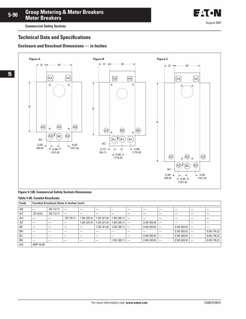
August 2007
5-90
For more information visit: www.eaton.com CA08101001E
Group Metering & Meter Breakers
5
Meter BreakersCommercial Safety Sockets
Technical Data and Specifications
Enclosure and Knockout Dimensions — in Inches
Figure 5-138. Commercial Safety Sockets Dimensions
Table 5-85. Conduit KnockoutsCode Conduit Knockout Sizes in Inches (mm)
AB — .50 (12.7) — — — – — — — — — —
AC .25 (6.4) .50 (12.7) — — — — — — — — — —
AU — — .75 (19.1) 1.00 (25.4) 1.25 (31.8) 1.50 (38.1) — — — — — —
AZ — — — 1.00 (25.4) 1.25 (31.8) 1.50 (38.1) — 2.00 (50.8) — — — —
BE — — — — 1.25 (31.8) 1.50 (38.1) — 2.00 (50.8) — 2.50 (63.5) — —
BH — — — — — — — — — 2.50 (63.5) — 3.00 (76.2)
BJ — — — — — — — 2.00 (50.8) — 2.50 (63.5) — 3.00 (76.2)
BK — — — — — 1.50 (38.1) — 2.00 (50.8) — 2.50 (63.5) — 3.00 (76.2)
HA ARP HUB
H
D W
HA
AC
AZ
HA
AZ AZBE
2.00(50.8)
4.00 (101.6)
AZ AZ
4.00 (101.6)
H
D W
HA HA
AC
AZ BE BE
BJ BJ BJ
2.13 (54.1)
4.56 (115.8)
4.56 (115.8)
H
D W
HA
AC
AZ
HA
AZ AZBE
AZ AZ
2.00(50.8)
4.00 (101.6)4.00
(101.6)
Figure A Figure B Figure C
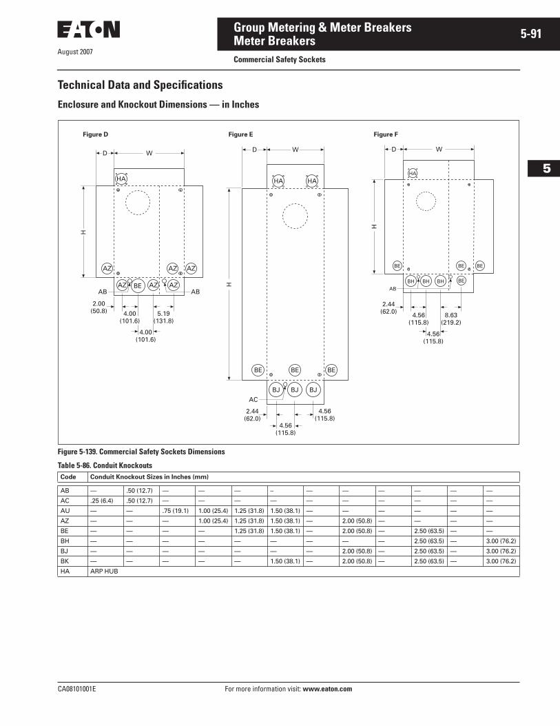
August 2007
CA08101001E For more information visit: www.eaton.com
5-91Group Metering & Meter Breakers
5
Meter BreakersCommercial Safety Sockets
Technical Data and Specifications
Enclosure and Knockout Dimensions — in Inches
Figure 5-139. Commercial Safety Sockets Dimensions
Table 5-86. Conduit KnockoutsCode Conduit Knockout Sizes in Inches (mm)
AB — .50 (12.7) — — — – — — — — — —
AC .25 (6.4) .50 (12.7) — — — — — — — — — —
AU — — .75 (19.1) 1.00 (25.4) 1.25 (31.8) 1.50 (38.1) — — — — — —
AZ — — — 1.00 (25.4) 1.25 (31.8) 1.50 (38.1) — 2.00 (50.8) — — — —
BE — — — — 1.25 (31.8) 1.50 (38.1) — 2.00 (50.8) — 2.50 (63.5) — —
BH — — — — — — — — — 2.50 (63.5) — 3.00 (76.2)
BJ — — — — — — — 2.00 (50.8) — 2.50 (63.5) — 3.00 (76.2)
BK — — — — — 1.50 (38.1) — 2.00 (50.8) — 2.50 (63.5) — 3.00 (76.2)
HA ARP HUB
H
D W
HA
BE
BHAB
BE BE
BEBHBH
8.63 (219.2)
4.56 (115.8)
2.44 (62.0)
4.56 (115.8)
H
D W
HA
BE BE BE
HA
AC
BJ BJ BJ
2.44(62.0)
4.56 (115.8)
4.56 (115.8)
H
D W
HA
AB AB
AZ
AZ AZ AZ
AZ AZ
BE
5.19 (131.8)
4.00 (101.6)
2.00 (50.8)
4.00 (101.6)
Figure D Figure E Figure F
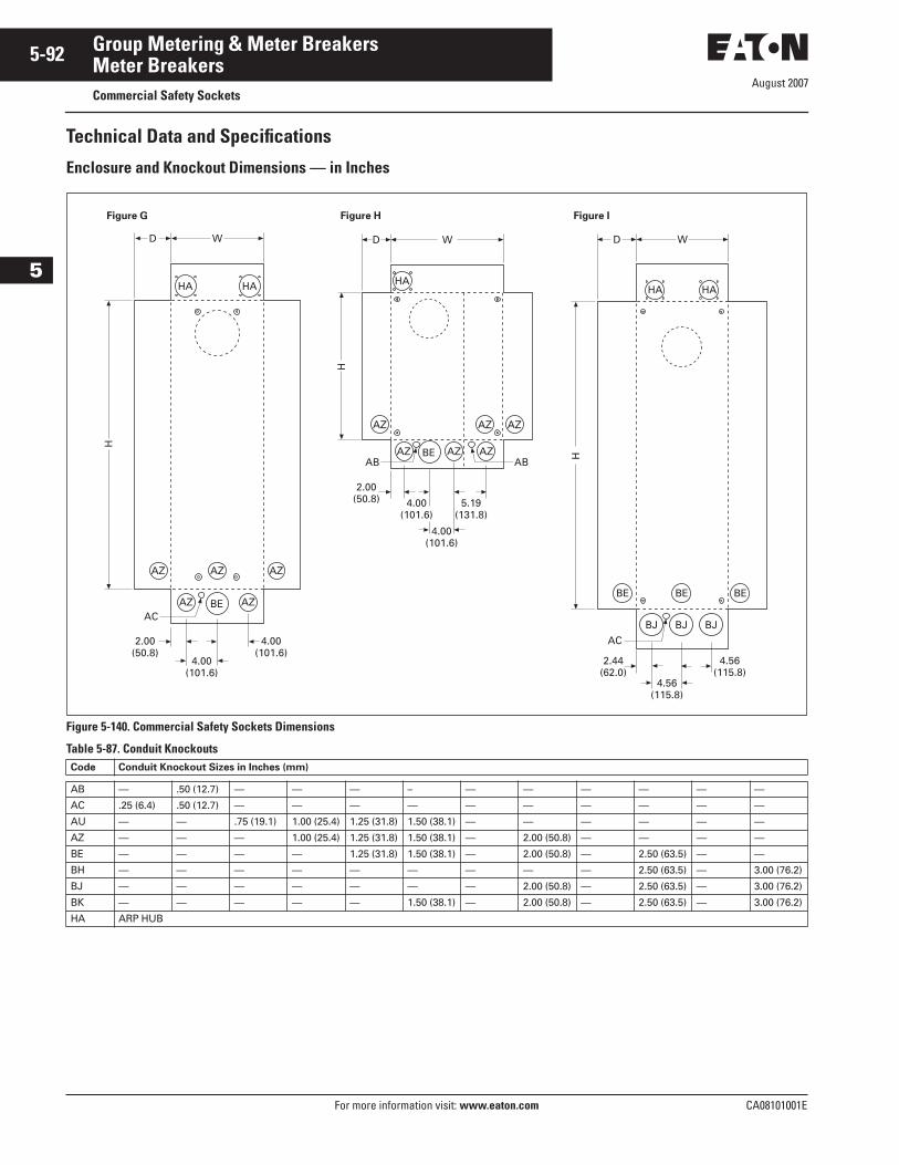
August 2007
5-92
For more information visit: www.eaton.com CA08101001E
Group Metering & Meter Breakers
5
Meter BreakersCommercial Safety Sockets
Technical Data and Specifications
Enclosure and Knockout Dimensions — in Inches
Figure 5-140. Commercial Safety Sockets Dimensions
Table 5-87. Conduit KnockoutsCode Conduit Knockout Sizes in Inches (mm)
AB — .50 (12.7) — — — – — — — — — —
AC .25 (6.4) .50 (12.7) — — — — — — — — — —
AU — — .75 (19.1) 1.00 (25.4) 1.25 (31.8) 1.50 (38.1) — — — — — —
AZ — — — 1.00 (25.4) 1.25 (31.8) 1.50 (38.1) — 2.00 (50.8) — — — —
BE — — — — 1.25 (31.8) 1.50 (38.1) — 2.00 (50.8) — 2.50 (63.5) — —
BH — — — — — — — — — 2.50 (63.5) — 3.00 (76.2)
BJ — — — — — — — 2.00 (50.8) — 2.50 (63.5) — 3.00 (76.2)
BK — — — — — 1.50 (38.1) — 2.00 (50.8) — 2.50 (63.5) — 3.00 (76.2)
HA ARP HUB
H
D W
HA
AB AB
AZ
AZ AZ AZ
AZ AZ
BE
5.19 (131.8)
4.00 (101.6)
2.00 (50.8)
4.00 (101.6)
H
D W
HA
AC
AZ
HA
AZ AZBE
AZ AZ
2.00(50.8)
4.00 (101.6)
4.00 (101.6)
H
D W
HA
BE BE BE
HA
AC
BJ BJ BJ
2.44(62.0)
4.56 (115.8)
4.56 (115.8)
Figure G Figure H Figure I
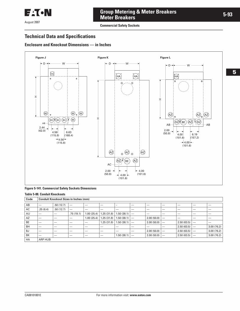
August 2007
CA08101001E For more information visit: www.eaton.com
5-93Group Metering & Meter Breakers
5
Meter BreakersCommercial Safety Sockets
Technical Data and Specifications
Enclosure and Knockout Dimensions — in Inches
Figure 5-141. Commercial Safety Sockets Dimensions
Table 5-88. Conduit KnockoutsCode Conduit Knockout Sizes in Inches (mm)
AB — .50 (12.7) — — — – — — — — — —
AC .25 (6.4) .50 (12.7) — — — — — — — — — —
AU — — .75 (19.1) 1.00 (25.4) 1.25 (31.8) 1.50 (38.1) — — — — — —
AZ — — — 1.00 (25.4) 1.25 (31.8) 1.50 (38.1) — 2.00 (50.8) — — — —
BE — — — — 1.25 (31.8) 1.50 (38.1) — 2.00 (50.8) — 2.50 (63.5) — —
BH — — — — — — — — — 2.50 (63.5) — 3.00 (76.2)
BJ — — — — — — — 2.00 (50.8) — 2.50 (63.5) — 3.00 (76.2)
BK — — — — — 1.50 (38.1) — 2.00 (50.8) — 2.50 (63.5) — 3.00 (76.2)
HA ARP HUB
H
D W
HA
AB AB
AZ
AZ AZ AZ
AZ AZ
BE
6.19 (157.2)
4.00 (101.6)
2.00 (50.8)
4.00 (101.6)
H
D W
HA
AC
AZ
HA
AZ AZBE
AZ AZ
2.00(50.8)
4.00 (101.6)4.00
(101.6)
H
D W
HA
BE
BHAB
BE BE
BEBHBH
6.63 (168.4)
4.56 (115.8)
2.44 (62.0)
4.56 (115.8)
Figure J Figure K Figure L
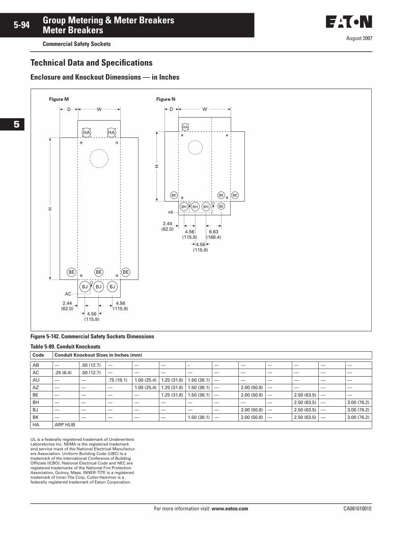
August 2007
5-94
For more information visit: www.eaton.com CA08101001E
Group Metering & Meter Breakers
5
Meter BreakersCommercial Safety Sockets
Technical Data and Specifications
Enclosure and Knockout Dimensions — in Inches
Figure 5-142. Commercial Safety Sockets Dimensions
Table 5-89. Conduit Knockouts
UL is a federally registered trademark of Underwriters Laboratories Inc. NEMA is the registered trademark and service mark of the National Electrical Manufactur-ers Association. Uniform Building Code (UBC) is a trademark of the International Conference of Building Officials (ICBO). National Electrical Code and NEC are registered trademarks of the National Fire Protection Association, Quincy, Mass. INNER-TITE is a registered trademark of Inner-Tite Corp. Cutler-Hammer is a federally registered trademark of Eaton Corporation.
Code Conduit Knockout Sizes in Inches (mm)
AB — .50 (12.7) — — — – — — — — — —
AC .25 (6.4) .50 (12.7) — — — — — — — — — —
AU — — .75 (19.1) 1.00 (25.4) 1.25 (31.8) 1.50 (38.1) — — — — — —
AZ — — — 1.00 (25.4) 1.25 (31.8) 1.50 (38.1) — 2.00 (50.8) — — — —
BE — — — — 1.25 (31.8) 1.50 (38.1) — 2.00 (50.8) — 2.50 (63.5) — —
BH — — — — — — — — — 2.50 (63.5) — 3.00 (76.2)
BJ — — — — — — — 2.00 (50.8) — 2.50 (63.5) — 3.00 (76.2)
BK — — — — — 1.50 (38.1) — 2.00 (50.8) — 2.50 (63.5) — 3.00 (76.2)
HA ARP HUB
H
D W
HA
BE
BHAB
BE BE
BEBHBH
6.63 (168.4)
4.56 (115.8)
2.44 (62.0)
4.56 (115.8)
H
D W
HA
BE BE BE
HA
AC
BJ BJ BJ
2.44(62.0)
4.56 (115.8)
4.56 (115.8)
Figure M Figure N
Recommended