Cisco uBR10-MC5X20S/U/H Cable Interface Line Card Hardware Installation Guide
First Published: September 2003Last Updated: April, 2012
Document Revision History
Document Revision Date Change Summary
OL-2818-04 September 30, 2003 Added information about ESD sensitivity.
OL-2818-05 March 25, 2004 Added universal “U” information to the MC5X20S documentation.
78-17658-01 September 15, 2006 Added universal MC5X20H and UCH2 information.
78-17658-01 Rev. B0 January 2, 2007 Updated the “Feature Overview” section to further differentiate the MC5X20U and MC5X20H.
78-17658-01 Rev. C0 April 9, 2007 Updated the “Feature Overview” section regarding Carrier-to-Noise Ratio, Signal-to-Noise Ratio, and Modulation Error Ratio.
78-17658-01 Rev. D0 June 25, 2007 Updated minimum software requirement for the MC5X20H to Cisco IOS Release 12.3(17b)BC4.
78-17658-02 September 19, 2007 Updated quad-shielded cable colors.
OL-18277-01 October 24, 2008 Added maximum torque specification for installation of a Cisco uBR10-MC5X20S/U/H card.
OL-18277-02 May 15, 2009 Updated for cable assembly change.
OL-18277-03 April 30, 2012 Added SODIMM memory installation and replacement procedure.
Americas Headquarters:Cisco Systems, Inc., 170 West Tasman Drive, San Jose, CA 95134-1706 USA
Purpose
PurposeThe purpose of this document is to provide installation, removal, and troubleshooting information for the Cisco uBR-MC5x20 S/U/H line cards in the Cisco uBR10012 universal broadband router.
AudienceThis document is intended for use by a field service engineer who is familiar with Cisco products and headend cable installation procedures.
Warning Only trained and qualified personnel should be allowed to install, replace, or service this equipment. Statement 1030.
Contents• Information on Cisco uBR10-MC5X20S/U/H Line Cards, page 3
• Safety Information and Warnings, page 8
• Installing and Replacing a Cisco uBR10-MC5X20S/U/H Cable Interface Line Card, page 10
– Unpacking the Cisco uBR10-MC5X20S/U/H Cable Interface Line Card, page 10
– Installing the Cisco uBR10-MC5X20S/U/H Cable Interface Line Card in the Card Slot, page 11
– Removing the Cisco uBR10-MC5X20S/U/H Cable Interface Line Card from the Card Slot, page 14
• Replacing the SODIMM on the Cisco uBR10-MC5x20H Line Card, page 16
• Using the Universal Cable Holder on Cisco uBR10-MC5X20 Line Cards, page 16
– Installing the UCH on the Cisco uBR10-MC5X20S/U/H Card, page 21
– Removing the UCH from the Cisco uBR10-MC5X20S/U/H Cable Interface Line Card, page 25
– Installing or Replacing Cables in the UCH1, page 27
– Installing or Replacing Cables in the UCH2, page 33
• Adding Heat-Shrink Tubing to Custom Built Cables, page 36
• Troubleshooting the Cisco uBR10-MC5X20S/U/H Cable Interface Line Card Installation, page 38
• Technical Specifications and Component Part Numbers, page 39
• Related Documentation, page 45
• Obtaining Documentation and Submitting a Service Request, page 46
2Cisco uBR10-MC5X20S/U/H Cable Interface Line Card Hardware Installation Guide
OL-18277-03
Information on Cisco uBR10-MC5X20S/U/H Line Cards
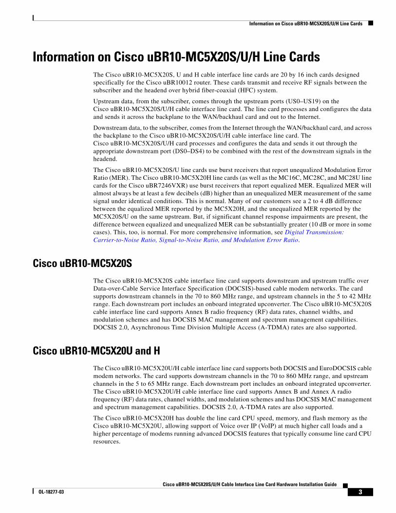
Information on Cisco uBR10-MC5X20S/U/H Line CardsThe Cisco uBR10-MC5X20S, U and H cable interface line cards are 20 by 16 inch cards designed specifically for the Cisco uBR10012 router. These cards transmit and receive RF signals between the subscriber and the headend over hybrid fiber-coaxial (HFC) system.
Upstream data, from the subscriber, comes through the upstream ports (US0–US19) on the Cisco uBR10-MC5X20S/U/H cable interface line card. The line card processes and configures the data and sends it across the backplane to the WAN/backhaul card and out to the Internet.
Downstream data, to the subscriber, comes from the Internet through the WAN/backhaul card, and across the backplane to the Cisco uBR10-MC5X20S/U/H cable interface line card. The Cisco uBR10-MC5X20S/U/H card processes and configures the data and sends it out through the appropriate downstream port (DS0–DS4) to be combined with the rest of the downstream signals in the headend.
The Cisco uBR10-MC5X20S/U line cards use burst receivers that report unequalized Modulation Error Ratio (MER). The Cisco uBR10-MC5X20H line cards (as well as the MC16C, MC28C, and MC28U line cards for the Cisco uBR7246VXR) use burst receivers that report equalized MER. Equalized MER will almost always be at least a few decibels (dB) higher than an unequalized MER measurement of the same signal under identical conditions. This is normal. Many of our customers see a 2 to 4 dB difference between the equalized MER reported by the MC5X20H, and the unequalized MER reported by the MC5X20S/U on the same upstream. But, if significant channel response impairments are present, the difference between equalized and unequalized MER can be substantially greater (10 dB or more in some cases). This, too, is normal. For more comprehensive information, see Digital Transmission: Carrier-to-Noise Ratio, Signal-to-Noise Ratio, and Modulation Error Ratio.
Cisco uBR10-MC5X20SThe Cisco uBR10-MC5X20S cable interface line card supports downstream and upstream traffic over Data-over-Cable Service Interface Specification (DOCSIS)-based cable modem networks. The card supports downstream channels in the 70 to 860 MHz range, and upstream channels in the 5 to 42 MHz range. Each downstream port includes an onboard integrated upconverter. The Cisco uBR10-MC5X20S cable interface line card supports Annex B radio frequency (RF) data rates, channel widths, and modulation schemes and has DOCSIS MAC management and spectrum management capabilities. DOCSIS 2.0, Asynchronous Time Division Multiple Access (A-TDMA) rates are also supported.
Cisco uBR10-MC5X20U and HThe Cisco uBR10-MC5X20U/H cable interface line card supports both DOCSIS and EuroDOCSIS cable modem networks. The card supports downstream channels in the 70 to 860 MHz range, and upstream channels in the 5 to 65 MHz range. Each downstream port includes an onboard integrated upconverter. The Cisco uBR10-MC5X20U/H cable interface line card supports Annex B and Annex A radio frequency (RF) data rates, channel widths, and modulation schemes and has DOCSIS MAC management and spectrum management capabilities. DOCSIS 2.0, A-TDMA rates are also supported.
The Cisco uBR10-MC5X20H has double the line card CPU speed, memory, and flash memory as the Cisco uBR10-MC5X20U, allowing support of Voice over IP (VoIP) at much higher call loads and a higher percentage of modems running advanced DOCSIS features that typically consume line card CPU resources.
3Cisco uBR10-MC5X20S/U/H Cable Interface Line Card Hardware Installation Guide
OL-18277-03
Information on Cisco uBR10-MC5X20S/U/H Line Cards
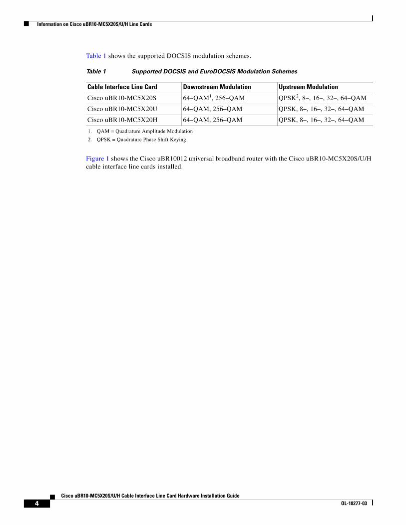
Table 1 shows the supported DOCSIS modulation schemes.
Figure 1 shows the Cisco uBR10012 universal broadband router with the Cisco uBR10-MC5X20S/U/H cable interface line cards installed.
Table 1 Supported DOCSIS and EuroDOCSIS Modulation Schemes
Cable Interface Line Card Downstream Modulation Upstream Modulation
Cisco uBR10-MC5X20S 64–QAM1, 256–QAM
1. QAM = Quadrature Amplitude Modulation
QPSK2, 8–, 16–, 32–, 64–QAM
2. QPSK = Quadrature Phase Shift Keying
Cisco uBR10-MC5X20U 64–QAM, 256–QAM QPSK, 8–, 16–, 32–, 64–QAM
Cisco uBR10-MC5X20H 64–QAM, 256–QAM QPSK, 8–, 16–, 32–, 64–QAM
4Cisco uBR10-MC5X20S/U/H Cable Interface Line Card Hardware Installation Guide
OL-18277-03

Information on Cisco uBR10-MC5X20S/U/H Line Cards
Figure 1 Cisco uBR10012 Chassis with Cisco uBR10-MC5X20S/U/H Cards
7232
2
US0
US1
US2
US3
US4
US5
US6
US7
US8
US9
US10
US11
US12
US13
US14
US15
US16
US17
US18
US19
DS0
DS1
DS2
DS3
DS4
RF
RF
RF
RF
RF
uB
R10-M
C5x2
0S
-D
POWER
STATUSM
AINT
US0
US1
US2
US3
US4
US5
US6
US7
US8
US9
US10
US11
US12
US13
US14
US15
US16
US17
US18
US19
DS0
DS1
DS2
DS3
DS4
RF
RF
RF
RF
RF
uB
R10-M
C5x2
0S
-D
POWER
STATUSM
AINT
US0
US1
US2
US3
US4
US5
US6
US7
US8
US9
US10
US11
US12
US13
US14
US15
US16
US17
US18
US19
DS0
DS1
DS2
DS3
DS4
RF
RF
RF
RF
RF
uB
R10-M
C5x2
0S
-D
POWER
STATUSM
AINT
US0
US1
US2
US3
US4
US5
US6
US7
US8
US9
US10
US11
US12
US13
US14
US15
US16
US17
US18
US19
DS0
DS1
DS2
DS3
DS4
RF
RF
RF
RF
RF
uB
R10-M
C5x2
0S
-D
POWER
STATUSM
AINT
US0
US1
US2
US3
US4
US5
US6
US7
US8
US9
US10
US11
US12
US13
US14
US15
US16
US17
US18
US19
DS0
DS1
DS2
DS3
DS4
RF
RF
RF
RF
RF
uB
R10-M
C5x2
0S
-D
POWER
STATUSM
AINT
US0
US1
US2
US3
US4
US5
US6
US7
US8
US9
US10
US11
US12
US13
US14
US15
US16
US17
US18
US19
DS0
DS1
DS2
DS3
DS4
RF
RF
RF
RF
RF
uB
R10-M
C5x2
0S
-D
POWER
STATUSM
AINT
US0
US1
US2
US3
US4
US5
US6
US7
US8
US9
US10
US11
US12
US13
US14
US15
US16
US17
US18
US19
DS0
DS1
DS2
DS3
DS4
RF
RF
RF
RF
RF
uB
R10-M
C5x2
0S
-D
POWER
STATUSM
AINT
US0
US1
US2
US3
US4
US5
US6
US7
US8
US9
US10
US11
US12
US13
US14
US15
US16
US17
US18
US19
DS0
DS1
DS2
DS3
DS4
RF
RF
RF
RF
RF
uB
R10-M
C5x2
0S
-D
POWER
STATUSM
AINT
8/07/0
6/05/08/1
7/1 6/15/1
CISCO10000
EN
AB
LE
PO
SS
RP
FA
IL
OC
–48/S
TM
–16 P
OS
/SR
P S
M–LR
CD TX
RX
SY
NC
WR
AP
PA
SS
TH
RU
TXRX
CISCO10000
EN
AB
LE
PO
SS
RP
FA
IL
OC
–48/S
TM
–16 P
OS
/SR
P S
M–LR
CD TX
RX
SY
NC
WR
AP
PA
SS
TH
RU
TXRX
CISCO10000
EN
AB
LE
PO
SS
RP
FA
IL
OC
–48/S
TM
–16 P
OS
/SR
P S
M–LR
CD TX
RX
SY
NC
WR
AP
PA
SS
TH
RU
TXRX
CISCO10000
EN
AB
LE
PO
SS
RP
FA
IL
OC
–48/S
TM
–16 P
OS
/SR
P S
M–LR
CD TX
RX
SY
NC
WR
AP
PA
SS
TH
RU
TXRX
5Cisco uBR10-MC5X20S/U/H Cable Interface Line Card Hardware Installation Guide
OL-18277-03
Information on Cisco uBR10-MC5X20S/U/H Line Cards
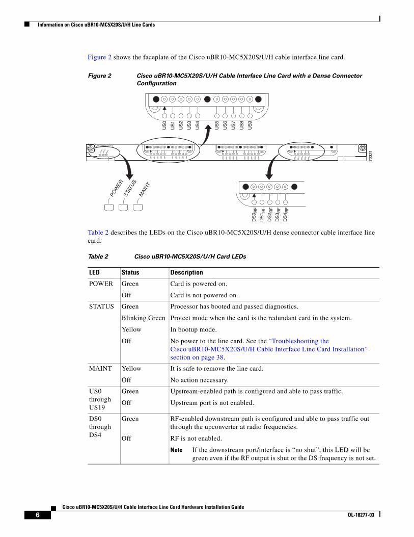
Figure 2 shows the faceplate of the Cisco uBR10-MC5X20S/U/H cable interface line card.
Figure 2 Cisco uBR10-MC5X20S/U/H Cable Interface Line Card with a Dense Connector
Configuration
Table 2 describes the LEDs on the Cisco uBR10-MC5X20S/U/H dense connector cable interface line card.
7232
1
US
0
US
1
US
2
US
3
US
4
US
5
US
6
US
7
US
8
US
9
US
10
US
11
US
12
US
13
US
14
US
15
US
16
US
17
US
18
US
19
DS
0
DS
1
DS
2
DS
3
DS
4RF
RF
RF
RF
RF
uBR10-MC5x20S-D
POW
ERST
ATUS
MAI
NT
POW
ERST
ATU
SM
AIN
T
US
0
US
1
US
2
US
3
US
4
US
5
US
6
US
7
US
8
US
9D
S0
DS
1
DS
2
DS
3
DS
4
RF
RF
RF
RF
RF
Table 2 Cisco uBR10-MC5X20S/U/H Card LEDs
LED Status Description
POWER Green
Off
Card is powered on.
Card is not powered on.
STATUS Green
Blinking Green
Yellow
Off
Processor has booted and passed diagnostics.
Protect mode when the card is the redundant card in the system.
In bootup mode.
No power to the line card. See the “Troubleshooting the Cisco uBR10-MC5X20S/U/H Cable Interface Line Card Installation” section on page 38.
MAINT Yellow
Off
It is safe to remove the line card.
No action necessary.
US0 through US19
Green
Off
Upstream-enabled path is configured and able to pass traffic.
Upstream port is not enabled.
DS0 through DS4
Green
Off
RF-enabled downstream path is configured and able to pass traffic out through the upconverter at radio frequencies.
RF is not enabled.
Note If the downstream port/interface is “no shut”, this LED will be green even if the RF output is shut or the DS frequency is not set.
6Cisco uBR10-MC5X20S/U/H Cable Interface Line Card Hardware Installation Guide
OL-18277-03
Information on Cisco uBR10-MC5X20S/U/H Line Cards
BenefitsThe Cisco uBR10-MC5X20S/U/H cable interface line cards provide the following benefits:
• Expanded capacity of the Cisco uBR10012 universal broadband router, providing the highest port density available in Cisco cable interface line cards.
• Additional flexibility for cable operators in partitioning the cable plant to address growing subscriber bandwidth demands; enables cost-effective scalability of services and subscribers.
• Online insertion and removal (OIR), allowing key system components to be added or removed without powering off the chassis.
• Integrated upconverters for each downstream port, removing the requirement for an external upconverter.
• The Cisco uBR10-MC5X20U and H cards provide hardware-based support for DOCSIS 1.1 features such as concatenation, fragmentation, payload headers suppression (PHS), and upstream pre-equalization.
• All three cards can co-exist in the same chassis in an N+1 Redundancy configuration.
• All three cards can be working or protecting (MC5X20U protecting MC5X20S or H, MC5X20S protecting MC5X20U or H, or MC5X20H protecting MC5X20S or U).
Onboard Failure LoggingThe On-Board Failure Logging (OBFL) feature enables storage and collection of critical failure information in the nonvolatile memory of an Field Replaceable Unit (FRU), like a Route Processor (RP) or line card. The Cisco uBR10000 series router supports OBFL on PRE4, the Cisco SIP-600 jacket card, Cisco UBR-MC20x20V cable line card and the Cisco UBR-MC5x20H cable line card.
The OBFL stored data assists in understanding and debugging field failures upon Return Material Authorization (RMA) of a RP or line card at repair and failure analysis sites.
OBFL records operating temperatures, voltages, hardware uptime and any other important events that assist board diagnosis in case of hardware failures.
For more information on the feature, see the Onboard Failure Logging feature guide located at the following URL:
http://www.cisco.com/en/US/docs/ios/12_2sx/12_2sxh/feature/guide/sxhobfl.html#wp1053048
Note The output from the CMTS router may vary slightly compared to the output samples shown in the URL mentioned above.
7Cisco uBR10-MC5X20S/U/H Cable Interface Line Card Hardware Installation Guide
OL-18277-03
Safety Information and Warnings
Logging details for OBFL
The logging details for the OBFL feature are described below:
• OBFL is enabled by default. You need to enable the feature if it has been disabled previously.
• On the Cisco UBR-MC5x20H line card logging begins after the system starts up.
• OBFL samples the Cisco UBR-MC5x20H voltage sensors every five minutes.
• Voltage data is stored only when it is different from the last stored record.
• The maximum logging time is two hours, hence, a new record is stored every two hours, regardless of data variation.
• Fatal Hardware events are logged with OBFL.
• Logs are organized as current (continuous) and historical (summarized) data records.
• OBFL logging has no impact on performance.
Storing OBFL Data
OBFL logs are recorded in the bootflash device on the Cisco UBR-MC5x20H line card. The logs are maintained in a separate 2MB partition, distinct from the Bootflash filesystem partition where the crash dumps are stored. OBFL log files are not accessible to the operator and their contents can be viewed only by using the OBFL CLI commands.
Displaying OBFL Data
The show logging onboard command displays the logs from the OBFL data.
For information on OBFL commands, see the "Configuration Tasks" chapter in the Onboard Failure Logging feature guide located at the following URL:
http://www.cisco.com/en/US/docs/ios/12_0s/feature/guide/12sobfl.html#wp1025118
Safety Information and WarningsFollowing are safety guidelines that you should follow when working with any equipment that connects to electrical power.
Tip Statement numbers (for example, Statement 1030) at the end of a Warning refer to specific warnings and their translations in the Regulatory Compliance and Safety Information for the Cisco uBR10012 Universal Broadband Router document.
Warning Definition
Warning Only trained and qualified personnel should be allowed to install, replace, or service this equipment. Statement 1030.
8Cisco uBR10-MC5X20S/U/H Cable Interface Line Card Hardware Installation Guide
OL-18277-03
Safety Information and Warnings
Warning IMPORTANT SAFETY INSTRUCTIONSThis warning symbol means danger. You are in a situation that could cause bodily injury. Before you work on any equipment, be aware of the hazards involved with electrical circuitry and be familiar with standard practices for preventing accidents. Use the statement number provided at the end of each warning to locate its translation in the translated safety warnings that accompanied this device. Statement 1071SAVE THESE INSTRUCTIONS
Electrical Equipment GuidelinesFollow these basic guidelines when working with any electrical equipment:
• Before beginning any procedures requiring access to the chassis interior, locate the emergency power-off switch for the room in which you are working.
• Disconnect all power and external cables before moving a chassis.
• Do not work alone when potentially hazardous conditions exist.
• Never assume that power has been disconnected from a circuit; always check.
• Do not perform any action that creates a potential hazard to people or makes the equipment unsafe.
• Carefully examine your work area for possible hazards such as moist floors, ungrounded power extension cables, and missing safety grounds.
Preventing Electrostatic Discharge DamageElectrostatic discharge (ESD) damage, which occurs when electronic cards or components are improperly handled, can result in complete or intermittent failures. The AC-input power shelf and its AC power modules contain a printed circuit card that is fixed in a metal carrier. Electromagnetic interference (EMI) shielding and connectors are integral components of the carrier. Although the metal carrier helps to protect the cards from ESD, use an anti-static strap each time you handle the modules.
Following are guidelines for preventing ESD damage:
• Always use an ESD-preventive wrist or ankle strap and ensure that it makes good skin contact. Before removing a card from the chassis, connect the equipment end of the strap to a bare metal, unpainted surface on the chassis or rack-mount. Make sure that the chassis and/or rack has a grounding cable installed. (For more information, see the Cisco uBR10012 Universal Broadband Router Hardware Installation Guide.)
• Handle components by the carrier edges only; avoid touching the card components or any connector pins.
• When removing a module, place it on an anti-static surface or in a static-shielding bag. If the module will be returned to the factory, immediately place it in a static-shielding bag.
• Avoid contact between the modules and clothing. The wrist strap protects the card from ESD voltages on the body only; ESD voltages on clothing can still cause damage.
Caution For safety, periodically check the resistance value of the anti-static strap. The measurement should be between 1 and 10 megohms.
9Cisco uBR10-MC5X20S/U/H Cable Interface Line Card Hardware Installation Guide
OL-18277-03
Installing and Replacing a Cisco uBR10-MC5X20S/U/H Cable Interface Line Card
Installing and Replacing a Cisco uBR10-MC5X20S/U/H Cable Interface Line Card
Note The following instructions describe the connection and removal process for the customized RF cables and the maintenance of the Cisco preconfigured cable bundles.
Note If you are returning a card to the factory, after removing the card from the chassis, immediately place it into an antistatic shielding bag.
Caution For proper cooling and airflow, always install a blank cover on any empty slot in the Cisco uBR10012 router chassis. Blank covers are available for all Cisco uBR10012 router modules. For information about specific modules, see the “Related Documentation” section on page 45.
Tools and Equipment• Replacement Cisco uBR10-MC5X20S card: UBR10-MC5X20S=
Replacement Cisco uBR10-MC5X20U card: UBR10-MC5X20U=Replacement Cisco uBR10-MC5X20H card: UBR10-MC5X20H=Blank uBR10012 card (if required): UBR10-MC-COVER=
• 1/4-inch flathead screwdriver
• ESD-preventive wrist strap
• Antistatic surface, such as a mat or antistatic bag
Unpacking the Cisco uBR10-MC5X20S/U/H Cable Interface Line CardTo unpack the Cisco uBR10-MC5X20S/U/H cable interface line card, complete the following steps:
Caution Make sure you are properly grounded with an ESD-preventative ground strap.
Step 1 Remove the Cisco uBR10-MC5X20S/U/H cable interface line card from the box.
Step 2 Place the card on an antistatic surface.
Step 3 Remove the protective sticker covering the DS ports.
Step 4 Review the installation information for the card.
10Cisco uBR10-MC5X20S/U/H Cable Interface Line Card Hardware Installation Guide
OL-18277-03
Installing and Replacing a Cisco uBR10-MC5X20S/U/H Cable Interface Line Card
Installing the Cisco uBR10-MC5X20S/U/H Cable Interface Line Card in the Card Slot
Caution Make sure your ESD wrist strap is properly attached to a chassis ground location.
Step 1 Carefully align the top and bottom edges of the card with the guides in the chassis.
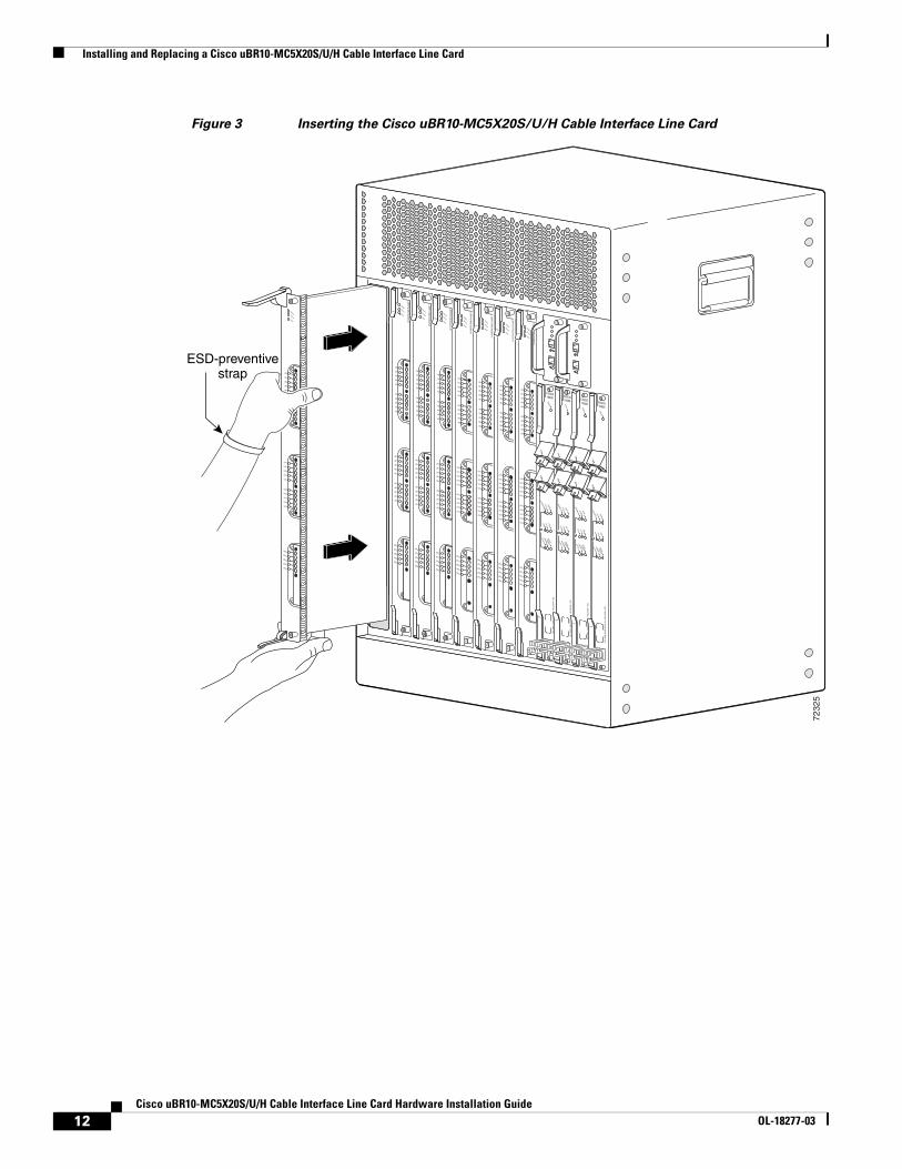
Caution This Cisco uBR10-MC5X20S/U/H line card weighs 16 lbs. Use both hands when handling the card. Do not drop the card or otherwise damage the carrier rails. Bent or damaged rails can damage the card guides and prevent line card installation.
When installing cards for the first time, or when all the card’s captive screws are loose, insert cards first in slot 5/1 and work towards slot 8/0 to prevent uneven gasket pressure.
Step 2 Slide the card into the slot. (See Figure 3.)
11Cisco uBR10-MC5X20S/U/H Cable Interface Line Card Hardware Installation Guide
OL-18277-03
Installing and Replacing a Cisco uBR10-MC5X20S/U/H Cable Interface Line Card
Figure 3 Inserting the Cisco uBR10-MC5X20S/U/H Cable Interface Line Card
7232
5
US0
US1
US2
US3
US4
US5
US6
US7
US8
US9
US10
US11
US12
US13
US14
US15
US16
US17
US18
US19
DS0
DS1
DS2
DS3
DS4
RF
RF
RF
RF
RF
POWER
STATUSM
AINT
US0
US1
US2
US3
US4
US5
US6
US7
US8
US9
US10
US11
US12
US13
US14
US15
US16
US17
US18
US19
DS0
DS1
DS2
DS3
DS4
RF
RF
RF
RF
RF
uB
R10-M
C5x2
0S
-D
POWER
STATUSM
AINT
US0
US1
US2
US3
US4
US5
US6
US7
US8
US9
US10
US11
US12
US13
US14
US15
US16
US17
US18
US19
DS0
DS1
DS2
DS3
DS4
RF
RF
RF
RF
RF
uB
R10-M
C5x2
0S
-D
POWER
STATUSM
AINT
US0
US1
US2
US3
US4
US5
US6
US7
US8
US9
US10
US11
US12
US13
US14
US15
US16
US17
US18
US19
DS0
DS1
DS2
DS3
DS4
RF
RF
RF
RF
RF
uB
R10-M
C5x2
0S
-D
POWER
STATUSM
AINT
US0
US1
US2
US3
US4
US5
US6
US7
US8
US9
US10
US11
US12
US13
US14
US15
US16
US17
US18
US19
DS0
DS1
DS2
DS3
DS4
RF
RF
RF
RF
RF
uB
R10-M
C5x2
0S
-D
POWER
STATUSM
AINT
US0
US1
US2
US3
US4
US5
US6
US7
US8
US9
US10
US11
US12
US13
US14
US15
US16
US17
US18
US19
DS0
DS1
DS2
DS3
DS4
RF
RF
RF
RF
RF
uB
R10-M
C5x2
0S
-D
POWER
STATUSM
AINT
US0
US1
US2
US3
US4
US5
US6
US7
US8
US9
US10
US11
US12
US13
US14
US15
US16
US17
US18
US19
DS0
DS1
DS2
DS3
DS4
RF
RF
RF
RF
RF
uB
R10-M
C5x2
0S
-D
POWER
STATUSM
AINT
US0
US1
US2
US3
US4
US5
US6
US7
US8
US9
US10
US11
US12
US13
US14
US15
US16
US17
US18
US19
DS0
DS1
DS2
DS3
DS4
RF
RF
RF
RF
RF
uB
R10-M
C5x2
0S
-D
POWER
STATUSM
AINT
CISCO10000
EN
AB
LE
PO
SS
RP
FA
IL
OC
–4
8/S
TM
–1
6 P
OS
/SR
P S
M–
LR
CD TX
RX
SY
NC
WR
AP
PA
SS
TH
RU
TXRX
CISCO10000
EN
AB
LE
PO
SS
RP
FA
IL
OC
–4
8/S
TM
–1
6 P
OS
/SR
P S
M–
LR
CD TX
RX
SY
NC
WR
AP
PA
SS
TH
RU
TXRX
CISCO10000
EN
AB
LE
PO
SS
RP
FA
IL
OC
–4
8/S
TM
–1
6 P
OS
/SR
P S
M–
LR
CD TX
RX
SY
NC
WR
AP
PA
SS
TH
RU
TXRX
CISCO10000
EN
AB
LE
PO
SS
RP
FA
IL
OC
–4
8/S
TM
–1
6 P
OS
/SR
P S
M–
LR
CD TX
RX
SY
NC
WR
AP
PA
SS
TH
RU
TXRX
ESD-preventivestrap
12Cisco uBR10-MC5X20S/U/H Cable Interface Line Card Hardware Installation Guide
OL-18277-03
Installing and Replacing a Cisco uBR10-MC5X20S/U/H Cable Interface Line Card
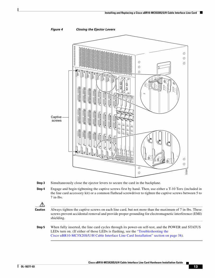
Figure 4 Closing the Ejector Levers
Step 3 Simultaneously close the ejector levers to secure the card in the backplane.
Step 4 Engage and begin tightening the captive screws first by hand. Then, use either a T-10 Torx (included in the line card accessory kit) or a common flathead screwdriver to tighten the captive screws between 5 to 7 in-lbs.
Caution Always tighten the captive screws on each line card, but not more than the maximum of 7 in-lbs. These screws prevent accidental removal and provide proper grounding for electromagnetic interference (EMI) shielding.
Step 5 When fully inserted, the line card cycles through its power-on self-test, and the POWER and STATUS LEDs turn on. (If either of those LEDs is flashing, see the “Troubleshooting the Cisco uBR10-MC5X20S/U/H Cable Interface Line Card Installation” section on page 38).
7232
6
US0
US1
US2
US3
US4
US5
US6
US7
US8
US9
US10
US11
US12
US13
US14
US15
US16
US17
US18
US19
DS0
DS1
DS2
DS3
DS4
RF
RF
RF
RF
RF
uB
R10-M
C5x2
0S
-D
POWER
STATUSM
AINT
US0
US1
US2
US3
US4
US5
US6
US7
US8
US9
US10
US11
US12
US13
US14
US15
US16
US17
US18
US19
DS0
DS1
DS2
DS3
DS4
RF
RF
RF
RF
RF
uB
R10-M
C5x2
0S
-D
POWER
STATUSM
AINT
US0
US1
US2
US3
US4
US5
US6
US7
US8
US9
US10
US11
US12
US13
US14
US15
US16
US17
US18
US19
DS0
DS1
DS2
DS3
DS4
RF
RF
RF
RF
RF
uB
R10-M
C5x2
0S
-D
POWER
STATUSM
AINT
US0
US1
US2
US3
US4
US5
US6
US7
US8
US9
US10
US11
US12
US13
US14
US15
US16
US17
US18
US19
DS0
DS1
DS2
DS3
DS4
RF
RF
RF
RF
RF
uB
R10-M
C5x2
0S
-D
POWER
STATUSM
AINT
CISCO10000
EN
AB
LE
PO
SS
RP
FA
IL
OC
–48/S
TM
–16 P
OS
/SR
P S
M–LR
CD TX
RX
SY
NC
WR
AP
PA
SS
TH
RU
TXRX
CISCO10000
EN
AB
LE
PO
SS
RP
FA
IL
OC
–48/S
TM
–16 P
OS
/SR
P S
M–LR
CD TX
RX
SY
NC
WR
AP
PA
SS
TH
RU
TXRX
CISCO10000
EN
AB
LE
PO
SS
RP
FA
IL
OC
–48/S
TM
–16 P
OS
/SR
P S
M–LR
CD TX
RX
SY
NC
WR
AP
PA
SS
TH
RU
TXRX
CISCO10000
EN
AB
LE
PO
SS
RP
FA
IL
OC
–48/S
TM
–16 P
OS
/SR
P S
M–LR
CD TX
RX
SY
NC
WR
AP
PA
SS
TH
RU
TXRX
US0
US1
US2
US3
US4
US5
US6
US7
US8
US9
US10
US11
US12
US13
US14
US15
US16
US17
US18
US19
DS0
DS1
DS2
DS3
DS4
RF
RF
RF
RF
RF
uB
R10-M
C5x2
0S
-D
POWER
STATUSM
AINT
US0
US1
US2
US3
US4
US5
US6
US7
US8
US9
US10
US11
US12
US13
US14
US15
US16
US17
US18
US19
DS0
DS1
DS2
DS3
DS4
RF
RF
RF
RF
RF
uB
R10-M
C5x2
0S
-D
POWER
STATUSM
AINT
US0
US1
US2
US3
US4
US5
US6
US7
US8
US9
US10
US11
US12
US13
US14
US15
US16
US17
US18
US19
DS0
DS1
DS2
DS3
DS4
RF
RF
RF
RF
RF
uB
R10-M
C5x2
0S
-D
POWER
STATUSM
AINT
US0
US1
US2
US3
US4
US5
US6
US7
US8
US9
US10
US11
US12
US13
US14
US15
US16
US17
US18
US19
DS0
DS1
DS2
DS3
DS4
RF
RF
RF
RF
RF
uB
R10-M
C5x2
0S
-D
POWER
STATUSM
AINT
uB
R10-M
C5x2
0S
-F
POWER
STATUSM
AINT
US0
uB
R10-M
C5x2
0S
-F
POWER
STATUSM
AINT
uB
R10-M
C5x2
0S
-F
POWER
STATUSM
AINT
uB
R10-M
C5x2
0S
-F
POWER
STATUSM
AINT
DS4 RF
Captivescrews
13Cisco uBR10-MC5X20S/U/H Cable Interface Line Card Hardware Installation Guide
OL-18277-03
Installing and Replacing a Cisco uBR10-MC5X20S/U/H Cable Interface Line Card
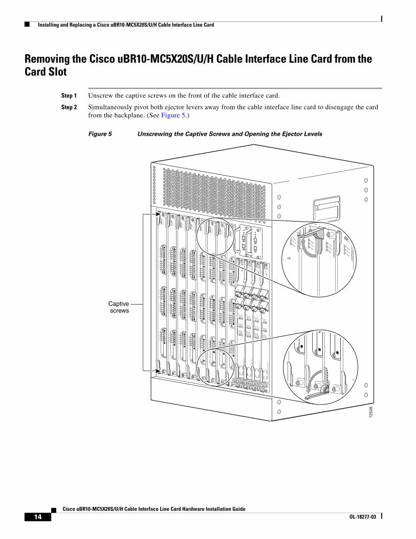
Removing the Cisco uBR10-MC5X20S/U/H Cable Interface Line Card from the Card Slot
Step 1 Unscrew the captive screws on the front of the cable interface card.
Step 2 Simultaneously pivot both ejector levers away from the cable interface line card to disengage the card from the backplane. (See Figure 5.)
Figure 5 Unscrewing the Captive Screws and Opening the Ejector Levels
7250
8
US0
US1
US2
US3
US4
US5
US6
US7
US8
US9
US10
US11
US12
US13
US14
US15
US16
US17
US18
US19
DS0
DS1
DS2
DS3
DS4
RF
RF
RF
RF
RF
uB
R10-M
C5x2
0S
-D
POWER
STATUSM
AINT
US0
US1
US2
US3
US4
US5
US6
US7
US8
US9
US10
US11
US12
US13
US14
US15
US16
US17
US18
US19
DS0
DS1
DS2
DS3
DS4
RF
RF
RF
RF
RF
uB
R10-M
C5x2
0S
-D
POWER
STATUSM
AINT
US0
US1
US2
US3
US4
US5
US6
US7
US8
US9
US10
US11
US12
US13
US14
US15
US16
US17
US18
US19
DS0
DS1
DS2
DS3
DS4
RF
RF
RF
RF
RF
uB
R10-M
C5x2
0S
-D
POWER
STATUSM
AINT
US0
US1
US2
US3
US4
US5
US6
US7
US8
US9
US10
US11
US12
US13
US14
US15
US16
US17
US18
US19
DS0
DS1
DS2
DS3
DS4
RF
RF
RF
RF
RF
uB
R10-M
C5x2
0S
-D
POWER
STATUSM
AINT
CISCO10000
EN
AB
LE
PO
SS
RP
FA
IL
OC
–48/S
TM
–16 P
OS
/SR
P S
M–LR
CD TX
RX
SY
NC
WR
AP
PA
SS
TH
RU
TXRX
CISCO10000
EN
AB
LE
PO
SS
RP
FA
IL
OC
–48/S
TM
–16 P
OS
/SR
P S
M–LR
CD TX
RX
SY
NC
WR
AP
PA
SS
TH
RU
TXRX
CISCO10000
EN
AB
LE
PO
SS
RP
FA
IL
OC
–48/S
TM
–16 P
OS
/SR
P S
M–LR
CD TX
RX
SY
NC
WR
AP
PA
SS
TH
RU
TXRX
CISCO10000
EN
AB
LE
PO
SS
RP
FA
IL
OC
–48/S
TM
–16 P
OS
/SR
P S
M–LR
CD TX
RX
SY
NC
WR
AP
PA
SS
TH
RU
TXRX
US0
US1
US2
US3
US4
US5
US6
US7
US8
US9
US10
US11
US12
US13
US14
US15
US16
US17
US18
US19
DS0
DS1
DS2
DS3
DS4
RF
RF
RF
RF
RF
uB
R10-M
C5x2
0S
-D
POWER
STATUSM
AINT
US0
US1
US2
US3
US4
US5
US6
US7
US8
US9
US10
US11
US12
US13
US14
US15
US16
US17
US18
US19
DS0
DS1
DS2
DS3
DS4
RF
RF
RF
RF
RF
uB
R10-M
C5x2
0S
-D
POWER
STATUSM
AINT
US0
US1
US2
US3
US4
US5
US6
US7
US8
US9
US10
US11
US12
US13
US14
US15
US16
US17
US18
US19
DS0
DS1
DS2
DS3
DS4
RF
RF
RF
RF
RF
uB
R10-M
C5x2
0S
-D
POWER
STATUSM
AINT
US0
US1
US2
US3
US4
US5
US6
US7
US8
US9
US10
US11
US12
US13
US14
US15
US16
US17
US18
US19
DS0
DS1
DS2
DS3
DS4
RF
RF
RF
RF
RF
uB
R10-M
C5x2
0S
-D
POWER
STATUSM
AINT
uB
R10-M
C5x2
0S
-F
POWER
STATUSM
AINT
US0
uB
R10-M
C5x2
0S
-F
POWER
STATUSM
AINT
uB
R10-M
C5x2
0S
-F
POWER
STATUSM
AINT
uB
R10-M
C5x2
0S
-F
POWER
STATUSM
AINT
DS4 RF
Captivescrews
14Cisco uBR10-MC5X20S/U/H Cable Interface Line Card Hardware Installation Guide
OL-18277-03
Installing and Replacing a Cisco uBR10-MC5X20S/U/H Cable Interface Line Card
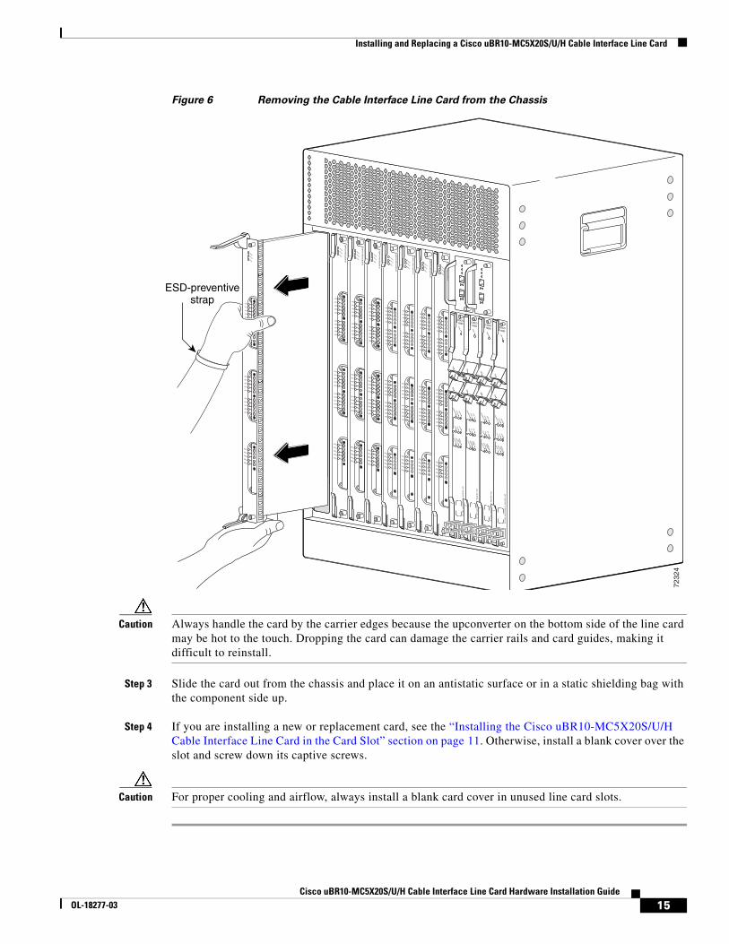
Figure 6 Removing the Cable Interface Line Card from the Chassis
Caution Always handle the card by the carrier edges because the upconverter on the bottom side of the line card may be hot to the touch. Dropping the card can damage the carrier rails and card guides, making it difficult to reinstall.
Step 3 Slide the card out from the chassis and place it on an antistatic surface or in a static shielding bag with the component side up.
Step 4 If you are installing a new or replacement card, see the “Installing the Cisco uBR10-MC5X20S/U/H Cable Interface Line Card in the Card Slot” section on page 11. Otherwise, install a blank cover over the slot and screw down its captive screws.
Caution For proper cooling and airflow, always install a blank card cover in unused line card slots.
7232
4
US0
US1
US2
US3
US4
US5
US6
US7
US8
US9
US10
US11
US12
US13
US14
US15
US16
US17
US18
US19
DS0
DS1
DS2
DS3
DS4
RF
RF
RF
RF
RF
POWER
STATUSM
AINT
US0
US1
US2
US3
US4
US5
US6
US7
US8
US9
US10
US11
US12
US13
US14
US15
US16
US17
US18
US19
DS0
DS1
DS2
DS3
DS4
RF
RF
RF
RF
RF
uB
R10-M
C5x2
0S
-D
POWER
STATUSM
AINT
US0
US1
US2
US3
US4
US5
US6
US7
US8
US9
US10
US11
US12
US13
US14
US15
US16
US17
US18
US19
DS0
DS1
DS2
DS3
DS4
RF
RF
RF
RF
RF
uB
R10-M
C5x2
0S
-D
POWER
STATUSM
AINT
US0
US1
US2
US3
US4
US5
US6
US7
US8
US9
US10
US11
US12
US13
US14
US15
US16
US17
US18
US19
DS0
DS1
DS2
DS3
DS4
RF
RF
RF
RF
RF
uB
R10-M
C5x2
0S
-D
POWER
STATUSM
AINT
US0
US1
US2
US3
US4
US5
US6
US7
US8
US9
US10
US11
US12
US13
US14
US15
US16
US17
US18
US19
DS0
DS1
DS2
DS3
DS4
RF
RF
RF
RF
RF
uB
R10-M
C5x2
0S
-D
POWER
STATUSM
AINT
US0
US1
US2
US3
US4
US5
US6
US7
US8
US9
US10
US11
US12
US13
US14
US15
US16
US17
US18
US19
DS0
DS1
DS2
DS3
DS4
RF
RF
RF
RF
RF
uB
R10-M
C5x2
0S
-D
POWER
STATUSM
AINT
US0
US1
US2
US3
US4
US5
US6
US7
US8
US9
US10
US11
US12
US13
US14
US15
US16
US17
US18
US19
DS0
DS1
DS2
DS3
DS4
RF
RF
RF
RF
RF
uB
R10-M
C5x2
0S
-D
POWER
STATUSM
AINT
US0
US1
US2
US3
US4
US5
US6
US7
US8
US9
US10
US11
US12
US13
US14
US15
US16
US17
US18
US19
DS0
DS1
DS2
DS3
DS4
RF
RF
RF
RF
RF
uB
R10-M
C5x2
0S
-D
POWER
STATUSM
AINT
CISCO10000
EN
AB
LE
PO
SS
RP
FA
IL
OC
–48/S
TM
–16 P
OS
/SR
P S
M–LR
CD TX
RX
SY
NC
WR
AP
PA
SS
TH
RU
TXRX
CISCO10000
EN
AB
LE
PO
SS
RP
FA
IL
OC
–48/S
TM
–16 P
OS
/SR
P S
M–LR
CD TX
RX
SY
NC
WR
AP
PA
SS
TH
RU
TXRX
CISCO10000
EN
AB
LE
PO
SS
RP
FA
IL
OC
–48/S
TM
–16 P
OS
/SR
P S
M–LR
CD TX
RX
SY
NC
WR
AP
PA
SS
TH
RU
TXRX
CISCO10000
EN
AB
LE
PO
SS
RP
FA
IL
OC
–48/S
TM
–16 P
OS
/SR
P S
M–LR
CD TX
RX
SY
NC
WR
AP
PA
SS
TH
RU
TXRX
ESD-preventivestrap
15Cisco uBR10-MC5X20S/U/H Cable Interface Line Card Hardware Installation Guide
OL-18277-03
Replacing the SODIMM on the Cisco uBR10-MC5x20H Line Card
Replacing the SODIMM on the Cisco uBR10-MC5x20H Line Card
Caution Small outline dual In-line memory modules (SODIMM) are ESD-sensitive components and can be damaged due to mishandling. Ensure that it is handled with care during installation and removal.
For information on replacing the SODIMM, see Replacement of SODIMM on the Cisco uBR10-MC5X20H Line Card.
Using the Universal Cable Holder on Cisco uBR10-MC5X20 Line Cards
The Cisco uBR10-MC5X20S/U/H cable interface line card must be used with the provided UCH for all cable connections to the line card. Failure to use the UCH may cause permanent damage to the line card connectors, resulting in low or no RF output in the downstream or low or no RF input in the upstream.
Perform the following procedures to install or replace, and remove UCH on the Cisco uBR10-MC5X20 line cards:
• Installing the UCH on the Cisco uBR10-MC5X20S/U/H Card, page 21
• Removing the UCH from the Cisco uBR10-MC5X20S/U/H Cable Interface Line Card, page 25
Both the UCH1 and UCH2 universal cable holders can be used with the Cisco UBR10-MC5X20S/U/H cable interface line cards. Both UCHs are designed to stabilize the cables and hold them in place.
Depending on your UCH, refer to the following sections:
• Installing or Replacing Cables in the UCH1, page 27
• Installing or Replacing Cables in the UCH2, page 33
Note For information about cabling to the Cisco RF switch, go to the following URL:http://www.cisco.com/en/US/docs/interfaces_modules/cable/broadband_processing_engines/ubr10_mc5x20s_u_h/quick/start/520QSC02.html
The dense connector configuration comes with the following equipment:
• Universal cable holder (UCH): UCH1 or UCH2
• T-10 TORX driver tool
• Cable extraction tool
• Cable bundle
Note Quad-shield coaxial cable bundles for the Cisco uBR10-MC5X20S/U/H cable interface line card can be purchased from Cisco, with the Universal Cable Holders already connected to the coaxial cable bundles. Alternatively, custom-length quad-shield coaxial cable bundles can be purchased from third-party vendors, with the Universal Cable Holders either connected to the cable bundles or provided as separate components.
16Cisco uBR10-MC5X20S/U/H Cable Interface Line Card Hardware Installation Guide
OL-18277-03

Using the Universal Cable Holder on Cisco uBR10-MC5X20 Line Cards
Figure 7 shows the UCH1. Figure 8 shows the UCH2. The UCH is used to group, hold, and protect the MCX cables when they are installed on the Cisco uBR10-MC5X20S/U/H cable interface line card. Always use the UCH when cabling the Cisco uBR10-MC5X20S/U/H card.
Figure 7 Universal Cable Holder (UCH): UCH1
Leadscrew
Shroud
Black line
Large pin
Screws intofaceplate
Cable clamp bar
Red line
TORX screw
TORX screw
Cutout
Cutout
Small pin
7241
1
17Cisco uBR10-MC5X20S/U/H Cable Interface Line Card Hardware Installation Guide
OL-18277-03
Using the Universal Cable Holder on Cisco uBR10-MC5X20 Line Cards
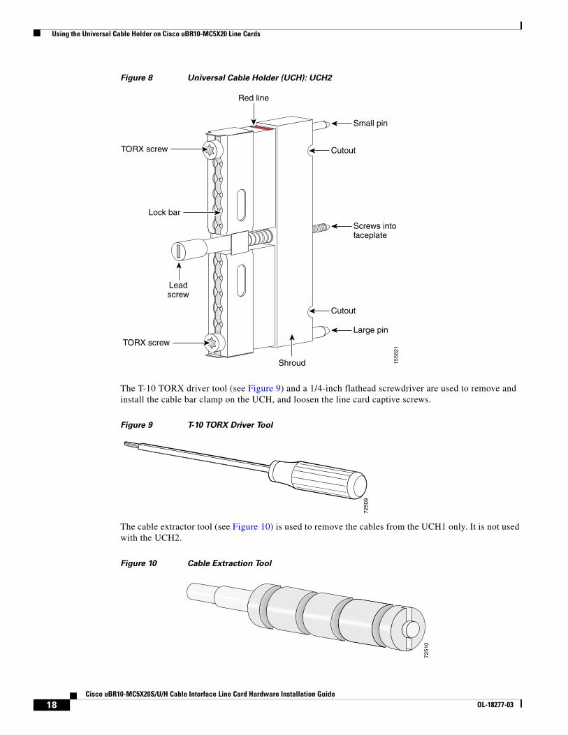
Figure 8 Universal Cable Holder (UCH): UCH2
The T-10 TORX driver tool (see Figure 9) and a 1/4-inch flathead screwdriver are used to remove and install the cable bar clamp on the UCH, and loosen the line card captive screws.
Figure 9 T-10 TORX Driver Tool
The cable extractor tool (see Figure 10) is used to remove the cables from the UCH1 only. It is not used with the UCH2.
Figure 10 Cable Extraction Tool
1558
21
Shroud
Red line
Large pin
Screws intofaceplate
TORX screw
TORX screw
Cutout
Cutout
Small pin
Leadscrew
Lock bar
7250
9
7251
0
18Cisco uBR10-MC5X20S/U/H Cable Interface Line Card Hardware Installation Guide
OL-18277-03
Using the Universal Cable Holder on Cisco uBR10-MC5X20 Line Cards
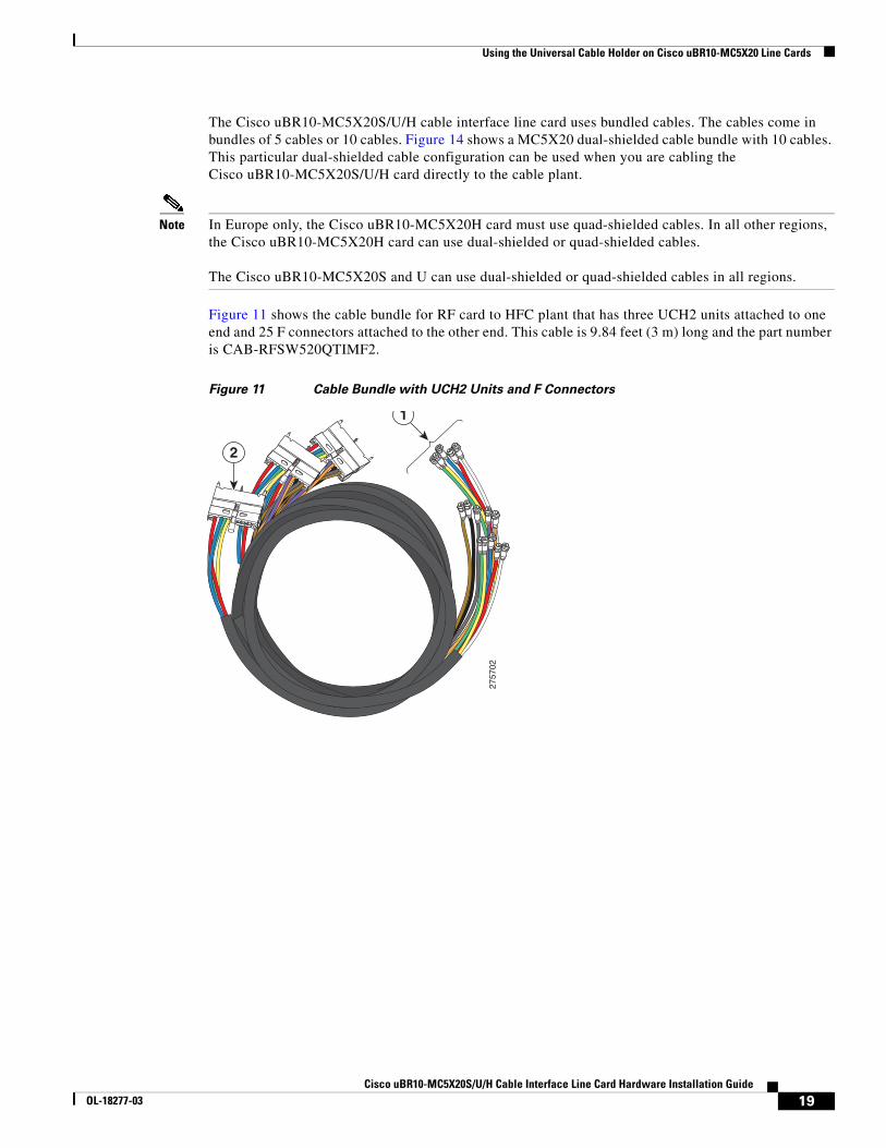
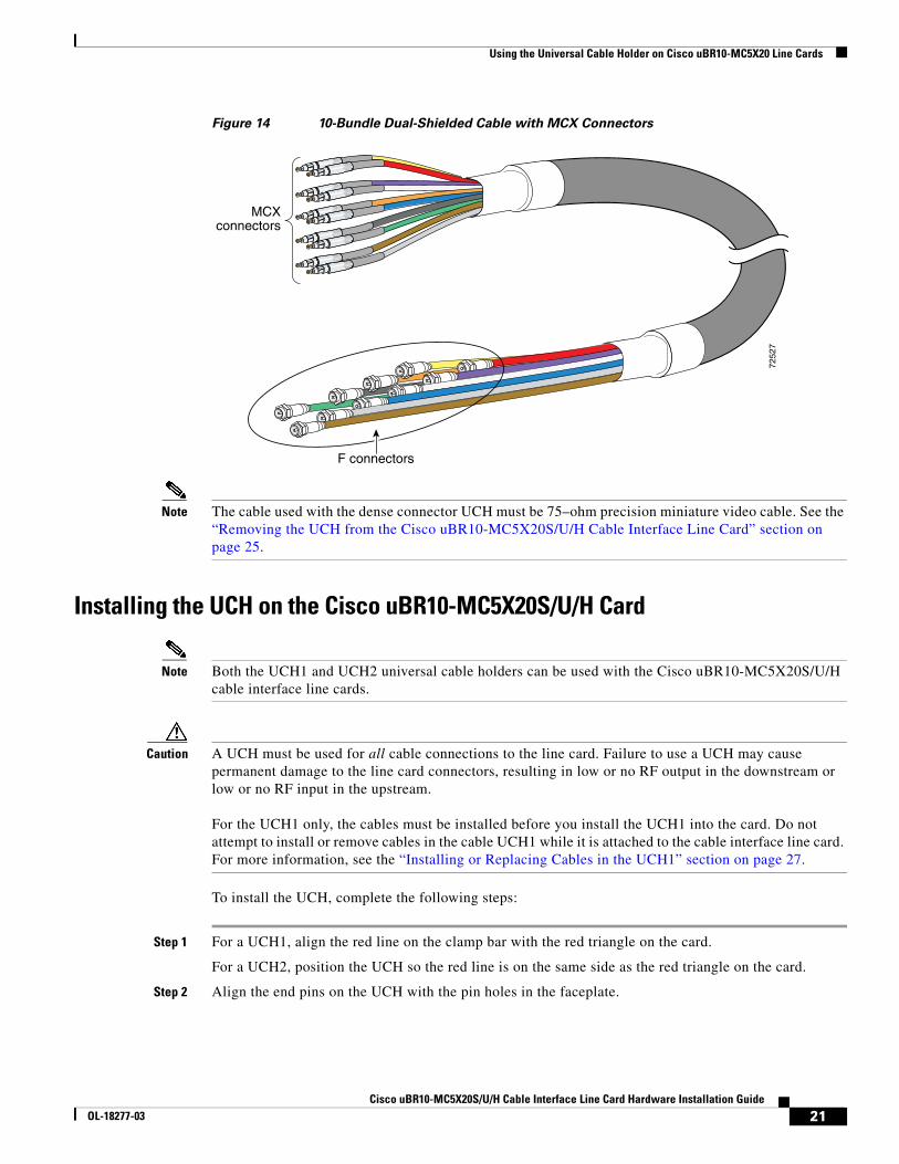
The Cisco uBR10-MC5X20S/U/H cable interface line card uses bundled cables. The cables come in bundles of 5 cables or 10 cables. Figure 14 shows a MC5X20 dual-shielded cable bundle with 10 cables. This particular dual-shielded cable configuration can be used when you are cabling the Cisco uBR10-MC5X20S/U/H card directly to the cable plant.
Note In Europe only, the Cisco uBR10-MC5X20H card must use quad-shielded cables. In all other regions, the Cisco uBR10-MC5X20H card can use dual-shielded or quad-shielded cables.
The Cisco uBR10-MC5X20S and U can use dual-shielded or quad-shielded cables in all regions.
Figure 11 shows the cable bundle for RF card to HFC plant that has three UCH2 units attached to one end and 25 F connectors attached to the other end. This cable is 9.84 feet (3 m) long and the part number is CAB-RFSW520QTIMF2.
Figure 11 Cable Bundle with UCH2 Units and F Connectors
2757
02
1
2
19Cisco uBR10-MC5X20S/U/H Cable Interface Line Card Hardware Installation Guide
OL-18277-03
Using the Universal Cable Holder on Cisco uBR10-MC5X20 Line Cards
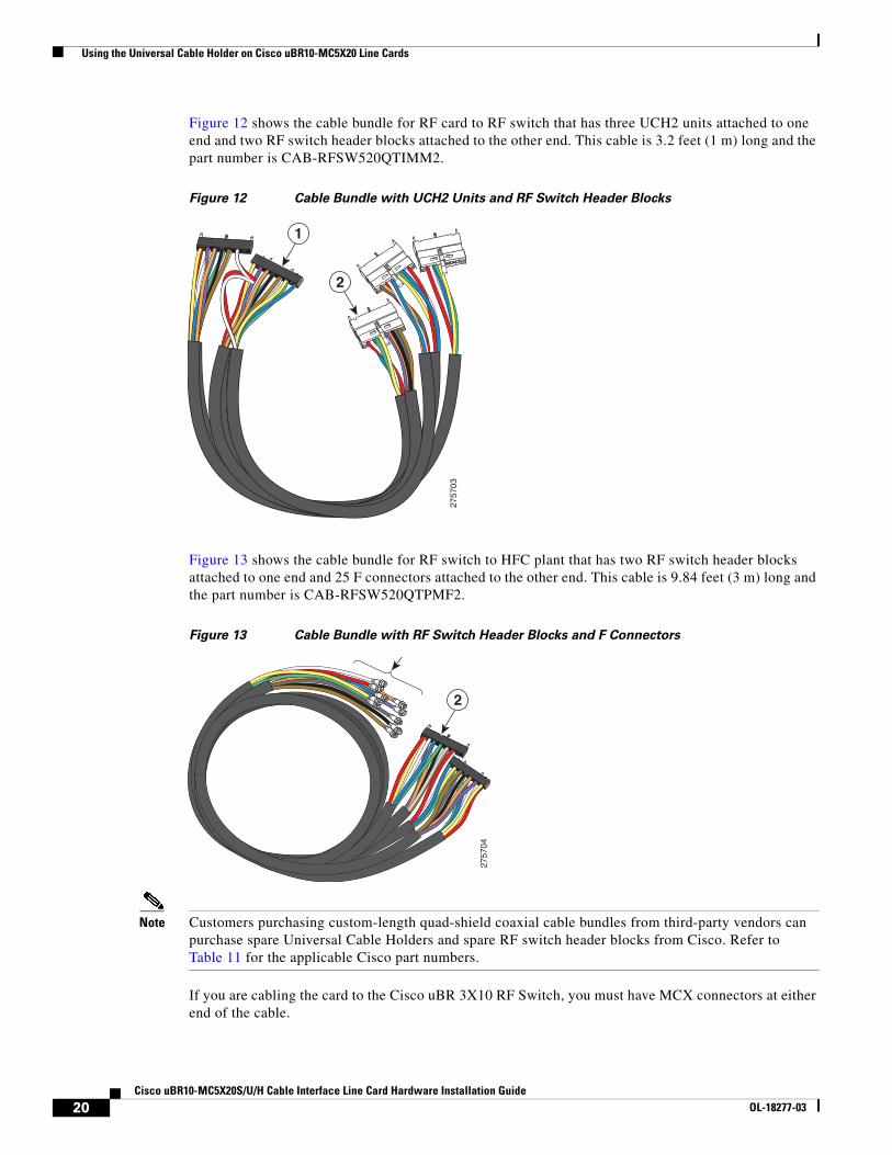
Figure 12 shows the cable bundle for RF card to RF switch that has three UCH2 units attached to one end and two RF switch header blocks attached to the other end. This cable is 3.2 feet (1 m) long and the part number is CAB-RFSW520QTIMM2.
Figure 12 Cable Bundle with UCH2 Units and RF Switch Header Blocks
Figure 13 shows the cable bundle for RF switch to HFC plant that has two RF switch header blocks attached to one end and 25 F connectors attached to the other end. This cable is 9.84 feet (3 m) long and the part number is CAB-RFSW520QTPMF2.
Figure 13 Cable Bundle with RF Switch Header Blocks and F Connectors
Note Customers purchasing custom-length quad-shield coaxial cable bundles from third-party vendors can purchase spare Universal Cable Holders and spare RF switch header blocks from Cisco. Refer to Table 11 for the applicable Cisco part numbers.
If you are cabling the card to the Cisco uBR 3X10 RF Switch, you must have MCX connectors at either end of the cable.
275703
1
2
275704
2
20Cisco uBR10-MC5X20S/U/H Cable Interface Line Card Hardware Installation Guide
OL-18277-03
Using the Universal Cable Holder on Cisco uBR10-MC5X20 Line Cards
Figure 14 10-Bundle Dual-Shielded Cable with MCX Connectors
Note The cable used with the dense connector UCH must be 75–ohm precision miniature video cable. See the “Removing the UCH from the Cisco uBR10-MC5X20S/U/H Cable Interface Line Card” section on page 25.
Installing the UCH on the Cisco uBR10-MC5X20S/U/H Card
Note Both the UCH1 and UCH2 universal cable holders can be used with the Cisco uBR10-MC5X20S/U/H cable interface line cards.
Caution A UCH must be used for all cable connections to the line card. Failure to use a UCH may cause permanent damage to the line card connectors, resulting in low or no RF output in the downstream or low or no RF input in the upstream.
For the UCH1 only, the cables must be installed before you install the UCH1 into the card. Do not attempt to install or remove cables in the cable UCH1 while it is attached to the cable interface line card. For more information, see the “Installing or Replacing Cables in the UCH1” section on page 27.
To install the UCH, complete the following steps:
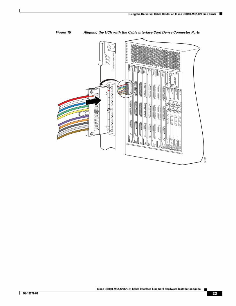
Step 1 For a UCH1, align the red line on the clamp bar with the red triangle on the card.
For a UCH2, position the UCH so the red line is on the same side as the red triangle on the card.
Step 2 Align the end pins on the UCH with the pin holes in the faceplate.
7252
7
MCXconnectors
F connectors
21Cisco uBR10-MC5X20S/U/H Cable Interface Line Card Hardware Installation Guide
OL-18277-03
Using the Universal Cable Holder on Cisco uBR10-MC5X20 Line Cards
Caution When you are replacing the UCH, be careful not to bend the cables in the holder at right angles.
Step 3 While holding the UCH and cables in place on the faceplate, use your fingers to tighten the leadscrew. If the UCH and cables do not appear to settle securely in place on the faceplate, wiggle the holder to resettle the connectors.
Step 4 Use the flathead screwdriver to tighten the leadscrew. Turn the leadscrew clockwise until it will no longer turn (10 in-lbs, maximum torque 15 in-lbs).
Caution Torquing the leadscrew to more than the maximum of 20 in-lbs can cause the leadscrew to fail.
Note For a UCH1, as you turn the leadscrew clockwise, the outer shroud on the UCH moves toward the black line scribed on the top of the UCH. The half circles on the edge of the shroud appear to close as the shroud fits down over the UCH. Full engagement is indicated by visible metal-to-metal contact between the UCH and the faceplate (check the half circle cutouts); the shroud is retracted back to the black line.
For a UCH2, as you turn the leadscrew clockwise, the outer shroud on the UCH moves to cover the red line on the top and the black line on the bottom of the UCH. The half circles on the edge of the shroud appear to close as the shroud fits down over the UCH. Full engagement is indicated by visible metal-to-metal contact between the UCH and the faceplate (check the half circle cutouts).
22Cisco uBR10-MC5X20S/U/H Cable Interface Line Card Hardware Installation Guide
OL-18277-03
Using the Universal Cable Holder on Cisco uBR10-MC5X20 Line Cards
Figure 15 Aligning the UCH with the Cable Interface Card Dense Connector Ports
7241
4
US0
US1
US2
US3
US4
US5
US6
US7
US8
US9
US10
US11
US12
US13
US14
US15
US16
US17
US18
US19
DS0
DS1
DS2
DS3
DS4
RF
RF
RF
RF
RF
uB
R10-M
C5x2
0S
-D
POWER
STATUSM
AINT
US0
US1
US2
US3
US4
US5
US6
US7
US8
US9
US10
US11
US12
US13
US14
US15
US16
US17
US18
US19
DS0
DS1
DS2
DS3
DS4
RF
RF
RF
RF
RF
uB
R10-M
C5x2
0S
-D
POWER
STATUSM
AINT
US0
US1
US2
US3
US4
US5
US6
US7
US8
US9
US10
US11
US12
US13
US14
US15
US16
US17
US18
US19
DS0
DS1
DS2
DS3
DS4
RF
RF
RF
RF
RF
uB
R10-M
C5x2
0S
-D
POWER
STATUSM
AINT
US0
US1
US2
US3
US4
US5
US6
US7
US8
US9
US10
US11
US12
US13
US14
US15
US16
US17
US18
US19
DS0
DS1
DS2
DS3
DS4
RF
RF
RF
RF
RF
uB
R10-M
C5x2
0S
-D
POWER
STATUSM
AINT
US0
US1
US2
US3
US4
US5
US6
US7
US8
US9
uB
R10-M
C5x2
0S
-D
POWER
STATUSM
AINT
US0
US1
US2
US3
US4
US5
US6
US7
US8
US9
US10
US11
US12
US13
US14
US15
US16
US17
US18
US19
DS0
DS1
DS2
DS3
DS4
RF
RF
RF
RF
RF
uB
R10-M
C5x2
0S
-D
POWER
STATUSM
AINT
US0
US1
US2
US3
US4
US5
US6
US7
US8
US9
US10
US11
US12
US13
US14
US15
US16
US17
US18
US19
DS0
DS1
DS2
DS3
DS4
RF
RF
RF
RF
RF
uB
R10-M
C5x2
0S
-D
POWER
STATUSM
AINT
US0
US1
US2
US3
US4
US5
US6
US7
US8
US9
US10
US11
US12
US13
US14
US15
US16
US17
US18
US19
DS0
DS1
DS2
DS3
DS4
RF
RF
RF
RF
RF
uB
R10-M
C5x2
0S
-D
POWER
STATUSM
AINT
US0
US1
US2
US3
US4
US5
US6
US7
US8
US9
US10
US11
US12
US13
US14
US15
US16
US17
US18
US19
DS0
DS1
DS2
DS3
DS4
RF
RF
RF
RF
RF
uB
R10-M
C5x2
0S
-D
POWER
STATUSM
AINT
CISCO10000
EN
AB
LE
PO
SS
RP
FA
IL
OC
–48/S
TM
–16 P
OS
/SR
P S
M–LR
CD TX
RX
SY
NC
WR
AP
PA
SS
TH
RU
TXRX
CISCO10000
EN
AB
LE
PO
SS
RP
FA
IL
OC
–48/S
TM
–16 P
OS
/SR
P S
M–LR
CD TX
RX
SY
NC
WR
AP
PA
SS
TH
RU
TXRX
CISCO10000
EN
AB
LE
PO
SS
RP
FA
IL
OC
–48/S
TM
–16 P
OS
/SR
P S
M–LR
CD TX
RX
SY
NC
WR
AP
PA
SS
TH
RU
TXRX
CISCO10000
EN
AB
LE
PO
SS
RP
FA
IL
OC
–48/S
TM
–16 P
OS
/SR
P S
M–LR
CD TX
RX
SY
NC
WR
AP
PA
SS
TH
RU
TXRX
23Cisco uBR10-MC5X20S/U/H Cable Interface Line Card Hardware Installation Guide
OL-18277-03
Using the Universal Cable Holder on Cisco uBR10-MC5X20 Line Cards
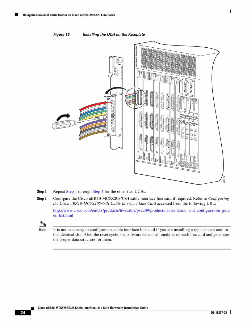
Figure 16 Installing the UCH on the Faceplate
Step 5 Repeat Step 1 through Step 4 for the other two UCHs.
Step 6 Configure the Cisco uBR10-MC5X20S/U/H cable interface line card if required. Refer to Configuring the Cisco uBR10-MC5X20S/U/H Cable Interface Line Card accessed from the following URL:
http://www.cisco.com/en/US/products/hw/cable/ps2209/products_installation_and_configuration_guides_list.html
Note It is not necessary to configure the cable interface line card if you are installing a replacement card in the identical slot. After the reset cycle, the software detects all modules on each line card and generates the proper data structure for them.
US0
US1
US2
US3
US4
US5
US6
US7
US8
US9uB
R10-M
C5x2
0S
-D
POWER
STATUSM
AINT
8292
4
US0
US1
US2
US3
US4
US5
US6
US7
US8
US9
US10
US11
US12
US13
US14
US15
US16
US17
US18
US19
DS0
DS1
DS2
DS3
DS4
RF
RF
RF
RF
RF
uB
R10-M
C5x2
0S
-D
POWER
STATUSM
AINT
US0
US1
US2
US3
US4
US5
US6
US7
US8
US9
US10
US11
US12
US13
US14
US15
US16
US17
US18
US19
DS0
DS1
DS2
DS3
DS4
RF
RF
RF
RF
RF
uB
R10-M
C5x2
0S
-D
POWER
STATUSM
AINT
US0
US1
US2
US3
US4
US5
US6
US7
US8
US9
US10
US11
US12
US13
US14
US15
US16
US17
US18
US19
DS0
DS1
DS2
DS3
DS4
RF
RF
RF
RF
RF
uB
R10-M
C5x2
0S
-D
POWER
STATUSM
AINT
US0
US1
US2
US3
US4
US5
US6
US7
US8
US9
US10
US11
US12
US13
US14
US15
US16
US17
US18
US19
DS0
DS1
DS2
DS3
DS4
RF
RF
RF
RF
RF
uB
R10-M
C5x2
0S
-D
POWER
STATUSM
AINT
US0
US1
US2
US3
US4
US5
US6
US7
US8
US9
US10
US11
US12
US13
US14
US15
US16
US17
US18
US19
DS0
DS1
DS2
DS3
DS4
RF
RF
RF
RF
RF
uB
R10-M
C5x2
0S
-D
POWER
STATUSM
AINT
US0
US1
US2
US3
US4
US5
US6
US7
US8
US9
US10
US11
US12
US13
US14
US15
US16
US17
US18
US19
DS0
DS1
DS2
DS3
DS4
RF
RF
RF
RF
RF
uB
R10-M
C5x2
0S
-D
POWER
STATUSM
AINT
US0
US1
US2
US3
US4
US5
US6
US7
US8
US9
US10
US11
US12
US13
US14
US15
US16
US17
US18
US19
DS0
DS1
DS2
DS3
DS4
RF
RF
RF
RF
RF
uB
R10-M
C5x2
0S
-D
POWER
STATUSM
AINT
US0
US1
US2
US3
US4
US5
US6
US7
US8
US9
US10
US11
US12
US13
US14
US15
US16
US17
US18
US19
DS0
DS1
DS2
DS3
DS4
RF
RF
RF
RF
RF
uB
R10-M
C5x2
0S
-D
POWER
STATUSM
AINT
CISCO10000
EN
AB
LE
PO
SS
RP
FA
IL
OC
–48/S
TM
–16 P
OS
/SR
P S
M–LR
CD TX
RX
SY
NC
WR
AP
PA
SS
TH
RU
TXRX
CISCO10000
EN
AB
LE
PO
SS
RP
FA
IL
OC
–48/S
TM
–16 P
OS
/SR
P S
M–LR
CD TX
RX
SY
NC
WR
AP
PA
SS
TH
RU
TXRX
CISCO10000
EN
AB
LE
PO
SS
RP
FA
IL
OC
–48/S
TM
–16 P
OS
/SR
P S
M–LR
CD TX
RX
SY
NC
WR
AP
PA
SS
TH
RU
TXRX
CISCO10000
EN
AB
LE
PO
SS
RP
FA
IL
OC
–48/S
TM
–16 P
OS
/SR
P S
M–LR
CD TX
RX
SY
NC
WR
AP
PA
SS
TH
RU
TXRX
24Cisco uBR10-MC5X20S/U/H Cable Interface Line Card Hardware Installation Guide
OL-18277-03
Using the Universal Cable Holder on Cisco uBR10-MC5X20 Line Cards
Removing the UCH from the Cisco uBR10-MC5X20S/U/H Cable Interface Line Card
Note The UCH1 or UCH2 universal cable holders may be used with the Cisco uBR10-MC5X20S/U/H cable interface line cards. For more information, see the “Installing or Replacing Cables in the UCH1” section on page 27.
Figure 17 and Figure 18 show the UCH1 being removed from the cable line card. The removal process is the same for the UCH2.
Caution Make sure you are properly grounded with an ESD-preventative ground strap.
Step 1 Carefully move the cables away from the front of the card so that you can easily reach the leadscrew on the UCH.
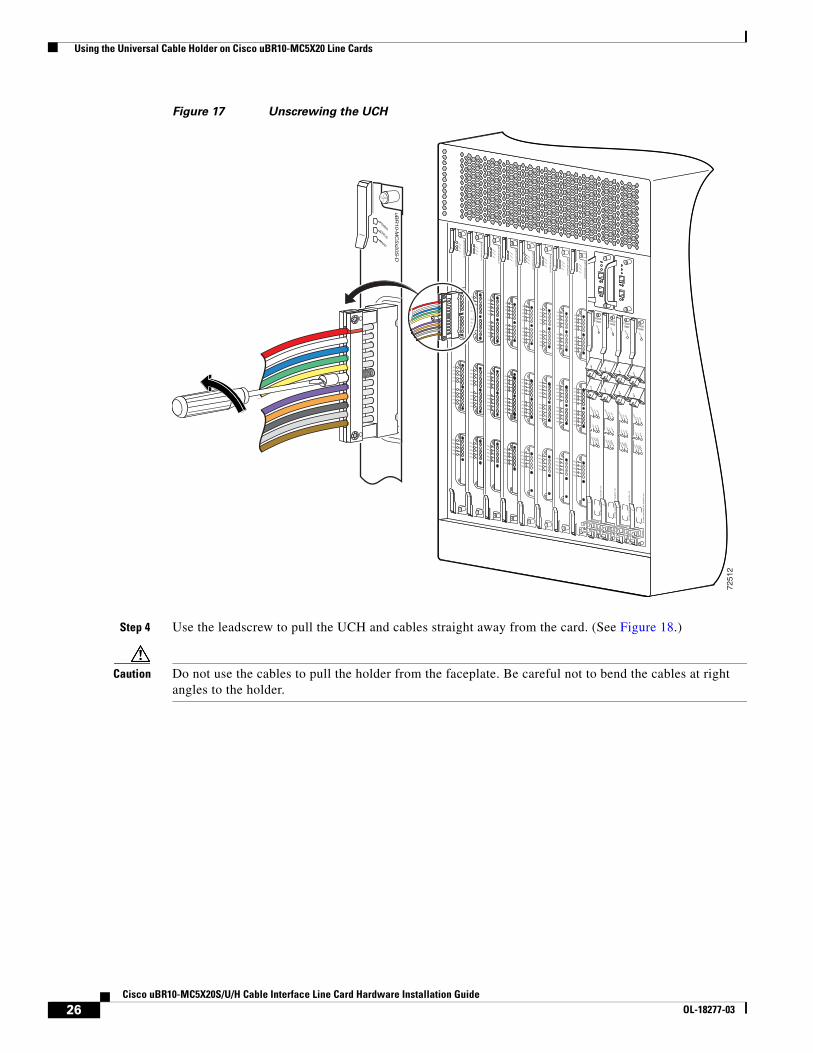
Step 2 Use the flathead screwdriver to loosen the leadscrew on the UCH. Turn the leadscrew counterclockwise. (See Figure 17.)
Step 3 Unscrew the leadscrew until it is completely out of the faceplate on the line card.
25Cisco uBR10-MC5X20S/U/H Cable Interface Line Card Hardware Installation Guide
OL-18277-03
Using the Universal Cable Holder on Cisco uBR10-MC5X20 Line Cards
Figure 17 Unscrewing the UCH
Step 4 Use the leadscrew to pull the UCH and cables straight away from the card. (See Figure 18.)
Caution Do not use the cables to pull the holder from the faceplate. Be careful not to bend the cables at right angles to the holder.
US0
US1
US2
US3
US4
US5
US6
US7
US8
US9uB
R10-M
C5x2
0S
-D
POWER
STATUSM
AINT
7251
2
US0
US1
US2
US3
US4
US5
US6
US7
US8
US9
US10
US11
US12
US13
US14
US15
US16
US17
US18
US19
DS0
DS1
DS2
DS3
DS4
RF
RF
RF
RF
RF
uB
R10-M
C5x2
0S
-D
POWER
STATUSM
AINT
US0
US1
US2
US3
US4
US5
US6
US7
US8
US9
US10
US11
US12
US13
US14
US15
US16
US17
US18
US19
DS0
DS1
DS2
DS3
DS4
RF
RF
RF
RF
RF
uB
R10-M
C5x2
0S
-D
POWER
STATUSM
AINT
US0
US1
US2
US3
US4
US5
US6
US7
US8
US9
US10
US11
US12
US13
US14
US15
US16
US17
US18
US19
DS0
DS1
DS2
DS3
DS4
RF
RF
RF
RF
RF
uB
R10-M
C5x2
0S
-D
POWER
STATUSM
AINT
US0
US1
US2
US3
US4
US5
US6
US7
US8
US9
US10
US11
US12
US13
US14
US15
US16
US17
US18
US19
DS0
DS1
DS2
DS3
DS4
RF
RF
RF
RF
RF
uB
R10-M
C5x2
0S
-D
POWER
STATUSM
AINT
US0
US1
US2
US3
US4
US5
US6
US7
US8
US9
US10
US11
US12
US13
US14
US15
US16
US17
US18
US19
DS0
DS1
DS2
DS3
DS4
RF
RF
RF
RF
RF
uB
R10-M
C5x2
0S
-D
POWER
STATUSM
AINT
US0
US1
US2
US3
US4
US5
US6
US7
US8
US9
US10
US11
US12
US13
US14
US15
US16
US17
US18
US19
DS0
DS1
DS2
DS3
DS4
RF
RF
RF
RF
RF
uB
R10-M
C5x2
0S
-D
POWER
STATUSM
AINT
US0
US1
US2
US3
US4
US5
US6
US7
US8
US9
US10
US11
US12
US13
US14
US15
US16
US17
US18
US19
DS0
DS1
DS2
DS3
DS4
RF
RF
RF
RF
RF
uB
R10-M
C5x2
0S
-D
POWER
STATUSM
AINT
US0
US1
US2
US3
US4
US5
US6
US7
US8
US9
US10
US11
US12
US13
US14
US15
US16
US17
US18
US19
DS0
DS1
DS2
DS3
DS4
RF
RF
RF
RF
RF
uB
R10-M
C5x2
0S
-D
POWER
STATUSM
AINT
CISCO10000
EN
AB
LE
PO
SS
RP
FA
IL
OC
–4
8/S
TM
–1
6 P
OS
/SR
P S
M–
LR
CD TX
RX
SY
NC
WR
AP
PA
SS
TH
RU
TXRX
CISCO10000
EN
AB
LE
PO
SS
RP
FA
IL
OC
–4
8/S
TM
–1
6 P
OS
/SR
P S
M–
LR
CD TX
RX
SY
NC
WR
AP
PA
SS
TH
RU
TXRX
CISCO10000
EN
AB
LE
PO
SS
RP
FA
IL
OC
–4
8/S
TM
–1
6 P
OS
/SR
P S
M–
LR
CD TX
RX
SY
NC
WR
AP
PA
SS
TH
RU
TXRX
CISCO10000
EN
AB
LE
PO
SS
RP
FA
IL
OC
–4
8/S
TM
–1
6 P
OS
/SR
P S
M–
LR
CD TX
RX
SY
NC
WR
AP
PA
SS
TH
RU
TXRX
26Cisco uBR10-MC5X20S/U/H Cable Interface Line Card Hardware Installation Guide
OL-18277-03
Using the Universal Cable Holder on Cisco uBR10-MC5X20 Line Cards
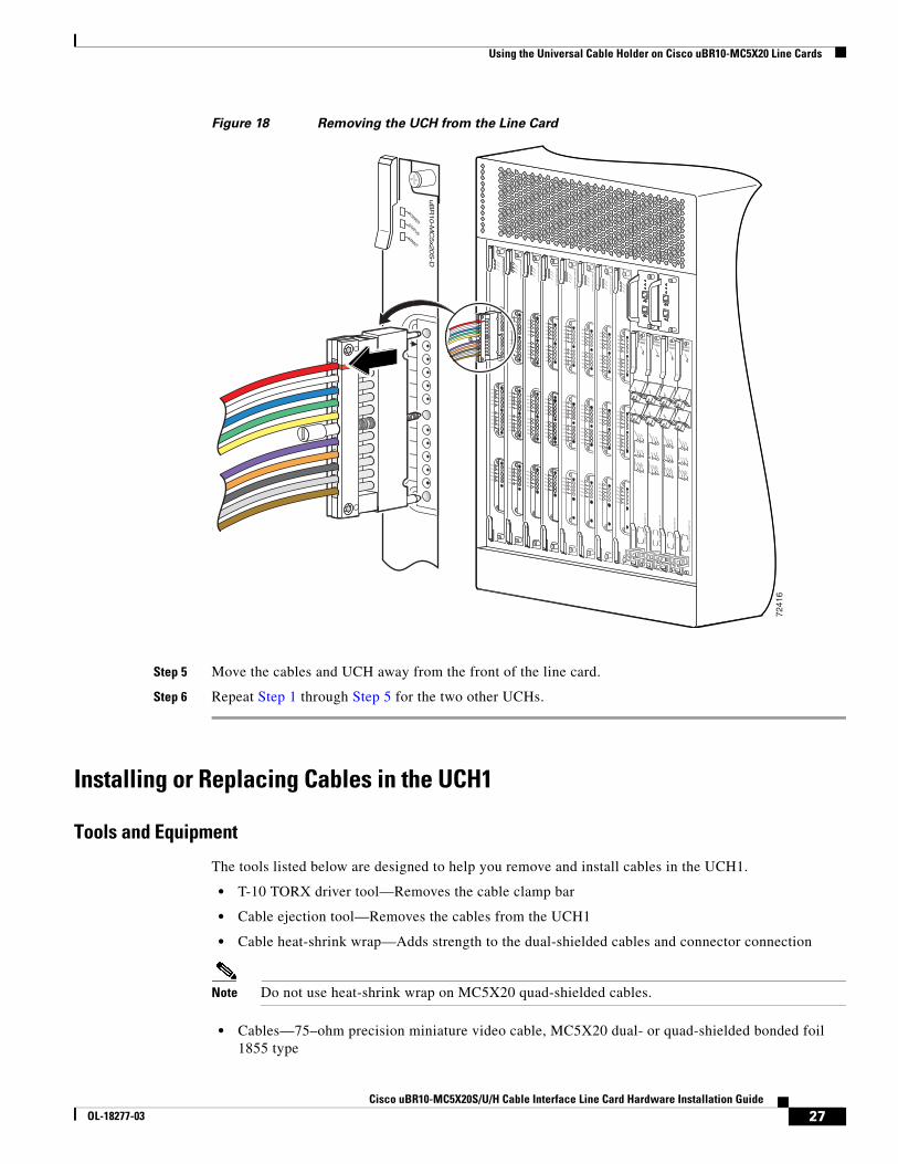
Figure 18 Removing the UCH from the Line Card
Step 5 Move the cables and UCH away from the front of the line card.
Step 6 Repeat Step 1 through Step 5 for the two other UCHs.
Installing or Replacing Cables in the UCH1
Tools and Equipment
The tools listed below are designed to help you remove and install cables in the UCH1.
• T-10 TORX driver tool—Removes the cable clamp bar
• Cable ejection tool—Removes the cables from the UCH1
• Cable heat-shrink wrap—Adds strength to the dual-shielded cables and connector connection
Note Do not use heat-shrink wrap on MC5X20 quad-shielded cables.
• Cables—75–ohm precision miniature video cable, MC5X20 dual- or quad-shielded bonded foil 1855 type
7241
6
US0
US1
US2
US3
US4
US5
US6
US7
US8
US9
US10
US11
US12
US13
US14
US15
US16
US17
US18
US19
DS0
DS1
DS2
DS3
DS4
RF
RF
RF
RF
RF
uB
R10-M
C5x2
0S
-D
POWER
STATUSM
AINT
US0
US1
US2
US3
US4
US5
US6
US7
US8
US9
US10
US11
US12
US13
US14
US15
US16
US17
US18
US19
DS0
DS1
DS2
DS3
DS4
RF
RF
RF
RF
RF
uB
R10-M
C5x2
0S
-D
POWER
STATUSM
AINT
US0
US1
US2
US3
US4
US5
US6
US7
US8
US9
US10
US11
US12
US13
US14
US15
US16
US17
US18
US19
DS0
DS1
DS2
DS3
DS4
RF
RF
RF
RF
RF
uB
R10-M
C5x2
0S
-D
POWER
STATUSM
AINT
US0
US1
US2
US3
US4
US5
US6
US7
US8
US9
US10
US11
US12
US13
US14
US15
US16
US17
US18
US19
DS0
DS1
DS2
DS3
DS4
RF
RF
RF
RF
RF
uB
R10-M
C5x2
0S
-D
POWER
STATUSM
AINT
US0
US1
US2
US3
US4
US5
US6
US7
US8
US9
uB
R10-M
C5x2
0S
-D
POWER
STATUSM
AINT
US0
US1
US2
US3
US4
US5
US6
US7
US8
US9
US10
US11
US12
US13
US14
US15
US16
US17
US18
US19
DS0
DS1
DS2
DS3
DS4
RF
RF
RF
RF
RF
uB
R10-M
C5x2
0S
-D
POWER
STATUSM
AINT
US0
US1
US2
US3
US4
US5
US6
US7
US8
US9
US10
US11
US12
US13
US14
US15
US16
US17
US18
US19
DS0
DS1
DS2
DS3
DS4
RF
RF
RF
RF
RF
uB
R10-M
C5x2
0S
-D
POWER
STATUSM
AINT
US0
US1
US2
US3
US4
US5
US6
US7
US8
US9
US10
US11
US12
US13
US14
US15
US16
US17
US18
US19
DS0
DS1
DS2
DS3
DS4
RF
RF
RF
RF
RF
uB
R10-M
C5x2
0S
-D
POWER
STATUSM
AINT
US0
US1
US2
US3
US4
US5
US6
US7
US8
US9
US10
US11
US12
US13
US14
US15
US16
US17
US18
US19
DS0
DS1
DS2
DS3
DS4
RF
RF
RF
RF
RF
uB
R10-M
C5x2
0S
-D
POWER
STATUSM
AINT
CISCO10000
EN
AB
LE
PO
SS
RP
FA
IL
OC
–48/S
TM
–16 P
OS
/SR
P S
M–LR
CD TX
RX
SY
NC
WR
AP
PA
SS
TH
RU
TXRX
CISCO10000
EN
AB
LE
PO
SS
RP
FA
IL
OC
–48/S
TM
–16 P
OS
/SR
P S
M–LR
CD TX
RX
SY
NC
WR
AP
PA
SS
TH
RU
TXRX
CISCO10000
EN
AB
LE
PO
SS
RP
FA
IL
OC
–48/S
TM
–16 P
OS
/SR
P S
M–LR
CD TX
RX
SY
NC
WR
AP
PA
SS
TH
RU
TXRX
CISCO10000
EN
AB
LE
PO
SS
RP
FA
IL
OC
–48/S
TM
–16 P
OS
/SR
P S
M–LR
CD TX
RX
SY
NC
WR
AP
PA
SS
TH
RU
TXRX
27Cisco uBR10-MC5X20S/U/H Cable Interface Line Card Hardware Installation Guide
OL-18277-03
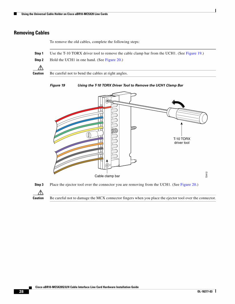
Using the Universal Cable Holder on Cisco uBR10-MC5X20 Line Cards
Removing Cables
To remove the old cables, complete the following steps:
Step 1 Use the T-10 TORX driver tool to remove the cable clamp bar from the UCH1. (See Figure 19.)
Step 2 Hold the UCH1 in one hand. (See Figure 20.)
Caution Be careful not to bend the cables at right angles.
Figure 19 Using the T-10 TORX Driver Tool to Remove the UCH1 Clamp Bar
Step 3 Place the ejector tool over the connector you are removing from the UCH1. (See Figure 20.)
Caution Be careful not to damage the MCX connector fingers when you place the ejector tool over the connector.
T-10 TORXdriver tool
7241
2
Cable clamp bar
28Cisco uBR10-MC5X20S/U/H Cable Interface Line Card Hardware Installation Guide
OL-18277-03
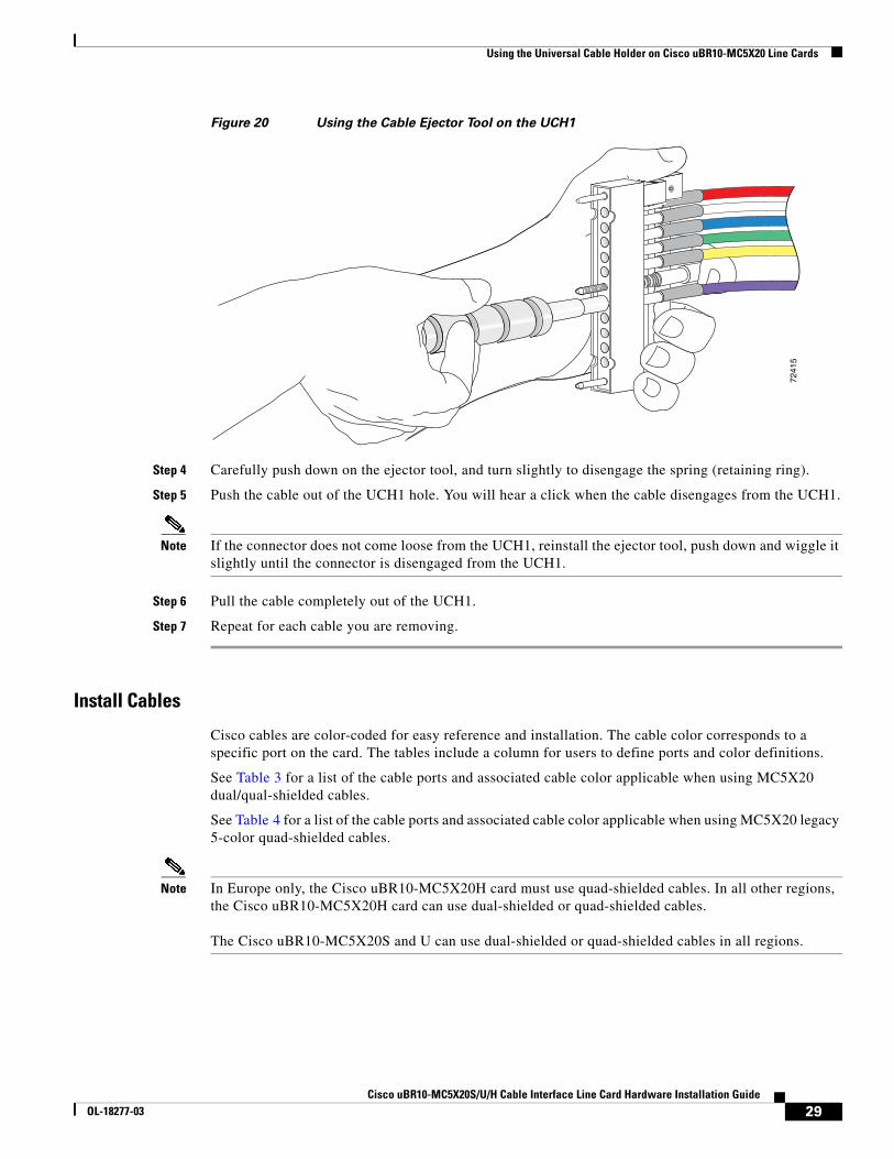
Using the Universal Cable Holder on Cisco uBR10-MC5X20 Line Cards
Figure 20 Using the Cable Ejector Tool on the UCH1
Step 4 Carefully push down on the ejector tool, and turn slightly to disengage the spring (retaining ring).
Step 5 Push the cable out of the UCH1 hole. You will hear a click when the cable disengages from the UCH1.
Note If the connector does not come loose from the UCH1, reinstall the ejector tool, push down and wiggle it slightly until the connector is disengaged from the UCH1.
Step 6 Pull the cable completely out of the UCH1.
Step 7 Repeat for each cable you are removing.
Install Cables
Cisco cables are color-coded for easy reference and installation. The cable color corresponds to a specific port on the card. The tables include a column for users to define ports and color definitions.
See Table 3 for a list of the cable ports and associated cable color applicable when using MC5X20 dual/qual-shielded cables.
See Table 4 for a list of the cable ports and associated cable color applicable when using MC5X20 legacy 5-color quad-shielded cables.
Note In Europe only, the Cisco uBR10-MC5X20H card must use quad-shielded cables. In all other regions, the Cisco uBR10-MC5X20H card can use dual-shielded or quad-shielded cables.
The Cisco uBR10-MC5X20S and U can use dual-shielded or quad-shielded cables in all regions.
7241
5
29Cisco uBR10-MC5X20S/U/H Cable Interface Line Card Hardware Installation Guide
OL-18277-03
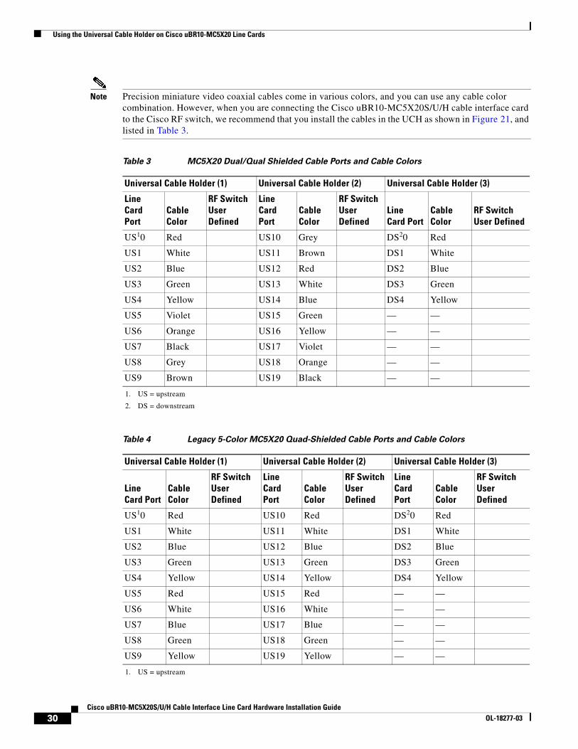
Using the Universal Cable Holder on Cisco uBR10-MC5X20 Line Cards
Note Precision miniature video coaxial cables come in various colors, and you can use any cable color combination. However, when you are connecting the Cisco uBR10-MC5X20S/U/H cable interface card to the Cisco RF switch, we recommend that you install the cables in the UCH as shown in Figure 21, and listed in Table 3.
Table 3 MC5X20 Dual/Qual Shielded Cable Ports and Cable Colors
Universal Cable Holder (1) Universal Cable Holder (2) Universal Cable Holder (3)
Line Card Port
Cable Color
RF Switch User Defined
Line Card Port
Cable Color
RF Switch User Defined
Line Card Port
Cable Color
RF Switch User Defined
US10
1. US = upstream
Red US10 Grey DS20
2. DS = downstream
Red
US1 White US11 Brown DS1 White
US2 Blue US12 Red DS2 Blue
US3 Green US13 White DS3 Green
US4 Yellow US14 Blue DS4 Yellow
US5 Violet US15 Green — —
US6 Orange US16 Yellow — —
US7 Black US17 Violet — —
US8 Grey US18 Orange — —
US9 Brown US19 Black — —
Table 4 Legacy 5-Color MC5X20 Quad-Shielded Cable Ports and Cable Colors
Universal Cable Holder (1) Universal Cable Holder (2) Universal Cable Holder (3)
Line Card Port
Cable Color
RF Switch User Defined
Line Card Port
Cable Color
RF Switch User Defined
Line Card Port
Cable Color
RF Switch User Defined
US10
1. US = upstream
Red US10 Red DS20 Red
US1 White US11 White DS1 White
US2 Blue US12 Blue DS2 Blue
US3 Green US13 Green DS3 Green
US4 Yellow US14 Yellow DS4 Yellow
US5 Red US15 Red — —
US6 White US16 White — —
US7 Blue US17 Blue — —
US8 Green US18 Green — —
US9 Yellow US19 Yellow — —
30Cisco uBR10-MC5X20S/U/H Cable Interface Line Card Hardware Installation Guide
OL-18277-03
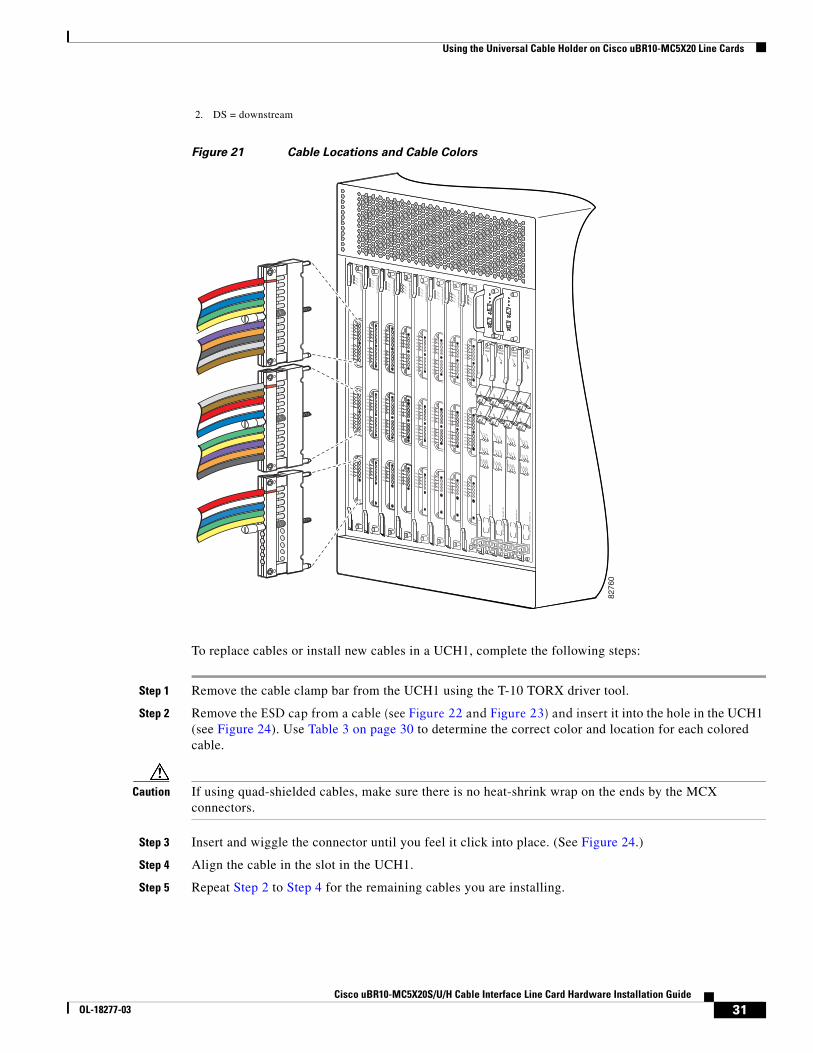
Using the Universal Cable Holder on Cisco uBR10-MC5X20 Line Cards
Figure 21 Cable Locations and Cable Colors
To replace cables or install new cables in a UCH1, complete the following steps:
Step 1 Remove the cable clamp bar from the UCH1 using the T-10 TORX driver tool.
Step 2 Remove the ESD cap from a cable (see Figure 22 and Figure 23) and insert it into the hole in the UCH1 (see Figure 24). Use Table 3 on page 30 to determine the correct color and location for each colored cable.
Caution If using quad-shielded cables, make sure there is no heat-shrink wrap on the ends by the MCX connectors.
Step 3 Insert and wiggle the connector until you feel it click into place. (See Figure 24.)
Step 4 Align the cable in the slot in the UCH1.
Step 5 Repeat Step 2 to Step 4 for the remaining cables you are installing.
2. DS = downstream
8276
0
US0
US1
US2
US3
US4
US5
US6
US7
US8
US9
US10
US11
US12
US13
US14
US15
US16
US17
US18
US19
DS0
DS1
DS2
DS3
DS4
RF
RF
RF
RF
RF
uB
R10-M
C5x2
0S
-D
POWER
STATUSM
AINT
US0
US1
US2
US3
US4
US5
US6
US7
US8
US9
US10
US11
US12
US13
US14
US15
US16
US17
US18
US19
DS0
DS1
DS2
DS3
DS4
RF
RF
RF
RF
RF
uB
R10-M
C5x2
0S
-D
POWER
STATUSM
AINT
US0
US1
US2
US3
US4
US5
US6
US7
US8
US9
US10
US11
US12
US13
US14
US15
US16
US17
US18
US19
DS0
DS1
DS2
DS3
DS4
RF
RF
RF
RF
RF
uB
R10-M
C5x2
0S
-D
POWER
STATUSM
AINT
US0
US1
US2
US3
US4
US5
US6
US7
US8
US9
US10
US11
US12
US13
US14
US15
US16
US17
US18
US19
DS0
DS1
DS2
DS3
DS4
RF
RF
RF
RF
RF
uB
R10-M
C5x2
0S
-D
POWER
STATUSM
AINT
US0
US1
US2
US3
US4
US5
US6
US7
US8
US9
US10
US11
US12
US13
US14
US15
US16
US17
US18
US19
DS0
DS1
DS2
DS3
DS4
RF
RF
RF
RF
RF
uB
R10-M
C5x2
0S
-D
POWER
STATUSM
AINT
US0
US1
US2
US3
US4
US5
US6
US7
US8
US9
US10
US11
US12
US13
US14
US15
US16
US17
US18
US19
DS0
DS1
DS2
DS3
DS4
RF
RF
RF
RF
RF
uB
R10-M
C5x2
0S
-D
POWER
STATUSM
AINT
US0
US1
US2
US3
US4
US5
US6
US7
US8
US9
US10
US11
US12
US13
US14
US15
US16
US17
US18
US19
DS0
DS1
DS2
DS3
DS4
RF
RF
RF
RF
RF
uB
R10-M
C5x2
0S
-D
POWER
STATUSM
AINT
US0
US1
US2
US3
US4
US5
US6
US7
US8
US9
US10
US11
US12
US13
US14
US15
US16
US17
US18
US19
DS0
DS1
DS2
DS3
DS4
RF
RF
RF
RF
RF
uB
R10-M
C5x2
0S
-D
POWER
STATUSM
AINT
CISCO10000
EN
AB
LE
PO
SS
RP
FA
IL
OC
–48/S
TM
–16 P
OS
/SR
P S
M–LR
CD TX
RX
SY
NC
WR
AP
PA
SS
TH
RU
TXRX
CISCO10000
EN
AB
LE
PO
SS
RP
FA
IL
OC
–48/S
TM
–16 P
OS
/SR
P S
M–LR
CD TX
RX
SY
NC
WR
AP
PA
SS
TH
RU
TXRX
CISCO10000
EN
AB
LE
PO
SS
RP
FA
IL
OC
–48/S
TM
–16 P
OS
/SR
P S
M–LR
CD TX
RX
SY
NC
WR
AP
PA
SS
TH
RU
TXRX
CISCO10000
EN
AB
LE
PO
SS
RP
FA
IL
OC
–48/S
TM
–16 P
OS
/SR
P S
M–LR
CD TX
RX
SY
NC
WR
AP
PA
SS
TH
RU
TXRX
31Cisco uBR10-MC5X20S/U/H Cable Interface Line Card Hardware Installation Guide
OL-18277-03
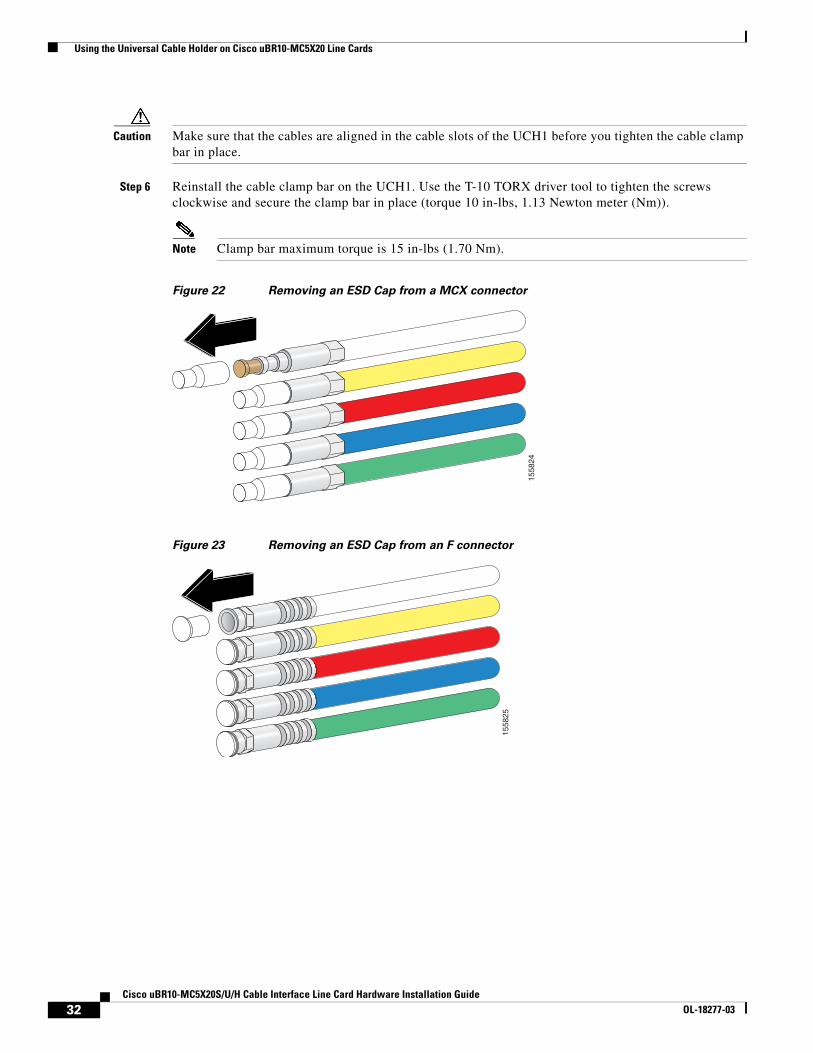
Using the Universal Cable Holder on Cisco uBR10-MC5X20 Line Cards
Caution Make sure that the cables are aligned in the cable slots of the UCH1 before you tighten the cable clamp bar in place.
Step 6 Reinstall the cable clamp bar on the UCH1. Use the T-10 TORX driver tool to tighten the screws clockwise and secure the clamp bar in place (torque 10 in-lbs, 1.13 Newton meter (Nm)).
Note Clamp bar maximum torque is 15 in-lbs (1.70 Nm).
Figure 22 Removing an ESD Cap from a MCX connector
Figure 23 Removing an ESD Cap from an F connector
1558
24
1558
25
32Cisco uBR10-MC5X20S/U/H Cable Interface Line Card Hardware Installation Guide
OL-18277-03

Using the Universal Cable Holder on Cisco uBR10-MC5X20 Line Cards
Figure 24 Placing Cables in the UCH1
Installing or Replacing Cables in the UCH2
Tools and Equipment
The tools listed below are designed to help you remove and install cables in the UCH2.
• T-10 TORX driver tool—Removes the cable clamp bar
• Cable heat-shrink wrap—Adds strength to the dual-shielded cables and connector connection
Note Do not use heat-shrink wrap on MC5X20 quad-shielded cables.
• Cables—75–ohm precision miniature video cable, MC5X20 dual- or quad-shielded bonded foil 1855 type
Removing Cables
To remove the old cables, complete the following steps:
Step 1 Use the T-10 TORX driver tool to loosen the UCH2 lock bar on the side from which you want to remove a cable. (See Figure 25.)
Step 2 Slide open the lock bar by hand, or with a flathead screwdriver if the bar is tight or hard to access. (See Figure 26.)
7279
6
33Cisco uBR10-MC5X20S/U/H Cable Interface Line Card Hardware Installation Guide
OL-18277-03
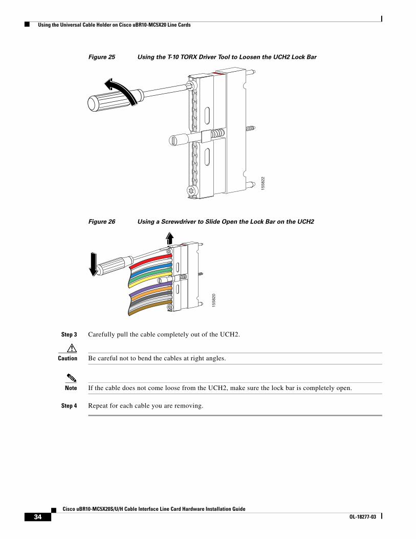
Using the Universal Cable Holder on Cisco uBR10-MC5X20 Line Cards
Figure 25 Using the T-10 TORX Driver Tool to Loosen the UCH2 Lock Bar
Figure 26 Using a Screwdriver to Slide Open the Lock Bar on the UCH2
Step 3 Carefully pull the cable completely out of the UCH2.
Caution Be careful not to bend the cables at right angles.
Note If the cable does not come loose from the UCH2, make sure the lock bar is completely open.
Step 4 Repeat for each cable you are removing.
1558
22
1558
20
34Cisco uBR10-MC5X20S/U/H Cable Interface Line Card Hardware Installation Guide
OL-18277-03

Using the Universal Cable Holder on Cisco uBR10-MC5X20 Line Cards
Installing Cables
Cisco cables are color-coded for easy reference and installation. The cable color corresponds to a specific port on the card. The tables include a column for users to define ports and color definitions.
See Table 3 on page 30 for a list of the cable ports and associated cable color applicable when using MC5X20 dual-shielded cables or quad-shielded cabling.
Note The recommended cable colors are the same for the UCH1 and UCH2.
Precision miniature video coaxial cables come in various colors, and you can use any cable color combination. However, when you are connecting the Cisco uBR10-MC5X20S/U/H cable interface card to the Cisco RF switch, we recommend that you install the cables in the UCH as shown in Figure 21, and listed in Table 3.
To replace cables or install new cables in a UCH2, complete the following steps:
Step 1 Use the T-10 TORX driver tool to loosen the lock bar on the side in which you want to install a cable. (See Figure 25.)
Step 2 Use a flathead screwdriver as a lever to slide open the lock bar. (See Figure 26.)
Step 3 Remove the ESD cap from a cable (see Figure 22 and Figure 23) and place it into the hole in the UCH2. (See Figure 27.) Use Table 3 on page 30 to determine the correct color and location for each colored cable.
Step 4 Insert and wiggle the connector into the hole.
Note The cables fit loosely in the holes, and are not locked into place until the lock bar is closed in Step 6.
Step 5 Repeat Step 3 and Step 4 for the remaining cables you are installing.
Note Make sure the cables are aligned correctly and inserted completely or the slide bar will not close.
Step 6 Slide the lock bar closed completely, and use the T-10 TORX driver tool to tighten the screws clockwise (torque 10 in-lbs, 1.13 Newton meters (Nm)).
Note Clamp bar maximum torque 15 in-lbs (1.70 Nm).
35Cisco uBR10-MC5X20S/U/H Cable Interface Line Card Hardware Installation Guide
OL-18277-03
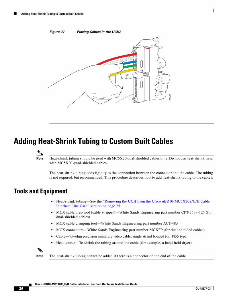
Adding Heat-Shrink Tubing to Custom Built Cables
Figure 27 Placing Cables in the UCH2
Adding Heat-Shrink Tubing to Custom Built Cables
Note Heat-shrink tubing should be used with MC5X20 dual-shielded cables only. Do not use heat-shrink wrap with MC5X20 quad-shielded cables.
The heat-shrink tubing adds rigidity to the connection between the connector and the cable. The tubing is not required, but recommended. This procedure describes how to add heat-shrink tubing to the cables.
Tools and Equipment• Heat-shrink tubing—See the “Removing the UCH from the Cisco uBR10-MC5X20S/U/H Cable
Interface Line Card” section on page 25.
• MCX cable prep tool (cable stripper)—White Sands Engineering part number CPT-7538-125 (for dual-shielded cables)
• MCX cable crimping tool—White Sands Engineering part number ACT-483
• MCX connectors—White Sands Engineering part number MCXFP (for dual-shielded cables)
• Cable—75–ohm precision miniature video cable, single strand bonded foil 1855 type
• Heat source—To shrink the tubing around the cable (for example, a hand-held dryer)
Note The heat-shrink tubing cannot be added if there is a connector on the end of the cable.
1558
26
36Cisco uBR10-MC5X20S/U/H Cable Interface Line Card Hardware Installation Guide
OL-18277-03
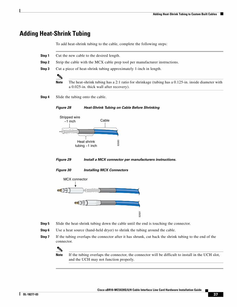
Adding Heat-Shrink Tubing to Custom Built Cables
Adding Heat-Shrink TubingTo add heat-shrink tubing to the cable, complete the following steps:
Step 1 Cut the new cable to the desired length.
Step 2 Strip the cable with the MCX cable prep tool per manufacturer instructions.
Step 3 Cut a piece of heat-shrink tubing approximately 1-inch in length.
Note The heat-shrink tubing has a 2:1 ratio for shrinkage (tubing has a 0.125-in. inside diameter with a 0.025-in. thick wall after recovery).
Step 4 Slide the tubing onto the cable.
Figure 28 Heat-Shrink Tubing on Cable Before Shrinking
Figure 29 Install a MCX connector per manufacturers instructions.
Figure 30 Installing MCX Connectors
Step 5 Slide the heat-shrink tubing down the cable until the end is touching the connector.
Step 6 Use a heat source (hand-held dryer) to shrink the tubing around the cable.
Step 7 If the tubing overlaps the connector after it has shrunk, cut back the shrink tubing to the end of the connector.
Note If the tubing overlaps the connector, the connector will be difficult to install in the UCH slot, and the UCH may not function properly.
8268
0Heat shrinktubing ~1 inch
Stripped wire~1 inch Cable
8268
1
MCX connector
37Cisco uBR10-MC5X20S/U/H Cable Interface Line Card Hardware Installation Guide
OL-18277-03
Troubleshooting the Cisco uBR10-MC5X20S/U/H Cable Interface Line Card Installation
Troubleshooting the Cisco uBR10-MC5X20S/U/H Cable Interface Line Card Installation
Check the following:
1. Verify that the captive screws and ejector levers are secure.
a. Check that the captive screws are secure in the faceplate.
b. Check that the ejectors levers are properly closed.
2. Verify that the card is properly seated in the chassis.
a. Release the ejector levers and captive screws.
b. Slide the card partially out of the chassis and then slide it back in, making sure that it is properly seated in the backplane.
c. Close the ejector levers and tighten the captive screws.
3. Verify that the UCH is securely in place on the faceplate.
a. Check that the leadscrew is secure.
Note The recommended maximum torque that should be applied to a leadscrew is 15 in-lbs (1.69 Nm).
4. Verify that the connectors are properly seated in the ports on the faceplate.
a. Verify that no cables are broken at the connector.
b. Verify that the cables are properly secured in the UCH.
c. Verify that all the MCX connectors are protruding the same distance out of the UCH.
Note Use the MCX to F connector adapter to easily adapt the MCX connection for testing the cables.
5. Verify that the clamp bar on the UCH1 or the lock bar on the UCH2 is in place and tightened.
Downstream RF Power Measurement Caution
Caution Exposure to ESD can damage this product.
If downstream RF power measurements are made to this line card, all the ESD precautions listed below must be followed to prevent damage to the product:
1. Check for a proper ground on the equipment and chassis before connecting any cables.
2. Ensure there is a common ground between all the test equipment and the unit under test.
3. Keep test cables as short as possible to limit static buildup.
4. Before attaching any test cables to the unit under test, momentarily ground the center pin of the test cable to remove any static buildup that may be present.
38Cisco uBR10-MC5X20S/U/H Cable Interface Line Card Hardware Installation Guide
OL-18277-03
Technical Specifications and Component Part Numbers
Broken LeadscrewsTo remove a lead screw that has broken off in the faceplate of the card, complete the following steps:
Step 1 Remove the cable bundle and UCH from the faceplate.
a. Take hold of the entire bundle of cables with one hand, and hold the card in place with the other.
b. Pull the cables and UCH away from the card.
Note If the UCH does not immediately come away from the faceplate, gently wiggle the UCH up and down while at the same time pulling it away from the faceplate.
Step 2 Inspect the screw hole and blow away any debris.
Step 3 Insert a small flathead screwdriver into the leadscrew hole.
Step 4 Press down and rotate the screwdriver counterclockwise until the broken part of the lead screw emerges from the hole.
Step 5 Use your fingers or needle-nose pliers to rotate the leadscrew the rest of the way out of the hole.
Technical Specifications and Component Part NumbersThe following tables provide specification information for the Cisco uBR10-MC5X20S/U/H cable interface line cards.
Physical Specifications and Compliance InformationTable 5 lists the physical specifications for the Cisco uBR10-MC5X20S/U/H cable interface line cards.
Table 5 Cisco uBR10-MC5X20S/U/H Cable Interface Line Card Specifications
Description Specification
Card dimensions • Width: 1.36 in (3.55 cm)
• Height: 20 in. (50.80 cm)
• Depth: 16 in. (10.64 cm)
Weight 16 lb (7.26 kg)
Power Consumption
Cisco uBR10-MC5X20SCisco uBR10-MC5X20UCisco uBR10-MC5X20H
185W1 (631.2 BTU/hr2)175W (597.1 BTU/hr)185W (631.2 BTU/hr)
Thermal Heat Dissipation
Cisco uBR10-MC5X20SCisco uBR10-MC5X20UCisco uBR10-MC5X20H
185W (631.2 BTU/hr)175W (597.1 BTU/hr)185W (631.2 BTU/hr)
39Cisco uBR10-MC5X20S/U/H Cable Interface Line Card Hardware Installation Guide
OL-18277-03

Technical Specifications and Component Part Numbers
RF Specifications
Input
Table 6 shows DOCSIS 1.0 input specifications.
Mean Time Between Failure (MTBF)
Cisco uBR10-MC5X20SCisco uBR10-MC5X20UCisco uBR10-MC5X20H
28,153 hours41,089 hours43,957 hours
Temperature range • Operating: 41 to 104° F (5 to 40° C)
• Non-operating: –4 to 149° F (–20 to 65° C)
Relative humidity • Operating: 10 to 90% non-condensing
• Non-operating: 5 to 95%
Operating altitude –197 to 13,123 ft. (–60 to 4000 m)
Standards, Compliance, Protocols
Cisco uBR10-MC5X20S
Cisco uBR10-MC5X20U
Cisco uBR10-MC5X20H
DOCSIS ITU J.112, ITU J.83 Annex B
DOCSIS ITU J.112, ITU J.83 Annex A, Annex B
DOCSIS 1.1DOCSIS MAC managementDOCSIS spectrum managementCableLabs ECR; RFI-R-98036DOCSIS 2.0 A-TDMA support
Software Requirements
Cisco uBR10-MC5X20SCisco uBR10-MC5X20UCisco uBR10-MC5X20H
Cisco IOS Release 12.2(11)BC2 or later releaseCisco IOS Release 12.2(15)CZ or later releaseCisco IOS Release 12.3(17a)BC4 or later release
1. W = Watts
2. BTU/hr = British thermal units per hour
Table 5 Cisco uBR10-MC5X20S/U/H Cable Interface Line Card Specifications (continued)
Description Specification
Table 6 DOCSIS 1.0 Supported Upstream Modulation Schemes (US0—US19)
Channel Width–MHz
Symbol Rate–Msym/s Max Throughput–Mbps
Nominal Throughput–Mbps Maximum
Range–dBmV1 Annex A Annex B QPSK 16–QAM QPSK 16–QAM
0.2 — 0.16 0.32 0.64 0.23 0.55 –16 to +14
0.4 — 0.32 0.64 1.28 0.55 1.1 –13 to +17
0.8 — 0.64 1.28 2.56 1.1 2.2 –10 to +20
1.6 — 1.28 2.56 5.12 2.2 4.4 –7 to +23
3.2 — 2.56 5.12 10.24 4.4 8.8 –4 to +26
40Cisco uBR10-MC5X20S/U/H Cable Interface Line Card Hardware Installation Guide
OL-18277-03
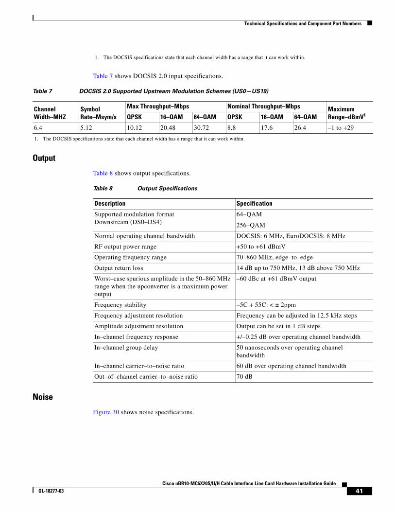
Technical Specifications and Component Part Numbers
Table 7 shows DOCSIS 2.0 input specifications.
Output
Table 8 shows output specifications.
Noise
Figure 30 shows noise specifications.
1. The DOCSIS specifications state that each channel width has a range that it can work within.
Table 7 DOCSIS 2.0 Supported Upstream Modulation Schemes (US0—US19)
Channel Width–MHZ
Symbol Rate–Msym/s
Max Throughput–Mbps Nominal Throughput–Mbps Maximum Range–dBmV1
1. The DOCSIS specifications state that each channel width has a range that it can work within.
QPSK 16–QAM 64–QAM QPSK 16–QAM 64–QAM
6.4 5.12 10.12 20.48 30.72 8.8 17.6 26.4 –1 to +29
Table 8 Output Specifications
Description Specification
Supported modulation formatDownstream (DS0–DS4)
64–QAM
256–QAM
Normal operating channel bandwidth DOCSIS: 6 MHz, EuroDOCSIS: 8 MHz
RF output power range +50 to +61 dBmV
Operating frequency range 70–860 MHz, edge–to–edge
Output return loss 14 dB up to 750 MHz, 13 dB above 750 MHz
Worst–case spurious amplitude in the 50–860 MHz range when the upconverter is a maximum power output
–60 dBc at +61 dBmV output
Frequency stability –5C + 55C: < ± 2ppm
Frequency adjustment resolution Frequency can be adjusted in 12.5 kHz steps
Amplitude adjustment resolution Output can be set in 1 dB steps
In–channel frequency response +/–0.25 dB over operating channel bandwidth
In–channel group delay 50 nanoseconds over operating channel bandwidth
In–channel carrier–to–noise ratio 60 dB over operating channel bandwidth
Out–of–channel carrier–to–noise ratio 70 dB
41Cisco uBR10-MC5X20S/U/H Cable Interface Line Card Hardware Installation Guide
OL-18277-03

Technical Specifications and Component Part Numbers
RF Specifications Specific to Cisco uBR-MC5X20U and H
The following specifications are specific to the Cisco uBR-MC5X20U and H cable interface line cards with onboard upconverters.
Part NumbersTable 11 lists the part numbers for the Cisco uBR10-MC5X20S/U/H cable interface line cards, cable kits, cables, connectors, tubing, and tools.
Table 9 Noise Specifications
Description Specification
Integrated phase noise 1 KHz–10 KHz –36 dBc double side band noise power
Integrated phase noise 10 KHz–50 KHz –54 dBc double side band noise power
Integrated phase noise 50 KHz–3 MHz –53 dBc double side band noise power
Spot phase noise at 10 KHz –91 dBc/Hz single side band noise power
Broadband noise at 61 dBmV output (all channels outside +/–18 MHz)
–12 dBmV/6 MHz, –11 dBmV/8 MHz
Modulated out of channel noise at 6 MHz –58 dBc minimum +/–3 to 3.75 MHz, –62 dBc minimum +/–3.75 to 9 MHz,–65 dBc minimum +/–9 to 15 MHz
Modulated out of channel noise at 8 MHz –58 dBc minimum +/–4 to 5 MHz, –61 dBc minimum +/–5 to 12 MHz,–64 dBc minimum +/–12 to 20 MHz
Table 10 RF Specifications
Description Specification
Group delay 15 nsec p–p max over any 5 MHz and +/– 18 nsec over any 7 MHz
Frequency step size 12.5 KHz
Amplitude flatness +/–0.25 dB over any 5 MHz, < ± 0.35 dB over any 7 MHz
Frequency accuracy + 23C:<+/–2ppm
Absolute error from command output level
+/– 2.0 dB
Table 11 Part Numbers
Description Part Numbers
1. Cisco uBR10-MC5X20S
2. Cisco uBR10-MC5X20U
3. Cisco uBR10-MC5X20H
4. Blank Cover
1. UBR10-MC5X20S=
2. UBR10-MC5X20U=
3. UBR10-MC5X20H=
4. UBR10-MC-COVER=
42Cisco uBR10-MC5X20S/U/H Cable Interface Line Card Hardware Installation Guide
OL-18277-03
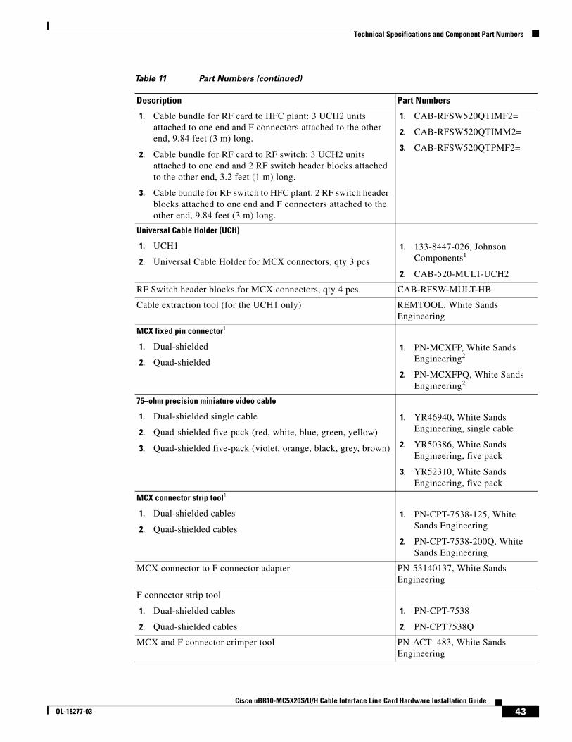
Technical Specifications and Component Part Numbers
1. Cable bundle for RF card to HFC plant: 3 UCH2 units attached to one end and F connectors attached to the other end, 9.84 feet (3 m) long.
2. Cable bundle for RF card to RF switch: 3 UCH2 units attached to one end and 2 RF switch header blocks attached to the other end, 3.2 feet (1 m) long.
3. Cable bundle for RF switch to HFC plant: 2 RF switch header blocks attached to one end and F connectors attached to the other end, 9.84 feet (3 m) long.
1. CAB-RFSW520QTIMF2=
2. CAB-RFSW520QTIMM2=
3. CAB-RFSW520QTPMF2=
Universal Cable Holder (UCH)
1. UCH1
2. Universal Cable Holder for MCX connectors, qty 3 pcs
1. 133-8447-026, Johnson Components1
2. CAB-520-MULT-UCH2
RF Switch header blocks for MCX connectors, qty 4 pcs CAB-RFSW-MULT-HB
Cable extraction tool (for the UCH1 only) REMTOOL, White Sands Engineering
MCX fixed pin connector1
1. Dual-shielded
2. Quad-shielded
1. PN-MCXFP, White Sands Engineering2
2. PN-MCXFPQ, White Sands Engineering2
75–ohm precision miniature video cable
1. Dual-shielded single cable
2. Quad-shielded five-pack (red, white, blue, green, yellow)
3. Quad-shielded five-pack (violet, orange, black, grey, brown)
1. YR46940, White Sands Engineering, single cable
2. YR50386, White Sands Engineering, five pack
3. YR52310, White Sands Engineering, five pack
MCX connector strip tool1
1. Dual-shielded cables
2. Quad-shielded cables
1. PN-CPT-7538-125, White Sands Engineering
2. PN-CPT-7538-200Q, White Sands Engineering
MCX connector to F connector adapter PN-53140137, White Sands Engineering
F connector strip tool
1. Dual-shielded cables
2. Quad-shielded cables
1. PN-CPT-7538
2. PN-CPT7538Q
MCX and F connector crimper tool PN-ACT- 483, White Sands Engineering
Table 11 Part Numbers (continued)
Description Part Numbers
43Cisco uBR10-MC5X20S/U/H Cable Interface Line Card Hardware Installation Guide
OL-18277-03
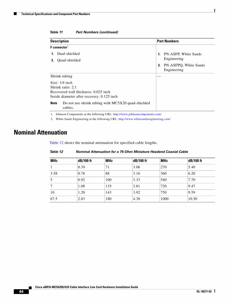
Technical Specifications and Component Part Numbers
Nominal AttenuationTable 12 shows the nominal attenuation for specified cable lengths.
F connector1
1. Dual-shielded
2. Quad-shielded
1. PN-ASFP, White Sands Engineering
2. PN-ASFPQ, White Sands Engineering
Shrink tubing
Size: 1/4 inchShrink ratio: 2:1 Recovered wall thickness: 0.025 inchInside diameter after recovery: 0.125 inch
Note Do not use shrink tubing with MC5X20 quad-shielded cables.
—
1. Johnson Components at the following URL: http://www.johnsoncomponents.com/
2. White Sands Engineering at the following URL: http://www.whitesandsengineering.com/
Table 11 Part Numbers (continued)
Description Part Numbers
Table 12 Nominal Attenuation for a 75-Ohm Miniature Headend Coaxial Cable
MHz dB/100 ft MHz dB/100 ft MHz dB/100 ft
1 0.39 71 3.06 270 5.40
3.58 0.78 88 3.16 360 6.20
5 0.92 100 3.33 540 7.70
7 1.08 135 3.81 720 9.47
10 1.20 143 3.92 750 9.59
67.5 2.83 180 4.38 1000 10.50
44Cisco uBR10-MC5X20S/U/H Cable Interface Line Card Hardware Installation Guide
OL-18277-03
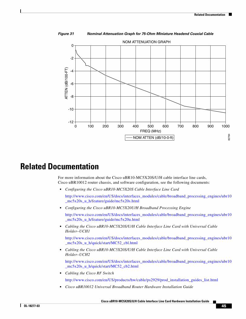
Related Documentation
Figure 31 Nominal Attenuation Graph for 75-Ohm Miniature Headend Coaxial Cable
Related DocumentationFor more information about the Cisco uBR10-MC5X20S/U/H cable interface line cards, Cisco uBR10012 router chassis, and software configuration, see the following documents:
• Configuring the Cisco uBR10-MC5X20S Cable Interface Line Card
http://www.cisco.com/en/US/docs/interfaces_modules/cable/broadband_processing_engines/ubr10_mc5x20s_u_h/feature/guide/mc5x20s.html
• Configuring the Cisco uBR10-MC5X20U/H Broadband Processing Engine
http://www.cisco.com/en/US/docs/interfaces_modules/cable/broadband_processing_engines/ubr10_mc5x20s_u_h/feature/guide/mc5x20u.html
• Cabling the Cisco uBR10-MC5X20S/U/H Cable Interface Line Card with Universal Cable Holder–UCH1
http://www.cisco.com/en/US/docs/interfaces_modules/cable/broadband_processing_engines/ubr10_mc5x20s_u_h/quick/start/MC52_cbl.html
• Cabling the Cisco uBR10-MC5X20S/U/H Cable Interface Line Card with Universal Cable Holder–UCH2
http://www.cisco.com/en/US/docs/interfaces_modules/cable/broadband_processing_engines/ubr10_mc5x20s_u_h/quick/start/MC52_cb2.html
• Cabling the Cisco RF Switch
http://www.cisco.com/en/US/products/hw/cable/ps2929/prod_installation_guides_list.html
• Cisco uBR10012 Universal Broadband Router Hardware Installation Guide
NOM ATTENUATION GRAPH
0-12
-10
-8
-6
-4
-2
0
100 200 300 400 500 600 700 800 900 1000
ATT
EN
(dB
/100
-FT
)
FREQ (MHz)
NOM ATTEN (dB/10-0-ft)
8278
4
45Cisco uBR10-MC5X20S/U/H Cable Interface Line Card Hardware Installation Guide
OL-18277-03
Obtaining Documentation and Submitting a Service Request
http://www.cisco.com/en/US/docs/cable/cmts/ubr10012/installation/guide/hig.html
• Cisco uBR10000 Series Universal Broadband Router Release Notes
http://www.cisco.com/en/US/products/hw/cable/ps2209/prod_release_notes_list.html
• Cisco uBR10012 Router Software Features
http://www.cisco.com/en/US/products/hw/cable/ps2209/products_feature_guides_list.html
• Cisco uBR10012 Universal Broadband Router Software Configuration Guide
http://www.cisco.com/en/US/docs/cable/cmts/ubr10012/configuration/guide/scg.html
• Cisco IOS CMTS Cable Software Configuration Guide, Release 12.2SC
http://www.cisco.com/web/techdoc/cable/Config/Sw_conf.html
• Cisco IOS CMTS Cable Command Reference
http://www.cisco.com/en/US/docs/ios/cable/command/reference/cbl_book.html
Obtaining Documentation and Submitting a Service RequestFor information on obtaining documentation, submitting a service request, and gathering additional information, see the monthly What’s New in Cisco Product Documentation, which also lists all new and revised Cisco technical documentation, at:
http://www.cisco.com/en/US/docs/general/whatsnew/whatsnew.html
Subscribe to the What’s New in Cisco Product Documentation as a Really Simple Syndication (RSS) feed and set content to be delivered directly to your desktop using a reader application. The RSS feeds are a free service and Cisco currently supports RSS version 2.0
Cisco and the Cisco logo are trademarks or registered trademarks of Cisco and/or its affiliates in the U.S. and other countries. To view a list of Cisco trademarks, go to this URL: www.cisco.com/go/trademarks. Third-party trademarks mentioned are the property of their respective owners. The use of the word partner does not imply a partnership relationship between Cisco and any other company. (1110R)
Any Internet Protocol (IP) addresses used in this document are not intended to be actual addresses. Any examples, command display output, and figures included in the document are shown for illustrative purposes only. Any use of actual IP addresses in illustrative content is unintentional and coincidental.
© 2009, 2012 Cisco Systems, Inc. All rights reserved.
46Cisco uBR10-MC5X20S/U/H Cable Interface Line Card Hardware Installation Guide
OL-18277-03
Recommended