×
Log in
Upload File
Most Popular
Art & Photos
Automotive
Business
Career
Design
Education
Hi-Tech
+ Browse for More
Download pdf -
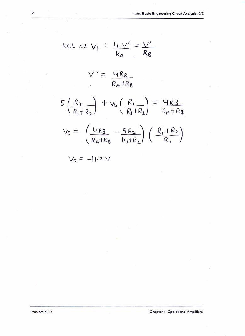
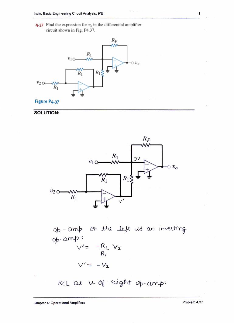
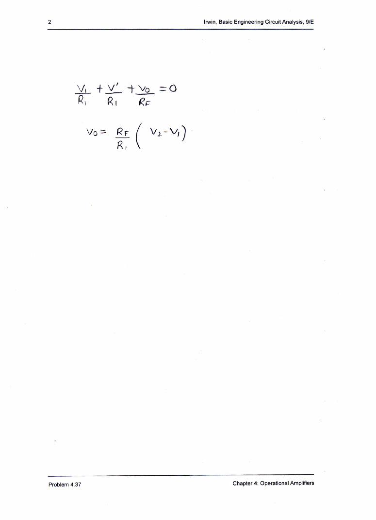
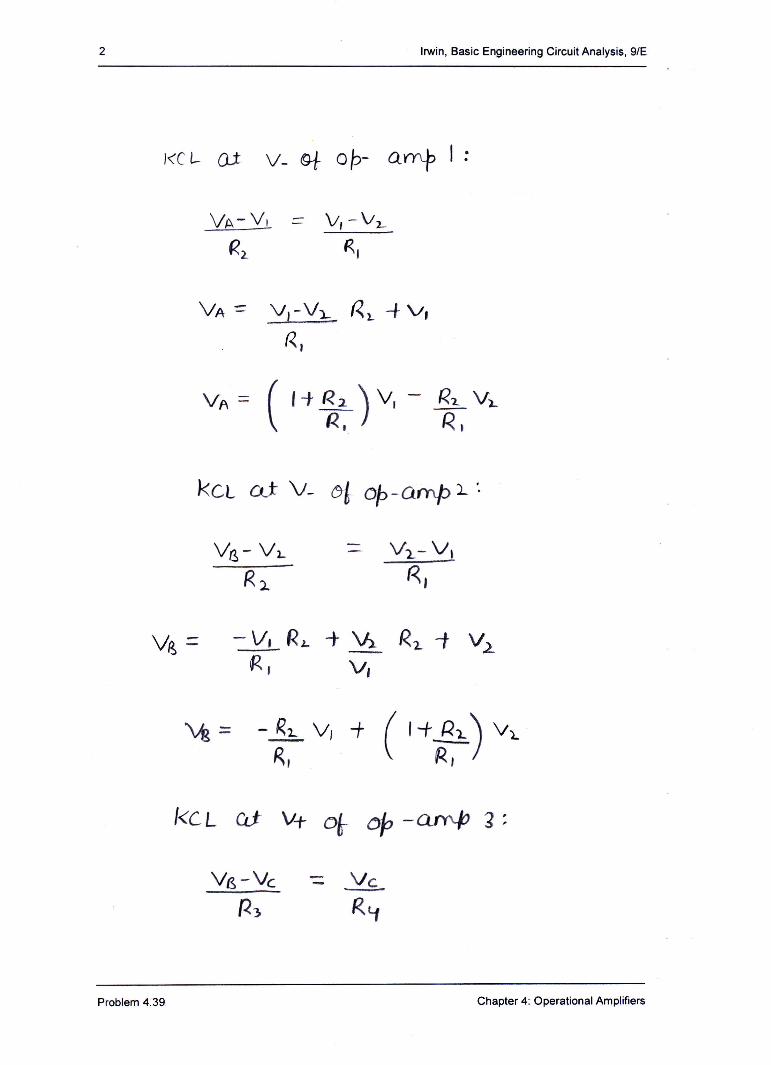
· circuit shown in Fig. P4.37. Figure P4-37 Irwin, Basic Engineering Circuit Analysis, 9/E 4-37 Find the expression for in the differential amplifier circuit shown in Fig. P4.37
Download pdf
Transcript
Page 1
Page 2
Page 3
Page 4
Page 5
Page 6
Page 7
Page 8
Page 9
Page 10
Page 11
Page 12
Page 13
Page 14
Page 15
Page 16
Page 17
Page 18
Page 19
Page 20
Page 21
Page 22
Page 23
LOAD MORE
Recommended
Railway Telephones - Principles of Electrical … TELEPHONES By S. FLINT Fig 1. - WAYSTATION TELEPHONE FOR OMNIBUS CIRCUIT TERMINATED AT A CONTROL OFFICE Telephone shown open for inspection
Documents
The Analog Computer Museum / Das Analogrechnermuseum · kg/ mm2 (2) Synthesis circuit for p- and p The circuit shown in Fig. 12 is used for synthesis, i. e. , in general, taking lower
Documents
Add-on decoder for AM stereomessui.polygonal-moogle.com/sch/kits/AMstereoEA.pdf · diagram of the IC is shown in Fig. 2 while Fig. 3 is a schematic of the complete decoder circuit
Documents
VERSATILE CONTROL USED FOR LLC RESONANT … with PSIM 6.0 software tool as shown in Fig.2. Fig .2 represents the simulation circuit diagram of LLC resonant converter for
Documents
THEORY AND PRACTICE OF MODULATED TEMPERATURE … · Fig. 3 Results from simple deconvolution procedure for the data shown in Fig. 2. This is illustrated in Fig. 3 using the data shown
Documents
Patterns: With Fibre (POF) Textiles Author: Institution ...ira.lib.polyu.edu.hk/bitstream/10397/53681/1/Photonic_Patterns.pdf · Institute Gala in 2010 as shown in Fig.1 (Cute Circuit,
Documents
MALLA REDDY ENGINEERING COLLEGE (Autonomous)...2020/10/19 · EQUIVALENT NORTON’S CIRCUIT Fig (1.6a) Tabulation for Thevenin’s: Under source voltage applied as shown in fig 1a
Documents
15 - Talking Electronics15.3 Analysis of Parallel Tuned Circuit A parallel tuned circuit consists of a capacitor C and inductor L in parallel as shown in Fig. 15.4 (i).talkingelectronics.com/Download
Documents
Development of an Overall Condition Monitoring System of ... · Fig.2. Installation of IC type accelerator on circuit breaker operation mechanism The piezoelectric accelerator shown
Documents
SIMPLE RADIO CIRCUITS - · PDF fileSIMPLE RADIO CIRCUITS ... 2 Medium Wave Transistor Receiver 14 3 Dual Wave One-valver 22 ... Circuit The circuit is shown in Fig. 1,
Documents
Operational Amplifi ers - Routledgecw.routledge.com/.../9780750687379/appendices/Operational_Amplif… · Operational Amplifi ers 83 Fig. 2 the V s connections are shown, but in circuit
Documents
Fig. 1: Locating Ignition System Components CIRCUIT DIAGRAM
Documents
-A (Answer any THREE · (c) State Kirchoff’s voltage and current laws. 2 (d) Find currents and voltages shown in the circuit of Fig. 1d. 3 2 (a) in the circuit Find the equivalent
Documents
Floating Gate MOSFET Programming Circuit for Standard ...OpAmp3, not shown in Fig. 3); belong to the current sources I_ electrical diagrams are shown in Fi sources use an integrated
Documents
· Web viewThe tuning circuit is shown as Fig 3.4.1. According to the theory, if the circuit is resonant, the voltage across the 50Ω resistor should be half of the open circuit voltage
Documents
Cambridge International Examinations ... - IGCSE Past Papersdynamicpapers.com/wp-content/uploads/2015/09/0625_w17_qp_61.pdf · Explain how you could use the circuit shown in Fig
Documents
Web viewThe fire alarm circuit has a resistor R, a thermistor and a buzzer connected to the battery shown in Fig. 6.2. Fig. 6.2. ... word. a complete loop of conductors
Documents
Applications of operational amplifier as Inverting amplifier, … · Inverting Amplifier Experimental set up & Procedure • Make the circuit diagram as shown in fig. with the help
Documents