Upload others
View 10
Download 0
Embed Size (px) 344 x 292 429 x 357 514 x 422 599 x 487
Citation preview
The Analog Computer Museum / Das Analogrechnermuseum · kg/ mm2 (2) Synthesis circuit for p- and p The circuit shown in Fig. 12 is used for synthesis, i. e. , in general, taking lower
Paper / Subject Code: 49704 / CIRCUIT THEORY Q.P. Code ...Q.1 a) For the circuit shown in fig. find v 1 and v 2 using Nodal Analysis. b) Find i,
Analyze the rigid frame shown in fig
FIGURE 2-1 Block diagram of a rectifier and a dc power ...hafizzaheer.pbworks.com/w/file/fetch/89661467/Ch4,L15&16...Find the Thevenin equivalent circuit of the circuit shown in Fig,
Simulation and Experimental Validation of Common Mode ... · Simulation circuit and experimental circuit of 5-level inverter shown in Fig. 5, Fig. 6 with 24 devices using SVM for
THEORY AND PRACTICE OF MODULATED TEMPERATURE … · Fig. 3 Results from simple deconvolution procedure for the data shown in Fig. 2. This is illustrated in Fig. 3 using the data shown
engineersnext.files.wordpress.com b. a. (10 Mark For the circuit shown in Fig. Q3 (b), calculate re, Z: Zo, Av, Al. , Fig. Q3 (b) Determine tßlower cut off frequency for the emitter
Operational Amplifi ers - Routledgecw.routledge.com/.../9780750687379/appendices/Operational_Amplif… · Operational Amplifi ers 83 Fig. 2 the V s connections are shown, but in circuit
shown in Fig. - Vintage Projects
DIGITAL COMMUNICATION RECEIVER BASED ON … COMMUNICATION RECEIVER BASED ON FPGA DESIGN ... Demodulation and detection circuit . ... the waveforms diagram as shown in fig.9.Where the
-A (Answer any THREE · (c) State Kirchoff’s voltage and current laws. 2 (d) Find currents and voltages shown in the circuit of Fig. 1d. 3 2 (a) in the circuit Find the equivalent
€¦ · 2-3V Fig. QI(c) and V for the circuit shown, Fig. Q2(a). Fig. Q2(a) Find the coordinates of the Q point and locate it on the dc load line for the voltage divider configuration
SIMPLE RADIO CIRCUITS - · PDF fileSIMPLE RADIO CIRCUITS ... 2 Medium Wave Transistor Receiver 14 3 Dual Wave One-valver 22 ... Circuit The circuit is shown in Fig. 1,
Applications of operational amplifier as Inverting amplifier, … · Inverting Amplifier Experimental set up & Procedure • Make the circuit diagram as shown in fig. with the help
15 - Talking Electronics15.3 Analysis of Parallel Tuned Circuit A parallel tuned circuit consists of a capacitor C and inductor L in parallel as shown in Fig. 15.4 (i).talkingelectronics.com/Download
Earth Continuity Relays - Switching Systemsswitchingsystems.co.za/ECR_brochure1.1.pdf · distribution circuit shown in Fig 1, an earth leakage relay provides protection against leak-age
and shown in Fig. 1b conduction mode
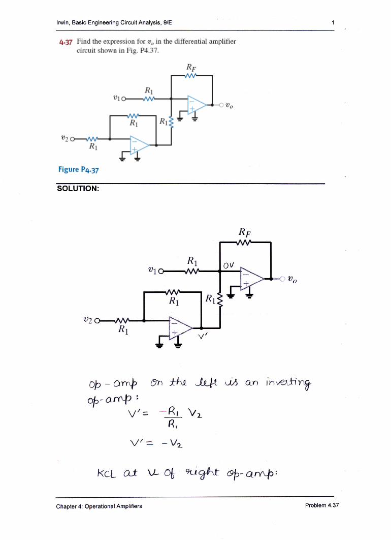
Operational AmplifiersA dual input, balanced output difference amplifier circuit is shown in fig. 1. Fig. 1 Inverting & Non inverting Inputs: In differential amplifier the output voltage
Development of an Overall Condition Monitoring System of ... · Fig.2. Installation of IC type accelerator on circuit breaker operation mechanism The piezoelectric accelerator shown
Fig. 1: Automatic A/C Circuit - taurus ... - taurus-club.ru · 2000 System Wiring Diagrams Ford - Taurus PAVLIN Fig. 61: Rear Wiper/Washer Circuit. Title: Fig. 1: Automatic A/C Circuit
Fig. 1: Locating Ignition System Components CIRCUIT DIAGRAM
archive.retro.co.zaarchive.retro.co.za/archive/amateur/QST/QST-1981-07...Circuit Description The power amplifier schematic diagram is shown in Fig. 1. An input matching transformer,
Electrical Measurements and Error Analysis · labs to follow. Fig. 5 shows the physical connections that are to be made to complete the circuit shown in Fig. 1. Figure 5: Signal interface
MALLA REDDY ENGINEERING COLLEGE (Autonomous)...2020/10/19 · EQUIVALENT NORTON’S CIRCUIT Fig (1.6a) Tabulation for Thevenin’s: Under source voltage applied as shown in fig 1a
· Web viewThe tuning circuit is shown as Fig 3.4.1. According to the theory, if the circuit is resonant, the voltage across the 50Ω resistor should be half of the open circuit voltage
Ashwin js ece dept UNIT IV - BRIDGE DC BRIDGES: …Wien Bridge Circuit Diagram: The Wien Bridge Circuit Diagram shown in Fig. 11.27 has a series RC combination in one arm and a parallel
ASSIGNMENT-I : THE BASIC WHEATSTONE BRIDGE · PDF fileFig 4.2.5 Circuit of Wheatstone Bridge Now, let us investigate circuit. Set up the module as shown in fig 4.2.6. this corresponds
AE110 CIRCUIT THEORY AND DESIGN DEC 2014 Q.2a. Determine Vx in the circuit shown in Fig · 2015-03-09 · b.For the circuit shown in Fig.6, obtain the value of current through 2Ω
NEW MATHEMATICAL MODEL FOR ANALYSING THREE-PHASE ... · This circuit represents a typical single phase ac controller circuit. Furthermore, the same circuit of Fig. 2-a and Fig. 2-b
Add-on decoder for AM stereomessui.polygonal-moogle.com/sch/kits/AMstereoEA.pdf · diagram of the IC is shown in Fig. 2 while Fig. 3 is a schematic of the complete decoder circuit