Chapter 3.
Characterization of bremsstrahlung radiationsfor 6 to 18 MeV electron beam from different Z
elements: experimental and simulationapproach
This chapter deals with the study of bremsstrahlung
spectra for 6 to 18 MeV electron beam from different
materials such as low to high Z elements as an e - target.
The simulation using FLUKA involves the neutron,
electron, positron and bremsstrahlung fluence
determination at various angles Moreover the thickness ofdetermination at various angles. Moreover, the thickness of
e - target has varied from thin to thick i.e from 0.1% to
150% of RCSDA. In addition, the reliability of FLUKA
simulation was confirmed by calculating the
bremsstrahlung spectrum for the setup of experiments
performed by other researchers and corresponding
validation was done. The data generated in this chapter can
be used as a right hand data for the researchers working in
the field of medical, nuclear and accelerator physics.
47
Chapter 3. Characterization of bremsstrahlung radiation 48
3.1 Importance and Objective
Radiation therapy is a clinical modality dealing with the use of high
doses of ionizing radiations in the treatment of patients mostly having malignant
tumors. The aim of radiation therapy is to deliver a sufficiently high absorbed
dose to a defined target volume resulting in the eradication of the tumor with
as minimal a damage as possible to the surrounding healthy tissues. Radiother-
apy with external high energy photon beams are the most common radiotherapy
modality [1]. Electron beams are used either as the primary mode of radiation
therapy or combined with photon beams. High energy electron and photon beams
are typically produced by linear accelerators and also by Microtrons [2]. For a
typical multi-energy medical linear accelerator, the accelerating potential spans
between 4 and 25 MV. The mean energy of the photon beams varies between
1.5 and 7 MeV [3]. In external beam therapy, to optimize the dose distribution
in a patient, the dose is typically delivered from different directions of modified
shape and intensity of the beam.
In radiation therapy with external radiation beams, the absorbed dose
at the specific point in a patient should be known with an overall uncertainty of
3.5% [4–6]. The main reason for the requirement of high accuracy in dose de-
livery is typically narrow margin between the dose needed for tumor control and
the dose causing complications for healthy tissues. The size of the dose margin
depends on the biological characteristics of tissues, size and shape of the irradi-
ated tissues, the quality of radiation as well as the dose fractionation regime. Due
to individual nature of the dose margin, 3.5% uncertainty can be regarded as a
general level accuracy requirement for dose delivery [4, 5]. Besides an individ-
ual treatments, the high accuracy in dose delivery is essential to enable a reliable
analysis and a comparison of results of different radiation therapy techniques and
modalities [6]. The knowledge of the energy spectra and angular distribution of
photon beams at the point of application is essential for accurate dose calcula-
tions [3]. Other applications requiring knowledge of the energy spectra include
design of the treatment machine head, flattening filter and collimator. It is also
Chapter 3. Characterization of bremsstrahlung radiation 49
important to know the variation of energy spectrum as a function of radial dis-
tance from the beam axis. The bremsstrahlung energy spectrum in the central
part of a photon beam is somewhat harder than in the region near edge of the
beam. Consequently, the relative depth dose in tissue will vary as a function of
distance from the beam axis. Variation of spectrum across the beam is also impor-
tant when calculating transmission through a block or a compensating device [3].
Knowledge of the angular distribution of photons is useful when calculating dose
near the beam boundaries. It is important to be able to evaluate reliably spectra of
bremsstrahlung from electron accelerators as functions of photon energy and an-
gle. As well as being required for fundamental reasons in photonuclear physics,
quantitative evaluations of bremsstrahlung spectra are required for purposes such
as predictions of γ ray radiation doses and dose rates, accelerator generated X-
ray radiography exposures, radioisotope production rates, and source strengths
in active γ-ray interrogation techniques [7]. Also it is necessary to know the
contamination of other particles like positron, neutron in bremsstrahlung beam,
to minimize unwanted dose to the patient body. Therefore, to generate data for
various energy and targets is very important as far as radiation therapy and radio-
graphy is concern.
3.1.1 Literature Survey
The process of bremsstrahlung has been studied theoretically and ex-
perimentally for several decades. The theoretical status of the field in 1959 was
reviewed by Koch and Motz [8], who presented a compilation of theoretical for-
mulae of various cross-sections, differentials in photon energy and photon scat-
tering angle in thin targets and for a wide range of incident electron energies.
The regimes of validity, in terms of incident energy, outgoing photon energy,
angle and radiator atomic number, etc. are discussed and evaluated for thin tar-
gets. At a depth in a thick bremsstrahlung target, the intrinsic angular photon
distribution for a thin target must be folded with the angular distribution of the
electron produced by multiple scattering [9]. For semi-thin targets, Schiff [10]
Chapter 3. Characterization of bremsstrahlung radiation 50
derived a formula for the angular photon distribution. A review, including exten-
sive tabulations of bremsstrahlung photon spectra, has been published by Seltzer
and Berger [11, 12]. A more recent review on various theoretical cross-sections
that have been used in Monte Carlo codes are described by Salvata [13].
Despite the relatively advanced state of the theory, few accurate, abso-
lute measurements have been made of the spectrum of bremsstrahlung photons
produced by high-energy electrons. A number of measurements have been per-
formed for electrons of energies below 30 MeV: Faddegon et al. [14, 15] and
the references therein. The thickness of the radiators generally used in these ex-
periments complicates their comparison with theory, as multiple scattering and
secondary processes become important. Monte Carlo calculations, with the the-
oretical bremsstrahlung cross-sections as input, must be employed to account for
the effects of radiator thickness and collimation on the photon spectrum and an-
gular distribution.
There has been much published on bremsstrahlung spectra over the past
few decades. A wide range of techniques have been proposed to determine the
bremsstrahlung: by early analytical modeling [10] and by elaborate Monte Carlo
simulations [16]. Additional analytical models exist in the literature which usu-
ally fit phase spaces obtained from Monte Carlo simulations [17]. Unfolding
of empirical radiation data measured by spectrometry [14, 18] has also been at-
tempted. Reconstruction from measured or calculated dosimetric data, usually
transmission measurements or depthdose curves [19–25] is yet another popular
means. While each method offers different advantages and disadvantages, it is
valuable to have an independent means to confirm the results of any given ap-
proach. Work on elementary bremsstrahlung cross sections [8, 11, 26] has been
complemented by work on the practical computation of bremsstrahlung from ra-
diators [27–33] in which different aspects of the bremsstrahlung spectrum are
treated in different ways according to the intended application.
A number of investigations on photon energy spectra have been re-
ported in literature. But, to the best of our knowledge as for angular distribu-
tions from thick targets, there are very few researcher have published their work.
Chapter 3. Characterization of bremsstrahlung radiation 51
Moreover, the contamination of unwanted radiations such as e−, e+, n have not
been calculated and measured very often. Therefore, keeping the importance of
bremsstrahlung in various fields mainly medical and industrial, the work on cal-
culation on bremsstrahlung yield and spectra have been carried out. The process
of bremsstrahlung production with other radiations is difficult to study theoret-
ically even on the basis of correct experiments for different cases of thickness
and materials of radiators (e− γ target). Therefore, simulations using effective
Monte Carlo based FLUKA has been carried out to generate bremsstrahlung ra-
diations by bombarding 6 to 18 MeV electrons on low to high Z target (e− γ ) of
thickness varying from 0.1% to 150% of RCS DA at various angles. RCS DA is the
range of the material for the incident electron energy. Also, the simulation using
FLUKA involves the fluence determination of neutron, positron and secondary
electrons. The data generated in this chapter will certainly help researchers work-
ing in the field of medical, nuclear and accelerator physics to take precise right
hand data of flux and energies of bremsstrahlung radiations. This can be used for
designing the various components of accelerator head of linear accelerator and
to treat desire object in radiation therapy accurately. The reliability of FLUKA
simulation was also confirmed by validating the bremsstrahlung results with the
results obtained in experiments performed by other researchers.
3.2 e− γ Target
The quality of the target to convert the electron energy into bremss-
trahlung radiation is actually given by the ratio of energy loss due to radiation
(dE/dx)rad and ionisation, (dE/dx)ion. It is therefore defined the conversion ef-
ficiency to produce bremsstrahlung radiation as the ratio between energy lost
by the electrons due to the bremsstrahlung radiation and the initial electron en-
ergy [32]. This value, in particular depends on the Z of the target material and
is proportional to energy of the electron. Basically, when high energy electrons
having kinetic energy Te passes through a target, the radiative loss results in emis-
sion of the bremsstrahlung radiation whose energy is distributed in a continuum
spectrum with end point equal to the electron energy. The energy spectrum of
Chapter 3. Characterization of bremsstrahlung radiation 52
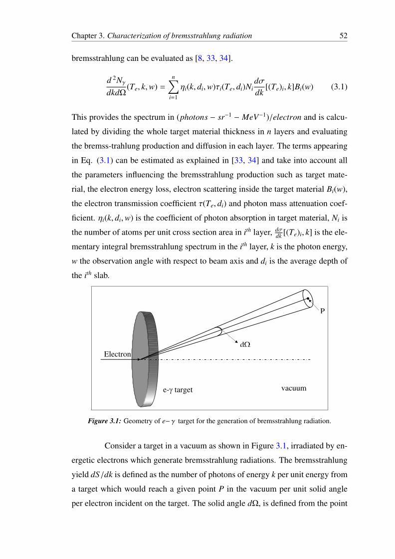
bremsstrahlung can be evaluated as [8, 33, 34].
d 2Nγ
dkdΩ(Te, k,w) =
n∑i=1
ηi(k, di,w)τi(Te, di)Nidσdk
[(Te)i, k]Bi(w) (3.1)
This provides the spectrum in (photons − sr−1 − MeV−1)/electron and is calcu-
lated by dividing the whole target material thickness in n layers and evaluating
the bremss-trahlung production and diffusion in each layer. The terms appearing
in Eq. (3.1) can be estimated as explained in [33, 34] and take into account all
the parameters influencing the bremsstrahlung production such as target mate-
rial, the electron energy loss, electron scattering inside the target material Bi(w),
the electron transmission coefficient τ(Te, di) and photon mass attenuation coef-
ficient. ηi(k, di,w) is the coefficient of photon absorption in target material, Ni is
the number of atoms per unit cross section area in ith layer, dσdk [(Te)i, k] is the ele-
mentary integral bremsstrahlung spectrum in the ith layer, k is the photon energy,
w the observation angle with respect to beam axis and di is the average depth of
the ith slab.
Electron
e- target vacuum
P
d
Figure 3.1: Geometry of e− γ target for the generation of bremsstrahlung radiation.
Consider a target in a vacuum as shown in Figure 3.1, irradiated by en-
ergetic electrons which generate bremsstrahlung radiations. The bremsstrahlung
yield dS/dk is defined as the number of photons of energy k per unit energy from
a target which would reach a given point P in the vacuum per unit solid angle
per electron incident on the target. The solid angle dΩ, is defined from the point
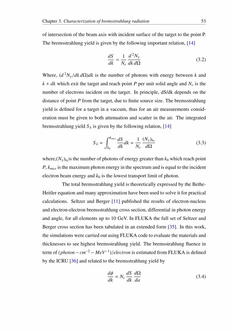
Chapter 3. Characterization of bremsstrahlung radiation 53
of intersection of the beam axis with incident surface of the target to the point P.
The bremsstrahlung yield is given by the following important relation, [14]
dSdk
=1Ne
d 2Nγ
dk dΩ(3.2)
Where, (d 2Nγ/dk dΩ)dk is the number of photons with energy between k and
k + dk which exit the target and reach point P per unit solid angle and Ne is the
number of electrons incident on the target. In principle, dS/dk depends on the
distance of point P from the target, due to finite source size. The bremsstrahlung
yield is defined for a target in a vaccum, thus for an air measurements consid-
eration must be given to both attenuation and scatter in the air. The integrated
bremsstrahlung yield S k is given by the following relation, [14]
S k =
∫ kmax
k0
dSdk
dk =1Ne
(Nγ)k0
dΩ(3.3)
where,(Nγ)k0is the number of photons of energy greater than k0 which reach point
P, kmax is the maximum photon energy in the spectrum and is equal to the incident
electron beam energy and k0 is the lowest transport limit of photon.
The total bremsstrahlung yield is theoretically expressed by the Bethe-
Heitler equation and many approximation have been used to solve it for practical
calculations. Seltzer and Berger [11] published the results of electron-nucleus
and electron-electron bremsstrahlung cross section, differential in photon energy
and angle, for all elements up to 10 GeV. In FLUKA the full set of Seltzer and
Berger cross section has been tabulated in an extended form [35]. In this work,
the simulations were carried out using FLUKA code to evaluate the materials and
thicknesses to see highest bremsstrahlung yield. The bremsstrahlung fluence in
term of (photon− cm−2 −MeV−1)/electron is estimated from FLUKA is defined
by the ICRU [36] and related to the bremsstrahlung yield by
dφdk
= NedSdk
dΩ
da(3.4)
Chapter 3. Characterization of bremsstrahlung radiation 54
where da is the cross-sectional area of the spehere at point P as shown in Fig-
ure 3.1.
The mean energy of the bremsstrahlung beam is useful quality indica-
tor [15].
Emean =1
S E0
∫ Emax
E0
EdSdE
dE (3.5)
Strictly speaking, the whole spectrum should be used in the evaluations of the
mean energy (E0=0). This would require knowledge of the spectral shape down
to energies well below the turnover pint. In practice, this is difficult to achieve,
especially for targets of low atomic number. It is therefore useful to define Emean
with a low energy cutoff.
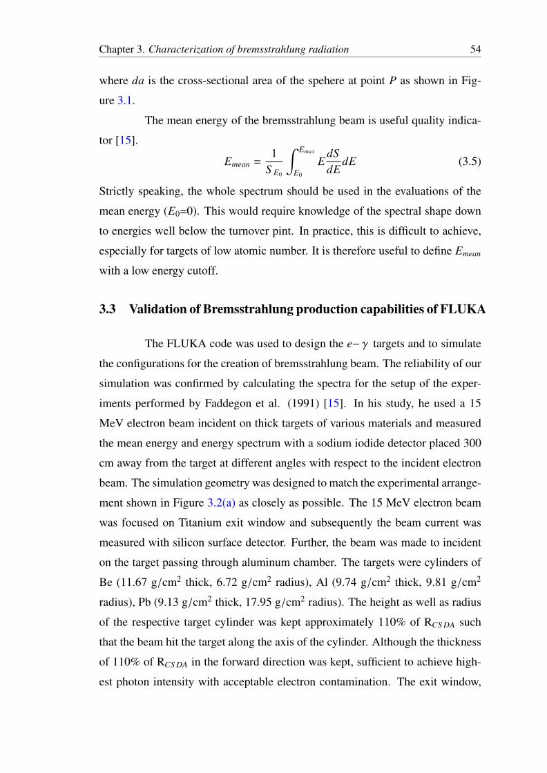
3.3 Validation of Bremsstrahlung production capabilities of FLUKA
The FLUKA code was used to design the e− γ targets and to simulate
the configurations for the creation of bremsstrahlung beam. The reliability of our
simulation was confirmed by calculating the spectra for the setup of the exper-
iments performed by Faddegon et al. (1991) [15]. In his study, he used a 15
MeV electron beam incident on thick targets of various materials and measured
the mean energy and energy spectrum with a sodium iodide detector placed 300
cm away from the target at different angles with respect to the incident electron
beam. The simulation geometry was designed to match the experimental arrange-
ment shown in Figure 3.2(a) as closely as possible. The 15 MeV electron beam
was focused on Titanium exit window and subsequently the beam current was
measured with silicon surface detector. Further, the beam was made to incident
on the target passing through aluminum chamber. The targets were cylinders of
Be (11.67 g/cm2 thick, 6.72 g/cm2 radius), Al (9.74 g/cm2 thick, 9.81 g/cm2
radius), Pb (9.13 g/cm2 thick, 17.95 g/cm2 radius). The height as well as radius
of the respective target cylinder was kept approximately 110% of RCS DA such
that the beam hit the target along the axis of the cylinder. Although the thickness
of 110% of RCS DA in the forward direction was kept, sufficient to achieve high-
est photon intensity with acceptable electron contamination. The exit window,
Chapter 3. Characterization of bremsstrahlung radiation 55
(a) (b)
Figure 3.2: Experiment arrangement (a) used by Faddegon et al. [15] (b) used byDeshmukh et al. [37] for the measurement of Bremsstrahlung Yield.
current monitor, target chamber (describe by Faddegon et al [15]), target, and the
detector with shield was modeled in FLUKA for estimation of bremsstrahlung
yield at 0°(i.e forward direction). The results measured and calculated by Fad-
degon et al [15] along with the results estimated using FLUKA are shown in
Table 3.1. It is observed that the results obtained using FLUKA are comparable
with the measured one by experimentally.
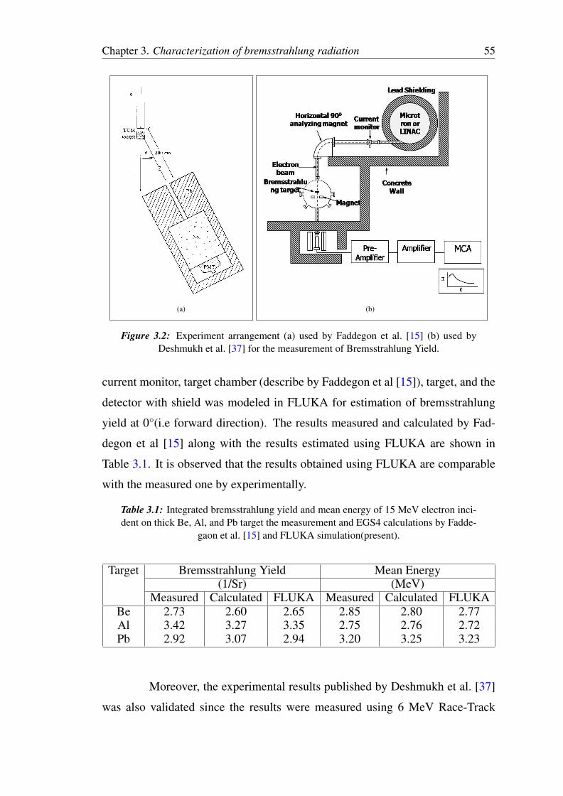
Table 3.1: Integrated bremsstrahlung yield and mean energy of 15 MeV electron inci-dent on thick Be, Al, and Pb target the measurement and EGS4 calculations by Fadde-
gaon et al. [15] and FLUKA simulation(present).
Target Bremsstrahlung Yield Mean Energy(1/Sr) (MeV)
Measured Calculated FLUKA Measured Calculated FLUKABe 2.73 2.60 2.65 2.85 2.80 2.77Al 3.42 3.27 3.35 2.75 2.76 2.72Pb 2.92 3.07 2.94 3.20 3.25 3.23
Moreover, the experimental results published by Deshmukh et al. [37]
was also validated since the results were measured using 6 MeV Race-Track
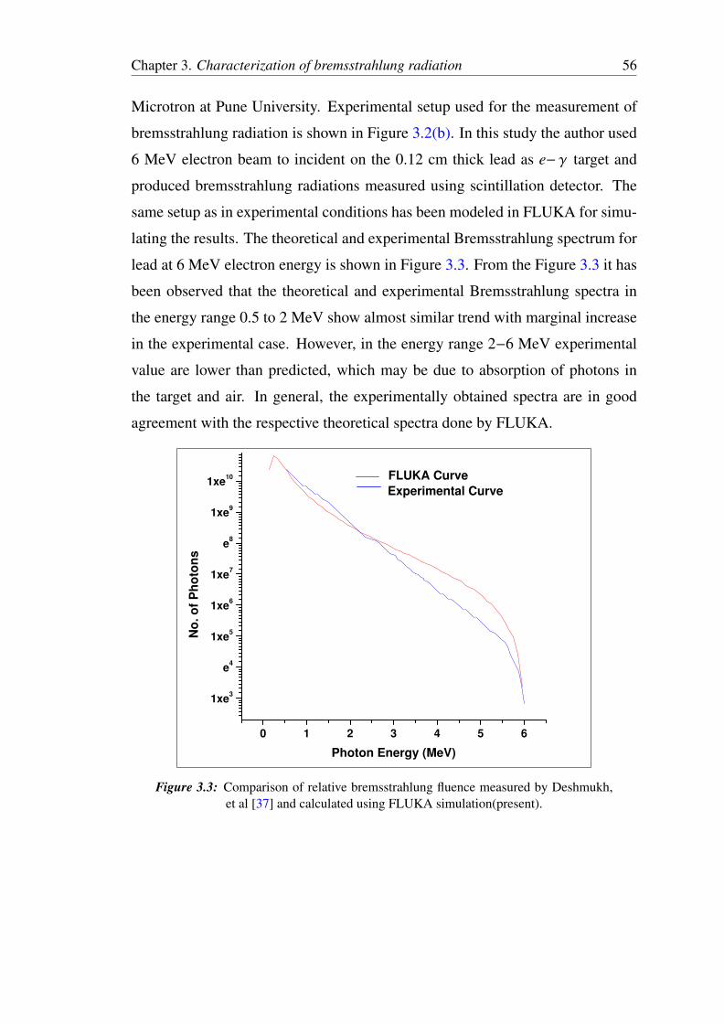
Chapter 3. Characterization of bremsstrahlung radiation 56
Microtron at Pune University. Experimental setup used for the measurement of
bremsstrahlung radiation is shown in Figure 3.2(b). In this study the author used
6 MeV electron beam to incident on the 0.12 cm thick lead as e− γ target and
produced bremsstrahlung radiations measured using scintillation detector. The
same setup as in experimental conditions has been modeled in FLUKA for simu-
lating the results. The theoretical and experimental Bremsstrahlung spectrum for
lead at 6 MeV electron energy is shown in Figure 3.3. From the Figure 3.3 it has
been observed that the theoretical and experimental Bremsstrahlung spectra in
the energy range 0.5 to 2 MeV show almost similar trend with marginal increase
in the experimental case. However, in the energy range 2−6 MeV experimental
value are lower than predicted, which may be due to absorption of photons in
the target and air. In general, the experimentally obtained spectra are in good
agreement with the respective theoretical spectra done by FLUKA.
0 1 2 3 4 5 6
1xe3
e4
1xe5
1xe6
1xe7
e8
1xe9
1xe10
Experimental Curve
FLUKA Curve
No
. o
f P
ho
ton
s
Photon Energy (MeV)
Figure 3.3: Comparison of relative bremsstrahlung fluence measured by Deshmukh,et al [37] and calculated using FLUKA simulation(present).
Chapter 3. Characterization of bremsstrahlung radiation 57
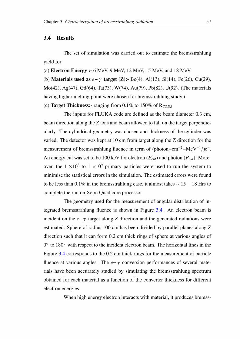
3.4 Results
The set of simulation was carried out to estimate the bremsstrahlung
yield for
(a) Electron Energy :- 6 MeV, 9 MeV, 12 MeV, 15 MeV, and 18 MeV
(b) Materials used as e− γ target (Z):- Be(4), Al(13), Si(14), Fe(26), Cu(29),
Mo(42), Ag(47), Gd(64), Ta(73), W(74), Au(79), Pb(82), U(92). (The materials
having higher melting point were chosen for bremsstrahlung study.)
(c) Target Thickness:- ranging from 0.1% to 150% of RCS DA
The inputs for FLUKA code are defined as the beam diameter 0.3 cm,
beam direction along the Z axis and beam allowed to fall on the target perpendic-
ularly. The cylindrical geometry was chosen and thickness of the cylinder was
varied. The detector was kept at 10 cm from target along the Z direction for the
measurement of bremsstrahlung fluence in term of (photon−cm−2−MeV−1/)e−.
An energy cut was set to be 100 keV for electron (Ecut) and photon (Pcut). More-
over, the 1 ×10⁸ to 1 ×10⁹ primary particles were used to run the system to
minimise the statistical errors in the simulation. The estimated errors were found
to be less than 0.1% in the bremsstrahlung case, it almost takes ∼ 15 − 18 Hrs to
complete the run on Xeon Quad core processor.
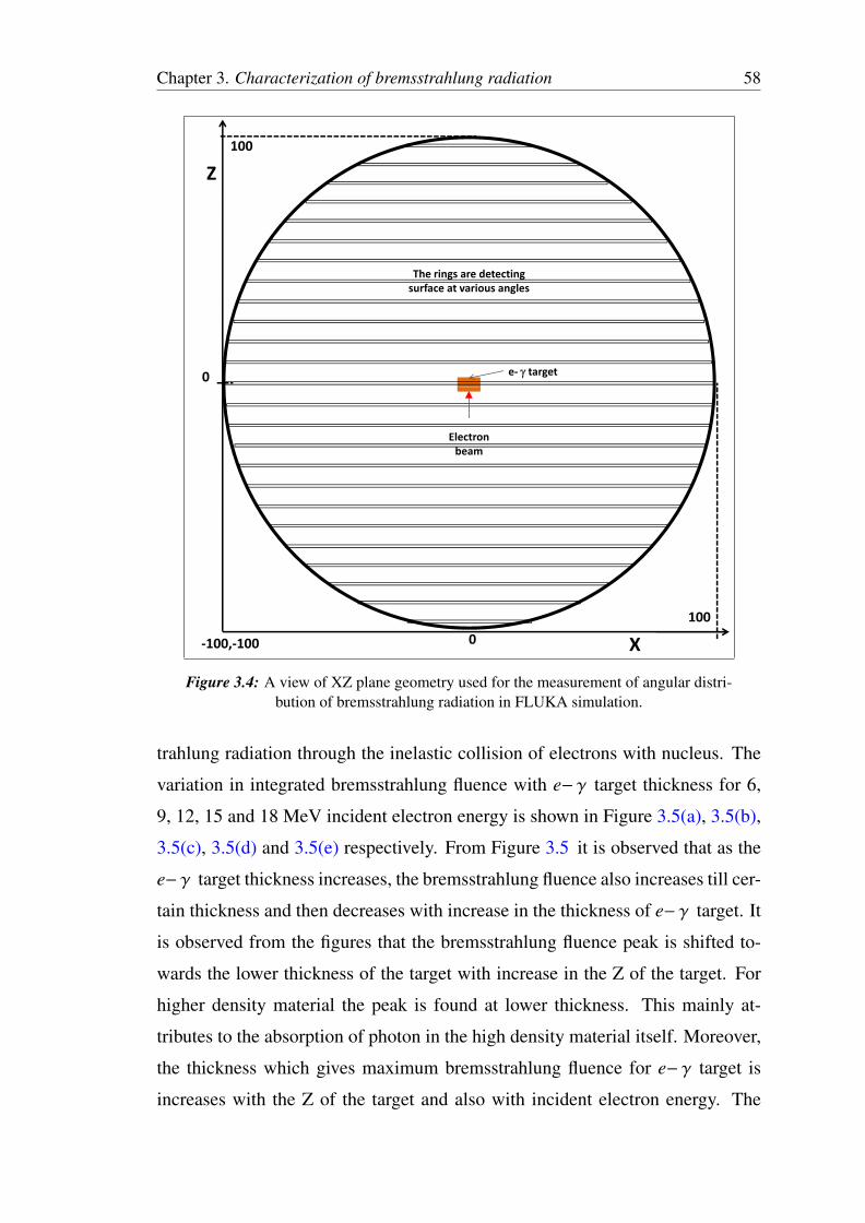
The geometry used for the measurement of angular distribution of in-
tegrated bremsstrahlung fluence is shown in Figure 3.4. An electron beam is
incident on the e− γ target along Z direction and the generated radiations were
estimated. Sphere of radius 100 cm has been divided by parallel planes along Z
direction such that it can form 0.2 cm thick rings of sphere at various angles of
0° to 180° with respect to the incident electron beam. The horizontal lines in the
Figure 3.4 corresponds to the 0.2 cm thick rings for the measurement of particle
fluence at various angles. The e− γ conversion performances of several mate-
rials have been accurately studied by simulating the bremsstrahlung spectrum
obtained for each material as a function of the converter thickness for different
electron energies.
When high energy electron interacts with material, it produces bremss-
Chapter 3. Characterization of bremsstrahlung radiation 58
Z
100
The rings are detecting
surface at various angles
e target0
Electron
beambeam
X
100
100, 100 0
Figure 3.4: A view of XZ plane geometry used for the measurement of angular distri-bution of bremsstrahlung radiation in FLUKA simulation.
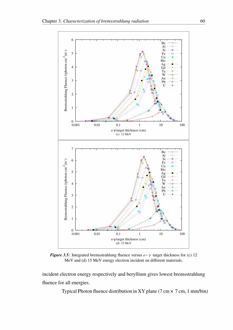
trahlung radiation through the inelastic collision of electrons with nucleus. The
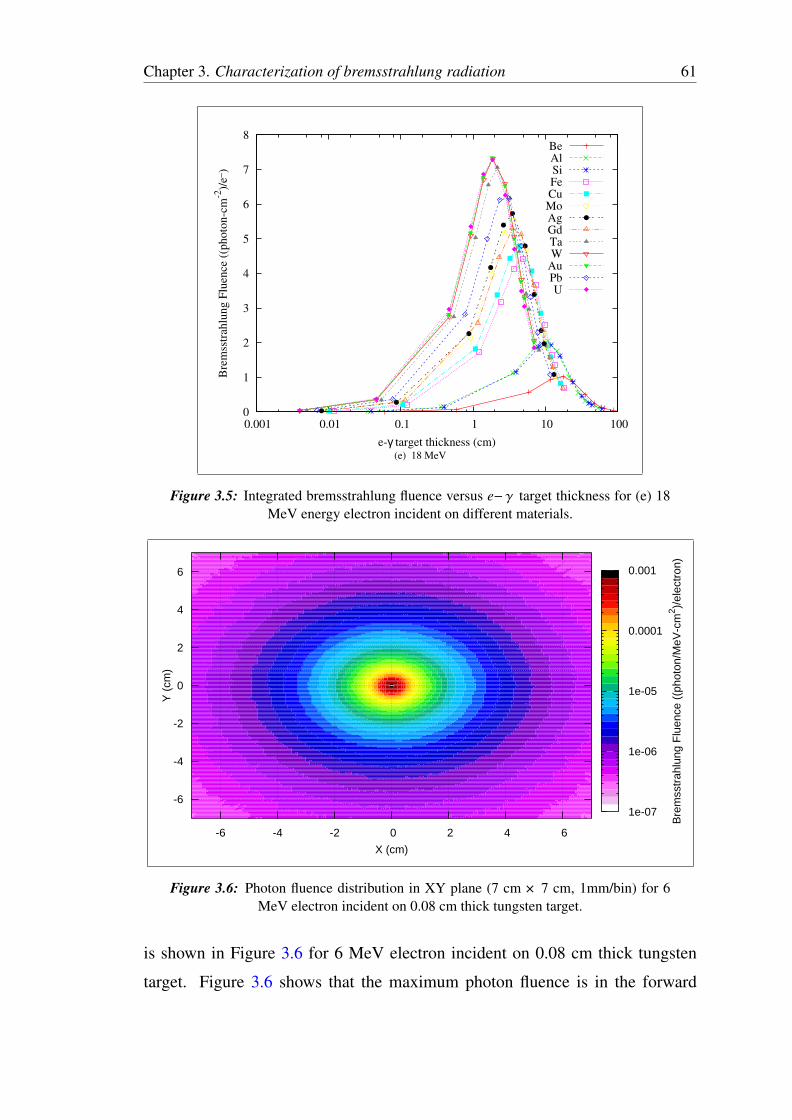
variation in integrated bremsstrahlung fluence with e− γ target thickness for 6,
9, 12, 15 and 18 MeV incident electron energy is shown in Figure 3.5(a), 3.5(b),
3.5(c), 3.5(d) and 3.5(e) respectively. From Figure 3.5 it is observed that as the
e− γ target thickness increases, the bremsstrahlung fluence also increases till cer-
tain thickness and then decreases with increase in the thickness of e− γ target. It
is observed from the figures that the bremsstrahlung fluence peak is shifted to-
wards the lower thickness of the target with increase in the Z of the target. For
higher density material the peak is found at lower thickness. This mainly at-
tributes to the absorption of photon in the high density material itself. Moreover,
the thickness which gives maximum bremsstrahlung fluence for e− γ target is
increases with the Z of the target and also with incident electron energy. The
Chapter 3. Characterization of bremsstrahlung radiation 59
0
0.5
1
1.5
2
2.5
3
0.001 0.01 0.1 1 10 100
Bre
mss
trah
lung F
luen
ce (
(photo
n-c
m-2
)/e_
)
e-γ target thickness (cm)
BeAlSiFeCuMoAgGdTaW
AuPbU
(a) 6 MeV
0
0.5
1
1.5
2
2.5
3
3.5
4
0.001 0.01 0.1 1 10 100
Bre
mss
trah
lung F
luen
ce (
(photo
n-c
m-2
)/e_
)
e-γ target thickness (cm)
BeAlSiFeCuMoAgGdTaW
AuPbU
(b) 9 MeV
Figure 3.5: Integrated bremsstrahlung fluence versus e− γ target thickness for (a) 6MeV and (b) 9 MeV energy electron incident on different materials.
same trend is observed for 9, 12, 15 and 18 MeV electron energy case. It is also
observed that Uranium gives maximum bremsstrahlung fluence at the 0.08 cm, 1
cm, 1.2 cm, 1.4 cm and 1.5 cm thickness of target for 6, 9, 12, 15 and 18 MeV
Chapter 3. Characterization of bremsstrahlung radiation 60
0
1
2
3
4
5
6
0.001 0.01 0.1 1 10 100
Bre
mss
trah
lung F
luen
ce (
(photo
n-c
m-2
)/e_
)
e-γ target thickness (cm)
BeAlSiFeCuMoAgGdTaW
AuPbU
(c) 12 MeV
0
1
2
3
4
5
6
7
0.001 0.01 0.1 1 10 100
Bre
mss
trah
lung F
luen
ce (
(photo
n-c
m-2
)/e_
)
e-γ target thickness (cm)
BeAlSiFeCuMoAgGdTaW
AuPbU
(d) 15 MeV
Figure 3.5: Integrated bremsstrahlung fluence versus e− γ target thickness for (c) 12MeV and (d) 15 MeV energy electron incident on different materials.
incident electron energy respectively and beryllium gives lowest bremsstrahlung
fluence for all energies.
Typical Photon fluence distribution in XY plane (7 cm × 7 cm, 1 mm/bin)
Chapter 3. Characterization of bremsstrahlung radiation 61
0
1
2
3
4
5
6
7
8
0.001 0.01 0.1 1 10 100
Bre
mss
trah
lung F
luen
ce (
(photo
n-c
m-2
)/e_
)
e-γ target thickness (cm)
BeAlSiFeCuMoAgGdTaW
AuPbU
(e) 18 MeV
Figure 3.5: Integrated bremsstrahlung fluence versus e− γ target thickness for (e) 18MeV energy electron incident on different materials.
1e-07
1e-06
1e-05
0.0001
0.001
Bre
mss
trah
lung
Flu
ence
((p
hoto
n/M
eV-c
m2 )/
elec
tron
)
X (cm)
Y (
cm)
-6 -4 -2 0 2 4 6
-6
-4
-2
0
2
4
6
Figure 3.6: Photon fluence distribution in XY plane (7 cm × 7 cm, 1mm/bin) for 6MeV electron incident on 0.08 cm thick tungsten target.
is shown in Figure 3.6 for 6 MeV electron incident on 0.08 cm thick tungsten
target. Figure 3.6 shows that the maximum photon fluence is in the forward
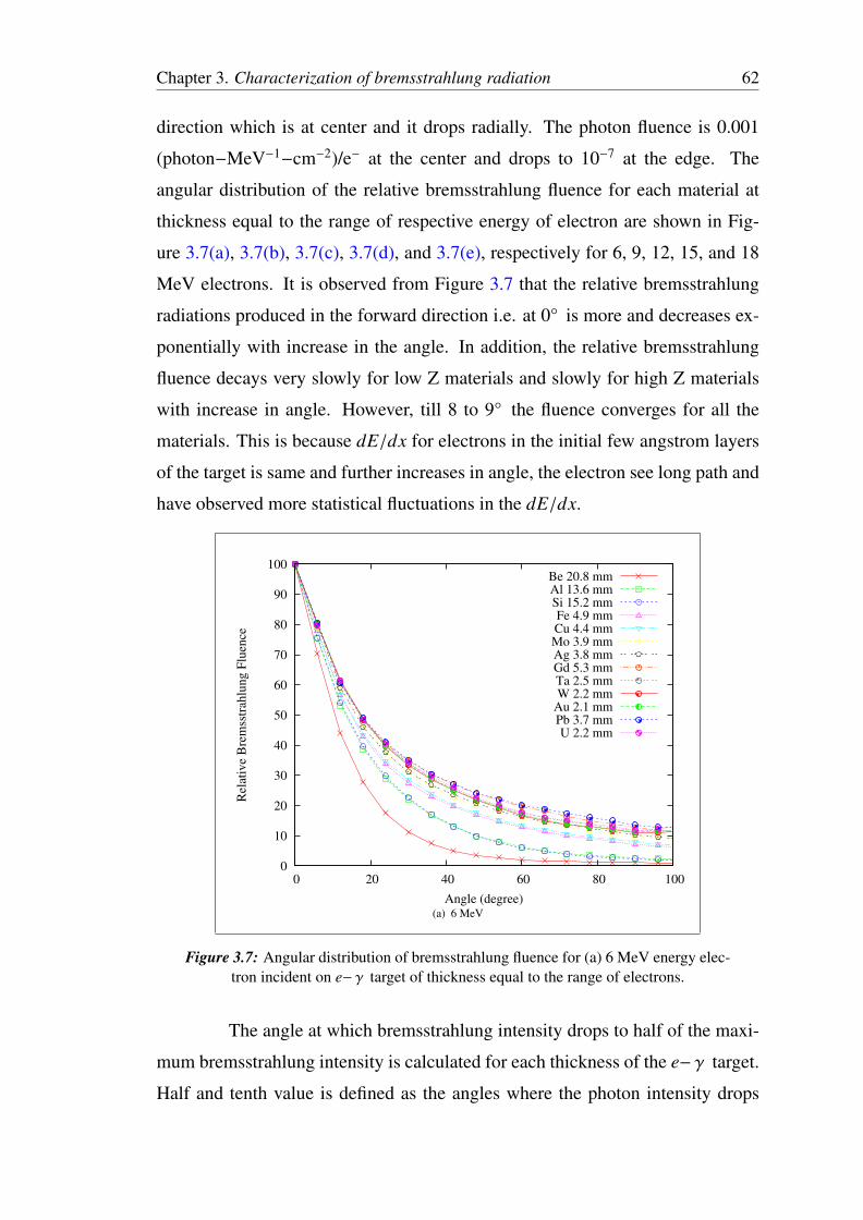
Chapter 3. Characterization of bremsstrahlung radiation 62
direction which is at center and it drops radially. The photon fluence is 0.001
(photon−MeV−1−cm−2)/e− at the center and drops to 10−7 at the edge. The
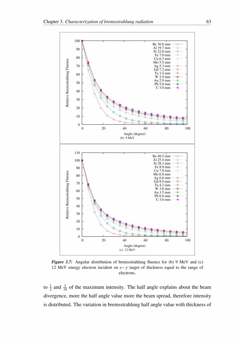
angular distribution of the relative bremsstrahlung fluence for each material at
thickness equal to the range of respective energy of electron are shown in Fig-
ure 3.7(a), 3.7(b), 3.7(c), 3.7(d), and 3.7(e), respectively for 6, 9, 12, 15, and 18
MeV electrons. It is observed from Figure 3.7 that the relative bremsstrahlung
radiations produced in the forward direction i.e. at 0° is more and decreases ex-
ponentially with increase in the angle. In addition, the relative bremsstrahlung
fluence decays very slowly for low Z materials and slowly for high Z materials
with increase in angle. However, till 8 to 9° the fluence converges for all the
materials. This is because dE/dx for electrons in the initial few angstrom layers
of the target is same and further increases in angle, the electron see long path and
have observed more statistical fluctuations in the dE/dx.
0
10
20
30
40
50
60
70
80
90
100
0 20 40 60 80 100
Rel
ativ
e B
rem
sstr
ahlu
ng F
luen
ce
Angle (degree)
Be 20.8 mmAl 13.6 mmSi 15.2 mmFe 4.9 mmCu 4.4 mmMo 3.9 mmAg 3.8 mmGd 5.3 mmTa 2.5 mmW 2.2 mm
Au 2.1 mmPb 3.7 mmU 2.2 mm
(a) 6 MeV
Figure 3.7: Angular distribution of bremsstrahlung fluence for (a) 6 MeV energy elec-tron incident on e− γ target of thickness equal to the range of electrons.
The angle at which bremsstrahlung intensity drops to half of the maxi-
mum bremsstrahlung intensity is calculated for each thickness of the e− γ target.
Half and tenth value is defined as the angles where the photon intensity drops
Chapter 3. Characterization of bremsstrahlung radiation 63
0
10
20
30
40
50
60
70
80
90
100
0 20 40 60 80 100
Rel
ativ
e B
rem
sstr
ahlu
ng F
luen
ce
Angle (degree)
Be 30.8 mmAl 19.7 mmSi 22.0 mmFe 7.0 mmCu 6.3 mmMo 5.5 mmAg 5.3 mmGd 7.2 mmTa 3.4 mmW 2.9 mm
Au 2.9 mmPb 5.0 mmU 3.0 mm
(b) 9 MeV
0
10
20
30
40
50
60
70
80
90
100
110
0 20 40 60 80 100
Rel
ativ
e B
rem
sstr
ahlu
ng F
luen
ce
Angle (degree)
Be 40.5 mmAl 25.4 mmSi 28.3 mmFe 8.9 mmCu 7.9 mmMo 6.8 mmAg 6.6 mmGd 8.9 mmTa 4.2 mmW 3.6 mm
Au 3.5 mmPb 6.0 mmU 3.6 mm
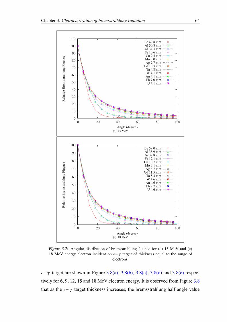
(c) 12 MeV
Figure 3.7: Angular distribution of bremsstrahlung fluence for (b) 9 MeV and (c)12 MeV energy electron incident on e− γ target of thickness equal to the range of
electrons.
to 12 and 1
10 of the maximum intensity. The half angle explains about the beam
divergence, more the half angle value more the beam spread, therefore intensity
is distributed. The variation in bremsstrahlung half angle value with thickness of
Chapter 3. Characterization of bremsstrahlung radiation 64
0
10
20
30
40
50
60
70
80
90
100
110
0 20 40 60 80 100
Rel
ativ
e B
rem
sstr
ahlu
ng F
luen
ce
Angle (degree)
Be 49.8 mmAl 30.8 mmSi 34.3 mmFe 10.6 mmCu 9.4 mmMo 8.0 mmAg 7.7 mm
Gd 10.3 mmTa 4.8 mmW 4.1 mm
Au 4.1 mmPb 7.0 mmU 4.1 mm
(d) 15 MeV
0
10
20
30
40
50
60
70
80
90
100
0 20 40 60 80 100
Rel
ativ
e B
rem
sstr
ahlu
ng F
luen
ce
Angle (degree)
Be 59.0 mmAl 35.9 mmSi 39.8 mmFe 12.1 mmCu 10.7 mmMo 9.1 mmAg 8.7 mm
Gd 11.5 mmTa 5.4 mmW 4.6 mm
Au 4.6 mmPb 7.7 mmU 4.6 mm
(e) 18 MeV
Figure 3.7: Angular distribution of bremsstrahlung fluence for (d) 15 MeV and (e)18 MeV energy electron incident on e− γ target of thickness equal to the range of
electrons.
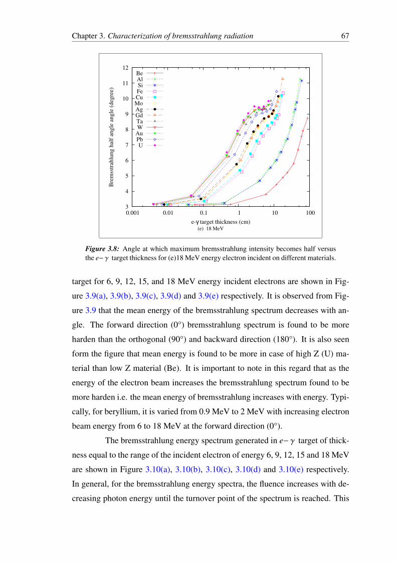
e− γ target are shown in Figure 3.8(a), 3.8(b), 3.8(c), 3.8(d) and 3.8(e) respec-
tively for 6, 9, 12, 15 and 18 MeV electron energy. It is observed from Figure 3.8
that as the e− γ target thickness increases, the bremsstrahlung half angle value
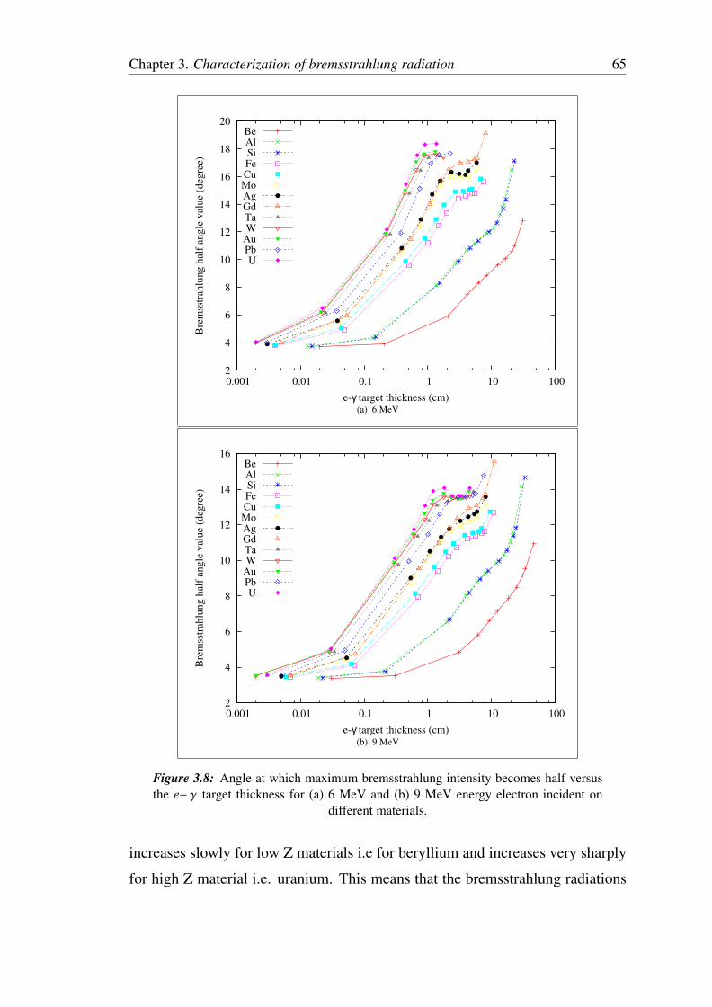
Chapter 3. Characterization of bremsstrahlung radiation 65
2
4
6
8
10
12
14
16
18
20
0.001 0.01 0.1 1 10 100
Bre
mss
trah
lung h
alf
angle
val
ue
(deg
ree)
e-γ target thickness (cm)
BeAlSiFeCuMoAgGdTaW
AuPbU
(a) 6 MeV
2
4
6
8
10
12
14
16
0.001 0.01 0.1 1 10 100
Bre
mss
trah
lung h
alf
angle
val
ue
(deg
ree)
e-γ target thickness (cm)
BeAlSiFeCuMoAgGdTaW
AuPbU
(b) 9 MeV
Figure 3.8: Angle at which maximum bremsstrahlung intensity becomes half versusthe e− γ target thickness for (a) 6 MeV and (b) 9 MeV energy electron incident on
different materials.
increases slowly for low Z materials i.e for beryllium and increases very sharply
for high Z material i.e. uranium. This means that the bremsstrahlung radiations
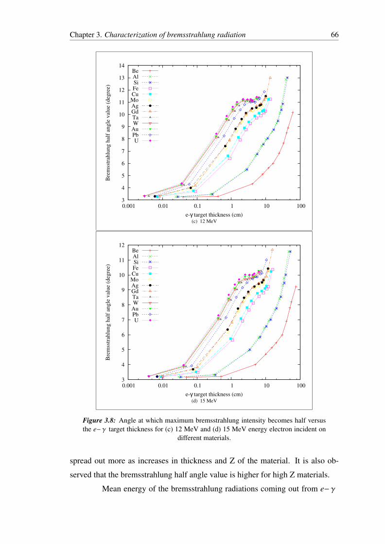
Chapter 3. Characterization of bremsstrahlung radiation 66
3
4
5
6
7
8
9
10
11
12
13
14
0.001 0.01 0.1 1 10 100
Bre
mss
trah
lung h
alf
angle
val
ue
(deg
ree)
e-γ target thickness (cm)
BeAlSiFeCuMoAgGdTaW
AuPbU
(c) 12 MeV
3
4
5
6
7
8
9
10
11
12
0.001 0.01 0.1 1 10 100
Bre
mss
trah
lung h
alf
angle
val
ue
(deg
ree)
e-γ target thickness (cm)
BeAlSiFeCuMoAgGdTaW
AuPbU
(d) 15 MeV
Figure 3.8: Angle at which maximum bremsstrahlung intensity becomes half versusthe e− γ target thickness for (c) 12 MeV and (d) 15 MeV energy electron incident on
different materials.
spread out more as increases in thickness and Z of the material. It is also ob-
served that the bremsstrahlung half angle value is higher for high Z materials.
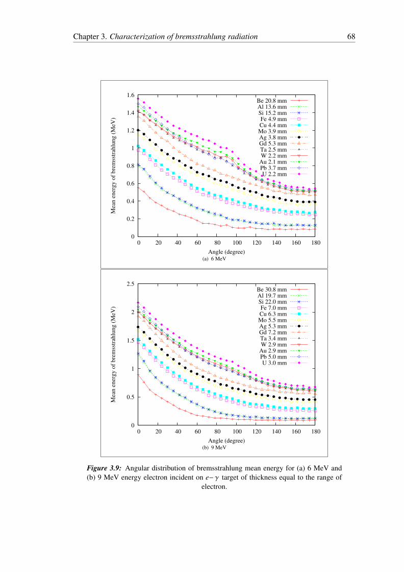
Mean energy of the bremsstrahlung radiations coming out from e− γ
Chapter 3. Characterization of bremsstrahlung radiation 67
3
4
5
6
7
8
9
10
11
12
0.001 0.01 0.1 1 10 100
Bre
mss
trah
lung h
alf
angle
angle
(deg
ree)
e-γ target thickness (cm)
BeAlSiFeCuMoAgGdTaW
AuPbU
(e) 18 MeV
Figure 3.8: Angle at which maximum bremsstrahlung intensity becomes half versusthe e− γ target thickness for (e)18 MeV energy electron incident on different materials.
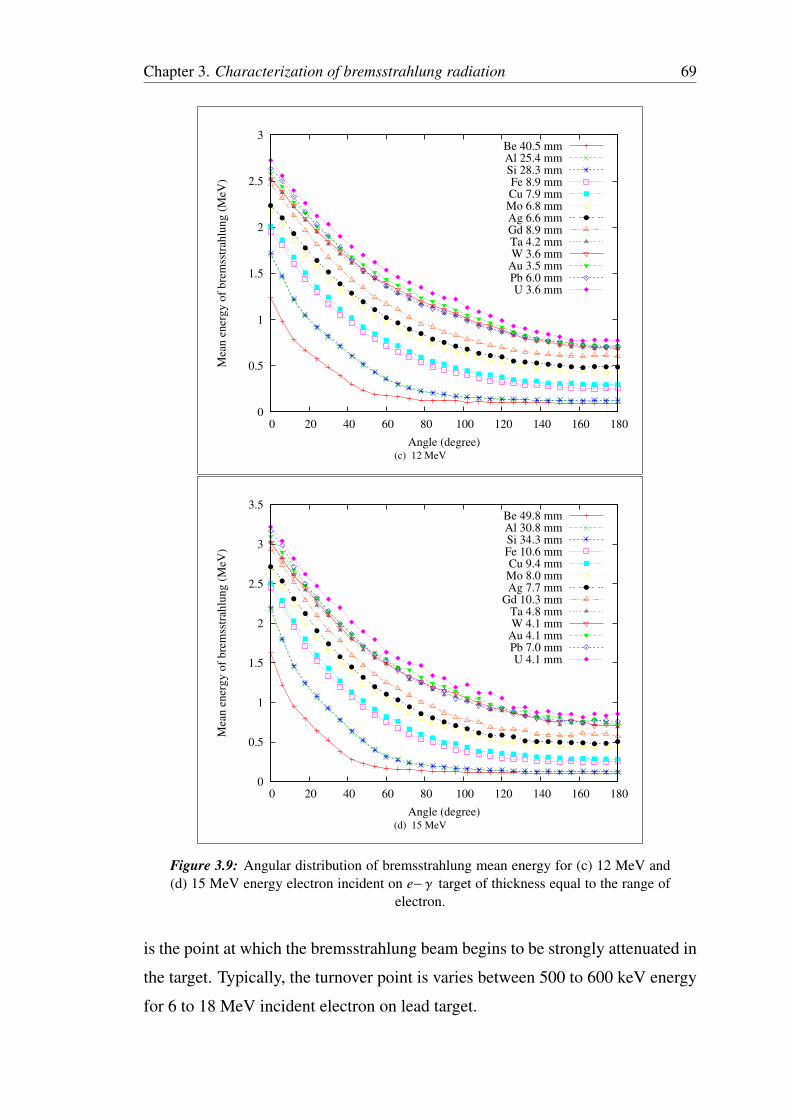
target for 6, 9, 12, 15, and 18 MeV energy incident electrons are shown in Fig-
ure 3.9(a), 3.9(b), 3.9(c), 3.9(d) and 3.9(e) respectively. It is observed from Fig-
ure 3.9 that the mean energy of the bremsstrahlung spectrum decreases with an-
gle. The forward direction (0°) bremsstrahlung spectrum is found to be more
harden than the orthogonal (90°) and backward direction (180°). It is also seen
form the figure that mean energy is found to be more in case of high Z (U) ma-
terial than low Z material (Be). It is important to note in this regard that as the
energy of the electron beam increases the bremsstrahlung spectrum found to be
more harden i.e. the mean energy of bremsstrahlung increases with energy. Typi-
cally, for beryllium, it is varied from 0.9 MeV to 2 MeV with increasing electron
beam energy from 6 to 18 MeV at the forward direction (0°).
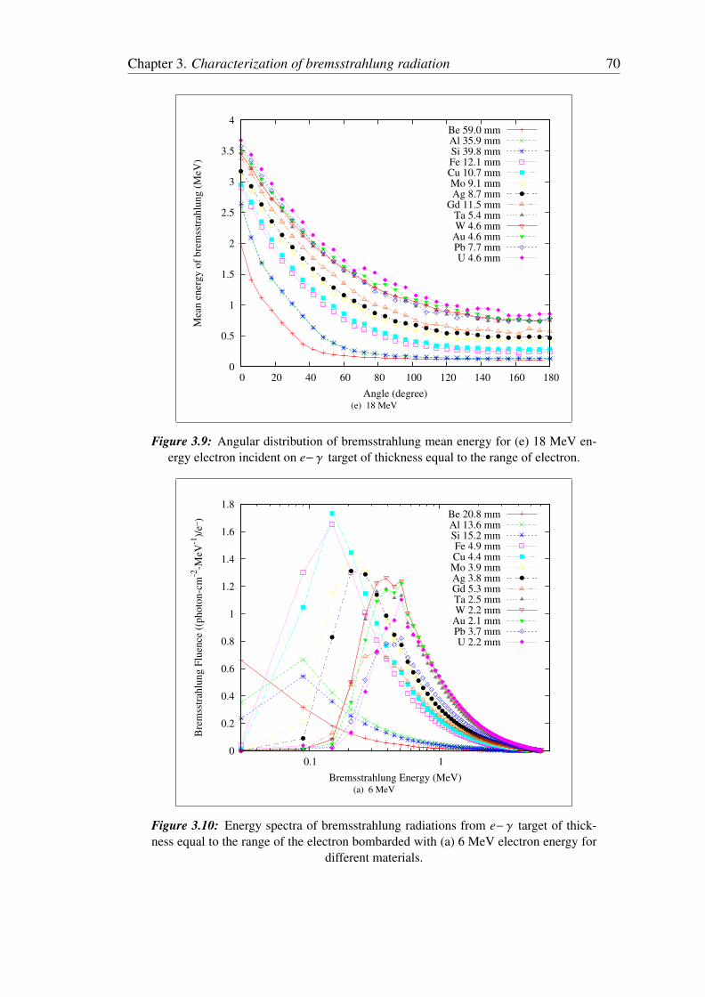
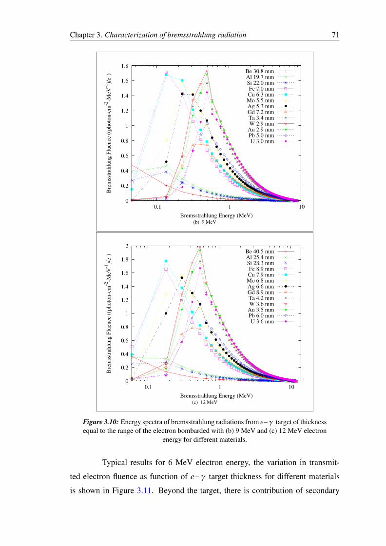
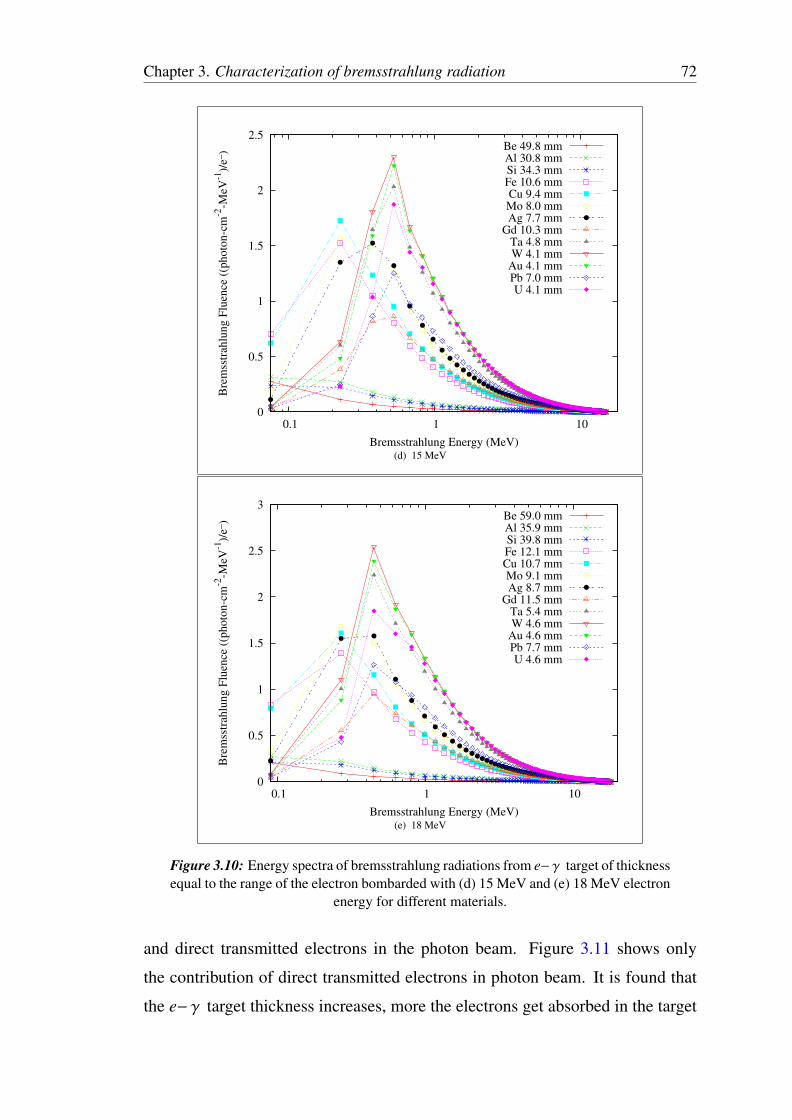
The bremsstrahlung energy spectrum generated in e− γ target of thick-
ness equal to the range of the incident electron of energy 6, 9, 12, 15 and 18 MeV
are shown in Figure 3.10(a), 3.10(b), 3.10(c), 3.10(d) and 3.10(e) respectively.
In general, for the bremsstrahlung energy spectra, the fluence increases with de-
creasing photon energy until the turnover point of the spectrum is reached. This
Chapter 3. Characterization of bremsstrahlung radiation 68
0
0.2
0.4
0.6
0.8
1
1.2
1.4
1.6
0 20 40 60 80 100 120 140 160 180
Mea
n e
ner
gy o
f bre
mss
trah
lung (
MeV
)
Angle (degree)
Be 20.8 mmAl 13.6 mmSi 15.2 mmFe 4.9 mmCu 4.4 mmMo 3.9 mmAg 3.8 mmGd 5.3 mmTa 2.5 mmW 2.2 mm
Au 2.1 mmPb 3.7 mmU 2.2 mm
(a) 6 MeV
0
0.5
1
1.5
2
2.5
0 20 40 60 80 100 120 140 160 180
Mea
n e
ner
gy o
f bre
mss
trah
lung (
MeV
)
Angle (degree)
Be 30.8 mmAl 19.7 mmSi 22.0 mmFe 7.0 mmCu 6.3 mmMo 5.5 mmAg 5.3 mmGd 7.2 mmTa 3.4 mmW 2.9 mm
Au 2.9 mmPb 5.0 mmU 3.0 mm
(b) 9 MeV
Figure 3.9: Angular distribution of bremsstrahlung mean energy for (a) 6 MeV and(b) 9 MeV energy electron incident on e− γ target of thickness equal to the range of
electron.
Chapter 3. Characterization of bremsstrahlung radiation 69
0
0.5
1
1.5
2
2.5
3
0 20 40 60 80 100 120 140 160 180
Mea
n e
ner
gy o
f bre
mss
trah
lung (
MeV
)
Angle (degree)
Be 40.5 mmAl 25.4 mmSi 28.3 mmFe 8.9 mmCu 7.9 mmMo 6.8 mmAg 6.6 mmGd 8.9 mmTa 4.2 mmW 3.6 mm
Au 3.5 mmPb 6.0 mmU 3.6 mm
(c) 12 MeV
0
0.5
1
1.5
2
2.5
3
3.5
0 20 40 60 80 100 120 140 160 180
Mea
n e
ner
gy o
f bre
mss
trah
lung (
MeV
)
Angle (degree)
Be 49.8 mmAl 30.8 mmSi 34.3 mmFe 10.6 mmCu 9.4 mmMo 8.0 mmAg 7.7 mm
Gd 10.3 mmTa 4.8 mmW 4.1 mm
Au 4.1 mmPb 7.0 mmU 4.1 mm
(d) 15 MeV
Figure 3.9: Angular distribution of bremsstrahlung mean energy for (c) 12 MeV and(d) 15 MeV energy electron incident on e− γ target of thickness equal to the range of
electron.
is the point at which the bremsstrahlung beam begins to be strongly attenuated in
the target. Typically, the turnover point is varies between 500 to 600 keV energy
for 6 to 18 MeV incident electron on lead target.
Chapter 3. Characterization of bremsstrahlung radiation 70
0
0.5
1
1.5
2
2.5
3
3.5
4
0 20 40 60 80 100 120 140 160 180
Mea
n e
ner
gy o
f bre
mss
trah
lung (
MeV
)
Angle (degree)
Be 59.0 mmAl 35.9 mmSi 39.8 mmFe 12.1 mmCu 10.7 mmMo 9.1 mmAg 8.7 mm
Gd 11.5 mmTa 5.4 mmW 4.6 mm
Au 4.6 mmPb 7.7 mmU 4.6 mm
(e) 18 MeV
Figure 3.9: Angular distribution of bremsstrahlung mean energy for (e) 18 MeV en-ergy electron incident on e− γ target of thickness equal to the range of electron.
0
0.2
0.4
0.6
0.8
1
1.2
1.4
1.6
1.8
0.1 1
Bre
mss
trah
lung F
luen
ce (
(photo
n-c
m-2
-MeV
-1)/
e_)
Bremsstrahlung Energy (MeV)
Be 20.8 mmAl 13.6 mmSi 15.2 mmFe 4.9 mmCu 4.4 mmMo 3.9 mmAg 3.8 mmGd 5.3 mmTa 2.5 mmW 2.2 mm
Au 2.1 mmPb 3.7 mmU 2.2 mm
(a) 6 MeV
Figure 3.10: Energy spectra of bremsstrahlung radiations from e− γ target of thick-ness equal to the range of the electron bombarded with (a) 6 MeV electron energy for
different materials.
Chapter 3. Characterization of bremsstrahlung radiation 71
0
0.2
0.4
0.6
0.8
1
1.2
1.4
1.6
1.8
0.1 1 10
Bre
mss
trah
lung F
luen
ce (
(photo
n-c
m-2
-MeV
-1)/
e_)
Bremsstrahlung Energy (MeV)
Be 30.8 mmAl 19.7 mmSi 22.0 mmFe 7.0 mmCu 6.3 mmMo 5.5 mmAg 5.3 mmGd 7.2 mmTa 3.4 mmW 2.9 mm
Au 2.9 mmPb 5.0 mmU 3.0 mm
(b) 9 MeV
0
0.2
0.4
0.6
0.8
1
1.2
1.4
1.6
1.8
2
0.1 1 10
Bre
mss
trah
lung F
luen
ce (
(photo
n-c
m-2
-MeV
-1)/
e_)
Bremsstrahlung Energy (MeV)
Be 40.5 mmAl 25.4 mmSi 28.3 mmFe 8.9 mmCu 7.9 mmMo 6.8 mmAg 6.6 mmGd 8.9 mmTa 4.2 mmW 3.6 mm
Au 3.5 mmPb 6.0 mmU 3.6 mm
(c) 12 MeV
Figure 3.10: Energy spectra of bremsstrahlung radiations from e− γ target of thicknessequal to the range of the electron bombarded with (b) 9 MeV and (c) 12 MeV electron
energy for different materials.
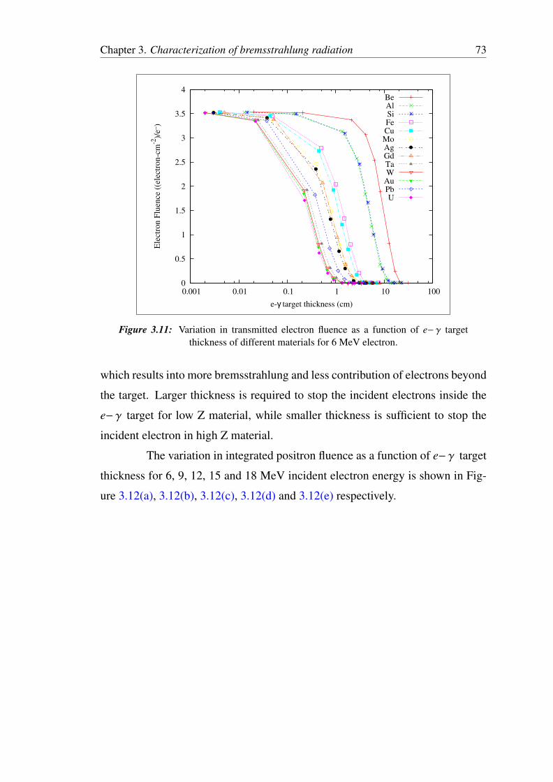
Typical results for 6 MeV electron energy, the variation in transmit-
ted electron fluence as function of e− γ target thickness for different materials
is shown in Figure 3.11. Beyond the target, there is contribution of secondary
Chapter 3. Characterization of bremsstrahlung radiation 72
0
0.5
1
1.5
2
2.5
0.1 1 10
Bre
mss
trah
lung F
luen
ce (
(photo
n-c
m-2
-MeV
-1)/
e_)
Bremsstrahlung Energy (MeV)
Be 49.8 mmAl 30.8 mmSi 34.3 mmFe 10.6 mmCu 9.4 mmMo 8.0 mmAg 7.7 mm
Gd 10.3 mmTa 4.8 mmW 4.1 mm
Au 4.1 mmPb 7.0 mmU 4.1 mm
(d) 15 MeV
0
0.5
1
1.5
2
2.5
3
0.1 1 10
Bre
mss
trah
lung F
luen
ce (
(photo
n-c
m-2
-MeV
-1)/
e_)
Bremsstrahlung Energy (MeV)
Be 59.0 mmAl 35.9 mmSi 39.8 mmFe 12.1 mmCu 10.7 mmMo 9.1 mmAg 8.7 mm
Gd 11.5 mmTa 5.4 mmW 4.6 mm
Au 4.6 mmPb 7.7 mmU 4.6 mm
(e) 18 MeV
Figure 3.10: Energy spectra of bremsstrahlung radiations from e− γ target of thicknessequal to the range of the electron bombarded with (d) 15 MeV and (e) 18 MeV electron
energy for different materials.
and direct transmitted electrons in the photon beam. Figure 3.11 shows only
the contribution of direct transmitted electrons in photon beam. It is found that
the e− γ target thickness increases, more the electrons get absorbed in the target
Chapter 3. Characterization of bremsstrahlung radiation 73
0
0.5
1
1.5
2
2.5
3
3.5
4
0.001 0.01 0.1 1 10 100
Ele
ctro
n F
luen
ce (
(ele
ctro
n-c
m-2
)/e_
)
e-γ target thickness (cm)
BeAlSiFeCuMoAgGdTaW
AuPbU
Figure 3.11: Variation in transmitted electron fluence as a function of e− γ targetthickness of different materials for 6 MeV electron.
which results into more bremsstrahlung and less contribution of electrons beyond
the target. Larger thickness is required to stop the incident electrons inside the
e− γ target for low Z material, while smaller thickness is sufficient to stop the
incident electron in high Z material.
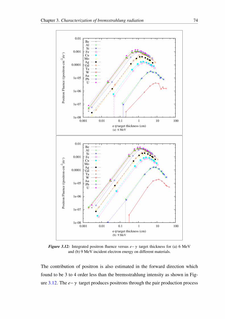
The variation in integrated positron fluence as a function of e− γ target
thickness for 6, 9, 12, 15 and 18 MeV incident electron energy is shown in Fig-
ure 3.12(a), 3.12(b), 3.12(c), 3.12(d) and 3.12(e) respectively.
Chapter 3. Characterization of bremsstrahlung radiation 74
1e-08
1e-07
1e-06
1e-05
0.0001
0.001
0.01
0.001 0.01 0.1 1 10 100
Posi
tron F
luen
ce (
(posi
tron-c
m-2
)/e_
)
e-γ target thickness (cm)
BeAlSiFeCuMoAgGdTaW
AuPbU
(a) 6 MeV
1e-08
1e-07
1e-06
1e-05
0.0001
0.001
0.01
0.001 0.01 0.1 1 10 100
Posi
tron F
luen
ce (
(posi
tron-c
m-2
)/e_
)
e-γ target thickness (cm)
BeAlSiFeCuMoAgGdTaW
AuPbU
(b) 9 MeV
Figure 3.12: Integrated positron fluence versus e− γ target thickness for (a) 6 MeVand (b) 9 MeV incident electron energy on different materials.
The contribution of positron is also estimated in the forward direction which
found to be 3 to 4 order less than the bremsstrahlung intensity as shown in Fig-
ure 3.12. The e− γ target produces positrons through the pair production process
Chapter 3. Characterization of bremsstrahlung radiation 75
1e-08
1e-07
1e-06
1e-05
0.0001
0.001
0.01
0.1
0.001 0.01 0.1 1 10 100
Posi
tron F
luen
ce (
(posi
tron-c
m-2
)/e_
)
e-γ target thickness (cm)
BeAlSiFeCuMoAgGdTaW
AuPbU
(c) 12 MeV
1e-08
1e-07
1e-06
1e-05
0.0001
0.001
0.01
0.1
0.001 0.01 0.1 1 10 100
Posi
tron F
luen
ce (
(posi
tron-c
m-2
)/e_
)
e-γ target thickness (cm)
BeAlSiFeCuMoAgGdTaW
AuPbU
(d) 15 MeV
Figure 3.12: Integrated positron fluence versus e− γ target thickness for (c) 12 MeVand (d) 15 MeV incident electron energy on different materials.
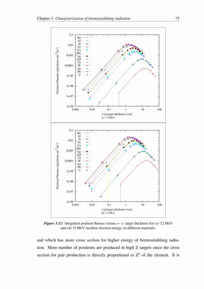
and which has more cross section for higher energy of bremsstrahlung radia-
tion. More number of positrons are produced in high Z targets since the cross
section for pair production is directly proportional to Z2 of the element. It is
Chapter 3. Characterization of bremsstrahlung radiation 76
1e-08
1e-07
1e-06
1e-05
0.0001
0.001
0.01
0.1
0.001 0.01 0.1 1 10 100
Posi
tron F
luen
ce (
(posi
tron-c
m-2
)/e_
)
e-γ target thickness (cm)
BeAlSiFeCuMoAgGdTaW
AuPbU
(e) 18 MeV
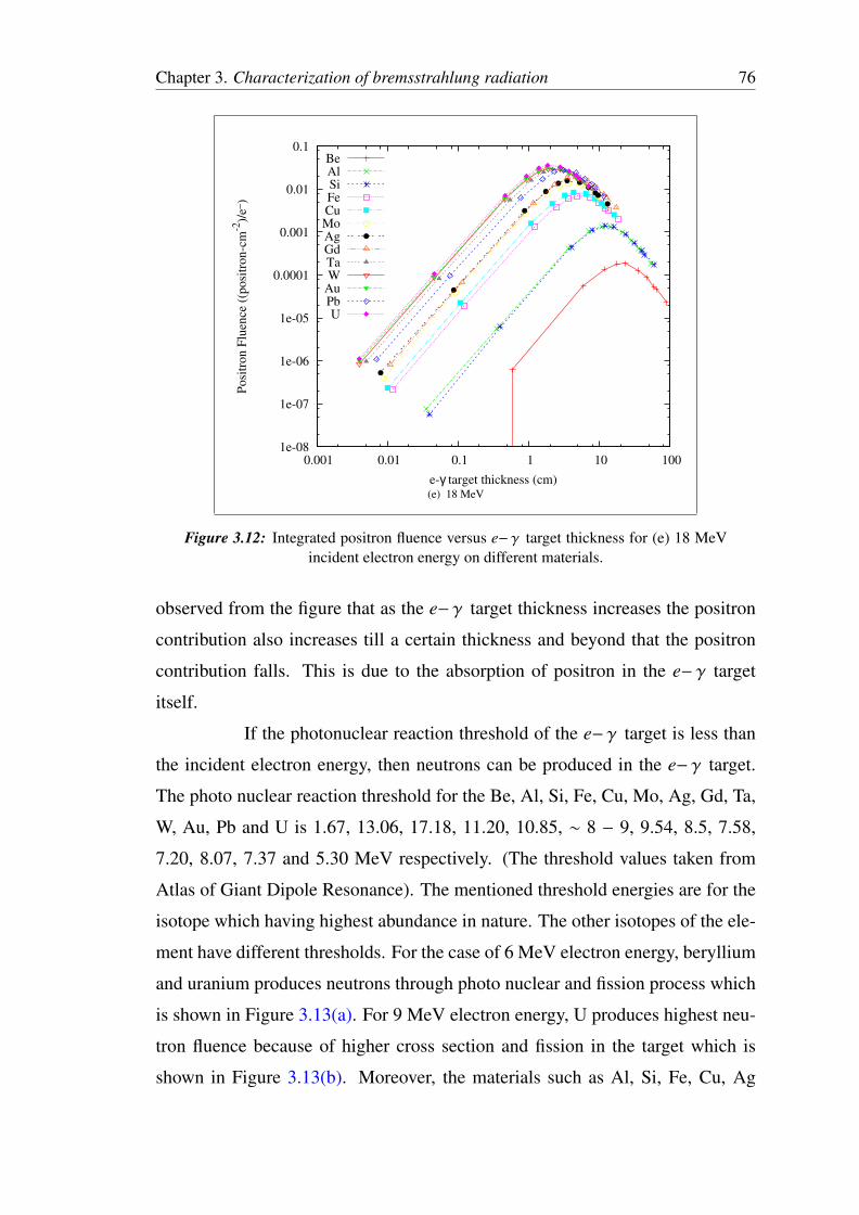
Figure 3.12: Integrated positron fluence versus e− γ target thickness for (e) 18 MeVincident electron energy on different materials.
observed from the figure that as the e− γ target thickness increases the positron
contribution also increases till a certain thickness and beyond that the positron
contribution falls. This is due to the absorption of positron in the e− γ target
itself.
If the photonuclear reaction threshold of the e− γ target is less than
the incident electron energy, then neutrons can be produced in the e− γ target.
The photo nuclear reaction threshold for the Be, Al, Si, Fe, Cu, Mo, Ag, Gd, Ta,
W, Au, Pb and U is 1.67, 13.06, 17.18, 11.20, 10.85, ∼ 8 − 9, 9.54, 8.5, 7.58,
7.20, 8.07, 7.37 and 5.30 MeV respectively. (The threshold values taken from
Atlas of Giant Dipole Resonance). The mentioned threshold energies are for the
isotope which having highest abundance in nature. The other isotopes of the ele-
ment have different thresholds. For the case of 6 MeV electron energy, beryllium
and uranium produces neutrons through photo nuclear and fission process which
is shown in Figure 3.13(a). For 9 MeV electron energy, U produces highest neu-
tron fluence because of higher cross section and fission in the target which is
shown in Figure 3.13(b). Moreover, the materials such as Al, Si, Fe, Cu, Ag
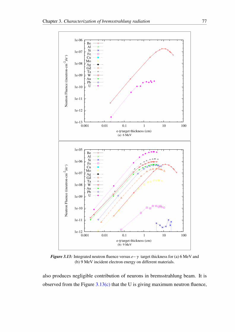
Chapter 3. Characterization of bremsstrahlung radiation 77
1e-13
1e-12
1e-11
1e-10
1e-09
1e-08
1e-07
1e-06
0.001 0.01 0.1 1 10 100
Neu
tron F
luen
ce (
(neu
tron-c
m-2
)/e_
)
e-γ target thickness (cm)
BeAlSiFeCuMoAgGdTaW
AuPbU
(a) 6 MeV
1e-12
1e-11
1e-10
1e-09
1e-08
1e-07
1e-06
1e-05
0.001 0.01 0.1 1 10 100
Neu
tron F
luen
ce (
(neu
tron-c
m-2
)/e_
)
e-γ target thickness (cm)
BeAlSiFeCuMoAgGdTaW
AuPbU
(b) 9 MeV
Figure 3.13: Integrated neutron fluence versus e− γ target thickness for (a) 6 MeV and(b) 9 MeV incident electron energy on different materials.
also produces negligible contribution of neurons in bremsstrahlung beam. It is
observed from the Figure 3.13(c) that the U is giving maximum neutron fluence,
Chapter 3. Characterization of bremsstrahlung radiation 78
1e-13
1e-12
1e-11
1e-10
1e-09
1e-08
1e-07
1e-06
1e-05
0.0001
0.001 0.01 0.1 1 10 100
Neu
tron F
luen
ce (
(neu
tron-c
m-2
)/e_
)
e-γ target thickness (cm)
BeAlSiFeCuMoAgGdTaW
AuPbU
(c) 12 MeV
1e-12
1e-11
1e-10
1e-09
1e-08
1e-07
1e-06
1e-05
0.0001
0.001
0.001 0.01 0.1 1 10 100
Neu
tron F
luen
ce (
(neu
tron-c
m-2
)/e_
)
e-γ target thickness (cm)
BeAlSiFeCuMoAgGdTaW
AuPbU
(d) 15 MeV
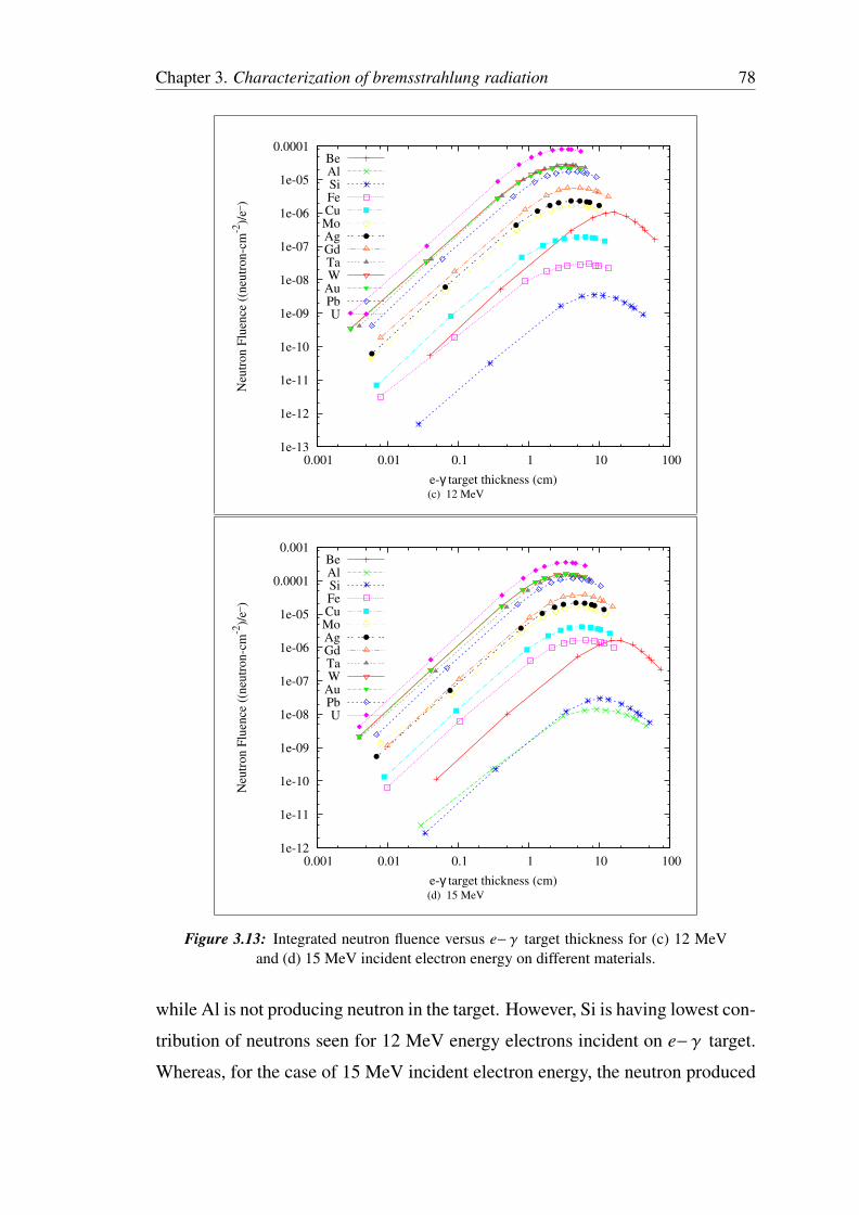
Figure 3.13: Integrated neutron fluence versus e− γ target thickness for (c) 12 MeVand (d) 15 MeV incident electron energy on different materials.
while Al is not producing neutron in the target. However, Si is having lowest con-
tribution of neutrons seen for 12 MeV energy electrons incident on e− γ target.
Whereas, for the case of 15 MeV incident electron energy, the neutron produced
Chapter 3. Characterization of bremsstrahlung radiation 79
1e-12
1e-11
1e-10
1e-09
1e-08
1e-07
1e-06
1e-05
0.0001
0.001
0.001 0.01 0.1 1 10 100
Neu
tron F
luen
ce (
(neu
tron-c
m-2
)/e_
)
e-γ target thickness (cm)
BeAlSiFeCuMoAgGdTaW
AuPbU
(e) 18 MeV
Figure 3.13: Integrated neutron fluence versus e− γ target thickness for (e) 18 MeVincident electron energy on different materials.
in the e− γ target is shown in Figure 3.13(d). It is observed that all the materials
having photonuclear reaction threshold lower than the 15 MeV electron energy,
shows neutrons for e− γ target. Out of this U is giving maximum neutron fluence
because of its higher cross section and fission. The neutron fluence contribution
in Al and Si material found to be negligible. Moreover, the threshold energy
for Be is lower than other materials, but it produces less neutrons because of
lower cross section value. However, the materials such as Au, Ta, W almost pro-
duces same amount of neutron fluence. Variation of neutron fluence produced
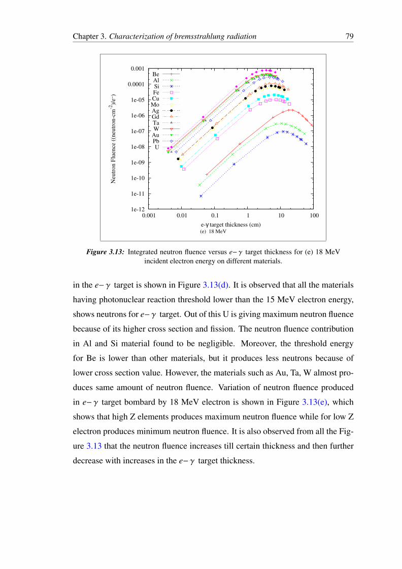
in e− γ target bombard by 18 MeV electron is shown in Figure 3.13(e), which
shows that high Z elements produces maximum neutron fluence while for low Z
electron produces minimum neutron fluence. It is also observed from all the Fig-
ure 3.13 that the neutron fluence increases till certain thickness and then further
decrease with increases in the e− γ target thickness.
Chapter 3. Characterization of bremsstrahlung radiation 80
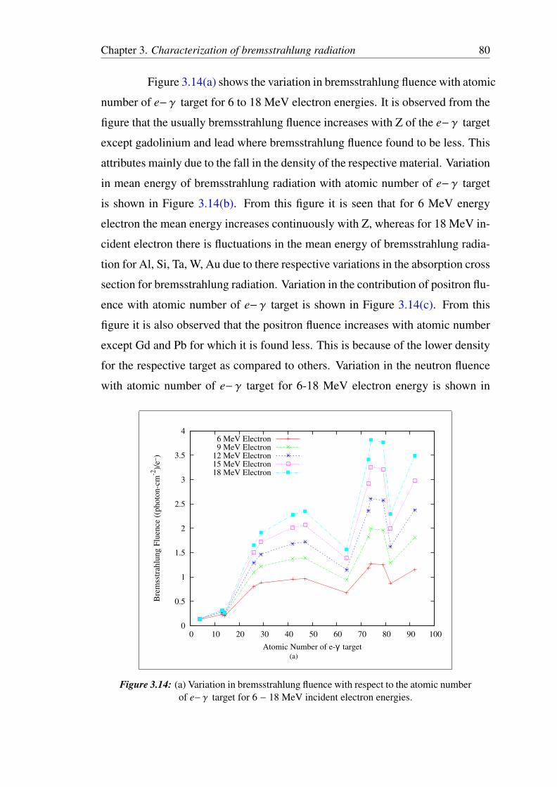
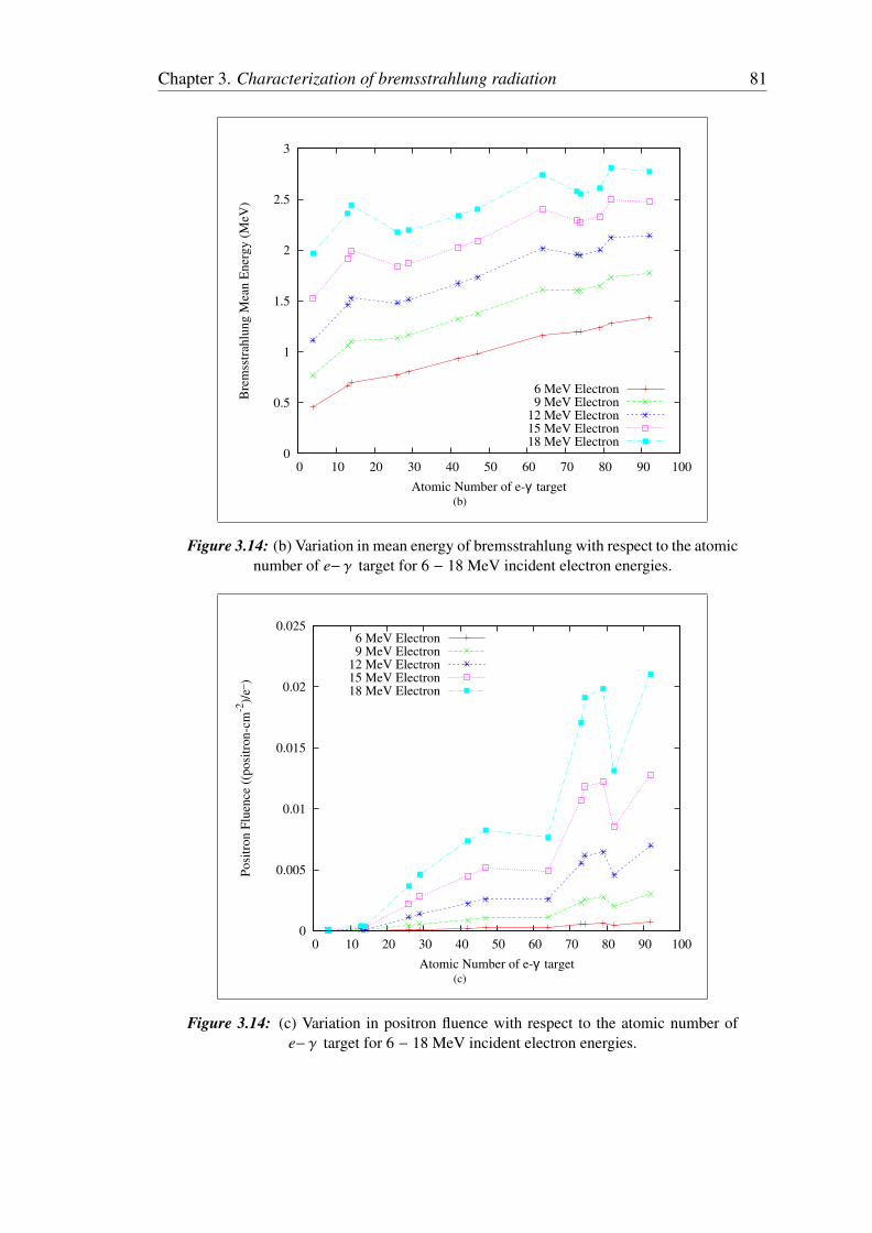
Figure 3.14(a) shows the variation in bremsstrahlung fluence with atomic
number of e− γ target for 6 to 18 MeV electron energies. It is observed from the
figure that the usually bremsstrahlung fluence increases with Z of the e− γ target
except gadolinium and lead where bremsstrahlung fluence found to be less. This
attributes mainly due to the fall in the density of the respective material. Variation
in mean energy of bremsstrahlung radiation with atomic number of e− γ target
is shown in Figure 3.14(b). From this figure it is seen that for 6 MeV energy
electron the mean energy increases continuously with Z, whereas for 18 MeV in-
cident electron there is fluctuations in the mean energy of bremsstrahlung radia-
tion for Al, Si, Ta, W, Au due to there respective variations in the absorption cross
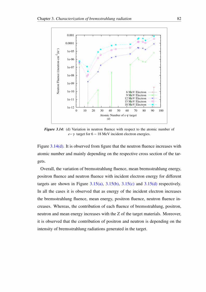
section for bremsstrahlung radiation. Variation in the contribution of positron flu-
ence with atomic number of e− γ target is shown in Figure 3.14(c). From this
figure it is also observed that the positron fluence increases with atomic number
except Gd and Pb for which it is found less. This is because of the lower density
for the respective target as compared to others. Variation in the neutron fluence
with atomic number of e− γ target for 6-18 MeV electron energy is shown in
0
0.5
1
1.5
2
2.5
3
3.5
4
0 10 20 30 40 50 60 70 80 90 100
Bre
mss
trah
lung F
luen
ce (
(photo
n-c
m-2
)/e_
)
Atomic Number of e-γ target
6 MeV Electron9 MeV Electron
12 MeV Electron15 MeV Electron18 MeV Electron
(a)
Figure 3.14: (a) Variation in bremsstrahlung fluence with respect to the atomic numberof e− γ target for 6 − 18 MeV incident electron energies.
Chapter 3. Characterization of bremsstrahlung radiation 81
0
0.5
1
1.5
2
2.5
3
0 10 20 30 40 50 60 70 80 90 100
Bre
mss
trah
lung M
ean E
ner
gy (
MeV
)
Atomic Number of e-γ target
6 MeV Electron9 MeV Electron
12 MeV Electron15 MeV Electron18 MeV Electron
(b)
Figure 3.14: (b) Variation in mean energy of bremsstrahlung with respect to the atomicnumber of e− γ target for 6 − 18 MeV incident electron energies.
0
0.005
0.01
0.015
0.02
0.025
0 10 20 30 40 50 60 70 80 90 100
Posi
tron F
luen
ce (
(posi
tron-c
m-2
)/e_
)
Atomic Number of e-γ target
6 MeV Electron9 MeV Electron
12 MeV Electron15 MeV Electron18 MeV Electron
(c)
Figure 3.14: (c) Variation in positron fluence with respect to the atomic number ofe− γ target for 6 − 18 MeV incident electron energies.
Chapter 3. Characterization of bremsstrahlung radiation 82
1e-12
1e-11
1e-10
1e-09
1e-08
1e-07
1e-06
1e-05
0.0001
0.001
0 10 20 30 40 50 60 70 80 90 100
Neu
tron F
luen
ce (
(neu
tron-c
m-2
)/e_
)
Atomic Number of e-γ target
6 MeV Electron9 MeV Electron
12 MeV Electron15 MeV Electron18 MeV Electron
(d)
Figure 3.14: (d) Variation in neutron fluence with respect to the atomic number ofe− γ target for 6 − 18 MeV incident electron energies.
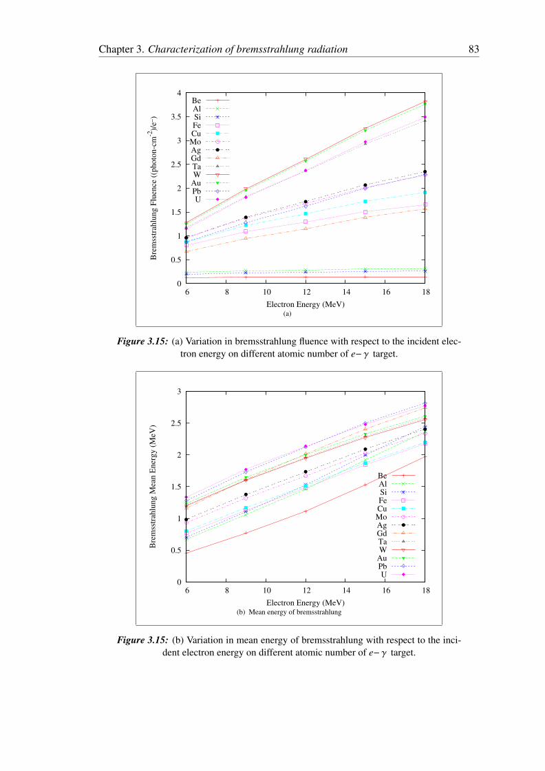
Figure 3.14(d). It is observed from figure that the neutron fluence increases with
atomic number and mainly depending on the respective cross section of the tar-
gets.
Overall, the variation of bremsstrahlung fluence, mean bremsstrahlung energy,
positron fluence and neutron fluence with incident electron energy for different
targets are shown in Figure 3.15(a), 3.15(b), 3.15(c) and 3.15(d) respectively.
In all the cases it is observed that as energy of the incident electron increases
the bremsstrahlung fluence, mean energy, positron fluence, neutron fluence in-
creases. Whereas, the contribution of each fluence of bremsstrahlung, positron,
neutron and mean energy increases with the Z of the target materials. Moreover,
it is observed that the contribution of positron and neutron is depending on the
intensity of bremsstrahlung radiations generated in the target.
Chapter 3. Characterization of bremsstrahlung radiation 83
0
0.5
1
1.5
2
2.5
3
3.5
4
6 8 10 12 14 16 18
Bre
mss
trah
lung F
luen
ce (
(photo
n-c
m-2
)/e_
)
Electron Energy (MeV)
BeAlSiFeCuMoAgGdTaW
AuPbU
(a)
Figure 3.15: (a) Variation in bremsstrahlung fluence with respect to the incident elec-tron energy on different atomic number of e− γ target.
0
0.5
1
1.5
2
2.5
3
6 8 10 12 14 16 18
Bre
mss
trah
lung M
ean E
ner
gy (
MeV
)
Electron Energy (MeV)
BeAlSiFeCuMoAgGdTaW
AuPbU
(b) Mean energy of bremsstrahlung
Figure 3.15: (b) Variation in mean energy of bremsstrahlung with respect to the inci-dent electron energy on different atomic number of e− γ target.
Chapter 3. Characterization of bremsstrahlung radiation 84
1e-06
1e-05
0.0001
0.001
0.01
0.1
6 8 10 12 14 16 18
Posi
tron F
luen
ce (
(posi
tron-c
m-2
)/e_
)
Electron Energy (MeV)
BeAlSiFeCuMoAgGdTaW
AuPbU
(c)
Figure 3.15: (c) Variation in positron fluence with respect to the incident electronenergy on different atomic number of e− γ target.
1e-12
1e-11
1e-10
1e-09
1e-08
1e-07
1e-06
1e-05
0.0001
0.001
6 8 10 12 14 16 18
Neu
tron F
luen
ce (
(neu
tron-c
m-2
)/e_
)
Electron Energy (MeV)
BeAlSiFeCuMoAgGdTaW
AuPbU
(d) Neutron fluence
Figure 3.15: (d) Variation in neutron fluence with respect to the incident electronenergy on different atomic number of e− γ target.
Chapter 3. Characterization of bremsstrahlung radiation 85
3.5 Conclusion
The data of bremsstrahlung radiations generated in various target for different
energy of electron from 6 to 18 MeV are summarized and concluded below,
• Maximum bremsstrahlung fluence is obtained for high Z material (U) and
higher incident electron energy (18 MeV).
• The mean energy of bremsstrahlung radiation for high Z target is observed
more.
• The bremsstrahlung fluence is maximum in the forward direction and it
decreases sharply with angle.
• High Z targets produce higher neutron fluence for energies greater than 12
MeV electron.
• The contribution of direct transmitted electrons beyond the range of elec-
tron in the target is negligible.
• The contribution of positron in the bremsstrahlung beam is negligible.
3.6 Future Scope
The study shown here only considers the individual targets. Based on the re-
sults further studies can be carried out using multilayer targets. The multilayer
target can be formed with the combinations of materials such that the maximum
bremsstrahlung radiations can be obtained with marginal contribution of electron,
positron and neutron.
Bibliography
[1] United Nations Scientific Committee on the Effects of Atomic Radiation (UNSCEAR),Sources and effects of ionizing radiation, Report 1993, UN Publications, 1993.
[2] Sjgren, R, Karlsson, M. 1996. Electron contamination in clinical high energy photonbeams. Med. Phys., 23, 1873-1881.
[3] Mohan, R, Chui, C, Lidofsky, L., 1985. Energy and angular distributions of photonsfrom medical accelerators. Med. Phys., 12, 592-597.
[4] Mijnheer, B.J., et al., 1987. What degree of accuracy is required and can be achieved inphoton and neutron therapy? Radiother. Oncol. 8, 237-252.
[5] Brahme, A., 1988. Accuracy requirements and quality assurance of external beam ther-apy with photons and electrons. Supplementum 1, Acta Oncologica.
[6] International Commission on Radiation Measurements and Units (ICRU), 1976. Deter-mination of Absorbed Dose in a Patient Irradiated by Beams of X or Gamma Rays inRadiotherapy Procedures. ICRU Report 24, Bethesda, Maryland.
[7] Findlay, D.J.S., 1990. Nucl. Instr. and Meth. B50, 314.
[8] Koch, H.W., and Motz, J.W., 1959. Rev. Mod. Phys., 31, 920.
[9] Nordell,B., and Brahme,A. 1984. Angular distribution and yield from bremsstrahlungtargets. Phys. Med. Biol., 29(7), 797-810.
[10] Shiff, L.I., 1946. Phys. Rev., 70, 87.
[11] Seltzer S.M., and Berger, M.J., 1986. At. Data Nucl. Data Tables 35, 345.
[12] Seltzer, S.M., Berger, M.J., 1985. Nucl. Instr. and Meth. B 12,95.
[13] Salvata,F., Fernandez-Vareaa,J.M., Sempaub,J., Llovet,X., 2006. Radiation Physics andChemistry 75, 12011219.
[14] Faddegon, B.A., Ross, C.K., and Rogers D.W.O., 1990. Forward-directedbremsstrahlung of 10- to 30-MeV electrons incident on thick targets of Al and Pb. Med.Phys., 17, 77385.
[15] Faddegon,B.A., Ross,C.K., Rogers,D.W.O., 1991. Med. Phys., 18 727.
[16] Rogers, D.W.O., et al. 1995. BEAM: a Monte Carlo code to simulate radiotherapy treat-ment units. Med. Phys., 22, 50324.
86
Chapter 3. Characterization of bremsstrahlung radiation 87
[17] Fippel, M, et al., 2003, A virtual photon energy fluence model for Monte Carlo dosecalculation, Med. Phys., 30, 30111.
[18] Landry, D.J., and Anderson, D.W., 1991. Measurement of accelerator bremsstrahlungspectra with a high-efficiency Ge detector. Med. Phys., 18, 52732.
[19] Bloch, P, et al. 2000. Determining clinical photon beam spectra from measured depth-dose curve with the Cimmino algorithm. Phys. Med. Biol., 45, 17183.
[20] Archer, B.R., Almond, P.R. and Wagner, L.K., 1985. Application of a Laplace transformpair model for high x-ray spectral reconstruction. Med. Phys., 12 63034.
[21] Nisbet A, et al. 1998. Spectral reconstruction of clinical megavoltage photon beams andimplications of spectral determination on dosimetry of such beams. Phys. Med. Biol.,43, 150721.
[22] Francois P, et al. 1997. Validation of reconstructed bremsstrahlung spectra between 6MV and 25 MV from measured transmission data. Med. Phys., 24, 76973.
[23] Catala, A, Francois, P, Bonnet, J. and Scouarnec, Ch, 1995. Reconstruction of 12 MVbremsstrahlung spectra from measured transmission data by direct resolution of the nu-meric system AF = T. Med. Phys., 22, 310.
[24] Huang P H, Kase K R and Bjarngard B E 1983 Reconstruction of 4-MV bremsstrahlungspectra from measured transmission data Med. Phys. 10 77885
[25] Hinson W H and Bourland J D 2002 Spectral reconstruction of high energy photonbeams for kernel based dose calculations Med. Phys. 29 178996
[26] H.K. Tseng and R.H. Pratt, Phys. Rev. A19 (1979) 1525.
[27] J.L. Matthews and R.O. Owens, Nucl. Instr. and Meth. 111 (1973) 157.
[28] V.E. Zhuchko and Yu.M. Tsipenyuk, Sov. At. En. 39 (1976) 643.
[29] D.J.S. Findlay, Nucl. Instr. and Meth. 206 (1983) 507.
[30] K. Shin et al., Nucl. Instr. and Meth. 151 (1978) 271 and 277.
[31] K.C.D. Chan et al., Nucl. Instr. and Meth. B10/ll (1985) 419.
[32] M.J. Berger and S.M. Seltzer, Phys. Rev. C2 (1970) 621.
[33] H. Ferdinande et al., Nucl. Instr. and Meth. 91 (1971) 135.
[34] Kondev, Ph.G., et al., 1992. Calculation of bremsstrahlung spectra from a thick tungstenradiator as a function of photon energy and angle. Nucl. Instr. and Meth. B 71, 126-131.
[35] Fasso, A., et al., 1995. FLUKA: Performance and applications in the intermediate energyrange. OECD documents, 287-304.
[36] ICRU report, 1980. Quantities and units for use in Radiation Protection. InternationalCommission on Radiation Units and Measurements Radiation quantities and units ICRUreport 33.
[37] V. S. Deshmukh, V. N. Bhoraskar, J. Radioanal. Nucl. Chem. 103, 87 (1986)
Recommended

![Studies on Bremsstrahlung sources in the BTH and …at5].pdf · Studies on Bremsstrahlung sources in the BTH and LCLS undulator Irradiation of the FEE by Bremsstrahlung beams from](https://img.pdfslide.us/doc/110x75/5b9309d109d3f2a22a8c84c7/studies-on-bremsstrahlung-sources-in-the-bth-and-at5pdf-studies-on-bremsstrahlung.jpg)