Installation & Maintenance Manual
CHALLENGERSOLO
CC50s, CC85s, CC105s, CC125s, CC125Hs, CC150s
If the information in this manual is not followed exactly, a fire or explosion may re-sult causing property damage, personal injury, or death.
FOR YOUR SAFETY
Do not store or use gasoline or other flammable vapors and liquids in the vicinity of•this or any other appliance.
WHAT TO DO IF YOU SMELL GAS•
Do not try to light any appliance•
Do not touch any electrical switch; do not use any phone in your building.•
Immediately call your gas supplier from a neighbor’s phone. Follow the gas•supplier’s instructions.
If you cannot reach your gas supplier, call the fire department.•
Installation and service must be performed by a qualified installer, service agency or•the gas supplier.
WARNING
Date: 10/6/2016 2016-21 Challenger Solo Manual
Table of Contents
i
Section I: Product & Safety Information...............................................................................................................................1
1.1 Definitions ..................................................................................................................................................................1
1.2 Safety Information .....................................................................................................................................................1
1.3 Qualified Installer .......................................................................................................................................................1
1.4 Homeowner ................................................................................................................................................................1
1.5 Warranty .....................................................................................................................................................................2
Section II: Pre-Installation Items ...........................................................................................................................................3
2.1 Code Compliance .......................................................................................................................................................3
2.2 Determining Product Location...................................................................................................................................3
2.3 Boiler Replacement....................................................................................................................................................3
2.4 Clearances..................................................................................................................................................................3
2.5 Residential Garage Installations ................................................................................................................................4
2.6 Boiler Freeze Protection Feature................................................................................................................................4
Section III: Combustion Air & Venting ...................................................................................................................................5
3.1 Combustion Air Contamination .................................................................................................................................5
3.2 Ventilation Air Requirements .....................................................................................................................................5
3.3 Combustion Air and Vent Piping ................................................................................................................................6
3.4 Removal of an Existing Boiler from a Common Vent System....................................................................................6
3.5 Commonwealth of Massachusetts Installations Only...............................................................................................7
Section IV: Appliance Preparations .......................................................................................................................................8
4.1 Shipping & Handling Instructions..............................................................................................................................8
4.2 Wall Mounting Installation..........................................................................................................................................8
4.3 Wall Mounting Guidelines...........................................................................................................................................8
4.4 Stud Wall Installation..................................................................................................................................................9
4.5 Solid Wall Installation .................................................................................................................................................9
4.6 Appliance Mounting ...................................................................................................................................................9
4.7 Piping Support Bracket..............................................................................................................................................9
Section V: Boiler Piping...........................................................................................................................................................10
5.1 General Piping Requirements ....................................................................................................................................10
5.2 Pressure Relief Valve (PRV)........................................................................................................................................10
5.3 Low Water Cut Off / CH Pressure Sensor..................................................................................................................10
5.4 Additional Limit Control .............................................................................................................................................10
5.5 Backflow Preventer ....................................................................................................................................................10
5.6 Boiler System Piping Applications.............................................................................................................................10
5.7 Expansion Tank and Makeup Water ...........................................................................................................................12
5.8 Central Heating (CH) Water Circulator......................................................................................................................12
5.9 Sizing Primary Piping.................................................................................................................................................12
5.10 System Piping - Zone Circulators...............................................................................................................................12
5.11 System Piping - Zone Valves ......................................................................................................................................12
5.12 System Piping - Radiant Heating ...............................................................................................................................12
5.13 System Piping - Indirect Fire Water Heater ...............................................................................................................12
5.14 System Piping - Special Application ..........................................................................................................................13
ii
Table of Contents
Section VI: Installing Vent / Combustion Air & Condensation Drain .................................................................................15
6.1 Installing Vent & Combustion Air ...............................................................................................................................15
6.2 Installing Condensate Drain Assembly ......................................................................................................................15
Section VII: Gas Piping............................................................................................................................................................16
7.1 Gas Supply Piping Connection ..................................................................................................................................16
7.2 Natural Gas.................................................................................................................................................................17
7.3 Propane Gas ...............................................................................................................................................................18
Section VIII: Internal Wiring....................................................................................................................................................19
8.1 General Requirements ...............................................................................................................................................19
Section IX: External Wiring .....................................................................................................................................................20
9.1 Installation Compliance .............................................................................................................................................20
9.2 Line Voltage Connections...........................................................................................................................................20
9.3 Circulator Maximum Current Rating .........................................................................................................................20
9.4 Central Heating (CH) Circulator ................................................................................................................................20
9.5 DHV Circulator for Optional SMART/COMFORT I.F.W.H............................................................................................20
9.6 System Circulator - Zone Valve Application...............................................................................................................20
9.7 Low Voltage Connections ...........................................................................................................................................20
9.8 Thermostat (Dry Contact) Wiring..............................................................................................................................21
9.9 Outdoor Temperature Sensor Wiring.........................................................................................................................21
9.10 SMART/COMFORT Aquastat Wiring ..........................................................................................................................21
Section X: Startup Preparation ..............................................................................................................................................24
10.1 Check Boiler System Water Chemistry......................................................................................................................24
10.2 Flush Boiler System to Remove Sediment ................................................................................................................24
10.3 Use of Antifreeze in the Boiler System.......................................................................................................................24
10.4 Filling the Boiler System ............................................................................................................................................24
10.5 Check Low Water Cut Off ...........................................................................................................................................25
10.6 Check for Gas Leaks...................................................................................................................................................25
10.7 Check Thermostat Circuit ..........................................................................................................................................25
10.8 Inspect Condensate Drain Assembly.........................................................................................................................25
Section XI: Startup Procedures..............................................................................................................................................26
11.1 Final Checks Before Startup ......................................................................................................................................26
11.2 CHALLENGER Startup ...............................................................................................................................................26
11.3 CHALLENGER Startup Troubleshooting....................................................................................................................26
11.4 Check the CHALLENGER and System .......................................................................................................................26
11.5 Appliance ON/OFF .....................................................................................................................................................27
11.6 Set Boiler Maximum Central Heating (CH) Set Point Temperature .........................................................................27
11.7 Operation Verification - Space Heating .....................................................................................................................27
11.8 Control Display ...........................................................................................................................................................29
11.9 Setting the Appliance Parameters.............................................................................................................................31
11.10 Error Mode..................................................................................................................................................................32
11.11 Error Codes.................................................................................................................................................................33
11.12 Warning Codes ...........................................................................................................................................................33
iii
Table of Contents
Section XII: Outdoor Reset Control........................................................................................................................................34
12.1 Mounting the Sensor..................................................................................................................................................34
12.2 Wiring the Sensor .......................................................................................................................................................34
12.3 Adjusting Outdoor Reset Curve .................................................................................................................................34
12.4 Changing Outdoor Reset Parameters........................................................................................................................35
Section XIII: Checkout Procedures ........................................................................................................................................36
Section XIV: Installation Record.............................................................................................................................................37
Section XV: Maintenance Schedule .......................................................................................................................................38
15.1 Service Technician......................................................................................................................................................38
15.2 Owner Maintenance ...................................................................................................................................................38
Section XVI: Maintenance Procedures ..................................................................................................................................39
16.1 Annual Maintenance Procedures...............................................................................................................................39
16.2 Reported Problems ....................................................................................................................................................39
16.3 Check Surrounding Area ............................................................................................................................................39
16.4 Inspect Burner Area ...................................................................................................................................................39
16.5 Check System Piping .................................................................................................................................................39
16.6 Clean Condensate Drain Assembly............................................................................................................................39
16.7 Check Ventilation Air Openings..................................................................................................................................39
16.8 Inspect Vent and Combustion Air Piping ...................................................................................................................39
16.9 Check Boiler System ..................................................................................................................................................40
16.10 Removing Internal Flue and Condensate Pan for Inspection....................................................................................40
16.11 Check Expansion Tank................................................................................................................................................40
16.12 Check Relief Valve ......................................................................................................................................................40
16.13 Inspection of Igniter ...................................................................................................................................................40
16.14 Check Ignition Wiring and Ground Wiring..................................................................................................................40
16.15 Check Control Wiring .................................................................................................................................................43
16.16 Check Control Settings ..............................................................................................................................................43
16.17 Perform Startup and Checkout Procedures..............................................................................................................43
16.18 Check Burner Flame...................................................................................................................................................43
16.19 Check Combustion Levels..........................................................................................................................................43
16.20 Clean Boiler Heat Exchanger .....................................................................................................................................43
16.21 Review With Owner.....................................................................................................................................................44
Section XVII: Replacement Parts ...........................................................................................................................................45
17.1 Internal Components .................................................................................................................................................45
17.2 Front Door...................................................................................................................................................................46
17.3 Vent Components.......................................................................................................................................................47
17.4 Heat Exchanger Components ....................................................................................................................................48
17.5 Blower & Gas Valve Components...............................................................................................................................49
17.6 Burner Components...................................................................................................................................................50
17.7 Control Components..................................................................................................................................................51
iv
Table of Contents
Section XVIII: Product Specifications .................................................................................................................................52
18.1 Dimensions & Connections .......................................................................................................................................52
18.2 CC50s & CC85s Pressure Loss Curves .....................................................................................................................53
18.3 CC105s Pressure Loss Curves ...................................................................................................................................54
18.4 CC125s, CC125Hs, & CC150s Pressure Loss Curves.................................................................................................55
18.5 Performance Ratings .................................................................................................................................................56
Section XIX: Notes ..............................................................................................................................................................57
Section I: Product & Safety Information
1.1 Definitions
The following terms are used throughout this manual to bringattention to the presence of potential hazards or importantinformation concerning the product.
Indicates the presence of a hazardous situation which, ifignored, will result in substantial property damage, seri-ous injury, or death.
Indicates a potentially hazardous situation which, if ig-nored, can result in substantial property damage, seriousinjury, or death.
Indicates a potentially hazardous situation which, if ig-nored, can result in minor property damage or injury.
Indicates special instructions on installation, operation,or maintenance, which are important to equipment butnot related to personal injury hazards.
Indicates recommendations made by ACV-Triangle Tubefor the installers which will help to ensure optimum oper-ation and longevity of the equipment.
1.2 Safety Information
Do not use this appliance if any part has been underwater. Immediately call a qualified service technician toinspect the boiler and to replace any part of the controlsystem and any gas control which has been under water.
DANGER
WARNING
CAUTION
NOTICE
BEST PRACTICE
DANGER
1
1. Product & Safety Information
WHAT TO DO IF YOU SMELL GAS:Do not try to light any appliance•Do not touch any electrical switch; do not use any•phone in your buildingImmediately call your gas supplier from a neighbor’s•phone. Follow the gas supplier’s instructions.If you cannot reach your gas supplier, call the fire de-•partment.
Installation and service must be performed by a qualifiedinstaller, service agency or the gas supplier.
Should overheating occur or the gas supply fails to shutoff, turn OFF the manual gas control valve external to theappliance.
DO NOT add cold make up water when the appliance ishot. Thermal shock can potentially cause cracks in theheat exchanger.
When servicing the appliance, avoid electrical shock bydisconnecting the electrical supply prior to performingmaintenance.
1.3 Qualified Installer
Prior to installing this product, read all instructions included in thismanual and all accompanying manuals/documents with thisappliance. Perform all installation steps required in these manuals inthe proper order given. Failure to adhere to the guidelines withinthese manuals can result in substantial property damage, seriousinjury, or death.
1.4 Homeowner
This product should be maintained, serviced, and inspected•annually by a qualified service technician.
This manual is intended for use by a qualified installer/service•technician.
WARNING
WARNING
CAUTION
WARNING
WARNING
2
1. Product & Safety Information
Please reference the appliance model number and the se-rial number from the rating label, on the right panel, wheninquiring about service or troubleshooting.
ACV-Triangle Tube reserves the right to modify the techni-cal specifications and components of its products with-out prior notice.
ACV-Triangle Tube accepts no liability for any damage, in-jury, or loss of life resulting from incorrect installation,alteration of any factory supplied parts, or the use ofparts or fittings not specified by ACV-Triangle Tube. Ifthere is a conflict or doubt about the proper installationof the appliance or any factory supplied replacementparts, please contact the ACV-Triangle Tube TechnicalSupport Department.
A byproduct of any gas fired appliance (stove, fire place,clothes dryer, water heater, furnace, boiler, etc.) is carbonmonoxide. In the absence of any state or local codes re-quiring installation of carbon monoxide detectors andalarms, ACV-Triangle Tube’s recommendation is to followthe requirements of the Commonwealth of Massachu-setts in Section 3.5.
Protection must be taken against excessive pressure. TOPROTECT AGAINST EXCESSIVE TEMPERATURE AND PRES-SURE:
Check if the 30 psi [2 bar] pressure relief valve sup-•plied is installed in the recommended location.To avoid injury, install the relief devices to comply•with local code requirements.
Parameter 1 (Installation Type) must be set to 3 (HeatingOnly) or 1 (Heating + SMART/COMFORT I.F.W.H.) for allCHALLENGER Solo Boilers (CC50s, CC85s, CC105s,CC125s, CC125Hs, and CC150s). See Setting the Appli-ance Parameters, Section 11.9
WARNING
NOTICE
WARNING
DANGER
NOTICE
NOTICE1.5 Warranty
Warranty Registration Card must be filled out by the cus-tomer and mailed within thirty (30) days of installation inorder to gain warranty coverage.
When receiving the CHALLENGER, any claims for damageor shortage in shipment must be filed immediatelyagainst the transportation company by the consignee.
Leave all documentation received with the appliance withthe owner for future reference.
NOTICE
NOTICE
NOTICE
3
2. Pre-Installation Items
Section II: Pre-Installation Items
2.1 Code Compliance
The CHALLENGER is certified to the Boiler Standard (ANSIZ21.13/CSA 4.9) Standard.
This appliance must be installed in accordance with the lates editionof following:
All applicable local, state, national, and provincial codes,•ordinances, regulations, and laws.
For installations in Massachusetts, code requires the appliance to•be installed by a licensed plumber or gas fitter, and if antifreeze isutilized, the installation of a reduced pressure backflow preventerdevice is required in the boiler’s cold water fill or make up watersupply line.
For installations in Massachusetts, all direct vented appliances•must comply with the guidelines outlined in Section 3.5.
Massachusetts Plumbing Board Product Approval Code # is CI-•0111-219 for the CHALLENGER.
The National Fuel Gas Code (NFPA 54/ANSI Z223.1).•
National Electric Code (ANSI/NFPA 70).•
For installations in Canada - Installation Code for Gas Burning•Equipment (CAN/CSA B149.1) & Canadian Electrical Code Part 1(CSA C22.1).
Standards for Controls and Safety Devices for Automatically•Fired Boilers (ANSI/ASME CSD-1) when required.
The CHALLENGER gas manifold and gas controls meetthe safe lighting and other performance requirements asspecified in ANSI Z21.13.
2.2 Determining Product Location
Before locating the CHALLENGER, check for convenient locations to:
Heating system piping•
Venting•
Gas supply piping•
Electrical service•
Ensure the appliance location allows the combustion air and ventpiping to be routed directly through the building and terminateproperly in the same pressure zone outside with a minimum amountof length and bends.
Ensure the area chosen for the installation of the CHALLENGER is freeof any combustible materials, gasoline or other flammable liquids.
NOTICE
Failure to remove or maintain the area free of com-bustible materials, gasoline, or other flammable liquids orvapors can result in substantial property damage, seriousinjury, or death.
Ensure the CHALLENGER and its controls are protected from drippingor spraying water during normal operation or service.
The CHALLENGER should be installed in a location so that any waterleaking from the appliance, piping connections or relief valve will notcause damage to the surrounding area or any lower floors in thestructure. When such a location cannot be avoided, it isrecommended that a suitable drain pan, adequately drained, beinstalled under the appliance. The pan must not restrict combustionair flow.
2.3 Boiler Replacement
If the CHALLENGER is replacing an existing boiler, the following itemsshould be checked and corrected prior to installation:
Boiler piping leaks and corrosion.•
Proper location and sizing of the expansion tank on the boiler•heating loop.
Vent condition.•
Amount and quality of propylene glycol, if applicable.•
2.4 Clearances
The CHALLENGER is approved for the following clearance tocombustibles:
Top panel - 12 inches [30.5 cm]•
Front - 0 inches•
Bottom panel - 12 inches [30.5 cm]•
Rear - 0 inches•
Right side - 4 inches [10.2 cm]•
Left side - 1.5 inches [3.8 cm]•
Boiler Piping - 0.25 inches [0.6 cm]•
Reference the appropriate vent supplement for venting clearance•requirements.
It is recommended that the following clearances be main-tained for serviceability:
Top Panel: 24 in [61 cm]Front: 24 in [61 cm]Bottom Panel: 24 in [61 cm]Rear: 0 in [0 cm]Sides: 6 in [15.2 cm]
BEST PRACTICE
WARNING
4
2. Pre-Installation Items
When maintaining the approved clearance but less thanrecommended service clearances, some product labelingmay become hidden and unreadable.
If the enclosure in which the appliance is installed is lessthan 45 cubic feet [1.3 m3], the space must be ventilated.See Ventilation Air Requirements, Section 3.2 for guide-lines and requirements.
When installing the CHALLENGER in a confined space,sufficient air must be provided to allow, under normaloperating conditions, proper air flow around the productto maintain ambient temperatures within safe limits tocomply with the National Fuel Gas Code (NFPA 54/ANSIZ223.1)
2.5 Residential Garage Installations
When installing the CHALLENGER in a residential garage, thefollowing special precautions per NFPA 54/ANSI Z223.1 must betaken:
Mount the appliance a minimum 18 inches [458 mm] above the•floor level of the garage. Ensure the burner and ignition devices /controls are no less than 18 inches [458 mm] above the floorlevel.
Locate or protect the appliance in a manner so it cannot be•damaged by a moving vehicle.
NOTICE
WARNING
WARNING
2.6 Boiler Freeze Protection Feature
The boiler control has a freeze protection feature. This featuremonitors the boiler supply water temperature and responds asfollows when no call for heat is present:
42°F [6°C] Boiler Circulator and Burner are ON.•
50°F [10°] Boiler Circulator and Burner are OFF.•
The boiler freeze protection feature is disabled during ahard lockout. The burner will not fire, but the CH circula-tor will operate.
The boiler freeze protection feature is designed to pro-tect the boiler installed in a primary/secondary pipingarrangement. See Section V for primary/secondary pip-ing examples. See Section X for antifreeze guidelines.
CAUTION
CAUTION
5
3. Combustion Air & Venting
Section III: Combustion Air & Venting
3.1 Combustion Air Contamination
If the CHALLENGER combustion air inlet is located in anyarea likely to cause or contain contamination, or if prod-ucts which could contaminate the air cannot be removed,the combustion air must be repiped and terminated toanother location. Contaminated combustion air will dam-age the appliance and the burner system and can resultin substantial property damage, serious injury, or death.
Do not operate a CHALLENGER if the combustion airinlet is located near a laundry room or pool facility.These areas will always contain hazardous contaminants.
Pool, laundry, common household, and hobby productsoften contain fluorine or chlorine compounds. Whenthese chemicals pass through the burner and vent sys-tem, they can form strong acids. These acids can createcorrosion of the heat exchanger, burner components, andvent system, causing serious damage and presenting apossible threat of flue gas spillage or water leakage intothe surrounding area.
Please read the information listed below. If contaminat-ing chemicals are located near the area of the combus-tion air inlet, the installer should pipe the combustion airinlet to an area free of these chemicals per SECTION V ofthis installation manual.
Potential contaminating products:
Spray cans containing chloro/fluorocarbons•
Permanent Wave Solutions•
Chlorinated wax •
Chlorine - based swimming pool chemicals / cleaners•
Calcium Chloride used for thawing ice•
Sodium Chloride used for water softening•
Refrigerant leaks•
Paint or varnish removers•
Hydrochloric acid / muriatic acid•
Cements and glues•
Antistatic fabric softeners used in clothes dryers•
WARNING
WARNING
Chlorine-type bleaches, detergents, and cleaning solvents found•in household laundry rooms
Adhesives used to fasten building products and other similar•products
Areas likely to contain these products
Dry cleaning / laundry areas and establishments•
Beauty salons•
Metal fabrication shops•
Swimming pools and health spas•
Refrigeration repair shops•
Photo processing plants•
Auto body shops•
Plastic manufacturing plants•
Furniture refinishing areas and establishments•
New building construction•
Remodeling areas•
Garages with workshops•
3.2 Ventilation Air Requirements
For installations involving only the CHALLENGER, in which theminimum service clearances are maintained as listed in Section 2.4,no ventilation openings are required.
For installations with less than the minimum service clerancesinvolving only the CHALLENGER, the space/enclosure must providetwo openings for ventilation. The openings must be sized to provide 1square inch [6 square centimeters] of free area per 1,000 Btu/h [0.3KW] of appliance input. The openings shall be placed 12 inches [30.5cm] from the top of the space and 12 inches [30.5 cm] from the floorof the space.
For installations in which the CHALLENGER shares the space with airmovers (exhaust fan, clothes dryers, fireplaces, etc.) and othercombustion equipment (gas or oil) the space must be provided withadequate air openings to provide ventilation and combusion air to theequipment. To properly size the ventilation/combustion air openings,the installer must comply with the National Fuel Gas Code (NFPA54/ANSI Z223.1) for installations in the U.S. or CAN/CSA B149.1 forinstallations in Canada.
The space must be provided with ventilation / combus-tion air openings properly sized for all make-up air re-quirements (exhaust fans, clothes dryers, fireplaces, etc.)and the total input of all appliances located in the samespace as the CHALLENGER. The input of a CHALLENGERwhich uses combustion air directly from the outside, isexcluded thus additional free area for the openings is notrequired. Failure to provide or properly size the openingscould result in severe personal injury, death or substan-tial property damage.
WARNING
3.3 Combustion Air and Vent Piping
The CHALLENGER requires a Category IV venting system, which isdesigned for pressurized venting and condensate.
The CHALLENGER is certified as a Direct Vent (sealed combustion)appliance. A Direct Vent appliance utilizes uncontaminated outdoor airpiped directly to the appliance for combustion.
Install combustion air and vent pipe as detailed in theCHALLENGER PVC, CPVC, and SS Vent Supplement in-cluded in the appliance installation envelope. Refer to in-structions for parts list and method of installation.
Contact ACV-Triangle Tube for other venting options in-cluding PVC Concentric Vent/Air Termination Supple-ment or CHALLENGER Concentric Vent/Air SystemSupplement. Refer to these instructions for parts listand method of installation.
Verify installed combustion air and vent piping are sealedgas tight and meet all provided instructions and applica-ble codes. Failure to comply will result in substantialproperty damage, serious injury, or death.
3.4 Removal of an Existing Boiler from a Common Vent System
When an existing boiler is removed from a common vent-ing system, the common venting system is likely to be toolarge for proper venting of the remaining appliances. Atthe time of removal of an existing boiler, the followingsteps shall be followed with each appliance remainingconnected to the common venting system place in opera-tion, while the other appliances connected to the com-mon venting system are not in operation.
Seal any unused openings in the common venting system.1.
Visually inspect the venting system for proper size and2.horizontal pitch and determine there is no blockage orrestriction, leakage, corrosion, or other deficiencies which couldcause an unsafe condition.
NOTICE
NOTICE
DANGER
BEST PRACTICE
6
3. Combustion Air & Venting
Insofar as is practical, close all exterior building doors and3.windows and all doors between the space in which theappliances remaining connected to the common venting systemare located and other spaces of the building. Turn on clothesdryers and any appliance not connected to the common ventingsystem. Turn on any exhaust fans, such as range hoods andbathroom exhausts, so they will operate at maximum speed. Donot operate a summer exhaust fan. Close fireplace dampers.
Place in operation the appliance being inspected. Follow the4.lighting instructions. Adjust thermostat so the appliance willoperate continuously.
Test for spillage at the draft hood relief opening after 5 minutes5.of main burner operation. Use the flame of a match or candle,or smoke from a cigarette, cigar, or pipe.
After it has been determined that each appliance remaining6.connected to the common venting system properly vents whentested as outlined above, return doors, windows, exhaust fans,fireplace dampers, and any other gas-burning appliances totheir previous condition of use.
Any improper operation of the common venting system should7.be corrected so the installation conforms with the National FuelGas Code (NFPA 54/ANSI Z223.1) and/or CAN/CSA B149.1.When resizing any portion of the common venting system, thecommon venting system should be resized to approach theminimum size as determined using the appropriate tables inChapter 13 of the National Fuel Gas Code (NFPA 54/ANSIZ223.1) and/or CAN/CSA B149.1.
Do not install the CHALLENGER into a common vent withother gas or oil appliances. This may cause flue gasspillage or appliance malfunction, which will result insubstantial property damage, serious injury, or death.
DANGER
7
3. Combustion Air & Venting
For direct-vent, mechanical-vent, or domestic hot water equipmentand appliances where the bottom of the vent terminal and the airintake is installed below four feet above grade, the followingrequirements must be satisfied:
If there is not one already present on each floor level where1.there are bedrooms, a carbon monoxide detector and alarmshall be placed in the living area outside the bedrooms. Thecarbon monoxide detector shall comply with NFPA 720.
A carbon monoxide detector shall also be located in the room2.that houses the appliance or equipment and shall:
Be powered by the same electrical circuit as the appliancea.or equipment such that only one service switch servicesboth the appliance and the carbon monoxide detector;
Have battery back-up power;b.
Meet ANSI/UL 2034 Standards and comply with NFPAc.720; and
Have been approved and listed by a nationally recognizedd.testing laboratory under 527 CMR.
A product-approved vent terminal must be used, and if3.applicable, a product-approved air intake must be used.Installation shall be in strict compliance with the manufacturer’sinstructions. A copy of the installation instructions shall remainwith the appliance or equipment at the completion of theinstallation.
A metal or plastic identification plate shall be mounted on the4.exterior of the building, four feet directly above the location ofthe vent terminal. The plate shall be of sufficient size to beeasily read from a distance of eight feet away and read “GasVent Directly Below”.
Installer must provide tag identification plate and ensurethe lettering meets code requirements.
NOTICE
For direct-vent, mechanical-vent, or domestic hot water equipmentand appliances where the bottom of the vent terminal and the airintake are installed above four feet above grade, the followingrequirements must be satisfied:
If there is not one already present on each floor level where1.there are bedrooms, a carbon monoxide detector and alarmshall be placed in the living area outside the bedrooms. Thecarbon monoxide detector shall comply with NFPA 720.
A carbon monoxide detector shall also be located in the room2.that houses the appliance or equipment and shall:
Be hard wired, battery powered, or both; anda.
Shall comply with NFPA 720.b.
A product-approved vent terminal must be used, and if3.applicable, a product-approved air intake must be used.Installation shall be in strict compliance with the manufacturer’sinstructions. A copy of the installation instructions shall remainwith the appliance or equipment at the completion of theinstallation.
3.5 Commonwealth of Massachusetts Installations Only
8
4. Appliance Preparations
Section IV: Appliance Preparations
4.1 Shipping & Handling Instructions
To avoid damage to gas fitting and piping at bottom ofappliance, the appliance must be shipped with rear orback of appliance (longest box length) laying down flat.
The CHALLENGER is generally easier to handle and maneuver onceremoved from the shipping carton.
To remove the shipping carton:
Use care not to lift the appliance from piping or damagecan occur. Use care not to drop or bump the appliance asdamage to the appliance may result.
Remove any shipping straps and the top shipping carton.1.
Carefully lift the appliance out of the carton.2.
Discard all packing materials.3.
4.2 Wall Mounting Installation
Prior to mounting the appliance, install the piping sup-port bracket according to instructions in Section 4.7.
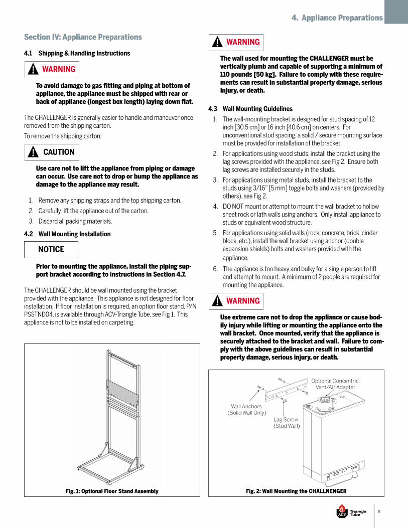
The CHALLENGER should be wall mounted using the bracketprovided with the appliance. This appliance is not designed for floorinstallation. If floor installation is required, an option floor stand, P/NPSSTND04, is available through ACV-Triangle Tube, see Fig 1. Thisappliance is not to be installed on carpeting.
WARNING
CAUTION
NOTICE
The wall used for mounting the CHALLENGER must bevertically plumb and capable of supporting a minimum of110 pounds [50 kg]. Failure to comply with these require-ments can result in substantial property damage, seriousinjury, or death.
4.3 Wall Mounting Guidelines
The wall-mounting bracket is designed for stud spacing of 121.inch [30.5 cm] or 16 inch [40.6 cm] on centers. Forunconventional stud spacing, a solid / secure mounting surfacemust be provided for installation of the bracket.
For applications using wood studs, install the bracket using the2.lag screws provided with the appliance, see Fig 2. Ensure bothlag screws are installed securely in the studs.
For applications using metal studs, install the bracket to the3.studs using 3/16” [5 mm] toggle bolts and washers (provided byothers), see Fig 2.
DO NOTmount or attempt to mount the wall bracket to hollow4.sheet rock or lath walls using anchors. Only install appliance tostuds or equivalent wood structure.
For applications using solid walls (rock, concrete, brick, cinder5.block, etc.), install the wall bracket using anchor (doubleexpansion shields) bolts and washers provided with theappliance.
The appliance is too heavy and bulky for a single person to lift6.and attempt to mount. A minimum of 2 people are required formounting the appliance.
Use extreme care not to drop the appliance or cause bod-ily injury while lifting or mounting the appliance onto thewall bracket. Once mounted, verify that the appliance issecurely attached to the bracket and wall. Failure to com-ply with the above guidelines can result in substantialproperty damage, serious injury, or death.
WARNING
WARNING
Fig. 1: Optional Floor Stand Assembly
Lag Screw(Stud Wall)
Wall Anchors (Solid Wall Only)
Optional Concentric Vent/Air Adapter
Fig. 2: Wall Mounting the CHALLNENGER
9
4. Appliance Preparations
4.4 Stud Wall Installation
Locate the studs in the general area of the appliance1.installation.
Place the wall-mounting bracket on the wall centering the2.mounting slots with the stud centers and ensuring the upperedge of the bracket is away from the wall.
Level the bracket while maintaining it’s centering with the studs3.and use a pencil to mark the location of the mountingslots/holes.
Remove the bracket from the wall and drill a 1/4” [6 mm]4.diameter by 3” [76 mm] deep hole in the center of each mark.For applications using metal studs and 3/16” [5 mm] togglebolts, drill the required clearance hole.
Reposition the bracket onto the wall and align with the5.mounting slots/holes. Insert the two lag screws provided (ortoggle bolts for metal studs) through the mounting slots/holesand loosely tighten.
Level bracket and tighten screws (bolts for metal studs)6.securely making sure not to overtighten to avoid damagingdrywall or plaster.
4.5 Solid Wall Installation
Locate the general area of the appliance installation.1.
Place the wall-mounting bracket on the wall ensuring the upper2.edge of the bracket is away from the wall.
Level the bracket and use a pencil to mark the location of the3.mounting slots/holes.
Remove the bracket from the wall and drill a 5/8” [16 mm]4.diameter by 1-3/8” [35 mm] deep hole in the center of eachmark.
Install the provided anchors flush or slightly recessed in the5.drilled holes with threaded side facing down.
Reposition the bracket on the wall and align with the mounting6.slots/holes. Insert the two bolts with washers through themounting slots/holes and loosely tighten.
Level bracket and tighten bolts securely.7.
4.6 Appliance Mounting
Obtain assistance in lifting the appliance onto the wall bracket.1.
Install the appliance making sure the appliance mounting lip2.located along the upper edge of the rear jacket panel engagesthe wall-mounting bracket. Ensure the appliance is seatedproperly and is secure.
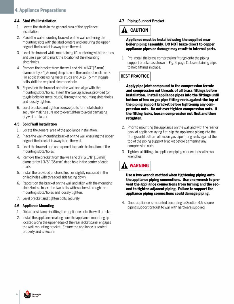
4.7 Piping Support Bracket
Appliance must be installed using the supplied nearboiler piping assembly. DO NOT braze direct to copperappliance pipes or damage may result to internal parts.
Pre-install the brass compression fittings onto the piping1.support bracket as shown in Fig. 4, page 11. Use retaining clipsto hold fittings in place.
Apply pipe joint compound to the compression ferruleand compression nut threads of all brass fittings beforeinstallation. Install appliance pipes into the fittings untilbottom of hex on gas pipe fitting rests against the top ofthe piping support bracket before tightening any com-pression nuts. Do not over tighten compression nuts. Ifthe fitting leaks, loosen compression nut first and thenretighten.
Prior to mounting the appliance on the wall and with the rear or2.back of appliance laying flat, slip the appliance piping into thefittings until bottom of hex on gas pipe fitting rests against thetop of the piping support bracket before tightening anycompression nuts.
Tighten all fittings to appliance piping connections with two3.wrenches.
Use a two wrench method when tightening piping ontothe appliance piping connections. Use one wrench to pre-vent the appliance connections from turning and the sec-ond to tighten adjacent piping. Failure to support theappliance piping connections could damage piping.
Once appliance is mounted according to Section 4.6, secure4.piping support bracket to wall with hardware supplied.
CAUTION
BEST PRACTICE
WARNING
10
5. Boiler Piping
Section V: Boiler Piping
5.1 General Piping Requirements
All plumbing must meet or exceed all local, state and national1.plumbing codes.
Support all piping using hangers. DO NOT support piping by the2.appliance or its components.
Use isolation valves to isolate system components.3.
Install unions for easy removal of the CHALLENGER from the4.system piping.
Use a two wrench method when tightening piping ontothe appliance piping connections. Use one wrench to pre-vent the appliance connections from turning and the sec-ond to tighten adjacent piping. Failure to support theappliance piping connections could damage piping.
5.2 Pressure Relief Valve (PRV)
The CHALLENGER has a ASME Maximum Allowable Working1.Pressure of 43.5 PSI [3 bar]. The appliance is supplied with a 30psi [2 bar] pressure relief valve and must be piped using thePRV connection as shown in Fig. 3 page 11..
To avoid potential water damage to the surrounding area or2.potential scalding hazard due to the operation of the relief valve,the discharge piping:
Must be connected to the discharge outlet of the reliefa.valve and directed to a safe place of disposal.
Length should be as short and direct as possible. Theb.size of the discharge line should not be reduced,maintain the same size as the outlet of the relief valve.
Should be directed downward towards the floor at allc.times. The piping should terminate at least 6 inches[153 mm] above any drain connection to allow clearvisibility of the discharge.
Should terminate with a plain end, not with a threadedd.end. The material of the piping should have aserviceable temperature rating of 250ºF [121ºC] orgreater.
Should not be subject to conditions where freezinge.could occur.
Should not contain any shut-off valves orf.obstructions. No shut-off valve should be pipedbetween the appliance and relief valve.
Failure to comply with the guidelines on installing thepressure relief valve and discharge piping can result insubstantial property damage, serious injury, or death.
WARNING
WARNING
5.3 Low Water Cut Off / CH Pressure Sensor
The CHALLENGER is equipped with a factory installed pressure1.sensor type Low Water Cut Off (LWCO).
The minimum operating Central Heating (CH) system pressure2.is 7 psig [0.5 bar].
If CH System pressure is below 7 psig [0.5 bar] the main display3.will flash a soft lockout of “LOP” followed by the pressurereading. Once CH system pressure is increased above 7 psi [0.5bar] normal boiler operation will be restored.
Check local codes if a LWCO is required. If so, determine if this4.device meets their requirements.
5.4 Additional Limit Control
If a Low Water Cut Off (LWCO) is required by certain local jurisdictionsor when the boiler is installed above the system piping, the followingguidelines must be followed:
The LWCO must be designed for water installations, electrode1.probe-type is recommended.
The LWCO must be installed in a tee connection on the boiler2.supply piping above the appliance.
Wiring of the LWCO to the CHALLENGER should be done in3.series with the 120 VAC service to the appliance.
If the installation is to comply with ASME CSD-1 or Canadianrequirements, an additional high temperature limit may be needed.Consult local code requirements to determine compliance. The limitshould be installed as follows:
Install the limit in the boiler supply piping between the boiler1.and any isolation valve.
Maximum set point for the limit is 200ºF [93ºC].2.
Wiring of the limit device to the CHALLENGER should be done in3.series with the 120 VAC service to the appliance.
5.5 Backflow Preventer
Use a backflow preventer valve in the make-up water supply to theappliance as required by local codes.
5.6 Boiler System Piping Applications
It is required on all piping applications to utilize a pri-mary/secondary piping arrangement. Maintain the mini-mum boiler flow rate, see Graphs 2-7 on pages 53-55.
BEST PRACTICE
11
5. Boiler Piping
Boiler Return Connection with Tee Fitting and Boiler Drain Valve
Boiler Supply Connection
with TeeFitting and
Temperature/Pressure Gauge
1
Pressure Relief Valve (Supplied with Boiler)
3/4" Street Elbow Manual Air Vent
(Supplied with Boiler)
Drain Piping Directed to a Suitable
Place of Drainage
Fig. 3: Boiler Pressure Relief Valve and Drain Valve Installation
Drain Valve(by Others)1 inch
CompressionAssembly(supplied)
1 inchCompression
Assembly(supplied) 1 inch Tee (by Others)
1 inchTee
(supplied) Temperature Pressure Gauge (supplied)
Piping Bracket(supplied)
Retaining Clip(supplied)
CompressionFerrule
Compression Nut
Compression/NPT Adapter
ManualAir Vent
(supplied)
3/4” Tee(supplied)
3/4” Nipple(supplied)3/4” Street
Elbow (supplied)
Installer must providerelief valve drain pipingdirected to a suitable place of drainage
Pressure Relief Valve(supplied)
Note:
Fig. 4: Near Boiler Piping Assembly
12
5. Boiler Piping
5.7 Expansion Tank and Makeup Water
Ensure the expansion tank is properly sized for the boiler watervolume (approximately 1 gallon [4 L]), the system water volume, andsystem water temperature.
Undersized expansion tanks will cause system water to belost through the pressure relief valve and cause addi-tional makeup water to be added to the system. Eventualboiler heat exchanger failure can result due to this exces-sive makeup water addition.
The expansion tank must be located as shown in Fig. 5 and Fig. 6, onpage 13, when using a primary/secondary piping arrangement or asper recognized design methods. Refer to the expansion tankmanufacturer for additional installation details.
Connect the expansion tank to an air separator only if the airseparator is located on the suction side (inlet) of the systemcirculator. Always locate and install the system fill connection at thesame location as the expansion tank connection to the system.
5.7.1 Diaphragm Expansion Tank
Always install an automatic air vent on top of the air separator toremove residual air from the system.
5.7.2 Closed-Type Expansion Tank
It is recommended to pitch any horizontal piping upwards toward theexpansion tank 1 inch per 5 feet [2.5 cm per 1.5 meter] of piping. Use3/4” piping to the expansion tank to allow air within the system to rise.
DO NOT install automatic air vents on a closed-type ex-pansion tank system. Air must remain in the system andbe returned to the expansion tank to provide an air cush-ion. An automatic air vent would cause air to be ventedfrom the system resulting in a water-logged expansiontank.
5.8 Central Heating (CH) Circulator
A Central Heating (CH) circulator with flow check must be utilizedwith the CHALLENGER. The circulator when wired directly to theCHALLENGER will provide circulation for the freeze protection featureof the boiler control. See Graphs 2-7 on pages 53-55 for pressure dropand minimum flow rate required through the boiler.
5.9 Sizing Primary Piping
See Fig. 7 and 8, on page 14, for recommended piping arrangementsbased on various applications. Size the piping and systemcomponents required in the space heating system using recognizeddesign methods.
CAUTION
CAUTION
5.10 System Piping - Zone Circulators
Connect the CHALLENGER to the system piping as shown in Fig. 7, onpage 14, when zoning with zone circulators.
The installer must provide a separate circulator for each zone of spaceheating.
To ensure an adequate flow rate through the CHAL-LENGER, the boiler supply and return piping size must bea minimum of 1 inch.
5.11 System Piping - Zone Valves
Connect the CHALLENGER to the system piping as shown in Fig. 8, onpage 14, when zoning with zone valves.
To ensure an adequate flow rate through the CHAL-LENGER, the boiler supply and return piping size must bea minimum of 1 inch.
5.12 System Piping - Radiant Heating
The heat exchanger design of the CHALLENGER allows operation in acondensing mode. This feature requires no regulation of the returnwater temperature back to the boiler in radiant heating applications.
The maximum boiler water supply temperature can be maintained bythe CHALLENGER, potentially eliminating the need for a mixingsystem to achieve the desired temperature if all zones of heat are atthe same temperature set point.
Size the system piping and circulator to provide the flow needed forthe radiant system.
To ensure an adequate flow rate through the CHAL-LENGER, the boiler supply and return piping size must bea minimum of 1 inch.
5.13 System Piping - Indirect Fired Water Heater
See Figs. 7 and 8, on page 14, for recommended piping of a ACV-Triangle Tube SMART/COMFORT I.F.W.H. This application will providehigher domestic hot water flow rates for a short period of time (dumpload). The SMART/COMFORT boiler piping should be piped off theprimary loop.
The boiler system piping must be a “closed” system toavoid any oxygen contamination and potential failure ofthe outer tank of the SMART/COMFORT I.F.W.H.
NOTICE
NOTICE
NOTICE
NOTICE
13
5. Boiler Piping
Max.12"
Boiler
Supply System
Return System
[30.5 cm]
Cold Water Fill
Boiler Supply Return
7
10
1
2
3
5 4 6
6 6
11
Fig. 5: Near Boiler Piping - Diaphragm Expansion Tank
7 1
10
9
8 4
3
6
6 6
Cold Water Fill
Boiler Supply
Minimum 3/4" Piping
Boiler Return
Return System
Supply System
11
Max.12" [30.5 cm]
Fig. 6: Near Boiler Piping - Closed Type Expansion Tank
System Circulator1.
Automatic Air Vent2.
Air Separator3.
Automatic Fill Valve4.
Diaphragm Expansion Tank5.
Isolation Valve6.
Drain/Purge Valve7.
Tank Fitting8.
Closed Type Expansion Tank9.
Primary/Secondary Connection10.
CH Circulator with Flow Check11.
Refer to the installation manual provided with the SMART/COMFORTfor additional installation details.
See Setting the Appliance Parameters, Section 11.9, for parameter,wiring and operational details using the SMART/COMFORT with aCHALLENGER boiler.
5.14 System Piping - Special Application
If the boiler is used in conjunction with a chilled water/mediumsystem, the boiler and chiller must be piped in parallel. Installflow/check valves to prevent the chilled medium from entering theboiler.
If the boiler is used to supply hot water to the heating coils of an airhandler where they may be exposed to chilled air circulation, installflow/check valves or other automatic devices to prevent gravitycirculation of the boiler water during cooling cycles.
14
5. Boiler Piping
5
5
4
6
2
3
3
[30.5 cm]9
8
1011
4
4
4
4
44
Zone Load
Additional
7
6
Max.12"
Zone Load
1
12
6
4
OptionalSMART /
COMFORT
4
Fig. 7: System Piping - Zoning with Zone Circulators
2
5
4
4
3
511
8
7
910
3
3
3
3
33
6
Additional
Max.[30.5 cm]12"
Zone Load
1
Zone Load
12
5
3
OptionalSMART /
COMFORT
3
Fig. 8: System Piping - Zoning with Zone Valves
CHALLENGER Boiler1.
Boiler Circulator with Flow Check2.
Flow/Check Valve3.
Isolation Valve4.
Zone Circulator5.
Drain/Purge Valve6.
Pressure Relief Valve7.
Air Separator8.
Automatic Air Vent9.
Diaphragm Expansion Tank10.
Automatic Fill Valve11.
DHW Circulator with Flow Check12.
CHALLENGER Boiler1.
Boiler Circulator with Flow Check2.
Isolation Valve3.
Zone Valve4.
Drain/Purge Valve5.
Pressure Relief Valve6.
Air Separator7.
Automatic Air Vent8.
Diaphragm Expansion Tank9.
Automatic Fill Valve10.
System Circulator11.
DHW Circulator with Flow Check12.
15
6. Installing Vent/Combustion Air & Condensate Drain
Section VI: Installing Vent / Combustion Air & Con-densate Drain
6.1 Installing Vent & Combustion Air
The CHALLENGER must be vented and supplied with com-bustion air as shown in the CHALLENGER PVC, CPVC, PPand SS Vent Supplement included in the installation en-velope. Refer to instructions for parts list and method ofinstallation. Once installation is completed, inspect thevent and combustion air system thoroughly to ensuresystems are airtight and comply with the instructionsgiven in the venting supplement and are within all re-quirements of applicable codes. Failure to comply withthe installation requirements of the venting and combus-tion air piping will result in substantial property damage,serious injury, or death.
Contact ACV - Triangle Tube for other venting options in-cluding PVC Concentric Vent/Air Termination or CHAL-LENGER Concentric Vent/Air System. Refer to theseinstructions for parts list and method of installation.
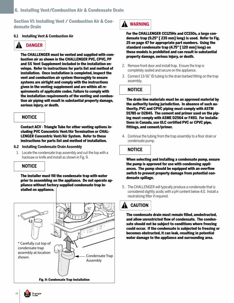
6.2 Installing Condensate Drain Assembly
Locate the condensate trap assembly and cut the top with a1.hacksaw or knife and install as shown in Fig. 9.
The installer must fill the condensate trap with waterprior to assembling on the appliance. Do not operate ap-pliance without factory supplied condensate trap in-stalled on appliance.
DANGER
NOTICE
NOTICE
For the CHALLENGER CC125Hs and CC150s, a large con-densate trap (9.25” [ 235 mm] long) is used. Refer to Fig.25 on page 47 for appropriate part numbers. Using thestandard condensate trap (4.75” [ 120 mm] long) onthese models is prohibited and can result in substantialproperty damage, serious injury, or death.
Remove front door and install trap. Ensure the trap is2.completely seated and secure on the appliance.
Connect 13/16” ID tubing to the drain barbed fitting on the trap3.assembly.
The drain line materials must be an approved material bythe authority having jurisdiction. In absence of such au-thority, PVC and CPVC piping must comply with ASTMD1785 or D2845. The cement and primer used on the pip-ing must comply with ASME D2564 or F493. For installa-tions in Canada, use ULC certified PVC or CPVC pipe,fittings, and cement/primer.
Continue the tubing from the trap assembly to a floor drain or4.condensate pump.
When selecting and installing a condensate pump, ensurethe pump is approved for use with condensing appli-ances. The pump should be equipped with an overflowswitch to prevent property damage from potential con-densate spillage.
The CHALLENGER will typically produce a condensate that is5.considered slightly acidic with a pH content below 4.0. Install aneutralizing filter if required.
The condensate drain must remain filled, unobstructed,and allow unrestricted flow of condensate. The conden-sate should not be subject to conditions where freezingcould occur. If the condensate is subjected to freezing orbecomes obstructed, it can leak, resulting in potentialwater damage to the appliance and surrounding area.
WARNING
NOTICE
NOTICE
CAUTION
Condensate Trap Assembly
* Carefully cut top ofcondensate trap assembly at location shown.
*
Fig. 9: Condensate Trap Installation
16
7. Gas Piping
Section VII: Gas Piping
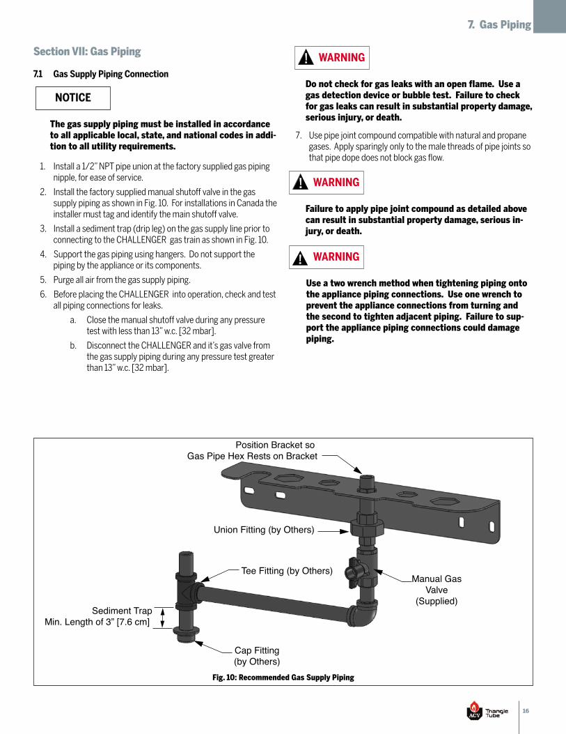
7.1 Gas Supply Piping Connection
Install a 1/2” NPT pipe union at the factory supplied gas piping1.nipple, for ease of service.
Install the factory supplied manual shutoff valve in the gas2.supply piping as shown in Fig. 10. For installations in Canada theinstaller must tag and identify the main shutoff valve.
Install a sediment trap (drip leg) on the gas supply line prior to3.connecting to the CHALLENGER gas train as shown in Fig. 10.
Support the gas piping using hangers. Do not support the4.piping by the appliance or its components.
Purge all air from the gas supply piping.5.
Before placing the CHALLENGER into operation, check and test6.all piping connections for leaks.
Close the manual shutoff valve during any pressurea.test with less than 13” w.c. [32 mbar].
Disconnect the CHALLENGER and it’s gas valve fromb.the gas supply piping during any pressure test greaterthan 13” w.c. [32 mbar].
Use pipe joint compound compatible with natural and propane7.gases. Apply sparingly only to the male threads of pipe joints sothat pipe dope does not block gas flow.
The gas supply piping must be installed in accordanceto all applicable local, state, and national codes in addi-tion to all utility requirements.
NOTICEDo not check for gas leaks with an open flame. Use agas detection device or bubble test. Failure to checkfor gas leaks can result in substantial property damage,serious injury, or death.
WARNING
Failure to apply pipe joint compound as detailed abovecan result in substantial property damage, serious in-jury, or death.
WARNING
Use a two wrench method when tightening piping ontothe appliance piping connections. Use one wrench toprevent the appliance connections from turning andthe second to tighten adjacent piping. Failure to sup-port the appliance piping connections could damagepiping.
WARNING
Position Bracket so Gas Pipe Hex Rests on Bracket
Tee Fitting (by Others)
Union Fitting (by Others)
Manual GasValve
(Supplied)
Cap Fitting(by Others)
Sediment TrapMin. Length of 3” [7.6 cm]
Fig. 10: Recommended Gas Supply Piping
17
7. Gas Piping
7.2 Natural Gas
7.2.1 Pipe Sizing
Refer to Table 1 for schedule 40 metallic pipe length and diameterrequirements for natural gas, based on rated CHALLENGER input(divide by 1,000 to obtain cubic feet per hour).
Table 1 is based on Natural Gas with a specific gravity of 0.601.and a pressure drop through the gas piping of 0.30” w.c. [0.75mbar].
For additional gas sizing information, refer to ANSI Z223.1. For2.Canadian installations refer to CAN/CSA B149.1.
7.2.2 Supply Pressure Requirements
Pressure required at the gas valve inlet supply pressure port:1.
Maximum 13” w.c. [32 mbar] at flow or no flowa.conditions to the burner.
Minimum 5” w.c. [13 mbar] during flow conditions tob.the burner. Must be verified during start up and withall other gas appliances operating within the gaspiping service.
Maximum gas inlet pressure must not be exceededc.and minimum gas inlet pressure is for the purpose ofinput adjustment.
Install 100% lockup gas pressure regulator in the gas supply line2.if inlet pressure can exceed 13” w.c. [32 mbar] at any time.Adjust the lockup pressure regulator for 13” w.c. [32 mbar].
7.2.3 Orifice Requirements
Refer to Table 2 for orifice required for appliance operation usingnatural gas. All units come set up for natural gas installation with theappropriate orifice pre-installed.
DO NOT adjust or attempt to measure gas valve outletpressure. The gas valve is factory-set for the correctoutlet pressure. This setting is suitable for natural andpropane gas and requires no field adjustment. At-tempts by the installer to adjust or measure the gasvalve outlet pressure could result in damage to thevalve and can cause substantial property damage, seri-ous injury, or death.
WARNING
Length of Pipe inFeet
Capacity of Schedule 40 Metallic Pipe in Cubic Feet of Natural Gas Per Hour (based on 0.60 specific gravity & 0.30" w.c. pressure drop)
SCH 40 1/2" 3/4" 1" 1-1/4" 1-1/2"
10 132 278 520 1050 1600
20 92 190 350 730 1100
30 73 152 285 590 890
40 63 130 245 500 760
50 56 115 215 440 670
75 45 93 175 360 545
100 38 79 150 305 460
150 31 64 120 250 380
Table 1: Gas Pipe Sizing - Natural Gas
Table 2: Natural Gas Orifice Requirements
CHALLENGERModel
NaturalOrifice Size
OrificeMarking
CC50s 0.217" [5.50 mm] 550
CC85s 0.256" [6.50 mm] 650
CC105s 0.256" [6.50 mm] 650
CC125s 0.285" [7.25 mm] 725
CC125Hs 0.217" [5.50 mm] 550
CC150s 0.285" [7.25 mm] 725
18
7. Gas Piping
7.3 Propane Gas
7.3.1 Pipe Sizing
Contact the local propane gas supplier for recommended sizing ofpiping, tanks, and 100% lockup gas regulator.
7.3.2 Supply Pressure Requirements
Adjust the propane supply regulator provided by the gas1.supplier for 13” w.c. [32 mbar] maximum pressure.
Pressure required at the gas valve inlet supply pressure port:2.
Maximum 13” w.c. [32 mbar] at flow or no flowa.conditions to the burner.
Minimum 5” w.c. [13 mbar] during flow conditions tob.the burner. Must be verified during start up and withall other gas appliances operating within the gaspiping service.
Maximum gas inlet pressure must not be exceededc.and minimum gas inlet pressure is for the purpose ofinput adjustment.
7.3.3 Orifice Requirements
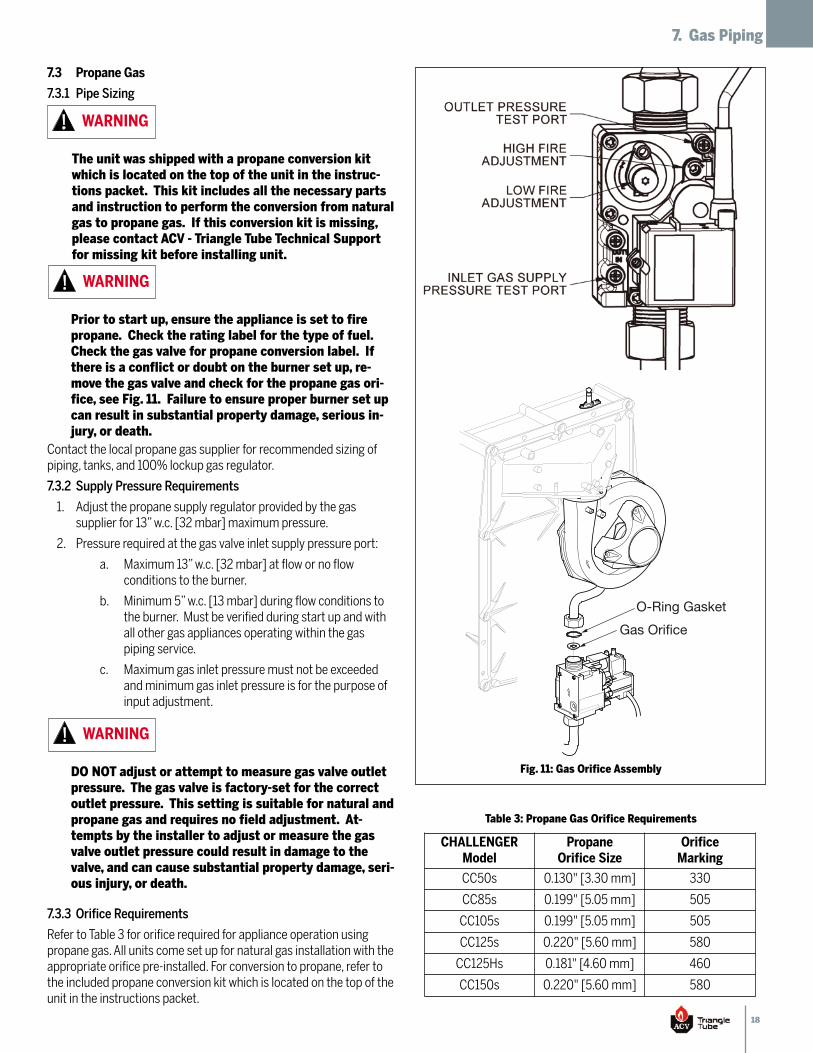
Refer to Table 3 for orifice required for appliance operation usingpropane gas. All units come set up for natural gas installation with theappropriate orifice pre-installed. For conversion to propane, refer tothe included propane conversion kit which is located on the top of theunit in the instructions packet.
The unit was shipped with a propane conversion kitwhich is located on the top of the unit in the instruc-tions packet. This kit includes all the necessary partsand instruction to perform the conversion from naturalgas to propane gas. If this conversion kit is missing,please contact ACV - Triangle Tube Technical Supportfor missing kit before installing unit.
WARNING
Prior to start up, ensure the appliance is set to firepropane. Check the rating label for the type of fuel.Check the gas valve for propane conversion label. Ifthere is a conflict or doubt on the burner set up, re-move the gas valve and check for the propane gas ori-fice, see Fig. 11. Failure to ensure proper burner set upcan result in substantial property damage, serious in-jury, or death.
WARNING
DO NOT adjust or attempt to measure gas valve outletpressure. The gas valve is factory-set for the correctoutlet pressure. This setting is suitable for natural andpropane gas and requires no field adjustment. At-tempts by the installer to adjust or measure the gasvalve outlet pressure could result in damage to thevalve, and can cause substantial property damage, seri-ous injury, or death.
WARNING
Table 3: Propane Gas Orifice Requirements
Gas Orifice
O-Ring Gasket
Fig. 11: Gas Orifice Assembly
CHALLENGERModel
PropaneOrifice Size
OrificeMarking
CC50s 0.130" [3.30 mm] 330
CC85s 0.199" [5.05 mm] 505
CC105s 0.199" [5.05 mm] 505
CC125s 0.220" [5.60 mm] 580
CC125Hs 0.181" [4.60 mm] 460
CC150s 0.220" [5.60 mm] 580
19
8. Internal Wiring
Section VIII: Internal Wiring
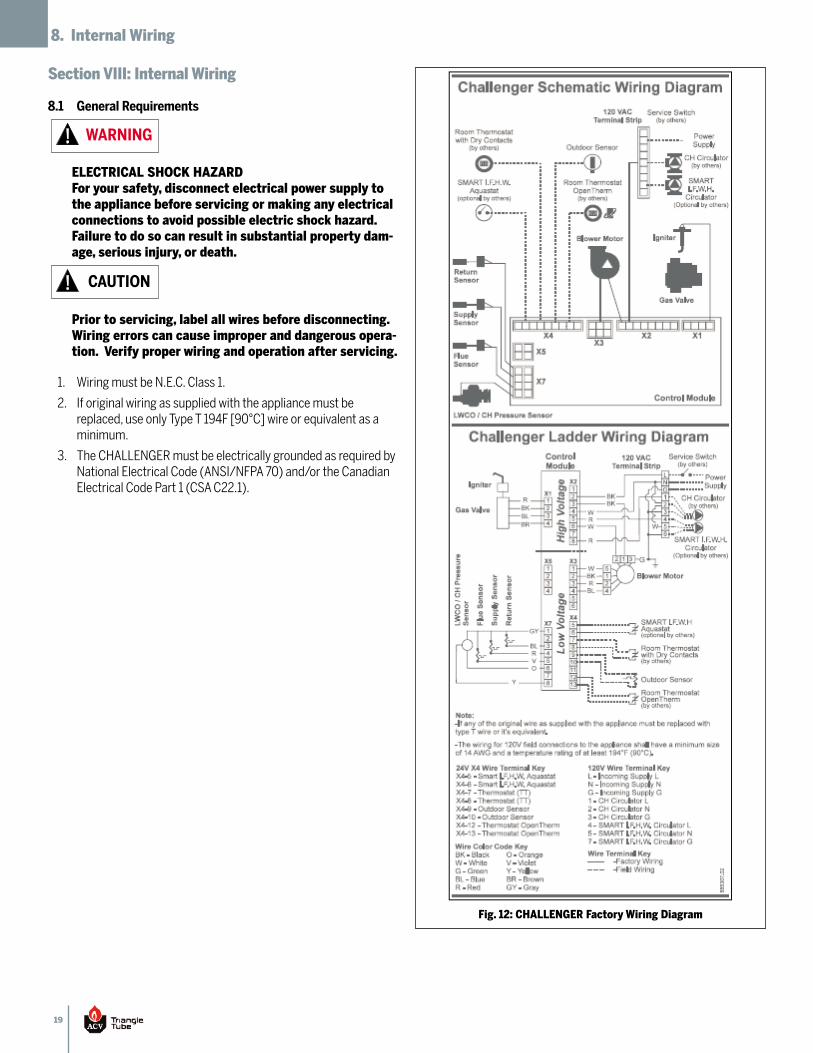
8.1 General Requirements
Wiring must be N.E.C. Class 1.1.
If original wiring as supplied with the appliance must be2.replaced, use only Type T 194F [90°C] wire or equivalent as aminimum.
The CHALLENGER must be electrically grounded as required by3.National Electrical Code (ANSI/NFPA 70) and/or the CanadianElectrical Code Part 1 (CSA C22.1).
ELECTRICAL SHOCK HAZARDFor your safety, disconnect electrical power supply tothe appliance before servicing or making any electricalconnections to avoid possible electric shock hazard.Failure to do so can result in substantial property dam-age, serious injury, or death.
WARNING
Prior to servicing, label all wires before disconnecting.Wiring errors can cause improper and dangerous opera-tion. Verify proper wiring and operation after servicing.
CAUTION
Fig. 12: CHALLENGER Factory Wiring Diagram
20
9. External Wiring
Section IX: External Wiring
9.1 Installation Compliance
All field wiring made during installation must comply with:
National Electrical Code (NFPA 70) and any other national,1.state, provincial, or local codes or requirements.
In Canada, Canadian Electrical Code Part 1 (CSA C22.1) and any2.other local codes.
9.2 Line Voltage Connections
Connect a 120 VAC/15A service to the 120V terminals L, N, and1.G inside the CHALLENGER as shown in Fig. 12 on page 19.
Route the incoming 120 VAC power wire through the provided2.openings in the bottom right side jacket panel.
The appliance must be provided with an external service switch.3.Check local code requirements for compliance.
9.3 Circulator Maximum Current Rating
The AMP draw of the CH/DHW circulators must not exceed 2.3 amps
9.4 Central Heating (CH) Circulator
Wire the CH circulator to the CHALLENGER 120 V terminals 1,2,4.and 3 located inside the appliance as shown in Fig. 12 on page19.
Maximum CH circulator continous current draw is 2.3 A.5.
9.5 DHW Circulator for Optional SMART/COMFORT I.F.W.H.
Wire the DHW circulator to the CHALLENGER 120 V terminals 4,1.5, and 6 located inside the appliance as shown in Fig. 12 on page19.
Maximum DHW circulator continuous current draw is 2.3 A.2.
9.6 System Circulator - Zone Valve Application
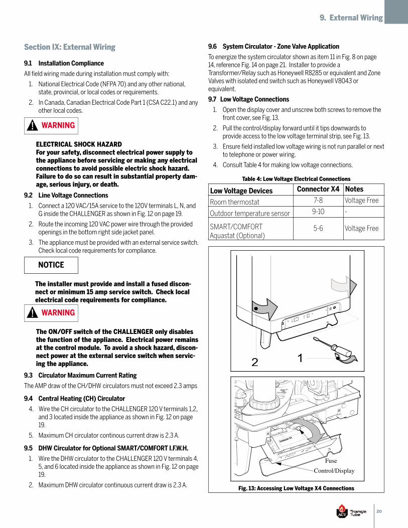
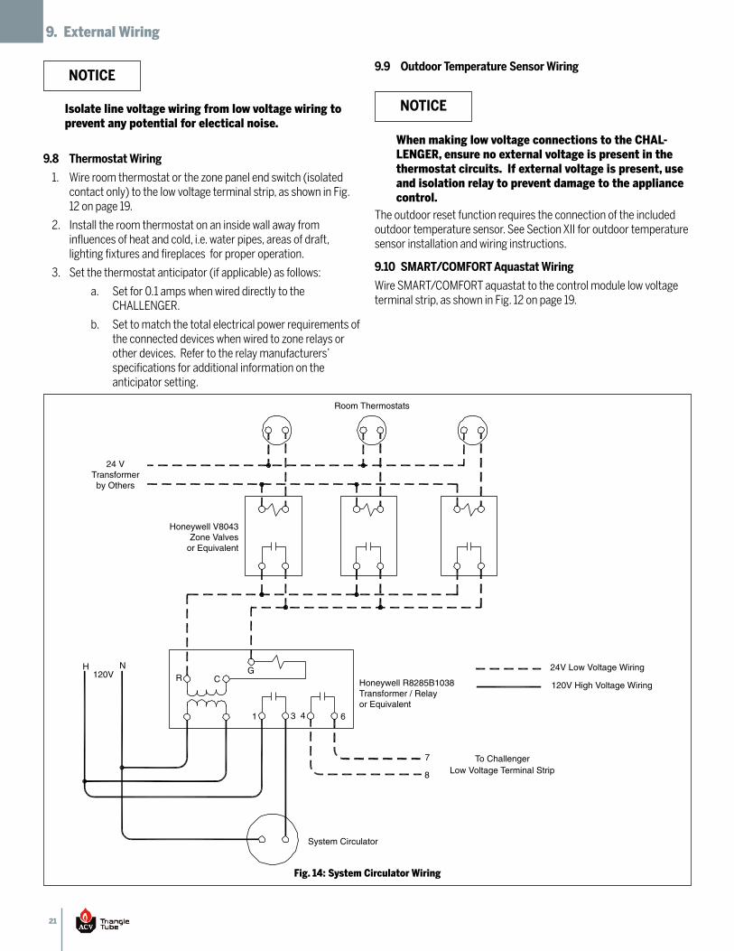
To energize the system circulator shown as item 11 in Fig. 8 on page14, reference Fig. 14 on page 21. Installer to provide aTransformer/Relay such as Honeywell R8285 or equivalent and ZoneValves with isolated end switch such as Honeywell V8043 orequivalent.
9.7 Low Voltage Connections
Open the display cover and unscrew both screws to remove the1.front cover, see Fig. 13.
Pull the control/display forward until it tips downwards to2.provide access to the low voltage terminal strip, see Fig. 13.
Ensure field installed low voltage wiring is not run parallel or next3.to telephone or power wiring.
Consult Table 4 for making low voltage connections.4.
ELECTRICAL SHOCK HAZARDFor your safety, disconnect electrical power supply tothe appliance before servicing or making any electricalconnections to avoid possible electric shock hazard.Failure to do so can result in substantial property dam-age, serious injury, or death.
WARNING
The installer must provide and install a fused discon-nect or minimum 15 amp service switch. Check localelectrical code requirements for compliance.
The ON/OFF switch of the CHALLENGER only disablesthe function of the appliance. Electrical power remainsat the control module. To avoid a shock hazard, discon-nect power at the external service switch when servic-ing the appliance.
WARNING
Table 4: Low Voltage Electrical Connections
5 – 6 Voltage free
FuseControl/Display
A
Fig. 13: Accessing Low Voltage X4 Connections
Low Voltage Devices Connector X4 Notes
Room thermostat 7-8 Voltage Free
Outdoor temperature sensor 9-10 -
SMART/COMFORTAquastat (Optional)
5-6 Voltage Free
NOTICE
21
9. External Wiring
9.8 Thermostat Wiring
Wire room thermostat or the zone panel end switch (isolated1.contact only) to the low voltage terminal strip, as shown in Fig.12 on page 19.
Install the room thermostat on an inside wall away from2.influences of heat and cold, i.e. water pipes, areas of draft,lighting fixtures and fireplaces for proper operation.
Set the thermostat anticipator (if applicable) as follows:3.
Set for 0.1 amps when wired directly to thea.CHALLENGER.
Set to match the total electrical power requirements ofb.the connected devices when wired to zone relays orother devices. Refer to the relay manufacturers’specifications for additional information on theanticipator setting.
9.9 Outdoor Temperature Sensor Wiring
The outdoor reset function requires the connection of the includedoutdoor temperature sensor. See Section XII for outdoor temperaturesensor installation and wiring instructions.
9.10 SMART/COMFORT Aquastat Wiring
Wire SMART/COMFORT aquastat to the control module low voltageterminal strip, as shown in Fig. 12 on page 19.
24 VTransformerby Others
Honeywell V8043Zone Valves
or Equivalent
Honeywell R8285B1038Transformer / Relayor Equivalent
Low Voltage Terminal Strip
System Circulator
24V Low Voltage Wiring
120V High Voltage Wiring
Room Thermostats
H N120V R C
G
1 3 4 6
7
8
To Challenger
Fig. 14: System Circulator Wiring
When making low voltage connections to the CHAL-LENGER, ensure no external voltage is present in thethermostat circuits. If external voltage is present, useand isolation relay to prevent damage to the appliancecontrol.
NOTICEIsolate line voltage wiring from low voltage wiring toprevent any potential for electical noise.
NOTICE
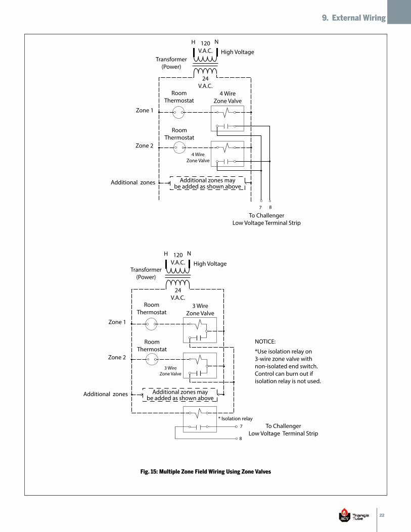
22
9. External Wiring
H N
High Voltage120
V.A.C.
24V.A.C.
RoomThermostat
RoomThermostat
Zone 1
Zone 2
Additional zones Additional zones maybe added as shown above
To ChallengerLow Voltage Terminal Strip
Transformer(Power)
4 WireZone Valve
4 WireZone Valve
7 8
Fig. 15: Multiple Zone Field Wiring Using Zone Valves
To ChallengerLow Voltage Terminal Strip
H N
High Voltage120
V.A.C.
24V.A.C.
RoomThermostat
RoomThermostat
Zone 1
Zone 2
Additional zones Additional zones maybe added as shown above
Transformer(Power)
3 WireZone Valve
3 WireZone Valve
* Isolation relay7
8
*Use isolation relay on 3-wire zone valve with non-isolated end switch. Control can burn out if isolation relay is not used.
NOTICE:
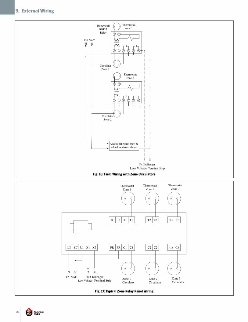
23
9. External Wiring
T T
To Challenger Low Voltage Terminal Strip
CirculatorZone 1
Thermostatzone 1
HoneywellR845ARelay
120H
VACN
CirculatorZone 2
Thermostatzone 2
Additional zones may beadded as shown above
7 8
62 1 4 3 5
62 1 4 3 5
T T
T T
Fig. 16: Field Wiring with Zone Circulators
Thermostat Zone 1
Zone 1 Circulator
120 VAC N
To ChallengerLow Voltage Terminal Strip Zone 2
Circulator Zone 3 Circulator
Thermostat Zone 2
Thermostat Zone 3
R C T1 T1 T2 T2 T3 T3
C3 C3 C2 C2 C1 C1 PR PR X2 X1 L1 L2 ZC
H 7
8
Fig. 17: Typical Zone Relay Panel Wiring
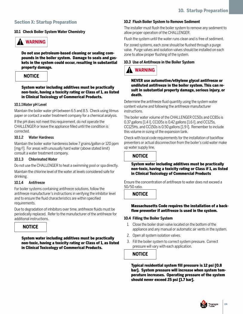
24
10. Startup Preparation
Section X: Startup Preparation
10.1 Check Boiler System Water Chemistry
10.1.1Water pH Level
Maintain the boiler water pH between 6.5 and 8.5. Check using litmuspaper or contact a water treatment company for a chemical analysis.
If the pH does not meet this requirement, do not operate theCHALLENGER or leave the appliance filled until the condition iscorrected.
10.1.2 Water Hardness
Maintain the boiler water hardeness below 7 grains/gallon or 120 ppm[mg/l]. For areas with unusually hard water (above stated limit)consult a water treatment company.
10.1.3 Chlorinated Water
Do not use the CHALLENGER to heat a swimming pool or spa directly.
Maintain the chlorine level of the water at levels considered safe fordrinking.
10.1.4 Antifreeze
For boiler systems containing antifreeze solutions, follow theantifreeze manufacturer’s instructions in verifying the inhibitor leveland to ensure the fluid characteristics are within specifiedrequirements.
Due to degradation of inhibitors over time, antifreeze fluids must beperiodically replaced. Refer to the manufacturer of the antifreeze foradditional instructions.
Do not use petroleum-based cleaning or sealing com-pounds in the boiler system. Damage to seals and gas-kets in the system could occur, resulting in substantialproperty damage.
WARNING
System water including additives must be practicallynon-toxic, having a toxicity rating or Class of 1, as listedin Clinical Toxicology of Commerical Products.
NOTICE
System water including additives must be practicallynon-toxic, having a toxicity rating or Class of 1, as listedin Clinical Toxicology of Commerical Products.
NOTICE
10.2 Flush Boiler System to Remove Sediment
The installer must flush the boiler system to remove any sediment toallow proper operation of the CHALLENGER.
Flush the system until the water runs clean and is free of sediment.
For zoned systems, each zone should be flushed through a purgevalve. Purge valves and isolation valves should be installed on eachzone to allow proper flushing of the system.
10.3 Use of Antifreeze in the Boiler System
Determine the antifreeze fluid quantity using the system watercontent volume and following the antifreeze manufacturerinstructions.
The boiler water volume of the CHALLENGER CC50s and CC85s is0.37 gallons [1.4 l], CC105s is 0.42 gallons [1.6 l], and CC125s,CC125Hs, and CC150s is 0.50 gallons [1.9 l]. Remember to includethis volume in sizing of the expansion tank.
Check with local code requirements for the installation of backflowpreventers or actual disconnection from the boiler’s cold water makeup water supply line.
Ensure the concentration of antifreeze to water does not exceed a50/50 ratio.
10.4 Filling the Boiler System
Close the boiler drain valve located on the bottom of the1.appliance and any manual or automatic air vents in the system.
Open all system isolation valves.2.
Fill the boiler system to correct system pressure. Correct3.pressure will vary with each application.
Typical residential system fill pressure is 12 psi [0.8bar]. System pressure will increase when system tem-perature increases. Operating pressure of the systemshould never exceed 25 psi [1.7 bar].
NOTICE
Massachusetts Code requires the installation of a back-flow preventer if antifreeze is used in the system.
NOTICE
System water including additives must be practicallynon-toxic, having a toxicity rating or Class if 1, as listedin Clinical Toxicology of Commercial Products
NOTICE
NEVER use automotive/ethylene glycol antifreeze orundiluted antifreeze in the boiler system. This can re-sult in substantial property damage, serious injury, ordeath.
WARNING
25
10. Startup Preparation
Purge air and sediment from each zone of the hydronic system4.through the purge valves. Open air vents to allow air to bevented from the zones.
Open manual air vent. Once the air has stopped escaping, close5.the manual air vent.
Once the system is completely filled and purged of all air and6.sediment, check the system pressure and check/repair anyleaks.
10.5 Check Low Water Cut Off
The CHALLENGER is equipped with a factory installed pressure1.sensor type Low Water Cut Off (LWCO).
The minimum operating CH system pressure is 7 psig [0.5bar]2.
Compare CH system pressure gauge reading to CHALLENGER’s3.control pressure display reading, which can only be viewed whencontrol is ON and no CH call is present. Adjust system pressureaccordingly.
10.6 Check for Gas Leaks
10.7 Check Thermostat Circuit
Disconnect the external thermostat wires from the control1.terminal strip, located on the drop down panel.
Connect a voltmeter across the wire ends of the external2.thermostat wiring.
Energize each thermostat, zone valve, and relay in the external3.circuit individually and check the voltage reading across the wireends.
There should NEVER be voltage measured at the wire ends.4.
If voltage is measure at the panel under any condition, check5.and correct the external wiring.
Reconnect the external thermostat wires to the control terminal6.strip.
10.8 Inspect Condensate Drain Assembly
Inspect and ensure the Condensate Drain Assembly is properly1.installed as described in Section 6.2 and shown in Fig. 9 on page15.
Remove the Condensate Drain Assembly and fill with fresh2.water.
Reinstall the Condensate Drain Assembly.3.
Prior to startup and during initial operation, smell nearthe floor and around the appliance for gas odorant orany unusual odor. Do not proceed with the startup ifthere is any indication of a gas leak. Any leaks foundmust be repaired immediately.
WARNING
Propane Installations OnlyThe propane supplier mixes an odorant with thepropane to make it’s presence detectable. In somecases the odorant can fade and the gas may no longerhave an odor.Prior to startup of the appliance, and periodically afterstartup, have the propane supplier check and verifyodorant level.
WARNING
In systems using 3-wire zone valves, backfeed of volt-age to the appliance is a common problem. Use an iso-lation relay to prevent voltage from the external circuitentering the CHALLENGER control panel.
NOTICE
The condensate drain assembly must be installed onthe appliance and filled with water when the CHAL-LENGER is in operation. The condensate drain assem-bly prevents flue gas emissions from entering thecondensate line. Failure to ensure trap is filled withwater can result in severe personal injury or death.
Unrepaired system leaks will cause continual makeupwater to be added to the system. Continual makeupwater could cause mineral buildup within the heat ex-changer, reducing the heat transfer, causing possibleheat buildup and eventual heat exchanger failure.
WARNING
WARNING
26
11. Startup Procedures
Section XI: Startup Procedures
11.1 Final Checks Before Startup
Read Sections 11.5 through 12.4 regarding the operation of the1.CHALLENGER control.
Verify the CHALLENGER and the boiler system are full of water2.and all system components are correctly set for operation,including the minimum flow rate through the boiler, see pages53-55.
Verify all Startup Preparation items outlined in Section 10 have3.been completed.
Verify all electrical connections are correct and securely4.fastened.
Inspect vent and combustion air piping for signs of5.deterioration from corrosion, physical damage or sagging.Verify combustion air and vent piping are intact and correctlyinstalled and supported. Reference the proper CHALLENGERvent supplement.
Verify burner configuration - gas orifice size.6.
Check for proper labeling on the gas valve (propanea.only) and the rating label for proper gas configuration.
If there is doubt on the burner configuration, removeb.the gas valve and check for proper gas orifice size. SeeSections 7.2.3 and 7.3.3 for correct orifice sizes.
Ensure the Condensate Drain Assembly is filled with water.7.
11.2 CHALLENGER Startup
Turn ON the electrical supply/service to the appliance. Press1.the ON/OFF button “ ” located on the front control panel.
Read and follow the Operating Instructions outlined on page 28.2.
11.3 CHALLENGER Startup Troubleshooting
If CHALLENGER does not start correctly:
Verify parameter 1 is set to “3”. Read Setting the Appliance1.Parameters, Section 11.9, for more information.
Check for loose electrical connections, blown fuse (external2.or internal at the appliance control) or open service switch.
Is the external limit control (if applicable) open? Ensure the3.external limit is reset to the closed position.
Is the gas supply valve(s) open at the appliance and meter?4.
Is incoming gas supply pressure at the appliance more than5.5”w.c. [13 mbar] and less than 13” w.c. [32 mbar] with all gasappliances ON or OFF.
Are the room thermostats set above room temperature?6.
If none of these conditions correct the problem, contact ACV - TriangleTube Technical Support.
11.4 Check the CHALLENGER and System
Check Piping:1.
Check heating system for leaks. If found, shut downa.the appliance and repair immediately.
Purge any remaining air from the system. Air in theb.system will interfere with circulation, causing heatdistribution problems and system noise.
Check Vent Piping and Combustion Air Piping2.
Check for gas-tight seal at every connection and seama.of the venting and combustion air piping.
Check Gas Piping3.
Check around the appliance for gas odor following thea.procedure outlined in Section 10.6.
Verify Flame Pattern and Combustion4.
Check the flame pattern through the inspection porta.on the left side of the heat exchanger. The flameshould be blue and stable over the length of theburner.
Test for CO2 or 02 and for CO during high and lowb.firing rate. Reference High Fire Test Mode, Section11.8.3, and Low Fire Test Mode, Section 11.8.4, forprocedure to manually place unit into high or low fire.The combustion readings should be within the rangelisted in Table 5 on page 27. The CO level should notexceed 100 ppm for natural gas or 150ppm forpropane gas.
Venting system must be sealed gas-tight to preventflue gas spillage and potential carbon monoxide emis-sions, which will result in substantial property damage,serious injury, or death.
DANGER
If any gas leaks are found or suspected, shut down theappliance immediately. Use a gas detection device orbubble test to locate the source of the gas leak and re-pair at once. Do not operate the appliance until theleak is corrected. Failure to comply with this procedurecan result in substantial property damage, serious in-jury, or death.
WARNING
The combustion testing and adjustments must be per-formed by a qualified installer, service agency, or thegas supplier. All combustion measurements must beperformed with calibrated equipment to ensure properreading and accuracy.
WARNING
27
11. Startup Procedures
Measure Input - Natural Gas Only5.
Ensure the appliance is firing at maximum firing rate.a.Reference High Fire Test Mode, Section 11.8.3, forprocedure to manually place the unit into high fire
Turn off all gas appliances on the gas service, exceptb.the CHALLENGER.
Operate the CHALLENGER for approximately 10c.minutes.
At the gas meter, record the time required to use oned.cubic foot of gas.
Calculate Natural Gas Input using the followinge.equation:
3600 * 1000 / Seconds for 1 cubic ft of gas = BTU/hr
The BTU/hr calculated should approximate the inputf.rating listed on the appliance.
11.5 Appliance ON/OFF
Turn appliance ON/OFF using the ON/OFF button.1.
When appliance is ON, the green LED above the ON/OFF2.button will be lit. The main display will show the water pressurefollowed by “P” when there is no heat demand.
When the appliance is OFF, the green LED above the ON/OFF3.button will not be lit. The main display will show “OFF” and theoperating display will show .
Table 5: Recommended Combustion Levels
If the reset button is not pressed within 30 sec-onds, the parameter menu is automatically closed andthe changes are stored.
If the ON/OFF button is pressed prior to the reset button, the parameter menu is closed and thechanges are NOT stored.
NOTICE
Digits and characters shown below in brackets repre-sent the control module operating display.
NOTICE
The combustion levels must be measured at high andlow firing rates. If the combustion levels are not withinthe range given in Table 5, shut down the appliance andcontact ACV - Triangle Tube Technical Support. Failureto comply with this requirement can result in substan-tial property damage, serious injury, or death.
WARNING
Combustion Levels Natural Gas Propane Gas
High Fire
DOOR OFF*
CO2 Range 9% - 10.1% 10.5% - 11.1%
CO2 Target 9.0% 10.8%
O2 Range 3.0% - 5% 4.1% - 5%
O2 Target 5.0% 4.5%
Low Fire CO2 Range
0% - 0.4% < H.F.9.0% min.
0% - 0.4% < H.F.10.5% min.
O2 Range0% - 0.6% > H.F.
5.0% max.0% - 0.6% > H.F5.0% max.
CO Max. 100 ppm 150 ppm
*Door On can raise the maximum allowable CO2 by 0.4 or lowerthe minimum allowable O2 by 0.6
11.6 Set Boiler Maximum Central Heating (CH) Set PointTemperature
Press the CH/DHW/Parameter button “ ” on the display panel1.for approximately 2 to 3 seconds until the radiator symbol “ ”LED lights up and the main display begins to flash.
Press the or buttons to set the desired maximum2.temperature setting on the main display.
Press the reset button to close the setting menu and store3.the changes.
Set the room thermostat to the lowest setting.1.
Turn off power to the appliance, wait a few seconds and turn on2.power to the appliance.
The following operating displays should occur:3.
[A] Self check on power up
[ ] No call for heat
Initiate a call for heat by raising the set point of the room4.thermostat to the highest setting. The following operatingdisplay should occur:
[ 1 ] This is the prepurge cycle. The burner blower and the CHcirculator become energized. The blower has a 5 secondprepurge cycle.
[ 2 ] This is the ignition cycle. The control module will open thegas valve and begin the spark for ignition.
If the burner lights and the flame is proven, the burnera.will begin to modulate.
If the burner fails to light or the flame is not proven, theb.control module will repeat the ignition sequence afterapproximately 15 seconds . If the flame is notestablished after four attempts, the control willlockout. The main display will show [4] and the fault
LED above the reset button will flash and [E] willflash in the operating display.
11.7 Operation Verification - Space Heating
28
11. Startup Procedures
A. This appliance does not have a pilot. It is equipped with an ignition device which automatically lights the burner. DO NOT tryto light the burner by hand.
B. BEFORE OPERATING, smell all around the appliance area for gas.Be sure to smell next to the floor because some gas is heavier than air and will settle on the floor.
WHAT TO DO IF YOU SMELL GAS
Do not try to light any appliance•
Do not touch any electrical switch; do not use any phone in•your building.
Immediately call your gas supplier from a neighbor’s phone.•Follow the gas supplier’s instructions.
If you cannot reach your gas supplier, call the fire•department.
C. Use only your hand to turn the external manual gas valve. Never use tools. If the valve will not turn by hand, do not try to repair it. Call a qualified service technician. Force or attempted repair mayresult in a fire or explosion.
D. Do not use this appliance if any part has been under water. Immediately call a qualified service technician to inspect the appliance and to replace any part of the control system and any gas control which has been under water.
FOR YOUR SAFETY READ BEFORE LIGHTING
If you do not follow these instructions exactly, a fire or explosion may result causing property dam-age, personal injury or loss of life.WARNING
STOP! Read the safety information above. This appliance is1.equipped with an ignition device which automatically lights theburner. DO NOT try to light the burner by hand.
Set room thermostat(s) to lowest setting. Turn the external2.manual gas valve handle clockwise “CLOSE” (valvehandle shall be perpendicular to gas piping).
Turn “OFF” all electrical power to the appliance.3.
Remove the front jacket panel on the appliance.4.
Turn the external manual gas valve handle counter clockwise5.to “OPEN” gas supply (valve handle shall be parallel to
gas piping).
Wait five (5) minutes to clear out any gas. If you then smell gas6.in the jacket enclosure or around the appliance, STOP! Follow“B” in the safety information above. If you don’t smell gas, go tothe next step.
Turn “ON” all electric power to the appliance. Push ON/OFF7.button on the CHALLENGER control panel display until LEDabove button is lit.
Set room thermostat(s) to desired setting(s).8.
The CHALLENGER control panel display will show a sequence9.of numbers (1,2,3,4) as the right digit. Sequence digit 3 or 4indicates the appliance is firing. A blank display means there isno call for heat (all external thermostats are satisfied).
If the appliance will not operate with a call for heat and the10.system piping is not hot, follow the instructions “To Turn Off Gasto Appliance”, below and call your service technician or gassupplier.
Replace the front jacket panel. Make sure the panel is seated11.firmly in place and all mounting screws are tightened.
Set the room thermostat to lowest setting.1.
Turn “OFF” all electrical power to the appliance if service is to be2.performed.
Turn the external manual gas valve handle clockwise to3.“CLOSE” (valve handle shall be perpendicular to gas piping).
OPERATING INSTRUCTIONS
TO TURN OFF GAS TO APPLIANCE
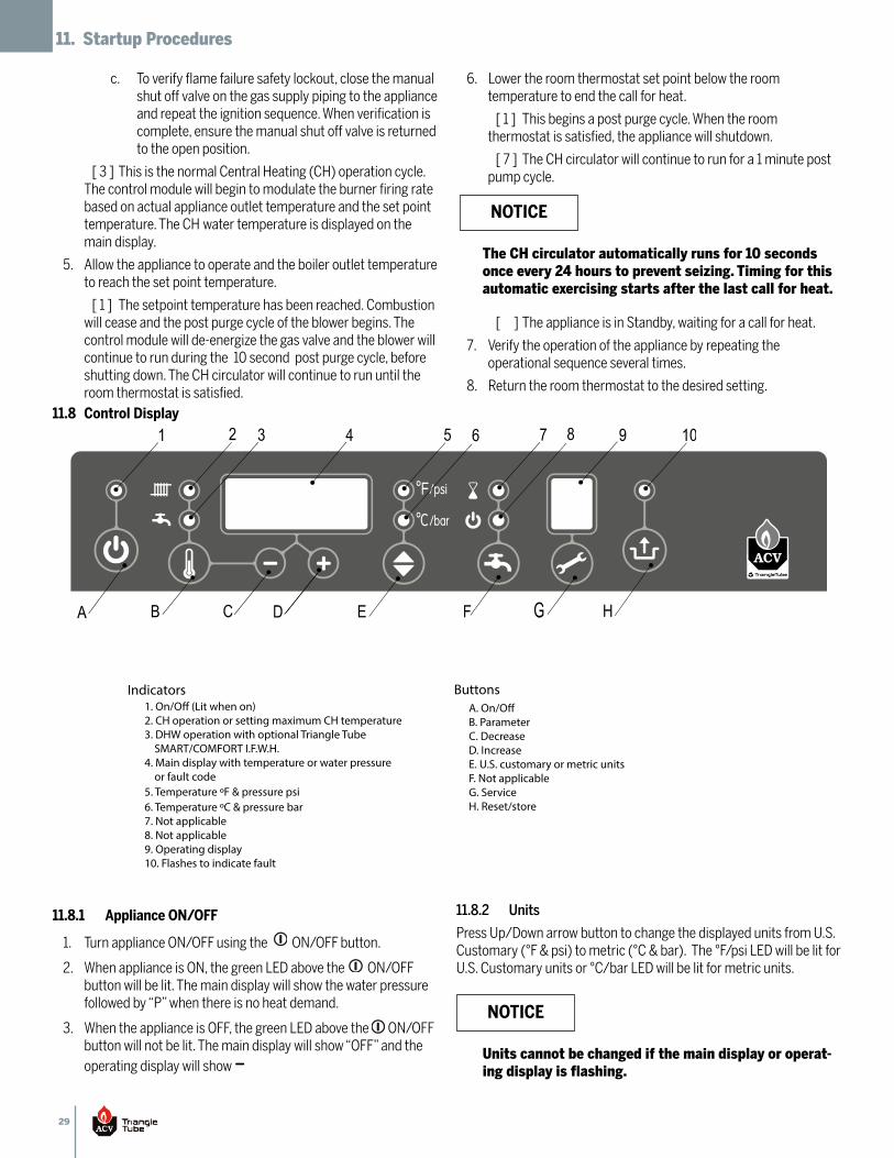
29
11. Startup Procedures
To verify flame failure safety lockout, close the manualc.shut off valve on the gas supply piping to the applianceand repeat the ignition sequence. When verification iscomplete, ensure the manual shut off valve is returnedto the open position.
[ 3 ] This is the normal Central Heating (CH) operation cycle.The control module will begin to modulate the burner firing ratebased on actual appliance outlet temperature and the set pointtemperature. The CH water temperature is displayed on themain display.
Allow the appliance to operate and the boiler outlet temperature5.to reach the set point temperature.
[ 1 ] The setpoint temperature has been reached. Combustionwill cease and the post purge cycle of the blower begins. Thecontrol module will de-energize the gas valve and the blower willcontinue to run during the 10 second post purge cycle, beforeshutting down. The CH circulator will continue to run until theroom thermostat is satisfied.
Lower the room thermostat set point below the room6.temperature to end the call for heat.
[ 1 ] This begins a post purge cycle. When the roomthermostat is satisfied, the appliance will shutdown.
[ 7 ] The CH circulator will continue to run for a 1 minute postpump cycle.
[ ] The appliance is in Standby, waiting for a call for heat.
Verify the operation of the appliance by repeating the7.operational sequence several times.
Return the room thermostat to the desired setting.8.
The CH circulator automatically runs for 10 secondsonce every 24 hours to prevent seizing. Timing for thisautomatic exercising starts after the last call for heat.
NOTICE
11.8 Control Display
11.8.1 Appliance ON/OFF
Turn appliance ON/OFF using the ON/OFF button.1.
When appliance is ON, the green LED above the ON/OFF2.button will be lit. The main display will show the water pressurefollowed by “P” when there is no heat demand.
When the appliance is OFF, the green LED above the ON/OFF3.button will not be lit. The main display will show “OFF” and theoperating display will show
11.8.2 Units
Press Up/Down arrow button to change the displayed units from U.S.Customary (°F & psi) to metric (°C & bar). The °F/psi LED will be lit forU.S. Customary units or °C/bar LED will be lit for metric units.
A. On/O� B. Parameter C. Decrease D. Increase E. U.S. customary or metric unitsF. Not applicableG. Service H. Reset/store
Indicators Buttons1. On/O� (Lit when on)2. CH operation or setting maximum CH temperature3. DHW operation with optional Triangle Tube SMART/COMFORT I.F.W.H.4. Main display with temperature or water pressure or fault code5. Temperature ºF & pressure psi6. Temperature ºC & pressure bar7. Not applicable8. Not applicable9. Operating display10. Flashes to indicate fault
Units cannot be changed if the main display or operat-ing display is flashing.
NOTICE
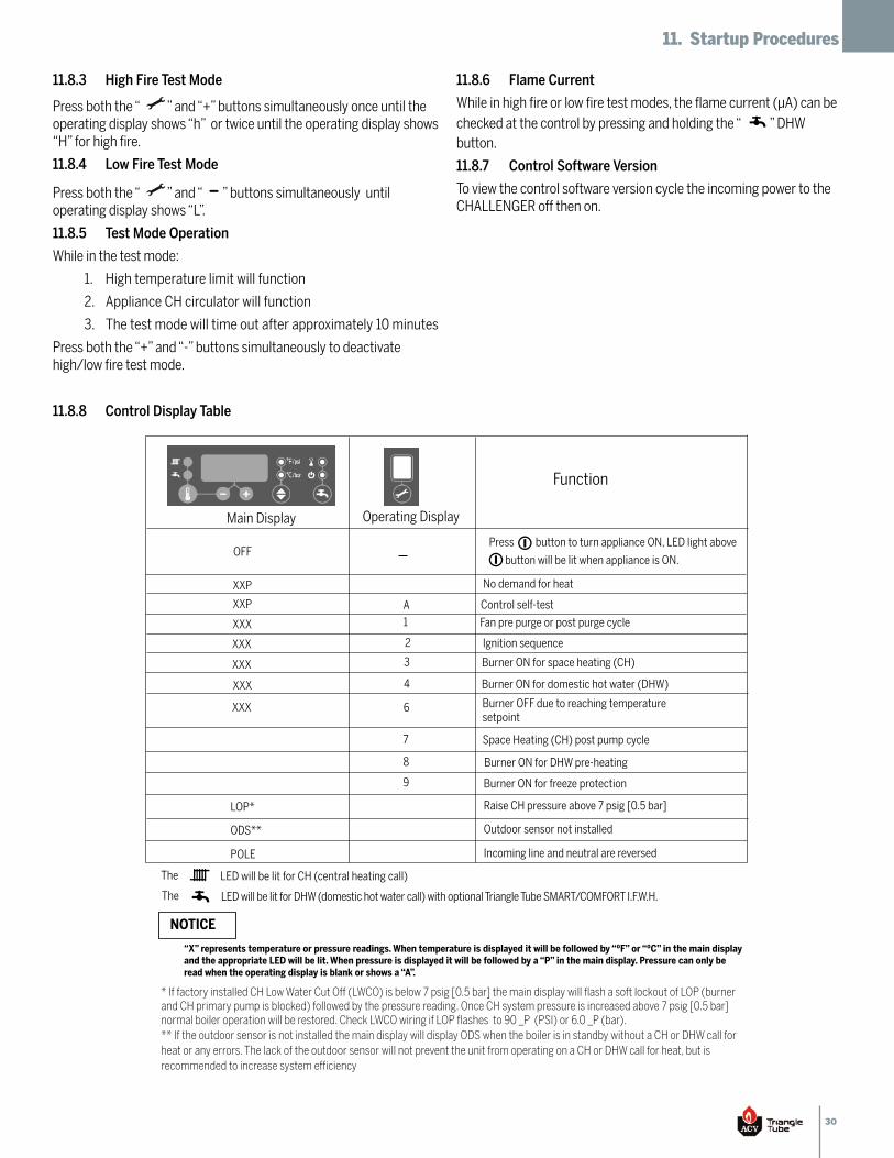
30
11. Startup Procedures
11.8.3 High Fire Test Mode
Press both the “ ” and “+” buttons simultaneously once until theoperating display shows “h” or twice until the operating display shows“H” for high fire.
11.8.4 Low Fire Test Mode
Press both the “ ” and “ ” buttons simultaneously untiloperating display shows “L”.
11.8.5 Test Mode Operation
While in the test mode:
High temperature limit will function1.
Appliance CH circulator will function2.
The test mode will time out after approximately 10 minutes3.
Press both the “+” and “-” buttons simultaneously to deactivatehigh/low fire test mode.
11.8.6 Flame Current
While in high fire or low fire test modes, the flame current (µA) can bechecked at the control by pressing and holding the “ ” DHWbutton.
11.8.7 Control Software Version
To view the control software version cycle the incoming power to theCHALLENGER off then on.
The LED will be lit for CH (central heating call)
The LED will be lit for DHW (domestic hot water call) with optional Triangle Tube SMART/COMFORT I.F.W.H.
“X” represents temperature or pressure readings. When temperature is displayed it will be followed by “ºF” or “ºC” in the main display and the appropriate LED will be lit. When pressure is displayed it will be followed by a “P” in the main display. Pressure can only be read when the operating display is blank or shows a “A”.
* If factory installed CH Low Water Cut Off (LWCO) is below 7 psig [0.5 bar] the main display will flash a soft lockout of LOP (burner and CH primary pump is blocked) followed by the pressure reading. Once CH system pressure is increased above 7 psig [0.5 bar] normal boiler operation will be restored. Check LWCO wiring if LOP flashes to 90 _P (PSI) or 6.0 _P (bar).** If the outdoor sensor is not installed the main display will display ODS when the boiler is in standby without a CH or DHW call for heat or any errors. The lack of the outdoor sensor will not prevent the unit from operating on a CH or DHW call for heat, but is recommended to increase system efficiency
Function
Main Display Operating Display
OFF
XXP
XXP
XXX
7
Press
No demand for heat
Control self-test
Fan pre purge or post purge cycle
Space Heating (CH) post pump cycle
XXX
XXX
6
A
1
Ignition sequence
XXX
2
Burner ON for space heating (CH)
XXX
LOP*
3
Burner ON for domestic hot water (DHW)4
Burner ON for DHW pre-heating
Raise CH pressure above 7 psig [0.5 bar]
ODS** Outdoor sensor not installed
POLE Incoming line and neutral are reversed
Burner ON for freeze protection
8
9
Burner OFF due to reaching temperaturesetpoint
button to turn appliance ON, LED light above
button will be lit when appliance is ON.
NOTICE
11.8.8 Control Display Table
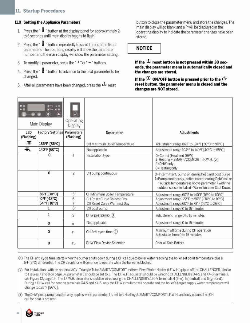
31
11. Startup Procedures
11.9 Setting the Appliance Parameters
Press the “ ” button at the display panel for approximately 21.to 3 seconds until main display begins to flash.
Press the “ ” button repeatedly to scroll through the list of2.parameters. The operating display will show the parameternumber and the main display will show the parameter setting.
To modify a parameter, press the “ ” or “ ” buttons.3.
Press the “ ” button to advance to the next parameter to be4.changed.
After all parameters have been changed, press the reset5.
button to close the parameter menu and store the changes. Themain display will go blank and a P will be displayed in theoperating display to indicate the parameter changes have beenstored.
If the reset button is not pressed within 30 sec-onds, the parameter menu is automatically closed andthe changes are stored.
If the ON/OFF button is pressed prior to the reset button, the parameter menu is closed and thechanges are NOT stored.
NOTICE
AdjustmentsDescriptionParameters(Flashing)
Factory SettingsLED(Flashing)
Installation type 0
186ºF [86ºC]
140ºF [60ºC]
0=Combi (Heat and DHW)
2=DHW only 3=Heating only
CH pump continuous 0 0=Intermittent, pump on during heat and post purge1=Pump continously, active except during DHW call or if outside temperature is above parameter 7 with the outdoor sensor installed - Warm Weather Shut Down.
1=Heating + SMART/COMFORT I.F.W.H.
CH Minimum Boiler Temperature 86ºF [30ºC] Adjustment range 60°F to 140°F [16ºC to 60ºC] CH Reset Curve Coldest Day0ºF [-18ºC] Adjustment range -22°F to 50°F [-30ºC to 10ºC] CH Reset Curve Warmest Day64 ºF [18ºC] Adjustment range 60°F to 78°F [16ºC to 26ºC] CH post pump1 Adjustment range 0 to 15 minutes
Not applicable 0 Adjustment range 0 to 15 minutes
CH Anti cycle time
The CH anti cycle time starts when the burner shuts down during a CH call due to boiler water reaching the boiler set point temperature plus a 6ºF [3ºC] differential. The CH circulator will continue to operate while the burner is blocked.
0 Minimum off time during CH operation Adjustable from 0 to 15 minutes
1
2
5678
o
P
Main DisplayOperating
Display
CH Maximum Boiler Temperature
Not applicableAdjustment range 86ºF to 194ºF [30ºC to 90ºC]
Adjustment range 104ºF to 149ºF [40ºC to 65ºC]
1
1
For installations with an optional ACV- Triangle Tube SMART/COMFORT Indirect Fired Water Heater (I.F.W.H.) piped off the CHALLENGER, similar to Figures 7 and 8 on page 14, parameter 1 should be set to 1. The I.F.W.H. aquastat should be wired to CHALLENGER’s X4-5 and X4-6 terminals, see Figure 12, page 19. The I.F.W.H. circulator should be wired using the CHALLENGER’s 120 V terminals 4 (line), 5 (neutral) and 6 (ground). During a DHW call for heat on terminals X4-5 and X4-6, only the DHW circulator will operate and the boiler’s target supply water temperature willchange to 186°F [86°C].
2
The DHW post pump function only applies when parameter 1 is set to 1 Heating & SMART/COMFORT I.F.W.H. and only occurs if no CHcall for heat is present.
3
2
DHW post pump1 Adjustment range 0 to 15 minutes 9 3
DHW Flow Device Selection 0 for all Solo BoilersP.0
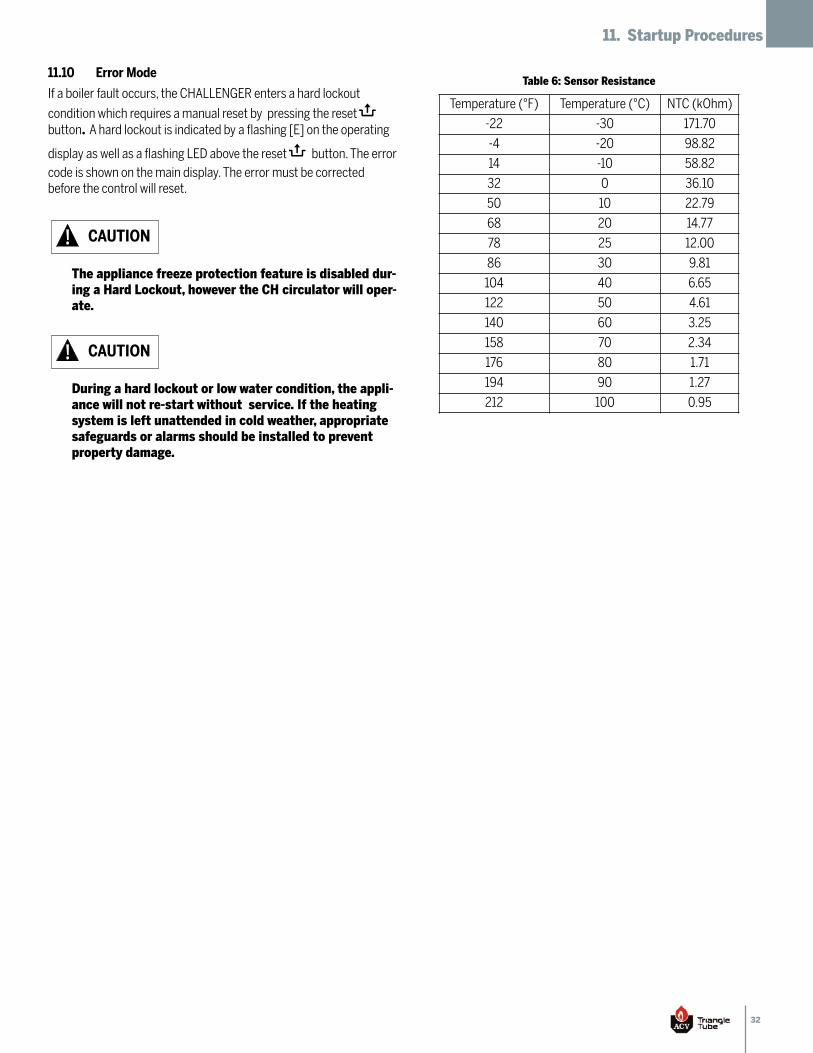
32
11. Startup Procedures
11.10 Error Mode
If a boiler fault occurs, the CHALLENGER enters a hard lockout
condition which requires a manual reset by pressing the reset button. A hard lockout is indicated by a flashing [E] on the operatingdisplay as well as a flashing LED above the reset button. The errorcode is shown on the main display. The error must be correctedbefore the control will reset.
The appliance freeze protection feature is disabled dur-ing a Hard Lockout, however the CH circulator will oper-ate.
CAUTION
During a hard lockout or low water condition, the appli-ance will not re-start without service. If the heatingsystem is left unattended in cold weather, appropriatesafeguards or alarms should be installed to preventproperty damage.
CAUTION
Table 6: Sensor Resistance
Temperature (°F) Temperature (°C) NTC (kOhm)
-22 -30 171.70
-4 -20 98.82
14 -10 58.82
32 0 36.10
50 10 22.79
68 20 14.77
78 25 12.00
86 30 9.81
104 40 6.65
122 50 4.61
140 60 3.25
158 70 2.34
176 80 1.71
194 90 1.27
212 100 0.95
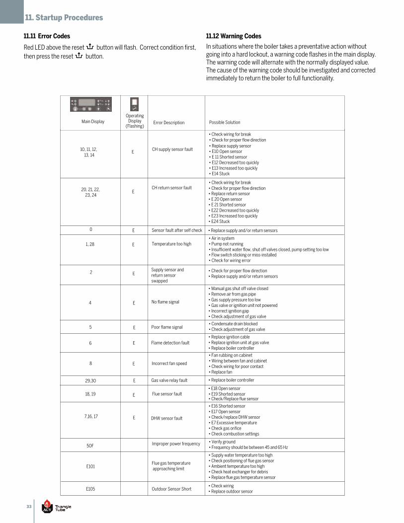
33
11. Startup Procedures
11.11 Error Codes
Red LED above the reset button will flash. Correct condition first,then press the reset button.
11.12 Warning Codes
In situations where the boiler takes a preventative action withoutgoing into a hard lockout, a warning code flashes in the main display.The warning code will alternate with the normally displayed value.The cause of the warning code should be investigated and correctedimmediately to return the boiler to full functionality.
10, 11, 12,
1, 28
4
0
2
29,30
5
6
8
13, 14 CH supply sensor fault
• Check wiring for break • Check for proper flow direction • Replace supply sensor • E10 Open sensor• E 11 Shorted sensor• E12 Decreased too quickly• E13 Increased too quickly• E14 Stuck
• Replace return sensor• E 20 Open sensor• E 21 Shorted sensor• E22 Decreased too quickly• E23 Increased too quickly• E24 Stuck
20, 21, 22, 23, 24
CH return sensor fault
• Check wiring for break • Check for proper flow direction
Sensor fault after self check • Replace supply and/or return sensors
Temperature too high • Air in system • Pump not running • Insufficient water flow, shut off valves closed, pump setting too low • Flow switch sticking or miss-installed• Check for wiring error
Supply sensor and return sensor swapped
• Check for proper flow direction• Replace supply and/or return sensors
No flame signal
• Manual gas shut off valve closed • Remove air from gas pipe • Gas supply pressure too low• Gas valve or ignition unit not powered• Incorrect ignition gap• Check adjustment of gas valve
Poor flame signal • Condensate drain blocked • Check adjustment of gas valve
Flame detection fault • Replace ignition cable• Replace ignition unit at gas valve• Replace boiler controller
Incorrect fan speed
• Fan rubbing on cabinet• Wiring between fan and cabinet• Check wiring for poor contact • Replace fan
Gas valve relay fault • Replace boiler controller
OperatingDisplay
(Flashing)Main Display Possible SolutionError Description
E
18, 19 Flue sensor fault• E18 Open sensor• E19 Shorted sensor• Check/Replace flue sensor
E
7,16, 17 DHW sensor fault
• E16 Shorted sensor• E17 Open sensor• Check/replace DHW sensor• E7 Excessive temperature• Check gas orifice• Check combustion settings
E
50F Improper power frequency • Verify ground• Frequency should be between 45 and 65 Hz
E
E
E
E
E
E
E
E
E
E101 Flue gas temperature approaching limit
• Supply water temperature too high• Check positioning of flue gas sensor• Ambient temperature too high• Check heat exchanger for debris• Replace flue gas temperature sensor
E105 Outdoor Sensor Short• Check wiring• Replace outdoor sensor
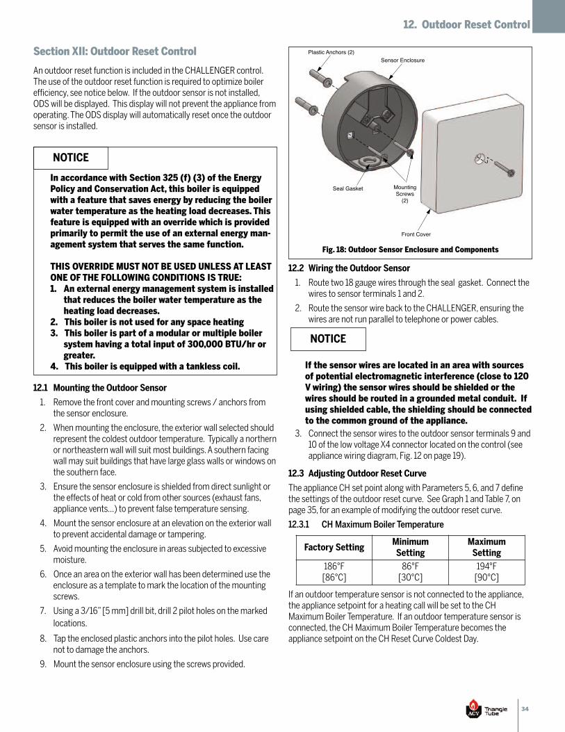
34
12. Outdoor Reset Control
Section XII: Outdoor Reset Control
An outdoor reset function is included in the CHALLENGER control.The use of the outdoor reset function is required to optimize boilerefficiency, see notice below. If the outdoor sensor is not installed,ODS will be displayed. This display will not prevent the appliance fromoperating. The ODS display will automatically reset once the outdoorsensor is installed.
12.1 Mounting the Outdoor Sensor
Remove the front cover and mounting screws / anchors from1.the sensor enclosure.
When mounting the enclosure, the exterior wall selected should2.represent the coldest outdoor temperature. Typically a northernor northeastern wall will suit most buildings. A southern facingwall may suit buildings that have large glass walls or windows onthe southern face.
Ensure the sensor enclosure is shielded from direct sunlight or3.the effects of heat or cold from other sources (exhaust fans,appliance vents...) to prevent false temperature sensing.
Mount the sensor enclosure at an elevation on the exterior wall4.to prevent accidental damage or tampering.
Avoid mounting the enclosure in areas subjected to excessive5.moisture.
Once an area on the exterior wall has been determined use the6.enclosure as a template to mark the location of the mountingscrews.
Using a 3/16” [5 mm] drill bit, drill 2 pilot holes on the marked7.locations.
Tap the enclosed plastic anchors into the pilot holes. Use care8.not to damage the anchors.
Mount the sensor enclosure using the screws provided.9.
12.2 Wiring the Outdoor Sensor
Route two 18 gauge wires through the seal gasket. Connect the1.wires to sensor terminals 1 and 2.
Route the sensor wire back to the CHALLENGER, ensuring the2.wires are not run parallel to telephone or power cables.
Connect the sensor wires to the outdoor sensor terminals 9 and3.10 of the low voltage X4 connector located on the control (seeappliance wiring diagram, Fig. 12 on page 19).
12.3 Adjusting Outdoor Reset Curve
The appliance CH set point along with Parameters 5, 6, and 7 definethe settings of the outdoor reset curve. See Graph 1 and Table 7, onpage 35, for an example of modifying the outdoor reset curve.
12.3.1 CH Maximum Boiler Temperature
If an outdoor temperature sensor is not connected to the appliance,the appliance setpoint for a heating call will be set to the CHMaximum Boiler Temperature. If an outdoor temperature sensor isconnected, the CH Maximum Boiler Temperature becomes theappliance setpoint on the CH Reset Curve Coldest Day.
In accordance with Section 325 (f) (3) of the EnergyPolicy and Conservation Act, this boiler is equippedwith a feature that saves energy by reducing the boilerwater temperature as the heating load decreases. Thisfeature is equipped with an override which is providedprimarily to permit the use of an external energy man-agement system that serves the same function.
THIS OVERRIDE MUST NOT BE USED UNLESS AT LEASTONE OF THE FOLLOWING CONDITIONS IS TRUE:
An external energy management system is installed1.that reduces the boiler water temperature as theheating load decreases.This boiler is not used for any space heating2.This boiler is part of a modular or multiple boiler3.system having a total input of 300,000 BTU/hr orgreater.This boiler is equipped with a tankless coil.4.
NOTICE
Sensor EnclosurePlastic Anchors (2)
Seal Gasket
Front Cover
MountingScrews
(2)
Fig. 18: Outdoor Sensor Enclosure and Components
If the sensor wires are located in an area with sourcesof potential electromagnetic interference (close to 120V wiring) the sensor wires should be shielded or thewires should be routed in a grounded metal conduit. Ifusing shielded cable, the shielding should be connectedto the common ground of the appliance.
NOTICE
Factory SettingMinimumSetting
MaximumSetting
186°F[86°C]
86°F[30°C]
194°F[90°C]
35
12. Outdoor Reset Control
12.3.2 CH Minimum Boiler Temperature (Parameter 5)
This parameter is not applicable if an outdoor sensor is not connectedto the appliance. When an outdoor temperature sensor is connected,the CH Minimum Boiler Temperature becomes the appliance setpointon the CH Reset Curve Warmest Day.
12.3.3 CH Reset Curve Coldest Day (Parameter 6)
This parameter is not applicable if an outdoor sensor is not connectedto the appliance. When an outdoor temperature sensor is connected,the CH Reset Curve Coldest Day is the coldest design temperature ofthe heating system.
12.3.4 CH Reset Curve Warmest Day (Parameter 7)
This parameter is not applicable if an outdoor sensor is not connectedto the appliance. When an outdoor temperature sensor is connected,the CH Reset Curve Warmest Day is the warmest design temperatureof the heating system.
12.4 Changing Outdoor Reset Parameters
Press the “ ” button at the display panel for approximately 21.to 3 seconds until main display begins to flash.
Press the “ ” button repeatedly to scroll through the list of2.parameters. The operating display will show the parameternumber and the main display will show the parameter setting.
To modify a parameter, press the “ ” or “ ” buttons.3.
Press the reset button to close the parameter menu and4.store the changes.
The appliance control module has now been reprogrammedwith the desired outdoor reset parameter values.
Factory SettingMinimumSetting
MaximumSetting
86°F[30°C]
59°F[16°C]
140°F[60°C]
Factory SettingMinimumSetting
MaximumSetting
64°F[18°C]
59°F[16°C]
77°F[26°C]
Factory SettingMinimumSetting
MaximumSetting
00°F[-18°C]
-22°F[-30°C]
50°F[10°C]
Pressing the ON/OFF button will exit the parametermode without storing the parameter changes.
NOTICE
90
20
60
80
100
140
180
7064
50 30 10 0 -10
77
Boi
ler T
empe
ratu
re (
F)
Outdoor Air Temperature ( F )
CH Maximum Boiler Temperature
Parameter 5 Setting
Para
met
er 7
Set
ting
Para
met
er 6
Set
ting
Graph 1: Outdoor Air Temperature Reset Curve Example
OutdoorTemperature
Appliance Target Temp.Based on Outdoor Temp.
10°F or Lower 140°F
30°F 117°F
50°F 93°F
64°F or Higher 77°F
Table 7: Outdoor Air Temperature Reset Example
36
13. Checkout Procedures
Section XIII: Checkout Procedures
c Boiler system water chemistry checked and verified asoutlined in Section 10.1.
c Any automatic air vent caps within the system are open onefull turn.
c Air is purged from the heating zones and appliance systempiping.
c Confirm the appliance has proper gas orifice as noted inSections 7.2 & 7.3.
c Thermostat circuit wiring checked and verified that novoltage is present to the low voltage terminals as outlined inSection 10.7.
c Operating Instructions on page 28 were followed duringstartup.
c Combustion levels and flame pattern verified as outlined inSection 11.4.
c Measured the Natural Gas input rate as outlined in Section11.4.
c Checked the incoming gas pressure to the CHALLENGER toensure a minimum pressure of 5”w.c [13 mbar] during flowconditions to all gas appliances and a maximum pressure of13”w.c [32 mbar] during non-flow conditions for Natural andPropane gas.
c Adjusted balancing valves and system limit controls toprovide design temperatures to the space heating system.
c In multiple zone applications, adjusted for correct flow ofwater to each zone.
c Checked and verified room thermostat(s) function properlyand the thermostat(s) heat anticipator (if used) was properlyset.
c Observed several operating cycles for proper operation ofthe CHALLENGER and the system.
c Set the room thermostat(s) to the desired roomtemperature.
c Reviewed all instructions shipped with the CHALLENGERwith the homeowner or maintenance personnel.
c Completed the Installation Record in Section XIV.
c Ensure all manuals and other documents are returned to theInstallation envelope and given to the owner for safekeeping.
Perform the following checkout procedures as outlinedand checkoff items as completed. When procedures arecompleted, the installer should complete the installa-tion record on page 37.
NOTICE
37
14. Installation Record
Section XIV: Installation Record
CHALLENGER Model Number:
Serial Number:
Date of Installation:
Fuel: Natural Gas Propane
Measured Rate of Input:
Combustion Readings:
CO2
O2
CO
The following items were completed during installation:
Installation instructions have been followed and completed
Check-out procedures have been followed and completed
Information regarding the unit and installation received and left with owner / maintenance personnel.
Installer Information
(Company)
(Address)
(Address)
(Phone Number)
Btu/hr
____________________________________________________________________
____________________________________________________________________
____________________________________________________________________
_________________________________________________________________
%
%
ppm
38
15. Maintenance Schedule
Section XV: Maintenance Schedule
15.1 Service Technician
At least on an annual basis the following maintenance should beperformed by a qualified service technician.
15.1.1General
Attend to any reported problems.1.
Inspect the interior of the appliance jacket area; clean and2.vacuum if necessary.
Clean the condensate drain assembly and fill with fresh water.3.
Check for leaks: water, gas, flue and condensate.4.
Verify flue vent piping and air inlet piping are in good condition,5.sealed tight and properly supported.
Check appliance water pressure, piping and expansion tank.6.
Check control settings.7.
Check ignition electrode (sand off any white oxide; clean and8.reposition).
Check ignition wiring and ground wiring.9.
Check all control wiring and connections.10.
Check burner flame pattern (stable and uniform).11.
15.1.2 Poor Combustion or Performance
Clean heat exchanger and flue ways.1.
Remove burner assembly and clean inside of burner head using2.compressed air only.
Once the maintenance items are completed, review the service withthe owner.
15.2 Owner Maintenance
15.2.1 Periodic
Check the area around the appliance. 1.
Check and remove any blockage from the combustion air inlet2.and ventilation openings.
Check the temperature and pressure gauge. 3.
15.2.2 Monthly
Check vent piping.1.
Check combustion air inlet piping.2.
Check the pressure relief valve.3.
Check the condensate drain assembly.4.
15.2.3 Every 6 Months
Check appliance piping and gas supply piping for corrosion or1.potential signs of leakage.
Operate the pressure relief valve.2.
Follow the maintenance procedures given throughoutthis manual. Failure to perform the service and mainte-nance or follow the directions in this manual can resultin damage to the CHALLENGER or system componentswhich can result in substantial property damage, seri-ous injury, or death.
WARNING
39
16. Maintenance Procedures
Section XVI: Maintenance Procedures
16.1 Annual Maintenance Procedures
16.2 Reported Problems
Any problems reported by the owner should be checked, verified, andcorrected before proceeding with any maintenance procedures.
16.3 Check Surrounding Area
Verify that the area surrounding the CHALLENGER is free ofcombustible / flammable materials, vapors or liquids. Removeimmediately if found.
Verify that combustion air inlet area is free of any contaminates.Refer to the materials listed in Section 3.1 of this manual. If any ofthese products are in the area from which the appliance takes itscombustion air, they must be removed immediately or thecombustion air intake must be relocated to another area.
16.4 Inspect Burner Area
Remove the appliance front jacket panel.1.
Vacuum any dirt or debris from the blower component.2.
Reinstall front jacket panel when completed.3.
The CHALLENGER should be inspected and servicedannually, preferably at the start of the heating season,by a qualified service technician. In addition, the main-tenance and care of the appliance as outlined in Sec-tion XV and further explained in Section XVI should beperformed to assure maximum efficiency and reliabilityof the appliance. Failure to service and maintain theCHALLENGER and the system components could resultin equipment failure which can result in substantialproperty damage, personal injury, or death.
WARNING
The following information provides detailed instructionfor completing the maintenance items outlined in themaintenance schedule in Section XV. In addition to thismaintenance, the CHALLENGER should be serviced atthe beginning of the heating season by a qualified serv-ice technician.
NOTICE
Do not use solvents to clean any of the components.The components could be damaged, resulting in unreli-able or unsafe operation.
WARNING
16.5 Check System Piping
Inspect all piping (water and gas) for leaks and verify that the piping isleak free and properly supported. Inspect the fittings andcomponents on the appliance and verify they are leak free.
16.6 Clean Condensate Drain Assembly
Remove the condensate assembly from the appliance.1.
Empty any water from the trap and drain assembly. Flush with2.fresh water as necessary to clean.
Check the drain piping from the condensate drain assembly to3.the drain. Flush to clean as necessary.
Fill the condensate drain assembly with water. 4.
Reassemble the condensate drain assembly onto the appliance.5.
16.7 Check Ventilation Air Openings
Verify that all ventilation openings to the mechanical room or buildingare open and unobstructed. Check the operation and wiring of anyautomatic ventilation dampers.
Check and verify the vent discharge and the combustion air intake arefree of debris and obstructions.
16.8 Inspect Vent and Combustion Air Piping
Visually inspect the venting system and combustion air piping forblockage, deterioration or leakage. Repair any deficiencies.
Verify that the combustion air inlet piping is connected, sealed andproperly supported.
Eliminate all boiler leaks. Continual fresh make-up waterwill reduce the heat exchanger life causing appliance fail-ure. Leaking water may also cause severe property dam-age to the surrounding area. Inspect the gas supplypiping using the procedure outlined in Section 10.6.
WARNING
When re-assembling the condensate drain assembly, ensureall gaskets are in place and correctly installed. Ensure all as-sociated internal joints are complete, tight and secure. Failureto comply can result in flue gas leakage resulting in substan-tial property damage, serious injury, or death.
WARNING
Failure to inspect the vent system and combustion airinlet piping and to have any conditions repaired can re-sult in substantial property damage, serious injury, ordeath.
WARNING
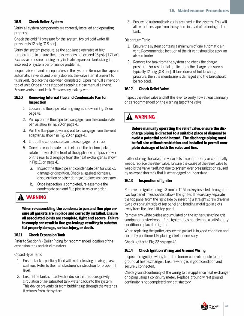
40
16. Maintenance Procedures
16.9 Check Boiler System
Verify all system components are correctly installed and operatingproperly.
Check the cold fill pressure for the system, typical cold water fillpressure is 12 psig [0.8 bar].
Verify the system pressure, as the appliance operates at hightemperature, to ensure the pressure does not exceed 25 psig [1.7 bar].Excessive pressure reading may indicate expansion tank sizing isincorrect or system performance problems.
Inspect air vent and air separators in the system. Remove the caps onautomatic air vents and briefly depress the valve stem if present toflush vent. Replace the cap when completed. Open manual air vent ontop of unit. Once air has stopped escaping, close manual air vent.Ensure vents do not leak. Replace any leaking vents.
16.10 Removing Internal Flue and Condensate Pan for Inspection
Loosen the flue pipe retaining ring as shown in Fig. 19 on1.page 41.
Pull up on the flue pipe to disengage from the condensate2.pan as show in Fig. 20 on page 41.
Pull the flue pipe down and out to disengage from the vent3.adapter as shown in Fig. 20 on page 41.
Lift up the condensate pan to disengage from trap.4.
Once the condensate pan is clear of the bottom jacket,5.rotate it towards the front of the appliance and push downon the rear to disengage from the heat exchanger as shownin Fig. 21 on page 41.
Inspect the flue pipe and condensate pan for cracks,a.damage or distortion. Check all gaskets for tears,discoloration or other damage, replace as necessary.
Once inspection is completed, re-assemble theb.condensate pan and flue pipe in reverse order.
16.11 Check Expansion Tank
Refer to Section V - Boiler Piping for recommended location of theexpansion tank and air eliminators.
Closed -Type Tank:
Ensure tank is partially filled with water leaving an air gap as a1.cushion. Refer to the manufacturer’s instruction for proper filllevel.
Ensure the tank is fitted with a device that reduces gravity2.circulation of air-saturated tank water back into the system.This device prevents air from bubbling up through the water asit returns from the system.
When re-assembling the condensate pan and flue pipe en-sure all gaskets are in place and correctly installed. Ensureall associated joints are complete, tight and secure. Failureto comply can result in flue gas leakage resulting in substan-tial property damage, serious injury, or death.
WARNING
Ensure no automatic air vents are used in the system. This will3.allow air to escape from the system instead of returning to thetank.
Diaphragm Tank:
Ensure the system contains a minimum of one automatic air1.vent. Recommended location of the air vent should be atop anair eliminator.
Remove the tank from the system and check the charge2.pressure. For residential applications the charge pressure istypically 12 psig [0.8 bar]. If tank does not hold a chargepressure, then the membrane is damaged and the tank shouldbe replaced.
16.12 Check Relief Valve
Inspect the relief valve and lift the lever to verify flow at least annuallyor as recommended on the warning tag of the valve.
If after closing the valve, the valve fails to seat properly or continuallyweeps, replace the relief valve. Ensure the cause of the relief valve toweep is the valve itself, not due to system over-pressurization causedby an expansion tank that is waterlogged or undersized.
16.13 Inspection of Igniter
Remove the igniter using a 3 mm or T-15 hex key inserted through thetwo top panel holes located above the igniter. If necessary separatethe top panel from the right side by inserting a straight screw driver intwo slots on right side of top panel and bending metal tab in slotsaway from the side. Lift top panel .
Remove any white oxides accumulated on the igniter using fine gritsandpaper or steel wool. If the igniter does not clean to a satisfactorycondition, replace the igniter .
When replacing the igniter, ensure the gasket is in good condition andcorrectly positioned. Replace gasket if necessary.
Check igniter to Fig. 22 on page 42.
16.14 Check Ignition Wiring and Ground Wiring
Inspect the ignition wiring from the burner control module to theground at heat exchanger. Ensure wiring is in good condition andsecurely connected.
Check ground continuity of the wiring to the appliance heat exchangeror piping using a continuity meter. Replace ground wire if groundcontinuity is not completed and satisfactory.
Before manually operating the relief valve, ensure the dis-charge piping is directed to a suitable place of disposal toavoid a potential scald hazard. The discharge piping mustbe full size without restriction and installed to permit com-plete drainage of both the valve and line.
WARNING
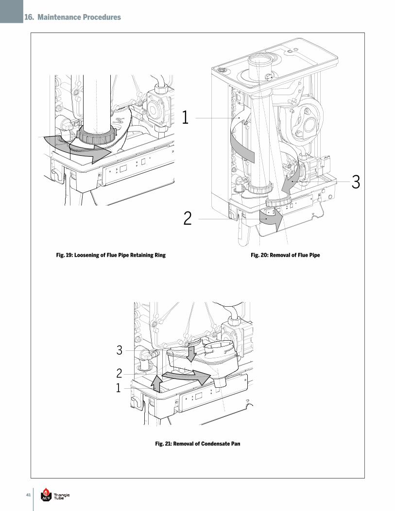
41
16. Maintenance Procedures
12
3
1
2
3
Fig. 19: Loosening of Flue Pipe Retaining Ring Fig. 20: Removal of Flue Pipe
Fig. 21: Removal of Condensate Pan
42
16. Maintenance Procedures
0.12” [ 3 mm]
0.12”
[3 m
m]
0.43” [11 mm]
Spark gap app. 0.18”
1.06”
-1.12
” [2
7 mm
- 29 m
m]
[5 mm]
1.75”
[44 m
m]
1.18”
[30 m
m]
(45º)
Fig. 22: Igniter Dimensions
43
16. Maintenance Procedures
16.15 Check Control Wiring
Inspect all control wiring. Ensure wiring is in good condition andproperly connected.
16.16 Check Control Settings
Check the control CH parameter settings by pressing the1.thermometer button “ ” on control display. When the LED is litfor “ ” this is the CH Maximumn Boiler Temperature. Adjustsetting with “ ” or “ ” buttons as necessary.
Press the reset button to close the parameter menu and2.store the changes.
Check any external limit control settings (if used). Adjust3.settings as necessary.
16.17 Perform Startup and Checkout Procedures
Start the appliance and perform the startup procedure as listed inSection XI.
Verify the cold water fill pressure is correct and the operating pressureof the boiler is within normal operating range.
Complete the checkout procedures as referenced in Section XIII.
16.18 Check Burner Flame
Inspect the burner flame through the observation port on left1.side of the heat exchanger.
Verify flame pattern is blue and covers the entire burner surface2.during high fire. Ensure combustion at both high and low firemeet the requirements listed in Table 5 on page 27. Ifcombustion is OK and flame pattern is not fully blue & coversthe entire burner surface during high fire, shut the appliancedown and allow it to cool thoroughly before disassembly.
Close the external manual gas valve on the gas supply line and3.disconnect the gas piping and electrical connector to the gasvalve.
Disconnect the wiring harness connectors from the blower.4.
Remove the mounting bolts and washers securing the front5.plate of the heat exchanger and set aside.
Carefully remove the front plate of the heat exchanger. Ensure6.combustion chamber insulation is not damaged during removal.See WARNING on page 44.
Remove the burner head mounting screws and remove the7.burner head. Inspect the burner head for deterioration. Usecompressed air or a vacuum to clean the burner head. Replaceburner head if necessary. Replace burner head gasket.
Re-assemble the burner head and burner head gasket. Ensure8.mounting screws are tight.
Remove the blower.9.
Use a vacuum cleaner or compressed air to clean the interior10.of the blower and venturi assembly. Inspect the blower bladesto ensure they are clean and not damaged.
Re-assemble the blower and venturi onto the front plate of the11.heat exchanger . Ensure all gaskets are in good condition, andpositioned correctly. Replace gaskets if necessary.
Re-assemble the front plate of the heat exchanger onto the12.heat exchanger with previously removed bolts and washers.Ensure the gasket and combustion chamber insulation is inplace and not damaged, replace gasket and insulation ifnecessary. See WARNING on page 44. Ensure all bolts are tight.
Reconnect the wiring harness connectors to the blower.13.
Re-assemble the gas supply connections and electrical14.connector to gas valve inside the appliance. Open the externalmanual gas valve. Check gas piping for any leaks as outlined inSection 10.6 and repair if necessary. Place the appliance backinto service.
16.19 Check Combustion Levels
Refer to Section 11.4 of this manual for measuring combustion levelsand burner adjustments.
16.20 Clean Boiler Heat Exchanger
Shut down the appliance:1.
Follow the instructions on Page 28 "To Turn Off Gas toa.Appliance"
Do not drain the appliance unless it will be subject tob.freezing conditions.
Do not drain the appliance if freeze protection fluid isc.used in the system.
Allow the appliance to cool down to room temperature2.before servicing.
Close the external manual gas valve on the gas supply line3.and disconnect the gas piping and electrical connector tothe gas valve.
Disconnect the wiring harness connectors from the blower.4.
Remove the mounting bolts and washers securing the front5.plate of the heat exchanger and set aside.
44
16. Maintenance Procedures
Carefully remove the front plate of the heat exchanger.6.Ensure combustion chamber insulation is not damagedduring removal. See WARNING on page 44.
Use a vacuum cleaner, compressed air or water to remove7.any accumulation from the heat exchanger flue ways. Donot use any solvent.
Re-assemble the front plate of the heat exchanger onto the8.heat exchanger with previously removed bolts and washers.Ensure the gasket and combustion chamber insulation is inplace and not damaged, replace gasket and insulation ifnecessary. See WARNING on page 44. Ensure all bolts aretight.
Reconnect the wiring harness connectors to the blower.9.
Re-assemble the gas supply connections and electrical10.connector to gas valve inside the appliance. Open theexternal manual gas valve. Check gas piping for any leaks asoutlined on Section 10.6 and repair if necessary. Place theappliance back into service.
Close isolation valves at the boiler piping to isolate the11.appliance from the heating system.
Attach a hose to the boiler drain valve and flush the boiler12.thoroughly with fresh water by using the purge valves toallow water to enter through the make-up water line to theboiler.
Once the boiler has been completely flushed, return the13.boiler and system piping back to operation.
Perform the required startup and checkout procedures as14.outlined in Sections X, XI, XIII.
16.21 Review With Owner
Ensure the owner understands the importance to perform themaintenance schedule specified in this manual.
Remind the owner of the importance to call a licensed contractorshould the appliance or system exhibit any unusual behavior.
Handling Previously Fired Combustion Chamber Insulation
The combustion chamber insulation contains ceramicfibers, which are classified as a possible human carcino-gen. When exposed to extremely high temperatures, theceramin fibers, which contain crystalline silica, can beconverted into cristoalite.
WARNING
Avoid Breathing and Contact with Skin and Eyes
When removing or repairing the combustion chamber insulation,follow these precaution measures:
Use a NIOSH approved respirator which meets OSHA1.requirements for cristobalite dust, similar to N95. ContactNIOSH at 1-800-356-4676 or on the web atwww.cdc.gov/niosh for latest recommendations.
Wear long sleeved, loosing fitting clothing, gloves, and eyes2.protection.
Assure adequate ventilation.3.
Wash with soap and water after contact.4.
Wash potentially contaminated clothes separately from other5.laundry and rinse washing machine thoroughly.
Discard used insulation in an air tight plastic bag.6.
NIOSH Stated First Aid:
Eye/Skin: Immediately irrigate
Breathing: Clean fresh air
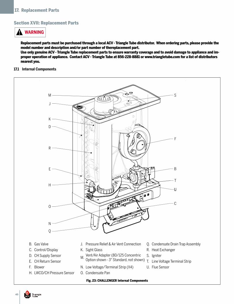
45
17. Replacement Parts
Section XVII: Replacement Parts
17.1 Internal Components
U
T
S
U
F
B
C
Q
N
O
H
E
R
D
K
J
M
Fig. 23: CHALLENGER Internal Components
Replacement parts must be purchased through a local ACV - Triangle Tube distributor. When ordering parts, please provide themodel number and description and/or part number of thereplacement part.Use only genuine ACV - Triangle Tube replacement parts to ensure warranty coverage and to avoid damage to appliance and im-proper operation of appliance. Contact ACV - Triangle Tube at 856-228-8881 or www.triangletube.com for a list of distributorsnearest you.
WARNING
B. Gas Valve J. Pressure Relief & Air Vent Connection Q. Condensate Drain Trap Assembly
C. Control/Display K. Sight Glass R. Heat Exchanger
D. CH Supply Sensor M.Vent/Air Adapter (80/125 ConcentricOption shown - 3" Standard, not shown)
S. Igniter
E. CH Return Sensor T. Line Voltage Terminal Strip
F. Blower N. Low Voltage/Terminal Strip (X4) U. Flue Sensor
H. LWCO/CH Pressure Sensor O. Condensate Pan
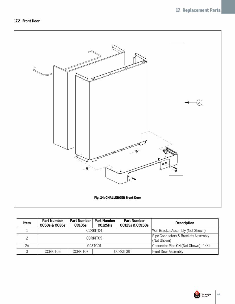
46
17. Replacement Parts
17.2 Front Door
3
Fig. 24: CHALLENGER Front Door
ItemPart NumberCC50s & CC85s
Part NumberCC105s
Part NumberCC125Hs
Part NumberCC125s & CC150s
Description
1 CCRKIT04 Wall Bracket Assembly (Not Shown)
2 CCRKIT05Pipe Connectors & Brackets Assembly(Not Shown)
2A CCFTG01 Connector Pipe CH (Not Shown) - 1/Kit
3 CCRKIT06 CCRKIT07 CCRKIT08 Front Door Assembly
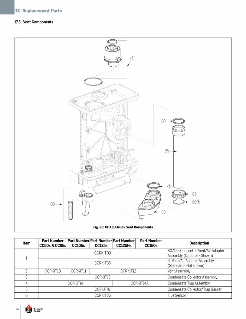
47
17. Replacement Parts
17.3 Vent Components
2
2
3
1
2 3
3
4
3
Fig. 25: CHALLENGER Vent Components
ItemPart NumberCC50s & CC85s
Part NumberCC105s
Part NumberCC125s
Part NumberCC125Hs
Part NumberCC150s
Description
1CCRKIT09
80/125 Concentric Vent/Air AdapterAssembly (Optional - Shown)
CCRKIT353" Vent/Air Adapter Assembly(Standard - Not shown)
2 CCRKIT10 CCRKIT11 CCRKIT12 Vent Assembly
3 CCRKIT13 Condensate Collector Assembly
4 CCRKIT14 CCRKIT14A Condensate Trap Assembly
5 CCRKIT41 Condensate Collector/Trap Gasket
6 CCRKIT36 Flue Sensor
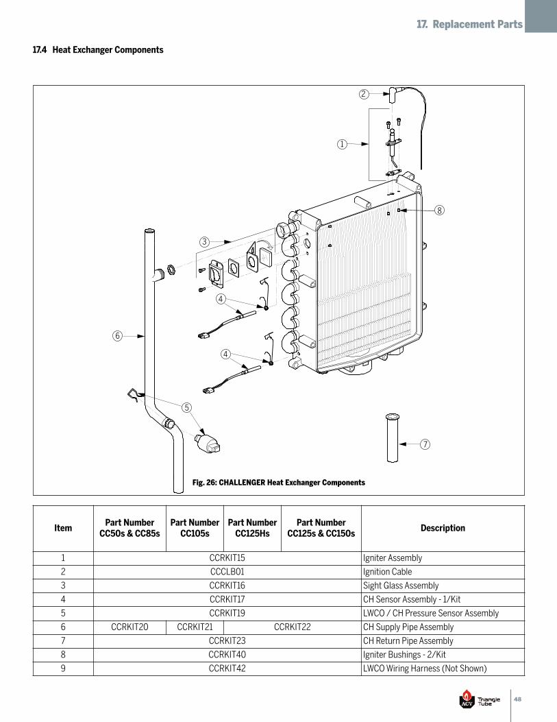
48
17. Replacement Parts
7
1
3
2
6
4
5
4
8
Fig. 26: CHALLENGER Heat Exchanger Components
17.4 Heat Exchanger Components
ItemPart NumberCC50s & CC85s
Part NumberCC105s
Part NumberCC125Hs
Part NumberCC125s & CC150s
Description
1 CCRKIT15 Igniter Assembly
2 CCCLB01 Ignition Cable
3 CCRKIT16 Sight Glass Assembly
4 CCRKIT17 CH Sensor Assembly - 1/Kit
5 CCRKIT19 LWCO / CH Pressure Sensor Assembly
6 CCRKIT20 CCRKIT21 CCRKIT22 CH Supply Pipe Assembly
7 CCRKIT23 CH Return Pipe Assembly
8 CCRKIT40 Igniter Bushings - 2/Kit
9 CCRKIT42 LWCO Wiring Harness (Not Shown)
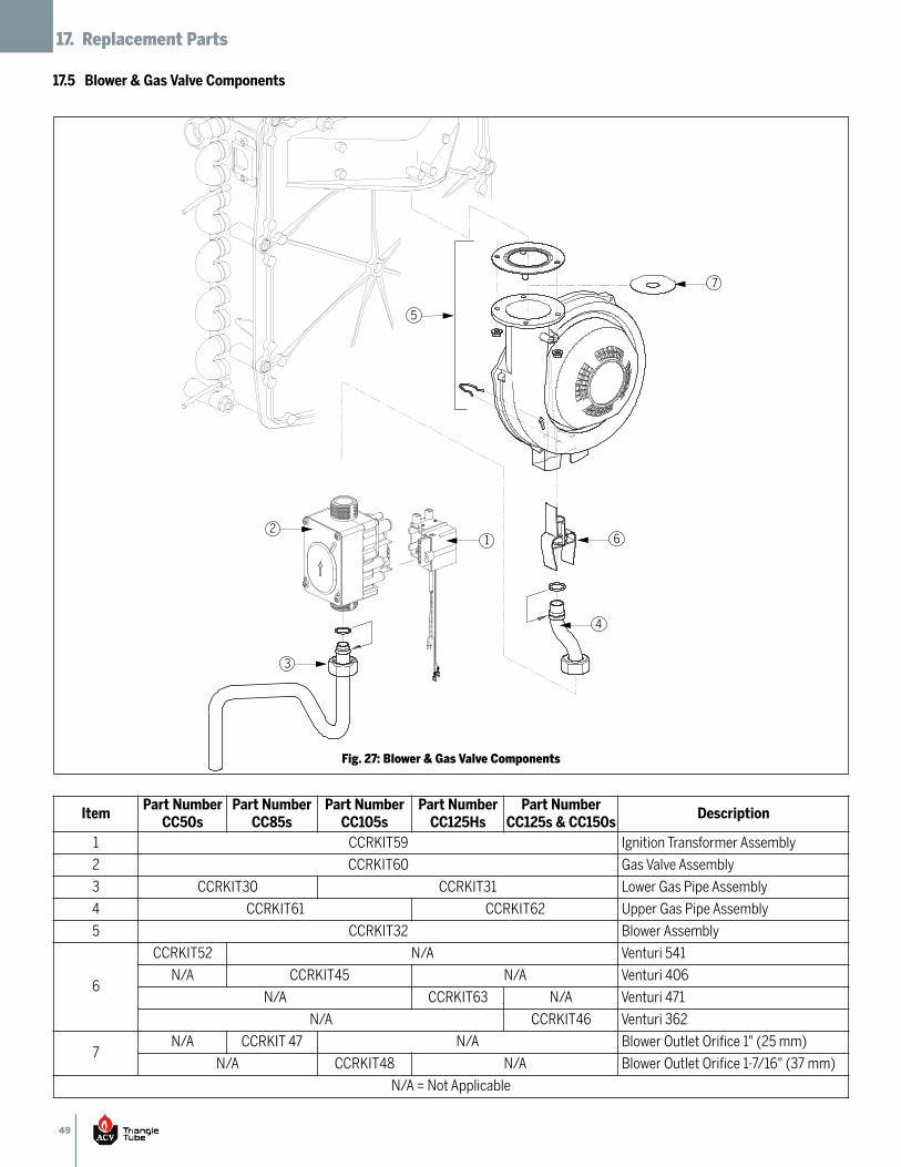
49
17. Replacement Parts
5
12
3
7
6
4
Fig. 27: Blower & Gas Valve Components
ItemPart NumberCC50s
Part NumberCC85s
Part NumberCC105s
Part NumberCC125Hs
Part NumberCC125s & CC150s
Description
1 CCRKIT59 Ignition Transformer Assembly
2 CCRKIT60 Gas Valve Assembly
3 CCRKIT30 CCRKIT31 Lower Gas Pipe Assembly
4 CCRKIT61 CCRKIT62 Upper Gas Pipe Assembly
5 CCRKIT32 Blower Assembly
6
CCRKIT52 N/A Venturi 541
N/A CCRKIT45 N/A Venturi 406
N/A CCRKIT63 N/A Venturi 471
N/A CCRKIT46 Venturi 362
7N/A CCRKIT 47 N/A Blower Outlet Orifice 1" (25 mm)
N/A CCRKIT48 N/A Blower Outlet Orifice 1-7/16" (37 mm)
N/A = Not Applicable
17.5 Blower & Gas Valve Components
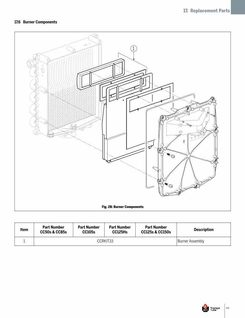
50
17. Replacement Parts
1
Fig. 28: Burner Components
17.6 Burner Components
ItemPart NumberCC50s & CC85s
Part NumberCC105s
Part NumberCC125Hs
Part NumberCC125s & CC150s
Description
1 CCRKIT33 Burner Assembly
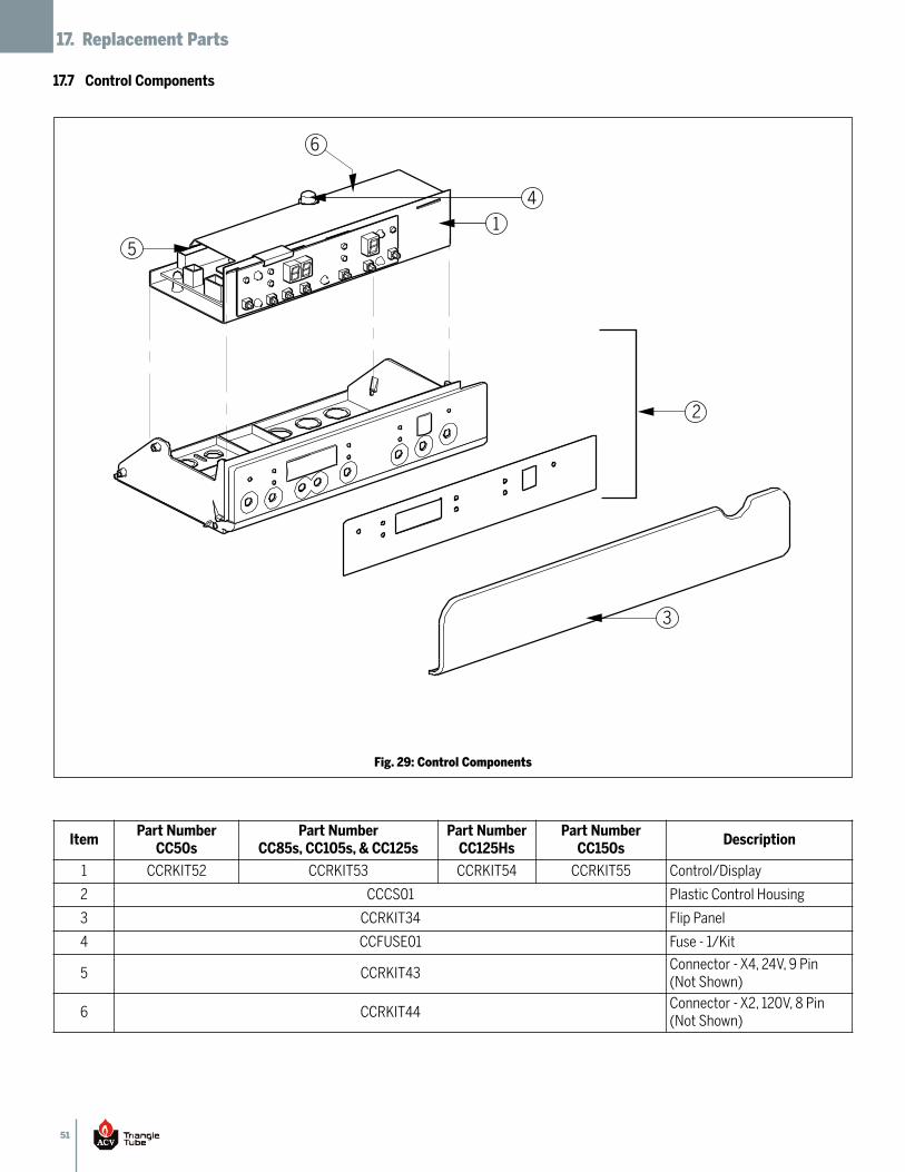
51
17. Replacement Parts
3
4
2
1
6
5
Fig. 29: Control Components
17.7 Control Components
ItemPart NumberCC50s
Part NumberCC85s, CC105s, & CC125s
Part NumberCC125Hs
Part NumberCC150s
Description
1 CCRKIT52 CCRKIT53 CCRKIT54 CCRKIT55 Control/Display
2 CCCS01 Plastic Control Housing
3 CCRKIT34 Flip Panel
4 CCFUSE01 Fuse - 1/Kit
5 CCRKIT43Connector - X4, 24V, 9 Pin(Not Shown)
6 CCRKIT44Connector - X2, 120V, 8 Pin(Not Shown)
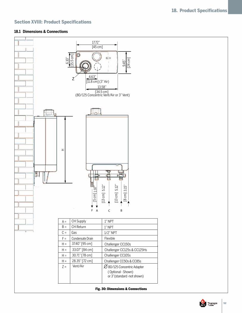
52
18. Product Specifications
Section XVIII: Product Specifications
18.1 Dimensions & Connections
AF
1.97
”[5
cm
]
[13
cm]
[8 c
m]
5.12
”
[13
cm]
5.12
”
3.15
”
H
9.45
”[2
4 cm
]
6.10
”[1
5.5
cm]
Z
33.07” [84 cm]
30.71” [78 cm]
CH Supply
Vent/Air
CH Return
28.35” [72 cm]
Flexible
1” NPT
1” NPT
1/2” NPT
C
80/125 Concentric Adapter
Challenger CC50s & CC85s
Condensate Drain
Challenger CC105s
Challenger CC125s & CC125Hs
37.40” [95 cm] Challenger CC150s
B
13.58”[34.5 cm]
(80/125 Concentric Vent/Air or 3” Vent)
4.63”[11.8 cm] (3” Air)
17.72”[45 cm]
( Optional - Shown) or 3”(standard -not shown)
A =
B =
C =
F =
H =
H =
H =
H =
Z =
Gas
Fig. 30: Dimensions & Connections
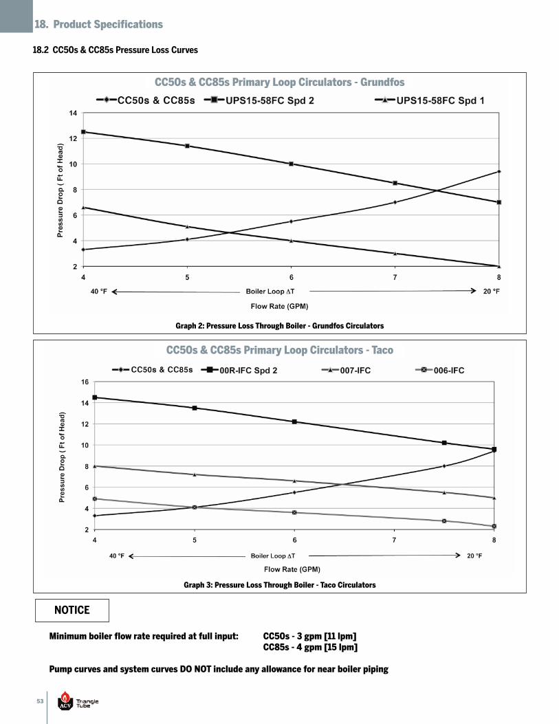
53
18. Product Specifications
18.2 CC50s & CC85s Pressure Loss Curves
Graph 2: Pressure Loss Through Boiler - Grundfos Circulators
Graph 3: Pressure Loss Through Boiler - Taco Circulators
Minimum boiler flow rate required at full input: CC50s - 3 gpm [11 lpm]CC85s - 4 gpm [15 lpm]
Pump curves and system curves DO NOT include any allowance for near boiler piping
NOTICE
CC50s & CC85s Primary Loop Circulators - Grundfos
CC50s & CC85s Primary Loop Circulators - Taco
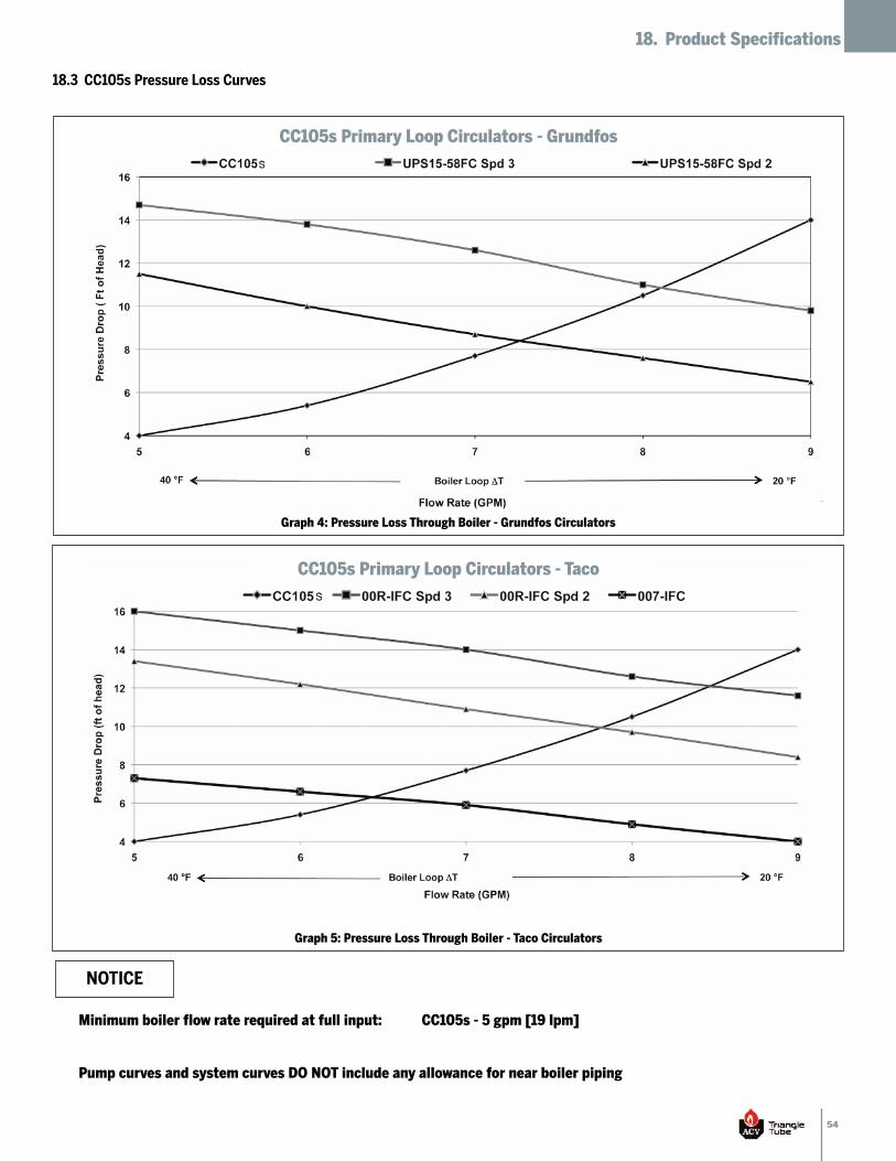
54
18. Product Specifications
18.3 CC105s Pressure Loss Curves
Graph 4: Pressure Loss Through Boiler - Grundfos Circulators
Graph 5: Pressure Loss Through Boiler - Taco Circulators
Minimum boiler flow rate required at full input: CC105s - 5 gpm [19 lpm]
Pump curves and system curves DO NOT include any allowance for near boiler piping
NOTICE
CC105s Primary Loop Circulators - Grundfos
CC105s Primary Loop Circulators - Taco
55
18. Product Specifications
18.4 CC125s, CC125Hs, & CC150s Pressure Loss Curves
Graph 6: Pressure Loss Through Boiler - Grundfos Circulators
Graph 7: Pressure Loss Through Boiler - Taco Circulators
Minimum boiler flow rate required at full input: CC125s & CC125Hs - 6 gpm [23 lpm]CC150s - 7 gpm [27 lpm]
Pump curves and system curves DO NOT include any allowance for near boiler piping
NOTICE
CC125s, CC125Hs, CC150s Primary Loop Circulators - Grundfos
CC125s, CC125Hs, CC150s Primary Loop Circulators - Taco
56
18. Product Specifications
Note 1: The heating capacity of the CHALLENGER is based on thetest requirements of the U.S. Department of Energy.
Note 2: The AHRI rating is based on a piping and pick up allowanceof 1.15. This allowance should be sufficient for thestandard radiation requirements for a building load.
Note 3: Based on the given AFUE the CHALLENGER meets theenergy efficiency guidelines established by Energy Star.
Note 4: Input and output ratings are shown for sea levelapplications. The CHALLENGER automatically derates theinput at approximately 2% for every 1,000 ft of altitude.No alterations to the appliance or burner system arerequired.
Note 5: The trailing letter “s” in the model number refers toCHALLENGER “Solo” Boilers (heating only). Theconstruction and components of these models are
identical to the combination (heating and domestic)models except the domestic coil is removed from the heatexchanger along with all associated domestic components(domestic piping, domestic sensor, flow sensor, domesticwiring and labeling). The combustion, safety, andefficiency performances are identical to the combinationunits.
The following efficiency performance is achieved when the CHALLENGER is operated as a boiler according to theASHRAE 103 test procedure.
NOTICE
18.5 Performance Ratings
CHALLENGERModel(Note 5)
Fuel
InputModulationBTUH [kW](Note 4)
DOEHeating CapacityBTUH [kW](Note 1 & 4)
Net AHRIRating
BTUH [kW](Note 2)
AFUE(Note 3)
WeightLbs [kg]
CC50sNatural orPropane
13,500 - 50,000[4.0 - 14.6]
46,000 [13.5] 40,000 [11.7] 95% 66 [30]
CC85sNatural orPropane
23,000 - 84,000[6.7 - 24.6]
75,000 [22.0] 65,000 [19.0] 94% 66 [30]
CC105sNatural orPropane
29,000 - 106,000[8.5 - 31]
94,000 [27.5] 82,000 [24.0] 94% 73 [33]
CC125sNatural orPropane
33,000 - 124,000[9.7 - 36.3]
110,000 [32.2] 96,000 [28.1] 94% 80 [36]
CC125HsNatural orPropane
20,000 - 125,000[5.9 - 36.6]
111,000 [32.5] 97,000 [28.4] 95% 80 [36]
CC150sNatural orPropane
33,000 - 145,000[9.7 - 42.5]
129,000 [37.8] 112,000 [32.8] 92.3% 80 [36]

57
19. Notes
Section XIX: Notes

58
19. Notes
Additional Quality Water Heating Equipment Available From
Maxi-Flo Pool and Spa Heat Exchangers
Constructed of high quality corrosion resistant stainless steel (AISI 316) or•titanium
Specially designed built-in flow restrictor to assure maximum heat exchange•
Compact and light weight•
Available in 8 sizes that can accommodate any size pool or spa•
SMART/COMFORT Indirect Fired Water Heaters
Exclusive Tank-in-Tank design•
Stainless steel construction•
Self cleaning/Self descaling heat exchanger•
SMART available in 7 sizes; COMFORT available in 2 sizes•
SMART: Limited LIFETIME residential warranty / Limited 6 year commercial•warranty
COMFORT: Limited 10 year warranty•
TTP Brazed Plate Heat Exchangers
For domestic water, snow melting, radiant floor, and more•
Plates made of stainless steel, with 99.9% copper brazing ensuring a high•resistance to corrosion.
Self Cleaning / Self Descaling•
Computerized sizing available from ACV - Triangle Tube•
Available in capacities from 25,000 BTUH to 5,000,000 BTUH•
88392704
Recommended