Case
Studies 1. Open Loop - Diameter measurement
2. Dancer application
3. Load cells tension control
4. Motor unwind /rewind
5. Motor infeed / outfeed intermediate control
6. Speed follower solution
7. Complementary wiring diagram

p-01
01 Diameter measurement
Open Loop control
Wiring
Starting parameter set
01-1
01-2
Ultrasonic or laser sensor measures distance from
a fixed point to the external surface of the roll.
Controller provides right torque level according to
the radius, and keep the tension constant all along
running process.
DISPLAY Ligne 1 Setpoint
Ligne 2 Diameter
PROCESS Time delay start
Time delay stop
Hold
INPUTS Max effort 100
Set point value 50
Diameter filtering 1000
Ligne speed filtering
OUTPUTS Upper limit 0
Bottom limit 10
Power output gain 100
REGULATION P
I
D
Measurement filtering
Open loop coefficient 100
Close loop coefficient 0
Speed gain
Speed coefficient
Overspeed
p-02
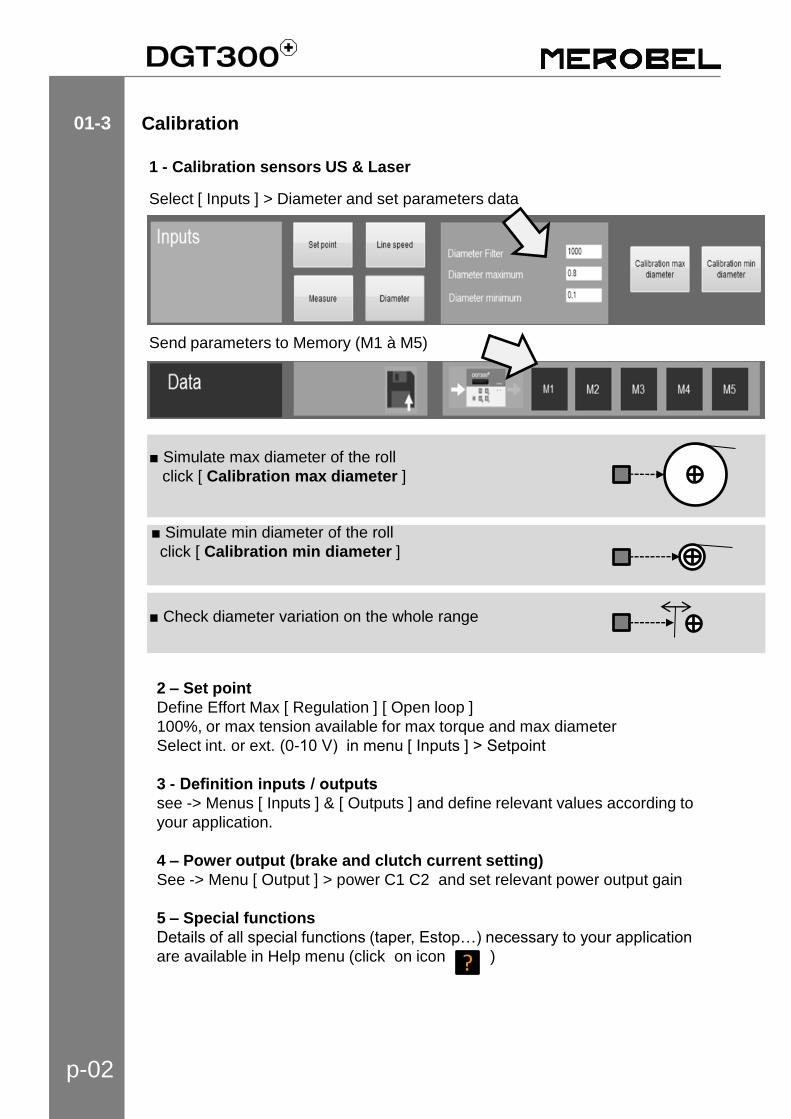
Calibration 01-3
1 - Calibration sensors US & Laser
Select [ Inputs ] > Diameter and set parameters data
■ Simulate max diameter of the roll
click [ Calibration max diameter ]
2 – Set point
Define Effort Max [ Regulation ] [ Open loop ]
100%, or max tension available for max torque and max diameter
Select int. or ext. (0-10 V) in menu [ Inputs ] > Setpoint
3 - Definition inputs / outputs
see -> Menus [ Inputs ] & [ Outputs ] and define relevant values according to
your application.
4 – Power output (brake and clutch current setting)
See -> Menu [ Output ] > power C1 C2 and set relevant power output gain
5 – Special functions
Details of all special functions (taper, Estop…) necessary to your application
are available in Help menu (click on icon )
Send parameters to Memory (M1 à M5)
■ Check diameter variation on the whole range
■ Simulate min diameter of the roll
click [ Calibration min diameter ]
?
p-03
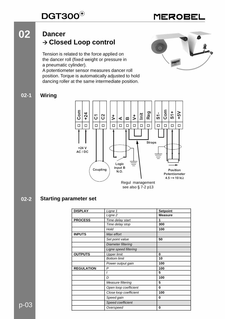
02 Dancer
Closed Loop control
Tension is related to the force applied on
the dancer roll (fixed weight or pressure in
a pneumatic cylinder).
A potentiometer sensor measures dancer roll
position. Torque is automatically adjusted to hold
dancing roller at the same intermediate position.
Wiring
Starting parameter set
02-1
02-2
Regul management
see also § 7-2 p13
DISPLAY Ligne 1 Setpoint
Ligne 2 Measure
PROCESS Time delay start 1
Time delay stop 300
Hold 100
INPUTS Max effort
Set point value 50
Diameter filtering
Ligne speed filtering
OUTPUTS Upper limit 0
Bottom limit 10
Power output gain 100
REGULATION P 100
I 5
D 100
Measure filtering 5
Open loop coefficient 0
Close loop coefficient 100
Speed gain 0
Speed coefficient
Overspeed 0
p-04
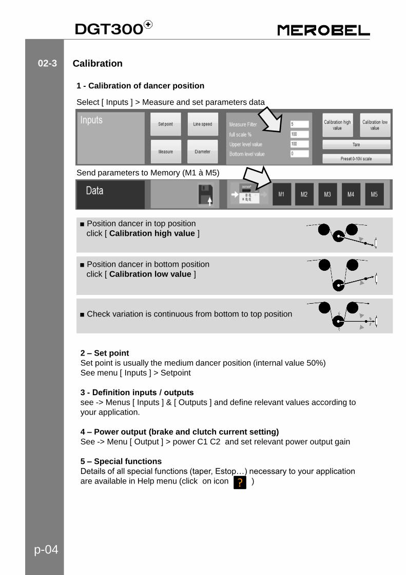
■ Position dancer in top position
click [ Calibration high value ]
■ Position dancer in bottom position
click [ Calibration low value ]
■ Check variation is continuous from bottom to top position
Calibration 02-3
1 - Calibration of dancer position
Select [ Inputs ] > Measure and set parameters data
Send parameters to Memory (M1 à M5)
2 – Set point
Set point is usually the medium dancer position (internal value 50%)
See menu [ Inputs ] > Setpoint
3 - Definition inputs / outputs
see -> Menus [ Inputs ] & [ Outputs ] and define relevant values according to
your application.
4 – Power output (brake and clutch current setting)
See -> Menu [ Output ] > power C1 C2 and set relevant power output gain
5 – Special functions
Details of all special functions (taper, Estop…) necessary to your application
are available in Help menu (click on icon )
?
p-05
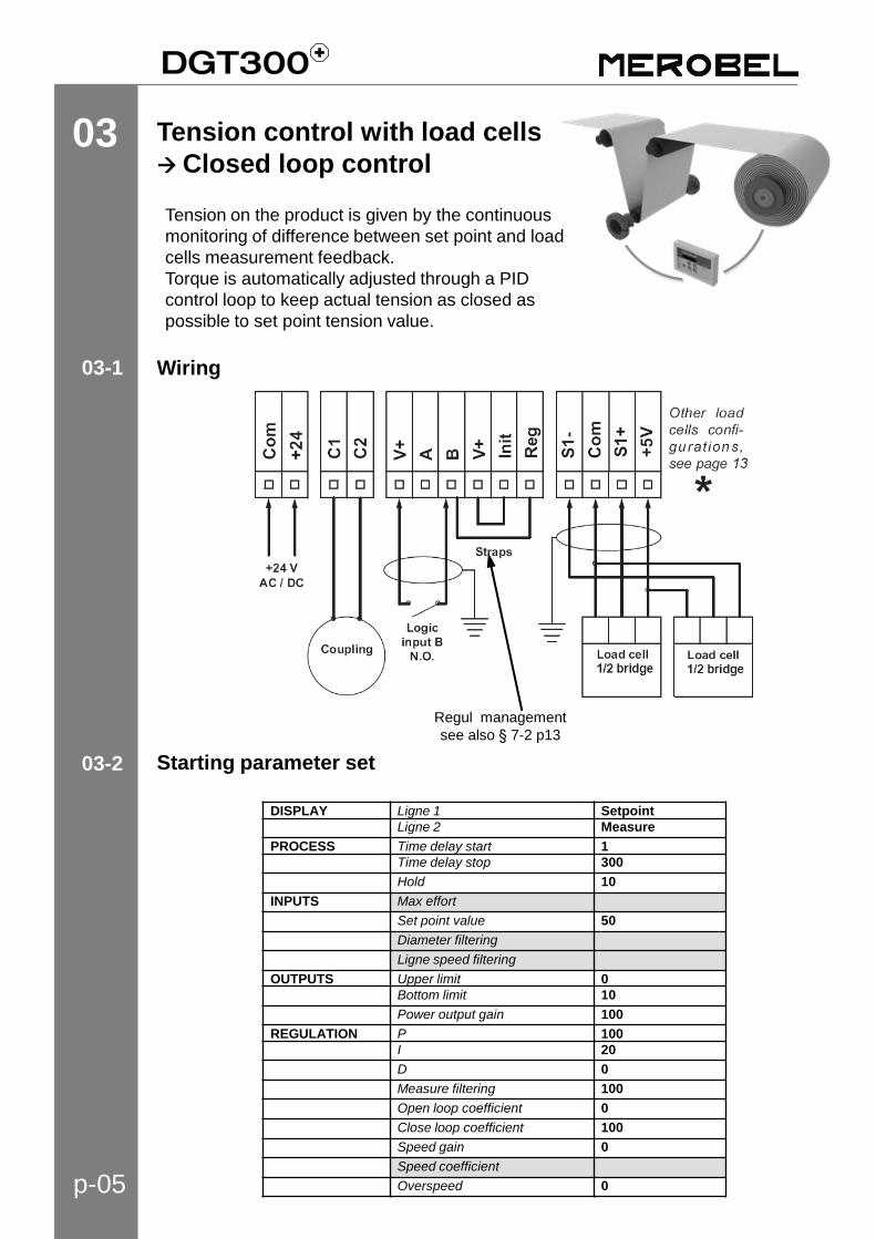
03 Tension control with load cells
Closed loop control
Tension on the product is given by the continuous
monitoring of difference between set point and load
cells measurement feedback.
Torque is automatically adjusted through a PID
control loop to keep actual tension as closed as
possible to set point tension value.
Wiring
Starting parameter set
03-1
03-2
DISPLAY Ligne 1 Setpoint
Ligne 2 Measure
PROCESS Time delay start 1
Time delay stop 300
Hold 10
INPUTS Max effort
Set point value 50
Diameter filtering
Ligne speed filtering
OUTPUTS Upper limit 0
Bottom limit 10
Power output gain 100
REGULATION P 100
I 20
D 0
Measure filtering 100
Open loop coefficient 0
Close loop coefficient 100
Speed gain 0
Speed coefficient
Overspeed 0
Regul management
see also § 7-2 p13

p-06
Kg
Kg
■ Simulate the load with a string following the product path
and hang the weight.
click [ Calibration high value ]
■ Remove the load and any stress on the load cells
click [ Calibration low value ]
Calibration done
■ Check your measure readout for minimum & maximum load
Calibration 03-3
1 - Calibration load cell measurement
Select [ Inputs ] > Measure and set parameters data
Enter calibration weight value : [Upper level value] (here75N)
If the weight is not equal to max tension required for the application (here 200N),
define in [ full scale % ], its percentage compared to max tension (here 37.5%)
Send parameters to Memory (M1 à M5)
2 – Set point
Set point is required tension level for your application
Select int. or ext. (0-10 V) in menu [ Inputs ] > Setpoint
See menu [ Inputs ] > Setpoint
3 - Definition inputs / outputs
see -> Menus [ Inputs ] & [ Outputs ] and define relevant values according to
your application.
4 – Power output (brake and clutch current setting)
See -> Menu [ Output ] > power C1 C2 and set relevant power output gain
5 – Special functions
Details of all special functions (taper, Estop…) necessary to your application
are available in Help menu (click on icon )
?
p-07
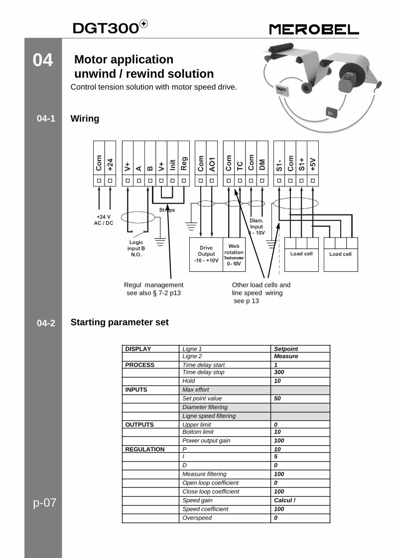
04 Motor application
unwind / rewind solution Control tension solution with motor speed drive.
Wiring
Starting parameter set
04-1
04-2
DISPLAY Ligne 1 Setpoint
Ligne 2 Measure
PROCESS Time delay start 1
Time delay stop 300
Hold 10
INPUTS Max effort
Set point value 50
Diameter filtering
Ligne speed filtering
OUTPUTS Upper limit 0
Bottom limit 10
Power output gain 100
REGULATION P 10
I 5
D 0
Measure filtering 100
Open loop coefficient 0
Close loop coefficient 100
Speed gain Calcul !
Speed coefficient 100
Overspeed 0
Other load cells and
line speed wiring
see p 13
Regul management
see also § 7-2 p13

p-08
Calibration 04-6
Diameter calibration
> See p2
Load cell calibration
> See p6
Set point definition
> See p6
Definition inputs / outputs
See p6
Special functions
> See p6
04-3
04-5
Formula Regulation / Speed Gain = VL
10 VR
04-4
VL (mpm) = linear speed for 10 V in tacho input
VR (rpm) = Max rotation speed of the motor (equivalent rotation speed with
10V sur AO1 output (or 10V on motor drive input))
Inputs : COM / TC
VL (mpm) = = linear speed for encoder signal = 30 kHz
VR (rpm) = Max rotation speed of the motor (equivalent rotation speed with
10V sur AO1 output (or 10V on motor drive input))
Inputs : COM / LS – see wiring p13
Case : line speed with encoder (pulses) signal
Case : line speed with 0-10 V tacho signal
p-09
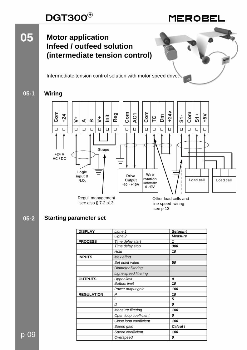
05 Motor application
Infeed / outfeed solution
(intermediate tension control)
Wiring
Starting parameter set
05-1
05-2
DISPLAY Ligne 1 Setpoint
Ligne 2 Measure
PROCESS Time delay start 1
Time delay stop 300
Hold 10
INPUTS Max effort
Set point value 50
Diameter filtering
Ligne speed filtering
OUTPUTS Upper limit 0
Bottom limit 10
Power output gain 100
REGULATION P 10
I 5
D 0
Measure filtering 100
Open loop coefficient 0
Close loop coefficient 100
Speed gain Calcul !
Speed coefficient 100
Overspeed 0
Other load cells and
line speed wiring
see p 13
Regul management
see also § 7-2 p13
Intermediate tension control solution with motor speed drive.
p-10
Calibration 05-6
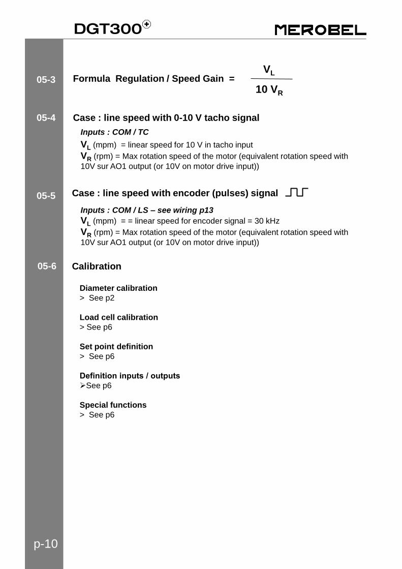
05-3
05-5
05-4
Diameter calibration
> See p2
Load cell calibration
> See p6
Set point definition
> See p6
Definition inputs / outputs
See p6
Special functions
> See p6
Formula Regulation / Speed Gain = VL
10 VR
VL (mpm) = linear speed for 10 V in tacho input
VR (rpm) = Max rotation speed of the motor (equivalent rotation speed with
10V sur AO1 output (or 10V on motor drive input))
Inputs : COM / TC
VL (mpm) = = linear speed for encoder signal = 30 kHz
VR (rpm) = Max rotation speed of the motor (equivalent rotation speed with
10V sur AO1 output (or 10V on motor drive input))
Inputs : COM / LS – see wiring p13
Case : line speed with encoder (pulses) signal
Case : line speed with 0-10 V tacho signal
p-11
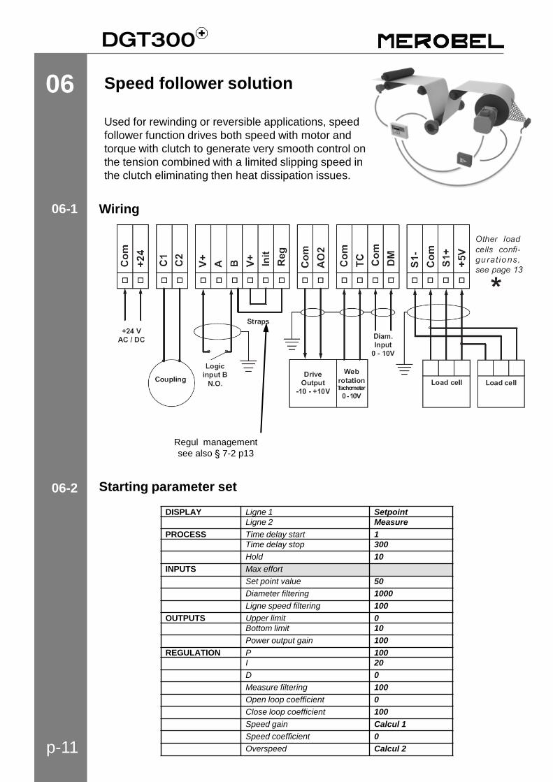
06 Speed follower solution
Used for rewinding or reversible applications, speed
follower function drives both speed with motor and
torque with clutch to generate very smooth control on
the tension combined with a limited slipping speed in
the clutch eliminating then heat dissipation issues.
Wiring
Starting parameter set
06-1
06-2
DISPLAY Ligne 1 Setpoint
Ligne 2 Measure
PROCESS Time delay start 1
Time delay stop 300
Hold 10
INPUTS Max effort
Set point value 50
Diameter filtering 1000
Ligne speed filtering 100
OUTPUTS Upper limit 0
Bottom limit 10
Power output gain 100
REGULATION P 100
I 20
D 0
Measure filtering 100
Open loop coefficient 0
Close loop coefficient 100
Speed gain Calcul 1
Speed coefficient 0
Overspeed Calcul 2
Regul management
see also § 7-2 p13
p-12
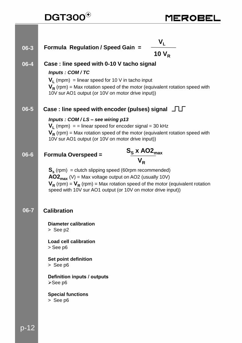
06-7
06-3
06-5
Formula Regulation / Speed Gain = VL
10 VR
06-4
06-6 Formula Overspeed =
Ss (rpm) = clutch slipping speed (60rpm recommended)
AO2max (V) = Max voltage output on AO2 (usually 10V)
VR (rpm) = VR (rpm) = Max rotation speed of the motor (equivalent rotation
speed with 10V sur AO1 output (or 10V on motor drive input))
SS x AO2max
VR
VL (mpm) = linear speed for 10 V in tacho input
VR (rpm) = Max rotation speed of the motor (equivalent rotation speed with
10V sur AO1 output (or 10V on motor drive input))
Inputs : COM / TC
VL (mpm) = = linear speed for encoder signal = 30 kHz
VR (rpm) = Max rotation speed of the motor (equivalent rotation speed with
10V sur AO1 output (or 10V on motor drive input))
Inputs : COM / LS – see wiring p13
Case : line speed with encoder (pulses) signal
Case : line speed with 0-10 V tacho signal
Calibration
Diameter calibration
> See p2
Load cell calibration
> See p6
Set point definition
> See p6
Definition inputs / outputs
See p6
Special functions
> See p6
p-13
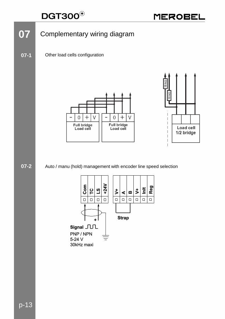
07 Complementary wiring diagram
Other load cells configuration
Auto / manu (hold) management with encoder line speed selection
07-1
07-2

Note
MEROBEL Zone Industrielle – 45210 Ferrières
T. +33 2 38 94 42 00 - F. +33 2 38 94 42 99
ANDANTEX USA Inc. 1705 Valley Road– Wanamassa, NJ 07712
Ph. 1 732 493 2812 - F. 1 732 493 29 49
ANDANTEX Srl Via Fratelli di Dio 2/A – 20063 Cernusco / Naviglio (MI)
T. +39 02 92 17 091 - F. +39 02 92 100 455
ANDANTEX Ltd Rowley Drive – Coventry CV3 4LS
T. +44 24 7630 7722 - F. +44 24 7630 4499
REDEX China 瑞德克斯(上海)机械维修服务有限公司
上海市松江区三浜路388号12栋 201611
Ph.+86 21 64480636 | F.+86 21 64480757
REDEX of India Alcazar Plaza, Hyderabad 500034 - Andra Pradesh -
Ph. +91 40 6613 9966 | Fx. +91 40 2338 6966
www.merobel.com
www.andantex.com
www.andantex.it
www.andantex.co.uk
www.merobel.com
www.merobel.com
FRANCE
USA
ITALIA
UK
CHINA
INDIA
www.redex-group.com
Local Contact
GBV0-1
Recommended