Embed Size (px)
Citation preview

Publication No. 29327001
Shipping Extendible with Hinged Infeed Belt
Conveyor Field Manual
May 15, 2012© 2012 Intelligrated, All rights reserved

To contact Intelligrated:
Direct questions and comments concerning the information contained in thismanual to:
Read these documents thoroughly before attempting to perform installation,maintenance or repairs to the applicable Intelligrated equipment components or devices.Exercise extreme caution when working around moving and rotating equipment. Wearthe proper clothing and safety equipment. DO NOT attempt to perform any maintenanceuntil the equipment is de-energized, locked out and tagged out in accordance withestablished company procedures and OSHA/ANSI standards.
The information presented in these documents is correct at the time of publication.Intelligrated has made every effort to ensure that the information presented is correctand free from error. However, some errors or misprints may occur. Please contactIntelligrated with any corrections.
This document is copyrighted © 2012 by Intelligrated, all rights reserved. No part of thismanual may be reproduced and/or distributed to parties other than the customer and thecustomer’s employees for whom it was originally produced.
The following terms are trademarks™ of Intelligrated: Accuglide™, Casemat™,EZ-set™, IntelliFlow™, I-Watch™, Palmat™, and Versa™.
The following terms are registered trademarks® of Intelligrated: Accumat®, Accuzone®,Alvey®, BOSS®, Buschman®, Crisplant®, EASYpick®, FKI Logistex®, FKI Logistexlogo®, "I" Only Logo®, In-24x7®, InControlWare®, Intelligrated®, Intelligrated logo®,Intelligrated Material Handling Solutions and Services®, IntelliMerge®, IntelliQ®,IntelliSort®, Mathews®, Maxiclaim®, Real Time Solutions®, Stearns®, SNE Systems®,Transitread®, and UniSort®.
By Mail or Phone:Intelligrated7901 Innovation WayMason, OH 45040
(513) 701-7300
For Service:Customer Service and Support (CSS)Hotline 1-877-315-3400On the World Wide Web: www.intelligrated.com
Documentation DepartmentIntelligrated10045 International Blvd.Cincinnati, Ohio 45246
Ph 1-800-922-1267 - Fax [email protected]
Documentation DepartmentIntelligrated9301 Olive BoulevardSt. Louis, MO 63132
Ph 1-314-993-4700 - Fax: 1-314-995-2400 Web site: http://www.intelligrated.com

Use of ManualThis manual contains important information. Please read this manual before attemptingto operate or perform installation or maintenance on this Conveyor. This manual is designed for operator personnel who have a substantial knowledge ofmechanical operations and who have basic knowledge of typical mechanical operations.Failure to comply with the instructions and warnings contained in this manual, and thewarnings posted on the Conveyor can result in serious injury to personnel and/ordamage to the equipment.
DisclaimersAll terms mentioned in this manual that are known to be trademarks or service markshave been appropriately capitalized. Intelligrated can not attest to the accuracy of thisinformation. Use of a term in this manual should not be regarded as affecting the validityof any trademark or service mark. This manual contains a generalized description of the Conveyor and its operationavailable at the time this manual was approved for printing. Intelligrated reserves theright to make changes in design and specifications and to make additions to, orimprovements in, the product without imposing any obligations upon it to install them onpreviously manufactured products.
Revision Date Initials Description

TABLE OF CONTENTS
Table of ContentsSafety Instructions . . . . . . . . . . . . . . . . . . . . . . . . . . . . . . . . . . . . . 1 - 1
For Your Safety . . . . . . . . . . . . . . . . . . . . . . . . . . . . . . . . . . . . . . . . . . 1 - 2Standard Safety Conventions . . . . . . . . . . . . . . . . . . . . . . . . . . . . . . 1 - 4Safety Precautions . . . . . . . . . . . . . . . . . . . . . . . . . . . . . . . . . . . . . 1 - 6
Guards and Guarding . . . . . . . . . . . . . . . . . . . . . . . . . . . . . . . . 1 - 6Interfacing of Equipment . . . . . . . . . . . . . . . . . . . . . . . . . 1 - 6Guarding Exceptions . . . . . . . . . . . . . . . . . . . . . . . . . . . 1 - 6Guarded by Location or Position . . . . . . . . . . . . . . . . . . 1 - 6
Headroom . . . . . . . . . . . . . . . . . . . . . . . . . . . . . . . . . . . . . . . . . 1 - 6Controls . . . . . . . . . . . . . . . . . . . . . . . . . . . . . . . . . . . . . . . . . . . . . . . . 1 - 7
Control Stations . . . . . . . . . . . . . . . . . . . . . . . . . . . . . . . . . . . . . 1 - 7Safety Devices . . . . . . . . . . . . . . . . . . . . . . . . . . . . . . . . . . . . . 1 - 8
Emergency Stops and Restarts . . . . . . . . . . . . . . . . . . . 1 - 8Operation Safety Precautions . . . . . . . . . . . . . . . . . . . . . . . . . . . . . . . 1 - 9Installation and Maintenance Safety . . . . . . . . . . . . . . . . . . . . . . . . . . 1 - 10Lockout / Tagout Guidelines . . . . . . . . . . . . . . . . . . . . . . . . . . . . . . . . 1 - 11Machine Operator Safety Precautions . . . . . . . . . . . . . . . . . . . . . . . . . 1 - 13Service and Maintenance Safety Precautions . . . . . . . . . . . . . . . . . . . 1 - 13Safety Signs . . . . . . . . . . . . . . . . . . . . . . . . . . . . . . . . . . . . . . . . . . . . . 1 - 13Shipping Extendible Safety Features . . . . . . . . . . . . . . . . . . . . . . . . . . 1 - 14
General Description . . . . . . . . . . . . . . . . . . . . . . . . . . . . . . . . . . . . 2 - 1Running the Decline Belt . . . . . . . . . . . . . . . . . . . . . . . . . . . . . . 2 - 4Running the Extendible Conveyor . . . . . . . . . . . . . . . . . . . . . . . 2 - 4
Glossary of Terms . . . . . . . . . . . . . . . . . . . . . . . . . . . . . . . . . . . . . . . . 2 - 6
Installation Procedures . . . . . . . . . . . . . . . . . . . . . . . . . . . . . . . . . 3 - 1Receiving & Inspections . . . . . . . . . . . . . . . . . . . . . . . . . . . . . . . . . . . 3 - 1
Reporting Product Damage . . . . . . . . . . . . . . . . . . . . . . . . . . . . 3 - 2Claims and Returns . . . . . . . . . . . . . . . . . . . . . . . . . . . . . . . . . . 3 - 2
Layout Requirements . . . . . . . . . . . . . . . . . . . . . . . . . . . . . . . . . . . . . . 3 - 2Codes and Standards . . . . . . . . . . . . . . . . . . . . . . . . . . . . . . . . . . . . . 3 - 3Safety Precautions . . . . . . . . . . . . . . . . . . . . . . . . . . . . . . . . . . . . . . . . 3 - 3Parts Replacement . . . . . . . . . . . . . . . . . . . . . . . . . . . . . . . . . . . . . . . . 3 - 4Site Preparation for Installation . . . . . . . . . . . . . . . . . . . . . . . . . . . . . . 3 - 4
Shipping Extendible with Hinged Infeed Belt Conveyor | Field Manual | 29327001 TOC - iMay 15, 2012
TABLE OF CONTENTS
Conveyor Installation . . . . . . . . . . . . . . . . . . . . . . . . . . . . . . . . . . . . . . 3 - 5Unloading and Moving into Position . . . . . . . . . . . . . . . . . . . . . . . . . . . 3 - 5Assembling the Conveyor System . . . . . . . . . . . . . . . . . . . . . . . . . . . . 3 - 6Installing Electrical Connections . . . . . . . . . . . . . . . . . . . . . . . . . . . . . 3 - 8Start-Up . . . . . . . . . . . . . . . . . . . . . . . . . . . . . . . . . . . . . . . . . . . . . . . . 3 - 9
Pre-Operation Check . . . . . . . . . . . . . . . . . . . . . . . . . . . . . . . . . 3 - 9Mechanical Pre-Operation Check . . . . . . . . . . . . . . . . . . 3 - 9Electrical Pre-Operation Check . . . . . . . . . . . . . . . . . . . 3 - 9
Initial Operation . . . . . . . . . . . . . . . . . . . . . . . . . . . . . . . . . . . . . 3 - 10
Preventive Maintenance . . . . . . . . . . . . . . . . . . . . . . . . . . . . . . . . 4 - 1Maintenance Precautions . . . . . . . . . . . . . . . . . . . . . . . . . . . . . . . . . . . 4 - 3
Safety Precautions for Conveyor Operator’s . . . . . . . . . . . . . . . 4 - 3Safety Precautions for Service and Maintenance . . . . . . . . . . . 4 - 4
Scheduled Maintenance . . . . . . . . . . . . . . . . . . . . . . . . . . . . . . . . . . . . 4 - 5Daily Inspections . . . . . . . . . . . . . . . . . . . . . . . . . . . . . . . . . . . . 4 - 5Weekly (40 Hours) . . . . . . . . . . . . . . . . . . . . . . . . . . . . . . . . . . . 4 - 6Monthly (160 hours) . . . . . . . . . . . . . . . . . . . . . . . . . . . . . . . . . 4 - 6Semi-Yearly (1040 hours) . . . . . . . . . . . . . . . . . . . . . . . . . . . . . 4 - 6
Speed Reducer - Lubrication and Maintenance . . . . . . . . . . . . . . . . . . 4 - 7Oil Levels . . . . . . . . . . . . . . . . . . . . . . . . . . . . . . . . . . . . . . . . . . 4 - 7Temperature . . . . . . . . . . . . . . . . . . . . . . . . . . . . . . . . . . . . . . . 4 - 7Changing Oil . . . . . . . . . . . . . . . . . . . . . . . . . . . . . . . . . . . . . . . 4 - 8Overloads . . . . . . . . . . . . . . . . . . . . . . . . . . . . . . . . . . . . . . . . . 4 - 8Seals . . . . . . . . . . . . . . . . . . . . . . . . . . . . . . . . . . . . . . . . . . . . . 4 - 8
Electrical Devices . . . . . . . . . . . . . . . . . . . . . . . . . . . . . . . . . . . . . . . . . 4 - 9Setting Extendible . . . . . . . . . . . . . . . . . . . . . . . . . . . . . . . . . . . 4 - 9
Bearings . . . . . . . . . . . . . . . . . . . . . . . . . . . . . . . . . . . . . . . . . . . . . . . . 4 - 10Extendible Steering/Tracking Adjustments . . . . . . . . . . . . . . . . . . . . . 4 - 11
Troubleshooting . . . . . . . . . . . . . . . . . . . . . . . . . . . . . . . . . . . . . . . 5 - 1Troubleshooting Guidelines . . . . . . . . . . . . . . . . . . . . . . . . . . . . 5 - 1
Troubleshooting Help . . . . . . . . . . . . . . . . . . . . . . . . . . . . . . . . . . . . . . 5 - 3
TOC - ii Shipping Extendible with Hinged Infeed Belt Conveyor | Field Manual | 29327001May 15, 2012
TABLE OF CONTENTS
Replacement Parts . . . . . . . . . . . . . . . . . . . . . . . . . . . . . . . . . . . . . 6 - 1Contact Information . . . . . . . . . . . . . . . . . . . . . . . . . . . . . . . . . . . . . . . 6 - 1
Parts Orders . . . . . . . . . . . . . . . . . . . . . . . . . . . . . . . . . . . . . . . 6 - 1Warranty Part Order Procedures . . . . . . . . . . . . . . . . . . . . . . . . . . . . . 6 - 2Non-Warranty Part Order Procedures . . . . . . . . . . . . . . . . . . . . . . . . . 6 - 4Order Processing and Shipping . . . . . . . . . . . . . . . . . . . . . . . . . . . . . . 6 - 4New Parts Warranty . . . . . . . . . . . . . . . . . . . . . . . . . . . . . . . . . . . . . . . 6 - 4Recommended Spare Parts . . . . . . . . . . . . . . . . . . . . . . . . . . . . . . . . . 6 - 5On-Time Parts Catalog . . . . . . . . . . . . . . . . . . . . . . . . . . . . . . . . . . . . 6 - 5
Accessing the On-Time Parts Catalog . . . . . . . . . . . . . . . . . . 6 - 5Using the On-Line Parts Catalog . . . . . . . . . . . . . . . . . . . . . . . 6 - 6
Parts Lists and Illustrations . . . . . . . . . . . . . . . . . . . . . . . . . . . . . . . . 6 - 9Using the Parts Lists . . . . . . . . . . . . . . . . . . . . . . . . . . . . . . . 6 - 10Shipping Extendible - Front End Top View and Front View . . . 6 - 12Shipping Extendible Rear Caster Assembly . . . . . . . . . . . . . . . 6 - 13Hinged Belt - Side View . . . . . . . . . . . . . . . . . . . . . . . . . . . . . . . 6 - 16Hinged Belt Upper Pivot Assembly . . . . . . . . . . . . . . . . . . . . . . 6 - 18
Index
Shipping Extendible with Hinged Infeed Belt Conveyor | Field Manual | 29327001 TOC - iiiMay 15, 2012

TABLE OF CONTENTS
TOC - iv Shipping Extendible with Hinged Infeed Belt Conveyor | Field Manual | 29327001May 15, 2012

LIST OF FIGURES
List of FiguresFigure 1 - 1 Lockout Main Disconnect Switch . . . . . . . . . . . . . . . . . . . . . . . . . . . . .1 - 12Figure 2 - 1 Extendible Gravity Conveyor . . . . . . . . . . . . . . . . . . . . . . . . . . . . . . . .2 - 2Figure 2 - 2 Extendible Gravity Conveyor Devices . . . . . . . . . . . . . . . . . . . . . . . . .2 - 2Figure 2 - 3 Combination Starter . . . . . . . . . . . . . . . . . . . . . . . . . . . . . . . . . . . . . . .2 - 3Figure 2 - 4 CS1. . . . . . . . . . . . . . . . . . . . . . . . . . . . . . . . . . . . . . . . . . . . . . . . . . . .2 - 5Figure 4 - 1 Lockout Main Disconnect Switch . . . . . . . . . . . . . . . . . . . . . . . . . . . . .4 - 4Figure 4 - 2 Setting Hex Nuts to Allow Clearance for Wheel Travel . . . . . . . . . . . .4 - 11Figure 4 - 3 Pivoting V-Groove Wheel . . . . . . . . . . . . . . . . . . . . . . . . . . . . . . . . . . .4 - 12Figure 6 - 1 Example of Conveyor Label . . . . . . . . . . . . . . . . . . . . . . . . . . . . . . . . .6 - 2Figure 6 - 2 On-Time Parts Link. . . . . . . . . . . . . . . . . . . . . . . . . . . . . . . . . . . . . . . .6 - 5 Figure 6 - 1 OPC Main Menu . . . . . . . . . . . . . . . . . . . . . . . . . . . . . . . . . . . . . . . . .6 - 7Figure 6 - 3 Warranty Claim Request Form. . . . . . . . . . . . . . . . . . . . . . . . . . . . . . .6 - 8Figure 6 - 4 Example of Links in the Electronic Manual. . . . . . . . . . . . . . . . . . . . . .6 - 9
Shipping Extendible with Hinged Infeed Belt Conveyor | Field Manual | 29327001 LOF - iMay 15, 2012

LIST OF FIGURES
LOF - ii Shipping Extendible with Hinged Infeed Belt Conveyor | Field Manual | 29327001May 15, 2012
SAFETY INSTRUCTIONS
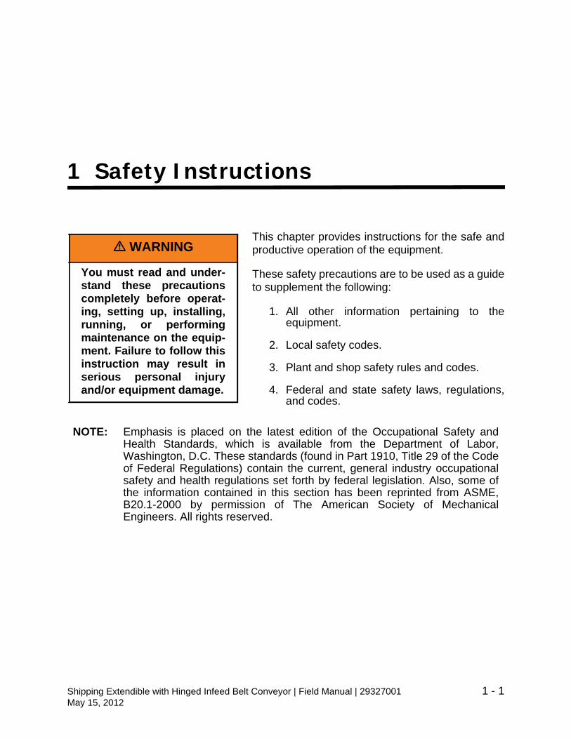
1 Safety Instructions
This chapter provides instructions for the safe andproductive operation of the equipment.
These safety precautions are to be used as a guideto supplement the following:
1. All other information pertaining to theequipment.
2. Local safety codes.
3. Plant and shop safety rules and codes.
4. Federal and state safety laws, regulations,and codes.
NOTE: Emphasis is placed on the latest edition of the Occupational Safety andHealth Standards, which is available from the Department of Labor,Washington, D.C. These standards (found in Part 1910, Title 29 of the Codeof Federal Regulations) contain the current, general industry occupationalsafety and health regulations set forth by federal legislation. Also, some ofthe information contained in this section has been reprinted from ASME,B20.1-2000 by permission of The American Society of MechanicalEngineers. All rights reserved.
m WARNING
You must read and under-stand these precautionscompletely before operat-ing, setting up, installing,running, or performingmaintenance on the equip-ment. Failure to follow thisinstruction may result inserious personal injuryand/or equipment damage.
Shipping Extendible with Hinged Infeed Belt Conveyor | Field Manual | 29327001 1 - 1May 15, 2012
SAFETY INSTRUCTIONS
For Your SafetyThis manual contains important safety information concerning the use, maintenance,installation, and operation of this equipment. Read and become familiar with the contentsof this manual before attempting to install, operate, or service this equipment. It isnecessary that all operators and maintenance personnel study the applicable sections ofthis manual thoroughly before operating the equipment.
m WARNING
If you are unable to under-stand the contents of thismanual, please bring it tothe attention of yoursupervisor or foreman.Failure to comply with theinstructions and warningscontained in this manual,and the warnings postedon the machine, can resultin serious injury to person-nel and damage to theequipment. Do not operatethis equipment unless youhave read and understoodthe contents of this man-ual.
1 - 2 Shipping Extendible with Hinged Infeed Belt Conveyor | Field Manual | 29327001May 15, 2012

SAFETY INSTRUCTIONS
m ADVERTENCIA
No dando caso a losinstruciones y precau-ciones contenidos en elmanual, puede resultar engraves heridas personal ydaño a la máquina. Notrate de operar el equiposin entender claramentelos instruciones del man-ual.
m AVERTISSEMENT
Si vous ne comprenez pasle contenu de ce manuel,s.v.p. aviser votre supervi-seur ou le contremaître. Adéfaut de suivre lesinstructions et les aver-tissements contenus dansce manuel, et les avertisse-ments installé sur l'équipe-ment, pourrait occasionnerdes blessures graves autravailleur et endommagerl'équipement. Ne pas opér-er cet équipement à moinsd'avoir lu et compris lecontenu de ce manueld'opérations.
Shipping Extendible with Hinged Infeed Belt Conveyor | Field Manual | 29327001 1 - 3May 15, 2012
SAFETY INSTRUCTIONS
Standard Safety Conventions This section includes information essential to the safety of personnel and equipment.Throughout this manual, and on the equipment, you will find DANGER, WARNING, andCAUTION signs. Pay particular attention to these because they signal information that isimportant to your safety and to the correct operation of the equipment.
Warning signs and labels posted on or near the equipment shall not be removed, paintedover, or altered at any time. Reference: ANSI Z535.4. All safety devices, warning lights,and alarms associated with the conveyor system must be regularly tested (at leastmonthly) for proper operation and serviced as needed. If the original safety item(s)become defective or damaged, refer to the conveyor parts list(s) of bill(s)-of-materials forreplacement part numbers.
m DANGER
DANGER - informationappearing under the DAN-GER caption concerns theprotection of personnelfrom immediate and immi-nent hazards that, if notavoided, will result inimmediate, serious per-sonal injury or loss of lifein addition to equipmentdamage.
1 - 4 Shipping Extendible with Hinged Infeed Belt Conveyor | Field Manual | 29327001May 15, 2012

SAFETY INSTRUCTIONS
NOTE: The term NOTE is used to call attention to useful information and is not asafety notice. Information appearing in a NOTE provides additionalinformation that is helpful in understanding the item being explained.
m WARNING
You must read and under-stand these precautionscompletely before operat-ing, setting up, installing,running, or performingmaintenance on the equip-ment. Failure to follow thisinstruction may result inserious personal injuryand/or equipment damage.
CAUTION
Information appearingunder the CAUTION cap-tion concerns the protec-tion of personnel andequipment, software, anddata from hazards that canresult in minor personalinjury or equipment dam-age.
Shipping Extendible with Hinged Infeed Belt Conveyor | Field Manual | 29327001 1 - 5May 15, 2012
SAFETY INSTRUCTIONS
Safety Precautions The success of any safety program depends primarily on the attitudes and training of theinstallation, maintenance, and operating personnel. The very nature of their work makesit necessary that they develop a complete and firsthand knowledge of each piece ofequipment that is within their care. This familiarity enables them to recognize the hazardsresulting from improper usage.
Guards and Guarding
Where necessary for the protection of personnel from hazards, all exposed movingmachinery parts that present a hazard to employees at work stations or operator’sstations shall be mechanically or electrically guarded, or guarded by location or position.
Interfacing of Equipment
When two or more pieces of equipment are interfaced, special attention shall be given tothe interfaced area to ensure the presence of adequate guarding and safety devices.
Guarding Exceptions
Wherever conditions prevail that would require guarding under these standards, but suchguarding would render the conveyor unusable, prominent warning means such as signsor warning lights shall be provided in the area or on the equipment in lieu of guarding.
Guarded by Location or Position
Remoteness from frequent presence of public or employed personnel shall constituteguarding by location. Overhead conveyors, such as trolley equipment andhanger-suspended tray conveyors, for which guarding would render the equipmentunusable or would be impractical, shall have prominent and legible warnings posted inthe area or on the equipment, and, where feasible, lines shall be painted on the floordelineating the danger area.
When the equipment passes over a walkway, roadway, or work station, it is consideredguarded by location if all moving parts are at least 8 ft. (2.4 m) above the floor or walkingsurface or are otherwise located so that the employee cannot inadvertently come incontact with hazardous moving parts. Although overhead conveyors may be guarded bylocation, spill guards, pan guards, or equivalent shall be provided if the product may falloff the conveyor for any reason and endanger personnel.
Headroom
When the equipment is installed above exit passageways, aisles, or corridors, there shallbe a minimum clearance of 6 ft. 8 in. (2.03 m) measured vertically from the floor orwalking surface to the lowest part of the equipment or guards. Where system function willbe impaired by providing the minimum clearance of 6 ft. 8 in. (2.03 m) through an
1 - 6 Shipping Extendible with Hinged Infeed Belt Conveyor | Field Manual | 29327001May 15, 2012

SAFETY INSTRUCTIONS
emergency exit, alternate passageways shall be provided. It is permissible to allowpassage under the equipment with less than 6 ft. 8 in. (2.03 m) clearance from the floorfor other than emergency exits if a suitable warning indicates low headroom.
ControlsAll electrical installations and wiring shall conform to the National Electrical Code (Article670 or other applicable articles) as published by the National Fire Protection Associationand as approved by the American National Standards Institute, Inc.
Control Stations
Control stations should be arranged and located so that the operation of the affectedequipment is visible from them. Control stations shall be clearly marked or labeled toindicate the function controlled.
Equipment that would cause injury when started shall not be started until employees inthe area are alerted by a signal, or by a designated person, that the equipment is aboutto start. When the equipment would cause injury and is automatically controlled or mustbe controlled from a remote location is started, an audible device shall be provided whichcan be clearly heard at all points along the conveyor where personnel may be present.The audible warning shall be actuated by the controller device starting the equipmentand shall continue for a required period of time before the equipment starts. A flashinglight or similar visual warning may be used in conjunction with, or in place of, the audibledevice if a visual warning is more effective. Where system function would be seriouslyhindered or adversely affected by the required time delay, or where the intent of thewarning may be misinterpreted (e.g., a work area with many different pieces ofequipment and allied devices), a clear, concise, and legible warning sign shall beprovided. The warning shall indicate that the equipment and allied equipment may bestarted at any time, that danger exists, and that personnel must keep clear. Thesewarning signs shall be provided along the equipment at areas not guarded by position orlocation.
Remotely and automatically controlled equipment, and equipment where operatorstations are not manned or are beyond voice or visual contact from drive areas, loadingareas, transfer points, and other potentially hazardous locations on the equipment pathnot guarded by location, position, or guards, shall be furnished with emergency stopbuttons, pull cords, limit switches, or similar emergency stop devices. All suchemergency stop devices shall be easily identifiable in the immediate vicinity of suchlocations unless guarded by location, position, or guards. Where the design, function,and operation of such equipment clearly is not hazardous to personnel, an emergencystop device is not required. The emergency stop device shall act directly on the control ofthe equipment concerned and shall not depend on the stopping of any other equipment.The emergency stop devices shall be installed so that they cannot be overridden fromother locations.
Shipping Extendible with Hinged Infeed Belt Conveyor | Field Manual | 29327001 1 - 7May 15, 2012

SAFETY INSTRUCTIONS
Inactive and unused actuators, controllers, and wiring should be removed from controlstations and panel boards, together with obsolete diagrams, indicators, control labels,and other material which may confuse the operator.
Safety Devices
All safety devices, including wiring of electrical safety devices, shall be arranged tooperate so that a power failure or failure of the device itself will not result in a hazardouscondition.
Emergency Stops and Restarts
The controls shall be arranged so that, in case of emergency stop, manual reset or startat the location where the emergency stop was initiated shall be required of theconveyor(s) and associated equipment to resume operation.
Before restarting the equipment that has been stopped because of an emergency, aninspection of the conveyor shall be made and the cause of the stoppage determined. Thestarting device shall be locked or tagged out before any attempt is made to remove thecause of the stoppage, unless operation is necessary to determine the cause or to safelyremove the stoppage. Refer to ANSI Z244.1-1982, American National Standard forPersonnel Protection - Lockout/Tagout of Energy Sources - Minimum SafetyRequirements, and OSHA Standard 29 CFR 1910.147, “The Control of HazardousEnergy (Lockout/Tagout)."
1 - 8 Shipping Extendible with Hinged Infeed Belt Conveyor | Field Manual | 29327001May 15, 2012

SAFETY INSTRUCTIONS
Operation Safety PrecautionsOnly a trained person shall be permitted to operate a conveyor. Training shall includeinstruction in operation under normal conditions and emergency situations.
Where safety is dependent upon stopping devices or starting devices or both, they shallbe kept free of obstructions to permit ready access.
The area around loading and unloading points shall be kept clear of obstructions thatcould endanger personnel.
No person shall ride on a conveyor under any circumstances.
Personnel working on or near a conveyor shall be instructed as to the location andoperation of pertinent stopping devices.
A conveyor shall be used to transport only material it is designed to handle safely.
Under no circumstances shall the safety characteristics of the conveyor be altered ifsuch alterations would endanger personnel.
Routine inspections and preventive and corrective installation and maintenanceprograms shall be conducted to ensure that all guards and safety features and devicesare retained and function properly.
Personnel should be alerted to the potential hazard of entanglement in conveyorscaused by items such as long hair, loose clothing, and jewelry.
Conveyors shall not be newly installed, maintained, or serviced while in operation unlessproper installation, maintenance, or service requires the conveyor to be in motion. In thiscase, personnel shall be made aware of the hazards and how the task may be safelyaccomplished.
Shipping Extendible with Hinged Infeed Belt Conveyor | Field Manual | 29327001 1 - 9May 15, 2012

SAFETY INSTRUCTIONS
Installation and Maintenance SafetyInstallation and Maintenance shall be performed only by qualified and trained personnel.
It is important to establish an installation and maintenance program to ensure that allconveyor components are maintained in a condition which does not constitute a hazardto personnel.
When a conveyor is stopped during installation or for maintenance, starting devices orpowered accessories shall be locked or tagged out, see Figure 1 - 1, in accordance witha formalized procedure designed to protect all persons or groups involved with theconveyor against an unexpected start. Personnel should be alerted to the hazard ofstored energy, which may exist after the power source is locked out. Refer to ANSIZ244.1-1982, American National Standard for Personnel Protection - Lockout/Tagout ofEnergy Sources - Minimum Safety Requirements, and OSHA Standard 29 CFR1910.147, “The Control of Hazardous Energy (Lockout/Tagout)."
Before starting equipment for normal operation, replace all safety devices and guards,and remove all tools and other material from the conveyor
Conveyors shall not be lubricated while in operation unless it is impractical to shut themdown for lubrication. Only trained and qualified personnel who are aware of the hazardsof the conveyor in motion shall be allowed to lubricate a conveyor that is operating.
Guards and safety devices shall be maintained in a serviceable and operationalcondition. Warning signs shall be maintained in a legible and operational condition.Examples of warning signs are shown later in this section.
It is the responsibility of the owner/user to add any additional protective components thatmay be needed whenever changes or variations are made to any of the equipmentcomponents or operational characteristics.
1 - 10 Shipping Extendible with Hinged Infeed Belt Conveyor | Field Manual | 29327001May 15, 2012

SAFETY INSTRUCTIONS
Lockout / Tagout GuidelinesAppropriate lockout and tagout policy and procedures shall comply with the Code ofFederal Regulations, 29 CFR 1910.147 and the minimum safety requirements outlinedin the current publication of the American National Standard Institute’sLockout/Tagout of Energy Sources (ANSI Z244.1).
Effective January 8, 1990, O.S.H.A. has designated the need for a ‘positive, lockable’means to remove all energy sources from equipment prior to new installation(s) or anymaintenance. The electrical power to your equipment can be locked out at the maindisconnect switch, which is normally located on the electrical cabinet. When this is done,residual energy remains for some time in the capacitors associated with the electricalsystem. This residual energy is automatically depleted by features built into theequipment. After locking out the main disconnect switch, wait at least 60 seconds beforebeginning any installation or maintenance procedures. This allows the residual energy todiminish. (If an equipment-mounted plate indicates that you should wait longer than 60seconds, wait the recommended period of time before beginning any installation ormaintenance work.)
Whenever you need to install new equipment or perform maintenance on the equipment,or whenever you need to shut it down for any other reason, a lockout procedure must befollowed. Your employer is required by O.S.H.A. to develop a written lockout/tagoutprocedure for this equipment. The following items should be considered in developingthis procedure:
• Notify everyone who normally operates, sets up, installs, or performs mainte-nance on the equipment that it will be shut down.
• Turn off all electric motors.
• Turn off the main electrical disconnect switch.
• Lock the main disconnect switch in the OFF position, and place a tag on theswitch to indicate that work is being performed on the equipment.
• If there is any auxiliary equipment associated with the equipment, make sure themain electrical disconnect switch is also turned off for each piece of auxiliaryequipment. Then lock each disconnect switch in the OFF position, and tag eachswitch to indicate that work is being performed on the equipment.
• Lock the air supply valves to make sure no air can be supplied to the equipment.
• Verify that no sources of residual energy (capacitors, suspended equipment com-ponents, etc.) are present on the equipment or any piece of auxiliary equipment. Ifany such energy sources are located, make sure they are neutralized. If neces-sary, manually discharge air pressure and capacitor voltage from charged compo-nents. Also, block all suspended or spring loaded mechanical parts to preventmovement.
Shipping Extendible with Hinged Infeed Belt Conveyor | Field Manual | 29327001 1 - 11May 15, 2012
SAFETY INSTRUCTIONS
• Verify that electrical power has been disconnected from the equipment, and fromany auxiliary equipment, by trying to energize the equipment and any auxiliarieswith the appropriate control switches. If any piece of equipment is found to beoperational, locate the electrical circuit(s) supplying the power, and disconnect allsuch power sources. Then lock and tag these power sources.
• Make sure the air system pressure is 0 PSI.
• Before you begin any work on the equipment or any auxiliary equipment, makesure that at least 60 seconds has elapsed since you turned off the main discon-nect switch. (If an equipment-mounted plate indicates that you should wait longerthan 60 seconds, wait the recommended period of time before beginning any newinstallation or performing any maintenance work.)
• Verify that any equipment which may have been added, and which is not coveredby previous bulleted items, is considered for the lockout/tagout procedure.
• After you have completed your work on the equipment, make sure all guards,gates and other safety-related devices are in place and functioning properly.
• When the equipment is completely ready to resume operation, remove your lockand tag from the main electrical disconnect switch. If someone else has placed alock and/or tag on the main disconnect, do not remove the additional lock or tag. Ifthere is no other lock or tag on the main disconnect, turn on the main disconnectswitch and the electric motors, then perform the daily safety checks.
Figure 1 - 1 Lockout Main Disconnect Switch
1 - 12 Shipping Extendible with Hinged Infeed Belt Conveyor | Field Manual | 29327001May 15, 2012
SAFETY INSTRUCTIONS
Machine Operator Safety Precautions1. Only authorized, properly trained personnel may operate the equipment.
2. Do not attempt to clear jams before shutting off power.
3. Do not reach into or climb on the machine for any reason before shutting offpower.
4. Extreme care should be taken when near the equipment to prevent fingers, hair,jewelry, or loose clothing from being caught in moving parts.
5. Do not wear gloves when working near the equipment's moving parts.
6. Remove all tools and non-product material from the equipment before starting.
7. Verify that no persons are in a position to be injured as a result of the start-up.
8. Never step on, over, or into the path of a moving conveyor.
Service and Maintenance Safety Precautions1. Only authorized and properly trained personnel may service the machine.
2. Turn the main disconnect switch OFF and lockout the equipment before beginningany maintenance or repairs, see Figure 1 - 1.
3. Before restarting and testing the machine, remove all tools and other materialfrom the machine.
4. Replace all safety guards and/or covers removed from the machine formaintenance, before operating the machine.
Safety Signs
In an effort to reduce the possibility of injury to personnel working around conveyingequipment, safety signs are placed at various points on the equipment to alert them ofpotential dangers. Please check the equipment and note all safety signs. Make certainyour personnel are alerted to and obey these signs.
The following illustration shows pictograms designed by the Conveyor EquipmentManufacturers Association (CEMA) Safety Committee as a service to the industry. Theyalso mirror, to the extent practical, the pictograms on the associated CEMA SafetyLabels placed on the equipment. CEMA Safety Posters are also available to place inwork areas and break areas to remind personnel of safe practices.
Shipping Extendible with Hinged Infeed Belt Conveyor | Field Manual | 29327001 1 - 13May 15, 2012
SAFETY INSTRUCTIONS
Shipping Extendible Safety FeaturesThe Gravity Extendible Shipping Conveyor is equipped with several built-in safetyfeatures designed to decrease the risk of injury to operating personnel, as well assafeguarding the machine from being damaged due to mechanical failures.
1. All photo-eyes, proximity switches, andpush button operator control switchesoperate on 24 VDC to reduce electricalshock hazard.
2. Photo-eyes - detect full conditions.
3. Indicator lights.
4. Over-travel Limit Switches - stops Extend-ible travel prior to mechanical stops.
5. Mechanical Stops - stops Extendible ofOver-travel Limit Switches or other electricaldevices fail.
m WARNING
Do not attempt to circum-vent any design safety fea-ture. Any attempt to do socould result in injury tooperating personneland/or damage to themachine. The lock-out/tagout procedures foryour company must be fol-lowed when entering orservicing the machine.Failure to follow theseinstructions may result inserious personal injuryand/or equipment damage.
1 - 14 Shipping Extendible with Hinged Infeed Belt Conveyor | Field Manual | 29327001May 15, 2012
SAFETY INSTRUCTIONS
Shipping Extendible with Hinged Infeed Belt Conveyor | Field Manual | 29327001 1 - 15May 15, 2012

SAFETY INSTRUCTIONS
1 - 16 Shipping Extendible with Hinged Infeed Belt Conveyor | Field Manual | 29327001May 15, 2012
GENERAL DESCRIPTION
2 General Description
This chapter describes the Extendible Gravity Conveyor machine operations, bothmechanical and electrical. A Glossary of Terms has been provided at the end of thischapter for explanations of commonly used terms when referring to the equipment.
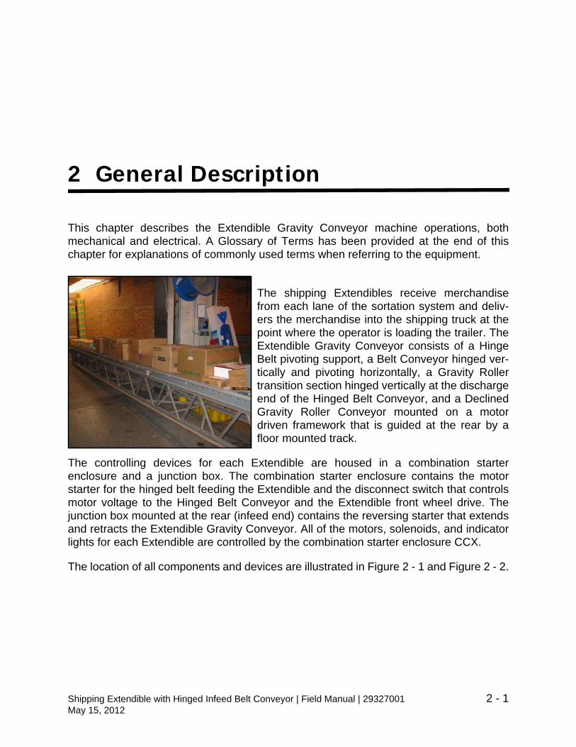
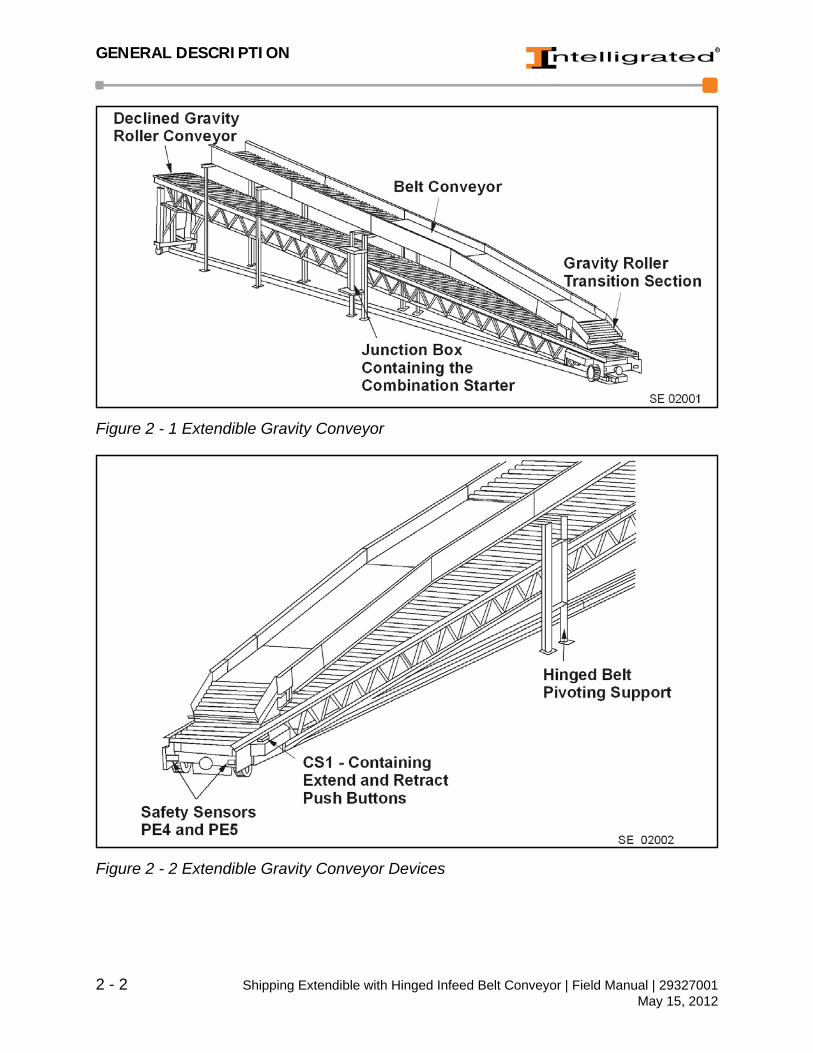
The shipping Extendibles receive merchandisefrom each lane of the sortation system and deliv-ers the merchandise into the shipping truck at thepoint where the operator is loading the trailer. TheExtendible Gravity Conveyor consists of a HingeBelt pivoting support, a Belt Conveyor hinged ver-tically and pivoting horizontally, a Gravity Rollertransition section hinged vertically at the dischargeend of the Hinged Belt Conveyor, and a DeclinedGravity Roller Conveyor mounted on a motordriven framework that is guided at the rear by afloor mounted track.
The controlling devices for each Extendible are housed in a combination starterenclosure and a junction box. The combination starter enclosure contains the motorstarter for the hinged belt feeding the Extendible and the disconnect switch that controlsmotor voltage to the Hinged Belt Conveyor and the Extendible front wheel drive. Thejunction box mounted at the rear (infeed end) contains the reversing starter that extendsand retracts the Extendible Gravity Conveyor. All of the motors, solenoids, and indicatorlights for each Extendible are controlled by the combination starter enclosure CCX.
The location of all components and devices are illustrated in Figure 2 - 1 and Figure 2 - 2.
Shipping Extendible with Hinged Infeed Belt Conveyor | Field Manual | 29327001 2 - 1May 15, 2012
GENERAL DESCRIPTION
Figure 2 - 1 Extendible Gravity Conveyor
Figure 2 - 2 Extendible Gravity Conveyor Devices
2 - 2 Shipping Extendible with Hinged Infeed Belt Conveyor | Field Manual | 29327001May 15, 2012
GENERAL DESCRIPTION
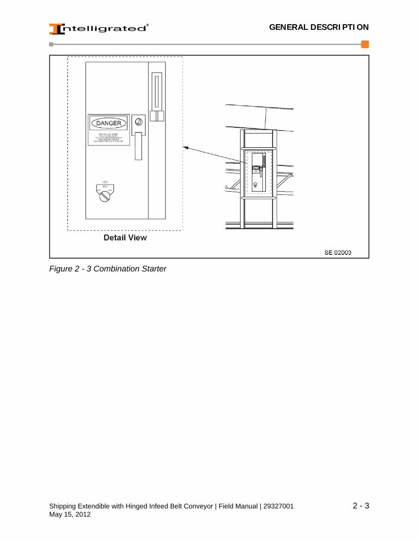
Figure 2 - 3 Combination Starter
Shipping Extendible with Hinged Infeed Belt Conveyor | Field Manual | 29327001 2 - 3May 15, 2012
GENERAL DESCRIPTION
Running the Decline Belt
Use the following procedure to operate the decline belt.
1. Turn the BELT ON/OFF selector switch to the ON position at the decline belt com-bination starter, see Figure 2 - 3.
2. At the discharge end of the Extendible Conveyor, in CS1, pull the BELTON/OFF/JOG switch to the ON position to run the decline belt automatically. Inautomatic operation, if the merchandise accumulates back onto the decline beltand photo-eyes on the transition section are blocked for a period of time this stopsthe decline belt.
3. In the event that merchandise becomes Stalled in front of either of the photo-eyes,pulling the BELT ON/OFF/JOG switch in CS1 to the JOG position will cause thedecline belt to run. The JOG position (on the BELT ON/OFF/JOG switch) willspring return to the ON position when the switch is released.
Running the Extendible Conveyor
1. To run the Extendible forward (into thetruck).
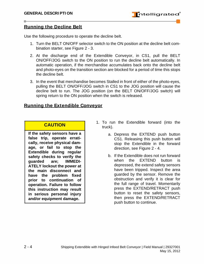
a. Depress the EXTEND push buttonCS1. Releasing this push button willstop the Extendible in the forwarddirection, see Figure 2 - 4.
b. If the Extendible does not run forwardwhen the EXTEND button isdepressed, the extend safety sensorshave been tripped. Inspect the areaguarded by the sensor. Remove theobstruction and verify it is clear forthe full range of travel. Momentarilypress the EXTEND/RETRACT pushbutton to reset the safety sensors,then press the EXTEND/RETRACTpush button to continue.
CAUTION
If the safety sensors have afalse trip, operate errati-cally, receive physical dam-age, or fail to stop theExtendible during regularsafety checks to verify theguarded are; IMMEDI-ATELY lockout the power atthe main disconnect andhave the problem fixedprior to continuation ofoperation. Failure to followthis instruction may resultin serious personal injuryand/or equipment damage.
2 - 4 Shipping Extendible with Hinged Infeed Belt Conveyor | Field Manual | 29327001May 15, 2012
GENERAL DESCRIPTION
2. To run the Extendible reverse (out of the truck):
a. Depress the RETRACT push button in CS1. Releasing the push button willstop the Extendible in the reverse direction.
b. If the Extendible does not reverse when the RETRACT push button isdepressed, the retract safety sensors have been tripped. Inspect the areaguarded by the sensor. Remove the obstruction and verify it is clear for thefull range of travel. Momentarily press the EXTEND/RETRACT push buttonto reset the safety sensors, then press the EXTEND/RETRACT pushbutton to continue.
Figure 2 - 4 CS1
Shipping Extendible with Hinged Infeed Belt Conveyor | Field Manual | 29327001 2 - 5May 15, 2012

GENERAL DESCRIPTION
Glossary of Terms
Hinged Belt Conveyor Conveyor that is hinged at the infeed end to follow Extendible vertical and horizontal position changes during forward and reverse movement. It acts to hold back accumulating product on the upstream gravity line and convey it on demand to the Extendible Grav-ity Conveyor.
Belt ON/OFF Selector Switch Located on the combination starter and mounted on the Hinged Belt Support, the Belt ON/OFF Selector Switch controls the Hinged Belt Conveyor.
Photo-eyeExtend Push Button A black flush push button that when pressed, extends
the conveyor into the trailer provided that neither the over-travel limit switch nor the front safety sensor has been actuated.
Extend Safety SensorsForward Safety SwitchesRetract Push Button A black mushroom head push button that when
pressed will retract the Extendible into the building, provided neither the over-travel sensor nor the rear safety sensor has been actuated.
Retract Safety SensorIndicator Lights (Amber and Clear) - The indicator lights are located
near the hinged belt combination starter. Each Extendible has two indicator lights (Amber and Clear). The Clear light will illuminate when the shipping line is becoming full. The Amber light will illuminate to indi-cate that the shipping line is full.
Flood Light The Flood Light is located on the end of the Extend-ible and illuminates the trailer during operation. To turn the light ON, actuate the 3-way switch at either end of the Extendible. The light will be extinguished when the Extendible is in the HOME position.
Interlock One interlock is provided from each shipping line to the sortation system that indicates the line is avail-able.
Over-Travel Limit SwitchSonalert The Sonalert is an audible warning device that is turn
ON when the Extendible is moved in either direction.
2 - 6 Shipping Extendible with Hinged Infeed Belt Conveyor | Field Manual | 29327001May 15, 2012

GENERAL DESCRIPTION
3-Way Light Switch Actuates the flood light on the front of the Extendible to illuminate dark trailers.
Junction Box Contains the reversing starter that extends and retracts the Extendible Gravity Conveyor.
CCS Panel and Combination Starter
Located on the Extendible Conveyor, the Combina-tion Starter enclosure contains the motor starter for the Decline Belt feeding the Extendible Gravity Con-veyor.
Shipping Extendible with Hinged Infeed Belt Conveyor | Field Manual | 29327001 2 - 7May 15, 2012

GENERAL DESCRIPTION
2 - 8 Shipping Extendible with Hinged Infeed Belt Conveyor | Field Manual | 29327001May 15, 2012

INSTALLATION PROCEDURES
3 Installation Procedures
The Installation chapter contains instructions for receiving, inspecting, and installing theconveyor equipment and preparing it for operation. It is essential that the equipment beproperly installed, and subsequently maintained, in order to obtain maximum productivity.
Receiving & Inspections
During the process of unloading the material, it isimportant to:
1. Make sure that the quantity of itemsreceived matches the count listed on the Billof Lading. Once the Bill of Lading has beensigned, the liability of any shortage is on thereceiver.
2. Inspect each item for damage to theproduct, especially if there is any damage tothe crate or container. Any obvious shortageor damage should be noted on the Bill ofLading before it is accepted.
m WARNING
The installer must be quali-fied and must comply withall applicable codes, ordi-nances, specifications,and/or other governingdata related to the installa-tion of the equipment.Read the installation chap-ter of this manual andresolve any questions youhave before attempting tomove or install the equip-ment. Obey all safety pre-cautions. Failure to followthese instructions mayresult in serious personalinjury and/or equipmentdamage.
Shipping Extendible with Hinged Infeed Belt Conveyor | Field Manual | 29327001 3 - 1May 15, 2012

INSTALLATION PROCEDURES
Reporting Product Damage
Any damage to the product that cannot be detected upon the initial receiving inspectionmust be reported to the carrier within 24 hours of the receipt of the product in order toqualify for a damage claim against the delivering carrier. It is the responsibility of therecipient to file claims for shipping shortages or damage whenever the freight chargesare borne by that recipient.
Please notify Intelligrated whenever there is a shipment shortage or any damage occursto the equipment so that we can provide support services as well as track carrierperformance. In the event that the shipment is refused, it is imperative that Intelligratedbe contacted immediately for return authorization approval to avoid demurrage costs.
If you need further assistance, please visit our website at www.intelligrated.com or callour Customer Service Department at (513) 701-7300, Monday through Friday 8:00 A.M.to 5:00 P.M. EST.
Claims and Returns
All equipment furnished in accordance with the Manufacturer’s Agreement is notreturnable for any reason except where authorized in writing by the Manufacturer.Notification of return must be made to the Manufacturer’s Customer Service Department,and if approved, a “Return Authorization Tag” will be sent to the Purchaser (Users). Thereturn tag sealed in the “Return Authorization Envelope” should be securely affixed to theexterior surface on any side of the shipping carton (not top or bottom), or affixed to anysmooth flat surface on the equipment, if not boxed.
Send authorized return shipment(s) transportation charges prepaid to the addressindicated on the Return Authorization Tag. If initial shipment is refused, the Purchaser(User) shall be liable for all freight charges, extra cost of handling, and other incidentalexpenses.
Layout Requirements
Conveyor layout drawings are typically used to determine the conveyor location andelevation based on the building grid. Layout drawings should be referenced in theinstallation preparations to determine the conveyor layout area and to make sure thereare no physical obstructions to the conveyor. Special consideration should be given todrives (motor/reducer combinations) that extend from the conveyor.
In addition, measurements should be taken along the conveyor to ensure that thesupport adjustment falls within the conveyor elevation requirements.
Prior to setting the conveyor or other components in place, scribe all referencemeasurements from the layout drawings to the facility floor. Typically, datum lines aremarked with red diamonds, conveyor center lines are marked with yellow diamonds,
3 - 2 Shipping Extendible with Hinged Infeed Belt Conveyor | Field Manual | 29327001May 15, 2012

INSTALLATION PROCEDURES
conveyor end of locations are marked with white diamonds, and 100 ft. lines are markedthroughout the facility with red arrows to make marking layout lines easier.
Codes and Standards
The equipment is designed and manufactured to comply with the American NationalStandard Institute’s “Safety Standards for Conveyors and Related Equipment”(ANSI/ASME B20.1) and with the National Electrical Code (ANSI/NFPA70).
The Purchaser/Operator shall be familiar with, and responsible for, compliance with allcodes and regulations having jurisdiction regarding the installation, use, andmaintenance of this equipment. Appropriate lockout/tagout policy and procedures shallcomply with the minimum safety requirements outlined in the American NationalStandard Institute’s current publication (ANSI Z244.1).
Safety Precautions• DO turn off power source(s) and affix appropriate lockout/tagout device(s) to oper-
ating controls before servicing the equipment. ONLY trained and qualified person-nel who are aware of the safety hazards should perform equipment adjustmentsor required maintenance while the equipment is in operation.
• DO observe all warning signs, lights, and alarms associated with the equipmentoperation and maintenance, and be alert at all times to automatic operation(s) ofadjacent equipment.
• DO use extreme caution near moving parts to avoid the hazard of hands, hair, andclothing being caught.
• DO NOT sit on, stand on, walk, ride, or cross (over or under) the equipment at anytime except where suitable catwalks, gates, or bridges are provided for personneltravel.
• DO NOT attempt to repair any equipment while it is running, replace any compo-nent without the appropriate replacement part, or modify the equipment withoutprior approval by the manufacturer.
• DO NOT operate the conveyor until all safety guards are securely in place, alltools and non-product materials are removed from or near the conveying sur-faces, and all personnel are in safe positions.
• DO NOT remove or modify any safety devices provided on or with the equipment.
• DO NOT clear jams or reach into any unit before first turning off the all powersource(s) and affixing appropriate lockout/tagout device(s).
Shipping Extendible with Hinged Infeed Belt Conveyor | Field Manual | 29327001 3 - 3May 15, 2012

INSTALLATION PROCEDURES
Parts Replacement
To minimize production downtime, selected spare parts should be stocked forreplacement of defective components when required. Refer to the equipmentbill-of-material where quantity requirements or code numbers are not indicated on theparts list. For added convenience, information on ordering parts is included in theReplacement Parts chapter of this manual.
Site Preparation for Installation
This section has instructions for preparing the installation site, inspecting and installingthe equipment, connecting the electrical supplies, and the pre-power check-out. It isrecommended that the installation be supervised by an Intelligrated representative.
1. Inspect the equipment site. The site work should be completed in advance of the machine arrival. The floor should be level and the trailers to be unloaded must be consistently positioned in-line with the Extendible travel and level to the building floor.
2. Clear out the area to receive the equipment. Provide sufficient space at theinstallation site for field assembly of the equipment. Adequate clearance at bothends and along the side of the equipment is necessary for installation.
3. Ensure there are adequate electrical services available to support the equipment.The main power supply is supplied by the user to the equipment’s high voltagecabinet. The connection is made inside the cabinet at the main power terminals.This will supply power to the electrical cabinet for distribution to the systemcabinet. Install the main circuit breaker and facility electrical supply according tothe electrical specifications and plans.
4. Plan for the below slab routing of electrical conduit from the high voltage cabinetto the Extendible cable carrier.
5. Provide for the necessary equipment and personnel required to unload andassemble the equipment. The equipment may be shipped fully or insub-assemblies, to be fully assemble in the field.
6. When installing the Extendible conveyor(s), the following information will beneeded:
a. Equipment Plan and Elevation Drawings.
b. Conveyor Shipping Bill of Materials.
c. Detailed assembly drawings for field assembly.
7. Mark the center line of the equipment on the installation site floor with a chalk line.Refer to the equipment plan and elevation drawings provided for exactdimensions.
3 - 4 Shipping Extendible with Hinged Infeed Belt Conveyor | Field Manual | 29327001May 15, 2012
INSTALLATION PROCEDURES
Conveyor InstallationThe exact equipment furnished and the degree of dismantling may vary from thesegeneral instructions. Review the equipment plan and elevation drawings provided forspecial instructions for each installation. Also, review any other installation drawingsprovided. If any information is unclear or missing, please call our Customer ServiceDepartment at (513) 701-7300, Monday through Friday 8:00 A.M. to 5:00 P.M. EST.
Unloading and Moving into Position
Walk the route that the equipment will travel to theinstallation site to ensure nothing has changed thatwill interfere with the moving plan. Check the hori-zontal and vertical clearances. Move the equip-ment to the installation site. When moving theequipment, DO NOT push directly against theequipment’s frame. Use timber to protect the frameand push against the timber instead of the steel.
m WARNING
Lifting the equipment witha device that is not config-ured or rated for the con-veyor’s load capacity isdangerous to both theequipment and to person-nel, and could damage theconveyor’s structure.Ensure that the crane,fork-lift, and tow trucksbeing used can lift the fullweight of the equipment.Failure to follow theseinstructions may result inserious personal injuryand/or equipment damage.
CAUTION
The Gravity Extendible isstructurally capable ofbeing lifted from below theopen web bar joint thatruns the length of the con-veyor. Any other liftingmethod could result in dis-tortion of the frame, and/ormechanical damage. Whenremoving fully assembledequipment from the trailer,it is suggested that theequipment be raised fromabove and that the trailer bepulled out from under it.Failure to follow thisinstruction may result inequipment damage.
Shipping Extendible with Hinged Infeed Belt Conveyor | Field Manual | 29327001 3 - 5May 15, 2012

INSTALLATION PROCEDURES
Assembling the Conveyor System
The exact arrangement of the conveyor system can vary from one to another. The planand elevation drawings for your equipment will show your particular system and therequired components. The attaching parts for the conveyors will be listed on the bill ofmaterials. The conveyor hangers and supports are not furnished with the conveyorsystem.
The Extendible Gravity Conveyor is normally shipped to the job-site in smallersub-components to reduce freight costs. Intelligrated normally assembles and installs thecomponents in the following sequence.
1. Check all components for shipping damage, paint errors, omissions, and overall appearance. Report any deficiencies prompty and before starting installation.
2. Weld and assembly the Extendible Gravity Conveyor.
a. Align two bar joist on a level working surface.
b. Weld in cross ties and cross bracing per detail drawings.
c. Weld on front steering sub-assembly.
d. Weld on rear caster sub-assembly.
e. Pre-assemble as much electrical devices and wiring as possible at thispoint for ease of access (per Electrical instructions).
f. Mount the Gravity Conveyor to top of joist, making sure to check squareness so rollers are not skewed.
g. It is possible for Gravity Conveyor sections to become out of square duringshipment. Therefore, check each section to determine if it is perfectlysquare before the sections are bolted together. Check the alignment of theconveyor sections by placing a framing square along one of the sideframes and checking the opposing roller shaft slots to see if they aredirectly opposite. If the slots are in line with each other, the rollers will beperpendicular to the side frames and parallel to each other.
3. Mounting the track to the floor.
a. Layout area track to be mounted per system drawing dimensions.
b. Locate Hinge Belt Support location and install floor slab power feed persystem/electrical drawing details.
c. Anchor the track to the floor and weld/grind splice connections as specifiedon the Detail Drawings. Good joint/splice alignment is critical for smoothcable Carrier/V-Groove Wheel operation. Floor anchor’s height must bekept to a minimum per detail drawings.
3 - 6 Shipping Extendible with Hinged Infeed Belt Conveyor | Field Manual | 29327001May 15, 2012

INSTALLATION PROCEDURES
d. Mount the cable carrier to the track. Pull electrical connections throughfloor entrance conduit and cable carrier per electrical Bills of Material anddrawings.
e. Weld in loose track pans to cover conduit entrance and verify all welds incable carrier run area are recessed or smooth enough to prevent catchpoints.
4. Mount Hinged Belt Conveyor and Support.
a. Set Extendible Gravity Conveyor in place over the track.
b. Locate and anchor Hinged Belt Conveyor support per system/detail draw-ings.
c. Mount Hinged Belt Conveyor to support Pivoting Hinge point. Dischargeend of Hinge Belt sled rests on the Extendible Gravity Roller Conveyor.
NOTE: Coordinate this location with adjacent infeed conveyor if field cut to lengthsections are not provided or desired as per system requirements.
Shipping Extendible with Hinged Infeed Belt Conveyor | Field Manual | 29327001 3 - 7May 15, 2012

INSTALLATION PROCEDURES
Installing Electrical Connections
1. Turn the main power disconnect switch(located on the high voltage cabinet) to theOFF position and lockout/tagout the con-veyor for safety precautions.
2. Make interconnections with other system (ifrequired). Refer to the electrical plans forproper wiring.
3. Route conduit runs and wires for the dis-charge conveyors. Mount and align allphoto-eyes and reflectors. (All conduit andwire must be supplied by the installer unlessstipulated to the contrary.) Refer to the planand elevation drawings for electricaldevices.
4. Connect the high voltage main electrical power supply line to the equipment’smain power disconnect switch. The main power disconnect switch is locatedinside the high voltage cabinet. Wiring must be sized to carry the service required.Refer to the electrical plan drawing for proper wiring.
5. Measure the supply voltage to assure conformity with the general specifications.
6. Push the OFF button of all motor starters.
7. Close the main disconnect switch and manually jog conveyor motor starter tocheck the rotation direction. If rotation is not correct, switch the incoming lineleads.
8. Check all inputs.
9. Use the manual controls to test each equipment function.
10.The equipment is now ready for inspection by a Customer Service Engineer inpreparation for start-up.
m WARNING
Use extreme caution whenworking on or around elec-trical components. Turn offany power circuit(s) and/orlockout/tagout operatingcontrol(s) before connect-ing any electrical compo-nents. Failure to followthese instructions mayresult in serious personalinjury and/or equipmentdamage.
3 - 8 Shipping Extendible with Hinged Infeed Belt Conveyor | Field Manual | 29327001May 15, 2012

INSTALLATION PROCEDURES
Start-Up
Pre-Operation Check
Mechanical Pre-Operation Check
1. Check the alignment (per the detail draw-ings) with a spirit level and square, makingcertain that all mounting bolts are securelytightened.
2. Check elevations.
3. Install all safety guards removed duringinstallation.
4. Remove tools and all installation materialfrom the installation site.
5. Review safety precautions located in Chap-ter 1 of this manual.
Electrical Pre-Operation Check
1. Check all the wiring connections (see themotor label or vendor’s instructions) and jogthe motor starter to test the gearmotor forthe proper shaft rotation.
2. Check that all the electrical devices installed(photo-eyes, proximity sensors, limitswitches, warning lights and alarms, etc.)are operative and properly adjusted.
3. Check other wiring connections. See theelectrical drawing and test all the electricalcontrols for proper operation (photo-eyes,proximity sensors, limit switches, warninglight and alarms, etc.).
m WARNING
Turn off any power cir-cuit(s) and/or lock-out/tagout operatingcontrol(s) to prevent acci-dental start-up. Make cer-tain electrical power to allgearmotors is turned offand locked out. Failure tofollow these instructionsmay result in serious per-sonal injury and/or equip-ment damage.
m WARNING
Before pre-operationcheck, ensure that allsafety guards are in place,tools are removed from theconveyor, and all person-nel are clear before start-ing the conveyor. Failureto follow these instruc-tions may result in seriouspersonal injury and/orequipment damage.
Shipping Extendible with Hinged Infeed Belt Conveyor | Field Manual | 29327001 3 - 9May 15, 2012
INSTALLATION PROCEDURES
Initial Operation
1. Test Hinged Belt Conveyor for proper direc-tion of travel.
2. Momentarily, jog the Extendible motorstarter to check for proper direction of travel.Reverse motor wiring if necessary.
3. To start the Extendible Gravity Conveyor,run the hinge belt with one or two cases andverify the operation per the (D.O.) Descrip-tion of Operation.
4. Re-adjust fixed steering for proper trackingin and out of trailer.
m WARNING
Before initial operation,ensure that all safetyguards are in place, toolsare removed from the con-veyor, and all personnelare clear before startingthe conveyor. Failure tofollow these instructionsmay result in serious per-sonal injury and/or equip-ment damage.
3 - 10 Shipping Extendible with Hinged Infeed Belt Conveyor | Field Manual | 29327001May 15, 2012
PREVENTIVE MAINTENANCE
4 Preventive Maintenance
The satisfactory performance and reliability of thisequipment is dependent upon a proficient preven-tive maintenance (PM) program with scheduledequipment inspections under normal operatingconditions. Accurate records of maintenance andrepairs will help to identify problem areas andrepetitive problem patterns. It is imperative thatadequate records be kept in connection with thepreventive maintenance program. These recordsshould contain the date of inspection, inspectionresults, equipment services, repair history, partreplacement history, and any other information thatwill help to make the maintenance process moreefficient and accurate. It is recommended that eachconveyor have its own record. Properly kept, theconveyor record sheet will form a mechanical his-tory of the equipment covered.
Preventive maintenance consists of regular service(lubrication, adjustments, cleaning, etc.). Part ofpreventive maintenance is becoming aware ofpotential problems by simply using your senses.Watch for potential component failure. Listen forabnormal or louder than normal noises. Use yournose to smell a motor running abnormally warm intime to prevent its burnout. These sights, noises,and smells can be indicators of lack of lubrication,misalignment, or other potential trouble. Ignorethem and you will be replacing a shaft, motor, orwhatever does go out when a component is lackingproper preventive maintenance.
m WARNING
Before performing anymaintenance or lubricationservices, follow the lock-out/tagout procedure in theChapter 1 Safety Instruc-tions to ensure that theequipment is safe to workon. Failure to follow thisinstruction may result inserious personal injuryand/or equipment damage.
m WARNING
Do not perform mainte-nance while the conveyor isrunning unless specificallyinstructed to do so in thismanual. Failure to followthis instruction may resultin serious personal injuryand/or equipment damage.
Shipping Extendible with Hinged Infeed Belt Conveyor | Field Manual | 29327001 4 - 1May 15, 2012

PREVENTIVE MAINTENANCE
All newly installed equipment should be frequently inspected and serviced as neededduring the first 40 hours of operation; thereafter, an appropriate maintenance programshould be established and followed.
Only qualified maintenance specialists should maintain the mechanical, electrical andpneumatic portion of the conveyor.
4 - 2 Shipping Extendible with Hinged Infeed Belt Conveyor | Field Manual | 29327001May 15, 2012

PREVENTIVE MAINTENANCE
Maintenance Precautions
For Safety Standards, refer to Chapter 1 Safety Instructions.
1. When testing operating performance, do notstart the equipment until all operations andmaintenance personnel are notified andclear of the unit being tested.
2. Be certain that required safety guards arenever removed without authorization.
3. Never run the equipment under productionconditions without safety guards in place.
4. Do not make any equipment repairs whilethe conveyor is running.
5. Keep hands, hair and clothing clear of anymoving parts.
6. Never attempt to clear load jams while the equipment is running.
7. Always use appropriate tools when making repairs or adjustments.
8. Observe all warning labels and follow plant safety rules.
Safety Precautions for Conveyor Operator’s
Use the following list for operator safety.
1. Only authorized, properly trained personnel may operate the conveyor.
2. Do not attempt to clear jams before shutting off the equipment.
3. Do not reach into or climb on the conveyor for any reason before shutting off theequipment.
4. Extreme care should be taken when near the equipment to prevent fingers, hair,jewelry, or loose clothing from being caught in moving parts.
5. Do not wear gloves when working near the equipment's moving parts.
6. Remove all tools and non-product material from the equipment before starting.
7. Verify that no persons are in a position to be injured as a result of the start-up.
8. Never step on, over, or into the path of a moving conveyor.
m WARNING
You must read and under-stand these precautionscompletely before operat-ing, setting up, installing,running, or performingmaintenance on the equip-ment. Failure to follow thisinstruction may result inserious personal injuryand/or equipment damage.
Shipping Extendible with Hinged Infeed Belt Conveyor | Field Manual | 29327001 4 - 3May 15, 2012
PREVENTIVE MAINTENANCE
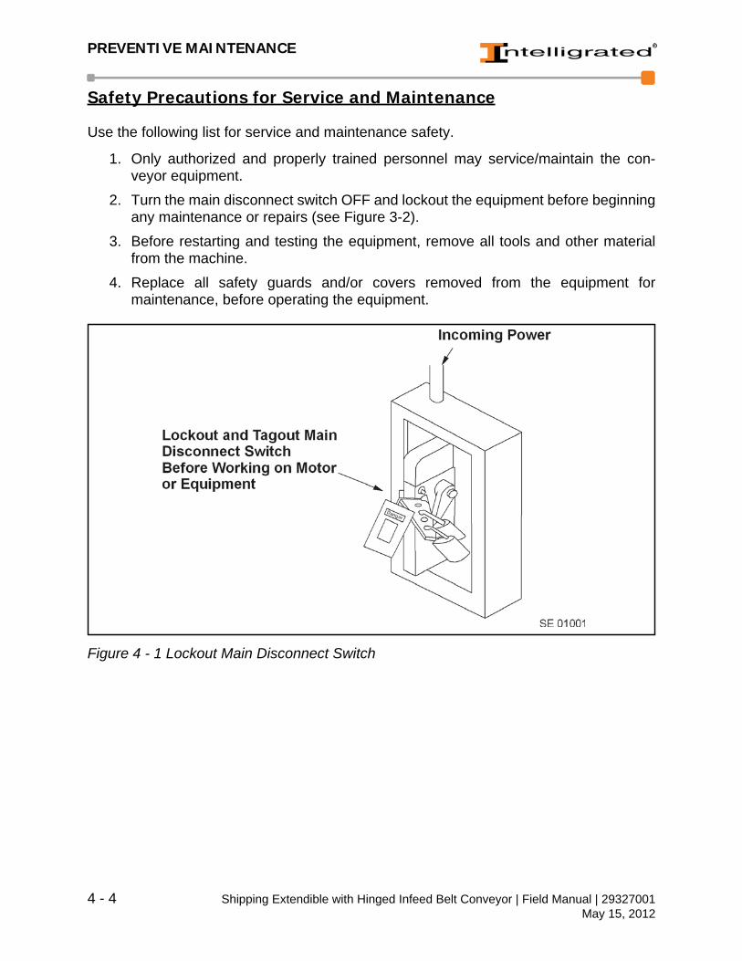
Safety Precautions for Service and Maintenance
Use the following list for service and maintenance safety.
1. Only authorized and properly trained personnel may service/maintain the con-veyor equipment.
2. Turn the main disconnect switch OFF and lockout the equipment before beginningany maintenance or repairs (see Figure 3-2).
3. Before restarting and testing the equipment, remove all tools and other materialfrom the machine.
4. Replace all safety guards and/or covers removed from the equipment formaintenance, before operating the equipment.
Figure 4 - 1 Lockout Main Disconnect Switch
4 - 4 Shipping Extendible with Hinged Infeed Belt Conveyor | Field Manual | 29327001May 15, 2012

PREVENTIVE MAINTENANCE
Scheduled Maintenance
Periodic maintenance intervals shown may varywith load, speed, hours of daily operation, ambienttemperature, humidity, etc. Intervals can be estab-lished by fairly frequent maintenance at first, thenlengthen the intervals as justified by observation ofthe need for maintenance and past history. Mainte-nance intervals are based on a five (5) day workweek, eight (8) hours per day.
Daily Inspections
1. General walk-through inspections of theconveyor equipment (listening for unusualnoises and carefully observing the system)during daily plant operation is recom-mended. For continuous duty applications,conduct conveyor inspections once eachshift.
2. Frequently check equipment safety guards, warning signs, lights, and alarmsassociated with the operation of the conveyor system and keep them in goodcondition to ensure the safety of all plant personnel. The operator should verify atthe start of each shift that the extend and retract collision avoidance sensors areoperating properly to automatically stop the Extendible's travel should its path oftravel become blocked. Any safety sensor malfunction, unusual conveyor noise,oil leaks, and operational problems should be immediately reported and promptlycorrected.
3. Check operation of all electrical controls, including dust build-up on photo-eyesand reflectors.
4. Inspect components for debris (tape, dust, glue, etc.) build-up that may hinderoperation.
m WARNING
Observe all warning signsposted on or near the con-veyor, and be alert at alltimes to the operation ofadjacent equipment. Attacha service tag to the equip-ment being serviced toidentify the date, mainte-nance required and down-time. Failure to follow thisinstruction may result inserious personal injuryand/or equipment damage.
Shipping Extendible with Hinged Infeed Belt Conveyor | Field Manual | 29327001 4 - 5May 15, 2012

PREVENTIVE MAINTENANCE
Weekly (40 Hours)
1. Inspect bearings, gear reducers and motors for excessive noise or heat. A motormay be hot to touch as normal. One-half horsepower motors may be slightly hot-ter.
2. Clean breather Cap on Reducer (if used).
Monthly (160 hours)
1. Inspect hinged belt drive pulley for wear and proper belt tensioning and tracking.
2. Inspect drive unit for leaking seals and oil level in gearcase if applicable.
3. Inspect fasteners and set screws for signs of loosening, fatigue or movement.
4. Inspect safety devices by actuation and observation of results.
Semi-Yearly (1040 hours)
1. Lubricate, drain, and flush gearcase after each 2,500 hours of normal operation orat least every six (6) months (if applicable).
4 - 6 Shipping Extendible with Hinged Infeed Belt Conveyor | Field Manual | 29327001May 15, 2012
PREVENTIVE MAINTENANCE
Speed Reducer - Lubrication and Maintenance
Oil Levels
1. Speed reducers are filled to the proper level for the standard mounting positionwith the appropriate grade of oil for operation in a 51°F to 110°F temperature envi-ronment. The oil level should be checked and adjusted (if necessary) prior tooperation, using the oil level plug provided and while the unit is oriented in itsoperating position.
2. If a speed reducer is overfilled with oil, the energy used in churning the excessiveoil can result in overheating. If this occurs, shut down the drive, remove the oillevel plug and allow oil to drain until oil ceases to drain from the level hole.Reinstall the oil level plug and restart the drive. If the speed reducer is underfilled,the resultant friction can cause overheating and possible damage. If this occurs,fill the speed reducer to the oil level plug hole and check the gearing for excessivewear.
Temperature
1. If the operating ambient temperature is outside the range specified above, thenrefer to the Vendor Lubrication Chart, and refill the unit with the correct gradebased on actual ambient temperatures.
2. Speed reducers in normal operation can generate high temperatures dependingon the type of reducer and the severity of the application (loading, duration ofservice, and ambient temperatures).
NOTE: Excessive oil temperatures may be the result of one or more of the followingcircumstances: Overloads, Overfilling, Underfilling or Inadequate Filling.
NOTE: To dissipate internally generated heat, the speed reducer must be installedin such a way that air can circulate freely.
Shipping Extendible with Hinged Infeed Belt Conveyor | Field Manual | 29327001 4 - 7May 15, 2012
PREVENTIVE MAINTENANCE
Changing Oil
1. When changing oil for any reason, remember that oil of various types may not becompatible. Therefore, when changing to a different oil, it is recommended thatthe housing be completely drained and thoroughly flushed with a light flushing oilbefore refilling with the appropriate lubricant. The oil level should be checked aftera short period of operation and adjusted, if necessary. When changing doublereduction models, each housing should be drained and filled independently, eventhough there may be a common level.
2. Synthetic lubricants can be advantageous over mineral oils in that they generallyare more stable, have a longer life, and operate over a wider temperature range.These oils are appropriate for any application, but are especially useful when unitsare subjected to low start-up temperatures or high operating temperatures.However, continuous operation at high temperatures may cause damage to theseals or other components.
3. It is recommended that the initial oil be changed or filtered after the first 1500 hourof operation to remove metal particles that accumulate during break-in. Undernormal conditions, after the initial oil change, the oil should be changed after every2,500 hours of operation, or every six months, whichever occurs first. Forsynthetic oils, subsequent oil changes should be made after 5000 hours ofoperation if units are operating in a clean environment. Under severe conditions(rapid temperature changes, moist, dirty, or corrosive environment) it may benecessary to change oil at intervals of one to three months. Periodic examinationof oil samples taken from the unit will help establish the appropriate interval.
Overloads
1. Overloads may be due to, an increase in speed or product/component weightexceeding the original design values, an increase in drag caused by a bad bear-ing, excessive belt snubbing, component interface etc.
2. Always check the speed reducer rating when increasing driven loads orincreasing the horsepower rating of the motor or other prime mover.
Seals
Although high quality seals and precision ground shafts are used to provide a superiorseal contact surface, it is possible that circumstances beyond control can cause oil sealleakage (defective seal, damage during the shipment or installation, etc.).
1. When replacing a shaft oil seal, using the following suggestion will help to insureleak-free operation and long seal life.
2. When installing a new seal, cover the keyway and any other surface discontinuitywith smooth tape to protect the seal lip from being damaged. A sealant should beused between O.D. of the seal and the I.D. of the bore into which the seal isinstalled. The seal bore should also be free of any burrs, nicks, or scratches.
4 - 8 Shipping Extendible with Hinged Infeed Belt Conveyor | Field Manual | 29327001May 15, 2012

PREVENTIVE MAINTENANCE
Electrical Devices
Periodically inspect photo-eyes, proximity sensors, limit switches, etc. and adjust asrequired. Lenses and reflectors on photoelectric devices should be wiped clean on adaily basis. Refer to appropriate Vendors' Instructions for additional maintenanceinformation.
Setting Extendible
1. The Honeywell Collision avoidance Photo-eye device has three lights on the front.They are OUT 1, OUT 2, and POWER. Only POWER and OUT 2 will be used inthis application.
2. The Honeywell Photo-eye device has three potentiometers on the front. They areSEN 1, SEN 2, and SEN 3. Only SEN 2 and SEN 3 will be used in the application.
3. Turn SEN 1 counter clockwise until you hear or feel a click. SEN 1 is now turnedall the way off.
4. The light OUT 1 will now be off and does not come on when the photo-eye isblocked.
5. Repeat step #3 for the other potentiometers on both photo-eyes. The POWERindicator should be the only light on.
6. Begin adjustment of the angled beams. These emanate from the inner beveledfaces of the photo-eyes and are controlled by SEN 3.
7. o verify proper wiring, turn SEN 3 clockwise 1/4 turn. This adjusts the angledbeam that should be on the inner beveled face of the photo-eye.
8. Bring your finger from below and cover the bevel. Do not block any other portionof the photo-eye's face. OUT 2 should turn on. If OUT 2 does not turn on, then trythe outside bevel.
9. Check both photo-eyes. If they are backward then the Orange and Brown wireswere connected incorrectly. See schematics and correct the wiring.
10.To properly set the photo-eyes it must be understood that these eyes work on adiffuse (faint) reflection of an infrared beam. Dark, dull surfaces will allow thephoto-eyes to trigger MUCH closer. To obtain maximum safety ranges, wear darkclothing while setting the photo-eyes.
11.Pick a photo-eye and adjust SEN 3 one and a half turns. Step back from thephoto-eye until OUT 2 turns OFF. Locate the beam by using your leg, hand or footto break the beam and turn-on OUT 2. Adjust the potentiometer until the edge ofthe beam (the farthest point at which it will trip) is just inside the line of the four legsupports.
12.Repeat the SEN 3 adjustment for the other photo-eye. DO NOT turn up SEN 2. Itis critical that the longer range straight beam is turned OFF while the short rangebeams are being adjusted.
Shipping Extendible with Hinged Infeed Belt Conveyor | Field Manual | 29327001 4 - 9May 15, 2012
PREVENTIVE MAINTENANCE
13.Begin SEN 2 (straight beam) adjustment by marking the floor 5 ft. from the back ofthe Extendible.
14.Turn SEN 2 two turns then back away from the sensor until OUT 2 turns OFF.
15.Slowly walk directly towards the photo-eye until OUT 2 turns on. Adjust thepotentiometers clockwise (up) or counterclockwise (down) until the photo-eyetrips when you reach your 5 ft. marker. Be sure that you are not wearing anythinghighly reflective on your shirt (Target I.D. badge, etc.) that will cause thephoto-eye to trip from much further away than it would normally.
16.Repeat this for the other photo-eyes.
17.Run the Extendible fully into a truck and back out to verify that passage can bemade between the supports without triggering the collision avoidance eyes. Donot adjust more than absolutely necessary. Over adjustment will reduce theeffectiveness of these devices.
Bearings
All bearings in the Extendible Conveyor units are sealed for life and do not requirelubrication. If a defective roller bearing is found, replace the roller.
4 - 10 Shipping Extendible with Hinged Infeed Belt Conveyor | Field Manual | 29327001May 15, 2012
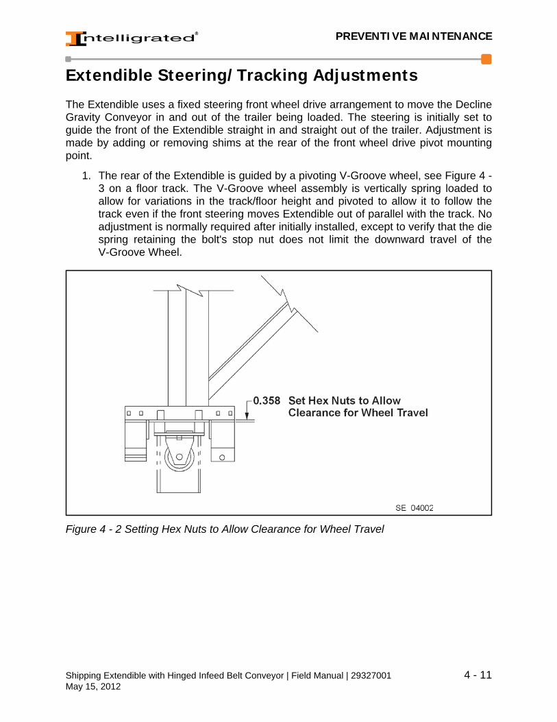
PREVENTIVE MAINTENANCE
Extendible Steering/Tracking Adjustments
The Extendible uses a fixed steering front wheel drive arrangement to move the DeclineGravity Conveyor in and out of the trailer being loaded. The steering is initially set toguide the front of the Extendible straight in and straight out of the trailer. Adjustment ismade by adding or removing shims at the rear of the front wheel drive pivot mountingpoint.
1. The rear of the Extendible is guided by a pivoting V-Groove wheel, see Figure 4 -3 on a floor track. The V-Groove wheel assembly is vertically spring loaded toallow for variations in the track/floor height and pivoted to allow it to follow thetrack even if the front steering moves Extendible out of parallel with the track. Noadjustment is normally required after initially installed, except to verify that the diespring retaining the bolt's stop nut does not limit the downward travel of theV-Groove Wheel.
Figure 4 - 2 Setting Hex Nuts to Allow Clearance for Wheel Travel
Shipping Extendible with Hinged Infeed Belt Conveyor | Field Manual | 29327001 4 - 11May 15, 2012
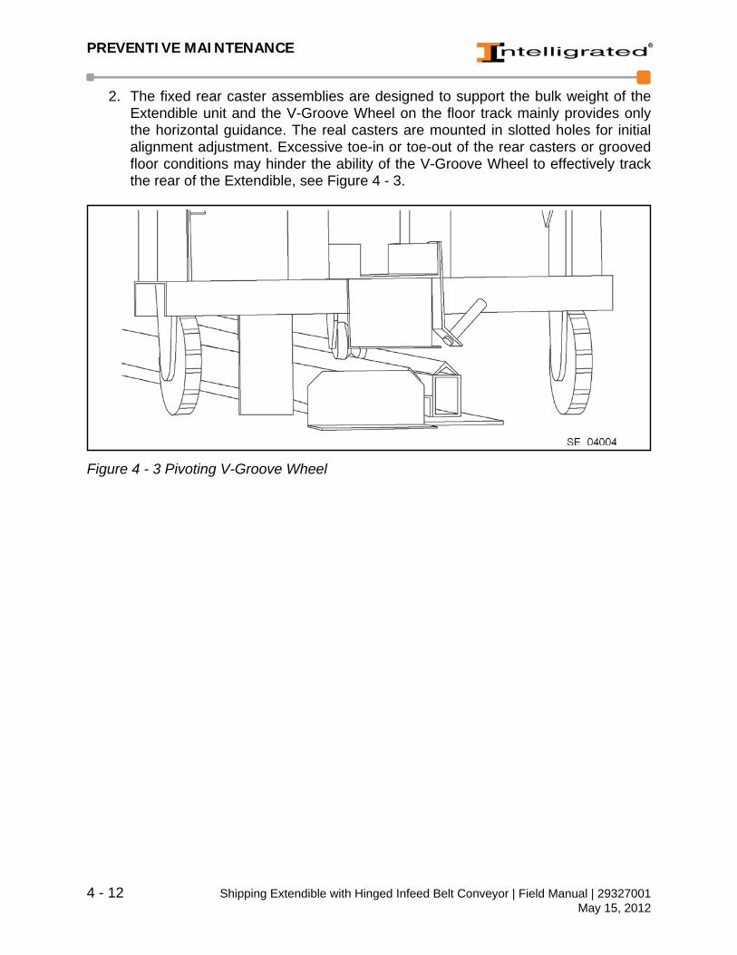
PREVENTIVE MAINTENANCE
2. The fixed rear caster assemblies are designed to support the bulk weight of theExtendible unit and the V-Groove Wheel on the floor track mainly provides onlythe horizontal guidance. The real casters are mounted in slotted holes for initialalignment adjustment. Excessive toe-in or toe-out of the rear casters or groovedfloor conditions may hinder the ability of the V-Groove Wheel to effectively trackthe rear of the Extendible, see Figure 4 - 3.
Figure 4 - 3 Pivoting V-Groove Wheel
4 - 12 Shipping Extendible with Hinged Infeed Belt Conveyor | Field Manual | 29327001May 15, 2012
TROUBLESHOOTING
5 Troubleshooting
When troubleshooting equipment problems, it isessential to completely understand how the systemfunctions during normal operation. Thoroughlyreview the operational description, the circuit draw-ings, and the electrical diagrams sent with yourequipment. Once the system operation is under-stood, it is usually best to start at the problem, andthen work back to the source.
Troubleshooting Guidelines
Procedures are discussed at length in the followingpages; however, there are certain guidelines thatshould be followed for all troubleshooting prob-lems:
1. Locate the problem.2. Listen and observe.3. Identify problem as electrical, mechanical, or pneumatic.4. Determine symptoms through observations.5. Think and act with caution and clear thinking.6. List short and long term solutions.7. Select a solution or possible solutions.8. Implement and document one solution at a time.
NOTE: The disassembling or repair ofequipment under warranty may voidsuch warranty (motor and reducer, forexample). Check to ensure warrantyhas not expired or will not be voidbefore performing disassembly orrepair.
m WARNING
Before performing anymaintenance or lubricationservices, follow the lock-out/tagout procedure in theSafety chapter to ensurethat the equipment is safeto work on. DO NOT clearjams or reach into any unitbefore first turning off theequipment power source(s)and making certain that allmoving parts are fullystopped. To avoid personalinjury or equipment dam-age, lockout the conveyordisconnect before attempt-ing to correct any malfunc-tion. Failure to follow thisinstruction may result inserious personal injuryand/or equipment damage.
Shipping Extendible with Hinged Infeed Belt Conveyor | Field Manual | 29327001 5 - 1May 15, 2012
TROUBLESHOOTING
Symptom Probable Cause Corrective ActionFront steering does not track to home position.
Setting loose or in need of adjustment.
Add or remove shims and tighten fasteners.
Floor/Dock/Trailer out of level or path obstructed.
Level surfaces and remove obstructions.
Front wheel loose or bent. Check for damage to wheel and/or axle. Align/tighten set screws and lug nuts.
V-groove wheel does not guide rear of Extendible along track.
Rigid casters not aligned in slots run parallel to floor track.
Loosen (4) fasteners at each caster and align using a straight-edge and measure-ment or line of site.
Variation in height of floor to top of track over-travel.
Level floor and/or shim track and rear rigid caster to obtain variations within toler-ance. Check using straight-edge on top of track (perpendicular to travel) and measure to floor at path of rear casters.
Threaded adjustment at V-groove wheel does not allow down travel to absorb variations in height.
Adjust threaded rods as shown in Chapter 4 Preven-tive Maintenance, Figure 4-3 for maximum vertical travel.
Extendible will not move in one direction; but will move in the other.
Travel proximity switch at rear of extendible is out of adjustment.
Adjust proximity switch dis-tance to track and/or range for consistent operation, drive to be enabled when switch is made and de-ener-gized when switch moves over end of travel track cut-out.
Proximity switch, control switch or wiring.
Test circuits, devices and connections. Repair, replace or adjust.
Obstruction in path, obstruc-tion sensor is out of adjust-ment or defective.
Clear path of Extendible travel and test operation of obstruction sensor. See Chapter 4 Preventive Main-tenance for adjustment pro-cedure.
5 - 2 Shipping Extendible with Hinged Infeed Belt Conveyor | Field Manual | 29327001May 15, 2012

TROUBLESHOOTING
Troubleshooting Help
If you need further assistance, please visit our website at www.intelligrated.com or callour Technical Support Department at 1-877-315-3400.
Product stalls or jams on gravity sections.
Conveyor rollers not perpen-dicular to side frame result-ing in skew that moves product closer to the side guides. May be caused by damage to the Extendible frame.
Check for damage to the Extendible frame, loosen fasteners, and square rollers to side frame and re-torque fasteners.
Rollers to not turn. Replace rollers.
Symptom Probable Cause Corrective Action
Shipping Extendible with Hinged Infeed Belt Conveyor | Field Manual | 29327001 5 - 3May 15, 2012

TROUBLESHOOTING
5 - 4 Shipping Extendible with Hinged Infeed Belt Conveyor | Field Manual | 29327001May 15, 2012

REPLACEMENT PARTS
6 Replacement Parts
This chapter contains the contact information and procedures for ordering replacementparts. Read the information below to ensure receipt of the correct parts, on time, andshipped to the correct location.
Contact Information
Parts Orders
Voice (Toll-Free): (877) 315-3400, select “1” at the prompt
Voice (Local): (513) 701-7346
Fax: (513) 701-7349
E-mail: [email protected]
On-Time Parts Catalog: www.OnTimeParts.com
The Parts Department’s normal working hours are Monday through Friday, 8:00 AM to5:00 PM, Eastern Time, except holidays. For Emergency parts support outside of normalbusiness hours, call the Toll-Free number and select “2” at the prompt.
Shipping Extendible with Hinged Infeed Belt Conveyor | Field Manual | 29327001 6 - 1May 15, 2012

REPLACEMENT PARTS
Warranty Part Order Procedures
The Warranty Replacement Parts program is designed to replace parts used from thecustomer’s spare parts inventory and not for supplying emergency replacement parts. Tomaximize system up-time, have a well stocked inventory of spare parts.
The warranty period for the conveyor equipment is detailed in the sales contract. Thestandard conveyor equipment warranty period is (one) year.
Parts may be ordered by phone, fax, e-mail, or by using our On-Line Parts Catalog. TheOn-Linie Parts Catalog displays a complete description and illustration of the part andalso shows the current price and availability.
During the warranty period, all parts that have failed due to defects in material and/orworkmanship will be replaced at no cost.
Damage caused by misuse, accidents, mis-adjustment, improper installation, impropermaintenance, modification by anyone except Intelligrated personnel, lack of preventivemaintenance, power failure or surge, air conditioning or humidity control, transportation,or causes other than a defect in the materials or workmanship are also not covered.
Use the following procedure when requesting a warranty replacement part(s):
1. Make a copy of the Warranty Parts Request Form located at the end of this sec-tion and complete the information requested on the form. Provide as much infor-mation about the equipment and part as possible, including the description,manufacturer, any information stamped on the part, and all the informatin from thelabel on the conveyor. Part numbers may also be easily found in the appropriatemaintenance manuals.
Figure 6 - 1 Example of Conveyor Label
Contact the Parts Department via e-mail, fax, phone, or through the On-TimeParts Catalog to request a copy of the form. The Parts Order Processor will fax ore-mail a Warranty Part Request Form.
2. Sign the form and fax it to the Parts Department at 513-701-7349.
6 - 2 Shipping Extendible with Hinged Infeed Belt Conveyor | Field Manual | 29327001May 15, 2012
REPLACEMENT PARTS
3. Upon receipt of the completed Warranty Part Request Form, the Parts OrderProcessor will enter the warranty order into the ordering system and issue aReturned Material Authorization (RMA) number.
4. The Parts Order Processor will record the Returned Material Authorization (RMA)on the completed Warranty Part Request Form and indicate on the form if thepart(s) must be returned to Intelligrated.
5. The Parts Order Processor will return the Warranty Part Request Form to thecustomer by fax or e-mail.
6. If indicated on the form, return the defective part to Intelligrated at the followingaddress. Be sure to package it to prevent damage during shipment. Also, includea copy of the Warranty Part Request Form inside the package and clearly markthe Returned Material Authorization (RMA) number on the outside of the package.
Intelligrated Returns4436 Muhlhauser Road Suite 300Attn: ReturnsHamilton, OH 45011RMA#_________________
Parts received without an RMA number will be returned to the customer.
If Intelligrated does not receive the defective part(s) within 30 days, the customerwill be billed for the part(s).
7. The order will be processed and the replacement part(s) will be shipped to thecustomer as soon as possible.
Warranty orders are always shipped via ground service. Other shipping arrange-ments may be made, but the customer will be billed for all shipping charges.
Shipping Extendible with Hinged Infeed Belt Conveyor | Field Manual | 29327001 6 - 3May 15, 2012
REPLACEMENT PARTS
Non-Warranty Part Order Procedures
Use the following procedure when ordering a non-warranty replacement part(s).
1. Contact the Parts Department via e-mail, fax, or phone, or by using our On-TimeParts Catalog to request the replacement part. Provide as much information aboutthe equipment and part as possible, including the description, manufacturer, anyinformation stamped on the part, and all the information from the label on the con-veyor (see label illustration on the previous pages). Part numbers may also beeasily found in the appropriate maintenance manuals.
2. Parts may be purchased using company issued purchase orders or by credit card(Visa, MasterCard, American Express and Discover).
Order Processing and Shipping
Orders for stock items are normally shipped the next business day.
Non-stock orders are subject to the lead time of the part. Orders are shipped via groundservice (Freight Prepaid and added to invoice) unless otherwise requested. Emergencyservice to ship via package carrier or scheduled airlines is also available for an additionalcharge.
Warranty orders are always shipped via ground service. Other shipping arrangementsmay be made, but the customer will be billed for all additional shipping charges.
New Parts Warranty
All parts purchased from Intelligrated carry a one-year warranty. All parts supplied at nocost as a warranty replacement for a component assume the warranty of the part beingreplaced.
Intelligrated will repair or replace, at our option (F.O.B. shipping point), parts which proveto be defective in material or workmanship within the warranty period. Intelligratedreserves the right to deny any warranty claims if during inspection it is determined thatfailure or damage was caused by accident, abuse or neglect by the user.
Parts damaged in shipment must be handled by submission of a claim to the shipper.Please save all boxes and packing materials and contact the Parts Department.
NOTE: There is a $100 minimum order for non-warranty orders.
6 - 4 Shipping Extendible with Hinged Infeed Belt Conveyor | Field Manual | 29327001May 15, 2012

REPLACEMENT PARTS
Recommended Spare Parts
Intelligrated can prepare and recommend a spare parts list for a customer’s specificmaterial handling system. The spare parts list will take into account the expected failurerate of each component and the criticality of each part for each segment of a specificmaterial handling system.
On-Time Parts Catalog
The Intelligrated On-Line Parts Catalog (OPC) is the only comprehensive materialhandling on-line parts catalog. Our unique “One Stop Shop” makes it easier to find, orderand receive all replacement and spare parts for Material Handling Systems,sub-components and assemblies.
Accessing the On-Time Parts Catalog
The On-Time Parts Catalog (OPC) can be accessed via the Web by two methods:
1. Go to www.OnTimeParts.com.
2. Go to www.intelligrated.com. Click the On-Time Parts link at the top of the page,or move the mouse cursor to the “Support Services” link, move the mouse to“Parts” and then click the “On-Line Parts Catalog” link on the submenu.
Figure 6 - 2 On-Time Parts Link
With the Intelligrated On-Line Parts catalog, it is easy to place orders on-line. In addition,phone support is available any time toll free at 1-877-315-3400. Intelligrated is alsoavailable by email; just click on the [email protected] link on the OPC home page.
Shipping Extendible with Hinged Infeed Belt Conveyor | Field Manual | 29327001 6 - 5May 15, 2012

REPLACEMENT PARTS
Online parts orders are risk free. Intelligrated provides a full money back guarantee if thecustomer is not totally satisfied with the service of the On-Line Parts Catalog.
Intelligrated has included contact information, policies, and how-to information. Just clickon the “Help Desk” link at any time.
Click “Help Desk” link and then the “How To” link for details on how to place an order.
Using the On-Line Parts Catalog
To use the On-Time Parts Catalog:
1. Click the Login link. Enter your e-mail address and password and press the“Login” button. To skip the login step the next time, check the "Remember Me"box.
If needed, click the “Create Account” link and fill in the account information.
2. Enter search information or use the links at the top of the page to select parts bycategory, Intelligrated product line, or by OEM parts or conveyor cross-referencecategories.
3. Choose a part by clicking on the part number or photo. Cross reference and otherinformation will be displayed.
4. Click the “Add to Cart” button and enter the quantity needed. If your companyrequires a requisition prior to ordering, click the “Add to Requisition” button. Yourpurchase requisition may be accessed under the “Order Info” link on the left sideof the page.
6 - 6 Shipping Extendible with Hinged Infeed Belt Conveyor | Field Manual | 29327001May 15, 2012

REPLACEMENT PARTS
Figure 6 - 1 OPC Main Menu
5. To checkout, click the “Shopping Cart” link on the left side of the page.
6. Verify the order information and click the “Checkout” button to submit your order.
7. Once the order is submitted, click the “Log Off” link to end the session.
Shipping Extendible with Hinged Infeed Belt Conveyor | Field Manual | 29327001 6 - 7May 15, 2012
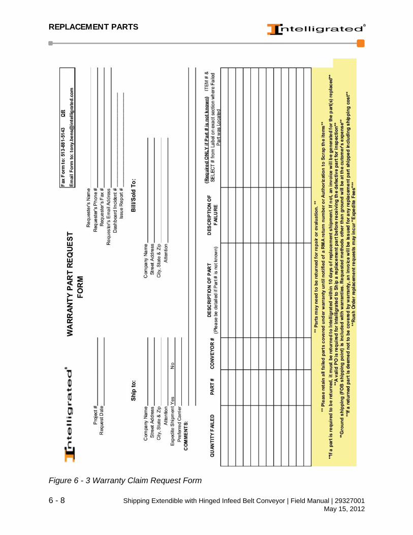
REPLACEMENT PARTS
Figure 6 - 3 Warranty Claim Request Form
6 - 8 Shipping Extendible with Hinged Infeed Belt Conveyor | Field Manual | 29327001May 15, 2012
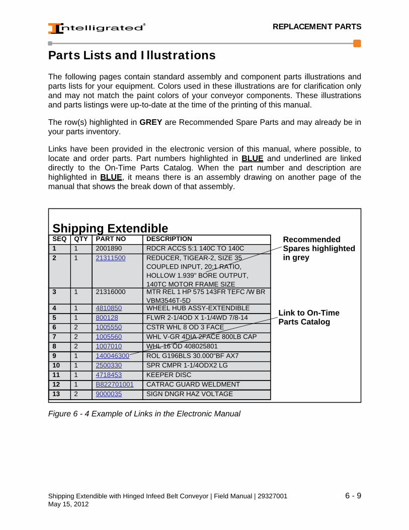
REPLACEMENT PARTS
Parts Lists and Illustrations
The following pages contain standard assembly and component parts illustrations andparts lists for your equipment. Colors used in these illustrations are for clarification onlyand may not match the paint colors of your conveyor components. These illustrationsand parts listings were up-to-date at the time of the printing of this manual.
The row(s) highlighted in GREY are Recommended Spare Parts and may already be inyour parts inventory.
Links have been provided in the electronic version of this manual, where possible, tolocate and order parts. Part numbers highlighted in BLUE and underlined are linkeddirectly to the On-Time Parts Catalog. When the part number and description arehighlighted in BLUE, it means there is an assembly drawing on another page of themanual that shows the break down of that assembly.
Figure 6 - 4 Example of Links in the Electronic Manual
Link to On-TimeParts Catalog
RecommendedSpares highlightedin grey
Shipping ExtendibleSEQ QTY PART NO DESCRIPTION1 1 2001890 RDCR ACCS 5:1 140C TO 140C2 1 21311500 REDUCER, TIGEAR-2, SIZE 35
COUPLED INPUT, 20:1 RATIO, HOLLOW 1.939" BORE OUTPUT, 140TC MOTOR FRAME SIZE
3 1 21316000 MTR REL 1 HP 575 143FR TEFC /W BR VBM3546T-5D
4 1 4810850 WHEEL HUB ASSY-EXTENDIBLE5 1 800128 FLWR 2-1/4OD X 1-1/4WD 7/8-146 2 1005550 CSTR WHL 8 OD 3 FACE7 2 1005560 WHL V-GR 4DIA 2FACE 800LB CAP8 2 1007010 WHL 16 OD 4080258019 1 140046300 ROL G196BLS 30.000"BF AX710 1 2500330 SPR CMPR 1-1/4ODX2 LG11 1 4718453 KEEPER DISC12 1 B822701001 CATRAC GUARD WELDMENT13 2 9000035 SIGN DNGR HAZ VOLTAGE
Shipping Extendible with Hinged Infeed Belt Conveyor | Field Manual | 29327001 6 - 9May 15, 2012

REPLACEMENT PARTS
Using the Parts Lists
The assemblies and components listed in these parts lists may not be describedcompletely if they contain special modifications and/or enhancements. Use the partnumber shown in this parts list to make sure the correct replacement parts are ordered.In addition, include nameplate information from motors, reducers, gearboxes,clutch/brakes, etc., whenever possible.
1. Find the exploded illustration of the applicable components.
2. Find the item number in the parts lists that matches the number in the illustration.Items on the parts list that are highlighted in GREY are Recommended SpareParts and may already be in your spare parts inventory.
3. Note the complete description and part number. See the Recommended SpareParts List to verify the part number for your specific project. Be sure to supply allthis information when placing the order.
4. To Order Spare Parts - click on the part number shaded in grey, see Figure 6 - 4.The Security Warning Window may be displayed. Click the Allow button and theIntelligrated Customer Service Dashboard window is displayed. Enter User Nameand Password, and click the Log In button.
NOTE: Do not provide the item number (the number in the circle) assigned to thepart in the illustration. These numbers are used for reference.
6 - 10 Shipping Extendible with Hinged Infeed Belt Conveyor | Field Manual | 29327001May 15, 2012
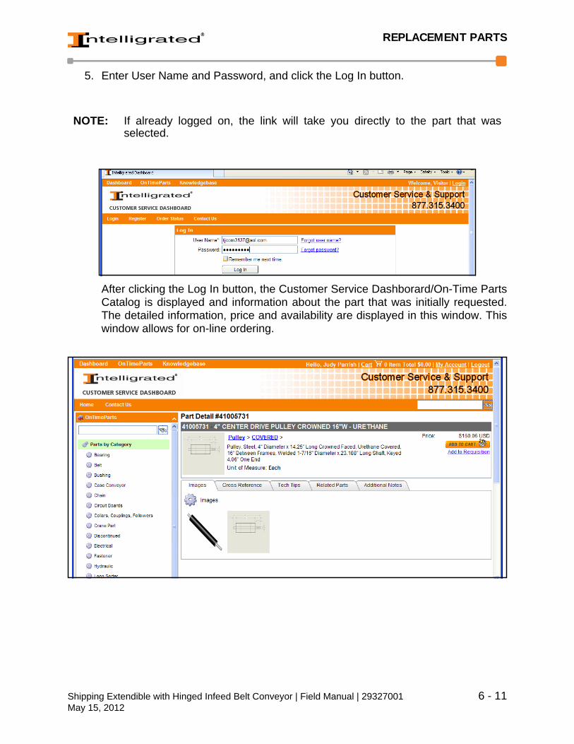
REPLACEMENT PARTS
5. Enter User Name and Password, and click the Log In button.
After clicking the Log In button, the Customer Service Dashborard/On-Time PartsCatalog is displayed and information about the part that was initially requested.The detailed information, price and availability are displayed in this window. Thiswindow allows for on-line ordering.
NOTE: If already logged on, the link will take you directly to the part that wasselected.
Shipping Extendible with Hinged Infeed Belt Conveyor | Field Manual | 29327001 6 - 11May 15, 2012
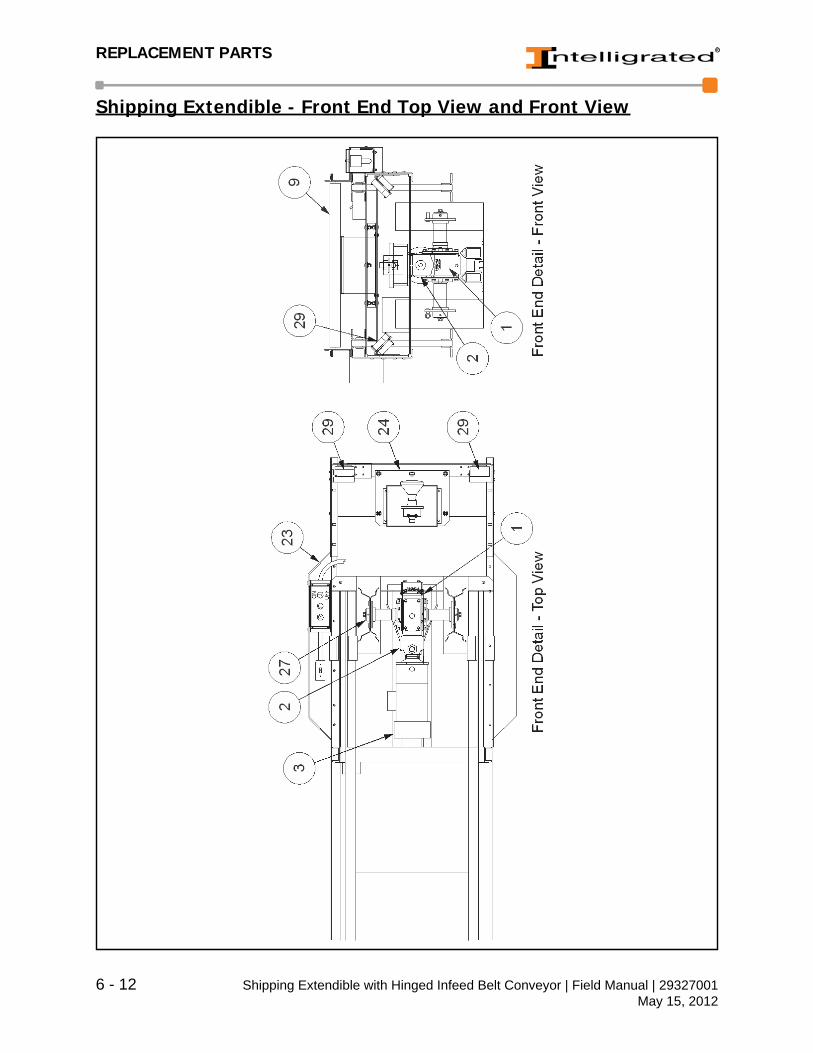
REPLACEMENT PARTS
Shipping Extendible - Front End Top View and Front View
6 - 12 Shipping Extendible with Hinged Infeed Belt Conveyor | Field Manual | 29327001May 15, 2012
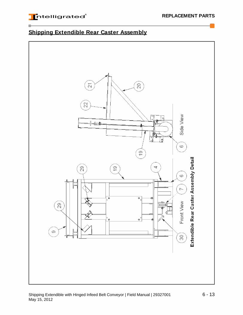
REPLACEMENT PARTS
Shipping Extendible Rear Caster Assembly
Shipping Extendible with Hinged Infeed Belt Conveyor | Field Manual | 29327001 6 - 13May 15, 2012
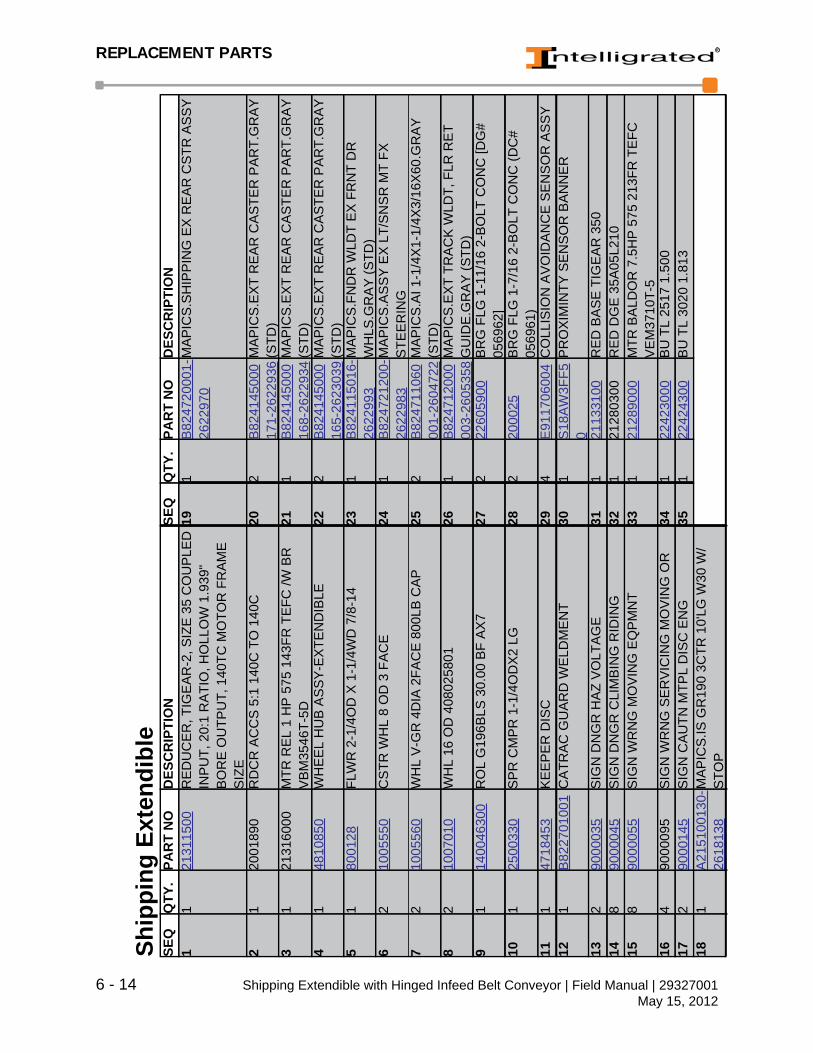
REPLACEMENT PARTS
Ship
ping
Ext
endi
ble
SEQ
QTY
.PA
RT
NO
DES
CR
IPTI
ON
SEQ
QTY
.PA
RT
NO
DES
CR
IPTI
ON
11
2131
1500
RE
DU
CE
R, T
IGE
AR
-2, S
IZE
35
CO
UP
LED
IN
PU
T, 2
0:1
RA
TIO
, HO
LLO
W 1
.939
" B
OR
E O
UTP
UT,
140
TC M
OTO
R F
RA
ME
S
IZE
191
B82
4720
001-
2622
970
MA
PIC
S.S
HIP
PIN
G E
X R
EA
R C
STR
AS
SY
21
2001
890
RD
CR
AC
CS
5:1
140
C T
O 1
40C
202
B82
4145
000
171-
2622
936
MA
PIC
S.E
XT
RE
AR
CA
STE
R P
AR
T.G
RA
Y
(STD
)3
121
3160
00M
TR R
EL
1 H
P 5
75 1
43FR
TE
FC /W
BR
V
BM
3546
T-5D
211
B82
4145
000
168-
2622
934
MA
PIC
S.E
XT
RE
AR
CA
STE
R P
AR
T.G
RA
Y
(STD
)4
148
1085
0W
HE
EL
HU
B A
SS
Y-E
XTE
ND
IBLE
222
B82
4145
000
165-
2623
039
MA
PIC
S.E
XT
RE
AR
CA
STE
R P
AR
T.G
RA
Y
(STD
)5
180
0128
FLW
R 2
-1/4
OD
X 1
-1/4
WD
7/8
-14
231
B82
4115
016-
2622
993
MA
PIC
S.F
ND
R W
LDT
EX
FR
NT
DR
W
HLS
.GR
AY
(STD
)6
210
0555
0C
STR
WH
L 8
OD
3 F
AC
E24
1B
8247
2120
0-26
2298
3M
AP
ICS
.AS
SY
EX
LT/
SN
SR
MT
FX
STE
ER
ING
72
1005
560
WH
L V
-GR
4D
IA 2
FAC
E 8
00LB
CA
P25
2B
8247
1106
000
1-26
0472
2M
AP
ICS
.AI 1
-1/4
X1-
1/4X
3/16
X60
.GR
AY
(S
TD)
82
1007
010
WH
L 16
OD
408
0258
0126
1B
8247
1200
000
3-26
0535
8M
AP
ICS
.EX
T TR
AC
K W
LDT,
FLR
RE
T G
UID
E.G
RA
Y (S
TD)
91
1400
4630
0R
OL
G19
6BLS
30.
00 B
F A
X7
272
2260
5900
BR
G F
LG 1
-11/
16 2
-BO
LT C
ON
C [D
G#
0569
62]
101
2500
330
SP
R C
MP
R 1
-1/4
OD
X2
LG28
220
0025
BR
G F
LG 1
-7/1
6 2-
BO
LT C
ON
C (D
C#
0569
61)
111
4718
453
KE
EP
ER
DIS
C29
4E
9117
0600
4C
OLL
ISIO
N A
VO
IDA
NC
E S
EN
SO
R A
SS
Y12
1B
8227
0100
1C
ATR
AC
GU
AR
D W
ELD
ME
NT
301
S18
AW
3FF5
0P
RO
XIM
INTY
SE
NS
OR
BA
NN
ER
132
9000
035
SIG
N D
NG
R H
AZ
VO
LTA
GE
311
2113
3100
RE
D B
AS
E T
IGE
AR
350
148
9000
045
SIG
N D
NG
R C
LIM
BIN
G R
IDIN
G32
121
2803
00R
ED
DG
E 3
5A05
L210
158
9000
055
SIG
N W
RN
G M
OV
ING
EQ
PM
NT
331
2128
9000
MTR
BA
LDO
R 7
.5H
P 5
75 2
13FR
TE
FC
VE
M37
10T-
516
490
0009
5S
IGN
WR
NG
SE
RV
ICIN
G M
OV
ING
OR
341
2242
3000
BU
TL
2517
1.5
0017
290
0014
5S
IGN
CA
UTN
MTP
L D
ISC
EN
G35
122
4243
00B
U T
L 30
20 1
.813
181
A21
5100
130-
2618
138
MA
PIC
S.IS
GR
190
3CTR
10'
LG W
30 W
/S
TOP
6 - 14 Shipping Extendible with Hinged Infeed Belt Conveyor | Field Manual | 29327001May 15, 2012

REPLACEMENT PARTS
Ship
ping
Ext
endi
ble
SEQ
QTY
.PA
RT
NO
DES
CR
IPTI
ON
SEQ
QTY
.PA
RT
NO
DES
CR
IPTI
ON
361
2247
3500
BT
DG
E H
T200
140
0-14
M-5
5 / G
ATE
S
1400
-14M
GT-
5547
114
0062
400
RO
L G
196H
S 4
0.00
BF
AX
7 S
LEE
VE
B20
06
371
2259
1500
PIN
CO
NN
EC
TIN
G .0
65 D
IA
DU
RA
STA
INLE
SS
#25
, CLI
PP
ER
#02
826
(RE
PLA
CE
D 4
1025
500)
481
1402
9240
0R
OL
G19
6AB
40.
00B
F W
/ SIL
EN
CE
B
AN
DS
AX
7 B
2006
381
2260
2500
BE
LT, T
RA
CK
ING
.188
X .3
75 X
5.8
4 83
A
(RE
PLA
CE
D 9
-M00
4230
-995
1)49
114
0307
400
11/1
6 H
EX
AX
LE P
INN
ED
40.
00B
F
391
2909
2300
LAC
ING
#1
HIG
H T
EN
SIL
E 1
2 in
. LO
NG
C
LIP
PE
R 0
2242
502
2200
2300
DO
DG
E 2
09S
, 1.8
12 S
HFT
DO
DG
E
#067
019
401
4100
5725
8 in
. CE
NTE
R D
RIV
E P
ULL
EY
CR
40
in.
UR
ETH
AN
E51
222
0029
00FL
AN
GE
BE
AR
ING
2 B
OLT
1 in
DIA
D
OD
GE
#12
4174
411
4100
7009
200
PU
LY R
D S
3 in
. RLR
CR
X 4
052
122
4598
00B
T S
PK
T D
OD
GE
P38
-14M
-55-
2517
11
2928
421
4100
7010
200
PU
LY R
D S
3 in
. RLR
FLT
X 4
053
122
4601
00B
T S
PK
T D
OD
GE
P48
-14M
-55-
3020
11
2931
431
4101
1705
200
CR
OW
NE
D E
N P
ULY
3.1
9OD
X 4
0BF
541
4101
3100
200
BT
CE
NTE
R D
RIV
E V
AC
FR
M G
RD
W/
LEX
AN
WIN
DO
W .1
56 (7
-1-0
4)44
141
0534
0020
0 B
T 4P
LY N
YLO
N T
OP
(412
9) 3
9W55
141
0512
0020
0 B
ELT
RE
TAIN
ER
EX
TRU
SIO
N 2
0 ft.
-0
in.
451
1400
2740
0R
OL
G25
1AB
DP
CU
P 4
0.00
BF
NO
AX
LE56
141
0537
0020
0 TA
KE
UP
WE
LDM
EN
T 11
in. A
SS
Y
(RE
PLA
CE
D 4
1006
900)
461
1400
6140
0R
OL
G19
6AB
40.
00B
F A
X7
B20
06
Shipping Extendible with Hinged Infeed Belt Conveyor | Field Manual | 29327001 6 - 15May 15, 2012
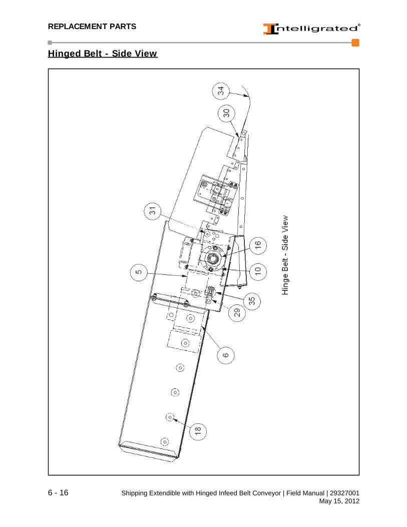
REPLACEMENT PARTS
Hinged Belt - Side View
6 - 16 Shipping Extendible with Hinged Infeed Belt Conveyor | Field Manual | 29327001May 15, 2012

REPLACEMENT PARTS
Hin
ged
Bel
t SE
TYPA
RT
NO
DES
CR
IPTI
ON
SEQ
QTY
PAR
T N
OD
ESC
RIP
TIO
N1
112
0105
0C
HN
50S
B F
LEX
SID
E B
OW
1919
1400
6128
0R
OL
G19
6AB
28.
00B
F A
X7
B20
062
112
0205
0C
HA
IN 5
0 R
IVE
TED
201
1400
6228
0R
OL
G19
6HS
28.
00"B
F A
X7
SLE
EV
E
B20
063
112
0305
0C
PLG
CH
N S
BR
50
STR
AT
SP
R C
LIP
211
1403
0728
011
/16
HE
X A
XLE
PIN
NE
D 2
8.00
BF
41
1203
056
CP
LG C
HN
50S
B S
TRA
T S
PR
CLI
P22
222
0026
00D
OD
GE
207
SE
RIE
S, 1
.437
5 S
HFT
D
OD
GE
# 05
2016
51
2001
437
RD
CR
50:
1 D
DG
E 2
6A H
56C
TIG
223
122
4096
00C
H S
PK
T 50
BTL
18H
-161
0 S
ST
or
DO
DG
E 1
0053
66
121
2900
00M
TR B
ALD
OR
3/4
HP
575
56F
R T
EFC
B
RK
VE
BM
3542
-5D
241
2241
0200
CH
AIN
SP
RO
CK
ET
50B
TL24
H-2
012
SS
T O
R D
OD
GE
100
542
72
2242
0200
BU
SH
ING
TA
PE
R L
OC
K 1
610
1.43
8 B
OR
E K
EY
WA
Y25
222
6059
00B
RG
2 B
LT F
LAN
GE
DO
DG
E D
LOK
1.
688"
F2B
DL1
11 #
1287
698
222
4204
00B
U T
L 16
10 1
.688
262
2901
273
BR
G F
LG 1
-3/1
6B 2
-BO
LT U
HM
W9
222
4218
00B
U T
L 20
12 1
.438
271
4100
7503
BR
US
H 2
7.75
" W 4
" H 2
" D10
129
0046
3P
LLY
6.5
W28
UR
THN
LG
NG
282
4105
3700
200
TAK
E U
P W
ELD
ME
NT
11" A
SS
Y
(RE
PLA
CE
D 4
1006
900)
111
4100
7005
200
PU
LY R
D S
3" R
LR C
R X
28"
292
4818
474
AS
SY
BR
KT
SN
UB
RLL
R T
KU
P12
141
0070
0620
0 P
ULY
RD
S 3
" RLR
FLT
X 2
8"30
1170
4388
9R
/A,1
.38X
.049
,26.
00,S
ST,
Z,S
L13
180
3578
00S
PC
L H
ING
E B
ELT
EN
D ID
LER
4"
CR
OW
NE
D P
ULL
EY
28"
BF
- U
RE
THA
NE
311
7045
497
R/A
1.3
8X.0
49 2
6.50
SS
T Z
SL
141
8037
1300
SP
CL
HIN
GE
BE
LT U
PP
ER
SE
C
4"C
RO
WN
ED
PU
LLE
Y 2
8"B
F -
UR
ETH
AN
E
321
8036
8700
SP
CL
MA
CH
INE
D C
H S
PK
T 50
BTL
18H
-16
10
151
8037
7800
BLT
25.
5X11
PO
LY W
/SE
ALE
D E
DG
ES
331
8037
6200
SP
CL
HIN
GE
BE
LT J
AC
K S
HA
FT
10.5
"LG
161
2000
25B
RG
FLG
1-7
/16
B 2
-BO
LT D
-LO
K34
180
3781
00S
HA
FT B
ELT
FLA
P W
=26.
5"17
220
0032
BR
G P
BLK
1-7
/16B
TP
PD
BS
DL
351
D32
1135
028
SP
EC
IAL
SN
UB
RO
LLE
R W
28
181
1400
2728
0R
OL
G25
1AB
DP
CU
P 2
8.00
0"B
F N
O
AX
LE
Shipping Extendible with Hinged Infeed Belt Conveyor | Field Manual | 29327001 6 - 17May 15, 2012
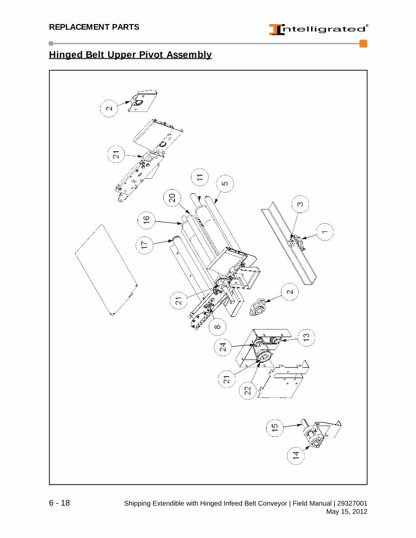
REPLACEMENT PARTS
Hinged Belt Upper Pivot Assembly
6 - 18 Shipping Extendible with Hinged Infeed Belt Conveyor | Field Manual | 29327001May 15, 2012

REPLACEMENT PARTS
Hin
ged
Bel
t Upp
er P
ivot
Ass
embl
y SE
TYPA
RT
NO
DES
CR
IPTI
ON
SEQ
QTY
PAR
T N
OD
ESC
RIP
TIO
N1
120
0025
BR
G F
LG 1
-7/1
6 2-
BO
LT C
ON
C (D
G#
0569
61)
133
8036
8700
SP
CL
MA
CH
INE
D C
H S
PK
T 50
BTL
18H
-16
102
422
6059
00B
RG
FLG
1-1
1/16
2-B
OLT
CO
NC
(DG
# 05
6962
)14
220
0032
BR
G P
BLK
1-7
/16B
TP
PD
BS
DL
31
8035
7000
SP
CL
HIN
GE
BE
LT P
IVO
T FR
AM
E
SH
AFT
1.4
38D
IA 4
.75L
G15
180
3762
00S
PC
L H
ING
E B
ELT
JA
CK
SH
AFT
10
.5"L
G4
180
0260
SE
T C
LLR
1-7
/16
B S
PLT
SH
FT16
180
3578
00S
PC
L H
ING
E B
ELT
EN
D ID
LER
4"
CR
OW
NE
D P
ULL
EY
28"
BF
554
1400
0228
0R
OL
G19
6AB
-28.
00"B
F A
X7
171
1400
3128
0R
OL
G25
0AB
28B
F6
241
0537
0020
0 TA
KE
UP
WE
LDM
EN
T 11
" AS
SY
182
4100
7301
200
AN
G, S
NU
B R
LR A
DJU
STE
R7
241
0070
0520
0 P
ULY
RD
S 3
" RLR
CR
28"
LG
191
4100
7403
200
BR
US
H H
OLD
ER
ALU
M
EX
TRU
SIO
N X
28"
84
4100
6801
200
AN
G S
NU
B A
DJU
STE
R20
141
0075
03B
RU
SH
28"
W 4
" H 2
" D9
314
0061
280
RO
L G
196
28.0
0BF
212
2200
2600
DO
DG
E 2
07 S
ER
IES
, 1.4
38 S
HFT
(1
2444
8 )
106
4100
6200
200
RE
TUR
N R
LR F
LT22
222
4102
00C
HA
IN S
PR
OC
KE
T 50
BTL
24H
-201
2 S
ST
OR
DO
DG
E 1
0054
211
180
3713
00S
PC
L H
ING
E B
ELT
UP
PE
R S
EC
4"
CR
OW
NE
D P
ULL
EY
28"
BF
232
2242
1800
BU
TL
2012
1.4
38
122
2242
0400
BU
TL
1610
1.6
8824
122
4096
00C
H S
PK
T 50
BTL
18H
-161
0 S
ST
or
DO
DG
E 1
0053
6
Shipping Extendible with Hinged Infeed Belt Conveyor | Field Manual | 29327001 6 - 19May 15, 2012

REPLACEMENT PARTS
6 - 20 Shipping Extendible with Hinged Infeed Belt Conveyor | Field Manual | 29327001May 15, 2012

INDEX
IndexA
Accessing the On-Time Parts Catalog 6 - 5Assembling the System 3 - 6
CCodes & Standards 3 - 3Controls 1 - 7
control stations 1 - 7safety devices 1 - 8
emergency stops and restarts 1 - 8Controls, Safety Devices 1 - 8
EElectrical Connections, installing 3 - 8Electrical Devices 4 - 9
setting extendible 4 - 9
FFor Your Safety 1 - 2
GGeneral Descripiton
components 2 - 1General Description 2 - 1
decline belt 2 - 4extendible conveyor 2 - 4glossary of Terms 2 - 6location of components 2 - 1
Glossary of Terms 2 - 6Guards and Guarding 1 - 6
guarded by location or position 1 - 6guarding exceptions 1 - 6interfacing of equipment 1 - 6
HHeadroom 1 - 6
IIdentifying parts 6 - 9Initial Operation 3 - 10
direction of travel 3 - 10Installation and Maintenance Safety 1 - 10Installation Procedures 3 - 1
check hinged belt direction of travel 3 - 10codes & standards 3 - 3conveyor system, assembling 3 - 6installing electrical connections 3 - 8parts replacement 3 - 4receiving & inspections 3 - 1safety precautions 3 - 3site preparation 3 - 4start-up 3 - 9unloading/moving into position 3 - 5
LLayout Requirements 3 - 2Lockout / Tagout Guidelines 1 - 11
MMaintenance Precautions 4 - 3
operator’s safety precautions 4 - 3service and maintenance safety 4 - 4
Moving into Position 3 - 5
NNew Parts Warranty 6 - 4Non-Warranty Part Order Procedures 6 - 4
OOn-Time Parts Catalog 6 - 5
accessing the on-line parts catalog 6 - 5Operation Safety Precautions 1 - 9Order Processing and Shipping 6 - 4Ordering Parts Catalog Main Menu 6 - 7
PParts Lists and Illustrations 6 - 9
hinged belt - side view 6 - 16hinged belt pivot assembly 6 - 18rear caster assembly 6 - 13
Shipping Extendible with Hinged Infeed Belt Conveyor | Field Manual | 29327001 Index - iMay 15, 2012

INDEX
shipping extendible, front end 6 - 12Parts Orders 6 - 1Parts Replacement 3 - 4Preventive Maintenance 4 - 1
bearings 4 - 10electrical devices 4 - 9lubrication and maintenance 4 - 7maintenance precautions 4 - 3scheduled maintenance 4 - 5steering/tracking adjustments 4 - 11
Procedure for non-warranty replacement part(s) 6 - 4Procedure requesting warranty replacement part(s) 6 - 2
RReceiving & Inspections 3 - 1
claims & returns 3 - 2reporting product damage 3 - 2
Recommended Spare Parts 6 - 5Replacement Parts 6 - 1
contact information 6 - 1parts lists and illustrations 6 - 9parts orders 6 - 1using parts lists 6 - 10
Running Decline Belt 2 - 4Running Extendible Conveyor 2 - 4
SSafety Devices 1 - 8Safety Instructions 1 - 1
controls 1 - 7for your safety 1 - 2lockout / tagout guidelines 1 - 11operating safety precautions 1 - 9safety precautions 1 - 6safety signs 1 - 13standard safety conventions 1 - 4
Safety Instuctionsinstallation and maintenance safety 1 -
10Safety Precautions 1 - 6, 3 - 3
guards and guarding 1 - 6headroom 1 - 6
Safety Precautions, Guards and Guarding 1 - 6Safety Signs 1 - 13Scheduled Maintenance 4 - 5
iinspections, monthly 4 - 6inspections semi-yearly 4 - 6inspections, daily 4 - 5inspections, weekly 4 - 6
Site Preparation 3 - 4Spare Parts Recommended 6 - 5Speed Reducer - Lubrication and Maintenance 4 - 7
oil levels 4 - 7oil, changing 4 - 8overloads 4 - 8seals 4 - 8temperature 4 - 7
Standard Safety Conventions 1 - 4Start-Up 3 - 9
electrical check 3 - 9initial operation 3 - 10mechanical check 3 - 9pre-operating check 3 - 9
Steering/Tracking Adjustments 4 - 11
TTroubleshooting 5 - 1
guidelines 5 - 1Troubleshooting Help 5 - 3
UUsing Parts Lists 6 - 10Using the On-Line Parts Catalog 6 - 6
WWarranty Claim Request Form 6 - 8Warranty New Parts 6 - 4Warranty Part Order Procedures 6 - 2Warranty Part Request Form 6 - 8Warranty period for conveyor 6 - 2
Index - ii Shipping Extendible with Hinged Infeed Belt Conveyor | Field Manual | 29327001May 15, 2012