Cooling capacity : 39.5 ~ 532kW
Carrier 2nd Generation
VWV INVERTER SERIES
BUILD THENEW NORMAL

Turn to the Experts
Since Willis Carrier invented the first
air-conditioning system in 1902, Carrier
has been a technology pioneer and the
preferred choice of customers around
the globe, providing highly efficient
chillers as well as central and airside
air-conditioning units for household
and commercial applications. As a unit
of United Technologies Corp., Carrier is
the world’s leading provider of heating,
ventilation and air-conditioning (HVAC)
and refrigeration equipment.

THE BEST OF BOTH WORLDS Carrier AquaFlowTM Variable Water Volume (VWV) System
Leading Benefits
Complete System Lineup
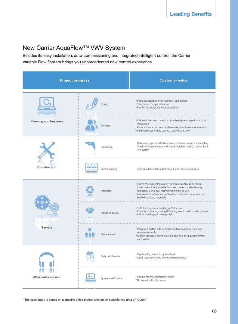
Customer valueDesign flexibilityEnergy efficiencyIndoor comfortEasy retrofittingPowerful controlExceptional reliability
Contents
03
06
08
07
29Major Technical Parameters
History 37
Shanghai Expo Boulevard
The Whitehouse, Washington
Hongkong International Airport The Kremlin, Moscow Shanghai MetroTaipei 101
Beijing Wanda Plaza The Great Hall of the People, Beijing
Beijing "Water Cube" National Swimming Center

03
Product conception
03

0404
Carrier AquaFlow™ Variable Water Volume (VWV) System
THE BEST OF BOTH WORLDS
Carrier’s innovative AquaFlowTM VWV System combines the benefits of conventional hydronic and VRF systems, providing superior indoor comfort and energy efficiency.
The AquaFlowTM VWV System includes modular outdoor air-cooled chiller and heat pump unit with self adaptive technology to control the variable refrigerant evaporating temperature*, low-noise fan coil unit, heat recovery fresh air handling unit, VFD hydronic kit, networked indoor thermostat, and intelligent system manager. Single system capacity: 39.5kW – 532kW
VFD hydronic kit
* Self adaptive variable water temperature / Self adaptive variable refrigerant evaporating temperature
Intelligent system manager
High ESP IDU(suspending AHU)
Small ducted IDU
Heat recovery fresh air handing unit
VFD air-cooled chiller(self adaptive variable
refrigerant evaporating temperature)
4-way cassette IDU

05
Carrier AquaFlow™ VWV System Conventional VRFConventional Hydronic System
Expanding the
benefits of conventional
hydronic systems
Flexible
Design
Easy
retrofit
Indoor
Comfort
Max. indoor unit (IDU) / outdoor unit connectivity: 200%
Max. pipe length: 400mMax. ODU / IDU height difference: 120m*
System changing conveniently via IDU adding or removing quickly
Max. indoor unit/outdoor unit connectivity: 130%
Max. pipe length: 150mMax. ODU / IDU height difference: 50m
Longer cycle if IDU changing and impact on others in same loop
Case by case design on job basis
Case by case design on job basis
System changing conveniently via IDU adding or removing quickly
Temp control +/-0.5°C, humidity detect +/-5%
Complete anti-PM 2.5 solution for fresh air and indoor air
No risk of indoor refrigerant leakage
Air supplied too cold or too hot; no humidity control function
No filter section for IDU
Potential risk of indoor refrigerant leakage
No humidity control function
Only fresh air handling unit with filter section
No risk of indoor refrigerant leakage
Easy Installa-tion and Mainte-nance
Expanding the
benefits of conventional
VRF
System centralized control
Energy metering and BA connection
No centralized control; no communication between IDU / ODU
Extra hardware & software neededand substantial investment
System centralized control
Extra hardware & software neededand substantial investment
40% higher system IPLV vs. conventional hydronic system, 10% higher system IPLV vs. VRF
Self adaptive variable water temperature / Self adaptive variable refrigerant evaporating temperature Energy efficiency: grade 1(China GB)
No cooling/heating capacity loss in long pipes, Outdoor unit optimized 10-20%**
Self adaptive variable water flow
100% fresh air effect, 25% fresh air operation cost
IPLV is 40% lower than the VWV system
No variable refrigerant flow / variable refrigerant evaporating temperature Energy efficiency: grade 2 or below (China GB)
No cooling/heating capacity loss in long pipes (subject to appropriate design)
Constant water flow speed
100% fresh air effect, 100% fresh air operation cost
IPLV is 10% lower than the VWV system
Variable refrigerant flow Energy efficiency: grade 1(China GB)
Cooling capacity loss: 10% – 20% in long pipes
Not applicable -
100% fresh air effect, 100% fresh air operation cost
* Outdoor unit and hydronic kit sited above the indoor unit** Within the recommended pipe length range
Cost
Savings
06
* The case study is based on a specific office project with an air-conditioning area of 1200m2.
Leading Benefits
New Carrier AquaFlow™ VWV SystemBesides its easy installation, auto-commissioning and integrated intelligent control, the Carrier
Variable Flow System brings you unprecedented new control experience.
Customer value
Planning and business
Service
After-sales service
Construction
Installation
Commissioning
DesignPackaged selection by components and systemSystem level design validationFlexible layout for any kinds of building
Efficient investment based on optimized system capacity and roof installation Reduce finance pressure via phase-investment even room by room Simple process via one contact, secured lead-time
Purchase
System automatically addressing, shorter commission cycle
Operation
Indoor air quality
Management
Daily maintenance
System modification
Project progress
Only water pipe and electrical connections are required, eliminating the risk of water leakage, with installation fees close to conventional VRF system
Lower system running cost derived from variable ODU control (compressor & fan), variable flow rate control, variable leaving temperature and heat recovery from fresh air unit Modularized outdoor unit w/ tandem compressor design can be backed up interchangeably.
Sufficient fresh air according to CO2 sensorContinuous heating during defrosting (multi-outdoor units system)Indoor no refrigerant leakage risk
Integrated system with dedicated system controller (zone and schedule control)Build-in individual billing function, only add one power meter for each system
Rigid quality control by system levelQuick response by one to one correspondence
Flexible for system retrofit in futureNo impact with other users

07
Complete System LineupSingle system capacity
39.5kw-532kwIntelligent system manager
Heat recovery fresh air handling unitand PM 2.5 option
Heat recovery fresh air unit
Control up to 8 outdoor units, 128 indoor units or fresh air units and 1 hydronic kit
9 models (1000~8000CMH)
17 models (600~6000CMH)
VFD / Fixedoutdoor unit39.5kW/ 66.5kW
VFD packagedhydronic kit5 models
Ducted indoor unit28 models (1.9~15.2kW)
4 way cassette indoor unit8 models (3.2-12.6kW)
High ESP Ducted indoor unit38 models (5-44kW)
Fresh air handling unit38 models (1000~6000CMH)
Hotels
Office buildings
Hall
Complete System Lineup
*Self adaptive variable water temperature / Self adaptive variable refrigerant evaporating temperature
Energy efficiency
Powerful controls
Easy retrofitting
Exceptional reliability
Six reasons
to choose VWV
Design flexibility
Indoor comfort
Customer value
08
09
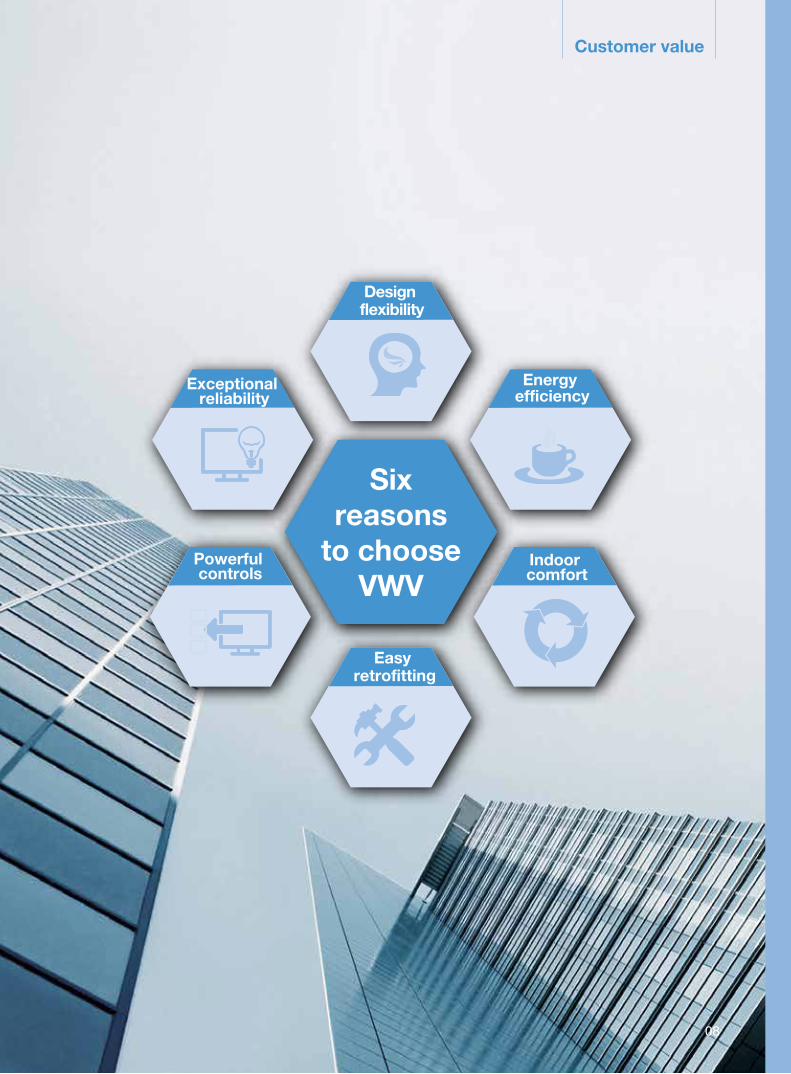
1.Design flexibility
Offering one station system, less design workload
» Validated system selection report for business matters
» Components level report to review all facilities
» Packaged hydronic kits offering: test proven performance, smaller foot print, shorter install cycle
and less labor burden
Other product report VWV system report
So many unrelated, unfocused and dizzied materials for all products!
Concise report by system level
Wider workable load range for outdoor units (10% – 200%),
lower initial cost and easier system upgrades.
Mutiple configuration options are offered with a wide range of IDUs and ODUs
VWV
0% 10% 200% 300%50% 130%
Recommended range
Workable range Oil return issues
Inferior comfort
Inhibited defrosting
Recommendedor workable range
Not recommended but workable range
Indoor unit-outdoor unit capacity ratio
Unworkable range
The outdoor unit starts and stops frequently
VRF
Indoor unit-outdoor unit capacity ratio = (combined capacity of all fresh air handling units and indoor units) / (total outdoor unit capacity) ×100%
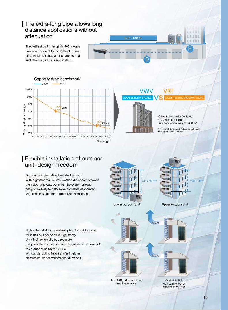
10
D+H ≤400m
» D
» H
Max 60 m*
Lower outdoor unit
Max 120 m
Upper outdoor unit
10
Office building with 20 floorsODU roof installationAir conditioning area: 20,000 m2
Capacity drop benchmark
Cap
acity
dro
p pe
rcen
tage
Pipe length
ODUs capacity 3192kW* ODUs capacity 3875kW*(+20%)
Office
Villa
* Case study based on 0.8 diversity factor andcooling load index 200w/m2
The farthest piping length is 400 meters
(from outdoor unit to the farthest indoor
unit), which is suitable for shopping mall
and other large space application.
The extra-long pipe allows long distance applications without attenuation
Flexible installation of outdoor unit, design freedom
Outdoor unit centralized installed on roof
With a greater maximum elevation difference between
the indoor and outdoor units, the system allows
design flexibility to help solve problems associated
with limited space for outdoor unit installation.
High external static pressure option for outdoor unit
for install by floor or on refuge storey
Ultra-high external static pressure
It is possible to increase the external static pressure of
the outdoor unit up to 120 Pa
without disrupting heat transfer in either
hierarchical or centralized configurations.
Low ESP, Air short circuit and interference
VWV high ESP, No interference for installation by floor
11
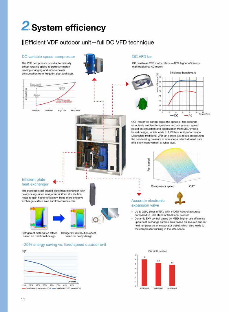
DC variable speed compressor
The VFD compressor could automatically adjust rotating speed to perfectly match loading changing and reduce power consumption from frequent start and stop.
DC VFD fan
Accurate electronic expansion valve
Efficient plate heat exchanger
DC brushless VFD motor offers ~+12% higher efficiency than traditional AC motor.
COP fan driver control logic: the speed of fan depends on outside ambient temperature and compressor speed based on simulation and optimization from MBD (model based design), which leads to fulfill best unit performance. Meanwhile traditional VFD fan control just focus on securing the condensing pressure in safe scope, which doesn’t care efficiency improvement at what level.
The stainless steel brazed plate heat exchanger, with newly design upon refrigerant uniform distribution, helps to gain higher efficiency from more effective exchange surface area and lower frozen risk.
Refrigerant distribution effect based on traditional design
Refrigerant distribution effect based on newly design
OATCompressor speed
Fan
spee
d
» Up to 2600 steps of EXV with +400% control accuracy compared to 500 steps of traditional product
» Dynamic EXV control based on MBD: higher use efficiency upon heat exchange surface area based on secured supper heat temperature of evaporator outlet, which also leads to the compressor running in the safe scope.
Efficiency benchmark
DC
Fixed speedcompressor
VWVII variablespeed compressor
Saving 90%
Saving 40%
Con
sum
ptio
n
Low load Mid load High load Peak load
Efficient VDF outdoor unit—full DC VFD technique
2.System efficiency
~20% energy saving vs. fixed speed outdoor unit
30RBH068 (fixed speed ODU) 30RBV068 (VFD speed ODU)
Unit load
7
6
5
4
3
2
1
0
IPLV (AHRI condition)
6
5.24.8
30RBV068 30RBM040 30RBH068
12
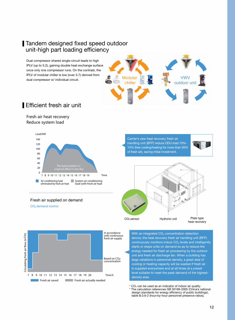
Modular chiller
VWV outdoor unit
Tandem designed fixed speed outdoor unit-high part loading efficiency
Dual compressor shared single-circuit leads to high
IPLV (up to 5.2), gaining double heat exchange surface
once only one compressor runs. On the contrast, the
IPLV of modular chiller is low (over 3.7) derived from
dual compressor w/ individual circuit.
Fresh air heat recoveryReduce system load
Carrier’s new heat recovery fresh air handling unit (BFP) reduce ODU load 10%-15% (free cooling/heating for more than 50% of fresh air), saving initial investment.
Fresh air supplied on demandCO2 demand control
CO2 sensor Hydronic coil Plate typeheat recovery
Efficient fresh air unit
Load/kW
140
120
100
80
60
40
20
07 8 9 10 11 12 13 14 15 16 17 18 19 Time/h
The load variation in a typical office in one day
Air conditioning load eliminated by fresh air heat recovery
System air conditioning load (with fresh air heat recovery unit)
Circ
ulat
ing
fres
h ai
r flo
w (m
3 /h)
Based on CO2 concentration
In accordance with continuous fresh air supply
Fresh air actually neededFresh air saved
7 8 9 10 11 12 13 14 15 16 17 18 19 20 Time/h
With an integrated CO2 concentration detection device, the heat recovery fresh air handling unit (BFP) continuously monitors indoor CO2 levels and intelligently starts or stops units on demand so as to reduce the energy needed for fresh air processing by the outdoor unit and fresh air discharge fan. When a building has large variations in personnel density, a great deal of cooling or heating capacity will be wasted if fresh air is supplied everywhere and at all times at a preset level suitable to meet the peak demand of the highest-density area.
* CO2 can be used as an indicator of indoor air quality.* The calculation references GB 50189-2005 China’s national
design standards for energy efficiency of public buildings , table B.0.6-2 (hour-by-hour personnel presence ratios).

13
Packaged VFD hydronic kits running curve
Pipe net curve
External lift
Energy saving from pump
Pipe net curve changing when related indoor temp. reach to setting point.
Reduce consumption by adjust frequency of VFD pump based on system condition
Water flow rateFlow rate at part load Flow rate at full load
Pump working point at full load
Pump working point w/ constant frequency when partial outdoor and indoor units isolated at part-load
Pump working point w/ smaller frequency when partial outdoor and indoor units isolated at part-load
Variable flow rate control, leads to -67% energy saving of water pump
Power consumption index
The gap between design point and run point in actual
Period when pump varies frequency
Delayed time of system stand-bye
no loading
Fixed pump Variable pump
System loading
Efficient system- variable water flow
H
LgP LgP
H
Te full loading=4℃
VRF Power Consumption
VRF Evaporation Temperature
VWV Power Consumption
VWV Evaporation Temperature
Te part loading =?℃
Part loading Full loading
In a VRF system, the refrigerant evaporating temperature is set at 6℃
25% -----------〉 50% -----------〉75% -----------〉100%
100%
80%
60%
40%
20%
0% 25% 50% 75% 100% load
11
9
7
5
3 25% 50% 75% 100%
Temperature
load
Under part load conditions, the VWV’s unique technologies reducepower consumption and increase operating efficiency by varying the leaving water temperature and refrigerant evaporation temperature.
VWV = Self adaptive variable leaving water temperature /Self adaptive variable refrigerant evaporation temperature
Power Consumption
Indoor temp.27℃
T1= -1℃
Indoor temp.35℃
T4= -9℃
Indoor temp.35℃
T5= -8℃
Indoor temp.26.5℃
Tn= -0.5℃
ThermostatOn
Setting temp.26℃
ThermostatOn
Setting temp.26℃
ThermostatOn
Setting temp.27℃
ThermostatOn
Setting temp.26℃
Setting temp.25℃
Setting temp.27℃
Indoor temp.25℃
T2= 0℃
ThermostatOn
Indoor temp.26℃
T3= 1℃
ThermostatOn
* IDU on / off* Room temperature * N is number of IDU that is ON, meanwhile remains
constantly comfortable indoor climate.
N
Set Room
Carrier Variable Water Temperature algorithm enables moment-to-moment control that matches building loads with precision, by monitoring timely in major:
System efficiency–variable water temperature based on indoor comfort
Power consumption drops rapidlyunder part-load conditions
Comparing part-load compressor operations

14
Case study
An office building with 7 floor in Kuala Lumpur, air-conditioning area 4200m2, indoor peak loading 3098kw, fresh air loading 150kw.
System configuration: outdoor unit 30RBV068 (66.5kw)*49 sets, HK520*7 sets, 42CT00730*525 sets, BFPR50*14 sets.
Harmony in Three Variables
Compare to VRF, VWVII leads to -16.5% energy saving in full year (259,700kw*h)*
0 1000 2000 3000 4000 5000 6000 7000 8000
Tem
per
atur
e (o
C)
Load
[kW
]
40
35
30
25
20
15
10
5
0
6000
5000
4000
3000
2000
1000
0
Annual building load & OAT profile
CLG Load OAT OAT_wb
Po
wer
(kW
h)
VRF
VWV
Hour9 10 13 1611 14 17 1912 15 18 20
* Date source derived from Carrier internal case study
Morning:
Outdoor Air Temperature: 35°C
IDUs keep ON except meeting rooms
High building load
Morning:
Outdoor Air Temperature: 25°C
Only a few IDUs remain ON
Lowest building load
Morning:
Outdoor Air Temperature: 28°C
All IDUs start on for pre-cooling
Low building load
VFD ODU: 70%
Variable water flow rate: 100%
Variable water temperature: >7°C
VFD ODU: 95%
Variable water flow rate: 95%
Variable water temperature: 7°C
VFD ODU: 30%
Variable water flow rate: 30%
Variable water temperature: 8.5°C
ON ON ON ON ON ON ON OFF OFF
ON ON ON ON OFF OFF ON OFF OFF

15
Low Indoor Noise
3.Indoor comfort
Whispered conversation; leaves rustling
20db
Normal conversation
50db
A quiet office
40db
Street environment
70db
45db
4-way cassette fan coil unit (42GWC)For large open-plan offices or meeting rooms; wide coverage, low noise, stylish design, and independent control
Small ducted IDU (42CTSmall ducted IDU (42CT)For large open-plane or individual small office, flexible control and effective investment
Allowable noise for general/premium offices
Allowable noise for a first-class office
Allowable noise for general office
DC brushless motors are optional for 42CN and 42GWC units, further reducing the system’s already minimal
operating noise (by as much as 26% for the 42CN006). DC brushless motor and drive
Less Noise

16
Low noise fan Bigger impeller and low entering
speed fan structure equipped with
NSK bearing leads to reduce the
mechanical noise
Carrier patent design Silencer the noise generated by the dynamic
pressure of the outlet of the wind
turbine is absorbed by built-in wing
type foam spacer, which involved
with the advanced computational
fluid dynamics to simulate the opti-
mization, and the performance of the
unit is not affected. At the same time,
greatly reduce the unit noise at high
speed (over -3 dB(A))
DC brushless motorDC brushless motor can avoid low frequency
noise and furtherly reduce running noise.
Considering indoor unit operating at mid or
low speed mostly, the effect of running noise is
better than AC motor
The running noise of indoor unit can be decreased down to 22 dB(A)
because of low noise fan and DC brushless motor
Ducted indoor unit Silencer ESP (Pa) Test flow rate (CMH) Test noise(dBA) Noise drop
Unit 1 (2 fans)No 30 1005.0 45.6
3.4 dBAYes 30 1011.6 42.2
Unit 2 (4 fans)No 30 1333.1 46.0
3.5 dBAYes 30 1351.4 42.5
Unit 3 (4 fans)No 12 1973.0 46.7
3.0 dBAYes 12 1954.0 43.7
The air flow rate and static pressure of the unit is not affected by silencer, the performance of some models is also slightly improved, the following is measured contrast by unit

17
Maintaining Pleasant Indoor Temperture and Humidity
Powerful air conditioning doesn’t mean better comfort, too cold in summer or too hot in winter leads to catch cold or serious water
loss of the human body. Carrier VWV can offer better indoor comfort based on strong temperature and humidity control technology.
Guaranteeing Indoor Air Quality
The heat recovery fresh air handling unit (BFP) intelligently monitors
indoor CO2 concentration and supplies fresh air on demand, giving
due consideration to both energy efficiency and comfort while also
controlling the fan units to avoid negative indoor air pressure.
National CO2 density standard
VWV CO2 Status
≤0.1%(2000mg/m3)* 700±50PPM(1260±90mg/m3)
* From GB/T 18883-2002 Indoor Air Quality Standard
AC/DC rectifier
AC power supply IPM power
module
Speed controller
PI controller
DC motor
Motor rotor
position d
etection
Set temperature
Indoor temperature
Precise humidity sensing(+/-5%) Precise temperature control(+/-5%)
Build-in temperature and humidity sensor for return air side
Optional wet film humidifier in winter
Strong ability for indoor temperature and humidity control
Indoor tem
perature
Set tem
perature
Time TimeConventional fan coil unit
3-stage air flow control; fluctuating indoor temperature
Hum
idity
Com
fort
Air conditioning in summer months
Wet
Dry
Variable air-conditioner water temperature
VRF
Stable air-conditioner water temperature
Indoor tem
perature
Set tem
perature
DC brushless fan coil unit
Infinitely variable air flow
control; stable indoor
temperature

18
Carrier PM 2.5 filter Glass fibre filter Meltblown filter
Benchmark of pressure drop and dust holding
Pre
ssur
e d
rop
(Pa)
Dust holding (g)
Fresh air purifier (anti PM 2.5)
Optional fresh air purifier, including supply fan, primary filter
and no charged medium filter
Nanoscale mechanical filter, uncharged. Anti particle smaller
than PM 2.5 especially: sandwich structure and ripple type
design of filter contribute to filtering area.
Efficient removal of PM2.5 particles Low air flow pressure drop Resistance to mildew and moistureThe unique electrostatic technology and microstruc-ture technology, and to ensure stable effect of electrostatic filter, the filter can increase the effective area, more efficient capture and bearing micro particles. Test loop filter efficiency of PM2.5 is up to 98%.)
The filter adopts the open channel structure, which ensures the high efficiency and low resistance, especially suitable for small ducted indoor unit w/ low static pressure
The filter made of pure synthetic fiber material, which is non-toxic, non-detach-ment, resistance to mildew and moisture, can not lead to secondary pollution indoor.
Filte
r pre
ssur
e dr
op (P
a)
* Please select suitable model according to air speed and related pressure drop
Air speed (m/s)
Microstructure feature
Air flow
Indoor air purifier (anti- PM 2.5)
Optional HAF electrostatically charged media filter for ducted
indoor unit (42CE/CN)
Longer life time due to
2-5 time of dust
holding compare to
triditional filter
Filter efficiency high to 98.5%*
stably (anti PM 2.5)
Wave type design
* Efficiency based on 0.1~2.5μm particle

19
Equipment room
4.Easy retrofitting
Multi-stage Installation to Spread Out Capital InvestmentAll indoor units can be installed first, followed by the outdoor units in batches, or the process can be reversed, with outdoor units
deployed first and indoor units following in batches.
As shown in below case: developer can install outdoor unit for property management office firstly, then add related outdoor unit for
trading company and customer service center step by step depending on leasing status.
Zone Status
1st stage Property management office
2nd stage Trading company
3rd stage Customer service center
Typical office conditionsInterior design with air duct layout
Typical office conditionsRental or sales period Interior design with air duct layout
Typical office conditionsTypical office conditions Interior design with air duct layout
20
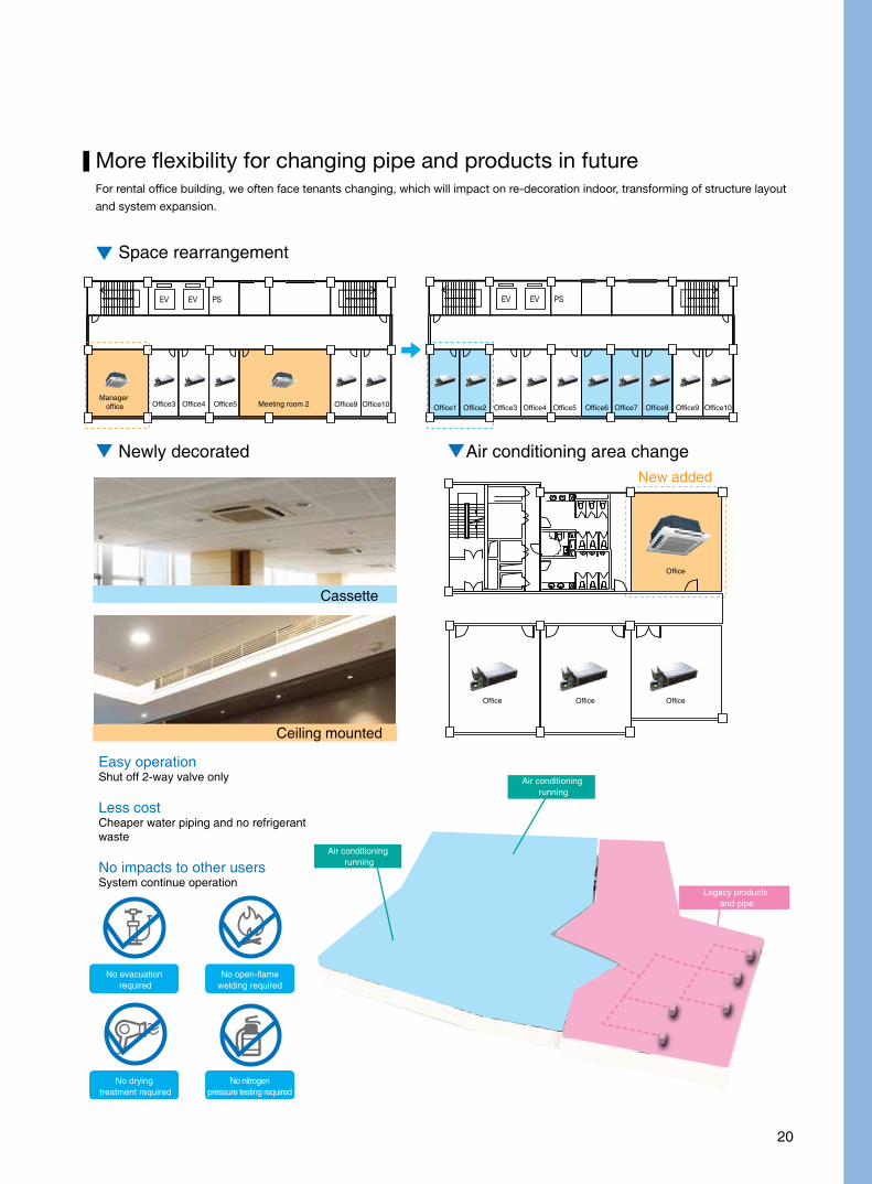
More flexibility for changing pipe and products in futureFor rental office building, we often face tenants changing, which will impact on re-decoration indoor, transforming of structure layout
and system expansion.
Space rearrangement
Newly decorated Air conditioning area change
Manager office Office3 Office1 Office2 Office3 Office4 Office5 Office6 Office7 Office8 Office9 Office10
Office
OfficeOfficeOffice
Office4 Office5 Meeting room 2 Office9 Office10
Cassette
Ceiling mounted
New added
Easy operationShut off 2-way valve only
Less costCheaper water piping and no refrigerant waste
No impacts to other usersSystem continue operation
No evacuation required
No open-flamewelding required
No drying treatment required
No nitrogenpressure testing required
Air conditioning running
Air conditioning running
Legacy products and pipe
21
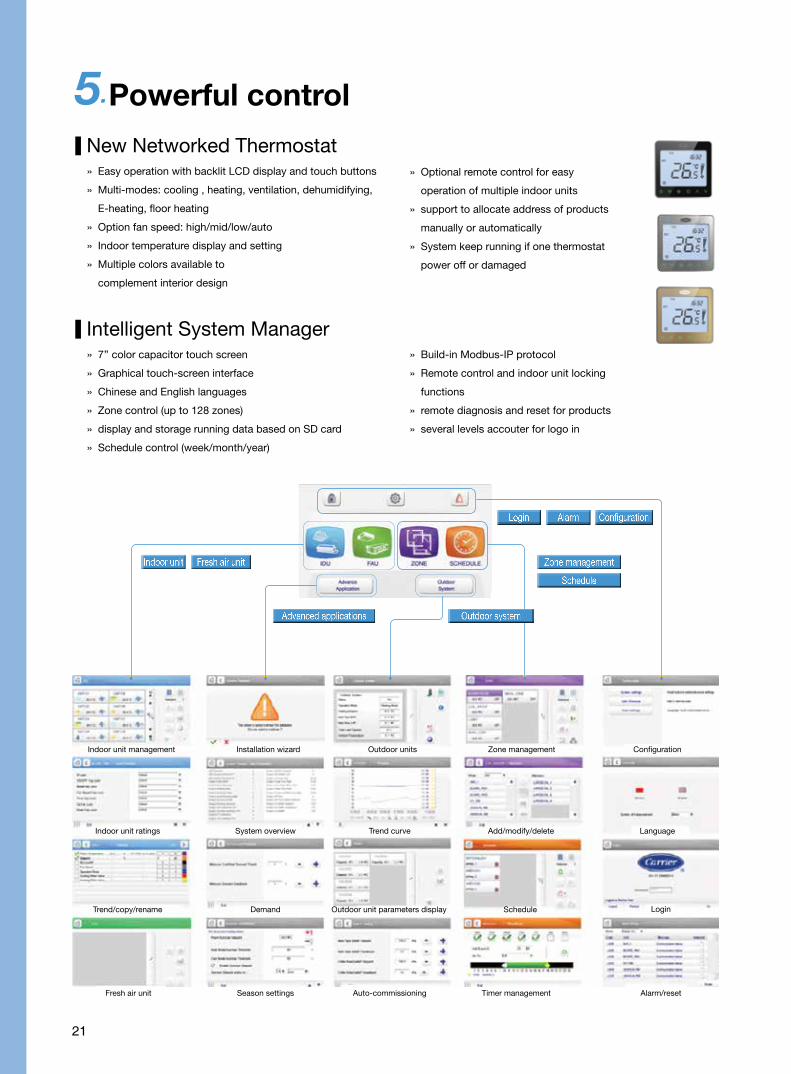
5.Powerful control
New Networked Thermostat » Easy operation with backlit LCD display and touch buttons
» Multi-modes: cooling , heating, ventilation, dehumidifying,
E-heating, floor heating
» Option fan speed: high/mid/low/auto
» Indoor temperature display and setting
» Multiple colors available to
complement interior design
» Optional remote control for easy
operation of multiple indoor units
» support to allocate address of products
manually or automatically
» System keep running if one thermostat
power off or damaged
Intelligent System Manager » 7’’ color capacitor touch screen
» Graphical touch-screen interface
» Chinese and English languages
» Zone control (up to 128 zones)
» display and storage running data based on SD card
» Schedule control (week/month/year)
» Build-in Modbus-IP protocol
» Remote control and indoor unit locking
functions
» remote diagnosis and reset for products
» several levels accouter for logo in
Indoor unit Fresh air unit
Login ConfigurationAlarm
Zone management
Schedule
Outdoor systemAdvanced applications
Indoor unit management Outdoor unitsInstallation wizard Zone management Configuration
Indoor unit ratings Trend curveSystem overview Add/modify/delete Language
Trend/copy/rename Outdoor unit parameters displayDemand Schedule Login
Fresh air unit Auto-commissioning Season settings Timer management Alarm/reset
22
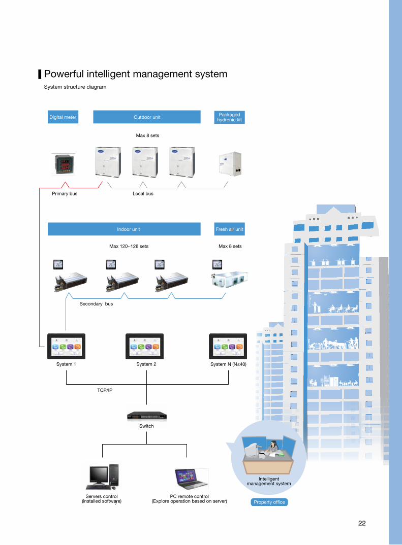
Digital meter Outdoor unit
Indoor unit Fresh air unit
Packagedhydronic kit
Max 8 sets
Primary bus Local bus
Max 120~128 sets
Secondary bus
System 1 System 2
TCP/IP
Servers control(installed software)
PC remote control(Explore operation based on server)
Intelligentmanagement system
Property office
System N (N≤40)
Max 8 sets
Switch
Powerful intelligent management systemSystem structure diagram

23
Shared power consumption accurate collection (Per 2s)
IDU capacity consumption accurate calculation (Per 10s)
Shared power
= HKT power + ODU powerTenant IDU Cap. Consumption
All IDU Cap. ConsumptionTenant Cap.
Consumption Rate=
Digital meter tou power price, measuring accuracy 0.05Hz
HKT
ODU
Power distribution
box 380V-3Ph-
50Hz Precision Temp SensorAccuracy ± 0.1℃
Precise energy metering
1
2
3 4
Accurately calculates each tenant's actual consumption of cooling and heating from power consumption dataand air-conditioning unit parameters
Energy Metering
Tenant power consumption transform to Tenant bill
Tenant cap. consumption transform to tenant power consumption (Per 10s)
Tenant power consumption /10s
Tenant power consumption /30m
= 10-second tenant power consumption
= x Tenant powerconsumption
Tenant Cap.consumption rate
Peak
pri
ce
Peak
pri
ce
Peak
pri
ce
Basi
c pr
ice
Valle
y p
rice
Valle
y p
rice
Basi
c pr
ice
Basi
c pr
ice
40 8 12 16 20 24hour
Power consumption indicators of a typical summer
air-conditioning system
Tenant Bill
Peak price bill+
Basic price bill +
Valley price bill
Discount
∑
Time A Tenant B Tenant C Tenant ….
... 0.27 0.9 1.11 0
14:00~14:30(2013/8/9) 0.46 0 1.58 0
14:30~15:00(2013/8/9) 0.39 0 1.77 0
15:00~15:30(2013/8/9) 0 0 1.09 0.44
15:30~16:00(2013/8/9) 0.41 0.29 0 0.27
... 0 0.44 0 0.53
AAA billing history
2012 total: 2500RMB, 2013 until now: 1400RMB
Period2013-62013-52013-42013-32013-22013-12012-122012-11
Peak120120120120120120120120
Low3030303030303030
Total150150150150150150150150
Electricity bills

24
Easy operation for admin team
» 1. Definition for detail information of tenants including combined unit cross system
Tenant information
Tenant name
Tenant number
Billing date
Carrier
295023
30th
Contact
Contact info.
Carrier
1567295023
Location
System
West of floor 5
System
» 2. Device information clear at a glance
Device selected: system 1-FAU3, system 1-FAU11, system 1-IDU2, system1-IDU16
Selected device
System selected Device selected
Key System Tenant Search

25
» 3. Billing report with multi-type solve potential worries
Monthly or daily tenant level report with accurate information
Item System Device Peak power
(kWH) Normal power
(kWH) Valley power
(kWH) Peak charge
(RMB) Normal charge
(RMB) Valley charge
(RMB) Power (kWH) Charge (RMB)
1 System5 IDU2 0.11 0.12 1.2 0.12 0.24 0.78 1.43 1.14
2 System5 IDU9 0.56 0.51 6.22 0.62 1.01 4.04 7.29 5.68
3 System5 IDU16 0.5 0.73 8.71 0.55 1.47 5.66 9.94 7.68
4 Sum of Device - 1.17 1.36 16.13 1.29 2.72 10.48 18.66 14.49
5 Sum of shared Device - 0.14 0.01 0.01 0.09 0.01 0.02 0.16 0.12
6 Sum of shared Device - 1.31 1.37 16.14 1.38 2.73 10.5 18.82 14.61
Tenant : Company Y
Billing cycle : 2017-08-01 - 2017-08-31
Detail IDU running record to solve potential challenge from tenant
Item Time Time Device ID Tenant Operation
60 8/4/2017 8:06:31 AM IDU16 0100504016 Company Y Turn on
86 8/4/2017 8:02:31 AM IDU16 0100504016 Company Y Turn off
112 8/4/2017 7:44:31 AM IDU16 0100504016 Company Y Turn on
142 8/4/2017 7:37:31 AM IDU16 0100504016 Company Y Turn off
164 8/4/2017 7:21:30 AM IDU16 0100504016 Company Y Turn on
193 8/4/2017 6:57:30 AM IDU16 0100504016 Company Y Turn off
251 8/3/2017 9:01:17 AM IDU16 0100504016 Company Y Turn on
263 8/3/2017 8:51:17 AM IDU16 0100504016 Company Y Turn off
274 8/3/2017 6:22:15 AM IDU16 0100504016 Company Y Turn on
287 8/3/2017 3:31:14 AM IDU16 0100504016 Company Y Turn off
Building level report for admin department, easy management without omission
Item TenantPeak power
(kWH)Normal power
(kWH) Valley power
(kWH) Peak charge
(RMB) Normal charge
(RMB) Valley charge
(RMB) Power (kWH) Charge (RMB)
1 Company A 1.03 1.52 18.08 1.13 3.04 11.75 20.63 15.92
2 Company Y 1.18 1.37 16.27 1.3 2.74 10.57 18.82 14.61
3 Company T 5.19 5.75 78.65 5.71 11.5 51.12 89.59 68.33
4 Sum 7.4 8.64 113 8.14 17.28 73.45 129.03 98.86
Building : B Tower
Billing cycle : 2017-08-01 - 2017-08-31

26
6.Overall safety and reliability
Integrated system, reliable performance and secured quality
» Components combined on site, compatibility concern and uncertain performance
» Lots of hydronic kits installed on site, more leakage points
» Failure shoot product by product, fussy and long cycle
» Design and test by system, no compatibility issue and reliable performance
» Packaged hydronic kits preinstalled, secured quality and less leakage points
» All alarm in one screen, quick and precise failure shoot
Fragmental system Integrated system
Conventional hydronic system
Carrier VWV system packaged hydronic kits
Conventional indoor unit
System failure shoot Carrier VWV system manager
Carrier VWV system indoor unit
Whose issue?Chillervendor
Pump vendor
Airsidevendor
Valvevendor
Controlvendor
Maybe others matter?
Gate valve
Check valve
Adapter
Differential pressure bypass valve
Expansion tank
Water pressure gauge
Thermometer
2-way motor valve
PI valve
Circulating water pump
Ball valve

27
Send andexecute order
Data collection
Calculatioin
Data collection
Calculatioin
Data collection
Calculatioin
Data collection
Calculatioin
Collect cutdoor unit status information
Collect hydronic module status information
Send andexecute order
Send andexecute order
Send andexecute order
Indoor unit
Open the indoor unit water valveSet indoor units to cleaning status
Open the fresh air handing unit water valveSet fresh air handing unit to cleaning status
Open the outdoor unit water valve Set thewaterchiller to cleaning status
Close the bypass valve and operates thepump at full speed to initlate cleaning
Heat recoveryFresh air handing unit
Computationprocessing
SystemManager
Outdoor unit
Hydronicmodule
Wider running envelop
Auto-Cleaning Process
Summer ambient design weather DB
35°C
Summer ambient design weather DB
32.2°C
Summer ambient design weather DB
34.4°C
Summer ambient design weather DB
32.8°C
Bangkok
Hanoi
Kuala LumpurSingapore
Jakarta
0°C-10°C-20°C
10°C20°C30°C40°C50°C
-10°CDB-10°CDB
48°CDB48°CDB
0°CDB0°CDB
Chilled water temperature range
5
18Cooling
48°CDB48°CDB
Cooling-only units30RBM040
Cooling-only units30RBV/RBH068
Beijing
Shanghai
Summer ambient design weather DB
37.2°C
Summer ambient design weather DB
37.2°C
Hong Kong
Guangzhou
Manila
Seoul
Taipei
» Auto-cleaning: The Carrier hydronic kit has an
auto-cleaning function that is used to clean
water pipes during commissioning and also at
regular intervals to prevent fouling and ruating.
» Automated pressure control: The system
automatically calculates and sets optimal
flow and lift without the need for operator
intervention.
*When it comes to first time installation or
restart system after long time power off, it
should do auto-cleaning process to ensure
product efficiency.
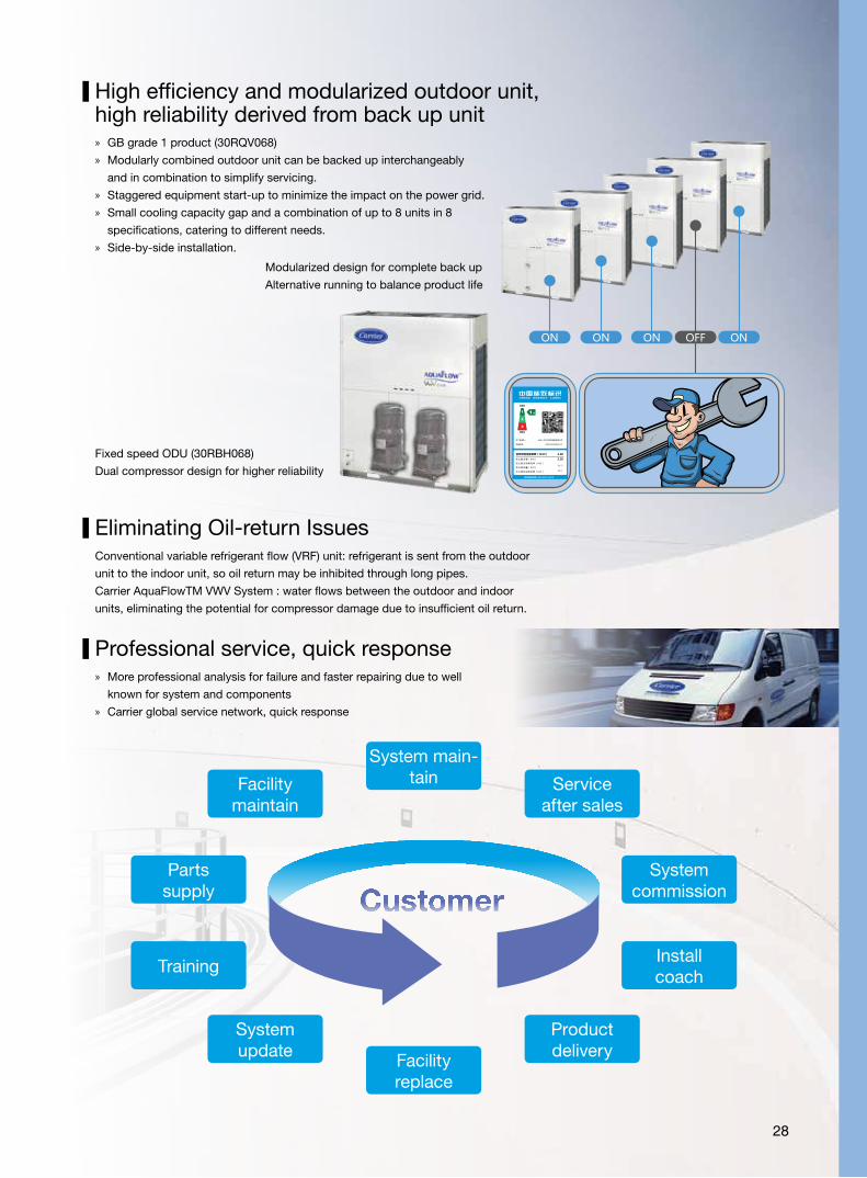
High efficiency and modularized outdoor unit,high reliability derived from back up unit
Modularized design for complete back up
Alternative running to balance product life
» GB grade 1 product (30RQV068)
» Modularly combined outdoor unit can be backed up interchangeably
and in combination to simplify servicing.
» Staggered equipment start-up to minimize the impact on the power grid.
» Small cooling capacity gap and a combination of up to 8 units in 8
specifications, catering to different needs.
» Side-by-side installation.
Fixed speed ODU (30RBH068)
Dual compressor design for higher reliability
Eliminating Oil-return Issues Conventional variable refrigerant flow (VRF) unit: refrigerant is sent from the outdoor
unit to the indoor unit, so oil return may be inhibited through long pipes.
Carrier AquaFlowTM VWV System : water flows between the outdoor and indoor
units, eliminating the potential for compressor damage due to insufficient oil return.
Facility maintain
Systemupdate
System main-tain
Facility replace
Service after sales
Product delivery
Systemcommission
Parts supply
Install coach
Training
Customer
» More professional analysis for failure and faster repairing due to well
known for system and components
» Carrier global service network, quick response
Professional service, quick response
28
29
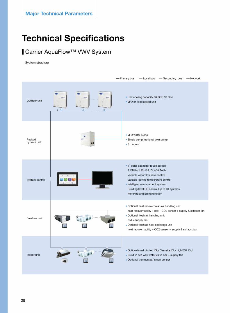
Major Technical Parameters
Carrier AquaFlow™ VWV System
System structure
Technical Specifications
Primary bus Local bus
Unit cooling capacity 66.5kw, 39.5kw
VFD or fixed speed unit
VFD water pump
Single pump, optional twin pump
5 models
7”color capacitor touch screen
8 ODUs/ 120-128 IDUs/ 8 FAUs
variable water flow rate control
variable leaving temperature control
Intelligent management system
Building level PC control (up to 40 systems)
Metering and billing function
Optional heat recover fresh air handling unit
heat recover facility + coil + CO2 sensor + supply & exhaust fan
Optional fresh air handling unit
coil + supply fan
Optional fresh air heat exchange unit
heat recover facility + CO2 sensor + supply & exhaust fan
Optional small ducted IDU/ Cassette IDU/ high ESP IDU
Build-in two way water valve coil + supply fan
Optional thermostat / smart sensor
Secondary bus Network
Outdoor unit
Packedhydronic kit
System control
Fresh air unit
Indoor unit
30
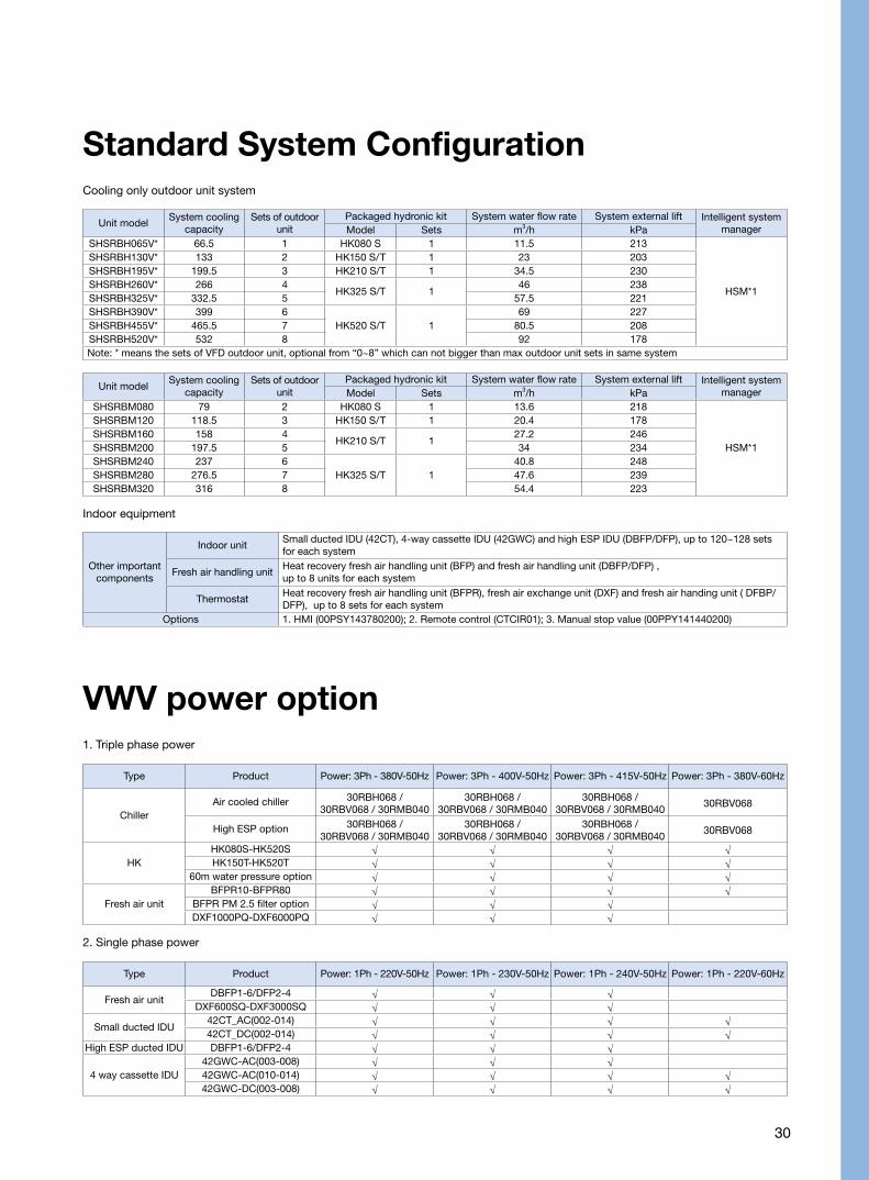
Other important components
Indoor unitSmall ducted IDU (42CT), 4-way cassette IDU (42GWC) and high ESP IDU (DBFP/DFP), up to 120~128 sets for each system
Fresh air handling unitHeat recovery fresh air handling unit (BFP) and fresh air handling unit (DBFP/DFP) , up to 8 units for each system
ThermostatHeat recovery fresh air handling unit (BFPR), fresh air exchange unit (DXF) and fresh air handing unit ( DFBP/DFP), up to 8 sets for each system
Options 1. HMI (00PSY143780200); 2. Remote control (CTCIR01); 3. Manual stop value (00PPY141440200)
Indoor equipment
Standard System Configuration
Unit modelSystem cooling
capacitySets of outdoor
unitPackaged hydronic kit System water flow rate System external lift Intelligent system
managerModel Sets m3/h kPaSHSRBH065V* 66.5 1 HK080 S 1 11.5 213
HSM*1
SHSRBH130V* 133 2 HK150 S/T 1 23 203SHSRBH195V* 199.5 3 HK210 S/T 1 34.5 230SHSRBH260V* 266 4
HK325 S/T 146 238
SHSRBH325V* 332.5 5 57.5 221SHSRBH390V* 399 6
HK520 S/T 169 227
SHSRBH455V* 465.5 7 80.5 208SHSRBH520V* 532 8 92 178Note: * means the sets of VFD outdoor unit, optional from “0~8” which can not bigger than max outdoor unit sets in same system
Unit modelSystem cooling
capacitySets of outdoor
unitPackaged hydronic kit System water flow rate System external lift Intelligent system
managerModel Sets m3/h kPaSHSRBM080 79 2 HK080 S 1 13.6 218
HSM*1
SHSRBM120 118.5 3 HK150 S/T 1 20.4 178SHSRBM160 158 4
HK210 S/T 127.2 246
SHSRBM200 197.5 5 34 234SHSRBM240 237 6
HK325 S/T 140.8 248
SHSRBM280 276.5 7 47.6 239SHSRBM320 316 8 54.4 223
Cooling only outdoor unit system
VWV power option
Type Product Power: 3Ph - 380V-50Hz Power: 3Ph - 400V-50Hz Power: 3Ph - 415V-50Hz Power: 3Ph - 380V-60Hz
ChillerAir cooled chiller 30RBH068 /
30RBV068 / 30RMB04030RBH068 /
30RBV068 / 30RMB04030RBH068 /
30RBV068 / 30RMB04030RBV068
High ESP option 30RBH068 / 30RBV068 / 30RMB040
30RBH068 / 30RBV068 / 30RMB040
30RBH068 / 30RBV068 / 30RMB040
30RBV068
HKHK080S-HK520S √ √ √ √HK150T-HK520T √ √ √ √
60m water pressure option √ √ √ √
Fresh air unitBFPR10-BFPR80 √ √ √ √
BFPR PM 2.5 filter option √ √ √DXF1000PQ-DXF6000PQ √ √ √
1. Triple phase power
Type Product Power: 1Ph - 220V-50Hz Power: 1Ph - 230V-50Hz Power: 1Ph - 240V-50Hz Power: 1Ph - 220V-60Hz
Fresh air unitDBFP1-6/DFP2-4 √ √ √
DXF600SQ-DXF3000SQ √ √ √
Small ducted IDU42CT_AC(002-014) √ √ √ √42CT_DC(002-014) √ √ √ √
High ESP ducted IDU DBFP1-6/DFP2-4 √ √ √
4 way cassette IDU42GWC-AC(003-008) √ √ √42GWC-AC(010-014) √ √ √ √42GWC-DC(003-008) √ √ √ √
2. Single phase power

31
Outdoor unit
Packaged hydronic kit
Model HK080S0100001THC HK150S1100001THC HK210S1100001THC HK325S1100001THC HK520S1100001YLCSystem cooling capacity range 39.5-79kw 39.5-133kw 39.5-199.5kwC 39.5-332.5kw 39.5-532kwNominal flow and hydronic kitexternal lift 13.6m3/h | 250KPa 23m3/h | 270KPa 34.5m3/h | 297KPa 57.5m3/h | 288KPa 92m3/h | 245KPa
Major componentsVFD pump, differential pressure bypass valve, water replenishing valve, expansion tank
(excluded if system endure pressure>20m) , automatic relief valve, filter, etc.Dimension (L*W*H, mm) 820x420x998 1312×608×1186 1277×700×1186Pump sets 1Nominal diameter of joint DN 60 DN 65 DN 80 DN 100 DN 100Bypass pipe connector DN 42 DN 50 DN 50 DN 65 DN 65Joint connection type ClampExpansion tank capacity 12 L 35 L 50 L 80 L 80 LPower supply 380/400V-3Ph-50Hz; 380V-3Ph-60HzRated power 1.85kW 4kW 5.5kW 7.5kW 11kWMaximum operating current 5 A 8.2 A 10.9 A 14.5 A 21 ANet weight (kg) 130 229 262 288 369
Model HK150T0100001THC HK210T0100001THC HK325T0100001THC HK520T0100001YLCSystem cooling capacity range 39.5-133kw 39.5-199.5kw 39.5-332.5kw 39.5-532kwNominal flow and hydronic kitexternal lift 23m3/h | 270KPa 34.5m3/h | 297KPa 57.5m3/h | 288KPa 92m3/h | 245KPa
Major componentsVFD pump, differential pressure bypass valve, water replenishing valve, expansion tank
(excluded if system endure pressure>20m) , automatic relief valve, filter, etc.Dimension (L*W*H, mm) 1404×798×1186 1462×878×1186 1462×918×1186Pump sets 2 (100% back up)Nominal diameter of joint DN 65 DN 80 DN 100 DN 100Bypass pipe connector DN 50 DN 50 DN 65 DN 65Joint connection type ClampExpansion tank capacity 35 L 50 L 80 L 80 LPower supply 380/400V-3Ph-50Hz; 380V-3Ph-60HzRated power 4kW 5.5kW 7.5kW 11kWMaximum operating current 7.7 A 10.2 A 13.7 A 22ANet weight (kg) 270 348 411 546
Singlea pump
Twin pump
Model 30RBV068 30RBH068 30RBM040Nominal Cooling Capacity kW 66.5 66.5 39.2EER* (1) kW/kW 4.10 3.70 3.77IPLV(China GB) kW/kW 4.80 3.90 4.12Refrigerant R410A R410A Charging kg 12.5 10.5 12Compressor VFD hermetic scroll compressor Hermetic scroll compressor Hermetic scroll compressor Quantity set 1 2 2 Capacity control step stepless 2 2 Min. capacity % 33 50 50Control System SPIC6 SPIC6
Condenser Grooved copper tubes and aluminum finsGrooved copper tubes and
aluminum fins Type of fan Axial fan Axial fan Quantity of Fan 2 2 1 Fan Speed RPM 150~1000 950 720Evaporator Brazed plate heat exchanger Brazed plate heat exchanger Water volume l 5.78 5.25 4.31 Nominal water flow M3/h 11.5 11.5 6.8 Nominal water-side pressure drop kPa 67 67 63 Max. water-side pressure kPa 1000 1000 1000 Inlet/Outlet Pipe Victaulic male thread Nominal Diameter DN 50 50 40Electrical Data
Nominal Power Supply 380V/415V-3Ph-50Hz380V-3Ph-
60Hz380V/415V-3Ph-50Hz
380V/400V-3Ph-50Hz230V-3Ph-60Hz
Nominal unit current A 44.1 48.1 36.5Unit length mm 1585 1585 1240Unit width mm 796 796 860Unit height mm 1811 1811 1820operation weight kg 542 489 360Noise level dB(A) 66 66 64NPLV (2) kW/kW 7.45 6.00 6.69IPLV (ARI) kW/kW 6.00 4.80 5.18EER kW/kW 3.35 3.18 3.29High ESP option Total Power Input kw 21.3 21.4
Non-standard option Total Power Input A 36 41 Max extend pressure Pa 120 120 Max fan speed rpm 1450 1360
Outdoor system paerformance data
(1) VWV EER condition: Indoor 27°C (DB)/19°C(WB) , Outdoor: 35°C(2) VWV NPLV: 100% load Indoor 27°C(DB)/19°C(WB) , Outdoor: 35°C; 75% load Indoor 27°C(DB)/19°C(WB) , Outdoor: 26.7°C; 50% load Indoor 27°C(DB)/19C(WB) , Outdoor:18.3°C; 25% load Indoor 27°C(DB)/19°C(WB) , Outdoor: 12.8°C
Note: 1. Please refer to Design, Installation and Commissioning Manual for Aqua-flow™ VWV System for nomenclature and detailed specifications.2. The standard working pressure of packaged VFD hydronic kits (HK 080-520) is 20 meter ; for HK150-520 Carrier can offer 60 meter option without expansion tank, which should be installed on the top of system lop and is purchased by customer or is supplied by Carrier.
32
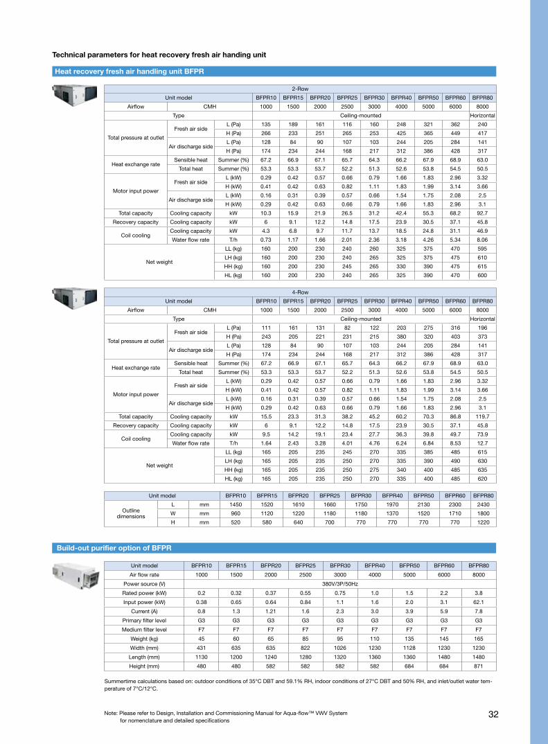
Heat recovery fresh air handling unit BFPR
Technical parameters for heat recovery fresh air handing unit
2-Row
Unit model BFPR10 BFPR15 BFPR20 BFPR25 BFPR30 BFPR40 BFPR50 BFPR60 BFPR80
Airflow CMH 1000 1500 2000 2500 3000 4000 5000 6000 8000
Type Ceiling-mounted Horizontal
Total pressure at outlet
Fresh air sideL (Pa) 135 189 161 116 160 248 321 362 240
H (Pa) 266 233 251 265 253 425 365 449 417
Air discharge side L (Pa) 128 84 90 107 103 244 205 284 141
H (Pa) 174 234 244 168 217 312 386 428 317
Heat exchange rateSensible heat Summer (%) 67.2 66.9 67.1 65.7 64.3 66.2 67.9 68.9 63.0
Total heat Summer (%) 53.3 53.3 53.7 52.2 51.3 52.6 53.8 54.5 50.5
Motor input power
Fresh air side L (kW) 0.29 0.42 0.57 0.66 0.79 1.66 1.83 2.96 3.32
H (kW) 0.41 0.42 0.63 0.82 1.11 1.83 1.99 3.14 3.66
Air discharge side L (kW) 0.16 0.31 0.39 0.57 0.66 1.54 1.75 2.08 2.5
H (kW) 0.29 0.42 0.63 0.66 0.79 1.66 1.83 2.96 3.1
Total capacity Cooling capacity kW 10.3 15.9 21.9 26.5 31.2 42.4 55.3 68.2 92.7
Recovery capacity Cooling capacity kW 6 9.1 12.2 14.8 17.5 23.9 30.5 37.1 45.8
Coil coolingCooling capacity kW 4.3 6.8 9.7 11.7 13.7 18.5 24.8 31.1 46.9
Water flow rate T/h 0.73 1.17 1.66 2.01 2.36 3.18 4.26 5.34 8.06
Net weight
LL (kg) 160 200 230 240 260 325 375 470 595
LH (kg) 160 200 230 240 265 325 375 475 610
HH (kg) 160 200 230 245 265 330 390 475 615
HL (kg) 160 200 230 240 265 325 390 470 600
4-Row
Unit model BFPR10 BFPR15 BFPR20 BFPR25 BFPR30 BFPR40 BFPR50 BFPR60 BFPR80
Airflow CMH 1000 1500 2000 2500 3000 4000 5000 6000 8000
Type Ceiling-mounted Horizontal
Total pressure at outlet
Fresh air side L (Pa) 111 161 131 82 122 203 275 316 196
H (Pa) 243 205 221 231 215 380 320 403 373
Air discharge side L (Pa) 128 84 90 107 103 244 205 284 141
H (Pa) 174 234 244 168 217 312 386 428 317
Heat exchange rateSensible heat Summer (%) 67.2 66.9 67.1 65.7 64.3 66.2 67.9 68.9 63.0
Total heat Summer (%) 53.3 53.3 53.7 52.2 51.3 52.6 53.8 54.5 50.5
Motor input power
Fresh air side L (kW) 0.29 0.42 0.57 0.66 0.79 1.66 1.83 2.96 3.32
H (kW) 0.41 0.42 0.57 0.82 1.11 1.83 1.99 3.14 3.66
Air discharge side L (kW) 0.16 0.31 0.39 0.57 0.66 1.54 1.75 2.08 2.5
H (kW) 0.29 0.42 0.63 0.66 0.79 1.66 1.83 2.96 3.1
Total capacity Cooling capacity kW 15.5 23.3 31.3 38.2 45.2 60.2 70.3 86.8 119.7
Recovery capacity Cooling capacity kW 6 9.1 12.2 14.8 17.5 23.9 30.5 37.1 45.8
Coil coolingCooling capacity kW 9.5 14.2 19.1 23.4 27.7 36.3 39.8 49.7 73.9
Water flow rate T/h 1.64 2.43 3.28 4.01 4.76 6.24 6.84 8.53 12.7
Net weight
LL (kg) 165 205 235 245 270 335 385 485 615
LH (kg) 165 205 235 250 270 335 390 490 630
HH (kg) 165 205 235 250 275 340 400 485 635
HL (kg) 165 205 235 250 270 335 400 485 620
Unit model BFPR10 BFPR15 BFPR20 BFPR25 BFPR30 BFPR40 BFPR50 BFPR60 BFPR80
Outline dimensions
L mm 1450 1520 1610 1660 1750 1970 2130 2300 2430
W mm 960 1120 1220 1180 1180 1370 1520 1710 1800
H mm 520 580 640 700 770 770 770 770 1220
Summertime calculations based on: outdoor conditions of 35°C DBT and 59.1% RH, indoor conditions of 27°C DBT and 50% RH, and inlet/outlet water tem-perature of 7°C/12°C.
Build-out purifier option of BFPR
Unit model BFPR10 BFPR15 BFPR20 BFPR25 BFPR30 BFPR40 BFPR50 BFPR60 BFPR80
Air flow rate 1000 1500 2000 2500 3000 4000 5000 6000 8000
Power source (V) 380V/3P/50Hz
Rated power (kW) 0.2 0.32 0.37 0.55 0.75 1.0 1.5 2.2 3.8
Input power (kW) 0.38 0.65 0.64 0.84 1.1 1.6 2.0 3.1 62.1
Current (A) 0.8 1.3 1.21 1.6 2.3 3.0 3.9 5.9 7.8
Primary filter level G3 G3 G3 G3 G3 G3 G3 G3 G3
Medium filter level F7 F7 F7 F7 F7 F7 F7 F7 F7
Weight (kg) 45 60 65 85 95 110 135 145 165
Width (mm) 431 635 635 822 1026 1230 1128 1230 1230
Length (mm) 1130 1200 1240 1280 1320 1360 1360 1480 1480
Height (mm) 480 480 582 582 582 582 684 684 871
Note: Please refer to Design, Installation and Commissioning Manual for Aqua-flow™ VWV Systemfor nomenclature and detailed specifications

33
Fresh air unit performance data
Note: 1. Connect position- left connect, when it comes to face inlet vent and the coil connector is on the left of AHU; opposition is right connect.2. Digital number 8 means external pressure ( H- high, L – low); digital number 9 means cooling capacity (3- standard capacity, 5- high capacity).3. Input power means total input power by unit level.
Rated condition: Cooling- entering air temperature of 35°C DBT and 28°C WBT; entering water temperature of 7°C.
Fresh air handling unit (suspending AHU)
Model Air flow rate(m3/h)
Width (unit + control box) ×length×height
Motor kW-pole
Input power (kW)
Fan/motor
setsESP (Pa) TP (Pa)
Cooling capacity
(kW)
Chilled water flow
rare(l/s)
Cooling WDP (Kpa)
Unit weight
(kg)
Noise level
(dB(A))
DBFP010L3X1000 (680+154)×986×380
0.175-4 0.341/1
130 23412.6 0.6 53.4
46 52
DBFP010H3X 0.275-4 0.44 220 321 47 55
DBFP015L3X1500 (875+154)×986×380
0.275-4 0.441/1
115 22719 0.9 50.4
53 55
DBFP015H3X 0.425-4 0.79 215 320 55 58
DBFP020L3X2000 (872+150)×986×500
0.35-4 0.631/1
195 30025.3 1.2 53.7
63 56.5
DBFP020H3X 0.55-4 0.84 280 381 64 59.5
DBFP025L3X2500 (1018+150)×986×500
0.45-4 0.831/1
165 26531 1.5 53.2
67 60
DBFP025H3X 0.55-4 0.84 250 356 70 61
DBFP030L3X3000 (1166+150)×986×500
0.65-4 1.091/1
120 25038.7 1.9 87.9
75 62
DBFP030H3X 0.65-4 1.09 200 330 75 62
DBFP040L3X4000 (1458+150)×986×500
0.35-4X2 0.63X22/2
185 30053.4 2.6 86.8
108 58
DBFP040H3X 0.55-4X2 0.84X2 250 381 112 61
DBFP050L3X5000 (1752+150)×986×500
0.45-4X2 0.83X22/2
160 26564.1 3.1 81.7
123 60.5
DBFP050H3X 0.55-4X2 0.84X2 250 356 127 61.5
DBFP060L3X6000 (2044+150)×986×500
0.65-4X2 1.09X22/2
150 25078.1 3.7 104
134 62.5
DBFP060H3X 0.65-4X2 1.09X2 220 330 138 63.5
DBFP010L5X1000 (680+150)×986×380
0.175-4 0.341/1
90 23415.8 0.8 44
49 52
DBFP010H5X 0.275-4 0.44 175 321 50 55
DBFP015L5X1500 (875+150)×986×380
0.275-4 0.441/1
70 22724 1.2 57.7
56 55
DBFP015H5X 0.425-4 0.79 170 320 58 58
DBFP020L5X2000 (872+150)×986×500
0.35-4 0.631/1
160 30031.4 1.5 46.8
67 56.5
DBFP020H5X 0.55-4 0.84 230 381 68 59.5
DBFP025L5X2500 (1018+150)×986×500
0.45-4 0.831/1
140 26539.7 1.9 58.9
75 60
DBFP025H5X 0.55-4 0.84 210 356 75 61
DBFP030L5X3000 (1166+150)×986×500
0.65-4 1.091/1
85 25049.5 2.4 101.1
81 62
DBFP030H5X 0.65-4 1.09 150 330 81 62
DBFP040L5X4000 (1458+150)×986×500
0.35-4X2 0.63X22/2
150 30065.5 3.1 81.6
115 58
DBFP040H5X 0.55-4X2 0.84X2 215 381 119 61
DBFP050L5X5000 (1752+150)×986×500
0.45-4X2 0.83X22/2
120 26580.4 3.8 76.5
129 60.5
DBFP050H5X 0.55-4X2 0.84X2 210 356 133 61.5
DBFP060L5X6000 (2044+150)×986×500
0.65-4X2 1.09X22/2
115 25098.7 4.7 109.9
142 62.5
DBFP060H5X 0.65-4X2 1.09X2 185 330 146 63.5
Note: 1. Unit capacity refer to DBFP(X) w/ same air flow rate.2. Digital number 7 means external pressure ( H- high, L – low).3. Input power means total input power by unit level.
Model Width (unit + control box) a*length*height
Air flow rate(m3/h) ESP (Pa) TP (Pa) Input power (kW) Unit weight (kg) Noise level (dB(A)
DFP020LX(1018+154)×986×380
2000 95 297 0.79×1 65 58.2
DFP020HX 2000 65 297 0.79×1 67 58.2
DFP030LX(1458+154)×986×380
3000 130 320 0.79×2 92 58.5
DFP030HX 3000 100 320 0.79×2 95 58.5
DFP040LX(1752+154)×986×380
4000 85 297 0.79×2 105 60
DFP040HX 4000 55 297 0.79×2 109 60
Note: Please refer to Design, Installation and Commissioning Manual for Aqua-flow™ VWV Systemfor nomenclature and detailed specifications

34
2 rows coil unit 3 rows coil unit 4 rows coil unit
Content Model 002 003 004 005 006 007 008 002 003 004 005 006 007 008 010 012 014 002 003 004 005 006 007 008 010 012 014
Air flow rate(CMH)
High 340 510 680 850 1020 1190 1360 340 510 680 850 1020 1190 1360 1700 2040 2380 340 510 680 850 1020 1190 1360 1700 2040 2380
Mid 270 400 530 670 800 940 1070 270 400 530 670 800 940 1070 1340 1610 1890 270 400 530 670 800 940 1070 1340 1610 1890
Low 200 300 400 500 600 700 800 200 300 400 500 600 700 800 1000 1200 1400 200 300 400 500 600 700 800 1000 1200 1400
Coolingcapacity
(W)
Total 1900 2950 3600 4500 5400 6300 7200 2300 3350 4300 5250 6300 7250 8450 9850 11500 13000 2660 3690 4680 5600 6900 7780 9300 11220 13000 15200
Sensible 1440 2190 2770 3450 4130 4790 5520 1630 2390 3110 3810 4580 5280 6140 7300 8610 9830 1810 2560 3300 4010 4890 5560 6550 7980 9400 10960
AC unit input power (W)
12Pa 34 45 58 75 94 112 130 34 45 58 75 94 112 130 152 180 228 34 45 58 75 94 112 130 152 180 228
30Pa 41 55 72 83 102 120 140 41 55 72 83 102 120 140 172 210 250 41 55 72 83 102 120 140 172 210 250
50Pa 44 63 78 95 108 130 155 44 63 78 95 108 130 155 185 225 298 44 63 78 95 108 130 155 185 225 298
DC unit input power
(W)
12 Pa 14 19 27 37 46 64 62 14 19 27 37 46 64 62 88 110 139 14 19 27 37 46 64 62 88 110 139
30 Pa 19 26 35 46 57 73 77 19 26 35 46 57 73 77 101 130 166 19 26 35 46 57 73 77 101 130 166
50 Pa 27 35 45 60 70 90 98 27 35 45 60 70 90 98 125 158 195 27 35 45 60 70 90 98 125 158 195
Noise (dB(A)
12Pa 34 37 39.5 42 44 47 44 34 37 39.5 42 44 47 44 47 49 51 34 37 39.5 42 44 47 44 47 49 51
30Pa 37.5 39.5 42 44 45.5 48 46.5 37.5 39.5 42 44 45.5 48 46.5 50 50.5 52.5 37.5 39.5 42 44 45.5 48 46.5 50 50.5 52.5
50Pa 41.5 43 44 47 47 49 48.5 41.5 43 44 47 47 49 48.5 51 51.5 54 41.5 43 44 47 47 49 48.5 51 51.5 54
Water flow rate (l/min) 5.4 8.5 10.3 12.9 15.5 18.1 20.6 6.6 9.5 12.3 15.0 18.2 20.8 24.2 28.2 33.0 37.3 7.6 10.6 13.4 16.1 19.8 22.3 26.7 32.2 37.3 43.6
Water pressure drop (kPa) 12 28 20 28 30 36 30 22 24 22 30 32 35 33 40 40 45 20 18 18 18 22 30 26 36 35 48
Fan type Centrifugal, forward multi-blade
Motor type Permanent Split Capacitor
CoilRow 2 3 4
Working pressure 1.6 MPa
Connecting In-Out 3/4” FPT
Drain Connection 3/4” MPT
Net weigh (kg) 15.8 17.8 18.7 20.5 22.7 23.7 30.3 16.8 18.8 19.7 21.5 23.7 24.7 31.5 34.4 37.8 40.8 17.3 19.3 20.2 22.2 24.4 25.4 32.3 35.2 38.8 41.6
42CT
Content Model 003 004 005 006 008 010 012 014
Air flow rate(CMH)
High 540 680 850 1020 1360 1700 2040 2380
Mid 430 540 680 810 1080 1300 1570 1830
Low 350 440 550 660 880 1010 1210 1410
Cooling capacity W 3200 3700 5800 6600 8700 9100 10900 12600
AC unit input power W 35 48 50 60 102 150 160 190
DC unit input power W 14 25 22 28 50 / / /
Current (AC) A 0.18 0.24 0.25 0.3 0.48 0.70 0.74 0.88
Noise dB (A) 35/32/29 40/35/31 35/31/27 37/33/29 45/40/35 48/45/41 50/47/44 52/49/46
Panel dimension (mm) 720*720 960*960 1050*1050
Unit dimension (mm) 575*575*298 825*825*298 930*930*290
Panel weight (kg) 2.5 2.5 5.0 5.0 5.0 6.5 6.5 6.5
Unit weight (kg) 17.0 17.0 37.5 37.5 40.1 42 42 42
Indoor unit performance data
Note: 1. The performance data in the table is measured at a high airflow rate with corresponding residual pressure.2. Cooling capacity is measured at an inlet cold water temperature of 7°C, inlet air temperature of 27°C DBT/19.5°C WBT, and inlet-outlet temperature difference of 5°C.3. Noise level is measured at a location 1m from both the front and bottom of the unit in a semi-anechoic room.4. The water pressure drop shown in table excludes 2 way water valve (kv=3.0)5. Additional input power for 2 way water valve and control board is 10W.
Note: 1. The performance data in the table is measured at a high airflow rate.2. Cooling capacity is measured with an inlet cold water temperature of 7°C, inlet air temperature of 27°C DBT and 19.5°C WBT, and inlet-outlet temperature difference of 5°C. 3. Noise level is measured at a location 1m from both the front and bottom of the unit in a semi-anechoic room.
Small ducted indoor unit
4 way cassette indoor unit (42GWC)
Note: Please refer to Design, Installation and Commissioning Manual for Aqua-flow™ VWV Systemfor nomenclature and detailed specifications
35 Note: Please refer to Design, Installation and Commissioning Manual for Aqua-flow™ VWV Systemfor nomenclature and detailed specifications
Model Air flow rate (CMH)
Width (unit + control box) *length*height
Input power (KW) ESP (Pa) TP (Pa) Cooling
capacity (kw)Cooling WDP
(Kpa)Unit weight
(kg)Noise level
(dB(A))
DBFP010L3R1000 (680+154)×986×380
0.34 130 2345.0 10.1
46 52DBFP010H3R 0.44 220 321 47 55DBFP015L3R
1500 (875+154)×986×3800.44 115 227
7.8 14.553 55
DBFP015H3R 0.79 215 320 55 58DBFP020L3R
2000 (872+150)×986×5000.63 195 300
11.1 22.063 56.5
DBFP020H3R 0.84 280 381 64 59.5DBFP025L3R
2500 (1018+150)×986×5000.83 165 265
13.9 25.867 60
DBFP025H3R 0.84 250 356 70 61DBFP030L3R
3000 (1166+150)×986×5001.09 120 250
16.9 30.075 62
DBFP030H3R 1.09 200 330 75 62DBFP040L3R
4000 (1458+150)×986×5000.63X2 185 300
22.1 28.3108 58
DBFP040H3R 0.84X2 250 381 112 61DBFP050L3R
5000 (1752+150)×986×5000.83X2 160 265
28.9 43.8123 60.5
DBFP050H3R 0.84X2 250 356 127 61.5DBFP060L3R
6000 (2044+150)×986×5001.09X2 150 250
34.5 57.2134 62.5
DBFP060H3R 1.09X2 220 330 138 63.5DBFP010L5R
1000 (680+150)×986×3800.34 90 234
6.4 8.349 52
DBFP010H5R 0.44 175 321 50 55DBFP015L5R
1500 (875+150)×986×3800.44 70 227
10.0 10.956 55
DBFP015H5R 0.79 170 320 58 58DBFP020L5R
2000 (872+150)×986×5000.63 160 300
12.7 8.667 56.5
DBFP020H5R 0.84 230 381 68 59.5DBFP025L5R
2500 (1018+150)×986×5000.83 140 265
16.1 18.875 60
DBFP025H5R 0.84 210 356 75 61DBFP030L5R
3000 (1166+150)×986×5001.09 85 250
20.2 28.381 62
DBFP030H5R 1.09 150 330 81 62DBFP040L5R
4000 (1458+150)×986×5000.63X2 150 300
27.2 31.3115 58
DBFP040H5R 0.84X2 215 381 119 61DBFP050L5R
5000 (1752+150)×986×5000.83X2 120 265
37.0 61.5129 60.5
DBFP050H5R 0.84X2 210 356 133 61.5DBFP060L5R
6000 (2044+150)×986×5001.09X2 115 250
44.0 66.0142 62.5
DBFP060H5R 1.09X2 185 330 146 63.5
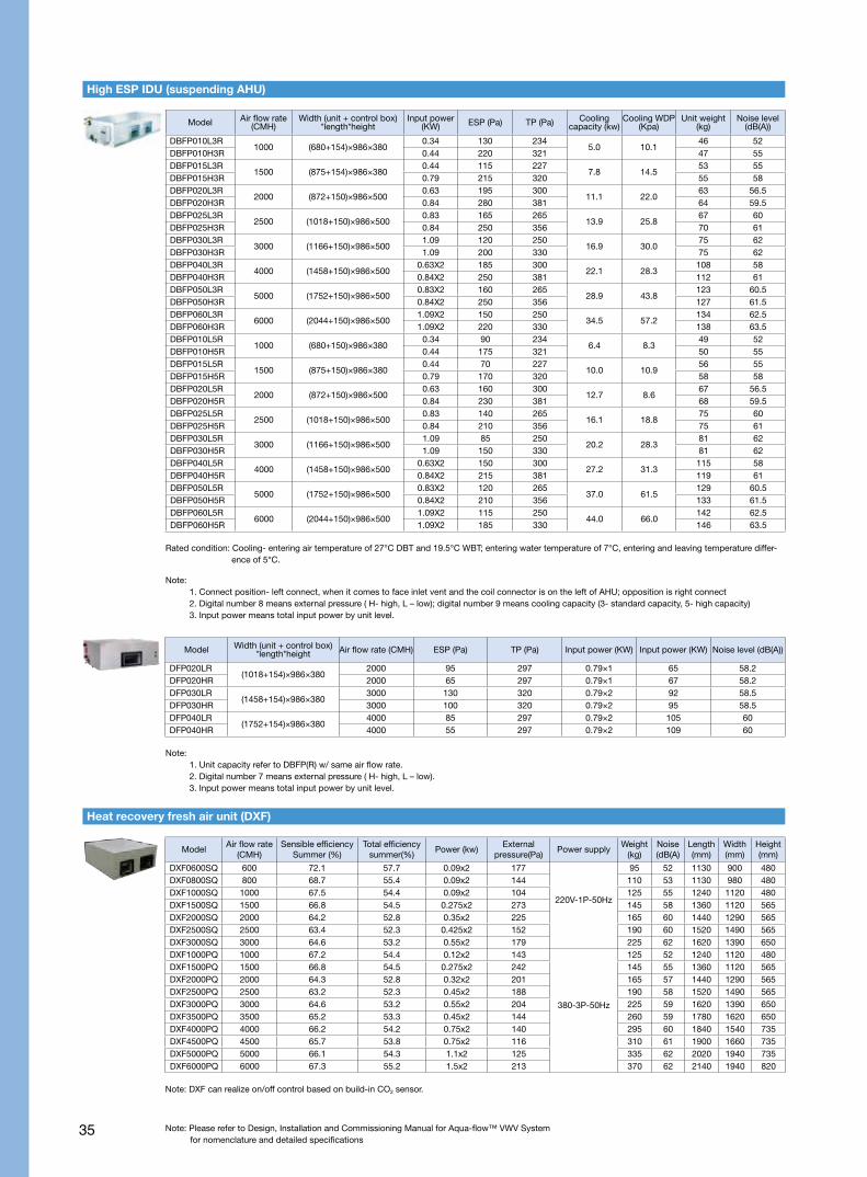
High ESP IDU (suspending AHU)
Model Air flow rate
(CMH)Sensible efficiency
Summer (%)Total efficiency
summer(%)Power (kw)
External pressure(Pa)
Power supplyWeight
(kg)Noise(dB(A)
Length(mm)
Width(mm)
Height(mm)
DXF0600SQ 600 72.1 57.7 0.09x2 177
220V-1P-50Hz
95 52 1130 900 480DXF0800SQ 800 68.7 55.4 0.09x2 144 110 53 1130 980 480DXF1000SQ 1000 67.5 54.4 0.09x2 104 125 55 1240 1120 480DXF1500SQ 1500 66.8 54.5 0.275x2 273 145 58 1360 1120 565DXF2000SQ 2000 64.2 52.8 0.35x2 225 165 60 1440 1290 565DXF2500SQ 2500 63.4 52.3 0.425x2 152 190 60 1520 1490 565DXF3000SQ 3000 64.6 53.2 0.55x2 179 225 62 1620 1390 650DXF1000PQ 1000 67.2 54.4 0.12x2 143
380-3P-50Hz
125 52 1240 1120 480DXF1500PQ 1500 66.8 54.5 0.275x2 242 145 55 1360 1120 565DXF2000PQ 2000 64.3 52.8 0.32x2 201 165 57 1440 1290 565DXF2500PQ 2500 63.2 52.3 0.45x2 188 190 58 1520 1490 565DXF3000PQ 3000 64.6 53.2 0.55x2 204 225 59 1620 1390 650DXF3500PQ 3500 65.2 53.3 0.45x2 144 260 59 1780 1620 650DXF4000PQ 4000 66.2 54.2 0.75x2 140 295 60 1840 1540 735DXF4500PQ 4500 65.7 53.8 0.75x2 116 310 61 1900 1660 735DXF5000PQ 5000 66.1 54.3 1.1x2 125 335 62 2020 1940 735DXF6000PQ 6000 67.3 55.2 1.5x2 213 370 62 2140 1940 820
Heat recovery fresh air unit (DXF)
Rated condition: Cooling- entering air temperature of 27°C DBT and 19.5°C WBT; entering water temperature of 7°C, entering and leaving temperature differ-ence of 5°C.
Note: 1. Unit capacity refer to DBFP(R) w/ same air flow rate.2. Digital number 7 means external pressure ( H- high, L – low).3. Input power means total input power by unit level.
Model Width (unit + control box) *length*height Air flow rate (CMH) ESP (Pa) TP (Pa) Input power (KW) Input power (KW) Noise level (dB(A))
DFP020LR(1018+154)×986×380
2000 95 297 0.79×1 65 58.2DFP020HR 2000 65 297 0.79×1 67 58.2DFP030LR
(1458+154)×986×3803000 130 320 0.79×2 92 58.5
DFP030HR 3000 100 320 0.79×2 95 58.5DFP040LR
(1752+154)×986×3804000 85 297 0.79×2 105 60
DFP040HR 4000 55 297 0.79×2 109 60
Note: DXF can realize on/off control based on build-in CO2 sensor.
Note: 1. Connect position- left connect, when it comes to face inlet vent and the coil connector is on the left of AHU; opposition is right connect2. Digital number 8 means external pressure ( H- high, L – low); digital number 9 means cooling capacity (3- standard capacity, 5- high capacity)3. Input power means total input power by unit level.

36Note: Please refer to Design, Installation and Commissioning Manual for Aqua-flow™ VWV Systemfor nomenclature and detailed specifications
Controller performance data
Model Integrated installation: HSM7IP2MA Flush mounted installation: HSM7RP2MA
Product name Intelligent system manager
Power supply 220~240V ± 10%/1ph/50-60Hz
Appearance 7’ color LCD touch screen with graphical display in Chinese and English
Basic functions Control scope : up to 8 outdoor units, 1 packed hydronic kit, up to 128 IDU and FAU (Max 8 FAU)
Advanced functionsZone control, schedule control, VFD pump control, self adaptive variable water temperature control, fresh air unit
CO2 concentration control
Network protocol Modbus IP protocol (link to BA)
Model OOPPY140131900
Name Network multifunction Power Meter
Size(W x H x D) 96 x 96 x92 mm
Grid Three-Phase Three-Wire System
Frequency 45~65Hz
Rated Power AC85~265V or DC100~350V: Power ≤ 100VA
Voltage Rated Value: AC 100V/400V, Overload: 1.2 times rated value (Continuity): Sustain 2 times rated value.
Current Rated Value: AC 1A/5A, Overload:1.2 times rated value (Continuity): Sustain 10 times rated value
Measurement Accuracy Current/Voltage: level 0.2, Power/Active Electric Energy: level 0.5/Frequency 0.01Hz, Reactive Electric Energy: level 1
Communication Protocol Interface: RS485, Protocol: Modbus-RTU/Profibus
ModelCTC300BR (for AC IDU)CTC301BR (for DC IDU)
CTC300GR (for AC IDU)CTC301GR (for DC IDU)
CTC300SR (for AC IDU)CTC301SR (for DC IDU)
Color Black Gold Silver
Name Indoor thermostat
Dimensions (W×H×D) 86×86×40 mm
Rated power supply DC 12V
Appearance LED back light, soft key, graphical display in English
Basic functions
On/Off; Operating mode selection; Cool, heat, Ventilation, Dehumidify; Sleep mode setting; Wind speed setting; Temperature settingCTC100 applied for 2 pipes, 2 pipes + E-heater, floor heating, and floor heating + 2 pipesCTC200 applied for 2 pipe, and 2 pipe + E-heater
Advanced functions Real-time clock setting; User parameter setting
Network connection Modbus protocol
Options Wireless remote control: CTCIR01
Model 30RBM90E003
Name Repeater
Dimensions (WxHxD) 70x120x25mm
Rated power supply Build-in power adapter,220V-240V+/-10%1P,50-60Hz
Shell material ABS plastic
Basic functionEnhance the signal between thermostats and system manager
Suggestion: add one repeater per 400 meter control line or per 40 thermostats

History
37
1902Carrier invents the world’s first scientific
air conditioning system, creating a new
industry that revolutionized the indoor
environment worldwide.
1952Carrier develops
the first residential
central air
conditioning
system.
1985Carrier invents the patented
electronic expansion
valve, which improves the
performance of water chillers,
reduces unnecessary superheat
via accurate adjustment, and
enhances efficiency at
part-load conditions.
1994Carrier adopts the patented expansion
turbine technology in its centrifugal
water chillers to replace conventional
throttle technology used by the rest
of the industry. Carrier receives the
Energy Saver Award from the US
Department of Energy.
1962Carrier’s pioneering
thermoelectric air-
conditioning system
is used in the
aerospace industry.
1922Carrier develops
the first centrifugal
water chiller, now
displayed at the
Washington State
Museum.
1945Carrier produces the world’s first
lithium bromide absorption chiller.
1911Dr. Carrier publishes his basic
principles of temperature and
humidity control, which later
evolved into his “Rational
Psychrometric Formulae” paper
and laid the foundation for modern
air conditioning calculation.
1939Carrier invents the first induction
air-conditioning system, a
breakthrough in air-conditioning
systems for tall buildings.
1972Carrier manufactures the first
centrifugal water chiller with
single unit cooling capacity of
10,000 RTH.
1982Carrier introduces the first
centrifugal water chiller with a
titanium heat exchange pipe,
completely overcoming pipe
corrosion issues.
1992Carrier develops the cone diffuser
for eco-friendly refrigerant. Used in
a positive-pressure environment,
it improves the efficiency of the
centrifugal compressor by reducing
loss in the diffusion section.
1955Carrier, an early first champion of
energy conservation, develops the
first automatic variable airflow supply
fan, controlled by system pressure.
Carrier air-conditioner milestones
38
2013Innovative Carrier
AquaFlow™ VWV System
2006Carrier globally launches the AquaForce
water chiller, using HFC energy efficiency.
It is also honored with the Chinese
construction industry’s Gold Energy-saving
Air Conditioning Product Award
2008Carrier launches the 19XRD twin-compressor
centrifugal chiller with HFC-134a, raising the cooling
capacity of a single unit to 3000 RTH and enhancing
part-load energy efficiency by 7%
1996Carrier launches the 30HXC water-
cooled screw chiller and the 30GX air-
cooled screw chiller, fully adopting the
eco-friendly chlorine-free refrigerant
HFC-134a.
It also launches a compact new
centrifugal chiller with the latest
centrifugal compression technology
and HFC-134a refrigerant to achieve
improved COP.
1999Carrier establishes a global strategic
alliance with Toshiba Corporation to
engage in technology research and
develop new residential and commercial
air-conditioning products.
2005Carrier globally launches
Starfire, the 30RB/RQ large
air-cooled scroll chiller/heat
pump that is the first to use
the eco-friendly refrigerant
HFC-410A .
2002Carrier and its
industry peers jointly
celebrate the 100
anniversary of Wills
H. Carrier’s invention
of air conditioning.
2009Carrier brings the 30XQ air-cooled screw
heat pump to market.Carrier introduces
the NGA air-cooled scroll water chiller/heat pump.
Carrier launches the 30XW water-cooled screw
chiller, with models ranging from 133 RTH o 500 RTH,
all of which achieve China’s national energy efficiency
grade 1 or 2.
2010Carrier launches 23XRV, the world’s first
variable-frequency water-cooled screw chiller,
achieving 40% higher energy
efficiency than the industry
standardby combining a 3-rotor
screw compressor with leading
inverter technologies.2018
Carrier AquaFlow™
VWVII inverter series2011
The AdvanTE3C Solutions Center
is established in Shanghai,
gathering experts in energy
efficiency and environment
protection from across
the globe to engage
in research and
development of
sustainable
building
solutions.

B-VWV II-EN-1806-01www.carrier.com.cn Carrier company reserves the right to change any product specifications without prior notices
©All Rights Reserved Carrier
Recommended