Bosch Sensortec | BME680 HSMI 1 | 17
Modifications reserved |Data subject not change without notice | Printed in Germany Document number: BST-BME680-HS000-05 Revision_1.5_112017
BME6xy: Handling, Soldering and Mounting Instructions
Document revision 1.5
Document release date November 2017
Document number BST-BME680-HS000-05
Technical reference code(s) 1 277 340 511
Notes Data and descriptions in this document are subject to change without
notice. Product photos and pictures are for illustration purposes only and
may differ from the real product appearance.
BME680
Environmental sensor

Bosch Sensortec | BME680 HSMI 2 | 17
Modifications reserved |Data subject not change without notice | Printed in Germany Document number: BST-BME680-HS000-05 Revision_1.5_112017
BME680 Digital low power gas, pressure, temperature & humidity sensor
The BME680 is a digital 4-in-1 sensor with gas, humidity, pressure and temperature measurement based on
proven sensing principles. The sensor module is housed in an extremely compact metal-lid LGA package with a
footprint of only 3.0 × 3.0 mm² with a maximum height of 1.00 mm (0.93 ± 0.07 mm). Its small dimensions and its
low power consumption enable the integration in battery-powered or frequency-coupled devices, such as
handsets or wearables.
Key features
High performance gas, pressure, temperature and humidity sensors
Very low power consumption: 3.6 µA @ 1 Hz humidity, pressure and temperature & 0.1‒16 mA for
p/h/T/gas depending on operation mode
Very small 3.0 x 3.0 mm² footprint, height 1.0 mm
Wide power supply range: 1.71 V … 3.6 V
Flexible digital interface to connect to host over I2C or SPI
Typical applications
Indoor air quality
Home automation and control
Internet of things
Weather forecast
GPS enhancement (e.g. time-to-first-fix improvement, dead reckoning, slope detection)
Indoor navigation (change of floor detection, elevator detection)
Outdoor navigation, leisure and sports applications
Vertical velocity indication (rise/sink speed)
Target Devices
Handsets such as mobile phones, tablet PCs, GPS devices
Wearables
Home weather stations
Smart watches
Navigation systems
Gaming, e.g. flying toys
IOT devices

Bosch Sensortec | BME680 HSMI 3 | 17
Modifications reserved |Data subject not change without notice | Printed in Germany Document number: BST-BME680-HS000-05 Revision_1.5_112017
Sensor features
The BME680 achieves high performance in all applications requiring gas, temperature, pressure and humidity
measurement. Emerging applications such as home automation, indoor navigation, personalized weather stations
and innovative sport and fitness tools require a gas sensor with quick response time, a pressure sensor with high
relative accuracy and a low TCO, in combination with fast response, high accuracy, relative humidity and ambient
temperature measurements. The BME680 is ideally suited for such barometer applications as the device features
excellent relative accuracy of ±0.12 hPa (equivalent to ±1 m difference in altitude) and an offset temperature
coefficient (TCO) of only 1.5 Pa/K (equivalent to 12.6cm/K).
The gas sensor within the BME680 can detect a broad range of gases to measure indoor air quality for personal
well-being. Gases that can be detected by the BME680 include: Volatile Organic Compounds (VOC) from paints
(such as formaldehyde), lacquers, paint strippers, cleaning, supplies, furnishings, office equipment, glues,
adhesives and alcohol.
The humidity sensor provides an extremely fast response time, particularly designed for fast context-awareness
applications. In addition, it ensures a high accuracy over a wide temperature range. On the other hand, the
integrated temperature sensor has been optimized for lowest noise and highest resolution. Its output is used for
temperature compensation of the humidity, pressure and gas sensors and can also be used as well for estimation
of the ambient temperature. Moreover, the pressure sensor is an absolute barometric pressure sensor with
extremely high accuracy and resolution.
Technical specifications The sensor provides both SPI (3-wire/4-wire) and I²C digital interfaces and can be supplied using 1.71 to 3.6 V
for the sensor supply VDD and 1.2 to 3.6 V for the interface supply VDDIO. Measurements can be triggered by
the host or performed in regular intervals. When the sensor is disabled, the current consumption drops to 0.1 µA.
Furthermore, a variety of oversampling modes, filter modes and data rates can be selected in order to tailor, for
example the data rate, noise, response time and current consumption, to the requirements of the target application.
The sensor can be operated in 2 low-level power modes: sleep mode and forced mode. No measurements are
performed during sleep mode for minimal power consumption. In forced mode, temperature, pressure, humidity
and gas (TPHG) conversion are performed sequentially. The sensor automatically returns to sleep mode
afterwards, the gas sensor heater only operates during gas sub-measurement.
The sensor module is housed in an extremely compact 8-pin metal-lid LGA package with a footprint of only 3.0 x
3.0 and 1.0 package height.

Bosch Sensortec | BME680 HSMI 4 | 17
Modifications reserved |Data subject not change without notice | Printed in Germany Document number: BST-BME680-HS000-05 Revision_1.5_112017
Table of contents
1 Introduction 6
2 Package Description 6
3 Device Marking 7
4 Soldering Instructions 8
5 Reconditioning Procedure 9
6 Warnings and Precautions 9
7 Design Guidelines 11
7.1 General Aspects ................................................................................................................................................ 11
7.2 Position Aspects ................................................................................................................................................ 11
7.3 Thermal Aspects ............................................................................................................................................... 12
7.4 Mechanical Aspects .......................................................................................................................................... 13
8 Environmental Safety 14
8.1 RoHS ................................................................................................................................................................. 14
8.2 Lead and Halogen Content ............................................................................................................................... 14
8.3 Internal Package Structure................................................................................................................................ 14

Bosch Sensortec | BME680 HSMI 5 | 17
Modifications reserved |Data subject not change without notice | Printed in Germany Document number: BST-BME680-HS000-05 Revision_1.5_112017
9 Legal disclaimer 15
9.1 Engineering samples ......................................................................................................................................... 15
9.2 Product use ....................................................................................................................................................... 15
9.3 Application examples and hints ........................................................................................................................ 15
10 Document history and modifications 16
Bosch Sensortec | BME680 HSMI 6 | 17
Modifications reserved |Data subject not change without notice | Printed in Germany Document number: BST-BME680-HS000-05 Revision_1.5_112017
1 Introduction
This technical note provides the main recommendations to handle, solder and mount the environmental sensor BME6xy.
Using the instructions and guidelines presented herein will help to prevent the damage of the sensor and the resultant loss
of warranty. Moreover, it is strongly advised to study the BME6xy datasheet prior the use of this document. For further
information, please contact the nearest Bosch Sensortec representative.
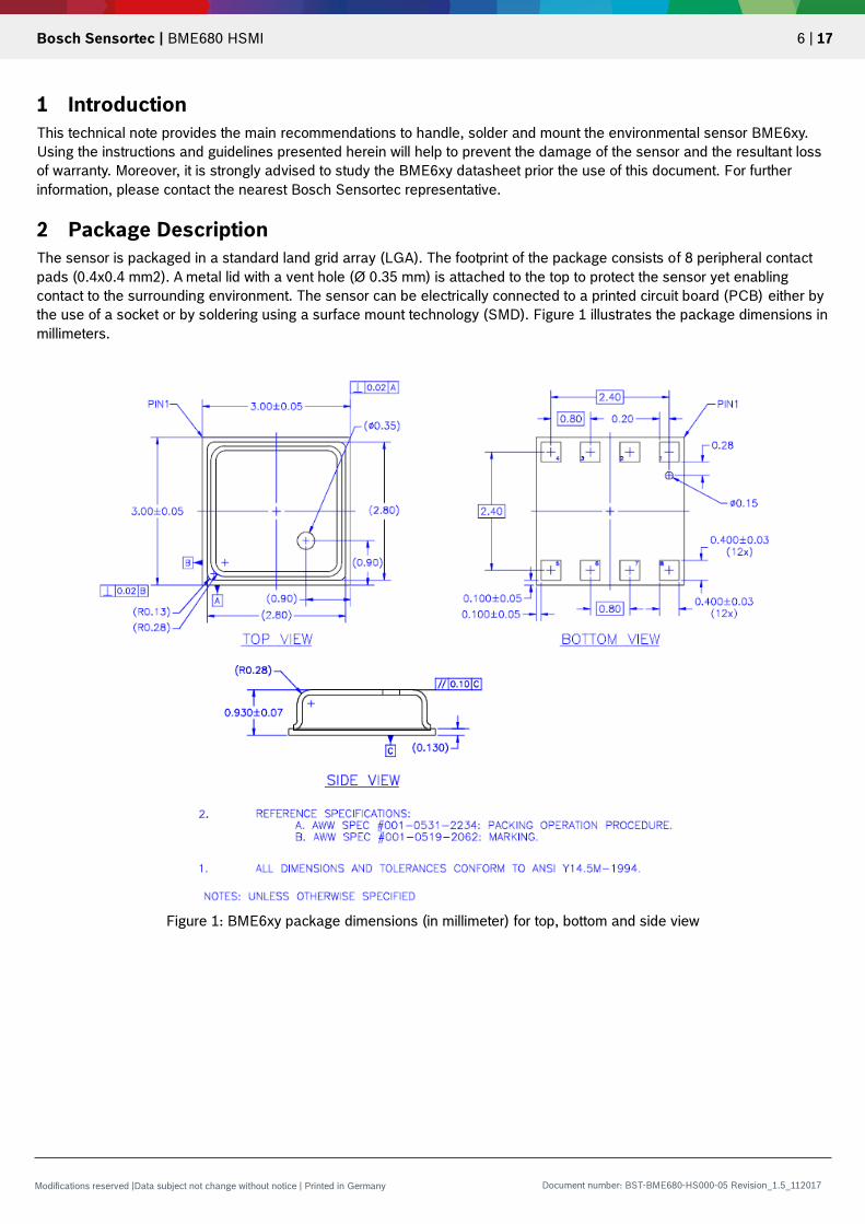
2 Package Description
The sensor is packaged in a standard land grid array (LGA). The footprint of the package consists of 8 peripheral contact
pads (0.4x0.4 mm2). A metal lid with a vent hole (Ø 0.35 mm) is attached to the top to protect the sensor yet enabling
contact to the surrounding environment. The sensor can be electrically connected to a printed circuit board (PCB) either by
the use of a socket or by soldering using a surface mount technology (SMD). Figure 1 illustrates the package dimensions in
millimeters.
Figure 1: BME6xy package dimensions (in millimeter) for top, bottom and side view

Bosch Sensortec | BME680 HSMI 7 | 17
Modifications reserved |Data subject not change without notice | Printed in Germany Document number: BST-BME680-HS000-05 Revision_1.5_112017
3 Device Marking
In order to facilitate traceability, a clear laser-marking is engraved on the metal housing. Tables 1 and 2 presents the marking for mass production parts and the engineering samples, respectively.
Table 1: Marking of mass production parts
Marking Symbol Description
CCC Lot counter: 3 alphanumeric digits, variable
to generate mass production trace-code
T Product number: 1 alphanumeric digit, fixed
to identify product type, T = “S” and “E”
“S” and “E” are associated with the product BME6xy
(part number 1 277 340 511)
L Sub-contractor ID: 1 alphanumeric digit, variable to
identify sub-contractor (L = “P”)
Table 2: Marking of engineering samples
Marking Symbol Description
XX Sample ID: 2 alphanumeric digits,
variable to generate trace-code
N Eng. Sample ID: 1 alphanumeric digit, fixed
to identify engineering sample,
N = “ * ” or “e” or “E”
CC Counter ID: 2 alphanumeric digits,
variable to generate trace-code

Bosch Sensortec | BME680 HSMI 8 | 17
Modifications reserved |Data subject not change without notice | Printed in Germany Document number: BST-BME680-HS000-05 Revision_1.5_112017
4 Soldering Instructions
The moisture sensitivity level of the BME680 sensors corresponds to JEDEC Level 1, see also:
IPC/JEDEC J-STD-020C “Joint Industry Standard: Moisture/Reflow Sensitivity Classification for non-hermetic Solid State Surface Mount Devices”
IPC/JEDEC J-STD-033A “Joint Industry Standard: Handling, Packing, Shipping and Use of Moisture/Reflow Sensitive Surface Mount Devices”
The sensor fulfils the lead-free soldering requirements of the above-mentioned IPC/JEDEC standards. Accordingly, reflow
soldering with a peak temperature up to 260°C for 20 to 40 seconds shall be used (see Figure 2). The sensors can
withstand up to 3 reflow soldering cycles; several cycles may be necessary when mounting for example devices on both
sides of a PCB. It is also important to note that the minimum height of the solder after reflow should be at least 50 µm. This
is required for a good mechanical decoupling between the sensor device and the PCB.
Figure 2: Soldering profile
Lorem Duis Aute
My nibh euismod tincidunt
ut laor eet dolore magna
aliquam erad minim
veniam, quis nostrud
exerci tation.

Bosch Sensortec | BME680 HSMI 9 | 17
Modifications reserved |Data subject not change without notice | Printed in Germany Document number: BST-BME680-HS000-05 Revision_1.5_112017
5 Reconditioning Procedure
After exposing the device to operating conditions that exceed the limits specified in the datasheet (e.g. after reflow), the
humidity sensor may possess an additional undesired offset. Therefore, the following reconditioning procedure is
mandatory to restore the sensors’ calibration state:
1. Dry-baking at 125 °C and <5% r.H. for 6 hours
2. Re-hydration at 25 °C and 80% r.H. for 24 hours
3. Rest period for one hour at room temperature
or alternatively
1. Do not perform Dry-Baking
2. Ambient Re-Hydration: 25 °C at >50% rH for >5d
6 Warnings and Precautions
The following list of instructions has to be carefully considered during handling, soldering and mounting of BME6xy:
ESD protective measures in the workplace shall be generally ensured (e.g. use of wrist straps, tweezers with ceramic tips, etc.)
The vent hole of the sensor shall be covered with a silicone-free protective layer during processing (e.g. cleaning, soldering, board wash etc.) to prevent possible contamination
It is permitted only to use silicone-free gloves during handling of the sensors (e.g. Nitrile-based gloves for clean rooms are recommended to use)
The sensors shall be stored in their original packaging (i.e. the original package do not emit odor or poisonous gases) and at the following conditions: temperature and humidity shall be within the ranges of 10–50°C and 20–60 % r.H., respectively
Sensor characteristics may be impaired when exposed to undesired vapours, and thus, it is important not to employ vapour-phase ovens and to avoid working with adhesives/glues, lacquer-like polymers, cosmetics (e.g. hand lotion), or sprays (e.g. lubricants) close to the assembly line
The sensors should not be operated in the following conditions: o Pure dry (synthetic) air o A zero or low oxygen atmosphere o A nitrogen-only atmosphere
Permanent (> 12 hrs) exposition to unusual high concentration of smoke or gases above the recommended maximum level (0…100 mg/m³ TVOC / reducing gases or 0…10mg/m³ total of (NOx+SOx+O3) / oxidizing gases) has to be avoided
It is not permitted to expose high concentrations of reducing (e.g. >20 mg/m3 of TVOC) and/or oxidizing gases (>10 mg/m³ of NOx+SOx+O3) to operating sensors for a long time
Do not expose high concentrations of cigarette lighter and/or exhaust pipe gases to operating sensors
It is not advised to put the sensors in close proximity to outgassing rubbers, and thus, it is recommended to use thermoplastic elastomers or highly filled rubbers (without or with a low content of plasticizers)
The PCBs shall not be coated with materials containing and/or emitting siloxanes
Soaking or splashing the sensors with liquids shall be avoided
Strong air blast from an air pistol is forbidden
To allow good reflow process, no excess solder paste shall be utilized
Under no circumstances should the sensors be dry-baked before soldering
Avoid manual disassembling of the sensors, particularly by exploiting higher temperatures (>260 °C) and/or longer heating durations (>40 s), because this may introduce irreversible changes in the sensor characteristics (e.g. offset shift)
Do not remove lid during target device assembly or application; don’t use in explosive sensitive area
Prevent any sharp objects (e.g. tweezer tips) from getting inside the vent hole of the sensor
The pressure sensor is vulnerable to damage if ultrasonic welding is used
Avoid rear side handling of the sensor by using for example underfil or cleaning materials
Avoid total or partial covering of the sensor by any protective material (e.g. epoxy resin coated on another IC component nearby); this may lead to clogging of the vent hole or result in an unsymmetrical mechanical stress distribution on the sensor package

Bosch Sensortec | BME680 HSMI 10 | 17
Modifications reserved |Data subject not change without notice | Printed in Germany Document number: BST-BME680-HS000-05 Revision_1.5_112017
Avoid exposure of the sensor to the following components: o Bases and acids (e.g. NH3, NaOH, HCl, H2SO4, HF, HNO3, H2S2O7, etc.) o Corrosive gases (e.g. SOx, Cl2, etc.) o Halogens (F2, Cl2, Br2, I2), their salts (e.g. NaCl) and alkaline metals o High concentrations of O3 or H2O2

Bosch Sensortec | BME680 HSMI 11 | 17
Modifications reserved |Data subject not change without notice | Printed in Germany Document number: BST-BME680-HS000-05 Revision_1.5_112017
7 Design Guidelines
MEMS sensors are in general high-precision measurement devices which consist of electronic as well as mechanical
silicon structures. Moreover, BME6xy offers chemically sensitive structures culminating in a combined gas, temperature,
humidity and/or pressure sensor. Accordingly, special care has to be given when these sensors are integrated inside
cavities and mounted for example on printed-circuit boards (PCBs). In this chapter, guidelines about the design of the
housing and placement of BME6xy on PCBs are presented to ensure accurate measurements as well as fast response
times.
7.1 General Aspects
For the integration of BME6xy the following general instructions are recommended:
Avoid usage of adhesive, PCB and housing materials that are emitting siloxanes and/or volatile organic compounds
(VOCs)
Avoid usage of materials within the cavity which are susceptible to moisture
The sensor is sensitive to light, which can influence the accuracy of the measurement; therefore, the housing shall
be designed to minimize light exposure to the vent hole
Note that the use of a port protection membranes might influence the sensitivity and the response time of the gas as
well as the humidity sensors
7.2 Position Aspects
Wrong placement of the sensor can impair the performance. Therefore, some guidelines are given below to ensure
accurate measurements and relatively fast response times:
The sensor should be placed as close as possible to the environment, i.e., ambient air
The dead volume inside the cavity, where the sensor is placed, should be minimized
The clearance above the metal lid of the sensor shall be at least 0.1 mm
A large aperture and a short channel, through which the gas is diffusing to reach the sensor inside the system, are
highly recommended
To have a better insight of how BME6xy is typically integrated, Figure 3 shows three different possible cavity designs. As
depicted in the figure, a defined air flow/circulation has to be guaranteed to minimize the temperature deviations between
the sensor and the surrounding environment. On a side note, an optional protection membrane at the aperture can be
used. More details about the design dimensions are given in the BME6xy Application Note – Device Integration Guidelines.
Figure 3: Cavity designs with: (left) defined air flow, (middle) small cavity, (right) large cavity volume and no direct air flow

Bosch Sensortec | BME680 HSMI 12 | 17
Modifications reserved |Data subject not change without notice | Printed in Germany Document number: BST-BME680-HS000-05 Revision_1.5_112017
7.3 Thermal Aspects
Thermal decoupling of the sensor to the PCB and housing is required to assure fast response for the temperature sensor
as well as efficient heat conduction between heater of the gas sensor and the chemically sensitive layer. On the other
hand, good thermal and air coupling of the sensor to the surrounding room-air is essential to accurately sense the target
environment. Accordingly, the following operation and layout design rules are recommended (see Figure 4 and Figure 5):
To avoid self-heating, the sensor should not be continuously active; the datasheet provides more information about how to minimize the power consumption at a particular resolution
Protect the sensor from heated air flow to avoid heat convection and radiation, which might lead to undesired warming-up of the device and wrong (over- or underestimated) output results
The sensor has to be placed at an adequate distance to any critical heat sources on the PCB or inside the system;
trenches around the sensor can be utilized to reduce the thermal conduction
The sensor has to be placed not in close vicinity to fast heating components (>3 °C/s)
The thickness of the metal interconnects to the sensor has to be minimized in order to ensure proper heat decoupling
The sensor has to be placed as close as possible to the environment and also close to the edges of the
device/system.
Figure 4: BME6xy placement on a PCB (red: heat radiation)
Figure 5: Three methods to thermally decouple the sensor from the PCB
1. Milled Trenches 2. Thin Interconnects 3. Flexible PCBs

Bosch Sensortec | BME680 HSMI 13 | 17
Modifications reserved |Data subject not change without notice | Printed in Germany Document number: BST-BME680-HS000-05 Revision_1.5_112017
7.4 Mechanical Aspects
Unnecessary mechanical stress induced on the sensor is not advisable. Referring to Figure 6, the following guidelines are
recommended for a good PCB design practice:
Place the sensor not nearby or directly beneath a push-button on the PCB
Keep the sensor as far as possible from areas where any mechanical-stress induced on the PCB is maximum
Mount the sensor at a reasonable distance from the anchor points (e.g. screw), where the PCB is typically attached to a base, shelf or similar
Remove or unscrew any redundant PCB anchor points that induce an undesirable mechanical stress
Figure 6: Methods to minimize mechanical stress on the sensor: (left) sensor is wrongly placed at a high mechanically-stressed location, (middle) redundant screw is removed to minimize stress, (right) sensor is properly placed at a reasonable distance from high mechanically-stressed areas
anchor point (e.g. screw)
PCB
sensor sensor
unscrew
or remove
anchor point (e.g. screw)
PCB
sensor sensor
unscrew
or remove
anchor point (e.g. screw)
PCB
Keep
distance !
sensor
anchor point (e.g. screw)
PCB
Keep
distance !
sensor
Bosch Sensortec | BME680 HSMI 14 | 17
Modifications reserved |Data subject not change without notice | Printed in Germany Document number: BST-BME680-HS000-05 Revision_1.5_112017
8 Environmental Safety
8.1 RoHS
The BME680 sensor meets the requirements of the EC restriction of hazardous substances (RoHS) directive, see also:
Directive 2011/65/EU of the European Parliament and of the Council of 8 June 2011 on the restriction of the use of certain
hazardous substances in electrical and electronic equipment.
8.2 Lead and Halogen Content
The BME680 is lead (Pb) and halogen-free. For more details on the analysis results please contact your Bosch Sensortec
representative.
8.3 Internal Package Structure
Within the scope of Bosch Sensortec’s ambition to improve its products and secure the mass product supply.
While Bosch Sensortec took care that all of the technical packaging parameters, which are described above, are 100%
identical for all sources, there can be differences in the chemical content and the internal structural between the different
package sources. However, as secured by the extensive product qualification process of Bosch Sensortec, this has no
impact to the usage or to the quality of the BME680 product.
Bosch Sensortec | BME680 HSMI 15 | 17
Modifications reserved |Data subject not change without notice | Printed in Germany Document number: BST-BME680-HS000-05 Revision_1.5_112017
9 Legal disclaimer
9.1 Engineering samples
Engineering Samples are marked with an asterisk (*) or (e) or (E). Samples may vary from the valid technical specifications
of the product series contained in this data sheet. They are therefore not intended or fit for resale to third parties or for use
in end products. Their sole purpose is internal client testing. The testing of an engineering sample may in no way replace
the testing of a product series. Bosch Sensortec assumes no liability for the use of engineering samples. The Purchaser
shall indemnify Bosch Sensortec from all claims arising from the use of engineering samples.
9.2 Product use
Bosch Sensortec products are developed for the consumer goods industry. They may only be used within the parameters
of this product data sheet. They are not fit for use in life-sustaining or security sensitive systems. Security sensitive
systems are those for which a malfunction is expected to lead to bodily harm or significant property damage. In addition,
they are not fit for use in products which interact with motor vehicle systems.
The resale and/or use of products are at the purchaser’s own risk and his own responsibility. The examination of fitness for
the intended use is the sole responsibility of the Purchaser.
The purchaser shall indemnify Bosch Sensortec from all third party claims arising from any product use not covered by the
parameters of this product data sheet or not approved by Bosch Sensortec and reimburse Bosch Sensortec for all costs in
connection with such claims.
The purchaser must monitor the market for the purchased products, particularly with regard to product safety, and inform
Bosch Sensortec without delay of all security relevant incidents.
9.3 Application examples and hints
With respect to any examples or hints given herein, any typical values stated herein and/or any information regarding the
application of the device, Bosch Sensortec hereby disclaims any and all warranties and liabilities of any kind, including
without limitation warranties of non-infringement of intellectual property rights or copyrights of any third party. The
information given in this document shall in no event be regarded as a guarantee of conditions or characteristics. They are
provided for illustrative purposes only and no evaluation regarding infringement of intellectual property rights or copyrights
or regarding functionality, performance or error has been made.

Bosch Sensortec | BME680 HSMI 16 | 17
Modifications reserved |Data subject not change without notice | Printed in Germany Document number: BST-BME680-HS000-05 Revision_1.5_112017
10 Document history and modifications
Rev. No Chapter Description of modification/changes Date
1.0 all Initial release 29.07.2015
1.6 28.11.2017

Bosch Sensortec | BME680 HSMI 17 | 17
Modifications reserved |Data subject not change without notice | Printed in Germany Document number: BST-BME680-HS000-05 Revision_1.5_112017
Bosch Sensortec GmbH Gerhard-Kindler-Straße 9 72770 Reutlingen / Germany www.bosch-sensortec.com Modifications reserved | Printed in Germany Preliminary - specifications subject to change without notice Document number: BST-BME680-HS000-05 Revision_1.5_112017
Recommended