AW400BT with GSMUser Manual
Version 1.1
Last Revised February 5, 2013
All contents in this manual are copyrighted by ArWest Communications.All rights reserved.The information contained herein may not be used, accessed, copied,
stored, displayed, sold, modified, published, or distributed, or otherwise reproduced without express written consent from ArWest Communications.

www.arwestcom.com

TABLE OF CONTENTS
Preface . . . . . . . . . . . . . . . . . . . . . . . . . . . . . . . . . . . . . . . . . . . . . . . . . . . . . . . . .7
Terms and Conditions. . . . . . . . . . . . . . . . . . . . . . . . . . . . . . . . . . . . . . . . . . . . . . . . . . . . . . . . 7Regulatory Information . . . . . . . . . . . . . . . . . . . . . . . . . . . . . . . . . . . . . . . . . . . . . . . . . . . . . . 9Manual Conventions. . . . . . . . . . . . . . . . . . . . . . . . . . . . . . . . . . . . . . . . . . . . . . . . . . . . . . . . 10Screen Captures . . . . . . . . . . . . . . . . . . . . . . . . . . . . . . . . . . . . . . . . . . . . . . . . . . . . . . . . . . . 10Technical Assistance . . . . . . . . . . . . . . . . . . . . . . . . . . . . . . . . . . . . . . . . . . . . . . . . . . . . . . . 10
Chapter 1. Introduction . . . . . . . . . . . . . . . . . . . . . . . . . . . . . . . . . . . . . . . . . . .11
1.1. Getting Acquainted . . . . . . . . . . . . . . . . . . . . . . . . . . . . . . . . . . . . . . . . . . . . . . . . . . . . . 121.1.1. LEDs . . . . . . . . . . . . . . . . . . . . . . . . . . . . . . . . . . . . . . . . . . . . . . . . . . . . . . . . . . . 121.1.2. Data and Power Port . . . . . . . . . . . . . . . . . . . . . . . . . . . . . . . . . . . . . . . . . . . . . . . 121.1.3. External Antenna and GSM Antenna Connectors. . . . . . . . . . . . . . . . . . . . . . . . . 131.1.4. Mounting Bracket . . . . . . . . . . . . . . . . . . . . . . . . . . . . . . . . . . . . . . . . . . . . . . . . . 131.1.5. Cables . . . . . . . . . . . . . . . . . . . . . . . . . . . . . . . . . . . . . . . . . . . . . . . . . . . . . . . . . . 131.1.6. Literature . . . . . . . . . . . . . . . . . . . . . . . . . . . . . . . . . . . . . . . . . . . . . . . . . . . . . . . . 141.1.7. External GSM Antenna . . . . . . . . . . . . . . . . . . . . . . . . . . . . . . . . . . . . . . . . . . . . . 141.1.8. External RF Antenna (not included) . . . . . . . . . . . . . . . . . . . . . . . . . . . . . . . . . . . 141.1.9. Storage Precautions . . . . . . . . . . . . . . . . . . . . . . . . . . . . . . . . . . . . . . . . . . . . . . . . 14
Chapter 2. Configuration. . . . . . . . . . . . . . . . . . . . . . . . . . . . . . . . . . . . . . . . . .15
2.1. Powering AW400BT with GSM . . . . . . . . . . . . . . . . . . . . . . . . . . . . . . . . . . . . . . . . . . . 152.1.1. Power supply requirements . . . . . . . . . . . . . . . . . . . . . . . . . . . . . . . . . . . . . . . . . . 15
2.2. RF Antenna Installation. . . . . . . . . . . . . . . . . . . . . . . . . . . . . . . . . . . . . . . . . . . . . . . . . . 16
2.3. GSM Antenna Installation . . . . . . . . . . . . . . . . . . . . . . . . . . . . . . . . . . . . . . . . . . . . . . . . 18
2.4. Installing AWLaunch. . . . . . . . . . . . . . . . . . . . . . . . . . . . . . . . . . . . . . . . . . . . . . . . . . . . 18
2.5. Connecting AW400BT with GSM and Computer . . . . . . . . . . . . . . . . . . . . . . . . . . . . . 182.5.1. Connecting through serial port . . . . . . . . . . . . . . . . . . . . . . . . . . . . . . . . . . . . . . . 182.5.2. Connecting through USB port . . . . . . . . . . . . . . . . . . . . . . . . . . . . . . . . . . . . . . . . 192.5.3. Connecting through Bluetooth® . . . . . . . . . . . . . . . . . . . . . . . . . . . . . . . . . . . . . . 19
2.6. Configuring AW400BT with GSM . . . . . . . . . . . . . . . . . . . . . . . . . . . . . . . . . . . . . . . . . 192.6.1. Sleep Mode and Alarm settings. . . . . . . . . . . . . . . . . . . . . . . . . . . . . . . . . . . . . . . 27
2.7. Checking Firmware Version . . . . . . . . . . . . . . . . . . . . . . . . . . . . . . . . . . . . . . . . . . . . . . 28
2.8. Loading New Firmware. . . . . . . . . . . . . . . . . . . . . . . . . . . . . . . . . . . . . . . . . . . . . . . . . . 29
3www.arwestcom.com

Chapter 3. Internet services. . . . . . . . . . . . . . . . . . . . . . . . . . . . . . . . . . . . . . . 31
3.1. TCP client . . . . . . . . . . . . . . . . . . . . . . . . . . . . . . . . . . . . . . . . . . . . . . . . . . . . . . . . . . . . 31
3.2. TCP server . . . . . . . . . . . . . . . . . . . . . . . . . . . . . . . . . . . . . . . . . . . . . . . . . . . . . . . . . . . 323.2.1. RTN corrections uploading . . . . . . . . . . . . . . . . . . . . . . . . . . . . . . . . . . . . . . . . . 323.2.2. Remote CLI support . . . . . . . . . . . . . . . . . . . . . . . . . . . . . . . . . . . . . . . . . . . . . . . 33
3.3. NTRIP client . . . . . . . . . . . . . . . . . . . . . . . . . . . . . . . . . . . . . . . . . . . . . . . . . . . . . . . . . . 34
Chapter 4. Command Line Interface . . . . . . . . . . . . . . . . . . . . . . . . . . . . . . . . 37
4.1. Command Line Interface Convention. . . . . . . . . . . . . . . . . . . . . . . . . . . . . . . . . . . . . . . 374.1.1. Software Switching to Maintenance Mode . . . . . . . . . . . . . . . . . . . . . . . . . . . . . 384.1.2. Hardware Switching to Maintenance Mode . . . . . . . . . . . . . . . . . . . . . . . . . . . . . 394.1.3. Switching to Data Mode. . . . . . . . . . . . . . . . . . . . . . . . . . . . . . . . . . . . . . . . . . . . 39
4.2. Networking Commands . . . . . . . . . . . . . . . . . . . . . . . . . . . . . . . . . . . . . . . . . . . . . . . . . 394.2.1. LINK. . . . . . . . . . . . . . . . . . . . . . . . . . . . . . . . . . . . . . . . . . . . . . . . . . . . . . . . . . . 39
4.3. Serial Interfacing Commands . . . . . . . . . . . . . . . . . . . . . . . . . . . . . . . . . . . . . . . . . . . . . 414.3.1. DPORT. . . . . . . . . . . . . . . . . . . . . . . . . . . . . . . . . . . . . . . . . . . . . . . . . . . . . . . . . 414.3.2. MPORT . . . . . . . . . . . . . . . . . . . . . . . . . . . . . . . . . . . . . . . . . . . . . . . . . . . . . . . . 42
4.4. Special Commands . . . . . . . . . . . . . . . . . . . . . . . . . . . . . . . . . . . . . . . . . . . . . . . . . . . . . 424.4.1. BOOT . . . . . . . . . . . . . . . . . . . . . . . . . . . . . . . . . . . . . . . . . . . . . . . . . . . . . . . . . . 424.4.2. HELP . . . . . . . . . . . . . . . . . . . . . . . . . . . . . . . . . . . . . . . . . . . . . . . . . . . . . . . . . . 424.4.3. SAVE . . . . . . . . . . . . . . . . . . . . . . . . . . . . . . . . . . . . . . . . . . . . . . . . . . . . . . . . . . 434.4.4. SLEEP . . . . . . . . . . . . . . . . . . . . . . . . . . . . . . . . . . . . . . . . . . . . . . . . . . . . . . . . . 43
4.5. Diagnostics and Identification Commands . . . . . . . . . . . . . . . . . . . . . . . . . . . . . . . . . . . 444.5.1. INFO. . . . . . . . . . . . . . . . . . . . . . . . . . . . . . . . . . . . . . . . . . . . . . . . . . . . . . . . . . . 444.5.2. STATE . . . . . . . . . . . . . . . . . . . . . . . . . . . . . . . . . . . . . . . . . . . . . . . . . . . . . . . . . 44
4.6. RTN . . . . . . . . . . . . . . . . . . . . . . . . . . . . . . . . . . . . . . . . . . . . . . . . . . . . . . . . . . . . . . . . 45
4.7. GSM . . . . . . . . . . . . . . . . . . . . . . . . . . . . . . . . . . . . . . . . . . . . . . . . . . . . . . . . . . . . . . . . 47
Appendix A. Specifications . . . . . . . . . . . . . . . . . . . . . . . . . . . . . . . . . . . . . . . 49
A.1. AW400BT with GSM Modem Specifications. . . . . . . . . . . . . . . . . . . . . . . . . . . . . . . . 49A.1.1. General Radio Specifications . . . . . . . . . . . . . . . . . . . . . . . . . . . . . . . . . . . . . . . 49A.1.2. Environmental Specifications . . . . . . . . . . . . . . . . . . . . . . . . . . . . . . . . . . . . . . . 50A.1.3. Transmitter Specifications. . . . . . . . . . . . . . . . . . . . . . . . . . . . . . . . . . . . . . . . . . 50A.1.4. Receiver Specifications . . . . . . . . . . . . . . . . . . . . . . . . . . . . . . . . . . . . . . . . . . . . 51
A.2. Internet Services. . . . . . . . . . . . . . . . . . . . . . . . . . . . . . . . . . . . . . . . . . . . . . . . . . . . . . . 52
A.3. Compliance . . . . . . . . . . . . . . . . . . . . . . . . . . . . . . . . . . . . . . . . . . . . . . . . . . . . . . . . . . 52
A.4. Connector Specifications . . . . . . . . . . . . . . . . . . . . . . . . . . . . . . . . . . . . . . . . . . . . . . . . 52
4 www.arwestcom.com

Appendix B. UHF Radio Usage. . . . . . . . . . . . . . . . . . . . . . . . . . . . . . . . . . . . .55
Appendix C. Safety Warnings. . . . . . . . . . . . . . . . . . . . . . . . . . . . . . . . . . . . . .57
C.1. General Warnings . . . . . . . . . . . . . . . . . . . . . . . . . . . . . . . . . . . . . . . . . . . . . . . . . . . . . . 58
Appendix D. Warranty Terms . . . . . . . . . . . . . . . . . . . . . . . . . . . . . . . . . . . . . .59
5www.arwestcom.com

6 www.arwestcom.com

PREFACE
Thank you for purchasing this product. The materials available in this Manual (the “Manual”) have beenprepared by ArWest Communications, Corp. (“ArWest”) for owners of ArWest products. It is designed toassist owners with the use of AW400BT with GSM modem and its use is subject to these terms andconditions (the “Terms and Conditions”).
Note: Please read these Terms and Conditions carefully.
Terms and ConditionsUSE – ArWest modems are designed to be used by a professional. The user is expected to have a goodknowledge and understanding of the user and safety instructions before operating, inspecting oradjusting.
COPYRIGHT – All information contained in this Manual is the intellectual property of, and copyrightedmaterial of ArWest. All rights are reserved. You may not use, access, copy, store, display, createderivative works of, sell, modify, publish, distribute, or allow any third party access to, any graphics,content, information or data in this Manual without ArWest’ express written consent and may only usesuch information for the care and operation of your AW400BT with GSM. The information and data inthis Manual are a valuable asset of ArWest and are developed by the expenditure of considerable work,time and money, and are the result of original selection, coordination and arrangement by ArWest.
TRADEMARKS – AW400BT with GSM™, AWLaunch™, ArWest® are trademarks or registeredtrademarks of ArWest Communications Corp. Windows® is a registered trademark of MicrosoftCorporation; Bluetooth® word mark is owned by the Bluetooth SIG, Inc. Product and company namesmentioned herein may be trademarks of their respective owners.
DISCLAIMER OF WARRANTY – EXCEPT FOR ANY WARRANTIES IN THIS MANUAL OR AWARRANTY CARD ACCOMPANYING THE PRODUCT, THIS MANUAL AND THE AW400BTWITH GSM MODEM ARE PROVIDED “AS-IS.” THERE ARE NO OTHER WARRANTIES.ARWEST DISCLAIMS ANY IMPLIED WARRANTY OF MERCHANTABILITY OR FITNESS FORANY PARTICULAR USE OR PURPOSE. ARWEST AND ITS DISTRIBUTORS SHALL NOT BELIABLE FOR TECHNICAL OR EDITORIAL ERRORS OR OMISSIONS CONTAINED HEREIN;NOR FOR INCIDENTAL OR CONSEQUENTIAL DAMAGES RESULTING FROM THEFURNISHING, PERFORMANCE OR USE OF THIS MATERIAL OR THE AW400BT with GSMMODEM. SUCH DISCLAIMED DAMAGES INCLUDE BUT ARE NOT LIMITED TO LOSS OFTIME, LOSS OR DESTRUCTION OF DATA, LOSS OF PROFIT, SAVINGS OR REVENUE, ORLOSS OF THE PRODUCT'S USE. IN ADDITION, ARWEST IS NOT RESPONSIBLE OR LIABLEFOR DAMAGES OR COSTS INCURRED IN CONNECTION WITH OBTAINING SUBSTITUTEPRODUCTS OR SOFTWARE, CLAIMS BY OTHERS, INCONVENIENCE, OR ANY OTHER
7www.arwestcom.com

PrefaceTerms and Conditions
COSTS. IN ANY EVENT, ARWEST SHALL HAVE NO LIABILITY FOR DAMAGES OROTHERWISE TO YOU OR ANY OTHER PERSON OR ENTITY IN EXCESS OF THE PURCHASEPRICE FOR AW400BT WITH GSM.
LICENSE AGREEMENT – Use of any computer programs or software supplied by ArWest ordownloaded from a ArWest website (the “Software”) in connection with AW400BT with GSMconstitutes acceptance of these Terms and Conditions in this Manual and an agreement to abide by theseTerms and Conditions. The user is granted a personal, non-exclusive, non-transferable license to use suchSoftware under the terms stated herein and in any case only with a single AW400BT with GSM or singlecomputer. You may not assign or transfer the Software or this license without the express written consentof ArWest. This license is effective until terminated. You may terminate the license at any time bydestroying the Software and Manual. ArWest may terminate the license if you fail to comply with any ofthe Terms or Conditions. You agree to destroy the Software and manual upon termination of your use ofAW400BT with GSM. All ownership, copyright and other intellectual property rights in and to theSoftware belong to ArWest. If these license terms are not acceptable, return any unused software andmanual.
CONFIDENTIALITY – This Manual, its contents and the Software (collectively, the “ConfidentialInformation”) are the confidential and proprietary information of ArWest. You agree to treat ArWest'Confidential Information with a degree of care no less stringent that the degree of care you would use insafeguarding your own most valuable trade secrets. Nothing in this paragraph shall restrict you fromdisclosing Confidential Information to your employees as may be necessary or appropriate to operate orcare for AW400BT with GSM. Such employees must also keep the Confidentiality Informationconfidential. In the event you become legally compelled to disclose any of the Confidential Information,you shall give ArWest immediate notice so that it may seek a protective order or other appropriateremedy.
WEBSITE; OTHER STATEMENTS – No statement contained at the ArWest website (or any otherwebsite) or in any other advertisements or ArWest literature or made by an employee or independentcontractor of ArWest modifies these Terms and Conditions (including the Software license, warranty andlimitation of liability).
SAFETY – Improper use of AW400BT with GSM can lead to injury to persons or property and/ormalfunction of the product. The AW400BT with GSM modem should only be repaired by authorizedArWest warranty service centers. Users should review and heed the safety warnings in Appendix C.
MISCELLANEOUS – The above Terms and Conditions may be amended, modified, superseded, orcanceled, at any time by ArWest. The above Terms and Conditions will be governed by, and construed inaccordance with, the laws of the State of California, without reference to conflict of laws.
8 www.arwestcom.com

PrefaceRegulatory Information
FCC Class A Compliance
Regulatory Information
FCC Class A Compliance
This equipment has been tested and found to comply with the limits for a Class A digital device, pursuantto part 15 of the FCC Rules. These limits are designed to provide reasonable protection against harmfulinterference when the equipment is operated in a commercial environment. This equipment generates,uses, and can radiate radio frequency energy and, if not installed and used in accordance with theinstruction manual, may cause harmful interference to radio communications. Operation of thisequipment in a residential area is likely to cause harmful interference in which case the user will berequired to correct the interference at his own expense.
CAUTION: Any changes or modifications to the equipment not expressly approved by the party responsible forcompliance could void your authority to operate such equipment.
Canadian Emissions Labeling Requirements
This Class A digital apparatus meets all requirements of the Canadian Interference-Causing EquipmentRegulations.
Cet appareil numérique de la classe A respecte toutes les exigences du Réglement sur le matérielbrouilleur du Canada.
Industry Canada
The term “IC:” before the equipment certification number only signifies that the Industry Canadatechnical specifications were met.
WEEE Directive
The following information is for EU-member states only: The use of the symbol indicates that thisproduct may not be treated as household waste. By ensuring this product is disposed of correctly, you willhelp prevent potential negative consequences for the environment and human health, which couldotherwise be caused by inappropriate waste handling of this product. For more detailed information aboutthe take-back and recycling of this product, please contact your supplier where you purchased the productor consult.
9www.arwestcom.com

PrefaceManual ConventionsWEEE Directive
Manual ConventionsThis manual uses the following conventions:
Screen CapturesThis manual includes sample screen captures. Your actual screen can look slightly different from thesample screen due to the modem you have connected, operating system used and settings you havespecified. This is normal and not a cause for concern.
Technical AssistanceIf you have a problem and cannot find the information you need in the product documentation, contactyour local dealer. Alternatively, request technical support using the [email protected].
Example Description
FileExit Click the File menu and click Exit
Link Space This format represents titles of dialog windows/boxes, names of menu options, identifies program interface objects, such as checkboxes, edit boxes, radio buttons, etc.
Temp This format is used to enter various string information (e.g., file and directory names) as well as operator commands.
10 www.arwestcom.com

Chapter 1
INTRODUCTION
AW400BT with GSM is the up-to-date unsurpassed 4 W UHF radio transceiver with USB andBluetooth® capacity, and built-in quad band GSM/GPRS module. AW400BT accesses Real TimeNetwork (RTN) via GPRS, takes incoming data from the network, modulates it with GMSK, FSK, PSKor most spectrum efficient QAM modulation and transmits it at RF power output levels from 15 dBm upto 36 dBm operating in UHF frequency band (406 to 470 MHz). The data taken from RTN can be routedto the UART, USB or Bluetooth communication ports as well. AW400BT is also capable of receiving RFsignal from remote UHF transmitter or data from communication ports (UART, USB or Bluetooth) andsending it over the cellular network using built-in GSM/GPRS module if such operation mode is selected.
Figure 1-1. AW400BT with GSM
The AW400BT with GSM radio transceiver provides a high-speed point-to-point and point-to-multipointwireless data transfer at up to 38.4 kbps. The firmware supports user selectable modulation techniques,which allows the user achieving the highest data speed for a given range. It also includes a selectableerror correction, which improves the functioning of the radio modem under interference. Thesophisticated features of AW400BT with GSM include data scrambling, frequency hopping, userselectable transmit output power level, low power consumption sleep modes, autoscanning for base andplug-and-play installation for remote terminals.
The firmware of the AW400BT with GSM radio modem resides in a flash memory. The updating of theradio modem programs is entirely software-based. The flash memory is re-programmable through an RS-232 interface, USB, Bluetooth. By accessing to the internet via GPRS the AW400BT with GSM providesremote CLI access and can be configured remotely (through the internet) if corresponding operationmode is selected.
11www.arwestcom.com
IntroductionGetting AcquaintedLEDs
1.1. Getting Acquainted
The AW400BT with GSM is a rugged and very powerful external radio transceiver 146 mm wide 75 mmdeep 44 mm high, weighs 488 g.
1.1.1. LEDs
External LED's (see Figure 1-2) are used for Link and Line status indication:
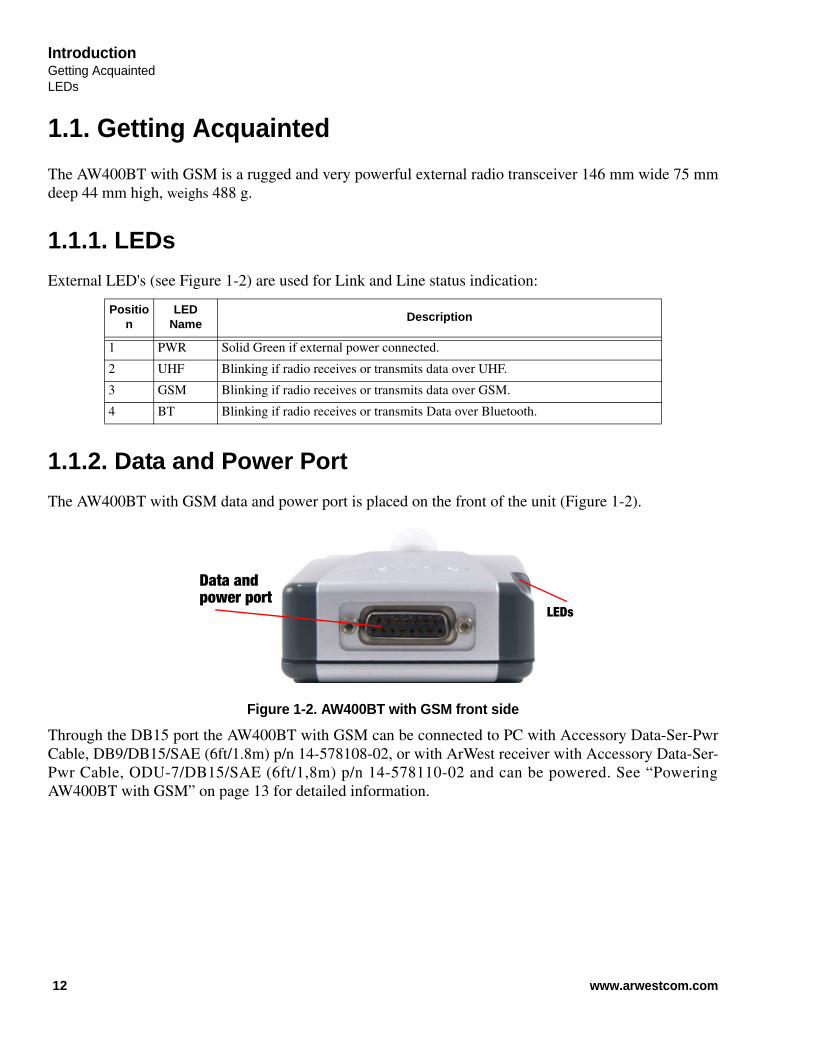
1.1.2. Data and Power Port
The AW400BT with GSM data and power port is placed on the front of the unit (Figure 1-2).
Figure 1-2. AW400BT with GSM front side
Through the DB15 port the AW400BT with GSM can be connected to PC with Accessory Data-Ser-PwrCable, DB9/DB15/SAE (6ft/1.8m) p/n 14-578108-02, or with ArWest receiver with Accessory Data-Ser-Pwr Cable, ODU-7/DB15/SAE (6ft/1,8m) p/n 14-578110-02 and can be powered. See “PoweringAW400BT with GSM” on page 13 for detailed information.
Position
LED Name
Description
1 PWR Solid Green if external power connected.
2 UHF Blinking if radio receives or transmits data over UHF.
3 GSM Blinking if radio receives or transmits data over GSM.
4 BT Blinking if radio receives or transmits Data over Bluetooth.
LEDs
Data andpower port
12 www.arwestcom.com

IntroductionGetting Acquainted
External Antenna and GSM Antenna Connectors
1.1.3. External Antenna and GSM Antenna Connectors
The external antenna connects to the BNC external antenna connector and GSM antenna connects to theSMA connector which are placed on the back panel of AW400BT with GSM.
Figure 1-3. RF and GSM Antenna Connectors
1.1.4. Mounting Bracket
The mounting bracket (optional) connects the modem to a standard pole/adapter (Figure 1-4).
Figure 1-4. Optional mounting bracket (p/n 10-587302-21)
1.1.5. Cables
The AW400BT with GSM package includes standard communication and power cable DB9/DB15/SAE(p/n 14-578110-02) for configuring the modem and providing a power source to the modem.
Figure 1-5. Cable DB9/DB15/SAE (p/n 14-578110-02)
RF Antenna
AntennaBluetooth GSM Antenna
13www.arwestcom.com
IntroductionGetting AcquaintedLiterature
1.1.6. Literature
AW400BT with GSM literature, including manuals and other product information are available on theArWest website (http://www.arwestcom.com):
• AW400BT with GSM Operator’s Manual
• Functional specifications
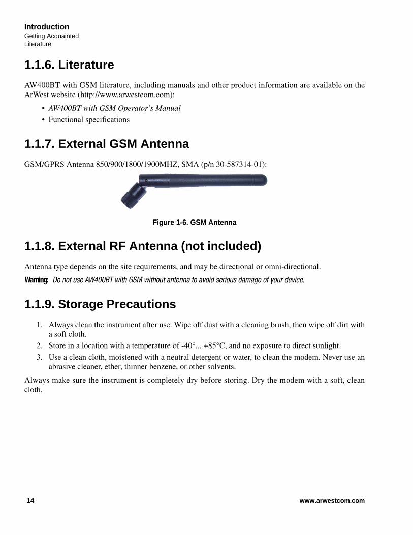
1.1.7. External GSM Antenna
GSM/GPRS Antenna 850/900/1800/1900MHZ, SMA (p/n 30-587314-01):
Figure 1-6. GSM Antenna
1.1.8. External RF Antenna (not included)
Antenna type depends on the site requirements, and may be directional or omni-directional.
Warning: Do not use AW400BT with GSM without antenna to avoid serious damage of your device.
1.1.9. Storage Precautions
1. Always clean the instrument after use. Wipe off dust with a cleaning brush, then wipe off dirt witha soft cloth.
2. Store in a location with a temperature of -40°... +85°C, and no exposure to direct sunlight.
3. Use a clean cloth, moistened with a neutral detergent or water, to clean the modem. Never use anabrasive cleaner, ether, thinner benzene, or other solvents.
Always make sure the instrument is completely dry before storing. Dry the modem with a soft, cleancloth.
14 www.arwestcom.com

Chapter 2
CONFIGURATION
2.1. Powering AW400BT with GSM
To power AW400BT with GSM use the Battery kit 1 (p/n 99-587300-10).
Figure 2-1. Battery Kit 1
2.1.1. Power supply requirements
A single external power supply is necessary to operate AW400BT with GSM. The external power supplyneeds to be Listed for US and Certified for EU countries, it needs also to be a Limited Power Source andrated for Outdoor Use and have an output rated for +9... +36V, 4A. This may not be the same range asother ArWest products with which you are familiar.
CAUTION: To avoid the introduction of hazards when operating and installing, before connecting of the equip-ment to the supply, make sure that the supply meets local and national safety ordinances andmatches the equipment’s voltage and current requirements.
CAUTION: Never attempt any maintenance or cleaning of the supply while plugged in. Always remove supplyfrom AC power before attempting service or cleaning.
Warning: If the voltage supplied is below the minimum specification, the modem will suspend operation. If the voltagesupplied is above the maximum specification, the modem may be permanently damaged, voiding yourwarranty.
Make sure cords are located so that will not be stepped on, tripped over, or otherwise subjected todamage or stress. Do not operate equipment with a damaged cord or plug – replace immediately.
15www.arwestcom.com

ConfigurationRF Antenna InstallationPower supply requirements
To reduce the risk of damage to the equipment, pull by the plug body rather than the output cordwhen disconnecting the equipment.
Do not operate the supply if it has received a sharp blow, been dropped, or otherwise damaged. Donot disassemble the supply.
Warning: Before connecting the external power source and the modem, make sure that the power source matches themodem’s voltage and current requirements.
2.2. RF Antenna Installation
Warning: To avoid the equipment serious damage, do not switch the modem to transmit mode if RF antenna is notconnected!
Select the type of antenna that best fits your application and the one that offers the highest dB gain. Inaddition, setup your system in the highest possible location to minimize obstacles between thetransmitting and receiving systems. Always place the antenna on the highest point available. At aminimum, set the antenna to at least ten feet above the terrain using an antenna mast.
Some antennas intended to be attached to the pole mount adaptor (p/n 14-578117-01) are designed to beoperated with a ground plane and some without it. Antennas operating without ground plane marked inour catalogue as NGP, e.g. UHF NGP Antenna 1/2, 2.4 dB gain, NMO:
• p/n 30-587307-01 UHF NGP Antenna 406-430 MHz, 1/2, 2.4 dB, NMO
• p/n 30-587308-01 UHF NGP Antenna 430-450 MHz, 1/2, 2.4 dB, NMO
• p/n 30-587309-01 UHF NGP Antenna 450-470 MHz, 1/2, 2.4 dB, NMO
These antennas are NO GROUND PLANE antennas with gain 2.4 dB and NMO specified connector typewith should match with your antenna adapter (pole mount or magnet mount). Antennas designed to beoperated with ground plane
• p/n 30-587303-01 UHF Antenna 406-430 MHz, 5/8, 5 dB, NMO
• p/n 30-587304-01 UHF Antenna 430-450 MHz, 5/8, 5 dB, NMO
• p/n 30-587305-01 UHF Antenna 450-470 MHz, 5/8, 5 dB, NMO
provide better gain, but to achieve the best performance of your antenna, add a UHF Antenna GroundPlane Disk (p/n 10-587400-01) to the bottom of the antenna for a ground plane. UHF antenna GroundPlane disk improves VSWR and as result increase RF power delivered from transmitter to antenna andsystem distance range.
To install antenna with ground plane disc (see pictures below):
1. Unscrew the cone-shaped cable part;
2. Place the ground plane disc between cable parts and screw all parts together;
3. Attach cable with ground plane to the UHF antenna;
16 www.arwestcom.com

ConfigurationRF Antenna Installation
Power supply requirements
4. Place the antenna on the pole.
Use coaxial cable and connectors that are impedance-matched with the radio equipment, and make sureto use the shortest length of cable to move the signal between the radio and the antenna:
• p/n 14-578115-01 Accessory UHF Ant Cable TNC/Magn Mount, 12ft1
• p/n 14-578116-01 Accessory UHF Ant Cable TNC/Mini-Magn Mount, 12ft1
• p/n 14-578117-01 Accessory UHF Ant Cable TNC/Pole Mount, 12ft
1. For this type of antenna a metal surface, e.g. car’s roof, serves as ground plane.
1 Unscrew the
2 Place the Ground Plane between3 Attach to the
cone-shaped cable part
cable parts and screw all together
+
UHF Antenna
UHF Antenna
Ground Plane
17www.arwestcom.com

ConfigurationGSM Antenna InstallationConnecting through serial port
2.3. GSM Antenna Installation
Attach the GSM antenna p/n 30-587314-01 to the SMA connector marked GSM.
Note: The GSM and RF antennas should be separated for about 1 meter to avoid the interference of GSM andUHF signals.
2.4. Installing AWLaunch
AWLaunchTM is a Windows® application for the radio modem configuration. AWLaunch is availablefrom the ArWest Communications website.
Note: Refer to the AWLaunch Software Manual for full details on installing and using AWLaunch Software.
1. If downloading the program from the website, extract the program files into a folder on your harddrive.
2. Navigate to the location of the AWLaunch program and double-click the AWLaunch.msi icon.
3. Follow the on-screen installation wizard instructions. Click Next to continue, Back to get back toprevious step, or Cancel to quit the installation.
4. Keep the default installation location or select a new location.
5. Click Close to complete the installation and quit wizard. If desired, create a shortcut on the com-puter’s desktop for quick access to AWLaunch.
To uninstall AWLaunch use the Add and Remove Programs from the Control Panel.
1. Open the Control Panel, then Add or Remove Programs tool. Find AWLaunch, and click Remove.This will uninstall AWLaunch.
2.5. Connecting AW400BT with GSM and Computer
2.5.1. Connecting through serial port
To configure, or maintain AW400BT with GSM, you need to connect the modem and a computer usingan Accessory Data-Ser-Pwr Cable, DB9/DB15/SAE (1,8m), p/n14-578108-02.
Figure 2-2. Accessory Data-Ser-Pwr Cables DB9/DB15/SAE
18 www.arwestcom.com

ConfigurationConfiguring AW400BT with GSM
Connecting through USB port
2.5.2. Connecting through USB port
Make sure the computer has special USB driver installed (available from www.arwestcom.com) beforecontinuing. To configure, or maintain AW400BT with GSM using USB port, you need to connect themodem and a computer using special cable (not included in the standard kit) Access Data-Ser Cable,USB/DB15/SAE (1,8m) (p/n 14-578123-02).
Figure 2-3. Cable p/n 14-578123-01
1. Download the zip-archive with USB driver from www.arwestcom.com;
2. Extract the archive to the new empty folder;
3. Connect the USB port of the computer to the data port of the modem at the switched off powersupply by using of a cable.
4. Turn on your computer.
5. Power AW400BT with GSM.
6. Widows will detect USB driver automatically. Otherwise it will ask to specify driver location.Select the folder with extracted file.
2.5.3. Connecting through Bluetooth®
The AW400BT with GSM modem contains Bluetooth® wireless technology that allows synchronizationbetween the modem and any other external device that supports Bluetooth® wireless technology.
AW400BT with GSM and external device connection procedure varies slightly depending on the type ofexternal device used. In general, the connection procedure is as follows:
Note: Refer to your Bluetooth®-enabled external device documentation for more detailed connectioninformation.
1. Turn on a Bluetooth®-enabled external device and your receiver. The default external devicemode is Master; the modem’s Bluetooth® module mode is Slave.
2. Instruct the external device (Master) to search for the modem (Slave).
3. Once the Master device detects the modem, use the procedure described in the external device’sdocumentation to connect it with the modem.
2.6. Configuring AW400BT with GSM
Once you have established a connection between the modem and the computer, you will be able to:
19www.arwestcom.com
ConfigurationConfiguring AW400BT with GSMConnecting through Bluetooth®
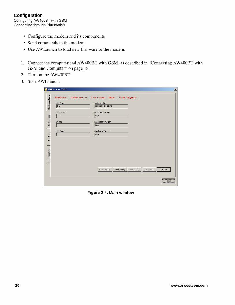
• Configure the modem and its components
• Send commands to the modem
• Use AWLaunch to load new firmware to the modem.
1. Connect the computer and AW400BT with GSM, as described in “Connecting AW400BT with GSM and Computer” on page 18.
2. Turn on the AW400BT.
3. Start AWLaunch.
Figure 2-4. Main window
20 www.arwestcom.com
ConfigurationConfiguring AW400BT with GSM
Connecting through Bluetooth®
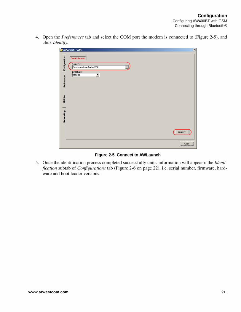
4. Open the Preferences tab and select the COM port the modem is connected to (Figure 2-5), andclick Identify.
Figure 2-5. Connect to AWLaunch
5. Once the identification process completed successfully unit's information will appear n the Identi-fication subtab of Configurations tab (Figure 2-6 on page 22), i.e. serial number, firmware, hard-ware and boot loader versions.
21www.arwestcom.com

ConfigurationConfiguring AW400BT with GSMConnecting through Bluetooth®
Figure 2-6. Identification tab
• In the Unit Name text field the unit’s name can be inserted;
• In the Owner field the owner’s name can be inserted.
6. In the ConfigurationsWireless sub tab set the parameters presented in Table 2-1 (Figure 2-7 onpage 23).
Table 2-1. Modem Parameters for the Wireless Subtab
Parameter Base Modem Remote Modem Repeater
Protocol Base Select from the List Simplex Transmitter, Half Duplex, or PCC transmitter if Pacific crest protocol is used.
RemoteSelect from the List Simplex Receiver, Half Duplex Remote, or PCC Receiver if Pacific crest protocol is used.
RemoteSelect from the List Repeater, if the modem will be used as Repeater, or PCC Repeater, if Pacific crest protocol is used.
Frequency channel Specifies the frequency channel on which the UHF radio operates.
Modulation type Specifies a modulation scheme that will be used by your modem1. DQPSK is recommended.
Forward Error Correction (FEC)
Enable
Scrambling Enable Enable
RF power Select the transmission power for the radio modem in the RF modem slider, or type the value in the edit box
1. For both Base and Remote modems the modulation type must be the same.
22 www.arwestcom.com

ConfigurationConfiguring AW400BT with GSM
Connecting through Bluetooth®
Figure 2-7. Configurations tab. Wireless subtab
7. In the Dealer Configuration set the channel spacing and fill in the channel map (the list of fre-quency channels). See Figure 2-8 on page 24. The specified frequencies should be in band of 406-470 MHz.
23www.arwestcom.com

ConfigurationConfiguring AW400BT with GSMConnecting through Bluetooth®
.
Figure 2-8. Dealer Configuration tab
24 www.arwestcom.com

ConfigurationConfiguring AW400BT with GSM
Connecting through Bluetooth®
8. Configure Bluetooth in ConfigurationsBluetooth subtab.
Figure 2-9. Bluetooth subtab
• Enter PIN code
• Set state to ON
• Set the Mode to Slave.
25www.arwestcom.com
ConfigurationConfiguring AW400BT with GSMConnecting through Bluetooth®
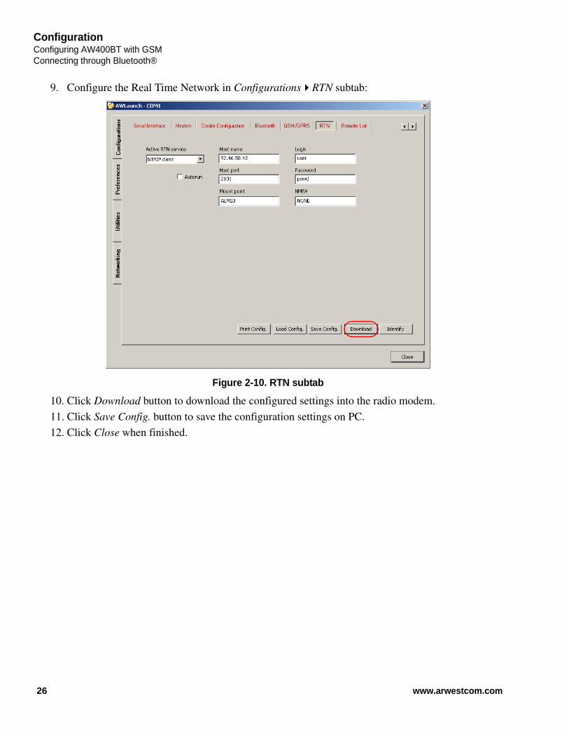
9. Configure the Real Time Network in ConfigurationsRTN subtab:
Figure 2-10. RTN subtab
10. Click Download button to download the configured settings into the radio modem.
11. Click Save Config. button to save the configuration settings on PC.
12. Click Close when finished.
26 www.arwestcom.com

ConfigurationConfiguring AW400BT with GSM
Sleep Mode and Alarm settings
2.6.1. Sleep Mode and Alarm settings
The sleep mode and alarm settings can be configured in the Modem subtab of the Configurations tab(Figure 2-11).
Figure 2-11. Configurations tab. Modem subtab
To configure the sleep mode set the period of inactivity in milliseconds and how the modem will beactivated: using internal real-time clock, command line, or internal sense line.
The First and second Event Output control allow routing the alarms and the inputs from remote sensors tothe first and second event outputs.
Note: This feature is not supported in current firmware version.
27www.arwestcom.com
ConfigurationChecking Firmware VersionSleep Mode and Alarm settings
2.7. Checking Firmware Version
Use AWLaunch to check the firmware version of your AW400BT with GSM.
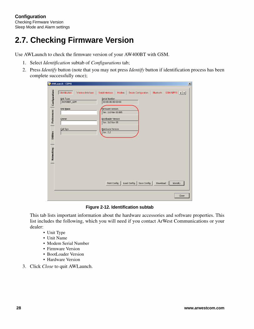
1. Select Identification subtab of Configurations tab;
2. Press Identify button (note that you may not press Identify button if identification process has beencomplete successfully once);
Figure 2-12. Identification subtab
This tab lists important information about the hardware accessories and software properties. Thislist includes the following, which you will need if you contact ArWest Communications or yourdealer:
• Unit Type• Unit Name• Modem Serial Number• Firmware Version• BootLoader Version• Hardware Version
3. Click Close to quit AWLaunch.
28 www.arwestcom.com
ConfigurationLoading New Firmware
Sleep Mode and Alarm settings
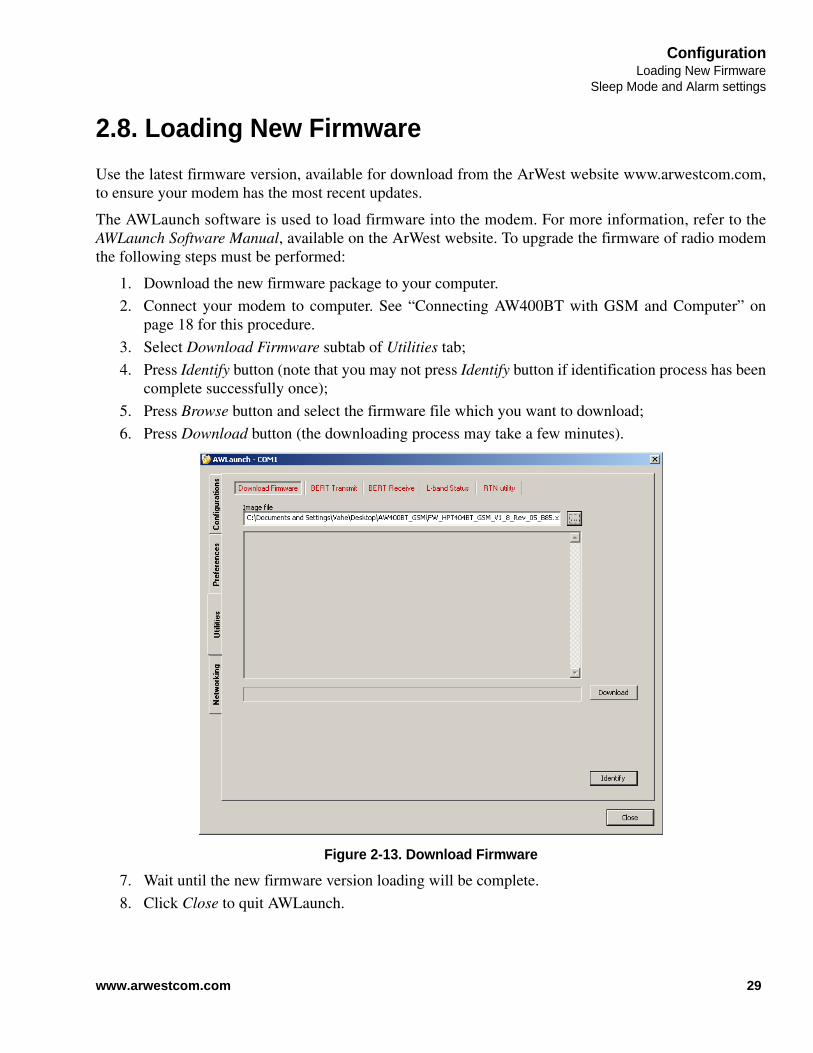
2.8. Loading New Firmware
Use the latest firmware version, available for download from the ArWest website www.arwestcom.com,to ensure your modem has the most recent updates.
The AWLaunch software is used to load firmware into the modem. For more information, refer to theAWLaunch Software Manual, available on the ArWest website. To upgrade the firmware of radio modemthe following steps must be performed:
1. Download the new firmware package to your computer.
2. Connect your modem to computer. See “Connecting AW400BT with GSM and Computer” onpage 18 for this procedure.
3. Select Download Firmware subtab of Utilities tab;
4. Press Identify button (note that you may not press Identify button if identification process has beencomplete successfully once);
5. Press Browse button and select the firmware file which you want to download;
6. Press Download button (the downloading process may take a few minutes).
Figure 2-13. Download Firmware
7. Wait until the new firmware version loading will be complete.
8. Click Close to quit AWLaunch.
29www.arwestcom.com

ConfigurationLoading New FirmwareSleep Mode and Alarm settings
30 www.arwestcom.com

Internet servicesTCP client
INTERNET SERVICES
3.1. TCP client
TCP client service is used to receive RTN corrections from the specified TCP server via GPRS network.The downloaded RTN corrections are routed to the communication ports (UART, USB, BT) and/orbroadcasted by UHF transmitter to multiple UHF receivers. Using this service it is possible to provide thelocal GPS receiver (connected to UART, USB or BT) and remote UHF receivers (for example thereceivers which are not equipped with GSM/GPRS module) by downloaded RTN correctionssimultaneously. To restart the TCP client after next boots automatically the RTN auto running feature canbe used (refer to RTN AUTORUN command’s description).
Example of TCP client configuration:Let’s assume we need to download RTN corrections from the TCP server which has thefollowing parameters:
• IP address – 92.43.102.1; • Port – 3615;• Login – user;• Password – pswd.
The TCP client should download corrections from TCP server, route them to UART andbroadcast by UHF transmitter simultaneously. Suppose the parameters of UHF transmitter are asfollows:
• Wireless protocol – ArWest Transmitter;• Output power – 25 dBm;• Modulation – DQPSK;• Channel spacing – 25 kHz;• Frequency channel – 1;• Scrambling vector – 255.
The following is the step by step configuration of AW400BT to configure and run described TCPclient:
Configure the UHF modem LINK PROT 2LINK PWRB 25LINK MOD 2LINK SPACE 0LINK CHAN 1LINK SCRAM 255
Select the TCP client as an active RTN service RTN TYPE 0
Set the host name/IP address to connect RTN HOSTNAME 92.43.102.1
Set the host port of remote machine RTN HOSTPORT 3615
31www.arwestcom.com
Internet servicesTCP serverRTN corrections uploading
The execution of “RTN CONNECT 1” command starts connecting process of TCP client andshows the progress of connecting. The following is the reported progress when the TCP clientconnected and authenticated on the host machine successfully:RTN CONNECT 1Connecting........Initializing GSM module..................PIN code authentication..Network registration..........Activating GPRS context................Socket Dialing..Connected, Authenticated
To start data routing the unit should be switched to data mode using “DATAMODE” command.Now to stop the running TCP client, the unit should be switched to command mode and “RTNCONNECT 0” command should be issued. The successful execution of this command reportsthe following progress and result:RTN CONNECT 0Disconnecting..........Disconnected@00
Note: If no data received from TCP server during 30 seconds the authorized TCP client disconnects from itsserver and starts reconnecting process.
3.2. TCP server
This service provides the following two features:
3.2.1. RTN corrections uploading
This feature is used to provide the authorized TCP clients by RTN corrections through the TCP channelusing GPRS network. RTN corrections are taken from local GPS receiver (connected to UART, USB orBT) or from remote UHF transmitter and sent to the authorized TCP client.
Set login and password to pass authentication on remote TCP server RTN LOGIN userRTN PASSWORD pswd
Set data routing type to “GSMGPRS<->UART and GSMGPRS->UHF” DPORT ROUTE 7
Start TCP client service RTN CONNECT 1
32 www.arwestcom.com

Internet servicesTCP server
Remote CLI support
3.2.2. Remote CLI support
TCP server also provides full functional Command Line Interface to the authorized TCP client. It meansusing the TCP server it is possible to configure and control the radio modem through the internet (by TCPclient terminal at side of DTE). Configuration files upload/download and firmware image upgradingoperations are also supported by remote CLI feature provided by TCP server. The CLI is shared withauthorized TCP client when the unit is in command mode.
The RTN command is used to configure, control and monitor the TCP server. To start the TCP server afternext boots automatically the RTN auto running feature can be used (refer to RTN AUTORUN command’sdescription). It means that BOOT command issued by Remote CLI will not disconnect the Remote CLIpermanently if the unit is configured to start TCP server automatically after next boot. The client terminalcan connect to the TCP server again after unit’s rebooting.
Example 1 of TCP server configuration – RTN corrections uploading:Let’s assume we need to upload RTN corrections (taken from UART) to authorized TCP clientusing TCP server:
• Server should be running on the 3615 port of assigned IP address (IP address is assigned byGPRS network);
• Login – user;• Password – pswd.
The following is the step by step configuration of AW400BT with GSM to configure and rundescribed TCP server:
The execution of “RTN CONNECT 1” command starts TCP server and shows the progress ofstarting process. The following is the reported progress when the TCP server is run successfully:RTN CONNECT 1Connecting..........Initializing GSM module..................PIN code authentication..Network registration..........Activating GPRS context..........Starting server..Server is running
At this point the server is running and waits for authorized TCP client. Now the unit should beswitched to data mode to start RTN corrections uploading when the TCP client is connected andauthorized.
Select TCP server as an active RTN service RTN TYPE 2
Set the host port on which the server should be run RTN HOSTPORT 3615
Set the login and password which are used for TCP client’s authorization RTN LOGIN userRTN PASSWORD pswd
Set data routing type to “GSMGPRS<->UART” DPORT ROUTE 4
Start/run the configured TCP server RTN CONNECT 1
33www.arwestcom.com

Internet servicesNTRIP clientRemote CLI support
RTN CONNECT 0Disconnecting..........Disconnected@00
Example 2 of TCP server configuration – Remote CLI support:Let’s assume we would like to configure the AW400BT with GSM remotely - through theinternet. We can do it using Remote CLI support provided by TCP server service. The followingis the step by step configuration of AW400BT with GSM to run TCP server in such mode (thelogin, password and host port are the same as in Example 1 above).
The execution of “RTN CONNECT 1” command starts TCP server and shows the progress ofstarting process. The following is the reported progress when the TCP server is run successfully:RTN CONNECT 1Connecting..........Initializing GSM module..................PIN code authentication..Network registration..........Activating GPRS context..........Starting server..Server is running
At this point the TCP server is running and waits for authorized TCP client to provide remoteCLI. To get the IP address on which the TCP server is running the RTN HOSTNAME commandcan be used.
Note: Currently the TCP server is able to serve one TCP client.
Note: TCP server is restarted if the connection with the client is closed.
3.3. NTRIP client
This service is used to receive RTN corrections from specified Mount point of the specified NTRIP castervia GPRS network. The downloaded RTN corrections are routed to the communication ports (UART,USB, BT) and/or broadcasted by UHF transmitter to multiple UHF receivers. Using this service it ispossible to provide the local GPS receiver (connected to UART, USB or BT) and remote UHF receivers(for example the receivers which are not equipped with GSM/GPRS module) by downloaded RTNcorrections simultaneously. If the NMEA GGA is required by remote NTRIP caster, the NTRIP client can
Select TCP server as an active RTN service RTN TYPE 2
Set the host port on which the server should be run RTN HOSTPORT 3615
Set the login and password which are used for TCP client’s authorization
RTN LOGIN userRTN PASSWORD pswd
Start/run the configured TCP server RTN CONNECT 1
34 www.arwestcom.com

Internet servicesNTRIP client
Remote CLI support
be configured to send the NMEA GGA messages to NTRIP caster taking NMEA from the local GPSreceiver (connected to the UART, USB or BT) or using predefined NMEA GGA message saved in theconfiguration file. The RTN command is used to configure, control and monitor the NTRIP client service.To start the NTRIP client service automatically after next boot the RTN auto running feature can be used(refer to “RTN AUTORUN” command’s description).
Example of NTRIP client configuration:Let’s assume we need to download RTN corrections from NTRIP caster which has the followingparameters:
• IP address - 78.43.52.12;• Port – 2101;• Mount point AUT10;• Login – user;• Password – pswd;
NMEA GGA messages are required by NTRIP caster.Suppose the NTRIP client should read the NMEA GGA messages from USB, send them toNTRIP caster then download RTN corrections from caster and route them to USB port. The following is step by step configuration of AW400BT to configure and run described NTRIPclient service.
The execution of “RTN CONNECT 1” command starts connecting process of NTRIP client andshows the progress of connecting. The following is the reported progress when the NTRIP clientconnected and authenticated on the host machine successfully:RTN CONNECT 1Connecting........Initializing GSM module..................PIN code authentication..Network registration..........Activating GPRS context................Socket Dialing..Connected, Authenticated
After successful authentication the unit should be switched to data mode to start data routing as itis configured.
Select the NTRIP client as an active RTN service RTN TYPE 1
Set the host name/IP address to connect RTN HOSTNAME 78.43.52.12
Set the host port of remote machine RTN HOSTPORT 2101
Set login and password to pass authentication on remote NTRIP caster. RTN LOGIN userRTN PASSWORD pswd
Set the Mount point RTN MPOINT AUT10
Set data routing type to “GSMGPRS<->USB” DPORT ROUTE 5
Disable the predefined NMEA GGA messages (the NMEA GGA messages are read from USB port)
RTN NMEA NONE
Start NTRIP client service RTN CONNECT 1
35www.arwestcom.com

Internet servicesNTRIP clientRemote CLI support
Now to stop the running NTRIP client service, the unit should be switched to command modeand “RTN CONNECT 0” command should be issued. The successful execution of this commandreports the following progress and result:RTN CONNECT 0Disconnecting..........Disconnected@00
Note: If no data received from NTRIP caster during 30 seconds the authorized NTRIP client disconnects fromits caster and starts reconnecting process.
Note: The IP address, host port, user name and login parameters in the examples above are invented. Theseparameters should be taken from RTN provider.
Note: In the examples above it is assumed that the GPRS Access point name, login and password are alreadyconfigured.
36 www.arwestcom.com

Chapter 4
COMMAND LINE INTERFACE
The built-in user friendly Command Line Interface (CLI) allows user performing full configuration of theunit and reading the statistics and alarm statuses. It is the most powerful tool to configure the unit. Itmakes changes to all possible settings that system will not be able to determine automatically.
The CLI commands allow user configuring and reconfiguring the unit’s settings. The user configurationparameters that could be changed through the CLI are:
• Data Port Settings
- Baud Rate
- Flow control (None or RTS/CTS)
• Radio Operation Modes
Note: The unit’s configuration that is set or modified through the CLI will be lost after unit’s reboot, unless thesaving operation is used to store a new setting in the unit’s configuration file.
The CLI commands also provide filling operations, which include:
• Downloading
- Unit’s Configuration files
- Software Images
• Uploading Unit’s Configuration files
• Saving into the configuration files the configuration parameters modified through the CLI.
4.1. Command Line Interface Convention
The following convention is implemented in AW400BT with GSM Command Line Interface (CLI):
• The Carriage Return/Line Feed (CR/LF, 0x0D/0x0A) is a command delimiter.
• The Carriage Return/Line Feed (CR/LF, 0x0D/0x0A) is a reply delimiter followed by the “CLI>”prompt if Echo option is On.
• The Carriage Return/Line Feed (CR/LF, 0x0D/0x0A) is a reply delimiter if Echo option is Off(default option).
• The 2-digit number followed by “@” in the unit’s reply indicates the error code (refer to Table 4-1 for description).
• A successfully performed command is replied by @00 code for both Echo ON and OFF modes.
• A command with the certain [Parameter Name] and blank [Parameter List] displays the currentsettings for a given parameter.
37www.arwestcom.com

Command Line InterfaceCommand Line Interface ConventionSoftware Switching to Maintenance Mode
• To set the mode ordered by CLI commands as permanent User Setting (the setting automaticallyselected for the boot-up unit) the SAVE command must be asserted.
• [/?] orders to show the help information for the given command.
• Commands are not case sensitive (unless the GSM and RTN commands): small, none capitalcharacters can be used to enter CLI commands.
Table 4-1. Command Line Interface Error Codes
4.1.1. Software Switching to Maintenance Mode
To switch to Maintenance mode the special byte-sequences with special meanings are used:
• Escape-Sequence: “+++” with 20 ms guard time before and after the command characters
• Escape-Acknowledge: “@00<CR><LF>” 20 ms toggling on CTS control line needed toacknowledge switching from Data to Maintenance mode and vice versa. In Maintenance mode,the unit’s serial port must keep CTS line always active.
Happy Flow
1. In data-mode the unit starts looking for the Escape-sequence if there is no data from DTE formore than 20 ms (Start Guard Time).
2. If the unit detects the Escape-Sequence, the Receiver immediately stops forwarding to DTE thedata received over the air and buffers it instead.
3. The radio unit waits for 20 ms and then sends Escape-Acknowledge to DTE if there is no datafrom DTE during 20 ms of Stop Guard Time.
4. The unit goes to Maintenance mode and discards Escape-Sequence from input buffer. The modemis immediately ready to receive commands. At the same time it continues buffering the datareceived over the air since step 2.
Error Code Short Description
0x01 Command Syntax Error. A command followed by “/?” displays a command usage.
0x02 The parameter has a format error. A command with the certain [Parameter Name] followed by “/?” displays the format and range of the variable.
0x03 The parameter is out of allowed range or it is not allowed to change in the current operation mode. A command with the certain [Parameter Name] followed by “/?” displays the format and range of the variable.
0x04 The command is not valid for specific radio model. To display the list of available commands, the HELP command must be used (see “Software Switching to Maintenance Mode” ).
0x05 Unspecified Error
0x06 Operation is not allowed
0x07 Operation failed
38 www.arwestcom.com

Command Line InterfaceNetworking Commands
Hardware Switching to Maintenance Mode
4.1.2. Hardware Switching to Maintenance Mode
As alternative to Software Switching, the switching through the MP/DP control line can be used (thiscontrol line can be also used as Data Terminal Ready, DTR). To set Maintenance mode, the DTE mustassert DTR signal active (0v level). By falling edge of DTR signal the unit goes to Maintenance mode andthen sends Escape-Acknowledge to DTE („@00<CR><LF>“).
20 ms toggling on CTS control line followed by Escape-Acknowledge response is needed toacknowledge switching from Data to Maintenance mode and vice versa. In Maintenance Mode, the unit’sserial port must keep Clear to Send (CTS) line always active (see also “MPORT” on page 42).
Note: The powered up radio modem always goes to data mode.
4.1.3. Switching to Data Mode
• DTE sends the CLI command „DATAMODE<CR><LF>“to the unit.
• Unit immediately goes to data mode without Escape Acknowledge.
• If no valid CLI commands received from DTE within 1 minute, the unit will automatically switchback to data-mode.
Note: The data received over the air could be lost due to Rx buffer overflow if the unit stays in Maintenancemode longer than 15 seconds.
4.2. Networking Commands
4.2.1. LINK
The LINK command is responsible for configuring radio’s operation mode. It has parameters listedbelow.
LINK [Parameter Name] [Parameters List] [/?]
39www.arwestcom.com

Command Line InterfaceNetworking CommandsLINK
Note: The frequency defined by CHAN parameter is not valid if Frequency Hopping mode is selected.
In the Frequency Hopping mode, the Frequency Pattern generator must generate the random numberssmaller than the number of frequencies listed in the unit's frequency list.
Parameter Name Parameter List
PROT 1 - “Simplex Receiver”, a default setting for Remote units 2 - “Simplex Transmitter”3 - Reserved for future use4 - Reserved for future use5 - Reserved for future use6 - Reserved for future use7 - “TRMB Receiver” (used with GMSK modulation, Trimble compatible) 8 - “TRMB Transmitter” (used with GMSK modulation, Trimble compatible) 9 - “Transparent w/EOT” Repeater (used with GMSK and 4FSK, Pacific Crest compatible) 10 - “Repeater” (ArWest Proprietary Simplex) 11 - “TRMB Repeater” (used with GMSK modulation, Trimble compatible) 12 - “Transparent w/EOT” Receiver (used with GMSK and 4FSK modulation, Pacific Crest compatible)13 - “Transparent w/EOT” Transmitter (used with GMSK and 4FSK modulation, Pacific Crest compatible) 14 - “STL Receiver” (used with 4FSK modulation, Satel compatible) 15 - “STL Transmitter” (used with 4FSK modulation, Satel compatible)
MOD 1 – DBPSK2 – DQPSK, a default settings3 – D8PSK4 – D16QAM5 – GMSK6 – 4FSK
CHAN 1-32 - Selects the frequency channel used for UHF data receiving operation. The maximum value is defined by number of frequencies in the channel map.
CHANTX 1-32 - Selects the frequency channel used for UHF data transmitting operation. The maximum value is defined by number of frequencies in the channel map.
SPACE Sets channel spacing:0 - 25kHz, a default setting1 - 12.5kHz2 - 6.25kHz3 - 20kHz
PWRB / PWRW (15 - 36) / (320 - 4000) - RF output Power in dBm / mW
FHOP (0 - 32) - Frequency Hopping Pattern numberLINK FHOP command can be processed only if the Channel Map (up to 32 channels)
SCRAM 0 - No Scrambling (a default setting)(1 - 255) - Seed for Pseudo-Random Sequence Generator
FEC 0 - Disable Forward Error Correction (FEC), a default setting1 - Enable Reed-Solomon encoding
RTR Base Unit 0 - No Retransmission in the wireless cluster1- There is RepeaterRemote Unit 0 - Auto Detect (Base or Repeater)1 - Receive from Repeater2 - Receive from Base
40 www.arwestcom.com
Command Line InterfaceSerial Interfacing Commands
DPORT
4.3. Serial Interfacing Commands
4.3.1. DPORT
The DPORT is an object that is responsible for data port interface configurations like Bit Rate, Flow Control, etc.
DPORT [Parameter Name] [Parameters List] [/?]
The response of command without Parameter Name indicates all values:
RATE =0
BITS =8
PARITY =NONE
FLOW =NONE
DTR =0
RS =RS232
ROUTE = 1
Parameter Name Parameter List
RATE 0 – Maintenance Port baud rate, a default setting1 – 1200 baud2 – 2400 baud3 – 4800 baud4 – 9600 baud5 – 14400 baud6 – 19200 baud7 – 38400 baud8 – 57600 baud9 – 115200 baud, a default setting
BITS Set number of bits in one byte (8 or 7) 8 is a default setting
PARITY 0 – None, a default setting1 – Odd2 – Even
FLOW 0 – None, a default setting1 – Not used2 – HW (RTS/CTS)
RS 0 - RS232, a default setting1 - RS4852 - RS422use save, boot commands to activate modification
ROUTE Sets/gets the data routing type. The following is the list of parameter values: 1 - UART<->UHF bidirectional 2 - USB<->UHF bidirectional 3 - BT<->UHF bidirectional 4 - UART<->GSM/GPRS bidirectional 5 - USB<->GSM/GPRS bidirectional 6 - BT<->GSM/GPRS bidirectional 7 - UART<->GSM/GPRS bidirectional & GSM/GPRS->UHF one directional 8 - USB<->GSM/GPRS bidirectional & GSM/GPRS->UHF one directional 9 - BT<->GSM/GPRS bidirectional & GSM/GPRS->UHF one directional 10 - GSM/GPRS<->UHF bidirectional.
41www.arwestcom.com

Command Line InterfaceSpecial CommandsMPORT
4.3.2. MPORT
The MPORT is an object that is responsible for maintenance serial port interface configuration such asdata rate.
MPORT [Parameter Name] [Parameters List] [/?]
4.4. Special Commands
4.4.1. BOOT
The BOOT command is intended to reboot the unit using selected user settings.
4.4.2. HELP
The HELP command types the list of all available commands:
HELP - Display this usage
XMOD - Activate X-Modem Protocol
BOOT - Reboot the unit
LINK - Set RF Link Operation Mode
DPORT - Set Data Port Configuration
MPORT - Set Maintenance Port Configuration
ALARM - Alarm Indication and Alarm Control Configuration
SLEEP - Set Sleep Mode Configuration
STATE - Display Status and Statistics
SAVE - Save Current Configuration into Configuration File
INFO - Display Product ID along with Hardware/Software Versions
ATI - Display Product ID along with Hardware/Software Versions
MAP - Operates with Channel Map
GSM - Configure and monitor GSM/GPRS module operation mode
RTN - Configure and monitor Virtual reference station operation mode
Parameter Name Parameter List
RATE 0 – Auto.1 – 1200 baud2 – 2400 baud3 – 4800 baud4 – 9600 baud5 – 14400 baud6 – 19200 baud7 – 38400 baud8 – 57600 baud9 – 115200 baud, a default setting
42 www.arwestcom.com
Command Line InterfaceSpecial Commands
SAVE
DATAMODE - Exit Command Mode
[COMMAND] /? - Display Command Usage
4.4.3. SAVE
The SAVE command is intended to store the unit’s currently used configuration into the UserConfiguration file. The configuration stored in the User Configuration file is activated automatically afterunit’s reboot.
4.4.4. SLEEP
The SLEEP command determines the sleep mode parameters. The sleeping AW400BT with GSM can beactivated by real-time CLK, DTR/RTS lines, and command received through TTL inputs. The user canselect one, two, or all three conditions.
SLEEP [Parameter Name] [Parameters List] [/?]
Parameter Name Parameter List
CLK 0 – Do not activate by internal real-time clock(1 – 255) – Activate by internal real-time clock after 100 to 25500 msec of sleeping
HW 0 – Do not activate through DTR/RTS lines1 – Activate through DTR/RTS lines
TTL 0 – Do not activate by external sense lines1 – Activate by external sense lines
GTS 0 – Disable Sleep mode (default)(1 – 255) – Go to sleep mode if there is no activity in 10 to 2550 msec
43www.arwestcom.com

Command Line InterfaceDiagnostics and Identification CommandsINFO
4.5. Diagnostics and Identification Commands
4.5.1. INFO
The INFO command is used to retrieve the Radio ID along with its Hardware version, the loaded real-time software version/revision and BootLoader’s version/revision.
INFO [Parameter Name] [Parameters List] [/?]
The INFO command without Parameter Name indicates all values:
AW400BT UHF Transceiver, ArWest
Product ID =49
S/N =0000000123BB
Hardware =Ver. 3.3
Software =Ver. 1.8 Rev 04 B24
BootLoader =Ver. 3.0 Rev 03
BT addr =00:18:D7:00:3C:C7
4.5.2. STATE
The STATE command is used to check the state of the wireless link and the alarm control lines.
STATE [Parameter Name] [Parameters List] [/?]
Parameter Name Parameter List
ID Product ID:ID49 - AW400BT_GSM
SN Six bytes Serial Number (SN)
HW 1.0 - hardware version in numeric “Major.Minor” format
SW Ver. 1.0 Rev. A - displays software's version in numeric “Major.Minor” format and revision in numeric format (range from 01 to 99) for engineering releases and alphabetic format (A to Z) for manufacturing releases
BL Ver. 1.0 Rev. A - displays BootLoader’s version in numeric “Major.Minor” format and revision in numeric format (range from 01 to 99) for engineering releases and alphabetic format (A to Z) for manufacturing releases
BT Bluetooth serial number
Parameter Name
Parameter List
RSSI -15 to -137 dBm - Indicates the Receive Signal Strength in dBm
BER 0 to 9.9E-3 - Indicates the BER level
FREQ 406.000000 to 470.000000 MHz - Displays the central frequency of the operating channel
TEMP -30.C to 100.C. Displays the temperate inside of enclosure.
44 www.arwestcom.com

Command Line InterfaceRTN
STATE
The STATE command without Parameter Name indicates all values as shown below:
RSSI =-141 dBm
BER =0E-0
FREQ =435.000000 MHz
CHAN =-4
TEMP =32
SYNC =0
MODE =FIXED
VHPA =11.75 V
BT =ON
4.6. RTN
Command RTN is used to select, configure, control and monitor the active Real Time Network. Exceptthe monitoring parameters (STATE and ERROR) all the parameters of RTN services can be saved in theuser configuration file by SAVE command.
SYNC 0 - if link is not established yet1 - indicates the link established
MODE AUTO/FHOP/FIXED
VHPA VCC V
BT ON/OFF
Parameter Name Description and parameters list
TYPE Sets/gets the active RTN service:0 – TCP client;1 – NTRIP client;2 – TCP server.Example: the next command selects NTRIP client as an active RTN service to be configured, controlled and monitored:RTN TYPE 1The next command is used to get currently selected active RTN service:RTN TYPE1@00
CONNECT Starts/stops the active RTN service.0 – Stops/disconnects the active RTN service if it is running;1 – Starts/connects the active RTN service if it is stopped.There is a 50-70 seconds and 15 seconds timeouts for start and stop processes correspondingly. If during this timeout the start/stop operation is not succeeded the operation is failed and the last error is monitored by RTN ERROR command.Example: the next command starts the active RTN service:RTN CONNECT 1
Parameter Name
Parameter List
45www.arwestcom.com

Command Line InterfaceRTNSTATE
HOSTNAME Sets/gets the string type value representing the host name/IP address of the active RTN service. In case of TCP/NTRIP clients this is the IP address/host name of the remote machine to connect. In case of TCP server this parameter is read only and represents its own IP address assigned by GPRS network.<value> – string (length < 64 bytes).Example: next command sets the IP address of the host to connectRTN HOSTNAME 92.43.102.1Next command gets the currently set IP address of the active RTN:RTN HOSTNAME92.43.102.1@00
HOSTPORT Sets/gets the decimal numeric value representing the host port of the active RTN service. In case of TCP/NTRIP clients this is the port of remote machine to connect. For TCP server this is the port on which the server is listening for incoming connections.<value> - port number (1..65535).Example: next command sets the host port of active RTN service:RTN HOSTPORT 3615Next command gets the currently set host port of the active RTN service:RTN HOSTPORT3615@00
MPOINT Sets/gets the string type value representing the Mount point for NTRIP client to connect. This parameter is not applicable for TCP client/server services. To set this parameter the NTRIP client should be selected as an active RTN service by RTN TYPE command.<value> – string (length < 64 bytes).Example: next command sets the Mount point for NTRIP client to connect:RTN MPOINT AUT10The next commands gets the Mount point of NTRIP client:RTN MPOINTAUT10@00
NMEA Sets/gets the string type value representing predefined NMEA GGA message to use in NTRIP client service. This parameter is not applicable for TCP client/server services. To set this parameter the NTRIP client should be selected as an active RTN service by RTN TYPE command. <value> – string (length < 128 bytes).If the value represents any string different from NONE the authorized NTRIP client uses this predefined message and sends it to NTRIP caster once a second.If the value is set to NONE the NTRIP client does not send predefined NMEA GGA message to NTRIP caster.Example: next command sets/defines the NMEA GGA message for NTRIP client:RTN NMEA 1234567890The next command gets the currently set NMEA parameter of NTRIP client:RTN NMEA1234567890@00
LOGIN Sets/gets the string type value representing the login (user name) of the active RTN service. For TCP/NTRIP clients this parameter is used to pass authorization on the remote machine. For TCP server this parameter is used to identify the authorized TCP clients.<value> - string (length < 64 bytes).Example: next command sets the login of the active RTN service to “user”RTN LOGIN userNext command gets the currently set login of the active RTN service:RTN LOGINuser@00
46 www.arwestcom.com

Command Line InterfaceGSM
STATE
Note: The internet service can be configured in its stopped/disconnected state only.
Note: The RTN command is case sensitive to support possible case sensitive string type values of its parameters.
4.7. GSM
GSM command is used to configure, control and monitor the built in Quad band GSM/GPRS module.
PASSWORD Sets/gets the string type value representing the password of the active RTN service. For TCP/NTRIP clients this parameter is used to pass authorization on the remote machine. For TCP server this parameter is used to identify the authorized TCP clients.<value> - string (length < 64 bytes).Example: next command sets the password of the active RTN service to “pswd”RTN PASSWORD pswd
Next command gets the currently set password of the active RTN service:RTN PASSWORDpswd@00
TRANSPORT Gets the transport of the RTN service used to access the internet. This parameter is read only and returns GPRS.Example: next command gets the transport of RTN servicesRTN TRANSPORTGPRS@00
STATE Gets the state of active RTN service. This parameter is used for monitoring purposes.Example: next command is used to get the state of active RTN serviceRTN STATEAuthenticated@00
ERROR Gets the description of last error occurred in the active RTN service. This parameter is used for monitoring purposes.Example: next command gets the last error occurred in the active RTN serviceRTN ERRORNone
AUTORUN Sets/gets the auto running state of the RTN service.0 – Disables auto running of active RTN service for next boots;1 – Enables auto running of active RTN service for next boots.To take effect the parameter should be saved in the configuration file using SAVE command.
Parameter name Parameter list and description
BAND Sets/gets the operating frequency band of GSM/GPRS module:0 - GSM 900MHz, DCS 1800MHz;1 - GSM 900MHz, PCS 1900MHz;2 - GSM 850MHz, DCS 1800MHz;3 - GSM 850MHz, PCS 1900MHz.Example: next command sets the operating frequency band of GSM/GPRS module to “GSM 900MHz, DCS 1800MHz”.GSM BAND 0Next command gets the current operating frequency band of GSM/GPRS module:GSM BANDGSM 900MHz, DCS 1800MHz@00
47www.arwestcom.com

Command Line InterfaceGSMSTATE
Note: The GSM command is case sensitive to support possible case sensitive string type values of itsparameters.
RSSI Gets the received signal level of GSM/GPRS module which is used for monitoring purposes.<response> – N/A – the GSM/GPRS module switched OFF or signal quality is not recognized; Not known – the received signal level of GSM/GPRS module is not detected yet; Value of received signal level in dBm.Example: next command gets the current received signal level of GSM/GPRS module.GSM RSSI-79 dBm@00
PINCODE Sets/gets the string type value representing the PIN code of the SIM card installed. PIN code is used by firmware to unlock the SIM card if it is requested. Otherwise the parameter is ignored.<value> - string (length < 64 bytes).Example: next command sets the PIN code to “1111” to unlock the SIM card by firmware.GSM PINCODE 1111Next command gets the currently set PINCODE parameter:GSM PINCODE1111@00
APN Sets/gets the string type value representing the Access Point Name of GPRS which is used to access the internet.<value> - string (length < 64 bytes).Example: next command sets the APN to “connect”GSM APN connectNext command gets the currently set APN:GSM APNConnect@00
APNLOGIN Sets/gets the string type value representing the login (user name) which is used in the authorization process at access point site of GPRS.<value> - string (length < 64 bytes).Example: next command sets the login to “user”GSM APNLOGIN userNext command gets the currently set login:GSM APNLOGINuser@00
APNPASSWORD Sets/gets the string type value representing the password which is used in the authorization process at access point site of GPRS.<value> - string (length < 64 bytes).Example: next command sets the password to “pswd”GSM APNPASSWORD pswdNext command gets the currently set password:GSM APNPASSWORDpswd@00
POWER Sets/gets the power of GSM/GPRS module.0 – switches OFF the module if it is ON;1 – switches ON the module if it is OFF.Example: next command switches ON the power of GSM/GPRS moduleGSM POWER 1Next command gets the power of GSM/GPRS module:GSM POWER1@00
48 www.arwestcom.com

Appendix A
SPECIFICATIONS
A.1. AW400BT with GSM Modem Specifications
The following sections provide specifications for the modem and its internal components.
A.1.1. General Radio Specifications
Table A-1. General Radio Specifications
Parameter Specification
Operating Frequency Range 406 - 470 MHz (EU)406.1 - 470 MHz (USA)406.1 - 430;450-470 MHz (Canada)
Channel Spacing 25/12.5/6.25 kHz (USA, Canada)25/20/12.5 kHz (EU)
Data Rate (25/20/12.5/6.25 kHz Channel Spacing)
9600/7500/4800/2400 bps – DBPSK/GMSK19200/15000/9600/4800 bps – DQPSK/4FSK28800/22500/14400/7200 bps – D8PSK38400/30000/19200/9600 bps – D16QAM
System Gain for DBPSKmodulation (Antenna gain is notincluded)
161 dB (for 25 kHz Channel Spacing)163 dB (for 12.5 kHz Channel Spacing)164 dB (for 6.25 kHz Channel Spacing)
Roaming Speed for DBPSK modulation 75 mph / 120 km/h
Modulation GMSK/4FSK/DBPSK/DQPSK/D8PSK/D16QAM
Nominal Impedance 50 Ohms
End to End delay 60 ms
Communication Mode Time Division Duplex (TDD)Time Division Multiple Access (TDMA)
Maximum Distance Range 16 miles / 26 km
Serial port Serial (RS-232) up to 115200 bps.Serial port configurable as RS-232 and RS-422, or RS-485
USB USB 2.0 device port (12 Mbps)
GSM/GPRS Module Internal GSM/GPRS quad-band module 850/900/1800/1900 MHz
GSM/GPRS Antenna External
Bluetooth Bluetooth V2.0 Class 2 supporting SPP Slave and Master Profiles
Bluetooth Antenna Embedded
49www.arwestcom.com

SpecificationsAW400BT with GSM Modem SpecificationsEnvironmental Specifications
A.1.2. Environmental Specifications
Table A-2 lists the modem’s environmental specifications.
Table A-2. Environmental Specifications
A.1.3. Transmitter Specifications
Table A-3 lists the transmitter specifications.
Table A-3. Transmitter Specifications
Parameter Specification
Temperature Operating –40oC to +60oCStorage –40oC to +85oC
Environmental IP 66
Dimensions (H x W x D) 146 mm x75 mm x 44 mm
Weight 488 g
Power Supply Voltage +9 to +36 VDC nominal
Power Consumption (Average) 18W / 2W / 0.01W –Transmit / Receive / Sleep
Housing/Color Aluminum / Two-tone ArWest Green / Gray
UHF Antenna Connector TNC, 50
GSM Connector SMA
Parameter Specification
Output Power USA, Canada 15 dBm to 36 dBm in 1 dB steps(32mW to 4W)
EU 15 dBm to 33 dBm in 1 dB steps(32mW to 2W)
Output Power Control Accuracy ±1.5 dB (at normal test conditions)
Carrier Frequency Stability ±1.5 ppm initial stability over temp with±3.0 ppm aging/year
Max. Frequency Error ±1.0 kHz (at normal test conditions)±1.5 kHz (under extreme test conditions)
Adjacent Channel Power (Conducted)25/12.5/6.25 kHz CS USA, Canada25/20/12.5 kHz CS EU
Part §90.210 (C, D, E)Clause 4.2.4 EN 300 113-2 (60 dBc)
Spurious Emission (Conducted) -36 dBm (9 kHz – 1GHz) -30 dBm (1GHz – 4 GHz)
Spurious Emission (Radiated) -36 dBm (9 kHz to 1 GHz)-30 dBm (1 GHz to 4 GHz)
50 www.arwestcom.com

SpecificationsAW400BT with GSM Modem Specifications
Receiver Specifications
A.1.4. Receiver Specifications
Table A-4 lists the receiver specifications.
Table A-4. Receiver Specifications
Parameter Specification
Noise Figure 3 dB
Receiver Sensitivity DBPSK(BER 1x10⁻⁴, 25 kHz CS) DQPSK D8PSK D16QAM GMSK
-116 dBm 25kHz / -117 dBm 12.5kHz-115 dBm 25kHz / -116 dBm 12.5kHz-110 dBm 25kHz / -111 dBm 12.5kHz-106 dBm 25kHz / -107 dBm 12.5kHz-113 dBm 25kHz / -114 dBm 12.5kHz
Dynamic Range -115 to –15 dBm
Max. Input Signal Level -10 dBm
Co-channel Rejection -8 dB for 25 kHz Channel Spacing-12 dB for 12.5 kHz Channel Spacing-16 dB for 6.25 kHz Channel Spacing
Adjacent Channel Selectivity 70 dB for 25 kHz Channel Spacing60 dB for 12.5 kHz Channel Spacing50 dB for 6.25 kHz Channel Spacing
51www.arwestcom.com

SpecificationsInternet ServicesReceiver Specifications
A.2. Internet Services
A.3. Compliance
A.4. Connector Specifications
DB15 Connector
This provides DB15 connectivity for the AW400BT with a DB9 for connection to a PC/CE Device forconfiguration.
Figure A-1. DB15 Connector
This connector provides DB15 connectivity for the AW400BT with DTE. About using and configurationRS-485 please contact ArWest support.
Table A-5. DB15 Connector Specifications
Parameter Specification
TCP server Runs a TCP server on the specified port of the hostname/IP provided by cellular network operator, accepts the connection from authorized TCP client, and uploads data receiving from RF interface (from a UHF transmitter) or communication ports (UART, USB or Bluetooth) to the connected TCP client.TCP server provides the authorized TCP client by Remote CLI feature also.
TCP Client Connects to the specified TCP server, downloads data from it, modulates with supported modulation types and transmits at RF output power levels from 15 dBm up to 36 dBm operating in UHF frequency band (406 to 470 MHz). The downloaded data can be routed to the UART, USB or Bluetooth communication ports also.
NTRIP Client Connects to the specified NTRIP caster and Mount point, downloads data from NTRIP caster and routes it as for TCP client service described above. The NTRIP client is also able to take NMEA GGA messages from UART, USB or Bluetooth communication ports and upload it to the NTRIP caster.
Parameter Specification
FCC Part 90
Industry Canada RSS-119
R&TTE ETSI EN 300 113-2; ETSI EN 301 489-5; EN 60950-1:2006
Number Signal Name Dir Details
1 DCD_OUT O Data Carrier Detect (RS-232)
2 DTR_OUT O Data Terminal Ready (RS-232)
52 www.arwestcom.com

SpecificationsConnector Specifications
Receiver Specifications
External Antenna RF Connector
The external antenna connector type is a TNC RF connector AEP Connectors 6001-7051-003.
GSM Antenna Connector
GSM Antenna Connector is a standard SMA connector.
3 RX+/CTS_IN I Receive Data positive line (RS-422/RS485)/Clear to Send (RS-232)
4 RX-/RX_IN I Receive Data negative line (RS-422/RS485)/Receive Data (RS-232)
5 PWR_IN I +9 to +36 VDC Power Input
6 USB_PWR I Power Input line (USB)
7 Ground - Power Ground
8 PWR_IN I +9 to +36 VDC Power Input
9 DSR_IN I Data Set Ready (RS-232)
10 TX+/RTS_OUT O Transmit Data positive line (RS-422/RS485) /Request to Send (RS-232)
11 TX-/TX_OUT O Transmit Data negative line (RS-422/RS485) / Transmit Data (RS-232)
12 Ground - Power Ground
13 USB_D+ I/O Positive line (USB)
14 USB_D- I/O Negative line (USB)
15 Ground - Power Ground
Number Signal Name Dir Details
53www.arwestcom.com

SpecificationsConnector SpecificationsReceiver Specifications
54 www.arwestcom.com

Appendix B
UHF RADIO USAGE
Many countries require a license for radio users (such as the United States of America). Be sure youcomply with all local laws while operating a UHF radio.
Surveying in RTK mode has made UHF the most popular choice for communications between base androver receivers. Know the strengths and weaknesses of this technology to get the best use out of yourreceiver.
The quality and strength of the UHF signals translates into range for UHF communications.
The system’s range will greatly depend on the local conditions. Topography, local communications andeven meteorological conditions play a major role in the possible range of RTK communications.
If needed, use a scanner to find clear channels for communication.
55www.arwestcom.com

UHF Radio Usage
56 www.arwestcom.com

Appendix C
SAFETY WARNINGS
Read these instructions.
• Keep these instructions.
• Heed all warnings.
• Follow all instructions.
• Clean only with a damp cloth.
• Do not block any of the ventilation openings. Install in accordance with the manufacturer'sinstructions.
• Do not install near any heat sources such as radiators, heat registers, stoves, or other apparatus(including amplifiers) that produce heat.
• Protect the power cord from being walked on or pinched particularly at plugs, conveniencereceptacles, and the point where they exit from the apparatus.
• Only use attachments/accessories specified by the manufacturer.
• Refer all servicing to qualified service personnel. Servicing is required when the apparatus hasbeen damaged in any way, such as power-supply cord or plug is damaged, liquid has been spilledor objects have fallen into the apparatus, or has been dropped.
• Apparatus shall not be exposed to dripping or splashing and no objects filled with liquids, shall beplaced on the apparatus.
57www.arwestcom.com

Safety WarningsGeneral Warnings
C.1. General Warnings
AW400BT with GSM is a wireless device used in a mobile application, at least 100 cm from any bodypart of the user or nearby persons.
Note: Minimum separation distance of 100 cm between the antenna and persons must be maintained.
This product should never be used:
• Without the user thoroughly understanding operator’s manual.
• After disabling safety systems or altering the product.
• With unauthorized accessories.
• Contrary to applicable laws, rules, and regulations.
DANGER: THE AW400BT WITH GSM SHOULD NEVER BE USED IN DANGEROUS ENVIRONMENTS.
58 www.arwestcom.com

Appendix D
WARRANTY TERMS
ArWest Communications Corp., Inc. (“Company”) warrants, to the end-user only, that the Narrow BandRadio Modems (“Radios”) purchased (a) conforms to the Company’s published specifications for themodel purchased, and (b) is free from defects in material or workmanship. The duration of this warrantyis twelve (12) months1 from date of purchase and any claim for breach of warranty must be brought to theCompany’s attention within such twelve (12) month period and the Receiver must be returned for actionon any such claim within twelve (12) months from the date of purchase. Within a reasonable period oftime after a claim, the Company will correct any failure of the Radio to conform to specifications or anydefect in materials or workmanship, or replace the Radio, or, at its option, provide a full refund of thepurchase price. A repaired or replaced product is warranted for 90 days from the date of return shipmentto the buyer, or for the balance of the original warranty period, whichever is longer. These remedies arethe buyer’s exclusive remedies for breach of warranty.
To obtain warranty service, the buyer must return the Radio, postage-paid, with proof of the date oforiginal purchase and the buyer's return address to the Company or an authorized service center. TheCompany will not be responsible for any loss or damage to the product incurred while it is in transit or isbeing shipped for repair. It is the buyer's responsibility to arrange for insurance, if the buyer so desires.
The Company does not warrant (a) any product, components or parts not manufactured by the Company,(b) defects caused by failure to provide a suitable installation environment for the Radio, (c) damagecaused by disasters such as fire, flood, wind, and lightning, (e) damage caused by unauthorizedattachments or modification, (f) damage during shipment, (g) any other abuse or misuse by the buyer, (h)that the Radio will be free from any claim for infringement of any patent, trademark, copyright or otherproprietary right, including trade secrets.
THE FOREGOING WARRANTIES ARE IN LIEU OF ALL OTHER WARRANTIES, EXPRESS ORIMPLIED, INCLUDING BUT NOT LIMITED TO THE IMPLIED WARRANTIES OFMERCHANTABILITY AND FITNESS FOR A PARTICULAR PURPOSE, AND IF APPLICABLE,IMPLIED WARRANTIES UNDER ARTICLE 35 OF THE UNITED NATIONS CONVENTION ONCONTRACTS FOR THE INTERNATIONAL SALE OF GOODS.
IN NO CASE SHALL THE COMPANY BE LIABLE FOR ANY SPECIAL, INCIDENTAL, ORCONSEQUENTIAL DAMAGES ARISING DIRECTLY OR INDIRECTLY OUT OF THEOWNERSHIP, USE OR OPERATION OF THE RADIO REGARDLESS OF WHETHER SUCHDAMAGES ARE PREDICATED OR BASED UPON BREACH OF WARRANTY, BREACH OFCONTRACT, NEGLIGENCE, STRICT TORT, OR ANY OTHER LEGAL THEORY. SUCHDAMAGES INCLUDE, BUT ARE NOT LIMITED TO, LOSS OF PROFITS, LOSS OF SAVINGS ORREVENUE, LOSS OF USE OF THE RADIO OR ANY ASSOCIATED EQUIPMENT, COST OFCAPITAL, COST OF ANY SUBSTITUTE EQUIPMENT, FACILITIES OR SERVICES, THE CLAIMS
1. The warranty against defects in ArWest adapter, antenna, battery, charger, or cable is 90 days.
59www.arwestcom.com
Warranty Terms
OF THIRD PARTIES, INCLUDING CUSTOMERS AND INJURY TO PROPERTY. THISLIMITATION DOES NOT APPLY TO CLAIMS FOR PERSONAL INJURY. SOME STATES DO NOTALLOW LIMITS ON WARRANTIES, OR ON REMEDIES FOR BREACH IN CERTAINTRANSACTIONS. IN SUCH STATES, THE LIMITS IN THIS PARAGRAPH AND THE PRECEDINGPARAGRAPH MAY NOT APPLY.
No employee of the Company, or any other party, is authorized to make any warranty in addition to thosemade in this document. This warranty allocates the risks of product failure between the Company and thebuyer. This allocation is recognized by both parties and is reflected in the price of the goods. The buyeracknowledges that it has read this warranty, understands it, and is bound by its terms. This limitedwarranty is governed by the laws of the State of California, without reference to its conflict of lawprovisions or the U.N. Convention on Contracts for the International Sale of Goods.
60 www.arwestcom.com

R
W
I
fo
P
1
TI TI TTTTT
P
W
W
W
O
Pp
EADER COMMENT FORM
e appreciate your comments and suggestions for improving this publication.
use the following ArWest product ______________________________________________________
r ________________________________________________________________________________
lease circle a response for each of the statements below:
= Strongly Agree 2 = Agree 3 = Neutral 4 = Disagree 5 = Strongly Disagree
he manual is well organized. 1 2 3 4 5can find the information I want. 1 2 3 4 5he information in the manual is accurate. 1 2 3 4 5can easily understand the instructions. 1 2 3 4 5he manual contains enough examples. 1 2 3 4 5he examples are appropriate and helpful. 1 2 3 4 5he layout and format are attractive and useful. 1 2 3 4 5he illustrations are clear and helpful. 1 2 3 4 5he manual is: too long just right too short
lease answer the following questions:
hich sections do you use the most? _____________________________________________________
hat do you like best about the manual? __________________________________________________
hat do you like least about the manual? __________________________________________________
ptional
Name _____________________________________________________________________Company __________________________________________________________________Address______________________________________________________________________________________________________________________________________________Telephone ____________________________ Fax __________________________________
lease mail to the ArWest local office listed on the back cover. All comments and suggestions become theroperty of ArWest Communications.
www.arwestcom.com

900 Rock Avenue, San Jose, CA 95131 USA
Tel: + 1(408) 770-1790
Fax: + 1(408) 770-1799
www.arwestcom.com
Copyright © ArWest Communications, 2012
All rights reserved. No unauthorized duplication.
Recommended