ARTICLE 16. SPRINKLER SYSTEMS
(15.1). §C26-1336.0 Installation of Sprinkler Systems.-
a. General.-Sprinkler systems required to comply with any provision of law or installed to
obtain advantages under any provision of law shall be installed in accordance with the
requirements of this article and the rules of the board.
(15.1.1). b. Filing and Approval of Plans for Automatic Sprinkler Systems.-
1. Before any automatic or non-automatic sprinkler equipment is installed, plans of the
proposed equipment shall be submitted to the department for approval. Such plans shall
be accompanied by an application for a permit and by specifications, on suitable forms
adopted as standard forms by the commissioner, in such manner as may be prescribed by
the commissioner.
When the equipment to be installed is an addition to an existing installation, enough of
the old system shall be indicated on the plans to make all conditions clear.
2. It shall be unlawful to commence any sprinkler work required or voluntary, until the
plans and application have been approved and a permit for the proposed work has been
issued by the superintendent.
3. Applications, specifications and plans shall be filed only by the owner or his duly
authorized agent.
4. After examination of the application, specifications and plans, the superintendent shall
promptly notify the applicant, in writing, of approval or disapproval. In the case of
disapproval, the superintendent shall list his criticisms and objections and such changes
in plans as may be necessary to make such plans conform to the provisions of this title
and to the rules of the board. When the applicant has fully corrected his plans, and has
satisfactorily answered all the objections raised, such applicant shall be notified that his
application and plans are approved. The superintendent may require the applicant to file a
maximum of two sets of clean, correct plans on cloth before issuing a permit for the
proposed work to proceed. If the structure is equipped with an approved stand-pipe
system, the plans shall include a notation to such effect.
(15.2). §C26-1337.0 Scope of Plans for Sprinkler Systems.-
a. The plans for sprinkler systems shall be drawn to an indicated scale of at least one-eighth
of an inch to one foot. The plans shall give the name of the owner of the property, the correct
address of the property, the name and address of the applicant, and the points of the compass.
b. The plans shall show the floors of the structure and a longitudinal section or cross-section
of the structure with story heights, and the essential features of construction of the structure,
including the size, location and direction of joists, timbers, beams or other structural
members, and walls, partitions and such other information as may be necessary.
c. The plans shall show the sizes and locations of the water supplies, and the location,
spacing, number and type of sprinklers. The plans shall show the approximate location and
the correct size of all feed mains, risers and connections and any valves placed therein. Such
plans need show only the essential features of the equipment.
d. The application forms signed by the applicant, shall contain a statement that the equipment
will be installed as shown on the approved plans, and that all details not required to be shown
on the plans will be installed in accordance with the requirements of this article and the rules
of the board.
e. Plans for non-automatic dry-pipe systems shall also indicate the number, type and location
of the automatic fire alarm devices required.
f. Equipment for sprinkler systems shall be installed in accordance with such approved plans,
unless amended plans are filed at a later date by the owner or his duly authorized agent.
When such amended plans are approved, the installation shall be made in accordance with
such plans. Amendment need not be filed where changes involve ten or less sprinklers or
where minor adjustments are required by field conditions, provided the protection in the area
affected is not impaired.
g. Where additions or alterations to an existing sprinkler system involves not more than
twenty heads in a fire area an application shall be filed by the contractor stating the number
of heads to be installed or relocated.
(15.3). §C26-1338.0 Test of Sprinkler Systems.-When a sprinkler system is entirely completed
in accordance with the approved plans, application shall be made to the fire department for
inspection and a hydrostatic pressure test of the completed installation. The test shall be
conducted at the owner's risk, by his representative and before a representative of the fire
department. The fire commissioner shall notify the superintendent in writing of the results of the
inspection and test. When the sprinkler equipment is approved the applicant shall be so advised
in writing by the superintendent.
(15.4). Definition of Sprinkler Systems.-A “sprinkler system” shall consist of a system of
piping connected to one or more acceptable sources of water supply, provided with distributing
devices so arranged and located as to discharge an effective spray over the interior of the
building area.
(15.5.1). §C26-1339.0 Classification of Sprinkler Systems by Type.-For the purpose of this
article, sprinkler systems shall be classified as:
1. Automatic Wet Pipe Sprinkler Systems.-Automatic wet pipe sprinkler systems are those
systems in which all pipes and sprinkler heads are at all times filled with water or other
approved liquids.
(15.5.2). 2.
(a) Automatic Dry Pipe Sprinkler Systems.-Automatic dry pipe sprinkler systems are
those systems in which the pipes and sprinkler heads are filled with air, either
compressed or at atmospheric pressure, and the water supply is controlled by a dry pipe
valve as defined in subdivision h of section C26-1365.0.
(b) Combined Dry Pipe and Pre-action Systems-Combined dry and pre-action systems
are those systems in which the dry pipe valves will operate as both type A and type B dry
pipe valves as described in subdivision h of section C26-1365.0.
(15.5.3). 3. Non-automatic Sprinkler Systems.-
(a) Non-automatic sprinkler systems are those systems in with all pipes and sprinkler
heads are maintained dry, the only water supply of which is a Siamese fire department
hose connection.
(b) An approved automatic fire alarm system connected to the fire department
headquarters, or to an approved central station of one of the fire alarm companies whose
sole business is fire protection service, shall be provided in connection with each required
non-automatic sprinkler system.
(15.5.4). 4. Deluge System.-A system employing open sprinklers or a combination of open
and closed sprinklers attached to a piping system connected to a water supply through a valve
which is opened by the operation of a heat responsive system installed in the same areas as

the sprinklers. When this valve opens, water flows into the piping system and discharges
from all opened sprinklers attached thereto.
(15.6). §C26-1340.0 Approved Devices for Sprinkler Systems.-Siamese connections, fire
pumps and their control devices, check, control and other valves, pipe line fittings and other units
of equipment and accessories in sprinkler systems, shall be of approved makes and shall be as
classified for the water pressures or other operating and service conditions to which they will be
subjected. Approved devices shall include those approved by the board at any time, or those
tested and approved by any nationally recognized standard testing laboratory which possesses
adequate equipment, experience and competency in this field.
(15.7). §C26-1341.0 Water Supply for Sprinkler Systems.-
a. General.-Approved sources of water supply shall be classified as “automatic” and
“auxiliary.” Capacities of automatic sources specified in sections C26-1342.0, C26-1345.0,
C26-1346.0 and C26-1347.0 are for ordinary hazard occupancies. For light hazard
occupancies these shall not be less than 50 percent of the requirements for ordinary hazard.
For extra hazard they shall not be less than 150 percent of the requirements for ordinary
hazard.
(15.7.1). b. Automatic Sources of Water Supply for Sprinkler Systems.-Automatic sources of
water supply for sprinkler systems shall include a gravity tank, pressure tank, automatic fire
pump or direct connection to the public water system.
(15.7.2). c. Auxiliary Sources of Water Supply for Sprinkler Systems.-Auxiliary sources of
water supply for sprinkler systems shall include a manually actuated fire pump or Siamese
fire department connection.
(15.7.3). d. Combination Sprinkler and Standpipe Tanks.-Tanks used to provide the required
primary water supply to a standpipe system may also be used as a supply for an automatic
sprinkler system in the structure as provided in section C26-1409.0.
(15.7.4). e. Non-automatic Sources of Water Supply for Sprinkler Systems.-Non-automatic
sources of supply for sprinkler systems shall include Siamese fire department hose
connections.
(15.8.1). §C26-1342.0 Gravity Tanks for Sprinkler Systems.-
a. Capacity and Elevation of Gravity Tanks.-
1. Gravity tanks for sprinkler systems shall contain an available quantity of water
sufficient to supply twenty-five percent of the number of sprinkler heads in the average
protected fire area for twenty minutes, and in any case at least five thousand gallons.
Where there are more than two hundred and not more than four hundred sprinklers in
such average protected fire area, the available quantity of water in excess of 20,000
gallons need not be greater than an amount sufficient to supply twelve and one half
percent of the sprinklers in excess of two hundred in such average protected fire area for
a period of twenty minutes. If the number of sprinklers in such average fire area exceeds
four hundred, the available quantity of water in excess of 30,000 gallons need not be
greater than an amount sufficient to supply six and one fourth percent of the sprinklers in
excess of four hundred in such average protected fire area for a period of twenty minutes.
The bottom of such tanks shall have an elevation of at least twenty feet above the highest
line of sprinklers supplied from such tank. It shall be unnecessary to elevate gravity tanks
above the highest sprinklers in pent houses or bulkheads having all area of less than
twenty-five hundred square feet, exclusive of mechanical equipment rooms, unless such

pent houses or bulkheads contain a hazardous occupancy or are used for the storage of
highly combustible material.
2. Where a tank supplies both sprinklers and yard hydrants, the capacity of such tank
shall be at least thirty thousand gallons, and the hollow of such tank shall be at least
seventy-five feet above the ground level.
3. Were a tank capacity in excess of thirty thousand gallons is required by this title, the
amount of water required shall be provided in separate tanks not grouped together, except
when tanks of unlimited capacities are supported on structures altogether independent of
buildings and except that the superintendent may, in his discretion, permit grouping of
tanks in specific cases.
(15.8.2). b. Means of Filling for Gravity Tanks.-
1. Gravity tanks shall be filled at the rate of at least sixty-five gallons per minute. Tank
may be filled through a by-pass around the check valve in the discharge pipe, which by-
pass shall be at least two inches in diameter. Such piping shall have therein an approved
outside screw and yoke gate valve on either side of a check valve, the O.S. & Y. valves
shall be kept closed except when the tank is being filled.
2. Where separate filling lines are used the filling pipe shall be carried up inside the
frostproof casing as provided in paragraph one of section C26-1343.0, and may extend
through the tank bottom to discharge at the top of the tank above full water level, except
where the tank is located on an independent structure. The portion of such pipe inside the
tank shall be of brass or copper or other non-corrosive material.
3. It shall be unlawful to feed tanks through sprinkler lines, except as otherwise provided.
4. The sprinkler and standpipe tanks may be fed from a common source of supply, either
a pump or a direct service main connection, provided that there are separate feed mains
from the basement or lowest story and a control valve in each feed line. Gravity tanks and
pressure tanks for sprinkler supply may be fed through one riser common to both tanks, if
an O.S. &Y. control valve is provided in the branch to each tank.
(15.8.3). c. Overflow Pipes for Gravity Tanks.-
1. An overflow pipe shall be provided on each gravity tank. Such pipe shall be at least
one size larger than the filling pipe but in any case such pipe shall be three inches or more
in diameter.
2. The top of such overflow pipe shall be at least one inch below the bottom of the spider
rod hole in a steel tank for the bottom or the bottom of the flat cover joists of a wood
tank, but in any case such top shall be three inches or more below the top of the tank
proper.
3. The overflow pipe may extend through the bottom of the tank provided the portion
inside the tank is of brass or copper or other non-corrosive metal and without joints, or
such pipe may extend through the side of the tank. For tanks over roofs, overflow pipes
shall terminate twenty-four inches above the roof and shall be fitted with a ninety degree
elbow to discharge horizontally.
(15.8.4). d. Emergency Drains for Gravity and Pressure Tanks.-
1. Each gravity tank and each pressure tank shall be provided with an emergency drain
four inches in diameter except that if a pressure tank is located on the lowest floor of the
building or at grade or below grade outside the building a two inch drain may be
accepted.
2. Such drain shall be equipped with a gate valve and arranged to discharge horizontally
twenty-four inches above the roof. When such tank or tanks are located on a separate
structure independent of buildings, such drain connections shall be allowed to discharge
at a level twenty-four inches above the ground. The valve controlling the emergency
drain of such tanks on a separate structure shall be located three feet or less above the
ground level. Emergency drain piping from the tank up to and including the drain control
valve shall be protected from freezing in an approved manner.
3. The water in all gravity tanks shall at all times, be maintained at a temperature between
forty degrees Fahrenheit and one hundred degrees Fahrenheit.
4. Where direct heating of the water in a gravity tank is necessary to obtain the required
temperature, the method of heating shall be in accordance with the rules of the board.
5. If tanks are in an adequately heated enclosure, interior heating of such tanks may be
omitted. Tank enclosures shall be properly lighted and drained, and the pipes properly
flashed.
(15.9). §C26-1343.0 Frost Protection for Sprinkler Systems.-Pipes, fittings and valves
exposed to freezing temperature, unless used in a dry pipe system or a system filled with calcium
chloride solution or other approved non-freezing solution, shall be frost proofed by either hair
felt and builders' paper or by wood boxing or equivalent protection, in accordance with the
following specifications:
(15.9.1). 1. Insulation Against Frost.-
(a) The discharge, fill, overflow and heating pipes of each tank, if not within an enclosure
in which the temperature is maintained at forty degrees Fahrenheit or more at all times,
shall each be frost-proofed in one of the following manners:
1. Each pipe shall be painted with two coats of red lead in linseed oil with a small
percentage of litharge as a hardener; such pipe or group of pipes shall then be
successively covered with: one wrapping of waterproof building paper; three layers of
one-inch thick hair felt, each such layer wrapped with waterproof building paper; a
covering jacket of eight-ounce or heavier canvas securely sewed in place; two coats
of waterproof paint applied to such canvas jacket.
2. Each pipe or group of pipes shall be surrounded by wooden boxing consisting of an
inner layer of at least five-eighths of an inch of matched sheathing separated by a
two-inch air space from an outer layer made of two thicknesses of such sheathing
with insulating paper between.
3. As otherwise provided in the rules of the board.
(b) All exterior surfaces of frostproofing shall be painted with at least two coats of
waterproof paint except as otherwise prescribed in the rules of the board.
(15.9.2). 2. Fire Protection of Wood Boxing.-If tank connections are frost-proofed by wood
boxing and are exposed to ignition from adjoining buildings, such wood boxing shall be
covered by from three-quarters of an inch to one inch of cement plaster, consisting of one
part of standard cement and three parts of clean sharp sand, with at most fifteen percent of
slaked lime added; the plaster shall be applied to at least No. 28 U.S. gage approved
expanded metal lath, securely fastened to the wood boxing, or by at least No. 24 U.S. gage,
corrosion resisting metal, securely fastened in place, by one-half inch locked joints and
copper or brass nails.
(15.9.3). 3. Penstock Type of Discharge.-
(a) Frostproofing may be omitted if the penstock type of tank discharge, thirty-six inches
or more in diameter, is used, provided approved internal heating connections are
installed. Painting shall be the same as that applied to the tank.
(b) It shall be unlawful to use the penstock type of discharge when the tank is over the
roof of a structure.
(15.10). §C26-1344.0 Tank Ladders and Supports.-
a. Easy access to the top of each tank shall be provided by means of a ladder constructed as
described in section C26-1417.0.
b. Tanks shall be constructed according to the requirements of this title and supporting
structures shall be approved by the superintendent. Tanks not enclosed and exposed to the
weather shall be covered with a double roof of acceptable construction consisting of a tight
flat cover of matched boards and above this a conical roof which shall be covered with an
approved roofing.
(15.11). §C26-1345.0 Pressure Tanks for Sprinkler Systems.-
a. Pressure tanks shall contain sufficient water to supply twelve and one-half percent of the
number of sprinklers in the average protected fire area for twenty minutes, but there shall be
at least three thousand gallons of water for a wet pipe system where supplemented by an
auxiliary water supply, and at least five thousand gallons of water for a dry pipe system.
Where there are more than two hundred and not more than four hundred sprinklers in such
average protected fire area, the available quantity of water in excess of 10,000 gallons need
not be greater than an amount sufficient to supply six and one-fourth percent of the sprinklers
in excess of two hundred in such average protected fire area for a period of twenty minutes.
If the number of sprinklers in such average protected area exceeds four hundred, the
available quantity of water in excess of 15,000 gallons need not be greater than an amount
sufficient to supply three percent of the sprinklers in excess of four hundred in such average
protected fire area for a period of twenty minutes. If there is a secondary supply consisting of
a gravity tank or tanks, as specified in C26-1342.0; a city connection or connections as
specified in C26-1346.0 or an automatic fire pump, as specified in C26-1347.0, the total
available quantity of water in the pressure tanks need not exceed 15,000 gallons. The
maximum gross capacity of a single pressure tank shall be nine thousand gallons. Each such
tank shall be kept at a maximum of two-thirds full of water; a minimum of one-third of its
capacity shall be filled with air under a minimum pressure of seventy-five pounds per square
inch. Each such tank shall be so proportioned and located that a pressure of at least fifteen
pounds per square inch will be available on the highest line of sprinklers below the main
roof, when all the water has been discharged from the tank.
b. Tank supports shall be figured on the basis of the tanks being full of water plus the weight
of the tanks.
c. The tank shall be supplied with water through a fixed pipe, independent of the sprinkler
piping, at least two inches in size. The water supply and connection shall be capable of
supplying the tank at a rate of at least sixty-five gallons per minute without reducing the
pressure in the tank. The tank shall have a fixed water level plate on the end of the tank
opposite the gauge glass, or other acceptable device to indicate the level of the water in the
tank.
d. The air compressor shall be of sufficient capacity to deliver at least sixteen cubic feet of
free air per minute for tanks up to seventy-five hundred gallons total capacity and at least
twenty cubic feet per minute for larger sizes.
(15.12). §C26-1346.0 Public Water System Connection for Sprinkler Systems.-
a. General-A direct connection to a city water main shall be acceptable as a supply to
automatic sprinklers, provided it is capable of maintaining a pressure of at least fifteen
pounds per square inch at the top of the highest sprinkler riser, with five hundred gallons of
water flowing per minute at a two and one-half inch outlet from a hydrant at the street level
within two hundred-fifty feet of the structure. The hydrant test shall be made between the
hours of eight a.m. and five p.m. on a working day. If the pressure found in this test is
insufficient to comply with the above requirement a minimum of twelve pounds per square
inch at top of the highest sprinkler riser may be accepted provided all propping in the
affected area and supply piping thereto four inches and under are increased one pipe size.
(15.12.1). b. Size of connections.-Subject to the requirements of the department of water
supply, gas and electricity, the size of each connection shall be as large as that of the main
riser, except that two six-inch connections, when taken from separate street mains, shall, at
the option of the owner, be accepted in lieu of one eight-inch connection and, except in
sprinkler systems in multiple dwellings, at least four inches and shall have a conveniently
accessible shut-off valve fixed to it. Such valve shall be located under the sidewalk in a flush
sidewalk box, of approved type, located within two feet and on the street side of the property
line or, as otherwise acceptable to the superintendent. The purpose of such shut-off valve
shall be clearly indicated on a sign as required by section C26-1346.0 sub-division (c)2. A
four-inch, a six-inch or an eight-inch tap in a street main shall, if immediately increased to
the next larger size, be considered the equivalent of a six-inch, eight-inch or ten-inch
connection, respectively, or an eight-inch tap shall, if immediately increased to twelve-inch
be considered the equivalent of a twelve-inch connection.
(15.12.2). c. Location of shut-off valves.
1. The location of the shut-off valve shall be indicated by an easily legible sign placed on
the structure directly opposite the sidewalk flush box.
2. This sign shall have a white background with one-inch red letters, bearing the
following description: “AUTOMATIC SPRINKLER SHUT-OFF VALVE...FEET
OPPOSITE THIS SIGN.”
3. Where the design or decoration of the front of a building may be marred by a white
and red sign, the superintendent may permit the use of a brass, bronze or other metal sign
with one inch letters, raised or counter-sunk one-eighth of one inch.
(15.12.3). d. House service water supply connections.-A house service water supply
connection may be taken from the sprinkler water supply connection to the city main on the
inlet side of the fire meter, up to one and one-half inches in diameter for a four-inch
connection, and two inches in diameter for a six-inch or larger connection.
(15.12.4). e. Water Main Data.-The department of water supply, gas and electricity shall
upon application and payment of such department's charge furnish a certificate to the owner
or his agent stating the size of street main or mains, distance to and size of mains from which
it or they are fed, the location of control valves, the static pressure on the hydrant nearest the
premises and the residual pressure in the street main taken on a hydrant near the premises
when the flow from the nearest hydrant is equal to the flow required under this section.
(15.12.5). f. Booster Pump Required.-Where the pressure from the city water supply is
insufficient to comply with the requirements of this article, but is sufficient to give at least
five pounds at the highest line of sprinklers as determined by test, an automatic, electrically
driven pump installed for the purpose of boosting or increasing the city water pressure in the
sprinkler system, may be accepted under the following conditions:
1. Pumps shall be of approved centrifugal type, capable of delivering at least 250 gallons
of water per minute in light hazard occupancy, 500 gallons of water per minute in
ordinary hazard occupancy and 750 gallons of water per minute in extra hazard
occupancy at a pressure of at least twenty-five pounds at the top of the highest sprinkler
riser.
2. Pumps shall be maintained under approved automatic control with closed circuit
supervisory attachment acceptable to the superintendent. The supervisory attachments
shall be directly connected to a local watch engineer's office, where a competent
supervisor is in attendance during twenty-four hours of each day, or directly connected to
the central station of an operating fire alarm company, whose sole business is fire
protective service, and which is directly connected to fire department headquarters. The
supervisory alarm service shall be arranged to provide positive indication at central office
or sprinkler alarm panel board that pump has operated and whenever the source of
electrical supply has failed. The acceptance of local supervisory service is entirely in the
discretion of the superintendent.
3. Such pumps shall also comply with the requirements of section C26-1347.0, except
that no enclosure will be required.
(15.13). §C26-1347.0 Fire Pumps for Sprinkler Systems.-
a. An approved fire pump or pumps for sprinkler systems shall receive water supply from an
independent suction tank or a direct connection to the city water main or other approved
source capable of supplying the pump at its rated capacity for sixty minutes. The rated
capacity of the pump shall be at least five hundred gallons per minute, and shall be sufficient
to supply twenty-five percent of the number of sprinklers in the average protected fire area at
an average discharge of twenty gallons per minute per sprinkler at a pressure of at least
twenty-five pounds per square inch on the highest line of sprinklers. This regulation shall not
require a pump of capacity larger than 1,000 gallons per minute except when supplying yard
hydrants.
b. Fire pumps shall be located in a room constructed of materials or assemblies having a fire
resistive rating of at least one hour, properly heated, ventilated, lighted and drained, with all
openings shut off by approved fire doors, The pump room shall be accessible to the street
level by means of a fireproof cut-off passage or stairway, or a direct opening from the street.
Pumps shall be set on approved concrete foundations, extending at least twelve inches above
the floor level. The pump may be located in a room or area containing other mechanical
equipment, except when, in the opinion of the superintendent, the nature of the other
equipment is such as to render such location dangerous or otherwise undesirable.
c. A reliable source of energy for driving the pump shall be provided. For steam pumps,
provision shall be made for sufficient steam power to operate fire pumps at full rated
capacity, and a steam pressure of at least fifty pounds shall be maintained at the pumps at all
times. Where there is more than one boiler, the pipes and valves shall be so arranged as to
permit the cutting out of anyone boiler without interrupting the steam supply to the pump
from the other boilers.
d. Where electric current is taken from an approved underground or overhead public service,
it shall be considered an acceptable source of power supply.
e. Where the power supply is from overhead lines and can be obtained from two separate
street feeders adjacent to the property, two separate and distinct services shall be installed.
f. Power lines shall be protected by approved conduits from a point where they enter the
structure to the control panel in the pump room.
g. Private power plants shall be located in cut-off rooms constructed of materials or
assemblies having a fire resistive rating of at least four hours with openings in fire walls shut
off by approved automatic fire doors.
(15.13.1). h. Transmission Lines.-The lines between the power plants and the pump room
shall be of such number, so arranged, and so located as to minimize the chance of
interrupting service to the motor, due to accident to the lines. All wiring in the pump room
shall be in approved conduits.
(15.13.2). i. Load and Voltages.-
1. Each line between the power plant and pump room shall be of such size that the load
carried will be within its safe carrying capacity as fixed in title B of chapter thirty of the
code.
2. Where direct current motors are used, the voltage at the motors shall not drop more
than five percent below the voltage rating of the motors when the pumps are being driven
at rated output, pressure and speed, and the lines between motors and power stations are
carrying their peak loads. When alternating current motors are used, the voltage at the
motors under such conditions shall not drop more than eight percent below the voltage
rating of the motors.
(15.13.3). j. Overload Protective Devices.-
1. The overload protective devices at the power plants, and where provided at various
points on the lines, shall be of such rating and so set that they will open the circuit only
under short circuit conditions.
2. An approved circuit breaker, set at one hundred percent above, the circuit breaker on
the pump control panel, shall be installed in a protecting steel cabinet, at a point where
feed lines for the pump enter the structure.
(15.13.4). k. Transformers.-Transformers, when installed, shall comply with title B of chapter
thirty of the code.
(15.14). §C26-1348.0 Sprinkler Discharge.-For computing the capacity of water supplies other
than at the fire pump, standard one-half inch sprinkler heads shall be assumed to have an average
discharge of twenty gallons per minute.
(15.15). §C26-1349.0 Fire Area.-
a. For the purposes of this article, a fire area is any floor space, enclosed on all sides by
exterior walls or fire walls or a combination of both, constructed in accordance with article
eleven of this title, and sections C26-412.0 through C26-467.0.
b. The number of sprinklers in the average protected fire area shall be determined by the
number of sprinklered fire areas or stories in such structure. In determining the required
capacity of water supplies, the number of sprinklers in the average protected fire area may
exclude those located in low positions, such as under benches, low shelves, closets and
platforms and in blind spaces. No fire area or story with a net area of less than thirty percent
of the typical floor shall be used in averaging the number of sprinklers required.

(15.16). §C26-1350.0 Fire Department Connection.-
a. Every automatic or non-automatic sprinkler system shall be provided with at least one
approved two-way Siamese hose connection.
b. Structures facing on only one street shall have a Siamese hose connection for each two
hundred fifty feet or fraction thereof of street frontage of the protected structure.
c. Structures at the corner of two intersecting streets shall have a Siamese hose connection on
each street front of the protected structure when continuous frontage is over two hundred
fifty feet, or when the shortest frontage is over twenty-five feet.
d. Structures fronting on two streets not intersecting shall have one Siamese hose connection
for each two hundred fifty feet, or fraction thereof of each street frontage of the protected
structure.
e. Structures fronting on more than two streets where frontage is continuous shall have two
Siamese hose connections where the total frontage is three hundred feet or less. Where the
total frontage is greater than three hundred feet, there shall be one Siamese hose connection
on each street frontage. When street frontages are not continuous there shall be at least one
Siamese hose connection on each street frontage.
f. Piping from the Siamese connection to the sprinkler riser, or trunk main shall be four
inches in diameter when supplying a four-inch riser or feed main, but need not be more than
five inches in diameter when supplying larger riser or feed mains. When more than one
Siamese is required the piping from each Siamese connection need not exceed 4 inches in
diameter.
g. Siamese hose connections installed after January first, nineteen hundred thirty-eight,
except those for fire boat use, shall be three inch, female connections. Siamese hose
connections on piers, warehouses, and similar structures, intended for fire boat use, shall be
at least three and one-half inch female connections with standard fire department threads.
h. It shall be unlawful to make fire boat connections to a sprinkler equipment supplied with
water directly from a city main containing potable water.
i. The Siamese hose connection shall be placed between eighteen inches and three feet above
the sidewalk or in other locations acceptable to the superintendent, in a horizontal position
accessible to the fire department. Each inlet shall be provided with a clapper valve machined
to a true face.
j. If not of the flush type, at least three feet shall be maintained between the centers of
automatic sprinkler and standpipe Siamese hose connections.
k. Each Siamese hose connection shall be designated by raised letters at least one inch in
height, cast in the fitting in a clear and prominent manner and showing the service
designated. If the entire structure is sprinklered the fitting shall be marked “Auto Spkr.”
Where only a portion of the building is protected a metal sign indicating the portion protected
shall be securely fastened to or above the Siamese connection. When areas protected are
scattered throughout premises, the sign shall read “Part Sprinklered.” Siamese connections
for structures erected after January first, nineteen hundred thirty-eight, shall be placed in a
wall recess of ample size to preclude projection of Siamese connections beyond the property
line and to permit the convenient attachment of fire department hose, or shall be the flush
type of Siamese hose connection.
l. Where structural conditions prevent the installation of wall or flush type Siamese, the
superintendent may permit sidewalk riser to be used. Where this type installation is used or a
defective sidewalk riser is replaced, brass or other non-corrosive material must be used.

m. In each fire department hose connection there shall be an approved straightway check
valve installed in a horizontal position; the piping shall be arranged to drain between the
check valve and the Siamese connection by an approved ball drip, having a three-quarter inch
pipe connection, or by a three-quarter inch gate valve with outlet plug.
n. The caps of each automatic sprinkler Siamese connection shall be painted green and the
entire Siamese connection of a non-automatic sprinkler system shall be painted aluminum.
(15.17.1). §C26-1351.0 Automatic Sprinkler Systems Classified by Sources.-
a. One Source Systems.-The term “one source system” shall mean a system supplied with
water from any one of the automatic sources specified in section C26-1341.0.
(15.17.2). b. Two Source Systems.-The term “two source system” shall mean a system
supplied with water from a combination of any two of the automatic sources; two pressure or
two gravity tanks with a total water capacity twice that required for a one source supply shall
be accepted as a two source system. Direct connection to the city water supply on two
different streets, so located that the closing of the controlling valve on one main will leave
the main on the other street open, shall be accepted as a two-source system; a direct
connection to the city water supply with either a gravity tank or a pressure tank, shall be
accepted as a two source supply.
(15.17.3). §C26-1351.0 Sprinkler Systems Classified by Occupancies.-
a. Light hazard occupancies: This class includes buildings housing occupancies such as:
Apartments
Asylums
Churches
Clubs
Colleges and universities
Dormitories
Dwellings
Hospitals
Hotels
Institutions
Libraries
Museums
Office buildings
Prisons
Public buildings
Rooming houses
Schools
Tenements
1. The rules for installation of sprinkler systems in light hazard occupancies shall apply to
all portions of the occupancies listed above or similar light hazard occupancies, except
that in certain sections of the above occupancies such as attics, basements, kitchens,
laundries, storage areas and work rooms, ordinary hazard spacing with light hazard pipe
sizing and water supplies shall be required.
2. The rules for installation of sprinkler systems in light hazard occupancies may also
apply in small stores and similar occupancies incidental to the properties listed above,
provided such occupancies do not individually exceed 3,000 square feet in floor area in
anyone store in any floor and provided floor openings are properly protected.

3. It is important that sprinkler systems designed for light hazard occupancies shall not be
installed in any building, the occupancy of which is likely to be changed subsequently to
a classification not so listed.
b. Ordinary hazard occupancies: This class includes buildings housing occupancies such as:
Abrasive works
Automobiles, garages, sales and service
Bakeries
Beverage manufacturing
Bleacheries
Boiler houses
Bottling works
Breweries
Brick, tile, and clay storage and manufacturing
Canneries
Cement plants
Cereal mills
Chemical works-Low hazard
Chemical works-Ordinary hazard
Clothing factories
Cold storage warehouses
Confectionery products mfg.
Cotton and woolen mills
Dairy products mfg. and processing
Distilleries
Dry cleaning except those using volatile inflammable oils
Dyeing and print works
Electric generating stations
Flour mills
Foundries
Fur processing
Glass and glass products factories
Grain elevators, tanks, and warehouses
Ice manufacturing
Laundries
Leather goods mfg.
Lithographing
Macaroni factories
Machine shops
Meat packing and curing
Mercantiles
Metal working
Millinery manufacturing
Mining properties
Paper and pulp mills
Pharmaceutical mfg.
Piers and wharves

Power plants
Printing and publishing
Restaurants
Rope, cordage and twine factories
Shoe factories
Slaughter houses
Smelters
Steel mills
Sugar refining
Tanneries
Television studios
Textile knitting and weaving mills
Theatres and auditoriums
Tire manufacturing
Tobacco products mfg.
Warehouses and storage
General
Household furniture
Tobacco
Watch and jewelry manufacturing
Waterworks and pumping stations
Wineries
Where hazards in those buildings or portions of buildings of the above occupancies
are severe as determined by the fire commissioner, extra hazard rules shall apply.
c. Extra hazard occupancies: This class includes only those buildings or portions of buildings
housing occupancies where the hazard is severe as determined by the fire commissioner.
These include occupancies such as:
Aircraft hangars
Chemical works-using volatile inflammable oils
Cotton picker and opening operations
Dry cleaning plants in which volatile inflammable oils are used
Explosives and pyrotechnics manufacturing
Linseed oil mills
Linoleum and oil cloth manufacturing
Oil refineries
Paint shops
Pyroxylin plastic manufacturing and processing
Shade cloth manufacturing
Solvent extracting
Varnish works
-and other occupancies involving processing, mixing, storage and dispensing of volatile
flammable liquids. Storage garages shall not be included in this classification.
(15.18). §C26-1352.0 Sprinkler Spacing.-
A. General Sprinkler heads shall be spaced as hereinafter provided.
(15.18.1). B. Sprinkler spacing in heavy timber or mill construction.-
1. Under heavy timber or mill construction ceilings of smooth solid plank and timber
construction, with five- to twelve-foot bays, one line of sprinklers shall be placed in the
center of each bay and the maximum permissible distance between the heads on each line
shall be:
a. For standard one-half inch heads-
1. With light hazard occupancy, the protection area allotted per sprinkler shall not
exceed 168 square feet with the distance between lines and between sprinklers on
lines not in excess of 14 feet.
With ordinary hazard occupancy, the protection area allotted per sprinkler
shall not exceed 100 square feet with the distance between lines and between
sprinklers on lines not in excess of 12 feet. The following table gives the proper
spacing of sprinklers on lines in bays of given width. Measurements should be
taken from center of beams or trusses.
8 feet in 12-foot bays;
9 feet in 11-foot bays;
10 feet in 10-foot bays;
11 feet in 9-foot bays;
12 feet in 6- to 8-foot bays.
With extra hazard occupancy, the protection area allotted per sprinkler shall
not exceed 80 square feet with the distance between lines and between sprinklers
on lines not in excess of 10 feet.
b. For approved type one-inch heads-for light and ordinary hazards:
20 feet in 5- to 12-foot bays
c. For approved type one and one-quarter inch heads for light and ordinary hazards:
25 feet in 5- to 12-foot bays
d. For spray sprinklers see section C26-1352.2.
2. Measurements shall be taken from center to center of timbers.
(15.18.2). C. Sprinkler spacing under ceilings of modified or semi-mill construction.
1. This is a modified form of standard mill construction in which the bays usually are
from three to seven feet wide and beams are supported on girders. Where bays are less
than three feet wide this shall be treated as open joist construction.
2. Where girders and beams are framed into each other the construction is designated as
panel construction. Under such construction sprinkler branch lines usually shall be run at
right angles to the beams or panels.
3. Where beams are six-inch by twelve-inch or smaller, including thickness of nailing
strips on steel beams, sprinklers may be placed under beams and in bays, depending on
the width of bays and distance between girders, occupancy and other conditions.
Sprinklers shall be “staggered” on adjacent branch lines. Where beams are larger than
six-inch by twelve-inch, including thickness of nailing strips on steel beams, sprinklers
shall be placed in the bays. Sprinklers shall be staggered in alternate bays or arranged
“two and one” depending upon width of bays and distance between girders.
a. With standard one-half inch heads:
1. With light hazard occupancy, the protection area allotted per sprinkler shall not
exceed 144 square feet with the distance between lines and between sprinklers on
lines not in excess of fourteen feet.
2. With ordinary hazard occupancy, the protection area allotted per sprinkler shall
not exceed 90 square feet with the distance between lines and between sprinklers
on lines not in excess of ten feet.
Where lines are run in beam panels sprinklers may be staggered not to exceed
twelve feet apart on a line. Where beams are supported on top of girders and
sprinklers are spaced 1 1/3, 1 1/2, 2 1/2 or 3 beam spaces apart, a progressive
stagger shall be used.
3. With extra hazard occupancy, the protection area allotted per sprinkler shall not
exceed 80 square feet with the distance between lines and between sprinklers on
lines not in excess of ten feet.
b. Approved type one-inch sprinklers shall be spaced as may be required by the
superintendent.
c. Approved type one and one-quarter inch sprinkler shall be spaced as may be
required by the superintendent.
d. For spray sprinklers see section C26-1352.2.
(15.18.3). D. Sprinkler spacing in open joisted construction:
Wood joist or wood plank and beam construction with bays less than three feet wide, center
to center, and construction consisting of combustible flooring on steel joists not conforming
to definition of bar joists in section C26-1352.0 sub-division E shall be treated as joist
construction. Under open-finish joisted construction, ceilings, floors, decks, and roofs, the
lines shall be run at right angles to the joists and the sprinklers shall be “staggered” so that
they will be opposite a point one-half the distance between sprinklers on the adjacent lines.
a. For standard one-half inch heads:
1. With light and with ordinary hazard occupancy, the protection area allotted per
sprinkler shall not exceed eighty square feet and the distance between sprinklers shall
not exceed eight feet at right angles to joists or ten feet parallel with the joists with
the end sprinklers on alternate lines not more than two feet from walls or partitions
and the end sprinklers on other lines not more than four feet from walls or partitions.
Open joisted bays, with joists on top of girders, ten feet one inch to twelve feet six
inches, in width, require two lines of sprinklers except where numerous bays of this
width prevail, in which case two and one lines may be installed in adjoining bays,
with two lines in the bays next to side or end walls.
In small rooms the exact number of sprinklers shall be determined by the
superintendent in accordance with the width of bay, hazards of occupancy, water
pressure, etc. The maximum allowable distance between sprinklers on lines shall be
eight feet and the maximum allowable distance between lines shall be limited to ten
feet. In bays eleven feet or twenty-two feet in width one and two lines respectively
may be placed in each bay with the sprinklers not over seven feet apart. Where there
are two sets of joists under a roof or floor and there is no flooring over the lower set,
sprinklers shall be installed above and below the lower set of joists where there is a
clearance of from six inches to twelve inches between the top of the lower joist and
bottom of the upper joist.
2. With extra hazard occupancy, the protection area allotted per sprinkler shall not
exceed 70 square feet and the distance between sprinklers shall not exceed seven feet
at right angles to the joists or ten feet parallel with the joists.
b. For one inch approved type heads for light and ordinary hazards-Only one line of
sprinklers shall be required in each bay where girders project below the under side of the
joists and divide the ceiling into bays not exceeding twenty feet in width, measured from
center to center of girders. In bays exceeding twenty feet in width at least two lines shall
be installed in each such bay, and in no case shall the distance between adjacent lines
exceed twenty feet. The distance between heads on each line shall be sixteen feet or less,
and the end heads on alternate lines shall be spaced four feet or less from a wall or
partition.
c. For one and one-quarter inch approved type heads for light and ordinary hazards-Only
one line of sprinklers shall be required in each bay where girders project below the under
side of the joists and divide the ceiling into bays not exceeding twenty-five feet in width
measured from center of girders. One line shall be placed in the center of each bay. In
bays exceeding twenty-live feet in width at least two lines shall be installed in each bay
and in no case shall the distance between adjacent lines exceed twenty-five feet. The
distance between the heads on each line shall be twenty feet or less and the end head on
alternate lines shall be spaced five feet or less from a wall or partition.
d. For spray type sprinklers see section C26-1352.2.
(15.18.4). E. Sprinkler spacing in bar joist construction:
Bar joists construction.-The term “bar joist construction” refers to construction employing
joists consisting of steel truss-shaped members formed of rods or small steel shapes.
a. For standard one-half inch sprinklers:
1. With light hazard occupancy-Incombustible floor or roof deck. The protection area
allotted per sprinkler shall not exceed 196 square feet with the distance between lines
and between sprinklers on lines not in excess of fourteen feet.
Combustible floor or roof deck. The protection area allotted per sprinkler shall
not exceed 144 square feet with the distance between lines and between sprinklers on
lines not in excess of fourteen feet.
2. With ordinary hazard occupancy:
Incombustible floor or roof deck. The protection area allotted per sprinkler shall not
exceed 100 square feet. Where spacing of joists is three feet or more, the distance
between lines and between sprinklers on lines shall not exceed twelve feet. Where
spacing of joists is less than three feet the distance between lines shall not exceed
twelve feet, with the distance between sprinklers on lines not in excess of eleven feet.
Combustible floor or roof deck. The protection area allotted per sprinkler shall not
exceed ninety square feet. Where spacing of joists is three feet or more, the distance
between lines and between sprinklers on lines shall not exceed twelve feet. Where
spacing of joists is less than three feet, the distance between lines shall not exceed
eleven feet, with the distance between sprinklers on lines not in excess of ten feet.
3. With extra hazard occupancy:
Incombustible floor or roof deck. The protection area allotted per sprinkler shall not
exceed ninety square feet, with the distance between lines and between sprinklers on
lines not in excess of ten feet.
Combustible floor or roof deck. The protection area allotted per sprinkler shall not
exceed eighty square feet with the distance between lines and between sprinklers on
lines not in excess of ten feet.

4. The distance between sprinklers and floor or roof deck may be increased where
conditions warrant but the distance shall not exceed sixteen inches. Sprinklers on
alternate lines shall be staggered.
b. For approved type one-inch heads for light and ordinary hazards.-Area per sprinkler
not to exceed 360 square feet and distance between lines or sprinklers on lines not to
exceed twenty feet.
c. For approved type one and one-quarter-inch heads for light and ordinary hazards.-Area
per sprinkler not to exceed 560 square feet and distance between lines or sprinklers on
lines not to exceed twenty-five feet.
d. For approved type spray sprinklers see section C26-1352.2.
(15.18.5). F. Sprinkler spacing under sheathed or plastered ceilings.-
a. With standard half-inch heads:
1. With light hazard occupancy, if sheathing is the equivalent of plasterboard not less
than half inch in thickness or is of metal, or of wood lath and plaster, the protection
area allotted per sprinkler shall not exceed 168 square feet with the distance between
lines and between sprinklers on lines not in excess of fourteen feet. Sprinklers need
not be staggered.
Where sheathing is combustible, such as matched boarding, the protection
area allotted per sprinkler shall not exceed 120 square feet with the distance between
lines and between sprinklers on lines not in excess of twelve feet. In basements with
such combustible sheathing the distance between lines and between sprinklers on
lines shall not exceed ten feet. With sheathing of light combustible material, the
spacing shall be the same as for open joists.
2. With ordinary hazard occupancy, under smooth sheathed ceilings, provided the
sheathing is the equivalent of plasterboard, not less than half inch thick, or is of metal,
or of wood lath and plaster, if tight and in good repair, with no openings to joist
channels, the protection area allotted per sprinkler shall not exceed eighty square feet
with the distance between lines and distance between sprinklers on lines not in excess
of ten feet. Sprinklers need not be staggered.
Where wood or other sheathing of similar combustibility is used as a fire stop, the
spacing of the sprinklers shall be the same as for open joist construction. A protection
area of 100 square feet with a distance between lines and between sprinklers on lines
not in excess of twelve feet may be allotted for sprinklers under suspended ceilings of
combustible construction provided there is a full complement of sprinklers
immediately above such ceilings and the attic space is unfloored and unoccupied.
Under smooth sheathed ceilings with cement or gypsum plaster on metal lath or the
equivalent, the protection area allotted per sprinkler shall not exceed 100 square feet
with the distance between lines and between sprinklers on lines not in excess of
twelve feet.
3. With extra hazard occupancy, where sheathing is the equivalent of metal lath and
cement plaster, the protection area allotted per sprinkler shall not exceed 80 square
feet with the distance between lines and between sprinklers on lines not in excess of
ten feet. The sprinklers need not be staggered. For other sheathing of lesser value as a
fire stop, the spacing shall be the same as for open joist construction.
b. For approved type one-inch heads for light and ordinary hazards: One line of sprinklers
shall be placed in the center of each bay twenty feet or less in width and the distance

between the heads on each sprinkler line shall be twenty feet or less. Bays in excess of
twenty feet in width shall require at least two lines of sprinklers and in no case shall the
distance between adjacent lines exceed twenty feet.
c. For one and one-quarter inch approved type heads for light and ordinary hazards-One
line of sprinklers shall be placed in the center of each bay twenty-five feet or less in
width and the distance between the heads on each line shall be twenty-five feet or less. At
least two lines of sprinklers shall be, placed in each bay exceeding twenty-five feet in
width and in no case shall the distance between adjacent lines exceed twenty-five feet.
d. For spray type sprinklers see section C26-1352.2.
e. Support of piping-Sprinkler piping shall be supported independently of the sheathing.
(15.18.6). G. Sprinkler spacing in class 1 fireproof construction-The requirement of
subdivision B of this section shall apply as far as practicable in class 1 fireproof construction.
The rule may be modified to arrange the spacing of heads to protect the contents rather than
the ceilings.
The term “fire-resistive” refers to construction such as reinforced concrete on protected
steel supports. “Incombustible” refers to construction such as precast concrete, gypsum or
steel floor or roof deck on unprotected steel supports.
With these types of construction the location and arrangement of sprinklers shall be such
that adequate protection will be given the building contents and keep any unprotected steel
cool. Where the type of construction is “incombustible” the arrangement of sprinklers shall
be as indicated for mill or semi-mill construction depending upon the spacing and
arrangement of beams and girders. For spacing under bar joist construction see subdivision E
of this section.
1. With light hazard occupancy, the protection area allotted per sprinkler shall not exceed
196 square feet with the distance between lines and between sprinklers on lines not in
excess of fourteen feet.
2.
a. With ordinary hazard occupancy, the protection area allotted per sprinkler shall not
exceed 100 square feet with the distance between lines and between sprinklers on
lines not in excess of twelve feet, except as covered by paragraph d of this
subdivision.
b. Under smooth ceilings or under flat-slab concrete construction branch lines may be
run in either direction.
c. Under so-called joisted type of concrete construction sprinklers shall be staggered
across the joist.
d. In unobstructed bays and under flat slab reinforced concrete construction where
lines are six feet to seven and one-half feet apart; sprinklers may be spaced one
hundred square feet per sprinkler with sprinklers staggered on alternate lines.
3. With extra hazard occupancy, fire protection area allotted per sprinkler shall not
exceed ninety square feet with the distance between lines and between sprinklers.
a. For standard one-half inch heads:
on lines not in excess of ten feet.
b. For approved one-inch heads for light and ordinary hazards, distance between
sprinklers on a line and between lines shall not exceed twenty feet.

c. For approved one and one-quarter inch heads for light and ordinary hazards,
distance between sprinklers on a line and between lines shall not exceed twenty-five
feet.
d. For spray type sprinklers sec section C26-1352.2.
(15.18.7). H. Distance of sprinklers from walls.-The maximum distance from a wall or
partition to the first head on a sprinkler line shall be one-half the allowable distance between
the heads on such line. Additional heads may be required in the narrow pockets formed by
bay timbers or beams and wall if such pockets are more than six inches wide in non-fireproof
structures, or more than twelve inches wide in fireproof structures. Where beams, girders,
columns, walls, partitions or other obstructions prevent the effective discharge of water,
additional heads shall be installed to protect the entire area effectively.
(15.18.8). I. Sprinklers in vertical shafts.
1. In vertical shafts having combustible sides, heads shall be provided within such shafts
in addition to the head or heads at the tops of shafts as follows:
a. One standard, spray or sidewall one-half inch head for each two hundred square
feet of combustible surface.
b. One approved type one-inch head for each four hundred square feet of combustible
surface.
c. One approved type one and one-quarter-inch head for each five hundred square feet
of combustible surface.
2. Such sprinklers shall be installed at each floor where practicable, and always when the
shaft is trapped.
3. Where practicable, sprinklers shall be staggered at the alternate floor levels,
particularly when only one sprinkler is installed at each floor level.
4. In shafts constructed of incombustible material sprinklers shall be located at top of
shaft with control valve accessibly located outside of shaft.
5. In incombustible elevator shafts:
a. The sprinkler supply riser and all sprinkler branch lines not directly supplying the
shaft sprinklers, shall be located outside the shaft.
b. Sprinkler branch lines in shafts shall supply sprinklers at not more than one floor
level.
c. Shut-off valves for sprinklers shall be provided and located outside the shaft so as
to be readily accessible.
d. Sprinklers shall be provided at top and bottom of shaft and shall be placed to avoid
damage from elevator car.
(15.18.9). J. Sprinkler spacing under pitched or curved roofs or Quonset type buildings.
1. Under non-fireproof construction pitched roofs sloping more steeply than one foot in
three, sprinkler heads shall be located in the peak of the roof, and those on either side of
the peak shall be spaced according to the foregoing requirements. The distance between
heads shall be measured on a line parallel with the roof. Where the roof meets the side
wall or the floor line, the heads shall be placed distant from such intersection not more
than the distances as follows:
(a) For standard one-half-inch heads, three and one-half feet.
(b) For approved type one-inch heads, seven feet.
(c) For approved type one and one-quarter-inch heads, eight and one-half feet.
(d) For spray type sprinklers, see section C26-1352.2.

2. In lieu of heads located in the peak of the roof, heads may be spaced at distances from
the peak of the roof measured on a line parallel with the roof not exceeding the following:
(a) For standard one-half-inch heads, two and one-half feet.
(b) For approved type one-inch heads, five feet.
(c) For approved type one and one-quarter-inch heads, six and one-quarter feet.
(d) For spray type sprinklers, see section C26-1352.2.
3. In sawtooth roof construction the distance of the end heads on the branch line from the
peak of the sawtooth shall not exceed the following:
(a) For standard one-half-inch heads, two and one-half feet.
(b) For approved type one-inch heads, five feet.
(c) For approved type one and one-quarter-inch heads, six and one-quarter feet.
(d) For spray type sprinklers, see section C26-1352.2.
4. Under roofs of fireproof construction the sprinklers shall be spaced in accordance with
the rules applying to fireproof construction.
5.
a. Under curved roofs, sprinklers shall be spaced in accordance with the foregoing
requirements for the closest comparable type of ceiling construction. For other than
fire-resistive construction the spacing shall be based on ceiling coverage. Where roofs
are curved down to the floor line the horizontal distance measured at the floor level
from the side wall or roof construction to the nearest sprinklers shall not be greater
than one-half the allowable distance between sprinklers in the same direction.
b. Under curved roofs of steel with ribs six inches deep, four feet apart, the spacing
for ordinary hazard occupancy shall not exceed 90 square feet of ceiling area per
sprinkler, with the sprinklers preferably staggered.
Where complete wetting of the ceiling surfaces is desired to avoid damage to
the light steel members, sprinklers may need to be spaced somewhat more closely.
c. Where extra hazard occupancy spacing of sprinklers is used under pitched or
curved ceilings of other than fire-resistive construction, as in aircraft storage or
servicing areas, the spacing as projected on the floor shall be not wider than required
for extra hazard occupancies, but in no case shall the spacing of the sprinklers at the
roof or ceiling be wider than required for ordinary hazard occupancies.
(15.18.10). K. Sprinkler spacing in motion picture film storage vaults:
Vaults used for the storage of inflammable motion picture films shall have one one-half inch
head for each sixty-two and one-half cubic feet of available storage space.
(15.18.11). L. Sprinkler spacing in special locations and permissible variations:
1. In high pressure boiler rooms, or over electric generating, power and transforming
apparatus, or over their controlling devices and switchboards, and similar special
locations where water from the fire extinguishing equipment might be detrimental, the
sprinkler lines and heads may be omitted where approved by superintendent.
2. Sprinklers shall be placed throughout premises, including basements and lofts, under
stairs, inside elevator wells, in belt, cable, pipe, gear and pulley boxes, inside such small
enclosures as drying and heating boxes, tenter and dry-room enclosures, chutes, conveyor
trunks, and all cupboards and closets, unless such enclosures have tops entirely open or
covered with one-sixteenth inch glass having a number 16 steel wire gauge one-third inch
mesh wire screen under the glass or covered with cheesecloth or paper, and are so located
that sprinklers can properly spray into them. It shall be unlawful to omit sprinklers in any

room merely because it is damp, wet or of fire resistive construction, except by written
permission of the superintendent. Where the application of water to the contents of an
area would produce or increase a fire hazard, the installation of sprinklers may be omitted
with the written permission of the superintendent.
a. Sprinklers shall be installed in all blind spaces enclosed by combustible
construction, as in walls, floors and ceilings where it is practicable to install
sprinklers, except as modified by paragraph b below. In spaces formed by studs or
joists, sprinkler protection shall be provided where there is six inches or more
clearance between the inside or near edges of the studs or joists which form the
opposite sides of the space. In bar joist construction, sprinklers shall also be installed
whenever the total depth of the space exceeds fourteen inches.
b. Permission may be given to omit sprinklers from combustible blind spaces where
the following conditions prevail:
1. Where the ceiling is attached directly to the underside of the supporting beams
of a combustible roof or floor or otherwise installed to make the installation of
sprinklers impracticable.
2. Where a concealed space exceeds six inches between structural members but is
very limited in area and does not extend to another fire area provided fire or draft
stops are installed to subdivide the areas. Such fire or draft stops shall be provided
at each floor level for vertical and at approximately fifty feet intervals for
horizontal divisions or at closer intervals if required by the superintendent.
4. Decks. Sprinklers shall be installed under decks and galleries unless they do not exceed
four feet in width.
5. Ducts. Sprinklers shall be installed under ducts which arc over four feet wide, and
under ducts of less width if distribution from ceiling sprinklers is obstructed.
6. Sprinklers may be omitted from portable metal lockers or cabinets unless such lockers
or cabinets contain highly inflammable material, and at the discretion of the
superintendent sprinklers may be omitted from ornamental entrance lobbies where such
omission will introduce no unusual hazard.
(15.18.12). §C26-1352.1 Sidewall Sprinklers.-Sidewall sprinklers are special purpose sprinklers
and ordinarily shall not be substituted for regular automatic sprinklers.
a. Sidewall sprinklers shall be located not more than 10 feet apart on walls for ordinary
hazard occupancies and not more than 14 feet apart for light hazard occupancies. Deflectors
shall be at a distance from walls and ceiling not exceeding six inches and never less than four
inches. In no case shall the protected area per sprinkler exceed that for an ordinary sprinkler
under the same occupancy classification.
b. Rooms having widths in excess of 15 feet up to 30 feet shall have sprinklers on two
opposite walls with spacing as above required and sprinklers regularly staggered. Where
rooms are over 20 feet in width special consideration shall be given to additional sprinkler
protection required to supplement the protection given by the sprinklers along the sidewalls.
The installation of sidewall sprinklers other than beneath smooth ceilings may be done only
with the approval of the superintendent.
c. Special consideration shall be given to placing sidewall sprinklers so that they will be
favored to the greatest possible extent in receiving the heat from a fire and at the same time
most effectively distribute the water discharged by them.

(15.18.13) §C26-1352.2 Automatic Spray Sprinkler Systems.-For ordinary hazard
occupancies:
(15.18.13.1) A.
1. Approved makes and types: Spray sprinklers shall be of approved makes and types
with nominal 1/2 inch discharge orifice.
2. Application:
a. The installation of automatic spray sprinklers shall comply with all other rules
except as modified by this section.
b. Spray sprinklers may be installed to protect any building construction and ordinary
hazard occupancy capable of being protected by regular sprinklers. Automatic spray
sprinklers may be substituted for regular automatic sprinklers in existing installations.
c. Where spray sprinklers are used with light hazard occupancies, spacing and area
per sprinkler shall not exceed the limits set forth in the following table:
Type of construction
Incombustible Combustible
Maximum
square feet
per
sprinkler
Maximum
spacing of
sprinklers
Maximum
square feet
per
sprinkler
Maximum
spacing of
sprinklers
Smooth ceiling, sub-section B 200 15 200 15
Beam and girder, sub-section C 200 15 200 15
Bar joist, sub-section D 168 15 168 15
Joisted, sub-section E Same as ordinary hazard
Sheathed ceiling, sub-section F 200 15 168 14
d. Where spray sprinklers are used with extra hazard occupancies, spacing and area
per sprinkler shall not exceed the limits set forth in the following table:
Type of construction
Incombustible Combustible
Maximum
square feet
per
sprinkler
Maximum
spacing of
sprinklers
Maximum
square feet
per
sprinkler
Maximum
spacing of
sprinklers
Smooth ceiling, sub-section B 90 12 80 12
Beam and girder, sub-section C 90 12 80 12
Bar joist, sub-section D 90 12 80 12
Joist with draft or fire stop, sub-
section E 80 10
Joist without draft or fire stop sub-
section E 70 10
Sheathed ceiling, sub-section F 90 12 80 12
3. Baffles: Baffles shall be installed wherever spray sprinklers are less than six, feet apart.
Baffles shall be located midway between sprinklers and arranged to baffle their actuating
elements. Baffles may be of sheet metal, about eight inches wide and six inches high.
When placed on branch line piping, the top of baffles shall extend two to three inches
above the deflectors.
4. Clear space between sprinklers and stored materials: Stored materials shall be kept at
least eighteen inches below sprinkler deflectors so as not to interfere with the distribution
of water from spray sprinklers.
(15.18.13.2). B. Smooth ceiling construction.
1. The term “smooth ceiling” construction as used in this section includes:
a. Flat slab reinforced concrete construction.
b. Continuous smooth bays formed by wood or steel beams spaced more than 7 1/2
feet on centers with beams supported by columns, girders or trusses.
c. Smooth ceiling supported directly on girders or trusses spaced more than 7 1/2 feet
on centers.
d. Smooth monolithic ceilings 3/4-inch thick of cement plaster, fibered gypsum
plaster or vermiculite plaster on metal lath or equivalent.
In b, c and d the roof and floor decks may be incombustible or combustible.
Item b would include standard mill construction.
2. Spacing of spray sprinklers under smooth ceiling construction: Ordinary hazard
occupancy.
a. Under smooth ceiling construction as described in 1a, 1b and 1c of this subsection
at least one spray sprinkler shall be provided for each 130 square feet of
incombustible ceiling and at least one spray sprinkler for each 120 square feet of
combustible ceiling. Under metal lath and plastered ceiling item 1d of this subsection
at least one spray sprinkler shall be provided for each 130 square feet of ceiling
attached to bar joists supporting an incombustible roof or floor deck and at least one
spray sprinkler for each 120 square feet of ceiling attached to wood joists or to bar
joists supporting a combustible roof or floor deck.
b. Under smooth ceiling construction the maximum allowable distance between lines
and between sprinklers on lines is fifteen feet. Sprinklers on alternate lines shall be
staggered if the distance between lines or the distance between sprinklers on lines
exceeds twelve feet.
c. Under flat slab reinforced concrete construction Item 1a of this subsection branch
lines may be run in either direction.
d. In continuous smooth bays formed by wood or steel beams spaced more than 7 1/2
feet apart and supported by columns item 1b of this subsection branch lines shall be
placed between the beams in each bay. Branch lines may be placed across the beams
and sprinklers may be spaced without regard to the location of beams provided the
maximum beams provided the maximum allowable distance from the ceiling to the
deflector will not be exceeded and provided the location of sprinkler deflectors, if
above the bottom of beams, will be at sufficient distance from the beams to avoid
obstructions to distribution, as specified in item I 3c of this section.
e. In continuous smooth bays formed by wood or steel beams spaced more than 7 1/2
feet on centers and supported on girders or trusses, 1c of this subsection, branch lines
may be placed across the beams and sprinklers may be spaced without regard to the
location of beams provided the maximum allowable distance from the ceiling to the
deflector will not be exceeded and provided the location of sprinkler deflectors, if
above the bottoms of beams, will be at sufficient distance from the beams to avoid
obstructions to distribution, as specified in item 3c of this section.
f. The branch line piping may be run in the continuous smooth bays but sprinklers
shall be at least three feet, nine inches from girders or trusses.

g. Under smooth ceilings supported directly on girders or trusses, item 1c of this
subsection, branch lines shall be placed between the girders or trusses of each bay.
The branch line piping may also be run through the trusses.
h. The distance from a wall, or other obstruction to the closest sprinkler shall not
exceed one-half the allowable distance between sprinklers.
i. Beams or trusses forming narrow pockets of combustible construction along walls
when of a depth which will obstruct the spray discharge pattern may require
additional spray sprinklers. See table in item I 3c of this section showing maximum
allowable distance deflector shall be permitted above the bottom of beam.
(15.18.13.3). C. Beam and girder construction.
1. The term “beam and girder construction” as used in this section includes incombustible
and combustible roof and floor decks supported by:
a. Wood beams of four inches or greater nominal thickness or steel beams spaced
three to seven and one-half feet on centers and either supported on or framed into
girders. When supporting a plank deck this would include semi-mill and panel
construction and when supporting, with steel framing, gypsum plank, steel deck,
concrete tile or similar material would include much of the so-called “incombustible”
construction.
b. Bar joists or light steel trusses spaced three to seven and one-half feet on centers.
2. Spacing of spray sprinklers under beam and girder construction: Ordinary hazard
occupancies.
a. Under beam and girder construction at least one spray sprinkler shall be provided
for each 130 square feet of incombustible ceiling and at least one spray sprinkler for
each 120 square feet of combustible ceiling. The maximum allowable distance
between lines, and between sprinklers on lines is fifteen feet. Sprinklers on alternate
lines shall be staggered.
b. When beams are spaced less than five feet on centers and either framed into or
supported on girders, sprinklers may be spaced without regard to location of beams
provided the maximum allowable distance from the ceiling to the deflector will not be
exceeded and provided the location of deflectors if above the bottom of beams, will
be at sufficient distance from the beams to avoid obstructions to distribution, as
specified in item I 3c of this section.
c. When beams are spaced five to seven and one-half feet on centers and supported on
girders, sprinklers may be staggered under alternate beams provided the maximum
allowable distance from ceiling to deflector will not be exceeded. With this framing,
sprinklers may also be spaced without regard to the location of beams provided the
maximum allowable distance from the ceiling to the deflector will not be exceeded
and provided the location of sprinkler deflectors, if above the bottoms of beams, will
be at sufficient distances from the beams to avoid obstruction to distribution, as
specified in item I 3c of this section.
d. When beams are spaced five to seven and one half feet on centers and are framed
into girders forming panels not over three hundred square feet, sprinklers may be
located under the beams provided the maximum allowable distance from the ceiling
to the deflector will not be exceeded and in the bays provided the maximum
allowable distance from the ceiling to the deflector in the bays will not be exceeded
and the location of sprinkler deflectors, if above the bottom of the beams section. The
deflectors of sprinklers in bays shall be located not lower than the bottom of the
girders. For the purpose of this paragraph, bays in panel construction may be wider
than seven and one half feet, if the panel does not exceed three hundred square feet in
area.
e. The distance from a wall or other obstruction to the closest sprinkler shall not
exceed one-half the allowable distance between sprinklers.
f. Additional spray sprinklers shall be required when the girders or trusses form
narrow pockets of combustible construction along walls if there is a depth which will
obstruct the spray discharge pattern.
(15.18.13.4). D. Bar joist construction.
1. This subsection includes incombustible and combustible roof and floor decks
supported on bar joists or light steel trusses spaced less than three feet on centers.
2. Spacing of spray sprinklers under bar joist construction: Ordinary hazard occupancies.
a. Under bar joist construction with bar joists spaced less than three feet on centers, at
least one spray sprinkler shall be provided for each 120 square feet of incombustible
ceiling and at least one spray sprinkler for each 110 square feet of combustible
ceiling. The maximum allowable distance between lines and between sprinklers on
lines shall be fifteen feet.
b. Spray sprinklers may be located without reference to the bar joists but shall be
staggered on alternate lines.
c. The distance from a wall or other obstruction to the closest sprinkler shall not
exceed one-half the allowable distance between sprinklers.
(15.18.13.5). E. Joisted construction.
1. Joisted construction consists of boards or planks on wooden beams spaced less than
three feet on centers. Wooden beams less than four inches nominal thickness spaced more
than three feet on centers are also considered to be joisted construction.
2. Spacing of spray sprinklers under joisted construction: Ordinary hazard occupancies.
a. Under joisted construction without draft or fire stops, at least one spray sprinkler
shall be provided for each ninety square feet of ceiling area, and if joist channels are
draft or fire stopped at not over forty feet intervals, at least one spray sprinkler shall
be provided for each 100 square feet of ceiling area. The maximum allowable
distance between lines and between sprinklers on lines shall be twelve feet. Sprinklers
shall be staggered across the joist if the distance between sprinklers across the joist
exceeds eight feet; otherwise, sprinklers need not be staggered.
b. Bays twelve feet one inch to fourteen feet six inches in width shall have two lines
of sprinklers except where numerous bays of this width prevail, in which case two
and one lines may be installed in adjoining bays with two lines in bays next to side or
end walls. With this arrangement neither the maximum allowable distance between
sprinklers on lines nor the maximum allowable protection area per sprinkler, within
each bay, shall be exceeded. In the bays containing two branch lines, the sprinklers
shall be located not closer than three feet to the girders.
c. Where the joists are framed into supporting girders, the girders may be disregarded
in the spacing of the branch lines providing sprinkler deflectors are at such elevation
that the girders offer no obstruction to the spray discharge pattern. See table in item I
3c of this section.
d. The distance from a wall or other obstruction to the closest sprinkler shall not
exceed one-half the allowable distance between sprinklers.
(15.18.13.6). F. Joist construction with sheathed ceiling:
1. Joist construction with sheathed ceilings as defined in this subsection consists of joist
construction sheathed with plasterboard, metal, wood lath and plaster, wood, fiberboard
or other combustible sheathing.
2. Spacing of spray sprinklers under joist construction with sheathed ceilings: Ordinary
hazard occupancy.
a. Where joisted construction is sheathed:
1. With plaster board, metal, wood lath and plaster-the protected area allotted per
sprinkler shall not exceed 100 square feet. The distance between lines and
between sprinklers on lines shall not exceed twelve feet.
2. With wood, fiber-board or other combustible sheathing, the protected area
allotted per sprinkler shall not exceed 90 square feet. The distance between lines
and between sprinklers on lines shall not exceed 12 feet. Sprinklers on alternate
lines shall be staggered if the distance between sprinklers on lines exceeds 8 feet.
b. A protection area of 120 square feet per spray sprinkler with a distance between
lines and between sprinklers on the lines not in excess of 15 feet may be allotted for
sprinklers under suspended ceilings of combustible construction provided there is a
full complement of sprinklers immediately above such ceilings, also under top-story
ceilings of combustible construction provided there is a full complement of sprinklers
immediately above such ceilings and the attic space is unfloored and unoccupied.
(15.18.13.7). G. Pitched roofs.
1. Pitched roofs are those in which the slope exceeds one foot in three feet.
2. Spacing of sprinklers under pitched roofs. Ordinary hazard occupancy:
a. Under pitched roofs where branch lines are run parallel to the peak, one line of spray
sprinklers shall be located in the peak of the roof or a line of spray sprinklers shall be
located on each side down from the peak a distance not greater than one-half the
allowable distance between branch lines. Where branch lines are run up the slopes, the
end sprinklers on branch lines on one slope shall be located in the peak or end
sprinklers on branch lines on both slopes shall be located down from the peak a
distance not greater than one-half the allowable distance between sprinklers on the
branch lines. In any case the deflectors of the highest sprinklers shall not be more than
two feet vertically below the peak.
b. The spacing of sprinklers shall be in accordance with the type of construction as
outlined in subsections B, C, D, E and F of this section. The distances between
sprinklers on branch lines shall be measured on a line parallel with the roof.
c. In sawtooth roofs the end spray sprinklers on the branch lines shall be not over two
and one-half feet from the peak of the sawtooth.
(15.18.13.8). H. Position of sprinklers: Upright or pendent.
1. Spray sprinklers shall be used only in the position for which they have been approved.
2. Upright spray sprinklers shall be installed except in special cases.
(15.18.13.9). I. Position of deflectors.
1. Deflectors of spray sprinklers shall be parallel to ceilings, roofs, or the incline of stairs,
but when installed in the peak of a pitched roof they shall be horizontal.
2. Under smooth ceiling construction: as defined in subsection B of this section.

a. Upright spray sprinklers shall be located with deflectors three to ten inches below
smooth combustible ceilings or three to twelve inches below smooth incombustible
ceilings. Where branch lines run across the beams, the deflectors of any sprinklers
under beams shall be one inch to not more than four inches below the beams and not
more than ten inches below the ceiling.
b. When spray sprinklers approved for pendent use are installed in the pendent
position under smooth ceilings the deflectors shall be not less than two and one-half
inches from ceiling. Special approved type pendent spray sprinkler, flush type, ceiling
type, may have deflectors nearer ceiling.
3. Under beam and girder construction: as defined in subsection C of this section.
a. Where sprinklers are placed under beams, the deflectors shall be one inch to not
more than four inches below the beams, but not more than sixteen inches below a
combustible ceiling and not more than eighteen inches below an incombustible
ceiling, except where beams are framed into girders forming panels not over two
hundred square feet, the deflectors under beams may be a maximum of twenty-two
inches below the ceiling. Where beams are framed into girders forming panels of
between two and three hundred square feet, the deflectors under beams may be a
maximum of twenty inches below the ceiling.
b. Where sprinklers are placed in the bays the distance between the deflectors and the
ceiling shall be not less than three inches nor more than sixteen inches in bays less
than five feet wide. When placed in bays five to seven and one half feet wide, the
distance between the deflectors and the ceiling shall be not less than three inches nor
more than twelve inches under combustible or fourteen inches under incombustible
ceilings, except where beams are framed into girders forming panels not over two
hundred square feet, deflectors may be a maximum of sixteen inches below
combustible or twenty inches below incombustible ceilings.
c. Where deflectors of spray sprinklers in bays are above the bottom of the beams,
they shall be located as shown in the following table:
Distance of sprinklers to side of beam
Maximum allowable distance of deflector
above bottom of beam
0 to 1 foot 0 inches
1 to 2 feet 1 ”
2 feet to 2 feet 6 inches 2 ”
2 feet 6 inches to 3 feet 3 ”
3 feet to 3 feet 6 inches 4 ”
3 feet 6 inches to 4 feet 6 inches
4 feet to 4 feet 6 inches 7 inches
4 feet 6 inches to 5 feet 9 inches
5 feet to 5 feet 6 inches 11 inches
5 feet 6 inches to 6 feet 14 inches
4.
a. Under bar joist or light steel trusses, spray sprinklers shall be located with
deflectors three to ten inches below a combustible or three to twelve inches below an
incombustible roof or floor deck.
5. Under joisted construction: As defined in subsection E of this section.

a. Under open joist construction spray sprinklers shall be located with deflectors one
inch to not more than six inches below the bottom of joists.
b. Under joist construction with sheathed ceilings: Subsection F of this section, spray
sprinklers shall be located with deflectors three to ten inches below the smooth
ceiling.
6. Under bar joist construction as defined in subsections C and D of this section.
a. Under bar joist construction spray sprinklers shall be located with deflectors six to
ten inches below the roof or floor deck except where required for drainage of long
lines the minimum distance may be reduced to four inches.
(15.18.13.10). J. Schedule of pipe sizes: the standard schedule of pipe sizes for one-half inch
heads given in section C26-1355.0 shall be used except as modified below. When the
distance between spray sprinklers on branch lines exceeds twelve feet or the distance
between branch lines exceeds twelve feet; the number of spray sprinklers on 20-inch pipe
shall be limited to 15, 3-inch pipe to 30, and on 30-inch pipe to 60.
(15.18.13.11). K. Hangers: location of hangers. All rules in section C26-1355.1 shall apply
except where-
1. Lengths of pipe up to and including 1 1/4 inch are over 12 feet long, hangers along
these pipes shall be spaced not over 12 feet apart.
2. On larger size pipe where lengths are over 12 feet, hangers along these pipes may be
spaced up to 15 feet apart.
(15.19) §C26-1353.0 Sprinkler Position.-
a. Sprinkler heads shall be located wherever possible, in an upright position on top of the
pipes, except that when the construction or occupancy of a room or enclosure makes it
preferable, on automatic systems sprinkler heads may be pendant on concealed piping. When
installing pendant sprinklers on a dry system, approved dry pendant sprinklers shall be
installed.
b. Where standard one-half inch heads are installed, sprinkler deflectors shall be parallel to
ceilings, roofs or the incline of stairs, but when installed in the peak of a pitched roof, such
deflectors shall be horizontal. The distance of deflectors from ceilings of mill or other
smooth construction, or the bottom of joists of open joists construction, shall be between
three and ten inches. The decking supported by bar joists shall be considered the ceiling.
c. Where approved type one inch or one and one-quarter inch heads are installed, the top of
each head shall be located the same distance below joists or ceiling as prescribed for
deflectors of one-half inch standard heads; except that when such heads are located under
pitched roofs or piers or similar structures, they shall in general be installed in the upright
position and three feet vertically below the under side of the roof. When the superintendent
deems a variation of this provision advisable in order to obtain a more efficient distribution
of water, the heads shall be located with respect to joists or ceiling, as he may direct.
d. In Class 1 Fireproof structures, the maximum permissible distances between deflectors and
panel ceilings shall be sixteen inches.
e. Where sprinklers are placed under the beams of semi-mill, panel, fire-resistive or
incombustible construction, deflectors of end sprinklers shall be three inches below the
beams; and other sprinklers, whether in bays or under beams, shall be only enough lower to
provide drainage in the piping. The distance between sprinkler deflectors and floor or roof
deck may be increased where conditions warrant, but the distance shall not exceed sixteen
inches.

f. Where regular sprinklers are placed less than five feet apart, baffles, or the equivalent, shall
be installed to prevent the first sprinkler opening from wetting adjoining sprinklers. Baffles
shall be so designed and located as not to interfere with the distribution of water from
sprinklers.
g. When standard sprinklers approved for pendent use are installed in pendent position under
smooth ceilings the deflectors shall be not less than 2 1/2 inches from ceiling. Special
approved type pendant sprinklers, flush type, ceiling, recessed, may have deflectors nearer
ceilings.
h. For position of spray type sprinklers see section C26-1352.2 Sub-section 1.
(15.20). §C26-1354.0 Spray Clearance.-
a. At least eighteen inches effective clear space shall be left below the sprinkler heads, so that
they may discharge an unbroken spray blanket from sprinkler to sprinkler, and to the sides of
the room, when in operation. It shall be unlawful to place any stock piles, racks or other
obstructions so that they interfere with such action. It shall be unlawful to use sprinkler
system piping for the support of stock, clothing and similar material.
b. In premises wherein the content are not deemed extra hazardous plastic light diffusers
complying with section C26-461.1 and suspended below sprinkler heads shall not be
construed as an obstruction or affecting the spray clearance required by sub-division a. of this
section, provided, that plastic sheets used in plastic light diffusers shall be not less than 24
inches and not more than 48 inches in width, and shall be supported by but not fastened to
metal “tee” or channel members not exceeding 1 inch in width per edge of plastic, and that
the use of such plastic sheets shall be limited in area to the requirements of the board of
standards and appeals.
(15.21). §C26-1355.0 Pipe Sizes and Permissible Number of Heads for Sprinkler Systems.-
a. The maximum permissible number of heads on a given size pipe in one fire area in any
story shall be as follows:
A. For one-half inch heads.-
1. Schedule for light hazard occupancies.
a. Branch lines shall not exceed eight sprinklers on either side of a cross main
except as provided in subdivision E of this section.
Pipe sizes shall be as follows:
1-inch pipe 2 sprinklers 2 1/2-inch pipe 30 sprinklers
1 1/4-inch pipe 3 sprinklers 3-inch pipe 60 sprinklers
1 1/2-inch pipe 5 sprinklers 3 1/2-inch pipe 100 sprinklers
2-inch pipe 10 sprinklers 4-inch pipe No limit, see note
Each large area requiring more than 100 sprinklers and without subdividing
partitions shall be supplied by feed mains or risers sized for ordinary hazard
occupancies.
b. Where sprinklers are installed in a space above a ceiling and such sprinklers are
supplied from the same piping which supplies sprinklers under the ceiling, pipe
sizes up to and including 2 1/2 inches shall be as follows:
1-inch pipe 2 sprinklers 2-inch pipe 15 sprinklers
1 1/4-inch pipe 4 sprinklers 2 1/2-inch pipe 50 sprinklers
1 1/2-inch pipe 7 sprinklers
Where the total number of sprinklers above and below the ceiling exceeds 50 the
pipe supplying more than 50 sprinklers shall be sized by the pipe schedule of
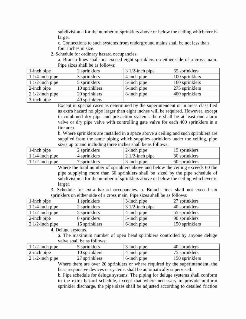
subdivision a for the number of sprinklers above or below the ceiling whichever is
larger.
c. Connections to such systems from underground mains shall be not less than
four inches in size.
2. Schedule for ordinary hazard occupancies.
a. Branch lines shall not exceed eight sprinklers on either side of a cross main.
Pipe sizes shall be as follows:
1-inch pipe 2 sprinklers 3 1/2-inch pipe 65 sprinklers
1 1/4-inch pipe 3 sprinklers 4-inch pipe 100 sprinklers
1 1/2-inch pipe 5 sprinklers 5-inch pipe 160 sprinklers
2-inch pipe 10 sprinklers 6-inch pipe 275 sprinklers
2 1/2-inch pipe 20 sprinklers 8-inch pipe 400 sprinklers
3-inch pipe 40 sprinklers
Except in special cases as determined by the superintendent or in areas classified
as extra hazard no pipe larger than eight inches will be required. However, except
in combined dry pipe and pre-action systems there shall be at least one alarm
valve or dry pipe valve with controlling gate valve for each 400 sprinklers in a
fire area.
b. Where sprinklers are installed in a space above a ceiling and such sprinklers are
supplied from the same piping which supplies sprinklers under the ceiling, pipe
sizes up to and including three inches shall be as follows:
1-inch pipe 2 sprinklers 2-inch pipe 15 sprinklers
1 1/4-inch pipe 4 sprinklers 2 1/2-inch pipe 30 sprinklers
1 1/2-inch pipe 7 sprinklers 3-inch pipe 60 sprinklers
Where the total number of sprinklers above and below the ceiling exceeds 60 the
pipe supplying more than 60 sprinklers shall be sized by the pipe schedule of
subdivision a for the number of sprinklers above or below the ceiling whichever is
larger.
3. Schedule for extra hazard occupancies. a. Branch lines shall not exceed six
sprinklers on either side of a cross main. Pipe sizes shall be as follows:
1-inch pipe 1 sprinklers 3-inch pipe 27 sprinklers
1 1/4-inch pipe 2 sprinklers 3 1/2-inch pipe 40 sprinklers
1 1/2-inch pipe 5 sprinklers 4-inch pipe 55 sprinklers
2-inch pipe 8 sprinklers 5-inch pipe 90 sprinklers
2 1/2-inch pipe 15 sprinklers 6-inch pipe 150 sprinklers
4. Deluge systems.
a. The maximum number of open head sprinklers controlled by anyone deluge
valve shall be as follows:
1 1/2-inch pipe 5 sprinklers 3-inch pipe 40 sprinklers
2-inch pipe 10 sprinklers 4-inch pipe 75 sprinklers
2 1/2-inch pipe 27 sprinklers 6-inch pipe 150 sprinklers
Where there are over 20 sprinklers or where required by the superintendent, the
heat-responsive devices or systems shall be automatically supervised.
b. Pipe schedule for deluge systems. The piping for deluge systems shall conform
to the extra hazard schedule, except that where necessary to provide uniform
sprinkler discharge, the pipe sizes shall be adjusted according to detailed friction
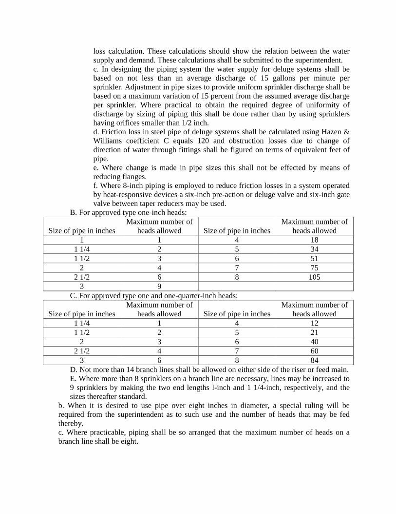
loss calculation. These calculations should show the relation between the water
supply and demand. These calculations shall be submitted to the superintendent.
c. In designing the piping system the water supply for deluge systems shall be
based on not less than an average discharge of 15 gallons per minute per
sprinkler. Adjustment in pipe sizes to provide uniform sprinkler discharge shall be
based on a maximum variation of 15 percent from the assumed average discharge
per sprinkler. Where practical to obtain the required degree of uniformity of
discharge by sizing of piping this shall be done rather than by using sprinklers
having orifices smaller than 1/2 inch.
d. Friction loss in steel pipe of deluge systems shall be calculated using Hazen &
Williams coefficient C equals 120 and obstruction losses due to change of
direction of water through fittings shall be figured on terms of equivalent feet of
pipe.
e. Where change is made in pipe sizes this shall not be effected by means of
reducing flanges.
f. Where 8-inch piping is employed to reduce friction losses in a system operated
by heat-responsive devices a six-inch pre-action or deluge valve and six-inch gate
valve between taper reducers may be used.
B. For approved type one-inch heads:
Size of pipe in inches
Maximum number of
heads allowed Size of pipe in inches
Maximum number of
heads allowed
1 1 4 18
1 1/4 2 5 34
1 1/2 3 6 51
2 4 7 75
2 1/2 6 8 105
3 9
C. For approved type one and one-quarter-inch heads:
Size of pipe in inches
Maximum number of
heads allowed Size of pipe in inches
Maximum number of
heads allowed
1 1/4 1 4 12
1 1/2 2 5 21
2 3 6 40
2 1/2 4 7 60
3 6 8 84
D. Not more than 14 branch lines shall be allowed on either side of the riser or feed main.
E. Where more than 8 sprinklers on a branch line are necessary, lines may be increased to
9 sprinklers by making the two end lengths l-inch and 1 1/4-inch, respectively, and the
sizes thereafter standard.
b. When it is desired to use pipe over eight inches in diameter, a special ruling will be
required from the superintendent as to such use and the number of heads that may be fed
thereby.
c. Where practicable, piping shall be so arranged that the maximum number of heads on a
branch line shall be eight.
d. When the piping is arranged on the “gridiron” plan, the permissible number of heads may
be doubled, provided the feed main is of the size indicated in the schedule for the total
number of heads.
e. The permissible number of heads fed by six and eight inch pipe may be increased ten
percent more than the numbers allowed where strict compliance with the pipe sizes listed in
this section would require another source of water supply or a larger feed main or riser.
f. Where feed mains supply branch lines having only two heads each, and the conditions
approach those of long single lines, such feed mains shall usually be centrally supplied where
there are over ten branch lines. Branch lines up to fourteen in number may be fed from the
end, provided a two and one-half inch pipe does not supply more than sixteen standard one-
half inch heads.
g. Structures having slatted floors, or large unprotected floor openings without approved
stops, shall be treated as one room with reference to the pipe sizes, and the feed main shall be
of sufficient size to accommodate the number of heads called for. Larger pipe sizes than are
allowed in the schedule for a given number of heads may be required wherever the
construction or conditions introduce unusually long runs of feed mains or many angles.
Structures with blind attics, with small, unprotected openings to the floor below, may be
piped from the system on the ceiling of the floor below, provided the pipe size schedule is
not overloaded on sizes three inches or under.
(15.21.1). §C26-1355.1 Hangers for Sprinkler Systems.- 1.
a. Sprinkler piping shall be substantially supported from the building structure. In all
cases, sprinkler piping shall be supported independently of suspended ceiling
construction.
b. Hangers shall be of approved types.
c. Sprinkler piping shall be supported by round wrought-iron U-type or approved
adjustable hangers.
d. Approved C-type hangers shall be acceptable for use on steel beams when provided
with a safety strap, or when cup-pointed set screws with lock nuts are provided for these
hangers by the manufacturer.
e. If hangers or parts of hangers are made of flat iron or steel, the thickness of the metal
must be at least 3/16 inch, unless protected by a suitable corrosion-resistant material.
Unprotected steel 1/8-inch in thickness is acceptable for retaining straps used with “C”
clamps.
f. Pipe rings hung from coach screw hooks shall not he used.
g. Hangers which permit wide lateral motion of the pipe, particularly on branch lines,
shall not be acceptable.
h. Toggle hangers shall be used only for the support of branch lines and under ceilings of
hollow tile or metal lath and plaster in buildings of fire-resistive or incombustible
construction.
2. Hangers in concrete.-
a. In concrete construction approved incombustible inserts set in the concrete may be
installed for the support of hangers. The use of wood plugs shall not be permitted.
b. Hangers shall be installed without regard to the support of the sleeves where pipes are
run through concrete beams. Such sleeves shall not normally be used for the support of
pipes.
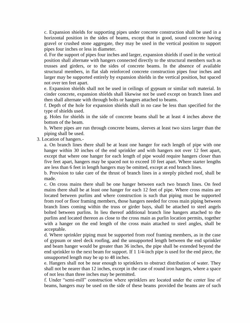
c. Expansion shields for supporting pipes under concrete construction shall be used in a
horizontal position in the sides of beams, except that in good, sound concrete having
gravel or crushed stone aggregate, they may be used in the vertical position to support
pipes four inches or less in diameter.
d. For the support of pipes four inches and larger, expansion shields if used in the vertical
position shall alternate with hangers connected directly to the structural members such as
trusses and girders, or to the sides of concrete beams. In the absence of available
structural members, in flat slab reinforced concrete construction pipes four inches and
larger may be supported entirely by expansion shields in the vertical position, but spaced
not over ten feet apart.
e. Expansion shields shall not be used in ceilings of gypsum or similar soft material. In
cinder concrete, expansion shields shall likewise not be used except on branch lines and
then shall alternate with through bolts or hangers attached to beams.
f. Depth of the hole for expansion shields shall in no case be less than specified for the
type of shields used.
g. Holes for shields in the side of concrete beams shall be at least 4 inches above the
bottom of the beam.
h. Where pipes are run through concrete beams, sleeves at least two sizes larger than the
piping shall be used.
3. Location of hangers.-
a. On branch lines there shall be at least one hanger for each length of pipe with one
hanger within 30 inches of the end sprinkler and with hangers not over 12 feet apart,
except that where one hanger for each length of pipe would require hangers closer than
five feet apart, hangers may be spaced not to exceed 10 feet apart. Where starter lengths
are less than 6 feet in length hangers may be omitted, except at end branch lines.
b. Provision to take care of the thrust of branch lines in a steeply pitched roof, shall be
made.
c. On cross mains there shall be one hanger between each two branch lines. On feed
mains there shall be at least one hanger for each 12 feet of pipe. Where cross mains are
located between purlins and where construction is such that piping must be supported
from roof or floor framing members, those hangers needed for cross main piping between
branch lines coming within the truss or girder bays, shall be attached to steel angels
bolted between purlins. In lieu thereof additional branch line hangers attached to the
purlins and located thereon as close to the cross main as purlin location permits, together
with a hanger on the end length of the cross main attached to steel angles, shall be
acceptable.
d. Where sprinkler piping must be supported from roof framing members, as in the case
of gypsum or steel deck roofing, and the unsupported length between the end sprinkler
and beam hanger would be greater than 36 inches, the pipe shall be extended beyond the
end sprinkler to the next beam for support. If 1 1/4-inch pipe is used for the end piece, the
unsupported length may be up to 48 inches.
e. Hangers shall not be near enough to sprinklers to obstruct distribution of water. They
shall not be nearer than 12 inches, except in the case of round iron hangers, where a space
of not less than three inches may be permitted.
f. Under “semi-mill” construction where sprinklers are located under the center line of
beams, hangers may be used on the side of these beams provided the beams are of such

width that hangers may not be closer than three inches to the sprinkler. Where beams are
less than six inches in width, offset hangers may be used or the hangers located twelve to
eighteen inches from sprinklers.
4. Support of Risers.-
a. Risers shall be adequately supported by attachments direct to the riser of by hangers
located on the horizontal connections close to the riser.
b. Risers shall be supported at every second floor.
c. Sprinkler and tank risers in vertical shafts shall be supported at every second floor.
5. Ceiling flanges, rods and “U” hooks.-
a. Ceiling flanges.-For pipe sizes up to 2-inch ceiling flanges shall have at least two
supporting screw holes; for sizes 2 1/2-inch to 8-inch, not less than three holes, and in
wood construction so located that no two holes are in the same line as the grain in the
planking.
b. Rods.-The size of rods for hangers shall be not less than that given in the following
table:
Pipe size Diameter of rod
Up to 2-inch 3/8-inch
2 1/2-inch, 3-inch, 3 1/2-inch 1/2-inch
4-inch, 5-inch 5/8-inch
6-inch 3/4-inch
8-inch 7/8-inch
c. “U” hooks.-The size of the rod material of “U” hooks shall be not less than that given
in the following table:
Pipe size Hook material diameter
Up to 2-inch 5/16-inch
2 1/2-inch, 3-inch 3/8-inch
3 1/2-inch, 4-inch 7/16-inch
5-inch 1/2-inch
6-inch 5/8-inch
8-inch 3/4-inch
d. Screws.-For the ceiling flanges and “U” hooks screw dimensions shall be not less than
those given in the following table:
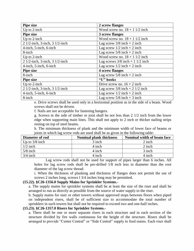
Pipe size 2 screw flanges
Up to 2-inch Wood screw no. 18 × 1 1/2 inch
Pipe size 3 screw flanges
Up to 2-inch Wood screw no. 18 × 1 1/2 inch
2 1/2-inch, 3-inch, 3 1/2-inch Lag screw 3/8 inch × 2 inch
4-inch, 5-inch, 6-inch Lag screw 1/2 inch × 2 inch
8-inch Lag screw 5/8 inch × 2 inch
Up to 2-inch Wood screw no. 18 × 1 1/2 inch
2 1/2-inch, 3-inch, 3 1/2-inch Lag screws 3/8 inch × 1 1/2 inch
4-inch, 5-inch, 6-inch Lag screw 1/2 inch × 2 inch
Pipe size 4 screw flanges
8-inch Lag screw 5/8 inch × 2 inch
Pipe size “U” hooks
Up to 2-inch Drive screw no. 16 × 2 inch
2 1/2-inch, 3-inch, 3 1/2-inch Lag screw 3/8 inch × 2 1/2 inch
4-inch, 5-inch, 6-inch Lag screw 1/2 inch × 2 inch
8-inch Lag screw 5/8 inch × 3 inch
e. Drive screws shall be used only in a horizontal position as in the side of a beam. Wood
screws shall not be driven.
f. Nails are not acceptable for fastening hangers.
g. Screws in the side of timber or joist shall be not less than 2 1/2 inch from the lower
edge when supporting main lines. This shall not apply to 2 inch or thicker nailing strips
resting on top of steel beams.
h. The minimum thickness of plank and the minimum width of lower face of beams or
joists in which lag screw rods are used shall be as given in the following table:
Diameter of rod Nominal plank thickness Nominal width of beam face
Up to 3/8 inch 3 inch 2 inch
1/2 inch 4 inch 2 inch
5/8 inch 4 inch 3 inch
3/4 inch 4 inch 4 inch
Lag screw rods shall not be used for support of pipes larger than 6 inches. All
holes for lag screw rods shall be pre-drilled 1/8 inch less in diameter than the root
diameter of the lag screw thread.
i. When the thickness of planking and thickness of flanges does not permit the use of
screws 2 inches long, screws l 3/4 inches long may be permitted.
(15.22). §C26-1356.0 Supply Mains for Sprinkler Systems.-
a. The supply mains for sprinkler systems shall be at least the size of the riser and shall be
arranged to run as directly as possible from the source of water supply to the riser.
b. Supply mains for stair or other towers without approved stops between floors when piped
on independent risers, shall be of sufficient size to accommodate the total number of
sprinklers in such towers but shall not be required to exceed two and one-half inches.
(15.23). §C26-1357.0 Risers for Sprinkler Systems.-
a. There shall be one or more separate risers in each structure and in each section of the
structure divided by fire walls continuous for the height of the structure. Risers shall be
arranged to provide “Center Central” or “Side Central” supply to feed mains. Each riser shall

be of sufficient size to supply all the heads on that riser in one story according to section
C26-1355.0.
b. If the conditions warrant, special permission will be granted to allow the heads in a fire
section to be fed from the risers in another section.
c. It shall be unlawful to locate risers close to windows. Risers shall be properly protected
from mechanical injury and freezing and shall be properly supported by wrought iron clamps,
couplings or approved hangers.
d. Wet pipe sprinklers for stairs or other towers without approved stops between floors shall
be supplied by independent risers, if more than two stories in height, with control valves at
lower level and be large enough to supply the total number of heads in such tower, but shall
not be required to exceed two and one-half inches. Soffits of stairs shall be protected except
when stair and enclosure are fireproof in such case only the floor landings shall be protected.
(15.24). §C26-1358.0 Prohibited Connections to Sprinkler Systems.-It shall be unlawful to
make connections, such as for sill cocks, house service or hose outlets, to any part of a sprinkler
system riser, except as provided in section C26-1346.0.
(15.25). §C26-1359.0 Air Lock Adjustment.-Where gravity and pressure tanks for sprinkler
systems feed through a common discharge pipe or “dead riser” to the foot of a riser and an air
lock is likely to develop, the discharge pipe of the gravity tank shall connect with the common
discharge pipe forty-five feet below the bottom of the gravity tank and the gravity tank check
valve shall be placed at the level of this connection.
(15.26). §C26-1360.0 Pipes and Fittings for Sprinkler Systems.-
a. Pipe for sprinkler systems shall be full-weight wrought iron or steel threaded pipe, well
reamed and screwed up tight into fittings without reducing the waterway.
b. Wrought iron pipe shall comply with the standard specifications for welded wrought iron
pipe of the A.S.T.M., D., A. 72-33.
c. Stee1 pipe shall comply with the standard specifications for welded and seamless steel
pipe of the A. S. T. M., D., A. 120-34 T.
d. Fittings shall be standard cast iron fittings or malleable fillings of a type specifically
approved for use in sprinkler systems.
e. Cast iron fittings shall be designed and guaranteed for a working pressure of one hundred
seventy-five pounds per square inch and malleable fittings shall be designed and guaranteed
for a working pressure of three hundred pounds per square inch.
f. Pipes shall be secured to the ceiling, walls and other parts of the building with standard
steel, wrought or malleable iron hangers.
g. Extra heavy fittings shall be employed where the normal pressure in the pipe system
exceeds the allowable working pressure limits as specified in “a.” and shall be designed for a
working pressure of two hundred fifty pounds per square inch.
h. Underground pipes shall comply with the regulations of the Department of Water Supply,
Gas and Electricity for the working pressure required.
i. Welding of joints may be allowed in special cases but permission must be secured in
writing from superintendent. When welding is permitted it shall be in accordance with the
American Standard Code for Pressure Piping B31.1-1951 and shall conform to the
requirements of title C26-211.0.
(15.27). §C26-1361.0 Protection of Pipes and Sprinklers.-
a. When exposed to moisture, sprinkler pipes and hangers, shall be protected against
corrosion whenever necessary by thoroughly cleaning the pipe of all scale and grease and
painting with a coat of red lead and linseed oil paint or other acceptable moisture resistive
paint. When exposed to chemical fumes, the pipe and fittings shall be coated with approved
chemical resistive paint. It shall be unlawful to paint sprinkler heads.
b. Supply pipes of risers in low basements, or low spaces under ground floors, exposed to
frost, shall be properly protected by concrete, brick or wood enclosures, properly heated, or
by two-inch creosoted plank boxing, extending twenty-four inches on all sides of the pipe
and filled with mineral wool, sawdust or tar mixed with granulated cork, extending below the
bottom of the pipe and through the top flooring of the ground floor, or by other approved
methods.
c. Where risers, drains, heating pipes, and similar installations, pass through cinder concrete
floors or partitions, they shall be protected with a substantial metal sleeve, and the space
between the floor and sleeve shall be grouted with cement mortar.
d. Wherever sprinklers are exposed to corrosion, the heads shall be protected with an
approved coating.
(15.28). §C26-1362.0 Drainage of Sprinkler Pipes and Fittings.-
a. Sprinkler pipes and fittings shall be so installed that they can be thoroughly drained, and
where practicable, piping shall be arranged to drain at the main drain valves.
b. Drains shall be so arranged as not to expose any part of the sprinkler system to frost and
shall be connected to a roof or house drain or through the wall of the structure. Systems not
supplied from public water mains may have drain connections to sewer lines provided with
brass swing check valves and standard traps. Drains for systems supplied from public water
mains must be arranged with air break to prevent contamination of water supplies. Discharge
from such drains may be made to open trapped receptacles, or on floor where no damage can
result, to open connections into roof leaders on house side of leader trap, to open trapped
connection to sanitary sewer, or discharge to outside of building. Connections into house
drain must be trapped and vented.
c. Drains, pitched at least one-quarter of an inch in ten feet, shall be installed at:
the base of the main riser, each alarm valve, each dry-pipe valve, each gravity tank, each
pressure tank, each fire department connection, on each floor if independent floor control
valves are used; and at each supply main when the water in such a main cannot be removed
through any of the above drains. Such drains shall be installed with controlling valves so that
flowing tests may be made to determine if the water supplies or connections from yard mains
to the inside of the structure are in order without causing water damage or overflowing
service connections to the same house drain. Any such drain shall be at least two inches in
size, except that drains at independent floor valves shall be at least one inch in size where
floor valves are two and one-half inches or less in size and one and one-quarter inches where
floor valves are larger and connected to a main drain riser at least one and one-half inches in
size. The drain at the main riser shall discharge into a cone or sight drain, or if carried
through the wall and exposed to the weather, it shall be fitted with an elbow turned down.
d. A drain may be omitted at an alarm valve at the top of a riser on a down-fed system.
e. On automatic wet-pipe systems, the horizontal branch pipes shall be pitched at least one-
quarter of an inch in ten feet to drain towards the sources of supply with drain valves at the
low points.

f. On automatic dry-pipe systems, branch pipes shall be pitched at least one-half of an inch in
ten feet.
(15.29). §C26-1363.0 Test Pipes for Sprinkler Systems.-
a. In wet-pipe automatic sprinkler systems a test pipe at least one inch in diameter shall be
connected directly with each system, and shall be connected to a pipe at least one and one-
quarter inches in diameter in the upper story and arranged to discharge through a one-half
inch brass outlet, preferably to a point where it can readily be seen. Controlling valves shall
be located at a sufficient distance from the point where the test pipe passes through the wall
of the structure, so as to avoid freezing.
b. In dry-pipe automatic sprinkler systems a one-inch inspector's test pipe shall be installed at
the end of the most distant branch line and tilted with a one-inch shut-off valve, plugged with
a brass plug.
(15.30). §C26-1364.0 Pressure Gauge for Sprinkler Systems.-
a. A double spring Bourdon pressure gauge, three and one-half inches or larger, shall be
provided in automatic sprinkler systems: above dry pipe valves, below dry pipe valves, at the
pressure tank, at the air compressor, above the alarm valve, below the alarm valve, valve and
the dry pipe valve with only one gage at each valve.
b. Provision may be made for taking the pressure both above and below the alarm and at the
suction and discharge of fire pump or pumps.
c. A gage may be omitted at an alarm valve located at the top of a riser in a down-fed system.
d. Gage connections shall be taken only from the supply main or riser.
e. Gages shall be installed in a suitable place protected from freezing and be controlled by a
valve with arrangements for draining. An outlet, at least one-quarter of an inch in size,
plugged for the installation of the inspector's gage, shall be located between each valve and
gage.
(15.31.1). §C26-1365.0 Valves for Sprinkler Systems.-
a. Gate Valves for Sprinkler Systems.-
1. Gate valves two inches and under shall be of cast valve bronze or other approved non-
corrosive material. Gate valves two and one-half inches and larger shall have cast iron or
cast steel bodies, flanged bronze mounted, bronze stem and ample size hand wheel.
2. Gate valves controlling any number of sprinklers shall be of the outside screw and
yoke pattern.
(15.31.2). b. Drain Valves for Sprinkler Systems.-Drain valves for sprinkler systems shall be
of valve bronze, angle globe pattern, with renewable discs and ample size hand wheels.
(15.31.3). c. Check Valve for Sprinkler Systems.-
1. Check valves two inches and under shall be of the swing regrinding pattern; bodies and
working parts shall be of cast valve bronze, or other approved non-corrosive material.
2. Check valves two and one-half inches and larger shall be of the swing flanged pattern,
having cast iron or cast steel bodies, bronze clappers and bronze seat rings.
3. Check valve clappers and their attachments shall be designed so they can be readily
removed from the body of the valve for repairs when necessary.
4. Check valves where used to hold a differential in pressure may be provided with
rubber or composition discs or washers. Where same require replacement the new part
must be of a type approved for that valve.
5. Where an alarm check valve is installed, on a system only requiring one alarm valve,
an additional check valve need not be installed in water supply to system. Alarm check
valves may be installed in either vertical or horizontal position.
(15.31.4). d. Water Supply Gate Valves for Sprinkler Systems.-The piping connecting each
source of water supply with the sprinkler system shall be provided with a gate valve of the
outside screw and yoke type, or an approved post indicator valve, sealed open and tagged to
designate its purpose so located as to control each source of water supply except the water
supply from fire department hose connections. Such gate valves shall be so located as to be
easily visible and readily accessible and shall be as close as possible to the supply inlet.
(15.31.5). e. Water Supply Check Valves for Sprinkler Systems.-
1. The piping connecting each source of water supply with the sprinkler system,
including fire department connections, shall be provided with a horizontal swing check
valve except when written permission is granted by the superintendent to use check
valves in other than horizontal position.
2. On two-source systems, check valves on each supply shall have a gate valve on each
side to permit repair of the check valve without shutting off both supplies.
(15.31.6). f. System Control Valves for Sprinkler Systems.-
1. Automatic sprinkler risers shall be provided with a main shut-off valve, which will
control the water supplies to the sprinklers fed by such riser, except single down feed
risers equipped with floor control valves.
2. Valves controlling water supplies to automatic sprinklers shall be readily accessible at
all times. Standard signs, indicating the purpose of the valve, shall be attached to the yoke
in a substantial manner. Valves shall be lubricated and sealed open.
(15.31.7). g. Precautions Against Freezing of Sprinkler Systems.-
1. When ten or less standard one-half inch sprinkler heads in any automatic wet-pipe
system are exposed to cold and subject to freezing, shut-off valves may be provided to
discontinue the water supply to such heads between November first and April first.
2. When thirty-six or less one-half inch sprinkler heads arc exposed to freezing, the
sprinkler piping may be filled with a non-freezing solution. This solution shall be
thoroughly mixed and introduced into sprinkler piping through approved filling
connection. Such filling connection shall be provided with a metal filling cup, shut-off
valve and with an outside screw and yoke gate valve between the solution and the water
supply, and with a three-quarter inch plugged drain valve at the bottom. A check valve
with 1/32 inch hole drilled in clapper shall be installed when sprinklers on non-freezing
system are above water supply.
Note-Where sprinkler systems are supplied by public water connections the use of
non-freezing solutions must be in conformity with any state or local health regulations
which may apply.
3. A greater number of heads than specified above, located in unheated areas, shall be
controlled by an approved automatic dry-pipe valve.
(15.31.8). h: Dry Pipe Valves for Sprinkler Systems.-
1. The term “dry pipe” valve shall mean a valve automatically controlling the water
supply of a sprinkler system in such a manner that under normal conditions the piping
system beyond the valve is maintained dry, but that in the event of fire, the valve
automatically releases the water into the sprinkler system for fire extinguishing purposes.
2. Dry pipe valves shall, for the purpose of this title, be classified as follows:

(a) Type A, in which the valve is actuated by the release of compressed air in the
sprinkler piping system, due to the opening of a sprinkler head;
(b) Type B, pre-action in which the valve is actuated automatically in an approved
manner by an approved system of control.
3. Dry pipe valves shall be located as near as practicable to the sprinkler system, in an
enclosed and accessible place protected from mechanical injury and freezing.
4. When type A dry valves are installed, the air pressure in sprinkler systems under such
dry pipe valve control shall be as specified by manufacturer.
5. The compressed air supply shall be from a reliable source available at all times and
having a capacity of restoring normal air pressure in the system within a period of thirty
minutes. The air supply for the compressor shall be taken, if possible, from a room
containing dry air, or it shall be passed through a drying chamber containing calcium
chloride, in order to avoid the introduction of moisture into the system. Air compressors
shall be provided with an approved bronze relief valve, set to open as specified by dry
valve manufacturer.
6. The air pressure on such dry system shall be maintained throughout the year.
7. The maximum number of heads controlled by one type A dry pipe valve shall be as
follows:
a. One-half inch heads, 400;
b. Approved type one-inch heads, 100;
c. Approved type one and one-quarter inch heads, 64; except when the system is
equipped with an approved type quick opening device, the maximum number of
heads controlled by one type A dry pipe valve may be increased fifty percent above
the numbers herein prescribed.
8. When type B dry valves are installed, the actuating system shall be designed to operate
at a temperature lower than that required to open the sprinkler heads, and all connections
between the system and the dry pipe valve shall be adequately protected against injury.
The maximum number of heads controlled by one type B dry pipe valve shall be as
follows:
a. One-half inch heads, 1,000;
b. Approved type one-inch heads, 150;
c. Approved type one and one-quarter inch heads, 96.
(15.31.9). 1. Alarm Devices for Sprinkler Systems.-
1. Automatic wet-pipe sprinkler systems shall be equipped with an alarm device or devices
so constructed that a flow of water through a one-half inch orifice will operate an electric or
mechanical gong.
2. Dry pipe valves shall be equipped with an approved water flow alarm device.
3. When an electrical alarm is installed in connection with an alarm valve or dry pipe valve,
the installation shall be made in conformity with section C26-1366.0.
(15.31.10) §C26-1365.1 Automatic Dry Pipe Sprinkler Systems Combined with Rate-Or-
Rise Actuating Systems.-
a. An automatic dry pipe sprinkler system combined with rate-of-rise actuating system is one
employing automatic sprinklers attached to a piping system containing air under pressure,
with a rate-or-rise heat responsive actuating system of more sensitive characteristics than the
automatic sprinklers themselves, installed in the same areas as the sprinklers; actuation of the
heat responsive system, as by a fire, opens dry pipe valves which permit water to flow into
the sprinkler piping system and to be discharged from any sprinklers which may be open. A
rate-of-rise actuating system is one that is operated automatically by a rise in temperature
occurring within a fixed period of time.
This combined automatic dry pipe and pre-action system of sprinklers shall be so
constructed that failure of the rate-of-rise actuating system shall not prevent the system from
properly functioning as a conventional automatic dry pipe system, namely, fusing of one or
more automatic sprinklers reduces air pressure in piping system thereby operating dry pipe
valves which permit water to flow into sprinkler piping system and to be discharged from
any of the sprinklers which may be open.
Further, this combined automatic dry pipe and pre-action system of sprinklers shall be so
constructed that failure of the dry pipe system of automatic sprinklers shall not prevent the
rate-of-rise actuating system from properly functioning as an automatic fire alarm system.
b. This system shall comply with the following requirements:
1. The sprinklers shall be supplied through two differential type dry pipe valves arranged
in parallel with their system sides joined as a unit to a common feed main.
2. Rate-of-rise heat responsive devices shall be properly spaced in the area of each sub-
division of the sprinkler system in such a manner as to trip automatically the dry pipe
valves described in sub-division b. 1 of this section. Such devices and their locations shall
be approved by the board.
3. Common feed mains shall be provided, making connection between two dry pipe
valves required under subdivision b. 1 of this section and the several sub-divisions of the
sprinkler system.
4. Each branch from the feed mains shall be provided with a check valve to retard back
flow of air to the feed main. Total number of sprinklers on the system side of each check
valve shall not exceed 600.
5. At least one air exhaust valve directly controlled by the rate-of-rise actuating system
shall be placed at the most distant end of each main. At least one air exhaust valve
actuated by a rapid drop in air pressure shall be placed at each end of each feed main.
6. The sprinkler system shall be so constructed, and the number of sprinkler heads
controlled by the two dry pipe valves shall be so limited, that water shall reach the
furthest sprinkler within a period of time not exceeding one minute for each 400 feet of
feed main, from the time the rate-of-rise system is actuated. The total number of
sprinklers controlled by the two dry pipe valves shall otherwise be unlimited.
7. The sprinkler and actuating systems shall be maintained in operating condition at all
times.
8. An approved automatic fire alarm or rate-of-rise actuating system shall be provided,
and a watchman shall be employed in the structure for twenty-four hours of each day to
send an alarm to the fire department whenever an alarm is sounded by the automatic fire
alarm system or the system alarms shall be directly connected to the central station of an
operating fire alarm company whose sole business is fire protective service and which is
directly connected to fire department headquarters. The fire alarm system shall be
operated by both the rate-of-rise actuating system and the operation of the dry pipe
valves.
9. When the ceiling height or bottom of beam across the structure exceeds 20 feet, the
sprinklered area shall be sub-divided into sections separated from each other by fire
curtains or other approved tire stops constructed of incombustible material having a

height of least one-sixth of the distance from the floor to the ceiling or bottom of beams
or to the roof if there is no ceiling. Where the ceiling, beam or roof height is twenty-four
feet or less, the fire curtain need not extend below an elevation that would allow twenty
feet in the clear from the bottom of such curtain to the floor. Not more than 275 heads
shall be permitted in any sub-divided area.
10. Provision shall be made for manual operation of the system at locations requiring not
more than two hundred feet of travel.
c. In the dry pipe automatic sprinkler system combined with rate-of-rise actuating systems,
sizes of pipe supplying the specified number of one-half inch sprinklers in a fire area on a
floor shall not be less than those given in the following schedule:
Minimum size of
pipe inches
No. of 1/2-inch
sprinklers
Minimum of pipe
inches
No. of 1/2-inch
sprinklers
1 2 3 40
1 1/4 3 3 1/2 65
1 1/2 5 4 100
2 10 5 160
2 1/2 20 6 275
d. Except as provided otherwise in this section, this system of sprinklers shall in addition
comply with all other pertinent provisions of the code.
(15.32). §C26-1366.0 Local Sprinkler Supervisory Alarm Systems.-
a. Each gravity tank, pressure tank and Type A dry pipe valve shall be provided with an
approved device, connected to an approved closed circuit panel, located in the headquarters
of the engineer or person in charge of the sprinkler system, or in the pump room, to indicate
when the water in any tank is too high or too low, when the air pressure in any pressure tank
is too high or too low, and when the compressed air in a Type A dry system is too low.
b. The wiring circuits used in connection with this supervisory alarm system shall be at least
No. 16, single braid, rubber covered, copper, National Electric Code wire, provided the
circuit carries two amperes or less; run in National Electric Code rigid metal conduit, except
that approved flexible metal ducts may be used between rigid conduits and devices from
which alarms originate, provided three feet or less of flexible duct is used.
c. High and low alarm signals shall be indicated by at least a four inch approved conduit type
gong and by visible indication.
d. Waterflow signals from alarm and dry pipe valves shall be indicated by at least a six inch
approved conduit type gong and by visible indication.
e. The following sources of energy may be employed:
1. Electricity supplied by a public utility.
2. A private electric generating plant, supplemented by a storage battery floating on the
line. Direct current supply lines shall be protected by reverse current circuit breakers.
3. An approved rectifier may be used to transform alternating current to direct current as
a source of energy for an alarm system.
f. When the system is connected to a one hundred ten volt lighting service a suitable cut out
is to be provided. Such cut-out shall be enclosed in a locked or sealed metal cabinet. The
connection to the system shall be the first connection on the house side of, and as near as
practicable to, the meter. When batteries are used to operate the system, they shall be placed
in an approved cabinet provided with a lock and key.

g. In addition to the above requirements for local supervisory alarm systems, additional
approved electrical supervisory devices for either local or central station indication may be
installed in any system.
(15.33). §C26-1367.0 Concealed Pipe Systems for Sprinkler Systems.-Pipe in concealed pipe
systems shall be of standard full-weight wrought iron or steel and shall be inspected prior to
concealment. Pipe installed in ducts or encased in cement mortar shall be inspected prior to
concealment. When installed in the concealed space between floor arches and ceiling, such pipe
shall be supported by hangers. Where piping is to be concealed before completion of installation
the superintendent and the fire commissioner shall be notified so that proper inspection can be
made.
(15.34). §C26-1368.0 Preparation of Structure.-
a. Floor or wall openings and other structural conditions which prevent the banking up of
heated air and retard the automatic action of sprinkler heads shall be provided with the
necessary curtain boards and draft stops to permit control of the fire by the sprinklers.
b. Curtain boards shall project at least six inches below the lowest sprinkler and shall be at
least twelve inches deep.
c. When curtain boards are provided to subdivide large areas such curtain boards shall be at
least twenty-four inches deep. For peaked roofs curtain boards shall follow slope of roof and
be not less than twenty-four inches deep with a minimum of forty-eight inches deep at the
peak when the slope is one foot in three feet, or more, except as provided in C26-1365.1.
Where required to baffle opening through floors they shall be not less than 12 inches deep.
(15.35). §C26-1369.0 Approval of Sprinkler Systems.-
a. Before acceptance automatic sprinkler systems, excluding water supply tanks, shall be
subjected after installation to a hydrostatic pressure test, of the whole system, of at least one
hour duration at a pressure at least fifty pounds per square inch in excess of that which will
be normally carried and observed in the sprinkler system. Such test pressure shall be at least
two hundred pounds per square inch in every part of the system. Pressure tanks shall be
tested after erection to test pressure of one and one-half times the working pressure. To
prevent the possibility of serious water damage in case of a break, the pressure shall be
maintained by a small pump, the main controlling gate being meanwhile kept shut. It shall be
unlawful to use brine or other corrosive chemicals for testing systems.
b. In automatic dry pipe systems with type A valve control, an air pressure of forty pounds
per square inch shall be pumped up, and shall be held for twenty-four hours. All leaks shall
be stopped which allow a loss of pressure of over one and one-half pounds per square inch
during the twenty-four hours.
c. In the case of automatic dry pipe systems with differential Type A valves, the valve shall
be held off its seat during the test to prevent injuring the valve.
d. Non-automatic systems shall be tested after installation at a pressure at least fifty pounds
per square inch in excess of the pressure necessary to reach the highest line of sprinklers.
e. Tests of installed systems shall be made by the contractor in the presence of a
representative of the fire department. The fire commissioner shall notify the commissioner of
buildings in writing of the results of the test.
f. It shall be unlawful to cover up or permanently conceal piping, devices or any portion of
newly constructed sprinkler system until such system, or portion of system, has been tested in
the presence of a representative of the fire department and inspected by a representative of
the department of housing and buildings and approved in writing, except piping passing
through floors, walls, partitions, or beams, for distances equal to the thickness of such floor,
wall, partitions or beams.
(15.36). §C26-1370.0 Sprinkler Systems in Non-fireproof Business Structures.-In business
structures requiring a sprinkler system to comply with section C26-254.0 the sprinkler system
shall have at least one automatic source of water supply and one auxiliary source.
(15.37). §C26-1371.0 Sprinkler Systems in Department Stores.-Wet sprinkler systems shall be
required in department stores where the floor area in any story or cellar exceeds ten thousand
square feet. When the floor area is less than twenty thousand square feet, at least one of the
automatic sources specified in section C26-1341.0, shall be provided and, when the floor area is
twenty thousand square feet or more, at least two such automatic sources shall be provided of
which one source shall conform to requirements of a one source system and the secondary source
may be either a 7,500 gallon pressure tank, a 10,000 gallon gravity tank elevated 20 feet above
the highest line of sprinklers under the main roof, a six inch connection to a city main fed two
ways and in accordance with section C26-1346.0 or a supervised automatic fire pump of 750
gallons per minute.
(15.38). §C26-1372.0 Sprinkler Systems in Factories and Other Structures.-
a. Where the labor law or any other law requires automatic sprinkler systems, or where any
of the requirements of the labor law or any other law are waived because of the installation of
an automatic sprinkler system, each such sprinkler system, unless specifically otherwise
required by law or by the fire commissioner, shall have at least the following sources of
supply installed in accordance with this article:
1. A gravity tank and Siamese hose connection, or
2. A pressure tank and Siamese hose connection, or
3. A direct connection to a city water main fed two ways with control valves at
intersections capable of maintaining a pressure of at least fifteen pounds per square inch
at the top of the highest sprinkler riser, which main shall have five hundred gallons of
water flowing per minute at a two and one-half inch hydrant butt at the street level within
two hundred fifty feet of the building. The diameter of such connection shall be at least
the diameter required in piping supplying the heads as provided in section C26-1355.0.
Siamese hose connection shall be installed in conjunction with such system as provided
in section C26-1350.0. The pressure test, with hydrant flow as provided in this section,
shall be made between the hours of eight ante meridian and five post meridian on a
working day.
b. Cellars and sub-cellars requiring sprinkler protection under chapter 19-161 administrative
code, because of combustible storage, inadequate ventilation and in-accessibility of fire
department hose streams shall be provided with a one source automatic sprinkler system. If
cellar or sub-cellar is unheated a non-automatic sprinkler system with thermostatic alarm as
defined in section C26-1339.0 may be provided in lieu of an automatic sprinkler system.
Where less than ten heads are required the heads may be supplied from the domestic water
line if the tap and main are of adequate size and the connection for the sprinkler system is
made before the house line at the outlet side of the meter or service pipe and an O.S. & Y,
valve and drain is provided in an accessible location. In all cases the water supply line need
only be sufficient to supply the number of heads required except where the distance from the
water supply to the sprinklered area exceeds 100 feet the main feed pipe to the sprinklered
area shall be increased one pipe size above the size otherwise required for the number of
sprinklers involved. Where less than ten heads are required a fire department connection need
not be provided. If more than ten and not more than thirty-six heads are required a single fire
department pumper connection may be installed. When more than thirty-six heads are
installed at least one Siamese connection and a water flow alarm shall be provided.
c. Sprinklers in multiple dwelling, garages.-Sprinklers in garages where more than thirty-six
heads are required shall comply with these rules in all respects, except as herein noted.
Where not more than thirty-six heads are required the water main shall be large enough to
supply all heads. If in a small garage not more than ten heads are required same may be
supplied from the domestic water main if the tap and main size are as large or larger than
required for the number of sprinklers involved and the connection is so made that repairs to
the domestic lines in the building will not affect the supply to the sprinklers in the garage
area except where the distance from the water supply to the sprinklered area exceeds 100 feet
the main feed pipe to the sprinklered area shall be increased one pipe size above the size
otherwise required for the number of sprinklers involved. Water flow alarm or Siamese
connection need not be provided where not more than thirty-six heads are required. Siamese
connections shall only be required at the fronts of the building where a garage entrance is
located. If the Siamese connection cannot be installed at the entrance to the garage a metal
sign securely fastened to the wall at the garage entrance indicating the location of the
Siamese connection shall be provided.
(15.39). §C26-1373.0 Sprinkler Systems in Theatre Structures.-An automatic sprinkler
system, where required under the provisions of article thirteen of this title, shall be at least a one-
source automatic system.
(15.40). §C26-1374.0 Sprinkler Systems in Fireworks Storage.-Each automatic sprinkler
system required in a structure in which fireworks are stored or sold under the provisions of
sections C19-41.0 of the code, shall consist of a system supplied from any two of the automatic
sources as required in section C26-1351.0 provided that the minimum working pressure is at
least twenty-five pounds per square inch at the highest sprinkler line.
(15.41). §C26-1375.0 Sprinkler Systems for Nitro-cellulose Products.-An automatic sprinkler
system required in a structure in which nitro-cellulose products are manufactured, stored, or kept,
under provisions of section C19-110.0, shall be a two source system having the following water
supplies:
a. A primary supply consisting of one of the automatic sources named in section C26-1341.0
b, but this source shall have a static pressure of not less than twenty-five pounds per square
inch on the highest line of sprinklers in the area where the nitro-cellulose is located. Tank
and pump capacities shall be determined according to sections C26-1342.0, C26-1345.0 and
C26-1347.0 but in determining these capacities each sprinkler in the area where the nitro-
cellulose is located shall be counted as two sprinklers, except that if there are more than four
vaults all sprinklers in the vaults in excess of four shall be omitted from the count.
b. A secondary supply consisting of a gravity tank, or tanks as specified in sections C26-
1342.0 through C26-1344.0 inclusive but such tank shall be of at least 10,000 gallons
capacity and shall contain an amount of water sufficient to supply fifty percent of the
sprinklers in the area where the nitro-cellulose is located for a period of twenty minutes. Only
sprinklers in this area are to be counted and sprinklers in not more than four vaults shall be
included in this count.
c. An auxiliary source consisting of a Siamese fire department connection or connections as
specified in section C26-1350.0.

(15.42). §C26-1376.0 Sprinkler Systems for Inflammable Motion Picture Films.-An
automatic sprinkler system required in a structure in which inflammable motion picture films are
stored or kept, under the provision of section C19-115.0 and C19-116.0 of the code shall be a
two source system having the following water supplies:
a. A primary supply consisting of one of the automatic sources named in section C26-1341.0
but this source shall have a static pressure of not less than twenty-five pounds per square inch
on the highest line of sprinklers in the area where the inflammable motion picture film is
located. Tank and pump capacities shall be determined according to section C26-1342.0,
C26-1345.0 and C26-1347 but in determining these capacities each sprinkler in the area
where inflammable motion picture film is located shall be counted as two sprinklers except
that if there are more than four vaults all sprinklers in the vaults in excess of four shall be
omitted from the count.
b. A secondary supply consisting of a gravity tank, or tanks, as specified in sections C26-
1342.0 through C26-1344.0, inclusive, but such tank shall be of at least 10,000-gallon
capacity and shall contain an amount of water sufficient to supply fifty percent of the
sprinklers in the area where the inflammable motion picture film is located for a period of
twenty minutes. Only sprinklers in this area are to be counted and sprinklers in not more than
four vaults shall be included in this count.
c. An auxiliary source consisting of a Siamese fire department connection or connections as
specified in section C26-1350.0.
(15.43). §C26-1377.0 Sprinkler Protection for Special Hazards in Non-sprinklered
Structures Unprovided for by Law.-
a. Sprinkler heads and piping may be provided on ceilings of enclosed rooms, closets, shafts,
or other spaces which are used as carpenter shops, upholstering rooms, paint shops, waste
paper rooms, old record storerooms, trunk and general storage rooms in hotels, office
buildings or other structures, and in stores and showrooms or where nitro-cellulose products
or inflammable photographic or x-ray film is stored or used, or in cold storage plants.
b. In such structures, the number and type of sprinkler heads, spacing and size of pipe,
location and number of valves, method of draining lines, water flow or other alarms, shall be
as required by the superintendent.
c. The source of water supply where required may be the house supply tank or other sources
of water supply, except that connections taken from the standpipe system or from the feed
line to boilers shall be unlawful. In all cases there shall be sufficient water to provide ten
gallons of water per head for each sprinkler in the largest protected fire area for fifteen
minutes, and the pressure on any sprinkler line shall be at least fifteen pounds static pressure.
d. Sprinklers installed under section C26-289.0 may be supplied from the domestic water
main if the tap and main size are sufficient and the connection is made at the outlet side of
the water meter before the house connection. Independent connection to the street main,
water flow alarm and Siamese connection shall be provided if more than thirty-six heads are
required.
e. Sprinklers permitted by the superintendent in lieu of other protection may be supplied from
the domestic water lines if the tap and main size is adequate and water pressure is at least
fifteen pounds per square inch at the highest sprinkler.
f. Sprinklers in spray booths in unsprinklered buildings may be supplied from the domestic
water line if the tap and pipe sizes are adequate and water pressure is at least fifteen pounds
per square inch at the highest sprinkler.
g. Where the distance from the water supply to the sprinklered area exceeds 100 feet the
main feed pipe to the sprinklered area shall be increased one pipe size above the size
otherwise required for the number of sprinklers involved. In all cases an O.S. & Y. control
valve must be provided in an accessible location and a test connection installed at the end of
the line so that system may be properly tested. Where more than five heads are supplied or
where damage may be caused by draining, a three-quarter inch drain valve shall be provided.
h. Outside sprinklers.-When used in lieu of iron shutters or fireproof windows a system of
approved window type sprinklers shall be installed with a fire department Siamese
connection as a water supply. Piping shall be galvanized and fittings shall be of malleable
type.
i. Special protection for hazards not covered by this code shall be determined by the fire
commissioner. Special protection as covered by this classification may include, but not
limited to:
Carbon dioxide, foam, spray or fog nozzles installations for transformers, dip tanks,
propane tanks and similar special hazards.
(15.44). §C26-1378.0 Existing Sprinkler System Installations and Approvals.-
a. Automatic sprinkler systems and devices installed before January first, nineteen hundred
thirty-eight, shall be required to conform to this title only where the fire hazard due to
construction and occupancy of the structure is increased. Where substantial additions or
extensions in height or area are made to the structure, this title shall apply if deemed
advisable or necessary by the superintendent.
b. In cases where sprinkler systems are voluntarily installed by the owner or his
representative, and where such sprinkler systems are not required by law, or by any
violations standing against the structure, it shall be unnecessary for such sprinkler systems to
be designed or installed in conformity with this title, except that where such systems are
provided with Siamese hose connections the entire system shall be maintained in a manner
satisfactory to the superintendent and to the fire commissioner or the Siamese connection
shall be removed. All materials shall be of approved type. Plans and application shall be filed
as per section C26-1337.0.
c. When a new system is installed and the water supply is received from an existing system in
an adjoining building, the new system must be complete in all respects and arranged so that a
shut down in either building will not prevent the effective operation of the fire department
Siamese connections. This shall not apply where groups of buildings are used by the same
firm or factory and there is no possibility of confusion in operating the system.
(15.45). §C26-1379.0 Communicating Openings.-When a structure fully equipped with
sprinklers communicates with another not so equipped, the openings between such structures
shall be protected by approved automatic fire doors on both sides of the wall.
(15.46). §C26-1380.0 Maintenance Inspection.-
a. Automatic sprinkler systems shall be inspected at least once a month by a competent
person holding a certificate of fitness, employed by the owner, to see that all parts of the
system are in perfect working order, and that the fire department connection or connections,
if any, are ready for immediate use by the fire department. A detailed record of each
inspection shall be kept for examination by a representative of the fire department.
b. There shall be kept available at all times in the premises a supply of at least six extra
sprinklers, to replace promptly any fused or damaged sprinklers. There shall be one or more
employees instructed in the maintenance of sprinkler systems.
Recommended