X-Plane Airport Data (apt.dat) File Specification Page 1 of 19 1000 Version, 17-Sep-15
X-PLANE
AIRPORT DATA (APT.DAT) FILE SPECIFICATION
VERSION 1000
REVISION HISTORY
12 Mar 2012 Spec created, based upon prior apt.dat 850 spec.
14 Mar 2012 Minor updates & corrections
10 Apr 2013 Updates on airport traffic flows and taxi networks based on Ben’s feedback
2 May 2013 Corrected errors in spec of line code 1300 (airport locations)
APPLICABILITY
This specification (APT.DAT 1000) is supported in X-Plane 10.00 and later and by WorldEditor (WED) 1.2 and later.
The prior specification for airport data was APT.DAT 850, which is recommended for X-Plane 8.60 – 9.70. This spec is an extension to 850 – all features in 850
are fully supported. However it is recommended that old data for ramp start locations (row code 15) be upgraded to the new row code 1300.
SUPPORT FOR DEPRECATED FILE FORMATS
The deprecated file specification (APT.DAT 810) is still supported. A dwindling quantity of custom airport data exists only in this format. So airports defined
according to this specification (APT.DAT 810) can be included in a file otherwise complying with the APT.DAT 1000 specification.
The specification for APT.DAT 810 is available at http://data.x-plane.com
OVERVIEW & SCOPE
This specification defines core airport data for X-Plane. This includes the locations of runways, taxiway and apron pavement, basic airport ‘furniture’
(VASI/PAPIs, windsocks, light beacons and taxiway signage) and communications frequencies. It also includes attributes for each of these features to fully
describe them (eg. it includes runway surface type, runway markings, taxiway lighting and markings, approach lighting, taxiway sign text, etc).
X-Plane Airport Data (apt.dat) File Specification Page 2 of 19 1000 Version, 17-Sep-15
This specification (1000) introduces new airport data to define arrival and departure traffic flows to airports and taxi networks & routings for AI-controlled
airplanes.
This specification does not include scenery objects (such as buildings, static aeroplanes or underlying terrain textures).
BASIC CONCEPTS
Latitudes and longitudes are described in a decimal notation (eg. 20.12345678) up to 8 decimal places.
o A latitude of 50 degrees 30 minutes south would be defined as -50.50000000
North latitudes and east longitudes are positive. South latitudes and west longitudes are negative.
All headings are referenced to true north (not magnetic north).
FILE CHARACTERISTICS
The apt.dat files are plain text files:
Fields in the data can be separated by one or more white space characters (space, tab).
o By default, the files are generated so that columns of data are consistently aligned, but this is not required.
Blank rows are permitted and are helpful to differentiate between airports.
Comments are permitted and are indicated by “#” as the first two characters of a row.
FILE STRUCTURE
It is recommended that all airports be created in WorldEditor (“WED”). This will ensure that all structural requirements listed here for airport data are met.
WED version 1.2 is required to support the features in this spec.
In common with most other X-Plane data file specification, header rows of data define the origin (“I” = PC or “A” = Mac) of a particular copy of a file, and define
the file specification version. The file specification may be followed by a reference to a sequential release data cycle and build number for the data, and a
copyright message:
I
1000 Version - data cycle 2012.03, build 20121054, metadata AptXP1000. Copyright © 2012, Robin A. Peel ([email protected])...
The complete copyright message must be left intact if you redistribute this data. The GNU GPL (general public License) under which this data is released is
designed to encourage modifications, enhancements and redistribution, even in commercial derivative products. More details about this license are available
on my website (http://data.x-plane.com).

X-Plane Airport Data (apt.dat) File Specification Page 3 of 19 1000 Version, 17-Sep-15
Subsequent rows of data follow a hierarchical structure:
Each row of data has a numeric ‘row code’ as its first field, to define its content.
The top level of this hierarchy defines an individual airport, defined by an airport header row (a row code of ‘1’, ‘16’ or ‘17’).
Subsequent rows define elements of an airport:
o Runways (including helipads) follow the airport header row (one row per runway).
o Pavement (taxiway/apron) definitions have a header row followed by an ordered list of nodes that define its boundaries:
Each pavement definition must each have a single boundary with no overlaps with itself.
Nodes on this outer boundary must be defined in a counter-clockwise direction.
Boundaries must be terminated with a node with a row code ‘113’ or ‘114’.
Pavement definitions may overlap with another pavement chunk. But this is not recommended – instead consider precise alignment
of adjacent features by ‘snapping’ nodes to identical locations in World Editor (WED).
A pavement definition can never overlap with itself.
The sequencing of the pavement definitions is the layering in which they will be rendered in X-Plane, top-down. So the last piece of
pavement in the file will be rendered underneath any others with which it overlaps.
Holes can be defined for pavement (through which the underlying terrain texture will show):
Hole boundaries should follow the termination of the pavement definition in which the hole occurs (starting with a row
type ‘111’ or ‘112’).
Hole boundaries are defined in a clockwise direction (ie, opposite direction to the boundary nodes).
Hole boundaries must form a closed loop (ie. must terminate with a row code ‘113’ or ‘114’).
Each pavement definition can have zero, one or multiple hole boundaries.
Hole boundaries must be contained within the outer boundary of the pavement definition.
Holes cannot overlap each other.
After creating a hole boundary, it can be ‘filled’ with a new pavement chunk (probably using a different surface type).
o Linear features also have a header row followed by an ordered list of nodes that define the line:
Linear features can be closed loops (terminating in a node of type ‘113’ or ‘114’) or just strings (terminating with ‘115’ or ‘116’).
o An airport boundary is defined with nodes in a counter-clockwise direction. A boundary can contain holes (see above) and must form a
closed loop (terminating in a node of type ‘113’ or ‘114’).
o Airport traffic flows have a header row (row code ‘1000’) followed by multiple rows that define rules of multiple classes (time, wind
direction, ceiling, visibility, runway in use, VFR traffic pattern) that indicated that a flow should be used (wind rules, minimum ceiling rules,
visibility rules, time rules, and operations rules).
A flow is acceptable is any rule of a class is acceptable, or if there are no rules of a given class. So to permit a flow with no time
restrictions, simple exclude any traffic time rules (row code ‘1004’).
X-Plane Airport Data (apt.dat) File Specification Page 4 of 19 1000 Version, 17-Sep-15
Rules use ‘or’ logic. For example, a flow may have two wind rules (row code ‘1001’) – one for slight winds very generally aligned
with a runway, and one with strong winds only if they are almost exactly with the runway.
A flow will be used only if all its rule classes are ‘passed’.
The flows are evaluated in sequence. The first flow to ‘pass’ will be used. So, the most specific-but-useful rule should be listed first
(eg. parallel VFR approaches on a clear, calm day) and the most general (but least useful) rules should be listed last (eg. a single ILS
cat III approach to a single runway).
If the rules prevent any defined flow from being ‘passed’ then the X-Plane’s AI engine will create a flow.
‘Runway in use’ rules (row code 1100} are also evaluated in sequence. The first ‘runway in use’ rule to ‘pass’ will be used for the
parent flow. So rules should be listed in preferential sequence.
o Airport taxi routes & networks begin with a row code ‘1200’ and are defined by a set of nodes (row code ‘1201’) and ‘edges’ (the taxi
routing) that connect two nodes (row code ‘1202’):
Nodes can be defined as ‘init’ (a point at which X-Plane will try to start a taxi route), ‘end’ (where X-Plane will try to end a taxi route),
or ‘both’. ‘junc’ can also be used for junctions between taxi routes.
Edges may be optionally followed by multiple rows (row code ‘1204) defining an ‘active zone’ ‘for that parent edge (eg. if the edge
conflicts with arrival or departure runways, or an ILS-critical area).
Taxi routings begin or end at airport locations (row code ‘1300’), which are also available as startup-locations in X-Plane. These
locations are not directly connected to the taxi route network – X-Plane’s ATC engine will calculate how to direct an airplane
between the taxi route network and each location.
o Other airport features are defined with one row for each feature.
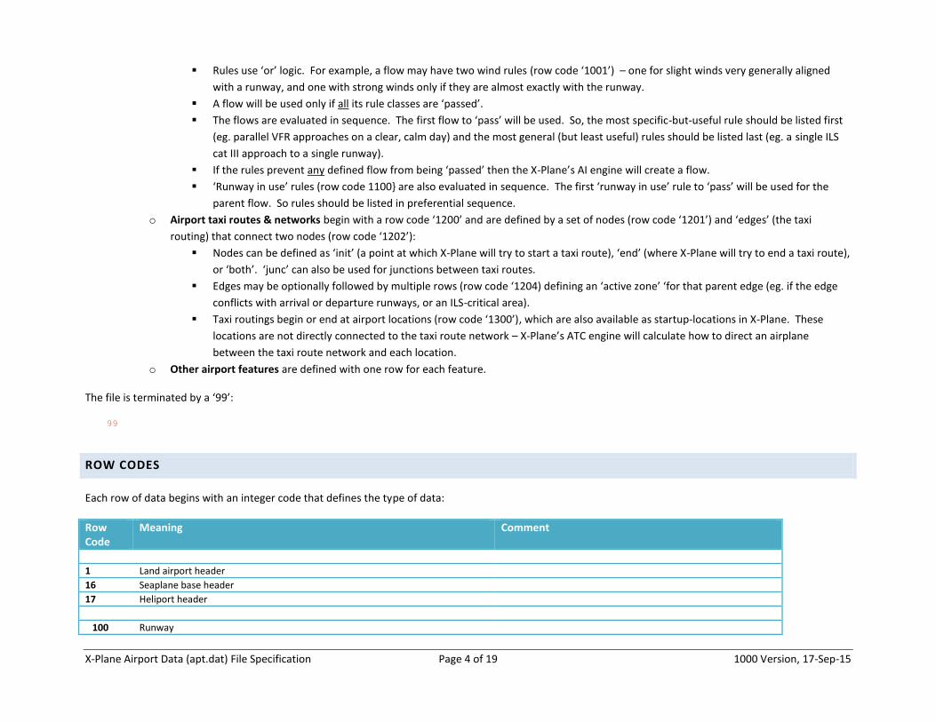
The file is terminated by a ‘99’:
99
ROW CODES
Each row of data begins with an integer code that defines the type of data:
Row Code
Meaning Comment
1 Land airport header
16 Seaplane base header
17 Heliport header
100 Runway
X-Plane Airport Data (apt.dat) File Specification Page 5 of 19 1000 Version, 17-Sep-15
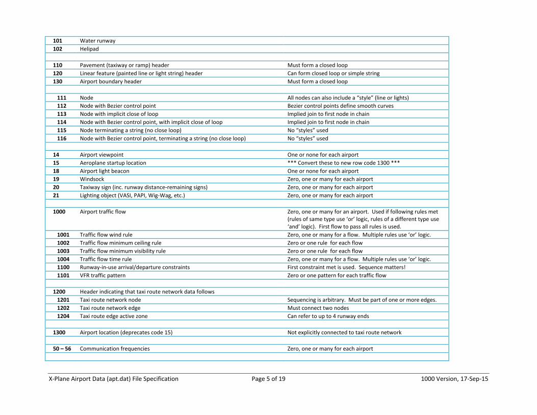
101 Water runway
102 Helipad
110 Pavement (taxiway or ramp) header Must form a closed loop
120 Linear feature (painted line or light string) header Can form closed loop or simple string
130 Airport boundary header Must form a closed loop
111 Node All nodes can also include a “style” (line or lights)
112 Node with Bezier control point Bezier control points define smooth curves
113 Node with implicit close of loop Implied join to first node in chain
114 Node with Bezier control point, with implicit close of loop Implied join to first node in chain
115 Node terminating a string (no close loop) No “styles” used
116 Node with Bezier control point, terminating a string (no close loop) No “styles” used
14 Airport viewpoint One or none for each airport
15 Aeroplane startup location *** Convert these to new row code 1300 ***
18 Airport light beacon One or none for each airport
19 Windsock Zero, one or many for each airport
20 Taxiway sign (inc. runway distance-remaining signs) Zero, one or many for each airport
21 Lighting object (VASI, PAPI, Wig-Wag, etc.) Zero, one or many for each airport
1000 Airport traffic flow Zero, one or many for an airport. Used if following rules met (rules of same type use ‘or’ logic, rules of a different type use ‘and’ logic). First flow to pass all rules is used.
1001 Traffic flow wind rule Zero, one or many for a flow. Multiple rules use ‘or’ logic.
1002 Traffic flow minimum ceiling rule Zero or one rule for each flow
1003 Traffic flow minimum visibility rule Zero or one rule for each flow
1004 Traffic flow time rule Zero, one or many for a flow. Multiple rules use ‘or’ logic.
1100 Runway-in-use arrival/departure constraints First constraint met is used. Sequence matters!
1101 VFR traffic pattern Zero or one pattern for each traffic flow
1200 Header indicating that taxi route network data follows
1201 Taxi route network node Sequencing is arbitrary. Must be part of one or more edges.
1202 Taxi route network edge Must connect two nodes
1204 Taxi route edge active zone Can refer to up to 4 runway ends
1300 Airport location (deprecates code 15) Not explicitly connected to taxi route network
50 – 56 Communication frequencies Zero, one or many for each airport
X-Plane Airport Data (apt.dat) File Specification Page 6 of 19 1000 Version, 17-Sep-15
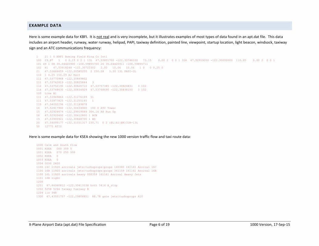
EXAMPLE DATA
Here is some example data for KBFI. It is not real and is very incomplete, but it illustrates examples of most types of data found in an apt.dat file. This data
includes an airport header, runway, water runway, helipad, PAPI, taxiway definition, painted line, viewpoint, startup location, light beacon, windsock, taxiway
sign and an ATC communications frequency:
1 21 1 0 KBFI Boeing Field King Co Intl
100 29.87 1 0 0.15 0 2 1 13L 47.53801700 -122.30746100 73.15 0.00 2 0 0 1 31R 47.52919200 -122.30000000 110.95 0.00 2 0 0 1
101 49 1 08 35.04420900 -106.59855700 26 35.04420911 -106.59855711
102 H1 47.53918248 -122.30722302 2.00 10.06 10.06 1 0 0 0.25 0
21 47.53666659 -122.30585255 2 150.28 3.30 13L PAPI-2L
110 1 0.25 150.29 A2 Exit
111 47.53770968 -122.30849802
111 47.53742819 -122.30825844 3
112 47.53752190 -122.30826710 47.53757385 -122.30824831 3 102
114 47.53768630 -122.30834929 47.53768690 -122.30838150 3 102
120 Line B1
111 47.53969864 -122.31276189 51
111 47.53977825 -122.31255145 1
115 47.54002296 -122.31189878
14 47.52917900 -122.30434900 100 0 ATC Tower
15 47.52926674 -122.29919589 304.16 A8 Run Up
18 47.52920400 -122.30412800 1 BCN
19 47.53900921 -122.30868700 1 WS
20 47.54099177 -122.31031317 235.71 0 2 {@L}A1{@R}31R-13L
50 12775 ATIS
Here is some example data for KSEA showing the new 1000 version traffic flow and taxi route data:
1000 Calm and South flow
1001 KSEA 000 359 5
1001 KSEA 070 250 999
1002 KSEA 0
1003 KSEA 0
1004 0000 2400
1100 16C 11920 arrivals jets|turboprops|props 160340 161161 Arrival 16C
1100 16R 11920 arrivals jets|turboprops|props 341159 161161 Arrival 16R
1100 16L 11920 arrivals heavy 000359 161161 Arrival Heavy Jets
1101 16R right
1200
1201 47.46360812 -122.30613338 both 5416 A_stop
1202 5258 5266 twoway taxiway B
1204 ils 34R
1300 47.43931757 -122.29806851 88.78 gate jets|turboprops A10
X-Plane Airport Data (apt.dat) File Specification Page 7 of 19 1000 Version, 17-Sep-15
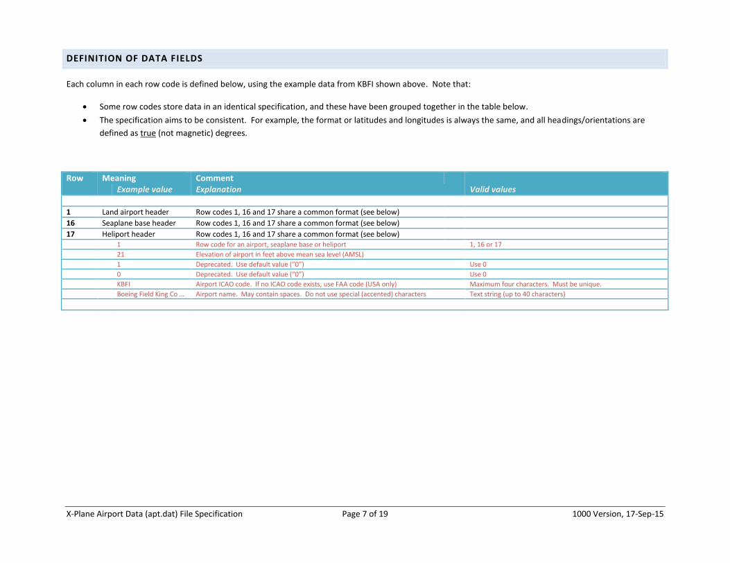
DEFINITION OF DATA FIELDS
Each column in each row code is defined below, using the example data from KBFI shown above. Note that:
Some row codes store data in an identical specification, and these have been grouped together in the table below.
The specification aims to be consistent. For example, the format or latitudes and longitudes is always the same, and all headings/orientations are
defined as true (not magnetic) degrees.
Row Meaning Comment Example value Explanation Valid values
1 Land airport header Row codes 1, 16 and 17 share a common format (see below)
16 Seaplane base header Row codes 1, 16 and 17 share a common format (see below)
17 Heliport header Row codes 1, 16 and 17 share a common format (see below) 1 Row code for an airport, seaplane base or heliport 1, 16 or 17
21 Elevation of airport in feet above mean sea level (AMSL)
1 Deprecated. Use default value (“0”) Use 0
0 Deprecated. Use default value (“0”) Use 0
KBFI Airport ICAO code. If no ICAO code exists, use FAA code (USA only) Maximum four characters. Must be unique.
Boeing Field King Co … Airport name. May contain spaces. Do not use special (accented) characters Text string (up to 40 characters)
X-Plane Airport Data (apt.dat) File Specification Page 8 of 19 1000 Version, 17-Sep-15
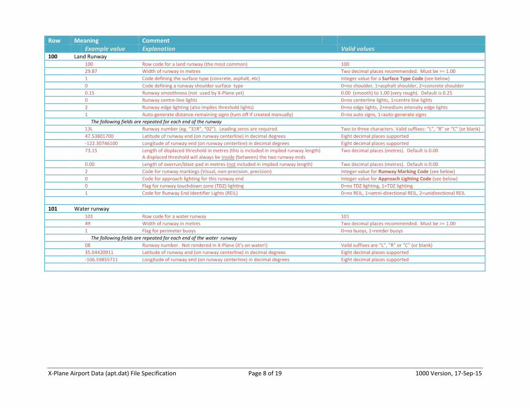
Row Meaning Comment Example value Explanation Valid values 100 Land Runway 100 Row code for a land runway (the most common) 100
29.87 Width of runway in metres Two decimal places recommended. Must be >= 1.00
1 Code defining the surface type (concrete, asphalt, etc) Integer value for a Surface Type Code (see below)
0 Code defining a runway shoulder surface type 0=no shoulder, 1=asphalt shoulder, 2=concrete shoulder
0.15 Runway smoothness (not used by X-Plane yet) 0.00 (smooth) to 1.00 (very rough). Default is 0.25
0 Runway centre-line lights 0=no centerline lights, 1=centre line lights
2 Runway edge lighting (also implies threshold lights) 0=no edge lights, 2=medium intensity edge lights
1 Auto-generate distance-remaining signs (turn off if created manually) 0=no auto signs, 1=auto-generate signs
The following fields are repeated for each end of the runway
13L Runway number (eg. “31R”, “02”). Leading zeros are required. Two to three characters. Valid suffixes: “L”, “R” or “C” (or blank)
47.53801700 Latitude of runway end (on runway centerline) in decimal degrees Eight decimal places supported
-122.30746100 Longitude of runway end (on runway centerline) in decimal degrees Eight decimal places supported
73.15 Length of displaced threshold in metres (this is included in implied runway length) A displaced threshold will always be inside (between) the two runway ends
Two decimal places (metres). Default is 0.00
0.00 Length of overrun/blast-pad in metres (not included in implied runway length) Two decimal places (metres). Default is 0.00
2 Code for runway markings (Visual, non-precision, precision) Integer value for Runway Marking Code (see below)
0 Code for approach lighting for this runway end Integer value for Approach Lighting Code (see below)
0 Flag for runway touchdown zone (TDZ) lighting 0=no TDZ lighting, 1=TDZ lighting
1 Code for Runway End Identifier Lights (REIL) 0=no REIL, 1=omni-directional REIL, 2=unidirectional REIL
101 Water runway 101 Row code for a water runway 101
49 Width of runway in metres Two decimal places recommended. Must be >= 1.00
1 Flag for perimeter buoys 0=no buoys, 1=render buoys
The following fields are repeated for each end of the water runway
08 Runway number. Not rendered in X-Plane (it’s on water!) Valid suffixes are “L”, “R” or “C” (or blank)
35.04420911 Latitude of runway end (on runway centerline) in decimal degrees Eight decimal places supported
-106.59855711 Longitude of runway end (on runway centerline) in decimal degrees Eight decimal places supported
X-Plane Airport Data (apt.dat) File Specification Page 9 of 19 1000 Version, 17-Sep-15
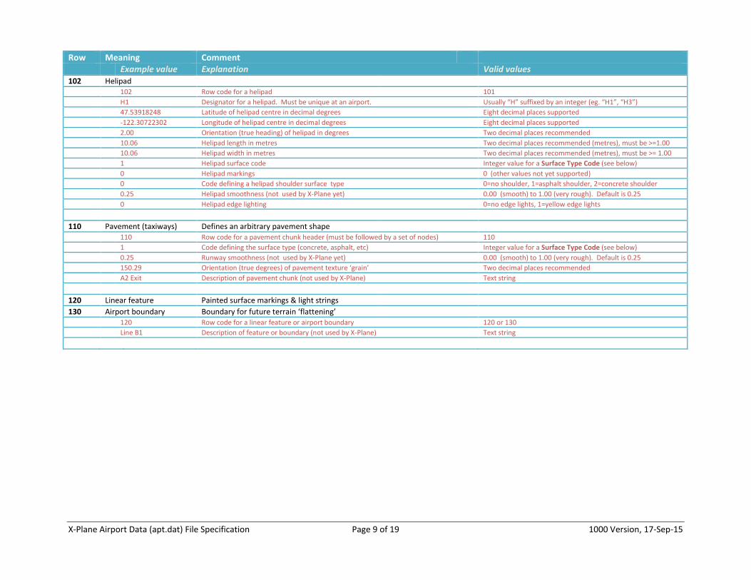
Row Meaning Comment Example value Explanation Valid values 102 Helipad 102 Row code for a helipad 101
H1 Designator for a helipad. Must be unique at an airport. Usually “H” suffixed by an integer (eg. “H1”, “H3”)
47.53918248 Latitude of helipad centre in decimal degrees Eight decimal places supported
-122.30722302 Longitude of helipad centre in decimal degrees Eight decimal places supported
2.00 Orientation (true heading) of helipad in degrees Two decimal places recommended
10.06 Helipad length in metres Two decimal places recommended (metres), must be >=1.00
10.06 Helipad width in metres Two decimal places recommended (metres), must be >= 1.00
1 Helipad surface code Integer value for a Surface Type Code (see below)
0 Helipad markings 0 (other values not yet supported)
0 Code defining a helipad shoulder surface type 0=no shoulder, 1=asphalt shoulder, 2=concrete shoulder
0.25 Helipad smoothness (not used by X-Plane yet) 0.00 (smooth) to 1.00 (very rough). Default is 0.25
0 Helipad edge lighting 0=no edge lights, 1=yellow edge lights
110 Pavement (taxiways) Defines an arbitrary pavement shape 110 Row code for a pavement chunk header (must be followed by a set of nodes) 110
1 Code defining the surface type (concrete, asphalt, etc) Integer value for a Surface Type Code (see below)
0.25 Runway smoothness (not used by X-Plane yet) 0.00 (smooth) to 1.00 (very rough). Default is 0.25
150.29 Orientation (true degrees) of pavement texture ‘grain’ Two decimal places recommended
A2 Exit Description of pavement chunk (not used by X-Plane) Text string
120 Linear feature Painted surface markings & light strings
130 Airport boundary Boundary for future terrain ‘flattening’ 120 Row code for a linear feature or airport boundary 120 or 130
Line B1 Description of feature or boundary (not used by X-Plane) Text string
X-Plane Airport Data (apt.dat) File Specification Page 10 of 19 1000 Version, 17-Sep-15
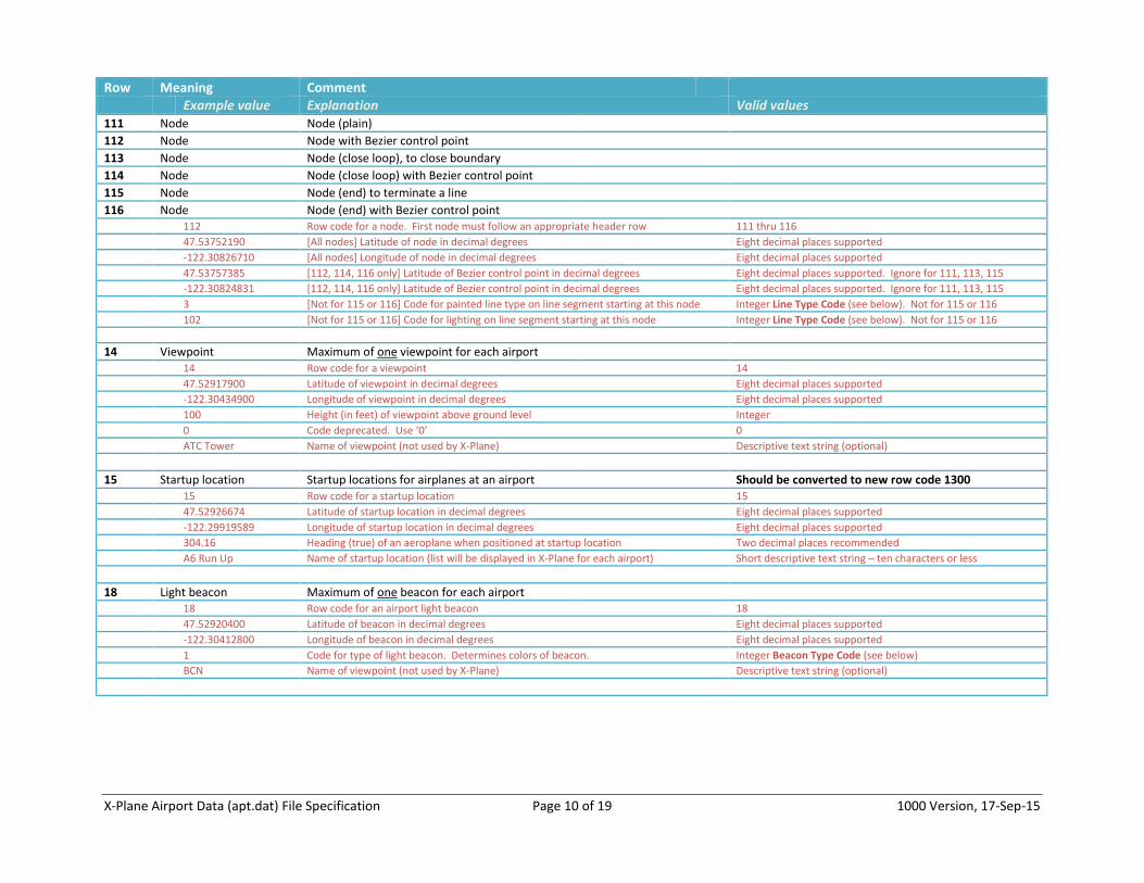
Row Meaning Comment Example value Explanation Valid values 111 Node Node (plain)
112 Node Node with Bezier control point
113 Node Node (close loop), to close boundary
114 Node Node (close loop) with Bezier control point
115 Node Node (end) to terminate a line
116 Node Node (end) with Bezier control point 112 Row code for a node. First node must follow an appropriate header row 111 thru 116
47.53752190 [All nodes] Latitude of node in decimal degrees Eight decimal places supported
-122.30826710 [All nodes] Longitude of node in decimal degrees Eight decimal places supported
47.53757385 [112, 114, 116 only] Latitude of Bezier control point in decimal degrees Eight decimal places supported. Ignore for 111, 113, 115
-122.30824831 [112, 114, 116 only] Latitude of Bezier control point in decimal degrees Eight decimal places supported. Ignore for 111, 113, 115
3 [Not for 115 or 116] Code for painted line type on line segment starting at this node Integer Line Type Code (see below). Not for 115 or 116
102 [Not for 115 or 116] Code for lighting on line segment starting at this node Integer Line Type Code (see below). Not for 115 or 116
14 Viewpoint Maximum of one viewpoint for each airport 14 Row code for a viewpoint 14
47.52917900 Latitude of viewpoint in decimal degrees Eight decimal places supported
-122.30434900 Longitude of viewpoint in decimal degrees Eight decimal places supported
100 Height (in feet) of viewpoint above ground level Integer
0 Code deprecated. Use ‘0’ 0
ATC Tower Name of viewpoint (not used by X-Plane) Descriptive text string (optional)
15 Startup location Startup locations for airplanes at an airport Should be converted to new row code 1300 15 Row code for a startup location 15
47.52926674 Latitude of startup location in decimal degrees Eight decimal places supported
-122.29919589 Longitude of startup location in decimal degrees Eight decimal places supported
304.16 Heading (true) of an aeroplane when positioned at startup location Two decimal places recommended
A6 Run Up Name of startup location (list will be displayed in X-Plane for each airport) Short descriptive text string – ten characters or less
18 Light beacon Maximum of one beacon for each airport 18 Row code for an airport light beacon 18
47.52920400 Latitude of beacon in decimal degrees Eight decimal places supported
-122.30412800 Longitude of beacon in decimal degrees Eight decimal places supported
1 Code for type of light beacon. Determines colors of beacon. Integer Beacon Type Code (see below)
BCN Name of viewpoint (not used by X-Plane) Descriptive text string (optional)

X-Plane Airport Data (apt.dat) File Specification Page 11 of 19 1000 Version, 17-Sep-15
Row Meaning Comment Example value Explanation Valid values 19 Windsock Multiple windsocks permitted for each airport 19 Row code for a windsock 19
47.53900921 Latitude of windsock in decimal degrees Eight decimal places supported
-122.30868700 Longitude of windsock in decimal degrees Eight decimal places supported
1 Flag for windsock lighting 0=unlit, 1=illuminated
WS Name of viewpoint (not used by X-Plane) Descriptive text string (optional)
20 Signs Taxiway signs or runway distance-remaining signs 20 Row code for a sign 20
47.54099177 Latitude of sign in decimal degrees Eight decimal places supported
-122.31031317 Longitude of sign in decimal degrees Eight decimal places supported
235.71 Orientation of sign in true degrees (heading of someone looking at sign’s front) Two decimal places recommended
0 Reserved for future use. Ignore. 0
2 Code for sign size Integer Sign Size Code (see below)
{@L}A1{@R}31R-13L Text to be rendered on sign front and/or back Text string formatted by Sign Text Definition (see below)
21 Lighting objects VASI, PAPI, wig-wags, etc. 21 Row code for a lighting object 21
47.53666659 Latitude of lighting object in decimal degrees Eight decimal places supported
-122.30585255 Longitude of lighting object in decimal degrees Eight decimal places supported
2 Code for type of lighting object Integer Lighting Object Code (see below)
150.28 Orientation of lighting object in true degrees (looking toward object) Two decimal places recommended
3.30 Visual glideslope angle in degrees Two decimal places. 0.00 if not required. Default is 3.00
13L Associated runway number (required for VASI/PAPI, etc) One to three characters
PAPI-2L Description of lighting object (not used by X-Plane Short text string (optional)
X-Plane Airport Data (apt.dat) File Specification Page 12 of 19 1000 Version, 17-Sep-15
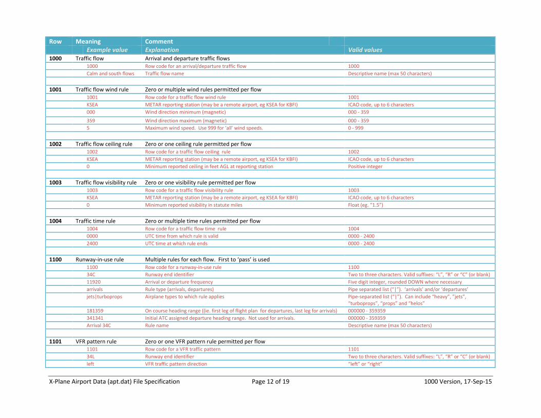
Row Meaning Comment Example value Explanation Valid values 1000 Traffic flow Arrival and departure traffic flows 1000 Row code for an arrival/departure traffic flow 1000
Calm and south flows Traffic flow name Descriptive name (max 50 characters)
1001 Traffic flow wind rule Zero or multiple wind rules permitted per flow 1001 Row code for a traffic flow wind rule 1001
KSEA METAR reporting station (may be a remote airport, eg KSEA for KBFI) ICAO code, up to 6 characters
000 Wind direction minimum (magnetic) 000 - 359
359 Wind direction maximum (magnetic) 000 - 359
5 Maximum wind speed. Use 999 for ‘all’ wind speeds. 0 - 999
1002 Traffic flow ceiling rule Zero or one ceiling rule permitted per flow 1002 Row code for a traffic flow ceiling rule 1002
KSEA METAR reporting station (may be a remote airport, eg KSEA for KBFI) ICAO code, up to 6 characters
0 Minimum reported ceiling in feet AGL at reporting station Positive integer
1003 Traffic flow visibility rule Zero or one visibility rule permitted per flow 1003 Row code for a traffic flow visibility rule 1003
KSEA METAR reporting station (may be a remote airport, eg KSEA for KBFI) ICAO code, up to 6 characters
0 Minimum reported visibility in statute miles Float (eg. “1.5”)
1004 Traffic time rule Zero or multiple time rules permitted per flow 1004 Row code for a traffic flow time rule 1004
0000 UTC time from which rule is valid 0000 - 2400
2400 UTC time at which rule ends 0000 - 2400
1100 Runway-in-use rule Multiple rules for each flow. First to ‘pass’ is used 1100 Row code for a runway-in-use rule 1100
34C Runway end identifier Two to three characters. Valid suffixes: “L”, “R” or “C” (or blank)
11920 Arrival or departure frequency Five digit integer, rounded DOWN where necessary
arrivals Rule type (arrivals, departures) Pipe separated list (“|”). ‘arrivals’ and/or ‘departures’
jets|turboprops Airplane types to which rule applies Pipe-separated list (“|”). Can include “heavy”, ”jets”, “turboprops”, “props” and “helos”
181359 On course heading range ((ie. first leg of flight plan for departures, last leg for arrivals) 000000 - 359359
341341 Initial ATC assigned departure heading range. Not used for arrivals. 000000 - 359359
Arrival 34C Rule name Descriptive name (max 50 characters)
1101 VFR pattern rule Zero or one VFR pattern rule permitted per flow 1101 Row code for a VFR traffic pattern 1101
34L Runway end identifier Two to three characters. Valid suffixes: “L”, “R” or “C” (or blank)
left VFR traffic pattern direction “left” or “right”
X-Plane Airport Data (apt.dat) File Specification Page 13 of 19 1000 Version, 17-Sep-15
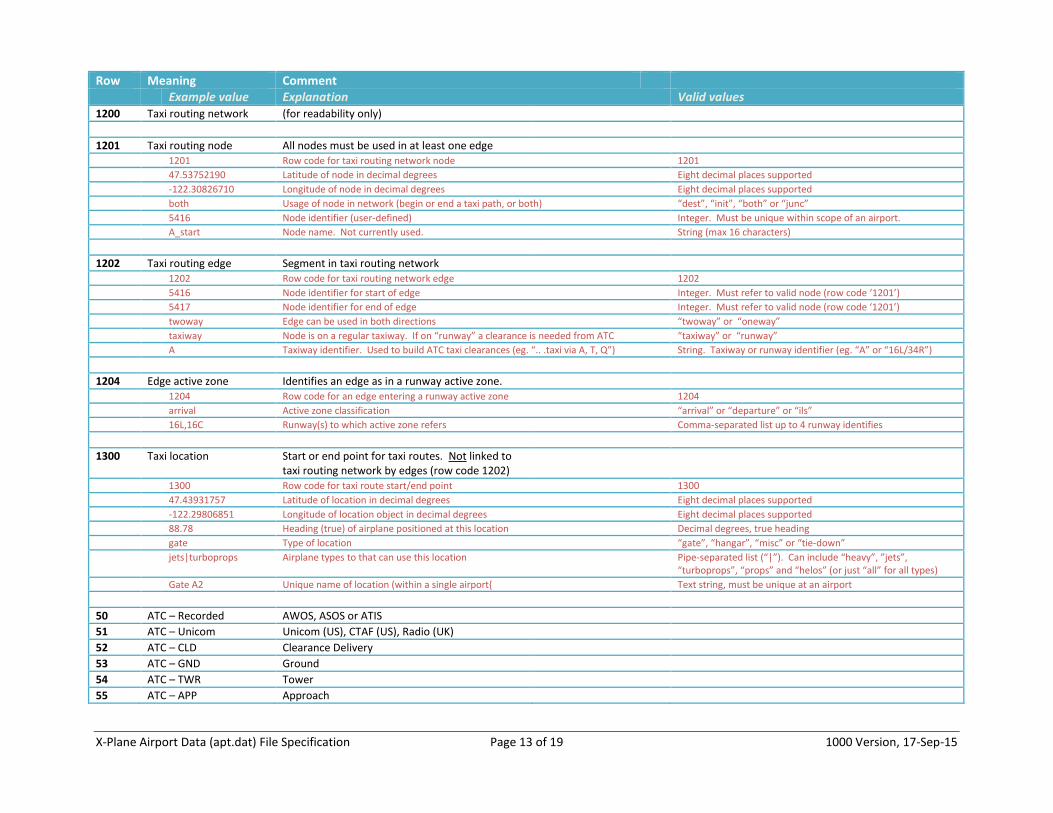
Row Meaning Comment Example value Explanation Valid values 1200 Taxi routing network (for readability only)
1201 Taxi routing node All nodes must be used in at least one edge 1201 Row code for taxi routing network node 1201
47.53752190 Latitude of node in decimal degrees Eight decimal places supported
-122.30826710 Longitude of node in decimal degrees Eight decimal places supported
both Usage of node in network (begin or end a taxi path, or both) “dest”, “init”, “both” or “junc”
5416 Node identifier (user-defined) Integer. Must be unique within scope of an airport.
A_start Node name. Not currently used. String (max 16 characters)
1202 Taxi routing edge Segment in taxi routing network 1202 Row code for taxi routing network edge 1202
5416 Node identifier for start of edge Integer. Must refer to valid node (row code ‘1201’)
5417 Node identifier for end of edge Integer. Must refer to valid node (row code ‘1201’)
twoway Edge can be used in both directions “twoway” or “oneway”
taxiway Node is on a regular taxiway. If on “runway” a clearance is needed from ATC “taxiway” or “runway”
A Taxiway identifier. Used to build ATC taxi clearances (eg. “.. .taxi via A, T, Q”) String. Taxiway or runway identifier (eg. “A” or “16L/34R”)
1204 Edge active zone Identifies an edge as in a runway active zone. 1204 Row code for an edge entering a runway active zone 1204
arrival Active zone classification “arrival” or “departure” or “ils”
16L,16C Runway(s) to which active zone refers Comma-separated list up to 4 runway identifies
1300 Taxi location Start or end point for taxi routes. Not linked to taxi routing network by edges (row code 1202)
1300 Row code for taxi route start/end point 1300
47.43931757 Latitude of location in decimal degrees Eight decimal places supported
-122.29806851 Longitude of location object in decimal degrees Eight decimal places supported
88.78 Heading (true) of airplane positioned at this location Decimal degrees, true heading
gate Type of location “gate”, “hangar”, “misc” or “tie-down”
jets|turboprops Airplane types to that can use this location Pipe-separated list (“|”). Can include “heavy”, ”jets”, “turboprops”, “props” and “helos” (or just “all” for all types)
Gate A2 Unique name of location (within a single airport{ Text string, must be unique at an airport
50 ATC – Recorded AWOS, ASOS or ATIS
51 ATC – Unicom Unicom (US), CTAF (US), Radio (UK)
52 ATC – CLD Clearance Delivery
53 ATC – GND Ground
54 ATC – TWR Tower
55 ATC – APP Approach
X-Plane Airport Data (apt.dat) File Specification Page 14 of 19 1000 Version, 17-Sep-15
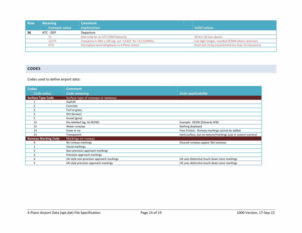
Row Meaning Comment Example value Explanation Valid values 56 ATC - DEP Departure 51 Row code for an ATC COM frequency 50 thru 56 (see above)
12775 Frequency in MHz x 100 (eg. use “12322” for 123.225MHz) Five digit integer, rounded DOWN where necessary
ATIS Descriptive name (displayed on X-Plane charts) Short text string (recommend less than 10 characters)
CODES
Codes used to define airport data:
Codes Comment Code value Code meaning Code applicability Surface Type Code Surface type of runways or taxiways 1 Asphalt
2 Concrete
3 Turf or grass
4 Dirt (brown)
5 Gravel (grey)
12 Dry lakebed (eg. At KEDW) Example: KEDW (Edwards AFB)
13 Water runways Nothing displayed
14 Snow or ice Poor friction. Runway markings cannot be added.
15 Transparent Hard surface, but no texture/markings (use in custom scenery)
Runway Marking Code Markings on runway 0 No runway markings Disused runways appear like taxiways
1 Visual markings
2 Non-precision approach markings
3 Precision approach markings
4 UK-style non-precision approach markings UK uses distinctive touch-down zone markings
5 UK-style precision approach markings UK uses distinctive touch-down zone markings
X-Plane Airport Data (apt.dat) File Specification Page 15 of 19 1000 Version, 17-Sep-15
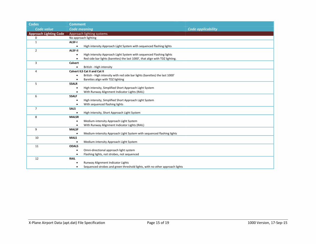
Codes Comment Code value Code meaning Code applicability Approach Lighting Code Approach lighting systems 0 No approach lighting
1 ALSF-I
High intensity Approach Light System with sequenced flashing lights
2 ALSF-II
High intensity Approach Light System with sequenced Flashing lights
Red side bar lights (barettes) the last 1000’, that align with TDZ lighting.
3 Calvert
British - High intensity
4 Calvert ILS Cat II and Cat II
British - High intensity with red side bar lights (barettes) the last 1000’
Barettes align with TDZ lighting
5 SSALR
High intensity, Simplified Short Approach Light System
With Runway Alignment Indicator Lights (RAIL)
6 SSALF
High intensity, Simplified Short Approach Light System
With sequenced flashing lights
7 SALS
High intensity, Short Approach Light System
8 MALSR
Medium-intensity Approach Light System
With Runway Alignment Indicator Lights (RAIL)
9 MALSF
Medium-intensity Approach Light System with sequenced flashing lights
10 MALS
Medium-intensity Approach Light System
11 ODALS
Omni-directional approach light system
Flashing lights, not strobes, not sequenced
12 RAIL
Runway Alignment Indicator Lights
Sequenced strobes and green threshold lights, with no other approach lights
X-Plane Airport Data (apt.dat) File Specification Page 16 of 19 1000 Version, 17-Sep-15
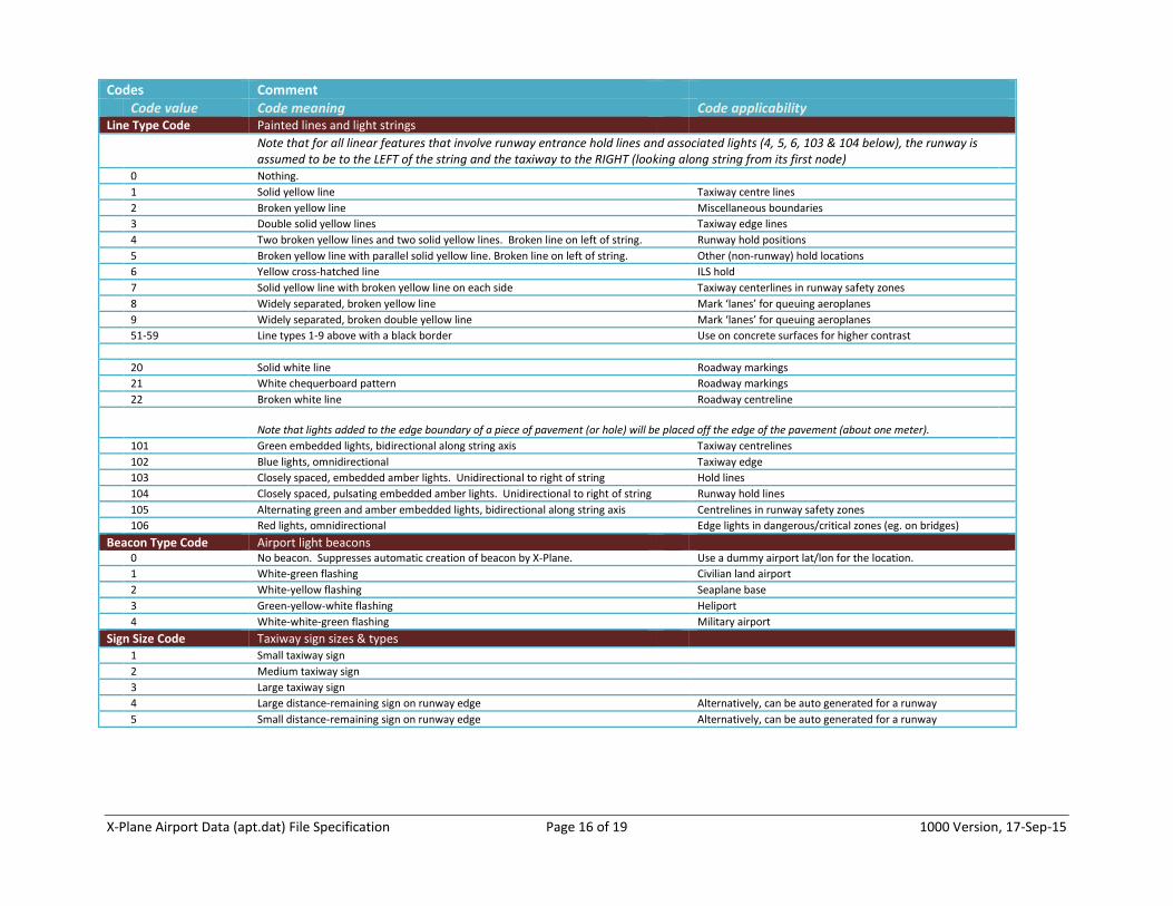
Codes Comment Code value Code meaning Code applicability Line Type Code Painted lines and light strings Note that for all linear features that involve runway entrance hold lines and associated lights (4, 5, 6, 103 & 104 below), the runway is
assumed to be to the LEFT of the string and the taxiway to the RIGHT (looking along string from its first node)
0 Nothing.
1 Solid yellow line Taxiway centre lines
2 Broken yellow line Miscellaneous boundaries
3 Double solid yellow lines Taxiway edge lines
4 Two broken yellow lines and two solid yellow lines. Broken line on left of string. Runway hold positions
5 Broken yellow line with parallel solid yellow line. Broken line on left of string. Other (non-runway) hold locations
6 Yellow cross-hatched line ILS hold
7 Solid yellow line with broken yellow line on each side Taxiway centerlines in runway safety zones
8 Widely separated, broken yellow line Mark ‘lanes’ for queuing aeroplanes
9 Widely separated, broken double yellow line Mark ‘lanes’ for queuing aeroplanes
51-59 Line types 1-9 above with a black border Use on concrete surfaces for higher contrast
20 Solid white line Roadway markings
21 White chequerboard pattern Roadway markings
22 Broken white line Roadway centreline
Note that lights added to the edge boundary of a piece of pavement (or hole) will be placed off the edge of the pavement (about one meter).
101 Green embedded lights, bidirectional along string axis Taxiway centrelines
102 Blue lights, omnidirectional Taxiway edge
103 Closely spaced, embedded amber lights. Unidirectional to right of string Hold lines
104 Closely spaced, pulsating embedded amber lights. Unidirectional to right of string Runway hold lines
105 Alternating green and amber embedded lights, bidirectional along string axis Centrelines in runway safety zones
106 Red lights, omnidirectional Edge lights in dangerous/critical zones (eg. on bridges)
Beacon Type Code Airport light beacons 0 No beacon. Suppresses automatic creation of beacon by X-Plane. Use a dummy airport lat/lon for the location.
1 White-green flashing Civilian land airport
2 White-yellow flashing Seaplane base
3 Green-yellow-white flashing Heliport
4 White-white-green flashing Military airport
Sign Size Code Taxiway sign sizes & types 1 Small taxiway sign
2 Medium taxiway sign
3 Large taxiway sign
4 Large distance-remaining sign on runway edge Alternatively, can be auto generated for a runway
5 Small distance-remaining sign on runway edge Alternatively, can be auto generated for a runway
X-Plane Airport Data (apt.dat) File Specification Page 17 of 19 1000 Version, 17-Sep-15
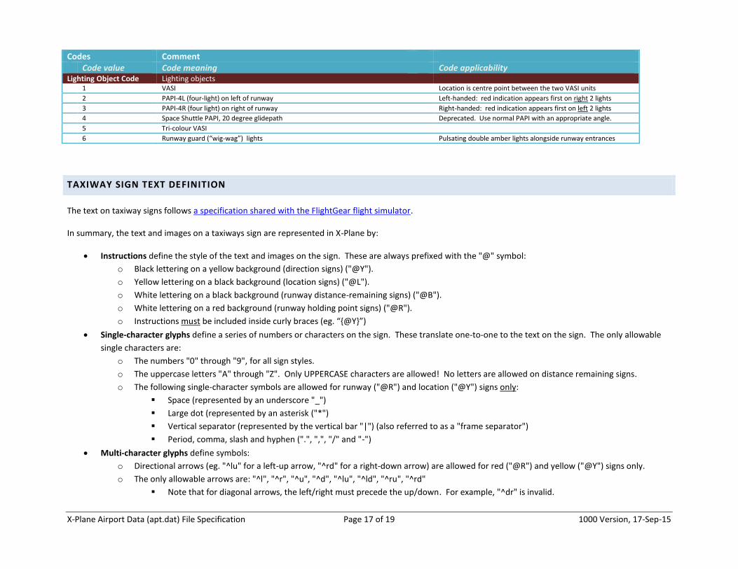
Codes Comment Code value Code meaning Code applicability Lighting Object Code Lighting objects 1 VASI Location is centre point between the two VASI units
2 PAPI-4L (four-light) on left of runway Left-handed: red indication appears first on right 2 lights
3 PAPI-4R (four light) on right of runway Right-handed: red indication appears first on left 2 lights
4 Space Shuttle PAPI, 20 degree glidepath Deprecated. Use normal PAPI with an appropriate angle.
5 Tri-colour VASI
6 Runway guard (“wig-wag”) lights Pulsating double amber lights alongside runway entrances
TAXIWAY SIGN TEXT DEFINITION
The text on taxiway signs follows a specification shared with the FlightGear flight simulator.
In summary, the text and images on a taxiways sign are represented in X-Plane by:
Instructions define the style of the text and images on the sign. These are always prefixed with the "@" symbol:
o Black lettering on a yellow background (direction signs) ("@Y").
o Yellow lettering on a black background (location signs) ("@L").
o White lettering on a black background (runway distance-remaining signs) ("@B").
o White lettering on a red background (runway holding point signs) ("@R").
o Instructions must be included inside curly braces (eg. “{@Y}”)
Single-character glyphs define a series of numbers or characters on the sign. These translate one-to-one to the text on the sign. The only allowable
single characters are:
o The numbers "0" through "9", for all sign styles.
o The uppercase letters "A" through "Z". Only UPPERCASE characters are allowed! No letters are allowed on distance remaining signs.
o The following single-character symbols are allowed for runway ("@R") and location ("@Y") signs only:
Space (represented by an underscore "_")
Large dot (represented by an asterisk ("*")
Vertical separator (represented by the vertical bar "|") (also referred to as a "frame separator")
Period, comma, slash and hyphen (".", ",", "/" and "-")
Multi-character glyphs define symbols:
o Directional arrows (eg. "^lu" for a left-up arrow, "^rd" for a right-down arrow) are allowed for red ("@R") and yellow ("@Y") signs only.
o The only allowable arrows are: "^l", "^r", "^u", "^d", "^lu", "^ld", "^ru", "^rd"
Note that for diagonal arrows, the left/right must precede the up/down. For example, "^dr" is invalid.
X-Plane Airport Data (apt.dat) File Specification Page 18 of 19 1000 Version, 17-Sep-15
o ILS-critical boundary ("critical"). These do not require a sign style.
o Runway safety zone boundary ("safety"). These do not require a sign style.
o No-entry symbols ("no-entry"). These do not require a sign style.
o Hazard (end of taxiway) ("hazard"). These do not require a sign style.
o Switch sides - flip to the back of the sign and start a new text string for the back ("@@")
o Roman numerals (for ILS categories, such as "CAT III") ("r1", "r2" and "r3") are allowed for red ("@R") and yellow ("@Y") signs only.
o Multi-character glyphs must be included inside curly braces (eg. “{r1}”)
There are rules about how these three types of data must be structured on a taxiway sign:
Instructions and single-character glyphs must be UPPERCASE.
Multi-character glyphs must be lowercase
Instructions and multi-character glyphs must be enclosed in curly braces ("{}"), to distinguish them from a set of single-character glyphs.
o If there are multiple consecutive instructions and/or multi-character glyphs, they can be separated within the same set of curly braces by a
comma (eg. “{@Y,^l}”)
Spaces are not allowed. Spaces on the sign itself are represented by the underscore ("_") character.
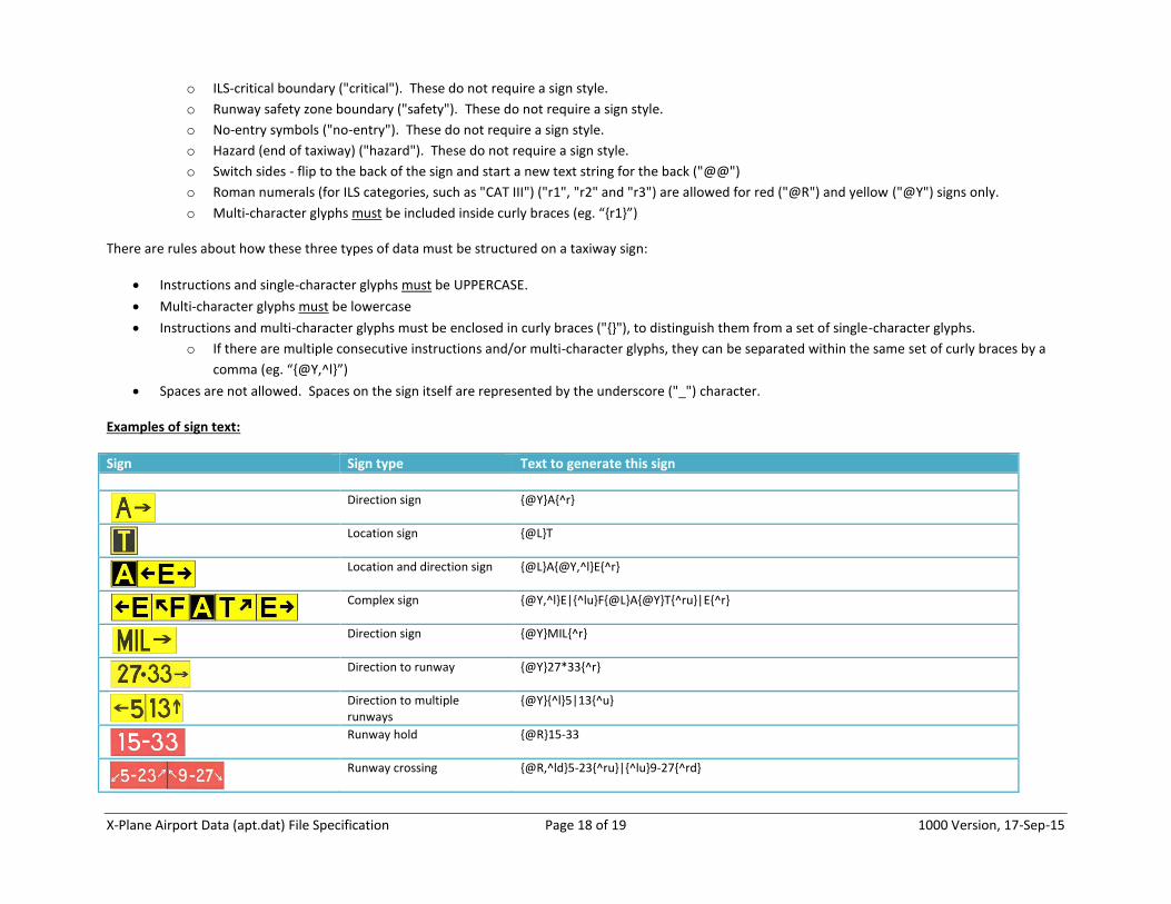
Examples of sign text:
Sign Sign type Text to generate this sign
Direction sign {@Y}A{^r}
Location sign {@L}T
Location and direction sign {@L}A{@Y,^l}E{^r}
Complex sign {@Y,^l}E|{^lu}F{@L}A{@Y}T{^ru}|E{^r}
Direction sign {@Y}MIL{^r}
Direction to runway {@Y}27*33{^r}
Direction to multiple runways
{@Y}{^l}5|13{^u}
Runway hold {@R}15-33
Runway crossing {@R,^ld}5-23{^ru}|{^lu}9-27{^rd}
X-Plane Airport Data (apt.dat) File Specification Page 19 of 19 1000 Version, 17-Sep-15
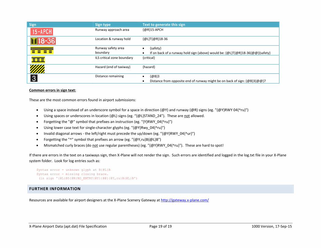
Sign Sign type Text to generate this sign
Runway approach area {@R}15-APCH
Location & runway hold {@L}T{@R}18-36
Runway safety area boundary
{safety}
If on back of a runway hold sign (above) would be: {@L}T{@R}18-36{@@}{safety}
ILS critical zone boundary {critical}
Hazard (end of taxiway) {hazard}
Distance remaining {@B}3
Distance from opposite end of runway might be on back of sign: {@B}3{@@}7
Common errors in sign text:
These are the most common errors found in airport submissions:
Using a space instead of an underscore symbol for a space in direction (@Y) and runway (@R) signs (eg. "{@Y}RWY 04{^ru}")
Using spaces or underscores in location (@L) signs (eg. “{@L}STAND_24”). These are not allowed.
Forgetting the "@" symbol that prefixes an instruction (eg. "{Y}RWY_04{^ru}")
Using lower case text for single-character glyphs (eg. "{@Y}Rwy_04{^ru}")
Invalid diagonal arrows - the left/right must precede the up/down (eg. "{@Y}RWY_04{^ur}")
Forgetting the "^" symbol that prefixes an arrow (eg. "{@Y,ru}B{@L}B")
Mismatched curly braces (do not use regular parentheses) (eg. "{@Y}RWY_04(^ru}"). These are hard to spot!
If there are errors in the text on a taxiways sign, then X-Plane will not render the sign. Such errors are identified and logged in the log.txt file in your X-Plane
system folder. Look for log entries such as:
Syntax error - unknown glyph at B{@L}B
Syntax error - missing closing brace.
(in sign '{@L}B5{@R}NO_ENTRY{@Y}{@@}{@Y,ru}B{@L}B')
FURTHER INFORMATION
Resources are available for airport designers at the X-Plane Scenery Gateway at http://gateway.x-plane.com/
Recommended


![Intro to Meteor [Deprecated]](https://img.pdfslide.us/doc/110x75/58f9b3a8760da3da068bd85b/intro-to-meteor-deprecated.jpg)
![Touch Research 2: HCI Details [Deprecated Revision]](https://img.pdfslide.us/doc/110x75/568c0f091a28ab955a92affe/touch-research-2-hci-details-deprecated-revision.jpg)


![Touch Research 1: Inspiration and History [Deprecated Revision]](https://img.pdfslide.us/doc/110x75/568c3b051a28ab0235a88a57/touch-research-1-inspiration-and-history-deprecated-revision.jpg)