Remedial Design and Implementation Plan Former Kast Property
APPENDIX I
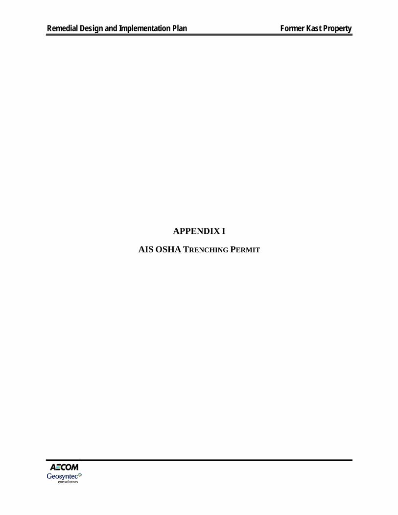
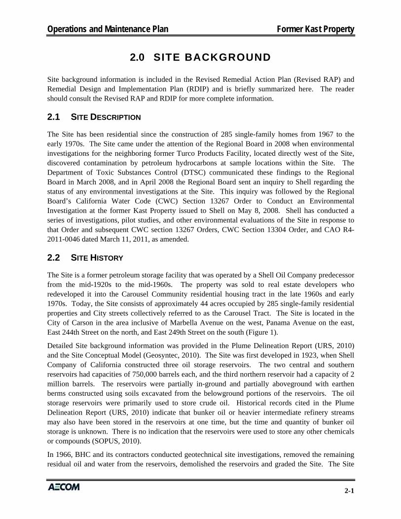
AIS OSHA TRENCHING PERMIT
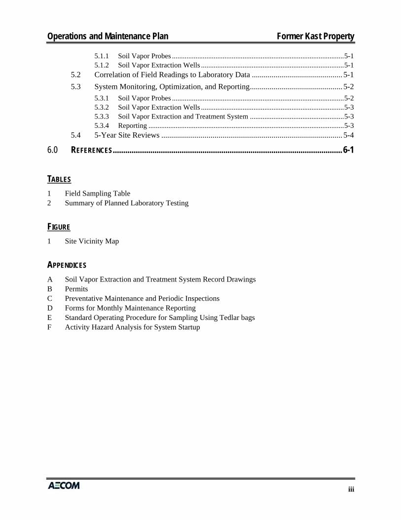
STATE OF CALIFORNIA DEPARTMENT OF INDUSTRIAL RELATIONS DIVISION OF OCCUPATIONAL SAFETY AND HEALTH
ANNUAL PERMIT Permit Issued To
(Insert Contractor/Project Administrator's Name, Address
and Telephone No.)
jAmerican Integrated Services Inc Attn: Safety Mgr or Paul Herrera PO Box 92316
Long Beach CA 90809-2316
li3HJ) 522-1168
-1
No: 2015-904781
No.
Date 2/3/2015
Region 3
District 5
Tel. (310) 516-3734
Type of Permit T1-h_NNUAL TR~NCij/EXG_t\VA_IIO~l_ ___ -------·-----
Pursuant to Labor Code Sections 6500 and 6502, this Permit is issued to the above-named employer for the projects described below.
- ·-·---- ---~ -----------State Contractor's License Number 757133
Permit Valid through February 03, 2016
AnticiQated Dates
-
Description of Project Location Address City and County _SJacting __ _c_o_mpleJlo.n. __ --------
Various Conditions of Issuance: Statewide Feb 03, 2016 Feb 3, 2015
- -------- -----------·
This Permit is issued upon the following conditions:
1. That the work is performed by the same employer. If this is an annual permit the appropriate District Office shall be notified, ir writing, of dates and location of job site prior to commencement.
2. The employer will comply with all occupational safety and health standards or orders applicable to the above projects, and an1 other lawful orders of the Division.
3. That if any unforeseen condition causes deviation from the plans or statements contained in the Permit Application Form the employer will notify the Division immediately.
4. Any variation from the specification and assertions of the Permit Application Form or violation of safety orders may be cause to revoke the permit.
5. This permit shall be posted at or near each place of employment as provided in 8 CCR 341.4
Received From Received By
Paul Herrera Permit Unit Investigated by
Date
D Cash Amount Date
IRJ Check 19434 $100.00 2/3/15 Approved by
2/3/2015 I
District Manager/Permit Unit Date

Remedial Design and Implementation Plan Former Kast Property
APPENDIX J
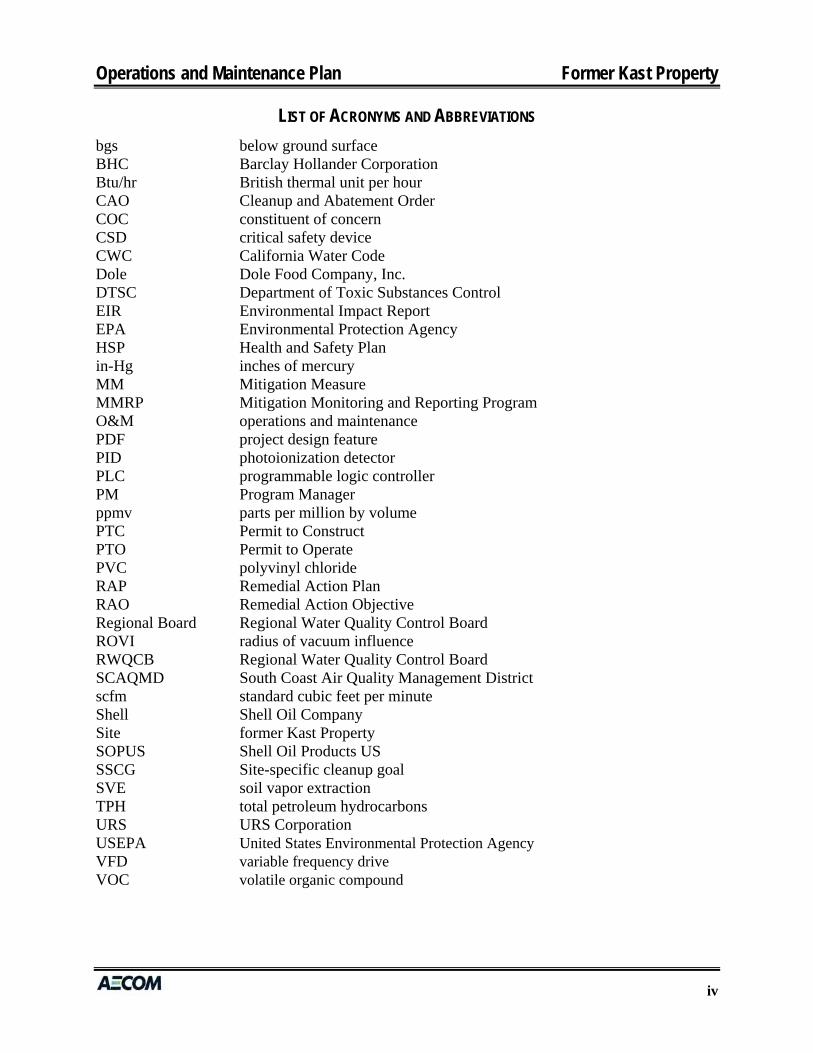
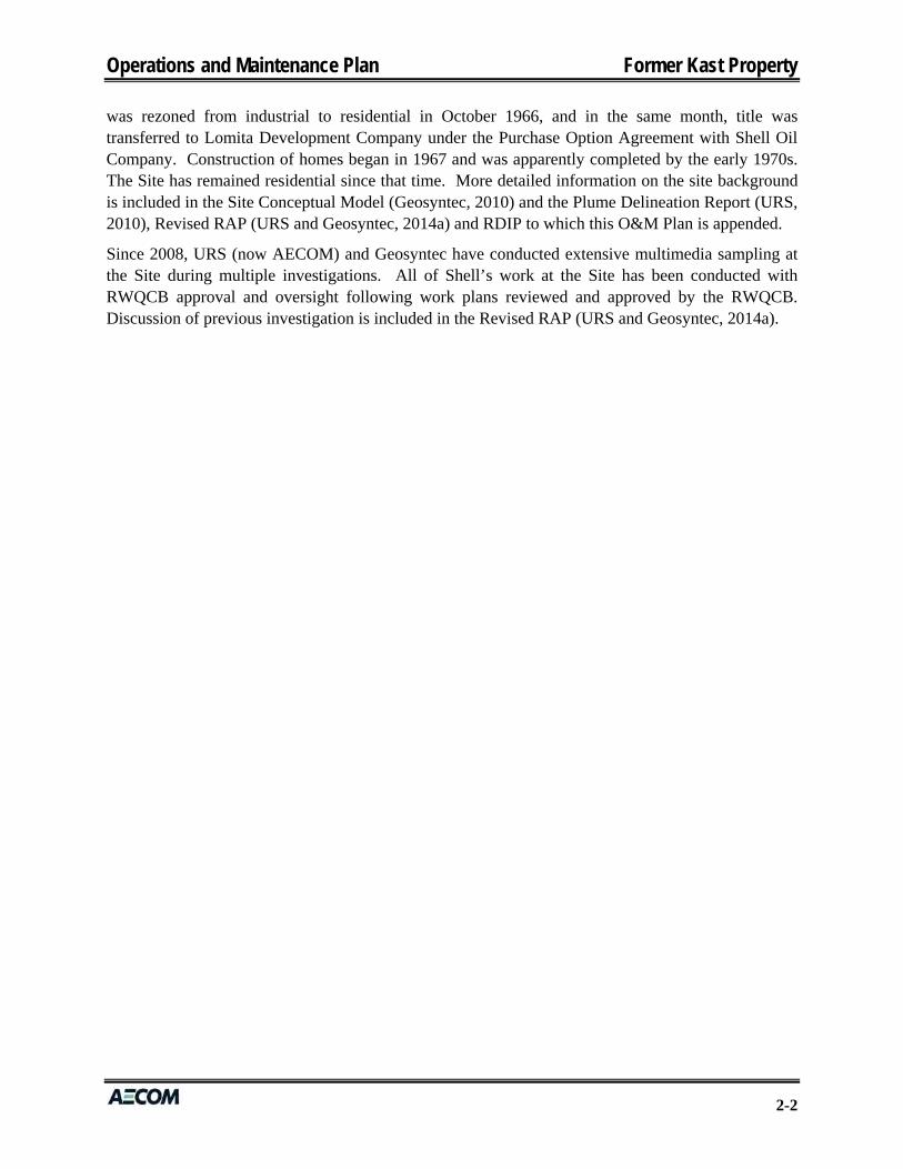
LAYDOWN YARD PLANNING SUBMITTAL
-• .. •
1-<1l .. <( 0 0: Ul ::> (!) U-
I
r .. e::;:
•
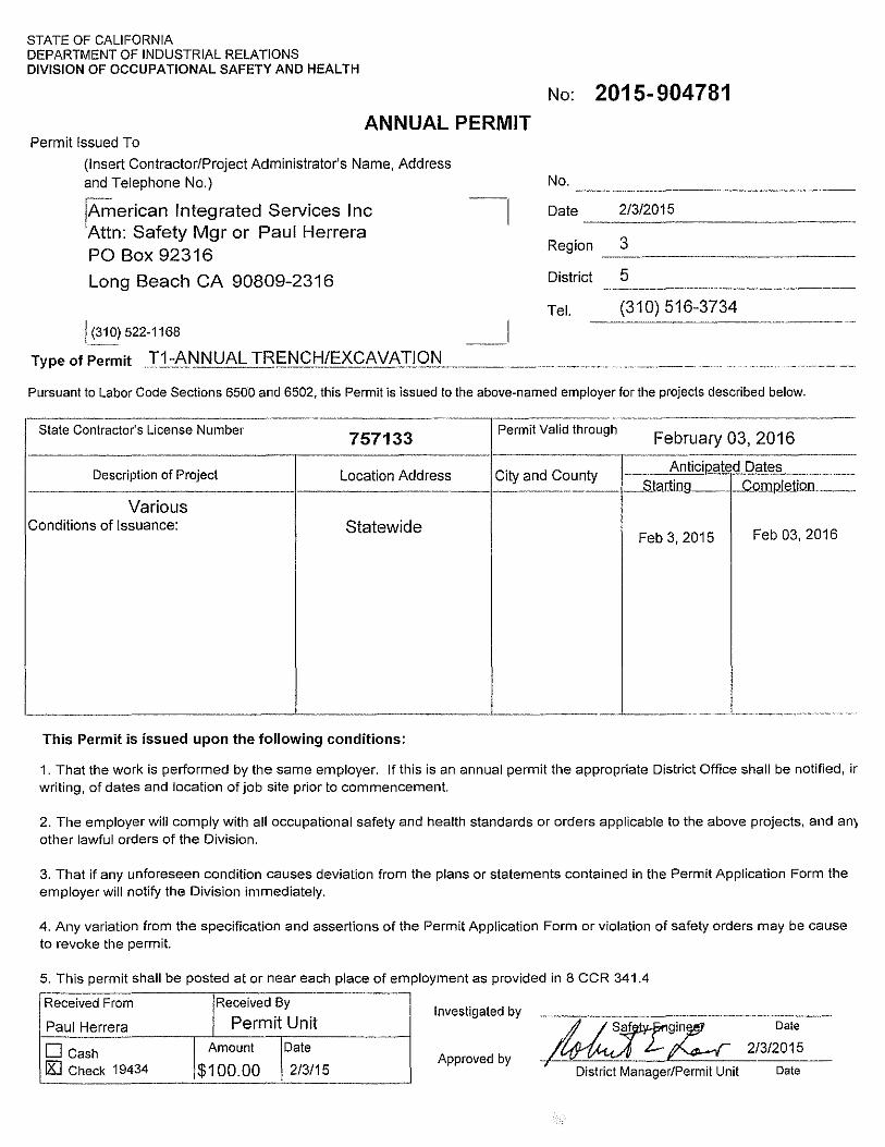
031 OVERALL SITE PLAN SCALE: 1"=150'
--"'
& ILIZED CONSTRUCTION ENTRANCE I EXIT, SEE DETAIL:~
APN# 7406026918
AREA = 7 48,360 +1- S.F.
I I
' I I
' l rif>· r-------1-=-'1' 1~ '
W. LOMITA BOULEVARD
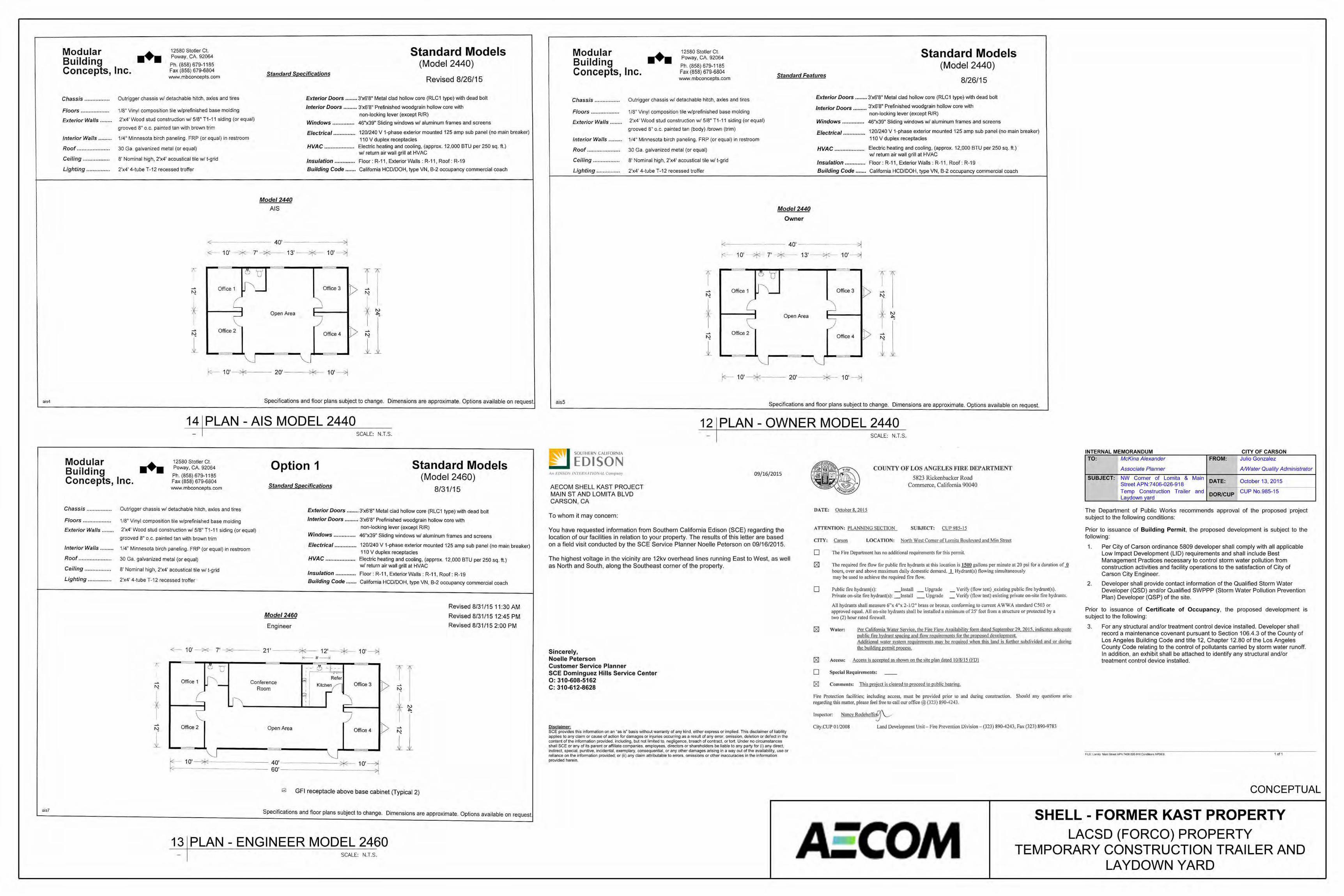
PROJECT DESCRIPTION: SUPPORT LAYDOWN YARD FOR SHELL KAST REMEDIAL ACTION PLAN IMPLEMENTATION PROJECT.
EQUIPMENT & MATERIAL LAYDOWN
I I
' I
•
-• •
- - -. - -. ... . -
A • .
' ,
•
. - . -- . -- -. . - -
NOTES: 1) STABILIZED CONSTRUCTION ENTRANCE I EXIT SHOULD BE INSTALLED
PER CASQA TC-1. 2) STABILIZED CONSTRUCTION ENTRANCE I EXIT SHOULD BE USED IN
CONJUCTION WITH STREET SWEEPING (CASQA SE-7) ON ADJACENT PUBLIC RIGHT OF WAY.
CRUSHED AGGREGATE GREATER THAN 3" BUT SMALLER THAN 6".
12" MIN, UNLESS OTHERWISE SPECIFIED BY A SOILS ENGINEER
SECTION A-A
ORIGINAL GRADE
FILTER FABRIC
. -
• • 12" MIN, UNLESS OTHERWISE SPECIFIED BY A SOILS ENGINEER
SECTION 8-8
CRUSHED AGGREGATE ~-GREATER THAN 3" BUT
SMALLER THAN 6".
ORIGINAL GRADE
FILTER FABRIC
. .
~ ~ I 0 0: 0 w ;;: [L
(!)
z l 1-<Jl X Ul
:~ ]0
'
~ '
'
MATCH EXISTING GRADE ,_,
20' R MIN
LCORRUGATED STEEL PANELS
A A ,-B ~ - ~ ~fi -- t F- )S-
.J'-i ' I J'-1 I )'-! , IJ'-1
'--B !.<. 24' MIN
50' MIN OR MAXIMUM ALLOWED BY _j SITE OR FOUR TIMES THE CIRCUMFERENCE
OF THE LARGEST VEHICLE TIRE, WHICHEVER IS GREATER
PLAN
10' MIN
w
STABILIZED CONSTRUCTION 0_11 ENTRANCE/ EXIT
SCALE: N.T.S.
LEGEND:
-x-x-x- TEMP CHAIN LINK FENCE 6' H
LOT LINE
-------- EQUIPMENT AND MATERIAL LAYDOWN BOUNDARY
D CRUSHED MISCELLANEOUS BASE (CMB)
INGRESS I EGRESS
CONCEPTUAL
SHELL - FORMER KAST PROPERTY LACSD(FORCO)PROPERTY
TEMPORARY CONSTRUCTION TRAILER AND LA YDOWN YARD
-- -- --
--
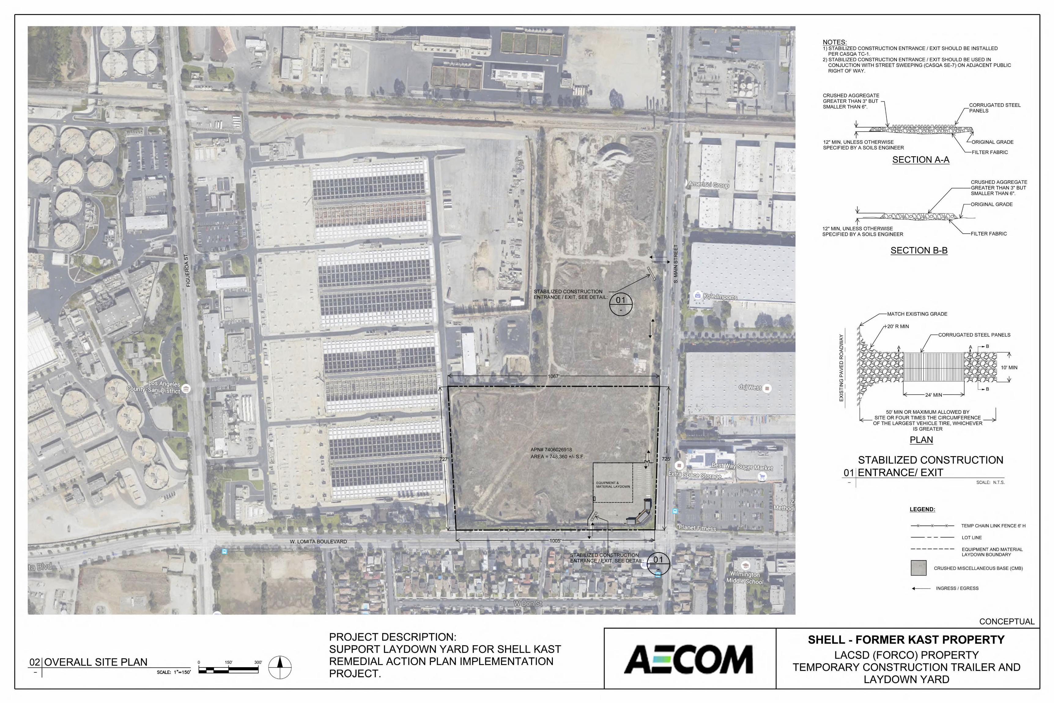
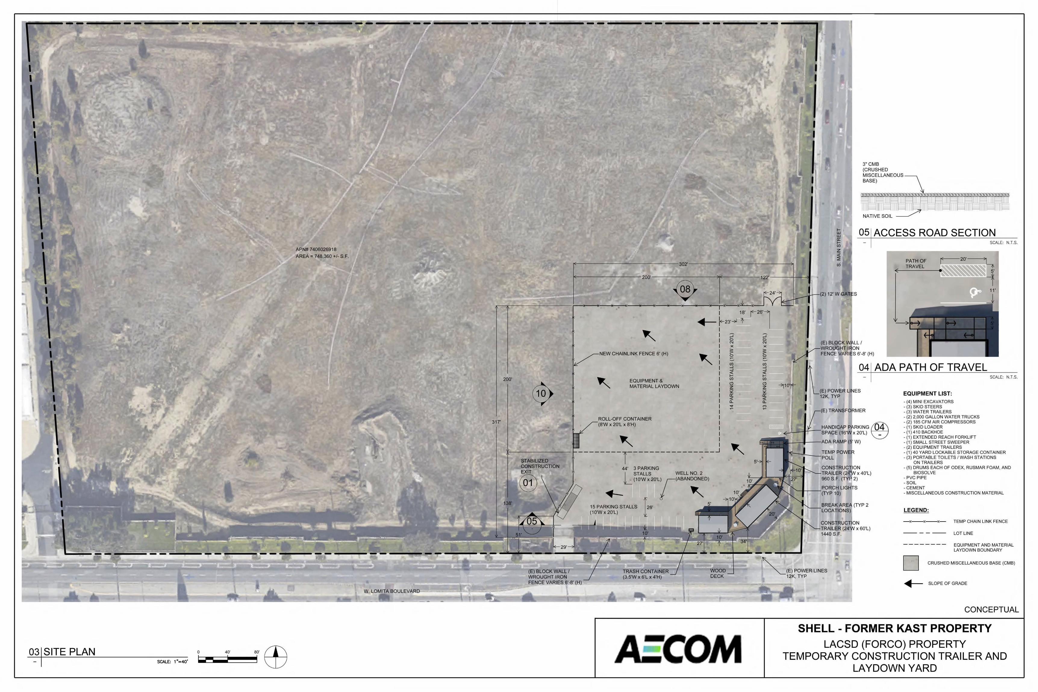
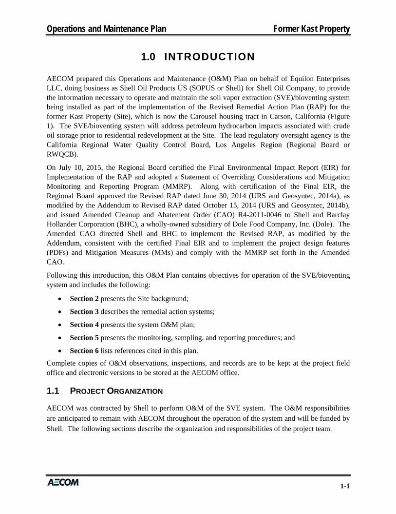
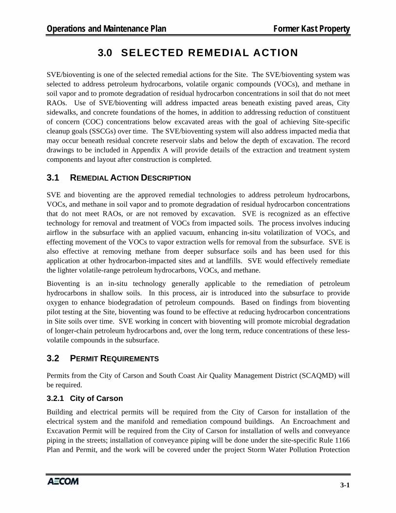
0~~ SITE PLAN SCALE: 1"=40'
-
APN# 7406026918
AREA= 748,360 +/- S.F.
--
200'
317'
-- -- -- -- --
I I
I I
3" CMB (CRUSHED MISCELLANEOUS-, BASE)
NATIVE SOIL _ ____...-
~ 0_51 ACCESS ROAD SECTIO~ALE: N.T.S.
tii z <( :2 en
PATH OF TRAVEL
1 18' r-26' l • r-23'~ t ~
NEW CHAINLINK FENCE 6' (H)
EQUIPMENT & MATERIAL LAYDOWN
ROLL-OFF CONTAINER x 20'L x 8'H)
"' STABILIZED CONSTRUCTION EXIT
--------~------------~--~
®
(E) BLOCK WALL I WROUGHT IRON FENCE VARIES 6'-8' (H)
44' 3 PARKING
L STALLS WELL NO.2 (10'W X 20'L) / (ABANDONED)
~- t "' 15 PARKING STALLS 26' (10'W X 20'L)
TRASH CONTAINER (3.5'W X 6'L X 4'H)
WOOD DECK
-' 0 N X
;;: 0 ~ ~
en -' -' <( r-en (!) z
"' <>: <( 0.. ..,. ~
-' 0 N X
s: 0 ~ ~
en -' -' ~ en (!) z
"' <>: <( 0..
"' ~
0~ 1 ADA PATH OF TRAVEL SCALE NTS.
==o.ti 10'~ (E) POWER Ll
I 12K, TYP
I (E) TRAI~SFCJRMEoR
m~~~~~_L~~rL_HANDICAP Pf,f<K I~I li ~-4 - SPACE (1
TRAILER lolf'IM
960 S.F.
1......_-1-__ PORCH LI GIHirS
(TYP 10)
EQUIPMENT LIST: - (4) MINI EXCAVATORS - (3) SKID STEERS - (3) WATER TRAILERS - (2) 2,000 GALLON WATER TRUCKS - (2) 185 CFM AIR COMPRESSORS - (1) SKID LOADER - (1) 410 BACKHOE - (1) EXTENDED REACH FORKLI FT - (1) SMALL STREET SWEEPER - (2) EQUIPMENT TRAILERS - (1) 40 YARD LOCKABLE STORAGE CONTAINER - (3) PORTABLE TOILETS I WASH STATIONS
ON TRAILERS - (5) DRUMS EACH OF ODEX, RUSMAR FOAM, AND
BIOSOLVE -PVC PIPE -SOIL -CEMENT - MI SCELLANEOUS CONSTRUCTION MATERIAL
LEGEND:
- <--<--<- TEMP CHAIN LINK FENCE
LOT LINE
EQUIPMENT AND MATERIAL LAYDOWN BOUNDARY
~(E) POWER LINES 12K, TYP
D CRUSHED MISCELLANEOUS BASE (CMB)
• SLOPE OF GRADE
CONCEPTUAL
SHELL - FORMER KAST PROPERTY LACSD(FORCO)PROPERTY
TEMPORARY CONSTRUCTION TRAILER AND LA YDOWN YARD

FENCE HEIGIHT
BLOCK WALL HEIGHT
. --: ..,_ail- ...,. "'
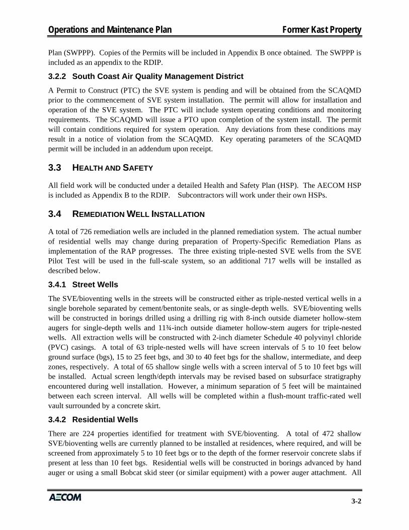
1~ lEAST ELEVATION SCALEo N.T.S.
O? ISOUTH ELEVATION SCALEo N.T.S.
DECK HEIGHT DECK HEIGHT
TRAILER HEIGHT (TYP) TRAILER HEIGHT (TYP)
1~ ~ WEST ELEVATION c_NE:W (6'H) CHAINLINK FENCE SCALEo N.T.S.
o~ ~ NORTH ELEVATION SCALEo N.T.S .
0! I PERSPECTIVE VIEW
•
'. . . . '
•
• • ••
0
\ \ \ \
0~~ PERSPECTIVE VIEW
EW (6'H) CHAINLINK FENCE
• • ..
SCALEo N.T.S .
•
'. '.
• •
• • -
SCALE: N.T.S.
CONCEPTUAL
SHELL- FORMER KAST PROPERTY LACSD(FORCO)PROPERTY
TEMPORARY CONSTRUCTION TRAILER AND LA YDOWN YARD
ais4
aisl
Modular Bu ilding Concepts, Inc. •••
12580 Stotler Ct. Poway, CA. 92064
Ph. (858) 679-1185 Fax (858) 679-6804 WWIN.mbconcepts.com
Standard Specifications
Standard Models (Model 2440)
Revised 8/26/15
Chassis ... ...... .... .. . Outrigger chassis w/ detachable hitch, axles and tires Exterior Doors ........ 3'x6'8" Metal clad hollow core (RLC1 type) with dead bolt
Floors. ...... .......... . 1/8" V inyl composition tile w/preffnished base molding Interior Doors ......... 3'x6'8" Prefinished woodgrain hollow core with
non-locking lever (except RJR) Exterior Walls.... .... 2'x4' Wood stud construction w/ 5/8'' T1 -11 s iding (or equal)
Windows .............. 46"x39" Sliding windows w/ aluminum frames and screens grooved 8" o.c . painted tan with brown trim
Electrical ... .. .... ..... 120/240 V 1-phase exterior mounted 125 amp sub panel (no main breaker)
11 0 V duplex receptacles Interior Walls....... .. 1/4'' Minnesota birch paneling. FRP (or equal ) in restroom
Roof...... .. .... ......... 30 Ga. ga lvan ized metal (or equal) HVAC ................... Electric heating and cooling, (approx. 12,000 BTU per 250 sq . ft .) w/ return air wall grill at HVAC
Ceiling.. .... ... ........ 8' Nominal high , 2'x4' acoustical ti le w/ t-grid Insulation ............. Floor : R-11 , Exterior Walls: R-11, Roof : R-19
Lighting......... .... .. 2'x4' 4-tube T-12 recessed troffer Building Code ....... California HCO/DOH, type VN , B-2 occupancy commercial coach
Modular • Build ing • • Concepts, Inc.
-~ I
Made/2440
AIS
~---------- 40' _______ ,:>!
-"'_ 1 0' --*- 7' -*- - 13' - -¥-- 1 0'~
I Office 3
~
!":; u Office! U\ -
C, Open Area
~ Office 2
Office 4
~--~ ·-\____I
r.-~- 10'-+~- 20' ---oo¥-- 1 0' -:>!
T ···-
Specifications and floor plans subject to change. Dimensions are approximate. Options available on request.
12580 Stotler Ct. Poway, CA. 92064
Ph. (858) 679-1185 Fax (858) 679-6804 www.mbconcepts.com
AIS MODEL 2440
Option 1
Standard Specificat ions
SCALE: N.T.S.
Standard Models (Model 2460)
8/31/15
Chassis ................ Outrigger chassis w/ detachable hitch, axles and tires Exterior Doors ........ 3'x6'8" Metal clad hollow core (RLC1 type) with dead bolt
Floors............... ... 1/8" V inyl compos ition tile w/prefinished base molding
Exterior Walls. ...... . 2'x4' Wood stud construction wl 518" T1-11 siding (or equal)
Interior Doors ......... 3'x6'8" Prefinished woodgrain hollow core with
non-locking lever {except RJR)
grooved 8" o.c. painted tan with brown trim Windows.............. 46"x39" Sliding windows w/ aluminum frames and screens
Interior Walls ... ...... 1/4" Minnesota birch paneling. FRP (or equal) in restroom Electrical .............. 120/240 V 1-phase exterior mounted 125 amp sub panel {no main breaker)
110 V duplex receptacles Roof ......... .. ....... ... 30 Ga. galvanized metal (or equal)
Ceiling.......... ....... a· Nominal high, 2'x4 ' acoustical ti le w/ !-Wid
HVAC ............. ...... Electric heating and cooling , (approx . 12,000 BTU per 250 sq. ft.) wl return air wall grill at HVAC
Lighting............... 2'x4 ' 4-tube T-12 recessed troffer Insulation .. .. .... .. ... Floor : R-11, Exterior Walls : R-11 , Roof : R-19
Building Code ... .... California HCD!DOH, type VN, B-2 occupancy commercial coach
Made/2460
Engineer
<'- 1 0' - "'"" 7' -.x~--- 21' ---+- 12'-+- 10'~
~· ~-- ·-~ '~~-""T":!, I:", -~~~~----~~~---:-_-_~. ;,.(!;,"'L"'!I---_"'1"'"-=~-.. -~-~ J ···-·-------t:;c.-;e= T
ll> ~
-t ~ U
----...__ h Refer Office 1 \ _ Conference t4 ;:t Offi 3 , Kitchen JCe
Room
.....__~'---.( j \.'--------'R"""": ----1 )
~ )~ Office J OpenArea Office 4 i)
r<- 10' -+\___~_1----- 40' ____ \J_ -*-- 10' ~. ~:: 60' ~
<el GFI receptacle above base cabinet (Typical 2)
Revised 8/31/15 11 :30 AM
Revised 8/31/15 12:45 PM
Revised 8/31/15 2:00PM
Specifications and floor plans subject to change. Dimensions are approximate. Options available on request.
ENGINEER MODEL 2460 SCALE: N.T.S .
... Standard Models (Model 2440)
Modular Building Concepts, Inc.
12580 Stotler Ct. Poway, CA. 92064
Ph. (858) 679-1185 Fax (858) 679-6804 www.mbconcepts .com
Standard Features 8/26/15
Chassis ................ Outrigger ch assis w/ detachable hitch , axles and tires
Floors .................. 1/8" Vinyl compositi on tile w/prefinished base molding
Ext - '" 11 2'x4' Wood stud construction w / 5!8" T1 -11 siding (or equal) enor na s ... ..... grooved 8" o.c . painted tan (body) /brown (trim)
Interior Walls......... 1/4" Minnesota birch paneling . FRP (or equal) in restroom
Roof.. .. ..... ...... .... .. 30 Ga. galvanized metal (or equal)
Ceiling .... .. ........... 8' Nominal high, 2'x4' acoustical tile wl t-grid
Lighting........... .... 2'x4' 4-tube T -·12 recessed troffer
Made/2440
Owner
Exterior Doors ........ 3'x6'8" Metal clad hollow core {RLC1 type) with dead bolt
Interior Doors ......... 3'x6'8" Prefinished woodgrain hollow core with non-locking lever {except R/R)
Windows .......... .. .. 46"x39" Sliding windows w/ aluminum frames and screens
Electrical .............. 120/240 V 1-phase exterior mounted 125 amp sub panel (no main breaker) 11 o v duplex receptacles
HVAC ................... Electric heating and cooling , (approx. 12,000 BTU per 250 sq . ft .) w/ retum air wall grill at HVAC
Insulation. ........ .... Floor : R-11 , Exterior Walls : R-11 . Roof : R-19
Building Code ....... California HCD/DOH, type VN, B-2 occupancy commercial coach
~~---------- 40' ----
~-
f Office 1 Office 3
Open Area c: Office 2
Office 4
r:-- 10·-+--- 20'---¥- 10'~
ais5 Specifications and floor plans subject to change. Dimensions are approximate. Options available on request.
OWNER MODEL 2440
SOUTHERN CAU IORNIA
EDISON
AECOM SHELL KAST PROJECT MAIN STAND LOMITA BLVD CARSON , CA
To whom it may concern:
09/16/2015
You have requested information from Southern California Edison (SCE) regarding the location of our faci lities in re lation to your property. The results of this letter are based on a field visit conducted by the SCE Service Planner Noelle Peterson on 09/16/2015.
The highest voltage in the v icinity are 12kv overhead lines running East to West, as well as North and South , along the Southeast corner of the property.
Sincerely, Noelle Peterson Customer Serv ice Planner SCE Dominguez Hills Se rvice Center 0 : 310-608-51 62 C: 310-612-8628
Disclaimer : SCE provides th is information on an "as is" basis without warranty of any kind, either express or implied_ This disclaimer of liabi lity applies to any claim or cause of action for damages or injuries occurring as a result of any error, omission, deletion or defect in the content of the information provided , including, but not limited to, negligence, breach of contract, or tort. Under no ci rcumstances shall SCE or any of its parent or affiliate companies, employees, directors or shareholders be liable to any party for (i) any direct, indirect, special, punitive, incidental , exemplary , consequential , or any other damages arising in a way out of the availability, use or reliance on the information provided : or (ii) any claim attributable to errors , omissions or other inaccuracies in the in formation provided herein.
SCALE: N.T.S.
COUNTY OF LOS ANGELES FIRE DEPARTMENT
5823 Rickenbacker Road Conunerce, Califomia 90040
DATE: October 8. 2015
ATTENTION: PLANNING SECTION SUBJ ECT: CUP 985-15
CITY: Carson LOCATION: North West Comer of Lomita Boulevard and Min Street
D The Fire Department has no additional requirements for this permit.
[8J The required fire flow for public fire hydrants at U1is location is .1500 ga llons per minute at 20 psi for a duraLion of ..Q hours, over and above maximum daily domestic demand . ...!.. Hydrant(s) flowing simultaneously
0
may be us·ed io achieve the required fire now.
Public fire hydrant{s); _ Install _Upgrade Private on-site fire hydrant(s): _ Install _Upgrade
_ Verify ( flow test) _existing public fi re hydrant(s). _ VerifY (flow test) existing private on-site fire hydrants,
All hydrants shall measure 6"x 4"x 2-l/2" brass or bronze, conforming to current A WWA standard C503 or approved equal. All on-site hydrants shall be installed a minimum of25' feet from a structure or protected by a two (2) hour rated firewal l .
f2l Water: Per Califomi<t Wmer Service, the Fire FIO\V Availability form dated Scmembcr29, 20 15, indicates ndeqtlj[C nublic lire hydr.mt spacing and flow requkenwnl'> for the proposed development. Additional water svstclll requirements may be J'equired when lhis land is further subdfvided and or during the building pennit process.
[8J Access: Access is accepted as shown on the site plan dated 10/8/ 15 (FDl
0 Special Requirements:
C8] Comments: This project is cleared to proceed 1.0 public hearing.
Fire Protection facilities; including access, must be provided prior to and during. construction . Should any questions arise regarding this matter, please feel free to call our office@ (323) 890-4243.
Inspector: N<1ncy RodeheiTeg'\.-
City.CUP 01/2008 Land Development Unit- Fire Prevention Division- (323) 890-4243, Fax (323) 890-9783
INTERNAL MEMORANDUM CITY OF CARSON TO: McKina Alexander FROM: Julio Gonzalez
Associate Planner A/Water Quality Administrator
SUBJECT: NW Corner of Lomita & Main DATE: October 13, 2015 Street APN:7406-026-918 Temp Construction Trai ler and DORIC UP CUP No.985-15 Lavdown vard
The Department of Public Works recommends approval of the proposed project subject to the following conditions:
Prior to issuance of Building Permit , the proposed development is subject to the following:
1. Per Cit_y of Carson ordinance 5809 developer shall comply with all applicable Low Impact Development (LI D) requirements and shall include Best Management Practices necessary to control storm water pollution from construction activities and facility operations to the satisfaction of City of Carson City Engineer.
2. Developer shall provide contact information of the Qualified Storm Water Developer (QSD) and/or Qualified SWPPP (Storm Water Pollution Prevention Plan) Developer (QSP) of the site.
Prior to issuance of Certif icate of Occupancy, the proposed development is subject to the fol lowing:
3. For any structural and/or treatment control device installed. Developer shall record a maintenance covenant pursuant to Section 106.4.3 of the County of Los Angeles Building Code and title 12, Chapter 12.80 of the Los Angeles County Code relating to the control of pollutants carried by storm water runoff. In addition , an exhibit shall be attached to identify any structural and/or treatment contro l device installed .
1 of 1
CONCEPTUAL
SHELL - FORMER KAST PROPERTY LACSD(FORCO)PROPERTY
TEMPORARY CONSTRUCTION TRAILER AND LA YO OWN YARD
Remedial Design and Implementation Plan Former Kast Property
APPENDIX M
SVE SYSTEM O&M PLAN
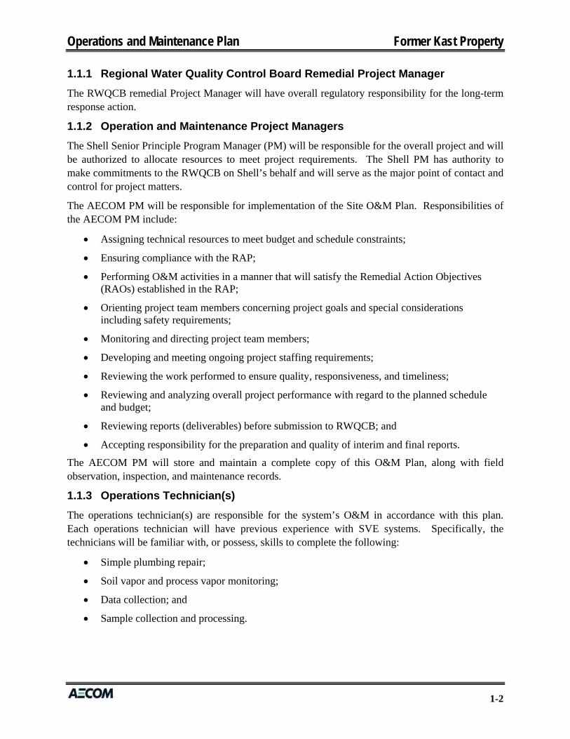
Operations and Maintenance Plan Former Kast Property
O P E R A T I O N S A N D M A I N T E N A N C E P L A N
SOIL VAPOR EXTRACTION/BIOVENTING AND
TREATMENT SYSTEMS
FORMER KAST PROPERTY CARSON, CALIFORNIA
Prepared for
Shell Oil Products US 20945 S. Wilmington Avenue Carson, California 90810
October 15, 2015
Prepared by
999 Town and Country Road Orange, California 92868

Operations and Maintenance Plan Former Kast Property
i
OPERATIONS AND MAINTENANCE PLAN SOIL VAPOR EXTRACTION/BIOVENTING AND
TREATMENT SYSTEMS
FORMER KAST PROPERTY
CARSON, CALIFORNIA
This Operations and Maintenance Plan provides information regarding operations and maintenance of a soil vapor extraction/bioventing and treatment system installed to address petroleum hydrocarbon impacts associated with crude oil storage during the period prior to residential redevelopment at the former Kast Property located in Carson, California.
No express or implied representation or warranty is included or intended in this plan except that the work was performed within the limits prescribed by Shell Oil Products US with the customary thoroughness and competence of professionals working in the same area on similar projects.
AECOM
Christian Osterberg, PG Project Manager
Peter Stumpf, PE Principal Engineer
Operations and Maintenance Plan Former Kast Property
ii
TABLE OF CONTENTS
SECTION PAGE
INTRODUCTION ............................................................................................................ 1-1 1.0
1.1 Project Organization ............................................................................................ 1-1
1.1.1 Regional Water Quality Control Board Remedial Project Manager ................... 1-2 1.1.2 Operation and Maintenance Project Managers ................................................... 1-2 1.1.3 Operations Technician ........................................................................................ 1-2
SITE BACKGROUND ..................................................................................................... 2-1 2.0
2.1 Site Description .................................................................................................... 2-1
2.2 Site History .......................................................................................................... 2-1
SELECTED REMEDIAL ACTION ...................................................................................... 3-1 3.0
3.1 Remedial Action Description ............................................................................... 3-1
3.2 Permit Requirements ............................................................................................ 3-1
3.2.1 City of Carson ..................................................................................................... 3-1 3.2.2 South Coast Air Quality Management District ................................................... 3-2
3.3 Health and Safety ................................................................................................. 3-2
3.4 Remediation Well Installation ............................................................................. 3-2
3.4.1 Street Wells ......................................................................................................... 3-2 3.4.2 Residential Wells ................................................................................................ 3-2
3.5 Soil Vapor Extraction and Treatment Systems .................................................... 3-3
3.5.1 Conveyance Piping ............................................................................................. 3-3 3.5.2 Piping Manifold .................................................................................................. 3-3 3.5.3 Skid-Mounted Equipment ................................................................................... 3-3 3.5.4 Instrumentation and Control Equipment ............................................................. 3-4 3.5.5 Critical Safety Devices ....................................................................................... 3-4 3.5.6 Alarms ................................................................................................................. 3-5
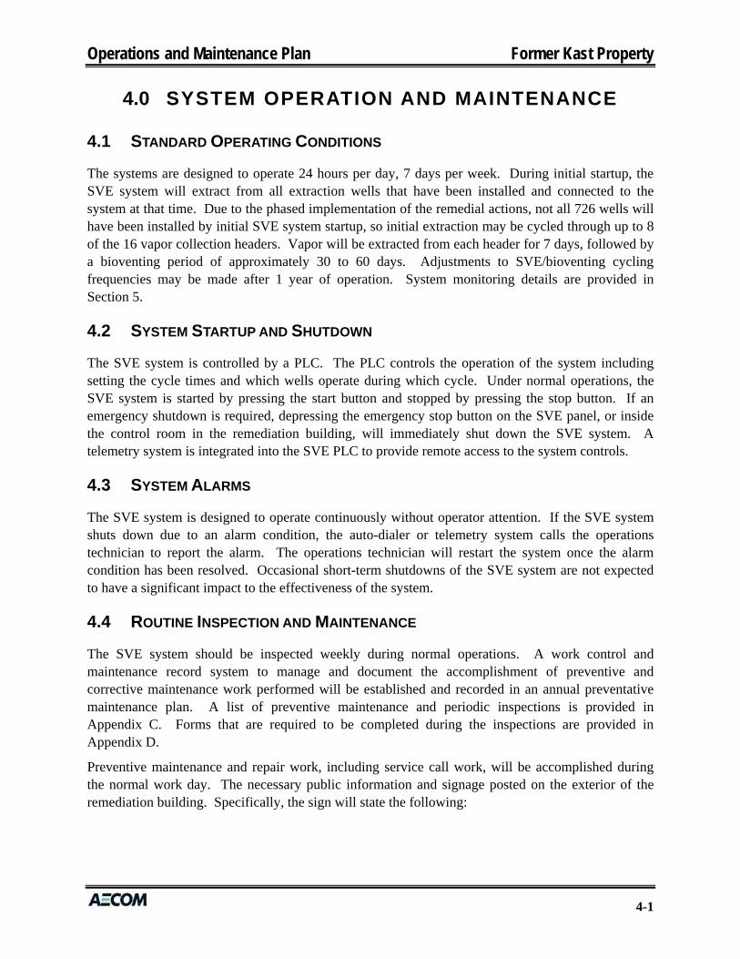
SYSTEM OPERATION AND MAINTENANCE ...................................................................... 4-1 4.0
4.1 Standard Operating Conditions ............................................................................ 4-1
4.2 System Startup and Shutdown ............................................................................. 4-1
4.3 System Alarms ..................................................................................................... 4-1
4.4 Routine Inspection and Maintenance ................................................................... 4-1
4.5 Water Disposal ..................................................................................................... 4-2
4.6 Emergency Response ........................................................................................... 4-2
SYSTEM MONITORING AND REPORTING ........................................................................ 5-1 5.0
5.1 Baseline Sampling ............................................................................................... 5-1
Operations and Maintenance Plan Former Kast Property
iii
5.1.1 Soil Vapor Probes ............................................................................................... 5-1 5.1.2 Soil Vapor Extraction Wells ............................................................................... 5-1
5.2 Correlation of Field Readings to Laboratory Data .............................................. 5-1
5.3 System Monitoring, Optimization, and Reporting ............................................... 5-2
5.3.1 Soil Vapor Probes ............................................................................................... 5-2 5.3.2 Soil Vapor Extraction Wells ............................................................................... 5-3 5.3.3 Soil Vapor Extraction and Treatment System .................................................... 5-3 5.3.4 Reporting ............................................................................................................ 5-3
5.4 5-Year Site Reviews ............................................................................................ 5-4
REFERENCES .............................................................................................................. 6-1 6.0
TABLES
1 Field Sampling Table 2 Summary of Planned Laboratory Testing
FIGURE
1 Site Vicinity Map
APPENDICES
A Soil Vapor Extraction and Treatment System Record Drawings B Permits C Preventative Maintenance and Periodic Inspections D Forms for Monthly Maintenance Reporting E Standard Operating Procedure for Sampling Using Tedlar bags F Activity Hazard Analysis for System Startup
Operations and Maintenance Plan Former Kast Property
iv
LIST OF ACRONYMS AND ABBREVIATIONS
bgs below ground surface BHC Barclay Hollander Corporation Btu/hr British thermal unit per hour CAO Cleanup and Abatement Order COC constituent of concern CSD critical safety device CWC California Water Code Dole Dole Food Company, Inc. DTSC Department of Toxic Substances Control EIR Environmental Impact Report EPA Environmental Protection Agency HSP Health and Safety Plan in-Hg inches of mercury MM Mitigation Measure MMRP Mitigation Monitoring and Reporting Program O&M operations and maintenance PDF project design feature PID photoionization detector PLC programmable logic controller PM Program Manager ppmv parts per million by volume PTC Permit to Construct PTO Permit to Operate PVC polyvinyl chloride RAP Remedial Action Plan RAO Remedial Action Objective Regional Board Regional Water Quality Control Board ROVI radius of vacuum influence RWQCB Regional Water Quality Control Board SCAQMD South Coast Air Quality Management District scfm standard cubic feet per minute Shell Shell Oil Company Site former Kast Property SOPUS Shell Oil Products US SSCG Site-specific cleanup goal SVE soil vapor extraction TPH total petroleum hydrocarbons URS URS Corporation USEPA United States Environmental Protection Agency VFD variable frequency drive VOC volatile organic compound
Operations and Maintenance Plan Former Kast Property
1-1
INTRODUCTION 1.0
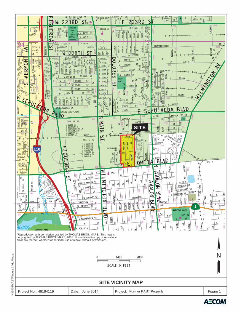
AECOM prepared this Operations and Maintenance (O&M) Plan on behalf of Equilon Enterprises LLC, doing business as Shell Oil Products US (SOPUS or Shell) for Shell Oil Company, to provide the information necessary to operate and maintain the soil vapor extraction (SVE)/bioventing system being installed as part of the implementation of the Revised Remedial Action Plan (RAP) for the former Kast Property (Site), which is now the Carousel housing tract in Carson, California (Figure 1). The SVE/bioventing system will address petroleum hydrocarbon impacts associated with crude oil storage prior to residential redevelopment at the Site. The lead regulatory oversight agency is the California Regional Water Quality Control Board, Los Angeles Region (Regional Board or RWQCB).
On July 10, 2015, the Regional Board certified the Final Environmental Impact Report (EIR) for Implementation of the RAP and adopted a Statement of Overriding Considerations and Mitigation Monitoring and Reporting Program (MMRP). Along with certification of the Final EIR, the Regional Board approved the Revised RAP dated June 30, 2014 (URS and Geosyntec, 2014a), as modified by the Addendum to Revised RAP dated October 15, 2014 (URS and Geosyntec, 2014b), and issued Amended Cleanup and Abatement Order (CAO) R4-2011-0046 to Shell and Barclay Hollander Corporation (BHC), a wholly-owned subsidiary of Dole Food Company, Inc. (Dole). The Amended CAO directed Shell and BHC to implement the Revised RAP, as modified by the Addendum, consistent with the certified Final EIR and to implement the project design features (PDFs) and Mitigation Measures (MMs) and comply with the MMRP set forth in the Amended CAO.
Following this introduction, this O&M Plan contains objectives for operation of the SVE/bioventing system and includes the following:
Section 2 presents the Site background;
Section 3 describes the remedial action systems;
Section 4 presents the system O&M plan;
Section 5 presents the monitoring, sampling, and reporting procedures; and
Section 6 lists references cited in this plan.
Complete copies of O&M observations, inspections, and records are to be kept at the project field office and electronic versions to be stored at the AECOM office.
1.1 PROJECT ORGANIZATION
AECOM was contracted by Shell to perform O&M of the SVE system. The O&M responsibilities are anticipated to remain with AECOM throughout the operation of the system and will be funded by Shell. The following sections describe the organization and responsibilities of the project team.
Operations and Maintenance Plan Former Kast Property
1-2
1.1.1 Regional Water Quality Control Board Remedial Project Manager
The RWQCB remedial Project Manager will have overall regulatory responsibility for the long-term response action.
1.1.2 Operation and Maintenance Project Managers
The Shell Senior Principle Program Manager (PM) will be responsible for the overall project and will be authorized to allocate resources to meet project requirements. The Shell PM has authority to make commitments to the RWQCB on Shell’s behalf and will serve as the major point of contact and control for project matters.
The AECOM PM will be responsible for implementation of the Site O&M Plan. Responsibilities of the AECOM PM include:
Assigning technical resources to meet budget and schedule constraints;
Ensuring compliance with the RAP;
Performing O&M activities in a manner that will satisfy the Remedial Action Objectives (RAOs) established in the RAP;
Orienting project team members concerning project goals and special considerations including safety requirements;
Monitoring and directing project team members;
Developing and meeting ongoing project staffing requirements;
Reviewing the work performed to ensure quality, responsiveness, and timeliness;
Reviewing and analyzing overall project performance with regard to the planned schedule and budget;
Reviewing reports (deliverables) before submission to RWQCB; and
Accepting responsibility for the preparation and quality of interim and final reports.
The AECOM PM will store and maintain a complete copy of this O&M Plan, along with field observation, inspection, and maintenance records.
1.1.3 Operations Technician(s)
The operations technician(s) are responsible for the system’s O&M in accordance with this plan. Each operations technician will have previous experience with SVE systems. Specifically, the technicians will be familiar with, or possess, skills to complete the following:
Simple plumbing repair;
Soil vapor and process vapor monitoring;
Data collection; and
Sample collection and processing.
Operations and Maintenance Plan Former Kast Property
2-1
SITE BACKGROUND 2.0
Site background information is included in the Revised Remedial Action Plan (Revised RAP) and Remedial Design and Implementation Plan (RDIP) and is briefly summarized here. The reader should consult the Revised RAP and RDIP for more complete information.
2.1 SITE DESCRIPTION
The Site has been residential since the construction of 285 single-family homes from 1967 to the early 1970s. The Site came under the attention of the Regional Board in 2008 when environmental investigations for the neighboring former Turco Products Facility, located directly west of the Site, discovered contamination by petroleum hydrocarbons at sample locations within the Site. The Department of Toxic Substances Control (DTSC) communicated these findings to the Regional Board in March 2008, and in April 2008 the Regional Board sent an inquiry to Shell regarding the status of any environmental investigations at the Site. This inquiry was followed by the Regional Board’s California Water Code (CWC) Section 13267 Order to Conduct an Environmental Investigation at the former Kast Property issued to Shell on May 8, 2008. Shell has conducted a series of investigations, pilot studies, and other environmental evaluations of the Site in response to that Order and subsequent CWC section 13267 Orders, CWC Section 13304 Order, and CAO R4-2011-0046 dated March 11, 2011, as amended.
2.2 SITE HISTORY
The Site is a former petroleum storage facility that was operated by a Shell Oil Company predecessor from the mid-1920s to the mid-1960s. The property was sold to real estate developers who redeveloped it into the Carousel Community residential housing tract in the late 1960s and early 1970s. Today, the Site consists of approximately 44 acres occupied by 285 single-family residential properties and City streets collectively referred to as the Carousel Tract. The Site is located in the City of Carson in the area inclusive of Marbella Avenue on the west, Panama Avenue on the east, East 244th Street on the north, and East 249th Street on the south (Figure 1).
Detailed Site background information was provided in the Plume Delineation Report (URS, 2010) and the Site Conceptual Model (Geosyntec, 2010). The Site was first developed in 1923, when Shell Company of California constructed three oil storage reservoirs. The two central and southern reservoirs had capacities of 750,000 barrels each, and the third northern reservoir had a capacity of 2 million barrels. The reservoirs were partially in-ground and partially aboveground with earthen berms constructed using soils excavated from the belowground portions of the reservoirs. The oil storage reservoirs were primarily used to store crude oil. Historical records cited in the Plume Delineation Report (URS, 2010) indicate that bunker oil or heavier intermediate refinery streams may also have been stored in the reservoirs at one time, but the time and quantity of bunker oil storage is unknown. There is no indication that the reservoirs were used to store any other chemicals or compounds (SOPUS, 2010).
In 1966, BHC and its contractors conducted geotechnical site investigations, removed the remaining residual oil and water from the reservoirs, demolished the reservoirs and graded the Site. The Site
Operations and Maintenance Plan Former Kast Property
2-2
was rezoned from industrial to residential in October 1966, and in the same month, title was transferred to Lomita Development Company under the Purchase Option Agreement with Shell Oil Company. Construction of homes began in 1967 and was apparently completed by the early 1970s. The Site has remained residential since that time. More detailed information on the site background is included in the Site Conceptual Model (Geosyntec, 2010) and the Plume Delineation Report (URS, 2010), Revised RAP (URS and Geosyntec, 2014a) and RDIP to which this O&M Plan is appended.
Since 2008, URS (now AECOM) and Geosyntec have conducted extensive multimedia sampling at the Site during multiple investigations. All of Shell’s work at the Site has been conducted with RWQCB approval and oversight following work plans reviewed and approved by the RWQCB. Discussion of previous investigation is included in the Revised RAP (URS and Geosyntec, 2014a).
Operations and Maintenance Plan Former Kast Property
3-1
SELECTED REMEDIAL ACTION 3.0
SVE/bioventing is one of the selected remedial actions for the Site. The SVE/bioventing system was selected to address petroleum hydrocarbons, volatile organic compounds (VOCs), and methane in soil vapor and to promote degradation of residual hydrocarbon concentrations in soil that do not meet RAOs. Use of SVE/bioventing will address impacted areas beneath existing paved areas, City sidewalks, and concrete foundations of the homes, in addition to addressing reduction of constituent of concern (COC) concentrations below excavated areas with the goal of achieving Site-specific cleanup goals (SSCGs) over time. The SVE/bioventing system will also address impacted media that may occur beneath residual concrete reservoir slabs and below the depth of excavation. The record drawings to be included in Appendix A will provide details of the extraction and treatment system components and layout after construction is completed.
3.1 REMEDIAL ACTION DESCRIPTION
SVE and bioventing are the approved remedial technologies to address petroleum hydrocarbons, VOCs, and methane in soil vapor and to promote degradation of residual hydrocarbon concentrations that do not meet RAOs, or are not removed by excavation. SVE is recognized as an effective technology for removal and treatment of VOCs from impacted soils. The process involves inducing airflow in the subsurface with an applied vacuum, enhancing in-situ volatilization of VOCs, and effecting movement of the VOCs to vapor extraction wells for removal from the subsurface. SVE is also effective at removing methane from deeper subsurface soils and has been used for this application at other hydrocarbon-impacted sites and at landfills. SVE would effectively remediate the lighter volatile-range petroleum hydrocarbons, VOCs, and methane.
Bioventing is an in-situ technology generally applicable to the remediation of petroleum hydrocarbons in shallow soils. In this process, air is introduced into the subsurface to provide oxygen to enhance biodegradation of petroleum compounds. Based on findings from bioventing pilot testing at the Site, bioventing was found to be effective at reducing hydrocarbon concentrations in Site soils over time. SVE working in concert with bioventing will promote microbial degradation of longer-chain petroleum hydrocarbons and, over the long term, reduce concentrations of these less-volatile compounds in the subsurface.
3.2 PERMIT REQUIREMENTS
Permits from the City of Carson and South Coast Air Quality Management District (SCAQMD) will be required.
3.2.1 City of Carson
Building and electrical permits will be required from the City of Carson for installation of the electrical system and the manifold and remediation compound buildings. An Encroachment and Excavation Permit will be required from the City of Carson for installation of wells and conveyance piping in the streets; installation of conveyance piping will be done under the site-specific Rule 1166 Plan and Permit, and the work will be covered under the project Storm Water Pollution Protection
Operations and Maintenance Plan Former Kast Property
3-2
Plan (SWPPP). Copies of the Permits will be included in Appendix B once obtained. The SWPPP is included as an appendix to the RDIP.
3.2.2 South Coast Air Quality Management District
A Permit to Construct (PTC) the SVE system is pending and will be obtained from the SCAQMD prior to the commencement of SVE system installation. The permit will allow for installation and operation of the SVE system. The PTC will include system operating conditions and monitoring requirements. The SCAQMD will issue a PTO upon completion of the system install. The permit will contain conditions required for system operation. Any deviations from these conditions may result in a notice of violation from the SCAQMD. Key operating parameters of the SCAQMD permit will be included in an addendum upon receipt.
3.3 HEALTH AND SAFETY
All field work will be conducted under a detailed Health and Safety Plan (HSP). The AECOM HSP is included as Appendix B to the RDIP. Subcontractors will work under their own HSPs.
3.4 REMEDIATION WELL INSTALLATION
A total of 726 remediation wells are included in the planned remediation system. The actual number of residential wells may change during preparation of Property-Specific Remediation Plans as implementation of the RAP progresses. The three existing triple-nested SVE wells from the SVE Pilot Test will be used in the full-scale system, so an additional 717 wells will be installed as described below.
3.4.1 Street Wells
The SVE/bioventing wells in the streets will be constructed either as triple-nested vertical wells in a single borehole separated by cement/bentonite seals, or as single-depth wells. SVE/bioventing wells will be constructed in borings drilled using a drilling rig with 8-inch outside diameter hollow-stem augers for single-depth wells and 11¾-inch outside diameter hollow-stem augers for triple-nested wells. All extraction wells will be constructed with 2-inch diameter Schedule 40 polyvinyl chloride (PVC) casings. A total of 63 triple-nested wells will have screen intervals of 5 to 10 feet below ground surface (bgs), 15 to 25 feet bgs, and 30 to 40 feet bgs for the shallow, intermediate, and deep zones, respectively. A total of 65 shallow single wells with a screen interval of 5 to 10 feet bgs will be installed. Actual screen length/depth intervals may be revised based on subsurface stratigraphy encountered during well installation. However, a minimum separation of 5 feet will be maintained between each screen interval. All wells will be completed within a flush-mount traffic-rated well vault surrounded by a concrete skirt.
3.4.2 Residential Wells
There are 224 properties identified for treatment with SVE/bioventing. A total of 472 shallow SVE/bioventing wells are currently planned to be installed at residences, where required, and will be screened from approximately 5 to 10 feet bgs or to the depth of the former reservoir concrete slabs if present at less than 10 feet bgs. Residential wells will be constructed in borings advanced by hand auger or using a small Bobcat skid steer (or similar equipment) with a power auger attachment. All
Operations and Maintenance Plan Former Kast Property
3-3
wells will be constructed with 2-inch diameter Schedule 40 PVC casings. Residential wells will be completed entirely below ground and not visible from the surface. A landscape valve box will be installed at the back of sidewalk that contains a shut-off valve and sampling port.
3.5 SOIL VAPOR EXTRACTION AND TREATMENT SYSTEMS
An SVE system will be installed to treat petroleum hydrocarbon, VOCs, and methane from soil vapor and the subsurface soil. The overall SVE system consists of two identical SVE blowers with gas-fired thermal oxidizer off-gas treatment (with option to transition to catalytic operation). Each SVE unit is designed to deliver a flow rate of 1,500 standard cubic feet per minute (scfm) and maximum vacuum of 15 inches of mercury (in-Hg). The SVE system will likely not extract the maximum air flow rate from the soil, but will utilize dilution air to reduce the inlet concentration to the vapor treatment system for optimal operation.
The SVE system will operate under a permit to operate (PTO) issued by the SCAQMD.
3.5.1 Conveyance Piping
The extraction wells will be connected to the remediation compound via underground piping. The underground conveyance pipe sizes vary from 2 to 14 inches in diameter and will be constructed using Schedule 40 PVC piping. A total of 16 pipe headers will be distributed in the main trenches. Each main trench contains separate headers for (i) residential wells, (ii) combined shallow street and shallow nested wells, (iii) intermediate nested wells, and (iv) deep nested wells. The number of wells connected to each header varies. The 16 pipe headers transition to steel piping above ground and converge into a 14-inch diameter steel manifold header located inside the manifold building.
3.5.2 Piping Manifold
The underground conveyance piping transitions to above ground piping at the SVE manifold, which in turn converges into a 14-inch diameter steel manifold header inside the manifold building. Then, the 14-inch diameter steel header transitions below ground to the remediation compound. Once in the remediation compound, the stub up is connected to the air/water separator tank. Manifold legs vary from 10 to 14 inches in diameter and will be constructed using steel pipe and flow upwards to the header pipe. In each leg, in order, will be a port for a pitot tube to measure flow, a vacuum gauge, a sample port, a manual butterfly valve; and motor operated wafer butterfly valve. A condensate collection line will be installed at the bottom of each manifold leg and supplemented with a conductivity water sensor, a normally-closed solenoid valve, and a diaphragm pump to remove condensate water. The extracted water will be discharged into a double-walled holding tank located adjacent to the remediation building.
3.5.3 Skid-Mounted Equipment
The SVE system consists of an extraction blower mounted on an elevated skid and gas-fired thermal oxidizer (with option to transition to catalytic operation) mounted on a separate skid both connected by a 12-inch diameter steel pipe. A rotary blower will be used to extract vapors from the subsurface. The blower (CycloBlower 11CDL23, 150 horsepower, 460-volt, three-phase or equivalent) is capable of producing up to 1,500 scfm of air at 15 in-Hg. The SVE blower and motor are housed in an enclosure with insulation to reduce sound emitted from the skid. The off-gas from each SVE
Operations and Maintenance Plan Former Kast Property
3-4
blower passes through a gas-fired thermal oxidizer heated by a 2 million British thermal unit per hour (Btu/hr) burner to destroy VOCs. A heat exchanger module on the oxidizer inlet pre-heats the incoming vapors prior to combustion and lowers supplementary energy consumption of the oxidizer. Treated vapors are discharged to the atmosphere via a discharge stack extending 15 feet minimum above grade. The skid has the following equipment:
Flow measuring device;
Flame arrestor to prevent flames from travelling back from the oxidizer;
Temperature switch to prevent the oxidizer from operating below 1400°F (when operating in thermal mode);
Low pressure switch to shut the system down in the event of loss of flow to the oxidizer;
Manual shutoff valve;
Manual dilution valve;
Motor operated shutoff valve;
Motor operated dilution valve;
Vacuum gauge to monitor the influent vacuum; and
Effluent sample port to monitor effluent VOCs.
Additional equipment will be integrated into the SVE system and installed within the remediation compound including:
Approximately 400 gallon capacity air/water separator; and
Variable frequency drive (VFD) to automatically/manually adjust vacuum blower motor speed.
3.5.4 Instrumentation and Control Equipment
The control panel for the SVE system is located in the SVE building control room. VFDs are located in the electrical room inside the SVE building. All instrument inputs are routed to the programmable logic controller (PLC), and the PLC is programmed with all required data processing algorithms and equipment control and alarm thresholds. A main disconnect switch located on the front of the SVE control panel controls power to the system. An autodialer and telemetry system connected to the PLC provides remote access to the system controls and notifies the technician or Lead Engineer in case the system shuts down.
3.5.5 Critical Safety Devices
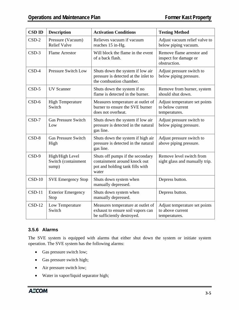
Critical safety devices (CSDs) for safe operation of the SVE system identified and installed on the SVE units and associated equipment, along with activation conditions and methods to test proper function of the CSDs are as follows:
CSD ID Description Activation Conditions Testing Method
CSD-1 High/High Level Switch (vapor/liquid separator)
Shuts off systems if vapor/liquid separator is full.
Remove level switch from sight glass and manually trip.
Operations and Maintenance Plan Former Kast Property
3-5
CSD ID Description Activation Conditions Testing Method
CSD-2 Pressure (Vacuum) Relief Valve
Relieves vacuum if vacuum reaches 15 in-Hg.
Adjust vacuum relief valve to below piping vacuum.
CSD-3 Flame Arrestor Will block the flame in the event of a back flash.
Remove flame arrestor and inspect for damage or obstruction.
CSD-4 Pressure Switch Low Shuts down the system if low air pressure is detected at the inlet to the combustion chamber.
Adjust pressure switch to below piping pressure.
CSD-5 UV Scanner Shuts down the system if no flame is detected in the burner.
Remove from burner, system should shut down.
CSD-6 High Temperature Switch
Measures temperature at outlet of burner to ensure the SVE burner does not overheat.
Adjust temperature set points to below current temperatures.
CSD-7 Gas Pressure Switch Low
Shuts down the system if low air pressure is detected in the natural gas line.
Adjust pressure switch to below piping pressure.
CSD-8 Gas Pressure Switch High
Shuts down the system if high air pressure is detected in the natural gas line.
Adjust pressure switch to above piping pressure.
CSD-9 High/High Level Switch (containment sump)
Shuts off pumps if the secondary containment around knock out pot and holding tank fills with water
Remove level switch from sight glass and manually trip.
CSD-10 SVE Emergency Stop Shuts down system when manually depressed.
Depress button.
CSD-11 Exterior Emergency Stop
Shuts down system when manually depressed.
Depress button.
CSD-12 Low Temperature Switch
Measures temperature at outlet of exhaust to ensure soil vapors can be sufficiently destroyed.
Adjust temperature set points to above current temperatures.
3.5.6 Alarms
The SVE system is equipped with alarms that either shut down the system or initiate system operation. The SVE system has the following alarms:
Gas pressure switch low;
Gas pressure switch high;
Air pressure switch low;
Water in vapor/liquid separator high;
Operations and Maintenance Plan Former Kast Property
3-6
Water in sump high-high;
Water in holding tank high;
SVE burner high temperature;
SVE burner no flame detected; and
SVE burner low temperature.
Operations and Maintenance Plan Former Kast Property
4-1
SYSTEM OPERATION AND MAINTENANCE 4.0
4.1 STANDARD OPERATING CONDITIONS
The systems are designed to operate 24 hours per day, 7 days per week. During initial startup, the SVE system will extract from all extraction wells that have been installed and connected to the system at that time. Due to the phased implementation of the remedial actions, not all 726 wells will have been installed by initial SVE system startup, so initial extraction may be cycled through up to 8 of the 16 vapor collection headers. Vapor will be extracted from each header for 7 days, followed by a bioventing period of approximately 30 to 60 days. Adjustments to SVE/bioventing cycling frequencies may be made after 1 year of operation. System monitoring details are provided in Section 5.
4.2 SYSTEM STARTUP AND SHUTDOWN
The SVE system is controlled by a PLC. The PLC controls the operation of the system including setting the cycle times and which wells operate during which cycle. Under normal operations, the SVE system is started by pressing the start button and stopped by pressing the stop button. If an emergency shutdown is required, depressing the emergency stop button on the SVE panel, or inside the control room in the remediation building, will immediately shut down the SVE system. A telemetry system is integrated into the SVE PLC to provide remote access to the system controls.
4.3 SYSTEM ALARMS
The SVE system is designed to operate continuously without operator attention. If the SVE system shuts down due to an alarm condition, the auto-dialer or telemetry system calls the operations technician to report the alarm. The operations technician will restart the system once the alarm condition has been resolved. Occasional short-term shutdowns of the SVE system are not expected to have a significant impact to the effectiveness of the system.
4.4 ROUTINE INSPECTION AND MAINTENANCE
The SVE system should be inspected weekly during normal operations. A work control and maintenance record system to manage and document the accomplishment of preventive and corrective maintenance work performed will be established and recorded in an annual preventative maintenance plan. A list of preventive maintenance and periodic inspections is provided in Appendix C. Forms that are required to be completed during the inspections are provided in Appendix D.
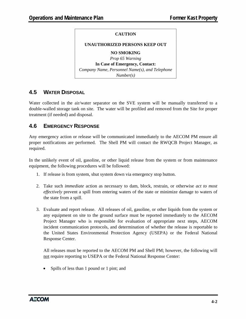
Preventive maintenance and repair work, including service call work, will be accomplished during the normal work day. The necessary public information and signage posted on the exterior of the remediation building. Specifically, the sign will state the following:
Operations and Maintenance Plan Former Kast Property
4-2
CAUTION
UNAUTHORIZED PERSONS KEEP OUT
NO SMOKING Prop 65 Warning
In Case of Emergency, Contact: Company Name, Personnel Name(s), and Telephone
Number(s)
4.5 WATER DISPOSAL
Water collected in the air/water separator on the SVE system will be manually transferred to a double-walled storage tank on site. The water will be profiled and removed from the Site for proper treatment (if needed) and disposal.
4.6 EMERGENCY RESPONSE
Any emergency action or release will be communicated immediately to the AECOM PM ensure all proper notifications are performed. The Shell PM will contact the RWQCB Project Manager, as required. In the unlikely event of oil, gasoline, or other liquid release from the system or from maintenance equipment, the following procedures will be followed:
1. If release is from system, shut system down via emergency stop button.
2. Take such immediate action as necessary to dam, block, restrain, or otherwise act to most effectively prevent a spill from entering waters of the state or minimize damage to waters of the state from a spill.
3. Evaluate and report release. All releases of oil, gasoline, or other liquids from the system or any equipment on site to the ground surface must be reported immediately to the AECOM Project Manager who is responsible for evaluation of appropriate next steps, AECOM incident communication protocols, and determination of whether the release is reportable to the United States Environmental Protection Agency (USEPA) or the Federal National Response Center. All releases must be reported to the AECOM PM and Shell PM; however, the following will not require reporting to USEPA or the Federal National Response Center: Spills of less than 1 pound or 1 pint; and

Operations and Maintenance Plan Former Kast Property
4-3
Spills of integral operating fluids, in the use of motor vehicles or other equipment, the total volume of which is less than or equal to 55 gallons and that do not damage waters of the state.
4. Perform repairs to the system.
The following procedures will be followed in the unlikely event of a condensate water release from the system:
1. Shut system down.
2. Take such immediate action as necessary to dam, block, restrain, or otherwise act to most effectively prevent a spill from entering waters of the state or minimize damage to waters of the state from a spill.
3. Evaluate and report release. All releases of any liquid from the system to the ground surface must be reported immediately to the AECOM Project Manager, who will follow AECOM incident communication protocols.
4. Perform repairs to the system.
Operations and Maintenance Plan Former Kast Property
5-1
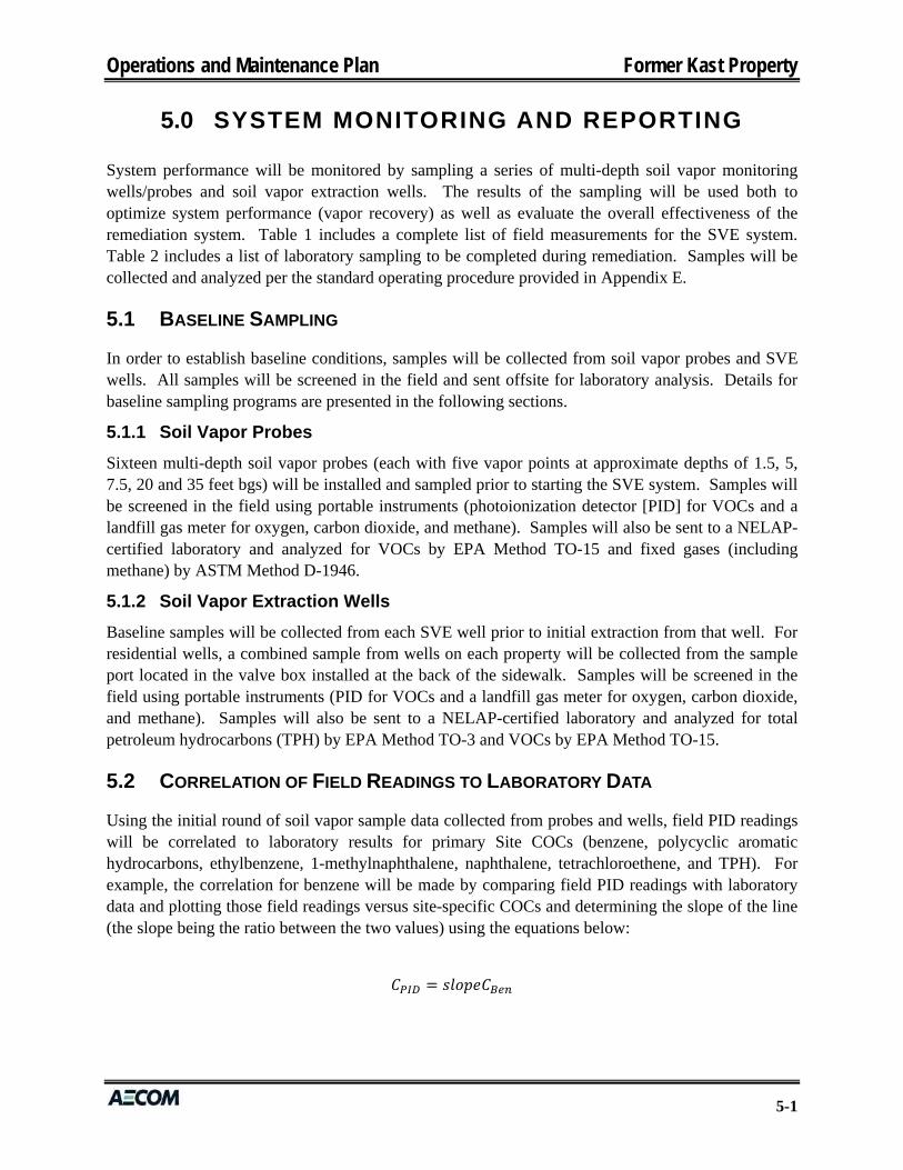
SYSTEM MONITORING AND REPORTING 5.0
System performance will be monitored by sampling a series of multi-depth soil vapor monitoring wells/probes and soil vapor extraction wells. The results of the sampling will be used both to optimize system performance (vapor recovery) as well as evaluate the overall effectiveness of the remediation system. Table 1 includes a complete list of field measurements for the SVE system. Table 2 includes a list of laboratory sampling to be completed during remediation. Samples will be collected and analyzed per the standard operating procedure provided in Appendix E.
5.1 BASELINE SAMPLING
In order to establish baseline conditions, samples will be collected from soil vapor probes and SVE wells. All samples will be screened in the field and sent offsite for laboratory analysis. Details for baseline sampling programs are presented in the following sections.
5.1.1 Soil Vapor Probes
Sixteen multi-depth soil vapor probes (each with five vapor points at approximate depths of 1.5, 5, 7.5, 20 and 35 feet bgs) will be installed and sampled prior to starting the SVE system. Samples will be screened in the field using portable instruments (photoionization detector [PID] for VOCs and a landfill gas meter for oxygen, carbon dioxide, and methane). Samples will also be sent to a NELAP-certified laboratory and analyzed for VOCs by EPA Method TO-15 and fixed gases (including methane) by ASTM Method D-1946.
5.1.2 Soil Vapor Extraction Wells
Baseline samples will be collected from each SVE well prior to initial extraction from that well. For residential wells, a combined sample from wells on each property will be collected from the sample port located in the valve box installed at the back of the sidewalk. Samples will be screened in the field using portable instruments (PID for VOCs and a landfill gas meter for oxygen, carbon dioxide, and methane). Samples will also be sent to a NELAP-certified laboratory and analyzed for total petroleum hydrocarbons (TPH) by EPA Method TO-3 and VOCs by EPA Method TO-15.
5.2 CORRELATION OF FIELD READINGS TO LABORATORY DATA
Using the initial round of soil vapor sample data collected from probes and wells, field PID readings will be correlated to laboratory results for primary Site COCs (benzene, polycyclic aromatic hydrocarbons, ethylbenzene, 1-methylnaphthalene, naphthalene, tetrachloroethene, and TPH). For example, the correlation for benzene will be made by comparing field PID readings with laboratory data and plotting those field readings versus site-specific COCs and determining the slope of the line (the slope being the ratio between the two values) using the equations below:

Operations and Maintenance Plan Former Kast Property
5-2
42μg/m0.024 /78 /
where,
Trigger Concentration = PID field reading where laboratory sample will be taken to confirm
COC concentration; CPID = field reading in sample where benzene was detected; and CBen = benzene concentration from lab sample where benzene was detected.
Should the slope of the line not be uniform, the slope of the line near the SSCG will be used. Once this correlation is made, laboratory samples will only be collected when field PID readings drop below a trigger concentration. The trigger concentration will be equal to the field PID reading corresponding to the onsite resident SSCG for the key Site COC (i.e. benzene soil vapor concentration of 42 µg/m3). If PID readings are above this trigger concentration, a sample will not be collected for laboratory analysis and the well will remain in active SVE cyclic operation mode.
5.3 SYSTEM MONITORING, OPTIMIZATION, AND REPORTING
The purpose of system monitoring and optimization will be to focus SVE efforts on wells with elevated concentrations of COCs and methane and to discontinue extraction from, or operate on a reduced frequency, wells with low concentrations.
5.3.1 Soil Vapor Probes
Following SVE/bioventing system startup, soil vapor samples will be collected from the 16 multi-depth soil vapor probes quarterly for a period of 2 years, semi-annually for a period of 3 years, annually for a period of 5 years, and once every 5 years thereafter through the projected 30-year operating life of the system in accordance with the Addendum to the Revised RAP (URS and Geosyntec, 2014b). Samples will be screened in the field using portable instruments (PID for VOCs and a landfill gas meter for oxygen, carbon dioxide, and methane). Samples will also be sent to a NELAP-certified laboratory and analyzed for VOCs by EPA Method TO-15 and fixed gases (including methane) by ASTM Method D-1946.
Periodic measurements of vacuum at the soil vapor probes will be performed to evaluate and confirm the radius of vacuum influence (ROVI) of the system. If the design ROVI is not confirmed by these vacuum readings, system operating parameters may be adjusted or the need for installation of additional wells will be evaluated.
Periodic monitoring and sampling will be used to optimize system operations. Combined with baseline sampling, periodic sampling will be used to assess and evaluate overall system effectiveness at reducing COC concentrations and degradation of longer-chain hydrocarbons. Results of baseline and periodic sampling will be reported in an initial 5-year review report and subsequent reports submitted on a 5-year basis.
Operations and Maintenance Plan Former Kast Property
5-3
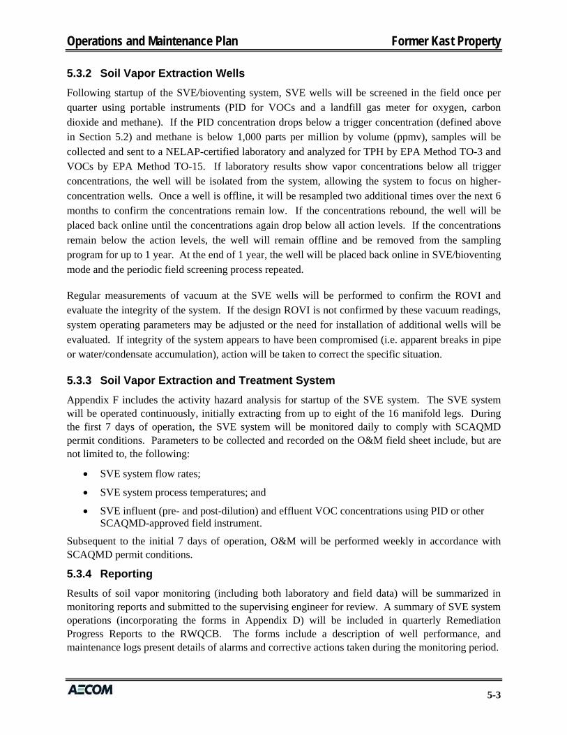
5.3.2 Soil Vapor Extraction Wells
Following startup of the SVE/bioventing system, SVE wells will be screened in the field once per quarter using portable instruments (PID for VOCs and a landfill gas meter for oxygen, carbon dioxide and methane). If the PID concentration drops below a trigger concentration (defined above in Section 5.2) and methane is below 1,000 parts per million by volume (ppmv), samples will be collected and sent to a NELAP-certified laboratory and analyzed for TPH by EPA Method TO-3 and VOCs by EPA Method TO-15. If laboratory results show vapor concentrations below all trigger concentrations, the well will be isolated from the system, allowing the system to focus on higher-concentration wells. Once a well is offline, it will be resampled two additional times over the next 6 months to confirm the concentrations remain low. If the concentrations rebound, the well will be placed back online until the concentrations again drop below all action levels. If the concentrations remain below the action levels, the well will remain offline and be removed from the sampling program for up to 1 year. At the end of 1 year, the well will be placed back online in SVE/bioventing mode and the periodic field screening process repeated.
Regular measurements of vacuum at the SVE wells will be performed to confirm the ROVI and evaluate the integrity of the system. If the design ROVI is not confirmed by these vacuum readings, system operating parameters may be adjusted or the need for installation of additional wells will be evaluated. If integrity of the system appears to have been compromised (i.e. apparent breaks in pipe or water/condensate accumulation), action will be taken to correct the specific situation.
5.3.3 Soil Vapor Extraction and Treatment System
Appendix F includes the activity hazard analysis for startup of the SVE system. The SVE system will be operated continuously, initially extracting from up to eight of the 16 manifold legs. During the first 7 days of operation, the SVE system will be monitored daily to comply with SCAQMD permit conditions. Parameters to be collected and recorded on the O&M field sheet include, but are not limited to, the following:
SVE system flow rates;
SVE system process temperatures; and
SVE influent (pre- and post-dilution) and effluent VOC concentrations using PID or other SCAQMD-approved field instrument.
Subsequent to the initial 7 days of operation, O&M will be performed weekly in accordance with SCAQMD permit conditions.
5.3.4 Reporting
Results of soil vapor monitoring (including both laboratory and field data) will be summarized in monitoring reports and submitted to the supervising engineer for review. A summary of SVE system operations (incorporating the forms in Appendix D) will be included in quarterly Remediation Progress Reports to the RWQCB. The forms include a description of well performance, and maintenance logs present details of alarms and corrective actions taken during the monitoring period.

Operations and Maintenance Plan Former Kast Property
5-4
5.4 5-YEAR SITE REVIEWS
Data collected during the monitoring program will be will be used to evaluate overall system effectiveness and will be reported in an initial 5-year review report and subsequent 5-year review reports submitted for RWQCB review.

Operations and Maintenance Plan Former Kast Property
6-1
REFERENCES 6.0
Geosyntec (Geosyntec Consultants, Inc.), 2010. Site Conceptual Model, Former Kast Property, Carson, California, Site Cleanup No. 1230, Site ID 2040330, September 2010.
SOPUS (Shell Oil Products US), 2010. Completed RWQCB Chemical Storage and Use Questionnaire, August 31, 2010.
URS (URS Corporation), 2010. Plume Delineation Report, Former Kast Property, Carson, California, September 29, 2010.
URS and Geosyntec (URS Corporation and Geosyntec Consultants, Inc.), 2014a. Revised Remedial Action Plan, Former Kast Property, Carson, California, Site Cleanup No. 1230, Site ID 2040330, June 30, 2014.
URS and Geosyntec, 2014b. Addendum to Revised Remedial Action Plan, Former Kast Property, Carson, California, Site Cleanup No. 1230, Site ID 2040330, October 15, 2014.
Operations and Maintenance Plan
Tables
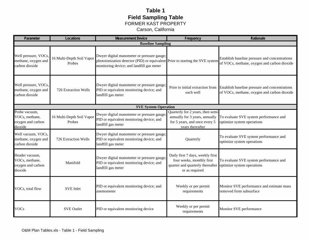
Table 1Field Sampling Table
FORMER KAST PROPERTYCarson, California
Parameter Locations Measurement Device Frequency Rationale
Well pressure, VOCs, methane, oxygen and carbon dioxide
16 Multi-Depth Soil Vapor Probes
Dwyer digital manometer or pressure gauge; photoionization detector (PID) or equivalent monitoring device; and landfill gas meter
Prior to starting the SVE systemEstablish baseline pressure and concentrations of VOCs, methane, oxygen and carbon dioxide
Well pressure, VOCs, methane, oxygen and carbon dioxide
726 Extraction WellsDwyer digital manometer or pressure gauge; PID or equivalent monitoring device; and landfill gas meter
Prior to initial extraction from each well
Establish baseline pressure and concentrations of VOCs, methane, oxygen and carbon dioxide
Probe vacuum, VOCs, methane, oxygen and carbon dioxide
16 Multi-Depth Soil Vapor Probes
Dwyer digital manometer or pressure gauge; PID or equivalent monitoring device; and landfill gas meter
Quarterly for 2 years, then semi-annually for 3 years, annually for 5 years, and once every 5
years thereafter
To evaluate SVE system performance and optimize system operations
Well vacuum, VOCs, methane, oxygen and carbon dioxide
726 Extraction WellsDwyer digital manometer or pressure gauge; PID or equivalent monitoring device; and landfill gas meter
QuarterlyTo evaluate SVE system performance and optimize system operations
Header vacuum, VOCs, methane, oxygen and carbon dioxide
ManifoldDwyer digital manometer or pressure gauge; PID or equivalent monitoring device; and landfill gas meter
Daily first 7 days, weekly first four weeks, monthly first
quarter and quarterly thereafter or as required
To evaluate SVE system performance and optimize system operations
VOCs, total flow SVE Inlet PID or equivalent monitoring device; and anemometer
Weekly or per permit requirements
Monitor SVE performance and estimate mass removed from subsurface
VOCs SVE Outlet PID or equivalent monitoring deviceWeekly or per permit
requirementsMonitor SVE performance
Baseline Sampling
SVE System Operation
O&M Plan Tables.xls - Table 1 - Field Sampling
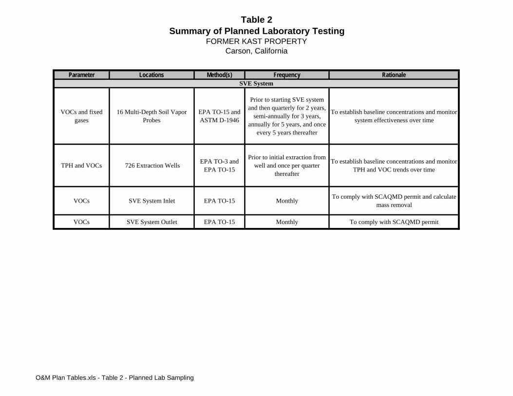
Table 2Summary of Planned Laboratory Testing
FORMER KAST PROPERTYCarson, California
Parameter Locations Method(s) Frequency Rationale
VOCs and fixed gases
16 Multi-Depth Soil Vapor Probes
EPA TO-15 and ASTM D-1946
Prior to starting SVE system and then quarterly for 2 years,
semi-annually for 3 years, annually for 5 years, and once
every 5 years thereafter
To establish baseline concentrations and monitor system effectiveness over time
TPH and VOCs 726 Extraction WellsEPA TO-3 and
EPA TO-15
Prior to initial extraction from well and once per quarter
thereafter
To establish baseline concentrations and monitor TPH and VOC trends over time
VOCs SVE System Inlet EPA TO-15 MonthlyTo comply with SCAQMD permit and calculate
mass removal
VOCs SVE System Outlet EPA TO-15 Monthly To comply with SCAQMD permit
SVE System
O&M Plan Tables.xls - Table 2 - Planned Lab Sampling

Operations and Maintenance Plan
Figures
CD
A
DANA
E
PALOS VERDE
MACHADO
DOLO R E S ST
W 228TH ST
W 223RD ST E 223RD ST
E ULVEDA
W SEPULVEDA B LVD
S VE
RMON
T AV
FIGUEROA ST
N A VA VALON BLVD
S MAIN STWIL
INGTN
LVD
ALON BLVD
E LO TA BLVD
SEP BLVD
MI
WILM
INGT
ON AV
FIGUERO A ST
MO
B 1
110
W 231ST ST
Y
STSANDISON
ST ST222NDEJOEL STST
E
2 6E
ST
W
E
E
224TH ST
E
W 232ND PL
ST233RD
ST234TH
PL234TH
ST235THW
CARRIAGEDALE DR
LINCOLN
HIGHLAND
W CRUCES
E
RDWATSONCENTER
230TH
E
3
238TH
ST
MW
ROBIDOUXW
W
W
PL
ST
MONETA AV
MARBELLA
AV AV
FRIGATE
A V KIN
RAS
MONETA
B
CLUFF
LUCERNE
UTILITY WY
BLVD
ST
MCCOY AV
VAN DEENE
RAVENNA AV
N
M
ROL
NAN AV
E
PACIFIC
REALTY
BONDS
E 246TH
ST
E CHANDLER ST
DONW
ST LINCOLN
ST
ST
ST
ST
LOMITA
E
DRDR
W MAURETANIA ST
ST
E
E
228TH
229TH
ST
E
ST
231ST
230THE
232ND ST
238TH
238TH
EGU
FAV
AV AV
AV
AV
AV
NEPTUNE
RAVENNA
ISLAND
PANAMA
AVMARINE
AV
ST
BONITA
STBROAD
EAST
AV
A
W
W
E
BROAD
AVAV
AV
AV
AV
AVAVAV
AV
MCDONALD
MARINE
FRIES
ISLAND
LAGOON
RAVENN
ANE
PTUN
E
BAYVIE
W
AVWA
TSON
SANFOR
D
RONAN
GULF
AV
AV
AV
AV
AV
AVAVAV BLVD
AV
EUBANK
AV
R
Q
E SANDISON ST
STR
STQ
W
W
ST
W
W R ST
ST
W CHANDLER ST
W LOWEN ST
Q
SANDISON
W
W DOLORES ST
ST
E
PROCTOR STST
E DOLORES ST E
E
E
DR
MWST
EN ST
STMEST
STL
AV
ST
ST
LUCERN
E
BANNIN
G
AVN A
EUDORA AV
VAN TRESS AV
AV
A
AV
AV
NIP
C
R
233RD
T
ST
STH
E
ST
EUBANKAV
L
N ST
A
E
PA
STAV
MEHD
EN
SE
AVFERNMEAD
LN
AV
R
H N
C AT SK IL L AVC AT SK IL L
ST244TH
224TH
ST225THW
E
CREEK
ST229THE
E
222ND222ND
237THE ST
E
JOEL
H
WYMILL
CARM
EL D
RVA
LLEY
GARS
L
STW PL
ST
TER
STE
ST
T
PI
A
NE
MENLO
234TH ST
AV
AV
MARI
BE
E
NCHO
236 STE
234TH ST
E 235THST
E 238TH PL
1 JERENE LN 2 GRAYMOUTH LN3 MOUNTAINEERING LN4 HILLCASTLE LN
LONDRINA LN 5 REALTYREDONDA LN 6
1 W 245TH ST 2 W 246TH ST 3 W 247TH ST
WILLOW TER 4SYCAMORE WY 5
6 MAGNOLIA PL 7 MAPLE LN
ST
PLSHADWELL ST
PISMO DR
W 230THST
2726
2428232221
1817
DELORAS DR
E
255TH
LNBAYCREST
DR
A2ND AV E
A5TH
ST
ST244TH
LN
26THST
2
3 64 SHERYL
225THST
ST
E
230TH
231ST ST
1
E
2
232ND ST
3
E
232ND PL
4
E
56
E
78910
E
E
111213 29 16
15CAROLDALE
MONETA AV
DELFORD AV
KINARD AV
NICOLLE AV
NAFFA AV
AV
FRIES
ISLAND
GULF
AVCAROLDALE
KINARD AV
ORCHARD AV
MEHDEN AV
BANNING
HYATT AV
DODGE
AV
DOBLE
AVSP
ICEWOOD
FERN
LAKE
DR
AVAV
BROADWELL
DOBL
E
ARCHIBALD AV
ATMORE AV
MONETA AV
GRACE AV
AVRAVENNA
GRACE
AV
AVNEPTUNE
ISLAND
AV
DR
FRIES
AVANCHOR
ANCHOR
AV
SERRA
ENOLA AV
BAYPOINTAV
H
DOBLE
ATMORE
AV
V
AVDOBL
E
LN
AVOR
CHARD
AV
BOLS
A AV
AVAV
BLVD
AV AV
BOLS
A
STBO
NITA
AV
PION
EER
AV
MARI
NE
ST
25
19
S
W ST
V
3RD AV E
VAV E
1
229TH
14
E 248TH
E 249TH
ST
45TH
R
CIR
233RD
BANNIN
G
AVSE
AGRO
VE
RIDG
E
20
T
5
BL
V
VD
OCEANSI DE ST
SEAG
O
RO
OE
R
E
S
A
A
S
T
HG
CT
C
R
AV
V A
V
DEEPWATER
PL
BA YSID E
HDR PIN
ROCKY POINTIGHE
E
DR
T
S
DR
A
CRE
S
N
EK
O
L
GH
R
N
LI
ST
RDHARBORL
COMBER
PL
O
BAY-
PORT
U R
O
FT
UAV
U
D
1S
4T
ST
E
E
A B
K
H
BELSON
R
OASIS DR
ST
FAIR-HAVEN
234TH PLE
235THST236THE
E245TH
ST
246THEST PLE
247TH
E
248TH
E
248TH
T
W 226TH STSTW 226TH
W 226TH PL227THE
STNEILSONW
W229THST
231ST
E
CAMBRIA
229THPL
W
W 230TH ST
SQUAW PEAK LN
LN
CENTRALPK N
PK S
LLAGE
CIRCLEE
AV E
DRMERE DROAK-
LAKE
LN
DRGIAN
W 227TH ST
W 229TH ST
230THWST230THW231ST
ST STSTMARTIN-
STW
SHIRE232NDWW
STST232ND
FAUNALN
CORIANDER
235TH
W
IST
PL
HACIENDA
226TH
E
E
LN
226TH
ADOBE
ST
CATALINALN
PL224TH
LN STAGE-COACH
229TH ST
KIDDIE LN
WPL
E
STE
DR
GINA
KIDDIELN
CENTRAL
6TH
WST
DR
R
MAIN
LNJODY GULF
PL
ATMORE
DR
WOOD
MEHDEN
MORRO
BAYDR
AV
FRIGATE AV
AV
AV
YAV
AV
BAYCREST
AV
TAV LN
D
SERENITY
SESAME
NICOLLE
AVKINARD AV
DELFORD
RAVENNA AV
NEPTUNE AV
ADR
CATSKILL
ISSI
O
DR N
COLONY
SPARK
ENOLA
RONAN
SCOTTSDALE
DIDABEL
DR S
236TH
CTW
B
LN
L
FIGUEROA
ARCHIBALD AV
MARIBEL
ALBATROSS
AV
AV
KNOLL
DROAK
AV
SEAGROVE
BROADWELL
LN
MCCOY
B
CT
ST
ARCHIBALD
AV
ISLAND AV
MARBELLA AV
ANCHOR AV
MARINE AV
AV
AV
MARBELLA
M
AVAV
S
AV
L
FRI
R
BRA
FIGUEROA
G
LYNTON AV
A
PETALUMA
C
TE
S T
AV
A
X
S
WEL
V
ST
I
E2
O
46
MO
T
N
DR
N
226TH ST
ST
F
E
H
247TH
ST
247THST
E
DR
SPRUCE
229TH
STBELSON
ST
DRW
EST
ST
LN
E
E O ST
N
L
R
G
EY
DR DR
DR
L
SHELL
CYPRESS
SCOTTSDALE
AV
CT
WYDR
PL
CAMELBACK
A V
AA
AV
T
B
O
B
WA
O
R
O
ER
P
Y
B
BI
I
A
PO
EN
ALA
T
ST
O M
AV
T
AV
BAY
DR
E
E
D
S
M
CT T
ZE
EP
EAST
Y
N
N
AV
ODR
VA
S
BA
L
LINDENCLIFFOLEUM
E
RL
RRBNSF
RR
UP
BNSF RR
BNSF RR
PLTESSERA
STVENICE
CORDOBA CT
MID FS
CARSON HS
CARRIAGE CREST PARK
LIB
VETERANSPARK&
SPORTSCOMPLEX
B
A
SEE A B1
GENERALSCOTTPARK
PARK(SITE)
WILMINGTONCEMETERY
PARK &RIDE
BUS STA
SEE C A3
MID
BANNINGHS
BANNING PARK
MUS
HARBOR PARK
7A
5
5
4
4
900 600 300
900
300
900
300900700300100
1300
800
100
800
900
500
900
800
2200
0
2280
0
2340
0
23700
2280
0
2280
0
2300
0
2330
0
2350
0
2340
0
23600
24100
24500
900
2270
0
2230
0
2390
0
2400
0
2440
0
1600
1300
1600
1
0
1600
100
2
900
300
4000
300100100
700600400 900
700
100
1000
100
800
300 400
100
23300
1100
23700
23900
600
24300
1600
730
24700
700
1400
500
300
1400
1200
1000
700
300
300
200
500
100 100
100
800
1700
1500
1300
1600
1700
1300
1400
1200
1400
1400
1500
200
500
24400
24700
24700
24900
1600
794
SITE VICINITY MAP
Date: Project: Figure 1Former KAST PropertyJune 2014
K:/2
008/
KA
ST
/fiug
ure
1 V
ic M
ap.a
i
Project No.: 49194119
“Reproduction with permission granted by THOMAS BROS. MAPS. This map is copyrighted by THOMAS BROS. MAPS, 2001. It is unlawful to copy or reproduce all or any thereof, whether for personal use or resale, without permission”.
EEEE LL
BELLA
AV
AV
NEPT
UNE
RARRVE
NNA
ISLA
NDPA
NAMA
244THEEE
STE
248THHHE
ETAT LLUUMA
247TH
EEY
2470
0
2470
0SITE
SCALE IN FEET
14000 2800 N

Operations and Maintenance Plan
Appendix A
Soil Vapor Extraction and Treatment System Record Drawings
(PENDING)
Operations and Maintenance Plan
Appendix B
Permits (PENDING)
Operations and Maintenance Plan
Appendix C
Preventative Maintenance and Periodic Inspections
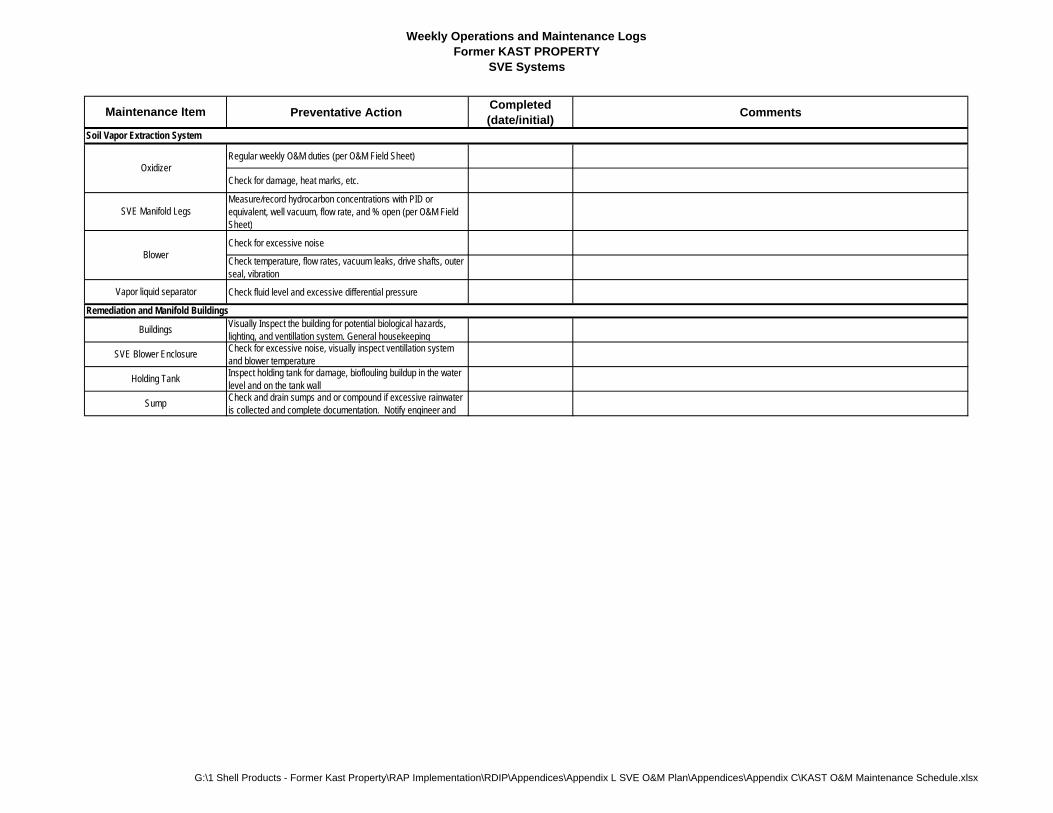
Weekly Operations and Maintenance LogsFormer KAST PROPERTY
SVE Systems
Preventative Action Completed(date/initial)
Comments
Regular weekly O&M duties (per O&M Field Sheet)
Check for damage, heat marks, etc.
Measure/record hydrocarbon concentrations with PID or equivalent, well vacuum, flow rate, and % open (per O&M Field Sheet)
Check for excessive noise
Check temperature, flow rates, vacuum leaks, drive shafts, outer seal, vibration
Check fluid level and excessive differential pressure
Visually Inspect the building for potential biological hazards, lighting, and ventillation system. General housekeepingCheck for excessive noise, visually inspect ventillation system and blower temperatureInspect holding tank for damage, bioflouling buildup in the water level and on the tank wallCheck and drain sumps and or compound if excessive rainwater is collected and complete documentation. Notify engineer and
Maintenance Item
Buildings
Remediation and Manifold Buildings
Soil Vapor Extraction System
Sump
SVE Blower Enclosure
Holding Tank
Oxidizer
Blower
Vapor liquid separator
SVE Manifold Legs
G:\1 Shell Products - Former Kast Property\RAP Implementation\RDIP\Appendices\Appendix L SVE O&M Plan\Appendices\Appendix C\KAST O&M Maintenance Schedule.xlsx
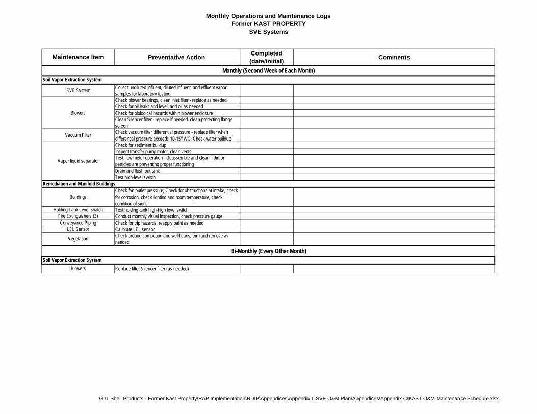
Monthly Operations and Maintenance LogsFormer KAST PROPERTY
SVE Systems
Preventative Action Completed(date/initial)
Comments
Collect undiluted influent, diluted influent, and effluent vapor samples for laboratory testingCheck blower bearings, clean inlet filter - replace as neededCheck for oil leaks and level; add oil as neededCheck for biological hazards within blower enclosureClean Silencer filter - replace if needed, clean protecting flange screenCheck vacuum filter differential pressure - replace filter when differential pressure exceeds 10-15" WC; Check water buildupCheck for sediment buildupInspect transfer pump motor, clean ventsTest flow meter operation - disassemble and clean if dirt or particles are preventing proper functioningDrain and flush out tankTest high-level switch
Check fan outlet pressure; Check for obstructions at intake, check for corrosion, check lighting and room temperature, check condition of signsTest holding tank high-high level switch Conduct monthly visual inspection, check pressure gauge Check for trip hazards, reapply paint as neededCalibrate LEL sensorCheck around compound and wellheads, trim and remove as needed
Replace filter Silencer filter (as needed)
Blowers
Maintenance Item
Soil Vapor Extraction System
Monthly (Second Week of Each Month)
SVE System
Vacuum Filter
Bi-Monthly (Every Other Month)
Vapor liquid separator
Soil Vapor Extraction System
Blowers
Remediation and Manifold Buildings
Buildings
Fire Extinguishers (3)
LEL Sensor
Holding Tank Level Switch
Vegetation
Conveyance Piping
G:\1 Shell Products - Former Kast Property\RAP Implementation\RDIP\Appendices\Appendix L SVE O&M Plan\Appendices\Appendix C\KAST O&M Maintenance Schedule.xlsx
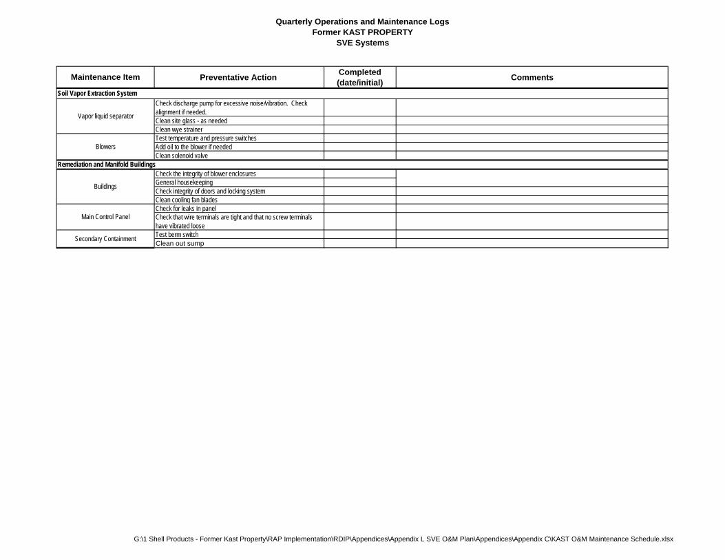
Quarterly Operations and Maintenance LogsFormer KAST PROPERTY
SVE Systems
Preventative Action Completed(date/initial)
Comments
Check discharge pump for excessive noise/vibration. Check alignment if needed.Clean site glass - as neededClean wye strainerTest temperature and pressure switchesAdd oil to the blower if neededClean solenoid valve
Check the integrity of blower enclosuresGeneral housekeepingCheck integrity of doors and locking systemClean cooling fan bladesCheck for leaks in panelCheck that wire terminals are tight and that no screw terminals have vibrated looseTest berm switchClean out sump
Maintenance Item
Soil Vapor Extraction System
Secondary Containment
Buildings
Main Control Panel
Vapor liquid separator
Blowers
Remediation and Manifold Buildings
G:\1 Shell Products - Former Kast Property\RAP Implementation\RDIP\Appendices\Appendix L SVE O&M Plan\Appendices\Appendix C\KAST O&M Maintenance Schedule.xlsx
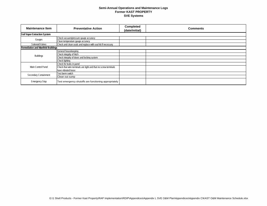
Semi-Annual Operations and Maintenance LogsFormer KAST PROPERTY
SVE Systems
Preventative Action Completed(date/initial)
Comments
Check vacuum/pressure gauge accuracyClean temperature gauge accuracyCheck and clean seals and replace with seal kit if necessary
General housekeepingCheck integrity of hitchCheck integrity of doors and locking systemCheck lightingCheck for leaks in panelCheck that wire terminals are tight and that no screw terminals have vibrated looseTest berm switchClean out sump
Test emergency shutoffs are functioning appropriately
Maintenance Item
Soil Vapor Extraction System
Gauges
Solenoid Valves
Emergency Stop
Remediation and Manifold Buildings
Buildings
Main Control Panel
Secondary Containment
G:\1 Shell Products - Former Kast Property\RAP Implementation\RDIP\Appendices\Appendix L SVE O&M Plan\Appendices\Appendix C\KAST O&M Maintenance Schedule.xlsx

Annual Operations and Maintenance LogsFormer KAST PROPERTY
SVE Systems
Preventative Action Completed(date/initial)
Comments
Lubricate tapered roller bearings
Check for proper grounding of panel
Check for moisture and condensation
Annual inspection and testing at qualified facility DUE DATE IS:
Remediation and Manifold buildings
Main Control Panel
Fire Extinguishers
Maintenance Item
Soil Vapor Extraction SystemBlowers
G:\1 Shell Products - Former Kast Property\RAP Implementation\RDIP\Appendices\Appendix L SVE O&M Plan\Appendices\Appendix C\KAST O&M Maintenance Schedule.xlsx
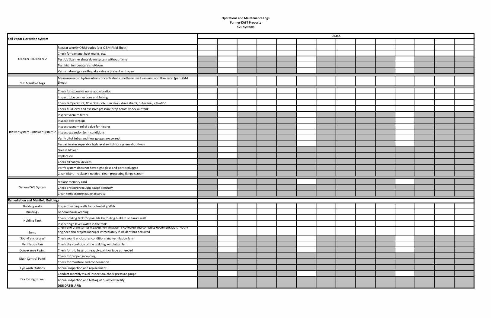
Operations and Maintenance LogsFormer KAST Property
SVE Systems
Regular weekly O&M duties (per O&M Field Sheet)
Check for damage, heat marks, etc.
Test UV Scanner shuts down system without flame
Test high temperature shutdown
Verify natural gas earthquake valve is present and open
SVE Manifold LegsMeasure/record hydrocarbon concentrations, methane, well vacuum, and flow rate. (per O&M
Sheet)
Check for excessive noise and vibration
Inspect tube connections and tubing
Check temperature, flow rates, vacuum leaks, drive shafts, outer seal, vibration
Check fluid level and exessive pressure drop across knock out tank
Inspect vacuum filters
Inspect belt tension
Inspect vacuum relief valve for hissing
Inspect expansion joint conditions
Verify pitot tubes and flow gauges are correct
Test air/water separator high level switch for system shut down
Grease blower
Replace oil
Check all control devices
Verify system does not have sight glass and port is plugged
Clean filters ‐ replace if needed, clean protecting flange screen
replace memory card
Check pressure/vacuum pauge accuracy
Clean temperature gauge accuracy
Remediation and Manifold Buildings
Building walls Inspect building walls for potential graffiti
Buildings General housekeeping
Check holding tank for possible buifouling buildup on tank's wall
Inspect high level switch in the tank
SumpCheck and drain sumps if excessive rainwater is collected and complete documentation. Notify engineer and project manager immediately if incident has occurred
Sound enclosures Check sound enclosures conditions and ventilation fans
Ventilation Fan Check the condition of the building ventilation fan
Conveyance Piping Check for trip hazards, reapply paint or tape as needed
Check for proper grounding
Check for moisture and condensation
Eye wash Stations Annual inspection and replacement
Conduct monthly visual inspection, check pressure gauge
Annual inspection and testing at qualified facility
DUE DATES ARE:
Main Control Panel
Fire Extinguishers
Soil Vapor Extraction System
Oxidizer 1/Oxidizer 2
Blower System 1/Blower System 2
General SVE System
Holding Tank
DATES

Operations and Maintenance Plan
Appendix D
Forms for Monthly Maintenance Reporting
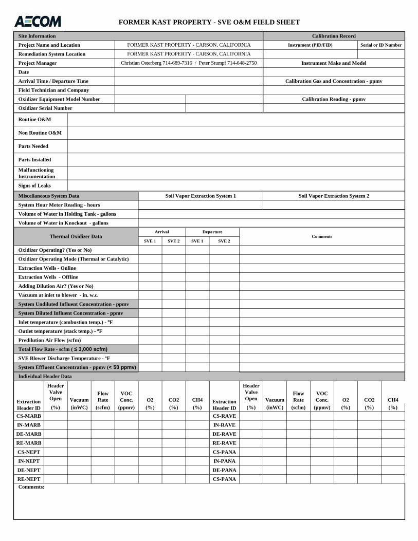
SVE 1 SVE 2 SVE 1 SVE 2
Header Valve Open Vacuum
Flow Rate
VOC Conc. O2 CO2 CH4
Header Valve Open Vacuum
Flow Rate
VOC Conc. O2 CO2 CH4
(%) (inWC) (scfm) (ppmv) (%) (%) (%) (%) (inWC) (scfm) (ppmv) (%) (%) (%)
CS-MARB CS-RAVE
IN-MARB IN-RAVE
DE-MARB DE-RAVE
RE-MARB RE-RAVE
CS-NEPT CS-PANA
IN-NEPT IN-PANA
DE-NEPT DE-PANA
RE-NEPT CS-PANA
Soil Vapor Extraction System 2
Volume of Water in Knockout - gallons
Individual Header Data
Field Technician and Company
Malfunctioning Instrumentation
FORMER KAST PROPERTY - SVE O&M FIELD SHEET
Routine O&M
Non Routine O&M
Parts Needed
Parts Installed
Signs of Leaks
Instrument (PID/FID)
Project Manager
Date
Instrument Make and Model
Project Name and Location
Arrival Time / Departure Time
Volume of Water in Holding Tank - gallons
Soil Vapor Extraction System 1 Miscellaneous System Data
System Hour Meter Reading - hours
FORMER KAST PROPERTY - CARSON, CALIFORNIA
FORMER KAST PROPERTY - CARSON, CALIFORNIA
ExtractionHeader ID
ExtractionHeader ID
Inlet temperature (combustion temp.) - ºF
System Effluent Concentration - ppmv (< 50 ppmv)
Total Flow Rate - scfm ( ≤ 3,000 scfm)
SVE Blower Discharge Temperature - ºF
System Diluted Influent Concentration - ppmv
System Undiluted Influent Concentration - ppmv
Vacuum at inlet to blower - in. w.c.
Adding Dilution Air? (Yes or No)
Extraction Wells - Offline
Outlet temperature (stack temp.) - ºF
Calibration Gas and Concentration - ppmv
Oxidizer Equipment Model Number
Oxidizer Serial Number
Oxidizer Operating Mode (Thermal or Catalytic)
Thermal Oxidizer Data
Christian Osterberg 714-689-7316 / Peter Stumpf 714-648-2750
Oxidizer Operating? (Yes or No)
DepartureComments
Comments:
Predilution Air Flow (scfm)
Serial or ID Number
Calibration RecordSite Information
Remediation System Location
Extraction Wells - Online
Calibration Reading - ppmv
Arrival
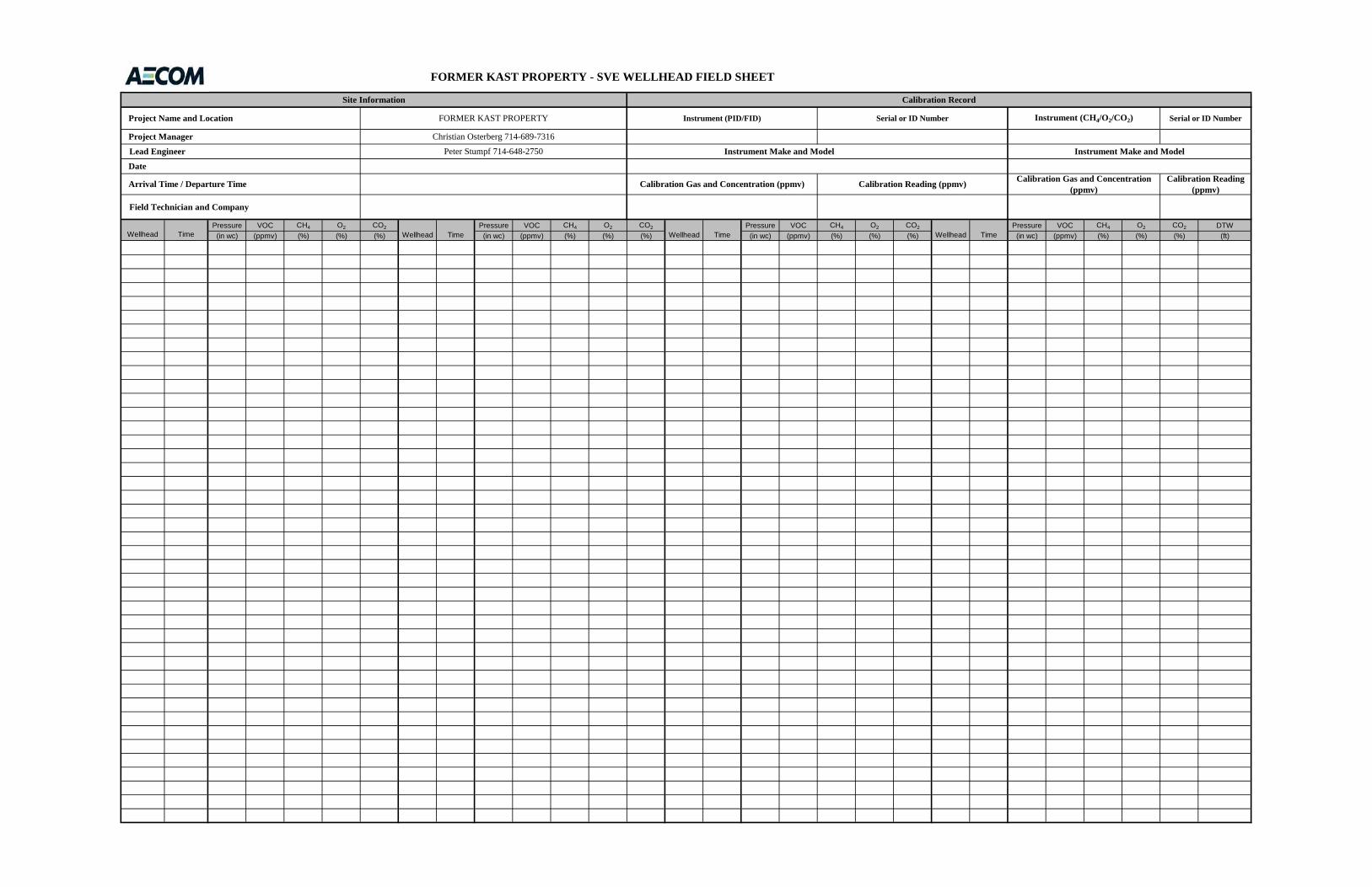
Pressure VOC CH4 O2 CO2 Pressure VOC CH4 O2 CO2 Pressure VOC CH4 O2 CO2 Pressure VOC CH4 O2 CO2 DTW
(in wc) (ppmv) (%) (%) (%) (in wc) (ppmv) (%) (%) (%) (in wc) (ppmv) (%) (%) (%) (in wc) (ppmv) (%) (%) (%) (ft)
Serial or ID Number
Calibration Reading (ppmv)
Wellhead Time TimeWellhead Wellhead Time Wellhead Time
Calibration Gas and Concentration (ppmv)
FORMER KAST PROPERTY - SVE WELLHEAD FIELD SHEET
Project Name and Location
Instrument Make and Model
Instrument (PID/FID)
Calibration RecordSite Information
Instrument (CH4/O2/CO2)FORMER KAST PROPERTY
Christian Osterberg 714-689-7316
Instrument Make and Model
Calibration Gas and Concentration (ppmv)
Serial or ID Number
Lead Engineer Peter Stumpf 714-648-2750
Project Manager
Calibration Reading (ppmv)
Date
Arrival Time / Departure Time
Field Technician and Company
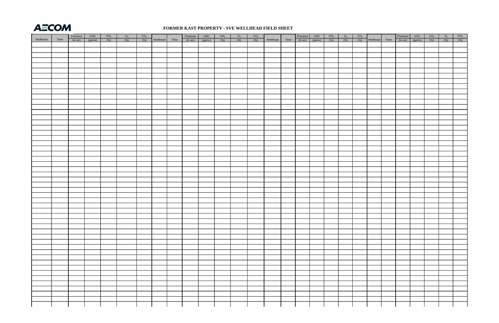
Pressure VOC CH4 O2 CO2 Pressure VOC CH4 O2 CO2 Pressure VOC CH4 O2 CO2 Pressure VOC CH4 O2 CO2
(in wc) (ppmv) (%) (%) (%) (in wc) (ppmv) (%) (%) (%) (in wc) (ppmv) (%) (%) (%) (in wc) (ppmv) (%) (%) (%)
FORMER KAST PROPERTY - SVE WELLHEAD FIELD SHEET
Wellhead Time Wellhead Time Wellhead Time Wellhead Time
AECOM
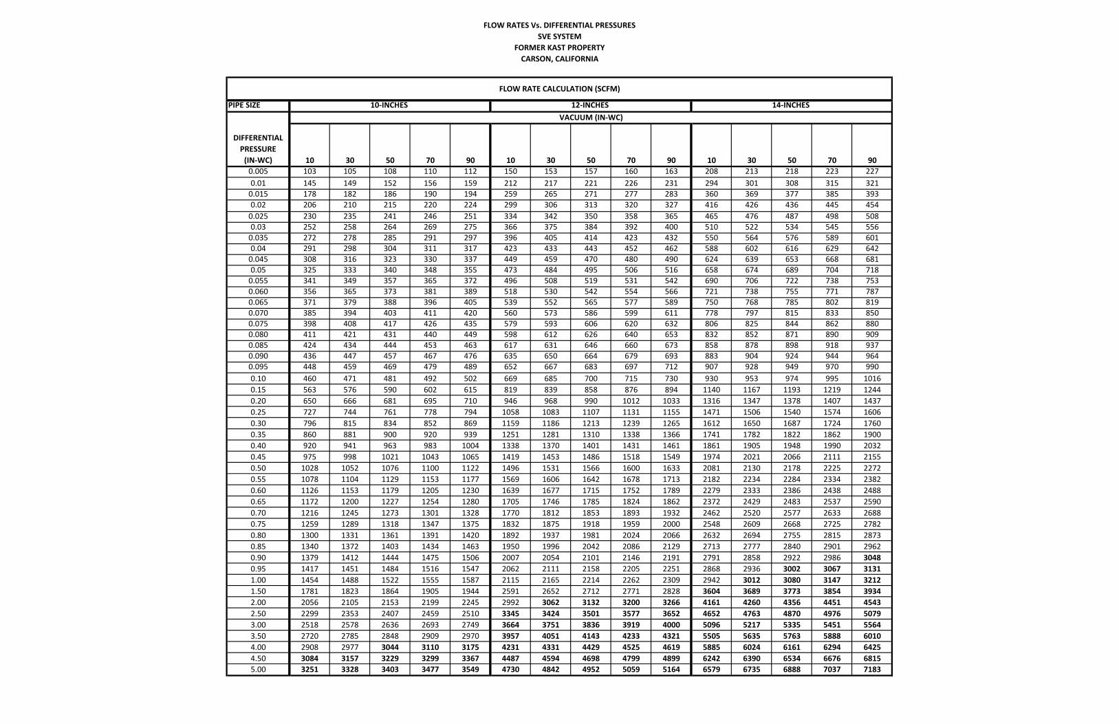
FLOW RATES Vs. DIFFERENTIAL PRESSURESSVE SYSTEM
FORMER KAST PROPERTYCARSON, CALIFORNIA
PIPE SIZE
10 30 50 70 90 10 30 50 70 90 10 30 50 70 900.005 103 105 108 110 112 150 153 157 160 163 208 213 218 223 2270.01 145 149 152 156 159 212 217 221 226 231 294 301 308 315 3210.015 178 182 186 190 194 259 265 271 277 283 360 369 377 385 3930.02 206 210 215 220 224 299 306 313 320 327 416 426 436 445 4540.025 230 235 241 246 251 334 342 350 358 365 465 476 487 498 5080.03 252 258 264 269 275 366 375 384 392 400 510 522 534 545 5560.035 272 278 285 291 297 396 405 414 423 432 550 564 576 589 6010.04 291 298 304 311 317 423 433 443 452 462 588 602 616 629 6420.045 308 316 323 330 337 449 459 470 480 490 624 639 653 668 6810.05 325 333 340 348 355 473 484 495 506 516 658 674 689 704 7180.055 341 349 357 365 372 496 508 519 531 542 690 706 722 738 7530.060 356 365 373 381 389 518 530 542 554 566 721 738 755 771 7870.065 371 379 388 396 405 539 552 565 577 589 750 768 785 802 8190.070 385 394 403 411 420 560 573 586 599 611 778 797 815 833 8500.075 398 408 417 426 435 579 593 606 620 632 806 825 844 862 8800.080 411 421 431 440 449 598 612 626 640 653 832 852 871 890 9090.085 424 434 444 453 463 617 631 646 660 673 858 878 898 918 9370.090 436 447 457 467 476 635 650 664 679 693 883 904 924 944 9640.095 448 459 469 479 489 652 667 683 697 712 907 928 949 970 9900.10 460 471 481 492 502 669 685 700 715 730 930 953 974 995 10160.15 563 576 590 602 615 819 839 858 876 894 1140 1167 1193 1219 12440.20 650 666 681 695 710 946 968 990 1012 1033 1316 1347 1378 1407 14370.25 727 744 761 778 794 1058 1083 1107 1131 1155 1471 1506 1540 1574 16060.30 796 815 834 852 869 1159 1186 1213 1239 1265 1612 1650 1687 1724 17600.35 860 881 900 920 939 1251 1281 1310 1338 1366 1741 1782 1822 1862 19000.40 920 941 963 983 1004 1338 1370 1401 1431 1461 1861 1905 1948 1990 20320.45 975 998 1021 1043 1065 1419 1453 1486 1518 1549 1974 2021 2066 2111 21550.50 1028 1052 1076 1100 1122 1496 1531 1566 1600 1633 2081 2130 2178 2225 22720.55 1078 1104 1129 1153 1177 1569 1606 1642 1678 1713 2182 2234 2284 2334 23820.60 1126 1153 1179 1205 1230 1639 1677 1715 1752 1789 2279 2333 2386 2438 24880.65 1172 1200 1227 1254 1280 1705 1746 1785 1824 1862 2372 2429 2483 2537 25900.70 1216 1245 1273 1301 1328 1770 1812 1853 1893 1932 2462 2520 2577 2633 26880.75 1259 1289 1318 1347 1375 1832 1875 1918 1959 2000 2548 2609 2668 2725 27820.80 1300 1331 1361 1391 1420 1892 1937 1981 2024 2066 2632 2694 2755 2815 28730.85 1340 1372 1403 1434 1463 1950 1996 2042 2086 2129 2713 2777 2840 2901 29620.90 1379 1412 1444 1475 1506 2007 2054 2101 2146 2191 2791 2858 2922 2986 30480.95 1417 1451 1484 1516 1547 2062 2111 2158 2205 2251 2868 2936 3002 3067 31311.00 1454 1488 1522 1555 1587 2115 2165 2214 2262 2309 2942 3012 3080 3147 32121.50 1781 1823 1864 1905 1944 2591 2652 2712 2771 2828 3604 3689 3773 3854 39342.00 2056 2105 2153 2199 2245 2992 3062 3132 3200 3266 4161 4260 4356 4451 45432.50 2299 2353 2407 2459 2510 3345 3424 3501 3577 3652 4652 4763 4870 4976 50793.00 2518 2578 2636 2693 2749 3664 3751 3836 3919 4000 5096 5217 5335 5451 55643.50 2720 2785 2848 2909 2970 3957 4051 4143 4233 4321 5505 5635 5763 5888 60104.00 2908 2977 3044 3110 3175 4231 4331 4429 4525 4619 5885 6024 6161 6294 64254.50 3084 3157 3229 3299 3367 4487 4594 4698 4799 4899 6242 6390 6534 6676 68155.00 3251 3328 3403 3477 3549 4730 4842 4952 5059 5164 6579 6735 6888 7037 7183
FLOW RATE CALCULATION (SCFM)
10‐INCHES 12‐INCHES 14‐INCHES VACUUM (IN‐WC)
DIFFERENTIAL PRESSURE (IN‐WC)

Operations and Maintenance Plan
Appendix E
Standard Operating Procedure for Sampling Using Tedlar Bags
Standard Operating Procedure for Sampling Using Tedlar Bags
Former Kast Property Carson, California
Prepared by Fouad Nasraddine
Date
Reviewed by Peter Stumpf (AECOM- Technical Lead) Date
Approved by Christian Osterberg (AECOM- Project Manager) Date
Standard Operating Procedure (SOP) for Sampling Sub-Surface Probes Using Tedlar bags
Scope and Application:
EPA method TO-15 is used to identify Volatile Organic Compounds present in gas. Tedlar™ bags are used to obtain vapor samples from sub-surface probes and/or manifold for laboratory and field use to determine the concentration of volatile organic compounds in the soil vapor.
Interferences and Potential Problems Cross-contamination can occur if improper materials are used in sampling. Thus, the gas should not be sampled after going through a pump as that would contribute to cross-contamination.
Equipment Tedlar bags 4-gas or multi meter (if needed) RKI Eagle or Landtec GEMTM 5000 or equivalent devices
Photo Ionization Detector (PID) or Flame Ionization Detector (FID)
Vacuum pump and vacuum box Teflon tubing
Method Summary for soil vapor extraction system lines:
I. Calibrate and/or check calibration of monitoring equipment and record on equipment calibration form. Recalibrate or discontinue use of instruments that do not meet manufacturer’s specified tolerances. Note the expiration date of the calibration gas on the calibration log. Check that the instruments are charged and FID is fueled.
II. Verify that sampling train valves and connections have been decontaminated and
record on field report.
III. Review data obtained during well installation. Notify AECOM Field Manager and Project Manager if the wellheads appear damaged or cap is missing. Inspect the manifold, system inlet, individual wells, and system outlet.
IV. Record the Well ID and label the Tedlar bag.
V. Record field measurements and information.

VI. For each well location:
a. Check newly cut Teflon tubing with PID and record reading. b. Check initial vacuum or pressure at the manifold; record reading. c. Set up sampling train.
The sampling train is made up of a decontaminated probe plug and isolation valve, Teflon field tubing, Tedlar bag, vacuum box and portable vacuum pump.
d. Make sure connections are tight Replace components if connections are loose or if worn threads are observed on connection fittings.
VII. Insert probe plug into sample port and begin initial purge into a Tedlar bag with a 200
mL/min vacuum pump.
VIII. Screen the Tedlar bag contents for LEL, oxygen, and carbon dioxide using a 4-gas or
multi-meter or equivalent, VOCs using a PID or equivalent, and methane using a Landtec GEMTM or equivalent. Readings shall be recorded on the form.
IX. Record the barometric pressure (in inches of mercury, in-Hg) using the Landtec
GEMTM 5000 or other barometer.
X. Use the vacuum box and vacuum pump to take another sample with 1 L Tedlar bag.
a. After obtaining a sufficient volume in the Tedlar bag (after approximately 5 minutes using a 200 mL/min pump), seal and mark the bag with the appropriate information, and give it to the mobile lab or ALS for testing.
XI. Clean work area to remove all traces of sampling activities when sampling is complete
and well vault lids are secured.

Operations and Maintenance Plan
Appendix F
Activity Hazard Analysis for System Startup
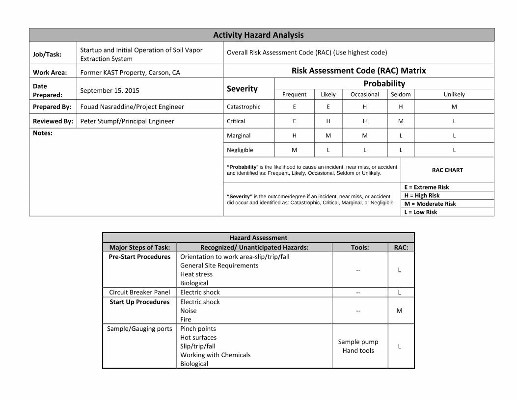
Activity Hazard Analysis
Job/Task: Startup and Initial Operation of Soil Vapor Extraction System
Overall Risk Assessment Code (RAC) (Use highest code)
Work Area: Former KAST Property, Carson, CA Risk Assessment Code (RAC) Matrix
Date Prepared: September 15, 2015 Severity Probability
Frequent Likely Occasional Seldom Unlikely
Prepared By: Fouad Nasraddine/Project Engineer Catastrophic E E H H M
Reviewed By: Peter Stumpf/Principal Engineer Critical E H H M L
Notes: Marginal H M M L L
Negligible M L L L L
“Probability” is the likelihood to cause an incident, near miss, or accident and identified as: Frequent, Likely, Occasional, Seldom or Unlikely. RAC CHART
“Severity” is the outcome/degree if an incident, near miss, or accident did occur and identified as: Catastrophic, Critical, Marginal, or Negligible
E = Extreme RiskH = High RiskM = Moderate RiskL = Low Risk
Hazard Assessment Major Steps of Task: Recognized/ Unanticipated Hazards: Tools: RAC: Pre‐Start Procedures Orientation to work area‐slip/trip/fall
General Site Requirements Heat stress Biological
‐‐ L
Circuit Breaker Panel Electric shock ‐‐ L Start Up Procedures Electric shock
Noise Fire
‐‐ M
Sample/Gauging ports Pinch points Hot surfaces Slip/trip/fall Working with Chemicals Biological
Sample pump Hand tools L
Adjacent Work/Processes and/or co‐occupancy Yes No Other workers adjacent, above, below
Notified them of our presence Coordinated with adjacent work supervisor/customer operator Can work safely TEAM MEMBERS SIGNATURES
The signature of the Site Safety Officer certifies the completion of the Hazard Assessment and Safe Plan of Action Checklist by the crew. SSO’s Signature: DateInstructions: 1. Write the name of the job or task in the space provided as needed. 2. Conduct a walk‐through survey of work area. 3. Write the steps of the task in a safe sequence as needed. 4. Mark and add to all hazards involved in each step as well as reaction to failure as needed. 5. In the Safe Plan column, provide the corrective actions that will be taken to keep the hazard from becoming an accident or injury as needed. 6. In Tools column list tools needed to do the job, additional safety equipment, etc. 7. Have each team member that helped develop and will use this AHA sign in the spaces provided at the bottom. 8. Review the AHA at the end of the task for improvements. (NOTE: THE WORK SHALL STOP IF CONDITIONS CHANGE, JOB CHANGES, OR DEFICIENCY IN PLAN IS NOTED.)
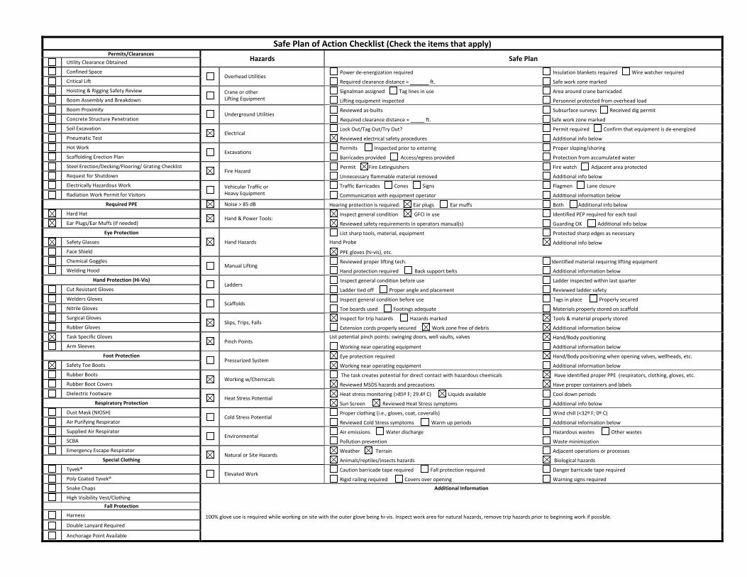
Safe Plan of Action Checklist (Check the items that apply) Permits/Clearances
Hazards Safe Plan Utility Clearance Obtained
Confined Space Overhead Utilities
Power de‐energization required Insulation blankets required Wire watcher required
Critical Lift Required clearance distance = ft. Safe work zone marked
Hoisting & Rigging Safety Review
Crane or other Lifting Equipment
Signalman assigned Tag lines in use Area around crane barricaded
Boom Assembly and Breakdown Lifting equipment inspected Personnel protected from overhead load
Boom Proximity Underground Utilities
Reviewed as‐builts Subsurface surveys Received dig permit
Concrete Structure Penetration Required clearance distance = ft. Safe work zone marked
Soil Excavation Electrical
Lock Out/Tag Out/Try Out? Permit required Confirm that equipment is de‐energized
Pneumatic Test Reviewed electrical safety procedures Additional info below
Hot Work Excavations
Permits Inspected prior to entering Proper sloping/shoring
Scaffolding Erection Plan Barricades provided Access/egress provided Protection from accumulated water
Steel Erection/Decking/Flooring/ Grating Checklist Fire Hazard
Permit Fire Extinguishers Fire watch Adjacent area protected
Request for Shutdown Unnecessary flammable material removed Additional info below
Electrically Hazardous Work
Vehicular Traffic or Heavy Equipment
Traffic Barricades Cones Signs Flagmen Lane closure
Radiation Work Permit for Visitors Communication with equipment operator Additional information below Required PPE Noise > 85 dB Hearing protection is required: Ear plugs Ear muffs Both Additional info below
Hard Hat Hand & Power Tools:
Inspect general condition GFCI in use Identified PEP required for each tool
Ear Plugs/Ear Muffs (if needed) Reviewed safety requirements in operators manual(s) Guarding OK Additional info below Eye Protection
Hand Hazards List sharp tools, material, equipment Protected sharp edges as necessary
Safety Glasses Hand Probe Additional info below
Face Shield PPE gloves (hi‐vis), etc.
Chemical Goggles Manual Lifting
Reviewed proper lifting tech. Identified material requiring lifting equipment
Welding Hood Hand protection required Back support belts Additional information below Hand Protection (Hi‐Vis)
Ladders Inspect general condition before use Ladder inspected within last quarter
Cut Resistant Gloves Ladder tied off Proper angle and placement Reviewed ladder safety
Welders Gloves Scaffolds
Inspect general condition before use Tags in place Properly secured
Nitrile Gloves Toe boards used Footings adequate Materials properly stored on scaffold
Surgical Gloves Slips, Trips, Falls
Inspect for trip hazards Hazards marked Tools & material properly stored
Rubber Gloves Extension cords properly secured Work zone free of debris Additional information below
Task Specific Gloves Pinch Points
List potential pinch points: swinging doors, well vaults, valves Hand/Body positioning
Arm Sleeves Working near operating equipment Additional information below Foot Protection
Pressurized System Eye protection required Hand/Body positioning when opening valves, wellheads, etc.
Safety Toe Boots Working near operating equipment Additional information below
Rubber Boots Working w/Chemicals
The task creates potential for direct contact with hazardous chemicals Have identified proper PPE (respirators, clothing, gloves, etc.
Rubber Boot Covers Reviewed MSDS hazards and precautions Have proper containers and labels
Dielectric Footware Heat Stress Potential
Heat stress monitoring (>85º F; 29.4º C) Liquids available Cool down periods Respiratory Protection Sun Screen Reviewed Heat Stress symptoms Additional info below
Dust Mask (NIOSH) Cold Stress Potential
Proper clothing (i.e., gloves, coat, coveralls) Wind chill (<32º F; 0º C)
Air Purifying Respirator Reviewed Cold Stress symptoms Warm up periods Additional information below
Supplied Air Respirator Environmental
Air emissions Water discharge Hazardous wastes Other wastes
SCBA Pollution prevention Waste minimization
Emergency Escape Respirator Natural or Site Hazards
Weather Terrain Adjacent operations or processes Special Clothing Animals/reptiles/insects hazards Biological hazards
Tyvek® Elevated Work
Caution barricade tape required Fall protection required Danger barricade tape required
Poly Coated Tyvek® Rigid railing required Covers over opening Warning signs required
Snake Chaps Additional Information
High Visibility Vest/Clothing
100% glove use is required while working on site with the outer glove being hi‐vis. Inspect work area for natural hazards, remove trip hazards prior to beginning work if possible.
Fall Protection
Harness
Double Lanyard Required
Anchorage Point Available

Remedial Design and Implementation Plan Former Kast Property
APPENDIX N
VAPOR MITIGATION SYSTEM CONCEPTUAL DESIGN
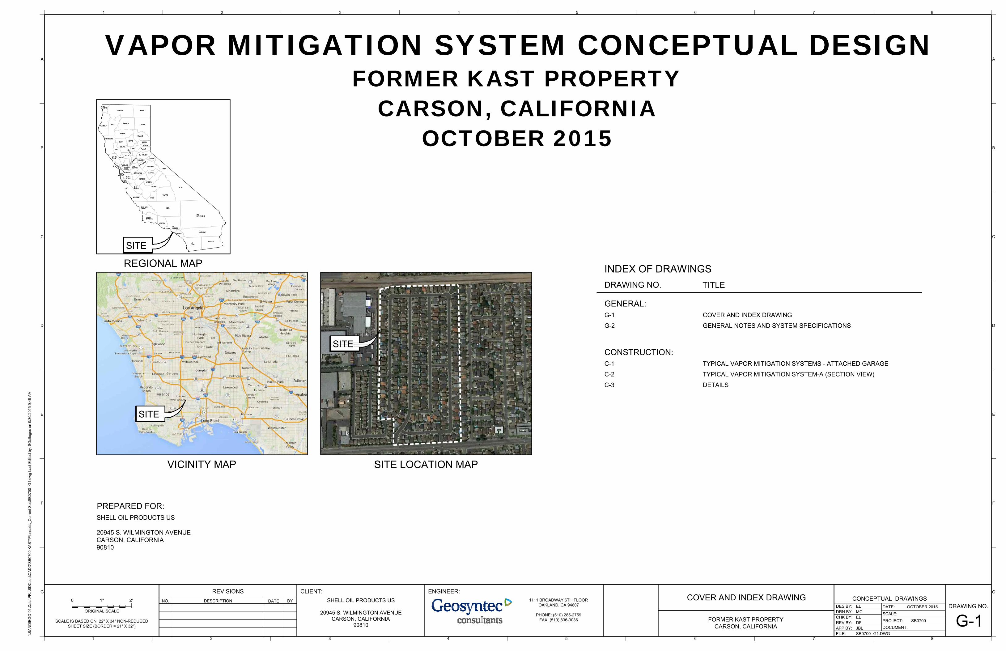
SHELL OIL PRODUCTS US
20945 S. WILMINGTON AVENUECARSON, CALIFORNIA90810
PREPARED FOR:
VAPOR MITIGATION SYSTEM CONCEPTUAL DESIGNFORMER KAST PROPERTY
CARSON, CALIFORNIAOCTOBER 2015
REGIONAL MAP
G-1
TITLE
G-2
DRAWING NO.
INDEX OF DRAWINGS
COVER AND INDEX DRAWING
GENERAL NOTES AND SYSTEM SPECIFICATIONS
GENERAL:
C-1
C-3
TYPICAL VAPOR MITIGATION SYSTEMS - ATTACHED GARAGE
DETAILS
CONSTRUCTION:
C-2 TYPICAL VAPOR MITIGATION SYSTEM-A (SECTION VIEW)
CONCEPTUAL DRAWINGS
\\SA
ND
IEG
O-0
1\D
ata\
PR
J\S
DC
add\
CA
DD
\SB
0700
KA
ST\
Pla
nset
s\_C
urre
nt S
et\S
B07
00 -G
1.dw
g La
st E
dite
d by
: SG
alle
gos
on 9
/30/
2015
9:4
8 A
M
B
C
D
E
F
G
8
B
C
D
E
F
G
AA
DRAWING NO.
PROJECT:DOCUMENT:
FILE:
REV BY:APP BY:
DATE:
SCALE:DRN BY:DES BY:
CHK BY:
DESCRIPTIONNO.
REVISIONSDATE BY
ENGINEER:
ISSUED FOR REVIEW1 10/30/14 JBL
SCALE IS BASED ON 22" X 34" NON-REDUCEDSHEET SIZE (BORDER = 21" X 32")
ORIGINAL SCALE
FORMER KAST PROPERTYCARSON, CALIFORNIA
MCEL
ELSB0700--
OCTOBER 20151111 BROADWAY 6TH FLOOR
OAKLAND, CA 94607
PHONE: (510) 285-2759FAX: (510) 836-3036 STATE OF CALIFORNIAC IV I L
REG
ISTE
RE
DPROFESSIONAL ENGINEER
Exp. __________No. C67805
SY
ED A . REHAN
JBL
SHELL OIL PRODUCTS US
20945 S. WILMINGTON AVENUECARSON, CALIFORNIA
90810
CLIENT:
DFMINOR REVISIONS2 04/28/15 JBL
SB0700 -G1.DWG
COVER AND INDEX DRAWING
G-1
VICINITY MAP SITE LOCATION MAP
SITE
SITE
SITE

CONCEPTUAL DRAWINGS
\\SA
ND
IEG
O-0
1\D
ata\
PR
J\S
DC
add\
CA
DD
\SB
0700
KA
ST\
Pla
nset
s\_C
urre
nt S
et\S
B07
00 -
G2.
dwg
Last
Edi
ted
by: k
yko3
_000
on
10/9
/201
5 6:
10 P
M
B
C
D
E
F
G
8
B
C
D
E
F
G
AA
DRAWING NO.
PROJECT:DOCUMENT:
FILE:
REV BY:APP BY:
DATE:
SCALE:DRN BY:DES BY:
CHK BY:
DESCRIPTIONNO.
REVISIONSDATE BY
ENGINEER:
ISSUED FOR REVIEW1 10/30/14 JBL
SCALE IS BASED ON 22" X 34" NON-REDUCEDSHEET SIZE (BORDER = 21" X 32")
ORIGINAL SCALE
FORMER KAST PROPERTYCARSON, CALIFORNIA
MCEL
ELSB0700--
OCTOBER 20151111 BROADWAY 6TH FLOOR
OAKLAND, CA 94607
PHONE: (510) 285-2759FAX: (510) 836-3036 STATE OF CALIFORNIAC IV I L
REG
ISTE
RE
DPROFESSIONAL ENGINEER
Exp. __________No. C67805
SY
ED A . REHAN
JBL
SHELL OIL PRODUCTS US
20945 S. WILMINGTON AVENUECARSON, CALIFORNIA
90810
CLIENT:
DFMINOR REVISIONS2 04/28/15 JBL
SB0700 - G2.DWG
GENERAL NOTES AND SYSTEMSPECIFICATIONS
G-2
A. GENERAL
1. THE CONCEPTUAL VAPOR MITIGATION SYSTEM DESIGN AND THESE DRAWINGS HAVE BEEN PREPARED ACCORDING TO THE STANDARD LEVEL OF CARE NORMALLY EXERCISEDBY MEMBERS OF THE ENVIRONMENTAL CONSULTING PROFESSION PRACTICING IN THE UNITED STATES AT THIS TIME. THEY ASSUME THAT THE WORK DEPICTED WILL BEPERFORMED BY AN EXPERIENCED CONTRACTOR WHO HAS A WORKING KNOWLEDGE OF APPLICABLE CODE STANDARDS AND REQUIREMENTS AND OF INDUSTRY ACCEPTEDSTANDARD GOOD PRACTICE. AS NOT EVERY CONDITION OR ELEMENT IS OR CAN BE EXPLICITLY SHOWN ON THESE DRAWINGS, THE CONTRACTOR SHALL USE INDUSTRYACCEPTED STANDARD GOOD PRACTICE FOR MISCELLANEOUS WORK NOT EXPLICITLY SHOWN.
2. THESE DRAWINGS REPRESENT THE FINISHED MITIGATION SYSTEM FOR A TYPICAL STRUCTURE. EACH INDIVIDUAL STRUCTURE WILL VARY TO SOME DEGREE FROM THISCONCEPTUAL DESIGN. THEY DO NOT INDICATE THE METHOD OF CONSTRUCTION. THE CONTRACTOR SHALL BE SOLELY RESPONSIBLE FOR CONSTRUCTION MEANS, METHODS,TECHNIQUES, SEQUENCES, PROCEDURES, ETC.
3. ALL WORK SHALL BE IN COMPLIANCE WITH FEDERAL, STATE, AND LOCAL BUILDING, FIRE, AND ELECTRICAL CODES.
4. FOR EACH STRUCTURE THE CONTRACTOR SHALL CONFER WITH AND SEEK THE APPROVAL OF GEOSYNTEC FOR THE FINAL LOCATIONS OF MITIGATION SYSTEM COMPONENTS,SUCH AS THE POINTS OF FOUNDATION PENETRATION, SUCTION POINTS, PIPE RUNS (FOR EXAMPLE, WHETHER INTERIOR OR EXTERIOR), AND EXHAUST POINTS ON THE ROOF.
5. NOTES AND DETAILS ON DRAWINGS SHALL TAKE PRECEDENCE OVER GENERAL NOTES, PROVIDED THE NOTES AND DETAILS ARE IN ACCORDANCE WITH ALL APPLICABLECODES.
6. ALL INSPECTIONS, IF REQUIRED BY BUILDING CODES, SHALL BE PROVIDED BY THE BUILDING DEPARTMENT OR AN INDEPENDENT INSPECTION COMPANY AS APPROPRIATE.SITE VISITS BY THE SYSTEM DESIGN ENGINEER DO NOT CONSTITUTE AN INSPECTION.
7. WITH HOMEOWNER APPROVAL, THE SUCTION POINTS WILL BE COMPLETED ON THE INSIDE OF THE BUILDING.
8. IF SOILS ARE EXCAVATED OUTSIDE THE BUILDING AS PART OF REMEDIAL MEASURE, THE REPLACEMENT SOIL PLACED NEAR THE BUILDING FOUNDATIONS SHOULD HAVEEQUAL OR LOWER AIR PERMEABILITY THAN THE EXISTING SOIL AND BE AND OTHERWISE SUITABLE.
9. DUE TO THE VARIOUS SURFACES THAT THE PIPE AND EQUIPMENT SUPPORT BRACKETS WILL BE ATTACHED TO, THE CONTRACTOR IS RESPONSIBLE FOR INSTALLING APPROPRIATEBRACKETS AND ANCHORS FOR EACH INDIVIDUAL SURFACE ENCOUNTERED. THE BRACKETS SHALL BE INSTALLED IN A MANNER THAT PROVIDES THE NECESSARY STRUCTURALREQUIREMENTS TO SUPPORT THE PIPE AND EQUIPMENT. THE INSTALLATIONS WILL MEET ALL BUILDING CODES, SEISMIC REQUIREMENTS, MAINTAIN A WATER TIGHT SURFACE AND WILL NOTCREATE A MEANS TO ALLOW FUTURE DAMAGE OR FAILURE TO THE EXISTING STRUCTURES OR SURFACES. THE PIPELINE ROUTING MAY NEED TO BE ALTERED IN THE FIELD IN ORDER TOPROVIDE THE BEST LOCATION TO ATTACH THE PIPE AND EQUIPMENT SUPPORT BRACKETS.
B. VAPOR MITIGATION SYSTEM
1. THE INTENT OF THE WORK IS TO CREATE A NEGATIVE AIR PRESSURE AT ALL POINTS BELOW THE BUILDING FLOOR SLAB UNDER TYPICAL METEOROLOGICAL AND HOUSEHEATING AND VENTILATION CONDITIONS BY WITHDRAWING AIR FROM SUCTION PITS BELOW THE SLAB AS DEMONSTRATED BY DIFFERENTIAL PRESSURE MEASUREMENTSMADE BY THE CONTRACTOR AND VERIFIED BY THE ENGINEER IN REPRESENTATIVE AREAS OF THE SLAB. BASED ON BUILDING-SPECIFIC CONDITIONS AND AS APPROVED BYTHE ENGINEER, IT MAY BE NECESSARY TO VARY THE LOCATION, NUMBER, AND SIZE OF THE SUCTION PITS FROM THOSE SHOWN ON THE DRAWINGS TO MEET THISOBJECTIVE.
2. THE MITIGATION SYSTEM PIPING CONSISTS OF PIPES THAT 1) PENETRATE THE EXISTING CONCRETE FOOTING WALL, AND 2) RISE VERTICALLY AND, AS NECESSARY, RUNHORIZONTALLY OUTSIDE THE BUILDING TO ROOF PENETRATION POINTS, AND 3) EXHAUST VAPORS TO THE ATMOSPHERE ABOVE THE ROOF. ALL VENT PIPES, AND FANSSHALL BE INSTALLED IN THE MANNER SHOWN ON THE DETAILS SHEET, AND AS REQUIRED BY THESE NOTES.
3. VENT PIPE SHALL BE SCHEDULE 80 PVC WITH CLASS A FIRE RATING AND FLAME/SMOKE INDEX OF AT MOST 25/50 BY METHOD ASTM E84 OR AS REQUIRED BY APPLICABLECODES AND SHALL BE 2, 3, OR 4 INCH I.D. UNLESS OTHERWISE INDICATED ON THE DRAWINGS. OTHER PIPE MATERIALS, E.G., CAST IRON, SHALL BE USED INSTEAD OFSCHEDULE 80 PVC WHEN REQUIRED BY CODE. CONTRACTOR SHALL USE LONG OR SHORT SWEEP ELBOWS WHERE POSSIBLE BASED ON FIELD CONDITIONS.
4. THE MITIGATION SYSTEM PIPING IS CONNECTED TO INLINE ELECTRIC FAN.
5. ALL PIPING CONNECTIONS SHALL BE SOLVENT CEMENTED AND PERMANENTLY SEALED USING A PRIMER MEETING ASTM F656 AND SOLVENT MEETING ASTM D2564. JOINTSSHALL BE MADE WHILE SOLVENT IS WET AND SHALL BE IN ACCORDANCE WITH ASTM 2855 AND ASTM F402.
6. ALL FLOOR, WALL, CEILING AND ROOF PENETRATIONS SHALL MEET ALL APPLICABLE FIRE AND BUILDING CODES. HORIZONTAL PIPE RUNS AND THE NUMBER OF ELBOWSSHOULD BE MINIMIZED TO THE EXTENT PRACTICABLE TO MINIMIZE FRICTION TO AIR FLOW. HORIZONTAL PIPE RUNS SHALL BE SLOPED TO ENSURE THAT ANY RAIN WATERTHAT ENTERS THE TOP OF THE PIPE AND ANY CONDENSATION THAT FORMS IN THE PIPE WILL DRAIN TOWARD THE FLOOR PENETRATION. HORIZONTAL RUNS SHALL BESUPPORTED AT LEAST EVERY 5 FEET WITH CODE APPROVED HANGERS. ALL PIPING SHALL BE INSTALLED IN COMPLIANCE WITH BUILDING AND FIRE CODES.
7. EXHAUST POINTS SHALL BE: AT LEAST 10 FEET ABOVE GRADE; AT LEAST 10 FEET AWAY FROM ANY OPENING THAT IS LESS THAN 2 FEET BELOW THE DISCHARGE; AT LEAST 10FEET FROM ANY PRIVATE OR PUBLIC ACCESS; AT LEAST 10 FEET FROM ANY ADJACENT BUILDING; ABOVE THE EAVE OF THE ROOF; AND AWAY FROM ANY AIR INTAKE.
8. CONTRACTOR SHALL USE THE SMALLEST FAN ABLE TO MEET MITIGATION OBJECTIVE, AS DIRECTED BY GEOSYNTEC.
9. ELECTRIC SERVICE SHALL BE INSTALLED TO THE FANS USING A LICENSED LOCAL ELECTRICIAN.
10. FANS SHALL BE INSTALLED ON VENT PIPES ACCORDING TO MANUFACTURER RECOMMENDATIONS. TO MINIMIZE VIBRATION NOISE, PIPING SHALL NOT COME IN DIRECTCONTACT WITH THE FAN HOUSING.
C. FOOTING WALL AND FLOOR SLAB PENETRATIONS
1. THE INTENT OF THIS WORK IS TO ENSURE THAT THE EXISTING FOOTING WALL AND FLOOR SLAB IS SEALED AT ALL LOCATIONS, TO PREVENT THE LEAKAGE OF AIR.
2. URETHANE CAULK OR SEALANT SHALL COMPLY WITH FEDERAL SPECIFICATION TT-S-00230C (E.G. PECORA CORPORATION'S DYNATROL 1-XL, OR TREMCO'S VULKEM 116) ANDFIRE CODES AS APPLICABLE.
3. ALL CONTROL JOINTS, CONSTRUCTION JOINTS, AND SIMILAR FEATURES SHALL BE SEALED USING URETHANE CAULK ACCORDING TO MANUFACTURER'S RECOMMENDATIONSAND APPLICABLE FIRE CODES.
4. ALL UTILITIES, PIPES, AND OTHER CONDUITS THAT PENETRATE THE EXISTING SLAB, INCLUDING VENT PIPES, SHALL BE WRAPPED AND SEALED WITH A URETHANE GROUTACCORDING TO MANUFACTURER'S RECOMMENDATIONS AND IN A MANNER MEETING APPLICABLE FIRE CODES, TO PREVENT THE MOVEMENT OF AIR ALONG THE ANNULUSBETWEEN THE PIPE, CONDUIT, BOX, OR OTHER FEATURE AND THE CONCRETE.
5. VISIBLE CONCRETE CRACKS EVIDENT NEAR THE SUCTION POINTS SHALL BE SEALED USING EXPANDING FOAM SEALANTS OR URETHANE CAULK TO ENSURE THAT THE SLAB ISSEALED FROM THE INDOOR SPACE.
6. ALL SEALANT APPLICATIONS WILL BE MADE AT THE FINISHED CONCRETE SURFACE.
7. TUB AND SHOWER DRAIN CUTOUT IN SLAB (IF PRESENT) SHALL BE SEALED USING FLOW-ABLE CONCRETE OR EXPANDABLE FOAM.
EQUIPMENT SCHEDULE
VAPOR VENT PIPING2, 3, OR 4 INCH PVC SCHEDULE 80 PIPE AND FITTINGS (ASTM D-2665) "WHITECOLOR".HOLLOW CORE PVC IS NOT PERMISSIBLE.PVC CEMENT PRIMER SHALL COMPLY WITH ASTM F-656.PVC CEMENT ADHESIVE SHALL COMPLY WITH ASTM D-2564.VARMIT GUARD, PIPE DAMPERS, PIPE LABELS
VAPOR SAMPLING PORT5/16" DIAMETER PORT, THREADED AND CAPPED WITH 5/16" x 3/8" STAINLESSSTEEL SOCKET HEAD CAP SCREW AND O-RING SEAL
PIPING SUPPORTS2, 3, OR 4 INCH HANGING PIPE SUPPORTS.SWIVEL RING OR STANDARD BOLT TYPE CLEVISADJUSTABLE BAND HANGAR.DOUBLE DROP IN ANCHORS.ASSORTED BOLTS, STUCCO ANCHORS, NUTS AND WASHERS.2, 3, OR 4 INCH PIPE SECURED TO CONCRETE FLOOR OR WALL.SLOTTED CONDUIT CHANNEL.CONDUIT CLAMPS.PIPE ACCESS PANELS
SYSTEM FANS (SPECIFIED BY GEOSYNTEC ON A CASE BY CASE BASIS)RADON AWAY RP145, RADON AWAY RP265 FAN COVER (RADON AWAY #28387),AMG EAGLE WITH WHITE HOUSINGSIZE APPROPRIATE RUBBER BOOTS WITH MARINE GRADE STAINLESS STEELHOSE CLAMPS.
CRACKS & SEALING MATERIALSURETHANE SEALANT SHALL COMPLY TO FEDERAL SPECIFICATIONTT-S-00230C, SUBJECT TO COMPLIANCE WITH CONTRACT REQUIREMENTS.VISUAL EXPANSION JOINTS OR SLAB CRACKS IN THE AREAS BEING MITIGATEDTHAT HAVE A 1/16 INCH OR GREATER OPENING SHOULD BE SEALED. SILICONESEALANT SHALL COMPLY TO FEDERAL SPECIFICATION TT-S 001 543A.
FIRE PROTECTIONMINERAL WOOL2, 3, OR 4 INCH FIRE COLLARSFIRE STOPPING CAULK
VISUAL PRESSURE INDICATORMAGNEHELIC (DWYER, 0-5" WATER COLUMN)
VISUAL ALARM INDICATORRADONAWAY CHECKPOINT II MITIGATION SYSTEM ALARM MOUNTED IN AWEATHER RESISTANT ENCLOSURE (NOMINAL 10 INCH BY 10 INCH) WITHVIEWING WINDOW.
VOLUME DAMPERPVC BALL VALVE WITH LOCKOUT
VAPOR MITIGATION SYSTEM
INSTALLATION - ALL WORK SHALL BE IN COMPLIANCE WITH FEDERAL, STATE AND LOCAL BUILDING AND ELECTRICAL CODES.
LABELING - PIPING SHOULD BE LABELED NEAR THE TERMINATION POINT AND AT FIVE FOOT INTERVALS USING TWO-INCH LETTERING AS "POTENTIALLYHAZARDOUS VOLATILE COMPOUNDS". A PLACARD SHALL ALSO BE PLACED NEXT TO THE MAGNAHELIC GAUGE INDICATING THE NAME AND PHONE NUMBEROF A PERSON TO CONTACT IN THE EVENT OF SYSTEM FAILURE. RED PIN STRIPPING SHALL BE PLACED ON THE MAGNAHELIC GAUGE (AS DIRECTED BYGEOSYNTEC) TO INDICATE ACCEPTABLE VACUUM LEVELS.
PIPE SIZING AND ELBOWS - THE MAXIMUM PIPE RUN WILL NOT EXCEED 250 FEET. EACH 90 DEGREE ELBOW SUBTRACTS 10 FEET OF AVAILABLE PIPE LENGTH.CONTRACTOR SHALL USE LONG OR SHORT SWEEP ELBOWS WHERE POSSIBLE BASED ON FIELD CONDITIONS.
PIPE FITTINGS - ALL ELBOWS AND BEND FITTINGS SHALL BE DRAIN WASTE VENT (DWV). ALL "T" FITTINGS SHALL BE SANITARY “T” INSTALLED IN DIRECTION OFAIR MOVEMENT TO REDUCE FRICTION LOSSES.
VOLUME DAMPER - FOR SYSTEMS WITH MULTIPLE SUCTION POINTS, A SCH 80 PVC VOLUME DAMPER (BALL VALVE OR BLAST GATE) SHALL BE PLACED WITHINEACH RISER PIPE AT A HEIGHT OF APPROXIMATELY FIVE FEET ABOVE GRADE. THE DAMPER CONTROL LEVER SHALL BE LOCKED AND POSITIONED SOTECHNICIANS CAN EASILY ACCESS AND ADJUST DAMPER.
PIPING SUPPORT AND INSTALLATION - ALL VERTICAL PIPING RUNS SHALL BE SUPPORTED AT LEAST EVERY 4 FEET AND AT EVERY PENETRATION THROUGHFOUNDATION WALLS AND SLABS, CEILING OR ROOF DECKS. HORIZONTAL RUNS SHALL BE SUPPORTED EVERY 5 FEET WITH CODE APPROVED HANGERS. ALLHORIZONTAL RUNS SHALL HAVE A SUPPORT WITH APPROPRIATE DEVICE WITHIN 2 FEET OF EACH FITTING. PLACE MAGNETIC TAPE OVER SUB-GRADE PIPINGWITH A LABEL THAT READS "CAUTION - ENVIRONMENTAL PIPE BURIED BELOW". PENETRATIONS IN EXTERIOR WALLS OF STRUCTURES SHOULD BE SEALEDWITH EXTERIOR GRADE SILICONE SEALANT. ALL PIPING SHALL BE INSTALLED IN COMPLIANCE WITH CA PLUMBING CODE.
PIPING CONNECTIONS - ALL PIPING CONNECTIONS SHALL BE SOLVENT CEMENTED USING A CLEAR PRIMER MEETING ASTM F656 AND NON-PURPLE SOLVENTMEETING ASTM D2564. JOINTS WILL SHALL BE MADE WHILE SOLVENT IS WET AND SHALL BE IN ACCORDANCE WITH ASTM 2855 ASTM F402.
ELECTRIC SERVICE - PROVIDE ELECTRIC SERVICE TO FAN FROM SELECTED ELECTRIC PANEL. PROVIDE AND INSTALL DESIGNATED 20 AMP BREAKER IN PANELAND LABEL “SSD FAN". OUTDOORS, PROVIDE AN EXTERIOR GRADE, WEATHER TIGHT TUBING AND TERMINATE AT FAN WITH FLEXIBLE TUBING. USEAPPROPRIATELY SIZED WIRING IN LENGTHS UP TO 120 LINEAR FEET. OVER 120 LINEAR FEET INCREASE WIRE SIZE 1 GAUGE. ALL ELECTRICAL WORK SHALL BECOMPLETED BY LICENSED ELECTRICIAN AND IN COMPLIANCE WITH NATIONAL ELECTRIC CODE AND STATE CODES.
ROOF PENETRATIONS AND REPAIRS - ALL ROOF FLASHING AND RELATED ROOF WORK SHALL BE MADE BY THE CONTRACTORS ROOFER THAT IS CERTIFIEDBY THE ROOFING MATERIAL MANUFACTURER AND IS PERMITTED BY MANUFACTURER TO PERFORM ROOF WORK ON WARRANTED ROOFS. ROOFER MUSTCERTIFY THE WORK MEETS MANUFACTURERS WARRANTY AFTER THE WORK IS COMPLETE.
FAN FAN (AND PIPING) SHOULD BE MOUNTED IN A WAY THAT MINIMIZES SOUND AND THE TRANSFER OF VIBRATIONS TO THE BUILDING, AS RECOMMENDED BYTHE FAN MANUFACTURER.
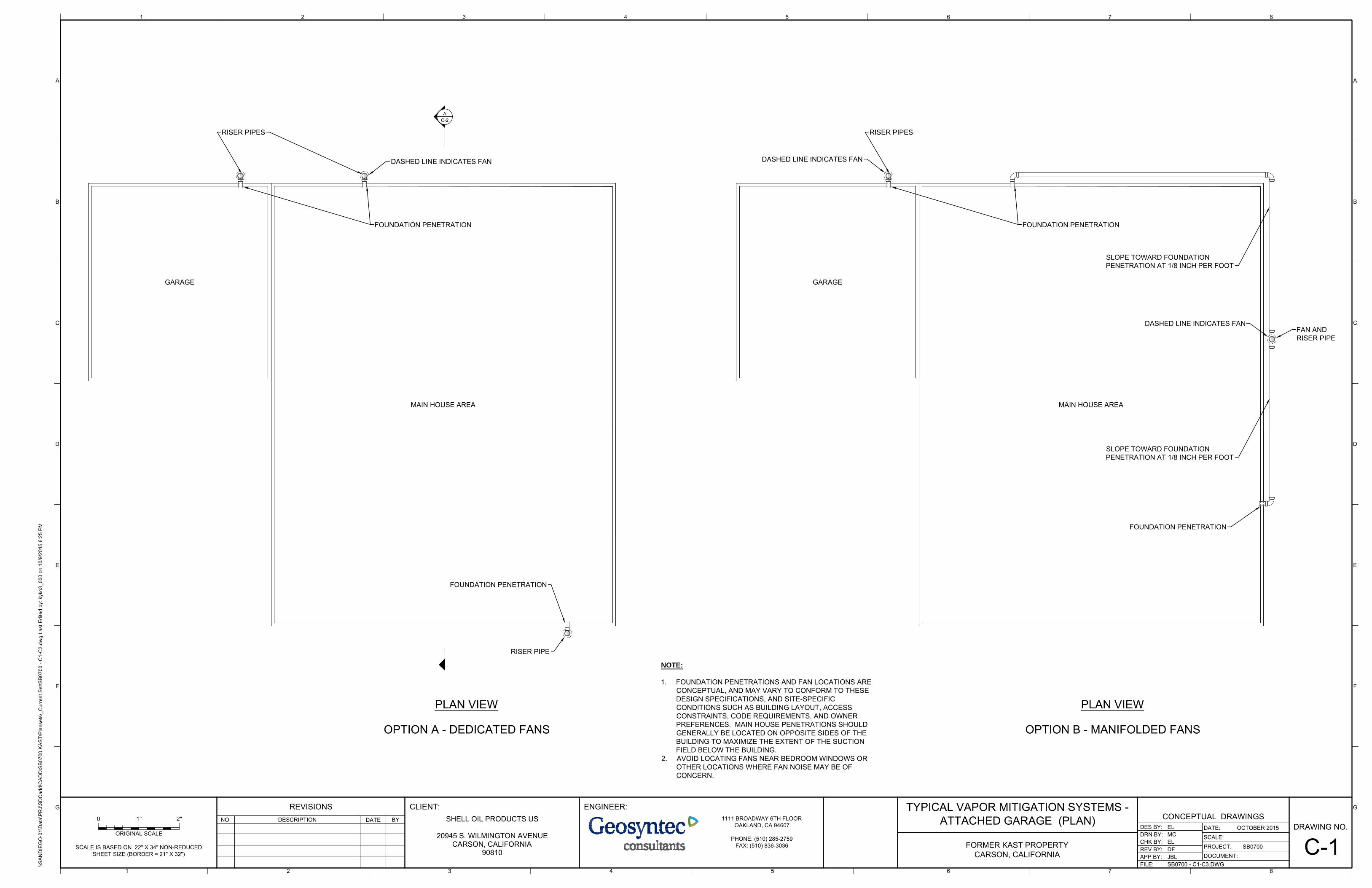
GARAGE
MAIN HOUSE AREA
FOUNDATION PENETRATION
RISER PIPE
FOUNDATION PENETRATION
RISER PIPES
DASHED LINE INDICATES FAN
PLAN VIEW
AC-2
GARAGE
MAIN HOUSE AREA
FOUNDATION PENETRATION
FOUNDATION PENETRATION
RISER PIPES
PLAN VIEW
DASHED LINE INDICATES FAN
FAN ANDRISER PIPE
DASHED LINE INDICATES FAN
OPTION A - DEDICATED FANS OPTION B - MANIFOLDED FANS
SLOPE TOWARD FOUNDATIONPENETRATION AT 1/8 INCH PER FOOT
SLOPE TOWARD FOUNDATIONPENETRATION AT 1/8 INCH PER FOOT
CONCEPTUAL DRAWINGS
\\SA
ND
IEG
O-0
1\D
ata\
PR
J\S
DC
add\
CA
DD
\SB
0700
KA
ST\
Pla
nset
s\_C
urre
nt S
et\S
B07
00 -
C1-
C3.
dwg
Last
Edi
ted
by: k
yko3
_000
on
10/9
/201
5 6:
25 P
M
B
C
D
E
F
G
8
B
C
D
E
F
G
AA
DRAWING NO.
PROJECT:DOCUMENT:
FILE:
REV BY:APP BY:
DATE:
SCALE:DRN BY:DES BY:
CHK BY:
DESCRIPTIONNO.
REVISIONSDATE BY
ENGINEER:
ISSUED FOR REVIEW1 10/30/14 JBL
SCALE IS BASED ON 22" X 34" NON-REDUCEDSHEET SIZE (BORDER = 21" X 32")
ORIGINAL SCALE
FORMER KAST PROPERTYCARSON, CALIFORNIA
MCEL
ELSB0700--
OCTOBER 20151111 BROADWAY 6TH FLOOR
OAKLAND, CA 94607
PHONE: (510) 285-2759FAX: (510) 836-3036
JBL
SHELL OIL PRODUCTS US
20945 S. WILMINGTON AVENUECARSON, CALIFORNIA
90810
CLIENT:
DFMINOR REVISIONS2 04/28/15 JBL
SB0700 - C1-C3.DWG
TYPICAL VAPOR MITIGATION SYSTEMS -ATTACHED GARAGE (PLAN)
C-1
NOTE:
1. FOUNDATION PENETRATIONS AND FAN LOCATIONS ARECONCEPTUAL, AND MAY VARY TO CONFORM TO THESEDESIGN SPECIFICATIONS, AND SITE-SPECIFICCONDITIONS SUCH AS BUILDING LAYOUT, ACCESSCONSTRAINTS, CODE REQUIREMENTS, AND OWNERPREFERENCES. MAIN HOUSE PENETRATIONS SHOULDGENERALLY BE LOCATED ON OPPOSITE SIDES OF THEBUILDING TO MAXIMIZE THE EXTENT OF THE SUCTIONFIELD BELOW THE BUILDING.
2. AVOID LOCATING FANS NEAR BEDROOM WINDOWS OROTHER LOCATIONS WHERE FAN NOISE MAY BE OFCONCERN.
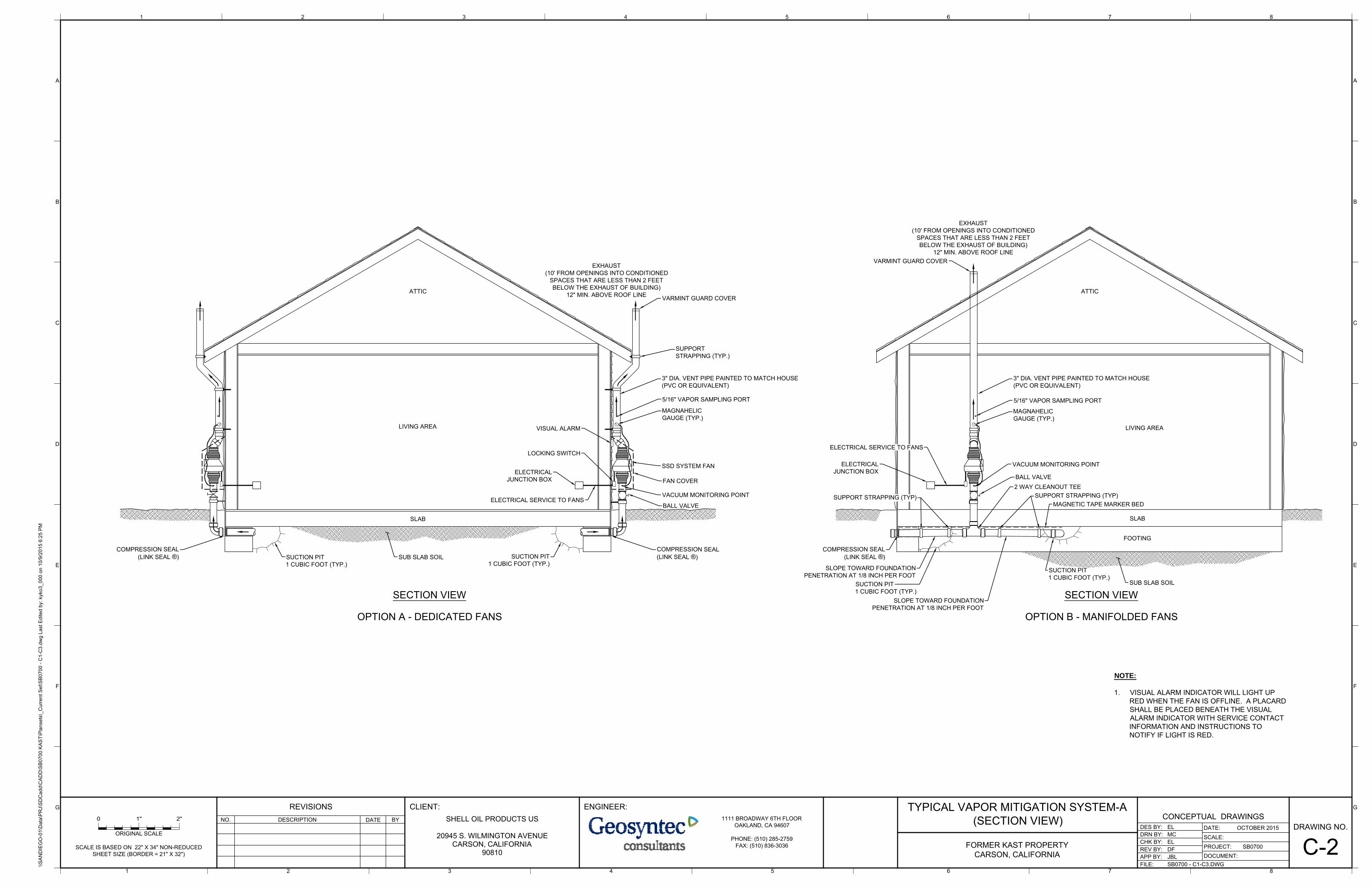
EXHAUST(10' FROM OPENINGS INTO CONDITIONED
SPACES THAT ARE LESS THAN 2 FEETBELOW THE EXHAUST OF BUILDING)
12" MIN. ABOVE ROOF LINE
ELECTRICALJUNCTION BOX
SUCTION PIT1 CUBIC FOOT (TYP.)
SLAB
MAGNAHELICGAUGE (TYP.)
3" DIA. VENT PIPE PAINTED TO MATCH HOUSE(PVC OR EQUIVALENT)
LIVING AREA
ATTIC
COMPRESSION SEAL(LINK SEAL ®)
SECTION VIEWSUB SLAB SOIL
VACUUM MONITORING POINT
5/16" VAPOR SAMPLING PORT
BALL VALVE
EXHAUST(10' FROM OPENINGS INTO CONDITIONED
SPACES THAT ARE LESS THAN 2 FEETBELOW THE EXHAUST OF BUILDING)
12" MIN. ABOVE ROOF LINE
SSD SYSTEM FAN
ELECTRICAL SERVICE TO FANS
ELECTRICALJUNCTION BOX
SUCTION PIT1 CUBIC FOOT (TYP.)
SLAB
MAGNAHELICGAUGE (TYP.)
SUCTION PIT1 CUBIC FOOT (TYP.)
SUPPORTSTRAPPING (TYP.)
3" DIA. VENT PIPE PAINTED TO MATCH HOUSE(PVC OR EQUIVALENT)
VARMINT GUARD COVER
LIVING AREA
ATTIC
COMPRESSION SEAL(LINK SEAL ®)
SECTION VIEW
VISUAL ALARM
SUB SLAB SOIL
LOCKING SWITCH
VACUUM MONITORING POINT
FAN COVER
COMPRESSION SEAL(LINK SEAL ®)
5/16" VAPOR SAMPLING PORT
BALL VALVE
VARMINT GUARD COVER
FOOTING
ELECTRICAL SERVICE TO FANS
2 WAY CLEANOUT TEESUPPORT STRAPPING (TYP)
OPTION A - DEDICATED FANS OPTION B - MANIFOLDED FANS
SUPPORT STRAPPING (TYP)
SLOPE TOWARD FOUNDATIONPENETRATION AT 1/8 INCH PER FOOT
SUCTION PIT1 CUBIC FOOT (TYP.)
SLOPE TOWARD FOUNDATIONPENETRATION AT 1/8 INCH PER FOOT
MAGNETIC TAPE MARKER BED
CONCEPTUAL DRAWINGS
\\SA
ND
IEG
O-0
1\D
ata\
PR
J\S
DC
add\
CA
DD
\SB
0700
KA
ST\
Pla
nset
s\_C
urre
nt S
et\S
B07
00 -
C1-
C3.
dwg
Last
Edi
ted
by: k
yko3
_000
on
10/9
/201
5 6:
25 P
M
B
C
D
E
F
G
8
B
C
D
E
F
G
AA
DRAWING NO.
PROJECT:DOCUMENT:
FILE:
REV BY:APP BY:
DATE:
SCALE:DRN BY:DES BY:
CHK BY:
DESCRIPTIONNO.
REVISIONSDATE BY
ENGINEER:
ISSUED FOR REVIEW1 10/30/14 JBL
SCALE IS BASED ON 22" X 34" NON-REDUCEDSHEET SIZE (BORDER = 21" X 32")
ORIGINAL SCALE
FORMER KAST PROPERTYCARSON, CALIFORNIA
MCEL
ELSB0700--
OCTOBER 20151111 BROADWAY 6TH FLOOR
OAKLAND, CA 94607
PHONE: (510) 285-2759FAX: (510) 836-3036
JBL
SHELL OIL PRODUCTS US
20945 S. WILMINGTON AVENUECARSON, CALIFORNIA
90810
CLIENT:
DFMINOR REVISIONS2 04/28/15 JBL
SB0700 - C1-C3.DWG
TYPICAL VAPOR MITIGATION SYSTEM-A(SECTION VIEW)
C-2
NOTE:
1. VISUAL ALARM INDICATOR WILL LIGHT UPRED WHEN THE FAN IS OFFLINE. A PLACARDSHALL BE PLACED BENEATH THE VISUALALARM INDICATOR WITH SERVICE CONTACTINFORMATION AND INSTRUCTIONS TONOTIFY IF LIGHT IS RED.
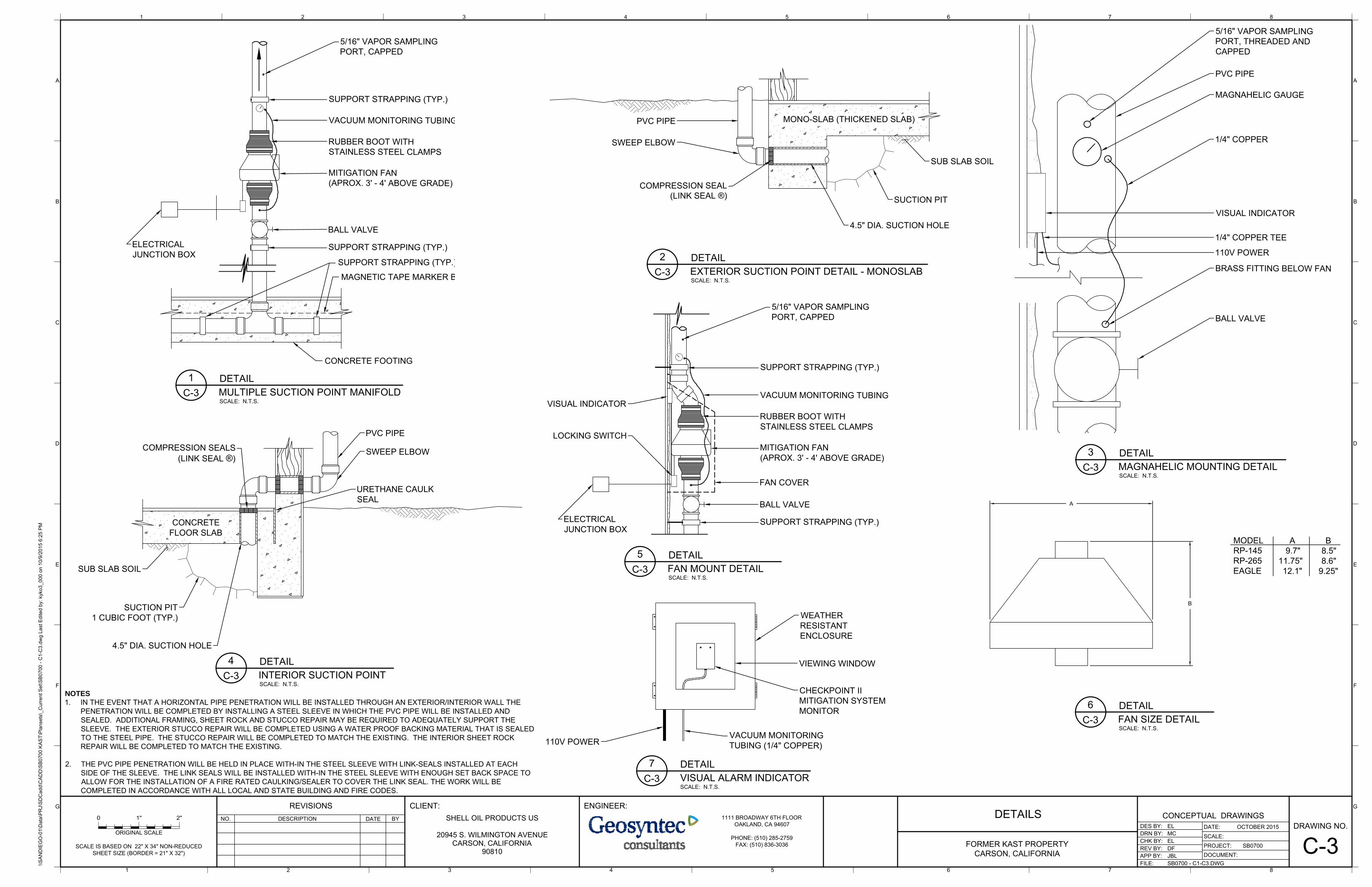
SUCTION PIT
SWEEP ELBOW
SUB SLAB SOIL
MONO-SLAB (THICKENED SLAB)PVC PIPE
COMPRESSION SEAL(LINK SEAL ®)
4.5" DIA. SUCTION HOLE
PVC PIPE
MAGNAHELIC GAUGE
1/4" COPPER
BRASS FITTING BELOW FAN
VISUAL INDICATOR
5/16" VAPOR SAMPLINGPORT, THREADED ANDCAPPED
1/4" COPPER TEE
110V POWER
BALL VALVE
SUCTION PIT1 CUBIC FOOT (TYP.)
SUB SLAB SOIL
CONCRETEFLOOR SLAB
PVC PIPE
SWEEP ELBOW
URETHANE CAULKSEAL
COMPRESSION SEALS(LINK SEAL ®)
4.5" DIA. SUCTION HOLE
SUPPORT STRAPPING (TYP.)
RUBBER BOOT WITHSTAINLESS STEEL CLAMPS
MITIGATION FAN(APROX. 3' - 4' ABOVE GRADE)
SUPPORT STRAPPING (TYP.)ELECTRICALJUNCTION BOX
LOCKING SWITCH
FAN COVER
VACUUM MONITORING TUBING
5/16" VAPOR SAMPLINGPORT, CAPPED
BALL VALVE
VISUAL INDICATOR
A
B
MODEL A BRP-145 9.7" 8.5"RP-265 11.75" 8.6"EAGLE 12.1" 9.25"
WEATHERRESISTANTENCLOSURE
VIEWING WINDOW
CHECKPOINT IIMITIGATION SYSTEMMONITOR
VACUUM MONITORINGTUBING (1/4" COPPER)110V POWER
SUPPORT STRAPPING (TYP.)
RUBBER BOOT WITHSTAINLESS STEEL CLAMPS
MITIGATION FAN(APROX. 3' - 4' ABOVE GRADE)
SUPPORT STRAPPING (TYP.)ELECTRICALJUNCTION BOX
VACUUM MONITORING TUBING
5/16" VAPOR SAMPLINGPORT, CAPPED
BALL VALVE
CONCRETE FOOTING
SUPPORT STRAPPING (TYP.)
MAGNETIC TAPE MARKER BED
CONCEPTUAL DRAWINGS
\\SA
ND
IEG
O-0
1\D
ata\
PR
J\S
DC
add\
CA
DD
\SB
0700
KA
ST\
Pla
nset
s\_C
urre
nt S
et\S
B07
00 -
C1-
C3.
dwg
Last
Edi
ted
by: k
yko3
_000
on
10/9
/201
5 6:
25 P
M
B
C
D
E
F
G
8
B
C
D
E
F
G
AA
DRAWING NO.
PROJECT:DOCUMENT:
FILE:
REV BY:APP BY:
DATE:
SCALE:DRN BY:DES BY:
CHK BY:
DESCRIPTIONNO.
REVISIONSDATE BY
ENGINEER:
ISSUED FOR REVIEW1 10/30/14 JBL
SCALE IS BASED ON 22" X 34" NON-REDUCEDSHEET SIZE (BORDER = 21" X 32")
ORIGINAL SCALE
FORMER KAST PROPERTYCARSON, CALIFORNIA
MCEL
ELSB0700--
OCTOBER 20151111 BROADWAY 6TH FLOOR
OAKLAND, CA 94607
PHONE: (510) 285-2759FAX: (510) 836-3036
JBL
SHELL OIL PRODUCTS US
20945 S. WILMINGTON AVENUECARSON, CALIFORNIA
90810
CLIENT:
DFMINOR REVISIONS2 04/28/15 JBL
SB0700 - C1-C3.DWG
DETAILS
C-3
2
SCALE: N.T.S.
DETAILEXTERIOR SUCTION POINT DETAIL - MONOSLABC-3
3
SCALE: N.T.S.
DETAILMAGNAHELIC MOUNTING DETAILC-3
4
SCALE: N.T.S.
DETAILINTERIOR SUCTION POINTC-3
5
SCALE: N.T.S.
DETAILFAN MOUNT DETAILC-3
6
SCALE: N.T.S.
DETAILFAN SIZE DETAILC-3
7
SCALE: N.T.S.
DETAILVISUAL ALARM INDICATORC-3
1
SCALE: N.T.S.
DETAILMULTIPLE SUCTION POINT MANIFOLDC-3
NOTES
1. IN THE EVENT THAT A HORIZONTAL PIPE PENETRATION WILL BE INSTALLED THROUGH AN EXTERIOR/INTERIOR WALL THEPENETRATION WILL BE COMPLETED BY INSTALLING A STEEL SLEEVE IN WHICH THE PVC PIPE WILL BE INSTALLED ANDSEALED. ADDITIONAL FRAMING, SHEET ROCK AND STUCCO REPAIR MAY BE REQUIRED TO ADEQUATELY SUPPORT THESLEEVE. THE EXTERIOR STUCCO REPAIR WILL BE COMPLETED USING A WATER PROOF BACKING MATERIAL THAT IS SEALEDTO THE STEEL PIPE. THE STUCCO REPAIR WILL BE COMPLETED TO MATCH THE EXISTING. THE INTERIOR SHEET ROCKREPAIR WILL BE COMPLETED TO MATCH THE EXISTING.
2. THE PVC PIPE PENETRATION WILL BE HELD IN PLACE WITH-IN THE STEEL SLEEVE WITH LINK-SEALS INSTALLED AT EACHSIDE OF THE SLEEVE. THE LINK SEALS WILL BE INSTALLED WITH-IN THE STEEL SLEEVE WITH ENOUGH SET BACK SPACE TOALLOW FOR THE INSTALLATION OF A FIRE RATED CAULKING/SEALER TO COVER THE LINK SEAL. THE WORK WILL BECOMPLETED IN ACCORDANCE WITH ALL LOCAL AND STATE BUILDING AND FIRE CODES.
Remedial Design and Implementation Plan Former Kast Property
APPENDIX O
MITIGATION MONITORING AND REPORTING PROGRAM CROSS-REFERENCE
TABLE
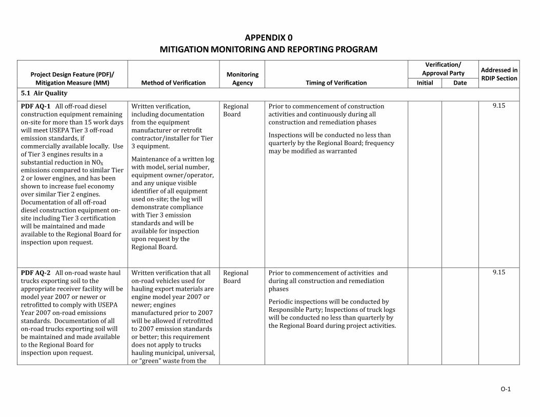
O‐1
APPENDIX 0 MITIGATION MONITORING AND REPORTING PROGRAM
Project Design Feature (PDF)/ Mitigation Measure (MM)
Method of Verification Monitoring Agency
Timing of Verification
Verification/ Approval Party Addressed in
RDIP Section Initial Date
5.1 AirQuality
PDFAQ‐1Alloff‐roaddieselconstructionequipmentremainingon‐siteformorethan15workdayswillmeetUSEPATier3off‐roademissionstandards,ifcommerciallyavailablelocally. UseofTier3enginesresultsinasubstantialreductioninNOXemissionscomparedtosimilarTier2orlowerengines,andhasbeenshowntoincreasefueleconomyoversimilarTier2engines.Documentationofalloff‐roaddieselconstructionequipmenton‐siteincludingTier3certificationwillbemaintainedandmadeavailabletotheRegionalBoardforinspectionuponrequest.
Writtenverification,includingdocumentationfromtheequipmentmanufacturerorretrofitcontractor/installerforTier3equipment.
Maintenanceofawrittenlogwithmodel,serialnumber,equipmentowner/operator,andanyuniquevisibleidentifierofallequipmentusedon‐site;thelogwilldemonstratecompliancewithTier3emissionstandardsandwillbeavailableforinspectionuponrequestbytheRegionalBoard.
RegionalBoard
Priortocommencementofconstructionactivitiesandcontinuouslyduringallconstructionandremediationphases
InspectionswillbeconductednolessthanquarterlybytheRegionalBoard;frequencymaybemodifiedaswarranted
9.15
PDFAQ‐2Allon‐roadwastehaultrucksexportingsoiltotheappropriatereceiverfacilitywillbemodelyear2007ornewerorretrofittedtocomplywithUSEPAYear2007on‐roademissionsstandards.Documentationofallon‐roadtrucksexportingsoilwillbemaintainedandmadeavailabletotheRegionalBoardforinspectionuponrequest.
Writtenverificationthatallon‐roadvehiclesusedforhaulingexportmaterialsareenginemodelyear2007ornewer;enginesmanufacturedpriorto2007willbeallowedifretrofittedto2007emissionstandardsorbetter;thisrequirementdoesnotapplytotruckshaulingmunicipal,universal,or“green”wastefromthe
RegionalBoard
Priortocommencementofactivities andduringallconstructionandremediationphases
PeriodicinspectionswillbeconductedbyResponsibleParty;InspectionsoftrucklogswillbeconductednolessthanquarterlybytheRegionalBoardduringprojectactivities.
9.15
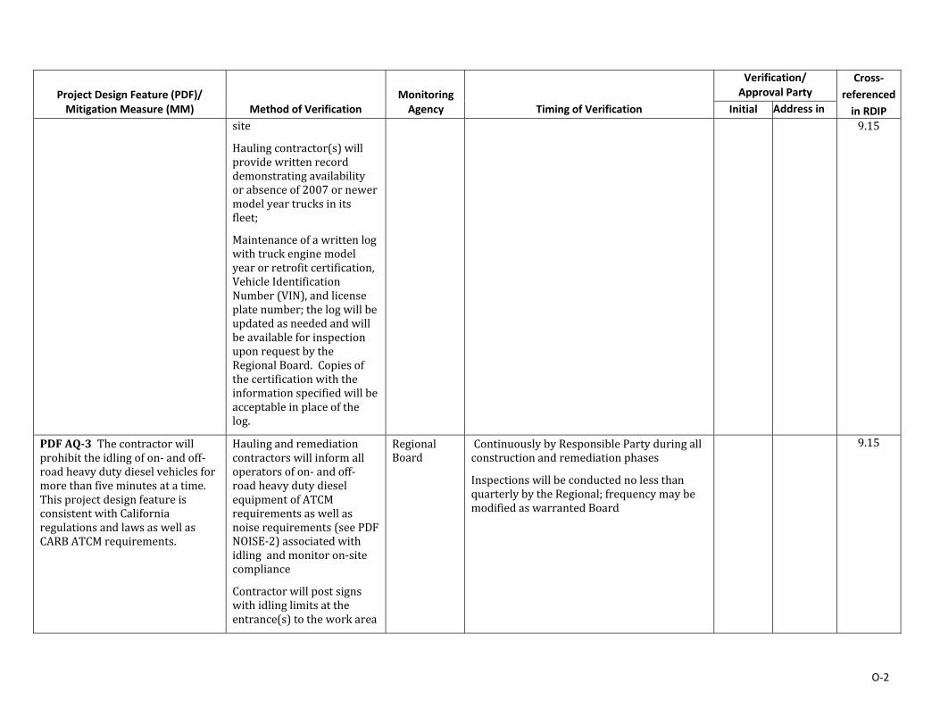
O‐2
Project Design Feature (PDF)/ Mitigation Measure (MM)
Method of Verification Monitoring Agency
Timing of Verification
Verification/ Approval Party
Cross‐referenced in RDIP Initial Address in
site
Haulingcontractor(s)willprovidewrittenrecorddemonstratingavailabilityorabsenceof2007ornewermodelyeartrucksinitsfleet;
Maintenanceofawrittenlogwithtruckenginemodelyearorretrofitcertification,VehicleIdentificationNumber(VIN),andlicenseplatenumber;thelogwillbeupdatedasneededandwillbeavailableforinspectionuponrequestbytheRegionalBoard.Copiesofthecertificationwiththeinformationspecifiedwillbeacceptableinplaceofthelog.
9.15
PDFAQ‐3Thecontractorwillprohibittheidlingofon‐andoff‐roadheavydutydieselvehiclesformorethanfiveminutesatatime.ThisprojectdesignfeatureisconsistentwithCaliforniaregulationsandlawsaswellasCARBATCMrequirements.
Haulingandremediationcontractorswillinformalloperatorsofon‐andoff‐roadheavydutydieselequipmentofATCMrequirementsaswellasnoiserequirements(seePDFNOISE‐2)associatedwithidling andmonitoron‐sitecompliance
Contractorwillpostsignswithidlinglimitsattheentrance(s)totheworkarea
RegionalBoard
ContinuouslybyResponsiblePartyduringallconstructionandremediationphases
InspectionswillbeconductednolessthanquarterlybytheRegional;frequencymaybemodifiedaswarrantedBoard
9.15
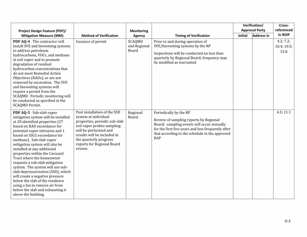
O‐3
Project Design Feature (PDF)/ Mitigation Measure (MM)
Method of Verification Monitoring Agency
Timing of Verification
Verification/ Approval Party
Cross‐referenced in RDIP Initial Address in
PDFAQ‐4ThecontractorwillinstallSVEandbioventingsystemstoaddresspetroleumhydrocarbons,VOCs,andmethaneinsoilvaporandtopromotedegradationofresidualhydrocarbonconcentrationsthatdonotmeetRemedialActionObjectives(RAOs),orarenotremovedbyexcavation. TheSVEandbioventingsystemswillrequireapermitfromtheSCAQMD.PeriodicmonitoringwillbeconductedasspecifiedintheSCAQMDPermit.
Issuanceofpermit SCAQMDandRegionalBoard
PriortoandduringoperationofSVE/bioventingsystemsbytheRP
InspectionswillbeconductednolessthanquarterlybyRegionalBoard;frequencymaybemodifiedaswarranted
4.2; 7.2;10.4;10.5;
15.8
PDFAQ‐5Sub‐slabvapormitigationsystemwillbeinstalledat28identifiedproperties(27basedonRAOexceedanceforpotentialvaporintrusionand1basedonSSCGexceedanceformethane).Sub‐slabvapormitigationsystemwillalsobeinstalledatanyadditionalpropertieswithintheCarouselTractwherethehomeownerrequestsasub‐slabmitigationsystem. Thesystemwillusesub‐slabdepressurization(SSD),whichwillcreateanegativepressurebelowtheslaboftheresidenceusingafantoremoveairfrombelowtheslabandexhaustingitabovethebuilding.
PostinstallationoftheSSDsystematindividualproperties,periodicsub‐slabsoilvaporprobessamplingwillbeperformedandresultswillbeincludedinthequarterlyprogressreportsforRegionalBoardreview.
RegionalBoard
PeriodicallybytheRP
ReviewofsamplingreportsbyRegionalBoard; samplingeventswilloccurannuallyforthefirstfiveyearsandlessfrequentlyafterthataccordingtothescheduleintheapprovedRAP
4.3;11.1
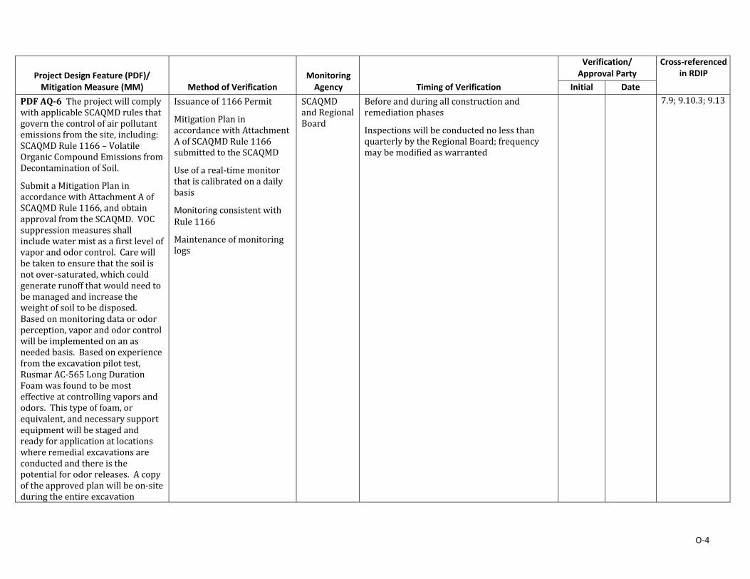
O‐4
Project Design Feature (PDF)/ Mitigation Measure (MM)
Method of Verification Monitoring Agency
Timing of Verification
Verification/ Approval Party
Cross‐referenced in RDIP
Initial Date PDFAQ‐6TheprojectwillcomplywithapplicableSCAQMDrulesthatgovernthecontrolofairpollutantemissionsfromthesite,including:SCAQMDRule1166–VolatileOrganicCompoundEmissionsfromDecontaminationofSoil.
SubmitaMitigationPlaninaccordancewithAttachmentAofSCAQMDRule1166,andobtainapprovalfromtheSCAQMD. VOCsuppressionmeasuresshallincludewatermistasafirstlevelofvaporandodorcontrol.Carewillbetakentoensurethatthesoilisnotover‐saturated,whichcouldgeneraterunoffthatwouldneedtobemanagedandincreasetheweightofsoiltobedisposed.Basedonmonitoringdataorodorperception,vaporandodorcontrolwillbeimplementedonanasneededbasis. Basedonexperiencefromtheexcavationpilottest,RusmarAC‐565LongDurationFoamwasfoundtobemosteffectiveatcontrollingvaporsandodors. Thistypeoffoam,orequivalent,andnecessarysupportequipmentwillbestagedandreadyforapplicationatlocationswhereremedialexcavationsareconductedandthereisthepotentialforodorreleases. Acopyoftheapprovedplanwillbeon‐siteduringtheentireexcavation
Issuanceof1166Permit
MitigationPlaninaccordancewithAttachmentAofSCAQMDRule1166submittedtotheSCAQMD
Useofareal‐timemonitorthatiscalibratedonadailybasis
Monitoring consistentwithRule1166
Maintenanceofmonitoringlogs
SCAQMDandRegionalBoard
Beforeandduringallconstructionandremediationphases
InspectionswillbeconductednolessthanquarterlybytheRegionalBoard;frequencymaybemodifiedaswarranted
7.9;9.10.3;9.13
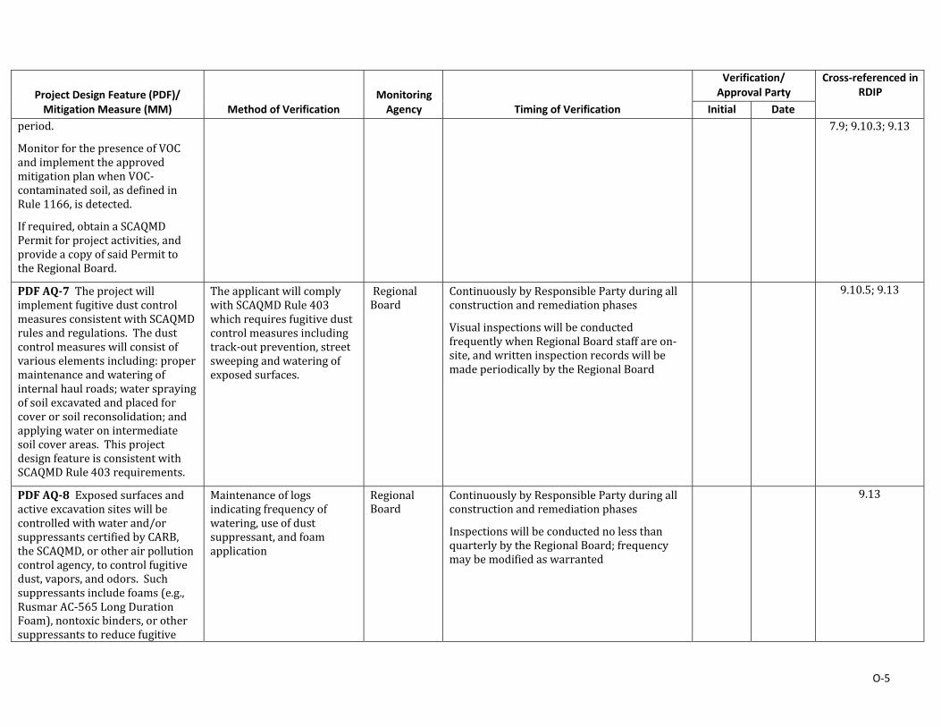
O‐5
Project Design Feature (PDF)/ Mitigation Measure (MM)
Method of Verification Monitoring Agency
Timing of Verification
Verification/ Approval Party
Cross‐referenced in RDIP
Initial Date period.
MonitorforthepresenceofVOCandimplementtheapprovedmitigationplanwhenVOC‐contaminatedsoil,asdefinedinRule1166,isdetected.
Ifrequired,obtainaSCAQMDPermitforprojectactivities,andprovideacopyofsaidPermittotheRegionalBoard.
7.9;9.10.3;9.13
PDFAQ‐7TheprojectwillimplementfugitivedustcontrolmeasuresconsistentwithSCAQMDrulesandregulations.Thedustcontrolmeasureswillconsistofvariouselementsincluding:propermaintenanceandwateringofinternalhaulroads;watersprayingofsoilexcavatedandplacedforcoverorsoilreconsolidation;andapplyingwateronintermediatesoilcoverareas. ThisprojectdesignfeatureisconsistentwithSCAQMDRule403requirements.
TheapplicantwillcomplywithSCAQMDRule403whichrequiresfugitivedustcontrolmeasuresincludingtrack‐outprevention,streetsweepingandwateringofexposedsurfaces.
RegionalBoard
ContinuouslybyResponsiblePartyduringallconstructionandremediationphases
VisualinspectionswillbeconductedfrequentlywhenRegionalBoardstaffareon‐site,andwritteninspectionrecordswillbemadeperiodicallybytheRegionalBoard
9.10.5;9.13
PDFAQ‐8Exposedsurfacesandactiveexcavationsiteswillbecontrolledwithwaterand/orsuppressantscertifiedbyCARB,theSCAQMD,orotherairpollutioncontrolagency,tocontrolfugitivedust,vapors,andodors. Suchsuppressantsincludefoams(e.g.,RusmarAC‐565LongDurationFoam),nontoxicbinders,orothersuppressantstoreducefugitive
Maintenanceoflogsindicatingfrequencyofwatering,useofdustsuppressant,andfoamapplication
RegionalBoard
ContinuouslybyResponsiblePartyduringallconstructionandremediationphases
InspectionswillbeconductednolessthanquarterlybytheRegionalBoard;frequencymaybemodifiedaswarranted
9.13
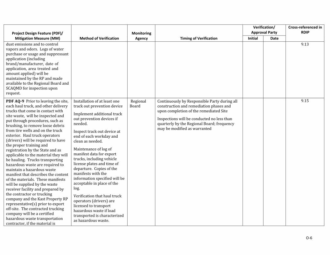
O‐6
Project Design Feature (PDF)/ Mitigation Measure (MM)
Method of Verification Monitoring Agency
Timing of Verification
Verification/ Approval Party
Cross‐referenced in RDIP
Initial Date dustemissionsandtocontrolvaporsandodors.Logsofwaterpurchaseorusageandsuppressantapplication(includingbrand/manufacturer, date ofapplication,area treatedandamountapplied)willbemaintainedbytheRPandmadeavailabletotheRegionalBoardandSCAQMDforinspectionuponrequest.
9.13
PDFAQ‐9Priortoleavingthesite,eachhaultruck,andotherdeliverytrucksthatcomeincontactwithsitewaste,willbeinspectedandputthroughprocedures,suchasbrushing,toremoveloosedebrisfromtirewellsandonthetruckexterior.Haultruckoperators(drivers)willberequiredtohavethepropertrainingandregistrationbytheStateandasapplicabletothematerialtheywillbehauling.Truckstransportinghazardouswastearerequiredtomaintainahazardouswastemanifestthatdescribesthecontentofthematerials.ThesemanifestswillbesuppliedbythewastereceiverfacilityandpreparedbythecontractorortruckingcompanyandtheKastPropertyRPrepresentative(s)priortoexportoff‐site.Thecontractedtruckingcompanywillbeacertifiedhazardouswastetransportationcontractor,ifthematerialis
Installationofatleastonetrackoutpreventiondevice
Implementadditionaltrackoutpreventiondevicesifneeded.
Inspecttrackoutdeviceatendofeachworkdayandcleanasneeded.
Maintenanceoflogofmanifestdataforexporttrucks,includingvehiclelicenseplatesandtimeofdeparture.Copiesofthemanifestswiththeinformationspecifiedwillbeacceptableinplaceofthelog.
Verificationthathaultruckoperators(drivers)arelicensedtotransporthazardouswasteifloadtransportedischaracterizedashazardouswaste.
RegionalBoard
ContinuouslybyResponsiblePartyduringallconstructionandremediationphasesanduponcompletionoftheremediatedSite
InspectionswillbeconductednolessthanquarterlybytheRegionalBoard;frequencymaybemodifiedaswarranted
9.15
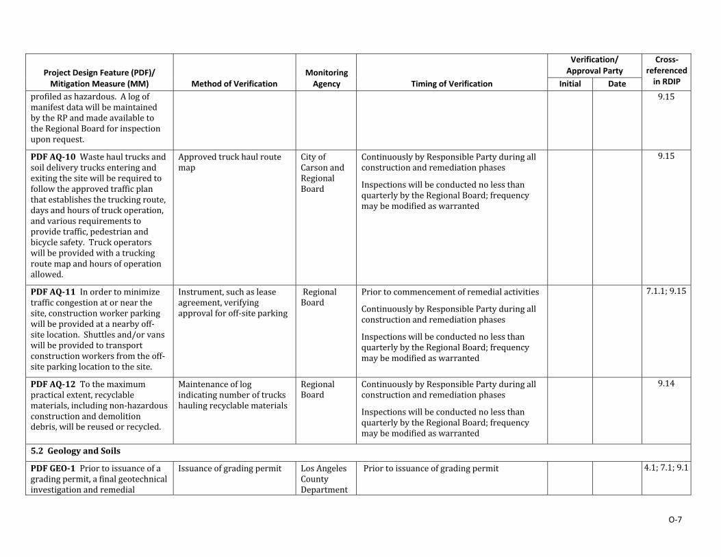
O‐7
Project Design Feature (PDF)/ Mitigation Measure (MM)
Method of Verification Monitoring Agency
Timing of Verification
Verification/ Approval Party
Cross‐referenced in RDIP Initial Date
profiledashazardous. AlogofmanifestdatawillbemaintainedbytheRPandmadeavailabletotheRegionalBoardforinspectionuponrequest.
9.15
PDFAQ‐10Wastehaultrucksandsoildeliverytrucksenteringandexitingthesitewillberequiredtofollowtheapprovedtrafficplanthatestablishesthetruckingroute,daysandhoursoftruckoperation,andvariousrequirementstoprovidetraffic,pedestrianandbicyclesafety. Truckoperatorswillbeprovidedwithatruckingroutemapandhoursofoperationallowed.
Approvedtruckhaulroutemap
CityofCarsonandRegionalBoard
ContinuouslybyResponsiblePartyduringallconstructionandremediationphases
InspectionswillbeconductednolessthanquarterlybytheRegionalBoard;frequencymaybemodifiedaswarranted
9.15
PDFAQ‐11Inordertominimizetrafficcongestionatornearthesite,constructionworkerparkingwillbeprovidedatanearbyoff‐sitelocation. Shuttlesand/orvanswillbeprovidedtotransportconstructionworkersfromtheoff‐siteparkinglocationtothesite.
Instrument,suchasleaseagreement,verifyingapprovalforoff‐siteparking
RegionalBoard
Priortocommencementofremedialactivities
ContinuouslybyResponsiblePartyduringallconstructionandremediationphases
InspectionswillbeconductednolessthanquarterlybytheRegionalBoard;frequencymaybemodifiedaswarranted
7.1.1;9.15
PDFAQ‐12Tothemaximumpracticalextent,recyclablematerials,includingnon‐hazardousconstructionanddemolitiondebris,willbereusedorrecycled.
Maintenanceoflogindicatingnumberoftruckshaulingrecyclablematerials
RegionalBoard
ContinuouslybyResponsiblePartyduringallconstructionandremediationphases
InspectionswillbeconductednolessthanquarterlybytheRegionalBoard;frequencymaybemodifiedaswarranted
9.14
5.2 GeologyandSoils
PDFGEO‐1Priortoissuanceofagradingpermit,afinalgeotechnicalinvestigationandremedial
Issuanceofgradingpermit LosAngelesCountyDepartment
Priortoissuanceofgradingpermit 4.1;7.1;9.1
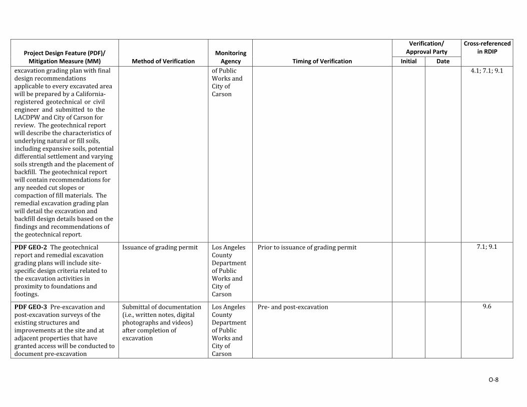
O‐8
Project Design Feature (PDF)/ Mitigation Measure (MM)
Method of Verification Monitoring Agency
Timing of Verification
Verification/ Approval Party
Cross‐referenced in RDIP
Initial Date excavationgradingplanwithfinaldesignrecommendationsapplicabletoeveryexcavatedareawillbepreparedbyaCalifornia‐registered geotechnical or civilengineer and submitted to theLACDPWandCityofCarsonforreview.Thegeotechnicalreportwilldescribethecharacteristicsofunderlyingnaturalorfillsoils,includingexpansivesoils,potentialdifferentialsettlementandvaryingsoilsstrengthandtheplacementofbackfill.Thegeotechnicalreportwillcontainrecommendationsforanyneededcutslopesorcompactionoffillmaterials. Theremedialexcavationgradingplanwilldetailtheexcavationandbackfilldesigndetailsbasedonthefindingsandrecommendationsofthegeotechnicalreport.
of PublicWorksandCityofCarson
4.1;7.1;9.1
PDFGEO‐2Thegeotechnicalreportandremedialexcavationgradingplanswillincludesite‐specificdesigncriteriarelatedtotheexcavationactivitiesinproximitytofoundationsandfootings.
Issuanceofgradingpermit LosAngelesCountyDepartmentofPublicWorksandCityofCarson
Priortoissuanceofgradingpermit 7.1;9.1
PDFGEO‐3Pre‐excavationandpost‐excavationsurveysoftheexistingstructuresandimprovementsatthesiteandatadjacentpropertiesthathavegrantedaccesswillbeconductedtodocumentpre‐excavation
Submittalofdocumentation(i.e.,writtennotes,digitalphotographsandvideos)aftercompletionofexcavation
LosAngelesCountyDepartmentofPublicWorksandCityofCarson
Pre‐andpost‐excavation 9.6
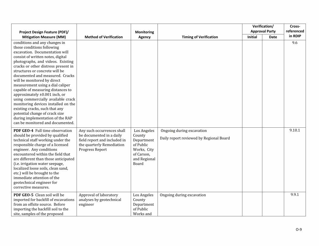
O‐9
Project Design Feature (PDF)/ Mitigation Measure (MM)
Method of Verification Monitoring Agency
Timing of Verification
Verification/ Approval Party
Cross‐referenced in RDIP Initial Date
conditionsandanychangesinthoseconditionsfollowingexcavation.Documentationwillconsistofwrittennotes,digitalphotographs,andvideos. Existingcracksorotherdistresspresentinstructuresorconcretewillbedocumentedandmeasured. Crackswillbemonitoredbydirectmeasurementusingadialcalipercapableofmeasuringdistancestoapproximately±0.001inch,orusing commercially available crackmonitoringdevicesinstalledontheexistingcracks,suchthatanypotentialchangeofcracksizeduringimplementationoftheRAPcanbemonitoredanddocumented.
9.6
PDFGEO‐4Fulltimeobservationshouldbeprovidedbyqualifiedtechnicalstaffworkingundertheresponsiblechargeofalicensedengineer.Anyconditionsencounteredwithinthefieldthataredifferentthanthoseanticipated(i.e.irrigationwaterseepage,localizedloosesoils,cleansand,etc.)willbebroughttotheimmediateattentionofthegeotechnicalengineerforcorrectivemeasures.
AnysuchoccurrencesshallbedocumentedinadailyfieldreportandincludedinthequarterlyRemediationProgressReport
LosAngelesCountyDepartmentofPublicWorks,CityofCarson,andRegionalBoard
Ongoingduringexcavation
DailyreportreviewedbyRegionalBoard
9.10.1
PDFGEO‐5Cleansoilwillbeimportedforbackfillofexcavationsfromanoffsitesource. Beforeimportingthebackfillsoiltothesite,samplesoftheproposed
Approvaloflaboratoryanalysesbygeotechnicalengineer
LosAngelesCountyDepartmentofPublicWorksand
Ongoingduringexcavation 9.9.1
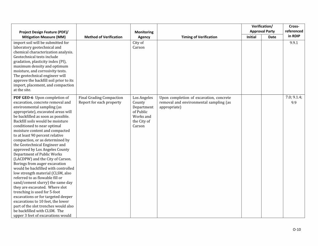
O‐10
Project Design Feature (PDF)/ Mitigation Measure (MM)
Method of Verification Monitoring Agency
Timing of Verification
Verification/ Approval Party
Cross‐referenced in RDIP Initial Date
importsoilwillbesubmittedforlaboratorygeotechnicalandchemicalcharacterizationanalysis.Geotechnicaltestsincludegradation,plasticityindex(PI),maximumdensityandoptimummoisture,andcorrosivitytests.Thegeotechnicalengineerwillapprovethebackfillsoilpriortoitsimport,placement,andcompactionatthesite.
CityofCarson
9.9.1
PDFGEO‐6Uponcompletionofexcavation,concreteremovalandenvironmentalsampling(asappropriate),excavatedareaswillbebackfilledassoonaspossible.Backfillsoilswouldbemoistureconditionedtonearoptimalmoisturecontentandcompactedtoatleast90percentrelativecompaction,orasdeterminedbytheGeotechnicalEngineerandapprovedbyLosAngelesCountyDepartmentofPublicWorks(LACDPW)andtheCityofCarson.Boringsfromaugerexcavationwouldbebackfilledwithcontrolledlowstrengthmaterial(CLSM,alsoreferredtoasflowablefillorsand/cementslurry)thesamedaytheyareexcavated. Whereslottrenchingisusedfor5‐footexcavationsorfortargeteddeeperexcavationsto10feet,thelowerpartoftheslottrencheswouldalsobebackfilledwithCLSM.Theupper3feetofexcavationswould
FinalGradingCompactionReportforeachproperty
LosAngelesCountyDepartmentofPublicWorksandtheCityofCarson
Uponcompletionof excavation, concreteremovalandenvironmentalsampling(asappropriate)
7.0;9.1.4;9.9
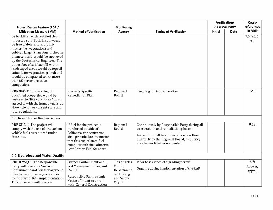
O‐11
Project Design Feature (PDF)/ Mitigation Measure (MM)
Method of Verification Monitoring Agency
Timing of Verification
Verification/ Approval Party
Cross‐referenced in RDIP Initial Date
bebackfilledwithcertifiedcleanimportedsoil.Backfillsoilwouldbefreeofdeleteriousorganicmatter(i.e.,vegetation)andcobbles larger than four inches indiameter, andwould be approvedbytheGeotechnicalEngineer. Theupperfootofsoilbackfillwithinlandscapedareaswouldbetopsoilsuitableforvegetationgrowthandwouldbecompactedtonotmorethan85percentrelativecompaction.
7.0;9.1.4;9.9
PDFGEO‐7Landscapingofbackfilledpropertieswouldberestoredto“likeconditions”orasagreedtowiththehomeowners,asallowableundercurrentstateandlocalregulations.
PropertySpecificRemediationPlan
RegionalBoard
Ongoingduringrestoration 12.0
5.3 GreenhouseGasEmissions
PDFGHG‐1TheprojectwillcomplywiththeuseoflowcarbonvehiclefuelsasrequiredunderStatelaw.
IffuelfortheprojectispurchasedoutsideofCalifornia,thecontractorshallprovidedocumentationthatthisout‐of‐statefuelcomplieswiththeCaliforniaLowCarbonFuelStandard.
RegionalBoard
ContinuouslybyResponsiblePartyduringallconstructionandremediationphases
InspectionswillbeconductednolessthanquarterlybytheRegionalBoard;frequencymaybemodifiedaswarranted
9.15
5.5 HydrologyandWaterQuality
PDFH/WQ‐1TheResponsiblePartywillprovideaSurfaceContainmentandSoilManagementPlantopermittingagenciespriortothestartofRAPimplementation.Thisdocumentwillprovide
SurfaceContainmentandSoilManagementPlan,andSWPPP
ResponsiblePartysubmitNoticeofIntenttoenrollwith GeneralConstruction
LosAngelesCountyDepartmentofBuildingandSafetyCityof
Priortoissuanceofagradingpermit
OngoingduringimplementationoftheRAP
6.7;AppxA;AppxC
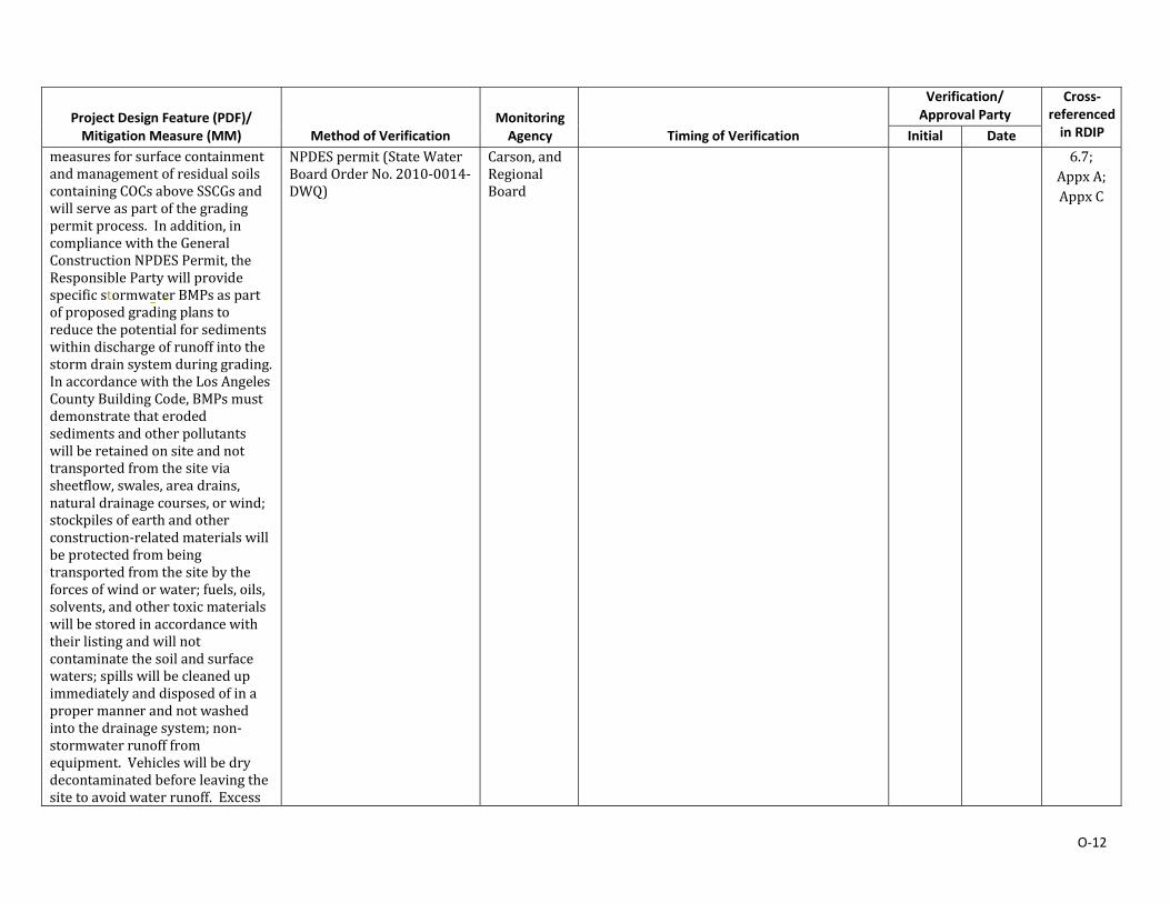
O‐12
Project Design Feature (PDF)/ Mitigation Measure (MM)
Method of Verification Monitoring Agency
Timing of Verification
Verification/ Approval Party
Cross‐referenced in RDIP Initial Date
measuresforsurfacecontainmentandmanagementofresidualsoilscontainingCOCsaboveSSCGsandwillserveaspartofthegradingpermitprocess.Inaddition,incompliancewiththeGeneralConstructionNPDESPermit,theResponsiblePartywillprovidespecificstormwaterBMPsaspartofproposedgradingplanstoreducethepotentialforsedimentswithindischargeofrunoffintothestormdrainsystemduringgrading.InaccordancewiththeLosAngelesCountyBuildingCode,BMPsmustdemonstratethaterodedsedimentsandotherpollutantswillberetainedonsiteandnottransportedfromthesiteviasheetflow,swales,areadrains,naturaldrainagecourses,orwind;stockpilesofearthandotherconstruction‐relatedmaterialswillbeprotectedfrombeingtransportedfromthesitebytheforcesofwindorwater;fuels,oils,solvents,andothertoxicmaterialswillbestoredinaccordancewiththeirlistingandwillnotcontaminatethesoilandsurfacewaters;spillswillbecleanedupimmediatelyanddisposedofinapropermannerandnotwashedintothedrainagesystem;non‐stormwaterrunofffromequipment.Vehicleswillbedrydecontaminatedbeforeleavingthesitetoavoidwaterrunoff.Excess
NPDESpermit(StateWaterBoardOrderNo.2010‐0014‐DWQ)
Carson, andRegionalBoard
6.7;AppxA;AppxC
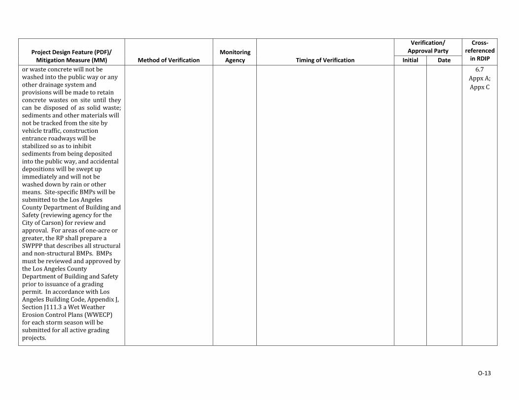
O‐13
Project Design Feature (PDF)/ Mitigation Measure (MM)
Method of Verification Monitoring Agency
Timing of Verification
Verification/ Approval Party
Cross‐referenced in RDIP Initial Date
orwasteconcretewillnotbewashedintothepublicwayoranyotherdrainagesystemandprovisionswillbemadetoretainconcrete wastes on site until theycan be disposed of as solidwaste;sedimentsandothermaterialswillnotbetrackedfromthesitebyvehicletraffic,constructionentranceroadwayswillbestabilizedsoastoinhibitsedimentsfrombeingdepositedintothepublicway,andaccidentaldepositionswillbesweptupimmediatelyandwillnotbewasheddownbyrainorothermeans.Site‐specificBMPswillbesubmittedtotheLosAngelesCountyDepartmentofBuildingandSafety(reviewingagencyfortheCityofCarson)forreviewandapproval.Forareasofone‐acreorgreater,theRPshallprepareaSWPPPthatdescribesallstructuralandnon‐structuralBMPs. BMPsmustbereviewedandapprovedbytheLosAngelesCountyDepartmentofBuildingandSafetypriortoissuanceofagradingpermit.InaccordancewithLosAngelesBuildingCode,AppendixJ,SectionJ111.3aWetWeatherErosionControlPlans(WWECP)foreachstormseasonwillbesubmittedforallactivegradingprojects.
6.7AppxA;AppxC
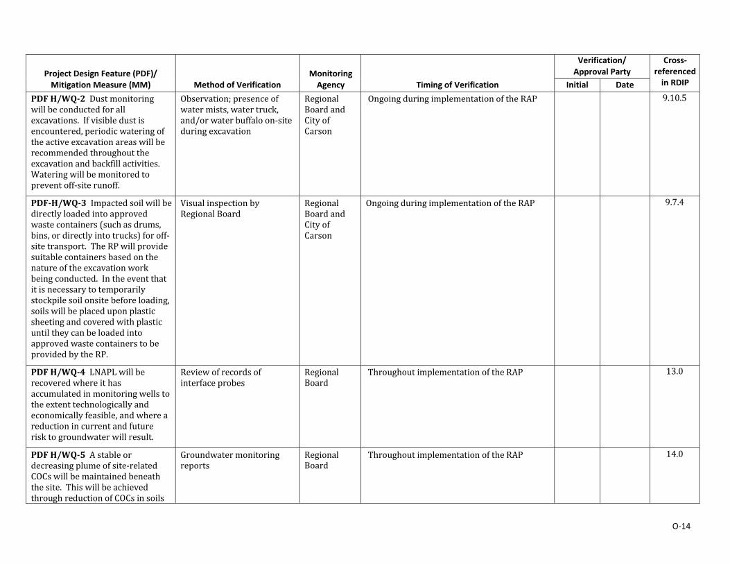
O‐14
Project Design Feature (PDF)/ Mitigation Measure (MM)
Method of Verification Monitoring Agency
Timing of Verification
Verification/ Approval Party
Cross‐referenced in RDIP Initial Date
PDFH/WQ‐2Dustmonitoringwillbeconductedforallexcavations. Ifvisibledustisencountered,periodicwateringoftheactiveexcavationareaswillberecommendedthroughouttheexcavationandbackfillactivities.Wateringwillbemonitoredtopreventoff‐siterunoff.
Observation;presenceofwatermists,watertruck,and/orwaterbuffaloon‐siteduringexcavation
RegionalBoardandCityofCarson
OngoingduringimplementationoftheRAP 9.10.5
PDF‐H/WQ‐3Impactedsoilwillbedirectlyloadedintoapprovedwastecontainers(suchasdrums,bins,ordirectlyintotrucks)foroff‐sitetransport. TheRPwillprovidesuitablecontainersbasedonthenatureoftheexcavationworkbeingconducted. Intheeventthatitisnecessarytotemporarilystockpilesoilonsitebeforeloading,soilswillbeplaceduponplasticsheetingandcoveredwithplasticuntiltheycanbeloadedintoapprovedwastecontainerstobeprovidedbytheRP.
VisualinspectionbyRegionalBoard
RegionalBoardandCityofCarson
OngoingduringimplementationoftheRAP 9.7.4
PDFH/WQ‐4LNAPLwillberecoveredwhereithasaccumulatedinmonitoringwellstotheextenttechnologicallyandeconomicallyfeasible,andwhereareductionincurrentandfuturerisktogroundwaterwillresult.
Reviewofrecordsofinterfaceprobes
RegionalBoard
ThroughoutimplementationoftheRAP 13.0
PDFH/WQ‐5Astableordecreasingplumeofsite‐relatedCOCswillbemaintainedbeneaththesite.ThiswillbeachievedthroughreductionofCOCsinsoils
Groundwatermonitoringreports
RegionalBoard
ThroughoutimplementationoftheRAP 14.0
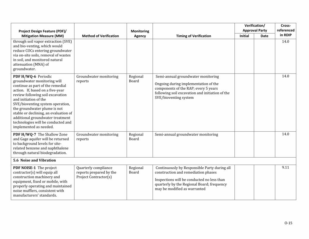
O‐15
Project Design Feature (PDF)/ Mitigation Measure (MM)
Method of Verification Monitoring Agency
Timing of Verification
Verification/ Approval Party
Cross‐referenced in RDIP Initial Date
throughsoilvaporextraction(SVE)andbio‐venting,whichwouldreduceCOCsenteringgroundwaterviaon‐sitesoils,removalofwastesinsoil,andmonitorednaturalattenuation(MNA)ofgroundwater.
14.0
PDFH/WQ‐6Periodicgroundwatermonitoringwillcontinueaspartoftheremedialaction.If,basedonafive‐yearreviewfollowingsoilexcavationandinitiationoftheSVE/bioventingsystemoperation,thegroundwaterplumeisnotstableordeclining,anevaluationofadditionalgroundwatertreatmenttechnologieswillbeconductedandimplementedasneeded.
Groundwatermonitoringreports
RegionalBoard
Semi‐annualgroundwatermonitoring
OngoingduringimplementationofthecomponentsoftheRAP;every5yearsfollowingsoilexcavationandinitiationoftheSVE/bioventingsystem
14.0
PDFH/WQ‐7TheShallowZoneandGageaquiferwillbereturnedtobackgroundlevelsforsite‐relatedbenzeneandnaphthalenethroughnaturalbiodegradation.
Groundwatermonitoringreports
RegionalBoard
Semi‐annualgroundwatermonitoring 14.0
5.6 NoiseandVibration
PDFNOISE‐1Theprojectcontractor(s)willequipallconstructionmachineryandequipment,fixedormobile,withproperlyoperatingandmaintainednoisemufflers,consistentwithmanufacturers’standards.
QuarterlycompliancereportspreparedbytheProjectContractor(s)
RegionalBoard
ContinuouslybyResponsiblePartyduringallconstructionandremediationphases
InspectionswillbeconductednolessthanquarterlybytheRegionalBoard;frequencymaybemodifiedaswarranted
9.11

O‐16
Project Design Feature (PDF)/ Mitigation Measure (MM)
Method of Verification Monitoring Agency
Timing of Verification
Verification/ Approval Party
Cross‐referenced in RDIP Initial Date
PDFNOISE‐2Engineidlingfromconstructionequipmentsuchasexcavatorsandhaultruckswillbelimited,totheextentfeasible.
SeePDFAQ‐3 SeePDFAQ‐3
SeePDFAQ‐3 9.11
PDFNOISE‐3Expectedhoursforconstructionequipmentuseon‐sitewillbe7:30A.M.to4:30P.M.MondaythroughFriday,withhaulingactivitiesfrom8:00A.M.to4:00P.M.
Dailylogofstartandstoptimesmaintainedbyconstructionsupervisor
RegionalBoard
ContinuouslybyResponsiblePartyduringallconstructionandremediationphases
9.11
PDFNOISE‐4Project‐relatedheavytrucktrafficwillbelimitedtospecificroutes.
Approvedtruckhaulroutemap
CityofCarsonandRegionalBoard
ContinuouslybyResponsiblePartyduringallconstructionandremediationphases
InspectionswillbeconductednolessthanquarterlybytheRegionalBoard;frequencymaybemodifiedaswarranted
6.4;9.11;9.15
PDFNOISE‐5Duringexcavation,acousticalattenuationblanketsapproximately12feetinheightwillbeinstalledbetweentheexcavationsiteandadjacentoccupiedhousesprovidedthatthiscanbedonewithoutcreatingasafetyhazard,toreducecommunitynoiseexposurefromstationarysourcesofsubstantialnoise,suchasgeneratorsandwaterbuffalos(trailer).
PropertySpecificPlans
AcousticalReportpreparedbyResponsibleParty
RegionalBoard
ContinuouslybyResponsiblePartyduringallconstructionandremediationphases
ReviewofAcousticalRecordbyRegionalBoard;InspectionswillbeconductedperiodicallybytheRegionalBoard
7.3;8.2;9.11
MMNOISE‐1Residentsofpropertiesshallbeofferednoisemitigationmeasures(e.g.,hearingprotection,soundproofing,whitenoisemachines,etc.)acceptabletotheresidentsorrelocationforthedurationofnearbyactive
PropertySpecificPlans RegionalBoard
ContinuouslybyResponsiblePartyduringallconstructionandremediationphases
InspectionswillbeconductednolessthanquarterlybytheRegionalBoard;frequencymaybemodifiedaswarranted
7.3;8.2;9.10.7;9.11

O‐17
Project Design Feature (PDF)/ Mitigation Measure (MM)
Method of Verification Monitoring Agency
Timing of Verification
Verification/ Approval Party
Cross‐referenced in RDIP Initial Date
remediationactivitieswhichmaycreateambientnoiselevelsattheirpropertyinexcessof75dBA,Leq.for20daysorlessorinexcessof65dBA,Leq.for21daysorlonger.BasedontheanalysespresentedinthisEIR,thisshallapplytoresidenceslocatedwithinapproximately90feetofstreettrenchingor130feetfromanedgeofresidentialremediation(i.e.aclusterof4to8homes);thesedistancesmayberevisedbytheRegionalBoarduponcompletionofadditionalmonitoringandanalysiswhichcouldbeperformedunderthedirectionofanindependentacousticianduringtheimplementationoftheRAP,oriftheCityofCarsonagreesthatthe75dBAthresholdisacceptablefortheconstructionactivities.AppendixF‐8includes75dBAand65dBAcontoursshowingtheimpactedpropertiessurroundingahypothetical8‐propertycluster.
7.3;8.2;9.10.7;9.11
MMNOISE‐2Tothemaximumextentfeasible,theprojectshallprovidenoiseblanket/temporarynoisebarriersbetweentheactiveareasandoccupiedresidentialunitsduringstreettrenching.
VisualinspectionbyRegionalBoard
RegionalBoard
ContinuouslybyResponsiblePartyduringallconstructionandremediationphases
InspectionswillbeconductednolessthanquarterlybytheRegionalBoard;frequencymaybemodifiedaswarranted
8.2;8.10.7;9.11
MMNOISE‐3TheRPshalleitherretaintheservicesofaqualifiedacousticalengineerwithexpertiseindesignofsoundisolationsto
Issuanceofpermit RegionalBoardandCityofCarson
PriortoissuanceofabuildingpermitfortheSVE/bioventingsystemenclosure
InspectionswillbeconductednolessthanquarterlybytheRegionalBoard;frequency
10.4;10.4.6
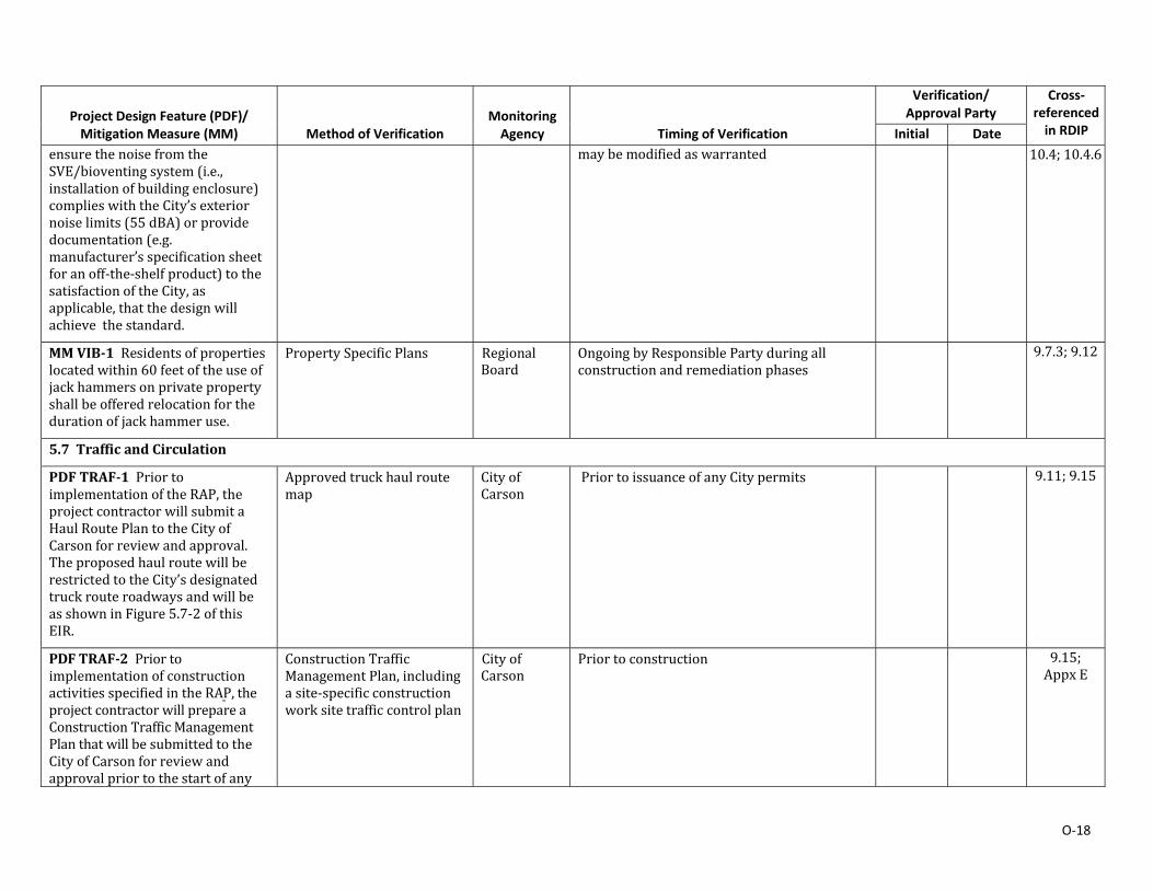
O‐18
Project Design Feature (PDF)/ Mitigation Measure (MM)
Method of Verification Monitoring Agency
Timing of Verification
Verification/ Approval Party
Cross‐referenced in RDIP Initial Date
ensurethenoisefromtheSVE/bioventingsystem(i.e.,installationofbuildingenclosure)complieswiththeCity’sexteriornoiselimits(55dBA)orprovidedocumentation(e.g.manufacturer’sspecificationsheetforanoff‐the‐shelfproduct)tothesatisfactionoftheCity,asapplicable,thatthedesignwillachieve thestandard.
maybemodifiedaswarranted 10.4;10.4.6
MMVIB‐1Residentsofpropertieslocatedwithin60feetoftheuseofjackhammersonprivatepropertyshallbeofferedrelocationforthedurationofjackhammeruse.
PropertySpecificPlans RegionalBoard
OngoingbyResponsiblePartyduringallconstructionandremediationphases
9.7.3;9.12
5.7 TrafficandCirculation
PDFTRAF‐1PriortoimplementationoftheRAP,theprojectcontractorwillsubmitaHaulRoutePlantotheCityofCarsonforreviewandapproval.TheproposedhaulroutewillberestrictedtotheCity’sdesignatedtruckrouteroadwaysandwillbeasshowninFigure5.7‐2ofthisEIR.
Approvedtruckhaulroutemap
CityofCarson
PriortoissuanceofanyCitypermits 9.11;9.15
PDFTRAF‐2PriortoimplementationofconstructionactivitiesspecifiedintheRAP,theprojectcontractorwillprepareaConstructionTrafficManagementPlanthatwillbesubmittedtotheCityofCarsonforreviewandapprovalpriortothestartofany
ConstructionTrafficManagementPlan,includingasite‐specificconstructionworksitetrafficcontrolplan
CityofCarson
Priortoconstruction 9.15;AppxE
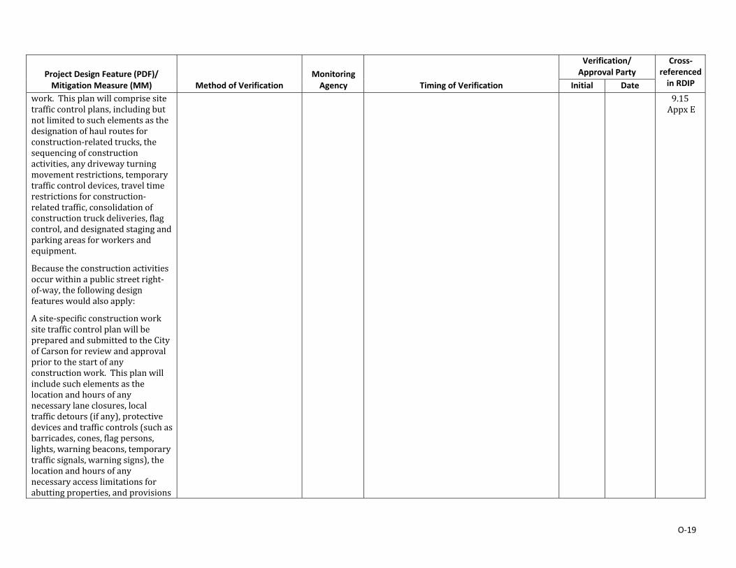
O‐19
Project Design Feature (PDF)/ Mitigation Measure (MM)
Method of Verification Monitoring Agency
Timing of Verification
Verification/ Approval Party
Cross‐referenced in RDIP Initial Date
work. Thisplanwillcomprisesitetrafficcontrolplans,includingbutnotlimitedtosuchelementsasthedesignationofhaulroutesforconstruction‐relatedtrucks,thesequencingofconstructionactivities,anydrivewayturningmovementrestrictions,temporarytrafficcontroldevices,traveltimerestrictionsforconstruction‐relatedtraffic,consolidationofconstructiontruckdeliveries,flagcontrol,anddesignatedstagingandparkingareasforworkersandequipment.
Becausetheconstructionactivitiesoccurwithinapublicstreetright‐of‐way,thefollowingdesignfeatureswouldalsoapply:
Asite‐specificconstructionworksitetrafficcontrolplanwillbepreparedandsubmittedtotheCityofCarsonforreviewandapprovalpriortothestartofanyconstructionwork. Thisplanwillincludesuchelementsasthelocationandhoursofanynecessarylaneclosures,localtrafficdetours(ifany),protectivedevicesandtrafficcontrols(suchasbarricades,cones,flagpersons,lights,warningbeacons,temporarytrafficsignals,warningsigns),thelocationandhoursofanynecessaryaccesslimitationsforabuttingproperties,andprovisions
9.15AppxE
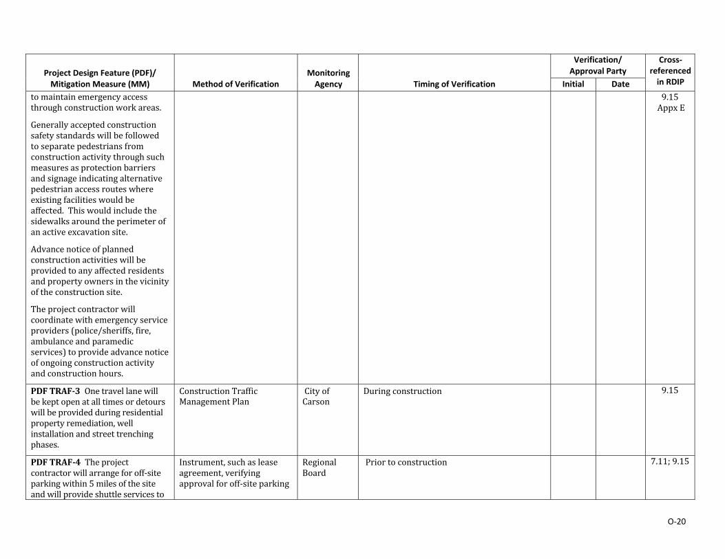
O‐20
Project Design Feature (PDF)/ Mitigation Measure (MM)
Method of Verification Monitoring Agency
Timing of Verification
Verification/ Approval Party
Cross‐referenced in RDIP Initial Date
tomaintainemergencyaccessthroughconstructionworkareas.
Generallyacceptedconstructionsafetystandardswillbefollowedtoseparatepedestriansfromconstructionactivitythroughsuchmeasuresasprotectionbarriersandsignageindicatingalternativepedestrianaccessrouteswhereexistingfacilitieswouldbeaffected.Thiswouldincludethesidewalksaroundtheperimeterofanactiveexcavationsite.
Advancenoticeofplannedconstructionactivitieswillbeprovidedtoanyaffectedresidentsandpropertyownersinthevicinityoftheconstructionsite.
Theprojectcontractorwillcoordinatewithemergencyserviceproviders(police/sheriffs,fire,ambulanceandparamedicservices)toprovideadvancenoticeofongoingconstructionactivityandconstructionhours.
9.15AppxE
PDFTRAF‐3Onetravellanewillbekeptopenatalltimesordetourswillbeprovidedduringresidentialpropertyremediation,wellinstallationandstreettrenchingphases.
ConstructionTrafficManagementPlan
CityofCarson
Duringconstruction 9.15
PDFTRAF‐4Theprojectcontractorwillarrangeforoff‐siteparkingwithin5milesofthesiteandwillprovideshuttleservicesto
Instrument,suchasleaseagreement,verifyingapprovalforoff‐siteparking
RegionalBoard
Priortoconstruction 7.11;9.15
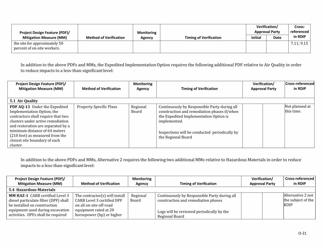
O‐21
Project Design Feature (PDF)/ Mitigation Measure (MM)
Method of Verification Monitoring Agency
Timing of Verification
Verification/ Approval Party
Cross‐referenced in RDIP Initial Date
thesiteforapproximately50percentofon‐siteworkers.
7.11;9.15
InadditiontotheabovePDFsandMMs,theExpeditedImplementationOptionrequiresthefollowingadditionalPDFrelativetoAirQualityinordertoreduceimpactstoaless‐than‐significantlevel:
Project Design Feature (PDF)/ Mitigation Measure (MM)
Method of Verification
Monitoring Agency Timing of Verification
Verification/ Approval Party
Cross‐referenced in RDIP
5.1 AirQualityPDFAQ‐13UndertheExpeditedImplementationOption,thecontractorsshallrequirethattwoclustersunderactiveremediationandrestorationareseparatedbyaminimumdistanceof64meters(210feet)asmeasuredfromtheclosestsiteboundaryofeachcluster.
PropertySpecificPlans RegionalBoard
ContinuouslybyResponsiblePartyduringallconstructionandremediationphasesif/whentheExpeditedImplementationOptionisimplemented.
Inspectionswillbeconducted periodicallybytheRegionalBoard
Notplannedatthistime.
InadditiontotheabovePDFsandMMs,Alternative2requiresthefollowingtwoadditionalMMsrelativetoHazardousMaterialsinordertoreduceimpactstoaless‐than‐significantlevel:
Project Design Feature (PDF)/ Mitigation Measure (MM)
Method of Verification
Monitoring Agency Timing of Verification
Verification/ Approval Party
Cross‐referenced in RDIP
5.4 HazardousMaterialsMMHAZ‐1CARBcertifiedLevel3dieselparticulatefilter(DPF)shallbeinstalledonconstructionequipmentusedduringexcavationactivities.DPFsshallberequired
Thecontractor(s)willinstallCARBLevel3certifiedDPFonallon‐siteoff‐roadequipmentratedat20horsepower(hp)orhigher
RegionalBoard
ContinuouslybyResponsiblePartyduringallconstructionandremediationphases
LogswillbereviewedperiodicallybytheRegionalBoard
Alternative2notthesubjectoftheRDIP

O‐22
Project Design Feature (PDF)/ Mitigation Measure (MM)
Method of Verification
Monitoring Agency Timing of Verification
Verification/ Approval Party
Cross‐referenced in RDIP
forconstructionequipmentratedat20horsepower(hp)orhigherandusedon‐sitefor21‐daysorlonger. Dieselparticulatefilters(DPFs)shallreduceoff‐roaddieselparticulatematter(DPM)emissionsfromeachpieceofoff‐roadequipmentbyatleast85percent.Equipmentwhichneedsservicing(breaksdown)maybereplacedwithTier3onatemporarybasisifequipmentwithaDPFisnotcommerciallyavailable.IfreplacementequipmentisnotequippedwithaDPF,documentationmustbeprovidedtodemonstratethatnocommerciallyavailableequipmentwithaDPFisavailable.
andanticipated to beusedon‐sitefor21‐daysorlonger
Equipmentwhichbreaksdownormalfunctionsmaybeimmediatelyreplacedwithnon‐DPFequippedTier3equipment.DocumentationthatnocommerciallyavailableDPFequippedreplacementequipmentisavailable.Documentationwithestimatedrepairtimeofequipmentandsearchforfeasiblereplacement.
InspectionswillbeconductednolessthanquarterlybytheRegionalBoard;frequencymaybemodifiedaswarranted
Alternative2notthesubjectoftheRDIP
MMHAZ‐2Theapplicantshallinvestigatethefeasibilityofrequiringhaultruckstobemodelyear2010andnewerenginesortruckswhichhavebeenretrofittedtomeetmodelyear2010emissionsstandards. ResultsofthisfeasibilityinvestigationshallbedocumentedandprovidedtotheRegionalWaterQualityControlBoardforapprovalpriortostartofhaulingactivities.
Haulingcontractor(s)willprovidewrittenrecorddemonstratingavailabilityorabsenceof2010ornewermodelyeartrucksinitsfleet;
Biddocumentsgivingpreferencetoyear2010andnewerhaultrucks
RegionalBoard
ContinuouslybyResponsiblePartyduringallconstructionandremediationphases
InspectionswillbeconductednolessthanquarterlybytheRegionalBoard;frequencymaybemodifiedaswarranted
Alternative2notthesubjectoftheRDIP
Remedial Design and Implementation Plan Former Kast Property
APPENDIX P
PROCEDURES FOR PAINT FILTER TEST

9095B - 1 Revision 2November 2004
EPA METHOD 9095B
PAINT FILTER LIQUIDS TEST
1.0 SCOPE AND APPLICATION
1.1 This method is used to determine the presence of free liquids in a representativesample of waste.
1.2 The method is used to determine compliance with 40 CFR 264.314 and 265.314.
2.0 SUMMARY OF METHOD
2.1 A predetermined amount of material is placed in a paint filter. If any portion of thematerial passes through and drops from the filter within the 5-min test period, the material isdeemed to contain free liquids.
3.0 INTERFERENCES
3.1 Filter media were observed to separate from the filter cone on exposure to alkalinematerials. This development causes no problem if the sample is not disturbed.
3.2 Temperature can affect the test results if the test is performed below the freezingpoint of any liquid in the sample. Tests must be performed above the freezing point and can,but are not required to, exceed room temperature of 25 oC.
4.0 APPARATUS AND MATERIALS
4.1 Conical paint filter -- Mesh number 60 +/- 5% (fine meshed size). Available at localpaint stores such as Sherwin-Williams and Glidden.
4.2 Glass funnel -- If the paint filter, with the waste, cannot sustain its weight on thering stand, then a fluted glass funnel or glass funnel with a mouth large enough to allow at least1 in. of the filter mesh to protrude should be used to support the filter. The funnel should befluted or have a large open mouth in order to support the paint filter yet not interfere with themovement, to the graduated cylinder, of the liquid that passes through the filter mesh.
4.3 Ring stand and ring, or tripod.
4.4 Graduated cylinder or beaker -- 100-mL.
5.0 REAGENTS
5.1 None.
APPENDIX P

9095B - 2 Revision 2November 2004
6.0 SAMPLE COLLECTION, PRESERVATION, AND HANDLING
A 100-mL or 100-g representative sample is required for the test. If it is not possible toobtain a sample of 100 mL or 100 g that is sufficiently representative of the waste, the analystmay use larger size samples in multiples of 100 mL or 100 g, i.e., 200, 300, 400 mL or g. However, when larger samples are used, analysts shall divide the sample into 100-mL or 100-gportions and test each portion separately. If any portion contains free liquids, the entire sampleis considered to have free liquids. If the sample is measured volumetrically, then it should lackmajor air spaces or voids.
7.0 PROCEDURE
7.1 Assemble test apparatus as shown in Figure 1.
7.2 Place sample in the filter. A funnel may be used to provide support for the paintfilter. If the sample is of such light bulk density that it overflows the filter, then the sides of thefilter can be extended upward by taping filter paper to the inside of the filter and above themesh. Settling the sample into the paint filter may be facilitated by lightly tapping the side of thefilter as it is being filled.
7.3 In order to assure uniformity and standardization of the test, material such assorbent pads or pillows which do not conform to the shape of the paint filter should be cut intosmall pieces and poured into the filter. Sample size reduction may be accomplished by cuttingthe sorbent material with scissors, shears, a knife, or other such device so as to preserve asmuch of the original integrity of the sorbent fabric as possible. Sorbents enclosed in a fabricshould be mixed with the resultant fabric pieces. The particles to be tested should be reducedsmaller than 1 cm (i.e., should be capable of passing through a 9.5 mm (0.375 inch) standardsieve). Grinding sorbent materials should be avoided as this may destroy the integrity of thesorbent and produce many "fine particles" which would normally not be present.
7.4 For brittle materials larger than 1 cm that do not conform to the filter, light crushingto reduce oversize particles is acceptable if it is not practical to cut the material. Materials suchas clay, silica gel, and some polymers may fall into this category.
7.5 Allow sample to drain for 5 min into the graduated cylinder.
7.6 If any portion of the test material collects in the graduated cylinder in the 5-minperiod, then the material is deemed to contain free liquids for purposes of 40 CFR 264.314 and265.314.
8.0 QUALITY CONTROL
8.1 Duplicate samples should be analyzed on a routine basis.
9.0 METHOD PERFORMANCE
9.1 No data provided.
10.0 REFERENCES
10.1 None provided.
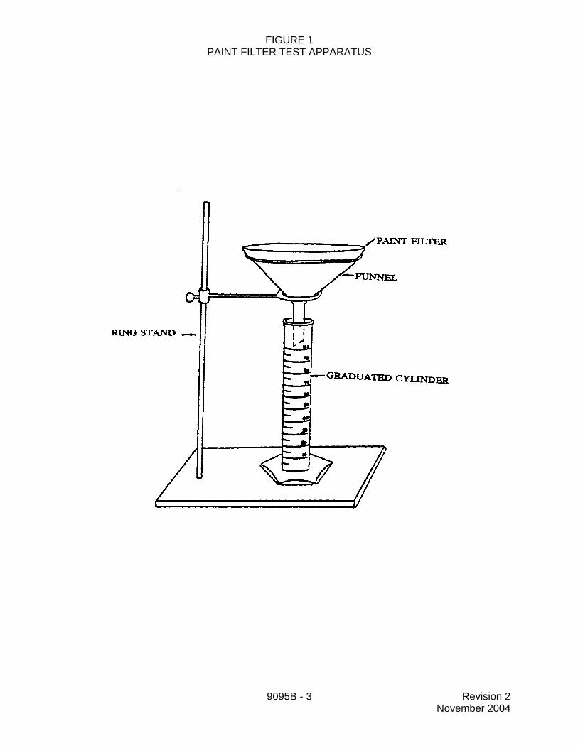
9095B - 3 Revision 2November 2004
FIGURE 1PAINT FILTER TEST APPARATUS
---------::::::,·/PAINT FILTER
RING STAND-
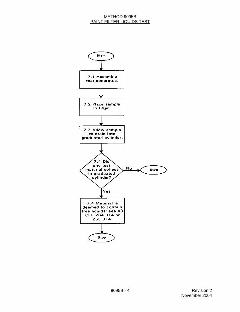
9095B - 4 Revision 2November 2004
METHOD 9095BPAINT FILTER LIQUIDS TEST
7. 1 Assemble test apparatus.
7.2 Place sample in filter.
7.3 Allow sample to drain into
graduated cylinder.
7.4 Material is deemed to contain free liquids; see 40
CFR 264.314 or 265.314.
Recommended