Embed Size (px)
Citation preview
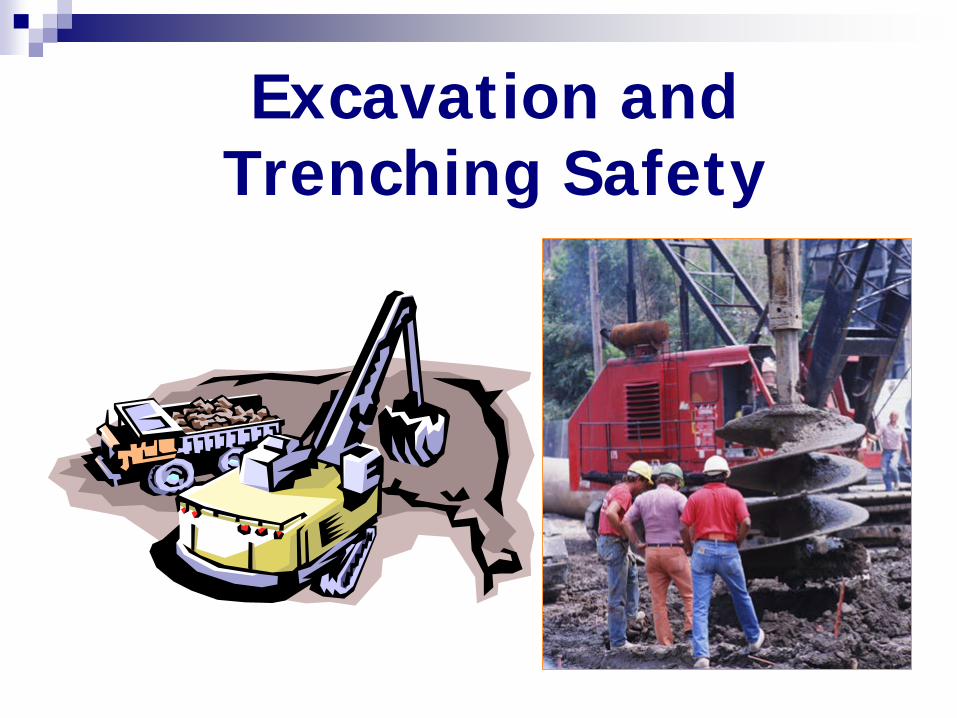
Excavation and Trenching Safety
References EM 385-1-1 Section 25 29 CFR 1926.650 ; Subpart P UFGS 01 35 29 (Latest) Manufacturer’ s
Recommendations Accident Abstracts
Potential Contractor Mishap Outcomes
Cave-ins Fires, Explosions, Electrocutions and Engulfment
due to utility hits Struck by falling objects Falls and Equipment rollovers Asphyxiation, toxic exposures, and explosions
due to hazardous atmospheres Leading to property damage, injury, death
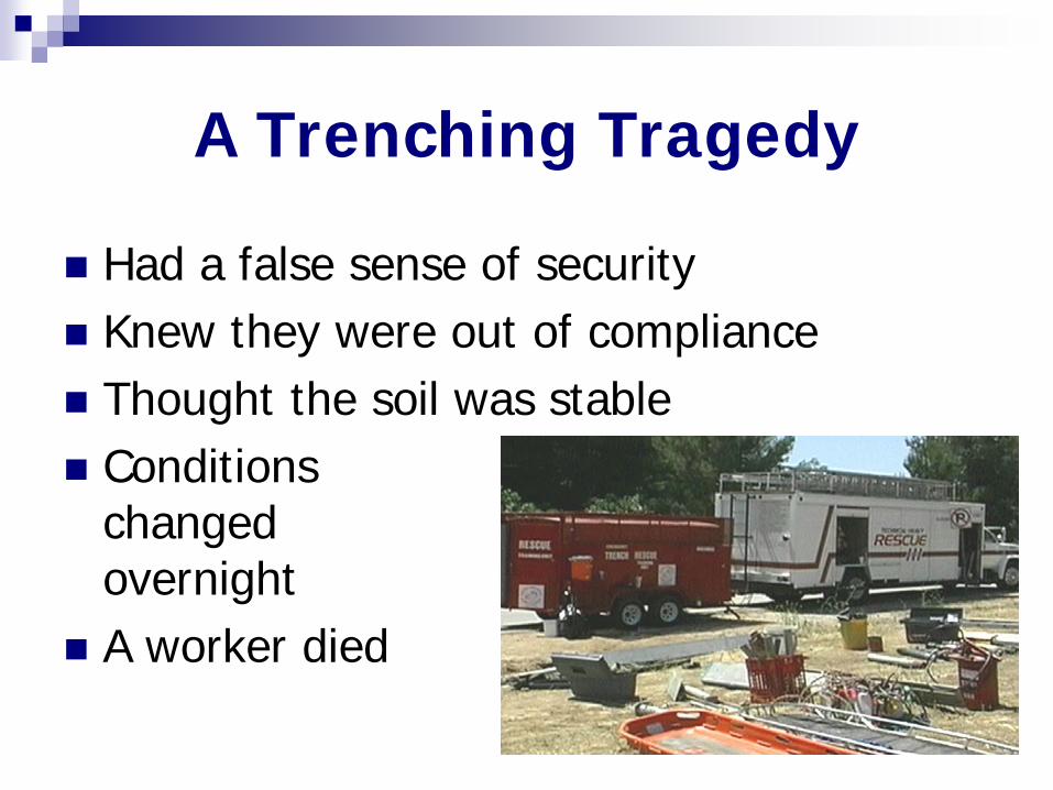
A Trenching Tragedy
Had a false sense of security Knew they were out of compliance Thought the soil was stable Conditions
changed overnight
A worker died
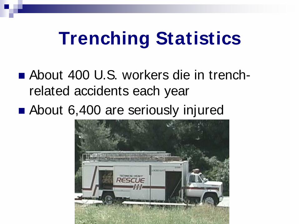
Trenching Statistics
About 400 U.S. workers die in trench-related accidents each year
About 6,400 are seriously injured
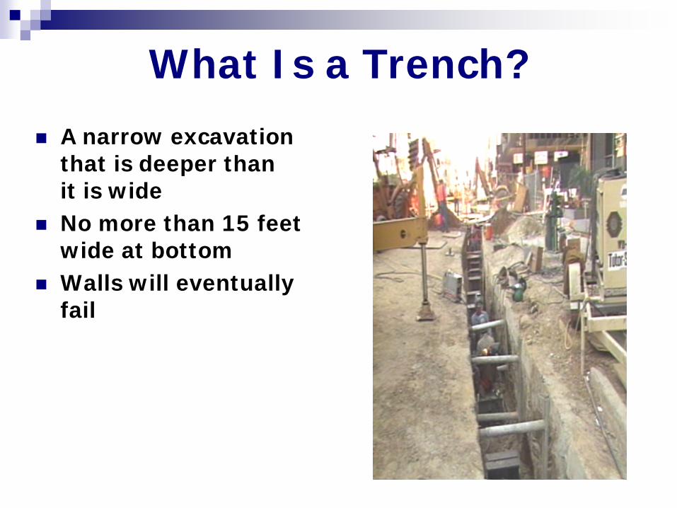
What Is a Trench? A narrow excavation
that is deeper than it is wide
No more than 15 feet wide at bottom
Walls will eventually fail
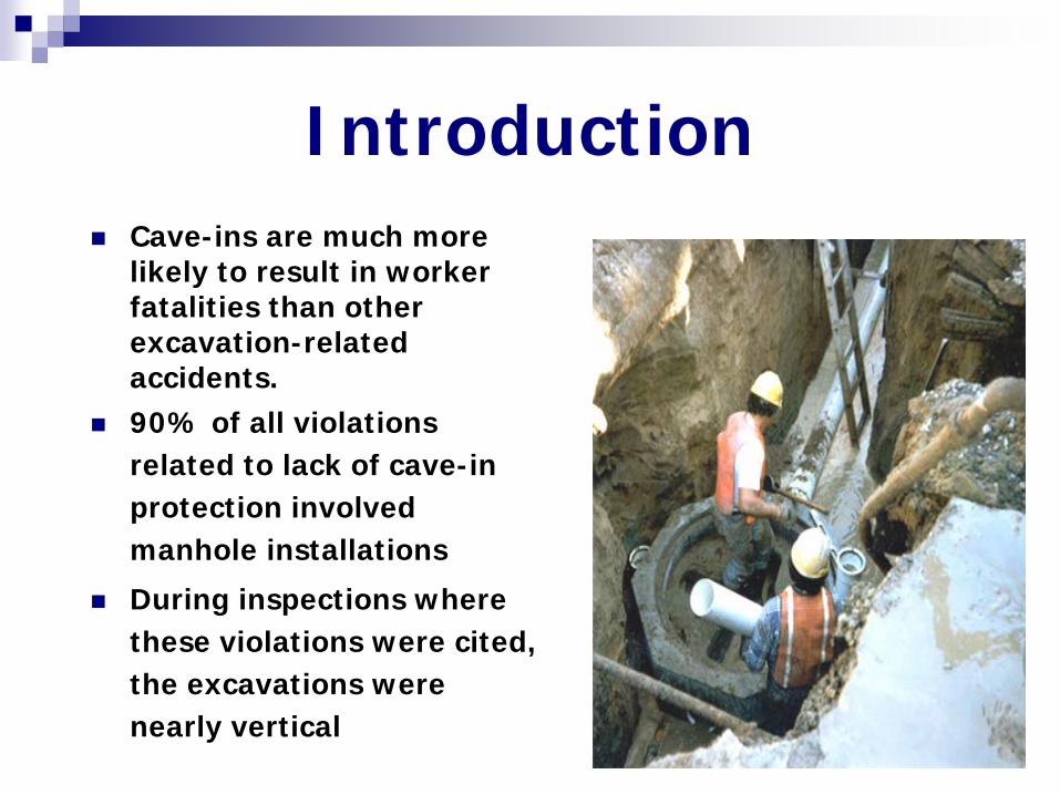
Cave-ins are much more likely to result in worker fatalities than other excavation-related accidents.
90% of all violations related to lack of cave-in protection involved manhole installations
During inspections where these violations were cited, the excavations were nearly vertical
Introduction
Excavation/Trenching Plan
Excavation/trenching plan will be submitted and accepted by the GDA prior to beginning operations.
Conditions
Excavations/trenches < 5ft (1.5m) in depth,
AHA is required but Plan optional
Excavations/trenches > 5ft (1.5m) in
depth, AHA and Plan required
Identification and credentials of CP Diagram or sketch of area where work to be done indicating
adjacent structures Projected depth of excavation Projected soil type and method of testing Planned method of shoring, sloping and/or benching Planned method of confined space entry, access, egress,
and atmospheric monitoring process Location of utility shut-offs (if required) Method for preventing overhead utility line damage, tree to
remain, or other features to remain Management of excavated soil/asphalt/concrete Traffic control Digging permits UXO clearance certificate Controlled flooding plan.
Plan Contents
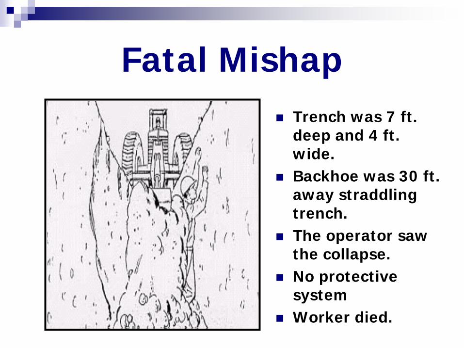
Fatal Mishap Trench was 7 ft.
deep and 4 ft. wide.
Backhoe was 30 ft. away straddling trench.
The operator saw the collapse.
No protective system
Worker died.
Remove all surface encumbrances
Determine location of all underground utilities before opening excavation
Use safe means to determine exact locations & protect underground utilities
If required, obtain “Digging Permit”
Excavation Requirements This image cannot currently be displayed.
Excavation Inspections
Competent person. Inspected daily. As needed through out shift. After every rainstorm or other
hazard- increasing occurrence. If cave-in hazard identified, work
stopped, workers removed !
Competent Person for Excavations:
• Training, experience, and knowledge
• Ability to detect.
• Authority to take prompt corrective measures to eliminate existing and predictable hazards and to stop work when required.
Definitions
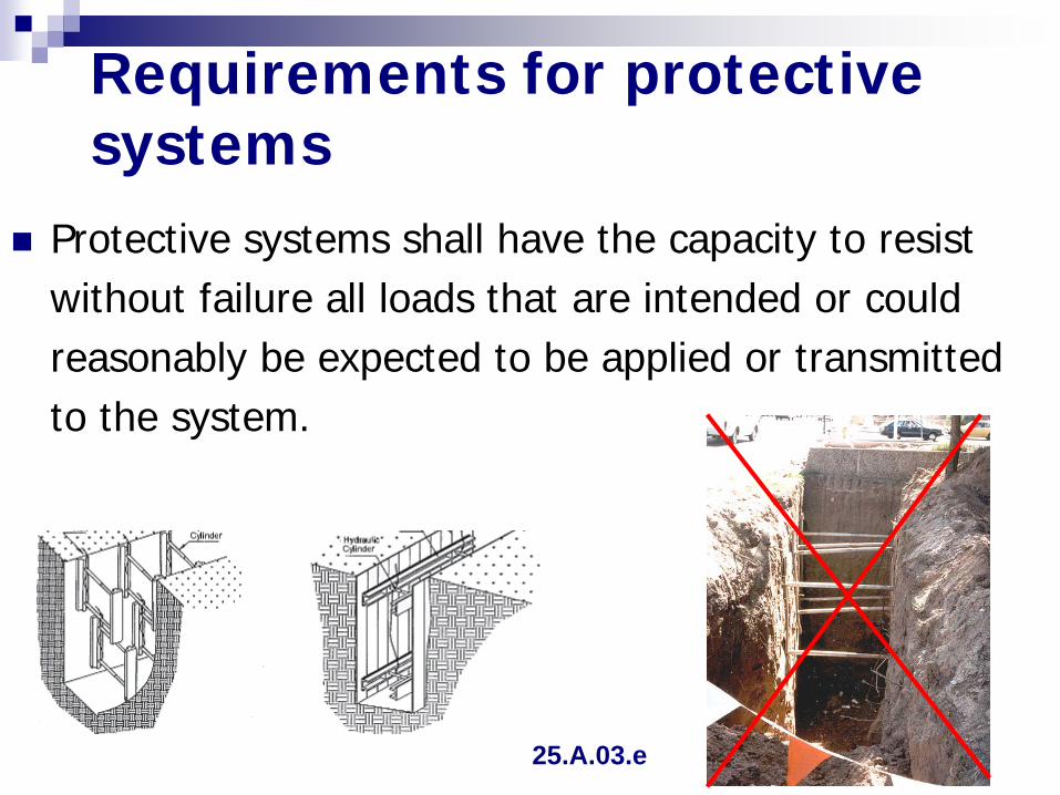
Requirements for protective systems
Protective systems shall have the capacity to resist without failure all loads that are intended or could reasonably be expected to be applied or transmitted to the system.
25.A.03.e
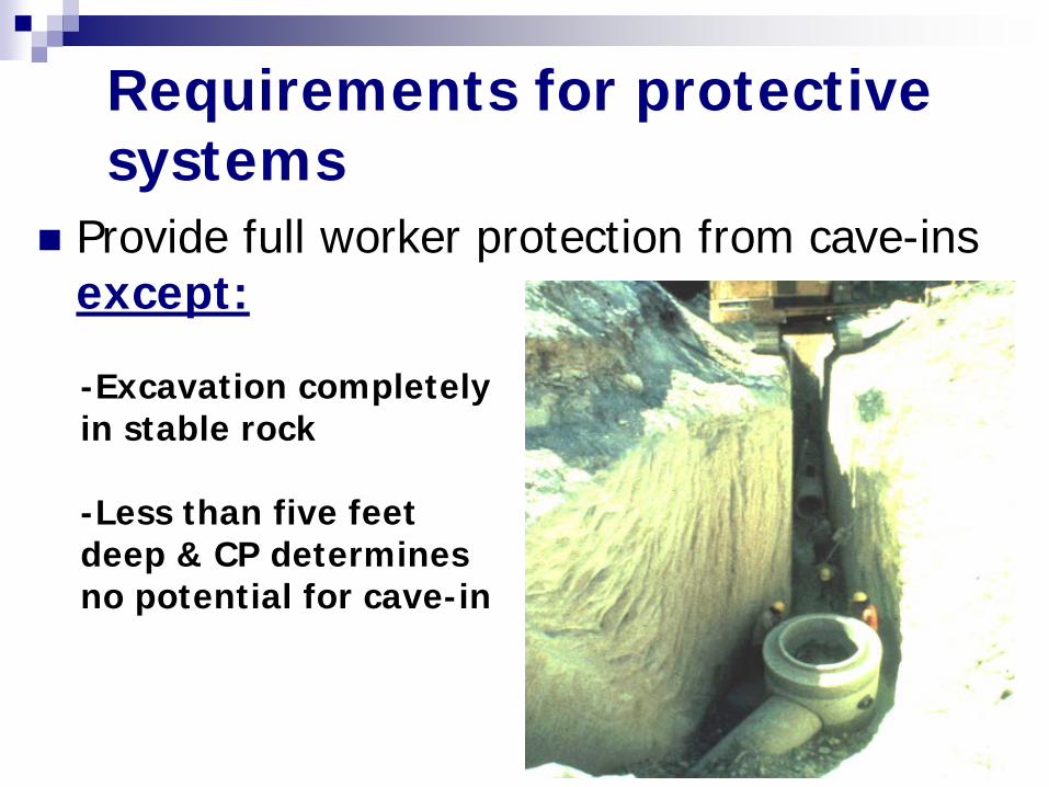
Provide full worker protection from cave-ins except:
Requirements for protective systems
-Excavation completely in stable rock -Less than five feet deep & CP determines no potential for cave-in
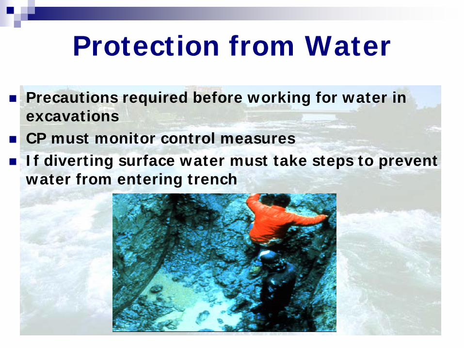
Protection from Water
Precautions required before working for water in excavations
CP must monitor control measures If diverting surface water must take steps to prevent
water from entering trench
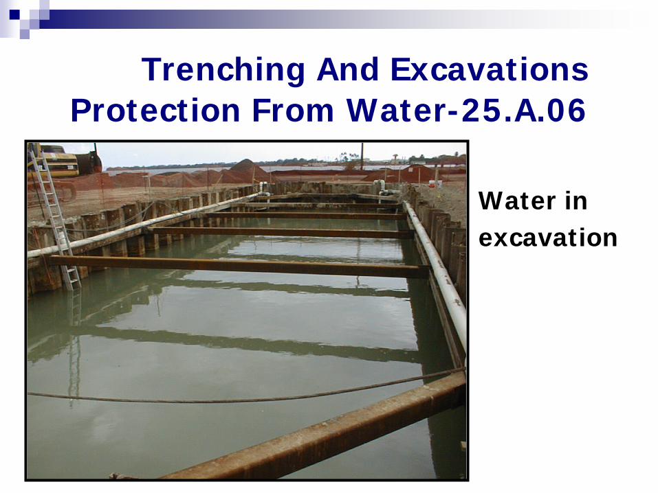
Trenching And Excavations Protection From Water-25.A.06
Water in excavation
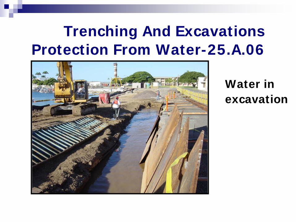
Trenching And Excavations Protection From Water-25.A.06
Water in excavation
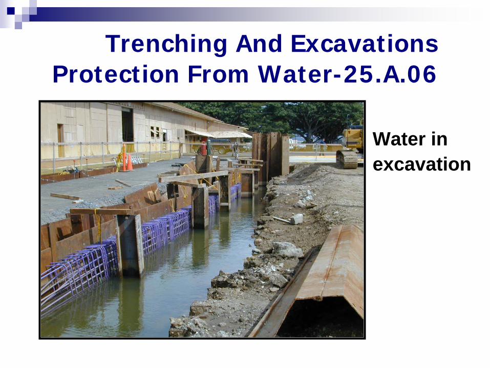
Trenching And Excavations Protection From Water-25.A.06
Water in excavation
Water in trench
Employees shall not work in excavations in which there is accumulated water or in which water is accumulating unless the water hazard posed by accumulation is controlled.
25.A.06.b
Falling Soil or Equipment
Protect workers from loose rock/soil that may fall from an excavation face
— Use scaling to remove loose soil — Use protective barricades, such as shoring
or shields Protect workers from material or equipment that
could fall into the excavation — Keep material/equipment 2 feet from edge — Use retaining devices
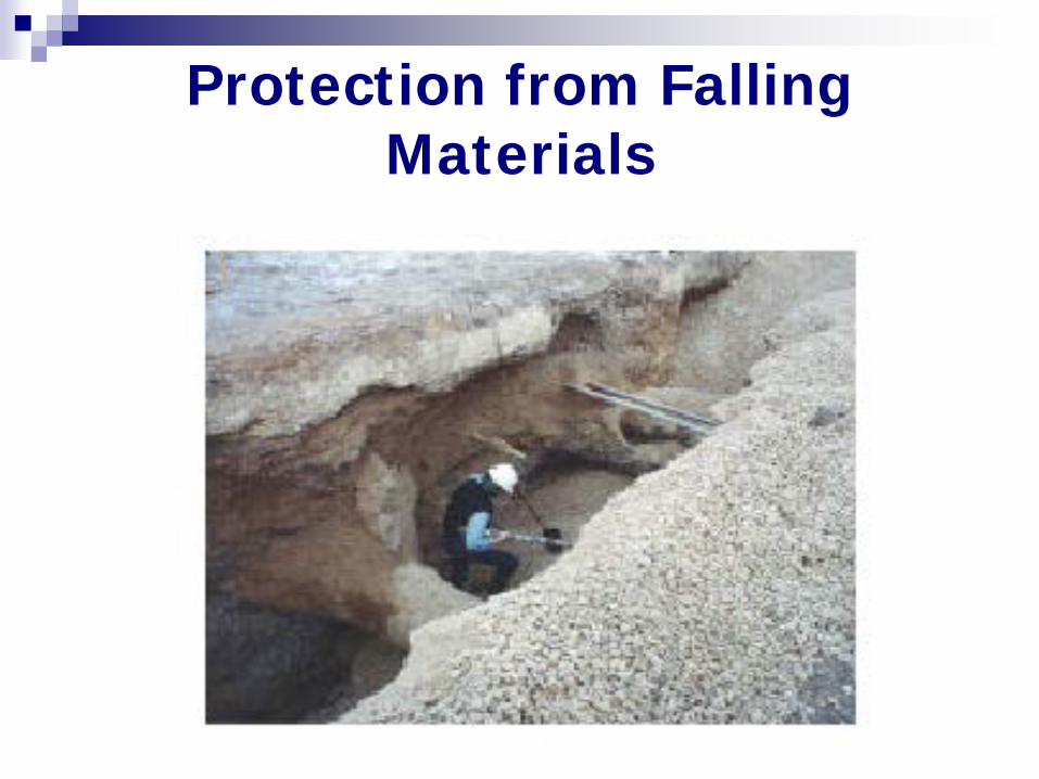
Protection from Falling Materials
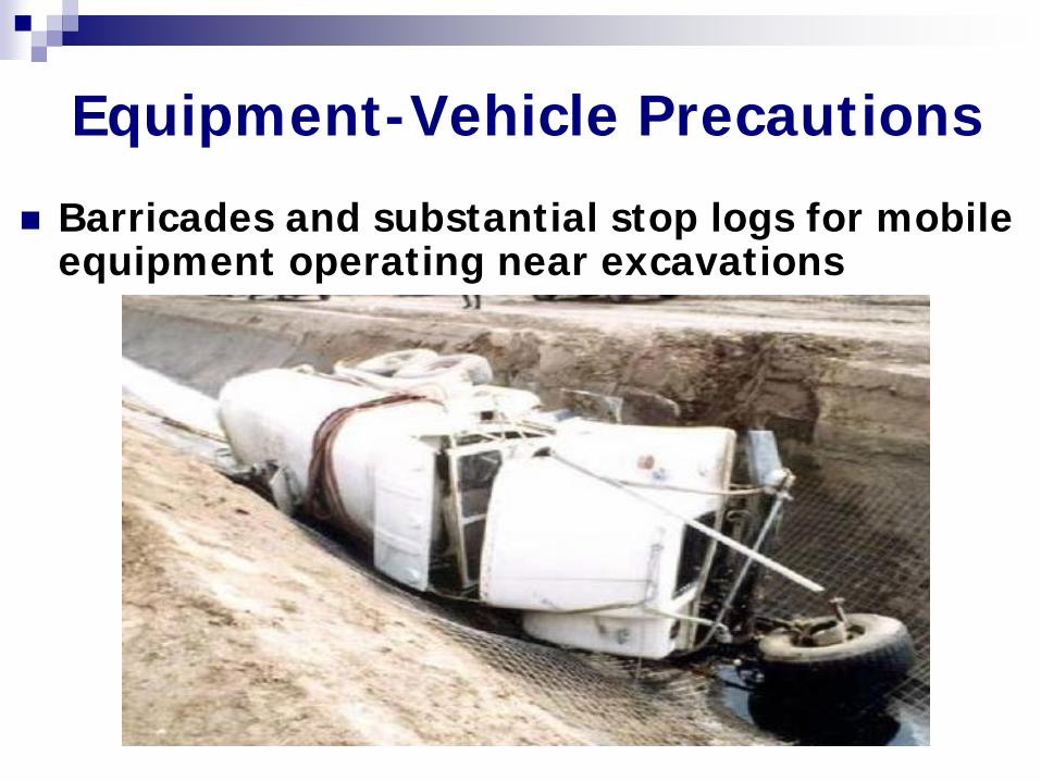
Barricades and substantial stop logs for mobile equipment operating near excavations
Equipment-Vehicle Precautions
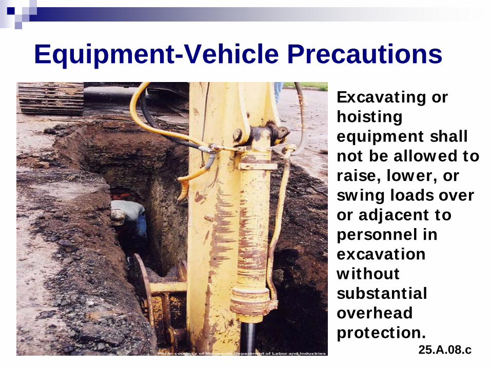
Excavating or hoisting equipment shall not be allowed to raise, lower, or swing loads over or adjacent to personnel in excavation without substantial overhead protection.
Equipment-Vehicle Precautions
25.A.08.c
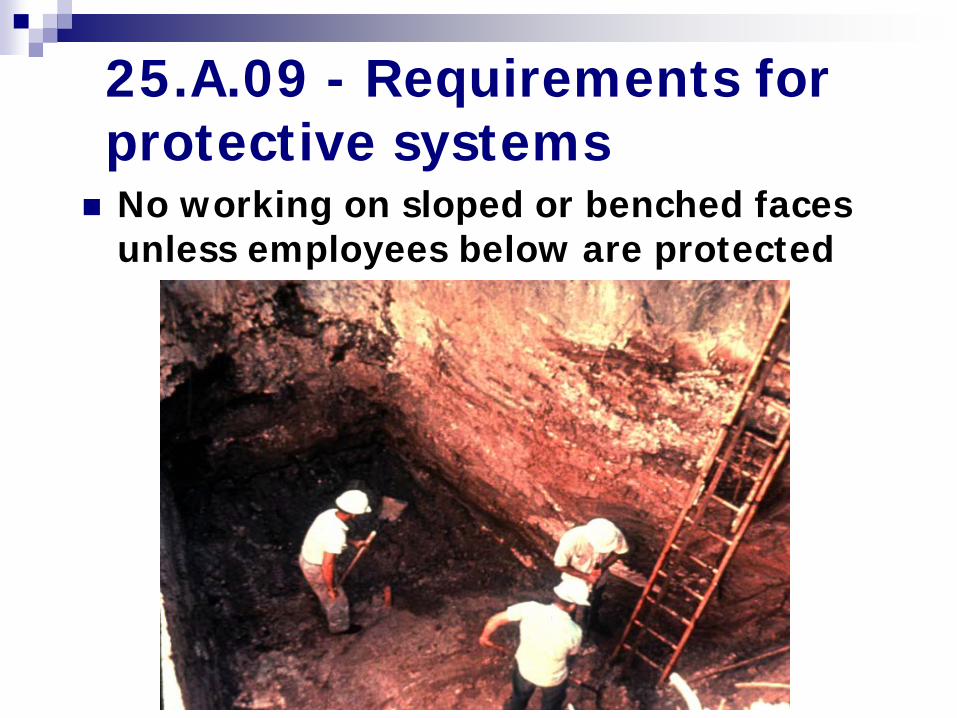
No working on sloped or benched faces unless employees below are protected
25.A.09 - Requirements for protective systems
Safe Access - 25.B Workers, vehicles, equipment and the
public must be protected. The public,vehicles or equipment
require class I perimeter guarding. Greater than 6 feet or other hazard and
worker exposure requires class II guarding.
If none of the above, at least class III. See definitions for type I, II, III
guarding.
Safe Access-25.B.01 Perimeter Protection Required Class I - Members of the Public or
Vehicles Class II - Contractor Employees/>6’ or Contain Hazard Class III - <6’, No Hazard, No Routine Contractor Employee Exposed
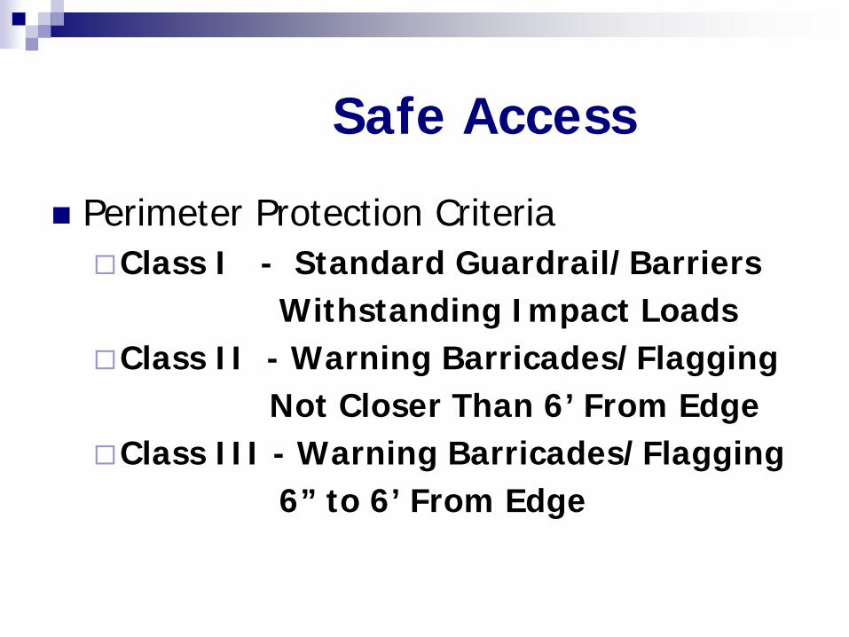
Safe Access
Perimeter Protection Criteria Class I - Standard Guardrail/Barriers Withstanding Impact Loads Class II - Warning Barricades/Flagging Not Closer Than 6’ From Edge Class III - Warning Barricades/Flagging 6” to 6’ From Edge
Safe Access-25.B
.03 - Excavations shall be backfilled as soon as possible
.04 - Walkways or bridges with guardrails shall be provided where people or equipment are required or permitted to cross over excavations
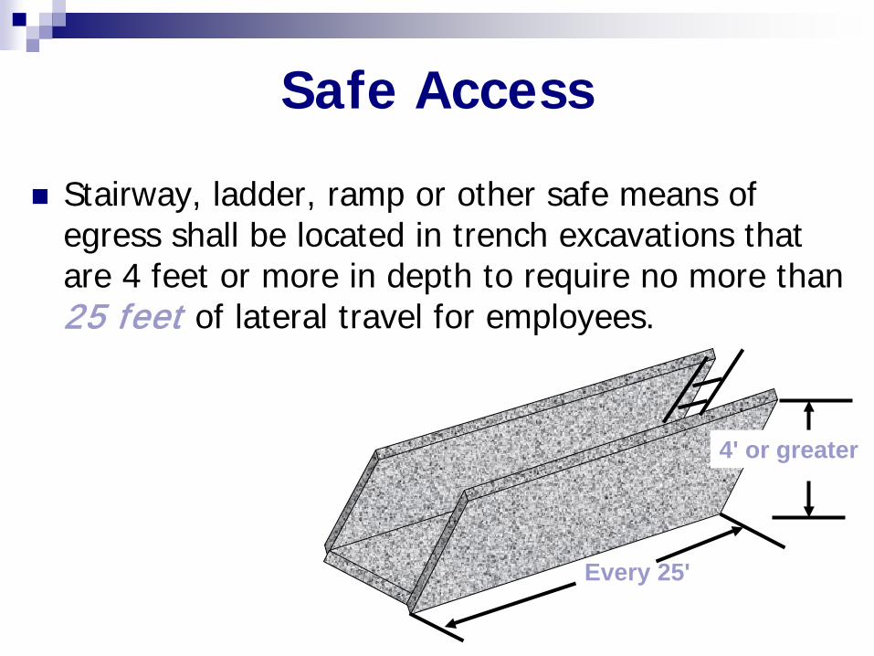
Stairway, ladder, ramp or other safe means of egress shall be located in trench excavations that are 4 feet or more in depth to require no more than 25 feet of lateral travel for employees.
Safe Access
Every 25'
4' or greater
Safe Access-25.B.05/07
At least two means of exit shall be provided for personnel working in excavations
Width of excavation exceeds 100 ft 2 or more means of exit for each side
Excavations 20 feet or more in depth Ramps, Stairs, or mechanical personnel hoists
Ladders used as access ways Shall extend 3 feet above the surface
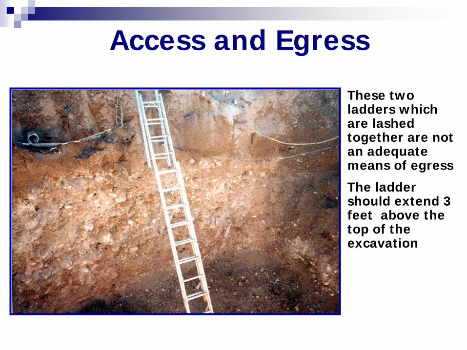
Access and Egress
These two ladders which are lashed together are not an adequate means of egress
The ladder should extend 3 feet above the top of the excavation
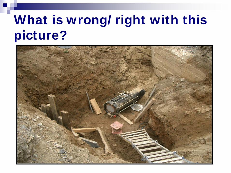
What is wrong/right with this picture?
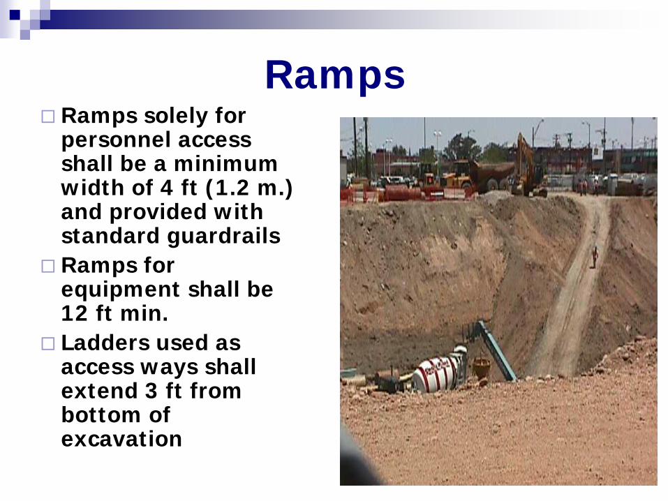
Ramps solely for personnel access shall be a minimum width of 4 ft (1.2 m.) and provided with standard guardrails
Ramps for equipment shall be 12 ft min.
Ladders used as access ways shall extend 3 ft from bottom of excavation
Ramps
What Is a Cave-in?
Soil or rock that suddenly falls or slides into an excavation
Sufficient quantity to entrap, bury, injure, or immobilize
Soil gravitates downward, pressure pushes soil inward toward the trench
Bottom third of wall typically fails first Soil above the collapsed lower wall follows
Cave-in Injuries
Soil weighs 125 lbs. per cubic foot
A worker can be crushed by soil, rock, or an object
Suffocation—even if worker’s head is not buried, soil prevents chest expansion
Worker becomes immobilized by soil’s suction effect
Sloping and Benching Options
Excavations less than 20 feet deep, maximum slope shall be 34 degrees measured from the horizontal (1 1/2 horizontal to 1 vertical).
Design selected from tabulated data (OSHA’s standard, Mfg’s specification)
Designed or approved by registered professional engineer.
Sloping and Benching
Sloping: angling of walls at an incline Benching: series of steps to angle walls Soil type determines angle of slope/bench
— Type A: 3 feet horizontal to 4 feet vertical (3/4:1) — Type B: 4 feet horizontal to 4 feet vertical (1:1) — Type C: 6 feet horizontal to 4 feet vertical (1-
1/2:1) — Benching not permitted for Type C soil
Support System Options
Timber, hydraulic and mechanical shoring systems etc..
Designs drawn form manufacturer’ s tabulated data.
From tabulated data (such as tables and charts such as OSHA’ s Standard).
Designed or approved by a registered professional engineer.
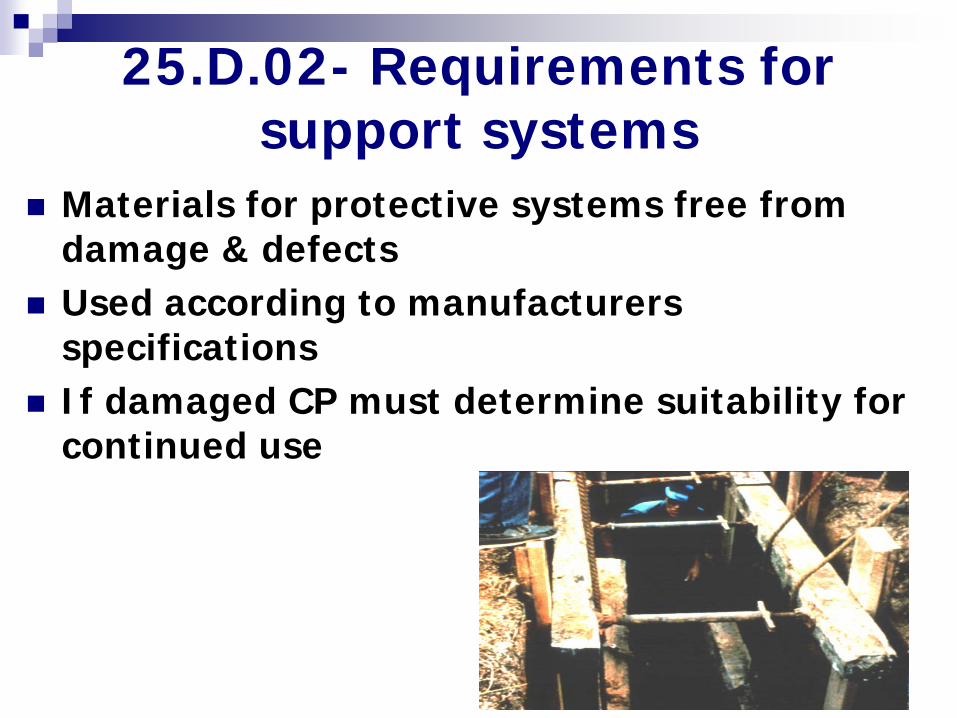
Materials for protective systems free from damage & defects
Used according to manufacturers specifications
If damaged CP must determine suitability for continued use
25.D.02- Requirements for support systems
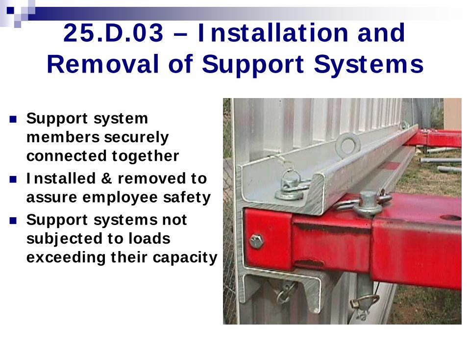
Support system members securely connected together
Installed & removed to assure employee safety
Support systems not subjected to loads exceeding their capacity
25.D.03 – Installation and Removal of Support Systems
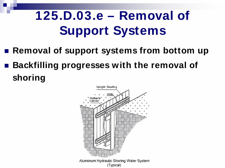
Removal of support systems from bottom up
Backfilling progresses with the removal of shoring
125.D.03.e – Removal of Support Systems
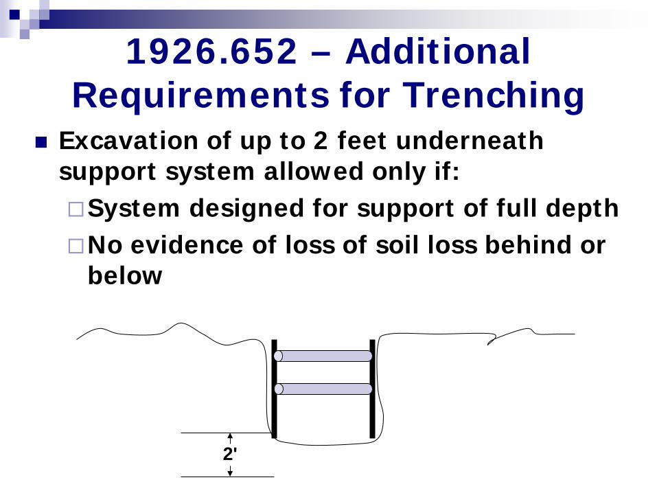
Excavation of up to 2 feet underneath support system allowed only if: System designed for support of full depth No evidence of loss of soil loss behind or
below
1926.652 – Additional Requirements for Trenching
2'
Soil Classification 29 CFR 1926 Appendix A 1926.652(b)(2) – Sloping &
Benching
1926.652(c) – Protective Systems
Competent Person Visual Test Manual Test
Soil Classification 29 CFR 1926 Appendix A Visual Test Observe soil as it is excavated. Soil
that remains in clumps when excavated is cohesive. Soil that breaks up easily and does not stay in clumps is granular.
Manual Test Penetrometer, Shear Vane, Plasticity,
Dry Strength, Thumb Penetration.
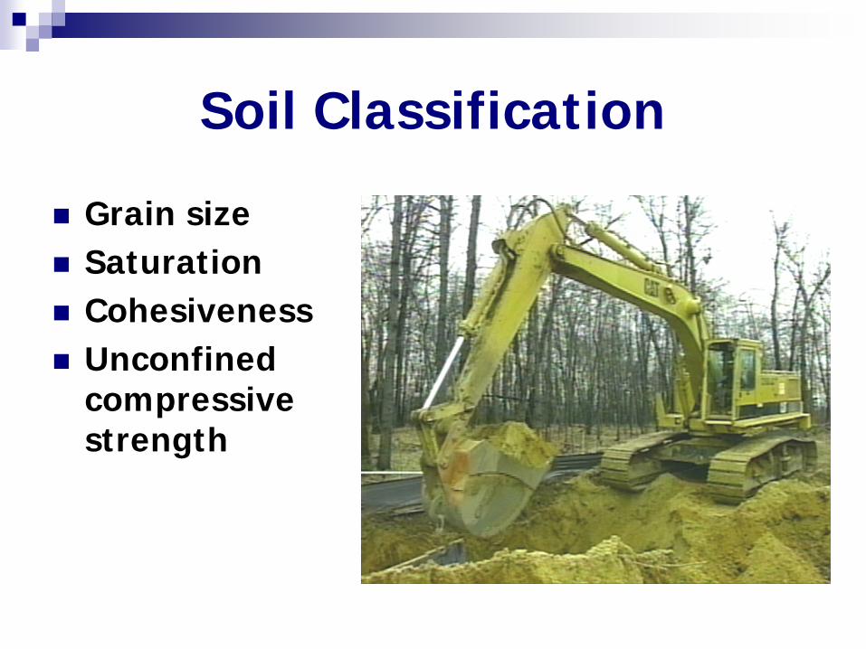
Soil Classification
Grain size Saturation Cohesiveness Unconfined
compressive strength
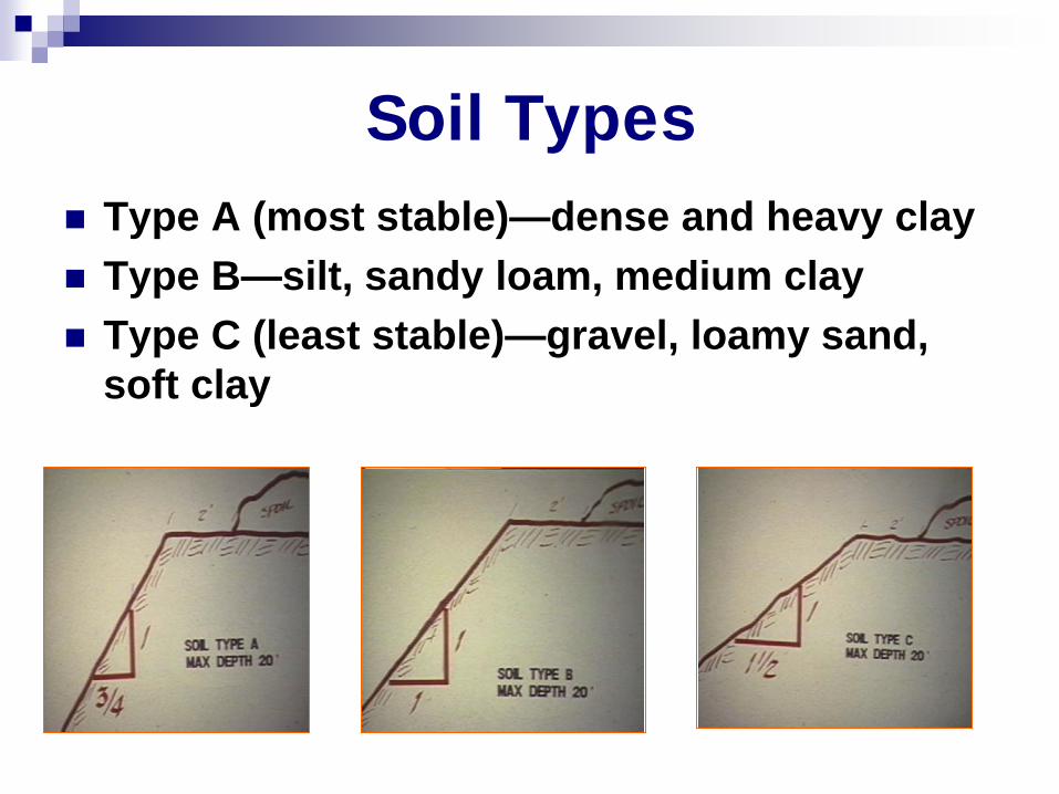
Soil Types Type A (most stable)—dense and heavy clay Type B—silt, sandy loam, medium clay Type C (least stable)—gravel, loamy sand,
soft clay
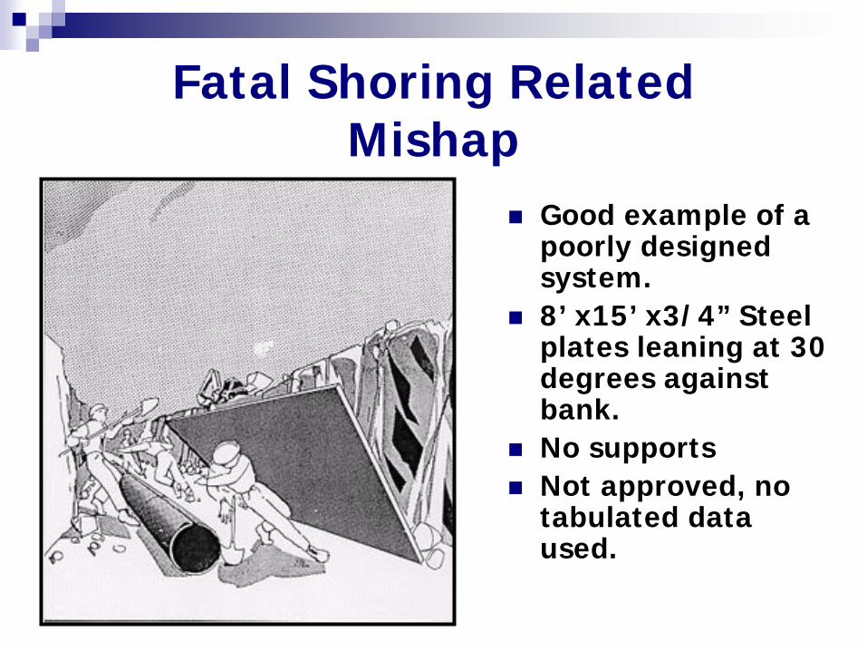
Fatal Shoring Related Mishap
Good example of a poorly designed system.
8’ x15’ x3/4” Steel plates leaning at 30 degrees against bank.
No supports Not approved, no
tabulated data used.
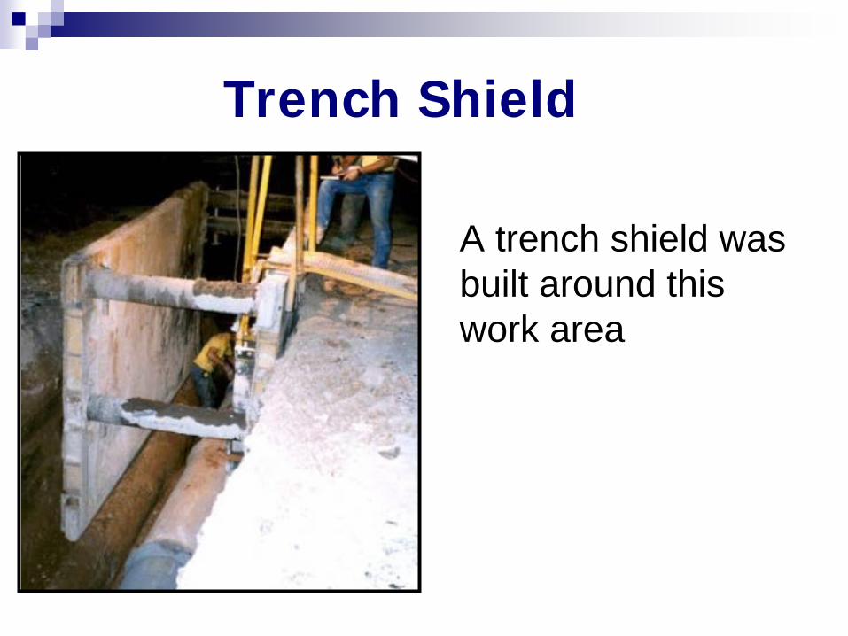
Trench Shield
A trench shield was built around this work area
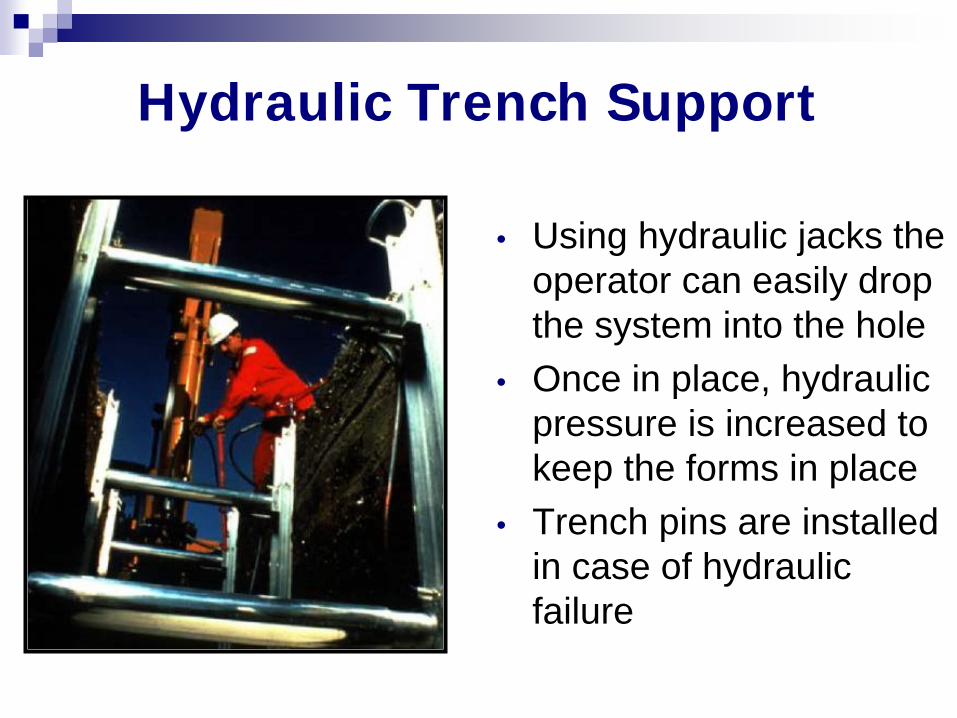
Hydraulic Trench Support
• Using hydraulic jacks the operator can easily drop the system into the hole
• Once in place, hydraulic pressure is increased to keep the forms in place
• Trench pins are installed in case of hydraulic failure
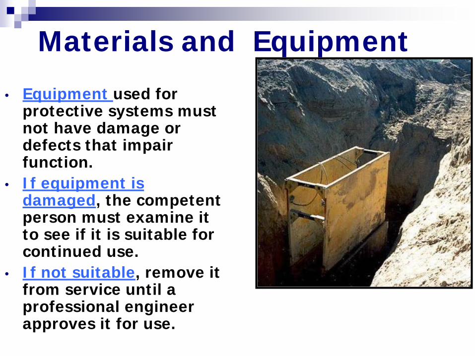
Materials and Equipment
• Equipment used for protective systems must not have damage or defects that impair function.
• If equipment is damaged, the competent person must examine it to see if it is suitable for continued use.
• If not suitable, remove it from service until a professional engineer approves it for use.
Summary Tone before you dig. Get a dig permit
where applicable. Classify soil and install proper protection
prior to entry of trench or excavation. Provide fall protection for employees
exposed to falls of 6 feet or greater. Provide members of the public protection.