AD-A245 013
COMPUTER AIDED DESIGN OF SOLDIER PILE AND LAGGINGRETAINING WALLS WITH TIEBACK ANCHORS
BY
KEVIN J. D'AMANDA RKiECTK9
,,v_____o_____
(o A REPORT TO THE GRADUATE CONK ITTE OF
THE DEPARTMENT OF CIVIL ENGINEERING INPARTIAL FULFILLMENT OF THE REQUIRD=ENTSFOR THE DEGREE OF MASTER OF ENGINEERING
o , (A)UNIVERSITY OF FLORIDA
FALL 1991
92 [5 O 2

IIII
COMPUTER AIDED DESIGN OF SOLDIER PILE AND LAGGINGRETAINING WALLS WITH TIEBACK ANCHORS
BY
KEVIN J. D'AMANDA
A REPORT TO THE GRADUATE COMMITTEE OFTHE DEPARTMENT OF CIVIL ENGINEERING INPARTIAL FULFILLMENT OF THE REQUIREMENTSFOR THE DEGREE OF MASTER OF ENGINEERING
UNIVERSITY OF FLORIDA
FALL 1991

ACKNOWLEDGEMENTS
I wish to express my gratitude to Dr. Townsend,
Dr. Davidson, Dr. McVay, and Dr. Bloomquist for their
support and for making their classes both challenging
and interesting while still enjoyable. Also to Jim
Hussin and the personnel at Hayward Baker for their
assistance in helping me prepare this program. Lastly
to the rest of the dungeon rats,
Barry "BATman" Mines;Dave "Mr. FDOT" Horhota;Dennis Vander Linde "Forces";Zan "The Zan Man" Bates;Craig "Cheats at Golf" Dunklenburger;Dave "Do I still have a desk?" Weintrub;Guillermo "Just one more year at UF" Ramirez;Pedro "Lost in Peru" Ruesta;Tove Feld "and Streams";and the rest of the crew;
thanks for being an island of lunacy in a sea of
sanity.
Aooession ForNTIS GRA&IDTIC TAB 0Unannrunced 5J, ut 11 rIcat in
D I -1b u c.-,'
Ai4i Idvl.ty C,:des, iA , , k and-'or[Dist 1 spoulal.

BIOGRAPHICAL SKETCH
Lieutenant Kevin J. D'Amanda, Civil Engineer
jCorps, U.S. Navy, was born and raised in Miami,Florida. He attended Miami Dade Community College and
jthe University of Miami earning a Associate in Arts
degree with highest honors in May 1982 and a Bachelor's
Degree in Civil Engineering, Magna Cum Laude, in
December 1984 respectively. Upon graduation, he was
commissioned an Ensign, U.S. Naval Reserve and
completed Officer Indoctrination School in Newport,
Rhode Island.
I Lieutenant D'Amanda's initial duty assignment was
as an Assistant Resident Officer in Charge of
Construction at Naval Air Station Atlanta from March
1985 to April 1988. In April 1988, he reported to
Naval Mobile Construction Battalion Sixty-Two where he
I served as Material Liaison Officer and as Assistant
Operations Officer. After the decommissioning of the
battalion in July 1989, he reported in Navy Support
Facility, Diego Garcia as the Public Works Planning
Officer from October 1989 to November 1990. After
I which, he reported to the University of Florida to
pursue a Master's Degree in Geotechnicai Engineering.
ii

iI
I Lieutenant D'Amanda is a registered engineer in
the states of Minnesota and Florida. Upon graduation,
he will report to Commander, Naval Construction
Battalions, U.S. Atlantic Fleet, at Norfolk, Virginia
for duty as Assistant Special Operations Officer.
Ii

II
ITABLE OF CONTENTS
I Pag~e
ACKNOWLEDGEMENTS ..................................... i
BIOGRAPHICAL SKETCH .................................. ii
LIST OF FIGURES ...................................... vi
LIST OF TABLES ....................................... ix
ABSTRACT .............................................. x
CHAPTER ONE - INTRODUCTION ........................... 1
1.1 Background ................................. 11.2 Computer Program Requirements .............. 31.3 Computer Language .......................... 4
CHAPTER TWO - BRACED EXCAVATIONS AND TIEBACKS ........ 6
2.1 Braced Excavations ......................... 62.2 Soldier Pile and Lagging ................... 92.3 Tiebacks Anchors .......................... 11
CHAPTER THREE - DESIGN THEORY ....................... 13
3.1 Lateral Earth Pressures in BracedExcavations ................................ 13
3.2 Active and Passive Earth Pressures ........ 183.3 Hydrostatic Pressure ...................... 18
3.4 Total versus Effective Stress Analysis .... 193.5 Surcharge Pressure due to a Strip Load .... 213.6 NAVFAC DM-7.2 Recommendation on Flexible
Wall Design ............................... 223.7 Other Design Considerations. ............... 23
3.8 Design Methodology for* Wall Analysis ...... 243.9 Tieback Anchor Capacity ................... 23.10 Minimum Unbonded and Total Anchor Length. 293.11 Lagging Thickness ........................ 33
iiv

TABLE OF CONTENTS (CONTINUED)
Page
ICHAPTER FOUR - COMPUTER PROGRAM .......................35
4.1 Program Flow and Logic ......................354.1.1 Main Function ....................... 354.1.2 Data Functions ...................... 444.1.3 Analysis Functions ...................45
4.2 Assumptions and Limitations .................484.3 Example Problems ........................... 51
ICHAPTER FIVE - USER'S GUIDE .......................... 52
5.1 Program Start-up ........................... 52I5.2 Input Data.................................. 535.2.1 Wall Data ........................... 545.2.2 Soil Data ........................... 545.2.3 Wall Analysis Data ...................555.2.4 Anchor Analysis Data .................56
5.3 Output Data................................. 56
15.4 Error Messages............................. 60CHAPTER SIX - CONCLUSICIS ............................ 63
6.1 Review of Objectives ....................... 636.2 Summary of Design Procedures ................636.3 Conclusions................................. 65
I APPENDICES
*APPENDIX A - VARIABLE NOMENCLATURE ....................66
APPENDIX B - COMPUTER PROGRAM FILE ....................71
APPENDIX C - CALCULATIONS AND EQUATIONS .............101
APPENDIX D - EXAMPLE PROBLEMS ....................... 117
IAPPENDIX E- REFERENCES ............................. 154
IV.

LIST OF FIGURES
Figure Page
1.1 Tieback Soldier Pile and Lagging Wallfor a Cut-and-Cover Station inPhiladelphia (FHWA/RD-82/047, 1982) ........ 2
3.1 Nature of Yielding of Retaining Walland Braced Cut (Das, 1990) ................ 13
3.2 General Pressure Distribution onBraced Excavation (Cernica, 1982) ......... 14
3.3 Pressure Distributions on BracedExcavations (NAVFAC DM-7.2) ............... 16
3.4 Draw Down of Ground Water Table inSands due to Natural Seepage orMechanical Dewatering (NYCTA, 1974) ....... 19
3.5 Conversion of a Strip Surcharge LoadI to an Uniform Pressure .................... 21
3.6 Effective Width of Soldier Pile thatI Passive Pressure Acts Upon (NYCTA, 1974).. 22
3.7 Force Diagram for Stage Two ofConstruction in Sands ..................... 25
3.8 Force Diagram with and without aTension Zone for Stage Two ofConstruction in Clays ..................... 25
I
II vi|

LIST OF FIGURES (CONTINUED)
FiQure PaQe
3.9 Pressure Diagram for Stage Three ofConstruction in Sands ..................... 27
3.10 Pressure Diagram for Stage Three ofConstruction in Stiff Clays ............... 27
3.11 Pressure Diagram for Stage Three ofConstruction in Soft to Medium Clays ...... 28
3.12 Force Diagram for Determining theEmbedment D-pth in Sands AssumingFixity about the Last Anchor Location ..... 28
3.13 Load Capacity of Anchors in CohesionlessSoil Showing the Effects of RelativeDensity, Gradation, Uniformity, andAnchor Length (FHWA/RD-75/128, 1976) ...... 30
3.14 Effect of Post-Grouting on AnchorCapacity in Cohesive Soils(FHWA/RD-75/128, 1976) .................... 31
3.15 Determination of the Unbonded and Total
Tieback Length (FHWA/RD-82/047, 1982) ..... 32
4.1 Computer Program's Flow Chart .......... 36-43
5.1 Main Menu Screen .......................... 52
5.2 Input Variables for Wall Analysis ......... 53
vii

II
I LIST OF FIGURES (CONTINUED)
I Figure PaQe
5.3 Sample Output File ...................... 57-58
I C.1 Average Load Capacity of Anchors inFine to Medium Sands ..................... 115
C.2 Average Load Capacity of Anchors inMedium to Coarse Sands ................... 115
C.3 Average Load Capacity of Anchors inI Sandy Gravel ............................. 116
iIIIIIIiI viii
I

LIST OF TABLES
Table Page
2.1 Steps in Engineering an Excavation(Lambe and Turner, 1970) ................... 7
3.1 Recommended Thickness of WoodLagging, Construction Grade Lumber(FHWA/RD-75/128, 1976) .................... 34
IIII
IIJi
I

ABSTRACT
Abstract of a Report to the Graduate Committee ofthe Department of Civil Engineering in Partial
Fulfillment of the Requirements for the Degree ofI Master of Engineering.
COMPUTER AIDED DESIGN OF SOLDIER PILE AND LAGGINGRETAINING WALLS WITH TIEBACK ANCHORS
By
KEVIN J. D'AMANDA
FALL 1991
Chairman: Dr. Frank C. TownsendMajor Department: Civil Engineering
I : Soldier pile and lagging walls are used to supportopen excavations and restrict lateral movementL. They
also provide an increased factgr o'- safety to nearby
structures and utilities against excessive deformations
and loss of bearing capacity. The soldier pile and
lagging wall consists of structure H-beams driven into
the ground with wood lagging installed between the
Iflanges of the beams to retain the soil. With the use
of tieback anchors as bracing, they can provide an
unobstructed area for construction.
The design of the soldier pile and lagging wall
consists of developing a pressure envelope for the soil
U conditions and determining the number and location of
U ,x
|
I x
I- the anchors for a given H-beam's section modulus. The
Ipressure envelopes for braced excavations differ fromRankine's active state. A braced excavation deforms
more laterally at the bottom of the excavation than the
top due to the installation of the anchors. 7Peck
1 (1969) developed pressure envelopes for braced
excavations which can be used for the design of a
retaining wall.
A C++ language computer program was developed to
optimize the design of the soldier pile and lagging
Iwall. The pressure diagrams for sand and claysdeveloped by Peck and tieback anchor capacity curves
from the Federal Highway Administration were used in
the program. Also referenced was Naval Facilities
Engineering Comnand, Design Manual 7.2, for flexible
wall design. -By varying the number and location of the
tieback anchors, the wall design may be optimized for
given soil conditions and wall requirements._
xi
I

I
CHAPTER ONE
INTRODUCTION
1.1 Backqround
Soldier pile and lagging retaining walls with
tieback anchors are used to support open construction
excavations and restrict lateral movements of the
surrounding soil. The wall provides a factor of safety
3 to nearby structures against any loss of bearing
capacity as the result of lateral movements. With the
use of tieback anchors, an unobstructed excavation for
construction can be provided. Figure 1.1 illustrates a
-- typical soldier pile and lagging wall with tieback
3 anchors. The basic design of the system is as follows:
a. Determine the given boundary conditions
3 indicating soil stratification, water level, slope of
the soil behind the wall, and surcharge loads.
b. Compute the lateral earth pressure diagrams
3 for the braced excavation including any pressure
diagrams from surcharge loads.
3 c. Design the components, which include the
soldier pile; wale; tiebacks; and lagging, based on the
I pressure diagrams.
I
I

The pressures diagrams for braced cuts differ
from lateral earth pressures obtained by Coulomb's or
Rankine's theory. Peck (1969) derived lateral earth
pressure diagrams for braced cuts in sands and clays
which can be used to calculate the maximum moment and
reaction forces for the design of the retaining wall
system.
F] --1-Exist ingBuilding
IIIITemporaryWall
Future
Temporary Station
Tiebacks ,
I
U Figure 1.1Tieback Soldier Pile and Lagging Wall fora Cut-and-Cover Station in Philadelphia
(FHWA/RD-82/047, 1982)
* 2I

I The basic concept of bracing an excavation is
based on the excavation causing the removal of a mass
of soil and water from a site. The ground water table
* may also be lowered outside and below the excavation to
accomplish the construction. Consequently, these
I actions will result in a total stress release and
movements in the surrounding soil. A retaining wall is
typically installed to control these movements.
Satisfactory performance of the wall requires that the
excavation periphery not have any excessive movements
or deformations. Moreover, deformations of the
surrounding soil may be limited so that adjacent
structures and utilities are not adversely affected.
* The factors that influence deformations include the
dimensions of the excavation, soil properties, ground
water control, time (time excavation open, time a
section is unbraced, etc.), support system, excavation
and bracing sequence, near-by structures and utilities,
and transient surcharge loads. (Lambe and Turner,
1970)
1.2 Comvuter Program Requirements
The design of soldier pile apd lagging retaining
walls requires the determination of the number and
I3I

location of tieback anchors for a given section modulus
-- of a soldier pile to ensure the pile is not
overstressed. This computer program was developed to
calculate the maximum moment of a soldier pile, depth
of embedment, and reaction forces based on the soil
I conditions, depth of the excavation, and location of
the tieback anchors. By varying the location and
number of the anchors, the design of the soldier pile
* wall may be optimized.
The computer program will also calculate the
required anchor capacities, bonded and unbonded
length of the tieback anchors, and the section
modulus of the wale system based on anchor spacing
and soil type. Tieback capacity and length is based
on pressure injected tiebacks in cohesionless soils
and post-grouted tieback anchors in cohesive soils.
I 1.3 Computer Language
The computer program was written and compiled in
Borland Turbo C++. C was originally developed in the
1970's for use with the UNIX operating system. The
definition of C was first presented in The C
I Programming Language, First Edition by Brain W.f
Kernighan and Dennis M. Ritchie in 1978. The
I 4
I

II
i American National Standards Institute (ANSI)
developed a new standard for the language five years
later which resolved ambiguities in it (Turbo C++
Users Guide, 1991). Turbo C++ implements the latest
ANSI standard for C. It is manufactured and a
i registered trademark of Borland International, Inc.
IIIIIIIII

CHAPTER TWO
BRACED EXCAVATIONS AND TIEBACKS
* 2.1 Braced Excavations
Braced excavation retaining walls are-used to
* support the sides of temporary excavations in various
construction applications. The vertical face of the
I cut is held open by the retaining structure until a
U permanent structure can be installed. The permanent
structure may include the basement of a building, walls
3- of a parking garage, or underground facilities. The
braced structure restricts the inward movement of the
I surrounding soil preventing settlement, collapse of the
3 excavation, and possible bearing capacity failure of
nearby structures. Table 2.1 lists the factors to be
3 considered in designing a braced excavation. The most
common methods of supporting a temporary excavation are
I sheetpile walls, drilled-in-place concrete piles,
3 slurry walls, and soldier pile and lagging.
Sheetpiles are driven into the ground prior to
excavation, interlocked forming a wall, and then the
soil excavated. They may be supported by struts or
I anchors as required. Drilled-in-place piles may be
* used with a spacing so that lagging is not required.
36

II
Table 2.1Isteps in Engineering an Excavation(Lambe and Turner, 1970)
Step Activity ConsiderationNo.
1 Explore and testsubsoil.
2 Select dimensions of Structure size andexcavation, grade requirements,
depth to good soil,depth to meet stab-ility requirements.
3 Survey adjacent Size, type, age,structures and location, andutilities, condition.
4 Establish permiss-ible movements.
5 Select bracing and Local experience,construction cost, time avail-sequence. able, type of wall,
depth of wall, typeand spacing ofbracing, and de-watering sequence.
6 Predict movementscaused by excavationI _and dewatering.
7 Compare predictedwith permissiblemovements.
8 Alter bracing andconstruction scheme,if needed.
9 Monitor constructionand alter bracingand construction asI _required.
I 7
I

Arching of the soil from the lateral pressures
developed by the pile will retain the soil across the
open spacing (Bowles, 1988). A slurry wall is
constructed when concrete is cast-in-placed in a cavity
retained open by a slurry liquid. After the concrete
cures, the soil next to the wall is excavated. Soldier
pile and lagging uses steel H-piles driven into the
ground prior to the actual excavation. Lagging is
placed between the piles as the ground is excavated.
The lagging may be either wood or steel members.
3 Anchors or struts are used to support the wall as the
excavation proceeds.
I If present, ground water acts against the wall and
Ithus contributes to the stresses which must be carriedby the wall. It also influences the effective stress
of the soil. The total force felt by the wall is a
combination of the hydrostatic force and the effective
I soil stress. If flowing water occurs, a seepage
3 analysis should be made. Factors which must be
considered in a seepage analysis includes the
3 permeability of the insitu soil, leakage through the
wall, flow parallel to the wall, excess pore pressures
3 generated by changes in total stresses, seepage forces,
and the time the excavation will be open and hence the
I8I

I degree of saturation. The actual pore water pressures
generated will typically be less than static pressures.
(Lambe and Turner, 1970)
2.2 Soldier Pile and LaQginQ
3 The procedure for constructing a soldier pile wall
is to drive the H-piles into the ground prior to any
U excavating. The piles are driven with the flanges
parallel to the proposed cut. They are usually spaced
between four and ten feet apart. When they have been
driven down to the desired depth (typically five to ten
feet beneath the proposed excavation bottom when in
soil), the excavation begins in stages. The first
U stage of the excavation is made to the location of the
uppermost str.. or anchor. Timber lagging, cut to fit
3 between the webs of adjacent soldier piles, is placed
in back of the front flanges of the piles. They are
set one piece of lagging on top of the other with only
-- a small spacer between them. Straw or a geotextile may
be placed between and behind the lagging to reduce
3 seepage through the wall. Once the lagging is set
down to the first strut level, a horizontal wale is
U installed against the piles and the struts or anchors
3 placed at the desired spacing. The excavation then
U 9
I

proceeds to the next strut level, with the process
continuing until the final excavation is reached.
(Keorner, 1984)
Primary components of a soldier pile and lagging
wall are as follows:
1. Soldier piles which may be either steel H-
beams, steel tubular pipes, concrete piles, or cast-in-
place concrete piles.
2. Support system of braced struts or anchors.
Anchors may be cast-in-place deadman, piles used as
anchors, sheetpile wall sections, or tieback anchors.
3. Wales which distribute the anchor force as
a line load between the soldier piles. They are
usually structural steel sections.
4. Wood or metal lagging which supports the soil
between the piles. (Boghrat, 1989)
Advantages of using soldier pile and lagging walls
include fewer piles, the lagging does not have to be
extended below the excavation bottom, and the soldier
piles can be driven easier in hard ground than can
3 sheetpile sections. By varying the spacing of the
soldier piles, underground utilities may be avoided.
Also the use of heavy sections for piles will allow
wider spacings of wales and bracing. (Merritt, 1976)
* 10U

2.3 Tieback Anchors
Temporary tieback anchors are used to support the
sides of deep excavation retaining structures. Tieback
systems deform less than strut braced excavations
because; (a) a force at or above the active earth
pressure is locked off in every tieback, (b) tieback
construction does not require over excavation, (c)
tiebacks are not subject to significant temperature-
caused deformations or loads, and (d) rebracing is not
required for tieback walls. When the depth of the
excavation exceeds fifteen to twenty feet and the width
exceeds sixty feet or when obstructions significantly
impact construction, tieback walls are usually less
expensive than strut braced support systems. Tieback
walls provide a clean open excavation for construction.
Internally braced walls interfere with excavations,
concrete work, structural steel placement, and
backfilling. (FHWA/RD-82/047, 1982)
Some disadvantages of a tieback anchor system may
include obtaining permission for the placement of the
anchors in the property of a municipality or a private
owner. The location of the anchors may be outside the
boundaries of the project where soil properties were
not obtained. Achieving a satisfactory anchorage
11
capacity in soft clays or submerged sands may also be
difficult to achieve. (Clough, 1972)
The capacity of tieback anchors is dependent on
the size and shape of the anchor,. tendon type and size,
insitu soil properties, and installation and grouting
method of the anchor. Design of a tieback system
should include the following:
I a. a tieback feasibility evaluation,
b. an evaluation of the risk and consequences
of failure,
c. the selection of a tieback type,
d. the estimation of the tieback capacity,
e. determination of the unbonded and total
tieback length,
f. selection of a corrosion protection system,
g. selection of a tieback testing procedure,
and
I h. establishment of an observation and monitoring
system. (FHWA/RD-82/047, 1982)
Federal Highway Administration report number
FHWA/RD-82/047, Tiebacks, provides detailed guidance
and design procedures for tiebacks.
II
* 12

CHAPTER THREE
DESIGN THEORY
3.1 Lateral Earth Pressures in Braced Excavations
When sufficient yielding of a retaining wall
occurs, the lateral earth pressure can be approximated
by Coulomb's or Rankine's theory. However, braced
excavations yield differently than conventional
retaining walls. Figure 3.1 depicts the different
deflections of the two wall types. The deformation of
a braced wall gradually increases with the depth of
excavation. The variation of the amount of deformation
will depend on the type of the soil, depth of the
excavation, and construction of the wall.
IRtaining Wiall Bracirq Cut
3 Mall al Iwe1tIM Oflection
3 Dot t(M of Cut
Figure 3.1Nature of Yielding of Retaining Wall anJ
Braced Cut (Das, 1990)
13
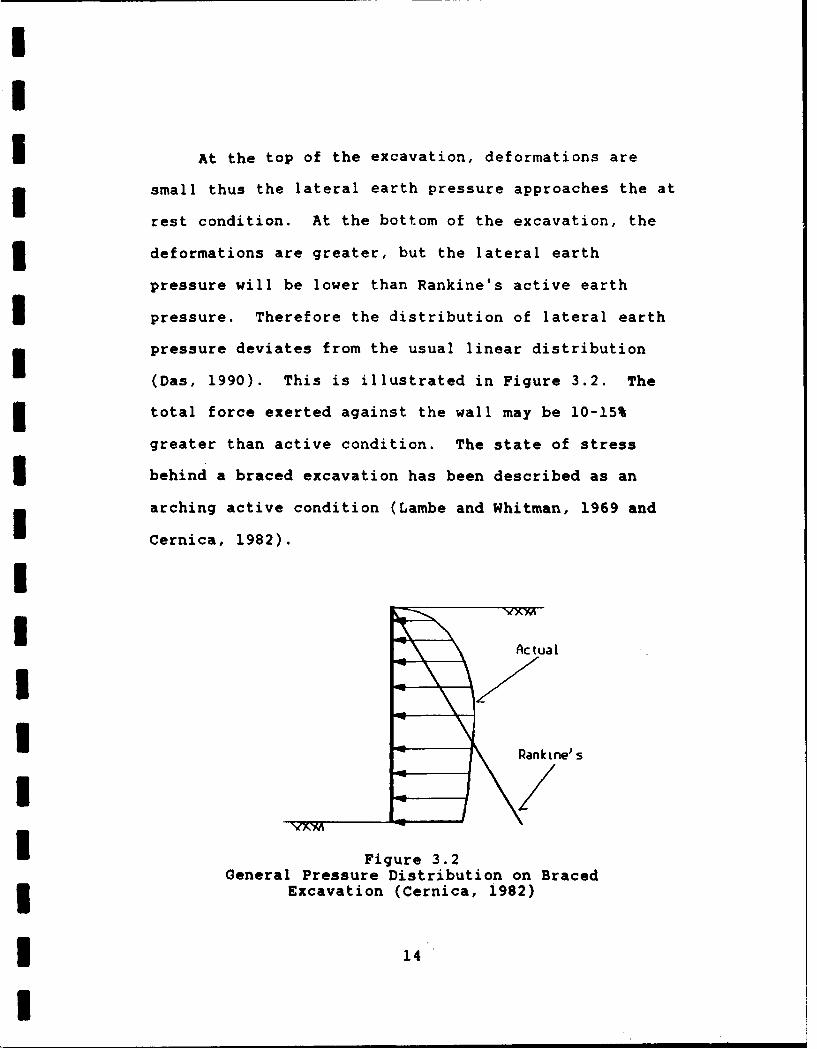
At the top of the excavation, deformations are
small thus the lateral earth pressure approaches the at
rest condition. At the bottom of the excavation, the
deformations are greater, but the lateral earth
pressure will be lower than Rankine's active earth
pressure. Therefore the distribution of lateral earth
pressure deviates from the usual linear distribution
(Das, 1990). This is illustrated in Figure 3.2. The
total force exerted against the wall may be 10-15%
greater than active condition. The state of stress
3 behind a braced excavation has been described as an
arching active condition (Lambe and Whitman, 1969 and
UCernica, 1982).U
I Actual
U Rankine's
IFigure 3.2General Pressure Distribution on Braced3Excavation (Cernica, 1982)
314

The pressure envelopes proposed by Terzaghi and
Peck (1967) and as recommended by NAVFAC DM-7.2 (1982)
are assumed for the design conditions within the
3 program. The earth pressure envelopes for braced walls
in sands, soft clays, and stiff clays are illustrated
in Figure 3.3. For stiff clays, NAVFAC DM-7.2 (1982)
recommends horizontal stresses between 0.2 and 0.4' H.
IThe value of 0.47 H is used within the program. The
3stability number is calculated as Ns = I H/c. Where
is the unit weight of the soil, H is the depth of the
3 excavation, and c is the undrained shear strength of
the soil. Characteristics of these pressure envelopes
Iinclude:3 a. They apply to excavations deeper than twenty
feet.
b. The pressure envelopes assume the water table
is below the bottom of the cut. Sands are assumed to
I be drained with the lowering of the ground water table
behind the wall. Clays are assumed undrained and under
short-term conditions.
3 c. Lateral stresses are apparent stresses which
are to be used for the calculations of the reaction
I loads.
II 15
I

II
I d. The behavior of an excavation in clays depends
3on its stability number. (Lambe and Turner, 1970)
ISAND SOFT - MEDIUM STIFF CLAY
CLAY
O.25H 25H
H O.7H 01H
I 4---0.25!l/
I 0.65Ka a ut a H Ka u ut x H 0.1 ut U HKa I - (4c/utiH)IFigure 3.3
Pressure Distributions on Braced Excavations(NAVFAC DM-7.2)
The apparent stresses are for entire sand or clay
I layering only. Engineering judgment should be used for
tills, silts, or fills; varying soil type with depth;
and when hydrostatic stresses act on the wall.
3 Lambe and Turner (1970) concluded that predicting
the behavior of braced excavations cannot be made with
I3 16
I

3 complete confidence. This is the result of difficulty
in selecting the proper soil parameters, field boundary
I conditions, and the details of construction. However,
3 Ulrich (1989) concluded that the recorded pressures for
overconsolidated clays agree with those developed by
3 Peck (1969). Ulrich also noted that soil
stratification does not have a significant influence on
Ithe apparent earth pressure in overconsolidated clays.3In another case study in Washington D.C. where the soil
stratification was layers of sands, silty sands, and
3 stiff silty clays, the measured earth pressures fell
within the apparent earth pressure envelope of 0.21H
I for clays (Chapman et al., 1972). Results from other
* excavations in the Washington area revealed that the
apparent earth pressure coefficient varied with the
3 depth of the cut. A value of 0.15T H for a thirty foot
cut, 0.2T H for a forty to fifty foot cut, and 0.231 H
I for a sixty foot cut (Chapman et al., 1972). The
* design of braced cuts is predominately based on
pressure diagrams derived empirically as a result of
3 field tests. Sound engineering judgement should be
used in determining the applicability of a given
I pressure diagram for a particular cut.
13 17
I

II
I 3.2 Active and Passive Earth Pressures
For the initial two stages of construction, the
soldier pile wall will develop earth pressures
3 approaching the active and passive states. In granular
soil, the soil is assumed to be drained and active
earth pressures are developed as the wall deforms
laterally. This is resisted by the passive resistance
which is developed as the H-beam compresses the soil
* acting on an effective area of three times the width of
the H-beam below the bottom of the excavation. However
there exists some uncertainty of how the pressures act
at and below the excavation line (Bowles, 1988). The
active and passive earth pressure coefficients are
3 calculated assuming Rankine's theory.
In the case of cohesive soils, undrained
3 conditions (f = 0) are assumed with no frictional
resistance developed. The stresses in the tension zone
are neglected in the design computations with the depth
3 of the tension zone taken as zt = (2*c-q)/ b'
3 3.3 Hydrostatic Pressure
Hydrostatic pressure is calculated as the unit
I weight of water (62.4 pcf) multiplied by the height
3 of the water table. It is assumed in the program
I 18
I

that sand and gravels are drained and the water table
will be drawn down to the bottom of the excavation by
natural seepage or mechanical dewatering. This is
illustrated in Figure 3.4. Clay layering is assumed to
be undrained and analyzed using either a total or
effective stress analysis approach.
6rond Surface
,4WtND - OPJAINED 'A
Oriqinal Grouid Water Surface
3ottm of Lt
Water table draun dow tobottom of cut due to seepawthrough tirdber sheetinq ormechanical deuateriLn.
Figure 3.4
Draw Down of Ground Water Table in Sandsdue to Natural Seepage or Mechanical3- Dewatering (NYCTA, 1974)
3.4 Total versus Effective Stress Analysis
*Some question on how to analyze the wall is raised
when the ground water table is located above the bottom
Iof the excavation in clay layering. The apparent
3 lateral earth pressure envelopes proposed by Peck are
* 19
I

Ibased on empirical data from total stress analyses.The use of a buoyant unit weight rather than the total
unit weight of the soil and superimposing hydrostatic
pressure onto the earth pressure diagrams change the
analysis to an effective stress analysis approach.
However the total stress soil parameter of undrained
shear strength is still used. Therefore this effective
stress analysis approach is not entirely correct.
Either a total or effective stress analysis
approach may be used to design the wall. In the case
of a total stress analysis, the saturated unit weight
above and below the water table should be entered. For
an effective stress analysis approach, the saturated
unit weight above the water table and the buoyant unit
weight below the water table should be used. The
I location of the ground water table for the effective
stress analysis must therefore be located above the
bottom of the cut.
Generally, the results from using the total unit
weights (total stress approach) are more critical
3loading conditions than the approach adapted by usingbuoyant unit weights (Liao and Neff, 1990).
I3 20

III
I3.5 Surcharge Pressure due to a Strip LoadTo account for the lateral pressures due to a
strip surcharge load located at some distance from the
I wall face, an equivalent uniformly distributed pressure
acting on the wall is developed. The total force
I exerted by the strip load on the wall is calculated andthen converted to a uniform pressure by dividing the
total force by the height of the wall. The force is
I calculated by the equations derived by Jarquio (1981)
and as illustrated in Figure 3.5.IFROM: TO:I b
_ _ q
iq =/
II
02
I
P 2q h p -82-0182 = arctia I ( a + b ) /h II1 = arclan I b / h ]
U Figure 3.5Conversion of Strip Surcharge Load to an Uniform Pressure
I* 21

3.6 NAVFAC DM-7.2 Recommendations on Flexible Wall
Des i ar,
The following recommendations from Naval
Facilities Engineering Command, Design Manual 7.2
(1982) were considered in the programming.
a. The total resistance force acts on an
effective area of three times the flange width of the
pile (3*bf) as shown in Figure 3.6. This is to account
* for the differences between the failure in soil of an
individual pile element and that of a continuous wall
* for which pressure distributions were derived.
bf
I _
3 bf
Figure 3.6Effective Width of Soldier Pile that Passive
Pressure Acts Upon (NYCTA, 1974)
b. For temporary construction, a factor of safety
of 1.5 should be applied to passive pressures. This
option is available within the program but it is not
recommended. Passive resistance is calculated using
3 Rankine's theory which is already conservative compared
* 22
I

I
I
I to a logarithmic spiral failure surface approach to
estimate passive resistance.
c. Neglect the soil resistance to a depth of 1.5
times the pile width from the bottom of the excavation
for clays and the depth of the pile width for sands.
This, however, is not accomplished in the program. It
was considered that significant conservativeness
already exists within the wall design.
d. The required depth of embedment is calculated
based on controlling the moment within the section to
ensure the pile is not overstressed at the final
anchor location. The active soil pressure will be
I resisted by the passive pressure and the allowable
* moment of the section.
3.7 Other Desion Considerations
Other design considerations included within the
* program are:
a. To calculate the anchor reactions, it is
assumed the piles are hinged at the bottom of the
* excavation and at all the anchor locations except the
upper anchor. The soldier pile between each pair of
I hinges is assumed to be a simply'supported beam
(Bowles, 1988 and Das, 1990).
* 23
I

I
b. An allowable stress for the steel soldier
piles of 28,800 psi is used to calculate the required
section modulus.
c. Wales are designed assuming they act as simply
supported beams, pin-ended with maximum moments equal
I to w*12/8. This moment is then increased by 33% to
allow for overstressing during preload testing of the
anchors. An allowable stress for the steel of 28,800
3 psi is used to calculate the section modulus from the
maximum moment.I3.8 Design Methodology for Wall Analysis
For the first two stages of construction, the
active and surcharge forces are being resisted by the
passive and reaction (stage two) forces. The reaction
force is calculated by summing moments about the point
of net zero forces on the embedded pile assuming it is
I hinged there and thus zero bending moment. The maximum
3 moment within the pile can be calculated by summing the
moments about the point of zero shear. From the
3 maximum moment, the required section modulus is
calculated. The embedment depths are calculated for
stage one by determining the point where the net moment
3 is zero and for stage two by assuming fixity at the
* 24
I
i
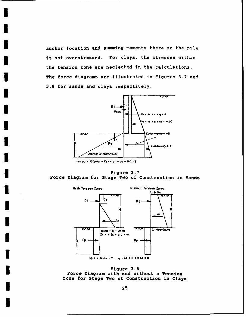
I anchor location and summing moments there so the pile
is not overstressed. For clays, the stresses within
the tension zone are neglected in the calculations.
The force diagrams are illustrated in Figures 3.7 and
3.8 for sands and clays respectively.
I °P I
I __=.. Ph - Ka w s 5 q ,,N
x KafEtfot,2
net pp = (3pAs - Ka) a bi u si a 2 4
Figure 3.7I Force Diagram for Stage Two of Construction in Sands
ith Tretin Zorw: Without Tersion Zare:(t -2t )INS
I Z( P 1-
I F r 3Pa
1 a5
M (utU4* q - 20)I -
ZI x C 2c - q )-ut
I a~Pp (6ucfs+*2c- q-Ut'of N)EUbE 90
Figure 3.8Force Diagram with and without a Tension
Zone for Stage Two of Construction in Clays
I 25
II
I Kiewit design procedures are also used to
calculate the maximum moments and reaction force for
the initial two stages of an excavation. Kiewit
procedures were developed by Peter Kiewit Sons'
Company based on empirical data and field results.
3 In the first stage, it is assumed that a pinned
connection exists in the pile two feet below the
bottom of the excavation. The maximum moment is
calculated at this point. In the second stage, the
maximum moment is taken as M = w*12/9. Where w is the
* average pressure on the span from the first anchor to
the bottom of the cut and 1 is the distance between t:;eI anchor and the bottom of the cut. The reaction force
* is calculated assuming pinned connections at the anchor
location and the bottom of the cut.
After the second anchor is in place, the pressure
distribution will correspond to those for braced cuts.
I Reaction forces are calculated by assuming pinned
connections and summing moments about the anchor
locations. Next the point of zero shear is found and
3 moments summed about it to calculate the maximum
moment. The pressure diagram for sands is depicted in
I Figure 3.9 and in Figures 3.10 and 3.11 for clays.
Embedment depth is determined by summing moments at the
3 26
I

I last anchor point assuming fixity so the pile is not
overstressed. This is illustrated in Figure 3.12 for
sands.
siqs sigh~__________
PP=3KjPfs 9 IwtbfIO2/2)
Figure 3. 9Pressure Diagram for Stage Three of Construction
in Sands
Da0. 4 S u
0. 25H p
PP Wv W6AS + 2c - q) I bf
I Figure 3.10Pressure Diagrams for Stage Three of Construction
* in Stiff Clays
* 27

II
-pa = Ka I ut 1 H
-Ka = 4c / (ut N H)
I 0. 25H p
u = S w utu I hu
0 0. 75HF
P12 - - Khu
I YNX4 " -
I -1 pp net (6cAs + 2c - q) N bf
Figure 3.11Pressure Diagram for Stage Three of Construction
in Soft to Medium Clays
I iMmax
NC[j] PAI Ka U s a (0.65utUh + q) R H'
I H'/2
I 2/3D + H' j__H
Pp 3Kp/fs*(utwbf"D"2/2)
PpI p
3 Calculate D - tlax + Ppa(2/3D * I') - PA IR /2 = 0
Figure 3.12Force Diagram for Determining the Embedment Depth in
in Sand Assuming Fixity about the Last Anchor Location
* 28
I
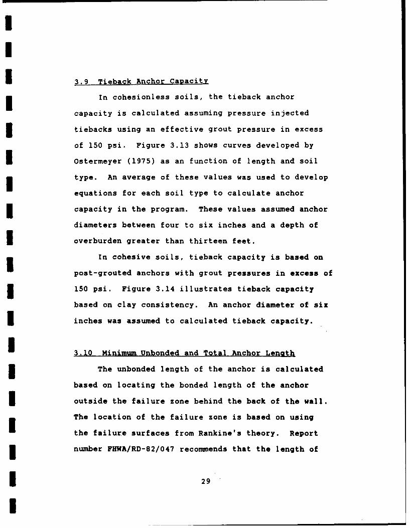
3.9 Tieback Anchor Capacity
3 In cohesionless soils, the tieback anchor
capacity is calculated assuming pressure injected
tiebacks using an effective grout pressure in excess
of 150 psi. Figure 3.13 shows curves developed by
Ostermeyer (1975) as an function of length and soil
type. An average of these values was used to develop
equations for each soil type to calculate anchor
capacity in the program. These values assumed anchor
diameters between four to six inches and a depth of
I overburden greater than thirteen feet.
In cohesive soils, tieback capacity is based on
post-grouted anchors with grout pressures in excess of
150 psi. Figure 3.14 illustrates tieback capacity
based on clay consistency. An anchor diameter of six
3inches was assumed to calculated tieback capacity.
I 3.10 Minimum Unbonded and Total Anchor Lenoth
The unbonded length of the anchor is calculated
based on locating the bonded length of the anchor
I outside the failure zone behind the back of the wall.
The location of the failure zone is based on using
the failure surfaces from Rankine's theory. Report
3number FHWA/RD-82/047 recommends that the length of
!29

A Very Dense
in 300
3 Uenj Dense
fled. Dense
* 443 red. Dense
10- fled. Dense
JZ
U Lenqh of Anchor 00t
Diameter of Nxichr: 4 6 in.I Depth of Overburden: )- 13 ft.
Sawtij Sravel flediti. to Fine toCu=5 -33 CoarseSand MediumSand
Cu = 3.+-4.5 Cu = 1.6-3.1
Figure 3.13Load Capacity of Anchors in Cohesionless Soil
Showing the Effects of Relative Density,Gradation, Uniformity, and Anchor Length
(PHWA/RD-75/128, 1976)
* 30

I1
3 N
1 10 u/' Post-6routing
U
*~ UPC. Licu LOV iit
2 u/ Post-Groumin
IMfed. Mled. StIfI Stiff ' U. Stiff U. stiffstill V. Stiff to Hard3 Clay Consistecyj
Figure 3.14I Effect of Post-Grouting on Anchor Capacity inCohesive Soils (FHWA/RD-75/128, 1976)
* 31'

11
I the anchor be of sufficient length to locate the anchor
in soil which would not be affected by movement of the
wall. The unbonded length should place the anchor
beyond the critical failure surface as illustrated in
Figure 3.15. Also recommended is a minimum unbonded
Ilength of fifteen feet to avoid load losses as a result
of long term steel relaxation, creep in the soil,
anchorage seating losses, and structural deformation.
1Critical Failure Surface
Tiebaks
gal I Face
I
-Most Probable Failure SurfaceThrough the Ends o4 the TiebacksI
Figure 3.15Determination of the Unbonded and Total Tieback
Length (FHWA/RD-82/047, 1982)
UThe total anchor length should be of sufficient
3length to ensure a satisfactory factor of safetyagainst sliding along the most critical failure
Isurface through the ends of the anchors. If the factor
1 32
I
of safety is insufficient, the total anchor length
should be increased (FHWA/RD-82/047, 1982). This is
also illustrated in Figure 3.15.
This computer program does not calculate the
factors of safety against failure of the tendons,
failure in the anchor zone, or overall external
stability against wall failure. Boghrat (1989)
-- recommends the use of the STABL computer program to
calculate of the total anchor length to achieve a
minimum factor of safety. The user manual for PCSTABL4
is presented in the Federal Highway Administration
Report No. FHWA-TS-85-229 (Carpenter and Kopperman,
1985).
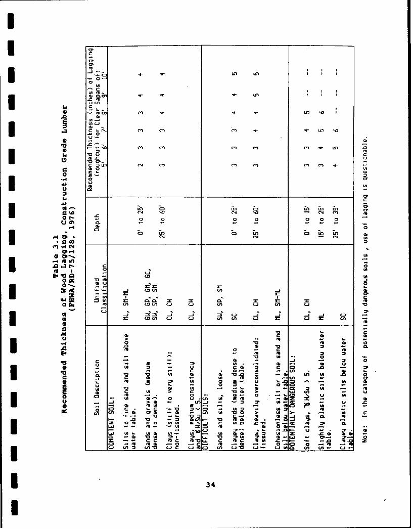
3.11 Lagaina Thickness
The required thickness of the wood lagging can
be estimated from Table 3.1 from report number
IFHWA/RD-75/128 (1976). The table is based on soil
type, depth of the cut, and soldier pile spacing.
i
I 33
i
0-
al- 0lr7V-
c
tA L-
Aa
.M 0- Pl Cl Inc - n 'D
I. o n n cq Cl v- In
_0 clcGo 0
0 38
$4 C41
(N .0 eq 10 InC-0 1 00a0(N -1 C(4
c 0
0--. --ac -j coCA 08n
0 egU Ln Lo i C-i - (A Li CA w~
S cD iCA Li Li LCA~ Li Li (
(b as
r4 0 (Al
-0 c oI- 0LA al al;
OA 0 4Ae - p
U,, c- at C ai CA - uI #- 0 -.-U2 % U OCa 34 1UU A o-4
UI j-

CHAPTER FOUR
COMPUTER PROGRAM
4.1 Program Flow and Logic
The computer program logic and flow is illustrated
in the flow charts shown in Figure 4.1. Appendix A
contains the variable nomenclature for the program and
the actual program file is included in Appendix B.
Appendix C contains various calculations and equations
used within the analysis functions in the program.
4.1.1 Main Function
I The program starts with the main function which
includes the main menu and exit routines. The main
menu routine displays the main menu screen which
prompts the user to input the next step. The options
include enter soil and wall data, read data from an
I existing file, edit the input data, save the data in a
file, execute the wall analysis, execute the anchor and
wale analysis, save the analysis results, or exit
the program. The program will execute the appropriate
function upon input. The program will request
I verification before exiting.
II 35
I

III
MAIN MENU EX T
1. Enter Soil Properties 8 Wall Data YES2. Pead Data From an Existinq File
3. Edit Inputted Data4. Save Inputted Data Program5. Execute al] inalysis H
6. Execute Ary-hor / Wale Analysis7. Save Analysis Data in OuJtput File8. Exit Program
Input Next Step
I !2
I
Figure 4.1Computer Program's Flow Chart
II* 36
I

I
I
II '~NPUT FUNCTO
~INPUT DATA:I /WALL: SOIL:
Engineer Elevation of GWTProject Wmber of Soil LayersLDate Soil Type
Top Elevation Sol] PropertiesBottom Elevation elev., unit ut.,
/ Number of Anchors friction anqle or cohesion)
/ Anchor Elevations BackslopeSpacinq Surcharge
IC)-,~ IAOJ-fTA FUNCTION
Input Filenare -
ENTEP FILENAIE
I
RedData file ABOPT
Main Mlnu
IFigure 4.1 (Continued)Computer Program's Flow Chart
I 37
I

III
Ou ~ ~ Ne Iau /uIW .1 ata
Ih YESurppuIem o.o
ID-ata, Neu Value /
I
Io
IiI
C utut Sgai l ha rt
I S D
I
MA N MNIO C a g E n u i s N .1I
IS
Figure 4.1 (Continued)* Computer Program's Flow Chart
* 38

INUT-Isiae it fpl-Iatro aeyaantpsiepesr-DphoIvrxaainbluaco oain
CLYAAYIIolISN ADAAYII-W D~pa esls rmAKhrAayi
- . Snlntionf c horsCalculate etioMd ulu I.act r*Sif to Medium SandC~
6. UmStiff tay dCa
I Cawclate Amtr Lwnqth Cacu ate d Lenqth
Output from Analpis:Anchor Section Anchor Anchor IUnboncfrd
IROU Modulus Capacity Length Length
MAIN MIEW
I Figure 4.1 (Continued)Computer Program's Flow Chart
I 39

MILS
3 Save Data in File
MAIN M1ENU
Figure 4.1 (Continued)
computer Program's Flow Chart
* 40

431io Sol~ & t &Cdw Foramdp oru3n ra miepam eut d & dwp For m
Dokrftn' ofle t o wo '1w ( z) D~ir PI ) whor No Form = 0Colafth NM of -o of Wor '1iw Cdut Ncti by Sww*i Ndil~ of X3 C~h~s~wD for Zero Moimw 1 at 0
W ft Mn*C01,M nm GO Zero ShooCdiits 3.q Irorn II -,Duiwniw ID by o Su wi dblue osi MltfOJ
Moo>0 YES ~m E
NO #13) > _IYE
II AA~~LYI5 N c~ ~II
I C Yr:Iant NL BNfi-
ComputerCI Prgrm' FowChr
3kd 41 Mdov wIWH a rmr

AMYSUP A-NLMISsoI
iaFbd Pt. of 2., 3w.Detvmbts101 hetw fzr.me z dait bm a aoSe
Dewm 0 h t RRO - SWm a t Dr N- ~ t %fr md NoLkplawtClel
NO tYES Dwrrdne P1 ( X ) w Ye NtfrSIdkoRmlnbySnf onn sat Xi
Det4Sk Du fo eoMi t Dk UdkeW=ai R .. K~f Cisf
mo- >ru 0imi lsq T
Figured 4.1% (ofiuedI ComuterProgam'sFlowChar
3svud 42m T
I0

I NAJMYP R CAJW
3naf Avrq Ur M.I'T*ad 1MEMFI.7N b" Aaa I.rA
Io&Mr
Odiji ~S.pI WL FA
daim a A rp~~
I ~iem £~ ~ 0 i i
Ik .UM X
IrfznoIV
Figre4. (onined
3~M Copue rogas Flw C art
Fiur 43(otiud
CoptrPormsFoIhr
III
3 4.1.2 Data Functions
The data functions will input, read, edit, and
3 save the input data or save the analysis results. The
input function prompts the user for the input of the
3various wall and soil data. The read function prompts
the user for the filename of the data. If the file
does not exist in the working directory, an error
message is displayed and it requests the filename be
reentered or the function aborted. Upon finding the
file, the data is read and entered into the appropriate
program variables. The view data function displays the
Uwall and soil data and requests if any changes are
3 desired. If a change is desired, the number of the
item and then its new value are entered. The save data
3 function will save the input data in a DOS file in the
working directory. If the file already exists,
verification will be requested before coping over it.
3 Lastly, the save function will save the results of the
analysis in a DOS file. The save routine will request
3 the filename and verification before coping over an
existing file. After executing a particular routine,
I the program returns to the main menu.
II 44
I
I
I 4.1.3 Analysis Functions
The next series of functions perform the various
analysis calculations. The analysis function requests
3 entry of the estimated thickness of the pile, the
factor of safety against passive pressure, and the
I depth of over-excavation below an anchor depth.
Following input, the function determines the soil type
and executes either the sand analysis or clay analysis
3 function. After executing the sub-function and
completing the calculations, flow is returned to the
3 analysis function and the results are displayed.
The sand analysis function executes its analysis
in three stages. The first stage is for the initial
3 stage of excavation before the first anchor has been
installed. It calculates the point of zero shear,
3 maximum moment at the point of zero shear, required
section modulus from the maximum moment, and the depth
of embedment at the point of zero bending moment. Stage
3 two is for the second stage of excavation after the
first anchor is installed. It calculates the same
3 items as stage one plus the reaction force. The
embedment depth is based on not overstressing the
pile at the anchor location assuming fixity there.
3 Additionally for the first two stages, the moments
I45
and reaction force are calculated using the Kiewit
criteria. Stage three is executed for the stages of
construction after the second and thereafter anchors
are installed. The pressure distributions for braced
cuts are used in this stage. The reaction forces,
I point of zero shear, maximum moment, and required
section modulus are calculated in the function. The
embedment depth is calculated by calling the sub-
function, "minD". It calculates the embedment depth
from the maximum moment for each particular stage.
After the final stage is completed, the minimum
embedment depth is calculated from the maximum moment
for all the stages of construction. The sand analysis
function uses the function "ka_kp" to calculate the
average unit weight, friction angles, and coefficients
of passive and active earth pressures. The base
friction angle and unit weight are the properties of
Ithe soil layer at the bottom of the excavation.
3If the soil type is clay, the function clay
analysis is executed. It performs essentially the
same calculations as the sand analysis function. It
first determines the location of a tension zone, if
it exists, and excludes the stresses within it from
any calculations. Also it verifies the soil will
-- 46
I

I
I support the excavation based on the net passive
resistance of the structure being greater than zero
(Pet= 6c/fs + 2c - q > 0). An error message is
displayed if it will not. In the third stage routine,
the stability number of the cut is calculated and the
pressure diagram corresponding to the stability number
determined. The function "cacb-wt" is used to
calculate the average unit weight and shear strength of
the cut and the base shear strength. The base shear
strength is calculated from an average over a depth
* twenty feet below the bottom of the excavation.
Both the sand and clay analysis functions use the
function "strip" to convert a strip surcharge load to
an equivalent uniform surcharge load. This surcharge
load is then included in the design calculations.
* The anchor analysis function is used to calculates
the section modulus of the wale for each row of
anchors, the required anchor capacity, the bonded
anchor length based on soil type and anchor capacity,
and the unbonded anchor length. Prior to the actual
analysis, anchor spacing; the inclination angle of the
anchors; and soil type are entered. After completion
I of the various calculations, the results are displayed
before the program returns to the main menu.
I47
4.2 Assumptions and Limitations
1. The coefficient of passive earth pressure is
calculated assuming Rankine's theory which is
conservative compared to a logarithmic spiral failure
surface approach in estimating the passive resistance.
*2. An average unit weight and friction angle (or
cohesion) for the cut is used in the soil pressure
calculations. The base values for sands are the
* properties of the sand layer at the bottom of the
excavation. For clay layering, the base value for
cohesion is calculated by averaging the cohesion values
over a twenty foot depth below the bottom of the
I excavation. This is to account for soft or stiff
layers just below the bottom of the excavation. The
difference between a soft and very stiff clay layer is
more significant than that between a loose and dense
sand. It is recommended only minimal soil layering be
I used.
* 3. A cut of entirely sand or clay layering is
assumed in the program. The computer program will
not accept mixed soil layering or silts. As an
alternative, an equivalent value of cohesion for a
nsand layer may be averaged with a cohesion value of
I the clay layer as follows:
* 48
I

II
I c [ C ( *Ks*Hs2*tanf + (H-H)*n'*q, ) /2H.
Where, H = total height of the cut,
Hs =height of the sand layer,
i s = unit weight of the sand layer,
Ks = lateral earth pressure coefficient for
I the sand layer ('1),
# = angle of friction of the sand layer,
qu = unconfined compression strength of clay,
and
nt = coefficient of progressive failure
I (ranges from 0.5 to 1). (Das, 1990)
With the average unit weight for the cut, the
pressure diagrams for clays can then be used to design
the wall. NYCTA (1974) recommends an alternate method
where the pressure diagrams are calculated using
Rankine's earth pressure theory for the individual
layers and an average uniform pressure over the entire
wall calculated from these pressures.
4. Sands are assumed to be drained with the water
table being drawn down below to the bottom of the
excavation. If the cut is not drained or the water
table is not drawn down, the hydrostatic pressure
should be included in the calculations.
I
I

I
5. For clays, short-term undrained conditions are
assumed. If drainage may occur as in the cases of
long-term construction (partially drained) or post-
3 construction (fully drained), an effective stress
analysis should be accomplished using effective stress
3 parameters (c' and '). Drained conditions for clays
are usually more critical than undrained conditions.
6. The assumption that the wall acts as a series
3 of pinned beams is conservative compared to assuming a
continuous beam and analyzing it using a finite
* element approach.
7. The program does not calculate the overall
Pstability of the structure. Most probable failure
* surfaces should be checked to ensure a satisfactory
factor of safety.
* 8. The program does not check the stability of
the base. Seepage forces should also be considered if
* present to check for quick conditions.
3 9. Anchor capacity is based on field testing of
pressure injected tiebacks in cohesionless soils. The
3 capacity curves used were developed with the majority
of anchors less than eight meters and most were not
I tested to their ultimate capacity (FHWA/RD-82/047,
1982). For cohesive soils, post-grouted tiebacks are
50
I

I
I assumed. The mechanism by which post-grouted tiebacks
develop their capacity is not entirely understood.
Increases in capacity of 25% to over 300% are possible
3 depending on the soil type and the post-grouting method
(FHWA-RD-82-047, 1982). The curves used represent a
3 wide range of values and an average of these values is
used to calculate capacity. The actual field
capacities of the tiebacks should be verified in the
* field.
10. Wale design is conservatively calculated based
3 on assuming pinned ends at the anchor locations.
4.3 Example Problems
3 Examples problems for sand and clay layering,
with and without a ground water table present are
3 included in Appendix D. The solutions are compared to
the computer's solutions to ensure reasonable results
I are produced by the program.
III
q.
L
CHAPTER FIVE
USER'S GUIDE
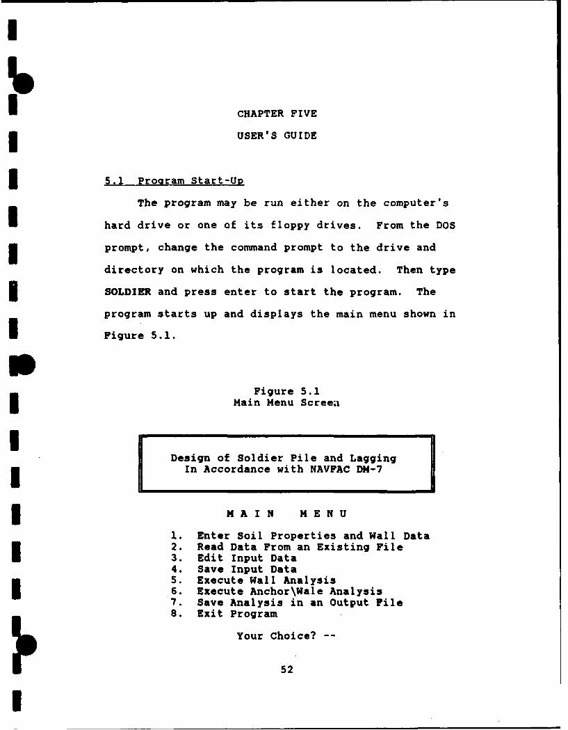
5.1 Program Start-Up
The program may be run either on the computer's
hard drive or one of its floppy drives. From the DOS
prompt, change the command prompt to the drive and
directory on which the program is located. Then type
SOLDIER and press enter to start the program. The
program starts up and displays the main menu shown in
UFigure 5.1.S
Figure 5.1Main Menu Screen, ii 1
Design of Soldier Pile and LaggingIn Accordance with NAVFAC DM-7
MAIN MENU
1. Enter Soil Properties and Wall Data2. Read Data From an Existing File3. Edit Input Data4. Save Input Data5. Execute Wall Analysis
.6. Execute Anchor\Wale Analysis7. Save Analysis in an Output File8. Exit Program
Your Choice? --
52
I

IThe user then should enter the next step, usually
enter or read data. The description of the required
input data is listed in the next section. The
analysis functions can only be executed after the
data have been entered.I5.2 Input Data
The following data shall be entered for the
3 various analysis functions. Figure 5.2 illustrates
various input data.
3iOstance from uall Strip Loadto o strp lad
Top Elevation Slope of BakfilI
Anchor Elevaion Top elevation, unit igzht, a"d friction angll
or cohesion.G
Annchor Elevationr~h , [ ,alonLager 2:
Top elevation, uit ut, ad friction nl*or cohesionl.
tctor Elevation
Lager 3:Top elevation, unit weiqht, and friction ionle
Bottom Cl] alzcn or cohesion.
SSpacinq of Soldier Piles
I Figure 5.2Input Variables for Wall Analysis
i53

I
I 5.2.1 Wall Data
1.. Name of engineer, for maximum of 40
characters.
2. Project title, for maximum of 40 characters.
3. Date of report, for maximum of 30 characters.
3 4. Elevation of the top of the excavation (ft).
5. Elevation of the bottom of tha excavation
(ft).
6. Number of anchors used in the cut for a
maximum of ten anchors.
7. Elevation of the anchors from the top of the
excavation to the bottom (ft).
*" 8. Center to center spacing of the soldier piles
3 (ft).
3 5.2.2 Soil Data
1. Number of soil layers for a maximum of ten
layers.
3 2. Soil type of the entire excavation, either one
for sands or two for clays.
3 3. For clays, the type of the analysis to be
performed (either total or effective stress analysis)
I is entered. If a total stress analysis is to be
accomplished, the saturated unit weight of the soil
54
I

U
I above and below the ground water table is entered. For
an effective stress analysis, the saturated unit weight
of the soil is entered above the water table and the
3 buoyant unit weight entered below the water table. The
elevation of the ground water table should be above the
I bottom of the excavation for the effective stress
* analysis.
4. Soil properties including elevation of the top
3 of the layer (ft), saturated, buoyant, or moist unit
weight (kcf), and friction angle (degrees) for sands or
5 undrained shear strength (ksf) for clays.
5. Elevation of the ground water table (ft).
6. Slope of t!,e ground surface behind the
3 excavation (degrees).
7. Uniform surcharge load (ksf).
U 8. Strip surcharge load (ksf), the width of the
strip load (ft), and the distance from the wall face to
I the start of the strip load (ft).
5.2.3 Wall Analysis Data
* 1. Estimated width of the flange of the soldier
pile (ft).
pe t2. Factor of safety against passive resistance.
3. Depth of over-excavation below an anchor
elevation for intermediate stages (ft).
55
I
I
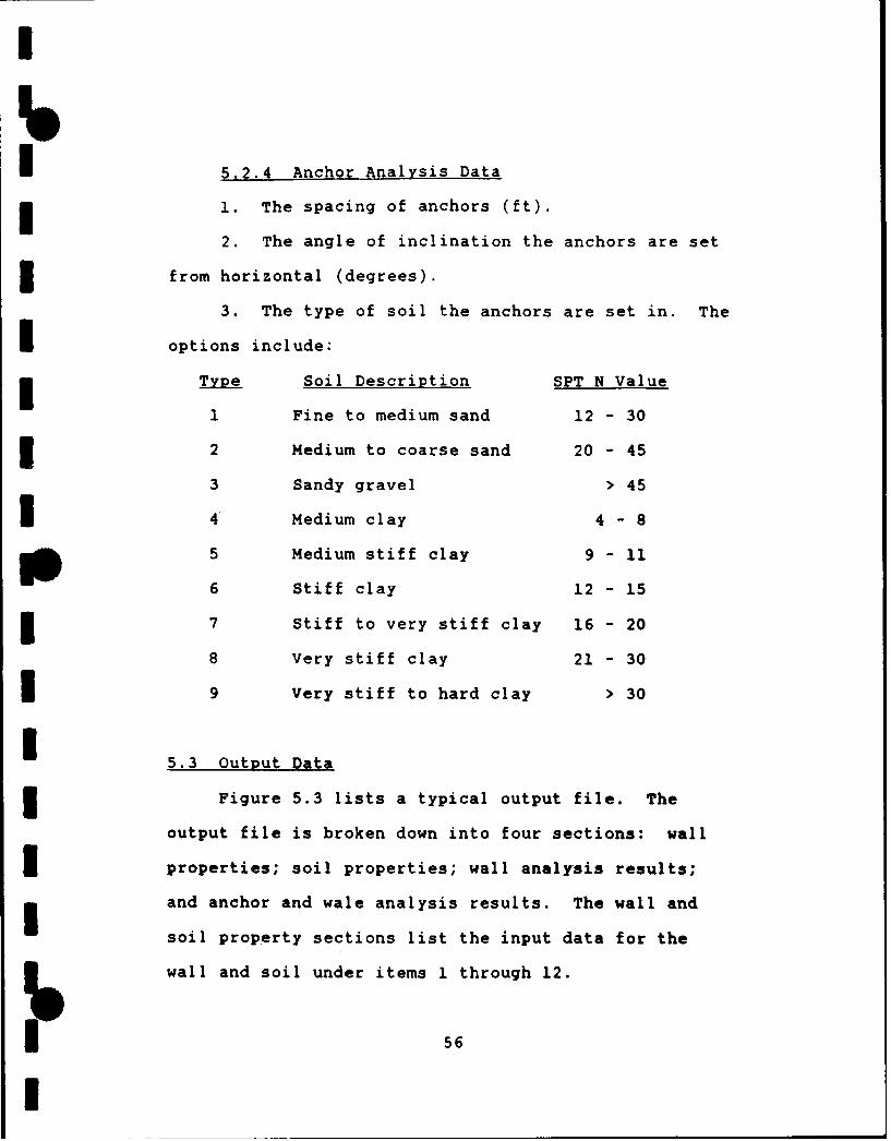
fo5.2.4 Anchor Analysis Data
1. The spacing of anchors (ft).
2. The angle of inclination the anchors are setSfrom horizontal (degrees).
3. The type of soil the anchors are set in. TheI options include:
3 Type Soil Description SPT N Value
1 Fine to medium sand 12 - 30
2 Medium to coarse sand 20 - 45
3 Sandy gravel > 45
I 4 Medium clay 4 - 8
5 Medium stiff clay 9 - 11
6 Stiff clay 12 - 15
3 7 Stiff to very stiff clay 16 - 20
8 Very stiff clay 21 - 30
I 9 Very stiff to hard clay > 30
I 5.3 Output Data
3 Figure 5.3 lists a typical output file. The
output file is broken down into four sections: wall
I properties; soil properties; wall analysis results;
and anchor and wale analysis results. The wall and
soil property sections list the input data for the
wall and soil under items 1 through 12.
56
I

I
* Design of Soldier Pile and Lagging *• In Accordance with NAVFAC DM-7 *
* I. WALL PROPERT I ES
1. Engineer: D'Amanda2. Project: International Corporate Park3. Date: 10 November 1989
4. The elevation of the top of the excavation is102.00 feet.
5. The elevation of the bottom of the excavation is81.00 feet.
6. The number of anchors is 2.The anchors are located as follows:
Anchor Elevation (feet)1 96.002 89.00
7. The spacing of the soldier piles is 5.00 feet.
II. S OI L P R O P E R T I E S
8. The elevation of the water table is 50.00 feet.* 9. The soil properties are as follows:
Soil Type Elev Unit Wt Friction Angleor Cohesion
sand 102.00 0.1150 38.00
10. The slope of the ground behind the wall is 31.5degrees.
11. The surcharge load is 0.250 ksf.12. The strip load is 0.50 ksf, 10.00 feet wide, and3 located 45.0 feet from the wall.
III. W A L L A N A L Y S I S R E S U L T S
13. Estimated width of the soldier pile is 0.5 feet.14. Factor of safety for passive resistance is 1.0.15. The wall was excavated 1.0 feet below the proposed3 anchor location.
Figure 5.3Sample Output File
57
I

I
16. STAGE ZERO MAXIMUM SECTION EMBEDMENT* REACTION(S) SHEAR MOMENT MODULUS DEPTH
(ft) (k-ft) (in^3) (ft) (kips)
1 1 12.1 55.23 23.01 10.12 21.9 20.45 8.52 5.5 R1 = 19.103 17.0 27.86 11.61 4.6 R1 42.04
R2 = 17.17
NOTE: Stage 1 moment based on Kiewit criteria is42.1 kip-ft.Stage 2 moment based on Kiewit criteria is19.0 kip-ft and reaction force is 16.7 kips.
I NOTE: Minimum depth of embedment based on maximummoment is 3.8 feet.
3 NOTE: NYCTA recommends minimum penetration depth ofsix feet.
3 IV. A N C H O R A N D W A L E R E S U L T S
17. Spacing of the anchors is 10.0 feet.18. The anchors are set at an angle of 5.0 degrees.19. The anchors are set in medium to coarse sand.20.ANCHOR SECTION MODULUS ANCHOR ANCHOR UNBONDEDROW OF WALE CAPACITY LENGTH LENGTH
(in^3) (kips) (ft) (ft)
1 58.4 84 7.4 7.02 23.8 34 4.0 3.8
NOTE: Tieback capacity is based on pressureinjected anchors using and effective groutpressure in excess of 150 psi with a diameterbetween 4 to 6 inches and depth of overburdengreatec than 13 feet.
NOTE: FHWA/RD-82/047 recommends a minimum unbonded
length of 15 feet.
END OF ANALYSIS
Figure 5.3 (Continued)Sample Output File
58
I

I
Im In the wall analysis results section, items 13
3through 15 are the input values for the width ofthe pile, factor of safety for passive resistance,
3 and the depth of over-excavation respectively. The
actual results from the analysis are listed under
I item 16 and include: stage; point of zero shear;
maximum moment; embedment depth; and reaction forces.
The location of the point of zero shear is from the top
3 of the pile. The depth of embedment is calculated
from the maximum moment for that particular stage and
3 is measured from the bottom of the cut. Four notes may
be displayed within this section. The results using
the Kiewit criteria for the first two stages are listed
3 in the first note. The next note lists the minimum
depth of embedment based on the maximum moment from all
3 stages of excavation. If the penetration depth for the
last stage or the minimum embedment depth is less than
six feet, a not.e is displayed indicating NYCTA (1974)
3 recommends a minimum penetration depth of six feet.
The last note is displayed for clay layering stating
3 the type of analysis, either total or effective stress,
used in the calculations.
The anchor and wale analysis results section
lists the anchor spacing, inclination angle of the
59
I

I
I anchor, and soil type under items 17 through 19. The
3 results of the analysis are listed under item 20. It
includes anchor row, section modulus of the wale,
3 required anchor capacity, (bonded) anchor length, and
unbonded anchor length. A note is displayed stating
I how the anchor capacity was derived. Another note is
displayed if the unbonded length of the anchor is less
than fifteen feet. FHWA/RD-82/047 recommends a minimum
3 unbonded length of fifteen feet.
5.4 Error Messages
The follow error messages are possible within
the program:
"You must input or read data before editing them."
Data must be entered or read before selecting the
3 edit function.
"You must input or read data before you save
them." Data must be entered or read before selecting
3 the save data function.
"You must input or read data before analysis."
3 Data must be entered or read before selecting the
wall analysis function.
"You must accomplish wall analysis before you can
save it." The wall analysis function must be
accomplished before selecting the save function.
60
I

"You must accomplish wall analysis before this
*analysis." The wall analysis function must be
accomplished before selecting the anchor/wale analysis
3 function.
"The bottom of the excavation must be below the
Itop." The elevation entered for the bottom of the
i excavation must be below the top of the excavation.
"The elevation of this anchor must be below the
3 prior anchor or the top of the excavation and above the
bottom of the excavation." The elevation entered
I for the anchor location must be below the previous
*anchor location or the top of the excavation and
above the elevation of the bottom of the excavation.
3 "The location of the water table can not be above
the top of the excavation." The elevation of the
3 ground water table must be entered below the elevation
of the top of the excavation.
"The soil type must be either I (sands) or 2
3 (clays)." The soil type for the cut must be entered
either 1 or 2 for sands and clays respectively.
3 "The first layer must extend to the top of the
excavation." For the first soil layer, the elevation
of the top of the layer must extend to the top of the
excavation.
61
I

I"The elevation of the top of the soil layer must
be below the last layer." The elevation entered for
the top of a soil layer must be below the elevation of
the previous layer.
"The location of the ground water table must be
I above the bottom of the excavation for an effective
stress analysis." When using an effective analysis
approach to calculate stresses for clay layering, the
3 ground water table must be located above the bottom of
the excavation. The buoyant unit weight of the soil
should be entered below the water table.
"Trouble opening 'filename' -- Read mode. Reenter
the filename or type abort to return to the main menu."
3 The filename entered for read data does not exist in
the working directory. Either the filename must be
3 reentered or abort entered to return to the main menu.
"Width must be positive." The estimated width
of the flange of the soldier pile must be entered as
3 a positive number.
"Factor of safety must be positive." The factor
3 of safety for passive resistance must be entered as a
positive number.
"Soil will not support the wall below a depth of
3XX.X feet." For clay layering, the soil will not
support the wall below the depth listed.
62
I

m
-- CHAPTER SIX
CONCLUSIONS
6.1 Review of Obiectives
The objective of the computer program was to
* provide a rapid and effective method to analyze braced
excavations. By varying the number and location of
tieback anchors, the design of a soldier pile and
lagging wall may be optimized. Once an initial design
is computed, the engineer may then accomplish final
m design calculations based on the results from the
computer program. This will significantly reduce the
time to accomplish an actual design.
6.2 Summary of Design Procedures
I Recommended design procedures are first to
determine the soil conditions, wall requirements, and
any surcharge loads. Next, select an initial number
of anchors and their respective locations. Then run
the program with the selected data, revising the number
3 and locations of the anchors until the reaction
forces and required section modulus are within
acceptable limits. A soldier pile section may be
6P,.. 6m3 m mmmmmmmm

I
selected from the Manual of Steel Construction (1980)
based on the required section modulus. Lagging size
may be chosen from the design table included in chapter
three (Table 3.1) from FHWA/RD-75/124 (1976). The
anchor analysis function of the program may be used to
estimate the wales' section modulus and the unbonded
I and bonded length of the tieback anchors. Spacing of
the anchors may be varied until acceptable results are
produced. Also by adjusting the input parameters, the
effects of a ground water table; different soil
conditions; or increased surcharge loading may be
, analyzed.
I The program does not check the overall stability
of a wall and the surrounding soil mass. The soil
* pressure acting against a wall may be greater in the
case of slope stability than for braced cuts and thus
govern wall design. Also, the factors of safety
against failure of the steel tendons of the anchors
and failure in the anchor zone should be verified
separately. The computer program PCSTABL can be used
to accomplished this analysis.
6
!6
I
I 6.3 Conclusions
The program SOLDIER.EXE can provide the engineer
with a quick and effective method of designing a
soldier pile and lagging wall. With the program, the
engineer can also investigate the effects of differing
I soil conditions, water table location, surcharge
loading, and wall dimensions and properties.
The engineer must understand the design concepts
* and assumptions made within the program to ensure they
are applicable to a particular project. This
computer program is not intended to be a replacement
for a complete design by a competent engineer. The
stresses produced by braced cuts can only be roughly
* estimated and a monitoring system should be employed
for critical cuts to ensure the acceptable performance
of the wall. The overall satisfactory performance of
the wall depends greatly on determining accurate soil
parameters, the external loading conditions, and the
use of proper construction procedures.
I
65
I
I
~APPENDIX A
I VARIABLE NOMENCLATURE
IIIII
0III
I6
I

I
The nomenclature of the variables used withinthe program are listed as follow.
* Variable Definition (units)
engineer Name of engineer, for maximum of 40* characters.
project Project title, for maximum of 40characters.
date Date of report, for maximum of 30characters.
I telev Top elevation of the excavation (ft).
belev Bottom elevation of the excavation (ft).
numa number of anchors used in the cutexcavation.
I anc[10] Elevation of anchor for maximum of tenanchors (ft).
B s Spacing of the soldier piles (ft).
gwt Elevation of the water table (ft).
nums Number of soil layers.
soiltype Type of soil. Either one for sands ortwo for clays.
soil[10][3] Soil properties for maximum of tenlayers: Elevation of top of the layer(ft), saturated or moist unit weight(kcf), and friction angle (degrees) orcohesion value (ksf).
b Slope of the ground behind the* excavation (degrees).
q Surcharge load (ksf).
* bf Estimated thickness of flange of soldierpile (ft).
I

fs Factor of safety against passiveresistance.
w Depth of over-excavation below theanchor elevation for intermediate stages(ft).
d Spacing of anchors (ft).
ang Inclination angle the anchors are set(degrees).
I type Soil type for anchor analysiscalculations.
I pi Constant value of 3.141592654.
filename Name of file to save or read data or tosave analysis, for maximum of 10characters.
wt Average saturated or moist unit weightof cut soil (kcf).
fa Average Friction angle of soil(degrees).
wtb Saturated or moist unit weight of basesoil (ksf).
fab Friction angle of base soil (degrees).
I Ka Coefficient of active earth pressure forthe cut soil.
Kab Coefficient of active earth pressure forthe base soil.
Kp Coefficient of passive earth pressurefor the base soil.
sigh Horizontal stress or force due to soil(ksf or kips).
sigs Horizontal stress or force due tosurcharge (ksf or kips).
I

I
pp Net passive resistance pressure or force(ksf or kips).
u Hydrostatic force or stress (kips or* ksf).
ca Undrained shear strength of cut claysoil (ksf).
cb Average undrained shear strength of baseclay soil (ksf).
Ns Stability number of the cut for clays.
zt Length of tension zone for clays (ft).
z[11] Depth of zero shear from top ofexcavation (ft).
R[10][1O] Reaction forces for each stage ofconstruction (kips).
I M[11] Maximum moment for a stage of excavation(kip-ft).
S S[11] Required sectin modulus for a stage ofexcavation (in ).
D[11] Embedment depth for a stage ofexcavation (ft).
Mmax Maximum moment from all stages ofexcavation (kip-ft).
Dmin Minimum embedment depth calculated usingMmax (ft).
Mk[2] M ximum moment from Kiewit Analysis forstage one and two of sand analysis (kip-ft).
Rk Reaction force from Kiewit, Analysis forstage two of sand analysis (kips).
P[10] Anchor force for maximum of tenreactions (kips).
I

I
sw[1O] Section Modulus of wale (in 3)
L[1O] Bonded length of anchor (ft).
ul(1O] Unbonded length of anchor (ft).
bp Used as a flag.
c Dummy character.
cc[20] Dummy characters, for maximum of twenty.
H, h, hh, hhh Various height of the cut variables(ft).
I a, v, y Internal variables used in variouscalculations.
i, j, k, 1 Global counters.
ii, ik Local counters.
stranal Type of stress analysis to be performedfor clay layering. Either 1 for totalor 2 for effective stress analysis.
IIII
70
I

I
APPENDIX B
I COMPUTER PROGRAM FILE
IIIII
III
71
I
I
// * SOLDIER.EXE, Version 1.01, dtd 15 NOV 91I/ * Program written by Kevin D'Amanda.// * Address until Jan 95:// * COMCBLANT, Naval Amphibious Base Little Creek,// * Norf6&k, VA 23521-5070// *************************************************************
#include <conio.h>#include <stdio.h>
#include <ctype.h>#include <stdlib.h>#include <complex.h>#include <string.h>I // **************************************************************
// * DECLARE FUNCTIONI // **************************************************************
void input(void);void readdata(void);void savedata(void);void viewdata(void);void analysis(void);S void anchor(void);void ka_kp(void);void clayanalysis(void);void wt_ccb(void);void sandanalysis(void);void save(void);void min_D(void);3 void strip(void);
// **************************************************************I /I * DECLARE VARIABLES
// **************************************************************
float belev = 0, telev = 0, s 0, gwt 0, q = 0, b = 0,anc[10], soil(10][3], hh = 0, H, sw[10], d = 0, ang 0, L[10],ul[10], bf = 0, fa = 0, W = 0, qs[3];
double sigh, sigs, wt, fa, v, y, Ka, Kp, Kab, wtb, fab, u, P[10],I c[2], Rc, qe, Mmax, Dmin, z[111, D[111, 1[11], S[11],
R[10][10], zt, pp, cb, ca, Mk[2], Rk;int type = 0, numa = 0, nums = 0, i = 0, k 0, j = 0, 1 = 0,bp = 0, soiltype, stranal;
const float pi = 3.141502654;char c = 'x', cc[20], filename[10], engineer[40], project[40],date[30];
j72

// * MAIN FUNCTION
main(void)(
// * INITIALIZE VARIABLES
for (i =0; i < 10; i++){for (k = 0; k <3; k++) soilti][k] = 0;I for (j =0; j < 10; j++) R~iJ[j++J = 0;anc~iJ = zQiJ D[iJ = M~iJ = S[iJ = sw(i] =P(i] ul[iJ
// L~i] =0;
1/ * MAIN MENU ROUTINE
clrscro;cout << '"\n'
<<« \tf Design of Soldier Pile and Lagging\n"\t fY In Accordance with NAVFAC DM-7 o
cout << "\n\n\t\t\t M A I N M4 E N U\n\n";Icout << "\t\t 1. Enter Soil Properties and Wall Data\n''<< "\t\t 2. Read Data From an Existing File\n"<< "\t\t 3. Edit Input Data\n"'<< "\t\t 4. Save Input Data\n"'<U MY:\\ 5: Execute Wall Analysis\n"'
<< "0 6.Execute Anchor\\Wale Analysis\n""\tMt 7. Save Analysis in an Output File\n"
<< M\tY 8. Exit Program\n\n''<< "\t\t\t Your Choice? -- "
while ((i =atoi(gets(cc))) <=0 1: i >=9){Icout << "\n\t\t" << cc << " is an incorrect response, try again."'<< "\n\a";
cout << "\t\t\t Your Choice? -" II switch (i) (case 1: inputo; bp = 1; break;case 2: read...datao; bp = 1; break;case 3: if (bp) view..datao;
else ( clrscr();cout << "\n\n\n\tERROR - You must input or read data before youedit them!" << "\n\t Press the enter key to return to the
P 73

main menu. \"gets(cc);}break;
case 4: if (bp) save...datao;else ( clrscro;I cout << "\n\n\n\tERROR - You must input or read data before you
save them!" << "\n\t Press the enter key to return tothe main menu.\a";gets(cc);break;
case 5: if (bp) { analysis(); bp 2;Ielse ( clrscr();
cout << "\n\n\n\tERROR -You must input or read data beforeanalysis!" << "\n\t Press the enter key to return to themain menu.\a";I gets(cc);break;
case 6: if ((bp > 1) &&(numa > 0)) anchoro;I if (numa == 0) ( clrscro;cout << "\n\n\n\t There are no anchors in the wall data,therefore" << "\n\t anchor analysis is not required." <<"\n\n\t Press the enter key to return to the main menu.\a";gets(cc); )
if (bp <= 1) ( clrscro;cout << "\n\n\n\tERROR - You must accomplish wall analysis beforeSthis analysis!" << "\n\t Press the enter key to returnto the main menu.\a";gets(cc);3 break;
case 7: if (bp > 1) saveo;else ( clrscr();
cout << "\n\n\n ERROR - You must accomplish wall analysis beforeIyou can save the data!" << "1\n Press the enter toreturn to the main menu.\a";gets(cc);
break;
3 // *EXIT ROUTINE
3 case 8: cout << "\n\t Are you sure you want to quit the program?(Y/N) -- "
do ( gets(cc);c toupper(cc[OJ);Iif ((c =='Y') ',. (c =='N')) break;cout << "\n\tThat's not Yes or No, please enter a Y or N. -- \"
) while ((c != 'Y') :: (c != 'N'));if (c == 'Y')(
p 74

1
clrscr(;cout << "\n\n\n\t\tP R O G R A M TERM I NATED\n";
exit(O); }goto M;)
/ / **************************************************************
// * INPUT FUNCTION// * Enter program variables for calculations.// **************************************************************
void input(void) {clrscr);cout << "\n\t\t\tWall Properties\n\n";cout << "\n\tEnter the Engineer's name. --
gets(engineer);cout << "\n\tEnter the project name. --gets(project);cout << "\n\tEnter the date. --
gets(date);cout << "\n\tEnter the elevation of the top of the excavation infeet. -- ";
cin >> telev;cout << "\n\tEnter the final elevation of the bottom of theexcavation. -- "I
cin >> belev;if (belev >= telev)f cout << "\nERROR - The bottom of the excavation must be belowthe top!" < "\n Reenter the final elevation of theexcavation. -- \a";
cin >> belev; }cout << "\n\tEnter the number of anchors that are to be used tosupport the" << "\n\t excavation for a maximum of ten anchors.
cin >; numa;if (numa) {cout << "\n\tEnter from the top to bottom the elevation in feetof the anchor(s).\n";
hh = telev;j = 0;for (1 = 0; 1 < numa; ++l) (cin >> anc[j];while (anc[j] >= hh 1 anc[j] <= belev)
cout << "\n\tERROR - The elevation of this anchor must be belowthe prior anchor or" << "\n\t the top of the excavationand above the bottom of the excavation." << "\n\t Reenterthe elevation of this anchor. -- \a";
cin >> anc[j]; )hh = anc[j]; ++j; I }cout << "\n\tEnter the spacing of the soldier piles. --
75
I

I
I
cin >> s;I clrscro;cout << "\n\t\t\tSoil Properties\n\n";cout << "\n\tEnter the number of soil layers for a maximum of ten
layers. --
cin >> nums;cout << "\n\tEnter the soil type, either 1 for sands or 2 for
Sclays. -- to'
cin >> soil-type;while ((soil_type <= 0) 1; (soil-type >= 3)) (cout << "\n\n\tERROR - The soil type must be either 1 (sands) or2 (clays).\a" << "\n\t Please reenter soil type. --
cin >> soil_type; }clrscro;if (soil_type 1I) {cout << "\n\n\tEnter the soil layering properties as follows fromtop down:\n" << "\n\tElevation of the top of the soil layer infeet from top down." << "\n\tMoist or saturated unit weight ofthe soil (kips/ft^3)." << "\n\tFriction angle (degrees)." <<"\n\t(The entry should read like: 100 .115 35)" <<"\n\n\tNOTE: The top of the excavation is at elevation " <<telev << " feet.\n"; I
else (cout << "\n\n\tDo you wish to perform a total or effective stressanalysis?";cout << "\n\n\tlf you would like to accomplish a TOTAL STRESSANALYSIS enter" << "\n\t the saturated unit weight of the soilabove and below the" << "\n\t ground water table.";
cout << "\n\n\tlf you would like to accomplish an EFFECTIVESTRESS ANALYSIS" << "\n\t enter the satuarted unit weight of thesoil above the water" << "\n\t table and the buoyant unit weightof the soil below the water" << "\n\t table. The water tableelevation should be located above the" << "\n\t bottom of thecut.";
cout << "\n\n\tEnter 1 for a total stress analysis and 2 for aneffective" << "\n\t stress analysis. --
cin >> stranal;while ((str_anal <= 0) 1: (str_anal >= 3)) cout << "\n\tERROR - Please enter either a 1 (total) or 2(effective). --\a";
cin >> str-anal; Iclrscr();cout << "\n\tEnter the soil layering properties as follows fromtop down:" << "\n\tElevation of the top of the soil layer infeet from top down." << "\n\tSaturated or buoyant unit weight ofthe soil (kips/ft^3)." << "\n\tUndrained shear strength (ksf)."<< "\n\t(The entry should read like: 100 .115 1.5)" <<"\n\n\tNOTE: The top of the excavation is at elevation "<<telev << " feet.\n";)
76II

II
hh = 1E10; j = 0;for (i = 0; i < nums; ++i) (cin >> soil(j](O] >> soil(j][1] >> soil(j]2];while ((soil[j][0] > hh) :: (soil[0][0] != telev))
I { if (soil(j][0] > hh)cout << "\nERROR - " << "\n The elevation of the top of thesoil layer must be below the last layer." << "\n Reenterall the soil data for this layer. -- \a";
if (soil[0][0] != telev)cout << "\nERROR - The first layer must extend to the top of theexcavation" << "\n Reenter all the soil data for thislayer. -- \a";
cin >> soil[j](O] >> soil[j](1] >> soil[j][2]; Ihh = soil[j](0]; ++j; }clrscro;cout << "\n\tEnter the elevation of the water table in feet. --
cin >> gwt;while (gwt > telev)cout << "\n\nERROR - " << "\n The location of the water table cannot be above the top of the excavation." << "\n Reenter thelocation of the water table. -- \a";
cin >> gwt; }while ((str_anal 2) && (gwt < belev)) {cout << "\n ERROR - The location of the ground water table mustbe above the bottom" << "\n of the excavation for aneffective stress analysis." << "\n\n Reenter the locationof the water table. -- \a";
cout << "\n\tEnter the slope of the ground behind the wall indegrees. -- ";
cin >> b;cout << "\n\tEnter the surcharge load (ksf)." << "\n\tPleaseenter 0 if none. --
cin >> q;cout << "\n\tEnter the data for any strip load:" << "\n\tSurcharge load (ksf), width of strip load (ft)," << "\n\t andthe distance the strip load is from the wall (ft)."; cout <<"\n\tPlease enter O's if none. --
cin >> qs[0] >> qs[l] >> qs[2];clrscr();}
// * READ DATA FUNCTIONI /f * Read data from a existing DOS file to enter variables.
// **************************************************************
I77I
I

void read-data(void)(char *c = "ABORT";clrscro;cout << "\n\n\n\tEnter filename. -
gets(filenaie);I FILE *ffp;while ((ffp=fopen(filename, "r") )=NULL){printf("\nERROR - Trouble opening %s -- read mode.\a",1 filename);cout << "\n\nReenter the filename or type ABORT to return to themain menu. -- "gets(filename);j =strlen(filename);for (i = 0; i < j; i++) filename~i) toupper(filename~iJ);if (strcmp(filename, cx) ==0) break;I if (strcmp(filename, cx) !0){fgets(engineer, 60, ftp);fgets(project, 60, ffp);I fgets(date, 30, ftp);fscanf(ffp, "\n %f \n %f \n %f \n %d", &telev, &belev, &s,&numa);
for (i = 0; i < numa; ++i){ fscanf(ffp, "\n %f", &anc(i]);}fscanf(ffp, "\n %f \n %d \n %d \n %d", &gwt, &nums, &soil..type,&str_anal);I for (i =0; i < nums; ++i)(fscanf(ffp, "\n %f %f %f", &soil~i]HO], &soil(iJ(1J,&soil[iJ(2J);)
fscanf(ffp, "\n %f \n %f \n %f %f %f", &b, &q, &qs(0J, &qs(1J,
fclose(ffp);cout«-< "\n\tPlease reenter: Engineer's name. -
gets(engineer);cout << "\t Project title. -
gets(project);I cout << "\t Date. -
gets(date);cout << "\n\tData read, press enter key to continue."3 gets(cc); I
/1 * VIEW AND EDIT ENTERED DATA FUNCTION
//*View and edit entered program variables.
I void view_data(void)(WALL: clrscro;cout << "\n\t\tW A L L P R 0 P E R T I E S\n';3 printf ("\n\tl. Engineer: %s" engineer);
78

printf ("\n\t2. Project: %s"1, project);printf ("\n\t3. Date: %s",date);cout << "\n\t4. The elevation of the top of the excavation is<< telev << " feet." << "\n\t5. The elevation of thebottom of the excavation is " << belev << " feet." << "\n\t6.IThe number of anchors is " << numa <'.-
if (numa) (cout << "\n\n\t The anchors are located as follows:\n" <<I "\t\tAnchor" << "\tElevation (feet)\n";j = 0;for (i =0; i <numa; ++i){ printf("\t\t %2d\t %5.2f\n", ++j, anc[i]);}1cout << "\n\t7. The spacing of the soldier piles is " << s <<feet.";
cout << "\n\n\tDo you want to change any values? (Y/N) -I do (gets(cc);c =toupper(cc[O]);if ((c == 'Y') 1..(c == 'N')) break;else {cout << "\n\t" << cc << is an incorrect response, try again -
\a"; ) while (c !=' N');if (c W N) ( SOIL: clrscr();Icout << "\n\t\tS 01L P ROP ER T I E S";cout << "\n\n\t8. The elevation of the water table is <<« gwt
<<"feet." << "\n\t9. The soil properties are as follow:\n"<< "\n\t Soil Type Elev Unit Wt FrictionUAngle" << "\n\\t or Cohesion";
j = 0;for (i =0; i < nums; ++i){cout << "t\n\t tif (soil_type ==1) cout << "sand";else cout << "clay";Iprintf (" %7.2f %1.4f%.2"soil(j](0], soil[jJ[1J, soil[j][21);
j++; Icout << "\n\n\tlo. The slope of the ground behind the wall is
cout<< \n~ll.Thesurcharge load is " << q << " ksf.";
Irnt s(0J, qs(J The strip load is %7.2f ksf, %4.2f feet wide,",
qs(2]);I cout << "\n\n\n\tDo you want to change any values? (Y/N) -
do (gets(cc);c =toupper(cc(0J);Iif ((c 'N'W) 1 (c =='Y')) break;else {cout << "\n\t" << cc << " is an incorrect response, try again -
\a"; }}while (c !='Y'); )
79

I / f *EDIT DATA ROUTINE//*Edit program variables.
I if (c == 'Y')cout << "\n\tEnter the number of what you want to change -
while ((i =atoi(gets(cc))) <= 0 ::i >= 13)I { cout << s\n\tII << cc <<" is an incorrect response.\a";cout << "\n\tYour choice? -"
clrscro;switch Wicase 1: cout << "\n\tEnter the Engineer' s name -
gets(engineer);break;I case 2: cout << "\n\tEnter the project name. -
gets(project);break;I case 3: cout << "\n\tEnter the date. -
gets(date);break;case 4: cout << "\n\tEnter the elevation of the top of theexcavation in feet. -- \"
cm >> telev;soil(OJ(O] = telev;I break;case 5: cout << "\n\tEnter the elevation of the bottom of theexcavation in feet. -
cmn >> belev;break;case 6:cout << "\n\tEnter the number of anchors that are to be used. --
cm >> numa;hh = 0;I if (numa != 0)( j = 0;cout << "\ntEnter from the top to bottom the elevation in feet3 of the anchor(s) --\n";for (1 = 0; 1 < numa; ++l){ cn >> anc~j];hh =telev;I while (anc~jJ >= hh :: anc~jJ <= belev)cout << "\n\tERROR- The elevation of this anchor must be belowthe prior anchor or" << of\n\t the top of the excavationI and above the bottom of the excavation." << "\n\n\tReenter theelevation of this anchor. -- \"
cmn >> anc(j]; Ihh =anc~jJ; ++j;})
s0

I|
Ibreak;case 7:cout << "\n\tEnter the spacing of the soldier piles. --
cin >> s;clrscr();I break;case 8: cout << "\n\n\tEnter the elevation to the water table infeet. -- ";
cin >> gwt;if (gwt > telev) (cout << "\nERROR - " << "\n The location of the water table cannot be above the top of the excavation." << "\n Reenter thelocation of the water table -- \a";
cin >> gwt; }break;case 9: cout << "\n\tEnter the number of soil layers. --
cin >> nums;cout << "\ntEnter the soil type, either 1 for sands or 2 for3 clays. -- ";cin >> soil-type;while ((soiltype <= 0) :: (soiltype >= 3)) £cout << "\n\tERROR - The soil type must be either 1 (sands) or 2(clays)." << "\n\t Please reenter soil type. -- \a";
cin >> soil type; )if (soiltype = 2) {cout << "\n\tDo you wish to perform a total or effective stressanalysis?" << "\n\tEnter 1 for a total stress analysis and2 for an effective" << "\n\t stress analysis. --
cin >> str anal;while ((str_anal <= 0) :: (str_anal >= 3)) {cout << "\n\tERROR - Please enter either a 1 (total) or 2(effective). --\a"; cin >> stranal; I )
cout << "\n\tEnter the soil layer's properties:" <<"\n\tElevation of top of the layer, unit weight, and frictionangle" << "\n\t or undrained shear strength.\n";
I hh = 1E8; j = 0;for (1 = 0; 1 < nums; ++l) (cin >> soil[j][0] >> soil[j][l] >> soil[j][2];while ((soil(j](O] > hh) :: (soil(0][0] != telev))( if (soil[j](0] > hh)cout << "\nERROR - " << "\n The elevation of the top of thesoil layer must be below the last layer." << \n Reenterall the soil data for this layer. -- \a";
if (soil(O][] != telev)cout << "\nERROR - The first layer must extend to the top of theexcavation" << "\n Reenter all the soil data for thislayer. -- \a";
cin >> soil[j][0] >> soil[j][1] >> soil[j][2]; }hh = soil(j][0]; ++j; }
81UI
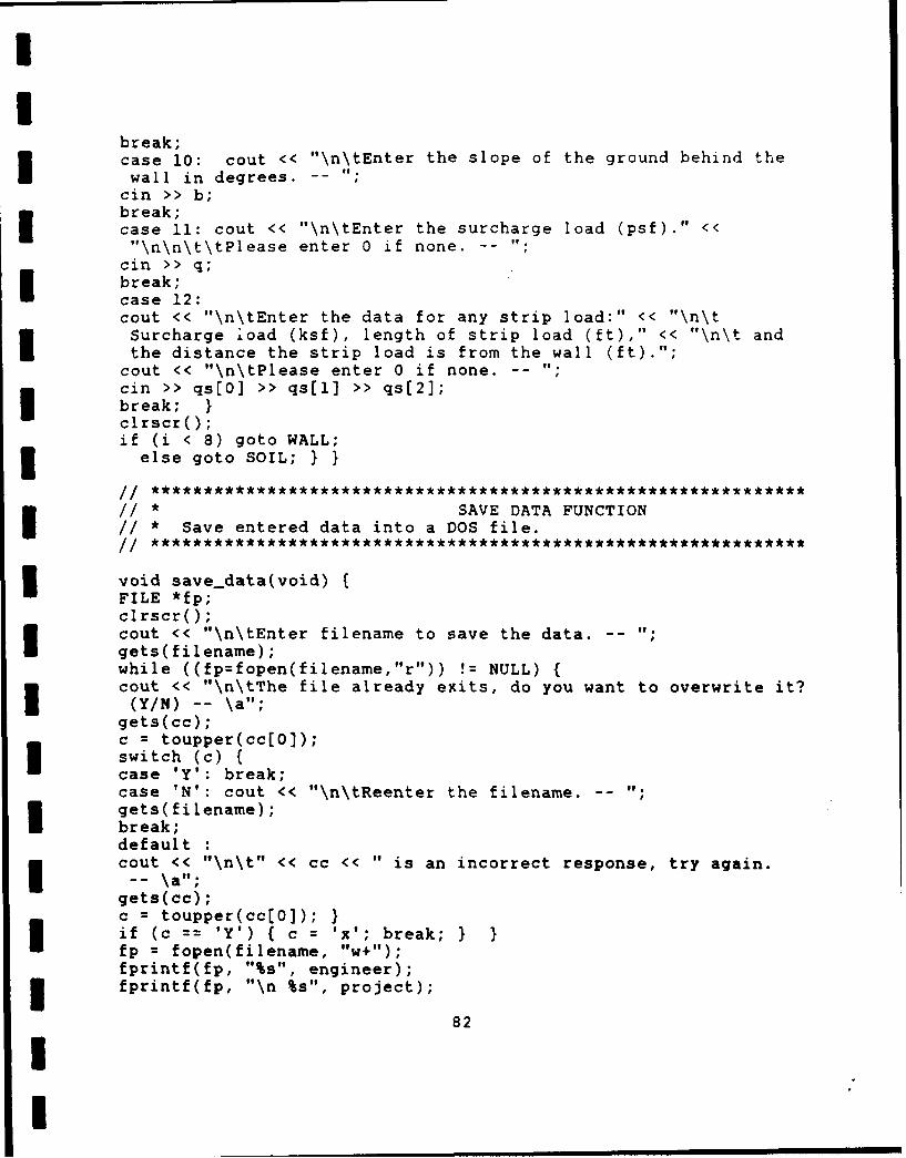
break;case 10: cout << "\n\tEnter the slope of the ground behind theI wall in degrees. -
cm >> b;break;I case 11: cout << "\n\tEnter the surcharge load (psf)." <<"\n\n\t\tPlease enter 0 if none. -
cin >>qbreak;case 12:cout << "\ntEnter the data for any strip load:" << "\n\tSurcharge load (ksf), length of strip load (ft)," << "\n\t andI the distance the strip load is from the wall (ft).";
cout << "\ntPlease enter 0 if none. -
cmn >> qs[0] >> qs[1] >> qs[2];I break; Iclrscro;if (i <8) goto WALL;3 else goto SOIL; I
// * SAVE DATA FUNCTIONI // *Save entered data into a DOS file.
void save...data(void)FILE *fp;cl rscro;cout << "\ntEnter filename to save the data. -I gets(filename);while ((fp=fopen(filenane, "r")) != NULL){cout << "\ntThe file already excits, do you want to overwrite it?(YIN) -- \"
gets(cc);c =toupper(cc[0));switch (c) {case 'Y': break;case WN: cout << "\n\tReenter the filename. -
gets(fileriame);I break;defaultcout << "\n\t" << cc << " is an incorrect response, try again.
gets(cc);c =toupper(cc(0));if (c == 'Y') ( c ='x'; break;fp =fopen(filename, "w+") ;fprintf(fp, "%s", engineer);fprintf(fp, "\n %s", project);
82
fprintf(fp, "\n %s", date);fprintf(fp, "\n %f", telev);Ipit~P \ V ee)fprintf(fp, "\n %f", be);fprintf(fp, "\n %f", su);
Ifor (j = 0; j <numa; ++j) fprintf(fp, "\n %f", ancE jJ);fprintl-fp, "\n %f", gwt);fprintf(fp, "\n %d", nums);fprintf(fp, "\n %d", soil~type);fprintf(fp, "\n %d", str_anal);for (i = 0; i <nums; ++i) si~j0,si~]1,si~]2)
fprintf(fp, "\n %fV, b);fprintf(fp, "\n %f", q):fprintf(fp, "\n %f %f %f", qs(0], qs[11], qs[2]);I fclose(fp);cout << "\n\tData saved, press enter key to return the mainmenu."I gets(cc);clrscr(); I
* ANALYSIS FUNCTION1/*Determine soil type, call subfunction to accomplish//*calculations, and display results from analysis.
void analysis(void)(clrscro;// Enter Width of Pile, Factor of Safety, & Excav. Depthcout << "\n\n\tEnter the estimated width of the flange of thesoldier Pile." << "\n\t (Enter 0 for default setting of 1
foot.) -- 'I;
cm >> bf;if (bf < 0)(cout << "\n\tERROR - Width must be positive, Reenter width -
Nco"u> << "n)bf-i*e the factor of safety for the passive
Upressure." << "\n\t(Enter 0 for DM-7 recommendation of 1.5.)
if (fs <0){cout << "\nERROR - Factor of safety must be positive, Reenter
fsF.S. -- \"
if (fs == 0) fs =1.5;3 if (numa){
83

cout << "\n\n\tEnter the depth in feet below the anchor locationIthat is to "< « \n\t excavated prior to installing theanchor. -
cii >> w;}clrscro;cout «<"\n\n\n\t\t\tC A L C U L A T I N G ofif (soil-type 1) sand_analysis();if (soil-type ==2) clay...analysiso;Iif (z[O) >= 0) (i =1, j =0;clrscr();cout << "\n\n\tRESULTS:" << "\n\n\tEstimated width of the soldierI pile is " << bf << " feet.";cout << "\n\tFactor of Safety for passive resistance is ' << fs
<< ,,.1
cout << "\n\tThe wall was excavated " << w << " feet below theI proposed anchor location.";cout << "\n\n\t STAGE ZERO MAXIMUM SECTION EMBEDMENTREACTION(S)" << "\n\t SHEAR MOMENT MODULUSIDEPTH" << "\nWt (ft) (k-ft) (in^3)(ft) (kips)" << "\n\t-------------------------------
----------------------------to
pruntf( "\ri\t %d %6.1f %6.2f %6.2f %6.lfIZi1,Mi1,Si1,Di1)for (i =2; i <= numa + 1; ++i) (printf( "\n\t %d %6.1f %6.2f %6.2f %6.1f R1I %6.2f", i, z(i-1], M~i-li, S~i-1J, D~i-1], R(0](jJ);for (k =2; k <= numa; ++k) {if (R~k-li(ji) (Icout << "\n\t\t\t\t\t\t\t R" << k <<printf("%6.2f", R~k-1J[j]); )I} ++j;printf("\n\nNOTE: Stage 1 moment based on Kiewit criteria is%6.1f kip-ft.", Mk[O]);
if (numa > 0) {printf("\n Stage 2 moment based on Kiewit criteria is %6.1fkip-ft", Mk~lJ);I printf("\n and reaction force is %6.1f kips.", Rk);}
if (numa > 1) printf("\nNOTE: Minimum depth of embedment basedon maximum moment is %3.1f feet.", Dmin);Iif ((D(numaJ < 6) :1 (Dmin < 6)) (
cout << "\nNOTE: NYCTA recommends minimum penetration depth ofsix feet."; ) I
if ((soil..type ==2) && (str..anal ==1))printf ("\nNOTE: A total stress analysis approach was used.");if ((soil..type == 2) && (str..anal ==2))printf ("\nNOTE: An effective stress analysis approach wasI used.");cout << "\n\nPress the enter key to return to the main menu. ;gets(cc);
84

// * SAND ANALYSIS FUNCTION//*Execute analysis for sands
I void sand_analysis(void)
I // *STAGE I - SAND
3j =0; i = 0; v = 0; y =0;if (numa) hh = anc~j] - w
else hh =belev;ka_kpo;strip();hh = telev -hh;
sigh = Ka*wt*hh*s*hh/2; IHorizontal Stress due to Soilsigs =Ka*qe*s*hh; IIHorizontal Stress due to Surchargepp = (3*Kp/fs-Kab)*bf*wtb;z[0] = 0; 1* Zero Shear *Iu =0;while(sigh + sigs + Kab*(wt*hh+qe)*bf*z[0] - pp*z[0J*z(OJ/2 + u > 0)( z[0] =z[0] + 0.05;if(gut >= (telev - hh u u 0.0312*bf*(3*Kp/fs-Kab)*z(0J*z(0J;
else u = 0; )if ( (gut > telev - hh -z[0J) && (gut < telev - hh))I ( z[(0J 0;while (sigh + sigs + Kab*(wt*hh+qe)*bf*z[0] - pp*zEO]*z(O]/2 +
- 0.0312*bf*(3*Kp/fs-Kab)*(z[0J-telev+hh+gwt)*(z[0]-telev+hh+gwt)*> 0) z[0J z[0J + 0.05;-v =z[01; /* Calculate Maximum Moment */ if
(gut <= (telev -hh - z[0J)) u = 0;else{ if (gut >= telev - hh) u =0.0104*bf*(3*Kp/fs-Kab)*v*v*v;else u = 0.01o4*bf*(3*Kp/fs-Kab)*pow((v-telev+hh+gwt),3); )M[O]J sigh*(hh/3+v)+ sigs*(hh/2+v)+ Kab*bf*(hh*ut+qe)*v*v/2-pp*v*v*v/6+ u;S[010= M[0]/2.4; /* Calculate Section Modulus *v 0 *Calculate Depth of Embedment *
w hile (sigh*(hh/3+v)+sigs*(hh/2+v)+Kab*bf*(wt*hh+qe)*v*v/2-pp*v*v*v/6+u > 0) (v = v + 0.05;if (gut >= (telev - hh ))u = O.01O4*bf*(3*Kp/fs-Kab)*v*v*v;I else u =0; )if ((gut > telev - hh - v) &S (gut < telev - hh) )(v = 0;while (sigh*(hh/3+v)+ sigs*(hh/2+v)+ Kab*bf*(hh*wt+qe)*v*v/2-I pp*bf*v*v*v/6 + O.0104*bf*(3*Kp/fs-Kab)*pow((v-telev+hh+gwt) ,3)
85

> 0) v =v + 0.05;D[0]J vz(0) hh + Z[01; Calculate Moment based on Kiewit Analysis
Mk(0] = Ka*qe*hh*s*(hh/2+2)+Ka*wt*hh*hh*S*(hh/3+2)/2 ; Dmin 7;
cout << "\n\n\t\t S T A G E 1 C 0 M P L E T E D. "
I // *STAGE II - SANDS
if (nurna) (++i;S=1; v =0; y 0;
if (numa ==1) hh belev;I kaelse hh =anc(jJ - w;kkpo;
strip();hh = telev -hh;Isigh = Ka*wt*s*hh*hh/2; 1* Horizontal Stress due to Soil*/ sigs =Ka*qe*s*hh; /* Horizontal Stress due toSurcharge */ pp = (3*Kp/fs-Kab)*wtb*bf;v 0;u =0;while (sigh + sigs + Kab*(hh*wt+qe)*bf*v - pp*v*v/2 + u > 0){v =v + 0.05;Iif (gwt >= (telev - hh ))u =0.0312*bf*(3*Kp/fs-Kab)*v*v;else u = 0; )if ((gut > telev - hh -v) &&(gut < telev - hh))I{ v= 0; u = 0;while (sigh + sigs + Kab*(hh*wt+qe)*bf*v - pp*v*v/2 +0 .0312*bf*(3*Kp/fs-Kab)*(v-telev+hh+gwt)*(v-telev+hh+gut) > 0)v =v + 0.05; )
/* Reaction Force *if (gwt <= (telev - hh - v)) Cu =0;elseI { if (gut >= telev - hh) { u 0.0104*bf*(3*Kp/fs-Kab)*v*v*v;}else { u =0.0104*bf*(3*Kp/fs-Kab)*pou((v-telev+hh+gwt),3); }R[0J[0J (sigh*(hh/3+v)+ sigs*(hh/2+v)+ Kab*(wt*hh+qe)*bf*v*v/2I - pp*v*v*v/6 + u) / (hh+anc(0J-telev+v);v =0; u = 0; 1* Zero Shear *while (R(0J(0] - sigh - sigs -Kab*(wt*hh+qe)*bf*v + pp*v*v*bf/2
- U < 0 ) { v =v + 0.05;Iif (gut >= (telev -hh ))u 0.0312*bf*(3*Kp/fs-Kab)*v*v;else u =0; 1if ( (gut > telev -hh -v) &&(gut < telev - hh) v = 0;Iwhile ( R(0J(0] - sigh -sigs -Kab*(wt*hh+qe)*bf*v + pp*v*v*bf/2
- 0.0312*bf*(3'*Kp/fs-Kab)*(v-telev+hh+gwt)*(v-telev+hh+gut) < 0)v = v + 0.05;3z[13 V
86

if (gwt <= (telev - hh - W) [ u = 0; 1 IMaximum Momentel1.seI { if (gwt >= telev - hh) u =0.0104*bf*(3*Kp/fs-Kab)*v*v*v;else u = }.14b*3K/sKb*pw(-ee~hgt,)M[1] = sigh*(hh/3+z[1]) + sigs*(hh/2+z(1)) +Kab*(wt*hh+qe)*bf*z(l]*z(l]/2 - pp*z(1)*zi:1)*z(1)/6-R(0)[0)*(hh-telev+anc(0J+z(1]) + u; S[1] =M[1]/2.4;
// Section ModulusD[1] = 0; u =0; /* Depth of Embedment *while (M[l] -Ka*(qe+(telev-anc[0])*wt)*pow((hh-
telev+anc[Ol),2)*s/2 - s*Ka*wtpow((hh-telev+anc[0)),3)/3-bf*Kab*(qe+hh*wt)*D(l]*(D(l1J/2+hh-telev+anc(0J) +I pp*D[1)*D[l)/2*(2*D[l)/3+hh-telev+ancfo)) - u <0)D[11l= D[l) + 0.05;
if (gwt >= (telev - hh )I u =0.0312*bf*(3*Kp/fs-Kab)*D[l)*D[1]*(2*D[l)/3+hh-telev+anc[0));else u= 0; }if ((gwt > telev - hh - D[l]) && (gwt < telev - hh) ){D[1] =0;while ( M[l] - Ka*(qe+(telev-ancEO])*wt)*pow((hh -I telev+anc[OJ),2)*s/2 - s*Ka*wt*pow((hh-telev+anc[0J),3)/3+ pp*DE1J*DE1J/2*bf*(hh-telev+ancE0]+2*D(1]/3)-bf*Kab*(qe+hh*wt)*D(1)*(D[1)/2+hh-telev+anc[0])-I 0.O312*bf*(3*Kp/fs-Kab)*pow((DE1]-telev+hh+gwt),2)*(D[l)+hh-telev+anc(0)-(D[1)-telev+hh+gwt)/3) < 0)
D[l] = D[1] + 0.05;}z[1] = z[13 + hh;
// Calculate Moment & Reaction based onKiewit y = hh-telev+anc(0);Mk(1] Ka*s*y*y*(qe+wt/2*(hh+telev-anc[0J))/9;I Rk = Ka*qe*s*(telev-ancE0J) + Ka*wt*s*pow((telev-anc(0]),2)/2 +(Ka*s*y*y/2*(qe+wt*(telev-ancE0J)) + y*y*y*Ka*s*wt/6)/y;3 cout << "\n\t\t S T A G E 2 C 0 M P L E T E D. "
// * STAGE III - SANDS
j =2;* wile (0 <= numa){v-= 0; y =0; 1* Average Unit Wt & FricionAngle */ if 0(j numa) hh =anc(j) - w;else hh =belev;I ka-kpo;
strip();sigs = Ka *qe; /* Horizontal Stress due to Surcharge *sigh =0.65 * Ka * wt * (telev - hh);/* Horizontal Stress due to Soil */for Ci = 0; i < 10; i++) [ R~iJ[j-1J 0;}3 for (k =0; k < j; ++k) /* Calculate Reaction Forces *
87

(if (k < j H 1) = anc~k+13;3else H hh;V = 0;for ( i 1; i <= k; ++i) v =R[i-11[j-1] * (anc[i-1] - H) + v;R~k3[j-13 = (pow((telev-H),2)*(sigh+sigs)*s/2 - v) /(anc[k]-H);I ~ = 0;/Calculate point of Zero Shear
v = R(O1[j-1J;while (v - (telev - anc~i]) * (sigh + sigs) * s > 0
{ v =R(++iJ[j-13 + v;if (i == j - 1) break; Iz~j3 v / ((sigh + sigs) *s)U v = 0; /* Calculate Maximum Moment *i =0; M~j] =0;while (telev - anc~il < z[jJ){ v =R~iJ(j-1] * (z~j) - telev + anc(iJ);
if (i == ) break; IUM~jJ M~jJ - (sigh + sigs) * s* z~jJ * z~jJ / 2;5(j) M~jJ/2.4;
/* Calculate Depth of Embedment *I V 8j); min _Do; D'jJ = yif (j = numa) {Mmax = M[03;for (i 1; i <= numa; i++) if (M(i) > Mmax) Mmax = (i);3, = Mmax; mm _Do; Dmin = y; I
cout << "\n\t\t S T A G E << « <<« C 0 M P L E T E D. "
// * CLAY ANALYSIS FUNCTION//*Execute analysis for clays.
void clay...analysis(void){Ifa 0; j 0;
I 1/ *STAGE I - CLAYS
3if (numa) hh =anc(0] - welse hh =belev;
float hhh =telev - hh;3 wt_c..cbo; /* Calculate Average unit wt, c, and c base *strip();zt = (2*ca-qe)Iwt; /* Depth of Tension Zone *3if ((6/fs*cb+2*cb-qe-wt*(telev-hh) < 0))
88

{v = (6*cb/fs+2*cb-qe)/wt;printf("\a\n\n\nERROR - Soil will not support the wall below adepth of %4.2f feet.", V);
z(0J -1; goto Q; Iif ((hh >= telev - zt) && (zt >= 0))( 14(0] 0; z[01 = 0; S[o3 = 0; D(0] =0;
if ((hh '~telev - zt) && (zt >= 0)) (sigh = s*(wt*hhh+qe-2*ca)*(hhh-zt)/2; /* Active Pressure *pp = (6*cb/fs+2*cb-wt*hhh-qe)*bf; 1/Result. Resistance Press.z(0J = sigh / pp; /* Zero Shear */M(0] = sigh*((hhh-zt)/3+z[0]) - pp*z[0)*z(0]12; // Max. MomentD[O) = 0; /* Depth of Embedment */while (sigh*((hhh-zt)/3+D[Q])-pp*D(0J*D(OJ/2 > 0) D(0] =D[0] +0.05;
z(OJ = z(01 + hhh;)I if (zt -( 0) fpp =(6*cb/fs+2*cb-wt*hhh-qe)*bf /* Resultant Resist Pres *z(0] = ((qe-2*ca)*hhh*s + wt*hhh*hhh/2*s) / pp; 1* Zero Shear *// Max. MomentM(0J (qe-2*ca)*hhh*s*(hhh/2+z[0])+wt*hhh*hhh/2*s*(hhh/3+z(0J)-pp*ZC0)*z[0)I2;
D(0] = 0;, /* Depth of Embedment *while (s*(qe-2*ca)*hhh*(hhh/2+D[0)) + wt*hhh*hhh/2*s*(hhh/3ID(O])
- pp*D(0J*D[0J/2 > 0) D(0] =D1(0] + 0.05;z(01 = z(0J + hhh; ISC0] = M(0]/2.4;
- MK(0 = 0
if(t<0 kO s*wt*hhh*hhh/2*(hhh/3+2) +
// Set zt, stage 1 equal to Kp to compare to zt, stage 2cout << "\n\n\t\t S T A G E 1 C 0 M P L E T E D. "
// *STAGE II -CLAYS
if (numa){
if (numa 1) hh = belev;else hh =anc(1J - w
I strip();zt =(2*ca-qe)/wt;if (zt > Kp) zt = Kp;hhh = telev-hh;
89
if ((6/fs*cb+2*cb-qe-wt*(telev-hh) < 0)){ v =(6*cb/fs+2*cb-qe)/wt;printf("\a\n\n\nERROR - Soil will not support the wall below adepth of %4.2f feet.", v);z[01 -1; goto Q; }if ((hh > telev - zt) && (zt >= 0))(MC1] =0; z[1l) 0; R[01[0] = 0; S(1] =0; D(1] =0; Rc =0;Mo[l] = 0; )I if ((hh < telev - zt) && (zt >= 0))(hh =telev - hh;sigh =s*(wt*hh+qe-2*ca)*(hh-zt)/2;pp= (6*cb/fs+2*cb-wt*hh-qe)*bf;Iv sigh /pp; /* Zero Earth Forces *R[0J[0] (sigh*((hh-zt)/3+v) - pp*v*v/2) / (hh-telev+anc(o]+v);z(I.] = (sigh - R(0]C0]) / pp; /* Zero Shear */I 1MC1] = sigh*((hh-zt)/3+z(1J) - pp*z~lJ*z(1)/2 -R[O)[0J*(hh
-telev+anc(0J+z(1]); D(1]J 0;if (aric[0J > telev-zt) {I while (M11 + pp*D(1]*(D(1)/2+hh-telev+anc(0]) sigh*(hh+anc(0J-telev-(hh-zt)/3) < 0)
D(1J D[11 + 0.05;}else{while (M[(1] + pp*DE1]*(D(1]/2+hh-telev+anc(0])s*(qe-2*ca+wt*(telev-anc(0J))* pow((hh-telev+anc(OJ),2)/2-s*wt*pow((hh-telev+ancE0]),3)/3 < 0)I D(1] = D(1J + 0.05; 1
z[1] z[1] + hh; Iif (zt < 0) { hh = telev - hh;Ip PP (6*cb/fs+2*cb-wt*hh-qe)*bf;sigh = s*wt*hh*hh/2;sigs =s*(qe-2*ca)*hh;I (sigh + sigs) / pp;R(O]0J0= (sigh*(hh/3+v) + sigs*(hh/2+v) - pp*v*v12) /(hh-telev+anc(0J+v);
z[1]J (sigh + sigs - R(0](0J) / pp;I M[1]1= sigh*(hh/3+z(1J) + sigs*(hh/2+z(1]) - pp*z(1J*z[1J/2 -R(0J(0J*(hh-telev+arlc(0J+z(1]);
DC1l) 0;
I hl 1(1 pD1*((J2h-elvac0)s*(qe-2*ca+wt*(telev..anc(0J)) * pow((hh-telev+anc(0]),2)/2 -s*wt*pou((hh-telev+anc[0J),3)/3 < 0) D[1J = D[1] + 0.05;
z[1] = z[11 + hh;}
S[11 = M1(1/2.4;
H =hhh-zt; IIKiewit AnalysisI v =telev - anc(0];y =hhh-telev+anc(0J;14k(1] =Rk =0;Iif (zt < 0) {Mk(1J s*y*y*(qe - 2*ca + wt*v + wt*y/2)/9;
90

Rk = s*(qe-2*ca)*v + s*wt*v*v/2 +s*((qe-2*ca+wt*v)*yI2+wt*y*yI6 );Uif (((zt >= 0) S& (zt >= y)) && (zt < hhh))
Mk[l]) s*y*y/9 * (qe-2*ca+wt*hhh)*H/(2*y);3 Rk = *(wt*hhh+qe-2*ca)*H*H/(6*y);if ((zt >0O) && (zt <y)) (Mk(1] =s*y*y/9 * (qe - 2*ca + wt*v + wt*y/2);Rk =s*((qe-2*ca+wt*v)*(v-zt)/2 + (qe-2*ca+wt*v)*y/2 + wt*y*y/6);}cout << "\n\t\t S T A G E 2 C 0 M P L E T E D."
// * STAGE III - CLAYS
if (numa > 1)(j = 2;while (j <= nurna)(double a, h;if (j < nurna) hh =anc~j] - welse hh =belev;wt..c..cbo;stripo;if (C6/fs*cb+2*cb-qe-wt*(telev-hh) < 0))( v =(6*cb/fs+2*cb-qe)/wt;printf("\a\n\n\nERROR - Soil will not support the wall below aI depth of %4.2f feet.", V);z[OJ -1; goto Q; }float Ns = wt*(telev-hh)/ca; /* Stability Number *for (i = 0; i < 10; i++) R~i](j-1] = 0;for (k =0; k < j; k++) {if (k < j - 1) H = anc~k+1);else H = hh;I h =telev - hh;a =telev - H;
if(gwt > H) u = 0.0104*pow((gwt-H),3)*s;
else u =0;for (i = 1; i <= k; i++) v =R~i-1J(j-1J (anc~i-1] - H) + v; if(Ns <= 6)( if (a <h/4) sigh = 1.6*wt*pow(a,3)/6;if ((a >= h/4) && (a <= 3*h/4))sigh = O.O5*wt*h*h*(a-h/6) + 0.2*wt*h*pow((a-hI4),2);I if (a > 3*h/4) sigh = wt*pow(h,2)*(0.05*(a-h/6) + O.2*(a-h/2))
+ 0.4*wt*pow((a-.75*h),2)*(h-2*a/3);Jif (Ns > 6)I { Ka 1 - 4*ca/(wt*h);if (a <h/4) sigh = 2*Ka*wt*a*a*a/3;else sigh =Ka*wt*h*h/8*(a-h/6) + Ka*wt*h*pow((a-h/4),2)/2;3 R(k][j-1] =(s*qe*pow((telev-H),2)/2 + s*sigh - v + u)/
91

(anc(kJ-H);v =0; /* Calculate point of Zero Shear *u =0; zlijJ 0;for (i =0; i < numa; i++) v = Rfi][j-1) + v;if (N~s <= 6) (while ( v + 0.05*wt*h*h*s -(qe+0.4*wt*h)*s*z[j] - u > 0){z~jJ zlj) + 0.059;if (telev - z~j) <= gwt) u 0.0312*sftpow((z[j]-telev+gwt),2); }I if (z~j] > 3*h14) (while (v- s*qe*z[jJ -u - s*(0.25*wt*h*h+ wt*(h-.0.8*z[j])(z[j]-0.75*h)) > 0)( zlj= zlj] + 0.05;
if (telev-z[j] <= gwt)u = 0.0312*s*pow((z[j] - telev + gwt),2); Iif (Ns > 6) (I while (v + s*Ka*wt*h*h18 - s*(Ka*wt*h+qe)*z[j] - u > 0)I z(jJ z~j] + 0.05;if (telev-z~j] <= gut) u = 0.0312*s*pow((z~j]-telev+gwt),2); II v =0; 1* Calculate Maximum Moment *M[j) = 0;for (i =0; i < j; ++i){ v =R[iJ[j-1] *(z[j) telev + anc~i]);
Mcj] McjJ + V;if (Ns <= 6) {if (z[jJ <= 3*h/4) sigh =0.05*wt*h*h*(z~jJ-h/6) +I 0.2*wt*h*pow((z~jJ-h/4) ,2);else sigh = 0.05*wf1*h*h*(z~jJ-h/6) + 0.2*wt*h*h*(z~jJ-h/2) +
0.4*wt*pow((z~j]-.75*h) ,2)*(h-2*z~j1/3); )I else sigh = Ka*wt*h*h/8*(z[jJ.-h/6) + Ka*wt*h*pow((z~jJ-h/4),2)/2;if (gut > telev-z(j]) u = 0.0104*s*pow((z~jJ-telev+gwt),3);else u =0;1 M~jJ = M(jJ - qe*s*z~j]*z~jJ/2 - sigh*s - u;S(jJ M(j)/2.4;D~j] = 0; /* Calculate Depth of Embedment *if (Ns <= 6) (I if (anc~j-1J >= telev-3*h/4)sigh =0.4*wt*h*pow((.75*h-telev+anctj-1]),2)/2 +0 .05*wt*h*h*(5*h/6-telev+anc[ i-i]);
else sigh = 0.8*wt*(h-telev+anc( i-i])pow((h-telev+anc[j-11),2)/3;Ielse sigh = Ka*wt*h*pow((anc~j-1J-hh),2)/2;if (gut >= anc( i-])u = 0.0312*(gwt-anc~j-lj)*pow((anc~j-1)-hh),2)*s +0.0208*pou( (ancE j-1J-hh) ,3)*s;
if ((gut > hh) 66 (gut < anc( i-i))
if (gut <= hh) u =0; -~<0
while (M~jJ + (6*cb/fs+2*cb-qe)*bf*D~jJ*(D~jJ/2+(anc[j-1J-hh))-sigh*s -s*qe*pow((anc(j-l]-hh),2)/2 -u<0
92

D(jJ D~jJ + 0.05;
cout << "\n\t\t S T A G E <<« j <<" C 0 M P L E T E D. "}if (numa > 1) ( Mmax M[1for (i =1; i <= numa; i++)I if (M[i] > Mmax) Mniax =M(i); Dmin =0;while (Mmax + (6*cb/fs+2*cb-qe)*bf*Dmin*(Dmin/2+(anc[j-2]-hh))
-sigh*s - s*qe*pow((anc[j-21-hh),2)/2 - u <z 0)I Dmin =Dmin + 0.05; ) Q: i = 0;
// * KA_KP FUNCTION//*Cal. average unit weight, friction angle, and Ka for cut.//*Calculate unit weight, friction, Ka, and Kp for base soil.
void ka-kp(void){for (k =0; hh < soil(k+1]H0]; ++k){ if (k >= (nums-1)) break;v =soil(k](1J * (soil~k](03 - soil(k+1](0]) +- v;y = soil(kJ(2) * (soil(kHOJ1 - soil~k4-1J(0]) + y;}v = v + soil(k](lJ * (soil(k]HOJ - hh);I y =y + soil~kJ(2] * (soil(kHOI] - hh);wt = v (telev - hh);fa =y I(telev - hh);I1 = nums - 1;while (hh > soil~ll]) --I;fab =soil~lH[2J;wtb =soil(l](1J;Kp =pow(tan((45 + fab/2)*pi/180),2); /* Calculate Ka &Kp *Kab =pow(tan((45 - fab/2)*pi/180),2);if (b ==0) { Ka = pow(tan((45 - fa/2)*pi/180),2);I else ( Ka =pow(cos(fa*pi/180),2)/(cos(fa*pj/270)*pow(l*sqrt(sin(fa*pi/108)*sin( (fa*pi/180)/(cos( fa*pi1270)cos(b*pi/180))),2)); I
/1* MIND FUNCTION//*Calculate min. embedment depth for stage III of sand excav.
void min_.D(void) ( u zy = 0;while (v + Kp/fs*1.5*wtb*bf*y*y*(2*y/3-hh+anc~j-1])
-(sigh+sigs)*(anc~j-1J-hh)*(anc~j-lJ-hh)*s/2 - u < 0)(y = y + 0.05;I if (gwt >= hh) u = 0.0936*bf*Kp/fs*y*y*(2*y/3-hh+ancj-1J);
else u = 0; 1if ((gwt > hh - y) && (gwt < hh) ){y = 0;while (v + Kp/fs*1.5*wtb*bf*y*y*(2*y/3-hh+anc~j-1J) -
93
(sigh+sigs)*(anc(P-llhh)*(afl~jtilhh)*s/2 - 0.0936*bf*Kp/fs*pow((y-hh+gwt) ,2)*(y-hh+anc~j-I]-(y+gwt-hh)/3) < 0O)Y y + 0.05;11
* WTCCB FUNCTION//*Calculate average unit weight and cohesion for cut.//*Also calculate average cohesion for base soils.
void wt-c-cb(void)(Ka =1;v =0; y =0;for (k = 0; hh < soil[k+1][0]; ++k)
(if (k >= (nums-1)) break;I = soil~k](l] * (soil~kkHO] - soil~k+1]0) + v;y =soil(k](2] * (soil~k]E0] - soil~k+11(0]) + y;Iv =v + soil~k] * (soil~k]lO) - hh);Iy =y + soil(k][2J * (soil(k][O] - hh);if (str -anal ==1) u =0;else ( if ((gwt > hh) &&(j < 2)) u =0.0624*(gwt-hh);else u 0; )
wt =(v + u) / (telev -hh);
ca = y /(telev -hh);
int ij, jk; IICalculate the average cohesion over 20 ft.Ij = jk =nums-1;while (soil~jk][O] < hh-20) --jk;while (soil~ij]lO] < hh) --ij;if (ij = jk) cb =soil~ij)(2J;U else ( y = 0; v =hh;
while (ij < jk){v =v -soil(ij+1J(0];
y =v *soil~ijJ(2] + yv =soilE++ij]HOJ; )cb = (y+ (20 - hh + soil~ij][0]) *soil~ijJ[2J) /20; }
3 // *STRIP FUNCTION//*Transform strip load to an equivalent surcharge load and
// * add to the surcharge load.
void strip(void)(double 01 = atan(qs(2J/(telev-hh));I double 02 = atan((qs(1]+qs[2])/(telev-hh));qe = 2*qs(0]/(pi*Ka)*(02-O1) + q; I
94
// * ANCHOR FUNCTION
1/*Perform analysis for wale section modulus, and bonded and//*unbonded length for tieback anchor.
void anchor(void)(ci rscr();I cout << "\n\tEnter the spacing of the anchors. -
ci >> d;cout << "\n\n\tEnter the angle of the anchors. -
cin >> ang;cout << "\n\n\tSelect soil type:"~<< "\n\t Type Soil Description SPT N Value"<< I\t\n\c 1 Fine to medium sand 12 - 30"
<< «"\n\t 2 Medium to coarse sand 20 - 459f<< "\n\t 3 Sandy Gravel > 45"9<< "\n\n\t 4 Medium Clay 4 - 8"<< "\n\t 5 Medium Stiff Clay 9 - lift
<< "\n\t 6 Stiff Clay 12 - 15"<< of\n\t 7 Stiff to Very Stiff Clay 16 - 20"<< "o\n\t 8 Very Stiff Clay 21 - 30"I<< "\n\t 9 Very Stiff to Hard Clay > 30"@<< go\n\t11;
while ((type = atoi(gets(cc))) <= 0 11 type >= 10)I ( cout << "\n\t" << cc << " is an incorrect response.\a";cout << "\n\tReenter soil type. -- "; )for (i = 0; i < numa; ++i) /* Cal. Wale Section Modulus *{ V = 0;for (j =0; j < numa; ++j) { if (v <R~i](j]) v =R~i][j];)sw~iJ v *d * d /(14.4 *s)P~i]J v *d /(s * ros(ang*pi/180)); 1/Cal. Anchor LengthI switch (type)(case 1: L~i] pow(10,((P~iJ+68.9)/147)); break;case 2: L~iJ pow(10,((P~i]+74.5)/182.4)); break;Icase 3: L~iJ pow(10,((P~iJ+144.2)/298.2)); break;case 4: L~i] P~i]/3.14; break;case 5: L~iJ P~iJ/4.71; break;case 6: L~i] =P~i]/6.28; break;case 7: L[iJ P~iJ/7.85; break;case 8: LVi] P~iJ/9.42; break;case 9: L[iJ P[iJ/11.0; break;I /* Calculate Urabonded Length */ulfi] = ((anc[iJ-belev)/sin((45 + ang + fa/2)*pi/180)) *sin((45
- fa/2)*pi/1S0);I clrscro;cnut << \n\t OUTPUT FROM WALE AND ANCHOR ANALYSIS\n"<< "\n\nSpacing of the anchors is " << d << " feet." <3"\nThe anchors are set at an angle of " << ang e< " degrees."~
95

<< (p \nT he anchors are set in ";~switch (type) {
case 1: cout << "fine to medium sand."; break;case 2: cout << "medium to coarse sand."; break;
case 3: cout << "sandy gravel."; break;I case 4: cout << "medium clay."; break;case 5: cout << "medium stiff clay."; break;case 6: cout << "stiff clay."; break;case 7: cout << "stiff to very stiff clay."; break;case 8: cout << "very stiff clay."; break;case 9: cout << "very stiff to hard clay."; break; Iprintf("\n\n ANCHOR SECTION MODULUS ANCHORANCHOR UNBONDED");
printf( "\n ROW OF WALE (in^3) CAPACITY (kips)LENGTH (ft) LENGTH (ft)");
for (i = 1; i <= numa; ++i) (printf("\n %2d %4.1f %4.Of%4.1f %4.1f", i, sw[i-1], P[i-1], L[i-1],
if ((type >=1) && (type <= 3))cout << "\n\nNOTE: Tieback capacity is based on pressureinjected anchors using an" <<"\n effective grout pressureI in excess of 150 psi with a diameter" <<"\n between 4 to6 inches and depth of overburden greater than 13 feet.";
elsecout << "\n\nNOTE: Tieback capacity is based on post-groutedanchors using an effective" <<"\n grout pressure inexcess of 150 psi with a diameter of six inches.";for (i = 0; i < numa; ++i) ( if (ul[i] < 15) (cout << "\n\nNOTE: FHWA/RD-82/047 recommends a minimum unbondedlength of 15 feet."; break; } }
bp = 3;cout << "\n\n\nPress the enter key to return to the main menu.
gets(cc); }
II **************************************************************1/ * SAVE FUNCTION// * Save the results from the various analysis functions.
void save(void) {FILE *xp;clrscro;cout 1< "\n\tEnter filename to save the data. ";gets(filename);while ((xp=fopen(filename, "r")) != NULL) {cout << "\n\tThe file already exits, do you want to overwrite it?3 (Y/N) -- \a";
96UI

gets (cc);
c =toupper(ccfO));switch (c) (case 'Y': break;case WN: clrscro;I cout << "\n\tReenter the filename. -
gets(filename); break;default:Icout << "\n\t" << cc <<~ is an incorrect response, try again.
gets(cc);c =toupper(ccCOJ);if (c =='Y') { c ='x'; break; ixp= fopen(filename, "w+");fprintf (xp, "\n\n");I fprintf (xp, "\t
*******************************************\n")
fprintf (xp, "\t* \n
fprintf (xp, "\t* Design of Soldier Pile and Lagging *\n")
fprintf (x'p, "\tIn Accordance with NAVFAC DM-7 *\n")
fprintf (xp, "\t* \n
fprintf (xp, "\t*************************************\n");*
fprintf (xp, "\n\n\tI. W A L L P R 0 P E R T I E S\n");fprintf (xp, "\n\tl. Engineer: %s", engineer);fprintf (xp, "\n\t2. Project: %s", project);fprintf (xp, "\n\t3. Date: %s", date);fprintf (xp, "\n\t4. The elevation of the top of the excavationI is %4.2f feet.", telev);fprintf (xp, "\n\t5. The elevation of the bottom of theexcavation is %4.2f feet.", belev);I fprintf (xp, "\n\t6. The number of anchors is %d.", numa);
if (nura) (fprintf (xp, "\n\t The anchors are located as follows:\n");fprintf (xp, "\t\tAnchor\tElevation (feet)\n");j = 0;for (i =0; i < numa; ++i) {fprintt(xp, "\t\t %2d\t%5.2f\n", ++j, anc~i]); ) )I fprintf (xp, "\n\t7. The spacing of the soldier piles is %3.2ffeet.", s);
fprintf (xp, "\n\n\n\tII. S 0 1 L P R 0 P E R T I E 5");I fprintf (xp, "\n\n\t8. The elevation -)f the water table is %6.2ffeet.", gut);
fprintf (xp, "\n\t9. The soil properties are as follow:\n");fprintf (xp, "\n\t Soil Type Elev Unit Wt
97
Friction Angle");fprintf (xp, "\n\tor Cohesion"); i j 0for (i =0; i < nums; ++i)fprintf (xp, "\n\t )Iif (soil~type == 1) fprintf (xp, "esand");else fprintf (xp, "clay");fprintf (xp, " %7.2f %1.4f%52"I soil(j](0J, soil(j](l], soil(j](2]);j++; Ifprintf (xp, "\n\n\tlO. The slope of the ground behind the wallis %2.2f degrees.", b);
fprintf (xp, "\n\tll. The surcharge load is %3.3f ksf.", q);fprintf (xp, "\n\t12. The strip load is %7.2f ksf, %4.2f feetwide,", qs[o], qs~l]l;Ifprintf (xp, "\n\t and located %5.1f feet from the wall."qs (2]);
fprintf (xp, "\n\n\n\tIII. W A L L A N A L Y S I S R E S U LIT So");fprintf (xp, "\n\ri\tl3. Estimated width of the soldier pile is%3.2f feet.", bf);
fprintf (xp, "\n\t14. Factor of safety for passive resistance is%3.1f." fs);
fprintf (xp, "\n\t15. The wall was excavated %3.1f feet belowthe proposed anchor location.", w);Ifprintf (xp, "\n\n\t16. STAGE ZERO MAXIMUM SECTIONEMBEDMENT REACTION(S)");
fprintf (xp, "\n\t SHEAR MOMENT MODULUSDEPTH");Ipit x,"nt(t) (-t i^)(t
(kips)");3 fprintf (xp, "\n\t-----------------------------------------------
fprintf (xp, "\n\t 1 %6.1f %6.2f %6.2f %6.1fz[O], M(O], S(OJ, D[O]);
for (i =2; i <= numa + 1; ++i) {fprintf (xp, "\n\t %d %6.1f %6.2f %6.2f %6.1f
fr( 2;k< na;+)R = %6.2f", i, z~i-1], M~i-1], S~i-1J, D~i-1], R[O][j]);
if (R~k-1J[jJ) (fprintf (xp, "\n\t\t\t\t\t\t\t R%d ",k);I fprintf (xp, "%6.2f", R~k-1J[jJ); I++j; Ifprintf(xp, "\n\n NOTE: Stage 1 moment based on Kiewit criteriaI is %6-1f kip-ft.", Mk[O]);if (numa > 0) (fprintf(xp, "\n Stage 2 moment based on Kiewit criteria3 is %6.1f kip-ft", Mk[1]);
98

I
fprintf(xp, "\n and reaction force is %6.1f kips.",Rk);}if (numa > 1)fprintf (xp, "\n\n NOTE: Minimum depth of embedment based onmaximum moment is %3.1f feet.", Dmin);
if ((D[numa] < 6) :1 (Dmin < 6)) {fprintf (xp, "\n\n NOTE: NYCTA recommends minimum penetrationdepth of six feet."); }if ((soiltype = 2) && (stranal == 1))fprintf (xp, "\n\n NOTE: A total stress analysis approach wasused.");
if ((soiltype == 2) && (stranal == 2))fprintf (xp, "\n\n NOTE: An effective stress analysis approach
~was used.") ;
if (bp > 2) {fprintf (xp, "\n\n\n\tIV. A N C H 0 R A N D W A L E R E SU L T S");fprintf (xp, "\n\n\tl7. Spacing of the anchors is %3.1f feet.",d);Ifprintf (xp, "\n\tl8. The anchors are set at an angle of %3.1fdegrees.", ang);
fprintf (xp, "\n\tl9. The anchors are set in ");switch (type) (case 1: fprintf (xp, "fine to medium sand."); break;case 2: fprintf (xp, "medium to coarse sand."); break;case 3: fprintf (xp, "sandy gravel."); break;case 4: fprintf (xp, "medium clay."); break;case 5: fprintf (xp, "medium stiff clay."); break;case 6: fprintf (xp, "stiff clay."); break;I case 7: fprintf (xp, "stiff to very stiff clay."); break;case 8: fprintf (xp, "very stiff clay."); break;case 9: fprintf (xp, "very stiff to hard clay."); break;fprintf (xp, "\n\t20.\n");fprintf (xp, "\n ANCHOR SECTION MODULUS ANCHORANCHOR UNBONDED");fprintf (xp, "\n ROW OF WALE (in^3) CAPACITY (kips)LENGTH (ft) LENGTH (ft)");
fprintf (xp, "\n
for (i = 1; i <= numa; ++i) {fprintf (xp, "\n %2d %4.1f %4.Of
%4.1f %4.1f", i, sw[i-1], P[i-1], L[i-1],ul(i-1J); }if ((type >=1) && (type <= 3)) {fprintf (xp, "\n\n NOTE: Tieback capacity is based on pressureinjected anchors using an");
fprintf (xp, "\n effective grout pressure in excess of150 psi with a diameter");
fprintf (xp, "\n between 4 to 6 inches and depth ofoverburden greater than 13 feet.");
3 99
I

else(fprintf (xp, "\n\n NOTE: Tieback capacity is based on post-grouted anchors using an effective");
fprintf (xp, "\n grout pressure in excess of 150 psiwith a diameter of six inches."); }I for (i = 0; i < numa; ++i) { if (ul[iJ < 15)fprintf (xp, "\n\n NOTE: FHWA/RD-82/047 recommends a minimumunbonded length of 15 feet."); break; } } }Ifprintf (xp, "\n\n\t\t\tE N D 0 F A N A L Y S I S");
fprintf (xp, "\n\n");fclose(xp);cout << "\n\tData saved, press the enter key to return to themain menu. "*gets(cc);
/1 * END OF PROGRAM
I I *************************************100**

III APPENDIX C
* CALCULATIONS AND EQUATIONS
IIIIIIIIIIIIU
101
II

05vI;I , cs
I5- I --,i-: S_ _ _ _ _ _ _ _ __+
~~ ~ PA~ ILJA
K a~c" 'P(L. K& Y RL/2.
I -~(7 K LuP~I Vc# Rj&/AL-Lw. - * aricJAJ TJ.k PLE So
S~-n(A ~ 3 A~ ~ ~ -AJ E~rUCt'T
COSuf
*eZ !;40 r.'(~/ cY 10 &6'H% *5+S 46
*pr .- b y 17, / z/ 2
+ K&= (6a~ Haai%/ + )h E&eKj#'~~a 3
102
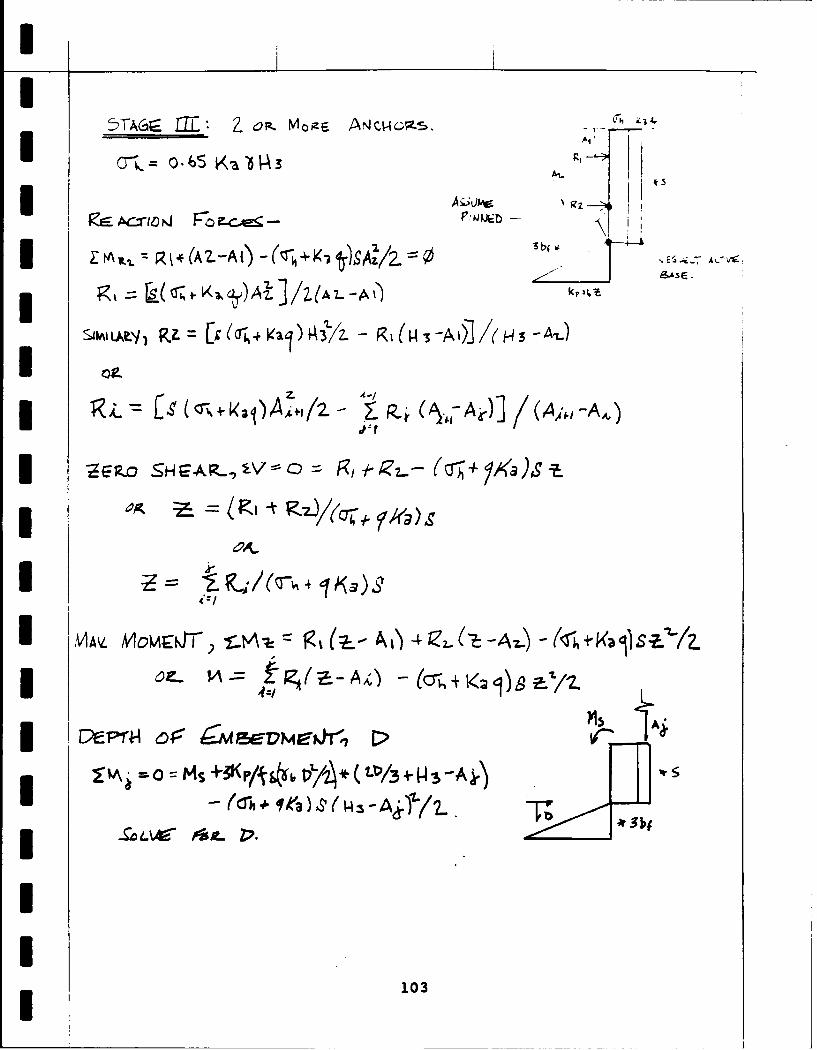
5TAGE : 2.~ MoizE A, Jc34gU ~ 065 3A4
*~ ~ A(A 2--A( +~~z/~ X -)
?Ui ;(r+ajAY Rjf43A ] ( ,4# -A )
4&
IAV MOCP- z I z)Si72
I z- Z -A(6-
103

IENOIs -P-.-ao 7 X
Ie- L-jfA~bvE 7A(L/.- ) 4.
waQDg Aq &r ,f
yb~~~~ ~ -x-A1 P,--AA
0 mJlEZ ev 't - - +-SV b:06 -F
IP I H~eJ /Z- +
*A -1TA
MS-3 04-Aix)b 3 3 -i 4-f 217/)
S=."/2_ 4 (,Aj)3 M p ye1.T
104

HoI6w4r OV -r =WsiorJ
(2-c-~/ -/ /\
www I
I 5 t 6CrA 2-C. +I~
ICr C~-Z
NlEr ?A~v-- 9JJ EsLs-rJcE &Lo\J 9;e>-1Zm
Pm-7 -. mJIVo'm ekj~Emrk oe ZC *3b~fW 111 rACrow- Or SArr Y~S)
If I z I~(Sa =(9 6 A - ZC) Nb+
ScA~s + -c. < q+ '601L YJuIL. bJT SUPPO~T 11VEIIALL.
&FA~ ~-re~ioW~ Zow5 V
IF tA1 3R+9 -Zc
105

N\A)(MO4 -X 4z.2 ~H ppX V2
MM Mz~( -It P
SLE </ o -l L
IE V P-I 2
5tiEA of~ ~~) ~r~ u
0 13~so~ UT Zt<CQ ~T
sL YvzIoL, (4 It/ - -
X = s-R-III/t-rp H-0 2-
106

< 0
X RsHLoK PJ zr p
+ ~ R/ S(jC)HL ul(P4+ApP
I M~x... N\c)?'1~1%r, A 2.c) H2. .ui±)
PpP-1 w-1oZ-e 64a -At~ 1) e~
107

U4STAGE 7=1 -6( :7:41
CI5- 77R. r'h-f a 7 wV
C- K 5 44 k/H e 41
3K~L= I-4wic/ wv~E s4t~
37 IF ~ J NX - L A-. V r ~ 5eS
6I0 = s As*~ 4-sl A241/2 - ,- (io Ai,](A. -A;)
a,; ANO~ozv STZe5S cA_
K~~A ZH/A l.Ts&= 1i4(A +30/6 O2.i(~~~
A <:11414 0..Y147A 4 i-l-%) o .2- 474i - i )
03 OM.4"(A&~ 0 'iH(A*i- +
AAI A 1~44 1c AsZ Ka.' A / 3 l
k -7/ W4 ('/&*(4A.4vHA~) + gaAA i1 " (A.4:4 1'1)/2-
CA&SC A,3rx so - (.o ~-, 1--6 H -44)) --S 0 'X
y lz +(~i' j- -- 7 5 M))-
108

3 MAX. MW r~i~
3 ~~~ A S') -f/Z- -eS-- 6' oz4I(.-tO
0 ZLA tL~ (-T - -1SHl H-
pp 4-604 1k- - C. *(O7gH-A)4 0-0-H-V&, ]Z
*A -7 '34414:2N j4e~~ (- Ak)31'j6
10

Y.A~e
I ~~ ~- )~H(~z.Z 4- Z
I C~110
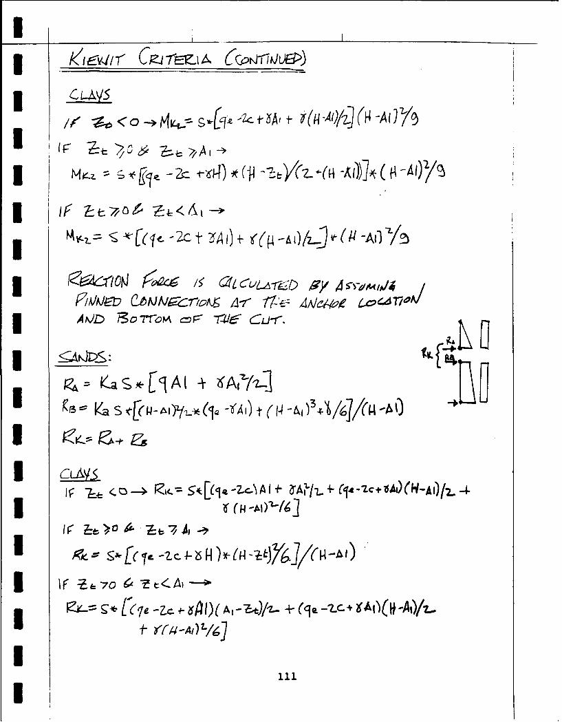
* K'iV4i CP-47rZA, (CON riJ1hJ>)
N~~~~ A c 4~<C6I ('I( (
98 S,) i7"rC A -At 1
KI 3 t~ WaS(AI2 I(a -&Ai) At A4 (14 -'/ (- A
> 0 II*A -
*g70 t:_

I, LTA LoL II
V
FI
I-*/TWI- ., r A bAV QS
IFtI/I/r
O~~.jV~f g--~ iP cAV112±~

WNALjE Atid$$:
WCF,5*e 6( 3576 T-0 ALC_-u.T F 4
4. w MI3 TAdLLs~. 73( 5 .1 Ks
3w3NV2 Lu= TAz
I~~~~~/ 44iE 'v ~Ak~
I00LAIr s e 9 A 1 4 fI% HA
IZ
113

rieI MeD i SAP.J> L. = C)
I C)L.I4'IS: CZ.
ULT. A~cwowr L)L-r. A4ct4oZ
____ ____ _ ( iP/r:T-' _________
3 7. 85
N m6DIlJA I 3~A
IAssia D = 6"~ - fr
ULT AP4C~oe rticnaw~ * lT/Z. LiLr Ag~r CaAry
114

° te
• x
--. -' ---------. - Rve, ,. t
I _ _~_ _-
Ct oUx
! --II _ _ __
C
20
0=
Length of Anchor (ft)
Figure C.1Average Load Capacity of Anchors in Fine to
Medium Sands
1 2W
300- +E
I 115
I
Uegho nhr0
FiueC
Average Lad Capat of Anchors inMdiu
3 To Coarse Sands
3 115

IIIIU
i v00 - a
j 50-
a00*
•Length of Anchor (ft)
I
1300-
a- I-- Length of Anchor (ft)
Figure C. 3Average Load Capacity of Anchors in Sandy Gravel
II
I
I 116

IUI* APPENDIX D
EXAMPLE PROBLEMS
IIIIIIIIIIIII3 117
I

UU
* Design of Soldier Pile and Lagging ** * *In Accordance with NAVFAC DM-7 *
I I. WALL PRO P ER T I E S
1. Engineer: D'Amanda2. Project: Sand Example #13. Date: 21 September 19914. The elevation of the top of the excavation is
250.00 feet.5. The elevation of the bottom of the excavation is
215.00 feet.6. The number of anchors is 3.
The anchors are located as follows:Anchor Elevation (feet)
1 245.002 235.003 225.00
3 7. The spacing of the soldier piles is 4.00 feet.
II. S OI L P R O P E R T I E S
8. The elevation of the water table is 0.00 feet.9. The soil properties are as follow:
Soil Type Elev Unit Wt Friction Angleor Cohesionsand 250.00 0.1100 30.00
I 10. The slope of the ground behind the wall is 0.00degrees.
11. The surcharge load is 0.500 ksf.12. The strip load is 5.00 ksf, 20.00 feet long,and located 50.0 feet from the wall.
3 III. W A LL ANALYSIS R E SU L T S
13. Estimated width of the soldier pile is 1.00 feet.14. Factor of safety for passive resistance is 1.0.15. The wall was excavated 1.O.feet below the proposed
anchor location.
II 118
I

1
116. STAGE ZERO MAXIMUM SECTION EMBEDMENT REACTION(S)SHEAR MOMENT MODULUS DEPTH(ft) (k-ft) (in^3) (ft) (kips)
1 11.0 57.53 23.97 9.5 ---2 22.9 59.63 24.84 5.8 R1 = 31.243 20.5 71.43 29.76 5.4 RI = 53.13
R2 = 43.684 30.0 73.45 30.60 5.7 R1 = 66.10
R2 = 51.41R3 = 58.76
NOTE: Stage 1 moment based on Kiewit criteria is 43.5kip-ft.Stage 2 moment based on Kiewit criteria is 44.2kip-ft and reaction force is 27.2 kips.
NOTE: Minimum depth of embedment based on maximummoment is 5.7 feet.
NOTE: NYCTA recommends minimum penetration depth ofsix feet.
IV. A N C H O R A N D W A L E R E S U L T S
17. Spacing of the anchors is 8.0 feet.18. The anchors are set at an angle of 5.0 degrees.19. The anchors are set in medium to coarse sand.20.
ANCHOR SECTION MODULUS ANCHOR ANCHOR UNBONDEDROW OF WALE CAPACITY LENGTH LENGTH
(in-3) (kips) (ft) (ft)
1 73.4 133 13.7 16.62 57.1 103 9.4 11.03 65.3 118 11.4 5.5
NOTE: Tieback capacity is based on pressure injectedanchors using an effective grout pressure inexcess of 150 psi with a diameter between 4 to 6inches and depth of overburden greater than 13
*feet.
NOTE: FHWA/RD-82/047 recommends a minimum unbondedlength of 15 feet.
END OF ANALYS I S
I119
I

lef-~~~< A5$1V V 5s~
&LO 4- o II
2L TmE (45A1 -Q~ 4JM5. I1/3~
KptJ - os TW - 012.) z -Ab "--i V 5~ +-0/- 41~6~ L~
9I Z/Knv (-e 1) ez mtj~ 50+o/ ) = 1.6
Ia Ip T& 0 501e
*a 7o. 4-C,
+ (K-Aj~f~ -64iE-(K~fs-K
120

I,
I WLA _c
I '- °'t ) 4- ( /a (6'H b
I t21 -K-N
I 6/t -, 5) +2- V5 2-5
Lt>2.9~I32Io~1~-~3~z.
I~~~~-s (a~ /Io ;2 2A~
9eIS? -f o! 3ZkS
121 I

U ~- 5-73- 31 -t-// Z7 ) (8S/ ti )I 4-Z: -J2 3 Z--7 (
I-1 - 6 -,'- / Z Z ~~
I .5-e-6 e - -,
I- -q
I - 1~~~~(4)(0,11),13 /3 ,(Ii2(*OL)
122
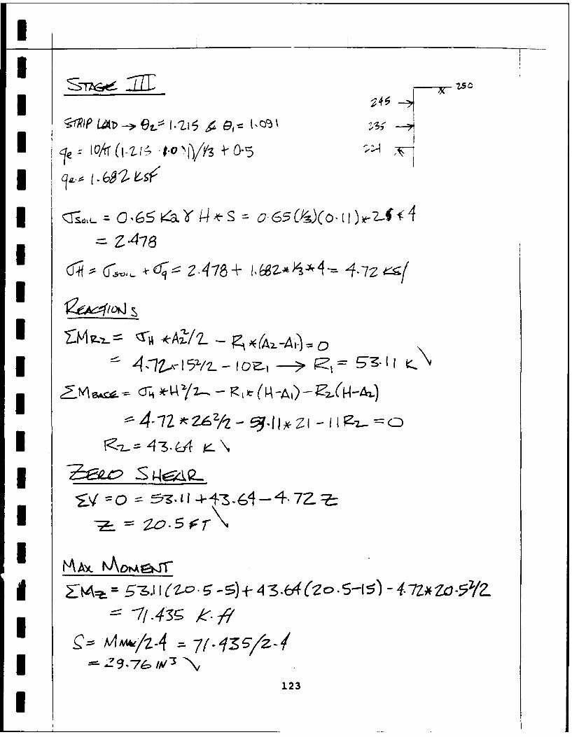
I A1.0
I~ ~~ avr(~i oto~Y -ie2
*~ ~ .4~ ~ -78
oS q5-9247±2*)r
IZMs e--4- /I-~tz
* 9.e ,/Wc'~ ~I44~4-4173

Iz 5 4 n 7 1
F -\7'
SjpLOADY :
~~~~~ I.0 S I 0.6
(o -~O±. /.)(-3 k - 3 - 3 7e
~~~1 3 Y7.-(34/s ;t- 4 = .75 I:-q
M ~ 6.' k-1 6-0 .
I~ 4 1i4 k.J
I5 5512 -3*6-0 .e 14
I 124

I ws-* -73A(+t (~)V Do-7(o~/
(Z3 t4, to) 25.(56
1J-twJJL C~xrmvI It6ys --) ( .Z
-3. 4 4
I IAL' 5*2 Z _j_ 11 / 2/3 f (27r,
* Z7-Ib
I/Se 4g/e.w &'?4ay&I e'.F~~4~~1
IS-6CT.J1 A"Q~LJS, SWA -g ,1
3o S, 66-1 8"'/4. 4 *4 7 .4 ,.
ESJ3.V4 3 5SZC. k 6 "/(1. 4*14 L-Z.9I 125
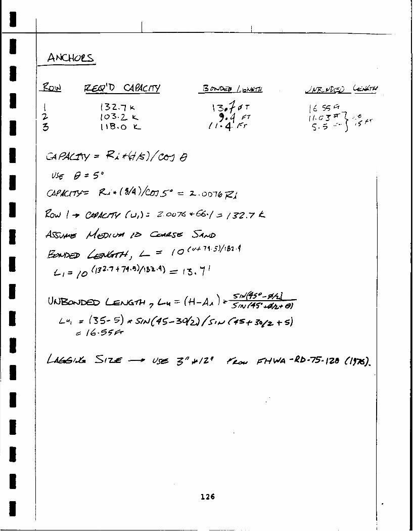
Z621 C4 PAC trY 7
I (3-Zs> ( 5
-- Lo3 / z o .
c edcny *(4 -0)/b 5 d4
UO&oi-.DED Lr=pj-ii-#7 4-t4 W4-A.A )~~ -
(41 zr(3 5-elf ~ 8)
12

11
I Design of Soldier Pile and Lagging *
In Accordance with NAVFAC DM-7 *I, ** ************* * **** ** ******* ************ *******
I. WALL PR O P ERT I E S
1. Engineer: D'Amanda2. Project: Sand Example #23. Date: 21 September 19914. The elevation of the top of the excavation is
10.00 feet.5. The elevation of the bottom of the excavation is
-10.00 feet.6. The number of anchors is 2.
The anchors are located as follows:Anchor Elevation (feet)
1 5.002 -5.00
7. The spacing of the soldier piles is 4.00 feet.III. S O I L P R O P E R T I E S
8. The elevation of the water table is 0.00 feet.9. The soil properties are as follow:
Soil Type Elev Unit Wt Friction Anglel1 or Cohesion
sand 10.00 0.1100 30.00sand 3.00 0.1150 35.00sand -4.00 0.1180 38.00
10. The slope of the ground behind the wall is 12.50degrees.
11. The surcharge load is 0.000 ksf.12. The strip load is 0.00 ksf, 0.00 feet long,
and located 0.0 feet from the wall.
I III. W A L L A N A L Y S I S R E S U L T S
13. Estimated width of the soldier pile is 1.00 feet.14. Factor of safety for passive resistance is 1.0.15. The wall was excavated 1.0"feet below the proposed
anchor location.
127
I

I
I
16. STAGE ZERO MAXIMUM SECTION EMBEDMENT REACTION(S)SHEAR MOMENT MODULUS DEPTH(ft) (k-ft) (in^3) (ft) (kips)
S1 10.9 32.85 13.69 9.7---2 23.6 43.25 18.02 6.6 RI = 23.563 17.5 12.32 5.14 3.8 RI = 44.37
R2 = 24.65
NOTE: Stage 1 moment based on Kiewit criteria is 25.2kip-ft.Stage 2 moment based on Kiewit criteria is 44.3
kip-ft and reaction force is 18.9 kips.
I NOTE: Minimum depth of embedment based on maximummoment is 1.7 feet.
I NOTE: NYCTA recommends minimum penetration depth ofsix feet.
IV. A N C H O R A N D W A L E R E S U L T S
17. Spacing of the anchors is 9.0 feet.18. The anchors are set at an angle of 10.0 degrees.19. The anchors are set in fine to medium sand.20.3 ANCHOR SECTION MODULUS ANCHOR ANCHOR UNBONDED
ROW OF WALE CAPACITY LENGTH LENGTH(in3) (kips) (ft) (ft)
------------------------------------------------------------1 27.7 45 6.0 7.42 15.4 25 4.4 2.5
I NOTE: Tieback capacity is based on pressure injectedanchors using an effective grout pressure inexcess of 150 psi with a diameter between 4 to 6inches and depth of overburden greater than 13feet.
NOTE: FHWA/RD-82/047 recommends a minimum unbondedlength of 15 feet.
I END OF ANALYSIS
3 128
I

IA L
~ ~)L~?L~~ 2L3 -1
x. E=1 15 :fl
2rI S (a~ PC 0 :-
I Ka=o34 ba-6'.
Ka~~~ Ka 6I6 ~z
I V +T o(f I~. b 4
I ~V6s) ( -0
0 Z-Z - a 4- o :
-7=4.5;+~ + k= (o.3.f4.\
(- 0. ~ t-A
(3 + +~ */. s
I~ ~ Crkv' -4 62f(-)/______Ila

I ~&~6-'\ (6/3 + '~ '/3s(.i I 6) 4.#/z. 4(ps '3)(Thk 4A 6
+ ( -(i-5 -Y) o -0LA 1YV0,/6
Kmx32 8'3 '-' -
I MSEPAEOT 7-; V'=;6
3L $T~L- 10
7= '~3 tec -6' 06= 5
Ka-. 0-30-7? 6
A 1Acsm* K&1wio23.
Ia A3S .073tSI 6 Z 'c
MWJ0 PT 14~~
33

I ~ =O-14((6/3 4l+ 4 .3(I3' .zd1~~~
5 53 -S,5 le-ipA-S\~
fo -4 +- 4033 - -.3k 4 -23.5 5-,
IAmA 1 V- t- (t \ s 4 -t). A ,.,A 3' \V~~.S 1.7~
A k#S v2v-I 1 5

-I -1+-, on 46 01 t
Kip- 4 o.,o
3 Ri c~ A~/~7 ALA') 3 -' 4 Ai-)
U~~~, .3 r2o- N 'o-Y/z-5
3 MAY A~.tew 7r-A-
=4 --- /1- -5) +s-s Z4. 61(7j '- 15) - 3',
I MAMAyLI'-.31 V--4-\

I+
36 1 -'+({o (C6-L ( 3*~ 5 ) -. f(
I ~ 3-75
II CIi~
o2 j-o307 8. x-0N945+4A/j
I- MA2o F> ($o7I.
3p 0 307 y*a II f.*. 0- 71r
4L3.3CI K
1s33

*H
I ~$~44-2-7
I ~K" .i... 4- E (H-AI')YZa( A I)+ (P -AI~~ii7U4)
6 31- c(0)/z - 4
JZ U 433v,
3 ~/AJC,(.I&JATOPNJ A4C3LZE- O
A4 ci-o ApAcZ,-y frfA -ro z-1
IZ-1 4 5o r,\ W~AIha
U U~=Zs.O IL-N
L-A 10"W91//A i -f 5.4156 Frv
UA~eoi~JZ- 114W
4 (zo- s-) v CIJ( 4 S-34-(52. )45,J 45 -3 4I1j- +mfd
I L~ 7.4 5T "s
134
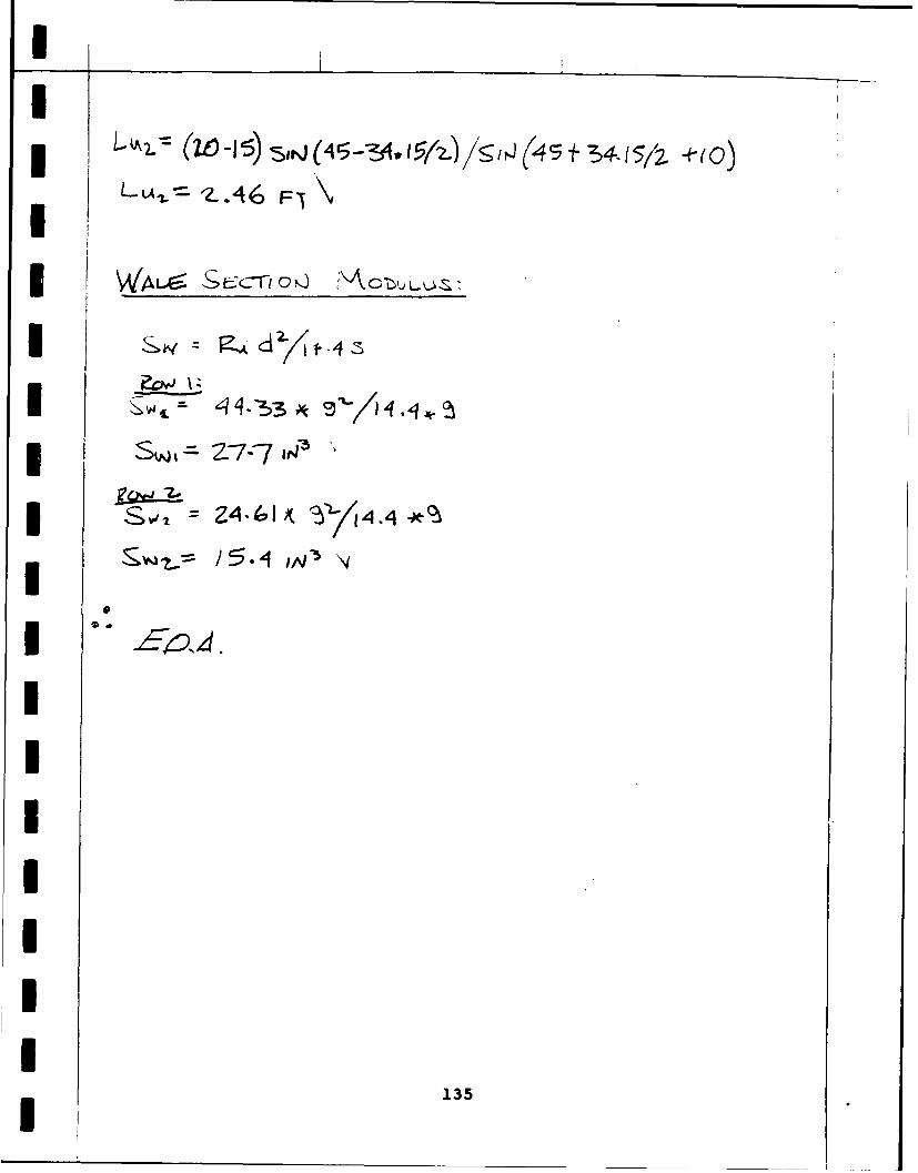
LIAI =F
zZ4. 4IA4
~~135

I
I
* Design of Soldier Pile and Lagging ** In Accordance with NAVFAC DM-7 *
•* •
3 I. WALL PROP ERT I ES
1. Engineer: D'Amanda2. Project: Clay Example #13. Date: 21 September 19914. The elevation of the top of the excavation is
100.00 feet.5. The elevation of the bottom of the excavation is
60.00 feet.6. The number of anchors is 3.
The anchors are located as follows:Anchor Elevation (feet)
1 90.Ou2 80.003 70.00
7. The spacing of the soldier piles is 5.00 feet.
II. S OI L P R O P E R T I E S
8. The elevation of the water table is 0.00 feet.9. The soil properties are as follow:
Soil Type Elev Unit Wt Friction Angleor Cohesion
clay 100.00 0.1100 0.50g clay 85.00 0.1200 1.75
10. The slope of the ground behind the wall is 0degrees.
11. The surcharge load is 0.750 ksf.12. The strip load is 5.00 ksf, 10.00 feet long,
and located 50.0 feet from the wall.
I III. W A L L A N A L Y S I S R E S U L T S
13. Estimated width of the soldier pile is 1.00 feet.14. Factor of safety for passive resistance is 1.0.15. The wall was excavated 1.0 feet below the proposed
anchor location.
3 136
I

16. STAGE ZERO MAXIMUM SECTION EMBEDMENT REACTION(S)SHEAR MOMENT MODULUS DEPTH(ft) (k-ft) (in^3) (ft) (kips)
1 13.6 119.25 49.69 7.5 ---
2 24.3 91.14 37.98 2.1 R1 = 44.133 25.1 150.38 62.66 2.2 R1 = 194.47
R2 = 80.754 34.7 123.01 51.25 2.1 R1 = 211.11
R2 = 103.15R3 = 128.81
NOTE: Stage 1 moment based on Kiewit criteria is 137.1kip-ft.Stage 2 moment based on Kiewit criteria is 65.8kip-ft an: reaction force is 29.1 kips.
NOTE: Minimum depth of embedment based on maximummoment is 1.9 feet.
NOTE: NYCTA recommends minimum penetration depth ofsix feet.
NOTE: A total stress analysis approach was used.
IV. A N C H O R A N D W A L E R E S U L T S
17. Spacing of the anchors is 5.0 feet.18. The anchors are set at an angle of 7.5 degrees.19. The anchors are set in stiff to very stiff clay.20.
ANCHOR SECTION MODULUS ANCHOR ANCHOR UNBONDEDROW OF WALE CAPACITY LENGTH LENGTH
-- (in^3) (kips) (ft) (ft)
1 73.3 213 27.1 26.72 35.8 104 13.3 17.83 44.7 130 16.5 8.9
3 NOTE: Tieback capacity is based on post-groutedanchors using an effective grout pressure inexcess of 150 psi with a diameter of six3 inches.
NOTE: FHWA/RD-82/047 recommends a minimum unbonded
3 length of 15 feet.
END OF ANALYSIS
137
I
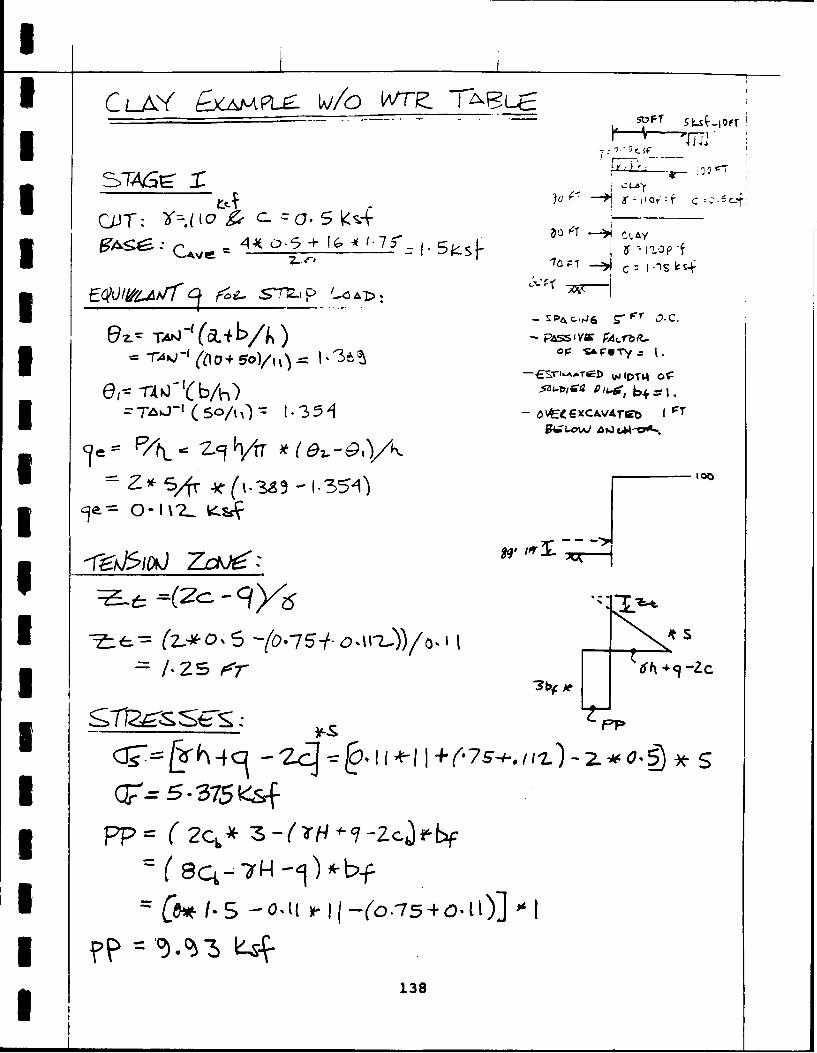
3CDJT: O
-rA -( r SFOT =i. 4
S1S-AT- Vjl-f
eII -A0 A / flJ -OVoi p aSS'Y IAfbi? .
0 2-ot zs*-89
~i -
SLi4 AZ &Z
5 375 E+
PP pp (2c, f-b~
(ec- 7H -ej-k
g 138
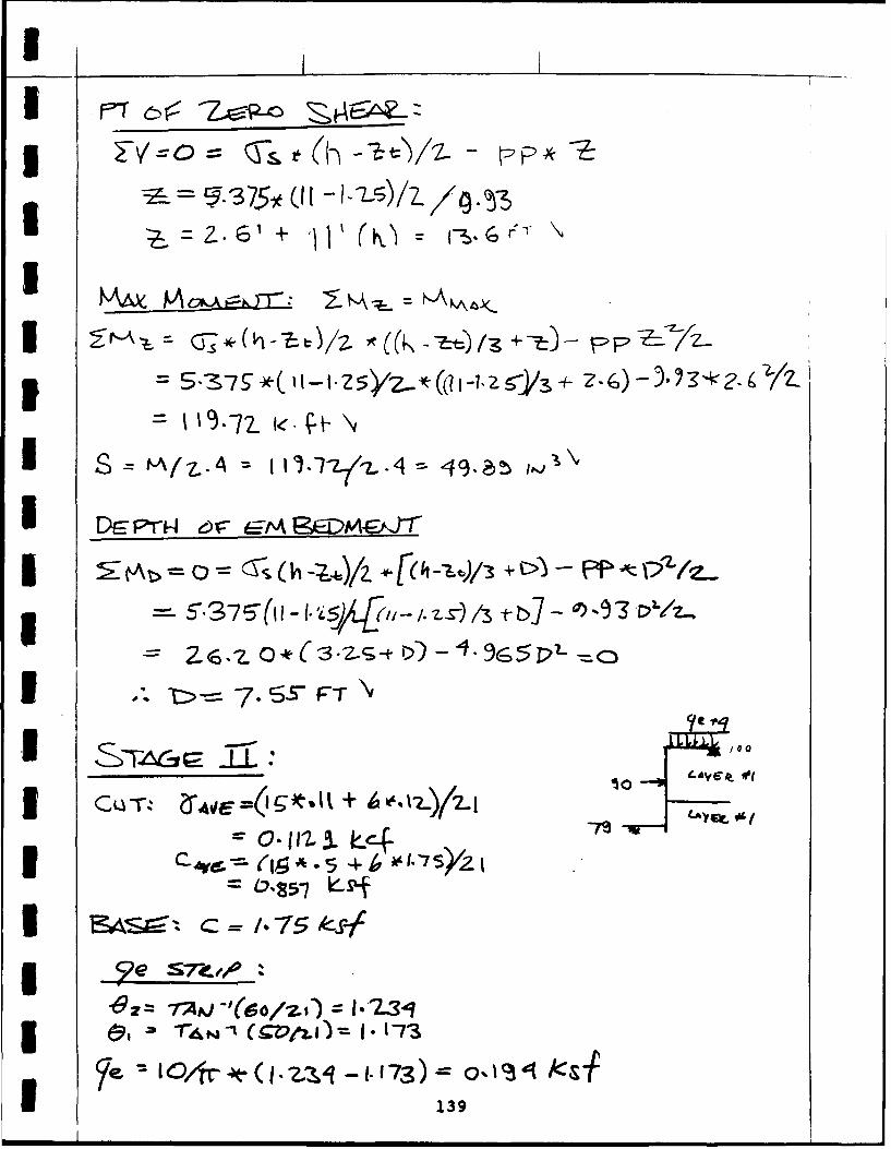
kA Ic~KF -Xy6 -4(,
i:tt>=-= T,72 -1. /. -'( [ h +C)
TN = 7-STIF
I Q r-aAE vIk+4
3 -75
'6z= -AP = -'( 51 k:Z s
I Or 1- 1.)'I.73) ,1O
139 ._____________

5 ~~ - 6.-1 > 1 -
(:j ( _l -r -7 P/)LE
KN=( S54- ( -I 40 X.7(o.I+X)=
=I00' ( I-''yL(
140

I
I = M .7( ml -FT ,
I S= 36ltas ,, 3
I v/?MJ C
*l P D
I2 .- ( -t r--r 3/&
I + .O 7 -o., t + 11)o,,2-1', -o . 65 7
-- -2 *Zd 5 -&(
C1 (I o 4 1 1). t>/ o Ij . .
3
II 141
U--6G

I
3: = o II o.iiS( .t.5
I - 14
3 q+c4_= o- -7 Y-4:(8- (9 1-1.) - VE~cccr P=e.oLae; smow c
II O ,_ 7.4 7z.../.*( m73- 2..5) + .1 5(-!.+ .
3 71 .' -. SH/z - 7 , ..1. +( t 12 o
I = \c0-1 . N
-7 1 t2 5 "/-Zt1Sr'3 z325 17i4 5(I;.'L+7 1)
I 7i.1 ,-, O,4..~~~l/ Vq3*,-~
S4- -&X +- 80.- 1-7 4 *-'75/ -7.4*.5-- s* o. T 5 5_.-- * -,115Z. (;3 1 0-9 o.-&)(S..-o. -7 (3 )
S136-7 4. 9 -O.5 ,( -.. )(, -.- 3.7)
I 12421 T\
3 142

I714* 1 5.Z5.1 - I5-S
SUX Y-/ -NF
I
IVV 150.-Lt4- 1-3 D(V/7 + 11 -
I = ,Iv +,
I = o -A 4 CLb p2.
aCA~i -
I V O~0-1625A-40/0.5 .114
I 143

I9 3
4P- /iT 0 -q t -Z~)
z I IVJ w3& (%V -tO--) 7r7 30
II I el0-26 -1V20 l-3 1
-I 0 . 4-Z ('fzo0 0 .ig 2 /Z4 --t.-3 CZ.)) ~z
II C, 730 -S82-S('0- -
-34o~5 -
144

A~- i2-4-16+ 1 C31*i- -4q .-3 Io/L* (34~- . /14) - k 1- (31 - L4
S 1z 4- ~(1*6
3r, (b PfO/
I ,o-v Iw.) SO Au. D(A'10 . 5
1 uJ4,- 2 a2. -I t >(D7-L-+ 10) ;-0 411.4
3 ~~~ -z o- Pr)
Is 4tZ(l2,1 -,
3 145

I-f4\
I -Z 6
A -r - .~ !5 N ( a
J~-3 5 -7. 9
LL= tI i'/ So I -S
U 14 O~r~e LW140 d* Z
l-&,- 0-0 t -I)=
I-- --f -O$ I (4-O) 7'=
I Sw,: 0.747-t )I I = 73. WIN~zS ~{7,
1 146

IA
1 147
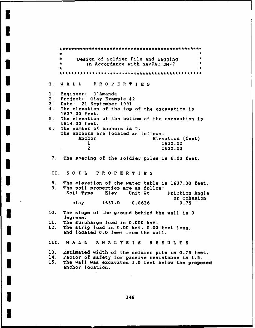
II
* Design of Soldier Pile and Lagging ** In Accordance with NAVFAC DM-7*
I. WALL PRO PERT I E S
1. Engineer: D'Amanda2. Project: Clay Example #23. Date: 21 September 19914. The elevation of the top of the excavation is
1637.00 feet.5. The elevation of the bottom of the excavation is
1614.00 feet.6. The number of anchors is 2.
The anchors are located as follows:Anchor Elevation (feet)
1 1630.002 1620.00
7. The spacing of the soldier piles is 6.00 feet.
II. S O I L P R O P E R T I E S
S8. The elevation of the water table is 1637.00 feet.9. The soil properties are as follow:
Soil Type Elev Unit Wt Friction Angleor Cohesion
clay 1637.0 0.0626 0.75
10. The slope of the ground behind the wall is 0degrees.
11. The surcharge load is 0.000 ksf.12. The strip load is 0.00 ksf, 0.00 feet long,
and located 0.0 feet from the wall.
III. W A L L A N A L Y S I S R E S U L T S
13. Estimated width of the soldier pile is 0.75 feet.14. Factor of safety for passive resistance is 1.5.15. The wall was excavated 1.0 feet below the proposed
anchor location.
13 148
I

5I
1 16. STAGE ZERO MAXIMUM SECTION EMBEDMENT REACTION(S)SHEAR MOMENT MODULUS DEPTH(ft) (k-ft) (in-3) (ft) (kips)
0.0 0.00 0.00 0.02 23.5 5.39 2.24 5.1 R1 4.263 20.0 41.81 17.42 4.4 R1 65.60
R2 = 65.84
NOTE: Stage 1 moment based on Kiewit criteria is 0.0kip-ft.Stage 2 moment based on Kiewit criteria is 16.5kip-ft and reaction force is 2.5 kips.
3 NOTE: Minimum depth of embedment based on maximummoment is 4.4 feet.3 NOTE: NYCTA recommends minimum penetration depth of
six feet.
3 NOTE: A effective stress analysis approach was used.
END OF ANALYSIS
IIIiIII
1 149
I

3CLAY1 4 A'L = F2LLJ-h\
- kT IA w,--~ AYv ~s,~C~
I 6z.4
I *'. A4~
3 -- 9I
150.

I
I -I
II
4Z6- o /jF
I - 7
Ib - i *(I-L)/3 f .b - (6,;275 a z ( -7-+ 8)
= .5'v( 1(.sf55) - (667 5 Z. - I-, *Il 6
I ~ '-5_.4 4 V,.FT~
151

I i
I
> ~qjFT
o, C'r4 0.N1 2vl .- d, .)C
I I LT o6Z4*Iz2 *Co(1/3)
=,- 6 - 52, -e- (,3 4- I7 5)4 3-16t -I,-,
-o.067-4 x s 31 6 W- .5 75- -75)I¢_,R---~ 65 7 IeIpsx \
-- 8V.7 - 3.374+[z3 -o. -5 )-
3 15
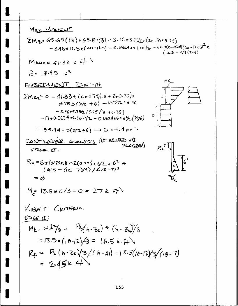
3:, (Z\'65 -Co5(v3 3 -4r -Y,5---
2- (2 - Z/3 (Z7d)
I CA~r. 6 A-- & ( 5. 5 - > I -1-5
3. 41T : 4.14
(As - - L--7),i /.' 5 > WIT
IR
1I t / 27 e
Ic
153

UII
APPENDIX E
I REFERENCES
IIIIIIIUIIUIUI 154
I
II
American Institute of Steel Construction, Manual ofSteel Construction, Eighth Edition, Illinois, 1980.
Boghrat, Alireza, "Use of STABL Program in Tie-BackWall Design", Journal of Geotechnical Engineering,Volume 115, No. 4, pp. 546-552, New York, April 1989.
Bowles, Joseph E., Foundation Analysis and Design,Fourth Edition, McGraw-Hill Book Company, New York,11988.
Carpenter, J. R., and S. Kopperman, U.S. Department ofTransportation, Federal Highway Administration,PCSTABL4 User Manual, Report Number FHWA-TS-85-229, U.SGovernment Printing Office, Washington, D.C., 1985.
Cernica, John N., Geotechnical Engineering, Holt,3Ricnehart and Wiston, New York, 1982.Chapman K. R., E. J. Cording, H. Schnabel, Jr.,"Performance of Braced Excavations in Granular andCohesive Soils", Proceedings of the SpecialtyConference on Performance of Earth and Earth-SuivortedStructures, American Society of Civil Engineers, VolumeIII, pp. 271-293, New York, 1972.
UClough, G. Wayne, "Performance of Tie-Back SupportSystems", Proceedings of the Specialty Conference onPerformance of Earth and Earth-Supported Structures,American Society of Civil Engineers, Volume III, pp.259-264, New York, 1972.
UDas, Braja M., Principles of Foundation Engineering,Second Edition, PWS-Kent Publishing Company,3Massachusetts, 1990.
II3155
I

Goldberg, D. T., W. E. Jaworski, and M. D. Gordon, U.S.Department of Transportation, Federal HighwayAdministration, Lateral Support SYstems andUnderpinning, Volume I Design and Construction, ReportNo. FHWA/RD-75/128, U.S. Government Printing Office,Washington, D.C., 1976.
Jarquio, Ramon, "Total Lateral Surcharge Pressure Dueto Strip Load", Journal of the Geotechnical EngineeringDivision, Proceedings of the American Society of CivilEngineers, Vol. 107, No. GT10, pp. 1424-1428, New York,October 1981.
Keorner, Robert M., Construction and GeotechnicalMethods in Foundation Engineering, McGraw-Hill BookCompany, New York, 1984.
Lambe, T. William, and Edmund K. Turner, "BracedExcavations", Lateral Stresses in the Ground and Designof Earth-Retaining Structures, State-of-the-Art Paperspresented at 1970 Specialty Conference, Soil Mechanicsand Foundations Division, American Society of CivilEngineers, New York, 1970.
Lambe, T. William, and Robert V. Whitman, SoilMechanics, John Wiley & Sons, New York, 1969.
I Liao, Sam S.C., and Thom L. Neff, "Estimating LateralEarth Pressures for Design of Excavation Support",Design and Performance of Earth Retaining Structures,Proceedings of a Conference, Geotechnical EngineeringDivision of American Society of Civil Engineers, NewYork, June 18-21, 1990
Merritt, Frederick S., Standard Handbook for Engineers,McGraw-Hill Book Company, New York, 1976.
New York City Transit Authority (NYCTA), EngineeringDepartment, Civil Engineering and ArchitecturalDivision, Field Design Standards, 1974.
156
II
I Ostermayer, H., "Construction. Carrying Behavior andCreep Characteristics of Ground Anchors", Proceeding ofDiaphragm Wall and Anchorages Conference,Institute of Civil Engineers, pp. 141-151, London,England, 1975.
I Peck, R. B., "Deep Excavations and Tunneling in SoftGround", Proceedings, Seventh I.C.S.M.F.E, State of theArt Volume, pp. 225-290, Mexico, 1969.
Terzaghi, X. and P. B. Peck, Soil Mechanics inEngineering Practice, Second Edition, Wiley, NewYork, 1967.
I Turbo C++ User's Guide, Second Edition, BorlandInternational Inc., California, 1991
1 U. S. Department of the Navy, Naval FacilitiesEngineering Command, Foundations and Earth Structures,Design Manual 7.2 (NAVFAC DM-7.2), Washington, D.C.,1982.
1 Ulrich, Edward J., Jr., "Tieback Supported Cuts inOverconsolidated Soils", Journal of GeotechnicalEngineering, Volume 115, No. 4, pp. 521-545, New York,
I April 1989.
U. S. Department of Transportation, Federal HighwayAdministration, Tiebacks, Report No. FHWA/RD-82/047,U. S. Government Printing Office, Washington, D.C.,
* 1982.
IIU3 157
I
Recommended