1/25
ActewAGL Distribution,
Telecommunications Strategy
Document Author James Cole Direct:
Mobile:
Revision R1.0
Release Date 27 May 2014
Released To: Role/Position Date

2/25
DOCUMENT APPROVAL
3/25
Contents
1 Background ............................................................................................................................................ 4
2 Business Requirements ........................................................................................................................ 5
2.1 Current situation and Options .................................................................................................................... 5 2.1.1 132kV line protection ................................................................................................................... 5 2.1.2 Future 132kV network synchro-phasors (zone substations) ........................................................ 7 2.1.3 SCADA communications (zone substations) ................................................................................ 7 2.1.4 AEMO ICCP communications .................................................................................................... 10
2.2 Risks and Controls ................................................................................................................................... 10
3 Strategic Vision .................................................................................................................................... 11
3.1 Wide Area Network (WAN) backbone ...................................................................................................... 12 3.2 WAN edge ................................................................................................................................................ 12 3.3 Neighbourhood Area Network (NAN) ....................................................................................................... 12 3.4 Digital Data Radio Network (DDRN) ........................................................................................................ 12 3.5 Voice Radio and Mobility .......................................................................................................................... 13
4 Telecommunications Bearers ............................................................................................................ 13
4.1 Optical fibre .............................................................................................................................................. 13 4.1.1 Optical fibre deployment option considerations .......................................................................... 13 4.1.2 Fibre count requirements ........................................................................................................... 14
4.2 Microwave links ........................................................................................................................................ 15
5 MPLS network ...................................................................................................................................... 15
5.1 Service Categories and Availability Targets ............................................................................................. 18
6 Proposed Implementation and Investment ....................................................................................... 19
6.1 MPLS WAN backbone ............................................................................................................................. 19 6.2 Fibre optic provisioning to distribution substations in the WAN edge ....................................................... 20 6.3 SCADA Radio IP, Bandwidth & Security (DDRN) .................................................................................... 20
7 Recommendation ................................................................................................................................. 21
Appendix A – Proposed OPGW Network ....................................................................................................... 22
Appendix B – Designated Category A ICON Communications Infrastructure ........................................... 23
Appendix C – Existing and Proposed Optical Fibres ................................................................................... 24

4/25
1 Background
The existing ActewAGL Distribution SCADA telecommunications network is a mix of UHF digital
radios (DDRN) and pilot wires, with some small scale use of optical fibre and microwave links.
The network is extremely limited in capacity and does not provide adequate and timely real
time SCADA information for effective control room operations, with some analogue and digital
changes taking several minutes to be reported. The performance constraints of the network
present a roadblock to realising the benefits of the SCADA system and this will only become
more apparent with the implementation of the ADMS, where real time data is critical to
correctly calculating the network state, load flows and correctly reporting network outages.
In the last few years in an attempt to overcome these shortcomings in the DDRN, the SCADA
communications network has been augmented with some higher capacity IP links to some zone
and distribution substations. These higher capacity IP links have been implemented using
optical fibre and microwave links to specific substations. While this has satisfied individual
project needs, the overall communications network requirements have not been thoroughly
considered and documented. Going forward, a more structured network architecture will be
required to maximise the benefits of investments and ensuring we meet the requirements of
SCADA, protection and other business needs of the Networks Divisions.
In addition to SCADA communications, the other critical application for communications is with
ActewAGL Distribution’s network protection. Increasingly some aspects of the protection
systems will require communications to overcome protection performance and grading issues.
In particular, the performance of the existing 132kV network protection falls short of technical
compliance with the current National Electricity Rules. These performance shortcomings are
considered acceptable due to ‘grandfathering’ provisions within the Rules, but as network
upgrades and augmentations occur the network protection will need to be brought into
compliance with current standards. Augmentations such as connecting generators to the
network1 or when the 132kV network is upgraded or modified2 are triggers for protection
upgrades. Required protection upgrades may include the implementation of intertripping and
line differential protection schemes and these are dependent on reliable and secure
communications. In the future, the emergence of IEC 61850 as the industry standard
substation automation and protection communications standard will require a very high level of
reliability in the communications network.
For mobile voice communications, ActewAGL Distribution currently employs a TMR radio
system operating in the 400MHz UHF band and a VHF radio network operating at 70Mhz. The
VHF radio equipment has reached the end of its useful life and it is proposed to upgrade the
remaining VHF base station at Mt Tennent to a TMR base. This will rationalise the deployment
of bases and mobile radios to the TMR radio system.
1 A connection agreement for the Royalla FRV 20MW solar farm has been accepted by ActewAGL Distribution and is expected to
be completed by end 2013.
2 With the completion of the Williamsdale supply point ActewAGL is now classified as a TNSP, ActewAGL Distribution’s re-
classification as a TNSP or the need for new work to meet TNSP obligations would most likely trigger the requirement to comply
with the new performance standards.

5/25
This strategy proposes a multi service fibre optic and microwave MPLS network covering the
main control centre at Fyshwick, the future DRF facility at Civic Zone substation and
connecting to all zone substations. The distribution network will be serviced by a mix of fibre
optic and an upgraded DDRN. The communication network will also support requirements for
advanced metering and future network automation requirements. The multi service network
will provide individual virtual private networks for different services such as protection, SCADA,
advanced metering and corporate services. This strategy aligns with the ICT strategy by
ensuring Operational Technology (OT) systems are independent of, and segmented from,
corporate ICT services.
2 Business Requirements
The telecommunications business requirements need to cater for the existing and future needs
of electrical network operations and corporate requirements for operating the electrical
network. An overview of these business requirements are as follows,
Current usage
1. Zone substation protection signalling, including communications for intertripping and
line differential protection,
2. SCADA communications to zone substations, fault passage indicators, reclosers,
switches and distribution substations,
3. Security video and remote access management,
4. Substation VoIP telephone,
5. Corporate data services,
Prospective usage
6. Advanced metering infrastructure (AMI) communications,
7. Inter station protection and control schemes,
8. Intra station protection schemes utilising IEC61850 and goose messaging,
9. Substation engineering access, for example remote access to protection relay fault
records,
10. Mobility communication to vehicles & deployed mobile tablets/computers,
11. Network video, for example infrared cameras for switchyard fault detection,
12. Monitoring and management of the communication network (MPLS devices),
13. Distribution Feeder Automation (DFA),
14. Power Quality Monitoring (PQM).
2.1 Current situation and Options
2.1.1 132kV line protection
Currently ActewAGL Distribution uses Distance protection on most 132kV transmission lines.
Distance protection utilizes voltage and current inputs and the line impedance in an algorithm
that looks at the positive sequence impedance for various types of faults. Zone 1 protection
operates instantaneously for 80% of the line section, whereas zone 2 and zone 3 backs-up
Zone 1 and provides protection for 100% of faults. Zones 2 and 3 operate at 400ms and
800ms respectively. Distance protection does not currently utilise any communications
between the protection relays at either end of the circuit. Faults in the first and last 20% of
distance protected circuits (40% of the circuit) will be cleared in 500 ms (Z2 time plus 100 ms
CB current breaking time)
6/25
Distance protection can be enhanced to provide unit protection with acceleration or
intertripping communications between the protection relays at each end of the circuit. It allows
faster tripping for a larger range of faults within the required maximum 120ms tripping time
under the NER. For these reasons it is recommended that ActewAGL Distribution enhances the
distance protection with intertripping as OPGW is rolled out under this communications
strategy.
Line differential protection monitors the difference of current inputs from current transformers
at either end of a cable section. For normal conditions, the protection does not see any
difference in current as current entering equals current leaving the cable section indicating that
the cable section is healthy. Line differential protection is required for underground cables or
extremely short 132 kV overhead lines.
The preferred options of distance protection with intertripping and line differential protection,
will achieve NER compliant clearance times for the entirety of each circuit.
Options (for consideration in individual business cases)
1. Do nothing – continue to use line distance without signal cooperation
Advantages
simple well proven scheme that does not require communications
Disadvantages
longer tripping time for zone 2 and 3 protection that may not meet
requirements under the NER.
2. Distance protection with intertripping
Preferred option for longer 132 kV overhead lines.
Advantages
faster tripping time that will meet the requirements under the NER
can be deployed as part of relays renewal program once OPGW is
available
minimal incremental cost once OPGW is available
will still operate as normal distance protection if communications
fails
Disadvantages
requires communications for intertripping to operate
3. Line differential protection
Preferred (required) option for underground cables or extremely short 132
kV overhead lines.
Advantages
deploy differential relays as part of the relay renewal program
minimal incremental cost once OPGW is available
Disadvantages
Will not operate if communications fails (reliant on backup
overcurrent)
requires OPGW with secure backup, higher cost
7/25
An allowance for sufficient capacity on the OPGW between zone substations is included in the
OPGW fibre count calculation in section 4.1.2.
2.1.2 Future 132kV network synchro-phasors (zone substations)
Phasor measurement units (PMUs) are devices that measure phase angles in the network and
enable synchronisation checking prior to closing circuit breakers. They also facilitate calculation
of network load flow in the ADMS and this can improve network performance and reliability.
Currently, ActewAGL Distribution does not have phasor measurements in the 132kV network
and does not have check synchronisation capability when closing open points in either the
132kV network or 11 kV network. With the introduction of the second bulk supply point from
Transgrid at Williamsdale, there can be a large phase angle difference across open points,
which may be unsafe to close or could result in large circulating currents under certain
conditions.
The installation of PMUs (Syncro-phasors) at strategic points in the 132kV network will be
proposed under a separate business case. Using data from PMUs, the ADMS can calculate
necessary phase angle differences across open points and load flows from state estimation to
enable safer and more optimal operation and planning of the electrical network.
PMUs (Syncro-phasors) will require the exchange of time synchronisation information using
C37.118-2005 protocol and this requires fibre optic circuits between zone substations where
the Syncro-phasors will be installed. Capacity on the OPGW between zone substations is
included in the OPGW fibre count calculation in section 4.1.2.
2.1.3 SCADA communications (zone substations)
The existing SCADA communications network connects the SCADA master station at Fyshwick
and disaster recovery facility (DRF) at Greenway to zone substation SCADA RTUs and SCADA
enabled distribution assets. The DRF will move to Civic ZS in 2015 with the implementation of
the new ADMS master station. Whilst the primary purpose of the SCADA communications
network is to provide SCADA communications for network monitoring and control, the system
needs to also support other zone substation communications requirements for business and
engineering functions.
An analysis of the current ZS communications system undertaken by Jacobs Australia
highlighted the following capability shortfalls:
The current Digital Data Radio Network (DDRN) owned and operated by ActewAGL
Distribution has limited bandwidth capacity to cope with additional communications
requirements;
The current DDRN is comprised of multiple point-to-point links with multiple single
points of failure. This limits the reliability/availability of the system;
The current SCADA communications system is not encrypted, which increases its
vulnerability to outside interference;
A number of operational problems have been highlighted by System Control such as
control commands timing out due to congested communications channels, inadequate
sequence of events data (particularly those time-stamped on receipt at the master
station), inability to verify control commands and unacceptable system response times
(some indications taking several minutes to be received); and
Electricity network monitoring and control data traffic is not adequately segregated
from corporate traffic and this poses a cyber-security and data integrity risk.

8/25
Jacobs Australia was also engaged to carry out the required analysis into various
communications options capable of meeting current and future ZS communication needs. High
level capabilities required by current and future ZS communication needs are identified as:
Electricity network monitoring and control (SCADA);
Remote engineering access to ZS RTUs;
Remote engineering access to ZS protection relays;
ZS Closed Circuit Television (CCTV) monitoring and control;
ZS electronic security access control and intruder detection; and
ZS corporate LAN/WAN access.
Bandwidth requirements for each capability have been calculated using a Monte-Carlo 3 point
estimate model. Accounting for anticipated future expansion in the ActewAGL Distribution
electricity network, as well as expected growth in capability, total bandwidth requirements
across all ZS has been estimated to be:
Under normal operating conditions the planned bandwidth requirement is estimated to
be 28 Mbps;
Under high activity operating conditions, with a 90% confidence level, the bandwidth
requirement is estimated to be 76 Mbps; and
Under worst case conditions the estimated bandwidth requirement is 90 Mbps.
In meeting the capabilities, needs and bandwidth requirements a number of communications
options are considered below. These options have each been assessed against estimated
bandwidth requirements as well as a number of other performance criteria.
A list of existing and proposed (near future) optical fibre connections is at Appendix C.
Options
1. Do nothing – continue to use DDRN as the main SCADA communications
medium.
Advantages
NIL cost
Disadvantages
Limited bandwidth capacity
Poor reliability/availability
Inadequate sequence of events data, inability to verify control
commands and unacceptable system response times (some
indications taking several minutes to be received)
Unencrypted data posing cyber security and data integrity risks
2. Use ACT Intra Government Communications Network (ICON) or
TransACT
Disadvantages / Limitations
Use of the ICON network by ActewAGL Distribution is bound by the
Commonwealth of Australia, Telecommunications Act 1997 and a
2013 Determination. Under the determination, the Commonwealth
have made designated parts of the ICON fibre network available to
ActewAGL Distribution for critical utility services. The parts of the
ICON network that are available are classified as category A ICON
Communications Infrastructure as listed in appendix B

9/25
The category A ICON infrastructure has been reviewed and is not
available at zone substation locations
Use of Transact fibre will be subject to commercial agreements
between ActewAGL Distribution and Transact
Use of Transact/ICON fibre would require special considerations when
bringing into substations, particularly in relation to mutual access
requirements by the service providers and contractors. Prospective usage is
limited to:
Use of the existing Transact fibre between Fyshwick and Civic Zone
substation
Use of the TransACT fibre between Fyshwick and distribution sub
TBA (TransACT House)
Use of ICON fibres where Commonwealth entities make the request
to ICON (as in the case of distribution sub 9555)
Possible use of Transact fibre in the distribution network for the
WAN edge. This shall be considered in business cases for any rollout
of communications in the 11kV distribution network.
3. Expand existing microwave network
Advantages
Faster roll out compared to fibre
Disadvantages
Analysis of the microwave option has highlighted a number of single
points of failure
Would not meet other business requirements such as protection
Would not have sufficient capacity for future business requirements
such as AMI
Microwave radio performance is affected by changing environmental
conditions, less reliable than fibre
Higher OPEX (compared to fibre) due to tower and equipment
maintenance and site lease costs
Shorter asset lifespan (15 years) compared to fibre (40+ years)
4. Redundant fibre optic utilising existing microwave to provide
redundancy
Preferred Option.
Advantages
Aligns with the preferred option for protection and can utilise shared
OPGW bearers between substations
Redundancy unaffected by single points of failure
Utilises existing microwave infrastructure to reduce total CAPEX
(compared to a fully redundant fibre network)
Higher capacity (1 Gigabit minimum) with room to grow for future
business requirements
Less equipment and complexity than microwave, leading to lower
OPEX and renewal costs
More reliable, unaffected by changing environmental conditions
Disadvantages
Needs to be rolled out as a meshed network requiring staged
investment covering a number of stations. (We are proposing 4
investment stages in section 0)
5. Fully Redundant fibre optic network

10/25
Advantages
Would provide extremely high reliability with no loss of network
speed under various failure scenarios once fully deployed
Disadvantages
Higher CAPEX investment required
Will leave stranded assets in the microwave network
Overall, the redundant fibre optic and microwave network solution presents the optimal
approach balancing cost, installation timeframe, performance and reliability. It also represents
better value for money over the life cycle of the assets, with fibre lasting over 40 years. On
this basis, and taking into account the additional considerations discussed above, option 4 for a
redundant fibre optic utilising existing microwave to provide redundancy is recommended.
2.1.4 AEMO ICCP communications
Under the NER, AEMO requires inter control centre protocol (ICCP) SCADA information from
the ActewAGL Distribution 132kV transmission network and embedded generators. Currently
AEMO is provided with data through a copper line DSL service to Transgrid’s Canberra
Substation. This does not currently meet AEMO’s redundancy requirements.
1. Do nothing – continue to use the DSL service to Transgrid’s Canberra Zone
Substation
Disadvantages
Does not comply with AEMO requirements
2. Use fibre into Transgrid’s Canberra and Williamsdale substations
Advantages
Share infrastructure (and costs) with the preferred SCADA
communications option above
Meets AEMO redundancy and availability requirements
2.2 Risks and Controls
If we do not proceed with this strategy the business will be exposed to the following risks:
1. Cyber security risks. Currently IP connections to substations are provisioned over the
corporate network with firewalls configured at both the substation and SCADA master
station endpoints. This is a complex and costly configuration both in terms of CAPEX
investments in multiple firewalls and also the OPEX required to maintain configurations.
Network virtualisation, network segregation and data encryption offered by the MPLS
solution under this strategy, are key mitigations for these cyber vulnerabilities3 and will
reduce lifecycle costs.
2. Radio system cyber security risks. The existing radio network design exposes radio
repeaters and substation SCADA RTUs to cyber intrusion and denial of service attacks.
The risks to ActewAGL Distribution are similar to those from the Maroochy Water
Services SCADA Cyber Security attack4 in the year 2000, where a hacker operated radio
3 Mitigations for Security Vulnerabilities Found in Control System Networks, The Instrumentation, Systems and Automation Society.
4 Malicious Control System Cyber Security Attack Case Study–Maroochy Water Services, Abrams and Weiss
11/25
controlled sewage equipment. Migrating the zone substations to MPLS and upgrading
the DDRN (section 3.4) will mitigate these risks.
3. Inefficient field operations due to failure of SCADA control signals (time out), slow
SCADA data reporting and non-redundant SCADA communication failures. Currently
some control commands routinely require multiple attempts to achieve execution and
analogue/digital changes take several minutes to be reported. 4. Lengthy SCADA outages due to non-redundant communication failures (three outages
occurred over 2011-2013). The proposed communications strategy and availability
standards will provide the necessary communication bandwidth and redundancy for
more effective operations. 5. Disaster recovery operational risks. The current IP connections into substations require
manual reconfiguration to enable network operations to function from the DRF.
Furthermore there is insufficient redundancy to accommodate routine maintenance of
the communications infrastructure without loss of Network Operational control
concurrently at both main and back up control rooms. The proposed WAN backbone will
provide the required N-1 redundant communications into the main and DR control
centres and all zone substations. 6. Not meeting obligations to AEMO under the NER. AEMO requires
5 that NSPs provide
ICCP SCADA data within the following standards: main system status indications be
received within 8 seconds and analogue values be received within 14 seconds. These
requirements are for the end-to-end latency from the primary plant operation to the
indications and logging in the SCADA master station. AEMO also requires redundancy in
the ICCP communications paths. Currently ActewAGL Distribution does not meet these
requirements due to bandwidth limitations in the DDRN and lack of backup
communication paths to Transgrid and AEMO. The proposed high capacity WAN
backbone is designed to meet these requirements.
7. Not realising the full benefits of the ADMS. The ADMS will require timely real time data
to correctly calculate the network state, load flows and correctly report network
outages. It is also capable of advanced distribution automation schemes. The current
limitations in communication bandwidth and redundancy will impact the timeliness of
SCADA data reporting from field devices therefore the operation of the ADMS. 8. Risks to advanced metering infrastructure (AMI) rollouts. A high performance, reliable
and secure communication network is one of the fundamental building blocks to the
introduction of AMI. 9. Risks to customer connection agreements and future embedded generation projects.
Communications is a necessary requirement for HV customer connections and large
embedded generation installations.
3 Strategic Vision
The strategic vision for the ActewAGL Distribution communication network is to create a
converged communication network to deliver multiple services required for the existing and
future requirements of the electrical network as outlined in Section 2.
To deliver these requirements a structured network is proposed with the following tiers:
Wide Area Network (WAN)
WAN edge
Neighbourhood Area Network (NAN)
Digital Data Radio Network (DDRN)
5 As defined in AEMO’s draft standard for power system data communications

12/25
3.1 Wide Area Network (WAN) backbone
It is proposed to create a WAN backbone with communications to:
the main and backup control centres at Fyshwick and Civic;
all zone substations; and
edge WAN connection points
The WAN backbone will use fibre optic and microwave links employed in an MPLS network. The
network topology shall be meshed to ensure there is at least N-1 redundancy to each control
centre and zone substation so there are no single points of failure.
ActewAGL Distribution has an associated strategy and augmentation plan to roll out OPGW on
its 132kV network. The WAN backbone will utilise this fibre in the MPLS network as outlined in
Section 5.
As a multi-service network is proposed, with some high bandwidth service requirements such
as video and advanced metering backhaul, the backbone should be implemented with
minimum 1 gigabit Ethernet links between control centres and zone substations.
3.2 WAN edge
WAN edge tier provides communication requirements for:
distribution substations;
HV customer and generator network connections;
NAN connection points, including mesh radio base stations or powerline
communications (PLC) connection points
The WAN edge will predominantly use fibre optic cores configured in an Ethernet star topology.
There is no baseline requirement for redundancy in the WAN edge network and any
redundancy requirements may be considered for critical sites on a case-by-case basis. Where
redundancy is required, Ethernet ring topologies or dual homed topologies may be used.
3.3 Neighbourhood Area Network (NAN)
Neighbourhood Area Network (NAN) providing communication requirements for:
LV customer advanced metering; and
LV distribution network automation.
The Neighbourhood Area Network (NAN) is an emerging requirement with the rollout of
advanced metering infrastructure (AMI). The network may utilise different technologies, with
RF mesh and PLC from the WAN edge connection points to endpoint devices in the LV network.
3.4 Digital Data Radio Network (DDRN)
The current DDRN is the main communications medium for zone substations, some distribution
substations, field reclosers and switches. The DDRN uses 12.5 kHz channels in UHF licensed
spectrum in the 400 MHz band. The 400 MHz base stations serve a notional 30km radius area.
The 400 MHz radios currently used in the ActewAGL Distribution SCADA network are Trio E
series. These radios operate in point to multipoint network and have a transport data rate of
9.6 kbps shared between all remotes. As noted above the performance of the current DDRN
communication is becoming inadequate for effectively managing the electrical network. The
available bandwidth and performance is not sufficient to meet requirements for zone
substation SCADA and going forward the DDRN should only be used for SCADA in the
distribution network.
In future DDRN will provide communication requirements for:
field reclosers and switches;
distribution substation communications where a fibre WAN edge connection is unviable.
13/25
Even for the proposed usage within the distribution network, the current DDRN performance
will not be sufficient for automated schemes within the centralised ADMS. Progressively
upgrading the DDRN to a higher speed IP based solution is proposed to enable these advanced
distribution automation schemes and realise the full benefits of the ADMS.
The strategy is to upgrade the DDRN radios to higher speed IP solution, either Trio Q series or
4RF. These radios offer data rates up to 56 kbps and will allow end devices to report by
exception to minimise scanning latency and will enable advanced automation. IP radios will
also have additional benefits in data encryption and enabling remote management of field
devices.
For existing network assets, upgrading of the DDRN network endpoints will occur during the
normal communication asset renewal cycle; for new assets IP radio solutions will be deployed
during construction.
3.5 Voice Radio and Mobility
A mobility solution is currently under consideration as part of the OSR program. This may be
deployed on tablets and Toughbook personal computers to provide access to Cityworks and
dispatch systems used by the control room. Due to the high bandwidth requirements,
commercial carrier networks, 3G or 4G, are the only viable options.
For Voice Radio, ActewAGL Distribution is currently using two technologies, a VHF system and
a UHF system. The VHF equipment has reached the end of life, and the strategy going forward
is to replace the existing VHF equipment at Mt Tennent with UHF TMR, equipment and thereby
rationalise all mobile and base station radio systems to the one UHF, TMR technology.
4 Telecommunications Bearers
Telecommunications Bearers are the physical medium used for transportation of signals
between sites.
The following bearer types are currently in use in the ActewAGL Distribution network:
Optical Fibre
Microwave Radio
UHF Digital Radio (in the DDRN outlined above)
Metallic pilots (not to be considered for future requirements)
4.1 Optical fibre
Optical fibre cabling is widely used in the power industry, with the capability of supporting high
transmission bandwidth on individual fibre pairs (2 x fibres for transmit and receive).
The benefits of fibre cabling include:
large capacity medium compared to other bearer types such as radio, power line carrier
and metallic pilot cables;
reliable carriage that achieves zero transmission error and performance that is
unaffected by changing environmental conditions;
can be run with electrical transmission and distribution lines with a small incremental
cost;
low environmental impact.
4.1.1 Optical fibre deployment option considerations
The optical fibre deployment method used for WAN backbone and WAN edge networks, shall
be considered in the order of preference outlined in the following table.

14/25
Optical fibre
deployment method
Reliability Application
OPGW on overhead
transmission lines
Very High Protection signalling - Preferred option
WAN backbone – Preferred option
WAN edge – Not to be used
Underground fibre in
transmission
communication ducts
Very High
Protection signalling - Preferred option
WAN backbone – Preferred option
WAN edge – transmission
communication ducts may be used
Underground fibre in
distribution
communication ducts
Medium High
Protection signalling – Not Applicable
WAN backbone – may be used
WAN edge – preferred option
ICON or TransACT Medium
Protection signalling – Not Applicable
WAN backbone – may be used
WAN edge – may be used
ADSS on transmission
or distribution poles,
below HV conductors
Medium
Protection signalling – Not Applicable
WAN backbone – may be used
WAN edge – may be used
ADSS on LV poles, on
LV cross arm or below
LV conductors
Low Protection signalling – Not Applicable
WAN backbone – Not to be used
WAN edge – may be used as the least
preferred option
The risks associated with using overhead ADSS optical fibres for the WAN backbone are
considered higher than for OPGW or underground fibre as ADSS is more susceptible to damage
(for example from vehicles impacting poles, bush fires, vehicles clipping the ADSS cable, bird
damage).
The assignment of fibre segments in the WAN backbone and edge is required to meet the
reliability and availability targets for services set out in section 0. The availability targets for
zone substation SCADA and protection will require geographical fibre (or microwave) path
diversity to provide continuity of services in the WAN backbone against the likelihood of fibre
segment failures. In building geographically diverse paths, it is preferred to follow transmission
lines between zone substations as the diversity requirements for communications are in-
common with the N-1 redundancy provisions built into the 132kV transmission network design.
The physical communications network will be based on a multiple ring topology. The topology
of the physical network for the MPLS network is depicted in section 5.
The reliability of the rings, and hence the physical fibre network, will depend on:
geographical diversity of ring segments;
number of nodes in a ring;
reliability of individual ring segments.
4.1.2 Fibre count requirements
The estimated optical fibre counts for typical requirements for protection, the WAN and WAN
edge are as follows:

15/25
Estimated OPGW usage between two zone substations (WAN)
Application Fibre Count
Protection - No1 Primary Paths (two feeders) 4
Protection – No2 Primary Paths (long way
around to provide geographic diversity) 20
Protection - Backup Paths 4
Syncro-phasor time synchronisation 2
WAN (MPLS network primary and backup paths) 4
ICCP to transgrid 2
Other Corporate BSD requirements 2
Total Minimum Requirement 38
Proposed implementation is to use 48 core OPGW.
Estimated underground fibre in the distribution network
The proposed WAN edge network uses a star topology connecting a hub in the zone substation
to each individual distribution substation. A 48 core underground cable can therefore service
up to 24 distribution substations in the one network. If and when the network needs to be
expanded beyond 24 distribution substations, distribution hubs or switching can be employed
in the WAN edge.
Proposed implementation is to use 48 core underground fibre optic cables in the distribution
network.
4.2 Microwave links
Microwave is a technology that can augment the optical fibre network and provide
communications to geographically difficult areas or where optical fibre is not viable. The
current SCADA network has limited microwave and this can be retained to add resilience as the
fibre optic network is rolled out.
Microwave is affected by weather and changing environmental conditions and therefore should
not be used for protection.
Future microwave links will only be considered as a last resort, when fibre is not available.
5 MPLS network
To meet the business requirements needs outlined in Section 2, a multiservice communication
network employing the MPLS technology is proposed.
MPLS is by far the most commonly selected WAN technology for smart grid implementations
because of its,
maturity and proven capabilities across large-scale industrial and enterprise networks,
ability to support both traditional applications and next-generation requirements,
ability to virtualize the WAN into independent sub-networks,
centralized management of physical infrastructure and virtualized sub-networks,
ability to enhance and become an integral part of the security framework across the
WAN, and
modularity for scalability and flexibility, as well as the ability to protect the overall
system from domain failures.

16/25
MPLS has recently been adopted by BSD to segment sensitive Payment Card Industry client
traffic from the corporate network. Currently BSD have MPLS configured between the data
centres in Fyshwick and Greenway, and ActewAGL Distribution House. It is proposed to
implement an MPLS network to electrical network sites in four stages as shown in Figure 1. The
MPLS rollout will occur in conjunction with the proposed OPGW fibre rollout outlined in
appendix A.
\
.
Figure 1 - Physical MPLS architecture for the WAN backbone
The MPLS network will have separate virtual private routed networks (VPRN) or virtual private
LAN segments (VPLS) for each service required by the Networks Division. This will provide a
layer of cyber security segregation between the separate business functions serviced over the
shared infrastructure. Service and availability targets are outlined in the following section 5.1.
Fyshwick
Gilmore
Greenway
Latham
Gold Creek
Wanniassa
City East
Telopea Park
East Lake
Transgrid Canberra Sub
Transgrid Williamsdale Sub
Angle Crossing
Legend
MPLS Provider Router
MPLS Provider Edge Router
Theodore
Transgrid ICCP Access Router
Transgrid ICCP Access Router
ActewAGL Fibre Termination Pillar
ActewAGL Fibre Termination Panel
Bunda St
Woden
Belconnen
BruceCivic
Transgrid Fibre Swap
Transgrid Fibre
Existing
Fibre Rollout Stage 1
Fibre Rollout Stage 2
Fibre Rollout Stage 3
Fibre Rollout Stage 4

17/25
Figure 2 – Logical MPLS Multi-Service Architecture
PCS Primary Control VLAN
SAS Staging Area VLAN
NMTZ Network Management VLAN
NMTZ External Integration VLAN
PCS Primary Control VLAN
SAS Staging Area VLAN
NMTZ Network Management VLAN
NMTZ External Integration VLAN
ADMS Disaster recovery,
via ActewAGL MPLS
Multi Services network
Architecture concept
SIZE DWG NO REV
A3 t.b.a. Draft, V2
SCALE N.T.S. Drawn: A.A. SHEET 1 OF 1
MPLS PE Router
LAN Router
SCADA VPRN
Engineering LAN VPRN
Corporate LAN VPRN
Other L2 or L3 MPLS VLANS
Substation locations
SCADA LAN1
SCADA LAN 2
Engineering LAN
Corp LAN
Comms repeater Site locations
Terminal Server
TrioRadioGW
TrioNetwork Substations
Office and Depot locations
Corp LAN
ActewAGL MPLSWAN network
Public Internet
Remote Support via VPN (e.g. Vendors and after Support
staff)
Fyshwick
Civic
Cat 6 cable
MPLS Service associations
Legend
Firewall User client
ICCP Gateway
ICCP Gateway
ICCP VPRN
Transgrid NetworkCanberra
Williamsdale
Hi s
pee
d D
bas
e u
pd
ate

18/25
5.1 Service Categories and Availability Targets
In order to reasonably meet the business requirements set out in section 2, the
communications network needs to deliver the service availability, as outlined in the following
table.
Service Category Quality of service
requirement
Availability
requirement
Downtime
per year
Protection signalling Real time mission
critical 99.999% 5.3 mins
Zone Substation SCADA Near real time mission
critical 99.98% 1.8 hours
Distribution network SCADA Near real time 99.9% 8.8 hours
Advanced metering Best effort
99% of meters
within 10
minutes6
43.8
hours
Substation engineering
access Best effort 99. 50%
43.8
hours
Network video, switchyard
monitoring
Real time non mission
critical 99.50%
43.8
hours
Security video and remote
access management
Real time non mission
critical 99.50%
43.8
hours
Substation VoIP telephone Real time 99.98% 1.8 hours
Corporate data Best effort 99.50% 43.8
hours
Communication network
management
Near real time mission
critical 99.98% 1.8 hours
Notes:
1. Quality of service and availability requirements are in terms of individual endpoints
2. Real time traffic requires minimal latency and no jitter on the data stream
3. Near real time data can afford latency up to 1 second
4. Mission critical data shall have preferential availability to bandwidth and alternate
communication paths
6 As defined in the NSMP Business Requirements Work Stream, Smart Metering Infrastructure Minimum Functionality
Specification

19/25
6 Proposed Implementation and Investment
6.1 MPLS WAN backbone
The MPLS and the supporting OPGW network will be rolled out in four stages over five years:
Stage 1 – July 2014 to December 2015
MPLS connection between Civic (including DRF), Bruce and Belconnen substations.
Leverages existing Bruce and Belconnen OPGW
Provides services to Bruce and Belconnen substations
Provides AMI backhaul for the Lawson South AMI rollout
Stage 2 – July 2015 to December 2016
Extends MPLS connection to City East, Telopea Park, East Lake and Fyshwick control
centre
Leverages proposed East Lake stage 2 to Telopea Park
Provides second communications path between Fyshwick control room and the Civic
DRF. The existing Transact service will be retained as the alternate path
Avoids investment in Civic microwave
Provides services to City East, Telopea Park, East Lake substations
Stage 3 – July 2016 to December 2017
Extends MPLS connection to Gold Creek and Latham substations and into TransGrid
Canberra
Provides ICCP service to AEMO via Transgrid replacing existing DSL service
Provides services to Gold Creek and Latham substations
Enables fibre swap with Transgrid to provide connection from Transgrid Canberra to
Williamsdale. This will enable services to Angle Crossing, Theodore and Gilmore in
Stage 4
Stage 4 – July 2017 to December 2018
Extends MPLS connection to Gilmore, Wanniassa, Woden and Theodore substations
Leverages proposed renewal of Theodore to Gilmore line that will include OPGW
Leverages existing microwave at Tuggeranong Hill to provide backup path into
Theodore
Provides second ICCP service to AEMO via Williamsdale substation
Provides services to Gilmore, Wanniassa, Woden and Theodore
Cash flows over the five year period for the MPLS WAN backbone (exclusive of OPGW
installation costs) are estimated as follows:
Cost Category Cost ($'000)
FY2014 FY2015 FY2016 FY2017 FY2018 Total
Design and Configuration 160 70 70 60 60 420
Network management Software 20 0 0 0 0 20
Stage 1 Installation 95 90 0 0 0 185
Stage 2 Installation 0 110 100 0 0 210
Stage 3 Installation 0 0 90 85 0 175
Stage 4 Installation 0 0 0 145 140 285
TOTAL 275 270 260 290 200 1,295

20/25
Site estimates include:
Cost Category Cost
a. MPLS Router (Provider)
b. MPLS Rack
c. Battery/UPS Rack
d. Batteries and Rectifiers
e. Electrical/data fitout
f. MPLS site installation
g. Connection to SCADA
h. Fibre Termination Rack
i. Fibre lead-in installation (per OPGW)
6.2 Fibre optic provisioning to distribution substations in the WAN edge
The implementation of fibre optic to individual distribution substations (in the WAN edge) will
be required in the following situations:
Replacement of existing copper pilot cables with fibre due to failure of the metallic pilot
(asset renewal of pilots with fibre);
Additional business requirement such as chamber substation SCADA or advanced
metering infrastructure (AMI);
Additional network protection requirements such as protection intertripping;
Network automation requirements such as flop over schemes for critical customers such
as hospitals; or
HV customer and generator network connections (normally separately customer
funded)
Cash flows over the five year period for fibre optic provisioning to distribution
substations/network are estimated in the following table. Projects for fibre optic
communications will be specified in separate business cases covering one or more distribution
substations.
Fibre optic provisioning to distribution substations
Cost ($'000)
FY2014 FY2015 FY2016 FY2017 FY2018 Total
TOTAL 300 350 400 400 450 1,900
6.3 SCADA Radio IP, Bandwidth & Security (DDRN)
Cash flows over the five year period for the IP upgrade of the Digital Data Radio Network
(DDRN) is estimated as follows:
SCADA Radio IP, Bandwidth & Security
Cost ($'000)
FY2014 FY2015 FY2016 FY2017 FY2018 Total
TOTAL 120 120 120 120 120 600
Note: Migration of DDRN remotes to the chosen IP solution will only occur during the normal
asset renewal cycle as assets fail or otherwise reach the end of their service life.

21/25
7 Recommendation
It is recommended that the business proceeds with the implementation of the following:
1. An MPLS WAN backbone covering the main control centre at Fyshwick, the future DRF
facility at Civic and connecting to all zone substations for a total investment of
$1,295,000 over 5 years;
2. The rollout of fibre optic to critical distribution substations (in the WAN edge) for a total
investment of $1,900,000 over 5 years; and
3. The migration of SCADA DDRN radio remotes to an IP solution for a total investment of
$600,000 over 5 years.

22/25
Appendix A – Proposed OPGW Network

23/25
Appendix B – Designated Category A ICON Communications
Infrastructure
4 Exemption – Designated Category A ICON Communications Infrastructure
There are restrictions around ActewAGL’s access to the ICON network, and in accordance with
the Telecommunications Act 1997 ICON can only provide access to designated category A
links. These links are covered by an exemption titled Telecommunications (Carrier Licence
Exemption — ICON, SSICT and ACTEW Networks) Determination 2013 (No. 1.), approved by
the relevant Minister and specifically lists the only ICON links that are exempt from the terms
of the Telecommunications Act 1997. The Department of Finance has indicated they does not
intend to seek any further exemptions from the Act now or in the future. An extract of the
relevant section of the determination is as follows:
Subject to the conditions set out in clause 6 below, section 42 of the Act does not apply in
relation to the use of the Designated Category A ICON Communications Infrastructure, where
the use is:
(a) by ActewAGL or ACTEW Corporation; and
(b) wholly or principally to support network resilience for one or more of the
following purposes:
(i) managing the generation, transmission, distribution or supply of
electricity;
(ii) managing the transmission, distribution or supply of natural gas in a
pipeline;
(iii) managing the distribution of water;
(iv) managing the supply of sewerage services;
(v) managing the supply of storm water drainage services; and
(c) authorised in writing by:
(i) the Commonwealth as represented by the Commonwealth
Department of Finance and Deregulation (or other replacement
Commonwealth body or agency responsible for the
Commonwealth’s administration of the Designated ICON
Communications Infrastructure); and
(ii) ActewAGL or ACTEW Corporation (as applicable).
Item 1: Locations - Designated Category A ICON Communications Infrastructure
Sub-item Location A Location B
1.1 Fyshwick, ACT Duffy, ACT
1.2 Fyshwick, ACT Greenway, ACT
1.3 Fyshwick, ACT Mitchell, ACT
1.4 Fyshwick, ACT Stromlo, ACT

24/25
Appendix C – Existing and Proposed Optical Fibres
A End B End Cores Provider Distance
(km)
Fyshwick Building D TransACT House Sub 9998 2 TransACT 20.24
Fyshwick Building D Civic Zone substation 2 TransACT 15.32
Fyshwick Building D Distribution Sub 9555 2 ICON Unknown
Non-ActewAGL Distribution Owned Fibres used in Network
A End B End Type
Civic Zone substation ANU Bulk Supply Sub 1254 Underground
Gilmore Zone substation HMAS Harman Bulk Supply Sub
9819
Underground
HMAS Harman Bulk Supply
Sub 9819
HMAS Harman substations 8754
and 9488
Underground
Bruce Switching substation Belconnen Zone substation OPGW
Theodore Zone substation Mobile substation Williamsdale OPGW
Theodore Zone substation Tuggeranong Hill transmission site Underground
Mobile substation
Williamsdale
Transgrid substation Williamsdale OPGW
Mobile substation
Williamsdale
High Lift Pump Station substation Underground
Causeway Switching
substation
Telopea Park Zone substation Underground
ActewAGL Distribution Owned Fibres used in Network
25/25
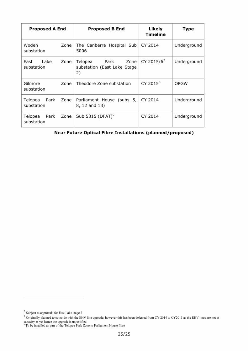
Proposed A End Proposed B End Likely
Timeline
Type
Woden Zone
substation
The Canberra Hospital Sub
5006
CY 2014 Underground
East Lake Zone
substation
Telopea Park Zone
substation (East Lake Stage
2)
CY 2015/67 Underground
Gilmore Zone
substation
Theodore Zone substation CY 20158 OPGW
Telopea Park Zone
substation
Parliament House (subs 5,
8, 12 and 13)
CY 2014 Underground
Telopea Park Zone
substation
Sub 5815 (DFAT)9 CY 2014 Underground
Near Future Optical Fibre Installations (planned/proposed)
7 Subject to approvals for East Lake stage 2
8 Originally planned to coincide with the EHV line upgrade, however this has been deferred from CY 2014 to CY2015 as the EHV lines are not at
capacity as yet hence the upgrade is unjustified 9 To be installed as part of the Telopea Park Zone to Parliament House fibre
Recommended