A ZERO "G" FLUID DROP INJECTOR FOR THE DROP DYNAMICS MODULE SPACELAB EXPERIMENT
by George M. Hotz *
ABSTRACT
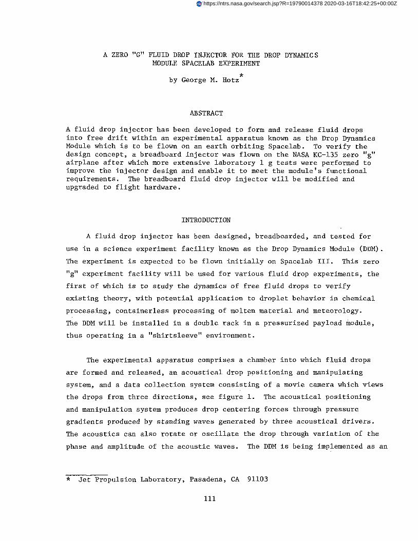
A fluid drop injector has been developed to form and release fluid drops into free drift within an experimental apparatus known as the Drop Dynamics Module which is to be flown on an earth orbiting Spacelab. To verify the design concept, a breadboard injector was flown on the NASA KC-135 zero "g" airplane after which more extensive laboratory 1 g tests were performed to improve the injector design and enable it to meet the module's functional requirements. The breadboard fluid drop injector will be modified and upgraded to flight hardware.
INTRODUCTION
A fluid drop injector has been designed, breadboarded, and tested for
use in a science experiment facility known as the Drop Dynamics Module (DDM).
The experiment is expected to be flown initially on Spacelab 111. This zero
"g" experiment facility will be used for various fluid drop experiments, the
first of which is to study the dynamics of free fluid drops to verify
existing theory, with potential application to droplet behavior in chemical
processing, containerless processing of molten material and meteorology.
The DDM will be installed in a double rack in a pressurized payload module,
thus operating in a "shirtsleeve" environment.
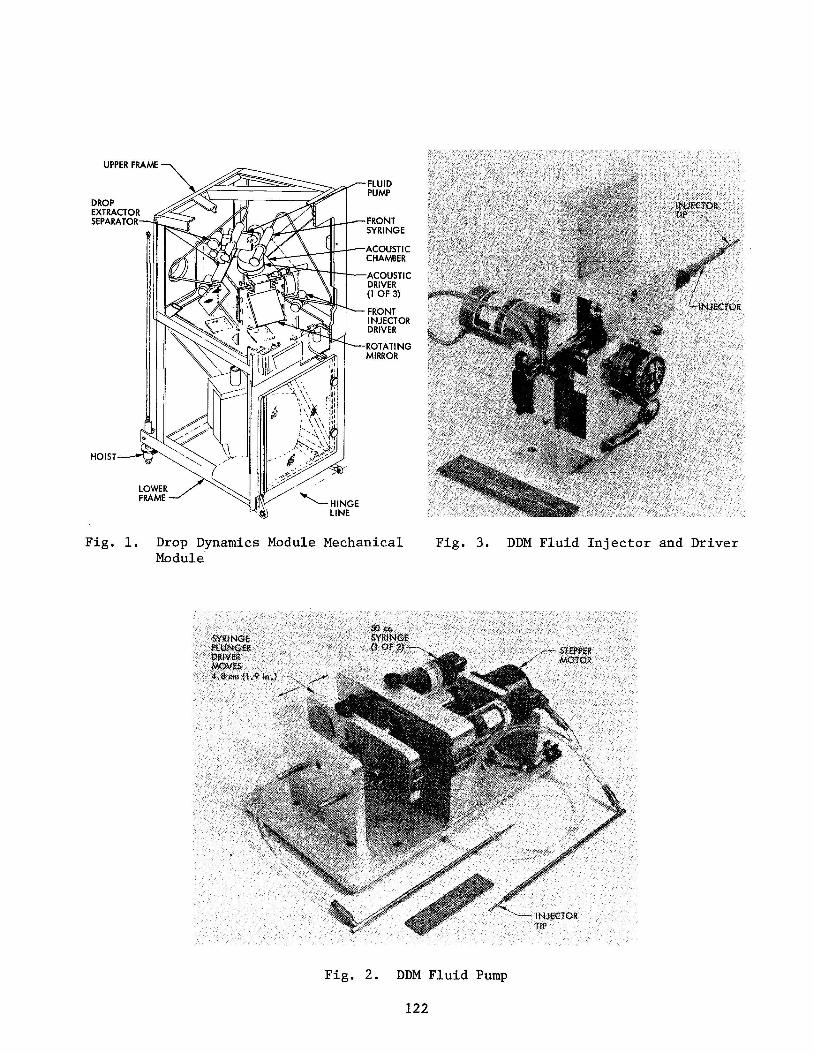
The experimental apparatus comprises a chamber into which fluid drops
are formed and released, an acoustical drop positioning and manipulating
system, and a data collection system consisting of a movie camera which views
the drops from three directions, see figure 1. The acoustical positioning
and manipulation system produces drop centering forces through pressure gradients produced by standing waves generated by three acoustical drivers.
The acoustics can also rotate or oscillate the drop through variation of the
phase and amplitude of the acoustic waves. The DDM is being implemented as an
* Jet Propulsion Laboratory, Pasadena, CA 91103
111
https://ntrs.nasa.gov/search.jsp?R=19790014378 2020-03-16T18:42:25+00:00Z
automated experiment to minimize attention by the Payload Specialist, who
will be required only to perform such tasks as replacing consumables, viz, changing fluid containers, film magazines and data tape cassettes, and
chamber cleanup in experiments where fluid drops fragment and strike the
chamber walls.
The fluid drop injector is required to produce drops of various fluids such as water and silicone oils of widely varying viscosities, surface ten-
sions and densities, and of various sizes from about 0.6-2.5 cm (%-1") in diameter. It must then release the drops in the center of a nearly cubical
transparent chaniber of about 15 cm cube (6") with essentially zero drift
velocity and with minimal rotation, oscillation or production of secondary
droplets and then must retract from the chamber.
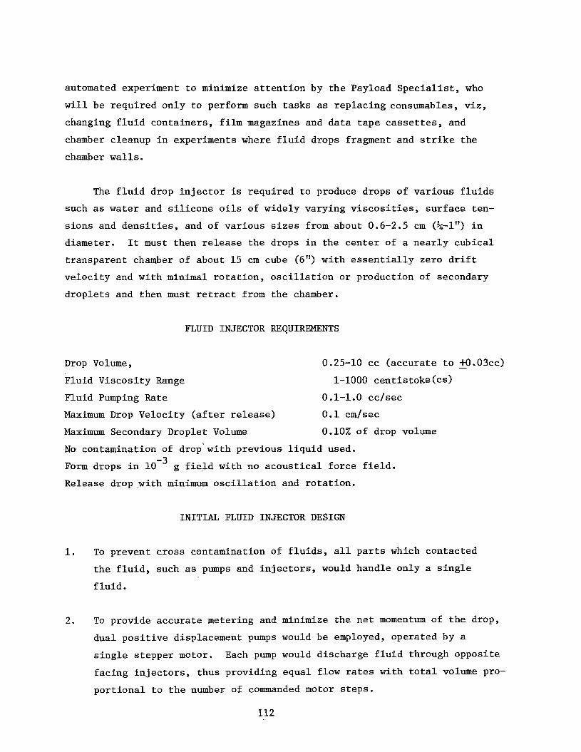
FLUID INJECTOR RF;QUIREKENTS
Drop Volume, 0.25-10 cc (accurate to - +O.O3cc)
Fluid Viscosity Range 1-1000 centistoke(cs) Fluid Pumping Rate 0.1-1.0 cc/sec
Maximum Drop Velocity (after release)
Maximum Secondary Droplet Volume
No- contamination of drop' with previous liquid used.
Form drops in
Release drop .with minimum oscillation and rotation.
0.1 cm/sec 0.10% of drop volume
g field with no acoustical force field.
INITIAL FLUID INJECTOR DESIGN
1. To prevent cross contamination of fluids, all parts which contacted
the fluid, such as pumps and injectors, would handle only a single
f hid.
2. To provide accurate metering and minimize the net momentum of the drop,
dual positive displacement pumps would be employed, operated by a
single stepper motor.
facing injectors, thus providing equal flow rates with total volume pro-
portional to the number of commanded motor steps.
Each pump would discharge fluid through opposite
112
3.
4 .
5.
t h e
S ince t h e optimum pos i t i on ing of i n j e c t o r s dur ing drop growth and t h e
optimum p o s i t i o n i n g and v e l o c i t y of i n j e c t o r s dur ing release of t h e
drop w e r e unknown, i t w a s decided t h a t programmable i n j e c t o r p o s i t i o n
and v e l o c i t y se rvos would be employed f o r maximum des ign f l e x i b i l i t y .
S ince i n j e c t o r t i p des ign w a s unknown, t i p s would be made r ep laceab le .
If p o s s i b l e , i n j e c t o r t i p s would u t i l i z e s u r f a c e t ens ion f o r c e s t o
s t a b i l i z e t h e drops dur ing drop growth.
Major unknowns i n t h e des ign w e r e parameters which c o n t r o l l e d t h e
product ion of secondary d r o p l e t s .
BREADBOARD FLUID PUMP, INJECTORS & INJECTOR DRIVERS
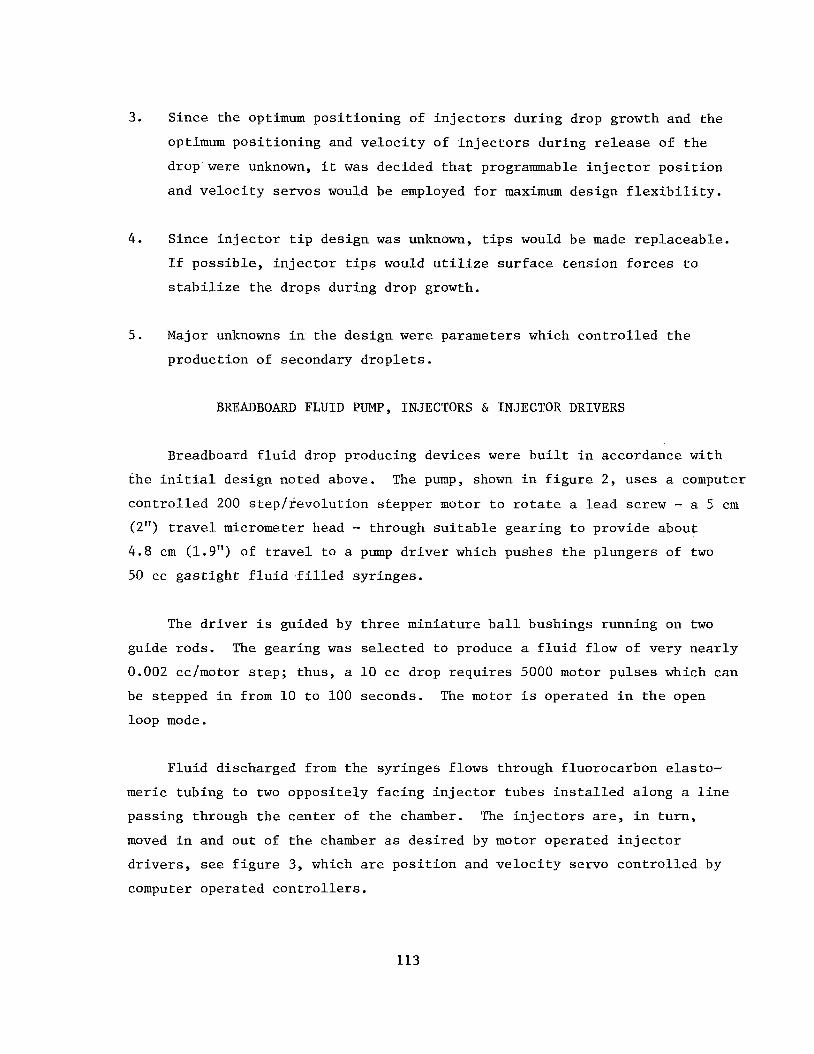
Breadboard f l u i d drop producing devices w e r e b u i l t i n accordance wi th
i n i t i a l design noted above. The pump, shown i n f i g u r e 2, u ses a computer
c o n t r o l l e d 200 s t e p f r e v o l u t i o n s t eppe r motor t o r o t a t e a l ead screw - a 5 c m
(2") travel micrometer head - through s u i t a b l e gear ing t o provide about
4.8 c m (1.9") of travel t o a pump d r i v e r which pushes t h e p lungers of two
50 cc g a s t i g h t f l u i d f i l l e d syr inges .
The d r i v e r i s guided by t h r e e min ia tu re b a l l bushings running on two
guide rods. The gear ing w a s s e l e c t e d t o produce a f l u i d f low of very n e a r l y
0.002 cc/motor s t e p ; thus , a 10 cc drop r e q u i r e s 5000 motor pu l se s which can
be s tepped i n from 10 t o 100 seconds. The motor i s opera ted i n t h e open
loop mode.
F l u i d discharged from t h e sy r inges f lows through f luorocarbon e l a s t o -
meric tub ing t o two oppos i t e ly f ac ing i n j e c t o r t ubes i n s t a l l e d a long a l i n e
pass ing through t h e c e n t e r of t he chamber. The i n j e c t o r s are, i n t u r n ,
moved i n and ou t of t h e chamber as d e s i r e d by motor opera ted i n j e c t o r
d r i v e r s , see f i g u r e 3, which are p o s i t i o n and v e l o c i t y servo c o n t r o l l e d by
computer opera ted c o n t r o l l e r s .
113
Each i n j e c t o r i s i n s t a l l e d i n t h e hollow i n j e c t o r d r i v e r which i s
pos i t i oned a x i a l l y by a r ack machinedinto t h e d r i v e r . The d r i v e r i s
guided by t h r e e sets of r o l l e r s , one of which i s s p r i n g loaded, and i s
d r iven by an a i r c r a f t q u a l i t y dc motor through two s t a g e s of an t i -backlash
r educ t ion gea r s . The d r i v e gear f o r t h e r ack a l s o d i r e c t l y r o t a t e s both
t h e i n j e c t o r p o s i t i o n ( s i n g l e tu rn ) po ten t iometer and, through s u i t a b l e
gear ing , a s m a l l i r o n l e s s armature dc motor which gene ra t e s t h e v o l t a g e
employed by t h e i n j e c t o r v e l o c i t y servo .
t h e r o l l e r s w i th s u f f i c i e n t accuracy t o a l i g n t h e i r c e n t e r l i n e s w i t h i n a
few thousandths of an inch when they m e e t a t t h e chamber c e n t e r .
t h e f u n c t i o n a l requirements o r i g i n a l l y c a l l e d f o r a minimum r e t r a c t i o n v e l o c i t y
v e l o c i t y of 100 cm/second i n a d i s t a n c e of 0.5 cm - and t h e v e l o c i t y of
t h e breadboard i n j e c t o r s and d r i v e r s approached t h a t v e l o c i t y - i n v e s t i g a -
t i o n s t o be descr ibed later showed t h a t t h e optimum r e t r a c t i o n v e l o c i t y
w a s less than h a l f t h a t f i g u r e . The lower v e l o c i t y w a s achieved by
ope ra t ing t h e motors a t reduced vo l t age .
The i n j e c t o r s are guided by
Although
Replaceable i n j e c t o r t i p s are i n s t a l l e d a t t h e o u t l e t end of each
i n j e c t o r t o s u i t t h e f l u i d c h a r a c t e r i s t i c s and d ischarge rate. Replacement
of sy r inges , i n j e c t o r s and f l e x i b l e tub ing i s f a c i l i t a t e d through t h e use
of s p l i t , hinged clamps which secu re t h e sy r inge b a r r e l s and p lungers .
Bubble f r e e f i l l i n g of f l u i d c o n t a i n e r s i s e s s e n t i a l and is expected t o
be a ground based ope ra t ion .
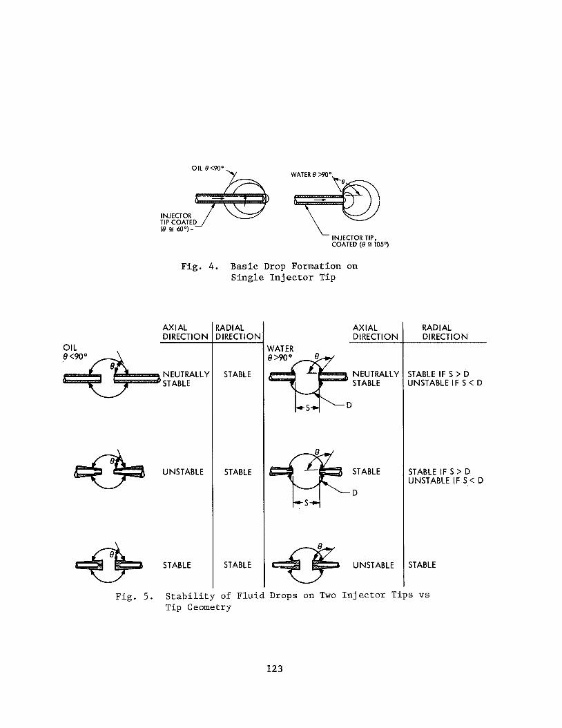
FLUID DROP STABILITY ON A SINGLE INJECTOR TIP
I n v e s t i g a t i o n s i n d i c a t e d t h a t t h e r e i s a b a s i c d i f f e r e n c e i n t h e
equi l ibr ium pos i t i on ing of f l u i d drops suspended on an i n j e c t o r t i p i n zero
"g" i f t h e con tac t ang le between t h e drop and t h e t i p i s g r e a t e r than 90'
i n t h e one case and less than 90 i n t h e o t h e r . F igure 4 i l l u s t r a t e s t h i s
po in t . I f t h e f l u i d / t i p con tac t ang le i s g r e a t e r than 90°, as is t h e case
f o r a water drop on a wax coated metal t i p , t h e drop w i l l n o t a l low i t s e l f
t o be impaled on t h e i n j e c t o r t i p bu t w i l l move tangent t o t h e end of t h e
t i p t o maximize i t s s u r f a c e energy.
0
Figure 4 a l s o shows t h a t f o r l i q u i d / t i p
114
0 * c o n t a c t ang le s of less than 90 , e.g. , a s i l i c o n e o i l drop on a PFOMA
coated m e t a l t i p , t h e drop cannot b e made t o s t a y tangent t o t h e end of
t h e t i p (without t h e a p p l i c a t i o n of an e x t e r n a l f o r c e ) b u t w i l l move back
u n t i l t h e f r o n t of t h e drop i s tangent t o t h e end of t h e t i p ( i .e. , t h e
drop i s impaled on t h e t i p ) .
Th i s d i f f e r e n c e i n drop behavior ( o i l vs. water ) can be e l imina ted by
making bo th o i l and w a t e r have a con tac t ang le of 0' which would make both
behave l i k e o i l , w i t h drops impaled on t h e t i p . This i d e a w a s d i scarded
as w a s t h e use of a s i n g l e i n j e c t o r t i p f o r t h r e e reasons:
( a ) Deep immersion of t h e drop i n t h e i n j e c t o r w a s suspected as
being a c o n t r i b u t o r t o t h e product ion of secondary d r o p l e t s .
(b) Release of t h e drop wi th near zero n e t momentum i n t h e absence
of an a c o u s t i c a l c e n t e r i n g f o r c e f i e l d appeared d i f f i c u l t . 0 ( c ) Achieving a 0 con tac t a n g l e r equ i r ed c a r e f u l c l ean ing of t h e
s u r f a c e s be ing contac ted and h igh p u r i t y of t h e f l u i d s . Main-
tenance of r equ i r ed t i p c l e a n l i n e s s f o r m u l t i p l e i n j e c t i o n s under
f l i g h t experiment cond i t ions would be d i f f i c u l t .
Accordingly t h e use of two PFOMA coated i n j e c t o r s w a s s e l e c t e d .
FLUID DROP STABILITY ON TWO INJECTOR TIPS
Figure 5 i l l u s t r a t e s t h r e e p o s s i b l e i n j e c t o r t i p shapes and i n d i c a t e s t h e
n e t s t a b i l i t y of a drop i n t h e axial and r a d i a l d i r e c t i o n s r e s u l t i n g from t h e
s u r f a c e t e n s i o n f o r c e s f o r f l u i d and t i p coa t ings having con tac t ang le s
1 ) g r e a t e r than 90 ; e. g. , w a t e r / p a r a f f i n , g l y c e r i n e / t e f l o n , mercury/ i ron,
e tc . , and
g l a s s , e tc .
p a r a f f i n , drop s t a b i l i t y can be achieved a t t h e chamber c e n t e r through t h e u s e of
t runca ted cone shaped t i p s w i th s m a l l ends f ac ing , whereas f o r s i l i c o n e o i l
on a "non-wetting" coa t ing such as PFOMA, s t a b i l i t y can be achieved wi th
t runca ted cones wi th bases f ac ing each o t h e r . Therefore , o t h e r cond i t ions
0
2) less than 90°; e.g. , petroleum o r s i l i c o n e oil/PFOMA, kerosene/
It shows t h a t f o r water on a %on-wetting" coa t ing such as
* poly (1,l-dihydropentadecaflourooctylmethacrylate)
115
permitting,the two cone shaped injector tips noted would be used.
IS PROGRAMMED INJECTOR MOTION NECESSARY?
The difference in direction of the axial force vectors for oil and * water drops in contact with PFOMA coated injector tips, figure 5, implies
that oil drops and water dropsrequire different injector positions during
drop growth if programming of the motion is to be avoided.
the tips should be moved apart to a separation equal to or somewhat greater
than the final drop diameter, and kept fixed during drop growth, whereas
with oil the tips must be moved to a separation equal to the tip inside
diameter or less and then held there until the drop is fully grown. Alter-
natively for both fluids, the tips can be moved together until they almost
touch, then the fluid pumped until the two streams coalesce into a single
drop, after which the injectors must be withdrawn at a varying rate so as to keep the drop periphery tangent to the two tips.
With water drops,
Determination of which motion technique was better awaited test results.
KC-135 ZERO ''G" TEST
The breadboard pumps, injectors, and injector drivers, shown in figures
2 and 3 were tested qualitatively in three flights of the NASA KC-135 air-
plane at Clearwater, Texas in mid-1978, and demonstrated that water and silicone oil drops could be formed in zero "g" with and without the acoustical
field, see figure 6 . However, the flights did not demonstrate that the
functional requirements could be met since the severe time limitations of zero ** g and generally poor "g" conditions preceding and following "free
float" necessitated injector tip geometries and fluid pumping rates not con-
ducive to meeting these requirements, e.g., large diameter tips and high fluid pumping rates.
did not provide adequate resolution to make accurate assessments of satellite
(secondary) droplet sizes, but it was apparent that secondary drop volumes
The high speed motion pictures taken on the KC-135 flights
*
** Zero "g" float durations were usually 5-10 seconds.
There is no known coating capable of increasing the contact angle of silicone oil to >goo.
116
were much g r e a t e r (20-30 t i m e s g r e a t e r ) than t h e 0.1% permi t ted by t h e
f u n c t i o n a l requirements . Residual drop v e l o c i t y w a s a l s o d i f f i c u l t t o
determine and i t w a s seldom p o s s i b l e t o assess whether t h e a i r p l a n e and/or
experiment o p e r a t o r s con t r ibu ted t o t h e drop v e l o c i t y r a t h e r than t h e f l u i d
i n j e c t o r s .
The KC-135 tests showed t h a t t h e sources of drop d i s tu rbance and
secondary d r o p l e t s produced i n drop release w e r e t h e columns of f l u i d exten-
ding from e i t h e r s i d e of t h e drop i n t h e wake of r a p i d l y r e t r a c t i n g i n j e c t o r
t i p s . It w a s no t known whether t h e sources of t h e s e columns w e r e f l u i d
pu l l ed from t h e drop o r f l u i d t r a i l e d f r o m t h e r a p i d l y a c c e l e r a t i n g i n j e c t o r s .
I n any case, a f t e r t h e columns a t t a i n e d some maximum l e n g t h , t hey broke up
i n t o d r o p l e t s whose diameter was approximately t h e column diameter .
I n t h e formation of s i l i c o n e o i l drops on t h e KC-135, due t o a program-
ming e r r o r , t h e i n j e c t o r t i p s w e r e moved a p a r t be fo re s u f f i c i e n t o i l had
been pumped and r e s u l t e d i n t h e formation of two drops i n s t e a d o f one. Af t e r
several such runs , t h e c o n t r o l l e r w a s switched t o manual ope ra t ion and t h e
i n j e c t o r t i p s w e r e he ld c l o s e toge the r dur ing t h e e n t i r e f l u i d pumping per iod
which r e s u l t e d i n t h e formation of s i n g l e o i l drops.
LABORATORY INJECTOR PARAMETRIC TESTS
Next l a b o r a t o r y tests w e r e conducted t o opt imize i n j e c t o r parameters t o
(a) reduce t h e product ion of s a t e l l i t e d r o p l e t s t o less than 0.1% of t h e
drop volume as c a l l e d f o r i n t h e f u n c t i o n a l requirements , and (b) minimize t h e
d i s tu rbance t o t h e drop caused by i n j e c t o r withdrawal. I n a d d i t i o n , s i n c e
only w a t e r and 100 cs s i l i c o n e o i l w e r e i n j e c t e d on t h e KC-135 f l i g h t s , o i l
of o t h e r v i s c o s i t i e s , viz.,lOOO cs and 10 cs w e r e a l s o t e s t e d . I n j e c t o r t i p s
and ope ra t ing parameters were included which were i d e n t i c a l t o t h o s e used on
t h e KC-135 f l i g h t s f o r comparison. Parameters i n v e s t i g a t e d inc luded t i p d ia -
meter, cone ang le ( f o r w a t e r t i p s ) , immersion depth i n t o drop, and i n j e c t o r
r e t r a c t i o n v e l o c i t y .
117
Since t h e KC-135 tests wi th 100 cs s i l i c o n e o i l had i n d i c a t e d t h a t t h e
t o t a l volume of secondary d r o p l e t s w a s e s s e n t i a l l y independent of drop s i z e ,
i t w a s decided t h a t t h e s imples t test procedure would be t o use a cup f i l l e d
wi th o i l (o r w a t e r ) , s imu la t ing a drop of i n f i n i t e r a d i u s and mount a s i n g l e
i n j e c t o r w i th i t s d r i v e mechanism over t h e cup, immerse the i n j e c t o r t i p t o
t h e des i r ed depth i n t h e f l u i d and withdraw t h e t i p v e r t i c a l l y upward a t t h e
d e s i r e d speed whi le t ak ing h igh speed motion p i c t u r e s of t h e t i p , s u r f a c e
d i s tu rbance and column o r d r o p l e t s of f l u i d .
Pre l iminary runs wi th va r ious f l u i d s noted i n d i c a t e d t h a t t h e test
procedure descr ibed above w a s adequate f o r de te rmina t ion of re la t ive drop
d i s tu rbance of a l l f l u i d s . It w a s a l s o adequate f o r t e s t i n g re la t ive secondary
d r o p l e t volumes f o r water and 10 cs s i l i c o n e o i l , b u t i t w a s marginal t o poor
f o r 100 cs s i l i c o n e o i l and t o t a l l y u n s a t i s f a c t o r y f o r 1000 cs s i l i c o n e o i l .
This w a s due t o t h e h ighe r v i s c o s i t y f l u i d s s t r i n g i n g out t o a l e n g t h cor res -
ponding t o f u l l travel of t h e i n j e c t o r , then s t reaming down from t h e motion-
less i n j e c t o r under t h e in f luence of g r a v i t y u n t i l they had necked down t o a
smaller diameter column which f i n a l l y broke up i n t o sa te l l i t e d r o p l e t s , b u t
n o t of t h e c o r r e c t s i z e nor volume.
A s a consequence, i t w a s decided t o employ another technique f o r
sa te l l i t e d r o p l e t volume de termina t ion .
of t h e i n j e c t o r i n a h o r i z o n t a l o r near h o r i z o n t a l a t t i t u d e i n s t e a d of vertical.
Two arrangements were t r i e d , t h e f irst having the t i p pass through a c l ea rance
ho le i n t h e s i d e of a cup. The h o l e w a s l o c a t e d c l o s e t o t h e f l u i d top sur -
f a c e and s i z e d so t h a t f l u i d s u r f a c e t e n s i o n prevented leakage of f l u i d from
t h e cup when t h e t i p w a s i n s e r t e d through t h e hole .
used a cup f i l l e d t o t h e top , i n t o the s u r f a c e of which t h e t i p w a s i n s e r t e d
a t an angle of about 15' above h o r i z o n t a l .
s a t i s f a c t o r y .
This technique involved t h e ope ra t ion
The second arrangement
Both of t h e s e techniques w e r e
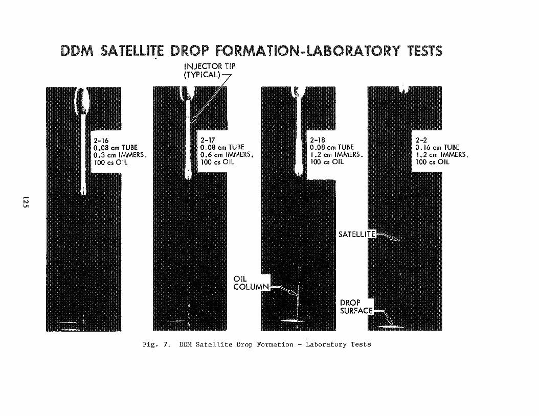
Another pre l iminary test w a s made t o determine t h e source of t h e f l u i d
which formed t h e column of f l u i d and, i n t u r n , produced t h e secondary d r o p l e t s .
I n j e c t o r t i p s were connected t o a hypodermic sy r inge f i l l e d wi th t h e a p p r o p r i a t e
f l u i d and f l u i d w a s forced from t h e t i p i n t o t h e s imulated drop ( i .e . , t h e
118
cup) j u s t be fo re t i p r e t r a c t i o n .
and secondary d r o p l e t s photographed (see f i g u r e 7 ) . S imi l a r tests were
performed us ing t i p s w i t h no o r i f i c e s ( rods were used i n s t e a d of t ubes ) .
A s r e s u l t s i n d i c a t e d only a minor d i f f e r e n c e i n drop d i s tu rbances o r product ion
of sa te l l i t e d r o p l e t s wi th t h e two techniques , rods w e r e used f o r subsequent
tests and t h e conclusion reached w a s t h a t t h e f l u i d forming t h e columns came
from t h e drop.
The t i p w a s then r e t r a c t e d and t h e column
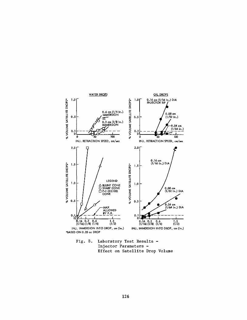
LABORATORY TEST RESULT TRENDS
T e s t r e s u l t s gene ra l ly confirmed expected t r e n d s , i .e . :
1) Smaller diameter i n j e c t o r t i p s produced s m a l l e r drop d i s tu rbances
and smaller volumes of secondary d r o p l e t s .
Smaller t i p immersions produced s m a l l e r drop d i s tu rbances .and
decreased secondary d r o p l e t volumes.
' 2 )
Unexpected t r ends included the fol lowing:
3 ) Decreased h j e c t o r withdrawal v e l o c i t i e s (wi th in t h e range t e s t e d )
produced s m a l l e r secondary d r o p l e t volumes.
LABORATORY TEST RESULT - DISCUSSION
R e s u l t s shown i n f i g u r e 8 i n d i c a t e d t h a t t h e secondary d r o p l e t volumes
s p e c i f i e d by t h e f u n c t i o n a l requirements could only be m e t through t h e use of
very s m a l l s i z e t i p s and/or minimal immersion of t h e t i p s i n t o t h e drops.
Minimal immersion of i n j e c t o r s meant t h a t accu ra t e programming of i n j e c t o r
motion dur ing t h e growth of o i l drops w a s e s s e n t i a l . The f e a s i b i l i t y of
t hese parameters depended upon o t h e r f a c t o r s such as:
1) Could t h e small t i p diameter produce s u f f i c i e n t s t a b i l i z i n g -3 s u r f a c e t ens ion f o r c e s t o r e t a i n t h e drop i n a 10 g f o r c e f i e l d ?
2 ) Was the i n j e c t o r d r i v e r s e rvo r e s o l u t i o n s u f f i c i e n t t o permit s m a l l
i n j e c t o r t i p immersions?
119
3) Did t h e s m a l l t i p a l low accep tab le f l u i d pumping rates w i t h
h i g h v i s c o s i t y f l u i d s ?
A c a l c u l a t i o n of t h e diameter of i n j e c t o r t i p r equ i r ed t o r e t a i n a
g f i e l d i n d i c a t e d t h a t a minimum diameter of -3 10 cc w a t e r drop i n a 10
0.04 c m (.016") is r equ i r ed .
minimum O.D. of t h e sharp cone t e s t e d and found t o m e e t t h e secondary drop-
l e t maximum volume allowed f o r a 0.25 cc drop a t an immersion of 0.16 c m (1/16")
Thus, a s i n g l e t i p s i z e w i l l be s a t i s f a c t o r y f o r w a t e r drops of a l l s i z e s
s i n c e c o n t r o l l i n g t h e p o s i t i o n of each i n j e c t o r , hence t h e t i p immersion t o
0.04 c m (.015") i s achievable .
0.04 cm (.016") diameter i n j e c t o r a t t h e maximum requ i r ed pumping rate of
1 cc/second.
This i s c o n s i s t e n t w i t h t h e 0.05 c m (.020")
F i n a l l y , water can be pumped through a n
A s i m i l a r c a l c u l a t i o n f o r s i l i c o n e o i l drops i n d i c a t e d t h a t a minimum
t i p o u t s i d e diameter of 0.18 c m ( .070" ) i s requ i r ed t o support a 10 cc drop -3
I on them i n a 1 0 g f i e l d ; a 0.24 ern O.D. ( .093") by 0.20 c m I . D . (-078")
t i p w a s s e l e c t e d . T e s t r e s u l t s (see f i g u r e 8) i n d i c a t e d t h a t t h e minimum
satel l i te volume can be m e t a t a reasonable immersion only f o r drops l a r g e r
than about 1 cc. Consequently, t h e use of a second, smaller i n j e c t o r t i p
s i z e 0 .11 c m O.D. ( .042" ) x 0.07 c m I . D . ( . 0 3 " ) , is requ i r ed f o r o i l drops
from 0.25-1.0 cc volume.
c ing of o i l i n t o one drop i s .07 c m ( . 03 " ) which i s about t h e r e s o l u t i o n l i m i t
of t h e p o s i t i o n servo , t h e i n j e c t o r t i p s w i l l be pos i t i oned t o touch ( i .e. zero
gap). t i p a t rates much above t h e minimum, i . e . , 0 . 1 cc / sec because of t h e ve ry
high p r e s s u r e drop which s w e l l s t h e e l a s tomer i c tub ing excess ive ly and stalls
t h e pump motor; however, a pumping t i m e of 10 seconds f o r a 1 cc drop i s
q u i t e acceptab le .
w i th 1000 cs o i l .
Since t h e maximum t i p s e p a r a t i o n t o i n s u r e coa les -
It i s n o t p o s s i b l e t o pump t h e h ighe r v i s c o s i t y o i l s through t h e small
The l a r g e r s i z e o i l t i p permi ts a pumping rate of 1 cc/sec
The use of t h e i n v e r t e d cone shape f o r s i l i c o n e o i l i n j e c t o r t i p s t o
achieve axial drop s t a b i l i t y w a s d i scarded s i n c e t h i s shape r e s u l t s i n
increased s a t e l l i t e d r o p l e t volume and/or decreased f l u i d pumping rates
because of smaller i n j e c t o r t i p i n s i d e diameters .
120
Cyl indr ica l ( tubular ) shaped t i p s were se l ec t ed f o r the o i l i n j e c t o r
t i p s s ince these r e s u l t i n a minimum t i p o u t l e t diameter, produce p o s i t i v e
drop s t a b i l i t y i n the r a d i a l d i r e c t i o n and n e u t r a l drop s t a b i l i t y i n t h e
axial d i r e c t i o n .
CONCLUSION
A p r a c t i c a l f l u i d drop i n j e c t i o n system has been developed f o r t h e
Drop Dynamics Module, capable of forming drops of a range of commandable
s i z e s from l i q u i d s having a wide range of physical c h a r a c t e r i s t i c s .
system employs:
This
0
0
0
0
0
0
0
0
A volume and rate commandable s tepper motor operated dual o u t l e t
p o s i t i v e displacement pump.
Two oppos i te ly discharging programmable servoed i n j e c t o r s which
move from ou t s ide the test chamber t o its cen te r as programmed.
Surface tens ion fo rces t o provide drop s t a b i l i t y during drop
growth and release.
An i n i t i a l t i p separa t ion of less than t h e t i p rad ius .
An i n j e c t o r r e t r a c t i o n motion which keeps the growing drop
per iphery tangent t o t h e i n j e c t o r t i p o u t l e t s .
One s i z e i n j e c t o r t i p f o r water drops of a l l s i z e s (% - 10 cc ) .
Two s i z e s of i n j e c t o r t i p s f o r o i l drops: one f o r drops from
k - 1 cc and t h e second f o r drops from 1% - 10 cc volume.
Programmed i n j e c t o r t i p motions together with t i p s i z e s which
minimize the production of sa te l l i t e d rop le t s and d is turbance t o
t h e drop during i ts release i n t o f r e e d r i f t .
The research described i n t h i s paper w a s c a r r i e d out a t t h e Jet Propulsion Laboratory, Ca l i fo rn ia I n s t i t u t e of Technology, under NASA Contract NAS7-100.
121
UPPER FRAME 7 -
Fig. 1. Drop Dynamics Module Mechanical Module
Fig. 3. DDM F lu id I n j e c t o r and Driver
Fig. 2 . DDM Flu id Pump
122
WATER e w o o . OIL e m 0
INJECTOR TIP COATED
INJECTOR TIP, /-
COATED (e E i o ~ )
F ig . 4 . Basic Drop Formation on S ing le I n j e c t o r Tip
AX I AL DI RECTI0 N
OIL
NEUTRALLY STABLE
U N STAB L E
STABLE
iADlAL 1 IRECTI ON
STABLE
STABLE
STABLE
AXIAL D IRECTI ON
VATER
NEUTRALLY STABLE
STABLE
D
UNSTABLE
RAD I AL DIRECT10 N
STABLE IF S > D UNSTABLE IF S < D
STABLE IF S > D UNSTABLE IF S < D
STABLE
Fig . 5. S t a b i l i t y of F l u i d Drops on Two I n j e c t o r T i p s vs Tip Geometry
123
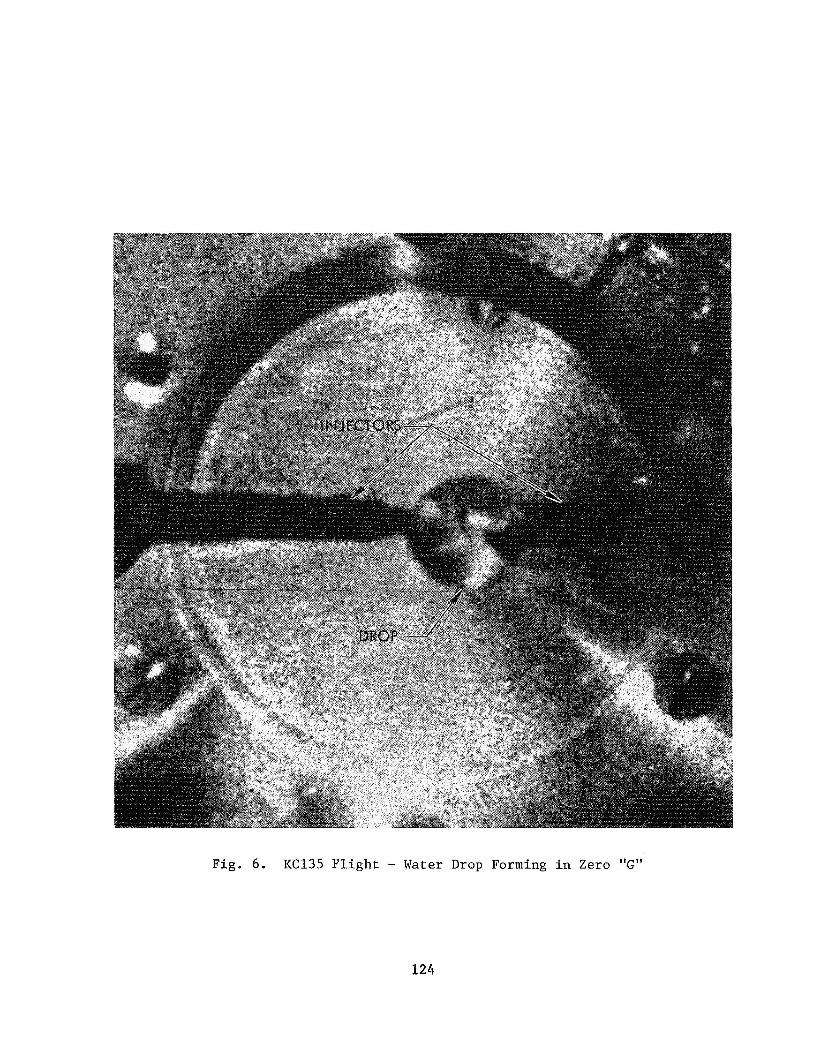
Fig . 6 . K C 1 3 5 F l i g h t - Water Drop Forming i n Zero "G"
124
3
ow
v)
wo
o-
rn U
rn a, w h
$4 0
U
cd $4 0
e cd
1-11 I
.rl U
cd 0
Frr a
0
h
R a,
U
-4
rl
rl a, u Ri
cn E E n
b
M
.4
Frr
125
WATER DROPS OIL DROPS
2 .o
2 1.5
n t
9 w
-1 -1 w 5 1.0
Y 3 2 1 0.5
0.1 0
0.6 cm (1/4 in.) IMMERSION
NZim IMMERSION (1/8 in.)
INJ. RETRACTION SPEED, cm/sec
0.16 cm (1/16 in.) DIA
n INJECTOR w
0.08 cm (1/32 in.)
0.04 cm
B o
2.0
2 1.5
8 Y
-1 -1 w t
I- 1.0 s r W
0
INJ. RETRACTION SPEED, c d s e c
(1/16 in.) DIA 0.16 c y
INJ. IMMERSION INTO DROP, cm (in.) *BASED ON 0 2 5 cc DROP
INJ. IMMERSION INTO DROP, cm (in.)
Fig . 8. Laboratory Test Results - Injector Parameters - Effect on Satellite Drop Volume
126
Recommended