BONDING CAPILLARY
TOWARDS BONDING EXCELLENCE
CONTENTS
Company Profi le 01
Special Bondings 14
Capillary Parameter Selection Guide 18
Standard Capillary Dimensions Table 23
P/No System 26
Tolerances 32
Cap Cleaning Service 33
Unplug Wire 34
Packing Information/ Colour Coding/ Bar Code Label 35
Capillary Request From 36
Dou Yee Group Worldwide Offi ce Addresses
Fine Pitch Capillary Dimensions For 60 μm B.P.P And Above Table 24
Ultra-Fine Pitch Capillary (CBC Design) Dimensions For 55 μmB.P.P And Below Table
25
Capillary Design Rules 15
Product Excellence. Customer Partnership 02
The Bonding Cycle 03
The Longer Lifespan Capillary 06
HMX Capillary 08
Ruby Capillary 10
Capillary Manufacturing Process 11
Quality Assurance/ Inspection System 12
Capillary Features 13
About Dou Yee - Global Capability, Local FocusOur Vision - Bonding Tool
Stud Gold Ball Bump CapillaryBond Stitch On Ball (BSOB) Bonding
Chamfer Ball Control (CBC) DesignTail Bond Enhancer
Capillary Hole DiameterCapillary Chamfer DiameterCapillary Inner Chamfer AngleCapillary Tip DiameterCapillary Tip FinishingCapillary Face AngleCapillary Outer Radius
Standard CapillaryFine-Pitch CapillaryUltra-Fine Pitch CapillaryVertical Bottleneck CapillaryHMX CapillaryRuby Capillary
(H)(CD)(ICA)(T)(P,M & HMX)(FA)(OR)
Glo
bal C
apab
ility
, Loc
al F
ocus
BO
ND
ING
CA
PIL
LAR
Y
01
COMPANY PROFILE
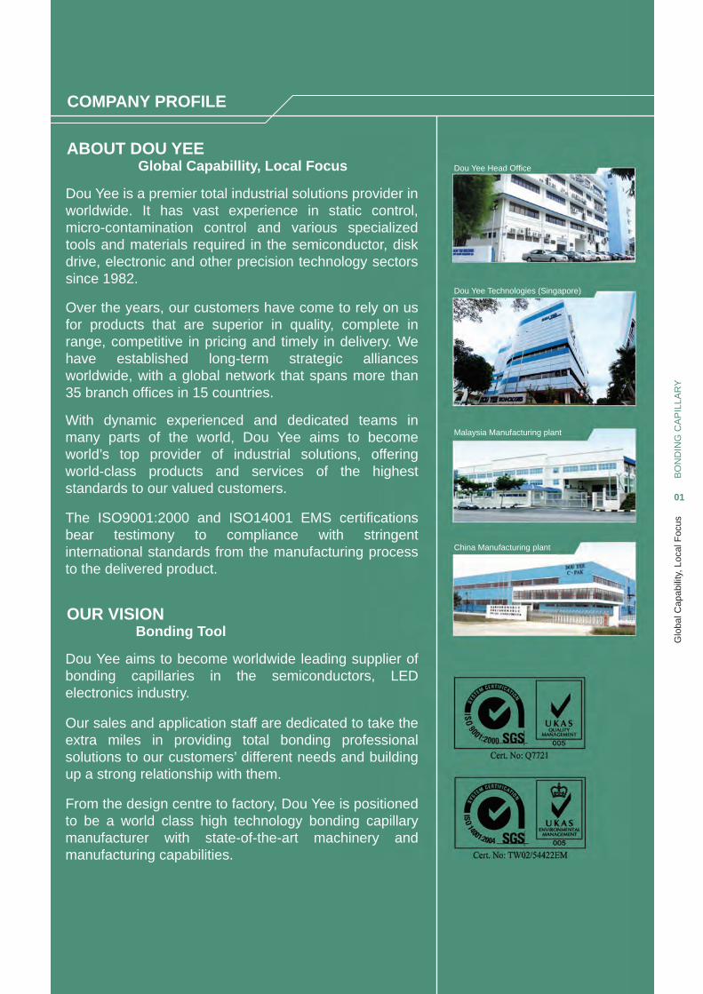
Dou Yee is a premier total industrial solutions provider in worldwide. It has vast experience in static control,micro-contamination control and various specializedtools and materials required in the semiconductor, diskdrive, electronic and other precision technology sectors since 1982.
ABOUT DOU YEE
OUR VISION
Global Capabillity, Local Focus
Bonding Tool
Over the years, our customers have come to rely on usfor products that are superior in quality, complete inrange, competitive in pricing and timely in delivery. Wehave established long-term strategic alliancesworldwide, with a global network that spans more than 35 branch offi ces in 15 countries.
With dynamic experienced and dedicated teams inmany parts of the world, Dou Yee aims to becomeworld’s top provider of industrial solutions, offeringworld-class products and services of the higheststandards to our valued customers.
The ISO9001:2000 and ISO14001 EMS certifi cationsbear testimony to compliance with stringentinternational standards from the manufacturing processto the delivered product.
Dou Yee aims to become worldwide leading supplier ofbonding capillaries in the semiconductors, LEDelectronics industry.
Our sales and application staff are dedicated to take theextra miles in providing total bonding professionalsolutions to our customers’ different needs and buildingup a strong relationship with them.
From the design centre to factory, Dou Yee is positionedto be a world class high technology bonding capillarymanufacturer with state-of-the-art machinery andmanufacturing capabilities.
Dou Yee Head Offi ce
Dou Yee Technologies (Singapore)
Malaysia Manufacturing plant
China Manufacturing plant
Bon
ding
Cap
illar
yB
ON
DIN
G C
AP
ILLA
RY
02
PRODUCT EXCELLENCE. CUSTOMER PARTNERSHIP
PRODUCT INNOVATIONS. EXCELLENCE.
OUR SUCCESS FORMULA.
CUSTOMER PARTNERSHIP.INNOVATIVE SOLUTIONS.
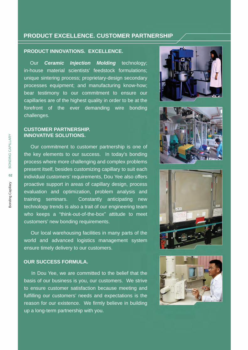
Our Ceramic Injection Molding technology;
in-house material scientists’ feedstock formulations;
unique sintering process; proprietary-design secondary
processes equipment; and manufacturing know-how;
bear testimony to our commitment to ensure our
capillaries are of the highest quality in order to be at the
forefront of the ever demanding wire bonding
challenges.
Our commitment to customer partnership is one of
the key elements to our success. In today’s bonding
process where more challenging and complex problems
present itself, besides customizing capillary to suit each
individual customers’ requirements, Dou Yee also offers
proactive support in areas of capillary design, process
evaluation and optimization, problem analysis and
training seminars. Constantly anticipating new
technology trends is also a trait of our engineering team
who keeps a “think-out-of-the-box” attitude to meet
customers’ new bonding requirements.
Our local warehousing facilities in many parts of the
world and advanced logistics management system
ensure timely delivery to our customers.
In Dou Yee, we are committed to the belief that the
basis of our business is you, our customers. We strive
to ensure customer satisfaction because meeting and
fulfi lling our customers’ needs and expectations is the
reason for our existence. We fi rmly believe in building
up a long-term partnership with you.
The
Bon
ding
Cyc
leB
ON
DIN
G C
AP
ILLA
RY
03
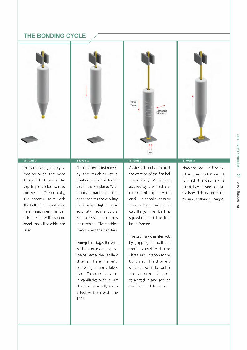
STAGE 0 STAGE 1 STAGE 2 STAGE 3
THE BONDING CYCLE
The
Bon
ding
Cyc
leB
ON
DIN
G C
AP
ILLA
RY
04
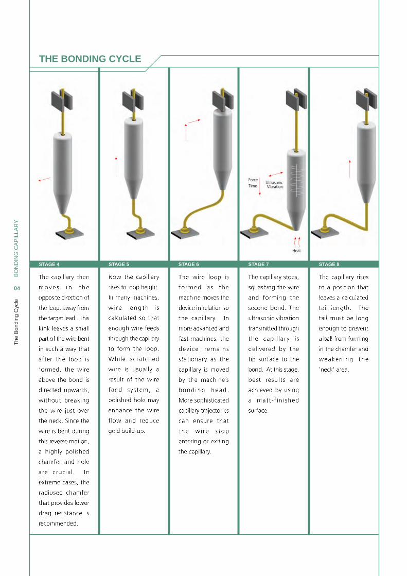
STAGE 4 STAGE 5 STAGE 6 STAGE 7 STAGE 8
THE BONDING CYCLE
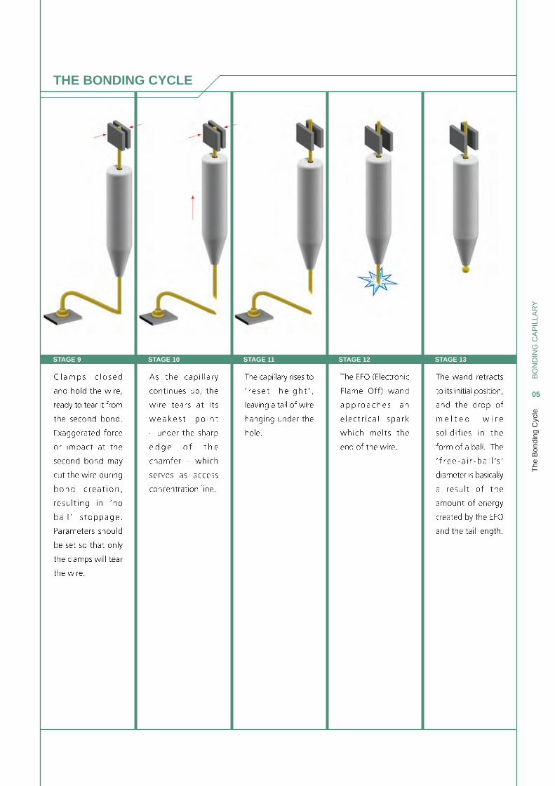
STAGE 9 STAGE 10 STAGE 11 STAGE 12 STAGE 13
The
Bon
ding
Cyc
leB
ON
DIN
G C
AP
ILLA
RY
05
THE BONDING CYCLE
BO
ND
ING
CA
PIL
LAR
Y
06
THE LONGER LIFESPAN CAPILLARY
INTERNAL BORE SURFACE POLISHING
The
Lon
ger
Life
span
Cap
illar
y
TOUGHENED
ALUMINA
Density
4.3g/cm3
COMPETITOR
PURE
ALUMINA
Density
3.8g/cm3
COMPETITORDOU YEE
Smooth Rough
Smooth Rough
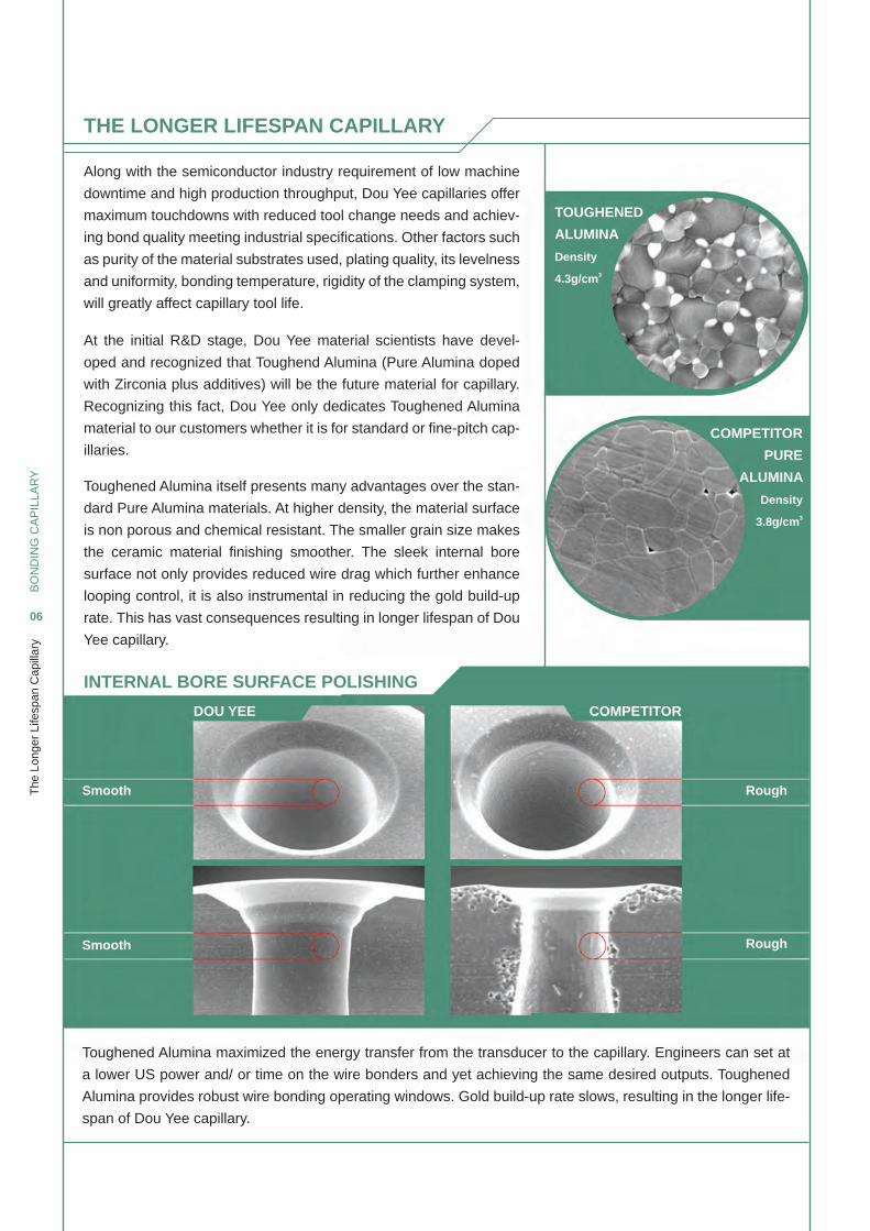
Along with the semiconductor industry requirement of low machine
downtime and high production throughput, Dou Yee capillaries offer
maximum touchdowns with reduced tool change needs and achiev-
ing bond quality meeting industrial specifi cations. Other factors such
as purity of the material substrates used, plating quality, its levelness
and uniformity, bonding temperature, rigidity of the clamping system,
will greatly affect capillary tool life.
At the initial R&D stage, Dou Yee material scientists have devel-
oped and recognized that Toughend Alumina (Pure Alumina doped
with Zirconia plus additives) will be the future material for capillary.
Recognizing this fact, Dou Yee only dedicates Toughened Alumina
material to our customers whether it is for standard or fi ne-pitch cap-
illaries.
Toughened Alumina itself presents many advantages over the stan-
dard Pure Alumina materials. At higher density, the material surface
is non porous and chemical resistant. The smaller grain size makes
the ceramic material fi nishing smoother. The sleek internal bore
surface not only provides reduced wire drag which further enhance
looping control, it is also instrumental in reducing the gold build-up
rate. This has vast consequences resulting in longer lifespan of Dou
Yee capillary.
Toughened Alumina maximized the energy transfer from the transducer to the capillary. Engineers can set at
a lower US power and/ or time on the wire bonders and yet achieving the same desired outputs. Toughened
Alumina provides robust wire bonding operating windows. Gold build-up rate slows, resulting in the longer life-
span of Dou Yee capillary.
BO
ND
ING
CA
PIL
LAR
Y
07
The
Lon
ger
Life
span
Cap
illar
y
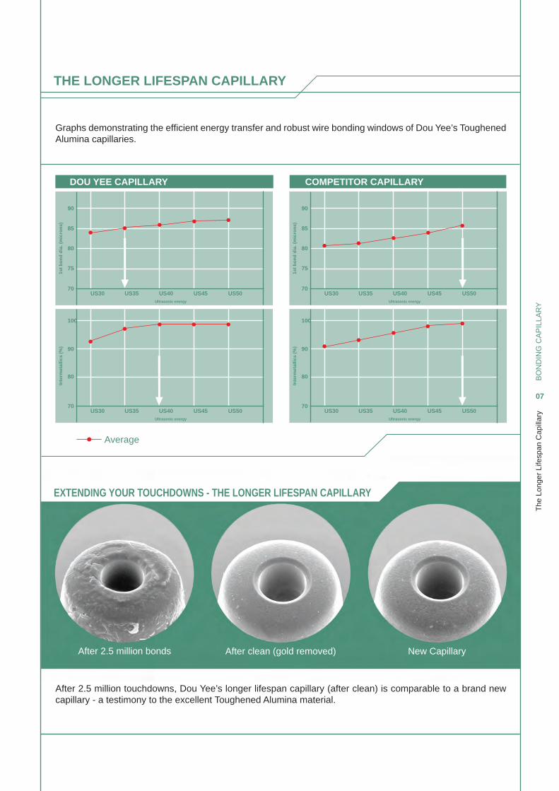
EXTENDING YOUR TOUCHDOWNS - THE LONGER LIFESPAN CAPILLARY
Graphs demonstrating the effi cient energy transfer and robust wire bonding windows of Dou Yee’s Toughened Alumina capillaries.
After 2.5 million touchdowns, Dou Yee’s longer lifespan capillary (after clean) is comparable to a brand new capillary - a testimony to the excellent Toughened Alumina material.
After 2.5 million bonds
Average
After clean (gold removed) New Capillary
DOU YEE CAPILLARY
90 90
85
100 100
85
1st
bo
nd
dia
. (m
icro
ns)
Inte
rmet
allic
s (%
)
Inte
rmet
allic
s (%
)1s
t b
on
d d
ia. (
mic
ron
s)
80
90 90
80
75
80 80
75
70
70 70
70US30
US30 US30
US30US35
US35 US35
US35US40
US40 US40
US40Ultrasonic energy
Ultrasonic energy Ultrasonic energy
Ultrasonic energy
US45
US45 US45
US45US50
US50 US50
US50
COMPETITOR CAPILLARY
THE LONGER LIFESPAN CAPILLARY
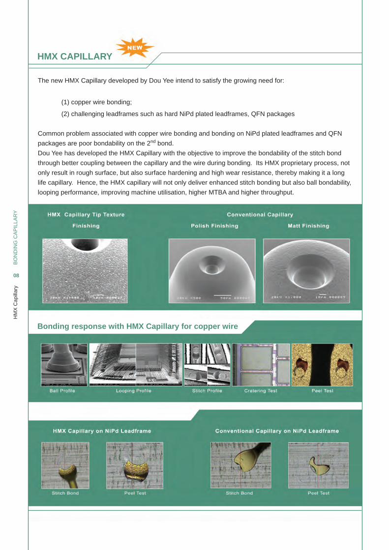
HMX CAPILLARY
Bonding response with HMX Capillary for copper wire
BO
ND
ING
CA
PIL
LAR
Y
08
HM
X C
apill
ary
The new HMX Capillary developed by Dou Yee intend to satisfy the growing need for:
(1) copper wire bonding;
(2) challenging leadframes such as hard NiPd plated leadframes, QFN packages
Common problem associated with copper wire bonding and bonding on NiPd plated leadframes and QFN
packages are poor bondability on the 2nd bond.
Dou Yee has developed the HMX Capillary with the objective to improve the bondability of the stitch bond
through better coupling between the capillary and the wire during bonding. Its HMX proprietary process, not
only result in rough surface, but also surface hardening and high wear resistance, thereby making it a long
life capillary. Hence, the HMX capillary will not only deliver enhanced stitch bonding but also ball bondability,
looping performance, improving machine utilisation, higher MTBA and higher throughput.
BO
ND
ING
CA
PIL
LAR
Y
09
HM
X C
apill
ary
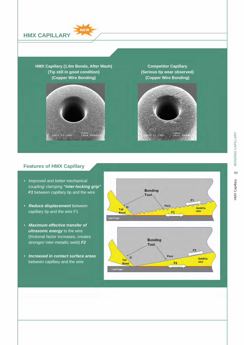
HMX Capillary (1.0m Bonds, After Wash)
(Tip still in good condition)
(Copper Wire Bonding)
Competitor Capillary
(Serious tip wear observed)
(Copper Wire Bonding)
Features of HMX Capillary
• Improved and better mechanical coupling/ clamping “inter-locking grip” F1 between capillary tip and the wire
• Reduce displacement between capillary tip and the wire F1
• Increased in contact surface areas between capillary and the wire
• Maximum effective transfer of ultrasonic energy to the wire (frictional factor increases, creates stronger/ inter-metallic weld) F2
HMX CAPILLARY
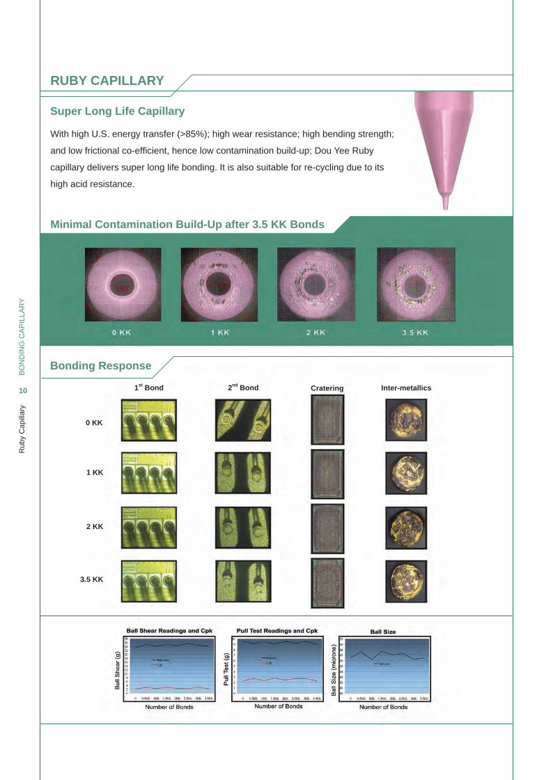
RUBY CAPILLARY
Super Long Life Capillary
Bonding Response
BO
ND
ING
CA
PIL
LAR
Y
10
Rub
y C
apill
ary
Minimal Contamination Build-Up after 3.5 KK Bonds
With high U.S. energy transfer (>85%); high wear resistance; high bending strength;
and low frictional co-effi cient, hence low contamination build-up; Dou Yee Ruby
capillary delivers super long life bonding. It is also suitable for re-cycling due to its
high acid resistance.
0 KK
1st Bond 2nd Bond Cratering Inter-metallics
1 KK
2 KK
3.5 KK
CAPILLARY MANUFACTURING PROCESS
BO
ND
ING
CA
PIL
LAR
Y
11
Cap
illar
y M
anuf
actu
ring
Pro
cess
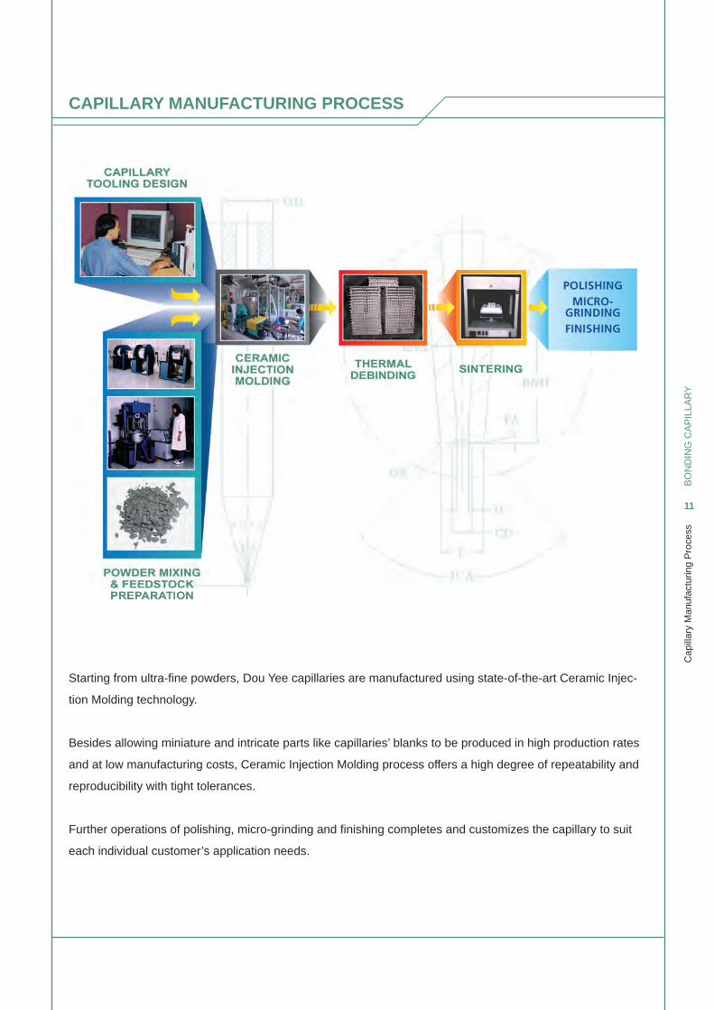
Starting from ultra-fi ne powders, Dou Yee capillaries are manufactured using state-of-the-art Ceramic Injec-
tion Molding technology.
Besides allowing miniature and intricate parts like capillaries’ blanks to be produced in high production rates
and at low manufacturing costs, Ceramic Injection Molding process offers a high degree of repeatability and
reproducibility with tight tolerances.
Further operations of polishing, micro-grinding and fi nishing completes and customizes the capillary to suit
each individual customer’s application needs.
QUALITY ASSURANCE/ INSPECTION SYSTEM
BO
ND
ING
CA
PIL
LAR
Y
12
Qua
lity
Ass
uran
ce/ I
nspe
ctio
n S
yste
m
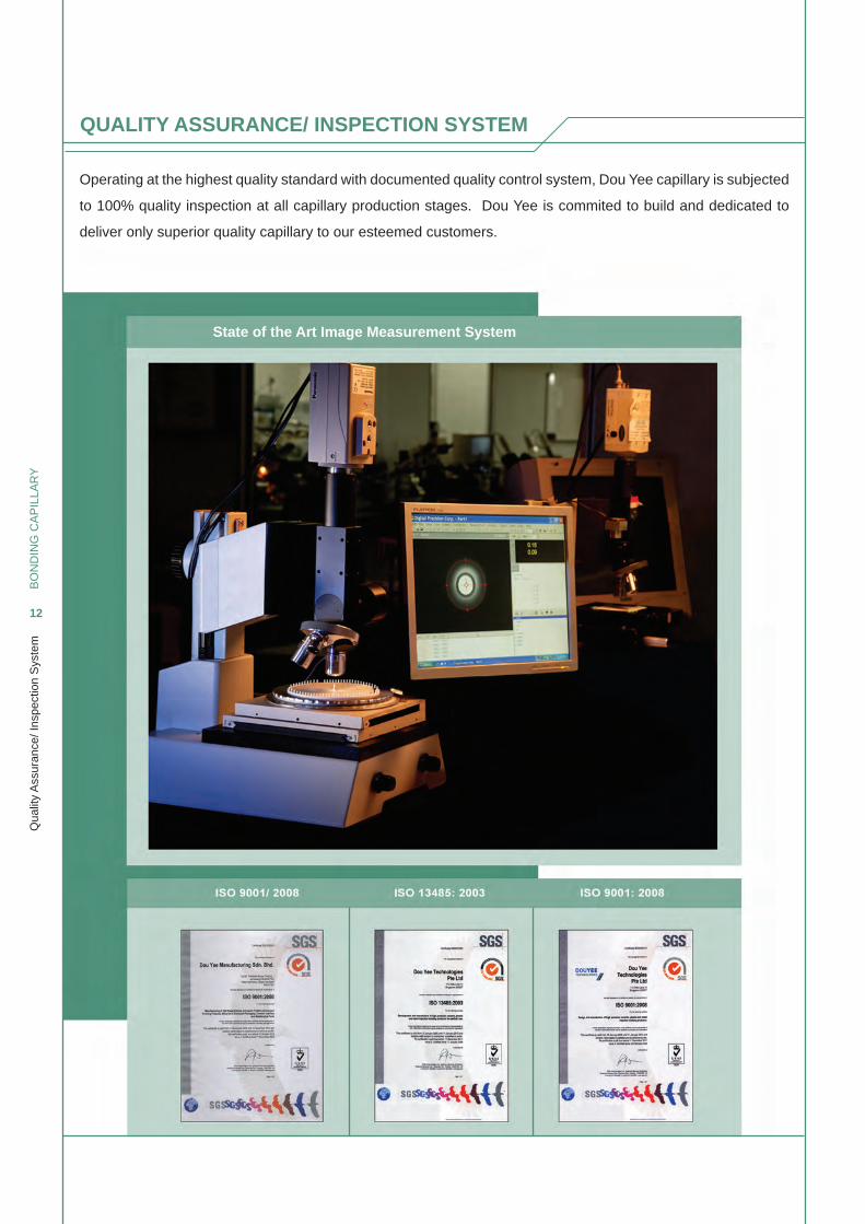
State of the Art Image Measurement System
Operating at the highest quality standard with documented quality control system, Dou Yee capillary is subjected
to 100% quality inspection at all capillary production stages. Dou Yee is commited to build and dedicated to
deliver only superior quality capillary to our esteemed customers.
CAPILLARY FEATURES
TAIL BOND ENHANCER
Chamfer Ball Control (CBC) DesignCapillaries for Ultra-FIne Pitch Bondings
Matrix Package (QFN / TFBGA SERIES)
BO
ND
ING
CA
PIL
LAR
Y
13
Cap
illar
y F
eatu
res
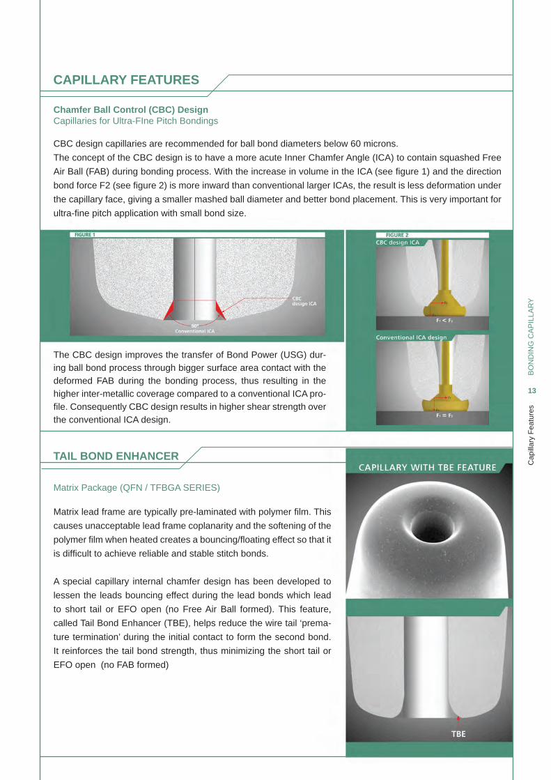
CBC design capillaries are recommended for ball bond diameters below 60 microns.
The concept of the CBC design is to have a more acute Inner Chamfer Angle (ICA) to contain squashed Free
Air Ball (FAB) during bonding process. With the increase in volume in the ICA (see fi gure 1) and the direction
bond force F2 (see fi gure 2) is more inward than conventional larger ICAs, the result is less deformation under
the capillary face, giving a smaller mashed ball diameter and better bond placement. This is very important for
ultra-fi ne pitch application with small bond size.
The CBC design improves the transfer of Bond Power (USG) dur-ing ball bond process through bigger surface area contact with the deformed FAB during the bonding process, thus resulting in the higher inter-metallic coverage compared to a conventional ICA pro-fi le. Consequently CBC design results in higher shear strength over the conventional ICA design.
Matrix lead frame are typically pre-laminated with polymer fi lm. This
causes unacceptable lead frame coplanarity and the softening of the
polymer fi lm when heated creates a bouncing/fl oating effect so that it
is diffi cult to achieve reliable and stable stitch bonds.
A special capillary internal chamfer design has been developed to
lessen the leads bouncing effect during the lead bonds which lead
to short tail or EFO open (no Free Air Ball formed). This feature,
called Tail Bond Enhancer (TBE), helps reduce the wire tail ‘prema-
ture termination’ during the initial contact to form the second bond.
It reinforces the tail bond strength, thus minimizing the short tail or
EFO open (no FAB formed)
BO
ND
ING
CA
PIL
LAR
Y
14
Spe
cial
Bon
ding
s
SPECIAL BONDINGS
Stud Gold Ball Bump CapillaryStud Bonding
Bond Stitch On Ball (BSOB) Bonding
Bond stitch on ball (BSOB) bonding is vital when one needs to wedge
bond on active circuitry. The stud / bump acts as a conductive barrier
and prevents the capillary coming in contact on the active circuitry
and damage it.
BSOB bonding is also recommended in applications where very
short deep and low loop lengths or enhanced wedge bond strength
on poor bondability substrate surface. The process is divided into
two step or cycles. The fi rst cycle is to bond the stud bonding called
bump onto the bond pad, followed by the reverse bonding where the
ball bond is placed on the lead or adjacent die pad (for die-to-die con-
nection) and stitch bond it on the ball bump.
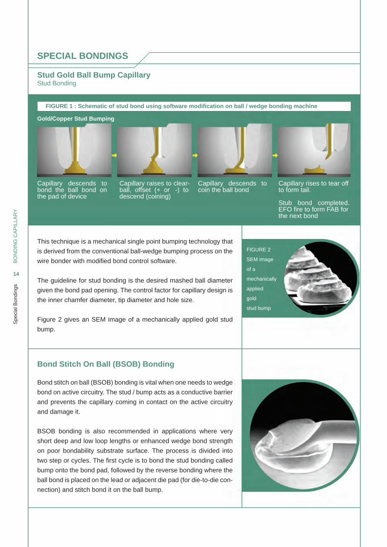
This technique is a mechanical single point bumping technology that
is derived from the conventional ball-wedge bumping process on the
wire bonder with modifi ed bond control software.
The guideline for stud bonding is the desired mashed ball diameter
given the bond pad opening. The control factor for capillary design is
the inner chamfer diameter, tip diameter and hole size.
Figure 2 gives an SEM image of a mechanically applied gold stud
bump.
FIGURE 2
SEM image
of a
mechanically
applied
gold
stud bump
Capillary descends to bond the ball bond on the pad of device
Gold/Copper Stud Bumping
Capillary raises to clear-ball, offset (+ or -) to descend (coining)
Capillary descends to coin the ball bond
Capillary rises to tear offto form tail.
Stub bond completed.EFO fi re to form FAB forthe next bond
FIGURE 1 : Schematic of stud bond using software modifi cation on ball / wedge bonding machine
BO
ND
ING
CA
PIL
LAR
Y
15
Cap
illar
y D
esig
n R
ules
CAPILLARY DESIGN RULES
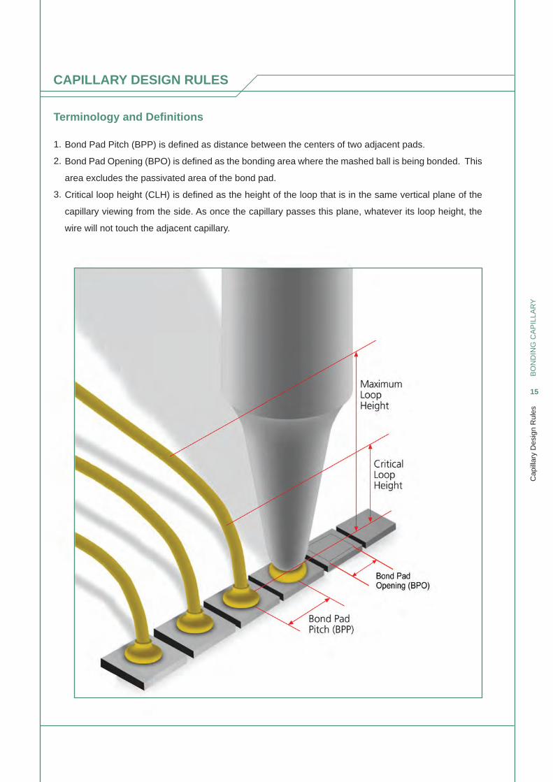
Terminology and Defi nitions
1.
2.
3.
Bond Pad Pitch (BPP) is defi ned as distance between the centers of two adjacent pads.
Bond Pad Opening (BPO) is defi ned as the bonding area where the mashed ball is being bonded. This
area excludes the passivated area of the bond pad.
Critical loop height (CLH) is defi ned as the height of the loop that is in the same vertical plane of the
capillary viewing from the side. As once the capillary passes this plane, whatever its loop height, the
wire will not touch the adjacent capillary.
BO
ND
ING
CA
PIL
LAR
Y
16
Cap
illar
y D
esig
n R
ules
CAPILLARY DESIGN RULES
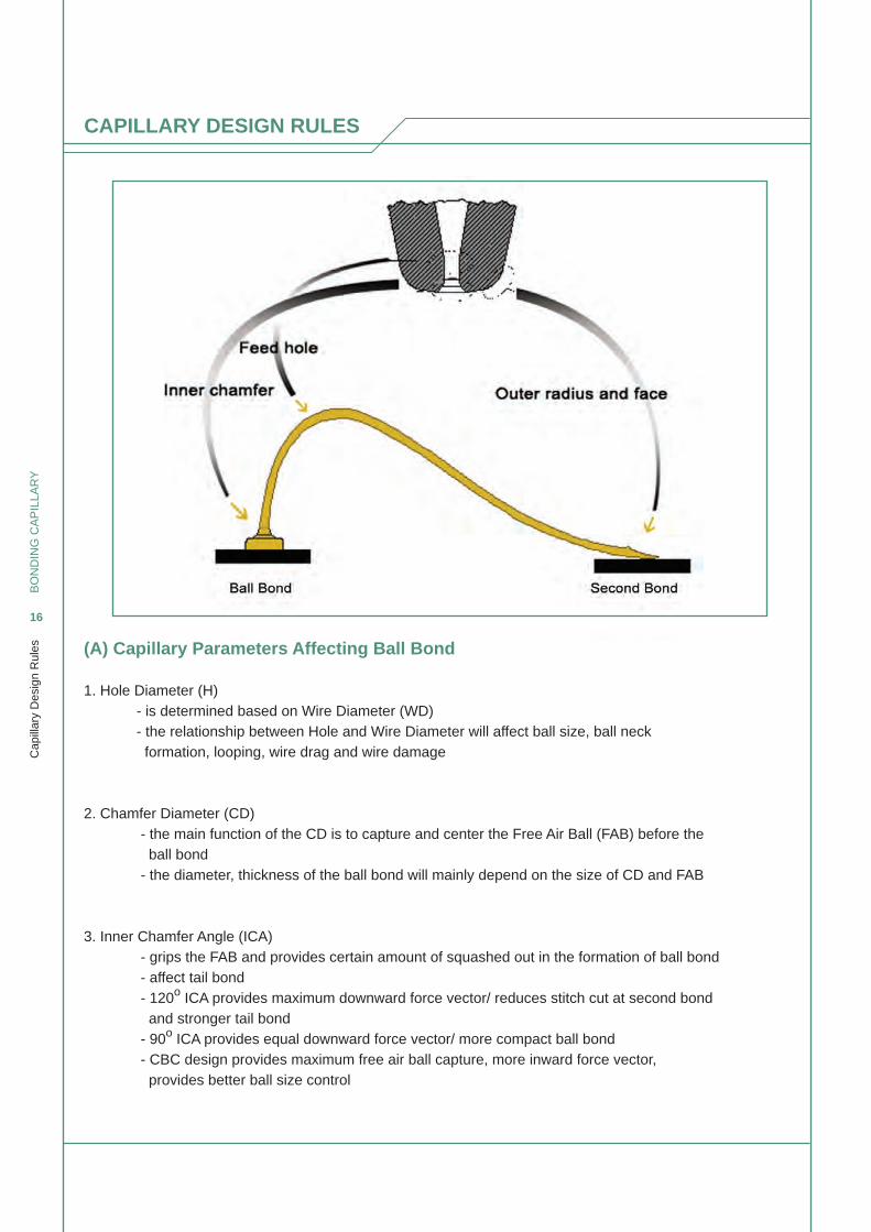
(A) Capillary Parameters Affecting Ball Bond
1. Hole Diameter (H) - is determined based on Wire Diameter (WD) - the relationship between Hole and Wire Diameter will affect ball size, ball neck formation, looping, wire drag and wire damage
2. Chamfer Diameter (CD) - the main function of the CD is to capture and center the Free Air Ball (FAB) before the ball bond - the diameter, thickness of the ball bond will mainly depend on the size of CD and FAB
3. Inner Chamfer Angle (ICA) - grips the FAB and provides certain amount of squashed out in the formation of ball bond - affect tail bond - 120o ICA provides maximum downward force vector/ reduces stitch cut at second bond and stronger tail bond - 90o ICA provides equal downward force vector/ more compact ball bond - CBC design provides maximum free air ball capture, more inward force vector, provides better ball size control
BO
ND
ING
CA
PIL
LAR
Y
17
Cap
illar
y D
esig
n R
ules
(C) Capillary Parameters Affecting Looping
1. Hole, Inner Chamfer Angle, Outer Radius Though the wire bonder looping software is a key factor affecting looping, capillary parameters such as Hole, Inner Chamfer, and Outer Radius also play a critical role in looping control.
CAPILLARY DESIGN RULES
(B) Capillary Parameters Affecting Stitch Bond
1. Tip Diameter (T) - providing the stitch pull strength; the larger the tip diameter, the larger surface will be provided for second bonding; hence higher stitch pull strength
2. Face Angle (FA) - determines the shape, width, and thickness of the stitch bond
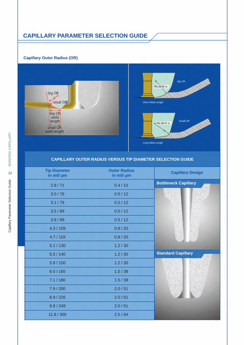
3. Outer Radius (OR) - is also a main factor to determine the shape, width, and thickness of stitch bond - creates smooth transition between FA and CA to avoid heel crack
4. Tip Finishing - Polish Finish is used for very good bondability application, provides longer tool life, and less prone to build-up - Matt Finish provides maximum coupling between capillary tip surface and wire, thus giving maximum ultrasonic energy transferred, may be prone to more build-up than polish tip - HMX Finish, our newly developed tip fi nishing specially catered for copper wire bonding, hard leadframe such as NiPd and QFN packages
CAPILLARY PARAMETER SELECTION GUIDE
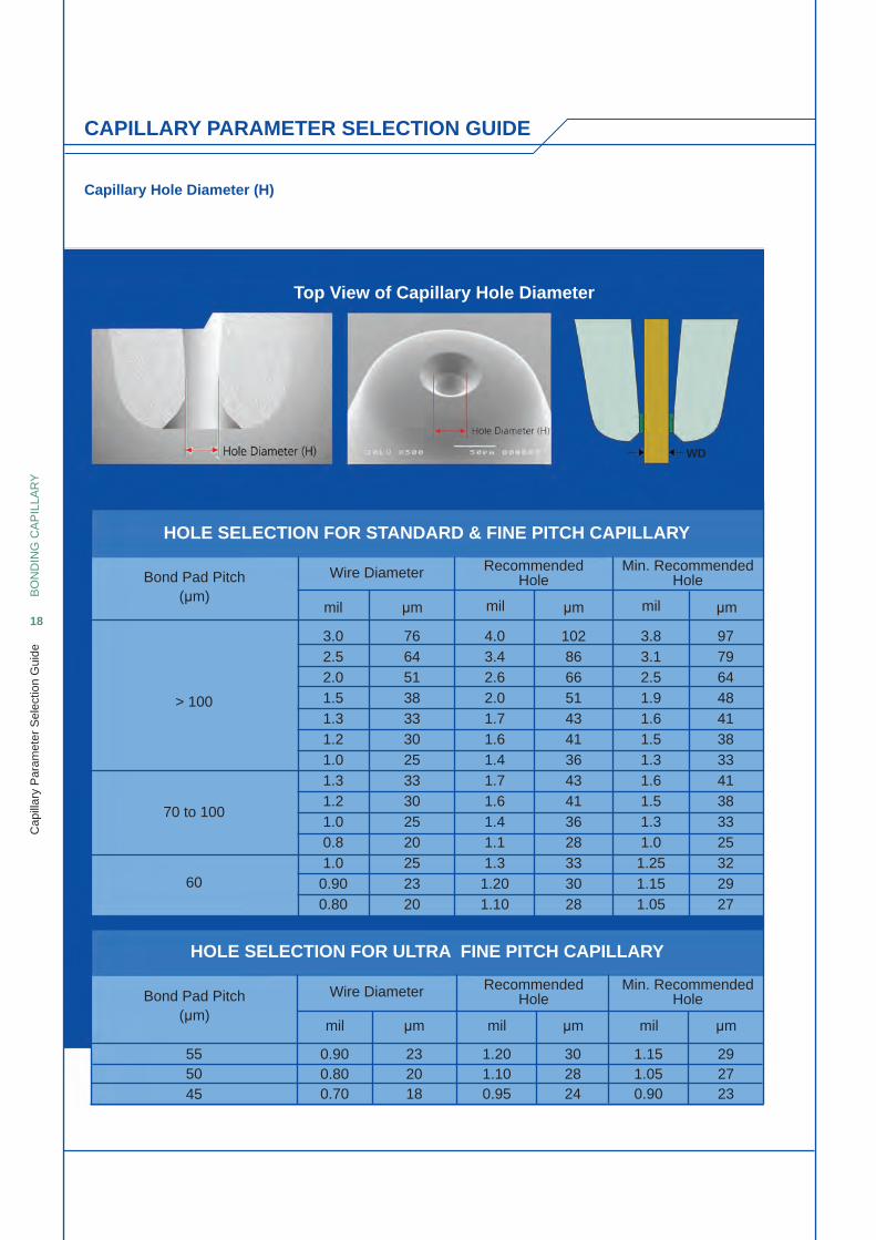
Capillary Hole Diameter (H)
Top View of Capillary Hole Diameter
Wire Diameter
Wire Diameter
mil
mil
mil
mil
Bond Pad Pitch (μm)
Bond Pad Pitch (μm)
> 100
70 to 100
60
555045
RecommendedHole
RecommendedHole
Min. RecommendedHole
Min. RecommendedHole
BO
ND
ING
CA
PIL
LAR
Y
18
Cap
illar
y P
aram
eter
Sel
ectio
n G
uide
HOLE SELECTION FOR STANDARD & FINE PITCH CAPILLARY
HOLE SELECTION FOR ULTRA FINE PITCH CAPILLARY
mil
mil
μm
μm
μm
μm
μm
μm
3.02.52.01.51.31.21.01.31.21.00.81.00.900.80
0.900.800.70
232018
1.201.100.95
302824
1.151.050.90
292723
4.03.42.62.01.71.61.41.71.61.41.11.3
1.201.10
3.83.12.51.91.61.51.31.61.51.31.0
1.251.151.05
9779644841383341383325322927
10286665143413643413628333028
7664513833302533302520252320
WD
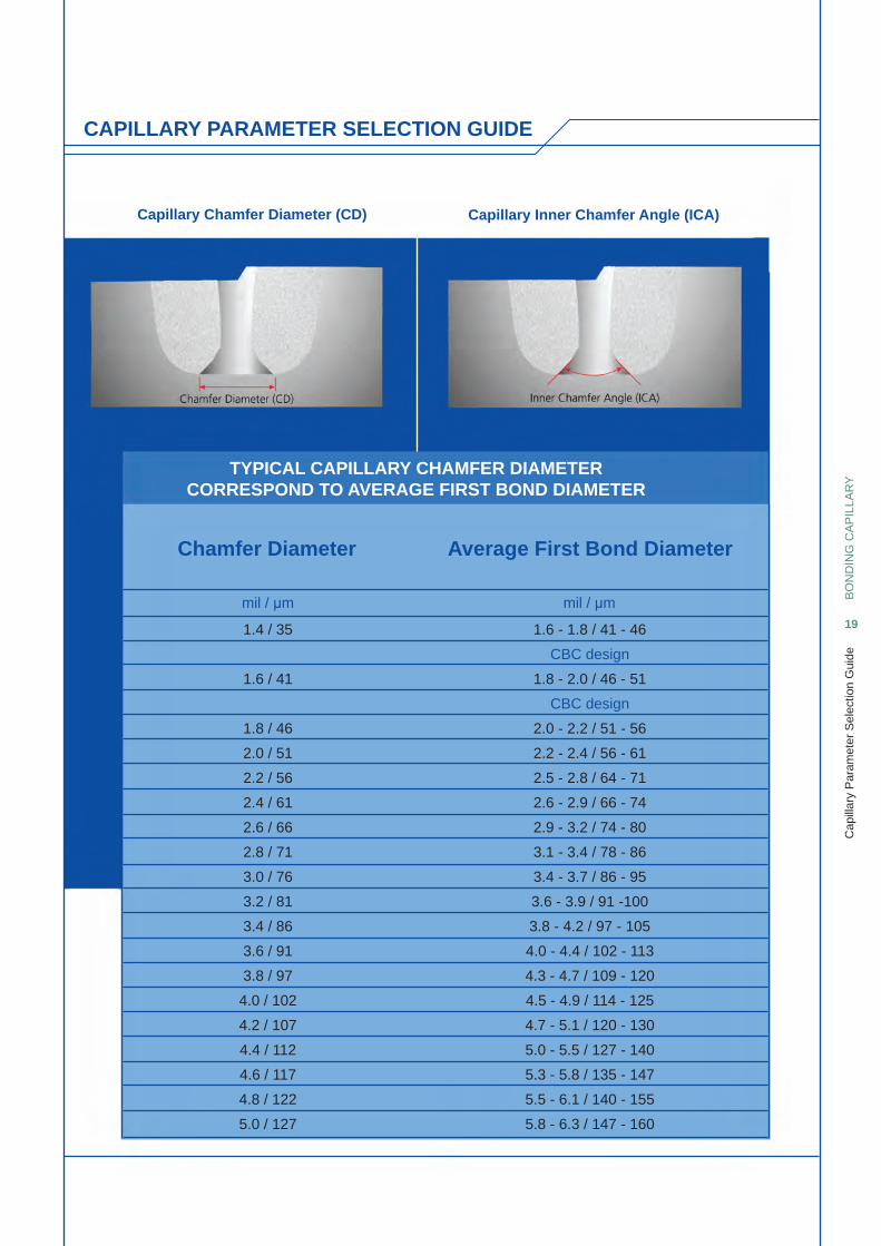
Capillary Chamfer Diameter (CD) Capillary Inner Chamfer Angle (ICA)
BO
ND
ING
CA
PIL
LAR
Y
19
Cap
illar
y P
aram
eter
Sel
ectio
n G
uide
TYPICAL CAPILLARY CHAMFER DIAMETERCORRESPOND TO AVERAGE FIRST BOND DIAMETER
mil / μm
1.4 / 35
1.6 / 41
1.8 / 46
2.0 / 51
2.2 / 56
2.4 / 61
2.6 / 66
2.8 / 71
3.0 / 76
3.2 / 81
3.4 / 86
3.6 / 91
3.8 / 97
4.0 / 102
4.2 / 107
4.4 / 112
4.6 / 117
4.8 / 122
5.0 / 127
1.6 - 1.8 / 41 - 46
CBC design
1.8 - 2.0 / 46 - 51
CBC design
2.0 - 2.2 / 51 - 56
2.2 - 2.4 / 56 - 61
2.5 - 2.8 / 64 - 71
2.6 - 2.9 / 66 - 74
2.9 - 3.2 / 74 - 80
3.1 - 3.4 / 78 - 86
3.4 - 3.7 / 86 - 95
3.6 - 3.9 / 91 -100
3.8 - 4.2 / 97 - 105
4.0 - 4.4 / 102 - 113
4.3 - 4.7 / 109 - 120
4.5 - 4.9 / 114 - 125
4.7 - 5.1 / 120 - 130
5.0 - 5.5 / 127 - 140
5.3 - 5.8 / 135 - 147
5.5 - 6.1 / 140 - 155
5.8 - 6.3 / 147 - 160
mil / μm
Chamfer Diameter Average First Bond Diameter
CAPILLARY PARAMETER SELECTION GUIDE
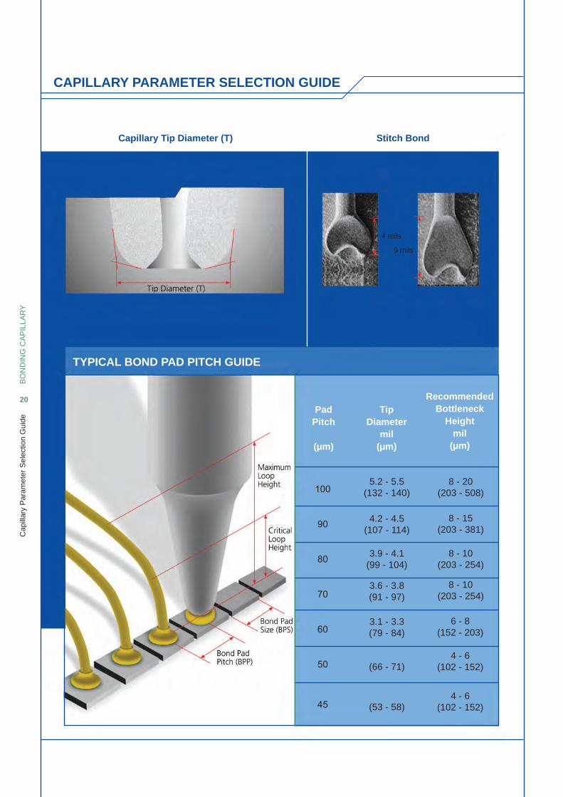
Capillary Tip Diameter (T)
TYPICAL BOND PAD PITCH GUIDE
Stitch Bond
BO
ND
ING
CA
PIL
LAR
Y
20
Cap
illar
y P
aram
eter
Sel
ectio
n G
uide
PadPitch
(μm)
TipDiameter
mil(μm)
RecommendedBottleneck
Heightmil
(μm)
5.2 - 5.5(132 - 140)
8 - 20(203 - 508)
8 - 15(203 - 381)
8 - 10 (203 - 254)
8 - 10 (203 - 254)
6 - 8(152 - 203)
4 - 6(102 - 152)
4 - 6(102 - 152)
4.2 - 4.5(107 - 114)
3.9 - 4.1(99 - 104)
3.6 - 3.8(91 - 97)
3.1 - 3.3(79 - 84)
(66 - 71)
(53 - 58)
9 mils
4 mils
CAPILLARY PARAMETER SELECTION GUIDE
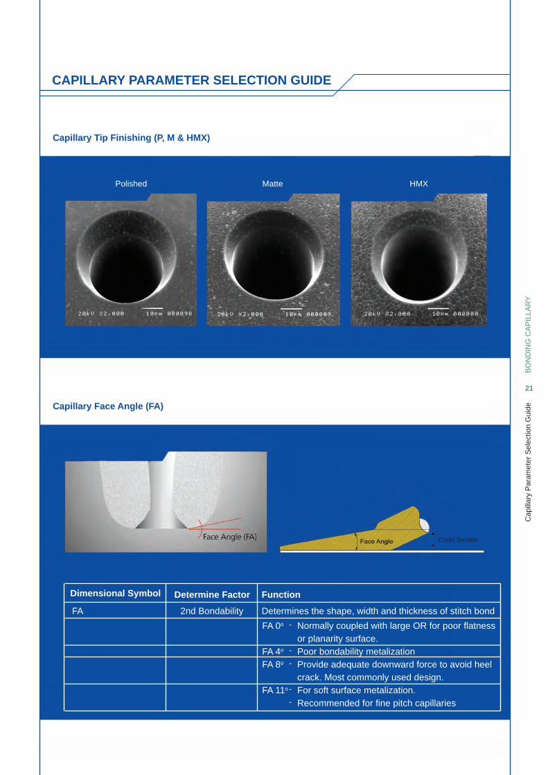
Capillary Tip Finishing (P, M & HMX)
Capillary Face Angle (FA)
Dimensional Symbol Determine Factor
FA 2nd Bondability
Function
Determines the shape, width and thickness of stitch bond
Normally coupled with large OR for poor fl atness or planarity surface.Poor bondability metalizationProvide adequate downward force to avoid heel crack. Most commonly used design.For soft surface metalization.Recommended for fi ne pitch capillaries
FA 0o
FA 4o
FA 8o
FA 11o
-
-
-
-
-
BO
ND
ING
CA
PIL
LAR
Y
21
Cap
illar
y P
aram
eter
Sel
ectio
n G
uide
Polished Matte HMX
Cross Section
CAPILLARY PARAMETER SELECTION GUIDE
BO
ND
ING
CA
PIL
LAR
Y
22
Cap
illar
y P
aram
eter
Sel
ectio
n G
uide
Capillary Outer Radius (OR)
CAPILLARY OUTER RADIUS VERSUS TIP DIAMETER SELECTION GUIDE
Big OR
Short Weld Length
Long Weld Length
Small OR
Bottleneck Capillary
Capillary DesignOuter Radiusin mil/ μm
Tip Diameterin mil/ μm
2.8 / 71
3.0 / 76
3.1 / 79
3.5 / 89
3.9 / 99
4.3 / 109
4.7 / 119
5.1 / 130
5.5 / 140
5.9 / 150
6.5 / 165
7.1 / 180
7.9 / 200
8.9 / 226
9.8 / 249
11.8 / 300
0.4 / 10
0.5 / 12
0.5 / 12
0.5 / 12
0.5 / 12
0.8 / 20
0.8 / 20
1.2 / 30
1.2 / 30
1.2 / 30
1.5 / 38
1.5 / 38
2.0 / 51
2.0 / 51
2.0 / 51
2.5 / 64
Standard Capillary
CAPILLARY PARAMETER SELECTION GUIDE
BO
ND
ING
CA
PIL
LAR
Y
23
Sta
ndar
d C
apill
ary
Dim
ensi
ons
Tabl
e
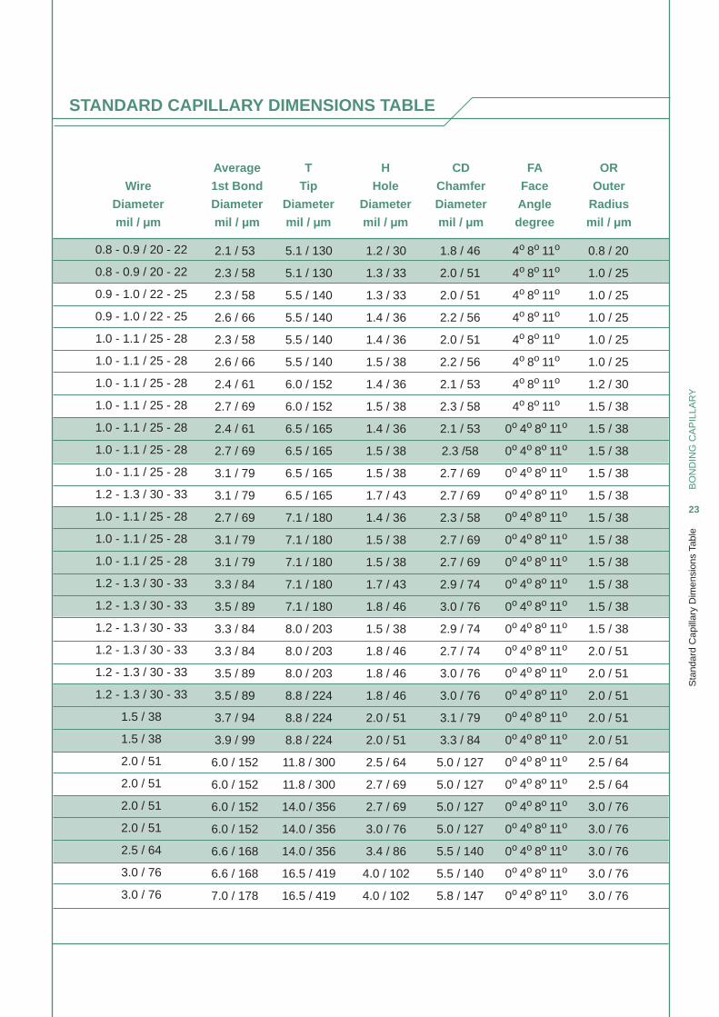
STANDARD CAPILLARY DIMENSIONS TABLE
Wire
Diameter
mil / μm
Average
1st Bond
Diameter
mil / μm
T
Tip
Diameter
mil / μm
H
Hole
Diameter
mil / μm
CD
Chamfer
Diameter
mil / μm
FA
Face
Angle
degree
OR
Outer
Radius
mil / μm
0.8 - 0.9 / 20 - 22
0.8 - 0.9 / 20 - 22
0.9 - 1.0 / 22 - 25
0.9 - 1.0 / 22 - 25
1.0 - 1.1 / 25 - 28
1.0 - 1.1 / 25 - 28
1.0 - 1.1 / 25 - 28
1.0 - 1.1 / 25 - 28
1.0 - 1.1 / 25 - 28
1.0 - 1.1 / 25 - 28
1.0 - 1.1 / 25 - 28
1.2 - 1.3 / 30 - 33
1.0 - 1.1 / 25 - 28
1.0 - 1.1 / 25 - 28
1.0 - 1.1 / 25 - 28
1.2 - 1.3 / 30 - 33
1.2 - 1.3 / 30 - 33
1.2 - 1.3 / 30 - 33
1.2 - 1.3 / 30 - 33
1.2 - 1.3 / 30 - 33
1.2 - 1.3 / 30 - 33
1.5 / 38
1.5 / 38
2.0 / 51
2.0 / 51
2.0 / 51
2.0 / 51
2.5 / 64
3.0 / 76
3.0 / 76
2.1 / 53
2.3 / 58
2.3 / 58
2.6 / 66
2.3 / 58
2.6 / 66
2.4 / 61
2.7 / 69
2.4 / 61
2.7 / 69
3.1 / 79
3.1 / 79
2.7 / 69
3.1 / 79
3.1 / 79
3.3 / 84
3.5 / 89
3.3 / 84
3.3 / 84
3.5 / 89
3.5 / 89
3.7 / 94
3.9 / 99
6.0 / 152
6.0 / 152
6.0 / 152
6.0 / 152
6.6 / 168
6.6 / 168
7.0 / 178
5.1 / 130
5.1 / 130
5.5 / 140
5.5 / 140
5.5 / 140
5.5 / 140
6.0 / 152
6.0 / 152
6.5 / 165
6.5 / 165
6.5 / 165
6.5 / 165
7.1 / 180
7.1 / 180
7.1 / 180
7.1 / 180
7.1 / 180
8.0 / 203
8.0 / 203
8.0 / 203
8.8 / 224
8.8 / 224
8.8 / 224
11.8 / 300
11.8 / 300
14.0 / 356
14.0 / 356
14.0 / 356
16.5 / 419
16.5 / 419
1.2 / 30
1.3 / 33
1.3 / 33
1.4 / 36
1.4 / 36
1.5 / 38
1.4 / 36
1.5 / 38
1.4 / 36
1.5 / 38
1.5 / 38
1.7 / 43
1.4 / 36
1.5 / 38
1.5 / 38
1.7 / 43
1.8 / 46
1.5 / 38
1.8 / 46
1.8 / 46
1.8 / 46
2.0 / 51
2.0 / 51
2.5 / 64
2.7 / 69
2.7 / 69
3.0 / 76
3.4 / 86
4.0 / 102
4.0 / 102
1.8 / 46
2.0 / 51
2.0 / 51
2.2 / 56
2.0 / 51
2.2 / 56
2.1 / 53
2.3 / 58
2.1 / 53
2.3 /58
2.7 / 69
2.7 / 69
2.3 / 58
2.7 / 69
2.7 / 69
2.9 / 74
3.0 / 76
2.9 / 74
2.7 / 74
3.0 / 76
3.0 / 76
3.1 / 79
3.3 / 84
5.0 / 127
5.0 / 127
5.0 / 127
5.0 / 127
5.5 / 140
5.5 / 140
5.8 / 147
0.8 / 20
1.0 / 25
1.0 / 25
1.0 / 25
1.0 / 25
1.0 / 25
1.2 / 30
1.5 / 38
1.5 / 38
1.5 / 38
1.5 / 38
1.5 / 38
1.5 / 38
1.5 / 38
1.5 / 38
1.5 / 38
1.5 / 38
1.5 / 38
2.0 / 51
2.0 / 51
2.0 / 51
2.0 / 51
2.0 / 51
2.5 / 64
2.5 / 64
3.0 / 76
3.0 / 76
3.0 / 76
3.0 / 76
3.0 / 76
4o 8o 11o
4o 8o 11o
4o 8o 11o
4o 8o 11o
4o 8o 11o
4o 8o 11o
4o 8o 11o
4o 8o 11o
0o 4o 8o 11o
0o 4o 8o 11o
0o 4o 8o 11o
0o 4o 8o 11o
0o 4o 8o 11o
0o 4o 8o 11o
0o 4o 8o 11o
0o 4o 8o 11o
0o 4o 8o 11o
0o 4o 8o 11o
0o 4o 8o 11o
0o 4o 8o 11o
0o 4o 8o 11o
0o 4o 8o 11o
0o 4o 8o 11o
0o 4o 8o 11o
0o 4o 8o 11o
0o 4o 8o 11o
0o 4o 8o 11o
0o 4o 8o 11o
0o 4o 8o 11o
0o 4o 8o 11o
BO
ND
ING
CA
PIL
LAR
Y
24
Fin
e P
itch
Cap
illar
y D
imen
sion
s fo
r 60μ
m B
.P.P
and
Abo
ve T
able
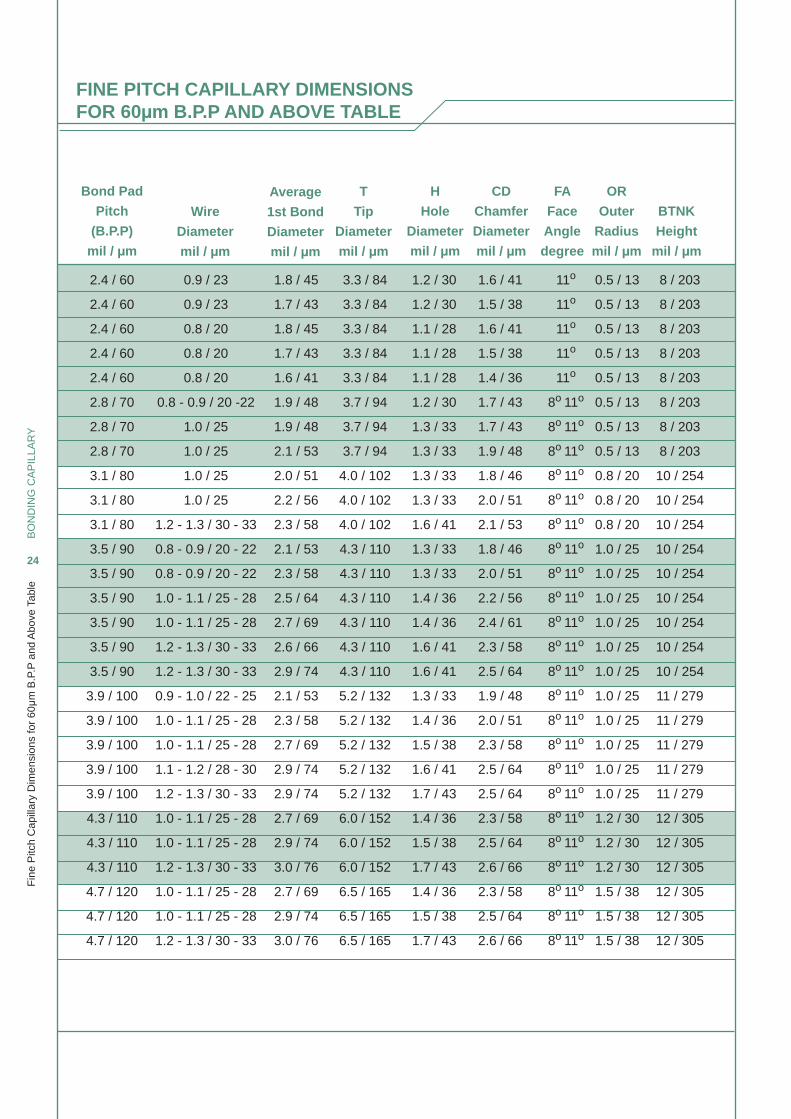
FINE PITCH CAPILLARY DIMENSIONS FOR 60μm B.P.P AND ABOVE TABLE
Bond Pad
Pitch
(B.P.P)
mil / μm
Wire
Diameter
mil / μm
Average
1st Bond
Diameter
mil / μm
H
Hole
Diameter
mil / μm
T
Tip
Diameter
mil / μm
CD
Chamfer
Diameter
mil / μm
FA
Face
Angle
degree
OR
Outer
Radius
mil / μm
BTNK
Height
mil / μm
2.4 / 60
2.4 / 60
2.4 / 60
2.4 / 60
2.4 / 60
2.8 / 70
2.8 / 70
2.8 / 70
3.1 / 80
3.1 / 80
3.1 / 80
3.5 / 90
3.5 / 90
3.5 / 90
3.5 / 90
3.5 / 90
3.5 / 90
3.9 / 100
3.9 / 100
3.9 / 100
3.9 / 100
3.9 / 100
4.3 / 110
4.3 / 110
4.3 / 110
4.7 / 120
4.7 / 120
4.7 / 120
1.8 / 45
1.7 / 43
1.8 / 45
1.7 / 43
1.6 / 41
1.9 / 48
1.9 / 48
2.1 / 53
2.0 / 51
2.2 / 56
2.3 / 58
2.1 / 53
2.3 / 58
2.5 / 64
2.7 / 69
2.6 / 66
2.9 / 74
2.1 / 53
2.3 / 58
2.7 / 69
2.9 / 74
2.9 / 74
2.7 / 69
2.9 / 74
3.0 / 76
2.7 / 69
2.9 / 74
3.0 / 76
3.3 / 84
3.3 / 84
3.3 / 84
3.3 / 84
3.3 / 84
3.7 / 94
3.7 / 94
3.7 / 94
4.0 / 102
4.0 / 102
4.0 / 102
4.3 / 110
4.3 / 110
4.3 / 110
4.3 / 110
4.3 / 110
4.3 / 110
5.2 / 132
5.2 / 132
5.2 / 132
5.2 / 132
5.2 / 132
6.0 / 152
6.0 / 152
6.0 / 152
6.5 / 165
6.5 / 165
6.5 / 165
1.2 / 30
1.2 / 30
1.1 / 28
1.1 / 28
1.1 / 28
1.2 / 30
1.3 / 33
1.3 / 33
1.3 / 33
1.3 / 33
1.6 / 41
1.3 / 33
1.3 / 33
1.4 / 36
1.4 / 36
1.6 / 41
1.6 / 41
1.3 / 33
1.4 / 36
1.5 / 38
1.6 / 41
1.7 / 43
1.4 / 36
1.5 / 38
1.7 / 43
1.4 / 36
1.5 / 38
1.7 / 43
1.6 / 41
1.5 / 38
1.6 / 41
1.5 / 38
1.4 / 36
1.7 / 43
1.7 / 43
1.9 / 48
1.8 / 46
2.0 / 51
2.1 / 53
1.8 / 46
2.0 / 51
2.2 / 56
2.4 / 61
2.3 / 58
2.5 / 64
1.9 / 48
2.0 / 51
2.3 / 58
2.5 / 64
2.5 / 64
2.3 / 58
2.5 / 64
2.6 / 66
2.3 / 58
2.5 / 64
2.6 / 66
0.5 / 13
0.5 / 13
0.5 / 13
0.5 / 13
0.5 / 13
0.5 / 13
0.5 / 13
0.5 / 13
0.8 / 20
0.8 / 20
0.8 / 20
1.0 / 25
1.0 / 25
1.0 / 25
1.0 / 25
1.0 / 25
1.0 / 25
1.0 / 25
1.0 / 25
1.0 / 25
1.0 / 25
1.0 / 25
1.2 / 30
1.2 / 30
1.2 / 30
1.5 / 38
1.5 / 38
1.5 / 38
8 / 203
8 / 203
8 / 203
8 / 203
8 / 203
8 / 203
8 / 203
8 / 203
10 / 254
10 / 254
10 / 254
10 / 254
10 / 254
10 / 254
10 / 254
10 / 254
10 / 254
11 / 279
11 / 279
11 / 279
11 / 279
11 / 279
12 / 305
12 / 305
12 / 305
12 / 305
12 / 305
12 / 305
11o
11o
11o
11o
11o
8o 11o
8o 11o
8o 11o
8o 11o
8o 11o
8o 11o
8o 11o
8o 11o
8o 11o
8o 11o
8o 11o
8o 11o
8o 11o
8o 11o
8o 11o
8o 11o
8o 11o
8o 11o
8o 11o
8o 11o
8o 11o
8o 11o
8o 11o
0.9 / 23
0.9 / 23
0.8 / 20
0.8 / 20
0.8 / 20
0.8 - 0.9 / 20 -22
1.0 / 25
1.0 / 25
1.0 / 25
1.0 / 25
1.2 - 1.3 / 30 - 33
0.8 - 0.9 / 20 - 22
0.8 - 0.9 / 20 - 22
1.0 - 1.1 / 25 - 28
1.0 - 1.1 / 25 - 28
1.2 - 1.3 / 30 - 33
1.2 - 1.3 / 30 - 33
0.9 - 1.0 / 22 - 25
1.0 - 1.1 / 25 - 28
1.0 - 1.1 / 25 - 28
1.1 - 1.2 / 28 - 30
1.2 - 1.3 / 30 - 33
1.0 - 1.1 / 25 - 28
1.0 - 1.1 / 25 - 28
1.2 - 1.3 / 30 - 33
1.0 - 1.1 / 25 - 28
1.0 - 1.1 / 25 - 28
1.2 - 1.3 / 30 - 33
BO
ND
ING
CA
PIL
LAR
Y
25
Ultr
a-fi n
e P
itch
Cap
illar
y (C
BC
des
ign)
Dim
ensi
ons
for
55μ
m B
.P.P
and
Bel
ow T
able
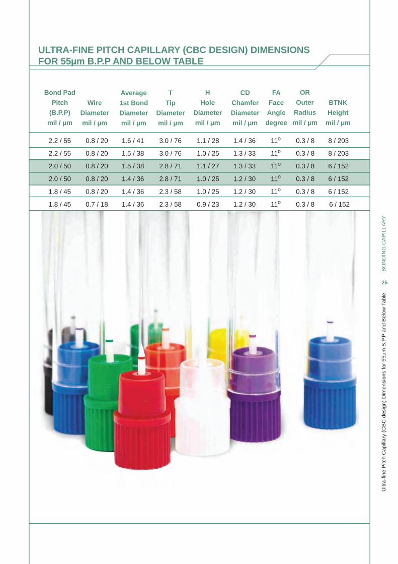
ULTRA-FINE PITCH CAPILLARY (CBC DESIGN) DIMENSIONSFOR 55μm B.P.P AND BELOW TABLE
Bond Pad
Pitch
(B.P.P)
mil / μm
Wire
Diameter
mil / μm
Average
1st Bond
Diameter
mil / μm
H
Hole
Diameter
mil / μm
T
Tip
Diameter
mil / μm
CD
Chamfer
Diameter
mil / μm
FA
Face
Angle
degree
OR
Outer
Radius
mil / μm
BTNK
Height
mil / μm
2.2 / 55
2.2 / 55
2.0 / 50
2.0 / 50
1.8 / 45
1.8 / 45
1.6 / 41
1.5 / 38
1.5 / 38
1.4 / 36
1.4 / 36
1.4 / 36
3.0 / 76
3.0 / 76
2.8 / 71
2.8 / 71
2.3 / 58
2.3 / 58
1.1 / 28
1.0 / 25
1.1 / 27
1.0 / 25
1.0 / 25
0.9 / 23
1.4 / 36
1.3 / 33
1.3 / 33
1.2 / 30
1.2 / 30
1.2 / 30
0.3 / 8
0.3 / 8
0.3 / 8
0.3 / 8
0.3 / 8
0.3 / 8
8 / 203
8 / 203
6 / 152
6 / 152
6 / 152
6 / 152
11o
11o
11o
11o
11o
11o
0.8 / 20
0.8 / 20
0.8 / 20
0.8 / 20
0.8 / 20
0.7 / 18
BO
ND
ING
CA
PIL
LAR
Y
26
P/N
o S
yste
m: S
tand
ard
Cap
illar
y
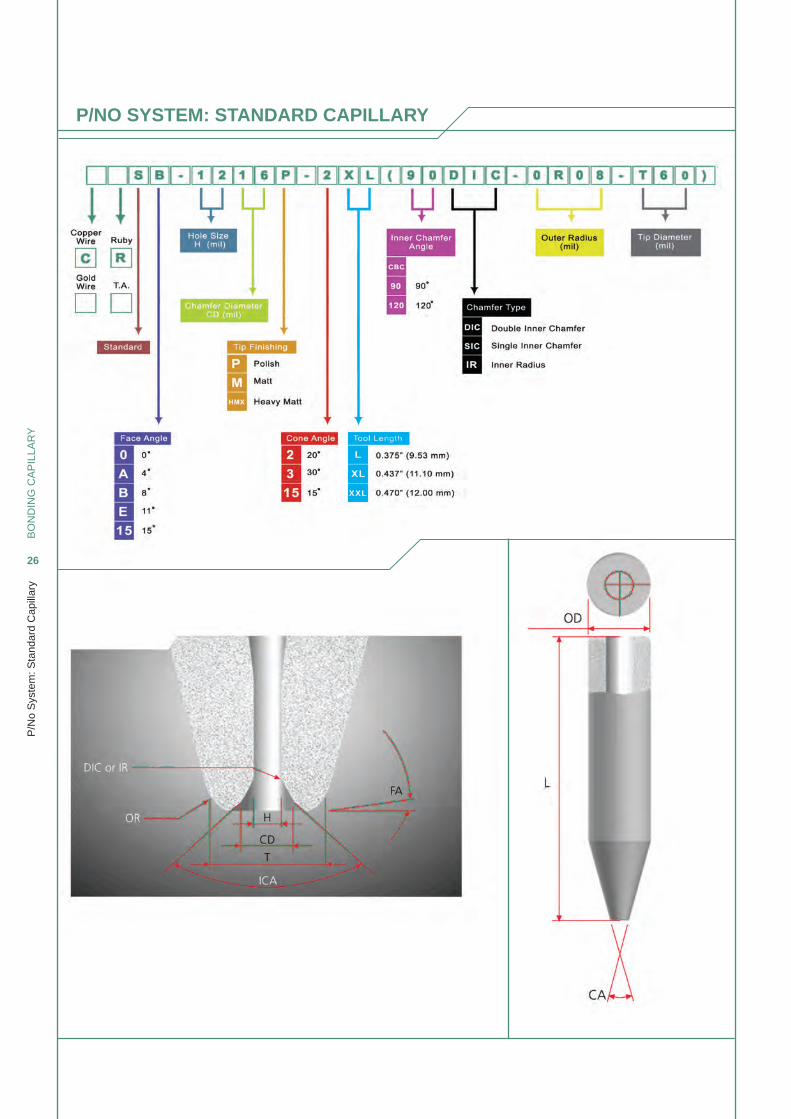
P/NO SYSTEM: STANDARD CAPILLARY
BO
ND
ING
CA
PIL
LAR
Y
27
P/N
o S
yste
m: F
ine
Pitc
h C
apill
ary
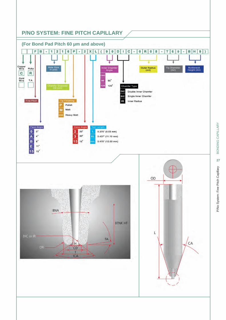
P/NO SYSTEM: FINE PITCH CAPILLARY
(For Bond Pad Pitch 60 μm and above)
BO
ND
ING
CA
PIL
LAR
Y
28
P/N
o S
yste
m: U
ltra
Fin
e P
itch
Cap
illar
y
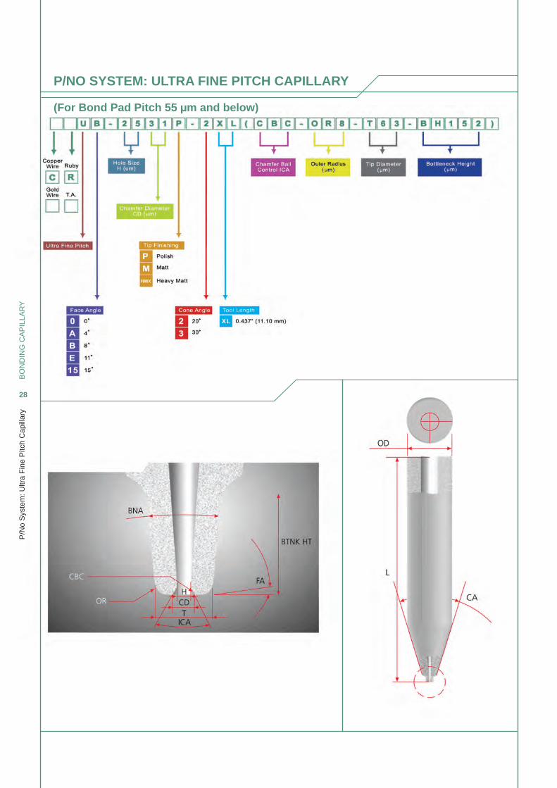
P/NO SYSTEM: ULTRA FINE PITCH CAPILLARY
(For Bond Pad Pitch 55 μm and below)
BO
ND
ING
CA
PIL
LAR
Y
29
P/N
o S
yste
m: V
ertic
al B
ottle
neck
Cap
illar
y
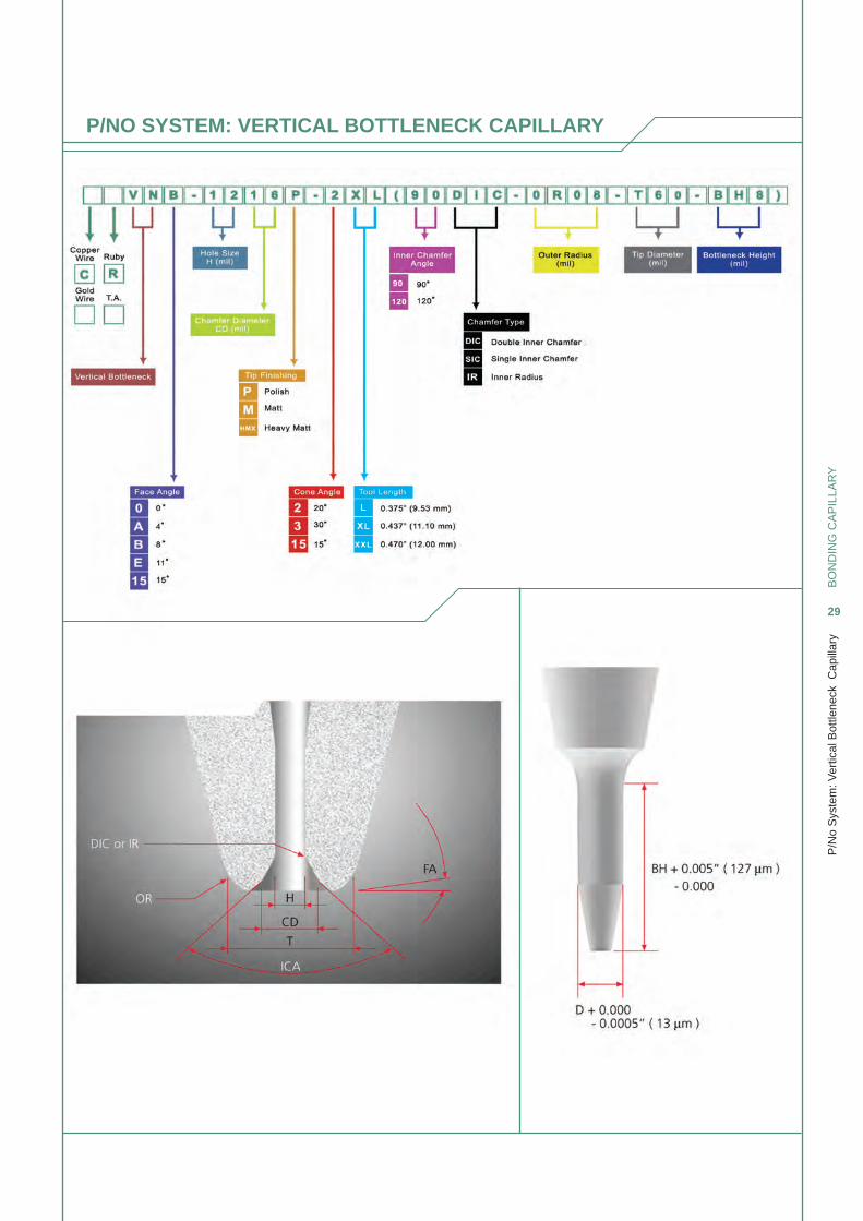
P/NO SYSTEM: VERTICAL BOTTLENECK CAPILLARY
BO
ND
ING
CA
PIL
LAR
Y
30
P/N
o S
yste
m: H
MX
Cap
illar
y
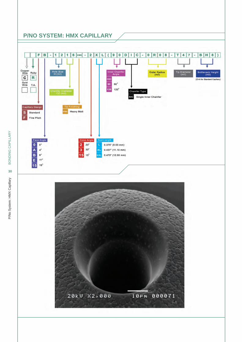
P/NO SYSTEM: HMX CAPILLARY
BO
ND
ING
CA
PIL
LAR
Y
31
P/N
o S
yste
m: R
uby
Cap
illar
y
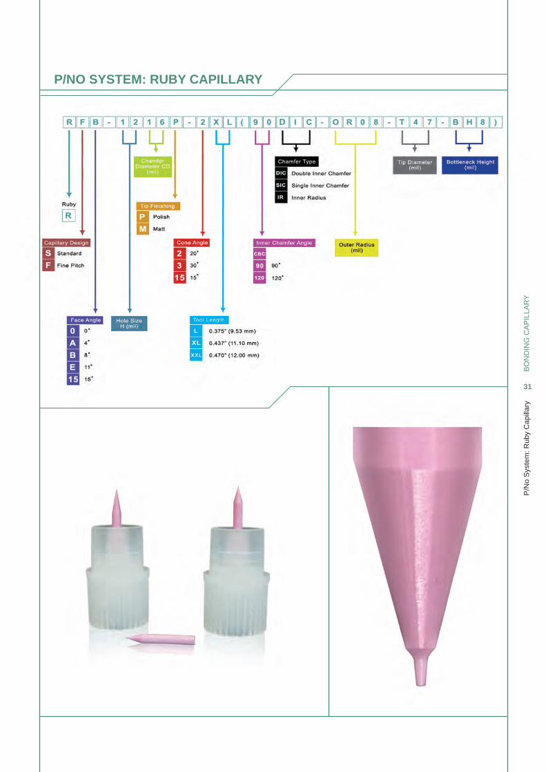
P/NO SYSTEM: RUBY CAPILLARY
BO
ND
ING
CA
PIL
LAR
Y
32
Tole
ranc
es
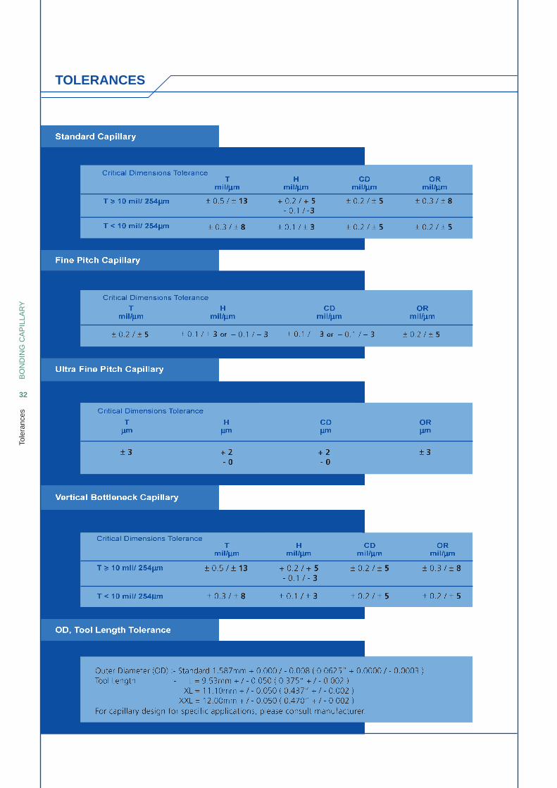
TOLERANCES
BO
ND
ING
CA
PIL
LAR
Y
33
Cap
Cle
anin
g S
ervi
ce
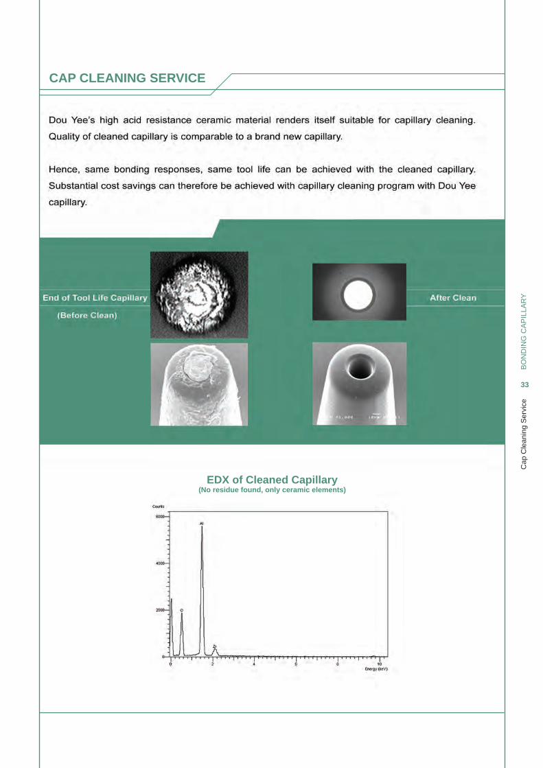
CAP CLEANING SERVICE
EDX of Cleaned Capillary(No residue found, only ceramic elements)
BO
ND
ING
CA
PIL
LAR
Y
34
Unp
lug
Wire
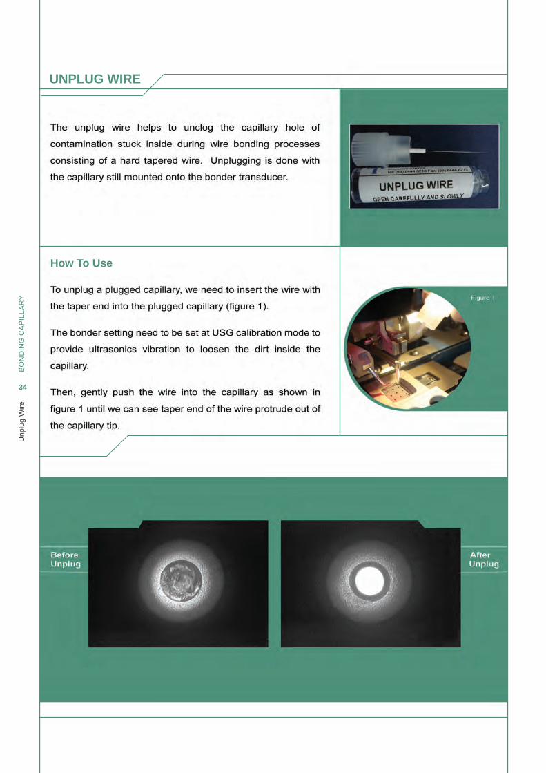
UNPLUG WIRE
How To Use
BO
ND
ING
CA
PIL
LAR
Y
35
Pac
king
Info
rmat
ion/
Col
our
Cod
ing/
Bar
Cod
e L
abel
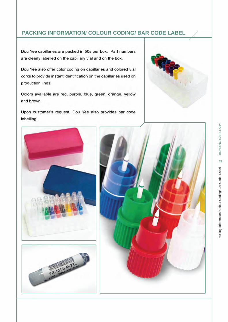
PACKING INFORMATION/ COLOUR CODING/ BAR CODE LABEL
BO
ND
ING
CA
PIL
LAR
Y
36
Cap
illar
y R
eque
st F
orm
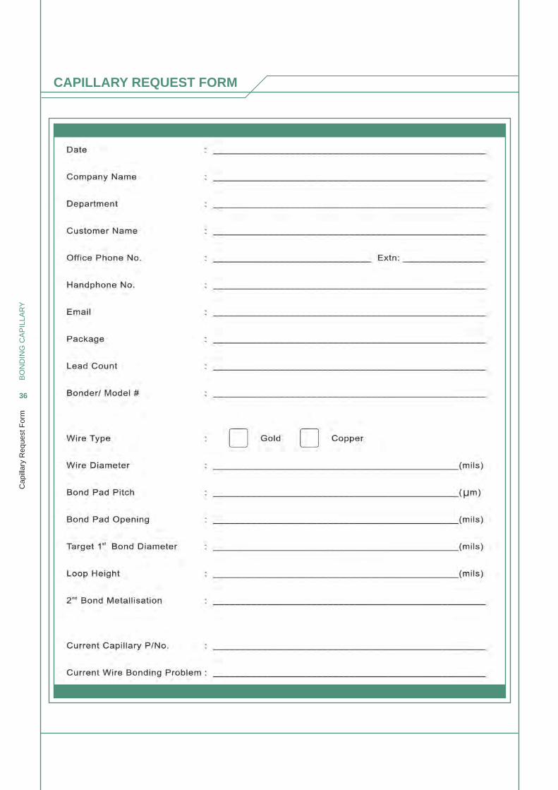
CAPILLARY REQUEST FORM
Johor Bahru, Malaysia131 & 131A, Jalan Seri Impian 1, Taman Impian Emas, 81300 Johor Bahru, Malaysia.Tel: (607) 556 6284 / 558 6285 Fax: (607) 556 6273 Email: [email protected]
Malacca, Malaysia13 and 13-1, Jalan Puncak 2, Taman Puncak, Bukit Katil, 75450 Melaka, Malaysia.Tel: (60-6) 231 5060/61/62/64 Fax: (60-6) 231 5059Email: [email protected]
Kuala Lumpur, Malaysia26 Shah Alam Technology Park, Jalan Tamborin 33/23, Sek. 33, 40460 Shah Alam, Selangor, Malaysia.Tel: (603) 5121 1613 / 14 Fax: (603) 5121 8121 Email: [email protected]
Penang, Malaysia18 Lorong Talang 8, Taman Emas, 13600 Perai, Penang, Malaysia.Tel: (60-4) 390 4824 Fax: (60-4) 390 3815 Email: [email protected]
Ipoh, Malaysia79 Persiaran Klebang, Kawasan Perusahaan IGB, Off Jalan Kuala Kangsar, 31200 Ipoh, Perak, Malaysia.Tel: (60-5) 2911853 Fax: (60-4) 390 3815Email: [email protected]
Bangkok, Thailand75/27 Moo 11, Phaholyothin Rd, T.Klongnueng, A.Klongluang, Pathumthani 12120 , Thailand.Tel: (662) 529 0979 Fax: (662) 9081820 Email: [email protected]
Ho Chi Minh, Vietnam2nd Floor, Fimexco Building, 231-233 Le Thanh Ton Street, Ben Thanh Ward, District 1, Ho Chi Minh City, VietnamTel: (84) 8 3910 4420 Fax: (84) 8 3910 4419Email: [email protected]
Hanoi, Vietnam28 Ngo 169 Thai Ha, Dong Da Dist, Hanoi, Vietnam Tel: (844) 6275 4337 Fax: (844) 6275 4337Email: [email protected]
Manila, Philippines#1105-1108 Richville Corporate Tower Madrigal Business Park, Alabang-Zapote Road Alabang, Muntinlupa City 1770, PhilippinesTel: (+632) 807 4683 / 84 / 85 Fax: (+632) 807 4682 Email: [email protected]
Cebu, PhilippinesRoom 204, Lilang's Guitar Building Quezon National Highway, Brgy. Pajo Lapu-Lapu City 6015, Cebu Philippines. Tel: (6332) 341 1577 / 0147 Fax: (6332) 340 7686 Email: [email protected]
Jakarta, IndonesiaMenara Pasifik Lt.3 Ruang 6, Jl.MH.Thamrin Kav.107, Lippo Cikarang, Bekasi 17550 Jawa Barat, Indonesia.Tel: (6221) 8990 1153 Fax: (6221) 8990 5101Email: [email protected]
Batam, IndonesiaBatamindo Shophouse Blk C #01-16, Mukakuning Batam, 29433 IndonesiaTel: (011) 7 7061 2490 Fax: (011) 7 7061 2489 Email: [email protected]
Shanghai, China3rd Floor, Block C, Hi-Tech Industrial Center, No. 501, JinGang Road, JinQiao, PuDong New Area, ShangHai 201206 China Tel: +86-21-5899 4619 Fax: +86-21-5899 4618Email: [email protected]
Suzhou, ChinaNo. 58, West Shen Hu Road, Suzhou Industrial Park, 215123 China Tel: +86-512-6258 5066 Fax: +86-512-6258 5366Email: [email protected]
Beijing, China#6010, Block 2, Chunlan Building, No.88, Nan San Huan road (west), Feng Tai District, Beijing 100070 China Tel: 010-83686931 Fax: 010-83687651 Email: [email protected]
Tianjin, China#202, SenTe Building, YuRong Garden,JinZhong River Street, HeBei District,TianJin Tel: +86-22-2642 2093 Fax: +86-22-2642 2023Email: [email protected]
Dalian, China#607, No.263, Huanghe Road, Xigang District, Dalian 116011 ChinaTel: +86-411-8377 9121 / 9193 Fax: +86-411-8369 5216Email: [email protected]
Chengdu, ChinaUnit #C1409, XieWang Building, No. 9, XieDu Road (South), 1st Avenue, ChengShuang Section, ChuanZang Road, WuHou District, ChengDu 610043 China Tel: +86-28-8501 7691 Fax: +86-28-8501 7693Email: [email protected]
Anhui, China#2607, Block 7, West Ring Central Plaza, Huangshan Road (West), Shushan District, Hefei 230000 ChinaTel: +86-21-5899 4619 Fax: +86-21-5899 4618Email: [email protected]
Xi An, China#401, Unit 3, Block 8, No.306, JiXiang Road,Southern suburb, XiAn 710063 ChinaTel: +86-29-8824 7085 Fax: +86-29-8824 7085Email: [email protected]
Hong Kong, ChinaRoom 6, 8/F, Vanta Industrial Centre, 21-33 Tai Lin Pai Road, Kwai Chung, N.T., Hong Kong Tel: (852) 2480 6337 Fax: (852) 2487 7956 Email: [email protected]
Shenzhen, ChinaUnit F, 13/F, Jin Song Building, Terra 4 Road, Che Gong Miao, Futian District, Shenzhen, P.R. China 518040Tel: (86-755) 8389-0255 Fax: (86-755) 8389-0675 Email: [email protected]
HungaryH-2120 DunakesziBaratsag u. 40/C, 4/9Tel: +36 70 609 4216Email: [email protected]
Taipei, Taiwan5F-2, No. 328, Chang Chun Road, 104 Taipei, Taiwan 104 328 5F-2Tel: (886)-2-2715 1156 Fax: (886)-2-2712 8570 Email: [email protected]
HsinChu, TaiwanRm. 1, 20F., No.295, Sec. 2, Guangfu Rd., Hsinchu City 30071, Taiwan30071 295 20 1Tel: +886-3-5711618 Fax: +886-3-5711619Email: [email protected]
Yokohama, Japan#2 Tsurumi Building, 302, 2-10-34 Kita-Saiwai, Nishi-ku,Yokohama, Kanagawa 220-0004 Japan. Tel: (81-45) 312 9906 Fax: (81-45) 312 9907 Email: [email protected]
Truckee, USA15570 Glenshire Drive, Truckee, CA 96161-1302 Tel: (530) 320-1313 Fax: (530) 587-2951 Email: [email protected]
Tournefeuille, France 94 Chemin De La Peyrette, 31170 Tournefeuille, FranceTel: (33) (0) 5 6116 2050 Fax: (33) (0) 5 3457 5130 Email: [email protected]
Pont de Poitte, France45 route d’OrgeletF – 39130 Pont de PoitteTel: +33 (0) 3 84 87 02 39 Fax: (33) (0) 384 483 000Email: [email protected]
Nykoping, Sweden Pontongatan 11611 64 NykopingTel: +46 (0) 155 20 26 80 Fax: +46 (0) 155 20 26 81 Email: [email protected]
Deventer, Netherlands Heuvel 6 A, 5664HK Geldrop, The NetherlandsTel: +31 (0) 886363 555 Fax: +31 (0) 886363 563Email: [email protected]
Great Britain, United KingdomUnit 4B, Bramhall Moor Industrial Park,Pepper Road, Hazel Grove Stockport, Cheshire SK7 5BW EnglandTel: +44 (0) 161 456 6088Email: [email protected]
Polandul. Sikorskiego 187-850 ChocenTel: +48 533 550 338E-mail: [email protected]
Sales Agent in KoreaMSW (Micro Semiconductor World )(102 Dong 1406, Chunui Technopark 1)#200-1 Chunui-Dong, Wonmi-Gu, Bucheon-Si,Kyunggi-Do, 420859 Korea Tel: (+82) 32 714 0355Fax:(+82) 32 714 0357E-mail: [email protected]
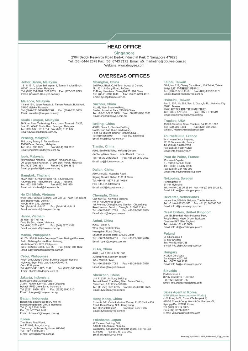
HEAD OFFICE Singapore
2304 Bedok Reservoir Road Bedok Industrial Park C Singapore 479223Tel: (65) 6444 2678 Fax: (65) 6743 7172 Email: [email protected]
Website: www.douyee.com
OVERSEAS OFFICES
BondingCap20150312EN_S5Richard_20pp_update
KoreaThe Sharp First World, unit F-1402, Songdo-dong, Yeonsu-gu, Incheon city,Korea, 406-743 Tel: +82 10 26984161 E-mail: [email protected]
Slovakia Podzahradna 482107 Bratislava – SlovakiaTel: +421 908 581 747Email: [email protected]
Recommended