Embed Size (px)
Citation preview
iNEMI Cu Wire Bonding Project Update on Technology Investigation
Reliability Test with Concerns
Masahiro Tsuriya1 , Andy Tseng2, JoonSu Kim3, [email protected], International Electronics Manufacturing Initiative (iNEMI)
[email protected], ASE (U.S.) Inc. [email protected], Amkor Technology Korea, Inc.
ABSTRACT
The adoption of copper wire bonding is picking up pace across semiconductor product families and system applications. iNEMI launched a project in 2010 to survey the industry and determined key concerns of the member companies. Based on the outcome of the industry-wide survey, the reliability project has been launched to assess the effects of leadframe and organic substrate packaging with multiple Cu wire types and process conditions. In this talk we will provide an overview of the technical project with bondability testing result and some preliminary reliability testing results are discussed. Two bonding wire manufacturers provide the copper wire and palladium coated copper wire used for evaluation. Bill of Material (BOM) is chosen from the recommendation from the assembly house. Process parameters of EFO current, bonding force and time are determined based on the preliminary process characterization study. Using these process parameters, bondability tests are performed for wire pull strength, ball shear IMC coverage on both BGA and QFN. The measurement data shows the similar results with acceptable level which prove that process characterization for all wire types can be established with acceptable level. Reliability test is underway and Temperature Cycling and HAST test for BGA is discussed in this paper.
1. INTRODUCTION
Copper (Cu) bond wires are increasingly being used for a wide variety of components from consumer applications to high-reliability electronic products, which drive cost merit as well as electrical and thermal performance improvement. Despite these positive impacts of the improvements, reliability still needs to be collectively assessed by the industry in a quantitative manner. Furthermore, for component qualification purposes, standard reliability test methods and durations established for Gold (Au) wire device need to review for Cu wire bonded devices.
iNEMI launched a collaborative project on Cu Wire Bonding Reliability in 2010 to firstly have conducted a survey on the industry-wide conversion status, as well as key reliability concerns for Cu wire bonding. Based on the findings from this survey, the team moves to next step in late 2011, which project is to understand the effects of key factors such as packaging material selection and process condition for environmental reliability performance.
Two package types are selected for the evaluation, which is QFN (Qual Flat Non-Leaded) and BGA (Ball Grid Array). Two bonding wires are used, which are bare Cu wire and Palladium (Pd) coated Cu wire, and the wires used are supplied from two companies. The process characteristics studies were performed to optimize process condition, and process parameters are determined for this project experiment. The accelerated environmental tests are performed on temperature cycling (TC), high temperature storage (HTS) and highly accelerated stress test (HAST) with 5 different conditions and duration for both BGA and QFN.
2. OUTCOME FROM PHASE1 PROJECT1
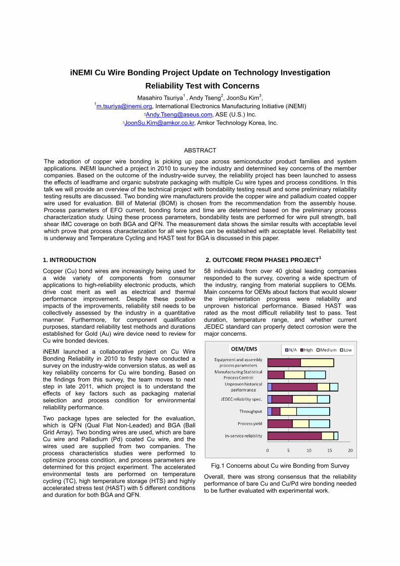
58 individuals from over 40 global leading companies responded to the survey, covering a wide spectrum of the industry, ranging from material suppliers to OEMs. Main concerns for OEMs about factors that would slower the implementation progress were reliability and unproven historical performance. Biased HAST was rated as the most difficult reliability test to pass. Test duration, temperature range, and whether current JEDEC standard can properly detect corrosion were the major concerns.
Fig.1 Concerns about Cu wire Bonding from Survey
Overall, there was strong consensus that the reliability performance of bare Cu and Cu/Pd wire bonding needed to be further evaluated with experimental work.
3. EXPERIMENTAL
3.1 Test Vehicle Information:
- Bonding Wire: Table1 shows the key characteristics of bonding wires. Two bonding wire types of bare Cu and Pd coated Cu (hereinafter referred to as "Cu/Pd") are used for the evaluation. These wires are supplied by two wire manufacturers (shown as Co-B and Co-C in the table). 4N Gold (Au) wire is used as control, which Au wires are chosen from the proven quality history from the volume production at the assembly house.
Table1 Wire Type for Evaluation
- Daisy Chain Die: Table2 shows the test die and package information. Daisy chain die is used for package assemblies, which packages are 32 leads QFN and 384 i/o BGA. This wafer metallization of Al/TiN thickness is 500/6000Å(angstrom).
Table2. Package Outline used for evaluation QFN 56ld BGA 384i/o
Die Size 2.5 x 2.5 x 0.02mm
5.1 x 5.1 x 0.02mm
Die Pad Opening 0.038mm 0.049mm
Die Pad Pitch 0.045mm 0.06mm
Package Size 5.0 x 5.0 x 0.65mm
14 x 14 x 1.16mm
Max Wire Length 1.482mm 3.75mm
Ball Size/ Pitch - /0.50mm 0.04/ 0.65mm
3.2 Design of Experiment:
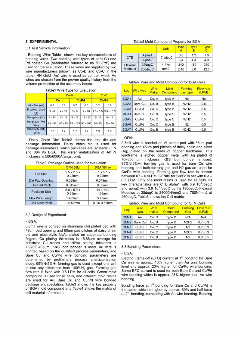
- BGA: 0.8mil wire is bonded on aluminum (Al) plated pad with 49um pad opening and 60um pad pitches of daisy chain die and electrolytic Ni/Au plated on substrate bonding fingers. Cu plating thickness is 18.88um average for substrate Cu traces and Ni/Au plating thickness is 7.928/0.486um. K&S Icon bonder is used. Au wire is bonded based on the qualified process parameters, and Bare Cu and Cu/Pd wire bonding parameters are determined by preliminary process characterization study. 95%N25%H2 forming gas is used except one cell to see any difference from 100%N2 gas. Forming gas flow rate is fixed with 0.5 LPM for all cells. Green mold compound is used for all cells, and different mold resins are used for Au, Bare Cu and Cu/Pd wire bonded package encapsulation. Table3 shows the key property of BGA mold compound and Table4 shows the matrix of cell material information.
Table3 Mold Compound Property for BGA
Unit Type
A Type
B Type
C
CTE Alpha1
10-5/degC 0.8 1.2 1.0
Alpha2 3.4 4.3 4.0
Flexural Modulus
25degC 102N/ mm2
240 180 230
260degC 2.40 8.0 12.0
Table4. Wire and Mold Compound for BGA Cells
Leg Wire typeWire
Maker Mold
Compound Forming gas type
Flow rate (LPM)
BGA1 Au Co. A type A No No
BGA2 Bare Cu Co. B type B N2H2 0.5
BGA3 Cu/Pd Co. C type B N2H2 0.5
BGA4 Bare Cu Co. B type C N2H2 0.5
BGA5 Cu/Pd Co. C type C N2H2 0.5
BGA6 Cu/Pd Co. C type B N2 0.5
BGA7 Cu/Pd Co. B type B N2H2 0.5 - QFN: 0.7mil wire is bonded on Al plated pad with 38um pad opening and 45um pad pitches of daisy chain and silver (Ag) plated on the leads of copper leadframe. This leadframe is etched copper metal with Ag plated of 70~350 um thickness. K&S Icon bonder is used. 95%N25%H2 forming gas is used for bare Cu wire bonding and both forming gas and N2 gas are used for Cu/Pd wire bonding. Forming gas flow rate is chosen between 07 – 0.9LPM. QFN#5 for Cu/Pd is set with 0.3 – 0.5 LPM. Only one mold resins is used for all cells. Its key characteristics are CTE alpha1 with 0.9 10-5/degC and apha2 with 3.9 10-5/degC by Tg 130degC. Flexural Modulus at 25degC is 24000N/mm2 and 750N/mm2 at 260degC. Table5 shows the Cell matrix.
Table5. Wire and Mold Compound for QFN Cells
Leg Wire type
Wire maker
Mold Compound
Forming Gas
Flow rate (LPM)
QFN1 Au Co. D Type D N/A N/A
QFN2 Bare Cu Co. B Type D N2H2 0.7~0.9
QFN3 Cu/Pd Co. C Type D N2 0.7~0.9
QFN4 Cu/Pd Co. C Type D N2H2 0.7~0.9
QFN5 Cu/Pd Co. B Type D N2 0.3~0.5
3.3 Bonding Parameters:
- BGA: Electric Flame-off (EFO) current at 1st bonding for Bare Cu wire is approx. 10% higher than Au wire bonding level and approx. 20% higher for Cu/Pd wire bonding. Same EFO current is used for both Bare Cu and Cu/Pd wire bonding which is approx. 25% higher than Au wire bonding.
Bonding force at 1st bonding for Bare Cu and Cu/Pd is the same, which is higher by approx. 80% and half force at 2nd bonding, comparing with Au wire bonding. Bonding
Wire Dia. (mil) 0.7 0.8 0.7 0.8 0.7 0.8
Breaking Load (gf)
3 - 8 4 - 10 3 - 8 4 - 10 4.5 - 8.5 5.5 - 10.5
Elongation (%) 7 - 15 7 - 15 9 - 15 11 - 17 8- 14 8– 14
Hardness (Hv) Wire
85 - 95 85 - 95 95 - 105 90 - 105 50- 80 50– 80
Resistivity (RT) μΩ 1.7 1.7 1.7 1.7 1.9 1.9
Co-B Co-C
Cu Cu/Pd Cu/Pd
capillary is PECO granular finish type and it has changed every time when new cell is started bonding.
- QFN: EFO current for Bare Cu wire is used the same range in N2H2 forming gas and approx. 20% higher for Cu/Pd wire bonding at 1st bonding, but slightly different value is used between N2 gas and forming gas. 2nd bonding EFO current is half for both Bare Cu and Cu/Pd wire bonding, comparing with Au wire bonding. Bonding force for 1st bond is the same range, but approx. 30% higher at 2nd bonding for both Bare Cu and Cu/Pd wire bonding but slightly lower force for Bare Cu wire. Bonding capillary is PECO granular type and it has changed every time when new cell is used for bonding. 4. WIRE BONDING STUDY RESULT:
4.1 Process Monitoring Plan:
Bill of Material (BOM) is chosen from the qualified materials at the assembly house. These include the leadframe material for QFN and substrate for BGA. Below-mentioned are key monitoring items at each assembly process step.
- Die Saw: Chipping and silicon dust on bond pads are visually checked to make sure that die surface condition does not impact the wire bondability.
- Die Attach: The items of bond Line thickness, Die tilt, epoxy void, filet height and die shift/shear are measured and inspected with no issues. Since items are impacted bondability or final package reliability, these verifications are made to reduce the potential items to influence the package quality.
- Wire Bond: Bonding parameters of bond temperature, 1st bond force and ultrasonic power, bonding time, wire floor age, and capillary age are recorded during the assembly process. The items of wire pull, ball shear, ball size and ball thickness, cratering, pad splash, 2nd bond wire pull and Intermetallic compound (IMC) coverage are measured. These items will be discussed by this paper.
- Encapsulation: Wire sweep is checked by x-ray.
- Singulation & Open Short test: All units are inspected and only good units are sent for reliability testing.
4.2 Key Characteristics Measurement:
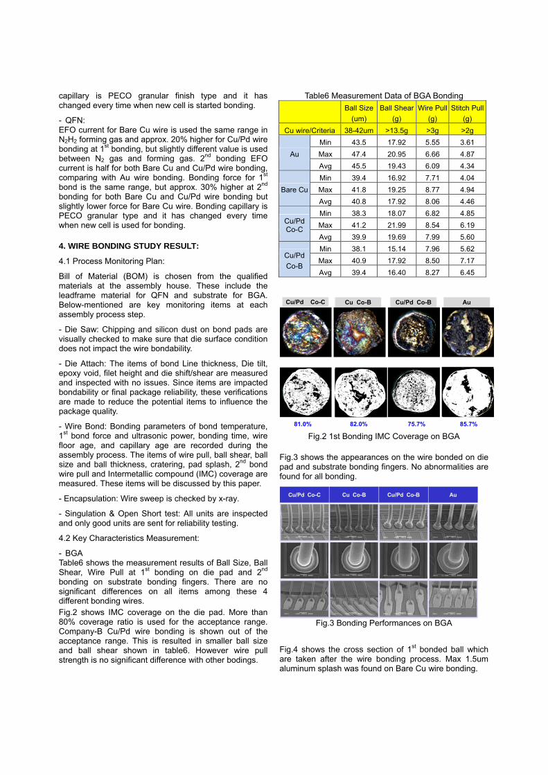
- BGA Table6 shows the measurement results of Ball Size, Ball Shear, Wire Pull at 1st bonding on die pad and 2nd bonding on substrate bonding fingers. There are no significant differences on all items among these 4 different bonding wires. Fig.2 shows IMC coverage on the die pad. More than 80% coverage ratio is used for the acceptance range. Company-B Cu/Pd wire bonding is shown out of the acceptance range. This is resulted in smaller ball size and ball shear shown in table6. However wire pull strength is no significant difference with other bodings.
Table6 Measurement Data of BGA Bonding
Ball Size
(um)
Ball Shear
(g)
Wire Pull
(g)
Stitch Pull
(g)
Cu wire/Criteria 38-42um >13.5g >3g >2g
Au
Min 43.5 17.92 5.55 3.61
Max 47.4 20.95 6.66 4.87
Avg 45.5 19.43 6.09 4.34
Bare Cu
Min 39.4 16.92 7.71 4.04
Max 41.8 19.25 8.77 4.94
Avg 40.8 17.92 8.06 4.46
Cu/Pd Co-C
Min 38.3 18.07 6.82 4.85
Max 41.2 21.99 8.54 6.19
Avg 39.9 19.69 7.99 5.60
Cu/Pd
Co-B
Min 38.1 15.14 7.96 5.62
Max 40.9 17.92 8.50 7.17
Avg 39.4 16.40 8.27 6.45
Fig.2 1st Bonding IMC Coverage on BGA
Fig.3 shows the appearances on the wire bonded on die pad and substrate bonding fingers. No abnormalities are found for all bonding.
Fig.3 Bonding Performances on BGA
Fig.4 shows the cross section of 1st bonded ball which are taken after the wire bonding process. Max 1.5um aluminum splash was found on Bare Cu wire bonding.
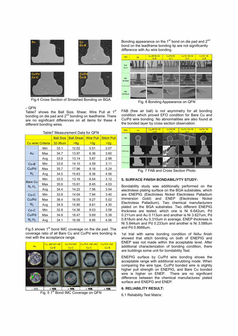
Fig.4 Cross Section of Smashed Bonding on BGA
- QFN Table7 shows the Ball Size, Shear, Wire Pull at 1st
bonding on die pad and 2nd bonding on leadframe. There are no significant differences on all items for these 4 different bonding wires.
Table7 Measurement Data for QFN
Ball Size Ball Shear Wire Pull Stitch Pull
Cu wire/ Criteria 32-36um >8g >3g >2g
Au
Min 33.1 12.02 5.51 2.07
Max 34.7 13.97 6.36 3.60
Avg 33.9 13.14 5.87 2.98
Co-B
Cu/Pd
N2
Min 33.6 14.10 4.59 3.11
Max 35.7 17.96 9.16 5.24
Avg 34.5 15.63 8.36 4.56
Bare Cu
N2 H2
Min 33.5 13.16 6.54 3.12
Max 35.6 15.61 8.45 4.03
Avg 34.4 14.22 7.56 3.54
Co-C
Cu/Pd
N2
Min 33.8 14.04 7.94 3.40
Max 36.4 16.05 9.27 5.02
Avg 34.9 14.90 8.61 4.30
Co-C
Cu/Pd
N2 H2
Min 32.8 14.36 8.03 3.58
Max 34.8 18.47 9.69 5.38
Avg 34.1 16.58 8.95 4.56 Fig.5 shows 1st bond IMC coverage on the die pad. The coverage ratio of all Bare Cu and Cu/Pd wire bonding is met with the acceptance range.
Fig. 5 1st Bond IMC Coverage on QFN
Bonding appearance on the 1st bond on die pad and 2nd bond on the leadframe bonding tip are not significantly difference with Au wire bonding.
Fig. 6 Bonding Appearance on QFN
FAB (free air ball) is not asymmetry for all bonding condition which proved EFO condition for Bare Cu and Cu/Pd wire bonding. No abnormalities are also found at the bonded layer by cross section observation.
Fig. 7 FAB and Cross Section Photo
5. SURFACE FINISH BONDABILIYTY STUDY:
Bondability study was additionally performed on the electroless plating surface on the BGA substrates, which are ENEPIG (Electroless Nickel Electroless Palladium Immersion Gold) and ENEP (Electroless Nickel Electroless Palladium). Two chemical manufacturers plated on the BGA substrates. Two different ENEPIG thickness are tested, which one is Ni 6.642um, Pd 0.211um and Au 0.113um and another is Ni 3.627um, Pd 0.818um and Au 0.310um in average. ENEP thickness is Ni 5.844um and Pd 0.233um and another is Ni 3.588um and Pd 0.8666um.
1st trial with same bonding condition of NiAu finish showed that stitch bonding on both of ENEPIG and ENEP was not made within the acceptable level. After additional characterization of bonding condition, there are buildings some unit for bondability Test.
ENEPIG surface by Cu/Pd wire bonding shows the acceptable range with additional scrubbing mode. When comparing the wire type, Cu/Pd bonded wire is slightly higher pull strength on ENEPIG, and Bare Cu bonded wire is higher on ENEP. There are no significant difference between the chemical manufactures’ plated surface and ENEPG and ENEP.
6. RELIABILITY RESULT:
6.1 Reliability Test Matrix:
All units of BGA and QFN are performed open/short testing after assembly process and these units are screened by x-ray inspection for reliability testing. These units are baked under 125degC for 24 hours before preconditioning test of 30degC and 60RH% for 192 hours which is Jedec level3. Units are sent for solder reflow with 260degC for 3 times.
Same Reliability test are performed for BGA and QFN, which 5 different condition of HAST (130degC/85%RH, 110degC/85%RH, 85degC/85%RH, 130degC/55%RH, 110degC/55%RH), HTS (175degC storage temperature condition) and TC (-55degC/125degC, 2x/hours). The reason for conducting 5 HAST conditions is to identify which can prove the detection of corrosion.
6.2 Reliability Test Result:
Reliability testing is still ongoing, so this paper provides the result for TC -55degC/125degC and HAST 130degC/85%RH with 5.5V bias test results for BGA package. Team continues for reliability tests.
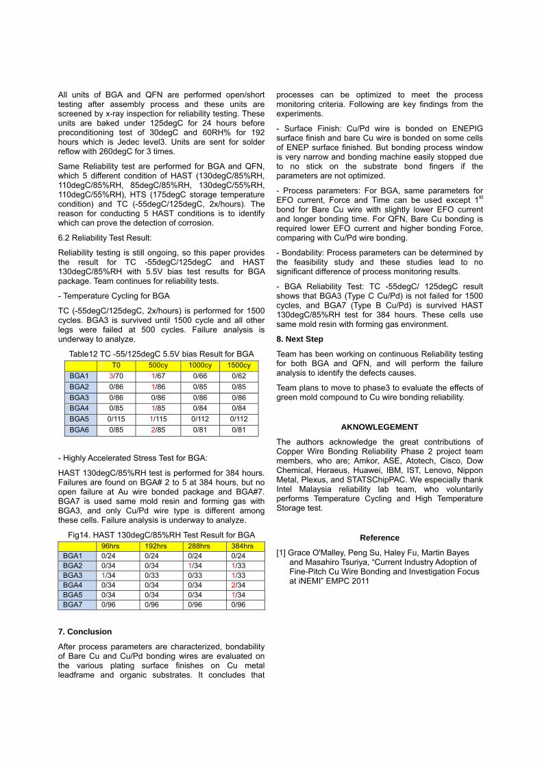
- Temperature Cycling for BGA
TC (-55degC/125degC, 2x/hours) is performed for 1500 cycles. BGA3 is survived until 1500 cycle and all other legs were failed at 500 cycles. Failure analysis is underway to analyze.
Table12 TC -55/125degC 5.5V bias Result for BGA T0 500cy 1000cy 1500cy
BGA1 3/70 1/67 0/66 0/62
BGA2 0/86 1/86 0/85 0/85
BGA3 0/86 0/86 0/86 0/86
BGA4 0/85 1/85 0/84 0/84
BGA5 0/115 1/115 0/112 0/112
BGA6 0/85 2/85 0/81 0/81
- Highly Accelerated Stress Test for BGA:
HAST 130degC/85%RH test is performed for 384 hours. Failures are found on BGA# 2 to 5 at 384 hours, but no open failure at Au wire bonded package and BGA#7. BGA7 is used same mold resin and forming gas with BGA3, and only Cu/Pd wire type is different among these cells. Failure analysis is underway to analyze.
Fig14. HAST 130degC/85%RH Test Result for BGA 96hrs 192hrs 288hrs 384hrs BGA1 0/24 0/24 0/24 0/24BGA2 0/34 0/34 1/34 1/33 BGA3 1/34 0/33 0/33 1/33 BGA4 0/34 0/34 0/34 2/34 BGA5 0/34 0/34 0/34 1/34 BGA7 0/96 0/96 0/96 0/96
7. Conclusion
After process parameters are characterized, bondability of Bare Cu and Cu/Pd bonding wires are evaluated on the various plating surface finishes on Cu metal leadframe and organic substrates. It concludes that
processes can be optimized to meet the process monitoring criteria. Following are key findings from the experiments.
- Surface Finish: Cu/Pd wire is bonded on ENEPIG surface finish and bare Cu wire is bonded on some cells of ENEP surface finished. But bonding process window is very narrow and bonding machine easily stopped due to no stick on the substrate bond fingers if the parameters are not optimized.
- Process parameters: For BGA, same parameters for EFO current, Force and Time can be used except 1st bond for Bare Cu wire with slightly lower EFO current and longer bonding time. For QFN, Bare Cu bonding is required lower EFO current and higher bonding Force, comparing with Cu/Pd wire bonding.
- Bondability: Process parameters can be determined by the feasibility study and these studies lead to no significant difference of process monitoring results.
- BGA Reliability Test: TC -55degC/ 125degC result shows that BGA3 (Type C Cu/Pd) is not failed for 1500 cycles, and BGA7 (Type B Cu/Pd) is survived HAST 130degC/85%RH test for 384 hours. These cells use same mold resin with forming gas environment.
8. Next Step
Team has been working on continuous Reliability testing for both BGA and QFN, and will perform the failure analysis to identify the defects causes.
Team plans to move to phase3 to evaluate the effects of green mold compound to Cu wire bonding reliability.
AKNOWLEGEMENT
The authors acknowledge the great contributions of Copper Wire Bonding Reliability Phase 2 project team members, who are; Amkor, ASE, Atotech, Cisco, Dow Chemical, Heraeus, Huawei, IBM, IST, Lenovo, Nippon Metal, Plexus, and STATSChipPAC. We especially thank Intel Malaysia reliability lab team, who voluntarily performs Temperature Cycling and High Temperature Storage test.
Reference
[1] Grace O'Malley, Peng Su, Haley Fu, Martin Bayes and Masahiro Tsuriya, “Current Industry Adoption of Fine-Pitch Cu Wire Bonding and Investigation Focus at iNEMI” EMPC 2011