3D-Printed Metal Flow Reactorsand MixersRSC Symposium 2017Chemspec, MuenchenGermanyMay 31 – June 1, 2017
André de Vrieswww.innosyn.com
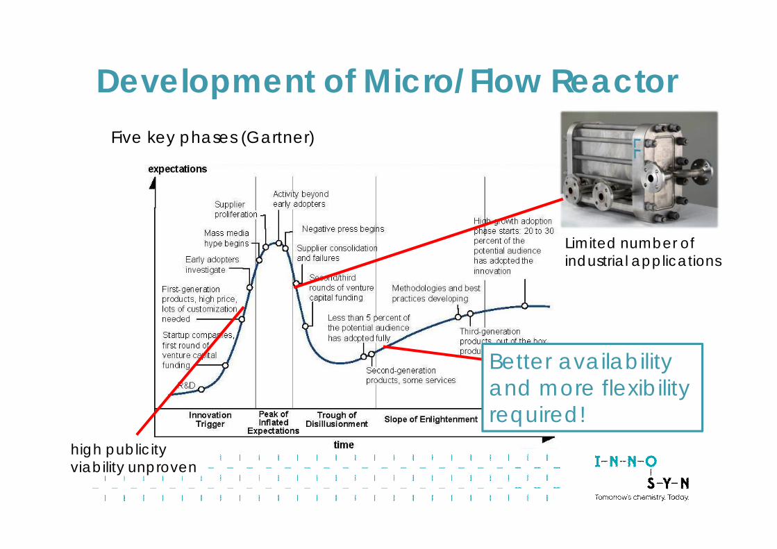
Five key phases (Gartner)
high publicityviability unproven
better understandingimproved versions
Better availabilityand more flexibilityrequired!
Limited number ofindustrial applications
Development of Micro/Flow Reactor
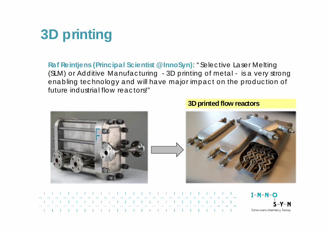
3D printed flow reactors3D printed flow reactors
Raf Reintjens (Principal Scientist @ InnoSyn): “Selective Laser Melting(SLM) or Additive Manufacturing - 3D printing of metal - is a very strongenabling technology and will have major impact on the production offuture industrial flow reactors!”
3D printing
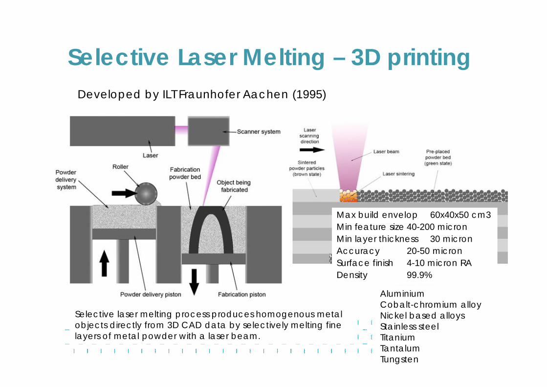
Developed by ILT Fraunhofer Aachen (1995)
Selective laser melting process produces homogenous metalobjects directly from 3D CAD data by selectively melting finelayers of metal powder with a laser beam.
Max build envelop 60x40x50 cm3Min feature size 40-200 micronMin layer thickness 30 micronAccuracy 20-50 micronSurface finish 4-10 micron RADensity 99.9%
AluminiumCobalt-chromium alloyNickel based alloysStainless steelTitaniumTantalumTungsten
Selective Laser Melting – 3D printing
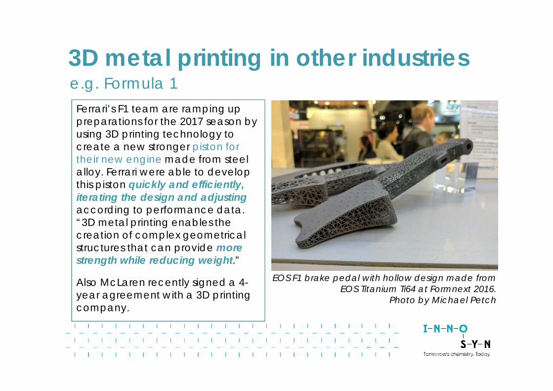
EOS F1 brake pedal with hollow design made fromEOS Titanium Ti64 at Formnext 2016.
Photo by Michael Petch
Ferrari’s F1 team are ramping uppreparations for the 2017 season byusing 3D printing technology tocreate a new stronger piston fortheir new engine made from steelalloy. Ferrari were able to developthis piston quickly and efficiently,iterating the design and adjustingaccording to performance data.“3D metal printing enables thecreation of complex geometricalstructures that can provide morestrength while reducing weight.”
Also McLaren recently signed a 4-year agreement with a 3D printingcompany.
e.g. Formula 13D metal printing in other industries
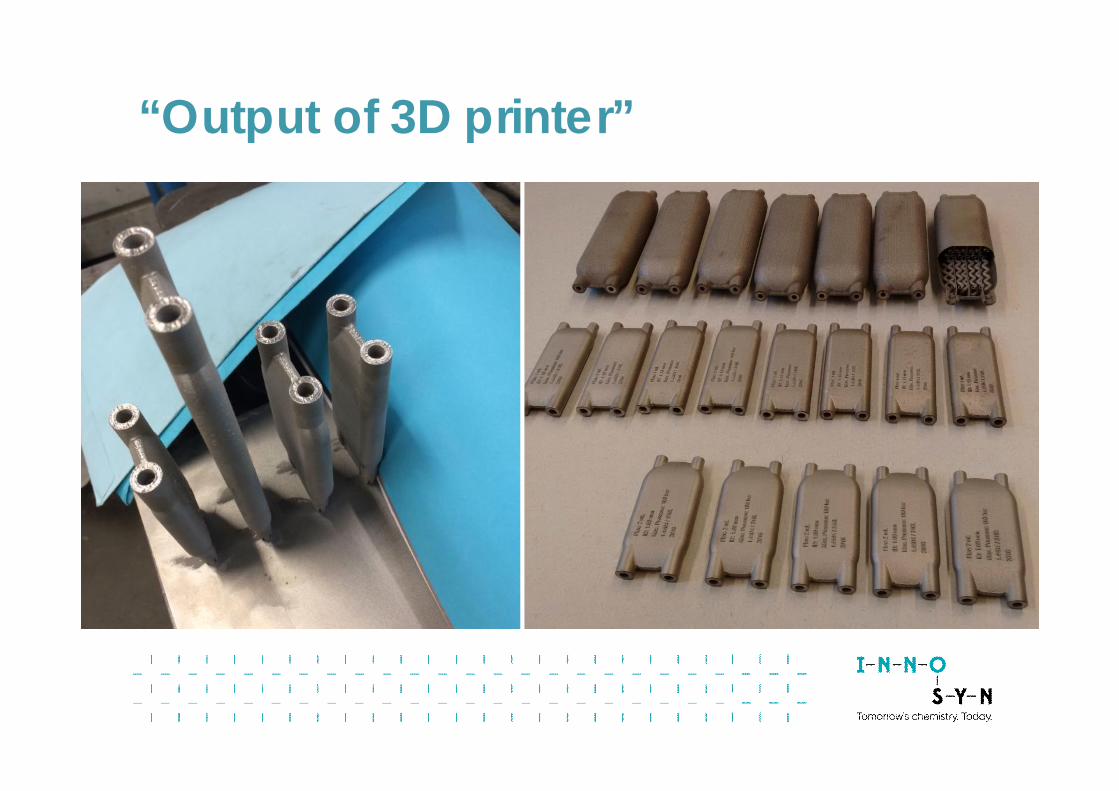
“Output of 3D printer”
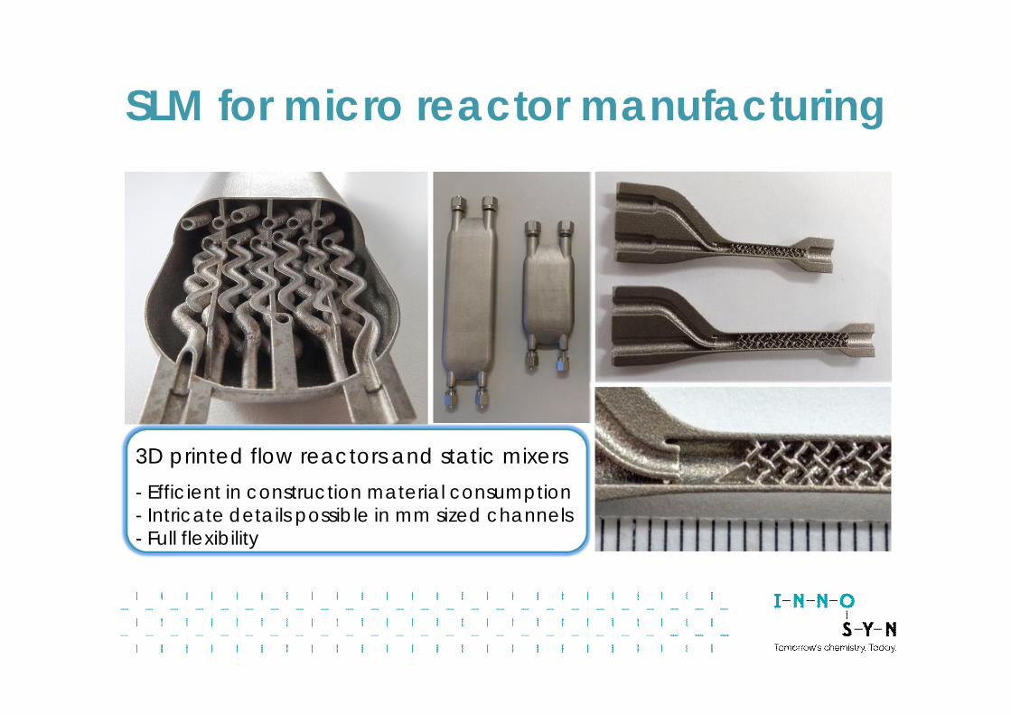
3D printed flow reactors and static mixers- Efficient in construction material consumption- Intricate details possible in mm sized channels- Full flexibility
SLM for micro reactor manufacturing
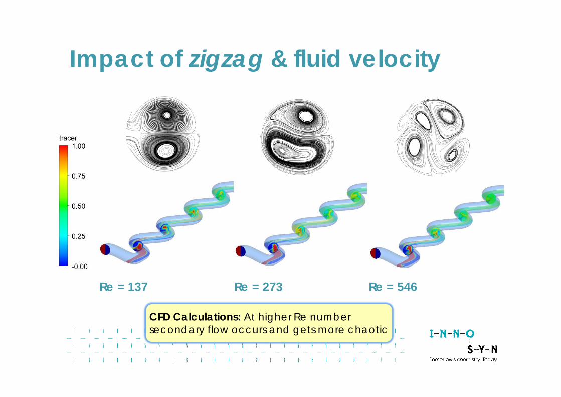
Impact of zigzag & fluid velocity
Re = 137 Re = 273 Re = 546
CFD Calculations: At higher Re numbersecondary flow occurs and gets more chaotic
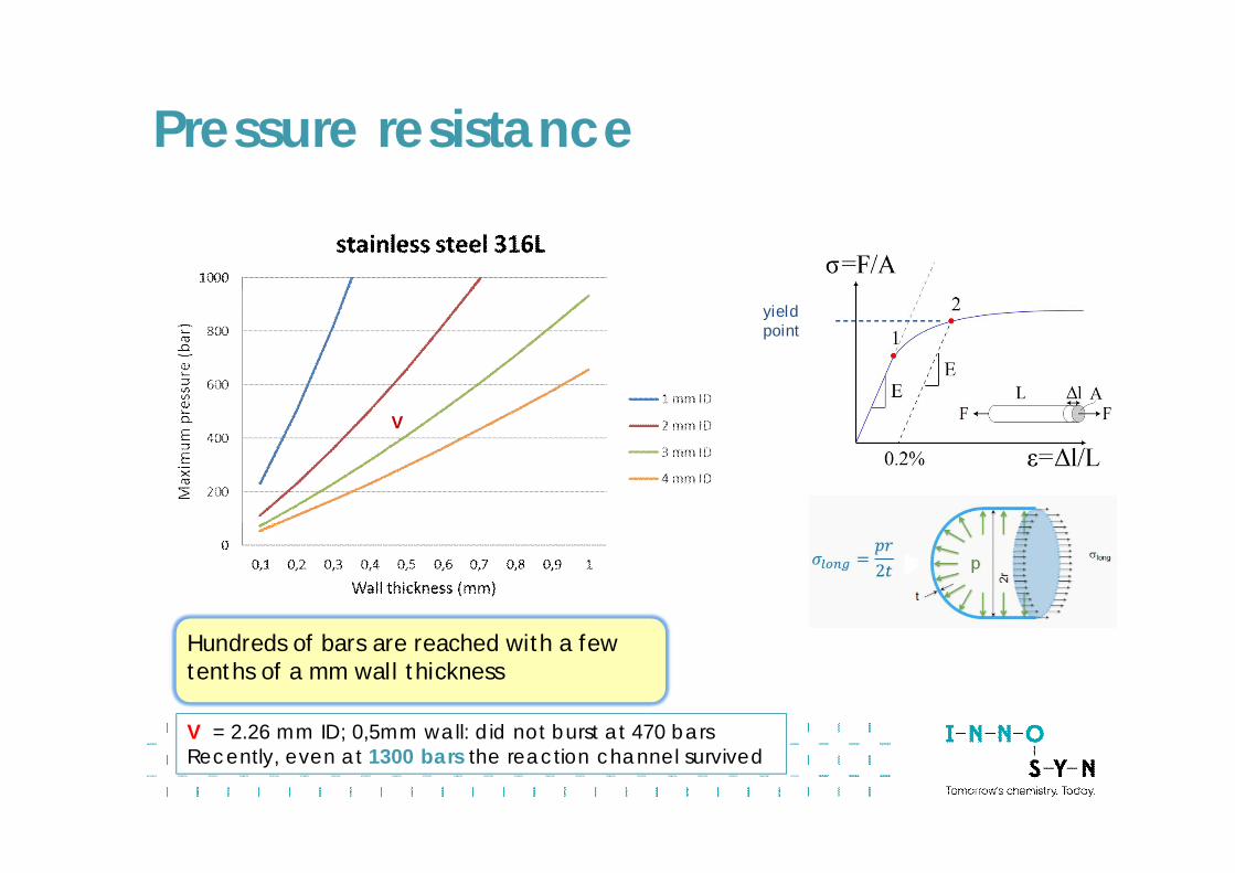
Pressure resistance
yieldpoint
Hundreds of bars are reached with a fewtenths of a mm wall thickness
V
V = 2.26 mm ID; 0,5mm wall: did not burst at 470 barsRecently, even at 1300 bars the reaction channel survived
ExampleCryogenic Organometallic Chemistry
In batch mode this fast and exothermic chemistry is “controlled” bylowering the temperature, dilution and/or slow dosing regimes.Often the cooling capacity determines the time demand.Byproduct formation due to local hot spots and/or wrong localstochiometries (slow mixing of reagents).
In flow, for these metalations the cooling/heat transfer is much better:- Metalations in flow enable to operate in principle as fast as thechemistry allows (seconds only, or even shorter).- Smaller cooling units required (limited capital expenses).- Higher selectivities to the desired compounds.
Several successful low-temp flow processes developed and applied(up to plant scale)
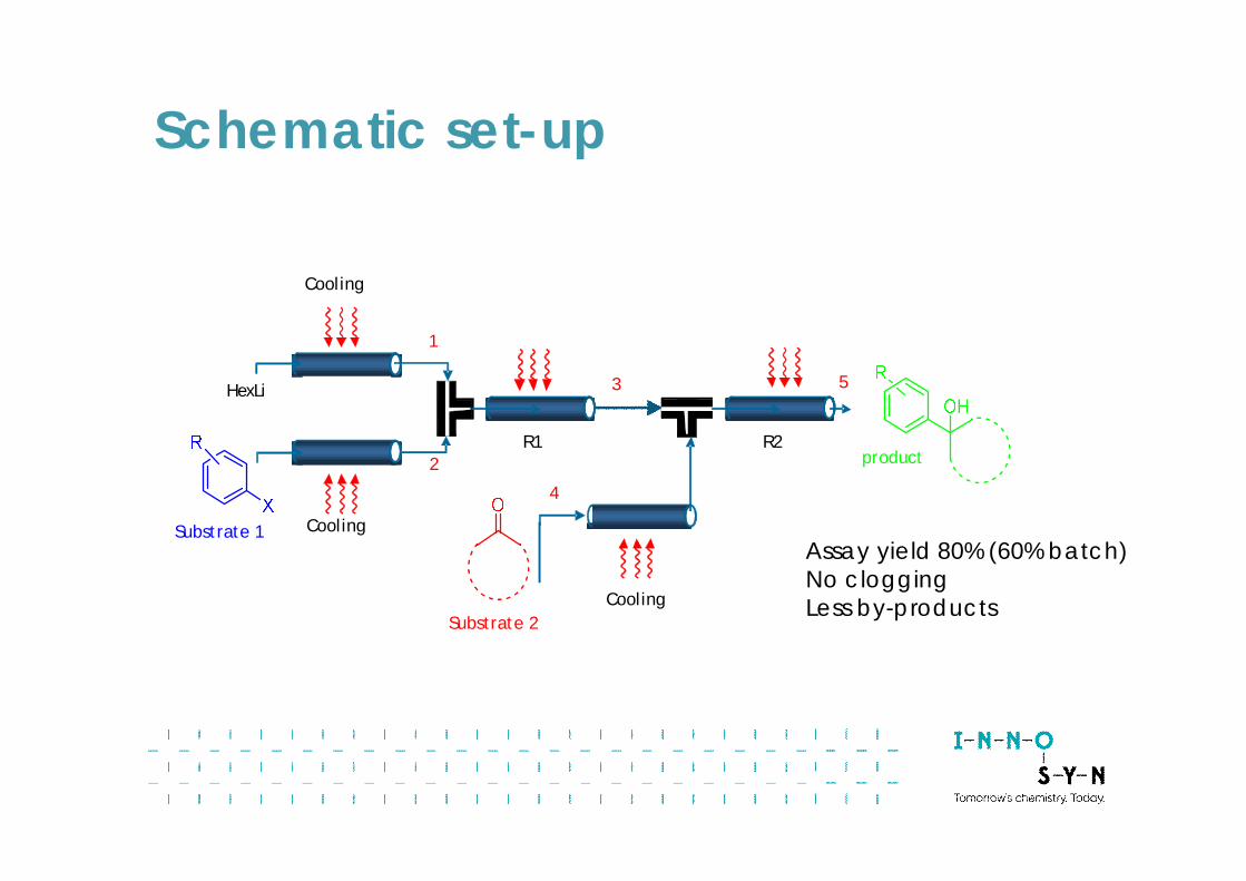
Schematic set-up
nBuLi
Cooling
Cooling
R1
Cooling
R2product
1
2
53
4
Substrate 1
Substrate 2
Assay yield 80% (60% batch)No cloggingLess by-products
HexLi
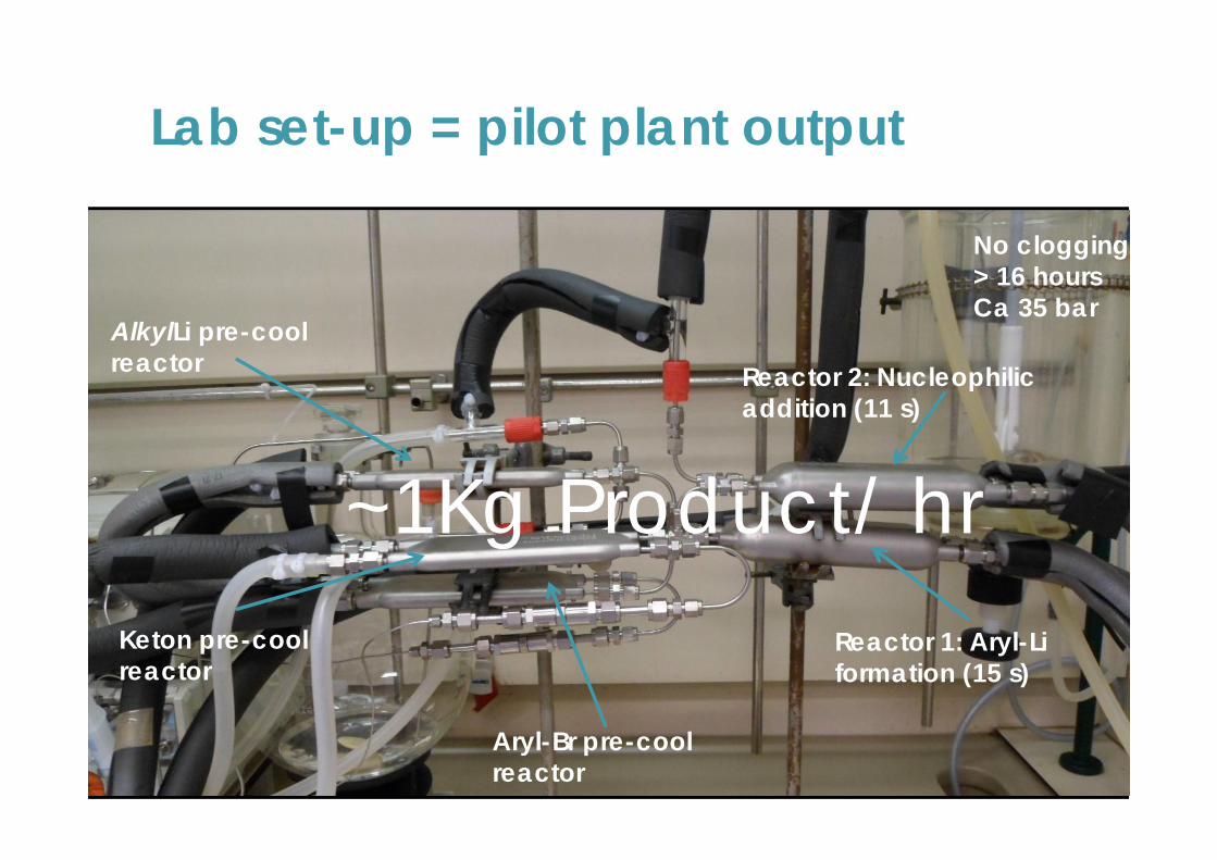
Aryl-Br pre-coolreactor
AlkylLi pre-coolreactor
Keton pre-coolreactor
Reactor 1: Aryl-Liformation (15 s)
Reactor 2: Nucleophilicaddition (11 s)
~1Kg Product/ hr
No clogging> 16 hoursCa 35 bar
Lab set-up = pilot plant output
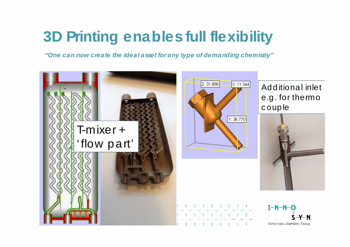
“One can now create the ideal asset for any type of demanding chemistry”
T-mixer +‘flow part’
Additional inlete.g. for thermocouple
3D Printing enables full flexibility
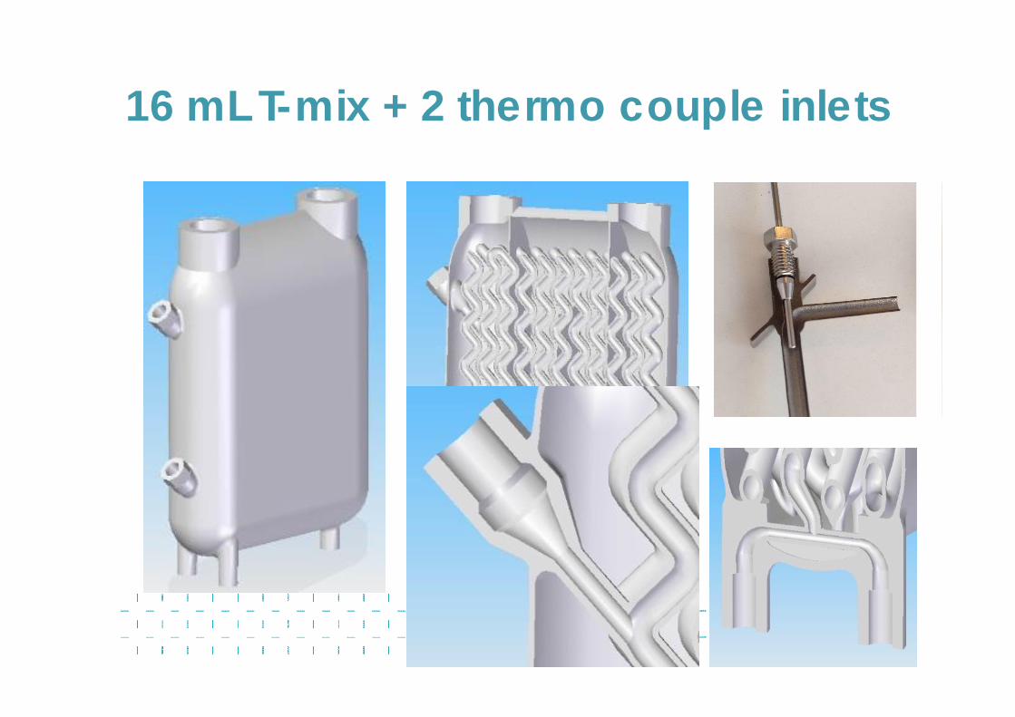
16 mL T-mix + 2 thermo couple inlets
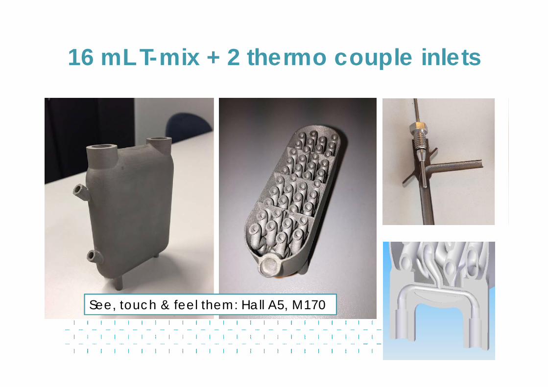
See, touch & feel them: Hall A5, M170
16 mL T-mix + 2 thermo couple inlets
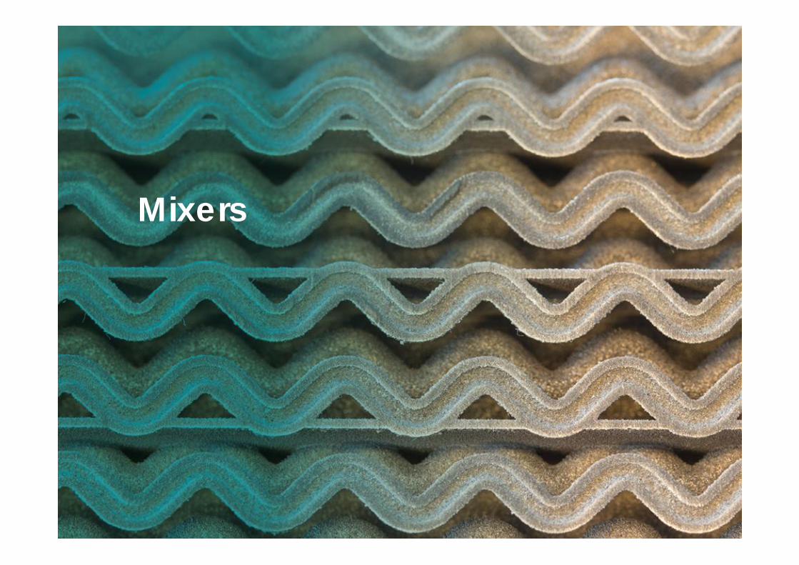
Mixers
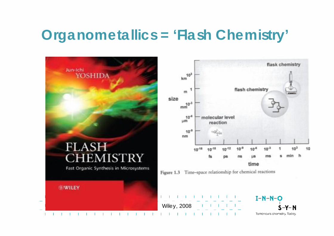
Wiley, 2008
Organometallics = ‘Flash Chemistry’
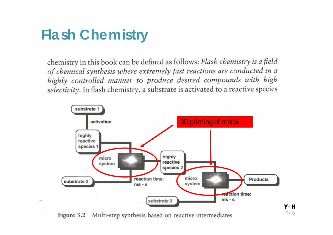
Flash Chemistry
3D printing of metal
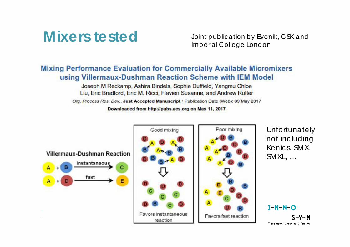
Mixers tested Joint publication by Evonik, GSK andImperial College London
Unfortunatelynot includingKenics, SMX,SMXL, …
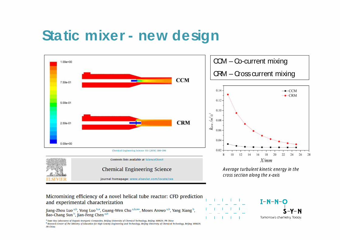
CCM – Co-current mixing
CRM – Cross current mixing
Average turbulent kinetic energy in thecross section along the x-axis
Static mixer - new design
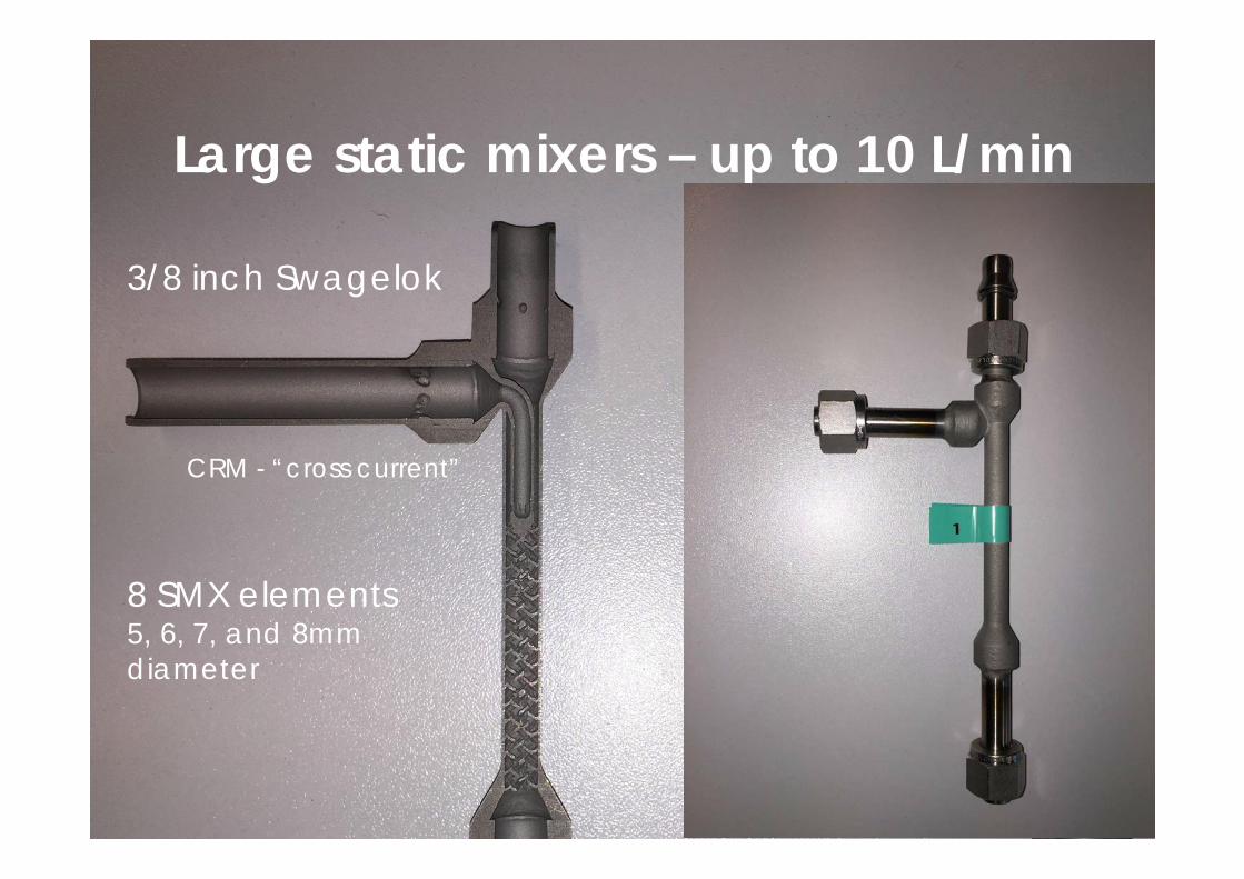
Static Mixers – Up to 10 L/min
CCM -“co-current”CRM - “cross current”
3/8 inch Swagelok
8 SMX elements5, 6, 7, and 8mmdiameter
Large static mixers – up to 10 L/min
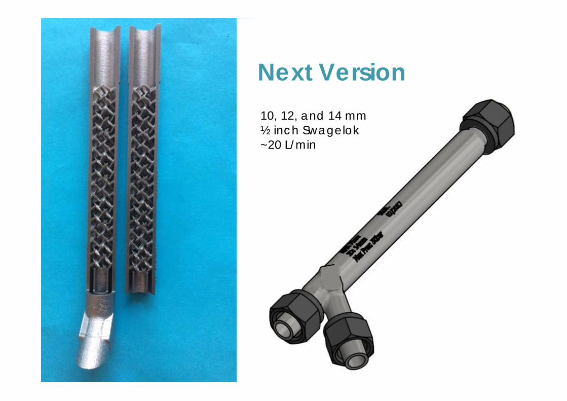
Next Version10, 12, and 14 mm½ inch Swagelok~20 L/min
Catalytic Oxidation
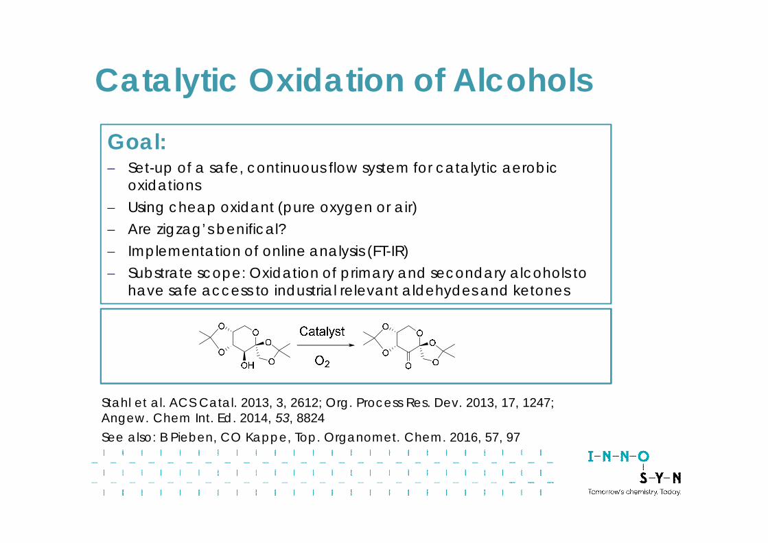
Catalytic Oxidation of AlcoholsGoal:- Set-up of a safe, continuous flow system for catalytic aerobic
oxidations- Using cheap oxidant (pure oxygen or air)- Are zigzag’s benifical?- Implementation of online analysis (FT-IR)- Substrate scope: Oxidation of primary and secondary alcohols to
have safe access to industrial relevant aldehydes and ketones
Stahl et al. ACS Catal. 2013, 3, 2612; Org. Process Res. Dev. 2013, 17, 1247;Angew. Chem Int. Ed. 2014, 53, 8824See also: B Pieben, CO Kappe, Top. Organomet. Chem. 2016, 57, 97
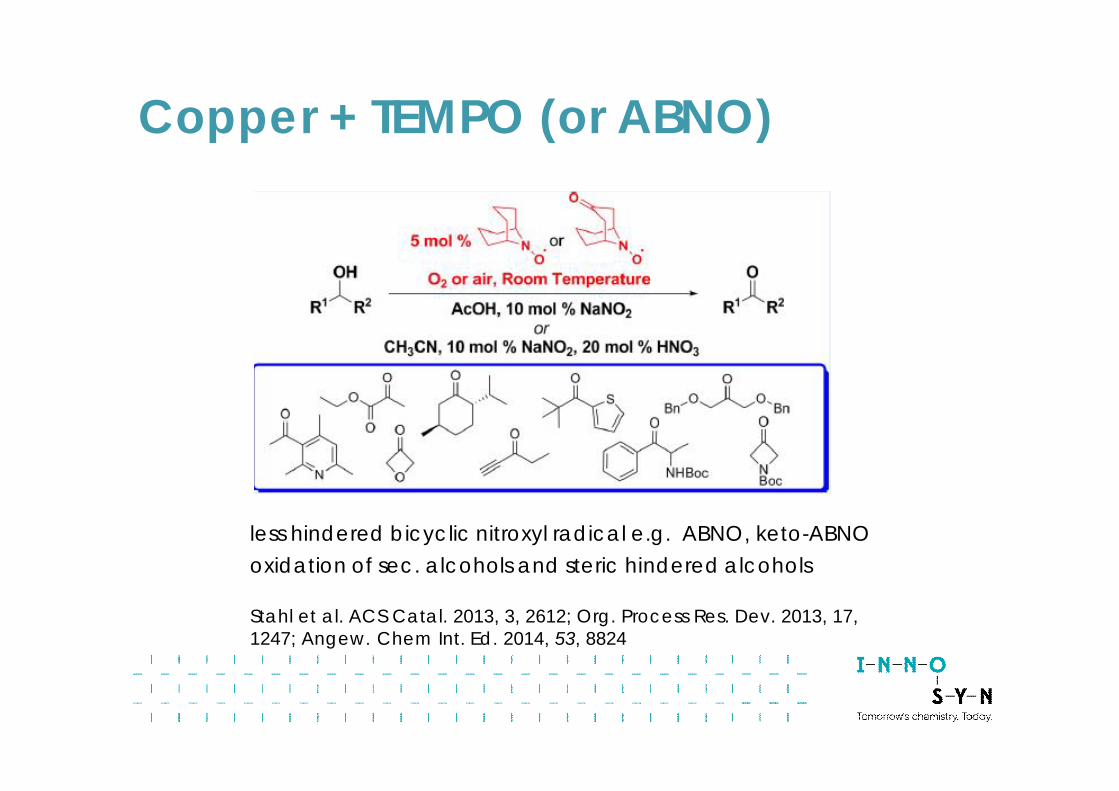
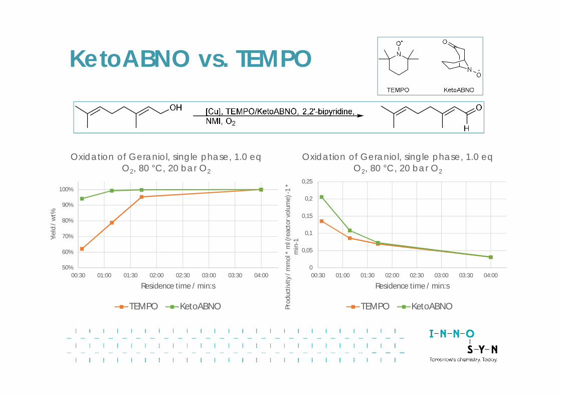
Copper + TEMPO (or ABNO)
less hindered bicyclic nitroxyl radical e.g. ABNO, keto-ABNOoxidation of sec. alcohols and steric hindered alcohols
Stahl et al. ACS Catal. 2013, 3, 2612; Org. Process Res. Dev. 2013, 17,1247; Angew. Chem Int. Ed. 2014, 53, 8824
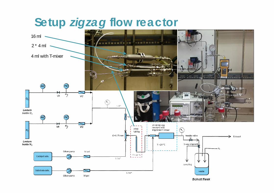
Setup zigzag flow reactor
4 ml with T-mixer
16 ml
2 * 4 ml
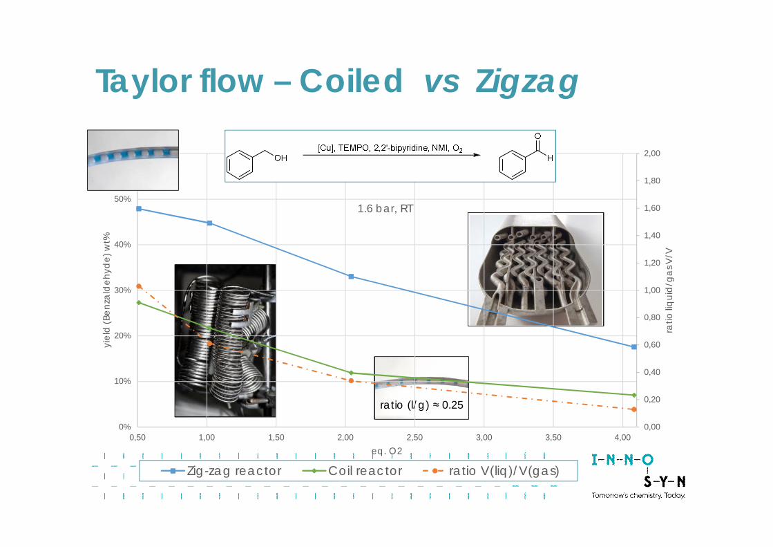
ratio (l/g) ≈ 1.0
ratio (l/g) ≈ 0.25
0,00
0,20
0,40
0,60
0,80
1,00
1,20
1,40
1,60
1,80
2,00
0%
10%
20%
30%
40%
50%
60%
0,50 1,00 1,50 2,00 2,50 3,00 3,50 4,00
ratio
liqui
d/g
asV
/V
yiel
d(B
enza
ldeh
yde)
wt%
eq. O2
1.6 bar, RT
Zig-zag reactor Coil reactor ratio V(liq)/V(gas)
Taylor flow – Coiled vs Zigzag
0,00
0,10
0,20
0,30
0,40
0,50
0,60
0,70
0,80
0,90
0 5 10 15 20 25
equi
valte
nsox
ygen
pressure / bar
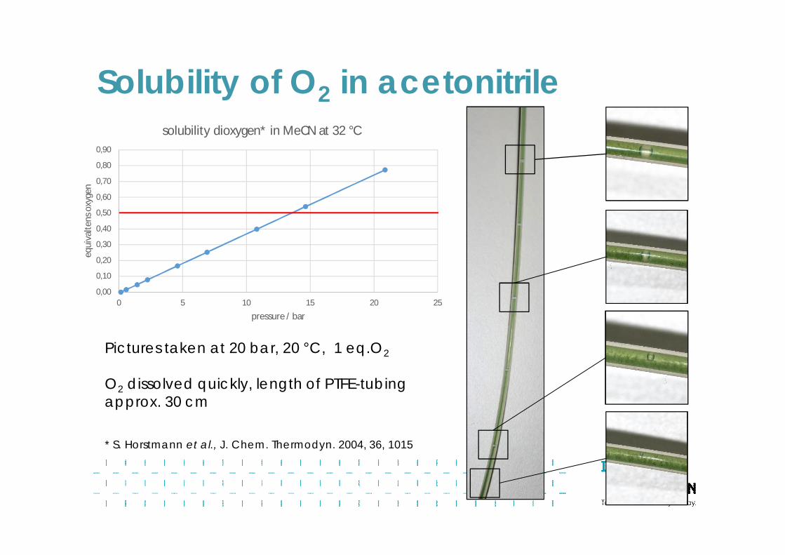
solubility dioxygen* in MeCN at 32 °C
* S. Horstmann et al., J. Chem. Thermodyn. 2004, 36, 1015
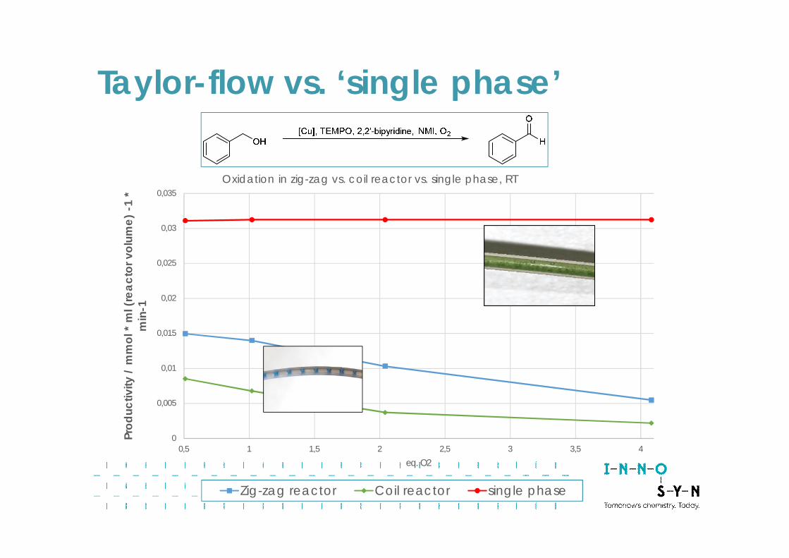
Pictures taken at 20 bar, 20 °C, 1 eq.O2
O2 dissolved quickly, length of PTFE-tubingapprox. 30 cm
Solubility of O2 in acetonitrile
0
0,005
0,01
0,015
0,02
0,025
0,03
0,035
0,5 1 1,5 2 2,5 3 3,5 4
Prod
uctiv
ity/
mm
ol*
ml(
reac
torv
olum
e)-1
*m
in-1
eq. O2
Oxidation in zig-zag vs. coil reactor vs. single phase, RT
Zig-zag reactor Coil reactor single phase
Taylor-flow vs. ‘single phase’
0
0,05
0,1
0,15
0,2
0,25
00:30 01:00 01:30 02:00 02:30 03:00 03:30 04:00
Prod
uctiv
ity/m
mol
*m
l(re
acto
rvol
ume)
-1*
min
-1Residence time / min:s
Oxidation of Geraniol, single phase, 1.0 eqO2, 80 °C, 20 bar O2
TEMPO KetoABNO
50%
60%
70%
80%
90%
100%
00:30 01:00 01:30 02:00 02:30 03:00 03:30 04:00
Yiel
d/w
t%
Residence time / min:s
Oxidation of Geraniol, single phase, 1.0 eqO2, 80 °C, 20 bar O2
TEMPO KetoABNO
KetoABNO vs. TEMPO
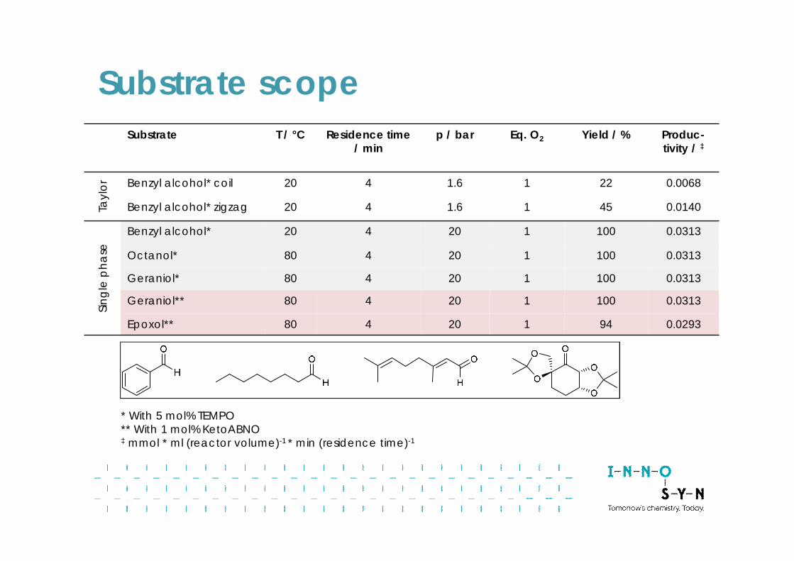
Substrate T / °C Residence time/ min
p / bar Eq. O2 Yield / % Produc-tivity / ‡
Tayl
or Benzyl alcohol* coil 20 4 1.6 1 22 0.0068
Benzyl alcohol* zigzag 20 4 1.6 1 45 0.0140
Singl
eph
ase
Benzyl alcohol* 20 4 20 1 100 0.0313
Octanol* 80 4 20 1 100 0.0313
Geraniol* 80 4 20 1 100 0.0313
Geraniol** 80 4 20 1 100 0.0313
Epoxol** 80 4 20 1 94 0.0293
* With 5 mol% TEMPO** With 1 mol% KetoABNO‡ mmol * ml (reactor volume)-1 * min (residence time)-1
Substrate scope
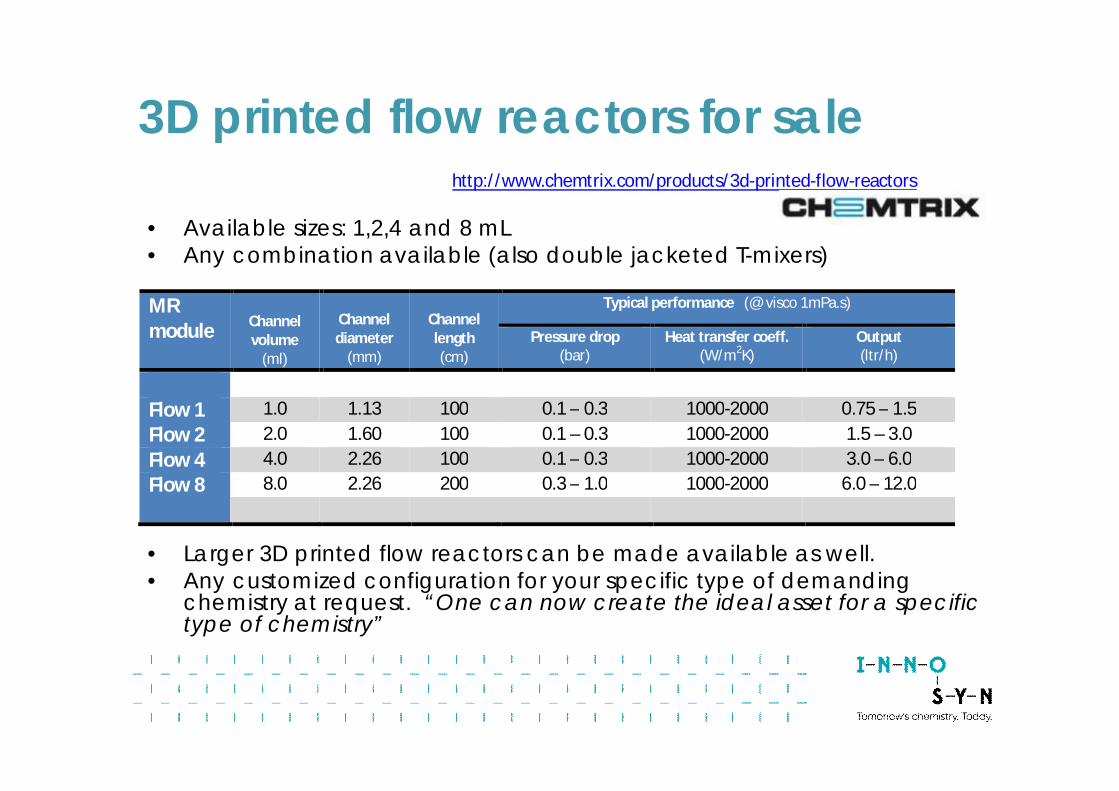
• Available sizes: 1,2,4 and 8 mL• Any combination available (also double jacketed T-mixers)
• Larger 3D printed flow reactors can be made available as well.• Any customized configuration for your specific type of demanding
chemistry at request. “One can now create the ideal asset for a specifictype of chemistry”
MRmodule Channel
volume(ml)
Channeldiameter
(mm)
Channellength(cm)
Typical performance (@ visco 1mPa.s)
Pressure drop(bar)
Heat transfer coeff.(W/m2K)
Output(ltr/h)
Flow 1 1.0 1.13 100 0.1 – 0.3 1000-2000 0.75 – 1.5Flow 2 2.0 1.60 100 0.1 – 0.3 1000-2000 1.5 – 3.0Flow 4 4.0 2.26 100 0.1 – 0.3 1000-2000 3.0 – 6.0Flow 8 8.0 2.26 200 0.3 – 1.0 1000-2000 6.0 – 12.0
http://www.chemtrix.com/products/3d-printed-flow-reactors
3D printed flow reactors for sale
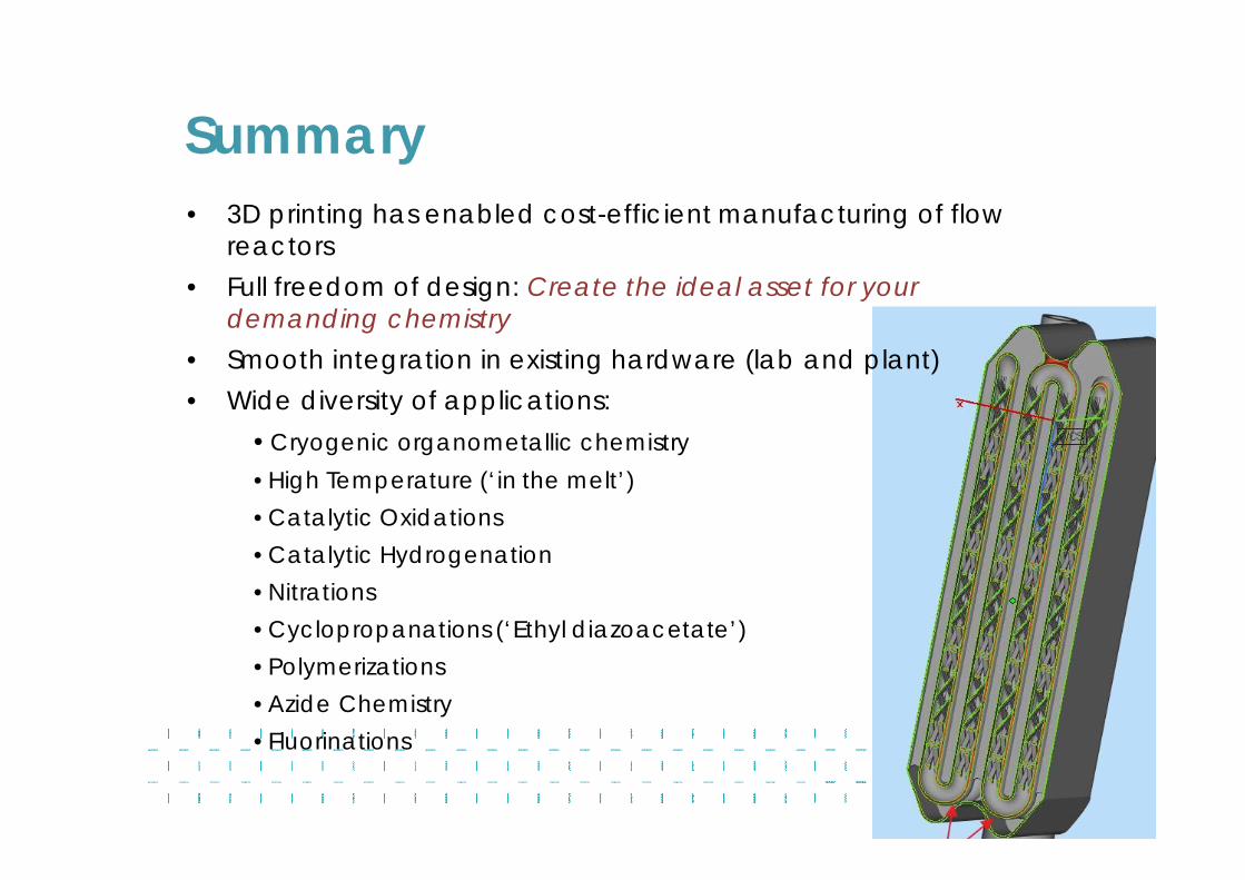
Summary• 3D printing has enabled cost-efficient manufacturing of flow
reactors• Full freedom of design: Create the ideal asset for your
demanding chemistry• Smooth integration in existing hardware (lab and plant)• Wide diversity of applications:
• Cryogenic organometallic chemistry• High Temperature (‘in the melt’)• Catalytic Oxidations• Catalytic Hydrogenation• Nitrations• Cyclopropanations (‘Ethyl diazoacetate’)• Polymerizations• Azide Chemistry• Fluorinations
InnoSyn [email protected]
Recommended