55
3 PLANT DESCRIPTION
56
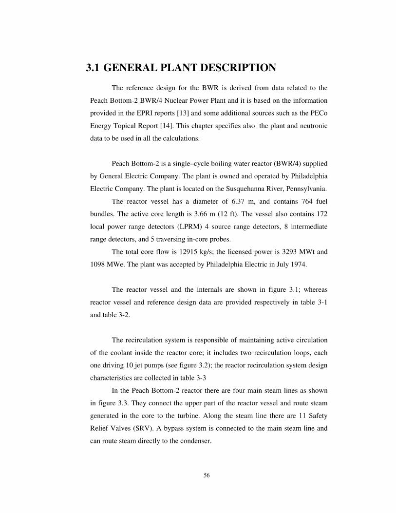
3.1 GENERAL PLANT DESCRIPTION
The reference design for the BWR is derived from data related to the
Peach Bottom-2 BWR/4 Nuclear Power Plant and it is based on the information
provided in the EPRI reports [13] and some additional sources such as the PECo
Energy Topical Report [14]. This chapter specifies also the plant and neutronic
data to be used in all the calculations.
Peach Bottom-2 is a single–cycle boiling water reactor (BWR/4) supplied
by General Electric Company. The plant is owned and operated by Philadelphia
Electric Company. The plant is located on the Susquehanna River, Pennsylvania.
The reactor vessel has a diameter of 6.37 m, and contains 764 fuel
bundles. The active core length is 3.66 m (12 ft). The vessel also contains 172
local power range detectors (LPRM) 4 source range detectors, 8 intermediate
range detectors, and 5 traversing in-core probes.
The total core flow is 12915 kg/s; the licensed power is 3293 MWt and
1098 MWe. The plant was accepted by Philadelphia Electric in July 1974.
The reactor vessel and the internals are shown in figure 3.1; whereas
reactor vessel and reference design data are provided respectively in table 3-1
and table 3-2.
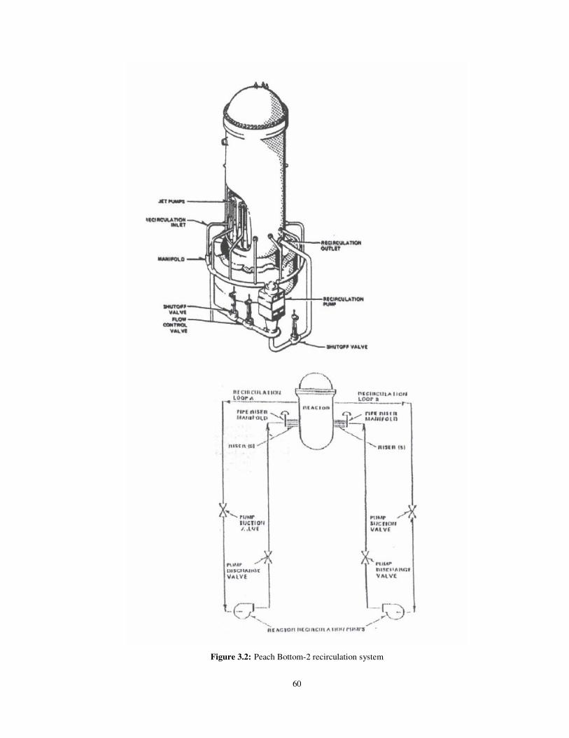
The recirculation system is responsible of maintaining active circulation
of the coolant inside the reactor core; it includes two recirculation loops, each
one driving 10 jet pumps (see figure 3.2); the reactor recirculation system design
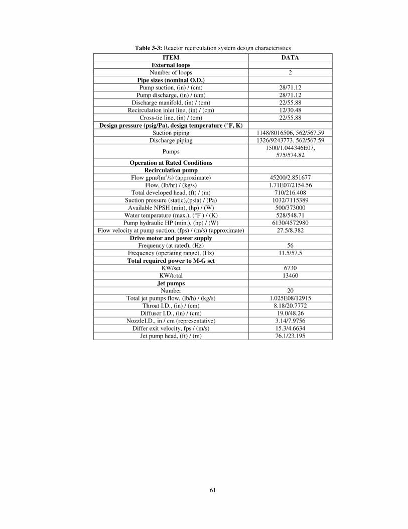
characteristics are collected in table 3-3
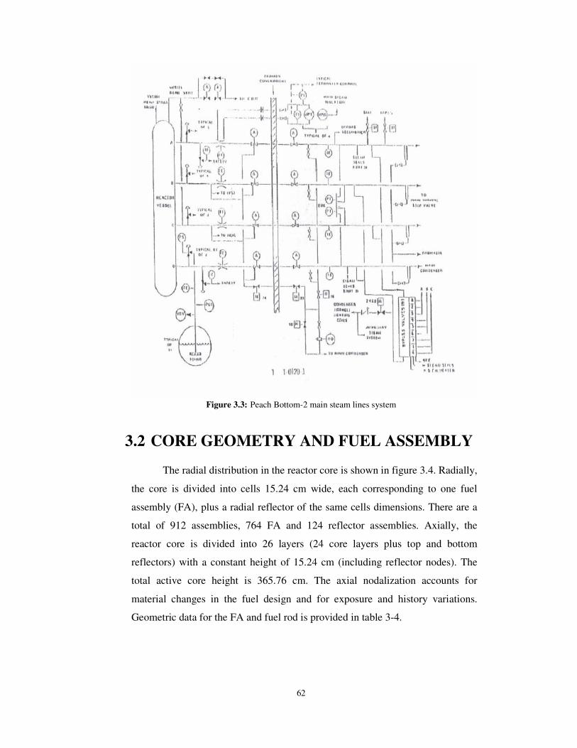
In the Peach Bottom-2 reactor there are four main steam lines as shown
in figure 3.3. They connect the upper part of the reactor vessel and route steam
generated in the core to the turbine. Along the steam line there are 11 Safety
Relief Valves (SRV). A bypass system is connected to the main steam line and
can route steam directly to the condenser.

57
Figure 3.1: Peach Bottom-2 reactor vessel and internals

58
Table 3-1: Peach Bottom-2 reference design information Parameter Value
Rated core thermal power, MWt 3293 Rated core total flowrate, (Mlb/hr) / (kg/s) 102.5 / 12915 Bypass flowrate, fraction of total core flow Ref [15], Figs. 54-55 Fraction of core thermal power passing through fuel cladding
.96
Approximate bypass coolant total power fraction
.02
Approximate active coolant total power fraction .02 Approximate channel wall direct heating fraction
.0075
Design minimum critical power ratio 7x7 assemblies (Cycle 2)
�1.28
Design minimum critical power ratio 8x8 assemblies (Cycle 2)
�1.31
Design overpower for turbine-generator system 105% rated steam Turbine inlet pressure, (psia) / (Pa) 965 / 6.653E06 Rated reactor dome pressure, (psia) / (Pa) 1020 / 7.033E06 Rated steam flowrate, (Mlb/hr) / (kg/s) 13.381 / 1685.98 Steam moisture content, fraction .001 Rate steam dryer and separator pressure drop, (psia) / (Pa)
15 / 103421
Rated core pressure, (psia) / (Pa) 1035/ 7.1361E06 Core pressure drop at rated conditions, (psia) / (Pa)
22 / 151685
Approximate core inlet pressure, (psia) / (Pa) 1060 / 7.3084E06 Core inlet enthalpy, (Btu/lb) / (J/kg) 521.3 / 1.2125 E06 Enthalpy rise across core (average), (Btu/lb)/ (J/kg)
109.6 / 2.5491 E05
Core support plate pressure drop, (psia) / (Pa) 18 / 1.24105 E05 Core orifice and lower tie pressure drop Ref [15], Figs. 48-53 Fuel bundle pressure drop Ref [15], Figs. 44-47 Reactor average exit quality at rated conditions .129 Design hot channel active coolant exit quality .25 Design bypass coolant exit quality .0 Total feedwater flowrate, (Mlb/hr) / (kg/s) 13.331 / 1679.1 Feedwater temperature, (ºF) / (K) 376.1 / 464.32 Control rod drive flowrate, (lb/hr) / (kg/s) 50000 / 6.2999 Control rod drive flow temperature, (ºF) / (K) 80 / 299.82 Cleanup demineralizer flowrate, (lb/hr) / (kg/s) 133300 / 16.7958 Cleanup demineralizer inlet temperature, (ºF) / (K)
528 / 548.7
Cleanup demineralizer outlet temperature, (ºF) / (K)
431 / 494.82
Location of demineralized water return Feedwater line Jet pump design M ratio 1.96 Jet pump design N ratio .16 Number of recirculation pumps 2 Recirculation pump type Centrifugal Recirculation pump rated flow, (Mlb/hr) / (kg/s) 17.1 / 2154.56 Total developed pump head , (ft) / (m) 710 / 216.41 Recirculation pump efficiency, percent 87 Head loss from vessel recirculation outlet to vessel inlet, (ft) / (m)
59 / 17.98
Head loss from vessel recirculation inlet to jet pump 180º bend entrance, (ft) / (m) 11 / 3.353

59
Table 3-2: Reactor vessel design data ITEM DATA
Reactor vessel Operating temperature (º F )/ (K) 575 / 574.82
Inside length (in) / (m) 875.125 / 22.228 Design pressure (psia) / (Pa) 1250 / 8719771
Vessel nozzles (number-size, in / cm) Recirculation outlet 2- 28 / 71.12
Steam outlet 4- 26 /66.04 Recirculation inlet 10- 12 / 30.48
Feedwater inlet 6- 12 / 30.48 Core spray inlet 2- 10 / 25.4
Instrument (one of these is head spray) 2- 6 / 15.24 CRD 185- 6 / 15.24
Jet pump instrumentation 2- 4 / 10.16 Vent 1- 4 / 10.16
Instrumentation 2- 6 / 15.24 CRD hydraulic system return 1- 4 / 10.16
Core differential pressure and liquid control 1- 2 / 5.08 Drain 1- 2 / 5.08
In-core flux instrumentation 55- 2 / 5.08 Head seal leak detection 2- 1 / 2.54
Weights (lb / kg) Bottom head 207500 / 94120.4 Vessel shell 842300 / 382061
Vessel flange 105800 / 47990.1 Support skirt 28200 / 12791
Other vessel components 65000 / 29484 Total vessel without top head 1248800 / 566446.2
Top head 252200 / 114396 Total vessel 1501000 / 680842.1
60
Figure 3.2: Peach Bottom-2 recirculation system
61
Table 3-3: Reactor recirculation system design characteristics ITEM DATA
External loops Number of loops 2
Pipe sizes (nominal O.D.) Pump suction, (in) / (cm) 28/71.12
Pump discharge, (in) / (cm) 28/71.12 Discharge manifold, (in) / (cm) 22/55.88
Recirculation inlet line, (in) / (cm) 12/30.48 Cross-tie line, (in) / (cm) 22/55.88
Design pressure (psig/Pa), design temperature (°F, K) Suction piping 1148/8016506, 562/567.59
Discharge piping 1326/9243773, 562/567.59
Pumps 1500/1.044346E07, 575/574.82
Operation at Rated Conditions Recirculation pump
Flow gpm/(m3/s) (approximate) 45200/2.851677 Flow, (lb/hr) / (kg/s) 1.71E07/2154.56
Total developed head, (ft) / (m) 710/216.408 Suction pressure (static),(psia) / (Pa) 1032/7115389 Available NPSH (min), (hp) / (W) 500/373000
Water temperature (max.), (°F ) / (K) 528/548.71 Pump hydraulic HP (min.), (hp) / (W) 6130/4572980
Flow velocity at pump suction, (fps) / (m/s) (approximate) 27.5/8.382 Drive motor and power supply
Frequency (at rated), (Hz) 56 Frequency (operating range), (Hz) 11.5/57.5 Total required power to M-G set
KW/set 6730 KW/total 13460
Jet pumps Number 20
Total jet pumps flow, (lb/h) / (kg/s) 1.025E08/12915 Throat I.D., (in) / (cm) 8.18/20.7772
Diffuser I.D., (in) / (cm) 19.0/48.26 NozzleI.D., in / cm (representative) 3.14/7.9756
Differ exit velocity, fps / (m/s) 15.3/4.6634 Jet pump head, (ft) / (m) 76.1/23.195
62
Figure 3.3: Peach Bottom-2 main steam lines system
3.2 CORE GEOMETRY AND FUEL ASSEMBLY
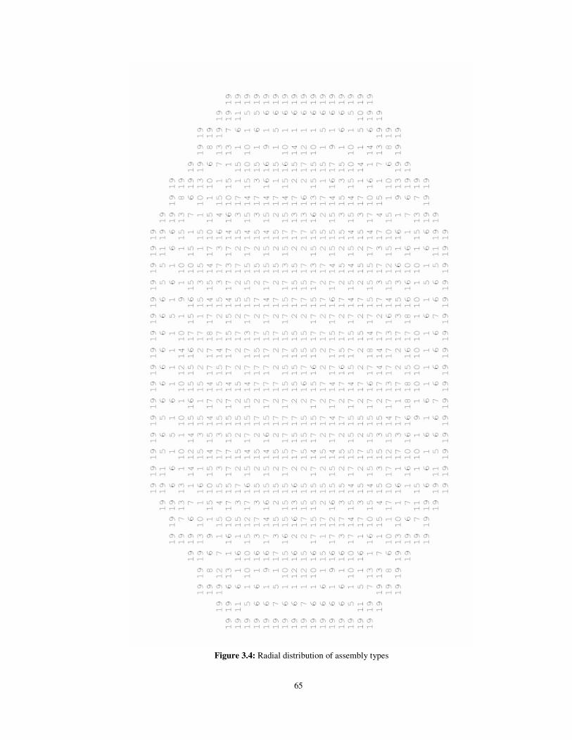
The radial distribution in the reactor core is shown in figure 3.4. Radially,
the core is divided into cells 15.24 cm wide, each corresponding to one fuel
assembly (FA), plus a radial reflector of the same cells dimensions. There are a
total of 912 assemblies, 764 FA and 124 reflector assemblies. Axially, the
reactor core is divided into 26 layers (24 core layers plus top and bottom
reflectors) with a constant height of 15.24 cm (including reflector nodes). The
total active core height is 365.76 cm. The axial nodalization accounts for
material changes in the fuel design and for exposure and history variations.
Geometric data for the FA and fuel rod is provided in table 3-4.

63
Table 3-4: Peach Bottom-2 fuel assembly data
Initial load Reload Reload LTA special
Assembly type 1 2 3 4 5 6 No. of assemblies 168 263 333 0 0 0
INITIAL CORE
No. of assemblies,C2 0 261 315 68 116 4
Geometry 7x7 7x7 7x7 8x8 8x8 8x8
Assembly Pitch,in 6.0 6.0 6.0 6.0 6.0 6.0
Fuel Rod Pitch 0.738 0.738 0.738 0.640 0.640 0.640
Fuel Rod per Assembly 49 49 49 63 63 62
Water Rods per Assembly 0 0 0 1 1 2
Burnable Poison Positions 0 4 5 5 5 5
No. of Spacer Grids 7 7 7 7 7 7
Inconel per Grid, lb 0.102 0.102 0.102 0.102 0.102 0.102
Zr-4 per Grid, lb 0.537 0.537 0.537 0.614 0.614 0.614
Spacer Width, in 1.625 1.625 1.625 1.625 1.625 1.625
ASSEMBLY AVERAGE FUEL COMPOSITION:
Gd2O3, g 0 441 547 490 328 313
UO2, kg 222.44 212.21 212.06 207.78 208.0 207.14
Total fuel, kg 222.44 212.65 212.61 208.27 208.33 207.45
The core loading during the tests was as follows: 576 fuel assemblies
were the original 7x7 type from cycle 1 (C1), and the remaining 188 were a
reload of 8x8 fuel assemblies; 185 control rods provided reactivity control.
Nineteen assembly types are contained within the core geometry. There
are 435 compositions. Each composition is defined by material properties (due
to changes in the fuel design) and burn-up8. Control rod geometry data are
provided in table 3-5. The definition of assembly types is shown in table 3-6.
8 The burn-up dependence is a three-component vector of variables: exposure (GWd/t), spectral history (void fraction), and control rod history.

64
Table 3-5: Definition of assembly types
Assembly Type Assembly Design (see tables 2.4.1.1 through 2.4.1.6 ref [16])
1 2 3 4 5 6 7 8 9 10 11 12 13 14 15 16 17 18 19
5 4 5 6 2 2 2 2 2 3 2 3 2 3 2 3 2 3
reflector
Table 3-6: Control rod data (movable control rod)
CONTROL ROD DATA Shape Cruciform
Pitch, (cm) 30.48
Stroke, (cm) 365.76
Control length, (cm) B4C granules in Type-304, stainless steel tubes and sheath
Control material 70% of theoretical
Material density 84
Number of control material tubes per rod
0.47752 cm outer diameter by 0.635 cm wall
Tube dimensions 12.3825
Control blade full thickness, (cm) 0.79248
Control blade tip radius, (cm) 0.39624
Sheath thickness, (cm) 0.14224
Central structure wing length, (cm) 1.98501
Blank tubes per wing None
The radial distribution of these assembly types, within the reactor
geometry is shown in figure 3.4 and figure 3.5. The axial locations of
compositions for each assembly type are shown in table 3-7.
65
Figure 3.4: Radial distribution of assembly types

66
Figure 3.5: Assembly type identification, TIP and Control rod location

67
Table 3-7: Composition numbers in axial layer for each assembly type

68
3.3 NUCLEAR INSTRUMENTATION DATA
Peach Bottom-2 is equipped with a system of Travelling In-Core Probe
(TIP) detectors and fixed Local Power Range Monitor (LPRM) detectors
designed to provide an accurate representation of a spatial distribution of the
neutron flux. The TIP detectors9 travel through a set of 43 vertical tubes which
are distributed uniformly throughout the core with the planar density of one
detector per 0.37 m2. Figure 3.6 shows the core location and coordinate
identification of the tip strings.
Figure 3.6: Core orificing and TIP system arrangement
9 The TIP measures the axial neutron flux distribution in the water gap by use an 1-in.
long U-235 fission chamber attached to a cable and motor which allows the chamber to be positioned at any point along the axial length of up to 10 core positions for each TIP machine. There are five TIP machines in the Peach Bottom-2 reactor.
69
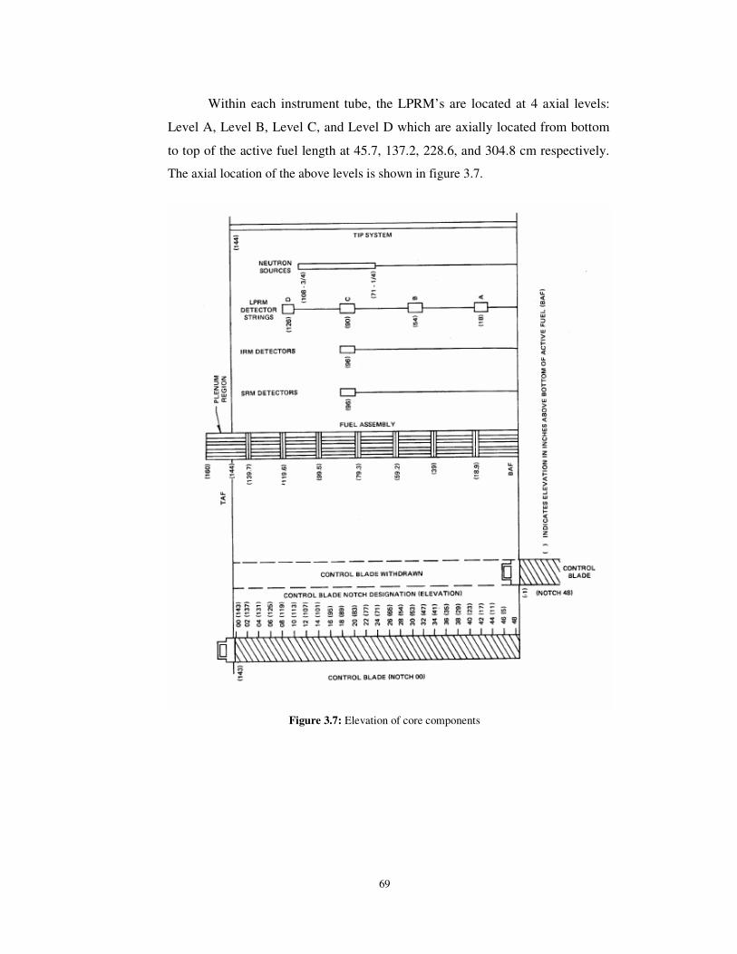
Within each instrument tube, the LPRM’s are located at 4 axial levels:
Level A, Level B, Level C, and Level D which are axially located from bottom
to top of the active fuel length at 45.7, 137.2, 228.6, and 304.8 cm respectively.
The axial location of the above levels is shown in figure 3.7.
Figure 3.7: Elevation of core components
Recommended