1
ECE 221Electric Circuit Analysis I
Chapter 7Node Voltage Method
Herbert G. Mayer, PSUStatus 2/2/2015
2
Syllabus
Current Status Parallel Resistor Definitions General Circuit Problem Samples Node Voltage Methodology (No Vo Mo) Node Voltage Methodology Steps
3
Current Status You have learned how to construct simple circuit
models
Learned the 2 Kirchhoff Laws: KCL and KVL
You know constant voltage and constant current sources
You know dependent current and dependent voltage sources
When a dependent voltage source depends on a*ix then that factor defines the voltage, i.e. the amount of Volt generated, NOT the current!
Ditto for dependent current source, depending on some voltage: A current is being defined, through a voltage of b*vx
We’ll repeat a few terms and laws

4
Parallel Resistors
Two resistors R1 and R2 are in a parallel circuit:
What is their resulting resistance? How to derive this? Hint: think about Siemens! Not the engineer, the conductance This seems trivial, yet will return again with
inductivities in the same way And in a similar (dual) way for capacities
5
Definitions Node (Nd): where 2 or more circuit elements come together
Essential Nd: ditto, but 3 or more circuit elements come together
Path: trace of >=1 basic elements w/o repeat
Branch (Br): path of circuit element connecting 2 nodes
Essential Br: path connecting only 2 essential nodes, not more
Loop: path whose end-node equals start-node w/o repeat
Mesh: loop not enclosing any other loops
Planar Circuit: circuit that can be drawn in 2 dimensions without crossing lines
Cross circuit exercise in class! And pentagon!
6
General Circuit Problem Given n unknown currents in a circuit C1 How many equations are needed to solve the
system? Rhetorical question: We know that n
equations are needed If circuit C1 also happens to have n nodes,
can you solve the problem of computing the unknowns using KCL?
Also rhetorical question: We know that n nodes alone will not suffice using only KCL!
How can we compute all n currents?
7
General Circuit Problem
Given n unknowns and n nodes: one can generate only n-1 equations using KCL
But NOT n equations, as electrical units at the nth node can be derived from the other n-1 equations, so this would be redundant
Redundant equations do not help solve unknowns
But one can also generate equations using KVL, to compute the remaining currents –or unknowns
8
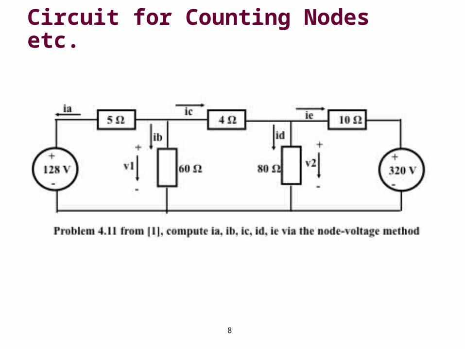
Circuit for Counting Nodes etc.
9
Sample: How Many of Each?
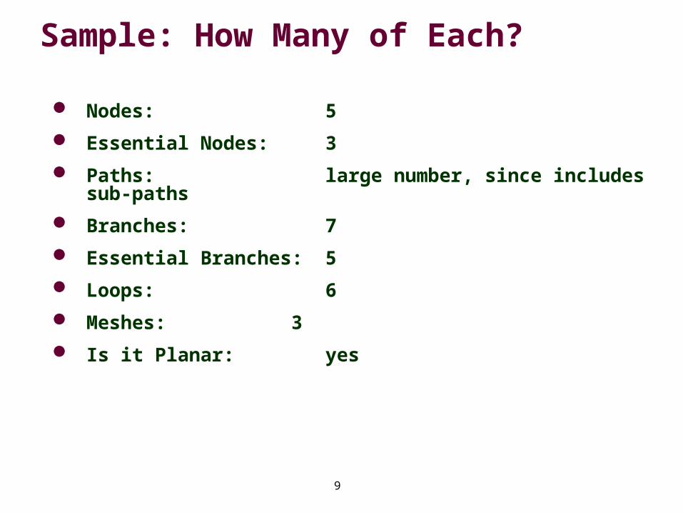
Nodes: 5
Essential Nodes: 3
Paths: large number, since includes sub-paths
Branches: 7
Essential Branches: 5
Loops: 6
Meshes: 3
Is it Planar: yes
10
Node Voltage Methodology (No Vo Mo)
Nodes have no voltage! So what’s up? What does this phrase mean?
Nodes are connecting points of branches
Due to laws of nature, expressed as KCL, nodes have a collective current of 0 Amp!
So why discuss a Node Voltage Method (No Vo Mo)?
No Vo Mo combines using KCL and Ohm’s law across all paths leading to any one node, from all essential nodes to a selected reference node
The reference node is also an essential node
Conveniently, we select the essential node with the largest number of branches as reference node
Is not necessary; works with any essential node
11
Node Voltage Steps
Interestingly, the No Vo Mo –i.e. Node Voltage Methodology– applies also to non-planar circuits!
The later to be discussed Mesh-Current Method only applies to planar circuits
We’ll ignore this added power of No Vo Mo for now, and focus on planar circuits
Here are the steps:
12
Node Voltage Steps Analyze your circuit, locate and number all essential
nodes; we call that number of essential nodes ne
For now, view only planar circuits
From these ne essential nodes, pick a reference node
Best to select the one with the largest number of branches; simplifies the formulae
Then for each remaining essential node, compute the voltage rises from the reference node to the selected essential node, using KCL
For ne essential nodes we can generate n-1 Node Voltage equations
13
Node Voltage Steps for Sample1
1. Using KCL:
2. Analyze the circuit below, and generate 2 Node Voltage equations
3. Enables us to compute 2 unknowns
4. We see that v1 and v2 are unknown
5. Once v1 and v2 are known then we can compute all currents
14
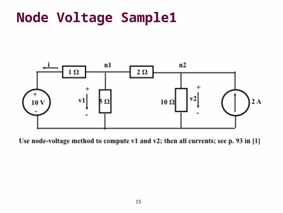
Node Voltage Sample1 In the following sample circuit, use the Node Voltage
Method to compute v1 and v2
There are 3 essential nodes
Pick the lowest one as the reference node, since it unites the largest number of branches
Once voltages v1 and v2 are known, the currents in the 5 and 10 Ohm resistors are computable
Using KCL and Ohm’s Law, all other current can be computed
Note: the current through the right-most branch is known to be 2 A
Here is the sample circuit:
15
Node Voltage Sample1
16
Node Voltage Sample1
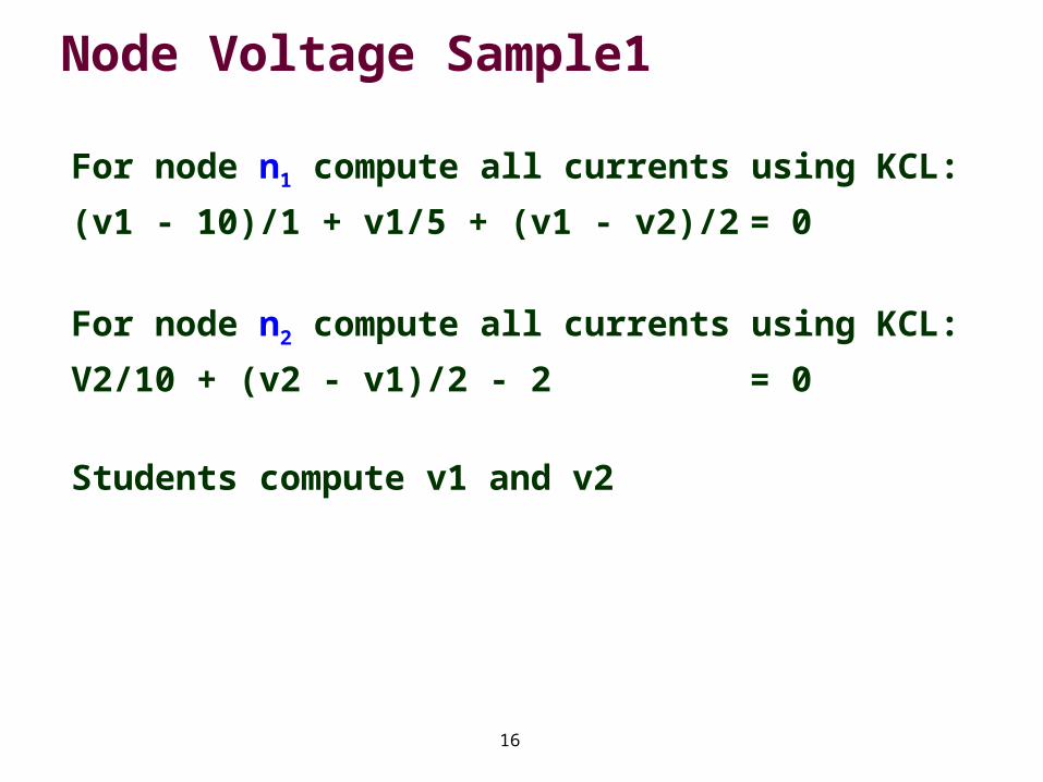
For node n1 compute all currents using KCL:
(v1 - 10)/1 + v1/5 + (v1 - v2)/2 = 0
For node n2 compute all currents using KCL:
V2/10 + (v2 - v1)/2 - 2 = 0
Students compute v1 and v2
17
Node Voltage Sample1: Compute
v1 = 100 / 11 = 9.09 V
v2 = 120 / 11 = 10.91 V
18
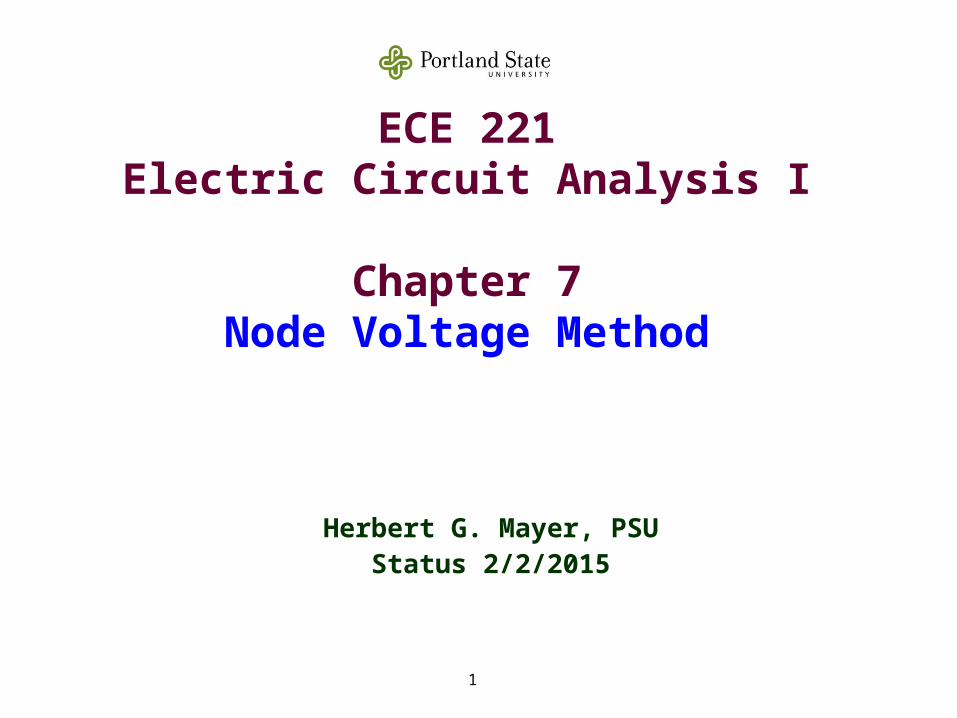
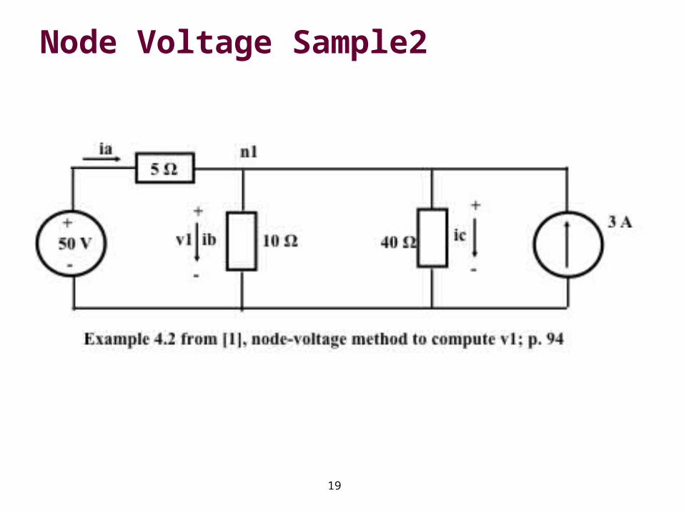
Node Voltage Sample2
In the following sample circuit, use the Node Voltage Method to compute v1, ia, ib, and ic
There are 2 essential nodes
Hence we need just 1 equation to compute v1
We pick the lowest one as the reference node, since it has the largest number of branches
Once voltage v1 is known, the currents are computable
Using KCL, all other current can be computed
19
Node Voltage Sample2
20
Node Voltage Sample2
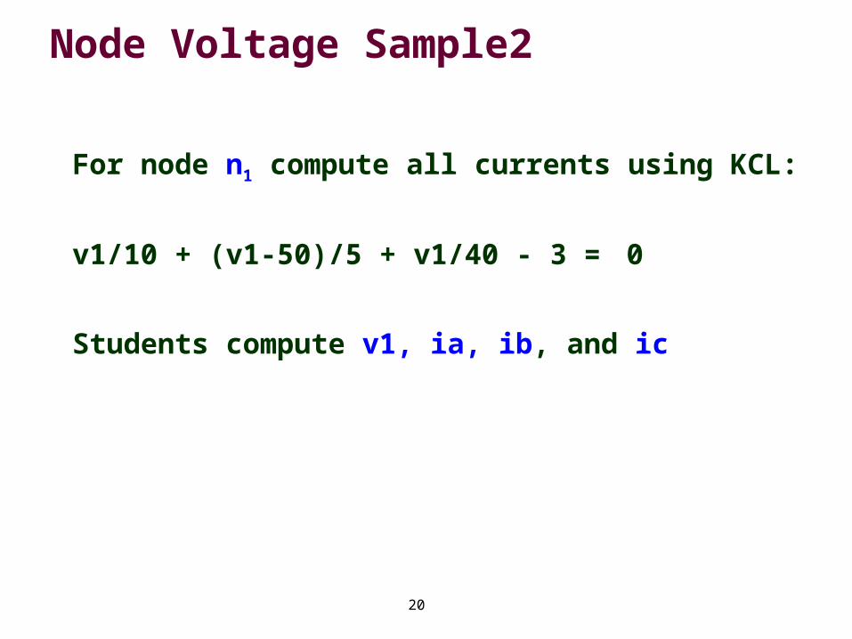
For node n1 compute all currents using KCL:
v1/10 + (v1-50)/5 + v1/40 - 3 = 0
Students compute v1, ia, ib, and ic
21
Node Voltage Sample2: Compute
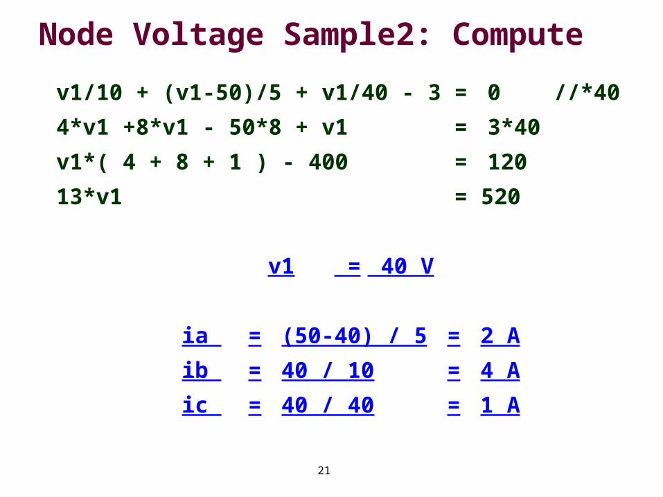
v1/10 + (v1-50)/5 + v1/40 - 3 = 0//*40
4*v1 +8*v1 - 50*8 + v1 = 3*40
v1*( 4 + 8 + 1 ) - 400 =120
13*v1= 520
v1 = 40 V
ia = (50-40) / 5 = 2 A
ib = 40 / 10 = 4 A
ic = 40 / 40 = 1 A
Recommended