1
Chapter 4-6
Signals, Media, And
Data Transmission

2
Transmission of Information
Transmission of Information
Well-understood basicsFrom physics
EnergyElectromagnetic wave propagation
From mathematicsCoding theory

3
Transmission MediaTransmission MediaCopper wire
Need two wiresPossibilities
Twisted pairCoaxial cable
Optical fiberFlexibleLight “stays in”
Air / spaceUsed for electromagnetic transmission

4
Forms of Energy Used To Transmit Data
Forms of Energy Used To Transmit Data
Electric currentAudible soundsOmni-directional electromagnetic waves
Radio Frequency (RF)Infrared

5
Forms of Energy Used to Transmit Data (continued)Forms of Energy Used to Transmit Data (continued)
Directional electromagnetic wavesPoint-to-point satellite channelLimited broadcast (spot beam)MicrowaveLaser beam
6
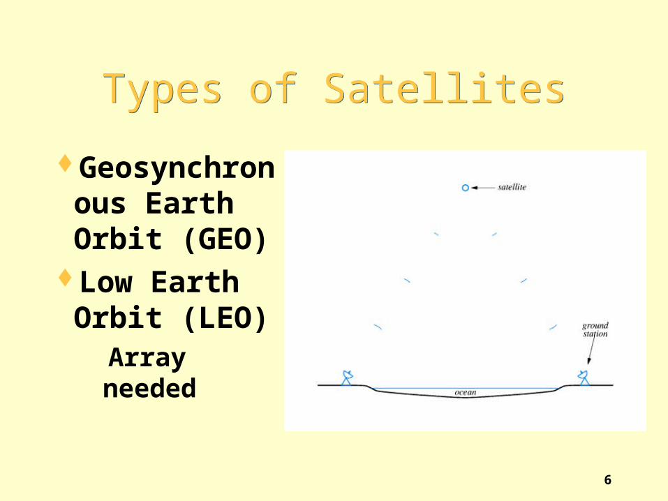
Types of SatellitesTypes of Satellites
Geosynchronous Earth Orbit (GEO)
Low Earth Orbit (LEO)
Array needed

7
Two Important Physical Limits
Of a Transmission System
Two Important Physical Limits
Of a Transmission SystemPropagation delay
Time required for signal to travel across mediaExample: electromagnetic radiation travels
through space at the speed of light (c = 3*108 meters per second)
BandwidthMaximum times per second the signal can
change

8
Transmission of DataTransmission of Data
Network hardware encodes information for transmission
Two types of encodingAnalog (amount of energy proportional to value
of item)Digital (two forms of energy to encode 0 and 1
Computer networks use the latter

9
Example Digital EncodingExample Digital Encoding
MediumCopper wire
Energy formElectric current
EncodingNegative voltage encodes 1Positive voltage encodes 0

10
Illustration Of Digital Encoding
Illustration Of Digital Encoding
Known as waveform diagramX-axis corresponds to timeY-axis corresponds to voltage

11
Encoding DetailsEncoding Details
Several organizations produce networking standards
IEEEITUEIA
Hardware that adheres to standard interoperable

12
The RS-232C StandardThe RS-232C Standard
Example useConnection to keyboard / mouseSerial port on PC
Specified by EIAVoltage is +15 or –15Cable limited to ~50 feetLatest EIA standard is RS-422 (ITU standard is V.24)Uses asynchronous communication
13
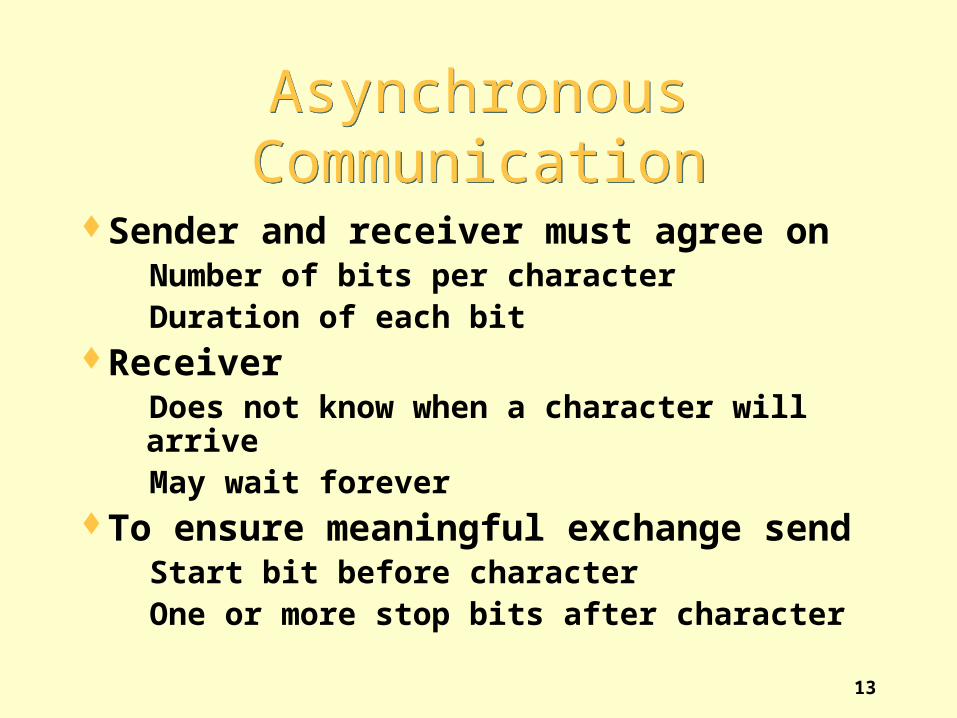
Asynchronous CommunicationAsynchronous
CommunicationSender and receiver must agree on
Number of bits per characterDuration of each bit
ReceiverDoes not know when a character will arriveMay wait forever
To ensure meaningful exchange sendStart bit before characterOne or more stop bits after character

14
Illustration of RS-232Illustration of RS-232
Start bitSame as 0Not part of data
Stop bit Same as 1Follows data

15
Duration of a Bit in RS-232C
Duration of a Bit in RS-232C
Determined by baud rateTypical baud rates: 9.6 Kbaud, 14.4 Kbaud, 28.8
KbaudDuration of bit is 1 / baud rateSender and receiver must agree a prioriReceiver samples signalDisagreement results in framing error

16
Two-Way CommunicationTwo-Way Communication
Desirable in practiceRequires each side to have transmitter and
receiverCalled full duplex

17
Illustration Of Full-Duplex
Communication
Illustration Of Full-Duplex
Communication
Transmitter on one side connected to receiver on otherSeparate wires needed to carry current in each directionCommon ground wireDB-25 connector used
Pin 2 is transmitPin 3 is receive

18
Electrical Transmission(The Bad News)
Electrical Transmission(The Bad News)
It’s an ugly worldElectrical energy dissipates as it travels alongWires have resistance, capacitance, and
inductance which distort signalsMagnetic or electrical interference distorts signalsDistortion can result in loss or misinterpretation

19
Illustration of DistortedSignal for a Single Bit
Illustration of DistortedSignal for a Single Bit
In practiceDistortion can be much worse than illustrated

20
ConsequencesConsequences
RS-232 hardware must handle minor distortionsTake multiple samples per bitTolerate less than full voltage
Cannot use electrical current for long-distance transmission

21
Long-Distance CommunicationLong-Distance
CommunicationImportant fact: an oscillating signal travels
farther than direct currentFor long-distance communication
Send a sine wave (called a carrier wave)Change (modulate) the carrier to encode date
Note: modulated carrier technique used for radio and television

22
Illustration of a CarrierIllustration of a Carrier
CarrierUsually a sine waveOscillates continuouslyFrequency of carrier fixed

23
Types of ModulationTypes of Modulation
Amplitude modulation (used in AM radio)Frequency modulation (used in FM radio)Phase shift modulation (used for data)
24
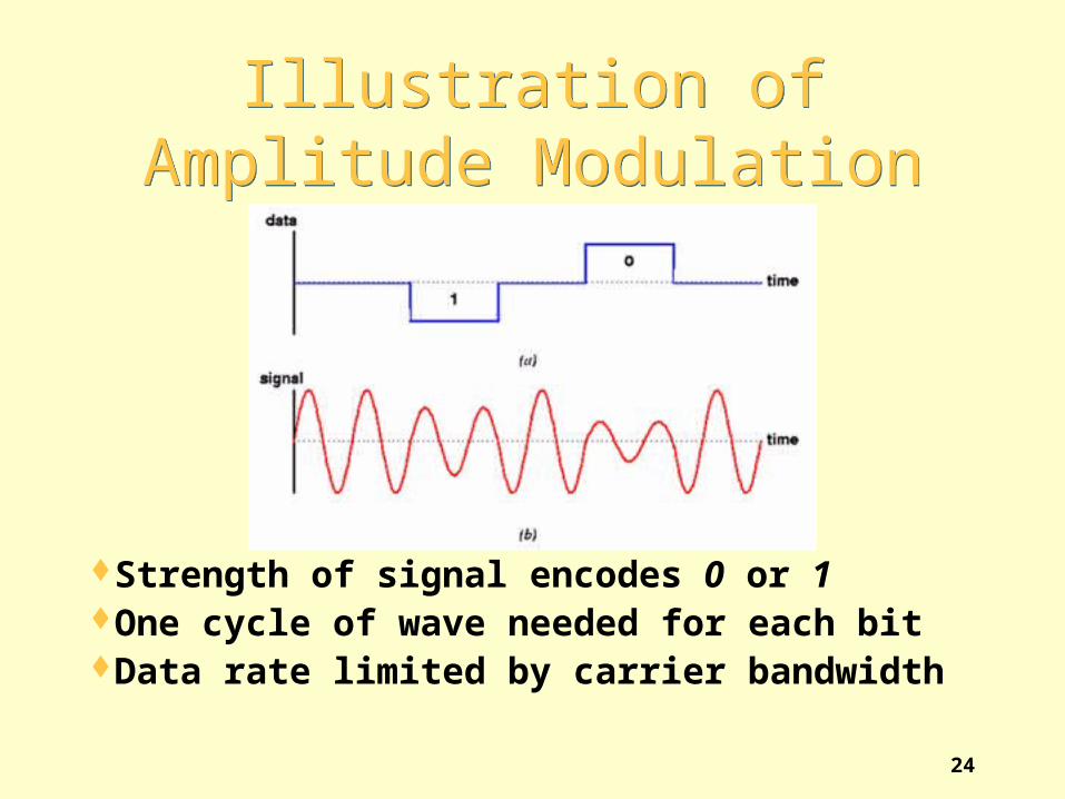
Illustration ofAmplitude Modulation
Illustration ofAmplitude Modulation
Strength of signal encodes 0 or 1One cycle of wave needed for each bitData rate limited by carrier bandwidth

25
Illustration ofPhase-Shift Modulation
Illustration ofPhase-Shift Modulation
Change in phase encodes K bitsData rate higher than carrier bandwidth

26
Phase-Shift ExamplePhase-Shift Example
Section of wave is omitted at phase shiftData bits determine size of omitted section

27
ModemModem
Hardware deviceUsed for long-distance communicationContains separate circuitry for
Modulation of outgoing signalDemodulation of incoming signal
Name abbreviates modulator / demodulator

28
Illustration of ModemsUsed Over a Long
Distance
Illustration of ModemsUsed Over a Long
Distance
One modem at each endSeparate wires carry signals in each directionModulator on one modem connects to
demodulator on other

29
Types of ModemsTypes of Modems
ConventionalUse four wiresTransmit modulated electrical wave
OpticalUse glass fibersTransmit modulated light
WirelessUse air / spaceTransmit modulated RF wave
30
Types of Modems(continued)
Types of Modems(continued)
DialupUse voice telephone systemTransmit modulated audio tone
Note: in practice, a dialup modem uses multiple tones simultaneously

31
Illustration of Dialup Modem
Illustration of Dialup Modem
Modem canDialAnswer
Carrier is audio tone

32
Modem TerminologyModem Terminology
Full-duplex modemProvides 2-way communicationAllows simultaneous transmissionUses four wires
Half-duplex modemDoes provide 2-way communicationTransmits in one direction at any timeUses two wires

33
RecallRecall
Propagation delayDetermined by physicsTime required for signal to travel across medium
BandwidthElectrical property of physical transmission
systemMaximum times per second signal can change

34
Fundamental Measures Of A
Digital Transmission System
Fundamental Measures Of A
Digital Transmission SystemDelay
The amount of time required for a bit of data to travel from one end to the other
Usually the same as the propagation delay in underlying hardware
ThroughputThe number of bits per second that can be
transmittedRelated to underlying hardware bandwidth

35
Relationship Between Digital
Throughput and Bandwidth
Relationship Between Digital
Throughput and BandwidthGiven by Nyquist’s theorem:
D = 2 B log2 K
whereD is maximum data rateB is hardware bandwidthK is number of values used to encode data

36
Applications of Nyquist’s Theorem
Applications of Nyquist’s Theorem
For RS-232K is 2 because RS-232 only uses two values,
+15 or –15 volts, to encode data bitsD is 2 B log2 2 = 2 B
For phase-shift encodingSuppose K is 8 (possible shifts)D is 2 B log2 8 = 2 B * 3 = 6 B

37
More Bad NewsMore Bad News
Physics tells us that real systems emit and absorb energy (e.g., thermal)
Engineers call unwanted energy noiseNyquist’s theorem
Assumes a noise-free systemOnly works in theory
Shannon’s theorem corrects for noise

38
Shannon’s TheoremShannon’s Theorem
Gives capacity in presence of noise:
C = B log2 (1 + S/N)where
C is the effective channel capacity in bits per secondB is hardware bandwidthS is the average power (signal)N is the noise
S/N is signal-to-noise ratio

39
Application of Shannon’s Theorem
Application of Shannon’s Theorem
Conventional telephone systemEngineered for voiceBandwidth is 3000 HzSignal-to-noise ratio is approximately 1000Effective capacity is
3000 log2 (1 + 1000) = ~30000 bps Conclusion: dialup modems have little hope
of exceeding 28.8 Kbps

40
The Bottom LineThe Bottom Line
Nyquist’s theorem means finding a way to encode more bits per cycle improves the data rate
Shannon’s theorem means that no amount of clever engineering can overcome the fundamental limits of a real transmission system

41
MultiplexingMultiplexing
Fundamental to networkingGeneral conceptUsed in
Lowest level of transmission systemsHigher levels of network hardwareProtocol softwareApplications

42
The General Concept of Multiplexing
The General Concept of Multiplexing
Separate pairs of communications travel across shared channel
Multiplexing prevents interferenceEach destination receives only data sent by
corresponding source

43
Multiplexing TerminologyMultiplexing Terminology
MultiplexorDevice or mechanismAccepts data from multiple sourcesSends data across shared channel
DemultiplexorDevice or mechanismEstracts data from shared channelSends to correct destination
44
Two Basic Types of Multiplexing
Two Basic Types of Multiplexing
Time Division Multiplexing (TDM)Only one item at a time on shared channelItem marked to identify sourceDemultiplexor uses identifying mark to know
where to deliverFrequency Division Multiplexing (FDM)
Multiple items transmitted simultaneouslyUses multiple “channels”

45
Transmission SchemesTransmission Schemes
Baseband transmissionUses only low frequenciesEncodes data directly
Broadband transmissionUses multiple carriersCan use higher frequenciesAchieves higher throughputHardware more complex and expensive

46
Scientific Principle BehindFrequency Division
Multiplexing
Scientific Principle BehindFrequency Division
Multiplexing
Note: this is the same principle that allows a cable TV company to send multiple television signals across a single cable
Two or more signals that use different carrier frequencies can be transmitted over a single medium simultaneously without interference

47
Wave Division MultiplexingWave Division Multiplexing
FactsFDM can be used with any electromagnetic
radiationLight is electromagnetic radiation
When applied to light, FDM is called wave division multiplexing
Informally called color division multiplexing

48
SummarySummary
Various transmission schemes and media availableElectric current over copperLight over glassElectromagnetic waves
Digital encoding used for dataAsynchronous communication
Used for keyboards and serial portsRS-232 is standardSender and receiver agree on baud rate

49
Summary (continued)Summary (continued)
ModemsUsed for long-distance communicationAvailable for copper, optical fiber, dialupTransmit modulated carrier
Phase-shift modulation popularClassified as full- or half-duplex
Two measures of digital communication systemDelayThroughput

50
Summary (continued)Summary (continued)
Nyquist’s theoremRelates throughput to bandwidthEncourages engineers to use complex encoding
Shannon’s theoremAdjusts for noiseSpecifies limits on real transmission systems
51
Summary (continued)Summary (continued)
MultiplexingFundamental conceptUsed at many levelsApplied in both hardware and softwareTwo basic types
Time-division multiplexing (TDM)Frequency-division multiplexing (FDM)
When applied to light, FDM is called wave-division multiplexing
Recommended