Embed Size (px)
Citation preview

ZXDU68 T601DC Power System
Product Description
Version: V4.1R03M01
ZTE CORPORATIONNO. 55, Hi-tech Road South, ShenZhen, P.R.ChinaPostcode: 518057Tel: +86-755-26771900Fax: +86-755-26770801URL: http://ensupport.zte.com.cnE-mail: [email protected]

LEGAL INFORMATIONCopyright © 2011 ZTE CORPORATION.
The contents of this document are protected by copyright laws and international treaties. Any reproduction or
distribution of this document or any portion of this document, in any form by any means, without the prior written
consent of ZTE CORPORATION is prohibited. Additionally, the contents of this document are protected by
contractual confidentiality obligations.
All company, brand and product names are trade or service marks, or registered trade or service marks, of ZTE
CORPORATION or of their respective owners.
This document is provided “as is”, and all express, implied, or statutory warranties, representations or conditions
are disclaimed, including without limitation any implied warranty of merchantability, fitness for a particular purpose,
title or non-infringement. ZTE CORPORATION and its licensors shall not be liable for damages resulting from the
use of or reliance on the information contained herein.
ZTE CORPORATION or its licensors may have current or pending intellectual property rights or applications
covering the subject matter of this document. Except as expressly provided in any written license between ZTE
CORPORATION and its licensee, the user of this document shall not acquire any license to the subject matter
herein.
ZTE CORPORATION reserves the right to upgrade or make technical change to this product without further notice.
Users may visit ZTE technical support website http://ensupport.zte.com.cn to inquire related information.
The ultimate right to interpret this product resides in ZTE CORPORATION.
Revision History
Revision No. Revision Date Revision Reason
R1.0 2011-01-20 First edition
Serial Number: SJ-20101125154934-003
Publishing Date: 2011-01-20(R1.0)
ContentsChapter 1 Overview.................................................................................... 1-1
1.1 System Introduction............................................................................................ 1-1
1.2 System Configuration ......................................................................................... 1-1
Chapter 2 System Structure and Components........................................ 2-12.1 Overall System Structure .................................................................................... 2-1
2.2 AC Distribution Unit ............................................................................................ 2-2
2.3 DC Distribution Unit ............................................................................................ 2-3
2.4 Electrical Connection Terminals........................................................................... 2-4
2.5 Monitoring Unit Parts .......................................................................................... 2-6
2.6 Rectifier Parts .................................................................................................... 2-7
2.7 Slots Configuration ............................................................................................. 2-7
2.8 Dimensions and Weight ...................................................................................... 2-8
Chapter 3 Board and Signal Interface ...................................................... 3-13.1 Boards Location ................................................................................................. 3-1
3.2 SIB Board Interfaces .......................................................................................... 3-2
3.3 MPB Interfaces .................................................................................................. 3-3
3.4 SNMP Board...................................................................................................... 3-3
Chapter 4 Characteristics and Specifications ......................................... 4-14.1 System Features ................................................................................................ 4-1
4.2 Networking Description....................................................................................... 4-1
4.3 System Technical Specifications.......................................................................... 4-2
4.3.1 Working Environment Specifications.......................................................... 4-2
4.3.2 AC Power Distribution Specifications ......................................................... 4-2
4.3.3 DC Power Distribution Specifications......................................................... 4-2
4.3.4 ZXD2400 (V4.x) Rectifier Specifications..................................................... 4-3
4.3.5 Precision of the Monitoring Unit................................................................. 4-3
4.3.6 Other Specifications ................................................................................. 4-4
4.4 Compliant Standards .......................................................................................... 4-4
Appendix A Monitoring Software............................................................. A-1A.1 Menu Hierarchy .................................................................................................A-1
A.2 System Parameter List .......................................................................................A-2
A.3 Battery Parameter List........................................................................................A-3
A.4 Alarm List ..........................................................................................................A-4
I

Appendix B Term List................................................................................ B-1
Appendix C Electrical Connection Diagram ........................................... C-1
II
Chapter 1OverviewTable of Contents
System Introduction....................................................................................................1-1System Configuration .................................................................................................1-1
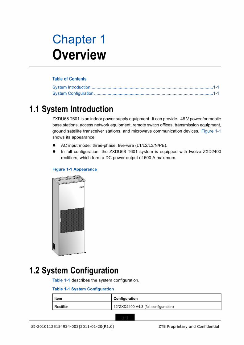
1.1 System IntroductionZXDU68 T601 is an indoor power supply equipment. It can provide –48 V power for mobilebase stations, access network equipment, remote switch offices, transmission equipment,ground satellite transceiver stations, and microwave communication devices. Figure 1-1shows its appearance.
l AC input mode: three-phase, five-wire (L1/L2/L3/N/PE).l In full configuration, the ZXDU68 T601 system is equipped with twelve ZXD2400
rectifiers, which form a DC power output of 600 A maximum.
Figure 1-1 Appearance
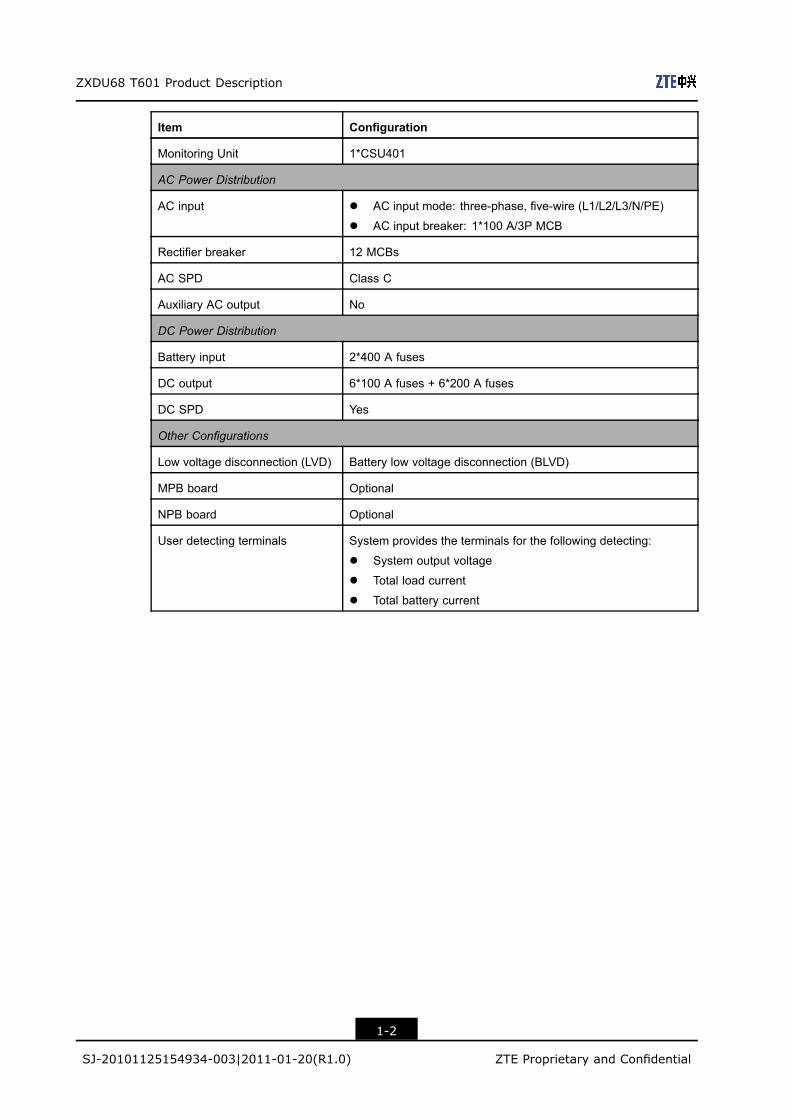
1.2 System ConfigurationTable 1-1 describes the system configuration.
Table 1-1 System Configuration
Item Configuration
Rectifier 12*ZXD2400 V4.3 (full configuration)
1-1
SJ-20101125154934-003|2011-01-20(R1.0) ZTE Proprietary and Confidential
ZXDU68 T601 Product Description
Item Configuration
Monitoring Unit 1*CSU401
AC Power Distribution
AC input l AC input mode: three-phase, five-wire (L1/L2/L3/N/PE)
l AC input breaker: 1*100 A/3P MCB
Rectifier breaker 12 MCBs
AC SPD Class C
Auxiliary AC output No
DC Power Distribution
Battery input 2*400 A fuses
DC output 6*100 A fuses + 6*200 A fuses
DC SPD Yes
Other Configurations
Low voltage disconnection (LVD) Battery low voltage disconnection (BLVD)
MPB board Optional
NPB board Optional
User detecting terminals System provides the terminals for the following detecting:
l System output voltage
l Total load current
l Total battery current
1-2
SJ-20101125154934-003|2011-01-20(R1.0) ZTE Proprietary and Confidential
Chapter 2System Structure andComponentsTable of ContentsOverall System Structure............................................................................................2-1AC Distribution Unit ....................................................................................................2-2DC Distribution Unit....................................................................................................2-3Electrical Connection Terminals..................................................................................2-4Monitoring Unit Parts..................................................................................................2-6Rectifier Parts.............................................................................................................2-7Slots Configuration .....................................................................................................2-7Dimensions and Weight..............................................................................................2-8
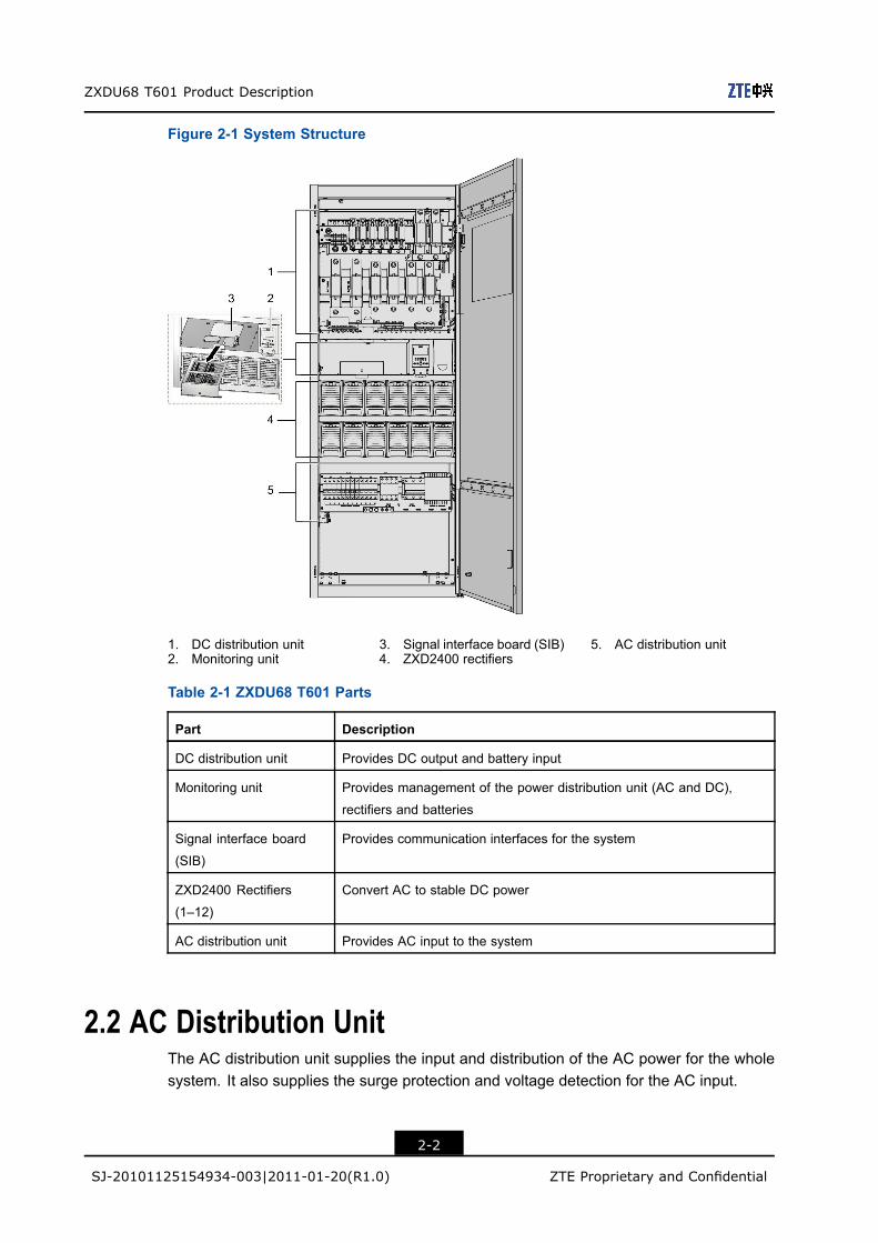
2.1 Overall System StructureThe ZXDU68 T601 system is mainly composed of the ZXD2400 rectifiers, monitoring unit,signal interface board (SIB), AC distribution unit, and DC distribution unit. Figure 2-1 showsits system structure.
Table 2-1 describes the functions of the components.
2-1
SJ-20101125154934-003|2011-01-20(R1.0) ZTE Proprietary and Confidential
ZXDU68 T601 Product Description
Figure 2-1 System Structure
1. DC distribution unit2. Monitoring unit
3. Signal interface board (SIB)4. ZXD2400 rectifiers
5. AC distribution unit
Table 2-1 ZXDU68 T601 Parts
Part Description
DC distribution unit Provides DC output and battery input
Monitoring unit Provides management of the power distribution unit (AC and DC),
rectifiers and batteries
Signal interface board
(SIB)
Provides communication interfaces for the system
ZXD2400 Rectifiers
(1–12)
Convert AC to stable DC power
AC distribution unit Provides AC input to the system
2.2 AC Distribution UnitThe AC distribution unit supplies the input and distribution of the AC power for the wholesystem. It also supplies the surge protection and voltage detection for the AC input.
2-2
SJ-20101125154934-003|2011-01-20(R1.0) ZTE Proprietary and Confidential
Chapter 2 System Structure and Components
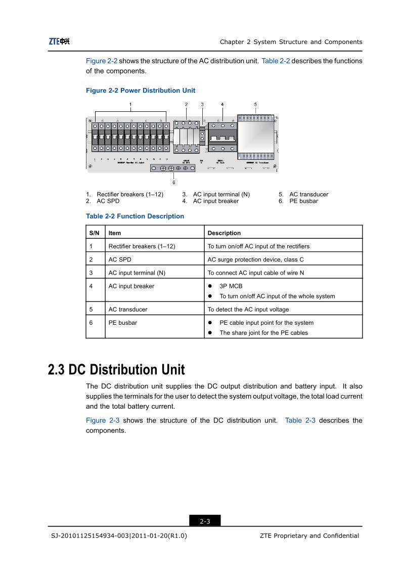
Figure 2-2 shows the structure of the AC distribution unit. Table 2-2 describes the functionsof the components.
Figure 2-2 Power Distribution Unit
1. Rectifier breakers (1–12)2. AC SPD
3. AC input terminal (N)4. AC input breaker
5. AC transducer6. PE busbar
Table 2-2 Function Description
S/N Item Description
1 Rectifier breakers (1–12) To turn on/off AC input of the rectifiers
2 AC SPD AC surge protection device, class C
3 AC input terminal (N) To connect AC input cable of wire N
4 AC input breaker l 3P MCB
l To turn on/off AC input of the whole system
5 AC transducer To detect the AC input voltage
6 PE busbar l PE cable input point for the system
l The share joint for the PE cables
2.3 DC Distribution UnitThe DC distribution unit supplies the DC output distribution and battery input. It alsosupplies the terminals for the user to detect the system output voltage, the total load currentand the total battery current.
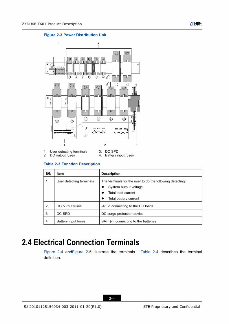
Figure 2-3 shows the structure of the DC distribution unit. Table 2-3 describes thecomponents.
2-3
SJ-20101125154934-003|2011-01-20(R1.0) ZTE Proprietary and Confidential
ZXDU68 T601 Product Description
Figure 2-3 Power Distribution Unit
1. User detecting terminals2. DC output fuses
3. DC SPD4. Battery input fuses
Table 2-3 Function Description
S/N Item Description
1 User detecting terminals The terminals for the user to do the following detecting:
l System output voltage
l Total load current
l Total battery current
2 DC output fuses -48 V, connecting to the DC loads
3 DC SPD DC surge protection device
4 Battery input fuses BATT(-), connecting to the batteries
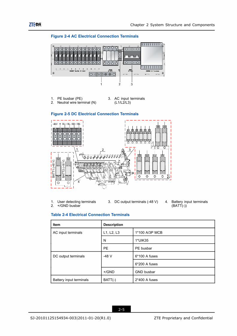
2.4 Electrical Connection TerminalsFigure 2-4 andFigure 2-5 illustrate the terminals. Table 2-4 describes the terminaldefinition.
2-4
SJ-20101125154934-003|2011-01-20(R1.0) ZTE Proprietary and Confidential
Chapter 2 System Structure and Components
Figure 2-4 AC Electrical Connection Terminals
1. PE busbar (PE)2. Neutral wire terminal (N)
3. AC input terminals(L1/L2/L3)
Figure 2-5 DC Electrical Connection Terminals
1. User detecting terminals2. +/GND busbar
3. DC output terminals (-48 V) 4. Battery input terminals(BATT(-))
Table 2-4 Electrical Connection Terminals
Item Description
L1, L2, L3 1*100 A/3P MCB
N 1*UIK35
AC input terminals
PE PE busbar
6*100 A fuses-48 V
6*200 A fuses
DC output terminals
+/GND GND busbar
Battery input terminals BATT(-) 2*400 A fuses
2-5
SJ-20101125154934-003|2011-01-20(R1.0) ZTE Proprietary and Confidential

ZXDU68 T601 Product Description
Item Description
-48 V
+
System output voltage detecting
RL+
RL-
Total load current detecting
RB+
User detecting terminals
RB-
Total battery current detecting
2.5 Monitoring Unit PartsThe monitoring unit manages the power distribution unit, rectifiers and batteries of theZXDU68 T601 system.
Figure 2-6 shows the appearance and structure of the monitoring unit.
Figure 2-6 Monitoring Unit
1. LCD2. Indicators3. Keys
4. Captive screw5. Handle6. Reset button (RST)
7. Input/output interface
Refer to Table 2-5 for the details of the indicators of the monitoring unit.
Table 2-5 Indicators Description
Designation Description
PWR Power indicator
RUN Running indicator
EQU Equalized charge (boost charge) indicator
COMM Communication indicator
ALM Alarm indicator
2-6
SJ-20101125154934-003|2011-01-20(R1.0) ZTE Proprietary and Confidential
Chapter 2 System Structure and Components
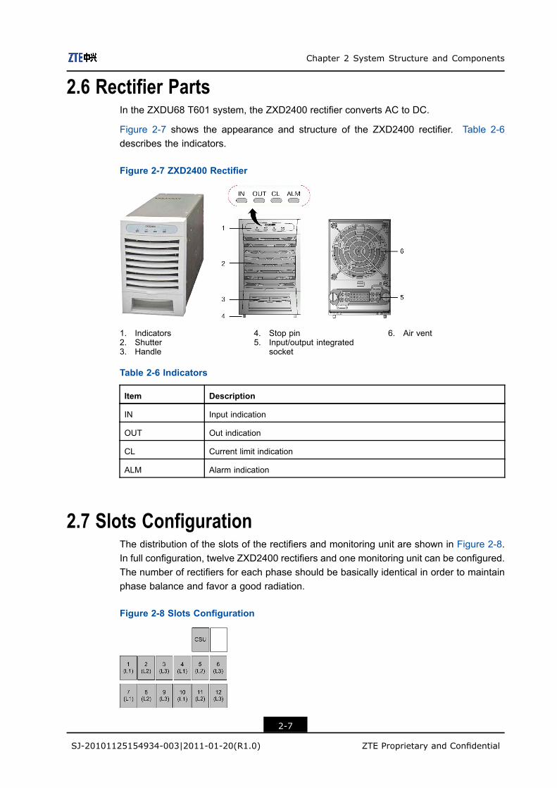
2.6 Rectifier PartsIn the ZXDU68 T601 system, the ZXD2400 rectifier converts AC to DC.
Figure 2-7 shows the appearance and structure of the ZXD2400 rectifier. Table 2-6describes the indicators.
Figure 2-7 ZXD2400 Rectifier
1. Indicators2. Shutter3. Handle
4. Stop pin5. Input/output integrated
socket
6. Air vent
Table 2-6 Indicators
Item Description
IN Input indication
OUT Out indication
CL Current limit indication
ALM Alarm indication
2.7 Slots ConfigurationThe distribution of the slots of the rectifiers and monitoring unit are shown in Figure 2-8.In full configuration, twelve ZXD2400 rectifiers and one monitoring unit can be configured.The number of rectifiers for each phase should be basically identical in order to maintainphase balance and favor a good radiation.
Figure 2-8 Slots Configuration
2-7
SJ-20101125154934-003|2011-01-20(R1.0) ZTE Proprietary and Confidential
ZXDU68 T601 Product Description
• 1–12: ZXD2400 rectifierslots
• CSU: monitoring unit slot
2.8 Dimensions and WeightWeight
Table 2-7 describes the weight of the components.
Table 2-7 ZXDU68 T601 Weight
Item Specification
Cabinet Approximately 100 kg (excluding monitoring unit, rectifiers)
Monitoring unit 2.2 kg
ZXD2400 rectifier 3.8 kg/set, 12 sets (full configuration)
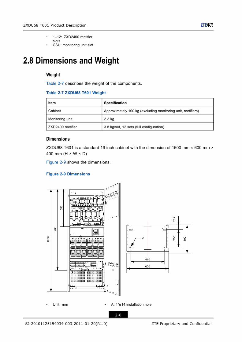
Dimensions
ZXDU68 T601 is a standard 19 inch cabinet with the dimension of 1600 mm × 600 mm ×400 mm (H × W × D).
Figure 2-9 shows the dimensions.
Figure 2-9 Dimensions
• Unit: mm • A: 4*ø14 installation hole
2-8
SJ-20101125154934-003|2011-01-20(R1.0) ZTE Proprietary and Confidential
Chapter 3Board and Signal InterfaceTable of Contents
Boards Location .........................................................................................................3-1SIB Board Interfaces ..................................................................................................3-2MPB Interfaces...........................................................................................................3-3SNMP Board ..............................................................................................................3-3
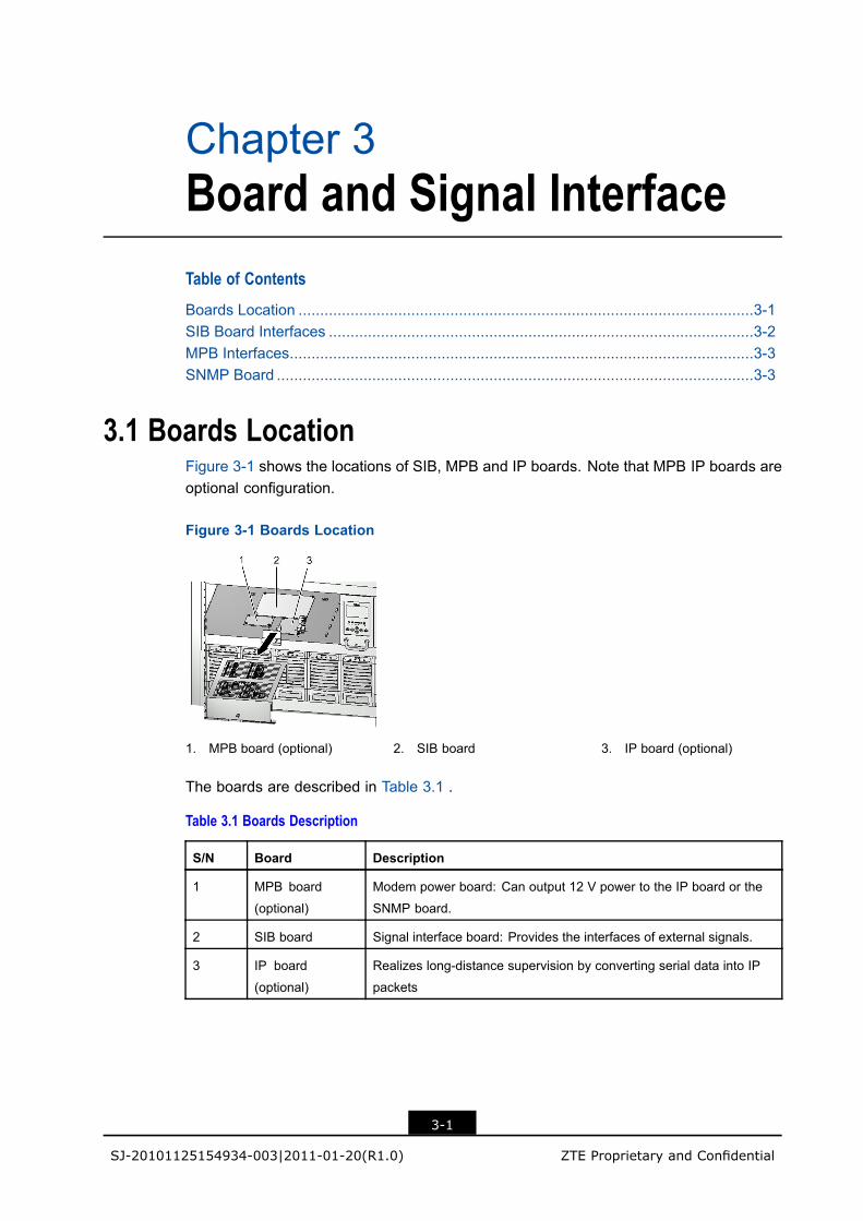
3.1 Boards LocationFigure 3-1 shows the locations of SIB, MPB and IP boards. Note that MPB IP boards areoptional configuration.
Figure 3-1 Boards Location
1. MPB board (optional) 2. SIB board 3. IP board (optional)
The boards are described in Table 3.1 .
Table 3.1 Boards Description
S/N Board Description
1 MPB board
(optional)
Modem power board: Can output 12 V power to the IP board or the
SNMP board.
2 SIB board Signal interface board: Provides the interfaces of external signals.
3 IP board
(optional)
Realizes long-distance supervision by converting serial data into IP
packets
3-1
SJ-20101125154934-003|2011-01-20(R1.0) ZTE Proprietary and Confidential
ZXDU68 T601 Product Description
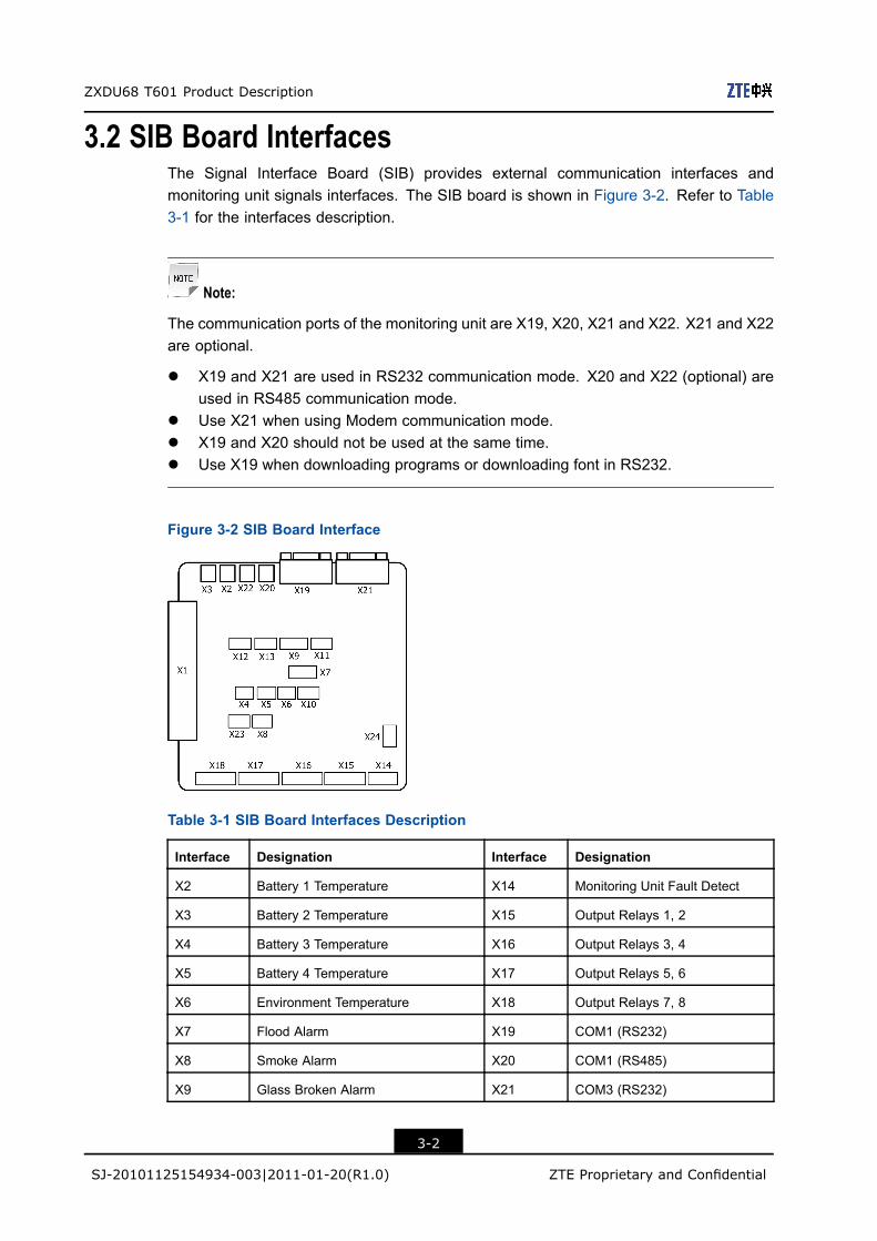
3.2 SIB Board InterfacesThe Signal Interface Board (SIB) provides external communication interfaces andmonitoring unit signals interfaces. The SIB board is shown in Figure 3-2. Refer to Table3-1 for the interfaces description.
Note:
The communication ports of the monitoring unit are X19, X20, X21 and X22. X21 and X22are optional.
l X19 and X21 are used in RS232 communication mode. X20 and X22 (optional) areused in RS485 communication mode.
l Use X21 when using Modem communication mode.l X19 and X20 should not be used at the same time.l Use X19 when downloading programs or downloading font in RS232.
Figure 3-2 SIB Board Interface
Table 3-1 SIB Board Interfaces Description
Interface Designation Interface Designation
X2 Battery 1 Temperature X14 Monitoring Unit Fault Detect
X3 Battery 2 Temperature X15 Output Relays 1, 2
X4 Battery 3 Temperature X16 Output Relays 3, 4
X5 Battery 4 Temperature X17 Output Relays 5, 6
X6 Environment Temperature X18 Output Relays 7, 8
X7 Flood Alarm X19 COM1 (RS232)
X8 Smoke Alarm X20 COM1 (RS485)
X9 Glass Broken Alarm X21 COM3 (RS232)
3-2
SJ-20101125154934-003|2011-01-20(R1.0) ZTE Proprietary and Confidential
Chapter 3 Board and Signal Interface
Interface Designation Interface Designation
X10 Intrusion Alarm X22 COM2 (RS485)
X11 Door Magnet Alarm X23 Environment Humidity
X12 Input Relays 1, 2 X24 48V Power Input
X13 Input Relays 3, 4 - -
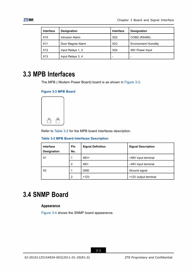
3.3 MPB InterfacesThe MPB ( Modem Power Board) board is as shown in Figure 3-3.
Figure 3-3 MPB Board
Refer to Table 3-2 for the MPB board interfaces description.
Table 3-2 MPB Board Interfaces Description
InterfaceDesignation
PinNo.
Signal Definition Signal Description
1 48V+ +48V input terminalX1
2 48V- –48V input terminal
1 GND Ground signalX2
2 +12V +12V output terminal
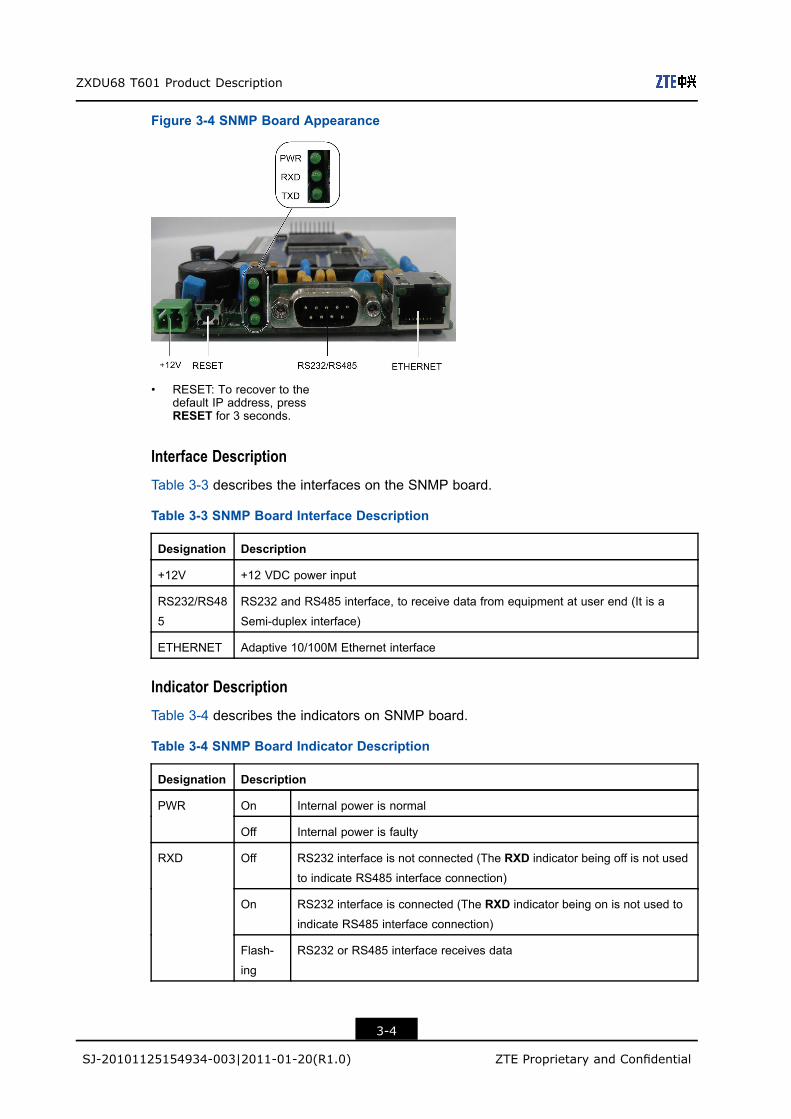
3.4 SNMP BoardAppearance
Figure 3-4 shows the SNMP board appearance.
3-3
SJ-20101125154934-003|2011-01-20(R1.0) ZTE Proprietary and Confidential
ZXDU68 T601 Product Description
Figure 3-4 SNMP Board Appearance
• RESET: To recover to thedefault IP address, pressRESET for 3 seconds.
Interface Description
Table 3-3 describes the interfaces on the SNMP board.
Table 3-3 SNMP Board Interface Description
Designation Description
+12V +12 VDC power input
RS232/RS48
5
RS232 and RS485 interface, to receive data from equipment at user end (It is a
Semi-duplex interface)
ETHERNET Adaptive 10/100M Ethernet interface
Indicator Description
Table 3-4 describes the indicators on SNMP board.
Table 3-4 SNMP Board Indicator Description
Designation Description
On Internal power is normalPWR
Off Internal power is faulty
Off RS232 interface is not connected (The RXD indicator being off is not used
to indicate RS485 interface connection)
On RS232 interface is connected (The RXD indicator being on is not used to
indicate RS485 interface connection)
RXD
Flash-
ing
RS232 or RS485 interface receives data
3-4
SJ-20101125154934-003|2011-01-20(R1.0) ZTE Proprietary and Confidential
Chapter 3 Board and Signal Interface
Designation Description
Off ZXDU68 T601 does not transmit dataTXD
Flash-
ing
ZXDU68 T601 is transmitting data
3-5
SJ-20101125154934-003|2011-01-20(R1.0) ZTE Proprietary and Confidential

ZXDU68 T601 Product Description
This page intentionally left blank.
3-6
SJ-20101125154934-003|2011-01-20(R1.0) ZTE Proprietary and Confidential
Chapter 4Characteristics andSpecificationsTable of Contents
System Features ........................................................................................................4-1Networking Description...............................................................................................4-1System Technical Specifications.................................................................................4-2Compliant Standards..................................................................................................4-4
4.1 System FeaturesThe ZXDU68 T601 system has the following features:
l AC input mode: three-phase, five-wire (L1/L2/L3/N/PE).l Intelligent monitoring unit.l Hot-pluggable rectifiers with N+1 backup function.l DC output capacity up to 600 A maximum.l Battery low voltage disconnection (BLVD) function.l High reliability with MTBF ≥ 2.2 × 10⁵ h.
4.2 Networking DescriptionThe ZXDU68 T601 system supports multiple network monitoring modes.
l The ZXDU68 T601 system provides RS232/RS485 serial port. ZXDU68 T601 canbe connected to a background PC via the serial port. The background monitoringsoftware installed in the PC monitors ZXDU68 T601 locally.
l The ZXDU68 T601 system with IP board (or SNMP board) can communicate with abackground PC via TCP/IP (or SNMP). The background monitoring software installedin the PC monitors ZXDU68 T601 remotely.
l ZXDU68 T601 system can be connected to a remote PC through a transmissionchannel (e.g. channel of microwave equipment and optical transmission equipment)and auxiliary communication equipment.
4-1
SJ-20101125154934-003|2011-01-20(R1.0) ZTE Proprietary and Confidential
ZXDU68 T601 Product Description
4.3 System Technical Specifications
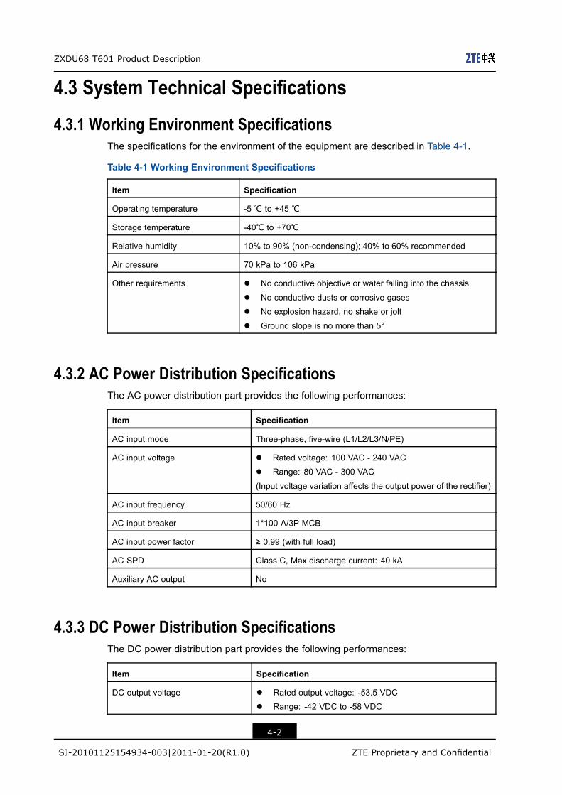
4.3.1 Working Environment SpecificationsThe specifications for the environment of the equipment are described in Table 4-1.
Table 4-1 Working Environment Specifications
Item Specification
Operating temperature -5 ℃ to +45 ℃
Storage temperature -40℃ to +70℃
Relative humidity 10% to 90% (non-condensing); 40% to 60% recommended
Air pressure 70 kPa to 106 kPa
Other requirements l No conductive objective or water falling into the chassis
l No conductive dusts or corrosive gases
l No explosion hazard, no shake or jolt
l Ground slope is no more than 5°
4.3.2 AC Power Distribution SpecificationsThe AC power distribution part provides the following performances:
Item Specification
AC input mode Three-phase, five-wire (L1/L2/L3/N/PE)
AC input voltage l Rated voltage: 100 VAC - 240 VAC
l Range: 80 VAC - 300 VAC
(Input voltage variation affects the output power of the rectifier)
AC input frequency 50/60 Hz
AC input breaker 1*100 A/3P MCB
AC input power factor ≥ 0.99 (with full load)
AC SPD Class C, Max discharge current: 40 kA
Auxiliary AC output No
4.3.3 DC Power Distribution SpecificationsThe DC power distribution part provides the following performances:
Item Specification
DC output voltage l Rated output voltage: -53.5 VDC
l Range: -42 VDC to -58 VDC
4-2
SJ-20101125154934-003|2011-01-20(R1.0) ZTE Proprietary and Confidential
Chapter 4 Characteristics and Specifications
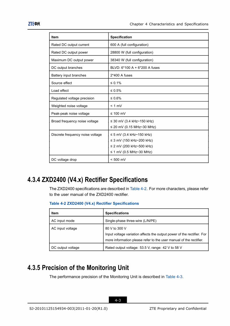
Item Specification
Rated DC output current 600 A (full configuration)
Rated DC output power 28800 W (full configuration)
Maximum DC output power 38340 W (full configuration)
DC output branches BLVD: 6*100 A + 6*200 A fuses
Battery input branches 2*400 A fuses
Source effect ≤ 0.1%
Load effect ≤ 0.5%
Regulated voltage precision ≤ 0.6%
Weighted noise voltage < 1 mV
Peak-peak noise voltage ≤ 100 mV
Broad frequency noise voltage ≤ 30 mV (3.4 kHz~150 kHz)
≤ 20 mV (0.15 MHz~30 MHz)
Discrete frequency noise voltage ≤ 5 mV (3.4 kHz~150 kHz)
≤ 3 mV (150 kHz~200 kHz)
≤ 2 mV (200 kHz~500 kHz)
≤ 1 mV (0.5 MHz~30 MHz)
DC voltage drop < 500 mV
4.3.4 ZXD2400 (V4.x) Rectifier SpecificationsThe ZXD2400 specifications are described in Table 4-2. For more characters, please referto the user manual of the ZXD2400 rectifier.
Table 4-2 ZXD2400 (V4.x) Rectifier Specifications
Item Specifications
AC input mode Single-phase three-wire (L/N/PE)
AC input voltage 80 V to 300 V
Input voltage variation affects the output power of the rectifier. For
more information please refer to the user manual of the rectifier.
DC output voltage Rated output voltage: 53.5 V, range: 42 V to 58 V
4.3.5 Precision of the Monitoring UnitThe performance precision of the Monitoring Unit is described in Table 4-3.
4-3
SJ-20101125154934-003|2011-01-20(R1.0) ZTE Proprietary and Confidential
ZXDU68 T601 Product Description
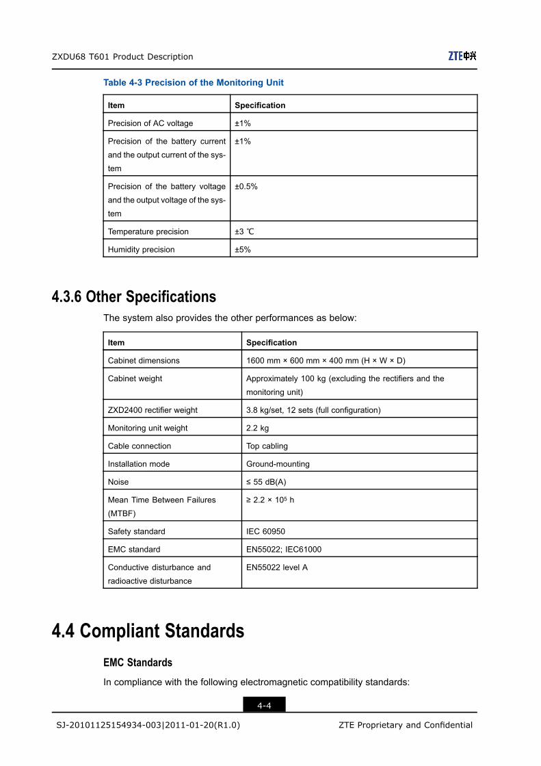
Table 4-3 Precision of the Monitoring Unit
Item Specification
Precision of AC voltage ±1%
Precision of the battery current
and the output current of the sys-
tem
±1%
Precision of the battery voltage
and the output voltage of the sys-
tem
±0.5%
Temperature precision ±3 ℃
Humidity precision ±5%
4.3.6 Other SpecificationsThe system also provides the other performances as below:
Item Specification
Cabinet dimensions 1600 mm × 600 mm × 400 mm (H × W × D)
Cabinet weight Approximately 100 kg (excluding the rectifiers and the
monitoring unit)
ZXD2400 rectifier weight 3.8 kg/set, 12 sets (full configuration)
Monitoring unit weight 2.2 kg
Cable connection Top cabling
Installation mode Ground-mounting
Noise ≤ 55 dB(A)
Mean Time Between Failures
(MTBF)
≥ 2.2 × 10⁵ h
Safety standard IEC 60950
EMC standard EN55022; IEC61000
Conductive disturbance and
radioactive disturbance
EN55022 level A
4.4 Compliant StandardsEMC Standards
In compliance with the following electromagnetic compatibility standards:
4-4
SJ-20101125154934-003|2011-01-20(R1.0) ZTE Proprietary and Confidential
Chapter 4 Characteristics and Specifications
l EN55022l IEC61000-3-3; IEC61000-3-2; IEC61000-4-2;IEC61000-4-3 IEC61000-4-4;
IEC61000-4-6; IEC61000-4-8; IEC61000-4-11
Safety Standards
In compliance with the safety standard: UL/IEC/EN 60950-2005
Other Standards
Also in compliance with the following standards:
l The RoHS directive (2002/95/EC) of the European Union (RoHS = Restriction ofHazardous Substances)
l This device complies with Part 15 of the FCC Rules. Operation is subject to thefollowing two conditions: (1) this device may not cause harmful interference, and (2)this device must accept any interference received, including interference that maycause undesired operation.
4-5
SJ-20101125154934-003|2011-01-20(R1.0) ZTE Proprietary and Confidential
ZXDU68 T601 Product Description
This page intentionally left blank.
4-6
SJ-20101125154934-003|2011-01-20(R1.0) ZTE Proprietary and Confidential
Appendix AMonitoring SoftwareTable of Contents
� Menu Hierarchy ...................................................................................................... A-1
� System Parameter List ........................................................................................... A-2
� Battery Parameter List ............................................................................................ A-3
� Alarm List ............................................................................................................... A-4
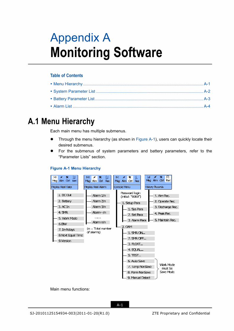
A.1 Menu HierarchyEach main menu has multiple submenus.
l Through the menu hierarchy (as shown in Figure A-1), users can quickly locate theirdesired submenus.
l For the submenus of system parameters and battery parameters, refer to the“Parameter Lists” section.
Figure A-1 Menu Hierarchy
Main menu functions:
A-1
SJ-20101125154934-003|2011-01-20(R1.0) ZTE Proprietary and Confidential
ZXDU68 T601 Product Description
l Msg: Displaying real-time data, used to query the real-time running status of thesystem.
l Alm: Displaying real-time alarms, used to query the real-time alarm information of thesystem.
l Ctrl: Operation console, used to modify system parameters and control systemrunning.
l Rec: Displaying history records, used to query the historical running status of thesystem.
Note:
When the monitoring unit is in the “screen saver” status, users can press Ent or Esc toenter the main menu interface.
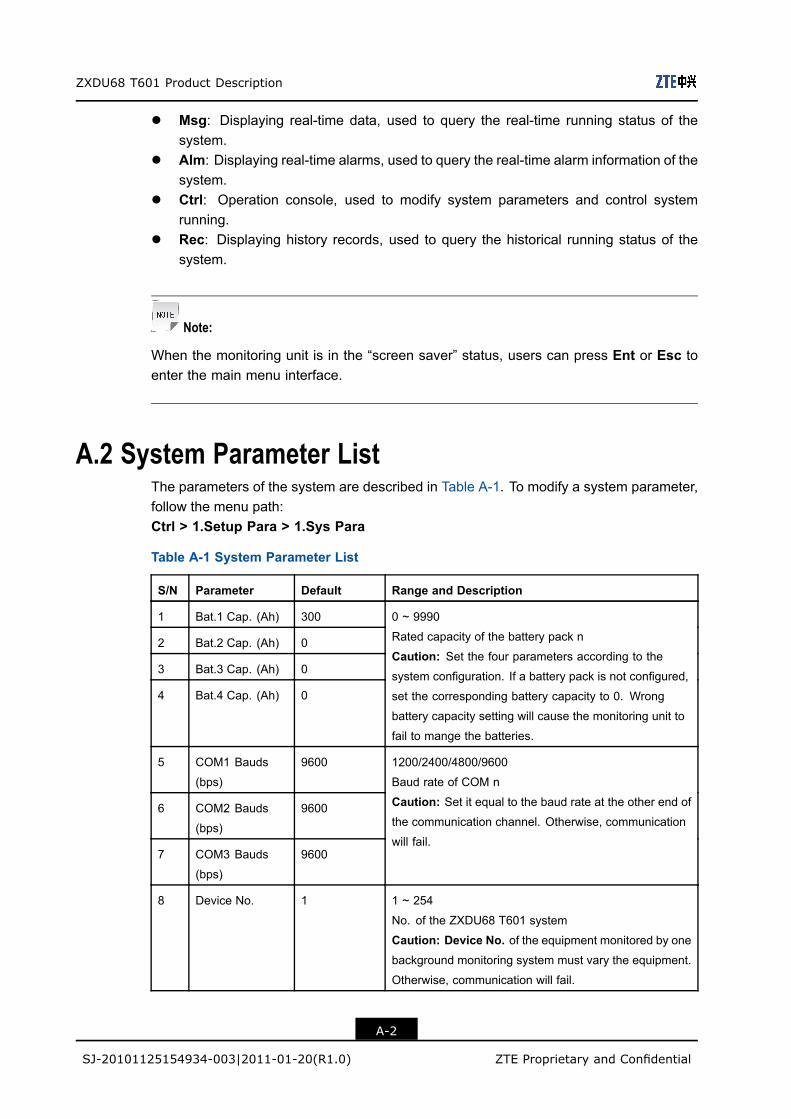
A.2 System Parameter ListThe parameters of the system are described in Table A-1. To modify a system parameter,follow the menu path:Ctrl > 1.Setup Para > 1.Sys Para
Table A-1 System Parameter List
S/N Parameter Default Range and Description
1 Bat.1 Cap. (Ah) 300
2 Bat.2 Cap. (Ah) 0
3 Bat.3 Cap. (Ah) 0
4 Bat.4 Cap. (Ah) 0
0 ~ 9990
Rated capacity of the battery pack n
Caution: Set the four parameters according to the
system configuration. If a battery pack is not configured,
set the corresponding battery capacity to 0. Wrong
battery capacity setting will cause the monitoring unit to
fail to mange the batteries.
5 COM1 Bauds
(bps)
9600
6 COM2 Bauds
(bps)
9600
7 COM3 Bauds
(bps)
9600
1200/2400/4800/9600
Baud rate of COM n
Caution: Set it equal to the baud rate at the other end ofthe communication channel. Otherwise, communication
will fail.
8 Device No. 1 1 ~ 254
No. of the ZXDU68 T601 system
Caution: Device No. of the equipment monitored by onebackground monitoring system must vary the equipment.
Otherwise, communication will fail.
A-2
SJ-20101125154934-003|2011-01-20(R1.0) ZTE Proprietary and Confidential

Appendix A Monitoring Software
S/N Parameter Default Range and Description
9 Password 0000 0000 ~ 9999
Password to access Ctrl menu
10 Language English Chinese/English
Language displayed on the LCD
11 Buzz Switch On On/Off
To enable or disable the buzzer to give a sound in case
of an alarm
12 AuxSwitch Set No Yes/No
To set whether an AC auxiliary switch is configured or not
13 Auto Alarm Enable Enable/Disable
To enable/disable the monitoring unit of ZXDU68 T601
to report a major alarm automatically to the background
monitoring system
14 SMR Pulled Alm Enable Enable/Disable
To enable/disable an alarm with an SMR (rectifier) pulled
out
15 Number of REB 0 0/1
To set the number of rectifier expansion boards (REBs)
16 Current Date – 1970-01-01 ~ 2099-12-31
Set it to local date
17 Current Time – 00:00:00 ~ 23:59:59
Set it to local time
A.3 Battery Parameter ListThe parameters involving the batteries are described in Table A-2. To modify a batteryparameter, follow the menu path:Ctrl > 1.Setup Para > 2.Bat Para
Table A-2 Battery Parameter List
S/N Parameter Default Range and Description
1 Work Mode Save
Mode
Safe Mode/Save Mode/Free Mode
System operation mode
2 Float Vol. (V) 53.5 42.0 ~ 58.0
System output voltage in floating charge mode
l Float Vol. ≤ Equal Vol.l Float Vol. ≥ BatVol Min. + 1 V
A-3
SJ-20101125154934-003|2011-01-20(R1.0) ZTE Proprietary and Confidential
ZXDU68 T601 Product Description
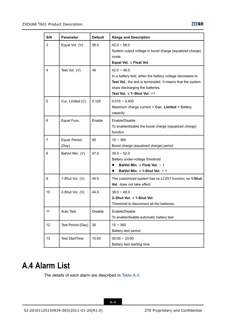
S/N Parameter Default Range and Description
3 Equal Vol. (V) 56.4 42.0 ~ 58.0
System output voltage in boost charge (equalized charge)
mode
Equal Vol. ≥ Float Vol.
4 Test Vol. (V) 46 42.0 ~ 48.0
In a battery test, when the battery voltage decreases to
Test Vol., the test is terminated. It means that the systemstops discharging the batteries.
Test Vol. ≥ 1–Shut Vol. +1
5 Cur. Limited (C) 0.125 0.010 ~ 0.400
Maximum charge current = Cur. Limited × Battery
capacity
6 Equal Func. Enable Enable/Disable
To enable/disable the boost charge (equalized charge)
function
7 Equal Period
(Day)
90 15 ~ 365
Boost charge (equalized charge) period
8 BatVol Min. (V) 47.0 39.0 ~ 52.0
Battery under-voltage threshold
l BatVol Min. ≤ Float Vol. – 1l BatVol Min. ≥ 1-Shut Vol. + 1
9 1-Shut Vol. (V) 45.0 The customized system has no LLVD1 function, so 1-ShutVol. does not take effect.
10 2-Shut Vol. (V) 44.0 38.0 ~ 49.0
2–Shut Vol. ≤ 1-Shut Vol.Threshold to disconnect all the batteries.
11 Auto Test Disable Enable/Disable
To enable/disable automatic battery test
12 Test Period (Day) 30 15 ~ 365
Battery test period
13 Test StartTime 10:00 00:00 ~ 23:00
Battery test starting time
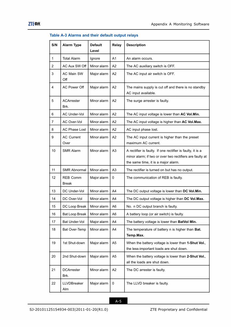
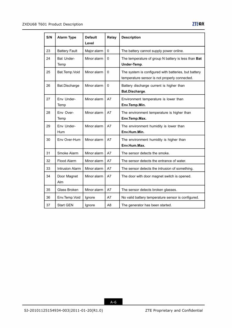
A.4 Alarm ListThe details of each alarm are described in Table A-3.
A-4
SJ-20101125154934-003|2011-01-20(R1.0) ZTE Proprietary and Confidential
Appendix A Monitoring Software
Table A-3 Alarms and their default output relays
S/N Alarm Type DefaultLevel
Relay Description
1 Total Alarm Ignore A1 An alarm occurs.
2 AC Aux SW Off Minor alarm A2 The AC auxiliary switch is OFF.
3 AC Main SW
Off
Major alarm A2 The AC input air switch is OFF.
4 AC Power Off Major alarm A2 The mains supply is cut off and there is no standby
AC input available.
5 ACArrester
Brk.
Minor alarm A2 The surge arrester is faulty.
6 AC Under-Vol Minor alarm A2 The AC input voltage is lower than AC Vol.Min.
7 AC Over-Vol Minor alarm A2 The AC input voltage is higher than AC Vol.Max.
8 AC Phase Lost Minor alarm A2 AC input phase lost.
9 AC Current
Over
Minor alarm A2 The AC input current is higher than the preset
maximum AC current.
10 SMR Alarm Minor alarm A3 A rectifier is faulty. If one rectifier is faulty, it is a
minor alarm; if two or over two rectifiers are faulty at
the same time, it is a major alarm.
11 SMR Abnormal Minor alarm A3 The rectifier is turned on but has no output.
12 REB Comm
Break
Major alarm 0 The communication of REB is faulty.
13 DC Under-Vol Minor alarm A4 The DC output voltage is lower than DC Vol.Min.
14 DC Over-Vol Minor alarm A4 The DC output voltage is higher than DC Vol.Max.
15 DC Loop Break Minor alarm A6 No. n DC output branch is faulty.
16 Bat Loop Break Minor alarm A6 A battery loop (or air switch) is faulty.
17 Bat Under-Vol Major alarm A4 The battery voltage is lower than BatVol Min.
18 Bat Over-Temp Minor alarm A4 The temperature of battery n is higher than Bat.Temp.Max.
19 1st Shut-down Major alarm A5 When the battery voltage is lower than 1-Shut Vol.,the less-important loads are shut down.
20 2nd Shut-down Major alarm A5 When the battery voltage is lower than 2-Shut Vol.,all the loads are shut down.
21 DCArrester
Brk.
Minor alarm A2 The DC arrester is faulty.
22 LLVDBreaker
Alm
Major alarm 0 The LLVD breaker is faulty.
A-5
SJ-20101125154934-003|2011-01-20(R1.0) ZTE Proprietary and Confidential
ZXDU68 T601 Product Description
S/N Alarm Type DefaultLevel
Relay Description
23 Battery Fault Major alarm 0 The battery cannot supply power online.
24 Bat Under-
Temp
Minor alarm 0 The temperature of group N battery is less than BatUnder-Temp.
25 Bat.Temp.Void Minor alarm 0 The system is configured with batteries, but battery
temperature sensor is not properly connected.
26 Bat.Discharge Minor alarm 0 Battery discharge current is higher than
Bat.Discharge.
27 Env Under-
Temp
Minor alarm A7 Environment temperature is lower than
Env.Temp.Min.
28 Env Over-
Temp
Minor alarm A7 The environment temperature is higher than
Env.Temp.Max.
29 Env Under-
Hum
Minor alarm A7 The environment humidity is lower than
Env.Hum.Min.
30 Env Over-Hum Minor alarm A7 The environment humidity is higher than
Env.Hum.Max.
31 Smoke Alarm Minor alarm A7 The sensor detects the smoke.
32 Flood Alarm Minor alarm A7 The sensor detects the entrance of water.
33 Intrusion Alarm Minor alarm A7 The sensor detects the intrusion of something.
34 Door Magnet
Alm
Minor alarm A7 The door with door magnet switch is opened.
35 Glass Broken Minor alarm A7 The sensor detects broken glasses.
36 Env.Temp.Void Ignore A7 No valid battery temperature sensor is configured.
37 Start GEN Ignore A8 The generator has been started.
A-6
SJ-20101125154934-003|2011-01-20(R1.0) ZTE Proprietary and Confidential
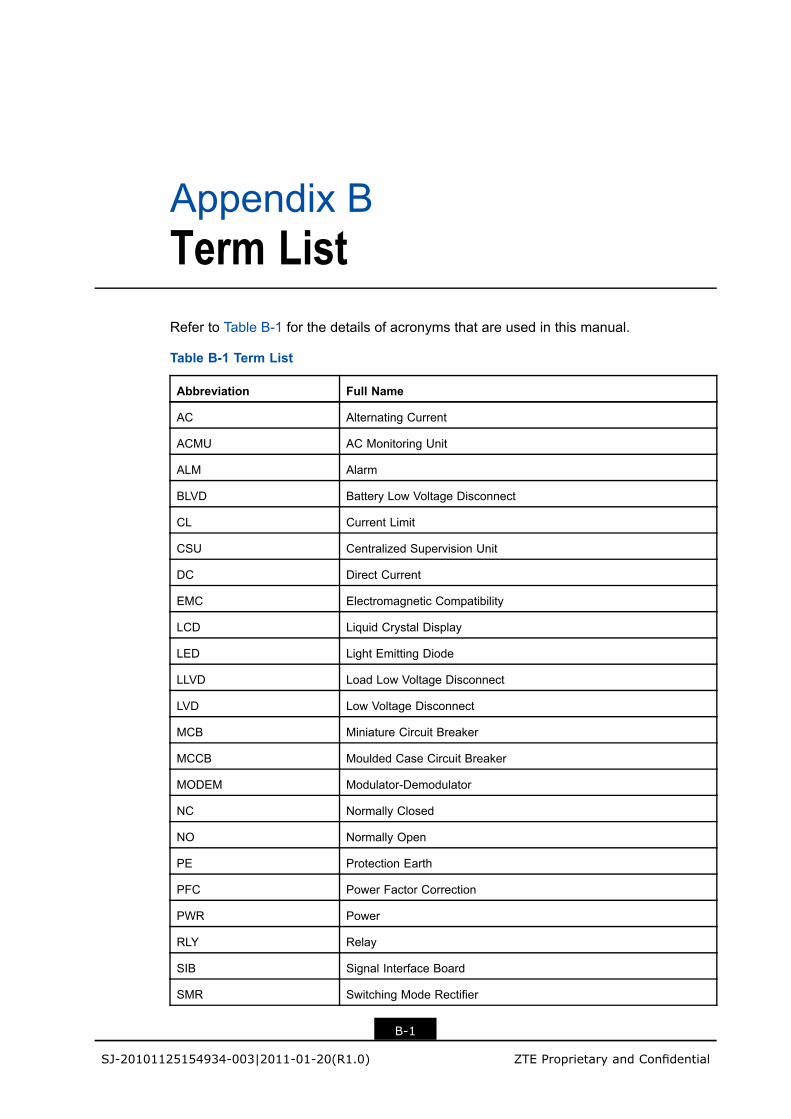
Appendix BTerm ListRefer to Table B-1 for the details of acronyms that are used in this manual.
Table B-1 Term List
Abbreviation Full Name
AC Alternating Current
ACMU AC Monitoring Unit
ALM Alarm
BLVD Battery Low Voltage Disconnect
CL Current Limit
CSU Centralized Supervision Unit
DC Direct Current
EMC Electromagnetic Compatibility
LCD Liquid Crystal Display
LED Light Emitting Diode
LLVD Load Low Voltage Disconnect
LVD Low Voltage Disconnect
MCB Miniature Circuit Breaker
MCCB Moulded Case Circuit Breaker
MODEM Modulator-Demodulator
NC Normally Closed
NO Normally Open
PE Protection Earth
PFC Power Factor Correction
PWR Power
RLY Relay
SIB Signal Interface Board
SMR Switching Mode Rectifier
B-1
SJ-20101125154934-003|2011-01-20(R1.0) ZTE Proprietary and Confidential

ZXDU68 T601 Product Description
This page intentionally left blank.
B-2
SJ-20101125154934-003|2011-01-20(R1.0) ZTE Proprietary and Confidential

Appendix CElectrical ConnectionDiagramFigure C-1 shows the electrical connection diagram of the ZXDU68 T601 (V4.1R03M01)DC power system.
C-1
SJ-20101125154934-003|2011-01-20(R1.0) ZTE Proprietary and Confidential

ZXDU68 T601 Product Description
Figure C-1 ZXDU68 T601 (V4.1R03M01) Electrical Connection Diagram
C-2
SJ-20101125154934-003|2011-01-20(R1.0) ZTE Proprietary and Confidential