Embed Size (px)
Citation preview

1
Comparison of Resistance Spot Welding and Refill Friction Stir Welding of Al 7075 Sheets
Jeff Hou
Z.Shen, Y. Chen, N. Zhou, M. Worswick, A. Gerlich, K. Chan, N. Scotchmer

2
Friction Stir Welding (FSW)
Background:
•“onion ring” structure in stir zone•Fine grains with good mechanical properties
Advancing SideRetreating Side
- Proven process for commercial welding of Al, Mg, Steel, and Ti alloys

3
Typical parameters: 500 - 3000 RPM rotation speed0.5 – 10 mm/s plunge rate1 – 5 s cycle times
Background
Conventional Friction stir spot welding

4
2004 Mazda RX-8
Conventional friction stir spot weld
http://www.mazda.com/mnl/200304/masatsu.html
- Significantly reduced energy consumption and capital
2005 Toyota Prius

Typical Friction Stir Spot Weld Microstructure
Stir Zone: Fine, equiaxed grains <10 µm
TMAZ: Thermo-mechanically affected zone: elongated grain structure
HAZ: Coarsening of precipitates resulting in reduced strength
Stir zone
TMAZ
HAZSheet interface
Weld microstructures consist of three main regions:

Typical Friction Stir Spot Weld Strengths
•In general, the fracture loads are directly proportional to the bonded area and the energy applied during weld formation.
•All of the energy serves to stir the material around the pin, which softens and forms the ring of bonded material between the sheets.
Su, P., Gerlich, A., North, T. H., and Bendzsak, G. J., SAE Technical Series: 2006-01-0971, 2006

7
Optical micrograph showing the microstructure of a refill friction stir spot weld made in Alclad 2024 alloy sheet
•Since the keyhole indentation is absent, a greater bonded area is produced, however the welding times are typically slightly higher.
Typical RFSS Weld Microstructure
Tier, M. D., dos Santos, J., Rosendo, T., Mazzaferro, J. A., and daSilva, A. A. M., SAE Technical Series: 2008-01-2287, 2008
Pure Al cladding layer

8
Typical RFSS Weld Strengths
•AA6181-T4 and 2024-T3 Alclad joints have been studied
•Generally higher for the same base material joints compared to conventional Friction stir spot welding, however properties increase with weld times ~ 3s
1.7 mm-thick AA6181-T4 aluminium alloy.
T. Rosendo et al. / Materials and Design 32 (2011) 1094–1100
9
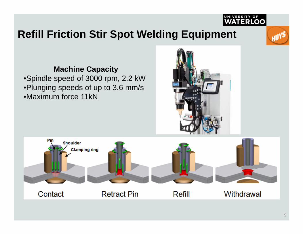
Refill Friction Stir Spot Welding Equipment
Machine Capacity•Spindle speed of 3000 rpm, 2.2 kW•Plunging speeds of up to 3.6 mm/s•Maximum force 11kN

10
Al 7075 Base MaterialThickness: 0.8 mm Size: 100mm x 25mm
• Tool rotation speed: 2100 RPM
• Plunge Depth: 0.85, 0.95 and 1.10 mm
• Welding Time: 3 and 3.5 sec
• Tool design: 6 mm pin, 9 mm shoulder OD
• AL-7075-T6: No pre-cleaning or surface treatment done
Welding Parameters Studied:

11
Refill Al 7075 Spot Weld Microstructures
Plunge depth / Welding Time
• Recrystallized volume increases with time and plunge depth
• Fine ‘hook’ region near periphery of weld caused by material flow

12
Refill Al 7075 Spot Weld Hook FeaturesPlunge depth / Welding Time
• Hooks are stress concentration regions that are generally detrimental to weld fracture load.
• The height of the hook increases with welding time and plunge depth
• However, the unbonded faying interface ends outside of the hook
faying interface
13
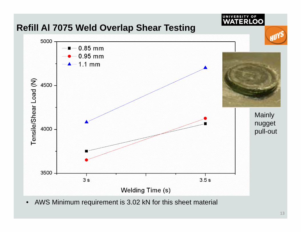
Refill Al 7075 Weld Overlap Shear Testing
• AWS Minimum requirement is 3.02 kN for this sheet material
Mainly nugget pull-out

14
Refill Al 7075 Spot Weld Microhardness•Microhardness distribution indicates full dissolution within stir zone followed by natural aging
•Hardness distributions are similar, however increasing plunge depth produces wider HAZ

15
RFSSW Summary
• Based on the AWS D8.1M:2007 standard, the tensile shear strength for 0.8 mm thick Al 7075 sheet (3.02 kN) can be readily achieved using Refill Friction Stir Spot Welding– Joint Strengths increase with time or plunge depth

• Fusion welding of Al‐7075 alloy is problematic.– Only preferred fusion welding => RSW
• Equipment Used– 144/180‐kVA MFDC Welder
• 60kA Current & 25kN Force
– Electrode• RWMA Female F Style Class II
– 2 Inch Radius
16
Resistance spot welding of Al7075-T6

17
RSW Parameters for Al 7075 – Initial Trial
No surface treatment were done to the Al‐7075‐T6 sheets
Weld Current [kA]
Weld Time
[Cycles]
Failure Mode Observations
5
10
N/A No Bond
10
IntSmall Bond
15Bond achieved with slight expulsion in
faying region
Plug
Electrode sticking and heavy expulsion in faying region
20
25
30 Worse electrode sticking, large faying region expulsion, bond

18
RSW Al 7075 Weld Tensile Shear Strength
1.24
1.70
2.632.34 2.28
1
1.5
2
2.5
3
3.5
4
4.5
5
10 15 20 25 30
Max Ten
sile Force (kN)
Welding Current (kA)
Max Force VS Weld Current @10cyc Single Pulse For Untreated Al 7075‐T6
Strength values significantly drop when using as‐received sheets (without etching)
AWS Minimum Tensile Force

19
Weld Current [kA]
Weld Time [Cycles]
Failure Mode Observations
30
5‐3.6‐5 All Plug
No nugget expulsion but increasing electrode sticking as current increases. 32
34
36 Similar to above with increasing sticking and faying gap. Weld nugget
surface cracking begin to show38
40 Full Electrode Stick (Bottom Electrode) and surface crack
RSW Parameters for Al 7075 – Second Trial
The Al coupons were ultrasonically cleaned in ethanol for 10 minutes and treated with solution of 1.2 mL HF, 67.5 mL HNO3 and 100 mL water for 40 seconds
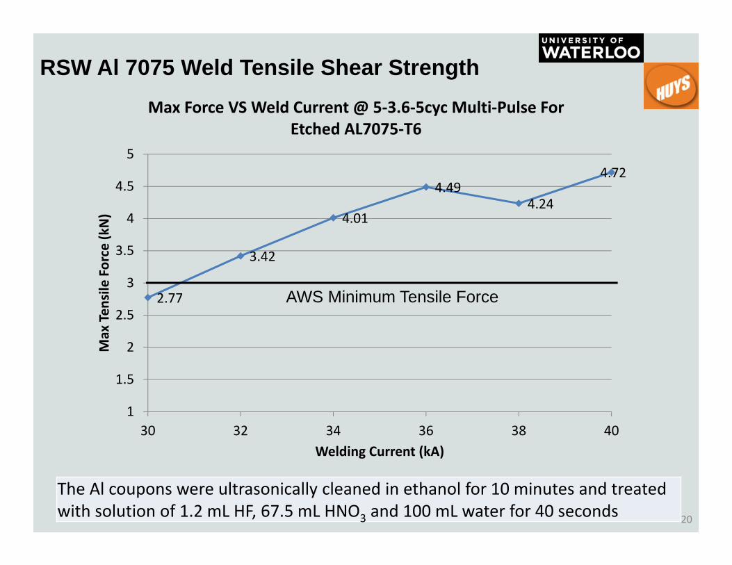
20
RSW Al 7075 Weld Tensile Shear Strength
The Al coupons were ultrasonically cleaned in ethanol for 10 minutes and treated with solution of 1.2 mL HF, 67.5 mL HNO3 and 100 mL water for 40 seconds
2.77
3.42
4.01
4.494.24
4.72
1
1.5
2
2.5
3
3.5
4
4.5
5
30 32 34 36 38 40
Max Ten
sile Force (kN)
Welding Current (kA)
Max Force VS Weld Current @ 5‐3.6‐5cyc Multi‐Pulse For Etched AL7075‐T6
AWS Minimum Tensile Force

21
RSW Al 7075 Weld MicrostructuresCross section when using welding current 30kA

22
RSW Al 7075 Weld MicrostructuresCross section when using welding current 40kA
Partially melted region at top of Nugget

23
RSW Al 7075 Weld Micro-hardness 30ka

24
RSW of Al7075-T6 Summary
• RSW of the Al 7075 material requires surface cleaning pre‐treatment to achieve minimum required TSS

25
Thank you
Acknowledgements:
Questions?