Embed Size (px)
Citation preview
Smart Sensors ZS-series
Manufacturing with a View to the Future.
Smart Sensors for High-precision
Displacement Measurements.
2D CMOS Laser Type
02
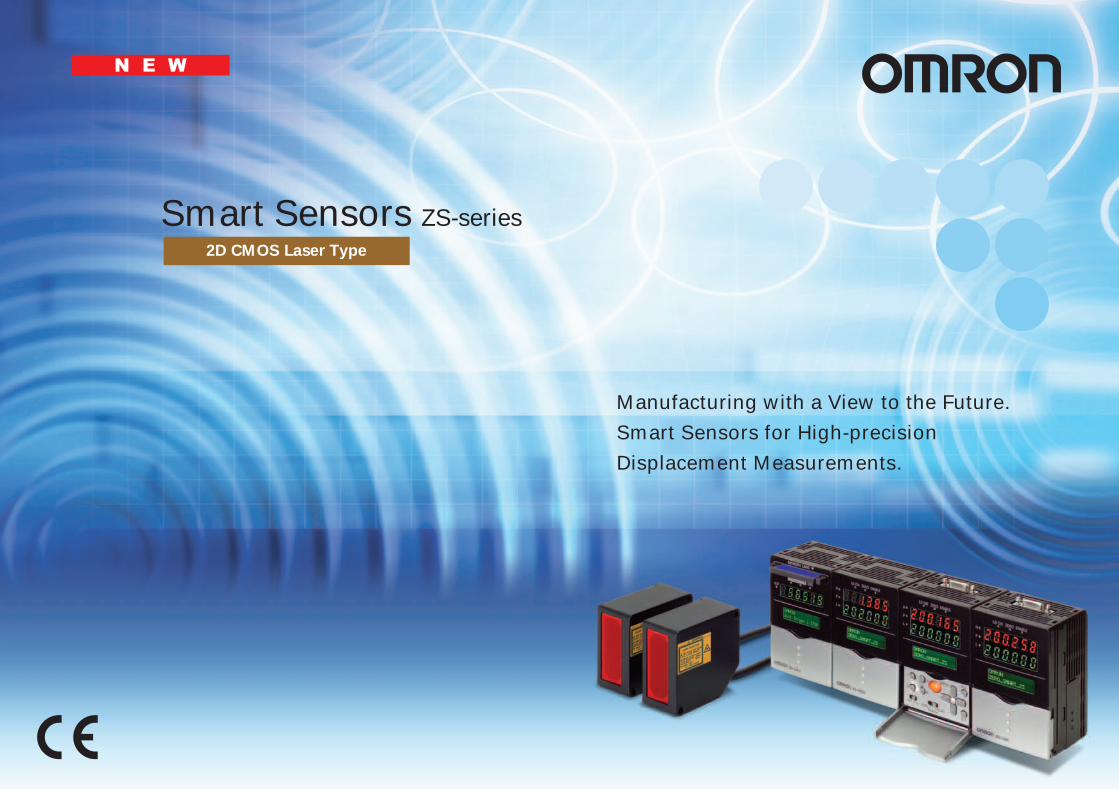
The Birth of a New-generation 2D Measurement Displacement SensorThe pursuit of 2D CMOS and other advanced functions will respond to application needs through optimum technology.
Our challenge to create the smallest and most lightweight compact sensor will enhance suitability to user applications.
And, our commitment to user operability will aid all sensing applications.

03
Platform
Evolution
INDEX
Concepts 02
Product Lineup 04
Sensor Heads 06
Sensor Controllers 10
Multi-Controllers 11
Data Storage Units 12
SmartMonitor Professional Software
14
Specifications 18
Dimensions 21
Beyond EvolutionA digital fusion of high-precision displacement measurement and image sensing. And even greater evolution for the Smart Sensors.
(Controller/Amplifier)Sensing Variations
ZS series
ZFV series
Information Handling
ZX series
Multi-Controller
SmartMonitor Zero
Data Storage Unit
Laser displacement: 2D CMOS
Camera: High-speed CCD
So that all those who pursue ultimate quality can easily acquire high-precision
sensing data, OMRON has changed its manufacturing focus to Zero.
The Zero Smart concept will make its way into a variety of fields.
04
Smart SensorAdvanced technology is carried.
More
P. 12
More
P. 11
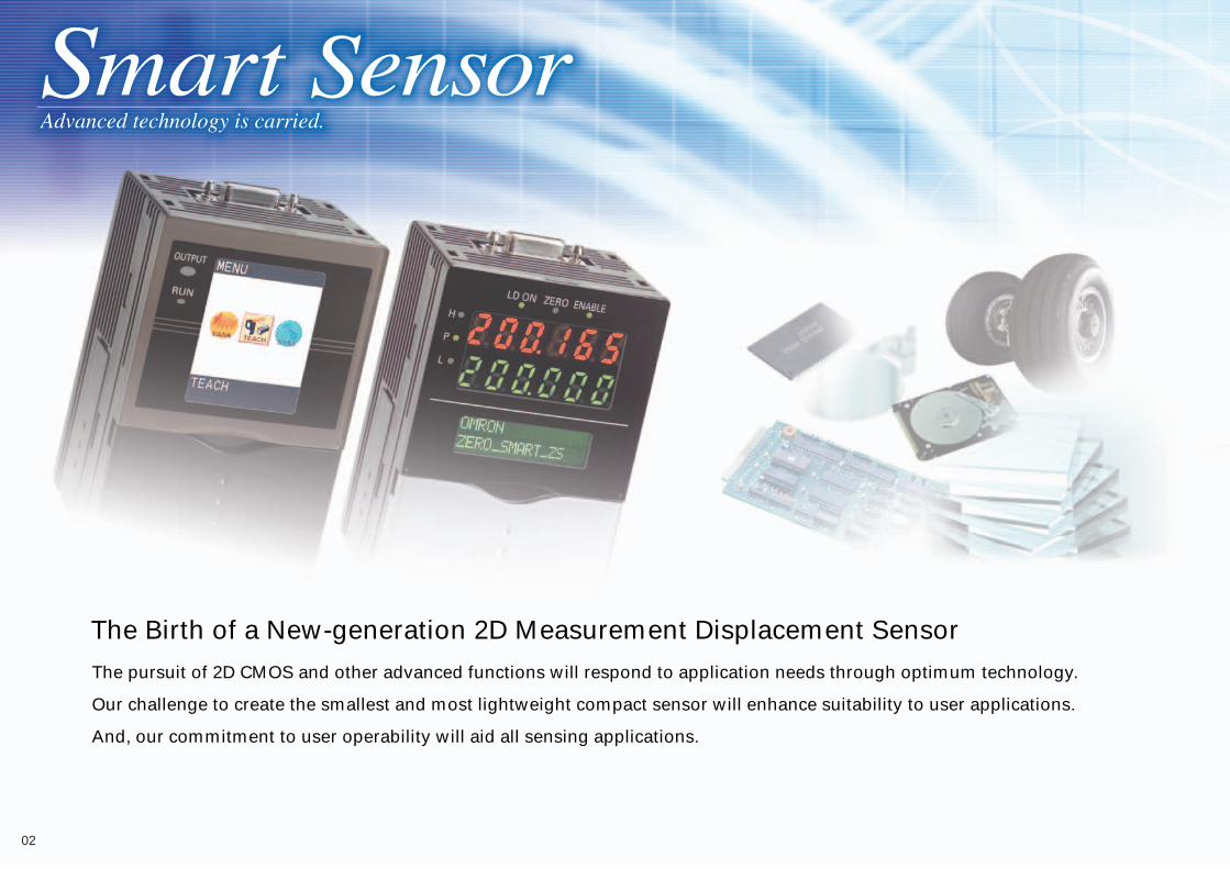
Enables onsite high-speed logging of data from Sensor Controllers or Multi-Controllers in external memory (compact flash card). Effective for building traceability systems, statistical process control (SPC), and much more.
Data Storage Unit ZS-DSU Enables full application of Sensor Controller information.
Multi-Controller ZC-MDC
Transfers data between multi-connected Sensor Controllers and performs high-speed multiprocessing.
Record
More
P. 14
The ZS-series SmartMonitor Professional Software now appears with expanded functionality.
SmartMonitor Professional ZS-SW11E
Meets a wide range of logging needs. High-speed simultaneous multichannel waveform graphs. Excel macro provided for simple analysis.
High-speed sampling rate: 150 µs Powerful support for logging data using various trigger functions. Connects to up to nine Sensor Controllers.
USB
Monitor Control
Advanced Functions Integrated
Easy Handling of High-grad
Ideal for ZS Series Data Logging!
05
More
P. 10
More
P. 06
ZS-LD200200
80
5040
20
Measuring center distance
Diffuse-reflective Models
Business Card Size
Regular-reflective Models
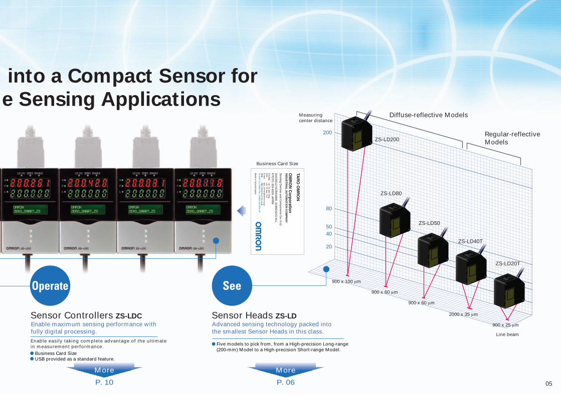
Business Card Size USB provided as a standard feature.
Five models to pick from, from a High-precision Long-range (200-mm) Model to a High-precision Short-range Model.
Enable maximum sensing performance with fully digital processing.
Sensor Controllers ZS-LDC Advanced sensing technology packed into the smallest Sensor Heads in this class.
Sensor Heads ZS-LD
Enable easily taking complete advantage of the ultimate in measurement performance.
Operate See 900 x 100 µm
900 x 60 µm
900 x 60 µm
2000 x 35 µm
900 x 25 µm
Line beam
ZS-LD50
ZS-LD80
ZS-LD40T
ZS-LD20T
into a Compact Sensor for
e Sensing Applications
06
Smart SensorAdvanced technology is carried.
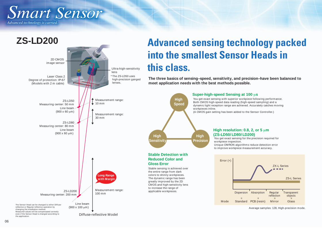
The three basics of sensing–speed, sensitivity, and precision–have been balanced to
meet application needs with the best methods possible.
Advanced sensing technology packed into the smallest Sensor Heads in this class.
Super-high-speed Sensing at 100 µsYou get exact sensing with superior workpiece following performance. Both CMOS high-speed data reading (high-speed sampling) and a dynamic light reception range are achieved. Accurately catches moving workpieces inline. (A CMOS gain setting has been added to the Sensor Controller.)
High resolution: 0.8, 2, or 5 µm
(ZS-LD50/LD80/LD200)You get exact sensing for the precision required for workpiece inspection. Unique OMRON algorithms reduce detection error to improve workpiece measurement accuracy.
Stable Detection with
Reduced Color and
Gloss ErrorStable sensing is achieved over the entire range from dark colors to shinny workpieces. The dynamic range has been greatly improved by the 2D CMOS and high-sensitivity lens to increase the range of applicable workpieces.
High
Precision
High
Sensitivity
High
Speed
*The ZS-LD50 uses high-precision ganged lenses.
ZS-LD200
Long Range
with Margin
2D CMOS image sensor
Laser Class 2Degree of protection: IP-67
(Models with 2 m cable)
Measurement range: 30 mm
Measurement range: 10 mm
Ultra-high-sensitivity lens
Measurement range: 100 mm
ZS-LD80Measuring center: 80 mm
ZS-LD200Measuring center: 200 mm
Line beam(900 x 60 µm)
ZS-LD50Measuring center: 50 mm
Line beam(900 x 60 µm)
Line beam(900 x 100 µm) Average samples: 128, High-precision mode.
Error (+)
Dispersion Absorption Regular reflection
Transparent objects
Mode Standard PCB (resin) Mirror Glass
ZX-L Series
= = = =
ZS-L Series
Diffuse-reflective Model
The Sensor Head can be changed to either Diffuse-reflective or Regular-reflective operation by changing the installation method.Measured values will be compensated correctly even if the Sensor Head is changed according to the application.

07
Although previously difficult with laser displacement sensors, detection is possible for PCBs and other workpieces that allow light to penetrate.The sensing algorithms implemented in the ZS-L enable stable detection of the surface of workpieces that allow light to penetrate.
PCB shapes can be measured without burs or waveform disruptions.
(Laser light penetrates.)
PCB surface
(Laser light does not penetrate.) Solder surface (land)
The sensing algorithm implemented in the ZS-L selects the right measurement level for the light-penetrating workpiece and accurately detects the position of the surface of the workpiece. Even if the reflected light distribution (line brightness) is distorted, stable measurementsare possible for positions near the surface (peak density positions) with little error.
Shift
(3) Edge
(1) Background suppression level
(2) Measurement level setting
Peak density Edge center position
100 %87.5 %
0 %
Peak density position = Edge center position (optimal calculation of (1) to (3))
Solder surface (land) PCB surface
Light is reflected normally from the solder surface.
Light is reflected by both the resin surface and particles in the resin.
Light intensity on the CMOS light reception surface
Light intensity on the CMOS light reception surface
Position of peak position (solder surface) correctly calculated.
Peak position is offset due to measurement error.
Affect of laser light penetration (affect on peak position calculation)
Close Far Close FarDisplacement Displacement
Directly Measure the Surfaces of PCBs
Connect directly to a computer using USB USB Connection
Response: 8 ms, High-precision mode, Black gain: 0, Red gain: 5 (max.)
1.75
1.73
1.71
1.69
1.67
1.65Penetration mode and gain settings used.
Gain setting: 515.000
10.000
5.000
0.000
–5.000
–10.000
–15.000
Hei
gh
t (m
m)
Hei
gh
t (m
m)
Number of data
0
10
20
30
40
Measuring the Shape of Black Resin Workpieces
Measuring the Shape PCB Surfaces
Typical Examples
The SmartMonitor Professional soft-ware provides a function that changes measurement levels (edge thresholds) to reduce error caused by light penetration, enabling handling many types of PCBs. The measurement level can be increased to adjust the measurement position for peak light reception.This function enables stable detection of PCB surfaces.
If there is insufficient light in High-speed Mode, gain settings (0 to 5) can be used to compensate.
When there is light penetration, the measurement level is set to 87.5%.
50 %
Amount of displacement
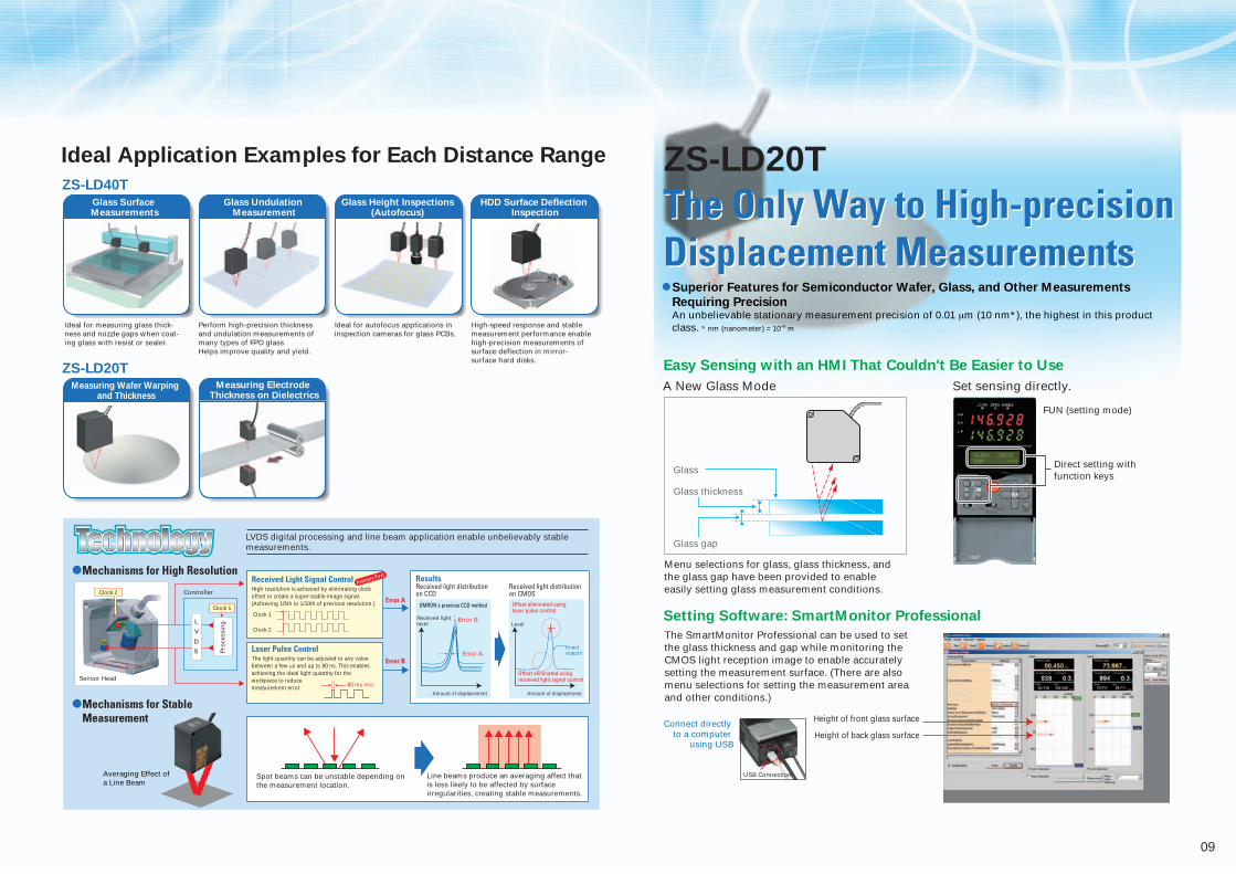
Ideal Application Examples for Each Distance Range
Setting Software: SmartMonitor Professional
FUN (setting mode)
ZS-LD50/LD80ZS-LD200/LD80
ZS-LD80/LD50
Stable Measurements for PCBs, Black Resin, and MetalStable Measurements for PCBs, Black Resin, and Metal
Just select High-precision Mode to stably measure black rubber.
Just select Penetration Mode to stably measure PCBs or black resin.
All you need to do is select the proper mode to achieve stable sensing of PCBs,
resins, black rubber, and other light-penetrating workpieces (which could not be
easily handled with previous reflective laser displacement meters.
Stable measurements are achieved by correctly recognizing the light reception distribution on the 2D CMOS.
Moving Workpieces (Black Rubber)
Measuring Door Attachment Offsets
Measuring Car BodiesMeasuring Tire Exteriors
Inspecting for Board Coplanarity
Inspecting coplanarity of pair boards or electronic components.
Ideal for measuring board height to control the height of dispensing nozzles for board adhesive coat-ings.
Ideal for inspecting lens holder feed operation for digital camera autofo-cus mechanisms. Helps prevent faults and increase quality.
DVD chassis flatness inspections, which were previously performed with contact displacement sensors, can be performed without contact.
Set sensing
directly.
Board Height InspectionDigital Camera
Tube Lens InspectionDVD Chassis
Flatness Inspections
Received light amount
Complete measurement data will be obtained at angles of up to 40 °.
Direct setting with function keys
Actual Light-penetrating Workpiece (PCBs)Display the light reception distribution (line brightness) on the CMOS during detection.

08
Smart SensorAdvanced technology is carried.
ZS-LD40T
The Only Way to Measure GlassThe Only Way to Measure Glass
Typical Examples (High-speed Mode, Response: 8 ms)
Moving Measurements
Measurements for Moving Glass
Glass, Response: 8 ms
0.25 µm
Measurements for Moving Mirrored
Surfaces (Wafers) Mirror, Response: 8 ms
0.25 µm
4[µm] [µm]
3210
–1–2–3–4
43210
–1–2–3–4
2D CMOS image sensor
Laser Class 2Degree of protection: IP-67
(Models with 2 m cable)
High-precision ganged lenses
ZS-LD40TMeasuring center: 40 mm
Resolution: 0.4 µm
Line beam(900 x 25 µm)
ZS-LD20TMeasuring center: 20mm
Resolution: 0.25 µm
Line beam(2000 x 35 µm)
Regular-reflective Models
Stably measure height and undulations in transparent, coated, or colored glass
on work tables. Menus let you easily set the measurement conditions for a wide range of glass to achieve stable measurements.
Stable detection at 40 mm with a line beam of 2 mm. A 2-mm line beam reduces in influence of the black and white pattern on granite work tables to achieve stable measurements.
Sensing Performance for Measurement Stability and High-speed Response Submicro resolution (0.25 µm) has been achieved for moving measurements (8 ms) of glass and mirror-surface wafers. (Actual Values)
Measurement range: 5 mm
Measurement range: 2 mm
09
Mechanisms for High Resolution Menu selections for glass, glass thickness, and the glass gap have been provided to enable easily setting glass measurement conditions.
Connect directly to a computer
using USB
Height of front glass surface
Height of back glass surface
Set sensing directly. A New Glass Mode
Easy Sensing with an HMI That Couldn't Be Easier to Use
Setting Software: SmartMonitor Professional
Glass
Glass thickness
Glass gap
FUN (setting mode)
Direct setting with function keys
The SmartMonitor Professional can be used to set the glass thickness and gap while monitoring the CMOS light reception image to enable accurately setting the measurement surface. (There are also menu selections for setting the measurement area and other conditions.)
The Only Way to High-precision Displacement MeasurementsThe Only Way to High-precision Displacement Measurements
ZS-LD20T
USB Connection
Received Light Signal Control Results
Error A
Error B
Pro
cess
ing
Sensor Head
Controller
Spot beams can be unstable depending on the measurement location.
Received light level
Amount of displacement
Level
Exact match!
Amount of displacement
Error A
Error B
Offset eliminated using received light signal control.
Offset eliminated using laser pulse control. Clock 1
Clock 2
Clock 1
Clock 2
Ideal for measuring glass thick-ness and nozzle gaps when coat-ing glass with resist or sealer.
Perform high-precision thickness and undulation measurements of many types of FPD glass.Helps improve quality and yield.
Ideal for autofocus applications in inspection cameras for glass PCBs.
High-speed response and stable measurement performance enable high-precision measurements of surface deflection in mirror-surface hard disks.
High resolution is achieved by eliminating clock offset to create a super-stable image signal. (Achieving 1/5th to 1/10th of previous resolution.)
Laser Pulse ControlThe light quantity can be adjusted to any value between a few µs and up to 80 ns. This enables achieving the ideal light quantity for the workpiece to reduce measurement error.
ZS-LD40T
ZS-LD20T
Ideal Application Examples for Each Distance Range
Glass Surface Measurements
Measuring Wafer Warping and Thickness
Glass Undulation Measurement
Measuring Electrode Thickness on Dielectrics
Glass Height Inspections (Autofocus)
HDD Surface Deflection Inspection
LVDS digital processing and line beam application enable unbelievably stable measurements.
Mechanisms for Stable Measurement
Industry First
Line beams produce an averaging affect that is less likely to be affected by surface irregularities, creating stable measurements.
Superior Features for Semiconductor Wafer, Glass, and Other Measurements
Requiring PrecisionAn unbelievable stationary measurement precision of 0.01 µm (10 nm*), the highest in this product class. * nm (nanometer) = 10-9 m
Averaging Effect of a Line Beam
80 ms min.
OMRON's previous CCD method
L
V
D
S
Received light distribution on CMOS
Received light distribution on CCD

10
Sensor Controllers ZS-LDC
Smart SensorAdvanced technology is carried.
Easy Sensing with an HMI That Couldn't Be Easier to Use
Information at the Touch of a Button Set sensing directly.
Connect directly to a PC using USBMount to DIN Track or directly to
control panels.
In RUN (measurement) Mode, measured values and information are displayed using 2 rows of 8-segments LEDs.The large LED display improves visibility. Measurement information includes the threshold, current, resolution, and received light amount and is available with simple key operations. LCD screens can be customized to change the display of desired information to easier-to-understand terminology.
In FUN (setting) Mode, setting menus are displayed on the 2 rows of the LCD. The many display capabilities of the LCD provide easy-to-understand guidance for making settings. Function keys corresponds to displayed menu items, and measurement conditions and other settings can be made intuitively. You can also easily switch between Japanese and English displays. Communication with the operator is better than ever before.
USB 2.0 and RS-232C provided as standard
features. LVDS, a new-generation high-speed communications interface, is used between the Sensor Head and Controller, an industry first. If USB is used to connect to the computer, high-speed all-digital measurement data transfer is possible.
Enable maximum sensing performance with fully digital processing.A controller the size of a business card filled with OMRON's leading-edge digital technology.
Enable easily taking complete advantage of the ultimate in measurement performance.
FUN (setting mode)RUN (measurement mode)
Direct setting with function keys
Measured value displayed.
Threshold, current, resolution, brightness, etc.
Switch measurement information at the touch of a button.
Example of Display Customization
Threshold Current Resolution Brightness
Patent pending.
Patent pending.
USB Connection
MAIN:MEASURESUB :THRESH
MAIN:MEASURESUB :THRESH
MAIN:MEASURESUB :CURRENT
MAIN:MEASURESUB :RESOLU
LD POWER 80.0%SUB:BRIGHT
Panel Mounting Adapter (option, sold separately)
Device: OMRON #1
11
B D F
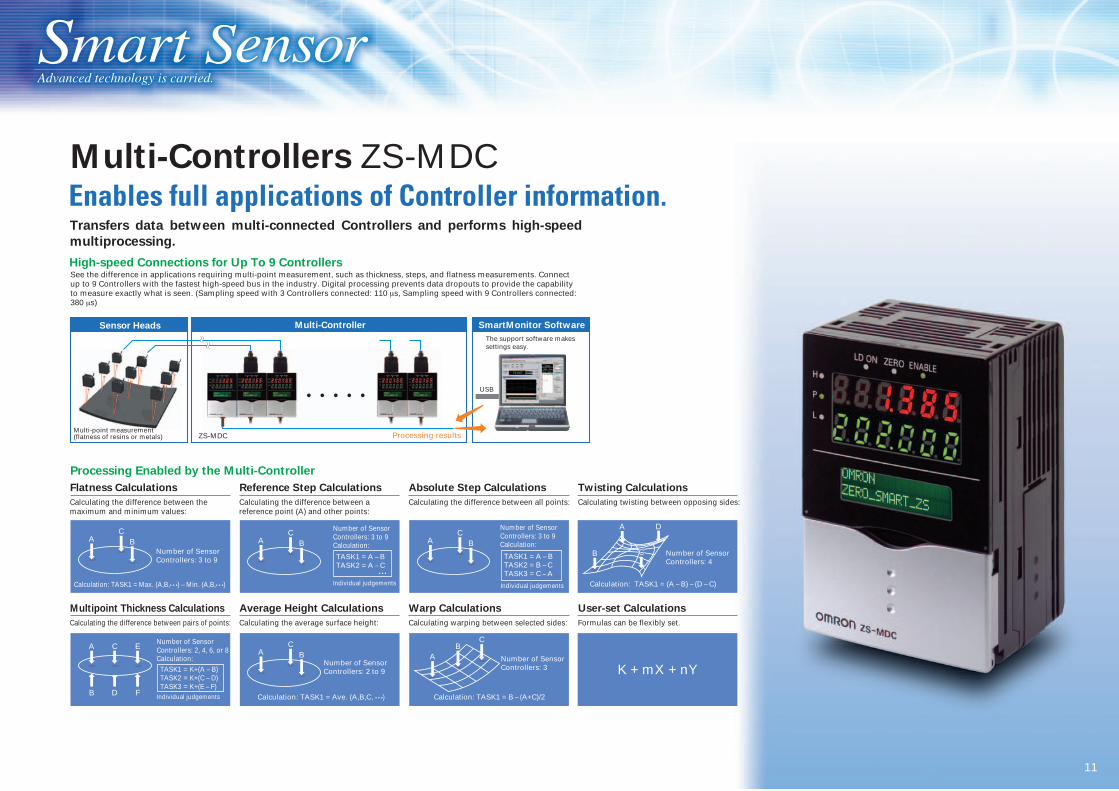
Multi-Controllers ZS-MDC
Smart SensorAdvanced technology is carried.
Flatness Calculations
A
Calculating the difference between the maximum and minimum values:
Reference Step Calculations
Calculating the difference between a reference point (A) and other points:
Absolute Step Calculations
Calculating the difference between all points:
Twisting Calculations
Calculating twisting between opposing sides:
High-speed Connections for Up To 9 ControllersSee the difference in applications requiring multi-point measurement, such as thickness, steps, and flatness measurements. Connect up to 9 Controllers with the fastest high-speed bus in the industry. Digital processing prevents data dropouts to provide the capability to measure exactly what is seen. (Sampling speed with 3 Controllers connected: 110 µs, Sampling speed with 9 Controllers connected: 380 µs)
Processing Enabled by the Multi-Controller
Number of Sensor Controllers: 3 to 9
Calculation: TASK1 = Max. (A,B,• • •) – Min. (A,B,• • •)
CB A
Number of Sensor Controllers: 3 to 9
Individual judgements
Individual judgements
Calculation:
TASK1 = A – BTASK2 = A – C
CB
A C EA
Number of Sensor Controllers: 2 to 9
Calculation: TASK1 = Ave. (A,B,C, • • •)
CB Number of Sensor
Controllers: 3
Calculation: TASK1 = B – (A+C)/2
Multipoint Thickness Calculations
Calculating the difference between pairs of points:
Average Height Calculations
Calculating the average surface height:
Warp Calculations
Calculating warping between selected sides:
User-set Calculations
Formulas can be flexibly set.
Number of Sensor Controllers: 4
Calculation: TASK1 = (A – B) – (D – C)
• • •
AC
B
Number of Sensor Controllers: 2, 4, 6, or 8
ZS-MDC
Calculation: TASK1 = K+(A – B)TASK2 = K+(C – D)TASK3 = K+(E – F)
A
CB
A D
B
K + mX + nY
The support software makes settings easy.
Multi-point measurement (flatness of resins or metals)
Enables full applications of Controller information. Transfers data between multi-connected Controllers and performs high-speed
multiprocessing.
Processing results
SmartMonitor SoftwareMulti-ControllerSensor Heads
USB
TASK1 = A – BTASK2 = B – CTASK3 = C – A
Number of Sensor Controllers: 3 to 9Calculation:
Individual judgements
CC
12
Smart SensorAdvanced technology is carried.
Number of connectable Controllers
Configuration
Performance
Functions
Software (included)
Applicable Controllers
Data resolution
Sampling rate
Trigger functions
Other functions
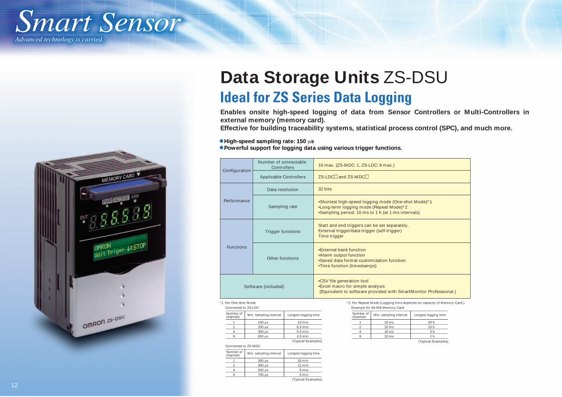
10 max. (ZS-MDC: 1, ZS-LDC: 9 max.)
ZS-LDC and ZS-MDC
32 bits
•Shortest high-speed logging mode (One-shot Mode)*1•Long-term logging mode (Repeat Mode)*2•Sampling period: 10 ms to 1 h (at 1-ms intervals)
Start and end triggers can be set separately. External trigger/data trigger (self-trigger) Time trigger
•External bank function•Alarm output function•Saved data format customization function •Time function (timestamps)
•CSV file generation tool•Excel macro for simple analysis (Equivalent to software provided with SmartMonitor Professional.)
Enables onsite high-speed logging of data from Sensor Controllers or Multi-Controllers in
external memory (memory card).
Effective for building traceability systems, statistical process control (SPC), and much more.
*1: For One-shot Mode
(Typical Examples)
*2: For Repeat Mode (Logging time depends on capacity of Memory Card.) Connected to ZS-LDC Example for 64-MB Memory Card
Number of channels Min. sampling interval Longest logging time
1249
150 µs200 µs350 µs650 µs
10 min6.5 min5.5 min4.5 min
Number of channels Min. sampling interval Longest logging time
1249
10 ms10 ms10 ms10 ms
20 h10 h5 h2 h
(Typical Examples)
(Typical Examples)Connected to ZS-MDC
Number of channels Min. sampling interval Longest logging time
1249
350 µs400 µs500 µs700 µs
20 min12 min8 min5 min
Data Storage Units ZS-DSU Ideal for ZS Series Data Logging
High-speed sampling rate: 150 µs
Powerful support for logging data using various trigger functions.

13
This is all that's required for a simple inspection/data storage system. (Supports separating the inspection process.)
Heavy system for each process
Bank data
A Wealth of Functions for Essentially Any Application
Select
Data can be saved at high speed during testing and system verification. That's just one example of the type of need that can be met by high-speed logging.
Controller setting information can be saved in the ZS-DSU as bank data. Bank data can then be transferred to switch banks for the ZS-LDC/MDC.
Data during operation can be massive. Save only the required data by using any of many trigger functions. The trigger functions can be effectively used in building traceability systems.
External input triggers
Self-triggers based on measured values (save only
specific ranges of data)
Time triggers
Judgement value triggers
Pre-triggers (saves data from before the trigger)
"Simple" Configuration for
Inspection Process Data can be logged at high speed.
Select between Short-term High-speed Logging
Mode and Long-term Logging Mode.
ZS-LDCZS-DSU
Test and Install
Simple Changeovers between
Inspection Processes
Save Only the Required Data
Many Save Triggers
Operate
Measurement and setting data saved in Memory Cards can be easily uploaded to a computer. This enable easily backing up inspection process data.
Simple Backup for Inspection Process
Maintain
The analysis tool that is provided can be used to analyze logging data.
Easy Data Analysis
Selection Testing/Installation Operation Maintenance
Easier Error Value
DetectionAlarm Output Function
When data exceeds a set level, alarm outputs (high high and
low low outputs) can be output from the Controller
in addition to the high, pass, and low outputs.
1 2 3 4

14
Smart SensorAdvanced technology is carried.
Log measurement results at various times to leave judgement and inspection results. Meets a wide range of logging needs.
Excel macro provided for simple analysis.
High-speed simultaneous multichannel waveform graphs.
Multi-channel Waveform Displays Sensing (Light Brightness)
Logging Analysis
Recommended Operating Environment
SmartMonitor Professional
OS: Windows 2000 or XP
CPU: Pentium III, 850 MHz or higher (Recommended: 2 GHz or higher)
Memory: 128 MB or higher (Recommended: 256 MB or higher)
Available hard disk space: 50 MB or more
Display: 800 x 600 dots, High Color (16-bit) or higher
(Recommended: 1024 x 768 dots, True Color (32-bit) or higher)
If the recommended specifications are not used, data may be broken in the
middle or waveforms may not be displayed properly for logging, high-speed
graphs, and multi-channel waveforms.
SmartAnalyzer Macro Edition
This is a Microsoft Excel macro program; Microsoft Excel 2000 or higher is
required.
SmartMonitor Professional
ZS-SW11E
The ZS-series SmartMonitor Software enables changing setting from PC.
Data collected by logging can be processed with the Excel macro using filters, slope compensation, filter median transitions, differentiation, integration, and math functions and used to nominal judgements and other determinations.
In High-speed Mode, display waveforms at intervals as short as 2 ms.* In Multichannel Waveform Mode, display up to 9 waveforms simultaneously.*Data may be broken up depending on the computer environment. Use a computer that meets or exceeds the recommended environment specifications.
15
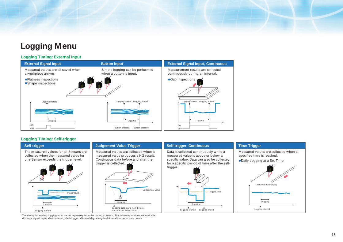
Logging Menu
Logging Timing: External Input
External Signal Input Button input External Signal Input, Continuous
*The timing for ending logging must be set separately from the timing to start it. The following options are available. •External signal input, •Button input, •Self-trigger, •Time of day, •Length of time, •Number of data points
Flatness inspectionsShape inspections
Logging started
Button pressed.
Logging Logging
Logging ended Logging started Logging ended
Button pressed.
Logging started
Logging
ON
OFFON
OFF
Trigger level Trigger level
Logging
Logging started Logging started Logging ended
Logging
Set time (hh:mm:ss)
Logging started
Judgement value
LoggingLogging
NG
Logging data starts from before the time the NG occurred.
Simple logging can be performed when a button is input.
Measured values are all saved when a workpiece arrives.
Logging Timing: Self-trigger
Self-trigger
The measured values for all Sensors are collected when the measured value for one Sensor exceeds the trigger level.
Judgement Value Trigger
Measured values are collected when a measured value produces a NG result. Continuous data before and after the trigger is collected.
Self-trigger, Continuous
Data is collected continuously while a measured value is above or below a specific value. Data can also be collected for a specific period of time after the self-trigger.
Time Trigger
Measured values are collected when a specified time is reached.
Gap inspections
Measurement results are collected continuously during an interval.
Daily Logging at a Set Time
16
Smart SensorAdvanced technology is carried.
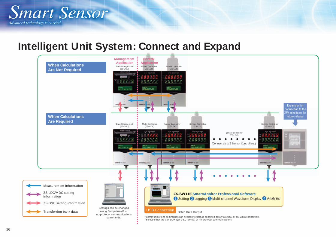
Setting AnalysisMulti-channel Waveform DisplayLogging
Batch Data Output
*Communications commands can be used to upload collected data via a USB or RS-232C connection. Select either the CompoWay/F (PLC format) or no-protocol communications.
When Calculations
Are Not Required
When Calculations
Are Required
ZS-SW11E SmartMonitor Professional Software
(Connect up to 9 Sensor Controllers.)
Management
Application
Control
Application
Data Storage Unit(ZS-DSU)
ZS-LDC/MDC setting information
Transferring bank data
Measurement information
ZS-DSU setting information1 2 3 4
USB Connection
Intelligent Unit System: Connect and Expand
Sensor Controller(ZS-LDC)
Sensor Controller(ZS-LDC)
Sensor Controller(ZS-LDC)
Sensor Controller(ZS-LDC)
Sensor Controller(ZS-LDC)
Sensor Controller(ZS-LDC)
Multi-Controller(ZS-MDC)
Data Storage Unit(ZS-DSU)
Expansion for connection to the ZFV scheduled for
future release.
Settings can be changed using CompoWay/F or
no-protocol communications commands.
17
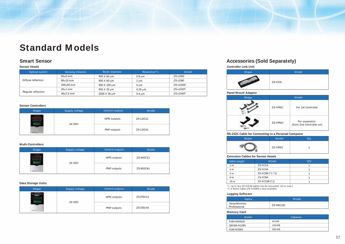
0.8 µm
2 µm
5 µm
0.25 µm
0.4 µm
Standard Models
Smart Sensor Accessories (Sold Separately)Sensor Heads
Sensor Controllers
Multi-Controllers
Data Storage Units
Controller Link Unit
Panel Mount Adapter
RS-232C Cable for Connecting to a Personal Computer
Extension Cables for Sensor Heads
Logging Software
Memory Card
ModelShape
Model
Model
Shape
Shape Qty
Qty
NameZS-DSU11
ZS-DSU41
24 VDC
24 VDC
NPN outputs
PNP outputs
NPN outputs
PNP outputs
ZS-MDC11
ZS-XCN
ZS-MDC41
24 VDC
NPN outputs
PNP outputs
ZS-LDC11
ZS-LDC41
ZS-XPM1 For 1st Controller
ZS-XRS2 1
1
1
1
1
1
ZS-SW11ESmartMonitor Professional
QtyModelCable length
ZS-XPM2 For expansion (from 2nd Controller on)
*1. Up to two ZS-XC B Cables can be connected. (22 m max.) *2. A Robot Cable (ZS-XC5BR) is also available.
Model Capacity
Model
F160-N64S(S)
QM300-N128S
F160-N256S
Optical system Sensing distance Beam diameter Resolution*1 Model
Shape Supply voltage Control outputs Model
Shape Supply voltage Control outputs Model
Shape Supply voltage Control outputs Model
ZS-LD50
ZS-LD80
ZS-LD200
ZS-LD20T
ZS-LD40T
Diffuse reflection
Regular reflection
50±5 mm
80±15 mm
200±50 mm
20±1 mm
40±2.5 mm
900 X 60 µm
900 X 60 µm
900 X 100 µm
900 X 25 µm
2000 X 35 µm
1 m
4 m
5 m
8 m
10 m
ZS-XC1A
ZS-XC4A
ZS-XC5B (*1 *2)
ZS-XC8A
ZS-XC10B (*1)
64 MB
128 MB
256 MB

18
Smart SensorAdvanced technology is carried.
Specifications
Sensor Heads
*1. Defined as 1/e2 (13.5 %) of the center optical intensity at the actual measurement center distance (effective value). The beam diameter is sometimes influenced by the ambient conditions of the workpiece, such as leaked light from the main beam.*2. This is the error in the measured value with respect to an ideal straight line. The standard workpiece is white aluminum ceramics in diffuse reflection mode and glass in the regular reflection mode of the ZS-LD20T/40T/50. Linearity may change according to the workpiece.*3. This is the peak-to-peak displacement conversion value in the displacement output at the measuring center distance in high-precision mode when the number of samples to average is set to 128 and the measuring mode is set to the high-resolution mode. The standard workpiece is white aluminum ceramics in diffuse reflection mode and glass in the regular reflection mode. *4. This is the value obtained at the measuring center distance when the Sensor and workpiece are fixed by an aluminum jig.*5. This value is obtained when the measuring mode is set to the high-speed mode.
Item Model ZS-LD20T ZS-LD40T ZS-LD50 ZS-LD80 ZS-LD200
Applicable Controllers ZS-LDC Series
Optical system
Measuring center distance
Measuring range
Light source
Beam diameter*1
Linearity*2
Resolution*3
Temperature characteristic*4
Sampling cycle*5
Indicators
NEAR indicator
FAR indicator
Operating ambient illumination
Ambient temperature
Degree of protection
Materials
Cable length
Weight
Accessories
Regular reflection
20 mm
±1 mm
Diffuse reflection
6.3 mm
±1 mm
Diffuse reflection
30 mm
±2 mm
Diffuse reflection
50 mm
±5 mm
Diffuse reflection
80 mm
±15 mm
Diffuse reflection
200 mm
±50 mm
Regular reflection
40 mm
±2.5 mm
Regular reflection
47 mm
±4 mm
Regular reflection
78 mm
±14 mm
Regular reflection
200 mm
±48 mm
900 X 25 µm 2000 X 35 µm 900 X 60 µm 900 X 60 µm 900 X 100 µm
Visible semiconductor laser (wavelength: 650 nm, 1 mW max., Class 2)
±0.1% F.S. ±0.25% F.S.
0.4 µm 0.8 µm 2 µm 5 µm0.25 µm
0.04 % F.S./°C 0.02 % F.S./°C 0.02 % F.S./°C 0.02 % F.S./°C0.01 % F.S./°C
110 µs
Lights near the measuring center distance, and nearer than the measuring center distance inside the measuring range. Flashes when the measurement target is outside of the measuring range or when the received light amount is insufficient.
Lights near the measuring center distance, and further than the measuring center distance inside the measuring range. Flashes when the measurement target is outside of the measuring range or when the received light amount is insufficient.
Illumination on received light surface: 3000 lx or less (incandescent light)
Operating: 0 to 50°C, Storage: –15 to 60°C (with no icing or condensation)
Cable length 0.5 m: IP66, cable length 2 m: IP67
Case: Aluminum die-cast, Front cover: Glass
0.5 m, 2 m
Approx. 350 g
Laser labels (1 each for JIS/EN, 3 for FDA), Ferrite cores (2), Insure Locks (2), Instruction Sheet
Ambient humidity Operating and storage: 35% to 85% (with no condensation)

19
Sensor Controllers
External interface
Serial I/O
Connection method
Laser OFF, ZERO reset timing, RESET
Segment display
Setting inputs
Power supply voltage
Current consumption
Ambient temperature
Ambient humidity
Materials
Weight
Accessories
Functions
Status indicators
Ferrite core (1), Instruction Sheet
Sensor Controllers
Model
No. of samples to average
Number of mounted Sensors
Inputs
Outputs
USB 2.0
RS-232C
Judgement outputs
Linear output
Main display
Sub-display
Setting keys
Slide switch
LCD
ZS-LDC41ZS-LDC11
1, 2, 4, 8, 16, 32, 64, 128, 256, 512, 1024, 2048, or 4096
1 per Sensor Controller
1 port, Full Speed (12 Mbps), MINI-B
1 port, 115,200 bps max.
Selectable from 2 types of output, voltage or current (selected by slide switch on base).
3 outputs: HIGH, PASS, and LOWNPN open-collector, 30 VDC, 50 mA max., residual voltage: 1.2 V max.
3 outputs: HIGH, PASS, and LOWPNP open-collector, 50 mA max., residual voltage: 1.2 V max.
Voltage output: –10 to 10 V, output impedance: 40 ΩCurrent output: 4 to 20 mA, maximum load resistance: 300 Ω
Serial I/O: connector, Other: pre-wired (standard cable length: 2 m)
ON: Short-circuited with 0V terminal or 1.5 V or lessOFF: Open (leakage current: 0.1 mA max.)
ON: Short-circuited to supply voltage or within 1.5 V of supply voltage OFF: Open (leakage current: 0.1 mA max.)
Display: Measured value, threshold value, voltage/current, received light amount, and resolutionSensing: Mode, gain, measurement object, head installationFilter: Smooth, average, and differentiationOutputs: Scaling, various hold values, and zero resetI/O settings: Linear (focus/correction), judgements (hysteresis and timer), non-measurement, and bank (switching and clear)System: Save, initialization, measurement information display, communications settings, key lock, language, and data load
HIGH (orange), PASS (green), LOW (orange), LDON (green), ZERO (orange), and ENABLE (green)
8-segment red LED, 6 digits
8-segment green LED, 6 digits
16 digits x 2 rows, Color of characters: green, Resolution per character: 5 x 8 pixel matrix
Direction keys (UP, DOWN, LEFT, and RIGHT), SET key, ESC key, MENU key, and function keys (1 to 4)
Threshold switch (2 states: High/Low), mode switch (3 states: FUN, TEACH, and RUN)
21.6 V to 26.4 VDC (including ripple)
0.5 A max. (when Sensor Head is connected)
Operating: 0 to 50°C, Storage: –15 to 60°C (with no icing or condensation)
Operating and storage: 35% to 85% (with no condensation)
Case: Polycarbonate (PC)
Approx. 280 g (excluding packing materials and accessories)
20
Smart SensorAdvanced technology is carried.
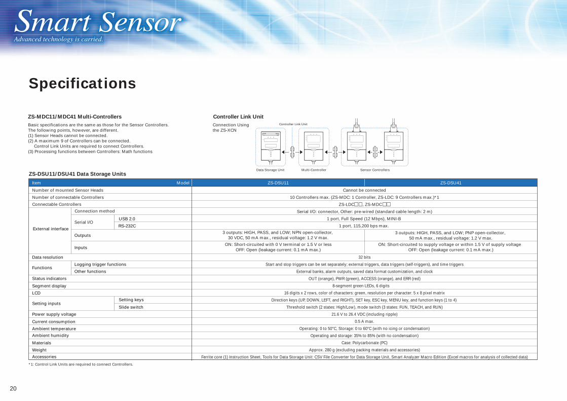
ZS-MDC11/MDC41 Multi-Controllers Controller Link Unit
ZS-DSU11/DSU41 Data Storage Units
Item Model ZS-DSU11 ZS-DSU41
Number of mounted Sensor Heads
Number of connectable Controllers
Serial I/O
32 bits
Start and stop triggers can be set separately; external triggers, data triggers (self-triggers), and time triggers
External banks, alarm outputs, saved data format customization, and clock
OUT (orange), PWR (green), ACCESS (orange), and ERR (red)
8-segment green LEDs, 6 digits
16 digits x 2 rows, color of characters: green, resolution per character: 5 x 8 pixel matrix
Direction keys (UP, DOWN, LEFT, and RIGHT), SET key, ESC key, MENU key, and function keys (1 to 4)
Threshold switch (2 states: High/Low), mode switch (3 states: FUN, TEACH, and RUN)
21.6 V to 26.4 VDC (including ripple)
0.5 A max.
Operating: 0 to 50°C, Storage: 0 to 60°C (with no icing or condensation)
Operating and storage: 35% to 85% (with no condensation)
Case: Polycarbonate (PC)
Approx. 280 g (excluding packing materials and accessories)
Ferrite core (1) Instruction Sheet, Tools for Data Storage Unit: CSV File Converter for Data Storage Unit, Smart Analyzer Macro Edition (Excel macros for analysis of collected data)
Cannot be connected
10 Controllers max. (ZS-MDC: 1 Controller, ZS-LDC: 9 Controllers max.)*1
ZS-LDC , ZS-MDC
Serial I/O: connector, Other: pre-wired (standard cable length: 2 m)
1 port, Full Speed (12 Mbps), MINI-B
1 port, 115,200 bps max.
3 outputs: HIGH, PASS, and LOW; PNP open-collector, 50 mA max., residual voltage: 1.2 V max.
3 outputs: HIGH, PASS, and LOW; NPN open-collector, 30 VDC, 50 mA max., residual voltage: 1.2 V max.
Basic specifications are the same as those for the Sensor Controllers. The following points, however, are different.(1) Sensor Heads cannot be connected.(2) A maximum 9 of Controllers can be connected. Control Link Units are required to connect Controllers. (3) Processing functions between Controllers: Math functions
Connection Using the ZS-XCN
Controller Link Unit
Multi-ControllerData Storage Unit Sensor Controllers
*1: Control Link Units are required to connect Controllers.
USB 2.0
RS-232C
Connection method
Connectable Controllers
External interface
Outputs
Inputs
Data resolution
FunctionsLogging trigger functions
Other functions
Status indicators
Segment display
LCD
Setting inputsSetting keys
Slide switch
Power supply voltage
Current consumption
Ambient temperature
Ambient humidity
Materials
Weight
Accessories
ON: Short-circuited with 0 V terminal or 1.5 V or lessOFF: Open (leakage current: 0.1 mA max.)
ON: Short-circuited to supply voltage or within 1.5 V of supply voltage OFF: Open (leakage current: 0.1 mA max.)
Specifications
21
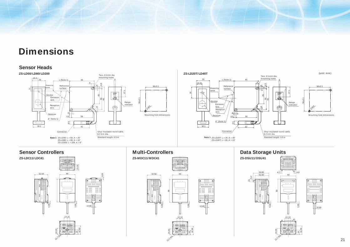
Sensor Controllers
ZS-LD50: L = 50, A = 25°ZS-LD80: L = 80, A = 15°ZS-LD200: L = 200, A = 8°
42
8.5
11
65
65
88
564.
5
8
8
564.5
45
Reference surface
Two, 4.5 mm dia. mounting holes
Connector Vinyl insulated round cable, 6.2 mm dia.
Standard length: 0.5 m
3515.3
30.1
L (Note 1)
Receiver
A° (Note 1)
Reception axis
Emission axis
Emitter
Measuring center
4
27.1
Range indicator
ZS-LDC11/LDC41
Multi-ControllersZS-MDC11/MDC41
Data Storage UnitsZS-DSU11/DSU41
42
8.5
65
8
56
8
564.5
56±0.1
56±
0.1
2-M4
45
Reference surface
Two, 4.5 mm dia. mounting holes
Connector
ZS-LD20T: L = 20, A = 45°ZS-LD40T: L = 80, A = 15°
Vinyl insulated round cable, 6.2 mm dia.
Standard length: 0.5 m
35
15.30
30.1
L (Note 1)
Mounting hole dimensionsReceiver
A° (Note 1)
Reception axis
Emission axis
Emitter
Measuring center
4
27.1
Range indicator
30
8
4.5
8
65
23.2
0
4.30
52.50
11.7
dia. 24
.20
13 10
32.9
018
4.61
10.803.90
60
11.7
dia.
24.2
0
13 10
32.9
018
4.30
52.50
3.90
90
60
10.80
(unit: mm)
4.84.7
10.80
5.2
11
4.30
52.5059.85
90
60
3.90
11.7
dia.
24.2
0
13 10
32.9
018
Dimensions
Sensor HeadsZS-LD50/LD80/LD200 ZS-LD20T/LD40T
56±0.1
56±
0.1
2-M4
Mounting hole dimensions
Note 1 Note 1
22
Smart SensorAdvanced technology is carried.
(unit: mm)
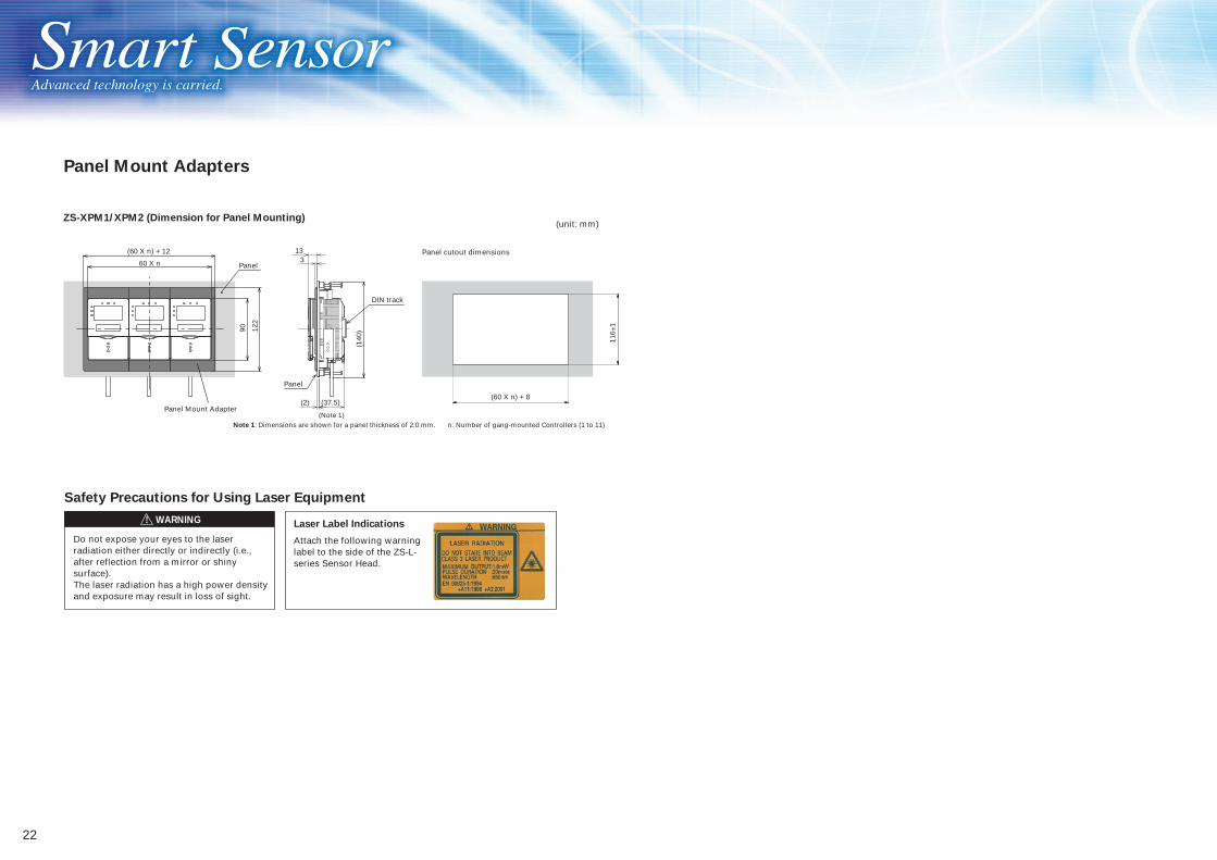
Safety Precautions for Using Laser Equipment
Do not expose your eyes to the laser radiation either directly or indirectly (i.e., after reflection from a mirror or shiny surface).The laser radiation has a high power density and exposure may result in loss of sight.
Attach the following warning label to the side of the ZS-L-series Sensor Head.
Laser Label Indications
116±
1
n: Number of gang-mounted Controllers (1 to 11)
Panel cutout dimensions
Panel Mount Adapters
ZS-XPM1/XPM2 (Dimension for Panel Mounting)
122
90
Panel
Panel Mount Adapter
Panel
Note 1: Dimensions are shown for a panel thickness of 2.0 mm.
(60 X n) + 12
(60 X n) + 8
60 X n
(37.5)
(140
)
DIN track
133
(2)
(Note 1)
WARNING

23
READ AND UNDERSTAND THIS DOCUMENTPlease read and understand this document before using the products. Please consult your OMRON representative if you have any questions or comments.
WARRANTYOMRON's exclusive warranty is that the products are free from defects in materials and workmanship for a period of one year (or other period if specified) from date of sale by OMRON.
OMRON MAKES NO WARRANTY OR REPRESENTATION, EXPRESS OR IMPLIED, REGARDING NON-INFRINGEMENT, MERCHANTABILITY, OR FITNESS FOR PARTICULAR PURPOSE OF THE PRODUCTS. ANY BUYER OR USER ACKNOWLEDGES THAT THE BUYER OR USER ALONE HAS DETERMINED THAT THE PRODUCTS WILL SUITABLY MEET THE REQUIREMENTS OF THEIR INTENDED USE. OMRON DISCLAIMS ALL OTHER WARRANTIES, EXPRESS OR IMPLIED.
LIMITATIONS OF LIABILITYOMRON SHALL NOT BE RESPONSIBLE FOR SPECIAL, INDIRECT, OR CONSEQUENTIAL DAMAGES, LOSS OF PROFITS OR COMMERCIAL LOSS IN ANY WAY CONNECTED WITH THE PRODUCTS, WHETHER SUCH CLAIM IS BASED ON CONTRACT, WARRANTY, NEGLIGENCE, OR STRICT LIABILITY.
In no event shall responsibility of OMRON for any act exceed the individual price of the product on which liability is asserted.
IN NO EVENT SHALL OMRON BE RESPONSIBLE FOR WARRANTY, REPAIR, OR OTHER CLAIMS REGARDING THE PRODUCTS UNLESS OMRON's ANALYSIS CONFIRMS THAT THE PRODUCTS WERE PROPERLY HANDLED, STORED, INSTALLED, AND MAINTAINED AND NOT SUBJECT TO CONTAMINATION, ABUSE, MISUSE, OR INAPPROPRIATE MODIFICATION OR REPAIR.
SUITABILITY FOR USETHE PRODUCTS CONTAINED IN THIS DOCUMENT ARE NOT SAFETY RATED. THEY ARE NOT DESIGNED OR RATED FOR ENSURING SAFETY OF PERSONS, AND SHOULD NOT BE RELIED UPON AS A SAFETY COMPONENT OR PROTECTIVE DEVICE FOR SUCH PURPOSES. Please refer to separate catalogs for OMRON's safety rated products.
OMRON shall not be responsible for conformity with any standards, codes, or regulations that apply to the combination of products in the customer's application or use of the product.
At the customer's request, OMRON will provide applicable third party certification documents identifying ratings and limitations of use that apply to the products. This information by itself is not sufficient for a complete determination of the suitability of the products in combination with the end product, machine, system, or other application or use.
The following are some examples of applications for which particular attention must be given. This is not intended to be an exhaustive list of all possible uses of the products, nor is it intended to imply that the uses listed may be suitable for the products:• Outdoor use, uses involving potential chemical contamination or electrical interference, or conditions or uses not described in this document.• Nuclear energy control systems, combustion systems, railroad systems, aviation systems, medical equipment, amusement machines, vehicles, safety equipment, and installations subject to separate industry or government regulations.• Systems, machines, and equipment that could present a risk to life or property.
Please know and observe all prohibitions of use applicable to the products.
NEVER USE THE PRODUCTS FOR AN APPLICATION INVOLVING SERIOUS RISK TO LIFE OR PROPERTY WITHOUT ENSURING THAT THE SYSTEM AS A WHOLE HAS BEEN DESIGNED TO ADDRESS THE RISKS, AND THAT THE OMRON PRODUCT IS PROPERLY RATED AND INSTALLED FOR THE INTENDED USE WITHIN THE OVERALL EQUIPMENT OR SYSTEM.
PERFORMANCE DATAPerformance data given in this document is provided as a guide for the user in determining suitability and does not constitute a warranty. It may represent the result of OMRON's test conditions, and the users must correlate it to actual application requirements. Actual performance is subject to the OMRON Warranty and Limitations of Liability.
CHANGE IN SPECIFICATIONSProduct specifications and accessories may be changed at any time based on improvements and other reasons.
It is our practice to change model numbers when published ratings or features are changed, or when significant construction changes are made. However, some specifications of the product may be changed without any notice. When in doubt, special model numbers may be assigned to fix or establish key specifications for your application on your request. Please consult with your OMRON representative at any time to confirm actual specifications of purchased products.
DIMENSIONS AND WEIGHTSDimensions and weights are nominal and are not to be used for manufacturing purposes, even when tolerances are shown.
ERRORS AND OMISSIONSThe information in this document has been carefully checked and is believed to be accurate; however, no responsibility is assumed for clerical, typographical, or proofreading errors, or omissions.
PROGRAMMABLE PRODUCTSOMRON shall not be responsible for the user's programming of a programmable product, or any consequence thereof.
COPYRIGHT AND COPY PERMISSIONThis document shall not be copied for sales or promotions without permission.
This document is protected by copyright and is intended solely for use in conjunction with the product. Please notify us before copying or reproducing this document in any manner, for any other purpose. If copying or transmitting this document to another, please copy or transmit it in its entirety.
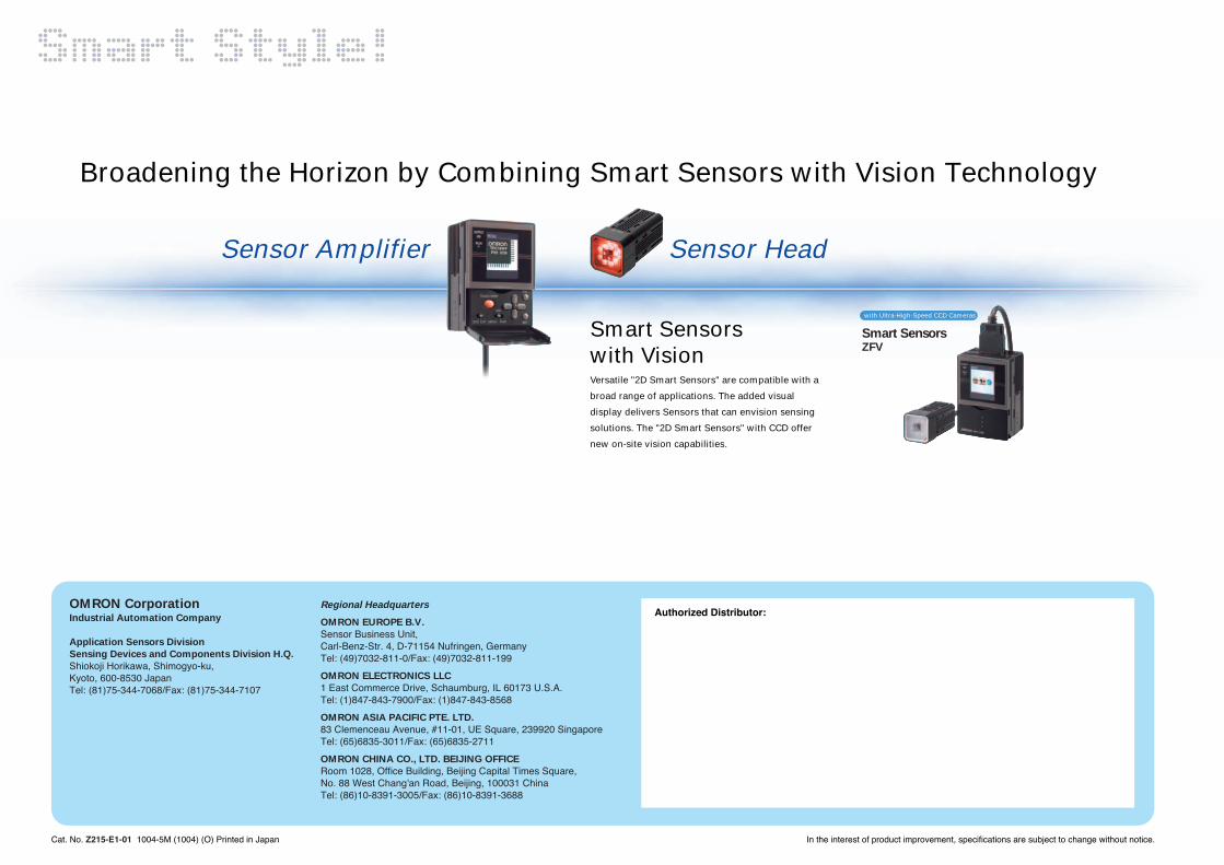
Smart SensorsZFV
with Ultra-High-Speed CCD Cameras
Versatile "2D Smart Sensors" are compatible with a
broad range of applications. The added visual
display delivers Sensors that can envision sensing
solutions. The "2D Smart Sensors" with CCD offer
new on-site vision capabilities.
In the interest of product improvement, specifications are subject to change without notice.
Authorized Distributor:
Cat. No. Z215-E1-01 1004-5M (1004) (O) Printed in Japan
OMRON CorporationIndustrial Automation Company
Application Sensors Division
Sensing Devices and Components Division H.Q.
Shiokoji Horikawa, Shimogyo-ku,Kyoto, 600-8530 JapanTel: (81)75-344-7068/Fax: (81)75-344-7107
Regional Headquarters
OMRON EUROPE B.V.
Sensor Business Unit,Carl-Benz-Str. 4, D-71154 Nufringen, GermanyTel: (49)7032-811-0/Fax: (49)7032-811-199
OMRON ELECTRONICS LLC
1 East Commerce Drive, Schaumburg, IL 60173 U.S.A.Tel: (1)847-843-7900/Fax: (1)847-843-8568
OMRON ASIA PACIFIC PTE. LTD.
83 Clemenceau Avenue, #11-01, UE Square, 239920 SingaporeTel: (65)6835-3011/Fax: (65)6835-2711
OMRON CHINA CO., LTD. BEIJING OFFICE
Room 1028, Office Building, Beijing Capital Times Square,No. 88 West Chang'an Road, Beijing, 100031 ChinaTel: (86)10-8391-3005/Fax: (86)10-8391-3688
Broadening the Horizon by Combining Smart Sensors with Vision Technology
Smart Sensors with Vision
Sensor Amplifier Sensor Head

Mouser Electronics
Authorized Distributor
Click to View Pricing, Inventory, Delivery & Lifecycle Information: Omron:
ZS-LDC41