Embed Size (px)
Citation preview

Designing a Mechanical Tool for Robots with 2-Finger Parallel Grippers
Zhengtao Hu1, Weiwei Wan1,2,∗, and Kensuke Harada1,2
Abstract— This work designs a mechanical tool for robotswith 2-finger parallel grippers, which extends the function ofthe robotic gripper without additional requirements on toolexchangers or other actuators. The fundamental kinematicstructure of the mechanical tool is two symmetric parallelo-grams which transmit the motion of the robotic gripper tothe mechanical tool. Four torsion springs are attached to thefour inner joints of the two parallelograms to open the toolas the robotic gripper releases. The forces and transmissionare analyzed in detail to make sure the tool reacts well withrespect to the gripping forces and the spring stiffness. Also,based on the kinematic structure, variety tooltips were designedfor the mechanical tool to perform various tasks. The kinematicstructure can be a platform to apply various skillful gripperdesigns. The designed tool could be treated as a normal objectand be picked up and used by automatically planned grasps.A robot may locate the tool through the AR markers attachedto the tool body, grasp the tool by selecting an automaticallyplanned grasp, and move the tool from any arbitrary pose toa specific pose to grip objects. The robot may also determinethe optimal grasps and usage according to the requirements ofgiven tasks.
I. Introduction
Manufacturing requires fast reconfiguration of roboticsystems to adapt to various products. Especially in theprocess of assembly, it is a challenge for robots to process avariety of components fast and precisely. Thus, developingrobotic systems to handle a wide range of objects in areliable and low-cost way is highly demanded. In the pastdecades, various robotic hands with advanced functions wereproposed. Each of them had merits in certain aspects. Also,to deal with different objects, tool changers and finger-tipchangers were designed to expand the feasible grasp scope.
While the tool changers and finger-tip changers increasedthe flexibility of robot systems, their drawbacks are alsoobvious. They require power supply, vacuum supply, ordelicate mechanism and control to assure the firm connectionbetween the actuators and a robot end. The tools and finger-tips have to be designed especially for specific robots andswitchers.
In this paper, we propose a solution by designing amechanical tool for robots with 2-finger parallel grippers(Fig.1(b)). Like the many tools designed for human hands(Fig.1(a)), the mechanical tool is general and independentfrom specific robots. Any robot with 2-finger parallel grip-pers could recognize, grasp, and use the tool. The tool couldhave lots of variations in the tooltips. A robot may select anduse different ones to finish different tasks. The tool is purely
1Graduate School of Engineering Science, Osaka University, Japan.2National Inst. of AIST, Japan. *Correspondent author: Weiwei Wan,[email protected]
Fig. 1: (a) Various tools designed for human hands. (b)A mechanical tool designed for parallel robotic grippers.The tool is purely mechanical. There are no additionalrequirements for power cables or air tubes. Any robots withparallel grippers could use it.
mechanical. There are no additional requirements for powercables or air tubes. There is also no special requirements forrobotic end-effectors. The tool could be used by any robotswith 2-finger parallel grippers.
The features of the design are: 1) The tool is mechanicaland is only manipulated and actuated by robotic grippers. 2)The tool can be designed with various tooltips adapted fordifferent tasks. 3) The tool can be placed at an arbitrary posein the work space, and be recognized, grasped, manipulated,and used by parallel robotic grippers.
In the following sections, we will discuss the details of thedesign, including the kinematic structure, the analysis andoptimization of grabbing force and sizes, and the consid-eration of stable placements, recognition, pose adjustment,and working poses. We carry out experiments to analyzethe performance of the design, as well as develop a robotsystem that uses the tools with different tips to pick upvarious objects. The experiments and analysis show that themechanical tool is a flexible alternative to tool changers andfinger-tip changers. With the help of visual detection andmotion planning algorithms, robots are able to automaticallyrecognize and use the tool to finish a wide range of tasks.
arX
iv:1
902.
0915
0v1
[cs
.RO
] 2
5 Fe
b 20
19
II. RelatedWork
We in this section review the related studies by separatingthem into three categories: (1) The design of robot handchangers, (2) The design of versatile and adaptive grippers,and (3) Grasp and regrasp planning.
A. The design of robot hand changers
Robot hand changers originate from the tool changers usedin Computer Numerical Control (CNC) machines [1] [2] [3],and are still widely studied [4] [5]. The reason is to use robotsin industry applications, engineers have to design variousgrippers [6] to adapt to different tasks and objects.
Recent development in robot hand changers has twotrends. The first is developing automatic tool changers formobile manipulators. Some of them are electro-mechanicallyactuated, like the one presented in [7]. Some others arepassive, like the one presented in [8]. Which used passivemechanisms actuated by host robots. Other than the changers,some studies design interfaces for robot end-effectors. Anexample is the da Vinci Surgical Research Kit [9]. The ideais to set an adapter between the tool and the original end-effector. A finger-tip changer [10] shares the similar idea.
The aforementioned studies all provide effective ways tochange hands for robots. However, though those systems canprovide reliable and precise fixing as well as connection,the efficiency of the exchanging process is still a problem.Also, the tools are adapted for specific end shapes, and theperipheral equipment is indispensable, which restricts thepotential applications. Unlike them, we in this paper designa mechanical tool for parallel robot grippers. The design ispassive and does not need any power or air supply. It isgeneral and could be grasped and used by any robots withparallel grippers. To our best knowledge, this is the first workthat designs a general mechanical tool for robots.
B. The design of versatile and adaptive gripper
Other than hand changers, more studied are devoted to de-signing versatile and adaptive gripper. For example, Haradaet al. [11] developed a novel gripper by combing a multi-finger mechanism and a granular jamming component, whichcan achieve versatile grasping firmly as well as flexibly.Triyonoputro et al. [12] developed a double jaw hand forgrasping and assembly. The inner and outer grippers canwork together to finish a task. The design was inspired bya human hand holding and manipulating two objects usingone hand in product assembly. Nie et al. [13] proposed apair of fingers for arranging screws. The gripper can pickup and tile a screw to let the screw slide to the bottom ofthe finger so as to achieve the picking and alignment. Hirataet al. [14] proposed a gripper with tips that can cage andself-align objects. Laliberte et al. [15] developed an under-actuated robot hand driven by two motors. The fingers of thehand could adapt to the shape of objects during grasping. Thehand is essentially a gripper but is versatile and adaptive. Maet al. [16] presented a gripper with one underactuated fingerand a passive finger, which is helpful to implement adaptive,shape-enveloping grasps, and also in-hand manipulation.
The versatile and adaptive grippers can perform well for agroup of workpieces, however they can never be completelyuniversal. Also, the structure has to be carefully designedto expand the function. Compared to them, using parallelgripper but preparing a range of mechanical tools could bea better way to obtain versatility and adaptivity.
C. Grasp and regrasp planning
Besides the design, this work also uses automatic recog-nition and motion planning to recognize the tool, and plan amotion to adjust and use the tool. The automatic recognitionand motion planning is based on our previous studies ingrasp and regrasp planning. Some representative ones areas follows. Wan et al. [17] presented a method for motionplanning to achieve smart assembly tasks. In the work, a3D vision system was employed to detect human operation,point clouds and geometric constraints were used to findrough poses. A method was used to plan the motion ofrobots to reorient objects. Raessa et al. [18] proposed amethod to teach a dual-arm robot to use common electrictools. Grasp and regrasp planning were implemented toadjust the work pose of the tool following [19]. Sanchez etal. [20] developed a planner with orientation constraints tomanipulate a tethered tool. Beyond our group, similar studiesabout the grasp and regrasp planning could be found in [21],[22], [23], [24], [25], etc.
III. Design and Optimization
This section presents the details of design and optimiza-tion, including the kinematic structure, the analysis andoptimization of forces and sizes, as well as the variation intooltips.
A. The kinematic structure
The tools designed for human hands usually have arotational joint, as is shown in Fig.1(a). The reason is becausethe rotational grab formed by the thumb is the main synergyof human hands [26], as is shown in Fig.2(a). Likewise, atool designed for parallel robotic grippers (Fig.2(b)) is bestto have a parallel mechanism to cater the parallel motion ofthe robotic gripper.
Fig. 2: (a) The main synergy of a human hand. The thumband the remaining fingers form a rotational grab. The toolsdesigned for human hands usually have a rotational joint. (b)The motion of a parallel robotic gripper. The tool designedfor it is best to have a parallel mechanism.
An intuitive idea to implement parallel motion is to usesliding rails. Linear springs may be attached to the railsto help return to the initial state after releasing. Fig.3(a)

illustrates the intuitive mechanism. This idea is easy to under-stand, but is difficult to assure stable parallel motion. Fig.3(b)shows the free body diagram of the intuitive mechanism.Since the sliding rail cannot bear force along the movingdirection, FA and FB are all from the springs. While thefingers keep parallel, the two springs deform equally andFA is the same as FB. To meet the momentum equilibriumequation FAdA − FBdB = 0, dA and dB must equal. Thatmeans to assure a stable parallel motion, the contact can onlybe applied at the center of the two springs, which severelydecreases the possible grasp configurations and increases thedifficulty of automatic manipulation planning.
Fig. 3: (a) The motion of an intuitive parallel mechanismmade by sliding rails and linear springs. (b) The free bodydiagram of the intuitive mechanism. (c) A parallel mecha-nism made of two symmetric parallelograms. In this case,the base frame will move backward while the tool is closed.(d) A similar parallel mechanism as (c). The difference is inthis case, the base frame will move forward while the toolis closed.
Instead of the simple sliding rails, we design the tool byusing two symmetric parallelograms, as is shown in Fig.3(c)and Fig.3(d). The two parallelograms allow the force fromrobotic grippers to be evenly distributed to the joints, andare therefore able to assure stable parallel motion. Both ofthe two configurations in Fig.3(c) and Fig.3(d) can provideparallel motion transmission. However, for the scheme shownin Fig.3(d), the grasp is likely to be impaired since thegrasping space will be occupied by the forward moving base.Also, as the heaviest part of the tool, the forward motionof the base also impair the stability of grasping. Thus, theconfiguration in Fig.3(c) is selected as the kinematic structureof our design. Besides space, the configuration has anotheradvantage, which will be explained in detail in the forceanalysis section.
Fig.4 shows the design. In Fig.4(a), the jaw of the tool isopened to its maximum. In Fig.4(b), the jaw is fully closed.The two parallelograms are installed symmetrically. Theyforce two tooltips to move in parallel. As is shown in inFig.4(a), four torsion springs are installed at joints P1∼P4.The torsion springs are concentric with their supportingshafts. The ends of the torsion springs are respectively fixedto the base frame and the angular linkages. The torsionsprings provide friction to prevent the tool from droppingas the robotic gripper holds it. They also provide forces toopen the tool as the robotic gripper releases.
The torsion springs are installed with a pre-angle β, which
Fig. 4: The designed mechanical tool. (a) The tool is com-pletely open. (b) The tool is closed. Torsion springs shownin the circle are installed at joints P1∼P4.
is determined by the stopper crafted in the base frame. Theforce exerted by a spring to an angular linkage is therefore:
Fspring = κ(β + ∆θ) (1)
where Fspring is the exerted force. β is the pre-angle. κ is theelastic coefficient. ∆θ is the rotational angle of the angularlinkage. Choosing a proper β is an optimization problem.On the one hand, with the same ∆θ, a large β provides alarge resistance force to robot grippers and hence provideslarger friction to prevent the tool from dropping out of therobot gripper. It also leads to a shorter stroke of the roboticgripper to get the same transmitted force. On the other hand,if β is too large, the robot gripper has to exert a very largeforce to overcome the tension of the torsion springs. In theworst case, the tool may not be closed. The details of forceanalysis will be discussed in the next subsection.
B. Force analysis
In this subsection, we analyze the forces between the tooland a robot gripper to optimize the design. The subsectioncomprises two parts. In the first part, we analyze the condi-tion for a robot gripper to firmly hold the tool as well as therelationship between robot grasping force and the resistanceforce from the torsion springs when a robot gripper is holdingthe tool. In the second part, we analyze the maximum weightof objects that can be pick up by the tool.
1) Holding the tool: We model the contact between therobot gripper and the tool as a soft contact. Following [27][28], the force and friction exerted by the robot gripper canbe computed by:
f 2 +T 2
e2 6 µ2F2
n (2)
where f is the tangential force at the contact. T is the torqueat the contact. Fn is the gripping force exerted by the robotgripper. e is an eccentricity parameter computed by the ratiobetween the maximum friction and friction torque on thecontact surface:
e =max Tmax f
(3)
The free body diagram when the tool is held by a robotgripper is shown in Fig.5. Here, f is the friction force at
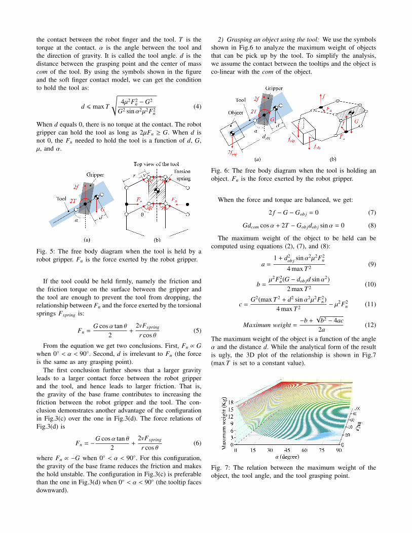
the contact between the robot finger and the tool. T is thetorque at the contact. α is the angle between the tool andthe direction of gravity. It is called the tool angle. d is thedistance between the grasping point and the center of masscom of the tool. By using the symbols shown in the figureand the soft finger contact model, we can get the conditionto hold the tool as:
d 6 max T
√4µ2F2
n −G2
G2 sinα2µ2F2n
(4)
When d equals 0, there is no torque at the contact. The robotgripper can hold the tool as long as 2µFn ≥ G. When d isnot 0, the Fn needed to hold the tool is a function of d, G,µ, and α.
Fig. 5: The free body diagram when the tool is held by arobot gripper. Fn is the force exerted by the robot gripper.
If the tool could be held firmly, namely the friction andthe friction torque on the surface between the gripper andthe tool are enough to prevent the tool from dropping, therelationship between Fn and the force exerted by the torsionalsprings Fspring is:
Fn =G cosα tan θ
2+
2vFspring
r cos θ(5)
From the equation we get two conclusions. First, Fn ∝ Gwhen 0◦ < α < 90◦. Second, d is irrelevant to Fn (the forceis the same as any grasping point).
The first conclusion further shows that a larger gravityleads to a larger contact force between the robot gripperand the tool, and hence leads to larger friction. That is,the gravity of the base frame contributes to increasing thefriction between the robot gripper and the tool. The con-clusion demonstrates another advantage of the configurationin Fig.3(c) over the one in Fig.3(d). The force relations ofFig.3(d) is
Fn = −G cosα tan θ
2+
2vFspring
r cos θ(6)
where Fn ∝ −G when 0◦ < α < 90◦. For this configuration,the gravity of the base frame reduces the friction and makesthe hold unstable. The configuration in Fig.3(c) is preferablethan the one in Fig.3(d) when 0◦ < α < 90◦ (the tooltip facesdownward).
2) Grasping an object using the tool: We use the symbolsshown in Fig.6 to analyze the maximum weight of objectsthat can be pick up by the tool. To simplify the analysis,we assume the contact between the tooltips and the object isco-linear with the com of the object.
Fig. 6: The free body diagram when the tool is holding anobject. Fn is the force exerted by the robot gripper.
When the force and torque are balanced, we get:
2 f −G −Gob j = 0 (7)
Gdcom cosα + 2T −Gob jdob j sinα = 0 (8)
The maximum weight of the object to be held can becomputed using equations (2), (7), and (8):
a =1 + d2
ob j sinα2µ2F2n
4 max T 2 (9)
b =µ2F2
n(G − dob jd sinα2)2 max T 2 (10)
c =G2(max T 2 + d2 sinα2µ2F2
n)4 max T 2 − µ2F2
n (11)
Maximum weight =−b +
√b2 − 4ac
2a(12)
The maximum weight of the object is a function of the angleα and the distance d. While the analytical form of the resultis ugly, the 3D plot of the relationship is shown in Fig.7(max T is set to a constant value).
Fig. 7: The relation between the maximum weight of theobject, the tool angle, and the tool grasping point.

C. Size optimization
In this section, we optimize the dimension of the tool.We would like the tool to have a large stroke and compactsize. The dimension parameters shown in Fig.8 are used foroptimization.
Fig. 8: The dimension parameters used to optimize the sizeof the tool.
Equations (13) and (14) show the relationship between thewidth of the tool, the stroke of the tool, and the rotationalangles of the angular linkage.
winit = m + 2r sin θinit (13)
w = 2r sin (θinit − θend) (14)
Given a fixed winit, w is expressed as:
w =linit − m2sinθinit
sin (θinit − θend) (15)
Equation (15) shows that increasing θinit and decreasingθend and m will enlarge the stroke l. When θiniti is 90◦, θend
is 0◦, and m is 0, l reaches to its maximum. However, therelationship between Fn and θinit shown in (5) told that anoverlarge θinitial will significantly increase the requirementson the grasping force Fn and make the tool hard to becompressed. If θiniti reaches 90◦, the tool can never be used.Also, if m is 0, the base will disappear. In this case, sincethe links have a width in the real world, they are hard tobe designed to move in the same plane unless increasingthe complexity of the design and using an asymmetricalstructure, which changes the position of the center of gravityand reduces the structural stability of the tool. In order toinstall the links appropriately, m should meet:
m > daxis + 2redge (16)
For the same reason, θend cannot be 0◦. It is minimumcan be calculated considering the radius of the joints andthe width of the linkages. The red dot lines in Fig.8(b)show the situation when θend reaches its minimum. In thiscase, the parallel linkage will touch the base frame. Theminimum θend can be computed using Equation (17). pshould meet equations (18) and (19). h should meet equation(20). Otherwise, the link bars will overlap with each other.
θend = arcsinqr
(17)
q = daxis + 2redge (18)
p > k sin θend (19)
h > r cos θend + tan θend(daxis + 2redge) (20)
D. Variation in tooltips
In addition to the mechanical design, we can make differ-ent tooltips for different tasks. Unlike the versatile gripperwhich is designed to adapt to a wide range of tasks, each ofthe tooltip is specially designed for a single task. The designcan thus be more compact and reliable. These differenttooltips are based on the same mechanism so that a robotcan manipulate them in the same way. Three examples ofthe special tooltips are shown in Fig.9.
Fig. 9: Three exemplary special tooltips.
IV. Using the Tool
When performing specific tasks, the tool is placed in anarbitrary pose in the work space. A robot identifies thetool using AR markers and grasps it using pre-plannedgrasp configurations. To use the tool, the robot should beconstrained to grasp the tool in specific poses (workingposes). When the pose of the tool makes it impossible ordifficult to be picked up in a working pose, regrasp planning[19] may be employed to adjust the grasp configuration.
A. Working poses
There are several pairs of parallel surfaces of the tools thatcan be stably grasped, but the tool can be used only when thesides of the parallel linkages are used as the contact surfaces.In addition, the angle α of the tool is expected to be withinthe range of 0◦ ∼ 90◦ unless there are special requirements.The angle γ, which is defined as the angle between the handand the tool (Fig.10), is also expected to be within the rangeof 0◦ ∼ 90◦. The reason is two-fold. For one thing, Fn ∝ Gwhen 0◦ < α < 90◦, the tool is more stable. For the other, thegripper is facing backward and does not obstruct the workingspace of the tool when 0◦ < γ < 90◦.
Using the holding condition equation (4), the changesof maximum friction torque when 0◦ < γ < 90◦ can becomputed. The result is shown in Fig.10 (d is set to 0, α isset to 90◦.). The maximum friction torque increases in thebeginning, and decreases after reaching the peak at γ = 23◦.

Fig. 10: The changes of maximum friction torque in therange of working poses. The maximum frictional momentarm increases in the beginning, and reaches the peak at 23◦.
B. Reorienting to the working poses
The tool could be placed in an arbitrary pose in the workspace. The pose is not necessarily able to be picked up intoa working pose. For example, the poses shown in Fig.11 cannever be directly used since the robot gripper can never grabthe sides of the parallel linkages. In that case, reorientingplanners are needed to help the robot adjust the poses. Theauthors had been working on reorienting planners for severalyears. This paper uses one of our recent results (regrasp usingtwo arms) [] to plan reorienting tools.
Fig. 11: Some poses of the tool that cannot be directly pickedup into a working pose.
V. Experiments
Fig.12 shows our experiment system. We used a dual-arm UR3 robot to conduct the experiments. Two UR3robots were mounted symmetrically with 45◦ to the bodyframe. Robotiq F-85, a two-finger parallel-jaw gripper, wasemployed for both arms. For visual detection, a camera, ELP-USBFHD06H-L36 skewless HD, was mounted to one sideof Robotiq F-85.
A. Maximum weight of an object
First, we perform experiments to test the maximumweights of objects that can be picked by the tool. DynPickforce sensor is used for measurement. The setting is shownin Fig.13. The sensor is fixed to a table. A string is usedto connect the sensor and the tooltips. The robot gripper isused to hold the tool and drag the string up vertically untilthe tool is moved. The peak force measured by the forcesensor before the tool moves is recorded as the maximum
Fig. 12: The experiment system. It has a dual-arm UR3 robotwith Robotiq F85 grippers installed to both of them. Camerasare also mounted on both grippers.
weight of objects that can be picked by the tool. The testis repeated with the α angle changing from 0◦ to 75◦. Tosimplify the experiment and improve precision, the γ angleis set to 0◦.
Fig. 13: The set up to measure the maximum weights ofobjects that can be picked by the tool. The peak forcemeasured by the force sensor before the tool moves isrecorded as the maximum weight of objects that can bepicked by the tool.
The result is shown in Fig.14. The solid curve shows thedata measured by the experiments. The dash curve is thecomputed value using equation (9-12). The measured resultsare nearly the same as the theoretical analysis. The proposeddesign could pick up an object of 8 kg when the anglebetween the tooltip and the gravity direction is 15◦.
B. Using the tool to pick various objects
Second, to test the performance of the tool, we conductedexperiments to pick up a screw, a washer, and a can. Theseobjects are difficult to be handled by only the RobotiqF85 gripper. The screw and washer are too small to begrasped by the gripper, successfully handling them woulddemonstrate the feasibility of the tool for picking up smallmechanical parts. When the screw is on the table, there islimited grasping space and requires suitable gripper shapeand precise position control. Fig.15 shows the experimentalresults of handling a screw. In this case, a thin tooltip wasused [13]. The compliant units at the parallel linkage allowedcontacting the table completely to achieve an available grasp.Compared to the screw, the washer is even more difficult

Fig. 14: The maximum weight that the tool can pick atdifferent α.
to grasp due to its thin thickness and circular outside. Thetooltip in this case was designed to stretch against theinner circle of the washer (radius: 1.5mm). the tool wascompressed fully to insert the tooltips into the inner circle.After insertion, the gripper opened a bit to hold and pick upthe washer, as is shown in Fig.16.
Fig. 15: Using the tool to pick up a screw.
Fig. 16: Using the tool to grasp and pick up a washer.
The third object, namely the can, is easy to deform.Grippers without feedback control are likely to crash the can.With a properly designed tooltip, the proposed tool has themerit to safely pick up a can. Fig.17 shows two examples.A can has two stable placement poses, and both of them canbe handled using the tool.
C. Automatic recognition and planning
Third, we used the tool to pick up a bolt with automaticplanning. Fig.18 is the result of the first test. In this case,
Fig. 17: (a) Using the tool to grasp and pick up a can froman upright pose. (b)Using the tool to grasp and pick up acan from an lateral pose.
the tool can be picked up into a working pose without anyadjustment. The robot recognized the tool, picked it up,planned a motion to use the tool to pick up the bolt. Fig.19is the result of the second test. In this case, the tool cannotbe picked up into a working pose directly. Regrasp planningis used to adjust the pose of the tool. The robot recognizedthe tool, planned a regrasp motion to adjust the pose of thetool (a handover was used to adjust the pose of the tool intoa working pose), and planned a motion to use the tool topick up the bolt. Together with the automatic recognition andplanning the tool can be used flexibly without requirementson power supply, vacuum supply, or delicate mechanism andcontrol.
VI. Conclusions and FutureWork
This paper presented a mechanical tool designed forrobots. The idea is inspired by the tools designed for humanhands. The tool is purely mechanical. It is free of powersupply, vacuum supply, and delicate mechanism and control.It is actuated by the gripper force from the robot gripper.The tool may have various tooltips designed for specifictasks to extend the function of robot grippers. The quan-titative analysis and real-world experiments demonstrate thefeasibility of the tool and show that it is able to be held andmanipulated by a robot gripper and to realize various pickingtasks. Our future work includes diversifying the tooltips todevelop wider applications as well as optimizing the planningalgorithms.
References
[1] M. I. Gokler and M. B. Koc, “Design of an automatic tool changer withdisc magazine for a cnc horizontal machining center,” InternationalJournal of Machine Tools and Manufacture, vol. 37, no. 3, pp. 277–286, 1997.
[2] K. Lundberg, “Automatic tool changer [25 years ago],” IEEE ControlSystems Magazine, vol. 31, no. 6, pp. 18–18, 2011.
[3] J. P. Rogelio and R. G. Baldovino, “Development of an automatic toolchanger (atc) system for the 3-axis computer numerically-controlled(cnc) router machine: Support program for the productivity andcompetitiveness of the metals and engineering industries,” in Interna-tional Conference on Humanoid, Nanotechnology, Information Tech-nology, Communication and Control, Environment and Management(HNICEM), 2014, pp. 1–5.

Fig. 18: Automatic recognition and planning 1. In this case, the tool can be manipulated into a working pose to pick up thebolt without any adjustment.
Fig. 19: Automatic recognition and planning 2. In this case, the tool cannot be manipulated into a working pose directly.The robot used a handover to adjust the pose of the tool.
[4] B.-S. Ryuh, S. M. Park, and G. R. Pennock, “An automatic toolchanger and integrated software for a robotic die polishing station,”Mechanism and Machine Theory, vol. 41, no. 4, pp. 415–432, 2006.
[5] M. T. Kordi, M. Husing, and B. Corves, “Development of a multifunc-tional robot end-effector system for automated manufacture of textilepreforms,” in IEEE/ASME International Conference on AdvancedIntelligent Mechatronics, 2007, pp. 1–6.
[6] G. J. Monkman, S. Hesse, R. Steinmann, and H. Schunk, Robotgrippers. John Wiley & Sons, 2007.
[7] D. Gyimothy and A. Toth, “Experimental evaluation of a novelautomatic service robot tool changer,” in IEEE/ASME InternationalConference on Advanced Intelligent Mechatronics, 2011, pp. 1046–1051.
[8] R. Berenstein, A. Wallach, P. E. Moudio, P. Cuellar, and K. Goldberg,“An open-access passive modular tool changing system for mobile ma-nipulation robots,” in IEEE International Conference on AutomationScience and Engineering, 2018, pp. 592–598.
[9] S. McKinley, A. Garg, S. Sen, D. V. Gealy, J. P. McKinley, Y. Jen,M. Guo, D. Boyd, and K. Goldberg, “An interchangeable surgi-cal instrument system with application to supervised automation ofmultilateral tumor resection,” in IEEE International Conference onAutomation Science and Engineering, 2016, pp. 821–826.
[10] C. Clevy, A. Hubert, J. Agnus, and N. Chaillet, “A micromanipula-tion cell including a tool changer,” Journal of Micromechanics andMicroengineering, vol. 15, no. 10, p. S292, 2005.
[11] K. Harada, K. Nagata, J. Rojas, I. G. Ramirez-Alpizar, W. Wan,H. Onda, and T. Tsuji, “Proposal of a shape adaptive gripper forrobotic assembly tasks,” Advanced Robotics, vol. 30, no. 17-18, pp.1186–1198, 2016.
[12] J. C. Triyonoputro, W. Wan, and K. Harada, “A double jaw handdesigned for multi-object assembly,” in 2018 IEEE-RAS 18th Interna-tional Conference on Humanoid Robots, 2018, pp. 427–430.
[13] K. Nie, W. Wan, and K. Harada, “A hand combining two simplegrippers to pick up and arrange objects for assembly,” IEEE Roboticsand Automation Letters, 2019.
[14] Y. Hirata, A. Kaisumi, K. Yamaguchi, and K. Kosuge, “Design ofhandling device for caging and aligning circular objects,” in 2011IEEE International Conference on Robotics and Automation, 2011,pp. 4370–4377.
[15] T. Laliberte, L. Birglen, and C. Gosselin, “Underactuation in roboticgrasping hands,” Machine Intelligence & Robotic Control, vol. 4, no. 3,pp. 1–11, 2002.
[16] R. R. Ma, A. Spiers, and A. M. Dollar, “M 2 gripper: Extendingthe dexterity of a simple, underactuated gripper,” in Advances inreconfigurable mechanisms and robots II, 2016, pp. 795–805.
[17] W. Wan, F. Lu, Z. Wu, and K. Harada, “Teaching robots to do objectassembly using multi-modal 3d vision,” Neurocomputing, vol. 259, pp.85–93, 2017.
[18] M. Raessa, D. E. S. Aranguren, W. Wan, and K. Harada, “Teaching arobot to use electric tools with regrasp planning,” CAAI Transactionson Intelligence Technology, 2019.
[19] W. Wan, K. Harada, and F. Kanehiro, “Preparatory manipulationplanning using automatically determined single and dual arms,” IEEETransactions on Industrial Informatics, 2019.
[20] D. Sanchez, W. Wan, and K. Harada, “Arm manipulation planningof tethered tools with the help of a tool balancer,” arXiv preprintarXiv:1812.06296, 2018.
[21] M. Dogar, A. Spielberg, S. Baker, and D. Rus, “Multi-Robot GraspPlanning for Sequential Assembly Operations,” in IEEE InternationalConferene on Robotics and Automation, 2015, pp. 193–200.
[22] P. Lertkultanon and Q.-C. Pham, “A Certified-Complete BimanualManipulation Planner,” IEEE Transactions on Automation Science andEngineering, 2018.
[23] X. Zhou, P. Lertkultanon, and Q.-C. Pham, “Closed-chain Manipula-tion of Large Objects by Multi-arm Robotic Systems,” IEEE Roboticsand Automation Letters, vol. 2, no. 4, pp. 1832–1839, 2017.
[24] F. Suarez-Ruiz, X. Zhou, and Q.-C. Pham, “Can Robots Assemble anIKEA Chair?” Science Robotics, vol. 3, no. 17, 2018.
[25] L. Chen, L. F. Figueredo, and M. Dogar, “Manipulation planning underchanging external forces,” in IEEE/RSJ International Conference onIntelligent Robots and Systems, 2018, pp. 3503–3510.
[26] M. Santello, M. Flanders, and J. F. Soechting, “Postural hand synergiesfor tool use,” Journal of Neuroscience, vol. 18, no. 23, pp. 10 105–10 115, 1998.
[27] R. D. Howe and M. R. Cutkosky, “Practical force-motion models forsliding manipulation,” The International Journal of Robotics Research,vol. 15, no. 6, pp. 557–572, 1996.
[28] M. Ciocarlie, C. Lackner, and P. Allen, “Soft finger model withadaptive contact geometry for grasping and manipulation tasks,” inSecond Joint EuroHaptics Conference and Symposium on HapticInterfaces for Virtual Environment and Teleoperator Systems, 2007,
pp. 219–224.


![The Introspective House - Architects Registration Board · Mount Fuji Architects Studio - Tokyo (Masahiro Harada and Mao Harada)[3] Alphaville Architects - Kyoto (Kentaro Takeguchi](https://img.pdfslide.us/doc/110x75/5fe6fee18b960474295e1090/the-introspective-house-architects-registration-board-mount-fuji-architects-studio.jpg)
![Advancements in Tiled-Based Compute Rendering - KlayGE · 2017. 1. 16. · Ryse Forward+ [Harada ... [Harada12] Takahiro Harada, “A 2.5D Culling for Forward+”, Technical Briefs,](https://img.pdfslide.us/doc/110x75/60cad290e28e7c40f4351dfd/advancements-in-tiled-based-compute-rendering-2017-1-16-ryse-forward-harada.jpg)