Embed Size (px)
Citation preview


3
ZETOR
The Operator's Manual accompanying the Z 8641 - Z 11741 tractors, which you have just started to read, will makeyou familiar with the operation and maintenance of the new tractor of yours.Though many of you may have got rich experience with the operation of other tractors, we exhort you to study thismanual as thoroughly as possible. It is for your safety and the efficiency of operation.We are sure that you will find many pieces of new and useful information and you will get a perfect overview of themethods you can apply for the best utilization of our product for the most diverse purposes.If you attain to the specified principles of operation and maintenance of the tractor, and observe the safety rules ofits driving, the new tractor you have got will become your reliable and long-term assistant and partner.The manufacturer of the tractor has the pleasure of wishing you thousands of hours of work accomplished to yourfull satisfaction.
ZETORBrno

4
The specified technical data, design, outfit, material, and visual aspects are in force at the moment of impression. The manufac-turer reserves the right to modifications
5
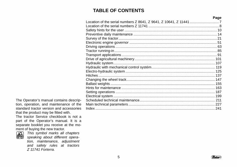
TABLE OF CONTENTS
The Operator’s manual contains descrip-tion, operation, and maintenance of thestandard tractor version and accessoriesthat the product may be fitted with.The tractor Service checkbook is not apart of the Operator’s manual. It is aseparate booklet you receive at the mo-ment of buying the new tractor.
This symbol marks all chaptersspeaking about different opera-tion, maintenance, adjustmentand safety rules at tractorsZ 11741 Forterra.
PageLocation of the serial numbers Z 8641, Z 9641, Z 10641, Z 11441............................. 7Location of the serial numbers Z 11741 ...................................................................... 8Safety hints for the user ............................................................................................ 10Preventive daily maintenance ................................................................................... 14Survey of the tractor.................................................................................................. 21Electronic engine governor ....................................................................................... 51Driving operations ..................................................................................................... 63Tractor running-in ...................................................................................................... 85Transport applications ............................................................................................... 91Drive of agricultural machinery................................................................................ 101Hydraulic system..................................................................................................... 107Hydraulic with mechanical control systém............................................................... 119Electro-hydraulic system ......................................................................................... 125Hitches .................................................................................................................... 137Changing the wheel track........................................................................................ 147Ballast weights ........................................................................................................ 155Hints for maintenance ............................................................................................. 163Setting operations ................................................................................................... 187Electrical system ..................................................................................................... 199Scheduled technical maintenance........................................................................... 211Main technical parameters ...................................................................................... 227Index ....................................................................................................................... 241
6
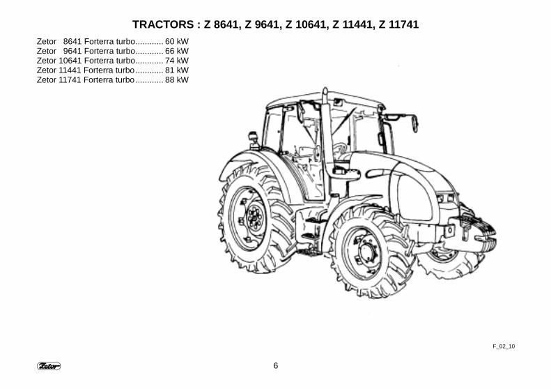
TRACTORS : Z 8641, Z 9641, Z 10641, Z 11441, Z 11741Zetor 8641 Forterra turbo............ 60 kWZetor 9641 Forterra turbo............ 66 kWZetor 10641 Forterra turbo............ 74 kWZetor 11441 Forterra turbo............ 81 kWZetor 11741 Forterra turbo............ 88 kW
F_02_10

7
LOCATION OF SERIAL NUMBERS Z 8641, Z 9641, Z 10641, Z 11441
F_02_154

8
LOCATION OF SERIAL NUMBERS Z 11741
F_02_187a
9
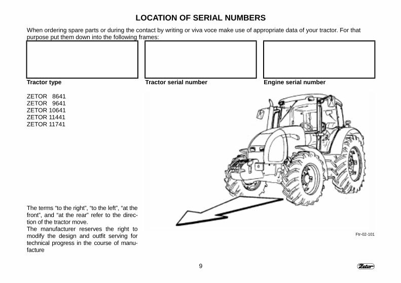
LOCATION OF SERIAL NUMBERSWhen ordering spare parts or during the contact by writing or viva voce make use of appropriate data of your tractor. For thatpurpose put them down into the following frames:
Tractor type
ZETOR 8641ZETOR 9641ZETOR 10641ZETOR 11441ZETOR 11741
The terms “to the right”, “to the left”, “at thefront”, and “at the rear” refer to the direc-tion of the tractor move.The manufacturer reserves the right tomodify the design and outfit serving fortechnical progress in the course of manu-facture
Tractor serial number Engine serial number
Ftr-02-101
10
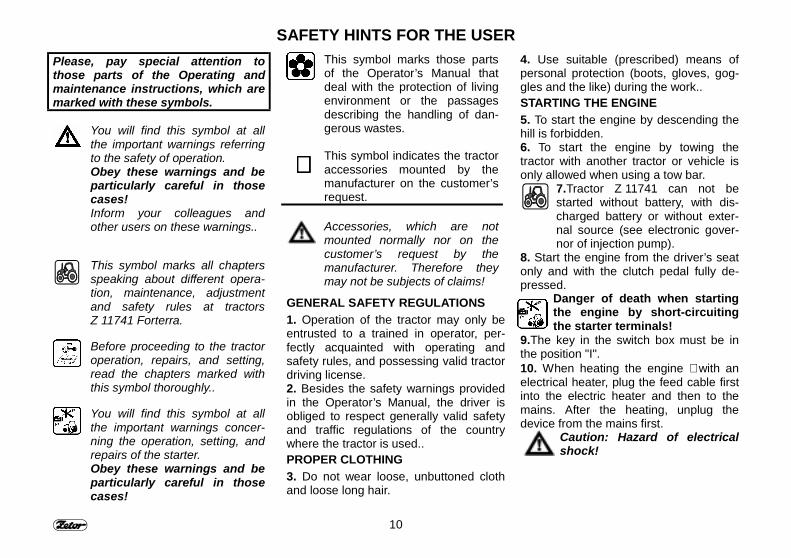
SAFETY HINTS FOR THE USERPlease, pay special attention tothose parts of the Operating andmaintenance instructions, which aremarked with these symbols.
You will find this symbol at allthe important warnings referringto the safety of operation.Obey these warnings and beparticularly careful in thosecases!Inform your colleagues andother users on these warnings..
This symbol marks all chaptersspeaking about different opera-tion, maintenance, adjustmentand safety rules at tractorsZ 11741 Forterra.
Before proceeding to the tractoroperation, repairs, and setting,read the chapters marked withthis symbol thoroughly..
You will find this symbol at allthe important warnings concer-ning the operation, setting, andrepairs of the starter.Obey these warnings and beparticularly careful in thosecases!
This symbol marks those partsof the Operator’s Manual thatdeal with the protection of livingenvironment or the passagesdescribing the handling of dan-gerous wastes.
∗∗∗∗ This symbol indicates the tractoraccessories mounted by themanufacturer on the customer’srequest.
Accessories, which are notmounted normally nor on thecustomer’s request by themanufacturer. Therefore theymay not be subjects of claims!
GENERAL SAFETY REGULATIONS1. Operation of the tractor may only beentrusted to a trained in operator, per-fectly acquainted with operating andsafety rules, and possessing valid tractordriving license.2. Besides the safety warnings providedin the Operator’s Manual, the driver isobliged to respect generally valid safetyand traffic regulations of the countrywhere the tractor is used..PROPER CLOTHING3. Do not wear loose, unbuttoned clothand loose long hair.
4. Use suitable (prescribed) means ofpersonal protection (boots, gloves, gog-gles and the like) during the work..STARTING THE ENGINE5. To start the engine by descending thehill is forbidden.6. To start the engine by towing thetractor with another tractor or vehicle isonly allowed when using a tow bar.
7. Tractor Z 11741 can not bestarted without battery, with dis-charged battery or without exter-nal source (see electronic gover-nor of injection pump).
8. Start the engine from the driver’s seatonly and with the clutch pedal fully de-pressed.
Danger of death when startingthe engine by short-circuitingthe starter terminals!
9. The key in the switch box must be inthe position "I".10. When heating the engine ∗ with anelectrical heater, plug the feed cable firstinto the electric heater and then to themains. After the heating, unplug thedevice from the mains first.
Caution: Hazard of electricalshock!
11
SAFETY HINTS FOR THE USERDRIVING OPERATION11. Check the hoses of hydrostaticsteering, brakes, and fuel system forproper conditions. In case of detectingany symptoms of damage, replace thehoses immediately. Cracks on the hosesurface, loss of the hose fitting pre-tensioning (which can be proved by itseasy removal from the socket) and itsmechanical damage are such symptoms,for instance.Hoses with specified servicelife shall be replaced as soon as theirservice life expires.12. In case the tractor uses bio-fuels forits operation, its fuel system shall befitted with REP hoses. (The manufac-turer furnishes the fuel system withREP 6 hoses).13. Brakes and steering shall be kept inperfect conditions.14. When driving on roads, with trailers,and implements, the pedals shall belatched together.15. Driving downhill with no speed gearengaged is forbidden!16. Special caution shall be paid in driv-ing through slopes, muddy, sandy, icyand uneven terrain.17. Do not exceed the admissible 12°-slope sheerness.18. Do not exceed the maximum overallweight of the rolling stock as given at the
tractor rating plate or at the rear wheelmudguard.19. Do not apply the differential lockwhen driving through turnings.20. To get in and out the tractor duringits move is strictly forbidden.21. When driving with implements at-tached to the rear hitches, the load of thesteering axle may not drop below 18 %of the rolling stock instantaneous weight.22. When driving the tractor with theagricultural implements suspended at thefront three-point hitches, reduce thetractor travel speed to 20 km/h.23. When combining the Z 8641 - Z 11741tractors with the machines and implementsof high hauling resistance when the enginespeed decays and the motor tends to stop,it is forbidden to use the reduced speedgears 1R, 2R (because of the danger ofshaft torsion).TRANSPORT OF PERSONNEL,OPERATION24. Tractor may only transport as manyindividuals as specified in the tractortechnical certificate.25. Individuals not charged with theoperation of the tractor additional imple-ments, are not allowed to stay betweenthe tractor and the suspended machine(implement).26. Before starting the tractor move,make sure that no unauthorized individ-
ual or obstacle obstructs the tractormove.27. Do not exceed the specified angle ofslope gradient, which for the Z 8641,Z 9641, Z 10641, Z 11441, Z 11741tractors equals 12°.TRACTOR RESCUE AND PUSHING28. To recover the stack tractor use a towbar or cable suspended at the fronthook.!
Never use chains, becausetheir rupture represents a mor-tal danger!
29. During the recovery, it is dangerousto stay close to the tow cable.30. It is forbidden to use the tractor axle(the individual drive wheels) as a winchfor recovering the tractor.31. The front hook is intended for towingor recovering the tractor alone, i.e. with-out the trailer or other suspended imple-ments.32. Never recover the tractor with thereduced speed gears engaged.33. For pushing other vehicles (trailers,implements, and the like) never put loosewooden beams or other bars betweenthe tractor and the item to be pushed.
LEAVING THE TRACTOR34. Do Not park the tractor with the at-tached implements in the lifted position.
12
SAFETY HINTS FOR THE USER35. Before leaving the tractor, do notforget to apply the parking brake (withengaging a speed gear). Remove thekey from the switch box and lock up thecab with key.36. In the tractors fitted with reversingsystem, shift the reversing lever to theforward-drive position.37. When leaving the tractor while theengine is in operation, apply the parkingbrake.38. For getting out of the tractor, makenormally use of its L.. H. side. Whendoing it, be sure that no vehicle, whichcould menace your safety, approaches.Then open the door.39. When getting out, make use of stepsand handles. Pay special attention to thegearshift lever, the hand-operated fuelsupply lever, and to the upper step.
OPERATIONS TO BE DONE WITH THESTOPPED ENGINE ONLY:40. All the operations associated with thetractor or implement refueling, cleaning,lubrication / greasing, and setting – ex-cepting the checks of brake, hydraulic,and electrical charging systems forproper conditions - shall be carried outwith the engine and other moving partsstopped.41. Before removing the bonnet sidecovers, stop the engine. Inside theclosed buildings, the tractor motor may
only be put into operation if sufficientventilation is ensured. Remember thatthe exhaust gases are harmful.
PRINCIPLES OF FIRE PREVENTION42. Refuel the tractor preferably afterconcluding the work and with the enginestopped..43. In summer season, do not refuel upto the top. Wipe off the spilled fuel im-mediately.44. Do not refuel close to naked flamesand do not moke45. When checking the storage batteryelectrolyte for proper level, do notsmoke, nor use the naked flames.46. In the environments of enhanceddanger of fire (haylofts, straw heaps, andthe like) be consequent in attaining to thefire fighting safety instructions.47. The manufacturer does not furnishtractors with fire extinguishers.
HEALTH AND LIVINGENVIRONMENT PROTECTION
48. Tractors are not furnished with spe-cial filters for cleaning the air sucked tothe tractor cab. Therefore they are notdesigned for working with aerosols andother harmful substances.49. Kerosene, gas oils, mineral oils andother crude oil products, which are usedfor tractor operation and servicing, cancause different skin diseases in the case
of direct contact, they have irritatingeffects on the mucous membrane, eyes,digestive apparatus, and upper respira-tory ways. Some of them – when swal-lowed – can cause even general intoxi-cation.50. The operators who enter in contactwith oil products are obliged to attain tosafety and hygienic instructions conse-quently, make use of appropriate pro-tecting means, and work in well-ventilated rooms.
MANIPULATION OF CRUDE-OILPRODUCTS
51. After concluding the work, washyourself with a non-irritant agent andtreat your hands with a suitable skinointment or cream.52. When connecting and disconnectingthe hydraulic circuit quick couplers, re-move – with a piece of any cloth – theresidual oil, which remains in the couplersocket or plug.
WASTE DISPOSAL
53. When disposing the tractor or someof its parts (including the service liquids),as soon as their service life is over, everybody is obliged to proceed in accordancewith the provisions of the relevant lawsand regulations.

13
SAFETY HINTS FOR THE USER54. The last tractor seller is obliged – bythe Law on wastes – to inform the con-sumer – when selling the tractor – on theways of taking back some of the con-sumed parts of the tractor. In questionare the oils and other service liquids,storage batteries, and tires.
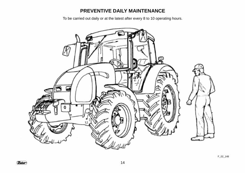
PREVENTIVE DAILY MAINTENANCE54. This maintenance shall be carried outdaily or at latest after every 8 to 10 oper-ating hours.
SAFETY CAB55. In case corrosion or any other acci-dent damages the cab-protecting frame,the cab must be replaced.
AIR CONDITIONING56. In no case it is allowed to disassem-ble, turn or manipulate in another waythe screw joints of the air conditioningsystem, because sudden leak of thecoolant and quick local cooling mayoccur. Contact or freezing of componentsin hands may result in serious injury ofsome tissues.57. The air conditioning system is fittedwith quick couplers, which allow sepa-rate the cab from the tractor body if nec-essary without any leak of the coolant.Entrust the interventions into the airconditioning system to the service spe-cialists.
ELECTRICAL EQUIPMENT
58. No additional interventionsinto the tractor electricalequipment (connection ofother electrical appliances) areallowed because of its possibleoverloading.
59. The values of electrical installationare:
Nominal voltage 12 V =Ground minus pole ( - )
The use of starting trucks or starting aiddevices with different voltage or polaritycauses serious failures of tractor.60. It is necessary to be careful whenmanipulating with the battery and toavoid short circuits. Turn off the batteryswitch at tractors equipped with thisswitch when manipulating with the bat-tery.61. Tractors Z 8641- Z 11741 mustnot run with the disconnected battery, theserious failure of tractor is possible.
14
PREVENTIVE DAILY MAINTENANCETo be carried out daily or at the latest after every 8 to 10 operating hours.
F_02_148
15
PREVENTIVE DAILY MAINTENANCE
F_02_192 F_02_193 F_02_3a
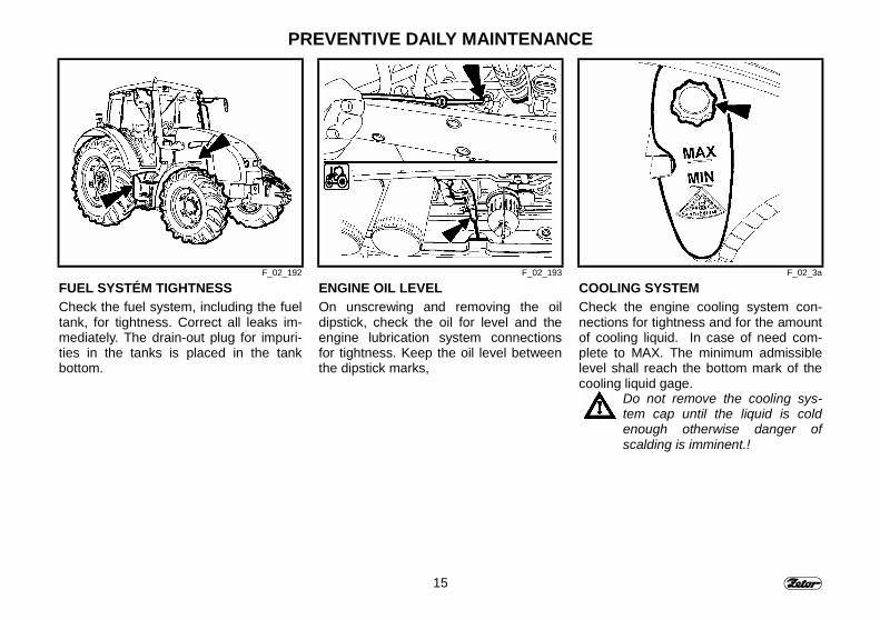
FUEL SYSTÉM TIGHTNESSCheck the fuel system, including the fueltank, for tightness. Correct all leaks im-mediately. The drain-out plug for impuri-ties in the tanks is placed in the tankbottom.
ENGINE OIL LEVELOn unscrewing and removing the oildipstick, check the oil for level and theengine lubrication system connectionsfor tightness. Keep the oil level betweenthe dipstick marks,
COOLING SYSTEMCheck the engine cooling system con-nections for tightness and for the amountof cooling liquid. In case of need com-plete to MAX. The minimum admissiblelevel shall reach the bottom mark of thecooling liquid gage.
Do not remove the cooling sys-tem cap until the liquid is coldenough otherwise danger ofscalding is imminent.!
16
PREVENTIVE DAILY MAINTENANCE
F_02_4 F_02_56 F13
LIQUID-OPERATED BRAKESCheck the liquid-operated brakes, clutchfor tightness, and the brake liquid recov-ery tank for amount. Keep the brakeliquid level within the limits of 3/4 (maxi-mum level) and 1/2 (minimum level) tankcapacity.
TRAILER PNEUMATIC BRAKESCheck the pneumatic brake system fortightness and the tractor brake withtrailer efficiency. (For details see theChapter Hints for Maintenance, part“Checking the Pneumatic Systems forTightness” of this Operating and Mainte-nance Manual).
TRAILER HYDRAULIC BRAKESCheck the trailer hydraulic brakes fortightness

17
PREVENTIVE DAILY MAINTENANCE
F_02_5 F_02_6a F_02_9
HYDROSTATIC STEERING- Check the oil level for amount in the
hydrostatic steering tank.- Check the bolts and nuts of the steer-
ing rods and levers for proper tighten-ing.
- Check all hoses of the steering hy-draulic circuit for conditions and leaks.
AIR CLEANERThe air cleaner is fitted with a sensorsignaling its clogging with impurities. Thesensor makes switch on a signal lightinstalled in the dashboard in case the aircleaner is heavily obstructed.
CAB FILTRATIONCheck and clean if necessary the cabventilation air filters installed in the frontoverhang of the cab.The filter replacement depends on theamount of dust at the working area at-mosphere.You can partially regenerate them byknocking or blowing them through withcompressed air.Cleaning or replacement of filter ele-ments should be carried out after re-moving the covering grids in the roofoverhang.

18
PREVENTIVE DAILY MAINTENANCE
F18 F_02_100 F_02_7
ATTACHING IMPLEMENTSCheck the tractor and trailer attachingand suspending implements for properconditions
AFTER OPERATION WITH FRONTIMPLEMENTSAfter operation with front implements:- Check the connections of hydraulic
control circuit of the front three-pointhitch for leaks
Clogging of coolers:- Remove the side part of hood- ∗ Loosen and pull the air-conditioning
condenser to the left-hand tractor side.- Clean the front part of engine radiator
(air-conditioning condenser) by meansof pressured air (blow air in directionfrom the engine).
- Remove the rest of impurities from thespace under the bonnet (otherwise theirrepeated suction might appear).
TIRES AND WHEELSCheck the front and rear wheel tyres forproper pressure with adjusting it to theforeseen operation. Check and tighten ifnecessary the bolts of the front and rearwheels (rim / wheel disk and wheel disk /wheel axle connections).
Never drive the machine with thebolts not fully tightened. l!
19
PREVENTIVE DAILY MAINTENANCE
F_02_102a
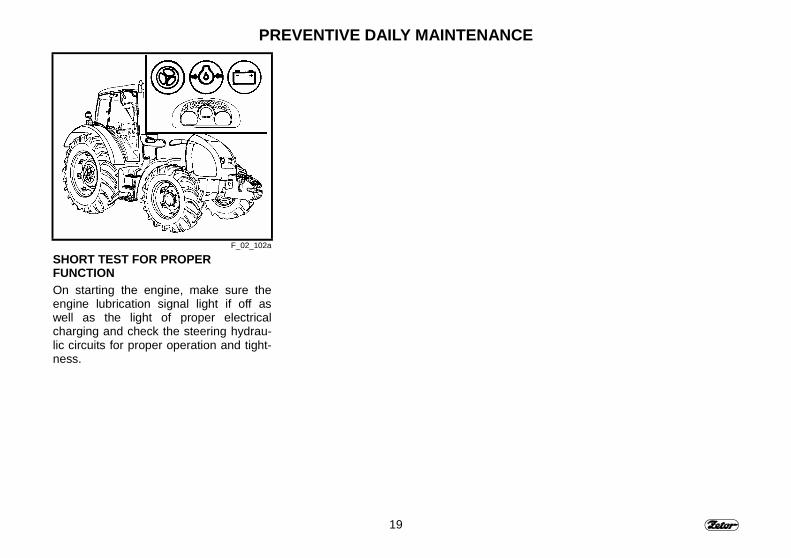
SHORT TEST FOR PROPERFUNCTIONOn starting the engine, make sure theengine lubrication signal light if off aswell as the light of proper electricalcharging and check the steering hydrau-lic circuits for proper operation and tight-ness.

20
NOTE
21
TRACTOR SURVEY
The tractor user has to acquaintwith the recommended proce-dures and hints for the tractorsafety operation in advance. Itwould be too late to do it in thecourse of tractor operation!
PageSafety cab ............................................................................................................................... 23Opening the door from outside ................................................................................................ 23Opening the door from inside................................................................................................... 23Rear window............................................................................................................................ 24Side window ............................................................................................................................ 24∗ Tilting cover .......................................................................................................................... 24Washer nozzle......................................................................................................................... 25Washer tank ............................................................................................................................ 25Washer control ........................................................................................................................ 25Fellow traveler's seat ............................................................................................................... 26Stowing compartment and tool box.......................................................................................... 26Rearview mirrors ..................................................................................................................... 26Adjusting the seat to the driver's weight (Mars seat) ................................................................ 27Longitudinal seat adjustment ................................................................................................... 27Vertical seat adjustment .......................................................................................................... 27∗ Grammer - Driver's seat........................................................................................................ 28Adjusting the seat to the driver's weight................................................................................... 28Longitudinal adjustment........................................................................................................... 28Tilting steering wheel ............................................................................................................... 29Angular adjustment.................................................................................................................. 29Vertical adjustment .................................................................................................................. 29Heating control panel, ∗ air conditioning, ∗ radio...................................................................... 30Heating valve controller (A)...................................................................................................... 30Fan controller (B)..................................................................................................................... 30Switch ∗ air conditioning (C) .................................................................................................... 30Cab air circulation controller (D) .............................................................................................. 31Heating and air conditioning system proper operation ............................................................. 31Cab interior fast heating........................................................................................................... 31Cab interior fast cooling ........................................................................................................... 32Heating and air conditioning system proper operation ............................................................. 32Immediately after the cab cooling ............................................................................................ 32Heating and air conditioning breathers (A) (∗ radio loudspeakers) ............................................ 33Windscreen defrosting (B) ....................................................................................................... 33Analog dashboard ................................................................................................................... 35∗ Digital dashboard.................................................................................................................. 37Changeover switches, switches, and levers............................................................................. 38
22
TRACTOR SURVEYPage
Light changeover switch (a) ..................................................................................................... 39Front axle drive switch (f)......................................................................................................... 39Warning light switch (e) ........................................................................................................... 39Hood / cab lights changeover switch (b) .................................................................................. 40Rear, front axle lock pushbutton (j) .......................................................................................... 40Direction lights, dimmed and distance lights and horn changeover switch (l) ........................... 40Switch box ............................................................................................................................... 41Key in the ”0” position .............................................................................................................. 41Key in the ”I” position ............................................................................................................... 41Key in the ”II” position .............................................................................................................. 42Electronic hand throttle control ................................................................................................ 43Hand-operated fuel supply lever Z 8641 - Z 11441................................................................... 43Engine run stop controller Z 8641 - Z 11441 ............................................................................ 43Pedals and levers .................................................................................................................... 44Main gearshift lever and reverse march shift lever ................................................................... 44Road and reduced gear shift lever ........................................................................................... 44P.T.O. shaft dependent and independent revolutions shifting lever .......................................... 45Hand-operated brake lever and two-wheel trailer hitch control lever ........................................ 45Hydraulic control panel location ............................................................................................... 45Additional hydraulic distributor control (outer hydraulic circuit) ................................................. 46Control panel on the cab r - h column ...................................................................................... 46Battery isolator......................................................................................................................... 46Location of information and warning plates.............................................................................. 48Fuel tank.................................................................................................................................. 49Fuel tank drain plug ................................................................................................................. 49Average fuel consumption in liters per Zetor tractor operating hour ......................................... 49
23
TRACTOR SURVEY
F_02_8 F_02_11 F23
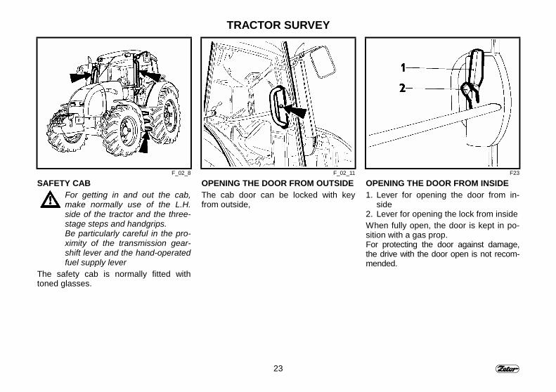
SAFETY CABFor getting in and out the cab,make normally use of the L.H.side of the tractor and the three-stage steps and handgrips.Be particularly careful in the pro-ximity of the transmission gear-shift lever and the hand-operatedfuel supply lever
The safety cab is normally fitted withtoned glasses.
OPENING THE DOOR FROM OUTSIDEThe cab door can be locked with keyfrom outside,
OPENING THE DOOR FROM INSIDE1. Lever for opening the door from in-
side2. Lever for opening the lock from insideWhen fully open, the door is kept in po-sition with a gas prop.For protecting the door against damage,the drive with the door open is not recom-mended.
24
TRACTOR SURVEY
F24 F25 F_02_14
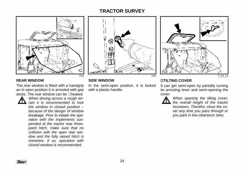
REAR WINDOWThe rear window is fitted with a handgripan in open position it is arrested with gasstruts. The rear window can be ∗ heated.
When driving across a rough ter-rain it is recommended to lockthe window in closed position –because of the danger of windowbreakage. Prior to initiate the ope-ration with the implements sus-pended at the tractor rear three-point hitch, make sure that nocollision with the open rear win-dow and the fully raised hitch isimminent. If so, operation withclosed window is recommended.
SIDE WINDOWIn the semi-open position, it is lockedwith a plastic handle.
∗∗∗∗ TILTING COVERIt can get semi-open by partially turningits arresting lever and semi-opening thecover.
When opening the tilting cover,the overall height of the tractorincreases. Therefor, close the co-ver any time you pass through oryou park in low clearance sites.
25
TRACTOR SURVEY
F28 F_02_152a F_02_137
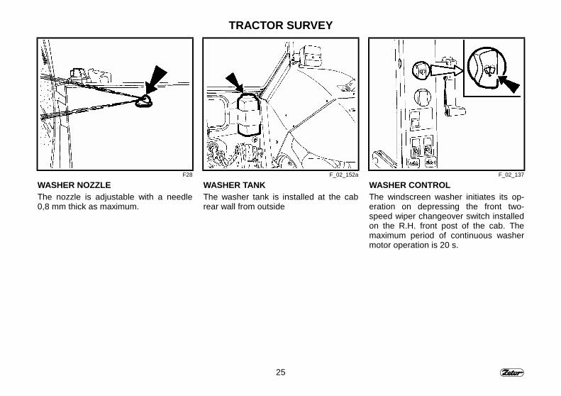
WASHER NOZZLEThe nozzle is adjustable with a needle0,8 mm thick as maximum.
WASHER TANKThe washer tank is installed at the cabrear wall from outside
WASHER CONTROLThe windscreen washer initiates its op-eration on depressing the front two-speed wiper changeover switch installedon the R.H. front post of the cab. Themaximum period of continuous washermotor operation is 20 s.
26
TRACTOR SURVEY
F_02_13 F31 F_02_12
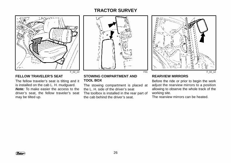
FELLOW TRAVELER'S SEATThe fellow traveler’s seat is tilting and itis installed on the cab L. H. mudguard.Note: To make easier the access to thedriver’s seat, the fellow traveler’s seatmay be tilted up.
STOWING COMPARTMENT ANDTOOL BOXThe stowing compartment is placed atthe L. H. side of the driver’s seatThe toolbox is installed in the rear part ofthe cab behind the driver’s seat.
REARVIEW MIRRORSBefore the ride or prior to begin the workadjust the rearview mirrors to a positionallowing to observe the whole track of theworking site.The rearview mirrors can be heated.
27
TRACTOR SURVEY
F33 F34 F35
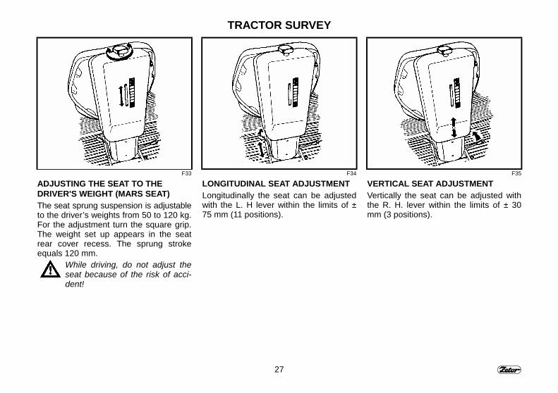
ADJUSTING THE SEAT TO THEDRIVER'S WEIGHT (MARS SEAT)The seat sprung suspension is adjustableto the driver’s weights from 50 to 120 kg.For the adjustment turn the square grip.The weight set up appears in the seatrear cover recess. The sprung strokeequals 120 mm.
While driving, do not adjust theseat because of the risk of acci-dent!
LONGITUDINAL SEAT ADJUSTMENTLongitudinally the seat can be adjustedwith the L. H lever within the limits of ±75 mm (11 positions).
VERTICAL SEAT ADJUSTMENTVertically the seat can be adjusted withthe R. H. lever within the limits of ± 30mm (3 positions).
28
TRACTOR SURVEY
F36 F37 F38
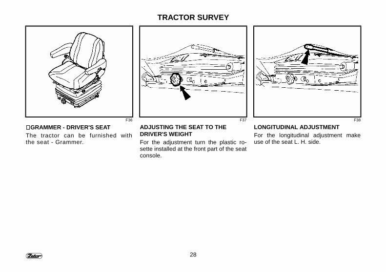
∗∗∗∗ GRAMMER - DRIVER'S SEATThe tractor can be furnished withthe seat - Grammer.
ADJUSTING THE SEAT TO THEDRIVER'S WEIGHTFor the adjustment turn the plastic ro-sette installed at the front part of the seatconsole.
LONGITUDINAL ADJUSTMENTFor the longitudinal adjustment makeuse of the seat L. H. side.
29
TRACTOR SURVEY
B12 B13 B14
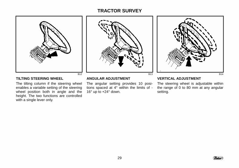
TILTING STEERING WHEELThe tilting column if the steering wheelenables a variable setting of the steeringwheel position both in angle and theheight. The two functions are controlledwith a single lever only.
ANGULAR ADJUSTMENTThe angular setting provides 10 posi-tions spaced at 4° within the limits of -16° up to +24° down.
VERTICAL ADJUSTMENTThe steering wheel is adjustable withinthe range of 0 to 80 mm at any angularsetting.
30
TRACTOR SURVEY
F_02_15 F_02_16 F_02_17a
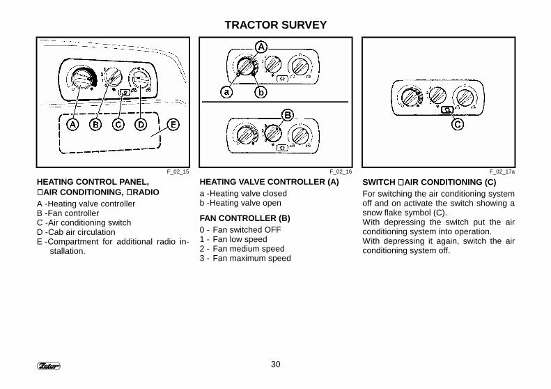
HEATING CONTROL PANEL,∗∗∗∗ AIR CONDITIONING, ∗∗∗∗ RADIOA - Heating valve controllerB - Fan controllerC - Air conditioning switchD - Cab air circulationE - Compartment for additional radio in-
stallation.
HEATING VALVE CONTROLLER (A)a - Heating valve closedb - Heating valve open
FAN CONTROLLER (B)0 - Fan switched OFF1 - Fan low speed2 - Fan medium speed3 - Fan maximum speed
SWITCH ∗∗∗∗ AIR CONDITIONING (C)For switching the air conditioning systemoff and on activate the switch showing asnow flake symbol (C).With depressing the switch put the airconditioning system into operation.With depressing it again, switch the airconditioning system off.
31
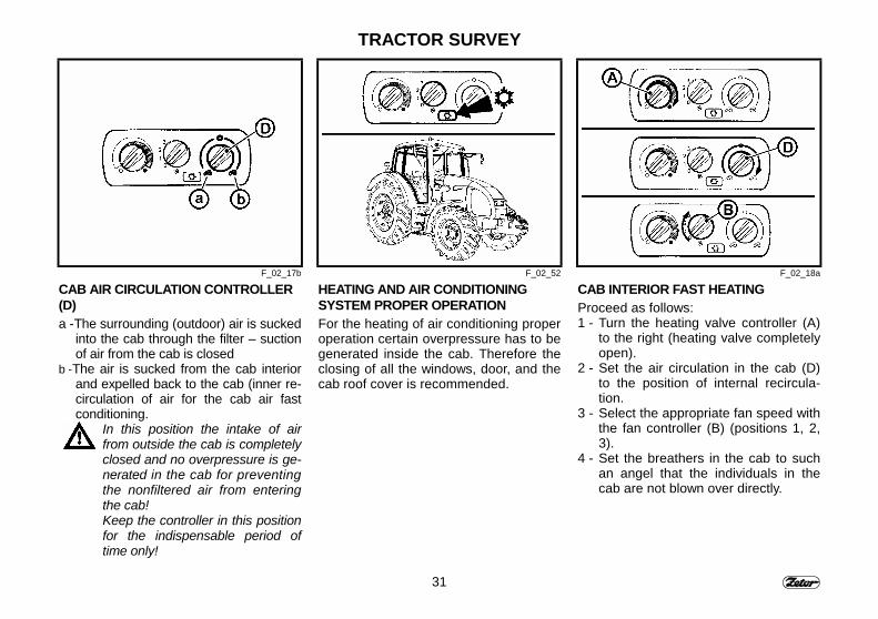
TRACTOR SURVEY
F_02_17b F_02_52 F_02_18a
CAB AIR CIRCULATION CONTROLLER(D)a - The surrounding (outdoor) air is sucked
into the cab through the filter – suctionof air from the cab is closed
b - The air is sucked from the cab interiorand expelled back to the cab (inner re-circulation of air for the cab air fastconditioning.
In this position the intake of airfrom outside the cab is completelyclosed and no overpressure is ge-nerated in the cab for preventingthe nonfiltered air from enteringthe cab!Keep the controller in this positionfor the indispensable period oftime only!
HEATING AND AIR CONDITIONINGSYSTEM PROPER OPERATIONFor the heating of air conditioning properoperation certain overpressure has to begenerated inside the cab. Therefore theclosing of all the windows, door, and thecab roof cover is recommended.
CAB INTERIOR FAST HEATINGProceed as follows:1 - Turn the heating valve controller (A)
to the right (heating valve completelyopen).
2 - Set the air circulation in the cab (D)to the position of internal recircula-tion.
3 - Select the appropriate fan speed withthe fan controller (B) (positions 1, 2,3).
4 - Set the breathers in the cab to suchan angel that the individuals in thecab are not blown over directly.
32
TRACTOR SURVEY
F_02_18 F_02_19 F_02_20
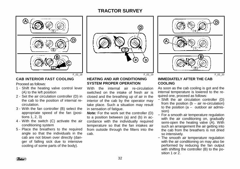
CAB INTERIOR FAST COOLINGProceed as follows:1 - Shift the heating valve control lever
(A) to the left position2 - Set the air circulation controller (D) in
the cab to the position of internal re-circulation.
3 - With the fan controller (B) select theappropriate speed of the fan (posi-tions 1, 2, 3)
4 - With the switch (C) activate the airconditioning system
5 - Place the breathers to the requiredangle so that the individuals in thecab are not blown over directly (dan-ger of falling sick due to intensivecooling of some parts of the body).
HEATING AND AIR CONDITIONINGSYSTEM PROPER OPERATIONWith the internal air re-circulationswitched on the intake of fresh air isclosed and the breathing up of air in theinterior of the cab by the operator maytake place. Such a situation may resultin sensation of fatigue.Note: For the work set the controller (D)to a position between (a) and (b) in ac-cordance with the individually requiredtemperature so that the fan intakes airfrom outside through the filters into thecab.
IMMEDIATELY AFTER THE CABCOOLINGAs soon as the cab cooling is got and theinternal temperature is lowered to the re-quired one, proceed as follows:− Shift the air circulation controller (D)
from the position (b – air re-circulation)to the position (a – outdoor air admis-sion)
− For a smooth air temperature regulationwith the air conditioning on, graduallysemi-open the heating valve (A). Withsuch an arrangement the air getting intothe cab from the breathers is not driedso intensively.
− The smooth air temperature regulationwith the air conditioning on may also beperformed by reducing the fan outputwith shifting the controller (B) to the po-sition 1 or 2.
33
TRACTOR SURVEY
F_02_151
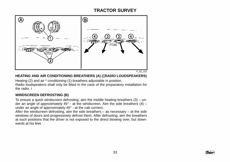
HEATING AND AIR CONDITIONING BREATHERS (A) (∗∗∗∗ RADIO LOUDSPEAKERS)Heating (2) and air * conditioning (1) breathers adjustable in position.Radio loudspeakers shall only be fitted in the case of the preparatory installation forthe radio. i
WINDSCREEN DEFROSTING (B)To ensure a quick windscreen defrosting, aim the middle heating breathers (3) – un-der an angle of approximately 45° - at the windscreen. Aim the side breathers (4) –under an angle of approximately 45° - at the cab corners.After the windscreen defrosting, aim the side breathers – as necessary – at the sidewindows of doors and progressively defrost them. After defrosting, aim the breathersat such positions that the driver is not exposed to the direct blowing over, but down-wards at his feet.
34
TRACTOR SURVEY
B21a
35
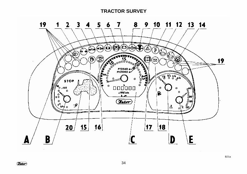
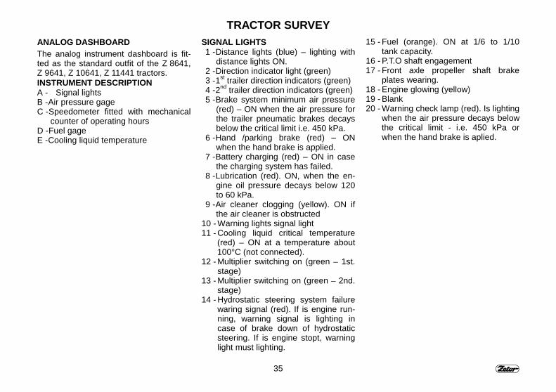
TRACTOR SURVEYANALOG DASHBOARDThe analog instrument dashboard is fit-ted as the standard outfit of the Z 8641,Z 9641, Z 10641, Z 11441 tractors.INSTRUMENT DESCRIPTIONA - Signal lightsB - Air pressure gageC - Speedometer fitted with mechanical
counter of operating hoursD - Fuel gageE - Cooling liquid temperature
SIGNAL LIGHTS1 - Distance lights (blue) – lighting with
distance lights ON.2 - Direction indicator light (green)3 - 1st trailer direction indicators (green)4 - 2nd trailer direction indicators (green)5 - Brake system minimum air pressure
(red) – ON when the air pressure forthe trailer pneumatic brakes decaysbelow the critical limit i.e. 450 kPa.
6 - Hand /parking brake (red) – ONwhen the hand brake is applied.
7 - Battery charging (red) – ON in casethe charging system has failed.
8 - Lubrication (red). ON, when the en-gine oil pressure decays below 120to 60 kPa.
9 - Air cleaner clogging (yellow). ON ifthe air cleaner is obstructed
10 - Warning lights signal light11 - Cooling liquid critical temperature
(red) – ON at a temperature about100°C (not connected).
12 - Multiplier switching on (green – 1st.stage)
13 - Multiplier switching on (green – 2nd.stage)
14 - Hydrostatic steering system failurewaring signal (red). If is engine run-ning, warning signal is lighting incase of brake down of hydrostaticsteering. If is engine stopt, warninglight must lighting.
15 - Fuel (orange). ON at 1/6 to 1/10tank capacity.
16 - P.T.O shaft engagement17 - Front axle propeller shaft brake
plates wearing.18 - Engine glowing (yellow)19 - Blank20 - Warning check lamp (red). Is lighting
when the air pressure decays belowthe critical limit - i.e. 450 kPa orwhen the hand brake is aplied.

36
TRACTOR SURVEY
F54b
37
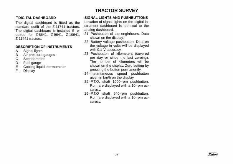
TRACTOR SURVEY∗∗∗∗ DIGITAL DASHBOARDThe digital dashboard is fitted as thestandard outfit of the Z 11741 tractors.The digital dashboard is installed if re-quired for Z 8641, Z 9641, Z 10641,Z 11441 tractors.
DESCRIPTION OF INSTRUMENTSA - Signal lightsB - Air pressure gaugesC - SpeedometerD - Fuel gaugeE - Cooling liquid thermometerF - Display
SIGNAL LIGHTS AND PUSHBUTTONSLocation of signal lights on the digital in-strument dashboard is identical to theanalog dashboard.21 - Pushbutton of the enginhours. Data
shown on the display.22 - Battery voltage pushbutton. Data on
the voltage in volts will be displayedwith 0,1-V accuracy.
23 - Pushbutton of kilometers (coveredper day or since the last zeroing).The number of kilometers will beshown on the display. Zero setting bypressing the button permanently.
24 - Instantaneous speed pushbuttongiven in km/h on the display.
25 - P.T.O. shaft 1000-rpm pushbutton.Rpm are displayed with a 10-rpm ac-curacy.
26 - P.T.O shaft 540-rpm pushbutton.Rpm are displayed with a 10-rpm ac-curacy.
38
TRACTOR SURVEY
F_02_149
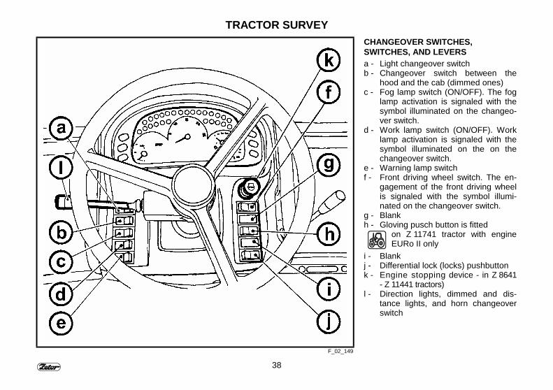
CHANGEOVER SWITCHES,SWITCHES, AND LEVERSa - Light changeover switchb - Changeover switch between the
hood and the cab (dimmed ones)c - Fog lamp switch (ON/OFF). The fog
lamp activation is signaled with thesymbol illuminated on the changeo-ver switch.
d - Work lamp switch (ON/OFF). Worklamp activation is signaled with thesymbol illuminated on the on thechangeover switch.
e - Warning lamp switchf - Front driving wheel switch. The en-
gagement of the front driving wheelis signaled with the symbol illumi-nated on the changeover switch.
g - Blankh - Gloving pusch button is fitted
on Z 11741 tractor with engineEURo II only
i - Blankj - Differential lock (locks) pushbuttonk - Engine stopping device - in Z 8641
- Z 11441 tractors)l - Direction lights, dimmed and dis-
tance lights, and horn changeoverswitch
39
TRACTOR SURVEY
F56 F57 F58
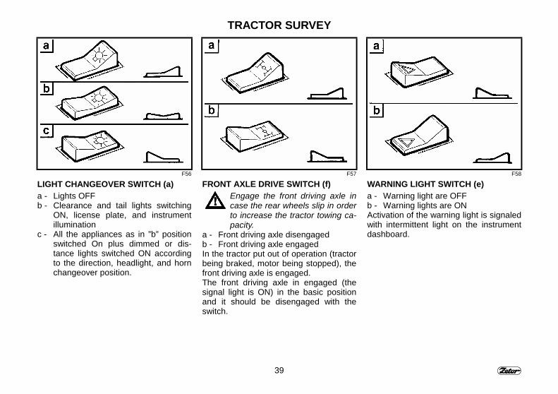
LIGHT CHANGEOVER SWITCH (a)a - Lights OFFb - Clearance and tail lights switching
ON, license plate, and instrumentillumination
c - All the appliances as in ”b” positionswitched On plus dimmed or dis-tance lights switched ON accordingto the direction, headlight, and hornchangeover position.
FRONT AXLE DRIVE SWITCH (f)Engage the front driving axle incase the rear wheels slip in orderto increase the tractor towing ca-pacity.
a - Front driving axle disengagedb - Front driving axle engagedIn the tractor put out of operation (tractorbeing braked, motor being stopped), thefront driving axle is engaged.The front driving axle in engaged (thesignal light is ON) in the basic positionand it should be disengaged with theswitch.
WARNING LIGHT SWITCH (e)a - Warning light are OFFb - Warning lights are ONActivation of the warning light is signaledwith intermittent light on the instrumentdashboard.
40
TRACTOR SURVEY
F59 F60 F_02_181
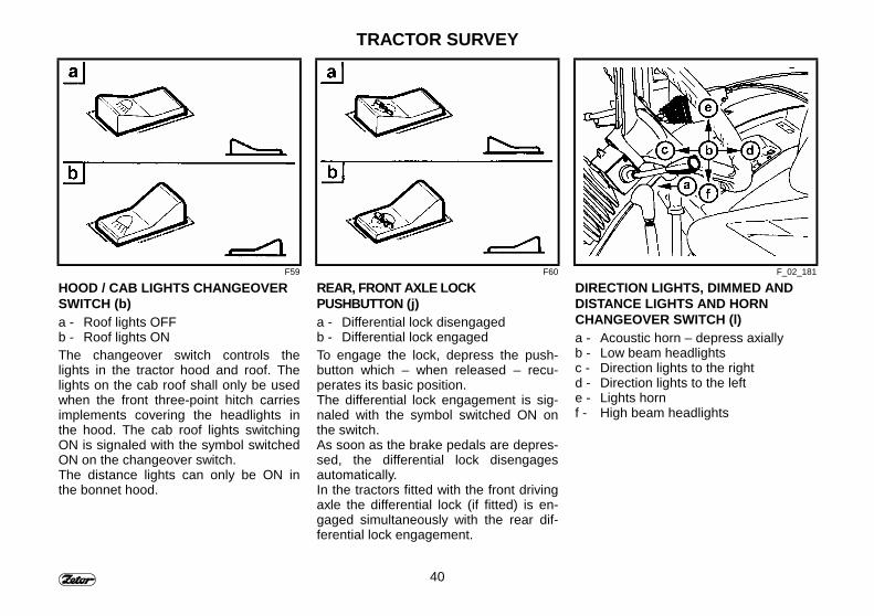
HOOD / CAB LIGHTS CHANGEOVERSWITCH (b)a - Roof lights OFFb - Roof lights ONThe changeover switch controls thelights in the tractor hood and roof. Thelights on the cab roof shall only be usedwhen the front three-point hitch carriesimplements covering the headlights inthe hood. The cab roof lights switchingON is signaled with the symbol switchedON on the changeover switch.The distance lights can only be ON inthe bonnet hood.
REAR, FRONT AXLE LOCKPUSHBUTTON (j)a - Differential lock disengagedb - Differential lock engagedTo engage the lock, depress the push-button which – when released – recu-perates its basic position.The differential lock engagement is sig-naled with the symbol switched ON onthe switch.As soon as the brake pedals are depres-sed, the differential lock disengagesautomatically.In the tractors fitted with the front drivingaxle the differential lock (if fitted) is en-gaged simultaneously with the rear dif-ferential lock engagement.
DIRECTION LIGHTS, DIMMED ANDDISTANCE LIGHTS AND HORNCHANGEOVER SWITCH (l)a - Acoustic horn – depress axiallyb - Low beam headlightsc - Direction lights to the rightd - Direction lights to the lefte - Lights hornf - High beam headlights
41
TRACTOR SURVAY
F62 S43 S44
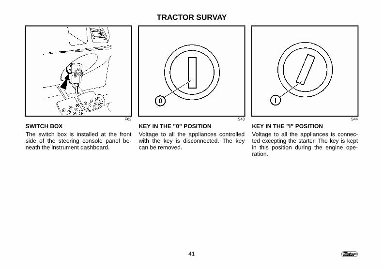
SWITCH BOXThe switch box is installed at the frontside of the steering console panel be-neath the instrument dashboard.
KEY IN THE ”0” POSITIONVoltage to all the appliances controlledwith the key is disconnected. The keycan be removed.
KEY IN THE ”I” POSITIONVoltage to all the appliances is connec-ted excepting the starter. The key is keptin this position during the engine ope-ration.
42
TRACTOR SURVEY
S45
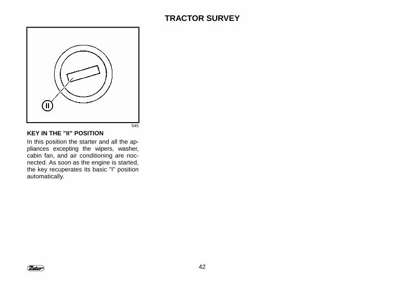
KEY IN THE ”II” POSITIONIn this position the starter and all the ap-pliances excepting the wipers, washer,cabin fan, and air conditioning are noc-nected. As soon as the engine is started,the key recuperates its basic ”I” positionautomatically.
43
TRACTOR SURVEY
F69 F67 F68
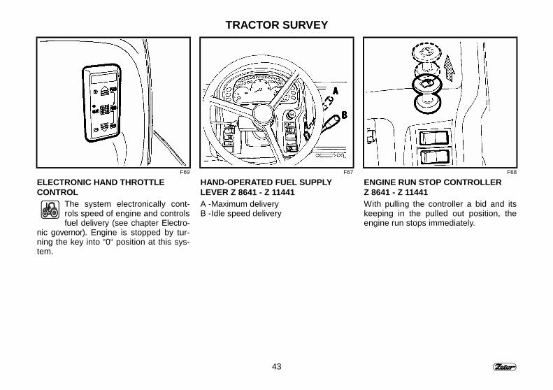
ELECTRONIC HAND THROTTLECONTROL
The system electronically cont-rols speed of engine and controlsfuel delivery (see chapter Electro-
nic governor). Engine is stopped by tur-ning the key into “0“ position at this sys-tem.
HAND-OPERATED FUEL SUPPLYLEVER Z 8641 - Z 11441A - Maximum deliveryB - Idle speed delivery
ENGINE RUN STOP CONTROLLERZ 8641 - Z 11441With pulling the controller a bid and itskeeping in the pulled out position, theengine run stops immediately.
44
TRACTOR SURVEY
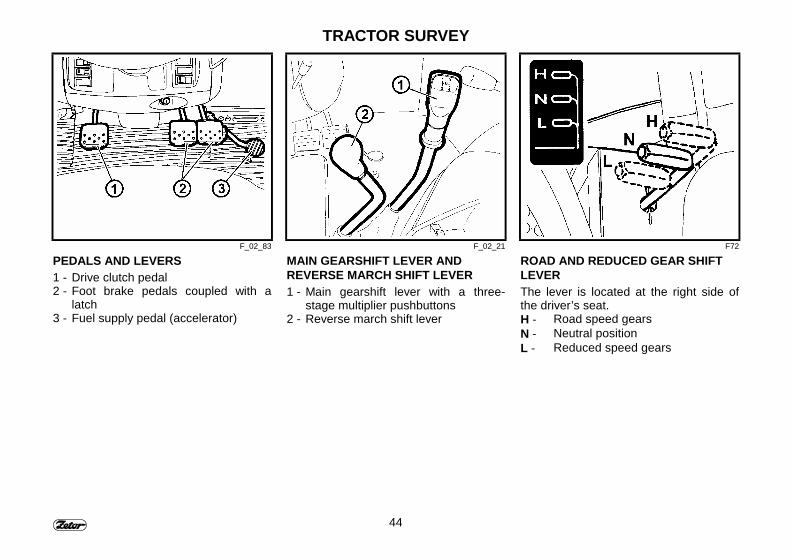
F_02_83 F_02_21 F72
PEDALS AND LEVERS1 - Drive clutch pedal2 - Foot brake pedals coupled with a
latch3 - Fuel supply pedal (accelerator)
MAIN GEARSHIFT LEVER ANDREVERSE MARCH SHIFT LEVER1 - Main gearshift lever with a three-
stage multiplier pushbuttons2 - Reverse march shift lever
ROAD AND REDUCED GEAR SHIFTLEVERThe lever is located at the right side ofthe driver’s seat.H - Road speed gearsN - Neutral positionL - Reduced speed gears
45
TRACTOR SURVEY
F73 F74 F_02_213
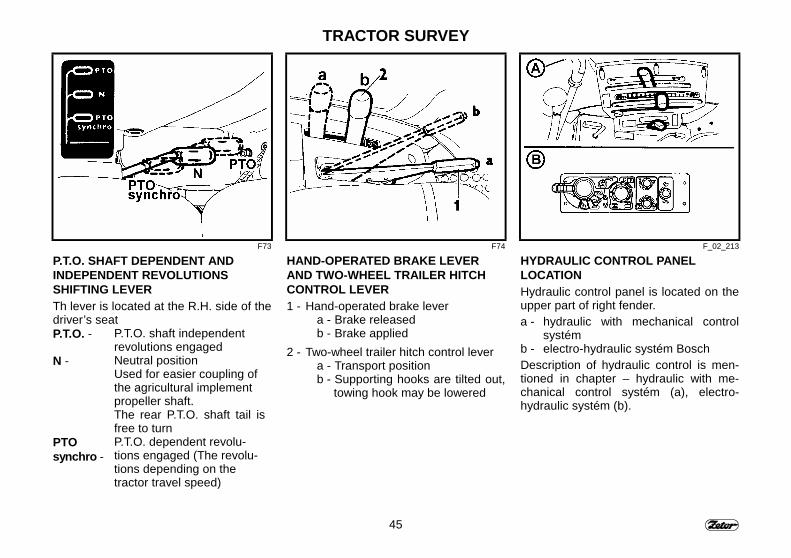
P.T.O. SHAFT DEPENDENT ANDINDEPENDENT REVOLUTIONSSHIFTING LEVERTh lever is located at the R.H. side of thedriver’s seatP.T.O. - P.T.O. shaft independent
revolutions engagedN - Neutral position
Used for easier coupling ofthe agricultural implementpropeller shaft.The rear P.T.O. shaft tail isfree to turn
PTOsynchro -
P.T.O. dependent revolu-tions engaged (The revolu-tions depending on thetractor travel speed)
HAND-OPERATED BRAKE LEVERAND TWO-WHEEL TRAILER HITCHCONTROL LEVER1 - Hand-operated brake lever
a - Brake releasedb - Brake applied
2 - Two-wheel trailer hitch control levera - Transport positionb - Supporting hooks are tilted out,
towing hook may be lowered
HYDRAULIC CONTROL PANELLOCATIONHydraulic control panel is located on theupper part of right fender.a - hydraulic with mechanical control
systémb - electro-hydraulic systém BoschDescription of hydraulic control is men-tioned in chapter – hydraulic with me-chanical control systém (a), electro-hydraulic systém (b).
46
TRACTOR SURVEY
F_02_51 F_02_156 F_02_175a
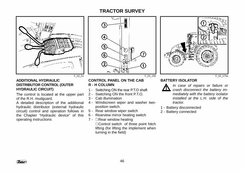
ADDITIONAL HYDRAULICDISTRIBUTOR CONTROL (OUTERHYDRAULIC CIRCUIT)The control is located at the upper partof the R.H. mudguard.A detailed description of the additionalhydraulic distributor (external hydrauliccircuit) control and operation follows inthe Chapter “Hydraulic device” of thisoperating instructions
CONTROL PANEL ON THE CABR - H COLUMN1 - Switching ON the rear P.T.O shaft2 - Switching ON the front P.T.O.3 - Cab illumination4 - Windscreen wiper and washer two-
position switch.5 - Rear window wiper switch6 - Rearview mirror heating switch7 - ∗ Rear window heating
∗ Control switch of three point hitchlifting (for lifting the implement whenturning in the field)
BATTERY ISOLATORIn case of repairs or failure orcrash disconnect the battery im-mediately with the battery isolatorinstalled at the L.H. side of thetractor.
1 - Battery disconnected2 - Battery connected
47
TRACTOR SURVAY
F_02_150
48
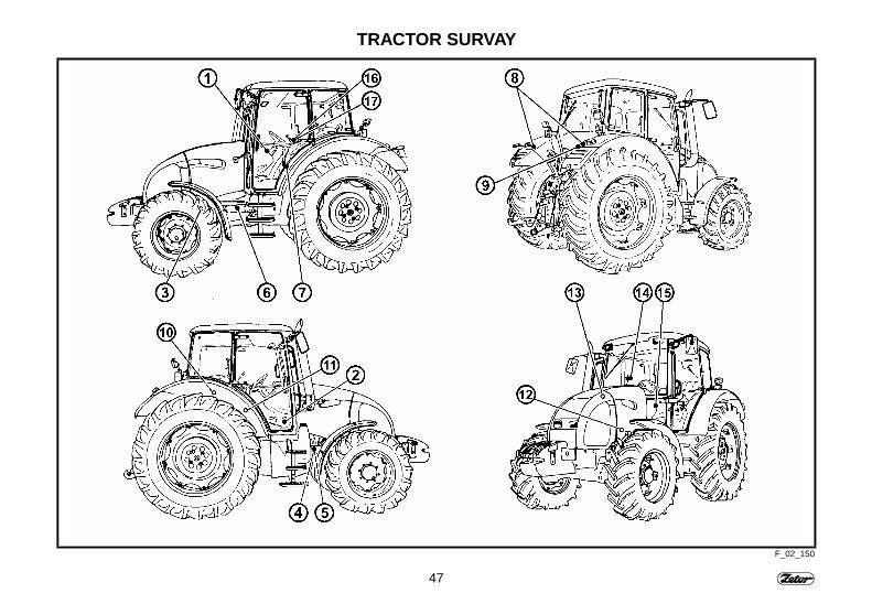
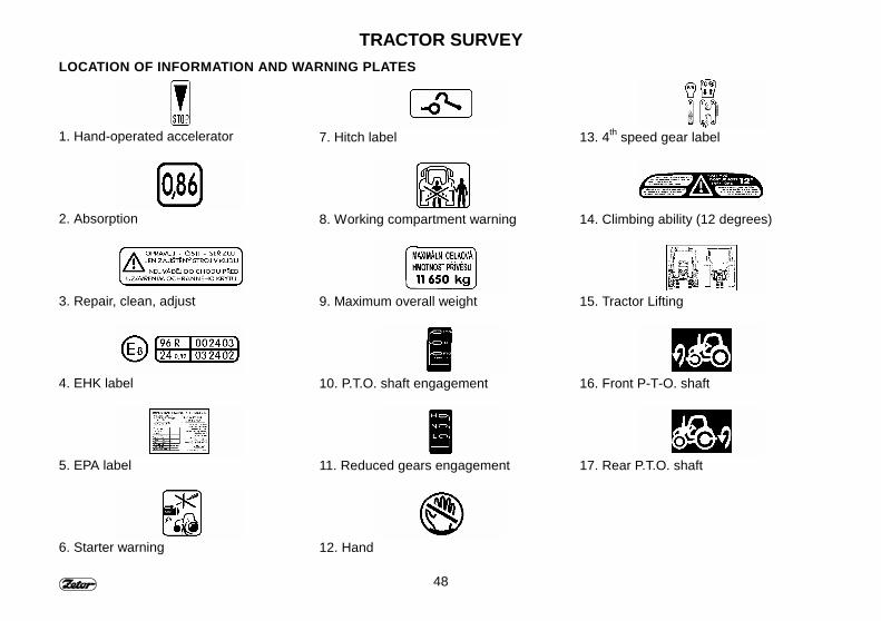
TRACTOR SURVEYLOCATION OF INFORMATION AND WARNING PLATES
1. Hand-operated accelerator
2. Absorption
3. Repair, clean, adjust
4. EHK label
5. EPA label
6. Starter warning
7. Hitch label
8. Working compartment warning
9. Maximum overall weight
10. P.T.O. shaft engagement
11. Reduced gears engagement
12. Hand
13. 4th speed gear label
14. Climbing ability (12 degrees)
15. Tractor Lifting
16. Front P-T-O. shaft
17. Rear P.T.O. shaft
49
TRACTOR SURVEY
F_02_22 F_02_23 F_02_24
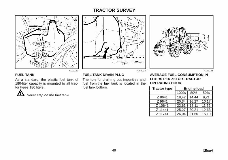
FUEL TANKAs a standard, the plastic fuel tank of180-liter capacity is mounted to all trac-tor types 180 liters.
Never step on the fuel tank!
FUEL TANK DRAIN PLUGThe hole for draining out impurities andfuel from the fuel tank is located in thefuel tank bottom.
AVERAGE FUEL CONSUMPTION INLITERS PER ZETOR TRACTOROPERATING HOUR
Tractor type Engine load100% 80% 50%
Z 8641 18,42 14,44 9,21Z 9641 20,34 16,27 10,17
Z 10641 22,63 18,11 11,32Z 11441 25,27 20,21 12,63Z 11741 26,04 21,60 15,10

50
NOTE
51
ELECTRONIC ENGINE GOVERNOR
All tractors Z 11741 are equippedwith electronic engine governor.
PageSchema of electronic engine control system ............................................................ 52Push button - MAX.................................................................................................... 53Push button - MIN ..................................................................................................... 53Push button - MEM ................................................................................................... 53Indicator lamp H/O .................................................................................................... 54Function of electronic governor................................................................................. 54Setting the temporary memory.................................................................................. 54Resetting and deleting the temporary memory ......................................................... 55Setting the permanent memory................................................................................. 55Permanent memory recall - H/O lamp is off .............................................................. 56Permanent memory recall - H/O lamp is on.............................................................. 57Memory reset - return to pedal control ...................................................................... 571. Setting the entry and exit speed at tillage and enter to memory........................... 582. Setting the operating speed and enter to temporary memory............................... 583. Tillage with operating speed temporarily memorised............................................ 584. Reset of temporary memory and recall of entry and exit speed memory.............. 595. Reset of permanent memory, setting the operating speed and its temporarymemorising ............................................................................................................... 596. Tillage with operating speed temporarily memorised............................................ 591. Setting the PTO speed.......................................................................................... 602. Setting the constant travel speed.......................................................................... 603. PTO speed engagement and setting the PTO speed for 540 or 1000 RPM......... 604. Temporary memorising the PTO speed ................................................................ 615. Manoeuvring with tractor and reset of temporary memory.................................... 61
52
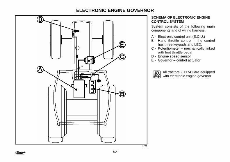
ELECTRONIC ENGINE GOVERNOR
RPM
SCHEMA OF ELECTRONIC ENGINECONTROL SYSTEMSystém consists of the following maincomponents and of wiring harness.
A - Electronic control unit (E.C.U.)B - Hand throttle control – the control
has three keypads and LED.C - Potentiometer – mechanically linked
with foot throttle pedalD - Engine speed sensorE - Governor – control actuator
All tractors Z 11741 are equippedwith electronic engine governor.
53
ELECTRONIC ENGINE GOVERNOR
RPM1 RPM2 RPM3
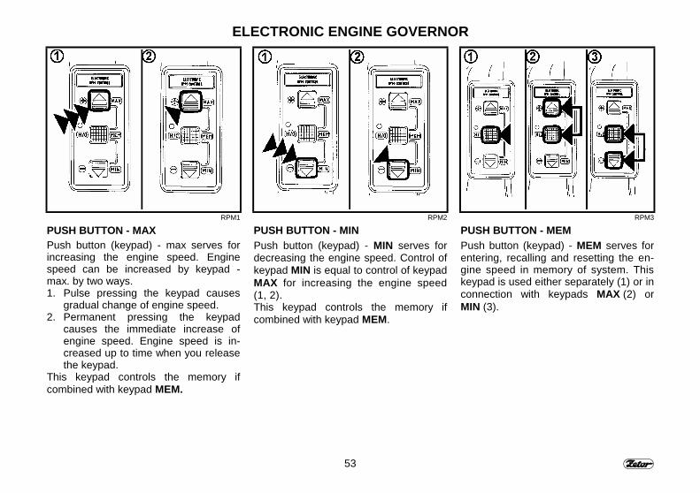
PUSH BUTTON - MAXPush button (keypad) - max serves forincreasing the engine speed. Enginespeed can be increased by keypad -max. by two ways.1. Pulse pressing the keypad causes
gradual change of engine speed.2. Permanent pressing the keypad
causes the immediate increase ofengine speed. Engine speed is in-creased up to time when you releasethe keypad.
This keypad controls the memory ifcombined with keypad MEM.
PUSH BUTTON - MINPush button (keypad) - MIN serves fordecreasing the engine speed. Control ofkeypad MIN is equal to control of keypadMAX for increasing the engine speed(1, 2).This keypad controls the memory ifcombined with keypad MEM.
PUSH BUTTON - MEMPush button (keypad) - MEM serves forentering, recalling and resetting the en-gine speed in memory of system. Thiskeypad is used either separately (1) or inconnection with keypads MAX (2) orMIN (3).
54
ELECTRONIC ENGINE GOVERNOR
RPM4 RPM5 RPM6
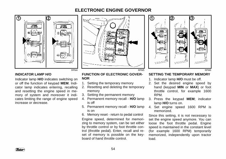
INDICATOR LAMP H/OIndicator lamp H/O indicates switching onor off the function of keypad MEM. Indi-cator lamp indicates entering, recallingand resetting the engine speed in me-mory of system and moreover it indi-cates limiting the range of engine speedincrease or decrease.
FUNCTION OF ELECTRONIC GOVER-NOR1. Setting the temporary memory2. Resetting and deleting the temporary
memory3. Setting the permanent memory4. Permanent memory recall - H/O lamp
is off5. Permanent memory recall - H/O lamp
is on6. Memory reset - return to pedal controlEngine speed, determined for memori-zing to memory system, can be set eitherby throttle control or by foot throttle con-trol (throttle pedal). Enter, recall and re-set of memory is possible on the key-board of hand throttle control.
SETTING THE TEMPORARY MEMORY1. Indicator lamp H/O must be off.2. Set the desired engine speed by
hand (keypad MIN or MAX) or footthrottle control, for example 1600RPM.
3. Press the keypad MEM; indicatorlamp H/O turns on.
4. Set engine speed 1600 RPM ismemorized.
Since this setting, it is not necessary toset the engine speed anymore. You canloose the foot throttle pedal. Enginespeed is maintained in the constant level(for example 1600 RPM) temporarilymemorized, independently upon tractorload.
55
ELECTRONIC ENGINE GOVERNOR
RPM7 RPM8 RPM9
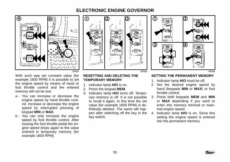
With such way set constant value (forexample 1600 RPM) it is possible to setthe engine speed by means of hand orfoot throttle control and the enteredmemory will not be lost.a - You can increase or decrease the
engine speed by hand throttle cont-rol. Increase or decrease the enginespeed by interrupted pressing ofkeypad MIN or MAX.
b - You can only increase the enginespeed by foot throttle control. Afterloosing the foot throttle pedal the en-gine speed drops again to the valueentered in temporary memory (forexample 1600 RPM).
RESETTING AND DELETING THETEMPORARY MEMORY1. Indicator lamp H/O is on.2. Press the keypad MEM.3. Indicator lamp H/O turns off. Tempo-
rary memory is off. It is not possibleto recall it again. In this time the setvalue (for example 1600 RPM) is de-finitively deleted. The same will hap-pen after switching off the key in thekey switch.
SETTING THE PERMANENT MEMORY1. Indicator lamp H/O must be off.2. Set the desired engine speed by
hand (keypads MIN or MAX) or footthrottle control.
3. Press both keypads MEM and MINor MAX depending if you want toenter into memory minimal or maxi-mal engine speed.
4. Indicator lamp H/O is on. Since thissetting the engine speed is enteredinto the permanent memory.
56
ELECTRONIC ENGINE GOVERNOR
RPM10 RPM11 RPM12
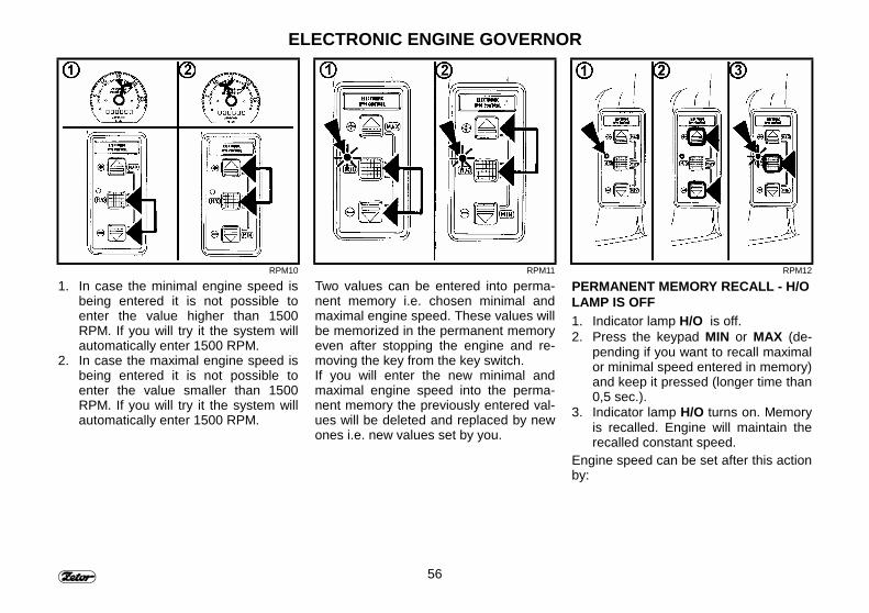
1. In case the minimal engine speed isbeing entered it is not possible toenter the value higher than 1500RPM. If you will try it the system willautomatically enter 1500 RPM.
2. In case the maximal engine speed isbeing entered it is not possible toenter the value smaller than 1500RPM. If you will try it the system willautomatically enter 1500 RPM.
Two values can be entered into perma-nent memory i.e. chosen minimal andmaximal engine speed. These values willbe memorized in the permanent memoryeven after stopping the engine and re-moving the key from the key switch.If you will enter the new minimal andmaximal engine speed into the perma-nent memory the previously entered val-ues will be deleted and replaced by newones i.e. new values set by you.
PERMANENT MEMORY RECALL - H/OLAMP IS OFF1. Indicator lamp H/O is off.2. Press the keypad MIN or MAX (de-
pending if you want to recall maximalor minimal speed entered in memory)and keep it pressed (longer time than0,5 sec.).
3. Indicator lamp H/O turns on. Memoryis recalled. Engine will maintain therecalled constant speed.
Engine speed can be set after this actionby:
57
ELECTRONIC ENGINE GOVERNOR
RPM13 RPM14 RPM15
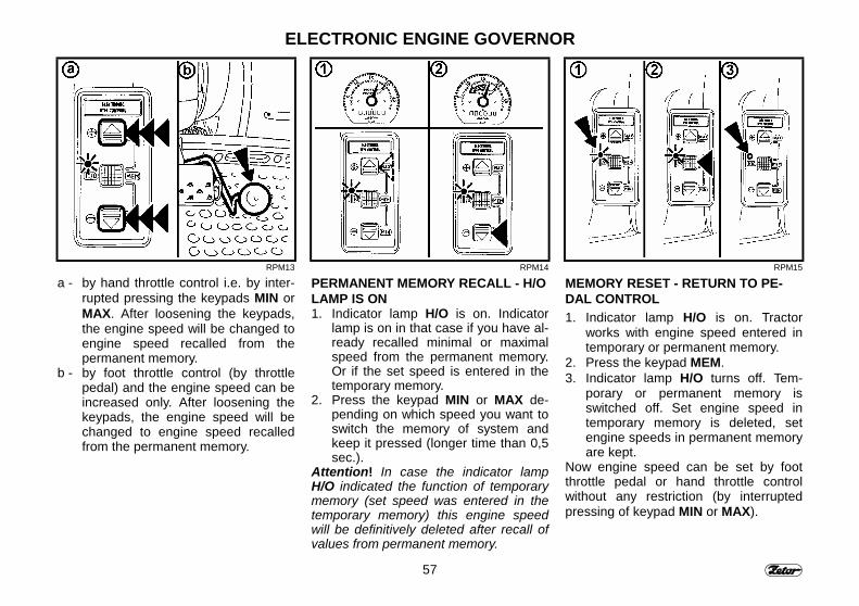
a - by hand throttle control i.e. by inter-rupted pressing the keypads MIN orMAX. After loosening the keypads,the engine speed will be changed toengine speed recalled from thepermanent memory.
b - by foot throttle control (by throttlepedal) and the engine speed can beincreased only. After loosening thekeypads, the engine speed will bechanged to engine speed recalledfrom the permanent memory.
PERMANENT MEMORY RECALL - H/OLAMP IS ON1. Indicator lamp H/O is on. Indicator
lamp is on in that case if you have al-ready recalled minimal or maximalspeed from the permanent memory.Or if the set speed is entered in thetemporary memory.
2. Press the keypad MIN or MAX de-pending on which speed you want toswitch the memory of system andkeep it pressed (longer time than 0,5sec.).
Attention! In case the indicator lampH/O indicated the function of temporarymemory (set speed was entered in thetemporary memory) this engine speedwill be definitively deleted after recall ofvalues from permanent memory.
MEMORY RESET - RETURN TO PE-DAL CONTROL1. Indicator lamp H/O is on. Tractor
works with engine speed entered intemporary or permanent memory.
2. Press the keypad MEM.3. Indicator lamp H/O turns off. Tem-
porary or permanent memory isswitched off. Set engine speed intemporary memory is deleted, setengine speeds in permanent memoryare kept.
Now engine speed can be set by footthrottle pedal or hand throttle controlwithout any restriction (by interruptedpressing of keypad MIN or MAX).
58
ELECTRONIC ENGINE GOVERNOR
RPM16
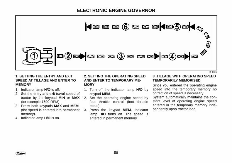
1. SETTING THE ENTRY AND EXITSPEED AT TILLAGE AND ENTER TOMEMORY1. Indicator lamp H/O is off.2. Set the entry and exit travel speed of
tractor by the keypad MIN or MAX(for example 1600 RPM)
3. Press both keypads MAX and MEM.(the speed is entered into permanentmemory).
4. Indicator lamp H/O is on.
2. SETTING THE OPERATING SPEEDAND ENTER TO TEMPORARY ME-MORY1. Turn off the indicator lamp H/O by
keypad MEM.2. Set the operating engine speed by
foot throttle control (foot throttlepedal)
3. Press the keypad MEM. Indicatorlamp H/O turns on. The speed isentered in permanent memory.
3. TILLAGE WITH OPERATING SPEEDTEMPORARILY MEMORISEDSince you entered the operating enginespeed into the temporary memory nocorrection of speed is necessary.System automatically maintains the con-stant level of operating engine speedentered in the temporary memory inde-pendently upon tractor load.
59
ELECTRONIC ENGINE GOVERNOR
RPM16
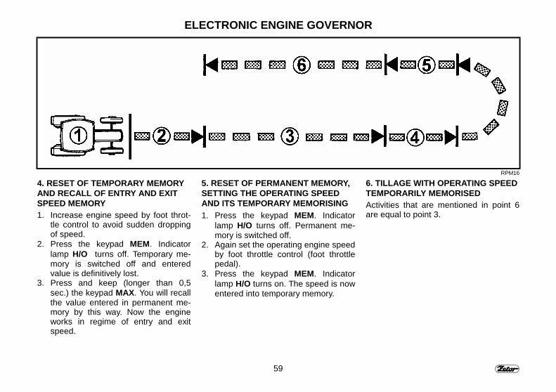
4. RESET OF TEMPORARY MEMORYAND RECALL OF ENTRY AND EXITSPEED MEMORY1. Increase engine speed by foot throt-
tle control to avoid sudden droppingof speed.
2. Press the keypad MEM. Indicatorlamp H/O turns off. Temporary me-mory is switched off and enteredvalue is definitively lost.
3. Press and keep (longer than 0,5sec.) the keypad MAX. You will recallthe value entered in permanent me-mory by this way. Now the engineworks in regime of entry and exitspeed.
5. RESET OF PERMANENT MEMORY,SETTING THE OPERATING SPEEDAND ITS TEMPORARY MEMORISING1. Press the keypad MEM. Indicator
lamp H/O turns off. Permanent me-mory is switched off.
2. Again set the operating engine speedby foot throttle control (foot throttlepedal).
3. Press the keypad MEM. Indicatorlamp H/O turns on. The speed is nowentered into temporary memory.
6. TILLAGE WITH OPERATING SPEEDTEMPORARILY MEMORISEDActivities that are mentioned in point 6are equal to point 3.
60
ELECTRONIC ENGINE GOVERNOR
RPM17
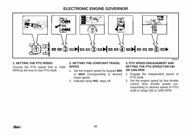
1. SETTING THE PTO SPEEDChoose the PTO speed 540 or 1000RPM by the end of rear PTO shaft.
2. SETTING THE CONSTANT TRAVELSPEED1. Set the engine speed by keypad MIN
or MAX corresponding to desiredtravel speed.
2. Indicator lamp H/O stays off.
3. PTO SPEED ENGAGEMENT ANDSETTING THE PTO SPEED FOR 540OR 1000 RPM1. Engage the independent speed of
PTO shaft.2. Set the engine speed by foot throttle
control (foot throttle pedal) cor-responding to desired speed of PTOshaft in range 540 or 1000 RPM.
61
ELECTRONIC ENGINE GOVERNOR
RPM17
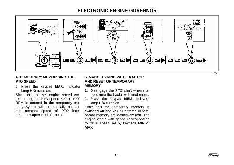
4. TEMPORARY MEMORISING THEPTO SPEED1. Press the keypad MAX. Indicator
lamp H/O turns on.Since this the set engine speed cor-responding the PTO speed 540 or 1000RPM is entered in the temporary me-mory. System will automatically maintainthe constant speed of PTO inde-pendently upon load of tractor.
5. MANOEUVRING WITH TRACTORAND RESET OF TEMPORARYMEMORY1. Disengage the PTO shaft when ma-
noeuvring the tractor with implement.2. Press the keypad MEM. Indicator
lamp H/O turns off.Since this the temporary memory isswitched off and values entered in tem-porary memory are definitively lost. Theengine works with speed correspondingto travel speed set by keypads MIN orMAX.

62
NOTE
63
DRIVE OPERATIONS
Before driving the new tractor,first of all make you acquaintedwith the gear shifting scheme andtry to engage the various gearshift lever positions with the en-gine at rest.Also make sure that the technicalconditions comply with the safetyoperation requirements.
PageBefore starting the engine......................................................................................... 65In case the engine fails to start ................................................................................. 65Starting forbidden...................................................................................................... 65Starting the engine Z 8641 - Z 11441........................................................................ 66Indicating the glow plug system failure Z 8641 - Z 11441......................................... 66Starting the engine Z 11741 equipped with electronic thermostart ........................... 67Engine Z 11741 equipt with glow gratigns................................................................. 68Failure in the glow grating system of Z 11741 engine............................................... 68Staring the engine fitted with glow gratings............................................................... 69∗ Cooling liquid heater .............................................................................................. 70Cooling liquid heater-aided engine starting............................................................... 70Immediately after starting the engine........................................................................ 71Engine warming-up ................................................................................................... 71Gear shifting.............................................................................................................. 72Reverse gearshift lever ............................................................................................. 72Road and reduced speed gears shifting ................................................................... 72Up-gear shifting......................................................................................................... 73Down-gear shifting .................................................................................................... 73Three-stage gear torque multiplier............................................................................ 73Torque multiplier operation signaling ........................................................................ 74Torque multiplier gear shifting ................................................................................... 74Travel speed increase / reduction through two speed gears .................................... 74Starting the tractor move........................................................................................... 75Uphill drive ................................................................................................................ 76Downhill drive............................................................................................................ 76Foot brakes ............................................................................................................... 76Front cardan brake.................................................................................................... 77Trailer and semi-trailer pneumatic brakes................................................................. 77Air pressure drop warning signal .............................................................................. 77Single-hose and twin-hose brakes............................................................................ 78Single-hose brakes ................................................................................................... 78Twin-hose brakes...................................................................................................... 78Air tanks .................................................................................................................... 79
64
DRIVE OPERATIONSPage
Trailer hydraulic brakes............................................................................................. 79Front driving axle control .......................................................................................... 80Drive with the front driving axle engaged.................................................................. 80Provision of the room for the front driving axle propeller shaft.................................. 80Tractor stopping - parking / hand - operated brake................................................... 81Stopping the engine Z 8641 - Z 11441 ..................................................................... 81Stopping the engine Z 11741.................................................................................... 81Leaving the tractor .................................................................................................... 82Hydrostatic steering failure warning signals ............................................................. 82

65
DRIVE OPERATIONS
F_02_28 F_02_31 F_02_32
BEFORE STARTING THE ENGINE1. The tractor is properly braked.2. The main gear shift lever andthe reverse run shift lever are inthe neutral positions.3. check turning off the PTOswitches on the right pillar of thetractor cab.If the clutch pedal is not de-pressed the tractor can not bestarted - safety interlock switch isnot actuated.
IN CASE THE ENGINE FAILS TOSTARTReturn the key to the "0" position, wait30 seconds and repeat the start.
In case the-tends to stop do nothelp it with the starter. You wouldexpose the starter to the risk ofbeing damaged.
STARTING FORBIDDENIt is strictly forbidden to startthe tract by short circuiting thestarter terminals. Start fromthe driver’s seat only.For any starter handling or repairthe negative pole of the batteryshall be disconnected and all theshift levers – including the P.T.O.shaft engagement shall be put toneutral positions. The starterterminals are protected withcaps.
66
DRIVE OPERATIONS
F_02_29 F_02_30 F_02_176
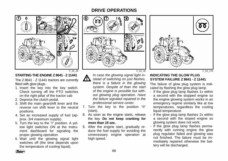
STARTING THE ENGINE Z 8641 - Z 11441The Z 8641 - Z 11441 tractors are currentlyfitted with glow plugs.1. Insert the key into the key switch.
Check turning off the PTO switcheson the right pillar of the tractor cab
2. Depress the clutch pedal.3. Shift the main gearshift lever and the
reverse run shift lever to the neutralpositions.
4. Set an increased supply of fuel (ap-prox. 3/4 maximum supply).
5. Turn the key to the “I“ position. A yel-low light switches ON at the instru-ment dashboard for signaling theproper glowing operation.
6. Wait until the glowing signal lightswitches off (the time depends uponthe temperature of cooling liquid).
In case the glowing signal light in-stead of switching on just flashes,there is a failure in the glowingsystem. Despite of than the startof the engine is possible but with-out glowing plug operation. Havethe failure signaled repaired in theprofessional service center.
7. Turn the key to the position “II“(start).
8. As soon as the engine starts, releasethe key. Do not keep cranking formore than 15 sec.
9. After the engine start, gradually re-duce the fuel supply for avoiding theunnecessary engine operation athigh speed.
INDICATING THE GLOW PLUGSYSTEM FAILURE Z 8641 - Z 11441The failure of glow plug system is indi-cated by flashing the glow plug lamp.- If the glow plug lamp flashes 1x within
a second with the stopped engine sothe engine glowing system works in anemergency regime similarly like at lowtemperatures, regardless the coolingliquid temperature.
- If the glow plug lamp flashes 2x withina second with the stoped engine soglowing system does not work.
- If the glow plug lamp flashes perma-nently with running engine the glowplug regulator failed and glowing wasnot finished. The failure must be im-mediately repaired otherwise the bat-tery will be discharged.
67
DRIVE OPERATIONS
F_02_191 F_02_182 F_02_183
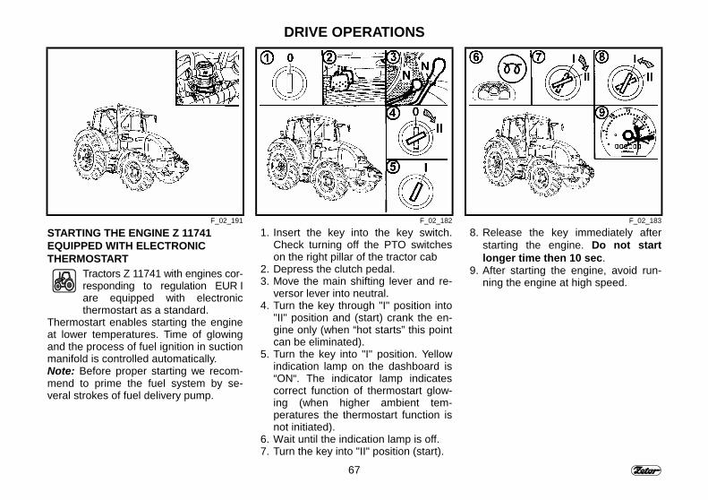
STARTING THE ENGINE Z 11741EQUIPPED WITH ELECTRONICTHERMOSTART
Tractors Z 11741 with engines cor-responding to regulation EUR Iare equipped with electronicthermostart as a standard.
Thermostart enables starting the engineat lower temperatures. Time of glowingand the process of fuel ignition in suctionmanifold is controlled automatically.Note: Before proper starting we recom-mend to prime the fuel system by se-veral strokes of fuel delivery pump.
1. Insert the key into the key switch.Check turning off the PTO switcheson the right pillar of the tractor cab
2. Depress the clutch pedal. 3. Move the main shifting lever and re-
versor lever into neutral. 4. Turn the key through "I" position into
"II" position and (start) crank the en-gine only (when “hot starts” this pointcan be eliminated).
5. Turn the key into "I" position. Yellowindication lamp on the dashboard is“ON“. The indicator lamp indicatescorrect function of thermostart glow-ing (when higher ambient tem-peratures the thermostart function isnot initiated).
6. Wait until the indication lamp is off. 7. Turn the key into "II" position (start).
8. Release the key immediately afterstarting the engine. Do not startlonger time then 10 sec.
9. After starting the engine, avoid run-ning the engine at high speed.
68
DRIVE OPERATIONS
F_02_191 F_02_176
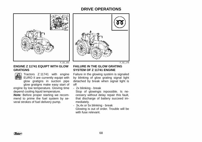
ENGINE Z 11741 EQUIPT WITH GLOWGRATIGNS
Tractors Z 11741 with engineEURO II are currently equipt withglow gratigns in suction pipeglow gratigns make easy start of
engine by low temperature. Gloving timedepend cooling liquid temperature.Note: Before proper starting we recom-mend to prime the fuel system by se-veral strokes of fuel delivery pump.
FAILURE IN THE GLOW GRATINGSYSTEM OF Z 11741 ENGINEFailure in the glowing systém is signaledby blinking of glow grating signal lightdetached by break when signal light isoff- 2x blinking - break
Stop of glowingis inpossible. Is ne-cessery without delay repair this fault,that discharge of battery succeed im-mediately.
- 3x,4x or 5x blinking - breakGlowing is out of order. Trouble will bewith fuse relevant.
69
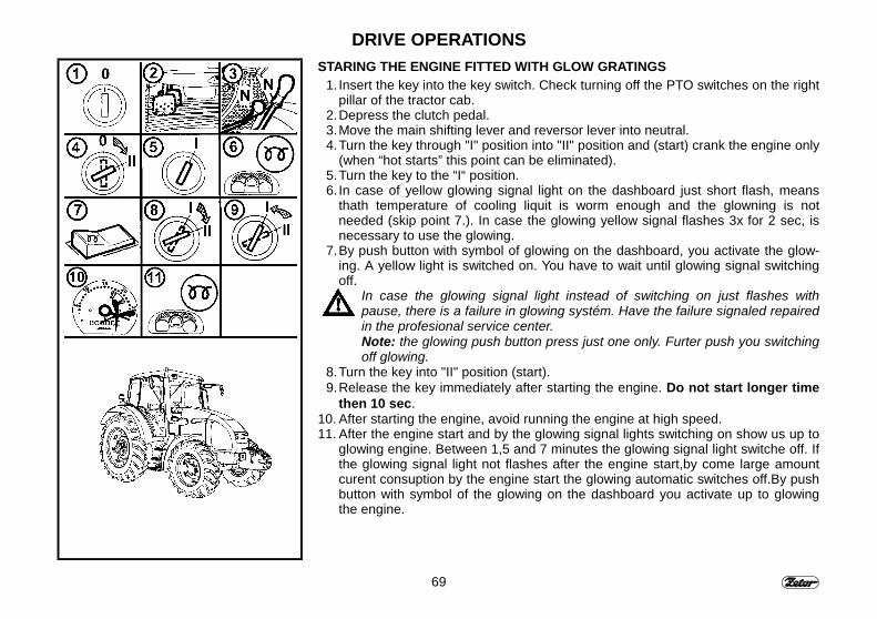
DRIVE OPERATIONSSTARING THE ENGINE FITTED WITH GLOW GRATINGS
1. Insert the key into the key switch. Check turning off the PTO switches on the rightpillar of the tractor cab.
2. Depress the clutch pedal.3. Move the main shifting lever and reversor lever into neutral.4. Turn the key through "I" position into "II" position and (start) crank the engine only
(when “hot starts” this point can be eliminated).5. Turn the key to the “I“ position.6. In case of yellow glowing signal light on the dashboard just short flash, means
thath temperature of cooling liquit is worm enough and the glowning is notneeded (skip point 7.). In case the glowing yellow signal flashes 3x for 2 sec, isnecessary to use the glowing.
7. By push button with symbol of glowing on the dashboard, you activate the glow-ing. A yellow light is switched on. You have to wait until glowing signal switchingoff.
In case the glowing signal light instead of switching on just flashes withpause, there is a failure in glowing systém. Have the failure signaled repairedin the profesional service center.Note: the glowing push button press just one only. Furter push you switchingoff glowing.
8. Turn the key into "II" position (start).9. Release the key immediately after starting the engine. Do not start longer time
then 10 sec.10. After starting the engine, avoid running the engine at high speed.11. After the engine start and by the glowing signal lights switching on show us up to
glowing engine. Between 1,5 and 7 minutes the glowing signal light switche off. Ifthe glowing signal light not flashes after the engine start,by come large amountcurent consuption by the engine start the glowing automatic switches off.By pushbutton with symbol of the glowing on the dashboard you activate up to glowingthe engine.
70
DRIVE OPERATIONS
F_02_185a F91
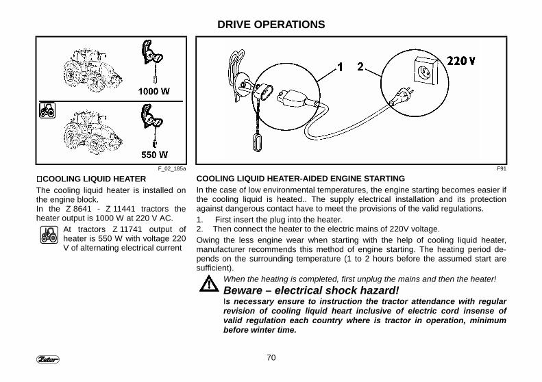
∗∗∗∗ COOLING LIQUID HEATERThe cooling liquid heater is installed onthe engine block.In the Z 8641 - Z 11441 tractors theheater output is 1000 W at 220 V AC.
At tractors Z 11741 output ofheater is 550 W with voltage 220V of alternating electrical current
COOLING LIQUID HEATER-AIDED ENGINE STARTINGIn the case of low environmental temperatures, the engine starting becomes easier ifthe cooling liquid is heated.. The supply electrical installation and its protectionagainst dangerous contact have to meet the provisions of the valid regulations.1. First insert the plug into the heater.2. Then connect the heater to the electric mains of 220V voltage.Owing the less engine wear when starting with the help of cooling liquid heater,manufacturer recommends this method of engine starting. The heating period de-pends on the surrounding temperature (1 to 2 hours before the assumed start aresufficient).
When the heating is completed, first unplug the mains and then the heater!Beware – electrical shock hazard!Is necessary ensure to instruction the tractor attendance with regularrevision of cooling liquid heart inclusive of electric cord insense ofvalid regulation each country where is tractor in operation, minimumbefore winter time.
71
DRIVE OPERATIONS
F_02_33a F_02_35
IMMEDIATELY AFTER STARTING THEENGINE
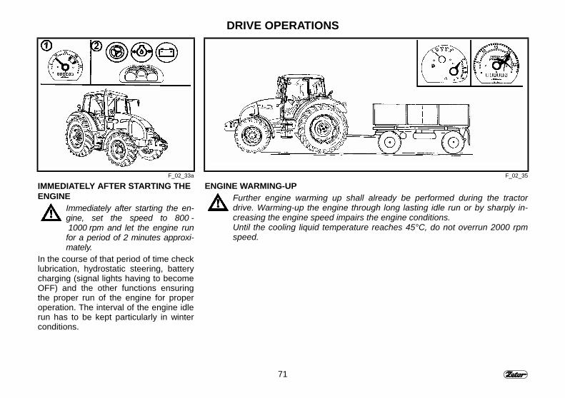
Immediately after starting the en-gine, set the speed to 800 - 1000 rpm and let the engine runfor a period of 2 minutes approxi-mately.
In the course of that period of time checklubrication, hydrostatic steering, batterycharging (signal lights having to becomeOFF) and the other functions ensuringthe proper run of the engine for properoperation. The interval of the engine idlerun has to be kept particularly in winterconditions.
ENGINE WARMING-UPFurther engine warming up shall already be performed during the tractordrive. Warming-up the engine through long lasting idle run or by sharply in-creasing the engine speed impairs the engine conditions.Until the cooling liquid temperature reaches 45°C, do not overrun 2000 rpmspeed.
72
DRIVE OPERATIONS
F_02_34 F_02_43 F96
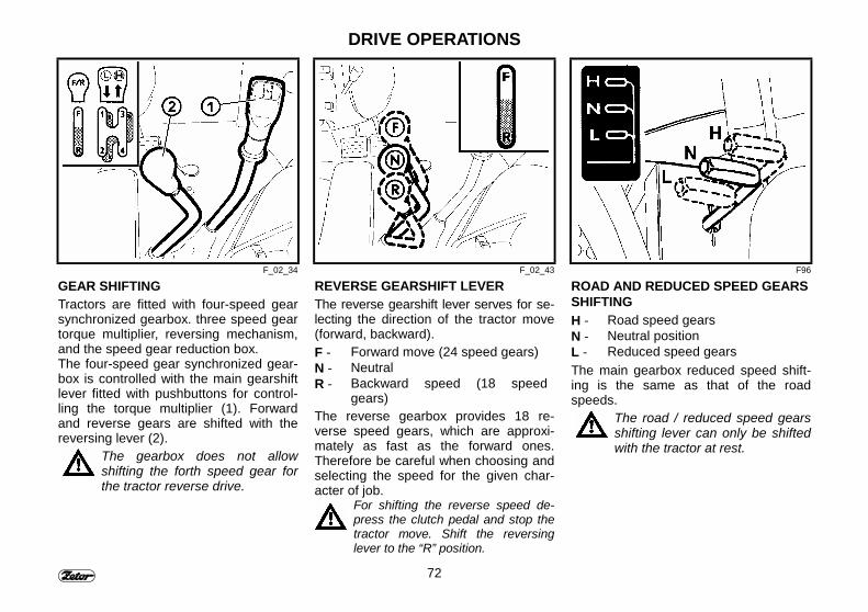
GEAR SHIFTINGTractors are fitted with four-speed gearsynchronized gearbox. three speed geartorque multiplier, reversing mechanism,and the speed gear reduction box.The four-speed gear synchronized gear-box is controlled with the main gearshiftlever fitted with pushbuttons for control-ling the torque multiplier (1). Forwardand reverse gears are shifted with thereversing lever (2).
The gearbox does not allowshifting the forth speed gear forthe tractor reverse drive.
REVERSE GEARSHIFT LEVERThe reverse gearshift lever serves for se-lecting the direction of the tractor move(forward, backward).F - Forward move (24 speed gears)N - NeutralR - Backward speed (18 speed
gears)The reverse gearbox provides 18 re-verse speed gears, which are approxi-mately as fast as the forward ones.Therefore be careful when choosing andselecting the speed for the given char-acter of job.
For shifting the reverse speed de-press the clutch pedal and stop thetractor move. Shift the reversinglever to the “R” position.
ROAD AND REDUCED SPEED GEARSSHIFTINGH - Road speed gearsN - Neutral positionL - Reduced speed gearsThe main gearbox reduced speed shift-ing is the same as that of the roadspeeds.
The road / reduced speed gearsshifting lever can only be shiftedwith the tractor at rest.
73
DRIVE OPERATIONS
F_02_44 F_02_45 F99
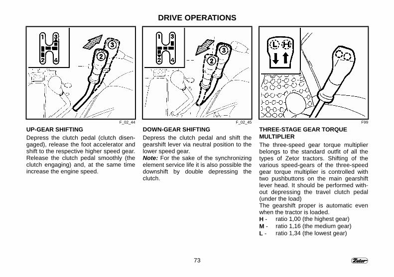
UP-GEAR SHIFTINGDepress the clutch pedal (clutch disen-gaged), release the foot accelerator andshift to the respective higher speed gear.Release the clutch pedal smoothly (theclutch engaging) and, at the same timeincrease the engine speed.
DOWN-GEAR SHIFTINGDepress the clutch pedal and shift thegearshift lever via neutral position to thelower speed gear.Note: For the sake of the synchronizingelement service life it is also possible thedownshift by double depressing theclutch.
THREE-STAGE GEAR TORQUEMULTIPLIERThe three-speed gear torque multiplierbelongs to the standard outfit of all thetypes of Zetor tractors. Shifting of thevarious speed-gears of the three-speedgear torque multiplier is controlled withtwo pushbuttons on the main gearshiftlever head. It should be performed with-out depressing the travel clutch pedal(under the load)The gearshift proper is automatic evenwhen the tractor is loaded.H - ratio 1,00 (the highest gear)M - ratio 1,16 (the medium gear)L - ratio 1,34 (the lowest gear)
74
DRIVE OPERATIONS
F100 F101 F102
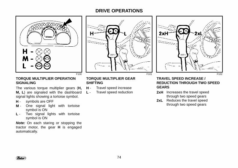
TORQUE MULTIPLIER OPERATIONSIGNALINGThe various torque multiplier gears (H,M, L) are signaled with the dashboardsignal lights showing a tortoise symbol.H - symbols are OFFM - One signal light with tortoise
symbol is ONL - Two signal lights with tortoise
symbol is ONNote: On each staring or stopping thetractor motor, the gear H is engagedautomatically.
TORQUE MULTIPLIER GEARSHIFTINGH - Travel speed increaseL - Travel speed reduction
TRAVEL SPEED INCREASE /REDUCTION THROUGH TWO SPEEDGEARS2xH Increases the travel speed
through two speed gears2xL Reduces the travel speed
through two speed gears
75
DRIVE OPERATIONS
F_02_36
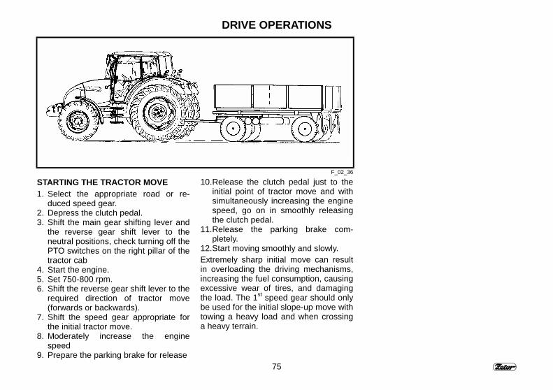
STARTING THE TRACTOR MOVE1. Select the appropriate road or re-
duced speed gear.2. Depress the clutch pedal.3. Shift the main gear shifting lever and
the reverse gear shift lever to theneutral positions, check turning off thePTO switches on the right pillar of thetractor cab
4. Start the engine.5. Set 750-800 rpm.6. Shift the reverse gear shift lever to the
required direction of tractor move(forwards or backwards).
7. Shift the speed gear appropriate forthe initial tractor move.
8. Moderately increase the enginespeed
9. Prepare the parking brake for release
10. Release the clutch pedal just to theinitial point of tractor move and withsimultaneously increasing the enginespeed, go on in smoothly releasingthe clutch pedal.
11. Release the parking brake com-pletely.
12. Start moving smoothly and slowly.Extremely sharp initial move can resultin overloading the driving mechanisms,increasing the fuel consumption, causingexcessive wear of tires, and damagingthe load. The 1st speed gear should onlybe used for the initial slope-up move withtowing a heavy load and when crossinga heavy terrain.
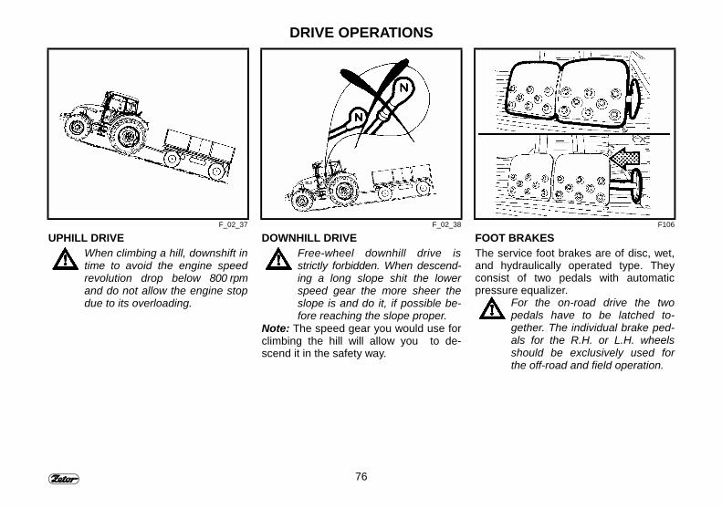
76
DRIVE OPERATIONS
F_02_37 F_02_38 F106
UPHILL DRIVEWhen climbing a hill, downshift intime to avoid the engine speedrevolution drop below 800 rpmand do not allow the engine stopdue to its overloading.
DOWNHILL DRIVEFree-wheel downhill drive isstrictly forbidden. When descend-ing a long slope shit the lowerspeed gear the more sheer theslope is and do it, if possible be-fore reaching the slope proper.
Note: The speed gear you would use forclimbing the hill will allow you to de-scend it in the safety way.
FOOT BRAKESThe service foot brakes are of disc, wet,and hydraulically operated type. Theyconsist of two pedals with automaticpressure equalizer.
For the on-road drive the twopedals have to be latched to-gether. The individual brake ped-als for the R.H. or L.H. wheelsshould be exclusively used forthe off-road and field operation.
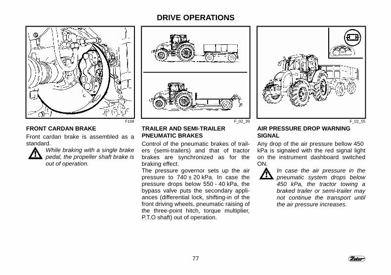
77
DRIVE OPERATIONS
F108 F_02_39 F_02_55
FRONT CARDAN BRAKEFront cardan brake is assembled as astandard.
While braking with a single brakepedal, the propeller shaft brake isout of operation.
TRAILER AND SEMI-TRAILERPNEUMATIC BRAKESControl of the pneumatic brakes of trail-ers (semi-trailers) and that of tractorbrakes are synchronized as for thebraking effect.The pressure governor sets up the airpressure to 740 ± 20 kPa. In case thepressure drops below 550 - 40 kPa, thebypass valve puts the secondary appli-ances (differential lock, shifting-in of thefront driving wheels, pneumatic raising ofthe three-point hitch, torque multiplier,P.T.O shaft) out of operation.
AIR PRESSURE DROP WARNINGSIGNALAny drop of the air pressure bellow 450 kPa is signaled with the red signal lighton the instrument dashboard switchedON.
In case the air pressure in thepneumatic system drops below450 kPa, the tractor towing abraked trailer or semi-trailer maynot continue the transport untilthe air pressure increases.
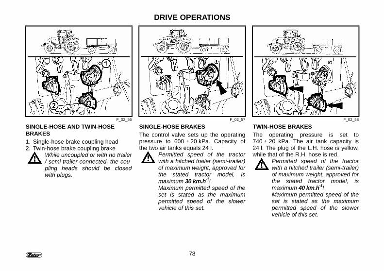
78
DRIVE OPERATIONS
F_02_56 F_02_57 F_02_58
SINGLE-HOSE AND TWIN-HOSEBRAKES1. Single-hose brake coupling head2. Twin-hose brake coupling brake
While uncoupled or with no trailer/ semi-trailer connected, the cou-pling heads should be closedwith plugs.
SINGLE-HOSE BRAKESThe control valve sets up the operatingpressure to 600 ± 20 kPa. Capacity ofthe two air tanks equals 24 l.
Permitted speed of the tractorwith a hitched trailer (semi-trailer)of maximum weight, approved forthe stated tractor model, ismaximum 30 km.h-1!Maximum permitted speed of theset is stated as the maximumpermitted speed of the slowervehicle of this set.
TWIN-HOSE BRAKESThe operating pressure is set to740 ± 20 kPa. The air tank capacity is24 l. The plug of the L.H. hose is yellow,while that of the R.H. hose is red.
Permitted speed of the tractorwith a hitched trailer (semi-trailer)of maximum weight, approved forthe stated tractor model, ismaximum 40 km.h-1!Maximum permitted speed of theset is stated as the maximumpermitted speed of the slowervehicle of this set.
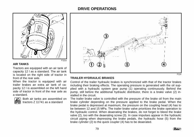
79
DRIVE OPERATIONS
F111a
AIR TANKSTractors are equipped with an air tank ofcapacity 12 l as a standard. The air tankis located on the right side of tractor infront of the rear axle.When the tractor is equipped with airtrailer brakes an extra air tank of ca-pacity 12 l is assembled on the left handside of tractor in front of the rear axle asa standard.
Both air tanks are assembled ontractors Z 11741 as a standard
F114
TRAILER HYDRAULIC BRAKESControl of the trailer hydraulic brakes is synchronized with that of the tractor brakesincluding their braking effects. The operating pressure is generated with the oil sup-plied with a hydraulic system gear pump (1) operating continuously. Behind thepump, still before the additional hydraulic distributor, there is a brake valve (2) in-stalled in the circuit.The trailer brake valve is controlled with the pressure of the brake oil from the mainbrake cylinder depending on the pressure applied to the brake pedal. When thebrake pedal is depressed at maximum, the pressure on the coupling head (4) has tobe between 12 and 15 MPa. The trailer brake valve prioritizes the brake operation tothe hydraulic control. When deaerating the brakes, do not forget to bleed the brakevalve (2), too with the deaerating screw (3). In case impulses appear in the hydrauliccircuit piping when depressing the brake pedals, the hydraulic hose (5) from thebrake cylinder (2) to the quick coupler (4) has to be deaerated.
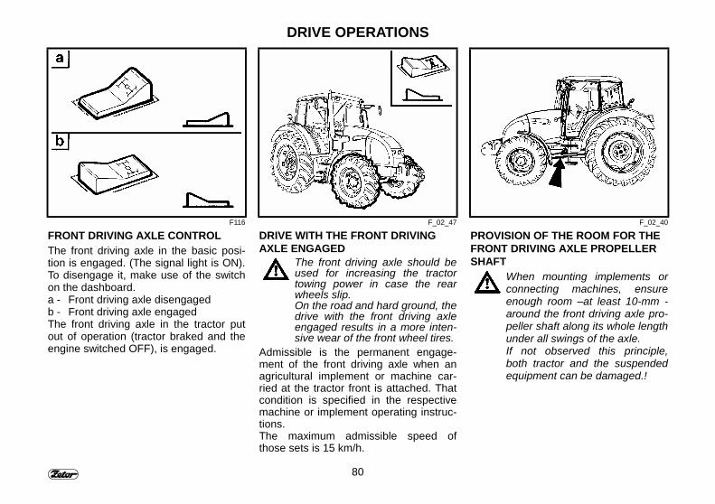
80
DRIVE OPERATIONS
F116 F_02_47 F_02_40
FRONT DRIVING AXLE CONTROLThe front driving axle in the basic posi-tion is engaged. (The signal light is ON).To disengage it, make use of the switchon the dashboard.a - Front driving axle disengagedb - Front driving axle engagedThe front driving axle in the tractor putout of operation (tractor braked and theengine switched OFF), is engaged.
DRIVE WITH THE FRONT DRIVINGAXLE ENGAGED
The front driving axle should beused for increasing the tractortowing power in case the rearwheels slip.On the road and hard ground, thedrive with the front driving axleengaged results in a more inten-sive wear of the front wheel tires.
Admissible is the permanent engage-ment of the front driving axle when anagricultural implement or machine car-ried at the tractor front is attached. Thatcondition is specified in the respectivemachine or implement operating instruc-tions.The maximum admissible speed ofthose sets is 15 km/h.
PROVISION OF THE ROOM FOR THEFRONT DRIVING AXLE PROPELLERSHAFT
When mounting implements orconnecting machines, ensureenough room –at least 10-mm -around the front driving axle pro-peller shaft along its whole lengthunder all swings of the axle.If not observed this principle,both tractor and the suspendedequipment can be damaged.!
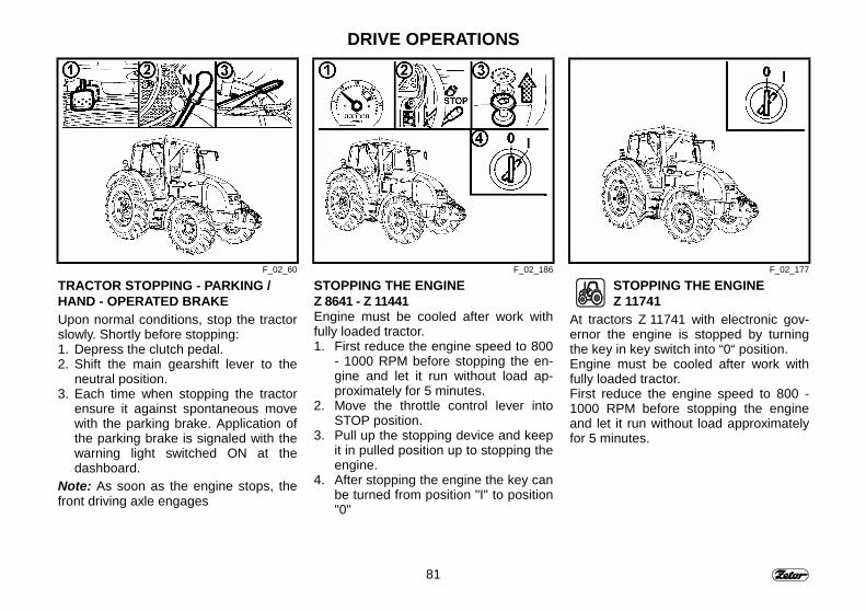
81
DRIVE OPERATIONS
F_02_60 F_02_186 F_02_177
TRACTOR STOPPING - PARKING /HAND - OPERATED BRAKEUpon normal conditions, stop the tractorslowly. Shortly before stopping:1. Depress the clutch pedal.2. Shift the main gearshift lever to the
neutral position.3. Each time when stopping the tractor
ensure it against spontaneous movewith the parking brake. Application ofthe parking brake is signaled with thewarning light switched ON at thedashboard.
Note: As soon as the engine stops, thefront driving axle engages
STOPPING THE ENGINEZ 8641 - Z 11441Engine must be cooled after work withfully loaded tractor.1. First reduce the engine speed to 800
- 1000 RPM before stopping the en-gine and let it run without load ap-proximately for 5 minutes.
2. Move the throttle control lever intoSTOP position.
3. Pull up the stopping device and keepit in pulled position up to stopping theengine.
4. After stopping the engine the key canbe turned from position "I" to position"0"
STOPPING THE ENGINEZ 11741
At tractors Z 11741 with electronic gov-ernor the engine is stopped by turningthe key in key switch into “0“ position.Engine must be cooled after work withfully loaded tractor.First reduce the engine speed to 800 -1000 RPM before stopping the engineand let it run without load approximatelyfor 5 minutes.
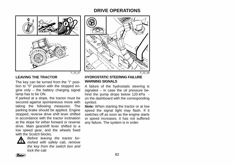
82
DRIVE OPERATIONS
F_02_67 F_02_68
LEAVING THE TRACTORThe key can be turned from the "I" posi-tion to "0" position with the stopped en-gine only – the battery charging signallamp has to be ON.If parked at a slope, the tractor must besecured against spontaneous move withtaking the following measures: Theparking brake should be applied. Enginestopped, reverse drive shift lever shiftedin accordance with the tractor inclinationat the slope for either forward or reversedrive. Main gearshift lever shifted to alow speed gear, and the wheels fixedwith the Scotch blocks.
Before leaving the tractor fur-nished with safety cab, removethe key from the switch box andlock the cab
HYDROSTATIC STEERING FAILUREWARNING SIGNALSA failure of the hydrostatic steering issignaled – in case the oil pressure be-hind the pump drops below 120 kPa -on the dashboard with the correspondingsymbol.Note: When starting the tractor or at lowspeed the signal light may flash. If itswitches off as soon as the engine startsor speed increases, it has not sufferedany failure. The system is in order.

83
NOTE

84
NOTE
85
TRACTOR RUNNING-INPage
General principles of running in a new tractor in the course of the first 100 operatinghours ......................................................................................................................... 86In the course of the first 10 Hours............................................................................. 86After 10 hours ........................................................................................................... 87After 50 hours ........................................................................................................... 88After 70 Hours Z 8641 - Z 11441............................................................................... 88After 70 hours ........................................................................................................... 89After 100 Hours......................................................................................................... 89
86
TRACTOR RUNNING IN
F_02_48 F_02_49
GENERAL PRINCIPLES OF RUNNINGIN A NEW TRACTOR IN THE COURSEOF THE FIRST 100 OPERATINGHOURSIn the course of the first operating hours:- Apply the normal load to the engine- Avoid operation at partial engine load- Avoid excessive idle run- Check frequently oil for level in the
engine (in the course of this period ahigher oil consumption is typical)
- Check the screwed joints mainly of thetractor supporting parts for propertightening
- Remedy the faults detected immedi-ately for avoiding the subsequentdamage or threat to the safety of op-eration
- Apply the same procedure after gen-eral tractor repair, too.
IN THE COURSE OF THE FIRST10 HOURS- Perform the running-in process in
transport conditions- Tighten the front and rear wheel fixing
nuts including the bead / rim joint withthe prescribed torque.
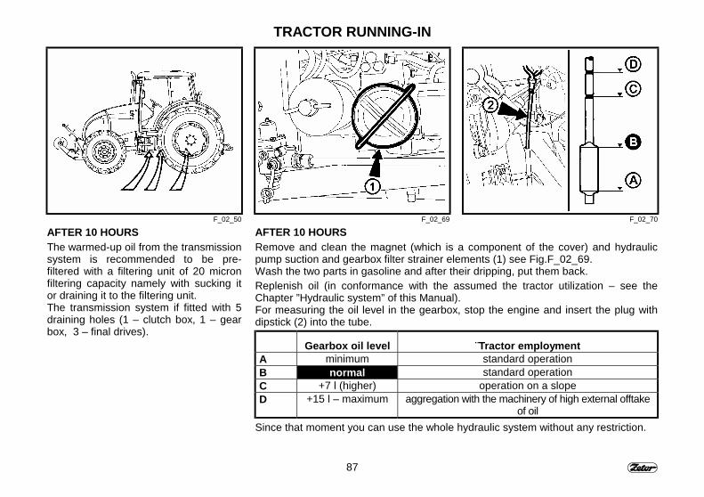
87
TRACTOR RUNNING-IN
F_02_50 F_02_69 F_02_70
AFTER 10 HOURSThe warmed-up oil from the transmissionsystem is recommended to be pre-filtered with a filtering unit of 20 micronfiltering capacity namely with sucking itor draining it to the filtering unit.The transmission system if fitted with 5draining holes (1 – clutch box, 1 – gearbox, 3 – final drives).
AFTER 10 HOURSRemove and clean the magnet (which is a component of the cover) and hydraulicpump suction and gearbox filter strainer elements (1) see Fig.F_02_69.Wash the two parts in gasoline and after their dripping, put them back.Replenish oil (in conformance with the assumed the tractor utilization – see theChapter ”Hydraulic system” of this Manual).For measuring the oil level in the gearbox, stop the engine and insert the plug withdipstick (2) into the tube.
Gearbox oil level ¨Tractor employmentA minimum standard operationB normal standard operationC +7 l (higher) operation on a slopeD +15 l – maximum aggregation with the machinery of high external offtake
of oilSince that moment you can use the whole hydraulic system without any restriction.
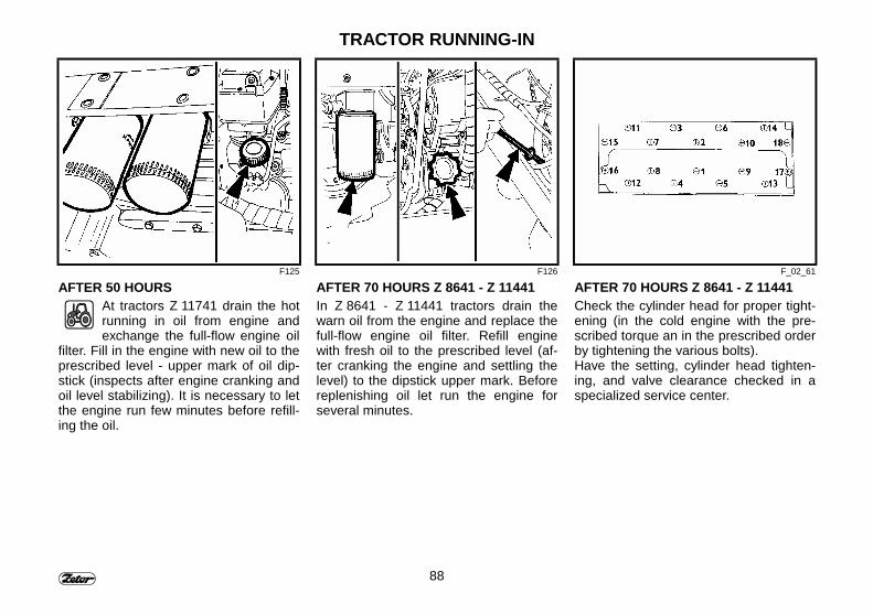
88
TRACTOR RUNNING-IN
F125 F126 F_02_61
AFTER 50 HOURSAt tractors Z 11741 drain the hotrunning in oil from engine andexchange the full-flow engine oil
filter. Fill in the engine with new oil to theprescribed level - upper mark of oil dip-stick (inspects after engine cranking andoil level stabilizing). It is necessary to letthe engine run few minutes before refill-ing the oil.
AFTER 70 HOURS Z 8641 - Z 11441In Z 8641 - Z 11441 tractors drain thewarn oil from the engine and replace thefull-flow engine oil filter. Refill enginewith fresh oil to the prescribed level (af-ter cranking the engine and settling thelevel) to the dipstick upper mark. Beforereplenishing oil let run the engine forseveral minutes.
AFTER 70 HOURS Z 8641 - Z 11441Check the cylinder head for proper tight-ening (in the cold engine with the pre-scribed torque an in the prescribed orderby tightening the various bolts).Have the setting, cylinder head tighten-ing, and valve clearance checked in aspecialized service center.
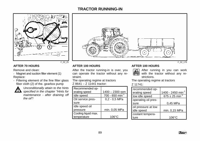
89
TRACTOR RUNNING-IN
F_02_25 F_02_178
AFTER 70 HOURSRemove and clean:- Magnet and suction filter element (1)Replace:- Filtering element of the fine filter glass
fiber cloth (2) of the. gearbox pumpUnconditionally attain to the hintsspecified in the chapter ”Hints formaintenance - after draining offthe oil”!
AFTER 100 HOURSAfter the tractor running-in is over, youcan operate the tractor without any re-straint.The operating regime at tractorsZ 8641 – Z 11441 tractor:Recommended op-erating speed 1400 – 2300 rpmIdle speed 700 - 650 min-1
Oil service pres-sure
0,2 - 0,5 MPa
Idle speed oilpressure min. 0,05 MPaCooling liquid max.temperature 106°C
AFTER 100 HOURSAfter running in you can workwith the tractor without any re-strictions.
The operating regime at tractorsZ 11741:recommended op-erating speed 1400 - 2450 min-1
low idle speed 675 ± 25 min-1
operating oil pres-sure 0,45 MPaoil pressure at lowidle speed min. 0,15 MPacoolant tempera-ture 106°C

90
NOTE
91
TRANSPORT APPLICATION
Still before starting the drivemake sure that the technicalconditions of your tractor meetsthe requirements of safety op-eration. If a trailer or any imple-ments are attached, revise theirconnection and proper stowing ofthe load. Never leave the tractorwhile in move for suspending thetrailer. Be also aware of thesafety of your assistant.
PageFront hook................................................................................................................. 92Multi-stage hitch for trailers....................................................................................... 92Multi-stage hitch mechanical tail ............................................................................... 92Multi-stage hitch automatic tail.................................................................................. 93Swing tie rod ............................................................................................................. 93Hitch for single-axle trailers combined with a swing tie rod....................................... 94Replacing the tow hook with a swing tie rod ............................................................. 94Swing tie rod of the combined hitch for single-axle trailers ....................................... 94Tow bar...................................................................................................................... 95Mechanical control of supporting hooks.................................................................... 95Hydraulic control of supporting hooks....................................................................... 96Agregation with the semi-trailer and trailer ............................................................... 96Admissible vertical static load for the trailer-hitch ..................................................... 97Admissible load on the hitch for single-axle trailer if the Z 8641 - Z 11741 tractors.. 98
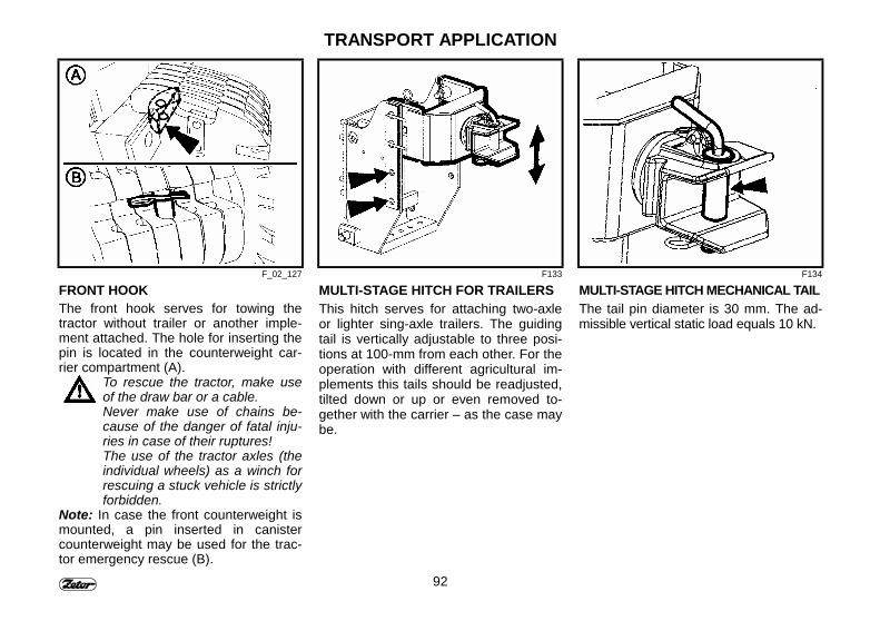
92
TRANSPORT APPLICATION
F_02_127 F133 F134
FRONT HOOKThe front hook serves for towing thetractor without trailer or another imple-ment attached. The hole for inserting thepin is located in the counterweight car-rier compartment (A).
To rescue the tractor, make useof the draw bar or a cable.Never make use of chains be-cause of the danger of fatal inju-ries in case of their ruptures!The use of the tractor axles (theindividual wheels) as a winch forrescuing a stuck vehicle is strictlyforbidden.
Note: In case the front counterweight ismounted, a pin inserted in canistercounterweight may be used for the trac-tor emergency rescue (B).
MULTI-STAGE HITCH FOR TRAILERSThis hitch serves for attaching two-axleor lighter sing-axle trailers. The guidingtail is vertically adjustable to three posi-tions at 100-mm from each other. For theoperation with different agricultural im-plements this tails should be readjusted,tilted down or up or even removed to-gether with the carrier – as the case maybe.
MULTI-STAGE HITCH MECHANICAL TAILThe tail pin diameter is 30 mm. The ad-missible vertical static load equals 10 kN.
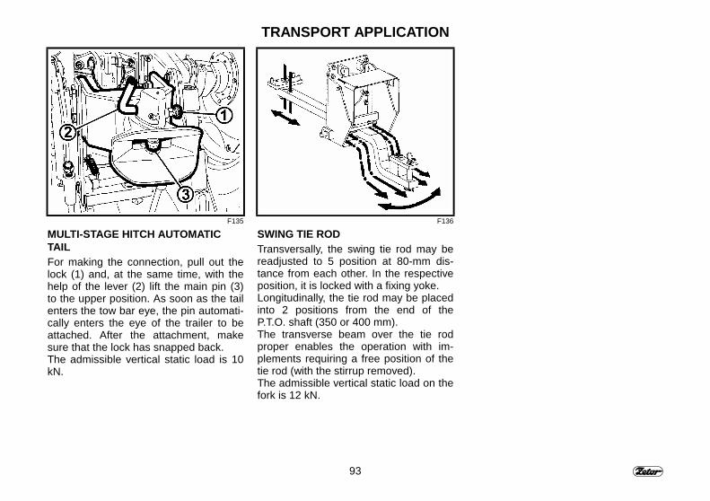
93
TRANSPORT APPLICATION
F135 F136
MULTI-STAGE HITCH AUTOMATICTAILFor making the connection, pull out thelock (1) and, at the same time, with thehelp of the lever (2) lift the main pin (3)to the upper position. As soon as the tailenters the tow bar eye, the pin automati-cally enters the eye of the trailer to beattached. After the attachment, makesure that the lock has snapped back.The admissible vertical static load is 10kN.
SWING TIE RODTransversally, the swing tie rod may bereadjusted to 5 position at 80-mm dis-tance from each other. In the respectiveposition, it is locked with a fixing yoke.Longitudinally, the tie rod may be placedinto 2 positions from the end of theP.T.O. shaft (350 or 400 mm).The transverse beam over the tie rodproper enables the operation with im-plements requiring a free position of thetie rod (with the stirrup removed).The admissible vertical static load on thefork is 12 kN.
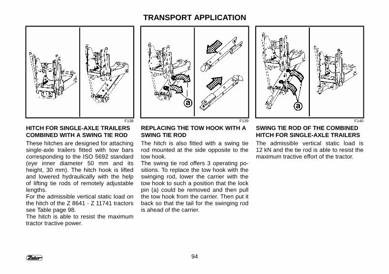
94
TRANSPORT APPLICATION
F138 F139 F140
HITCH FOR SINGLE-AXLE TRAILERSCOMBINED WITH A SWING TIE RODThese hitches are designed for attachingsingle-axle trailers fitted with tow barscorresponding to the ISO 5692 standard(eye inner diameter 50 mm and itsheight, 30 mm). The hitch hook is liftedand lowered hydraulically with the helpof lifting tie rods of remotely adjustablelengths.For the admissible vertical static load onthe hitch of the Z 8641 - Z 11741 tractorssee Table page 98.The hitch is able to resist the maximumtractor tractive power.
REPLACING THE TOW HOOK WITH ASWING TIE RODThe hitch is also fitted with a swing tierod mounted at the side opposite to thetow hook.The swing tie rod offers 3 operating po-sitions. To replace the tow hook with theswinging rod, lower the carrier with thetow hook to such a position that the lockpin (a) could be removed and then pullthe tow hook from the carrier. Then put itback so that the tail for the swinging rodis ahead of the carrier.
SWING TIE ROD OF THE COMBINEDHITCH FOR SINGLE-AXLE TRAILERSThe admissible vertical static load is12 kN and the tie rod is able to resist themaximum tractive effort of the tractor.
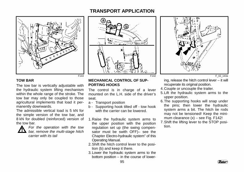
95
TRANSPORT APPLICATION
F144 F142 F_02_143a
TOW BARThe tow bar is vertically adjustable withthe hydraulic system lifting mechanismwithin the whole range of the stroke. Thetow bar may only be coupled to thoseagricultural implements that load it per-manently downwards.The admissible vertical load is 5 kN forthe simple version of the tow bar, and8 kN for doubled (reinforced) version ofthe tow bar.
For the operation with the towbar, remove the multi-stage hitchcarrier with its tail
MECHANICAL CONTROL OF SUP-PORTING HOOKSThe control is in charge of a levermounted on the L.H. side of the driver’sseat.a - Transport positionb - Supporting hook tilted off - tow hook
with the carrier can be lowered.
1. Raise the hydraulic system arms tothe upper position with the positionregulation set up (the swing compen-sator must be swith OFF)– see theChapter Electro-hydraulic system” of thisOperating Manual.
2. Shift the hitch control lever to the posi-tion (b) and keep it there.
3. Lower the hydraulic system arms to thebottom position – in the course of lower-
ing, release the hitch control lever – it willrecuperate its original position.
4. Couple or uncouple the trailer.5. Lift the hydraulic system arms to the
upper position.6. The supporting hooks will snap under
the pins; then lower the hydraulicsystem arms a bit. The hitch tie rodsmay not be tensioned! Keep the mini-mum clearance (x) – see Fig. F142!
7. Shift the lifting lever to the STOP posi-tion.
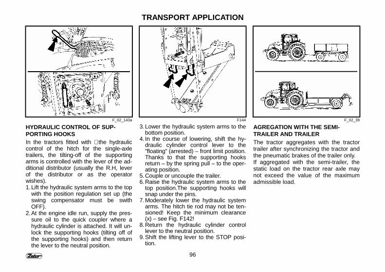
96
TRANSPORT APPLICATION
F_02_143a F144 F_02_39
HYDRAULIC CONTROL OF SUP-PORTING HOOKSIn the tractors fitted with ∗ the hydrauliccontrol of the hitch for the single-axletrailers, the tilting-off of the supportingarms is controlled with the lever of the ad-ditional distributor (usually the R.H, leverof the distributor or as the operatorwishes).1. Lift the hydraulic system arms to the top
with the position regulation set up (theswing compensator must be swithOFF).
2. At the engine idle run, supply the pres-sure oil to the quick coupler where ahydraulic cylinder is attached. It will un-lock the supporting hooks (tilting off ofthe supporting hooks) and then returnthe lever to the neutral position.
3. Lower the hydraulic system arms to thebottom position.
4. In the course of lowering, shift the hy-draulic cylinder control lever to the”floating” (arrested) – front limit position.Thanks to that the supporting hooksreturn – by the spring pull – to the oper-ating position.
5. Couple or uncouple the trailer.6. Raise the hydraulic system arms to the
top position.The supporting hooks willsnap under the pins.
7. Moderately lower the hydraulic systemarms. The hitch tie rod may not be ten-sioned! Keep the minimum clearance(x) – see Fig. F142!
8. Return the hydraulic cylinder controllever to the neutral position.
9. Shift the lifting lever to the STOP posi-tion.
AGREGATION WITH THE SEMI-TRAILER AND TRAILERThe tractor aggregates with the tractortrailer after synchronizing the tractor andthe pneumatic brakes of the trailer only.If aggregated with the semi-trailer, thestatic load on the tractor rear axle maynot exceed the value of the maximumadmissible load.
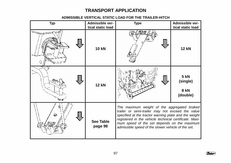
97
TRANSPORT APPLICATIONADMISSIBLE VERTICAL STATIC LOAD FOR THE TRAILER-HITCH
Typ Admissible ver-tical static load
Type Admissible ver-tical static load
10 kN 12 kN
12 kN
5 kN(single)
8 kN(double)
See Tablepage 98
The maximum weight of the aggregated brakedtrailer or semi-trailer may not exceed the valuespecified at the tractor warning plate and the weightregistered in the vehicle technical certificate. Maxi-mum speed of the set depends on the maximumadmissible speed of the slower vehicle of the set.
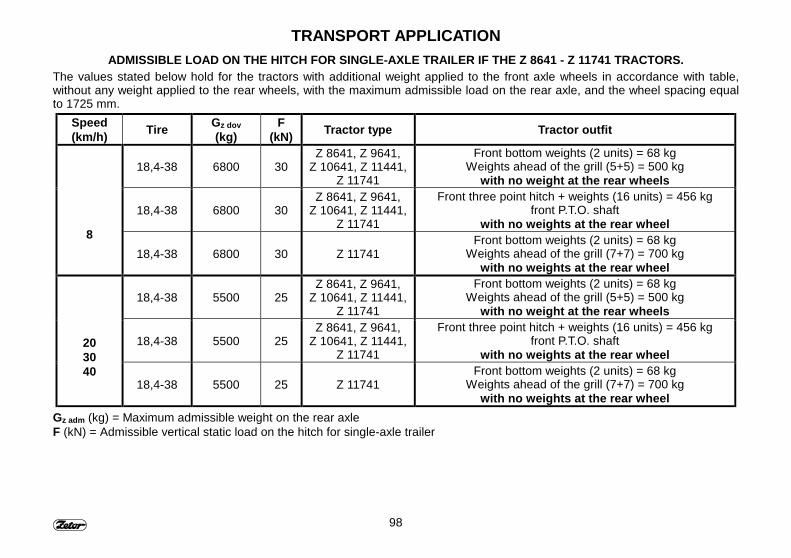
98
TRANSPORT APPLICATIONADMISSIBLE LOAD ON THE HITCH FOR SINGLE-AXLE TRAILER IF THE Z 8641 - Z 11741 TRACTORS.
The values stated below hold for the tractors with additional weight applied to the front axle wheels in accordance with table,without any weight applied to the rear wheels, with the maximum admissible load on the rear axle, and the wheel spacing equalto 1725 mm.
Speed(km/h) Tire Gz dov
(kg)F
(kN) Tractor type Tractor outfit
18,4-38 6800 30Z 8641, Z 9641,
Z 10641, Z 11441,Z 11741
Front bottom weights (2 units) = 68 kgWeights ahead of the grill (5+5) = 500 kg
with no weight at the rear wheels
18,4-38 6800 30Z 8641, Z 9641,
Z 10641, Z 11441,Z 11741
Front three point hitch + weights (16 units) = 456 kgfront P.T.O. shaft
with no weights at the rear wheel8
18,4-38 6800 30 Z 11741Front bottom weights (2 units) = 68 kg
Weights ahead of the grill (7+7) = 700 kgwith no weights at the rear wheel
18,4-38 5500 25Z 8641, Z 9641,
Z 10641, Z 11441,Z 11741
Front bottom weights (2 units) = 68 kgWeights ahead of the grill (5+5) = 500 kg
with no weight at the rear wheels
18,4-38 5500 25Z 8641, Z 9641,
Z 10641, Z 11441,Z 11741
Front three point hitch + weights (16 units) = 456 kgfront P.T.O. shaft
with no weights at the rear wheel203040
18,4-38 5500 25 Z 11741Front bottom weights (2 units) = 68 kg
Weights ahead of the grill (7+7) = 700 kgwith no weights at the rear wheel
Gz adm (kg) = Maximum admissible weight on the rear axleF (kN) = Admissible vertical static load on the hitch for single-axle trailer

99
NOTE

100
NOTE
101
DRIVE OF AGRICULTURAL MACHINES
Before coupling the machinedriven with the P.T.O. shaft, makesure that the tractor and the at-tached machine P.T.O shaftspeeds are compatible (540 or1000), because different speedsmay result in serious damageand accidents.
PageOperation with the p.t.o. shaft ................................................................................. 102Control of the front and rear P.T.O. shafts............................................................... 102Rear p.t.o. shaft – shifting of dependent and independent speeds......................... 102Changing the rear P.T.O. shaft independent speed ................................................ 103P.T.O. shaft tails ...................................................................................................... 103∗ Front P.T.O. – sense of rotation............................................................................ 103P.T.O. shaft guards.................................................................................................. 104Maximum transferred power Z 8641 - Z 11441 ....................................................... 104Maximum transferred power Z 11741...................................................................... 104Drive of the machines of higher inertia masses (crashers. rotary harrowas, movers,reaping machines and the like) ............................................................................... 105
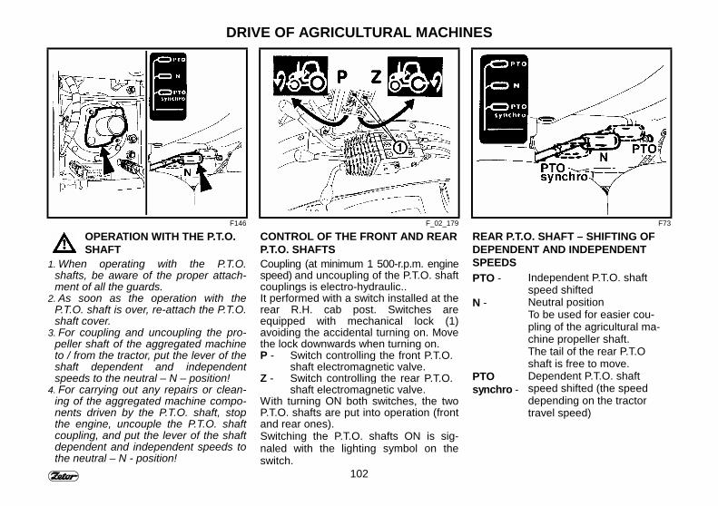
102
DRIVE OF AGRICULTURAL MACHINES
F146 F_02_179 F73
OPERATION WITH THE P.T.O.SHAFT
1. When operating with the P.T.O.shafts, be aware of the proper attach-ment of all the guards.
2. As soon as the operation with theP.T.O. shaft is over, re-attach the P.T.O.shaft cover.
3. For coupling and uncoupling the pro-peller shaft of the aggregated machineto / from the tractor, put the lever of theshaft dependent and independentspeeds to the neutral – N – position!
4. For carrying out any repairs or clean-ing of the aggregated machine compo-nents driven by the P.T.O. shaft, stopthe engine, uncouple the P.T.O. shaftcoupling, and put the lever of the shaftdependent and independent speeds tothe neutral – N - position!
CONTROL OF THE FRONT AND REARP.T.O. SHAFTSCoupling (at minimum 1 500-r.p.m. enginespeed) and uncoupling of the P.T.O. shaftcouplings is electro-hydraulic..It performed with a switch installed at therear R.H. cab post. Switches areequipped with mechanical lock (1)avoiding the accidental turning on. Movethe lock downwards when turning on.P - Switch controlling the front P.T.O.
shaft electromagnetic valve.Z - Switch controlling the rear P.T.O.
shaft electromagnetic valve.With turning ON both switches, the twoP.T.O. shafts are put into operation (frontand rear ones).Switching the P.T.O. shafts ON is sig-naled with the lighting symbol on theswitch.
REAR P.T.O. SHAFT – SHIFTING OFDEPENDENT AND INDEPENDENTSPEEDSPTO - Independent P.T.O. shaft
speed shiftedN - Neutral position
To be used for easier cou-pling of the agricultural ma-chine propeller shaft.The tail of the rear P.T.Oshaft is free to move.
PTOsynchro -
Dependent P.T.O. shaftspeed shifted (the speeddepending on the tractortravel speed)
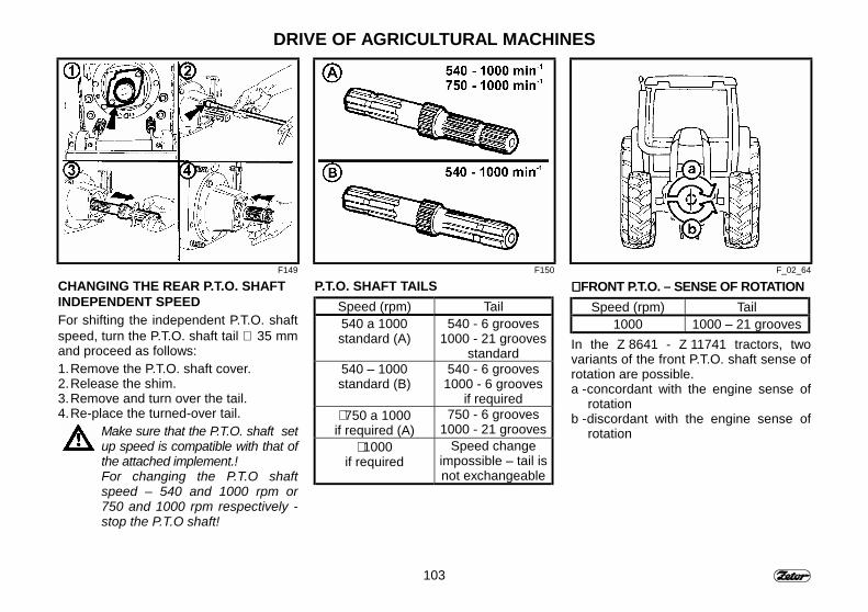
103
DRIVE OF AGRICULTURAL MACHINES
F149 F150 F_02_64
CHANGING THE REAR P.T.O. SHAFTINDEPENDENT SPEEDFor shifting the independent P.T.O. shaftspeed, turn the P.T.O. shaft tail ∅ 35 mmand proceed as follows:1. Remove the P.T.O. shaft cover.2. Release the shim.3. Remove and turn over the tail.4. Re-place the turned-over tail.
Make sure that the P.T.O. shaft setup speed is compatible with that ofthe attached implement.!For changing the P.T.O shaftspeed – 540 and 1000 rpm or750 and 1000 rpm respectively -stop the P.T.O shaft!
P.T.O. SHAFT TAILSSpeed (rpm) Tail540 a 1000standard (A)
540 - 6 grooves1000 - 21 grooves
standard540 – 1000standard (B)
540 - 6 grooves1000 - 6 grooves
if required∗ 750 a 1000if required (A)
750 - 6 grooves1000 - 21 grooves
∗ 1000if required
Speed changeimpossible – tail isnot exchangeable
∗∗∗∗ FRONT P.T.O. – SENSE OF ROTATIONSpeed (rpm) Tail
1000 1000 – 21 groovesIn the Z 8641 - Z 11741 tractors, twovariants of the front P.T.O. shaft sense ofrotation are possible.a - concordant with the engine sense of
rotationb - discordant with the engine sense of
rotation
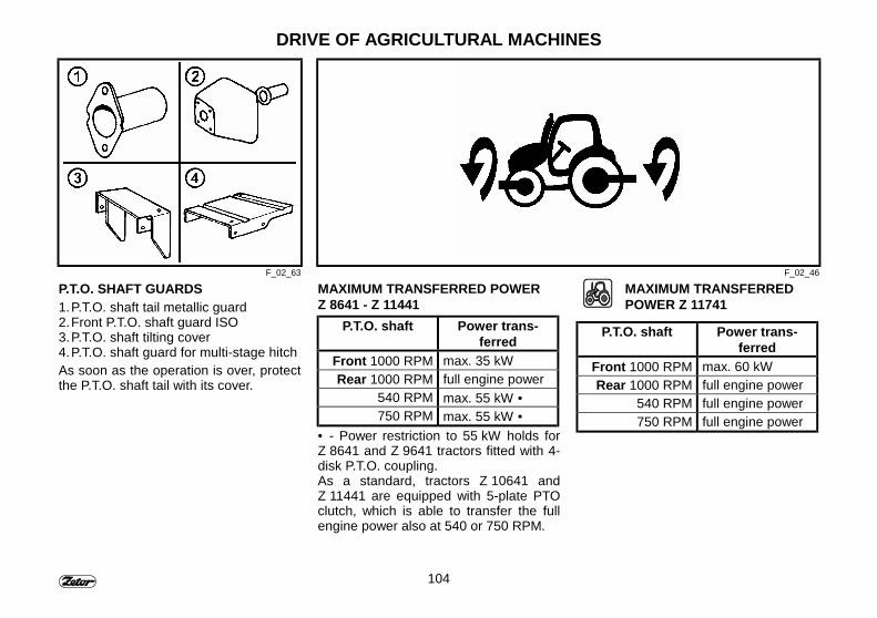
104
DRIVE OF AGRICULTURAL MACHINES
F_02_63 F_02_46
P.T.O. SHAFT GUARDS1. P.T.O. shaft tail metallic guard2. Front P.T.O. shaft guard ISO3. P.T.O. shaft tilting cover4. P.T.O. shaft guard for multi-stage hitchAs soon as the operation is over, protectthe P.T.O. shaft tail with its cover.
MAXIMUM TRANSFERRED POWERZ 8641 - Z 11441
P.T.O. shaft Power trans-ferred
Front 1000 RPM max. 35 kWRear 1000 RPM full engine power
540 RPM max. 55 kW •750 RPM max. 55 kW •
• - Power restriction to 55 kW holds forZ 8641 and Z 9641 tractors fitted with 4-disk P.T.O. coupling.As a standard, tractors Z 10641 andZ 11441 are equipped with 5-plate PTOclutch, which is able to transfer the fullengine power also at 540 or 750 RPM.
MAXIMUM TRANSFERREDPOWER Z 11741
P.T.O. shaft Power trans-ferred
Front 1000 RPM max. 60 kWRear 1000 RPM full engine power
540 RPM full engine power750 RPM full engine power
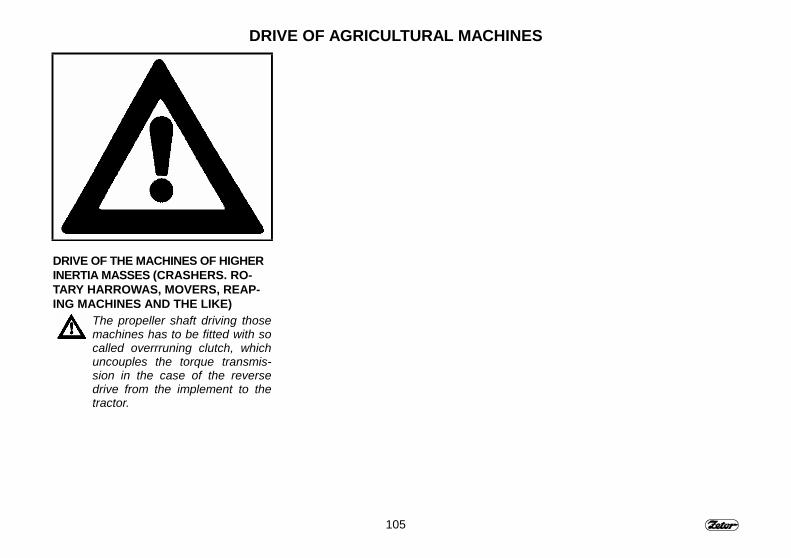
105
DRIVE OF AGRICULTURAL MACHINES
DRIVE OF THE MACHINES OF HIGHERINERTIA MASSES (CRASHERS. RO-TARY HARROWAS, MOVERS, REAP-ING MACHINES AND THE LIKE)
The propeller shaft driving thosemachines has to be fitted with socalled overrruning clutch, whichuncouples the torque transmis-sion in the case of the reversedrive from the implement to thetractor.

106
NOTE
107
HYDRAULIC SYSTEMPage
Hydraulic system..................................................................................................... 108Hydraulic system pump........................................................................................... 108Control panel location - electro-hydraulic systém EHR B............................................. 108Control panel location - Hydraulic with mechanical control system ........................ 109Outer hydraulic circuit ............................................................................................. 109Quick couplers coupling and uncoupling ................................................................ 109Amount of oil taken from the hydraulic circuit outer outlets: ................................... 110Outer circuit control lever - Hydraulic with mechanical control system ....................111Rear outlets of hydraulic outer circuit.......................................................................111Control of single-acting hydraulic cylinder .............................................................. 112Control of double-acting hydraulic cylinder ............................................................. 112Selective control valve (SCV).................................................................................. 113∗ Two-section Selective control valve ...................................................................... 113Three-section Selective control valve ..................................................................... 113Description of the functions assigned to the various control levers ........................ 114Rear outlets of hydraulic outer circuit...................................................................... 115Outlets of front outer circuit..................................................................................... 115Connection of machines and implements to hydraulic outer circuit ........................ 116
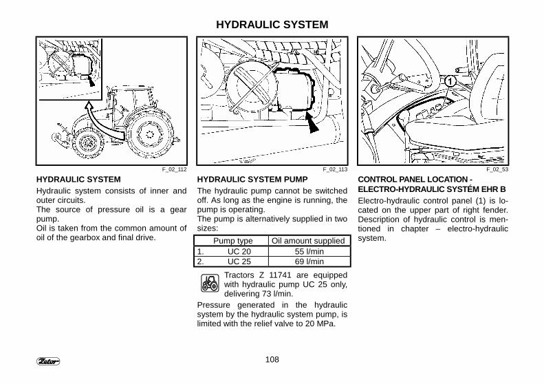
108
HYDRAULIC SYSTEM
F_02_112 F_02_113 F_02_53
HYDRAULIC SYSTEMHydraulic system consists of inner andouter circuits.The source of pressure oil is a gearpump.Oil is taken from the common amount ofoil of the gearbox and final drive.
HYDRAULIC SYSTEM PUMPThe hydraulic pump cannot be switchedoff. As long as the engine is running, thepump is operating.The pump is alternatively supplied in twosizes:
Pump type Oil amount supplied1. UC 20 55 l/min2. UC 25 69 l/min
Tractors Z 11741 are equippedwith hydraulic pump UC 25 only,delivering 73 l/min.
Pressure generated in the hydraulicsystem by the hydraulic system pump, islimited with the relief valve to 20 MPa.
CONTROL PANEL LOCATION -ELECTRO-HYDRAULIC SYSTÉM EHR B Electro-hydraulic control panel (1) is lo-cated on the upper part of right fender.Description of hydraulic control is men-tioned in chapter – electro-hydraulicsystem.

109
HYDRAULIC SYSTEM
F_02_H15 F_02_71 F_02_124
CONTROL PANEL LOCATION - HYD-RAULIC WITH MECHANICAL CON-TROL SYSTEMElectro-hydraulic control panel (1) is lo-cated on the upper part of right fender.Description of hydraulic control is men-tioned in chapter – hydraulic with me-chanical control systém
OUTER HYDRAULIC CIRCUITIt supplies pressure oil for the hydraulicappliances connected to the outer out-lets of the hydraulic system fitted withquick couplers. The rear and front quickcoupler plugs (A and B respectively) in-ner diameter is 12,5 mm and they com-ply with the international ISO 5675 stan-dard.
QUICK COUPLERS COUPLING ANDUNCOUPLING
When coupling and uncoupling thequick couplers be very careful be-cause of the residual oil, whichremains in the socket or in theplug of the quick coupler.For the ecological reasons thisresidual oil has to be removedwith any cloth after each un-coupling of the quick couplers.
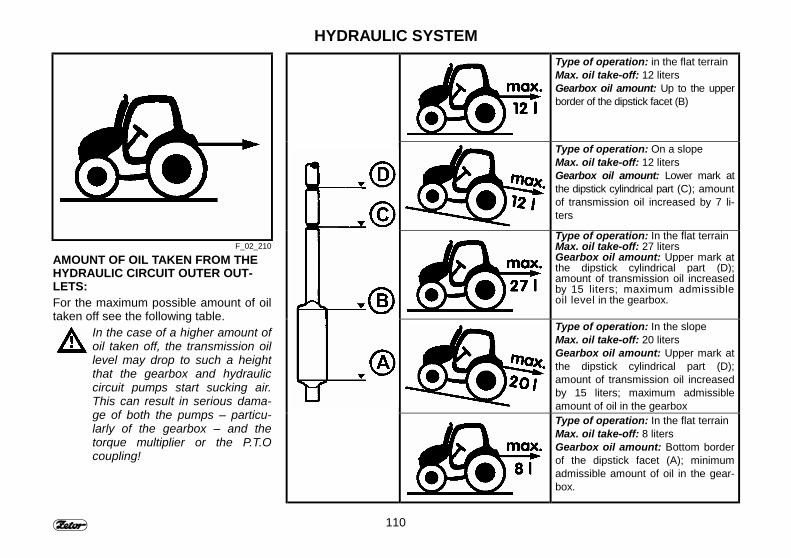
110
HYDRAULIC SYSTEM
F_02_210
AMOUNT OF OIL TAKEN FROM THEHYDRAULIC CIRCUIT OUTER OUT-LETS:For the maximum possible amount of oiltaken off see the following table.
In the case of a higher amount ofoil taken off, the transmission oillevel may drop to such a heightthat the gearbox and hydrauliccircuit pumps start sucking air.This can result in serious dama-ge of both the pumps – particu-larly of the gearbox – and thetorque multiplier or the P.T.Ocoupling!
Type of operation: in the flat terrainMax. oil take-off: 12 litersGearbox oil amount: Up to the upperborder of the dipstick facet (B)
Type of operation: On a slopeMax. oil take-off: 12 litersGearbox oil amount: Lower mark atthe dipstick cylindrical part (C); amountof transmission oil increased by 7 li-ters
Type of operation: In the flat terrainMax. oil take-off: 27 litersGearbox oil amount: Upper mark atthe dipstick cylindrical part (D);amount of transmission oil increasedby 15 liters; maximum admissibleoil level in the gearbox.
Type of operation: In the slopeMax. oil take-off: 20 litersGearbox oil amount: Upper mark atthe dipstick cylindrical part (D);amount of transmission oil increasedby 15 liters; maximum admissibleamount of oil in the gearboxType of operation: In the flat terrainMax. oil take-off: 8 litersGearbox oil amount: Bottom borderof the dipstick facet (A); minimumadmissible amount of oil in the gear-box.
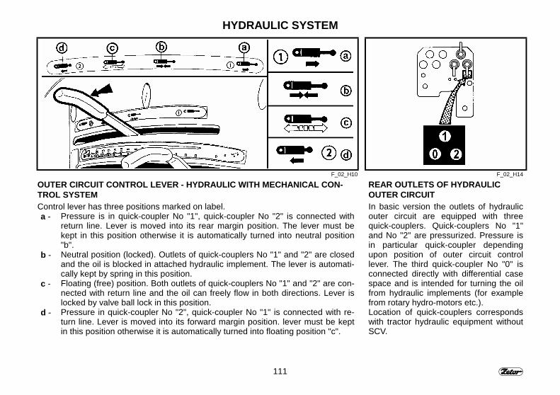
111
HYDRAULIC SYSTEM
F_02_H10 F_02_H14
OUTER CIRCUIT CONTROL LEVER - HYDRAULIC WITH MECHANICAL CON-TROL SYSTEMControl lever has three positions marked on label.a - Pressure is in quick-coupler No "1", quick-coupler No "2" is connected with
return line. Lever is moved into its rear margin position. The lever must bekept in this position otherwise it is automatically turned into neutral position"b".
b - Neutral position (locked). Outlets of quick-couplers No "1" and "2" are closedand the oil is blocked in attached hydraulic implement. The lever is automati-cally kept by spring in this position.
c - Floating (free) position. Both outlets of quick-couplers No "1" and "2" are con-nected with return line and the oil can freely flow in both directions. Lever islocked by valve ball lock in this position.
d - Pressure in quick-coupler No "2", quick-coupler No "1" is connected with re-turn line. Lever is moved into its forward margin position. lever must be keptin this position otherwise it is automatically turned into floating position "c".
REAR OUTLETS OF HYDRAULICOUTER CIRCUITIn basic version the outlets of hydraulicouter circuit are equipped with threequick-couplers. Quick-couplers No "1"and No "2" are pressurized. Pressure isin particular quick-coupler dependingupon position of outer circuit controllever. The third quick-coupler No "0" isconnected directly with differential casespace and is intended for turning the oilfrom hydraulic implements (for examplefrom rotary hydro-motors etc.).Location of quick-couplers correspondswith tractor hydraulic equipment withoutSCV.
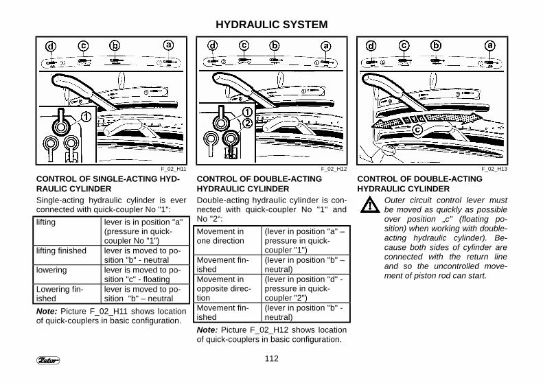
112
HYDRAULIC SYSTEM
F_02_H11 F_02_H12 F_02_H13
CONTROL OF SINGLE-ACTING HYD-RAULIC CYLINDERSingle-acting hydraulic cylinder is everconnected with quick-coupler No "1":lifting lever is in position "a"
(pressure in quick-coupler No "1”)
lifting finished lever is moved to po-sition "b" - neutral
lowering lever is moved to po-sition "c" - floating
Lowering fin-ished
lever is moved to po-sition "b" – neutral
Note: Picture F_02_H11 shows locationof quick-couplers in basic configuration.
CONTROL OF DOUBLE-ACTINGHYDRAULIC CYLINDERDouble-acting hydraulic cylinder is con-nected with quick-coupler No "1" andNo "2“:Movement inone direction
(lever in position "a" –pressure in quick-coupler "1")
Movement fin-ished
(lever in position "b" –neutral)
Movement inopposite direc-tion
(lever in position "d" -pressure in quick-coupler "2")
Movement fin-ished
(lever in position "b" -neutral)
Note: Picture F_02_H12 shows locationof quick-couplers in basic configuration.
CONTROL OF DOUBLE-ACTINGHYDRAULIC CYLINDER
Outer circuit control lever mustbe moved as quickly as possibleover position „c" (floating po-sition) when working with double-acting hydraulic cylinder). Be-cause both sides of cylinder areconnected with the return lineand so the uncontrolled move-ment of piston rod can start.
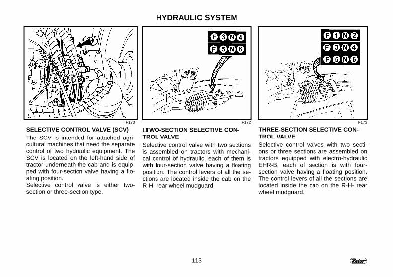
113
HYDRAULIC SYSTEM
F170 F172 F173
SELECTIVE CONTROL VALVE (SCV)The SCV is intended for attached agri-cultural machines that need the separatecontrol of two hydraulic equipment. TheSCV is located on the left-hand side oftractor underneath the cab and is equip-ped with four-section valve having a flo-ating position.Selective control valve is either two-section or three-section type.
∗∗∗∗ TWO-SECTION SELECTIVE CON-TROL VALVESelective control valve with two sectionsis assembled on tractors with mechani-cal control of hydraulic, each of them iswith four-section valve having a floatingposition. The control levers of all the se-ctions are located inside the cab on theR-H- rear wheel mudguard
THREE-SECTION SELECTIVE CON-TROL VALVESelective control valves with two secti-ons or three sections are assembled ontractors equipped with electro-hydraulicEHR-B, each of section is with four-section valve having a floating position.The control levers of all the sections arelocated inside the cab on the R-H- rearwheel mudguard.
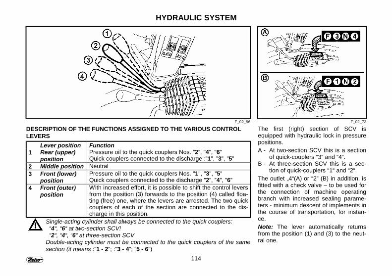
114
HYDRAULIC SYSTEM
F_02_96 F_02_72
DESCRIPTION OF THE FUNCTIONS ASSIGNED TO THE VARIOUS CONTROLLEVERS
Lever position Function1 Rear (upper)
positionPressure oil to the quick couplers Nos. ”2”, "4", "6"Quick couplers connected to the discharge :”1”, ”3”, ”5”
2 Middle position Neutral3 Front (lower)
positionPressure oil to the quick couplers Nos. "1", "3", "5"Quick couplers connected to the discharge ”2”, ”4”, ”6”
4 Front (outer)position
With increased effort, it is possible to shift the control leversfrom the position (3) forwards to the position (4) called floa-ting (free) one, where the levers are arrested. The two quickcouplers of each of the section are connected to the dis-charge in this position.
Single-acting cylinder shall always be connected to the quick couplers: “4“, “6“ at two-section SCV! “2“, “4“, “6“ at three-section SCVDouble-acting cylinder must be connected to the quick couplers of the samesection (it means :”1 - 2”; :”3 - 4”; ”5 - 6”)
The first (right) section of SCV isequipped with hydraulic lock in pressurepositions.A - At two-section SCV this is a section
of quick-couplers “3“ and “4“.B - At three-section SCV this is a sec-
tion of quick-couplers “1“ and “2“.The outlet „4“(A) or “2” (B) in addition, isfitted with a check valve – to be used forthe connection of machine operatingbranch with increased sealing parame-ters - minimum descent of implements inthe course of transportation, for instan-ce.Note: The lever automatically returnsfrom the position (1) and (3) to the neut-ral one.
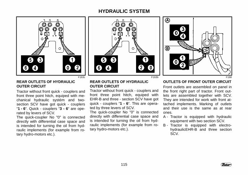
115
HYDRAULIC SYSTEM
F163c F163b F168
REAR OUTLETS OF HYDRAULICOUTER CIRCUITTractor without front quick - couplers andfront three point hitch, equiped with me-chanical hydraulic systém and two-section SCV have got quick - couplers“1 - 6“. Quick - couplers “3 - 6“ are ope-rated by levers of SCV.The quick-coupler No "0" is connecteddirectly with differential case space andis intended for turning the oil from hyd-raulic implements (for example from ro-tary hydro-motors etc.).
REAR OUTLETS OF HYDRAULICOUTER CIRCUITTractor without front quick - couplers andfront three point hitch, equiped withEHR-B and three - section SCV have gotquick - couplers “1 - 6“. This are opera-ted by three levers of SCV.The quick-coupler No "0" is connecteddirectly with differential case space andis intended for turning the oil from hyd-raulic implements (for example from ro-tary hydro-motors etc.).
OUTLETS OF FRONT OUTER CIRCUITFront outlets are assembled on panel inthe front right part of tractor. Front out-lets are assembled together with SCV.They are intended for work with front at-tached implements. Marking of outletsand their use is the same as at rearones.A - Tractor is equipped with hydraulic
equipment with two section SCV.B - Tractor is equipped with electro-
hydraulicEHR-B and three sectionSCV.
116
HYDRAULIC SYSTEMCONNECTION OF MACHINES AND IMPLEMENTS TO HYDRAULIC OUTERCIRCUITConnection of machines and implements combined from more partsTractors equipped with mechanical control of hydraulicAgricultural machines that are combined from more parts (combinators, skids, andharrows), are often equipped with outer frames which are hinged to the middle fra-me. This configuration needs to control folding of outer frames. These outer framesare folded by independent hydraulic cylinders. For folding, cylinders are connectedwith outer circuit of tractor hydraulic. When working with such implement it is neces-sary to control folding of outer frames by raising the control lever of outer circuitupward. Moving the control lever upward ensures that the pressure oil in quick-coupler "1" lifts frames to vertical (transport) position. Quick-coupler "2" is connectedwith drain.Tractors equipped with selective control valveWhen operating the agricultural machines assembled of more components (cultiva-tors, clod crushers, harrows, and the like), in which outer frames are hinged at theinner frame, and should be raised – during the transportation - to the vertical positionby the action of separate hydraulic cylinders controlled by the tractor outer hydrauliccircuit, the tilting of outer frames has to be controlled with moving the additional dis-tributor lever upwards (rearwards). The ”lifting” branches of cylinders have to beconnected to th quick couplers “2”, “4” or “6”.Connection of rotary hydromotorIf the rotary hydromotor is connected with hydraulic outer circuit, the oil return linemust be connected with quick-coupler "0".Connection of reversible hydromotorIf the reversible hydromotor is used the oil lines must be connected with quick-couplers "1" and "2". In this case both lines must be equipped with relief valveswhich will limit the pressure peaks when stopping the machine. The oil return linefrom these valves is connected with quick-coupler "0".

117
NOTE

118
NOTE
119
HYDRAULIC WITH MECHANICAL CONTROL SYSTEMStrana
Function of control elements................................................................................... 120Hydraulic inner circuit.............................................................................................. 120Inner circuit control lever......................................................................................... 121Control mode selection lever .................................................................................. 121Response arate control lever .................................................................................. 122Electro-pneumatic control of hydraulic.................................................................... 122Cab control switch................................................................................................... 123Control switch on fender ......................................................................................... 123Use of switches....................................................................................................... 123
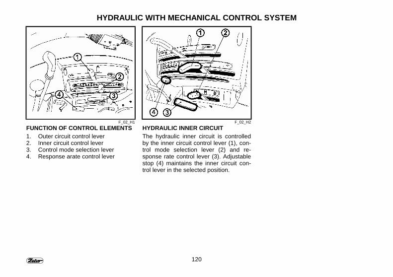
120
HYDRAULIC WITH MECHANICAL CONTROL SYSTEM
F_02_H1 F_02_H2FUNCTION OF CONTROL ELEMENTS1. Outer circuit control lever2. Inner circuit control lever3. Control mode selection lever4. Response arate control lever
HYDRAULIC INNER CIRCUITThe hydraulic inner circuit is controlledby the inner circuit control lever (1), con-trol mode selection lever (2) and re-sponse rate control lever (3). Adjustablestop (4) maintains the inner circuit con-trol lever in the selected position.
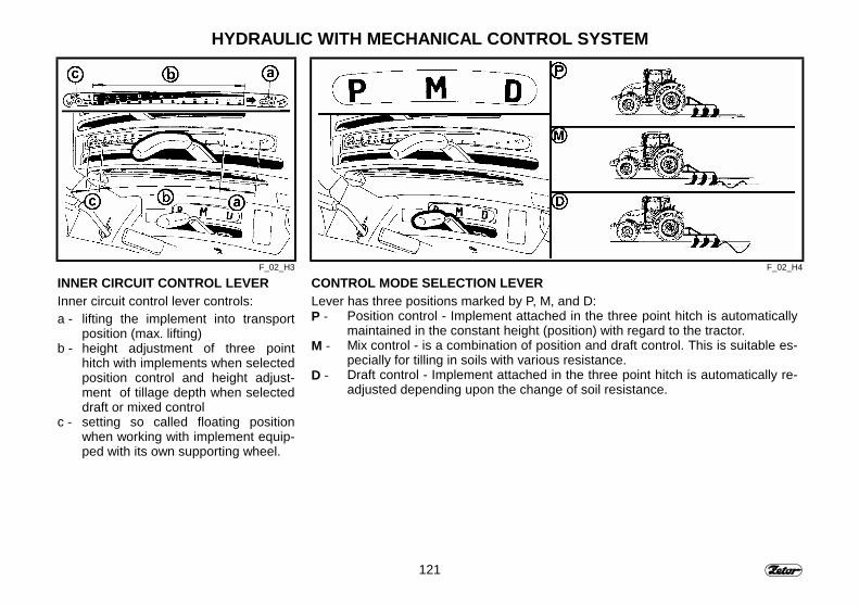
121
HYDRAULIC WITH MECHANICAL CONTROL SYSTEM
F_02_H3 F_02_H4
INNER CIRCUIT CONTROL LEVERInner circuit control lever controls:a - lifting the implement into transport
position (max. lifting)b - height adjustment of three point
hitch with implements when selectedposition control and height adjust-ment of tillage depth when selecteddraft or mixed control
c - setting so called floating positionwhen working with implement equip-ped with its own supporting wheel.
CONTROL MODE SELECTION LEVERLever has three positions marked by P, M, and D:P - Position control - Implement attached in the three point hitch is automatically
maintained in the constant height (position) with regard to the tractor.M - Mix control - is a combination of position and draft control. This is suitable es-
pecially for tilling in soils with various resistance.D - Draft control - Implement attached in the three point hitch is automatically re-
adjusted depending upon the change of soil resistance.
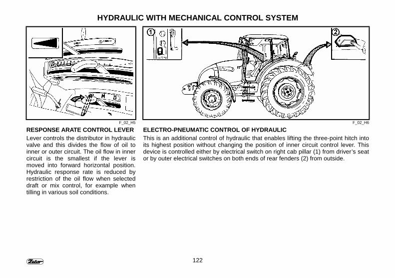
122
HYDRAULIC WITH MECHANICAL CONTROL SYSTEM
F_02_H5 F_02_H6
RESPONSE ARATE CONTROL LEVERLever controls the distributor in hydraulicvalve and this divides the flow of oil toinner or outer circuit. The oil flow in innercircuit is the smallest if the lever ismoved into forward horizontal position.Hydraulic response rate is reduced byrestriction of the oil flow when selecteddraft or mix control, for example whentilling in various soil conditions.
ELECTRO-PNEUMATIC CONTROL OF HYDRAULICThis is an additional control of hydraulic that enables lifting the three-point hitch intoits highest position without changing the position of inner circuit control lever. Thisdevice is controlled either by electrical switch on right cab pillar (1) from driver’s seator by outer electrical switches on both ends of rear fenders (2) from outside.
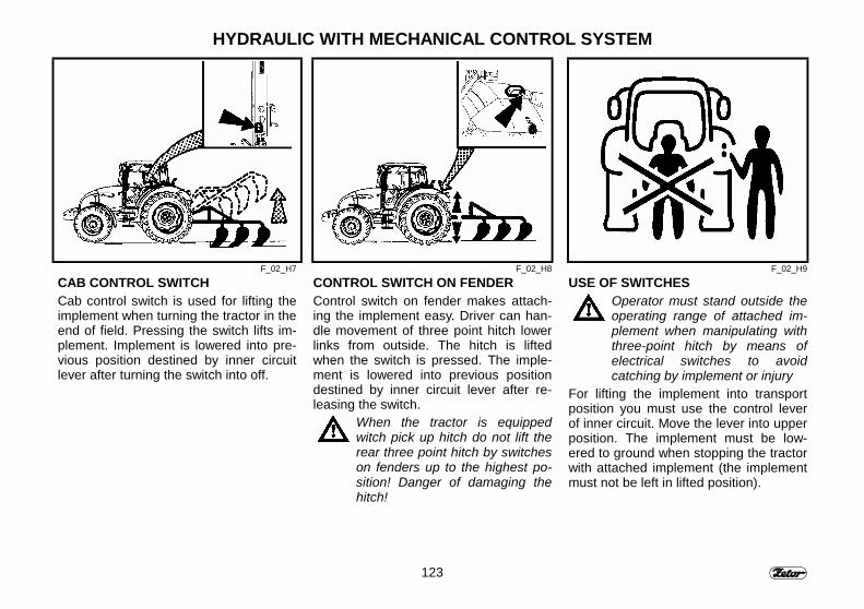
123
HYDRAULIC WITH MECHANICAL CONTROL SYSTEM
F_02_H7 F_02_H8 F_02_H9
CAB CONTROL SWITCHCab control switch is used for lifting theimplement when turning the tractor in theend of field. Pressing the switch lifts im-plement. Implement is lowered into pre-vious position destined by inner circuitlever after turning the switch into off.
CONTROL SWITCH ON FENDERControl switch on fender makes attach-ing the implement easy. Driver can han-dle movement of three point hitch lowerlinks from outside. The hitch is liftedwhen the switch is pressed. The imple-ment is lowered into previous positiondestined by inner circuit lever after re-leasing the switch.
When the tractor is equippedwitch pick up hitch do not lift therear three point hitch by switcheson fenders up to the highest po-sition! Danger of damaging thehitch!
USE OF SWITCHESOperator must stand outside theoperating range of attached im-plement when manipulating withthree-point hitch by means ofelectrical switches to avoidcatching by implement or injury
For lifting the implement into transportposition you must use the control leverof inner circuit. Move the lever into upperposition. The implement must be low-ered to ground when stopping the tractorwith attached implement (the implementmust not be left in lifted position).

124
NOTE
125
ELECTRO-HYDRAULIC SYSTEMPage
Scheme of the EHR B - BOSCH electro-hydraulic system operation diagram ....... 126Functions of the controls......................................................................................... 127Device switched off ................................................................................................. 127Eliminating the blocking system.............................................................................. 128Fast dipping ............................................................................................................ 129Implement transportation ........................................................................................ 129Stop position ........................................................................................................... 129Compensator of swinging ....................................................................................... 130Three-point hitch upper position limitation .............................................................. 130Lowering speed....................................................................................................... 131Free position ........................................................................................................... 131Field operation ........................................................................................................ 132Use of the rear control ............................................................................................ 133Electro-hydraulic system external control pushbuttons........................................... 133Use of pushbuttons ................................................................................................. 133Signalization of EHR - B failure............................................................................... 134Description of signalizing the electro-hydraulic EHR-B failure................................ 134Description of electro-hydraulic EHR-B light failure ................................................ 135

126
ELECTRO-HYDRAULIC SYSTEMSCHEME OF THE EHR B - BOSCHELECTRO-HYDRAULIC SYSTEMOPERATION DIAGRAMThe hydraulic system pump (1) suppliesoil to the additional distributor (2) of thehydraulic system, and from there it is de-livered to the regulating distributor (3),which controls the lifting arm cylinders(4,5) of the hydraulic system.The arms are interconnected with thethree-point hitch lower tie rods where theagricultural implements – lifted, lowered,or kept in required position with respectto the tractor – are suspended.The electronic control unit (6) receiveselectric signals from the dynamometricpins (7) and the sensors of position (8).These signals are confronted with therequired value set up on the controlpanel (9).From the comparison of the required andreal values the resulting regulation de-viation, which is transmitted to the regu-lating distributor (3). This one is then re-adjusted with two proportional electro-magnets.The lifting and lowering is independenton the load.
F_02_161a
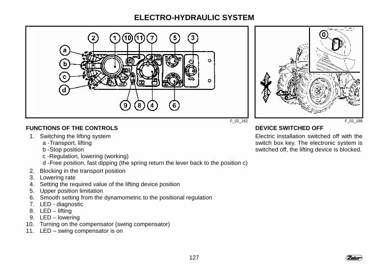
127
ELECTRO-HYDRAULIC SYSTEM
F_02_162 F_02_188
FUNCTIONS OF THE CONTROLS1. Switching the lifting system
a - Transport, liftingb - Stop positionc - Regulation, lowering (working)d - Free position, fast dipping (the spring return the lever back to the position c)
2. Blocking in the transport position3. Lowering rate4. Setting the required value of the lifting device position5. Upper position limitation6. Smooth setting from the dynamometric to the positional regulation7. LED - diagnostic8. LED – lifting9. LED – lowering
10. Turning on the compensator (swing compensator)11. LED – swing compensator is on
DEVICE SWITCHED OFFElectric installation switched off with theswitch box key. The electronic system isswitched off, the lifting device is blocked.
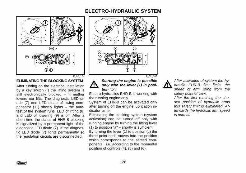
128
ELECTRO-HYDRAULIC SYSTEM
F_02_164 F_02_163
ELIMINATING THE BLOCKING SYSTEMAfter turning on the electrical installationby a key switch (I) the lifting system isstill electronically blocked – it neitherlowers nor lifts. The diagnostic LED di-ode (7) and LED diode of swing com-pensator (11) shortly lights – the auto-test of the system runs. LED of lifting (8)and LED of lowering (9) is off. After ashort time the status of EHR-B blockingis signalized by a permanent light of thediagnostic LED diode (7). If the diagnos-tic LED diode (7) lights permanently sothe regulation circuits are disconnected.
Starting the engine is possibleonly with the lever (1) in posi-tion "b".
Electro-hydraulics EHR-B is working withthe running engine only.System of EHR-B can be activated onlyafter turning off the engine lubrication in-dicator lamp.Eliminating the blocking system (systemactivation) can be turned off only withrunning engine by turning the lifting lever(1) to position "a" – shortly is sufficient.By turning the lever (1) to position (c) thethree point hitch moves into the positionwhich corresponds to the settled com-ponents, i.e. according to the momentalposition of controls (4), (5) and (6).
After activation of system the hy-draulic EHR-B first limits thespeed of arm lifting from thesafety point of view.After the first reaching the cho-sen position of hydraulic armsthis safety limit is eliminated. Af-terwards the hydraulic arm speedis normal.
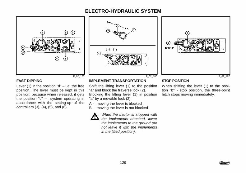
129
ELECTRO-HYDRAULIC SYSTEM
F_02_165 F_02_166 F_02_167
FAST DIPPINGLever (1) in the position "d" – i.e. the freeposition. The lever must be kept in thisposition, because when released, it getsthe position "c" – system operating inaccordance with the setting-up of thecontrollers (3), (4), (5), and (6).
IMPLEMENT TRANSPORTATIONShift the lifting lever (1) to the position”a” and block the traverse lock (2).Blocking the lifting lever (1) in position"a" by a movable lock (2):A - moving the lever is blockedB - moving the lever is not blocked
When the tractor is stopped withthe implements attached, lowerthe implements to the ground (donot leave it with the implementsin the lifted position).
STOP POSITIONWhen shifting the lever (1) to the posi-tion "b" - stop position, the three-pointhitch stops moving immediately.
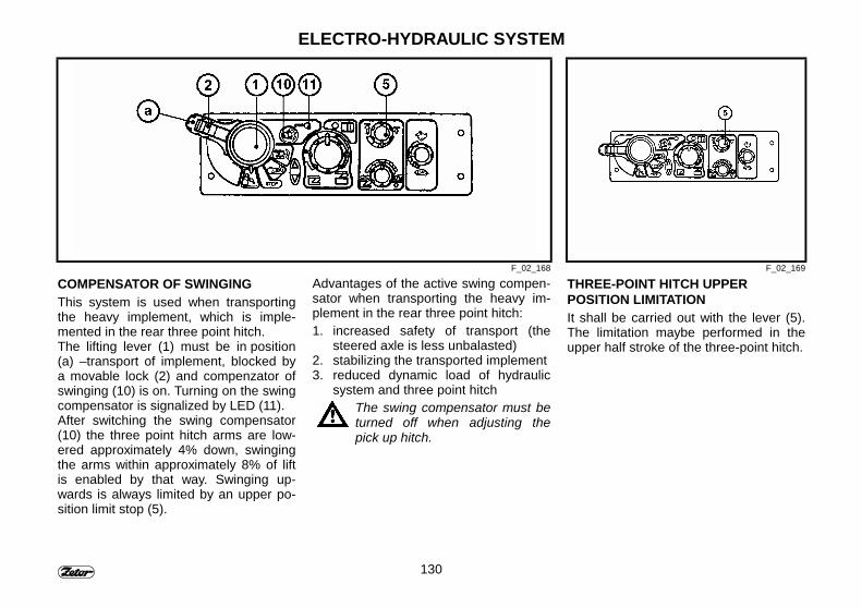
130
ELECTRO-HYDRAULIC SYSTEM
F_02_168 F_02_169
COMPENSATOR OF SWINGINGThis system is used when transportingthe heavy implement, which is imple-mented in the rear three point hitch.The lifting lever (1) must be in position(a) –transport of implement, blocked bya movable lock (2) and compenzator ofswinging (10) is on. Turning on the swingcompensator is signalized by LED (11).After switching the swing compensator(10) the three point hitch arms are low-ered approximately 4% down, swingingthe arms within approximately 8% of liftis enabled by that way. Swinging up-wards is always limited by an upper po-sition limit stop (5).
Advantages of the active swing compen-sator when transporting the heavy im-plement in the rear three point hitch:1. increased safety of transport (the
steered axle is less unbalasted)2. stabilizing the transported implement3. reduced dynamic load of hydraulic
system and three point hitchThe swing compensator must beturned off when adjusting thepick up hitch.
THREE-POINT HITCH UPPERPOSITION LIMITATIONIt shall be carried out with the lever (5).The limitation maybe performed in theupper half stroke of the three-point hitch.
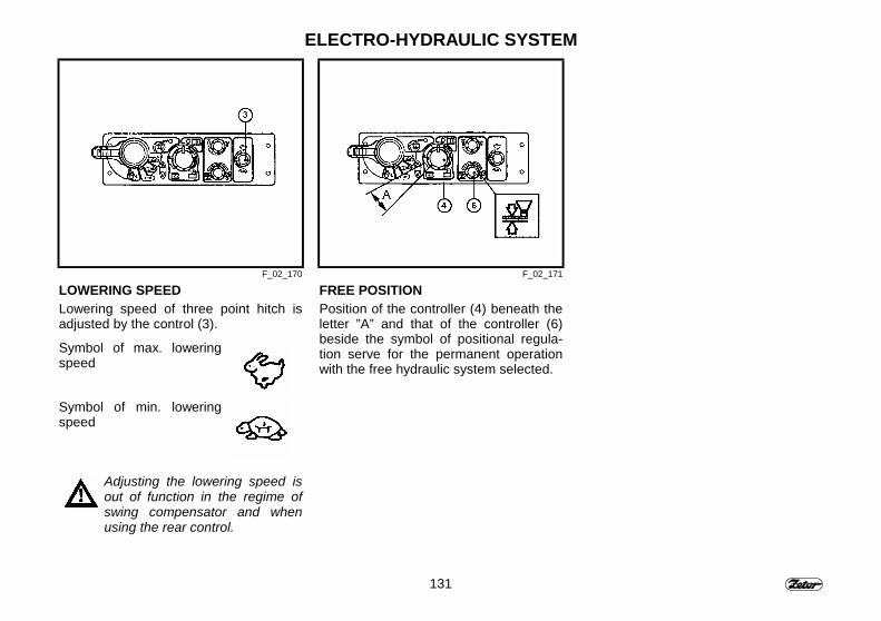
131
ELECTRO-HYDRAULIC SYSTEM
F_02_170 F_02_171
LOWERING SPEEDLowering speed of three point hitch isadjusted by the control (3).
Symbol of max. loweringspeed
Symbol of min. loweringspeed
Adjusting the lowering speed isout of function in the regime ofswing compensator and whenusing the rear control.
FREE POSITIONPosition of the controller (4) beneath theletter ”A” and that of the controller (6)beside the symbol of positional regula-tion serve for the permanent operationwith the free hydraulic system selected.
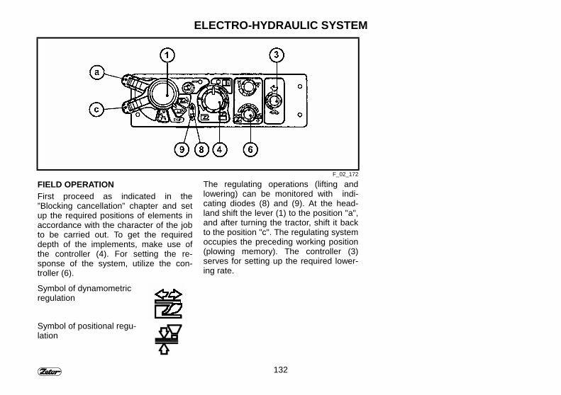
132
ELECTRO-HYDRAULIC SYSTEM
F_02_172
FIELD OPERATIONFirst proceed as indicated in the”Blocking cancellation” chapter and setup the required positions of elements inaccordance with the character of the jobto be carried out. To get the requireddepth of the implements, make use ofthe controller (4). For setting the re-sponse of the system, utilize the con-troller (6).
Symbol of dynamometricregulation
Symbol of positional regu-lation
The regulating operations (lifting andlowering) can be monitored with indi-cating diodes (8) and (9). At the head-land shift the lever (1) to the position "a",and after turning the tractor, shift it backto the position "c". The regulating systemoccupies the preceding working position(plowing memory). The controller (3)serves for setting up the required lower-ing rate.
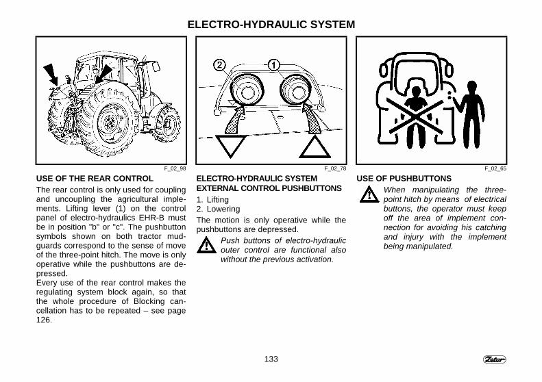
133
ELECTRO-HYDRAULIC SYSTEM
F_02_98 F_02_78 F_02_65
USE OF THE REAR CONTROLThe rear control is only used for couplingand uncoupling the agricultural imple-ments. Lifting lever (1) on the controlpanel of electro-hydraulics EHR-B mustbe in position "b" or "c". The pushbuttonsymbols shown on both tractor mud-guards correspond to the sense of moveof the three-point hitch. The move is onlyoperative while the pushbuttons are de-pressed.Every use of the rear control makes theregulating system block again, so thatthe whole procedure of Blocking can-cellation has to be repeated – see page126.
ELECTRO-HYDRAULIC SYSTEMEXTERNAL CONTROL PUSHBUTTONS1. Lifting2. LoweringThe motion is only operative while thepushbuttons are depressed.
Push buttons of electro-hydraulicouter control are functional alsowithout the previous activation.
USE OF PUSHBUTTONSWhen manipulating the three-point hitch by means of electricalbuttons, the operator must keepoff the area of implement con-nection for avoiding his catchingand injury with the implementbeing manipulated.
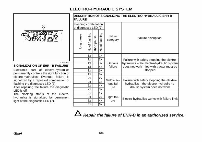
134
ELECTRO-HYDRAULIC SYSTEM
F -02 -173SIGNALIZATION OF EHR - B FAILUREElectronic part of electro-hydraulicspermanently controls the right function ofelectro-hydraulics. Eventual failure issignalized by a repeated combination offlashing the diagnostic LED (7).After repairing the failure the diagnosticLED is off.The blocking status of the electro-hydraulics is signalized by permanentlight of the diagnostic LED (7).
DESCRIPTION OF SIGNALIZING THE ELECTRO-HYDRAULIC EHR-BFAILUREFlashing combinationof diagnostic LED (7)
long
pau
se
No
of fl
ashi
ng
shor
t pau
se
No
of fl
ashi
ng failurecategory failure discription
1x 1x1x 2x1x 3x1x 4x1x 5x1x 6x
Seriousfailure
Failure with safety stopping the elektro-hydraulics – the electro-hydraulic systemdoes not work – job with tractor must be
stopped
2x 2x2x 3x2x 4x2x 8x
Middle se-rious fail-
ure
Failure with safety stopping the elektro-hydraulics – the electro-hydraulic hy-
draulic system does not work
3x 1x3x 2x3x 4x3x 6x
Light fail-ure Electro-hydraulics works with failure limit
Repair the failure of EHR-B in an authorized service.
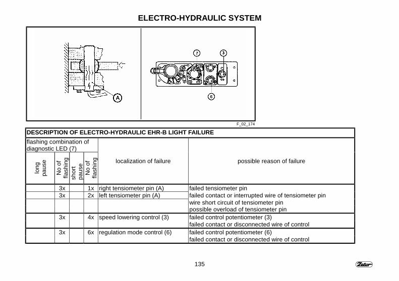
135
ELECTRO-HYDRAULIC SYSTEM
F_02_174
DESCRIPTION OF ELECTRO-HYDRAULIC EHR-B LIGHT FAILUREflashing combination ofdiagnostic LED (7)
long
paus
e
No
offla
shin
gsh
ort
paus
eN
o of
flash
ing localization of failure possible reason of failure
3x 1x right tensiometer pin (A) failed tensiometer pin3x 2x left tensiometer pin (A) failed contact or interrupted wire of tensiometer pin
wire short circuit of tensiometer pinpossible overload of tensiometer pinfailed control potentiometer (3)3x 4x speed lowering control (3)failed contact or disconnected wire of controlfailed control potentiometer (6)3x 6x regulation mode control (6)failed contact or disconnected wire of control

136
NOTE

137
HITCHESStrana
Rear three-point hitch ............................................................................................. 138Safety principles for the .......................................................................................... 139three-point hitch manipulation................................................................................. 139Procedure of attaching machines to the three-point hitch....................................... 139Lower tie rods fitted with extendable terminals ....................................................... 140Attaching machines to three point hitch with CBM hooks ....................................... 140Blocking the side swings of the lower tie rods............................................................. 141Top link ................................................................................................................... 142Selection of top link position ................................................................................... 142Front three-point hitch............................................................................................. 143Front three-point hitch control .................................................................................... 143Front three-point hitch regulation and hydraulic locking ......................................... 143Throttle valve adjustment ........................................................................................ 144Connecting the attached implements...................................................................... 144Drive with agricultural machines suspended in the front three-point hitch.............. 144
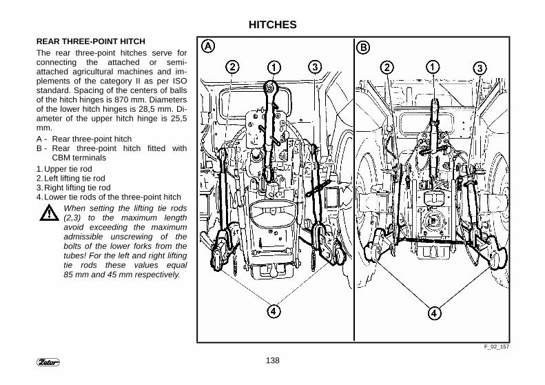
138
HITCHESREAR THREE-POINT HITCHThe rear three-point hitches serve forconnecting the attached or semi-attached agricultural machines and im-plements of the category II as per ISOstandard. Spacing of the centers of ballsof the hitch hinges is 870 mm. Diametersof the lower hitch hinges is 28,5 mm. Di-ameter of the upper hitch hinge is 25,5mm.A - Rear three-point hitchB - Rear three-point hitch fitted with
CBM terminals1. Upper tie rod2. Left lifting tie rod3. Right lifting tie rod4. Lower tie rods of the three-point hitch
When setting the lifting tie rods(2,3) to the maximum lengthavoid exceeding the maximumadmissible unscrewing of thebolts of the lower forks from thetubes! For the left and right liftingtie rods these values equal85 mm and 45 mm respectively.
F_02_157
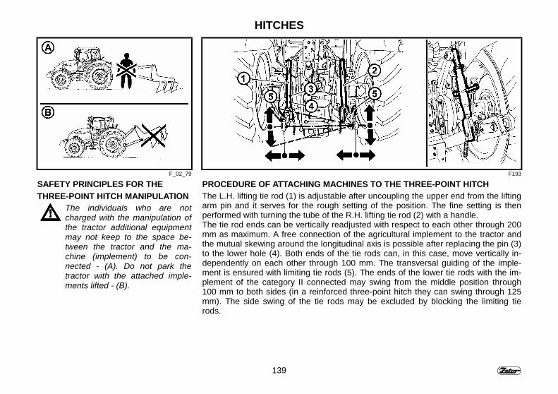
139
HITCHES
F_02_79 F193
SAFETY PRINCIPLES FOR THETHREE-POINT HITCH MANIPULATION
The individuals who are notcharged with the manipulation ofthe tractor additional equipmentmay not keep to the space be-tween the tractor and the ma-chine (implement) to be con-nected - (A). Do not park thetractor with the attached imple-ments lifted - (B).
PROCEDURE OF ATTACHING MACHINES TO THE THREE-POINT HITCHThe L.H. lifting tie rod (1) is adjustable after uncoupling the upper end from the liftingarm pin and it serves for the rough setting of the position. The fine setting is thenperformed with turning the tube of the R.H. lifting tie rod (2) with a handle.The tie rod ends can be vertically readjusted with respect to each other through 200mm as maximum. A free connection of the agricultural implement to the tractor andthe mutual skewing around the longitudinal axis is possible after replacing the pin (3)to the lower hole (4). Both ends of the tie rods can, in this case, move vertically in-dependently on each other through 100 mm. The transversal guiding of the imple-ment is ensured with limiting tie rods (5). The ends of the lower tie rods with the im-plement of the category II connected may swing from the middle position through100 mm to both sides (in a reinforced three-point hitch they can swing through 125mm). The side swing of the tie rods may be excluded by blocking the limiting tierods.
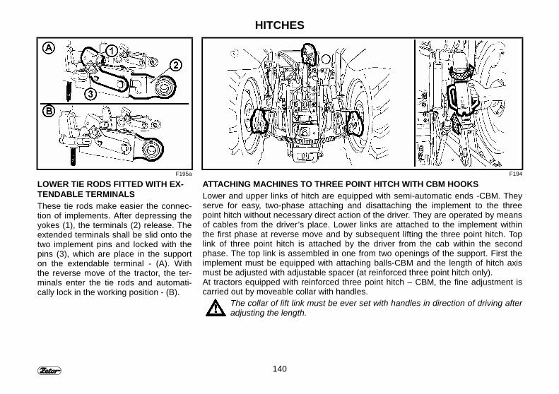
140
HITCHES
F195a F194
LOWER TIE RODS FITTED WITH EX-TENDABLE TERMINALSThese tie rods make easier the connec-tion of implements. After depressing theyokes (1), the terminals (2) release. Theextended terminals shall be slid onto thetwo implement pins and locked with thepins (3), which are place in the supporton the extendable terminal - (A). Withthe reverse move of the tractor, the ter-minals enter the tie rods and automati-cally lock in the working position - (B).
ATTACHING MACHINES TO THREE POINT HITCH WITH CBM HOOKSLower and upper links of hitch are equipped with semi-automatic ends -CBM. Theyserve for easy, two-phase attaching and disattaching the implement to the threepoint hitch without necessary direct action of the driver. They are operated by meansof cables from the driver’s place. Lower links are attached to the implement withinthe first phase at reverse move and by subsequent lifting the three point hitch. Toplink of three point hitch is attached by the driver from the cab within the secondphase. The top link is assembled in one from two openings of the support. First theimplement must be equipped with attaching balls-CBM and the length of hitch axismust be adjusted with adjustable spacer (at reinforced three point hitch only).At tractors equipped with reinforced three point hitch – CBM, the fine adjustment iscarried out by moveable collar with handles.
The collar of lift link must be ever set with handles in direction of driving afteradjusting the length.
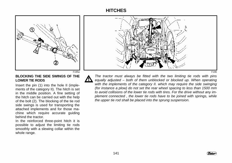
141
HITCHES
F195a F196
BLOCKING THE SIDE SWINGS OF THELOWER TIE RODSInsert the pin (1) into the hole II (imple-ments of the category II). The hitch is setin the middle position. A fine setting ofthe hitch can be carried out with the helpof the bolt (2). The blocking of the tie rodside swings is used for transporting theattached implements and for those ma-chine which require accurate guidingbehind the tractor.In the reinforced three-point hitch it ispossible to adjust the limiting tie rodssmoothly with a slewing collar within thewhole range.
The tractor must always be fitted with the two limiting tie rods with pinsequally adjusted – both of them unblocked or blocked up. When operatingwith the implements of the category II. which may require the side swinging(for instance a plow) do not set the rear wheel spacing to less than 1500 mmto avoid collisions of the lower tie rods with tires. For the drive without any im-plement connected , the lower tie rods have to be joined with springs, whilethe upper tie rod shall be placed into the sprung suspension.
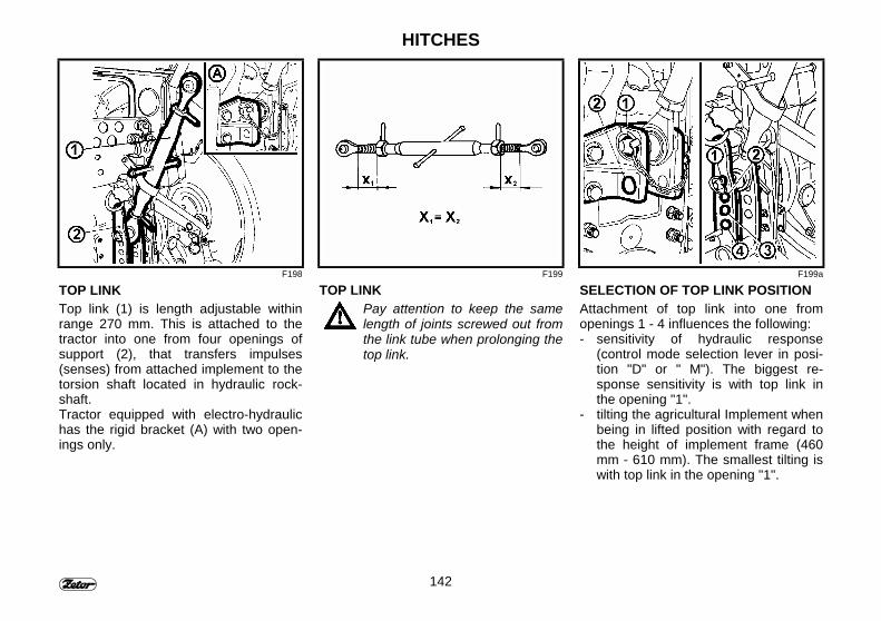
142
HITCHES
F198 F199 F199a
TOP LINKTop link (1) is length adjustable withinrange 270 mm. This is attached to thetractor into one from four openings ofsupport (2), that transfers impulses(senses) from attached implement to thetorsion shaft located in hydraulic rock-shaft.Tractor equipped with electro-hydraulichas the rigid bracket (A) with two open-ings only.
TOP LINKPay attention to keep the samelength of joints screwed out fromthe link tube when prolonging thetop link.
SELECTION OF TOP LINK POSITIONAttachment of top link into one fromopenings 1 - 4 influences the following:- sensitivity of hydraulic response
(control mode selection lever in posi-tion "D" or " M"). The biggest re-sponse sensitivity is with top link inthe opening "1".
- tilting the agricultural Implement whenbeing in lifted position with regard tothe height of implement frame (460mm - 610 mm). The smallest tilting iswith top link in the opening "1".
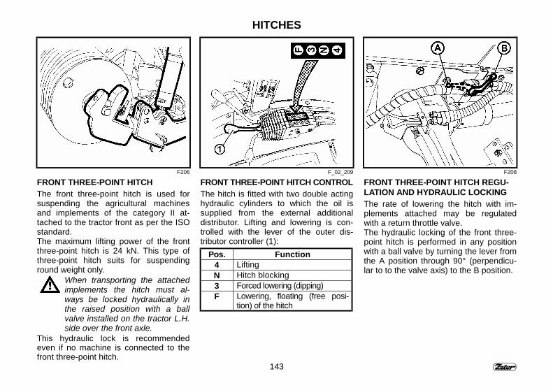
143
HITCHES
F206 F_02_209 F208
FRONT THREE-POINT HITCHThe front three-point hitch is used forsuspending the agricultural machinesand implements of the category II at-tached to the tractor front as per the ISOstandard.The maximum lifting power of the frontthree-point hitch is 24 kN. This type ofthree-point hitch suits for suspendinground weight only.
When transporting the attachedimplements the hitch must al-ways be locked hydraulically inthe raised position with a ballvalve installed on the tractor L.H.side over the front axle.
This hydraulic lock is recommendedeven if no machine is connected to thefront three-point hitch.
FRONT THREE-POINT HITCH CONTROLThe hitch is fitted with two double actinghydraulic cylinders to which the oil issupplied from the external additionaldistributor. Lifting and lowering is con-trolled with the lever of the outer dis-tributor controller (1):
Pos. Function4 LiftingN Hitch blocking3 Forced lowering (dipping)F Lowering, floating (free posi-
tion) of the hitch
FRONT THREE-POINT HITCH REGU-LATION AND HYDRAULIC LOCKINGThe rate of lowering the hitch with im-plements attached may be regulatedwith a return throttle valve.The hydraulic locking of the front three-point hitch is performed in any positionwith a ball valve by turning the lever fromthe A position through 90° (perpendicu-lar to to the valve axis) to the B position.
144
HITCHES
F209 F210 F211
THROTTLE VALVE ADJUSTMENTBefore initiating the operation with theimplement attached to the front three-point hitch, the adjustment of the throttlevalve (3) to such a value that the periodof time necessary for lowering the im-plement from the highest to the lowestposition is from 1 to 1,5 sec. is recom-mended. The control lever is in the posi-tion F (see Fig. F207). With turning thevalve body to the left the rate of loweringdecreases..
CONNECTING THE ATTACHED IM-PLEMENTSThe implement attached is locked in thehitch forks with connecting pins. Lockingof the fixed and floating position of theimplement attached is provided with thepins in the following manner:- With the pins put in the position 1 the
fixed position of the attached imple-ment is got. í
- With the pins placed in the position 2the floating position of the attachedimplement is ensured.
DRIVE WITH AGRICULTURAL MA-CHINES SUSPENDED IN THE FRONTTHREE-POINT HITCH
When driving the tractor with ag-ricultural machines suspended inthe front, reduce the tractor travelspeed to 20 km.h.
If the front three-point hitch is not usedimmediately, remove the lower lifting tierods (1) with releasing the lock and re-moving the pins. (2).In the tractors not fitted with propellershaft brakes, drive with the front driveengaged is recommended.

145
NOTE

146
NOTE
147
CHANGING THE WHEEL TRACKPage
Adjustable front driving axle wheels in the Z 8641 - Z 11741 tractors..................... 148Front driving axle wheel toe-in ................................................................................ 149Toe-in of the front driving axle wheels..................................................................... 150Setting the front driving axle wheel stops................................................................ 151Changing the track of the rear wheels .................................................................... 152Setting the rear wheel track .................................................................................... 152

148
CHANGING THE WHEEL TRACKADJUSTABLE FRONT DRIVING AXLE WHEELS IN THE Z 8641 - Z 11741 TRACTORS
Tire dimensions12,4-24 13,6-24 12,4-28 14,9-24 Rim position
Front wheels track in mm
1590∗ - - -
1645 1730 1730
1740 1655 1730 -
1800 1880 1810 1880
1890 1810 1880 1810
1945 2030 1955 2030
2040 1955 2030 1955
∗ - Standard trackFor tightening the front wheel nuts apply a torque between 250 and 290 Nm.Tightenthe nuts joining the wheel bead with the wheel disk with a torque between 230 and250 Nm.
To change the wheel track, positions ofthe wheel rims and disks have to bechanged.
First of all assure the tractoragainst the move, then lift it witha jack, and prop it adequately.
− Unscrew the nuts of the bolts joiningthe disk with the rim and remove thebolts.
− Change the track with placing the therim to the required position. Put backthe bolts with washers and lock themwith nuts. Tighten the nuts with atorque between 230 and 250 Nm.
− After each release of the bead joint ,tighten the bolts to the prescribedvalue.
− After covering 100-m distance with anunloaded tractor, tighten the jointsagain with the prescribed torque.
− With the tractor loaded, tighten thejoints after a 3-operating hours run.
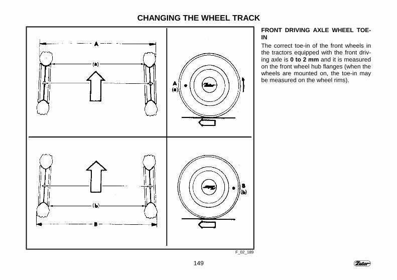
149
CHANGING THE WHEEL TRACK
F_02_189
FRONT DRIVING AXLE WHEEL TOE-INThe correct toe-in of the front wheels inthe tractors equipped with the front driv-ing axle is 0 to 2 mm and it is measuredon the front wheel hub flanges (when thewheels are mounted on, the toe-in maybe measured on the wheel rims).
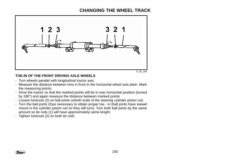
150
CHANGING THE WHEEL TRACK
F_02_160
TOE-IN OF THE FRONT DRIVING AXLE WHEELS- Turn wheels parallel with longitudinal tractor axis.- Measure the distance between rims in front in the horizontal wheel axis plain. Mark
the measuring points.- Drive the tractor so that the marked points will be in rear horizontal position (turned
by 180°) and again measure the distance between marked points- Loosen locknuts (2) on ball joints onboth ends of the steering cylinder piston rod.- Turn the ball joints (3)as necessary to obtain proper toe - in (ball joints have swiwel
mount in the cylinder piston rod so they will turn). Turn both ball joints by the sameamount so tie rods (1) will have approximately same lenght.
- Tighten locknuts (2) on both tie rods
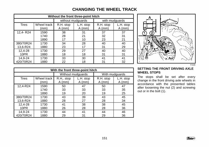
151
CHANGING THE WHEEL TRACKWithout the front three-point hitch
without mudguards with mudguardsTires Wheel track
(mm)R.H. stopA (mm)
L.H. stopA (mm)
R.H. stopA (mm)
L.H. stopA (mm)
12,4- R24 159017401890
382817
312110
373223
373121
380/70R2413,6-R24
17301880
3423
2817
4031
4029
12,4-2810PR
17301880
2918
2718
4031
4031
14,9-24420/70R24
17301880
3322
3018
4131
4132
With the front three-point hitchWithout mudguards With mudguards
Tires Wheel track(mm)
R.H,. stopA (mm)
L.H. stopA (mm)
R.H. stopA (mm)
L.H. stopA (mm)
12,4-R24 159017401890
503319
473320
503319
473525
380/70R2413,6-R24
17301880
4328
3927
4328
4534
12,4-2810PR
17301880
4126
3828
3828
4536
14,9-24420/70R24
17301880
4429
4131
4429
4636
F216
SETTING THE FRONT DRIVING AXLEWHEEL STOPSThe stops shall be set after everychange in the front driving axle wheels inaccordance with the presented tablesafter loosening the nut (2) and screwingout or in the bolt (1).
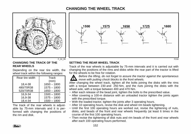
152
CHANGING THE WHEEL TRACK
F_02_99 F218
CHANGING THE TRACK OF THEREAR WHEELSDepending on the rear tire width, thewheel track within the following ranges:
Rear tire width Track(mm)
18,4-38480/70R38520/70R38
1650 – 18001575 – 18001650 – 1800
16,9-3416,9-3818,4-34
1500 – 18001575 – 18001500 – 1800
The track of the rear wheels is adjust-able by 75-mm intervals and it is per-formed with changing the positions ofthe rim and disk.
SETTING THE REAR WHEEL TRACKTrack of the rear wheels is adjustable by 75-mm intervals and it is carried out withchanging the positions of the rims and disks while the rear part of the tractor is liftedfor the wheels to be free for rotation.
Before the lifting, do not forget to assure the tractor against the spontaneousmove with putting chock blocks to the front wheels.
After changing the wheel track, tighten all the bolts joining the disks with the rimswith a torque between 230 and 250 Nm, and the nuts joining the disks with thewheel axle, with a torque between 400 and 470 Nm.− After each release of the bead joint, tighten the bolts to the prescribed value.− After covering a 100-m distance with an unloaded tractor tighten the joints again
with the prescribed torque.− With the loaded tractor, tighten the joints after 3 operating hours.− After 10 operating hours, revise the disk and wheel rim beads tightening.− Until the first 100 operating hours are worked out, revise the tightening of nuts,
disks, and beads of the front and rear wheels frequently (at least 6 times in thecourse of the first 100 operating hours.
− Then revise the tightening of disk nuts and rim beads of the front and rear wheelsafter each 100 operating hours performed.

153
NOTE

154
NOTE
155
BALLAST WEIGHTS
The ballast weights are indispensable forcompleting the load on the tractor axles,assuring the steering ability or tractorstability.
PageRear wheel ballast weights ..................................................................................... 156Lower ballast weights.............................................................................................. 156Front ballast weights ............................................................................................... 157Front three-point hitch ballast weights .................................................................... 157Valve for filling the air tube with a liquid .................................................................. 158Procedure of filling the tires with liquids.................................................................. 158Procedure of draining the liquid off the tire ............................................................. 159Applying the scotch blocks to the front wheels ....................................................... 159Maximum weight of the liquid for the various tire sizes........................................... 160
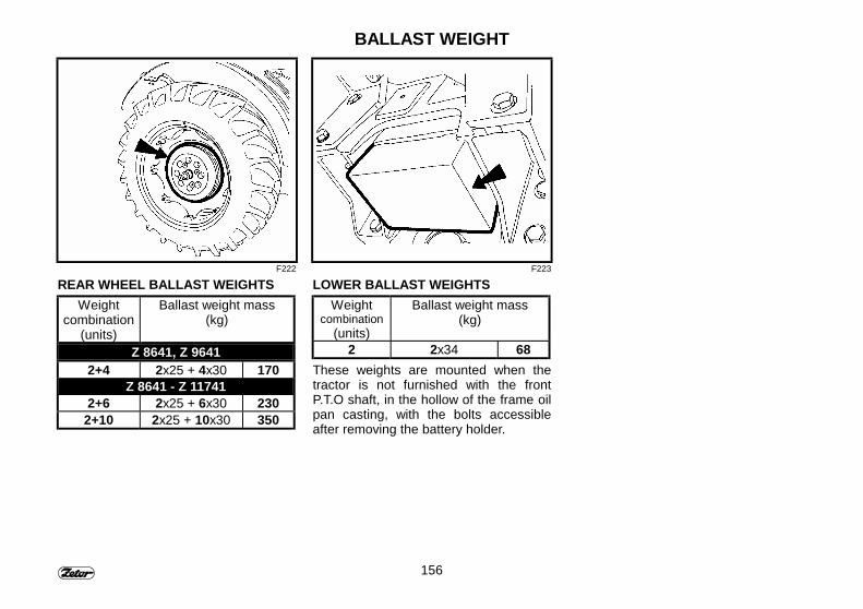
156
BALLAST WEIGHT
F222 F223
REAR WHEEL BALLAST WEIGHTSWeight
combination(units)
Ballast weight mass(kg)
Z 8641, Z 96412+4 2x25 + 4x30 170
Z 8641 - Z 117412+6 2x25 + 6x30 230
2+10 2x25 + 10x30 350
LOWER BALLAST WEIGHTSWeight
combination(units)
Ballast weight mass(kg)
2 2x34 68These weights are mounted when thetractor is not furnished with the frontP.T.O shaft, in the hollow of the frame oilpan casting, with the bolts accessibleafter removing the battery holder.
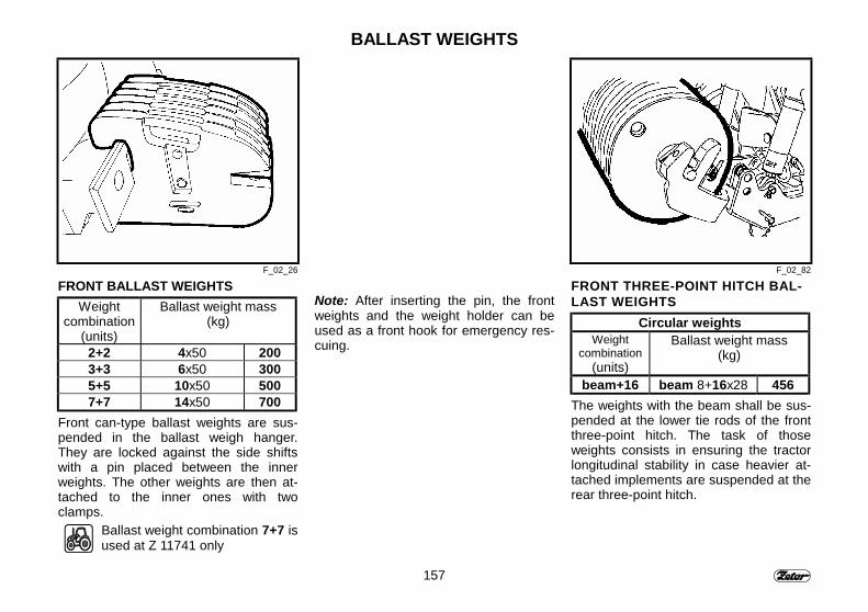
157
BALLAST WEIGHTS
F_02_26 F_02_82
FRONT BALLAST WEIGHTSWeight
combination(units)
Ballast weight mass(kg)
2+2 4x50 2003+3 6x50 3005+5 10x50 5007+7 14x50 700
Front can-type ballast weights are sus-pended in the ballast weigh hanger.They are locked against the side shiftswith a pin placed between the innerweights. The other weights are then at-tached to the inner ones with twoclamps.
Ballast weight combination 7+7 isused at Z 11741 only
Note: After inserting the pin, the frontweights and the weight holder can beused as a front hook for emergency res-cuing.
FRONT THREE-POINT HITCH BAL-LAST WEIGHTS
Circular weightsWeight
combination(units)
Ballast weight mass(kg)
beam+16 beam 8+16x28 456The weights with the beam shall be sus-pended at the lower tie rods of the frontthree-point hitch. The task of thoseweights consists in ensuring the tractorlongitudinal stability in case heavier at-tached implements are suspended at therear three-point hitch.
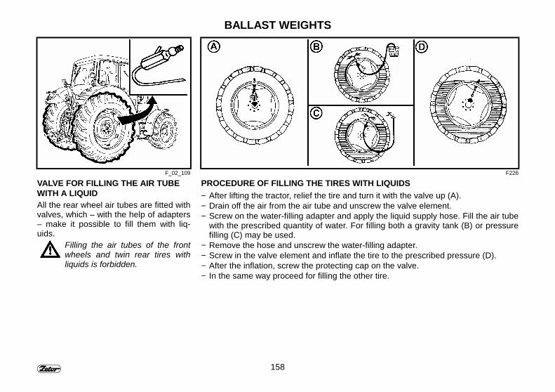
158
BALLAST WEIGHTS
F_02_109 F226
VALVE FOR FILLING THE AIR TUBEWITH A LIQUIDAll the rear wheel air tubes are fitted withvalves, which – with the help of adapters– make it possible to fill them with liq-uids.
Filling the air tubes of the frontwheels and twin rear tires withliquids is forbidden.
PROCEDURE OF FILLING THE TIRES WITH LIQUIDS− After lifting the tractor, relief the tire and turn it with the valve up (A).− Drain off the air from the air tube and unscrew the valve element.− Screw on the water-filling adapter and apply the liquid supply hose. Fill the air tube
with the prescribed quantity of water. For filling both a gravity tank (B) or pressurefilling (C) may be used.
− Remove the hose and unscrew the water-filling adapter.− Screw in the valve element and inflate the tire to the prescribed pressure (D).− After the inflation, screw the protecting cap on the valve.− In the same way proceed for filling the other tire.

159
BALLAST WEIGHTS
F227 F_02_110
PROCEDURE OF DRAINING THE LIQUID OFF THE TIRE− With lifting the tractor, relief the tire and turn the wheel with the valve aiming up.
(A).− Drain the air off the valve and unscrew the valve element from the air tube. Then
turn the valve with the valve aiming down.When draining the liquid off the air tube, vacuum may arise in the tire.Therefore, from time to time, the wheel should be turned to the top position ofthe valve (B).
− Remove the remaining portion of liquid with screwing on the adapter for filling wa-ter and supply the compressed air (C) and keep removing the liquid until the liquidstops flowing from the air adapter.
− Remove the water-filling adapter, screw back the pneumatic section of the valve,and inflate the tire to the prescribed pressure (D).
− After the inflation, screw the protecting cap on the valve.− Analogously proceed when treating the second tire.
APPLYING THE SCOTCH BLOCKS TOTHE FRONT WHEELS
Before lifting the rear wheel donot forget to apply the blocks tothe front wheels for preventingthe tractor from a spontaneousmove.

160
BALLAST WEIGHTSMAXIMUM WEIGHT OF THE LIQUID FOR THE VARIOUS TIRE SIZES
Size Filling 75%pure water
(l), (kg)
Calcium chloride solution
CaCl2 (kg) water (l) Additionalload (kg)
16,9-34 250 108 166 27416,9-38 290 126 192 31818,4-34 330 144 218 362
18,4R-38 385 168 254 422480/70R38 335 146 222 368
18,4-38 385 168 254 422520/70R38 390 170 258 428
The table defines values for temperatures up to - 30°C.
Preparing the solution:1.Anhydrous calcium chloride CaCl2 shall be added to water, never opposite!2. The solution is not danger, but it should be manipulated with care. Wash the spilt solution drops with pure water..3. Before filling, allow the solution cool down. Keep to the prescribed quantity of slaked lime.4. The solution may not enter in contact with metallic components and electric installation elements. It is not dangerous for the
air tube valve.5. The frost-proof solution prepared in the described way may not be used may in the cooling system.6. After being discharged, dispose the anti-freeze agents as a special waste.
Note: The volume of the mixture in the tire corresponds to the filling up to the valve..The frost-proof mixture can be prepared with adding calcium chloride CaCl2 or magnesium chloride MgCl2.Dosing 0,40 kg of CaCl2 into 1 l of water protects the tire up to -30°C temperature (0,3 kg / l protects the tire up to -20°C tem-perature, and 0,2 kg /l does it up to -15°C temperature).Dosing 0,55 kg of MgCl2 per 1 l of water protects the tire up to -30°C temperature.

161
NOTE

162
NOTE
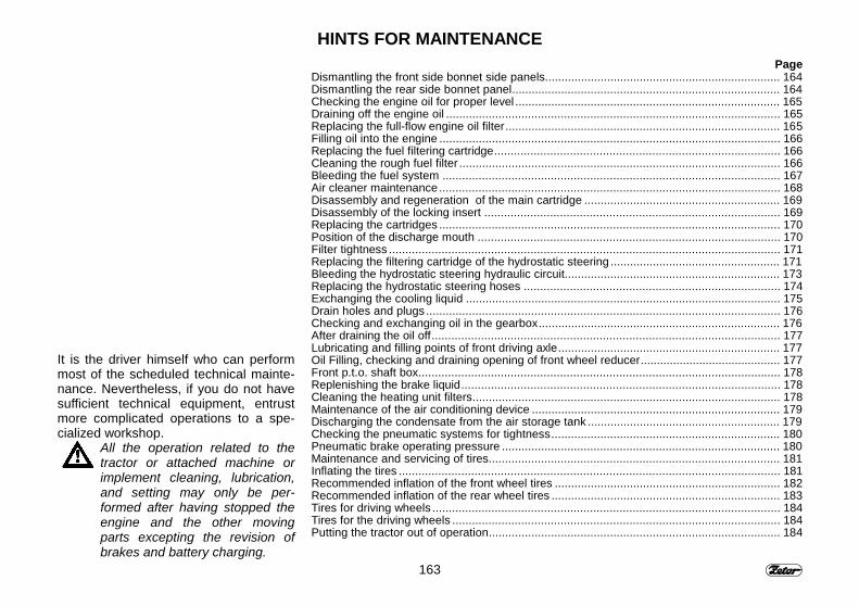
163
HINTS FOR MAINTENANCE
It is the driver himself who can performmost of the scheduled technical mainte-nance. Nevertheless, if you do not havesufficient technical equipment, entrustmore complicated operations to a spe-cialized workshop.
All the operation related to thetractor or attached machine orimplement cleaning, lubrication,and setting may only be per-formed after having stopped theengine and the other movingparts excepting the revision ofbrakes and battery charging.
PageDismantling the front side bonnet side panels........................................................................ 164Dismantling the rear side bonnet panel.................................................................................. 164Checking the engine oil for proper level ................................................................................. 165Draining off the engine oil ...................................................................................................... 165Replacing the full-flow engine oil filter.................................................................................... 165Filling oil into the engine ........................................................................................................ 166Replacing the fuel filtering cartridge....................................................................................... 166Cleaning the rough fuel filter .................................................................................................. 166Bleeding the fuel system ....................................................................................................... 167Air cleaner maintenance........................................................................................................ 168Disassembly and regeneration of the main cartridge ............................................................ 169Disassembly of the locking insert .......................................................................................... 169Replacing the cartridges ........................................................................................................ 170Position of the discharge mouth ............................................................................................ 170Filter tightness ....................................................................................................................... 171Replacing the filtering cartridge of the hydrostatic steering .................................................... 171Bleeding the hydrostatic steering hydraulic circuit.................................................................. 173Replacing the hydrostatic steering hoses .............................................................................. 174Exchanging the cooling liquid ................................................................................................ 175Drain holes and plugs ............................................................................................................ 176Checking and exchanging oil in the gearbox.......................................................................... 176After draining the oil off.......................................................................................................... 177Lubricating and filling points of front driving axle.................................................................... 177Oil Filling, checking and draining opening of front wheel reducer........................................... 177Front p.t.o. shaft box.............................................................................................................. 178Replenishing the brake liquid................................................................................................. 178Cleaning the heating unit filters.............................................................................................. 178Maintenance of the air conditioning device ............................................................................ 179Discharging the condensate from the air storage tank ........................................................... 179Checking the pneumatic systems for tightness...................................................................... 180Pneumatic brake operating pressure ..................................................................................... 180Maintenance and servicing of tires......................................................................................... 181Inflating the tires .................................................................................................................... 181Recommended inflation of the front wheel tires ..................................................................... 182Recommended inflation of the rear wheel tires ...................................................................... 183Tires for driving wheels .......................................................................................................... 184Tires for the driving wheels .................................................................................................... 184Putting the tractor out of operation......................................................................................... 184
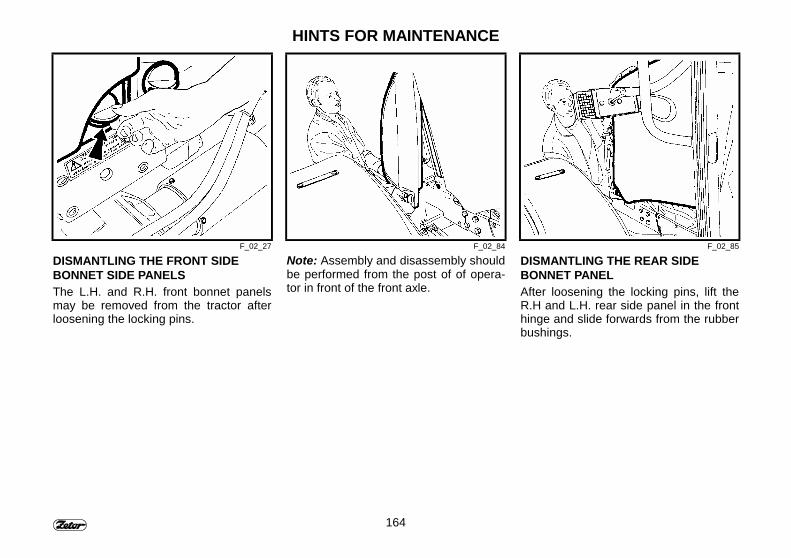
164
HINTS FOR MAINTENANCE
F_02_27 F_02_84 F_02_85
DISMANTLING THE FRONT SIDEBONNET SIDE PANELSThe L.H. and R.H. front bonnet panelsmay be removed from the tractor afterloosening the locking pins.
Note: Assembly and disassembly shouldbe performed from the post of of opera-tor in front of the front axle.
DISMANTLING THE REAR SIDEBONNET PANELAfter loosening the locking pins, lift theR.H and L.H. rear side panel in the fronthinge and slide forwards from the rubberbushings.
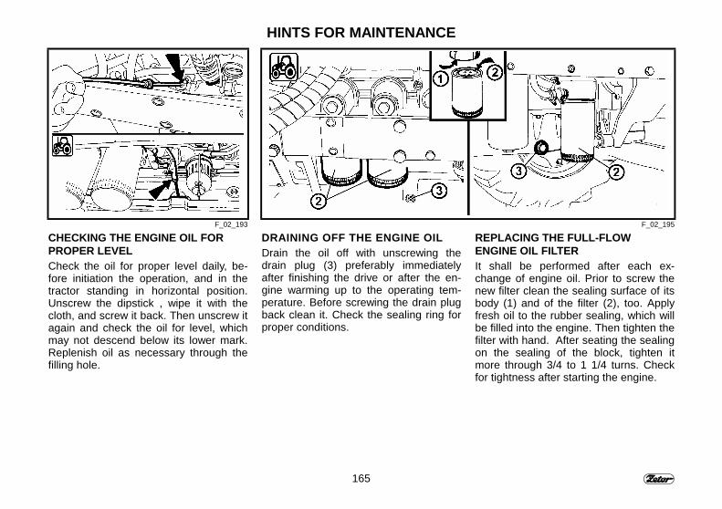
165
HINTS FOR MAINTENANCE
F_02_193 F_02_195
CHECKING THE ENGINE OIL FORPROPER LEVELCheck the oil for proper level daily, be-fore initiation the operation, and in thetractor standing in horizontal position.Unscrew the dipstick , wipe it with thecloth, and screw it back. Then unscrew itagain and check the oil for level, whichmay not descend below its lower mark.Replenish oil as necessary through thefilling hole.
DRAINING OFF THE ENGINE OILDrain the oil off with unscrewing thedrain plug (3) preferably immediatelyafter finishing the drive or after the en-gine warming up to the operating tem-perature. Before screwing the drain plugback clean it. Check the sealing ring forproper conditions.
REPLACING THE FULL-FLOWENGINE OIL FILTERIt shall be performed after each ex-change of engine oil. Prior to screw thenew filter clean the sealing surface of itsbody (1) and of the filter (2), too. Applyfresh oil to the rubber sealing, which willbe filled into the engine. Then tighten thefilter with hand. After seating the sealingon the sealing of the block, tighten itmore through 3/4 to 1 1/4 turns. Checkfor tightness after starting the engine.
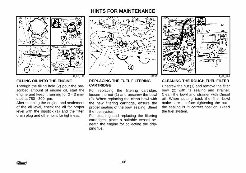
166
HINTS FOR MAINTENANCE
F_02_196 F238 F_02_194
FILLING OIL INTO THE ENGINEThrough the filling hole (2) pour the pre-scribed amount of engine oil, start theengine and keep it running for 2 - 3 min-utes at 750 - 800 rpm.After stopping the engine and settlementof the oil level, check the oil for properlevel with the dipstick (1) and the filter,drain plug and other joint for tightness.
REPLACING THE FUEL FILTERINGCARTRIDGEFor replacing the filtering cartridge,loosen the nut (1) and unscrew the bowl(2). When replacing the clean bowl withthe new filtering cartridge, ensure theproper seating of the bowl sealing. Bleedthe fuel system.For cleaning and replacing the filteringcartridges, place a suitable vessel be-neath the engine for collecting the drip-ping fuel.
CLEANING THE ROUGH FUEL FILTERUnscrew the nut (1) and remove the filterbowl (2) with its sealing and strainer.Clean the bowl and strainer with Dieseloil. When putting back the filter bowlmake sure - before tightening the nut -the sealing is in correct position. Bleedthe fuel system.
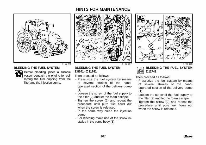
167
HINTS FOR MAINTENANCE
F_02_93 F_02_197 F_02_198
BLEEDING THE FUEL SYSTEMBefore bleeding, place a suitablevessel beneath the engine for col-lecting the fuel dripping from thefilter and the injection pump.
BLEEDING THE FUEL SYSTEMZ 8641 - Z 11741Then proceed as follows:- Pressurize the fuel system by means
of several strokes of the hand-operated section of the delivery pump(1)
- Loosen the screw of the fuel supply tothe filter (2) and let the foam escape.
- Tighten the screw (2) and repeat theprocedure until pure fuel flows outwhen the screw is released.
- In the same way bleed the injectionpump
- For bleeding make use of the screw in-stalled in the pump body (3)
BLEEDING THE FUEL SYSTEMZ 11741
Then proceed as follows:- Pressurize the fuel system by means
of several strokes of the hand-operated section of the delivery pump(1)
- Loosen the screw of the fuel supply tothe filter (2) and let the foam escape.
- Tighten the screw (2) and repeat theprocedure until pure fuel flows outwhen the screw is released.
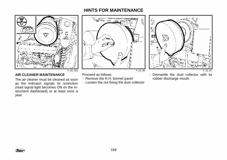
168
HINTS FOR MAINTENANCE
F_02_92a F_02_86 F_02_87
AIR CLEANER MAINTENANCEThe air cleaner must be cleaned as soonas the indicator signals its restriction(read signal light becomes ON on the in-strument dashboard) or at least once ayear.
Proceed as follows:- Remove the R.H. bonnet panel- Loosen the nut fixing the dust collector
- Dismantle the dust collector with itsrubber discharge mouth
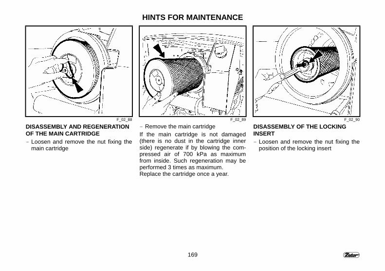
169
HINTS FOR MAINTENANCE
F_02_88 F_02_89 F_02_90
DISASSEMBLY AND REGENERATIONOF THE MAIN CARTRIDGE- Loosen and remove the nut fixing the
main cartridge
- Remove the main cartridgeIf the main cartridge is not damaged(there is no dust in the cartridge innerside) regenerate if by blowing the com-pressed air of 700 kPa as maximumfrom inside. Such regeneration may beperformed 3 times as maximum.Replace the cartridge once a year.
DISASSEMBLY OF THE LOCKINGINSERT- Loosen and remove the nut fixing the
position of the locking insert
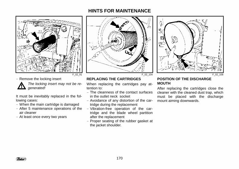
170
HINTS FOR MAINTENANCE
F_02_91 F_02_104 F_02_108
- Remove the locking insertThe locking insert may not be re-generated!
It must be inevitably replaced in the fol-lowing cases:- When the main cartridge is damaged- After 5 maintenance operations of the
air cleaner- At least once every two years
REPLACING THE CARTRIDGESWhen replacing the cartridges pay at-tention to:- The cleanness of the contact surfaces
in the outlet neck socket- Avoidance of any distortion of the car-
tridge during the replacement- Vibration-free operation of the car-
tridge and the blade wheel partitionafter the replacement
- Proper seating of the rubber gasket atthe jacket shoulder.
POSITION OF THE DISCHARGEMOUTHAfter replacing the cartridges close thecleaner with the cleaned dust trap, whichmust be placed with the dischargemount aiming downwards.
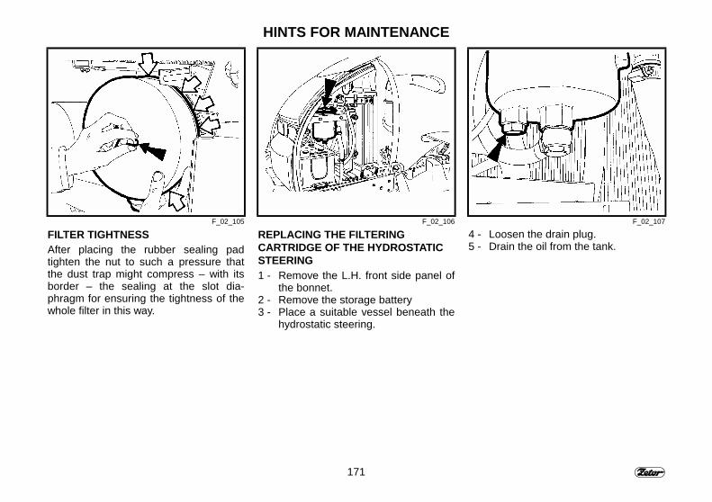
171
HINTS FOR MAINTENANCE
F_02_105 F_02_106 F_02_107
FILTER TIGHTNESSAfter placing the rubber sealing padtighten the nut to such a pressure thatthe dust trap might compress – with itsborder – the sealing at the slot dia-phragm for ensuring the tightness of thewhole filter in this way.
REPLACING THE FILTERINGCARTRIDGE OF THE HYDROSTATICSTEERING1 - Remove the L.H. front side panel of
the bonnet.2 - Remove the storage battery3 - Place a suitable vessel beneath the
hydrostatic steering.
4 - Loosen the drain plug.5 - Drain the oil from the tank.
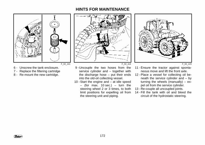
172
HINTS FOR MAINTENANCE
F_02_141 F_02_114 F_02_123
6 - Unscrew the tank enclosure.7 - Replace the filtering cartridge8 - Re-mount the new cartridge.
9 - Uncouple the two hoses from theservice cylinder and – together withthe discharge hose – put their endsinto the old-oil collecting vessel.
10 - Start the engine and – at idle speed– (for max. 10 sec.) – turn thesteering wheel 2 or 3 times, to bothlimit positions for expelling oil fromthe steering unit and piping.
11 - Ensure the tractor against sponta-neous move and lift the front axle.
12 - Place a vessel for collecting oil be-neath the service cylinder and – byturning the wheels (manually) – ex-pel oil from the service cylinder.
13 - Re-couple all uncoupled joints.14 - Fill the tank with oil and bleed the
circuit of the hydrostatic steering.
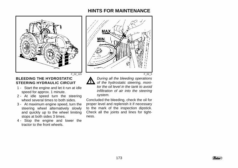
173
HINTS FOR MAINTENANCE
F_02_115 F_02_5
BLEEDING THE HYDROSTATICSTEERING HYDRAULIC CIRCUIT1 - Start the engine and let it run at idle
speed for approx. 1 minute.2 - At idle speed turn the steering
wheel several times to both sides.3 - At maximum engine speed, turn the
steering wheel alternatively slowlyand quickly up to the wheel limitingstops at both sides 3 times.
4 - Stop the engine and lower thetractor to the front wheels.
During all the bleeding operationsof the hydrostatic steering, moni-tor the oil level in the tank to avoidinfiltration of air into the steeringsystem.
Concluded the bleeding, check the oil forproper level and replenish it if necessaryto the mark of the inspection dipstick.Check all the joints and lines for tight-ness.
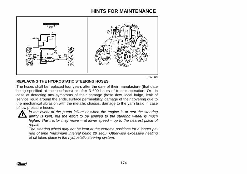
174
HINTS FOR MAINTENANCE
F_02_116
REPLACING THE HYDROSTATIC STEERING HOSESThe hoses shall be replaced four years after the date of their manufacture (that datebeing specified at their surfaces) or after 3 600 hours of tractor operation. Or –incase of detecting any symptoms of their damage (hose dew, local bulge, leak ofservice liquid around the ends, surface permeability, damage of their covering due tothe mechanical abrasion with the metallic chassis, damage to the yarn braid in caseof low pressure hoses.
in the event of the pump failure or when the engine is at rest the steeringability is kept, but the effort to be applied to the steering wheel is muchhigher. The tractor may move – at lower speed – up to the nearest place ofrepair.The steering wheel may not be kept at the extreme positions for a longer pe-riod of time (maximum interval being 20 sec.). Otherwise excessive heatingof oil takes place in the hydrostatic steering system.

175
HINTS FOR MAINTENANCE
F_02_117 F_02_199
EXCHANGING THE COOLING LIQUIDProceed as follows:1 - Open the heating unit cock and re-
lease the overpressure enclosure onthe expansion tank (C).
2 - Drain the cooling liquid off the radia-tor. The drain cock (A) is accessibleafter tilting out the L.H. side panel.
3 - Drain the cooling liquid off the engineblock. The drain cock (B) is accessi-ble after dismantling the R.H sidepanel.
3 - Z 11741 - Drain the coolingliquid off the engine block. Thedrain cock (B) is accessible afterdismantling the L.H side panel.
4 - As soon as the cooling liquid hasbeen drained off, close the two drain
cocks (the cock of the heating unitremaining open).
5 - Fill the cooling system with coolingliquid up to the neck and close theexpansion (equalizing) tank over-pressure enclosure..
6 - Start the engine and keep it runningfor approx. 1 minute.
7 - Complete the level of cooling liquid inthe expansion tank up to the markMAX.
8 - Close the tank with the overpressureenclosure.
In the Z 10641 and Z 114 41 tractorscheck the bleeding of the auxiliary ra-diator. On loosening the screws at theupper chamber of the auxiliary radiator,pure liquid must go out.
Use only the prescribed coolingliquid for filling the engine coolingsystem.Never fill water into the coolingsystem. The engine can be dam-aged when the another than pre-scribed liquid is used.

176
HINTS FOR MAINTENANCE
F_02_118 F_02_136
DRAIN HOLES AND PLUGSPos.. Hole – plug
1 - Oil from clutch box2 - Oil from the gearbox3,4,5 - Oil from final drive box
CHECKING AND EXCHANGING OIL IN THE GEARBOXIf necessary, replenish the oil up to the upper border of the dipstick flat (1), or tosome of the marks depending on the class of job the tractor is employed. For meas-uring the oil level in the gearbox, stop the engine and insert the plug dipstick fullyinto the tube mouth.
Level in the gear-box Tractor employment
A minimum Standard operationB normal Standard operationC +7 l (increased) Operation in a slopeD +15 l - maximum Aggregation of machines with high oil takeoff
The filling hole for the transmission oil (2) is placed in the hydraulic system cover..Accessible from the tractor rear side.
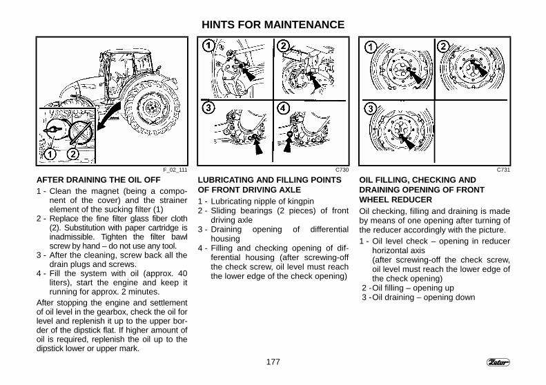
177
HINTS FOR MAINTENANCE
F_02_111 C730 C731
AFTER DRAINING THE OIL OFF1 - Clean the magnet (being a compo-
nent of the cover) and the strainerelement of the sucking filter (1)
2 - Replace the fine filter glass fiber cloth(2). Substitution with paper cartridge isinadmissible. Tighten the filter bawlscrew by hand – do not use any tool.
3 - After the cleaning, screw back all thedrain plugs and screws.
4 - Fill the system with oil (approx. 40liters), start the engine and keep itrunning for approx. 2 minutes.
After stopping the engine and settlementof oil level in the gearbox, check the oil forlevel and replenish it up to the upper bor-der of the dipstick flat. If higher amount ofoil is required, replenish the oil up to thedipstick lower or upper mark.
LUBRICATING AND FILLING POINTSOF FRONT DRIVING AXLE1 - Lubricating nipple of kingpin2 - Sliding bearings (2 pieces) of front
driving axle3 - Draining opening of differential
housing4 - Filling and checking opening of dif-
ferential housing (after screwing-offthe check screw, oil level must reachthe lower edge of the check opening)
OIL FILLING, CHECKING ANDDRAINING OPENING OF FRONTWHEEL REDUCEROil checking, filling and draining is madeby means of one opening after turning ofthe reducer accordingly with the picture.1 - Oil level check – opening in reducer
horizontal axis(after screwing-off the check screw,oil level must reach the lower edge ofthe check opening)
2 - Oil filling – opening up3 - Oil draining – opening down
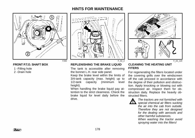
178
HINTS FOR MAINTENANCE
F260 F_02_4 F_02_119
FRONT P.T.O. SHAFT BOX1 - Filling hole2 - Drain hole
REPLENISHING THE BRAKE LIQUIDThe tank is accessible after removingthe bonnet L.H. rear side panel.Keep the brake level within the limits of3/4-tank capacity (max. height) up to1/2-tank capacity (minimum levelheight).When handling the brake liquid pay at-tention to the strict cleanness. Check thebrake liquid for level daily before thedrive.
CLEANING THE HEATING UNITFITERSFor regenerating the filters located underthe covering grills over the windscreenoff the cab proceed in accordance withthe degree of their pollution and obstruc-tion. Apply knocking or blowing out withcompressed air. Inspect them for ob-struction daily. Replace the heavily ob-structed filters.
The tractors are not furnished withspecial chemical air filters suckingthe air into the cab from outside.Therefore they are not designedfor the dealing with aerosols andother harmful substances.When washing the tractor avoidspraying water into the filters!
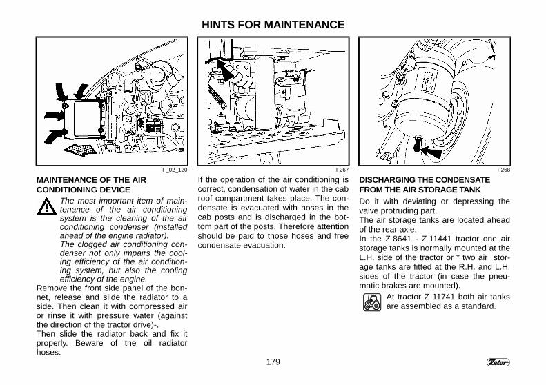
179
HINTS FOR MAINTENANCE
F_02_120 F267 F268
MAINTENANCE OF THE AIRCONDITIONING DEVICE
The most important item of main-tenance of the air conditioningsystem is the cleaning of the airconditioning condenser (installedahead of the engine radiator).The clogged air conditioning con-denser not only impairs the cool-ing efficiency of the air condition-ing system, but also the coolingefficiency of the engine.
Remove the front side panel of the bon-net, release and slide the radiator to aside. Then clean it with compressed airor rinse it with pressure water (againstthe direction of the tractor drive)-.Then slide the radiator back and fix itproperly. Beware of the oil radiatorhoses.
If the operation of the air conditioning iscorrect, condensation of water in the cabroof compartment takes place. The con-densate is evacuated with hoses in thecab posts and is discharged in the bot-tom part of the posts. Therefore attentionshould be paid to those hoses and freecondensate evacuation.
DISCHARGING THE CONDENSATEFROM THE AIR STORAGE TANKDo it with deviating or depressing thevalve protruding part.The air storage tanks are located aheadof the rear axle.In the Z 8641 - Z 11441 tractor one airstorage tanks is normally mounted at theL.H. side of the tractor or * two air stor-age tanks are fitted at the R.H. and L.H.sides of the tractor (in case the pneu-matic brakes are mounted).
At tractor Z 11741 both air tanksare assembled as a standard.
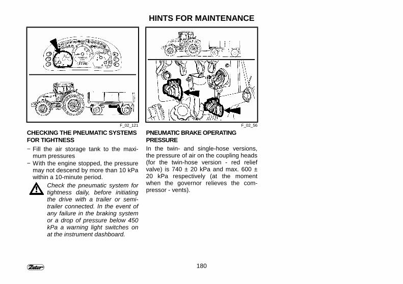
180
HINTS FOR MAINTENANCE
F_02_121 F_02_56
CHECKING THE PNEUMATIC SYSTEMSFOR TIGHTNESS− Fill the air storage tank to the maxi-
mum pressures− With the engine stopped, the pressure
may not descend by more than 10 kPawithin a 10-minute period.
Check the pneumatic system fortightness daily, before initiatingthe drive with a trailer or semi-trailer connected. In the event ofany failure in the braking systemor a drop of pressure below 450kPa a warning light switches onat the instrument dashboard.
PNEUMATIC BRAKE OPERATINGPRESSUREIn the twin- and single-hose versions,the pressure of air on the coupling heads(for the twin-hose version - red reliefvalve) is 740 ± 20 kPa and max. 600 ±20 kPa respectively (at the momentwhen the governor relieves the com-pressor - vents).

181
HINTS FOR MAINTENANCE
F_02_122
MAINTENANCE AND SERVICING OF TIRESCheck the tires periodically for their surface conditions and ensure that the tires haveno defects in the side and over-bead sections and their carcass are not damaged.
Put the tires showing defects out of operation.
INFLATING THE TIRESThe basic pressures of recommended inflation are specified in the Table. Revise thepressure regularly before the drive, when the tires are cold. For the inflation makeuse of the pressure governor (B), which acts as the pressure equalizer, tire filler, andrelief valve. Unscrew the wing nut of the pressure governor (or a rubber cap) and in-stead of it screw on the tire inflating hose. The hose must be screwed on completelyup to the end of the thread to depress the check valve. In case the maximum pres-sure 0,6 MPa (or 0,7 MPa in the twin-hose brake) is in the air storage tank (A), thetire may not be inflated. In such a case the pressure must first be reduced with thecondensate discharging valve located in the air tank bottom. After the inflation do notforget to screw back the wing nut or the rubber cap on the pressure governor).
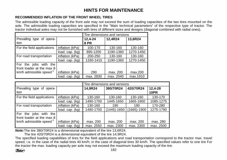
182
HINTS FOR MAINTENANCERECOMMENDED INFLATION OF THE FRONT WHEEL TIRESThe admissible loading capacity of the front axle may not exceed the sum of loading capacities of the two tires mounted on theaxle. The admissible loading capacities are specified in the ”Main technical parameters” of the respective type of tractor. Thetractor individual axles may not be furnished with tires of different sizes and designs (diagonal combined with radial ones).
Tire dimensions and versionsPrevailing type of opera-tion
12,4-248 PR
12,4R24 13,6R24
For the field applications inflation (kPa) 100-170 130-160 130-160load. cap. (kg) 895-1200 1190-1360 1270-1450
For road transportation inflation (kPa) 200-250 130-160 130-160load. cap. (kg) 1330-1415 1190-1360 1270-1450
For the jobs with thefront loader at the max 8km/h admissible speed-1 inflation (kPa) 290 max. 200 max.200
load. cap. (kg) max. 2830 max. 2040 max.1910
Tire dimensions and versionsPrevailing type of opera-tion
14,9R24 380/70R24 420/70R24 12,4-2810PR
For the field applications inflation (kPa) 130-160 130-160 130-160 130-170load. cap. (kg) 1490-1700 1445-1650 1665-1900 1085-1275
For road transportation inflation (kPa) 130-160 190 190 170-280load. cap. (kg) 1490-1700 (1445)-1650 (1665)-1900 1275-1790
For the jobs with thefront loader at the max 8km/h admissible speed-1 inflation (kPa) max. 200 max. 200 max. 200 max. 280
load. cap. (kg) max. 2550 max. 2300 max. 2300 max. 2500Note:The tire 380/70R24 is a dimensional equivalent of the tire 13,6R24.
The tire 420/70R24 is a dimensional equivalent of the tire 14,9R24.The specified loading capabilities of tires for the field applications and road transportation correspond to the tractor max. travelspeed, i.e. in the case of the radial tires 40 km/h; in the case of diagonal tires 30 km/h. The specified values refer to one tire Forthe tractor the max. loading capacity per axle may not exceed the maximum loading capacity of the tire.
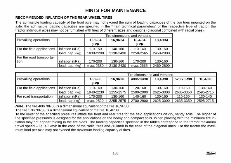
183
HINTS FOR MAINTENANCERECOMMENDED INFLATION OF THE REAR WHEEL TIRESThe admissible loading capacity of the front axle may not exceed the sum of loading capacities of the two tires mounted on theaxle. the admissible loading capacities are specified in the ”main technical parameters” of the respective type of tractor. thetractor individual axles may not be furnished with tires of different sizes and designs (diagonal combined with radial ones).
Tire dimensions and versionsPrevailing operations 16,9-34
8 PR16,9R34 18,4-34
8 PR18,4R34
For the field applications inflation (kPa) 110-150 140-160 110-140 130-160load. cap. (kg) 1830-2200 2130-2430 2250-2565 2450-2800
For the road transporta-tion inflation (kPa) 170-200 130-160 170-200 130-160
load. cap. (kg) max. 2380 2130-2430 max. 2565 2450-2800
Tire dimensions and versionsPrevailing operations 16,9-38
8 PR16,9R38 480/70R38 18,4R38 520/70R38 18,4-38
For the field applications inflation (kPa) 110-140 130-160 120-160 130-160 110-160 130-140load. cap. (kg) 1940-2230 2255-2575 2500-2900 2625-3000 2635-3350 2595-2715
For road transportation inflation (kPa) 170-200 130-160 140-160 130-160 110-160 130-140load. cap.(kg) max. 2520 2255-2575 2700-2900 2625-3000 2635-3350 2595-2715
Note: The tire 480/70R38 is a dimensional equivalent of the tire 16,9R38.The tire 570/70R38 is a dimensional equivalent of the tire 18,4R38.To the lower of the specified pressures inflate the front and rear tires for the field applications on dry, sandy soils. The higher ofthe specified pressures is designed for the applications on the heavy and compact soils. When plowing with the minimum tire in-flation may not appear folding in the tire sides. The loading capacities specified in the tables correspond to the tractor maximumtravel speed – i.e. 40 km/h in the case of the radial tires and 30 km/h in the case of the diagonal ones. For the tractor the maxi-mum load per axle may not exceed the maximum loading capacity of tires.
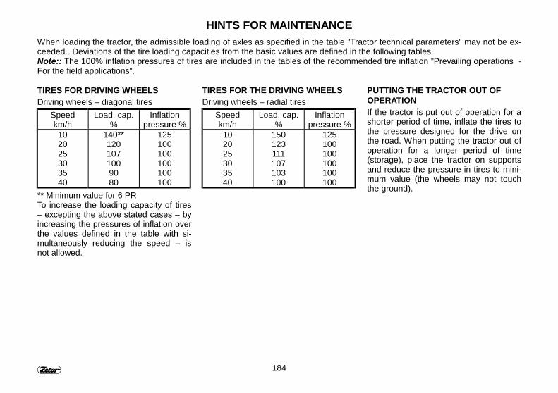
184
HINTS FOR MAINTENANCEWhen loading the tractor, the admissible loading of axles as specified in the table ”Tractor technical parameters” may not be ex-ceeded.. Deviations of the tire loading capacities from the basic values are defined in the following tables.Note:: The 100% inflation pressures of tires are included in the tables of the recommended tire inflation ”Prevailing operations -For the field applications”.
TIRES FOR DRIVING WHEELSDriving wheels – diagonal tires
Speedkm/h
Load. cap.%
Inflationpressure %
102025303540
140**1201071009080
125100100100100100
** Minimum value for 6 PRTo increase the loading capacity of tires– excepting the above stated cases – byincreasing the pressures of inflation overthe values defined in the table with si-multaneously reducing the speed – isnot allowed.
TIRES FOR THE DRIVING WHEELSDriving wheels – radial tires
Speedkm/h
Load. cap.%
Inflationpressure %
102025303540
150123111107103100
125100100100100100
PUTTING THE TRACTOR OUT OFOPERATIONIf the tractor is put out of operation for ashorter period of time, inflate the tires tothe pressure designed for the drive onthe road. When putting the tractor out ofoperation for a longer period of time(storage), place the tractor on supportsand reduce the pressure in tires to mini-mum value (the wheels may not touchthe ground).

185
NOTE

186
NOTE
187
SETTING-UP OPERATIONS
Since most of the following operationsrequire some experience and more de-manding service and diagnostic equip-ment, it is recommended to entrust themto the professional or authorized work-shops.
PageInspecting the tension of engine belt ...................................................................... 188∗ Inspecting the tension of aircondition compressor belt ........................................ 188Inspecting the tension of engine belt Z 11741 ........................................................ 188Tightening the head of cylinders ............................................................................. 188Setting up the valve clearance Z 8641 - Z 11441.................................................... 189Setting up the valve clearance Z 11741.................................................................. 189Setting-up the injectors Z 8641 - Z 11441............................................................... 189Setting up the injectors Z 11741 ............................................................................. 190Setting up the brake pedal dead motion ................................................................. 190Tractor brake system bleeding................................................................................ 190Bleeding the rear brake system .............................................................................. 191Setting up the clutch pedal dead motion................................................................. 192Bleeding the clutch hydraulic circuit........................................................................ 192Bleeding the front propeller shaft brake .................................................................. 193Checking the foot brake for proper setting-up......................................................... 193Setting up the foot brake......................................................................................... 194Setting-up the parking brake................................................................................... 194Replacing the front propeller shaft braking segments............................................. 195Setting up the lifting tie rods for the single-axle trailer ............................................ 195Setting the Bowden cable ....................................................................................... 195Calibrating the digital dashboard travel speed........................................................ 196
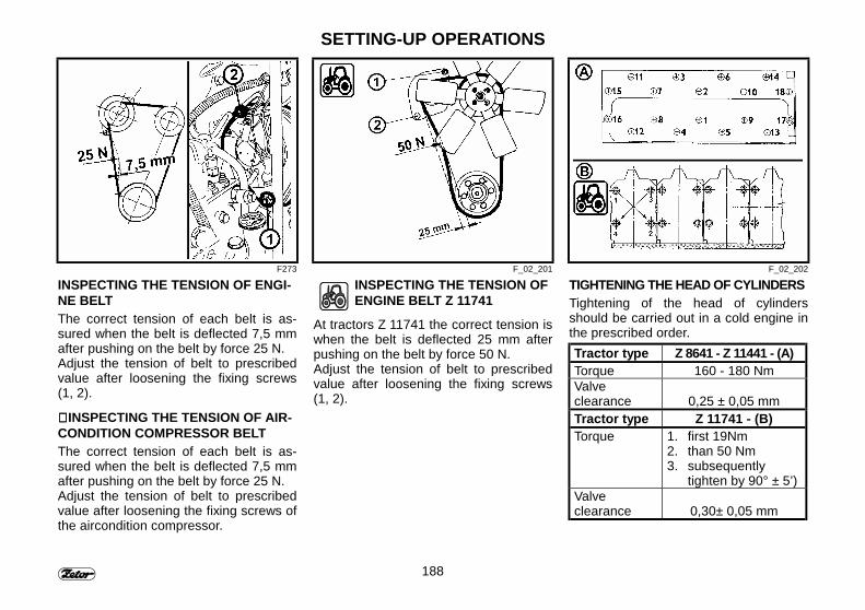
188
SETTING-UP OPERATIONS
F273 F_02_201 F_02_202
INSPECTING THE TENSION OF ENGI-NE BELTThe correct tension of each belt is as-sured when the belt is deflected 7,5 mmafter pushing on the belt by force 25 N.Adjust the tension of belt to prescribedvalue after loosening the fixing screws(1, 2).
∗∗∗∗ INSPECTING THE TENSION OF AIR-CONDITION COMPRESSOR BELTThe correct tension of each belt is as-sured when the belt is deflected 7,5 mmafter pushing on the belt by force 25 N.Adjust the tension of belt to prescribedvalue after loosening the fixing screws ofthe aircondition compressor.
INSPECTING THE TENSION OFENGINE BELT Z 11741
At tractors Z 11741 the correct tension iswhen the belt is deflected 25 mm afterpushing on the belt by force 50 N.Adjust the tension of belt to prescribedvalue after loosening the fixing screws(1, 2).
TIGHTENING THE HEAD OF CYLINDERSTightening of the head of cylindersshould be carried out in a cold engine inthe prescribed order.Tractor type Z 8641 - Z 11441 - (A)Torque 160 - 180 NmValveclearance 0,25 ± 0,05 mmTractor type Z 11741 - (B)Torque 1. first 19Nm
2. than 50 Nm3. subsequently
tighten by 90° ± 5’)Valveclearance 0,30± 0,05 mm

189
SETTING-UP OPERATIONS
F276 F_02_203a F278
SETTING UP THE VALVE CLEARANCEZ 8641 - Z 11441The valve clearance should be set up inthe cold engine. The correct clearance inthe admission and exhaust valves is0,25 ± 0,05 mm.
Alternation of the rocker arms motion:Cylinder rockerarm alternation:
Cylinder to beadjusted:
1 42 33 24 1
SETTING UP THE VALVECLEARANCE Z 11741
The valve clearance should be set up inthe cold engine. The correct clearance inthe admission and exhaust valves is0,30 ± 0,05 mm.
Alternation of the rocker arms motion:Cylinder rockerarm alternation:
Cylinder to beadjusted:
1 65 23 46 12 54 3
SETTING-UP THE INJECTORSZ 8641 - Z 11441The service opening pressure of the in-jectors is 22,0 - 0,8 MPa. The openingpressure of injectors should be set up tothe upper limit of the range (22,0 MPa)with spacing washers (1) of differentthickness, which should be put under thespring (2). The Correct position of theinjection nozzle (3) is determined withthe positioning pins at the sealing sur-face. The tightening torque of the fixingnut (4) is 50 to 60 Nm. Before tighteningthe nut, push the nozzle against thespring with leaning it against the woodenblock
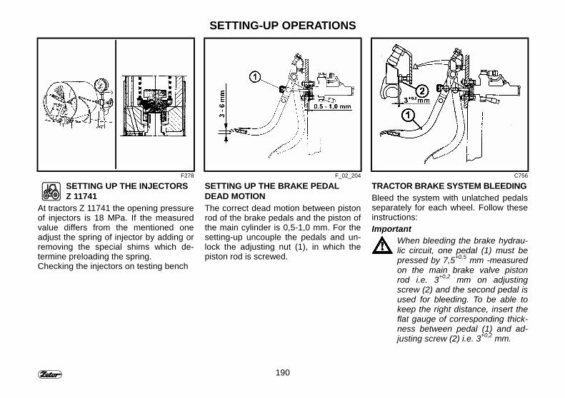
190
SETTING-UP OPERATIONS
F278 F_02_204 C756
SETTING UP THE INJECTORSZ 11741
At tractors Z 11741 the opening pressureof injectors is 18 MPa. If the measuredvalue differs from the mentioned oneadjust the spring of injector by adding orremoving the special shims which de-termine preloading the spring.Checking the injectors on testing bench
SETTING UP THE BRAKE PEDALDEAD MOTIONThe correct dead motion between pistonrod of the brake pedals and the piston ofthe main cylinder is 0,5-1,0 mm. For thesetting-up uncouple the pedals and un-lock the adjusting nut (1), in which thepiston rod is screwed.
TRACTOR BRAKE SYSTEM BLEEDINGBleed the system with unlatched pedalsseparately for each wheel. Follow theseinstructions:Important
When bleeding the brake hydrau-lic circuit, one pedal (1) must bepressed by 7,5+0,5 mm -measuredon the main brake valve pistonrod i.e. 3+0,2 mm on adjustingscrew (2) and the second pedal isused for bleeding. To be able tokeep the right distance, insert theflat gauge of corresponding thick-ness between pedal (1) and ad-justing screw (2) i.e. 3+0,2 mm.

191
SETTING-UP OPERATIONS
F_02_147 F_02_128
BLEEDING THE REAR BRAKE SYSTEM− Check the level of the brake liquid in the expansion tank, replenish it with the fresh
liquid to the maximum level.− Put a hose on the bleeding screw of the brake cylinder and submerge its second
end to the bottom of the transparent vessel partially filled with brake liquid.− Depress the brake pedal, loosen the bleeding screw through 1/4 turn as maximum,
depress fully the pedal, and tighten the bleeding screw again.− Release the brake pedal and repeat the procedure until air bubbles stop escaping
from the hose.
In the course of bleeding monitor theamount of liquid in the expansion tankfor avoiding aspiration of air (A).
Keep the hose end submerged inthe liquid continuously with hold-ing the vessel as high as possi-ble (B). After two years, thebrake liquid must be exchangedin the whole braking circuit:
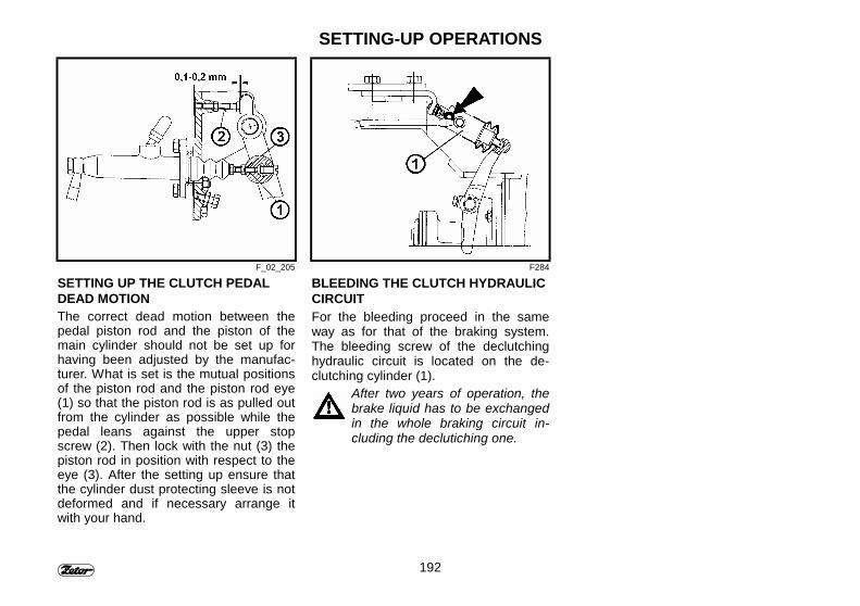
192
SETTING-UP OPERATIONS
F_02_205 F284
SETTING UP THE CLUTCH PEDALDEAD MOTIONThe correct dead motion between thepedal piston rod and the piston of themain cylinder should not be set up forhaving been adjusted by the manufac-turer. What is set is the mutual positionsof the piston rod and the piston rod eye(1) so that the piston rod is as pulled outfrom the cylinder as possible while thepedal leans against the upper stopscrew (2). Then lock with the nut (3) thepiston rod in position with respect to theeye (3). After the setting up ensure thatthe cylinder dust protecting sleeve is notdeformed and if necessary arrange itwith your hand.
BLEEDING THE CLUTCH HYDRAULICCIRCUITFor the bleeding proceed in the sameway as for that of the braking system.The bleeding screw of the declutchinghydraulic circuit is located on the de-clutching cylinder (1).
After two years of operation, thebrake liquid has to be exchangedin the whole braking circuit in-cluding the declutiching one.
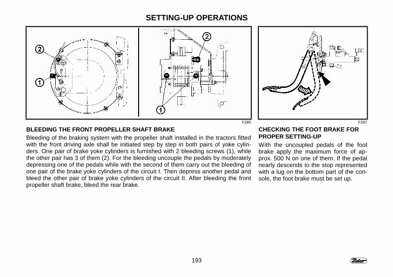
193
SETTING-UP OPERATIONS
F285 F287
BLEEDING THE FRONT PROPELLER SHAFT BRAKEBleeding of the braking system with the propeller shaft installed in the tractors fittedwith the front driving axle shall be initiated step by step in both pairs of yoke cylin-ders. One pair of brake yoke cylinders is furnished with 2 bleeding screws (1), whilethe other pair has 3 of them (2). For the bleeding uncouple the pedals by moderatelydepressing one of the pedals while with the second of them carry out the bleeding ofone pair of the brake yoke cylinders of the circuit I. Then depress another pedal andbleed the other pair of brake yoke cylinders of the circuit II. After bleeding the frontpropeller shaft brake, bleed the rear brake.
CHECKING THE FOOT BRAKE FORPROPER SETTING-UPWith the uncoupled pedals of the footbrake apply the maximum force of ap-prox. 500 N on one of them. If the pedalnearly descends to the stop representedwith a lug on the bottom part of the con-sole, the foot brake must be set up.
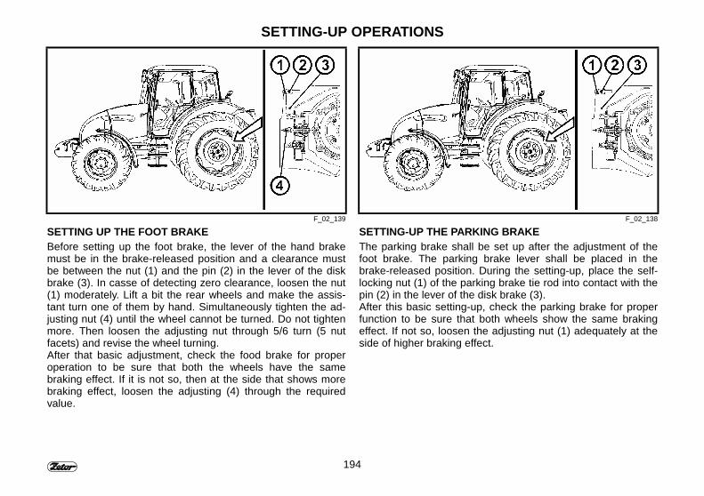
194
SETTING-UP OPERATIONS
F_02_139 F_02_138
SETTING UP THE FOOT BRAKEBefore setting up the foot brake, the lever of the hand brakemust be in the brake-released position and a clearance mustbe between the nut (1) and the pin (2) in the lever of the diskbrake (3). In casse of detecting zero clearance, loosen the nut(1) moderately. Lift a bit the rear wheels and make the assis-tant turn one of them by hand. Simultaneously tighten the ad-justing nut (4) until the wheel cannot be turned. Do not tightenmore. Then loosen the adjusting nut through 5/6 turn (5 nutfacets) and revise the wheel turning.After that basic adjustment, check the food brake for properoperation to be sure that both the wheels have the samebraking effect. If it is not so, then at the side that shows morebraking effect, loosen the adjusting (4) through the requiredvalue.
SETTING-UP THE PARKING BRAKEThe parking brake shall be set up after the adjustment of thefoot brake. The parking brake lever shall be placed in thebrake-released position. During the setting-up, place the self-locking nut (1) of the parking brake tie rod into contact with thepin (2) in the lever of the disk brake (3).After this basic setting-up, check the parking brake for properfunction to be sure that both wheels show the same brakingeffect. If not so, loosen the adjusting nut (1) adequately at theside of higher braking effect.
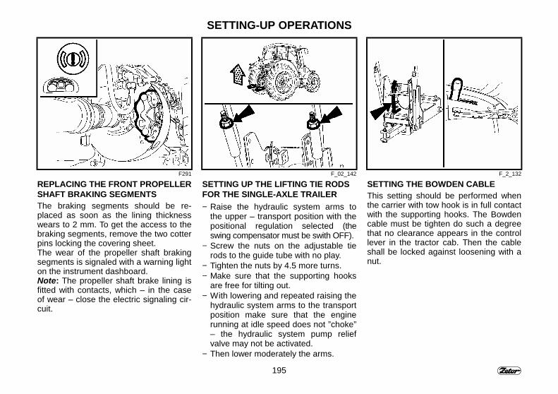
195
SETTING-UP OPERATIONS
F291 F_02_142 F_2_132
REPLACING THE FRONT PROPELLERSHAFT BRAKING SEGMENTSThe braking segments should be re-placed as soon as the lining thicknesswears to 2 mm. To get the access to thebraking segments, remove the two cotterpins locking the covering sheet.The wear of the propeller shaft brakingsegments is signaled with a warning lighton the instrument dashboard.Note: The propeller shaft brake lining isfitted with contacts, which – in the caseof wear – close the electric signaling cir-cuit.
SETTING UP THE LIFTING TIE RODSFOR THE SINGLE-AXLE TRAILER− Raise the hydraulic system arms to
the upper – transport position with thepositional regulation selected (theswing compensator must be swith OFF).
− Screw the nuts on the adjustable tierods to the guide tube with no play.
− Tighten the nuts by 4.5 more turns.− Make sure that the supporting hooks
are free for tilting out.− With lowering and repeated raising the
hydraulic system arms to the transportposition make sure that the enginerunning at idle speed does not ”choke”– the hydraulic system pump reliefvalve may not be activated.
− Then lower moderately the arms.
SETTING THE BOWDEN CABLEThis setting should be performed whenthe carrier with tow hook is in full contactwith the supporting hooks. The Bowdencable must be tighten do such a degreethat no clearance appears in the controllever in the tractor cab. Then the cableshall be locked against loosening with anut.
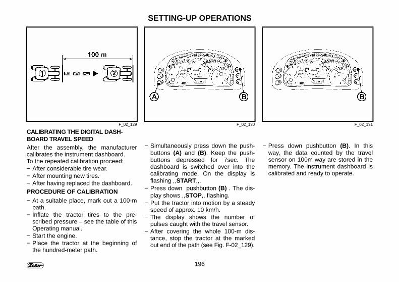
196
SETTING-UP OPERATIONS
F_02_129 F_02_130 F_02_131
CALIBRATING THE DIGITAL DASH-BOARD TRAVEL SPEEDAfter the assembly, the manufacturercalibrates the instrument dashboard.To the repeated calibration proceed:− After considerable tire wear.− After mounting new tires.− After having replaced the dashboard.PROCEDURE OF CALIBRATION− At a suitable place, mark out a 100-m
path.− Inflate the tractor tires to the pre-
scribed pressure – see the table of thisOperating manual.
− Start the engine.− Place the tractor at the beginning of
the hundred-meter path.
− Simultaneously press down the push-buttons (A) and (B). Keep the push-buttons depressed for 7sec. Thedashboard is switched over into thecalibrating mode. On the display isflashing ,,START,,.
− Press down pushbutton (B) . The dis-play shows ,,STOP,, flashing.
− Put the tractor into motion by a steadyspeed of approx. 10 km/h.
− The display shows the number ofpulses caught with the travel sensor.
− After covering the whole 100-m dis-tance, stop the tractor at the markedout end of the path (see Fig. F-02_129).
− Press down pushbutton (B). In thisway, the data counted by the travelsensor on 100m way are stored in thememory. The instrument dashboard iscalibrated and ready to operate.

197
NOTE

198
NOTE
199
ELECTRICAL SYSTEM
No additional interventionsinto the electrical system areallowed (connection of otherelectrrical appliances) for thereason of its possible over-loading!
StranaElectrical equipment................................................................................................ 200Basic service information ........................................................................................ 200Battery, battery switch ............................................................................................. 201Storage battery maintenance .................................................................................. 202Storage battery charging and maintenance ............................................................ 203Alternator................................................................................................................. 204Alternator maintenance ........................................................................................... 204Fuse box ................................................................................................................. 205Checking the lights in the tractor hood for proper setting-up................................... 206Setting up the lights in the tractor hood................................................................... 206Checking the lights in the cab roof for proper setting-up ......................................... 207Bulb location............................................................................................................ 208
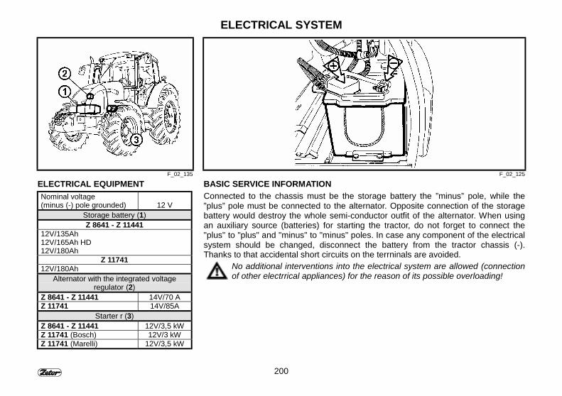
200
ELECTRICAL SYSTEM
F_02_135 F_02_125
ELECTRICAL EQUIPMENTNominal voltage(minus (-) pole grounded) 12 V
Storage battery (1)Z 8641 - Z 11441
12V/135Ah12V/165Ah HD12V/180Ah
Z 1174112V/180Ah
Alternator with the integrated voltageregulator (2)
Z 8641 - Z 11441 14V/70 AZ 11741 14V/85A
Starter r (3)Z 8641 - Z 11441 12V/3,5 kWZ 11741 (Bosch) 12V/3 kWZ 11741 (Marelli) 12V/3,5 kW
BASIC SERVICE INFORMATIONConnected to the chassis must be the storage battery the ”minus” pole, while the”plus” pole must be connected to the alternator. Opposite connection of the storagebattery would destroy the whole semi-conductor outfit of the alternator. When usingan auxiliary source (batteries) for starting the tractor, do not forget to connect the"plus" to "plus" and "minus" to "minus" poles. In case any component of the electricalsystem should be changed, disconnect the battery from the tractor chassis (-).Thanks to that accidental short circuits on the terrninals are avoided.
No additional interventions into the electrical system are allowed (connectionof other electrrical appliances) for the reason of its possible overloading!

201
ELECTRICAL SYSTEM
F_02_134b
BATTERY, BATTERY SWITCHThe battery (1) is accessible after re-moving the left side bonnet panel.∗ Battery switch (2) is located on the left-hand side of tractor on the implementframe. It is accessible from the outside.A - Battery disconnectedB - Battery connected
If the tractor is out of operation forlonger period of time, it is necessaryto charge the battery at least oncein three month because of thebattery selfdischarging and thespacing current of AEV warninglights breaker. It is recommended todisconnect the battery by means ofthe battery disconnecting switch incase the tractor is put out of action.
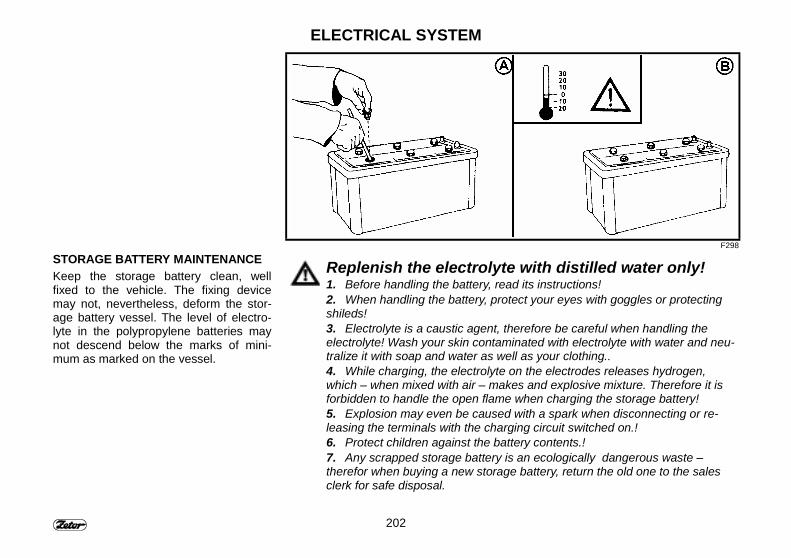
202
ELECTRICAL SYSTEM
F298
STORAGE BATTERY MAINTENANCEKeep the storage battery clean, wellfixed to the vehicle. The fixing devicemay not, nevertheless, deform the stor-age battery vessel. The level of electro-lyte in the polypropylene batteries maynot descend below the marks of mini-mum as marked on the vessel.
Replenish the electrolyte with distilled water only!1. Before handling the battery, read its instructions!2. When handling the battery, protect your eyes with goggles or protectingshileds!3. Electrolyte is a caustic agent, therefore be careful when handling theelectrolyte! Wash your skin contaminated with electrolyte with water and neu-tralize it with soap and water as well as your clothing..4. While charging, the electrolyte on the electrodes releases hydrogen,which – when mixed with air – makes and explosive mixture. Therefore it isforbidden to handle the open flame when charging the storage battery!5. Explosion may even be caused with a spark when disconnecting or re-leasing the terminals with the charging circuit switched on.!6. Protect children against the battery contents.!7. Any scrapped storage battery is an ecologically dangerous waste –therefor when buying a new storage battery, return the old one to the salesclerk for safe disposal.
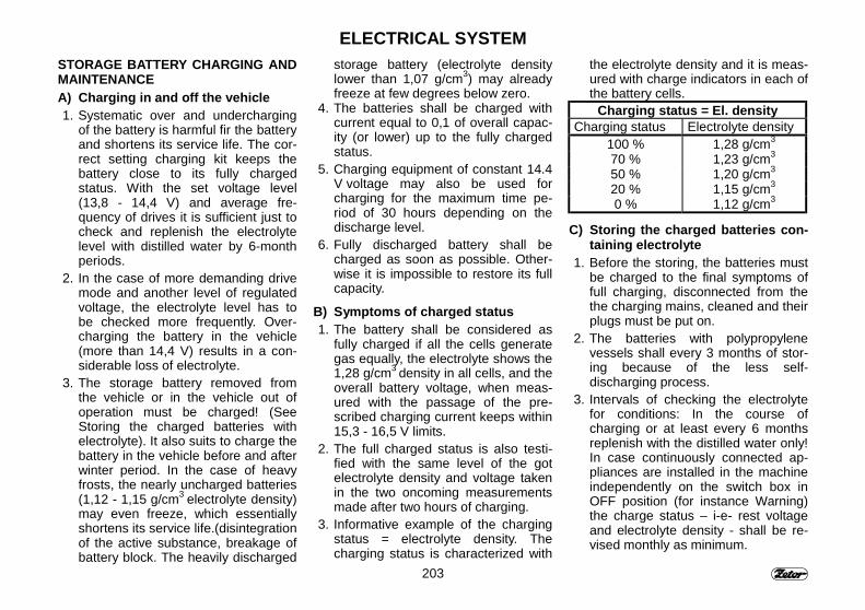
203
ELECTRICAL SYSTEMSTORAGE BATTERY CHARGING ANDMAINTENANCEA) Charging in and off the vehicle 1. Systematic over and undercharging
of the battery is harmful fir the batteryand shortens its service life. The cor-rect setting charging kit keeps thebattery close to its fully chargedstatus. With the set voltage level(13,8 - 14,4 V) and average fre-quency of drives it is sufficient just tocheck and replenish the electrolytelevel with distilled water by 6-monthperiods.
2. In the case of more demanding drivemode and another level of regulatedvoltage, the electrolyte level has tobe checked more frequently. Over-charging the battery in the vehicle(more than 14,4 V) results in a con-siderable loss of electrolyte.
3. The storage battery removed fromthe vehicle or in the vehicle out ofoperation must be charged! (SeeStoring the charged batteries withelectrolyte). It also suits to charge thebattery in the vehicle before and afterwinter period. In the case of heavyfrosts, the nearly uncharged batteries(1,12 - 1,15 g/cm3 electrolyte density)may even freeze, which essentiallyshortens its service life.(disintegrationof the active substance, breakage ofbattery block. The heavily discharged
storage battery (electrolyte densitylower than 1,07 g/cm3) may alreadyfreeze at few degrees below zero.
4. The batteries shall be charged withcurrent equal to 0,1 of overall capac-ity (or lower) up to the fully chargedstatus.
5. Charging equipment of constant 14.4V voltage may also be used forcharging for the maximum time pe-riod of 30 hours depending on thedischarge level.
6. Fully discharged battery shall becharged as soon as possible. Other-wise it is impossible to restore its fullcapacity.
B) Symptoms of charged status 1. The battery shall be considered as
fully charged if all the cells generategas equally, the electrolyte shows the1,28 g/cm3 density in all cells, and theoverall battery voltage, when meas-ured with the passage of the pre-scribed charging current keeps within15,3 - 16,5 V limits.
2. The full charged status is also testi-fied with the same level of the gotelectrolyte density and voltage takenin the two oncoming measurementsmade after two hours of charging.
3. Informative example of the chargingstatus = electrolyte density. Thecharging status is characterized with
the electrolyte density and it is meas-ured with charge indicators in each ofthe battery cells.
Charging status = El. densityCharging status Electrolyte density
100 % 1,28 g/cm3
70 % 1,23 g/cm3
50 % 1,20 g/cm3
20 % 1,15 g/cm3
0 % 1,12 g/cm3
C) Storing the charged batteries con-taining electrolyte
1. Before the storing, the batteries mustbe charged to the final symptoms offull charging, disconnected from thethe charging mains, cleaned and theirplugs must be put on.
2. The batteries with polypropylenevessels shall every 3 months of stor-ing because of the less self-discharging process.
3. Intervals of checking the electrolytefor conditions: In the course ofcharging or at least every 6 monthsreplenish with the distilled water only!In case continuously connected ap-pliances are installed in the machineindependently on the switch box inOFF position (for instance Warning)the charge status – i-e- rest voltageand electrolyte density - shall be re-vised monthly as minimum.
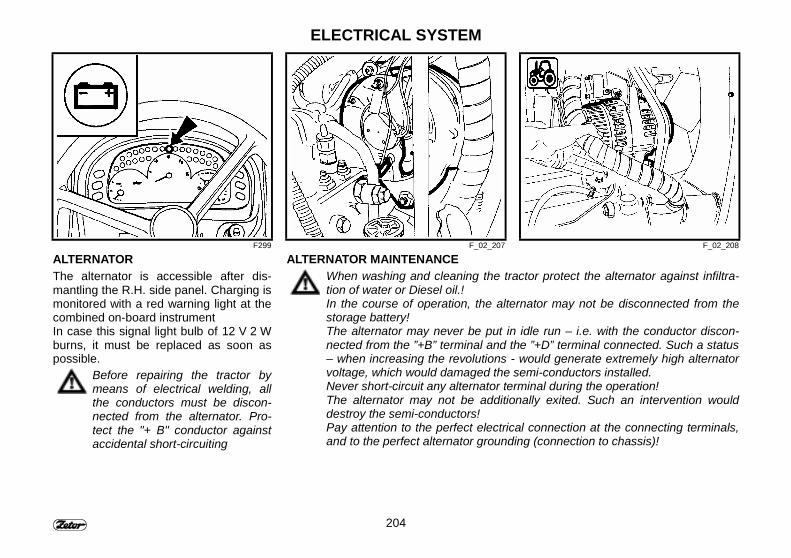
204
ELECTRICAL SYSTEM
F299 F_02_207 F_02_208
ALTERNATORThe alternator is accessible after dis-mantling the R.H. side panel. Charging ismonitored with a red warning light at thecombined on-board instrumentIn case this signal light bulb of 12 V 2 Wburns, it must be replaced as soon aspossible.
Before repairing the tractor bymeans of electrical welding, allthe conductors must be discon-nected from the alternator. Pro-tect the "+ B" conductor againstaccidental short-circuiting
ALTERNATOR MAINTENANCEWhen washing and cleaning the tractor protect the alternator against infiltra-tion of water or Diesel oil.!In the course of operation, the alternator may not be disconnected from thestorage battery!The alternator may never be put in idle run – i.e. with the conductor discon-nected from the ”+B” terminal and the ”+D” terminal connected. Such a status– when increasing the revolutions - would generate extremely high alternatorvoltage, which would damaged the semi-conductors installed.Never short-circuit any alternator terminal during the operation!The alternator may not be additionally exited. Such an intervention woulddestroy the semi-conductors!Pay attention to the perfect electrical connection at the connecting terminals,and to the perfect alternator grounding (connection to chassis)!
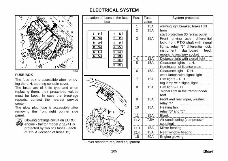
205
ELECTRICAL SYSTEM
F301
FUSE BOXThe fuse box is accessible after remov-ing the L.H. steering console cover.The fuses are of knife type and whenreplacing them, their prescribed valuesmust be kept.. In case the breakagerepeats, contact the nearest servicecenter.The glow plug fuse is accessible afterremoving the front right bonnet sidepanel.
Glowing gratings circuit on EURO IIengine - tractor model Z 11741 isprotected by two pcs fuses - eachof 125 A (location of fuses 15).
Location of fuses in the fusebox
Pos. Fusevalue
System protected
1 15A warning light breaker, brake light2 15A horn
start protection 30 relays outlet3 15A Front driving axle, differential
lock, front P.T.O shaft with signallights, relay ”3” differential lock,instrument dashboard feed,mounting auxiliary socket
4 15A Distance light with signal light5 15A Clearance lights – L.H.
illumination of license plate6 15A Clearance light – R.H.
work lamps with signal light7 15A Dim lights – R.H.
fog lamp with signal light8 15A Dim light – L.H.
signal light in the tractor hood/roof
9 15A Front and rear wiper, washer,relay ”4”
10 15A Heating fanrelay ”5” and ”6”
11 15A Blank∗ 12 7,5A Air conditioning (compressor
coupling)∗ 13 15A Mirror heating∗ 14 15A Rear window heating15 80A Engine glowing
∗ - over standard requived equipment
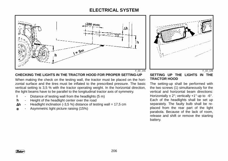
206
ELECTRICAL SYSTEM
F_02_145 F_02_126
CHECKING THE LIGHTS IN THE TRACTOR HOOD FOR PROPER SETTING-UPWhen making the check on the testing wall, the tractor must be placed on the hori-zontal surface and the tires must be inflated to the prescribed pressure. The basicvertical setting is 3,5 % with the tractor operating weight. In the horizontal direction,the light beams have to be parallel to the longitudinal tractor axis of symmetry.I - Distance of testing wall from the headlights (5 m)h - Height of the headlight center over the road∆∆∆∆h - Headlight inclination (-3,5 %) distance of testing wall = 17,5 cmαααα - Asymmetric light picture raising (15%)
SETTING UP THE LIGHTS IN THETRACTOR HOODThe setting-up shall be performed withthe two screws (1) simultaneously for thevertical and horizontal beam directions:Horizontally ± 2°; vertically +1° up to -6°.Each of the headlights shall be set upseparately. The faulty bulb shall be re-placed from the rear part of the lightparabola. Because of the lack of room,release and shift or remove the startingbattery.
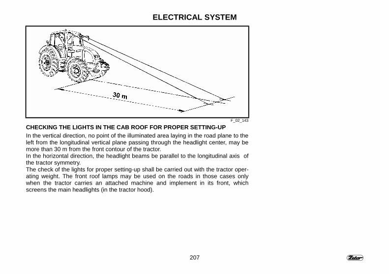
207
ELECTRICAL SYSTEM
F_02_143
CHECKING THE LIGHTS IN THE CAB ROOF FOR PROPER SETTING-UPIn the vertical direction, no point of the illuminated area laying in the road plane to theleft from the longitudinal vertical plane passing through the headlight center, may bemore than 30 m from the front contour of the tractor.In the horizontal direction, the headlight beams be parallel to the longitudinal axis ofthe tractor symmetry.The check of the lights for proper setting-up shall be carried out with the tractor oper-ating weight. The front roof lamps may be used on the roads in those cases onlywhen the tractor carries an attached machine and implement in its front, whichscreens the main headlights (in the tractor hood).

208
ELECTRICAL SYSTEM
F_02_144l
Pos. Bulb location Voltage Power Cap Note1 Head lights H 4 12 V 55/60 W P 43 T2 Cab illumination H 4 12 V 55/60 W P 43 T low beam filament connected3 Front combined lights
Directional lights 12 V 21 W BA 15 SClearance lights 12 V 10 W BA 15 S
4 Work service lamp H3 12 V 55 W PK 22 S5 Rear combined lights
Tail lights 12 V 10 W BA 15 SBrake lights 12 V 21 W BA 15 SDirectional lights 12 V 21 W BA 15 S
6 License plate illumination 2x12 V 5 W S 8,512 V 2 W B 8,5 D7 Instrument dashboard – integrated in-
strument KMGY 12 V 1,2 W B 8,5 D8 Cab illumination 12 V 5 W S 8,59 Hydraulic system electromagnetic control
switch12 V 1,2 W W 2X4,6 D

209
NOTE

210
NOTE
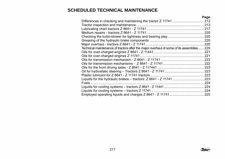
211
SCHEDULED TECHNICAL MAINTENANCEPage
Differences in checking and maintaining the tractor Z 11741 ................................. 212Tractor inspection and maintenance ....................................................................... 213Lubricating chart tractors Z 8641 - Z 11741 ............................................................ 217Medium repairs - tractors Z 8641 - Z 11741............................................................ 220Checking the turbo-blower for tightness and bearing play...................................... 220Greasing of the hydraulic brake components ......................................................... 220Major overhaul - tractors Z 8641 - Z 11741............................................................. 220Technical maintenance of tractors after the major overhaul of some of its assemblies...... 220Oils for over-charged engines Z 8641 - Z 11441..................................................... 221Oils for over-charged engines Z 11741................................................................... 221Oils for transmission mechanism - Z 8641 - Z 11741 ............................................. 222Oils for transmission mechanisms - Z 8641 - Z 11741........................................... 222Oils for the front driving axles - Z 8641 - Z 117441 ................................................. 223Oil for hydrostatic steering � Tractors Z 8641 - Z 11741......................................... 223Plastic lubricant for Z 8641 - Z 11741 tractors ........................................................ 223Liquids for the hydraulic brakes � tractors: Z 8641 - Z 11741................................. 223Fuels ....................................................................................................................... 224Liquids for cooling systems � tractors Z 8641 - Z 11441.......................................... 224Liquids for cooling systems � tractors Z 11741........................................................ 224Employed operating liquids and charges Z 8641 - Z 11741.................................... 225
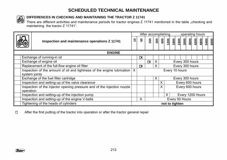
212
SCHEDULED TECHNICAL MAINTENANCEDIFFERENCES IN CHECKING AND MAINTAINING THE TRACTOR Z 11741There are different activities and maintenance periods for tractor engines Z 11741 mentioned in the table �checking andmaintaining the tractor Z 11741�.
After accomplishing...........operating hours
Inspection and maintenance operations Z 11741 10 50 150
300
600
1200
1800
2400
3000
3600
4200
4800
5400
6000
ENGINEExchange of running-in oil ∗∗∗∗ XExchange of engine oil ∗∗∗∗ X X Every 300 hoursReplacement of the full-flow engine oil filter ∗∗∗∗ X X Every 300 hoursInspection of the amount of oil and tightness of the engine lubricationsystem joints
X Every 10 hours
Exchange of the fuel filter cartridge X Every 300 hoursInspection and setting-up of the valve clearance X Every 600 hoursInspection of the injector opening pressure and of the injection nozzleoperation
X Every 600 hours
Inspection and setting-up of the injection pump X Every 1200 HoursInspection and setting-up of the engine V-belts X Every 50 HoursTightening of the heads of cylinders not to tighten
∗∗∗∗ After the first putting of the tractor into operation or after the tractor general repair
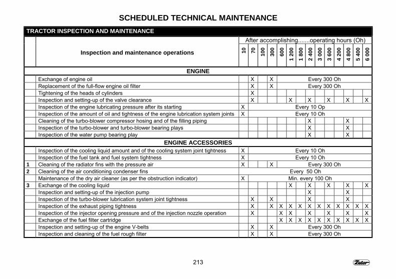
213
SCHEDULED TECHNICAL MAINTENANCETRACTOR INSPECTION AND MAINTENANCE
After accomplishing.......operating hours (Oh)
Inspection and maintenance operations 10 70 100
300
600
1 20
01
800
2 40
03
000
3 60
0
4 20
04
800
5 40
06
000
ENGINEExchange of engine oil X X Every 300 OhReplacement of the full-flow engine oil filter X X Every 300 OhTightening of the heads of cylinders XInspection and setting-up of the valve clearance X X X X X XInspection of the engine lubricating pressure after its starting X Every 10 OpInspection of the amount of oil and tightness of the engine lubrication system joints X Every 10 OhCleaning of the turbo-blower compressor hosing and of the filling piping X XInspection of the turbo-blower and turbo-blower bearing plays X XInspection of the water pump bearing play X X
ENGINE ACCESSORIESInspection of the cooling liquid amount and of the cooling system joint tightness X Every 10 OhInspection of the fuel tank and fuel system tightness X Every 10 Oh
1 Cleaning of the radiator fins with the pressure air X X Every 300 Oh2 Cleaning of the air conditioning condenser fins Every 50 Oh
Maintenance of the dry air cleaner (as per the obstruction indicator) X Min. every 100 Oh3 Exchange of the cooling liquid X X X X X
Inspection and setting-up of the injection pump X XInspection of the turbo-blower lubrication system joint tightness X X X XInspection of the exhaust piping tightness X X X X X X X X X X X XInspection of the injector opening pressure and of the injection nozzle operation X X X X X X XExchange of the fuel filter cartridge X X X X X X X X X XInspection and setting-up of the engine V-belts X X Every 300 OhInspection and cleaning of the fuel rough filter X X Every 300 Oh
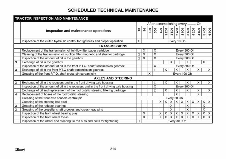
214
SCHEDULED TECHNICAL MAINTENANCETRACTOR INSPECTION AND MAINTENANCE
After accomplishing every�...... Oh
Inspection and maintenance operations 10 70 100
300
600
1 20
01
800
2 40
03
000
3 60
0
4 20
04
800
5 40
06
000
Inspection of the clutch hydraulic control for tightness and proper operation X Every 10 OhTRANSMISSIONS
Replacement of the transmission oil full-flow fiter paper cartridge X X Every 300 OhCleaning of the transmission oil suction filter magnetic and strainer cartridge ∗ X X Every 300 OhInspection of the amount of oil in the gearbox ∗ X X Every 300 Oh
3 Exchange of oil in the gearbox X X XInspection of the amount of oil in the front P.T.O. shaft transmission gearbox X Every 300 Oh
3 Exchange of oil in the front P.T.O shaft transmission gearbos ∗ X X X X XGreasing of the front P.T.O. shaft cross-pin cardan joint X Every 100 Oh
AXLES AND STEERING3 Exchange of oil in the reducers and in the front driving axle housing ∗ X X X X X
Inspection of the amount of oil in the reducers and in the front driving axle housing X Every 300 OhExchange of oil and replacement of the hydrostatic steering filtering cartridge ∗ X X X X X
4 Replacement of hoses of the hydrostatic steering X XGreasing of the front axle console central pin Every 50 OhGreasing of the steering ball stud X X X X X X X X X X
3 Greasing of the reducer bearings X X X3 Greasing of the propeller shaft grooves and cross-head pins X X X
Inspection of the front wheel bearing play X X X X X X X X X X XInspection of the front wheel toe-in X X X X X X X X X X XInspection of the wheel and steering tie rod nuts and bolts for tightening ∗ Every 300 Oh
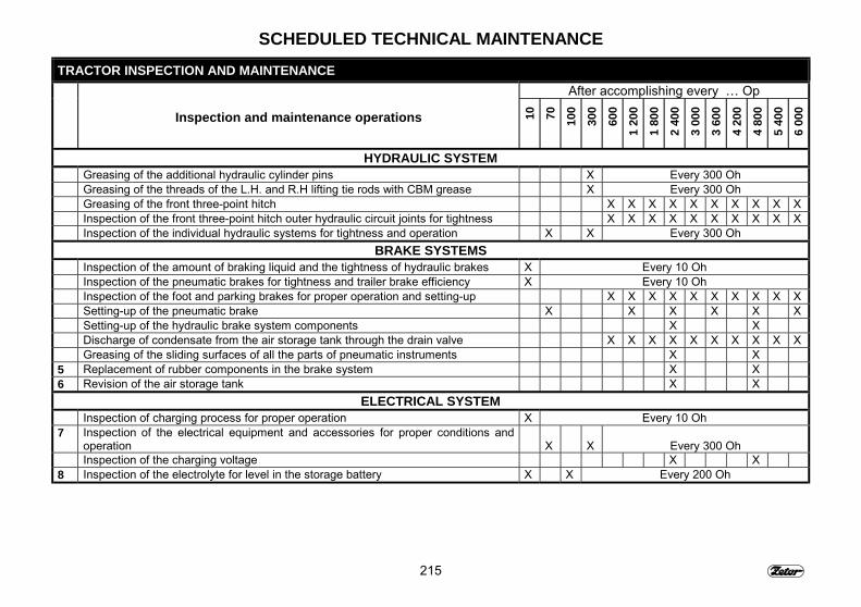
215
SCHEDULED TECHNICAL MAINTENANCETRACTOR INSPECTION AND MAINTENANCE
After accomplishing every � Op
Inspection and maintenance operations 10 70 100
300
600
1 20
01
800
2 40
03
000
3 60
0
4 20
04
800
5 40
06
000
HYDRAULIC SYSTEMGreasing of the additional hydraulic cylinder pins X Every 300 OhGreasing of the threads of the L.H. and R.H lifting tie rods with CBM grease X Every 300 OhGreasing of the front three-point hitch X X X X X X X X X XInspection of the front three-point hitch outer hydraulic circuit joints for tightness X X X X X X X X X XInspection of the individual hydraulic systems for tightness and operation X X Every 300 Oh
BRAKE SYSTEMSInspection of the amount of braking liquid and the tightness of hydraulic brakes X Every 10 OhInspection of the pneumatic brakes for tightness and trailer brake efficiency X Every 10 OhInspection of the foot and parking brakes for proper operation and setting-up X X X X X X X X X XSetting-up of the pneumatic brake X X X X X XSetting-up of the hydraulic brake system components X XDischarge of condensate from the air storage tank through the drain valve X X X X X X X X X XGreasing of the sliding surfaces of all the parts of pneumatic instruments X X
5 Replacement of rubber components in the brake system X X6 Revision of the air storage tank X X
ELECTRICAL SYSTEMInspection of charging process for proper operation X Every 10 Oh
7 Inspection of the electrical equipment and accessories for proper conditions andoperation X X Every 300 OhInspection of the charging voltage X X
8 Inspection of the electrolyte for level in the storage battery X X Every 200 Oh
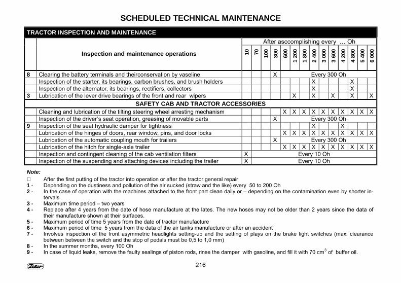
216
SCHEDULED TECHNICAL MAINTENANCETRACTOR INSPECTION AND MAINTENANCE
After asccomplishing every � Oh
Inspection and maintenance operations 10 70 100
300
600
1 20
01
800
2 40
03
000
3 60
0
4 20
04
800
5 40
06
000
8 Clearing the battery terminals and theirconservation by vaseline X Every 300 OhInspection of the starter, its bearings, carbon brushes, and brush holders X XInspection of the alternator, its bearings, rectifiers, collectors X X
3 Lubrication of the lever drive bearings of the front and rear wipers X X X X XSAFETY CAB AND TRACTOR ACCESSORIES
Cleaning and lubrication of the tilting steering wheel arresting mechanism X X X X X X X X X XInspection of the driver�s seat operation, greasing of movable parts X Every 300 Oh
9 Inspection of the seat hydraulic damper for tightness X XLubrication of the hinges of doors, rear window, pins, and door locks X X X X X X X X X XLubrication of the automatic coupling mouth for trailers X Every 300 OhLubrication of the hitch for single-axle trailer X X X X X X X X X XInspection and contingent cleaning of the cab ventilation filters X Every 10 OhInspection of the suspending and attaching devices including the trailer X Every 10 Oh
Note:∗ After the first putting of the tractor into operation or after the tractor general repair1 - Depending on the dustiness and pollution of the air sucked (straw and the like) every 50 to 200 Oh2 - In the case of operation with the machines attached to the front part clean daily or � depending on the contamination even by shorter in-
tervals3 - Maximum time period � two years4 - Replace after 4 years from the date of hose manufacture at the lates. The new hoses may not be older than 2 years since the data of
their manufacture shown at their surfaces.5 - Maximum period of time 5 years from the date of tractor manufacture6 - Maximum period of time 5 years from the data of the air tanks manufacture or after an accident7 - Involves inspection of the front asymmetric headlights setting-up and the setting of plays on the brake light switches (max. clearance
between between the switch and the stop of pedals must be 0,5 to 1,0 mm)8 - In the summer months, every 100 Oh9 - In case of liquid leaks, remove the faulty sealings of piston rods, rinse the damper with gasoline, and fill it with 70 cm3 of buffer oil.

217
SCHEDULED TECHNICAL MAINTENANCELUBRICATING CHART TRACTORS Z 8641 - Z 11741
F_02_155
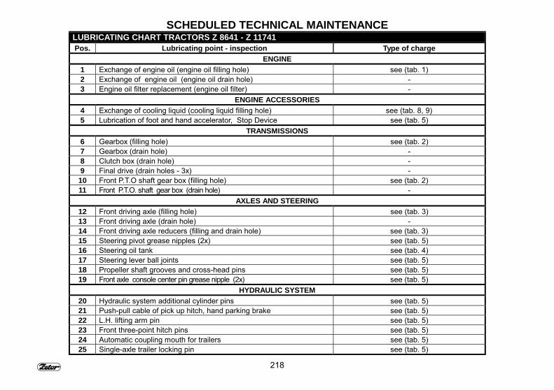
218
SCHEDULED TECHNICAL MAINTENANCELUBRICATING CHART TRACTORS Z 8641 - Z 11741Pos. Lubricating point - inspection Type of charge
ENGINE1 Exchange of engine oil (engine oil filling hole) see (tab. 1)2 Exchange of engine oil (engine oil drain hole) -3 Engine oil filter replacement (engine oil filter) -
ENGINE ACCESSORIES4 Exchange of cooling liquid (cooling liquid filling hole) see (tab. 8, 9)5 Lubrication of foot and hand accelerator, Stop Device see (tab. 5)
TRANSMISSIONS6 Gearbox (filling hole) see (tab. 2)7 Gearbox (drain hole) -8 Clutch box (drain hole) -9 Final drive (drain holes - 3x) -10 Front P.T.O shaft gear box (filling hole) see (tab. 2)11 Front P.T.O. shaft gear box (drain hole) -
AXLES AND STEERING12 Front driving axle (filling hole) see (tab. 3)13 Front driving axle (drain hole) -14 Front driving axle reducers (filling and drain hole) see (tab. 3)15 Steering pivot grease nipples (2x) see (tab. 5)16 Steering oil tank see (tab. 4)17 Steering lever ball joints see (tab. 5)18 Propeller shaft grooves and cross-head pins see (tab. 5)19 Front axle console center pin grease nipple (2x) see (tab. 5)
HYDRAULIC SYSTEM20 Hydraulic system additional cylinder pins see (tab. 5)21 Push-pull cable of pick up hitch, hand parking brake see (tab. 5)22 L.H. lifting arm pin see (tab. 5)23 Front three-point hitch pins see (tab. 5)24 Automatic coupling mouth for trailers see (tab. 5)25 Single-axle trailer locking pin see (tab. 5)
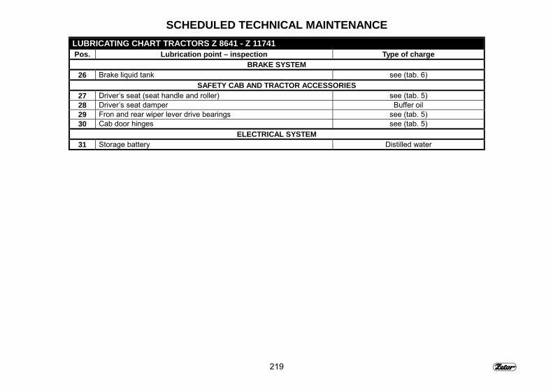
219
SCHEDULED TECHNICAL MAINTENANCELUBRICATING CHART TRACTORS Z 8641 - Z 11741Pos. Lubrication point – inspection Type of charge
BRAKE SYSTEM26 Brake liquid tank see (tab. 6)
SAFETY CAB AND TRACTOR ACCESSORIES27 Driver�s seat (seat handle and roller) see (tab. 5)28 Driver�s seat damper Buffer oil29 Fron and rear wiper lever drive bearings see (tab. 5)30 Cab door hinges see (tab. 5)
ELECTRICAL SYSTEM31 Storage battery Distilled water
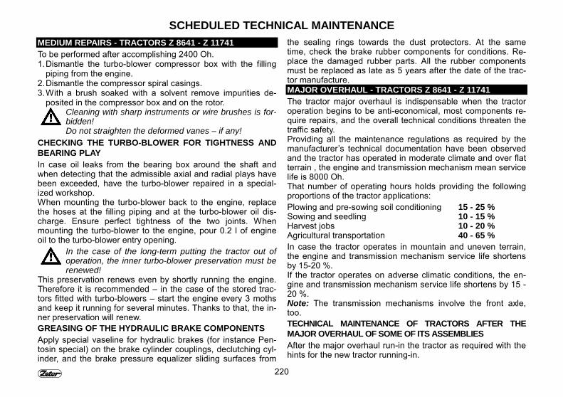
220
SCHEDULED TECHNICAL MAINTENANCEMEDIUM REPAIRS - TRACTORS Z 8641 - Z 11741To be performed after accomplishing 2400 Oh.1. Dismantle the turbo-blower compressor box with the filling
piping from the engine.2. Dismantle the compressor spiral casings.3. With a brush soaked with a solvent remove impurities de-
posited in the compressor box and on the rotor.Cleaning with sharp instruments or wire brushes is for-bidden!Do not straighten the deformed vanes – if any!
CHECKING THE TURBO-BLOWER FOR TIGHTNESS ANDBEARING PLAYIn case oil leaks from the bearing box around the shaft andwhen detecting that the admissible axial and radial plays havebeen exceeded, have the turbo-blower repaired in a special-ized workshop.When mounting the turbo-blower back to the engine, replacethe hoses at the filling piping and at the turbo-blower oil dis-charge. Ensure perfect tightness of the two joints. Whenmounting the turbo-blower to the engine, pour 0.2 l of engineoil to the turbo-blower entry opening.
In the case of the long-term putting the tractor out ofoperation, the inner turbo-blower preservation must berenewed!
This preservation renews even by shortly running the engine.Therefore it is recommended � in the case of the stored trac-tors fitted with turbo-blowers � start the engine every 3 mothsand keep it running for several minutes. Thanks to that, the in-ner preservation will renew.GREASING OF THE HYDRAULIC BRAKE COMPONENTSApply special vaseline for hydraulic brakes (for instance Pen-tosin special) on the brake cylinder couplings, declutching cyl-inder, and the brake pressure equalizer sliding surfaces from
the sealing rings towards the dust protectors. At the sametime, check the brake rubber components for conditions. Re-place the damaged rubber parts. All the rubber componentsmust be replaced as late as 5 years after the date of the trac-tor manufacture.MAJOR OVERHAUL - TRACTORS Z 8641 - Z 11741The tractor major overhaul is indispensable when the tractoroperation begins to be anti-economical, most components re-quire repairs, and the overall technical conditions threaten thetraffic safety.Providing all the maintenance regulations as required by themanufacturer�s technical documentation have been observedand the tractor has operated in moderate climate and over flatterrain , the engine and transmission mechanism mean servicelife is 8000 Oh.That number of operating hours holds providing the followingproportions of the tractor applications:Plowing and pre-sowing soil conditioning 15 - 25 %Sowing and seedling 10 - 15 %Harvest jobs 10 - 20 %Agricultural transportation 40 - 65 %In case the tractor operates in mountain and uneven terrain,the engine and transmission mechanism service life shortensby 15-20 %.If the tractor operates on adverse climatic conditions, the en-gine and transmission mechanism service life shortens by 15 -20 %.Note: The transmission mechanisms involve the front axle,too.TECHNICAL MAINTENANCE OF TRACTORS AFTER THEMAJOR OVERHAUL OF SOME OF ITS ASSEMBLIESAfter the major overhaul run-in the tractor as required with thehints for the new tractor running-in.
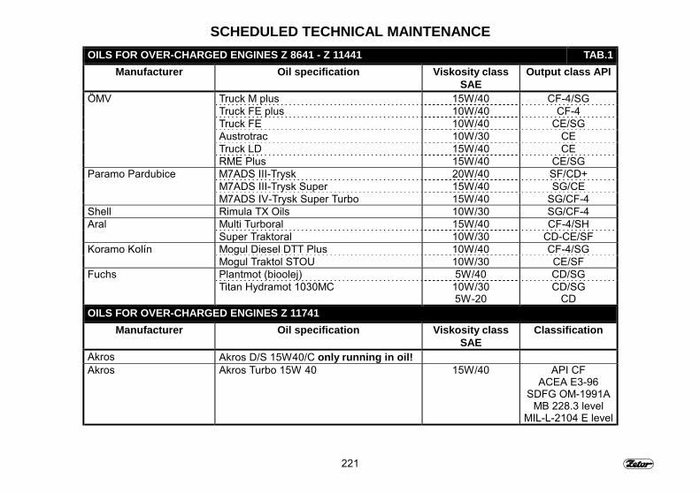
221
SCHEDULED TECHNICAL MAINTENANCEOILS FOR OVER-CHARGED ENGINES Z 8641 - Z 11441 TAB.1
Manufacturer Oil specification Viskosity classSAE
Output class API
ÖMV Truck M plus 15W/40 CF-4/SGTruck FE plus 10W/40 CF-4Truck FE 10W/40 CE/SGAustrotrac 10W/30 CETruck LD 15W/40 CERME Plus 15W/40 CE/SG
Paramo Pardubice M7ADS III-Trysk 20W/40 SF/CD+M7ADS III-Trysk Super 15W/40 SG/CEM7ADS IV-Trysk Super Turbo 15W/40 SG/CF-4
Shell Rimula TX Oils 10W/30 SG/CF-4Aral Multi Turboral 15W/40 CF-4/SH
Super Traktoral 10W/30 CD-CE/SFKoramo Kolín Mogul Diesel DTT Plus 10W/40 CF-4/SG
Mogul Traktol STOU 10W/30 CE/SFFuchs Plantmot (bioolej) 5W/40 CD/SG
Titan Hydramot 1030MC 10W/305W-20
CD/SGCD
OILS FOR OVER-CHARGED ENGINES Z 11741Manufacturer Oil specification Viskosity class
SAEClassification
Akros Akros D/S 15W40/C only running in oil!Akros Akros Turbo 15W 40 15W/40 API CF
ACEA E3-96SDFG OM-1991A
MB 228.3 levelMIL-L-2104 E level
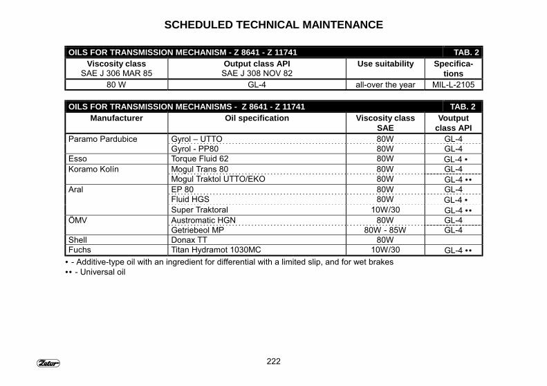
222
SCHEDULED TECHNICAL MAINTENANCE
OILS FOR TRANSMISSION MECHANISM - Z 8641 - Z 11741 TAB. 2Viscosity class
SAE J 306 MAR 85Output class API
SAE J 308 NOV 82Use suitability Specifica-
tions80 W GL-4 all-over the year MIL-L-2105
OILS FOR TRANSMISSION MECHANISMS - Z 8641 - Z 11741 TAB. 2Manufacturer Oil specification Viscosity class
SAEVoutput
class APIParamo Pardubice Gyrol � UTTO 80W GL-4
Gyrol - PP80 80W GL-4Esso Torque Fluid 62 80W GL-4 •Koramo Kolín Mogul Trans 80 80W GL-4
Mogul Traktol UTTO/EKO 80W GL-4 ••Aral EP 80 80W GL-4
Fluid HGS 80W GL-4 •Super Traktoral 10W/30 GL-4 ••
ÖMV Austromatic HGN 80W GL-4Getriebeol MP 80W - 85W GL-4
Shell Donax TT 80WFuchs Titan Hydramot 1030MC 10W/30 GL-4 ••
• - Additive-type oil with an ingredient for differential with a limited slip, and for wet brakes•• - Universal oil
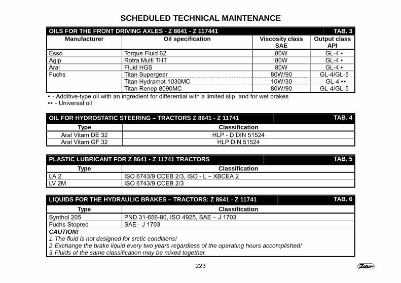
223
SCHEDULED TECHNICAL MAINTENANCEOILS FOR THE FRONT DRIVING AXLES - Z 8641 - Z 117441 TAB. 3
Manufacturer Oil specification Viscosity classSAE
Output classAPI
Esso Torque Fluid 62 80W GL-4 •Agip Rotra Multi THT 80W GL-4 •Aral Fluid HGS 80W GL-4 •Fuchs Titan Supergear 80W/90 GL-4/GL-5
Titan Hydramot 1030MC 10W/30 GL-4 ••Titan Renep 8090MC 80W/90 GL-4/GL-5
• - Additive-type oil with an ingredient for differential with a limited slip, and for wet brakes•• - Universal oil
OIL FOR HYDROSTATIC STEERING – TRACTORS Z 8641 - Z 11741 TAB. 4Type Classification
Aral Vitam DE 32 HLP - D DIN 51524Aral Vitam GF 32 HLP DIN 51524
PLASTIC LUBRICANT FOR Z 8641 - Z 11741 TRACTORS TAB. 5Type Classification
LA 2 ISO 6743/9 CCEB 2/3, ISO - L � XBCEA 2LV 2M ISO 6743/9 CCEB 2/3
LIQUIDS FOR THE HYDRAULIC BRAKES – TRACTORS: Z 8641 - Z 11741 TAB. 6Type Classification
Synthol 205 PND 31-656-80, ISO 4925, SAE � J 1703Fuchs Stopred SAE - J 1703CAUTION!1. The fluid is not designed for srctic conditions!2. Exchange the brake liquid every two years regardless of the operating hours accomplished!3. Fluids of the same classification may be mixed together.
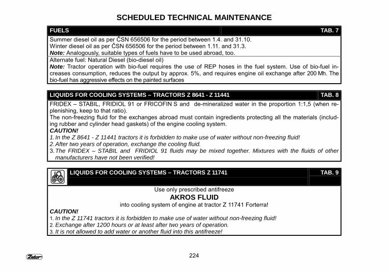
224
SCHEDULED TECHNICAL MAINTENANCEFUELS TAB. 7Summer diesel oil as per ČSN 656506 for the period between 1.4. and 31.10.Winter diesel oil as per ČSN 656506 for the period between 1.11. and 31.3.Note: Analogously, suitable types of fuels have to be used abroad, too.Alternate fuel: Natural Diesel (bio-diesel oil)Note: Tractor operation with bio-fuel requires the use of REP hoses in the fuel system. Use of bio-fuel in-creases consumption, reduces the output by approx. 5%, and requires engine oil exchange after 200 Mh. Thebio-fuel has aggressive effects on the painted surfaces
LIQUIDS FOR COOLING SYSTEMS – TRACTORS Z 8641 - Z 11441 TAB. 8FRIDEX � STABIL, FRIDIOL 91 or FRICOFIN S and de-mineralized water in the proportion 1:1,5 (when re-plenishing, keep to that ratio).The non-freezing fluid for the exchanges abroad must contain ingredients protecting all the materials (includ-ing rubber and cylinder head gaskets) of the engine cooling system.CAUTION!1. In the Z 8641 - Z 11441 tractors it is forbidden to make use of water without non-freezing fluid!2. After two years of operation, exchange the cooling fluid.3. The FRIDEX – STABIL and FRIDIOL 91 fluids may be mixed together. Mixtures with the fluids of other
manufacturers have not been verified!
LIQUIDS FOR COOLING SYSTEMS – TRACTORS Z 11741 TAB. 9
Use only prescribed antifreezeAKROS FLUID
into cooling system of engine at tractor Z 11741 Forterra!CAUTION!1. In the Z 11741 tractors it is forbidden to make use of water without non-freezing fluid!2. Exchange after 1200 hours or at least after two years of operation.3. It is not allowed to add water or another fluid into this antifreeze!
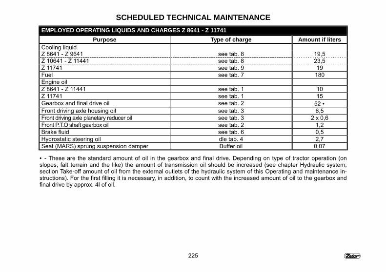
225
SCHEDULED TECHNICAL MAINTENANCEEMPLOYED OPERATING LIQUIDS AND CHARGES Z 8641 - Z 11741
Purpose Type of charge Amount if litersCooling liquidZ 8641 - Z 9641 see tab. 8 19,5Z 10641 - Z 11441 see tab. 8 23,5Z 11741 see tab. 9 19Fuel see tab. 7 180Engine oilZ 8641 - Z 11441 see tab. 1 10Z 11741 see tab. 1 15Gearbox and final drive oil see tab. 2 52 •Front driving axle housing oil see tab. 3 6,5Front driving axle planetary reducer oil see tab. 3 2 x 0,6Front P.T.O shaft gearbox oil see tab. 2 1,2Brake fluid see tab. 6 0,5Hydrostatic steering oil dle tab. 4 2,7Seat (MARS) sprung suspension damper Buffer oil 0,07
• - These are the standard amount of oil in the gearbox and final drive. Depending on type of tractor operation (onslopes, falt terrain and the like) the amount of transmission oil should be increased (see chapter Hydraulic system;section Take-off amount of oil from the external outlets of the hydraulic system of this Operating and maintenance in-structions). For the first filling it is necessary, in addition, to count with the increased amount of oil to the gearbox andfinal drive by approx. 4l of oil.

226
NOTE
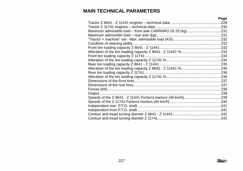
227
MAIN TECHNICAL PARAMETERSPage
Tractor Z 8641 - Z 11441 engines – technical data................................................. 228Tractor Z 11741 engines – technical data ............................................................... 230Maximum admissible load – front axle CARRARO 20.19 (kg) ................................ 231Maximum admissible load – rear axle (kg).............................................................. 231"Tractor + machine" set - Max. admissible load (KG).............................................. 232Condition of steering ability..................................................................................... 232Front tire loading capacity Z 8641 - Z 11441........................................................... 233Alteration of the tire loading capacity Z 8641 - Z 11441 %...................................... 233Front tire loading capacity Z 11741......................................................................... 234Alteration of the tire loading capacity Z 11741 %.................................................... 234Rear tire loading capacity Z 8641 - Z 11441 ........................................................... 235Alteration of the tire loading capacity Z 8641 - Z 11441 %...................................... 235Rear tire loading capacity Z 11741.......................................................................... 236Alteration of the tire loading capacity Z 11741 %.................................................... 236Dimensions of the front tires ................................................................................... 237Dimensions of the rear tires .................................................................................... 237Forces (kN) ............................................................................................................. 238Output ..................................................................................................................... 238Speeds of the Z 8641 - Z 11441 Forterra tractors (40 km/h)................................... 239Speeds of the Z 11741 Forterra tractors (40 km/h) ................................................. 240Independent rear P.T.O. shaft ................................................................................ 241Independent front P.T.O. shaft................................................................................. 241Contour and tread turning diametr Z 8641 - Z 11441.............................................. 242Contour and tread turning diametr Z 11741 ............................................................ 242
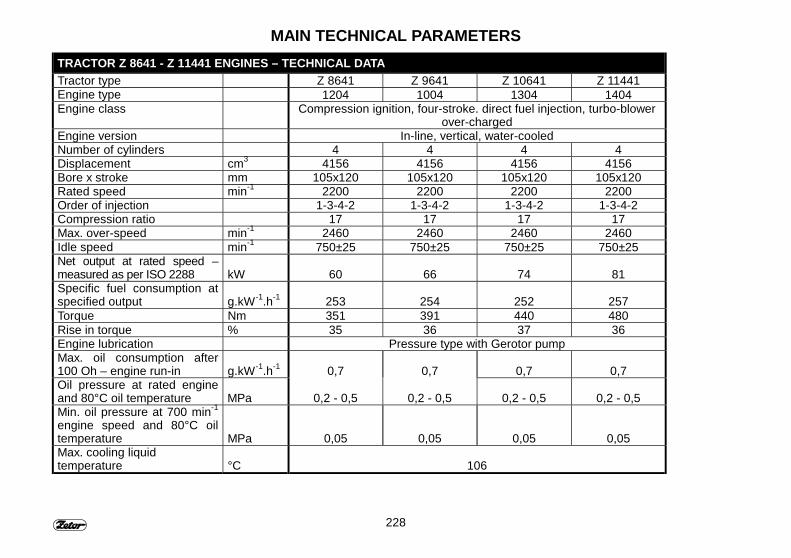
228
MAIN TECHNICAL PARAMETERSTRACTOR Z 8641 - Z 11441 ENGINES – TECHNICAL DATATractor type Z 8641 Z 9641 Z 10641 Z 11441Engine type 1204 1004 1304 1404Engine class Compression ignition, four-stroke. direct fuel injection, turbo-blower
over-chargedEngine version In-line, vertical, water-cooledNumber of cylinders 4 4 4 4Displacement cm3 4156 4156 4156 4156Bore x stroke mm 105x120 105x120 105x120 105x120Rated speed min-1 2200 2200 2200 2200Order of injection 1-3-4-2 1-3-4-2 1-3-4-2 1-3-4-2Compression ratio 17 17 17 17Max. over-speed min-1 2460 2460 2460 2460Idle speed min-1 750±25 750±25 750±25 750±25Net output at rated speed –measured as per ISO 2288 kW 60 66 74 81Specific fuel consumption atspecified output g.kW-1.h-1 253 254 252 257Torque Nm 351 391 440 480Rise in torque % 35 36 37 36Engine lubrication Pressure type with Gerotor pumpMax. oil consumption after100 Oh – engine run-in g.kW-1.h-1 0,7 0,7 0,7 0,7Oil pressure at rated engineand 80°C oil temperature MPa 0,2 - 0,5 0,2 - 0,5 0,2 - 0,5 0,2 - 0,5Min. oil pressure at 700 min-1
engine speed and 80°C oiltemperature MPa 0,05 0,05 0,05 0,05Max. cooling liquidtemperature °C 106
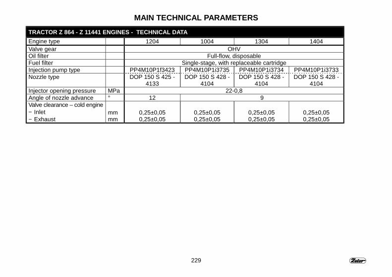
229
MAIN TECHNICAL PARAMETERSTRACTOR Z 864 - Z 11441 ENGINES - TECHNICAL DATAEngine type 1204 1004 1304 1404Valve gear OHVOil filter Full-flow, disposableFuel filter Single-stage, with replaceable cartridgeInjection pump type PP4M10P1f3423 PP4M10P1i3735 PP4M10P1i3734 PP4M10P1i3733Nozzle type DOP 150 S 425 -
4133DOP 150 S 428 -
4104DOP 150 S 428 -
4104DOP 150 S 428 -
4104Injector opening pressure MPa 22-0,8Angle of nozzle advance ° 12 9Valve clearance – cold engine− Inlet− Exhaust
mmmm
0,25±0,050,25±0,05
0,25±0,050,25±0,05
0,25±0,050,25±0,05
0,25±0,050,25±0,05
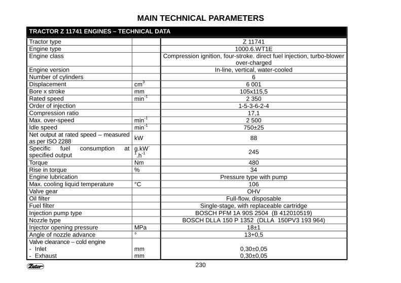
230
MAIN TECHNICAL PARAMETERSTRACTOR Z 11741 ENGINES – TECHNICAL DATATractor type Z 11741Engine type 1000.6.WT1EEngine class Compression ignition, four-stroke. direct fuel injection, turbo-blower
over-chargedEngine version In-line, vertical, water-cooledNumber of cylinders 6Displacement cm3 6 001Bore x stroke mm 105x115,5Rated speed min-1 2 350Order of injection 1-5-3-6-2-4Compression ratio 17,1Max. over-speed min-1 2 500Idle speed min-1 750±25Net output at rated speed – measuredas per ISO 2288 kW 88
Specific fuel consumption atspecified output
g.kW-1.h-1 245
Torque Nm 480Rise in torque % 34Engine lubrication Pressure type with pumpMax. cooling liquid temperature °C 106Valve gear OHVOil filter Full-flow, disposableFuel filter Single-stage, with replaceable cartridgeInjection pump type BOSCH PFM 1A 90S 2504 (B 412010519)Nozzle type BOSCH DLLA 150 P 1352 (DLLA 150PV3 193 964)Injector opening pressure MPa 18±1Angle of nozzle advance ° 13+0,5Valve clearance – cold engine- Inlet- Exhaust
mmmm
0,30±0,050,30±0,05
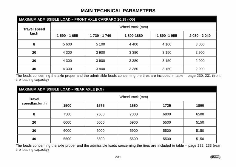
231
MAIN TECHNICAL PARAMETERSMAXIMUM ADMISSIBLE LOAD – FRONT AXLE CARRARO 20.19 (KG)
Wheel track (mm)Travel speedkm.h 1 590 - 1 655 1 730 - 1 740 1 800-1880 1 890 -1 955 2 030 - 2 040
8 5 600 5 100 4 400 4 100 3 800
20 4 300 3 900 3 380 3 150 2 900
30 4 300 3 900 3 380 3 150 2 900
40 4 300 3 900 3 380 3 150 2 900
The loads concerning the axle proper and the admissible loads concerning the tires are included in table – page 230, 231 (fronttire loading capacity)
MAXIMUM ADMISSIBLE LOAD – REAR AXLE (KG)
Wheel track (mm)Travelspeedkm.km.h 1500 1575 1650 1725 1800
8 7500 7500 7300 6800 6500
20 6000 6000 5900 5500 5150
30 6000 6000 5900 5500 5150
40 5500 5500 5500 5500 5150
The loads concerning the axle proper and the admissible loads concerning the tires are included in table – page 232, 233 (reartire loading capacity)
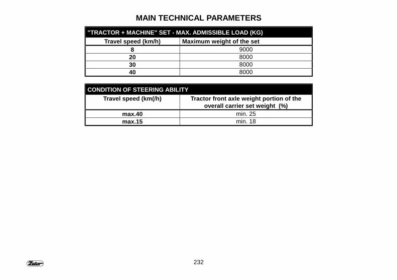
232
MAIN TECHNICAL PARAMETERS"TRACTOR + MACHINE" SET - MAX. ADMISSIBLE LOAD (KG)
Travel speed (km/h) Maximum weight of the set8 9000
20 800030 800040 8000
CONDITION OF STEERING ABILITYTravel speed (km(/h) Tractor front axle weight portion of the
overall carrier set weight (%)max.40 min. 25max.15 min. 18
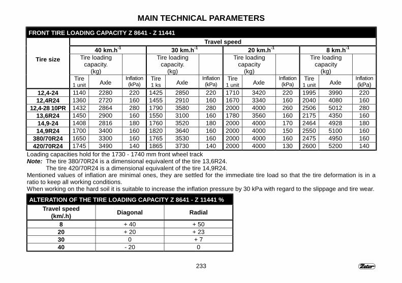
233
MAIN TECHNICAL PARAMETERSFRONT TIRE LOADING CAPACITY Z 8641 - Z 11441
Travel speed40 km.h-1 30 km.h-1 20 km.h-1 8 km.h-1
Tire loadingcapacity.
(kg)
Tire loadingcapacity.
(kg)
Tire loadingcapacity
(kg)
Tire loadingcapacity
(kg)
Tire size
Tire1 unit Axle
Inflation(kPa)
Tire1 ks Axle
Inflation(kPa)
Tire1 unit Axle
Inflation(kPa)
Tire1 unit Axle
Inflation(kPa)
12,4-24 1140 2280 220 1425 2850 220 1710 3420 220 1995 3990 22012,4R24 1360 2720 160 1455 2910 160 1670 3340 160 2040 4080 160
12,4-28 10PR 1432 2864 280 1790 3580 280 2000 4000 260 2506 5012 28013,6R24 1450 2900 160 1550 3100 160 1780 3560 160 2175 4350 16014,9-24 1408 2816 180 1760 3520 180 2000 4000 170 2464 4928 18014,9R24 1700 3400 160 1820 3640 160 2000 4000 150 2550 5100 160
380/70R24 1650 3300 160 1765 3530 160 2000 4000 160 2475 4950 160420/70R24 1745 3490 140 1865 3730 140 2000 4000 130 2600 5200 140
Loading capacities hold for the 1730 - 1740 mm front wheel trackNote: The tire 380/70R24 is a dimensional equivalent of the tire 13,6R24.
The tire 420/70R24 is a dimensional equivalent of the tire 14,9R24.Mentioned values of inflation are minimal ones, they are settled for the immediate tire load so that the tire deformation is in aratio to keep all working conditions.When working on the hard soil it is suitable to increase the inflation pressure by 30 kPa with regard to the slippage and tire wear.
ALTERATION OF THE TIRE LOADING CAPACITY Z 8641 - Z 11441 %Travel speed
(km/.h) Diagonal Radial
8 + 40 + 5020 + 20 + 2330 0 + 740 - 20 0
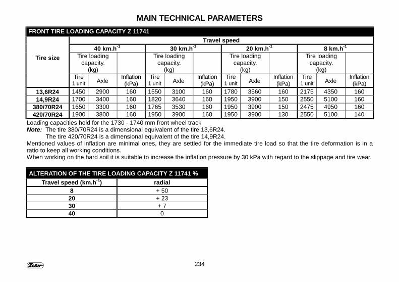
234
MAIN TECHNICAL PARAMETERSFRONT TIRE LOADING CAPACITY Z 11741
Travel speed40 km.h-1 30 km.h-1 20 km.h-1 8 km.h-1
Tire loadingcapacity.
(kg)
Tire loadingcapacity.
(kg)
Tire loadingcapacity.
(kg)
Tire loadingcapacity.
(kg)
Tire size
Tire1 unit Axle Inflation
(kPa)Tire
1 unit Axle Inflation(kPa)
Tire1 unit Axle Inflation
(kPa)Tire
1 unit Axle Inflation(kPa)
13,6R24 1450 2900 160 1550 3100 160 1780 3560 160 2175 4350 16014,9R24 1700 3400 160 1820 3640 160 1950 3900 150 2550 5100 160
380/70R24 1650 3300 160 1765 3530 160 1950 3900 150 2475 4950 160420/70R24 1900 3800 160 1950 3900 160 1950 3900 130 2550 5100 140
Loading capacities hold for the 1730 - 1740 mm front wheel trackNote: The tire 380/70R24 is a dimensional equivalent of the tire 13,6R24.
The tire 420/70R24 is a dimensional equivalent of the tire 14,9R24.Mentioned values of inflation are minimal ones, they are settled for the immediate tire load so that the tire deformation is in aratio to keep all working conditions.When working on the hard soil it is suitable to increase the inflation pressure by 30 kPa with regard to the slippage and tire wear.
ALTERATION OF THE TIRE LOADING CAPACITY Z 11741 %Travel speed (km.h-1) radial
8 + 5020 + 2330 + 740 0
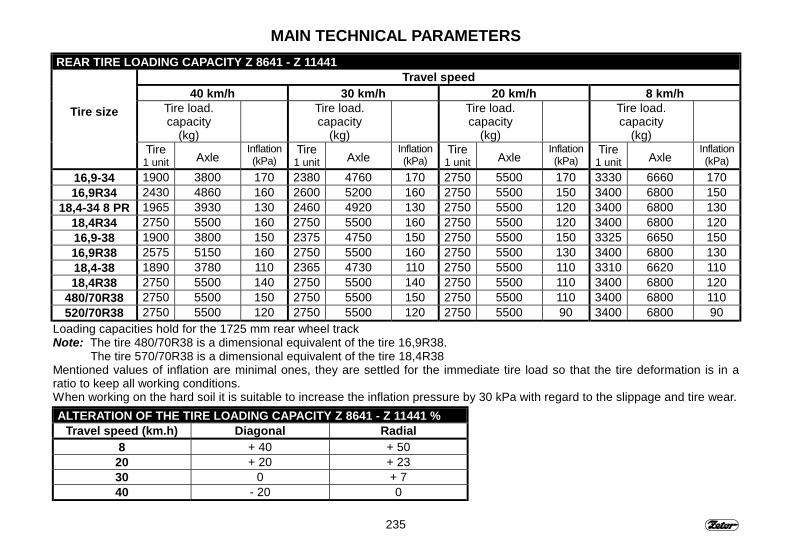
235
MAIN TECHNICAL PARAMETERSREAR TIRE LOADING CAPACITY Z 8641 - Z 11441
Travel speed40 km/h 30 km/h 20 km/h 8 km/h
Tire load.capacity
(kg)
Tire load.capacity
(kg)
Tire load.capacity
(kg)
Tire load.capacity
(kg)
Tire size
Tire1 unit Axle
Inflation(kPa)
Tire1 unit Axle
Inflation(kPa)
Tire1 unit Axle
Inflation(kPa)
Tire1 unit Axle
Inflation(kPa)
16,9-34 1900 3800 170 2380 4760 170 2750 5500 170 3330 6660 17016,9R34 2430 4860 160 2600 5200 160 2750 5500 150 3400 6800 150
18,4-34 8 PR 1965 3930 130 2460 4920 130 2750 5500 120 3400 6800 13018,4R34 2750 5500 160 2750 5500 160 2750 5500 120 3400 6800 12016,9-38 1900 3800 150 2375 4750 150 2750 5500 150 3325 6650 15016,9R38 2575 5150 160 2750 5500 160 2750 5500 130 3400 6800 13018,4-38 1890 3780 110 2365 4730 110 2750 5500 110 3310 6620 11018,4R38 2750 5500 140 2750 5500 140 2750 5500 110 3400 6800 120
480/70R38 2750 5500 150 2750 5500 150 2750 5500 110 3400 6800 110520/70R38 2750 5500 120 2750 5500 120 2750 5500 90 3400 6800 90
Loading capacities hold for the 1725 mm rear wheel trackNote: The tire 480/70R38 is a dimensional equivalent of the tire 16,9R38.
The tire 570/70R38 is a dimensional equivalent of the tire 18,4R38Mentioned values of inflation are minimal ones, they are settled for the immediate tire load so that the tire deformation is in aratio to keep all working conditions.When working on the hard soil it is suitable to increase the inflation pressure by 30 kPa with regard to the slippage and tire wear.ALTERATION OF THE TIRE LOADING CAPACITY Z 8641 - Z 11441 %
Travel speed (km.h) Diagonal Radial8 + 40 + 50
20 + 20 + 2330 0 + 740 - 20 0
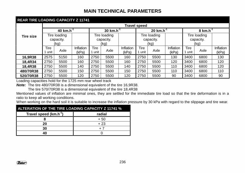
236
MAIN TECHNICAL PARAMETERSREAR TIRE LOADING CAPACITY Z 11741
Travel speed40 km.h-1 30 km.h-1 20 km.h-1 8 km.h-1
Tire loadingcapacity.
(kg)
Tire loadingcapacity.
(kg)
Tire loadingcapacity.
(kg)
Tire loadingcapacity.
(kg)
Tire size
Tire1 unit Axle Inflation
(kPa)Tire
1 unit Axle Inflation(kPa)
Tire1 unit Axle Inflation
(kPa)Tire
1 unit Axle Inflation(kPa)
16,9R38 2575 5150 160 2750 5500 160 2750 5500 130 3400 6800 13018,4R34 2750 5500 160 2750 5500 160 2750 5500 120 3400 6800 12018,4R38 2750 5500 140 2750 5500 140 2750 5500 110 3400 6800 120
480/70R38 2750 5500 150 2750 5500 150 2750 5500 110 3400 6800 110520/70R38 2750 5500 120 2750 5500 120 2750 5500 90 3400 6800 90
Loading capacities hold for the 1725 mm rear wheel trackNote: The tire 480/70R38 is a dimensional equivalent of the tire 16,9R38.
The tire 570/70R38 is a dimensional equivalent of the tire 18,4R38Mentioned values of inflation are minimal ones, they are settled for the immediate tire load so that the tire deformation is in aratio to keep all working conditions.When working on the hard soil it is suitable to increase the inflation pressure by 30 kPa with regard to the slippage and tire wear.
ALTERATION OF THE TIRE LOADING CAPACITY Z 11741 %Travel speed (km.h-1) radial
8 + 5020 + 2330 + 740 0

237
MAIN TECHNICAL PARAMETERSDIMENSIONS OF THE FRONT TIRES
Tractor typeZ 8641 Z 9641 Z 10641 Z 11441 Z 11741
12,4R24 X X - - -12,4-24 X X - - -
12,4-28 10PR X X X X -13,6R24 X X X X X14,9-24 X X X X -
380/70R24 X X X X X420/70R24 X X X X X
14,9R24 X X X X X
DIMENSIONS OF THE REAR TIRESTractor type
Z 8641 Z 9641 Z 10641 Z 11441 Z 1174116,9R34 X ◊◊ X ◊◊ - - -16,9-34 X ◊◊ X ◊◊ - - -16,9R38 X X X X X16,9-38 X ◊◊ X ◊◊ - - -18,4R34 X X X X X18,4-34 X X - - -18,4-38 X X - - -18,4R38 X X X X X
480/70R38 X X X X X520/70R38 X X X X X
◊◊ - Loading capacity limited for 40 km/h
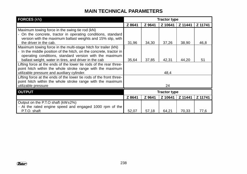
238
MAIN TECHNICAL PARAMETERSFORCES (kN) Tractor type
Z 8641 Z 9641 Z 10641 Z 11441 Z 11741Maximum towing force in the swing tie rod (kN)- On the concrete, tractor in operating conditions, standard
version with the maximum ballast weights and 15% slip, withthe driver in the cab. 31,96 34,30 37,26 38,90 46,8
Maximum towing force in the multi-stage hitch for trailer (kN)- In the middle position of the hitch, on the concrete, tractor in
operating conditions, standard version with the maximumballast weight, water in tires, and driver in the cab 35,64 37,85 42,31 44,20 51
Lifting force at the ends of the lower tie rods of the rear three-point hitch within the whole stroke range with the maximumutilizable pressure and auxiliary cylinder. 48,4Lifting force at the ends of the lower tie rods of the front three-point hitch within the whole stroke range with the maximumutilizable pressure 24OUTPUT Tractor type
Z 8641 Z 9641 Z 10641 Z 11441 Z 11741Output on the P.T.O shaft (kW±2%)- At the rated engine speed and engaged 1000 rpm of the
P.T.O. shaft 52,07 57,18 64,21 70,33 77,6
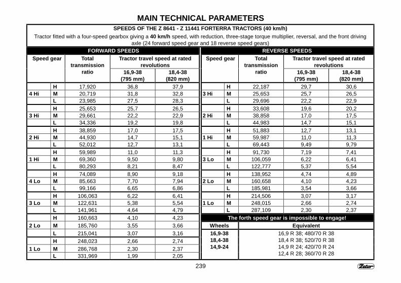
239
MAIN TECHNICAL PARAMETERSSPEEDS OF THE Z 8641 - Z 11441 FORTERRA TRACTORS (40 km/h)
Tractor fitted with a four-speed gearbox giving a 40 km/h speed, with reduction, three-stage torque multiplier, reversal, and the front drivingaxle (24 forward speed gear and 18 reverse speed gears)
FORWARD SPEEDS REVERSE SPEEDSTractor travel speed at rated
revolutionsTractor travel speed at rated
revolutionsSpeed gear Total
transmissionratio 16,9-38
(795 mm)18,4-38
(820 mm)
Speed gear Totaltransmission
ratio 16,9-38(795 mm)
18,4-38(820 mm)
H 17,920 36,8 37,9 H 22,187 29,7 30,64 Hi M 20,719 31,8 32,8 3 Hi M 25,653 25,7 26,5
L 23,985 27,5 28,3 L 29,696 22,2 22,9H 25,653 25,7 26,5 H 33,608 19,6 20,2
3 Hi M 29,661 22,2 22,9 2 Hi M 38,858 17,0 17,5L 34,336 19,2 19,8 L 44,983 14,7 15,1H 38,859 17,0 17,5 H 51,883 12,7 13,1
2 Hi M 44,930 14,7 15,1 1 Hi M 59,987 11,0 11,3L 52,012 12,7 13,1 L 69,443 9,49 9,79H 59,989 11,0 11,3 H 91,730 7,19 7,41
1 Hi M 69,360 9,50 9,80 3 Lo M 106,059 6,22 6,41L 80,293 8,21 8,47 L 122,777 5,37 5,54H 74,089 8,90 9,18 H 138,952 4,74 4,89
4 Lo M 85,663 7,70 7,94 2 Lo M 160,658 4,10 4,23L 99,166 6,65 6,86 L 185,981 3,54 3,66H 106,063 6,22 6,41 H 214,506 3,07 3,17
3 Lo M 122,631 5,38 5,54 1 Lo M 248,015 2,66 2,74L 141,961 4,64 4,79 L 287,109 2,30 2,37H 160,663 4,10 4,23 The forth speed gear is impossible to engage!
2 Lo M 185,760 3,55 3,66 Wheels EquivalentL 215,041 3,07 3,16H 248,023 2,66 2,74
1 Lo M 286,768 2,30 2,37L 331,969 1,99 2,05
16,9-3818,4-3814,9-24
16,9 R 38; 480/70 R 3818,4 R 38; 520/70 R 3814,9 R 24; 420/70 R 2412,4 R 28; 360/70 R 28
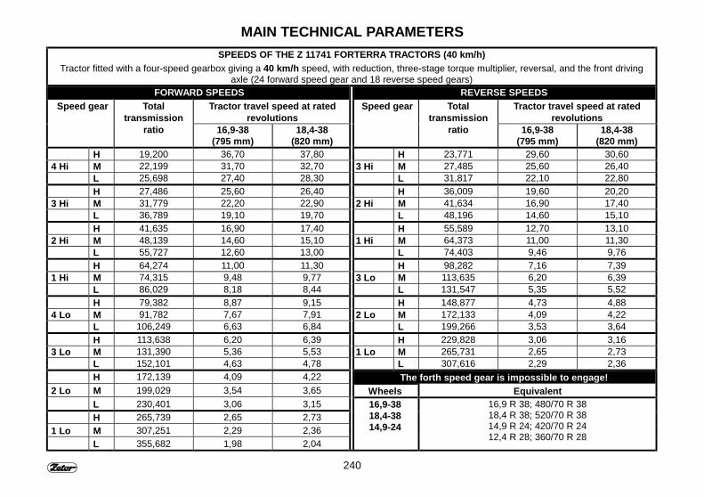
240
MAIN TECHNICAL PARAMETERSSPEEDS OF THE Z 11741 FORTERRA TRACTORS (40 km/h)
Tractor fitted with a four-speed gearbox giving a 40 km/h speed, with reduction, three-stage torque multiplier, reversal, and the front drivingaxle (24 forward speed gear and 18 reverse speed gears)
FORWARD SPEEDS REVERSE SPEEDSTractor travel speed at rated
revolutionsTractor travel speed at rated
revolutionsSpeed gear Total
transmissionratio 16,9-38
(795 mm)18,4-38
(820 mm)
Speed gear Totaltransmission
ratio 16,9-38(795 mm)
18,4-38(820 mm)
H 19,200 36,70 37,80 H 23,771 29,60 30,604 Hi M 22,199 31,70 32,70 3 Hi M 27,485 25,60 26,40
L 25,698 27,40 28,30 L 31,817 22,10 22,80H 27,486 25,60 26,40 H 36,009 19,60 20,20
3 Hi M 31,779 22,20 22,90 2 Hi M 41,634 16,90 17,40L 36,789 19,10 19,70 L 48,196 14,60 15,10H 41,635 16,90 17,40 H 55,589 12,70 13,10
2 Hi M 48,139 14,60 15,10 1 Hi M 64,373 11,00 11,30L 55,727 12,60 13,00 L 74,403 9,46 9,76H 64,274 11,00 11,30 H 98,282 7,16 7,39
1 Hi M 74,315 9,48 9,77 3 Lo M 113,635 6,20 6,39L 86,029 8,18 8,44 L 131,547 5,35 5,52H 79,382 8,87 9,15 H 148,877 4,73 4,88
4 Lo M 91,782 7,67 7,91 2 Lo M 172,133 4,09 4,22L 106,249 6,63 6,84 L 199,266 3,53 3,64H 113,638 6,20 6,39 H 229,828 3,06 3,16
3 Lo M 131,390 5,36 5,53 1 Lo M 265,731 2,65 2,73L 152,101 4,63 4,78 L 307,616 2,29 2,36H 172,139 4,09 4,22 The forth speed gear is impossible to engage!
2 Lo M 199,029 3,54 3,65 Wheels EquivalentL 230,401 3,06 3,15H 265,739 2,65 2,73
1 Lo M 307,251 2,29 2,36L 355,682 1,98 2,04
16,9-3818,4-3814,9-24
16,9 R 38; 480/70 R 3818,4 R 38; 520/70 R 3814,9 R 24; 420/70 R 2412,4 R 28; 360/70 R 28

241
MAIN TECHNICAL PARAMETERSINDEPENDENT REAR P.T.O. SHAFT
Z 8641 - Z 11741 Z 8641 - Z 114 41 Z 11741 Z 11741Ratio Shaft speed / Engine speed Shaft speed / Engine speed Shaft speed / Engine speed Shaft speed / Engine speed3,54 540/1913 621/2200 540/1914 663/23501,95 1000/1950 1128/2200 1000/1950 1205/23502,89 750/2171 760/2200 750/2170 812/2350
INDEPENDENT FRONT P.T.O. SHAFTZ 8641 - Z 11741 Z 8641 - Z 114 41 Z 11741 Z 11741
Ratio Shaft speed / Engine speed Shaft speed / Engine speed Shaft speed / Engine speed Shaft speed / Engine speed1,95 1000/1955 1126/2200 1000/1955 1204/2350
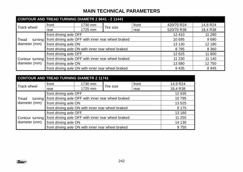
242
MAIN TECHNICAL PARAMETERSCONTOUR AND TREAD TURNING DIAMETR Z 8641 - Z 11441
front 1730 mm front 420/70 R24 14,9 R24Track wheel rear 1725 mm Tire size rear 520/70 R38 18,4 R38front driving axle OFF 12 410 11 280front driving axle OFF with inner rear wheel braked 10 695 9 690front driving axle ON 13 130 12 180
Tread turningdiameter (mm)
front driving axle ON with inner rear wheel braked 8 795 8 360front driving axle OFF 12 625 11 800front driving axle OFF with inner rear wheel braked 11 230 11 140front driving axle ON 13 580 12 750
Contour turningdiameter (mm)
front driving axle ON with inner rear wheel braked 9 435 8 945
CONTOUR AND TREAD TURNING DIAMETR Z 11741front 1730 mm front 14,9 R24Track wheel rear 1725 mm Tire size rear 18,4 R38front driving axle OFF 12 635front driving axle OFF with inner rear wheel braked 10 795front driving axle ON 13 525
Tread turningdiameter (mm)
front driving axle ON with inner rear wheel braked 9 175front driving axle OFF 13 160front driving axle OFF with inner rear wheel braked 11 255front driving axle ON 14 130
Contour turningdiameter (mm)
front driving axle ON with inner rear wheel braked 9 755
243
INDEXA
Additional hydraulic distributor control (outer hydraulic circuit) 46Adjustable front driving axle wheels in the Z 8641 - Z 11741tractors 148Adjusting the seat to the driver's weight 28Adjusting the seat to the driver's weight (Mars seat) 27Admissible load on the hitch for single-axle trailer if theZ 8641 - Z 11741 tractors. 98Admissible vertical static load for the trailer-hitch 97After 10 hours 87After 100 Hours 89After 50 hours 88After 70 hours 89After 70 Hours Z 8641 - Z 11441 88After draining the oil off 177After operation with front implements 18Agregation with the semi-trailer and trailer 96Air cleaner 17Air cleaner maintenance 168Air pressure drop warning signal 77Air tanks 79Alteration of the tire loading capacity Z 11741 % 234Alteration of the tire loading capacity Z 11741 % 236Alteration of the tire loading capacity Z 8641 - Z 11441 % 233Alteration of the tire loading capacity Z 8641 - Z 11441 % 235Alternator 204Alternator maintenance 204Amount of oil taken from the hydraulic circuit outer outlets: 110Analog dashboard 35Angular adjustment 29Applying the scotch blocks to the front wheels 159
Attaching implements 18Attaching machines to three point hitch with CBM hooks 140Average fuel consumption in liters per Zetor tractor operatinghour 49
BBallast weights 155Battery isolator 46Battery, battery switch 201Before starting the engine 65Bleeding the clutch hydraulic circuit 192Bleeding the front propeller shaft brake 193Bleeding the fuel system 167Bleeding the hydrostatic steering hydraulic circuit 173Bleeding the rear brake system 191Blocking the side swings of the lower tie rods 141Bulb location 208
CCab air circulation controller (D) 31Cab control switch 123Cab filtration 17Cab interior fast cooling 32Cab interior fast heating 31Calibrating the digital dashboard travel speed 196Cleaning the heating unit filters 178Cleaning the rough fuel filter 166Condition of steering ability 232Connecting the attached implements 144Connection of machines and implements to hydraulic outercircuit 116Contour and tread turning diametr Z 11741 242Contour and tread turning diametr Z 8641 - Z 11441 242
244
INDEXControl mode selection lever 121Control of double-acting hydraulic cylinder 112Control of single-acting hydraulic cylinder 112Control of the front and rear P.T.O. shafts 102Control panel location - electro-hydraulic systém EHR B 108Control panel location - Hydraulic with mechanical controlsystem 109Control panel on the cab r - h column 46Control switch on fender 123Cooling liquid heater 70Cooling liquid heater-aided engine starting 70Cooling system 15
DDescription of the functions assigned to the various controllevers 114Differences in checking and maintaining the tractor Z 11741 212Digital dashboard 37Dimensions of the front tires 237Dimensions of the rear tires 237Direction lights, dimmed and distance lights and hornchangeover switch (l) 40Disassembly and regeneration of the main cartridge 169Disassembly of the locking insert 169Discharging the condensate from the air storage tank 179Dismantling the front side bonnet side panels 164Dismantling the rear side bonnet panel 164Down-gear shifting 73Downhill drive 76Drain holes and plugs 176Draining off the engine oil 165Drive of agricultural machinery 101Drive of the machines of higher inertia masses (crashers.rotary harrowas, movers, reaping machines and the like) 105
Drive with agricultural machines suspended in the front three-point hitch 144Drive with the front driving axle engaged 80Driving operations 63
EElectrical equipment 200Electrical equipment - basic service information 200Electrical system 199Electro-hydraulic system 125Electro-hydraulic systém - Compensator of swinging 131Electro-hydraulic systém - Description of electro-hydraulicEHR-B light failure 136Electro-hydraulic systém - Description of signalizing theelectro-hydraulic EHR-B failure 135Electro-hydraulic systém - Device switched off 128Electro-hydraulic systém - Electro-hydraulic system externalcontrol pushbuttons 134Electro-hydraulic systém - Eliminating the blocking system 129Electro-hydraulic systém - Fast dipping 129Electro-hydraulic systém - Field operation 133Electro-hydraulic systém - Free position 132Electro-hydraulic systém - Functions of the controls 127Electro-hydraulic systém - Implement transportation 130Electro-hydraulic systém - Lowering speed 132Electro-hydraulic systém - Scheme of the EHR B - BOSCHelectro-hydraulic system operation diagram 126Electro-hydraulic systém - Signalization of EHR - B failure 135Electro-hydraulic systém - Stop position 130Electro-hydraulic systém - Three-point hitch upper positionlimitation 131Electro-hydraulic systém - Use of pushbuttons 134
245
INDEXElectro-hydraulic systém - Use of the rear control 134Electronic engine governor 51Electronic engine governor - Function of electronic governor 54Electronic engine governor - Indicator lamp H/O 54Electronic engine governor - Manoeuvring with tractor andreset of temporary memory 61Electronic engine governor - Memory reset - return to pedalcontrol 57Electronic engine governor - Permanent memory recall - H/Olamp is off 56Electronic engine governor - Permanent memory recall - H/Olamp is on 57Electronic engine governor - PTO speed engagement andsetting the PTO speed for 540 or 1000 RPM 60Electronic engine governor - Push button - MAX 53Electronic engine governor - Push button - MEM 53Electronic engine governor - Push button - MIN 53Electronic engine governor - Reset of permanent memory,setting the operating speed and its temporary memorising 59Electronic engine governor - Reset of temporary memory andrecall of entry and exit speed memory 59Electronic engine governor - Resetting and deleting thetemporary memory 55Electronic engine governor - Setting the constant travel speed 60Electronic engine governor - Setting the entry and exit speed attillage and enter to memory 58Electronic engine governor - Setting the operating speed andenter to temporary memory 58Electronic engine governor - Setting the permanent memory 55Electronic engine governor - Setting the PTO speed 60Electronic engine governor - Setting the temporary memory 54Electronic engine governor - Schema of electronic enginecontrol system 52
Electronic engine governor - Temporary memorising the PTOspeed 61Electronic engine governor - Tillage with operating speedtemporarily memorised 58Electronic engine governor - Tillage with operating speedtemporarily memorised 59Electronic hand throttle control 43Electro-pneumatic control of hydraulic 122Employed operating liquids and charges Z 8641 - Z 11741 225Engine oil level 15Engine run stop controller Z 8641 - Z 11441 43Engine warming-up 71Engine Z 11741 equipt with glow gratigns 68Exchanging the cooling liquid 175
FFailure in the glow grating system of Z 11741 engine 68Fan controller (B) 30Fellow traveler's seat 26Filling oil into the engine 166Filter tightness 171Foot brakes 76Forces (kN) 238Front axle drive switch (f) 39Front ballast weights 157Front cardan brake 77Front driving axle control 80Front driving axle wheel toe-in 149Front hook 92Front P.T.O. - sense of rotation 103Front p.t.o. shaft box 178Front three-point hitch 143Front three-point hitch ballast weights 157
246
INDEXFront three-point hitch control 143Front three-point hitch regulation and hydraulic locking 143Front tire loading capacity Z 11741 234Front tire loading capacity Z 8641 - Z 11441 233Fuel systém tightness 15Fuel tank 49Fuel tank drain plug 49Fuels 224Function of control elements 120Fuse box 205
GGear shifting 72General principles of running in a new tractor in the course ofthe first 100 operating hours 86Grammer - Driver's seat 28Greasing of the hydraulic brake components 220
HHand-operated brake lever and two-wheel trailer hitch controllever 45Hand-operated fuel supply lever Z 8641 - Z 11441 43Heating and air conditioning breathers (A) (radio loudspeakers) 33Heating and air conditioning system proper operation 31Heating and air conditioning system proper operation 32Heating control panel, air conditioning, radio 30Heating valve controller (A) 30Hints for maintenance 163Hitch for single-axle trailers combined with a swing tie rod 94Hitches 137Hood / cab lights changeover switch (b) 40Hydraulic control of supporting hooks 96Hydraulic control panel location 45
Hydraulic inner circuit 120Hydraulic system 107Hydraulic system 108Hydraulic system pump 108Hydraulic with mechanical control systém 119Hydrostatic steering 17Hydrostatic steering failure warning signals 82
CHChangeover switches, switches, and levers 38Changing the rear P.T.O. shaft independent speed 103Changing the track of the rear wheels 152Changing the wheel track 147Checking and exchanging oil in the gearbox 176Checking the engine oil for proper level 165Checking the foot brake for proper setting-up 193Checking the lights in the cab roof for proper setting-up 207Checking the lights in the tractor hood for proper setting-up 206Checking the pneumatic systems for tightness 180Checking the turbo-blower for tightness and bearing play 220
IImmediately after starting the engine 71Immediately after the cab cooling 32In case the engine fails to start 65In the course of the first 10 Hours 86Independent front P.T.O. shaft 241Independent rear P.T.O. shaft 241Indicating the glow plug system failure Z 8641 - Z 11441 66Inflating the tires 181Inner circuit control lever 121Inspecting the tension of aircondition compressor belt 188
247
INDEXInspecting the tension of engine belt 188Inspecting the tension of engine belt Z 11741 188
KKey in the "0" position 41Key in the "I" position 41Key in the "II" position 42
LLeaving the tractor 82Light changeover switch (a) 39Liquid-operated brakes 16Liquids for cooling systems - tractors Z 11741 224Liquids for cooling systems - tractors Z 8641 - Z 11441 224Liquids for the hydraulic brakes - tractors: Z 8641 - Z 11741 223Location of information and warning plates 48Location of the serial numbers Z 11741 8Location of the serial numbersZ 8641, Z 9641, Z 10641, Z 11441 7Longitudinal adjustment 28Longitudinal seat adjustment 27Lower ballast weights 156Lower tie rods fitted with extendable terminals 140Lubricating and filling points of front driving axle 177Lubricating chart tractors Z 8641 - Z 11741 217
MMain gearshift lever and reverse march shift lever 44Main technical parameters 227Maintenance and servicing of tires 181Maintenance of the air conditioning device 179Major overhaul - tractors Z 8641 - Z 11741 220Maximum admissible load - front axle CARRARO 20.19 (kg) 231Maximum admissible load - rear axle (kg) 231
Maximum transferred power Z 11741 104Maximum transferred power Z 8641 - Z 11441 104Maximum weight of the liquid for the various tire sizes 160Medium repairs - tractors Z 8641 - Z 11741 220Mechanical control of supporting hooks 95Multi-stage hitch automatic tail 93Multi-stage hitch for trailers 92Multi-stage hitch mechanical tail 92
OOil Filling, checking and draining opening of front wheelreducer 177Oil for hydrostatic steering - Tractors Z 8641 - Z 11741 223Oils for over-charged engines Z 11741 221Oils for over-charged engines Z 8641 - Z 11441 221Oils for the front driving axles - Z 8641 - Z 117441 223Oils for transmission mechanism - Z 8641 - Z 11741 222Oils for transmission mechanisms - Z 8641 - Z 11741 222Opening the door from inside 23Opening the door from outside 23Operation with the p.t.o. shaft 102Outer circuit control lever - Hydraulic with mechanical controlsystem 111Outer hydraulic circuit 109Outlets of front outer circuit 115Output 238
PP.T.O. shaft dependent and independent revolutions shiftinglever 45P.T.O. shaft guards 104P.T.O. shaft tails 103Pedals and levers 44Plastic lubricant for Z 8641 - Z 11741 tractors 223
248
INDEXPneumatic brake operating pressure 180Position of the discharge mouth 170Preventive daily maintenance 14Procedure of attaching machines to the three-point hitch 139Procedure of draining the liquid off the tire 159Procedure of filling the tires with liquids 158Provision of the room for the front driving axle propeller shaft 80Putting the tractor out of operation 184
QQuick couplers coupling and uncoupling 109
RRear outlets of hydraulic outer circuit 111Rear outlets of hydraulic outer circuit 115Rear p.t.o. shaft - shifting of dependent and independentspeeds 102Rear three-point hitch 138Rear tire loading capacity Z 11741 236Rear tire loading capacity Z 8641 - Z 11441 235Rear wheel ballast weights 156Rear window 24Rear, front axle lock pushbutton (j) 40Rearview mirrors 26Recommended inflation of the front wheel tires 182Recommended inflation of the rear wheel tires 183Replacing the cartridges 170Replacing the filtering cartridge of the hydrostatic steering 171Replacing the front propeller shaft braking segments 195Replacing the fuel filtering cartridge 166Replacing the full-flow engine oil filter 165Replacing the hydrostatic steering hoses 174Replacing the tow hook with a swing tie rod 94
Replenishing the brake liquid 178Response arate control lever 122Reverse gearshift lever 72Road and reduced gear shift lever 44Road and reduced speed gears shifting 72
SSafety cab 23Safety hints for the user 10Safety principles for the 139Selecting the holes in the console 142Selective control valve (SCV) 113Setting operations 187Setting the Bowden cable 195Setting the front driving axle wheel stops 151Setting the rear wheel track 152Setting up the brake pedal dead motion 190Setting up the clutch pedal dead motion 192Setting up the foot brake 194Setting up the injectors Z 11741 190Setting up the lifting tie rods for the single-axle trailer 195Setting up the lights in the tractor hood 206Setting up the valve clearance Z 11741 189Setting up the valve clearance Z 8641 - Z 11441 189Setting-up the injectors Z 8641 - Z 11441 189Setting-up the parking brake 194Short test for proper function 19Scheduled technical maintenance 211Side window 24Single-hose and twin-hose brakes 78Single-hose brakes 78Speeds of the Z 11741 Forterra tractors (40 km/h) 240

249
INDEXSpeeds of the Z 8641 - Z 11441 Forterra tractors (40 km/h) 239Staring the engine fitted with glow gratings 69Starting forbidden 65Starting the engine Z 11741 equipped with electronicthermostart 67Starting the engine Z 8641 - Z 11441 66Starting the tractor move 75Stopping the engine Z 11741 81Stopping the engine Z 8641 - Z 11441 81Storage battery charging and maintenance 203Storage battery maintenance 202Stowing compartment and tool box 26Survey of the tractor 21Swing tie rod 93Swing tie rod of the combined hitch for single-axle trailers 94Switch air conditioning (C) 30Switch box 41
TTechnical maintenance of tractors after the major overhaul ofsome of its assemblies 220three-point hitch manipulation 139Three-section Selective control valve 113Three-stage gear torque multiplier 73Throttle valve adjustment 144Tightening the head of cylinders 188Tilting cover 24Tilting steering wheel 29Tires and wheels 18Tires for driving wheels 184Tires for the driving wheels 184Toe-in of the front driving axle wheels 150Torque multiplier gear shifting 74Torque multiplier operation signaling 74
Tow bar 95Tractor + machine set - Max. admissible load (KG) 232Tractor brake system bleeding 190Tractor inspection and maintenance 213Tractor running-in 85Tractor stopping - parking / hand - operated brake 81Tractor Z 11741 engines - technical data 230Tractor Z 8641 - Z 11441 engines - technical data 228Trailer and semi-trailer pneumatic brakes 77Trailer hydraulic brakes 16Trailer hydraulic brakes 79Trailer pneumatic brakes 16Transport applications 91Travel speed increase / reduction through two speed gears 74Twin-hose brakes 78Two-section Selective control valve 113
UUp-gear shifting 73Uphill drive 76Upper tie rod 142Use of switches 123
VValve for filling the air tube with a liquid 158Vertical adjustment 29Vertical seat adjustment 27
WWarning light switch (e) 39Washer control 25Washer nozzle 25Washer tank 25Windscreen defrosting (B) 33

250
Operator's manualZ 8641 ForterraZ 9641 ForterraZ 10641 ForterraZ 11441 ForterraZ 11741 Forterra
Edition: 2-300-2004Publication No.: 22.22.12.395Zetor a.s.Department of Technical DocumentationTrnkova 111632 00
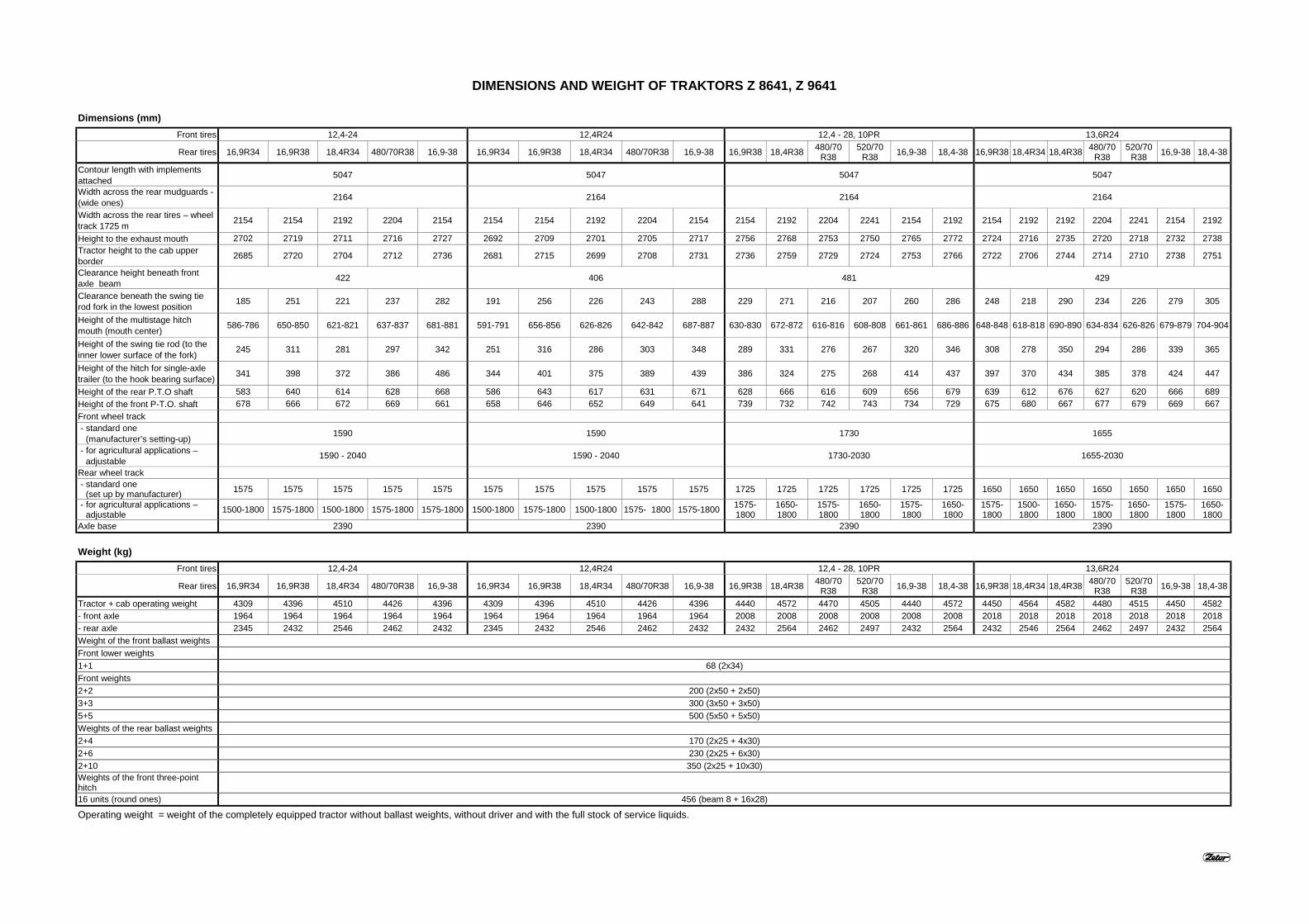
DIMENSIONS AND WEIGHT OF TRAKTORS Z 8641, Z 9641
Dimensions (mm)Front tires 12,4-24 12,4R24 12,4 - 28, 10PR 13,6R24
Rear tires 16,9R34 16,9R38 18,4R34 480/70R38 16,9-38 16,9R34 16,9R38 18,4R34 480/70R38 16,9-38 16,9R38 18,4R38 480/70R38
520/70R38 16,9-38 18,4-38 16,9R38 18,4R34 18,4R38 480/70
R38520/70
R38 16,9-38 18,4-38
Contour length with implementsattached 5047 5047 5047 5047
Width across the rear mudguards -(wide ones) 2164 2164 2164 2164
Width across the rear tires – wheeltrack 1725 m 2154 2154 2192 2204 2154 2154 2154 2192 2204 2154 2154 2192 2204 2241 2154 2192 2154 2192 2192 2204 2241 2154 2192
Height to the exhaust mouth 2702 2719 2711 2716 2727 2692 2709 2701 2705 2717 2756 2768 2753 2750 2765 2772 2724 2716 2735 2720 2718 2732 2738Tractor height to the cab upperborder 2685 2720 2704 2712 2736 2681 2715 2699 2708 2731 2736 2759 2729 2724 2753 2766 2722 2706 2744 2714 2710 2738 2751
Clearance height beneath frontaxle beam 422 406 481 429
Clearance beneath the swing tierod fork in the lowest position 185 251 221 237 282 191 256 226 243 288 229 271 216 207 260 286 248 218 290 234 226 279 305
Height of the multistage hitchmouth (mouth center) 586-786 650-850 621-821 637-837 681-881 591-791 656-856 626-826 642-842 687-887 630-830 672-872 616-816 608-808 661-861 686-886 648-848 618-818 690-890 634-834 626-826 679-879 704-904
Height of the swing tie rod (to theinner lower surface of the fork) 245 311 281 297 342 251 316 286 303 348 289 331 276 267 320 346 308 278 350 294 286 339 365
Height of the hitch for single-axletrailer (to the hook bearing surface) 341 398 372 386 486 344 401 375 389 439 386 324 275 268 414 437 397 370 434 385 378 424 447
Height of the rear P.T.O shaft 583 640 614 628 668 586 643 617 631 671 628 666 616 609 656 679 639 612 676 627 620 666 689Height of the front P-T.O. shaft 678 666 672 669 661 658 646 652 649 641 739 732 742 743 734 729 675 680 667 677 679 669 667Front wheel track - standard one
(manufacturer’s setting-up) 1590 1590 1730 1655
- for agricultural applications –adjustable 1590 - 2040 1590 - 2040 1730-2030 1655-2030
Rear wheel track - standard one
(set up by manufacturer) 1575 1575 1575 1575 1575 1575 1575 1575 1575 1575 1725 1725 1725 1725 1725 1725 1650 1650 1650 1650 1650 1650 1650
- for agricultural applications –adjustable 1500-1800 1575-1800 1500-1800 1575-1800 1575-1800 1500-1800 1575-1800 1500-1800 1575- 1800 1575-1800 1575-
18001650-1800
1575-1800
1650-1800
1575-1800
1650-1800
1575-1800
1500-1800
1650-1800
1575-1800
1650-1800
1575-1800
1650-1800
Axle base 2390 2390 2390 2390
Weight (kg)Front tires 12,4-24 12,4R24 12,4 - 28, 10PR 13,6R24
Rear tires 16,9R34 16,9R38 18,4R34 480/70R38 16,9-38 16,9R34 16,9R38 18,4R34 480/70R38 16,9-38 16,9R38 18,4R38 480/70R38
520/70R38 16,9-38 18,4-38 16,9R38 18,4R34 18,4R38 480/70
R38520/70
R38 16,9-38 18,4-38
Tractor + cab operating weight 4309 4396 4510 4426 4396 4309 4396 4510 4426 4396 4440 4572 4470 4505 4440 4572 4450 4564 4582 4480 4515 4450 4582- front axle 1964 1964 1964 1964 1964 1964 1964 1964 1964 1964 2008 2008 2008 2008 2008 2008 2018 2018 2018 2018 2018 2018 2018- rear axle 2345 2432 2546 2462 2432 2345 2432 2546 2462 2432 2432 2564 2462 2497 2432 2564 2432 2546 2564 2462 2497 2432 2564Weight of the front ballast weightsFront lower weights1+1 68 (2x34)Front weights2+2 200 (2x50 + 2x50)3+3 300 (3x50 + 3x50)5+5 500 (5x50 + 5x50)Weights of the rear ballast weights2+4 170 (2x25 + 4x30)2+6 230 (2x25 + 6x30)2+10 350 (2x25 + 10x30)Weights of the front three-pointhitch16 units (round ones) 456 (beam 8 + 16x28)
Operating weight = weight of the completely equipped tractor without ballast weights, without driver and with the full stock of service liquids.
DIMENSIONS AND WEIGHT OF TRAKTORS Z 8641, Z 9641
Dimensions (mm)Front tires 14,9-24 14,9R24 380/70R24 420/70R24
Rear tires 16,9R38 18,4R38 480/70R38
520/70R38 16,9-38 18,4-38 16,9R38 18,4R38 480/70
R38520/70
R38 16,9-38 18,4-38 16,9R38
18,4R34
18,4R38
480/70R38
520/70R38 16,9-38 18,4-38 16,9R38 18,4R38 480/70
R38520/70
R38 16,9-38 18,4-38
Contour length with implementsattached 5047 5047 5047 5047
Width across the rear mudguards -(wide ones) 2164 2164 2164 2164
Width across the rear tires – wheeltrack 1725 m 2154 2192 2204 2241 2154 2192 2154 2192 2204 2241 2154 2192 2154 2192 2192 2204 2241 2154 2192 2154 2192 2204 2241 2154 2192
Height to the exhaust mouth 2746 2757 2742 2740 2754 2761 2736 2747 2732 2730 2744 2751 2716 2708 2727 2712 2710 2724 2730 2740 2751 2736 2734 2749 2755Tractor height to the cab upperborder 2732 2754 2724 2720 2748 2762 2727 2749 2720 2716 2743 2757 2718 2702 2740 2711 2707 2734 2748 2729 2751 2722 2717 2745 2759
Clearance height beneath frontaxle beam 464 448 417 455
Clearance beneath the swing tierod fork in the lowest position 235 278 222 214 267 293 241 283 227 219 272 298 252 222 295 239 231 284 310 239 281 225 217 270 296
Height of the multistage hitchmouth (mouth center) 636-836 677-877 622-822 614-814 667-867 692-892 671-871 683-883 628-828 620-820 672-872 698-898 652-852 622-822 694-894 639-839 630-830 683-883 708-908 639-839 681-881 625-825 617-817 670-870 695-895
Height of the swing tie rod (to theinner lower surface of the fork) 295 338 282 274 327 353 301 343 287 279 332 358 312 282 355 299 291 344 370 299 341 285 277 330 356
Height of the hitch for single-axletrailer (to the hook bearing surface) 390 427 378 371 417 440 393 430 381 374 421 443 399 373 436 387 380 427 450 392 429 380 372 419 442
Height of the rear P.T.O shaft 632 669 620 613 659 682 635 672 623 616 663 685 641 615 678 629 622 669 692 634 671 622 614 661 684Height of the front P-T.O. shaft 718 711 721 722 713 708 699 691 701 702 693 688 660 665 653 662 664 654 650 707 700 710 711 702 697Front wheel track - standard one
(manufacturer’s setting-up) 1730 1730 1655 1730
- for agricultural applications –adjustable 1730-2030 1730-2030 1655-2030 1730-2030
Rear wheel track - standard one
(set up by manufacturer) 1725 1725 1725 1725 1725 1725 1725 1725 1725 1725 1725 1725 1650 1650 1650 1650 1650 1650 1650 1725 1725 1725 1725 1725 1725
- for agricultural applications –adjustable
1575-1800
1650-1800
1575-1800
1650-1800
1575-1800
1650-1800
1575-1800
1650-1800
1575-1800
1650-1800
1575-1800
1650-1800
1575-1800
1500-1800
1650-1800
1575-1800
1650-1800
1575-1800
1650-1800
1575-1800
1650-1800
1575-1800
1650-1800
1575-1800
1650-1800
Axle base 2390 2390 2390 2390
Weight (kg)Front tires 14,9-24 14,9R24 380/70R24 420/70R24
Rear tires 16,9R38 18,4R38 480/70R38
520/70R38 16,9-38 18,4-38 16,9R38 18,4R38 480/70
R38520/70
R38 16,9-38 18,4-38 16,9R38
18,4R34
18,4R38
480/70R38
520/70R38 16,9-38 18,4-38 16,9R38 18,4R38 480/70
R38520/70
R38 16,9-38 18,4-38
Tractor + cab operating weight 4485 4617 4515 4550 4485 4617 4485 4617 4515 4550 4485 4617 4455 4569 4587 4485 4520 4455 4587 4497 4629 4527 4562 4497 4629- front axle 2053 2053 2053 2053 2053 2053 2053 2053 2053 2053 2053 2053 2023 2023 2023 2023 2023 2023 2023 2065 2065 2065 2065 2065 2065- rear axle 2432 2564 2462 2497 2432 2564 2432 2564 2462 2497 2432 2564 2432 2546 2564 2462 2497 2432 2564 2432 2564 2462 2497 2432 2564Weight of the front ballast weightsFront lower weights1+1 68 (2x34)Front weights2+2 200 (2x50 + 2x50)3+3 300 (3x50 + 3x50)5+5 500 (5x50 + 5x50)Weights of the rear ballast weights2+4 170 (2x25 + 4x30)2+6 230 (2x25 + 6x30)2+10 350 (2x25 + 10x30)Weights of the front three-pointhitch16 units (round ones) 456 (beam 8 + 16x28)
Operating weight = weight of the completely equipped tractor without ballast weights, without driver and with the full stock of service liquids.
DIMENSIONS AND WEIGHT OF TRAKTORS Z 10641, Z 11441
Dimensions (mm)Front tires 12,4 - 28, 10PR 13,6R24 14,9-24 14,9 R 24 380/70R24 420/70R24
Rear tires 16,9R38 18,4R38 480/70R38
520/70R38 16,9R38 18,4R34 18,4R38 480/70
R38520/70
R38 16,9R38 18,4R38 480/70R38
520/70R38 16,9R38 18,4R38 480/70
R38520/70
R3816,9R38 18,4R34 18,4R38 480/70
R38520/70
R3816,9R38 18,4R38 480/70
R38520/70
R38Contour length with implementsattachedWidth across the rear mudguards -(wide ones) 5047 5047 5047 5047 5047 5047
Width across the rear tires – wheeltrack 1725 mm 2164 2164 2164 2164 2164 2164
Clearance beneath the swing tierod fork in the lowest position 481 429 464 448 417 455
Height of the multistage hitchmouth (mouth center) 229 271 216 207 248 218 290 234 26 235 278 222 214 241 283 227 219 252 222 295 239 231 239 281 225 217
Height of the swing tie rod (to theinner lower surface of the fork) 630-830 672-872 616-816 608-808 648-848 618-818 690-890 634-834 626-826 636-836 677-877 622-822 614-814 671-871 683-883 628-828 620-820 652-852 622-822 694-894 639-839 630-830 639-839 681-881 625-825 617-817
Height of the hitch for single-axletrailer (to the hook bearing surface) 289 331 276 267 308 278 350 294 286 295 338 282 274 301 343 287 279 312 282 355 299 291 299 341 285 277
Height of the rear P.T.O shaft 386 324 275 268 397 370 434 385 378 390 427 378 371 396 432 383 376 399 373 436 387 380 392 429 380 372Height of the front P-T.O. shaft 628 666 616 609 639 612 676 627 620 632 669 620 613 635 672 623 616 641 615 678 629 622 634 671 622 614Front wheel track 739 732 742 743 675 680 667 677 679 718 711 721 722 699 691 701 702 660 665 653 662 664 707 700 710 711 - standard one
(manufacturer’s setting-up) 1730 1655 1730 1730 1655 1730
- for agricultural applications –adjustable 1730-2030 1655-2030 1730-2030 1730-2030 1655-2030 1730-2030
Rear wheel track - standard one
(set up by manufacturer) 1725 1725 1725 1725 1650 1650 1650 1650 1650 1725 1725 1725 1725 1725 1725 1725 1725 1650 1650 1650 1650 1650 1725 1725 1725 1725
- for agricultural applications –adjustable
1575-1800
1650-1800
1575-1800
1650-1800
1500-1800
1575-1800
1650-1800
1575-1800
1650-1800
1575-1800
1650-1800
1575-1800
1650-1800
1575-1800
1650-1800
1575-1800
1650-1800
1575-1800
1500-1800
1650-1800
1575-1800
1650-1800
1575-1800
1650-1800
1575-1800
1650-1800
Axle base 2390 2390 2390 2390 2390 2390
Weight (kg)Front tires 12,4 - 28, 10PR 13,6R24 14,9-24 14,9 R 24 380/70R24 420/70R24
Rear tires 16,9R38 18,4R38 480/70R38
520/70R38 16,9R38 18,4R34 18,4R38 480/70
R38520/70
R38 16,9R38 18,4R38 480/70R38
520/70R38 16,9R38 18,4R38 480/70
R38520/70
R38 16,9R38 18,4R34 18,4R38 480/70R38
520/70R38 16,9R38 18,4R38 480/70
R38520/70
R38Tractor + cab operating weight 4440 4572 4470 4505 4450 4564 4582 4480 4515 4485 4617 4515 4550 4485 4696 4515 4550 4455 4569 4587 4485 4520 4497 4629 4527 4562- front axle 2008 2008 2008 2008 2018 2018 2018 2018 2018 2053 2053 2053 2053 2053 2102 2053 2053 2023 2023 2023 2023 2023 2065 2065 2065 2065- rear axle 2432 2564 2462 2497 2432 2546 2564 2462 2497 2432 2564 2462 2497 2432 2594 2462 2497 2432 2546 2564 2462 2497 2432 2564 2462 2497Weight of the front ballast weightsFront lower weights1+1 68 (2x34)Front weights2+2 200 (2x50 + 2x50)3+3 300 (3x50 + 3x50)5+5 500 (5x50 + 5x50)Weights of the rear ballast weights2+6 230 (2x25 + 6x30)2+10 350 (2x25 + 10x30)Weights of the front three-pointhitch16 units (round ones) 456 (beam 8 + 16x28)
Operating weight = weight of the completely equipped tractor without ballast weights, without driver and with the full stock of service liquids.
DIMENSIONS AND WEIGHT OF TRAKTORS Z 11741
Dimensions (mm)Front tires 13,6R24 14,9 R 24 380/70R24 420/70 R24Rear tires 16,9R38 18,4R34 480/70R38 16,9R38 18,4R38 18,4R38 480/70R38 520/70R38 16,9R38 18,4R34 480/70R38 16,9R38 18,4R34 18,4R38 480/70R38 520/70R38
Contour length with implementsattached 5305 5305 5305 5305
Width across the rear mudguards -(wide ones) 2164 2164 2164 2164
Width across the rear tires – wheeltrack 1725 mm 2154 2192 2204 2154 2192 2192 2204 2241 2154 2192 2204 2154 2192 2192 2204 2241
Height to the exhaust mouth 2725 2718 2722 2738 2730 2748 2732 2733 2717 2709 2714 2743 2735 2753 2739 2737Tractor height to the cab upperborder 2724 2710 2718 2731 2716 2751 2725 2721 2720 2705 2714 2729 2719 2754 2727 2723
Clearance height beneath frontaxle beam 429 448 417 455
Clearance beneath the swing tierod fork in the lowest position 249 219 236 243 213 284 230 222 253 223 240 241 210 282 228 220
Height of the multistage hitchmouth (mouth center) 649-849 619-819 636-836 673-873 613-813 684-884 630-830 622-822 653-853 623-823 640-840 641-841 611-811 682-882 628-828 620-820
Height of the swing tie rod (to theinner lower surface of the fork) 309 279 296 303 273 344 290 282 313 283 300 301 270 342 288 280
Height of the hitch for single-axletrailer (to the hook bearing surface) 398 370 386 394 367 431 382 375 400 373 388 393 366 429 381 374
Height of the rear P.T.O shaft 640 612 628 636 609 673 624 617 642 615 630 635 608 671 623 616Height of the front P-T.O. shaft 674 679 676 697 702 690 699 701 659 664 662 706 711 699 708 709Front wheel track - standard one
(manufacturer’s setting-up) 1655 1730 1655 1730
- for agricultural applications –adjustable 1655-2030 1730-2030 1655-2030 1730-2030
Rear wheel track - standard one
(set up by manufacturer) 1650 1650 1650 1725 1725 1725 1725 1725 1650 1650 1650 1725 1725 1725 1725 1725
- for agricultural applications –adjustable 1575-1800 1500-1800 1575-1800 1575-1800 1650-1800 1650-1800 1575-1800 1650-1800 1575-1800 1500-1800 1575-1800 1575-1800 1500-1800 1650-1800 1575-1800 1650-1800
Axle base 2648 2648 2648 2648
Weight (kg)Front tires 13,6R24 14,9 R 24 380/70R24 420/70 R24Rear tires 16,9R38 18,4R34 480/70R38 16,9R38 18,4R38 18,4R38 480/70R38 520/70R38 16,9R38 18,4R34 480/70R38 16,9R38 18,4R34 18,4R38 480/70R38 520/70R38
Tractor + cab operating weight 4528 4643 4559 4563 4678 4696 4594 4624 4533 4648 4564 4575 4690 4708 4606 4636- front axle 2068 2068 2068 2102 2102 2102 2102 2102 2072 2072 2072 2114 2114 2114 2114 2114- rear axle 2461 2576 2492 2461 2576 2594 2492 2522 2461 2576 2492 2461 2576 2594 2492 2522Weight of the front ballast weightsFront lower weights1+1 68 (2x34)Front weights2+2 300 (3x50 + 3x50)3+3 500 (5x50 + 5x50)5+5 700 (7x50 + 7x50)Weights of the rear ballast weights2+6 230 (2x25 + 6x30)2+10 350 (2x25 + 10x30)Weights of the front three-pointhitch16 units (round ones) 456 (beam 8 + 16x28)
Operating weight = weight of the completely equipped tractor without ballast weights, without driver and with the full stock of service liquids.
494949a49aC3C3C2C2
CC3131
CC C2C2 C3C3
66
55
22
33
P5P5
1010 22
33
66
P1P1
PP00LL
PP
F8F8
F7F7 55
66
11
7722
88
99
P2P2
56bL56bL 56bP56bP
55
11
5511
P4P4 P3P3
99
1010
99
1010
F4F41010 56aL56aL 56aP56aP
56bL56bL 56bP56bP
58P58P
58L58L
5252
5454
LL
PP
3131
F6F6
F5F5
SPZSPZ
GG
D+D+ B+B+WW
MM
3030
8787
5050
1122
00
IGNIGN
ACCACC
STSTJSJS
RE1RE1 8585
8686
F9F9
8585
8686RE4RE4
3030
87a87a
F2F2
F3F3
F1F1
PPPP
MM KK
RBRB
F11F11
EHREHR
BOSCHBOSCH
3030
8787
ttMM3131 KK
55
11
99
1010
55
99
1010
77
P6P6 P10P10
V3V3
11
RE2RE2 8585
8686
3030
87a87a
RE3RE3 8585
8686
8787
3030
V4V4
PD DGTPD DGT
V8V8
nn
V2V2 V1V1
T2T2
T1T1
66
44
22
55
33
11
99
11
22
55
66 66
55
22
11
99
P11P11 P12P12
V6V6 V5V5V7V7RE1aRE1a
8686
8585
00
P20P20
MM MM
MM
RE11RE11 8585
8686
F10F10
F12F12
3030
8787 P21P21
MM
R1R1
RE12RE12 8585
8686
3030
8787
T CT C R2R2
RE13RE13 8585
8686
3030
8787
MM
F13F13
F14F14 3030
8787
F15F15
8787
3030
3030
8787
8585RE5RE5
8686
22
11
303033
66
44
1
2
3
4
5 76
98 10
11
12 13
14
15
16
18
17
19
20 21 2322 24 25 2826 27
3029
31
32 33
68
34
35
36
37 38
39
40
41
42
43
44
45
46 47
49
48
50 51
52
53
54
56
55 57
58
59 60
61
62
63
5
64
65
66
67
Wiring harness diagram
for tractors Z 8641 - Z 114 41Forterra
1 - Hazard light interrupter 16 - Tachometer 32 - Battery disconnector 45 - Washer 63 - Hi - Lo electronic control unit 2 - Hazard lights 17 - Key switch 33 - Alternator 46 - Front wiper 64 - Front cab headlights 3 - Combined toggle switch 18 - Starter motor 34 - Dashboard illumination 47 - Air condition compressor 65 - Front grill headlights 4 - Light changeover switch 19 - Electro-hydraulic system 35 - Differential lock valve 48 - Fan switch 66 - High bean pilot lamp 5 - Changeover switch between EHR-Bosch 36 - Pilot lamp of air cleaner 49 - Fan 67 - Fuel level indicator the hood and the cab 20 - Plug socket for assembly lamp clogging 50 - Rear window heating 68 - Front wheel drive valve 6 - Working lights 21 - Lubrication pilot lamp 37 - Sensor of air cleaner clogging 51 - Mirror heating 7 - Fog light 22 - Pressure gauge 38 - Sensor of hydrostatic steering 52 - Engine glowing 8 - Left front headlight 23 - Air pressure pilot lamp system 53 - Pilot lamp of engine glowing 9 - Left rear light 24 - Failure pilot lamp 39 - Pilot lamp of hydrostatic 54 - Glow plugs10 - License number plate 25 - Pilot lamp parking brake steering system 55 - Valve 2. of Hi - Lo illumination 26 - Thermometer 40 - Driving sensor 56 - Hi -Lo pilot lamp11 - Seven pole socket 27 - Fuel gauge 41 - Digital dashboard 57 - Valve 1. of Hi - Lo12 - Right rear light 28 - Fuel level pilot lamp 42 - Valve of the fuel starting 58 - Hi - Lo pilot lamp13 - Right front headlight 29 - Front wheel drive delivery 59 - PTO control (front)14 - Battery 30 - Differential lock 43 - Rear wiper 61 - Hi - Lo push button ( 1 )15 - Pilot lamp of charging 31 - Foot brakes 44 - Front wiper and washer switch 62 - Hi - Lo push button ( 2 )
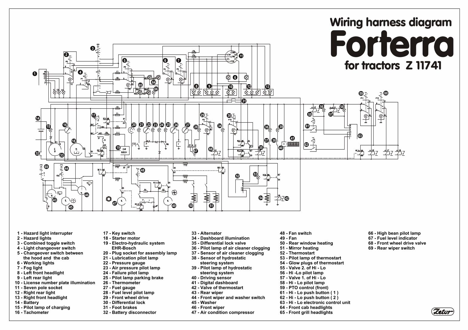
8
6
55
1 - Hazard light interrupter 17 - Key switch 33 - Alternator 48 - Fan switch 66 - High bean pilot lamp 2 - Hazard lights 18 - Starter motor 34 - Dashboard illumination 49 - Fan 67 - Fuel level indicator 3 - Combined toggle switch 19 - Electro-hydraulic system 35 - Differential lock valve 50 - Rear window heating 68 - Front wheel drive valve 4 - Light changeover switch EHR-Bosch 36 - Pilot lamp of air cleaner clogging 51 - Mirror heating 69 - Rear wiper switch 5 - Changeover switch between 20 - Plug socket for assembly lamp 37 - Sensor of air cleaner clogging 52 - Thermostart the hood and the cab 21 - Lubrication pilot lamp 38 - Sensor of hydrostatic 53 - Pilot lamp of thermostart 6 - Working lights 22 - Pressure gauge steering system 54 - Glow plugs of thermostart 7 - Fog light 23 - Air pressure pilot lamp 39 - Pilot lamp of hydrostatic 55 - Valve 2. of Hi - Lo 8 - Left front headlight 24 - Failure pilot lamp steering system 56 - Hi -Lo pilot lamp 9 - Left rear light 25 - Pilot lamp parking brake 40 - Driving sensor 57 - Valve 1. of Hi - Lo10 - License number plate illumination 26 - Thermometer 41 - Digital dashboard 58 - Hi - Lo pilot lamp11 - Seven pole socket 27 - Fuel gauge 42 - Valve of thermostart 59 - PTO control (front)12 - Right rear light 28 - Fuel level pilot lamp 43 - Rear wiper 61 - Hi - Lo push button ( 1 )13 - Right front headlight 29 - Front wheel drive 44 - Front wiper and washer switch 62 - Hi - Lo push button ( 2 )14 - Battery 30 - Differential lock 45 - Washer 63 - Hi - Lo electronic control unit15 - Pilot lamp of charging 31 - Foot brakes 46 - Front wiper 64 - Front cab headlights16 - Tachometer 32 - Battery disconnector 47 - Air condition compressor 65 - Front grill headlights