Embed Size (px)
Citation preview

ZETA REV .Ei29÷84 kW
GeneralWater chiller unit with modulating capacity with hermetic scroll compressors, air heat rejection with axial fans and user-side plate heat exchanger.
ConfigurationsSEi: Compact unitHEi: High efficiency unitLN: Low noise unitOptional hydronic module
Strengths ► DC inverter-controlled brushless compressor ► High seasonal efficiency ► Unit in Eurovent class A ► Multilogic function for multi-unit systems ► Web server integrated as standard for remote control
► Night Shift System function ► Hydraulic modules also integrated with buffer tank
► External free cooling management


1
CONTENTSZETA REV .Ei
Product description 3
DESCRIPTION OF ACCESSORIES 6REFRIGERANT CIRCUIT ACCESSORIES 6FAN ACCESSORIES 7Hydraulic circuit accessories 8Electrical accessories 10Other accessories 12
Technical specifications 14
Electrical specifications 16
Pump data 16
Flow rate ranges 16
Operating limits 17Zeta Rev SEi 17Zeta Rev HEi 17
Noise levels 18
Configurations that are not possible 19
Dimensional diagrams 20Zeta Rev SEi 20Zeta Rev HEi 24

2
3
ZETA REV .EiWater chiller unit with modulating capacity with hermetic scroll compressors, air heat rejection with axial fans and user-side plate heat exchanger.
PRODUCT DESCRIPTIONBODYThe structure of the unit is made of galvanized steel sheet coated with polyester powder RAL 7035/5017 at 180°C, which makes it highly resistant to weather conditions.The structure is a load-bearing frame, with removable pa-nelling lined with sound absorbing expanded polyurethane matting.All screws and bolts are stainless steel.
COMPRESSORSThe compressors are hermetic orbiting spiral scroll com-pressors connected in tandem or trio, fitted with oil level sight glass, oil equalization line and electronic protection.All the compressors are fitted as standard with crankcase heater.
SOURCE-SIDE HEAT EXCHANGERFor the cooling only units, the exchangers are made with microchannel aluminium coils.The microchannel coils are made using specific aluminium alloys for the tubes and for the fins. This allows the effects of galvanic corrosion to be drastically reduced to always ensure protection of the tubes that confine the refrigerant. The entire coil is also subjected to SilFLUX coating proces-ses (or equivalent) or has zinc added to further increase its corrosion resistance.E-coated microchannel coils are available as an option. This option is strongly recommended for applications in coastal or highly industrialized areas.The use of microchannel coils compared to conventional copper/aluminium coils reduces the total weight of the unit by about 10% and gives a reduction in refrigerant charge of at least 30%.To protect the exchangers from corrosion and ensure opti-mal operation of the unit, we advise following the recom-mendations given in the user, installation and maintenan-ce manual for cleaning the coils.For installations within a kilometre of the coast, the use of Cu/Al coils with anti-corrosion treatment is strongly re-commended.The exchanger is protected by a metal mesh.
FANSThe fans are axial fans, directly coupled to a three-pha-se 6-pole electric motor, with integrated thermal overload protection (klixon) and IP 54 protection rating.The fan includes the shroud, designed to optimize its effi-ciency and reduce noise emission to a minimum, and the safety guard.
USER-SIDE HEAT EXCHANGERThe exchanger is a braze-welded stainless steel plate heat exchanger, insulated with a shroud of closed-cell insula-ting material.The exchanger is also equipped with thermostat-con-trolled anti-freeze heater to protect it from ice formation when the unit is not running.
REFRIGERANT CIRCUITUnit provided with a refrigerant circuit that comprises:• valve on the liquid line• charging valves• liquid sight glass• welded dehydrator filter on sizes 3.1 and 6.2• replaceable solid cartridge dehydrator filter on size 8.3• electronic expansion valve• high and low pressure switchesThe pipes of the circuit and the exchanger are insulated with extruded closed-cell expanded elastomer.
ELECTRICAL CONTROL PANELThe electrical control panel is made in a painted galvani-zed sheet-iron box with forced ventilation and IP54 pro-tection rating.The electrical control panel of the basic unit comprises:• main disconnect switch• automatic circuit breakers for compressors with fixed
calibration• fuses for protecting the fans and auxiliary circuits• thermal magnetic circuit breakers for the pumps (if pre-
sent)• contactors for compressors, fans and pumps (if present)• phase-cutting speed adjuster• phase monitor• potential-free general alarm contacts• single potential free operating contacts for compres-
sors, fans and pumps (if present)• microprocessor controller with display accessible from
the outsideAll the electrical cables inside the panel are numbered and the terminal board dedicated to the customer's con-nections is coloured blue so that it can be quickly identi-fied in the panel.The power supply of the unit is 400V/3~+N/50Hz.
4
CONTROLThermoregulation of the unit controls water temperature at the outlet from the user-side heat exchanger. As stan-dard, the unit uses the advanced BlueThink controller that allows the following functions:• management of the inverter-controlled compressor and
its operating range• freeze protection• compressor timings• automatic rotation of compressor starting sequence• management of capacity reduction due to high pressure
limit• display of alarms• recording of log of last 100 alarms. In addition to the
alarm, it shows the date, time and type of operation of the unit when the alarm occurs
• recording of all the variables and parameters of the unit with sampling for 15 seconds. This allows a log to be kept with FIFO logic that covers about 20 days, depen-ding on the size of machine
• digital input for remote ON/OFF• digital input for remote selection of double set point• display of hours of operation of all the compressors• display of starts per hour of the compressors• an RS485 serial port with Modbus protocol• an Ethernet serial port with TCP/IP protocol• an integrated WEB server with display pages and mana-
gement of preloaded pagesThe following can be viewed on the display of the control-ler:• water inlet and outlet temperatures• set temperature and differential set points• description of alarms• operating hour counter and number of start-ups of the
unit and of the compressors• operating hour counter of the pumps (if present)• degree of capacity reduction of the inverter-controlled
compressor• high and low pressure values• condensing and evaporating temperatures)• external air temperature• superheating at compressor suction.For further details on available functions and on displayed information, refer to the specific documentation of the controller.By default, the serial connections present as standard are enabled only for reading from BMS.
CONTROLS AND SAFETY DEVICES• chilled water temperature probe• antifreeze probe at outlet of each user-side heat
exchanger• high pressure switch (with manual reset)• low pressure safety device (with manual reset managed
by the controller)• compressor overtemperature protection• fan overtemperature protection• water differential pressure switch
TESTINGAll the units are factory-tested and supplied complete with oil and refrigerant.
PACKAGINGThe unit is made and shipped on a wooden pallet that al-lows the unit to be handled using a forklift truck. The unit is wrapped in transparent polyethylene stretch film.
VERSIONSZETA REV SEi: compact unitIn this version, the unit combines the high seasonal ef-ficiency of a unit with modulating capacity with a small footprint
ZETA REV HEi: high efficiency unitIn this version, the unit uses oversize coils in order to in-crease efficiency, especially at reduced capacity.
OPTIONS/LN: low noise unitThe unit with this option has a soundproof casing inserted on each compressor.
5
HYDRAULIC MODULESAll units can be fitted with hydraulic module in various configurations:• /1P: hydraulic module with one pump• /2P: hydraulic module with two pumps• /1PS: hydraulic module with one pump and buffer tank• /2PS: hydraulic module with two pumps and buffer tankAll the above-mentioned modules have pumps with stan-dard discharge head.The following are also available:• modules /1PM, /2PM, /1PMS and /2PMS that have pu-
mps with increased available discharge head• modules /1PG, /2PG, /1PGS and /2PGS that have pu-
mps suitable for operating with glycol up to 50%Hydraulic modules with one pump have:• one pump• a gate valve on the delivery side of the pump• an expansion vesselHydraulic modules with two pumps have:• two pumps• a check valve on the delivery side of each pump• a gate valve on the outlet of the delivery manifold• an expansion vesselIn the version with 2 pumps, these are always with one on standby while the other is working. Switching over betwe-en the pumps is automatic and is done by time (to balan-ce the hours of operation of each one) or in the event of failure.Hydraulic modules with tank also have:a gate valve at the inlet of the pump or the suction ma-nifolda tank with drain valve and air valveRefer to the table of configurations that are not possible to check for availability of specific set-ups.
6
DESCRIPTION OF ACCESSORIESREFRIGERANT CIRCUIT ACCESSORIESBK Brine Kit
Application of this accessory is mandatory if the unit has to produce water with temperature lower than +3° (if the unit is provided with double set point or variable set point, the lower set point is considered).The accessory consists of adopting an increased insulation and a suitable sizing and calibration of some com-ponents.This accessory obligatorily requires the condensation control with speed governor or EC fans to be connected.
MAFR Pressure gaugesThe operating pressures of each circuit of the unit can be displayed on the control by accessing the relevant screens. Also, the machine can be fitted with pressure gauges (two for each circuit) installed in a clearly visible position. These allow reading in real time of the working pressures of the refrigerant gas on the low pressure side and on the high pressure side of each refrigerant circuit.
RG Condensation control with fan speed governorThe control manages the speed of the fans through a phase cutting speed governor, in order to optimize the operating conditions and efficiency of the unit.This control also has the effect of reducing the noise level of the unit: in fact, the typical conditions under which the control will be modulating the speed of the fans are those of the night, spring and autumn.For HP units, the control also carries out evaporation control when the unit is working in heat pump mode.For units equipped with EC fans, the same function is carried out using the electronically commutated motor of the fans and is supplied as standard.
RIC Liquid receivers.The adoption of this accessory always guarantees correct feeding of the expansion valve even when the unit is subjected to wide external air temperature ranges.This accessory is standard on DC and HP units.
RPP Refrigerant leak detector with automatic pump downWith this accessory, a refrigerant leak detector is placed inside each compressor compartment. Detection of a refrigerant leak is managed by the control through a specific alarm and display of a specific icon on the display of the control. For all the circuits of the unit, the alarm also starts the machine stopping procedure with pump down, confining all the refrigerant in the coils.The accessory includes the capacitive backup battery.The accessory can be applied only to units in LN or SLN set-up.
RPR Refrigerant leak detectorWith this accessory, a refrigerant leak detector is placed inside each compressor compartment. Detection of a refrigerant leak is managed by the control through a specific alarm and display of a specific icon on the display of the control. This alarm does not stop the unit.The accessory can be applied only to units in LN or SLN set-up.
RUB Compressor suction and delivery valvesThe valves situated on the delivery side and on the suction side of the compressors allow the compressor to be isolated from the rest of the refrigerant circuit, so making the maintenance operations quicker and less invasive
VS Liquid line solenoid valveThis accessory prevents refrigerant migration that could damage the compressor on starting.
VTE Electronic expansion valveThe use of this component is particularly advisable on units operating in very variable heat load or operating mode conditions, as in the case of joint management of air conditioning and high temperature water pro-duction. The use of an electronic thermostatic valve allows you to:• maximize heat exchange at the evaporator• minimize response times to changes in load and operating conditions• optimize control of overheating• ensure maximum energy efficiency ensure maximum energy efficiency

7
FAN ACCESSORIESVEC EC fans
With this accessory, EC fans, with electronically commutated brushless motor, are used for the ventilating section. These guarantee very high efficiency levels for all working conditions and allow a 15% saving on the power absorbed by each fan working at full capacity.Also, through a 0-10V analogue signal sent to each fan, the microprocessor carries out condensation/evapo-ration control by continuous adjustment of the air flow rate as the external air temperature changes, with a further reduction in electrical absorption and noise emission.
VEM Oversize EC fansWith this accessory, oversize EC fans, with electronically commutated brushless motor, are used for the ven-tilating section. These guarantee very high efficiency levels for all working conditions. Through a 0-10V ana-logue signal sent to each fan, the microprocessor carries out condensation/evaporation control by continuous adjustment of the air flow rate as the external air temperature changes, with a further reduction in electrical absorption and noise emission.Oversize EC fans make it possible to have an available residual pressure of about 70Pa for standard units and about 100Pa for SLN units.
8
Hydraulic circuit accessoriesIRP Inverter for pump adjustment
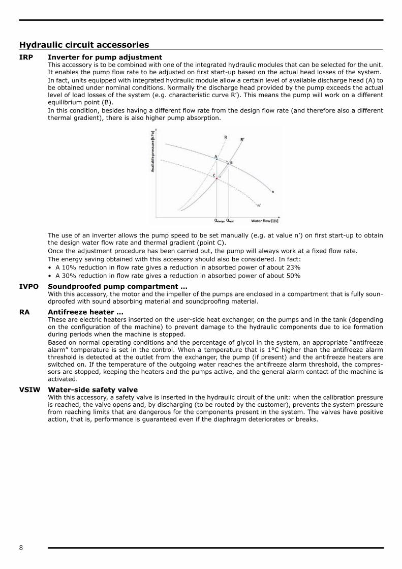
This accessory is to be combined with one of the integrated hydraulic modules that can be selected for the unit. It enables the pump flow rate to be adjusted on first start-up based on the actual head losses of the system.In fact, units equipped with integrated hydraulic module allow a certain level of available discharge head (A) to be obtained under nominal conditions. Normally the discharge head provided by the pump exceeds the actual level of load losses of the system (e.g. characteristic curve R’). This means the pump will work on a different equilibrium point (B).In this condition, besides having a different flow rate from the design flow rate (and therefore also a different thermal gradient), there is also higher pump absorption.
The use of an inverter allows the pump speed to be set manually (e.g. at value n’) on first start-up to obtain the design water flow rate and thermal gradient (point C).Once the adjustment procedure has been carried out, the pump will always work at a fixed flow rate.The energy saving obtained with this accessory should also be considered. In fact:• A 10% reduction in flow rate gives a reduction in absorbed power of about 23%• A 30% reduction in flow rate gives a reduction in absorbed power of about 50%
IVPO Soundproofed pump compartment …With this accessory, the motor and the impeller of the pumps are enclosed in a compartment that is fully soun-dproofed with sound absorbing material and soundproofing material.
RA Antifreeze heater …These are electric heaters inserted on the user-side heat exchanger, on the pumps and in the tank (depending on the configuration of the machine) to prevent damage to the hydraulic components due to ice formation during periods when the machine is stopped.Based on normal operating conditions and the percentage of glycol in the system, an appropriate “antifreeze alarm” temperature is set in the control. When a temperature that is 1°C higher than the antifreeze alarm threshold is detected at the outlet from the exchanger, the pump (if present) and the antifreeze heaters are switched on. If the temperature of the outgoing water reaches the antifreeze alarm threshold, the compres-sors are stopped, keeping the heaters and the pumps active, and the general alarm contact of the machine is activated.
VSIW Water-side safety valveWith this accessory, a safety valve is inserted in the hydraulic circuit of the unit: when the calibration pressure is reached, the valve opens and, by discharging (to be routed by the customer), prevents the system pressure from reaching limits that are dangerous for the components present in the system. The valves have positive action, that is, performance is guaranteed even if the diaphragm deteriorates or breaks.
9
FLUS Flow switch (instead of the water differential pressure switch)As an alternative to the differential pressure switch (standard flow sensor), it is possible to request the paddle flow switch as accessory. This detects when there is no water flow to the user-side exchanger and sends a signal to the control of the unit that will stop the compressors to prevent damage to the exchangers.Application of this accessory is compulsory for units that use non-glycol water and work with a yearly cycle where external air temperatures are zero or below.The flow switch is supplied with the unit (installation by the customer) and replaces the water differential pressure switch (standard).
PFP User-side pump with Pulse functionAs standard, the unit is set to keep the system-side circulation pump on all the time, even when the set point temperature is reached.But when the unit is provided with this accessory, on reaching the set point, the controller will switch off the pump and start it again at regular intervals for a sufficient time to measure the water temperature. If the controller verifies that the water temperature is still in set point condition, it will switch off the pump again. Otherwise the controller will start the compressors again to meet the requirements of the system.This accessory therefore allows electrical absorption due to pumping to be drastically reduced, especially in spring and autumn when the load is extremely low.
CORM Connection for manual fillingThis accessory allows the system filling procedure to be carried out directly from the unit: on the fan holder cover, there is a 1’’ filling valve and a 1/2’’ air valve. Near the filling valve, there is also a pressure gauge for displaying the pressure in the hydraulic circuit. This accessory can be combined only with units provided with tank.
10
Electrical accessoriesCSP Set point compensation depending on external air temperature
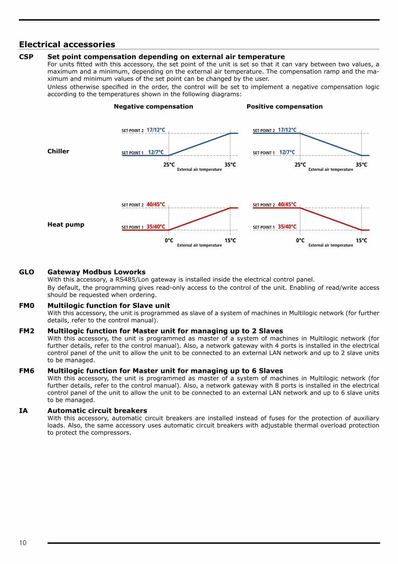
For units fitted with this accessory, the set point of the unit is set so that it can vary between two values, a maximum and a minimum, depending on the external air temperature. The compensation ramp and the ma-ximum and minimum values of the set point can be changed by the user.Unless otherwise specified in the order, the control will be set to implement a negative compensation logic according to the temperatures shown in the following diagrams:
Negative compensation Positive compensation
Chiller
Heat pump
SET POINT 2 17/12°C
SET POINT 1 12/7°C
25°C 35°C
SET POINT 2 17/12°C
SET POINT 1 12/7°C
25°C 35°C
SET POINT 2 40/45°C
SET POINT 1 35/40°C
0°C 15°C
SET POINT 2 40/45°C
SET POINT 1 35/40°C
0°C 15°C External air temperature External air temperature
External air temperature External air temperature
GLO Gateway Modbus LoworksWith this accessory, a RS485/Lon gateway is installed inside the electrical control panel.By default, the programming gives read-only access to the control of the unit. Enabling of read/write access should be requested when ordering.
FM0 Multilogic function for Slave unitWith this accessory, the unit is programmed as slave of a system of machines in Multilogic network (for further details, refer to the control manual).
FM2 Multilogic function for Master unit for managing up to 2 SlavesWith this accessory, the unit is programmed as master of a system of machines in Multilogic network (for further details, refer to the control manual). Also, a network gateway with 4 ports is installed in the electrical control panel of the unit to allow the unit to be connected to an external LAN network and up to 2 slave units to be managed.
FM6 Multilogic function for Master unit for managing up to 6 SlavesWith this accessory, the unit is programmed as master of a system of machines in Multilogic network (for further details, refer to the control manual). Also, a network gateway with 8 ports is installed in the electrical control panel of the unit to allow the unit to be connected to an external LAN network and up to 6 slave units to be managed.
IA Automatic circuit breakersWith this accessory, automatic circuit breakers are installed instead of fuses for the protection of auxiliary loads. Also, the same accessory uses automatic circuit breakers with adjustable thermal overload protection to protect the compressors.
11
NSS Night Shift SystemThis accessory is applied to high efficiency /LN version units with speed governor or to SLN units.In the day time slot, which is normally the one with the highest heat load, priority is given to efficiency and therefore the machine works with a fan control curve that maximises the EER. In this time slot, therefore, the unit is a high efficiency low noise machine (equivalent to HE/LN)In the night time slot, priority goes to keeping down the noise of the machine and therefore the control imple-ments a reduction of the air flow rate using a specific speed governor control curve. So in this time slot, the unit is a super low noise machine (equivalent to SLN).The time slots can be set from the control depending on installation requirements.
PBA BACnet protocol over IP (Ethernet)The control is set for using the BACnet protocol (instead of Modbus) on the Ethernet port.By default, the programming gives read-only access to the control of the unit. Enabling of read/write access should be requested when ordering.
RE1P Relay for management of 1 external pumpThis accessory can be requested for units without pumps and allows a pump outside the machine to be con-trolled.
RE2P Relay for management of 2 external pumpsThis accessory can be requested for units without pumps and allows two pumps outside the machine to be controlled with a running/stand-by logic by implementing a rotation on the hours of operation.
RMMT Maximum and minimum voltage relayThis accessory constantly monitors the voltage value and the unit's power supply phase sequence. If the sup-ply voltage does not fall within the set parameters or there is a phase reversal, an alarm is generated that stops the machine to prevent damage to its main parts
SETD Double set point from digital inputFor units fitted with this accessory, it is possible to preset two different operating set points and manage the change from one to the other through a digital signal.The set point temperatures must be specified when ordering.
SETV Variable set point with remote signalFor units fitted with this accessory, the set point can be varied continuously between two preset values, a maximum and a minimum, depending on an external signal that can be of the 0-1V, 0-10V or 4-20mA type.
SQE Heater for electrical control panelElectric heaters are positioned inside the electrical control panel and these prevent the formation of ice or condensation inside it.
TERM Remote-controlled user terminal panelThis accessory allows the terminal normally situated on the machine to be replicated on a support situated at a distance. It is particularly suitable when the unit is placed in an area that is not easily accessible.The accessory is supplied with the unit and is to be installed by the customer at a maximum distance of 120m from the unit.
12
Other accessoriesAG Rubber anti-vibration mounts
These allow you to reduce the vibrations transmitted from the unit to the surface it is standing on.Accessory supplied with the unit.
ANTC Coil treated with anti-corrosion paintsThe treatment is applied exclusively to finned pack coils with copper tubes and aluminium fins and consists of aluminium passivation and coating with a polyurethane base; a double layer of paint, of which the first passi-vates the aluminium and acts as primer and the second is a polyurethane based surface coating. The product has high resistance to corrosion and all environmental conditions.The choice of whether or not to treat the exchanger should be made in relation to the environment in which the unit is to be installed and through observation of other structures and machinery with exposed metal surfaces present in the destination environment.The cross observation criterion is the most valid method of selection currently available without having to carry out preliminary tests or measurements with instruments. The identified reference environments are:• marine coastal• industrial• urban with a high housing density• ruralPlease note that in cases where different conditions co-exist, even for short periods, the choice must be sui-table for preserving the exchanger in the harsher environmental conditions and not in conditions between the worst and best situation.Particular attention must be given to cases where an environment that is not particularly aggressive becomes aggressive as a consequence of a local and/or temporal concomitant cause such as, for example, due to the presence of a heating flue outlet or an industrial kitchen or a solvent extraction fan in a small craft business.Protective treatment of the exchanger is strongly recommended if at least one of the points below is verified:• there are obvious signs of corrosion of the exposed metal surfaces in the installation area• the distance from the coast is less than 20 km• the prevailing winds come from the sea towards the unit• the environment is industrial with a significant concentration of pollutants• the environment is urban with a high population density• the environment is rural with the presence of organic discharges and effluents.For chiller units, this accessory also includes the “Cu/Al coil” accessory.
FW Water filterTo protect the elements of the hydraulic circuit (in particular, the exchangers), there are Y filters that can stop and settle the particles that are normally present in the water flow and would otherwise settle in the more delicate parts of the hydraulic circuit and damage its heat exchange capacity.Installation of the water filter is mandatory even when it is not supplied as an accessory.Accessory supplied with the unit.
GABB Packaging in wooden crateThe unit is protected by a made-to-measure wooden crate. The accessory is mandatory if shipping by contai-ner is required

13
MCHE E-coated microchannel coilThe e-coated microchannel coils are treated by immersion of the whole exchanger in an emulsion of organic resins, solvents, ionic stabilisers and deionised water. This is all subjected to a suitable electric field that causes the formation of a solid, uniform deposit on the exchanger. The function of this deposit will be to protect the aluminium from corrosion without penalising its thermophysical properties.The choice of whether or not to treat the exchanger should be made in relation to the environment in which the unit is to be installed and through observation of other structures and machinery with exposed metal surfaces present in the destination environment.The cross observation criterion is the most valid method of selection currently available without having to carry out preliminary tests or measurements with instruments. The identified reference environments are:• marine coastal• industrial• urban with a high housing density• ruralPlease note that in cases where different conditions co-exist, even for short periods, the choice must be sui-table for preserving the exchanger in the harsher environmental conditions and not in conditions between the worst and best situation.Particular attention must be given to cases where an environment that is not particularly aggressive becomes aggressive as a consequence of a local and/or temporal concomitant cause such as, for example, due to the presence of a heating flue outlet or an industrial kitchen or a solvent extraction fan in a small craft business.Protective treatment of the exchanger is strongly recommended if at least one of the points below is verified:• there are obvious signs of corrosion of the exposed metal surfaces in the installation area• the prevailing winds come from the sea towards the unit• the environment is industrial with a significant concentration of pollutants• the environment is urban with a high population density• the environment is rural with the presence of organic discharges and effluents.For installations within a kilometre of the coast, the use of Cu/Al coils with anti-corrosion treatment is strongly recommended for cold only units too.This accessory is not available for HP version units.
PREA Partially assembled constructionThe unit is delivered so that it can be disassembled easily on site if this makes the installation operations ea-sier.A unit requested with this option is supplied:• screwed instead of riveted• with plugged and not welded pipes• without refrigerant charge• untested• covered by the warranty only if reassembled and screwed together by personnel authorized by the factory
RAAL Cu/Al coilsThis accessory uses finned pack coils with copper tubes and aluminium fins instead of microchannel coils.
SLIT Special pallet/skid for container shipmentThe unit is placed on a skid that makes the container loading and unloading operations easier.The accessory is mandatory if shipping by container is required

14
TECHNICAL SPECIFICATIONSZETA REV SEi 6.2 8.3Cooling (A35°C; W7°C; 90Hz)Refrigeration capacity (1) kW 58 84Total absorbed power (1) kW 20 28EER (1) 2,93 2,95EER energy class (Eurovent) (1) B BESEER 4,47 4,47CompressorsCompressors/Circuits n°/n° 2/1 3/1Capacity modulation range % 17% / 108% 11% / 106%Refrigerant charge (MCHX) kg 6 8Refrigerant charge (Cu/Al) kg 8 24FansQuantity n° 2 3Total air flow for chiller m³/h 17.000 25.500User-side heat exchangerQuantity n° 1 1Water flow (A35°C; W7°C; 90Hz) (1) m³/h 10,0 14,5Pressure drops (A35°C; W7°C; 90Hz) (1) kPa 29 27Hydraulic modulesVolume of the expansion vessel l 18 18Volume of the buffer tank l 190 380Standard pumpsPump model (STD) P4 P5Available head (1P) kPa 149 170Available head (2P) kPa 134 135Oversize pumpsPump model (OVS) P6 P8Available head (1PM) kPa 233 333Available head (2PM) kPa 218 320Pumps for glycolPump model (GLY) P16 P17Available head (1PG) kPa 174 163Available head (2PG) kPa 163 154Noise levelsSound power level of basic unit (5) dB(A) 85 86Sound pressure level of basic unit (4) dB(A) 54 54Sound power level of LN version (5) dB(A) 83 84Sound pressure level of LN version (4) dB(A) 52 52Dimensions and weights of basic unitLength mm 2.247 3.258Depth mm 1.028 1.135Height mm 1.788 1.788 (1) External air temperature 35°C; user-side heat exchanger inlet-outlet water temperature 12-7°C. Values compliant with standard EN 14511(4) Mean sound pressure level, measured at 10 metres from the unit, in free field on a reflecting surface. Non binding value obtained from the sound power level(5) Sound power levels calculated according to ISO 3744
15
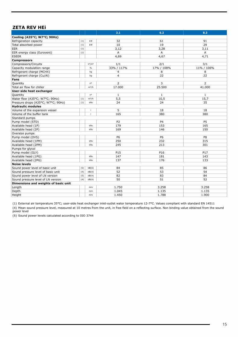
ZETA REV HEi 3.1 6.2 8.3Cooling (A35°C; W7°C; 90Hz)Refrigeration capacity (1) kW 32 61 91Total absorbed power (1) kW 10 19 29EER (1) 3,12 3,28 3,11EER energy class (Eurovent) (1) A A AESEER 4,69 4,67 4,71CompressorsCompressors/Circuits n°/n° 1/1 2/1 3/1Capacity modulation range % 33% / 117% 17% / 108% 11% / 106%Refrigerant charge (MCHX) kg 4 8 8Refrigerant charge (Cu/Al) kg 4 22 22FansQuantity n° 2 3 2Total air flow for chiller m³/h 17.000 25.500 41.000User-side heat exchangerQuantity n° 1 1 1Water flow (A35°C; W7°C; 90Hz) (1) m³/h 5,5 10,5 15,7Pressure drops (A35°C; W7°C; 90Hz) (1) kPa 24 24 35Hydraulic modulesVolume of the expansion vessel l 5 18 18Volume of the buffer tank l 165 380 380Standard pumpsPump model (STD) P2 P4 P5Available head (1P) kPa 179 153 165Available head (2P) kPa 169 146 150Oversize pumpsPump model (OVS) P6 P6 P8Available head (1PM) kPa 250 232 315Available head (2PM) kPa 245 213 301Pumps for glycolPump model (GLY) P15 P16 P17Available head (1PG) kPa 147 181 143Available head (2PG) kPa 137 176 133Noise levelsSound power level of basic unit (5) dB(A) 84 85 86Sound pressure level of basic unit (4) dB(A) 52 53 54Sound power level of LN version (5) dB(A) 82 83 84Sound pressure level of LN version (4) dB(A) 50 51 52Dimensions and weights of basic unitLength mm 1.750 3.258 3.258Depth mm 1.045 1.135 1.135Height mm 1.450 1.788 1.900 (1) External air temperature 35°C; user-side heat exchanger inlet-outlet water temperature 12-7°C. Values compliant with standard EN 14511(4) Mean sound pressure level, measured at 10 metres from the unit, in free field on a reflecting surface. Non binding value obtained from the sound power level(5) Sound power levels calculated according to ISO 3744

16
ELECTRICAL SPECIFICATIONSZETA REV SEi 6.2 8.3General electrical specificationsMax. absorbed power kW 28 40Max. absorbed current A 50 75Max. inrush current A 150 174Power supply 400V / 3ph+N / 50HzPower supply for auxiliary circuits 230V-24V / 1ph / 50HzElectrical specifications for fansRated power of standard fan n° x kW 2 x 0,6 3 x 0,6Rated current of standard fan n° x A 2 x 2,6 3 x 2,6Rated power of EC fan n° x kW 2 x 0,8 3 x 0,8Rated current of EC fan n° x A 2 x 1,4 3 x 1,4Rated power of oversize EC fans n° x kW 2 x 1,0 3 x 1,0Rated current of oversize EC fans n° x A 2 x 1,6 3 x 1,6
ZETA REV HEi 3.1 6.2 8.3General electrical specificationsMax. absorbed power kW 16 28 42Max. absorbed current A 29 53 74Max. inrush current A 7 153 174Power supply 400V / 3ph+N / 50HzPower supply for auxiliary circuits 230V-24V / 1ph / 50HzElectrical specifications for fansRated power of standard fan n° x kW 2 x 0,6 3 x 0,6 2 x 1,8Rated current of standard fan n° x A 2 x 2,6 3 x 2,6 2 x 3,9Rated power of EC fan n° x kW 2 x 0,8 3 x 0,8 2 x 1,9Rated current of EC fan n° x A 2 x 1,4 3 x 1,4 2 x 2,9Rated power of oversize EC fans n° x kW 2 x 1,0 3 x 1,0 2 x 3,0Rated current of oversize EC fans n° x A 2 x 1,6 3 x 1,6 2 x 4,5
PUMP DATAType Rated power Rated current Min. flow rate Max. flow rate
kW A m³/h m³/h
P2 0,9 2,1 3,6 9,6
P4 1,1 2,5 7,0 18,0
P5 1,5 3,2 7,0 18,0
P6 1,9 4,2 7,0 18,0
P8 3,0 6,1 6,0 20,0
P15 1,5 3,2 7,0 18,0
P16 1,9 4,2 7,0 18,0
P17 2,2 4,6 12,0 31,2
FLOW RATE RANGESThe water flow to the heat exchangers must be between Qmin and Qmax
ZETA REV SEi Qmin Qmax
m³/h m³/h
6.2 5,0 14,9
8.3 7,3 21,8
ZETA REV HEi Qmin Qmax
m³/h m³/h
3.1 2,7 8,2
6.2 5,2 15,7
8.3 7,9 23,6
17
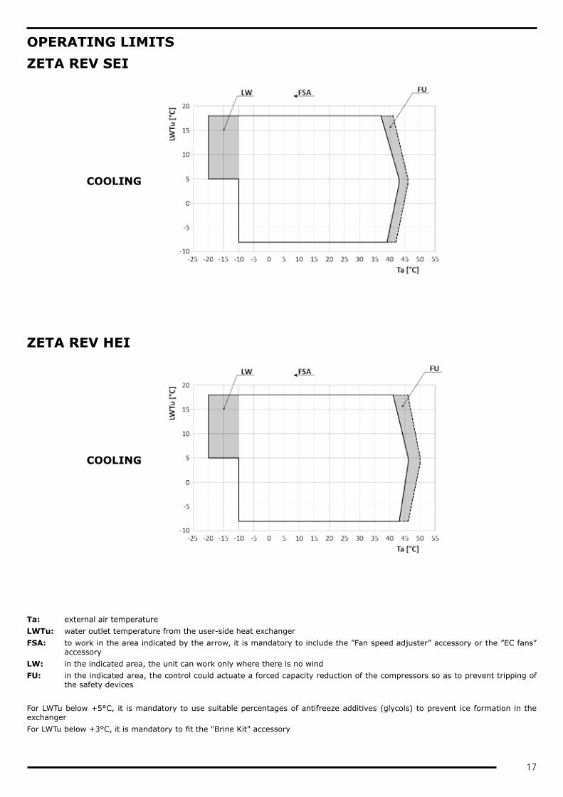
OPERATING LIMITSZETA REV SEI
COOLING
ZETA REV HEI
COOLING
Ta: external air temperatureLWTu: water outlet temperature from the user-side heat exchangerFSA: to work in the area indicated by the arrow, it is mandatory to include the ”Fan speed adjuster” accessory or the ”EC fans”
accessoryLW: in the indicated area, the unit can work only where there is no windFU: in the indicated area, the control could actuate a forced capacity reduction of the compressors so as to prevent tripping of
the safety devices For LWTu below +5°C, it is mandatory to use suitable percentages of antifreeze additives (glycols) to prevent ice formation in the exchangerFor LWTu below +3°C, it is mandatory to fit the "Brine Kit" accessory

18
NOISE LEVELSZETA REV SEi
MODELOctave bands [dB] Total
[dB(A)]63 Hz 125 Hz 250 Hz 500 Hz 1000 Hz 2000 Hz 4000 Hz 8000 HzLw Lp Lw Lp Lw Lp Lw Lp Lw Lp Lw Lp Lw Lp Lw Lp Lw Lp
6.2 82 50 78 47 76 44 78 47 79 48 79 48 77 46 72 40 85 548.3 83 51 80 48 77 45 79 47 80 48 80 48 79 47 73 41 86 54
ZETA REV SEi/LN
MODELOctave bands [dB] Total
[dB(A)]63 Hz 125 Hz 250 Hz 500 Hz 1000 Hz 2000 Hz 4000 Hz 8000 HzLw Lp Lw Lp Lw Lp Lw Lp Lw Lp Lw Lp Lw Lp Lw Lp Lw Lp
6.2 80 48 76 45 74 42 76 45 77 46 77 46 76 44 70 38 83 528.3 81 50 78 47 75 44 77 46 78 47 78 47 77 45 71 40 84 52
ZETA REV HEi
MODELOctave bands [dB] Total
[dB(A)]63 Hz 125 Hz 250 Hz 500 Hz 1000 Hz 2000 Hz 4000 Hz 8000 HzLw Lp Lw Lp Lw Lp Lw Lp Lw Lp Lw Lp Lw Lp Lw Lp Lw Lp
3.1 81 49 77 46 74 43 77 46 78 47 78 47 76 45 71 39 84 536.2 83 51 80 48 76 44 78 46 79 47 79 47 77 45 72 40 85 538.3 87 55 77 45 78 46 80 48 80 48 80 48 78 46 73 41 86 54
ZETA REV HEi /LN
MODELOctave bands [dB] Total
[dB(A)]63 Hz 125 Hz 250 Hz 500 Hz 1000 Hz 2000 Hz 4000 Hz 8000 HzLw Lp Lw Lp Lw Lp Lw Lp Lw Lp Lw Lp Lw Lp Lw Lp Lw Lp
3.1 79 47 75 44 72 41 75 44 76 45 76 45 74 43 69 37 82 506.2 80 49 77 46 74 42 76 45 77 46 77 46 75 44 70 38 83 518.3 85 53 75 43 76 44 78 46 78 47 78 47 76 45 71 39 84 52
Declared data with 35°C air and 12/7°C water inlet/outlet conditionsLw: sound power value based on measurements made in accordance with ISO 3744 and the Eurovent certification programme. This
certification refers specifically to the sound power level in dB(A). This is therefore the only acoustic reading to be considered bin-ding.
Lp: mean sound pressure level, measured at 10 metres from the unit, in free field on a reflecting surface. Non binding value obtained from the sound power level

19
CONFIGURATIONS THAT ARE NOT POSSIBLEZeta Rev SEi
Basi
c
/1Px
/2Px
/1Px
S
/2PS
/2PM
S
/2PG
S
6.2 n.a. n.a. n.a.
8.3 (1) (1)
ZETA REV HEi
Basi
c
/1Px
/2Px
/1Px
S
/2PS
/2PM
S
/2PG
S
3.1
6.2
8.3 (1) (1)
n.a. Configuration not available(1) The unit is built on a larger frame than the standard

20
DIMENSIONAL DIAGRAMS
ZETA REV SEI 6.2 A4G740A
Mf
Rp
VIEW FROM "B"VIEW FROM "A"
Ep
Rp
A BG 1 1/4" M G 2" F G 2" M
Uin
C
* OPTIONAL
*
Uin
Uout
A
UinB
INSTALLFLOW SWITCH *
*
Es
C
1 1/4" M
"A"
"B"
536,5 491
1788
,5
254 2203 36,9
2494
Uin
742,5 1460,5
183
280
466
St
1000 2203 1000
37
2247
188
1600
1003 1500100057
5
FILLING KITBLEED VALVE 1/2''GVALVE 1''G
A
B HYDRAULIC MODULE ST1P-2P
WITHOUT HYDRAULIC MODULE
HYDRAULIC CONNECTIONS
C HYDRAULIC MODULE ST1PS
*
Pu*
Lh
220318,5 18,5
2258

21
ZETA REV SEI 6.2 A4G740A
FOOTPRINT
G1 G2 G2
G4 G3 G3
SCALE1:30
392 712 946 150
2200
3094
030
6088
060
1000
Fh
FOOTPRINT
G1 G1 G2
G4 G4 G3
SCALE1:30
392 712 946 150
2200
3094
030
6088
060
1000
Fh
VERSION 1PS
22
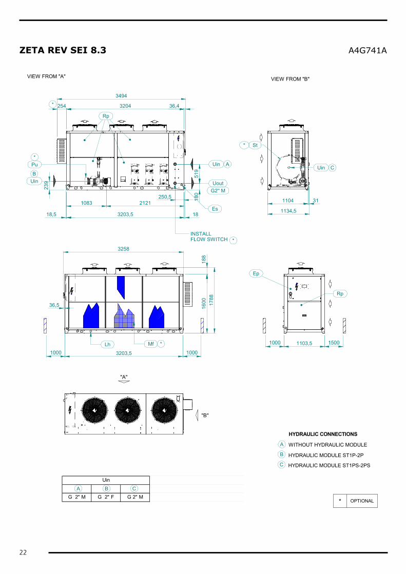
ZETA REV SEI 8.3 A4G741A
"A"
"B"
Mf
Rp
VIEW FROM "B"VIEW FROM "A"
Ep
Rp
St
A BG 2" M G 2" F G 2" M
Uin
C
* OPTIONAL
*
3204254 36,4
3494
1000 1103,5 1500
1000 3203,5 1000Lh
160036,5
1104 31180
519
250,51083 2121
239
Uin
Uout
A
UinB
*
Es
G2'' M
3258
Uin C
INSTALLFLOW SWITCH *
*
Pu*
1134,518
817
88
A
B HYDRAULIC MODULE ST1P-2P
WITHOUT HYDRAULIC MODULE
HYDRAULIC CONNECTIONS
C HYDRAULIC MODULE ST1PS-2PS
18,5 3203,5 18
23
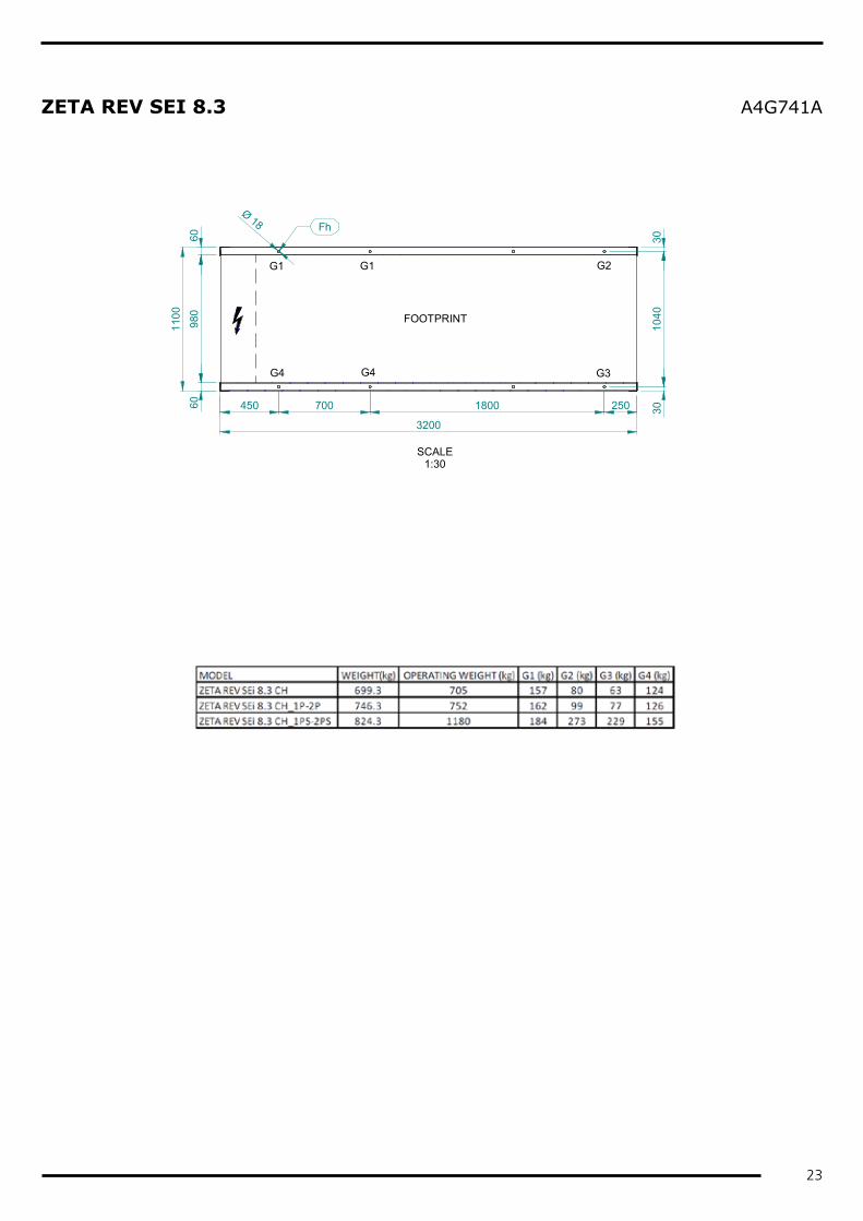
ZETA REV SEI 8.3 A4G741A
FOOTPRINT
450 700 250
3200
G1 G1 G2
G4 G4 G3
6098
060
1100
3010
4030
Fh
SCALE1:30
Ø 18
1800

24
ZETA REV HEI 3.1 A4G742A
"A"
"B"
Rp
VIEW FROM "B"VIEW FROM "A"
Ep
Rp
Cdh
A BG 1 1/4" M G 2" F G 2" M
C
* OPTIONAL
*
UinB
INSTALLFLOW SWITCH
1450
46
77,5753
1750
199
St
Uin
Rp
1002,5 15001000
Mf
Es 45
1000 1750 1000
70
77,5
1260
190
*
FILLING KITBLEED VALVE 1/2''GVALVE 1''G
81
715
436 567
C
466
UinA
Uout
1792
1711
1045
A
B HYDRAULIC MODULE ST1P-2P
WITHOUT HYDRAULIC MODULE
HYDRAULIC CONNECTIONS
C HYDRAULIC MODULE ST1PS-2PS
997
25
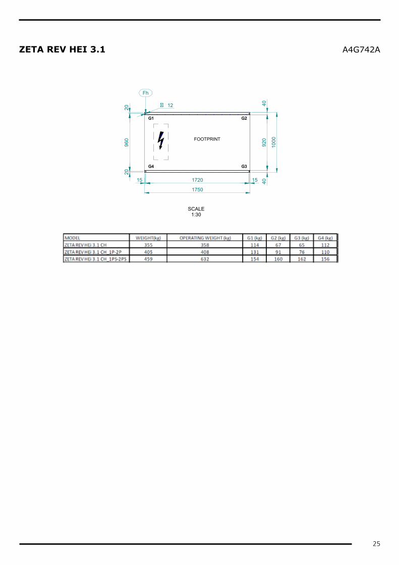
ZETA REV HEI 3.1 A4G742A
SCALE1:30
FOOTPRINT
4092
040
1000
G3G4
G2G1
1750
2096
020
15 1720 15
Fh
� 12
26
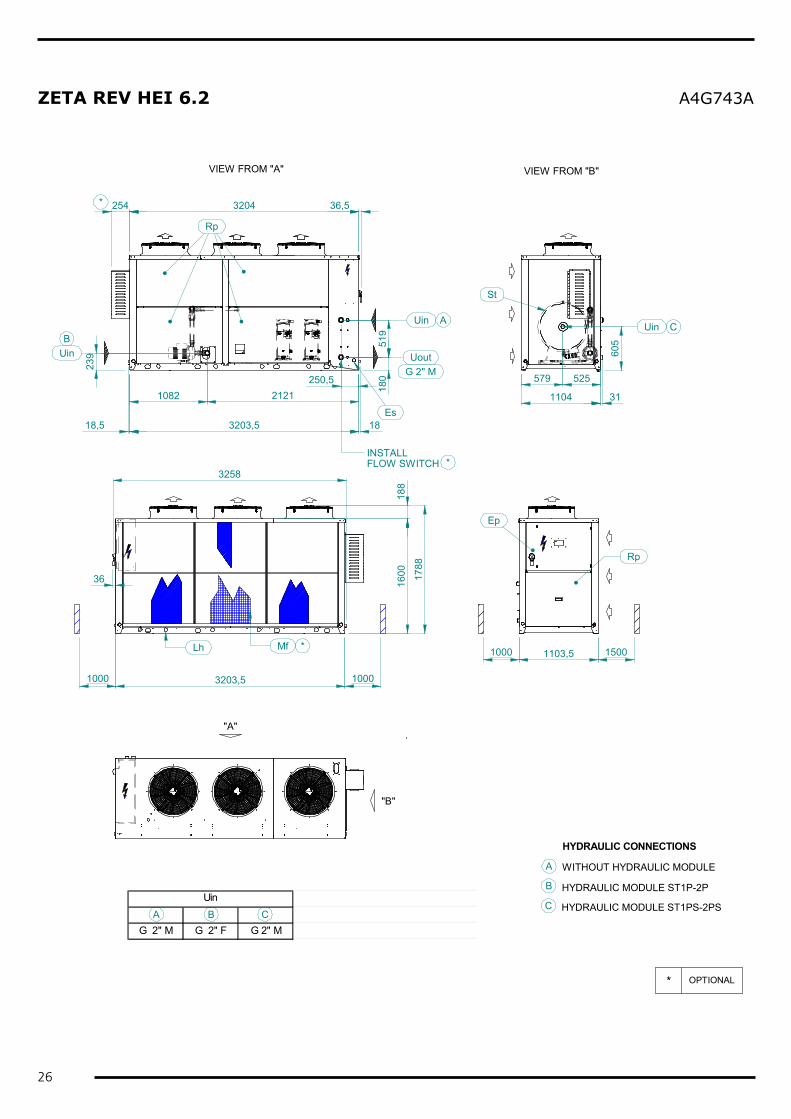
ZETA REV HEI 6.2 A4G743A
"A"
"B"
Mf
Rp
VIEW FROM "B"VIEW FROM "A"
Ep
Rp
A BG 2" M G 2" F G 2" M
UinC
* OPTIONAL
*
3204 36,5
1000 1103,5 1500
1000 3203,5 1000
Lh
160036
1104 3118
051
9250,5
1082 2121
239
Uin
Uout
A
UinB
INSTALLFLOW SWITCH *
St
254*
3258
605
579 525
Uin
Es
C
G 2" M
1788
188
A
B HYDRAULIC MODULE ST1P-2P
WITHOUT HYDRAULIC MODULE
HYDRAULIC CONNECTIONS
C HYDRAULIC MODULE ST1PS-2PS
18,5 3203,5 18
27
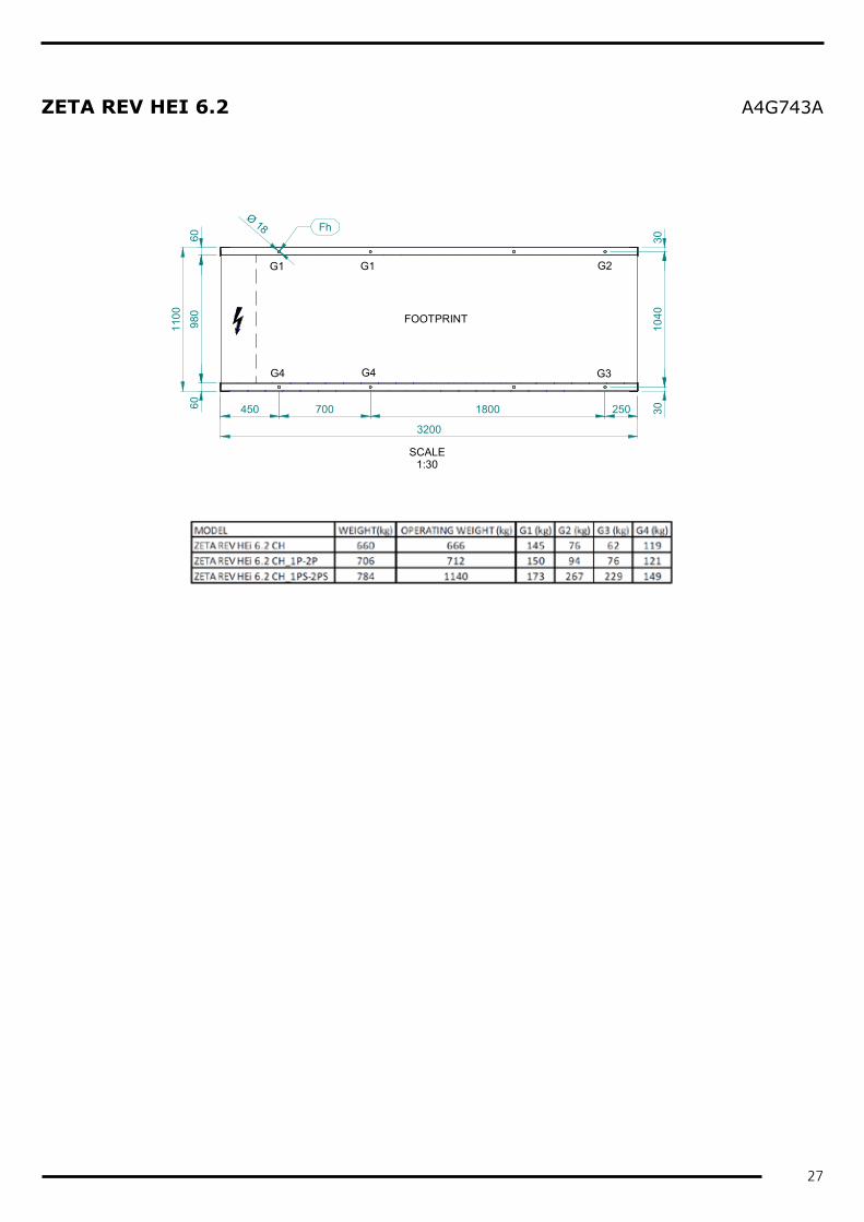
ZETA REV HEI 6.2 A4G743A
FOOTPRINT
450 700 250
3200
G1 G1 G2
G4 G4 G3
6098
060
1100
3010
4030
Fh
SCALE1:30
Ø 18
1800
28
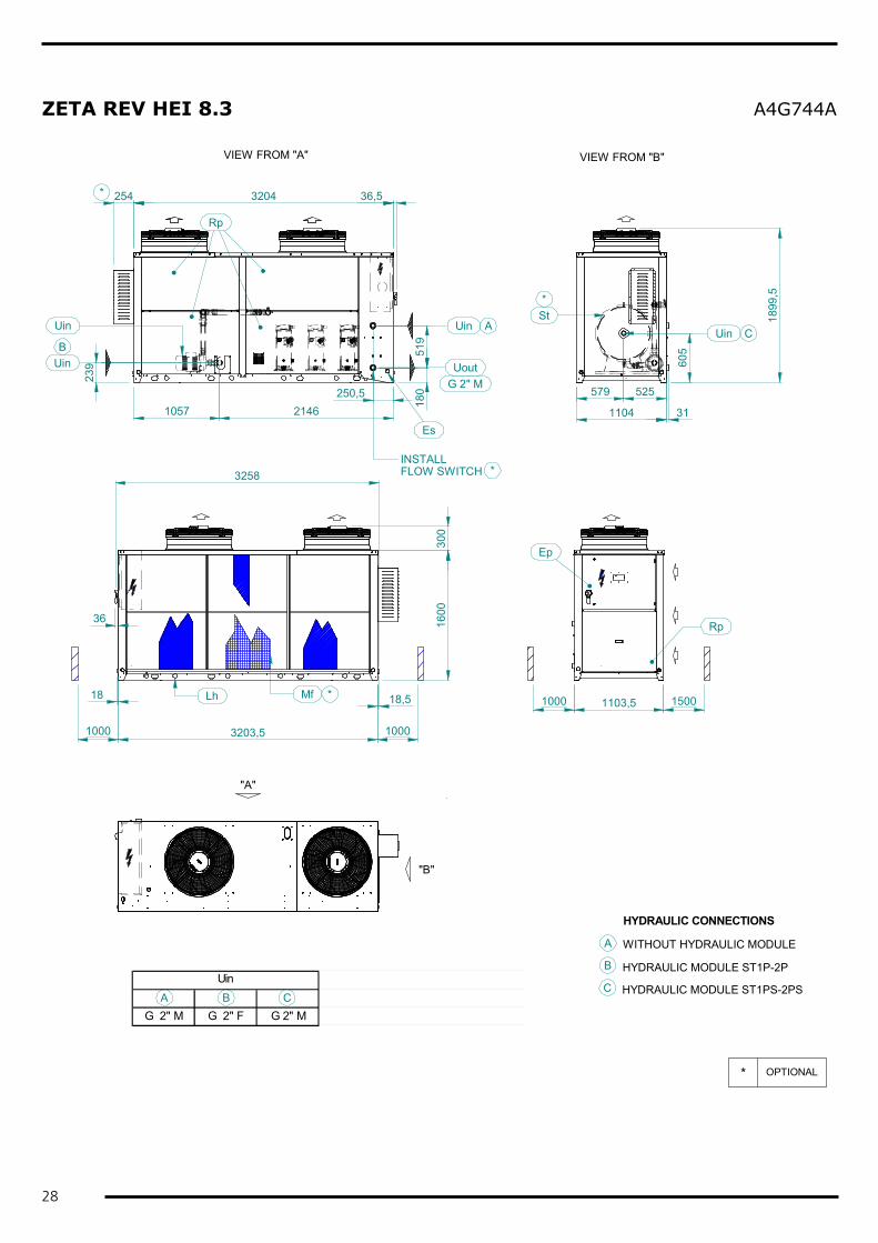
ZETA REV HEI 8.3 A4G744A
"A"
"B"
Mf
Rp
VIEW FROM "B"VIEW FROM "A"
Ep
Rp
A BG 2" M G 2" F G 2" M
UinC
* OPTIONAL
*
3204 36,5
1000 1103,5 1500
1000 3203,5 1000
Lh
160036
1104 3118
051
9
250,51057 2146
239
Uin
Uout
A
UinB
INSTALLFLOW SWITCH *
St
254*
3258
605
579 525
Uin
Es
C
G 2" M
300
1899
,5
A
B HYDRAULIC MODULE ST1P-2P
WITHOUT HYDRAULIC MODULE
HYDRAULIC CONNECTIONS
C HYDRAULIC MODULE ST1PS-2PS
*
Uin
18 18,5

29
ZETA REV HEI 8.3 A4G744A
FOOTPRINT
450 700 250
3200
G1 G1 G2
G4 G4 G3
6098
060
1100
3010
4030
Fh
SCALE1:30
1800
Ø 18

TC_0
000_
Zeta
Rev
.Ei_
EN_R
ev00
_201
6021
2
Blue Box Group S.r.l.Via Valletta, 5 - 30010Cantarana di Cona, (VE) Italy - T. +39 0426 921111 - F. +39 0426 302222www.blueboxcooling.com - [email protected]
Blue Box Group S.r.l. a socio unico - P.IVA 02481290282Company directed and coordinated by Investment Latour (Sweden)