Embed Size (px)
Citation preview
ZENO®-3200 User Manual
Version 1.965November 8, 2001
P/N 0302.116004
COASTAL ENVIRONMENTAL SYSTEMS
820 First Avenue South • Seattle, WA 98134Telephone: (206) 682-6048 or (800) 488-8291 • Fax: (206) 682-5658
Website: http://www.coastalenvironmental.com
ZENO®-3200 TABLE OF CONTENTS
Coastal Environmental Systems (206) 682-6048 Page i
1. INTRODUCTION 1
1.1. What Is The ZENO®-3200? 1
1.2. How Does The ZENO®-3200 Work? 1
1.3. ZENO®-3200 specifications 21.3.1. Analog Inputs 21.3.2. Digital I/O Ports 21.3.3. Sensor And Auxiliary Power Outputs 31.3.4. Serial Communication Ports 31.3.5. ADC Conversion Rates 3
2. ZENO®-3200 BASICS 5
2.1. The ZENO®-3200 Front Panel 5
2.2. Communicating with & powering up the ZENO®-3200 6
2.3. ZENO®-3200 memory 82.3.1. RAM 92.3.2. EEPROM 9
2.4. The User Interface 102.4.1. The User Interface Menu Structure 102.4.2. Online Help 11
2.5. ZENO®-3200 functional block diagram 12
3. TUTORIAL: BASIC ZENO®-3200 OPERATION 13
3.1. Part One—How To Work With An Existing Configuration 133.1.1. Looking At Logged Data 133.1.2. Changing Output Message Format 173.1.3. Understanding & Changing the Sample Interval and Power Usage 20
3.2. Part Two—Learning How To Configure Your Own ZENO®-3200 233.2.1. How Do I Configure The ZENO®-3200 To Perform My Requirements? 233.2.2. Data Flow Within The ZENO®-3200 243.2.3. Learning How To Configure A Sensor 273.2.4. Learning How To Configure A Process 363.2.5. Learning How To Configure A Data Output 433.2.6. Other Configuration Changes 52
4. RETRIEVING LOGGED DATA 53
4.1. Data Retrieval Options 544.1.1. Communications Settings Affect How Data Records Are Viewed 554.1.2. Viewing The Most Recently Logged Data Records 554.1.3. Viewing & Marking The Oldest Data Records 564.1.4. Viewing All Of The Logged Data Records 564.1.5. Searching For Logged Data Records Based Upon Their Timestamps 574.1.6. Downloading Data Records Into A File As A Text Dump 574.1.7. Downloading Data Records Into A File Using The X-Modem Protocol 58
4.2. Data Logging Capacity Information 59
4.3. Deleting Logged Data Records 60
4.4. Data Output Message Format Options 60
ZENO®-3200 TABLE OF CONTENTS
Coastal Environmental Systems (206) 682-6048 Page ii
4.4.1. Retrieved Data Output Message Format 604.4.2. Real Time Data Output Message Format 61
4.5. Bad Sensor Value Replacement 62
4.6. The CCSAIL Communications protocol 634.6.1. The Structure of a CCSAIL Framed Message 634.6.2. The ZENO®-3200's Response to a CCSAIL Message 654.6.3. CCSAIL Data Retrieval Commands 654.6.4. Intercept™ And Data Records Transmitted In CCSAIL Format 66
4.7. Optional Flash Logging Memory 674.7.1. How Flash Logging Memory Differs From RAM 674.7.2. Retrieving Flash Logging Memory Status 68
5. INTERNAL ZENO®-3200 SETTINGS 70
5.1. ZENO®-3200 System Date and Time 71
5.2. Calibrating Internal Temperature Sensor 71
5.3. Getting Current ZenoSoft™ Version Number 72
5.4. Contact Information 72
5.5. ZENO®-3200 Identification Number_The Primary Unit ID 72
5.6. A Destination Identification Number_The Secondary Unit ID 73
5.7. Compass Sensor Usage 74
5.8. Barometer Elevation Setting 74
6. COMMUNICTION INTERFACES 75
6.1. basic Communications settings 76
6.2. Direct Terminal Access 79
6.3. Hardware Handshaking 80
6.4. Telephone Modems 806.4.1. ZENO®-3200 Modem Configuration 816.4.2. MODEM SETTINGS 836.4.3. CABLE PIN-OUTS 87
6.5. cellular modems 886.5.1. AMPS Cellular Modem Configuration (StarComm Cellular Modem) 906.5.2. AMPS Cellular Modem Network Activation 906.5.3. Understanding CDPD Cellular Modems 916.5.4. Sierra Wireless MP200 Sample Configuration 93
6.6. Radio communications 946.6.1. Connecting the Radio To The ZENO®-3200 956.6.2. Power Control Options 956.6.3. Controlling Unidirectional Radio Power (The Power Control Menu) 966.6.4. Controlling Bi-directional Radio Power (The Digital Output Menu) 976.6.5. Push-To-Talk (PTT) 986.6.6. Response Delay Time 996.6.7. Data Packetization 99
6.7. GOES SATELLITE COMMUNICATIONS 1006.7.1. Obtaining GOES Channels 1006.7.2. Data Download 1016.7.3. DAPS Dial-in Procedure 102
ZENO®-3200 TABLE OF CONTENTS
Coastal Environmental Systems (206) 682-6048 Page iii
6.7.4. Directing The Antenna (For North America Only) 1046.7.5. TELONICS TGT-1 GOES TRANSMITTER 1056.7.6. Campbell Scientific SAT HDR GOES Transmitter 1066.7.7. ZENO®-3200 Configuration 1066.7.8. Connecting A GOES Radio And Serial Sensors To The Same COM Port 1086.7.9. GOES Transmitter Diagnostics 1096.7.10. Self-Timed Transmissions 1096.7.11. Random Transmissions 1096.7.12. GOES Binary Format 109
6.8. ArGOS Satellite Communication 1106.8.1. Applying To Use ARGOS 1106.8.2. ARGOS Coverage 1116.8.3. Data Recovery 1116.8.4. Connecting The Telonics ST-13 ARGOS PTT With The ZENO®-3200 1116.8.5. ZENO®-3200 Configuration 1126.8.6. ARGOS Binary Format 113
6.9. Passthrough Modes 1146.9.1. Terminal Passthrough Mode 1146.9.2. SDI-12 Passthrough Mode 115
6.10. Repeater Capability 117
6.11. Speech Interface Capability 1206.11.1. Overview 1216.11.2. Creating A Spoken Output Message 1216.11.3. Defining The Speech/Modem Ports And Control Lines 1236.11.4. Wiring Diagram 125
6.12. Optional Access Control Customization To The User Interface 126
7. MONITORING & CALIBRATING SENSOR DATA 128
7.1. MOnitoring Raw or Scaled Sensor Data 128
7.2. Scaling (Calibrating) Raw Sensor Data 129
7.3. Viewing Process Record Data 130
7.4. Viewing Sensor Error & Status Codes 130
7.5. Viewing Sensor & Process Record Data Collection Counters 131
7.6. Displaying Global Built-In-Test (BIT) Status 133
8. ZENO®-3200 ACCESS PRIVILEGES 135
8.1. Accessing the Zeno Program Menu 135
8.2. Setting access privileges 136
9. UPLOADING AND DOWNLOADING AN ENTIRE CONFIGURATION 138
9.1. Downloading A Configuration To Your Computer 139
9.2. Uploading a Configuration To Your ZENO®-3200 140
9.3. Viewing A Configuration With All Menus 142
9.4. Configuration File Compatibility Between Different ZenoSoft™ Versions 142
10. ZENO®-3200 CONFIGURATION SPECIFICS 144
ZENO®-3200 TABLE OF CONTENTS
Coastal Environmental Systems (206) 682-6048 Page iv
10.1. ZENO®-3200 configuration Tips 144
10.2. Common Sensor, Process And Data Output Menu commands 145
10.3. Defining the sensors 14510.3.1. Analog Sensors 14710.3.2. Digital Sensors 15010.3.3. Serial Sensor Background 15110.3.4. Specifics For Each Supported Serial Sensor Type 15310.3.5. Configuring A Serial Sensor 15610.3.6. User-Specified Sensor Name 16010.3.7. Setting How Often To Read A Sensor--The Sensor Timing Loop 16010.3.8. Setting The Maximum Number Of Readings 16210.3.9. Setting Number Of Measurements To Take--Sensor Sample Count 16210.3.10. Using Switched Voltage To Control Sensor Power 16410.3.11. Specifying Warm-up Time For a Sensor Using Switched Voltage 16510.3.12. Using Excitation Voltage & Returns To Control Sensor Power 16510.3.13. Setting Scaling (Calibration) Coefficients 167
10.4. Defining The Data Processes 16910.4.1. Process Category and Process Number 17010.4.2. User-Defined Process Name 17310.4.3. Selecting the Appropriate Processes 17310.4.4. Unique Data Inputs and User Inputs For Each Process 17410.4.5. Process Error Checking & Reporting 175
10.5. Defining Constants 176
10.6. Defining Data To Be TRANSMITTED and/OR logged 17710.6.1. Data Record Structure 17710.6.2. Output Message Structure 17810.6.3. The Different Types Of Data Output Records 17910.6.4. Setting Which Output Message Uses Which Data Output Record 18210.6.5. The Data Output Record Field Name--A Columnar Heading Or A Literal String 18310.6.6. Setting Up A Data Output Record To Transmit And/Or Log Data 18510.6.7. Creating An Automatic Output Message For CCSAIL Format 18910.6.8. Creating An Automatic Output Message in NMEA 0183 Format 19010.6.9. Conditional Message Fragments 19110.6.10. Selecting Data To Log & Transmit Via Output Message Number 193
10.7. Setting Output message schedules and destinations 19510.7.1. Selecting The Communications Port For Each Output Message 19610.7.2. Specifying The Time Of Transmission For Each Output Message 196
10.8. Reseting (Rebooting) The ZENO®-3200 199
11. ALARM MESSAGES 200
11.1. Configuring An Alarm Condition 201
11.2. Creating An Alarm Message 20311.2.1. Transmitting Your Regular Output Message As An Alarm Message 20411.2.2. Using Conditional Message Fragments In An Alarm Message 20411.2.3. Transmitting A Unique Alarm Message 204
11.3. Configuring The ZENO®-3200 To Transmit (And Possibly Log) An Alarm MEssage 20411.3.1. Selecting The Communications Port To Transmit The Alarm Message 20511.3.2. Dialing-out An Alarm Message Via A Telephone Or Cellular Modem 20611.3.3. Transmitting An Alarm Message Via A GOES Transmitter 20711.3.4. Transmitting An Alarm Message Via An ARGOS Transmitter 208
ZENO®-3200 TABLE OF CONTENTS
Coastal Environmental Systems (206) 682-6048 Page v
12. ADVANCED ZENO®-3200 CONFIGURATION TOPICS 209
12.1. Understanding ZENO®-3200 Timing 20912.1.1. ZENO®-3200 Timing Structure 20912.1.2. The ZENO®-3200 Internal Clock 21012.1.3. The Real Time Operating System 21012.1.4. ZenoSoft and Multitasking 21112.1.5. The User-Defined Configuration And Timing 21112.1.6. Multiple Sensors And Timing 21412.1.7. Calculating The Total Time Required For The ZENO®-3200 To Measure All Sensor Records 21412.1.8. Multiple Sensors Sharing The Same Resource And Timing 21512.1.9. Timing And Effects Upon The User Interface 217
12.2. The Universal Serial Interface 21812.2.1. Three Menus Are Used To Configure The USI 21812.2.2. The Sensor Menu 21812.2.3. The General Serial Script Menu (In Brief) 22012.2.4. The Memory Management Menu 22112.2.5. Changing Script Record Command Lines 22212.2.6. Library Of USI Commands 22412.2.7. Writing & Troubleshooting A USI Script 230
12.3. Configurations With Multiple Serial Sensors 232
12.4. Sharing Data Between Multiple ZENO®-3200's (Multiprocessing) 233
13. ELECTRICAL CONSIDERATIONS 235
13.1. The ZENO®-3200 Enclosure 235
13.2. Grounding 235
13.3. Connecting differential inputs 237
13.4. The ZENO®-3200 CPU Board 238
13.5. Serial Port Wiring 23813.5.1. COM3 RS232 SERIAL PORT 23913.5.2. AUXILIARY SERIAL PORT 24013.5.3. Revision A & Revision D ZENO®-3200 Communication Wiring Setups 242
A. CONSTANTS, CONVERSIONS & ASCII TABLE A-1
B. ZENO®-3200 MENU LISTING B-1
C. SENSOR CONFIGURATIONS C-1
D. ZENO®-3200 PROCESS LIBRARY D-1
E. CONFIGURATION FILE CONTENTS E-1
F. LIBRARY OF CCSAIL COMMANDS F-1
G. WARRANTY G-1
ZENO®-3200 TABLE OF CONTENTS
Coastal Environmental Systems (206) 682-6048 Page vi
H. INDEX H-1
ZENO®-3200 USER MANUAL
Coastal Environmental Systems (206) 682-6048 Page 1
1. INTRODUCTION
Coastal EnvironmentalSystems
ZENO®-3200 User Manual
1.1. WHAT IS THE ZENO®-3200?
The ZENO®-3200 is the world's first intelligent, versatile, low-power, 32-bit data acquisition systemdesigned to collect, process, store and transmit data from multiple sensors. Its mechanical robustnessand low power requirements allow the ZENO®-3200 to operate independently and remotely in a widerange of environmental extremes that include polar ice sheets, ocean buoys and windy mountaintops.
The ZENO®-3200's advanced firmware, ZenoSoft™, contains extensive libraries of sensor types,data processes, and data output options that allow each ZENO®-3200 to be configured to meet avariety of requirements. The built-in, help-assisted menus contained in ZenoSoft™ let you configurethe ZENO®-3200 with ease. The ZenoSoft™ libraries are continually being expanded. ContactCoastal Environmental Systems if your particular application is not discussed in this User Manual.
The related Intercept™ program1 collects, displays, and forwards all data from the ZENO®-3200.Through Intercept™, data can be directly shared with other Microsoft Windows™ applicationprograms. For further information, please refer to Coastal Environmental System's Intercept™documentation.
1.2. HOW DOES THE ZENO®-3200 WORK?
The ZENO®-3200 carries out three primary functions via its built-in firmware, ZenoSoft™, in aregular and timely fashion according to the configuration defined within the ZENO®-3200 memory:
1. Collect data from the sensors.2. Process the collected data.3. Log into RAM and/or transmit the processed and collected data.
ZenoSoft™ operates within a Real Time Operating System (RTOS) that is controlled by the ZENO®-3200's built-in clock. The RTOS allows multiple tasks to be performed concurrently anddeterministically by the ZENO®-3200's single Central Processing Unit (CPU). This ensures that theZENO®-3200 precisely performs its primary functions in accordance with the user's instructionsstored in the configuration.
The ZENO®-3200 configuration is a set of information created by the user that tells the ZENO®-3200:
• How many sensors to collect data from. 1 Intercept™, produced by Coastal Environmental Systems, is a Microsoft Windows™ application.
ZENO®-3200 USER MANUAL
Coastal Environmental Systems (206) 682-6048 Page 2
• What each sensor is.• When to collect the data from each sensor.• How to process the collected data.• Which data values define a single data record to be logged into logging memory.• When to log into memory and/or transmit the data record.• Whether to generate one or more alarm messages.• If an alarm message is to be sent via a telephone modem, which telephone numbers to dial
(up to 4 telephone numbers).• What (if any) types of communication devices are connected to the ZENO®-3200 (a one-
way radio, two-way radio, telephone modem, cellular modem, GOES or ARGOS transmitter).
To define the configuration within the ZENO®-3200 (and to retrieve data logged), the userinteractively communicates with ZenoSoft™ using its built-in User Interface. The User Interfacecontains a set of interactive menus that allow the user to create a new configuration or modify anexisting configuration.
1.3. ZENO®-3200 SPECIFICATIONS
1.3.1. Analog Inputs
Seven (7) differential or fourteen (14) single ended inputs offer a choice of sampling performance.
• Ultra-high resolution: ±18-bit at up to two channels/second with 50/60 Hz noise rejection.
• High resolution: ±15-bit at up to 10 channels/second with 50/60 Hz noise rejection.
• Low resolution: Two (2) channels available at ±12-bit A/D at 10,000 conversions/second.
Accuracy and linearity are provided over a wide temperature range as follows:
• Linearity: ±0.001% (-40°C to +60°C).
• Basic radiometric accuracy: ±0.05% (-40°C to +60°C).
• Wide dynamic input range: ±5 mV to ±5 V in 10 ranges.
All analog inputs are fault-protected against shorts, overvoltages, transients and ESD.
• Up to four multiplexer boards can be added, each allowing 32 additional single-ended or 16differential inputs.
1.3.2. Digital I/O Ports
• 6 Schmidt trigger conditioned inputs.
• 2 comparator inputs.
• 6 general purpose input or output channels (inputs TTL with pull up resistor, outputs 1 - 5 VDChigh impedance).
• 1 switch closure (event counter).
Digital inputs can be configured for frequency, period, count, or event counting. Digital outputs canprovide control or alarm signals.
• Count inputs: Up to 65536 counts at 0.005% accuracy.
• Frequency inputs: Up to 100 kHz at 0.005% accuracy.
ZENO®-3200 USER MANUAL
Coastal Environmental Systems (206) 682-6048 Page 3
1.3.3. Sensor And Auxiliary Power Outputs
• Sensor excitation: Five switched excitation outputs for software selectable voltages of 1.25, 2.50,5.00, with basic accuracy of 0.01% at up to 100 mA. Long-term stability of 20 ppm over 1000hours, with most of the drift occurring within the first 100 hours.
• Reference outputs: One fixed, for sensor signal offsets.
• Power outputs (switched):
• Three channels of +12V; one channel at 700 mA; two channels at 150 mA.
• Two channels of +5V at total 600 mA peak, 200 mA mean.
• Other power output: Optional.
• Optional Digital to Analog expansion board gives 4 or 8 channels of individually programmable12-bit analog output at 0 to 5 V.2
1.3.4. Serial Communication Ports
• Three serial communication ports labeled as COM1, COM2 and COM3.
• Baud rates: each serial communications port supports baud rates of 300, 600, 1200, 2400, 4800,9600 and 19,200 bits per second (bps).
• COM1 supports RS232, RS232H3, and unidirectional and bi-directional radio communications.
• COM2 supports RS232, RS232H, RS485, GOES satellite transmitters4 and ARGOS satellitetransmitters5. COM2 is fully multiplexed.6
• COM3 supports RS232, RS232H, RS485 and RS422.
1.3.5. ADC Conversion Rates
The ZENO®-3200 has two A/D converters: one referred to as 12-bit, and one referred to as 18-bit.The 12-bit ADC is very fast, with up to 10,000 samples per second. The main limitation on youruse of the 12-bit ADC is the fact that only two terminal block connections are available.
A single conversion on the 18-bit ADC requires approximately 100 milliseconds, which equates to 10samples per second. This always outputs a signed 18-bit value, but the least significant 3 bits arehighly susceptible to noise and may not be accurate. Hence, a single sample has 15-bit accuracy. Toobtain full 18-bit accuracy, three values must be averaged by setting the Sensor Sample Count in theSensor Menu to three.7 This brings the sample rate down to no more than three samples per second.
Therefore, the maximum possible sample rate -- including all sensors -- is a total of 16 samples persecond at an effective 15 bits of resolution, or 2 samples per second at a full 18 bits of resolution.
In practice, the best available sample rate is often rather lower than this. If multiple sensors arebeing read, with different excitation voltages or powers, the ZENO®-3200 must wait for the systemto settle before beginning a conversion. Because the ZENO®-3200 is a multi-tasking system8, if agreat deal of processing or message-transmission is required, then the CPU cannot revisit the ADC
2 Other voltage ranges are optional.3 RS232H is half-duplex RS232.4 Refer to Section 6.7.5 Refer to Section 6.8.6 Refer to Section 6.1.7 Refer to Section 10.3.1.8 Refer to Section 12.1.4.
ZENO®-3200 USER MANUAL
Coastal Environmental Systems (206) 682-6048 Page 4
task immediately once each conversion is complete. A typical maximum sample rate is 10 samplesper second at 15 bits.
ZENO®-3200 USER MANUAL
Coastal Environmental Systems (206) 682-6048 Page 5
2. ZENO®-3200 BASICS
Coastal EnvironmentalSystems
ZENO®-3200 User Manual
2.1. THE ZENO®-3200 FRONT PANEL
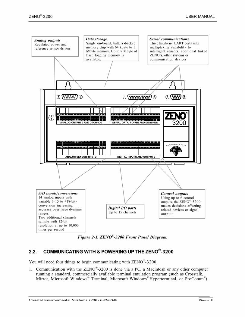
The ZENO®-3200 Front Panel, illustrated in Figure 2-1, allows easy access to nearly all externalconnections to the ZENO®-3200.
Only a _-inch screwdriver9 is required to attach wires to connections along the four terminal strips.The four terminal strips organize the external connections into the following groups:• Analog Outputs and Grounds• Analog Sensor Inputs• Serial Data, Power and Grounds• Digital Inputs and Outputs
The Serial Communications Port that is usually used for computer access, COM3 (a two-row, 9-pin,DE-9 connector), is located on the top, far right hand side of the front panel. COM3 is sometimesreferred to as the Maintenance Port.
The Auxiliary Serial Port (the two-row, 25-pin, DB-25 connector) is located to the left of COM3.Various connections for radio communication (both RS232 and TTL) as well as standard RS232communications are available on this port. (Details about this port are located in a different sectionof the User Manual.)
The Analog Expansion Port, (the two-row, 15-pin, DA-15 connector), located on the top, far left-hand side of the front panel, is currently not in use.
9 This is equivalent to a 3-millimeter screwdriver.
ZENO®-3200 USER MANUAL
Coastal Environmental Systems (206) 682-6048 Page 6
Figure 2-1. ZENO®-3200 Front Panel Diagram.
2.2. COMMUNICATING WITH & POWERING UP THE ZENO®-3200
You will need four things to begin communicating with ZENO®-3200.
1. Communication with the ZENO®-3200 is done via a PC, a Macintosh or any other computerrunning a standard, commercially available terminal emulation program (such as Crosstalk,Mirror, Microsoft Windows® Terminal, Microsoft Windows® Hyperterminal, or ProComm®).
A/D inputs/conversions14 analog inputs withvariable (±15 to ±18-bit)conversion increasingaccuracy over large dynamicranges.Two additional channelssample with 12-bitresolution at up to 10,000times per second
Digital I/O portsUp to 15 channels
Control outputsUsing up to 6 controloutputs, the ZENO®-3200makes decisions affectingrelated devices or signaloutputs
Serial communicationsThree hardware UART ports withmultiplexing capability tointelligent sensors, additional linkedZENO’s, other systems orcommunication devices
Analog outputsRegulated power andreference sensor drivers
Data storageSingle on-board, battery-backedmemory chip with 64 kbyte to 1Mbyte memory. Up to 8 Mbyte offlash logging memory isavailable.
ZENO®-3200 USER MANUAL
Coastal Environmental Systems (206) 682-6048 Page 7
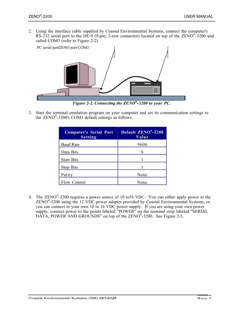
2. Using the interface cable supplied by Coastal Environmental Systems, connect the computer'sRS-232 serial port to the DE-9 (9-pin, 2-row connector) located on top of the ZENO®-3200 andcalled COM3 (refer to Figure 2-2).
PC serial portZENO port COM3
Figure 2-2. Connecting the ZENO®-3200 to your PC.
3. Start the terminal emulation program on your computer and set its communication settings tothe ZENO®-3200's COM3 default settings as follows:
Computer's Serial PortSetting
Default ZENO®-3200Value
Baud Rate 9600
Data Bits 8
Start Bits 1
Stop Bits 1
Parity None
Flow Control None
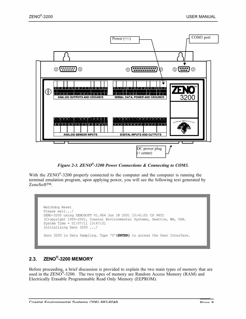
4. The ZENO®-3200 requires a power source of 10 to16 VDC. You can either apply power to theZENO®-3200 using the 12 VDC power adapter provided by Coastal Environmental Systems, oryou can connect to your own 10 to 16 VDC power supply. If you are using your own powersupply, connect power to the points labeled "POWER" on the terminal strip labeled "SERIALDATA, POWER AND GROUNDS" on top of the ZENO®-3200. See Figure 2-3.
ZENO®-3200 USER MANUAL
Coastal Environmental Systems (206) 682-6048 Page 8
Figure 2-3. ZENO®-3200 Power Connections & Connecting to COM3.
With the ZENO®-3200 properly connected to the computer and the computer is running theterminal emulation program, upon applying power, you will see the following text generated byZenoSoft™:
Watchdog ResetPlease wait.../ZENO-3200 using ZENOSOFT V1.964 Jun 28 2001 15:41:01 CS 96CC(C)opyright 1995-2001, Coastal Environmental Systems, Seattle, WA, USA.System Time = 01/07/11 13:47:31Initializing Zeno 3200 .../
Zeno 3200 is Data Sampling. Type 'U'{ENTER} to access the User Interface.
2.3. ZENO®-3200 MEMORY
Before proceeding, a brief discussion is provided to explain the two main types of memory that areused in the ZENO®-3200. The two types of memory are Random Access Memory (RAM) andElectrically Erasable Programmable Read Only Memory (EEPROM).
COM3 portPower (+/-)
DC power plug(+ center)
ZENO®-3200 USER MANUAL
Coastal Environmental Systems (206) 682-6048 Page 9
2.3.1. RAM
Each ZENO®-3200 is shipped with a minimum of 256 kilobytes of static RAM.10 The RAM is theworking memory in the ZENO®-3200. It is used to store the active configuration, the logged datarecords and the internal data that is used by ZenoSoft™ to perform the operations necessary for theactive configuration.
Since the ZENO®-3200 is used in harsh environments, there is the possibility that there will bemomentary losses of power to the ZENO®-3200. Since RAM cannot maintain its stored contentsduring a power loss, the ZENO®-3200 contains a small battery to maintain power to the RAM,allowing it to maintain its contents during the power loss.11
The battery used to backup RAM in the ZENO®-3200 lasts approximately 10 years. Eventually, itwill discharge to a point where it can no longer provide enough power for the RAM to be maintainedduring a momentary power disruption and the data stored in RAM will be lost. It is for this reasonthat the second type of memory, EEPROM, is used in the ZENO®-3200.
2.3.2. EEPROM
Unlike RAM, EEPROM does not require constant power to maintain its contents. Hence, the datastored in EEPROM remains intact regardless of any power loss. The size of the EEPROM is verysmall, though, in comparison to RAM. Your ZENO®-3200 will contain either 2 kilobytes or 8kilobytes of EEPROM.
Because EEPROM is a very safe type of memory storage, EEPROM is used by the ZENO®-3200 tostore the configuration. The ZENO®-3200 stores the configuration in a condensed format in theEEPROM since it is much smaller than RAM.
ZenoSoft™ does not use the configuration stored in EEPROM during its normal operations becausethe condensed configuration stored in EEPROM is not in a useable form.12
One of the first things that ZenoSoft™ does when the ZENO®-3200 is turned on is to read andexpand the condensed configuration stored in EEPROM, then store the expanded (useable)configuration in RAM for use during normal operations.
When you create a new configuration or modify an existing configuration, you are changing theconfiguration stored in RAM, not EEPROM.
Once you are done creating or modifying the configuration, it isrecommended that you save your configuration to EEPROM in the
event that there is a loss of power. Only those configurationchanges that have been stored in EEPROM will be retrieved when
the ZENO®-3200 is turned on. Any configuration changes storedonly in RAM will be lost when the ZENO®-3200 is turned off.
10 Formerly, the minimum amount of installed RAM was 64 kilobytes. Refer to Section 13.4 for the location ofthe RAM location on the main CPU board.11 The battery acts like a miniature UPS, or Uninterrupted Power Supply, to the RAM.12 This is analogous to a file that has been shrunk on a personal computer using a zip program.
ZENO®-3200 USER MANUAL
Coastal Environmental Systems (206) 682-6048 Page 10
2.4. THE USER INTERFACE
Once communications between your computer and the ZENO®-3200 have been established, you canenter the User Interface. The User Interface is a text-based menu system provided entirely withinZenoSoft™ that allows easy logged data retrieval, easy creation of a new ZENO®-3200 configurationor modification of an existing configuration.13
2.4.1. The User Interface Menu Structure
The User Interface is divided into two levels: the lower level menus called the User Menus and theupper level menus called the Zeno Program Menus.
When the user accesses the User Menus, the ZENO®-3200 will continue to perform its primary datacollection functions unhindered. Some changes to the configuration can be made in submenus of theUser Menu, but none that directly impact the definitions of sensors, processes or the contents oflogged data records. For this reason, the factory default setting for User Menu access is unprotected--meaning that no password is required to access any of the lower level menus. The functions that canbe performed via User Menu and its various submenus include:
• Changing communications settings.• Changing system settings such as the clock time.• Changing the data collection schedule.• Retrieving logged data.• Inspect raw sensor data and calibrate sensors.
When the user accesses the Zeno Program Menus, the ZENO®-3200 suspends all primary datacollection functions.
If your ZENO®-3200 arrives factory-configured, you should neverneed to enter the Zeno Program Menu.
The submenus of Zeno Program Menu are designed to directly modify the definitions of sensors,processes and the contents of logged data records. For this reason, the factory default setting forZeno Program Menu access requires a password. The functions that can be performed via the ZenoProgram Menu and its submenus include:
• Changes to sensor definitions, including addition or deletion of sensors.• Changes to process definitions, including addition or deletion of processes.• Changes to logged data record definitions, including addition or deletion of specific data
values to the data record.• Uploading an entire configuration file from a computer, or downloading an entire
configuration to a computer.• Changing User Menu and Zeno Program Menu access passwords.
A complete listing of the User Interface menu structure is provided in Appendix B. An abridgedmenu listing is provided below.
User Menu Communications Menu Modem Menu 13 You do not need to install any special software on your computer to use the User Interface. Just use your sameterminal emulation program!
ZENO®-3200 USER MANUAL
Coastal Environmental Systems (206) 682-6048 Page 11
System Functions Menu Power Control Menu
Sample Period Menu GOES Menu
Data Retrieval Menu Digital Control Menu
Test Menu
ZENO Program Menu Sensor Menu
Processing Menu
Data Output Menu
Sensor Timing Loop Menu
Output Message Timing Menu
System Load Menu
Password Menu
2.4.2. Online Help
The full User Interface menu structure contains full access to all parts of the configuration. To aid inunderstanding specific menu options or menu items contained in the User Interface, several context-sensitive on-line help commands are available in all User Interface menus:
H Provides general help information.
Hx Provides information about menu item x, where x is a letter. For example, type HC toobtain information about menu option C.
Hn Provides information about line item n, where n is a number. For example, type H2 toobtain information about Line Item #2. This command is only available within menusinvolving line items; for example, it is available within the Communications Menu, but notwithin the User Menu.
HPn Provides information about PROCESS Record #n, where n is the Process Record number.This command is available in any User Interface menu. Processes defined in the ProcessMenu are numbered. Process Record #1 is the first process in the configuration, ProcessRecord #2 is the second process in the configuration and so on.
HPTn.mProvides information about specific PROCESS TYPE type m, in process category n; where mis a number designating the process category and n is the number designating the process typewithin the category. This command is available within any User Interface menu.
HSn Provides information about SENSOR Record #n, where n is the Sensor Record number. Thiscommand is available in any User Interface menu. Sensors defined in the Sensor Menu arenumbered. Sensor Record #1 is the first sensor in the configuration, Sensor Record #2 is thesecond sensor in the configuration and so on.
HSTn Provides information about specific SENSOR TYPE number n, where n is a numberdesignating the sensor type. This command is available within any User Interface menu.
ZENO®-3200 USER MANUAL
Coastal Environmental Systems (206) 682-6048 Page 12
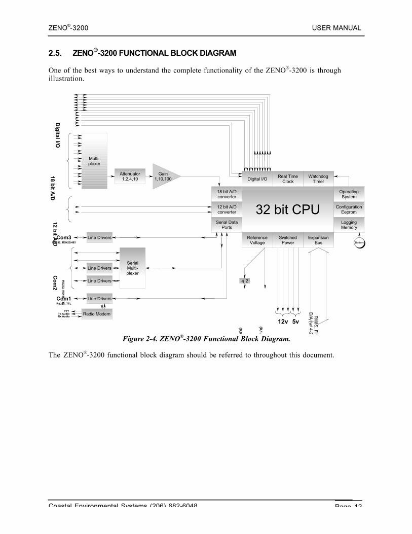
2.5. ZENO®-3200 FUNCTIONAL BLOCK DIAGRAM
One of the best ways to understand the complete functionality of the ZENO®-3200 is throughillustration.
32 bit CPU
WatchdogTimer
Real TimeClock
Digital I/O
LoggingMemory
ConfigurationEeprom
OperatingSystem
Serial DataPorts
ReferenceVoltage
SwitchedPower
ExpansionBus
18 bit A/Dconverter
12 bit A/Dconverter
Attenuator1,2,4,10
Multi-plexer
Line Drivers
Line Drivers
Line Drivers
Line Drivers
Radio Modem
4 2
SerialMulti-plexer
Gain1,10,100
Com1
Co
m2
5v12v
(0,1.25,2.50, or 5.00v)
Tx AudioRx Audio
RS
232, RS
485, TT
LRS232, TTL
Com3RS232, RS422/485
PTT D/A
(w/ 4-20m
A), A
/D exp,
RW
IS, F
lash Logging Mem
ory
Battery
(0,0.625,1.25, or 2.50v)
Dig
ital I/O18 b
it A/D
12 bit A
/D
Figure 2-4. ZENO®-3200 Functional Block Diagram.
The ZENO®-3200 functional block diagram should be referred to throughout this document.
ZENO®-3200 USER MANUAL
Coastal Environmental Systems (206) 682-6048 Page 13
3. TUTORIAL: BASICZENO®-3200 OPERATION
Coastal EnvironmentalSystems
ZENO®-3200 User Manual
This tutorial is divided into two parts. The first part emphasizes on how to work with an existingconfiguration:
1. Viewing logged data from a simple configuration.
2. Changing output message format.
3. Understanding & changing the Sample Interval and power usage.
The second part emphasizes the basics of how to configure the ZENO®-3200:
1. Identify what needs to be done and how the ZENO®-3200 can make it happen.
2. Where to begin configuring.
3. How to setup two sensors that collect data from the internal temperature and input powervoltage sensors.
4. How you might process the collected data.
5. How you might log the collected & processed data in logging memory.
3.1. PART ONE—HOW TO WORK WITH AN EXISTING CONFIGURATION
3.1.1. Looking At Logged Data
Let's assume that you purchased your ZENO®-3200 with a very simple, factory-installedconfiguration that causes the ZENO®-3200 to perform the following:
• There are 2 sensors. One monitors internal temperature, the other monitors input batteryvoltage to the ZENO®-3200. Each of these sensors is read once per second.
• There are 2 processes. One process calculates the average of all the internal temperaturereadings done during the sample duration. The second does a similar average, but with batteryvoltage readings.
• Each data record contains the following information: the time when the data record waslogged, the average internal temperature over the sample duration and the average inputbattery voltage over the sample duration.
ZENO®-3200 USER MANUAL
Coastal Environmental Systems (206) 682-6048 Page 14
• The ZENO®-3200 is set to collect and process data for a duration of 55 seconds (the sampleduration), and the data collection process is to be repeated every 60 seconds (the sampleinterval).
• Further, the ZENO®-3200 is set to automatically output each logged data record at the end ofeach sample duration.
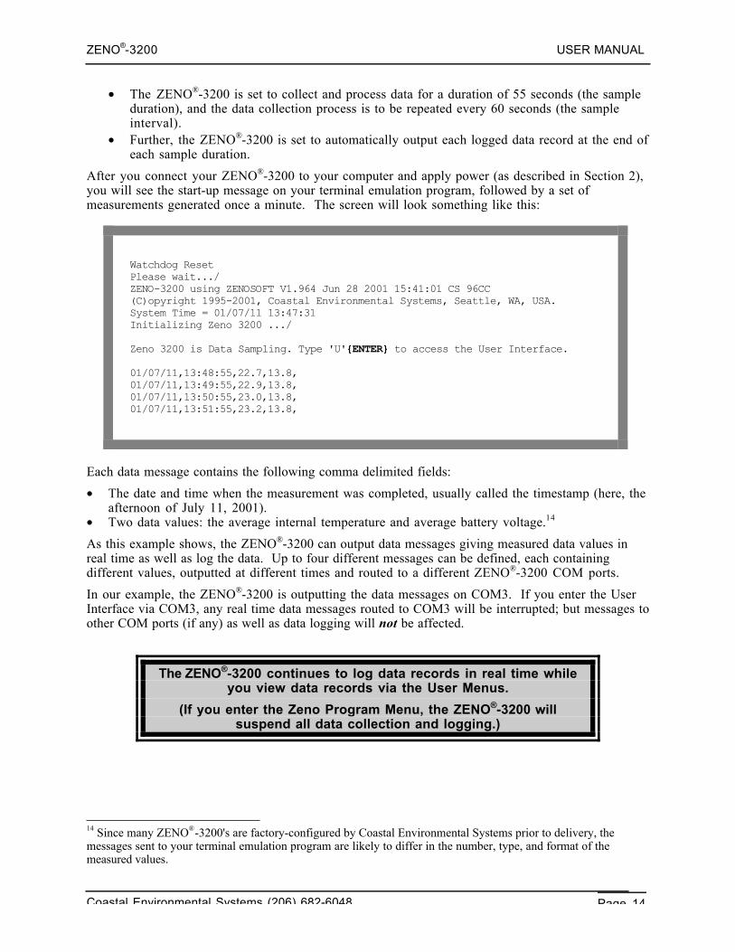
After you connect your ZENO®-3200 to your computer and apply power (as described in Section 2),you will see the start-up message on your terminal emulation program, followed by a set ofmeasurements generated once a minute. The screen will look something like this:
Watchdog ResetPlease wait.../ZENO-3200 using ZENOSOFT V1.964 Jun 28 2001 15:41:01 CS 96CC(C)opyright 1995-2001, Coastal Environmental Systems, Seattle, WA, USA.System Time = 01/07/11 13:47:31Initializing Zeno 3200 .../
Zeno 3200 is Data Sampling. Type 'U'{ENTER} to access the User Interface.
01/07/11,13:48:55,22.7,13.8,01/07/11,13:49:55,22.9,13.8,01/07/11,13:50:55,23.0,13.8,01/07/11,13:51:55,23.2,13.8,
Each data message contains the following comma delimited fields:
• The date and time when the measurement was completed, usually called the timestamp (here, theafternoon of July 11, 2001).
• Two data values: the average internal temperature and average battery voltage.14
As this example shows, the ZENO®-3200 can output data messages giving measured data values inreal time as well as log the data. Up to four different messages can be defined, each containingdifferent values, outputted at different times and routed to a different ZENO®-3200 COM ports.
In our example, the ZENO®-3200 is outputting the data messages on COM3. If you enter the UserInterface via COM3, any real time data messages routed to COM3 will be interrupted; but messages toother COM ports (if any) as well as data logging will not be affected.
The ZENO®-3200 continues to log data records in real time whileyou view data records via the User Menus.
(If you enter the Zeno Program Menu, the ZENO®-3200 willsuspend all data collection and logging.)
14 Since many ZENO®-3200's are factory-configured by Coastal Environmental Systems prior to delivery, themessages sent to your terminal emulation program are likely to differ in the number, type, and format of themeasured values.
ZENO®-3200 USER MANUAL
Coastal Environmental Systems (206) 682-6048 Page 15
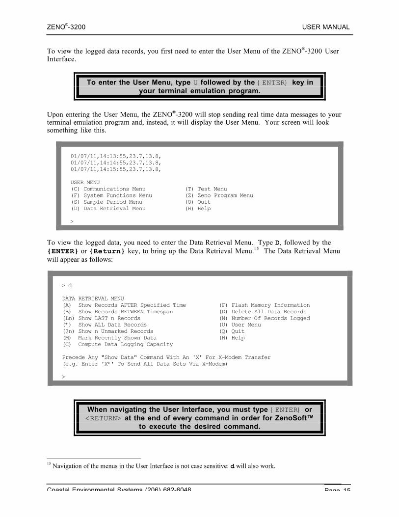
To view the logged data records, you first need to enter the User Menu of the ZENO®-3200 UserInterface.
To enter the User Menu, type U followed by the {ENTER} key inyour terminal emulation program.
Upon entering the User Menu, the ZENO®-3200 will stop sending real time data messages to yourterminal emulation program and, instead, it will display the User Menu. Your screen will looksomething like this.
01/07/11,14:13:55,23.7,13.8,01/07/11,14:14:55,23.7,13.8,01/07/11,14:15:55,23.7,13.8,
USER MENU(C) Communications Menu (T) Test Menu(F) System Functions Menu (Z) Zeno Program Menu(S) Sample Period Menu (Q) Quit(D) Data Retrieval Menu (H) Help
>
To view the logged data, you need to enter the Data Retrieval Menu. Type D, followed by the{ENTER} or {Return} key, to bring up the Data Retrieval Menu.15 The Data Retrieval Menuwill appear as follows:
> d
DATA RETRIEVAL MENU(A) Show Records AFTER Specified Time (F) Flash Memory Information(B) Show Records BETWEEN Timespan (D) Delete All Data Records(Ln) Show LAST n Records (N) Number Of Records Logged(*) Show ALL Data Records (U) User Menu(@n) Show n Unmarked Records (Q) Quit(M) Mark Recently Shown Data (H) Help(C) Compute Data Logging Capacity
Precede Any "Show Data" Command With An 'X' For X-Modem Transfer(e.g. Enter 'X*' To Send All Data Sets Via X-Modem)
>
When navigating the User Interface, you must type {ENTER} or<RETURN> at the end of every command in order for ZenoSoft™
to execute the desired command.
15 Navigation of the menus in the User Interface is not case sensitive: d will also work.
ZENO®-3200 USER MANUAL
Coastal Environmental Systems (206) 682-6048 Page 16
While in the User Menus, if the ZENO®-3200 does not receive a command after 60 seconds,ZenoSoft™ will automatically exit the User Interface. If this happens, simply type U{ENTER} tore-enter the User Menu. The screen will look something like this:
>WARNING: Timeout on command line input. Exiting user interface!
01/07/11,14:24:55,23.9,13.8,01/07/11,14:25:55,23.8,13.8,01/07/11,14:26:55,23.8,13.8,
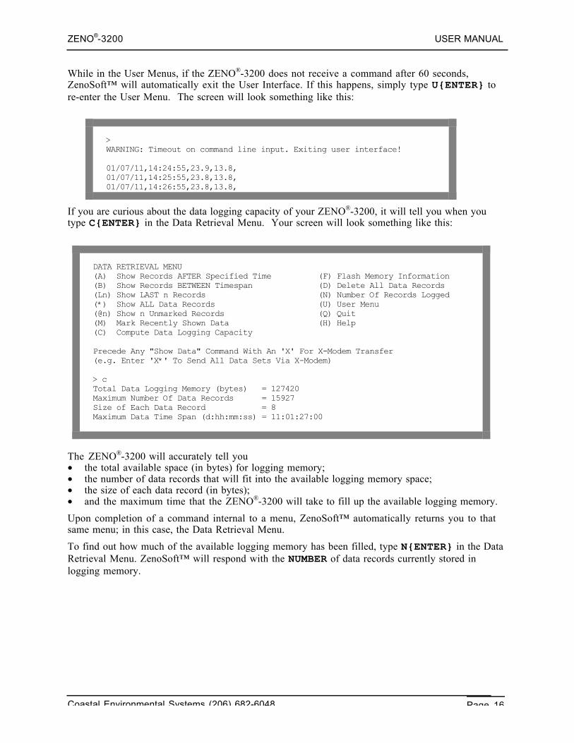
If you are curious about the data logging capacity of your ZENO®-3200, it will tell you when youtype C{ENTER} in the Data Retrieval Menu. Your screen will look something like this:
DATA RETRIEVAL MENU(A) Show Records AFTER Specified Time (F) Flash Memory Information(B) Show Records BETWEEN Timespan (D) Delete All Data Records(Ln) Show LAST n Records (N) Number Of Records Logged(*) Show ALL Data Records (U) User Menu(@n) Show n Unmarked Records (Q) Quit(M) Mark Recently Shown Data (H) Help(C) Compute Data Logging Capacity
Precede Any "Show Data" Command With An 'X' For X-Modem Transfer(e.g. Enter 'X*' To Send All Data Sets Via X-Modem)
> cTotal Data Logging Memory (bytes) = 127420Maximum Number Of Data Records = 15927Size of Each Data Record = 8Maximum Data Time Span (d:hh:mm:ss) = 11:01:27:00
The ZENO®-3200 will accurately tell you• the total available space (in bytes) for logging memory;• the number of data records that will fit into the available logging memory space;• the size of each data record (in bytes);• and the maximum time that the ZENO®-3200 will take to fill up the available logging memory.
Upon completion of a command internal to a menu, ZenoSoft™ automatically returns you to thatsame menu; in this case, the Data Retrieval Menu.
To find out how much of the available logging memory has been filled, type N{ENTER} in the DataRetrieval Menu. ZenoSoft™ will respond with the NUMBER of data records currently stored inlogging memory.
ZENO®-3200 USER MANUAL
Coastal Environmental Systems (206) 682-6048 Page 17
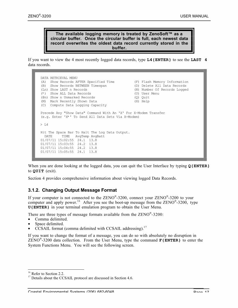
The available logging memory is treated by ZenoSoft™ as acircular buffer. Once the circular buffer is full, each newest datarecord overwrites the oldest data record currently stored in the
buffer.
If you want to view the 4 most recently logged data records, type L4{ENTER} to see the LAST 4data records.
DATA RETRIEVAL MENU(A) Show Records AFTER Specified Time (F) Flash Memory Information(B) Show Records BETWEEN Timespan (D) Delete All Data Records(Ln) Show LAST n Records (N) Number Of Records Logged(*) Show ALL Data Records (U) User Menu(@n) Show n Unmarked Records (Q) Quit(M) Mark Recently Shown Data (H) Help(C) Compute Data Logging Capacity
Precede Any "Show Data" Command With An 'X' For X-Modem Transfer(e.g. Enter 'X*' To Send All Data Sets Via X-Modem)
> L4
Hit The Space Bar To Halt The Log Data Output. DATE TIME AvgTemp AvgBatt01/07/11 15:02:55 24.1 13.801/07/11 15:03:55 24.2 13.801/07/11 15:04:55 24.2 13.801/07/11 15:05:55 24.1 13.8
When you are done looking at the logged data, you can quit the User Interface by typing Q{ENTER}to QUIT (exit).
Section 4 provides comprehensive information about viewing logged Data Records.
3.1.2. Changing Output Message Format
If your computer is not connected to the ZENO®-3200, connect your ZENO®-3200 to yourcomputer and apply power.16 After you see the boot-up message from the ZENO®-3200, typeU{ENTER} in your terminal emulation program to obtain the User Menu.
There are three types of message formats available from the ZENO®-3200:• Comma delimited.• Space delimited.• CCSAIL format (comma delimited with CCSAIL addressing).17
If you want to change the format of a message, you can do so with absolutely no disruption inZENO®-3200 data collection. From the User Menu, type the command F{ENTER} to enter theSystem Functions Menu. You will see the following screen.
16 Refer to Section 2.2.17 Details about the CCSAIL protocol are discussed in Section 4.6.
ZENO®-3200 USER MANUAL
Coastal Environmental Systems (206) 682-6048 Page 18
> f
SYSTEM FUNCTIONS MENU(Cn/m) Change Item n To Value m (I) Contact Information(S) System Date And Time (E) Save Parameters To EEPROM(T) Calibrate Internal Temperature (U) User Menu(V) Program Version (Q) Quit(K) Constants Menu (H) Help(B) BIT Names Menu
Item 1: 0 (Primary Unit/Experiment ID)Item 2: 0 (Secondary Unit/Experiment ID)Item 3: 1 (Data Dump Format)Item 4: 1 (Real Time Output Format)Item 5: 0 (Add Compass To Vane)Item 6: 0 (Compass Offset)Item 7: 0 (Barometer Elevation)Item 8: (Bad Sensor Value Replace)
>
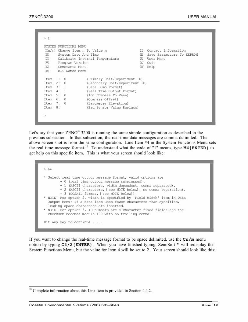
Let's say that your ZENO®-3200 is running the same simple configuration as described in theprevious subsection. In that subsection, the real-time data messages are comma delimited. Theabove screen shot is from the same configuration. Line Item #4 in the System Functions Menu setsthe real-time message format.18 To understand what the code of "1" means, type Η4{ENTER} toget help on this specific item. This is what your screen should look like:
> h4
* Select real time output message format, valid options are - 0 (real time output message suppressed). - 1 (ASCII characters, width dependent, comma separated). - 2 (ASCII characters, [see NOTE below], no comma separation). - 3 (CCSAIL format, [see NOTE below]).* NOTE: For option 2, width is specified by 'Field Width' item in Data Output Menu; if a data item uses fewer characters than specified, leading space characters are inserted.* NOTE: For option 3, ID numbers are 4 character fixed fields and the checksum becomes modulo 100 with no trailing comma.
Hit any key to continue . . .
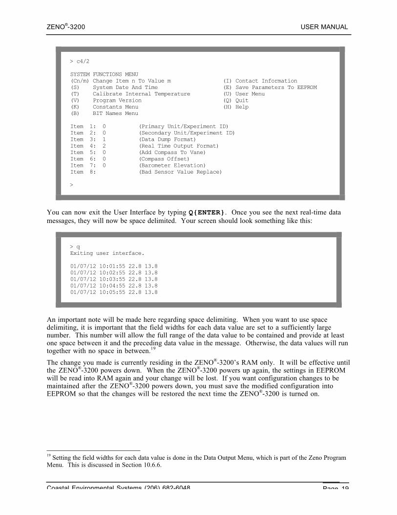
If you want to change the real-time message format to be space delimited, use the Cn/m menuoption by typing C4/2{ENTER}. When you have finished typing, ZenoSoft™ will redisplay theSystem Functions Menu, but the value for Item 4 will be set to 2. Your screen should look like this:
18 Complete information about this Line Item is provided in Section 4.4.2.
ZENO®-3200 USER MANUAL
Coastal Environmental Systems (206) 682-6048 Page 19
> c4/2
SYSTEM FUNCTIONS MENU(Cn/m) Change Item n To Value m (I) Contact Information(S) System Date And Time (E) Save Parameters To EEPROM(T) Calibrate Internal Temperature (U) User Menu(V) Program Version (Q) Quit(K) Constants Menu (H) Help(B) BIT Names Menu
Item 1: 0 (Primary Unit/Experiment ID)Item 2: 0 (Secondary Unit/Experiment ID)Item 3: 1 (Data Dump Format)Item 4: 2 (Real Time Output Format)Item 5: 0 (Add Compass To Vane)Item 6: 0 (Compass Offset)Item 7: 0 (Barometer Elevation)Item 8: (Bad Sensor Value Replace)
>
You can now exit the User Interface by typing Q{ENTER}. Once you see the next real-time datamessages, they will now be space delimited. Your screen should look something like this:
> qExiting user interface.
01/07/12 10:01:55 22.8 13.801/07/12 10:02:55 22.8 13.801/07/12 10:03:55 22.8 13.801/07/12 10:04:55 22.8 13.801/07/12 10:05:55 22.8 13.8
An important note will be made here regarding space delimiting. When you want to use spacedelimiting, it is important that the field widths for each data value are set to a sufficiently largenumber. This number will allow the full range of the data value to be contained and provide at leastone space between it and the preceding data value in the message. Otherwise, the data values will runtogether with no space in between.19
The change you made is currently residing in the ZENO®-3200’s RAM only. It will be effective untilthe ZENO®-3200 powers down. When the ZENO®-3200 powers up again, the settings in EEPROMwill be read into RAM again and your change will be lost. If you want configuration changes to bemaintained after the ZENO®-3200 powers down, you must save the modified configuration intoEEPROM so that the changes will be restored the next time the ZENO®-3200 is turned on.
19 Setting the field widths for each data value is done in the Data Output Menu, which is part of the Zeno ProgramMenu. This is discussed in Section 10.6.6.
ZENO®-3200 USER MANUAL
Coastal Environmental Systems (206) 682-6048 Page 20
When you want to save a modified configuration in case youpower down the ZENO®-3200, type E{ENTER} from any menu that
offers the "Save Parameters to EEPROM" option.20
3.1.3. Understanding & Changing the Sample Interval and Power Usage
One of the most important aspects to understand about the ZENO®-3200 is timing. All datacollection done by the ZENO®-3200 is based upon regular timed intervals that are controlled by theZENO®-3200's internal clock. The main timed interval is called the Sample Interval.
The Sample Interval defines the overall, recurring period of timethat all data collection, processing, data logging and transmitting
occurs.
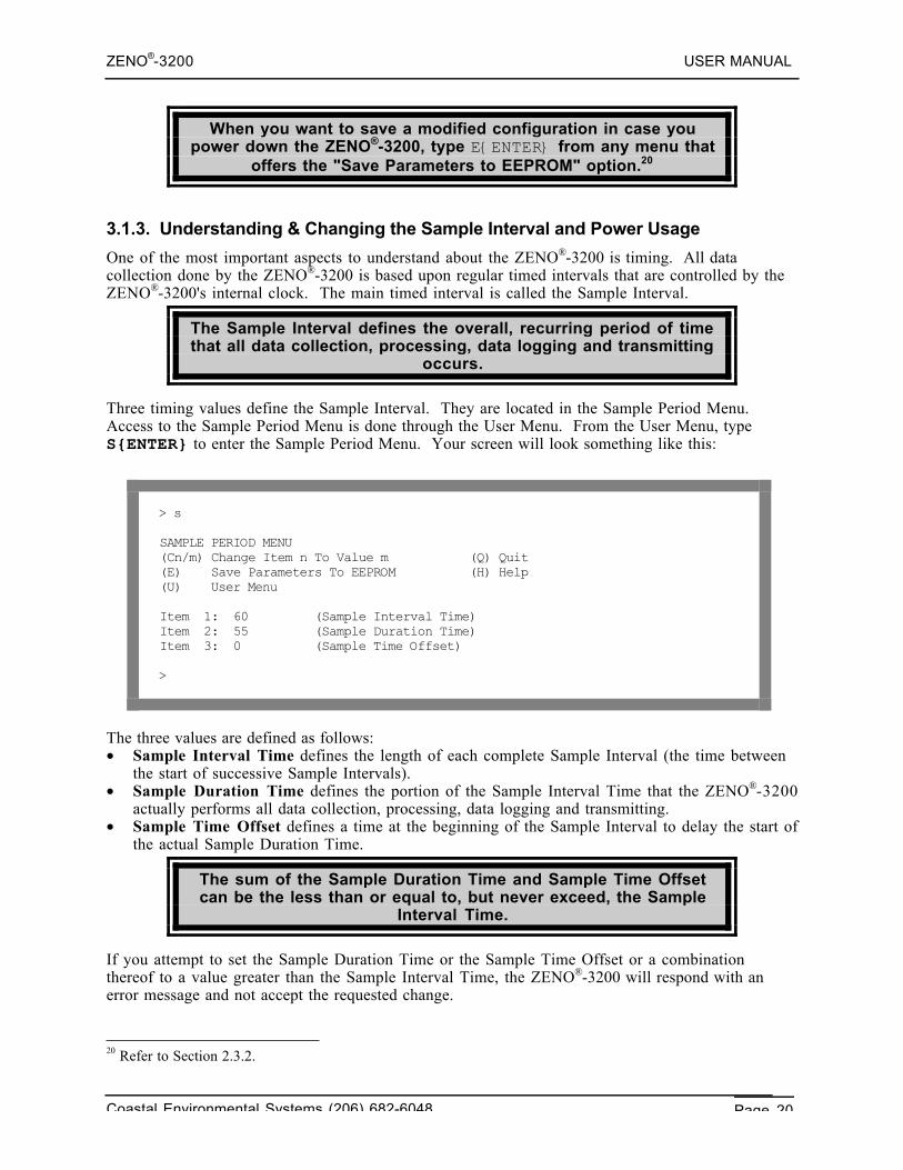
Three timing values define the Sample Interval. They are located in the Sample Period Menu.Access to the Sample Period Menu is done through the User Menu. From the User Menu, typeS{ENTER} to enter the Sample Period Menu. Your screen will look something like this:
> s
SAMPLE PERIOD MENU(Cn/m) Change Item n To Value m (Q) Quit(E) Save Parameters To EEPROM (H) Help(U) User Menu
Item 1: 60 (Sample Interval Time)Item 2: 55 (Sample Duration Time)Item 3: 0 (Sample Time Offset)
>
The three values are defined as follows:• Sample Interval Time defines the length of each complete Sample Interval (the time between
the start of successive Sample Intervals).• Sample Duration Time defines the portion of the Sample Interval Time that the ZENO®-3200
actually performs all data collection, processing, data logging and transmitting.• Sample Time Offset defines a time at the beginning of the Sample Interval to delay the start of
the actual Sample Duration Time.
The sum of the Sample Duration Time and Sample Time Offsetcan be the less than or equal to, but never exceed, the Sample
Interval Time.
If you attempt to set the Sample Duration Time or the Sample Time Offset or a combinationthereof to a value greater than the Sample Interval Time, the ZENO®-3200 will respond with anerror message and not accept the requested change.
20 Refer to Section 2.3.2.
ZENO®-3200 USER MANUAL
Coastal Environmental Systems (206) 682-6048 Page 21
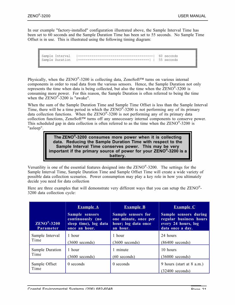
In our example "factory-installed" configuration illustrated above, the Sample Interval Time hasbeen set to 60 seconds and the Sample Duration Time has been set to 55 seconds. No Sample TimeOffset is in use. This is illustrated using the following timing diagram:
Sample Interval |---------------------------------------| 60 secondsSample Duration |-------------------------------------| | 55 seconds
Physically, when the ZENO®-3200 is collecting data, ZenoSoft™ turns on various internalcomponents in order to read data from the various sensors. Hence, the Sample Duration not onlyrepresents the time when data is being collected, but also the time when the ZENO®-3200 isconsuming more power. For this reason, the Sample Duration is often referred to being the timewhen the ZENO®-3200 is "awake".
When the sum of the Sample Duration Time and Sample Time Offset is less than the Sample IntervalTime, there will be a time period in which the ZENO®-3200 is not performing any of its primarydata collection functions. When the ZENO®-3200 is not performing any of its primary datacollection functions, ZenoSoft™ turns off any unnecessary internal components to conserve power.This scheduled gap in data collection is often referred to as the time when the ZENO®-3200 is"asleep".
The ZENO®-3200 consumes more power when it is collectingdata. Reducing the Sample Duration Time with respect to the
Sample Interval Time conserves power. This may be veryimportant if the primary source of power for your ZENO®-3200 is a
battery.
Versatility is one of the essential features designed into the ZENO®-3200. The settings for theSample Interval Time, Sample Duration Time and Sample Offset Time will create a wide variety ofpossible data collection scenarios. Power consumption may play a key role in how you ultimatelydecide you need for data collection
Here are three examples that will demonstrate very different ways that you can setup the ZENO®-3200 data collection cycle:
ZENO®-3200Parameter
Example A
Sample sensorscontinuously (nosleep time), log dataonce an hour.
Example B
Sample sensors forone minute, once perhour; log data oncean hour.
Example C
Sample sensors duringregular business hoursevery 24 hours, logdata once a day.
Sample IntervalTime
1 hour
(3600 seconds)
1 hour
(3600 seconds)
24 hours
(86400 seconds)
Sample DurationTime
1 hour
(3600 seconds)
1 minute
(60 seconds)
10 hours
(36000 seconds)
Sample OffsetTime
0 seconds 0 seconds 9 hours (start at 8 a.m.)
(32400 seconds)
ZENO®-3200 USER MANUAL
Coastal Environmental Systems (206) 682-6048 Page 22
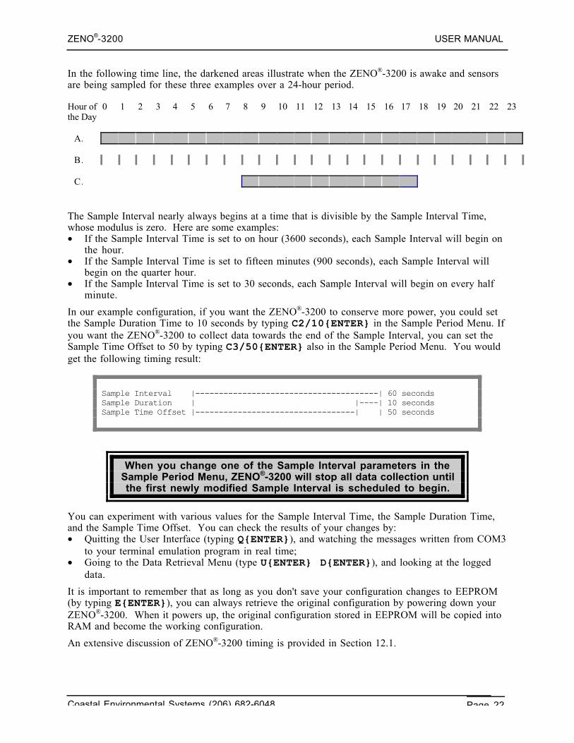
In the following time line, the darkened areas illustrate when the ZENO®-3200 is awake and sensorsare being sampled for these three examples over a 24-hour period.
Hour ofthe Day
0 1 2 3 4 5 6 7 8 9 10 11 12 13 14 15 16 17 18 19 20 21 22 23
A.
B.
C.
The Sample Interval nearly always begins at a time that is divisible by the Sample Interval Time,whose modulus is zero. Here are some examples:• If the Sample Interval Time is set to on hour (3600 seconds), each Sample Interval will begin on
the hour.• If the Sample Interval Time is set to fifteen minutes (900 seconds), each Sample Interval will
begin on the quarter hour.• If the Sample Interval Time is set to 30 seconds, each Sample Interval will begin on every half
minute.
In our example configuration, if you want the ZENO®-3200 to conserve more power, you could setthe Sample Duration Time to 10 seconds by typing C2/10{ENTER} in the Sample Period Menu. Ifyou want the ZENO®-3200 to collect data towards the end of the Sample Interval, you can set theSample Time Offset to 50 by typing C3/50{ENTER} also in the Sample Period Menu. You wouldget the following timing result:
Sample Interval |---------------------------------------| 60 secondsSample Duration | |----| 10 secondsSample Time Offset |----------------------------------| | 50 seconds
When you change one of the Sample Interval parameters in theSample Period Menu, ZENO®-3200 will stop all data collection untilthe first newly modified Sample Interval is scheduled to begin.
You can experiment with various values for the Sample Interval Time, the Sample Duration Time,and the Sample Time Offset. You can check the results of your changes by:• Quitting the User Interface (typing Q{ENTER}), and watching the messages written from COM3
to your terminal emulation program in real time;• Going to the Data Retrieval Menu (type U{ENTER} D{ENTER}), and looking at the logged
data.
It is important to remember that as long as you don't save your configuration changes to EEPROM(by typing E{ENTER}), you can always retrieve the original configuration by powering down yourZENO®-3200. When it powers up, the original configuration stored in EEPROM will be copied intoRAM and become the working configuration.
An extensive discussion of ZENO®-3200 timing is provided in Section 12.1.
ZENO®-3200 USER MANUAL
Coastal Environmental Systems (206) 682-6048 Page 23
3.2. PART TWO—LEARNING HOW TO CONFIGURE YOUR OWN ZENO®-3200
3.2.1. How Do I Configure The ZENO®-3200 To Perform My Requirements?
If you purchased your ZENO®-3200 with no factory-installed configuration, it will be shipped withthe default configuration.
The default ZENO®-3200 configuration contains no sensors, noprocesses and no data to be logged. It is a blank configuration.
In this case, you need to configure the ZENO®-3200 to meet your own requirements.
In this section, some simple aspects of configuring sensors, processes and setting up data to be logged& transmitted will be examined.
Before you start to configure your own ZENO®-3200, ask yourself the following list of questions.
Identifying what you need the ZENO®-3200 to do and how theZENO®-3200 can accomplish your requirements will simplify the
configuration process.
1. What do I need to the ZENO®-3200 to measure?
2. What are the types of sensors that I need to collect data from?
3. How do my sensors match each of the sensor types defined in ZenoSoft™?
4. How often do I need to measure data from each sensor (once every second, twice every 5seconds, once every 10 seconds, etc.)
5. How do I electrically connect each sensor to the ZENO®-3200?
6. Do I need each sensor to be powered continuously or do I want each sensor powered only when ameasurement is to be taken? (This may be very important if your ZENO®-3200 has a limitedsource of power.)
7. Do I need data that can only be obtained indirectly by processing the collected data?
8. If processing is required, which process (or processes) can I use to obtain the desired results?
9. Which collected & processed data (if any) needs to be logged in each data record?
10. Which collected & processed data (if any) needs to be transmitted? (Is it the same or differentfrom the data that is to be logged?)
11. Do I need the ZENO®-3200 to transmit the data records automatically or do I only plan to viewlogged data?
12. How much and how often do I want the ZENO®-3200 to perform the configuration; i.e., whatSample Interval, Sample Duration and Sample Offset will be used?
Other questions may arise, or some may not be important; but each of the listed questions should beanswered so that "no stone is left uncovered".
For an illustration of creating a simple configuration, let's use the configuration that was usedthroughout Part One of the Tutorial Section.21
First, we must answer the 12 questions asked in the preceding paragraphs: 21 Refer to Section 3.1.
ZENO®-3200 USER MANUAL
Coastal Environmental Systems (206) 682-6048 Page 24
1. We need the ZENO®-3200 to measure its internal temperature and battery voltage, averagethe data, and log and transmit the data at the end of each Sample Interval.
2. There are two sensors: internal temperature and battery voltage. Each sensor is an internal(built-in) analog sensor.
3. In this case, each sensor is a built-in analog sensor internally connected to the 12-bit Analog-to-Digital Converter (ADC).
4. Each sensor needs to be read once per second.5. No external connections to the ZENO®-3200 are necessary since each sensor is built in.6. Each internal sensor is powered internally. It is not necessary to control the power to each
built-in sensor.7. We need to view the average value of all the readings taken from each sensor over the course
of the Sample Interval.8. To obtain the average value of all the readings taken from each sensor, two Average
Processes will need to be configured. (One Average Process per sensor.)9. The average internal temperature and average battery voltage need to be logged in each data
record at the end of each Sample Interval.10. The average internal temperature and average battery voltage need to be transmitted at the
end of each Sample Interval. This is the same data that is being logged.11. The ZENO®-3200 needs to transmit each data record at the end of the Sample Duration.12. We need the ZENO®-3200 to perform all data collection once a minute and to measure the
sensors for 55 seconds before logging and transmitting the collected & processed data.
As you can see, answering those 12 key questions will make the creation of this configuration veryeasy.
3.2.2. Data Flow Within The ZENO®-3200
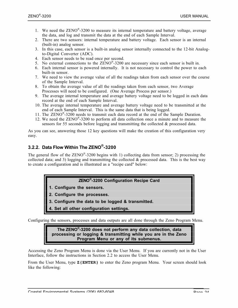
The general flow of the ZENO®-3200 begins with 1) collecting data from sensor; 2) processing thecollected data; and 3) logging and transmitting the collected & processed data. This is the best wayto create a configuration and is illustrated as a "recipe card" below:
ZENO®-3200 Configuration Recipe Card
1. Configure the sensors.
2. Configure the processes.
3. Configure the data to be logged & transmitted.
4. Set all other configuration settings.
Configuring the sensors, processes and data outputs are all done through the Zeno Program Menu.
The ZENO®-3200 does not perform any data collection, dataprocessing or logging & transmitting while you are in the Zeno
Program Menu or any of its submenus.
Accessing the Zeno Program Menu is done via the User Menu. If you are currently not in the UserInterface, follow the instructions in Section 2.2 to access the User Menu.
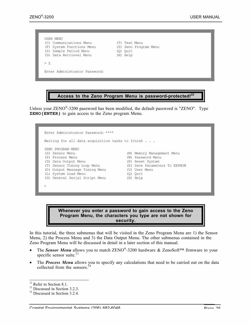
From the User Menu, type Z{ENTER} to enter the Zeno program Menu. Your screen should looklike the following:
ZENO®-3200 USER MANUAL
Coastal Environmental Systems (206) 682-6048 Page 25
USER MENU(C) Communications Menu (T) Test Menu(F) System Functions Menu (Z) Zeno Program Menu(S) Sample Period Menu (Q) Quit(D) Data Retrieval Menu (H) Help
> Z
Enter Administrator Password:
Access to the Zeno Program Menu is password-protected!22
Unless your ZENO®-3200 password has been modified, the default password is "ZENO". TypeZENO{ENTER} to gain access to the Zeno program Menu.
Enter Administrator Password: ****
Waiting for all data acquisition tasks to finish . . .
ZENO PROGRAM MENU(S) Sensor Menu (M) Memory Management Menu(P) Process Menu (W) Password Menu(D) Data Output Menu (R) Reset System(T) Sensor Timing Loop Menu (E) Save Parameters To EEPROM(O) Output Message Timing Menu (U) User Menu(L) System Load Menu (Q) Quit(G) General Serial Script Menu (H) Help
>
Whenever you enter a password to gain access to the ZenoProgram Menu, the characters you type are not shown for
security.
In this tutorial, the three submenus that will be visited in the Zeno Program Menu are 1) the SensorMenu, 2) the Process Menu and 3) the Data Output Menu. The other submenus contained in theZeno Program Menu will be discussed in detail in a later section of this manual.
• The Sensor Menu allows you to match ZENO®-3200 hardware & ZenoSoft™ firmware to yourspecific sensor suite.23
• The Process Menu allows you to specify any calculations that need to be carried out on the datacollected from the sensors.24
22 Refer to Section 8.1.23 Discussed in Section 3.2.3.24 Discussed in Section 3.2.4.
ZENO®-3200 USER MANUAL
Coastal Environmental Systems (206) 682-6048 Page 26
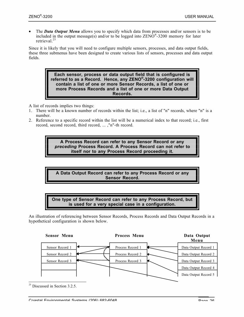
• The Data Output Menu allows you to specify which data from processes and/or sensors is to beincluded in the output message(s) and/or to be logged into ZENO®-3200 memory for laterretrieval.25
Since it is likely that you will need to configure multiple sensors, processes, and data output fields,these three submenus have been designed to create various lists of sensors, processes and data outputfields.
Each sensor, process or data output field that is configured isreferred to as a Record. Hence, any ZENO®-3200 configuration will
contain a list of one or more Sensor Records, a list of one ormore Process Records and a list of one or more Data Output
Records.
A list of records implies two things:1. There will be a known number of records within the list; i.e., a list of "n" records, where "n" is a
number.2. Reference to a specific record within the list will be a numerical index to that record; i.e., first
record, second record, third record, ... ,"n"-th record.
A Process Record can refer to any Sensor Record or anypreceding Process Record. A Process Record can not refer to
itself nor to any Process Record proceeding it.
A Data Output Record can refer to any Process Record or anySensor Record.
One type of Sensor Record can refer to any Process Record, butis used for a very special case in a configuration.
An illustration of referencing between Sensor Records, Process Records and Data Output Records in ahypothetical configuration is shown below.
Sensor Menu Process Menu Data OutputMenu
Sensor Record 1 Process Record 1 Data Output Record 1
Sensor Record 2 Process Record 2 Data Output Record 2
Sensor Record 3 Process Record 3 Data Output Record 3
Data Output Record 4
Data Output Record 5
25 Discussed in Section 3.2.5.
ZENO®-3200 USER MANUAL
Coastal Environmental Systems (206) 682-6048 Page 27
Data Output Record 6
Figure 3-1. ZENO®-3200 Data Flow.*
*The arrows in Figure 3-1 show the direction of the reference. The flow of data is in the opposite.
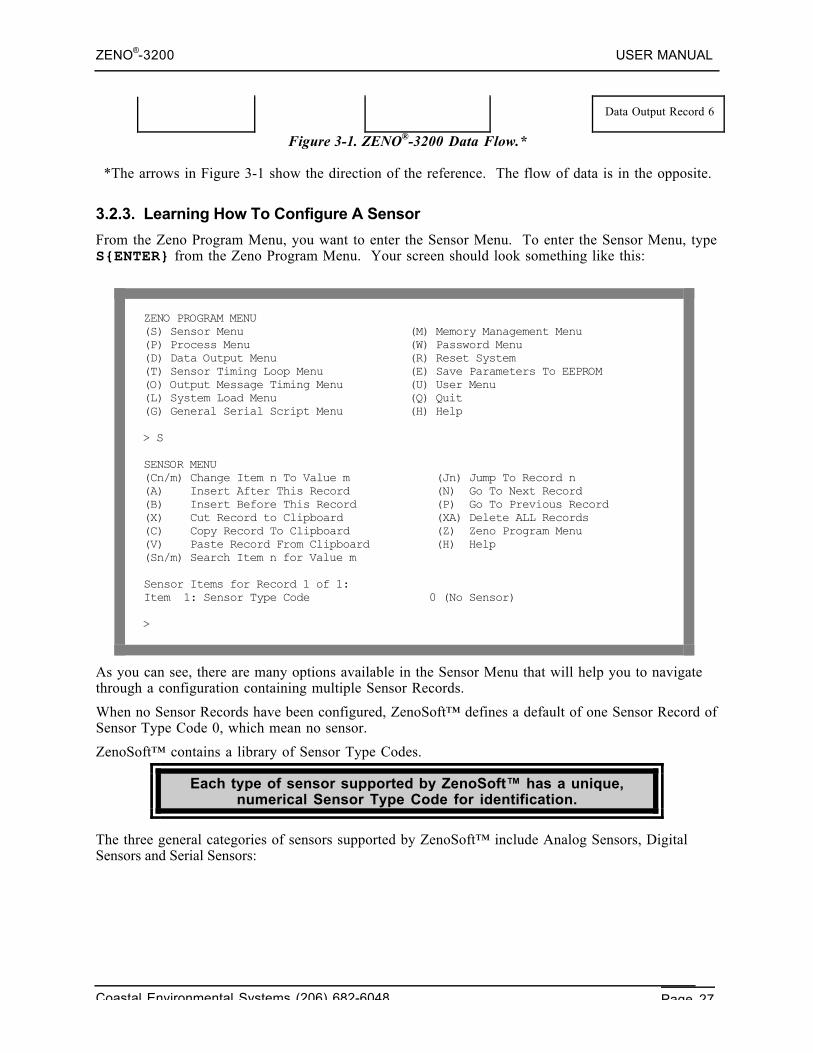
3.2.3. Learning How To Configure A Sensor
From the Zeno Program Menu, you want to enter the Sensor Menu. To enter the Sensor Menu, typeS{ENTER} from the Zeno Program Menu. Your screen should look something like this:
ZENO PROGRAM MENU(S) Sensor Menu (M) Memory Management Menu(P) Process Menu (W) Password Menu(D) Data Output Menu (R) Reset System(T) Sensor Timing Loop Menu (E) Save Parameters To EEPROM(O) Output Message Timing Menu (U) User Menu(L) System Load Menu (Q) Quit(G) General Serial Script Menu (H) Help
> S
SENSOR MENU(Cn/m) Change Item n To Value m (Jn) Jump To Record n(A) Insert After This Record (N) Go To Next Record(B) Insert Before This Record (P) Go To Previous Record(X) Cut Record to Clipboard (XA) Delete ALL Records(C) Copy Record To Clipboard (Z) Zeno Program Menu(V) Paste Record From Clipboard (H) Help(Sn/m) Search Item n for Value m
Sensor Items for Record 1 of 1:Item 1: Sensor Type Code 0 (No Sensor)
>
As you can see, there are many options available in the Sensor Menu that will help you to navigatethrough a configuration containing multiple Sensor Records.
When no Sensor Records have been configured, ZenoSoft™ defines a default of one Sensor Record ofSensor Type Code 0, which mean no sensor.
ZenoSoft™ contains a library of Sensor Type Codes.
Each type of sensor supported by ZenoSoft™ has a unique,numerical Sensor Type Code for identification.
The three general categories of sensors supported by ZenoSoft™ include Analog Sensors, DigitalSensors and Serial Sensors:
ZENO®-3200 USER MANUAL
Coastal Environmental Systems (206) 682-6048 Page 28
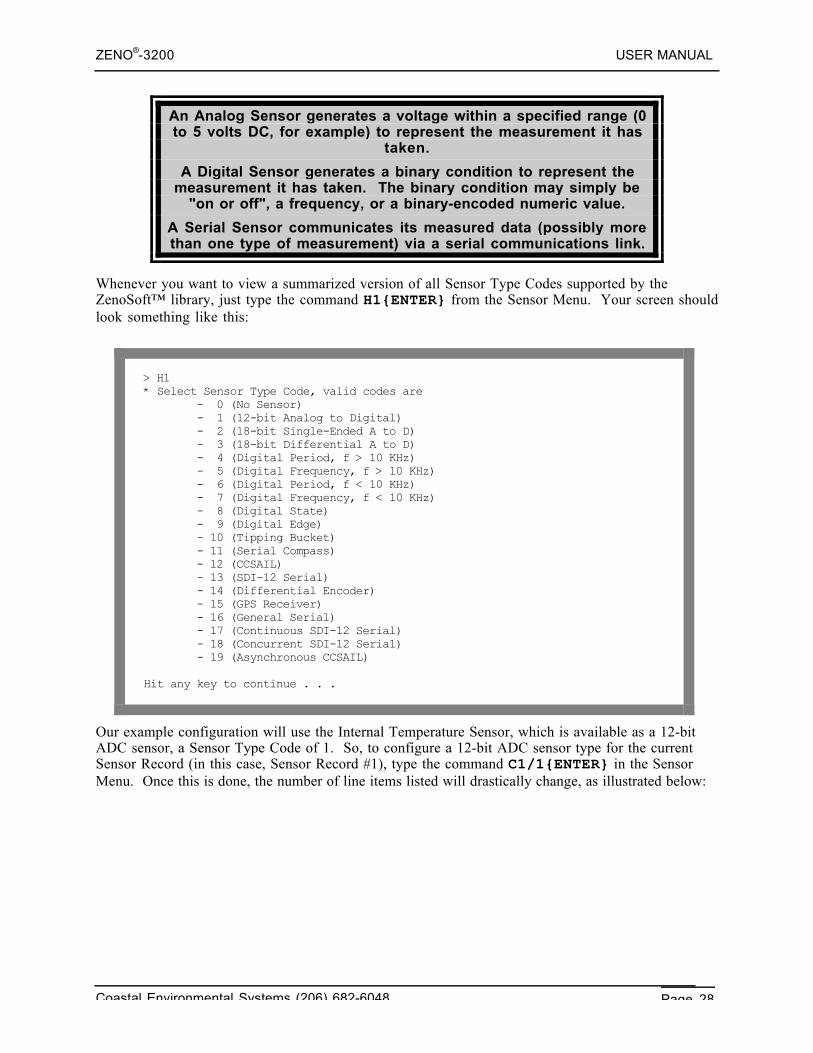
An Analog Sensor generates a voltage within a specified range (0to 5 volts DC, for example) to represent the measurement it has
taken.
A Digital Sensor generates a binary condition to represent themeasurement it has taken. The binary condition may simply be
"on or off", a frequency, or a binary-encoded numeric value.
A Serial Sensor communicates its measured data (possibly morethan one type of measurement) via a serial communications link.
Whenever you want to view a summarized version of all Sensor Type Codes supported by theZenoSoft™ library, just type the command H1{ENTER} from the Sensor Menu. Your screen shouldlook something like this:
> H1* Select Sensor Type Code, valid codes are - 0 (No Sensor) - 1 (12-bit Analog to Digital) - 2 (18-bit Single-Ended A to D) - 3 (18-bit Differential A to D) - 4 (Digital Period, f > 10 KHz) - 5 (Digital Frequency, f > 10 KHz) - 6 (Digital Period, f < 10 KHz) - 7 (Digital Frequency, f < 10 KHz) - 8 (Digital State) - 9 (Digital Edge) - 10 (Tipping Bucket) - 11 (Serial Compass) - 12 (CCSAIL) - 13 (SDI-12 Serial) - 14 (Differential Encoder) - 15 (GPS Receiver) - 16 (General Serial) - 17 (Continuous SDI-12 Serial) - 18 (Concurrent SDI-12 Serial) - 19 (Asynchronous CCSAIL)
Hit any key to continue . . .
Our example configuration will use the Internal Temperature Sensor, which is available as a 12-bitADC sensor, a Sensor Type Code of 1. So, to configure a 12-bit ADC sensor type for the currentSensor Record (in this case, Sensor Record #1), type the command C1/1{ENTER} in the SensorMenu. Once this is done, the number of line items listed will drastically change, as illustrated below:
ZENO®-3200 USER MANUAL
Coastal Environmental Systems (206) 682-6048 Page 29
> C1/1
SENSOR MENU(Cn/m) Change Item n To Value m (Jn) Jump To Record n(A) Insert After This Record (N) Go To Next Record(B) Insert Before This Record (P) Go To Previous Record(X) Cut Record to Clipboard (XA) Delete ALL Records(C) Copy Record To Clipboard (Z) Zeno Program Menu(V) Paste Record From Clipboard (H) Help(Sn/m) Search Item n for Value m
Sensor Items for Record 1 of 1:Item 1: Sensor Type Code 1 (12-bit Analog to Digital)Item 2: Sensor NameItem 3: Sensor Input Channel 8Item 6: Switched Power Code 0 (NO SWITCHED POWER)Item 7: Sensor Excitation Voltage Code 0 (NO EXCITATION VOLTAGE)Item 8: Switched Excitation Return 0Item 9: Switched Power Warmup Time 0Item 10: Sensor Sample Count 1Item 11: Maximum Sensor Readings 0Item 12: Sensor Timing Loop 1 (0.5 seconds)Item 13: Conversion Coefficient A 0Item 14: Conversion Coefficient B 1Item 15: Conversion Coefficient C 0
>
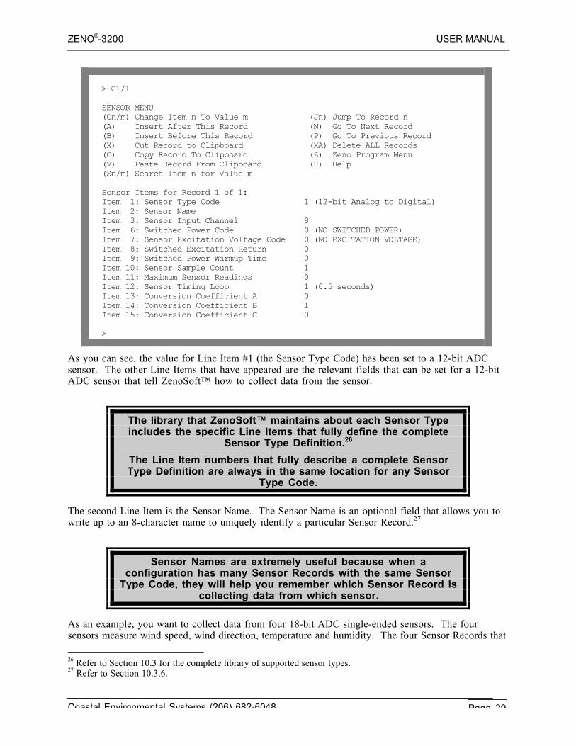
As you can see, the value for Line Item #1 (the Sensor Type Code) has been set to a 12-bit ADCsensor. The other Line Items that have appeared are the relevant fields that can be set for a 12-bitADC sensor that tell ZenoSoft™ how to collect data from the sensor.
The library that ZenoSoft™ maintains about each Sensor Typeincludes the specific Line Items that fully define the complete
Sensor Type Definition.26
The Line Item numbers that fully describe a complete SensorType Definition are always in the same location for any Sensor
Type Code.
The second Line Item is the Sensor Name. The Sensor Name is an optional field that allows you towrite up to an 8-character name to uniquely identify a particular Sensor Record.27
Sensor Names are extremely useful because when aconfiguration has many Sensor Records with the same Sensor
Type Code, they will help you remember which Sensor Record iscollecting data from which sensor.
As an example, you want to collect data from four 18-bit ADC single-ended sensors. The foursensors measure wind speed, wind direction, temperature and humidity. The four Sensor Records that
26 Refer to Section 10.3 for the complete library of supported sensor types.27 Refer to Section 10.3.6.
ZENO®-3200 USER MANUAL
Coastal Environmental Systems (206) 682-6048 Page 30
define these four sensors are numbered 1 through 4. You do not look at the configuration for aperiod of time. How will it be easier to remember which Sensor Record collects which sensor data:based solely upon the Sensor Record number or if the four Sensor Records have the Sensor Names of"WS", "WD", "Temp", and "Humid" respectively? Most people would probably find it easier toremember with unique Sensor Names.
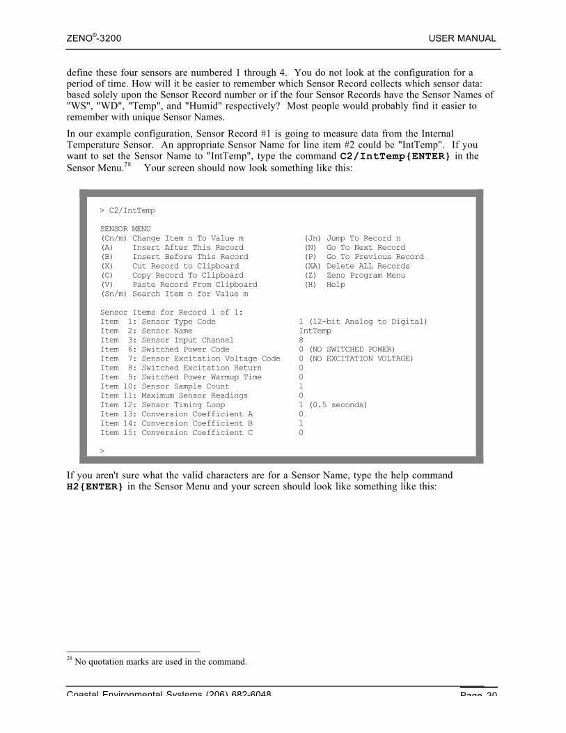
In our example configuration, Sensor Record #1 is going to measure data from the InternalTemperature Sensor. An appropriate Sensor Name for line item #2 could be "IntTemp". If youwant to set the Sensor Name to "IntTemp", type the command C2/IntTemp{ENTER} in theSensor Menu.28 Your screen should now look something like this:
> C2/IntTemp
SENSOR MENU(Cn/m) Change Item n To Value m (Jn) Jump To Record n(A) Insert After This Record (N) Go To Next Record(B) Insert Before This Record (P) Go To Previous Record(X) Cut Record to Clipboard (XA) Delete ALL Records(C) Copy Record To Clipboard (Z) Zeno Program Menu(V) Paste Record From Clipboard (H) Help(Sn/m) Search Item n for Value m
Sensor Items for Record 1 of 1:Item 1: Sensor Type Code 1 (12-bit Analog to Digital)Item 2: Sensor Name IntTempItem 3: Sensor Input Channel 8Item 6: Switched Power Code 0 (NO SWITCHED POWER)Item 7: Sensor Excitation Voltage Code 0 (NO EXCITATION VOLTAGE)Item 8: Switched Excitation Return 0Item 9: Switched Power Warmup Time 0Item 10: Sensor Sample Count 1Item 11: Maximum Sensor Readings 0Item 12: Sensor Timing Loop 1 (0.5 seconds)Item 13: Conversion Coefficient A 0Item 14: Conversion Coefficient B 1Item 15: Conversion Coefficient C 0
>
If you aren't sure what the valid characters are for a Sensor Name, type the help commandH2{ENTER} in the Sensor Menu and your screen should look like something like this:
28 No quotation marks are used in the command.
ZENO®-3200 USER MANUAL
Coastal Environmental Systems (206) 682-6048 Page 31
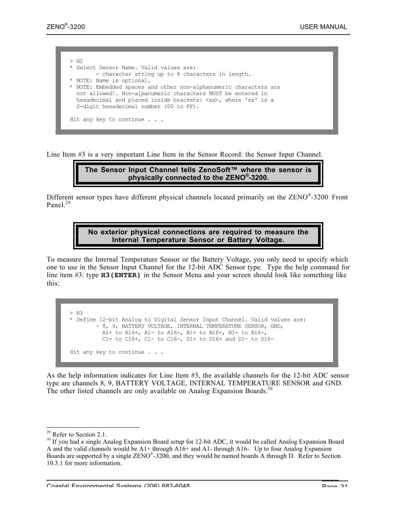
> H2* Select Sensor Name. Valid values are: - character string up to 8 characters in length.* NOTE: Name is optional.* NOTE: Embedded spaces and other non-alphanumeric characters are not allowed!. Non-alpanumeric characters MUST be entered in hexadecimal and placed inside brackets: <xx>, where 'xx' is a 2-digit hexadecimal number (00 to FF).
Hit any key to continue . . .
Line Item #3 is a very important Line Item in the Sensor Record: the Sensor Input Channel.
The Sensor Input Channel tells ZenoSoft™ where the sensor isphysically connected to the ZENO®-3200.
Different sensor types have different physical channels located primarily on the ZENO®-3200 FrontPanel.29
No exterior physical connections are required to measure theInternal Temperature Sensor or Battery Voltage.
To measure the Internal Temperature Sensor or the Battery Voltage, you only need to specify whichone to use in the Sensor Input Channel for the 12-bit ADC Sensor type. Type the help command forline item #3: type H3{ENTER} in the Sensor Menu and your screen should look like something likethis:
> H3* Define 12-bit Analog to Digital Sensor Input Channel. Valid values are: - 8, 9, BATTERY VOLTAGE, INTERNAL TEMPERATURE SENSOR, GND, A1+ to A16+, A1- to A16-, B1+ to B16+, B1- to B16-, C1+ to C16+, C1- to C16-, D1+ to D16+ and D1- to D16-
Hit any key to continue . . .
As the help information indicates for Line Item #3, the available channels for the 12-bit ADC sensortype are channels 8, 9, BATTERY VOLTAGE, INTERNAL TEMPERATURE SENSOR and GND.The other listed channels are only available on Analog Expansion Boards.30
29 Refer to Section 2.1.30 If you had a single Analog Expansion Board setup for 12-bit ADC, it would be called Analog Expansion BoardA and the valid channels would be A1+ through A16+ and A1- through A16-. Up to four Analog ExpansionBoards are supported by a single ZENO®-3200, and they would be named boards A through D. Refer to Section10.3.1 for more information.
ZENO®-3200 USER MANUAL
Coastal Environmental Systems (206) 682-6048 Page 32
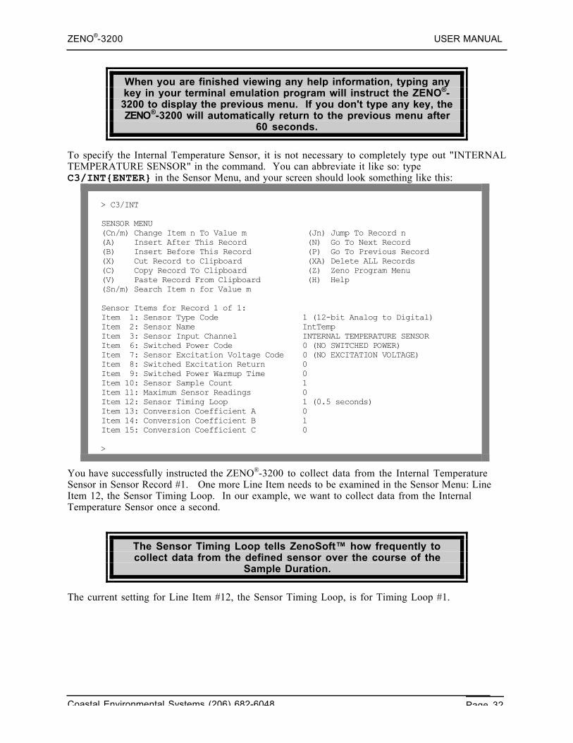
When you are finished viewing any help information, typing anykey in your terminal emulation program will instruct the ZENO®-3200 to display the previous menu. If you don't type any key, theZENO®-3200 will automatically return to the previous menu after
60 seconds.
To specify the Internal Temperature Sensor, it is not necessary to completely type out "INTERNALTEMPERATURE SENSOR" in the command. You can abbreviate it like so: typeC3/INT{ENTER} in the Sensor Menu, and your screen should look something like this:
> C3/INT
SENSOR MENU(Cn/m) Change Item n To Value m (Jn) Jump To Record n(A) Insert After This Record (N) Go To Next Record(B) Insert Before This Record (P) Go To Previous Record(X) Cut Record to Clipboard (XA) Delete ALL Records(C) Copy Record To Clipboard (Z) Zeno Program Menu(V) Paste Record From Clipboard (H) Help(Sn/m) Search Item n for Value m
Sensor Items for Record 1 of 1:Item 1: Sensor Type Code 1 (12-bit Analog to Digital)Item 2: Sensor Name IntTempItem 3: Sensor Input Channel INTERNAL TEMPERATURE SENSORItem 6: Switched Power Code 0 (NO SWITCHED POWER)Item 7: Sensor Excitation Voltage Code 0 (NO EXCITATION VOLTAGE)Item 8: Switched Excitation Return 0Item 9: Switched Power Warmup Time 0Item 10: Sensor Sample Count 1Item 11: Maximum Sensor Readings 0Item 12: Sensor Timing Loop 1 (0.5 seconds)Item 13: Conversion Coefficient A 0Item 14: Conversion Coefficient B 1Item 15: Conversion Coefficient C 0
>
You have successfully instructed the ZENO®-3200 to collect data from the Internal TemperatureSensor in Sensor Record #1. One more Line Item needs to be examined in the Sensor Menu: LineItem 12, the Sensor Timing Loop. In our example, we want to collect data from the InternalTemperature Sensor once a second.
The Sensor Timing Loop tells ZenoSoft™ how frequently tocollect data from the defined sensor over the course of the
Sample Duration.
The current setting for Line Item #12, the Sensor Timing Loop, is for Timing Loop #1.
ZENO®-3200 USER MANUAL
Coastal Environmental Systems (206) 682-6048 Page 33
There are four available Sensor Timing Loops. Sensor TimingLoop #1 is always a 0.5-second timing loop, but the other three
can be modified using a different menu.31
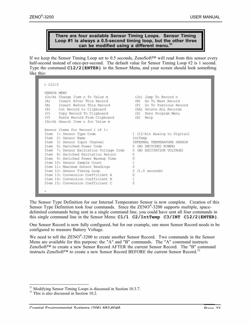
If we keep the Sensor Timing Loop set to 0.5 seconds, ZenoSoft™ will read from this sensor everyhalf-second instead of once-per-second. The default value for Sensor Timing Loop #2 is 1 second.Type the command C12/2{ENTER} in the Sensor Menu, and your screen should look somethinglike this:
> C12/2
SENSOR MENU(Cn/m) Change Item n To Value m (Jn) Jump To Record n(A) Insert After This Record (N) Go To Next Record(B) Insert Before This Record (P) Go To Previous Record(X) Cut Record to Clipboard (XA) Delete ALL Records(C) Copy Record To Clipboard (Z) Zeno Program Menu(V) Paste Record From Clipboard (H) Help(Sn/m) Search Item n for Value m
Sensor Items for Record 1 of 1:Item 1: Sensor Type Code 1 (12-bit Analog to Digital)Item 2: Sensor Name IntTempItem 3: Sensor Input Channel INTERNAL TEMPERATURE SENSORItem 6: Switched Power Code 0 (NO SWITCHED POWER)Item 7: Sensor Excitation Voltage Code 0 (NO EXCITATION VOLTAGE)Item 8: Switched Excitation Return 0Item 9: Switched Power Warmup Time 0Item 10: Sensor Sample Count 1Item 11: Maximum Sensor Readings 0Item 12: Sensor Timing Loop 2 (1.0 seconds)Item 13: Conversion Coefficient A 0Item 14: Conversion Coefficient B 1Item 15: Conversion Coefficient C 0
>
The Sensor Type Definition for our Internal Temperature Sensor is now complete. Creation of thisSensor Type Definition took four commands. Since the ZENO®-3200 supports multiple, space-delimited commands being sent in a single command line, you could have sent all four commands inthis single command line in the Sensor Menu: C1/1 C2/IntTemp C3/INT C12/2{ENTER}.
One Sensor Record is now fully configured, but for our example, one more Sensor Record needs to beconfigured to measure Battery Voltage.
We need to tell the ZENO®-3200 to create another Sensor Record. Two commands in the SensorMenu are available for this purpose: the "A" and "B" commands. The "A" command instructsZenoSoft™ to create a new Sensor Record AFTER the current Sensor Record. The "B" commandinstructs ZenoSoft™ to create a new Sensor Record BEFORE the current Sensor Record.32
31 Modifying Sensor Timing Loops is discussed in Section 10.3.7.32 This is also discussed in Section 10.2.
ZENO®-3200 USER MANUAL
Coastal Environmental Systems (206) 682-6048 Page 34
During the Sample Duration, data is collected from sensorsbased upon the order of the Sensor Records and the Sensor
Timing Loop assigned to each sensor.
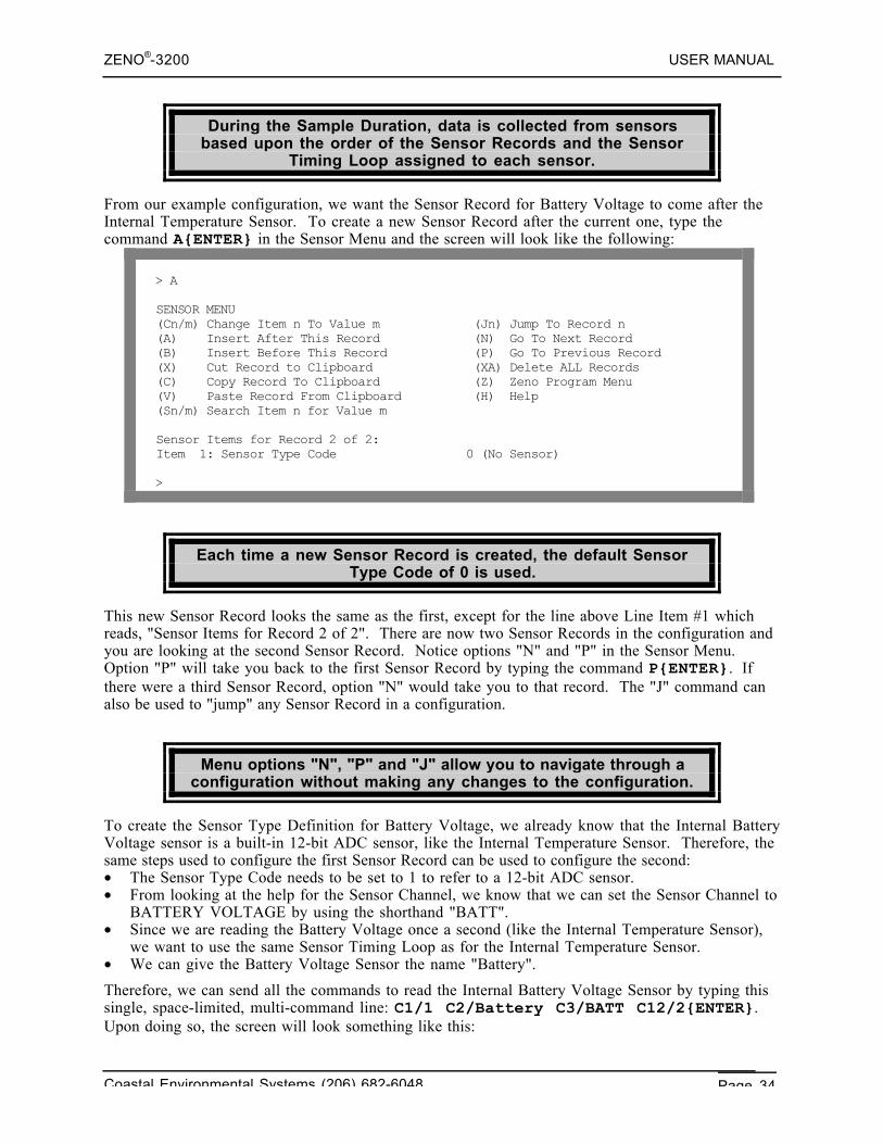
From our example configuration, we want the Sensor Record for Battery Voltage to come after theInternal Temperature Sensor. To create a new Sensor Record after the current one, type thecommand A{ENTER} in the Sensor Menu and the screen will look like the following:
> A
SENSOR MENU(Cn/m) Change Item n To Value m (Jn) Jump To Record n(A) Insert After This Record (N) Go To Next Record(B) Insert Before This Record (P) Go To Previous Record(X) Cut Record to Clipboard (XA) Delete ALL Records(C) Copy Record To Clipboard (Z) Zeno Program Menu(V) Paste Record From Clipboard (H) Help(Sn/m) Search Item n for Value m
Sensor Items for Record 2 of 2:Item 1: Sensor Type Code 0 (No Sensor)
>
Each time a new Sensor Record is created, the default SensorType Code of 0 is used.
This new Sensor Record looks the same as the first, except for the line above Line Item #1 whichreads, "Sensor Items for Record 2 of 2". There are now two Sensor Records in the configuration andyou are looking at the second Sensor Record. Notice options "N" and "P" in the Sensor Menu.Option "P" will take you back to the first Sensor Record by typing the command P{ENTER}. Ifthere were a third Sensor Record, option "N" would take you to that record. The "J" command canalso be used to "jump" any Sensor Record in a configuration.
Menu options "N", "P" and "J" allow you to navigate through aconfiguration without making any changes to the configuration.
To create the Sensor Type Definition for Battery Voltage, we already know that the Internal BatteryVoltage sensor is a built-in 12-bit ADC sensor, like the Internal Temperature Sensor. Therefore, thesame steps used to configure the first Sensor Record can be used to configure the second:• The Sensor Type Code needs to be set to 1 to refer to a 12-bit ADC sensor.• From looking at the help for the Sensor Channel, we know that we can set the Sensor Channel to
BATTERY VOLTAGE by using the shorthand "BATT".• Since we are reading the Battery Voltage once a second (like the Internal Temperature Sensor),
we want to use the same Sensor Timing Loop as for the Internal Temperature Sensor.• We can give the Battery Voltage Sensor the name "Battery".
Therefore, we can send all the commands to read the Internal Battery Voltage Sensor by typing thissingle, space-limited, multi-command line: C1/1 C2/Battery C3/BATT C12/2{ENTER}.Upon doing so, the screen will look something like this:
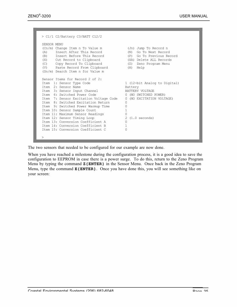
ZENO®-3200 USER MANUAL
Coastal Environmental Systems (206) 682-6048 Page 35
> C1/1 C2/Battery C3/BATT C12/2
SENSOR MENU(Cn/m) Change Item n To Value m (Jn) Jump To Record n(A) Insert After This Record (N) Go To Next Record(B) Insert Before This Record (P) Go To Previous Record(X) Cut Record to Clipboard (XA) Delete ALL Records(C) Copy Record To Clipboard (Z) Zeno Program Menu(V) Paste Record From Clipboard (H) Help(Sn/m) Search Item n for Value m
Sensor Items for Record 2 of 2:Item 1: Sensor Type Code 1 (12-bit Analog to Digital)Item 2: Sensor Name BatteryItem 3: Sensor Input Channel BATTERY VOLTAGEItem 6: Switched Power Code 0 (NO SWITCHED POWER)Item 7: Sensor Excitation Voltage Code 0 (NO EXCITATION VOLTAGE)Item 8: Switched Excitation Return 0Item 9: Switched Power Warmup Time 0Item 10: Sensor Sample Count 1Item 11: Maximum Sensor Readings 0Item 12: Sensor Timing Loop 2 (1.0 seconds)Item 13: Conversion Coefficient A 0Item 14: Conversion Coefficient B 1Item 15: Conversion Coefficient C 0
>
The two sensors that needed to be configured for our example are now done.
When you have reached a milestone during the configuration process, it is a good idea to save theconfiguration to EEPROM in case there is a power surge. To do this, return to the Zeno ProgramMenu by typing the command Z{ENTER} in the Sensor Menu. Once back in the Zeno ProgramMenu, type the command E{ENTER}. Once you have done this, you will see something like onyour screen:
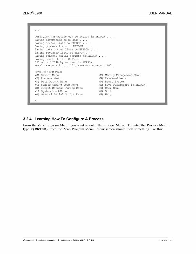
ZENO®-3200 USER MANUAL
Coastal Environmental Systems (206) 682-6048 Page 36
> e
Verifying parameters can be stored in EEPROM . . .Saving parameters to EEPROM . . .Saving sensor lists to EEPROM . . .Saving process lists to EEPROM . . .Saving data output lists to EEPROM . . .Saving repeater lists to EEPROM . . .Saving general serial scripts to EEPROM . . .Saving constants to EEPROM . . .665 out of 2048 bytes used in EEPROM.Total EEPROM Writes = 151, EEPROM Checksum = 102.
ZENO PROGRAM MENU(S) Sensor Menu (M) Memory Management Menu(P) Process Menu (W) Password Menu(D) Data Output Menu (R) Reset System(T) Sensor Timing Loop Menu (E) Save Parameters To EEPROM(O) Output Message Timing Menu (U) User Menu(L) System Load Menu (Q) Quit(G) General Serial Script Menu (H) Help
>
3.2.4. Learning How To Configure A Process
From the Zeno Program Menu, you want to enter the Process Menu. To enter the Process Menu,type P{ENTER} from the Zeno Program Menu. Your screen should look something like this:
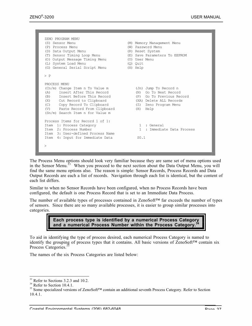
ZENO®-3200 USER MANUAL
Coastal Environmental Systems (206) 682-6048 Page 37
ZENO PROGRAM MENU(S) Sensor Menu (M) Memory Management Menu(P) Process Menu (W) Password Menu(D) Data Output Menu (R) Reset System(T) Sensor Timing Loop Menu (E) Save Parameters To EEPROM(O) Output Message Timing Menu (U) User Menu(L) System Load Menu (Q) Quit(G) General Serial Script Menu (H) Help
> P
PROCESS MENU(Cn/m) Change Item n To Value m (Jn) Jump To Record n(A) Insert After This Record (N) Go To Next Record(B) Insert Before This Record (P) Go To Previous Record(X) Cut Record to Clipboard (XA) Delete ALL Records(C) Copy Record To Clipboard (Z) Zeno Program Menu(V) Paste Record From Clipboard (H) Help(Sn/m) Search Item n for Value m
Process Items for Record 1 of 1:Item 1: Process Category 1 : GeneralItem 2: Process Number 1 : Immediate Data ProcessItem 3: User-defined Process NameItem 4: Input for Immediate Data S0.1
>
The Process Menu options should look very familiar because they are same set of menu options usedin the Sensor Menu.33 When you proceed to the next section about the Data Output Menu, you willfind the same menu options also. The reason is simple: Sensor Records, Process Records and DataOutput Records are each a list of records. Navigation through each list is identical, but the content ofeach list differs.
Similar to when no Sensor Records have been configured, when no Process Records have beenconfigured, the default is one Process Record that is set to an Immediate Data Process.
The number of available types of processes contained in ZenoSoft™ far exceeds the number of typesof sensors. Since there are so many available processes, it is easier to group similar processes intocategories.
Each process type is identified by a numerical Process Categoryand a numerical Process Number within the Process Category.34
To aid in identifying the type of process desired, each numerical Process Category is named toidentify the grouping of process types that it contains. All basic versions of ZenoSoft™ contain sixProcess Categories.35
The names of the six Process Categories are listed below:
33 Refer to Sections 3.2.3 and 10.2.34 Refer to Section 10.4.1.35 Some specialized versions of ZenoSoft™ contain an additional seventh Process Category. Refer to Section10.4.1.
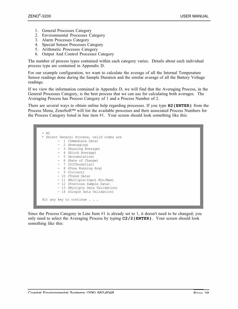
ZENO®-3200 USER MANUAL
Coastal Environmental Systems (206) 682-6048 Page 38
1. General Processes Category2. Environmental Processes Category3. Alarm Processes Category4. Special Sensor Processes Category5. Arithmetic Processes Category6. Output And Control Processes Category
The number of process types contained within each category varies. Details about each individualprocess type are contained in Appendix D.
For our example configuration, we want to calculate the average of all the Internal TemperatureSensor readings done during the Sample Duration and the similar average of all the Battery Voltagereadings.
If we view the information contained in Appendix D, we will find that the Averaging Process, in theGeneral Processes Category, is the best process that we can use for calculating both averages. TheAveraging Process has Process Category of 1 and a Process Number of 2.
There are several ways to obtain online help regarding processes. If you type H2{ENTER} from theProcess Menu, ZenoSoft™ will list the available processes and their associated Process Numbers forthe Process Category listed in line item #1. Your screen should look something like this:
> H2* Select General Process, valid codes are - 1 (Immediate Data) - 2 (Averaging) - 3 (Running Average) - 4 (Block Average) - 5 (Accumulation) - 6 (Rate of Change) - 7 (Differential) - 8 (Free Running Avg) - 9 (Collect) - 10 (Trend Data) - 11 (Multiple-Input Min/Max) - 12 (Previous Sample Data) - 13 (Multiple Data Validation) - 14 (Single Data Validation)
Hit any key to continue . . .
Since the Process Category in Line Item #1 is already set to 1, it doesn't need to be changed; youonly need to select the Averaging Process by typing C2/2{ENTER}. Your screen should looksomething like this:
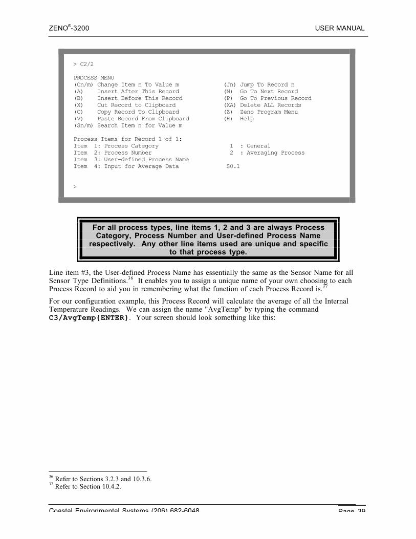
ZENO®-3200 USER MANUAL
Coastal Environmental Systems (206) 682-6048 Page 39
> C2/2
PROCESS MENU(Cn/m) Change Item n To Value m (Jn) Jump To Record n(A) Insert After This Record (N) Go To Next Record(B) Insert Before This Record (P) Go To Previous Record(X) Cut Record to Clipboard (XA) Delete ALL Records(C) Copy Record To Clipboard (Z) Zeno Program Menu(V) Paste Record From Clipboard (H) Help(Sn/m) Search Item n for Value m
Process Items for Record 1 of 1:Item 1: Process Category 1 : GeneralItem 2: Process Number 2 : Averaging ProcessItem 3: User-defined Process NameItem 4: Input for Average Data S0.1
>
For all process types, line items 1, 2 and 3 are always ProcessCategory, Process Number and User-defined Process Name
respectively. Any other line items used are unique and specificto that process type.
Line item #3, the User-defined Process Name has essentially the same as the Sensor Name for allSensor Type Definitions.36 It enables you to assign a unique name of your own choosing to eachProcess Record to aid you in remembering what the function of each Process Record is.37
For our configuration example, this Process Record will calculate the average of all the InternalTemperature Readings. We can assign the name "AvgTemp" by typing the commandC3/AvgTemp{ENTER}. Your screen should look something like this:
36 Refer to Sections 3.2.3 and 10.3.6.37 Refer to Section 10.4.2.
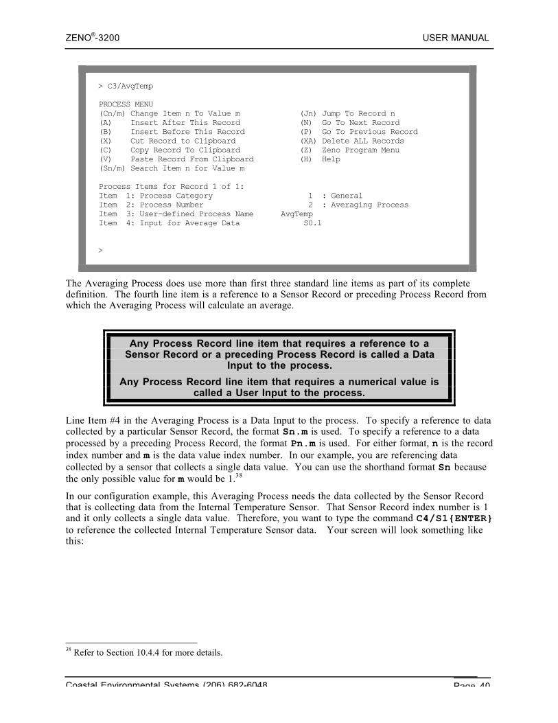
ZENO®-3200 USER MANUAL
Coastal Environmental Systems (206) 682-6048 Page 40
> C3/AvgTemp
PROCESS MENU(Cn/m) Change Item n To Value m (Jn) Jump To Record n(A) Insert After This Record (N) Go To Next Record(B) Insert Before This Record (P) Go To Previous Record(X) Cut Record to Clipboard (XA) Delete ALL Records(C) Copy Record To Clipboard (Z) Zeno Program Menu(V) Paste Record From Clipboard (H) Help(Sn/m) Search Item n for Value m
Process Items for Record 1 of 1:Item 1: Process Category 1 : GeneralItem 2: Process Number 2 : Averaging ProcessItem 3: User-defined Process Name AvgTempItem 4: Input for Average Data S0.1
>
The Averaging Process does use more than first three standard line items as part of its completedefinition. The fourth line item is a reference to a Sensor Record or preceding Process Record fromwhich the Averaging Process will calculate an average.
Any Process Record line item that requires a reference to aSensor Record or a preceding Process Record is called a Data
Input to the process.
Any Process Record line item that requires a numerical value iscalled a User Input to the process.
Line Item #4 in the Averaging Process is a Data Input to the process. To specify a reference to datacollected by a particular Sensor Record, the format Sn.m is used. To specify a reference to a dataprocessed by a preceding Process Record, the format Pn.m is used. For either format, n is the recordindex number and m is the data value index number. In our example, you are referencing datacollected by a sensor that collects a single data value. You can use the shorthand format Sn becausethe only possible value for m would be 1.38
In our configuration example, this Averaging Process needs the data collected by the Sensor Recordthat is collecting data from the Internal Temperature Sensor. That Sensor Record index number is 1and it only collects a single data value. Therefore, you want to type the command C4/S1{ENTER}to reference the collected Internal Temperature Sensor data. Your screen will look something likethis:
38 Refer to Section 10.4.4 for more details.
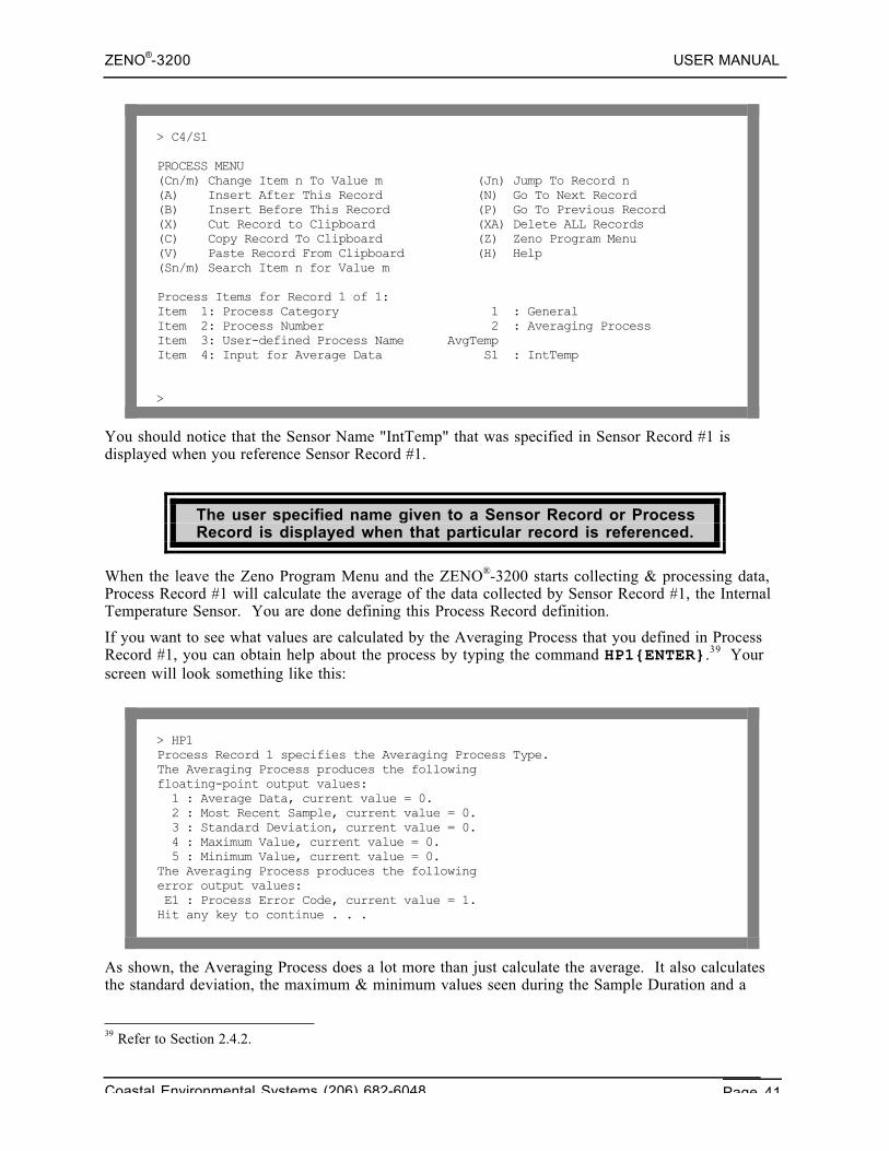
ZENO®-3200 USER MANUAL
Coastal Environmental Systems (206) 682-6048 Page 41
> C4/S1
PROCESS MENU(Cn/m) Change Item n To Value m (Jn) Jump To Record n(A) Insert After This Record (N) Go To Next Record(B) Insert Before This Record (P) Go To Previous Record(X) Cut Record to Clipboard (XA) Delete ALL Records(C) Copy Record To Clipboard (Z) Zeno Program Menu(V) Paste Record From Clipboard (H) Help(Sn/m) Search Item n for Value m
Process Items for Record 1 of 1:Item 1: Process Category 1 : GeneralItem 2: Process Number 2 : Averaging ProcessItem 3: User-defined Process Name AvgTempItem 4: Input for Average Data S1 : IntTemp
>
You should notice that the Sensor Name "IntTemp" that was specified in Sensor Record #1 isdisplayed when you reference Sensor Record #1.
The user specified name given to a Sensor Record or ProcessRecord is displayed when that particular record is referenced.
When the leave the Zeno Program Menu and the ZENO®-3200 starts collecting & processing data,Process Record #1 will calculate the average of the data collected by Sensor Record #1, the InternalTemperature Sensor. You are done defining this Process Record definition.
If you want to see what values are calculated by the Averaging Process that you defined in ProcessRecord #1, you can obtain help about the process by typing the command HP1{ENTER}.39 Yourscreen will look something like this:
> HP1Process Record 1 specifies the Averaging Process Type.The Averaging Process produces the followingfloating-point output values: 1 : Average Data, current value = 0. 2 : Most Recent Sample, current value = 0. 3 : Standard Deviation, current value = 0. 4 : Maximum Value, current value = 0. 5 : Minimum Value, current value = 0.The Averaging Process produces the followingerror output values: E1 : Process Error Code, current value = 1.Hit any key to continue . . .
As shown, the Averaging Process does a lot more than just calculate the average. It also calculatesthe standard deviation, the maximum & minimum values seen during the Sample Duration and a
39 Refer to Section 2.4.2.
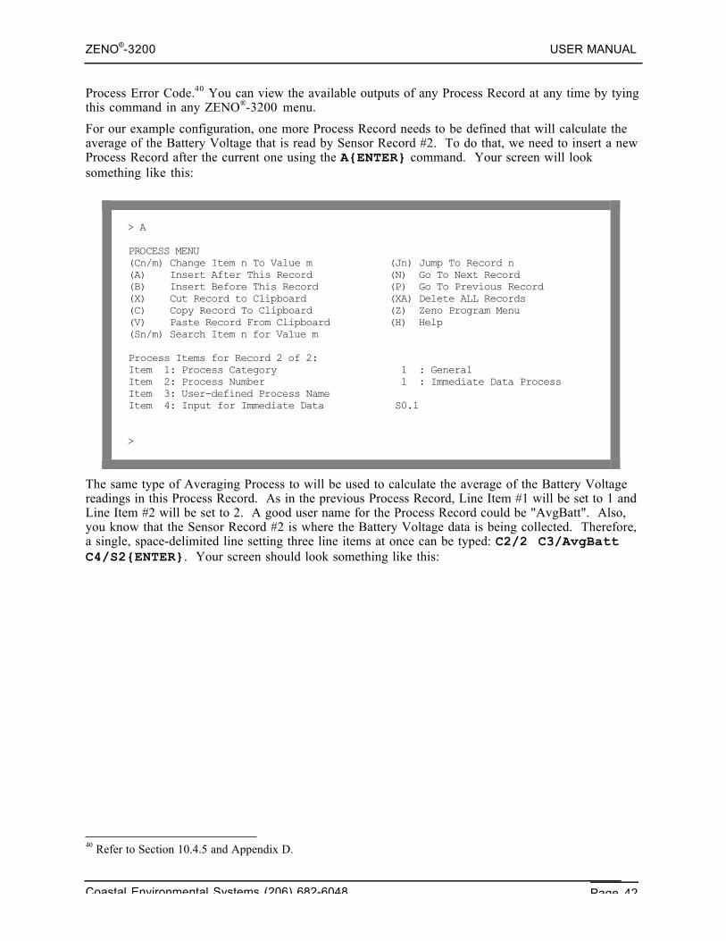
ZENO®-3200 USER MANUAL
Coastal Environmental Systems (206) 682-6048 Page 42
Process Error Code.40 You can view the available outputs of any Process Record at any time by tyingthis command in any ZENO®-3200 menu.
For our example configuration, one more Process Record needs to be defined that will calculate theaverage of the Battery Voltage that is read by Sensor Record #2. To do that, we need to insert a newProcess Record after the current one using the A{ENTER} command. Your screen will looksomething like this:
> A
PROCESS MENU(Cn/m) Change Item n To Value m (Jn) Jump To Record n(A) Insert After This Record (N) Go To Next Record(B) Insert Before This Record (P) Go To Previous Record(X) Cut Record to Clipboard (XA) Delete ALL Records(C) Copy Record To Clipboard (Z) Zeno Program Menu(V) Paste Record From Clipboard (H) Help(Sn/m) Search Item n for Value m
Process Items for Record 2 of 2:Item 1: Process Category 1 : GeneralItem 2: Process Number 1 : Immediate Data ProcessItem 3: User-defined Process NameItem 4: Input for Immediate Data S0.1
>
The same type of Averaging Process to will be used to calculate the average of the Battery Voltagereadings in this Process Record. As in the previous Process Record, Line Item #1 will be set to 1 andLine Item #2 will be set to 2. A good user name for the Process Record could be "AvgBatt". Also,you know that the Sensor Record #2 is where the Battery Voltage data is being collected. Therefore,a single, space-delimited line setting three line items at once can be typed: C2/2 C3/AvgBattC4/S2{ENTER}. Your screen should look something like this:
40 Refer to Section 10.4.5 and Appendix D.
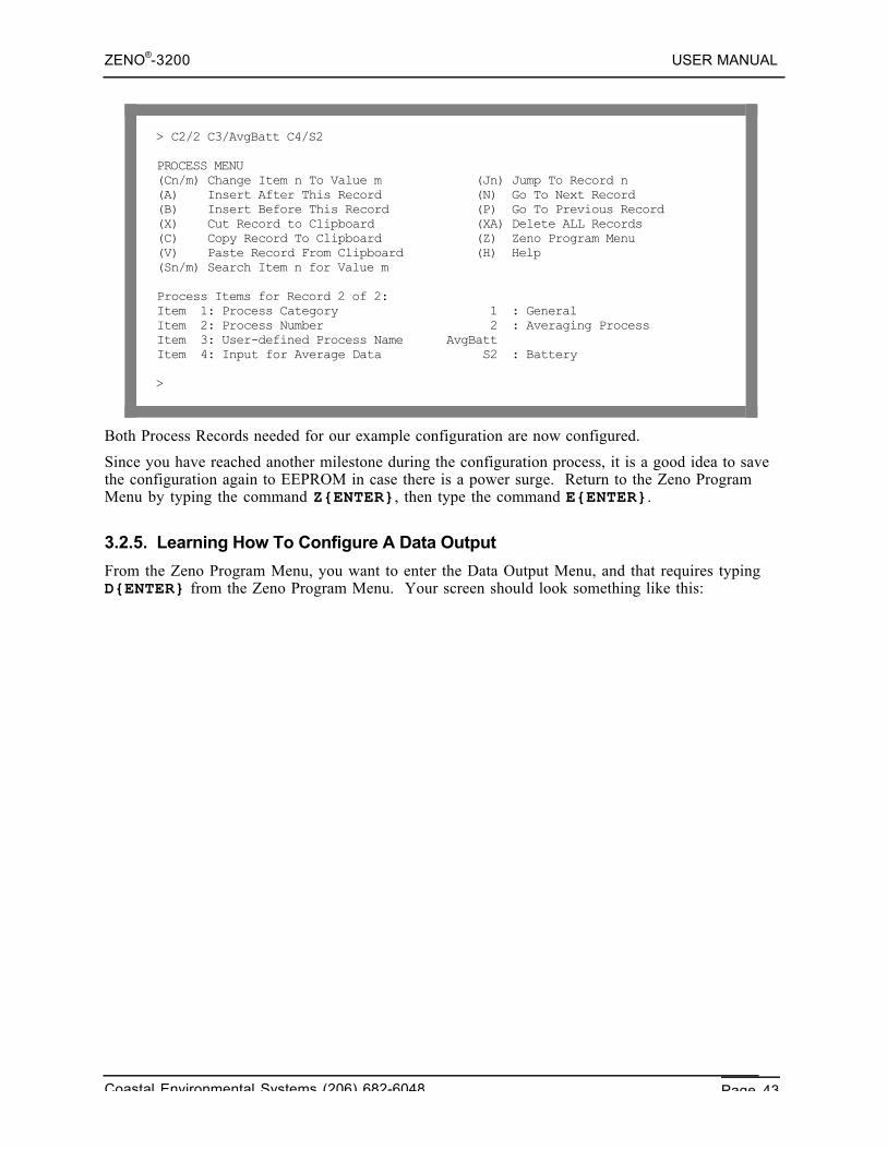
ZENO®-3200 USER MANUAL
Coastal Environmental Systems (206) 682-6048 Page 43
> C2/2 C3/AvgBatt C4/S2
PROCESS MENU(Cn/m) Change Item n To Value m (Jn) Jump To Record n(A) Insert After This Record (N) Go To Next Record(B) Insert Before This Record (P) Go To Previous Record(X) Cut Record to Clipboard (XA) Delete ALL Records(C) Copy Record To Clipboard (Z) Zeno Program Menu(V) Paste Record From Clipboard (H) Help(Sn/m) Search Item n for Value m
Process Items for Record 2 of 2:Item 1: Process Category 1 : GeneralItem 2: Process Number 2 : Averaging ProcessItem 3: User-defined Process Name AvgBattItem 4: Input for Average Data S2 : Battery
>
Both Process Records needed for our example configuration are now configured.
Since you have reached another milestone during the configuration process, it is a good idea to savethe configuration again to EEPROM in case there is a power surge. Return to the Zeno ProgramMenu by typing the command Z{ENTER}, then type the command E{ENTER}.
3.2.5. Learning How To Configure A Data Output
From the Zeno Program Menu, you want to enter the Data Output Menu, and that requires typingD{ENTER} from the Zeno Program Menu. Your screen should look something like this:
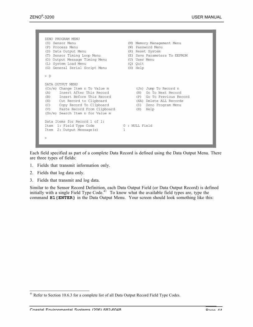
ZENO®-3200 USER MANUAL
Coastal Environmental Systems (206) 682-6048 Page 44
ZENO PROGRAM MENU(S) Sensor Menu (M) Memory Management Menu(P) Process Menu (W) Password Menu(D) Data Output Menu (R) Reset System(T) Sensor Timing Loop Menu (E) Save Parameters To EEPROM(O) Output Message Timing Menu (U) User Menu(L) System Load Menu (Q) Quit(G) General Serial Script Menu (H) Help
> D
DATA OUTPUT MENU(Cn/m) Change Item n To Value m (Jn) Jump To Record n(A) Insert After This Record (N) Go To Next Record(B) Insert Before This Record (P) Go To Previous Record(X) Cut Record to Clipboard (XA) Delete ALL Records(C) Copy Record To Clipboard (Z) Zeno Program Menu(V) Paste Record From Clipboard (H) Help(Sn/m) Search Item n for Value m
Data Items for Record 1 of 1:Item 1: Field Type Code 0 : NULL FieldItem 2: Output Message(s) 1
>
Each field specified as part of a complete Data Record is defined using the Data Output Menu. Thereare three types of fields:
1. Fields that transmit information only.
2. Fields that log data only.
3. Fields that transmit and log data.
Similar to the Sensor Record Definition, each Data Output Field (or Data Output Record) is definedinitially with a single Field Type Code.41 To know what the available field types are, type thecommand H1{ENTER} in the Data Output Menu. Your screen should look something like this:
41 Refer to Section 10.6.3 for a complete list of all Data Output Record Field Type Codes.
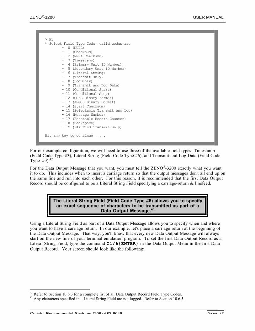
ZENO®-3200 USER MANUAL
Coastal Environmental Systems (206) 682-6048 Page 45
> H1* Select Field Type Code, valid codes are - 0 (NULL) - 1 (Checksum) - 2 (NMEA Checksum) - 3 (Timestamp) - 4 (Primary Unit ID Number) - 5 (Secondary Unit ID Number) - 6 (Literal String) - 7 (Transmit Only) - 8 (Log Only) - 9 (Transmit and Log Data) - 10 (Conditional Start) - 11 (Conditional Stop) - 12 (GOES Binary Format) - 13 (ARGOS Binary Format) - 14 (Start Checksum) - 15 (Selectable Transmit and Log) - 16 (Message Number) - 17 (Resetable Record Counter) - 18 (Backspace) - 19 (FAA Wind Transmit Only)
Hit any key to continue . . .
For our example configuration, we will need to use three of the available field types: Timestamp(Field Code Type #3), Literal String (Field Code Type #6), and Transmit and Log Data (Field CodeType #9).42
For the Data Output Message that you want, you must tell the ZENO®-3200 exactly what you wantit to do. This includes when to insert a carriage return so that the output messages don't all end up onthe same line and run into each other. For this reason, it is recommended that the first Data OutputRecord should be configured to be a Literal String Field specifying a carriage-return & linefeed.
The Literal String Field (Field Code Type #6) allows you to specifyan exact sequence of characters to be transmitted as part of a
Data Output Message.43
Using a Literal String Field as part of a Data Output Message allows you to specify when and whereyou want to have a carriage return. In our example, let's place a carriage return at the beginning ofthe Data Output Message. That way, you'll know that every new Data Output Message will alwaysstart on the new line of your terminal emulation program. To set the first Data Output Record as aLiteral String Field, type the command C1/6{ENTER} in the Data Output Menu in the first DataOutput Record. Your screen should look like the following:
42 Refer to Section 10.6.3 for a complete list of all Data Output Record Field Type Codes.43 Any characters specified in a Literal String Field are not logged. Refer to Section 10.6.5.
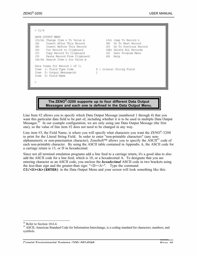
ZENO®-3200 USER MANUAL
Coastal Environmental Systems (206) 682-6048 Page 46
> C1/6
DATA OUTPUT MENU(Cn/m) Change Item n To Value m (Jn) Jump To Record n(A) Insert After This Record (N) Go To Next Record(B) Insert Before This Record (P) Go To Previous Record(X) Cut Record to Clipboard (XA) Delete ALL Records(C) Copy Record To Clipboard (Z) Zeno Program Menu(V) Paste Record From Clipboard (H) Help(Sn/m) Search Item n for Value m
Data Items for Record 1 of 1:Item 1: Field Type Code 6 : Literal String FieldItem 2: Output Message(s) 1Item 3: Field Name
>
The ZENO®-3200 supports up to four different Data OutputMessages and each one is defined in the Data Output Menu.
Line Item #2 allows you to specify which Data Output Message (numbered 1 through 4) that youwant this particular data field to be part of, including whether it is to be used in multiple Data OutputMessages.44 In our example configuration, we are only using one Data Output Message (the firstone), so the value of line item #2 does not need to be changed in any way.
Line item #3, the Field Name, is where you will specify what characters you want the ZENO®-3200to print for the Literal String Field. In order to enter "non-printable characters" (any non-alphanumeric or non-punctuation character), ZenoSoft™ allows you to specify the ASCII45 code ofeach non-printable character. By using the ASCII table contained in Appendix A, the ASCII code fora carriage return is 13, or D in hexadecimal.
Since not all terminal emulation programs add a line feed to a carriage return, it's a good idea to alsoadd the ASCII code for a line feed, which is 10, or a hexadecimal A. To designate that you areentering character as an ASCII code, you enclose the hexadecimal ASCII code in two brackets usingthe less-than sign and the greater-than sign: "<D><A>". Type the commandC3/<D><A>{ENTER} in the Data Output Menu and your screen will look something like this:
44 Refer to Section 10.6.4.45 ASCII, American Standard Code for Information Interchange, is a coding standard for characters, numbers, andsymbols.
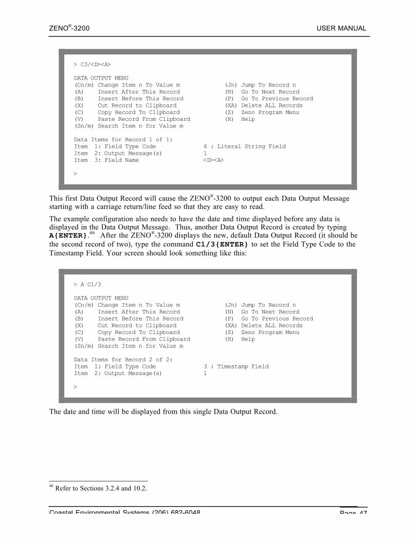
ZENO®-3200 USER MANUAL
Coastal Environmental Systems (206) 682-6048 Page 47
> C3/<D><A>
DATA OUTPUT MENU(Cn/m) Change Item n To Value m (Jn) Jump To Record n(A) Insert After This Record (N) Go To Next Record(B) Insert Before This Record (P) Go To Previous Record(X) Cut Record to Clipboard (XA) Delete ALL Records(C) Copy Record To Clipboard (Z) Zeno Program Menu(V) Paste Record From Clipboard (H) Help(Sn/m) Search Item n for Value m
Data Items for Record 1 of 1:Item 1: Field Type Code 6 : Literal String FieldItem 2: Output Message(s) 1Item 3: Field Name <D><A>
>
This first Data Output Record will cause the ZENO®-3200 to output each Data Output Messagestarting with a carriage return/line feed so that they are easy to read.
The example configuration also needs to have the date and time displayed before any data isdisplayed in the Data Output Message. Thus, another Data Output Record is created by typingA{ENTER}.46 After the ZENO®-3200 displays the new, default Data Output Record (it should bethe second record of two), type the command C1/3{ENTER} to set the Field Type Code to theTimestamp Field. Your screen should look something like this:
> A C1/3
DATA OUTPUT MENU(Cn/m) Change Item n To Value m (Jn) Jump To Record n(A) Insert After This Record (N) Go To Next Record(B) Insert Before This Record (P) Go To Previous Record(X) Cut Record to Clipboard (XA) Delete ALL Records(C) Copy Record To Clipboard (Z) Zeno Program Menu(V) Paste Record From Clipboard (H) Help(Sn/m) Search Item n for Value m
Data Items for Record 2 of 2:Item 1: Field Type Code 3 : Timestamp FieldItem 2: Output Message(s) 1
>
The date and time will be displayed from this single Data Output Record.
46 Refer to Sections 3.2.4 and 10.2.
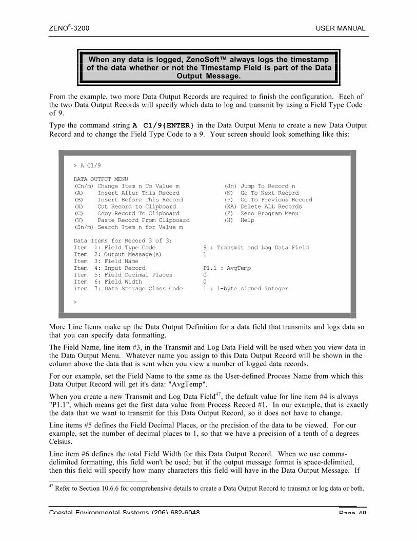
ZENO®-3200 USER MANUAL
Coastal Environmental Systems (206) 682-6048 Page 48
When any data is logged, ZenoSoft™ always logs the timestampof the data whether or not the Timestamp Field is part of the Data
Output Message.
From the example, two more Data Output Records are required to finish the configuration. Each ofthe two Data Output Records will specify which data to log and transmit by using a Field Type Codeof 9.
Type the command string A C1/9{ENTER} in the Data Output Menu to create a new Data OutputRecord and to change the Field Type Code to a 9. Your screen should look something like this:
> A C1/9
DATA OUTPUT MENU(Cn/m) Change Item n To Value m (Jn) Jump To Record n(A) Insert After This Record (N) Go To Next Record(B) Insert Before This Record (P) Go To Previous Record(X) Cut Record to Clipboard (XA) Delete ALL Records(C) Copy Record To Clipboard (Z) Zeno Program Menu(V) Paste Record From Clipboard (H) Help(Sn/m) Search Item n for Value m
Data Items for Record 3 of 3:Item 1: Field Type Code 9 : Transmit and Log Data FieldItem 2: Output Message(s) 1Item 3: Field NameItem 4: Input Record P1.1 : AvgTempItem 5: Field Decimal Places 0Item 6: Field Width 0Item 7: Data Storage Class Code 1 : 1-byte signed integer
>
More Line Items make up the Data Output Definition for a data field that transmits and logs data sothat you can specify data formatting.
The Field Name, line item #3, in the Transmit and Log Data Field will be used when you view data inthe Data Output Menu. Whatever name you assign to this Data Output Record will be shown in thecolumn above the data that is sent when you view a number of logged data records.
For our example, set the Field Name to the same as the User-defined Process Name from which thisData Output Record will get it's data: "AvgTemp".
When you create a new Transmit and Log Data Field47, the default value for line item #4 is always"P1.1", which means get the first data value from Process Record #1. In our example, that is exactlythe data that we want to transmit for this Data Output Record, so it does not have to change.
Line items #5 defines the Field Decimal Places, or the precision of the data to be viewed. For ourexample, set the number of decimal places to 1, so that we have a precision of a tenth of a degreesCelsius.
Line item #6 defines the total Field Width for this Data Output Record. When we use comma-delimited formatting, this field won't be used; but if the output message format is space-delimited,then this field will specify how many characters this field will have in the Data Output Message. If 47 Refer to Section 10.6.6 for comprehensive details to create a Data Output Record to transmit or log data or both.
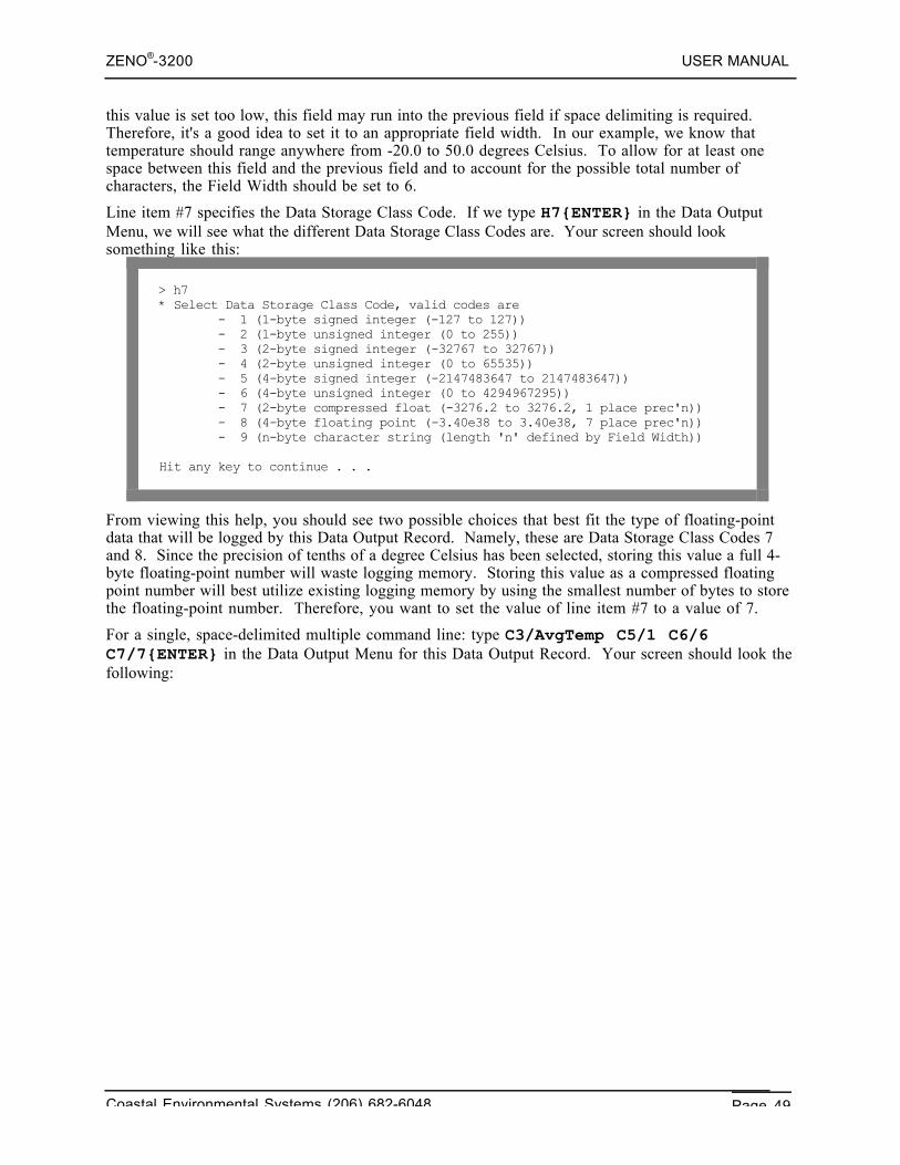
ZENO®-3200 USER MANUAL
Coastal Environmental Systems (206) 682-6048 Page 49
this value is set too low, this field may run into the previous field if space delimiting is required.Therefore, it's a good idea to set it to an appropriate field width. In our example, we know thattemperature should range anywhere from -20.0 to 50.0 degrees Celsius. To allow for at least onespace between this field and the previous field and to account for the possible total number ofcharacters, the Field Width should be set to 6.
Line item #7 specifies the Data Storage Class Code. If we type H7{ENTER} in the Data OutputMenu, we will see what the different Data Storage Class Codes are. Your screen should looksomething like this:
> h7* Select Data Storage Class Code, valid codes are - 1 (1-byte signed integer (-127 to 127)) - 2 (1-byte unsigned integer (0 to 255)) - 3 (2-byte signed integer (-32767 to 32767)) - 4 (2-byte unsigned integer (0 to 65535)) - 5 (4-byte signed integer (-2147483647 to 2147483647)) - 6 (4-byte unsigned integer (0 to 4294967295)) - 7 (2-byte compressed float (-3276.2 to 3276.2, 1 place prec'n)) - 8 (4-byte floating point (-3.40e38 to 3.40e38, 7 place prec'n)) - 9 (n-byte character string (length 'n' defined by Field Width))
Hit any key to continue . . .
From viewing this help, you should see two possible choices that best fit the type of floating-pointdata that will be logged by this Data Output Record. Namely, these are Data Storage Class Codes 7and 8. Since the precision of tenths of a degree Celsius has been selected, storing this value a full 4-byte floating-point number will waste logging memory. Storing this value as a compressed floatingpoint number will best utilize existing logging memory by using the smallest number of bytes to storethe floating-point number. Therefore, you want to set the value of line item #7 to a value of 7.
For a single, space-delimited multiple command line: type C3/AvgTemp C5/1 C6/6C7/7{ENTER} in the Data Output Menu for this Data Output Record. Your screen should look thefollowing:
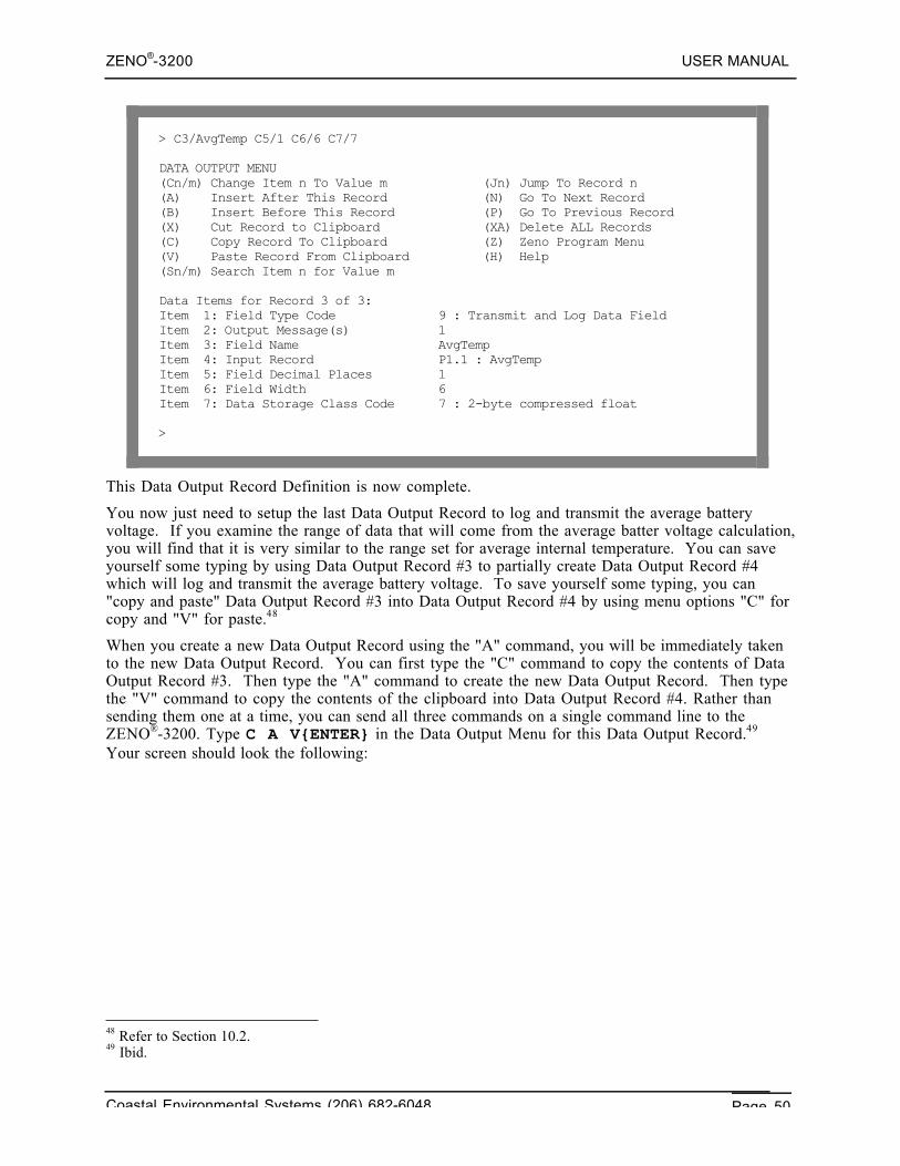
ZENO®-3200 USER MANUAL
Coastal Environmental Systems (206) 682-6048 Page 50
> C3/AvgTemp C5/1 C6/6 C7/7
DATA OUTPUT MENU(Cn/m) Change Item n To Value m (Jn) Jump To Record n(A) Insert After This Record (N) Go To Next Record(B) Insert Before This Record (P) Go To Previous Record(X) Cut Record to Clipboard (XA) Delete ALL Records(C) Copy Record To Clipboard (Z) Zeno Program Menu(V) Paste Record From Clipboard (H) Help(Sn/m) Search Item n for Value m
Data Items for Record 3 of 3:Item 1: Field Type Code 9 : Transmit and Log Data FieldItem 2: Output Message(s) 1Item 3: Field Name AvgTempItem 4: Input Record P1.1 : AvgTempItem 5: Field Decimal Places 1Item 6: Field Width 6Item 7: Data Storage Class Code 7 : 2-byte compressed float
>
This Data Output Record Definition is now complete.
You now just need to setup the last Data Output Record to log and transmit the average batteryvoltage. If you examine the range of data that will come from the average batter voltage calculation,you will find that it is very similar to the range set for average internal temperature. You can saveyourself some typing by using Data Output Record #3 to partially create Data Output Record #4which will log and transmit the average battery voltage. To save yourself some typing, you can"copy and paste" Data Output Record #3 into Data Output Record #4 by using menu options "C" forcopy and "V" for paste.48
When you create a new Data Output Record using the "A" command, you will be immediately takento the new Data Output Record. You can first type the "C" command to copy the contents of DataOutput Record #3. Then type the "A" command to create the new Data Output Record. Then typethe "V" command to copy the contents of the clipboard into Data Output Record #4. Rather thansending them one at a time, you can send all three commands on a single command line to theZENO®-3200. Type C A V{ENTER} in the Data Output Menu for this Data Output Record.49
Your screen should look the following:
48 Refer to Section 10.2.49 Ibid.
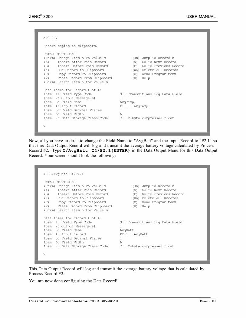
ZENO®-3200 USER MANUAL
Coastal Environmental Systems (206) 682-6048 Page 51
> C A V
Record copied to clipboard.
DATA OUTPUT MENU(Cn/m) Change Item n To Value m (Jn) Jump To Record n(A) Insert After This Record (N) Go To Next Record(B) Insert Before This Record (P) Go To Previous Record(X) Cut Record to Clipboard (XA) Delete ALL Records(C) Copy Record To Clipboard (Z) Zeno Program Menu(V) Paste Record From Clipboard (H) Help(Sn/m) Search Item n for Value m
Data Items for Record 4 of 4:Item 1: Field Type Code 9 : Transmit and Log Data FieldItem 2: Output Message(s) 1Item 3: Field Name AvgTempItem 4: Input Record P1.1 : AvgTempItem 5: Field Decimal Places 1Item 6: Field Width 6Item 7: Data Storage Class Code 7 : 2-byte compressed float
>
Now, all you have to do is to change the Field Name to "AvgBatt" and the Input Record to "P2.1" sothat this Data Output Record will log and transmit the average battery voltage calculated by ProcessRecord #2. Type C/AvgBatt C4/P2.1{ENTER} in the Data Output Menu for this Data OutputRecord. Your screen should look the following:
> C3/AvgBatt C4/P2.1
DATA OUTPUT MENU(Cn/m) Change Item n To Value m (Jn) Jump To Record n(A) Insert After This Record (N) Go To Next Record(B) Insert Before This Record (P) Go To Previous Record(X) Cut Record to Clipboard (XA) Delete ALL Records(C) Copy Record To Clipboard (Z) Zeno Program Menu(V) Paste Record From Clipboard (H) Help(Sn/m) Search Item n for Value m
Data Items for Record 4 of 4:Item 1: Field Type Code 9 : Transmit and Log Data FieldItem 2: Output Message(s) 1Item 3: Field Name AvgBattItem 4: Input Record P2.1 : AvgBattItem 5: Field Decimal Places 1Item 6: Field Width 6Item 7: Data Storage Class Code 7 : 2-byte compressed float
>
This Data Output Record will log and transmit the average battery voltage that is calculated byProcess Record #2.
You are now done configuring the Data Record!
ZENO®-3200 USER MANUAL
Coastal Environmental Systems (206) 682-6048 Page 52
Since you have reached another milestone in your configuration, you should return to the ZenoProgram Menu and type E{ENTER} to save the configuration changes to EEPROM. That way, thechanges you have made won't be lost if there is a power surge or outage.
3.2.6. Other Configuration Changes
Since all the sensors, processes and data output records are now configured, you can go back to theUser Menu and do any other configuration changes that are required. In particular, you might wantthis example configuration to behave as in the first part of the Tutorial Section. In that case, youcan go to the Sample Period Menu and set the Sample Interval, Sample Duration and Sample TimeOffset to the settings that match the first part of the tutorial.50
When you create your own configuration, other things may need to be set in the configurationbeyond what was described in the examples within this tutorial. These will be covered in the nextsections of this User Manual.
50 Refer to Section 3.1.3.
ZENO®-3200 USER MANUAL
Coastal Environmental Systems (206) 682-6048 Page 53
4. RETRIEVING LOGGEDDATA
Coastal EnvironmentalSystems
ZENO®-3200 User Manual
When you use your ZENO®-3200 to log Data Records, ZenoSoft™ stores the Data Records insequential order. Each Data Record consists of a timestamp (the date and time) as well as the datavalues to be logged. The data values being logged are defined in the Data Output Menu.
The time interval between successive, regularly logged DataRecords is always the same as long as:
1. There is no power loss to the ZENO®-3200.
2. There are no changes in the Sample Interval, Sample Duration,Sample Time Offset, internal ZENO®-3200 clock or other timerelated information in the configuration.
3. There are no Alarm Messages being logged.
4. A user does not enter the Zeno Program Menu in the UserInterface.
If the ZENO®-3200 suffers a loss of power, there will be a gap in your logged Data Records. The sizeof the gap will depend upon the duration of the power loss.
A "gap" in logged Data Records is not a physical gap in memory,but a longer difference in timestamps between successive Data
Records than your configuration specifies.
If you make any changes to the Sample Interval, Sample Duration Time, Sample Time Offset,internal ZENO®-3200 clock or any other time related information in your configuration, there willprobably be a gap in your logged Data Records.
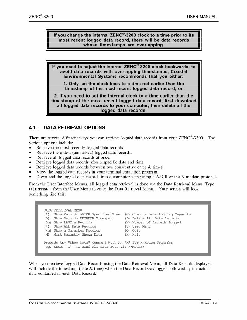
ZENO®-3200 USER MANUAL
Coastal Environmental Systems (206) 682-6048 Page 54
If you change the internal ZENO®-3200 clock to a time prior to itsmost recent logged data record, there will be data records
whose timestamps are overlapping.
If you need to adjust the internal ZENO®-3200 clock backwards, toavoid data records with overlapping timestamps, Coastal
Environmental Systems recommends that you either:
1. Only set the clock back to a time not earlier than thetimestamp of the most recent logged data record, or
2. If you need to set the internal clock to a time earlier than thetimestamp of the most recent logged data record, first download
all logged data records to your computer, then delete all thelogged data records.
4.1. DATA RETRIEVAL OPTIONS
There are several different ways you can retrieve logged data records from your ZENO®-3200. Thevarious options include:• Retrieve the most recently logged data records.• Retrieve the oldest (unmarked) logged data records.• Retrieve all logged data records at once.• Retrieve logged data records after a specific date and time.• Retrieve logged data records between two consecutive dates & times.• View the logged data records in your terminal emulation program.• Download the logged data records into a computer using simple ASCII or the X-modem protocol.
From the User Interface Menus, all logged data retrieval is done via the Data Retrieval Menu. TypeD{ENTER} from the User Menu to enter the Data Retrieval Menu. Your screen will looksomething like this:
DATA RETRIEVAL MENU(A) Show Records AFTER Specified Time (C) Compute Data Logging Capacity(B) Show Records BETWEEN Timespan (D) Delete All Data Records(Ln) Show LAST n Records (N) Number of Records Logged(*) Show ALL Data Records (U) User Menu(@n) Show n Unmarked Records (Q) Quit(M) Mark Recently Shown Data (H) Help
Precede Any "Show Data" Command With An 'X' For X-Modem Transfer(eg. Enter 'X*' To Send All Data Sets Via X-Modem)
When you retrieve logged Data Records using the Data Retrieval Menu, all Data Records displayedwill include the timestamp (date & time) when the Data Record was logged followed by the actualdata contained in each Data Record.
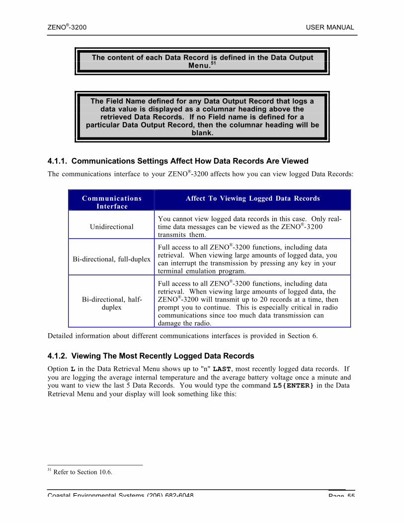
ZENO®-3200 USER MANUAL
Coastal Environmental Systems (206) 682-6048 Page 55
The content of each Data Record is defined in the Data OutputMenu.51
The Field Name defined for any Data Output Record that logs adata value is displayed as a columnar heading above theretrieved Data Records. If no Field name is defined for a
particular Data Output Record, then the columnar heading will beblank.
4.1.1. Communications Settings Affect How Data Records Are Viewed
The communications interface to your ZENO®-3200 affects how you can view logged Data Records:
CommunicationsInterface
Affect To Viewing Logged Data Records
UnidirectionalYou cannot view logged data records in this case. Only real-time data messages can be viewed as the ZENO®-3200transmits them.
Bi-directional, full-duplex
Full access to all ZENO®-3200 functions, including dataretrieval. When viewing large amounts of logged data, youcan interrupt the transmission by pressing any key in yourterminal emulation program.
Bi-directional, half-duplex
Full access to all ZENO®-3200 functions, including dataretrieval. When viewing large amounts of logged data, theZENO®-3200 will transmit up to 20 records at a time, thenprompt you to continue. This is especially critical in radiocommunications since too much data transmission candamage the radio.
Detailed information about different communications interfaces is provided in Section 6.
4.1.2. Viewing The Most Recently Logged Data Records
Option L in the Data Retrieval Menu shows up to "n" LAST, most recently logged data records. Ifyou are logging the average internal temperature and the average battery voltage once a minute andyou want to view the last 5 Data Records. You would type the command L5{ENTER} in the DataRetrieval Menu and your display will look something like this:
51 Refer to Section 10.6.
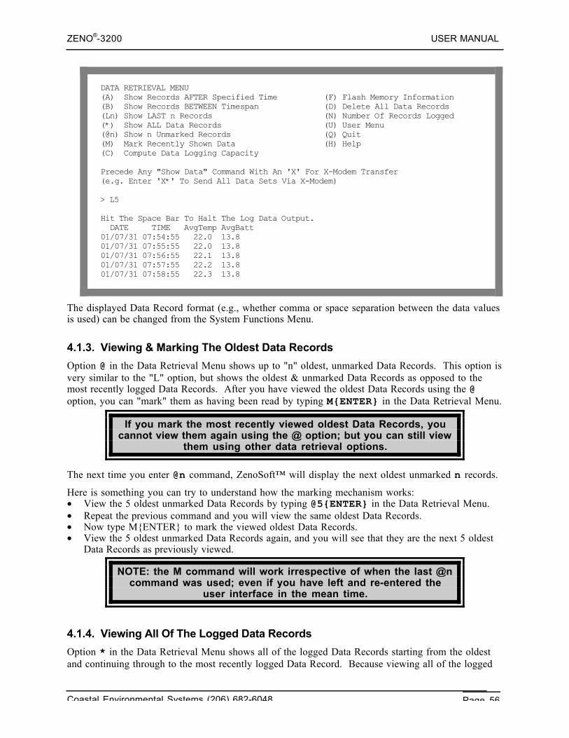
ZENO®-3200 USER MANUAL
Coastal Environmental Systems (206) 682-6048 Page 56
DATA RETRIEVAL MENU(A) Show Records AFTER Specified Time (F) Flash Memory Information(B) Show Records BETWEEN Timespan (D) Delete All Data Records(Ln) Show LAST n Records (N) Number Of Records Logged(*) Show ALL Data Records (U) User Menu(@n) Show n Unmarked Records (Q) Quit(M) Mark Recently Shown Data (H) Help(C) Compute Data Logging Capacity
Precede Any "Show Data" Command With An 'X' For X-Modem Transfer(e.g. Enter 'X*' To Send All Data Sets Via X-Modem)
> L5
Hit The Space Bar To Halt The Log Data Output. DATE TIME AvgTemp AvgBatt01/07/31 07:54:55 22.0 13.801/07/31 07:55:55 22.0 13.801/07/31 07:56:55 22.1 13.801/07/31 07:57:55 22.2 13.801/07/31 07:58:55 22.3 13.8
The displayed Data Record format (e.g., whether comma or space separation between the data valuesis used) can be changed from the System Functions Menu.
4.1.3. Viewing & Marking The Oldest Data Records
Option @ in the Data Retrieval Menu shows up to "n" oldest, unmarked Data Records. This option isvery similar to the "L" option, but shows the oldest & unmarked Data Records as opposed to themost recently logged Data Records. After you have viewed the oldest Data Records using the @option, you can "mark" them as having been read by typing M{ENTER} in the Data Retrieval Menu.
If you mark the most recently viewed oldest Data Records, youcannot view them again using the @ option; but you can still view
them using other data retrieval options.
The next time you enter @n command, ZenoSoft™ will display the next oldest unmarked n records.
Here is something you can try to understand how the marking mechanism works:• View the 5 oldest unmarked Data Records by typing @5{ENTER} in the Data Retrieval Menu.• Repeat the previous command and you will view the same oldest Data Records.• Now type M{ENTER} to mark the viewed oldest Data Records.• View the 5 oldest unmarked Data Records again, and you will see that they are the next 5 oldest
Data Records as previously viewed.
NOTE: the M command will work irrespective of when the last @ncommand was used; even if you have left and re-entered the
user interface in the mean time.
4.1.4. Viewing All Of The Logged Data Records
Option * in the Data Retrieval Menu shows all of the logged Data Records starting from the oldestand continuing through to the most recently logged Data Record. Because viewing all of the logged
ZENO®-3200 USER MANUAL
Coastal Environmental Systems (206) 682-6048 Page 57
data can be a huge amount of information, the type of communications interface to your ZENO®-3200 will determine how the ZENO®-3200 sends the data.52
4.1.5. Searching For Logged Data Records Based Upon Their Timestamps
There are two options in the Data Retrieval Menu that cause ZenoSoft™ to search through alllogged Data Records for Data Records that were logged at specified times. These options are the Aand B options.
A This option shows a specified number of Data Records AFTER a specified time. For example,you may wish to examine the three Data Records logged after 3 p.m. Type A{ENTER} inthe Data Retrieval Menu. You will be prompted to enter the date and time of the earliestData Record that you wish to view. After you enter the date and time in the format“YY/MM/DD HH:MM:SS”, you will then be prompted for the number of Data Records to bedisplayed. ZenoSoft™ will then search all of the logged Data Records based upon theserequirements. When it finds the first Data Record that meets your criteria, it will display thatData Record plus any more consecutive Data Records that meet the number of Data Recordsthat you specified. If ZenoSoft™ cannot find any Data Records that meet your criteria, itwill simply respond with "EOF". If ZenoSoft™ finds the first Data Record, but there arefewer consecutive Data Records than the number you specified, all of the found Data Recordwill be displayed, followed by "EOF".
B This option shows all Data Records BETWEEN two different dates & times. When you typeB{ENTER} in the Data Retrieval Menu, you will be prompted to enter a date and time of theearliest Data Record that you wish to view. After you enter the date and time in the format“YY/MM/DD HH:MM:SS”, you will be prompted again to enter the date and time of thelatest Data Record that you want to view (using the same format as before). . ZenoSoft™will then search all of the logged Data Records based upon these requirements. When it findsthe first Data Record that meets your criteria, it will search for the last Data Record thatmeets your criteria and display all the Data Records from first to last that it finds. IfZenoSoft™ cannot find any Data Records meeting your criteria, it will simply respond with"EOF".
The date & time format "YY/MM/DD HH:MM:SS" is defined as follows:• YY is the last two digits of the current year (valid from 1970 through 2037).• MM is the month (1 to 12).• DD is the day (1 to 31).• HH is the hour of day (00 to 23).• MM is the minute (00 to 59).• SS is the seconds (00 to 59).
4.1.6. Downloading Data Records Into A File As A Text Dump
When you want to download Data Records from the ZENO®-3200 into a computer, there are twoways you can retrieve data:• Using a simple text dump, or• Using the X-modem protocol.
52 Refer to Section 4.1.1.
ZENO®-3200 USER MANUAL
Coastal Environmental Systems (206) 682-6048 Page 58
To download Data Records into a file, your terminal emulationprogram needs to be equipped with a "file capture" mode.
To do a simple text dump, you need to start "file capture" function of your terminal emulationprogram before you enter any data retrieval command. The procedure is as follows:
1. Enter the Data Retrieval Menu of the ZENO®-3200 User Interface.2. Start the "File Capture" function in your terminal emulation program.3. Enter the desired data retrieval command.4. Wait for all of the requested Data Records to be transmitted by the ZENO®-3200.5. After the ZENO®-3200 has finished sending all of the requested Data Records, stop the "File
Capture" function of your terminal emulation program.
Using a simple text editor, you can remove any unwanted information at the beginning of thecaptured text file that will be there before the actual Data Records.
4.1.7. Downloading Data Records Into A File Using The X-Modem Protocol
Unlike a simple text dump, the X-modem file transfer protocol53 uses built-in error-checkingalgorithms to verify that the messages being transmitted by the ZENO®-3200 are readable by yourcomputer. Whereas you can directly view the content of a simple text dump, you cannot readilyview contents of an X-modem communication because it is binary and broken up into chunks forerror checking.
The X-modem protocol should be used on any communicationsinterface that is prone to noise.
The X-modem protocol is limited to bi-directional communicationinterfaces only.
To use the X-modem protocol, your terminal emulation programneeds to support X-modem file retrieval. 54
The X-modem protocol can be used when downloading Data Records from the ZENO®-3200 usingany of the data retrieval options available in the Data Retrieval Menu. To use the X-modemprotocol, simply prefix the character X to any of the data retrieval commands in the Data RetrievalMenu. Before the ZENO®-3200 begins to transmit the Data Records in X-modem protocol, it willprompt you to open a file on your computer where the Data Records will be stored. Your terminalemulation program should have an "X-modem file capture" that you will need to start. As soon asyou start the "X-modem file capture" in your terminal emulation program, the ZENO®-3200 willstart sending the Data Records in X-modem protocol. At the completion of the transmission, yourterminal emulation program will automatically stop capturing the data. Once the transmission iscomplete, you can view the data file on your computer using any text editing or spreadsheetprogram. 53 The X-modem file transfer protocol was developed by Ward Christensen in 1977 and is a public domain. It is asimple send-and-wait ARQ (automatic repeat request) protocol using a fixed-length data field and uses either asimple single-byte checksum or CRC checksum for error detecting. For a complete description of the X-modem filetransfer protocol, refer to pages 100-112 of the book C Programmer's Guide to Serial Communications, 2ndEdition: Joe Campbell, 1994, Sams Publishing.54 Many terminal emulation programs refer to an X-modem file transfer as a binary file transfer. If you don't see X-modem file transfer specified, try the binary file transfer. If your terminal emulation program does not support X-modem file transfer, you might want to find a different terminal emulation program that does. (Contact CoastalEnvironmental Systems for assistance.) Note: X-modem file transfer is not the same as Z-modem file transfer orKermit file transfer.
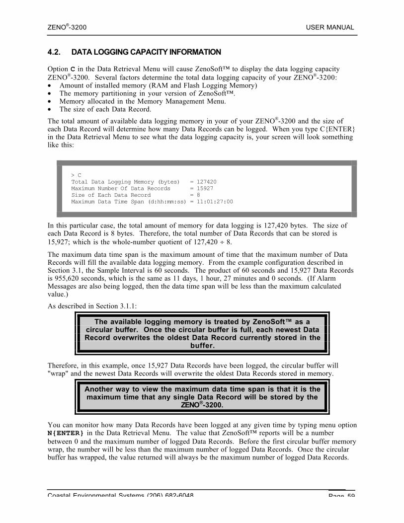
ZENO®-3200 USER MANUAL
Coastal Environmental Systems (206) 682-6048 Page 59
4.2. DATA LOGGING CAPACITY INFORMATION
Option C in the Data Retrieval Menu will cause ZenoSoft™ to display the data logging capacityZENO®-3200. Several factors determine the total data logging capacity of your ZENO®-3200:• Amount of installed memory (RAM and Flash Logging Memory)• The memory partitioning in your version of ZenoSoft™.• Memory allocated in the Memory Management Menu.• The size of each Data Record.
The total amount of available data logging memory in your of your ZENO®-3200 and the size ofeach Data Record will determine how many Data Records can be logged. When you type C{ENTER}in the Data Retrieval Menu to see what the data logging capacity is, your screen will look somethinglike this:
> CTotal Data Logging Memory (bytes) = 127420Maximum Number Of Data Records = 15927Size of Each Data Record = 8Maximum Data Time Span (d:hh:mm:ss) = 11:01:27:00
In this particular case, the total amount of memory for data logging is 127,420 bytes. The size ofeach Data Record is 8 bytes. Therefore, the total number of Data Records that can be stored is15,927; which is the whole-number quotient of 127,420 ÷ 8.
The maximum data time span is the maximum amount of time that the maximum number of DataRecords will fill the available data logging memory. From the example configuration described inSection 3.1, the Sample Interval is 60 seconds. The product of 60 seconds and 15,927 Data Recordsis 955,620 seconds, which is the same as 11 days, 1 hour, 27 minutes and 0 seconds. (If AlarmMessages are also being logged, then the data time span will be less than the maximum calculatedvalue.)
As described in Section 3.1.1:
The available logging memory is treated by ZenoSoft™ as acircular buffer. Once the circular buffer is full, each newest DataRecord overwrites the oldest Data Record currently stored in the
buffer.
Therefore, in this example, once 15,927 Data Records have been logged, the circular buffer will"wrap" and the newest Data Records will overwrite the oldest Data Records stored in memory.
Another way to view the maximum data time span is that it is themaximum time that any single Data Record will be stored by the
ZENO®-3200.
You can monitor how many Data Records have been logged at any given time by typing menu optionN{ENTER} in the Data Retrieval Menu. The value that ZenoSoft™ reports will be a numberbetween 0 and the maximum number of logged Data Records. Before the first circular buffer memorywrap, the number will be less than the maximum number of logged Data Records. Once the circularbuffer has wrapped, the value returned will always be the maximum number of logged Data Records.
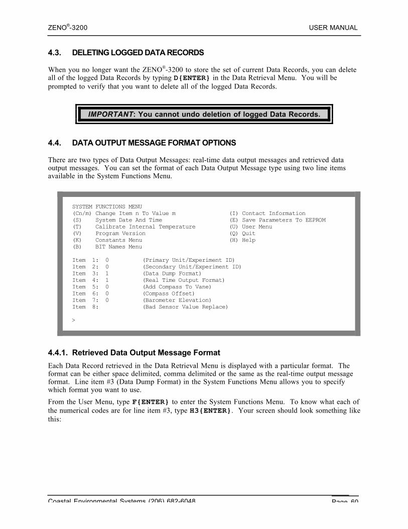
ZENO®-3200 USER MANUAL
Coastal Environmental Systems (206) 682-6048 Page 60
4.3. DELETING LOGGED DATA RECORDS
When you no longer want the ZENO®-3200 to store the set of current Data Records, you can deleteall of the logged Data Records by typing D{ENTER} in the Data Retrieval Menu. You will beprompted to verify that you want to delete all of the logged Data Records.
IMPORTANT: You cannot undo deletion of logged Data Records.
4.4. DATA OUTPUT MESSAGE FORMAT OPTIONS
There are two types of Data Output Messages: real-time data output messages and retrieved dataoutput messages. You can set the format of each Data Output Message type using two line itemsavailable in the System Functions Menu.
SYSTEM FUNCTIONS MENU(Cn/m) Change Item n To Value m (I) Contact Information(S) System Date And Time (E) Save Parameters To EEPROM(T) Calibrate Internal Temperature (U) User Menu(V) Program Version (Q) Quit(K) Constants Menu (H) Help(B) BIT Names Menu
Item 1: 0 (Primary Unit/Experiment ID)Item 2: 0 (Secondary Unit/Experiment ID)Item 3: 1 (Data Dump Format)Item 4: 1 (Real Time Output Format)Item 5: 0 (Add Compass To Vane)Item 6: 0 (Compass Offset)Item 7: 0 (Barometer Elevation)Item 8: (Bad Sensor Value Replace)
>
4.4.1. Retrieved Data Output Message Format
Each Data Record retrieved in the Data Retrieval Menu is displayed with a particular format. Theformat can be either space delimited, comma delimited or the same as the real-time output messageformat. Line item #3 (Data Dump Format) in the System Functions Menu allows you to specifywhich format you want to use.
From the User Menu, type F{ENTER} to enter the System Functions Menu. To know what each ofthe numerical codes are for line item #3, type H3{ENTER}. Your screen should look something likethis:
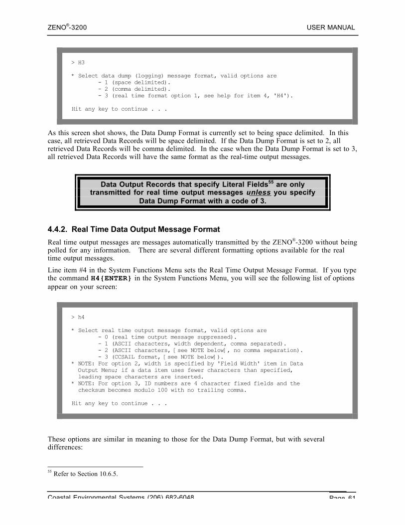
ZENO®-3200 USER MANUAL
Coastal Environmental Systems (206) 682-6048 Page 61
> H3
* Select data dump (logging) message format, valid options are - 1 (space delimited). - 2 (comma delimited). - 3 (real time format option 1, see help for item 4, 'H4').
Hit any key to continue . . .
As this screen shot shows, the Data Dump Format is currently set to being space delimited. In thiscase, all retrieved Data Records will be space delimited. If the Data Dump Format is set to 2, allretrieved Data Records will be comma delimited. In the case when the Data Dump Format is set to 3,all retrieved Data Records will have the same format as the real-time output messages.
Data Output Records that specify Literal Fields55 are onlytransmitted for real time output messages unless you specify
Data Dump Format with a code of 3.
4.4.2. Real Time Data Output Message Format
Real time output messages are messages automatically transmitted by the ZENO®-3200 without beingpolled for any information. There are several different formatting options available for the realtime output messages.
Line item #4 in the System Functions Menu sets the Real Time Output Message Format. If you typethe command H4{ENTER} in the System Functions Menu, you will see the following list of optionsappear on your screen:
> h4
* Select real time output message format, valid options are - 0 (real time output message suppressed). - 1 (ASCII characters, width dependent, comma separated). - 2 (ASCII characters, [see NOTE below], no comma separation). - 3 (CCSAIL format, [see NOTE below]).* NOTE: For option 2, width is specified by 'Field Width' item in Data Output Menu; if a data item uses fewer characters than specified, leading space characters are inserted.* NOTE: For option 3, ID numbers are 4 character fixed fields and the checksum becomes modulo 100 with no trailing comma.
Hit any key to continue . . .
These options are similar in meaning to those for the Data Dump Format, but with severaldifferences:
55 Refer to Section 10.6.5.
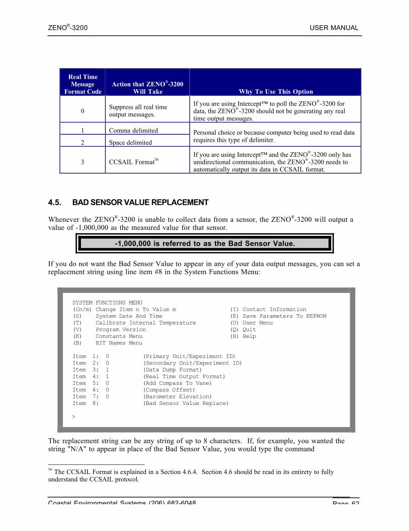
ZENO®-3200 USER MANUAL
Coastal Environmental Systems (206) 682-6048 Page 62
Real TimeMessage
Format CodeAction that ZENO®-3200
Will Take Why To Use This Option
0Suppress all real timeoutput messages.
If you are using Intercept™ to poll the ZENO®-3200 fordata, the ZENO®-3200 should not be generating any realtime output messages.
1 Comma delimited
2 Space delimited
Personal choice or because computer being used to read datarequires this type of delimiter.
3 CCSAIL Format56If you are using Intercept™ and the ZENO®-3200 only hasunidirectional communication, the ZENO®-3200 needs toautomatically output its data in CCSAIL format.
4.5. BAD SENSOR VALUE REPLACEMENT
Whenever the ZENO®-3200 is unable to collect data from a sensor, the ZENO®-3200 will output avalue of -1,000,000 as the measured value for that sensor.
-1,000,000 is referred to as the Bad Sensor Value.
If you do not want the Bad Sensor Value to appear in any of your data output messages, you can set areplacement string using line item #8 in the System Functions Menu:
SYSTEM FUNCTIONS MENU(Cn/m) Change Item n To Value m (I) Contact Information(S) System Date And Time (E) Save Parameters To EEPROM(T) Calibrate Internal Temperature (U) User Menu(V) Program Version (Q) Quit(K) Constants Menu (H) Help(B) BIT Names Menu
Item 1: 0 (Primary Unit/Experiment ID)Item 2: 0 (Secondary Unit/Experiment ID)Item 3: 1 (Data Dump Format)Item 4: 1 (Real Time Output Format)Item 5: 0 (Add Compass To Vane)Item 6: 0 (Compass Offset)Item 7: 0 (Barometer Elevation)Item 8: (Bad Sensor Value Replace)
>
The replacement string can be any string of up to 8 characters. If, for example, you wanted thestring "N/A" to appear in place of the Bad Sensor Value, you would type the command
56 The CCSAIL Format is explained in a Section 4.6.4. Section 4.6 should be read in its entirety to fullyunderstand the CCSAIL protocol.
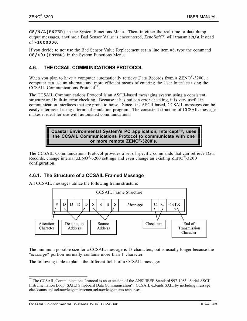
ZENO®-3200 USER MANUAL
Coastal Environmental Systems (206) 682-6048 Page 63
C8/N/A{ENTER} in the System Functions Menu. Then, in either the real time or data dumpoutput messages, anytime a Bad Sensor Value is encountered, ZenoSoft™ will transmit N/A insteadof -1000000.
If you decide to not use the Bad Sensor Value Replacement set in line item #8, type the commandC8/<0>{ENTER} in the System Functions Menu.
4.6. THE CCSAIL COMMUNICATIONS PROTOCOL
When you plan to have a computer automatically retrieve Data Records from a ZENO®-3200, acomputer can use an alternate and more efficient means of entering the User Interface using theCCSAIL Communications Protocol57.
The CCSAIL Communications Protocol is an ASCII-based messaging system using a consistentstructure and built-in error checking. Because it has built-in error checking, it is very useful incommunication interfaces that are prone to noise. Since it is ASCII based, CCSAIL messages can beeasily interpreted using a terminal emulation program. The consistent structure of CCSAIL messagesmakes it ideal for use with automated communications.
Coastal Environmental System's PC application, Intercept™, usesthe CCSAIL Communications Protocol to communicate with one
or more remote ZENO®-3200's.
The CCSAIL Communications Protocol provides a set of specific commands that can retrieve DataRecords, change internal ZENO®-3200 settings and even change an existing ZENO®-3200configuration.
4.6.1. The Structure of a CCSAIL Framed Message
All CCSAIL messages utilize the following frame structure:
The minimum possible size for a CCSAIL message is 13 characters, but is usually longer because the"message" portion normally contains more than 1 character.
The following table explains the different fields of a CCSAIL message:
57 The CCSAIL Communications Protocol is an extension of the ANSI/IEEE Standard 997-1985 "Serial ASCIIInstrumentation Loop (SAIL) Shipboard Data Communication". CCSAIL extends SAIL by including messagechecksums and acknowledgements/non-acknowledgements responses.
CCSAIL Frame Structure
# D D D D S S S S Message C C <ETX>
AttentionCharacter
DestinationAddress
SourceAddress
Checksum End ofTransmission
Character
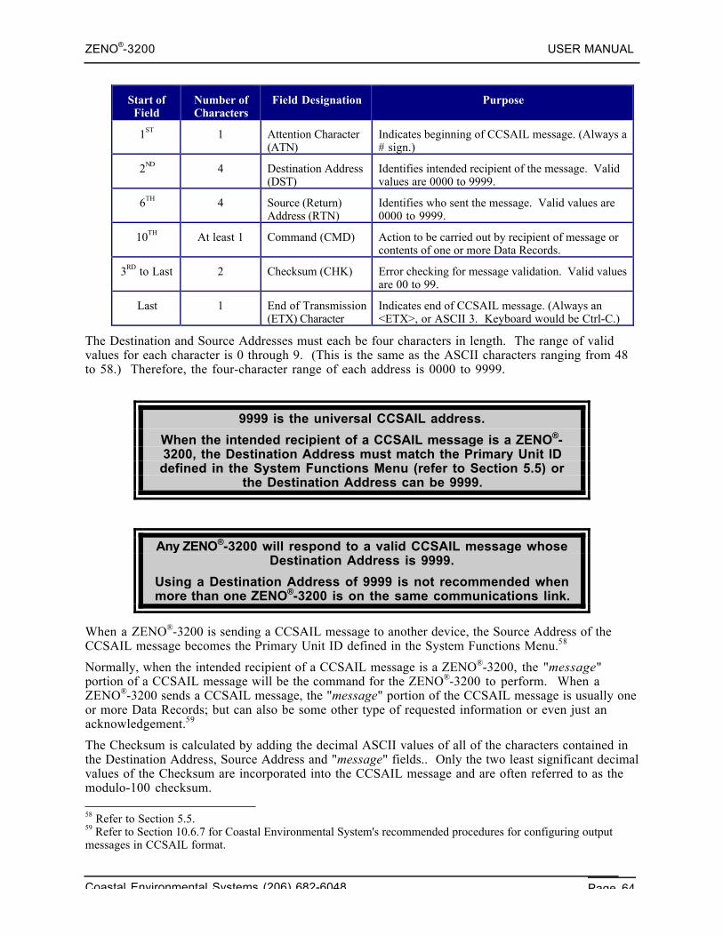
ZENO®-3200 USER MANUAL
Coastal Environmental Systems (206) 682-6048 Page 64
Start ofField
Number ofCharacters
Field Designation Purpose
1ST 1 Attention Character(ATN)
Indicates beginning of CCSAIL message. (Always a# sign.)
2ND 4 Destination Address(DST)
Identifies intended recipient of the message. Validvalues are 0000 to 9999.
6TH 4 Source (Return)Address (RTN)
Identifies who sent the message. Valid values are0000 to 9999.
10TH At least 1 Command (CMD) Action to be carried out by recipient of message orcontents of one or more Data Records.
3RD to Last 2 Checksum (CHK) Error checking for message validation. Valid valuesare 00 to 99.
Last 1 End of Transmission(ETX) Character
Indicates end of CCSAIL message. (Always an<ETX>, or ASCII 3. Keyboard would be Ctrl-C.)
The Destination and Source Addresses must each be four characters in length. The range of validvalues for each character is 0 through 9. (This is the same as the ASCII characters ranging from 48to 58.) Therefore, the four-character range of each address is 0000 to 9999.
9999 is the universal CCSAIL address.
When the intended recipient of a CCSAIL message is a ZENO®-3200, the Destination Address must match the Primary Unit IDdefined in the System Functions Menu (refer to Section 5.5) or
the Destination Address can be 9999.
Any ZENO®-3200 will respond to a valid CCSAIL message whoseDestination Address is 9999.
Using a Destination Address of 9999 is not recommended whenmore than one ZENO®-3200 is on the same communications link.
When a ZENO®-3200 is sending a CCSAIL message to another device, the Source Address of theCCSAIL message becomes the Primary Unit ID defined in the System Functions Menu.58
Normally, when the intended recipient of a CCSAIL message is a ZENO®-3200, the "message"portion of a CCSAIL message will be the command for the ZENO®-3200 to perform. When aZENO®-3200 sends a CCSAIL message, the "message" portion of the CCSAIL message is usually oneor more Data Records; but can also be some other type of requested information or even just anacknowledgement.59
The Checksum is calculated by adding the decimal ASCII values of all of the characters contained inthe Destination Address, Source Address and "message" fields.. Only the two least significant decimalvalues of the Checksum are incorporated into the CCSAIL message and are often referred to as themodulo-100 checksum. 58 Refer to Section 5.5.59 Refer to Section 10.6.7 for Coastal Environmental System's recommended procedures for configuring outputmessages in CCSAIL format.
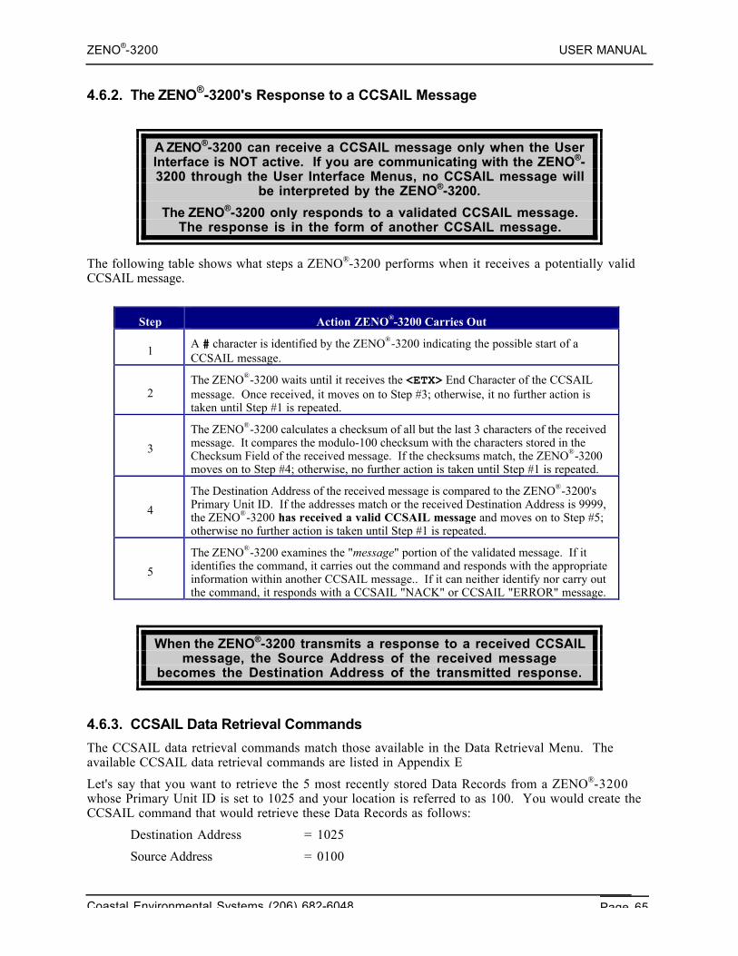
ZENO®-3200 USER MANUAL
Coastal Environmental Systems (206) 682-6048 Page 65
4.6.2. The ZENO®-3200's Response to a CCSAIL Message
A ZENO®-3200 can receive a CCSAIL message only when the UserInterface is NOT active. If you are communicating with the ZENO®-3200 through the User Interface Menus, no CCSAIL message will
be interpreted by the ZENO®-3200.
The ZENO®-3200 only responds to a validated CCSAIL message.The response is in the form of another CCSAIL message.
The following table shows what steps a ZENO®-3200 performs when it receives a potentially validCCSAIL message.
Step Action ZENO®-3200 Carries Out
1A # character is identified by the ZENO®-3200 indicating the possible start of aCCSAIL message.
2The ZENO®-3200 waits until it receives the <ETX> End Character of the CCSAILmessage. Once received, it moves on to Step #3; otherwise, it no further action istaken until Step #1 is repeated.
3
The ZENO®-3200 calculates a checksum of all but the last 3 characters of the receivedmessage. It compares the modulo-100 checksum with the characters stored in theChecksum Field of the received message. If the checksums match, the ZENO®-3200moves on to Step #4; otherwise, no further action is taken until Step #1 is repeated.
4
The Destination Address of the received message is compared to the ZENO®-3200'sPrimary Unit ID. If the addresses match or the received Destination Address is 9999,the ZENO®-3200 has received a valid CCSAIL message and moves on to Step #5;otherwise no further action is taken until Step #1 is repeated.
5
The ZENO®-3200 examines the "message" portion of the validated message. If itidentifies the command, it carries out the command and responds with the appropriateinformation within another CCSAIL message.. If it can neither identify nor carry outthe command, it responds with a CCSAIL "NACK" or CCSAIL "ERROR" message.
When the ZENO®-3200 transmits a response to a received CCSAILmessage, the Source Address of the received message
becomes the Destination Address of the transmitted response.
4.6.3. CCSAIL Data Retrieval Commands
The CCSAIL data retrieval commands match those available in the Data Retrieval Menu. Theavailable CCSAIL data retrieval commands are listed in Appendix E
Let's say that you want to retrieve the 5 most recently stored Data Records from a ZENO®-3200whose Primary Unit ID is set to 1025 and your location is referred to as 100. You would create theCCSAIL command that would retrieve these Data Records as follows:
Destination Address = 1025
Source Address = 0100
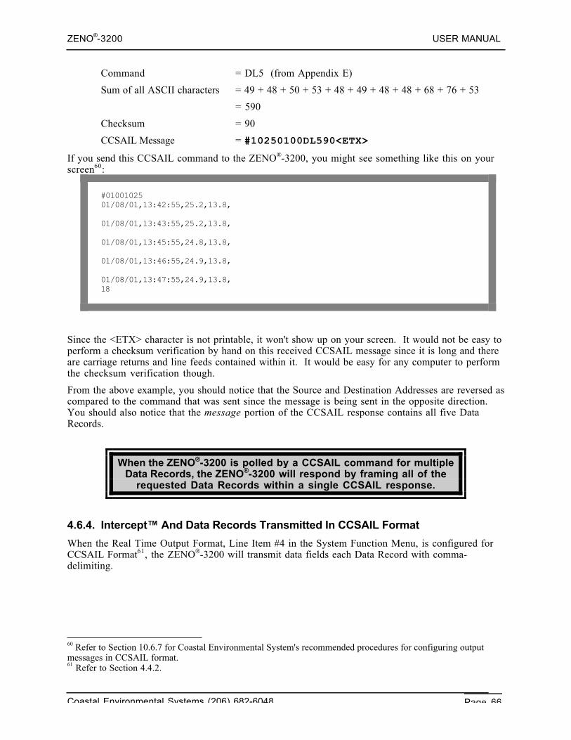
ZENO®-3200 USER MANUAL
Coastal Environmental Systems (206) 682-6048 Page 66
Command = DL5 (from Appendix E)
Sum of all ASCII characters = 49 + 48 + 50 + 53 + 48 + 49 + 48 + 48 + 68 + 76 + 53
= 590
Checksum = 90
CCSAIL Message = #10250100DL590<ETX>
If you send this CCSAIL command to the ZENO®-3200, you might see something like this on yourscreen60:
#0100102501/08/01,13:42:55,25.2,13.8,
01/08/01,13:43:55,25.2,13.8,
01/08/01,13:45:55,24.8,13.8,
01/08/01,13:46:55,24.9,13.8,
01/08/01,13:47:55,24.9,13.8,18
Since the <ETX> character is not printable, it won't show up on your screen. It would not be easy toperform a checksum verification by hand on this received CCSAIL message since it is long and thereare carriage returns and line feeds contained within it. It would be easy for any computer to performthe checksum verification though.
From the above example, you should notice that the Source and Destination Addresses are reversed ascompared to the command that was sent since the message is being sent in the opposite direction.You should also notice that the message portion of the CCSAIL response contains all five DataRecords.
When the ZENO®-3200 is polled by a CCSAIL command for multipleData Records, the ZENO®-3200 will respond by framing all of the
requested Data Records within a single CCSAIL response.
4.6.4. Intercept™ And Data Records Transmitted In CCSAIL Format
When the Real Time Output Format, Line Item #4 in the System Function Menu, is configured forCCSAIL Format61, the ZENO®-3200 will transmit data fields each Data Record with comma-delimiting.
60 Refer to Section 10.6.7 for Coastal Environmental System's recommended procedures for configuring outputmessages in CCSAIL format.61 Refer to Section 4.4.2.
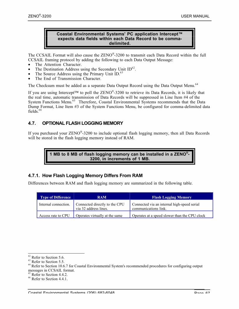
ZENO®-3200 USER MANUAL
Coastal Environmental Systems (206) 682-6048 Page 67
Coastal Environmental Systems' PC application Intercept™expects data fields within each Data Record to be comma-
delimited.
The CCSAIL Format will also cause the ZENO®-3200 to transmit each Data Record within the fullCCSAIL framing protocol by adding the following to each Data Output Message:• The Attention Character.• The Destination Address using the Secondary Unit ID62.• The Source Address using the Primary Unit ID.63
• The End of Transmission Character.
The Checksum must be added as a separate Data Output Record using the Data Output Menu.64
If you are using Intercept™ to poll the ZENO®-3200 to retrieve its Data Records, it is likely thatthe real time, automatic transmission of Data Records will be suppressed in Line Item #4 of theSystem Functions Menu.65 Therefore, Coastal Environmental Systems recommends that the DataDump Format, Line Item #3 of the System Functions Menu, be configured for comma-delimited datafields.66
4.7. OPTIONAL FLASH LOGGING MEMORY
If you purchased your ZENO®-3200 to include optional flash logging memory, then all Data Recordswill be stored in the flash logging memory instead of RAM.
1 MB to 8 MB of flash logging memory can be installed in a ZENO®-3200, in increments of 1 MB.
4.7.1. How Flash Logging Memory Differs From RAM
Differences between RAM and flash logging memory are summarized in the following table.
Type of Difference RAM Flash Logging Memory
Internal connection. Connected directly to the CPUvia 32 address lines.
Connected via an internal high-speed serialcommunications link.
Access rate to CPU Operates virtually at the samerate as the CPU clock speed.
Operates at a speed slower than the CPU clockspeed. Access is slower than RAM.
62 Refer to Section 5.6.63 Refer to Section 5.5.64 Refer to Section 10.6.7 for Coastal Environmental System's recommended procedures for configuring outputmessages in CCSAIL format.65 Refer to Section 4.4.2.66 Refer to Section 4.4.1.
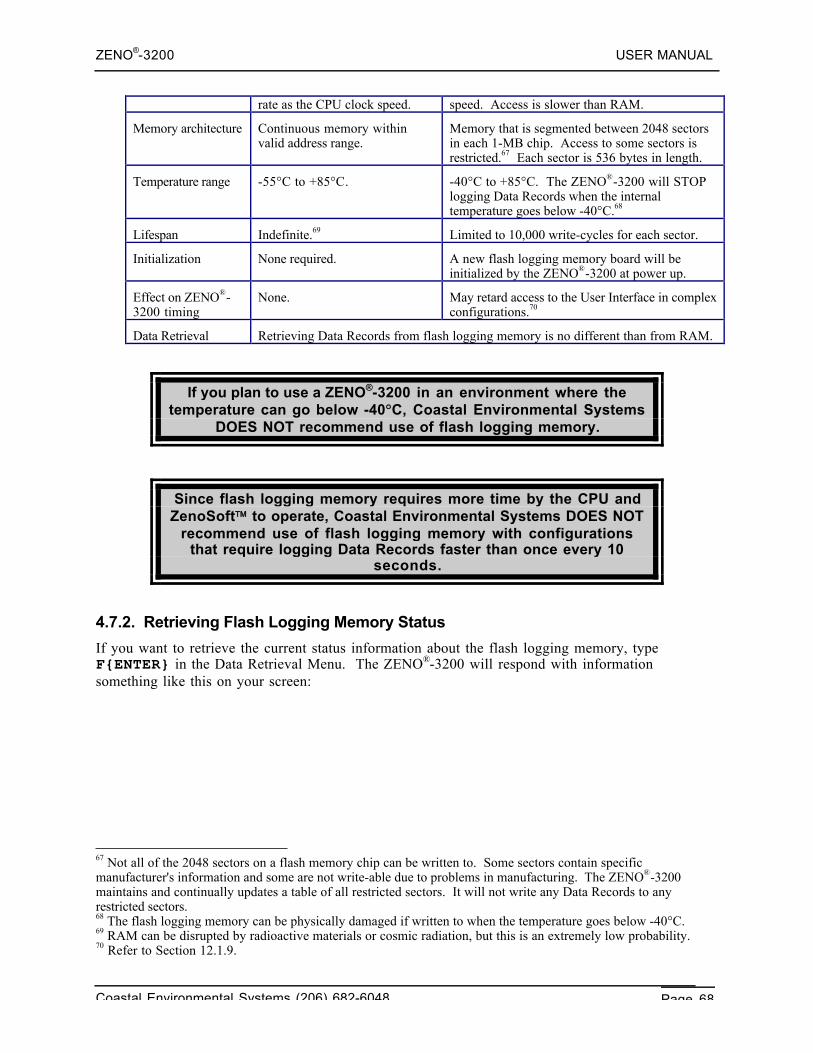
ZENO®-3200 USER MANUAL
Coastal Environmental Systems (206) 682-6048 Page 68
rate as the CPU clock speed. speed. Access is slower than RAM.
Memory architecture Continuous memory withinvalid address range.
Memory that is segmented between 2048 sectorsin each 1-MB chip. Access to some sectors isrestricted.67 Each sector is 536 bytes in length.
Temperature range -55°C to +85°C. -40°C to +85°C. The ZENO®-3200 will STOPlogging Data Records when the internaltemperature goes below -40°C.68
Lifespan Indefinite.69 Limited to 10,000 write-cycles for each sector.
Initialization None required. A new flash logging memory board will beinitialized by the ZENO®-3200 at power up.
Effect on ZENO®-3200 timing
None. May retard access to the User Interface in complexconfigurations.70
Data Retrieval Retrieving Data Records from flash logging memory is no different than from RAM.
If you plan to use a ZENO®-3200 in an environment where thetemperature can go below -40°C, Coastal Environmental Systems
DOES NOT recommend use of flash logging memory.
Since flash logging memory requires more time by the CPU andZenoSoft™ to operate, Coastal Environmental Systems DOES NOT
recommend use of flash logging memory with configurationsthat require logging Data Records faster than once every 10
seconds.
4.7.2. Retrieving Flash Logging Memory Status
If you want to retrieve the current status information about the flash logging memory, typeF{ENTER} in the Data Retrieval Menu. The ZENO®-3200 will respond with informationsomething like this on your screen:
67 Not all of the 2048 sectors on a flash memory chip can be written to. Some sectors contain specificmanufacturer's information and some are not write-able due to problems in manufacturing. The ZENO®-3200maintains and continually updates a table of all restricted sectors. It will not write any Data Records to anyrestricted sectors.68 The flash logging memory can be physically damaged if written to when the temperature goes below -40°C.69 RAM can be disrupted by radioactive materials or cosmic radiation, but this is an extremely low probability.70 Refer to Section 12.1.9.
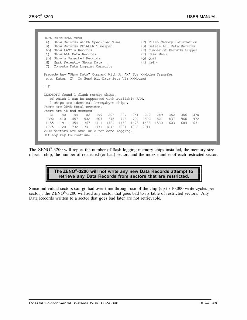
ZENO®-3200 USER MANUAL
Coastal Environmental Systems (206) 682-6048 Page 69
DATA RETRIEVAL MENU(A) Show Records AFTER Specified Time (F) Flash Memory Information(B) Show Records BETWEEN Timespan (D) Delete All Data Records(Ln) Show LAST n Records (N) Number Of Records Logged(*) Show ALL Data Records (U) User Menu(@n) Show n Unmarked Records (Q) Quit(M) Mark Recently Shown Data (H) Help(C) Compute Data Logging Capacity
Precede Any "Show Data" Command With An 'X' For X-Modem Transfer(e.g. Enter 'X*' To Send All Data Sets Via X-Modem)
> F
ZENOSOFT found 1 flash memory chips, of which 1 can be supported with available RAM. 1 chips are identical 1-megabyte chips.There are 2048 total sectors.There are 48 bad sectors: 31 40 44 82 199 206 207 251 272 289 352 356 370 390 410 457 532 607 643 746 792 800 801 837 960 972 1155 1191 1354 1367 1411 1424 1462 1473 1488 1530 1603 1604 1631 1715 1720 1732 1741 1771 1846 1894 1963 20112000 sectors are available for data logging.Hit any key to continue . . .
The ZENO®-3200 will report the number of flash logging memory chips installed, the memory sizeof each chip, the number of restricted (or bad) sectors and the index number of each restricted sector.
The ZENO®-3200 will not write any new Data Records attempt toretrieve any Data Records from sectors that are restricted.
Since individual sectors can go bad over time through use of the chip (up to 10,000 write-cycles persector), the ZENO®-3200 will add any sector that goes bad to its table of restricted sectors. AnyData Records written to a sector that goes bad later are not retrievable.
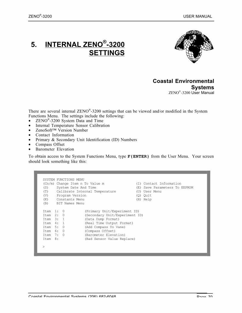
ZENO®-3200 USER MANUAL
Coastal Environmental Systems (206) 682-6048 Page 70
5. INTERNAL ZENO®-3200SETTINGS
Coastal EnvironmentalSystems
ZENO®-3200 User Manual
There are several internal ZENO®-3200 settings that can be viewed and/or modified in the SystemFunctions Menu. The settings include the following:• ZENO®-3200 System Data and Time• Internal Temperature Sensor Calibration• ZenoSoft™ Version Number• Contact Information• Primary & Secondary Unit Identification (ID) Numbers• Compass Offset• Barometer Elevation
To obtain access to the System Functions Menu, type F{ENTER} from the User Menu. Your screenshould look something like this:
SYSTEM FUNCTIONS MENU(Cn/m) Change Item n To Value m (I) Contact Information(S) System Date And Time (E) Save Parameters To EEPROM(T) Calibrate Internal Temperature (U) User Menu(V) Program Version (Q) Quit(K) Constants Menu (H) Help(B) BIT Names Menu
Item 1: 0 (Primary Unit/Experiment ID)Item 2: 0 (Secondary Unit/Experiment ID)Item 3: 1 (Data Dump Format)Item 4: 1 (Real Time Output Format)Item 5: 0 (Add Compass To Vane)Item 6: 0 (Compass Offset)Item 7: 0 (Barometer Elevation)Item 8: (Bad Sensor Value Replace)
>
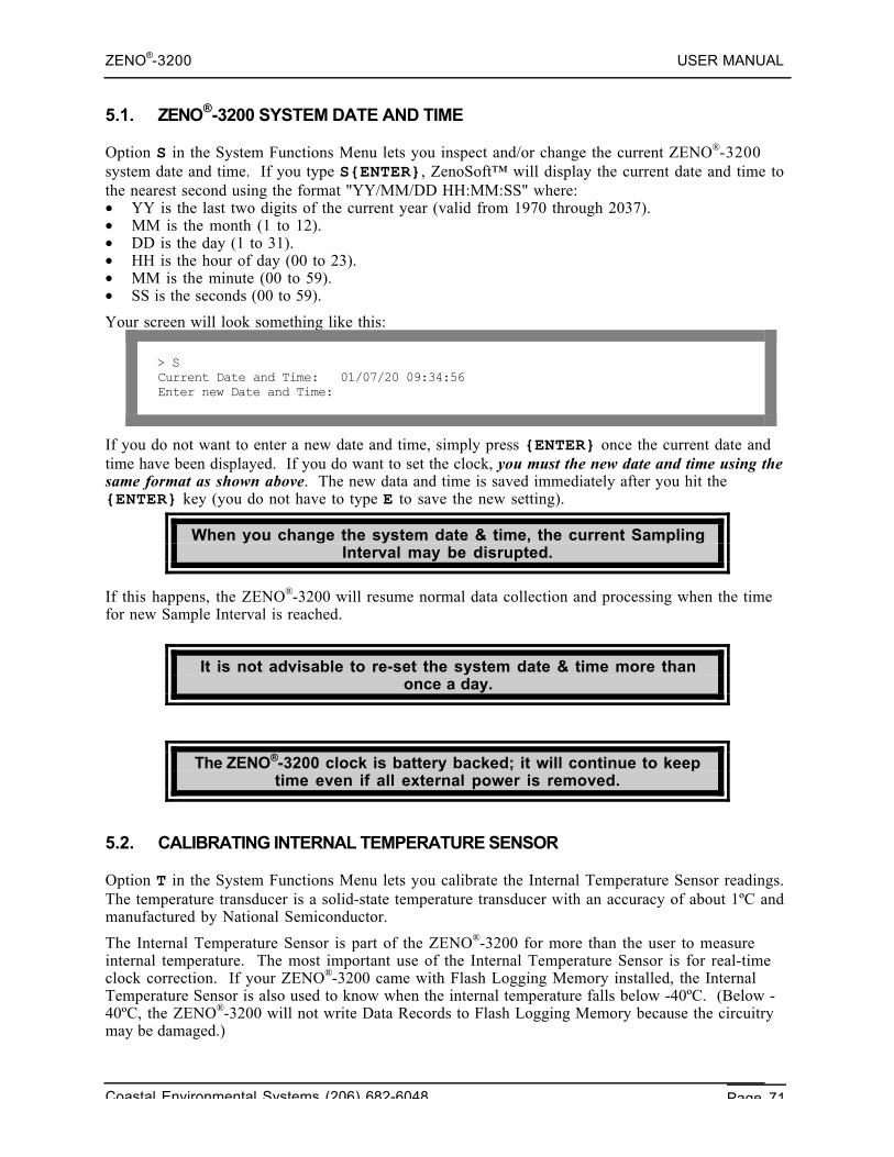
ZENO®-3200 USER MANUAL
Coastal Environmental Systems (206) 682-6048 Page 71
5.1. ZENO®-3200 SYSTEM DATE AND TIME
Option S in the System Functions Menu lets you inspect and/or change the current ZENO®-3200system date and time. If you type S{ENTER}, ZenoSoft™ will display the current date and time tothe nearest second using the format "YY/MM/DD HH:MM:SS" where:• YY is the last two digits of the current year (valid from 1970 through 2037).• MM is the month (1 to 12).• DD is the day (1 to 31).• HH is the hour of day (00 to 23).• MM is the minute (00 to 59).• SS is the seconds (00 to 59).
Your screen will look something like this:
> SCurrent Date and Time: 01/07/20 09:34:56Enter new Date and Time:
If you do not want to enter a new date and time, simply press {ENTER} once the current date andtime have been displayed. If you do want to set the clock, you must the new date and time using thesame format as shown above. The new data and time is saved immediately after you hit the{ENTER} key (you do not have to type E to save the new setting).
When you change the system date & time, the current SamplingInterval may be disrupted.
If this happens, the ZENO®-3200 will resume normal data collection and processing when the timefor new Sample Interval is reached.
It is not advisable to re-set the system date & time more thanonce a day.
The ZENO®-3200 clock is battery backed; it will continue to keeptime even if all external power is removed.
5.2. CALIBRATING INTERNAL TEMPERATURE SENSOR
Option T in the System Functions Menu lets you calibrate the Internal Temperature Sensor readings.The temperature transducer is a solid-state temperature transducer with an accuracy of about 1ºC andmanufactured by National Semiconductor.
The Internal Temperature Sensor is part of the ZENO®-3200 for more than the user to measureinternal temperature. The most important use of the Internal Temperature Sensor is for real-timeclock correction. If your ZENO®-3200 came with Flash Logging Memory installed, the InternalTemperature Sensor is also used to know when the internal temperature falls below -40ºC. (Below -40ºC, the ZENO®-3200 will not write Data Records to Flash Logging Memory because the circuitrymay be damaged.)
ZENO®-3200 USER MANUAL
Coastal Environmental Systems (206) 682-6048 Page 72
When you type T{ENTER} in the System Functions Menu, you will be prompted to enter thecurrent ambient air temperature. Ideally, you will be measuring the current ambient air temperaturewith an accurate temperature transducer located very near your ZENO®-3200. If you need to movethe ZENO®-3200 to be near the transducer (or the transducer near the ZENO®-3200), it isrecommended that you wait 15 minutes before entering the calibration temperature. This will alloweither the Internal Temperature Sensor or your external temperature transducer sufficient time tosettle and provide an accurate reading.
When you enter the new temperature reading, you must include the temperature scale. The choicesare FAHRENHEIT (example input: 72.5F), CELSIUS (23.2C), or KELVIN (295.6K). The newtemperature that you type is automatically saved internally by the ZENO®-3200.
You do not need to save the configuration to EEPROM after entering the new temperature;ZenoSoft™ automatically saves the calibration settings to EEPROM automatically.
5.3. GETTING CURRENT ZENOSOFT™ VERSION NUMBER
Option V in the System Functions Menu will display the version of ZenoSoft™ in use in yourZENO®-3200.
If you ever need to call the Customer Service Department atCoastal Environmental Systems, please note your version
ZenoSoft™ before calling.
5.4. CONTACT INFORMATION
Option I in the System Functions Menu will display information as to how to contact CoastalEnvironmental Systems should the need arise.
5.5. ZENO®-3200 IDENTIFICATION NUMBER_THE PRIMARY UNIT ID
Many ZENO®-3200 users have more than one ZENO®-3200 collecting data in different locations,but download the data from a central location. To identify the data coming form a particularZENO®-3200, a unique identification number can be set in the ZENO®-3200's configuration.
The Primary Unit ID is the unique identification number that canbe configured into your ZENO®-3200.
The Primary Unit ID can be set to any whole number within therange 0 to 9998.
If more than one ZENO®-3200 is being used in your application,each ZENO®-3200 should have a different Primary Unit ID.
Coastal Environmental System's PC application Intercept™ also uses the Primary Unit ID toidentify which ZENO®-3200 it is collecting data from using the CCSAIL message protocol.71
71 Refer to Section 4.6.
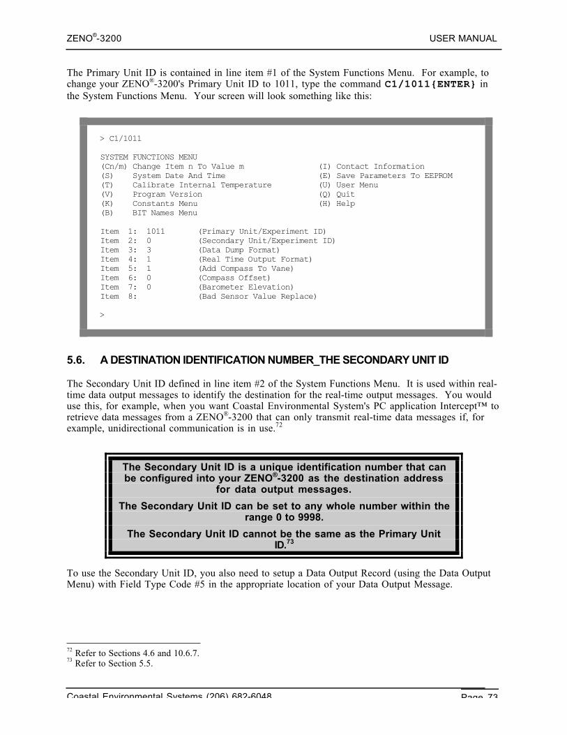
ZENO®-3200 USER MANUAL
Coastal Environmental Systems (206) 682-6048 Page 73
The Primary Unit ID is contained in line item #1 of the System Functions Menu. For example, tochange your ZENO®-3200's Primary Unit ID to 1011, type the command C1/1011{ENTER} inthe System Functions Menu. Your screen will look something like this:
> C1/1011
SYSTEM FUNCTIONS MENU(Cn/m) Change Item n To Value m (I) Contact Information(S) System Date And Time (E) Save Parameters To EEPROM(T) Calibrate Internal Temperature (U) User Menu(V) Program Version (Q) Quit(K) Constants Menu (H) Help(B) BIT Names Menu
Item 1: 1011 (Primary Unit/Experiment ID)Item 2: 0 (Secondary Unit/Experiment ID)Item 3: 3 (Data Dump Format)Item 4: 1 (Real Time Output Format)Item 5: 1 (Add Compass To Vane)Item 6: 0 (Compass Offset)Item 7: 0 (Barometer Elevation)Item 8: (Bad Sensor Value Replace)
>
5.6. A DESTINATION IDENTIFICATION NUMBER_THE SECONDARY UNIT ID
The Secondary Unit ID defined in line item #2 of the System Functions Menu. It is used within real-time data output messages to identify the destination for the real-time output messages. You woulduse this, for example, when you want Coastal Environmental System's PC application Intercept™ toretrieve data messages from a ZENO®-3200 that can only transmit real-time data messages if, forexample, unidirectional communication is in use.72
The Secondary Unit ID is a unique identification number that canbe configured into your ZENO®-3200 as the destination address
for data output messages.
The Secondary Unit ID can be set to any whole number within therange 0 to 9998.
The Secondary Unit ID cannot be the same as the Primary UnitID.73
To use the Secondary Unit ID, you also need to setup a Data Output Record (using the Data OutputMenu) with Field Type Code #5 in the appropriate location of your Data Output Message.
72 Refer to Sections 4.6 and 10.6.7.73 Refer to Section 5.5.
ZENO®-3200 USER MANUAL
Coastal Environmental Systems (206) 682-6048 Page 74
5.7. COMPASS SENSOR USAGE
If you are using a compass sensor as part of your sensor suite, two parameters are specified in theSystem Functions Menu that affect its usage:
System FunctionsMenu Line Item No.
Parameter Name Valid Range
5 Add Compass To Vane 0 = NO or 1 = YES
6 Compass Offset -180 to 180 degrees
Line item #5, Add compass to vane, controls whether or not the ZENO®-3200 will add the measuredcompass value to the measured wind direction (the vane) when executing a Wind Vector AverageProcess74 or Running Wind Vector Average Process75. If you are not measuring the wind direction,if you have no compass, or if you are not processing the wind measurements using a Wind VectorAverage Process or Running Wind Vector Average Process, this option has no effect.
Line item #6, Compass offset, is a value that is added to the compass sensor measurement tocompensate for local variations in magnetic North. The value is added directly to the compasssensor reading76. If you have no compass sensor in your sensor suite, this option has no effect.
5.8. BAROMETER ELEVATION SETTING
If your sensor suite includes a barometric pressure sensor and you are using the Barometric PressureProcess77, Line Item #7, the Barometer Elevation, in the System Functions Menu is used to correctthe barometric pressure reading to sea level. The valid range of values for the Barometer Elevationline item is 0 to 5000 meters.
If the Barometric Pressure Process78 is not specified in your configuration, this line item has noteffect.
74 Refer to Appendix D, Category #2, Process #1.75 Refer to Appendix D, Category #2, Process #2.76 Refer to Section 10.3.4.77 Refer to Appendix D, Category #2, Process #5.78 Ibid.
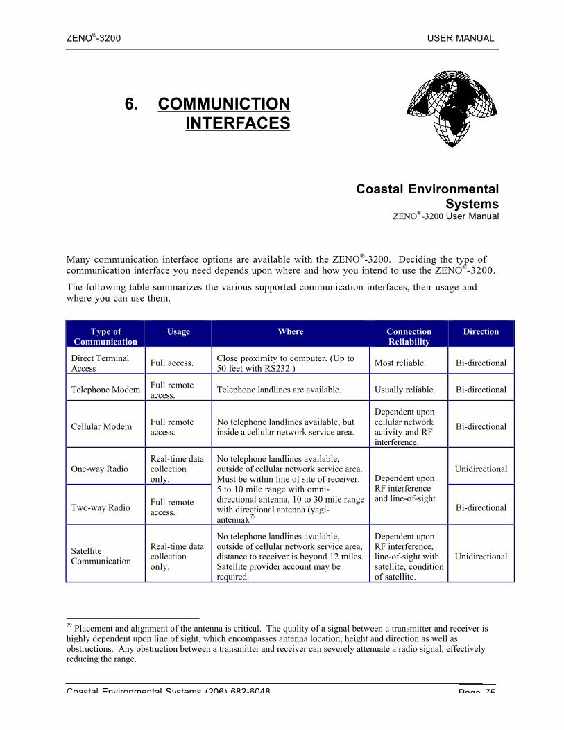
ZENO®-3200 USER MANUAL
Coastal Environmental Systems (206) 682-6048 Page 75
6. COMMUNICTIONINTERFACES
Coastal EnvironmentalSystems
ZENO®-3200 User Manual
Many communication interface options are available with the ZENO®-3200. Deciding the type ofcommunication interface you need depends upon where and how you intend to use the ZENO®-3200.
The following table summarizes the various supported communication interfaces, their usage andwhere you can use them.
Type ofCommunication
Usage Where ConnectionReliability
Direction
Direct TerminalAccess
Full access. Close proximity to computer. (Up to50 feet with RS232.)
Most reliable. Bi-directional
Telephone Modem Full remoteaccess.
Telephone landlines are available. Usually reliable. Bi-directional
Cellular Modem Full remoteaccess.
No telephone landlines available, butinside a cellular network service area.
Dependent uponcellular networkactivity and RFinterference.
Bi-directional
One-way RadioReal-time datacollectiononly.
Unidirectional
Two-way RadioFull remoteaccess.
No telephone landlines available,outside of cellular network service area.Must be within line of site of receiver.5 to 10 mile range with omni-directional antenna, 10 to 30 mile rangewith directional antenna (yagi-antenna).79
Dependent uponRF interferenceand line-of-sight
Bi-directional
SatelliteCommunication
Real-time datacollectiononly.
No telephone landlines available,outside of cellular network service area,distance to receiver is beyond 12 miles.Satellite provider account may berequired.
Dependent uponRF interference,line-of-sight withsatellite, conditionof satellite.
Unidirectional
79 Placement and alignment of the antenna is critical. The quality of a signal between a transmitter and receiver ishighly dependent upon line of sight, which encompasses antenna location, height and direction as well asobstructions. Any obstruction between a transmitter and receiver can severely attenuate a radio signal, effectivelyreducing the range.
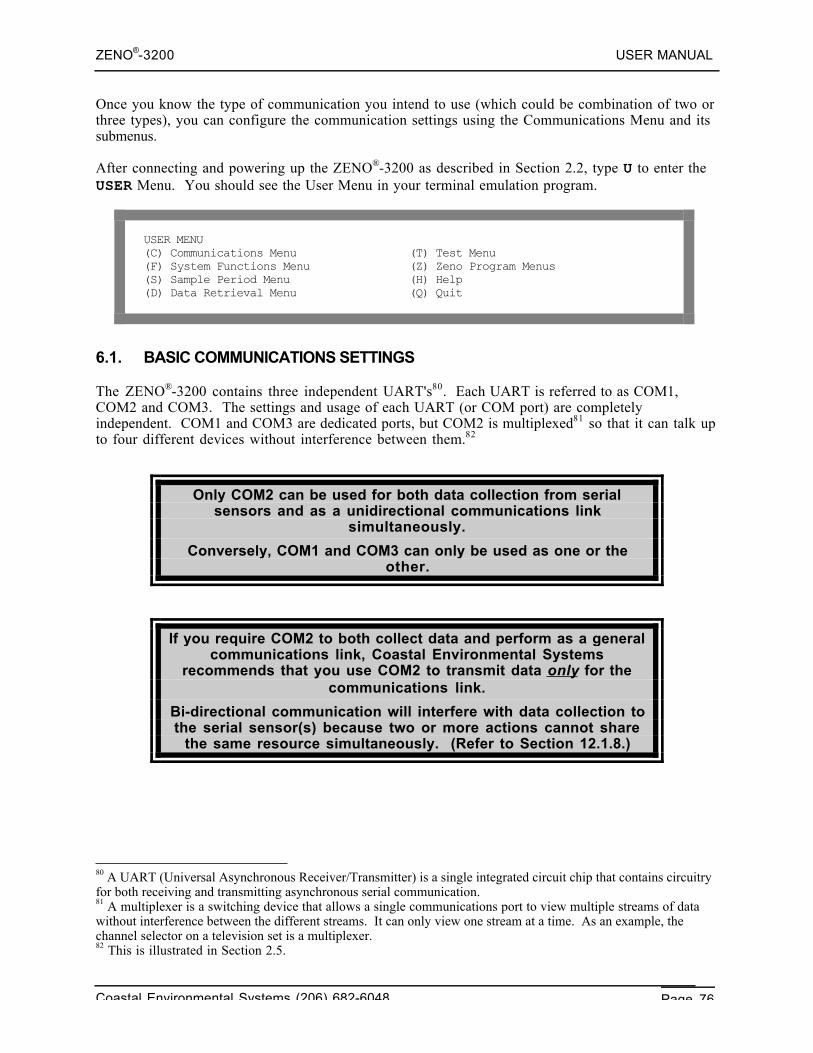
ZENO®-3200 USER MANUAL
Coastal Environmental Systems (206) 682-6048 Page 76
Once you know the type of communication you intend to use (which could be combination of two orthree types), you can configure the communication settings using the Communications Menu and itssubmenus.
After connecting and powering up the ZENO®-3200 as described in Section 2.2, type U to enter theUSER Menu. You should see the User Menu in your terminal emulation program.
USER MENU(C) Communications Menu (T) Test Menu(F) System Functions Menu (Z) Zeno Program Menus(S) Sample Period Menu (H) Help(D) Data Retrieval Menu (Q) Quit
6.1. BASIC COMMUNICATIONS SETTINGS
The ZENO®-3200 contains three independent UART's80. Each UART is referred to as COM1,COM2 and COM3. The settings and usage of each UART (or COM port) are completelyindependent. COM1 and COM3 are dedicated ports, but COM2 is multiplexed81 so that it can talk upto four different devices without interference between them.82
Only COM2 can be used for both data collection from serialsensors and as a unidirectional communications link
simultaneously.
Conversely, COM1 and COM3 can only be used as one or theother.
If you require COM2 to both collect data and perform as a generalcommunications link, Coastal Environmental Systems
recommends that you use COM2 to transmit data only for thecommunications link.
Bi-directional communication will interfere with data collection tothe serial sensor(s) because two or more actions cannot share
the same resource simultaneously. (Refer to Section 12.1.8.)
80 A UART (Universal Asynchronous Receiver/Transmitter) is a single integrated circuit chip that contains circuitryfor both receiving and transmitting asynchronous serial communication.81 A multiplexer is a switching device that allows a single communications port to view multiple streams of datawithout interference between the different streams. It can only view one stream at a time. As an example, thechannel selector on a television set is a multiplexer.82 This is illustrated in Section 2.5.
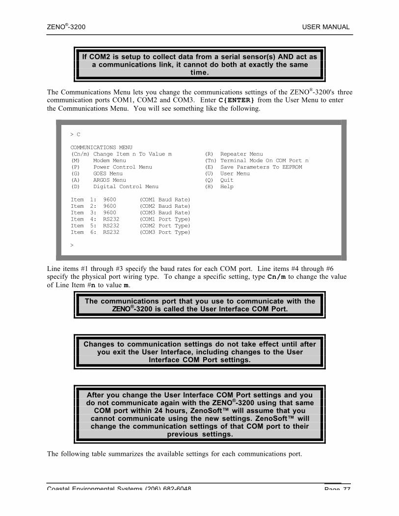
ZENO®-3200 USER MANUAL
Coastal Environmental Systems (206) 682-6048 Page 77
If COM2 is setup to collect data from a serial sensor(s) AND act asa communications link, it cannot do both at exactly the same
time.
The Communications Menu lets you change the communications settings of the ZENO®-3200's threecommunication ports COM1, COM2 and COM3. Enter C{ENTER} from the User Menu to enterthe Communications Menu. You will see something like the following.
> C
COMMUNICATIONS MENU(Cn/m) Change Item n To Value m (R) Repeater Menu(M) Modem Menu (Tn) Terminal Mode On COM Port n(P) Power Control Menu (E) Save Parameters To EEPROM(G) GOES Menu (U) User Menu(A) ARGOS Menu (Q) Quit(D) Digital Control Menu (H) Help
Item 1: 9600 (COM1 Baud Rate)Item 2: 9600 (COM2 Baud Rate)Item 3: 9600 (COM3 Baud Rate)Item 4: RS232 (COM1 Port Type)Item 5: RS232 (COM2 Port Type)Item 6: RS232 (COM3 Port Type)
>
Line items #1 through #3 specify the baud rates for each COM port. Line items #4 through #6specify the physical port wiring type. To change a specific setting, type Cn/m to change the valueof Line Item #n to value m.
The communications port that you use to communicate with theZENO®-3200 is called the User Interface COM Port.
Changes to communication settings do not take effect until afteryou exit the User Interface, including changes to the User
Interface COM Port settings.
After you change the User Interface COM Port settings and youdo not communicate again with the ZENO®-3200 using that same
COM port within 24 hours, ZenoSoft™ will assume that youcannot communicate using the new settings. ZenoSoft™ willchange the communication settings of that COM port to their
previous settings.
The following table summarizes the available settings for each communications port.
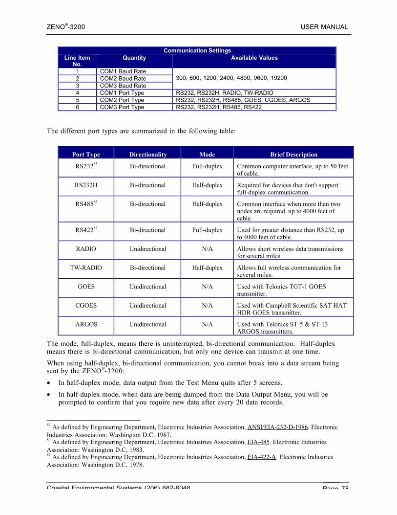
ZENO®-3200 USER MANUAL
Coastal Environmental Systems (206) 682-6048 Page 78
Communication SettingsLine Item
No.Quantity Available Values
1 COM1 Baud Rate2 COM2 Baud Rate3 COM3 Baud Rate
300, 600, 1200, 2400, 4800, 9600, 19200
4 COM1 Port Type RS232, RS232H, RADIO, TW-RADIO5 COM2 Port Type RS232, RS232H, RS485, GOES, CGOES, ARGOS6 COM3 Port Type RS232, RS232H, RS485, RS422
The different port types are summarized in the following table:
Port Type Directionality Mode Brief Description
RS23283 Bi-directional Full-duplex Common computer interface, up to 50 feetof cable.
RS232H Bi-directional Half-duplex Required for devices that don't supportfull-duplex communication.
RS48584 Bi-directional Half-duplex Common interface when more than twonodes are required, up to 4000 feet ofcable.
RS42285 Bi-directional Full-duplex Used for greater distance than RS232, upto 4000 feet of cable.
RADIO Unidirectional N/A Allows short wireless data transmissionsfor several miles.
TW-RADIO Bi-directional Half-duplex Allows full wireless communication forseveral miles.
GOES Unidirectional N/A Used with Telonics TGT-1 GOEStransmitter.
CGOES Unidirectional N/A Used with Campbell Scientific SAT HATHDR GOES transmitter.
ARGOS Unidirectional N/A Used with Telonics ST-5 & ST-13ARGOS transmitters.
The mode, full-duplex, means there is uninterrupted, bi-directional communication. Half-duplexmeans there is bi-directional communication, but only one device can transmit at one time.
When using half-duplex, bi-directional communication, you cannot break into a data stream beingsent by the ZENO®-3200:
• In half-duplex mode, data output from the Test Menu quits after 5 screens.
• In half-duplex mode, when data are being dumped from the Data Output Menu, you will beprompted to confirm that you require new data after every 20 data records.
83 As defined by Engineering Department, Electronic Industries Association, ANSI/EIA-232-D-1986 . ElectronicIndustries Association: Washington D.C, 1987.84 As defined by Engineering Department, Electronic Industries Association, EIA-485 . Electronic IndustriesAssociation: Washington D.C, 1983.85 As defined by Engineering Department, Electronic Industries Association, EIA-422-A . Electronic IndustriesAssociation: Washington D.C, 1978.
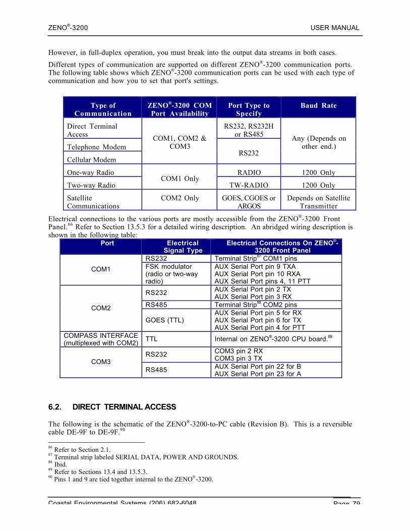
ZENO®-3200 USER MANUAL
Coastal Environmental Systems (206) 682-6048 Page 79
However, in full-duplex operation, you must break into the output data streams in both cases.
Different types of communication are supported on different ZENO®-3200 communication ports.The following table shows which ZENO®-3200 communication ports can be used with each type ofcommunication and how you to set that port's settings.
Type ofCommunication
ZENO®-3200 COMPort Availability
Port Type toSpecify
Baud Rate
Direct TerminalAccess
RS232, RS232Hor RS485
Telephone Modem
Cellular Modem
COM1, COM2 &COM3
RS232
Any (Depends onother end.)
One-way Radio RADIO 1200 Only
Two-way RadioCOM1 Only
TW-RADIO 1200 Only
SatelliteCommunications
COM2 Only GOES, CGOES orARGOS
Depends on SatelliteTransmitter
Electrical connections to the various ports are mostly accessible from the ZENO®-3200 FrontPanel.86 Refer to Section 13.5.3 for a detailed wiring description. An abridged wiring description isshown in the following table:
Port ElectricalSignal Type
Electrical Connections On ZENO®-3200 Front Panel
RS232 Terminal Strip87 COM1 pins
COM1 FSK modulator(radio or two-wayradio)
AUX Serial Port pin 9 TXAAUX Serial Port pin 10 RXAAUX Serial Port pins 4, 11 PTT
RS232 AUX Serial Port pin 2 TXAUX Serial Port pin 3 RX
RS485 Terminal Strip88 COM2 pinsCOM2
GOES (TTL)AUX Serial Port pin 5 for RXAUX Serial Port pin 6 for TXAUX Serial Port pin 4 for PTT
COMPASS INTERFACE(multiplexed with COM2)
TTL Internal on ZENO®-3200 CPU board.89
RS232 COM3 pin 2 RXCOM3 pin 3 TXCOM3
RS485 AUX Serial Port pin 22 for BAUX Serial Port pin 23 for A
6.2. DIRECT TERMINAL ACCESS
The following is the schematic of the ZENO®-3200-to-PC cable (Revision B). This is a reversiblecable DE-9F to DE-9F.90
86 Refer to Section 2.1.87 Terminal strip labeled SERIAL DATA, POWER AND GROUNDS.88 Ibid.89 Refer to Sections 13.4 and 13.5.3.90 Pins 1 and 9 are tied together internal to the ZENO®-3200.
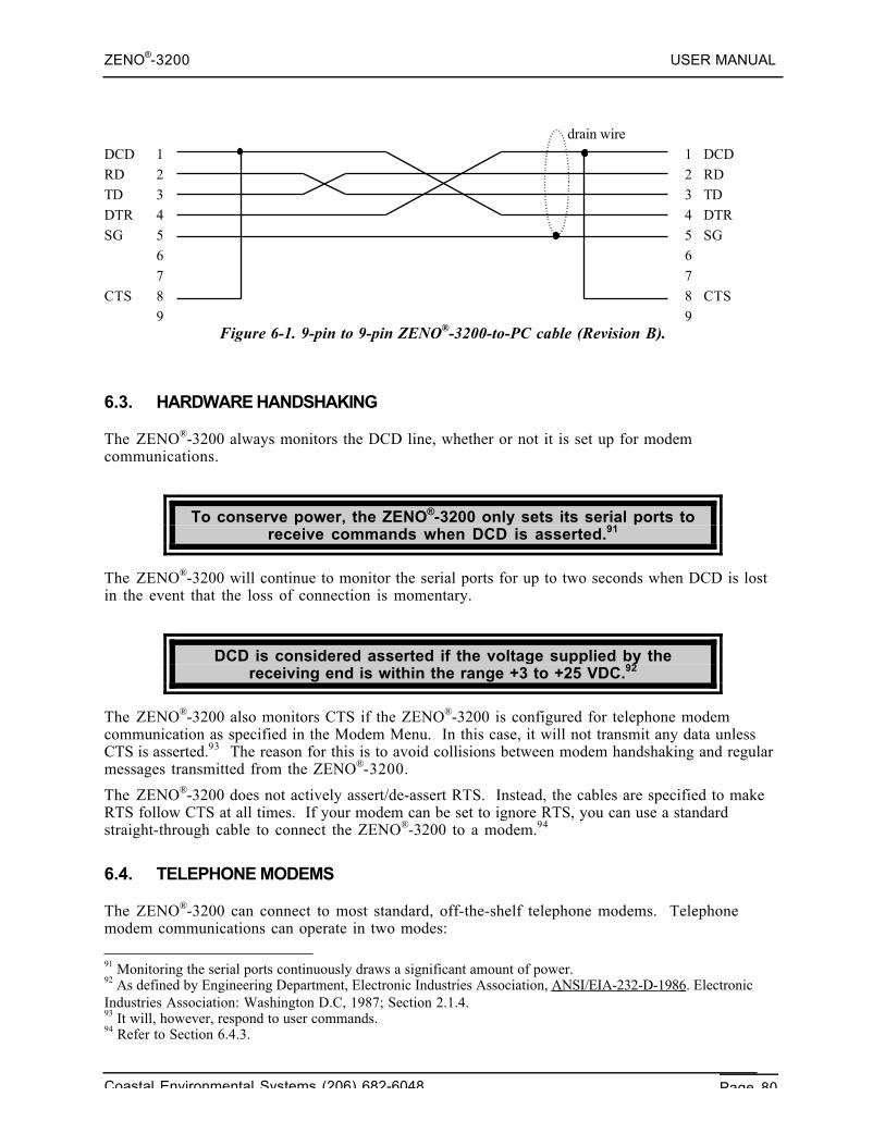
ZENO®-3200 USER MANUAL
Coastal Environmental Systems (206) 682-6048 Page 80
drain wireDCD 1 1 DCDRD 2 2 RDTD 3 3 TDDTR 4 4 DTRSG 5 5 SG
6 67 7
CTS 8 8 CTS9 9
Figure 6-1. 9-pin to 9-pin ZENO®-3200-to-PC cable (Revision B).
6.3. HARDWARE HANDSHAKING
The ZENO®-3200 always monitors the DCD line, whether or not it is set up for modemcommunications.
To conserve power, the ZENO®-3200 only sets its serial ports toreceive commands when DCD is asserted.91
The ZENO®-3200 will continue to monitor the serial ports for up to two seconds when DCD is lostin the event that the loss of connection is momentary.
DCD is considered asserted if the voltage supplied by thereceiving end is within the range +3 to +25 VDC.92
The ZENO®-3200 also monitors CTS if the ZENO®-3200 is configured for telephone modemcommunication as specified in the Modem Menu. In this case, it will not transmit any data unlessCTS is asserted.93 The reason for this is to avoid collisions between modem handshaking and regularmessages transmitted from the ZENO®-3200.
The ZENO®-3200 does not actively assert/de-assert RTS. Instead, the cables are specified to makeRTS follow CTS at all times. If your modem can be set to ignore RTS, you can use a standardstraight-through cable to connect the ZENO®-3200 to a modem.94
6.4. TELEPHONE MODEMS
The ZENO®-3200 can connect to most standard, off-the-shelf telephone modems. Telephonemodem communications can operate in two modes:
91 Monitoring the serial ports continuously draws a significant amount of power.92 As defined by Engineering Department, Electronic Industries Association, ANSI/EIA-232-D-1986 . ElectronicIndustries Association: Washington D.C, 1987; Section 2.1.4.93 It will, however, respond to user commands.94 Refer to Section 6.4.3.
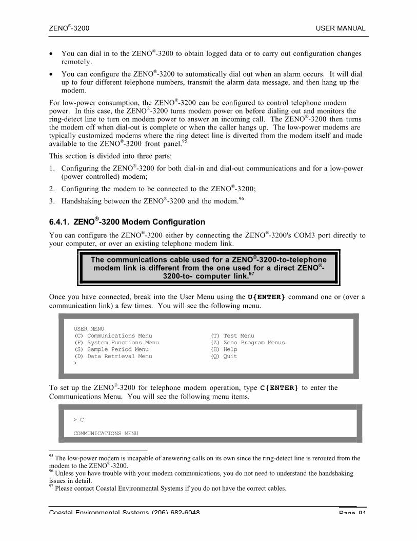
ZENO®-3200 USER MANUAL
Coastal Environmental Systems (206) 682-6048 Page 81
• You can dial in to the ZENO®-3200 to obtain logged data or to carry out configuration changesremotely.
• You can configure the ZENO®-3200 to automatically dial out when an alarm occurs. It will dialup to four different telephone numbers, transmit the alarm data message, and then hang up themodem.
For low-power consumption, the ZENO®-3200 can be configured to control telephone modempower. In this case, the ZENO®-3200 turns modem power on before dialing out and monitors thering-detect line to turn on modem power to answer an incoming call. The ZENO®-3200 then turnsthe modem off when dial-out is complete or when the caller hangs up. The low-power modems aretypically customized modems where the ring detect line is diverted from the modem itself and madeavailable to the ZENO®-3200 front panel.95
This section is divided into three parts:
1. Configuring the ZENO®-3200 for both dial-in and dial-out communications and for a low-power(power controlled) modem;
2. Configuring the modem to be connected to the ZENO®-3200;
3. Handshaking between the ZENO®-3200 and the modem.96
6.4.1. ZENO®-3200 Modem Configuration
You can configure the ZENO®-3200 either by connecting the ZENO®-3200's COM3 port directly toyour computer, or over an existing telephone modem link.
The communications cable used for a ZENO®-3200-to-telephonemodem link is different from the one used for a direct ZENO®-
3200-to- computer link.97
Once you have connected, break into the User Menu using the U{ENTER} command one or (over acommunication link) a few times. You will see the following menu.
USER MENU(C) Communications Menu (T) Test Menu(F) System Functions Menu (Z) Zeno Program Menus(S) Sample Period Menu (H) Help(D) Data Retrieval Menu (Q) Quit>
To set up the ZENO®-3200 for telephone modem operation, type C{ENTER} to enter theCommunications Menu. You will see the following menu items.
> C
COMMUNICATIONS MENU
95 The low-power modem is incapable of answering calls on its own since the ring-detect line is rerouted from themodem to the ZENO®-3200.96 Unless you have trouble with your modem communications, you do not need to understand the handshakingissues in detail.97 Please contact Coastal Environmental Systems if you do not have the correct cables.
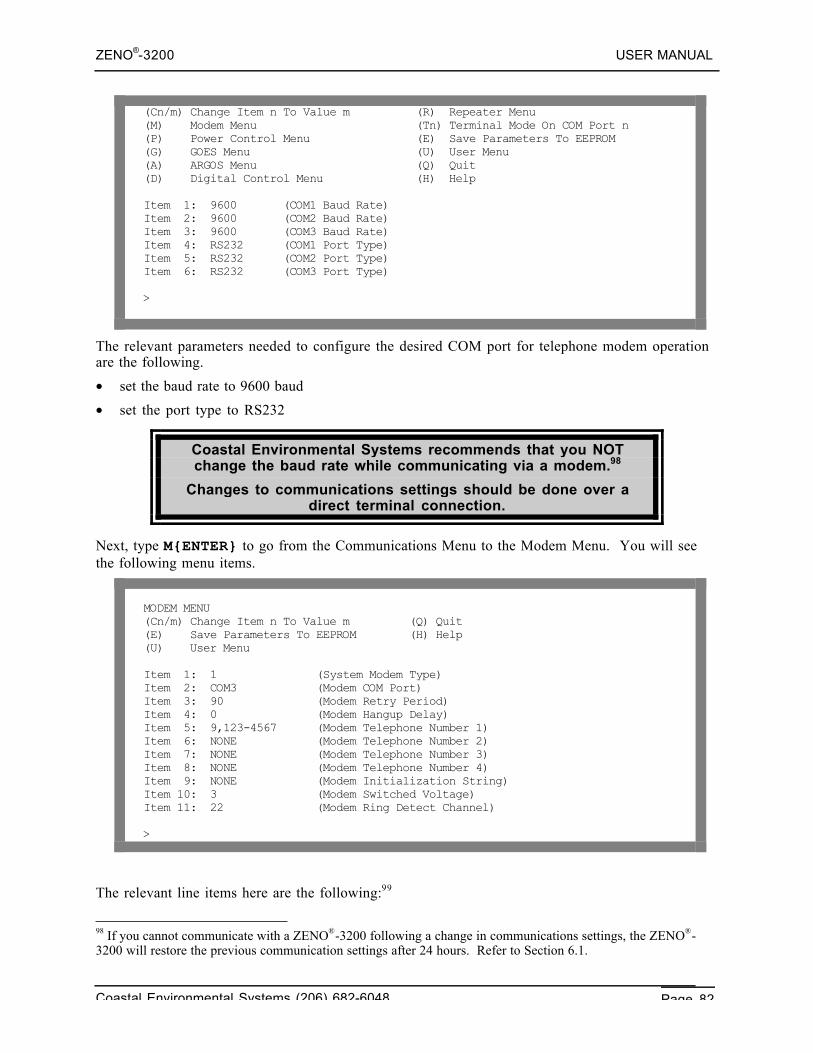
ZENO®-3200 USER MANUAL
Coastal Environmental Systems (206) 682-6048 Page 82
(Cn/m) Change Item n To Value m (R) Repeater Menu(M) Modem Menu (Tn) Terminal Mode On COM Port n(P) Power Control Menu (E) Save Parameters To EEPROM(G) GOES Menu (U) User Menu(A) ARGOS Menu (Q) Quit(D) Digital Control Menu (H) Help
Item 1: 9600 (COM1 Baud Rate)Item 2: 9600 (COM2 Baud Rate)Item 3: 9600 (COM3 Baud Rate)Item 4: RS232 (COM1 Port Type)Item 5: RS232 (COM2 Port Type)Item 6: RS232 (COM3 Port Type)
>
The relevant parameters needed to configure the desired COM port for telephone modem operationare the following.
• set the baud rate to 9600 baud
• set the port type to RS232
Coastal Environmental Systems recommends that you NOTchange the baud rate while communicating via a modem.98
Changes to communications settings should be done over adirect terminal connection.
Next, type M{ENTER} to go from the Communications Menu to the Modem Menu. You will seethe following menu items.
MODEM MENU(Cn/m) Change Item n To Value m (Q) Quit(E) Save Parameters To EEPROM (H) Help(U) User Menu
Item 1: 1 (System Modem Type)Item 2: COM3 (Modem COM Port)Item 3: 90 (Modem Retry Period)Item 4: 0 (Modem Hangup Delay)Item 5: 9,123-4567 (Modem Telephone Number 1)Item 6: NONE (Modem Telephone Number 2)Item 7: NONE (Modem Telephone Number 3)Item 8: NONE (Modem Telephone Number 4)Item 9: NONE (Modem Initialization String)Item 10: 3 (Modem Switched Voltage)Item 11: 22 (Modem Ring Detect Channel)
>
The relevant line items here are the following:99
98 If you cannot communicate with a ZENO®-3200 following a change in communications settings, the ZENO®-3200 will restore the previous communication settings after 24 hours. Refer to Section 6.1.
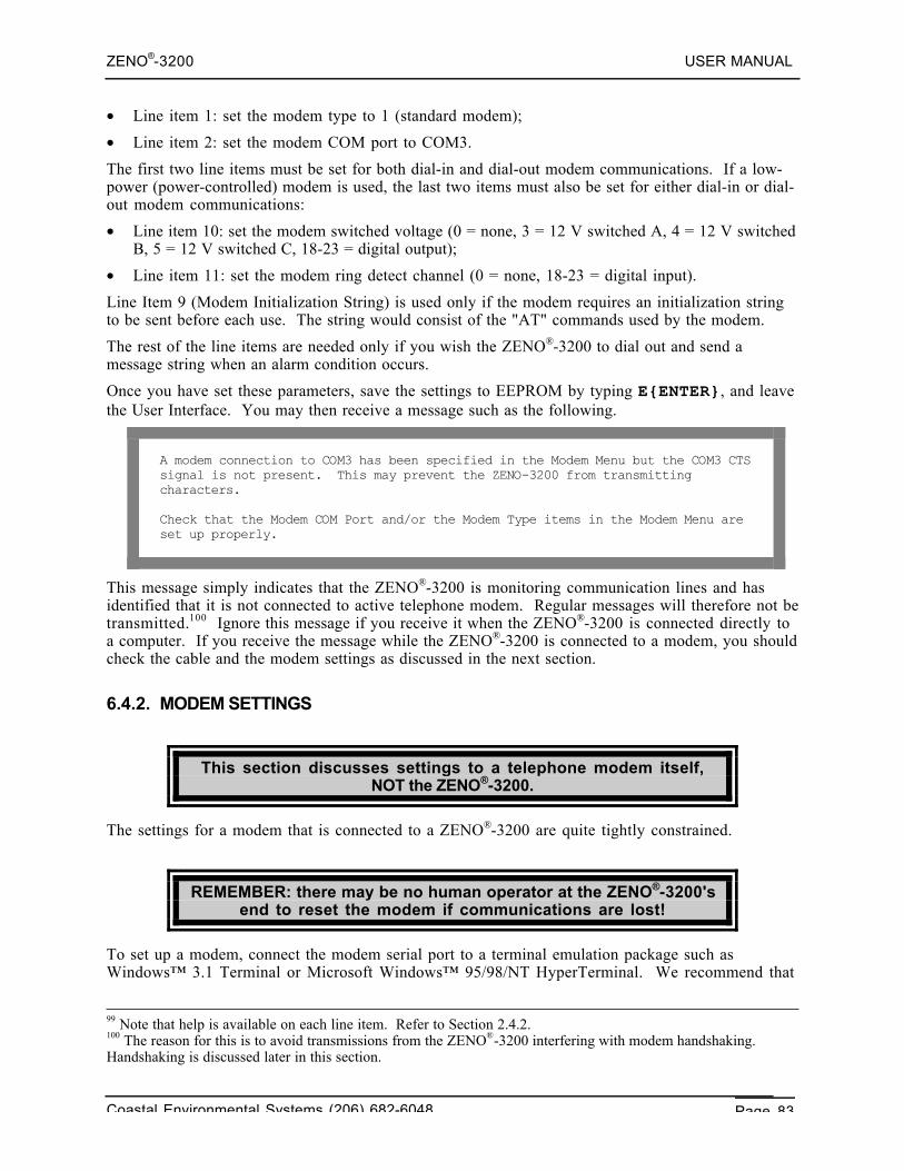
ZENO®-3200 USER MANUAL
Coastal Environmental Systems (206) 682-6048 Page 83
• Line item 1: set the modem type to 1 (standard modem);
• Line item 2: set the modem COM port to COM3.
The first two line items must be set for both dial-in and dial-out modem communications. If a low-power (power-controlled) modem is used, the last two items must also be set for either dial-in or dial-out modem communications:
• Line item 10: set the modem switched voltage (0 = none, 3 = 12 V switched A, 4 = 12 V switchedB, 5 = 12 V switched C, 18-23 = digital output);
• Line item 11: set the modem ring detect channel (0 = none, 18-23 = digital input).
Line Item 9 (Modem Initialization String) is used only if the modem requires an initialization stringto be sent before each use. The string would consist of the "AT" commands used by the modem.
The rest of the line items are needed only if you wish the ZENO®-3200 to dial out and send amessage string when an alarm condition occurs.
Once you have set these parameters, save the settings to EEPROM by typing E{ENTER}, and leavethe User Interface. You may then receive a message such as the following.
A modem connection to COM3 has been specified in the Modem Menu but the COM3 CTSsignal is not present. This may prevent the ZENO-3200 from transmittingcharacters.
Check that the Modem COM Port and/or the Modem Type items in the Modem Menu areset up properly.
This message simply indicates that the ZENO®-3200 is monitoring communication lines and hasidentified that it is not connected to active telephone modem. Regular messages will therefore not betransmitted.100 Ignore this message if you receive it when the ZENO®-3200 is connected directly toa computer. If you receive the message while the ZENO®-3200 is connected to a modem, you shouldcheck the cable and the modem settings as discussed in the next section.
6.4.2. MODEM SETTINGS
This section discusses settings to a telephone modem itself,NOT the ZENO®-3200.
The settings for a modem that is connected to a ZENO®-3200 are quite tightly constrained.
REMEMBER: there may be no human operator at the ZENO®-3200'send to reset the modem if communications are lost!
To set up a modem, connect the modem serial port to a terminal emulation package such asWindows™ 3.1 Terminal or Microsoft Windows™ 95/98/NT HyperTerminal. We recommend that
99 Note that help is available on each line item. Refer to Section 2.4.2.100 The reason for this is to avoid transmissions from the ZENO®-3200 interfering with modem handshaking.Handshaking is discussed later in this section.
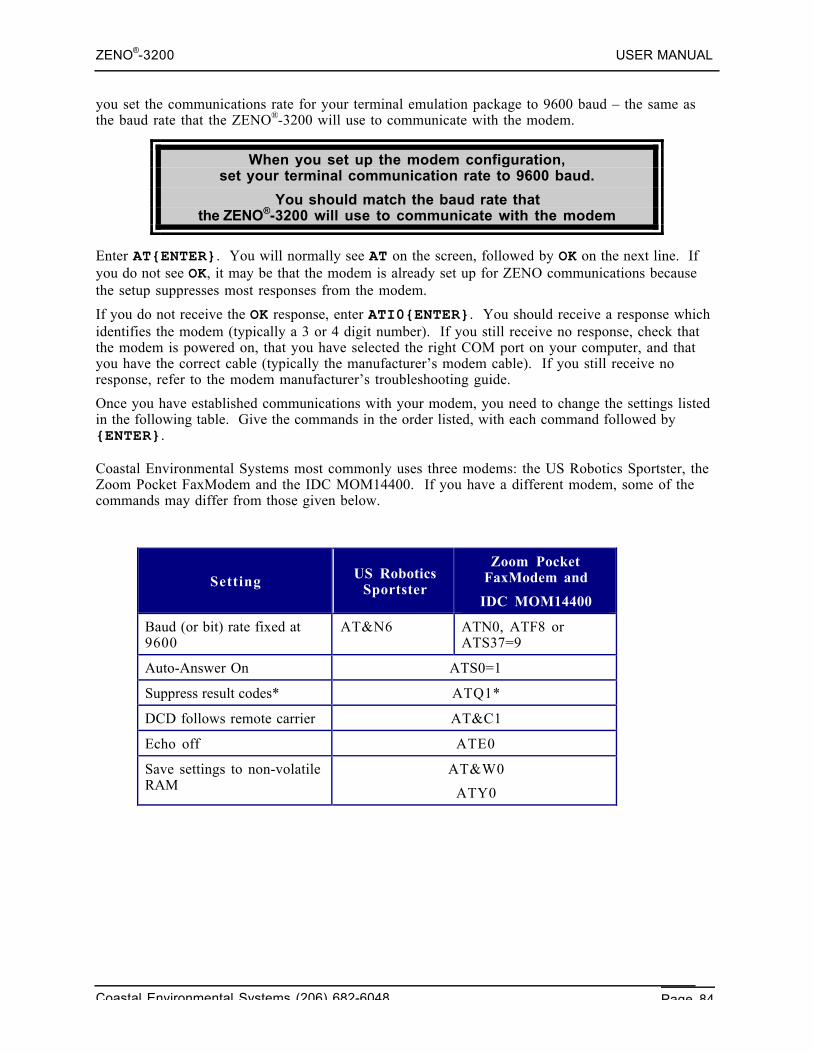
ZENO®-3200 USER MANUAL
Coastal Environmental Systems (206) 682-6048 Page 84
you set the communications rate for your terminal emulation package to 9600 baud – the same asthe baud rate that the ZENO®-3200 will use to communicate with the modem.
When you set up the modem configuration,set your terminal communication rate to 9600 baud.
You should match the baud rate thatthe ZENO®-3200 will use to communicate with the modem
Enter AT{ENTER}. You will normally see AT on the screen, followed by OK on the next line. Ifyou do not see OK, it may be that the modem is already set up for ZENO communications becausethe setup suppresses most responses from the modem.
If you do not receive the OK response, enter ATI0{ENTER}. You should receive a response whichidentifies the modem (typically a 3 or 4 digit number). If you still receive no response, check thatthe modem is powered on, that you have selected the right COM port on your computer, and thatyou have the correct cable (typically the manufacturer’s modem cable). If you still receive noresponse, refer to the modem manufacturer’s troubleshooting guide.
Once you have established communications with your modem, you need to change the settings listedin the following table. Give the commands in the order listed, with each command followed by{ENTER}.
Coastal Environmental Systems most commonly uses three modems: the US Robotics Sportster, theZoom Pocket FaxModem and the IDC MOM14400. If you have a different modem, some of thecommands may differ from those given below.
Setting US RoboticsSportster
Zoom PocketFaxModem and
IDC MOM14400
Baud (or bit) rate fixed at9600
AT&N6 ATN0, ATF8 orATS37=9
Auto-Answer On ATS0=1
Suppress result codes* ATQ1*
DCD follows remote carrier AT&C1
Echo off ATE0
Save settings to non-volatileRAM
AT&W0
ATY0
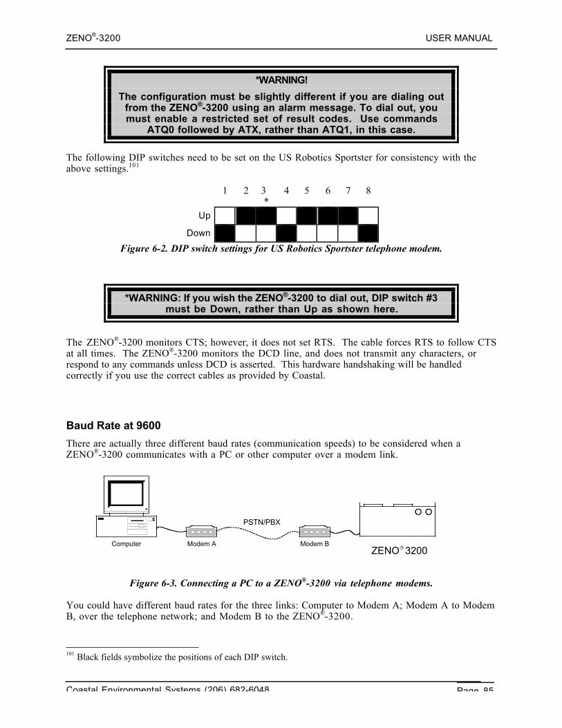
ZENO®-3200 USER MANUAL
Coastal Environmental Systems (206) 682-6048 Page 85
*WARNING!
The configuration must be slightly different if you are dialing outfrom the ZENO®-3200 using an alarm message. To dial out, youmust enable a restricted set of result codes. Use commands
ATQ0 followed by ATX, rather than ATQ1, in this case.
The following DIP switches need to be set on the US Robotics Sportster for consistency with theabove settings.101
1 2 3*
4 5 6 7 8
Up
Down
Figure 6-2. DIP switch settings for US Robotics Sportster telephone modem.
*WARNING: If you wish the ZENO®-3200 to dial out, DIP switch #3must be Down, rather than Up as shown here.
The ZENO®-3200 monitors CTS; however, it does not set RTS. The cable forces RTS to follow CTSat all times. The ZENO®-3200 monitors the DCD line, and does not transmit any characters, orrespond to any commands unless DCD is asserted. This hardware handshaking will be handledcorrectly if you use the correct cables as provided by Coastal.
Baud Rate at 9600
There are actually three different baud rates (communication speeds) to be considered when aZENO®-3200 communicates with a PC or other computer over a modem link.
Figure 6-3. Connecting a PC to a ZENO®-3200 via telephone modems.
You could have different baud rates for the three links: Computer to Modem A; Modem A to ModemB, over the telephone network; and Modem B to the ZENO®-3200.
101 Black fields symbolize the positions of each DIP switch.
Computer Modem A Modem BZENO 3200®
PSTN/PBX
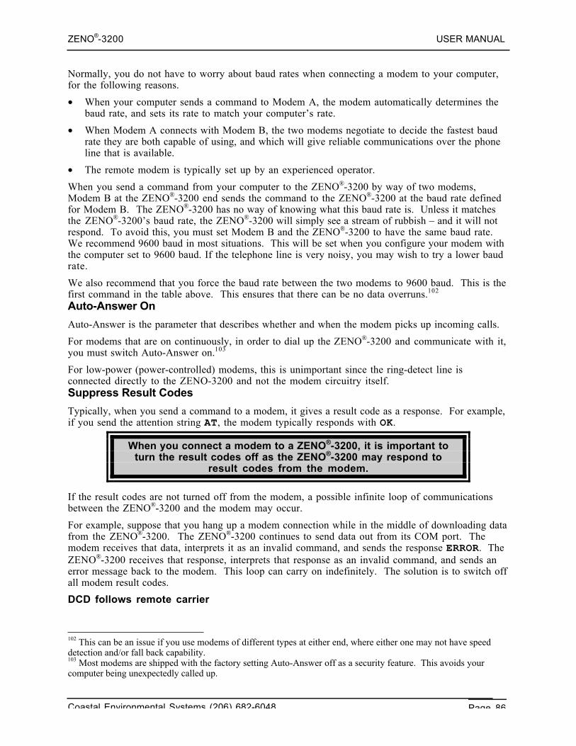
ZENO®-3200 USER MANUAL
Coastal Environmental Systems (206) 682-6048 Page 86
Normally, you do not have to worry about baud rates when connecting a modem to your computer,for the following reasons.
• When your computer sends a command to Modem A, the modem automatically determines thebaud rate, and sets its rate to match your computer’s rate.
• When Modem A connects with Modem B, the two modems negotiate to decide the fastest baudrate they are both capable of using, and which will give reliable communications over the phoneline that is available.
• The remote modem is typically set up by an experienced operator.
When you send a command from your computer to the ZENO®-3200 by way of two modems,Modem B at the ZENO®-3200 end sends the command to the ZENO®-3200 at the baud rate definedfor Modem B. The ZENO®-3200 has no way of knowing what this baud rate is. Unless it matchesthe ZENO®-3200’s baud rate, the ZENO®-3200 will simply see a stream of rubbish – and it will notrespond. To avoid this, you must set Modem B and the ZENO®-3200 to have the same baud rate.We recommend 9600 baud in most situations. This will be set when you configure your modem withthe computer set to 9600 baud. If the telephone line is very noisy, you may wish to try a lower baudrate.
We also recommend that you force the baud rate between the two modems to 9600 baud. This is thefirst command in the table above. This ensures that there can be no data overruns.102
Auto-Answer On
Auto-Answer is the parameter that describes whether and when the modem picks up incoming calls.
For modems that are on continuously, in order to dial up the ZENO®-3200 and communicate with it,you must switch Auto-Answer on.103
For low-power (power-controlled) modems, this is unimportant since the ring-detect line isconnected directly to the ZENO-3200 and not the modem circuitry itself.Suppress Result Codes
Typically, when you send a command to a modem, it gives a result code as a response. For example,if you send the attention string AT, the modem typically responds with OK.
When you connect a modem to a ZENO®-3200, it is important toturn the result codes off as the ZENO®-3200 may respond to
result codes from the modem.
If the result codes are not turned off from the modem, a possible infinite loop of communicationsbetween the ZENO®-3200 and the modem may occur.
For example, suppose that you hang up a modem connection while in the middle of downloading datafrom the ZENO®-3200. The ZENO®-3200 continues to send data out from its COM port. Themodem receives that data, interprets it as an invalid command, and sends the response ERROR. TheZENO®-3200 receives that response, interprets that response as an invalid command, and sends anerror message back to the modem. This loop can carry on indefinitely. The solution is to switch offall modem result codes.
DCD follows remote carrier
102 This can be an issue if you use modems of different types at either end, where either one may not have speeddetection and/or fall back capability.103 Most modems are shipped with the factory setting Auto-Answer off as a security feature. This avoids yourcomputer being unexpectedly called up.
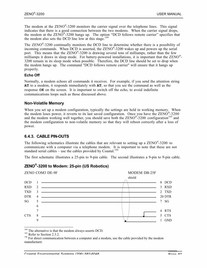
ZENO®-3200 USER MANUAL
Coastal Environmental Systems (206) 682-6048 Page 87
The modem at the ZENO®-3200 monitors the carrier signal over the telephone lines. This signalindicates that there is a good connection between the two modems. When the carrier signal drops,the modem at the ZENO®-3200 hangs up. The option “DCD follows remote carrier” specifies thatthe modem also sets the DCD line low at this stage.104
The ZENO®-3200 continually monitors the DCD line to determine whether there is a possibility ofincoming commands. When DCD is asserted, the ZENO®-3200 wakes up and powers up the serialport. This means that the ZENO®-3200 is drawing several tens of milliamps, rather than the fewmilliamps it draws in sleep mode. For battery-powered installations, it is important that the ZENO®-3200 remain in its sleep mode when possible. Therefore, the DCD line should be set to drop whenthe modem hangs up. The command "DCD follows remote carrier" will ensure that it hangs upproperly.
Echo Off
Normally, a modem echoes all commands it receives. For example, if you send the attention stringAT to a modem, it responds immediately with AT, so that you see the command as well as theresponse OK on the screen. It is important to switch off the echo, to avoid indefinitecommunications loops such as those discussed above.
Non-Volatile Memory
When you set up a modem configuration, typically the settings are held in working memory. Whenthe modem loses power, it reverts to its last saved configuration. Once you have the ZENO®-3200and the modem working well together, you should save both the ZENO®-3200 configuration105 andthe modem configuration to non-volatile memory so that they will reboot correctly after a loss ofpower.
6.4.3. CABLE PIN-OUTS
The following schematics illustrate the cables that are relevant to setting up a ZENO®-3200 tocommunicate with a computer via a telephone modem. It is important to note that these are notstandard serial cables – use the cables provided by Coastal.106
The first schematic illustrates a 25-pin to 9-pin cable. The second illustrates a 9-pin to 9-pin cable.
ZENO®-3200 to Modem: 25-pin (US Robotics)
ZENO COM3 DE-9F MODEM DB-25Fshield
DCD 1 8 DCDRXD 2 3 RXDTXD 3 2 TXDDTR 4 20 DTRSG 5 7 SG
67 4 RTS
CTS 8 5 CTS9 1 GND
104 The alternative is that the modem always asserts DCD.105 Refer to Section 2.3.2.106 For direct communication between a computer and a modem, use the cable provided by the modemmanufacturer.
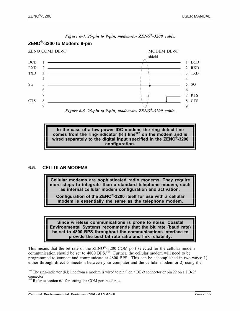
ZENO®-3200 USER MANUAL
Coastal Environmental Systems (206) 682-6048 Page 88
Figure 6-4. 25-pin to 9-pin, modem-to- ZENO®-3200 cable.
ZENO®-3200 to Modem: 9-pin
ZENO COM3 DE-9F MODEM DE-9Fshield
DCD 1 1 DCDRXD 2 2 RXDTXD 3 3 TXD
4 4SG 5 5 SG
6 67 7 RTS
CTS 8 8 CTS9 9
Figure 6-5. 25-pin to 9-pin, modem-to- ZENO®-3200 cable.
In the case of a low-power IDC modem, the ring detect linecomes from the ring-indicator (RI) line107 on the modem and iswired separately to the digital input specified in the ZENO®-3200
configuration.
6.5. CELLULAR MODEMS
Cellular modems are sophisticated radio modems. They requiremore steps to integrate than a standard telephone modem, such
as internal cellular modem configuration and activation.
Configuration of the ZENO®-3200 itself for use with a cellularmodem is essentially the same as the telephone modem.
Since wireless communications is prone to noise, CoastalEnvironmental Systems recommends that the bit rate (baud rate)be set to 4800 BPS throughout the communications interface to
provide the best bit rate ratio and link reliability.
This means that the bit rate of the ZENO®-3200 COM port selected for the cellular modemcommunication should be set to 4800 BPS.108 Further, the cellular modem will need to beprogrammed to connect and communicate at 4800 BPS. This can be accomplished in two ways: 1)either through direct connection between your computer and the cellular modem or 2) using the 107 The ring-indicator (RI) line from a modem is wired to pin 9 on a DE-9 connector or pin 22 on a DB-25connector.108 Refer to section 6.1 for setting the COM port baud rate.
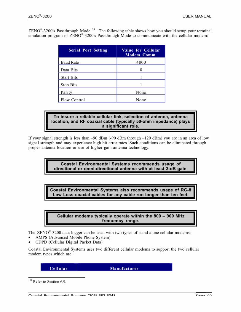
ZENO®-3200 USER MANUAL
Coastal Environmental Systems (206) 682-6048 Page 89
ZENO®-3200's Passthrough Mode109. The following table shows how you should setup your terminalemulation program or ZENO®-3200's Passthrough Mode to communicate with the cellular modem:
Serial Port Setting Value for CellularModem Comm.
Baud Rate 4800
Data Bits 8
Start Bits 1
Stop Bits 1
Parity None
Flow Control None
To insure a reliable cellular link, selection of antenna, antennalocation, and RF coaxial cable (typically 50-ohm impedance) plays
a significant role.
If your signal strength is less than –90 dBm (-90 dBm through –120 dBm) you are in an area of lowsignal strength and may experience high bit error rates. Such conditions can be eliminated throughproper antenna location or use of higher gain antenna technology.
Coastal Environmental Systems recommends usage ofdirectional or omni-directional antenna with at least 3-dB gain.
Coastal Environmental Systems also recommends usage of RG-8Low Loss coaxial cables for any cable run longer than ten feet.
Cellular modems typically operate within the 800 – 900 MHzfrequency range.
The ZENO®-3200 data logger can be used with two types of stand-alone cellular modems:• AMPS (Advanced Mobile Phone System)• CDPD (Cellular Digital Packet Data)
Coastal Environmental Systems uses two different cellular modems to support the two cellularmodem types which are:
CellularModem Type
Manufacturer
109 Refer to Section 6.9.
ZENO®-3200 USER MANUAL
Coastal Environmental Systems (206) 682-6048 Page 90
Modem Type
AMPS StarComm Cellular Modem 1442E-616-C
CDPD Sierra Wireless MP200
6.5.1. AMPS Cellular Modem Configuration (StarComm Cellular Modem)
First, make sure that there is communication with the cellular modem. From your computerconnected directly to the cellular modem or from the ZENO®-3200's Passthrough Mode, typeAT{ENTER}. The modem should respond with OK. If you don't get a response, check the wiring tothe cellular modem and that it is powered.
If communication is established, type the following command string:
AT&FBEMN1Q1X4&DS0=1S7=70S10=50{ENTER}
At this point the cellular modem will no longer echo or respond to most typed commands. If youwish to see the commands that you type on your computer screen, enable the local echo in yourterminal emulation program.
Next, type the following series of commands to the cellular modem:
AT%A%C3%E2\A\G\N2\Q{ENTER}
AT+MS=10,0,4800,9600{ENTER}
AT&W{ENTER}
These commands will save the configuration within the cellular modem. The configuration can bechecked by typing AT&V{ENTER}. The modem will respond with the list of parameters in itsactive profiles (profile zero and profile one).
The cellular modem will respond with 10,0,4800,9600,0,0,300 if you type the commandAT+MS?{ENTER}.
6.5.2. AMPS Cellular Modem Network Activation
In order to operate an AMPS cellular modem, you must establishservice with a cellular service provider that offers this type of
service.
You will need to provide the cellular service provider with the following information:
1. The ESN of your cellular modem – Every cellular modem is identified by a unique number calledESN (Electronic Serial Number). The ESN is supplied with the modem documentation or has tobe retrieved from the modem's EEPROM. To retrieve this information from the StarCommCellular Modem, type the command AT>I{ENTER}.
2. Device Type – Your cellular provider may ask you to identify the type of device that you areactivating on their network. The device type can be acquired from the modem documentation.Two most common types are Motorola Radio and Standard Communications CMR4100 radio.
After you have established an account with your cellular provider, you need to request the followinginformation from your cellular provider:
ZENO®-3200 USER MANUAL
Coastal Environmental Systems (206) 682-6048 Page 91
1. MIN – Mobile Identification Number, a 10-digit number that is your cellular modem/phonenumber.
2. SID – System ID, 5-digit number that defines the cellular system.
3. CAOC – Carrier Access Overload Class, a 2-digit number that defines the cellular carrier accessparameters.
4. CGID – Carrier Group ID, a 2-digit number that defines.
5. Network Preference – a parameter that selects the network operating characteristics.
To configure some cellular modems you may not require all of the above parameters. The StarCommCellular Modem only requires MIN, SID and Network Preference parameters. To input theseparameters you need to use the following commands:
Telephone Number: AT>M=mmmmmmmmmm{ENTER} (m = telephone number)
System ID: AT>S=sssss{ENTER} (s = SID)
Network Preference: AT>N=n{ENTER} (n = preference)
Your cellular modem should now be ready to operate.
Using the AT>Q{ENTER} command on a StarComm Cellularmodem will evaluate the quality of service at your particular
location.
6.5.3. Understanding CDPD Cellular Modems
Cellular Digital Packed Data (CDPD, or Wireless IP110) is a superset of the AMPS specifically forsending data over cellular network.
CDPD transmits data in small packets over cellular network using UDP111 PAD112. If a connection islost during transmission, the CDPD cellular modem reconnects to the network and automaticallyretransmits or re-receives the message in its entirety. Since it is completely digital, CDPD has low biterror rates at higher speeds. The typical raw speed is 19.2 kbps. Generally, CDPD has loweroperational costs than analog wireless connection.
To activate and register your CDPD cellular modem with thecellular network, it is necessary to select a CDPD service
provider and acquire an NEI (Network Entity Identifier), alsoknown as an IP address.
110 IP is the acronym for Internet Protocol.111 UDP (User Datagram Protocol) is a subset of TCP/IP, the standard internet protocol.112 PAD is the acronym for Packet Assembly/Disassembly.
ZENO®-3200 USER MANUAL
Coastal Environmental Systems (206) 682-6048 Page 92
Configuring and using the UDP PAD service requires familiaritywith AT commands. In particular, an understanding of the +WS
registers from +WS60 to +WS74 (as described in the ATCommand Reference Manual) is essential.
The Sierra Wireless MP200 has two states: the command state and the data state. When the UDPPAD service is selected (+WS45=0), the modem is in command state. The data state will be enteredwhen a call is originated by dialing or the cellular modem answers an incoming packet (call).
Escaping Data State Using TIES
The Time Independent Escape Sequence (TIES) is a method to shift the cellular modem from thedata state to the command state. It is enabled by setting register +WS60=1 (the default).
The escape sequence is the string AT+++, ending with the Primary Forwarding Character (defined byregister +WS64). The complete sequence must fit within the current packet; otherwise, it will not beincluded in the TIES checking.
CDPD Dialing Out – Client Sessions
The Sierra Wireless MP200 can be used to originate a UDP session by “dialing” an IP address andport using the ATD[ip_address.port] command. The modem will only answer calls addressedto port 2100. The modem will go on-line (into data state) and wait for a packet to send or one toarrive. While the session is open, only traffic from the dialed server will be accepted by the MP200.
The local host (the ZENO®-3200) can compose packets and forward them to the network. Packetsfrom the called server will be delivered to the local host.
To close the session, the local host must leave data state by issuing the TIES or toggling DTR (ifconfigured with (AT&D1 or AT&D2) followed by a “hang up” using the ATH command.
CDPD Answering a Call – Server Sessions
The Sierra Wireless MP200 cellular modem can be configured to auto-answer incoming packets byopening a session when a packet arrives. This is handled by setting ATS0=1. The MP200 will open asession and enter the data state when a packet addressed to the cellular modem’s IP address arrives onany port.
When a packet arrives, the modem sends the CONNECT message, enters the data state, and sends thepacket to the local host (the ZENO®-3200). Again, the cellular modem will remain in the data stateuntil the local host issues the TIES or toggling DTR (if configured with (AT&D1 or AT&D2) followedby a “hang up” using the ATH command.
CDPD Packet Assembly
A packet is started and buffered when the local host starts sending data to the cellular modem. If thebuffer reaches the maximum packet length, the packet is forwarded and a new packet is started.
The modem can echo characters sent from the local host if register +WS62=1 and, in cases whereterminal emulation program is being used, it allows typing and sending messages in real time.
Forwarding a CDPD Packet
The cellular modem closes and sends a packet when one of the following events occur:• The maximum packet length, set in register +WS74 (default 1000 bytes), is reached.• The modem receives the PAD Primary Forwarding Character set in register +WS64. This register
defaults to ASCII character {CR} (decimal value 13).• The PAD Inter-Character Timer (register +WS70) expires.
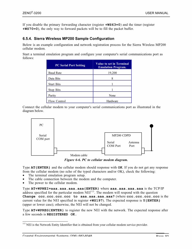
ZENO®-3200 USER MANUAL
Coastal Environmental Systems (206) 682-6048 Page 93
If you disable the primary forwarding character (register +WS63=0) and the timer (register+WS70=0), the only way to forward packets will be to fill the packet buffer.
6.5.4. Sierra Wireless MP200 Sample Configuration
Below is an example configuration and network registration process for the Sierra Wireless MP200cellular modem.
Start a terminal emulation program and configure your computer's serial communications port asfollows:
PC Serial Port Setting Value to set in TerminalEmulation Program.
Baud Rate 19,200
Data Bits 8
Start Bits 1
Stop Bits 1
Parity None
Flow Control Hardware
Connect the cellular modem to your computer's serial communications port as illustrated in thediagram below.
Figure 6-6. PC to cellular modem diagram.
Type AT{ENTER} and the cellular modem should response with OK. If you do not get any responsefrom the cellular modem (no echo of the typed characters and/or OK), check the following:• The terminal emulation program setup.• The cable connection between the modem and the computer.• The power to the cellular modem.
Type AT+WPNEI=aaa.aaa.aaa.aaa{ENTER} where aaa.aaa.aaa.aaa is the TCP/IPaddress specified for the particular modem NEI113. The modem will respond with the questionChange ccc.ccc.ccc.ccc to aaa.aaa.aaa.aaa? (where ccc.ccc.ccc.ccc is thecurrent value for the NEI specified in register +WS197). The expected response is Y{ENTER}(upper or lower case); otherwise, the NEI will not be changed.
Type AT+WPREG{ENTER} to register the new NEI with the network. The expected response aftera few seconds is REGISTERED OK.
113 NEI is the Network Entity Identifier that is obtained from your cellular modem service provider.
PC
Serial COM port
MP200 CDPD
Serial AntennaCOM Port Port
Modem cable
ZENO®-3200 USER MANUAL
Coastal Environmental Systems (206) 682-6048 Page 94
Type AT+WPNEILIST{ENTER}. The response to this command should display the four-entry NEItable, with the value and registration status of each NEI:
1 aaa.aaa.aaa.aaa * Registered
2 000.000.000.000 P No
3 000.000.000.000 P No
4 000.000.000.000 P No
OK
Type the following command string (no breaks!):
AT&F&DS0=1+WS45=0+WS46=4+WS60=1+WS62=0+WS64=126+WS72=0+WS74=512+WS173=1+WS176=1{ENTER}
Type AT+IPR=9600{ENTER}. The cellular modem will respond with OK, followed with a shortstring of garbled characters. This means the modem has changed its serial communications port baud-rate to 9600 BPS. Therefore, in order to continue to communicate with the modem you shouldchange the baud rate of your terminal emulation program to 9600 BPS.
Depending on the modem application, type the following string:
- as a Host Modem (connected to PC, Intercept™): ATEQ&W{ENTER}
- as a Remote Modem (connected to ZENO®-3200): ATEQ1&W{ENTER}
Cycle the power to the cellular modem. After approximately 10 seconds type a test string for asingle register e.g.: AT+WS64?{ENTER} (a request for the contents of register WS64). If you getthe response be 126{CR/LF}, you have successfully configured your cellular modem. If you get noresponse, redo the listed steps.
6.6. RADIO COMMUNICATIONS
All radio communication is prone to noise!
The ZENO®-3200 radio and your host must have good Line Of Site(LOS) for effective radio communication.
The CCSAIL protocol should be used to download data because of its built-in checksum for errorchecking114 for either unidirectional or bi-directional communication.
The X-modem file transfer protocol is also good for noisy communications links, but can only beused with two-way radio communication because it is bi-directional.
If you are using unidirectional communication, you cannot usethe X-modem file transfer protocol!
114 Refer to Section 4.6.
ZENO®-3200 USER MANUAL
Coastal Environmental Systems (206) 682-6048 Page 95
Radio transmitters use a lot of power!
Coastal Environmental Systems typically uses radios that transmit at 2 Watts, requiring 1 Amp at 12VDC during transmission. The typical transmitter duty cycle115 is 30% to 50%.
Coastal Environmental Systems does not recommenddownloading large amounts of data via radio because the radio
transmitter could be damaged.
6.6.1. Connecting the Radio To The ZENO®-3200
It is important to note that your ZENO®-3200 must be equippedwith an internal, properly tuned FSK116 Modem Chip in order to
use radio communications.
Both unidirectional and bi-directional radios are connected to the ZENO®-3200 using COM1. Severalpins on the Auxiliary Serial Port117 are used to connect the radio to the ZENO®-3200:
Auxiliary PortPin
Pin Function
4 Push-To-Talk (PTT)
9 Audio Transmit (TXA)
10 Audio Receive (RXA)
12 Digital Ground (DGND)
13 +12 VDC Switched Voltage A
25 Input Power (Power supplied to ZENO®-3200 on Front Panel118)
For a complete listing of the Auxiliary Port Pins, refer to Section 13.5.2.
6.6.2. Power Control Options
115 Duty cycle is the percentage of time that a radio can transmit before it needs to rest. If a radio transmits for 10seconds and its duty cycle is 30%, then it must rest for at least 23 seconds.116 FSK stands for Frequency Shift Keying.117 The Auxiliary Serial Port is located on the ZENO®-3200 Front Panel, refer to Section 2.1.118 Refer to Section 2.1
ZENO®-3200 USER MANUAL
Coastal Environmental Systems (206) 682-6048 Page 96
Coastal Environmental System's Standard Indoor Battery ChargerDOES NOT supply enough power to supply a radio during
transmission.
Coastal Environmental Systems recommends use of a batterywith sufficient amperage or other power source to supply both
the ZENO®-3200 and a radio.
Since radios require a lot of power, Coastal Environmental Systems designed the ZENO®-3200 sothat power to a radio can be controlled in several ways. Depending upon the type of radio used andthe amount of available power needed, the following table illustrates radio power control options:
Power Control Option Reason For Using Option Typical Source Of Power
Leave the radio on at all times. This is only good when youhave unlimited power and youare using a bi-directional radio.
Pin 25 on Auxiliary Serial Port.(This is on whenever the ZENO®-3200 is on.)
Only turn a radio on when it istime to transmit data.
This is done typically withunidirectional radios.
Pin 13 on Auxiliary Serial Port.(+12 VDC Switched Voltage A,controlled using Power ControlMenu.)
Turn the radio on for a specifiedlength of time on a regularschedule.
This is done typically with bi-directional radios.
External relay controlled by aDigital Output via the DigitalControl Menu.
A Switched Voltage can provide enough power to supply aunidirectional radio, but not for a bi-directional radio.
6.6.3. Controlling Unidirectional Radio Power (The Power Control Menu)
Typically, you will control power to a unidirectional radio using +12 VDC Switched Voltage A, whichis directly available on the Auxiliary Serial Port.119 To do this, you need to specify which switchedvoltage is to be used to control radio power in the Power Control Menu. To get to the PowerControl Menu, you first need to be in the Communications Menu, then type P{ENTER} to go to thePower Control Menu. You should see the following on your terminal emulation program:
119 +12 VDC Switched Voltage B or C can also be used by wiring to the ZENO®-3200 Front Panel.
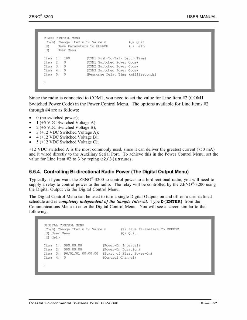
ZENO®-3200 USER MANUAL
Coastal Environmental Systems (206) 682-6048 Page 97
POWER CONTROL MENU(Cn/m) Change Item n To Value m (Q) Quit(E) Save Parameters To EEPROM (H) Help(U) User Menu
Item 1: 100 (COM1 Push-To-Talk Setup Time)Item 2: 0 (COM1 Switched Power Code)Item 3: 0 (COM2 Switched Power Code)Item 4: 0 (COM3 Switched Power Code)Item 5: 0 (Response Delay Time (milliseconds)
>
Since the radio is connected to COM1, you need to set the value for Line Item #2 (COM1Switched Power Code) in the Power Control Menu. The options available for Line Items #2through #4 are as follows:
• 0 (no switched power);• 1 (+5 VDC Switched Voltage A);• 2 (+5 VDC Switched Voltage B);• 3 (+12 VDC Switched Voltage A);• 4 (+12 VDC Switched Voltage B);• 5 (+12 VDC Switched Voltage C);
+12 VDC switched A is the most commonly used, since it can deliver the greatest current (750 mA)and it wired directly to the Auxiliary Serial Port. To achieve this in the Power Control Menu, set thevalue for Line Item #2 to 3 by typing C2/3{ENTER}.
6.6.4. Controlling Bi-directional Radio Power (The Digital Output Menu)
Typically, if you want the ZENO®-3200 to control power to a bi-directional radio, you will need tosupply a relay to control power to the radio. The relay will be controlled by the ZENO®-3200 usingthe Digital Output via the Digital Control Menu.
The Digital Control Menu can be used to turn a single Digital Outputs on and off on a user-definedschedule and is completely independent of the Sample Interval. Type D{ENTER} from theCommunications Menu to enter the Digital Control Menu. You will see a screen similar to thefollowing.
DIGITAL CONTROL MENU(Cn/m) Change Item n to Value m (E) Save Parameters To EEPROM(U) User Menu (Q) Quit(H) Help
Item 1: 000:00:00 (Power-On Interval)Item 2: 000:00:00 (Power-On Duration)Item 3: 96/01/01 00:00:00 (Start of First Power-On)Item 4: 0 (Control Channel)
>
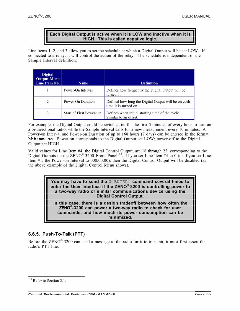
ZENO®-3200 USER MANUAL
Coastal Environmental Systems (206) 682-6048 Page 98
Each Digital Output is active when it is LOW and inactive when it isHIGH. This is called negative logic.
Line items 1, 2, and 3 allow you to set the schedule at which a Digital Output will be set LOW. Ifconnected to a relay, it will control the action of the relay. The schedule is independent of theSample Interval definition:
DigitalOutput MenuLine Item No. Name Definition
1 Power-On Interval Defines how frequently the Digital Output will beturned on.
2 Power-On Duration Defined how long the Digital Output will be on eachtime it is turned on.
3 Start of First Power-On Defines when initial starting time of the cycle.Similar to an offset.
For example, the Digital Output could be switched on for the first 5 minutes of every hour to turn ona bi-directional radio, while the Sample Interval calls for a new measurement every 10 minutes. APower-on Interval and Power-on Duration of up to 168 hours (7 days) can be entered in the formathhh:mm:ss. Power-on corresponds to the Digital Output set LOW; power-off to the DigitalOutput set HIGH.
Valid values for Line Item #4, the Digital Control Output, are 18 through 23, corresponding to theDigital Outputs on the ZENO®-3200 Front Panel120. If you set Line Item #4 to 0 (or if you set LineItem #1, the Power-on Interval to 000:00:00), then the Digital Control Output will be disabled (asthe above example of the Digital Control Menu shows).
You may have to send the U{ENTER} command several times toenter the User Interface if the ZENO®-3200 is controlling power to
a two-way radio or similar communications device using theDigital Control Output.
In this case, there is a design tradeoff between how often theZENO®-3200 can power a two-way radio to check for user
commands, and how much its power consumption can beminimized.
6.6.5. Push-To-Talk (PTT)
Before the ZENO®-3200 can send a message to the radio for it to transmit, it must first assert theradio's PTT line.
120 Refer to Section 2.1.
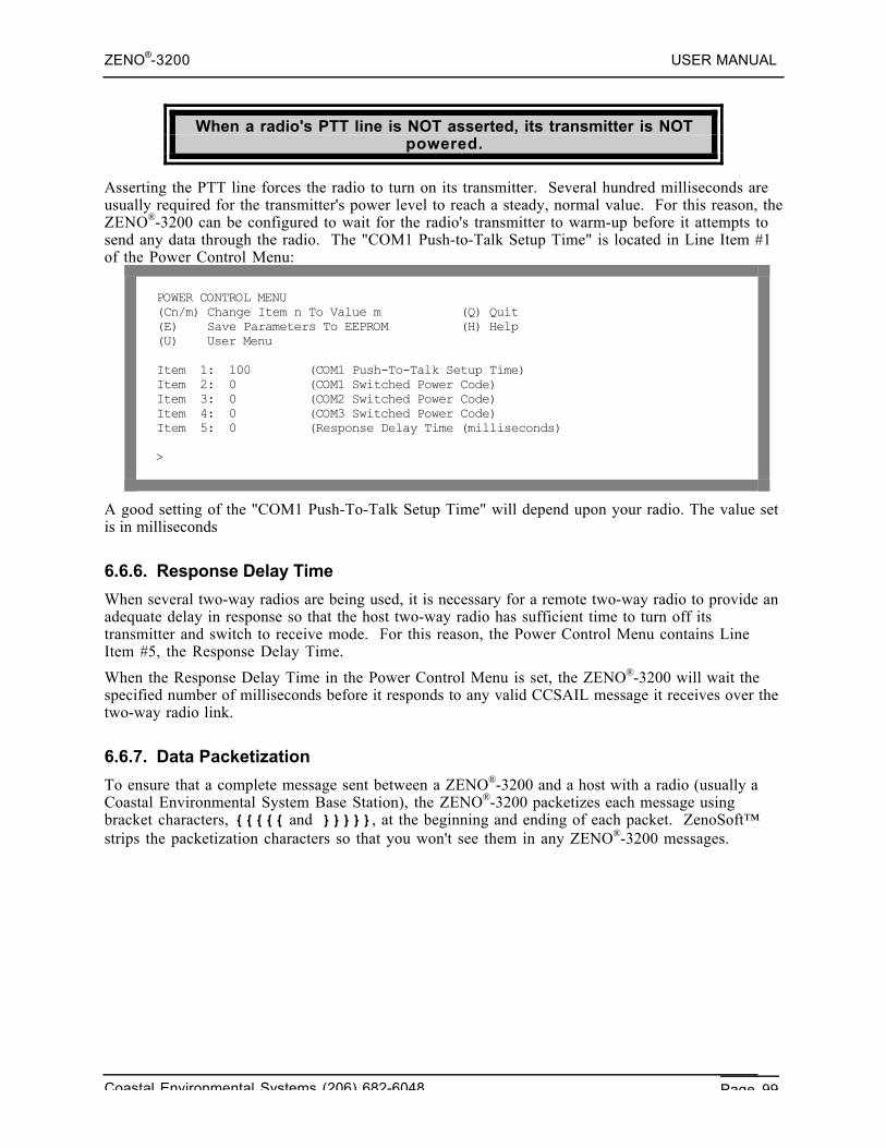
ZENO®-3200 USER MANUAL
Coastal Environmental Systems (206) 682-6048 Page 99
When a radio's PTT line is NOT asserted, its transmitter is NOTpowered.
Asserting the PTT line forces the radio to turn on its transmitter. Several hundred milliseconds areusually required for the transmitter's power level to reach a steady, normal value. For this reason, theZENO®-3200 can be configured to wait for the radio's transmitter to warm-up before it attempts tosend any data through the radio. The "COM1 Push-to-Talk Setup Time" is located in Line Item #1of the Power Control Menu:
POWER CONTROL MENU(Cn/m) Change Item n To Value m (Q) Quit(E) Save Parameters To EEPROM (H) Help(U) User Menu
Item 1: 100 (COM1 Push-To-Talk Setup Time)Item 2: 0 (COM1 Switched Power Code)Item 3: 0 (COM2 Switched Power Code)Item 4: 0 (COM3 Switched Power Code)Item 5: 0 (Response Delay Time (milliseconds)
>
A good setting of the "COM1 Push-To-Talk Setup Time" will depend upon your radio. The value setis in milliseconds
6.6.6. Response Delay Time
When several two-way radios are being used, it is necessary for a remote two-way radio to provide anadequate delay in response so that the host two-way radio has sufficient time to turn off itstransmitter and switch to receive mode. For this reason, the Power Control Menu contains LineItem #5, the Response Delay Time.
When the Response Delay Time in the Power Control Menu is set, the ZENO®-3200 will wait thespecified number of milliseconds before it responds to any valid CCSAIL message it receives over thetwo-way radio link.
6.6.7. Data Packetization
To ensure that a complete message sent between a ZENO®-3200 and a host with a radio (usually aCoastal Environmental System Base Station), the ZENO®-3200 packetizes each message usingbracket characters, {{{{{ and }}}}}, at the beginning and ending of each packet. ZenoSoft™strips the packetization characters so that you won't see them in any ZENO®-3200 messages.
ZENO®-3200 USER MANUAL
Coastal Environmental Systems (206) 682-6048 Page 100
If you are using two-way radio communication and you see thecharacters {{{{{ or }}}}} appear on your screen, it probably
means you are using a Base Station set for one-way radiocommunication only.
6.7. GOES SATELLITE COMMUNICATIONS
The ZENO®-3200 data logger can transmit data through the GOES121 satellite system operated bythe National Environmental Satellite, Data and Information Service (NESDIS) of the NationalOceanographic and Atmospheric Administration (NOAA). The GOES system provides 232 channelsfor users to up-link messages.122 A typical assigned transmit window of 1 minute allows 355 bytes ofdata to be sent, allowing for preamble and 15 second guard bands.
Data messages sent to the GOES transmitter are limited to 355bytes.
Coastal Environmental Systems uses either the Telonics TGT-1 GOES transmitter or the CampbellScientific SAT HDR GOES transmitter. Both self-timed (regular) and random transmissions aresupported in either clear-text (ASCII) or compressed (binary) format. Self-timed transmissions aregenerally used for routine monitoring, typically every 3 - 4 hours. Random (or emergency)transmissions are used to report on unusual or critical conditions.
Self-timed and random transmissions cannot be usedconcurrently.
6.7.1. Obtaining GOES Channels
Before you can use a GOES radio, NESDIS will assign channels and time windows for self-timed and/orrandom transmissions to you. Different channels are used for self-timed and random transmissions,so that the self-timed transmissions are not overwritten by the random transmissions.
You must send your self-timed or random transmissions withinthe one-minute time window assigned by NESDIS.
GOES users are primarily US based government agencies, and private US and non-US users whensponsored by a US government agency.
121 GOES stands for Geostationary Operational Environmental Satellites.122 199 channels are regional, and the other 33 are international.
ZENO®-3200 USER MANUAL
Coastal Environmental Systems (206) 682-6048 Page 101
Use of the Data Collection System is limited to the collection ofenvironmental data.
There is currently no charge for use of the GOES system.
There are two operational GOES satellites, and you will be assigned channels on one or the othersatellite:• The GOES East satellite is stationed 35,000 km above the equator at 75° W longitude.• The GOES West satellite at 135° W longitude.• There is also a spare (non-operational) satellite that is normally located at 105º W.
Each channel operates at a specified baud rate of 100, 300 or 1200 baud. The Telonics TGT-1transmitter is only capable of transmitting at 100 baud. The Campbell Scientific SAT HDR GOEStransmitter can be configured for 100, 300 or 1200 baud.
To obtain channels, complete the GOES DCS Program Application and Renewal Form, which isavailable from:
DCP Program ManagerNOAA/NESDISNOAA Science Center, Room 8065200 Auth RoadCamp Springs, MD 20746Phone: (301) 763-8062Fax: (301) 763-8449Email: [email protected]
Website: http://www.oso.noaa.gov/goes/
6.7.2. Data Download
Data relayed from GOES satellites are received and demodulated at the NESDIS ground station inWallops Island, Virginia. The data may be accessed through telephone lines with use of a modem,and are available through a satellite downlink called DOMSAT.
To access the GOES data directly, you can dial in to the GOES DCS Automatic Processing System, orDAPS. When you are assigned GOES channels, you should also be assigned a user name and passwordfor DAPS.
There are many commands available on the DASP system. Consult the GOES DAPS User InterfaceManual for details about these commands. The ZENO®-3200 User Manual provides a basic overviewof this software.
ZENO®-3200 USER MANUAL
Coastal Environmental Systems (206) 682-6048 Page 102
Before dialing in to DAPS, set your modem communications tothe following parameters: 9600 Baud, 7 Data Bits, 1 Stop Bit, Even
Parity.
The following telephone numbers are available for dial-in access and technical support.
Main Rotary line: (757) 824-0105
Other lines: (757) 824-0125 (757) 824-0156(757) 824-0126 (757) 824-0162(757) 824-0127 (757) 824-0163(757) 824-0145 (757) 824-0164(757) 824-0149
Operator Line Monitoring or User Assistance: (757) 824-1064
Operator Voice Lines: (757) 824-3552
(757) 824-3702
6.7.3. DAPS Dial-in Procedure
After setting up your modem communications, and dialing in to one of the dial-in numbers, hit{ENTER} a few times, until you are prompted for a user name and password.
Once you have logged in to the DAPS computer system, type the following command:
DOWNLOAD MESSAGE_FILE PLATFORM_ID platform_id
You should then prepare for a text file download. Type BYE to log out of DAPS and hang up yourmodem connection.
The following screen illustrates these steps. After receiving a CONNECT message, which indicatesthat the modem connection has succeeded, hit {ENTER} a few times. Enter your user name andpassword when prompted.
CONNECT
AOS/VS 7.64.00.00 / EXEC-32 7.64.00.00 4-Oct-97 1:00:17 @CON29Username: xxxxxPassword: xxxxx------ Copyright (C) Data General Corporation, 1980 - 1988 All rights reserved. Licensed material -- property of Data General Corporation
This software is made available solely pursuant to the terms of a DGC license agreement which governs its use.
--------
Most recent logon 7-Aug-97 22:45:14
ZENO®-3200 USER MANUAL
Coastal Environmental Systems (206) 682-6048 Page 103
DISPLAY COMPLETE>
Messages are downloaded in the format that they are received by the DAPS system. The DAPSsystem inserts a header at the start of each message, indicating the date and time at which themessages were received by the satellite. The most recently received messages are downloaded first.
At the prompt, enter the command to download data from your ZENO. When you are prompted tobegin the download, turn on text capture, and type Y.
> DOWNLOAD MESSAGE_FILE PLATFORM_CE1192D4BEGIN DOWNLOAD? (Y/N)>> YCE1192D497277004338G46-3NN052WFF00086#000000032446.858,11.6,#000000032446.839,12.9,#000000032447.996,12.8,
CE1192D497276204337G49-3NN052WFF00113#000000032446.871,11.7,#000000032446.878,12.9,#000000032446.856,12.9,#000000032446.852,12.9,
DOWNLOAD COMPLETE; NUMBER OF MESSAGES TRANSFERRED: 2>
Finally, enter BYE to log off.
> BYE
Process 26 terminatedConnect time 0:02:36User ‘xxxxx’ logged off @CON29 4-Oct-97 1:03:02
NO CARRIER
Because transmission windows typically occur every 3 to 4 hours – and environmental data are loggedmore often – you will generally receive more than 1 data set in each message.
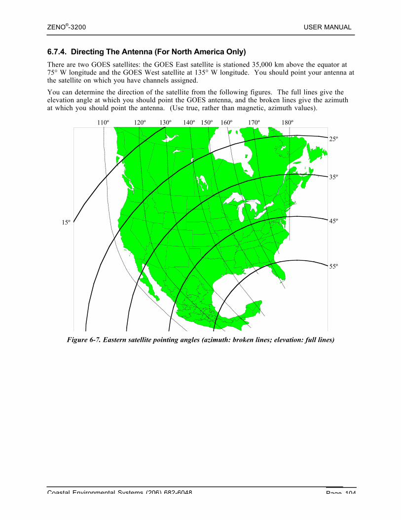
ZENO®-3200 USER MANUAL
Coastal Environmental Systems (206) 682-6048 Page 104
6.7.4. Directing The Antenna (For North America Only)
There are two GOES satellites: the GOES East satellite is stationed 35,000 km above the equator at75° W longitude and the GOES West satellite at 135° W longitude. You should point your antenna atthe satellite on which you have channels assigned.
You can determine the direction of the satellite from the following figures. The full lines give theelevation angle at which you should point the GOES antenna, and the broken lines give the azimuthat which you should point the antenna. (Use true, rather than magnetic, azimuth values).
Figure 6-7. Eastern satellite pointing angles (azimuth: broken lines; elevation: full lines)
15º
25º
35º
45º
55º
110º 120º 130º 140º 150º 160º 170º 180º
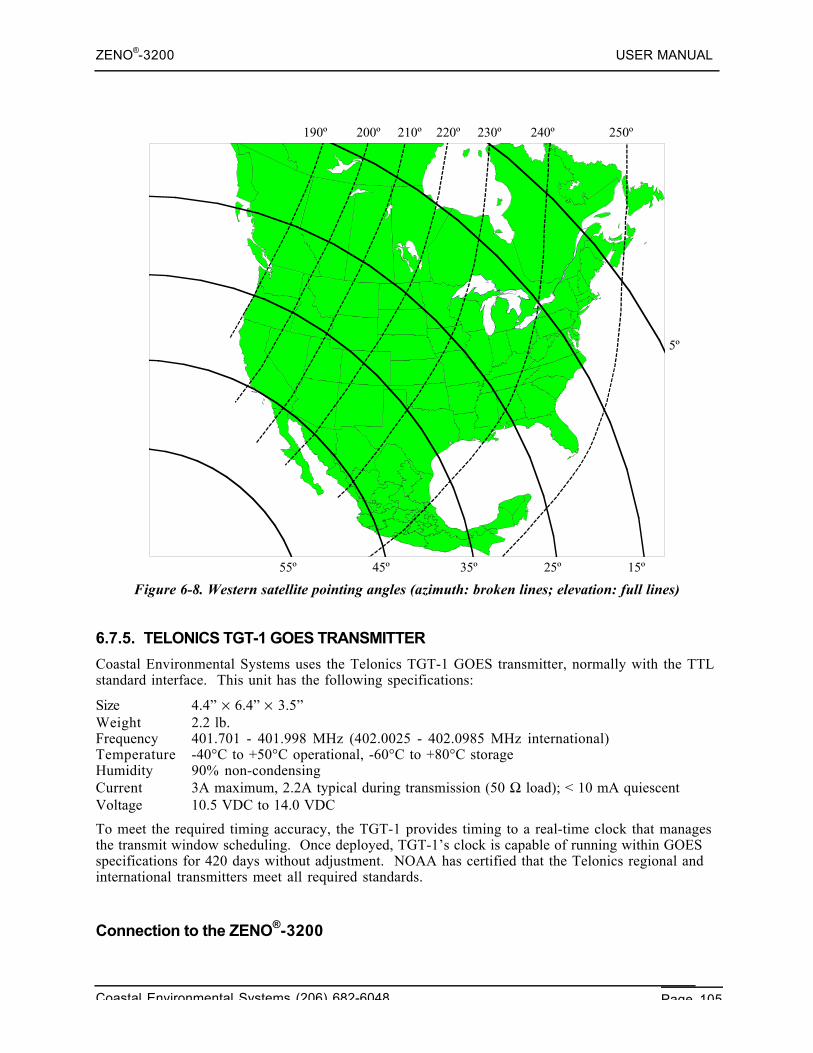
ZENO®-3200 USER MANUAL
Coastal Environmental Systems (206) 682-6048 Page 105
Figure 6-8. Western satellite pointing angles (azimuth: broken lines; elevation: full lines)
6.7.5. TELONICS TGT-1 GOES TRANSMITTER
Coastal Environmental Systems uses the Telonics TGT-1 GOES transmitter, normally with the TTLstandard interface. This unit has the following specifications:
Size 4.4” × 6.4” × 3.5”Weight 2.2 lb.Frequency 401.701 - 401.998 MHz (402.0025 - 402.0985 MHz international)Temperature -40°C to +50°C operational, -60°C to +80°C storageHumidity 90% non-condensingCurrent 3A maximum, 2.2A typical during transmission (50 Ω load); < 10 mA quiescentVoltage 10.5 VDC to 14.0 VDC
To meet the required timing accuracy, the TGT-1 provides timing to a real-time clock that managesthe transmit window scheduling. Once deployed, TGT-1’s clock is capable of running within GOESspecifications for 420 days without adjustment. NOAA has certified that the Telonics regional andinternational transmitters meet all required standards.
Connection to the ZENO®-3200
55º 45º 35º 25º 15º
5º
190º 200º 210º 220º 230º 240º 250º
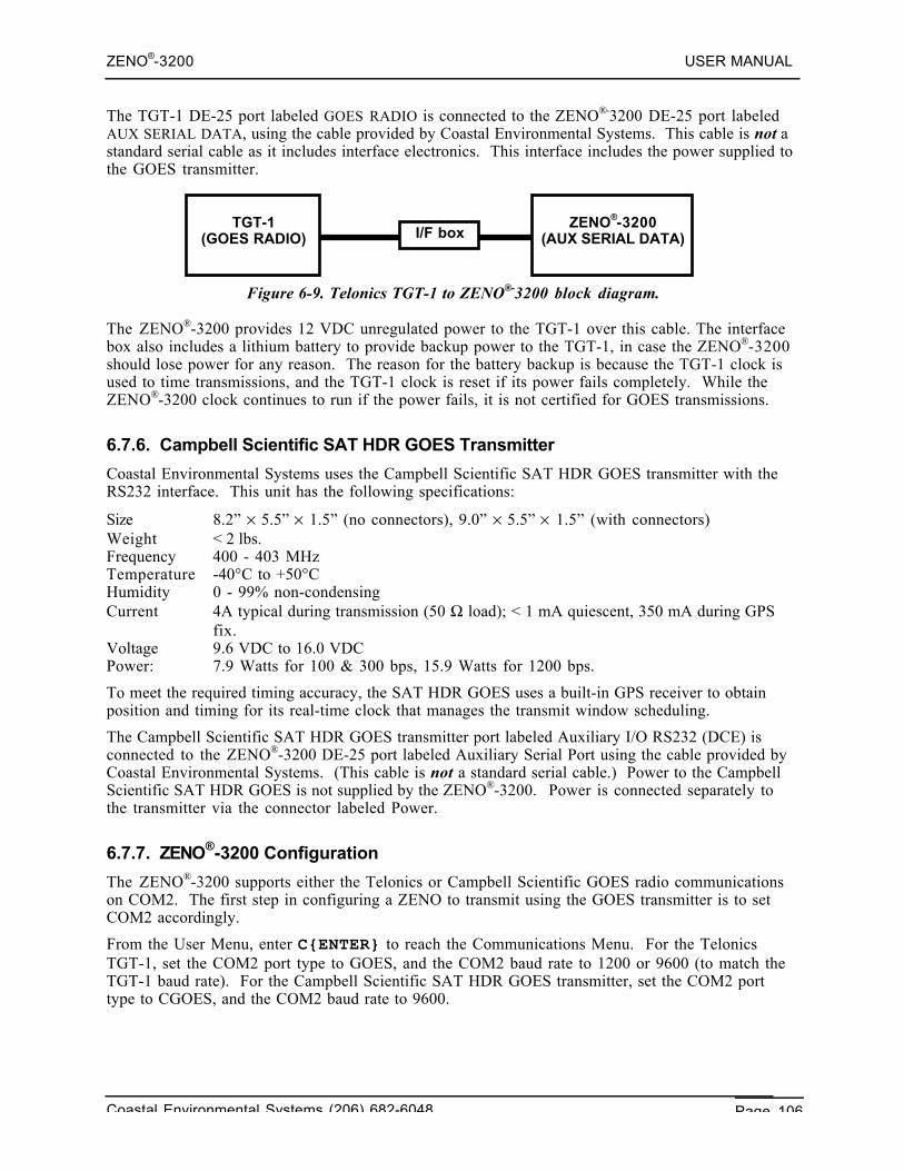
ZENO®-3200 USER MANUAL
Coastal Environmental Systems (206) 682-6048 Page 106
The TGT-1 DE-25 port labeled GOES RADIO is connected to the ZENO®-3200 DE-25 port labeledAUX SERIAL DATA, using the cable provided by Coastal Environmental Systems. This cable is not astandard serial cable as it includes interface electronics. This interface includes the power supplied tothe GOES transmitter.
Figure 6-9. Telonics TGT-1 to ZENO®-3200 block diagram.
The ZENO®-3200 provides 12 VDC unregulated power to the TGT-1 over this cable. The interfacebox also includes a lithium battery to provide backup power to the TGT-1, in case the ZENO®-3200should lose power for any reason. The reason for the battery backup is because the TGT-1 clock isused to time transmissions, and the TGT-1 clock is reset if its power fails completely. While theZENO®-3200 clock continues to run if the power fails, it is not certified for GOES transmissions.
6.7.6. Campbell Scientific SAT HDR GOES Transmitter
Coastal Environmental Systems uses the Campbell Scientific SAT HDR GOES transmitter with theRS232 interface. This unit has the following specifications:
Size 8.2” × 5.5” × 1.5” (no connectors), 9.0” × 5.5” × 1.5” (with connectors)Weight < 2 lbs.Frequency 400 - 403 MHzTemperature -40°C to +50°CHumidity 0 - 99% non-condensingCurrent 4A typical during transmission (50 Ω load); < 1 mA quiescent, 350 mA during GPS
fix.Voltage 9.6 VDC to 16.0 VDCPower: 7.9 Watts for 100 & 300 bps, 15.9 Watts for 1200 bps.
To meet the required timing accuracy, the SAT HDR GOES uses a built-in GPS receiver to obtainposition and timing for its real-time clock that manages the transmit window scheduling.
The Campbell Scientific SAT HDR GOES transmitter port labeled Auxiliary I/O RS232 (DCE) isconnected to the ZENO®-3200 DE-25 port labeled Auxiliary Serial Port using the cable provided byCoastal Environmental Systems. (This cable is not a standard serial cable.) Power to the CampbellScientific SAT HDR GOES is not supplied by the ZENO®-3200. Power is connected separately tothe transmitter via the connector labeled Power.
6.7.7. ZENO®-3200 Configuration
The ZENO®-3200 supports either the Telonics or Campbell Scientific GOES radio communicationson COM2. The first step in configuring a ZENO to transmit using the GOES transmitter is to setCOM2 accordingly.
From the User Menu, enter C{ENTER} to reach the Communications Menu. For the TelonicsTGT-1, set the COM2 port type to GOES, and the COM2 baud rate to 1200 or 9600 (to match theTGT-1 baud rate). For the Campbell Scientific SAT HDR GOES transmitter, set the COM2 porttype to CGOES, and the COM2 baud rate to 9600.
I/F boxZENO®-3200
(AUX SERIAL DATA)TGT-1
(GOES RADIO)
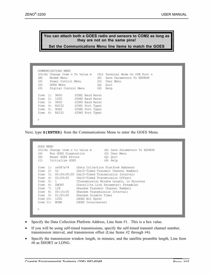
ZENO®-3200 USER MANUAL
Coastal Environmental Systems (206) 682-6048 Page 107
You can attach both a GOES radio and sensors to COM2 as long asthey are not on the same pins!
Set the Communications Menu line items to match the GOES
COMMUNICATIONS MENU(Cn/m) Change Item n To Value m (Tn) Terminal Mode On COM Port n(M) Modem Menu (E) Save Parameters To EEPROM(P) Power Control Menu (U) User Menu(G) GOES Menu (Q) Quit(D) Digital Control Menu (H) Help
Item 1: 9600 (COM1 Baud Rate)Item 2: 1200 (COM2 Baud Rate)Item 3: 9600 (COM3 Baud Rate)Item 4: RS232 (COM1 Port Type)Item 5: GOES (COM2 Port Type)Item 6: RS232 (COM3 Port Type)
>
Next, type G{ENTER} from the Communications Menu to enter the GOES Menu.
GOES MENU(Cn/m) Change Item n to Value m (E) Save Parameters To EEPROM(D) Run GOES Diagnostics (U) User Menu(R) Reset GOES Errors (Q) Quit(I) Initialize GOES (H) Help
Item 1: ce587a74 (Data Collection Platform Address)Item 2: 52 (Self-Timed Transmit Channel Number)Item 3: 00:04:00:00 (Self-Timed Transmission Interval)Item 4: 02:09:00 (Self-Timed Transmission Offset)Item 5: 1 (Transmission Window Length, in Minutes)Item 6: SHORT (Satellite Link Parameter: Preamble)Item 7: 128 (Random Transmit Channel Number)Item 8: 00:15:00 (Random Transmission Interval)Item 9: 01:05:00 (Random Disable Time)Item 10: 1200 (GOES Bit Rate)Item 11: NONE (GOES Interleaver)
>
• Specify the Data Collection Platform Address, Line Item #1. This is a hex value.
• If you will be using self-timed transmissions, specify the self-timed transmit channel number,transmission interval, and transmission offset (Line Items #2 through #4).
• Specify the transmission window length, in minutes; and the satellite preamble length, Line Item#6 as SHORT or LONG.
ZENO®-3200 USER MANUAL
Coastal Environmental Systems (206) 682-6048 Page 108
• If you are using a Campbell Scientific SAT HDR GOES transmitter, set the GOES bit rate in Item10 and the Interleaver in Item 11.
• If you will be using random transmissions, set the random transmission channel number, therandom transmission interval, and the random transmit disable time. When a randomtransmission is required, the GOES radio will transmit the random message at the frequencyspecified in the random transmission interval, until the end of the random transmit disable time.For example, if you set the random transmission interval to 1 minute and the random transmitdisable time to 5 minutes, the GOES radio will transmit the random message once per minute to 5minutes.
• Enter I{ENTER} to initialize the GOES radio. This loads the channel number and otherinformation to the GOES radio. It also deletes all data currently in the transmit buffer. TheZENO®-3200 will prompt you to give the system date and time. You must give this valueaccurately, and in GMT123 (also known as UTC124 – 8 hours ahead of Pacific Standard Time).
When initializing the GOES transmitter you must also set thesystem clock to GMT or UTC.125
The GOES transmissions are timed on the transmitter’s clock. Unlike the ZENO®-3200’s systemclock, the transmitter’s clock does not retain its time through a power failure. Therefore, everytime the Telonics TGT-1 GOES transmitter loses and regains power, the GOES clock must be setagain by re-initializing the GOES transmitter using GOES Menu option I. If there is a backup batteryto the Telonics TGT-1 GOES transmitter, resetting of the clock after initial system deployment isnot necessary.
For a Campbell Scientific SAT HDR GOES transmitter, you do not need to re-initialize thetransmitter if there is power failure since its clock is set according to an internal GPS receiver.
With these communications settings any regular ZENO®-3200 Data Output messages routed toCOM2 will be sent to the GOES transmitter. At the programmed time, the GOES transmitter willtransmit the contents of its data buffer over the self-timed transmit channel when the next self-timed transmission interval occurs. Any alarm messages generated by the ZENO will be transmittedover the random transmit channel with the frequency specified in the GOES menu.126
You can send ONLY a maximum of 355 bytes in a singletransmission
6.7.8. Connecting A GOES Radio And Serial Sensors To The Same COM Port
You may wish to attach both a GOES radio and one or more serial sensors to the ZENO. This can bedone as long as the serial sensor(s) is not connected to same lines as the GOES radio. In the case ofthe Telonics TGT-1 transmitter, the RS232, RS485 and Compass ports are available for serial sensoruse. In the case of the Campbell Scientific SAT HDR GOES transmitter, the TTL, RS485 andCompass ports are available for serial sensor use.
123 GMT is Greenwich Mean Time.124 UTC is Universal Time Coordinate.125 The Campbell Scientific SAT HDR GOES transmitter obtains its time from a GPS (Global Positioning System)receiver.126 Refer to Section 11.3.3.
ZENO®-3200 USER MANUAL
Coastal Environmental Systems (206) 682-6048 Page 109
6.7.9. GOES Transmitter Diagnostics
You can obtain basic diagnostic information on the state of the Telonics TGT-1 or CampbellScientific SAT HDR GOES transmitter by entering D from the GOES Menu. The ZENO®-3200displays the diagnostic information in a simple to read table.
6.7.10. Self-Timed Transmissions
Once you have set up the GOES parameters, the only additional step for self-timed transmissions isto define a data output message to be transmitted over the COM2 port. Refer to Section 10.6 fordetails on creating an output message. The output message can be contain normal ASCII characters,or it can be in the binary format described in Section 6.7.12. All output messages sent to COM2 willbe buffered up by the GOES transmitter, and transmitted during its self-timed transmit window.
6.7.11. Random Transmissions
To generate random, or emergency, transmissions, you must perform the following steps.
• Set up a data output message to contain the data to be transmitted when the alarm messageoccurs.127 This can be a normal ASCII message, or it can be in the binary format described below.
• In the Output Message Timing Menu, specify that the message is to be routed to COM2, andassign the message a period of zero.128
• In the Process Menu, set up a Dial-out Alarm Process to trigger the alarm message under thedesired circumstances.129
Whenever the sensor or process input moves beyond the defined threshold level, a randomtransmission is initiated. For example, by setting the sensor or process input to be a water levelmeasurement, and by setting the alarm threshold to a specified level, a random transmission can beinitiated whenever the water level reaches the specified value.
6.7.12. GOES Binary Format
The GOES binary format packs data into an efficient format that is suitable for transmission over aGOES satellite (or other limited communications channel).
To define an output message in GOES Binary Format, each field ofthat message must be GOES Binary Format (rather than Log Only,
Time Stamp, etc.) Field Type.
Use the Data Output menu to define each field in your message, and to choose the GOES BinaryFormat type.130 Fields of this type are transmitted, but not logged.
The GOES Binary Format converts each data value into an integer, encodes it as a binary value, andthen breaks that binary-encoded data value into chunks of 6 bits. Each byte of data will contain oneof these 6-bit chunks as its 6 least significant bits. Bit #7 is always set to 1 to ensure that theresulting character is printable. Bit #8 is a parity bit that will only be set to 1 if the there are an evennumber of bits set in the lower 7 bits of the byte. 127 Refer to Section 11.2.128 This will indicate that the message is not transmitted as a regular output message. Refer to Section 11.3.129 Refer to Section 11.3.130 Refer to Section 10.6.
ZENO®-3200 USER MANUAL
Coastal Environmental Systems (206) 682-6048 Page 110
The following line items in the Data Output Menu are interpreted in a non-standard way for theGOES Binary Format.
• Field decimal places: The data value to be treated is multiplied by the appropriate number offactors of 10 to bring the data value to an integer, while still retaining the requested accuracy.For example, suppose you wish to output a measured temperature to 2 decimal places (e.g., 23.62degrees). Line item 5 should take the value 2. The value will be converted to 2362 beforetransmission.
• Field width: Suppose that the field width is 3. The data value (2362) will be converted to a3×6=18-bit value, with the most significant bit being a sign bit. The binary version of this datavalue becomes:
000000 100100 111010
For this example, the data field would be calculated and output as follows.
• For output to any device other than the GOES radio, each 6-bit chunk is preceded by a mostsignificant pair of bits 01, giving a printable ASCII string. The above value will give:
• hex values: <40><64><7A>
• characters: @dz
• You will see @dz on the screen, if the output message is routed to a terminal.
• For output to a GOES radio, the most significant bit of each byte will be replaced by a parity bit.When you download the data from NOAA/NESDIS, the format is 7 data bits, 1 parity bit.Therefore, the parity bit will be transparent; and you will therefore still see @dz.
6.8. ARGOS SATELLITE COMMUNICATION
The ZENO®-3200 data logger can transmit data through the ARGOS satellite system operated by theCentre National d’Etudes Spatiales (CNES) ARGOS System on board two polar-orbiting, sun-synchronous satellites operated by the National Oceanographic and Atmospheric Administration(NOAA).
Coastal Environmental Systems uses the Telonics ST-13 ARGOS Platform Transmitter Terminal(PTT) for transmitting data to the ARGOS System. Regular transmissions can be formatted andtransmitted, in either clear-text (ASCII) or binary format.
Individual messages are limited to a maximum of 32 bytes.
6.8.1. Applying To Use ARGOS
Before you can use an ARGOS radio, you must first apply to use the ARGOS System to obtain criticalID numbers. The application form is available on the Internet from http://www.argosinc.com. Thecompleted application can be mailed either electronically or standard to the following addresses:
In North America:Service Argos, Inc.1801 McCormic Drive, Suite 10Largo, MD 20774Telephone: (301) 925-4411Fax: (301) 925-8995
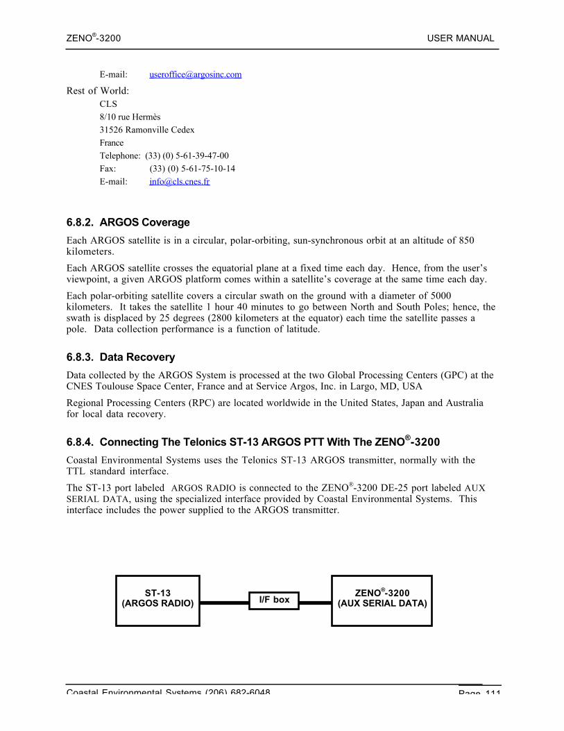
ZENO®-3200 USER MANUAL
Coastal Environmental Systems (206) 682-6048 Page 111
E-mail: [email protected]
Rest of World:CLS8/10 rue Hermès31526 Ramonville CedexFranceTelephone: (33) (0) 5-61-39-47-00Fax: (33) (0) 5-61-75-10-14E-mail: [email protected]
6.8.2. ARGOS Coverage
Each ARGOS satellite is in a circular, polar-orbiting, sun-synchronous orbit at an altitude of 850kilometers.
Each ARGOS satellite crosses the equatorial plane at a fixed time each day. Hence, from the user’sviewpoint, a given ARGOS platform comes within a satellite’s coverage at the same time each day.
Each polar-orbiting satellite covers a circular swath on the ground with a diameter of 5000kilometers. It takes the satellite 1 hour 40 minutes to go between North and South Poles; hence, theswath is displaced by 25 degrees (2800 kilometers at the equator) each time the satellite passes apole. Data collection performance is a function of latitude.
6.8.3. Data Recovery
Data collected by the ARGOS System is processed at the two Global Processing Centers (GPC) at theCNES Toulouse Space Center, France and at Service Argos, Inc. in Largo, MD, USA
Regional Processing Centers (RPC) are located worldwide in the United States, Japan and Australiafor local data recovery.
6.8.4. Connecting The Telonics ST-13 ARGOS PTT With The ZENO®-3200
Coastal Environmental Systems uses the Telonics ST-13 ARGOS transmitter, normally with theTTL standard interface.
The ST-13 port labeled ARGOS RADIO is connected to the ZENO®-3200 DE-25 port labeled AUXSERIAL DATA, using the specialized interface provided by Coastal Environmental Systems. Thisinterface includes the power supplied to the ARGOS transmitter.
I/F boxZENO®-3200
(AUX SERIAL DATA)ST-13
(ARGOS RADIO)
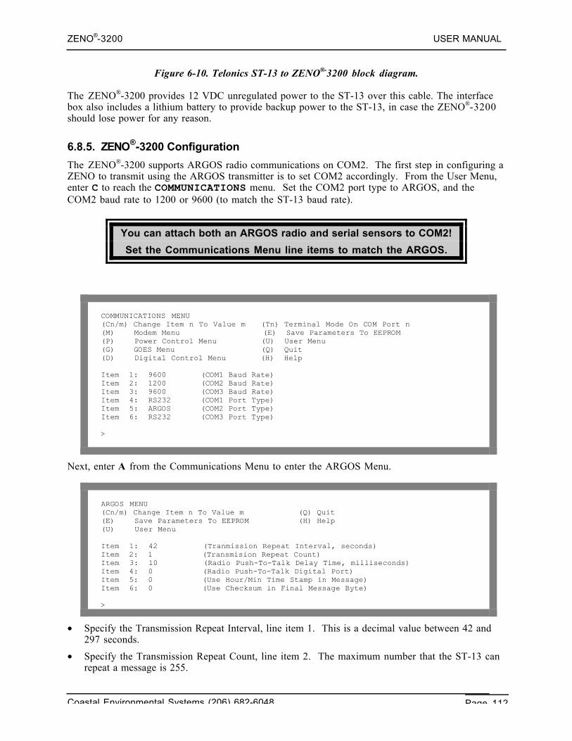
ZENO®-3200 USER MANUAL
Coastal Environmental Systems (206) 682-6048 Page 112
Figure 6-10. Telonics ST-13 to ZENO®-3200 block diagram.
The ZENO®-3200 provides 12 VDC unregulated power to the ST-13 over this cable. The interfacebox also includes a lithium battery to provide backup power to the ST-13, in case the ZENO®-3200should lose power for any reason.
6.8.5. ZENO®-3200 Configuration
The ZENO®-3200 supports ARGOS radio communications on COM2. The first step in configuring aZENO to transmit using the ARGOS transmitter is to set COM2 accordingly. From the User Menu,enter C to reach the COMMUNICATIONS menu. Set the COM2 port type to ARGOS, and theCOM2 baud rate to 1200 or 9600 (to match the ST-13 baud rate).
You can attach both an ARGOS radio and serial sensors to COM2!
Set the Communications Menu line items to match the ARGOS.
COMMUNICATIONS MENU(Cn/m) Change Item n To Value m (Tn) Terminal Mode On COM Port n(M) Modem Menu (E) Save Parameters To EEPROM(P) Power Control Menu (U) User Menu(G) GOES Menu (Q) Quit(D) Digital Control Menu (H) Help
Item 1: 9600 (COM1 Baud Rate)Item 2: 1200 (COM2 Baud Rate)Item 3: 9600 (COM3 Baud Rate)Item 4: RS232 (COM1 Port Type)Item 5: ARGOS (COM2 Port Type)Item 6: RS232 (COM3 Port Type)
>
Next, enter A from the Communications Menu to enter the ARGOS Menu.
ARGOS MENU(Cn/m) Change Item n To Value m (Q) Quit(E) Save Parameters To EEPROM (H) Help(U) User Menu
Item 1: 42 (Tranmission Repeat Interval, seconds)Item 2: 1 (Transmision Repeat Count)Item 3: 10 (Radio Push-To-Talk Delay Time, milliseconds)Item 4: 0 (Radio Push-To-Talk Digital Port)Item 5: 0 (Use Hour/Min Time Stamp in Message)Item 6: 0 (Use Checksum in Final Message Byte)
>
• Specify the Transmission Repeat Interval, line item 1. This is a decimal value between 42 and297 seconds.
• Specify the Transmission Repeat Count, line item 2. The maximum number that the ST-13 canrepeat a message is 255.
ZENO®-3200 USER MANUAL
Coastal Environmental Systems (206) 682-6048 Page 113
• Specify the Radio Push-To-Talk Delay Time in milliseconds, line item 3. The range of thisvalue is 10 to 5000 milliseconds.
• Specify the Radio Push-To-Talk Digital Port, line item 4. Set this value to 0 to use the ZENO®-3200's built-in PTT line; otherwise, a value of 18 to 23 can be used to specify a digital outputline.
• Specify whether to use Hour/Min Time Stamp in Message, line item 5. By setting this value to 1,ZenoSoft™ will set the first two bytes of the ARGOS message to the current hour and minute.Setting this value to 0 will allow the first two bytes to be used for user-specified data.
• Specify whether to Use Checksum in Final Message Byte, line item 6. By setting this value to 1,ZenoSoft™ will calculate a modulus-256 checksum of the first 31 bytes of the ARGOS messageand set the 32n d byte to the checksum. If the user doesn’t want a checksum, set the value to 0.
The ARGOS transmissions are timed on the transmitter’s clock
With the above communications settings, any regular ZENO®-3200 Data Output messages routed toCOM2 will be sent to the ARGOS radio. The ARGOS radio will be buffered up, and transmit over theself-timed transmit channel when the next self-timed transmission interval occurs.
ARGOS MESSAGES ARE LIMITED TO 32 BYTES.
6.8.6. ARGOS Binary Format
The ARGOS binary format packs data into an efficient format, suitable for transmission over anARGOS satellite. To define a message in ARGOS Binary Format, each field of that message must be afield of type ARGOS Binary Format (rather than Log Only, Time Stamp, etc.) Use the Data OutputMenu to define each field in your message, and to choose the ARGOS Binary Format type.131 Fieldsof this type are transmitted, but not logged.
The ARGOS Binary Format converts each data value into an integer, encodes it as a 1-, 2-, 3- or 4-byte binary value.
The following line items in the Data Output Menu are interpreted in a non-standard way for theARGOS Binary Format.
• Field decimal places: The data value to be treated is multiplied by the appropriate number offactors of 10 to bring the data value to an integer, while still retaining the requested accuracy.For example, suppose you wish to output a measured temperature to 2 decimal places (e.g., 23.62degrees). Line item 5 should take the value 2. The value will be converted to 2362 beforetransmission.
• Field width: Suppose that the field width is 3. The data value (2362) will be converted to a3x8=24-bit value, with the most significant bit being a sign bit. The binary version of this datavalue becomes:
00000000 00001001 00111010
For this example, the data field would be calculated and output as follows.
• Unless the data sent to ARGOS is ASCII, it will not be viewable on a standard terminal. Theabove value will give:
• hex values: <00><09><3A>
131 Refer to Section 10.6.
ZENO®-3200 USER MANUAL
Coastal Environmental Systems (206) 682-6048 Page 114
6.9. PASSTHROUGH MODES
Passthrough mode allows you to talk directly through one COMport on the ZENO®-3200 to a device connected to different COM
port on the ZENO®-3200.
Examples of using passthrough mode are having direct communication with a serial sensor connectedto the ZENO®-3200 or testing communications over a two-way radio.
There are two types of passthrough mode available:• Terminal Passthrough Mode: direct communication between two ZENO®-3200 COM ports.• SDI-12 Passthrough Mode: direct communication between two ZENO®-3200 COM ports where
the remote device is a SDI-12 sensor, which requires special timing and message formatting forcommunications.
When you enter Passthrough Mode, ZenoSoft™ will continue toperform normal data collection EXCEPT from any serial sensor(s)
connected to the COM port that you have specified for yourPassthrough Mode Session.
6.9.1. Terminal Passthrough Mode
Terminal Passthrough Mode is accessed via the Communications Menu. There are two options forentering Terminal Passthrough Mode:
Passthrough Mode Option Command To Enter in CommunicationsMenu
Enter Terminal Passthrough Mode directly to aspecific COM port.
Type Tn{ENTER}. Valid values for n are:
- 1 for COM1
- 2 for COM2
- 3 for COM3
- T for TTL port on COM2
- C for COMPASS port on COM2
Enter Terminal Passthrough Mode to a specificserial sensor. ZenoSoft™ will turn on anyspecified excitation voltage or switched powerto the serial sensor so that communicationswith the device are possible.
Type TSn{ENTER}, where n is the SensorRecord Number of the desired serial sensor.
If you use the first option to enter Terminal Passthrough Mode, ZenoSoft™ will ask severalquestions to setup the necessary communication parameters for communicating on the specifiedCOM port, such as the port type, baud rate, and parity:
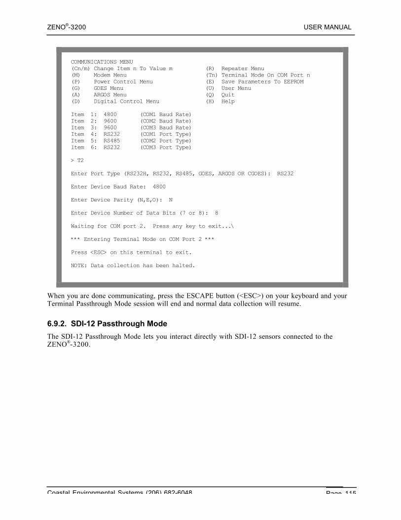
ZENO®-3200 USER MANUAL
Coastal Environmental Systems (206) 682-6048 Page 115
COMMUNICATIONS MENU(Cn/m) Change Item n To Value m (R) Repeater Menu(M) Modem Menu (Tn) Terminal Mode On COM Port n(P) Power Control Menu (E) Save Parameters To EEPROM(G) GOES Menu (U) User Menu(A) ARGOS Menu (Q) Quit(D) Digital Control Menu (H) Help
Item 1: 4800 (COM1 Baud Rate)Item 2: 9600 (COM2 Baud Rate)Item 3: 9600 (COM3 Baud Rate)Item 4: RS232 (COM1 Port Type)Item 5: RS485 (COM2 Port Type)Item 6: RS232 (COM3 Port Type)
> T2
Enter Port Type (RS232H, RS232, RS485, GOES, ARGOS OR CGOES): RS232
Enter Device Baud Rate: 4800
Enter Device Parity (N,E,O): N
Enter Device Number of Data Bits (7 or 8): 8
Waiting for COM port 2. Press any key to exit...\
*** Entering Terminal Mode on COM Port 2 ***
Press <ESC> on this terminal to exit.
NOTE: Data collection has been halted.
When you are done communicating, press the ESCAPE button (<ESC>) on your keyboard and yourTerminal Passthrough Mode session will end and normal data collection will resume.
6.9.2. SDI-12 Passthrough Mode
The SDI-12 Passthrough Mode lets you interact directly with SDI-12 sensors connected to theZENO®-3200.
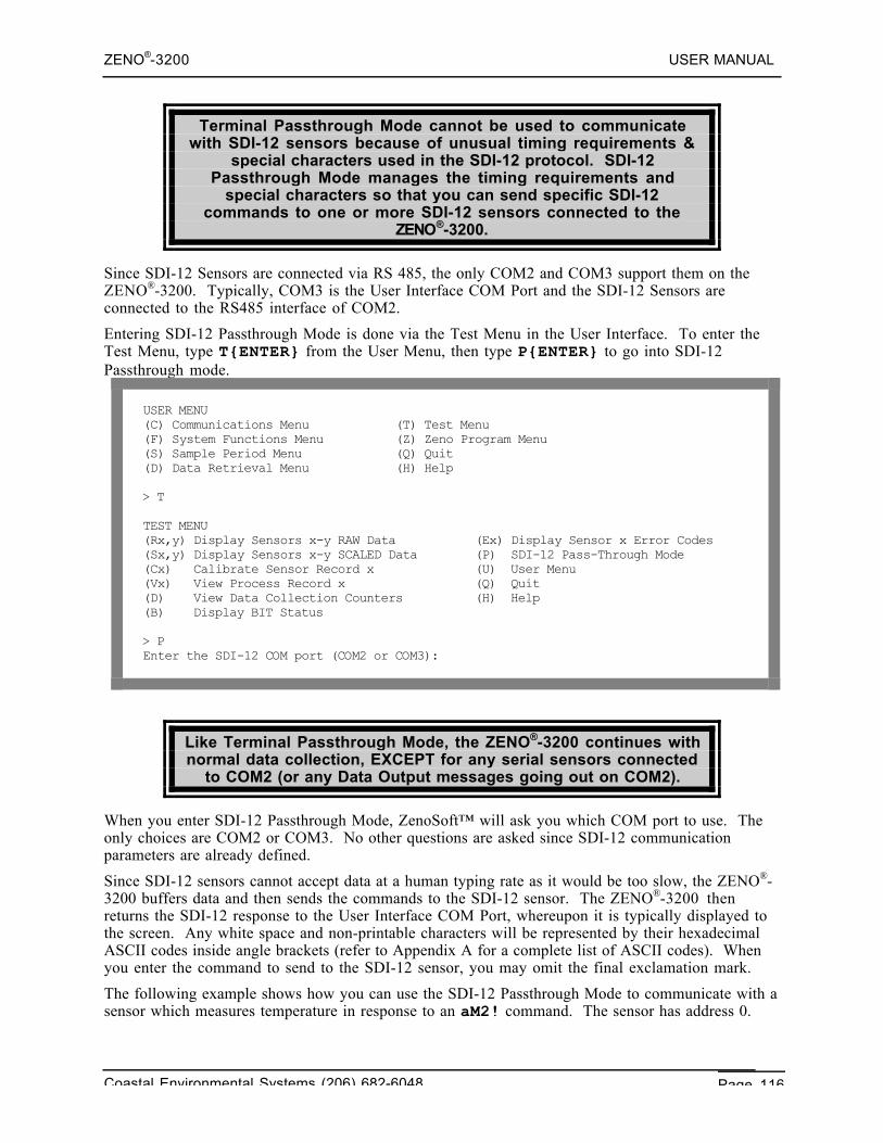
ZENO®-3200 USER MANUAL
Coastal Environmental Systems (206) 682-6048 Page 116
Terminal Passthrough Mode cannot be used to communicatewith SDI-12 sensors because of unusual timing requirements &
special characters used in the SDI-12 protocol. SDI-12Passthrough Mode manages the timing requirements and
special characters so that you can send specific SDI-12commands to one or more SDI-12 sensors connected to the
ZENO®-3200.
Since SDI-12 Sensors are connected via RS 485, the only COM2 and COM3 support them on theZENO®-3200. Typically, COM3 is the User Interface COM Port and the SDI-12 Sensors areconnected to the RS485 interface of COM2.
Entering SDI-12 Passthrough Mode is done via the Test Menu in the User Interface. To enter theTest Menu, type T{ENTER} from the User Menu, then type P{ENTER} to go into SDI-12Passthrough mode.
USER MENU(C) Communications Menu (T) Test Menu(F) System Functions Menu (Z) Zeno Program Menu(S) Sample Period Menu (Q) Quit(D) Data Retrieval Menu (H) Help
> T
TEST MENU(Rx,y) Display Sensors x-y RAW Data (Ex) Display Sensor x Error Codes(Sx,y) Display Sensors x-y SCALED Data (P) SDI-12 Pass-Through Mode(Cx) Calibrate Sensor Record x (U) User Menu(Vx) View Process Record x (Q) Quit(D) View Data Collection Counters (H) Help(B) Display BIT Status
> PEnter the SDI-12 COM port (COM2 or COM3):
Like Terminal Passthrough Mode, the ZENO®-3200 continues withnormal data collection, EXCEPT for any serial sensors connected
to COM2 (or any Data Output messages going out on COM2).
When you enter SDI-12 Passthrough Mode, ZenoSoft™ will ask you which COM port to use. Theonly choices are COM2 or COM3. No other questions are asked since SDI-12 communicationparameters are already defined.
Since SDI-12 sensors cannot accept data at a human typing rate as it would be too slow, the ZENO®-3200 buffers data and then sends the commands to the SDI-12 sensor. The ZENO®-3200 thenreturns the SDI-12 response to the User Interface COM Port, whereupon it is typically displayed tothe screen. Any white space and non-printable characters will be represented by their hexadecimalASCII codes inside angle brackets (refer to Appendix A for a complete list of ASCII codes). Whenyou enter the command to send to the SDI-12 sensor, you may omit the final exclamation mark.
The following example shows how you can use the SDI-12 Passthrough Mode to communicate with asensor which measures temperature in response to an aM2! command. The sensor has address 0.
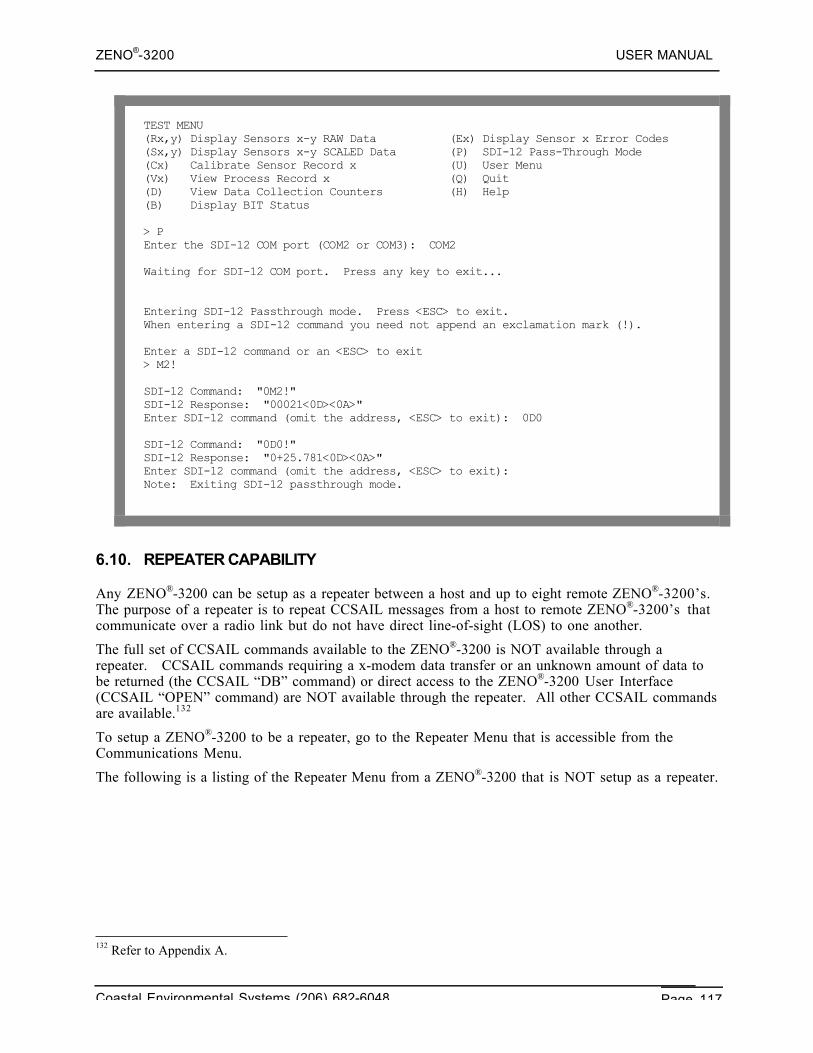
ZENO®-3200 USER MANUAL
Coastal Environmental Systems (206) 682-6048 Page 117
TEST MENU(Rx,y) Display Sensors x-y RAW Data (Ex) Display Sensor x Error Codes(Sx,y) Display Sensors x-y SCALED Data (P) SDI-12 Pass-Through Mode(Cx) Calibrate Sensor Record x (U) User Menu(Vx) View Process Record x (Q) Quit(D) View Data Collection Counters (H) Help(B) Display BIT Status
> PEnter the SDI-12 COM port (COM2 or COM3): COM2
Waiting for SDI-12 COM port. Press any key to exit...
Entering SDI-12 Passthrough mode. Press <ESC> to exit.When entering a SDI-12 command you need not append an exclamation mark (!).
Enter a SDI-12 command or an <ESC> to exit> M2!
SDI-12 Command: "0M2!"SDI-12 Response: "00021<0D><0A>"Enter SDI-12 command (omit the address, <ESC> to exit): 0D0
SDI-12 Command: "0D0!"SDI-12 Response: "0+25.781<0D><0A>"Enter SDI-12 command (omit the address, <ESC> to exit):Note: Exiting SDI-12 passthrough mode.
6.10. REPEATER CAPABILITY
Any ZENO®-3200 can be setup as a repeater between a host and up to eight remote ZENO®-3200’s.The purpose of a repeater is to repeat CCSAIL messages from a host to remote ZENO®-3200’s thatcommunicate over a radio link but do not have direct line-of-sight (LOS) to one another.
The full set of CCSAIL commands available to the ZENO®-3200 is NOT available through arepeater. CCSAIL commands requiring a x-modem data transfer or an unknown amount of data tobe returned (the CCSAIL “DB” command) or direct access to the ZENO®-3200 User Interface(CCSAIL “OPEN” command) are NOT available through the repeater. All other CCSAIL commandsare available.132
To setup a ZENO®-3200 to be a repeater, go to the Repeater Menu that is accessible from theCommunications Menu.
The following is a listing of the Repeater Menu from a ZENO®-3200 that is NOT setup as a repeater.
132 Refer to Appendix A.
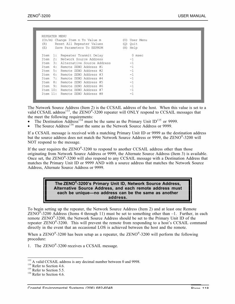
ZENO®-3200 USER MANUAL
Coastal Environmental Systems (206) 682-6048 Page 118
REPEATER MENU(Cn/m) Change Item n To Value m (U) User Menu(R) Reset All Repeater Values (Q) Quit(E) Save Parameters To EEPROM (H) Help
Item 1: Repeater Tranmit Delay 0 msecItem 2: Network Source Address -1Item 3: Alternative Source Address -1Item 4: Remote ZENO Address #1 -1Item 5: Remote ZENO Address #2 -1Item 6: Remote ZENO Address #3 -1Item 7: Remote ZENO Address #4 -1Item 8: Remote ZENO Address #5 -1Item 9: Remote ZENO Address #6 -1Item 10: Remote ZENO Address #7 -1Item 11: Remote ZENO Address #8 -1
The Network Source Address (Item 2) is the CCSAIL address of the host. When this value is set to avalid CCSAIL address133, the ZENO®-3200 repeater will ONLY respond to CCSAIL messages thatthe meet the following requirements:• The Destination Address134 must be the same as the Primary Unit ID135 or 9999.• The Source Address136 must the same as the Network Source Address or 9999.
If a CCSAIL message is received with a matching Primary Unit ID or 9999 as the destination addressbut the source address does not match the Network Source Address or 9999, the ZENO®-3200 willNOT respond to the message.
If the user requires the ZENO®-3200 to respond to another CCSAIL address other than thoseoriginating from Network Source Address or 9999, the Alternate Source Address (Item 3) is available.Once set, the ZENO®-3200 will also respond to any CCSAIL message with a Destination Address thatmatches the Primary Unit ID or 9999 AND with a source address that matches the Network SourceAddress, Alternate Source Address or 9999.
The ZENO®-3200’s Primary Unit ID, Network Source Address,Alternative Source Address, and each remote address must
each be unique—no address can be the same as anotheraddress.
To begin setting up the repeater, the Network Source Address (Item 2) and at least one RemoteZENO®-3200 Address (Items 4 through 11) must be set to something other than –1. Further, in eachremote ZENO®-3200, the Network Source Address should be set to the Primary Unit ID of therepeater ZENO®-3200. This will prevent the remote from responding to a host’s CCSAIL commanddirectly in the event that an occasional LOS is achieved between the host and the remote.
When a ZENO®-3200 has been setup as a repeater, the ZENO®-3200 will perform the followingprocedure:
1. The ZENO®-3200 receives a CCSAIL message.
133 A valid CCSAIL address is any decimal number between 0 and 9998.134 Refer to Section 4.6.135 Refer to Section 5.5.136 Refer to Section 4.6.
ZENO®-3200 USER MANUAL
Coastal Environmental Systems (206) 682-6048 Page 119
2. The ZENO®-3200 checks whether the Source Address of the received message is the same as theNetwork Source Address and if the Destination Address is one of the specified remote ZENO®-3200 addresses. If the check fails, it proceeds to step #5; otherwise it proceeds to step #3.
3. The ZENO®-3200 checks the received CCSAIL message to see if it contains a repeatablecommand. If so, it proceeds to step #4; otherwise, it does nothing further.
4. The ZENO®-3200 changes the Source Address of the received message to its Primary Unit ID.The ZENO®-3200 then calculates a new CCSAIL message checksum and transmit the modifiedCCSAIL message on the same COM port that the original message was received. The procedureends.
5. The ZENO®-3200 checks whether the Source Address of the received message is one of thespecified remote ZENO®-3200 addresses and if the Destination Address is the same as its PrimaryUnit ID. If the check fails, the procedure ends; otherwise it proceeds to step #6.
6. The ZENO®-3200 checks whether the received CCSAIL message contains data. If so, it proceedsto step #7; otherwise, it does nothing further.
7. The ZENO®-3200 changes the Destination Address of the received message to the NetworkSource Address. The ZENO®-3200 then calculates a new CCSAIL message checksum andtransmits the modified CCSAIL message on the same COM port that the original message wasreceived. The procedure ends.
If the host needs to send a command intended for the repeater itself, it simply sets the destinationaddress of its message to the Primary Unit ID of the repeater.
A ZENO®-3200 that is setup to be a repeater can continue itsprimary function of data collection with any suite of supported
sensors.
As an example, a host with CCSAIL address 1 wants to communicate with 4 remote ZENO®-3200’swhose addresses are 1010, 1020, 1030 and 1040. There is no direct LOS between the host and theremotes, but another ZENO®-3200 with address 500 has LOS with the host and all the remotes. TheZENO®-3200 with address 500 will be setup as a repeater by setting the Network Source Address to 1and setting the first four remote addresses as 1010, 1020, 1030 and 1040. A secondary host alsoneeds to talk to the remotes and to the repeater. Its address is 10, so the Alternate Source Address inthe repeater ZENO®-3200 is set to 10.
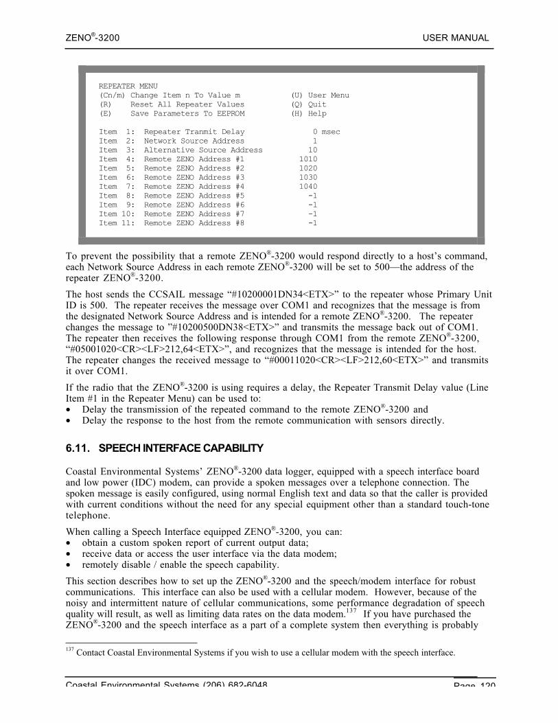
ZENO®-3200 USER MANUAL
Coastal Environmental Systems (206) 682-6048 Page 120
REPEATER MENU(Cn/m) Change Item n To Value m (U) User Menu(R) Reset All Repeater Values (Q) Quit(E) Save Parameters To EEPROM (H) Help
Item 1: Repeater Tranmit Delay 0 msecItem 2: Network Source Address 1Item 3: Alternative Source Address 10Item 4: Remote ZENO Address #1 1010Item 5: Remote ZENO Address #2 1020Item 6: Remote ZENO Address #3 1030Item 7: Remote ZENO Address #4 1040Item 8: Remote ZENO Address #5 -1Item 9: Remote ZENO Address #6 -1Item 10: Remote ZENO Address #7 -1Item 11: Remote ZENO Address #8 -1
To prevent the possibility that a remote ZENO®-3200 would respond directly to a host’s command,each Network Source Address in each remote ZENO®-3200 will be set to 500—the address of therepeater ZENO®-3200.
The host sends the CCSAIL message “#10200001DN34<ETX>” to the repeater whose Primary UnitID is 500. The repeater receives the message over COM1 and recognizes that the message is fromthe designated Network Source Address and is intended for a remote ZENO®-3200. The repeaterchanges the message to ”#10200500DN38<ETX>” and transmits the message back out of COM1.The repeater then receives the following response through COM1 from the remote ZENO®-3200,“#05001020<CR><LF>212,64<ETX>”, and recognizes that the message is intended for the host.The repeater changes the received message to “#00011020<CR><LF>212,60<ETX>” and transmitsit over COM1.
If the radio that the ZENO®-3200 is using requires a delay, the Repeater Transmit Delay value (LineItem #1 in the Repeater Menu) can be used to:• Delay the transmission of the repeated command to the remote ZENO®-3200 and• Delay the response to the host from the remote communication with sensors directly.
6.11. SPEECH INTERFACE CAPABILITY
Coastal Environmental Systems’ ZENO®-3200 data logger, equipped with a speech interface boardand low power (IDC) modem, can provide a spoken messages over a telephone connection. Thespoken message is easily configured, using normal English text and data so that the caller is providedwith current conditions without the need for any special equipment other than a standard touch-tonetelephone.
When calling a Speech Interface equipped ZENO®-3200, you can:• obtain a custom spoken report of current output data;• receive data or access the user interface via the data modem;• remotely disable / enable the speech capability.
This section describes how to set up the ZENO®-3200 and the speech/modem interface for robustcommunications. This interface can also be used with a cellular modem. However, because of thenoisy and intermittent nature of cellular communications, some performance degradation of speechquality will result, as well as limiting data rates on the data modem.137 If you have purchased theZENO®-3200 and the speech interface as a part of a complete system then everything is probably
137 Contact Coastal Environmental Systems if you wish to use a cellular modem with the speech interface.
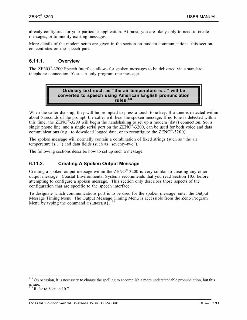
ZENO®-3200 USER MANUAL
Coastal Environmental Systems (206) 682-6048 Page 121
already configured for your particular application. At most, you are likely only to need to createmessages, or to modify existing messages.
More details of the modem setup are given in the section on modem communications: this sectionconcentrates on the speech part.
6.11.1. Overview
The ZENO®-3200 Speech Interface allows for spoken messages to be delivered via a standardtelephone connection. You can only program one message.
Ordinary text such as “the air temperature is…” will beconverted to speech using American English pronunciation
rules.138
When the caller dials up, they will be prompted to press a touch-tone key. If a tone is detected withinabout 5 seconds of the prompt, the caller will hear the spoken message. If no tone is detected withinthis time, the ZENO®-3200 will begin the handshaking to set up a modem (data) connection. So, asingle phone line, and a single serial port on the ZENO®-3200, can be used for both voice and datacommunications (e.g., to download logged data, or to reconfigure the ZENO®-3200).
The spoken message will normally contain a combination of fixed strings (such as “the airtemperature is…”) and data fields (such as “seventy-two”).
The following sections describe how to set up such a message.
6.11.2. Creating A Spoken Output Message
Creating a spoken output message within the ZENO®-3200 is very similar to creating any otheroutput message. Coastal Environmental Systems recommends that you read Section 10.6 beforeattempting to configure a spoken message. This section only describes those aspects of theconfiguration that are specific to the speech interface.
To designate which communications port is to be used for the spoken message, enter the OutputMessage Timing Menu. The Output Message Timing Menu is accessible from the Zeno ProgramMenu by typing the command O{ENTER}.139
138 On occasion, it is necessary to change the spelling to accomplish a more understandable pronunciation, but thisis rare.139 Refer to Section 10.7.
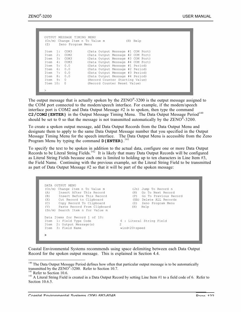
ZENO®-3200 USER MANUAL
Coastal Environmental Systems (206) 682-6048 Page 122
OUTPUT MESSAGE TIMING MENU(Cn/m) Change Item n To Value m (H) Help(Z) Zeno Program Menu
Item 1: COM3 (Data Output Message #1 COM Port)Item 2: COM2 (Data Output Message #2 COM Port)Item 3: COM3 (Data Output Message #3 COM Port)Item 4: COM3 (Data Output Message #4 COM Port)Item 5: 0.0 (Data Output Message #1 Period)Item 6: 0.0 (Data Output Message #2 Period)Item 7: 0.0 (Data Output Message #3 Period)Item 8: 0.0 (Data Output Message #4 Period)Item 9: 0 (Record Counter Starting Value)Item 10: 0 (Record Counter Reset Value)
>
The output message that is actually spoken by the ZENO®-3200 is the output message assigned tothe COM port connected to the modem/speech interface. For example, if the modem/speechinterface port is COM2 and Data Output Message #2 is to spoken, then type the commandC2/COM2{ENTER} in the Output Message Timing Menu. The Data Output Message Period140
should be set to 0 so that the message is not transmitted automatically by the ZENO®-3200.
To create a spoken output message, add Data Output Records from the Data Output Menu anddesignate them to apply to the same Data Output Message number that you specified in the OutputMessage Timing Menu for the speech interface. The Data Output Menu is accessible from the ZenoProgram Menu by typing the command D{ENTER}.141
To specify the text to be spoken in addition to the actual data, configure one or more Data OutputRecords to be Literal String Fields.142 It is likely that many Data Output Records will be configuredas Literal String Fields because each one is limited to holding up to ten characters in Line Item #3,the Field Name. Continuing with the previous example, set the Literal String Field to be transmittedas part of Data Output Message #2 so that it will be part of the spoken message:
DATA OUTPUT MENU(Cn/m) Change Item n To Value m (Jn) Jump To Record n(A) Insert After This Record (N) Go To Next Record(B) Insert Before This Record (P) Go To Previous Record(X) Cut Record to Clipboard (XA) Delete ALL Records(C) Copy Record To Clipboard (Z) Zeno Program Menu(V) Paste Record From Clipboard (H) Help(Sn/m) Search Item n for Value m
Data Items for Record 1 of 10:Item 1: Field Type Code 6 : Literal String FieldItem 2: Output Message(s) 2Item 3: Field Name wind<20>speed
>
Coastal Environmental Systems recommends using space delimiting between each Data OutputRecord for the spoken output message. This is explained in Section 4.4.
140 The Data Output Message Period defines how often that particular output message is to be automaticallytransmitted by the ZENO®-3200. Refer to Section 10.7.141 Refer to Section 10.6.142 A Literal String Field is created in a Data Output Record by setting Line Item #1 to a field code of 6. Refer toSection 10.6.5.
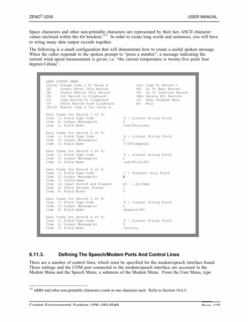
ZENO®-3200 USER MANUAL
Coastal Environmental Systems (206) 682-6048 Page 123
Space characters and other non-printable characters are represented by their hex ASCII charactervalues enclosed within the <> brackets.143 In order to create long words and sentences, you will haveto string many data output records together.
The following is a small configuration that will demonstrate how to create a useful spoken message.When the caller responds to the spoken prompt to “press a number”, a message indicating thecurrent wind speed measurement is given; i.e. “the current temperature is twenty-five point fourdegrees Celsius”.
DATA OUTPUT MENU(Cn/m) Change Item n To Value m (Jn) Jump To Record n(A) Insert After This Record (N) Go To Next Record(B) Insert Before This Record (P) Go To Previous Record(X) Cut Record to Clipboard (XA) Delete ALL Records(C) Copy Record To Clipboard (Z) Zeno Program Menu(V) Paste Record From Clipboard (H) Help(Sn/m) Search Item n for Value m
Data Items for Record 1 of 6:Item 1: Field Type Code 6 : Literal String FieldItem 2: Output Message(s) 2Item 3: Field Name the<20>curren
Data Items for Record 2 of 6:Item 1: Field Type Code 6 : Literal String FieldItem 2: Output Message(s) 2Item 3: Field Name t<20>temperat
Data Items for Record 3 of 6:Item 1: Field Type Code 6 : Literal String FieldItem 2: Output Message(s) 2Item 3: Field Name ure<20>is<20>
Data Items for Record 4 of 6:Item 1: Field Type Code 7 : Transmit Only FieldItem 2: Output Message(s) 2Item 3: Field NameItem 4: Input Record and Element S3 : AirTempItem 5: Field Decimal Places 1Item 6: Field Width 5
Data Items for Record 5 of 6:Item 1: Field Type Code 6 : Literal String FieldItem 2: Output Message(s) 2Item 3: Field Name degrees<20>
Data Items for Record 6 of 6:Item 1: Field Type Code 6 : Literal String FieldItem 2: Output Message(s) 2Item 3: Field Name celsius.
6.11.3. Defining The Speech/Modem Ports And Control Lines
There are a number of control lines, which must be specified for the modem/speech interface board.These settings and the COM port connected to the modem/speech interface are accessed in theModem Menu and the Speech Menu, a submenu of the Modem Menu. From the User Menu, type
143 <20> and other non-printable characters count as one character each. Refer to Section 10.6.5.
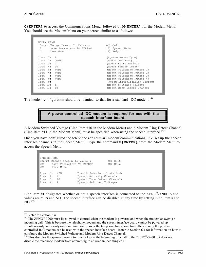
ZENO®-3200 USER MANUAL
Coastal Environmental Systems (206) 682-6048 Page 124
C{ENTER} to access the Communications Menu, followed by M{ENTER} for the Modem Menu.You should see the Modem Menu on your screen similar to as follows:
MODEM MENU(Cn/m) Change Item n To Value m (Q) Quit(E) Save Parameters To EEPROM (S) Speech Menu(U) User Menu (H) Help
Item 1: 1 (System Modem Type)Item 2: COM3 (Modem COM Port)Item 3: 5 (Modem Retry Period)Item 4: 30 (Modem Hangup Delay)Item 5: NONE (Modem Telephone Number 1)Item 6: NONE (Modem Telephone Number 2)Item 7: NONE (Modem Telephone Number 3)Item 8: NONE (Modem Telephone Number 4)Item 9: (Modem Initialization String)Item 10: 5 (Modem Switched Voltage)Item 11: 18 (Modem Ring Detect Channel)
The modem configuration should be identical to that for a standard IDC modem.144
A power-controlled IDC modem is required for use with thespeech interface board.
A Modem Switched Voltage (Line Item #10 in the Modem Menu) and a Modem Ring Detect Channel(Line Item #11 in the Modem Menu) must be specified when using the speech interface.145
Once you have configured the telephone (or cellular) modem communications link, set up the speechinterface channels in the Speech Menu. Type the command S{ENTER} from the Modem Menu toaccess the Speech Menu.
SPEECH MENU(Cn/m) Change Item n To Value m (Q) Quit(E) Save Parameters To EEPROM (H) Help(U) User Menu
Item 1: YES (Speech Interface Installed)Item 2: 21 (Speech Activity Channel)Item 3: 20 (Speech Tone Detect Channel)Item 4: 4 (Speech Switched Voltage)
Line Item #1 designates whether or not a speech interface is connected to the ZENO®-3200. Validvalues are YES and NO. The speech interface can be disabled at any time by setting Line Item #1 toNO.146
144 Refer to Section 6.4.145 The ZENO®-3200 must be allowed to control when the modem is powered and when the modem answers anincoming call. This is because the telephone modem and the speech interface board cannot be powered upsimultaneously since only one can have control over the telephone line at one time. Hence, only the power-controlled IDC modem can be used with the speech interface board. Refer to Section 6.4 for information on how toconfigure the Modem Switched Voltage and Modem Ring Detect Channel.146 This disables the spoken prompt to press a key at the beginning of a call to the ZENO®-3200 but does notdisable the telephone modem from attempting to answer an incoming call.
ZENO®-3200 USER MANUAL
Coastal Environmental Systems (206) 682-6048 Page 125
If the speech interface is disabled and modem settings areunchanged, the modem should work normally as if the speech
interface was not installed.
Line Item #2, the Speech Activity Channel, is an output from the speech interface board to theZENO®-3200. It allows the ZENO®-3200 to detect when speech is being generated and when it hasfinished. Valid values for Line Item #2 18 through 23.
Line Item #3, the Tone Detect Channel, is used to detect whether the caller is pressing a touch-tonekey on the telephone. Valid values range from 18 through 23.
The Modem Ring Detect Channel147, the Speech Activity Channeland the Tone Detect Channel CANNOT specify the same channels.
Line Item #4, the Speech Switched Voltage, specifies which switched voltage is used to power thespeech interface board. The normal speech interface board is powered with 12 VDC. ContactCoastal Environmental Systems if you require the speech interface board to be powered by 5 VDC.Valid values for this line item are as follows:• 0 (no switched voltage)• 1 (5 VDC Switched A)148
• 2 (5 VDC Switched B)149
• 3 (12 VDC Switched A)• 4 (12 VDC Switched B)• 5 (12 VDC Switched C)• 18 - 23 (a digital output)150
6.11.4. Wiring Diagram
The speech/modem interface product contains three boards: the IDC modem, the speech engineboard, and the speech interface board. All connections to the ZENO®-3200 are through connectorson the speech interface board, with a wiring harness provided by Coastal Environmental Systems.
The following diagram illustrates the wiring to the complete speech/modem interface product.
147 The Modem Ring Detect Channel is Line Item #11 in the Modem Menu.148 Requires a modified speech interface board. Contact Coastal Environmental Systems for this modification.149 Ibid.150 As with the Modem Switched Voltage (refer to Section 6.4), the Speech Switched Voltage could also beconfigured to control one of the digital control channels (digital I/O channels 18 through 23). However, an externalswitching device would be required to meet the voltage and current requirements of the speech interface.
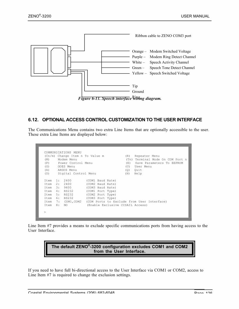
ZENO®-3200 USER MANUAL
Coastal Environmental Systems (206) 682-6048 Page 126
Figure 6-11. Speech interface wiring diagram.
6.12. OPTIONAL ACCESS CONTROL CUSTOMIZATION TO THE USER INTERFACE
The Communications Menu contains two extra Line Items that are optionally accessible to the user.These extra Line Items are displayed below:
COMMUNICATIONS MENU(Cn/m) Change Item n To Value m (R) Repeater Menu(M) Modem Menu (Tn) Terminal Mode On COM Port n(P) Power Control Menu (E) Save Parameters To EEPROM(G) GOES Menu (U) User Menu(A) ARGOS Menu (Q) Quit(D) Digital Control Menu (H) Help
Item 1: 2400 (COM1 Baud Rate)Item 2: 2400 (COM2 Baud Rate)Item 3: 9600 (COM3 Baud Rate)Item 4: RS232 (COM1 Port Type)Item 5: RS232 (COM2 Port Type)Item 6: RS232 (COM3 Port Type)Item 7: COM1,COM2 (COM Ports to Exclude from User Interface)Item 8: NO (Enable Exclusive CCSAIL Access)
>
Line Item #7 provides a means to exclude specific communications ports from having access to theUser Interface.
The default ZENO®-3200 configuration excludes COM1 and COM2from the User Interface.
If you need to have full bi-directional access to the User Interface via COM1 or COM2, access toLine Item #7 is required to change the exclusion settings.
Orange – Modem Switched VoltagePurple – Modem Ring Detect ChannelWhite – Speech Activity ChannelGreen – Speech Tone Detect ChannelYellow – Speech Switched Voltage
Ribbon cable to ZENO COM3 port
TipGroundRing
ZENO®-3200 USER MANUAL
Coastal Environmental Systems (206) 682-6048 Page 127
Contact Coastal Environmental Systems if you require access toLine Items #7 or #8 in the Communications Menu.
The options for excluding communications ports from the User Interface in Line Item #7 of theCommunications Menu are as follows:• NONE• COM1• COM2• COM3• COM1,COM2• COM2,COM3• COM1,COM3
Line Item #8 provides a means to exclude access to the User Interface via the standard U{ENTER}command, meaning that it will only respond to CCSAIL commands. The possible values for LineItem #8 are either NO or YES.
As an example of using Line Item #8 would be if there are multiple ZENO®-3200's beingcommunicated with on a multi-drop link, such as two-way radio or RS485. In this case, it is veryimportant that each ZENO®-3200 only respond when it is specifically addressed. If the U{ENTER}command was sent on a multi-drop line to several ZENO®-3200's, each ZENO®-3200 would respondsimultaneously, which is not desirable.
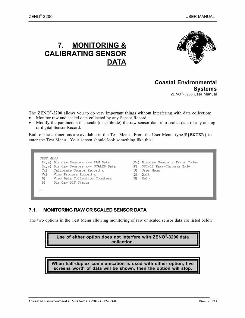
ZENO®-3200 USER MANUAL
Coastal Environmental Systems (206) 682-6048 Page 128
7. MONITORING &CALIBRATING SENSOR
DATA
Coastal EnvironmentalSystems
ZENO®-3200 User Manual
The ZENO®-3200 allows you to do very important things without interfering with data collection:• Monitor raw and scaled data collected by any Sensor Record.• Modify the parameters that scale (or calibrate) the raw sensor data into scaled data of any analog
or digital Sensor Record.
Both of these functions are available in the Test Menu. From the User Menu, type T{ENTER} toenter the Test Menu. Your screen should look something like this:
TEST MENU(Rx,y) Display Sensors x-y RAW Data (Ex) Display Sensor x Error Codes(Sx,y) Display Sensors x-y SCALED Data (P) SDI-12 Pass-Through Mode(Cx) Calibrate Sensor Record x (U) User Menu(Vx) View Process Record x (Q) Quit(D) View Data Collection Counters (H) Help(B) Display BIT Status
>
7.1. MONITORING RAW OR SCALED SENSOR DATA
The two options in the Test Menu allowing monitoring of raw or scaled sensor data are listed below.
Use of either option does not interfere with ZENO®-3200 datacollection.
When half-duplex communication is used with either option, fivescreens worth of data will be shown, then the option will stop.
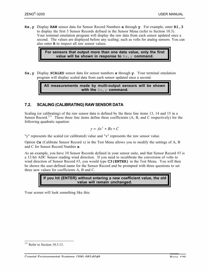
ZENO®-3200 USER MANUAL
Coastal Environmental Systems (206) 682-6048 Page 129
Rx,y Display RAW sensor data for Sensor Record Numbers x through y. For example, enter R1,3to display the first 3 Sensor Records defined in the Sensor Menu (refer to Section 10.3).Your terminal emulation program will display the raw data from each sensor updated once asecond. The values are displayed before any scaling; such as volts for analog sensors. You canalso enter R to inspect all raw sensor values.
For sensors that output more than one data value, only the firstvalue will be shown in response to Rx,y command.
Sx,y Display SCALED sensor data for sensor numbers x through y. Your terminal emulationprogram will display scaled data from each sensor updated once a second.
All measurements made by multi-output sensors will be shownwith the Sx,y command.
7.2. SCALING (CALIBRATING) RAW SENSOR DATA
Scaling (or calibrating) of the raw sensor data is defined by the three line items 13, 14 and 15 in aSensor Record.151 These three line items define three coefficients (A, B, and C respectively) for thefollowing quadratic equation:
CBxAxy ++= 2
"y" represents the scaled (or calibrated) value and "x" represents the raw sensor value.
Option Cx (Calibrate Sensor Record x) in the Test Menu allows you to modify the settings of A, Band C for Sensor Record Number x.
As an example, you have 10 Sensor Records defined in your sensor suite, and that Sensor Record #3 isa 12-bit ADC Sensor reading wind direction. If you need to recalibrate the conversion of volts towind direction of Sensor Record #3, you would type C3{ENTER} in the Test Menu. You will thenbe shown the user-defined name for the Sensor Record and be prompted with three questions to setthree new values for coefficients A, B and C.
If you hit {ENTER} without entering a new coefficient value, the oldvalue will remain unchanged.
Your screen will look something like this:
151 Refer to Section 10.3.13.
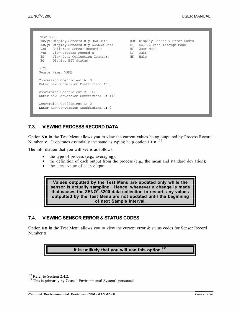
ZENO®-3200 USER MANUAL
Coastal Environmental Systems (206) 682-6048 Page 130
TEST MENU(Rx,y) Display Sensors x-y RAW Data (Ex) Display Sensor x Error Codes(Sx,y) Display Sensors x-y SCALED Data (P) SDI-12 Pass-Through Mode(Cx) Calibrate Sensor Record x (U) User Menu(Vx) View Process Record x (Q) Quit(D) View Data Collection Counters (H) Help(B) Display BIT Status
> C3Sensor Name: VANE
Conversion Coefficient A: 0Enter new Conversion Coefficient A: 0
Conversion Coefficient B: 142Enter new Conversion Coefficient B: 142
Conversion Coefficient C: 0Enter new Conversion Coefficient C: 0
7.3. VIEWING PROCESS RECORD DATA
Option Vx in the Test Menu allows you to view the current values being outputted by Process RecordNumber x. It operates essentially the same as typing help option HPx.152
The information that you will see is as follows:
• the type of process (e.g., averaging);• the definition of each output from the process (e.g., the mean and standard deviation);• the latest value of each output.
Values outputted by the Test Menu are updated only while thesensor is actually sampling. Hence, whenever a change is madethat causes the ZENO®-3200 data collection to restart, any valuesoutputted by the Test Menu are not updated until the beginning
of next Sample Interval.
7.4. VIEWING SENSOR ERROR & STATUS CODES
Option Ex in the Test Menu allows you to view the current error & status codes for Sensor RecordNumber x.
It is unlikely that you will use this option.153
152 Refer to Section 2.4.2.153 This is primarily by Coastal Environmental System's personnel.
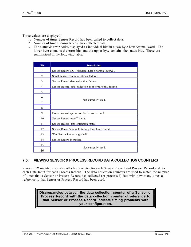
ZENO®-3200 USER MANUAL
Coastal Environmental Systems (206) 682-6048 Page 131
Three values are displayed:1. Number of times Sensor Record has been called to collect data.2. Number of times Sensor Record has collected data.3. The status & error codes displayed as individual bits in a two-byte hexadecimal word. The
lower byte contains the error bits and the upper byte contains the status bits. These aresummarized in the following table:
Bit Description
1 Sensor Record NOT signaled during Sample Interval.
2 Serial sensor communications failure.
3 Sensor Record data collection failure.
4 Sensor Record data collection is intermittently failing.
5
6
7
8
Not currently used.
9 Excitation voltage in use for Sensor Record.
10 Sensor Record on/off status.
11 Sensor Record data collection status.
12 Sensor Record's sample timing loop has expired.
13 Was Sensor Record signaled?
14 Sensor Record is marked.
15
16Not currently used.
7.5. VIEWING SENSOR & PROCESS RECORD DATA COLLECTION COUNTERS
ZenoSoft™ maintains a data collection counter for each Sensor Record and Process Record and foreach Data Input for each Process Record. The data collection counters are used to match the numberof times that a Sensor or Process Record has collected (or processed) data with how many times areference to that Sensor or Process Record has been used.
Discrepancies between the data collection counter of a Sensor orProcess Record with the data collection counter of reference tothat Sensor or Process Record indicate timing problems with
your configuration.
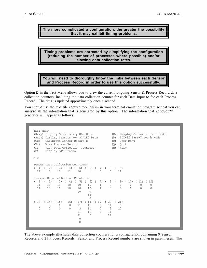
ZENO®-3200 USER MANUAL
Coastal Environmental Systems (206) 682-6048 Page 132
The more complicated a configuration, the greater the possibilitythat it may exhibit timing problems.
Timing problems are corrected by simplifying the configuration(reducing the number of processes where possible) and/or
slowing data collection rates.
You will need to thoroughly know the links between each Sensorand Process Record in order to use this option successfully.
Option D in the Test Menu allows you to view the current, ongoing Sensor & Process Record datacollection counters, including the data collection counter for each Data Input to for each ProcessRecord. The data is updated approximately once a second.
You should use the text file capture mechanism in your terminal emulation program so that you cananalyze all the information that is generated by this option. The information that ZenoSoft™generates will appear as follows:
TEST MENU(Rx,y) Display Sensors x-y RAW Data (Ex) Display Sensor x Error Codes(Sx,y) Display Sensors x-y SCALED Data (P) SDI-12 Pass-Through Mode(Cx) Calibrate Sensor Record x (U) User Menu(Vx) View Process Record x (Q) Quit(D) View Data Collection Counters (H) Help(B) Display BIT Status
> D
Sensor Data Collection Counters:( 1) ( 2) ( 3) ( 4) ( 5) ( 6) ( 7) ( 8) ( 9) 21 3 11 11 10 1 0 0 11
Process Data Collection Counters:( 1) ( 2) ( 3) ( 4) ( 5) ( 6) ( 7) ( 8) ( 9) ( 10) ( 11) ( 12) 11 10 11 10 10 10 1 0 0 0 0 0 11 10 11 10 10 10 1 0 0 0 0 0 10 0 10 0( 13) ( 14) ( 15) ( 16) ( 17) ( 18) ( 19) ( 20) ( 21) 0 0 0 0 11 11 0 11 5 0 0 0 0 3 11 0 3 20 11 11 0 11 21 0 21 0 0
The above example illustrates data collection counters for a configuration containing 9 SensorRecords and 21 Process Records. Sensor and Process Record numbers are shown in parentheses. The
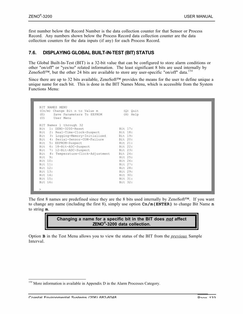
ZENO®-3200 USER MANUAL
Coastal Environmental Systems (206) 682-6048 Page 133
first number below the Record Number is the data collection counter for that Sensor or ProcessRecord. Any numbers shown below the Process Record data collection counter are the datacollection counters for the data inputs (if any) for each Process Record.
7.6. DISPLAYING GLOBAL BUILT-IN-TEST (BIT) STATUS
The Global Built-In-Test (BIT) is a 32-bit value that can be configured to store alarm conditions orother "on/off" or "yes/no" related information. The least significant 8 bits are used internally byZenoSoft™, but the other 24 bits are available to store any user-specific "on/off" data.154
Since there are up to 32 bits available, ZenoSoft™ provides the means for the user to define unique aunique name for each bit. This is done in the BIT Names Menu, which is accessible from the SystemFunctions Menu:
BIT NAMES MENU(Cn/m) Change Bit n to Value m (Q) Quit(E) Save Parameters To EEPROM (H) Help(U) User Menu
BIT Names 1 through 32Bit 1: ZENO-3200-Reset Bit 17:Bit 2: Real-Time-Clock-Suspect Bit 18:Bit 3: Logging-Memory-Initialized Bit 19:Bit 4: Serial-Sensor-COM-Failure Bit 20:Bit 5: EEPROM-Suspect Bit 21:Bit 6: 18-Bit-ADC-Suspect Bit 22:Bit 7: 12-Bit-ADC-Suspect Bit 23:Bit 8: Temperature-Clock-Adjustment Bit 24:Bit 9: Bit 25:Bit 10: Bit 26:Bit 11: Bit 27:Bit 12: Bit 28:Bit 13: Bit 29:Bit 14: Bit 30:Bit 15: Bit 31:Bit 16: Bit 32:
>
The first 8 names are predefined since they are the 8 bits used internally by ZenoSoft™. If you wantto change any name (including the first 8), simply use option Cn/m{ENTER} to change Bit Name nto string m.
Changing a name for a specific bit in the BIT does not affectZENO®-3200 data collection.
Option B in the Test Menu allows you to view the status of the BIT from the previous SampleInterval.
154 More information is available in Appendix D in the Alarm Processes Category.
ZENO®-3200 USER MANUAL
Coastal Environmental Systems (206) 682-6048 Page 134
Since the contents of the BIT is dynamic during data collection,only the value of the BIT from the previous Sample Interval is
available to be viewed using this option.
When you type this option, you will be presented ONLY with the ACTIVE or SET bits in the BITfrom the previous Sample Interval.
ZENO®-3200 USER MANUAL
Coastal Environmental Systems (206) 682-6048 Page 135
8. ZENO®-3200 ACCESSPRIVILEGES
Coastal EnvironmentalSystems
ZENO®-3200 User Manual
Since the ZENO®-3200 is a configurable device and things can be done that would interfere with thepurpose that the user intends, Coastal Environmental Systems provided each ZENO®-3200 withbuilt-in access privilege and security.
8.1. ACCESSING THE ZENO PROGRAM MENU
An Administrator Password is required to access the Zeno Program Menu from the User Menu. Toenter the Zeno Program Menu, you should:
• Connect and power up the ZENO®-3200 as described in Section 2.2.• Type U{ENTER} to enter the User Menu.• Type Z{ENTER} to enter the Zeno Program Menu.
You will be prompted for the Administrator Password. The default Administrator Password (whichyou can change) is ZENO. After you enter the correct Administrator Password, the ZENO®-3200will stop performing all data collection, processing, data logging and output message transmission. Ifany serial sensors are in use, ZenoSoft™ will wait to complete any current communications betweenthem and the ZENO®-3200. Once all data collections have stopped, you will be presented with theZeno Program Menu.155
Sensor sampling, logging and data output cease when youenter the Zeno Program Menu.
From the Zeno Program Menu, type Q (to quit the User Interface)or U (to enter the User Menu) to resume normal operation.
The default Administrator Password is ZENO.
The Zeno Program Menu will offer you the following options.
155 If you have to return to the User Menu for some reason, then re-enter the Zeno Program Menu, you won't have tore-enter the Administrator Password unless you exited the User Interface altogether.
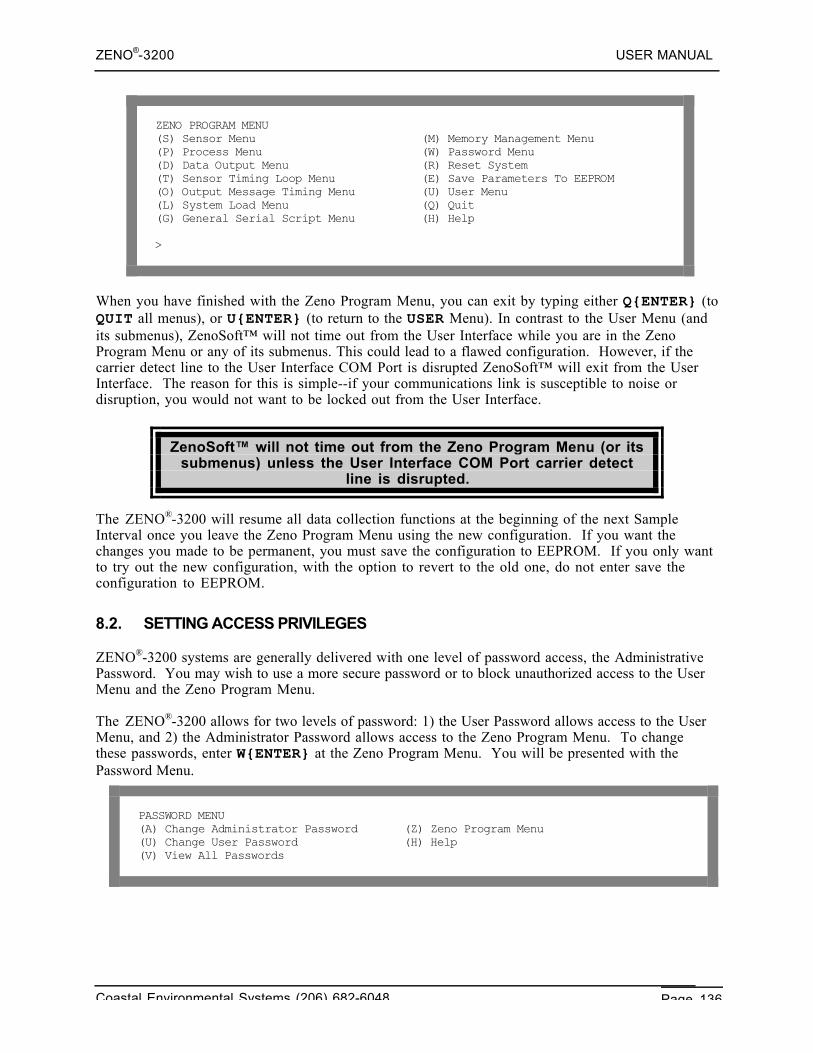
ZENO®-3200 USER MANUAL
Coastal Environmental Systems (206) 682-6048 Page 136
ZENO PROGRAM MENU(S) Sensor Menu (M) Memory Management Menu(P) Process Menu (W) Password Menu(D) Data Output Menu (R) Reset System(T) Sensor Timing Loop Menu (E) Save Parameters To EEPROM(O) Output Message Timing Menu (U) User Menu(L) System Load Menu (Q) Quit(G) General Serial Script Menu (H) Help
>
When you have finished with the Zeno Program Menu, you can exit by typing either Q{ENTER} (toQUIT all menus), or U{ENTER} (to return to the USER Menu). In contrast to the User Menu (andits submenus), ZenoSoft™ will not time out from the User Interface while you are in the ZenoProgram Menu or any of its submenus. This could lead to a flawed configuration. However, if thecarrier detect line to the User Interface COM Port is disrupted ZenoSoft™ will exit from the UserInterface. The reason for this is simple--if your communications link is susceptible to noise ordisruption, you would not want to be locked out from the User Interface.
ZenoSoft™ will not time out from the Zeno Program Menu (or itssubmenus) unless the User Interface COM Port carrier detect
line is disrupted.
The ZENO®-3200 will resume all data collection functions at the beginning of the next SampleInterval once you leave the Zeno Program Menu using the new configuration. If you want thechanges you made to be permanent, you must save the configuration to EEPROM. If you only wantto try out the new configuration, with the option to revert to the old one, do not enter save theconfiguration to EEPROM.
8.2. SETTING ACCESS PRIVILEGES
ZENO®-3200 systems are generally delivered with one level of password access, the AdministrativePassword. You may wish to use a more secure password or to block unauthorized access to the UserMenu and the Zeno Program Menu.
The ZENO®-3200 allows for two levels of password: 1) the User Password allows access to the UserMenu, and 2) the Administrator Password allows access to the Zeno Program Menu. To changethese passwords, enter W{ENTER} at the Zeno Program Menu. You will be presented with thePassword Menu.
PASSWORD MENU(A) Change Administrator Password (Z) Zeno Program Menu(U) Change User Password (H) Help(V) View All Passwords
ZENO®-3200 USER MANUAL
Coastal Environmental Systems (206) 682-6048 Page 137
To change either the Administrator Password or the User Password, you must enter the appropriatecommand (A or U). You will be prompted to enter the current password, and then to enter andconfirm the new password.
Contact Coastal Environmental Systems if you haveforgotten your password.
ZENO®-3200 USER MANUAL
Coastal Environmental Systems (206) 682-6048 Page 138
9. UPLOADING ANDDOWNLOADING AN ENTIRE
CONFIGURATION
Coastal EnvironmentalSystems
ZENO®-3200 User Manual
A great feature of the ZENO®-3200 is the ability to download a configuration into a file on yourcomputer. This feature allows you to configure multiple ZENO®-3200's with the same configuration,or to backup your configuration, or to send the configuration to Coastal Environmental Systems inthe event that you need assistance.
Coastal Environmental Systems recommends that youperiodically backup your configuration onto a computer while youmake changes so that you can go back to an earlier configuration
if a mistake occurs.
To upload or download a complete configuration, you need to use the System Load Menu, which is asubmenu of the Zeno Program Menu. From the Zeno Program Menu, type L{ENTER} to enter theSystem Load Menu. You should see the following:
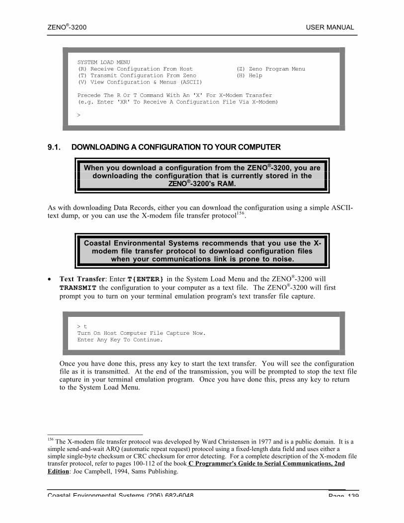
ZENO®-3200 USER MANUAL
Coastal Environmental Systems (206) 682-6048 Page 139
SYSTEM LOAD MENU(R) Receive Configuration From Host (Z) Zeno Program Menu(T) Transmit Configuration From Zeno (H) Help(V) View Configuration & Menus (ASCII)
Precede The R Or T Command With An 'X' For X-Modem Transfer(e.g. Enter 'XR' To Receive A Configuration File Via X-Modem)
>
9.1. DOWNLOADING A CONFIGURATION TO YOUR COMPUTER
When you download a configuration from the ZENO®-3200, you aredownloading the configuration that is currently stored in the
ZENO®-3200's RAM.
As with downloading Data Records, either you can download the configuration using a simple ASCII-text dump, or you can use the X-modem file transfer protocol156.
Coastal Environmental Systems recommends that you use the X-modem file transfer protocol to download configuration files
when your communications link is prone to noise.
• Text Transfer: Enter T{ENTER} in the System Load Menu and the ZENO®-3200 willTRANSMIT the configuration to your computer as a text file. The ZENO®-3200 will firstprompt you to turn on your terminal emulation program's text transfer file capture.
> tTurn On Host Computer File Capture Now.Enter Any Key To Continue.
Once you have done this, press any key to start the text transfer. You will see the configurationfile as it is transmitted. At the end of the transmission, you will be prompted to stop the text filecapture in your terminal emulation program. Once you have done this, press any key to returnto the System Load Menu.
156 The X-modem file transfer protocol was developed by Ward Christensen in 1977 and is a public domain. It is asimple send-and-wait ARQ (automatic repeat request) protocol using a fixed-length data field and uses either asimple single-byte checksum or CRC checksum for error detecting. For a complete description of the X-modem filetransfer protocol, refer to pages 100-112 of the book C Programmer's Guide to Serial Communications, 2ndEdition: Joe Campbell, 1994, Sams Publishing.
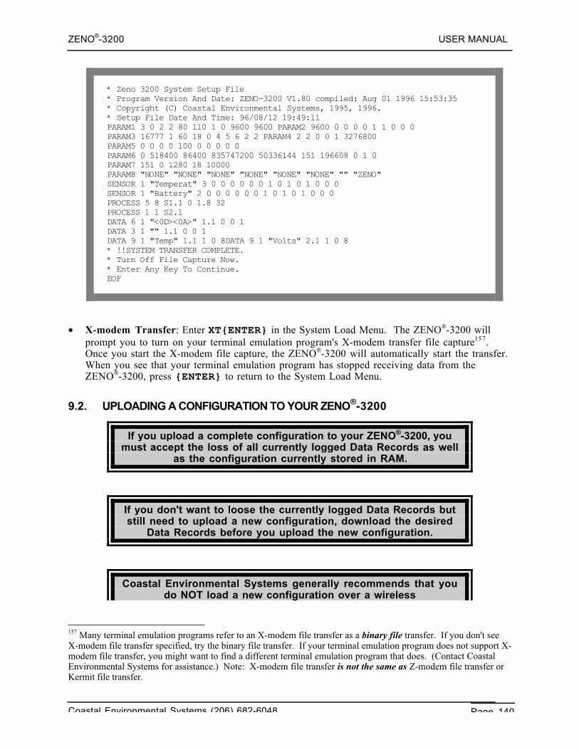
ZENO®-3200 USER MANUAL
Coastal Environmental Systems (206) 682-6048 Page 140
* Zeno 3200 System Setup File* Program Version And Date: ZENO-3200 V1.80 compiled: Aug 01 1996 15:53:35* Copyright (C) Coastal Environmental Systems, 1995, 1996.* Setup File Date And Time: 96/08/12 19:49:11PARAM1 3 0 2 2 80 110 1 0 9600 9600 PARAM2 9600 0 0 0 0 1 1 0 0 0PARAM3 16777 1 60 18 0 4 5 6 2 2 PARAM4 2 2 0 0 1 3276800PARAM5 0 0 0 0 100 0 0 0 0 0PARAM6 0 518400 86400 835747200 50336144 151 196608 0 1 0PARAM7 151 0 1280 18 10000PARAM8 "NONE" "NONE" "NONE" "NONE" "NONE" "NONE" "" "ZENO"SENSOR 1 "Temperat" 3 0 0 0 0 0 0 1 0 1 0 1 0 0 0SENSOR 1 "Battery" 2 0 0 0 0 0 0 1 0 1 0 1 0 0 0PROCESS 5 8 S1.1 0 1.8 32PROCESS 1 1 S2.1DATA 6 1 "<0D><0A>" 1.1 0 0 1DATA 3 1 "" 1.1 0 0 1DATA 9 1 "Temp" 1.1 1 0 8DATA 9 1 "Volts" 2.1 1 0 8* !!SYSTEM TRANSFER COMPLETE.* Turn Off File Capture Now.* Enter Any Key To Continue.EOF
• X-modem Transfer: Enter XT{ENTER} in the System Load Menu. The ZENO®-3200 willprompt you to turn on your terminal emulation program's X-modem transfer file capture157.Once you start the X-modem file capture, the ZENO®-3200 will automatically start the transfer.When you see that your terminal emulation program has stopped receiving data from theZENO®-3200, press {ENTER} to return to the System Load Menu.
9.2. UPLOADING A CONFIGURATION TO YOUR ZENO®-3200
If you upload a complete configuration to your ZENO®-3200, youmust accept the loss of all currently logged Data Records as well
as the configuration currently stored in RAM.
If you don't want to loose the currently logged Data Records butstill need to upload a new configuration, download the desired
Data Records before you upload the new configuration.
Coastal Environmental Systems generally recommends that youdo NOT load a new configuration over a wireless
157 Many terminal emulation programs refer to an X-modem file transfer as a binary file transfer. If you don't seeX-modem file transfer specified, try the binary file transfer. If your terminal emulation program does not support X-modem file transfer, you might want to find a different terminal emulation program that does. (Contact CoastalEnvironmental Systems for assistance.) Note: X-modem file transfer is not the same as Z-modem file transfer orKermit file transfer.
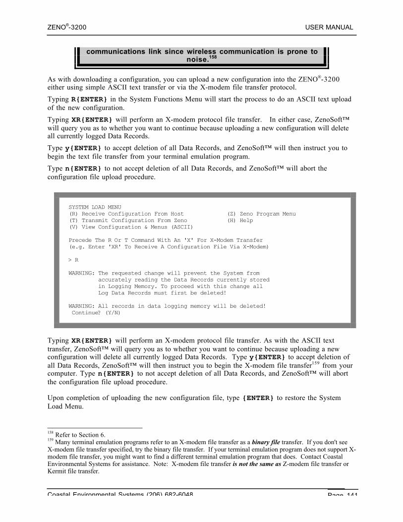
ZENO®-3200 USER MANUAL
Coastal Environmental Systems (206) 682-6048 Page 141
communications link since wireless communication is prone tonoise.158
As with downloading a configuration, you can upload a new configuration into the ZENO®-3200either using simple ASCII text transfer or via the X-modem file transfer protocol.
Typing R{ENTER} in the System Functions Menu will start the process to do an ASCII text uploadof the new configuration.
Typing XR{ENTER} will perform an X-modem protocol file transfer. In either case, ZenoSoft™will query you as to whether you want to continue because uploading a new configuration will deleteall currently logged Data Records.
Type y{ENTER} to accept deletion of all Data Records, and ZenoSoft™ will then instruct you tobegin the text file transfer from your terminal emulation program.
Type n{ENTER} to not accept deletion of all Data Records, and ZenoSoft™ will abort theconfiguration file upload procedure.
SYSTEM LOAD MENU(R) Receive Configuration From Host (Z) Zeno Program Menu(T) Transmit Configuration From Zeno (H) Help(V) View Configuration & Menus (ASCII)
Precede The R Or T Command With An 'X' For X-Modem Transfer(e.g. Enter 'XR' To Receive A Configuration File Via X-Modem)
> R
WARNING: The requested change will prevent the System from accurately reading the Data Records currently stored in Logging Memory. To proceed with this change all Log Data Records must first be deleted!
WARNING: All records in data logging memory will be deleted! Continue? (Y/N)
Typing XR{ENTER} will perform an X-modem protocol file transfer. As with the ASCII texttransfer, ZenoSoft™ will query you as to whether you want to continue because uploading a newconfiguration will delete all currently logged Data Records. Type y{ENTER} to accept deletion ofall Data Records, ZenoSoft™ will then instruct you to begin the X-modem file transfer159 from yourcomputer. Type n{ENTER} to not accept deletion of all Data Records, and ZenoSoft™ will abortthe configuration file upload procedure.
Upon completion of uploading the new configuration file, type {ENTER} to restore the SystemLoad Menu.
158 Refer to Section 6.159 Many terminal emulation programs refer to an X-modem file transfer as a binary file transfer. If you don't seeX-modem file transfer specified, try the binary file transfer. If your terminal emulation program does not support X-modem file transfer, you might want to find a different terminal emulation program that does. Contact CoastalEnvironmental Systems for assistance. Note: X-modem file transfer is not the same as Z-modem file transfer orKermit file transfer.
ZENO®-3200 USER MANUAL
Coastal Environmental Systems (206) 682-6048 Page 142
If the file upload is successful, the new configuration file will beuploaded into RAM only. If you want it saved, you must return to
the Zeno Program Menu and type E{ENTER} to save theconfiguration to EEPROM.
If the new configuration file fails to upload for any reason,ZenoSoft™ will restore the configuration that is currently stored
in EEPROM.
9.3. VIEWING A CONFIGURATION WITH ALL MENUS
You can instruct the ZENO®-3200 to display the entire configuration with the menus from the UserInterface by using option V in the System Load Menu.
Option V in the System Load Menu allows you to download yourconfiguration in the same user-readable format as all the User
Interface menus.
It would be the same as going to each & every menu in the User Interface by hand while you captureall of the text in your terminal emulation program.
When you type V{ENTER} in the System Load Menu, the ZENO®-3200 will query you to start anASCII file capture. After you start the file capture and type any key in your terminal emulationprogram the ZENO®-3200 will transmit the entire configuration--including menus--into the file thatyou specified.
Using any text editor program, you can then print the view of your configuration as a hardcopy foryour records.
The file that you download using option V in the System LoadMenu CANNOT be uploaded as a readable configuration file by the
ZENO®-3200.
9.4. CONFIGURATION FILE COMPATIBILITY BETWEEN DIFFERENT ZENOSOFT™VERSIONS
ZenoSoft™ is designed so that it can upload configuration files that were generated by earlierversions of ZenoSoft™. For example, a configuration file that was generated using ZenoSoft™V1.811 can be uploaded by any subsequent version of ZenoSoft™ such as V1.965.
An older version of ZenoSoft™ cannot upload configuration files generated by newer versions ofZenoSoft™. For example, a configuration file that was generated using ZenoSoft™ V1.965 cannotbe uploaded into ZenoSoft™ V1.811.
ZENO®-3200 USER MANUAL
Coastal Environmental Systems (206) 682-6048 Page 143
The same rules listed above also apply to custom versions of ZenoSoft™, but with several additions:• A custom version of ZenoSoft™ can upload a configuration file generated by any earlier version
of the same custom version or any earlier standard version of ZenoSoft™.• A custom version of ZenoSoft™ may or may not be able to upload a configuration file that was
generated by a different custom version of ZenoSoft™.160 Each custom version of ZenoSoft™is identified by its custom version identifier, which is part of the custom version number asdescribed below.
• A configuration file generated by a custom version of ZenoSoft™ may or may not be uploadableby any standard version of ZenoSoft™ that is newer than the custom version.161
Custom versions of ZenoSoft™ are distinguished from standardversions by their version numbers.
The version number for a standard version of ZenoSoft™ takesthe form "Vx.xx", where "x.xx" is the standard version number.
The version number for a custom version of ZenoSoft™ takesthe form "Vx.xx-yyyy-z.zz", where "x.xx" is the baseline standard
version number, "yyyy" is the custom version identifier and"z.zz" is the custom version sub-number.
160 Each custom version of ZenoSoft™ may include unique elements that are not compatible with any other versionof ZenoSoft™ rendering their configuration files unusable to a different ZenoSoft™ version.161 Custom versions of ZenoSoft™ may include unique elements that are not present in standard versions ofZenoSoft™ and, consequently, won't be understood by the standard version.
ZENO®-3200 USER MANUAL
Coastal Environmental Systems (206) 682-6048 Page 144
10. ZENO®-3200CONFIGURATION
SPECIFICS
Coastal EnvironmentalSystems
ZENO®-3200 User Manual
This section contains detailed information regarding the creation and/or modification of a ZENO®-3200 configuration. It focuses primarily on the details and options available in the Zeno ProgramMenu and its submenus.
The Zeno Program Menu provides for the following:• Match the ZENO®-3200 hardware and firmware to your sensor suite.• Specify calculations, such as averaging, to apply to the sensor outputs.• Specify the format and content of data to be logged, and to be transmitted.• Using multiple data output messages.• Setting up an alarm message to be transmitted if one or more conditions are met.• Using Constants in Processes
If you have not yet done so, it is highly recommend that you workthrough Part 2 of the tutorial in Section 3 before proceeding with
this section.
10.1. ZENO®-3200 CONFIGURATION TIPS
When you create or modify a configuration, there are things you can do that will ensure you canrecover if any mistakes are made along the way:
1. Ask yourself the list of questions described in Section 3.2.1. These questions will assistyou in writing an effective configuration.
2. Provide each Sensor Record, Process Record and Data Output Record with a user-defined name. This will help you to remember what each record is responsible for.
3. Before you change an existing configuration, make sure you have a copy of theconfiguration stored on your computer. If you don't have the current configuration storedon your computer, download the configuration before you make any changes in case you need togo back to it. Refer to Section 9.1.
4. Periodically save your configuration to EEPROM or download the configuration toyour computer while you change it. When you change a configuration, you are changing
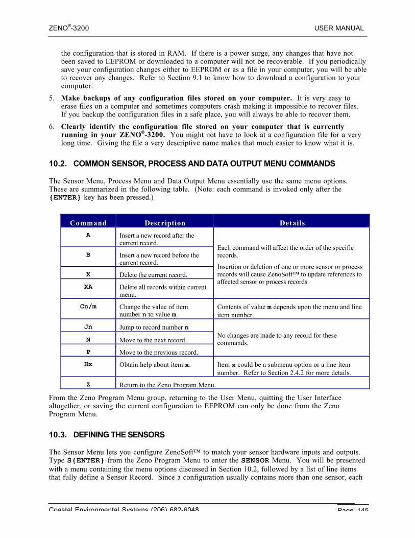
ZENO®-3200 USER MANUAL
Coastal Environmental Systems (206) 682-6048 Page 145
the configuration that is stored in RAM. If there is a power surge, any changes that have notbeen saved to EEPROM or downloaded to a computer will not be recoverable. If you periodicallysave your configuration changes either to EEPROM or as a file in your computer, you will be ableto recover any changes. Refer to Section 9.1 to know how to download a configuration to yourcomputer.
5. Make backups of any configuration files stored on your computer. It is very easy toerase files on a computer and sometimes computers crash making it impossible to recover files.If you backup the configuration files in a safe place, you will always be able to recover them.
6. Clearly identify the configuration file stored on your computer that is currentlyrunning in your ZENO®-3200. You might not have to look at a configuration file for a verylong time. Giving the file a very descriptive name makes that much easier to know what it is.
10.2. COMMON SENSOR, PROCESS AND DATA OUTPUT MENU COMMANDS
The Sensor Menu, Process Menu and Data Output Menu essentially use the same menu options.These are summarized in the following table. (Note: each command is invoked only after the{ENTER} key has been pressed.)
Command Description Details
A Insert a new record after thecurrent record.
B Insert a new record before thecurrent record.
X Delete the current record.
XA Delete all records within currentmenu.
Each command will affect the order of the specificrecords.
Insertion or deletion of one or more sensor or processrecords will cause ZenoSoft™ to update references toaffected sensor or process records.
Cn/m Change the value of itemnumber n to value m.
Contents of value m depends upon the menu and lineitem number.
Jn Jump to record number n
N Move to the next record.
P Move to the previous record.
No changes are made to any record for thesecommands.
Hx Obtain help about item x. Item x could be a submenu option or a line itemnumber. Refer to Section 2.4.2 for more details.
Z Return to the Zeno Program Menu.
From the Zeno Program Menu group, returning to the User Menu, quitting the User Interfacealtogether, or saving the current configuration to EEPROM can only be done from the ZenoProgram Menu.
10.3. DEFINING THE SENSORS
The Sensor Menu lets you configure ZenoSoft™ to match your sensor hardware inputs and outputs.Type S{ENTER} from the Zeno Program Menu to enter the SENSOR Menu. You will be presentedwith a menu containing the menu options discussed in Section 10.2, followed by a list of line itemsthat fully define a Sensor Record. Since a configuration usually contains more than one sensor, each
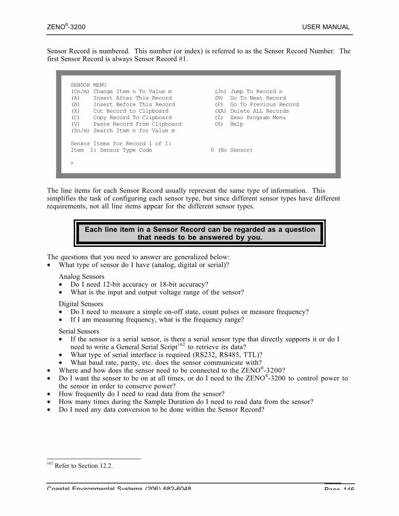
ZENO®-3200 USER MANUAL
Coastal Environmental Systems (206) 682-6048 Page 146
Sensor Record is numbered. This number (or index) is referred to as the Sensor Record Number. Thefirst Sensor Record is always Sensor Record #1.
SENSOR MENU(Cn/m) Change Item n To Value m (Jn) Jump To Record n(A) Insert After This Record (N) Go To Next Record(B) Insert Before This Record (P) Go To Previous Record(X) Cut Record to Clipboard (XA) Delete ALL Records(C) Copy Record To Clipboard (Z) Zeno Program Menu(V) Paste Record From Clipboard (H) Help(Sn/m) Search Item n for Value m
Sensor Items for Record 1 of 1:Item 1: Sensor Type Code 0 (No Sensor)
>
The line items for each Sensor Record usually represent the same type of information. Thissimplifies the task of configuring each sensor type, but since different sensor types have differentrequirements, not all line items appear for the different sensor types.
Each line item in a Sensor Record can be regarded as a questionthat needs to be answered by you.
The questions that you need to answer are generalized below:• What type of sensor do I have (analog, digital or serial)?
Analog Sensors• Do I need 12-bit accuracy or 18-bit accuracy?• What is the input and output voltage range of the sensor?
Digital Sensors• Do I need to measure a simple on-off state, count pulses or measure frequency?• If I am measuring frequency, what is the frequency range?
Serial Sensors• If the sensor is a serial sensor, is there a serial sensor type that directly supports it or do I
need to write a General Serial Script162 to retrieve its data?• What type of serial interface is required (RS232, RS485, TTL)?• What baud rate, parity, etc. does the sensor communicate with?
• Where and how does the sensor need to be connected to the ZENO®-3200?• Do I want the sensor to be on at all times, or do I need to the ZENO®-3200 to control power to
the sensor in order to conserve power?• How frequently do I need to read data from the sensor?• How many times during the Sample Duration do I need to read data from the sensor?• Do I need any data conversion to be done within the Sensor Record?
162 Refer to Section 12.2.
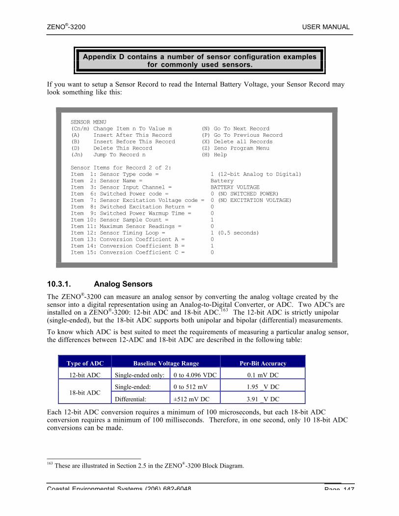
ZENO®-3200 USER MANUAL
Coastal Environmental Systems (206) 682-6048 Page 147
Appendix D contains a number of sensor configuration examplesfor commonly used sensors.
If you want to setup a Sensor Record to read the Internal Battery Voltage, your Sensor Record maylook something like this:
SENSOR MENU(Cn/m) Change Item n To Value m (N) Go To Next Record(A) Insert After This Record (P) Go To Previous Record(B) Insert Before This Record (X) Delete all Records(D) Delete This Record (Z) Zeno Program Menu(Jn) Jump To Record n (H) Help
Sensor Items for Record 2 of 2:Item 1: Sensor Type code = 1 (12-bit Analog to Digital)Item 2: Sensor Name = BatteryItem 3: Sensor Input Channel = BATTERY VOLTAGEItem 6: Switched Power code = 0 (NO SWITCHED POWER)Item 7: Sensor Excitation Voltage code = 0 (NO EXCITATION VOLTAGE)Item 8: Switched Excitation Return = 0Item 9: Switched Power Warmup Time = 0Item 10: Sensor Sample Count = 1Item 11: Maximum Sensor Readings = 0Item 12: Sensor Timing Loop = 1 (0.5 seconds)Item 13: Conversion Coefficient A = 0Item 14: Conversion Coefficient B = 1Item 15: Conversion Coefficient C = 0
10.3.1. Analog Sensors
The ZENO®-3200 can measure an analog sensor by converting the analog voltage created by thesensor into a digital representation using an Analog-to-Digital Converter, or ADC. Two ADC's areinstalled on a ZENO®-3200: 12-bit ADC and 18-bit ADC.163 The 12-bit ADC is strictly unipolar(single-ended), but the 18-bit ADC supports both unipolar and bipolar (differential) measurements.
To know which ADC is best suited to meet the requirements of measuring a particular analog sensor,the differences between 12-ADC and 18-bit ADC are described in the following table:
Type of ADC Baseline Voltage Range Per-Bit Accuracy
12-bit ADC Single-ended only: 0 to 4.096 VDC 0.1 mV DC
Single-ended: 0 to 512 mV 1.95 _V DC18-bit ADC
Differential: ±512 mV DC 3.91 _V DC
Each 12-bit ADC conversion requires a minimum of 100 microseconds, but each 18-bit ADCconversion requires a minimum of 100 milliseconds. Therefore, in one second, only 10 18-bit ADCconversions can be made.
163 These are illustrated in Section 2.5 in the ZENO®-3200 Block Diagram.
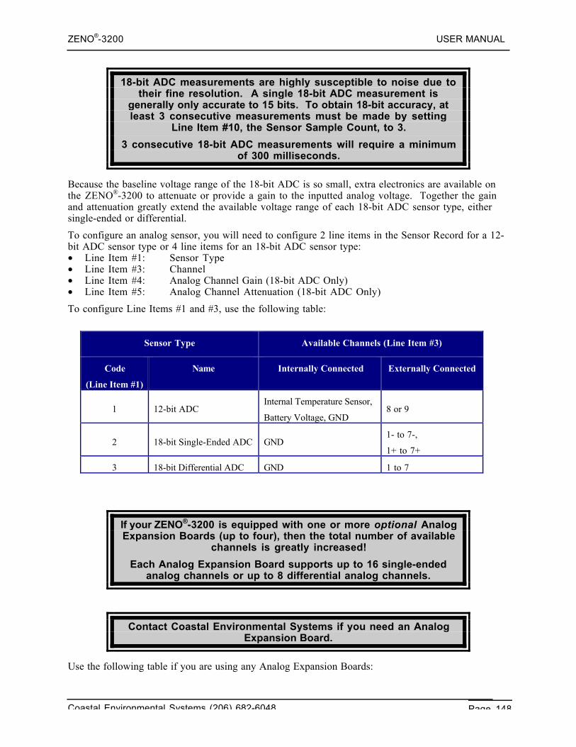
ZENO®-3200 USER MANUAL
Coastal Environmental Systems (206) 682-6048 Page 148
18-bit ADC measurements are highly susceptible to noise due totheir fine resolution. A single 18-bit ADC measurement is
generally only accurate to 15 bits. To obtain 18-bit accuracy, atleast 3 consecutive measurements must be made by setting
Line Item #10, the Sensor Sample Count, to 3.
3 consecutive 18-bit ADC measurements will require a minimumof 300 milliseconds.
Because the baseline voltage range of the 18-bit ADC is so small, extra electronics are available onthe ZENO®-3200 to attenuate or provide a gain to the inputted analog voltage. Together the gainand attenuation greatly extend the available voltage range of each 18-bit ADC sensor type, eithersingle-ended or differential.
To configure an analog sensor, you will need to configure 2 line items in the Sensor Record for a 12-bit ADC sensor type or 4 line items for an 18-bit ADC sensor type:• Line Item #1: Sensor Type• Line Item #3: Channel• Line Item #4: Analog Channel Gain (18-bit ADC Only)• Line Item #5: Analog Channel Attenuation (18-bit ADC Only)
To configure Line Items #1 and #3, use the following table:
Sensor Type Available Channels (Line Item #3)
Code
(Line Item #1)
Name Internally Connected Externally Connected
1 12-bit ADCInternal Temperature Sensor,
Battery Voltage, GND8 or 9
2 18-bit Single-Ended ADC GND1- to 7-,
1+ to 7+
3 18-bit Differential ADC GND 1 to 7
If your ZENO®-3200 is equipped with one or more optional AnalogExpansion Boards (up to four), then the total number of available
channels is greatly increased!
Each Analog Expansion Board supports up to 16 single-endedanalog channels or up to 8 differential analog channels.
Contact Coastal Environmental Systems if you need an AnalogExpansion Board.
Use the following table if you are using any Analog Expansion Boards:
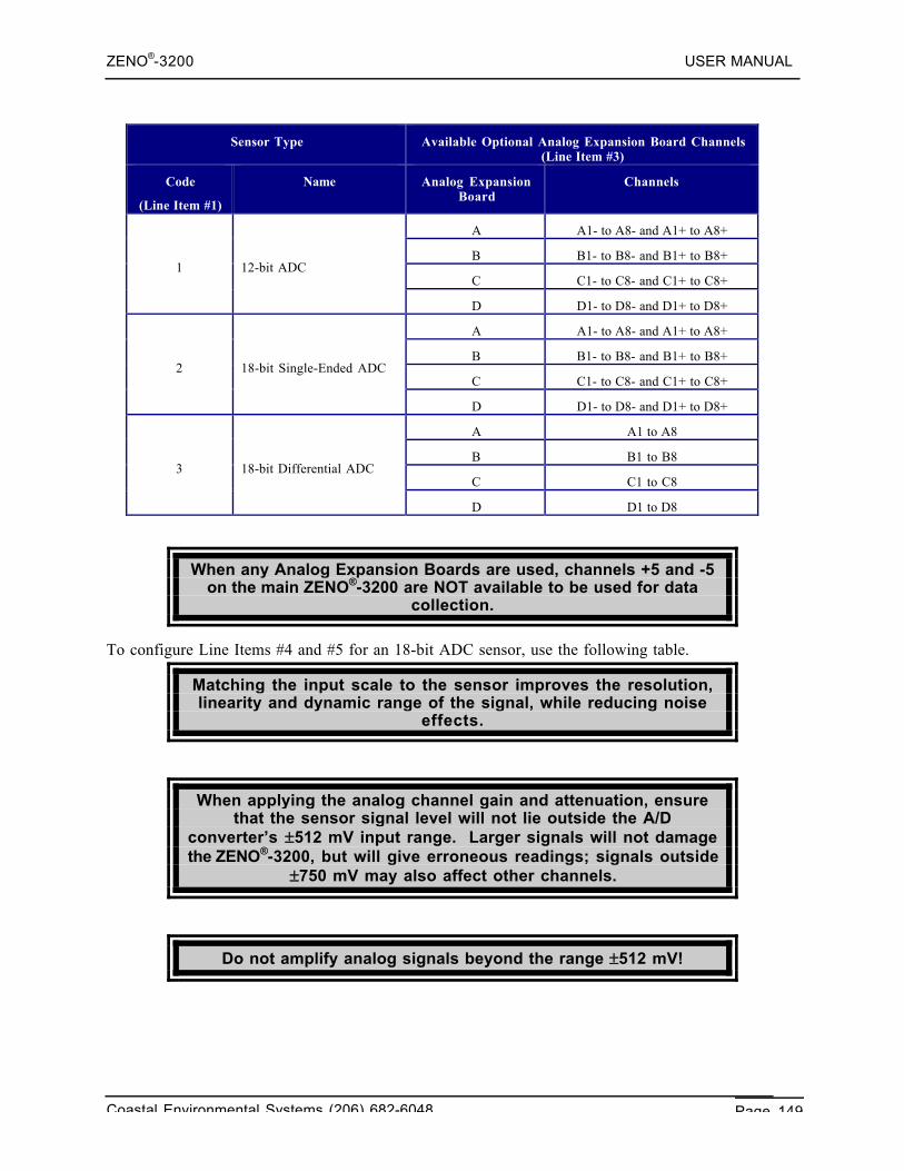
ZENO®-3200 USER MANUAL
Coastal Environmental Systems (206) 682-6048 Page 149
Sensor Type Available Optional Analog Expansion Board Channels(Line Item #3)
Code
(Line Item #1)
Name Analog ExpansionBoard
Channels
A A1- to A8- and A1+ to A8+
B B1- to B8- and B1+ to B8+
C C1- to C8- and C1+ to C8+1 12-bit ADC
D D1- to D8- and D1+ to D8+
A A1- to A8- and A1+ to A8+
B B1- to B8- and B1+ to B8+
C C1- to C8- and C1+ to C8+2 18-bit Single-Ended ADC
D D1- to D8- and D1+ to D8+
A A1 to A8
B B1 to B8
C C1 to C83 18-bit Differential ADC
D D1 to D8
When any Analog Expansion Boards are used, channels +5 and -5on the main ZENO®-3200 are NOT available to be used for data
collection.
To configure Line Items #4 and #5 for an 18-bit ADC sensor, use the following table.
Matching the input scale to the sensor improves the resolution,linearity and dynamic range of the signal, while reducing noise
effects.
When applying the analog channel gain and attenuation, ensurethat the sensor signal level will not lie outside the A/D
converter’s ±512 mV input range. Larger signals will not damagethe ZENO®-3200, but will give erroneous readings; signals outside
±750 mV may also affect other channels.
Do not amplify analog signals beyond the range ±512 mV!
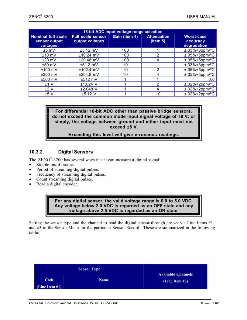
ZENO®-3200 USER MANUAL
Coastal Environmental Systems (206) 682-6048 Page 150
18-bit ADC Input voltage range selectionNominal full scale
sensor outputvoltages
Full scale sensoroutput voltages
Gain (Item 4) Attenuation(Item 5)
Worst-caseaccuracy
degradation±5 mV ±5.12 mV 100 1 ±.03%+3ppm/ºC
±10 mV ±10.24 mV 100 2 ±.05%+5ppm/ºC±20 mV ±20.48 mV 100 4 ±.05%+5ppm/ºC±50 mV ±51.2 mV 10 1 ±.03%+3ppm/ºC
±100 mV ±102.4 mV 10 2 ±.05%+5ppm/ºC±200 mV ±204.8 mV 10 4 ±.05%+5ppm/ºC±500 mV ±512 mV 1 1 0.0
±1 V ±1.024 V 1 2 ±.02%+2ppm/ºC±2 V ±2.048 V 1 4 ±.02%+2ppm/ºC±5 V ±5.12 V 1 10 ±.02%+2ppm/ºC
For differential 18-bit ADC other than passive bridge sensors,do not exceed the common mode input signal voltage of ±8 V; orsimply, the voltage between ground and either input must not
exceed ±8 V.
Exceeding this level will give erroneous readings.
10.3.2. Digital Sensors
The ZENO®-3200 has several ways that it can measure a digital signal:• Simple on/off status.• Period of streaming digital pulses.• Frequency of streaming digital pulses.• Count streaming digital pulses.• Read a digital encoder.
For any digital sensor, the valid voltage range is 0.0 to 5.0 VDC.Any voltage below 2.0 VDC is regarded as an OFF state and any
voltage above 2.5 VDC is regarded as an ON state.
Setting the sensor type and the channel to read the digital sensor through are set via Line Items #1and #3 in the Sensor Menu for the particular Sensor Record. These are summarized in the followingtable:
Sensor Type
Code
(Line Item #1)
NameAvailable Channels
(Line Item #3)
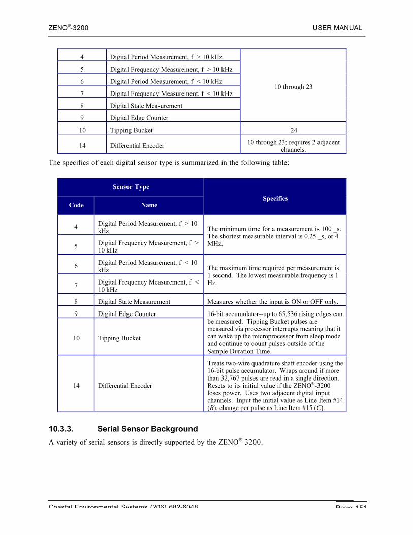
ZENO®-3200 USER MANUAL
Coastal Environmental Systems (206) 682-6048 Page 151
4 Digital Period Measurement, f > 10 kHz
5 Digital Frequency Measurement, f > 10 kHz
6 Digital Period Measurement, f < 10 kHz
7 Digital Frequency Measurement, f < 10 kHz
8 Digital State Measurement
9 Digital Edge Counter
10 through 23
10 Tipping Bucket 24
14 Differential Encoder 10 through 23; requires 2 adjacentchannels.
The specifics of each digital sensor type is summarized in the following table:
Sensor Type
Code NameSpecifics
4 Digital Period Measurement, f > 10kHz
5 Digital Frequency Measurement, f >10 kHz
The minimum time for a measurement is 100 _s.The shortest measurable interval is 0.25 _s, or 4MHz.
6 Digital Period Measurement, f < 10kHz
7 Digital Frequency Measurement, f <10 kHz
The maximum time required per measurement is1 second. The lowest measurable frequency is 1Hz.
8 Digital State Measurement Measures whether the input is ON or OFF only.
9 Digital Edge Counter
10 Tipping Bucket
16-bit accumulator--up to 65,536 rising edges canbe measured. Tipping Bucket pulses aremeasured via processor interrupts meaning that itcan wake up the microprocessor from sleep modeand continue to count pulses outside of theSample Duration Time.
14 Differential Encoder
Treats two-wire quadrature shaft encoder using the16-bit pulse accumulator. Wraps around if morethan 32,767 pulses are read in a single direction.Resets to its initial value if the ZENO®-3200loses power. Uses two adjacent digital inputchannels. Input the initial value as Line Item #14(B), change per pulse as Line Item #15 (C).
10.3.3. Serial Sensor Background
A variety of serial sensors is directly supported by the ZENO®-3200.
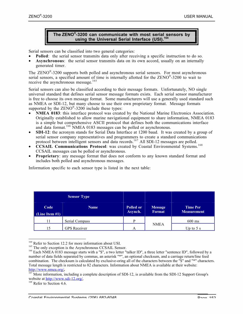
ZENO®-3200 USER MANUAL
Coastal Environmental Systems (206) 682-6048 Page 152
The ZENO®-3200 can communicate with most serial sensors byusing the Universal Serial Interface (USI).164
Serial sensors can be classified into two general categories:• Polled: the serial sensor transmits data only after receiving a specific instruction to do so.• Asynchronous: the serial sensor transmits data on its own accord, usually on an internally
generated timer.
The ZENO®-3200 supports both polled and asynchronous serial sensors. For most asynchronousserial sensors, a specified amount of time is internally allotted for the ZENO®-3200 to wait toreceive the asynchronous message.165
Serial sensors can also be classified according to their message formats. Unfortunately, NO singleuniversal standard that defines serial sensor message formats exists. Each serial sensor manufactureris free to choose its own message format. Some manufacturers will use a generally used standard suchas NMEA or SDI-12, but many choose to use their own proprietary format. Message formatssupported by the ZENO®-3200 include these types:• NMEA 0183: this interface protocol was created by the National Marine Electronics Association.
Originally established to allow marine navigational equipment to share information, NMEA 0183is a simple but comprehensive ASCII protocol that defines both the communications interfaceand data format.166 NMEA 0183 messages can be polled or asynchronous.
• SDI-12: the acronym stands for Serial Data Interface at 1200 baud. It was created by a group ofserial sensor company representatives and programmers to create a standard communicationsprotocol between intelligent sensors and data records.167 All SDI-12 messages are polled.
• CCSAIL Communications Protocol: was created by Coastal Environmental Systems.168
CCSAIL messages can be polled or asynchronous.• Proprietary: any message format that does not conform to any known standard format and
includes both polled and asynchronous messages.
Information specific to each sensor type is listed in the next table:
Sensor Type
Code
(Line Item #1)
Name Polled orAsynch.
MessageFormat
Time PerMeasurement
11 Serial Compass P 600 ms
15 GPS Receiver ANMEA
Up to 5 s
164 Refer to Section 12.2 for more information about USI.165 The only exception is the Asynchronous CCSAIL Sensor.166 Each NMEA 0183 message starts with a "$", a two letter "talker ID", a three letter "sentence ID", followed by anumber of data fields separated by commas, an asterisk "*", an optional checksum, and a carriage return/line feedcombination. The checksum is calculated by exclusive-oring all of the characters between the "$" and "*" characters.Total message length is restricted to 82 characters. Information about NMEA is available at their website:http://www.nmea.org/ .167 More information, including a complete description of SDI-12, is available from the SDI-12 Support Group'swebsite at http://www.sdi-12.org/ .168 Refer to Section 4.6.
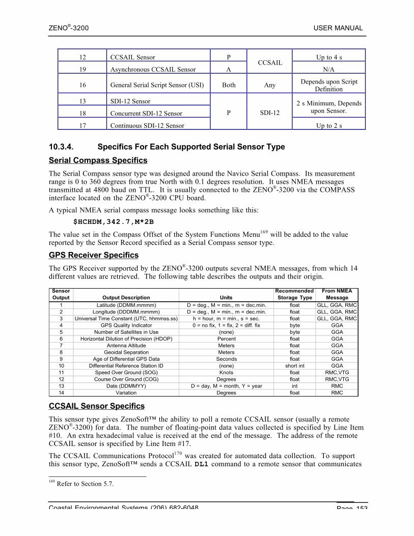
ZENO®-3200 USER MANUAL
Coastal Environmental Systems (206) 682-6048 Page 153
12 CCSAIL Sensor P Up to 4 s
19 Asynchronous CCSAIL Sensor ACCSAIL
N/A
16 General Serial Script Sensor (USI) Both Any Depends upon ScriptDefinition
13 SDI-12 Sensor
18 Concurrent SDI-12 Sensor
2 s Minimum, Dependsupon Sensor.
17 Continuous SDI-12 Sensor
P SDI-12
Up to 2 s
10.3.4. Specifics For Each Supported Serial Sensor Type
Serial Compass Specifics
The Serial Compass sensor type was designed around the Navico Serial Compass. Its measurementrange is 0 to 360 degrees from true North with 0.1 degrees resolution. It uses NMEA messagestransmitted at 4800 baud on TTL. It is usually connected to the ZENO®-3200 via the COMPASSinterface located on the ZENO®-3200 CPU board.
A typical NMEA serial compass message looks something like this:
$HCHDM,342.7,M*2B
The value set in the Compass Offset of the System Functions Menu169 will be added to the valuereported by the Sensor Record specified as a Serial Compass sensor type.
GPS Receiver Specifics
The GPS Receiver supported by the ZENO®-3200 outputs several NMEA messages, from which 14different values are retrieved. The following table describes the outputs and their origin.
CCSAIL Sensor Specifics
This sensor type gives ZenoSoft™ the ability to poll a remote CCSAIL sensor (usually a remoteZENO®-3200) for data. The number of floating-point data values collected is specified by Line Item#10. An extra hexadecimal value is received at the end of the message. The address of the remoteCCSAIL sensor is specified by Line Item #17.
The CCSAIL Communications Protocol170 was created for automated data collection. To supportthis sensor type, ZenoSoft™ sends a CCSAIL DL1 command to a remote sensor that communicates
169 Refer to Section 5.7.
Sensor Output Output Description Units
Recommended Storage Type
From NMEA Message
1 Latitude (DDMM.mmmm) D = deg., M = min., m = dec.min. float GLL, GGA, RMC2 Longitude (DDDMM.mmmm) D = deg., M = min., m = dec.min. float GLL, GGA, RMC3 Universal Time Constant (UTC, hhmmss.ss) h = hour, m = min., s = sec. float GLL, GGA, RMC4 GPS Quality Indicator 0 = no fix, 1 = fix, 2 = diff. fix byte GGA5 Number of Satellites in Use (none) byte GGA6 Horizontal Dilution of Precision (HDOP) Percent float GGA7 Antenna Altitude Meters float GGA8 Geoidal Separation Meters float GGA9 Age of Differential GPS Data Seconds float GGA10 Differential Reference Station ID (none) short int GGA11 Speed Over Ground (SOG) Knots float RMC,VTG12 Course Over Ground (COG) Degrees float RMC,VTG13 Date (DDMMYY) D = day, M = month, Y = year int RMC14 Variation Degrees float RMC
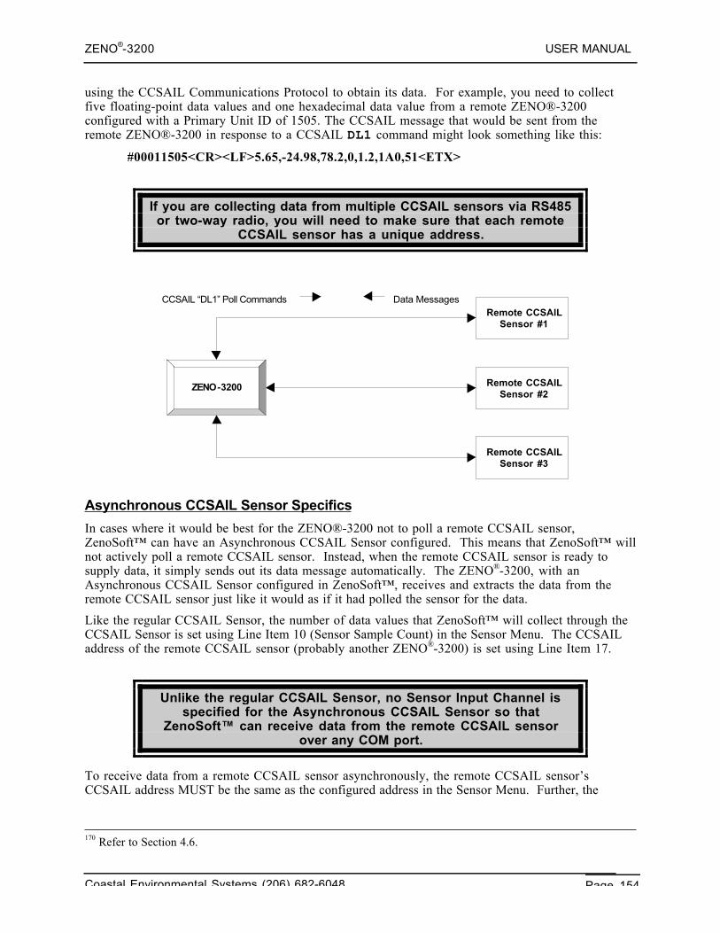
ZENO®-3200 USER MANUAL
Coastal Environmental Systems (206) 682-6048 Page 154
using the CCSAIL Communications Protocol to obtain its data. For example, you need to collectfive floating-point data values and one hexadecimal data value from a remote ZENO®-3200configured with a Primary Unit ID of 1505. The CCSAIL message that would be sent from theremote ZENO®-3200 in response to a CCSAIL DL1 command might look something like this:
#00011505<CR><LF>5.65,-24.98,78.2,0,1.2,1A0,51<ETX>
If you are collecting data from multiple CCSAIL sensors via RS485or two-way radio, you will need to make sure that each remote
CCSAIL sensor has a unique address.
Asynchronous CCSAIL Sensor Specifics
In cases where it would be best for the ZENO®-3200 not to poll a remote CCSAIL sensor,ZenoSoft™ can have an Asynchronous CCSAIL Sensor configured. This means that ZenoSoft™ willnot actively poll a remote CCSAIL sensor. Instead, when the remote CCSAIL sensor is ready tosupply data, it simply sends out its data message automatically. The ZENO®-3200, with anAsynchronous CCSAIL Sensor configured in ZenoSoft™, receives and extracts the data from theremote CCSAIL sensor just like it would as if it had polled the sensor for the data.
Like the regular CCSAIL Sensor, the number of data values that ZenoSoft™ will collect through theCCSAIL Sensor is set using Line Item 10 (Sensor Sample Count) in the Sensor Menu. The CCSAILaddress of the remote CCSAIL sensor (probably another ZENO®-3200) is set using Line Item 17.
Unlike the regular CCSAIL Sensor, no Sensor Input Channel isspecified for the Asynchronous CCSAIL Sensor so that
ZenoSoft™ can receive data from the remote CCSAIL sensorover any COM port.
To receive data from a remote CCSAIL sensor asynchronously, the remote CCSAIL sensor’sCCSAIL address MUST be the same as the configured address in the Sensor Menu. Further, the
170 Refer to Section 4.6.
Remote CCSAIL Sensor #1
Remote CCSAIL Sensor #2
Remote CCSAIL Sensor #3
ZENO-3200
Data Messages CCSAIL “DL1” Poll Commands
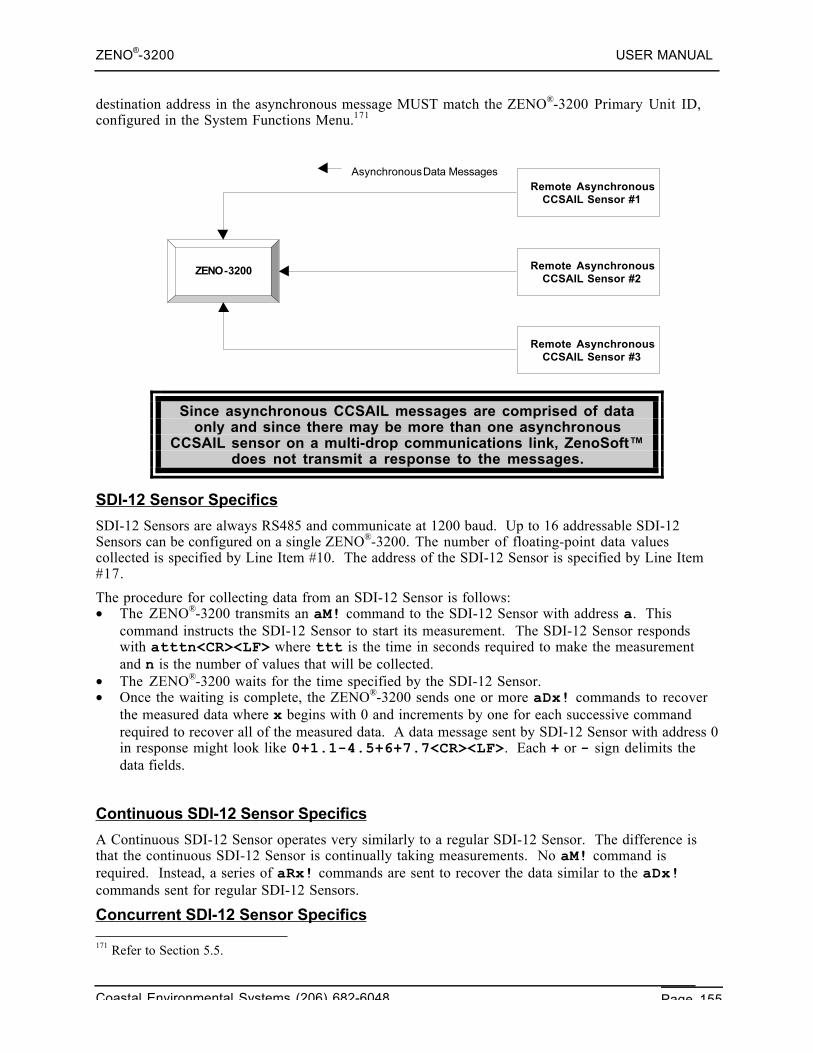
ZENO®-3200 USER MANUAL
Coastal Environmental Systems (206) 682-6048 Page 155
destination address in the asynchronous message MUST match the ZENO®-3200 Primary Unit ID,configured in the System Functions Menu.171
Since asynchronous CCSAIL messages are comprised of dataonly and since there may be more than one asynchronous
CCSAIL sensor on a multi-drop communications link, ZenoSoft™does not transmit a response to the messages.
SDI-12 Sensor Specifics
SDI-12 Sensors are always RS485 and communicate at 1200 baud. Up to 16 addressable SDI-12Sensors can be configured on a single ZENO®-3200. The number of floating-point data valuescollected is specified by Line Item #10. The address of the SDI-12 Sensor is specified by Line Item#17.
The procedure for collecting data from an SDI-12 Sensor is follows:• The ZENO®-3200 transmits an aM! command to the SDI-12 Sensor with address a. This
command instructs the SDI-12 Sensor to start its measurement. The SDI-12 Sensor respondswith atttn<CR><LF> where ttt is the time in seconds required to make the measurementand n is the number of values that will be collected.
• The ZENO®-3200 waits for the time specified by the SDI-12 Sensor.• Once the waiting is complete, the ZENO®-3200 sends one or more aDx! commands to recover
the measured data where x begins with 0 and increments by one for each successive commandrequired to recover all of the measured data. A data message sent by SDI-12 Sensor with address 0in response might look like 0+1.1-4.5+6+7.7<CR><LF>. Each + or - sign delimits thedata fields.
Continuous SDI-12 Sensor Specifics
A Continuous SDI-12 Sensor operates very similarly to a regular SDI-12 Sensor. The difference isthat the continuous SDI-12 Sensor is continually taking measurements. No aM! command isrequired. Instead, a series of aRx! commands are sent to recover the data similar to the aDx!commands sent for regular SDI-12 Sensors.
Concurrent SDI-12 Sensor Specifics 171 Refer to Section 5.5.
Remote Asynchronous CCSAIL Sensor #1
Remote Asynchronous CCSAIL Sensor #2
Remote Asynchronous CCSAIL Sensor #3
ZENO-3200
Asynchronous Data Messages
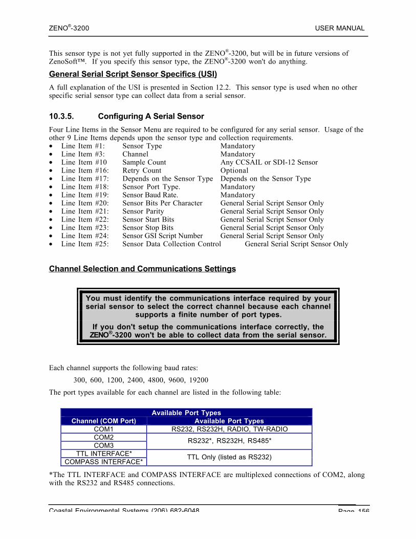
ZENO®-3200 USER MANUAL
Coastal Environmental Systems (206) 682-6048 Page 156
This sensor type is not yet fully supported in the ZENO®-3200, but will be in future versions ofZenoSoft™. If you specify this sensor type, the ZENO®-3200 won't do anything.
General Serial Script Sensor Specifics (USI)
A full explanation of the USI is presented in Section 12.2. This sensor type is used when no otherspecific serial sensor type can collect data from a serial sensor.
10.3.5. Configuring A Serial Sensor
Four Line Items in the Sensor Menu are required to be configured for any serial sensor. Usage of theother 9 Line Items depends upon the sensor type and collection requirements.• Line Item #1: Sensor Type Mandatory• Line Item #3: Channel Mandatory• Line Item #10 Sample Count Any CCSAIL or SDI-12 Sensor• Line Item #16: Retry Count Optional• Line Item #17: Depends on the Sensor Type Depends on the Sensor Type• Line Item #18: Sensor Port Type. Mandatory• Line Item #19: Sensor Baud Rate. Mandatory• Line Item #20: Sensor Bits Per Character General Serial Script Sensor Only• Line Item #21: Sensor Parity General Serial Script Sensor Only• Line Item #22: Sensor Start Bits General Serial Script Sensor Only• Line Item #23: Sensor Stop Bits General Serial Script Sensor Only• Line Item #24: Sensor GSI Script Number General Serial Script Sensor Only• Line Item #25: Sensor Data Collection Control General Serial Script Sensor Only
Channel Selection and Communications Settings
You must identify the communications interface required by yourserial sensor to select the correct channel because each channel
supports a finite number of port types.
If you don't setup the communications interface correctly, theZENO®-3200 won't be able to collect data from the serial sensor.
Each channel supports the following baud rates:
300, 600, 1200, 2400, 4800, 9600, 19200
The port types available for each channel are listed in the following table:
Available Port TypesChannel (COM Port) Available Port Types
COM1 RS232, RS232H, RADIO, TW-RADIOCOM2COM3
RS232*, RS232H, RS485*
TTL INTERFACE*COMPASS INTERFACE*
TTL Only (listed as RS232)
*The TTL INTERFACE and COMPASS INTERFACE are multiplexed connections of COM2, alongwith the RS232 and RS485 connections.
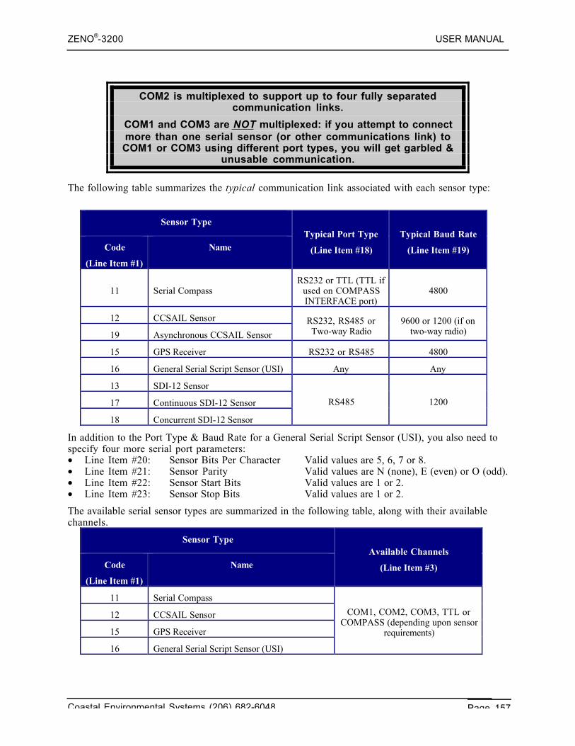
ZENO®-3200 USER MANUAL
Coastal Environmental Systems (206) 682-6048 Page 157
COM2 is multiplexed to support up to four fully separatedcommunication links.
COM1 and COM3 are NOT multiplexed: if you attempt to connectmore than one serial sensor (or other communications link) toCOM1 or COM3 using different port types, you will get garbled &
unusable communication.
The following table summarizes the typical communication link associated with each sensor type:
Sensor Type
Code
(Line Item #1)
NameTypical Port Type
(Line Item #18)
Typical Baud Rate
(Line Item #19)
11 Serial CompassRS232 or TTL (TTL if
used on COMPASSINTERFACE port)
4800
12 CCSAIL Sensor
19 Asynchronous CCSAIL Sensor
RS232, RS485 orTwo-way Radio
9600 or 1200 (if ontwo-way radio)
15 GPS Receiver RS232 or RS485 4800
16 General Serial Script Sensor (USI) Any Any
13 SDI-12 Sensor
17 Continuous SDI-12 Sensor
18 Concurrent SDI-12 Sensor
RS485 1200
In addition to the Port Type & Baud Rate for a General Serial Script Sensor (USI), you also need tospecify four more serial port parameters:• Line Item #20: Sensor Bits Per Character Valid values are 5, 6, 7 or 8.• Line Item #21: Sensor Parity Valid values are N (none), E (even) or O (odd).• Line Item #22: Sensor Start Bits Valid values are 1 or 2.• Line Item #23: Sensor Stop Bits Valid values are 1 or 2.
The available serial sensor types are summarized in the following table, along with their availablechannels.
Sensor Type
Code
(Line Item #1)
NameAvailable Channels
(Line Item #3)
11 Serial Compass
12 CCSAIL Sensor
15 GPS Receiver
16 General Serial Script Sensor (USI)
COM1, COM2, COM3, TTL orCOMPASS (depending upon sensor
requirements)
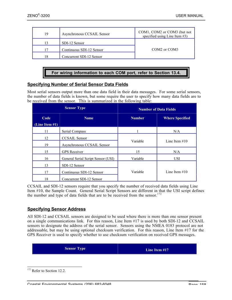
ZENO®-3200 USER MANUAL
Coastal Environmental Systems (206) 682-6048 Page 158
19 Asynchronous CCSAIL Sensor COM1, COM2 or COM3 (but notspecified using Line Item #3)
13 SDI-12 Sensor
17 Continuous SDI-12 Sensor
18 Concurrent SDI-12 Sensor
COM2 or COM3
For wiring information to each COM port, refer to Section 13.4.
Specifying Number of Serial Sensor Data Fields
Most serial sensors output more than one data field in their data messages. For some serial sensors,the number of data fields is known, but some require the user to specify how many data fields are tobe received from the sensor. This is summarized in the following table:
Sensor Type Number of Data Fields
Code
(Line Item #1)
Name Number Where Specified
11 Serial Compass 1 N/A
12 CCSAIL Sensor
19 Asynchronous CCSAIL SensorVariable Line Item #10
15 GPS Receiver 15 N/A
16 General Serial Script Sensor (USI) Variable USI
13 SDI-12 Sensor
17 Continuous SDI-12 Sensor
18 Concurrent SDI-12 Sensor
Variable Line Item #10
CCSAIL and SDI-12 sensors require that you specify the number of received data fields using LineItem #10, the Sample Count. General Serial Script Sensors are different in that the USI script definesthe number and type of data fields that are to be received from the sensor.172
Specifying Sensor Address
All SDI-12 and CCSAIL sensors are designed to be used where there is more than one sensor presenton a single communications link. For this reason, Line Item #17 is used by both SDI-12 and CCSAILsensors to designate the address of the serial sensor. Sensors using the NMEA 0183 protocol are notaddressable, but may be using optional checksum verification. For this reason, Line Item #17 for theGPS Receiver is used to specify whether to use checksum verification on received GPS messages.
Sensor Type Line Item #17
172 Refer to Section 12.2.
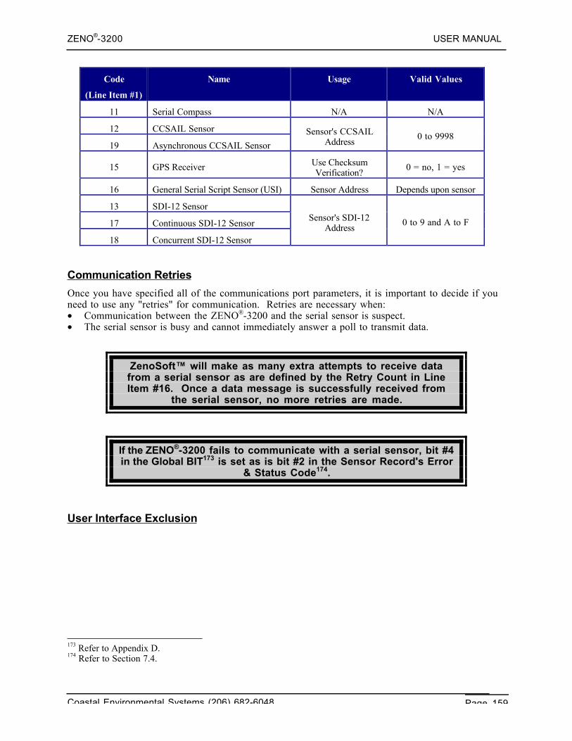
ZENO®-3200 USER MANUAL
Coastal Environmental Systems (206) 682-6048 Page 159
Code
(Line Item #1)
Name Usage Valid Values
11 Serial Compass N/A N/A
12 CCSAIL Sensor
19 Asynchronous CCSAIL Sensor
Sensor's CCSAILAddress
0 to 9998
15 GPS Receiver Use ChecksumVerification?
0 = no, 1 = yes
16 General Serial Script Sensor (USI) Sensor Address Depends upon sensor
13 SDI-12 Sensor
17 Continuous SDI-12 Sensor
18 Concurrent SDI-12 Sensor
Sensor's SDI-12Address
0 to 9 and A to F
Communication Retries
Once you have specified all of the communications port parameters, it is important to decide if youneed to use any "retries" for communication. Retries are necessary when:• Communication between the ZENO®-3200 and the serial sensor is suspect.• The serial sensor is busy and cannot immediately answer a poll to transmit data.
ZenoSoft™ will make as many extra attempts to receive datafrom a serial sensor as are defined by the Retry Count in LineItem #16. Once a data message is successfully received from
the serial sensor, no more retries are made.
If the ZENO®-3200 fails to communicate with a serial sensor, bit #4in the Global BIT173 is set as is bit #2 in the Sensor Record's Error
& Status Code174.
User Interface Exclusion
173 Refer to Appendix D.174 Refer to Section 7.4.
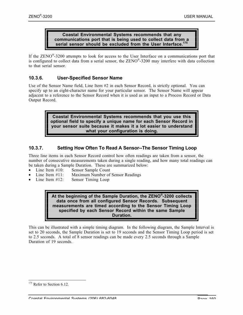
ZENO®-3200 USER MANUAL
Coastal Environmental Systems (206) 682-6048 Page 160
Coastal Environmental Systems recommends that anycommunications port that is being used to collect data from aserial sensor should be excluded from the User Interface.175
If the ZENO®-3200 attempts to look for access to the User Interface on a communications port thatis configured to collect data from a serial sensor, the ZENO®-3200 may interfere with data collectionto that serial sensor.
10.3.6. User-Specified Sensor Name
Use of the Sensor Name field, Line Item #2 in each Sensor Record, is strictly optional. You canspecify up to an eight-character name for your particular sensor. The Sensor Name will appearadjacent to a reference to the Sensor Record when it is used as an input to a Process Record or DataOutput Record.
Coastal Environmental Systems recommends that you use thisoptional field to specify a unique name for each Sensor Record inyour sensor suite because it makes it a lot easier to understand
what your configuration is doing.
10.3.7. Setting How Often To Read A Sensor--The Sensor Timing Loop
Three line items in each Sensor Record control how often readings are taken from a sensor, thenumber of consecutive measurements taken during a single reading, and how many total readings canbe taken during a Sample Duration. These are summarized below:• Line Item #10: Sensor Sample Count• Line Item #11: Maximum Number of Sensor Readings• Line Item #12: Sensor Timing Loop
At the beginning of the Sample Duration, the ZENO®-3200 collectsdata once from all configured Sensor Records. Subsequent
measurements are timed according to the Sensor Timing Loopspecified by each Sensor Record within the same Sample
Duration.
This can be illustrated with a simple timing diagram. In the following diagram, the Sample Interval isset to 20 seconds, the Sample Duration is set to 19 seconds and the Sensor Timing Loop period is setto 2.5 seconds. A total of 8 sensor readings can be made every 2.5 seconds through a SampleDuration of 19 seconds.
175 Refer to Section 6.12.
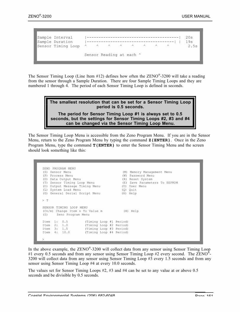
ZENO®-3200 USER MANUAL
Coastal Environmental Systems (206) 682-6048 Page 161
Sample Interval |---------------------------------------| 20sSample Duration |-------------------------------------| | 19sSensor Timing Loop ^ ^ ^ ^ ^ ^ ^ ^ 2.5s
Sensor Reading at each ^
The Sensor Timing Loop (Line Item #12) defines how often the ZENO®-3200 will take a readingfrom the sensor through a Sample Duration. There are four Sample Timing Loops and they arenumbered 1 through 4. The period of each Sensor Timing Loop is defined in seconds.
The smallest resolution that can be set for a Sensor Timing Loopperiod is 0.5 seconds.
The period for Sensor Timing Loop #1 is always set to 0.5seconds, but the settings for Sensor Timing Loops #2, #3 and #4
can be changed via the Sensor Timing Loop Menu.
The Sensor Timing Loop Menu is accessible from the Zeno Program Menu. If you are in the SensorMenu, return to the Zeno Program Menu by typing the command Z{ENTER}. Once in the ZenoProgram Menu, type the command T{ENTER} to enter the Sensor Timing Menu and the screenshould look something like this:
ZENO PROGRAM MENU(S) Sensor Menu (M) Memory Management Menu(P) Process Menu (W) Password Menu(D) Data Output Menu (R) Reset System(T) Sensor Timing Loop Menu (E) Save Parameters To EEPROM(O) Output Message Timing Menu (U) User Menu(L) System Load Menu (Q) Quit(G) General Serial Script Menu (H) Help
> T
SENSOR TIMING LOOP MENU(Cn/m) Change Item n To Value m (H) Help(Z) Zeno Program Menu
Item 1: 0.5 (Timing Loop #1 Period)Item 2: 1.0 (Timing Loop #2 Period)Item 3: 1.5 (Timing Loop #3 Period)Item 4: 10.0 (Timing Loop #4 Period)
>
In the above example, the ZENO®-3200 will collect data from any sensor using Sensor Timing Loop#1 every 0.5 seconds and from any sensor using Sensor Timing Loop #2 every second. The ZENO®-3200 will collect data from any sensor using Sensor Timing Loop #3 every 1.5 seconds and from anysensor using Sensor Timing Loop #4 at every 10.0 seconds.
The values set for Sensor Timing Loops #2, #3 and #4 can be set to any value at or above 0.5seconds and be divisible by 0.5 seconds.
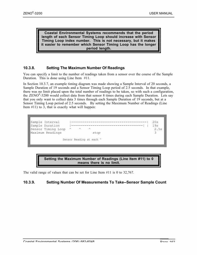
ZENO®-3200 USER MANUAL
Coastal Environmental Systems (206) 682-6048 Page 162
Coastal Environmental Systems recommends that the periodlength of each Sensor Timing Loop should increase with SensorTiming Loop index number. This is not necessary, but it makesit easier to remember which Sensor Timing Loop has the longer
period length.
10.3.8. Setting The Maximum Number Of Readings
You can specify a limit to the number of readings taken from a sensor over the course of the SampleDuration. This is done using Line Item #11.
In Section 10.3.7, an example timing diagram was made showing a Sample Interval of 20 seconds, aSample Duration of 19 seconds and a Sensor Timing Loop period of 2.5 seconds. In that example,there was no limit placed upon the total number of readings to be taken, so with such a configuration,the ZENO®-3200 would collect data from that sensor 8 times during each Sample Duration. Lets saythat you only want to collect data 3 times through each Sample Duration of 19 seconds, but at aSensor Timing Loop period of 2.5 seconds. By setting the Maximum Number of Readings (LineItem #11) to 3, that is exactly what will happen:
Sample Interval |---------------------------------------| 20sSample Duration |-------------------------------------| | 19sSensor Timing Loop ^ ^ ^ 2.5sMaximum Readings stop 3
Sensor Reading at each ^
Setting the Maximum Number of Readings (Line Item #11) to 0means there is no limit.
The valid range of values that can be set for Line Item #11 is 0 to 32,767.
10.3.9. Setting Number Of Measurements To Take--Sensor Sample Count
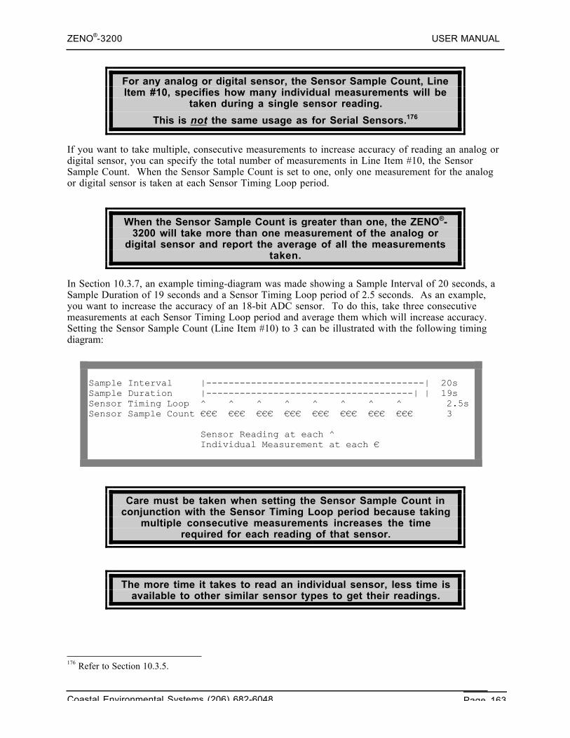
ZENO®-3200 USER MANUAL
Coastal Environmental Systems (206) 682-6048 Page 163
For any analog or digital sensor, the Sensor Sample Count, LineItem #10, specifies how many individual measurements will be
taken during a single sensor reading.
This is not the same usage as for Serial Sensors.176
If you want to take multiple, consecutive measurements to increase accuracy of reading an analog ordigital sensor, you can specify the total number of measurements in Line Item #10, the SensorSample Count. When the Sensor Sample Count is set to one, only one measurement for the analogor digital sensor is taken at each Sensor Timing Loop period.
When the Sensor Sample Count is greater than one, the ZENO®-3200 will take more than one measurement of the analog or
digital sensor and report the average of all the measurementstaken.
In Section 10.3.7, an example timing-diagram was made showing a Sample Interval of 20 seconds, aSample Duration of 19 seconds and a Sensor Timing Loop period of 2.5 seconds. As an example,you want to increase the accuracy of an 18-bit ADC sensor. To do this, take three consecutivemeasurements at each Sensor Timing Loop period and average them which will increase accuracy.Setting the Sensor Sample Count (Line Item #10) to 3 can be illustrated with the following timingdiagram:
Sample Interval |---------------------------------------| 20sSample Duration |-------------------------------------| | 19sSensor Timing Loop ^ ^ ^ ^ ^ ^ ^ ^ 2.5sSensor Sample Count €€€ €€€ €€€ €€€ €€€ €€€ €€€ €€€ 3
Sensor Reading at each ^ Individual Measurement at each €
Care must be taken when setting the Sensor Sample Count inconjunction with the Sensor Timing Loop period because taking
multiple consecutive measurements increases the timerequired for each reading of that sensor.
The more time it takes to read an individual sensor, less time isavailable to other similar sensor types to get their readings.
176 Refer to Section 10.3.5.
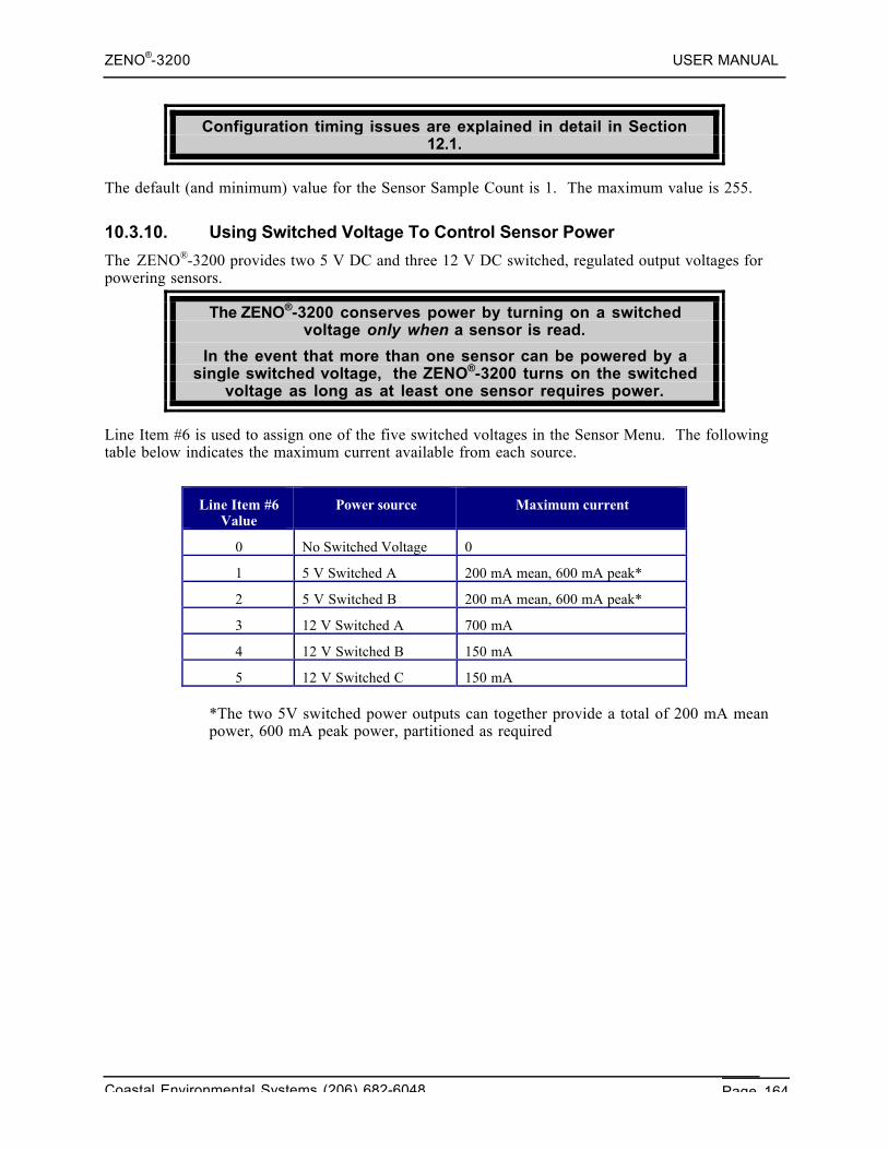
ZENO®-3200 USER MANUAL
Coastal Environmental Systems (206) 682-6048 Page 164
Configuration timing issues are explained in detail in Section12.1.
The default (and minimum) value for the Sensor Sample Count is 1. The maximum value is 255.
10.3.10. Using Switched Voltage To Control Sensor Power
The ZENO®-3200 provides two 5 V DC and three 12 V DC switched, regulated output voltages forpowering sensors.
The ZENO®-3200 conserves power by turning on a switchedvoltage only when a sensor is read.
In the event that more than one sensor can be powered by asingle switched voltage, the ZENO®-3200 turns on the switched
voltage as long as at least one sensor requires power.
Line Item #6 is used to assign one of the five switched voltages in the Sensor Menu. The followingtable below indicates the maximum current available from each source.
Line Item #6Value
Power source Maximum current
0 No Switched Voltage 0
1 5 V Switched A 200 mA mean, 600 mA peak*
2 5 V Switched B 200 mA mean, 600 mA peak*
3 12 V Switched A 700 mA
4 12 V Switched B 150 mA
5 12 V Switched C 150 mA
*The two 5V switched power outputs can together provide a total of 200 mA meanpower, 600 mA peak power, partitioned as required
ZENO®-3200 USER MANUAL
Coastal Environmental Systems (206) 682-6048 Page 165
Connect the sensor's positive power terminal to the sameswitched voltage on the ZENO®-3200 Front Panel177 as specified in
the ZenoSoft™ configuration.
Connect the sensor's negative power terminal (may also becalled common or return) to one of the grounds marked as GND
on the ZENO®-3200 Front Panel.178
Refer to Section 13.2 for a full discussion on grounding.
10.3.11. Specifying Warm-up Time For a Sensor Using Switched Voltage
Your sensor may require time to warm up prior to being read in order to provide accuratemeasurements. The ZENO®-3200 allows you to specify a Sensor Warm-up Time using Line Item #9in the Sensor Menu if your sensor is being powered by a switched voltage specified in Line Item#6.179
The ZENO®-3200 will turn on a switched voltage before the start ofa Sample Interval when the sensor requires time to warm up.
If the Sensor Warm-up Time is set to a value longer than theSample Interval, the ZENO®-3200 will always keep the designated
Switched Voltage on.
If more than one sensor is on the same Switched Voltage and allrequire warm-up time, the Switched Voltage will be turned on
based upon the sensor with the longest warm-up time.
No warm-up time will occur if no Switched Voltage is specifiedfor the sensor.
The valid range of values for the Sensor Warm-up Time (Line Item #9) is 0 to 255 seconds.
10.3.12. Using Excitation Voltage & Returns To Control Sensor Power
177 Refer to Section 2.1.178 Ibid.179 Refer to Section 10.3.10.
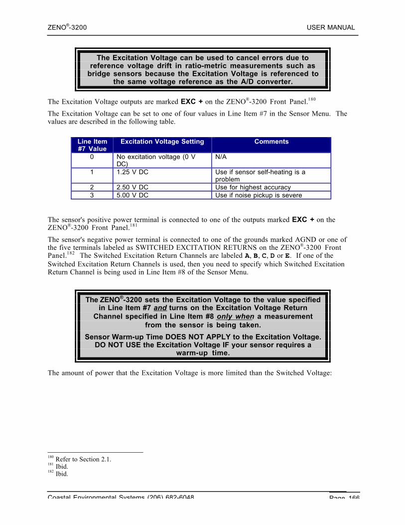
ZENO®-3200 USER MANUAL
Coastal Environmental Systems (206) 682-6048 Page 166
The Excitation Voltage can be used to cancel errors due toreference voltage drift in ratio-metric measurements such as
bridge sensors because the Excitation Voltage is referenced tothe same voltage reference as the A/D converter.
The Excitation Voltage outputs are marked EXC + on the ZENO®-3200 Front Panel.180
The Excitation Voltage can be set to one of four values in Line Item #7 in the Sensor Menu. Thevalues are described in the following table.
Line Item#7 Value
Excitation Voltage Setting Comments
0 No excitation voltage (0 VDC)
N/A
1 1.25 V DC Use if sensor self-heating is aproblem
2 2.50 V DC Use for highest accuracy3 5.00 V DC Use if noise pickup is severe
The sensor's positive power terminal is connected to one of the outputs marked EXC + on theZENO®-3200 Front Panel.181
The sensor's negative power terminal is connected to one of the grounds marked AGND or one ofthe five terminals labeled as SWITCHED EXCITATION RETURNS on the ZENO®-3200 FrontPanel.182 The Switched Excitation Return Channels are labeled A, B, C, D or E. If one of theSwitched Excitation Return Channels is used, then you need to specify which Switched ExcitationReturn Channel is being used in Line Item #8 of the Sensor Menu.
The ZENO®-3200 sets the Excitation Voltage to the value specifiedin Line Item #7 and turns on the Excitation Voltage Return
Channel specified in Line Item #8 only when a measurementfrom the sensor is being taken.
Sensor Warm-up Time DOES NOT APPLY to the Excitation Voltage.DO NOT USE the Excitation Voltage IF your sensor requires a
warm-up time.
The amount of power that the Excitation Voltage is more limited than the Switched Voltage:
180 Refer to Section 2.1.181 Ibid.182 Ibid.
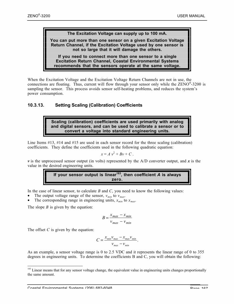
ZENO®-3200 USER MANUAL
Coastal Environmental Systems (206) 682-6048 Page 167
The Excitation Voltage can supply up to 100 mA.
You can put more than one sensor on a given Excitation VoltageReturn Channel, if the Excitation Voltage used by one sensor is
not so large that it will damage the others.
If you need to connect more than one sensor to a singleExcitation Return Channel, Coastal Environmental Systems
recommends that the sensors operate at the same voltage.
When the Excitation Voltage and the Excitation Voltage Return Channels are not in use, theconnections are floating. Thus, current will flow through your sensor only while the ZENO®-3200 issampling the sensor. This process avoids sensor self-heating problems, and reduces the system’spower consumption.
10.3.13. Setting Scaling (Calibration) Coefficients
Scaling (calibration) coefficients are used primarily with analogand digital sensors, and can be used to calibrate a sensor or to
convert a voltage into standard engineering units.
Line Items #13, #14 and #15 are used in each sensor record for the three scaling (calibration)coefficients. They define the coefficients used in the following quadratic equation:
x = A v2 + Bv + C .
v is the unprocessed sensor output (in volts) represented by the A/D converter output, and x is thevalue in the desired engineering units.
If your sensor output is linear183, then coefficient A is alwayszero.
In the case of linear sensor, to calculate B and C, you need to know the following values:• The output voltage range of the sensor, vmin to vmax.• The corresponding range in engineering units, xmin to xmax.
The slope B is given by the equation:
Bx x
v vmax min
max min=
−−
The offset C is given by the equation:
.minmax
minmaxmaxmin
vv
vxvxC
−−=
As an example, a sensor voltage range is 0 to 2.5 VDC and it represents the linear range of 0 to 355degrees in engineering units. To determine the coefficients B and C, you will obtain the following:
183 Linear means that for any sensor voltage change, the equivalent value in engineering units changes proportionallythe same amount.
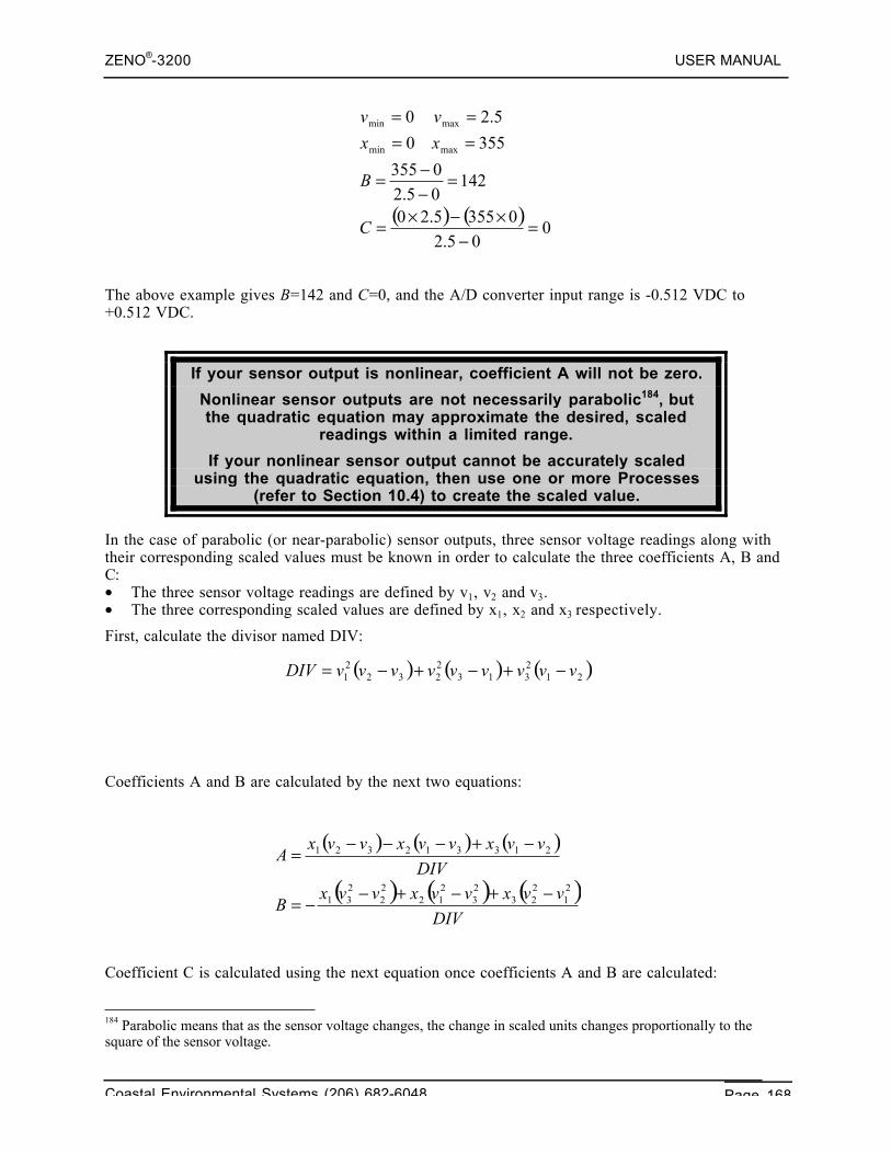
ZENO®-3200 USER MANUAL
Coastal Environmental Systems (206) 682-6048 Page 168
The above example gives B=142 and C=0, and the A/D converter input range is -0.512 VDC to+0.512 VDC.
If your sensor output is nonlinear, coefficient A will not be zero.
Nonlinear sensor outputs are not necessarily parabolic184, butthe quadratic equation may approximate the desired, scaled
readings within a limited range.
If your nonlinear sensor output cannot be accurately scaledusing the quadratic equation, then use one or more Processes
(refer to Section 10.4) to create the scaled value.
In the case of parabolic (or near-parabolic) sensor outputs, three sensor voltage readings along withtheir corresponding scaled values must be known in order to calculate the three coefficients A, B andC:• The three sensor voltage readings are defined by v1, v2 and v3.• The three corresponding scaled values are defined by x1, x2 and x3 respectively.
First, calculate the divisor named DIV:
Coefficients A and B are calculated by the next two equations:
Coefficient C is calculated using the next equation once coefficients A and B are calculated:
184 Parabolic means that as the sensor voltage changes, the change in scaled units changes proportionally to thesquare of the sensor voltage.
( ) ( ) ( )212313
2232
21 vvvvvvvvvDIV −+−+−=
( ) ( ) ( )
( ) ( ) ( )DIV
vvxvvxvvxB
DIV
vvxvvxvvxA
21
223
23
212
22
231
213312321
−+−+−−=
−+−−−=
( ) ( )0
05.203555.20
14205.20355
3550
5.20
maxmin
maxmin
=−
×−×=
=−−=
====
C
B
xx
vv
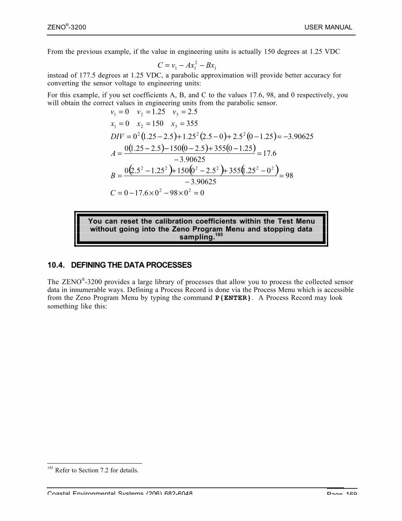
ZENO®-3200 USER MANUAL
Coastal Environmental Systems (206) 682-6048 Page 169
From the previous example, if the value in engineering units is actually 150 degrees at 1.25 VDC
instead of 177.5 degrees at 1.25 VDC, a parabolic approximation will provide better accuracy forconverting the sensor voltage to engineering units:
For this example, if you set coefficients A, B, and C to the values 17.6, 98, and 0 respectively, youwill obtain the correct values in engineering units from the parabolic sensor.
You can reset the calibration coefficients within the Test Menuwithout going into the Zeno Program Menu and stopping data
sampling.185
10.4. DEFINING THE DATA PROCESSES
The ZENO®-3200 provides a large library of processes that allow you to process the collected sensordata in innumerable ways. Defining a Process Record is done via the Process Menu which is accessiblefrom the Zeno Program Menu by typing the command P{ENTER}. A Process Record may looksomething like this:
185 Refer to Section 7.2 for details.
1211 BxAxvC −−=
( ) ( ) ( )( ) ( ) ( )
( ) ( ) ( )
009806.170
9890625.3
025.13555.2015025.15.20
6.1790625.3
25.103555.201505.225.10
90625.325.105.205.225.15.225.10
3551500
5.225.10
22
222222
222
321
321
=×−×−=
=−
−+−+−=
=−
−+−−−=
−=−+−+−=
======
C
B
A
DIV
xxx
vvv
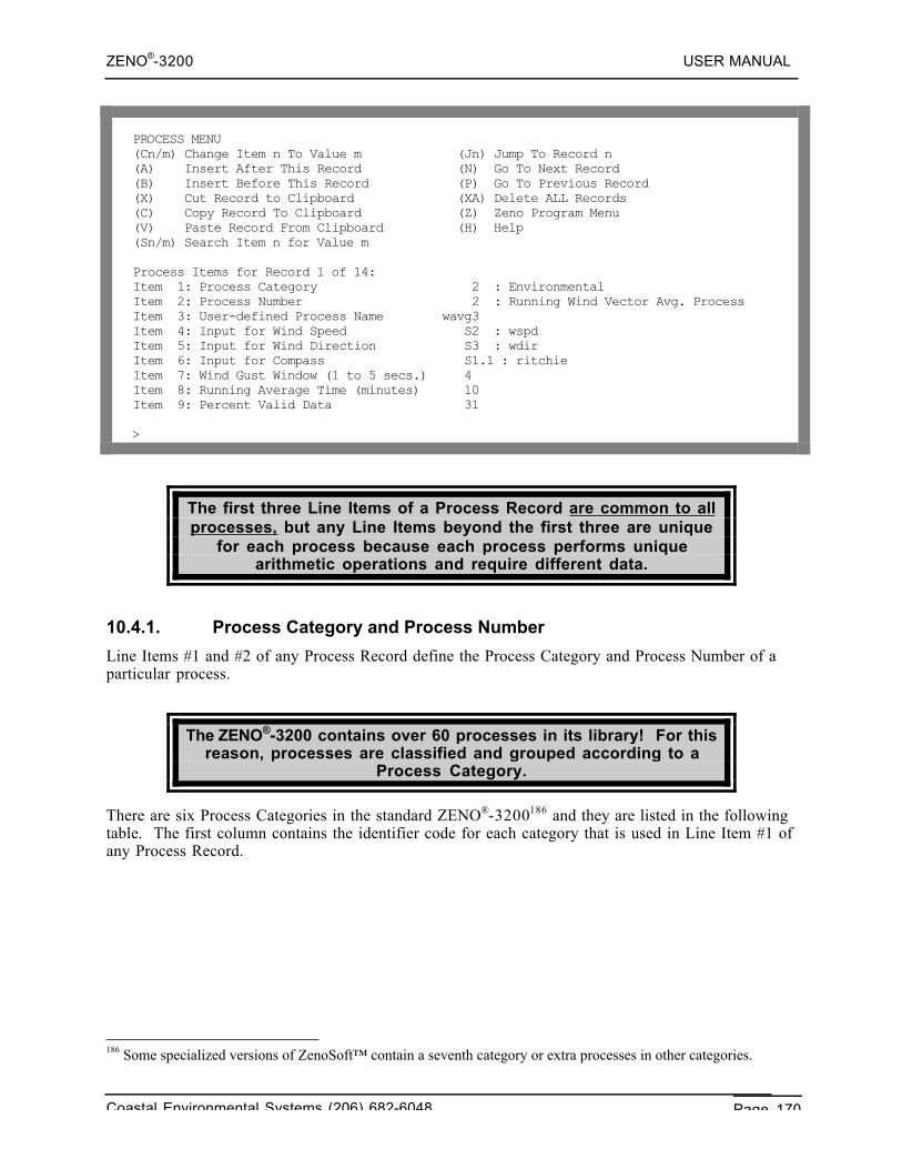
ZENO®-3200 USER MANUAL
Coastal Environmental Systems (206) 682-6048 Page 170
PROCESS MENU(Cn/m) Change Item n To Value m (Jn) Jump To Record n(A) Insert After This Record (N) Go To Next Record(B) Insert Before This Record (P) Go To Previous Record(X) Cut Record to Clipboard (XA) Delete ALL Records(C) Copy Record To Clipboard (Z) Zeno Program Menu(V) Paste Record From Clipboard (H) Help(Sn/m) Search Item n for Value m
Process Items for Record 1 of 14:Item 1: Process Category 2 : EnvironmentalItem 2: Process Number 2 : Running Wind Vector Avg. ProcessItem 3: User-defined Process Name wavg3Item 4: Input for Wind Speed S2 : wspdItem 5: Input for Wind Direction S3 : wdirItem 6: Input for Compass S1.1 : ritchieItem 7: Wind Gust Window (1 to 5 secs.) 4Item 8: Running Average Time (minutes) 10Item 9: Percent Valid Data 31
>
The first three Line Items of a Process Record are common to allprocesses, but any Line Items beyond the first three are unique
for each process because each process performs uniquearithmetic operations and require different data.
10.4.1. Process Category and Process Number
Line Items #1 and #2 of any Process Record define the Process Category and Process Number of aparticular process.
The ZENO®-3200 contains over 60 processes in its library! For thisreason, processes are classified and grouped according to a
Process Category.
There are six Process Categories in the standard ZENO®-3200186 and they are listed in the followingtable. The first column contains the identifier code for each category that is used in Line Item #1 ofany Process Record.
186 Some specialized versions of ZenoSoft™ contain a seventh category or extra processes in other categories.
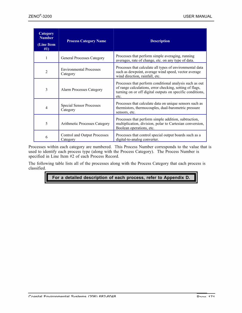
ZENO®-3200 USER MANUAL
Coastal Environmental Systems (206) 682-6048 Page 171
CategoryNumber
(Line Item#1)
Process Category Name Description
1 General Processes Category Processes that perform simple averaging, runningaverages, rate of change, etc. on any type of data.
2Environmental ProcessesCategory
Processes that calculate all types of environmental datasuch as dewpoint, average wind speed, vector averagewind direction, rainfall, etc.
3 Alarm Processes Category
Processes that perform conditional analysis such as outof range calculations, error checking, setting of flags,turning on or off digital outputs on specific conditions,etc.
4Special Sensor ProcessesCategory
Processes that calculate data on unique sensors such asthermistors, thermocouples, dual-barometric pressuresensors, etc.
5 Arithmetic Processes CategoryProcesses that perform simple addition, subtraction,multiplication, division, polar to Cartesian conversion,Boolean operations, etc.
6 Control and Output ProcessesCategory
Processes that control special output boards such as adigital-to-analog converter.
Processes within each category are numbered. This Process Number corresponds to the value that isused to identify each process type (along with the Process Category). The Process Number isspecified in Line Item #2 of each Process Record.
The following table lists all of the processes along with the Process Category that each process isclassified.
For a detailed description of each process, refer to Appendix D.
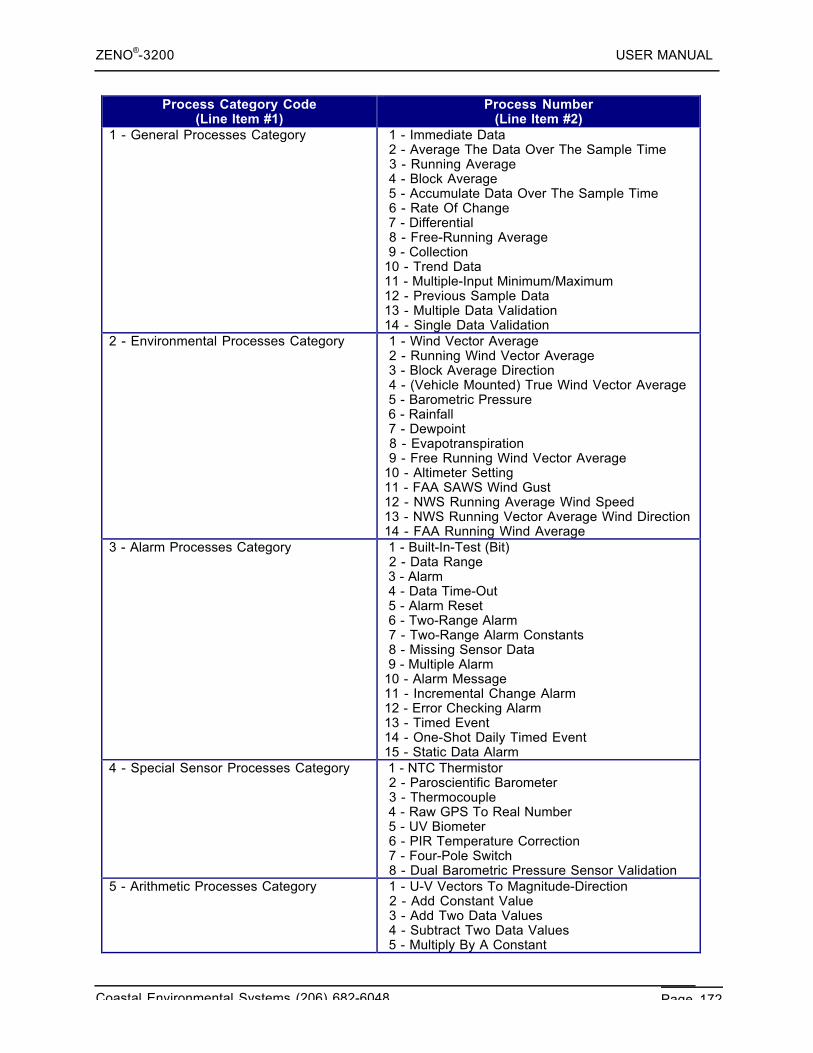
ZENO®-3200 USER MANUAL
Coastal Environmental Systems (206) 682-6048 Page 172
Process Category Code(Line Item #1)
Process Number(Line Item #2)
1 - General Processes Category 1 - Immediate Data 2 - Average The Data Over The Sample Time 3 - Running Average 4 - Block Average 5 - Accumulate Data Over The Sample Time 6 - Rate Of Change 7 - Differential 8 - Free-Running Average 9 - Collection10 - Trend Data11 - Multiple-Input Minimum/Maximum12 - Previous Sample Data13 - Multiple Data Validation14 - Single Data Validation
2 - Environmental Processes Category 1 - Wind Vector Average 2 - Running Wind Vector Average 3 - Block Average Direction 4 - (Vehicle Mounted) True Wind Vector Average 5 - Barometric Pressure 6 - Rainfall 7 - Dewpoint 8 - Evapotranspiration 9 - Free Running Wind Vector Average10 - Altimeter Setting11 - FAA SAWS Wind Gust12 - NWS Running Average Wind Speed13 - NWS Running Vector Average Wind Direction14 - FAA Running Wind Average
3 - Alarm Processes Category 1 - Built-In-Test (Bit) 2 - Data Range 3 - Alarm 4 - Data Time-Out 5 - Alarm Reset 6 - Two-Range Alarm 7 - Two-Range Alarm Constants 8 - Missing Sensor Data 9 - Multiple Alarm10 - Alarm Message11 - Incremental Change Alarm12 - Error Checking Alarm13 - Timed Event14 - One-Shot Daily Timed Event15 - Static Data Alarm
4 - Special Sensor Processes Category 1 - NTC Thermistor 2 - Paroscientific Barometer 3 - Thermocouple 4 - Raw GPS To Real Number 5 - UV Biometer 6 - PIR Temperature Correction 7 - Four-Pole Switch 8 - Dual Barometric Pressure Sensor Validation
5 - Arithmetic Processes Category 1 - U-V Vectors To Magnitude-Direction 2 - Add Constant Value 3 - Add Two Data Values 4 - Subtract Two Data Values 5 - Multiply By A Constant 6 - Multiply Two Data Values 7 - Divide Two Data Values 8 - Quadratic 9 - Invert Data Value10 - Raise Data Value To A Constant Power11 - Add Multiple Data Values12 - Polynomial13 - Conditional Select
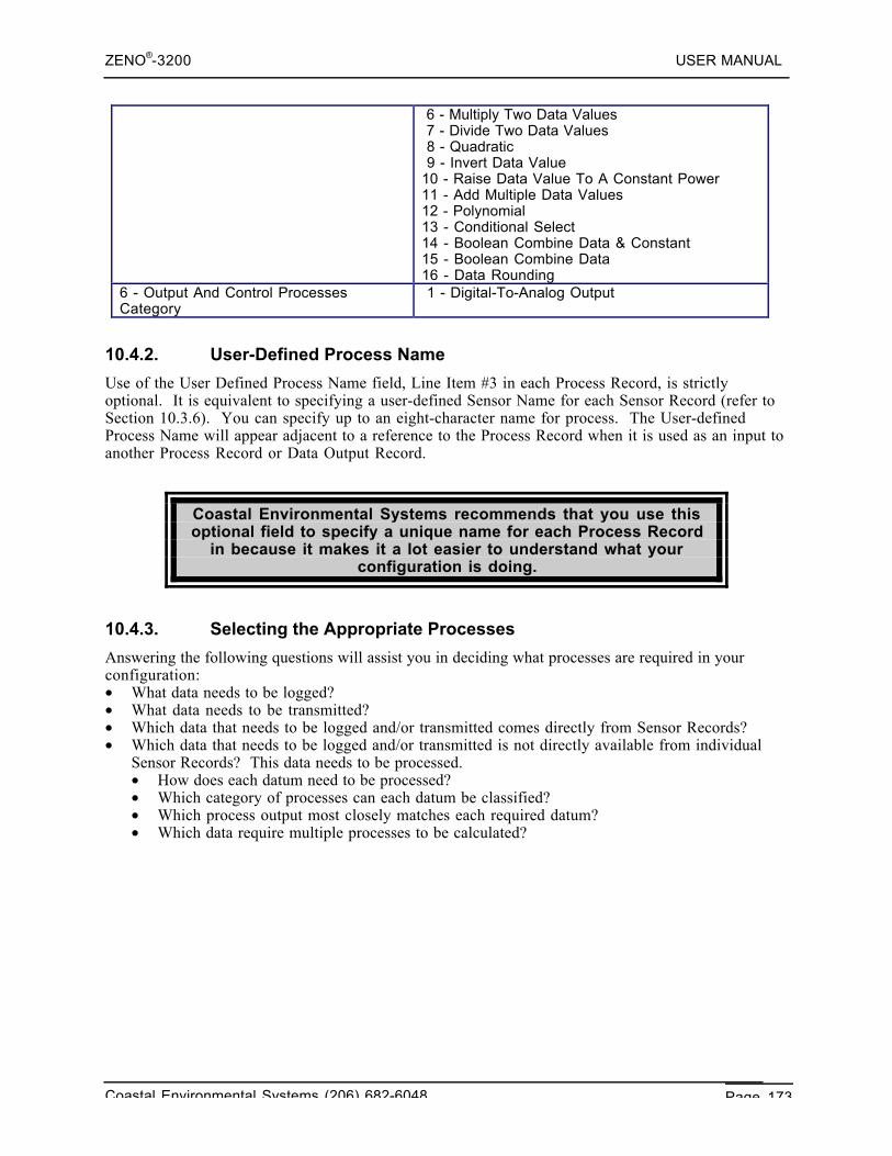
ZENO®-3200 USER MANUAL
Coastal Environmental Systems (206) 682-6048 Page 173
6 - Multiply Two Data Values 7 - Divide Two Data Values 8 - Quadratic 9 - Invert Data Value10 - Raise Data Value To A Constant Power11 - Add Multiple Data Values12 - Polynomial13 - Conditional Select14 - Boolean Combine Data & Constant15 - Boolean Combine Data16 - Data Rounding
6 - Output And Control ProcessesCategory
1 - Digital-To-Analog Output
10.4.2. User-Defined Process Name
Use of the User Defined Process Name field, Line Item #3 in each Process Record, is strictlyoptional. It is equivalent to specifying a user-defined Sensor Name for each Sensor Record (refer toSection 10.3.6). You can specify up to an eight-character name for process. The User-definedProcess Name will appear adjacent to a reference to the Process Record when it is used as an input toanother Process Record or Data Output Record.
Coastal Environmental Systems recommends that you use thisoptional field to specify a unique name for each Process Record
in because it makes it a lot easier to understand what yourconfiguration is doing.
10.4.3. Selecting the Appropriate Processes
Answering the following questions will assist you in deciding what processes are required in yourconfiguration:• What data needs to be logged?• What data needs to be transmitted?• Which data that needs to be logged and/or transmitted comes directly from Sensor Records?• Which data that needs to be logged and/or transmitted is not directly available from individual
Sensor Records? This data needs to be processed.• How does each datum need to be processed?• Which category of processes can each datum be classified?• Which process output most closely matches each required datum?• Which data require multiple processes to be calculated?
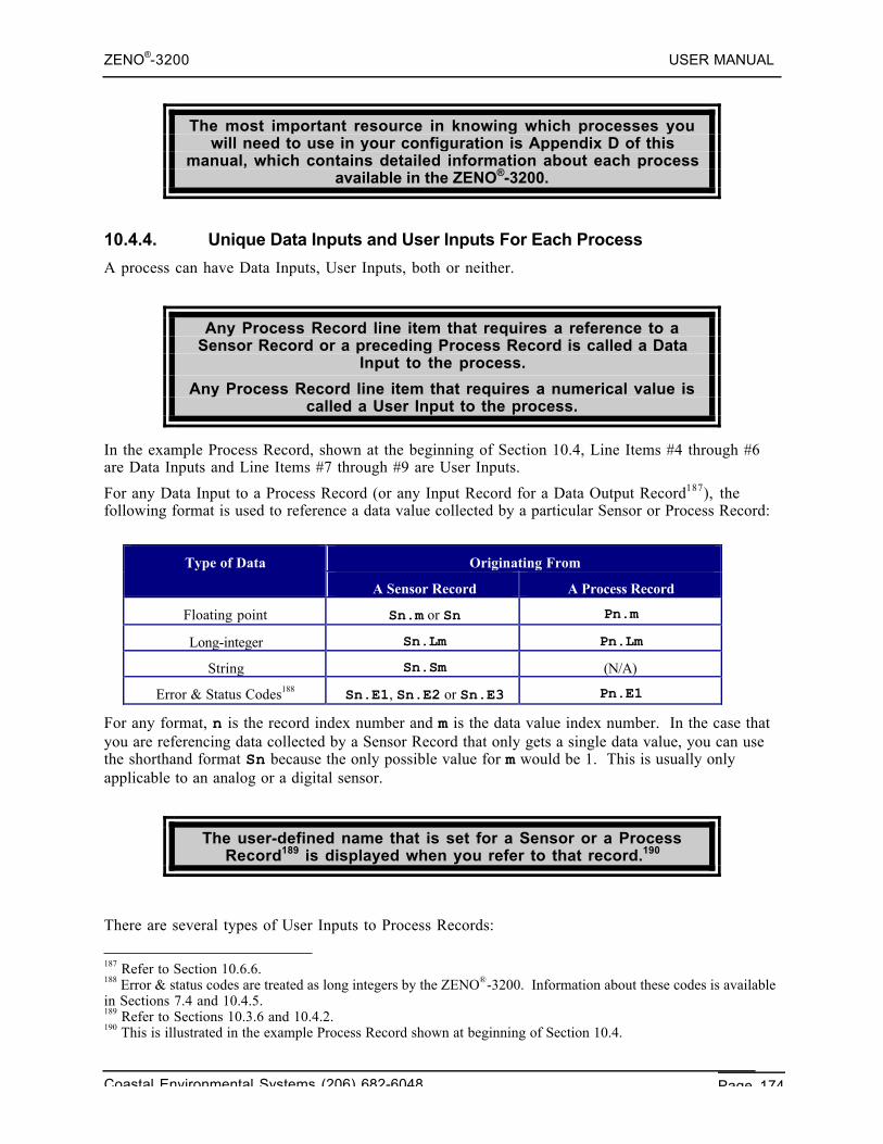
ZENO®-3200 USER MANUAL
Coastal Environmental Systems (206) 682-6048 Page 174
The most important resource in knowing which processes youwill need to use in your configuration is Appendix D of this
manual, which contains detailed information about each processavailable in the ZENO®-3200.
10.4.4. Unique Data Inputs and User Inputs For Each Process
A process can have Data Inputs, User Inputs, both or neither.
Any Process Record line item that requires a reference to aSensor Record or a preceding Process Record is called a Data
Input to the process.
Any Process Record line item that requires a numerical value iscalled a User Input to the process.
In the example Process Record, shown at the beginning of Section 10.4, Line Items #4 through #6are Data Inputs and Line Items #7 through #9 are User Inputs.
For any Data Input to a Process Record (or any Input Record for a Data Output Record187), thefollowing format is used to reference a data value collected by a particular Sensor or Process Record:
Originating FromType of Data
A Sensor Record A Process Record
Floating point Sn.m or Sn Pn.m
Long-integer Sn.Lm Pn.Lm
String Sn.Sm (N/A)
Error & Status Codes188 Sn.E1, Sn.E2 or Sn.E3 Pn.E1
For any format, n is the record index number and m is the data value index number. In the case thatyou are referencing data collected by a Sensor Record that only gets a single data value, you can usethe shorthand format Sn because the only possible value for m would be 1. This is usually onlyapplicable to an analog or a digital sensor.
The user-defined name that is set for a Sensor or a ProcessRecord189 is displayed when you refer to that record.190
There are several types of User Inputs to Process Records:
187 Refer to Section 10.6.6.188 Error & status codes are treated as long integers by the ZENO®-3200. Information about these codes is availablein Sections 7.4 and 10.4.5.189 Refer to Sections 10.3.6 and 10.4.2.190 This is illustrated in the example Process Record shown at beginning of Section 10.4.
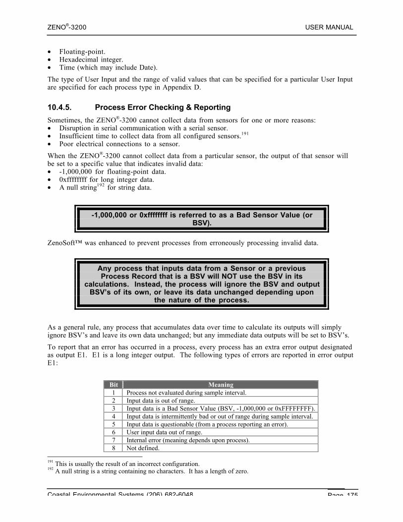
ZENO®-3200 USER MANUAL
Coastal Environmental Systems (206) 682-6048 Page 175
• Floating-point.• Hexadecimal integer.• Time (which may include Date).
The type of User Input and the range of valid values that can be specified for a particular User Inputare specified for each process type in Appendix D.
10.4.5. Process Error Checking & Reporting
Sometimes, the ZENO®-3200 cannot collect data from sensors for one or more reasons:• Disruption in serial communication with a serial sensor.• Insufficient time to collect data from all configured sensors.191
• Poor electrical connections to a sensor.
When the ZENO®-3200 cannot collect data from a particular sensor, the output of that sensor willbe set to a specific value that indicates invalid data:• -1,000,000 for floating-point data.• 0xffffffff for long integer data.• A null string192 for string data.
-1,000,000 or 0xffffffff is referred to as a Bad Sensor Value (orBSV).
ZenoSoft™ was enhanced to prevent processes from erroneously processing invalid data.
Any process that inputs data from a Sensor or a previousProcess Record that is a BSV will NOT use the BSV in its
calculations. Instead, the process will ignore the BSV and outputBSV’s of its own, or leave its data unchanged depending upon
the nature of the process.
As a general rule, any process that accumulates data over time to calculate its outputs will simplyignore BSV’s and leave its own data unchanged; but any immediate data outputs will be set to BSV’s.
To report that an error has occurred in a process, every process has an extra error output designatedas output E1. E1 is a long integer output. The following types of errors are reported in error outputE1:
Bit Meaning1 Process not evaluated during sample interval.2 Input data is out of range.3 Input data is a Bad Sensor Value (BSV, -1,000,000 or 0xFFFFFFFF).4 Input data is intermittently bad or out of range during sample interval.5 Input data is questionable (from a process reporting an error).6 User input data out of range.7 Internal error (meaning depends upon process).8 Not defined.
191 This is usually the result of an incorrect configuration.192 A null string is a string containing no characters. It has a length of zero.
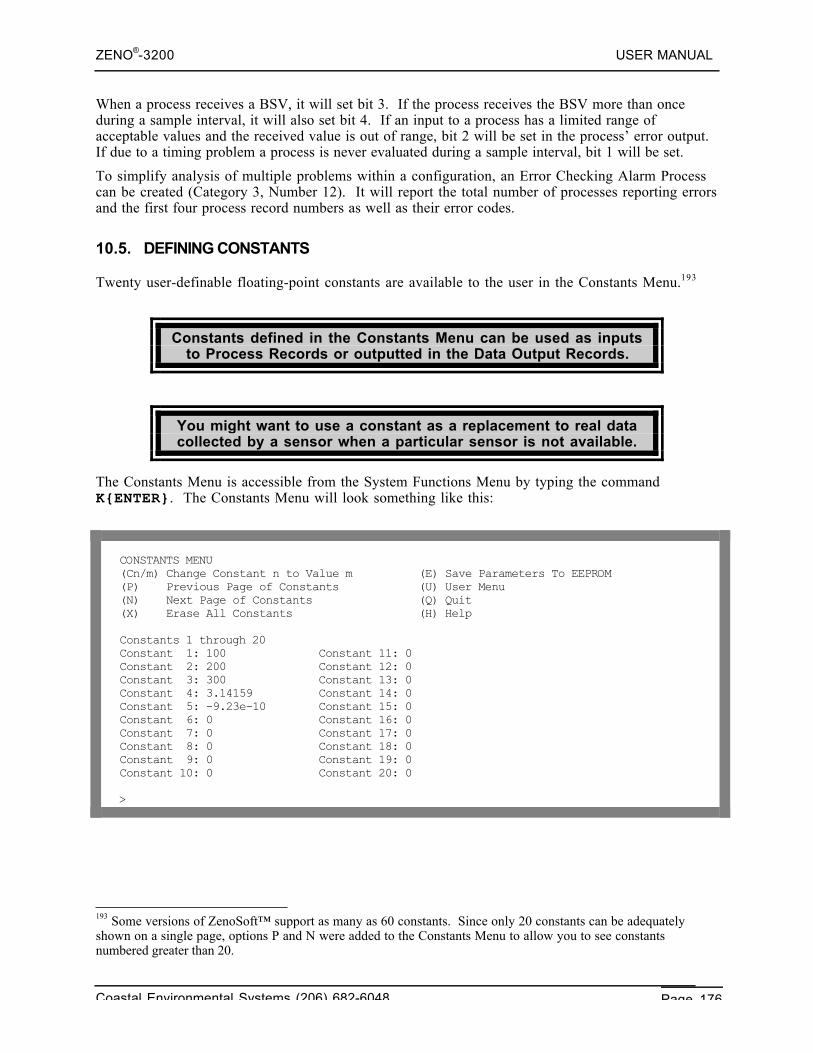
ZENO®-3200 USER MANUAL
Coastal Environmental Systems (206) 682-6048 Page 176
When a process receives a BSV, it will set bit 3. If the process receives the BSV more than onceduring a sample interval, it will also set bit 4. If an input to a process has a limited range ofacceptable values and the received value is out of range, bit 2 will be set in the process’ error output.If due to a timing problem a process is never evaluated during a sample interval, bit 1 will be set.
To simplify analysis of multiple problems within a configuration, an Error Checking Alarm Processcan be created (Category 3, Number 12). It will report the total number of processes reporting errorsand the first four process record numbers as well as their error codes.
10.5. DEFINING CONSTANTS
Twenty user-definable floating-point constants are available to the user in the Constants Menu.193
Constants defined in the Constants Menu can be used as inputsto Process Records or outputted in the Data Output Records.
You might want to use a constant as a replacement to real datacollected by a sensor when a particular sensor is not available.
The Constants Menu is accessible from the System Functions Menu by typing the commandK{ENTER}. The Constants Menu will look something like this:
CONSTANTS MENU(Cn/m) Change Constant n to Value m (E) Save Parameters To EEPROM(P) Previous Page of Constants (U) User Menu(N) Next Page of Constants (Q) Quit(X) Erase All Constants (H) Help
Constants 1 through 20Constant 1: 100 Constant 11: 0Constant 2: 200 Constant 12: 0Constant 3: 300 Constant 13: 0Constant 4: 3.14159 Constant 14: 0Constant 5: -9.23e-10 Constant 15: 0Constant 6: 0 Constant 16: 0Constant 7: 0 Constant 17: 0Constant 8: 0 Constant 18: 0Constant 9: 0 Constant 19: 0Constant 10: 0 Constant 20: 0
>
193 Some versions of ZenoSoft™ support as many as 60 constants. Since only 20 constants can be adequatelyshown on a single page, options P and N were added to the Constants Menu to allow you to see constantsnumbered greater than 20.
ZENO®-3200 USER MANUAL
Coastal Environmental Systems (206) 682-6048 Page 177
The range for any constant is a floating-point number between±3.40282334663×1038.
To refer to a constant as a Data Input or Data Output Record Data Field, use the form Cn, where n isthe constant number between 1 and 20.
If the number you want to enter requires scientific notation, n×10d, enter the value using the formatned. For example, to enter the number 1.25×10² 0 for constant #1, you would type the commandC1/1.25e20{ENTER}. As another example, to enter the number 9.653×10⁻¹⁵, you would typethe command C1/9.653e-15{ENTER}. This is the same format, which will appear in theConstants Menu.
The values of constants can be changes while the ZENO®-3200collects data without any disruption to data collection.
10.6. DEFINING DATA TO BE TRANSMITTED AND/OR LOGGED
Data that is to be logged and/or transmitted by the ZENO®-3200 is defined using the Data OutputMenu.
The Data Output Menu allows you to define:• The contents of up to four different output messages, transmitted on the same or different
communications ports.• Data fields that can be conditionally added to a message, which are commonly used within Alarm
Messages.194
• What data fields are to be logged in ZENO®-3200 RAM195 for later retrieval.
10.6.1. Data Record Structure
The ZENO®-3200 logs data as binary data, meaning that each datafield takes up as little memory as possible to optimize memory
usage.
A Data Record is the complete set of Data Output Records thatdefine all the data to be logged in ZENO®-3200 RAM at the end of
each Sample Duration for later retrieval196.
194 Refer to Section 11.195 Refer to Section 2.3.1.196 Refer to Section 4.
ZENO®-3200 USER MANUAL
Coastal Environmental Systems (206) 682-6048 Page 178
A Data Output Record is an individual data field to be transmittedin an output message or logged in a Data Record and is defined in
the Data Output Menu.
Data Output Records can be subdivided into three different field type categories:• Field types that transmit information or data only.• Field types that log data into ZENO®-3200 memory only.• Field types that both log and transmit data.
If no Data Output Records specify a field type that logs data, thenno data will be logged by the ZENO®-3200.
Anytime one or more data is logged, the ZENO®-3200 always logsthe Time Stamp as the first four bytes of the Data Record.
The order of the Data Output Records that log data defines theorder of the data fields within the Data Record.
As an example, you have a configuration that contains 15 Data Output Records, of which, DataOutput Records #5, #8 and #12 are the only ones that log data. The Data Record will consist of fourdata fields: the Time Stamp, followed by the data referred to by Data Output Records #5, #8 and #12respectively. If you were to go the Data Retrieval Menu197 to retrieve the logged data, you willretrieve Data Records consisting of these four data fields.
The data content and length of each Data Record is the SAME!
You cannot configure different Data Records of different lengths!
If more than one Output Message contains fields that log data,each logged Data Record will contain ALL of the logged data from
ALL of the output messages in the order of the Data OutputRecords!
10.6.2. Output Message Structure
Like the Data Record structures, the contents of each Output Message is determined by the order andfield types defined in each Data Output Record.
197 Refer to Section 4.
ZENO®-3200 USER MANUAL
Coastal Environmental Systems (206) 682-6048 Page 179
Except for the GOES Binary and ARGOS Binary field types, theZENO®-3200 transmits Output Messages using the standard ASCII
character set.198
Unlike the Data Record structure that is limited to one length and content definition for aconfiguration, up to four unique output messages can be configured in the ZENO®-3200 within asingle configuration.
What is transmitted automatically in an output message can betotally different from what is logged in each Data Record in the
ZENO®-3200 memory.
If no Data Output Records specify a field type that transmits data,then no data will be automatically transmitted by the ZENO®-3200.
The order of the Data Output Records that transmit data definesthe order of the data fields transmitted automatically in an output
message.
When configuring more than one output message, CoastalEnvironmental Systems recommends that you group the DataOutput Records common to each output message together as
much as possible. Data Output Records that define data fields formore than one output message are the exception.
10.6.3. The Different Types Of Data Output Records
Line Item #1 of the Data Output Menu defines the Field Type Code of each Data Output Record. Togo to the Data Output Menu, type the command D{ENTER} from the Zeno Program Menu. A fullyconfigured Data Output Record could look something like this on your terminal emulation programscreen:
198 ASCII, the acronym for American Standard Code for Information Interchange, is an encoding standard used bycomputers for 128 characters, numbers, and symbols commonly used in written communication. The first 32characters are control characters. The second group of 32 characters contains punctuation marks, special charactersand numeric digits. The third group of 32 characters contains mostly uppercase alphabetic characters and the fourthgroup of 32 characters contains mostly lowercase alphabetic characters.
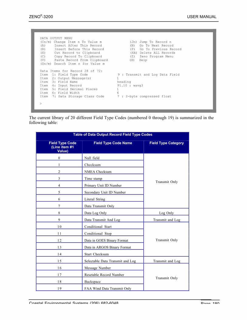
ZENO®-3200 USER MANUAL
Coastal Environmental Systems (206) 682-6048 Page 180
DATA OUTPUT MENU(Cn/m) Change Item n To Value m (Jn) Jump To Record n(A) Insert After This Record (N) Go To Next Record(B) Insert Before This Record (P) Go To Previous Record(X) Cut Record to Clipboard (XA) Delete ALL Records(C) Copy Record To Clipboard (Z) Zeno Program Menu(V) Paste Record From Clipboard (H) Help(Sn/m) Search Item n for Value m
Data Items for Record 28 of 72:Item 1: Field Type Code 9 : Transmit and Log Data FieldItem 2: Output Message(s) 1Item 3: Field Name headingItem 4: Input Record P1.10 : wavg3Item 5: Field Decimal Places 1Item 6: Field Width 6Item 7: Data Storage Class Code 7 : 2-byte compressed float
>
The current library of 20 different Field Type Codes (numbered 0 through 19) is summarized in thefollowing table:
Table of Data Output Record Field Type Codes
Field Type Code(Line item #1
Value)
Field Type Code Name Field Type Category
0 Null field
1 Checksum
2 NMEA Checksum
3 Time stamp
4 Primary Unit ID Number
5 Secondary Unit ID Number
6 Literal String
7 Data Transmit Only
Transmit Only
8 Data Log Only Log Only
9 Data Transmit And Log Transmit and Log
10 Conditional Start
11 Conditional Stop
12 Data in GOES Binary Format
13 Data in ARGOS Binary Format
14 Start Checksum
Transmit Only
15 Selectable Data Transmit and Log Transmit and Log
16 Message Number
17 Resetable Record Number
18 Backspace
19 FAA Wind Data Transmit Only
Transmit Only
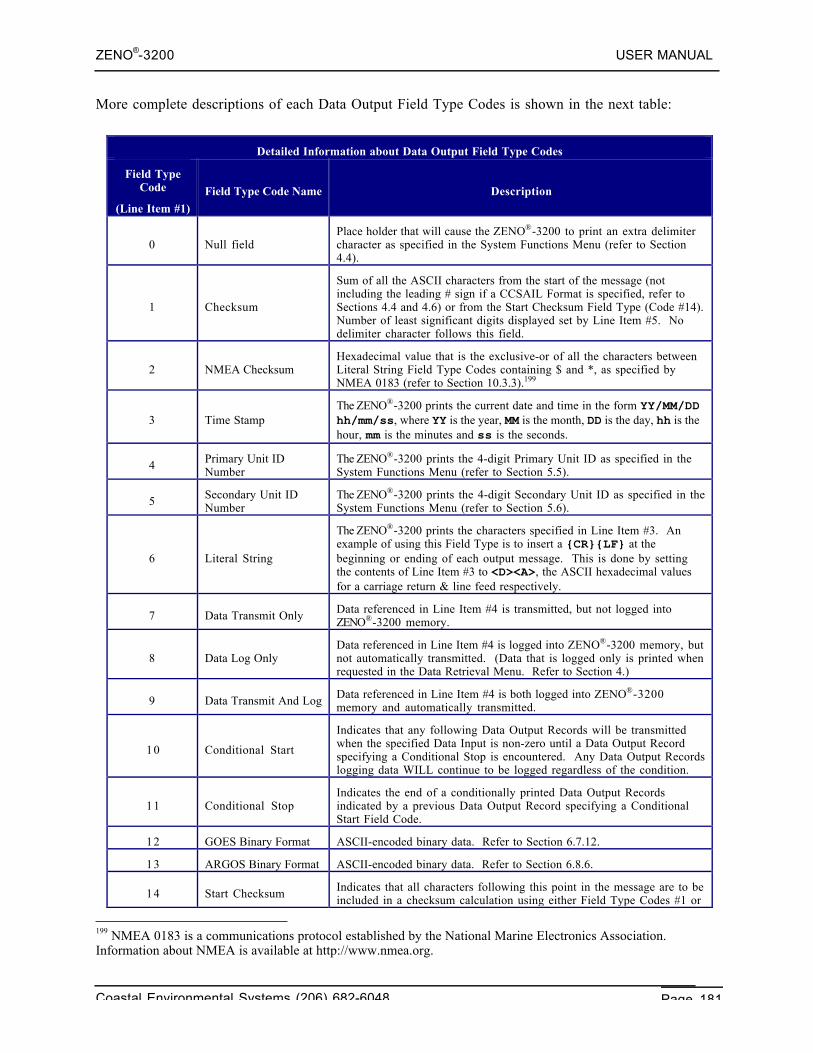
ZENO®-3200 USER MANUAL
Coastal Environmental Systems (206) 682-6048 Page 181
More complete descriptions of each Data Output Field Type Codes is shown in the next table:
Detailed Information about Data Output Field Type Codes
Field TypeCode
(Line Item #1)
Field Type Code Name Description
0 Null fieldPlace holder that will cause the ZENO®-3200 to print an extra delimitercharacter as specified in the System Functions Menu (refer to Section4.4).
1 Checksum
Sum of all the ASCII characters from the start of the message (notincluding the leading # sign if a CCSAIL Format is specified, refer toSections 4.4 and 4.6) or from the Start Checksum Field Type (Code #14).Number of least significant digits displayed set by Line Item #5. Nodelimiter character follows this field.
2 NMEA ChecksumHexadecimal value that is the exclusive-or of all the characters betweenLiteral String Field Type Codes containing $ and *, as specified byNMEA 0183 (refer to Section 10.3.3).199
3 Time StampThe ZENO®-3200 prints the current date and time in the form YY/MM/DDhh/mm/ss, where YY is the year, MM is the month, DD is the day, hh is thehour, mm is the minutes and ss is the seconds.
4 Primary Unit IDNumber
The ZENO®-3200 prints the 4-digit Primary Unit ID as specified in theSystem Functions Menu (refer to Section 5.5).
5 Secondary Unit IDNumber
The ZENO®-3200 prints the 4-digit Secondary Unit ID as specified in theSystem Functions Menu (refer to Section 5.6).
6 Literal String
The ZENO®-3200 prints the characters specified in Line Item #3. Anexample of using this Field Type is to insert a {CR}{LF} at thebeginning or ending of each output message. This is done by settingthe contents of Line Item #3 to <D><A>, the ASCII hexadecimal valuesfor a carriage return & line feed respectively.
7 Data Transmit Only Data referenced in Line Item #4 is transmitted, but not logged intoZENO®-3200 memory.
8 Data Log OnlyData referenced in Line Item #4 is logged into ZENO®-3200 memory, butnot automatically transmitted. (Data that is logged only is printed whenrequested in the Data Retrieval Menu. Refer to Section 4.)
9 Data Transmit And Log Data referenced in Line Item #4 is both logged into ZENO®-3200memory and automatically transmitted.
10 Conditional Start
Indicates that any following Data Output Records will be transmittedwhen the specified Data Input is non-zero until a Data Output Recordspecifying a Conditional Stop is encountered. Any Data Output Recordslogging data WILL continue to be logged regardless of the condition.
11 Conditional StopIndicates the end of a conditionally printed Data Output Recordsindicated by a previous Data Output Record specifying a ConditionalStart Field Code.
12 GOES Binary Format ASCII-encoded binary data. Refer to Section 6.7.12.
13 ARGOS Binary Format ASCII-encoded binary data. Refer to Section 6.8.6.
14 Start Checksum Indicates that all characters following this point in the message are to beincluded in a checksum calculation using either Field Type Codes #1 or#2. No characters preceding this point in the message will be includedin a checksum calculation following this field.
199 NMEA 0183 is a communications protocol established by the National Marine Electronics Association.Information about NMEA is available at http://www.nmea.org.
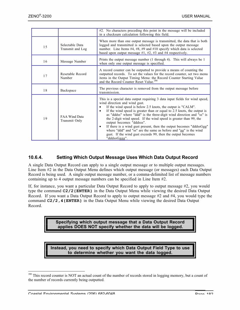
ZENO®-3200 USER MANUAL
Coastal Environmental Systems (206) 682-6048 Page 182
#2. No characters preceding this point in the message will be includedin a checksum calculation following this field.
15 Selectable DataTransmit and Log
When more than one output message is transmitted, the data that is bothlogged and transmitted is selected based upon the output messagenumber. Line Items #4, #8, #9 and #10 specify which data is selectedbased upon output message #1, #2, #3 and #4 respectively.
16 Message Number Prints the output message number (1 through 4). This will always be 1when only one output message is specified.
17 Resetable RecordNumber
A record counter can be outputted to provide a means of counting theoutputted records. To set the values for the record counter, set two menuitems in the Output Timing Menu: the Record Counter Starting Valueand the Record Counter Reset Value.200
18 Backspace The previous character is removed from the output message beforetransmission.
19 FAA Wind DataTransmit Only
This is a special data output requiring 3 data input fields for wind speed,wind direction and wind gust.• If the wind speed is below 2.5 knots, the output is "CALM".• If the wind speed is greater than or equal to 2.5 knots, the output is
as "dddss" where "ddd" is the three-digit wind direction and "ss" isthe 2-digit wind speed. If the wind speed is greater than 99, theoutput becomes "dddsss".
• If there is a wind gust present, then the output becomes "dddssGgg"where "ddd" and "ss" are the same as before and "gg" is the windgust. If the wind gust exceeds 99, then the output becomes"dddssGggg".
10.6.4. Setting Which Output Message Uses Which Data Output Record
A single Data Output Record can apply to a single output message or to multiple output messages.Line Item #2 in the Data Output Menu defines which output message (or messages) each Data OutputRecord is being used. A single output message number, or a comma-delimited list of message numberscontaining up to 4 output message numbers can be specified in Line Item #2.
If, for instance, you want a particular Data Output Record to apply to output message #2, you wouldtype the command C2/2{ENTER} in the Data Output Menu while viewing the desired Data OutputRecord. If you want a Data Output Record to apply to output message #2 and #4, you would type thecommand C2/2,4{ENTER} in the Data Output Menu while viewing the desired Data OutputRecord.
Specifying which output message that a Data Output Recordapplies DOES NOT specify whether the data will be logged.
Instead, you need to specify which Data Output Field Type to useto determine whether you want the data logged.
200 This record counter is NOT an actual count of the number of records stored in logging memory, but a count ofthe number of records currently being outputted.
ZENO®-3200 USER MANUAL
Coastal Environmental Systems (206) 682-6048 Page 183
Data is only logged at the end of a Sample Duration, notnecessarily when an output message is sent.
If Field Type Code #8 (Log Data Only) is used, specifying an outputmessage number does not apply.
10.6.5. The Data Output Record Field Name--A Columnar Heading Or A LiteralString
Line Item #3 in the Data Output Menu specifies the user-defined Field Name for a Data OutputRecord.
The user-defined Field Name for any Data Output Record that logsdata is used as a columnar heading when data is retrieved in the
Data Retrieval Menu201.
The other primary use of the user-defined Field Name is tospecify text that will be transmitted verbatim when the Field
Code for the Data Output Record is a Literal String (Field Code #6)in the specified output message(s).
Some common uses for the Field Name when the Data Output Record specifies a Literal String arelisted below:• The name of the site where your ZENO®-3200 is installed.• A carriage-return/line-feed ({CR}{LF}) at the start or end of each message to start a new line.• The delimiting fields $ and * in two Data Output Records for use with a NMEA 0183 checksum.• Sensor names or data identifier to aid the readability of the message.
The length of the Field Name is limited to ten characters.
If you require text that exceeds ten characters, create more thanone Data Output Record specified as a Literal String and put up to
ten characters in each Field Name of each Data Output Record.
If you need to specify a non-printable or non-viewable character,such as a carriage return, you can specify non-printable ASCII
201 Refer to Sections 3.2.5 and 4.
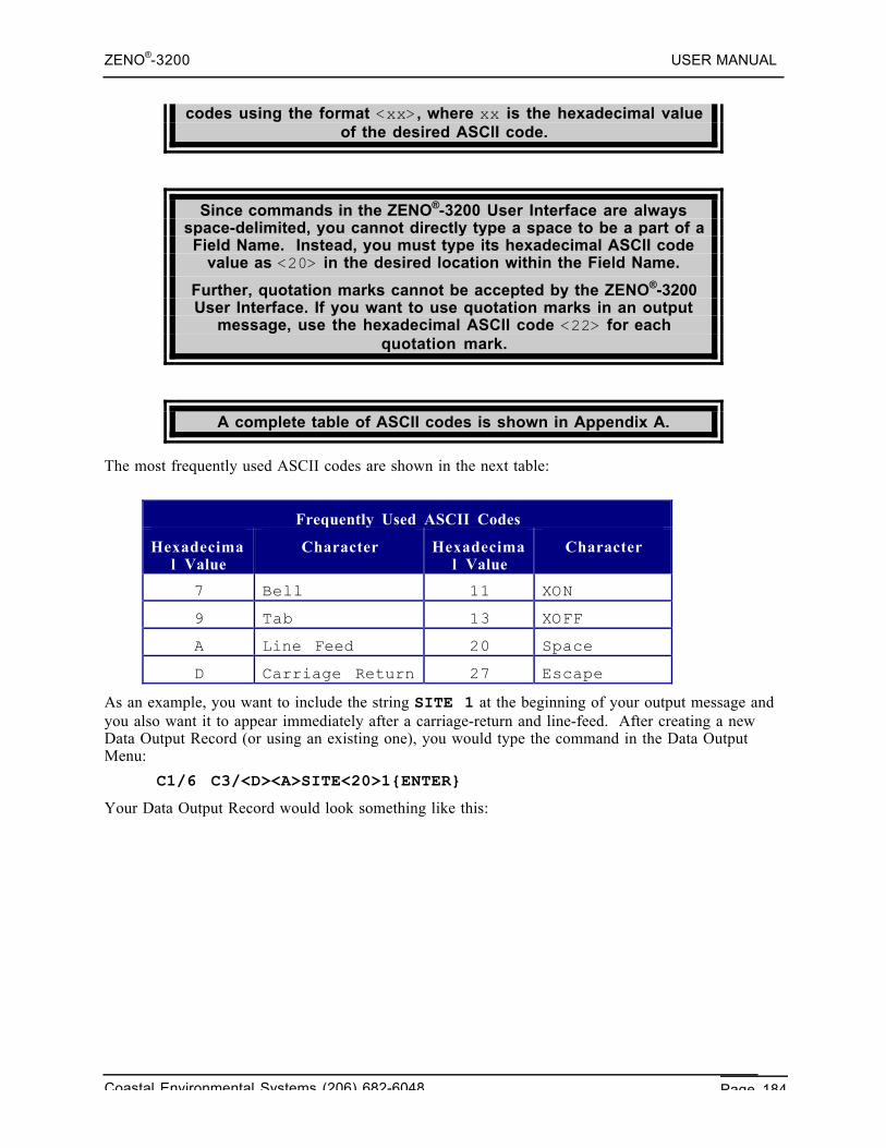
ZENO®-3200 USER MANUAL
Coastal Environmental Systems (206) 682-6048 Page 184
codes using the format <xx>, where xx is the hexadecimal valueof the desired ASCII code.
Since commands in the ZENO®-3200 User Interface are alwaysspace-delimited, you cannot directly type a space to be a part of aField Name. Instead, you must type its hexadecimal ASCII code
value as <20> in the desired location within the Field Name.
Further, quotation marks cannot be accepted by the ZENO®-3200User Interface. If you want to use quotation marks in an output
message, use the hexadecimal ASCII code <22> for eachquotation mark.
A complete table of ASCII codes is shown in Appendix A.
The most frequently used ASCII codes are shown in the next table:
Frequently Used ASCII Codes
Hexadecimal Value
Character Hexadecimal Value
Character
7 Bell 11 XON
9 Tab 13 XOFF
A Line Feed 20 Space
D Carriage Return 27 Escape
As an example, you want to include the string SITE 1 at the beginning of your output message andyou also want it to appear immediately after a carriage-return and line-feed. After creating a newData Output Record (or using an existing one), you would type the command in the Data OutputMenu:
C1/6 C3/<D><A>SITE<20>1{ENTER}
Your Data Output Record would look something like this:
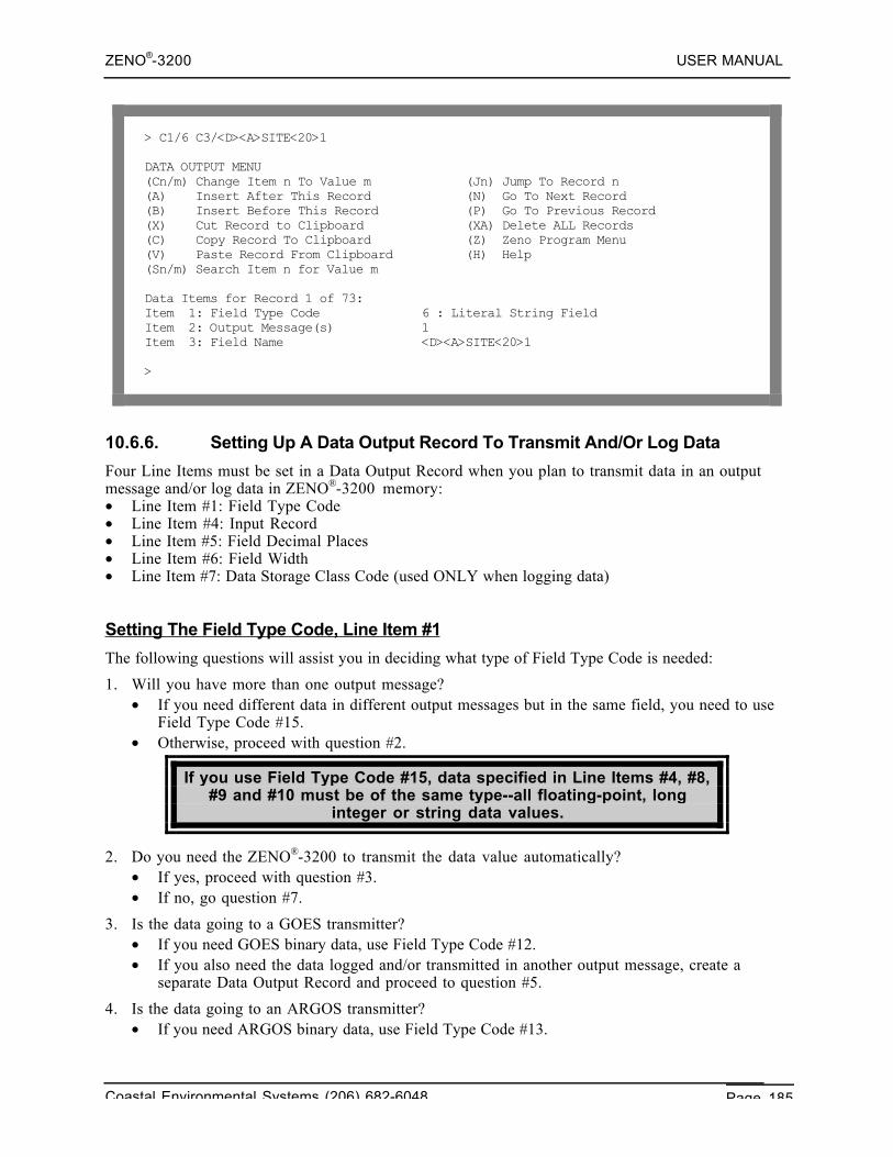
ZENO®-3200 USER MANUAL
Coastal Environmental Systems (206) 682-6048 Page 185
> C1/6 C3/<D><A>SITE<20>1
DATA OUTPUT MENU(Cn/m) Change Item n To Value m (Jn) Jump To Record n(A) Insert After This Record (N) Go To Next Record(B) Insert Before This Record (P) Go To Previous Record(X) Cut Record to Clipboard (XA) Delete ALL Records(C) Copy Record To Clipboard (Z) Zeno Program Menu(V) Paste Record From Clipboard (H) Help(Sn/m) Search Item n for Value m
Data Items for Record 1 of 73:Item 1: Field Type Code 6 : Literal String FieldItem 2: Output Message(s) 1Item 3: Field Name <D><A>SITE<20>1
>
10.6.6. Setting Up A Data Output Record To Transmit And/Or Log Data
Four Line Items must be set in a Data Output Record when you plan to transmit data in an outputmessage and/or log data in ZENO®-3200 memory:• Line Item #1: Field Type Code• Line Item #4: Input Record• Line Item #5: Field Decimal Places• Line Item #6: Field Width• Line Item #7: Data Storage Class Code (used ONLY when logging data)
Setting The Field Type Code, Line Item #1
The following questions will assist you in deciding what type of Field Type Code is needed:
1. Will you have more than one output message?• If you need different data in different output messages but in the same field, you need to use
Field Type Code #15.• Otherwise, proceed with question #2.
If you use Field Type Code #15, data specified in Line Items #4, #8,#9 and #10 must be of the same type--all floating-point, long
integer or string data values.
2. Do you need the ZENO®-3200 to transmit the data value automatically?• If yes, proceed with question #3.• If no, go question #7.
3. Is the data going to a GOES transmitter?• If you need GOES binary data, use Field Type Code #12.• If you also need the data logged and/or transmitted in another output message, create a
separate Data Output Record and proceed to question #5.
4. Is the data going to an ARGOS transmitter?• If you need ARGOS binary data, use Field Type Code #13.
ZENO®-3200 USER MANUAL
Coastal Environmental Systems (206) 682-6048 Page 186
• If you also need the data logged and/or transmitted in another output message, create aseparate Data Output Record and proceed to question #5.
5. If you only need to transmit the data, use Field Type Code #7.
6. If you need to BOTH transmit and log the data, use Field Type Code #9.
7. If you ONLY need to log the data, then you need to use Field Type Code #8.
Setting the Input Data, Line Item #4
Once you decide which type of Field Type Code is appropriate for your data value, you need to setthe values for Line Item #4, the Input Record, to tell the ZENO®-3200 which data to transmit and/orlog.
The format for Line Item #4, the Input Record, is the same as fora Process Record Data Input202.
Remember, you can always type the command for help HPn,where n is the Process Record Number, to view the all the
outputs for Process Record #n.
String outputs can ONLY be transmitted and logged using DataOutput types 7, 8 and 9 (Transmit Only, Log Only, and Transmit
and Log). An error will be generated if a user attempts to use astring output as a Conditional Start, a GOES Binary Format, or an
ARGOS Binary Format field.
The ZENO®-3200 does not put quotation marks around string data. Since strings can containcommas or spaces, confusion can result with the type of delimiter being used within output messages.If you want the string data to be contained inside of quotation marks, specify two separate DataOutput Records as Literal Strings, one immediately before and one immediately after the string DataOutput Record.
Setting the Decimal Places, Line Item #5
After setting the Field Type Code and the Input Data (Line Items #1 and #4), you are ready to setthe Field Decimal Places and Field Width (Line Items #5 and #6 respectively).
The following table will assist you in setting the value for Line Item #5, which depends upon the typeof data that is going to be transmitted and/or logged:
202 Refer to Section 10.4.4.
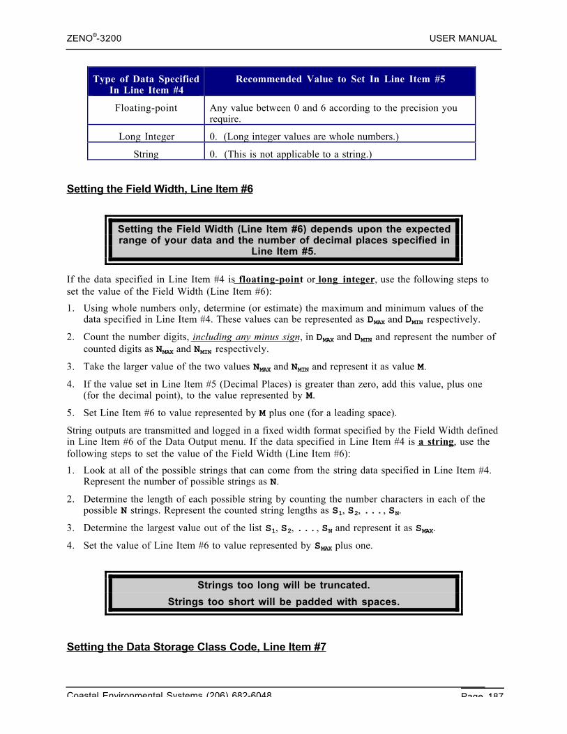
ZENO®-3200 USER MANUAL
Coastal Environmental Systems (206) 682-6048 Page 187
Type of Data SpecifiedIn Line Item #4
Recommended Value to Set In Line Item #5
Floating-point Any value between 0 and 6 according to the precision yourequire.
Long Integer 0. (Long integer values are whole numbers.)
String 0. (This is not applicable to a string.)
Setting the Field Width, Line Item #6
Setting the Field Width (Line Item #6) depends upon the expectedrange of your data and the number of decimal places specified in
Line Item #5.
If the data specified in Line Item #4 is floating-point or long integer, use the following steps toset the value of the Field Width (Line Item #6):
1. Using whole numbers only, determine (or estimate) the maximum and minimum values of thedata specified in Line Item #4. These values can be represented as DMAX and DMIN respectively.
2. Count the number digits, including any minus sign, in DMAX and DMIN and represent the number ofcounted digits as NMAX and NMIN respectively.
3. Take the larger value of the two values NMAX and NMIN and represent it as value M.
4. If the value set in Line Item #5 (Decimal Places) is greater than zero, add this value, plus one(for the decimal point), to the value represented by M.
5. Set Line Item #6 to value represented by M plus one (for a leading space).
String outputs are transmitted and logged in a fixed width format specified by the Field Width definedin Line Item #6 of the Data Output menu. If the data specified in Line Item #4 is a string, use thefollowing steps to set the value of the Field Width (Line Item #6):
1. Look at all of the possible strings that can come from the string data specified in Line Item #4.Represent the number of possible strings as N.
2. Determine the length of each possible string by counting the number characters in each of thepossible N strings. Represent the counted string lengths as S1, S2, ..., SN.
3. Determine the largest value out of the list S1, S2, ..., SN and represent it as SMAX.
4. Set the value of Line Item #6 to value represented by SMAX plus one.
Strings too long will be truncated.
Strings too short will be padded with spaces.
Setting the Data Storage Class Code, Line Item #7
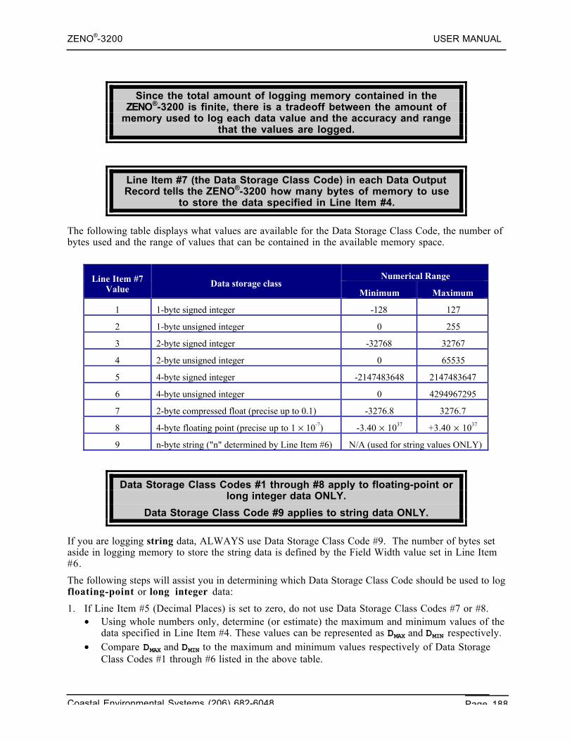
ZENO®-3200 USER MANUAL
Coastal Environmental Systems (206) 682-6048 Page 188
Since the total amount of logging memory contained in theZENO®-3200 is finite, there is a tradeoff between the amount of
memory used to log each data value and the accuracy and rangethat the values are logged.
Line Item #7 (the Data Storage Class Code) in each Data OutputRecord tells the ZENO®-3200 how many bytes of memory to use
to store the data specified in Line Item #4.
The following table displays what values are available for the Data Storage Class Code, the number ofbytes used and the range of values that can be contained in the available memory space.
Numerical RangeLine Item #7Value
Data storage classMinimum Maximum
1 1-byte signed integer -128 127
2 1-byte unsigned integer 0 255
3 2-byte signed integer -32768 32767
4 2-byte unsigned integer 0 65535
5 4-byte signed integer -2147483648 2147483647
6 4-byte unsigned integer 0 4294967295
7 2-byte compressed float (precise up to 0.1) -3276.8 3276.7
8 4-byte floating point (precise up to 1 × 10⁻⁷) -3.40 × 1037 +3.40 × 1037
9 n-byte string ("n" determined by Line Item #6) N/A (used for string values ONLY)
Data Storage Class Codes #1 through #8 apply to floating-point orlong integer data ONLY.
Data Storage Class Code #9 applies to string data ONLY.
If you are logging string data, ALWAYS use Data Storage Class Code #9. The number of bytes setaside in logging memory to store the string data is defined by the Field Width value set in Line Item#6.
The following steps will assist you in determining which Data Storage Class Code should be used to logfloating-point or long integer data:
1. If Line Item #5 (Decimal Places) is set to zero, do not use Data Storage Class Codes #7 or #8.• Using whole numbers only, determine (or estimate) the maximum and minimum values of the
data specified in Line Item #4. These values can be represented as DMAX and DMIN respectively.• Compare DMAX and DMIN to the maximum and minimum values respectively of Data Storage
Class Codes #1 through #6 listed in the above table.
ZENO®-3200 USER MANUAL
Coastal Environmental Systems (206) 682-6048 Page 189
• If DMIN is zero or greater, limit your selection to Data Storage Class Codes #2, #4 or #6.• If DMIN is less than zero, limit your selection to Data Storage Class Codes #1, #3 or #5.
2. If Line Item #5 (Decimal Places) is non-zero, only consider using Data Storage Class Codes #7 or#8.• If Line Item #5 (Decimal Places) is greater than one, use Data Storage Class Code #8.• If Line Item #5 (Decimal Places) is set to one, determine (or estimate) the maximum and
minimum values of the data specified in Line Item #4. These values can be represented asDMAX and DMIN respectively. If DMAX and DMIN are between the limits of Data Storage Class Code#7, use Data Storage Class Code #7; otherwise, use Data Storage Class Code #8.
10.6.7. Creating An Automatic Output Message For CCSAIL Format
You need to perform several steps if you need the ZENO®-3200 to automatically transmit one ormore output messages in CCSAIL format.203
For a CCSAIL-formatted output message, Coastal EnvironmentalSystems recommends that you 1) set the first Data Output
Record to be a Literal String containing a Carriage-Return/Linefeed and 2) set the second Data Output Record to be a
Timestamp.
Since the ZENO®-3200 is the source of an automatically transmitted output message, the PrimaryUnit ID (Line Item #1 of the System Functions Menu) will be used as the Source Address in theCCSAIL message. The Secondary Unit ID (Line Item #2 of the System Functions Menu) is used bythe ZENO®-3200 to contain the Destination Address.
You do NOT need to create Data Output Records containing theAttention Character, Destination Address, Source Address or
End of Transmission Character. The ZENO®-3200 willautomatically generate these fields when Real Time OutputFormat in the System Functions Menu is set to 3 for CCSAILformat.204 This will also cause the individual data fields to be
comma-delimited.
If you want the Source Address (Primary Unit ID) or theDestination Address (Secondary Unit ID) to be transmitted as
separate data fields, create one or two Data Output Records andset the Field Type Code accordingly.
203 Refer to Section 4.6 for details about the CCSAIL Protocol.204 Line Item #4 of the System Functions Menu. Refer to Sections 4.4.2 and 4.6.4.
ZENO®-3200 USER MANUAL
Coastal Environmental Systems (206) 682-6048 Page 190
NOTE: Coastal Environmental Systems PC program Intercept™requires the Primary Unit ID immediately after the timestamp
data field.
Use the following steps to create an automatically transmitted output message in CCSAIL format:
1. Create all of the Data Output Records necessary to transmit the various data values in youroutput message.
2. Go to the first Data Output Record, create another Data Output Record BEFORE the first record(using Data Output Menu option B).• Set Line Item #1 (the Field Type Code) to 6 for a Literal String.• Set Line Item #3 (the Field Name) to the ASCII values for a Carriage-Return/Line-Feed,
<D><A>.
3. After the first Data Output Record, create another Data Output Record using Data Output Menuoption A.• Set Line Item #1 (the Field Type Code) in the new Data Output Record to 3 for a
Timestamp.
4. If you are using Intercept™, create another Data Output Record after the timestamp DataOutput Record using Data Output Menu option A.• Set Line Item #1 (the Field Type Code) in the new Data Output Record to 4 for the Primary
Unit ID.
5. Jump to the last Data Output Record and create one more Data Output Record after it using DataOutput Menu option A.• Set Line Item #1 (the Field Type Code) to 1 for a Checksum.• Set Line Item #6 (the Field Width) to 2 for a 2-digit checksum.
6. Go to the System Functions Menu, a submenu of the User Menu.205
7. Set the Primary Unit ID (Line Item #1 of the System Functions Menu) to the CCSAIL address ofyour ZENO®-3200.206
8. Set the Secondary Unit ID (Line Item #2 of the System Functions Menu) to the destinationaddress for the CCSAIL message.207
9. Set the Real Time Output Format, Line Item #4 of the System Functions Menu, to 3 for CCSAILformat.208
10.6.8. Creating An Automatic Output Message in NMEA 0183 Format
Several steps need to be performed to configure the ZENO®-3200 to automatically transmit anoutput message in NMEA 0183 format. (Refer to Section 10.3.3 for information about NMEA0183.)
1. Create all of the Data Output Records necessary to transmit the various data values in youroutput message.
2. Jump to the first Data Output Record and create another Data Output Record before it using DataOutput Menu option B.
205 Refer to Section 5.206 Refer to Section 5.5.207 Refer to Section 5.6.208 Refer to Section 4.4.2.
ZENO®-3200 USER MANUAL
Coastal Environmental Systems (206) 682-6048 Page 191
• Set Line Item #1 (the Field Type Code) in the new Data Output Record to 6 for anotherLiteral String.
• Set Line Item #3 (the Field Name) will contain six characters as follows: a $, a two-character"talker ID" and a three-character "sentence ID".
3. Jump to the last Data Output Record and create one more Data Output Record after it using DataOutput Menu option A.• Set Line Item #1 (the Field Type Code) to 18 for a Backspace to remove the delimiter
character from the last Data Output Record that transmits data.
4. Create another Data Output Record after the backspace using Data Output Menu option A.• Set Line Item #1 (the Field Type Code) in the new Data Output Record to 6 for a Literal
String.• Set Line Item #3 (the Field Name) to an asterisk.
5. Create another Data Output Record after the asterisk literal string using Data Output Menuoption A.• Set Line Item #1 (the Field Type Code) to 18 for a Backspace to remove the delimiter
character that follows the asterisk.
6. Create another Data Output Record after the backspace using Data Output Menu option A.• Set Line Item #1 (the Field Type Code) to 2 for a NMEA Checksum.
7. Create another Data Output Record after the NMEA checksum using Data Output Menu optionA. Set Line Item #1 (the Field Type Code) to 6 for a Literal String.• Set Line Item #3 (the Field Name) to the ASCII values for a Carriage-Return/Line-Feed,
<D><A>.
8. Go to the System Functions Menu, a submenu of the User Menu.209
9. Set the Real Time Output Format (Line Item #4 of the System Functions Menu) to 1 forcomma-delimited data.210
10.6.9. Conditional Message Fragments
The ZENO®-3200 provides the means to vary the contents of eachoutput message according to the actual data values using the
Conditional Start & Conditional Stop Field Type Codes in the DataOutput Menu.
Conditional Start and Conditional Stop Data Output Records mustbe used in pairs.
209 Refer to Section 5.210 Refer to Section 4.4.2.
ZENO®-3200 USER MANUAL
Coastal Environmental Systems (206) 682-6048 Page 192
More than one pair of Conditional Start and Conditional Stop DataOutput Records can be used in a single output message, but they
CANNOT be nested or overlap.
Examples of using the Conditional Start and Conditional Stop include:• Transmitting extra data fields or text during an alarm condition.211
• Transmitting different text for different data.212
The ZENO®-3200 transmits all Data Output Records containedbetween Conditional Start and Condition Stop Data Output
Records ONLY when the data referred to in Line Item #4 (theInput Record) of the Conditional Start Data Output Record is non-
zero.
NO data is transmitted by the Conditional Start Data OutputRecord itself!
The ZENO®-3200 ALWAYS LOGS data from any Data OutputRecords that log data and are contained between Conditional
Start & Conditional Stop Data Output Records regardless of theConditional Start status!
When you configure a Data Output Record to be a Conditional Start, you will see something like thison your terminal emulation program screen; along with the matching Conditional Stop Data OutputRecord.
211 Refer to Section 11.212 This would be used extensively with the Optional Speech Interface, refer to Section 6.11.
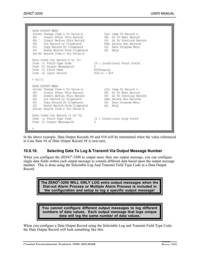
ZENO®-3200 USER MANUAL
Coastal Environmental Systems (206) 682-6048 Page 193
DATA OUTPUT MENU(Cn/m) Change Item n To Value m (Jn) Jump To Record n(A) Insert After This Record (N) Go To Next Record(B) Insert Before This Record (P) Go To Previous Record(X) Cut Record to Clipboard (XA) Delete ALL Records(C) Copy Record To Clipboard (Z) Zeno Program Menu(V) Paste Record From Clipboard (H) Help(Sn/m) Search Item n for Value m
Data Items for Record 8 of 72:Item 1: Field Type Code 10 : Conditional Start FieldItem 2: Output Message(s) 2Item 3: Field Name BITdisplayItem 4: Input Record P14.L1 : BIT
> S1/11
DATA OUTPUT MENU(Cn/m) Change Item n To Value m (Jn) Jump To Record n(A) Insert After This Record (N) Go To Next Record(B) Insert Before This Record (P) Go To Previous Record(X) Cut Record to Clipboard (XA) Delete ALL Records(C) Copy Record To Clipboard (Z) Zeno Program Menu(V) Paste Record From Clipboard (H) Help(Sn/m) Search Item n for Value m
Data Items for Record 11 of 72:Item 1: Field Type Code 11 : Conditional Stop FieldItem 2: Output Message(s) 2
>
In the above example, Data Output Records #9 and #10 will be transmitted when the value referencedin Line Item #4 of Data Output Record #8 is non-zero.
10.6.10. Selecting Data To Log & Transmit Via Output Message Number
When you configure the ZENO®-3200 to output more than one output message, you can configuresingle data fields within each output message to contain different data based upon the output messagenumber. This is done using the Selectable Log And Transmit Field Type Code in a Data OutputRecord.
The ZENO®-3200 WILL ONLY LOG extra output messages when theDial-out Alarm Process or Multiple Alarm Process is included inthe configuration and setup to log a specific output message!
You cannot configure different output messages to log differentnumbers of data values. Each output message that logs unique
data will log the same number of data values.
When you configure a Data Output Record using the Selectable Log and Transmit Field Type Code,the Data Output Record will look something like this:
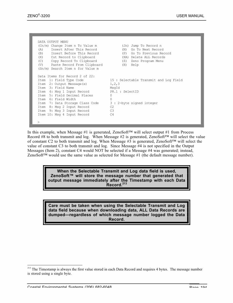
ZENO®-3200 USER MANUAL
Coastal Environmental Systems (206) 682-6048 Page 194
DATA OUTPUT MENU(Cn/m) Change Item n To Value m (Jn) Jump To Record n(A) Insert After This Record (N) Go To Next Record(B) Insert Before This Record (P) Go To Previous Record(X) Cut Record to Clipboard (XA) Delete ALL Records(C) Copy Record To Clipboard (Z) Zeno Program Menu(V) Paste Record From Clipboard (H) Help(Sn/m) Search Item n for Value m
Data Items for Record 2 of 22:Item 1: Field Type Code 15 : Selectable Transmit and Log FieldItem 2: Output Message(s) 1,2,3Item 3: Field Name MsgIdItem 4: Msg 1 Input Record P8.1 : SelectIDItem 5: Field Decimal Places 0Item 6: Field Width 0Item 7: Data Storage Class Code 3 : 2-byte signed integerItem 8: Msg 2 Input Record C2Item 9: Msg 3 Input Record C3Item 10: Msg 4 Input Record C4
>
In this example, when Message #1 is generated, ZenoSoft™ will select output #1 from ProcessRecord #8 to both transmit and log. When Message #2 is generated, ZenoSoft™ will select the valueof constant C2 to both transmit and log. When Message #3 is generated, ZenoSoft™ will select thevalue of constant C3 to both transmit and log. Since Message #4 is not specified in the OutputMessages (Item 2), constant C4 would NOT be selected if a Message #4 was generated; instead,ZenoSoft™ would use the same value as selected for Message #1 (the default message number).
When the Selectable Transmit and Log data field is used,ZenoSoft™ will store the message number that generated that
output message immediately after the Timestamp with each DataRecord.213
Care must be taken when using the Selectable Transmit and Logdata field because when downloading data, ALL Data Records aredumped—regardless of which message number logged the Data
Record.
213 The Timestamp is always the first value stored in each Data Record and requires 4 bytes. The message numberis stored using a single byte.
ZENO®-3200 USER MANUAL
Coastal Environmental Systems (206) 682-6048 Page 195
Coastal Environmental Systems recommends that you use somemeans to identify which message number logged each Data
Record. You can create a separate Data Output Record using theMessage Number Field Type Code214, or by some other meansusing another Selectable Transmit and Log data field to store a
user-specified identification number.
Further, when multiple output messages are being logged,information provided by option C in the Data Retrieval Menu215
may not be accurate, because ZenoSoft™ cannot predict whenextra output messages are going to be logged.
However, these erroneous messages in NO way interfere withdata collection or retrieval!
10.7. SETTING OUTPUT MESSAGE SCHEDULES AND DESTINATIONS
Since the ZENO®-3200 can transmit up to four different outputmessages, the ZENO®-3200 provides the means to configure
which COM port each output message is transmitted as well asthe time of transmission of each output message.
The Output Message Timing Menu lets you control when, and from which communications port,each of the up to four output messages will be sent. To access the Output Message Timing Menu,type O{ENTER} from the Zeno Program Menu. Your screen should look something like this:
214 Refer to Section 10.6.3.215 Refer to Section 4.2.
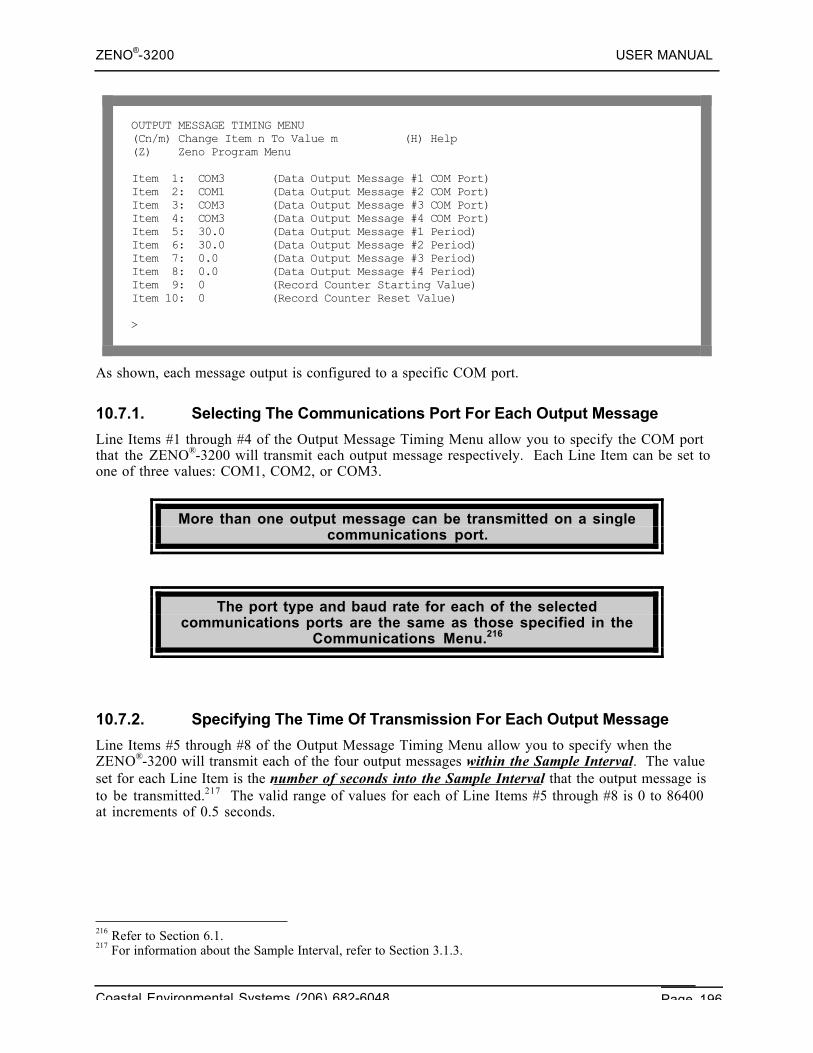
ZENO®-3200 USER MANUAL
Coastal Environmental Systems (206) 682-6048 Page 196
OUTPUT MESSAGE TIMING MENU(Cn/m) Change Item n To Value m (H) Help(Z) Zeno Program Menu
Item 1: COM3 (Data Output Message #1 COM Port)Item 2: COM1 (Data Output Message #2 COM Port)Item 3: COM3 (Data Output Message #3 COM Port)Item 4: COM3 (Data Output Message #4 COM Port)Item 5: 30.0 (Data Output Message #1 Period)Item 6: 30.0 (Data Output Message #2 Period)Item 7: 0.0 (Data Output Message #3 Period)Item 8: 0.0 (Data Output Message #4 Period)Item 9: 0 (Record Counter Starting Value)Item 10: 0 (Record Counter Reset Value)
>
As shown, each message output is configured to a specific COM port.
10.7.1. Selecting The Communications Port For Each Output Message
Line Items #1 through #4 of the Output Message Timing Menu allow you to specify the COM portthat the ZENO®-3200 will transmit each output message respectively. Each Line Item can be set toone of three values: COM1, COM2, or COM3.
More than one output message can be transmitted on a singlecommunications port.
The port type and baud rate for each of the selectedcommunications ports are the same as those specified in the
Communications Menu.216
10.7.2. Specifying The Time Of Transmission For Each Output Message
Line Items #5 through #8 of the Output Message Timing Menu allow you to specify when theZENO®-3200 will transmit each of the four output messages within the Sample Interval. The valueset for each Line Item is the number of seconds into the Sample Interval that the output message isto be transmitted.217 The valid range of values for each of Line Items #5 through #8 is 0 to 86400at increments of 0.5 seconds.
216 Refer to Section 6.1.217 For information about the Sample Interval, refer to Section 3.1.3.
ZENO®-3200 USER MANUAL
Coastal Environmental Systems (206) 682-6048 Page 197
REMEMBER: the ZENO®-3200 will only automatically transmit anyoutput message when they have not been suppressed by theReal Time Output Format, Line Item #4 in the System Functions
Menu.218
If you specify a time (in seconds into the Sample Interval) that exceeds the length of the SampleInterval, the ZENO®-3200 will transmit the output message at the end of the Sample Interval.
If no time is specified for Output Message #1 (Line Item #5 is set to 0), which is the default outputmessage, the ZENO®-3200 will automatically transmit Output Message #1 at the end of the SampleDuration.
The ZENO®-3200 will only automatically & regularly transmitOutput Messages #2, #3 and #4 when a non-zero time is specified
in their respective Line Items (#6, #7 and #8) in the OutputMessage Timing Menu.
This DOES NOT include the transmission of any of thesemessages when configured to transmit as an asynchronous
alarm message using one of the Alarm Processes.219
Any output message can be automatically transmitted on a regular schedule and be transmitted as anasynchronous Alarm Message.220
Regular logging of data is ALWAYS done at the end of the SampleDuration regardless of the settings for output message timing in
the Output Message Timing Menu.
When you configure the ZENO®-3200 to transmit an outputmessage several times during a Sample Interval, you are viewing
snapshots of the current states of any referenced sensor orprocess data.
Any output messages transmitted prior to the end of the SampleDuration do not necessarily contain the same data that will be
logged at the end of the Sample Duration.
Here are a few examples that demonstrate output message timing.
Example #1
Here are a few possibilities that demonstrate how can Output Message #1 be configured to transmit inaccordance with the Sample Interval.
218 Refer to Section 4.4.2.219 Refer to Section 11.220 Refer to Section 11.
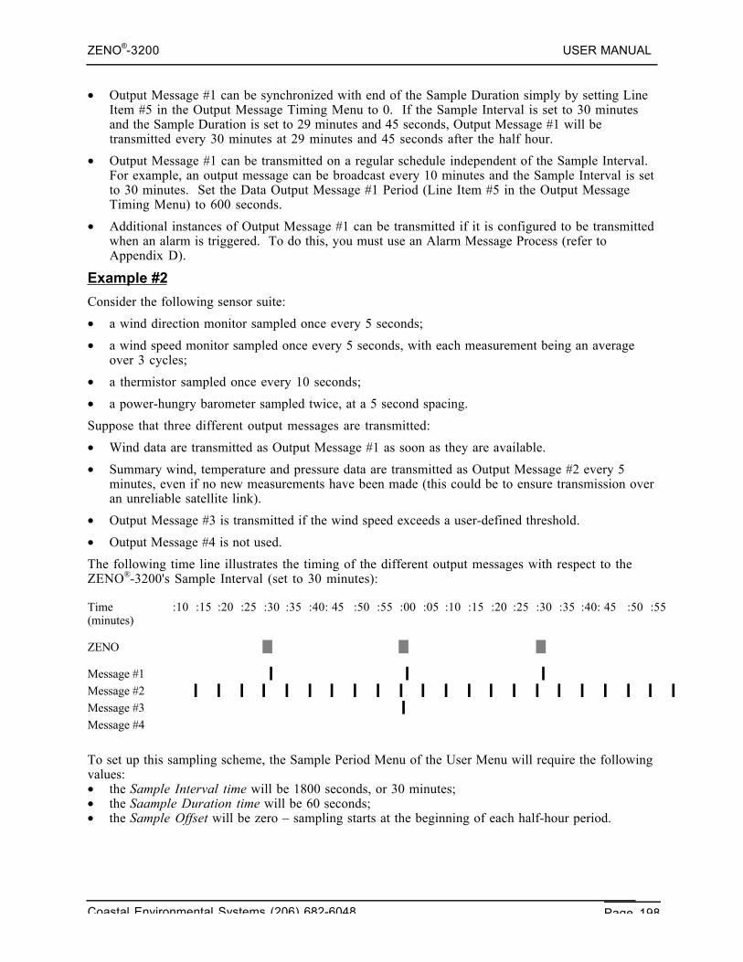
ZENO®-3200 USER MANUAL
Coastal Environmental Systems (206) 682-6048 Page 198
• Output Message #1 can be synchronized with end of the Sample Duration simply by setting LineItem #5 in the Output Message Timing Menu to 0. If the Sample Interval is set to 30 minutesand the Sample Duration is set to 29 minutes and 45 seconds, Output Message #1 will betransmitted every 30 minutes at 29 minutes and 45 seconds after the half hour.
• Output Message #1 can be transmitted on a regular schedule independent of the Sample Interval.For example, an output message can be broadcast every 10 minutes and the Sample Interval is setto 30 minutes. Set the Data Output Message #1 Period (Line Item #5 in the Output MessageTiming Menu) to 600 seconds.
• Additional instances of Output Message #1 can be transmitted if it is configured to be transmittedwhen an alarm is triggered. To do this, you must use an Alarm Message Process (refer toAppendix D).
Example #2
Consider the following sensor suite:
• a wind direction monitor sampled once every 5 seconds;
• a wind speed monitor sampled once every 5 seconds, with each measurement being an averageover 3 cycles;
• a thermistor sampled once every 10 seconds;
• a power-hungry barometer sampled twice, at a 5 second spacing.
Suppose that three different output messages are transmitted:
• Wind data are transmitted as Output Message #1 as soon as they are available.
• Summary wind, temperature and pressure data are transmitted as Output Message #2 every 5minutes, even if no new measurements have been made (this could be to ensure transmission overan unreliable satellite link).
• Output Message #3 is transmitted if the wind speed exceeds a user-defined threshold.
• Output Message #4 is not used.
The following time line illustrates the timing of the different output messages with respect to theZENO®-3200's Sample Interval (set to 30 minutes):
Time :10 :15 :20 :25 :30 :35 :40: 45 :50 :55 :00 :05 :10 :15 :20 :25 :30 :35 :40: 45 :50 :55(minutes)
ZENO
Message #1Message #2Message #3Message #4
To set up this sampling scheme, the Sample Period Menu of the User Menu will require the followingvalues:• the Sample Interval time will be 1800 seconds, or 30 minutes;• the Saample Duration time will be 60 seconds;• the Sample Offset will be zero – sampling starts at the beginning of each half-hour period.
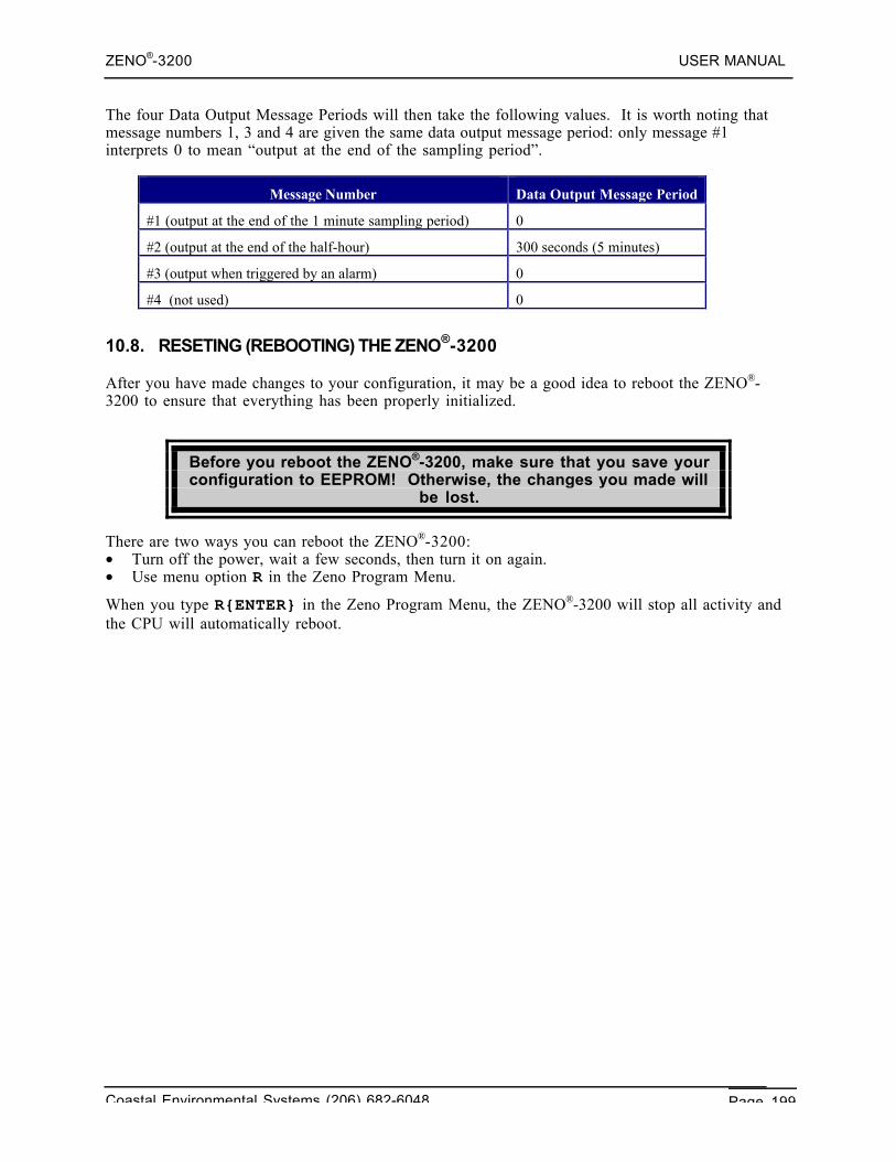
ZENO®-3200 USER MANUAL
Coastal Environmental Systems (206) 682-6048 Page 199
The four Data Output Message Periods will then take the following values. It is worth noting thatmessage numbers 1, 3 and 4 are given the same data output message period: only message #1interprets 0 to mean “output at the end of the sampling period”.
Message Number Data Output Message Period
#1 (output at the end of the 1 minute sampling period) 0
#2 (output at the end of the half-hour) 300 seconds (5 minutes)
#3 (output when triggered by an alarm) 0
#4 (not used) 0
10.8. RESETING (REBOOTING) THE ZENO®-3200
After you have made changes to your configuration, it may be a good idea to reboot the ZENO®-3200 to ensure that everything has been properly initialized.
Before you reboot the ZENO®-3200, make sure that you save yourconfiguration to EEPROM! Otherwise, the changes you made will
be lost.
There are two ways you can reboot the ZENO®-3200:• Turn off the power, wait a few seconds, then turn it on again.• Use menu option R in the Zeno Program Menu.
When you type R{ENTER} in the Zeno Program Menu, the ZENO®-3200 will stop all activity andthe CPU will automatically reboot.
ZENO®-3200 USER MANUAL
Coastal Environmental Systems (206) 682-6048 Page 200
11. ALARM MESSAGES
Coastal EnvironmentalSystems
ZENO®-3200 User Manual
One of the most important features of the ZENO®-3200 is the ability to transmit unsolicited alarmmessages.
A regular output message is transmitted by the ZENO®-3200 on aregular schedule.
An alarm message is transmitted when a specific conditionoccurs making them completely asynchronous.
An alarm condition is defined by configuring the appropriateprocesses, especially Alarm Processes, and can be based upon
more than one requirement.
Once the alarm condition is met, the ZENO®-3200 can transmit analarm message via any of the following:
• Simple terminal • Radio link • Telephone modem • Cellularmodem
• GOES radio •
An alarm condition can also be used to turn on (or off) a digitaloutput or a switched voltage.
ZENO®-3200 USER MANUAL
Coastal Environmental Systems (206) 682-6048 Page 201
You can configure more than one alarm message (up to 4) in theZENO®-3200.
11.1. CONFIGURING AN ALARM CONDITION
Configuring an alarm condition can be done by carrying out the following steps:
1. Identify the one or more parameters that constitute an alarm condition, including the validranges of the parameters.
2. Determine what sensor readings are required to measure the parameters.
3. Determine what processes are needed to process the parameters, including the Alarm Processes.
An example for an alarm condition is a ZENO®-3200 under-voltage. If you are powering yourZENO®-3200 with a battery, you will probably be monitoring the battery voltage. As a batterydischarges over time through use, its voltage will begin to drop. You can configure the ZENO®-3200to automatically alert you that its battery is discharging by monitoring how low the battery voltagehas dropped. For example, you might want the ZENO®-3200 to alert you that the battery voltagehas dropped below 11 VDC. You have now defined an alarm condition and a valid range.
Therefore, to monitor the battery voltage, you can configure a 12-bit ADC Sensor Record tomonitor the internal battery voltage.221 This is the only reading that needs to be made for thisexample alarm condition.
To set an alarm condition, you need to setup an appropriate alarm process (or processes). Reviewingthe available processes listed in Appendix D shows that the best process to use is the Alarm Process(Category 3, Process Number 3):
221 Section 3.2.3 describes this procedure.
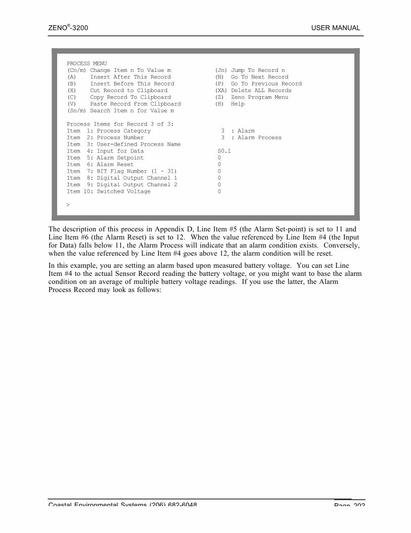
ZENO®-3200 USER MANUAL
Coastal Environmental Systems (206) 682-6048 Page 202
PROCESS MENU(Cn/m) Change Item n To Value m (Jn) Jump To Record n(A) Insert After This Record (N) Go To Next Record(B) Insert Before This Record (P) Go To Previous Record(X) Cut Record to Clipboard (XA) Delete ALL Records(C) Copy Record To Clipboard (Z) Zeno Program Menu(V) Paste Record From Clipboard (H) Help(Sn/m) Search Item n for Value m
Process Items for Record 3 of 3:Item 1: Process Category 3 : AlarmItem 2: Process Number 3 : Alarm ProcessItem 3: User-defined Process NameItem 4: Input for Data S0.1Item 5: Alarm Setpoint 0Item 6: Alarm Reset 0Item 7: BIT Flag Number (1 - 31) 0Item 8: Digital Output Channel 1 0Item 9: Digital Output Channel 2 0Item 10: Switched Voltage 0
>
The description of this process in Appendix D, Line Item #5 (the Alarm Set-point) is set to 11 andLine Item #6 (the Alarm Reset) is set to 12. When the value referenced by Line Item #4 (the Inputfor Data) falls below 11, the Alarm Process will indicate that an alarm condition exists. Conversely,when the value referenced by Line Item #4 goes above 12, the alarm condition will be reset.
In this example, you are setting an alarm based upon measured battery voltage. You can set LineItem #4 to the actual Sensor Record reading the battery voltage, or you might want to base the alarmcondition on an average of multiple battery voltage readings. If you use the latter, the AlarmProcess Record may look as follows:
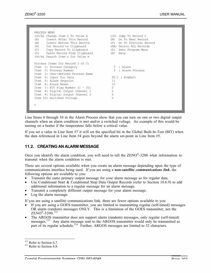
ZENO®-3200 USER MANUAL
Coastal Environmental Systems (206) 682-6048 Page 203
PROCESS MENU(Cn/m) Change Item n To Value m (Jn) Jump To Record n(A) Insert After This Record (N) Go To Next Record(B) Insert Before This Record (P) Go To Previous Record(X) Cut Record to Clipboard (XA) Delete ALL Records(C) Copy Record To Clipboard (Z) Zeno Program Menu(V) Paste Record From Clipboard (H) Help(Sn/m) Search Item n for Value m
Process Items for Record 3 of 3:Item 1: Process Category 3 : AlarmItem 2: Process Number 3 : Alarm ProcessItem 3: User-defined Process NameItem 4: Input for Data P2.1 : AvgBattItem 5: Alarm Setpoint 11Item 6: Alarm Reset 12Item 7: BIT Flag Number (1 - 31) 0Item 8: Digital Output Channel 1 0Item 9: Digital Output Channel 2 0Item 10: Switched Voltage 0
>
Line Items 8 through 10 in the Alarm Process show that you can turn on one or two digital outputchannels when an alarm condition is met and/or a switched voltage. An example of this would beturning on a heater if the temperature falls below a critical value.
If you set a value in Line Item #7 it will set the specified bit in the Global Built-In-Test (BIT) whenthe data referenced in Line Item #4 goes beyond the alarm set-point in Line Item #5.
11.2. CREATING AN ALARM MESSAGE
Once you identify the alarm condition, you will need to tell the ZENO®-3200 what information totransmit when the alarm condition is met.
There are several options available when you create an alarm message depending upon the type ofcommunications interface being used. If you are using a non-satellite communications link, thefollowing options are available to you:• Transmit the same primary output message for your alarm message as for regular data.• Use Conditional Start & Conditional Stop Data Output Records (refer to Section 10.6.9) to add
additional information to a regular message for an alarm message.• Transmit a completely different output message for your alarm message.• Log the alarm message.
If you are using a satellite communications link, there are fewer options available to you:• If you are using a GOES transmitter, you are limited to transmitting regular (self-timed) messages
OR alarm (random) messages ONLY. This is a limitation of the GOES transmitter, not theZENO®-3200.222
• The ARGOS transmitter does not support alarm (random) messages, only regular (self-timed)messages.223 Any alarm message sent to the ARGOS transmitter would only be transmitted aspart of its regular schedule.224 Further, ARGOS messages are limited to 32 characters.
222 Refer to Section 6.7.223 Refer to Section 6.8.
ZENO®-3200 USER MANUAL
Coastal Environmental Systems (206) 682-6048 Page 204
11.2.1. Transmitting Your Regular Output Message As An Alarm Message
Transmitting (and possibly logging) your regular output message as an alarm message is simply amatter of setting up the correct process (or processes) that define the alarm condition, thenfollowing the instructions in Section 11.3.
11.2.2. Using Conditional Message Fragments In An Alarm Message
Your regular output message may not contain sufficient information when an alarm condition arises.If you need to transmit the regular output message information along with the alarm informationwhen an alarm condition arises, you can setup one or more conditional message fragments to betransmitted by following the instructions in Section 10.6.9:
• Place all alarm information between two Data Output Records setup as Conditional Start andConditional Stop field types.
• Configure the Data Input (Line Item #4 in the Data Output Menu) in the Conditional Start DataOutput Record to reference the alarm state generated by your alarm condition process.
• If you need the alarm message to be transmitted immediately when the alarm condition is met(and possibly be logged), then you need to follow the instructions in Section 11.3. Otherwise,you can simply have the regular output message transmit at its regular time with the addition ofthe conditional message fragment containing the alarm information.
11.2.3. Transmitting A Unique Alarm Message
You may need to transmit completely different information when an alarm condition arises asopposed to what you would transmit in a regular output message. For this procedure, you will need touse at least two output messages in which one is designated as the regular output message and thesecond is designated as the alarm message.
You can also configure a single output message to be an alarmmessage and not have a regularly transmitted output message.
To distinguish each Data Output Record for which output message is applies, you need to configureLine Item #2 in each Data Output Record (the Output Message) accordingly.225
To transmit (and possibly log) the unique alarm message, follow the instructions in Section 11.3.
11.3. CONFIGURING THE ZENO®-3200 TO TRANSMIT (AND POSSIBLY LOG) ANALARM MESSAGE
You must use one of two processes in the Alarm ProcessesCategory to cause the ZENO®-3200 to transmit (and possibly log)
224 Unlike GOES satellites that sit in geo-synchronous orbits, the ARGOS system is installed on two polar-orbitingsatellites. This means that when an alarm condition occurs, there is a very high probability that no satellite will bethere to receive the alarm message when it occurs.225 Refer to Section 10.6.4.
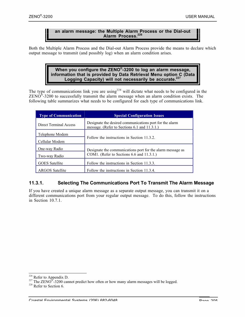
ZENO®-3200 USER MANUAL
Coastal Environmental Systems (206) 682-6048 Page 205
an alarm message: the Multiple Alarm Process or the Dial-outAlarm Process.226
Both the Multiple Alarm Process and the Dial-out Alarm Process provide the means to declare whichoutput message to transmit (and possibly log) when an alarm condition arises.
When you configure the ZENO®-3200 to log an alarm message,information that is provided by Data Retrieval Menu option C (Data
Logging Capacity) will not necessarily be accurate.227
The type of communications link you are using228 will dictate what needs to be configured in theZENO®-3200 to successfully transmit the alarm message when an alarm condition exists. Thefollowing table summarizes what needs to be configured for each type of communications link.
Type of Communication Special Configuration Issues
Direct Terminal Access Designate the desired communications port for the alarmmessage. (Refer to Sections 6.1 and 11.3.1.)
Telephone Modem
Cellular ModemFollow the instructions in Section 11.3.2.
One-way Radio
Two-way Radio
Designate the communications port for the alarm message asCOM1. (Refer to Sections 6.6 and 11.3.1.)
GOES Satellite Follow the instructions in Section 11.3.3.
ARGOS Satellite Follow the instructions in Section 11.3.4.
11.3.1. Selecting The Communications Port To Transmit The Alarm Message
If you have created a unique alarm message as a separate output message, you can transmit it on adifferent communications port from your regular output message. To do this, follow the instructionsin Section 10.7.1.
226 Refer to Appendix D.227 The ZENO®-3200 cannot predict how often or how many alarm messages will be logged.228 Refer to Section 6.
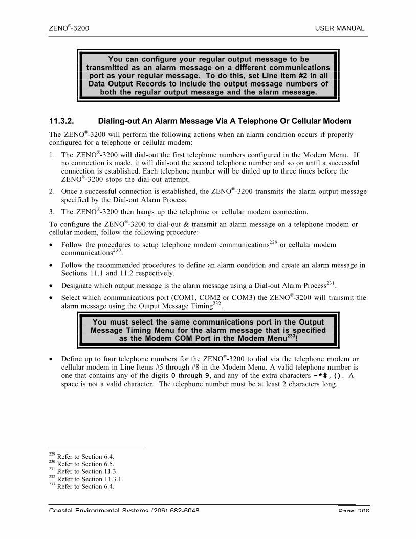
ZENO®-3200 USER MANUAL
Coastal Environmental Systems (206) 682-6048 Page 206
You can configure your regular output message to betransmitted as an alarm message on a different communicationsport as your regular message. To do this, set Line Item #2 in allData Output Records to include the output message numbers of
both the regular output message and the alarm message.
11.3.2. Dialing-out An Alarm Message Via A Telephone Or Cellular Modem
The ZENO®-3200 will perform the following actions when an alarm condition occurs if properlyconfigured for a telephone or cellular modem:
1. The ZENO®-3200 will dial-out the first telephone numbers configured in the Modem Menu. Ifno connection is made, it will dial-out the second telephone number and so on until a successfulconnection is established. Each telephone number will be dialed up to three times before theZENO®-3200 stops the dial-out attempt.
2. Once a successful connection is established, the ZENO®-3200 transmits the alarm output messagespecified by the Dial-out Alarm Process.
3. The ZENO®-3200 then hangs up the telephone or cellular modem connection.
To configure the ZENO®-3200 to dial-out & transmit an alarm message on a telephone modem orcellular modem, follow the following procedure:
• Follow the procedures to setup telephone modem communications229 or cellular modemcommunications230.
• Follow the recommended procedures to define an alarm condition and create an alarm message inSections 11.1 and 11.2 respectively.
• Designate which output message is the alarm message using a Dial-out Alarm Process231.
• Select which communications port (COM1, COM2 or COM3) the ZENO®-3200 will transmit thealarm message using the Output Message Timing232.
You must select the same communications port in the OutputMessage Timing Menu for the alarm message that is specified
as the Modem COM Port in the Modem Menu233!
• Define up to four telephone numbers for the ZENO®-3200 to dial via the telephone modem orcellular modem in Line Items #5 through #8 in the Modem Menu. A valid telephone number isone that contains any of the digits 0 through 9, and any of the extra characters -*#,(). Aspace is not a valid character. The telephone number must be at least 2 characters long.
229 Refer to Section 6.4.230 Refer to Section 6.5.231 Refer to Section 11.3.232 Refer to Section 11.3.1.233 Refer to Section 6.4.
ZENO®-3200 USER MANUAL
Coastal Environmental Systems (206) 682-6048 Page 207
MODEM MENU(Cn/m) Change Item n To Value m (U) User Menu(E) Save Parameters To EEPROM (Q) Quit(S) Speech Interface Menu (H) Help
Item 1: 1 (System Modem Type)Item 2: COM3 (Modem COM Port)Item 3: 5 (Modem Retry Period)Item 4: 0 (Modem Hangup Delay)Item 5: 1-206-555-1234 (Modem Telephone Number 1)Item 6: NONE (Modem Telephone Number 2)Item 7: NONE (Modem Telephone Number 3)Item 8: NONE (Modem Telephone Number 4)Item 9: NONE (Modem Initialization String)Item 10: 0 (Modem Switched Voltage)Item 11: 0 (Modem Ring Detect Channel)
>
Line Items #3 and #4 in the Modem Menu are explained more fully below:
• Line item 3, Modem Retry Period in seconds: a good minimum value for the retry period is 90seconds, since it can take a minute or more for a phone modem to connect. If the ZENO®-3200cannot connect on dial-out, it will try a total of 3 times before giving up.
• Line item 4, Modem Hang-up Delay in seconds: this is the delay between when the ZENO®-3200sends its message and when the ZENO®-3200 instructs the modem to hang up its communication.If you wish to communicate further with the ZENO®-3200 when an alarm condition occurs, setthis to a non-zero value. This gives a delay time in which you (or the receiving computer) cansend polling, user or other commands to the ZENO®-3200.
11.3.3. Transmitting An Alarm Message Via A GOES Transmitter
A GOES transmitter is limited to transmitting self-timed(regularly scheduled) messages only or random (alarm)
messages only. It cannot do both simultaneously.234
If you need to transmit alarm messages via a GOES transmitter, you will need to setup its randommessage settings instead of the self-timed settings. When the ZENO®-3200 sends the alarm messageto the GOES transmitter, it will be stored by the GOES transmitter in its random message bufferinstead of the self-time message buffer.
You have the option of sending the alarm message in GOES binary format, like the regular (self-timed) output messages.235
To setup the ZENO®-3200 to send alarm messages via a GOES transmitter, use the following steps:
• Follow the procedures to setup the GOES transmitter communications link using randommessages.236
234 Refer to Section 6.7.235 Refer to Section 6.7.12.236 Refer to Section 6.7.
ZENO®-3200 USER MANUAL
Coastal Environmental Systems (206) 682-6048 Page 208
• Follow the recommended procedures to define an alarm condition and create an alarm message inSections 11.1 and 11.2 respectively.
• Designate which output message is the alarm message using a Dial-out Alarm Process or MultipleAlarm Process.237
• Select COM2 as the communications port for the ZENO®-3200 will transmit the alarm messageusing the Output Message Timing.238 The GOES transmitter can only be connected to COM2.
11.3.4. Transmitting An Alarm Message Via An ARGOS Transmitter
Coastal Environmental Systems does NOT recommend use ofthe ARGOS transmitter & satellites for alarm messages. The
satellites containing the ARGOS transceivers are in polar orbitsreducing the likelihood that a satellite will be in range to receive
an alarm message when an alarm condition occurs.
If you choose to use the ARGOS transmitter with an alarm message, the alarm message will betransmitted to the satellite in the same manner that it would transmit a regular output message.
You have the option of sending the alarm message in ARGOS binary format, like the regular outputmessages.239
REMEMBER: a message to the ARGOS satellite is limited to 32bytes!
To configure the ARGOS transmitter for an alarm message, use the following steps:
• Follow the procedures to setup the ARGOS transmitter communications link.240
• Follow the recommended procedures to define an alarm condition and create an alarm message inSections 11.1 and 11.2 respectively.
• Designate which output message is the alarm message using a Dial-out Alarm Process or MultipleAlarm Process.241
• Select COM2 as the communications port for the ZENO®-3200 will transmit the alarm messageusing the Output Message Timing.242 The ARGOS transmitter can only be connected to COM2.
237 Refer to Section 11.3.238 Refer to Section 11.3.1.239 Refer to Section 6.8.6.240 Refer to Section 6.8.241 Refer to Section 11.3.242 Refer to Section 11.3.1.
ZENO®-3200 USER MANUAL
Coastal Environmental Systems (206) 682-6048 Page 209
12. ADVANCED ZENO®-3200 CONFIGURATION
TOPICS
Coastal EnvironmentalSystems
ZENO®-3200 User Manual
This section describes several topics of an advanced nature. You should not read this section untilyou have a good understanding of creating basic ZENO®-3200 configurations.
The topics covered in this section are varied:• Understanding ZENO®-3200 Timing.• The Universal Serial Interface.• Configurations with Multiple Serial Sensors.• Sharing Data between multiple ZENO®-3200's (Multiprocessing).
12.1. UNDERSTANDING ZENO®-3200 TIMING
The key to understanding timing in the ZENO®-3200 can be summarized by the followingstatements.• Each function that the ZENO®-3200 is required to do by its configuration requires a certain
amount of time for completion.• The time that each function requires must be balanced with each other in order for the ZENO®-
3200 to successfully carry out all the functions defined in a configuration.• When the amounts of time of various functions within a configuration are imbalanced, the
ZENO®-3200 will be unable to carry out the various functions for a configuration and errors willresult.
Many of the errors that occur in a ZENO®-3200 configuration arethe result of the user not understanding how much time each
function will require within the configuration.
12.1.1. ZENO®-3200 Timing Structure
ZENO®-3200 timing structure can be illustrated with the following diagram showing four differentlayers. Each layer is dependent upon the layers beneath it!
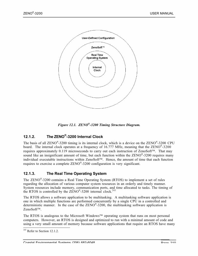
ZENO®-3200 USER MANUAL
Coastal Environmental Systems (206) 682-6048 Page 210
Figure 12.1. ZENO®-3200 Timing Structure Diagram.
12.1.2. The ZENO®-3200 Internal Clock
The basis of all ZENO®-3200 timing is its internal clock, which is a device on the ZENO®-3200 CPUboard. The internal clock operates at a frequency of 16.777 MHz, meaning that the ZENO®-3200requires approximately 0.119 microseconds to carry out each instruction of ZenoSoft. That maysound like an insignificant amount of time, but each function within the ZENO®-3200 requires manyindividual executable instructions within ZenoSoft. Hence, the amount of time that each functionrequires to exercise a complete ZENO®-3200 configuration is very significant.
12.1.3. The Real Time Operating System
The ZENO®-3200 contains a Real Time Operating System (RTOS) to implement a set of rulesregarding the allocation of various computer system resources in an orderly and timely manner.System resources include memory, communication ports, and time allocated to tasks. The timing ofthe RTOS is controlled by the ZENO®-3200 internal clock.243
The RTOS allows a software application to be multitasking. A multitasking software application isone in which multiple functions are performed concurrently by a single CPU in a controlled anddeterministic manner. In the case of the ZENO®-3200, the multitasking software application isZenoSoft.
The RTOS is analogous to the Microsoft Windows operating system that runs on most personalcomputers. However, an RTOS is designed and optimized to run with a minimal amount of code andusing a very small amount of memory because software applications that require an RTOS have many 243 Refer to Section 12.1.2.
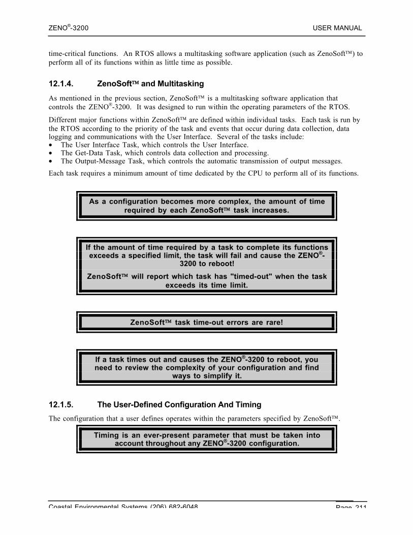
ZENO®-3200 USER MANUAL
Coastal Environmental Systems (206) 682-6048 Page 211
time-critical functions. An RTOS allows a multitasking software application (such as ZenoSoft) toperform all of its functions within as little time as possible.
12.1.4. ZenoSoft and Multitasking
As mentioned in the previous section, ZenoSoft is a multitasking software application thatcontrols the ZENO®-3200. It was designed to run within the operating parameters of the RTOS.
Different major functions within ZenoSoft are defined within individual tasks. Each task is run bythe RTOS according to the priority of the task and events that occur during data collection, datalogging and communications with the User Interface. Several of the tasks include:• The User Interface Task, which controls the User Interface.• The Get-Data Task, which controls data collection and processing.• The Output-Message Task, which controls the automatic transmission of output messages.
Each task requires a minimum amount of time dedicated by the CPU to perform all of its functions.
As a configuration becomes more complex, the amount of timerequired by each ZenoSoft task increases.
If the amount of time required by a task to complete its functionsexceeds a specified limit, the task will fail and cause the ZENO®-
3200 to reboot!
ZenoSoft will report which task has "timed-out" when the taskexceeds its time limit.
ZenoSoft task time-out errors are rare!
If a task times out and causes the ZENO®-3200 to reboot, youneed to review the complexity of your configuration and find
ways to simplify it.
12.1.5. The User-Defined Configuration And Timing
The configuration that a user defines operates within the parameters specified by ZenoSoft.
Timing is an ever-present parameter that must be taken intoaccount throughout any ZENO®-3200 configuration.
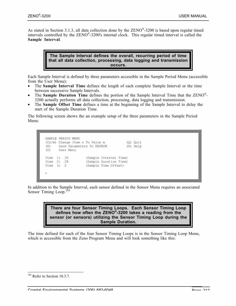
ZENO®-3200 USER MANUAL
Coastal Environmental Systems (206) 682-6048 Page 212
As stated in Section 3.1.3, all data collection done by the ZENO®-3200 is based upon regular timedintervals controlled by the ZENO®-3200's internal clock. This regular timed interval is called theSample Interval.
The Sample Interval defines the overall, recurring period of timethat all data collection, processing, data logging and transmission
occurs.
Each Sample Interval is defined by three parameters accessible in the Sample Period Menu (accessiblefrom the User Menu):• The Sample Interval Time defines the length of each complete Sample Interval or the time
between successive Sample Intervals.• The Sample Duration Time defines the portion of the Sample Interval Time that the ZENO®-
3200 actually performs all data collection, processing, data logging and transmission.• The Sample Offset Time defines a time at the beginning of the Sample Interval to delay the
start of the Sample Duration Time.
The following screen shows the an example setup of the three parameters in the Sample PeriodMenu:
SAMPLE PERIOD MENU(Cn/m) Change Item n To Value m (Q) Quit(E) Save Parameters To EEPROM (H) Help(U) User Menu
Item 1: 30 (Sample Interval Time)Item 2: 28 (Sample Duration Time)Item 3: 2 (Sample Time Offset)
>
In addition to the Sample Interval, each sensor defined in the Sensor Menu requires an associatedSensor Timing Loop.244
There are four Sensor Timing Loops. Each Sensor Timing Loopdefines how often the ZENO®-3200 takes a reading from the
sensor (or sensors) utilizing the Sensor Timing Loop during theSample Duration.
The time defined for each of the four Sensor Timing Loops is in the Sensor Timing Loop Menu,which is accessible from the Zeno Program Menu and will look something like this:
244 Refer to Section 10.3.7.
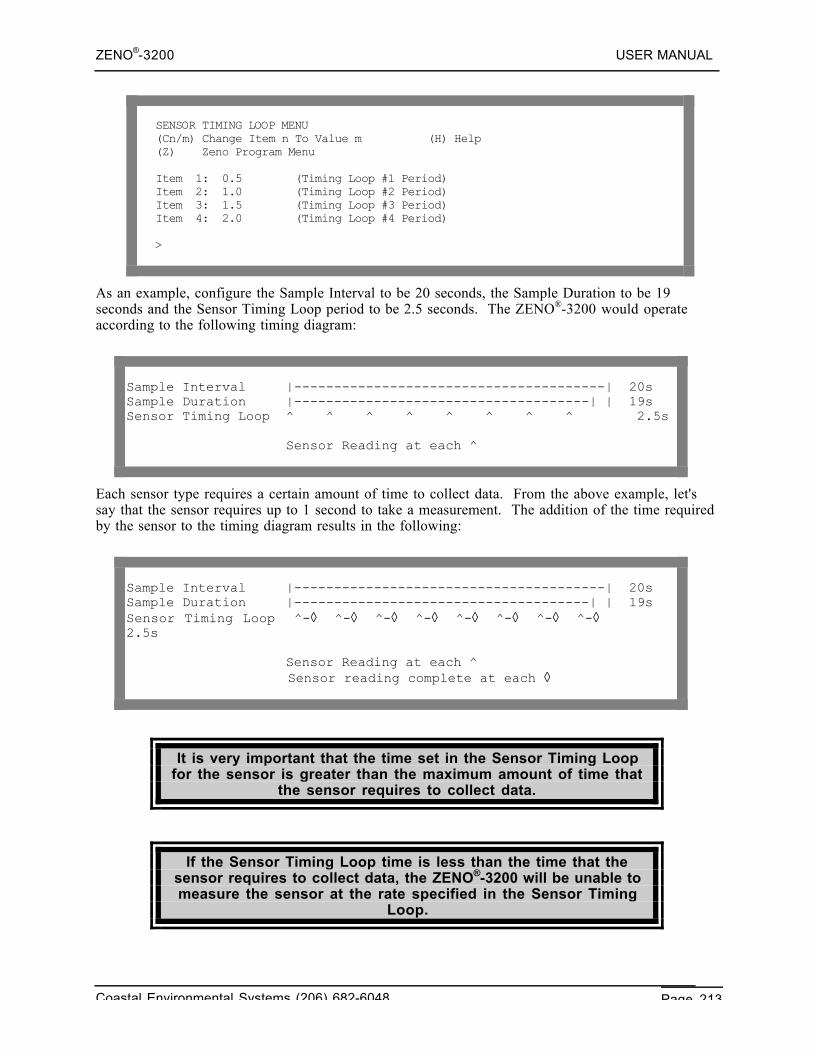
ZENO®-3200 USER MANUAL
Coastal Environmental Systems (206) 682-6048 Page 213
SENSOR TIMING LOOP MENU(Cn/m) Change Item n To Value m (H) Help(Z) Zeno Program Menu
Item 1: 0.5 (Timing Loop #1 Period)Item 2: 1.0 (Timing Loop #2 Period)Item 3: 1.5 (Timing Loop #3 Period)Item 4: 2.0 (Timing Loop #4 Period)
>
As an example, configure the Sample Interval to be 20 seconds, the Sample Duration to be 19seconds and the Sensor Timing Loop period to be 2.5 seconds. The ZENO®-3200 would operateaccording to the following timing diagram:
Sample Interval |---------------------------------------| 20sSample Duration |-------------------------------------| | 19sSensor Timing Loop ^ ^ ^ ^ ^ ^ ^ ^ 2.5s
Sensor Reading at each ^
Each sensor type requires a certain amount of time to collect data. From the above example, let'ssay that the sensor requires up to 1 second to take a measurement. The addition of the time requiredby the sensor to the timing diagram results in the following:
Sample Interval |---------------------------------------| 20sSample Duration |-------------------------------------| | 19sSensor Timing Loop ^-◊ ^-◊ ^-◊ ^-◊ ^-◊ ^-◊ ^-◊ ^-◊2.5s
Sensor Reading at each ^ Sensor reading complete at each ◊
It is very important that the time set in the Sensor Timing Loopfor the sensor is greater than the maximum amount of time that
the sensor requires to collect data.
If the Sensor Timing Loop time is less than the time that thesensor requires to collect data, the ZENO®-3200 will be unable tomeasure the sensor at the rate specified in the Sensor Timing
Loop.
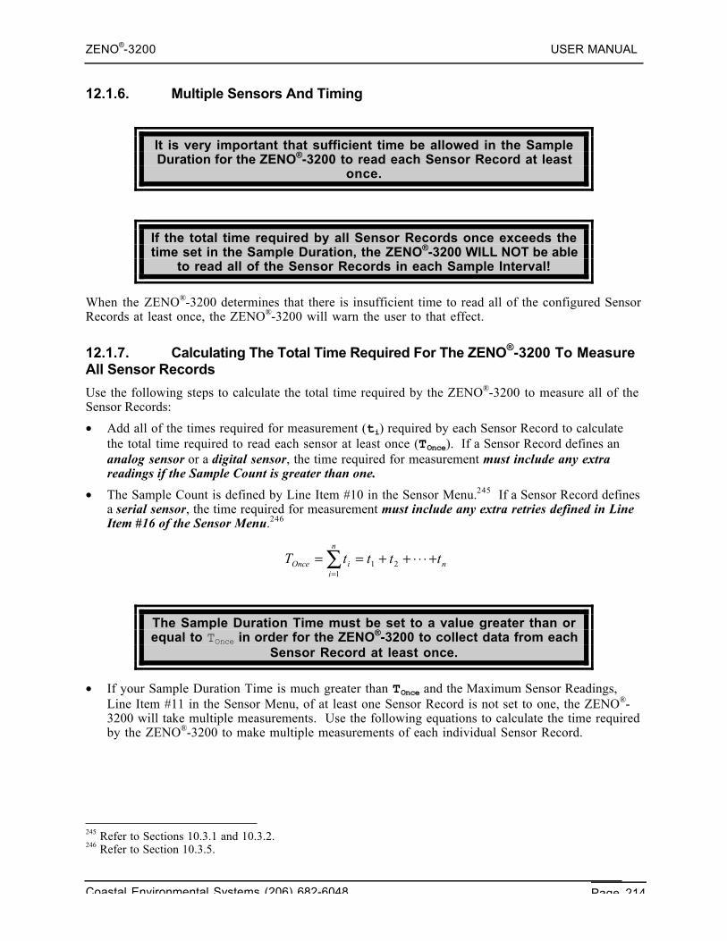
ZENO®-3200 USER MANUAL
Coastal Environmental Systems (206) 682-6048 Page 214
12.1.6. Multiple Sensors And Timing
It is very important that sufficient time be allowed in the SampleDuration for the ZENO®-3200 to read each Sensor Record at least
once.
If the total time required by all Sensor Records once exceeds thetime set in the Sample Duration, the ZENO®-3200 WILL NOT be able
to read all of the Sensor Records in each Sample Interval!
When the ZENO®-3200 determines that there is insufficient time to read all of the configured SensorRecords at least once, the ZENO®-3200 will warn the user to that effect.
12.1.7. Calculating The Total Time Required For The ZENO®-3200 To MeasureAll Sensor Records
Use the following steps to calculate the total time required by the ZENO®-3200 to measure all of theSensor Records:
• Add all of the times required for measurement (ti) required by each Sensor Record to calculatethe total time required to read each sensor at least once (TOnce). If a Sensor Record defines ananalog sensor or a digital sensor, the time required for measurement must include any extrareadings if the Sample Count is greater than one.
• The Sample Count is defined by Line Item #10 in the Sensor Menu.245 If a Sensor Record definesa serial sensor, the time required for measurement must include any extra retries defined in LineItem #16 of the Sensor Menu.246
The Sample Duration Time must be set to a value greater than orequal to TOnce in order for the ZENO®-3200 to collect data from each
Sensor Record at least once.
• If your Sample Duration Time is much greater than TOnce and the Maximum Sensor Readings,Line Item #11 in the Sensor Menu, of at least one Sensor Record is not set to one, the ZENO®-3200 will take multiple measurements. Use the following equations to calculate the time requiredby the ZENO®-3200 to make multiple measurements of each individual Sensor Record.
245 Refer to Sections 10.3.1 and 10.3.2.246 Refer to Section 10.3.5.
n
n
iiOnce ttttT +⋅⋅⋅++==∑
=121
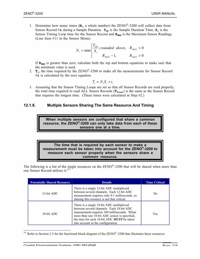
ZENO®-3200 USER MANUAL
Coastal Environmental Systems (206) 682-6048 Page 215
1. Determine how many times (Ni, a whole number) the ZENO®-3200 will collect data fromSensor Record #i during a Sample Duration. TSD is the Sample Duration Time, Si is theSensor Timing Loop time for the Sensor Record and RMAX is the Maximum Sensor Readings(Line Item #11 in the Sensor Menu).
If RMAX is greater than zero, calculate both the top and bottom equations to make sure thatthe minimum value is used.
2. Ti, the time required by the ZENO®-3200 to make all the measurements for Sensor Record#i is calculated by the next equation.
3. Assuming that the Sensor Timing Loops are set so that all Sensor Records are read properly,the total time required to read ALL Sensor Records (TTotal) is the same as the Sensor Recordthat requires the longest time. (These times were calculated in Step #2.)
12.1.8. Multiple Sensors Sharing The Same Resource And Timing
When multiple sensors are configured that share a commonresource, the ZENO®-3200 can only take data from each of these
sensors one at a time.
The time that is required by each sensor to make ameasurement must be taken into account for the ZENO®-3200 to
measure each sensor properly when the sensors share acommon resource.
The following is a list of the single resources on the ZENO®-3200 that will be shared when more thanone Sensor Record utilizes it.247
Potentially Shared Resource Details Time Critical
12-bit ADC
There is a single 12-bit ADC multiplexedbetween several channels. Each 12-bit ADCmeasurement requires only 0.1 milliseconds, sosharing this resource is not that critical.
No
18-bit ADC
There is a single 18-bit ADC multiplexedbetween several channels. Each 18-bit ADCmeasurement requires 100 milliseconds. Whenmore than one 18-bit ADC sensor is specified,the time for each 18-bit ADC MUST be takeninto account in the configuration.
Yes
247 Refer to Section 2.5 for the functional block-diagram of the ZENO®-3200 that illustrates these resources.
⎪⎩
⎪⎨⎧
>−
=⋅=0,1
0,;min
MAXMAX
MAXi
SD
i
RR
RdownroundedS
TN
iiii tSNT +=
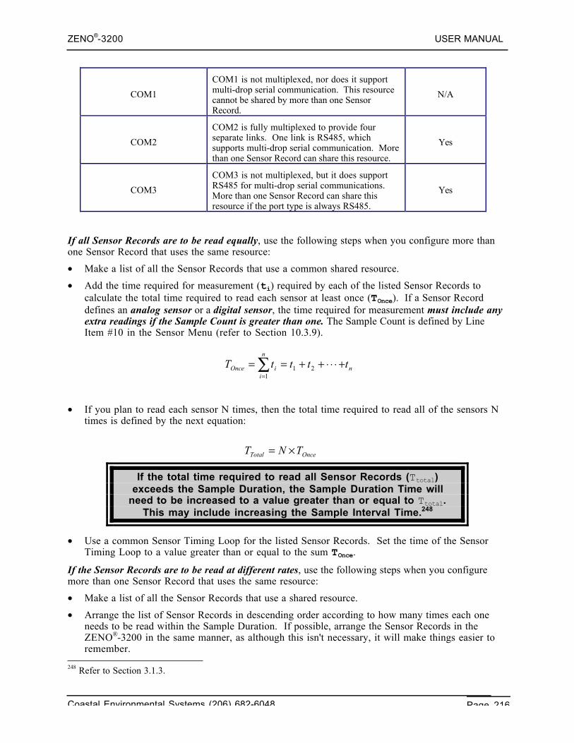
ZENO®-3200 USER MANUAL
Coastal Environmental Systems (206) 682-6048 Page 216
COM1
COM1 is not multiplexed, nor does it supportmulti-drop serial communication. This resourcecannot be shared by more than one SensorRecord.
N/A
COM2
COM2 is fully multiplexed to provide fourseparate links. One link is RS485, whichsupports multi-drop serial communication. Morethan one Sensor Record can share this resource.
Yes
COM3
COM3 is not multiplexed, but it does supportRS485 for multi-drop serial communications.More than one Sensor Record can share thisresource if the port type is always RS485.
Yes
If all Sensor Records are to be read equally, use the following steps when you configure more thanone Sensor Record that uses the same resource:
• Make a list of all the Sensor Records that use a common shared resource.
• Add the time required for measurement (ti) required by each of the listed Sensor Records tocalculate the total time required to read each sensor at least once (TOnce). If a Sensor Recorddefines an analog sensor or a digital sensor, the time required for measurement must include anyextra readings if the Sample Count is greater than one. The Sample Count is defined by LineItem #10 in the Sensor Menu (refer to Section 10.3.9).
• If you plan to read each sensor N times, then the total time required to read all of the sensors Ntimes is defined by the next equation:
If the total time required to read all Sensor Records (Ttotal)exceeds the Sample Duration, the Sample Duration Time will
need to be increased to a value greater than or equal to Ttotal.This may include increasing the Sample Interval Time.248
• Use a common Sensor Timing Loop for the listed Sensor Records. Set the time of the SensorTiming Loop to a value greater than or equal to the sum TOnce.
If the Sensor Records are to be read at different rates, use the following steps when you configuremore than one Sensor Record that uses the same resource:
• Make a list of all the Sensor Records that use a shared resource.
• Arrange the list of Sensor Records in descending order according to how many times each oneneeds to be read within the Sample Duration. If possible, arrange the Sensor Records in theZENO®-3200 in the same manner, as although this isn't necessary, it will make things easier toremember.
248 Refer to Section 3.1.3.
n
n
iiOnce ttttT +⋅⋅⋅++==∑
=121
OnceTotal TNT ×=
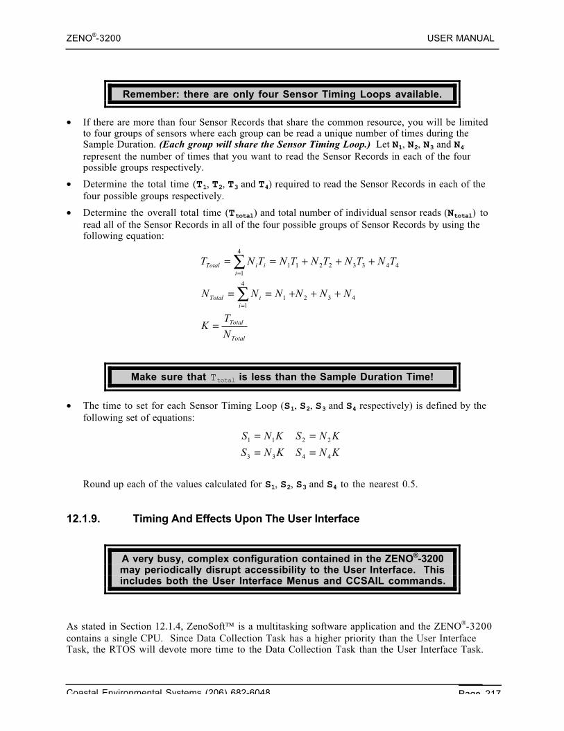
ZENO®-3200 USER MANUAL
Coastal Environmental Systems (206) 682-6048 Page 217
Remember: there are only four Sensor Timing Loops available.
• If there are more than four Sensor Records that share the common resource, you will be limitedto four groups of sensors where each group can be read a unique number of times during theSample Duration. (Each group will share the Sensor Timing Loop.) Let N1, N2, N3 and N4represent the number of times that you want to read the Sensor Records in each of the fourpossible groups respectively.
• Determine the total time (T1, T2, T3 and T4) required to read the Sensor Records in each of thefour possible groups respectively.
• Determine the overall total time (Ttotal) and total number of individual sensor reads (Ntotal) toread all of the Sensor Records in all of the four possible groups of Sensor Records by using thefollowing equation:
Make sure that Ttotal is less than the Sample Duration Time!
• The time to set for each Sensor Timing Loop (S1, S2, S3 and S4 respectively) is defined by thefollowing set of equations:
Round up each of the values calculated for S1, S2, S3 and S4 to the nearest 0.5.
12.1.9. Timing And Effects Upon The User Interface
A very busy, complex configuration contained in the ZENO®-3200may periodically disrupt accessibility to the User Interface. Thisincludes both the User Interface Menus and CCSAIL commands.
As stated in Section 12.1.4, ZenoSoft is a multitasking software application and the ZENO®-3200contains a single CPU. Since Data Collection Task has a higher priority than the User InterfaceTask, the RTOS will devote more time to the Data Collection Task than the User Interface Task.
Total
Total
iiTotal
iiiTotal
N
TK
NNNNNN
TNTNTNTNTNT
=
+++==
+++==
∑
∑
=
=
432
4
11
44332211
4
1
KNSKNS
KNSKNS
4433
2211
====
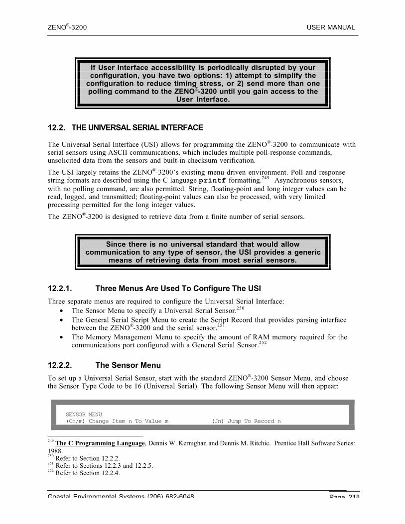
ZENO®-3200 USER MANUAL
Coastal Environmental Systems (206) 682-6048 Page 218
If User Interface accessibility is periodically disrupted by yourconfiguration, you have two options: 1) attempt to simplify the
configuration to reduce timing stress, or 2) send more than onepolling command to the ZENO®-3200 until you gain access to the
User Interface.
12.2. THE UNIVERSAL SERIAL INTERFACE
The Universal Serial Interface (USI) allows for programming the ZENO®-3200 to communicate withserial sensors using ASCII communications, which includes multiple poll-response commands,unsolicited data from the sensors and built-in checksum verification.
The USI largely retains the ZENO®-3200’s existing menu-driven environment. Poll and responsestring formats are described using the C language printf formatting.249 Asynchronous sensors,with no polling command, are also permitted. String, floating-point and long integer values can beread, logged, and transmitted; floating-point values can also be processed, with very limitedprocessing permitted for the long integer values.
The ZENO®-3200 is designed to retrieve data from a finite number of serial sensors.
Since there is no universal standard that would allowcommunication to any type of sensor, the USI provides a generic
means of retrieving data from most serial sensors.
12.2.1. Three Menus Are Used To Configure The USI
Three separate menus are required to configure the Universal Serial Interface:• The Sensor Menu to specify a Universal Serial Sensor.250
• The General Serial Script Menu to create the Script Record that provides parsing interfacebetween the ZENO®-3200 and the serial sensor.251
• The Memory Management Menu to specify the amount of RAM memory required for thecommunications port configured with a General Serial Sensor.252
12.2.2. The Sensor Menu
To set up a Universal Serial Sensor, start with the standard ZENO®-3200 Sensor Menu, and choosethe Sensor Type Code to be 16 (Universal Serial). The following Sensor Menu will then appear:
SENSOR MENU(Cn/m) Change Item n To Value m (Jn) Jump To Record n
249 The C Programming Language, Dennis W. Kernighan and Dennis M. Ritchie. Prentice Hall Software Series:1988.250 Refer to Section 12.2.2.251 Refer to Sections 12.2.3 and 12.2.5.252 Refer to Section 12.2.4.
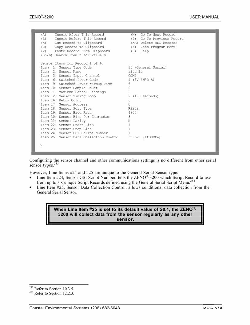
ZENO®-3200 USER MANUAL
Coastal Environmental Systems (206) 682-6048 Page 219
(A) Insert After This Record (N) Go To Next Record(B) Insert Before This Record (P) Go To Previous Record(X) Cut Record to Clipboard (XA) Delete ALL Records(C) Copy Record To Clipboard (Z) Zeno Program Menu(V) Paste Record From Clipboard (H) Help(Sn/m) Search Item n for Value m
Sensor Items for Record 1 of 6:Item 1: Sensor Type Code 16 (General Serial)Item 2: Sensor Name ritchieItem 3: Sensor Input Channel COM2Item 6: Switched Power Code 1 (5V SW'D A)Item 9: Switched Power Warmup Time 6Item 10: Sensor Sample Count 2Item 11: Maximum Sensor Readings 2Item 12: Sensor Timing Loop 2 (1.0 seconds)Item 16: Retry Count 6Item 17: Sensor Address 0Item 18: Sensor Port Type RS232Item 19: Sensor Baud Rate 4800Item 20: Sensor Bits Per Character 8Item 21: Sensor Parity NItem 22: Sensor Start Bits 1Item 23: Sensor Stop Bits 1Item 24: Sensor GSI Script Number 1Item 25: Sensor Data Collection Control P6.L2 (lt3ORte)
>
Configuring the sensor channel and other communications settings is no different from other serialsensor types.253
However, Line Items #24 and #25 are unique to the General Serial Sensor type:• Line Item #24, Sensor GSI Script Number, tells the ZENO®-3200 which Script Record to use
from up to six unique Script Records defined using the General Serial Script Menu.254
• Line Item #25, Sensor Data Collection Control, allows conditional data collection from theGeneral Serial Sensor.
When Line Item #25 is set to its default value of S0.1, the ZENO®-3200 will collect data from the sensor regularly as any other
sensor.
253 Refer to Section 10.3.5.254 Refer to Section 12.2.3.
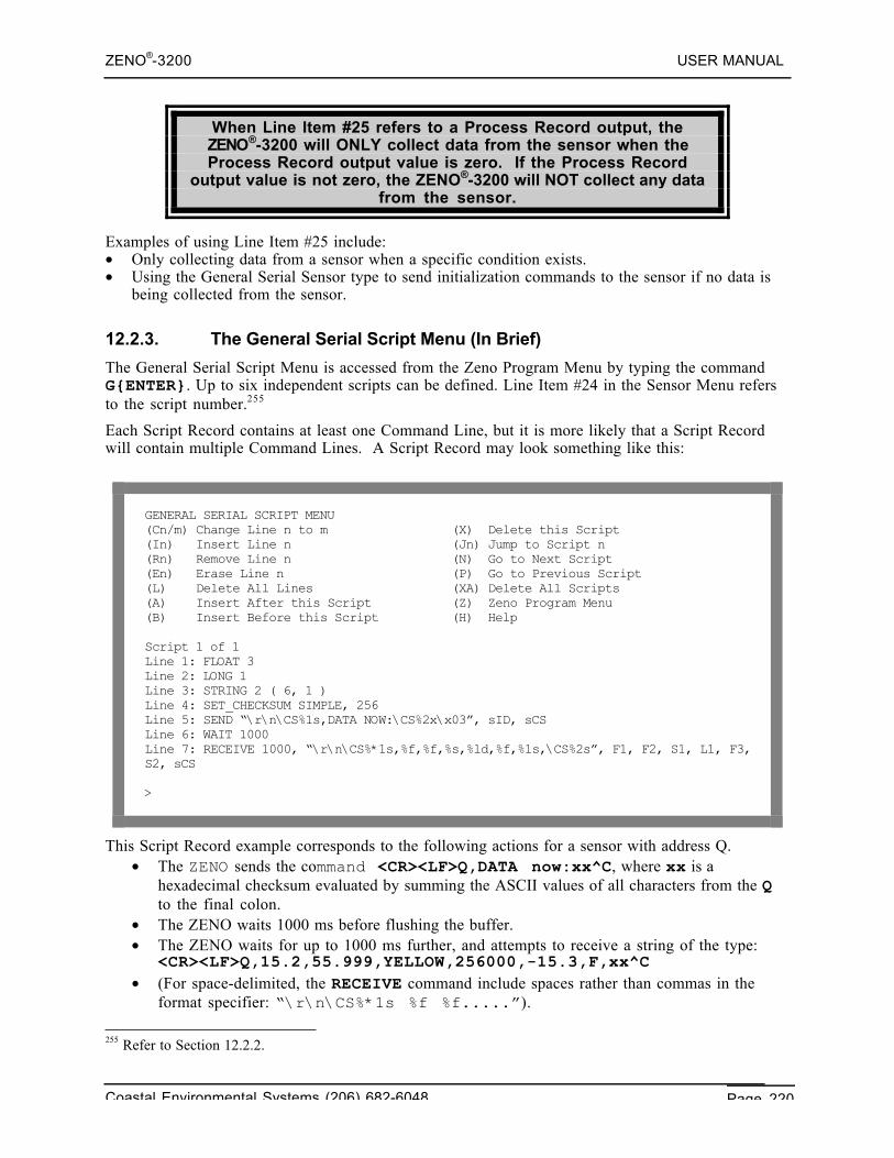
ZENO®-3200 USER MANUAL
Coastal Environmental Systems (206) 682-6048 Page 220
When Line Item #25 refers to a Process Record output, theZENO®-3200 will ONLY collect data from the sensor when theProcess Record output value is zero. If the Process Record
output value is not zero, the ZENO®-3200 will NOT collect any datafrom the sensor.
Examples of using Line Item #25 include:• Only collecting data from a sensor when a specific condition exists.• Using the General Serial Sensor type to send initialization commands to the sensor if no data is
being collected from the sensor.
12.2.3. The General Serial Script Menu (In Brief)
The General Serial Script Menu is accessed from the Zeno Program Menu by typing the commandG{ENTER}. Up to six independent scripts can be defined. Line Item #24 in the Sensor Menu refersto the script number.255
Each Script Record contains at least one Command Line, but it is more likely that a Script Recordwill contain multiple Command Lines. A Script Record may look something like this:
GENERAL SERIAL SCRIPT MENU(Cn/m) Change Line n to m (X) Delete this Script(In) Insert Line n (Jn) Jump to Script n(Rn) Remove Line n (N) Go to Next Script(En) Erase Line n (P) Go to Previous Script(L) Delete All Lines (XA) Delete All Scripts(A) Insert After this Script (Z) Zeno Program Menu(B) Insert Before this Script (H) Help
Script 1 of 1Line 1: FLOAT 3Line 2: LONG 1Line 3: STRING 2 ( 6, 1 )Line 4: SET_CHECKSUM SIMPLE, 256Line 5: SEND “\r\n\CS%1s,DATA NOW:\CS%2x\x03”, sID, sCSLine 6: WAIT 1000Line 7: RECEIVE 1000, “\r\n\CS%*1s,%f,%f,%s,%ld,%f,%1s,\CS%2s”, F1, F2, S1, L1, F3,S2, sCS
>
This Script Record example corresponds to the following actions for a sensor with address Q.• The ZENO sends the command <CR><LF>Q,DATA now:xx^C, where xx is a
hexadecimal checksum evaluated by summing the ASCII values of all characters from the Qto the final colon.
• The ZENO waits 1000 ms before flushing the buffer.• The ZENO waits for up to 1000 ms further, and attempts to receive a string of the type:
<CR><LF>Q,15.2,55.999,YELLOW,256000,-15.3,F,xx^C• (For space-delimited, the RECEIVE command include spaces rather than commas in the
format specifier: “\r\n\CS%*1s %f %f.....”).
255 Refer to Section 12.2.2.
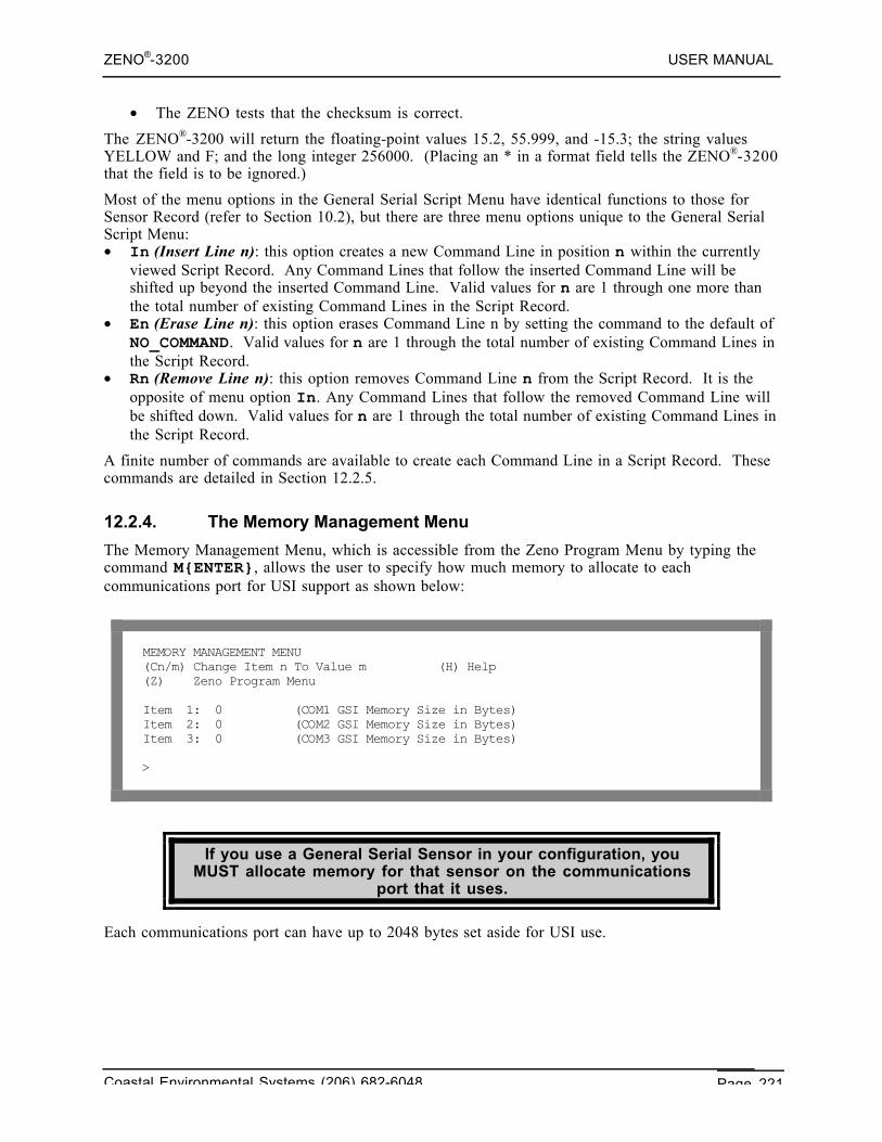
ZENO®-3200 USER MANUAL
Coastal Environmental Systems (206) 682-6048 Page 221
• The ZENO tests that the checksum is correct.
The ZENO®-3200 will return the floating-point values 15.2, 55.999, and -15.3; the string valuesYELLOW and F; and the long integer 256000. (Placing an * in a format field tells the ZENO®-3200that the field is to be ignored.)
Most of the menu options in the General Serial Script Menu have identical functions to those forSensor Record (refer to Section 10.2), but there are three menu options unique to the General SerialScript Menu:• In (Insert Line n): this option creates a new Command Line in position n within the currently
viewed Script Record. Any Command Lines that follow the inserted Command Line will beshifted up beyond the inserted Command Line. Valid values for n are 1 through one more thanthe total number of existing Command Lines in the Script Record.
• En (Erase Line n): this option erases Command Line n by setting the command to the default ofNO_COMMAND. Valid values for n are 1 through the total number of existing Command Lines inthe Script Record.
• Rn (Remove Line n): this option removes Command Line n from the Script Record. It is theopposite of menu option In. Any Command Lines that follow the removed Command Line willbe shifted down. Valid values for n are 1 through the total number of existing Command Lines inthe Script Record.
A finite number of commands are available to create each Command Line in a Script Record. Thesecommands are detailed in Section 12.2.5.
12.2.4. The Memory Management Menu
The Memory Management Menu, which is accessible from the Zeno Program Menu by typing thecommand M{ENTER}, allows the user to specify how much memory to allocate to eachcommunications port for USI support as shown below:
MEMORY MANAGEMENT MENU(Cn/m) Change Item n To Value m (H) Help(Z) Zeno Program Menu
Item 1: 0 (COM1 GSI Memory Size in Bytes)Item 2: 0 (COM2 GSI Memory Size in Bytes)Item 3: 0 (COM3 GSI Memory Size in Bytes)
>
If you use a General Serial Sensor in your configuration, youMUST allocate memory for that sensor on the communications
port that it uses.
Each communications port can have up to 2048 bytes set aside for USI use.
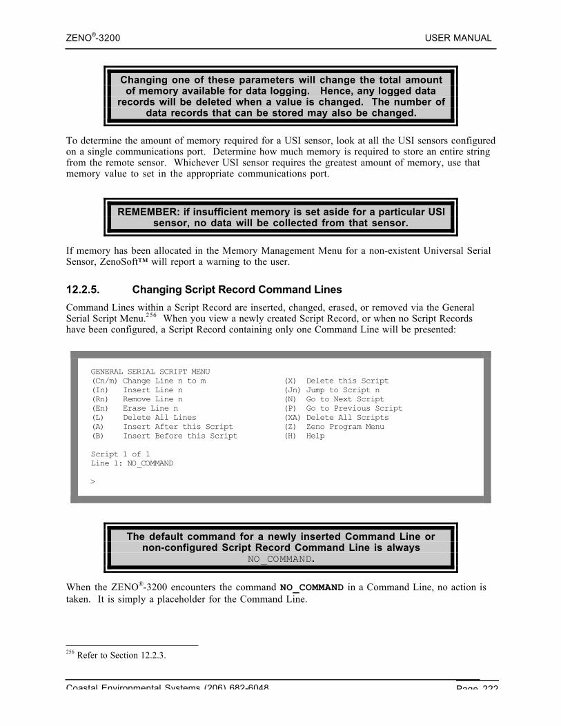
ZENO®-3200 USER MANUAL
Coastal Environmental Systems (206) 682-6048 Page 222
Changing one of these parameters will change the total amountof memory available for data logging. Hence, any logged data
records will be deleted when a value is changed. The number ofdata records that can be stored may also be changed.
To determine the amount of memory required for a USI sensor, look at all the USI sensors configuredon a single communications port. Determine how much memory is required to store an entire stringfrom the remote sensor. Whichever USI sensor requires the greatest amount of memory, use thatmemory value to set in the appropriate communications port.
REMEMBER: if insufficient memory is set aside for a particular USIsensor, no data will be collected from that sensor.
If memory has been allocated in the Memory Management Menu for a non-existent Universal SerialSensor, ZenoSoft™ will report a warning to the user.
12.2.5. Changing Script Record Command Lines
Command Lines within a Script Record are inserted, changed, erased, or removed via the GeneralSerial Script Menu.256 When you view a newly created Script Record, or when no Script Recordshave been configured, a Script Record containing only one Command Line will be presented:
GENERAL SERIAL SCRIPT MENU(Cn/m) Change Line n to m (X) Delete this Script(In) Insert Line n (Jn) Jump to Script n(Rn) Remove Line n (N) Go to Next Script(En) Erase Line n (P) Go to Previous Script(L) Delete All Lines (XA) Delete All Scripts(A) Insert After this Script (Z) Zeno Program Menu(B) Insert Before this Script (H) Help
Script 1 of 1Line 1: NO_COMMAND
>
The default command for a newly inserted Command Line ornon-configured Script Record Command Line is always
NO_COMMAND.
When the ZENO®-3200 encounters the command NO_COMMAND in a Command Line, no action istaken. It is simply a placeholder for the Command Line.
256 Refer to Section 12.2.3.
ZENO®-3200 USER MANUAL
Coastal Environmental Systems (206) 682-6048 Page 223
The contents of a Command Line are changed using menu option Cn/m{ENTER} in the GeneralSerial Script Menu, where n is the Command Line number and m is the new command string for theCommand Line n.
When you change the contents of a Script Record Command Line,you must adhere to the syntax specific to the command being
specified.
When you change the contents of a Command Line, the ZENO®-3200 verifies that the syntax iscorrect in the Cn/m command (or from a configuration file).
If the ZENO®-3200 detects any errors in Command Line syntax,the ZENO®-3200 will reject the changed Command Line, keep thecurrent contents of the specified Command Line and report the
error to the user.
Command Line syntax is very important because the ZENO®-3200 must know exactly what it needsto do in order to successfully communicate with the desired serial sensor. Syntax issues includespacing and capitalization which depends upon the portion of the Command Line.
Script Record Command Line syntax usually includes spaces.When you change a Command Line using the Cn/m menu option,m can includes spaces. For this reason, if you make a syntaxmistake when changing a Script Record Command Line, the
ZENO®-3200 will probably report several errors because it cannotdistinguish space-delimited parts of a failed script.
If a Command Line is longer than 200 characters, you will need tochange it directly into a downloaded configuration file using a
standard text editor.257
Coastal Environmental Systems recommends that you hand-edita configuration file ONLY AFTER you have gained experience with
the USI.
If you need to change a Script Record Command Line to something longer than 200 characters, usethe following instructions:• Download the configuration from the ZENO®-3200 into a text file. (Refer to Section 9.1.)• Hand-edit the downloaded configuration file using a standard text editor, such as Microsoft
Notepad.• Upload the edited configuration file back into the ZENO®-3200. (Refer to Section 9.2).
257 The User Interface is limited to menu command lines of 200 characters.
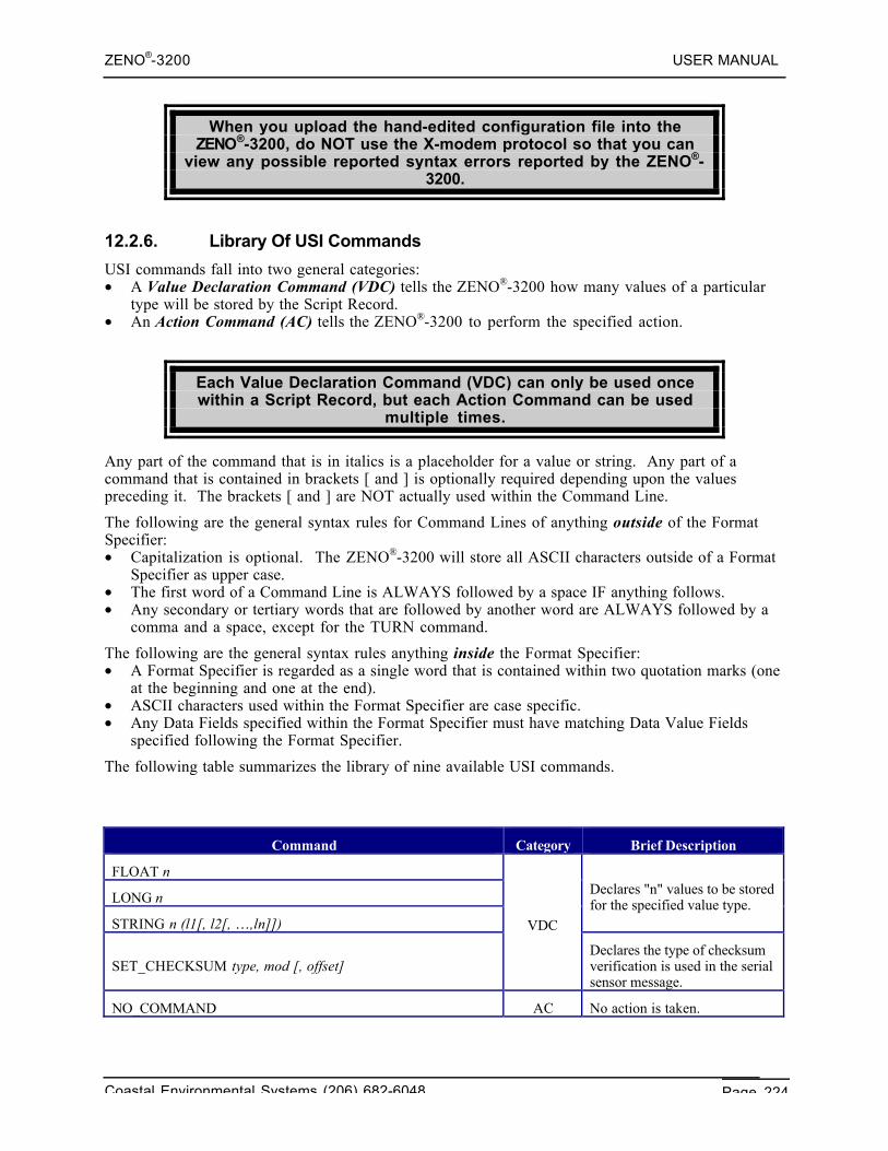
ZENO®-3200 USER MANUAL
Coastal Environmental Systems (206) 682-6048 Page 224
When you upload the hand-edited configuration file into theZENO®-3200, do NOT use the X-modem protocol so that you can
view any possible reported syntax errors reported by the ZENO®-3200.
12.2.6. Library Of USI Commands
USI commands fall into two general categories:• A Value Declaration Command (VDC) tells the ZENO®-3200 how many values of a particular
type will be stored by the Script Record.• An Action Command (AC) tells the ZENO®-3200 to perform the specified action.
Each Value Declaration Command (VDC) can only be used oncewithin a Script Record, but each Action Command can be used
multiple times.
Any part of the command that is in italics is a placeholder for a value or string. Any part of acommand that is contained in brackets [ and ] is optionally required depending upon the valuespreceding it. The brackets [ and ] are NOT actually used within the Command Line.
The following are the general syntax rules for Command Lines of anything outside of the FormatSpecifier:• Capitalization is optional. The ZENO®-3200 will store all ASCII characters outside of a Format
Specifier as upper case.• The first word of a Command Line is ALWAYS followed by a space IF anything follows.• Any secondary or tertiary words that are followed by another word are ALWAYS followed by a
comma and a space, except for the TURN command.
The following are the general syntax rules anything inside the Format Specifier:• A Format Specifier is regarded as a single word that is contained within two quotation marks (one
at the beginning and one at the end).• ASCII characters used within the Format Specifier are case specific.• Any Data Fields specified within the Format Specifier must have matching Data Value Fields
specified following the Format Specifier.
The following table summarizes the library of nine available USI commands.
Command Category Brief Description
FLOAT n
LONG n
STRING n (l1[, l2[, …,ln]])
Declares "n" values to be storedfor the specified value type.
SET_CHECKSUM type, mod [, offset]
VDC
Declares the type of checksumverification is used in the serialsensor message.
NO_COMMAND AC No action is taken.
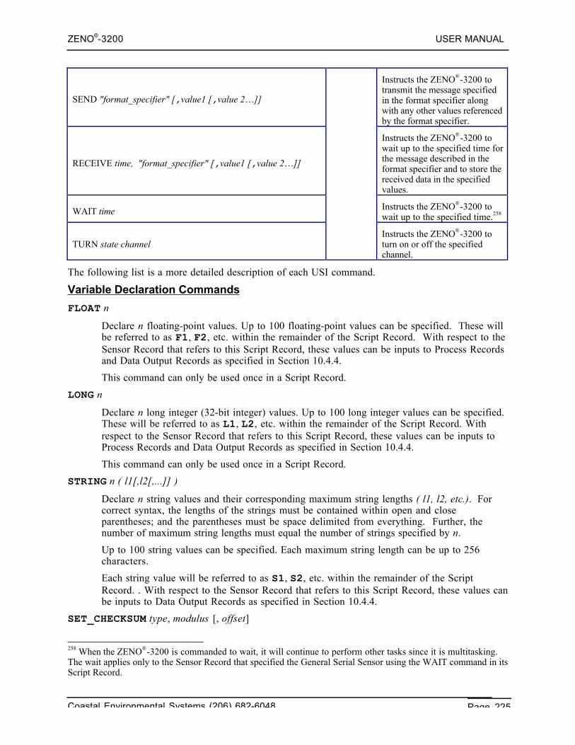
ZENO®-3200 USER MANUAL
Coastal Environmental Systems (206) 682-6048 Page 225
SEND "format_specifier" [,value1 [,value 2…]]
Instructs the ZENO®-3200 totransmit the message specifiedin the format specifier alongwith any other values referencedby the format specifier.
RECEIVE time, "format_specifier" [,value1 [,value 2…]]
Instructs the ZENO®-3200 towait up to the specified time forthe message described in theformat specifier and to store thereceived data in the specifiedvalues.
WAIT time Instructs the ZENO®-3200 towait up to the specified time.258
TURN state channelInstructs the ZENO®-3200 toturn on or off the specifiedchannel.
The following list is a more detailed description of each USI command.
Variable Declaration Commands
FLOAT n
Declare n floating-point values. Up to 100 floating-point values can be specified. These willbe referred to as F1, F2, etc. within the remainder of the Script Record. With respect to theSensor Record that refers to this Script Record, these values can be inputs to Process Recordsand Data Output Records as specified in Section 10.4.4.
This command can only be used once in a Script Record.
LONG n
Declare n long integer (32-bit integer) values. Up to 100 long integer values can be specified.These will be referred to as L1, L2, etc. within the remainder of the Script Record. Withrespect to the Sensor Record that refers to this Script Record, these values can be inputs toProcess Records and Data Output Records as specified in Section 10.4.4.
This command can only be used once in a Script Record.
STRING n ( l1[,l2[,...]] )
Declare n string values and their corresponding maximum string lengths ( l1, l2, etc.). Forcorrect syntax, the lengths of the strings must be contained within open and closeparentheses; and the parentheses must be space delimited from everything. Further, thenumber of maximum string lengths must equal the number of strings specified by n.
Up to 100 string values can be specified. Each maximum string length can be up to 256characters.
Each string value will be referred to as S1, S2, etc. within the remainder of the ScriptRecord. . With respect to the Sensor Record that refers to this Script Record, these values canbe inputs to Data Output Records as specified in Section 10.4.4.
SET_CHECKSUM type, modulus [, offset]
258 When the ZENO®-3200 is commanded to wait, it will continue to perform other tasks since it is multitasking.The wait applies only to the Sensor Record that specified the General Serial Sensor using the WAIT command in itsScript Record.
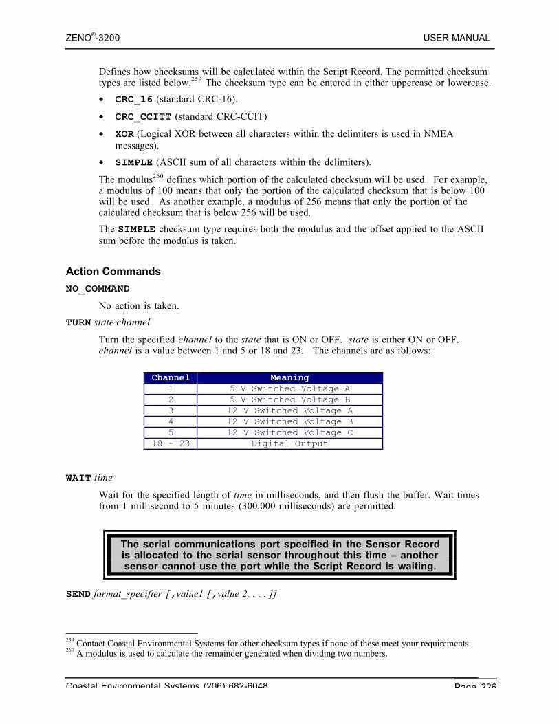
ZENO®-3200 USER MANUAL
Coastal Environmental Systems (206) 682-6048 Page 226
Defines how checksums will be calculated within the Script Record. The permitted checksumtypes are listed below.259 The checksum type can be entered in either uppercase or lowercase.
• CRC_16 (standard CRC-16).
• CRC_CCITT (standard CRC-CCIT)
• XOR (Logical XOR between all characters within the delimiters is used in NMEAmessages).
• SIMPLE (ASCII sum of all characters within the delimiters).
The modulus260 defines which portion of the calculated checksum will be used. For example,a modulus of 100 means that only the portion of the calculated checksum that is below 100will be used. As another example, a modulus of 256 means that only the portion of thecalculated checksum that is below 256 will be used.
The SIMPLE checksum type requires both the modulus and the offset applied to the ASCIIsum before the modulus is taken.
Action Commands
NO_COMMAND
No action is taken.
TURN state channel
Turn the specified channel to the state that is ON or OFF. state is either ON or OFF.channel is a value between 1 and 5 or 18 and 23. The channels are as follows:
Channel Meaning
1 5 V Switched Voltage A2 5 V Switched Voltage B3 12 V Switched Voltage A4 12 V Switched Voltage B5 12 V Switched Voltage C
18 - 23 Digital Output
WAIT time
Wait for the specified length of time in milliseconds, and then flush the buffer. Wait timesfrom 1 millisecond to 5 minutes (300,000 milliseconds) are permitted.
The serial communications port specified in the Sensor Recordis allocated to the serial sensor throughout this time – anothersensor cannot use the port while the Script Record is waiting.
SEND format_specifier [,value1 [,value 2. . . . ]]
259 Contact Coastal Environmental Systems for other checksum types if none of these meet your requirements.260 A modulus is used to calculate the remainder generated when dividing two numbers.
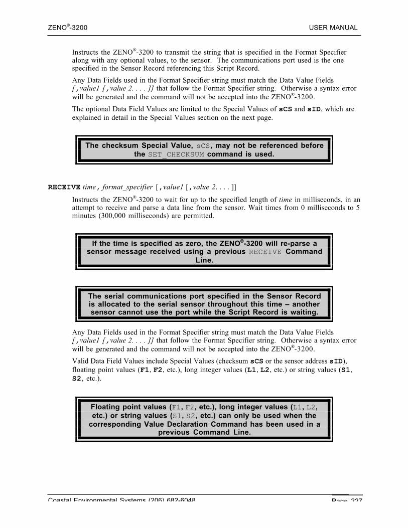
ZENO®-3200 USER MANUAL
Coastal Environmental Systems (206) 682-6048 Page 227
Instructs the ZENO®-3200 to transmit the string that is specified in the Format Specifieralong with any optional values, to the sensor. The communications port used is the onespecified in the Sensor Record referencing this Script Record.
Any Data Fields used in the Format Specifier string must match the Data Value Fields[,value1 [,value 2. . . . ]] that follow the Format Specifier string. Otherwise a syntax errorwill be generated and the command will not be accepted into the ZENO®-3200.
The optional Data Field Values are limited to the Special Values of sCS and sID, which areexplained in detail in the Special Values section on the next page.
The checksum Special Value, sCS, may not be referenced beforethe SET_CHECKSUM command is used.
RECEIVE time, format_specifier [,value1 [,value 2. . . . ]]
Instructs the ZENO®-3200 to wait for up to the specified length of time in milliseconds, in anattempt to receive and parse a data line from the sensor. Wait times from 0 milliseconds to 5minutes (300,000 milliseconds) are permitted.
If the time is specified as zero, the ZENO®-3200 will re-parse asensor message received using a previous RECEIVE Command
Line.
The serial communications port specified in the Sensor Recordis allocated to the serial sensor throughout this time – anothersensor cannot use the port while the Script Record is waiting.
Any Data Fields used in the Format Specifier string must match the Data Value Fields[,value1 [,value 2. . . . ]] that follow the Format Specifier string. Otherwise a syntax errorwill be generated and the command will not be accepted into the ZENO®-3200.
Valid Data Field Values include Special Values (checksum sCS or the sensor address sID),floating point values (F1, F2, etc.), long integer values (L1, L2, etc.) or string values (S1,S2, etc.).
Floating point values (F1, F2, etc.), long integer values (L1, L2,etc.) or string values (S1, S2, etc.) can only be used when the
corresponding Value Declaration Command has been used in aprevious Command Line.
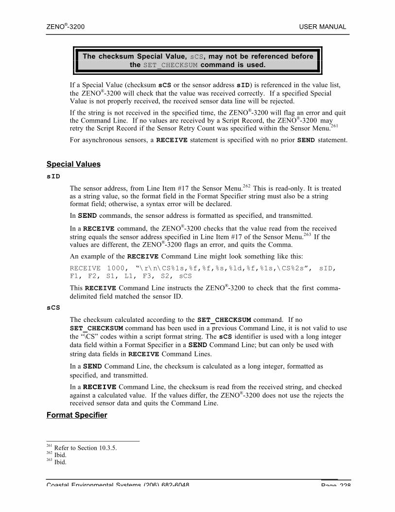
ZENO®-3200 USER MANUAL
Coastal Environmental Systems (206) 682-6048 Page 228
The checksum Special Value, sCS, may not be referenced beforethe SET_CHECKSUM command is used.
If a Special Value (checksum sCS or the sensor address sID) is referenced in the value list,the ZENO®-3200 will check that the value was received correctly. If a specified SpecialValue is not properly received, the received sensor data line will be rejected.
If the string is not received in the specified time, the ZENO®-3200 will flag an error and quitthe Command Line. If no values are received by a Script Record, the ZENO®-3200 mayretry the Script Record if the Sensor Retry Count was specified within the Sensor Menu.261
For asynchronous sensors, a RECEIVE statement is specified with no prior SEND statement.
Special Values
sID
The sensor address, from Line Item #17 the Sensor Menu.262 This is read-only. It is treatedas a string value, so the format field in the Format Specifier string must also be a stringformat field; otherwise, a syntax error will be declared.
In SEND commands, the sensor address is formatted as specified, and transmitted.
In a RECEIVE command, the ZENO®-3200 checks that the value read from the receivedstring equals the sensor address specified in Line Item #17 of the Sensor Menu.263 If thevalues are different, the ZENO®-3200 flags an error, and quits the Comma.
An example of the RECEIVE Command Line might look something like this:
RECEIVE 1000, “\r\n\CS%1s,%f,%f,%s,%ld,%f,%1s,\CS%2s”, sID,F1, F2, S1, L1, F3, S2, sCS
This RECEIVE Command Line instructs the ZENO®-3200 to check that the first comma-delimited field matched the sensor ID.
sCS
The checksum calculated according to the SET_CHECKSUM command. If noSET_CHECKSUM command has been used in a previous Command Line, it is not valid to usethe “\CS” codes within a script format string. The sCS identifier is used with a long integerdata field within a Format Specifier in a SEND Command Line; but can only be used withstring data fields in RECEIVE Command Lines.
In a SEND Command Line, the checksum is calculated as a long integer, formatted asspecified, and transmitted.
In a RECEIVE Command Line, the checksum is read from the received string, and checkedagainst a calculated value. If the values differ, the ZENO®-3200 does not use the rejects thereceived sensor data and quits the Command Line.
Format Specifier
261 Refer to Section 10.3.5.262 Ibid.263 Ibid.
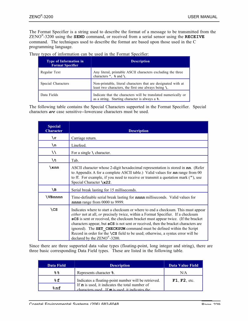
ZENO®-3200 USER MANUAL
Coastal Environmental Systems (206) 682-6048 Page 229
The Format Specifier is a string used to describe the format of a message to be transmitted from theZENO®-3200 using the SEND command, or received from a serial sensor using the RECEIVEcommand. The techniques used to describe the format are based upon those used in the Cprogramming language.
Three types of information can be used in the Format Specifier:
Type of Information inFormat Specifier
Description
Regular Text Any literal, printable ASCII characters excluding the threecharacters ", % and \.
Special Characters Non-printable, literal characters that are designated with atleast two characters, the first one always being \.
Data Fields Indicate that the characters will be translated numerically oras a string. Starting character is always a %.
The following table contains the Special Characters supported in the Format Specifier. Specialcharacters are case sensitive--lowercase characters must be used.
SpecialCharacter Description
\r Carriage return.
\n Linefeed.
\\ For a single \ character.
\t Tab.
\xnn ASCII character whose 2-digit hexadecimal representation is stored in nn. (Referto Appendix A for a complete ASCII table.) Valid values for nn range from 00to ff. For example, if you need to receive or transmit a quotation mark ("), useSpecial Character \x22.
\B Serial break lasting for 15 milliseconds.
\VBnnnn Time-definable serial break lasting for nnnn milliseconds. Valid values fornnnn range from 0000 to 9999.
\CS Indicates where to start a checksum or where to end a checksum. This must appeareither not at all, or precisely twice, within a Format Specifier. If a checksumsCS is sent or received, the checksum bracket must appear twice. (If the bracketcharacters appear, but sCS is not sent or received, then the bracket characters areignored). The SET_CHECKSUM command must be defined within the ScriptRecord in order for the \CS field to be used; otherwise, a syntax error will bedeclared by the ZENO®-3200.
Since there are three supported data value types (floating-point, long integer and string), there arethree basic corresponding Data Field types. These are listed in the following table.
Data Field Description Data Value Field
%% Represents character %. N/A
%f
%nf
Indicates a floating-point number will be retrieved.If n is used, it indicates the total number ofcharacters used. If m is used, it indicates thenumber of characters that follow the decimal point.
F1, F2, etc.
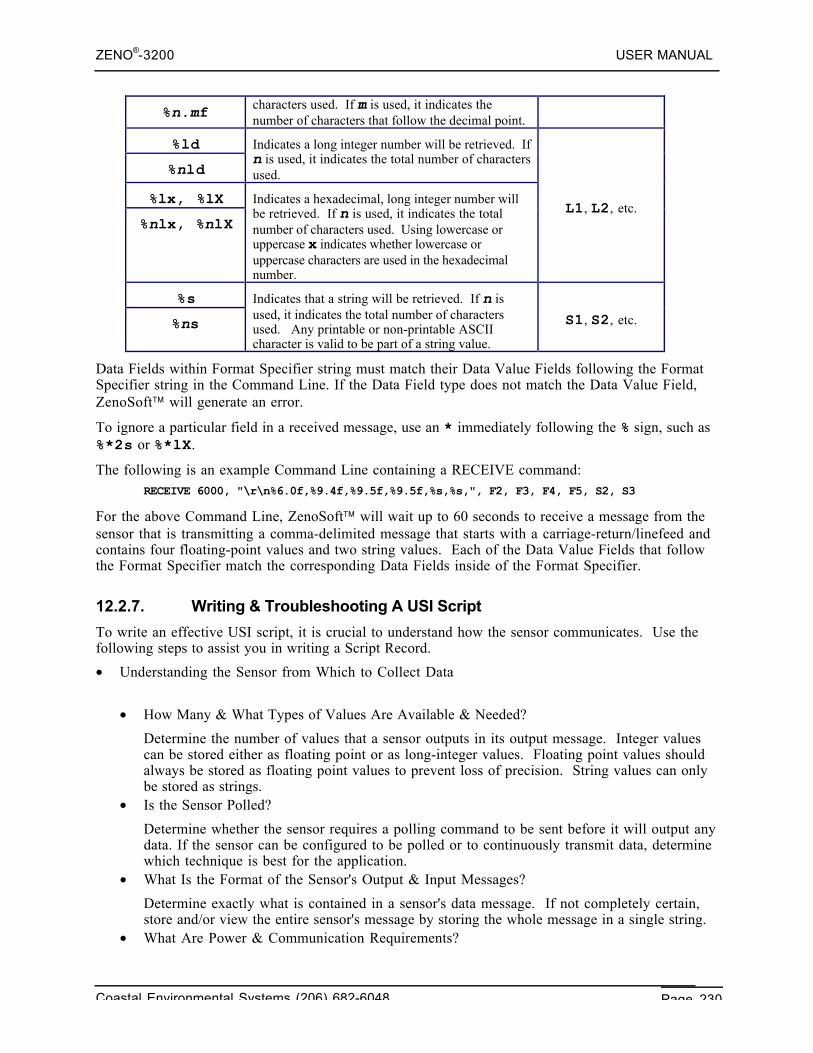
ZENO®-3200 USER MANUAL
Coastal Environmental Systems (206) 682-6048 Page 230
%n.mf characters used. If m is used, it indicates thenumber of characters that follow the decimal point.
%ld
%nld
Indicates a long integer number will be retrieved. Ifn is used, it indicates the total number of charactersused.
%lx, %lX
%nlx, %nlX
Indicates a hexadecimal, long integer number willbe retrieved. If n is used, it indicates the totalnumber of characters used. Using lowercase oruppercase x indicates whether lowercase oruppercase characters are used in the hexadecimalnumber.
L1, L2, etc.
%s
%ns
Indicates that a string will be retrieved. If n isused, it indicates the total number of charactersused. Any printable or non-printable ASCIIcharacter is valid to be part of a string value.
S1, S2, etc.
Data Fields within Format Specifier string must match their Data Value Fields following the FormatSpecifier string in the Command Line. If the Data Field type does not match the Data Value Field,ZenoSoft™ will generate an error.
To ignore a particular field in a received message, use an * immediately following the % sign, such as%*2s or %*lX.
The following is an example Command Line containing a RECEIVE command:RECEIVE 6000, "\r\n%6.0f,%9.4f,%9.5f,%9.5f,%s,%s,", F2, F3, F4, F5, S2, S3
For the above Command Line, ZenoSoft™ will wait up to 60 seconds to receive a message from thesensor that is transmitting a comma-delimited message that starts with a carriage-return/linefeed andcontains four floating-point values and two string values. Each of the Data Value Fields that followthe Format Specifier match the corresponding Data Fields inside of the Format Specifier.
12.2.7. Writing & Troubleshooting A USI Script
To write an effective USI script, it is crucial to understand how the sensor communicates. Use thefollowing steps to assist you in writing a Script Record.
• Understanding the Sensor from Which to Collect Data
• How Many & What Types of Values Are Available & Needed?
Determine the number of values that a sensor outputs in its output message. Integer valuescan be stored either as floating point or as long-integer values. Floating point values shouldalways be stored as floating point values to prevent loss of precision. String values can onlybe stored as strings.
• Is the Sensor Polled?
Determine whether the sensor requires a polling command to be sent before it will output anydata. If the sensor can be configured to be polled or to continuously transmit data, determinewhich technique is best for the application.
• What Is the Format of the Sensor's Output & Input Messages?
Determine exactly what is contained in a sensor's data message. If not completely certain,store and/or view the entire sensor's message by storing the whole message in a single string.
• What Are Power & Communication Requirements?
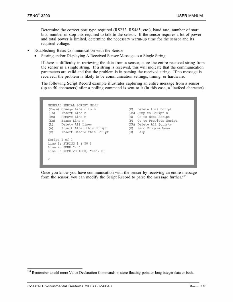
ZENO®-3200 USER MANUAL
Coastal Environmental Systems (206) 682-6048 Page 231
Determine the correct port type required (RS232, RS485, etc.), baud rate, number of startbits, number of stop bits required to talk to the sensor. If the sensor requires a lot of powerand total power is limited, determine the necessary warm-up time for the sensor and itsrequired voltage.
• Establishing Basic Communication with the Sensor• Storing and/or Displaying A Received Sensor Message as a Single String
If there is difficulty in retrieving the data from a sensor, store the entire received string fromthe sensor in a single string. If a string is received, this will indicate that the communicationparameters are valid and that the problem is in parsing the received string. If no message isreceived, the problem is likely to be communication settings, timing, or hardware.
The following Script Record example illustrates capturing an entire message from a sensor(up to 50 characters) after a polling command is sent to it (in this case, a linefeed character).
GENERAL SERIAL SCRIPT MENU(Cn/m) Change Line n to m (X) Delete this Script(In) Insert Line n (Jn) Jump to Script n(Rn) Remove Line n (N) Go to Next Script(En) Erase Line n (P) Go to Previous Script(L) Delete All Lines (XA) Delete All Scripts(A) Insert After this Script (Z) Zeno Program Menu(B) Insert Before this Script (H) Help
Script 1 of 1Line 1: STRING 1 ( 50 )Line 2: SEND "\n"Line 3: RECEIVE 1000, "%s", S1
>
Once you know you have communication with the sensor by receiving an entire messagefrom the sensor, you can modify the Script Record to parse the message further.264
264 Remember to add more Value Declaration Commands to store floating-point or long integer data or both.
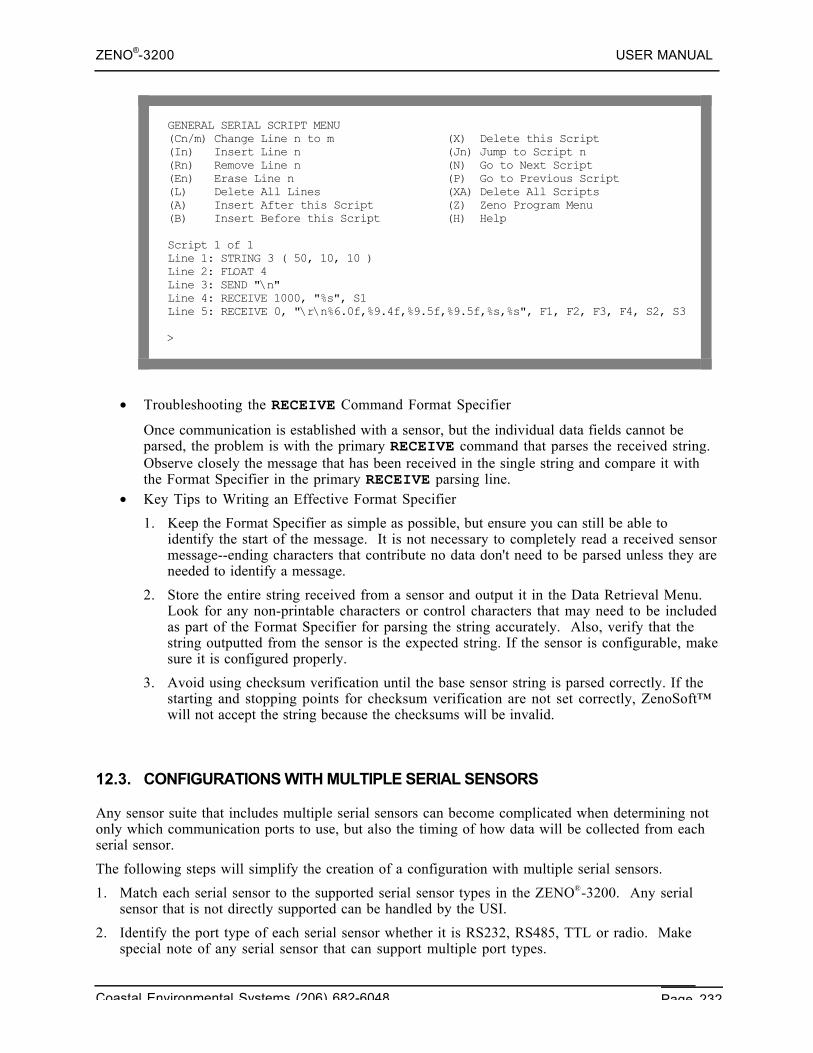
ZENO®-3200 USER MANUAL
Coastal Environmental Systems (206) 682-6048 Page 232
GENERAL SERIAL SCRIPT MENU(Cn/m) Change Line n to m (X) Delete this Script(In) Insert Line n (Jn) Jump to Script n(Rn) Remove Line n (N) Go to Next Script(En) Erase Line n (P) Go to Previous Script(L) Delete All Lines (XA) Delete All Scripts(A) Insert After this Script (Z) Zeno Program Menu(B) Insert Before this Script (H) Help
Script 1 of 1Line 1: STRING 3 ( 50, 10, 10 )Line 2: FLOAT 4Line 3: SEND "\n"Line 4: RECEIVE 1000, "%s", S1Line 5: RECEIVE 0, "\r\n%6.0f,%9.4f,%9.5f,%9.5f,%s,%s", F1, F2, F3, F4, S2, S3
>
• Troubleshooting the RECEIVE Command Format Specifier
Once communication is established with a sensor, but the individual data fields cannot beparsed, the problem is with the primary RECEIVE command that parses the received string.Observe closely the message that has been received in the single string and compare it withthe Format Specifier in the primary RECEIVE parsing line.
• Key Tips to Writing an Effective Format Specifier
1. Keep the Format Specifier as simple as possible, but ensure you can still be able toidentify the start of the message. It is not necessary to completely read a received sensormessage--ending characters that contribute no data don't need to be parsed unless they areneeded to identify a message.
2. Store the entire string received from a sensor and output it in the Data Retrieval Menu.Look for any non-printable characters or control characters that may need to be includedas part of the Format Specifier for parsing the string accurately. Also, verify that thestring outputted from the sensor is the expected string. If the sensor is configurable, makesure it is configured properly.
3. Avoid using checksum verification until the base sensor string is parsed correctly. If thestarting and stopping points for checksum verification are not set correctly, ZenoSoft™will not accept the string because the checksums will be invalid.
12.3. CONFIGURATIONS WITH MULTIPLE SERIAL SENSORS
Any sensor suite that includes multiple serial sensors can become complicated when determining notonly which communication ports to use, but also the timing of how data will be collected from eachserial sensor.
The following steps will simplify the creation of a configuration with multiple serial sensors.
1. Match each serial sensor to the supported serial sensor types in the ZENO®-3200. Any serialsensor that is not directly supported can be handled by the USI.
2. Identify the port type of each serial sensor whether it is RS232, RS485, TTL or radio. Makespecial note of any serial sensor that can support multiple port types.
ZENO®-3200 USER MANUAL
Coastal Environmental Systems (206) 682-6048 Page 233
3. Do not mix serial sensors with different communications protocols on the same multi-dropcommunications link (RS485 or radio) unless necessary. If the port type of more than one serialsensor is multi-drop (RS485 or radio) and they communicate using different protocols, there maybe difficulty in connecting them to the same multi-drop port on the ZENO®-3200. Differentprotocols may cause interference on the same multi-drop communications link.
4. Coastal Environmental Systems recommends that any communications port that is being usedwith a serial sensor should be excluded from using the User Interface.265 Allowing the UserInterface Task to access the communications port that is being used for a serial sensor mayinhibit the ZENO®-3200 from retrieving data from the serial sensor.
5. Do not mix serial sensor data collection with bi-directional User Interface communication on thesame communications port. Using bi-directional communication with the User Interface on thesame communications port that supports one or more serial sensors can cause interference withboth data collection and User Interface communications.
Coastal Environmental Systems recommends that you reserveone communications port (either COM1 or COM3) for bi-
directional User Interface communication.
Since COM2 is fully multiplexed and since it provides fourindependent communication routes, Coastal EnvironmentalSystems recommends that you start with COM2 for locating
serial sensors.
If COM1 or COM3 is NOT being used for any User Interfacecommunication, Coastal Environmental Systems recommends
that you locate at least one serial sensor on the unusedcommunications port to relieve timing demands on COM2.
6. Follow the procedure described in Section 12.1.8 for determining the timing for multiple serialsensors sharing the same communications port.
12.4. SHARING DATA BETWEEN MULTIPLE ZENO®-3200'S (MULTIPROCESSING)
You may have a situation in which you are measuring data using one or more sensors connected toone ZENO®-3200, that is required by one or more other ZENO®-3200's in order process their data.Further, you may want to log all the data collected by all ZENO®-3200's on the first ZENO®-3200.Such a situation would be defined as multiprocessing.
265 Refer to Section 6.12.
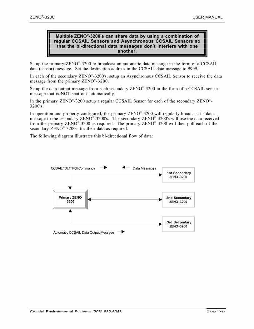
ZENO®-3200 USER MANUAL
Coastal Environmental Systems (206) 682-6048 Page 234
Multiple ZENO®-3200's can share data by using a combination ofregular CCSAIL Sensors and Asynchronous CCSAIL Sensors so
that the bi-directional data messages don’t interfere with oneanother.
Setup the primary ZENO®-3200 to broadcast an automatic data message in the form of a CCSAILdata (sensor) message. Set the destination address in the CCSAIL data message to 9999.
In each of the secondary ZENO®-3200's, setup an Asynchronous CCSAIL Sensor to receive the datamessage from the primary ZENO®-3200.
Setup the data output message from each secondary ZENO®-3200 in the form of a CCSAIL sensormessage that is NOT sent out automatically.
In the primary ZENO®-3200 setup a regular CCSAIL Sensor for each of the secondary ZENO®-3200's.
In operation and properly configured, the primary ZENO®-3200 will regularly broadcast its datamessage to the secondary ZENO®-3200's. The secondary ZENO®-3200's will use the data receivedfrom the primary ZENO®-3200 as required. The primary ZENO®-3200 will then poll each of thesecondary ZENO®-3200's for their data as required.
The following diagram illustrates this bi-directional flow of data:
1st Secondary ZENO-3200
2nd Secondary ZENO-3200
3rd Secondary ZENO-3200
Primary ZENO-3200
Data Messages CCSAIL “DL1” Poll Commands
Automatic CCSAIL Data Output Message
ZENO®-3200 USER MANUAL
Coastal Environmental Systems (206) 682-6048 Page 235
13. ELECTRICALCONSIDERATIONS
Coastal EnvironmentalSystems
ZENO®-3200 User Manual
13.1. THE ZENO®-3200 ENCLOSURE
The ZENO®-3200 enclosure is NOT watertight, moisture-resistantor weatherproof!
If you plan to install the ZENO®-3200 outdoors, it must besheltered to protect it from water, moisture and weather.
13.2. GROUNDING
Proper grounding is required to minimize errors in sensorreadings and to protect the ZENO®-3200 from damage due toESD266, lightning-induced power surges, and other potential
causes.
Without proper grounding, interfering signals can couple to your sensor circuits, resulting in errorsmuch greater than those due to thermal noise. These errors can be introduced as:
• Noise induced from AC signals typically arises from mutual inductance267 or capacitivecoupling268 between different parts of the same circuit or different circuits. Using twisted pairsfor signal and excitation leads greatly reduces noise created by mutual inductance. Capacitively
266 ESD stands for electrostatic discharge.267 A varying current in a circuit will create a varying magnetic field surrounding the circuit. If a separate, nearbycircuit is unprotected, the varying magnetic field from the first circuit can induce noise current in the unprotectedcircuit. This phenomenon is called inductive coupling or mutual inductance.268 Capacitive coupling occurs when the varying voltage of one circuit affects the voltage level of a nearbyunprotected circuit because of the varying electric field created by the first circuit.
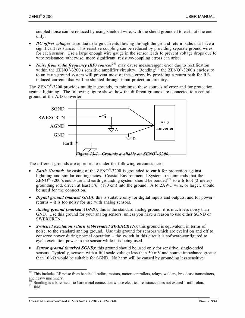
ZENO®-3200 USER MANUAL
Coastal Environmental Systems (206) 682-6048 Page 236
coupled noise can be reduced by using shielded wire, with the shield grounded to earth at one endonly.
• DC offset voltages arise due to large currents flowing through the ground return paths that have asignificant resistance. This resistive coupling can be reduced by providing separate ground wiresfor each sensor. Use a large enough wire gauge in the sensor leads to prevent voltage drops due towire resistance; otherwise, more significant, resistive-coupling errors can arise.
• Noise from radio frequency (RF) sources269 may cause measurement error due to rectificationwithin the ZENO®-3200's sensitive amplifier circuitry. Bonding270 the ZENO®-3200's enclosureto an earth ground system will prevent most of these errors by providing a return path for RF-induced currents that will be shunted through input protection circuitry.
The ZENO®-3200 provides multiple grounds, to minimize these sources of error and for protectionagainst lightning. The following figure shows how the different grounds are connected to a centralground at the A/D converter
Figure 13-1. Grounds available on ZENO®-3200.
The different grounds are appropriate under the following circumstances.
• Earth Ground: the casing of the ZENO®-3200 is grounded to earth for protection againstlightning and similar contingencies. Coastal Environmental Systems recommends that theZENO®-3200’s enclosure and earth grounding system should be bonded271 to a 6 foot (2 meter)grounding rod, driven at least 5’6” (180 cm) into the ground. A to 2AWG wire, or larger, shouldbe used for the connection.
• Digital ground (marked GND): this is suitable only for digital inputs and outputs, and for powerreturns – it is too noisy for use with analog sensors.
• Analog ground (marked AGND): this is the standard analog ground; it is much less noisy thanGND. Use this ground for your analog sensors, unless you have a reason to use either SGND orSWEXCRTN.
• Switched excitation return (abbreviated SWEXCRTN): this ground is equivalent, in terms ofnoise, to the standard analog ground. Use this ground for sensors which are cycled on and off toconserve power during normal operation – the switch in this circuit is software-configured tocycle excitation power to the sensor while it is being used.
• Sensor ground (marked SGND): this ground should be used only for sensitive, single-endedsensors. Typically, sensors with a full scale voltage less than 50 mV and source impedance greaterthan 10 kΩ would be suitable for SGND. No harm will be caused by grounding less sensitive
269 This includes RF noise from handheld radios, motors, motor controllers, relays, welders, broadcast transmitters,and heavy machinery.270 Bonding is a bare metal-to-bare metal connection whose electrical resistance does not exceed 1 milli-ohm.271 Ibid.
A/Dconverter
D
A
Earth
GND
AGND
SWEXCRTN
SGND
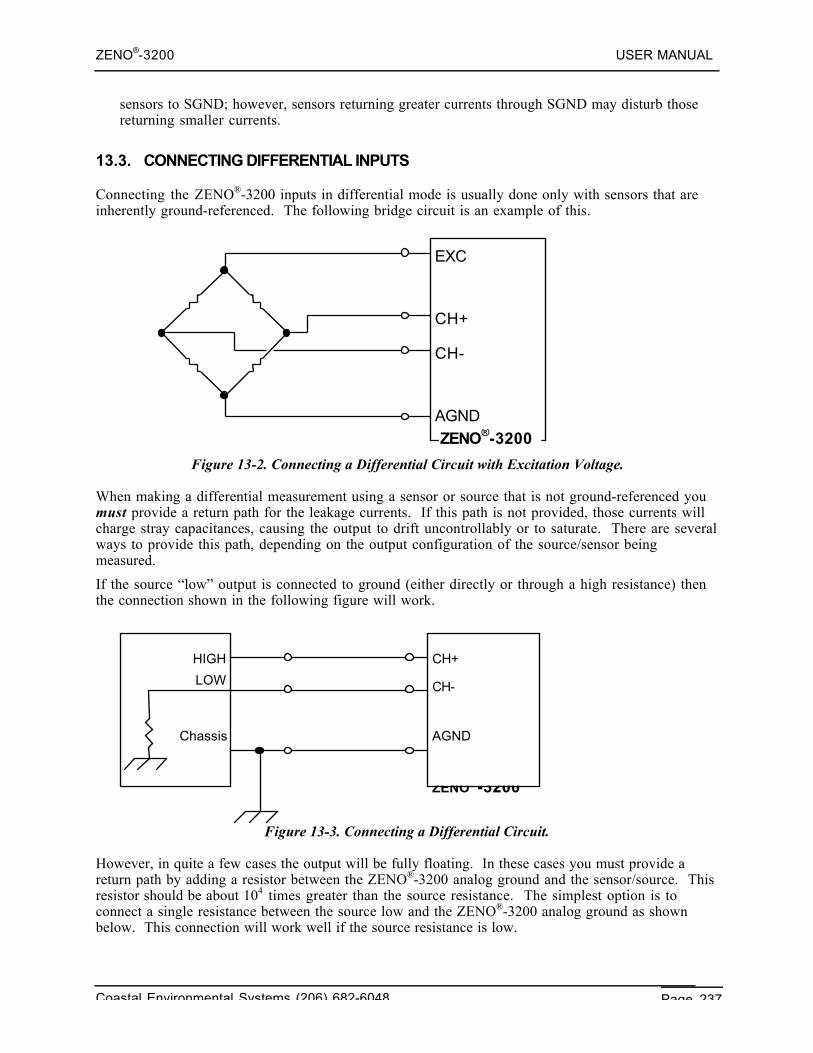
ZENO®-3200 USER MANUAL
Coastal Environmental Systems (206) 682-6048 Page 237
sensors to SGND; however, sensors returning greater currents through SGND may disturb thosereturning smaller currents.
13.3. CONNECTING DIFFERENTIAL INPUTS
Connecting the ZENO®-3200 inputs in differential mode is usually done only with sensors that areinherently ground-referenced. The following bridge circuit is an example of this.
Figure 13-2. Connecting a Differential Circuit with Excitation Voltage.
When making a differential measurement using a sensor or source that is not ground-referenced youmust provide a return path for the leakage currents. If this path is not provided, those currents willcharge stray capacitances, causing the output to drift uncontrollably or to saturate. There are severalways to provide this path, depending on the output configuration of the source/sensor beingmeasured.
If the source “low” output is connected to ground (either directly or through a high resistance) thenthe connection shown in the following figure will work.
Figure 13-3. Connecting a Differential Circuit.
However, in quite a few cases the output will be fully floating. In these cases you must provide areturn path by adding a resistor between the ZENO®-3200 analog ground and the sensor/source. Thisresistor should be about 104 times greater than the source resistance. The simplest option is toconnect a single resistance between the source low and the ZENO®-3200 analog ground as shownbelow. This connection will work well if the source resistance is low.
LOW
ZENO®-3200
CH+
CH-
AGND
HIGH
Chassis
EXC+
CH+
CH-
AGNDRETZENO®-3200
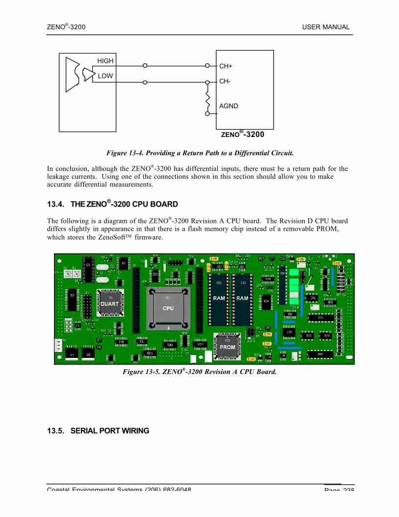
ZENO®-3200 USER MANUAL
Coastal Environmental Systems (206) 682-6048 Page 238
Figure 13-4. Providing a Return Path to a Differential Circuit.
In conclusion, although the ZENO®-3200 has differential inputs, there must be a return path for theleakage currents. Using one of the connections shown in this section should allow you to makeaccurate differential measurements.
13.4. THE ZENO®-3200 CPU BOARD
The following is a diagram of the ZENO®-3200 Revision A CPU board. The Revision D CPU boarddiffers slightly in appearance in that there is a flash memory chip instead of a removable PROM,which stores the ZenoSoft firmware.
Figure 13-5. ZENO®-3200 Revision A CPU Board.
13.5. SERIAL PORT WIRING
HIGH
LOW
ZENO®-3200
CH+
CH-
AGND
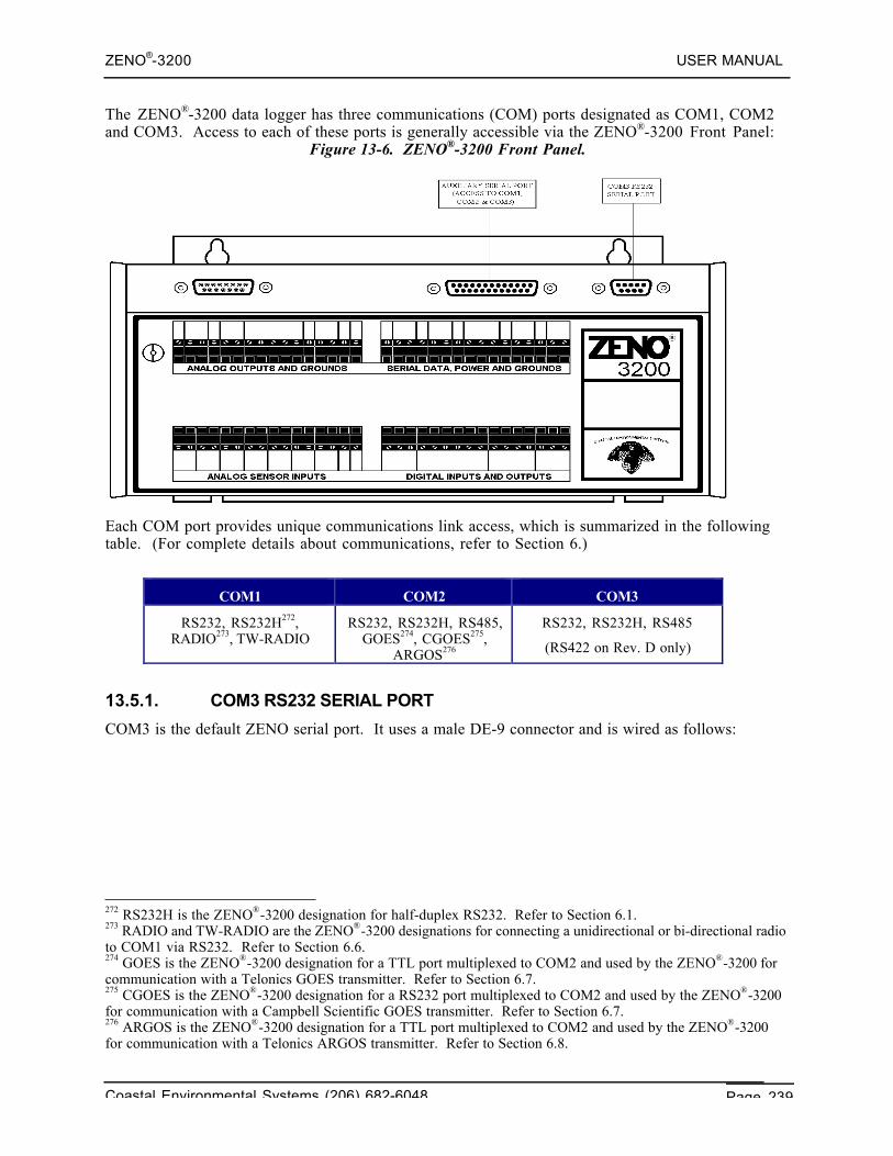
ZENO®-3200 USER MANUAL
Coastal Environmental Systems (206) 682-6048 Page 239
The ZENO®-3200 data logger has three communications (COM) ports designated as COM1, COM2and COM3. Access to each of these ports is generally accessible via the ZENO®-3200 Front Panel:
Figure 13-6. ZENO®-3200 Front Panel.
Each COM port provides unique communications link access, which is summarized in the followingtable. (For complete details about communications, refer to Section 6.)
COM1 COM2 COM3
RS232, RS232H272,RADIO273, TW-RADIO
RS232, RS232H, RS485,GOES274, CGOES275,
ARGOS276
RS232, RS232H, RS485
(RS422 on Rev. D only)
13.5.1. COM3 RS232 SERIAL PORT
COM3 is the default ZENO serial port. It uses a male DE-9 connector and is wired as follows:
272 RS232H is the ZENO®-3200 designation for half-duplex RS232. Refer to Section 6.1.273 RADIO and TW-RADIO are the ZENO®-3200 designations for connecting a unidirectional or bi-directional radioto COM1 via RS232. Refer to Section 6.6.274 GOES is the ZENO®-3200 designation for a TTL port multiplexed to COM2 and used by the ZENO®-3200 forcommunication with a Telonics GOES transmitter. Refer to Section 6.7.275 CGOES is the ZENO®-3200 designation for a RS232 port multiplexed to COM2 and used by the ZENO®-3200for communication with a Campbell Scientific GOES transmitter. Refer to Section 6.7.276 ARGOS is the ZENO®-3200 designation for a TTL port multiplexed to COM2 and used by the ZENO®-3200for communication with a Telonics ARGOS transmitter. Refer to Section 6.8.
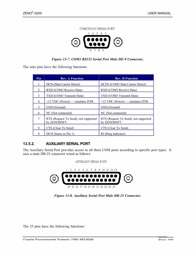
ZENO®-3200 USER MANUAL
Coastal Environmental Systems (206) 682-6048 Page 240
Figure 13-7. COM3 RS232 Serial Port Male DE-9 Connector.
The nine pins have the following functions:
Pin Rev. A Function Rev. D Function
1 DCD (Data Carrier Detect) DCD3 (COM3 Data Carrier Detect)
2 RXD (COM3 Receive Data) RXD (COM3 Receive Data)
3 TXD (COM3 Transmit Data) TXD (COM3 Transmit Data)
4 +12 VDC (Power) — emulates DTR +12 VDC (Power) — emulates DTR
5 GND (Ground) GND (Ground)
6 NC (Not connected) NC (Not connected)
7 RTS (Request To Send), not supportedby ZENOSOFT
RTS (Request To Send), not supportedby ZENOSOFT
8 CTS (Clear To Send) CTS (Clear To Send)
9 DCD (Same as Pin 1) RI (Ring Indicator)
13.5.2. AUXILIARY SERIAL PORT
The Auxiliary Serial Port provides access to all three COM ports according to specific port types. Ituses a male DB-25 connector wired as follows:
Figure 13-8. Auxiliary Serial Port Male DB-25 Connector.
The 25 pins have the following functions:
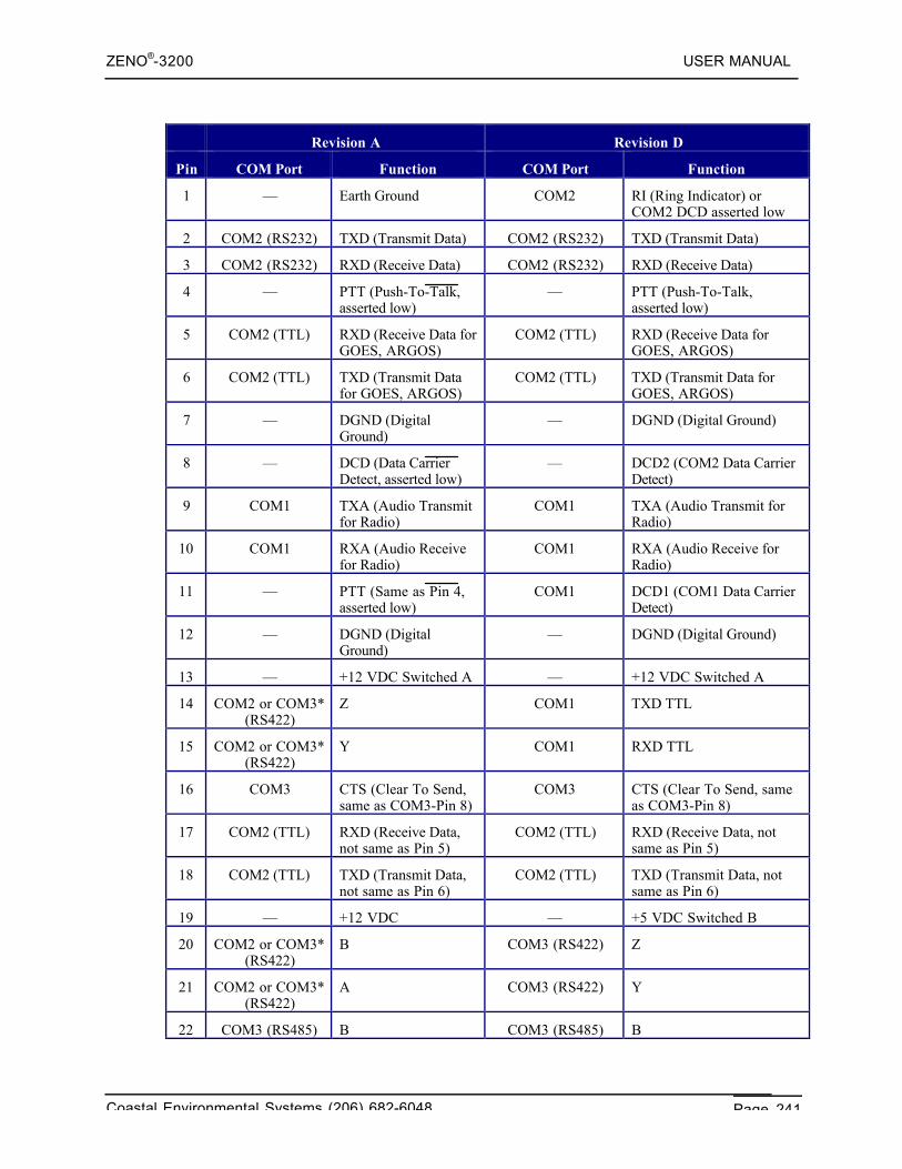
ZENO®-3200 USER MANUAL
Coastal Environmental Systems (206) 682-6048 Page 241
Revision A Revision D
Pin COM Port Function COM Port Function
1 — Earth Ground COM2 RI (Ring Indicator) orCOM2 DCD asserted low
2 COM2 (RS232) TXD (Transmit Data) COM2 (RS232) TXD (Transmit Data)
3 COM2 (RS232) RXD (Receive Data) COM2 (RS232) RXD (Receive Data)
4 — PTT (Push-To-Talk,asserted low)
— PTT (Push-To-Talk,asserted low)
5 COM2 (TTL) RXD (Receive Data forGOES, ARGOS)
COM2 (TTL) RXD (Receive Data forGOES, ARGOS)
6 COM2 (TTL) TXD (Transmit Datafor GOES, ARGOS)
COM2 (TTL) TXD (Transmit Data forGOES, ARGOS)
7 — DGND (DigitalGround)
— DGND (Digital Ground)
8 — DCD (Data CarrierDetect, asserted low)
— DCD2 (COM2 Data CarrierDetect)
9 COM1 TXA (Audio Transmitfor Radio)
COM1 TXA (Audio Transmit forRadio)
10 COM1 RXA (Audio Receivefor Radio)
COM1 RXA (Audio Receive forRadio)
11 — PTT (Same as Pin 4,asserted low)
COM1 DCD1 (COM1 Data CarrierDetect)
12 — DGND (DigitalGround)
— DGND (Digital Ground)
13 — +12 VDC Switched A — +12 VDC Switched A
14 COM2 or COM3*(RS422)
Z COM1 TXD TTL
15 COM2 or COM3*(RS422)
Y COM1 RXD TTL
16 COM3 CTS (Clear To Send,same as COM3-Pin 8)
COM3 CTS (Clear To Send, sameas COM3-Pin 8)
17 COM2 (TTL) RXD (Receive Data,not same as Pin 5)
COM2 (TTL) RXD (Receive Data, notsame as Pin 5)
18 COM2 (TTL) TXD (Transmit Data,not same as Pin 6)
COM2 (TTL) TXD (Transmit Data, notsame as Pin 6)
19 — +12 VDC — +5 VDC Switched B
20 COM2 or COM3*(RS422)
B COM3 (RS422) Z
21 COM2 or COM3*(RS422)
A COM3 (RS422) Y
22 COM3 (RS485) B COM3 (RS485) B
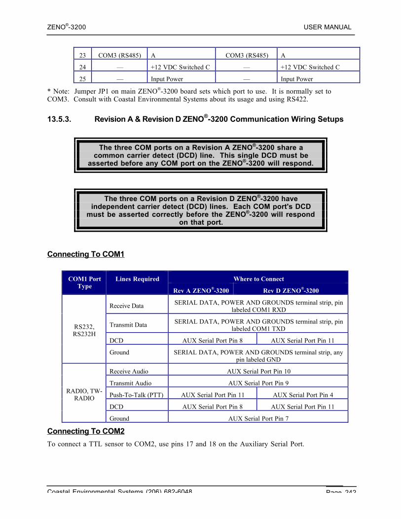
ZENO®-3200 USER MANUAL
Coastal Environmental Systems (206) 682-6048 Page 242
23 COM3 (RS485) A COM3 (RS485) A
24 — +12 VDC Switched C — +12 VDC Switched C
25 — Input Power — Input Power
* Note: Jumper JP1 on main ZENO®-3200 board sets which port to use. It is normally set toCOM3. Consult with Coastal Environmental Systems about its usage and using RS422.
13.5.3. Revision A & Revision D ZENO®-3200 Communication Wiring Setups
The three COM ports on a Revision A ZENO®-3200 share acommon carrier detect (DCD) line. This single DCD must be
asserted before any COM port on the ZENO®-3200 will respond.
The three COM ports on a Revision D ZENO®-3200 haveindependent carrier detect (DCD) lines. Each COM port's DCD
must be asserted correctly before the ZENO®-3200 will respondon that port.
Connecting To COM1
Where to ConnectCOM1 PortType
Lines Required
Rev A ZENO®-3200 Rev D ZENO®-3200
Receive Data SERIAL DATA, POWER AND GROUNDS terminal strip, pinlabeled COM1 RXD
Transmit Data SERIAL DATA, POWER AND GROUNDS terminal strip, pinlabeled COM1 TXD
DCD AUX Serial Port Pin 8 AUX Serial Port Pin 11
RS232,RS232H
Ground SERIAL DATA, POWER AND GROUNDS terminal strip, anypin labeled GND
Receive Audio AUX Serial Port Pin 10
Transmit Audio AUX Serial Port Pin 9
Push-To-Talk (PTT) AUX Serial Port Pin 11 AUX Serial Port Pin 4
DCD AUX Serial Port Pin 8 AUX Serial Port Pin 11
RADIO, TW-RADIO
Ground AUX Serial Port Pin 7
Connecting To COM2
To connect a TTL sensor to COM2, use pins 17 and 18 on the Auxiliary Serial Port.
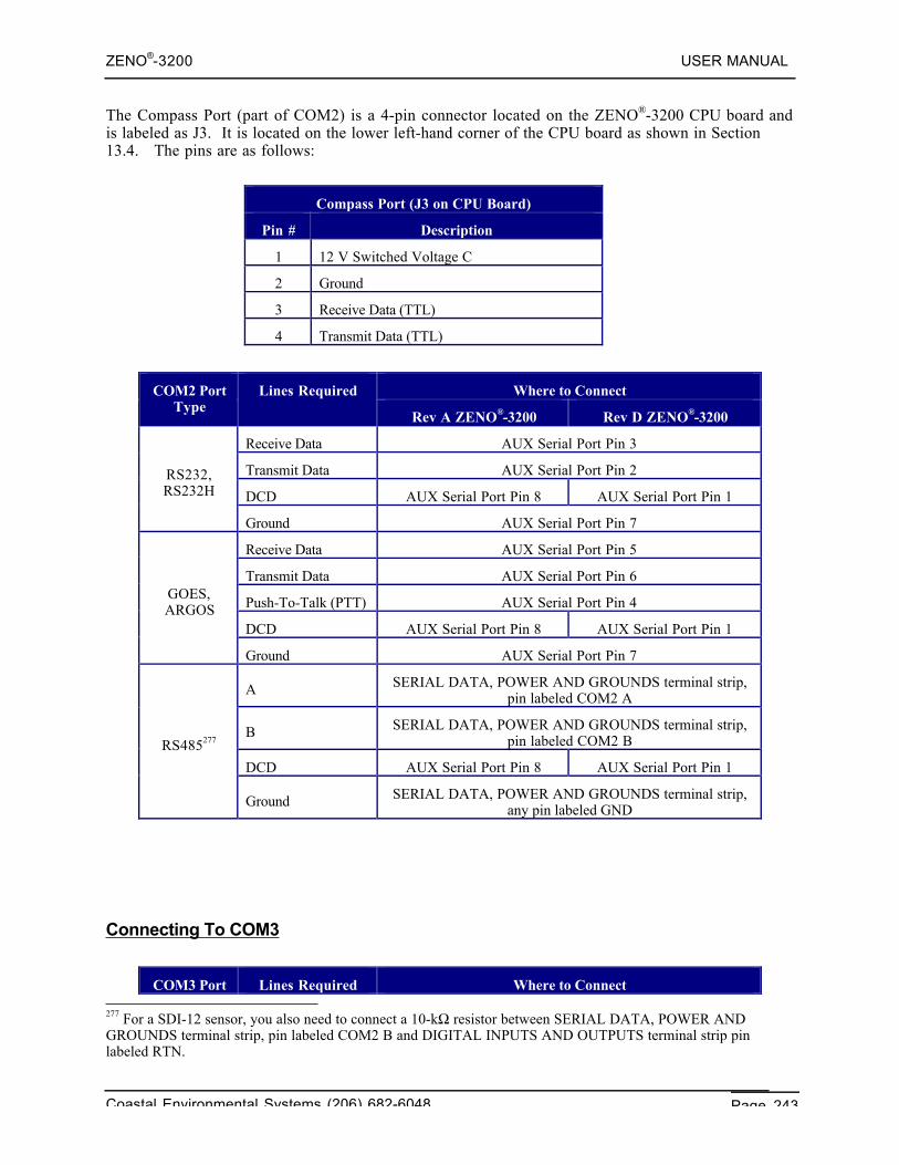
ZENO®-3200 USER MANUAL
Coastal Environmental Systems (206) 682-6048 Page 243
The Compass Port (part of COM2) is a 4-pin connector located on the ZENO®-3200 CPU board andis labeled as J3. It is located on the lower left-hand corner of the CPU board as shown in Section13.4. The pins are as follows:
Compass Port (J3 on CPU Board)
Pin # Description
1 12 V Switched Voltage C
2 Ground
3 Receive Data (TTL)
4 Transmit Data (TTL)
Where to ConnectCOM2 PortType
Lines Required
Rev A ZENO®-3200 Rev D ZENO®-3200
Receive Data AUX Serial Port Pin 3
Transmit Data AUX Serial Port Pin 2
DCD AUX Serial Port Pin 8 AUX Serial Port Pin 1
RS232,RS232H
Ground AUX Serial Port Pin 7
Receive Data AUX Serial Port Pin 5
Transmit Data AUX Serial Port Pin 6
Push-To-Talk (PTT) AUX Serial Port Pin 4
DCD AUX Serial Port Pin 8 AUX Serial Port Pin 1
GOES,ARGOS
Ground AUX Serial Port Pin 7
A SERIAL DATA, POWER AND GROUNDS terminal strip,pin labeled COM2 A
B SERIAL DATA, POWER AND GROUNDS terminal strip,pin labeled COM2 B
DCD AUX Serial Port Pin 8 AUX Serial Port Pin 1
RS485277
Ground SERIAL DATA, POWER AND GROUNDS terminal strip,any pin labeled GND
Connecting To COM3
COM3 PortType
Lines Required Where to Connect 277 For a SDI-12 sensor, you also need to connect a 10-kΩ resistor between SERIAL DATA, POWER ANDGROUNDS terminal strip, pin labeled COM2 B and DIGITAL INPUTS AND OUTPUTS terminal strip pinlabeled RTN.
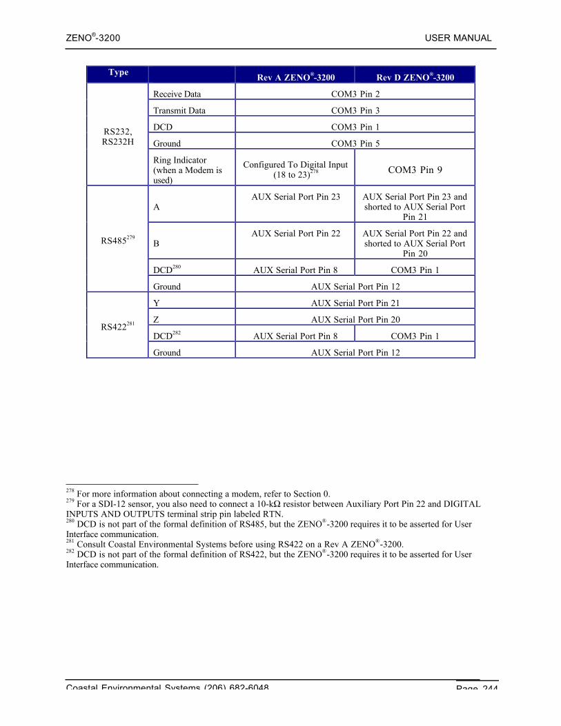
ZENO®-3200 USER MANUAL
Coastal Environmental Systems (206) 682-6048 Page 244
TypeRev A ZENO®-3200 Rev D ZENO®-3200
Receive Data COM3 Pin 2
Transmit Data COM3 Pin 3
DCD COM3 Pin 1
Ground COM3 Pin 5RS232,RS232H
Ring Indicator(when a Modem isused)
Configured To Digital Input(18 to 23)278 COM3 Pin 9
AAUX Serial Port Pin 23 AUX Serial Port Pin 23 and
shorted to AUX Serial PortPin 21
BAUX Serial Port Pin 22 AUX Serial Port Pin 22 and
shorted to AUX Serial PortPin 20
DCD280 AUX Serial Port Pin 8 COM3 Pin 1
RS485279
Ground AUX Serial Port Pin 12
Y AUX Serial Port Pin 21
Z AUX Serial Port Pin 20
DCD282 AUX Serial Port Pin 8 COM3 Pin 1RS422281
Ground AUX Serial Port Pin 12
278 For more information about connecting a modem, refer to Section 0.279 For a SDI-12 sensor, you also need to connect a 10-kΩ resistor between Auxiliary Port Pin 22 and DIGITALINPUTS AND OUTPUTS terminal strip pin labeled RTN.280 DCD is not part of the formal definition of RS485, but the ZENO®-3200 requires it to be asserted for UserInterface communication.281 Consult Coastal Environmental Systems before using RS422 on a Rev A ZENO®-3200.282 DCD is not part of the formal definition of RS422, but the ZENO®-3200 requires it to be asserted for UserInterface communication.
ZENO®-3200 USER MANUAL
Coastal Environmental Systems (206) 682-6048 Page A-1
A. CONSTANTS,CONVERSIONS & ASCII
TABLE
Coastal EnvironmentalSystems
ZENO®-3200 User Manual
1. PHYSICAL & MATHEMATICAL CONSTANTS
Avagadro Constant (NA) 6.022045 × 10² 3 mol-1
Boltzmann Constant (k) 1.380662 × 10⁻²³ J/K
Elementary Charge (e) 1.6021892 × 10⁻¹⁹ Coulomb
Exponential (_) 2.718281828
Gravitational Constant (G) 6.6720 × 10⁻¹¹ N•m2/kg2
Permittivity Constant (ε0) 8.85418782 × 10⁻¹² F/m
Permeability Constant (µ0) 1.25663706144 × 10⁻⁶ H/m
Pi (!) 3.141592654
Plank Constant (h) 6.626176 × 10⁻³⁴ J•s
Speed of Light (c) 2.99792458 × 10⁸ m/s
Stefan-Boltzmann Constant (_) 5.67032 × 10⁻⁸ W/m2•K4
Universal Gas Constant (R) 8.31 J/mol•K
Physical Properties of Dry Air (1 atm @ 20 °C)
Property Value
Density 1.20 kg/m3
Specific heat capacity at constant pressure 1010 J/kg·K
Ratio of specific heat capacities 1.40
Speed of sound 343 m/s
Electrical Breakdown strength 3 × 10⁶ V/m
Effective molecular weight 0.0289 kg/mol
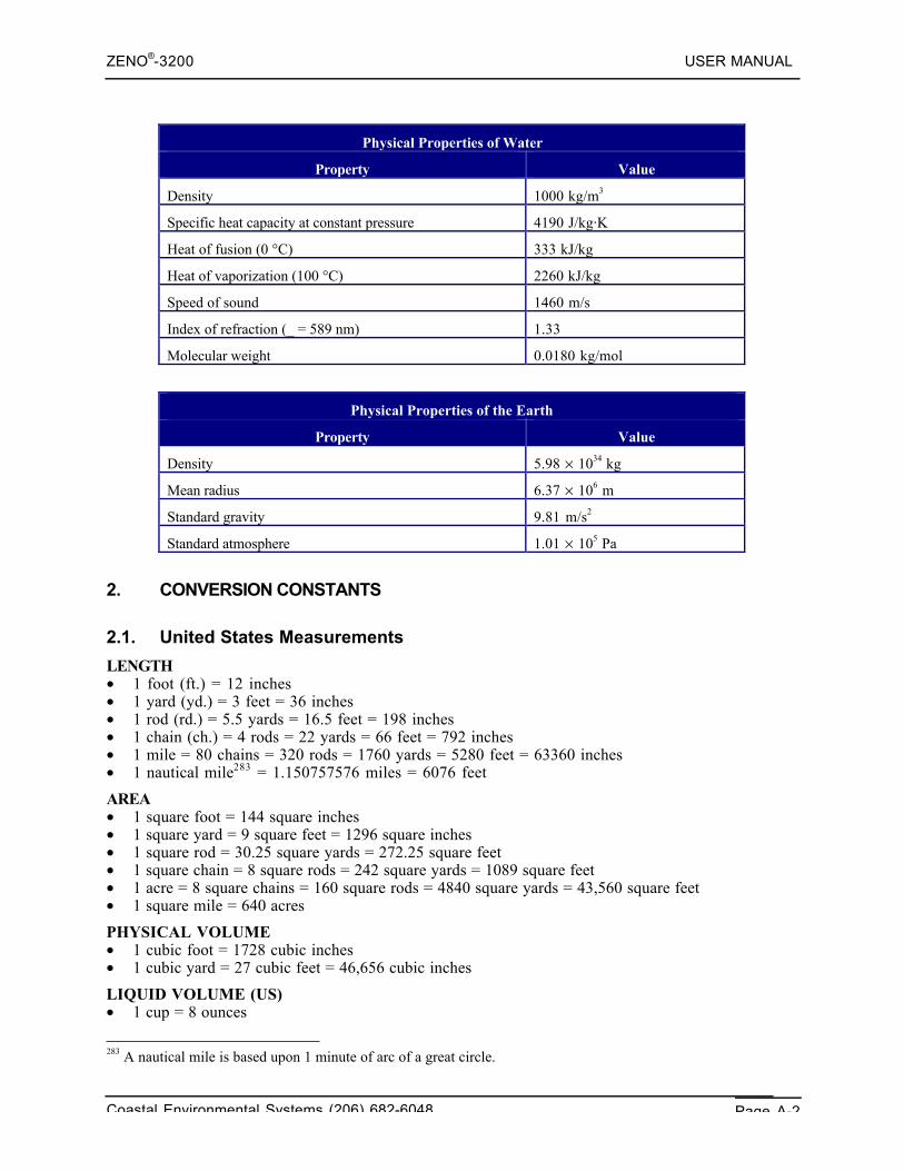
ZENO®-3200 USER MANUAL
Coastal Environmental Systems (206) 682-6048 Page A-2
Physical Properties of Water
Property Value
Density 1000 kg/m3
Specific heat capacity at constant pressure 4190 J/kg·K
Heat of fusion (0 °C) 333 kJ/kg
Heat of vaporization (100 °C) 2260 kJ/kg
Speed of sound 1460 m/s
Index of refraction (_ = 589 nm) 1.33
Molecular weight 0.0180 kg/mol
Physical Properties of the Earth
Property Value
Density 5.98 × 1034 kg
Mean radius 6.37 × 10⁶ m
Standard gravity 9.81 m/s2
Standard atmosphere 1.01 × 10⁵ Pa
2. CONVERSION CONSTANTS
2.1. United States Measurements
LENGTH• 1 foot (ft.) = 12 inches• 1 yard (yd.) = 3 feet = 36 inches• 1 rod (rd.) = 5.5 yards = 16.5 feet = 198 inches• 1 chain (ch.) = 4 rods = 22 yards = 66 feet = 792 inches• 1 mile = 80 chains = 320 rods = 1760 yards = 5280 feet = 63360 inches• 1 nautical mile283 = 1.150757576 miles = 6076 feet
AREA• 1 square foot = 144 square inches• 1 square yard = 9 square feet = 1296 square inches• 1 square rod = 30.25 square yards = 272.25 square feet• 1 square chain = 8 square rods = 242 square yards = 1089 square feet• 1 acre = 8 square chains = 160 square rods = 4840 square yards = 43,560 square feet• 1 square mile = 640 acres
PHYSICAL VOLUME• 1 cubic foot = 1728 cubic inches• 1 cubic yard = 27 cubic feet = 46,656 cubic inches
LIQUID VOLUME (US)• 1 cup = 8 ounces
283 A nautical mile is based upon 1 minute of arc of a great circle.
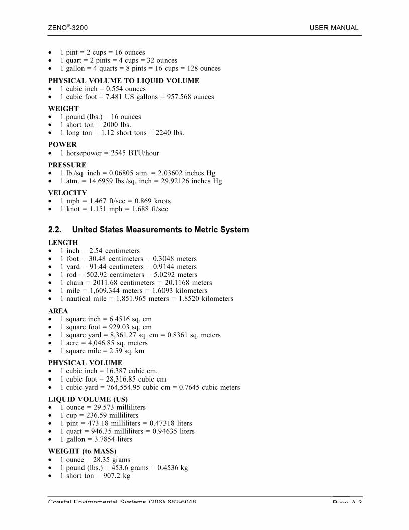
ZENO®-3200 USER MANUAL
Coastal Environmental Systems (206) 682-6048 Page A-3
• 1 pint = 2 cups = 16 ounces• 1 quart = 2 pints = 4 cups = 32 ounces• 1 gallon = 4 quarts = 8 pints = 16 cups = 128 ounces
PHYSICAL VOLUME TO LIQUID VOLUME• 1 cubic inch = 0.554 ounces• 1 cubic foot = 7.481 US gallons = 957.568 ounces
WEIGHT• 1 pound (lbs.) = 16 ounces• 1 short ton = 2000 lbs.• 1 long ton = 1.12 short tons = 2240 lbs.
POWER• 1 horsepower = 2545 BTU/hour
PRESSURE• 1 lb./sq. inch = 0.06805 atm. = 2.03602 inches Hg• 1 atm. = 14.6959 lbs./sq. inch = 29.92126 inches Hg
VELOCITY• 1 mph = 1.467 ft/sec = 0.869 knots• 1 knot = 1.151 mph = 1.688 ft/sec
2.2. United States Measurements to Metric System
LENGTH• 1 inch = 2.54 centimeters• 1 foot = 30.48 centimeters = 0.3048 meters• 1 yard = 91.44 centimeters = 0.9144 meters• 1 rod = 502.92 centimeters = 5.0292 meters• 1 chain = 2011.68 centimeters = 20.1168 meters• 1 mile = 1,609.344 meters = 1.6093 kilometers• 1 nautical mile = 1,851.965 meters = 1.8520 kilometers
AREA• 1 square inch = 6.4516 sq. cm• 1 square foot = 929.03 sq. cm• 1 square yard = 8,361.27 sq. cm = 0.8361 sq. meters• 1 acre = 4,046.85 sq. meters• 1 square mile = 2.59 sq. km
PHYSICAL VOLUME• 1 cubic inch = 16.387 cubic cm.• 1 cubic foot = 28,316.85 cubic cm• 1 cubic yard = 764,554.95 cubic cm = 0.7645 cubic meters
LIQUID VOLUME (US)• 1 ounce = 29.573 milliliters• 1 cup = 236.59 milliliters• 1 pint = 473.18 milliliters = 0.47318 liters• 1 quart = 946.35 milliliters = 0.94635 liters• 1 gallon = 3.7854 liters
WEIGHT (to MASS)• 1 ounce = 28.35 grams• 1 pound (lbs.) = 453.6 grams = 0.4536 kg• 1 short ton = 907.2 kg
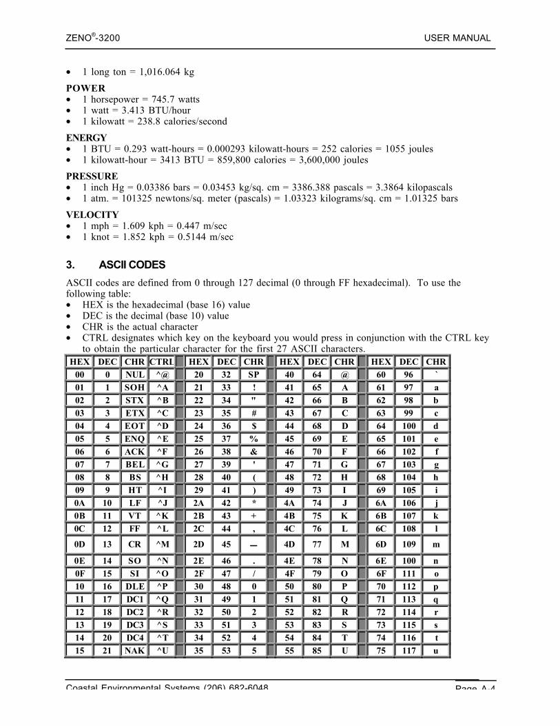
ZENO®-3200 USER MANUAL
Coastal Environmental Systems (206) 682-6048 Page A-4
• 1 long ton = 1,016.064 kg
POWER• 1 horsepower = 745.7 watts• 1 watt = 3.413 BTU/hour• 1 kilowatt = 238.8 calories/second
ENERGY• 1 BTU = 0.293 watt-hours = 0.000293 kilowatt-hours = 252 calories = 1055 joules• 1 kilowatt-hour = 3413 BTU = 859,800 calories = 3,600,000 joules
PRESSURE• 1 inch Hg = 0.03386 bars = 0.03453 kg/sq. cm = 3386.388 pascals = 3.3864 kilopascals• 1 atm. = 101325 newtons/sq. meter (pascals) = 1.03323 kilograms/sq. cm = 1.01325 bars
VELOCITY• 1 mph = 1.609 kph = 0.447 m/sec• 1 knot = 1.852 kph = 0.5144 m/sec
3. ASCII CODES
ASCII codes are defined from 0 through 127 decimal (0 through FF hexadecimal). To use thefollowing table:• HEX is the hexadecimal (base 16) value• DEC is the decimal (base 10) value• CHR is the actual character• CTRL designates which key on the keyboard you would press in conjunction with the CTRL key
to obtain the particular character for the first 27 ASCII characters.HEX DEC CHR CTRL HEX DEC CHR HEX DEC CHR HEX DEC CHR
00 0 NUL ^@ 20 32 SP 40 64 @ 60 96 `01 1 SOH ^A 21 33 ! 41 65 A 61 97 a02 2 STX ^B 22 34 " 42 66 B 62 98 b03 3 ETX ^C 23 35 # 43 67 C 63 99 c04 4 EOT ^D 24 36 $ 44 68 D 64 100 d05 5 ENQ ^E 25 37 % 45 69 E 65 101 e06 6 ACK ^F 26 38 & 46 70 F 66 102 f07 7 BEL ^G 27 39 ' 47 71 G 67 103 g08 8 BS ^H 28 40 ( 48 72 H 68 104 h09 9 HT ^I 29 41 ) 49 73 I 69 105 i0A 10 LF ^J 2A 42 * 4A 74 J 6A 106 j0B 11 VT ^K 2B 43 + 4B 75 K 6B 107 k0C 12 FF ^L 2C 44 , 4C 76 L 6C 108 l
0D 13 CR ^M 2D 45 − 4D 77 M 6D 109 m
0E 14 SO ^N 2E 46 . 4E 78 N 6E 100 n0F 15 SI ^O 2F 47 / 4F 79 O 6F 111 o10 16 DLE ^P 30 48 0 50 80 P 70 112 p11 17 DC1 ^Q 31 49 1 51 81 Q 71 113 q12 18 DC2 ^R 32 50 2 52 82 R 72 114 r13 19 DC3 ^S 33 51 3 53 83 S 73 115 s14 20 DC4 ^T 34 52 4 54 84 T 74 116 t15 21 NAK ^U 35 53 5 55 85 U 75 117 u
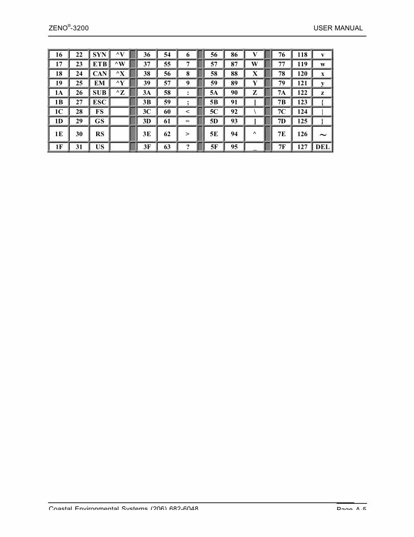
ZENO®-3200 USER MANUAL
Coastal Environmental Systems (206) 682-6048 Page A-5
16 22 SYN ^V 36 54 6 56 86 V 76 118 v17 23 ETB ^W 37 55 7 57 87 W 77 119 w18 24 CAN ^X 38 56 8 58 88 X 78 120 x19 25 EM ^Y 39 57 9 59 89 Y 79 121 y1A 26 SUB ^Z 3A 58 : 5A 90 Z 7A 122 z1B 27 ESC 3B 59 ; 5B 91 [ 7B 123 {1C 28 FS 3C 60 < 5C 92 \ 7C 124 |1D 29 GS 3D 61 = 5D 93 ] 7D 125 }
1E 30 RS 3E 62 > 5E 94 ^ 7E 126 ~1F 31 US 3F 63 ? 5F 95 _ 7F 127 DEL

ZENO®-3200 USER MANUAL
Coastal Environmental Systems (206) 682-6048 Page A-6
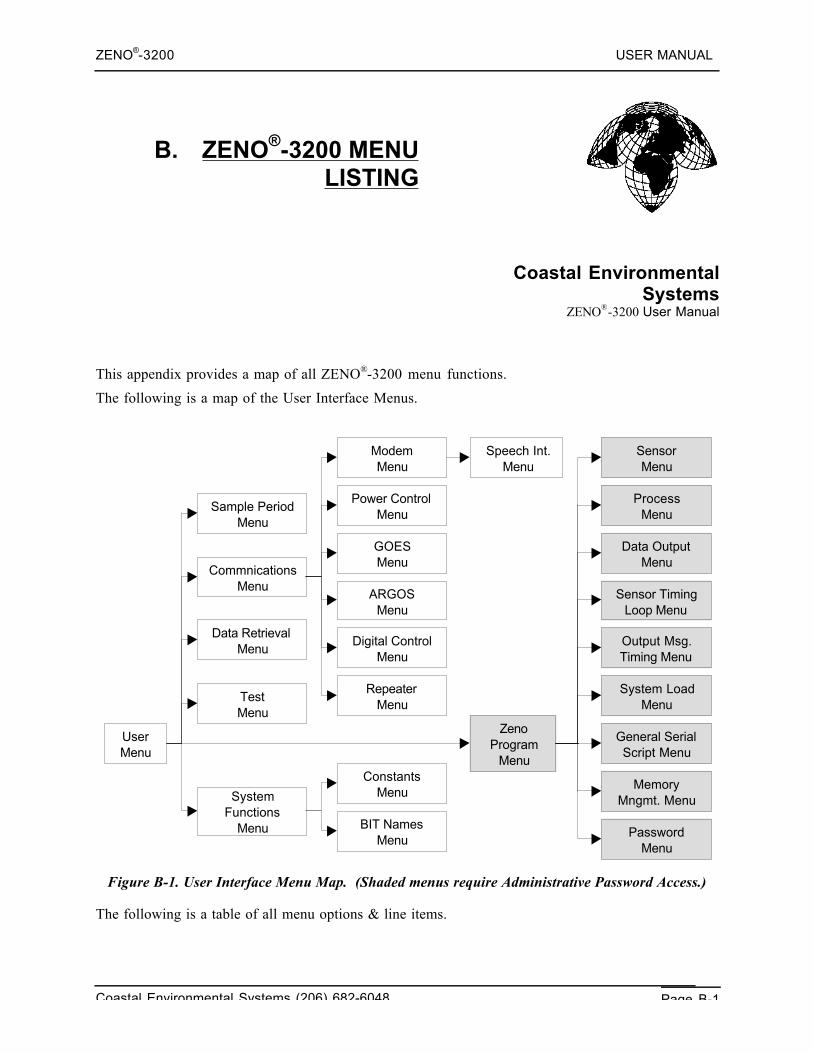
ZENO®-3200 USER MANUAL
Coastal Environmental Systems (206) 682-6048 Page B-1
B. ZENO®-3200 MENULISTING
Coastal EnvironmentalSystems
ZENO®-3200 User Manual
This appendix provides a map of all ZENO®-3200 menu functions.
The following is a map of the User Interface Menus.
User Menu
Sample Period Menu
Commnications Menu
Data Retrieval Menu
Test Menu
Modem Menu
Power Control Menu
GOES Menu
ARGOS Menu
Digital Control Menu
Repeater Menu
Zeno Program
Menu
System Functions
Menu
Constants Menu
BIT Names Menu
Sensor Menu
Process Menu
Data Output Menu
Sensor Timing Loop Menu
Output Msg. Timing Menu
System Load Menu
General Serial Script Menu
Memory Mngmt. Menu
Password Menu
Speech Int. Menu
Figure B-1. User Interface Menu Map. (Shaded menus require Administrative Password Access.)
The following is a table of all menu options & line items.
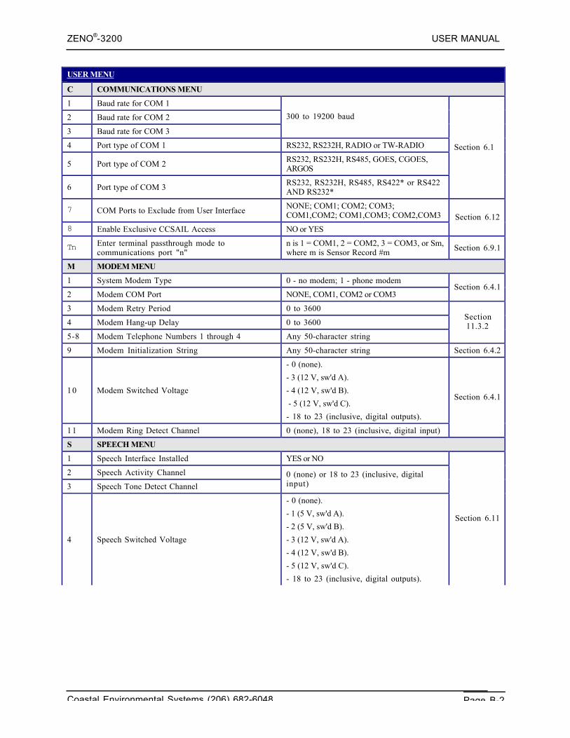
ZENO®-3200 USER MANUAL
Coastal Environmental Systems (206) 682-6048 Page B-2
USER MENU
C COMMUNICATIONS MENU
1 Baud rate for COM 1
2 Baud rate for COM 2
3 Baud rate for COM 3
300 to 19200 baud
4 Port type of COM 1 RS232, RS232H, RADIO or TW-RADIO
5 Port type of COM 2 RS232, RS232H, RS485, GOES, CGOES,ARGOS
6 Port type of COM 3 RS232, RS232H, RS485, RS422* or RS422AND RS232*
Section 6.1
7 COM Ports to Exclude from User Interface NONE; COM1; COM2; COM3;COM1,COM2; COM1,COM3; COM2,COM3
8 Enable Exclusive CCSAIL Access NO or YES
Section 6.12
Tn Enter terminal passthrough mode tocommunications port "n"
n is 1 = COM1, 2 = COM2, 3 = COM3, or Sm,where m is Sensor Record #m Section 6.9.1
M MODEM MENU
1 System Modem Type 0 - no modem; 1 - phone modem
2 Modem COM Port NONE, COM1, COM2 or COM3Section 6.4.1
3 Modem Retry Period 0 to 3600
4 Modem Hang-up Delay 0 to 3600
5-8 Modem Telephone Numbers 1 through 4 Any 50-character string
Section11.3.2
9 Modem Initialization String Any 50-character string Section 6.4.2
10 Modem Switched Voltage
- 0 (none).
- 3 (12 V, sw'd A).
- 4 (12 V, sw'd B).
- 5 (12 V, sw'd C).
- 18 to 23 (inclusive, digital outputs).
11 Modem Ring Detect Channel 0 (none), 18 to 23 (inclusive, digital input)
Section 6.4.1
S SPEECH MENU
1 Speech Interface Installed YES or NO
2 Speech Activity Channel
3 Speech Tone Detect Channel
0 (none) or 18 to 23 (inclusive, digitalinput)
4 Speech Switched Voltage
- 0 (none).
- 1 (5 V, sw'd A).
- 2 (5 V, sw'd B).
- 3 (12 V, sw'd A).
- 4 (12 V, sw'd B).
- 5 (12 V, sw'd C).
- 18 to 23 (inclusive, digital outputs).
Section 6.11
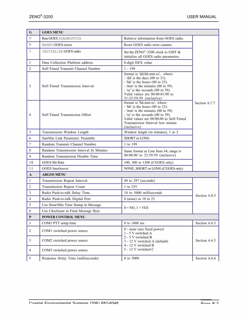
ZENO®-3200 USER MANUAL
Coastal Environmental Systems (206) 682-6048 Page B-3
G GOES MENU
D Run GOES DIAGNOSTICS Retrieve information from GOES radio.
R RESET GOES errors Reset GOES radio error counter.
I INITIALIZE GOES radio Set the ZENO®-3200 clock to GMT &initialize all GOES radio parameters.
1 Data Collection Platform address 8-digit HEX value
2 Self-Timed Transmit Channel Number 1 - 199
3 Self-Timed Transmission Interval
format is 'dd:hh:mm:ss', where:- 'dd' is the days (00 to 31).- 'hh' is the hours (00 to 23).- 'mm' is the minutes (00 to 59).- 'ss' is the seconds (00 to 59).Valid values are 00:00:01:00 to31:23:59:59 (inclusive)
4 Self-Timed Transmission Offset
format is 'hh:mm:ss', where:- 'hh' is the hours (00 to 23).- 'mm' is the minutes (00 to 59).- 'ss' is the seconds (00 to 59).Valid values are 00:00:00 to Self-TimedTransmission Interval less minute(inclusive)
5 Transmission Window Length Window length (in minutes), 1 or 2
6 Satellite Link Parameter: Preamble SHORT or LONG
7 Random Transmit Channel Number 1 to 199
8 Random Transmission Interval In Minutes
9 Random Transmission Disable Time
Same format as Line Item #4, range is00:00:00 to 23:59:59 (inclusive)
10 GOES Bit Rate 100, 300 or 1200 (CGOES only)
11 GOES Interleaver NONE, SHORT or LONG (CGOES only)
Section 6.7.7
A ARGOS MENU
1 Transmission Repeat Interval 49 to 297 (seconds)
2 Transmission Repeat Count 1 to 255
3 Radio Push-to-talk Delay Time 10 to 5000 milliseconds
4 Radio Push-to-talk Digital Port 0 (none) or 18 to 23
5 Use Hour/Min Time Stamp in Message
6 Use Checksum in Final Message Byte0 = NO, 1 = YES
Section 6.8.5
P POWER CONTROL MENU
1 COM1 PTT setup time 0 to 1000 ms Section 6.6.5
2 COM1 switched power source
3 COM2 switched power source
4 COM3 switched power source
0 - none (use fixed power)1 - 5 V switched A2 - 5 V switched B3 - 12 V switched A (default)4 - 12 V switched B5 - 12 V switched C
Section 6.6.3
5 Response Delay Time (milliseconds) 0 to 5000 Section 6.6.6
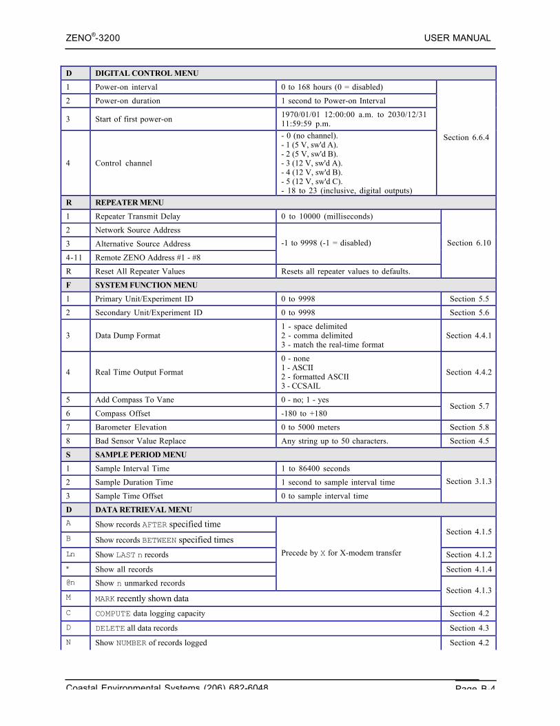
ZENO®-3200 USER MANUAL
Coastal Environmental Systems (206) 682-6048 Page B-4
D DIGITAL CONTROL MENU
1 Power-on interval 0 to 168 hours (0 = disabled)
2 Power-on duration 1 second to Power-on Interval
3 Start of first power-on 1970/01/01 12:00:00 a.m. to 2030/12/3111:59:59 p.m.
4 Control channel
- 0 (no channel).- 1 (5 V, sw'd A).- 2 (5 V, sw'd B).- 3 (12 V, sw'd A).- 4 (12 V, sw'd B).- 5 (12 V, sw'd C).- 18 to 23 (inclusive, digital outputs)
Section 6.6.4
R REPEATER MENU
1 Repeater Transmit Delay 0 to 10000 (milliseconds)
2 Network Source Address
3 Alternative Source Address
4-11 Remote ZENO Address #1 - #8
-1 to 9998 (-1 = disabled)
R Reset All Repeater Values Resets all repeater values to defaults.
Section 6.10
F SYSTEM FUNCTION MENU
1 Primary Unit/Experiment ID 0 to 9998 Section 5.5
2 Secondary Unit/Experiment ID 0 to 9998 Section 5.6
3 Data Dump Format1 - space delimited2 - comma delimited3 - match the real-time format
Section 4.4.1
4 Real Time Output Format
0 - none1 - ASCII2 - formatted ASCII3 - CCSAIL
Section 4.4.2
5 Add Compass To Vane 0 - no; 1 - yes
6 Compass Offset -180 to +180Section 5.7
7 Barometer Elevation 0 to 5000 meters Section 5.8
8 Bad Sensor Value Replace Any string up to 50 characters. Section 4.5
S SAMPLE PERIOD MENU
1 Sample Interval Time 1 to 86400 seconds
2 Sample Duration Time 1 second to sample interval time
3 Sample Time Offset 0 to sample interval time
Section 3.1.3
D DATA RETRIEVAL MENU
A Show records AFTER specified time
B Show records BETWEEN specified timesSection 4.1.5
Ln Show LAST n records Section 4.1.2
* Show all records Section 4.1.4
@n Show n unmarked records
Precede by X for X-modem transfer
M MARK recently shown dataSection 4.1.3
C COMPUTE data logging capacity Section 4.2
D DELETE all data records Section 4.3
N Show NUMBER of records logged Section 4.2
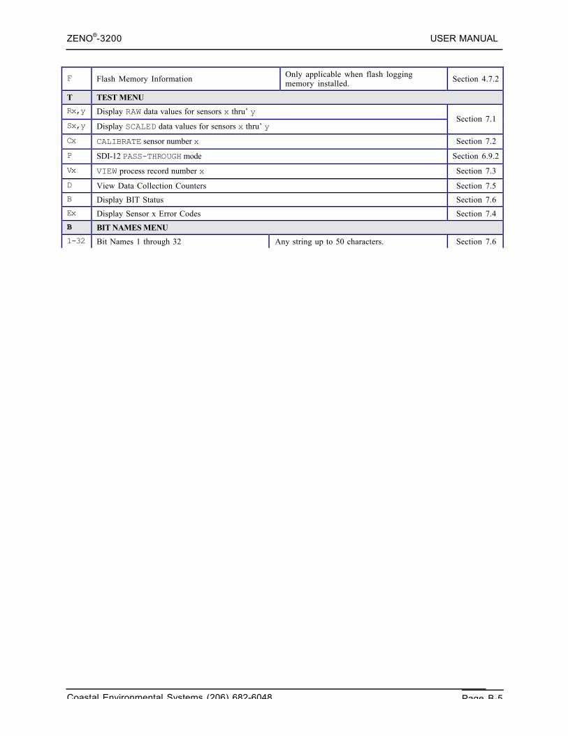
ZENO®-3200 USER MANUAL
Coastal Environmental Systems (206) 682-6048 Page B-5
F Flash Memory Information Only applicable when flash loggingmemory installed. Section 4.7.2
T TEST MENU
Rx,y Display RAW data values for sensors x thru’ y
Sx,y Display SCALED data values for sensors x thru’ ySection 7.1
Cx CALIBRATE sensor number x Section 7.2
P SDI-12 PASS-THROUGH mode Section 6.9.2
Vx VIEW process record number x Section 7.3
D View Data Collection Counters Section 7.5
B Display BIT Status Section 7.6
Ex Display Sensor x Error Codes Section 7.4
B BIT NAMES MENU
1-32 Bit Names 1 through 32 Any string up to 50 characters. Section 7.6
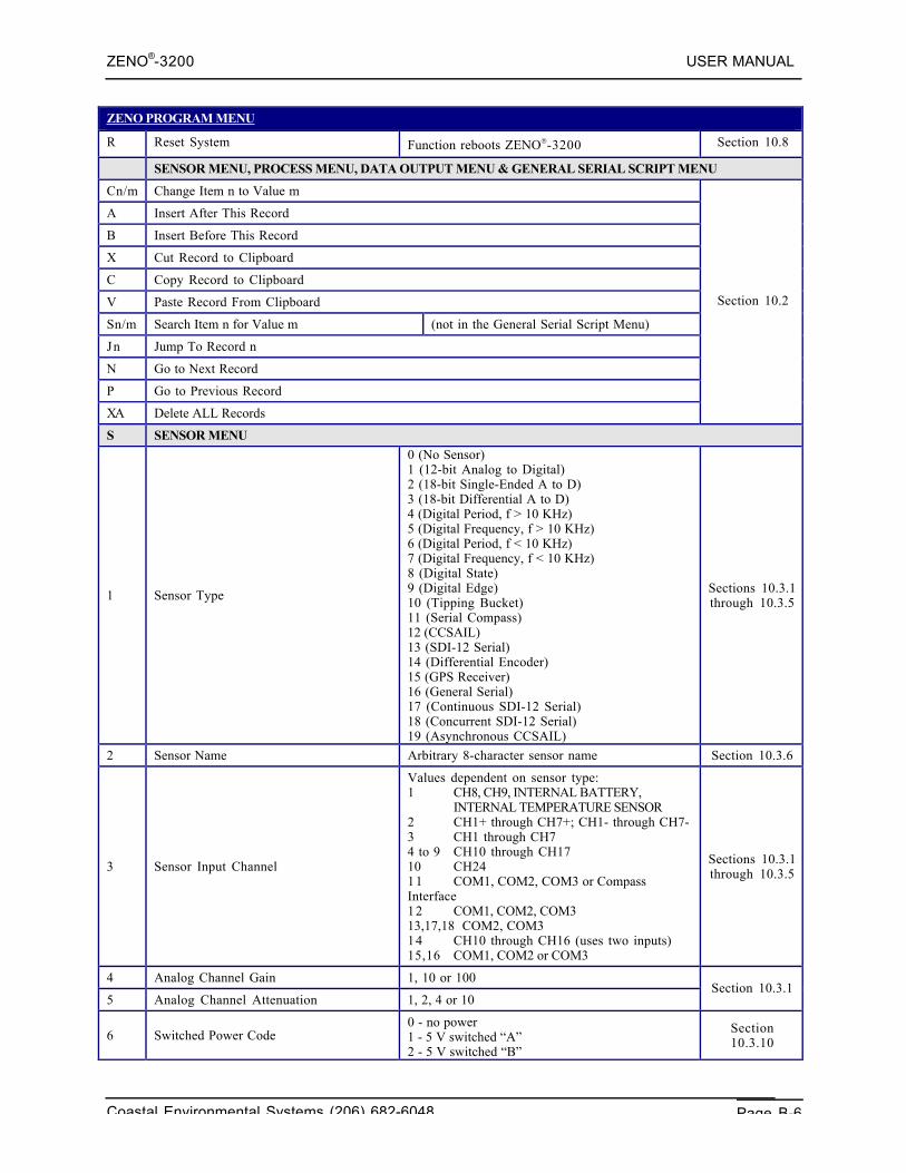
ZENO®-3200 USER MANUAL
Coastal Environmental Systems (206) 682-6048 Page B-6
ZENO PROGRAM MENU
R Reset System Function reboots ZENO®-3200 Section 10.8
SENSOR MENU, PROCESS MENU, DATA OUTPUT MENU & GENERAL SERIAL SCRIPT MENU
Cn/m Change Item n to Value m
A Insert After This Record
B Insert Before This Record
X Cut Record to Clipboard
C Copy Record to Clipboard
V Paste Record From Clipboard
Sn/m Search Item n for Value m (not in the General Serial Script Menu)
Jn Jump To Record n
N Go to Next Record
P Go to Previous Record
XA Delete ALL Records
Section 10.2
S SENSOR MENU
1 Sensor Type
0 (No Sensor)1 (12-bit Analog to Digital)2 (18-bit Single-Ended A to D)3 (18-bit Differential A to D)4 (Digital Period, f > 10 KHz)5 (Digital Frequency, f > 10 KHz)6 (Digital Period, f < 10 KHz)7 (Digital Frequency, f < 10 KHz)8 (Digital State)9 (Digital Edge)10 (Tipping Bucket)11 (Serial Compass)12 (CCSAIL)13 (SDI-12 Serial)14 (Differential Encoder)15 (GPS Receiver)16 (General Serial)17 (Continuous SDI-12 Serial)18 (Concurrent SDI-12 Serial)19 (Asynchronous CCSAIL)
Sections 10.3.1through 10.3.5
2 Sensor Name Arbitrary 8-character sensor name Section 10.3.6
3 Sensor Input Channel
Values dependent on sensor type:1 CH8, CH9, INTERNAL BATTERY,
INTERNAL TEMPERATURE SENSOR2 CH1+ through CH7+; CH1- through CH7-3 CH1 through CH74 to 9 CH10 through CH1710 CH2411 COM1, COM2, COM3 or CompassInterface12 COM1, COM2, COM313,17,18 COM2, COM314 CH10 through CH16 (uses two inputs)15,16 COM1, COM2 or COM3
Sections 10.3.1through 10.3.5
4 Analog Channel Gain 1, 10 or 100
5 Analog Channel Attenuation 1, 2, 4 or 10Section 10.3.1
6 Switched Power Code0 - no power1 - 5 V switched “A”2 - 5 V switched “B”3 - 12 V switched “A”4 - 12 V switched “B”5 - 12 V switched “C”
Section10.3.10
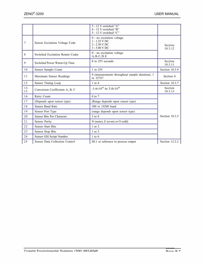
ZENO®-3200 USER MANUAL
Coastal Environmental Systems (206) 682-6048 Page B-7
3 - 12 V switched “A”4 - 12 V switched “B”5 - 12 V switched “C”
7 Sensor Excitation Voltage Code
0 - no excitation voltage1 - 1.25 V DC2 - 2.50 V DC3 - 5.00 V DC
8 Switched Excitation Return Codes 0 - no excitation voltageA, B, C, D, E
Section10.3.12
9 Switched Power Warm-Up Time 0 to 255 seconds Section10.3.11
10 Sensor Sample Count 1 to 255 Section 10.3.9
11 Maximum Sensor Readings 0 (measurements throughout sample duration), 1to 32767 Section 0
12 Sensor Timing Loop 1 to 4 Section 10.3.7
13-15 Conversion Coefficients A, B, C -3.4×1038 to 3.4×1038 Section
10.3.13
16 Retry Count 0 to 7
17 (Depends upon sensor type) (Range depends upon sensor type)
18 Sensor Baud Rate 300 to 19200 baud
19 Sensor Port Type (range depends upon sensor type)
20 Sensor Bits Per Character 5 to 8
21 Sensor Parity N (none), E (even) or O (odd)
22 Sensor Start Bits 1 or 2
23 Sensor Stop Bits 1 or 2
24 Sensor GSI Script Number 1 to 6
Section 10.3.5
25 Sensor Data Collection Control S0.1 or reference to process output Section 12.2.2
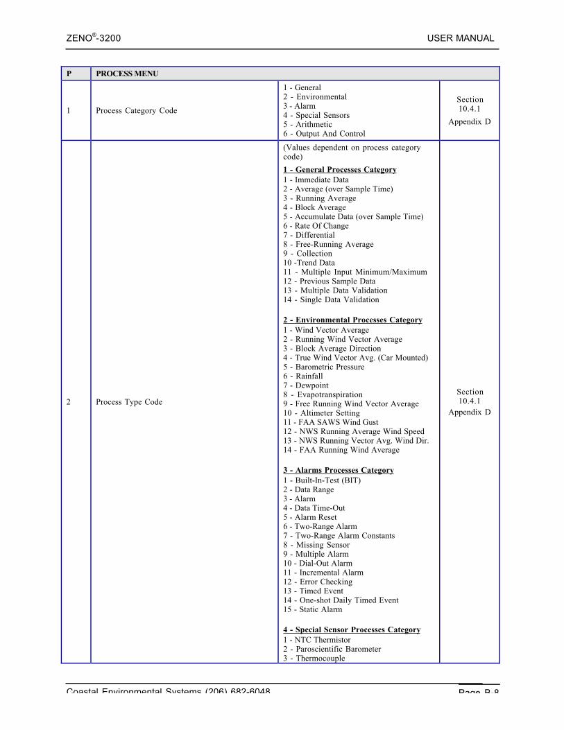
ZENO®-3200 USER MANUAL
Coastal Environmental Systems (206) 682-6048 Page B-8
P PROCESS MENU
1 Process Category Code
1 - General2 - Environmental3 - Alarm4 - Special Sensors5 - Arithmetic6 - Output And Control
Section10.4.1
Appendix D
2 Process Type Code
(Values dependent on process categorycode)
1 - General Processes Category1 - Immediate Data2 - Average (over Sample Time)3 - Running Average4 - Block Average5 - Accumulate Data (over Sample Time)6 - Rate Of Change7 - Differential8 - Free-Running Average9 - Collection10 -Trend Data11 - Multiple Input Minimum/Maximum12 - Previous Sample Data13 - Multiple Data Validation14 - Single Data Validation
2 - Environmental Processes Category1 - Wind Vector Average2 - Running Wind Vector Average3 - Block Average Direction4 - True Wind Vector Avg. (Car Mounted)5 - Barometric Pressure6 - Rainfall7 - Dewpoint8 - Evapotranspiration9 - Free Running Wind Vector Average10 - Altimeter Setting11 - FAA SAWS Wind Gust12 - NWS Running Average Wind Speed13 - NWS Running Vector Avg. Wind Dir.14 - FAA Running Wind Average
3 - Alarms Processes Category1 - Built-In-Test (BIT)2 - Data Range3 - Alarm4 - Data Time-Out5 - Alarm Reset6 - Two-Range Alarm7 - Two-Range Alarm Constants8 - Missing Sensor9 - Multiple Alarm10 - Dial-Out Alarm11 - Incremental Alarm12 - Error Checking13 - Timed Event14 - One-shot Daily Timed Event15 - Static Alarm
4 - Special Sensor Processes Category1 - NTC Thermistor2 - Paroscientific Barometer3 - Thermocouple
Section10.4.1
Appendix D
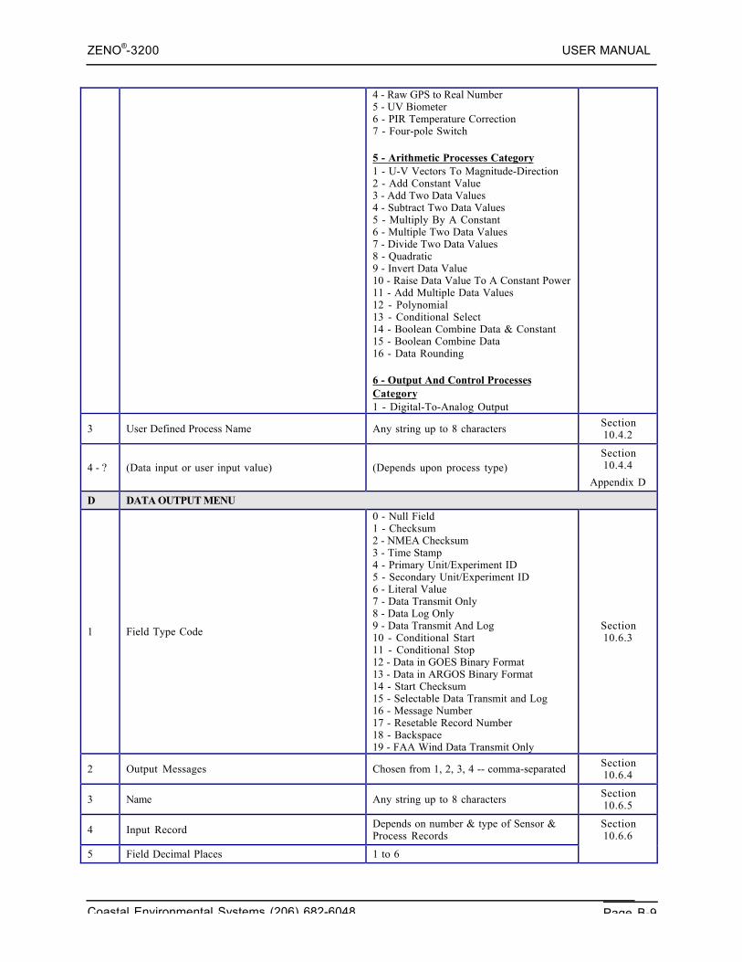
ZENO®-3200 USER MANUAL
Coastal Environmental Systems (206) 682-6048 Page B-9
4 - Raw GPS to Real Number5 - UV Biometer6 - PIR Temperature Correction7 - Four-pole Switch
5 - Arithmetic Processes Category1 - U-V Vectors To Magnitude-Direction2 - Add Constant Value3 - Add Two Data Values4 - Subtract Two Data Values5 - Multiply By A Constant6 - Multiple Two Data Values7 - Divide Two Data Values8 - Quadratic9 - Invert Data Value10 - Raise Data Value To A Constant Power11 - Add Multiple Data Values12 - Polynomial13 - Conditional Select14 - Boolean Combine Data & Constant15 - Boolean Combine Data16 - Data Rounding
6 - Output And Control ProcessesCategory1 - Digital-To-Analog Output
3 User Defined Process Name Any string up to 8 characters Section10.4.2
4 - ? (Data input or user input value) (Depends upon process type)Section10.4.4
Appendix D
D DATA OUTPUT MENU
1 Field Type Code
0 - Null Field1 - Checksum2 - NMEA Checksum3 - Time Stamp4 - Primary Unit/Experiment ID5 - Secondary Unit/Experiment ID6 - Literal Value7 - Data Transmit Only8 - Data Log Only9 - Data Transmit And Log10 - Conditional Start11 - Conditional Stop12 - Data in GOES Binary Format13 - Data in ARGOS Binary Format14 - Start Checksum15 - Selectable Data Transmit and Log16 - Message Number17 - Resetable Record Number18 - Backspace19 - FAA Wind Data Transmit Only
Section10.6.3
2 Output Messages Chosen from 1, 2, 3, 4 -- comma-separated Section10.6.4
3 Name Any string up to 8 characters Section10.6.5
4 Input Record Depends on number & type of Sensor &Process Records
5 Field Decimal Places 1 to 6
Section10.6.6
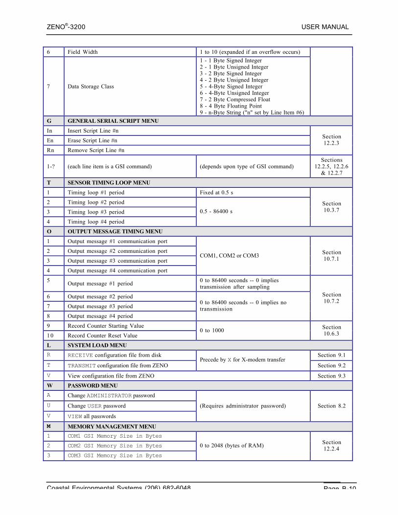
ZENO®-3200 USER MANUAL
Coastal Environmental Systems (206) 682-6048 Page B-10
6 Field Width 1 to 10 (expanded if an overflow occurs)
7 Data Storage Class
1 - 1 Byte Signed Integer2 - 1 Byte Unsigned Integer3 - 2 Byte Signed Integer4 - 2 Byte Unsigned Integer5 - 4-Byte Signed Integer6 - 4-Byte Unsigned Integer7 - 2 Byte Compressed Float8 - 4 Byte Floating Point9 - n-Byte String ("n" set by Line Item #6)
G GENERAL SERIAL SCRIPT MENU
In Insert Script Line #n
En Erase Script Line #n
Rn Remove Script Line #n
Section12.2.3
1-? (each line item is a GSI command) (depends upon type of GSI command)Sections
12.2.5, 12.2.6& 12.2.7
T SENSOR TIMING LOOP MENU
1 Timing loop #1 period Fixed at 0.5 s
2 Timing loop #2 period
3 Timing loop #3 period
4 Timing loop #4 period
0.5 - 86400 sSection10.3.7
O OUTPUT MESSAGE TIMING MENU
1 Output message #1 communication port
2 Output message #2 communication port
3 Output message #3 communication port
4 Output message #4 communication port
COM1, COM2 or COM3 Section10.7.1
5 Output message #1 period 0 to 86400 seconds -- 0 impliestransmission after sampling
6 Output message #2 period
7 Output message #3 period
8 Output message #4 period
0 to 86400 seconds -- 0 implies notransmission
Section10.7.2
9 Record Counter Starting Value
10 Record Counter Reset Value0 to 1000 Section
10.6.3
L SYSTEM LOAD MENU
R RECEIVE configuration file from disk Section 9.1
T TRANSMIT configuration file from ZENOPrecede by X for X-modem transfer
Section 9.2
V View configuration file from ZENO Section 9.3
W PASSWORD MENU
A Change ADMINISTRATOR password
U Change USER password
V VIEW all passwords
(Requires administrator password) Section 8.2
M MEMORY MANAGEMENT MENU
1 COM1 GSI Memory Size in Bytes
2 COM2 GSI Memory Size in Bytes
3 COM3 GSI Memory Size in Bytes
0 to 2048 (bytes of RAM) Section12.2.4
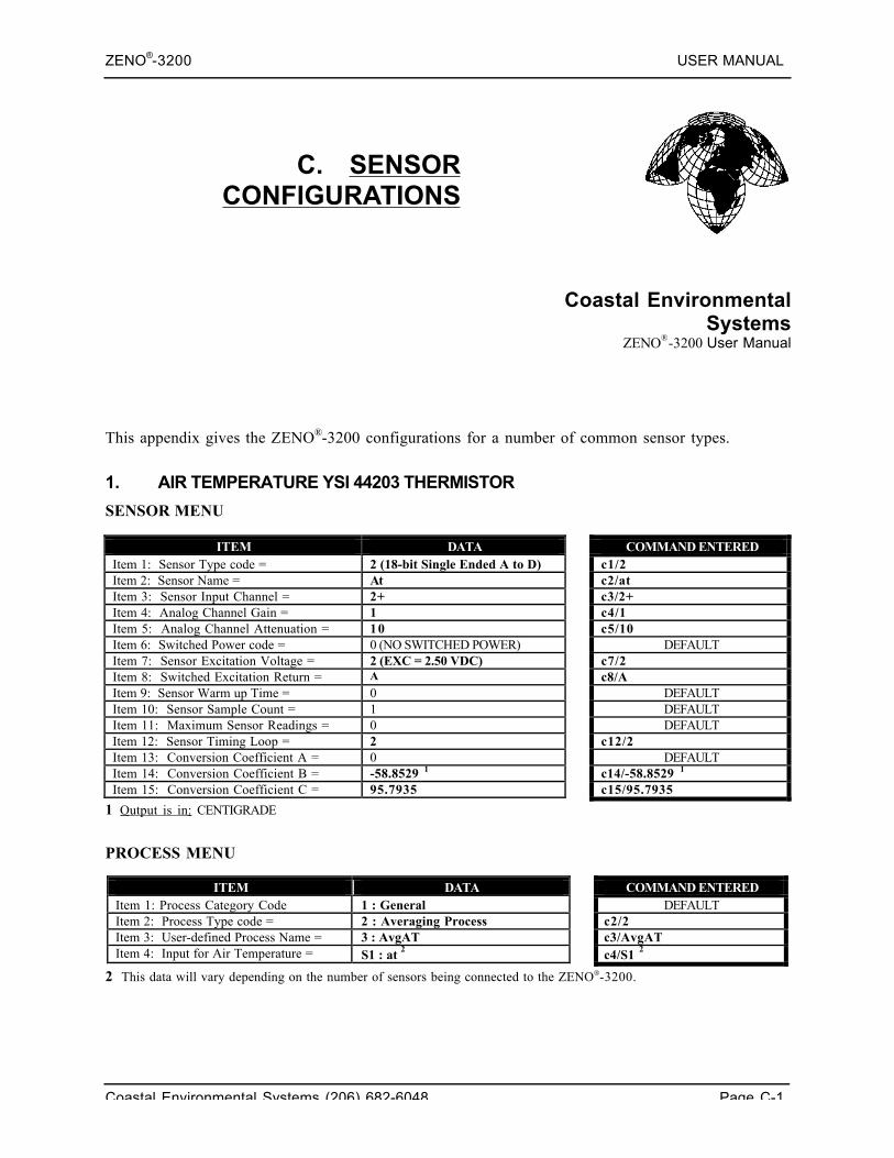
ZENO®-3200 USER MANUAL
Coastal Environmental Systems (206) 682-6048 Page C-1
C. SENSORCONFIGURATIONS
Coastal EnvironmentalSystems
ZENO®-3200 User Manual
This appendix gives the ZENO®-3200 configurations for a number of common sensor types.
1. AIR TEMPERATURE YSI 44203 THERMISTOR
SENSOR MENU
ITEM DATA COMMAND ENTEREDItem 1: Sensor Type code = 2 (18-bit Single Ended A to D) c1/2Item 2: Sensor Name = At c2/atItem 3: Sensor Input Channel = 2+ c3/2+Item 4: Analog Channel Gain = 1 c4/1Item 5: Analog Channel Attenuation = 10 c5/10Item 6: Switched Power code = 0 (NO SWITCHED POWER) DEFAULTItem 7: Sensor Excitation Voltage = 2 (EXC = 2.50 VDC) c7/2Item 8: Switched Excitation Return = A c8/AItem 9: Sensor Warm up Time = 0 DEFAULTItem 10: Sensor Sample Count = 1 DEFAULTItem 11: Maximum Sensor Readings = 0 DEFAULTItem 12: Sensor Timing Loop = 2 c12/2Item 13: Conversion Coefficient A = 0 DEFAULTItem 14: Conversion Coefficient B = -58.8529 1 c14/-58.8529 1
Item 15: Conversion Coefficient C = 95.7935 c15/95.7935
1 Output is in: CENTIGRADE
PROCESS MENU
ITEM DATA COMMAND ENTEREDItem 1: Process Category Code 1 : General DEFAULTItem 2: Process Type code = 2 : Averaging Process c2/2Item 3: User-defined Process Name = 3 : AvgAT c3/AvgATItem 4: Input for Air Temperature = S1 : at 2 c4/S1 2
2 This data will vary depending on the number of sensors being connected to the ZENO-3200.
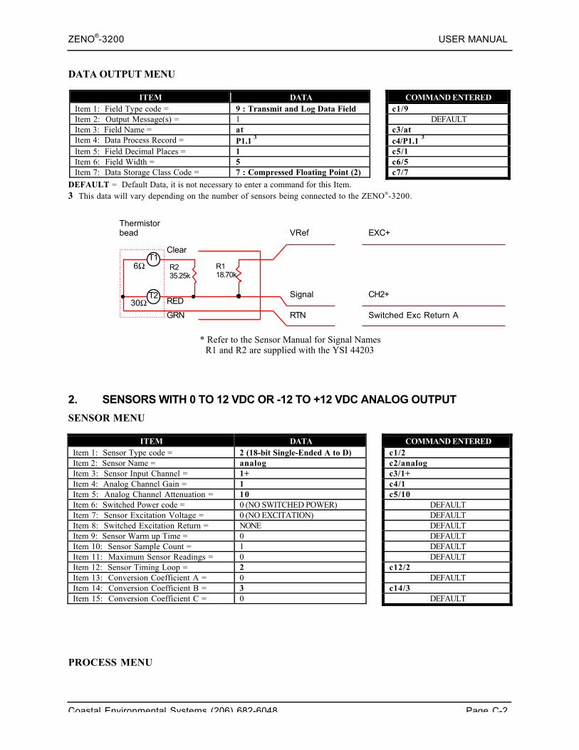
ZENO®-3200 USER MANUAL
Coastal Environmental Systems (206) 682-6048 Page C-2
DATA OUTPUT MENU
ITEM DATA COMMAND ENTEREDItem 1: Field Type code = 9 : Transmit and Log Data Field c1/9Item 2: Output Message(s) = 1 DEFAULTItem 3: Field Name = at c3/atItem 4: Data Process Record = P1.1 3 c4/P1.1 3
Item 5: Field Decimal Places = 1 c5/1Item 6: Field Width = 5 c6/5Item 7: Data Storage Class Code = 7 : Compressed Floating Point (2) c7/7
DEFAULT = Default Data, it is not necessary to enter a command for this Item.3 This data will vary depending on the number of sensors being connected to the ZENO-3200.
* Refer to the Sensor Manual for Signal NamesR1 and R2 are supplied with the YSI 44203
2. SENSORS WITH 0 TO 12 VDC OR -12 TO +12 VDC ANALOG OUTPUT
SENSOR MENU
ITEM DATA COMMAND ENTEREDItem 1: Sensor Type code = 2 (18-bit Single-Ended A to D) c1/2Item 2: Sensor Name = analog c2/analogItem 3: Sensor Input Channel = 1+ c3/1+Item 4: Analog Channel Gain = 1 c4/1Item 5: Analog Channel Attenuation = 10 c5/10Item 6: Switched Power code = 0 (NO SWITCHED POWER) DEFAULTItem 7: Sensor Excitation Voltage = 0 (NO EXCITATION) DEFAULTItem 8: Switched Excitation Return = NONE DEFAULTItem 9: Sensor Warm up Time = 0 DEFAULTItem 10: Sensor Sample Count = 1 DEFAULTItem 11: Maximum Sensor Readings = 0 DEFAULTItem 12: Sensor Timing Loop = 2 c12/2Item 13: Conversion Coefficient A = 0 DEFAULTItem 14: Conversion Coefficient B = 3 c14/3Item 15: Conversion Coefficient C = 0 DEFAULT
PROCESS MENU
R235.25k
R118.70k
6Ω
30Ω
Thermistorbead
Clear
RED
GRN RTN Switched Exc Return A
CH2+
EXC+
Signal
VRef
T2
T1
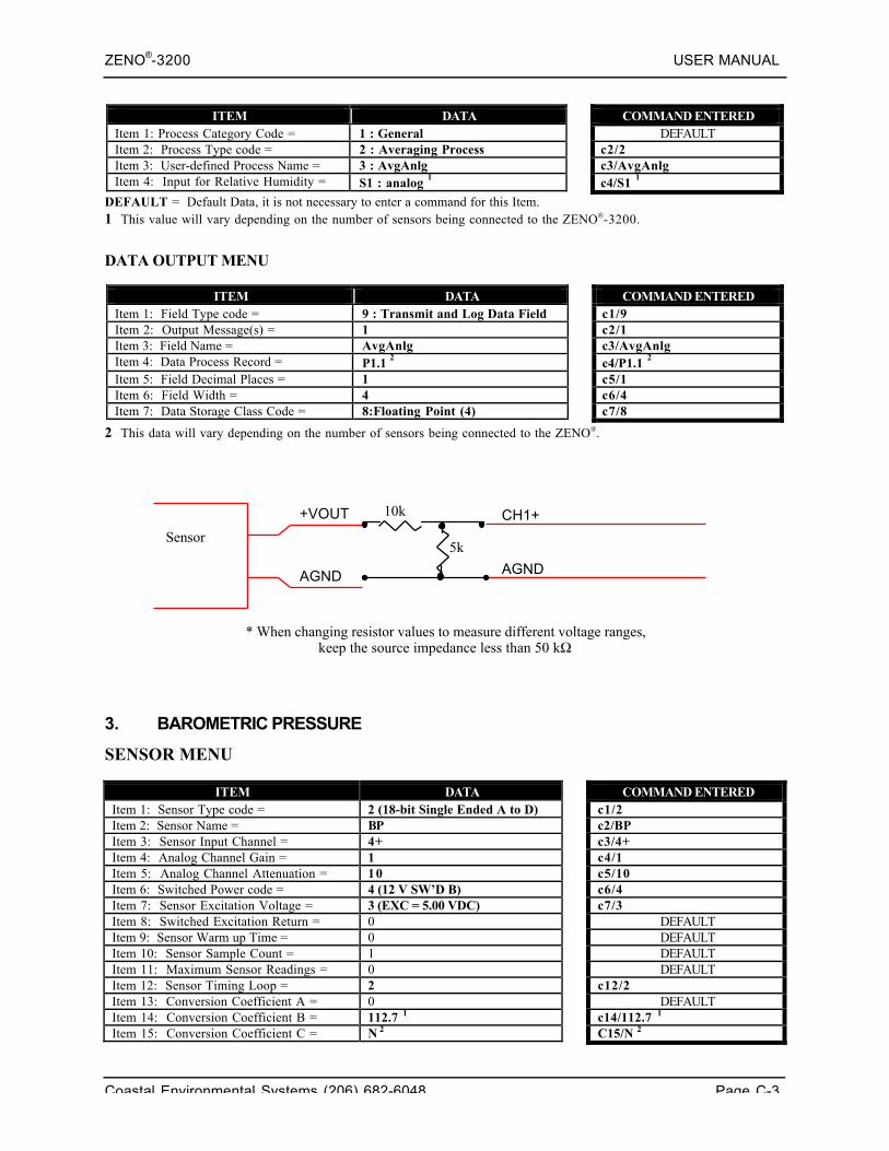
ZENO®-3200 USER MANUAL
Coastal Environmental Systems (206) 682-6048 Page C-3
ITEM DATA COMMAND ENTEREDItem 1: Process Category Code = 1 : General DEFAULTItem 2: Process Type code = 2 : Averaging Process c2/2Item 3: User-defined Process Name = 3 : AvgAnlg c3/AvgAnlgItem 4: Input for Relative Humidity = S1 : analog 1 c4/S1 1
DEFAULT = Default Data, it is not necessary to enter a command for this Item.1 This value will vary depending on the number of sensors being connected to the ZENO-3200.
DATA OUTPUT MENU
ITEM DATA COMMAND ENTEREDItem 1: Field Type code = 9 : Transmit and Log Data Field c1/9Item 2: Output Message(s) = 1 c2/1Item 3: Field Name = AvgAnlg c3/AvgAnlgItem 4: Data Process Record = P1.1 2 c4/P1.1 2
Item 5: Field Decimal Places = 1 c5/1Item 6: Field Width = 4 c6/4Item 7: Data Storage Class Code = 8:Floating Point (4) c7/8
2 This data will vary depending on the number of sensors being connected to the ZENO.
* When changing resistor values to measure different voltage ranges,keep the source impedance less than 50 kΩ
3. BAROMETRIC PRESSURE
SENSOR MENU
ITEM DATA COMMAND ENTEREDItem 1: Sensor Type code = 2 (18-bit Single Ended A to D) c1/2Item 2: Sensor Name = BP c2/BPItem 3: Sensor Input Channel = 4+ c3/4+Item 4: Analog Channel Gain = 1 c4/1Item 5: Analog Channel Attenuation = 10 c5/10Item 6: Switched Power code = 4 (12 V SW’D B) c6/4Item 7: Sensor Excitation Voltage = 3 (EXC = 5.00 VDC) c7/3Item 8: Switched Excitation Return = 0 DEFAULTItem 9: Sensor Warm up Time = 0 DEFAULTItem 10: Sensor Sample Count = 1 DEFAULTItem 11: Maximum Sensor Readings = 0 DEFAULTItem 12: Sensor Timing Loop = 2 c12/2Item 13: Conversion Coefficient A = 0 DEFAULTItem 14: Conversion Coefficient B = 112.7 1 c14/112.7 1
Item 15: Conversion Coefficient C = N 2 C15/N 2
5k
10k CH1++VOUT
AGND AGND
Sensor
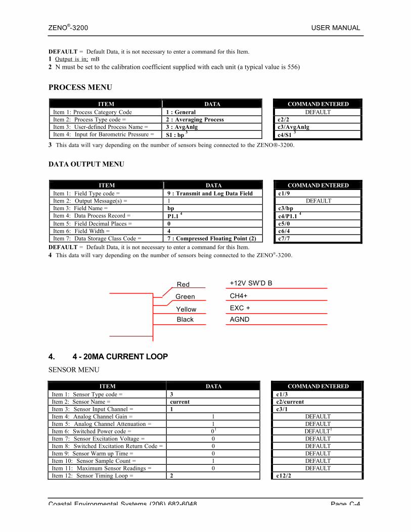
ZENO®-3200 USER MANUAL
Coastal Environmental Systems (206) 682-6048 Page C-4
DEFAULT = Default Data, it is not necessary to enter a command for this Item.1 Output is in: mB2 N must be set to the calibration coefficient supplied with each unit (a typical value is 556)
PROCESS MENU
ITEM DATA COMMAND ENTEREDItem 1: Process Category Code 1 : General DEFAULTItem 2: Process Type code = 2 : Averaging Process c2/2Item 3: User-defined Process Name = 3 : AvgAnlg c3/AvgAnlgItem 4: Input for Barometric Pressure = S1 : bp 3 c4/S1 3
3 This data will vary depending on the number of sensors being connected to the ZENO-3200.
DATA OUTPUT MENU
ITEM DATA COMMAND ENTEREDItem 1: Field Type code = 9 : Transmit and Log Data Field c1/9Item 2: Output Message(s) = 1 DEFAULTItem 3: Field Name = bp c3/bpItem 4: Data Process Record = P1.1 4 c4/P1.1 4
Item 5: Field Decimal Places = 0 c5/0Item 6: Field Width = 4 c6/4Item 7: Data Storage Class Code = 7 : Compressed Floating Point (2) c7/7
DEFAULT = Default Data, it is not necessary to enter a command for this Item.4 This data will vary depending on the number of sensors being connected to the ZENO-3200.
4. 4 - 20MA CURRENT LOOP
SENSOR MENU
ITEM DATA COMMAND ENTEREDItem 1: Sensor Type code = 3 c1/3Item 2: Sensor Name = current c2/currentItem 3: Sensor Input Channel = 1 c3/1Item 4: Analog Channel Gain = 1 DEFAULTItem 5: Analog Channel Attenuation = 1 DEFAULTItem 6: Switched Power code = 01 DEFAULT1
Item 7: Sensor Excitation Voltage = 0 DEFAULTItem 8: Switched Excitation Return Code = 0 DEFAULTItem 9: Sensor Warm up Time = 0 DEFAULTItem 10: Sensor Sample Count = 1 DEFAULTItem 11: Maximum Sensor Readings = 0 DEFAULTItem 12: Sensor Timing Loop = 2 c12/2
Red
CH4+Green
Yellow
+12V SW’D B
EXC +
AGNDBlack
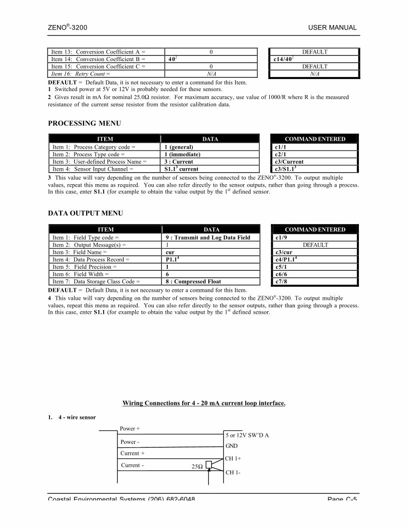
ZENO®-3200 USER MANUAL
Coastal Environmental Systems (206) 682-6048 Page C-5
Item 13: Conversion Coefficient A = 0 DEFAULTItem 14: Conversion Coefficient B = 402 c14/402
Item 15: Conversion Coefficient C = 0 DEFAULTItem 16: Retry Count = N/A N/A
DEFAULT = Default Data, it is not necessary to enter a command for this Item.1 Switched power at 5V or 12V is probably needed for these sensors.2 Gives result in mA for nominal 25.0Ω resistor. For maximum accuracy, use value of 1000/R where R is the measuredresistance of the current sense resistor from the resistor calibration data.
PROCESSING MENU
ITEM DATA COMMAND ENTEREDItem 1: Process Category code = 1 (general) c1/1Item 2: Process Type code = 1 (immediate) c2/1Item 3: User-defined Process Name = 3 : Current c3/CurrentItem 4: Sensor Input Channel = S1.13 current c3/S1.13
3 This value will vary depending on the number of sensors being connected to the ZENO-3200. To output multiplevalues, repeat this menu as required. You can also refer directly to the sensor outputs, rather than going through a process.In this case, enter S1.1 (for example to obtain the value output by the 1st defined sensor.
DATA OUTPUT MENU
ITEM DATA COMMAND ENTEREDItem 1: Field Type code = 9 : Transmit and Log Data Field c1/9Item 2: Output Message(s) = 1 DEFAULTItem 3: Field Name = cur c3/curItem 4: Data Process Record = P1.14 c4/P1.14
Item 5: Field Precision = 1 c5/1Item 6: Field Width = 6 c6/6Item 7: Data Storage Class Code = 8 : Compressed Float c7/8
DEFAULT = Default Data, it is not necessary to enter a command for this Item.4 This value will vary depending on the number of sensors being connected to the ZENO-3200. To output multiplevalues, repeat this menu as required. You can also refer directly to the sensor outputs, rather than going through a process.In this case, enter S1.1 (for example to obtain the value output by the 1st defined sensor.
Wiring Connections for 4 - 20 mA current loop interface.
1. 4 - wire sensor
Power +
Power -
Current +
Current -
5 or 12V SW’D A
GND
CH 1+
CH 1-25Ω
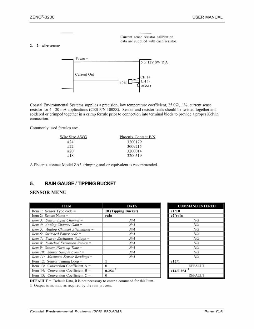
ZENO®-3200 USER MANUAL
Coastal Environmental Systems (206) 682-6048 Page C-6
2. 2 - wire sensor
Coastal Environmental Systems supplies a precision, low temperature coefficient, 25.0Ω, .1%, current senseresistor for 4 - 20 mA applications (CES P/N 1008Z). Sensor and resistor leads should be twisted together andsoldered or crimped together in a crimp ferrule prior to connection into terminal block to provide a proper Kelvinconnection.
Commonly used ferrules are:
Wire Size AWG Phoenix Contact P/N#24 3200179#22 3009215#20 3200014#18 3200519
A Phoenix contact Model ZA3 crimping tool or equivalent is recommended.
5. RAIN GAUGE / TIPPING BUCKET
SENSOR MENU
ITEM DATA COMMAND ENTEREDItem 1: Sensor Type code = 10 (Tipping Bucket) c1/10Item 2: Sensor Name = rain c2/rainItem 3: Sensor Input Channel = N/A N/AItem 4: Analog Channel Gain = N/A N/AItem 5: Analog Channel Attenuation = N/A N/AItem 6: Switched Power code = N/A N/AItem 7: Sensor Excitation Voltage = N/A N/AItem 8: Switched Excitation Return = N/A N/AItem 9: Sensor Warm up Time = N/A N/AItem 10: Sensor Sample Count = N/A N/AItem 11: Maximum Sensor Readings = N/A N/AItem 12: Sensor Timing Loop = 1 c12/1Item 13: Conversion Coefficient A = 0 DEFAULTItem 14: Conversion Coefficient B = 0.254 1 c14/0.254 1
Item 15: Conversion Coefficient C = 0 DEFAULT
DEFAULT = Default Data, it is not necessary to enter a command for this Item.1 Output is in : mm, as required by the rain process.
Current sense resistor calibrationdata are supplied with each resistor.
Power +
Current Out
5 or 12V SW’D A
CH 1+CH 1-25ΩAGND
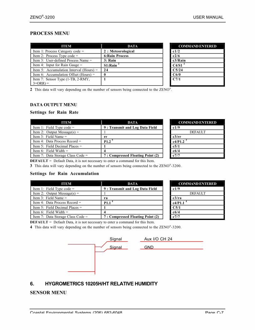
ZENO®-3200 USER MANUAL
Coastal Environmental Systems (206) 682-6048 Page C-7
PROCESS MENU
ITEM DATA COMMAND ENTEREDItem 1: Process Category code = 2 : Meteorological c1/2Item 2: Process Type code = 6:Rain Process c2/6Item 3: User-defined Process Name = 3: Rain c3/RainItem 4: Input for Rain Gauge = S1:Rain 2 C4/S1 2
Item 5: Accumulation Interval (Hours) = 24 C5/24Item 6: Accumulation Offset (Hours) = 0 C6/0Item 7: Sensor Type (1-TB, 2-RMY,3=ORR) =
1 C7/1
2 This data will vary depending on the number of sensors being connected to the ZENO.
DATA OUTPUT MENU
Settings for Rain Rate
ITEM DATA COMMAND ENTEREDItem 1: Field Type code = 9 : Transmit and Log Data Field c1/9Item 2: Output Message(s) = 1 DEFAULTItem 3: Field Name = rr c3/rrItem 4: Data Process Record = P1.2 3 c4/P1.2 3
Item 5: Field Decimal Places = 1 c5/1Item 6: Field Width = 4 c6/4Item 7: Data Storage Class Code = 7 : Compressed Floating Point (2) c7/7
DEFAULT = Default Data, it is not necessary to enter a command for this Item.3 This data will vary depending on the number of sensors being connected to the ZENO-3200.
Settings for Rain Accumulation
ITEM DATA COMMAND ENTEREDItem 1: Field Type code = 9 : Transmit and Log Data Field c1/9Item 2: Output Message(s) = 1 DEFAULTItem 3: Field Name = ra c3/raItem 4: Data Process Record = P1.1 4 c4/P1.1 4
Item 5: Field Decimal Places = 1 C5/1Item 6: Field Width = 4 c6/4Item 7: Data Storage Class Code = 7 : Compressed Floating Point (2) c7/7
DEFAULT = Default Data, it is not necessary to enter a command for this Item.4 This data will vary depending on the number of sensors being connected to the ZENO-3200.
6. HYGROMETRICS 10205H/HT RELATIVE HUMIDITY
SENSOR MENU
Signal
GNDSignal
Aux I/O CH 24
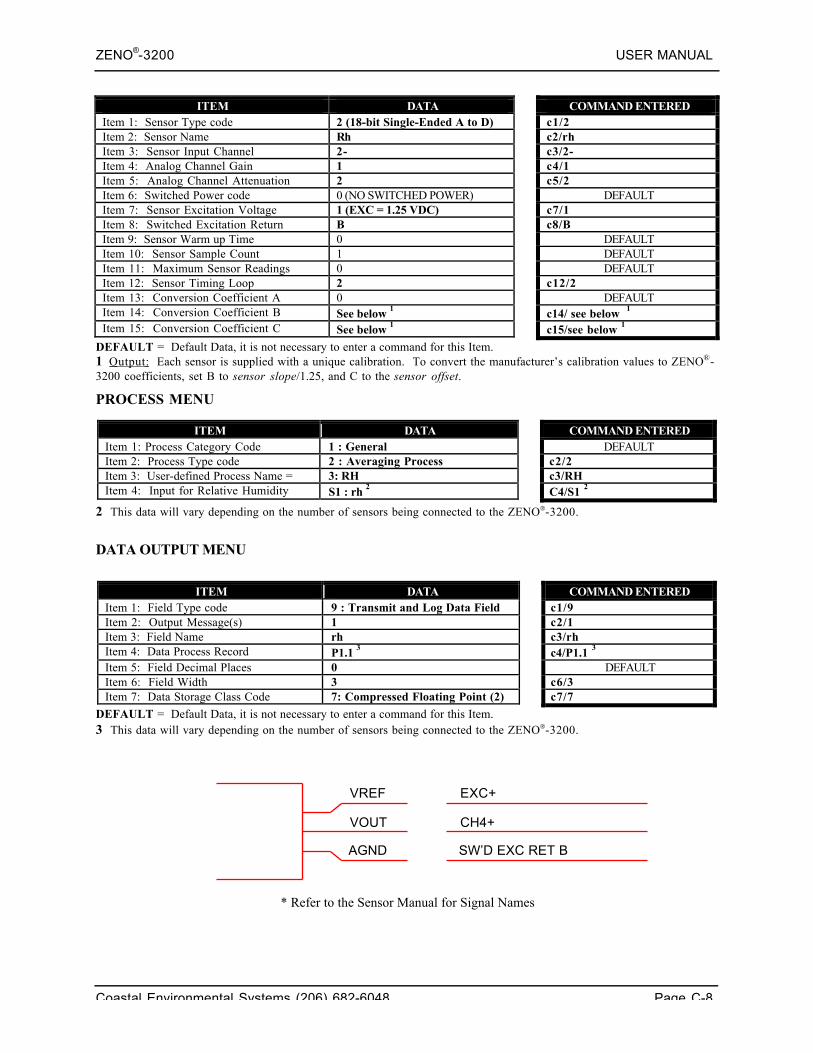
ZENO®-3200 USER MANUAL
Coastal Environmental Systems (206) 682-6048 Page C-8
ITEM DATA COMMAND ENTEREDItem 1: Sensor Type code 2 (18-bit Single-Ended A to D) c1/2Item 2: Sensor Name Rh c2/rhItem 3: Sensor Input Channel 2- c3/2-Item 4: Analog Channel Gain 1 c4/1Item 5: Analog Channel Attenuation 2 c5/2Item 6: Switched Power code 0 (NO SWITCHED POWER) DEFAULTItem 7: Sensor Excitation Voltage 1 (EXC = 1.25 VDC) c7/1Item 8: Switched Excitation Return B c8/BItem 9: Sensor Warm up Time 0 DEFAULTItem 10: Sensor Sample Count 1 DEFAULTItem 11: Maximum Sensor Readings 0 DEFAULTItem 12: Sensor Timing Loop 2 c12/2Item 13: Conversion Coefficient A 0 DEFAULTItem 14: Conversion Coefficient B See below 1 c14/ see below 1
Item 15: Conversion Coefficient C See below 1 c15/see below 1
DEFAULT = Default Data, it is not necessary to enter a command for this Item.1 Output: Each sensor is supplied with a unique calibration. To convert the manufacturer’s calibration values to ZENO®-3200 coefficients, set B to sensor slope/1.25, and C to the sensor offset.
PROCESS MENU
ITEM DATA COMMAND ENTEREDItem 1: Process Category Code 1 : General DEFAULTItem 2: Process Type code 2 : Averaging Process c2/2Item 3: User-defined Process Name = 3: RH c3/RHItem 4: Input for Relative Humidity S1 : rh 2 C4/S1 2
2 This data will vary depending on the number of sensors being connected to the ZENO-3200.
DATA OUTPUT MENU
ITEM DATA COMMAND ENTEREDItem 1: Field Type code 9 : Transmit and Log Data Field c1/9Item 2: Output Message(s) 1 c2/1Item 3: Field Name rh c3/rhItem 4: Data Process Record P1.1 3 c4/P1.1 3
Item 5: Field Decimal Places 0 DEFAULTItem 6: Field Width 3 c6/3Item 7: Data Storage Class Code 7: Compressed Floating Point (2) c7/7
DEFAULT = Default Data, it is not necessary to enter a command for this Item.3 This data will vary depending on the number of sensors being connected to the ZENO-3200.
* Refer to the Sensor Manual for Signal Names
AGND
EXC+VREF
VOUT
SW’D EXC RET B
CH4+
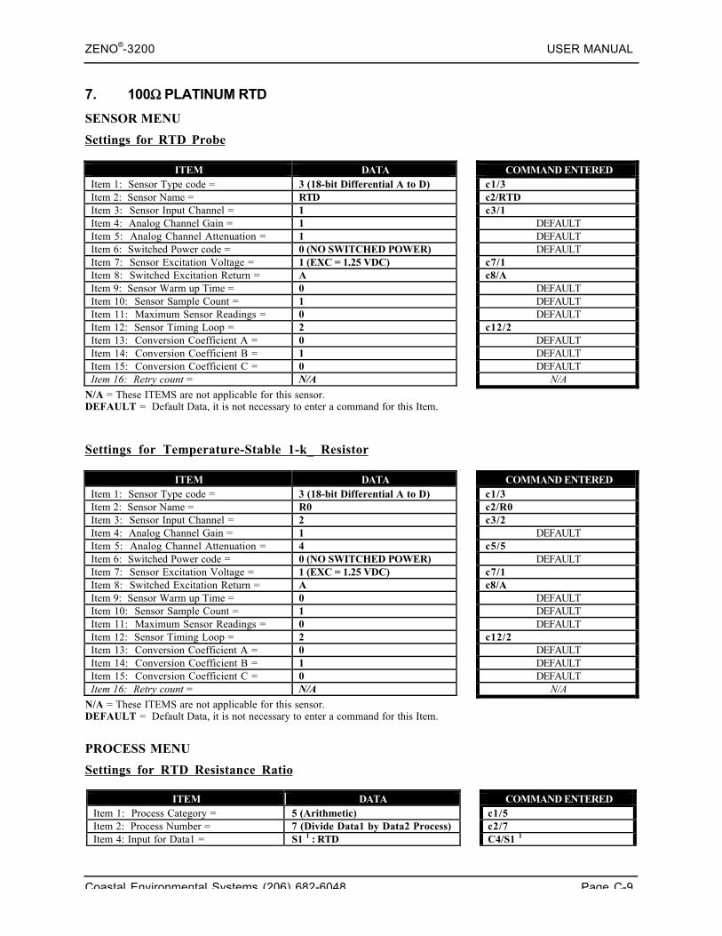
ZENO®-3200 USER MANUAL
Coastal Environmental Systems (206) 682-6048 Page C-9
7. 100Ω PLATINUM RTD
SENSOR MENU
Settings for RTD Probe
ITEM DATA COMMAND ENTEREDItem 1: Sensor Type code = 3 (18-bit Differential A to D) c1/3Item 2: Sensor Name = RTD c2/RTDItem 3: Sensor Input Channel = 1 c3/1Item 4: Analog Channel Gain = 1 DEFAULTItem 5: Analog Channel Attenuation = 1 DEFAULTItem 6: Switched Power code = 0 (NO SWITCHED POWER) DEFAULTItem 7: Sensor Excitation Voltage = 1 (EXC = 1.25 VDC) c7/1Item 8: Switched Excitation Return = A c8/AItem 9: Sensor Warm up Time = 0 DEFAULTItem 10: Sensor Sample Count = 1 DEFAULTItem 11: Maximum Sensor Readings = 0 DEFAULTItem 12: Sensor Timing Loop = 2 c12/2Item 13: Conversion Coefficient A = 0 DEFAULTItem 14: Conversion Coefficient B = 1 DEFAULTItem 15: Conversion Coefficient C = 0 DEFAULTItem 16: Retry count = N/A N/A
N/A = These ITEMS are not applicable for this sensor.DEFAULT = Default Data, it is not necessary to enter a command for this Item.
Settings for Temperature-Stable 1-k_ Resistor
ITEM DATA COMMAND ENTEREDItem 1: Sensor Type code = 3 (18-bit Differential A to D) c1/3Item 2: Sensor Name = R0 c2/R0Item 3: Sensor Input Channel = 2 c3/2Item 4: Analog Channel Gain = 1 DEFAULTItem 5: Analog Channel Attenuation = 4 c5/5Item 6: Switched Power code = 0 (NO SWITCHED POWER) DEFAULTItem 7: Sensor Excitation Voltage = 1 (EXC = 1.25 VDC) c7/1Item 8: Switched Excitation Return = A c8/AItem 9: Sensor Warm up Time = 0 DEFAULTItem 10: Sensor Sample Count = 1 DEFAULTItem 11: Maximum Sensor Readings = 0 DEFAULTItem 12: Sensor Timing Loop = 2 c12/2Item 13: Conversion Coefficient A = 0 DEFAULTItem 14: Conversion Coefficient B = 1 DEFAULTItem 15: Conversion Coefficient C = 0 DEFAULTItem 16: Retry count = N/A N/A
N/A = These ITEMS are not applicable for this sensor.DEFAULT = Default Data, it is not necessary to enter a command for this Item.
PROCESS MENU
Settings for RTD Resistance Ratio
ITEM DATA COMMAND ENTEREDItem 1: Process Category = 5 (Arithmetic) c1/5Item 2: Process Number = 7 (Divide Data1 by Data2 Process) c2/7Item 4: Input for Data1 = S1 1 : RTD C4/S1 1
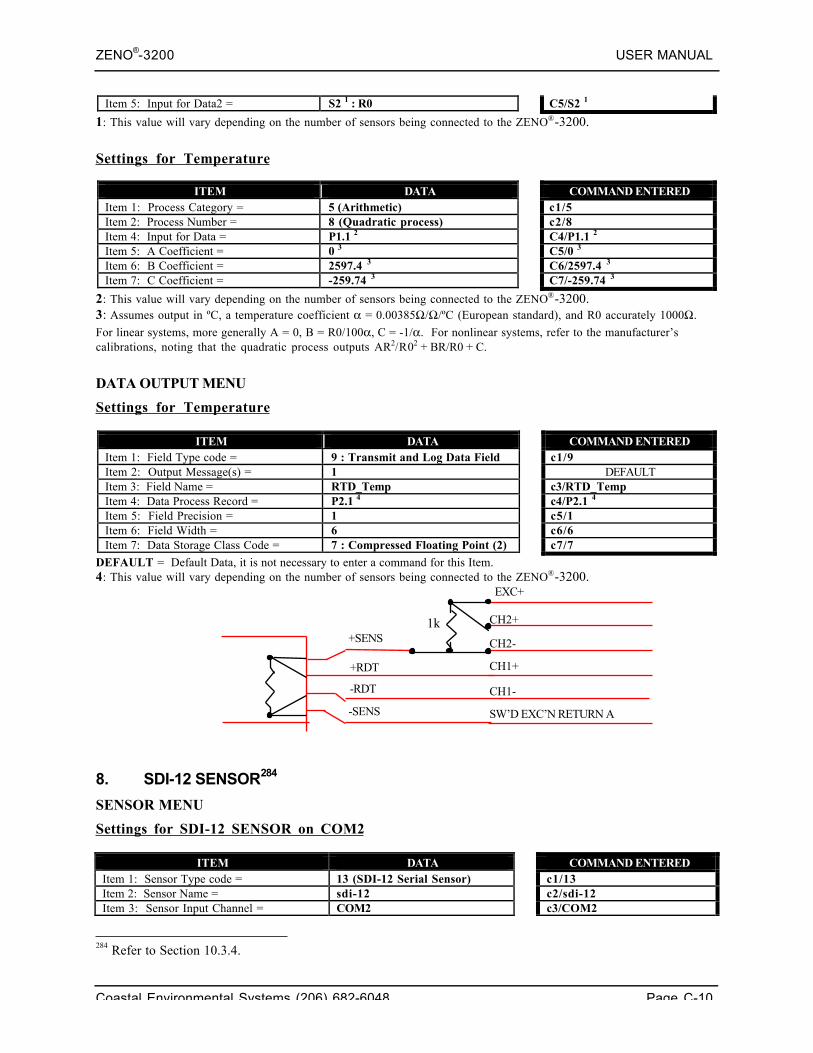
ZENO®-3200 USER MANUAL
Coastal Environmental Systems (206) 682-6048 Page C-10
Item 5: Input for Data2 = S2 1 : R0 C5/S2 1
1: This value will vary depending on the number of sensors being connected to the ZENO®-3200.
Settings for Temperature
ITEM DATA COMMAND ENTEREDItem 1: Process Category = 5 (Arithmetic) c1/5Item 2: Process Number = 8 (Quadratic process) c2/8Item 4: Input for Data = P1.1 2 C4/P1.1 2
Item 5: A Coefficient = 0 3 C5/0 3
Item 6: B Coefficient = 2597.4 3 C6/2597.4 3
Item 7: C Coefficient = -259.74 3 C7/-259.74 3
2: This value will vary depending on the number of sensors being connected to the ZENO®-3200.3: Assumes output in ºC, a temperature coefficient α = 0.00385Ω/Ω/ºC (European standard), and R0 accurately 1000Ω.
For linear systems, more generally A = 0, B = R0/100α, C = -1/α. For nonlinear systems, refer to the manufacturer’scalibrations, noting that the quadratic process outputs AR2/R02 + BR/R0 + C.
DATA OUTPUT MENU
Settings for Temperature
ITEM DATA COMMAND ENTEREDItem 1: Field Type code = 9 : Transmit and Log Data Field c1/9Item 2: Output Message(s) = 1 DEFAULTItem 3: Field Name = RTD_Temp c3/RTD_TempItem 4: Data Process Record = P2.1 4 c4/P2.1 4
Item 5: Field Precision = 1 c5/1Item 6: Field Width = 6 c6/6Item 7: Data Storage Class Code = 7 : Compressed Floating Point (2) c7/7
DEFAULT = Default Data, it is not necessary to enter a command for this Item.4: This value will vary depending on the number of sensors being connected to the ZENO®-3200.
8. SDI-12 SENSOR284
SENSOR MENU
Settings for SDI-12 SENSOR on COM2
ITEM DATA COMMAND ENTEREDItem 1: Sensor Type code = 13 (SDI-12 Serial Sensor) c1/13Item 2: Sensor Name = sdi-12 c2/sdi-12Item 3: Sensor Input Channel = COM2 c3/COM2
284 Refer to Section 10.3.4.
-SENS
-RDT
+RDT
+SENS
SW’D EXC’N RETURN A
CH1-
CH1+
EXC+
CH2+
CH2-
1k
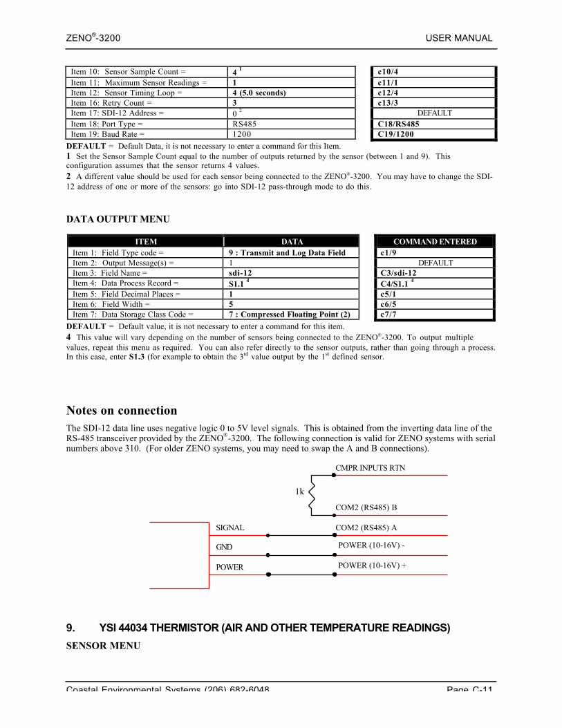
ZENO®-3200 USER MANUAL
Coastal Environmental Systems (206) 682-6048 Page C-11
Item 10: Sensor Sample Count = 4 1 c10/4Item 11: Maximum Sensor Readings = 1 c11/1Item 12: Sensor Timing Loop = 4 (5.0 seconds) c12/4Item 16: Retry Count = 3 c13/3Item 17: SDI-12 Address = 0 2 DEFAULTItem 18: Port Type = RS485 C18/RS485Item 19: Baud Rate = 1200 C19/1200
DEFAULT = Default Data, it is not necessary to enter a command for this Item.1 Set the Sensor Sample Count equal to the number of outputs returned by the sensor (between 1 and 9). Thisconfiguration assumes that the sensor returns 4 values.2 A different value should be used for each sensor being connected to the ZENO-3200. You may have to change the SDI-12 address of one or more of the sensors: go into SDI-12 pass-through mode to do this.
DATA OUTPUT MENU
ITEM DATA COMMAND ENTEREDItem 1: Field Type code = 9 : Transmit and Log Data Field c1/9Item 2: Output Message(s) = 1 DEFAULTItem 3: Field Name = sdi-12 C3/sdi-12Item 4: Data Process Record = S1.1 4 C4/S1.1 4
Item 5: Field Decimal Places = 1 c5/1Item 6: Field Width = 5 c6/5Item 7: Data Storage Class Code = 7 : Compressed Floating Point (2) c7/7
DEFAULT = Default value, it is not necessary to enter a command for this item.4 This value will vary depending on the number of sensors being connected to the ZENO-3200. To output multiplevalues, repeat this menu as required. You can also refer directly to the sensor outputs, rather than going through a process.In this case, enter S1.3 (for example to obtain the 3rd value output by the 1st defined sensor.
Notes on connectionThe SDI-12 data line uses negative logic 0 to 5V level signals. This is obtained from the inverting data line of theRS-485 transceiver provided by the ZENO®-3200. The following connection is valid for ZENO systems with serialnumbers above 310. (For older ZENO systems, you may need to swap the A and B connections).
9. YSI 44034 THERMISTOR (AIR AND OTHER TEMPERATURE READINGS)
SENSOR MENU
1k
CMPR INPUTS RTN
SIGNAL
POWER
GND
POWER (10-16V) +
POWER (10-16V) -
COM2 (RS485) B
COM2 (RS485) A
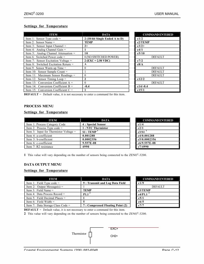
ZENO®-3200 USER MANUAL
Coastal Environmental Systems (206) 682-6048 Page C-12
Settings for Temperature
ITEM DATA COMMAND ENTEREDItem 1: Sensor Type code = 2 (18-bit Single Ended A to D) c1/2Item 2: Sensor Name = TEMP c2/TEMPItem 3: Sensor Input Channel = 2+ c3/2+Item 4: Analog Channel Gain = 1 c4/1Item 5: Analog Channel Attenuation = 10 c5/10Item 6: Switched Power code = 0 (NO SWITCHED POWER) DEFAULTItem 7: Sensor Excitation Voltage = 2 (EXC = 2.50 VDC) c7/2Item 8: Switched Excitation Return = A c8/AItem 9: Sensor Warm up Time = 0 DEFAULTItem 10: Sensor Sample Count = 1 DEFAULTItem 11: Maximum Sensor Readings = 0 DEFAULTItem 12: Sensor Timing Loop = 2 c12/2Item 13: Conversion Coefficient A = 0 DEFAULTItem 14: Conversion Coefficient B = -0.4 c14/-0.4Item 15: Conversion Coefficient C = 1 c15/1
DEFAULT = Default value, it is not necessary to enter a command for this item.
PROCESS MENU
Settings for Temperature
ITEM DATA COMMAND ENTEREDItem 1: Process Category Code 4 : Special Sensor c1/4Item 2: Process Type code = 1 : NTC Thermistor c2/1Item 3: Input for Thermistor Voltage = S1 : TEMP 1 c3/S1 1
Item 4: a-coefficient 0.001288 c4/0.001288Item 5: b-coefficient 0.0002356 c5/0.0002356Item 6: c-coefficient 9.557E-08 c6/9.557E-08Item 7: R2 resistance 4990 c7/4990
1 This value will vary depending on the number of sensors being connected to the ZENO-3200.
DATA OUTPUT MENU
Settings for Temperature
ITEM DATA COMMAND ENTEREDItem 1: Field Type code = 9 : Transmit and Log Data Field c1/9Item 2: Output Message(s) = 1 DEFAULTItem 3: Field Name = TEMP c3/TEMPItem 4: Data Process Record = P1.1 2 c4/P1.1 2
Item 5: Field Decimal Places = 1 c5/1Item 6: Field Width = 5 c6/5Item 7: Data Storage Class Code = 7 : Compressed Floating Point (2) c7/7
DEFAULT = Default value, it is not necessary to enter a command for this item.2 This value will vary depending on the number of sensors being connected to the ZENO-3200.
CH2+
EXC+
Thermistor
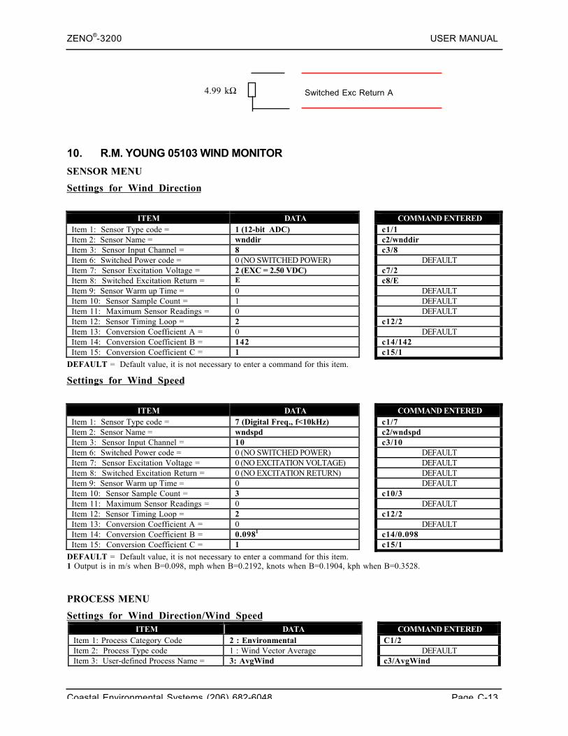
ZENO®-3200 USER MANUAL
Coastal Environmental Systems (206) 682-6048 Page C-13
4.99 kΩ
10. R.M. YOUNG 05103 WIND MONITOR
SENSOR MENU
Settings for Wind Direction
ITEM DATA COMMAND ENTEREDItem 1: Sensor Type code = 1 (12-bit ADC) c1/1Item 2: Sensor Name = wnddir c2/wnddirItem 3: Sensor Input Channel = 8 c3/8Item 6: Switched Power code = 0 (NO SWITCHED POWER) DEFAULTItem 7: Sensor Excitation Voltage = 2 (EXC = 2.50 VDC) c7/2Item 8: Switched Excitation Return = E c8/EItem 9: Sensor Warm up Time = 0 DEFAULTItem 10: Sensor Sample Count = 1 DEFAULTItem 11: Maximum Sensor Readings = 0 DEFAULTItem 12: Sensor Timing Loop = 2 c12/2Item 13: Conversion Coefficient A = 0 DEFAULTItem 14: Conversion Coefficient B = 142 c14/142Item 15: Conversion Coefficient C = 1 c15/1
DEFAULT = Default value, it is not necessary to enter a command for this item.
Settings for Wind Speed
ITEM DATA COMMAND ENTEREDItem 1: Sensor Type code = 7 (Digital Freq., f<10kHz) c1/7Item 2: Sensor Name = wndspd c2/wndspdItem 3: Sensor Input Channel = 10 c3/10Item 6: Switched Power code = 0 (NO SWITCHED POWER) DEFAULTItem 7: Sensor Excitation Voltage = 0 (NO EXCITATION VOLTAGE) DEFAULTItem 8: Switched Excitation Return = 0 (NO EXCITATION RETURN) DEFAULTItem 9: Sensor Warm up Time = 0 DEFAULTItem 10: Sensor Sample Count = 3 c10/3Item 11: Maximum Sensor Readings = 0 DEFAULTItem 12: Sensor Timing Loop = 2 c12/2Item 13: Conversion Coefficient A = 0 DEFAULTItem 14: Conversion Coefficient B = 0.0981 c14/0.098Item 15: Conversion Coefficient C = 1 c15/1
DEFAULT = Default value, it is not necessary to enter a command for this item.1 Output is in m/s when B=0.098, mph when B=0.2192, knots when B=0.1904, kph when B=0.3528.
PROCESS MENU
Settings for Wind Direction/Wind SpeedITEM DATA COMMAND ENTERED
Item 1: Process Category Code 2 : Environmental C1/2Item 2: Process Type code 1 : Wind Vector Average DEFAULTItem 3: User-defined Process Name = 3: AvgWind c3/AvgWind
Switched Exc Return A
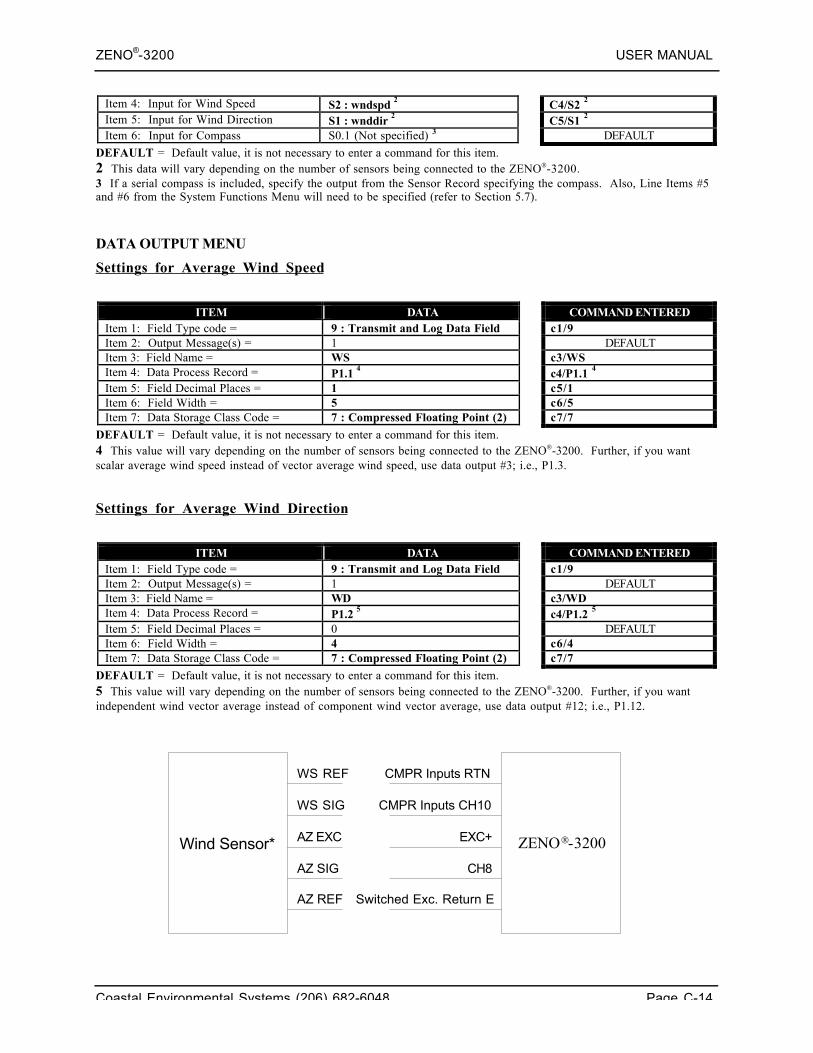
ZENO®-3200 USER MANUAL
Coastal Environmental Systems (206) 682-6048 Page C-14
Item 4: Input for Wind Speed S2 : wndspd 2 C4/S2 2
Item 5: Input for Wind Direction S1 : wnddir 2 C5/S1 2
Item 6: Input for Compass S0.1 (Not specified) 3 DEFAULT
DEFAULT = Default value, it is not necessary to enter a command for this item.2 This data will vary depending on the number of sensors being connected to the ZENO-3200.3 If a serial compass is included, specify the output from the Sensor Record specifying the compass. Also, Line Items #5and #6 from the System Functions Menu will need to be specified (refer to Section 5.7).
DATA OUTPUT MENU
Settings for Average Wind Speed
ITEM DATA COMMAND ENTEREDItem 1: Field Type code = 9 : Transmit and Log Data Field c1/9Item 2: Output Message(s) = 1 DEFAULTItem 3: Field Name = WS c3/WSItem 4: Data Process Record = P1.1 4 c4/P1.1 4
Item 5: Field Decimal Places = 1 c5/1Item 6: Field Width = 5 c6/5Item 7: Data Storage Class Code = 7 : Compressed Floating Point (2) c7/7
DEFAULT = Default value, it is not necessary to enter a command for this item.4 This value will vary depending on the number of sensors being connected to the ZENO-3200. Further, if you wantscalar average wind speed instead of vector average wind speed, use data output #3; i.e., P1.3.
Settings for Average Wind Direction
ITEM DATA COMMAND ENTEREDItem 1: Field Type code = 9 : Transmit and Log Data Field c1/9Item 2: Output Message(s) = 1 DEFAULTItem 3: Field Name = WD c3/WDItem 4: Data Process Record = P1.2 5 c4/P1.2 5
Item 5: Field Decimal Places = 0 DEFAULTItem 6: Field Width = 4 c6/4Item 7: Data Storage Class Code = 7 : Compressed Floating Point (2) c7/7
DEFAULT = Default value, it is not necessary to enter a command for this item.5 This value will vary depending on the number of sensors being connected to the ZENO-3200. Further, if you wantindependent wind vector average instead of component wind vector average, use data output #12; i.e., P1.12.
Wind Sensor* ZENO-3200
WS REF
WS SIG
AZ EXC
AZ SIG
AZ REF
CMPR Inputs RTN
CMPR Inputs CH10
EXC+
CH8
Switched Exc. Return E
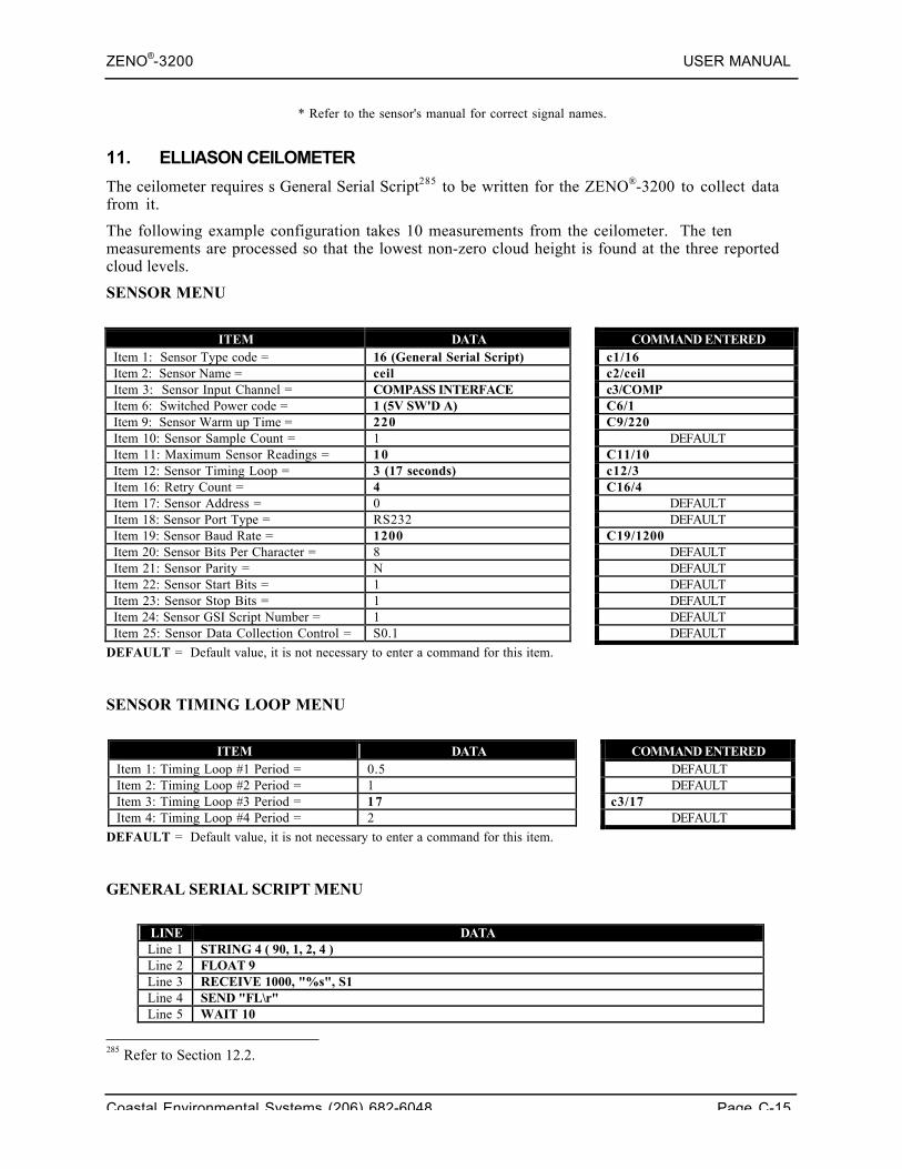
ZENO®-3200 USER MANUAL
Coastal Environmental Systems (206) 682-6048 Page C-15
* Refer to the sensor's manual for correct signal names.
11. ELLIASON CEILOMETER
The ceilometer requires s General Serial Script285 to be written for the ZENO®-3200 to collect datafrom it.
The following example configuration takes 10 measurements from the ceilometer. The tenmeasurements are processed so that the lowest non-zero cloud height is found at the three reportedcloud levels.
SENSOR MENU
ITEM DATA COMMAND ENTEREDItem 1: Sensor Type code = 16 (General Serial Script) c1/16Item 2: Sensor Name = ceil c2/ceilItem 3: Sensor Input Channel = COMPASS INTERFACE c3/COMPItem 6: Switched Power code = 1 (5V SW'D A) C6/1Item 9: Sensor Warm up Time = 220 C9/220Item 10: Sensor Sample Count = 1 DEFAULTItem 11: Maximum Sensor Readings = 10 C11/10Item 12: Sensor Timing Loop = 3 (17 seconds) c12/3Item 16: Retry Count = 4 C16/4Item 17: Sensor Address = 0 DEFAULTItem 18: Sensor Port Type = RS232 DEFAULTItem 19: Sensor Baud Rate = 1200 C19/1200Item 20: Sensor Bits Per Character = 8 DEFAULTItem 21: Sensor Parity = N DEFAULTItem 22: Sensor Start Bits = 1 DEFAULTItem 23: Sensor Stop Bits = 1 DEFAULTItem 24: Sensor GSI Script Number = 1 DEFAULTItem 25: Sensor Data Collection Control = S0.1 DEFAULT
DEFAULT = Default value, it is not necessary to enter a command for this item.
SENSOR TIMING LOOP MENU
ITEM DATA COMMAND ENTEREDItem 1: Timing Loop #1 Period = 0.5 DEFAULTItem 2: Timing Loop #2 Period = 1 DEFAULTItem 3: Timing Loop #3 Period = 17 c3/17Item 4: Timing Loop #4 Period = 2 DEFAULT
DEFAULT = Default value, it is not necessary to enter a command for this item.
GENERAL SERIAL SCRIPT MENU
LINE DATALine 1 STRING 4 ( 90, 1, 2, 4 )Line 2 FLOAT 9Line 3 RECEIVE 1000, "%s", S1Line 4 SEND "FL\r"Line 5 WAIT 10
285 Refer to Section 12.2.
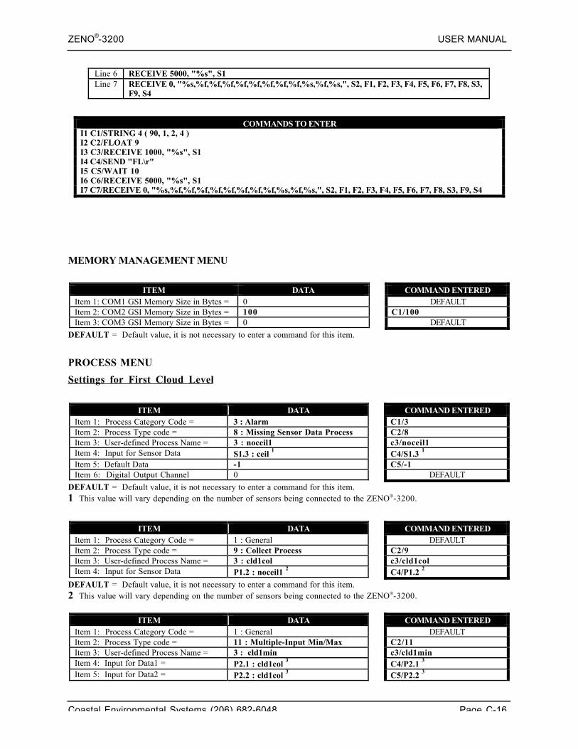
ZENO®-3200 USER MANUAL
Coastal Environmental Systems (206) 682-6048 Page C-16
Line 6 RECEIVE 5000, "%s", S1Line 7 RECEIVE 0, "%s,%f,%f,%f,%f,%f,%f,%f,%f,%s,%f,%s,", S2, F1, F2, F3, F4, F5, F6, F7, F8, S3,
F9, S4
COMMANDS TO ENTERI1 C1/STRING 4 ( 90, 1, 2, 4 )I2 C2/FLOAT 9I3 C3/RECEIVE 1000, "%s", S1I4 C4/SEND "FL\r"I5 C5/WAIT 10I6 C6/RECEIVE 5000, "%s", S1I7 C7/RECEIVE 0, "%s,%f,%f,%f,%f,%f,%f,%f,%f,%s,%f,%s,", S2, F1, F2, F3, F4, F5, F6, F7, F8, S3, F9, S4
MEMORY MANAGEMENT MENU
ITEM DATA COMMAND ENTEREDItem 1: COM1 GSI Memory Size in Bytes = 0 DEFAULTItem 2: COM2 GSI Memory Size in Bytes = 100 C1/100Item 3: COM3 GSI Memory Size in Bytes = 0 DEFAULT
DEFAULT = Default value, it is not necessary to enter a command for this item.
PROCESS MENU
Settings for First Cloud Level
ITEM DATA COMMAND ENTEREDItem 1: Process Category Code = 3 : Alarm C1/3Item 2: Process Type code = 8 : Missing Sensor Data Process C2/8Item 3: User-defined Process Name = 3 : noceil1 c3/noceil1Item 4: Input for Sensor Data S1.3 : ceil 1 C4/S1.3 1
Item 5: Default Data -1 C5/-1Item 6: Digital Output Channel 0 DEFAULT
DEFAULT = Default value, it is not necessary to enter a command for this item.1 This value will vary depending on the number of sensors being connected to the ZENO-3200.
ITEM DATA COMMAND ENTEREDItem 1: Process Category Code = 1 : General DEFAULTItem 2: Process Type code = 9 : Collect Process C2/9Item 3: User-defined Process Name = 3 : cld1col c3/cld1colItem 4: Input for Sensor Data P1.2 : noceil1 2 C4/P1.2 2
DEFAULT = Default value, it is not necessary to enter a command for this item.2 This value will vary depending on the number of sensors being connected to the ZENO-3200.
ITEM DATA COMMAND ENTEREDItem 1: Process Category Code = 1 : General DEFAULTItem 2: Process Type code = 11 : Multiple-Input Min/Max C2/11Item 3: User-defined Process Name = 3 : cld1min c3/cld1minItem 4: Input for Data1 = P2.1 : cld1col 3 C4/P2.1 3
Item 5: Input for Data2 = P2.2 : cld1col 3 C5/P2.2 3
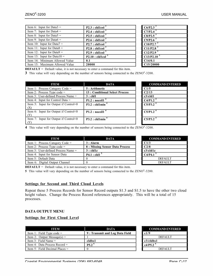
ZENO®-3200 USER MANUAL
Coastal Environmental Systems (206) 682-6048 Page C-17
Item 6: Input for Data3 = P2.3 : cld1col 3 C6/P2.3 3
Item 7: Input for Data4 = P2.4 : cld1col 3 C7/P2.4 3
Item 8: Input for Data5 = P2.5 : cld1col 3 C8/P2.5 3
Item 9: Input for Data6 = P2.6 : cld1col 3 C9/P2.6 3
Item 10: Input for Data7 = P2.7 : cld1col 3 C10/P2.7 3
Item 11: Input for Data8 = P2.8 : cld1col 3 C11/P2.8 3
Item 12: Input for Data9 = P2.9 : cld1col 3 C12/P2.9 3
Item 13: Input for Data10 = P2.10 : cld1col 3 C13/P2.10 3
Item 14: Minimum Allowed Value 0.1 C14/0.1Item 15: Maximum Allowed Value 20000 C15/20000
DEFAULT = Default value, it is not necessary to enter a command for this item.3 This value will vary depending on the number of sensors being connected to the ZENO-3200.
ITEM DATA COMMAND ENTEREDItem 1: Process Category Code = 5 : Arithmetic C1/5Item 2: Process Type code = 13 : Conditional Select Process C2/13Item 3: User-defined Process Name = 3 : cld1 c3/cld1Item 4: Input for Control Data = P1.2 : noceil1 4 C4/P1.2 4
Item 5: Input for Output if Control=0(X)
P3.2 : cld1min 4 C5/P3.2 4
Item 6: Input for Output if Control<0(Y)
P1.2 : noceil1 4 C5/P1.2 4
Item 7: Input for Output if Control<0(Y)
P3.2 : cld1min 4 C5/P3.2 4
4 This value will vary depending on the number of sensors being connected to the ZENO-3200.
ITEM DATA COMMAND ENTEREDItem 1: Process Category Code = 3 : Alarm C1/3Item 2: Process Type code = 8 : Missing Sensor Data Process C2/8Item 3: User-defined Process Name = 3 : cld1z c3/cld1zItem 4: Input for Sensor Data P4.1 : cld1 5 C4/P4.1 5
Item 5: Default Data 0 DEFAULTItem 6: Digital Output Channel 0 DEFAULT
DEFAULT = Default value, it is not necessary to enter a command for this item.5 This value will vary depending on the number of sensors being connected to the ZENO-3200.
Settings for Second and Third Cloud Levels
Repeat these 5 Process Records for Sensor Record outputs S1.3 and S1.5 to have the other two cloudheight values. Change the Process Record references appropriately. This will be a total of 15processes.
DATA OUTPUT MENU
Settings for First Cloud Level
ITEM DATA COMMAND ENTEREDItem 1: Field Type code = 9 : Transmit and Log Data Field c1/9Item 2: Output Message(s) = 1 DEFAULTItem 3: Field Name = cldbs1 c3/cldbs1Item 4: Data Process Record = P5.2 6 c4/P5.2 6
Item 5: Field Decimal Places = 0 DEFAULT
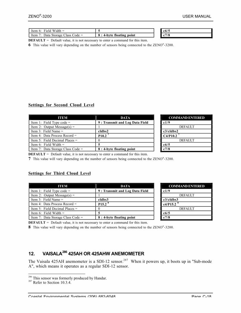
ZENO®-3200 USER MANUAL
Coastal Environmental Systems (206) 682-6048 Page C-18
Item 6: Field Width = 5 c6/5Item 7: Data Storage Class Code = 8 : 4-byte floating point c7/8
DEFAULT = Default value, it is not necessary to enter a command for this item.6 This value will vary depending on the number of sensors being connected to the ZENO-3200.
Settings for Second Cloud Level
ITEM DATA COMMAND ENTEREDItem 1: Field Type code = 9 : Transmit and Log Data Field c1/9Item 2: Output Message(s) = 1 DEFAULTItem 3: Field Name = cldbs2 c3/cldbs2Item 4: Data Process Record = P10.2 7 C4/P10.2 7
Item 5: Field Decimal Places = 0 DEFAULTItem 6: Field Width = 5 c6/5Item 7: Data Storage Class Code = 8 : 4-byte floating point c7/8
DEFAULT = Default value, it is not necessary to enter a command for this item.7 This value will vary depending on the number of sensors being connected to the ZENO-3200.
Settings for Third Cloud Level
ITEM DATA COMMAND ENTEREDItem 1: Field Type code = 9 : Transmit and Log Data Field c1/9Item 2: Output Message(s) = 1 DEFAULTItem 3: Field Name = cldbs3 c3/cldbs3Item 4: Data Process Record = P15.2 8 c4/P15.2 8
Item 5: Field Decimal Places = 0 DEFAULTItem 6: Field Width = 5 c6/5Item 7: Data Storage Class Code = 8 : 4-byte floating point c7/8
DEFAULT = Default value, it is not necessary to enter a command for this item.8 This value will vary depending on the number of sensors being connected to the ZENO-3200.
12. VAISALA286 425AH OR 425AHW ANEMOMETER
The Vaisala 425AH anemometer is a SDI-12 sensor.287 When it powers up, it boots up in "Sub-modeA", which means it operates as a regular SDI-12 sensor.
286 This sensor was formerly produced by Handar.287 Refer to Section 10.3.4.
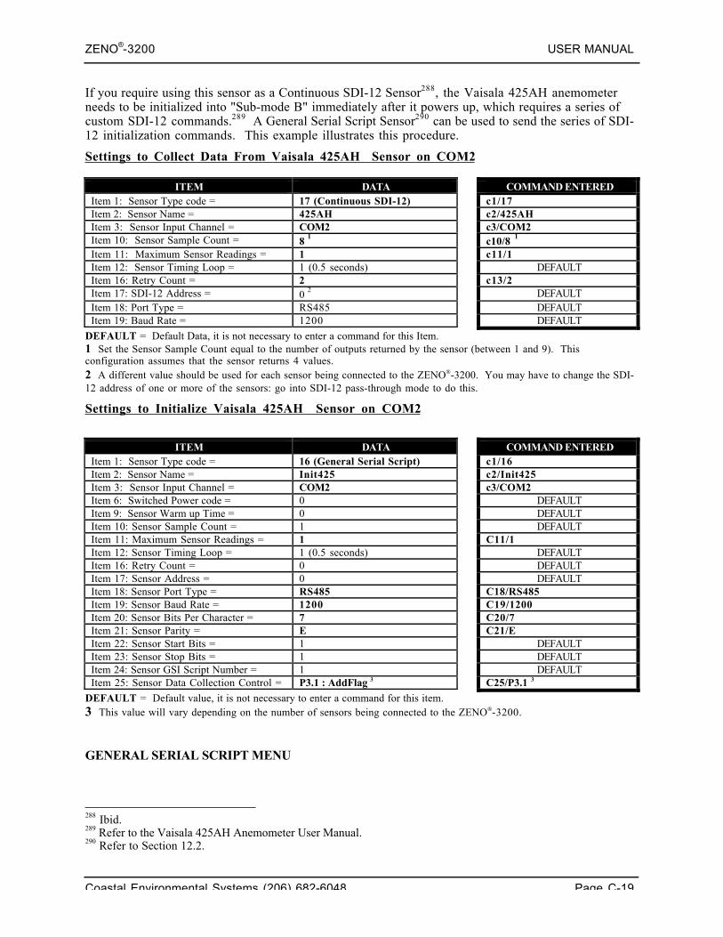
ZENO®-3200 USER MANUAL
Coastal Environmental Systems (206) 682-6048 Page C-19
If you require using this sensor as a Continuous SDI-12 Sensor288, the Vaisala 425AH anemometerneeds to be initialized into "Sub-mode B" immediately after it powers up, which requires a series ofcustom SDI-12 commands.289 A General Serial Script Sensor290 can be used to send the series of SDI-12 initialization commands. This example illustrates this procedure.
Settings to Collect Data From Vaisala 425AH Sensor on COM2
ITEM DATA COMMAND ENTEREDItem 1: Sensor Type code = 17 (Continuous SDI-12) c1/17Item 2: Sensor Name = 425AH c2/425AHItem 3: Sensor Input Channel = COM2 c3/COM2Item 10: Sensor Sample Count = 8 1 c10/8 1
Item 11: Maximum Sensor Readings = 1 c11/1Item 12: Sensor Timing Loop = 1 (0.5 seconds) DEFAULTItem 16: Retry Count = 2 c13/2Item 17: SDI-12 Address = 0 2 DEFAULTItem 18: Port Type = RS485 DEFAULTItem 19: Baud Rate = 1200 DEFAULT
DEFAULT = Default Data, it is not necessary to enter a command for this Item.1 Set the Sensor Sample Count equal to the number of outputs returned by the sensor (between 1 and 9). Thisconfiguration assumes that the sensor returns 4 values.2 A different value should be used for each sensor being connected to the ZENO-3200. You may have to change the SDI-12 address of one or more of the sensors: go into SDI-12 pass-through mode to do this.
Settings to Initialize Vaisala 425AH Sensor on COM2
ITEM DATA COMMAND ENTEREDItem 1: Sensor Type code = 16 (General Serial Script) c1/16Item 2: Sensor Name = Init425 c2/Init425Item 3: Sensor Input Channel = COM2 c3/COM2Item 6: Switched Power code = 0 DEFAULTItem 9: Sensor Warm up Time = 0 DEFAULTItem 10: Sensor Sample Count = 1 DEFAULTItem 11: Maximum Sensor Readings = 1 C11/1Item 12: Sensor Timing Loop = 1 (0.5 seconds) DEFAULTItem 16: Retry Count = 0 DEFAULTItem 17: Sensor Address = 0 DEFAULTItem 18: Sensor Port Type = RS485 C18/RS485Item 19: Sensor Baud Rate = 1200 C19/1200Item 20: Sensor Bits Per Character = 7 C20/7Item 21: Sensor Parity = E C21/EItem 22: Sensor Start Bits = 1 DEFAULTItem 23: Sensor Stop Bits = 1 DEFAULTItem 24: Sensor GSI Script Number = 1 DEFAULTItem 25: Sensor Data Collection Control = P3.1 : AddFlag 3 C25/P3.1 3
DEFAULT = Default value, it is not necessary to enter a command for this item.3 This value will vary depending on the number of sensors being connected to the ZENO-3200.
GENERAL SERIAL SCRIPT MENU
288 Ibid.289 Refer to the Vaisala 425AH Anemometer User Manual.290 Refer to Section 12.2.
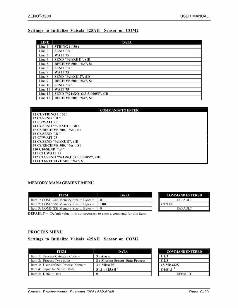
ZENO®-3200 USER MANUAL
Coastal Environmental Systems (206) 682-6048 Page C-20
Settings to Initialize Vaisala 425AH Sensor on COM2
LINE DATALine 1 STRING 1 ( 50 )Line 2 SEND "\B "Line 3 WAIT 75Line 4 SEND "%1sXH1!", sIDLine 5 RECEIVE 500, "%s", S1Line 6 SEND "\B "Line 7 WAIT 75Line 8 SEND "%1sXU1!", sIDLine 9 RECEIVE 500, "%s", S1Line 10 SEND "\B "Line 11 WAIT 75Line 12 SEND "%1sXQ1;3.3;3;0005!", sIDLine 13 RECEIVE 500, "%s", S1
COMMANDS TO ENTERI1 C1/STRING 1 ( 50 )I2 C2/SEND "\B "I3 C3/WAIT 75I4 C4/SEND "%1sXH1!", sIDI5 C5/RECEIVE 500, "%s", S1I6 C6/SEND "\B "I7 C7/WAIT 75I8 C8/SEND "%1sXU1!", sIDI9 C9/RECEIVE 500, "%s", S1I10 C10/SEND "\B "I11 C11/WAIT 75I12 C12/SEND "%1sXQ1;3.3;3;0005!", sIDI13 C13/RECEIVE 500, "%s", S1
MEMORY MANAGEMENT MENU
ITEM DATA COMMAND ENTEREDItem 1: COM1 GSI Memory Size in Bytes = 0 DEFAULTItem 2: COM2 GSI Memory Size in Bytes = 100 C1/100Item 3: COM3 GSI Memory Size in Bytes = 0 DEFAULT
DEFAULT = Default value, it is not necessary to enter a command for this item.
PROCESS MENU
Settings to Initialize Vaisala 425AH Sensor on COM2
ITEM DATA COMMAND ENTEREDItem 1: Process Category Code = 3 : Alarm C1/3Item 2: Process Type code = 8 : Missing Sensor Data Process C2/8Item 3: User-defined Process Name = 3 : Miss425 c3/Miss425Item 4: Input for Sensor Data S1.1 : 425AH 4 C4/S1.1 4
Item 5: Default Data 0 DEFAULT
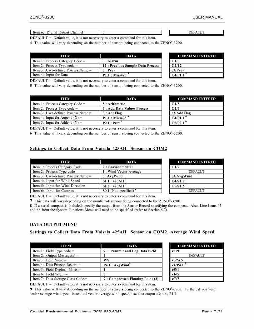
ZENO®-3200 USER MANUAL
Coastal Environmental Systems (206) 682-6048 Page C-21
Item 6: Digital Output Channel 0 DEFAULT
DEFAULT = Default value, it is not necessary to enter a command for this item.4 This value will vary depending on the number of sensors being connected to the ZENO-3200.
ITEM DATA COMMAND ENTEREDItem 1: Process Category Code = 3 : Alarm C1/3Item 2: Process Type code = 12 : Previous Sample Data Process C2/12Item 3: User-defined Process Name = 3 : Prev c3/PrevItem 4: Input for Data P1.1 : Miss425 5 C4/P1.1 5
DEFAULT = Default value, it is not necessary to enter a command for this item.5 This value will vary depending on the number of sensors being connected to the ZENO-3200.
ITEM DATA COMMAND ENTEREDItem 1: Process Category Code = 5 : Arithmetic C1/5Item 2: Process Type code = 3 : Add Data Values Process C2/3Item 3: User-defined Process Name = 3 : AddFlag c3/AddFlagItem 4: Input for Augend (X) = P1.1 : Miss425 6 C4/P1.1 6
Item 5: Input for Addend (Y) = P2.1 : Prev 6 C5/P2.1 6
DEFAULT = Default value, it is not necessary to enter a command for this item.6 This value will vary depending on the number of sensors being connected to the ZENO-3200.
Settings to Collect Data From Vaisala 425AH Sensor on COM2
ITEM DATA COMMAND ENTEREDItem 1: Process Category Code 2 : Environmental C1/2Item 2: Process Type code 1 : Wind Vector Average DEFAULTItem 3: User-defined Process Name = 3: AvgWind c3/AvgWindItem 4: Input for Wind Speed S1.1 : 425AH 7 C4/S1.1 7
Item 5: Input for Wind Direction S1.2 : 425AH 7 C5/S1.2 7
Item 6: Input for Compass S0.1 (Not specified) 8 DEFAULT
DEFAULT = Default value, it is not necessary to enter a command for this item.7 This data will vary depending on the number of sensors being connected to the ZENO-3200.8 If a serial compass is included, specify the output from the Sensor Record specifying the compass. Also, Line Items #5and #6 from the System Functions Menu will need to be specified (refer to Section 5.7).
DATA OUTPUT MENU
Settings to Collect Data From Vaisala 425AH Sensor on COM2, Average Wind Speed
ITEM DATA COMMAND ENTEREDItem 1: Field Type code = 9 : Transmit and Log Data Field c1/9Item 2: Output Message(s) = 1 DEFAULTItem 3: Field Name = WS c3/WSItem 4: Data Process Record = P4.1 : AvgWind9 c4/P4.1 9
Item 5: Field Decimal Places = 1 c5/1Item 6: Field Width = 5 c6/5Item 7: Data Storage Class Code = 7 : Compressed Floating Point (2) c7/7
DEFAULT = Default value, it is not necessary to enter a command for this item.9 This value will vary depending on the number of sensors being connected to the ZENO-3200. Further, if you wantscalar average wind speed instead of vector average wind speed, use data output #3; i.e., P4.3.
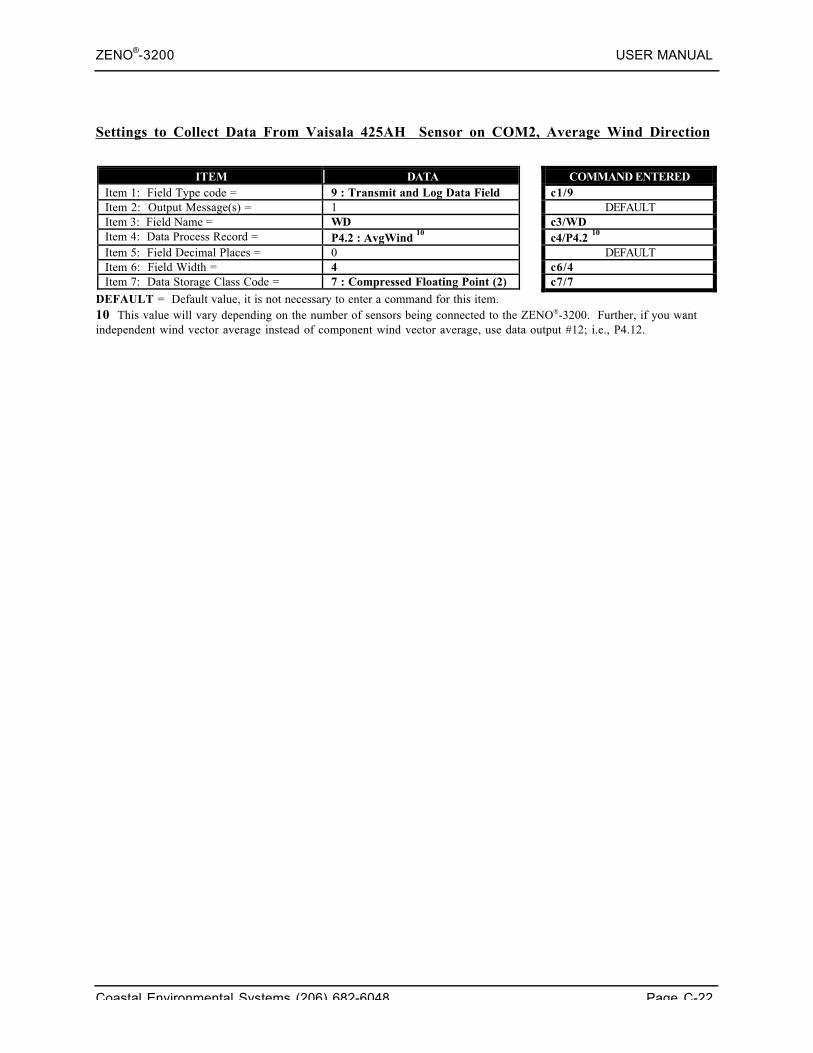
ZENO®-3200 USER MANUAL
Coastal Environmental Systems (206) 682-6048 Page C-22
Settings to Collect Data From Vaisala 425AH Sensor on COM2, Average Wind Direction
ITEM DATA COMMAND ENTEREDItem 1: Field Type code = 9 : Transmit and Log Data Field c1/9Item 2: Output Message(s) = 1 DEFAULTItem 3: Field Name = WD c3/WDItem 4: Data Process Record = P4.2 : AvgWind 10 c4/P4.2 10
Item 5: Field Decimal Places = 0 DEFAULTItem 6: Field Width = 4 c6/4Item 7: Data Storage Class Code = 7 : Compressed Floating Point (2) c7/7
DEFAULT = Default value, it is not necessary to enter a command for this item.10 This value will vary depending on the number of sensors being connected to the ZENO-3200. Further, if you wantindependent wind vector average instead of component wind vector average, use data output #12; i.e., P4.12.
ZENO®-3200 USER MANUAL
Coastal Environmental Systems (206) 682-6048 Page D-1
D. ZENO®-3200 PROCESSLIBRARY
Coastal EnvironmentalSystems
ZENO®-3200 User Manual
This appendix lists all the processes, their inputs and outputs. The process outputs are meaningfulthroughout the sample interval times -- for example, averages are maintained throughout, ratherthan being calculated at the end of the sample duration.
Enter HPTn.m to obtain help on Process Type number m inCategory n.
Bad Sensor Values (BSV)291 are NOT processed, including anyprocess that requires cumulative data in its calculations.
1. GENERAL PROCESSES CATEGORY
1.1. Immediate Data Process
Inputs: 4 Any sensor or process output
Outputs: 1 The most recent valueE1 Process Error Code
Assumptions: None.
Each time the Immediate process is called it simply moves the data value from the input into its ownoutput data address.
1.2. Averaging Process
Inputs 4 Any sensor or process output
Outputs 1 Average value2 The most recent input value3 Standard deviation
291 Refer to Section 10.4.5.
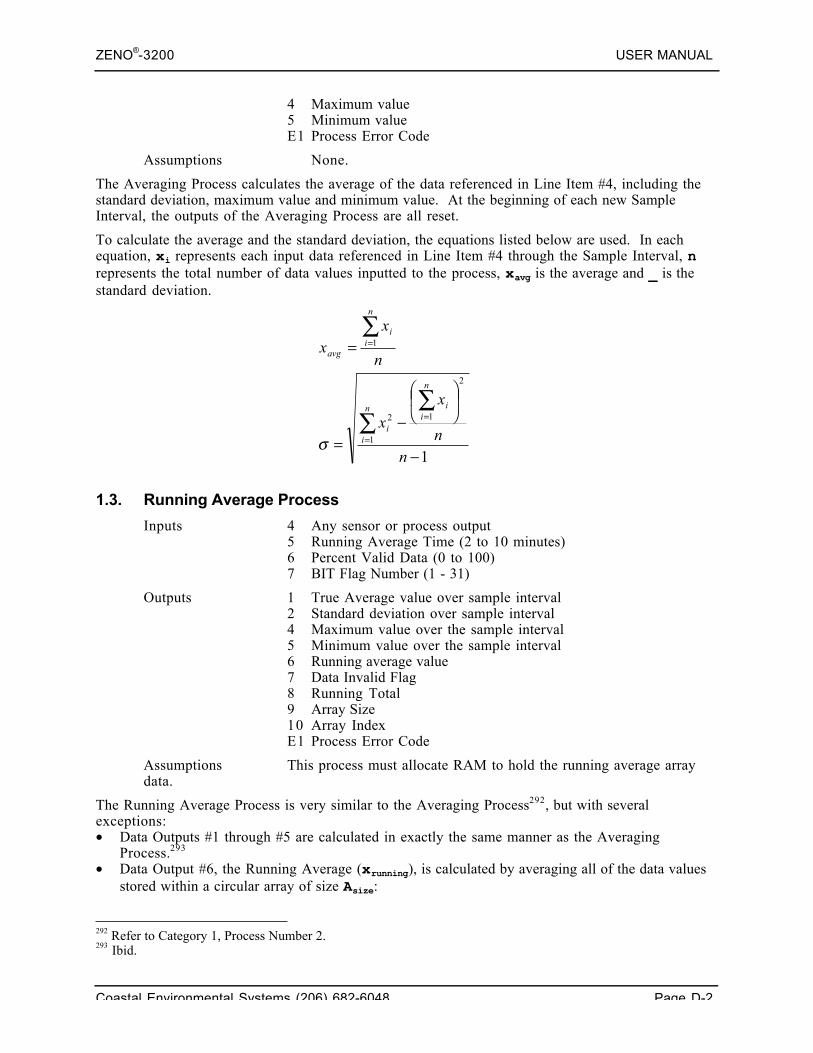
ZENO®-3200 USER MANUAL
Coastal Environmental Systems (206) 682-6048 Page D-2
4 Maximum value5 Minimum valueE1 Process Error Code
Assumptions None.
The Averaging Process calculates the average of the data referenced in Line Item #4, including thestandard deviation, maximum value and minimum value. At the beginning of each new SampleInterval, the outputs of the Averaging Process are all reset.
To calculate the average and the standard deviation, the equations listed below are used. In eachequation, xi represents each input data referenced in Line Item #4 through the Sample Interval, nrepresents the total number of data values inputted to the process, xavg is the average and _ is thestandard deviation.
1.3. Running Average Process
Inputs 4 Any sensor or process output5 Running Average Time (2 to 10 minutes)6 Percent Valid Data (0 to 100)7 BIT Flag Number (1 - 31)
Outputs 1 True Average value over sample interval2 Standard deviation over sample interval4 Maximum value over the sample interval5 Minimum value over the sample interval6 Running average value7 Data Invalid Flag8 Running Total9 Array Size10 Array IndexE1 Process Error Code
Assumptions This process must allocate RAM to hold the running average arraydata.
The Running Average Process is very similar to the Averaging Process292, but with severalexceptions:• Data Outputs #1 through #5 are calculated in exactly the same manner as the Averaging
Process.293
• Data Output #6, the Running Average (xrunning), is calculated by averaging all of the data valuesstored within a circular array of size Asize:
292 Refer to Category 1, Process Number 2.293 Ibid.
1
2
1
1
2
1
−
⎟⎠⎞⎜
⎝⎛
−=
=
∑∑
∑
=
=
=
nn
x
x
n
xx
n
iin
ii
n
ii
avg
σ
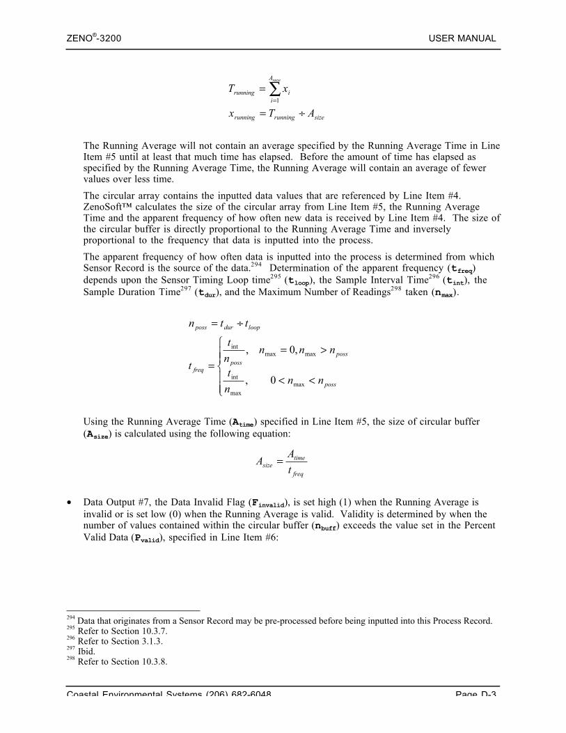
ZENO®-3200 USER MANUAL
Coastal Environmental Systems (206) 682-6048 Page D-3
The Running Average will not contain an average specified by the Running Average Time in LineItem #5 until at least that much time has elapsed. Before the amount of time has elapsed asspecified by the Running Average Time, the Running Average will contain an average of fewervalues over less time.
The circular array contains the inputted data values that are referenced by Line Item #4.ZenoSoft™ calculates the size of the circular array from Line Item #5, the Running AverageTime and the apparent frequency of how often new data is received by Line Item #4. The size ofthe circular buffer is directly proportional to the Running Average Time and inverselyproportional to the frequency that data is inputted into the process.
The apparent frequency of how often data is inputted into the process is determined from whichSensor Record is the source of the data.294 Determination of the apparent frequency (tfreq)depends upon the Sensor Timing Loop time295 (tloop), the Sample Interval Time296 (tint), theSample Duration Time297 (tdur), and the Maximum Number of Readings298 taken (nmax).
Using the Running Average Time (Atime) specified in Line Item #5, the size of circular buffer(Asize) is calculated using the following equation:
• Data Output #7, the Data Invalid Flag (Finvalid), is set high (1) when the Running Average isinvalid or is set low (0) when the Running Average is valid. Validity is determined by when thenumber of values contained within the circular buffer (nbuff) exceeds the value set in the PercentValid Data (Pvalid), specified in Line Item #6:
294 Data that originates from a Sensor Record may be pre-processed before being inputted into this Process Record.295 Refer to Section 10.3.7.296 Refer to Section 3.1.3.297 Ibid.298 Refer to Section 10.3.8.
⎪⎪⎩
⎪⎪⎨
⎧
<<
>==
÷=
poss
possposs
freq
loopdurposs
nnn
t
nnnn
t
t
ttn
maxmax
int
maxmaxint
0,
,0,
freq
timesize t
AA =
sizerunningrunning
A
iirunning
ATx
xTsuze
÷=
= ∑=1
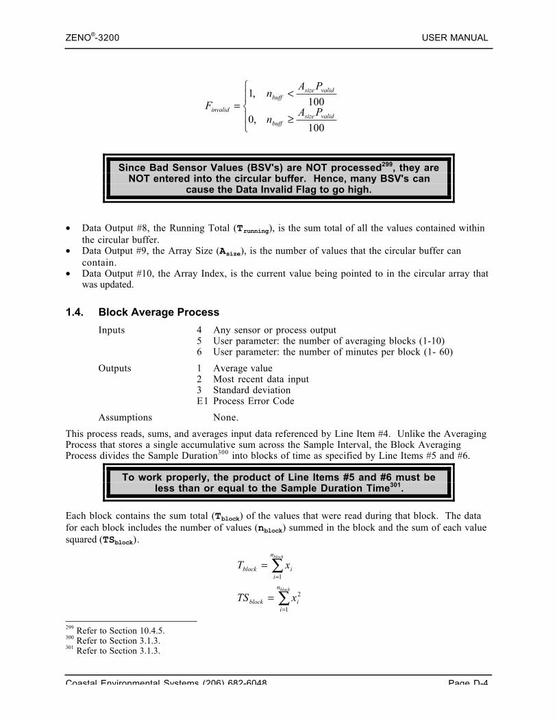
ZENO®-3200 USER MANUAL
Coastal Environmental Systems (206) 682-6048 Page D-4
Since Bad Sensor Values (BSV's) are NOT processed299, they areNOT entered into the circular buffer. Hence, many BSV's can
cause the Data Invalid Flag to go high.
• Data Output #8, the Running Total (Trunning), is the sum total of all the values contained withinthe circular buffer.
• Data Output #9, the Array Size (Asize), is the number of values that the circular buffer cancontain.
• Data Output #10, the Array Index, is the current value being pointed to in the circular array thatwas updated.
1.4. Block Average Process
Inputs 4 Any sensor or process output5 User parameter: the number of averaging blocks (1-10)6 User parameter: the number of minutes per block (1- 60)
Outputs 1 Average value2 Most recent data input3 Standard deviationE1 Process Error Code
Assumptions None.
This process reads, sums, and averages input data referenced by Line Item #4. Unlike the AveragingProcess that stores a single accumulative sum across the Sample Interval, the Block AveragingProcess divides the Sample Duration300 into blocks of time as specified by Line Items #5 and #6.
To work properly, the product of Line Items #5 and #6 must beless than or equal to the Sample Duration Time301.
Each block contains the sum total (Tblock) of the values that were read during that block. The datafor each block includes the number of values (nblock) summed in the block and the sum of each valuesquared (TSblock).
299 Refer to Section 10.4.5.300 Refer to Section 3.1.3.301 Refer to Section 3.1.3.
∑
∑
=
=
=
=
block
block
n
iiblock
n
iiblock
xTS
xT
1
2
1
⎪⎩
⎪⎨
⎧
≥
<=
100,0
100,1
validsizebuff
validsizebuff
invalid PAn
PAn
F
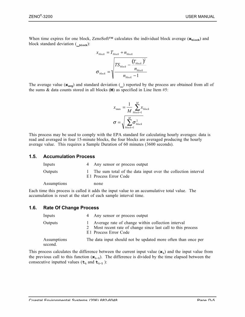
ZENO®-3200 USER MANUAL
Coastal Environmental Systems (206) 682-6048 Page D-5
When time expires for one block, ZenoSoft™ calculates the individual block average (xblock) andblock standard deviation (_block):
The average value (xavg) and standard deviation (_) reported by the process are obtained from all ofthe sums & data counts stored in all blocks (M) as specified in Line Item #5:
This process may be used to comply with the EPA standard for calculating hourly averages: data isread and averaged in four 15-minute blocks, the four blocks are averaged producing the hourlyaverage value. This requires a Sample Duration of 60 minutes (3600 seconds).
1.5. Accumulation Process
Inputs 4 Any sensor or process output
Outputs 1 The sum total of the data input over the collection intervalE1 Process Error Code
Assumptions none
Each time this process is called it adds the input value to an accumulative total value. Theaccumulation is reset at the start of each sample interval time.
1.6. Rate Of Change Process
Inputs 4 Any sensor or process output
Outputs 1 Average rate of change within collection interval2 Most recent rate of change since last call to this processE1 Process Error Code
Assumptions The data input should not be updated more often than once persecond.
This process calculates the difference between the current input value (xi) and the input value fromthe previous call to this function (xi-1). The difference is divided by the time elapsed between theconsecutive inputted values (ti and ti-1 ):
( )
1
2
−
−=
÷=
block
block
blockblock
block
blockblockblock
n
n
TTS
nTx
σ
∑
∑
=
=
=
=
M
blockblock
M
blockblockx
Mx
1
2
1max
1
σσ
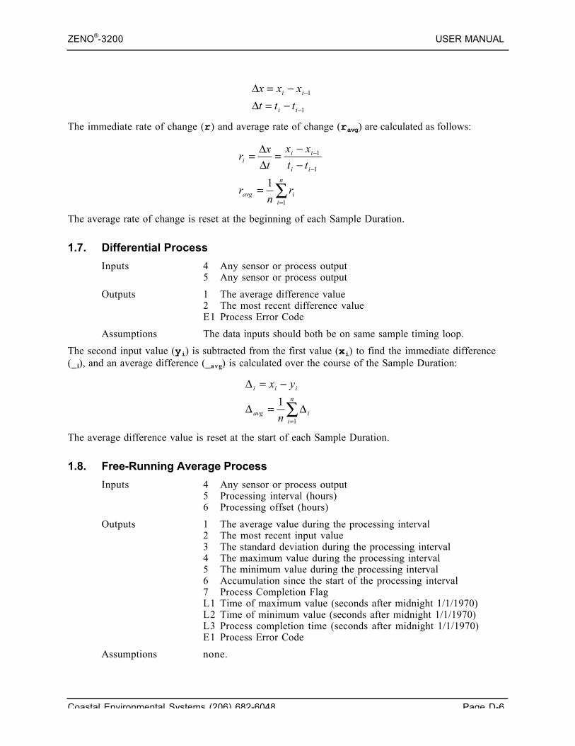
ZENO®-3200 USER MANUAL
Coastal Environmental Systems (206) 682-6048 Page D-6
The immediate rate of change (r) and average rate of change (ravg) are calculated as follows:
The average rate of change is reset at the beginning of each Sample Duration.
1.7. Differential Process
Inputs 4 Any sensor or process output5 Any sensor or process output
Outputs 1 The average difference value2 The most recent difference valueE1 Process Error Code
Assumptions The data inputs should both be on same sample timing loop.
The second input value (yi) is subtracted from the first value (xi) to find the immediate difference(_i), and an average difference (_avg) is calculated over the course of the Sample Duration:
The average difference value is reset at the start of each Sample Duration.
1.8. Free-Running Average Process
Inputs 4 Any sensor or process output5 Processing interval (hours)6 Processing offset (hours)
Outputs 1 The average value during the processing interval2 The most recent input value3 The standard deviation during the processing interval4 The maximum value during the processing interval5 The minimum value during the processing interval6 Accumulation since the start of the processing interval7 Process Completion FlagL1 Time of maximum value (seconds after midnight 1/1/1970)L2 Time of minimum value (seconds after midnight 1/1/1970)L3 Process completion time (seconds after midnight 1/1/1970)E1 Process Error Code
Assumptions none.
1
1
−
−
−=Δ−=Δ
ii
ii
ttt
xxx
∑=
−
−
=
−−
=ΔΔ=
n
iiavg
ii
iii
rn
r
tt
xx
tx
r
1
1
1
1
∑=
Δ=Δ
−=Δn
iiavg
iii
n
yx
1
1
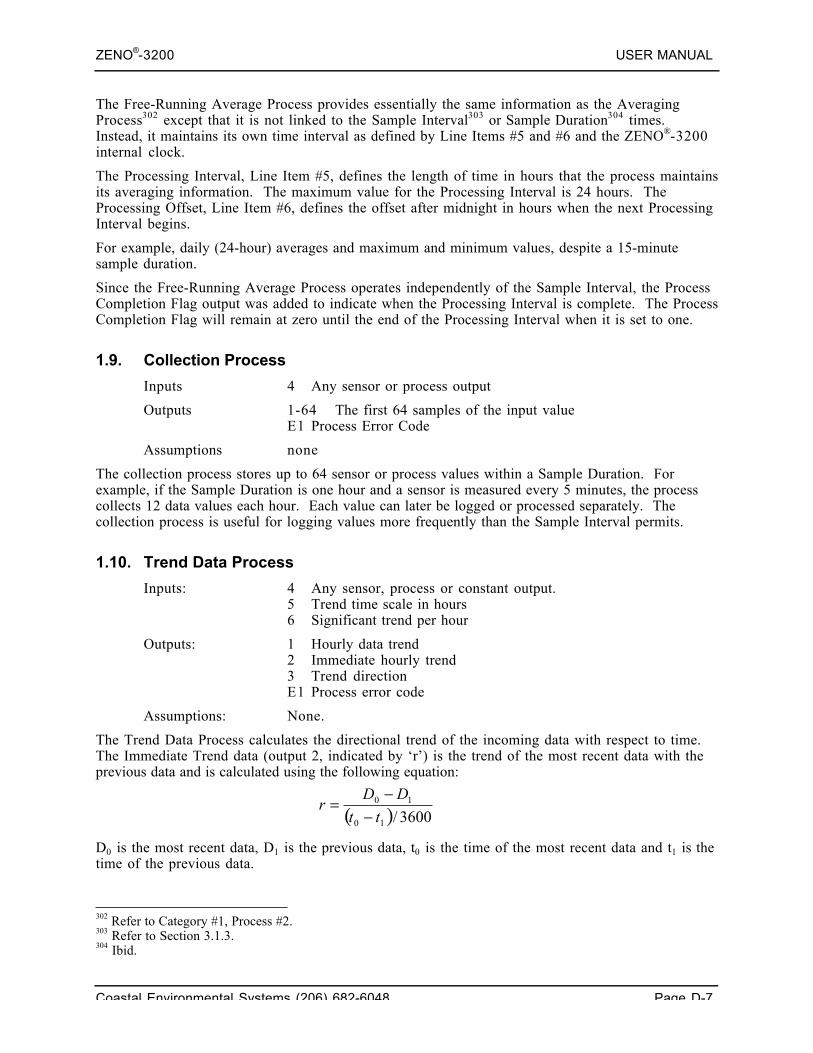
ZENO®-3200 USER MANUAL
Coastal Environmental Systems (206) 682-6048 Page D-7
The Free-Running Average Process provides essentially the same information as the AveragingProcess302 except that it is not linked to the Sample Interval303 or Sample Duration304 times.Instead, it maintains its own time interval as defined by Line Items #5 and #6 and the ZENO®-3200internal clock.
The Processing Interval, Line Item #5, defines the length of time in hours that the process maintainsits averaging information. The maximum value for the Processing Interval is 24 hours. TheProcessing Offset, Line Item #6, defines the offset after midnight in hours when the next ProcessingInterval begins.
For example, daily (24-hour) averages and maximum and minimum values, despite a 15-minutesample duration.
Since the Free-Running Average Process operates independently of the Sample Interval, the ProcessCompletion Flag output was added to indicate when the Processing Interval is complete. The ProcessCompletion Flag will remain at zero until the end of the Processing Interval when it is set to one.
1.9. Collection Process
Inputs 4 Any sensor or process output
Outputs 1-64 The first 64 samples of the input valueE1 Process Error Code
Assumptions none
The collection process stores up to 64 sensor or process values within a Sample Duration. Forexample, if the Sample Duration is one hour and a sensor is measured every 5 minutes, the processcollects 12 data values each hour. Each value can later be logged or processed separately. Thecollection process is useful for logging values more frequently than the Sample Interval permits.
1.10. Trend Data Process
Inputs: 4 Any sensor, process or constant output.5 Trend time scale in hours6 Significant trend per hour
Outputs: 1 Hourly data trend2 Immediate hourly trend3 Trend directionE1 Process error code
Assumptions: None.
The Trend Data Process calculates the directional trend of the incoming data with respect to time.The Immediate Trend data (output 2, indicated by ‘r’) is the trend of the most recent data with theprevious data and is calculated using the following equation:
D0 is the most recent data, D1 is the previous data, t0 is the time of the most recent data and t1 is thetime of the previous data.
302 Refer to Category #1, Process #2.303 Refer to Section 3.1.3.304 Ibid.
( ) 3600/10
10
tt
DDr
−−
=
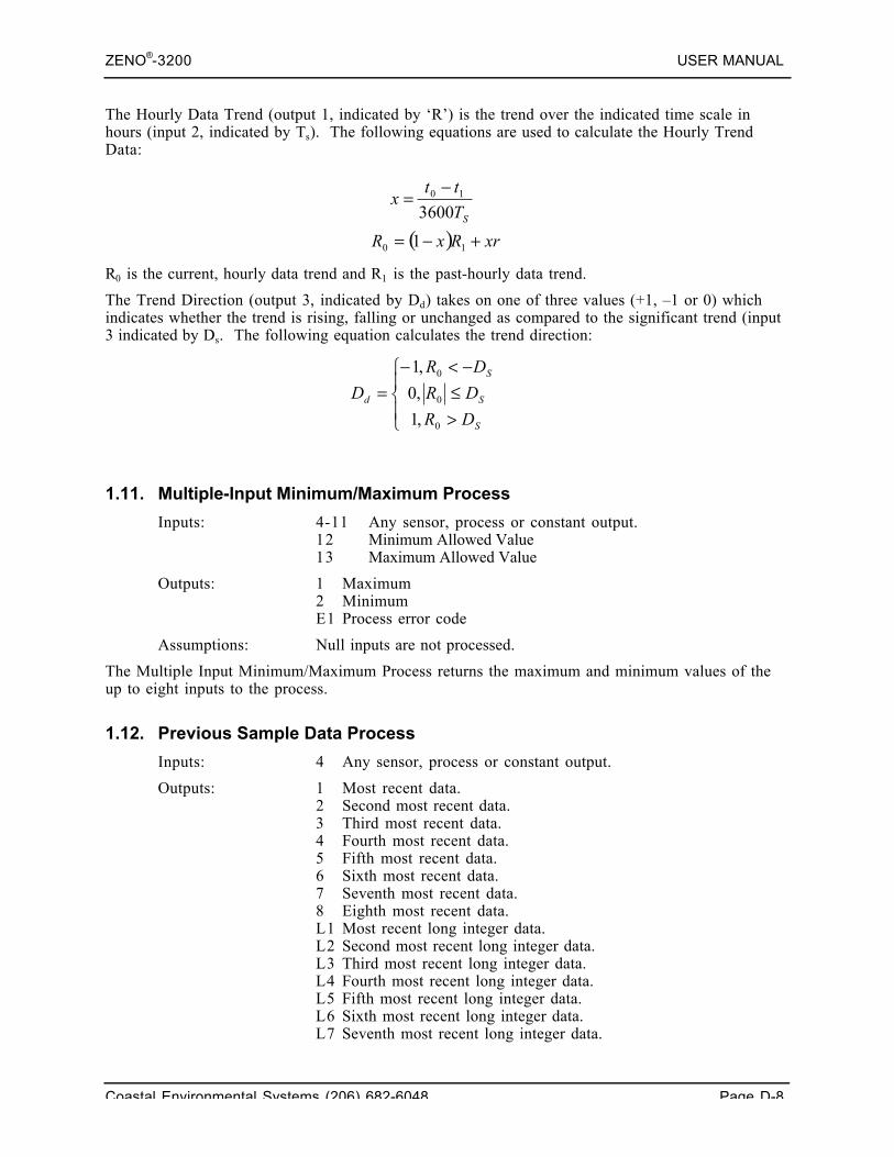
ZENO®-3200 USER MANUAL
Coastal Environmental Systems (206) 682-6048 Page D-8
The Hourly Data Trend (output 1, indicated by ‘R’) is the trend over the indicated time scale inhours (input 2, indicated by Ts). The following equations are used to calculate the Hourly TrendData:
R0 is the current, hourly data trend and R1 is the past-hourly data trend.
The Trend Direction (output 3, indicated by Dd) takes on one of three values (+1, –1 or 0) whichindicates whether the trend is rising, falling or unchanged as compared to the significant trend (input3 indicated by Ds. The following equation calculates the trend direction:
1.11. Multiple-Input Minimum/Maximum Process
Inputs: 4-11 Any sensor, process or constant output.12 Minimum Allowed Value13 Maximum Allowed Value
Outputs: 1 Maximum2 MinimumE1 Process error code
Assumptions: Null inputs are not processed.
The Multiple Input Minimum/Maximum Process returns the maximum and minimum values of theup to eight inputs to the process.
1.12. Previous Sample Data Process
Inputs: 4 Any sensor, process or constant output.
Outputs: 1 Most recent data.2 Second most recent data.3 Third most recent data.4 Fourth most recent data.5 Fifth most recent data.6 Sixth most recent data.7 Seventh most recent data.8 Eighth most recent data.L1 Most recent long integer data.L2 Second most recent long integer data.L3 Third most recent long integer data.L4 Fourth most recent long integer data.L5 Fifth most recent long integer data.L6 Sixth most recent long integer data.L7 Seventh most recent long integer data.
( ) xrRxR +−= 10 1
⎪⎩
⎪⎨⎧
>≤−<−
=
S
S
S
d
DR
DR
DR
D
0
0
0
,1
,0
,1
ST
ttx
360010 −=
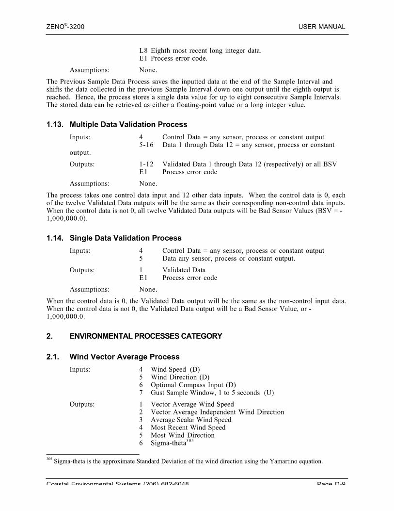
ZENO®-3200 USER MANUAL
Coastal Environmental Systems (206) 682-6048 Page D-9
L8 Eighth most recent long integer data.E1 Process error code.
Assumptions: None.
The Previous Sample Data Process saves the inputted data at the end of the Sample Interval andshifts the data collected in the previous Sample Interval down one output until the eighth output isreached. Hence, the process stores a single data value for up to eight consecutive Sample Intervals.The stored data can be retrieved as either a floating-point value or a long integer value.
1.13. Multiple Data Validation Process
Inputs: 4 Control Data = any sensor, process or constant output5-16 Data 1 through Data 12 = any sensor, process or constant
output.
Outputs: 1-12 Validated Data 1 through Data 12 (respectively) or all BSVE1 Process error code
Assumptions: None.
The process takes one control data input and 12 other data inputs. When the control data is 0, eachof the twelve Validated Data outputs will be the same as their corresponding non-control data inputs.When the control data is not 0, all twelve Validated Data outputs will be Bad Sensor Values (BSV = -1,000,000.0).
1.14. Single Data Validation Process
Inputs: 4 Control Data = any sensor, process or constant output5 Data any sensor, process or constant output.
Outputs: 1 Validated DataE1 Process error code
Assumptions: None.
When the control data is 0, the Validated Data output will be the same as the non-control input data.When the control data is not 0, the Validated Data output will be a Bad Sensor Value, or -1,000,000.0.
2. ENVIRONMENTAL PROCESSES CATEGORY
2.1. Wind Vector Average Process
Inputs: 4 Wind Speed (D)5 Wind Direction (D)6 Optional Compass Input (D)7 Gust Sample Window, 1 to 5 seconds (U)
Outputs: 1 Vector Average Wind Speed2 Vector Average Independent Wind Direction3 Average Scalar Wind Speed4 Most Recent Wind Speed5 Most Wind Direction6 Sigma-theta305
305 Sigma-theta is the approximate Standard Deviation of the wind direction using the Yamartino equation.
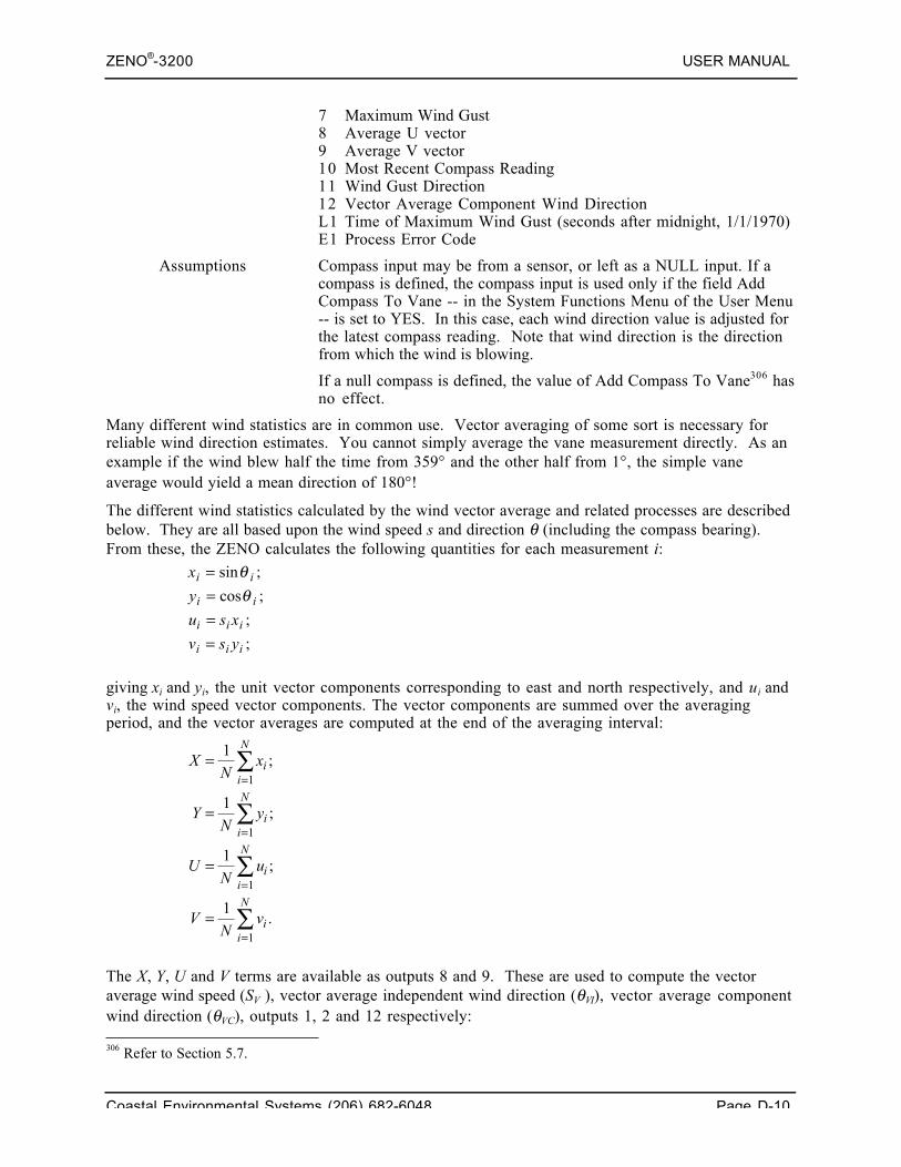
ZENO®-3200 USER MANUAL
Coastal Environmental Systems (206) 682-6048 Page D-10
7 Maximum Wind Gust8 Average U vector9 Average V vector10 Most Recent Compass Reading11 Wind Gust Direction12 Vector Average Component Wind DirectionL1 Time of Maximum Wind Gust (seconds after midnight, 1/1/1970)E1 Process Error Code
Assumptions Compass input may be from a sensor, or left as a NULL input. If acompass is defined, the compass input is used only if the field AddCompass To Vane -- in the System Functions Menu of the User Menu-- is set to YES. In this case, each wind direction value is adjusted forthe latest compass reading. Note that wind direction is the directionfrom which the wind is blowing.
If a null compass is defined, the value of Add Compass To Vane306 hasno effect.
Many different wind statistics are in common use. Vector averaging of some sort is necessary forreliable wind direction estimates. You cannot simply average the vane measurement directly. As anexample if the wind blew half the time from 359° and the other half from 1°, the simple vaneaverage would yield a mean direction of 180°!
The different wind statistics calculated by the wind vector average and related processes are describedbelow. They are all based upon the wind speed s and direction θ (including the compass bearing).From these, the ZENO calculates the following quantities for each measurement i:
x
y
u s x
v s y
i i
i i
i i i
i i i
====
sin ;
cos ;
;
;
θθ
giving xi and yi, the unit vector components corresponding to east and north respectively, and ui andvi, the wind speed vector components. The vector components are summed over the averagingperiod, and the vector averages are computed at the end of the averaging interval:
XN
x
YN
y
UN
u
VN
v
ii
N
ii
N
ii
N
ii
N
=
=
=
=
=
=
=
=
∑
∑
∑
∑
1
1
1
1
1
1
1
1
;
;
;
.
The X, Y, U and V terms are available as outputs 8 and 9. These are used to compute the vectoraverage wind speed (SV ), vector average independent wind direction (θVI), vector average componentwind direction (θVC), outputs 1, 2 and 12 respectively: 306 Refer to Section 5.7.
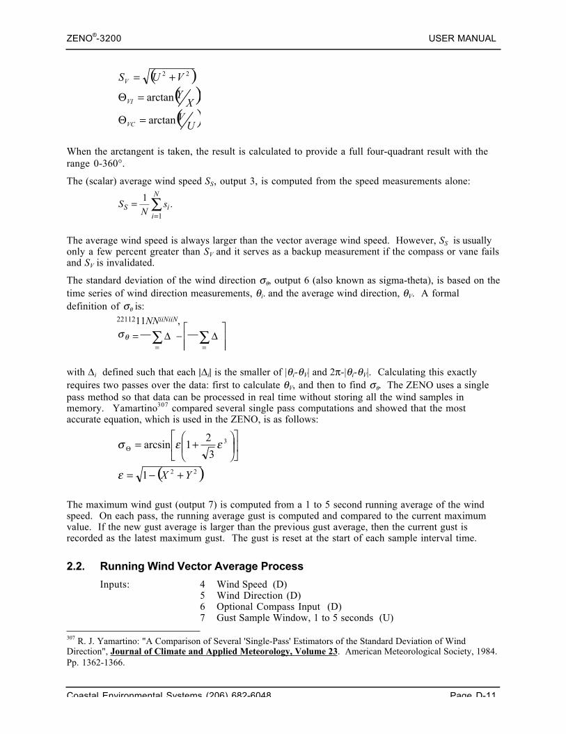
ZENO®-3200 USER MANUAL
Coastal Environmental Systems (206) 682-6048 Page D-11
( )( )( )UVX
Y
VUS
VC
VI
V
arctan
arctan
22
=Θ
=Θ
+=
When the arctangent is taken, the result is calculated to provide a full four-quadrant result with therange 0-360°.
The (scalar) average wind speed SS, output 3, is computed from the speed measurements alone:
SN
sS ii
N
==∑11
.
The average wind speed is always larger than the vector average wind speed. However, SS is usuallyonly a few percent greater than SV and it serves as a backup measurement if the compass or vane failsand SV is invalidated.
The standard deviation of the wind direction σθ, output 6 (also known as sigma-theta), is based on thetime series of wind direction measurements, θi. and the average wind direction, θV. A formaldefinition of σθ is:
σθ
2211211
= −⎡
⎣⎢⎢
⎤
⎦⎥⎥= =
∑ ∑NNiiNiiN
Δ Δ,
with Δi defined such that each |Δi| is the smaller of |θi-θV| and 2π-|θi-θV|. Calculating this exactlyrequires two passes over the data: first to calculate θV, and then to find σθ. The ZENO uses a singlepass method so that data can be processed in real time without storing all the wind samples inmemory. Yamartino307 compared several single pass computations and showed that the mostaccurate equation, which is used in the ZENO, is as follows:
( )22
3
1
3
21arcsin
YX +−=
⎥⎦
⎤⎢⎣
⎡⎟⎟⎠⎞
⎜⎜⎝⎛ +=Θ
ε
εεσ
The maximum wind gust (output 7) is computed from a 1 to 5 second running average of the windspeed. On each pass, the running average gust is computed and compared to the current maximumvalue. If the new gust average is larger than the previous gust average, then the current gust isrecorded as the latest maximum gust. The gust is reset at the start of each sample interval time.
2.2. Running Wind Vector Average Process
Inputs: 4 Wind Speed (D)5 Wind Direction (D)6 Optional Compass Input (D)7 Gust Sample Window, 1 to 5 seconds (U)
307 R. J. Yamartino: "A Comparison of Several 'Single-Pass' Estimators of the Standard Deviation of WindDirection", Journal of Climate and Applied Meteorology, Volume 23. American Meteorological Society, 1984.Pp. 1362-1366.
ZENO®-3200 USER MANUAL
Coastal Environmental Systems (206) 682-6048 Page D-12
8 Running Average Time in Minutes (U)9 Percent Valid Data (U)
Outputs: 1 Vector Average Wind Speed2 Vector Average Independent Wind Direction3 Average Scalar Wind Speed4 Most Recent Wind Speed5 Most Recent Wind Direction6 Sigma-theta308
7 Maximum Wind Gust8 Average U vector9 Average V vector10 Most Recent Compass Reading11 Running Vector Average Wind Speed12 Running Vector Average Independent Wind Direction13 Running Average Sigma-theta14 Running Maximum Wind Gust Speed15 Wind Direction during Running Maximum Wind Gust Speed16 Running Vector Average Component Wind Direction17 Vector Average (Not Running) Component Wind Direction18 Data Invalid FlagE1 Process Error Code
Assumptions: This process must allocate RAM to hold the running average arraydata.
This process is nearly identical to the Wind Vector Average Process309, but with the addition of theprocessing required to hold up to 10 minutes worth of running vector wind speed and direction data.
The first 10 data outputs and Data Output #17 of the Running Wind Vector Average Process arecalculated exactly the same way as the Wind Vector Average Process.310 Data outputs #11 through#16, and #18 are calculated using circular buffers of data similar to the Running Average Process311,but using vector calculations.
Five circular buffers are maintained, whose values are calculated from the inputted wind speed andwind direction using the same equations as described in the Wind Vector Average Process312:
1. Unit vector x-component wind direction (xi).
2. Unit vector y-component wind direction (yi).
3. Magnitude vector u-component wind direction (ui).
4. Magnitude vector v-component wind direction (vi).
5. Scalar wind speed (si).
The sizes of the circular buffers are identical. ZenoSoft™ calculates the size of each circular buffer(Asize) from Line Item #8, the Running Average Time and the apparent frequency of how often newdata is received by Line Item #5, the wind direction. Calculating the size of each circular buffer isdone using the same equations as used in the Running Average Process313.
308 Sigma-theta is the approximate Standard Deviation of the wind direction using the Yamartino equation. Refer tothe Vector Average Wind Process for details regarding this equation.309 Refer to Category #2, Process #1.310 Ibid.311 Refer to Category #1, Process #3.312 Refer to Category #2, Process #1.313 Refer to Category #1, Process #3.
ZENO®-3200 USER MANUAL
Coastal Environmental Systems (206) 682-6048 Page D-13
The process will validate the calculated data by determining what percentage of the inputted windspeed and wind direction data is valid using the same technique as described in the Running AverageProcess314. (Valid data is any data that is not a Bad Sensor Value.)
2.3. Block Average Direction Process
Inputs 4 Wind Direction data5 Compass data (optional)6 The number of averaging blocks (1-10)7 The number of minutes per block (1- 60)
Outputs 1 Average wind direction2 Immediate data (most recent sample)3 Standard deviation of data over sample intervalE1 Process Error Code
Assumptions This process assumes that the wind direction will not change by morethan 180 degrees between sampling.
This process operates similarly to the Block Average Process315, but it is intended for wind directionaveraging. Unlike the Wind Vector Average Process316 and Running Wind Vector AverageProcess317, this process computes a scalar average of the wind direction rather than a vectoraverage.
Coastal Environmental Systems favors the use of the WindVector Average Process or Running Wind Vector Average
Process over the Block Average Direction Process becausevector averaging of wind direction is more accurate.
2.4. True Wind Vector Average Process
Inputs: 4 Wind speed (D)5 Wind direction (D)6 Compass Input (D)7 Vehicle Speed Over Ground (D)8 Vehicle Course Over Ground (D)
Outputs: 1 Vector Average True Wind Speed2 Vector Average True Independent Wind Direction3 Vector Average True Component Wind Direction4 Most Recent True Wind Speed5 Most Recent True Independent Wind Direction6 Most Recent True Component Wind Direction7 Average U vector8 Average V vectorE1 Process Error Code
Assumptions: This process assumes that you have compass data, the vehicle speedover ground and course over ground.
314 Ibid.315 Refer to Category #1, Process #4.316 Refer to Category #2, Process #1.317 Refer to Category #2, Process #2.
ZENO®-3200 USER MANUAL
Coastal Environmental Systems (206) 682-6048 Page D-14
This process is used to calculate the true wind speed and direction from an anemometer installed on amoving vehicle. While the vehicle is moving, the vehicle's course over ground and speed over groundmust be known to convert the measured wind speed and wind direction into true values. If nocompass is present, the orientation of the anemometer with respect to the vehicle must be known.If a compass is available, the orientation of the anemometer with respect to the vehicle isunimportant.
When the vehicle is stationary, the True Wind Vector AverageProcess can only provide true wind speed and true wind
direction data if a compass is installed.
The vehicle's course over ground and speed over ground can be obtained from a GPS receiver.318 Ifno compass is present, the orientation of the anemometer must be provided as a constant input forLine Item #6, the Compass Input. The orientation is specified so that the measured wind directionwill be zero degrees when the anemometer is pointing towards the front (or bow) of the vehicle.
The process uses the following calculations to determine true wind speed (Strue), true component winddirection (DCtrue) and true independent wind direction (DItrue) from the measured wind speed (Smeas),measured wind direction (Dmeas), compass (C), speed over ground (Sgnd) and course over ground(Dgnd):
2.5. Barometric Pressure Process
Inputs 4 Barometric pressure sensor or process input
Outputs 1 Average sea level Barometric pressure2 Most recent sea level Barometric pressure calculationE1 Process Error Code
Assumptions Data input to this function should be scaled to millibars.
This process calculates immediate barometric pressure (Pimm) and average barometric pressure thatare corrected to sea level by using the Barometer Elevation (Hbaro) parameter located in the SystemFunctions Menu.319 The measured barometric pressure (Pmeas) is corrected by a factor of onemillibar for every 8 meters that the barometric pressure sensor is above sea level using the followingequation:
318 Refer to Section 10.3.4.319 Refer to Section 5.8.
( ) ( )( ) ( )
true
truetrue
truetruetruetruetruetrue
true
truetrue
truetruetrue
vehicleitruevehicleitrue
gndgndvehiclegndgndvehicle
truemeasitruemeasi
x
yDI
SvySux
u
vDC
vuS
vvvuuu
DSvDSu
CDSvCDSu
arctan
,
arctan
,
cos,sin
cos,sin
22
=
÷=÷=
=
+=
−=−=
==+=+=
8baro
measimm
HPP +=
ZENO®-3200 USER MANUAL
Coastal Environmental Systems (206) 682-6048 Page D-15
The average barometric pressure is calculated across the Sample Interval from the correctedimmediate barometric pressure using equations similar to the Averaging Process.320
2.6. Rainfall Process
Inputs 4 Rain Data (D)5 Rain accumulation interval, 0 to 24 hours (U)6 Rain accumulation offset, 0 to 24 hours (U)7 Rain Sensor Type (U)
1 Tipping bucket2 R.M. Young sensor3 Optical rain rate
8 Rain End Reset Delay (U)
Outputs 1 Rain accumulation over accumulation interval2 Average hourly rain rate in accumulation per hour3 Rain accumulation over the sample interval4 Rain Indication (0 = not raining, 1 = raining)L1 Rain Start Time (seconds after midnight, 1/1/1970)L2 Rain End Time (seconds after midnight, 1/1/1970)E1 Process Error Code
Assumptions The accumulation interval and offset should be defined in hours.The rain data input must be a sensor, not a process, and the sensormust be configured with its Maximum Sensor Readings value set to 0(the default).
This process first determines the input sensor type, defined in Line Item #7, to properly interpretthe measured rain sensor data from Line Item #4:• Tipping bucket sensors yield a discrete quantity of rain.• R.M. Young rain sensors show a current accumulation from 0 to 50 mm.• Optical rain sensors show the current rain rate in mm/hr.
ZenoSoft™ converts the measured rain sensor data from the R.M. Young or optical rain sensor intoa quantity of rainfall that is similar to that reported by a tipping bucket sensor.
The measured quantity of rain is added to two independent accumulation values:• A long-term rain accumulation interval, data output #1, that is user-defined and independent of
the Sample Interval.• A rain accumulation interval, whose length of time is equivalent to the Sample Interval, data
output #3.
The long-term rain accumulation interval is defined by Line Items #5 and #6. The RainAccumulation Offset parameter in Line Item #6 defines the offset from midnight that the RainAccumulation Interval from Line Item #5 begins. The long-term rain accumulation value is reset tozero at the beginning of each Rain Accumulation Interval. As an example, a Rain AccumulationInterval of 24 hours with a Rain Accumulation Offset of 9 hours would mean that every morning a9:00 a.m. the long-term rain accumulation value is reset.
A running rain accumulation value can be calculated if the following steps are used:• Divide the desired time interval for the running rain accumulation value by the Sample Interval
Time321 to obtain the number of required running intervals.• Divide the number of required running intervals by 7 and round it up to the nearest whole number.
320 Refer to Category #1, Process #2.321 Refer to Section 3.1.3.
ZENO®-3200 USER MANUAL
Coastal Environmental Systems (206) 682-6048 Page D-16
• Create as many Process Records as calculated from the previous step following the ProcessRecord containing the Rain Process.
• Configure each new Process Record to be a Previous Sample Value Process.322
• Set the input data value, Line Item #4, of the first Previous Sample Value Process to the dataoutput #3, the Sample Interval rain accumulation, of the Rain Process. Set the input value forany successive Previous Sample Value Processes to the oldest data from the previous ProcessRecord that defines a Previous Sample Value Process.
• Create as many new Process Records as were done to hold the Previous Sample Value Processes.• Configure each new Process Record to be an Add Multiple Data Values Process.323
• Set the data input of each Add Multiple Data Value Process to the last 7 outputs of each PreviousSample Data Process. Only use the first data output from the first Previous Sample Data Processin one Add Multiple Data Value Process.324
• The running rain accumulation will be obtained by adding the outputs of each Add Multiple DataValue Process into a single value. You will need to create at least one more Process Record to dothis, and configure it to be an Add Multiple Data Value Process.
The hourly rain rate value, data output #2, is calculated by dividing the Sample Interval rainaccumulation value (the value reported by data output #3) by the time elapsed since the beginning ofthe Sample Interval.
The rain indication output, data output #4, is an indication that the rain sensor is currently detectingrain; i.e., 0 means no current rainfall, 1 means it is currently raining. The Rain Process will continueto report that rain is falling, even if the data inputted into Line Item #4 is zero for as long as the userspecified in the Rain End Reset Delay, Line Item #8. If no rain is reported to the process for a timeperiod exceeding the Rain End Reset Delay, the Rain Process will assume that rainfall has ended andwill set the rain indication output to 0. Once rain is reported to the Rain Process and current rainindication is zero, the process will set the rain indication high and set the rain start time (data output#L1) to the current time. The rain end time (data output #L2) is set to the current clock value whenthe Rain Reset Delay Time runs out.
2.7. Dewpoint Process
Inputs 4 Temperature in °C (D)5 Humidity as a Percentage (D)6 Barometric Pressure in mbar325 (D)
Outputs 1 Average calculated Dewpoint temperature in °C2 Most recent calculated Dewpoint temperature in °C3 Virtual Temperature in °C4 Wet-bulb Temperature in °CE1 Process Error Code
Assumptions Metric input and output data
The algorithm is that in “Principles of Meteorological Analysis”, by W.J. Saucier. It is assumed thatif the temperature is below freezing then the surface layer is ice, and that if it is above freezing thesurface layer is water. This gives the following choice:
322 Refer to Category #1, Process #12.323 Refer to Category #5, Process #11.324 Since you are linking multiple Previous Sample Data Processes together, the oldest value in each PreviousSample Period Process will be the same as the current (or newest) value in the next Previous Sample Data Process.325 If this input is not specified, the process uses a default value of 1013 mbar for barometric pressure.
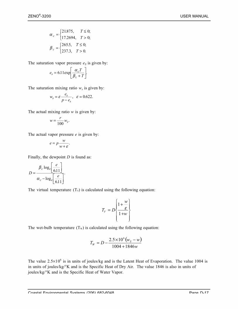
ZENO®-3200 USER MANUAL
Coastal Environmental Systems (206) 682-6048 Page D-17
α
β
c
c
T
T
T
T
=≤>
⎧⎨⎩
=≤>
⎧⎨⎩
21875 0
17 2694 0
2655 0
237 3 0
. , ;
. , ;
. , ;
. , .
The saturation vapor pressure eS is given by:
eTTs
c
c=
+⎡
⎣⎢
⎤
⎦⎥611. exp .
αβ
The saturation mixing ratio ws is given by:
wep ess
s=
−=ε ε, . .0 622
The actual mixing ratio w is given by:
wrws=
100.
The actual vapor pressure e is given by:
e pww
=+ ε.
Finally, the dewpoint D is found as:
D
e
e
c e
c e
=
⎡⎣⎢
⎤⎦⎥
− ⎡⎣⎢
⎤⎦⎥
β
α
log.
log.
.611
611
The virtual temperature (TV) is calculated using the following equation:
The wet-bulb temperature (TW) is calculated using the following equation:
The value 2.5×10⁶ is in units of joules/kg and is the Latent Heat of Evaporation. The value 1004 isin units of joules/kg/°K and is the Specific Heat of Dry Air. The value 1846 is also in units ofjoules/kg/°K and is the Specific Heat of Water Vapor.
⎪⎪⎭
⎪⎪⎬
⎫
⎪⎪⎩
⎪⎪⎨
⎧
+
+=
w
w
DTV 1
1ε
( )w
wwDT S
W 18461004
105.2 6
+−×
−=
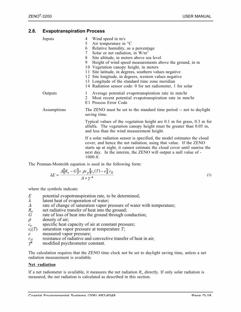
ZENO®-3200 USER MANUAL
Coastal Environmental Systems (206) 682-6048 Page D-18
2.8. Evapotranspiration Process
Inputs 4 Wind speed in m/s5 Air temperature in °C6 Relative humidity, as a percentage7 Solar or net radiation, in W/m2
8 Site altitude, in meters above sea level9 Height of wind speed measurements above the ground, in m10 Vegetation canopy height, in meters11 Site latitude, in degrees, southern values negative12 Site longitude, in degrees, western values negative13 Longitude of the standard time zone meridian14 Radiation sensor code: 0 for net radiometer, 1 for solar
Outputs 1 Average potential evapotranspiration rate in mm/hr2 Most recent potential evapotranspiration rate in mm/hrE1 Process Error Code
Assumptions The ZENO must be set to the standard time period -- not to daylightsaving time.
Typical values of the vegetation height are 0.1 m for grass, 0.3 m foralfalfa. The vegetation canopy height must be greater than 0.05 m,and less than the wind measurement height.
If a solar radiation sensor is specified, the model estimates the cloudcover, and hence the net radiation, using that value. If the ZENOstarts up at night, it cannot estimate the cloud cover until sunrise thenext day. In the interim, the ZENO will output a null value of -1000.0.
The Penman-Monteith equation is used in the following form:
[ ] ( )[ ]λ
ργ
ER G c e T e rn p s H
=− + −
+Δ
Δ *(1)
where the symbols indicate:
E potential evapotranspiration rate, to be determined;λ latent heat of evaporation of water;Δ rate of change of saturation vapor pressure of water with temperature;Rn net radiative transfer of heat into the ground;G rate of loss of heat into the ground through conduction;ρ density of air;cp specific heat capacity of air at constant pressure;es(T) saturation vapor pressure at temperature T;e measured vapor pressure;rH resistance of radiative and convective transfer of heat in air;γ* modified psychrometer constant.
The calculation requires that the ZENO time clock not be set to daylight saving time, unless a netradiation measurement is available.
Net radiation
If a net radiometer is available, it measures the net radiation Rn directly. If only solar radiation ismeasured, the net radiation is calculated as described in this section.
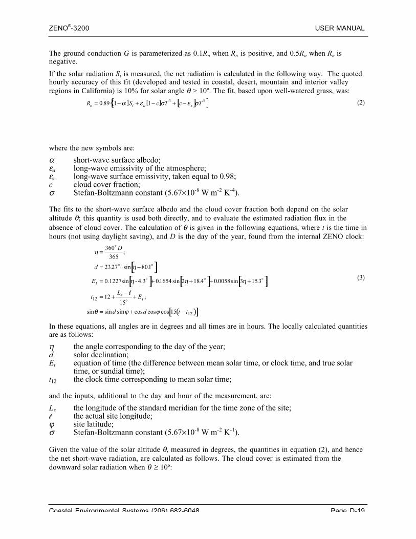
ZENO®-3200 USER MANUAL
Coastal Environmental Systems (206) 682-6048 Page D-19
The ground conduction G is parameterized as 0.1Rn when Rn is positive, and 0.5Rn when Rn isnegative.
If the solar radiation St is measured, the net radiation is calculated in the following way. The quotedhourly accuracy of this fit (developed and tested in coastal, desert, mountain and interior valleyregions in California) is 10% for solar angle θ > 10º. The fit, based upon well-watered grass, was:
[ ] [ ] [ ]{ }R S c T c Tn t a s= − + − + −0 89 1 1 4 4. α ε σ ε σ (2)
where the new symbols are:
α short-wave surface albedo;εa long-wave emissivity of the atmosphere;εs long-wave surface emissivity, taken equal to 0.98;c cloud cover fraction;σ Stefan-Boltzmann constant (5.67×10⁻⁸ W m-2 K-4).
The fits to the short-wave surface albedo and the cloud cover fraction both depend on the solaraltitude θ; this quantity is used both directly, and to evaluate the estimated radiation flux in theabsence of cloud cover. The calculation of θ is given in the following equations, where t is the time inhours (not using daylight saving), and D is the day of the year, found from the internal ZENO clock:
[ ][ ] [ ] [ ]
( )[ ]
η
η
η η η
θ ϕ ϕ
=
= ⋅ −
= + + + +
= +−
+
= + −
360
365
2327 801
01654 2 18 4 0 0058 3 153
1215
15
12
12
D
d
E
tL
E
d d t t
t
st
;
. sin . ;
. sin . . sin . ;
;
sin sin sin cos cos cos .
0.1227sin - 4.3
l
(3)
In these equations, all angles are in degrees and all times are in hours. The locally calculated quantitiesare as follows:
η the angle corresponding to the day of the year;d solar declination;Et equation of time (the difference between mean solar time, or clock time, and true solar
time, or sundial time);t12 the clock time corresponding to mean solar time;
and the inputs, additional to the day and hour of the measurement, are:
Ls the longitude of the standard meridian for the time zone of the site;l the actual site longitude;ϕ site latitude;σ Stefan-Boltzmann constant (5.67×10⁻⁸ W m-2 K-1).
Given the value of the solar altitude θ, measured in degrees, the quantities in equation (2), and hencethe net short-wave radiation, are calculated as follows. The cloud cover is estimated from thedownward solar radiation when θ ≥ 10º:
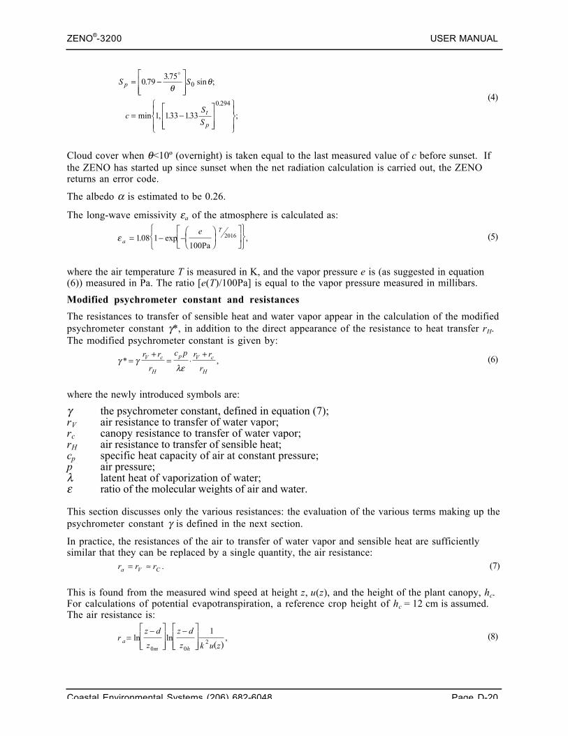
ZENO®-3200 USER MANUAL
Coastal Environmental Systems (206) 682-6048 Page D-20
S S
cS
S
p
t
p
= −⎡
⎣⎢⎢
⎤
⎦⎥⎥
= −⎡
⎣⎢⎢
⎤
⎦⎥⎥
⎧⎨⎪
⎩⎪
⎫⎬⎪
⎭⎪
0 79375
1 133 133
0
0 294
..
sin ;
min , . .
.
θθ
;
(4)
Cloud cover when θ<10º (overnight) is taken equal to the last measured value of c before sunset. Ifthe ZENO has started up since sunset when the net radiation calculation is carried out, the ZENOreturns an error code.
The albedo α is estimated to be 0.26.
The long-wave emissivity εa of the atmosphere is calculated as:
ε aTe
= − −⎛⎝⎜
⎞⎠⎟
⎡
⎣⎢
⎤
⎦⎥
⎧⎨⎩
⎫⎬⎭
108 1100Pa
2016. exp , (5)
where the air temperature T is measured in K, and the vapor pressure e is (as suggested in equation(6)) measured in Pa. The ratio [e(T)/100Pa] is equal to the vapor pressure measured in millibars.
Modified psychrometer constant and resistances
The resistances to transfer of sensible heat and water vapor appear in the calculation of the modifiedpsychrometer constant γ*, in addition to the direct appearance of the resistance to heat transfer rH.The modified psychrometer constant is given by:
γ γλε
* ,=+
= ⋅+r r
r
c p r r
rV c
H
p V c
H
(6)
where the newly introduced symbols are:
γ the psychrometer constant, defined in equation (7);rV air resistance to transfer of water vapor;rc canopy resistance to transfer of water vapor;rH air resistance to transfer of sensible heat;cp specific heat capacity of air at constant pressure;p air pressure;λ latent heat of vaporization of water;ε ratio of the molecular weights of air and water.
This section discusses only the various resistances: the evaluation of the various terms making up thepsychrometer constant γ is defined in the next section.
In practice, the resistances of the air to transfer of water vapor and sensible heat are sufficientlysimilar that they can be replaced by a single quantity, the air resistance:
r r ra V C= ≈ . (7)
This is found from the measured wind speed at height z, u(z), and the height of the plant canopy, hc.For calculations of potential evapotranspiration, a reference crop height of hc = 12 cm is assumed.The air resistance is:
( )r
z d
z
z d
z k u za
m h
=−⎡
⎣⎢⎢
⎤
⎦⎥⎥
−⎡
⎣⎢⎢
⎤
⎦⎥⎥
ln ln ,0 0
2
1 (8)
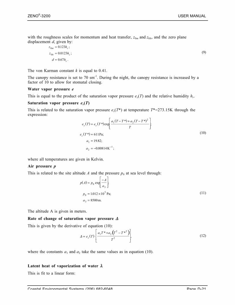
ZENO®-3200 USER MANUAL
Coastal Environmental Systems (206) 682-6048 Page D-21
with the roughness scales for momentum and heat transfer, z0m and z0h, and the zero planedisplacement d, given by:
z h
z h
d h
m c
h c
c
0
0
0123
0 0123
0 67
=
=
=
. ;
. ;
. .
(9)
The von Karman constant k is equal to 0.41.
The canopy resistance is set to 70 sm-1. During the night, the canopy resistance is increased by afactor of 10 to allow for stomatal closing.
Water vapor pressure e
This is equal to the product of the saturation vapor pressure es(T) and the relative humidity hr.
Saturation vapor pressure es(T)
This is related to the saturation vapor pressure es(T*) at temperature T*=273.15K through theexpression:
( ) ( )( ) ( )
( )
e T e Ta T T a T T
T
e T
a
a
s s
s
=− + −⎡
⎣⎢⎢
⎤
⎦⎥⎥
=
=
= − −
* exp* *
;
* Pa;
.
. K ;
1 22
1
21
611
19 82;
0 00814
(10)
where all temperatures are given in Kelvin.
Air pressure p
This is related to the site altitude A and the pressure p0 at sea level through:
( )p A pA
a
p
a
=−⎡
⎣⎢⎢
⎤
⎦⎥⎥
= ×
=
03
05
3
1012 10
8500
exp ;
. Pa;
m.
(11)
The altitude A is given in meters.
Rate of change of saturation vapor pressure Δ
This is given by the derivative of equation (10):
( )( )
Δ = ⋅+ −⎡
⎣
⎢⎢
⎤
⎦
⎥⎥e T
a T a T T
Ts
1 22 2
2
* *, (12)
where the constants a1 and a2 take the same values as in equation (10).
Latent heat of vaporization of water λ
This is fit to a linear form:
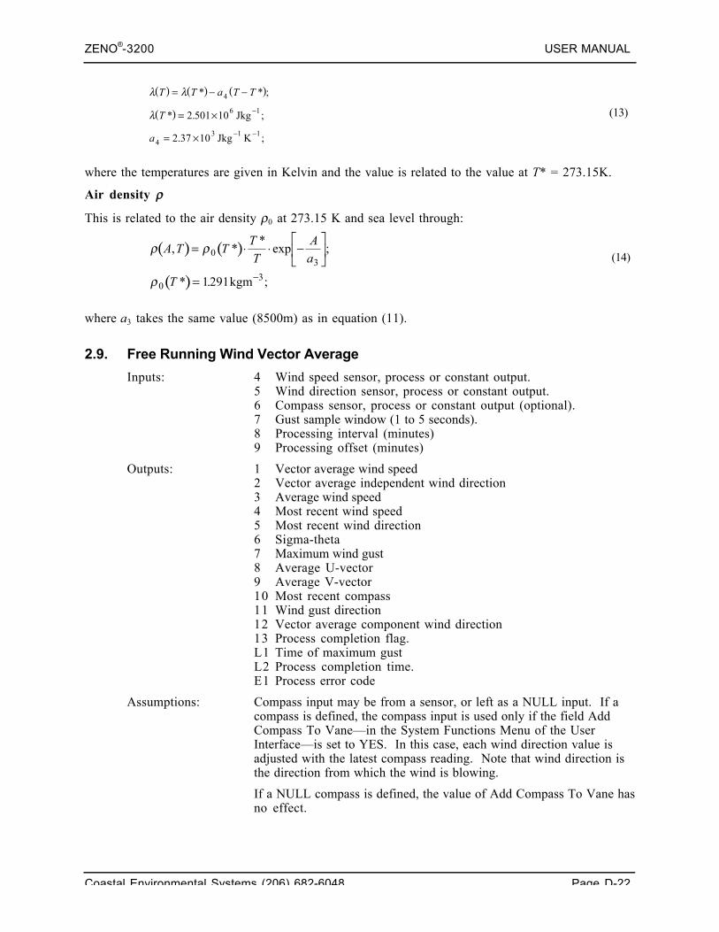
ZENO®-3200 USER MANUAL
Coastal Environmental Systems (206) 682-6048 Page D-22
( ) ( ) ( )
( )
λ λ
λ
T T a T T
T
a
= − −
= ×
= ×
−
− −
* * ;
* Jkg ;
Jkg K ;
4
6 1
43 1 1
2.501 10
2.37 10
(13)
where the temperatures are given in Kelvin and the value is related to the value at T* = 273.15K.
Air density ρ
This is related to the air density ρ0 at 273.15 K and sea level through:
( ) ( )
( )
ρ ρ
ρ
A T TTT
Aa
T
, **exp ;
* . kgm ;
= ⋅ ⋅ −⎡
⎣⎢
⎤
⎦⎥
= −
03
031291
(14)
where a3 takes the same value (8500m) as in equation (11).
2.9. Free Running Wind Vector Average
Inputs: 4 Wind speed sensor, process or constant output.5 Wind direction sensor, process or constant output.6 Compass sensor, process or constant output (optional).7 Gust sample window (1 to 5 seconds).8 Processing interval (minutes)9 Processing offset (minutes)
Outputs: 1 Vector average wind speed2 Vector average independent wind direction3 Average wind speed4 Most recent wind speed5 Most recent wind direction6 Sigma-theta7 Maximum wind gust8 Average U-vector9 Average V-vector10 Most recent compass11 Wind gust direction12 Vector average component wind direction13 Process completion flag.L1 Time of maximum gustL2 Process completion time.E1 Process error code
Assumptions: Compass input may be from a sensor, or left as a NULL input. If acompass is defined, the compass input is used only if the field AddCompass To Vane—in the System Functions Menu of the UserInterface—is set to YES. In this case, each wind direction value isadjusted with the latest compass reading. Note that wind direction isthe direction from which the wind is blowing.
If a NULL compass is defined, the value of Add Compass To Vane hasno effect.
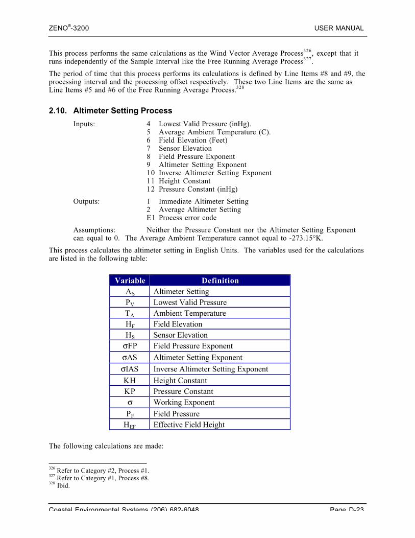
ZENO®-3200 USER MANUAL
Coastal Environmental Systems (206) 682-6048 Page D-23
This process performs the same calculations as the Wind Vector Average Process326, except that itruns independently of the Sample Interval like the Free Running Average Process327.
The period of time that this process performs its calculations is defined by Line Items #8 and #9, theprocessing interval and the processing offset respectively. These two Line Items are the same asLine Items #5 and #6 of the Free Running Average Process.328
2.10. Altimeter Setting Process
Inputs: 4 Lowest Valid Pressure (inHg).5 Average Ambient Temperature (C).6 Field Elevation (Feet)7 Sensor Elevation8 Field Pressure Exponent9 Altimeter Setting Exponent10 Inverse Altimeter Setting Exponent11 Height Constant12 Pressure Constant (inHg)
Outputs: 1 Immediate Altimeter Setting2 Average Altimeter SettingE1 Process error code
Assumptions: Neither the Pressure Constant nor the Altimeter Setting Exponentcan equal to 0. The Average Ambient Temperature cannot equal to -273.15°K.
This process calculates the altimeter setting in English Units. The variables used for the calculationsare listed in the following table:
Variable DefinitionAS Altimeter SettingPV Lowest Valid PressureTA Ambient TemperatureHF Field ElevationHS Sensor ElevationσFP Field Pressure Exponent
σAS Altimeter Setting Exponent
σIAS Inverse Altimeter Setting Exponent
KH Height ConstantKP Pressure Constantσ Working Exponent
PF Field PressureHEF Effective Field Height
The following calculations are made:
326 Refer to Category #2, Process #1.327 Refer to Category #1, Process #8.328 Ibid.
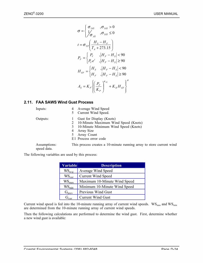
ZENO®-3200 USER MANUAL
Coastal Environmental Systems (206) 682-6048 Page D-24
σσ
σ
σσ
σσσ
⎪⎭
⎪⎬⎫
⎪⎩
⎪⎨⎧
+⎟⎟⎠
⎞⎜⎜⎝
⎛=
⎩⎨⎧
≥−<−
=
⎩⎨⎧
≥−<−
=
⎟⎟⎠
⎞⎜⎜⎝
⎛+−
=
⎪⎩
⎪⎨⎧
≤>
=
EFHP
FPS
SFF
SFSEF
SFt
V
SFVF
A
FSFP
IASAS
IASIAS
HKK
PKA
HHH
HHHH
HHeP
HHPP
T
HHt
AS
90,
90,
90,
90,
15.273
0,10,
2.11. FAA SAWS Wind Gust Process
Inputs: 4 Average Wind Speed5 Current Wind Speed.
Outputs: 1 Gust for Display (Knots)2 10-Minute Maximum Wind Speed (Knots)3 10-Minute Minimum Wind Speed (Knots)4 Array Size5 Array CountE1 Process error code
Assumptions: This process creates a 10-minute running array to store current windspeed data.
The following variables are used by this process:
Variable DescriptionWSavg Average Wind SpeedWScur Current Wind SpeedWSmax Maximum 10-Minute Wind SpeedWSmin Minimum 10-Minute Wind SpeedGprev Previous Wind GustGcur Current Wind Gust
Current wind speed is fed into the 10-minute running array of current wind speeds. WSmax and WSmin
are determined from the 10-minute running array of current wind speeds.
Then the following calculations are performed to determine the wind gust. First, determine whethera new wind gust is available:
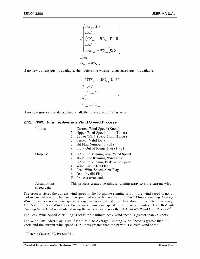
ZENO®-3200 USER MANUAL
Coastal Environmental Systems (206) 682-6048 Page D-25
( )
( )
max
max
minmax
5
10
9
WSG
then
WSWS
and
WSWS
and
WS
if
cur
avg
avg
=
⎟⎟⎟⎟⎟⎟⎟
⎠
⎞
⎜⎜⎜⎜⎜⎜⎜
⎝
⎛
≥−
≥−
≥
If no new current gust is available, then determine whether a sustained gust is available:
( )
max
max
0
3
WSG
then
G
and
WSWS
if
cur
prev
avg
=
⎟⎟⎟
⎠
⎞
⎜⎜⎜
⎝
⎛
>
≥−
If no new gust can be determined at all, then the current gust is zero.
2.12. NWS Running Average Wind Speed Process
Inputs: 4 Current Wind Speed (Knots)5 Upper Wind Speed Limit (Knots)6 Lower Wind Speed Limit (Knots)7 Percent Valid Data8 Bit Flag Number (1 - 31)9 Input Out of Range Flag (1 - 31)
Outputs: 1 2-Minute Running Avg. Wind Speed2 10-Minute Running Wind Gust3 2-Minute Running Peak Wind Speed4 Wind Gust Alert Flag5 Peak Wind Speed Alert Flag6 Data Invalid FlagE1 Process error code
Assumptions: This process creates 10-minute running array to store current windspeed data.
The process stores the current wind speed in the 10-minute running array if the wind speed is not abad sensor value and is between the specified upper & lower limits. The 2-Minute Running AverageWind Speed is a scalar wind speed average and is calculated from data stored in the 10-minute array.The 2-Minute Peak Wind Speed is the maximum wind speed for the past 2 minutes. The 10-MinuteRunning Wind Gust is calculated using the same algorithm as the FAA SAWS Wind Gust Process329.
The Peak Wind Speed Alert Flag is set if the 2-minute peak wind speed is greater than 25 knots.
The Wind Gust Alert Flag is set if the 2-Minute Average Running Wind Speed is greater than 20knots and the current wind speed is 15 knots greater than the previous current wind speed.
329 Refer to Category #2, Process #11.
ZENO®-3200 USER MANUAL
Coastal Environmental Systems (206) 682-6048 Page D-26
If the percent of data received by the process is bad and is less than the acceptable Percent GoodData, the Data Invalid Flag is set. If a BIT Flag Number is between 1 and 31, the specified bit willalso be set in the BIT.330
If the current wind speed is outside the specified upper & lower limits and the Input Out of RangeFlag is set to a value between 1 and 31, the specified bit will be set in the BIT.331
2.13. NWS Running Vector Average Wind Direction Process
Inputs: 4 Wind Direction5 Average Wind Speed (Knots)6 Minimum Wind Speed for Variability7 Minimum Wind Direction for Variability8 Percent Valid Data9 Bit Flag Number (1 - 31)
Outputs: 1 2-Minute Running Avg. Vector Wind Direction2 Variable Wind Direction Flag3 Wind Difference4 Data Invalid FlagE1 Process error code
Assumptions: This process creates 2-minute running array to store current winddirection data.
The 2-Minute Running Average Vector Wind Direction is calculated the same as in the RunningVector Average Wind Process332.
The Variable Wind Direction Flag is calculated in the following manner:
1. Two running averages are calculated--all the winds to the "left" and "right" of the current 2-Minute Running Average Vector Wind Direction are averaged.
2. The Wind Difference is the difference between the "left" and "right" wind direction averages.
3. If the Wind Difference is greater than the Minimum Wind Direction for Variability and theCurrent Average Wind Speed is greater than the Minimum Wind Speed for Variability, then theVariable Wind Direction Flag is set to one. Otherwise, it is set to zero.
2.14. FAA Running Wind Average Process
Inputs: 4 Wind Speed5 Wind Direction6 Switch Closure7 Percent Valid Data
Outputs: 1 Running Average Scalar Wind Speed2 Running Average Vector Independent Wind Direction3 Data Invalid Flag4 Data Index 15 Data Index 26 Data Index 37 Data Index 4E1 Process error code
330 Viewable from the BIT Process, refer to Category #3, Process #1.331 Ibid.332 Refer to Category #2, Process #2.
ZENO®-3200 USER MANUAL
Coastal Environmental Systems (206) 682-6048 Page D-27
Assumptions: This process creates 2-minute running array to store current winddirection data.
This process calculates four separate running wind averages simultaneously. Depending upon thevalue of the third input (Switch Closure), one of the four running wind averages is supplied:
SwitchClosure
Outputted Running WindAverage (Seconds)
0 151 302 603 120
The calculation of the running wind average data is similar to the Running Wind Vector AverageProcess333. However, only the running average scalar wind speed and no other values are calculatedother than running average independent wind direction.
3. ALARM PROCESSES CATEGORY
Many of the alarm processes have both process outputs (a status value of 1 or 0) and digital outputs(high or low). The precise timing of when these outputs are set high (1) or low (0) differs slightly.
Except where otherwise stated, digital outputs are set high or low immediately as the process inputsenter or leave the alarm state; and only when the process inputs enter or leave the alarm state.Thus, if the alarm reset process (or any other process) is used to set a high digital output to the lowstate, it will not go high again until the alarm state is left and re-entered.
The numerical process output (0 or 1) is set to 1 the first time that the process is called with theinputs in the alarm state. The process output remains at 1 until the end of the sample interval time.This means that if the alarm is set and the re-set within a sample interval time, the process outputwill be 0 until the alarm is first set; 1 from that point until the end of the sample interval; and 0 fromthe start of the next sample interval. The reason for this is that the output message will alwaysnotify the user that an alarm has occurred within the sample interval.
3.1. Built-In-Test (BIT) Process
Inputs none
Outputs L1 32-bit value of theE1 Process Error Code
Various internal system functions or user-defined processes are used to set individual bits in the globalBIT value. Up to 31 bits can be assigned in the global BIT value (the 32nd bit is used internally bythe ZENO®-3200, and is not accessible to the user). The process clears the global BIT value after ithas been read at the end of the Sample Duration.
The following list of bit flags are pre-assigned for system wide operation
1 System reset.2 Real-time clock suspect.3 Data logging memory initialized.4 Serial device communication failure.5 EEPROM suspect. 333 Refer to Category #2, Process #1.
ZENO®-3200 USER MANUAL
Coastal Environmental Systems (206) 682-6048 Page D-28
6 18-bit analog to digital converter suspect.7 12-bit analog to digital converter suspect.8 Clock adjustment made due to temperature compensation.
These flags may be OR-ed with other warnings, and flags 8 to 31 set, by user processes Data Range,Alarm and Data Time-out.
3.2. Data Range Process
Inputs 4 Any sensor or process output5 Upper limit (User Value)6 Lower limit (User Value)7 User parameter BIT bit number (1 to 31, 0 = disabled)8 Valid Range (0 = between, 1 = beyond)9 Limits (0 = inclusive, 1 = exclusive)
Outputs 1 Status0 data in range1 data outside the specified range.
E1 Process Error Code
Also sets a bit flag in the global BIT value.
Assumptions none
This process reads the input data from referenced by Line Item #4 and compares it to the rangelimits as specified in Line Items #5, #6, #8 and #9. This is summarized in the following table:
Valid Range
(Line Item #8)
Limits
(Line Item #9)Action Performed by Process
0 = inclusive If the input data is between the Upper Limit and Lower Limit or equal toeither limit, the data is valid; otherwise, it's invalid.
0 = between1 = exclusive If the input data is between the Upper Limit and Lower Limit but not
equal to either limit, the data is valid; otherwise, it's invalid.
0 = inclusive If the input data is greater than the Upper Limit or less than the LowerLimit or equal to either limit, the data is valid; otherwise, it's invalid.
1 = beyond 1 = exclusive If the input data is greater than the Upper Limit or less than the LowerLimit and not equal to either limit, the data is valid; otherwise, it'sinvalid.
If the data is valid, the data output #1 is set to zero. If the data is invalid, the data output #1 is set toone and the bit flag as specified in Line Item #7 is set in the global BIT value if Line Item #7 isgreater than zero.
3.3. Alarm Process
Inputs 4 Any sensor or process output5 Alarm set-point6 Alarm Reset7 BIT bit number (1 to 31, 0 = disabled)8 Digital I/O port number (18 to 23)9 Second digital I/O port number (18 to 23)10 Switched Voltage
ZENO®-3200 USER MANUAL
Coastal Environmental Systems (206) 682-6048 Page D-29
Outputs 1 Status0 no alarm condition1 alarm condition
E1 Process Error Code
Sets a bit flag in the global BIT valueActivates a digital output (5 VDC) if there is an active alarm condition or a switched voltage.
Assumptions If the Alarm Reset value is less than the Alarm Set-point value thenthe alarm is activated when the data value becomes greater than theAlarm Set-point, and deactivated when it goes below the Alarm Reset.
If the Alarm Reset value is greater than the Alarm Set-point valuethen the alarm is activated when the data value drops below the AlarmSet-point, and deactivated when it returns above the Alarm Resetvalue.
This process reads the data input, compare it to the Alarm Set-point and Alarm Reset values, andactivates or deactivates the alarm status accordingly.
If the alarm is set, the corresponding bit in the global BIT value will be set.334 Any digital outputspecified by Line Items #8 or #9 will be set HIGH. Any switched voltage specified by Line Item #10will be turned on.
3.4. Data Time-out Process
Inputs 4 Any sensor or process output5 Time-out Interval (seconds)6 Minimum Delta Change7 BIT bit number (1 to 31, 0 = disabled)
Outputs 1 Status0 data has changed within the time interval1 data has not changed.
E1 Process Error Code
Assumptions none
The Data Time-out Process is an excellent tool to check for faulty sensors or malfunctioning systemcomponents because the process observes how much the input data changes over time:• The input data is read and compared to a baseline reading.• If the difference between the two values is greater than the Minimum Delta Change value, then a
new baseline level is established as the current data reading, and the time elapsed counter is reset.• Otherwise, if the difference is less than the Minimum Delta Change, then the time elapsed
counter is compared to the Time-out Interval. If the time elapsed is greater than the Time-outInterval then the output status is set to 1 and a bit flag may be set in the global BIT value335.
This process is similar to the Static Alarm Process.336
3.5. Alarm Reset Process
Inputs 4 Digital I/O port number (18 to 23)5 Second digital I/O port number (18 to 23)
334 Refer to Category #3, Process #1.335 Refer to Category #3, Process #1.336 Refer to Category #3, Process #15.
ZENO®-3200 USER MANUAL
Coastal Environmental Systems (206) 682-6048 Page D-30
Outputs E1 Process Error Code
Assumptions A reset button provides a switch closure input to channel 24, theIRQ4 channel. This cannot coexist with a tipping bucket sensorwhich requires the same input channel.
This process is used to acknowledge (set to low) an alarm set by either the Alarm Process337 or theTwo-Range Alarm processes338. An alarm can be acknowledged at any time, independent of theSample Interval. Once acknowledged, the alarm will not be re-enabled until a new alarm conditionexists.
3.6. Two-Range Alarm Process
Inputs 4 Any sensor or process output representing a high/low threshold5 Any sensor or process output upon which the alarm is triggered6 Two-Range Alarm Constants Process Record Number7 BIT bit number (1 to 31, 0=disabled)9 Digital I/O port number (18 to 23)10 Digital I/O port number (18 to 23)
Outputs 1 Status0 no alarm condition1 alarm condition
E1 Process Error Code
Sets a bit flag in the global BIT valueActivates a digital output (5 VDC) if there is an active alarm condition.
Assumptions The process number specified as input number 4 must be of the typeTwo-Range Alarm Constants.
This process is described in more detail under the Two-Range Alarm Constants Process.339
3.7. Two-Range Alarm Constants Process
Inputs 4 Threshold select decision point5 First upper limit6 First lower limit7 Second upper limit8 Second lower limit
Outputs E1 Process Error Code
This process, in conjunction with a Two-Range Alarm Process340, is used to set a alarm in caseswhere there are two distinct alarm thresholds.
The Two-Range Alarm Process and the Two-Range Alarms Constants process are separated to allowmore than one Two-Range Alarm Process to access the same constants.
Line Item #4 of this process defines the threshold that selects which set of limits to use: the first setupper & lower limits or the second set of upper & lower limits. The following table summarizes howthe constants defined in this process apply to a Two-Range Alarm Process341.
337 Refer to Category #3, Process #3.338 Refer to Category #3, Process #6.339 Refer to Category #3, Process #7.340 Refer to Category #3, Process #6.341 Ibid.
ZENO®-3200 USER MANUAL
Coastal Environmental Systems (206) 682-6048 Page D-31
Value Referenced in Line Item #4 of Two-Range Alarm
Value Referenced in Line Item #5 of Two-Range AlarmProcess
Below the Threshold defined in Line Item #4of the Two-Range Alarm Constants Process
Compared to first set of limits (Line Items #5 and #6) of theTwo-Range Alarm Constants Process
Above the Threshold defined in Line Item #4of the Two-Range Alarm Constants Process
Compared to second set of limits (Line Items #7 and #8) ofthe Two-Range Alarm Constants Process
If the value referenced by Line Item #5 of the Two-Range Alarm Process342 goes beyond the selectedlimits, then the alarm condition will be set in the Two-Range Alarm Process.
Consider the example in which a system used to monitor wind loading on power lines. Damage to thepower lines may be caused by high wind speeds, as well as relatively low wind speeds if thetemperature is below freezing and the power lines are covered in ice. In this example, the ZENO®-3200 would be configured as follows:• A temperature sensor would be defined as the input for Line Item #4 of the Two-Range Alarm
Process.• The threshold select decision point, the Line Item #4 of the Two-Level Alarm Constants
Process, would be set to 32ºF.• A wind speed sensor would be defined as the input for Line Item #5 of the Two-Range Alarm
Process.• The First Upper Limit, Line Item #5 of the Two-Level Alarm Constants Process, would define
the maximum allowable wind speed for below-freezing temperatures.• The First Lower Limit, Line Item #6 of the Two-Level Alarm Constants Process, would be set to
a negative number since no wind would not cause a problem.• The Second Upper Limit, Line Item #7 of the Two-Level Alarm Constants Process, would define
the maximum allowable wind speed for above-freezing temperatures.• The Second Lower Limit, Line Item #8 of the Two-Level Alarm Constants Process, would be set
to a negative number since low winds would not cause a problem with above-freezingtemperatures.
3.8. Missing Sensor Data Process
Inputs 4 Sensor process from an SDI-12 sensor5 Default data value6 Digital I/O port number (18 to 23)
Outputs 1 Status0 no alarm condition1 alarm condition
2 Sensor data valueE1 Process Error Code
Assumptions Input number 1 is from an SDI-12 sensor
Activates a digital output (5 VDC) if there is an active alarmcondition.
When the ZENO®-3200 is unable to collect data from a Sensor Record, the all data outputs for thatSensor Record are set to Bad Sensor Values (BSV's)343. For floating point values, the BSV is thenumber -1,000,000.
The Missing Sensor Data Process allows the setting of an alarm condition when the inputted datavalue is set a BSV and allows replacement of a BSV with a substitute value. The first data output 342 Ibid.343 Refer to Section 10.4.5.
ZENO®-3200 USER MANUAL
Coastal Environmental Systems (206) 682-6048 Page D-32
from this process is the alarm condition, which is set to one if the inputted data value is a BSV;otherwise, it is set to zero. The second data output is the inputted data value (Line Item #4) when itis NOT a BSV; otherwise, it is the substitute, default value specified by Line Item #5.
3.9. Multiple Alarm Process
Inputs 4-11 Data inputs, preferably from other alarm processes (D)12 Number of input alarms required for output alarm (U)13 Digital I/O port number, 18 to 23 (U)14 Digital I/O port number, 18 to 23 (U)15 Output Message Number, 1 to 4 (U)16 Log Alarm Message, 0 = no or 1 = yes (U)
Outputs 1 Status0 no alarm condition1 alarm condition
E1 Process Error Code
Assumptions Input numbers 1 through 8 are alarm inputs
Activates a digital output (5 VDC), and initiates modem dial-out, oncertain combinations of alarm conditions (see below).
The Multiple Alarm Process allows the user to define an alarm condition that is the result of acombination of conditions. Up to eight individual input values can be referenced by Line Items #4through #11. Each of the input values is interpreted in a Boolean fashion: 1) no condition exists ifthe input value is zero or 2) the condition does exist when the input value is non-zero. Line Item#12 defines how many (N) existing conditions from Line Items #4 through #11 constitute an alarmcondition.
Here is an example of four separate conditions:• Let Line Item #4 reference an alarm process triggered when the temperature goes below freezing.• Let Line Item #5 reference an alarm process triggered when the wind speed exceeds 25 knots.• Let Line Item #6 reference an alarm process triggered when the air temperature drops below the
dewpoint.• Let Line Item #7 reference an alarm process triggered when the barometric pressure drops below
30 inches of mercury.
To continue the example, an alarm condition does not need to be reported when only one or two ofthe listed conditions exists; but an alarm condition does need to be reported if at least threeconditions exist simultaneously. Therefore, Line Item #12 would be set to 3 and the Multiple AlarmProcess will be triggered when at least three of the four conditions is present.
When the Multiple Alarm Process determines that an alarm condition exists, data output #1 will beset to one; otherwise, it is set to zero.
The digital outputs, switched voltage and logging an alarm message344 are set slightly differently fromdata output #1. If less than N of the input values is non-zero, then the digital outputs (if defined) andswitched voltage (if defined) are set low. The first time that N or more input alarms are non-zero, ifdefined, the digital outputs and switched voltage are set high and an alarm message will be transmittedand/or logged. This is repeated if an input alarm is set to non-zero that was previously set to zeroand N or more of the input values are non-zero.
If this process instructs ZenoSoft™ to transmit an alarm message, it will follow the same procedurethat is used in the Dial-out Alarm Process.345
344 Refer to Section 11.3.345 Refer to Category #3, Process #10.
ZENO®-3200 USER MANUAL
Coastal Environmental Systems (206) 682-6048 Page D-33
3.10. Dial-out Alarm ProcessInputs 4 Data Input (D)
5 Alarm threshold (U)6 Message number, 0=disabled or 1-4 (U)7 Log Alarm Message, 0=no or 1=yes (U)
Outputs 1 Status0 no alarm condition1 alarm condition
E1 Process Error Code
Assumptions Initiates a modem dial-out when the input first exceeds its threshold(see below).
When the referenced input data value in Line Item #4 moves from below to above the definedthreshold level defined in Line Item #5, ZenoSoft™ will transmit the specified output messagedefined in Line Item #6. If no output message number is defined in Line Item #6, no output messagewill be transmitted. If Line Item #7 is set to 1 and an output message is defined in Line Item #6,ZenoSoft™ will also log the output message defined in Line Item #6.
If the output message number is specified on a communications port that is configured to connect toa modem, ZenoSoft™ will initiate a dial-out on the modem prior to transmitting the outputmessage.346 Hence the name, Dial-out Alarm Process.
If the output message number is specified on a communications port that is a direct terminalconnection, the ZenoSoft™ will transmit the message directly to the communications port with nodial-out.347
If the output message number is specified on a communications port that is connected to a GOEStransmitter, the output message will be sent to the GOES transmitter as a random message.348
3.11. Incremental Change Alarm Process
Inputs 4 Any sensor or process input5 Incremental change alarm threshold6 Decrease Baseline flag (0=no, 1=yes).
Outputs 1 Immediate alarm state (0=off, 1=on)2 Alarm occurred in this interval? (0=off, 1=on)3 Increment since last alarmE1 Process Error Code
Assumptions May be used for a weighed bucket rain sensor.
The Incremental Change Alarm Process triggers indicates an alarm condition when the inputted datavalue (xi), referenced in Line Item #4, changes by an amount that exceeds the change threshold value(dxthreshold) referenced in Line Item #5.
The process does this by initially storing the first data value (x0) as a baseline value (xbase) whenZenoSoft™ begins data collection. The difference (dx) between each successive new data value andthe baseline value is compared with the change threshold value:
346 Refer to Section 11.3.2.347 Refer to Section 11.3.348 Refer to Section 11.3.3.
⎩⎨⎧
≡≡
=
⎩⎨⎧
<≥
=
−=
0,
1,
,0
,1
alarmunchanged
alarmxx
dxdx
dxdxalarm
xxdx
ibase
threshold
threshold
basei
ZENO®-3200 USER MANUAL
Coastal Environmental Systems (206) 682-6048 Page D-34
The original baseline value is replaced by the current inputted value when an alarm is triggered.
Data output #1 will remain set to one only if successive inputted data values continue to exceed thenew baseline threshold difference. Data output #2 will remain set to one throughout the SampleInterval that the alarm was triggered. Data output #3 reports the difference dx.
If Line Item #6 is set to one and the current inputted value referenced by Line Item #4 is below thestored baseline value, ZenoSoft™ will set the baseline value to the current inputted value. If LineItem #6 is set to zero, this does not occur.
As an example, a weighed-bucket rain sensor can lose contents due to evaporation after a period ofrain. If Line Item #6 is set to one, the process will immediately detect new rainfall; otherwise,rainfall will only be detected if the after the weight of water exceeds the amount lost due toevaporation from the previous rain cycle.
3.12. Error Checking Alarm Process
Inputs: 4 BIT flag number (1 – 31)
Outputs: 1 Number of processes reporting errors2-6 First 4 process record numbers of processes reporting errors.L1-L4 First 4 process error codes of processes reporting errors.E1 Process error code.
Assumptions: None.
Called by ZenoSoft™ only at the end of the Sample Duration, the Error Checking Alarm Processchecks the status of each configured Process Record's error code (data output E1).349 It counts andreports the number of configured Process Records that indicate error codes and lists up to fourProcess Records that are reporting errors as well as their error codes.
The Error Checking Alarm Process is an excellent tool for discovering problems with data collectionand issues with timing.350 Often, this process is used only during the development of a complexconfiguration to work out errors within the configuration.
3.13. Timed Event Process
Inputs: 4 Digital output channel (0 or 18 – 23)5 Timed event on interval (xxx:xx:xx)6 Timed event on duration (xxx:xx:xx)7 Start of first event (xx/xx/xx xx:xx:xx)
Outputs: 1 Boolean state (0 = off, 1 = on)E1 Process error code.
Assumptions: Inputs 2 through 4 are entered and displayed as time values or as date& time, but are stored internally and in configuration files as secondsafter midnight, 1/1/1970.
The Timed Event Process is used to control the state of a data output and optional digital output ona regularly timed basis. It operates similarly to the digital output that is controlled from the DigitalControl Menu,351 but can be used to directly affect other Process Records by using its data output asan input to other Process Records.
349 Refer to Section 10.4.5.350 Refer to Section 12.1.351 Refer to Section 6.6.4.
ZENO®-3200 USER MANUAL
Coastal Environmental Systems (206) 682-6048 Page D-35
Line Items #5, #6, and #7 operate in essentially the same manner as Line Items #1, #2, and #3 ofthe Digital Control Menu.352 The beginning of the first Event-on Interval, defined by Line Item #5,is set by Line Item #7, the Start of the first event. The duration of the Event-on Interval is set byLine Item #6. During the Event-on Interval, data output #1 is set to one and the digital outputchannel specified in Line Item #4 will be turned on if one is specified. Otherwise, data output #1 isset to zero and the digital output channel is kept off if one is specified.
More than one Timed Event Process can be created in a single configuration and each one cancontrol a different digital output channel.
Coastal Environmental Systems does NOT recommendconfiguring more than one Process Record to control the same
digital output channel.
3.14. One-shot Daily Timed Event Process
Inputs: 4 When Timed Even Occurs (seconds after midnight)5 Timed event on duration (seconds)6 Digital Output Channel
Outputs: 1 Boolean state (0 = off, 1 = on)E1 Process error code.
Assumptions: Inputs 1 and 2 are entered as data inputs. Constants can be used.Their values are in seconds after midnight of the same day.
The One-shot Daily Timed Event Process is similar to the Timed Event Process353, except that it isdesigned to operate only once every 24 hours
Data output #1 will be set to one when the current time is past the start of the first event, as definedin Line Item #4, and will remain so for as long as specified by Line Item #5. Otherwise, the dateoutput is set to zero. The on-event only occurs only once in a 24-hour period as defined by theZENO®-3200's internal clock.
If the digital output channel, Line Item #6, is set to a value between 18 and 23, then the specifieddigital output channel will be set high when the output of the process is high. Otherwise, it will be setlow.
3.15. Static Alarm Process
Inputs: 4 Data5 Threshold6 Timeout for Threshold7 BIT Flag Number (1 - 31)
Outputs: 1 Immediate Alarm State (0 = off, 1 = on)2 Interval Alarm State (0 = off, 1 = on)3 Baseline Value4 Seconds Remaining Before TimeoutE1 Process error code.
The Static Alarm Process monitors the data referenced by Line Item #4. It verifies that the data ischanging by an amount greater than the threshold defined by Line Item #5 and within the time
352 Ibid.353 Refer to Category #3, Process #13.
ZENO®-3200 USER MANUAL
Coastal Environmental Systems (206) 682-6048 Page D-36
period as defined by Line Item #6. The alarm is set to one if the data input value does not change byan amount greater than the specified threshold and within the given time period.
This process operates similarly to the Data Time-out Process354, but it provides extra informationwith data outputs #2, #3 and #4.
4. SPECIAL SENSOR PROCESSES CATEGORY
4.1. NTC Thermistor Process
Inputs 4 Any sensor or process value (read below)5 A-coefficient for Steinhart-Hart equation.6 B-coefficient for Steinhart-Hart equation.7 C-coefficient for Steinhart-Hart equation.8 Resistance value for R2.9 Upper Limit10 Lower Limit11 BIT flag number (1 - 31)
Outputs 1 The average temperature value2 The most recent temperature valueE1 Process Error Code
Assumptions Sensor data is scaled to show a voltage ratio of V-measured divided byV-excitation. The linear scale factor in the sensor input (line item14) should be set equal to 1 / V-excitation.
The data value inputted into Line Item #4 must represent the voltage ratio produced by a voltagedivider circuit where R1 is a thermistor. The sensor scale coefficient should multiply the sensorreading by the inverse of the excitation value.
This process converts the non-linear sensor voltage ratio into a resistance value for the NTCthermistor and applies the Steinhart-Hart thermistor equation to the resistance value to derive atemperature value:
1 3
TA B R C R= + +ln (ln ) .
Coefficients A, B, C and R in the Steinhart-Hart thermistor equation correspond to Line Items #5through #8 respectively. Values for these coefficients for the YSI 44034 Thermistor are described inAppendix C.
The process further calculates an average temperate across the Sample Duration after applying theSteinhart-Hart thermistor equation. Data output #1 contains the average temperature as calculatedacross the Sample Duration. Data output #1 contains the immediate temperature for the most recentdata referenced by Line Item #4.
Line Items #9 through #11 are used in the event that a valid temperature range needs to be checkedwithout having to add an additional alarm process. If the average temperature calculated by thisprocess exceeds the upper and lower limits as specified in Line Items #9 and #10 respectively,ZenoSoft™ will set the bit in the Global BIT355 as specified in Line Item #11.
354 Refer to Category #3, Process #4.355 Refer to Category #3, Process #1.
ZENO®-3200 USER MANUAL
Coastal Environmental Systems (206) 682-6048 Page D-37
4.2. Paroscientific Barometer Process
Inputs 4 Temperature period in micro-seconds5 Pressure period in micro-seconds6 U0 (Paroscientific equation coefficients from calibration sheet)7 Y18 Y29 C110 C211 C312 D113 T 114 T 215 T 3
Outputs 1 Average pressure value in mbar2 Average temperature value in degrees Celsius3 Immediate pressure value (last value read)4 Immediate temperature value (last value read)E1 Process Error Code
Assumptions This process is intended for the Paroscientific barometer model216B-101.
This process takes the pressure (T) and temperature (U) period measurements, applies this data to theParoscientific third order logarithmic equation to derive the immediate temperature (Temp) andpressure (P) values. The coefficients listed in Line Items #6 through #15 are used as follows:
The average temperature and average pressure values are calculated from their respective immediatevalues across the Sample Duration.
4.3. Thermocouple Process
Inputs: 4 Thermocouple voltage from any sensor, process or constantoutput.
5 Thermocouple type code (0 = J, 1 = K, 2 = T).
Outputs: 1 Average temperature in ºC2 Most recent temperature in ºC.E1 Process error code.
Assumptions: The data inputted into Line Item #4 MUST BE in volts from athermocouple. The process converts the value in volts to a value inmicrovolts (_V).
21211
24
2
112213
4
1
112213
01
68.965517
1
1
UYUYTemp
CDTP
T
TUTUTT
DD
CUCUCC
UUU
+=
⋅=
⎟⎟⎠
⎞⎜⎜⎝
⎛ ++−=
−=++=
−=
ZENO®-3200 USER MANUAL
Coastal Environmental Systems (206) 682-6048 Page D-38
The Thermocouple Process converts the extremely nonlinear voltage supplied by a thermocoupleinto an equivalent temperature. The three most common types of thermocouples are supported bythis process: Type-J, Type-K, and Type-T.
To convert the nonlinear thermocouple voltage into temperature, a ninth-order polynomial is used:
The above polynomial approximation is only good over a limited range of voltages. Further, fordifferent voltage ranges, different values are used for the polynomial coefficients. The followingtable describes the valid range of voltages in microvolts. Different coefficients are used for thepolynomial equation for different voltage ranges.
ThermocoupleType
Lowest ValidVoltage (_V)
First MidrangeVoltage (_V)
Second MidrangeVoltage (_V)
Highest ValidVoltage (_V)
J -8095 0 42919 69553
K -5891 0 20644 54886
T -5603 0 N/A 20872
For any inputted voltage that is outside of the lowest and highestvalid voltage range, the Thermocouple Process will report the
immediate temperature as a BSV.356
The coefficients that are used in the polynomial equation for the thermocouple type and voltagerange are listed in the following table:
Coefficients
Typ
e
A9 A8 A7 A6 A5 A4 A3 A2 A1 A0
1 0 -8.3823321e-29
-2.3963370e-24
-2.8131513e-20
-1.7256713e-16
-5.9086933e-13
-1.0752178e-9 -1.2286185e-6 1.9528268e-2 0
2 0 0 5.099890e-31 -5.344285e-26 3.585153e-21 -2.549687e-16 1.036969e-11 -2.001204e-7 1.978425e-2 0J
3 0 0 0 0 4.73886084e-21
-1.43033468e-15
1.70276630e-10 -9.94773230e-6 0.3.00543684 -3113.58187
1 0 -5.1920577e-28
-1.0450598e-23
-8.6632643e-20
-3.7342377e-16
-8.9773540e-13
-1.0833638e-9 -1.1662878e-6 2.5173462e-2 0
2 -1.052755e-35 1.057734e-30 -4.413030e-26 9.804036e-22 -1.228034e-17 8.315270e-14 -2.503131e-10 7.860106e-8 2.508355e-2 0L
3 0 0 0 -3.110810e-26 8.802193e-21 -9.650715e-16 5.464731e-11 -1.646031e-6 4.830222e-2 -131.8058
1 0 0 1.2668171e-24 2.0241446e-20 1.3304473e-16 4.2527777e-13 7.9018692e-10 -2.1316967e-7 2.5949192e-2 0
T2 0 0 0 -7.293422e-25 6.048144e-20 -2.165394e-15 4.637791e-11 -7.602961e-7 2.592800e-2 0
All immediate temperatures calculated by this process are averaged to provide an averagetemperature across the Sample Duration. Any immediate temperature that is a BSV357 due to an out-of-range voltage is not included in the average calculations.
356 Refer to Section 10.4.5.357 Ibid.
012
23
34
45
56
67
78
89
9 aVaVaVaVaVaVaVaVaVaT +++++++++≈
ZENO®-3200 USER MANUAL
Coastal Environmental Systems (206) 682-6048 Page D-39
4.4. Raw GPS to Real Number Process
Inputs: 4 Latitude from GPS sensor (any sensor, process or constant input)5 Longitude from GPS sensor (any sensor, process or constant
input)
Outputs: 1 Latitude as a real number2 Longitude as real numberE1 Process error code.
Assumptions: It is assumed that the inputs to the process are taken directly fromthe latitude & longitude outputs from a GPS sensor.
This process converts raw GPS latitude and longitude data from a GPS sensor into real-number values.Both the raw latitudinal and longitudinal values from a GPS sensor have the format“DDDMM.mmmm” where “D” is degrees, “M” is minutes and “m” is decimal minutes.358
The outputs from this process are both of the form “DDD.dddd” where “D” is in degrees and “d” isdecimal degrees.
4.5. UV Biometer Process
Inputs: 4 UV biometer temperature in ºC (D).5 UV biometer radiation in MED/hr (D).
Outputs: 1 Average temperature corrected radiation in MED/hr2 Most recent temperature corrected radiation in MED/hr.E1 Process error code.
Assumptions: None.
This process calculates the temperature corrected radiation for an Ultraviolet (UV) Biometer usingthe following equation:
RC is the temperature corrected radiation, R is the inputted UV Biometer radiation and T is the UVBiometer temperature.
4.6. PIR Temperature Correction Process
Inputs: 4 Dome temperature in ºC (any sensor, process or constant output)5 Case temperature in ºC (any sensor, process or constant output)6 Thermopile output (any sensor, process or constant output)7 Thermopile surface emissivity8 Constant K
Outputs: 1 Average corrected PIR2 Most recent PIRE1 Process error code
Assumptions: None.
358 Refer to Section 10.3.4.
)25(01.01 −+=
TR
Rc
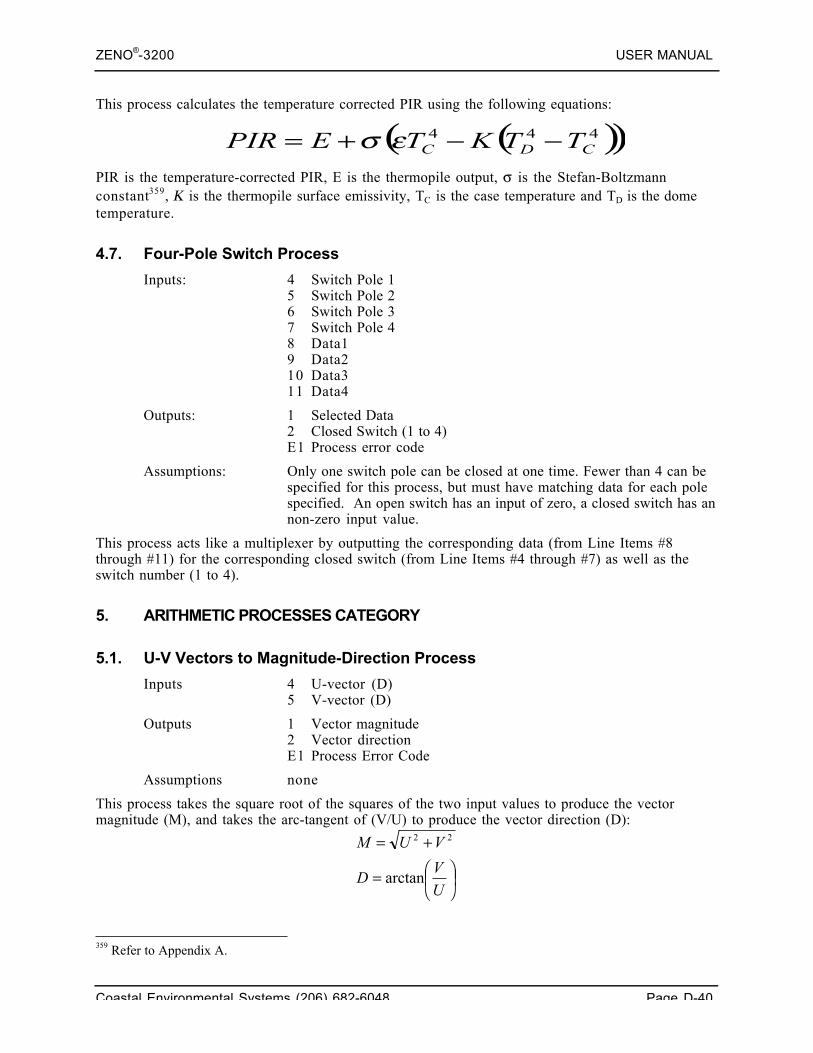
ZENO®-3200 USER MANUAL
Coastal Environmental Systems (206) 682-6048 Page D-40
This process calculates the temperature corrected PIR using the following equations:
PIR is the temperature-corrected PIR, E is the thermopile output, σ is the Stefan-Boltzmannconstant359, Κ is the thermopile surface emissivity, TC is the case temperature and TD is the dometemperature.
4.7. Four-Pole Switch Process
Inputs: 4 Switch Pole 15 Switch Pole 26 Switch Pole 37 Switch Pole 48 Data19 Data210 Data311 Data4
Outputs: 1 Selected Data2 Closed Switch (1 to 4)E1 Process error code
Assumptions: Only one switch pole can be closed at one time. Fewer than 4 can bespecified for this process, but must have matching data for each polespecified. An open switch has an input of zero, a closed switch has annon-zero input value.
This process acts like a multiplexer by outputting the corresponding data (from Line Items #8through #11) for the corresponding closed switch (from Line Items #4 through #7) as well as theswitch number (1 to 4).
5. ARITHMETIC PROCESSES CATEGORY
5.1. U-V Vectors to Magnitude-Direction Process
Inputs 4 U-vector (D)5 V-vector (D)
Outputs 1 Vector magnitude2 Vector directionE1 Process Error Code
Assumptions none
This process takes the square root of the squares of the two input values to produce the vectormagnitude (M), and takes the arc-tangent of (V/U) to produce the vector direction (D):
359 Refer to Appendix A.
( )( )444CDC TTKTEPIR −−+= εσ
⎟⎠⎞⎜
⎝⎛=
+=
UV
D
VUM
arctan
22
ZENO®-3200 USER MANUAL
Coastal Environmental Systems (206) 682-6048 Page D-41
5.2. Add Data & Constant Process
Inputs 4 Augend (D)5 Constant Addend (U)
Outputs 1 The sum of the augend and addendE1 Process Error Code
5.3. Add Two Data Values Process
Inputs 4 Augend (D)5 Addend (D)
Outputs 1 The sum of the augend and addendE1 Process Error Code
5.4. Subtract Data Values Process
Inputs 4 Minuend (Any sensor or process output)5 Subtrahend (Any sensor or process output)
Outputs 1 The difference between minuend and subtrahendE1 Process Error Code
5.5. Multiply Data & Constant Process
Inputs 4 Multiplicand (D)5 Constant Multiplier (U)
Outputs 1 The product of multiplying the multiplicand with the constant multiplier.
E1 Process Error Code
5.6. Multiply Two Data Values Process
Inputs 4 Multiplicand (D)5 Multiplier (D)
Outputs 1 The product of multiplying the multiplicand with the constant multiplier.
E1 Process Error Code
5.7. Divide Two Data Values Process
Inputs 4 Dividend (D)5 Divisor (D)
Outputs 1 The quotient of dividing the dividend by the divisor.E1 Process Error Code
5.8. Quadratic Process
Inputs 4 Data X (D)5 Quadratic coefficient A (U)6 Quadratic coefficient B (U)7 Quadratic coefficient C (U)
ZENO®-3200 USER MANUAL
Coastal Environmental Systems (206) 682-6048 Page D-42
Outputs 1 The result y calculated from quadratic equation y = Ax2 + Bx + C.E1 Process Error Code
5.9. Invert Data Value Process
Inputs 4 Data X (D)
Outputs 1 The result from inverting the input data value (1/X)
Assumptions If Data X is 0, the result will be set to a Bad Sensor Value.E1 Process Error Code
5.10. Raise Data To Power Process
Inputs 4 Data X (D)5 Constant Exponent Value Y (U)
Outputs 1 The results from raising the Data X to the exponential value, XY
E1 Process Error Code
5.11. Add Multiple Data Values Process
Inputs 4-11 Data1 through Data8 (All D)
Outputs 1 The numerical sum of all 8 inputsE1 Process Error Code
5.12. Sixth-order Polynomial Process
Inputs 4 Data X (D)5 Coefficient a6 (U)
6 Coefficient a5 (U)
7 Coefficient a4 (U)
8 Coefficient a3 (U)
9 Coefficient a2 (U)
10 Coefficient a1 (U)
11 Coefficient a0 (U)
Outputs 1 The value of the sixth-order polynomial applied to x.E1 Process Error Code
This process calculates the sixth-order polynomial a6x6 + a5x5 + a4x4 + a3x3 + a2x2 + a1x + a0.
5.13. Conditional Select Process
Inputs 4 Control Data C (D)5 Data X_Output if Control=0 (D)6 Data Y_Output if Control<0 (D)7 Data Z_Output if Control>0 (D)
Outputs 1 Data X if C=0, or Data Y if C<0; or Data Z if C>0.E1 Process Error Code
This process can be used as a logical IF statement. It allows you to choose between 2 or 3 calculateddata values. For example, if the control input is the temperature in ºC, you can use this process tocalculate a meteorological quantity differently for positive and negative inputs.
ZENO®-3200 USER MANUAL
Coastal Environmental Systems (206) 682-6048 Page D-43
5.14. Boolean Combine Data & Constant Process
Inputs: 4 Data (D).5 Constant (32-bit User Input in hexadecimal)
Outputs: L1 AND of both inputs.L2 OR of both inputs.L3 XOR of both inputs.L4 NAND of both inputsL5 NOR of both inputs.L6 XNOR of both inputs.E1 Process error code.
Assumptions: None.
5.15. Boolean Combine Data Process
Inputs: 4 Data1 (D).5 Data2 (D)
Outputs: L1 AND of both inputs.L2 OR of both inputs.L3 XOR of both inputs.L4 NAND of both inputsL5 NOR of both inputs.L6 XNOR of both inputs.E1 Process error code.
Assumptions: None.
5.16. Data Rounding Process
Inputs: 4 Data .5 Decimal Places6 Rounding Factor
Outputs: 1 Rounded DataE1 Process error code.
Assumptions: None.
The data is rounded to the specified number of decimal places and specified rounding factor. Arounding factor of 1 is standard rounding.
6. OUTPUT AND CONTROL PROCESSES CATEGORY
6.1. DAC Analog Output Process
Inputs 4 Any sensor or process output5 Maximum data limit, corresponding to 5 V output6 Minimum data limit, corresponding to 0 V output7 DAC number (1 - 36)8 DAC update code 0 - 1
0 Output voltage changes at the end of the sample period1 Output voltage changes whenever the input value changes
Outputs 1 Number of DAC counts
ZENO®-3200 USER MANUAL
Coastal Environmental Systems (206) 682-6048 Page D-44
E1 Process Error Code
Assumptions The optional Digital to Analog expansion board must be present.
The output voltage will be scaled so that the minimum and maximum data limits correspond to 0 and5 V respectively.
The minimum configuration is for four DACs on a single board. DACs 1 through 8 will be on thefirst expansion board, 9 - 16 on the second, and so on. If you program a DAC that is not present,you will be warned when you exit from the Zeno Program Menu or save the configuration toEEPROM. The following set of channels represents the maximum configuration:
• DAC channels 1 through 8 on board 1;• DAC channels 10 through 17 on board 2;• DAC channels 19 through 26 on board 3;• DAC channels 28 through 35 on board 4.
Channels 9, 18, 27 and 36 are reserved for the AC excitation, a separate option that must be factoryconfigured.
ZENO®-3200 USER MANUAL
Coastal Environmental Systems (206) 682-6048 Page E-1
E. CONFIGURATION FILECONTENTS
Coastal EnvironmentalSystems
ZENO®-3200 User Manual
1. CONFIGURATION FILE DEFINITION
The configuration file is a text-based file generated by the ZENO®-3200. It is designed to be readableby itself or by other ZENO®-3200's. It contains all of the information necessary to configure aZENO®-3200.
Each line of the configuration file begins with an Identifier (ID) code. The ID's are summarized inthe following table.
ID Description
* Remark.
PARAMn List of up to 10 run-time parameters beginning with parameter number "n *10".
CONSTANTn
List of up to 10 constants beginning with constant number "n * 10".
REPEATn List of up to 10 repeater remote addresses beginning with remote addressnumber "n * 10".
GSIA Command Line from a General Serial Script Record definition. These arelisted sequentially according to Command Line number and Script Recordnumber.
SENSOR A Sensor Record definition.
PROCESS A Process Record definition.
DATA A Data Output Record definition.
These are listed sequentially according toRecord Number. Order of valuescorresponds to their Line Item numberposition in the User Interface menus.
EOF End of file.
ZENO®-3200 USER MANUAL
Coastal Environmental Systems (206) 682-6048 Page E-2
In general, Coastal Environmental Systems does not recommendthat you edit any configuration file directly; but there may be
times when this is necessary.
2. CONTENTS OF RUN-TIME PARAMETER LINES
For interested users, the following is a brief line-by-line description of the run-time parameterscontained in the "PARAM" lines of a configuration file.
Coastal Environmental Systems strongly recommends notmodifying any run-time parameters that are italicized below
because they are not generally accessible and not intended to bechanged by the user.
• Lines beginning with an asterisk * are treated as comments. The only exception to this is thesecond line, containing the firmware version: this version number is read by the ZENO.
• The line beginning PARAM1 contains the following information:- Sample interval time, in seconds- Sample time offset, in seconds- Sample duration time, in seconds- Sensor timing loop #2 in half-seconds- Sensor timing loop #3 in half-seconds- Sensor timing loop #4 in half-seconds- Primary unit ID- Secondary unit ID- COM1 baud rate- COM2 baud rate
• The line beginning PARAM2 contains the following information:- COM3 baud rate- COM1 port type (0=RS232, 2=RADIO, 3=TWO-WAY RADIO, 5=RS232H)- COM2 port type (0=RS232, 1=RS485, 4=GOES, 5=RS232H)- COM3 port type (0=RS232, 1=RS485, 5=RS232H)- COM3 CCSAIL exclusive? (0=NO, 1=YES; generally set to 0)- Data dump format (1=space delimited, 2=comma delimited, 3=match real-time message)- Real time message format (0=none, 1=comma delimited ASCII, 2=fixed width ASCII)- Add compass to vane? (0=NO, 1=YES)- Compass offset in degrees- Barometer elevation in meters
• The line beginning PARAM3 contains the following information:- Clock processor speed (generally set to 16777)- System read/write parameter (generally set to 1)- ADC noise rejection frequency (50/60 Hz; jumper required to set this option)- ADC significant bits (18/13; jumper required to set this option)- Output message #1 period in half-seconds (e.g., 1s given as 2) (0 = after data sampling)- Output message #2 period in half-seconds (0 = not transmitted)- Output message #3 period in half-seconds (0 = not transmitted)- Output message #4 period in half-seconds (0=not transmitted)
ZENO®-3200 USER MANUAL
Coastal Environmental Systems (206) 682-6048 Page E-3
- Output message #1 COM port (0=COM1; 1=COM2; 2=COM3)- Output message #2 COM port
• The line beginning PARAM4 contains the following information:- Output message #3 COM port- Output message #4 COM port- Modem present? (0=NO, 1=YES)- ADC values output in volts or counts? (0=VOLTS, 1=COUNTS)- Time crystal calibration offset (generally 0)- Time crystal calibration base frequency- ADC quiet mode (generally 0)- Modem COM port (-1=NONE, 0, 1 or 2 for COM1, COM2 or COM3)- Modem retry period in seconds- Modem hang-up delay in seconds
• The line beginning PARAM5 contains the following information:- User interface on COM2/3 only? (0=NO, 1=YES)- Switched voltage code for radios on COM1- Not used- Not used- COM1 PTT setup time in ms- Switched voltage code for radios on COM2- Not used- Not used- Switched voltage code for radios on COM3- Not used
• The line beginning PARAM6 contains the following information:- Not used- Digital power on interval in seconds- Digital power on duration in seconds- Time of first power on -- seconds since 12:00:00AM, December 31, 1969- GOES DCP address (decimal representation of a hex address)- GOES self-timed channel number (decimal)- GOES self-timed transmission interval code- GOES self-timed transmission offset- GOES transmission window length in minutes- GOES preamble (0=SHORT; 1=LONG)
• The line beginning PARAM7 contains the following information:- GOES random transmission channel number- GOES random transmission interval- GOES random transmission active time- Control channel for digital power control- 12-bit ADC correction factor (×10,000)- Network Source Address (0 to 9998)- Alternate Source Address (0 to 9998)- Repeater transmit delay- ARGOS push-to-talk delay- ARGOS repeat count
• The line beginning PARAM8 contains the following information:- ARGOS repeat interval- ARGOS push-to-talk digital port- ARGOS timestamp flag- ARGOS checksum flag
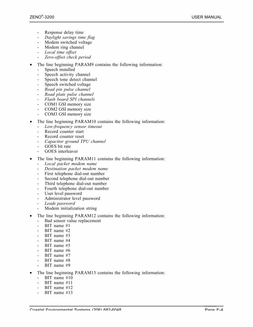
ZENO®-3200 USER MANUAL
Coastal Environmental Systems (206) 682-6048 Page E-4
- Response delay time- Daylight savings time flag- Modem switched voltage- Modem ring channel- Local time offset- Zero-offset check period
• The line beginning PARAM9 contains the following information:- Speech installed- Speech activity channel- Speech tone detect channel- Speech switched voltage- Road pin pulse channel- Road plate pulse channel- Flash board SPI channels- COM1 GSI memory size- COM2 GSI memory size- COM3 GSI memory size
• The line beginning PARAM10 contains the following information:- Low-frequency sensor timeout- Record counter start- Record counter reset- Capacitor ground TPU channel- GOES bit rate- GOES interleaver
• The line beginning PARAM11 contains the following information:- Local packet modem name- Destination packet modem name- First telephone dial-out number- Second telephone dial-out number- Third telephone dial-out number- Fourth telephone dial-out number- User level password- Administrator level password- Leads password- Modem initialization string
• The line beginning PARAM12 contains the following information:- Bad sensor value replacement- BIT name #1- BIT name #2- BIT name #3- BIT name #4- BIT name #5- BIT name #6- BIT name #7- BIT name #8- BIT name #9
• The line beginning PARAM13 contains the following information:- BIT name #10- BIT name #11- BIT name #12- BIT name #13
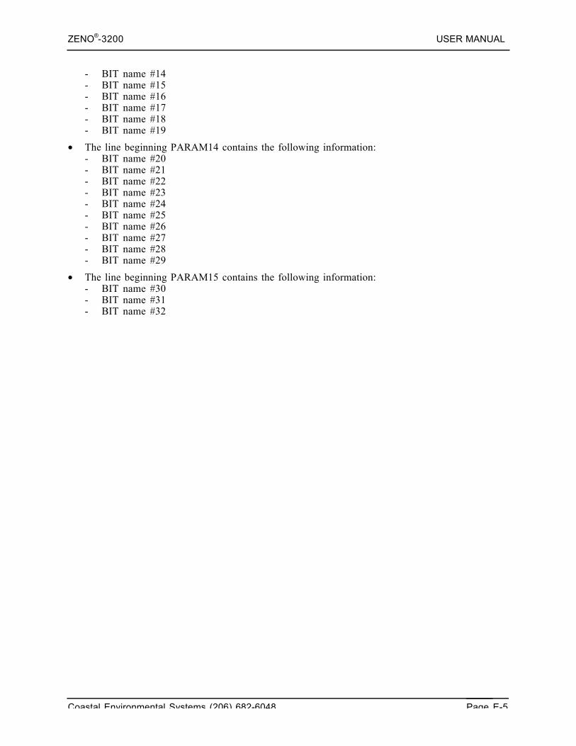
ZENO®-3200 USER MANUAL
Coastal Environmental Systems (206) 682-6048 Page E-5
- BIT name #14- BIT name #15- BIT name #16- BIT name #17- BIT name #18- BIT name #19
• The line beginning PARAM14 contains the following information:- BIT name #20- BIT name #21- BIT name #22- BIT name #23- BIT name #24- BIT name #25- BIT name #26- BIT name #27- BIT name #28- BIT name #29
• The line beginning PARAM15 contains the following information:- BIT name #30- BIT name #31- BIT name #32
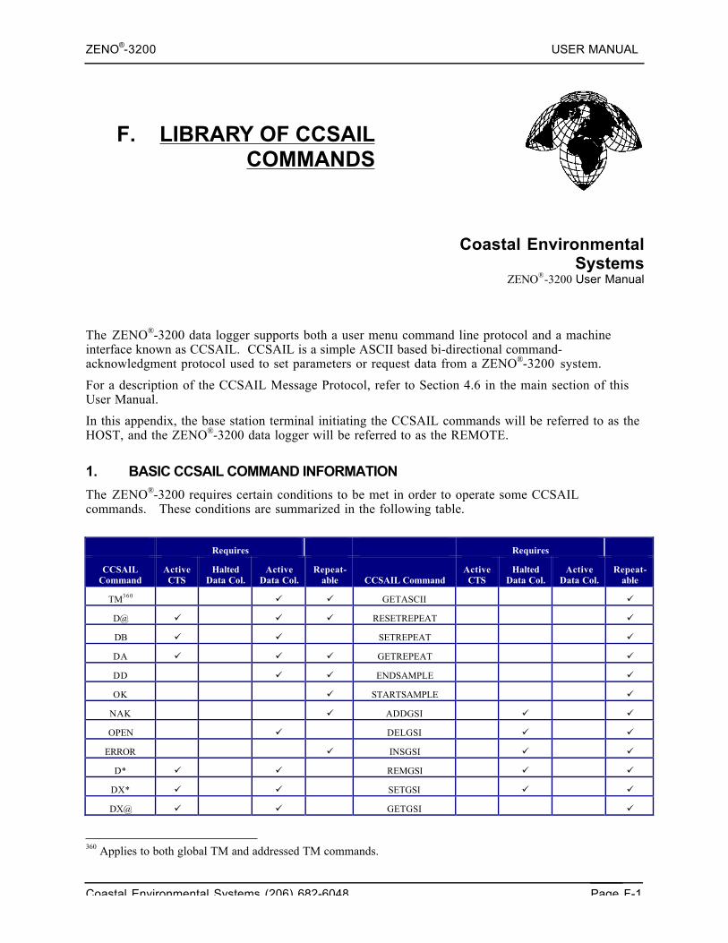
ZENO®-3200 USER MANUAL
Coastal Environmental Systems (206) 682-6048 Page F-1
F. LIBRARY OF CCSAILCOMMANDS
Coastal EnvironmentalSystems
ZENO®-3200 User Manual
The ZENO®-3200 data logger supports both a user menu command line protocol and a machineinterface known as CCSAIL. CCSAIL is a simple ASCII based bi-directional command-acknowledgment protocol used to set parameters or request data from a ZENO®-3200 system.
For a description of the CCSAIL Message Protocol, refer to Section 4.6 in the main section of thisUser Manual.
In this appendix, the base station terminal initiating the CCSAIL commands will be referred to as theHOST, and the ZENO®-3200 data logger will be referred to as the REMOTE.
1. BASIC CCSAIL COMMAND INFORMATION
The ZENO®-3200 requires certain conditions to be met in order to operate some CCSAILcommands. These conditions are summarized in the following table.
Requires Requires
CCSAILCommand
ActiveCTS
HaltedData Col.
ActiveData Col.
Repeat-able CCSAIL Command
ActiveCTS
HaltedData Col.
ActiveData Col.
Repeat-able
TM360 GETASCII
D@ RESETREPEAT
DB SETREPEAT
DA GETREPEAT
DD ENDSAMPLE
OK STARTSAMPLE
NAK ADDGSI
OPEN DELGSI
ERROR INSGSI
D* REMGSI
DX* SETGSI
DX@ GETGSI
360 Applies to both global TM and addressed TM commands.
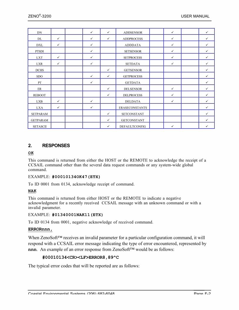
ZENO®-3200 USER MANUAL
Coastal Environmental Systems (206) 682-6048 Page F-2
DN ADDSENSOR
DL ADDPROCESS
DXL ADDDATA
PTSDI SETSENSOR
LXT SETPROCESS
LXR SETDATA
DCHS GETSENSOR
SDO GETPROCESS
PT GETDATA
ER DELSENSOR
REBOOT DELPROCESS
LXB DELDATA
LXA ERASECONSTANTS
SETPARAM SETCONSTANT
GETPARAM GETCONSTANT
SETASCII DEFAULTCONFIG
2. RESPONSES
OK
This command is returned from either the HOST or the REMOTE to acknowledge the receipt of aCCSAIL command other than the several data request commands or any system-wide globalcommand.
EXAMPLE: #00010134OK47(ETX)
To ID 0001 from 0134, acknowledge receipt of command.
NAK
This command is returned from either HOST or the REMOTE to indicate a negativeacknowledgment for a recently received CCSAIL message with an unknown command or with ainvalid parameter.
EXAMPLE: #01340001NAK11(ETX)
To ID 0134 from 0001, negative acknowledge of received command.
ERRORnnn,
When ZenoSoft™ receives an invalid parameter for a particular configuration command, it willrespond with a CCSAIL error message indicating the type of error encountered, represented bynnn. An example of an error response from ZenoSoft™ would be as follows:
#00010134<CR><LF>ERROR8,89^C
The typical error codes that will be reported are as follows:
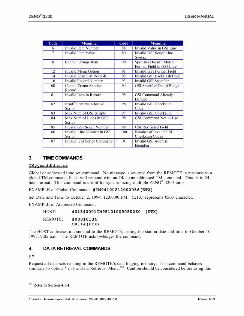
ZENO®-3200 USER MANUAL
Coastal Environmental Systems (206) 682-6048 Page F-3
Code Meaning Code Meaning6 Invalid Item Number 88 Invalid Value in GSI Line7 Invalid Item Value 89 Invalid GSI Script Line
Syntax8 Cannot Change Item 90 Specifier Doesn’t Match
Format Field in GSI Line12 Invalid Menu Option 91 Invalid GSI Format Field14 Invalid Scan List Records 92 Invalid GSI Backslash Code16 Invalid Record Number 93 Invalid GSI Specifier60 Cannot Create Another
Record94 GSI Specifier Out of Range
61 Invalid Item in Record 95 GSI Command AlreadyDefined
82 Insufficient Mem for GSIScript
96 Invalid GSI ChecksumCode
83 Max Num of GSI Scripts 97 Invalid GSI Checksum84 Max Num of Lines in GSI
Script98 GSI Command Not in Use
85 Invalid GSI Script Number 99 GSI Restricted Field86 Invalid Line Number in GSI
Script100 Number of Invalid GSI
Checksum Codes87 Invalid GSI Script Command 101 Invalid GSI Address
Identifier
3. TIME COMMANDS
TMyymmddhhmmss
Global or addressed time set command. No message is returned from the REMOTE in response to aglobal TM command, but it will respond with an OK to an addressed TM command. Time is in 24hour format. This command is useful for synchronizing multiple ZENO®-3200 units.
EXAMPLE of Global Command: #TM94100212000056(ETX)
Set Date and Time to October 2, 1994, 12:00:00 PM. (ETX) represents 0x03 character.
EXAMPLE of Addressed Command:
HOST: #01340001TM95101009050060 (ETX)
REMOTE: #00010134OK,14(ETX)
The HOST addresses a command to the REMOTE, setting the station date and time to October 10,1995, 9:05 a.m. The REMOTE acknowledges the command.
4. DATA RETRIEVAL COMMANDS
D*
Request all data sets residing in the REMOTE’s data logging memory. This command behavessimilarly to option * in the Data Retrieval Menu.361 Caution should be considered before using this
361 Refer to Section 4.1.4.
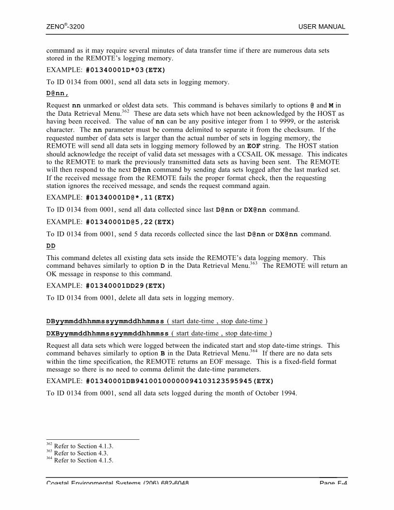
ZENO®-3200 USER MANUAL
Coastal Environmental Systems (206) 682-6048 Page F-4
command as it may require several minutes of data transfer time if there are numerous data setsstored in the REMOTE’s logging memory.
EXAMPLE: #01340001D*03(ETX)
To ID 0134 from 0001, send all data sets in logging memory.
D@nn,
Request nn unmarked or oldest data sets. This command is behaves similarly to options @ and M inthe Data Retrieval Menu.362 These are data sets which have not been acknowledged by the HOST ashaving been received. The value of nn can be any positive integer from 1 to 9999, or the asteriskcharacter. The nn parameter must be comma delimited to separate it from the checksum. If therequested number of data sets is larger than the actual number of sets in logging memory, theREMOTE will send all data sets in logging memory followed by an EOF string. The HOST stationshould acknowledge the receipt of valid data set messages with a CCSAIL OK message. This indicatesto the REMOTE to mark the previously transmitted data sets as having been sent. The REMOTEwill then respond to the next D@nn command by sending data sets logged after the last marked set.If the received message from the REMOTE fails the proper format check, then the requestingstation ignores the received message, and sends the request command again.
EXAMPLE: #01340001D@*,11(ETX)
To ID 0134 from 0001, send all data collected since last D@nn or DX@nn command.
EXAMPLE: #01340001D@5,22(ETX)
To ID 0134 from 0001, send 5 data records collected since the last D@nn or DX@nn command.
DD
This command deletes all existing data sets inside the REMOTE’s data logging memory. Thiscommand behaves similarly to option D in the Data Retrieval Menu.363 The REMOTE will return anOK message in response to this command.
EXAMPLE: #01340001DD29(ETX)
To ID 0134 from 0001, delete all data sets in logging memory.
DByymmddhhmmssyymmddhhmmss ( start date-time , stop date-time )
DXByymmddhhmmssyymmddhhmmss ( start date-time , stop date-time )
Request all data sets which were logged between the indicated start and stop date-time strings. Thiscommand behaves similarly to option B in the Data Retrieval Menu.364 If there are no data setswithin the time specification, the REMOTE returns an EOF message. This is a fixed-field formatmessage so there is no need to comma delimit the date-time parameters.
EXAMPLE: #01340001DB94100100000094103123595945(ETX)
To ID 0134 from 0001, send all data sets logged during the month of October 1994.
362 Refer to Section 4.1.3.363 Refer to Section 4.3.364 Refer to Section 4.1.5.
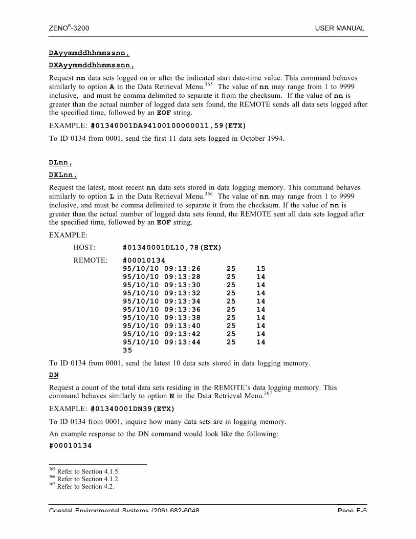
ZENO®-3200 USER MANUAL
Coastal Environmental Systems (206) 682-6048 Page F-5
DAyymmddhhmmssnn,
DXAyymmddhhmmssnn,
Request nn data sets logged on or after the indicated start date-time value. This command behavessimilarly to option A in the Data Retrieval Menu.365 The value of nn may range from 1 to 9999inclusive, and must be comma delimited to separate it from the checksum. If the value of nn isgreater than the actual number of logged data sets found, the REMOTE sends all data sets logged afterthe specified time, followed by an EOF string.
EXAMPLE: #01340001DA94100100000011,59(ETX)
To ID 0134 from 0001, send the first 11 data sets logged in October 1994.
DLnn,
DXLnn,
Request the latest, most recent nn data sets stored in data logging memory. This command behavessimilarly to option L in the Data Retrieval Menu.366 The value of nn may range from 1 to 9999inclusive, and must be comma delimited to separate it from the checksum. If the value of nn isgreater than the actual number of logged data sets found, the REMOTE sent all data sets logged afterthe specified time, followed by an EOF string.
EXAMPLE:
HOST: #01340001DL10,78(ETX)
REMOTE: #0001013495/10/10 09:13:26 25 1595/10/10 09:13:28 25 1495/10/10 09:13:30 25 1495/10/10 09:13:32 25 1495/10/10 09:13:34 25 1495/10/10 09:13:36 25 1495/10/10 09:13:38 25 1495/10/10 09:13:40 25 1495/10/10 09:13:42 25 1495/10/10 09:13:44 25 1435
To ID 0134 from 0001, send the latest 10 data sets stored in data logging memory.
DN
Request a count of the total data sets residing in the REMOTE’s data logging memory. Thiscommand behaves similarly to option N in the Data Retrieval Menu.367
EXAMPLE: #01340001DN39(ETX)
To ID 0134 from 0001, inquire how many data sets are in logging memory.
An example response to the DN command would look like the following:
#00010134
365 Refer to Section 4.1.5.366 Refer to Section 4.1.2.367 Refer to Section 4.2.
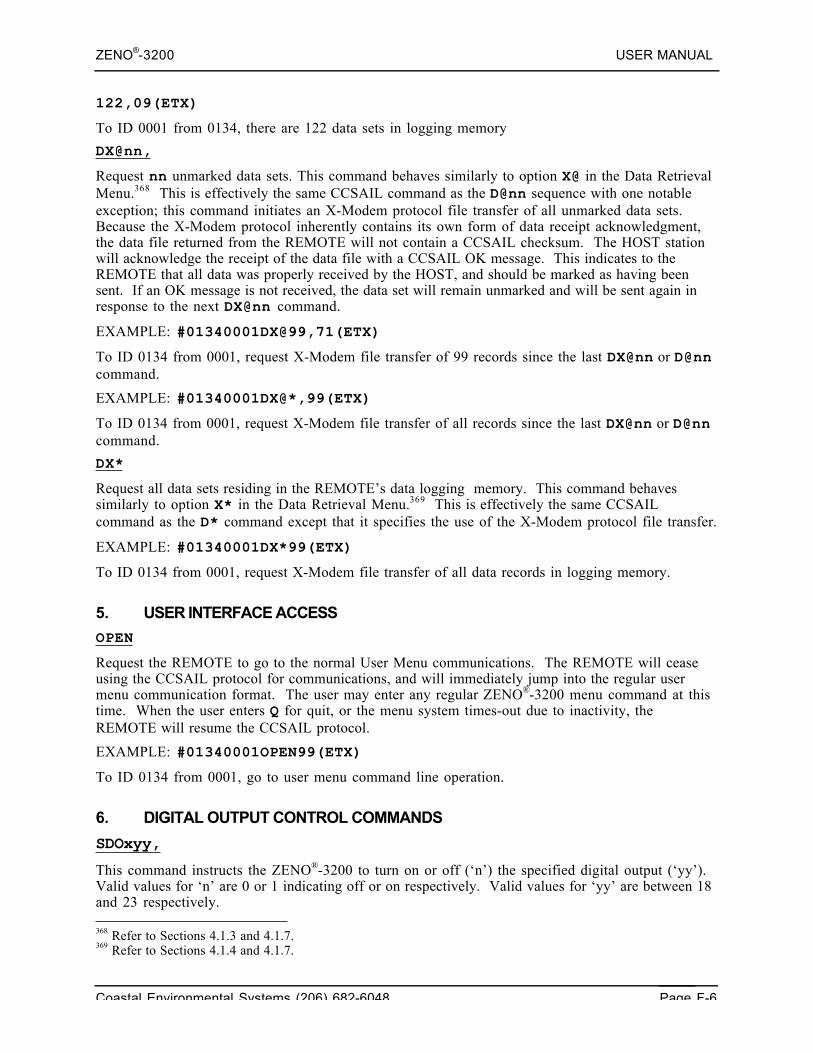
ZENO®-3200 USER MANUAL
Coastal Environmental Systems (206) 682-6048 Page F-6
122,09(ETX)
To ID 0001 from 0134, there are 122 data sets in logging memory
DX@nn,
Request nn unmarked data sets. This command behaves similarly to option X@ in the Data RetrievalMenu.368 This is effectively the same CCSAIL command as the D@nn sequence with one notableexception; this command initiates an X-Modem protocol file transfer of all unmarked data sets.Because the X-Modem protocol inherently contains its own form of data receipt acknowledgment,the data file returned from the REMOTE will not contain a CCSAIL checksum. The HOST stationwill acknowledge the receipt of the data file with a CCSAIL OK message. This indicates to theREMOTE that all data was properly received by the HOST, and should be marked as having beensent. If an OK message is not received, the data set will remain unmarked and will be sent again inresponse to the next DX@nn command.
EXAMPLE: #01340001DX@99,71(ETX)
To ID 0134 from 0001, request X-Modem file transfer of 99 records since the last DX@nn or D@nncommand.
EXAMPLE: #01340001DX@*,99(ETX)
To ID 0134 from 0001, request X-Modem file transfer of all records since the last DX@nn or D@nncommand.
DX*
Request all data sets residing in the REMOTE’s data logging memory. This command behavessimilarly to option X* in the Data Retrieval Menu.369 This is effectively the same CCSAILcommand as the D* command except that it specifies the use of the X-Modem protocol file transfer.
EXAMPLE: #01340001DX*99(ETX)
To ID 0134 from 0001, request X-Modem file transfer of all data records in logging memory.
5. USER INTERFACE ACCESS
OPEN
Request the REMOTE to go to the normal User Menu communications. The REMOTE will ceaseusing the CCSAIL protocol for communications, and will immediately jump into the regular usermenu communication format. The user may enter any regular ZENO®-3200 menu command at thistime. When the user enters Q for quit, or the menu system times-out due to inactivity, theREMOTE will resume the CCSAIL protocol.
EXAMPLE: #01340001OPEN99(ETX)
To ID 0134 from 0001, go to user menu command line operation.
6. DIGITAL OUTPUT CONTROL COMMANDS
SDOxyy,
This command instructs the ZENO®-3200 to turn on or off (‘n’) the specified digital output (‘yy’).Valid values for ‘n’ are 0 or 1 indicating off or on respectively. Valid values for ‘yy’ are between 18and 23 respectively. 368 Refer to Sections 4.1.3 and 4.1.7.369 Refer to Sections 4.1.4 and 4.1.7.
ZENO®-3200 USER MANUAL
Coastal Environmental Systems (206) 682-6048 Page F-7
Upon success, ZenoSoft™ responds with a CCSAIL OK. Upon failure, ZenoSoft™ responds with aCCSAIL NAK.
7. CONFIGURATION UPLOAD, DOWNLOAD AND CHECKSUM COMMANDS
LXR or LXRn,
This command instructs the ZENO®-3200 to upload (receive) a new configuration file in an x-modem transfer.370 The value ‘n’ indicates the size in bytes of the configuration file from whichZenoSoft™ calculates a time limit for the upload. If ‘n’ is not specified, a default time limit of 60seconds is used.
Upon success, ZenoSoft™ responds with a CCSAIL OK; otherwise, it responds with a CCSAIL NAK.Also, upon failure, ZenoSoft™ will reload the configuration still stored in EEPROM.
LXT
This command instructs the ZENO®-3200 to download (transmit) the existing configuration file inan x-modem transfer.371 ZenoSoft™ does not respond with a CCSAIL response at the end of thetransfer.
DCHS
This CCSAIL command instructs the ZENO®-3200 to immediately output a checksum of theconfiguration stored in RAM and the checksum of the configuration stored in EEPROM. The output(for example) would look as follows:
#00010777<CR><LF>E3R184,32<ETX>
8. SAVE AND REBOOT OR REBOOT ONLY
ER
This CCSAIL command instructs the ZENO®-3200 to immediately save the existing configurationinto EEPROM and to immediately reboot. Prior to reboot, ZenoSoft™ generates a CCSAIL OKresponse.
REBOOT
This CCSAIL command instructs the ZENO®-3200 to immediately reboot. This behaves the same asoption R in the Zeno Program Menu.372 Prior to reboot, ZenoSoft™ generates a CCSAIL OKresponse.
9. PASSTHROUGH MODE COMMANDS
PTtttnbbbbbpd,
This command instructs the ZENO®-3200 to go into passthrough mode over the specified COM port‘n’, with type ‘ttt’, at baud rate ‘bbbbb’, with parity ‘p’ and data bits ‘d’.373
370 Refer to Section 9.2.371 Refer to Section 9.1.372 Refer to Section 10.8.373 Refer to Section 6.9.1.
ZENO®-3200 USER MANUAL
Coastal Environmental Systems (206) 682-6048 Page F-8
Valid values for ‘n’ are 1, 2, 3, T or C for COM ports COM1, COM2, COM3, TTL-INTERFACEand COMPASS-INTERFACE respectively. Valid values for ‘ttt’ are 232 or 485 for either RS232 orRS485 communications. Valid values for ‘bbbbb’ are the following baud rates 00300, 00600, 01200,02400, 04800, 09600 or 19200. Valid values for parity ‘p’ are N (no parity), E (even parity) or O(odd parity). Valid values for data bits ‘d’ are 6, 7 or 8.
Upon success, ZenoSoft™ will go into passthrough mode over the specified COM port. Uponfailure, ZenoSoft™ responds with a CCSAIL NAK.
PTSDIn,
This command instructs the ZENO®-3200 to go into SDI-12 passthrough mode over the specifiedCOM port ‘n’. Valid values for ‘n’ are 2 or 3 for COM ports COM2 or COM3 respectively.374
Upon success, ZenoSoft™ will go into SDI-12 passthrough mode over the specified COM port.Upon failure, ZenoSoft™ responds with a CCSAIL NAK.
10. CONFIGURATION COMMANDS
The following set of new CCSAIL commands will be defined. The commands are based upon theformat of the ZENO®-3200 configuration file.
With the exception of the checksum, which is always a two-digit value, the numeric values here canbe of any length – the descriptions shown below should not be taken to imply fixed-length values.
10.1. Run-time Parameters
SETPARAMnnn,xxxxx,
Set parameter number nnn to the numeric value xxxxx. For example, the very first parameterdefined is the sample interval time, in seconds; the nineteenth parameter is the compass offset. So toinstruct ZENO®-3200 number 134 to change the sample period to 30 seconds would require thefollowing command:
#01340001SETPARAM1,30,34^C
To instruct the same ZENO®-3200 to change the compass offset to negative 16 degrees wouldrequire the following command:
#01340001SETPARAM19,-16,40^C
ZenoSoft™ will respond with a CCSAIL OK if the parameter can be changed successfully.
ZenoSoft™ will respond with a CCSAIL ERROR 6 if run-time parameter nnn is not valid.
ZenoSoft™ will respond with a CCSAIL ERROR 7 if run-time parameter nnn is valid, but data valuexxxxx is out of range.
ZenoSoft™ will respond with CCSAIL ERROR 8 if run-time parameter nnn cannot be changed.These include the following run-time parameters:
21 Clock processor speed (generally set to 16777)
22 System read/write parameter (generally set to 1)
ADC significant bits (18/13)
374 Refer to Section 6.9.2.
ZENO®-3200 USER MANUAL
Coastal Environmental Systems (206) 682-6048 Page F-9
ADC quiet mode (generally set to 0)
Not used
Not used
Not used
Not used
50 Not used
Not used
Additionally, before setting any of the following parameters, the user must send the ENDSAMPLEcommand (see below). This command instructs the ZENO®-3200 to cease sampling.
Sensor timing loop #2 in half-seconds
Sensor timing loop #3 in half-seconds
Sensor timing loop #4 in half-seconds
23 ADC noise rejection frequency (50/60 Hz)
Output message #1 period in half-seconds (0 = directly after data sampling)
Output message #2 period in half-seconds (0 = not transmitted)
Output message #3 period in half-seconds (0 = not transmitted)
Output message #4 period in half-seconds (0 = not transmitted)
Output message #1 COM port (0=COM1; 1=COM2; 2=COM3)
Output message #2 COM port (0=COM1; 1=COM2; 2=COM3)
Output message #3 COM port (0=COM1; 1=COM2; 2=COM3)
Output message #4 COM port (0=COM1; 1=COM2; 2=COM3)
ADC values output in volts or counts? (0 = VOLTS, 1 = COUNTS)
Time crystal calibration offset (generally 0)
Time crystal calibration base frequency
70 12-bit ADC correction factor (×10,000)
If the user attempts to change any of these parameters while the ZENO®-3200 is sampling,ZenoSoft™ will return a CCSAIL ERROR 8.
GETPARAMnnn,
Retrieve the value of parameter number nnn from the remote ZENO®-3200.
ZenoSoft™ will respond with a CCSAIL ERROR 6 if run-time parameter nnn is not valid.
If it is a valid run-time parameter number, ZenoSoft™ will respond with the stringPARAMnnn,xxxxx. For example, if ZENO®-3200 number 134 is being polled for the current valueof parameter number 2 (the sample time offset in seconds), and if the actual value is 15 seconds, thefollowing communications will occur.
#01340001GETPARAM2,80^C
#00010134PARAM2,15,02^C
ASCII Run-time Parameters
ZENO®-3200 USER MANUAL
Coastal Environmental Systems (206) 682-6048 Page F-10
SETASCIInnn,abcde,
Set the value of the ASCII parameter number nnn to the string abcde. For example, the thirdASCII parameter is the first modem alarm dial-out phone number. To instruct ZENO®-3200 number329 to change the first modem alarm dial-out phone number to 555-1212 would require the followingcommand:
#03290001SETASCII3,555-1212,37^C
The ZENO®-3200 will respond with a CCSAIL OK if the parameter can be changed successfully.
ZenoSoft™ will respond with a CCSAIL ERROR 6 if ASCII parameter nnn is not valid.
ZenoSoft™ will respond with a CCSAIL ERROR 7 if ASCII parameter nnn is valid, but data valuexxxxx is out of range.
ZenoSoft™ will respond with CCSAIL ERROR 8 if ASCII parameter nnn cannot be changed.
The CCSAIL commands count the ASCII parameters starting from 1, rather than starting from thelast numeric run-time parameter. (In the ZENO®-3200 configuration files, the ASCII parametercount starts from the last numeric run-time parameter). The reason for counting the ASCIIparameters from 1, rather than from the last numeric run-time parameter, is for future compatibility.New numeric run-time parameters are defined often.
GETASCIInnn,
Retrieve the value of ASCII parameter number nnn from the remote ZENO®-3200.
ZenoSoft™ will respond with a CCSAIL ERROR 6 if ASCII parameter nnn is not valid.
If it is a valid ASCII parameter number, ZenoSoft™ will respond with the stringPARAMnnn,abcde. For example, if ZENO®-3200 number 329 is being polled for the current valueof parameter number 8 (the administrator level password), and if the actual value is ZENO®-3200,the following communications will occur.
#03290001GETASCII8,84^C
#00010329ASCII8,ZENO,20^C
10.2. Constants375
GETCONSTANTnnn,
This CCSAIL command will retrieve the floating-point value of constant nnn.
ZenoSoft™ will respond with a CCSAIL ERROR 6 if nnn is invalid.
An example of its usage is as follows:
#01340001GETCONSTANT5,45^C
#00010134
375 Refer to Section 10.5.
ZENO®-3200 USER MANUAL
Coastal Environmental Systems (206) 682-6048 Page F-11
CONSTANT5,6.787,12^C
SETCONSTANTnnn,mmm,
This CCSAIL command will set the floating-point value of constant nnn to mmm.
ZenoSoft™ will respond with a CCSAIL ERROR 6 if nnn is invalid.
An example of its usage is as follows:
#01340001SETCONSTANT5,8.783e-5,45^C
ZenoSoft™ will respond with a CCSAIL OK upon success.
ERASECONSTANTS
This CCSAIL command will set the floating-point value of all constants to 0.0.
An example of its usage is as follows:
#01340001ERASECONSTANTS52^C
ZenoSoft™ will respond with a CCSAIL OK upon success.
10.3. Repeater Values376
RESETREPEAT
This CCSAIL command will reset all the repeater values (including the repeater run-time parameters)to their default values. It has the same effect as the "R" option in the Repeater Menu of the UserInterface. The default values for the repeater are that all remote addresses are reset to -1; theNetwork Source Address and Alternate Source Address are both reset to -1; and the RepeaterTransmit Delay parameter is reset to zero. An example of its usage would be as follows:
#01340001RESETREPEAT29^C
ZenoSoft™ will respond with a CCSAIL "OK".
SETREPEATnnn n1 n2 n3 n4 n5 n6 n7 n8,
Set repeater line nnn to contain the specified 8 remote ZENO®-3200 addresses, n1 through n8. (Inthe current ZENO®-3200 version, the repeater line number nnn must take the value 1; however, therepeater line number is provided for future possible upgrades to permit more than 8 remote ZENO®-3200s in a single network).
ZenoSoft™ will respond with a CCSAIL OK if all eight remote addresses can be changed successfully.
ZenoSoft™ will respond with a CCSAIL ERROR 6 if REPEAT line nnn is not valid. (1 is the onlyvalid number currently.)
ZenoSoft™ will respond with a CCSAIL ERROR 7 if REPEAT line nnn is valid, but one or more ofthe eight data values is not valid.
376 Refer to Section 6.10.
ZENO®-3200 USER MANUAL
Coastal Environmental Systems (206) 682-6048 Page F-12
ZenoSoft™ will respond with a CCSAIL ERROR 8 if REPEAT line nnn is valid, but one or more ofthe eight data values cannot be changed.
For example, to set the first three remote addresses to 1001, 1002, 1003, when communicating withZENO®-3200 number 8001, the following command would be sent.
#80010001SETREPEAT1 1001 1002 1003 –1 –1 –1 –1 –1,79^C
GETREPEATnnn,
Retrieve the value of the nnnth eight remote addresses from the ZENO®-3200.
ZenoSoft™ will respond with a CCSAIL ERROR 6 if REPEAT line nnn is not valid. (1 is the onlyvalid number currently.)
If it is a valid REPEAT line number, ZenoSoft™ will respond with the string REPEATnnn,followed by a comma-separated list of remote addresses. For example, if ZENO®-3200 number 329 isbeing polled for the current repeater values, after they were set as described in the previousparagraph, the communications would be as follows.
#80010001GETREPEAT1,60^C
#00018001
REPEAT1 1001 1002 1003 -1 -1 -1 -1 -1,43^C
10.4. Data Collection Control
ENDSAMPLE
This command instructs the remote ZENO®-3200 to cease sampling. This command is equivalent toentering the Zeno Program Menu through the standard User Interface, in that it allows the user toconstruct temporarily inconsistent configurations. (For example, if the user wishes to rewrite aGeneral Serial Interface script, intermediate stages in the construction of the script may not make upa valid script file).
The ZENO®-3200 will not start sampling again until the user sends the STARTSAMPLE command.There is one exception to this, which already occurs when the user enters the Zeno Program Menuthrough the standard User Interface. If the user is communicating with the ZENO®-3200 over atelephone modem, and the Carrier Detect line is dropped, then the ZENO®-3200 assumes that theconnection has been lost. If the ZENO®-3200 has a valid configuration at this stage, then it quits theZENO®-3200 Program Menu, and starts sampling again.
If the user enters the User Interface while the ZENO®-3200 is not sampling – using either the Ucommand or the CCSAIL OPEN command – the user will be presented with the Zeno Program Menu,rather than with the User Menu.
The ENDSAMPLE command must be used before any of the commands listed below (relating to GSIscripts, sensors, processes, or data output items) can be used. Several of run-time parameters can onlybe modified after the ENDSAMPLE command has been used; these are listed above.
For example, to instruct ZENO®-3200 number 1234 to cease sampling temporarily, the followingcommand would be sent.
#12340001ENDSAMPLE60^C
ZENO®-3200 USER MANUAL
Coastal Environmental Systems (206) 682-6048 Page F-13
The ZENO®-3200 would respond with
#00011234OK,93^C
There may be a pause between when the ZENO®-3200 sends the ENDSAMPLE command and whenthe CCSAIL OK response is sent. This pause allows the ZENO®-3200 to complete any current tasks.
STARTSAMPLE,x,
This command instructs the remote ZENO®-3200 to check that its configuration is internallyconsistent, and if so then to start sampling. This command is equivalent to leaving the ZenoProgram Menu through the standard User Interface.
The parameter x takes one of the values Y (yes) or N (no).
The ZENO®-3200 will respond with a CCSAIL OK if the current ZENO®-3200 configuration isinternally consistent, and will immediately start sampling. This response is unaffected by the value ofthe parameter (Y or N). If the ZENO®-3200 is already sampling (i.e., the ENDSAMPLE was notpreviously used), it responds with a CCSAIL OK and continues sampling without pause.
If the current ZenoSoft™ configuration is not internally consistent, ZenoSoft™ returns with aCCSAIL ERROR 14. If the value of the parameter was N (no), ZenoSoft™ simply returns a standardCCSAIL ERROR 14. If the value of the parameter was Y (yes), ZenoSoft™ appends a set of warningmessages to the ERROR 14 (before the checksum). These are the same messages that appear if theuser attempts to quit the Zeno Program Menu with an inconsistent interface. In either case, theZENO®-3200 does not re-start data sampling. The user must either correct the problems with theZENO®-3200 configuration; or they must use the (pre-existing) CCSAIL REBOOT command toreboot and reload the previously saved configuration.
Two examples, with an inconsistent configuration, are as follows. If the user does not requestdiagnostic messages, the following conversation occurs.
#06290001STARTSAMPLE,N,72^C
#00010629ERROR14,64^C
If the user does request diagnostic messages, the following conversation occurs.
#06290001STARTSAMPLE,Y,83
Data output record #20 Item 4, Sensor reference S3.2 isinvalid.
#00010629
ERROR14,29^C
10.5. Create Default Configuration
DEFAULTCONFIG
ZENO®-3200 USER MANUAL
Coastal Environmental Systems (206) 682-6048 Page F-14
This command causes ZenoSoft™ to go to the default configuration—it completely deletes theexisting configuration. The default configuration sets all run-time parameters to their default values,all constants to zero, deletes all sensors, processes, data outputs and GSI scripts. If successful,ZenoSoft™ returns a CCSAIL OK.
If CCSAIL ENDSAMPLE has not been previously sent, ZenoSoft™ responds with a CCSAIL ERROR8.
10.6. General Serial Interface (GSI) Commands377
ADDGSI,n,mmm,
Add a new GSI script before or after script mmm. n is either A for after or B for before. mmm is theexisting GSI script number or L for last. If successful, ZenoSoft™ creates the new GSI script andreturns a CCSAIL OK. This command can only be sent after the ENDSAMPLE command has beensent.
If CCSAIL ENDSAMPLE has not been previously sent, ZenoSoft™ responds with a CCSAIL ERROR8.
If n is neither an A or B, ZenoSoft™ will respond with a CCSAIL ERROR 12.
If script number mmm does not exist, ZenoSoft™ will respond with a CCSAIL ERROR 85.
If no more scripts can be added, ZenoSoft™ will respond with a CCSAIL ERROR 83.
DELGSInnn,
Delete GSI script number nnn. If successful, ZenoSoft™ deletes the desired GSI script and returns aCCSAIL OK. If nnn is set to 0, all scripts will be deleted.
If CCSAIL ENDSAMPLE has not been previously sent, ZenoSoft™ responds with a CCSAIL ERROR8.
If script number nnn does not exist, ZenoSoft™ will respond with a CCSAIL ERROR 85.
INSGSInnn,mmm,
Insert line number mmm in script number nnn in the ZENO®-3200 configuration. This command canonly be sent after the ENDSAMPLE command has been sent. If script number nnn exists and linenumber mmm is valid, ZenoSoft™ inserts the new line, sets the GSI command to NO_COMMAND inthe new line and returns CCSAIL OK. This command can only be sent after the ENDSAMPLEcommand has been sent.
If CCSAIL ENDSAMPLE has not been previously sent, ZenoSoft™ responds with a CCSAIL ERROR8.
If script number nnn does not exist, ZenoSoft™ will respond with a CCSAIL ERROR 85.
If script number nnn exists but line number mmm is invalid (either less than 1 or 2 more than the lastline number), ZenoSoft™ will respond with a CCSAIL ERROR 86.
377 Refer to Section 12.2.
ZENO®-3200 USER MANUAL
Coastal Environmental Systems (206) 682-6048 Page F-15
If script number nnn exists but no more lines can be inserted, ZenoSoft™ responds with CCSAILERROR 84.
REMGSInnn,mmm,
Remove line number mmm in script number nnn from the ZENO®-3200 configuration. If mmm takesthe value 0, all script lines are removed. This command can only be sent after the ENDSAMPLEcommand has been sent.
If CCSAIL ENDSAMPLE has not been previously sent, ZenoSoft™ responds with a CCSAIL ERROR8.
If script number nnn does not exist, ZenoSoft™ will respond with a CCSAIL ERROR 85.
If script number nnn exists but line number mmm is invalid (either less than 0 or more than the lastline number), ZenoSoft™ will respond with a CCSAIL ERROR 86.
If line number mmm in script number nnn exists (or if mmm is equal to 0 and script number nnnexists), and the ZENO®-3200 has ceased sampling, then the ZENO®-3200 sends a CCSAIL OKcommand. The line(s) is removed.
If the user wishes to remove all script lines, then the script is not completely deleted. Instead, it hasone line left – and that line contains the single command NO_COMMAND. This is consistent withwhat happens when the user deletes script number 1 through the user interface.
SETGSInnn,mmm,abcde,
Change line number mmm in script number nnn to contain the line abcde. If line number mmm doesnot exist, but line number mmm-1 exists, then insert line mmm as a new line and change it to abcde.Upon success, ZenoSoft™ returns a CCSAIL OK. A CCSAIL ENDSAMPLE command must havebeen previously sent for before this command is accepted.
If CCSAIL ENDSAMPLE has not been previously sent, ZenoSoft™ responds with a CCSAIL ERROR8.
If script number nnn does not exist, ZenoSoft™ will respond with a CCSAIL ERROR 85.
If script number nnn exists but line number mmm is invalid (either less than 0 or more than the lastline number + 1), ZenoSoft™ will respond with a CCSAIL ERROR 86.
If the specified line cannot be written due to an error with line abcde, ZenoSoft™ will respond witha CCSAIL ERROR message with an error code between 87 and 101 inclusive to indicate the problemwith the line.
For example, suppose that the user wishes to send the following script, as script number 1, to theZENO®-3200 with ID number 1287.
FLOAT 3
SEND "DATA?\r"
RECEIVE 1000, "%f,%f,%f\r", F1, F2, F3
The complete communication, including deleting the previous script file, would be as follows. Theresponses from the remote ZENO®-3200 are italicized.
ZENO®-3200 USER MANUAL
Coastal Environmental Systems (206) 682-6048 Page F-16
#12670001ENDSAMPLE66^C
#00011267OK,99^C
#12670001REMGSI1,0,90^C
#00011267OK,99^C
#12670001SETGSI1,1,FLOAT 3,72^C
#00011267OK,99^C
#12670001SETGSI1,2,SEND "DATA?\r",65^C
#00011267OK,99^C
#12670001SETGSI1,3,RECEIVE 1000, "%f,%f,%f\r", F1, F2,F3,00^C
#00011267OK,99^C
#12670001STARTSAMPLE49^C
#00011267OK,99^C
GETGSInnn,
This command instructs ZenoSoft™ to return the lines comprising script number nnn. It is notnecessary to first send the CCSAIL ENDSAMPLE command.
If script number nnn does not exist, ZenoSoft™ will respond with a CCSAIL ERROR 85.
For example, if the user wishes to view lines installed in the previous example, the user would sendthe following CCSAIL command:
#12670001GETGSI1,41^C
The remote ZENO®-3200 (number 1267) would respond as follows.
#00011267
GSI1 1 FLOAT 3
GSI1 2 SEND "DATA?\r"
GSI1 3 RECEIVE 1000, "%f,%f,%f\r", F1, F2, F3,67^C
It is possible to use the GETGSI command without first using the ENDSAMPLE command.
10.7. Sensor, Process and Data Output Commands378
ADDSENSOR,n,mmm,
ADDPROCESS,n,mmm,
ADDDATA,n,mmm,
378 Refer to Section 10.
ZENO®-3200 USER MANUAL
Coastal Environmental Systems (206) 682-6048 Page F-17
These commands work in essentially the same way (and in a similar way to the ADDGSI command).
The command adds a new sensor, process or data output record after or before record number mmm.If record number mmm is L, the record number is the last configured record. If n is A, the new recordis placed after record number mmm. If n is B, the new record is placed before record number mmm.Upon success, another record will have been added in the desired location and ZenoSoft™ will returna CCSAIL OK.
If CCSAIL ENDSAMPLE has not been previously sent, ZenoSoft™ responds with a CCSAIL ERROR8.
If n is neither an A or B, ZenoSoft™ will respond with a CCSAIL ERROR 12.
If record number mmm does not exist, ZenoSoft™ will respond with a CCSAIL ERROR 16.
If no more records can be created, ZenoSoft™ will respond with a CCSAIL ERROR 60.
SETSENSORnnn,abcde,
SETPROCESSnnn,abcde,
SETDATAnnn,abcde,
These commands work essentially the same way (and in a similar way) to the SETGSI command.
The commands change sensor, process or data output record number nnn to take the value abcde.The value abcde is formatted just as the corresponding line would be formatted in a completeconfiguration file, except that the initial word SENSOR, PROCESS or DATA is omitted.
If record number nnn does not exist, but record number nnn-1 exists, the ZENO®-3200 createsrecord nnn and changes it to the new value abcde.
The ENDSAMPLE command must be used before any of these commands are used.
If the specified record can be written, the ZENO®-3200 writes that record and returns a CCSAIL OKmessage.
If CCSAIL ENDSAMPLE has not been previously sent, ZenoSoft™ responds with a CCSAIL ERROR8.
If record number nnn–1 does not exist, ZenoSoft™ will respond with a CCSAIL ERROR 16.
If no more records can be created, ZenoSoft™ will respond with a CCSAIL ERROR 60.
If there is an error in the abcde string, ZenoSoft™ will respond with a CCSAIL ERROR 61.
For example, in the following conversation, the user first attempts to set up data output recordnumber 14, referring to a nonexistent sensor output (the 11th output from sensor number 1: S1.11).The user then sets up the correct data output record, referring to the 11th output from processnumber 1: P1.11. The unit ID number of the ZENO®-3200 is 5310.
#53100001SETDATA14,9 1 "AWSPD" S1.11 1 5 7,53^C
#00015310ERROR61,56^C
#53100001SETDATA14,9 1 "AWSPD" P1.11 1 5 7,50^C
#00015310OK,92^C
ZENO®-3200 USER MANUAL
Coastal Environmental Systems (206) 682-6048 Page F-18
GETSENSORnnn,
GETPROCESSnnn,
GETDATAnnn,
These commands work in essentially the same way (and in a similar way to the GETGSI command).The remote ZENO®-3200 returns the value of sensor record number nnn, process record numbernnn, or data output record number nnn. These commands can be used while the remote ZENO®-3200 is still sampling – the ENDSAMPLE command does not need to be used first.
If the specified record exists, the remote ZENO®-3200 returns with SENSORnnn, PROCESSnnn,or DATAnnn, followed by the specified line. The initial word SENSOR, PROCESS or DATA isomitted.
If record number nnn does not exist, ZenoSoft™ will respond with a CCSAIL ERROR 16.
For example, if the user wishes to double-check that data output record number 14 was correctlyreceived by the remote ZENO®-3200 in the previous example, the following conversation wouldoccur.
#53100001GETDATA1458^C
#00015310
DATA14,9 1 "AWSPD" P1.11 1 5 7,52^C
DELSENSORnnn,
DELPROCESSnnn,
DELDATAnnn,
These commands work in essentially the same way (and in a similar way to the DELGSI command).They instruct the remote ZENO®-3200 to delete the specified sensor, process or data output record.If nnn takes the value 0, then all sensors, processes, or data output records are deleted.
When the sensor, process or data output records are deleted, any subsequent records are updated (as isdone when the user deletes a sensor, process or data output record through the standard UserInterface). For example, if sensor record number 6 is deleted, then any references to sensor number 7are replaced by sensor number 6.
The ENDSAMPLE command must be used before any of these commands is used.
If CCSAIL ENDSAMPLE has not been previously sent, ZenoSoft™ responds with a CCSAIL ERROR8.
If record number nnn does not exist, ZenoSoft™ will respond with a CCSAIL ERROR 16.
As with the standard User Interface, if the user deletes all of the sensor, process or data outputrecords, the first one is not actually deleted. Instead, it is replaced by the null record.
Upon success, ZenoSoft™ will return a CCSAIL OK.
ZENO®-3200 USER MANUAL
Coastal Environmental Systems (206) 682-6048 Page G-1
G. WARRANTY
Coastal EnvironmentalSystems
ZENO®-3200 User Manual
LIMITED ONE-YEAR WARRANTY
All equipment manufactured by Coastal Environmental Systems is guaranteed to (a) meetspecifications, and (b) function properly. As soon as possible after taking delivery, the customershall notify Coastal Environmental Systems or their service agent of any defects. It is theresponsibility of the customer to inspect the system for conformance. If no notice of problems isgiven to Coastal Environmental Systems within thirty (30) days of delivery, the unit is consideredaccepted by the customer as satisfactory. Internal electronics or computer failure and softwareproblems are covered by our normal use warranty against defective components and workmanship.These defects will be repaired at the plant in Seattle, WA, USA, free of charge for a period of one (1)year after shipment. Major OEM items, including all sensors and the transmitter, are covered by theterms and conditions of warranties provided by the supplier to Coastal Environmental Systems onlyto the extent that the supplier to Coastal Environmental Systems will, upon request, honor thewarranty. Not covered under this warranty is malfunction due to improper use by the customer;malfunction resulting from deployment; malfunction due to shipment damage to include but notlimited to shock damage due to dropping or moisture/water immersion; malfunction caused bypersonnel not trained in the proper operation of the equipment by Coastal Environmental Systems;and malfunction resulting from act(s) of God.
NOTES ON LIABILITY
Final data accuracy is the customer’s responsibility. Transportation officials, recreational boaters,airplane pilots, and commercial maritime operations desperately seek information on localconditions. When such data is available, the public quickly begins to depend on the data and toaccept reports as accurate. When Coastal Environmental Systems ships any instrumentation it isguaranteed to perform as specified. We choose the best sensors, electronics, and mechanicalhardware but final accuracy depends on a good installation and continued maintenance of theequipment. Any device is subject to wear and tear and to unlikely failure, and the operator of theinstrument is responsible for: (a) detecting erroneous data, (b) alerting the public to the problem, and(c) the timely repair of the system. The above steps must be taken in as timely a manner as possible.Of the three responsibilities, the first, recognition, is the most difficult. Often problems such as amalfunctioning compass or partially seized propeller will go undetected unless compared to weathermaps or nearby measurements. A trained meteorological observer is necessary for this task.
ZENO®-3200 USER MANUAL
Coastal Environmental Systems (206) 682-6048 Page H-1
H. INDEX
Coastal EnvironmentalSystems
ZENO®-3200 User Manual
112-bit ADC, 315-bit ADC, 318-bit ADC, 3
AAccumulate, 167Administrator Password, 132Advanced Mobile Phone System, 87AGND, 230Alarm, 167Alarm message, 167Analog Expansion Port, 4Analog Sensor, 4, 27anemometer, C-19, D-14Arithmetic, 167ASCII, 17, 44, 52, 59, 61, 62, 64, 90, 97, 106, 107, 111,
113, 120, 135, 137, 138, 147, 174, 176, 179, 185,186, 212, 214, 218, 220, 223, 224, A-1, A-4, B-4, E-2,F-1, F-10
Auxiliary Serial Port, 4, 93, 94, 95, 103, 234, 236Average, 167Average Process, 23, 72, D-12, D-28
BBacking up configurations, 134Bad Sensor Value, 17, 18, 58, 60, 61, 68, 71, 170, B-4, D-
9, D-13, D-44BIT, 167Bridge, 161Bridge circuit, 231Built-In-Test, 167
CCalibration coefficients, 162Category
Alarm Processes, 36, 130, 166, 167, 199, D-28Arithmetic Processes, 36, 166, 167, B-9, D-42Environmental Processes, 36, 166, 167, B-8, D-9General Processes, 36, 166, 167, B-8, D-1Output And Control Processes, 36, D-46Special Sensor Processes, 36, 166, 167, B-8, D-38
CCSAILCommunications Protocol, 61, 147, 149message, 61, 62, 63, 64, 70, 97, 115, 116, 117, 149,
184, 185, F-2ceilometer, C-15Cellular Digital Packet Data, 87Central Processing Unit, 1Checksum, 175, 176Circular buffer, 15Common mode signal voltage, 145Communications Menu, 74Compass Offset, 17, 18, 58, 60, 68, 71, 72, B-4Compressed float, 183Conditional start and stop, 175Contact Information, 70Conversion coefficients, 162CPU, 1, 3, 65, 66, 148, 194, 204, 205, 212, 232, 237
DData Field definitions, 26Dewpoint, 167Differential encoder, 146Differential mode, 231Digital output, D-30, D-31, D-33Digital Sensor, 27, 30Digital-to-analog, 168Downloading configurations, 134Dynamic range, 144
EEarth ground, 230EEPROM, 7, 8, 17, 18, 19, 21, 34, 41, 50, 58, 60, 70, 80,
88, 94, 95, 96, 104, 109, 112, 115, 117, 121, 130, 132,138, 140, 157, 171, 194, 201, 206, D-29, D-46, F-7
ZENO®-3200 USER MANUAL
Coastal Environmental Systems (206) 682-6048 Page H-2
Electrically Erasable Programmable Read Only Memory,7
Engineering units, 162Evapotranspiration, 167Excitation voltage, 161
Ffile capture, 56, 129, 135, 136, 138flash logging memory, 65, 66, 67, B-5Floating point, 183Frequency measurement, 146
GGND, 230GOES, 75, 152
Campbell Scientific SAT HDR GOES transmitter, 97,98, 103, 104, 105, 106
random transmissions, 97, 98, 105self-timed transmissions, 97Telonics TGT-1 GOES transmitter, 76, 97, 102
GOES random transmissions, 106Grounding, 229
HHalf-duplex, 75, 152Help, 10
IImmediate Data Process, 35, 40Intercept™, 1, 60, 61, 70, 71, 92, 185
LLeakage currents, 231Lightning protection, 230
MMaintenance Port, 4menu
ARGOS Menu, 109, 112Data Output Menu, 10, 18, 25, 26, 35, 41, 42, 43, 44,
46, 47, 48, 49, 51, 53, 71, 76, 107, 110, 119, 132,140, 172, 173, 174, 177, 178, 185, 186, 198
Data Retrieval Menu, 10, 14, 15, 21, 24, 52, 53, 54, 55,56, 57, 58, 63, 66, 74, 79, 113, 173, 176, 178, 190,199, 226
Digital Control Menu, 10, 94, 95, 104, 109, 112GOES Menu, 10, 104, 106, 109, 112Power Control Menu, 10, 79, 94, 95, 96, 97, 104, 109,
112Process Menu, 10, 25, 26, 35, 36, 106, 132, 140, 157,
164Repeater Menu, 112, 114, F-11Sample Period Menu, 10, 14, 19, 21, 24, 50, 74, 79,
113, 193, 206Sensor Menu, 3, 10, 25, 26, 27, 29, 30, 31, 32, 33, 34,
35, 41, 126, 132, 140, 145, 149, 150, 151, 156,
157, 159, 160, 161, 206, 208, 209, 210, 212, 213,214, 222
System Functions Menu, 54, 58, 59, 60, 68, 69, 70,71, 72
User Menu, 14Zeno Program Menu, 24
modemcellular, 86, 87, 88, 89, 90, 91, 92, 117, 118, 200cellular service provider, 88telephone, 2, 78, 79, 81, 85, 86, 200, F-12
NNMEA Checksum, 175, 176Noise, 229
OOn-line Help, 10Output Message Timing Menu, 190
PPassword
Administrator, 24, 131, 132, 133User, 132
Period measurement, 146Primary Unit ID, 43, 62, 63, 64, 70, 71, 115, 116, 117,
149, 150, 175, 176, 184, 185Process
Accumulation, D-5Add Data & Constant, D-43Add Multiple Data Values, D-44Add Two Data Values, D-43Alarm Process, D-30Alarm Reset, D-31Altimeter Setting, D-24Averaging, 36, 37, 38, 39, 40, 41, C-1, C-3, C-4, C-8,
D-1Barometric Pressure, D-15Block Average, D-4Block Average Direction, D-13Boolean Combine Data, D-45Boolean Combine Data & Constant, D-45Built-In-Test (BIT), D-28Collection, D-7Conditional Select, D-44DAC Analog Output, D-46Data Range, D-29Data Rounding, D-45Data Time-Out, D-30Dewpoint, D-17Dial-out Alarm, D-34Differential, D-6Divide Two Data Values, D-43Error Checking Alarm, D-35Evapotranspiration, D-18FAA Running Wind Average, D-27FAA SAWS Wind Gust, D-25Four-Pole Switch, D-42Free Running Wind Vector Average, D-23Free-Running Average, D-6Immediate Data, 35, D-1
ZENO®-3200 USER MANUAL
Coastal Environmental Systems (206) 682-6048 Page H-3
Incremental Change Alarm, D-35Invert Data Value, D-44Missing Sensor Data, D-33Multiple Alarm, D-33Multiple Data Validation, D-9Multiple-Input Minimum/Maximum, D-8Multiply Data & Constant, D-43Multiply Two Data Values, D-43NTC Thermistor, D-38NWS Running Average Wind Speed, D-26NWS Running Vector Average Wind Direction, D-27One-shot Daily Timed Event, D-37Paroscientific Barometer, D-38PIR Temperature Correction, D-41Previous Sample Data, D-8Quadratic, D-43Rainfall, D-15Raise Data To Power, D-44Rate Of Change, D-5Raw GPS to Real Number, D-40Running Average, D-2Running Wind Vector Average, D-12Single Data Validation, D-9Sixth-order Polynomial, D-44Static Alarm, D-37Subtract Data Values, D-43Thermocouple, D-39Timed Event, D-36Trend Data, D-7True Wind Vector Average, D-14Two-Range Alarm, D-31Two-Range Alarm Constants, D-32UV Biometer, D-41U-V Vectors to Magnitude-Direction, D-42Wind Vector Average, D-9
Process definitions, 26
Qquadratic equation, 126, 162, 163, D-44
RRadio, 75, 152RAM, 1, 7, 8, 18, 21, 57, 65, 66, 67, 82, 135, 136, 138,
140, 172, 212, B-10, D-2, D-12, F-7Random Access Memory, 7Ratiometric measurements, 161Real Time Operating System, 1, 204Reference voltage, 161Return path, 231RS 232, 75, 152RS 485, 75, 152RTOS, 1, 204, 205, 212
SSample duration time, 19Sample Interval, 19Sample interval time, 19Sample time offset, 19
Saving configurations, 134Secondary Unit ID, 43, 71, 175, 176, 184, 185Self-heating, 161Sensor
Internal Temperature, 27, 29, 30, 31, 32, 33, 36, 38,39, 68, 69, 70, 143
Sensor definitions, 26Sensor name, 155Serial Sensor, 27, 147, 148, 151, 153, 212, 213, 214,
215, 216, 219, C-11, C-19SGND, 230Shaft encoder, 146Specifications, 2Steinhart - Hart equation, D-38SWEXCRTN, 230Switched excitation return, 230System Functions Menu, 10, 14, 16, 17, 24, 61, 62, 72,
74, 79, 113, 130, 137, 150, 171, 176, 184, 185, 186,191, D-10, D-23
System Load Menu, 134
TText transfer, 135thermistor, 193, D-38Thermistor, 167Time stamp, 175, 176Time-out, 167tipping bucket, D-16, D-31Two-way radio, 75, 152
UUART, 74Uploading configurations, 134User Interface, 2, 7, 9, 10, 11, 13, 14, 15, 16, 18, 21, 24,
51, 52, 56, 61, 63, 66, 75, 80, 96, 99, 113, 114, 131,132, 138, 140, 179, 205, 211, 212, 217, 227, B-1, D-23, E-1, F-6, F-11, F-12, F-13, F-18Menu Structure, 9
User Password, 133
VVersion Number, 70Voltage drift, 161Voltage reference, 161
Wwarranty, G-1Watertight casing, 229Wind vector average, 167
XX-modem
protocol, 52, 55, 56, 137, 218transfer, 136, B-4, B-10