Embed Size (px)
Citation preview
349
����������������� � �� �������� �� ����� �� ����
http://dx.doi.org/10.7494/drill.2017.34.2.349
* AGH University of Science and Technology, Faculty of Drilling, Oil and Gas, Krakow, Poland** Graduate Student of AGH University of Science and Technology, Faculty of Drilling, Oil and
Gas, Krakow, Poland*** The paper was prepared within the Statutory Research program on Drilling, Oil and Gas Faculty,
AGH University of Science and Technology No. 11.11.190.555
Zbigniew Fąfara* , Roman Mazur**, Rafał Matuła*
THE STUDY OF UNSTEADY OPERATION MODEOF THE CRUDE OIL TRUNK PIPELINEIN CASE OF A SUDDEN STOP FLOW***
1. INTRODUCTION
Non-stationary processes in pipelines are that processes in which flow characte-ristics of liquid changing from section to section and changing at each section ofthe pipeline depending on time. During this phenomenon pressure, velocity, flow rateand temperature flow are changed. Moreover, within unsteady flow all parameters de-pend on linear pipeline section coordinates x and depend on time t: pressure P = P(x, t),velocity V = V(x, t), volumetric flow rate Q = Q(x, t), temperature T = T(x, t) [1].
Unsteady modes of oil movement in pipelines are primarily associated with differenttechnological operations undertaken during transportation oil [1]. Also, pumping ofcrude oil over main pipelines is connected with complicated hydrodynamic processes.Most of them deal with the implementation of the different ways of regulating operatingmodes such as stop and start of the oil pump station, stop and triggering certain pumpingunits. These situations cause significant changes in the operating modes of pipelinesand in some cases can lead to an emergency situation. These changes occurring in thepipeline before that time when new operation mode of transportation will be established,so this unsteady process named as transient processes [2].
350
Besides, modern hydraulic systems operate over a broad range of operating regimes.
Any change of flow velocity in the system induces a change in pressure. The sudden shut-
-down of a pump or closure of a valve causes fluid transients which may involve largepressure variations, local cavity formation, distributed cavitations, hydraulic and struc-
tural vibrations and excessive mass oscillations. In particular, the occurrence of liquid
column separation may have a significant impact on subsequent transients in the system.Large pressures with steep wave fronts may occur when vapor cavities collapse and
its practical implications are significant. As an outcome, fluid transients may lead to
severe accidents [3].In additional, in fully filled pipelines may occur a water hammer event when
the pressure drops to the vapor pressure at specific locations such as closed ends, high
points or knees (changes in pipe slope). A vapor cavity, caused by the inertia of the part-ing liquid columns, will start to grow. The cavity acts as a vacuum, a low-pressure point,
retarding the liquid columns, and finally starts to diminish in size when the liquid
columns change flow direction. The collision of two liquid columns, or of one liquid columnwith a closed end of the pipeline, moving towards the shrinking cavity, may cause a large
and nearly instantaneous rise in pressure. The large pressure rise travels through
the entire pipeline and forms a severe load for hydraulic machinery, individual pipesand supporting structures. The situation is even worse when in one water hammer event
will occur many repetitions of cavity formation and its collapse [3].
2. THEORY OF UNSTEADY FLOW
The equations (1)–(2) are applied to calculate unsteady pipe liquid flow when thepressure is (always and everywhere) greater than the vapor pressure. They comprisethe continuity equation and the equation of motion:
2sin 0
H V a VV
t t g x∂ ∂ ∂+ − ⋅ θ + =∂ ∂ ∂
(1)
02
f V VH H Vg V
t t t D⋅∂ ∂ ∂+ + + =
∂ ∂ ∂(2)
where:H – piezometric head,
t – time,V – flow velocity,
351
x – distance along the pipeline,
θ – pipe slope,
a – pressure wave speed,
g – gravitational acceleration,
f – Darcy–Weisbach friction factor,
D – pipe diameter.
For most engineering applications, the convective terms V(∂H/∂x), V(∂V/∂x) and Vsinθare very small compared to the other terms and therefore may be neglected. Research by
Streeter and Wylie (1967) led to the direct use of the method of characteristics [3].
Also, transient flow occurs when sudden change in flow velocity happens. During
the design of the pipeline we must take into account the safety factor against upsurge and
down surge pressures. When the cavitations and fluid column separation occur despite
the high safety factor of equipment, damage is possible during operation. So water
hammer calculation and application of protective equipment is necessary to protect
the pipeline. Surge vessel is one of useful equipment that can balance both upsurge
and down surge phases. Selection of tank volume and size of connection line is very
important due to safe system [4].
More than a century ago Joukowsky mathematically described many of the physical
aspects of wave propagation in liquid systems. He also observed and explained column
separation. Water hammer numerical models give physically accurate results, especially
as to the first pressure rise, when the pressure is above the liquid vapor pressure.
The pressure drop is usually quicker in reality due to effects of free air, unsteady friction
and structural vibration. Cavitations occurs when the pressure drops to the liquid vapor
pressure and the one-phase flow is transformed to two-phase flow. The classical water
hammer equations are not valid in regions of cavitations. The first objective of modeling
column separation is to predict the pressures that occur when large vapor cavities
collapse. The second objective is to predict the timing of the events. A third objective
might be to predict the structural response of pipes and supports [3].
The fundamental equation in water hammer theory relates pressure changes ΔP,
to velocity changes ΔV, according to:
P v cΔ = ρ ⋅ Δ ⋅ (3)
where:
ρ – the fluid mass density,
c – the speed of sound.
352
Korteweg’s formula defines c for fluid contained in cylindrical pipes of circularcross-section [5]:
* /c K= ρ (4)
* /[1 ( ) /( )]K K DK eE= + (5)
where:D – the diameter of the pipe,
e – the wall thickness,
E – the modulus of elasticity for the wall,K – the bulk modulus of the contained fluid.
During the second half of the 19th century and the first quarter of the 20th century,
the majority of the publications on water hammer came from Europe. The conception ofthe theory of surges can, amongst others, be traced to Ménabréa (1858, 1862), Michaud
(1878), Von Kries (1883), Frizell (1898), Joukowsky (1900) and Allievi (1902, 1913).
Joukowsky performed classic experiments and proposed the law for instantaneous waterhammer in a simple pipe system. This law states that the (piezometric) head rise
ΔH resulting from a fast (Tc < 2L/a) closure of a valve, is given by:
0aVH
gΔ = (6)
where:
a – pressure wave speed,V0 – initial flow velocity,
g – gravitational acceleration,
L – pipe length,Tc – valve closure time.
The period of pipe, 2L/a is defined as the return time for a water hammer wave to
travel from a valve at one end of the pipeline to a reservoir at the other end, and back
to the valve [3].The theoretical analyses performed independently by Joukowsky (1900) and Allievi
(1902, 1913) formed the basis for classical water-hammer theory.
353
3. RESULTS OF EXPERIMENTAL INVESTIGATIONOF OIL PRESSURE IN THE PIPELINEDURING STOP OF PUMPING UNITSAT OIL PUMPING STATION
Pumping system can never be operated in steady-state condition all the time, since
starting up and stopping the pump. The duty conditions of the pump will change. Every
change in operating conditions and every disturbance cause pressure and flow variations
or, put differently, cause the flow conditions to change with time. Flow conditions of
this kind are commonly referred to as unsteady or transient. Referring specifically to
pressures, they are sometimes called dynamic pressure changes or pressure transients.
The main causes of transient flow conditions are:
a) Pump stop as a result of switching off the power supply or a power failure.
b) Starting or stopping up one or more pumps whilst other pumps are in operation.
c) Closing or opening of shut-off valves in the piping system.
d) Excitation of resonant vibrations by pumps with an unstable H/Q curve (H – pressure
differential or head, Q – media flow).
These situations cause significant changes in the operating modes of pipelines which
can lead to an emergency situation. Thus, practical implementation of oil pipeline trans-
portation requires scientific and methodological support. The aim is to establish patterns
of transient hydrodynamic processes and dynamics of pressure changes at the inlet and
outlet of oil pump station caused by stops of pumping units and develops mathematical
models for determining the hydrodynamic parameters during non-stationary modes.
The investigation which was conducted at this paper is based on the handling results
of experimental researches performed by using the methods of statistical analysis.
The parameters of oil movement in trunk pipeline was measured. In order to develop
mathematical models of hydrodynamic processes within abnormal operating modes
of oil trunk pipelines exploitation, methods of differential and integral calculus and
methods of mathematical modeling which were implemented in computer programs
have been used.
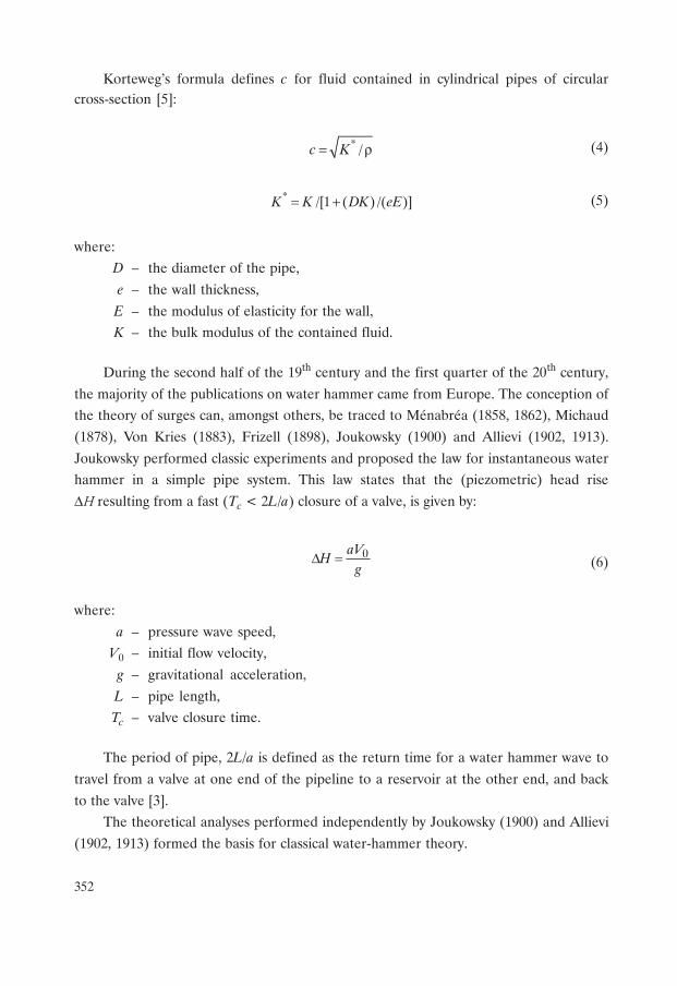
Source data for this investigation was received for the section of oil trunk pipeline
with nominal diameter of 702 mm and a length of about 400 km. On this pipeline section
are situated four oil pump stations which are equipped by modern oil pumping units.
Moreover, along this pipeline twelve inspection stations are allocated (Fig. 1). These
stations are equipped by modern tools which can control pressure. Inspection station
354
has possibility to make pressure measurement every second during the fast transitionprocesses. Within that time when industrial experiments were conducted the densityof transported oil varies in the range from 866 to 875 kg/m3 and viscosity of transportedoil varies in the range from 16 to 30 cSt.
Fig. 1. Location of Oil Pump Stations and Inspection Stations along the pipeline
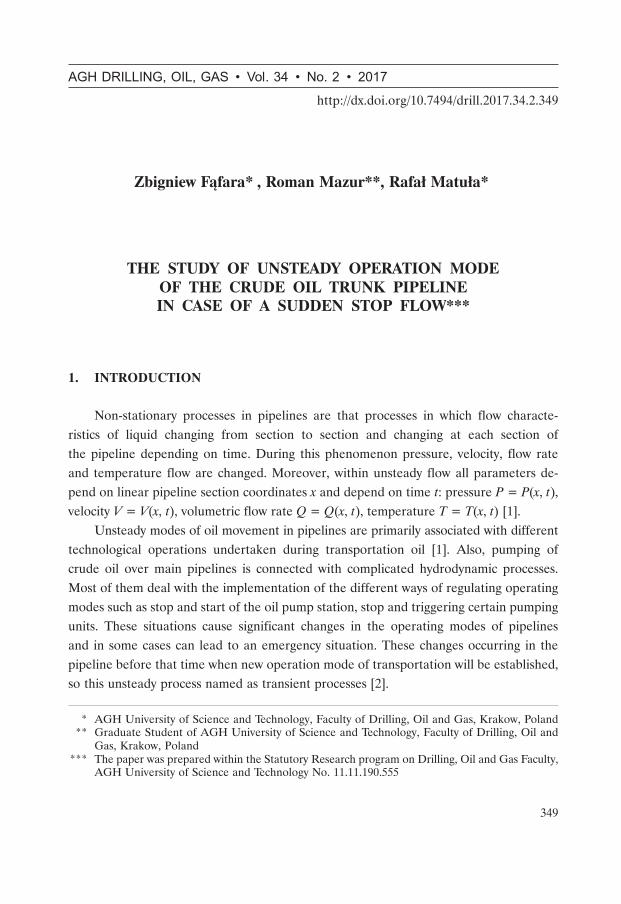
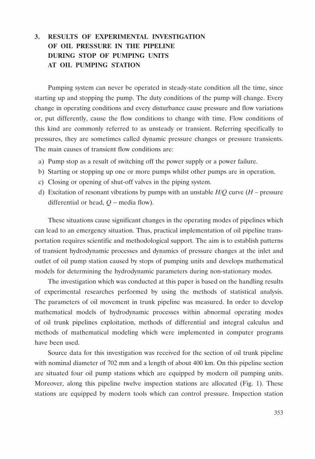
For obtaining principles of the change in pressure along the pipeline caused by stopsof pumping units several experiments were carried. For example, volume flow of oil inthe pipeline before stop amounted 2335 m3/hour. At some point in time, the pumpingunits at the oil pump stations No. 2 have been disconnected. As a result within a few
seconds pressure dramatically increases from 0.55 MPa to 1.45 MPa at the inlet of oilpump station (Fig. 2). After this phenomenon within 20–30 min pressure remained onlyslightly increased.
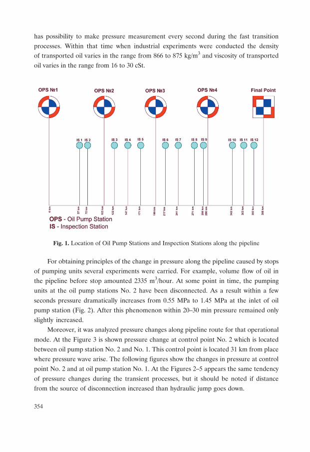
Moreover, it was analyzed pressure changes along pipeline route for that operational
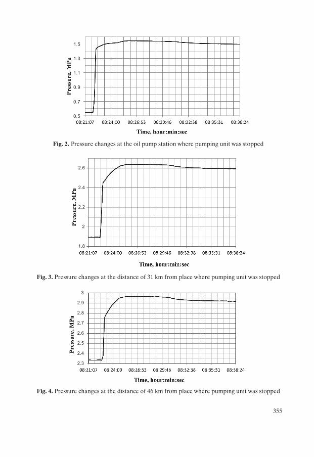
mode. At the Figure 3 is shown pressure change at control point No. 2 which is locatedbetween oil pump station No. 2 and No. 1. This control point is located 31 km from placewhere pressure wave arise. The following figures show the changes in pressure at controlpoint No. 2 and at oil pump station No. 1. At the Figures 2–5 appears the same tendency
of pressure changes during the transient processes, but it should be noted if distancefrom the source of disconnection increased than hydraulic jump goes down.
355
Fig. 2. Pressure changes at the oil pump station where pumping unit was stopped
Fig. 3. Pressure changes at the distance of 31 km from place where pumping unit was stopped
Fig. 4. Pressure changes at the distance of 46 km from place where pumping unit was stopped
���
���
���
���
���
���
�
��
�
���
�
��
��
��
�
��
��
��
356
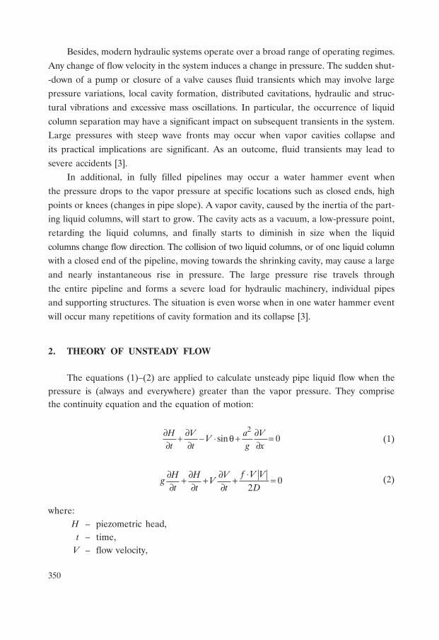
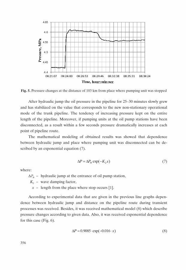
Fig. 5. Pressure changes at the distance of 103 km from place where pumping unit was stopped
After hydraulic jump the oil pressure in the pipeline for 25–30 minutes slowly grew
and has stabilized on the value that corresponds to the new non-stationary operationalmode of the trunk pipeline. The tendency of increasing pressure kept on the entire
length of the pipeline. Moreover, if pumping units at the oil pump stations have been
disconnected, as a result within a few seconds pressure dramatically increases at eachpoint of pipeline route.
The mathematical modeling of obtained results was showed that dependencebetween hydraulic jump and place where pumping unit was disconnected can be de-
scribed by an exponential equation (7).
exp( )n zP P K xΔ = Δ − (7)
where:
ΔPn – hydraulic jump at the entrance of oil pump station,
Kz – wave damping factor,x – length from the place where stop occurs [1].
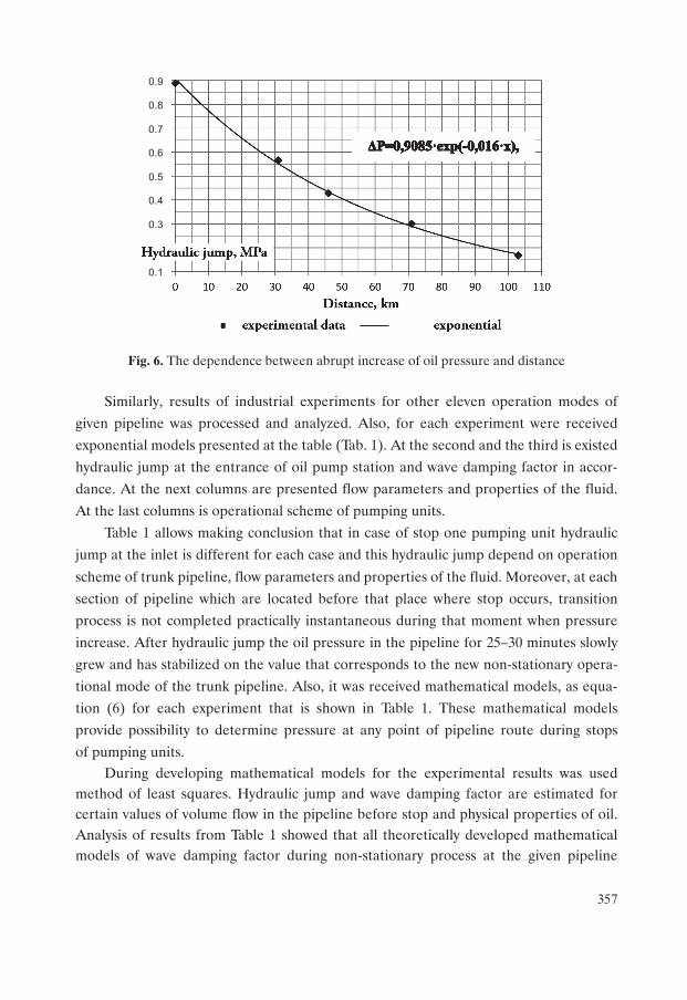
According to experimental data that are given in the previous line graphs depen-
dence between hydraulic jump and distance on the pipeline route during transient
processes was received. Besides, it was received mathematical model (8) which describepressure changes according to given data. Also, it was received exponential dependence
for this case (Fig. 6).
0.9085 exp( 0.016 )P xΔ = ⋅ − ⋅ (8)
����
���
����
���
����
���
357
Fig. 6. The dependence between abrupt increase of oil pressure and distance
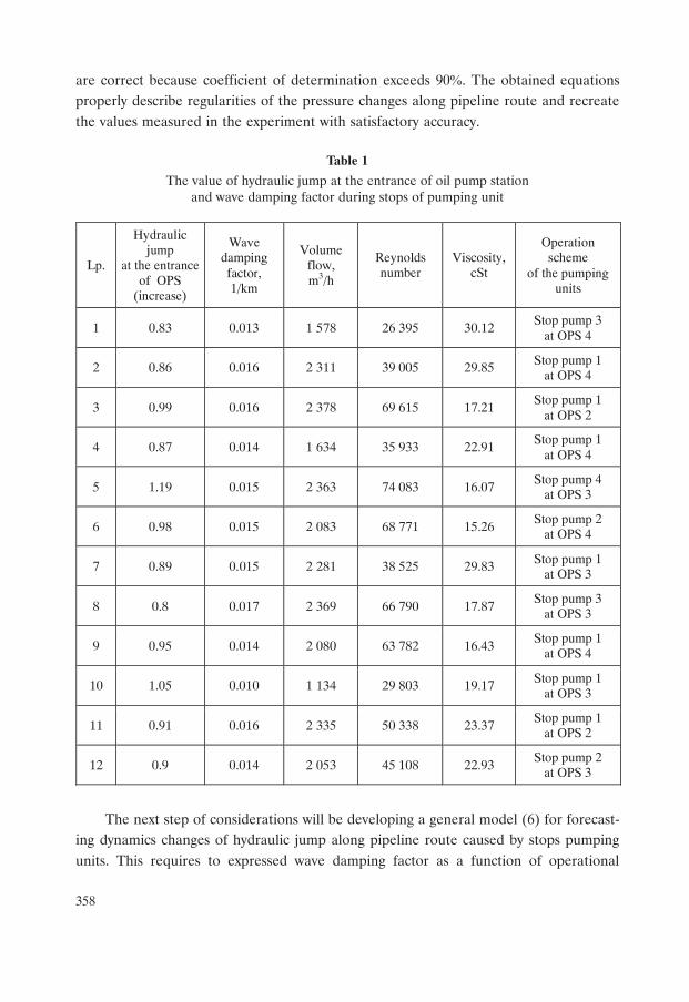
Similarly, results of industrial experiments for other eleven operation modes of
given pipeline was processed and analyzed. Also, for each experiment were received
exponential models presented at the table (Tab. 1). At the second and the third is existed
hydraulic jump at the entrance of oil pump station and wave damping factor in accor-
dance. At the next columns are presented flow parameters and properties of the fluid.
At the last columns is operational scheme of pumping units.
Table 1 allows making conclusion that in case of stop one pumping unit hydraulic
jump at the inlet is different for each case and this hydraulic jump depend on operation
scheme of trunk pipeline, flow parameters and properties of the fluid. Moreover, at each
section of pipeline which are located before that place where stop occurs, transition
process is not completed practically instantaneous during that moment when pressure
increase. After hydraulic jump the oil pressure in the pipeline for 25–30 minutes slowly
grew and has stabilized on the value that corresponds to the new non-stationary opera-
tional mode of the trunk pipeline. Also, it was received mathematical models, as equa-
tion (6) for each experiment that is shown in Table 1. These mathematical models
provide possibility to determine pressure at any point of pipeline route during stops
of pumping units.During developing mathematical models for the experimental results was used
method of least squares. Hydraulic jump and wave damping factor are estimated forcertain values of volume flow in the pipeline before stop and physical properties of oil.Analysis of results from Table 1 showed that all theoretically developed mathematicalmodels of wave damping factor during non-stationary process at the given pipeline
���
���
���
���
���
��
��
���
358
are correct because coefficient of determination exceeds 90�. The obtained equationsproperly describe regularities of the pressure changes along pipeline route and recreatethe values measured in the experiment with satisfactory accuracy.
Table 1
The value of hydraulic jump at the entrance of oil pump stationand wave damping factor during stops of pumping unit
The next step of considerations will be developing a general model (6) for forecast-ing dynamics changes of hydraulic jump along pipeline route caused by stops pumpingunits. This requires to expressed wave damping factor as a function of operational
Lp.
Hydraulic jump
at the entrance of OPS
(increase)
Wave damping factor, 1/km
Volume flow, m3/h
Reynolds number
Viscosity, cSt
Operation scheme
of the pumping units
1 0.83 0.013 1 578 26 395 30.12 Stop pump 3
at OPS 4
2 0.86 0.016 2 311 39 005 29.85 Stop pump 1 at OPS 4
3 0.99 0.016 2 378 69 615 17.21 Stop pump 1
at OPS 2
4 0.87 0.014 1 634 35 933 22.91 Stop pump 1
at OPS 4
5 1.19 0.015 2 363 74 083 16.07 Stop pump 4
at OPS 3
6 0.98 0.015 2 083 68 771 15.26 Stop pump 2
at OPS 4
7 0.89 0.015 2 281 38 525 29.83 Stop pump 1 at OPS 3
8 0.8 0.017 2 369 66 790 17.87 Stop pump 3
at OPS 3
9 0.95 0.014 2 080 63 782 16.43 Stop pump 1
at OPS 4
10 1.05 0.010 1 134 29 803 19.17 Stop pump 1 at OPS 3
11 0.91 0.016 2 335 50 338 23.37 Stop pump 1
at OPS 2
12 0.9 0.014 2 053 45 108 22.93 Stop pump 2
at OPS 3
359
parameters of the pipeline and the physical properties of transported oil. Hydraulic jumpat the entrance of OPS may be calculated from the equation (3) using parameters ofthe pipeline and the physical properties of transported oil too. Research will be continued.
4. CONCLUSIONS
Theoretical investigations of hydrodynamic processes in crude oil trunk pipelinewithin non-stationary operation mode allowed making the following conclusions:
1. During stops of pumping units was observed pressure increasing at the inlet of oil
pump station and pressure decreasing at the outlet. Duration of the quick pressurechanges not exceed 10–20 sec.
2. The total duration of transient processes depend on the geometric characteristics
of the trunk oil pipeline, oil pump hydrodynamic characteristics and physical pro-perties of the transported fluid.
3. Within transient processes was detected that pressure sharply increased at the mo-
ment when pressure wave approach to inspection station. Then oil pressure inthe pipeline for 25–30 minutes slowly decreased and has stabilized on the value that
corresponds to the new non-stationary operational mode of the trunk pipeline.
4. Wave damping factor depend on geometric characteristics of the crude oil pipelineand physical properties of the transported fluid.
5. Mathematical models which were obtained theoretically provide a wide range
of volume flow changes in the trunk pipeline and wide range of oil viscosity.The reliability of the mathematical models was confirmed by industrial experiments.
That’s why these models can be useful for forecasting parameters of transient pro-
cess caused by stops of pumping units during oil transportation.
REFERENCES
[1] Hrehorsky S.T., Serediuk M.D.: Improving the technology process of oil pipeline
exploitation considering emergency situations. Ivano-Frankivsk, Ukraine, 2015.
[2] Mazur R.: Improving the technology process of crude oil transportation by trunk pipe-
lines. East meets West Conference, Krakow, Poland, 2016.[3] Bergant A., Simpson A.R., Tijsseling A.S.: Water hammer with column separation:
a review of research in the twentieth century. Journal of Fluids and Structures, 22,
2006, pp. 135–171.
360
[4] Asadiniazi M., Saband E.M.: Study on mechanism and control methods of water
hammer in pump station and pipelines. International Offshore and Polar Engi-
neering Conference, Beijing, China 2010.[5] Tijsseling A.S., Anderson A.: The Joukowsky equation for fluids and solids. CASA
Report 06-08, March 2016, TU Eindhoven Netherlands.
(http://www.win.tue.nl/analysis/reports/rana06-08.pdf)


![infoShare 2013: Rafał Brzoska - InPost - Challanger from Poland [EN]](https://img.pdfslide.us/doc/110x75/548472c7b4af9fd2568b4ab2/infoshare-2013-rafal-brzoska-inpost-challanger-from-poland-en.jpg)