Embed Size (px)
Citation preview
Version 0.0.3
ZANTHIC
TECHNOLOGIES
INC.
Zanthic Cheetah64 processor with
6803 BMS Firmware for
Lithium Ion Battery Management
Datasheet

Zanthic Technologies Inc. C64 Processor for BMS – Datasheet Page 2
Zanthic Technologies Inc. C64/6803BMS
Version History
Bootloader V1.0 Main program V1.0 6803-2 Device V1.0 Main Configuration Device V1.0 RS232 Port V1.0
This document version history
June 1, 2011 V 0.0.3 - Preliminary Version, internal use only

Zanthic Technologies Inc. C64 Processor for BMS – Datasheet Page 3
Zanthic Technologies Inc. C64/6803BMS
Table of Contents
Contents Introduction .................................................................................................................................................. 4
Features ........................................................................................................................................................ 5
CAN – Controller Area Network ................................................................................................................ 5
RS232 ........................................................................................................................................................ 5
SPI Communications to Linear 6803-2 Slaves ........................................................................................... 5
Analog Input for current sensing .............................................................................................................. 5
Digital outputs ........................................................................................................................................... 5
Processor Pinouts .......................................................................................................................................... 6
CAN protocol details ..................................................................................................................................... 8
Packet format: ........................................................................................................................................... 8
Nodes and Devices: ................................................................................................................................... 9
C64/6803BMS Device Listing .................................................................................................................... 9
Monitoring the CAN bus data from the C64/6803BMS .......................................................................... 10
Detailed CAN packet description ............................................................................................................ 10
CAN packets from the main board (Device 17)................................................................................... 11
CAN packets from the slave devices (Device 1-16) ............................................................................. 13
Detailed RS-232 Output Description ........................................................................................................... 15
Terminal Mode ........................................................................................................................................ 15
Digital Output Reporting: .................................................................................................................... 16
Extended data report: ......................................................................................................................... 16
RS-232 LCD Mode.................................................................................................................................... 17
Negative values ....................................................................................................................................... 18
Error Conditions ...................................................................................................................................... 18
Specifications .............................................................................................................................................. 19
Individual cell measurement: .................................................................................................................. 19
Internal data storage............................................................................................................................... 19
Current Sensor ........................................................................................................................................ 19
Sample Schematics ..................................................................................................................................... 19

Zanthic Technologies Inc. C64 Processor for BMS – Datasheet Page 4
Zanthic Technologies Inc. C64/6803BMS
Packaging .................................................................................................................................................... 19
Licensing and Legal Issues ........................................................................................................................... 20
Introduction
The Zanthic Technologies Inc. Cheetah64 processor with 6803 battery management firmware is
designed to provide a single IC solution for lithium ion cell monitoring and management by providing
built in functionality to perform
1. Data gathering functionality from Linear Technology’s 6803-2 devices
2. Warning and error set points
3. Data output through RS232, USB and CAN
4. Current sensing and reporting with battery pack capability calculations
5. Cell balancing functionality
6. Configuration through easy to use Windows PC software
Schematic examples are provided from the simplest monitoring application to the more complex
monitoring and management functionality with configuration settings to choose the options.

Zanthic Technologies Inc. C64 Processor for BMS – Datasheet Page 5
Zanthic Technologies Inc. C64/6803BMS
Features The Zanthic C64/6803BMS device provides the following functionality
CAN – Controller Area Network The built in CAN port is configured to run at 500Kbps and provides an interface for the
configuration software to allow access to all of the configuration settings. The CAN interface also
provides continuous updates including the pack voltage, pack current, cell voltages, cell temperatures,
warning and alarm values as well as other detailed information. Please refer to the “CAN protocol
details” section for more details. A built in custom CAN protocol allows up to 126 boards to coexist on
the same CAN network with the configuration software allowing individual access to each board.
RS232 The built in RS232 output is currently equipped to output data at 4 different baud rates (9600,
19200, 38400, 57600) and in two different formats;
1. 4 line by 20 character LCD panel
2. Terminal program
The RS232 port can also accept incoming characters that can change the output to provide more
detailed information if required. Please refer to the “Detailed RS-232 Output Description ” section for
more details. An optional hardware interface can also provide USB conversion to output directly to your
computer’s USB port using a standard FTDI interface IC.
SPI Communications to Linear 6803-2 Slaves Built in functionality allows the C64/6803BMS to communicate with the Linear Technologies
6803-2 cell monitoring IC to monitor up to 16 slave boards with each board providing from 1 to 12 cells
of monitoring with optional cell balancing functionality. An internal temperature sensor is monitored as
well as two external sensors can be used to monitor cell temperatures. Note that depending on the
method of powering the 6803 device, a minimum cell requirement might be greater than 1 in order to
meet the 10 volt requirement to power the 6803.
Analog Input for current sensing One of the built in 10 bit analog inputs can be used for monitoring an external current sensor
with configurable settings for current sensor sensitivity, pack capacity and zero current set point. State
of charge values are calculated using simple coulomb counting techniques. Currently there is no
compensation provided for cell aging or temperature effects.
Digital outputs Eight digital outputs are configured to output a constant high signal (5v) when there is no
warning or error conditions. Each output can be configured to go low upon a warning or error condition
with the ability to combine any of the (currently) 13 warning and error conditions. This allows a single
output to show multiple warning or error conditions if required. The warning and error states as well as
Zanthic Technologies Inc. C64 Processor for BMS – Datasheet Page 6
Zanthic Technologies Inc. C64/6803BMS
the actual digital output states are transmitted within the CAN and RS232 messages so the physical
outputs do not need to be connected to still use this functionality.
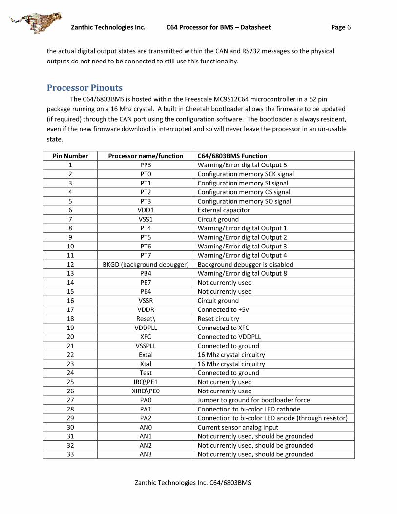
Processor Pinouts The C64/6803BMS is hosted within the Freescale MC9S12C64 microcontroller in a 52 pin
package running on a 16 Mhz crystal. A built in Cheetah bootloader allows the firmware to be updated
(if required) through the CAN port using the configuration software. The bootloader is always resident,
even if the new firmware download is interrupted and so will never leave the processor in an un-usable
state.
Pin Number Processor name/function C64/6803BMS Function
1 PP3 Warning/Error digital Output 5
2 PT0 Configuration memory SCK signal
3 PT1 Configuration memory SI signal
4 PT2 Configuration memory CS signal
5 PT3 Configuration memory SO signal
6 VDD1 External capacitor
7 VSS1 Circuit ground
8 PT4 Warning/Error digital Output 1
9 PT5 Warning/Error digital Output 2
10 PT6 Warning/Error digital Output 3
11 PT7 Warning/Error digital Output 4
12 BKGD (background debugger) Background debugger is disabled
13 PB4 Warning/Error digital Output 8
14 PE7 Not currently used
15 PE4 Not currently used
16 VSSR Circuit ground
17 VDDR Connected to +5v
18 Reset\ Reset circuitry
19 VDDPLL Connected to XFC
20 XFC Connected to VDDPLL
21 VSSPLL Connected to ground
22 Extal 16 Mhz crystal circuitry
23 Xtal 16 Mhz crystal circuitry
24 Test Connected to ground
25 IRQ\PE1 Not currently used
26 XIRQ\PE0 Not currently used
27 PA0 Jumper to ground for bootloader force
28 PA1 Connection to bi-color LED cathode
29 PA2 Connection to bi-color LED anode (through resistor)
30 AN0 Current sensor analog input
31 AN1 Not currently used, should be grounded
32 AN2 Not currently used, should be grounded
33 AN3 Not currently used, should be grounded

Zanthic Technologies Inc. C64 Processor for BMS – Datasheet Page 7
Zanthic Technologies Inc. C64/6803BMS
34 AN4 Not currently used, should be grounded
35 AN5 Not currently used, should be grounded
36 AN6 Not currently used, should be grounded
37 AN7 Not currently used, should be grounded
38 VDDA Connected to +5v if not using current sensor functionality or to +5.12v reference if using current sensor functionality to provide 5mv A/D resolution
39 VRH Connected to +5v if not using current sensor functionality or to +5.12v reference if using current sensor functionality to provide 5mv A/D resolution
40 VSSA Connected to ground
41 PS0/Rxd RS232 Receive data
42 PS1/Txd RS232 Transmit data
43 SCK SPI Clock out for 6803-2 interface
44 MOSI Data out for 6803-2 interface
45 SS Select output for 6803-2 interface
46 MISO Data input from 6803-2 interface
47 CAN Tx CAN Tx to transceiver
48 CAN Rx CAN Rx from transceiver
49 VSSX Connected to ground
50 VDDX Connected to +5v
51 PP5 Warning/Error digital Output 7
52 PP4 Warning/Error digital Output 6
Zanthic Technologies Inc. C64 Processor for BMS – Datasheet Page 8
Zanthic Technologies Inc. C64/6803BMS
CAN protocol details The communications protocol used for the C64/6803BMS system was designed to be
easy to understand, expandable to allow other devices to share the communications bus and be
easy to implement on a small micro-controller. As well, the protocol is fast because of the
limited overhead and also reliable due to a simple configuration. Note: This information is
presented here as additional protocol information and is provided as detailed information to
the advanced user and is not required for every implementation of the C64/6803BMS processor.
The protocol allows multiple boards to communicate on a twisted pair network at
speeds of 500Kbps. The CAN bus controller handles most of the details of transmitting data
between the different controllers, freeing the software to handle the higher level details. For a
full understanding of this protocol, a basic understanding of CAN is assumed.
Packet format:
According to the CAN specification, CAN packets can contain either an 11 bit identifier
or a 29 bit identifier. Within the current protocol, only 29 bit ID’s are used and 11 bit ID’s are
currently ignored.
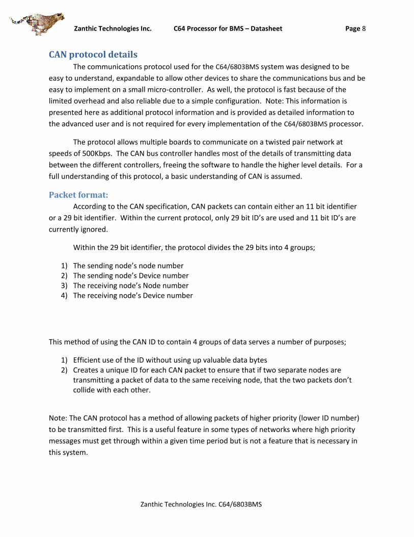
Within the 29 bit identifier, the protocol divides the 29 bits into 4 groups;
1) The sending node’s node number 2) The sending node’s Device number 3) The receiving node’s Node number 4) The receiving node’s Device number
This method of using the CAN ID to contain 4 groups of data serves a number of purposes;
1) Efficient use of the ID without using up valuable data bytes 2) Creates a unique ID for each CAN packet to ensure that if two separate nodes are
transmitting a packet of data to the same receiving node, that the two packets don’t collide with each other.
Note: The CAN protocol has a method of allowing packets of higher priority (lower ID number)
to be transmitted first. This is a useful feature in some types of networks where high priority
messages must get through within a given time period but is not a feature that is necessary in
this system.
Zanthic Technologies Inc. C64 Processor for BMS – Datasheet Page 9
Zanthic Technologies Inc. C64/6803BMS
28
27
26
25
24
23
22
21
20
19
18
17
16
15
14
13
12
11
10
9 8 7 6 5 4 3 2 1 0
0 Sender’s Node # Sender’s Device # Receiver’s Node # Receiver’s Dev #
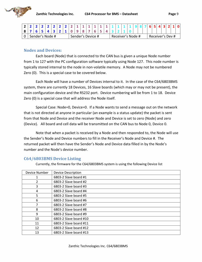
Nodes and Devices:
Each board (Node) that is connected to the CAN bus is given a unique Node number
from 1 to 127 with the PC configuration software typically using Node 127. This node number is
typically stored internal to the node in non-volatile memory. A Node may not be numbered
Zero (0). This is a special case to be covered below.
Each Node will have a number of Devices internal to it. In the case of the C64/6803BMS
system, there are currently 18 Devices, 16 Slave boards (which may or may not be present), the
main configuration device and the RS232 port. Device numbering will be from 1 to 18. Device
Zero (0) is a special case that will address the Node itself.
Special Case: Node=0, Device=0. If a Node wants to send a message out on the network
that is not directed at anyone in particular (an example is a status update) the packet is sent
from that Node and Device and the receiver Node and Device is set to zero (Node) and zero
(Device). All board and cell data will be transmitted on the CAN bus to Node 0, Device 0.
Note that when a packet is received by a Node and then responded to, the Node will use
the Sender’s Node and Device numbers to fill in the Receiver’s Node and Device #. The
returned packet will then have the Sender’s Node and Device data filled in by the Node’s
number and the Node’s device number.
C64/6803BMS Device Listing Currently, the firmware for the C64/6803BMS system is using the following Device list
Device Number Device Description
1 6803-2 Slave board #1
2 6803-2 Slave board #2
3 6803-2 Slave board #3
4 6803-2 Slave board #4
5 6803-2 Slave board #5
6 6803-2 Slave board #6
7 6803-2 Slave board #7
8 6803-2 Slave board #8
9 6803-2 Slave board #9
10 6803-2 Slave board #10
11 6803-2 Slave board #11
12 6803-2 Slave board #12
13 6803-2 Slave board #13
Zanthic Technologies Inc. C64 Processor for BMS – Datasheet Page 10
Zanthic Technologies Inc. C64/6803BMS
14 6803-2 Slave board #14
15 6803-2 Slave board #15
16 6803-2 Slave board #16
17 Main BMS Configuration
18 RS232 port for LCD or terminal
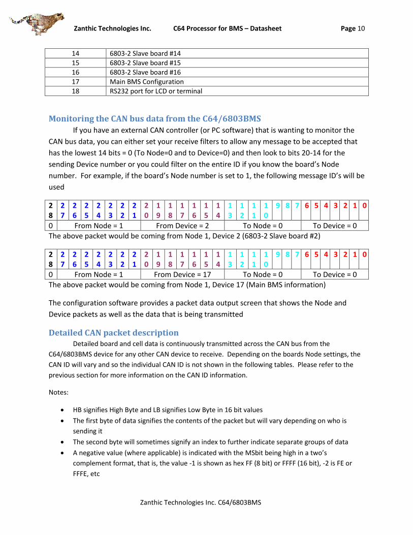
Monitoring the CAN bus data from the C64/6803BMS
If you have an external CAN controller (or PC software) that is wanting to monitor the
CAN bus data, you can either set your receive filters to allow any message to be accepted that
has the lowest 14 bits = 0 (To Node=0 and to Device=0) and then look to bits 20-14 for the
sending Device number or you could filter on the entire ID if you know the board’s Node
number. For example, if the board’s Node number is set to 1, the following message ID’s will be
used
28
27
26
25
24
23
22
21
20
19
18
17
16
15
14
13
12
11
10
9 8 7 6 5 4 3 2 1 0
0 From Node = 1 From Device = 2 To Node = 0 To Device = 0
The above packet would be coming from Node 1, Device 2 (6803-2 Slave board #2)
28
27
26
25
24
23
22
21
20
19
18
17
16
15
14
13
12
11
10
9 8 7 6 5 4 3 2 1 0
0 From Node = 1 From Device = 17 To Node = 0 To Device = 0
The above packet would be coming from Node 1, Device 17 (Main BMS information)
The configuration software provides a packet data output screen that shows the Node and
Device packets as well as the data that is being transmitted
Detailed CAN packet description Detailed board and cell data is continuously transmitted across the CAN bus from the
C64/6803BMS device for any other CAN device to receive. Depending on the boards Node settings, the
CAN ID will vary and so the individual CAN ID is not shown in the following tables. Please refer to the
previous section for more information on the CAN ID information.
Notes:
HB signifies High Byte and LB signifies Low Byte in 16 bit values
The first byte of data signifies the contents of the packet but will vary depending on who is
sending it
The second byte will sometimes signify an index to further indicate separate groups of data
A negative value (where applicable) is indicated with the MSbit being high in a two’s
complement format, that is, the value -1 is shown as hex FF (8 bit) or FFFF (16 bit), -2 is FE or
FFFE, etc

Zanthic Technologies Inc. C64 Processor for BMS – Datasheet Page 11
Zanthic Technologies Inc. C64/6803BMS
CAN packets from the main board (Device 17)
Pack Summary Bit 7 Bit 6 Bit 5 Bit 4 Bit 3 Bit 2 Bit 1 Bit 0
Byte 0 CmdStatPackSum (0x56)
Byte 1 index = 0
Byte 2 Pack Total Voltage (HB)
Byte 3 Pack Total Voltage (LB) *
Byte 4 Pack Current (HB)
Byte 5 Pack Current (LB) **
Byte 6 Pack SOC (0-100)
Byte 7 not used
* Pack Total Voltage is given in 100mV increments with a maximum value of +-3276 volts. Negative values are possible. ** Pack current is in 100mA increments with +- 3276 Amps maximum value. A negative value indicates the pack is discharging.
Pack Volt Summary
Bit 7 Bit 6 Bit 5 Bit 4 Bit 3 Bit 2 Bit 1 Bit 0
Byte 0 CmdStatPackSum (0x56)
Byte 1 index = 1
Byte 2 Lowest Cell Voltage (HB)
Byte 3 Lowest Cell Voltage (LB)
Byte 4 Highest Cell Voltage (HB)
Byte 5 Highest Cell Voltage (LB)
Byte 6 Average Cell Voltage (HB)
Byte 7 Average Cell Voltage (LB)
These are the lowest, highest and average cell voltages over the entire pack and are given in mV’s so a
value of 3456 (decimal) would equal 3.456 volts. An error condition will result in a value of 0x8000 being
transmitted.
Pack Summary Bit 7 Bit 6 Bit 5 Bit 4 Bit 3 Bit 2 Bit 1 Bit 0
Byte 0 CmdStatPackSum (0x56)
Byte 1 index = 2
Byte 2 Number of cells reporting properly
Byte 3 Number of enabled cells in system
Byte 4 Total number of slaves reporting properly
Byte 5 Total number of enabled slaves in system
Byte 6 not used
Byte 7 not used

Zanthic Technologies Inc. C64 Processor for BMS – Datasheet Page 12
Zanthic Technologies Inc. C64/6803BMS
Pack Temp. Summary
Bit 7 Bit 6 Bit 5 Bit 4 Bit 3 Bit 2 Bit 1 Bit 0
Byte 0 CmdStatPackSum (0x56)
Byte 1 index = 3
Byte 2 Pack summary lowest temperature*
Byte 3 Pack summary highest temperature*
Byte 4 Pack summary average temperature*
Byte 5** SNR PDCE PCCE HCTE LCTE HCVE LCVE
Byte 6** PDCW PCCW HCTW LCTW HCVW LCVW
Byte 7*** Output 8
Output 7
Output 6
Output 5
Output 4
Output 3
Output 2
Output 1
*Temperatures are for external slave sensors only and are given as +-127 degrees C format with a usable
range of -30C to +110C. Too low is shown as -31C, too hot is 111C and an error is -128C
**Bytes 5 & 6 error and warning bits will go HIGH to indicate the following conditions
Byte 5 Details Errors
Bit 0 (LCVE) Low Cell Voltage Error
Bit 1 (HCVE) High Cell Voltage Error
Bit 2 (LCTE) Low Cell Temp Error
Bit 3 (HCTE) High Cell Temp Error
Bit 4 (PCCE) Pack Current Charge Error
Bit 5 (PDCE) Pack DisCharge Error
Bit 6 (SNR) Slave(s) Not Responding
Bit 7 Not currently used
Byte 6 Details Warnings
Bit 0 (LCVW) Low Cell Voltage Warning
Bit 1 (HCVW) High Cell Voltage Warning
Bit 2 (LCTW) Low Cell Temp Warning
Bit 3 (HCTW) High Cell Temp Warning
Bit 4 (PCCW) Pack Current Charge Warning
Bit 5 (PDCW) Pack DisCharge Warning
Bit 6 Not currently used
Bit 7 Not currently used
***Byte 7 will indicate the actual warning/Error digital outputs and will go LOW to indicate a warning or
error condition to more accurately represent the actual hardware output pins state.
Zanthic Technologies Inc. C64 Processor for BMS – Datasheet Page 13
Zanthic Technologies Inc. C64/6803BMS
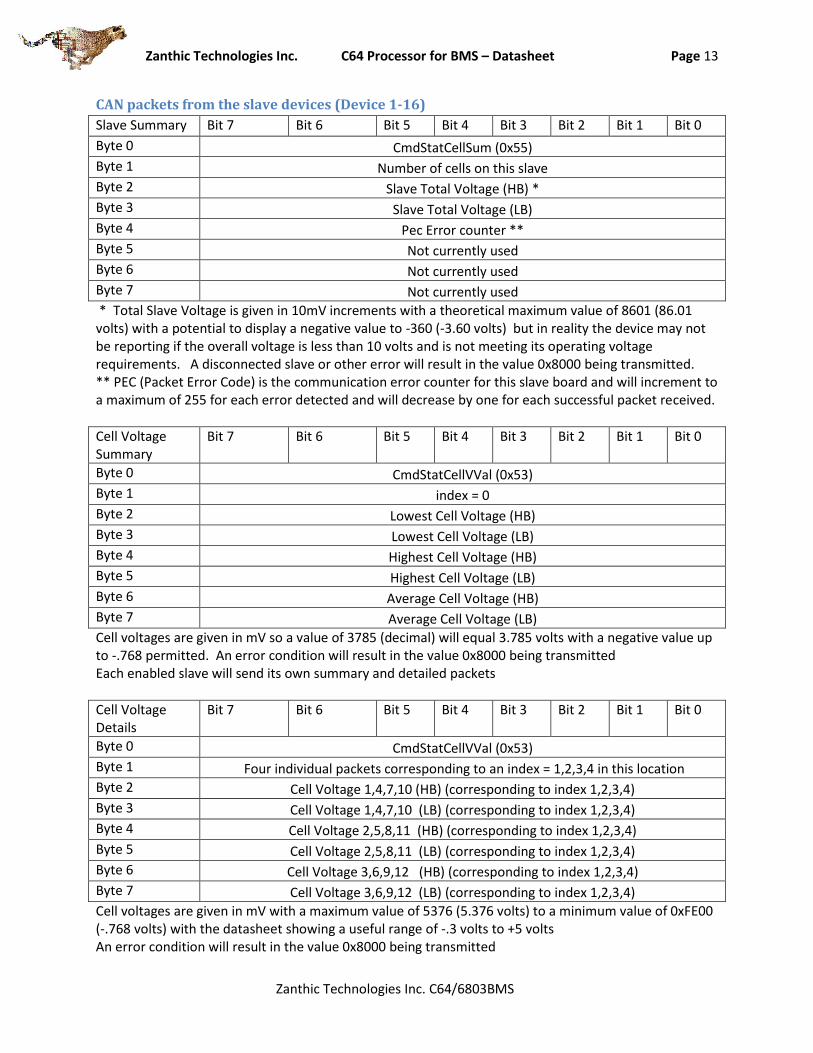
CAN packets from the slave devices (Device 1-16)
Slave Summary Bit 7 Bit 6 Bit 5 Bit 4 Bit 3 Bit 2 Bit 1 Bit 0
Byte 0 CmdStatCellSum (0x55)
Byte 1 Number of cells on this slave
Byte 2 Slave Total Voltage (HB) *
Byte 3 Slave Total Voltage (LB)
Byte 4 Pec Error counter **
Byte 5 Not currently used
Byte 6 Not currently used
Byte 7 Not currently used
* Total Slave Voltage is given in 10mV increments with a theoretical maximum value of 8601 (86.01 volts) with a potential to display a negative value to -360 (-3.60 volts) but in reality the device may not be reporting if the overall voltage is less than 10 volts and is not meeting its operating voltage requirements. A disconnected slave or other error will result in the value 0x8000 being transmitted. ** PEC (Packet Error Code) is the communication error counter for this slave board and will increment to a maximum of 255 for each error detected and will decrease by one for each successful packet received.
Cell Voltage Summary
Bit 7 Bit 6 Bit 5 Bit 4 Bit 3 Bit 2 Bit 1 Bit 0
Byte 0 CmdStatCellVVal (0x53)
Byte 1 index = 0
Byte 2 Lowest Cell Voltage (HB)
Byte 3 Lowest Cell Voltage (LB)
Byte 4 Highest Cell Voltage (HB)
Byte 5 Highest Cell Voltage (LB)
Byte 6 Average Cell Voltage (HB)
Byte 7 Average Cell Voltage (LB)
Cell voltages are given in mV so a value of 3785 (decimal) will equal 3.785 volts with a negative value up to -.768 permitted. An error condition will result in the value 0x8000 being transmitted Each enabled slave will send its own summary and detailed packets
Cell Voltage Details
Bit 7 Bit 6 Bit 5 Bit 4 Bit 3 Bit 2 Bit 1 Bit 0
Byte 0 CmdStatCellVVal (0x53)
Byte 1 Four individual packets corresponding to an index = 1,2,3,4 in this location
Byte 2 Cell Voltage 1,4,7,10 (HB) (corresponding to index 1,2,3,4)
Byte 3 Cell Voltage 1,4,7,10 (LB) (corresponding to index 1,2,3,4)
Byte 4 Cell Voltage 2,5,8,11 (HB) (corresponding to index 1,2,3,4)
Byte 5 Cell Voltage 2,5,8,11 (LB) (corresponding to index 1,2,3,4)
Byte 6 Cell Voltage 3,6,9,12 (HB) (corresponding to index 1,2,3,4)
Byte 7 Cell Voltage 3,6,9,12 (LB) (corresponding to index 1,2,3,4)
Cell voltages are given in mV with a maximum value of 5376 (5.376 volts) to a minimum value of 0xFE00 (-.768 volts) with the datasheet showing a useful range of -.3 volts to +5 volts An error condition will result in the value 0x8000 being transmitted

Zanthic Technologies Inc. C64 Processor for BMS – Datasheet Page 14
Zanthic Technologies Inc. C64/6803BMS
Cell Balancing Bit 7 Bit 6 Bit 5 Bit 4 Bit 3 Bit 2 Bit 1 Bit 0
Byte 0 CmdStatCellVVal
Byte 1 index = 5
Byte 2 cell 2 balancing status cell 1 balancing status
Byte 3 cell 4 balancing status cell 3 balancing status
Byte 4 cell 6 balancing status cell 5 balancing status
Byte 5 cell 8 balancing status cell 7 balancing status
Byte 6 cell 10 balancing status cell 9 balancing status
Byte 7 cell 12 balancing status cell 11 balancing status
The following table provides a more detailed description of the balancing bits from the above table
Bit 7/3 Bit 6/2 Bit 5/1 Bit 4/0
Not currently used If ‘1’ then balancing is actually on (may not be if maximum number of balancing cells is being exceeded
If ‘1’ then manual balancing is currently attempting to activate
If ‘1’ then automatic balancing is currently attempting to activate
Cell Temperatures
Bit 7 Bit 6 Bit 5 Bit 4 Bit 3 Bit 2 Bit 1 Bit 0
Byte 0 CmdStatCellTVal (0x54)
Byte 1 index = 1
Byte 2 Temperature Internal to slave IC
Byte 3 Temperature external 1
Byte 4 Temperature external 2
Byte 5 Not currently used
Byte 6 Not currently used
Byte 7 Not currently used
Temperature is reported from -30C to +110C, too low is -31, too hot is 111, an error is -128C (0x80) All negative numbers are 0xFF and down, so -2 is 0xFE, -3 is 0xFD etc
Zanthic Technologies Inc. C64 Processor for BMS – Datasheet Page 15
Zanthic Technologies Inc. C64/6803BMS
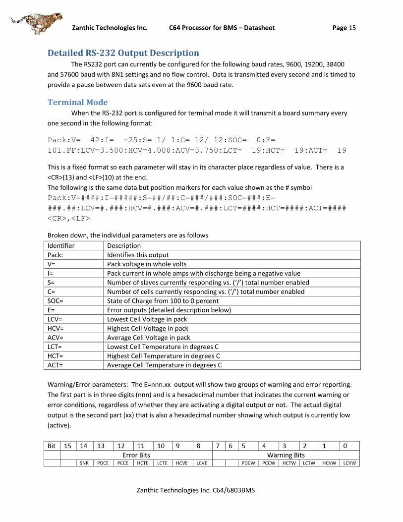
Detailed RS-232 Output Description The RS232 port can currently be configured for the following baud rates, 9600, 19200, 38400
and 57600 baud with 8N1 settings and no flow control. Data is transmitted every second and is timed to
provide a pause between data sets even at the 9600 baud rate.
Terminal Mode When the RS-232 port is configured for terminal mode it will transmit a board summary every
one second in the following format:
Pack:V= 42:I= -25:S= 1/ 1:C= 12/ 12:SOC= 0:E=
101.FF:LCV=3.500:HCV=4.000:ACV=3.750:LCT= 19:HCT= 19:ACT= 19
This is a fixed format so each parameter will stay in its character place regardless of value. There is a
<CR>(13) and <LF>(10) at the end.
The following is the same data but position markers for each value shown as the # symbol
Pack:V=####:I=#####:S=##/##:C=###/###:SOC=###:E=
###.##:LCV=#.###:HCV=#.###:ACV=#.###:LCT=####:HCT=####:ACT=####
<CR>,<LF>
Broken down, the individual parameters are as follows
Identifier Description
Pack: Identifies this output
V= Pack voltage in whole volts
I= Pack current in whole amps with discharge being a negative value
S= Number of slaves currently responding vs. (‘/’) total number enabled
C= Number of cells currently responding vs. (‘/’) total number enabled
SOC= State of Charge from 100 to 0 percent
E= Error outputs (detailed description below)
LCV= Lowest Cell Voltage in pack
HCV= Highest Cell Voltage in pack
ACV= Average Cell Voltage in pack
LCT= Lowest Cell Temperature in degrees C
HCT= Highest Cell Temperature in degrees C
ACT= Average Cell Temperature in degrees C
Warning/Error parameters: The E=nnn.xx output will show two groups of warning and error reporting.
The first part is in three digits (nnn) and is a hexadecimal number that indicates the current warning or
error conditions, regardless of whether they are activating a digital output or not. The actual digital
output is the second part (xx) that is also a hexadecimal number showing which output is currently low
(active).
Bit 15 14 13 12 11 10 9 8 7 6 5 4 3 2 1 0
Error Bits Warning Bits SNR PDCE PCCE HCTE LCTE HCVE LCVE PDCW PCCW HCTW LCTW HCVW LCVW
Zanthic Technologies Inc. C64 Processor for BMS – Datasheet Page 16
Zanthic Technologies Inc. C64/6803BMS
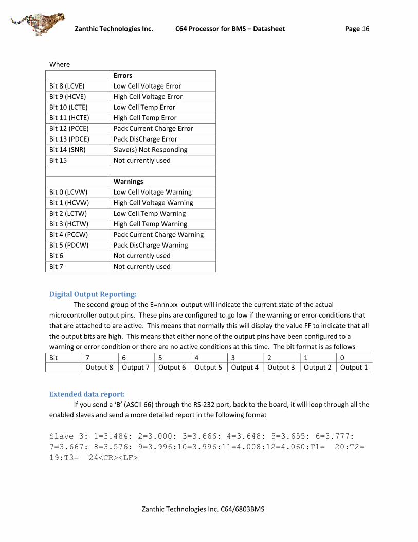
Where
Errors
Bit 8 (LCVE) Low Cell Voltage Error
Bit 9 (HCVE) High Cell Voltage Error
Bit 10 (LCTE) Low Cell Temp Error
Bit 11 (HCTE) High Cell Temp Error
Bit 12 (PCCE) Pack Current Charge Error
Bit 13 (PDCE) Pack DisCharge Error
Bit 14 (SNR) Slave(s) Not Responding
Bit 15 Not currently used
Warnings
Bit 0 (LCVW) Low Cell Voltage Warning
Bit 1 (HCVW) High Cell Voltage Warning
Bit 2 (LCTW) Low Cell Temp Warning
Bit 3 (HCTW) High Cell Temp Warning
Bit 4 (PCCW) Pack Current Charge Warning
Bit 5 (PDCW) Pack DisCharge Warning
Bit 6 Not currently used
Bit 7 Not currently used
Digital Output Reporting:
The second group of the E=nnn.xx output will indicate the current state of the actual
microcontroller output pins. These pins are configured to go low if the warning or error conditions that
that are attached to are active. This means that normally this will display the value FF to indicate that all
the output bits are high. This means that either none of the output pins have been configured to a
warning or error condition or there are no active conditions at this time. The bit format is as follows
Bit 7 6 5 4 3 2 1 0
Output 8 Output 7 Output 6 Output 5 Output 4 Output 3 Output 2 Output 1
Extended data report:
If you send a ‘B’ (ASCII 66) through the RS-232 port, back to the board, it will loop through all the
enabled slaves and send a more detailed report in the following format
Slave 3: 1=3.484: 2=3.000: 3=3.666: 4=3.648: 5=3.655: 6=3.777:
7=3.667: 8=3.576: 9=3.996:10=3.996:11=4.008:12=4.060:T1= 20:T2=
19:T3= 24<CR><LF>
Zanthic Technologies Inc. C64 Processor for BMS – Datasheet Page 17
Zanthic Technologies Inc. C64/6803BMS
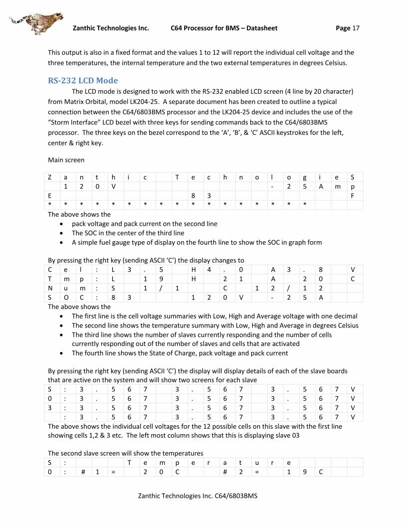
This output is also in a fixed format and the values 1 to 12 will report the individual cell voltage and the
three temperatures, the internal temperature and the two external temperatures in degrees Celsius.
RS-232 LCD Mode The LCD mode is designed to work with the RS-232 enabled LCD screen (4 line by 20 character)
from Matrix Orbital, model LK204-25. A separate document has been created to outline a typical
connection between the C64/6803BMS processor and the LK204-25 device and includes the use of the
“Storm Interface” LCD bezel with three keys for sending commands back to the C64/6803BMS
processor. The three keys on the bezel correspond to the ‘A’, ‘B’, & ‘C’ ASCII keystrokes for the left,
center & right key.
Main screen
Z a n t h i c T e c h n o l o g i e S
1 2 0 V - 2 5 A m p
E 8 3 F
* * * * * * * * * * * * * * * * *
The above shows the
pack voltage and pack current on the second line
The SOC in the center of the third line
A simple fuel gauge type of display on the fourth line to show the SOC in graph form By pressing the right key (sending ASCII ‘C’) the display changes to
C e l : L 3 . 5 H 4 . 0 A 3 . 8 V
T m p : L 1 9 H 2 1 A 2 0 C
N u m : S 1 / 1 C 1 2 / 1 2
S O C : 8 3 1 2 0 V - 2 5 A
The above shows the
The first line is the cell voltage summaries with Low, High and Average voltage with one decimal
The second line shows the temperature summary with Low, High and Average in degrees Celsius
The third line shows the number of slaves currently responding and the number of cells currently responding out of the number of slaves and cells that are activated
The fourth line shows the State of Charge, pack voltage and pack current By pressing the right key (sending ASCII ‘C’) the display will display details of each of the slave boards that are active on the system and will show two screens for each slave
S : 3 . 5 6 7 3 . 5 6 7 3 . 5 6 7 V
0 : 3 . 5 6 7 3 . 5 6 7 3 . 5 6 7 V
3 : 3 . 5 6 7 3 . 5 6 7 3 . 5 6 7 V
: 3 . 5 6 7 3 . 5 6 7 3 . 5 6 7 V
The above shows the individual cell voltages for the 12 possible cells on this slave with the first line showing cells 1,2 & 3 etc. The left most column shows that this is displaying slave 03 The second slave screen will show the temperatures
S : T e m p e r a t u r e
0 : # 1 = 2 0 C # 2 = 1 9 C

Zanthic Technologies Inc. C64 Processor for BMS – Datasheet Page 18
Zanthic Technologies Inc. C64/6803BMS
3 :
:
Pressing the right key (sending ASCII ‘C’) will eventually loop through all the active slave screens and return you to the main screen. The center button (sending ASCII ‘B’) will return immediately to the main screen and the left button (sending ASCII ‘A’) will scroll through the screens in reverse order.
Negative values With the addition of the LTC6803 being able to measure small negative values, the display firmware was upgraded to accommodate this. Where a single decimal point voltage is being displayed and the voltage is negative, the display will show -.1 for example. If the more detailed 3 decimal value is being displayed it will display -.123, for example. Because the negative voltage is limited to -.3 volts, a whole digit will never be displayed (ie, less than -1v)
Error Conditions If the slave board is not responding to the master or some other bus error is keeping the master from receiving proper information, any of the RS232 values will be displayed with the ‘*’ symbol. This means the following display
S : 3 . 5 6 7 3 . 5 6 7 3 . 5 6 7 V
0 : 3 . 5 6 7 3 . 5 6 7 3 . 5 6 7 V
3 : 3 . 5 6 7 3 . 5 6 7 3 . 5 6 7 V
: 3 . 5 6 7 3 . 5 6 7 3 . 5 6 7 V
would be displayed as
S : * * * * * * * * * * * * * * * V
0 : * * * * * * * * * * * * * * * V
3 : * * * * * * * * * * * * * * * V
: * * * * * * * * * * * * * * * V
Zanthic Technologies Inc. C64 Processor for BMS – Datasheet Page 19
Zanthic Technologies Inc. C64/6803BMS
Specifications
Individual cell measurement: For individual cell measurement specifications, please refer to the Linear Technology LTC6803-2
datasheet at www.linear.com
Internal data storage Cell voltage = 1mV per bit
Temperature = 1 degree Celsius per bit
Pack voltage = +-3276 volts (practical limit is 60v per slave * 16 slaves = 960 volts)
Current Sensor 10 bit A/D with 5 or 5.12v reference (configurable)
Current Sensor must be ½ reference voltage with +- voltage swing from 0 to 5 volts with zero set point being +-127 of raw 10bit (1024) value.
Configurable current sensor sensitivity can be adjusted from .1mV per amp to 819.2mV per amp. Typical current sensor would be LEM HASS 50 – 600 amp
Pack current data storage = +- 3200 amps with 100mA per bit resolution
Current is measured every 10ms with 10 samples averaged with total pack capacity calculated every 100ms with a 100mA resolution in firmware.
Pack total capacity for SOC calculations .1Ahr to 6500Ahr
Sample Schematics Please refer to the Zanthic website for more information on sample schematics and other
information.
Packaging The C64/6803BMS is programmed into a Freescale 9S12C64 processor in a 52 pin LQFP package.
Mechanical dimensions can be obtained directly from the Freescale website

Zanthic Technologies Inc. C64 Processor for BMS – Datasheet Page 20
Zanthic Technologies Inc. C64/6803BMS
Licensing and Legal Issues (C) COPYRIGHT 2011 By Zanthic Technologies Inc. All other trademarks mentioned in this document are the property of their respective owners. Information in this document is subject to change without notice and does not represent a commitment on the part of Zanthic Technologies Inc. Zanthic provides this document “as is,” without warranty of any kind, either expressed or implied, including, but not limited to, the implied warranties of fitness or merchantability for a particular purpose. Zanthic may make improvements and/or changes in this manual or in the product(s) and/or the firmware/program(s) described in this manual at any time. This product could include technical inaccuracies or typographical errors. Changes are periodically made to the information herein; these changes may be incorporated in new editions of the publication. It is a Condition of Sale that the user of Zanthic Technologies Inc.’s products assumes all risk and responsibility of use and indemnifies Zanthic Technologies Inc. against all damages. Zanthic Technologies Inc. is not liable for loss of profits, lost savings, special, incidental, consequential, indirect or other similar damages arising from breach of warranty, breach of contract, negligence, or other legal action even if Zanthic Technologies Inc., or its agent has been advised of the possibility of such damages, or for any claim brought against you by another party.