Embed Size (px)
Citation preview

03/17/2016
Zagros Robotics Example Installation of Arduino IDE and
Basic Line Follower Program within Windows 7 and newer
Before you begin :
Make sure you have administrative privileges on the computer which you plan to install.
The Basic Line Follower Program has been tuned to best match the Zagros Robot Starter Kit -
Gobbit Version, although you can adjust it to work on many other robot chassis as well. You can
find the Gobbit kit and others at : http://www.zagrosrobotics.com/
The wiring diagram can be found here :
http://www.zagrosrobotics.com/files/ZagrosLineMazeFollowWiring_03172016a.pdf
Before you can run the Basic Line Follower, you will need a lined course. Use white poster
board, foam board, white board, or even a white floor or table and create a line course with
black electrical tape. It will run best if the turns are gradual without sharp corners.
Windows 8 has had driver signing issues with some older versions of installs. The current
drivers should install on an updated system without any problems, so we will not go into the
detailed work around within this document.
Windows XP… for now these steps may also work for the older windows. It is unknown when
compatibility of software and drivers will end since XP is no longer supported by its maker.

Installing the Arduino IDE
1) Go to the download page for the latest Arduino IDE (Integrated Development Environment) here :
https://www.arduino.cc/en/Main/Software
2) Choose your operating system on the right and download :
3) Run the downloaded installation.
4) Unless you are an advanced user, leave all of the settings as default and allow the installation to
install all of its drivers in default locations.
Installing the SparkFun Redboard on your PC
5) Download the FTDI VCP drivers (Virtual COM Port) for the RedBoard here :
http://www.ftdichip.com/Drivers/VCP.htm
6) Choose the "setup executable" Windows driver :
7) Run the downloaded FTDI driver (file name will be similar to "CDM21216_Setup.exe") and follow the
instructions. If you are prompted by User Account Controls or other Windows or Antivirus safeties,
allow the software to install as a trusted/safe source.
Occasionally, we have seen Windows respond with a message that the installation “requires
elevation” followed by a message that the installation may not have installed correctly. If this
occurs, most of the time you can simply re-run the installation and it will work the second time.
Otherwise, try re-running the installer by right clicking on the file and selecting “Run as
Administrator” if available.

8) Plug in the Redboard to your computer with your USB cable.
9) Wait for windows to install the board and find the drivers. When it is complete, it should tell you the
new device is ready for use in the bottom right of your screen.
Test the Installation
10) Run the Arduino IDE from your new desktop icon.
11) Make sure your RedBoard is still plugged in with the USB cable.
12) Open a basic Arduino program. From the menu bar, select File > Examples > Basics > Blink

13) Set your board type. From the menu bar, select Tools > Board > Arduino Uno
14) Set your Serial Port. From the menu bar, select Tools > Serial Port > COM(some number)
Usually, if there is more than one listed, the correct COM port number will be the highest
numbered port. However, a simple test is to unplug your Redboard while watching the list of
ports, and note which one disappears. Make sure to plug the board back in and select its port.

15) Click on the "Upload" icon.
Near the bottom of the window, the status bar will say "Compiling Sketch," then "Uploading...,"
then "Done uploading" if it was a success. While it is uploading, there should be some LED's
flickering on the Redboard. When it is done uploading, the LED near digital pin 13 should be
blinking slowly if it was successfully programmed.
You should now have a functioning Arduino IDE with Redboard communication.
If not, you can find further detailed installation and trouble shooting on Arduino's website:
https://www.arduino.cc/en/Guide/Windows
https://www.arduino.cc/en/Guide/Troubleshooting
Installing the Line Follower sketches and library.
16) Download the sketches with library here :
http://www.zagrosrobotics.com/files/ZagrosBasicLineFollower_03172016a.zip
17) Extract the zipfile in a temporary location, and open the new folder.
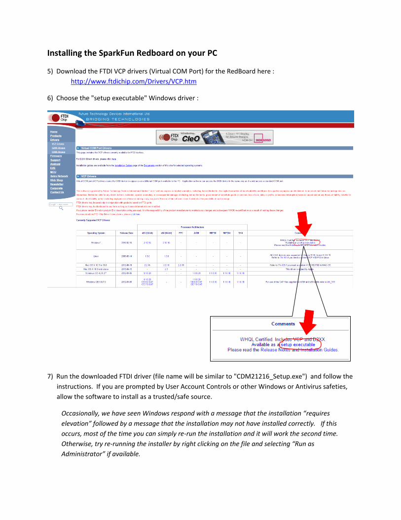
18) Copy all of the folders ("BasicLineFollower_08232015a," "libraries," “MotorDirTest_08232015a,”
and "QTRTest_02292016b") to your ...Documents\Arduino folder. This folder may be easiest
located by going to the Windows’ Start menu, on the right choose Documents, then open the
Arduino folder.
Note that on some systems where parental control is enabled, this folder can sometimes be
installed under the administrator's user documents instead of the child's account, even if it was
installed while logged in under the child's account.
19) Allow the Libraries folders or files to overwrite or merge and replace any existing files when it gives
you the message.
20) After moving the folders is complete, you can delete the now empty extracted sketch and library
folder from the temporary location used in Step 17.
Test Motors and Wiring with Serial Monitor
21) From within the Arduino IDE, either use the File menu > Open or the Open icon and navigate to the
" MotorDirTest_08232015a" folder you placed within Documents\Arduino. Open the folder and
you will find the sketch (.ino file) with the same name. Open the file.
22) Make sure your robot and computer are plugged in to the USB cable, your COM port is correct, then
Upload the sketch.
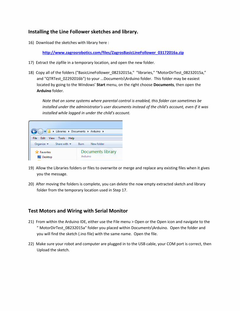
23) Open the Serial Monitor from the menu Tools > Serial Monitor. When the window opens set the
baud rate at the bottom right to 115200.
24) Within the serial monitor, follow the menus to test the motors individually first (l or r). Enter the
command letter in the prompt at the top of the monitor window and hit either enter or the send
button on the right.
a) If the wrong motor moves, swap the Ardumoto A1-A2 terminal wires with the B3-B4.
b) If the correct motor moves, but the wrong direction, swap the black and red motor wires at
the Ardumoto A or B terminals for just that motor.
c) Re-test individual motors after any wiring changes and make any additional needed wiring
changes.
d) After the individual motors appear to run correctly, run the test for both motors to confirm
individual setup is correct.

Test the QTR line sensor and Wiring with Serial Monitor
25) From within the Arduino IDE, either use the File menu > Open or the Open icon and navigate to the
"QTRTest_02292016b" folder you placed within Documents\Arduino. Open the folder and you will
find the sketch (.ino file) with the same name. Open the file.
26) Make sure your robot and computer are plugged in to the USB cable, your COM port is correct, then
Upload the sketch.
27) Place your robot on a piece of white paper on a flat surface, such as your desk or table.
28) Open the Serial Monitor from the menu Tools > Serial Monitor. The baud rate should still be at
115200. You should see something similar to this:

29) Stand the robot up on end and pass your finger or a large pencil/pen/marker near the sensors. If it
is wired correctly, the readout should show "XX" at a sensor that is seeing little reflection, such as a
dark line or open space, and "__" where it sees a bright reflection, such as your finger or white
paper. It will also display"--" where it is seeing somewhere between no reflection and a lot of
reflection.
a) The display should match left/right with the left/right of the sensors you are covering. If
they are opposite, you will need to change your wiring.
In this example, my finger was covering the 3rd and 4th sensor from the left.
b) If some of the sensors do not change, and only show "XX" they may be either unplugged or
non functional. Check your wiring for loose connections and your solder joints on the
sensor.
Upload and Run the Line Follower Sketch
30) From within the Arduino IDE, either use the File menu > Open or the Open icon and navigate to the
" BasicLineFollower_08232015a" folder you placed within Documents\Arduino. Open the folder
and you will find the sketch (.ino file) with the same name. Open the file.
31) Make sure your robot and computer are plugged in to the USB cable, your COM port is correct, then
Upload the sketch.

32) Set your robot on your lined course and turn it on. You should see the robot turn back and forth
over the line and begin following.
33) You can "tune" some of the variables in the sketch to affect its performance. Until you understand
how the sketch works, only adjust the couple of variables noted for "Tune."
The sketch is only a basic example to help you learn several fundamentals of sensing and motor
control. The real fun begins as you tune some of the variables and add further refined control
functions while developing an understanding of how to instruct the robot to accomplish tasks.
If you ran into any trouble finding the correct locations for any of the sketches or library files, you can
find more information and trouble shooting at Arduino's website here:
http://arduino.cc/en/Guide/Libraries


![The Role of the Zagros Suture on Three Dimensional ...journals.ut.ac.ir/article_20881_d08239240afe41517836baec...Zagros Reverse Fault’ by various authors [e.g., 75,33,27,9] in the](https://img.pdfslide.us/doc/110x75/5f0be6817e708231d432c598/the-role-of-the-zagros-suture-on-three-dimensional-zagros-reverse-faulta.jpg)