Embed Size (px)
Citation preview

ZTT/Plus CATV UPSUsers Guide
120V Input ModelEffective: June, 2003

PowerAlpha Technologies®

3164201085 Rev. F0
NOTE: Photographs contained in this manual are for illustrative purposes only.These photographs may not exactly match your installation.
NOTE: Review the drawings and illustrations contained in this manual beforeproceeding. If there are questions regarding the safe operation of thispowering system, please contact Alpha Technologies or your nearestAlpha representative.
NOTE: Alpha denies responsibility for any damage or injury involving itsenclosures, power supplies, generators, batteries, or other hardwarewhen used for an unintended purpose, installed or operated in anunapproved manner, or improperly maintained.
ZTT/Plus CATV UPS — 120VACUser’s Guide
Effective: June, 2003164201085 Rev. F0 — © 2003 Alpha Technologies
Contacting Alpha Technologies:
For general product information and customer service
1-800-863-3930(7:00 AM to 5:00 PM Pacific Time )
For complete technical support
1-800-863-3364 (7:00 AM to 5:00 PM Pacific Time, or 24/7 emergency support)

4 164201085 Rev. F0
Table of Contents
PREFACE
Important Safety Instructions ............................................................................................6General Safety Precautions ..............................................................................................7Battery Safety Notes .........................................................................................................9Battery Maintenance Guidelines .....................................................................................10Recycling and Disposal Instructions ...............................................................................11Electrical Safety ..............................................................................................................11Mechanical Safety ...........................................................................................................11
1. OVERVIEW
1.1 ZTT/Plus Uninterruptible Power Supply ................................................................12
2. CABINET INSTALLATION
2.1 Pole Mount Cabinet ...............................................................................................132.2 Ground Mount Cabinet ..........................................................................................17
2.2.1 Enclosure Grounding ............................................................................182.3 Electrical Connection ............................................................................................23
3. POWER SUPPLY INSTALLATION
3.1 Installing the ZTT/Plus ...........................................................................................243.2 Battery Installation and Connection ......................................................................26
3.2.1 Three battery Installation .......................................................................273.2.2 Six Battery Installation ...........................................................................283.2.3 Battery Removal ....................................................................................29
4. OPERATION
4.1 Startup and Initial Test ...........................................................................................304.2 Inverter Module Removal ......................................................................................324.3 Front Panel ............................................................................................................32
5. MAINTENANCE
5.1 General Guidelines................................................................................................355.2 Maintenance Log Sheet ........................................................................................36
6. SPECIFICATIONS
6.1 Models ...................................................................................................................376.2 Specifications, Electrical and Mechanical .............................................................386.3 Battery Specifications ............................................................................................39
7. TROUBLESHOOTING
7.1 Troubleshooting the ZTT/Plus ...............................................................................40

5164201085 Rev. F0
List of Figures
1. OVERVIEW
Fig. 1-1 Lectro ZTT/Plus CATV UPS ............................................................................12
2. CABINET INSTALLATION
Fig. 2-1 Utility Disconnect ............................................................................................14Fig. 2-2 Exploded view, Pole Mount Arrangement .......................................................15Fig. 2-3 Utility Disconnect, Grounding .........................................................................16Fig. 2-4 Enclosure Grounding ......................................................................................19Fig. 2-5 Ground Mount (Cement Pad) ..........................................................................20Fig. 2-6 Ground Mount (Front View) .............................................................................21Fig. 2-7 Ground Mount (Rear View) .............................................................................22
3. POWER SUPPLY INSTALLATION
Fig. 3-1 Opening the Cabinet .......................................................................................24Fig. 3-2 Three Battery Connection ...............................................................................27Fig. 3-3 Six Battery Connection ...................................................................................29
4. OPERATION
Fig. 4-1 Output Voltage Selection .................................................................................30Fig. 4-2 Front Panel ......................................................................................................32
List of Tables
Table 4-1 LCD/LED Indicators ..................................................................................33Table 7-1 Troubleshooting Matrix (1) ........................................................................40Table 7-2 Troubleshooting Matrix (2) ........................................................................41

6
Preface
164201085 Rev. F0
NOTE: Alpha Technologies’ products are subject to change through continualimprovement processes. Therefore, specifications and/or design layoutsmay vary slightly from descriptions included in this manual. Updates tothe manual will be issued when changes affect form, fit or function.
Review the drawings and illustrations contained in this manual before proceeding. If there are anyquestions regarding the safe installation or operation of the system, contact Alpha Technologies or thenearest Alpha representative. Save this document for future reference.
To reduce the risk of injury or death caused by electrical shock, explosion of fuel or moving parts; and toensure the continued safe operation of this product, the following symbols have been placed throughoutthis manual. Where these symbols appear, use extra care and attention.
DANGEROUS VOLTAGE
This symbol indicates a “dangerous voltage” may exist in this area of the product. Use cautionwhenever working in the area to prevent electrical shock.
INHALATION HAZARD - DON’T BREATHE VAPORS
This symbol indicates an “inhalation hazard” may exist in this area of the product. Use cautionwhenever working in the area to prevent possible inhalation of harmful (fuel or exhaust) vapors.
NO MATCHES OR OPEN FLAMES
This symbol indicates a “fire or explosive hazard” may exist in this area of the product. Usecaution whenever working in the area to prevent possible combustion of fuel vapors.
MECHANICAL OR MOVING PARTS HAZARD
These symbols indicate a “mechanical or moving parts hazard” may exist in this area of theproduct. Use caution whenever working in the area to prevent possible injury to the operatoror service personnel.
LEAK HAZARD
This symbol indicates a “leak hazard” may exist in this area of the product. Use caution wheneverworking in this area to prevent and correct any leaks detected.
ATTENTION
This symbol indicates important installation, operation or maintenance instructions. Alwaysfollow these instructions closely.
Important Safety Instructions
Contained In This Manual.
Read This Manual Before Proceeding!

7
Preface
164201085 Rev. F0
General Safety Precautions
A “Warning” identifies conditions and actions that pose a hazard to the user.
A “Caution” identifies conditions and actions that may damage the power supply or associatedequipment.
Warnings
NOTE: This enclosure and its associated hardware (power supply, batteries,cabling) may contain equipment, batteries or parts which have accessiblehazardous voltage or currents.
To avoid injury:
• This enclosure and its associated hardware must be serviced by authorized personnel only.
• Enclosure must remain locked at all times, except when authorized service personnel arepresent.
• Remove all conductive jewelry or personal equipment prior to servicing equipment, parts,connectors, wiring, or batteries.
• Read and follow all installation, equipment grounding, usage, and service instructionsincluded in this manual.
• Use proper lifting techniques whenever handling enclosure, equipment, parts, or batteries.
• Batteries contain dangerous voltages, currents and corrosive material. Battery installation,maintenance, service and replacement must be performed by authorized personnel only.
• Never use uninsulated tools or other conductive materials when installing, maintaining,servicing or replacing batteries.
• Use special caution when connecting or adjusting battery cabling. An improperly connectedbattery cable or an unconnected battery cable can result in arcing, a fire, or possibleexplosion.
• A battery that shows signs of cracking, leaking or swelling must be replaced immediately byauthorized personnel using a battery of identical type and rating.
• Avoid any contact with gelled or liquid emissions from a valve-regulated lead-acid (VRLA)battery. Emissions contain dilute sulfuric acid which is harmful to the skin and eyes.Emissions are electrolytic, which are electrically conductive and are corrosive. Follow theChemical Hazards notes if contact occurs.
• Do not smoke or introduce sparks in the vicinity of a battery.
• Under certain overcharging conditions, lead-acid batteries can vent a mixture of hydrogengas which is explosive. Proper venting of the enclosure is required.
• Follow the battery manufacturer’s approved transportation and storage instructions.

8
Preface
164201085 Rev. F0
Cautions
NOTE: Enclosure, equipment or parts may be damaged or cause damage if usedor installed improperly.
To avoid damage:
• Prior to installation, verify that the AC input voltage to the enclosure and itsequipment match with respect to voltage and frequency.
• Prior to installation, verify that the output voltage from the enclosure or itsequipment match the voltage requirements of the connected equipment (load).
• Prior to installation, verify that the enclosure’s utility service panel is equipped witha properly rated circuit breaker for use with the equipment inside. Refer tomanufacturer’s recommendations.
• Review and upgrade utility service panel circuit breaker requirements whenever theequipment within the enclosure is changed.
• Prior to installation, contact local utilities, local building maintenance departments,and cable/ piping locator services to ensure that installation does not interfere withexisting utility or building cables/piping.
• Do not exceed the output rating of equipment. Verify load requirements prior andduring connection process.
• Prior to handling the batteries, touch a grounded metal object to dissipate any staticcharge that may have developed on your body.
• Alpha Technologies is not responsible for unit damage due to enclosure orinstallation temperatures which exceed the operating temperature of the product.
General Safety Precautions

9
Preface
164201085 Rev. F0
Battery Safety Notes
Lead-acid batteries contain dangerous voltages, currents and corrosive material. Batteryinstallation, maintenance, service and replacement must be performed by authorized personnelonly.
Chemical Hazards
NOTE: Any gelled or liquid emissions from a valve-regulated lead-acid (VRLA)battery contain dilute sulfuric acid, which is harmful to the skin and eyes.Emissions are electrolytic, which are electrically conductive and corrosive.
To avoid injury:
• Servicing and connection of batteries shall be performed by, or under the directsupervision of, personnel knowledgeable of batteries and the required safetyprecautions.
• Always wear eye protection, rubber gloves, and a protective vest when workingnear batteries. Remove all metallic objects from hands and neck.
• Batteries produce explosive gases. Keep all open flames and sparks away frombatteries.
• Use tools with insulated handles, do not rest any tools on top of batteries.
• Batteries contain or emit chemicals known to the State of California to cause cancerand birth defects or other reproductive harm. Battery post terminals and relatedaccessories contain lead and lead compounds. Wash hands after handling.(California Proposition 65)
• Wear protective clothing (insulated gloves, eye protection, etc.) whenever installing,maintaining, servicing, or replacing batteries.
• If any battery emission contacts the skin, wash immediately and thoroughly withwater. Follow your company’s approved chemical exposure procedures.
• If any battery emission contacts the eye, wash immediately and thoroughly withwater for 10 minutes with pure water or a special neutralizing eye wash solutionand seek immediate medical attention. Follow your company’s approved chemicalexposure procedures.
• Neutralize any spilled battery emission with the special solution contained in anapproved spill kit or with a solution of 1 lb. Bicarbonate of soda to 1 gallon of water.Report chemical spill using your company’s spill reporting structure and seekmedical attention if necessary.
• Always replace batteries with those of an identical type and rating. Never install oldor untested batteries.
• Do not charge batteries in a sealed container. Each individual battery should haveat least 0.5 inches of space between it and all surrounding surfaces to allow forconvection cooling.
• All battery compartments must have adequate ventilation to prevent anaccumulation ofpotentially dangerous gas.

10
Preface
164201085 Rev. F0
The battery maintenance instructions listed below are for reference only. Batterymanufacturer’s instructions for transportation, installation, storage or maintenance takeprecedence over these instructions.
• To prevent damage, inspect batteries every 3 months for:
Signs of battery cracking, leaking or swelling. The battery should be replacedimmediately by authorized personnel using a battery of the identical type andrating.
Signs of battery cable damage. Battery cable should be replaced immediately byAuthorized Personnel using replacement parts specified by vendor.
Loose battery connection hardware. Refer to battery manufacturer’s documentationfor the correct torque and connection hardware for the application.
• Apply battery manufacturer’s specified antioxidant compound on all exposedconnections.
• Verify battery terminals and/or exposed connection hardware is not within 2 inchesof aconductive surface. Reposition batteries as necessary to maintain adequateclearance.
• Clean up any electrolyte (battery emission) in accordance with all federal, state,and local regulations or codes.
• Proper venting of the enclosure is recommended. Follow the Battery Manufacturer’sapproved transportation and storage instructions.
• Always replace batteries with those of an identical type and rating. Never install oldor untested batteries.
• Do not charge batteries in a sealed container. Each individual battery should haveat least 0.5 inches of space between it and all surrounding surfaces to allow forconvection cooling.
• All battery compartments must have adequate ventilation to prevent anaccumulation ofpotentially dangerous gas.
Battery Maintenance Guidelines
• Prior to handling the batteries, touch a grounded metal object to dissipate any staticcharge that may have developed on your body.
• Never use uninsulated tools or other conductive materials when installing,maintaining, servicing or replacing batteries.
• Use special caution when connecting or adjusting battery cabling. An improperlyconnected battery cable or an unconnected battery cable can make contact with anunintended surface that can result in arcing, fire, or possible explosion.
• A battery showing signs of cracking, leaking, or swelling should be replacedimmediately by authorized personnel using a battery of identical type and rating.
• Under extreme overcharging conditions, Lead-acid batteries can vent a mixture ofHydrogen gas which is explosive.
Battery Safety Notes, continued

11
Preface
164201085 Rev. F0
• Lethal voltages are present within the power supply and electrical boxes. Neverassume that an electrical connection or conductor is not energized. Check thecircuit with a volt meter with respect to the grounded portion of the enclosure (bothAC and DC) prior to any installation or removal procedure.
• Do not work alone under hazardous conditions.
• A licensed electrician is required to install permanently wired equipment.
• Input voltages can range up to 240 VAC. Ensure that utility power is disabled beforebeginning installation or removal.
• Ensure no liquids or wet clothes contact internal components.
• Hazardous electrically live parts inside this unit are energized from batteries evenwhen the AC input power is disconnected.
Electrical Safety
Mechanical Safety
• Keep hands and tools clear of fans. Fans are thermostatically controlled and willturn on automatically.
• Power supplies can reach extreme temperatures under load.
• Use caution around sheet metal components and sharp edges.
• Spent or damaged batteries are considered environmentally unsafe. Always recycleused batteries or dispose of the batteries in accordance with all federal, state andlocal regulations.
Recycling and Disposal Instructions

12
1.Overview
164201085 Rev. F0
1.1 The ZTT/Plus Uninterruptible Power Supply
This manual provides information related to the installation, operation, and service of specificLectro equipment. For assistance in personnel training applications, please contact AlphaTechnologies at: 1-800-863-3930. For Technical Support, or for specific problems, call 1-800-863-3364 (7AM-5PM Pacific Time, or 24/7 emergency) and ask for Technical Support. Theinformation in this manual is restricted to customers of Alpha Technologies, and use byunauthorized persons is strictly prohibited.
Prior knowledge of good CATV system construction practice and a working knowledge ofelectrical safety practices are minimum qualifications for installation and operation. However,for equipment servicing, the technician should also be well versed in basic electronics.It is recommended that you carefully read the manual prior to leaving your office to performthe work. The figure below shows the front panel controls of the Lectro ZTT/Plus CATV UPS.
TEST JACKS
DC CIRCUIT BREAKER
AC CIRCUIT BREAKER
EXTERNAL LED CONNECTOR
LCD PANEL
LCD CONTROL BUTTONS
GREEN (NORMAL) LED
RED (FAULT/STANDBY) LED
YELLOW (ALARM) LED
STATUS MONITORINTERFACE CONNECTOR
Fig. 1-1 Lectro ZTT/Plus CATV UPS

2. Cabinet Installation
13164201085 Rev. F0
The standard cabinet is designed to be pole-mounted. Wooden pole mount applicationsutilize machine bolts to attach the enclosure mounting brackets to the pole, while installationsdone on concrete or steel poles utilize straps to attach the mounting bracket(s) to the pole.
NOTE: Mounting bolts must go completely through the wooden pole and besecured from the back with a large washer and nut. The two galvanizedmounting brackets are placed between the enclosure and pole. Most codesrequire the base of the enclosure to be located a minimum height from theground. Always verify height restrictions before proceeding.
NOTE: The majority of poles are the property of the local Utility. Before installing anenclosure, the location and method of mounting must be approved by theUtility.
This chapter contains instructions for pole mount and ground mount installationsincluding the electrical connections.
A bucket truck and other suitable equipment, such as spikes and safety harnesses, should beused during installation or service of pole-mounted cabinets. To mount the ZTT/Plus UPS toa utility pole perform the following steps:
NOTE Pole mounting the cabinet should be done in accordance with the localagreement between the cable operator and the utility company.
The disconnect box should have a high magnetic circuit breaker capable of passing shortduration inrush currents and have a 20A minimum rating.
2.1 Pole-Mount Cabinet
14
2. Cabinet Installation
164201085 Rev. F0
INSTALLATION PROCEDURE
1. Install an appropriate disconnect box between the AC power source and the cabinetmounting point. Wire to the power line in accordance with local codes.
2. Remove all equipment, hardware, and options from the outdoor cabinet and store in asecure location for future use.
3. Remove the U-shaped mounting bracket from the cabinet rear panel (see Figure 2-2).
4. Use the bracket as a template to mark mounting holes at the desired mounting location.If possible, position the cabinet so the front panel and optional LEDs are easily visible.
5. Drill 11/16" holes in the pole at the marked locations.
6. Attach the mounting bracket to the pole using 5/8" hardware (not provided). Tightensecurely.
7. Optional band mounting for metal/cement poles: insert the metal bands or straps (notprovided) through the band slots on the mounting bracket. Tighten the bands securely.
8. Raise the cabinet and set into place on the bracket. Attach the cabinet using thehardware removed in step 3. Tighten the bolts securely.
9. Confirm availability of a suitable ground rod next to the power pole. If required, drive arod according to local codes, and connect to the utility disconnect box and theenclosure grounding lug.
NOTE On some products, the cabinet bracket may be one piece instead of two (asshown), and the number of mounting screws may vary.
2.1 Pole-Mount Cabinet, continued
Power Meter
1
Fig. 2-1 Utility Disconnect

2. Cabinet Installation
15164201085 Rev. F0
6
4
5
437
2, 8
2.1 Pole-Mount Cabinet, continued
Fig. 2-2 Exploded View, Pole Mounting Arrangement
16
2. Cabinet Installation
164201085 Rev. F0
Power Meter
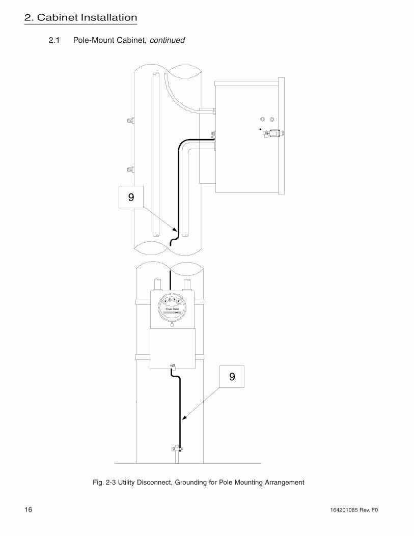
9
9
2.1 Pole-Mount Cabinet, continued
Fig. 2-3 Utility Disconnect, Grounding for Pole Mounting Arrangement
2. Cabinet Installation
17164201085 Rev. F0
INSTALLATION PROCEDURE
Although ground mounting the power supply can be accomplished by several methods, thefollowing procedure is recommended. Figure 2-5, Figure 2-6, and Figure 2-7 illustrate theground mount installation.
1. Select an appropriate site. Clear and level an area of approximately 36" X 36".
2. In accordance with local codes, install the disconnect box near the AC power source.
NOTE The disconnect box should have a high-magnetic circuit breaker, capable ofpassing short duration inrush currents, and have a 20A minimum rating.
3. From the disconnect, install conduit to the power supply site and turn a stub up toextend above ground level. Drive a suitable ground rod according to local codes (seeFigure 2-5). Install appropriate size conduit for the output connections and turn a stubup to extend flush with the pad surface cast into the concrete. Ensure the conduitlocations correspond with the appropriate cabinet connections.
4. Using 1 X 4 lumber, construct a form for the cement pad (see Figure 2-5 fordimensions). Anchor the form securely to the ground.
5. Attach the ground mounting brackets from the supplied kit to the ground skirt using the5/16-18 X .75 screws and the 5/16-18 nuts.
6. Make a template from sheet metal or wood indicating the position of the groundmounting bracket mounting holes. Drill out the four holes in the template and insert four5/8" X 4" bolts (not supplied). The head of the bolts will be embedded into the concretepad when installation is complete. Leave sufficient thread above the pad for securingthe ground skirt.
7. Center and secure template (with bolts in position) over the form. Be sure the conduitstub-ups for the AC input and the ground rod are positioned at desired locations.
8. Pour, level, and finish concrete to the bottom of the template. Allow to cure for 24 hours.
9. Attach the ground skirt to the power supply cabinet. Align skirt inside the bottom lip ofthe cabinet and secure using 10-32 X 3/8" screws from the parts kit.
10. Attach the power supply cabinet to the concrete pad using 5/8" nuts (not provided)through the ground mounting brackets (see Figure 2-6). Tighten all hardware securely.
11. Continue to Section 2.3, Electrical Connection on page 23.
2.2 Ground-Mount Cabinet

18
2. Cabinet Installation
164201085 Rev. F0
2.2 Ground-Mount Cabinet, continued
2.2.1 Enclosure Grounding
NOTE: Alpha Technologies recommends using the grounding method illustratedon the following page. The grounding method for a particular site will bedependant upon soil type, available space, local codes, NEC (NationalElectric Code), and other site-specific characteristics.
NOTE: Alpha Technologies recommends 5 ohms minimum ground resistance (25ohms per NEC) between enclosure and ground rods, in accordance withIEEE 1100-1999 Powering and grounding Electronic Equipment.
NOTE: Alpha Technologies assumes no responsibility or liability for failure of theinstaller to comply with the requirements of all applicable local and nationalcodes. Where allowed, exothermic welding may be used as an alternativeto Burndy clamps and connectors.
2. Cabinet Installation
19164201085 Rev. F0
2.2 Ground-Mount Cabinet, continued
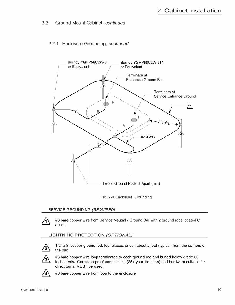
2.2.1 Enclosure Grounding, continued
SERVICE GROUNDING (REQUIRED)
#6 bare copper wire from Service Neutral / Ground Bar with 2 ground rods located 6'apart.
LIGHTNING PROTECTION (OPTIONAL)
1/2" x 8' copper ground rod, four places, driven about 2 feet (typical) from the corners ofthe pad.
#6 bare copper wire loop terminated to each ground rod and buried below grade 30inches min. Corrosion-proof connections (25+ year life-span) and hardware suitable fordirect burial MUST be used.
#6 bare copper wire from loop to the enclosure.
Burndy YGHP58C2W-2TNor Equivalent
Burndy YGHP58C2W-3or Equivalent
Terminate atEnclosure Ground Bar
Terminate atService Entrance Ground
Two 8' Ground Rods 6' Apart (min)
4
1
2
2' min.
#2 AWG
2
2
2
3
1
2
3
4
Fig. 2-4 Enclosure Grounding

20
2. Cabinet Installation
164201085 Rev. F0
2.2 Ground-Mount Cabinet, continued
NOTE: It is recommended the cement pad dimensions extend beyond the ground skirton the front and sides and 3-5" in the back.
Fig. 2-5 Ground Mount (Cement Pad)

2. Cabinet Installation
21164201085 Rev. F0
2.2 Ground-Mount Cabinet, continued
Fig. 2-6 Ground Mount (Front View)

22
2. Cabinet Installation
164201085 Rev. F0
2.2 Ground-Mount Cabinet, continued
Fig. 2-7 Ground Mount (Rear View)

2. Cabinet Installation
23164201085 Rev. F0
WARNING: Adhere to all appropriate electrical precautions
CONNECTION PROCEDURE
1. Open the cabinet doors.
2. Install liquid tight conduit to the fitting on the cabinet rear panel and pull the AC primarywiring into the cabinet housing.
3. Using the receptacle provided, connect the AC high input (black) to the copperreceptacle terminal, the AC neutral input (white) to the silver receptacle terminal, andthe utility protective ground (green) to the green receptacle terminal. The screw tightentorque is 20 lb in.
4. Position all wiring neatly in the receptacle box and install the receptacle and cover.
5. Using the output wire harness (green and yellow wires with power lock connectors, aseizure clamp, and a-ring) and cable adapter from the parts kit, install the cable adapterand ground wire.
Insert the cable adapter from outside the cabinet into the paint-masked hole, alongwith supplied cable feed guard bracket for ground mount installation.
Use the locknut to secure the adapter and the large a-ring to the cabinet. Tightensecurely.
6. Install your choice of output cable in the adapter. A right-angle adapter is required forground mount installation.
Connect the yellow output wire to the coax cable center conductor by sliding theseizure clamp into place and tightening securely.
Slide the protective boot over the cable center conductor and seizure clamp. Installthe cable feed guard to the bracket under the cable adapter.
7. Connect an unbroken 6 AWG soft-drawn copper ground wire between the lug providedon the back of the cabinet and a ground rod for lightning protection. Use a ground rodclamp of the proper type, above or below grade.
NOTE: If local codes require bonding to utility ground. a separate ground rodand vertical should be provided. then the two verticals should be bondedat the bottom of the pole.
2.3 Electrical Connection
3. Power Supply Installation
24 164201085 Rev. F0
3.1.1 ZTT/Plus Chassis Installation
INSTALLATION PROCEDURE
CAUTION: The maximum ZTT/Plus chassis weight is 60 lb, and the center ofgravity is offset to the right. The lifting lugs on the top may be used toraise the chassis with the proper equipment. All appropriate safetyprecautions must be taken to prevent serious personal injury.
WARNING: Verify the DC circuit breaker is in the OFF (down) position and the ACcircuit breaker is in the OFF position before proceeding.
Optional
Remove the inverter module from the ZTT/Plus chassis and store in a securelocation. This module reduces the total chassis weight by approximately 6.5pounds.
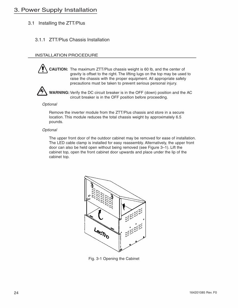
Optional
The upper front door of the outdoor cabinet may be removed for ease of installation.The LED cable clamp is installed for easy reassembly. Alternatively, the upper frontdoor can also be held open without being removed (see Figure 3–1). Lift thecabinet top, open the front cabinet door upwards and place under the lip of thecabinet top.
3.1 Installing the ZTT/Plus
Fig. 3-1 Opening the Cabinet

3. Power Supply Installation
25164201085 Rev. F0
1. Place the ZTT/Plus chassis on the upper shelf of the cabinet with the circuit breakersfacing the front of the cabinet.
2. Thread the battery cables through the two 0.875" holes in the cabinet shelf. Thebushings should be fully seated.
3. If the battery temperature probe is used, connect the sensor plate containing the smallPC board to the negative battery terminal on the right battery (the same terminal wherethe negative [black] wire from the chassis is connected).
4. Plug in the modular phone type connector into the RJ -11 port on the right side of theinverter module (not available on all configurations).
5. Connect the output harness power lock connector (green and yellow) to the ZTT/Pluschassis green and yellow power lock connector. Confirm both wire and connector colorsmatch.
6. Connect the green ground wire from the ZTT/Plus chassis to the mounting bolt with the#10 hardware provided. (The mounting bolt attaches the exterior ground clamp to theoutdoor cabinet.)
7. Confirm the AC circuit breaker is off. Plug the AC line cord from the chassis into thereceptacle.
8. If the upper front door was removed in step 2 reinstall it. Be careful to install the LEDcable clamp without binding or catching it in the door opening.
9. If the inverter module was removed from the chassis in step 1, fully insert the moduleback into the chassis and tighten the thumbscrews. Plug the external LED connectorinto the front of the module.
10. Install any optional equipment at this time. Refer to the instructions supplied with theoption.
3.1 Installing the ZTT/Plus, continued

3. Power Supply Installation
26 164201085 Rev. F0
NOTE: Read the safety instructions at the front of this manual prior to installing thebatteries.
CAUTION: Batteries shall be 12 Vdc with the same ampere rating. Do not mix oldand new batteries; replace as a set using recognized batteries.
Servicing of batteries shall be performed or supervised by personnel knowledgeable of batteriesand the required precautions Keep unauthorized personnel away from batteries.
Short circuit danger: do not rest tools or equipment on top of batteries Do not allow batteries toshort circuit; they may explode and cause severe injury. Do not open or mutilate the batteries.Released electrolyte is extremely harmful to skin and eyes, and may be toxic. Do not dispose ofbatteries in a fire, they may explode.
This product contains or emits chemicals known to the State of California to cause cancer andbirth defects or other reproductive harm. Battery post, terminals and related accessoriescontain lead and lead compounds. Wash hands after handling. (California Proposition 65)
CAUTION: The following precautions shall be observed when working withbatteries.
Follow approved OSHA regulations for handling batteries.- Always wear eye protection anda protective vest when working near batteries.
Batteries produce explosive gases. Keep away all sparks and flames.
Remove watches, rings, or other metal objects.
Use tools with insulated handles.
Wear rubber gloves and boots.
3.2 Battery Installation and Connection

3. Power Supply Installation
27164201085 Rev. F0
3.2.1 Three Battery Installation
To install three batteries for use with the ZTT/Plus:
NOTE: Do not allow the loose end of a battery jumper or battery cable to contact thecabinet or other battery terminals during installation.
1. Place batteries in the bottom of the cabinet, positive terminals to the front.
2. Connect the red battery cable from the ZTT/Plus chassis to the positive (+) terminalof left battery.
3. Connect the battery jumper from the negative (-) terminal of left battery to thepositive (+) terminal of center battery.
4. Connect the battery jumper from the negative (-) terminal of center battery to thepositive (+) terminal of right battery.
CAUTION: Visually check all battery wiring. Batteries may explode if wiring is notcorrect.
5. Confirm the DC circuit breaker is off (down). Connect the black battery cable fromthe enics chassis to the negative (-) terminal of the right battery.
6. Measure the DC voltage to ensure wiring was installed correctly (between 31.5Vand 41.4 V) and to confirm the charge state of the batteries.
3.2 Battery Installation and Connection, continued
3A 2A 1A
Figure 3-2 Three Battery Connection

3. Power Supply Installation
28 164201085 Rev. F0
3.2 Battery Installation and Connection, continued
3.2.2 Six Battery Connection
To install six batteries for use with the ZTT/Plus:
NOTE: Do not allow the loose end of a battery jumper or battery cable to contactthe cabinet or other battery terminals during installation.
1. Place three batteries in the bottom of the cabinet and three batteries in the middle shelf,positive terminals to the front.
2. Complete the following for the lower batteries and then repeat for the upper batteries(see Figure 3–3):
Connect the battery jumper from the negative (-) terminal of left battery to the positive(+) terminal of center battery.
Connect the battery jumper from the negative (-) terminal of center battery to thepositive (+) terminal of right battery.
NOTE: In addition to the battery cables from the chassis, two long battery cablesare included. Pull these long cables down through the middle shelf toensure they reach from one battery tray to the other.
3. Connect one end of the long red cable to the positive (+) terminal of lower left battery.
4. Connect the other end of the long red cable and the red battery cable from the ZTT/Plus chassis to the positive (+) terminal of upper left battery.
5. Connect one end of the long black cable to the negative (-) terminal of lower rightbattery.
CAUTION: Visually check all battery wiring. Batteries may explode if wiring is notcorrect.
6. Confirm the DC circuit breaker is off (down). Connect the other end of the long blackcable and the black battery cable from the chassis to the negative (-) terminal of theupper right battery.
7. Measure the DC voltage to ensure wiring was installed correctly (between 31.5V and41.4V) and to confirm the charge state of the batteries.

3. Power Supply Installation
29164201085 Rev. F0
3.2.3 Battery Removal
1. Turn the DC circuit breaker off (down) and observe all precautions for handlingbatteries as outlined in “Battery Safety Notes” on pages 9 and 10.
2. Removal is in the reverse order of installation.
3.2 Battery Installation and Connection, continued
3A 2A 1A
3B 2B 1B
Figure 3-3 Six Battery Connections

30
4. Operation
164201085 Rev. F0
This chapter explains the operation of the ZTT/Plus CATV UPS including startup and initialtest, the front panel, UPS operational modes, and how to use the LCD panel. After mountingthe cabinet and installing the UPS, perform the following steps to start up the ZTT/Plus.
TURN UP AND TEST PROCEDURE
1. If you have a 60V model, skip to step 3. If you have a 60/72/90V or 60/90Vmodel, continue to step 2.
2. For 60/72/90V and 60/90V Models Only. Select the output voltage by pluggingthe output connector into the desired voltage source. The output connector is yellowand is located towards the rear of the chassis. The voltage source connectors arelocated towards the front of the chassis:
Red = 87 Vac White = 72 Vac Yellow = 60 Vac
Locate the proper source connector for your cable company voltage and plug it into theyellow output connector.
NOTE:The connection for selecting output voltage is inside the ZTT/Plus chassisalong the main wire harness in the center of the chassis; it is accessible whenthe inverter module is removed.
4.1 Startup and Initial Test
Figure 4-1 Output Voltage Selection ZTT/Plus 60/72/90V and 60/90V Models

31
4. Operation
164201085 Rev. F0
TURN UP AND TEST PROCEDURE, CONTINUED
3. If the inverter module is not already installed (Verify AC and DC breakers are OFF)fully insert and seat the module into the chassis and tighten the thumbscrews.
4. Turn on the external disconnect provided by the installer; then turn on the AC circuitbreaker on the ZTT/Plus front panel.
5. The LCD panel indicates BATTERY BREAKER OPEN and the FAULT/STANDBY (red)LED comes on.
6. Confirm the output voltage at the test points on the front of the chassis or through theLCD panel.
7. Turn the DC circuit breaker on (up position closes the breaker).
8. Verify the LCD displays Normal Mode.
9. The unit is now operating normally. Use step 10 through step 13 to test standbyoperation.
NOTE: If the charge level of the battery is too low, the unit will not transfer tostandby operation; the battery charges automatically. Allow the batteries tocharge and then perform the standby operation tests.
10. Turn off the AC circuit breaker on the front of the ZTT/Plus chassis.
11. The unit transfers to STANDBY mode. The FAULT/STANDBY (red) LED comes on andthe LCD panel displays STANDBY mode.
12. Turn on the AC circuit breaker.
13. After restoring AC power and waiting approximately 8 to 10 seconds for the ZTT/Plus tophase lock to the incoming AC line, the unit transfers to the NORMAL mode. TheNORMAL (green) LED comes on, the FAULT/STANDBY (red) LED turns off, and theLCD displays NORMAL mode.
The unit is now fully functional. Close and secure the cabinet.
4.1 Startup and Initial Test, continued

32
4. Operation
164201085 Rev. F0
The ZTT/Plus UPS can operate in NORMAL mode (AC operation) with the inverter moduleremoved. The module can be safely removed without disturbing the output.
To prevent outages and improper operation:
1. Turn the DC circuit breaker off (down) before removal or installation.
2. Remove the inverter module by loosening the thumbscrews and pulling the handle.Leave the DC circuit breaker off.
3. When installing, verify the DC circuit breaker is OFF, then fully insert and seat themodule and tighten the thumbscrews, then turn the DC Circuit breaker on (up).
4.3 Front panel
The following tables describe the front panel LEDs, connectors, and the LCD panel.
TEST JACKS
DC CIRCUIT BREAKER
AC CIRCUIT BREAKER
EXTERNAL LED CONNECTOR
LCD PANEL
LCD CONTROL BUTTONS
GREEN (NORMAL) LED
RED (FAULT/STANDBY) LED
YELLOW (ALARM) LED
STATUS MONITORINTERFACE CONNECTOR
4.2 Inverter Module Removal
Figure 4-2 Front panel controls, ZTT/Plus Power Supply
DESCRIPTIONMODE
The Normal LED is green and on when the ZTT/Plusdetermines utility power is present and usable. Thisindicates output power is coming from AC input (utility).
NORMAL (AC operation)
The Alert LED is yellow and on when there is a UPS alarm condition. See the following LCD table for alarmdescriptions.
ALERT
The Fault/Standby LED is red and on when the ZTT/Plusis running on battery power (Standby mode) or when theZTT /Plus diagnoses a module fault condition. See thefollowing LCD table for fault conditions and descriptions.
FAULTS/Standby
Used for connecting to external LEDs (Normal and Fault/Standby), typically located on the front of the cabinet door.
External LED Connector
Used for connecting to the optional Status MonitorInterface module or directly to status monitoringtransponders (certain manufacturers only).
Status Monitor Interface
DESCRIPTIONCONNECTOR
33
4. Operation
164201085 Rev. F0
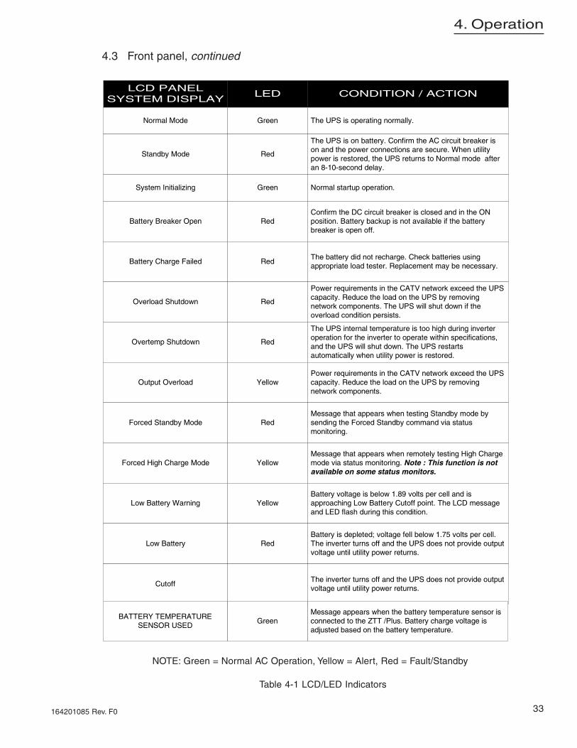
CONDITION / ACTIONLEDLCD PANEL
SYSTEM DISPLAY
The UPS is operating normally.GreenNormal Mode
The UPS is on battery. Confirm the AC circuit breaker ison and the power connections are secure. When utilitypower is restored, the UPS returns to Normal mode afteran 8-10-second delay.
RedStandby Mode
Normal startup operation.GreenSystem Initializing
Confirm the DC circuit breaker is closed and in the ONposition. Battery backup is not available if the batterybreaker is open off.
RedBattery Breaker Open
The battery did not recharge. Check batteries usingappropriate load tester. Replacement may be necessary.
RedBattery Charge Failed
Power requirements in the CATV network exceed the UPScapacity. Reduce the load on the UPS by removingnetwork components. The UPS will shut down if theoverload condition persists.
RedOverload Shutdown
The UPS internal temperature is too high during inverteroperation for the inverter to operate within specifications,and the UPS will shut down. The UPS restartsautomatically when utility power is restored.
RedOvertemp Shutdown
Power requirements in the CATV network exceed the UPScapacity. Reduce the load on the UPS by removingnetwork components.
YellowOutput Overload
Message that appears when testing Standby mode bysending the Forced Standby command via statusmonitoring.
RedForced Standby Mode
Message that appears when remotely testing High Chargemode via status monitoring. Note : This function is notavailable on some status monitors.
YellowForced High Charge Mode
Battery voltage is below 1.89 volts per cell and isapproaching Low Battery Cutoff point. The LCD messageand LED flash during this condition.
YellowLow Battery Warning
Battery is depleted; voltage fell below 1.75 volts per cell.The inverter turns off and the UPS does not provide outputvoltage until utility power returns.
RedLow Battery
The inverter turns off and the UPS does not provide outputvoltage until utility power returns.
Cutoff
Message appears when the battery temperature sensor isconnected to the ZTT /Plus. Battery charge voltage isadjusted based on the battery temperature.
GreenBATTERY TEMPERATURE
SENSOR USED
4.3 Front panel, continued
NOTE: Green = Normal AC Operation, Yellow = Alert, Red = Fault/Standby
Table 4-1 LCD/LED Indicators

34
4. Operation
164201085 Rev. F0
LCD panel Menu
The following information can be viewed by pushing the LCD control buttons ( and ).Push the button to scroll from beginning to end of the list. Push the button to scroll fromthe end to beginning of the list.
1. Input Voltage (measured phase to neutral)2. Battery Voltage3. Charge Current4. Ambient Temperature (temperature of air intake from the front of the inverter module;
displayed in degrees Celsius and degrees Fahrenheit, +5 degrees)5. Standby Events: displays the number of times that the ZTT/Plus operated on inverter
(the number of times the ZTT/Plus transferred to battery)6. Standby Minutes: displays the cumulative time in minutes that the ZTT/Plus operated on
inverter (the total number of minutes on battery)7. Output Voltage (measured phase to neutral)8. Output Current9. System Display
Resetting Standby Counters
To reset the standby counters (items 5 and 6 above), press and hold both LCD control buttons( and ) simultaneously for 10 seconds.
LCD Operation
The ZTT/Plus LCD has an automatic 25-second delay for reporting system parameters (suchas voltage, current, events). This delay allows time during maintenance visits for writing thereadings on the maintenance log sheet. The LCD reporting screen displays the data for 25seconds or until you press the control buttons ( and ) to advance the screens.
If the ZTT/Plus mode of operation changes (for example, goes to standby operation) while theZTT/Plus LCD is reporting system parameters, the LCD panel displays the current parameterfor 25 seconds and then reports the new mode of operation.
Before demonstrating or testing the manual standby operation (turning the AC circuit breakeroff and on), confirm the LCD is in a status screen such as Normal mode or Standby mode.
4.3 Front panel, continued

35
5. Maintenance
164201085 Rev. F0
NOTE: It is important that secure mechanical and electrical connections bemaintained on this equipment. Secure connections will help preventoutages and equipment damage. A sample maintenance log sheet isprovided.
• Inspect the external ground connections for mechanical integrity and good physicalcondition.
• Check the cabinet for damage and check the mounting hardware for mechanicalintegrity.
• Open the cabinet. Check tightness of all battery, internal ground, and outputconnections.
• Observe condition of batteries (such as leaks). Look for excessive dust or moistureindicating cabinet damage. Repair as required and note any unusual conditions forfuture reference.
• Inspect the input surge suppressor (if installed) for damage.• The optional input surge suppressor may be installed in the receptacle. It should show
gray potting compound on the surface when viewed from the front of the unit. If thissurface color is not light gray, replacement of the suppressor is recommended.
• Record status of LEDs on inverter module. Typically the NORMAL (green) LED is on.• Confirm that the LCD panel does not show any fault condition.• Record information from the LCD panel menu. Reset the inverter counters, as required
by your procedures, by holding both control buttons ( and ) simultaneously for 10seconds.
• If verification is required to confirm the LCD readings, use a true RMS meter to recordAC output voltage and battery voltage at front panel test points. If available, use aclamp-on current probe to record AC output current at the cable adapter.
WARNING: Refer to applicable battery safety precautions.
• Turn the DC circuit breaker off (down). Record battery voltage for each battery (well-matched batteries should differ by no more than 0.2 Vdc). Record date code for eachbattery if available.
• Using a battery load tester, check the performance of each battery. Replace batteries ifrequired.
NOTE: Do not mix batteries of different types, sizes, or ages.
• After confirming proper battery condition, turn the DC circuit breaker on (up).• Force the unit into standby operation by turning the AC circuit breaker off. Verify standby
operation. Record AC output voltage (at test points or through LCD panel) and recordLED status; only the FAULT/STANDBY (red) LED should be on. If other LEDs are onrefer to the LCD panel.
• Return the unit to normal operation by turning the AC circuit breaker on. After phaselocking to input AC line, the unit returns to Normal mode.
• Confirm status of LEDs: typically the NORMAL (green) LED is on. This completes theroutine maintenance check. Close and lock the cabinet.
5.1 General Guidelines

36
5. Maintenance
164201085 Rev. F0
5.2 Maintenance Log Sheet
ZTT/Plus UPS Maintenance Log SheetFor use with routine maintenance procedures in the operator’s manual.
WARNING Follow all safety precautions and instructions.
Cable CompanyInspection Date: Location:Technician: Model/Serial #
VISUAL INSPECTION Problem and Fix:Comments:
LED’s:Normal Mode:* NORMAL Comments:
ALERTFAULT/STANDBY
LCD PANEL AC Input Battery Voltage Standby EventsCharge Current Standby Minutes
AC Output Ambient TemperatureVolts Amps Reset? Y N
Optional DVM Readings:
DVM(RMS) AC Voltage DC Voltage AC Amps(Test Point) (Test Point) (Clamp on Probe)
Turn the DC breaker off (down). FAULT (red) LED on? Y N
BATTERYTESTS
DCV1 DCV2 DCV3
Load test OK ? Y N Load Test OK ? Y N Load Test OK ? Y N
Notes: Notes: Notes:Turn the DC breaker on (down). FAULT (red) LED off? Y NTurn the AC breaker off. Transfer to STANDBY OK? Y N
STANDBYMODETESTS*
NORMALALERTFAULT/STANDBY
Standby AC Voltage:Comments:
Turn the AC breaker on. Transfer to NORMAL OK? Y N Explain
Comments:
*Fill into show LEDs on.
37
6. Specifications
164201085 Rev. F0
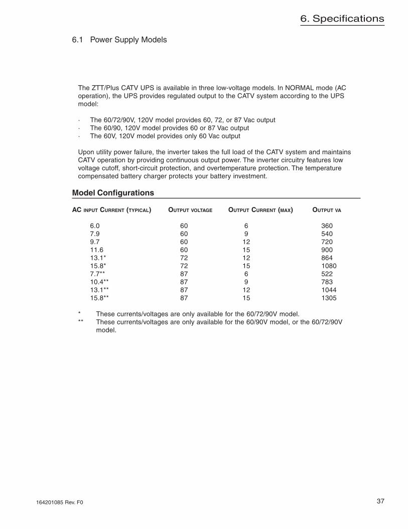
The ZTT/Plus CATV UPS is available in three low-voltage models. In NORMAL mode (ACoperation), the UPS provides regulated output to the CATV system according to the UPSmodel:
· The 60/72/90V, 120V model provides 60, 72, or 87 Vac output· The 60/90, 120V model provides 60 or 87 Vac output· The 60V, 120V model provides only 60 Vac output
Upon utility power failure, the inverter takes the full load of the CATV system and maintainsCATV operation by providing continuous output power. The inverter circuitry features lowvoltage cutoff, short-circuit protection, and overtemperature protection. The temperaturecompensated battery charger protects your battery investment.
Model Configurations
AC INPUT CURRENT (TYPICAL) OUTPUT VOLTAGE OUTPUT CURRENT (MAX) OUTPUT VA
6.0 60 6 3607.9 60 9 5409.7 60 12 72011.6 60 15 90013.1* 72 12 86415.8* 72 15 10807.7** 87 6 52210.4** 87 9 78313.1** 87 12 104415.8** 87 15 1305
* These currents/voltages are only available for the 60/72/90V model.** These currents/voltages are only available for the 60/90V model, or the 60/72/90V
model.
6.1 Power Supply Models

38
6. Specifications
164201085 Rev. F0
ZTT/Plus Chassis 178mm 419mm 330mm 60/72/90V and 60/90V
Zero (0) - Uninterrupted output under all line loss or short conditions
No shutdown up to 113.3% (+10/-5%); Inverter shutdown upon along duration short with auto-retry upon cooldown period (approx 5seconds)
Mechanical SpecificationsUnit Height Width Depth Weight
(7") (16.5") (13") Model Chassis
27 kg (60lb)
60V Model Chassis
23kg (50lb)
3kg (6.5lb)
Inverter Module only:
Technical Specifications60/72/90V & 60/90 V models 60V model
Input voltage
Input frequency (normal mode)
87 VRMS 72 VRMS or 60VRMS ±3%
selectable with internal jumper
Output voltage and regulation 60 VRMS ± 3%
Output frequency (Standby Mode) 60 Hz ± 1%
Full Load Efficiency (Typical) Normal mode: 90%Standby mode: 82%
Input overload protection 20A high magnetic circuit breaker
120 Vac, -20 +10% (96-132 VAC)
60 Hz ± 3 Hz
Output overload protection(Typical)
Foldback Limited Foldback Limited<300% of rated output @60V<250% of rated output @72V<200% of rated output @87V
<200% of rated output @60V
Inverter output / Software fuse
Operating environment -40 to +55°C(-40 to 131°F)
Humidity 0 to 95% (non-condensing)
Typical battery(approximate measurements)
241mm (9.5") 324mm (12.75") 165mm (6.5") 32kg (70 lbs.)
Temperature inside cabinet
Transfer time (seconds)
39
6. Specifications
164201085 Rev. F0
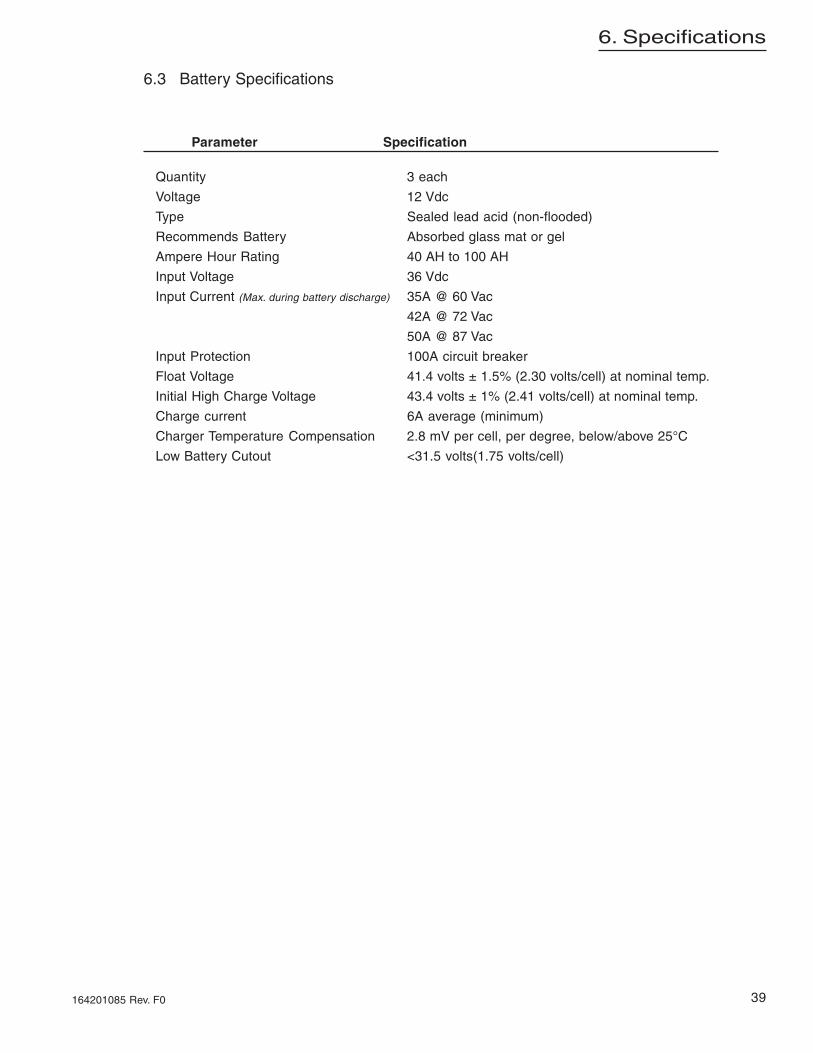
Parameter Specification
Quantity 3 each
Voltage 12 Vdc
Type Sealed lead acid (non-flooded)
Recommends Battery Absorbed glass mat or gel
Ampere Hour Rating 40 AH to 100 AH
Input Voltage 36 Vdc
Input Current (Max. during battery discharge) 35A @ 60 Vac
42A @ 72 Vac
50A @ 87 Vac
Input Protection 100A circuit breaker
Float Voltage 41.4 volts ± 1.5% (2.30 volts/cell) at nominal temp.
Initial High Charge Voltage 43.4 volts ± 1% (2.41 volts/cell) at nominal temp.
Charge current 6A average (minimum)
Charger Temperature Compensation 2.8 mV per cell, per degree, below/above 25°C
Low Battery Cutout <31.5 volts(1.75 volts/cell)
6.3 Battery Specifications

40
7. Troubleshooting
164201085 Rev. F0
ACTIONPROBABLE
CAUSESYMPTOM
Close battery breaker if open and check for secure batteryconnection.
Battery breaker open orloose battery connection(BATTERY BREAKEROPEN displays on the LCD).
ZTT/Plus does not transferfrom Normal to Standbymode when tested.
Load-test batteries. Recharge or replace the batteries ifnecessary
Battery charge is too low tosupport CATV load, possiblydue to extended standbyoperation or failed battery. Aclicking sound is often heardwith this condition.
Replace with a spare inverter module.Inverter inoperative.
Check the battery wiring for proper polarity. Reset thebattery breaker.
Battery breaker tripped.No output to coax duringStandby mode.
Check all battery terminals for secure connections.Loose battery cableconnection
Load-test batteries. Recharge or replace the batteries ifnecessary. If the batteries test okay, replace the inverter.
Battery charge is too low tosupport CATV load, possiblydue to extended standbyoperation or failed battery. Aclicking sound is often heardwith this condition.
Disconnect output from coax and measure AC voltage onthe ZTT/Plus output connector. If okay, check the networkfor a short circuit.
Short circuit on output(OVERLOAD SHUTDOWNdisplays on the LCD)
Replace the inverter.Inverter not operating(STANDBY MODE does notappear on the LCD).
Close both breakers and check the power cordconnections. Also check the receptacle for AC voltage.
AC input disconnect breakeror front panel input breakeropen.
No output to Coax duringNormal Mode
Disconnect output from coax and measure AC voltage onthe ZTT/Plus output connector. If okay, check the networkfor a short circuit.
Short circuit on output(OVERLOAD SHUTDOWNdisplays on the LCD)
Pullout the inverter module and check for AC output. If ACoutput returns, replace the inverter. If AC output is stillabsent, replace the ZTT/Plus chassis.
Inverter AC detectionproblem.
Table 7-1 Troubleshooting Matrix

41
7. Troubleshooting
164201085 Rev. F0
ACTIONPROBABLE
CAUSESYMPTOM
Reset the alarm by opening, then closing the batterybreaker. Load-test the batteries and replace if necessary.
The batteries have notreturned to float voltage aftercharging for >96 hours. Toprevent the overcharging ofgood batteries, the charger isautomatically disabled untilthe alarm is reset.
BATTERY CHARGEFAILED displays on LCD
Close breaker.Battery breaker left open.Batteries do not charge
Replace the failed batteries
Battery failure (highimpedance). The batteryvoltage tests normal with aDC voltmeter, but does notaccept a charge.
See page 23 to select the correct output voltage.Output connector is not set tothe correct voltage setting(60, 72, or 87 Vdc).
Incorrect output voltage
Reduce load on UPS by removing network components;open and re-close (cycle) the battery breaker. Verify theoutput voltage returns to normal.
Unit overloaded(OVERLOAD SHUTDOWNdisplats on LCD)
Low output voltage
Check for loose AC input wiring connections. If okay, notifylocal power company of low voltage at this location.
Very low input voltage (80%of normal).
The fan should run whenever the inverter is operating orwhenever the battery is charging. If the fan does notoperate in these modes, replace the inverter module
Fan failure.OVERTEMP SHUTDOWNdisplays on the LCD.
Open the battery breaker and pull out the inverter modulewhile monitoring output voltage. If output voltage remainsnormal, replace the inverter module
Inverter AC detectionproblem.
ZTT/Plus does not transferfrom Standby to Normalmode.
Open the battery breaker and pull out the inverter modulewhile monitoring output voltage. If output voltagedisappears, replace the ZTT/Plus chassis
An input relay is open in theZTT/Plus chassis
Verify that the generator is rated at least 1800 to 2400watts.Some generator brands may require even greateroversizing.
Generator output voltage orfrequency is not closelyregulated, or the generator isundersized.
Table 7-2 Troubleshooting Matrix


Due to continuing product improvements, Alpha reserves the right to change specifications without notice.Copyright © 2003 Alpha Technologies, Inc. All rights reserved. Alpha is a registered trademark of Alpha Technologies. 164201085 Rev. F0
CorporateAlpha Technologies3767 Alpha WayBellingham, WA 98226USATel: (360) 647-2360Fax: (360) 671-4936Web: www.alpha.com
Alpha Technologies Ltd.4084 McConnell CourtBurnaby, BC, V5A 3N7CANADATel: (604) 430-1476Fax: (604) 430-8908
Alpha TechnologiesEurope Ltd.Cartel Business EstateEdinburgh WayHarlow, Essex CM20 2TTUNITED KINGDOMTel: +44-1279-422110Fax: +44-1279-423355
Alpha TechnologiesHansastrasse 8D-91126 SchwabachGERMANYTel: +49-9122-79889-0Fax: +49-9122-79889-21
Alphatec339 St. Andrews StreetSuite 101Andrea ChambersLimassol, CyprusCYPRUSTel: +357-25-375675Fax: +357-25-359595
Alpha TechnologiesUnits R5-R7 Regents ParkCorner Park Rd. and Prince’s Rd. EastRegents Park NSW 2143AUSTRALIATel: +61-2-9722-3320Fax: +61-2-9722-3321
PowerAlpha Technologies®


![0) It & z L 0 If1L 0 000 & it IflL IfiJ z & z Q) Cit 1) (D 3 Q) IJJ & IfIL ff. IflL i' z < & illi (D L L z E B 2 E L & ili E IflL fitj -C Z -g-itï If1L 7 Z ill] tt tt IflL IflL E](https://img.pdfslide.us/doc/110x75/5e506b2f5fb9cc39d50c5f4d/0-it-z-l-0-if1l-0-000-it-ifll-ifij-z-z-q-cit-1-d-3-q-ijj.jpg)