Embed Size (px)
Citation preview

www.gofanyourself.comwww.gofanyourself.com
Z-Tech™ FanFeatures & specificationsZ-Tech™ Intended Use: Industrial high-volume, low-speed fan that is ideal for spaces in need of an energy efficient air movement solution. Applications include automotive dealerships, transportation maintenance, aviation hangars, agriculture, education, commercial and retail spaces, government, manufacturing, recreational, warehousing and other indoor spaces where comfort and energy are required with minimum 14’ ceiling height.
NUMBER & TYPE OF BLADES: (5) patent-pending Z-Tech™ blades with 20° plus pitch.
BLADE CONSTRUCTION: Two-piece extruded anodized aluminum blade with ABS leading edge and end caps with UV inhibitors. Frame is powder coated steel with a cast aluminum hub A356-T6. Leading edge blade is riveted to the primary blade with stainless steel rivets. Standard blade color is Safety Orange.
ELECTRICAL (MOTOR): NORD™ motor utilizes cast iron housing with a precise sha� and gear alignment that has a high load bearing capacity. Single housing block in which all bearing points are integrated. No sealing faces are subjected to torque or lateral forces. IP 55; UL 1004; 120/230/460/575v; single and three phase available.
ELECTRICAL (CONTROLLER): Premium control with hardware flexibility, programmability, and scalability for an optimal solution. ABB™ Variable Frequency Drive – Nema 4X, IP66/67. ESFR relay ready to connect to existing fire suppression systems, integral lock out, tag out (LOTO) disconnect ship standard. ROHS compliant.
INSTALLATION: Suitable for mounting by I-Beam, Top Chord angle iron, Bo�om Chord angle iron, L-Bracket, Z-Purlin and Wood Beam. Standard mount is used for 6"-10" I-beams, XL mount is used for 12"-15" I-beams. 1 foot down tube is standard.
SAFETY: Safety ring (1/4" powder coated steel), two safety cables (5/16" stainless steel aircra� cable), guide wires (1/8" stainless steel aircra� cable) – with 4 foot or greater down tube extension.
DESIGNER SERIES: Optional color combinations & designs available.
OPERATING TEMPERATURES: Motor & Gearbox (20°F to 122°F); Controller (20°F to 122°F).
WARRANTY: Lifetime warranty on blades, hub and mounting system. 15-year warranty on motor, gearbox and controller.
page 1 of 13
Catalog Number:
Type of Fan:
Notes:
01/16/17
®
®
www.gofanyourself.comwww.gofanyourself.com
Z-Tech™ Fan Technical specifications
page 2 of 13
FOOTNOTES
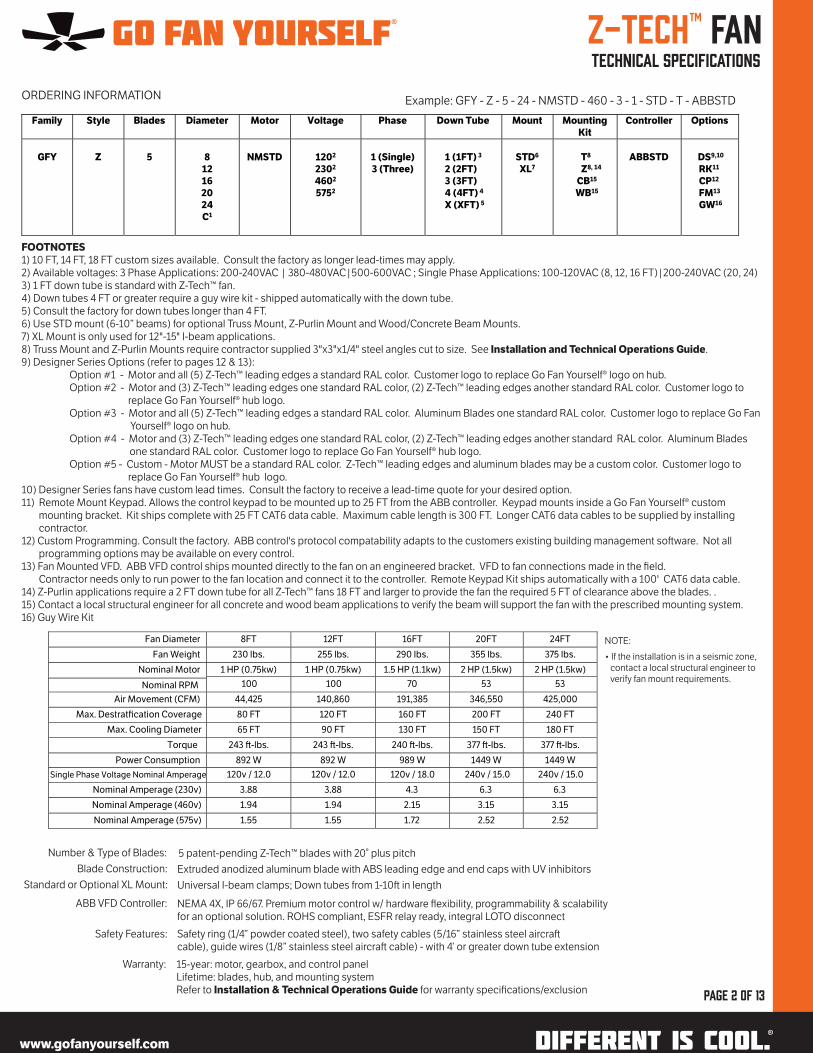
1) 10 FT, 14 FT, 18 FT custom sizes available. Consult the factory as longer lead-times may apply. 2) Available voltages: 3 Phase Applications: 200-240VAC | 380-480VAC|500-600VAC ; Single Phase Applications: 100-120VAC (8, 12, 16 FT)|200-240VAC (20, 24)3) 1 FT down tube is standard with Z-Tech™ fan.4) Down tubes 4 FT or greater require a guy wire kit - shipped automatically with the down tube. 5) Consult the factory for down tubes longer than 4 FT. 6) Use STD mount (6-10” beams) for optional Truss Mount, Z-Purlin Mount and Wood/Concrete Beam Mounts. 7) XL Mount is only used for 12"-15" I-beam applications.8) Truss Mount and Z-Purlin Mounts require contractor supplied 3"x3"x1/4" steel angles cut to size. See Installation and Technical Operations Guide.9) Designer Series Options (refer to pages 12 & 13): Option #1 - Motor and all (5) Z-Tech™ leading edges a standard RAL color. Customer logo to replace Go Fan Yourself® logo on hub. Option #2 - Motor and (3) Z-Tech™ leading edges one standard RAL color, (2) Z-Tech™ leading edges another standard RAL color. Customer logo to replace Go Fan Yourself® hub logo. Option #3 - Motor and all (5) Z-Tech™ leading edges a standard RAL color. Aluminum Blades one standard RAL color. Customer logo to replace Go Fan Yourself® logo on hub. Option #4 - Motor and (3) Z-Tech™ leading edges one standard RAL color, (2) Z-Tech™ leading edges another standard RAL color. Aluminum Blades one standard RAL color. Customer logo to replace Go Fan Yourself® hub logo. Option #5 - Custom - Motor MUST be a standard RAL color. Z-Tech™ leading edges and aluminum blades may be a custom color. Customer logo to replace Go Fan Yourself® hub logo. 10) Designer Series fans have custom lead times. Consult the factory to receive a lead-time quote for your desired option. 11) Remote Mount Keypad. Allows the control keypad to be mounted up to 25 FT from the ABB controller. Keypad mounts inside a Go Fan Yourself® custom mounting bracket. Kit ships complete with 25 FT CAT6 data cable. Maximum cable length is 300 FT. Longer CAT6 data cables to be supplied by installing contractor. 12) Custom Programming. Consult the factory. ABB control's protocol compatability adapts to the customers existing building management so�ware. Not all programming options may be available on every control.13) Fan Mounted VFD. ABB VFD control ships mounted directly to the fan on an engineered bracket. VFD to fan connections made in the field. Contractor needs only to run power to the fan location and connect it to the controller. Remote Keypad Kit ships automatically with a 100' CAT6 data cable.14) Z-Purlin applications require a 2 FT down tube for all Z-Tech™ fans 18 FT and larger to provide the fan the required 5 FT of clearance above the blades. . 15) Contact a local structural engineer for all concrete and wood beam applications to verify the beam will support the fan with the prescribed mounting system. 16) Guy Wire Kit
Number & Type of Blades:
Blade Construction:
Standard or Optional XL Mount:
ABB VFD Controller:
Safety Features:
Warranty:
5 patent-pending Z-Tech™ blades with 20° plus pitch
Extruded anodized aluminum blade with ABS leading edge and end caps with UV inhibitors
Universal I-beam clamps; Down tubes from 1-10� in length
NEMA 4X, IP 66/67. Premium motor control w/ hardware flexibility, programmability & scalability for an optional solution. ROHS compliant, ESFR relay ready, integral LOTO disconnect
Safety ring (1/4” powder coated steel), two safety cables (5/16” stainless steel aircra� cable), guide wires (1/8” stainless steel aircra� cable) - with 4’ or greater down tube extension
15-year: motor, gearbox, and control panel Lifetime: blades, hub, and mounting system Refer to Installation & Technical Operations Guide for warranty specifications/exclusion page 2 of 13
ORDERING INFORMATION Example: GFY - Z - 5 - 24 - NMSTD - 460 - 3 - 1 - STD - T - ABBSTD
Fan Diameter 8FT 12FT 16FT 20FT 24FT
Fan Weight 230 lbs. 255 lbs. 290 lbs. 355 lbs. 375 lbs.
Nominal Motor 1 HP (0.75kw) 1 HP (0.75kw) 1.5 HP (1.1kw) 2 HP (1.5kw) 2 HP (1.5kw)
Nominal RPM 100 100 70 53 53
Air Movement (CFM) 44,425 140,860 191,385 346,550 425,000
Max. Destratfication Coverage 80 FT 120 FT 160 FT 200 FT 240 FT
Max. Cooling Diameter 65 FT 90 FT 130 FT 150 FT 180 FT
Torque 243 �-lbs. 243 �-lbs. 240 �-lbs. 377 �-lbs. 377 �-lbs.
Power Consumption 892 W 892 W 989 W 1449 W 1449 W
Single Phase Voltage Nominal Amperage 120v / 12.0 120v / 18.0
Nominal Amperage (230v) 3.88 3.88 4.3 6.3 6.3
Nominal Amperage (460v) 1.94 1.94 2.15 3.15 3.15
Nominal Amperage (575v) 1.55 1.55 1.72 2.52 2.52
120v / 12.0 240v / 15.0 240v / 15.0
Family Style Blades Diameter Motor Voltage Phase Down Tube Mount Mounting
Kit
Controller Options
GFY
Z
5
8
12
16
20
24
C1
NMSTD
1202
2302
4602
5752
1 (Single)
3 (Three)
1 (1FT) 3
2 (2FT)
3 (3FT)
4 (4FT) 4
X (XFT) 5
STD6
XL7
T8
Z8, 14
CB15
WB15
ABBSTD
DS9,10
RK11
CP12
FM13
GW16
• If the installation is in a seismic zone, contact a local structural engineer to verify fan mount requirements.
NOTE:
®
®

Dimension
set by
Down Tube
28”
Fan length
with standard
1FT Down Tube
is 44”
Hub○ Die-cast aluminum hub with the same 20º pitch as Z-Tech™ blade.
NORD™ Motor○ The Helical In-Line gearbox from Nord utilizes UNICASE cast iron housing with a precise sha� and gear alingment that has a high load bearing capacity with a long operating life.
Motor Frame○ Powder Coated Steel
Down Tube - 1FT standard○ Optional Lengths available ○ Used to lower the fan to provide blade clearance around obstacles
Fan Mount - STD shown.○ XL optional for 12” - 15” I-Beam applications only
www.gofanyourself.com
Z-Tech™ Fan component descriptions Nominal dimensions Mounting/motor detail
page 3 of 13
®
www.gofanyourself.com®
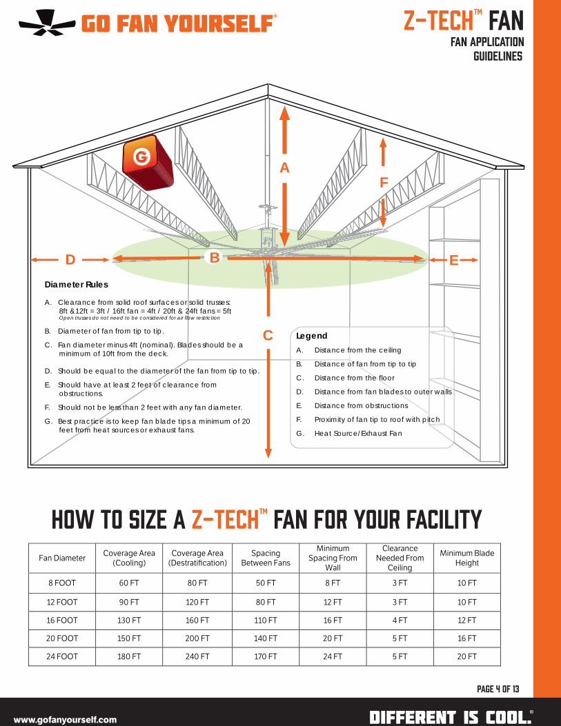
Z-Tech™ Fan fan application guidelines
page 4 of 13
A
B ED
GF
C LegendA. Distance from the ceiling
B. Distance of fan from tip to tip
C. Distance from the floor
D. Distance from fan blades to outer walls
E. Distance from obstructions
F. Proximity of fan tip to roof with pitch
G. Heat Source/Exhaust Fan
Diameter Rules
A. Clearance from solid roof surfaces or solid trusses: 8ft &12ft = 3ft / 16ft fan = 4ft / 20ft & 24ft fans = 5ftOpen trusses do not need to be considered for air flow restriction
B. Diameter of fan from tip to tip.
C. Fan diameter minus 4ft (nominal). Blades should be a minimum of 10ft from the deck.
D. Should be equal to the diameter of the fan from tip to tip.
E. Should have at least 2 feet of clearance from obstructions.
F. Should not be less than 2 feet with any fan diameter.
G. Best practice is to keep fan blade tips a minimum of 20 feet from heat sources or exhaust fans.
How to size a Z-Tech™ fan for your facility
Fan Diameter Coverage Area
(Cooling) Coverage Area
(Destratification) Spacing
Between Fans
Minimum Spacing From
Wall
Clearance Needed From
Ceiling
Minimum Blade Height
8 FOOT 60 FT 80 FT 50 FT 8 FT 3 FT 10 FT
12 FOOT 90 FT 120 FT 80 FT 12 FT 3 FT 10 FT
16 FOOT 130 FT 160 FT 110 FT 16 FT 4 FT 12 FT
20 FOOT 150 FT 200 FT 140 FT 20 FT 5 FT 16 FT
24 FOOT 180 FT 240 FT 170 FT 24 FT 5 FT 20 FT
®
www.gofanyourself.com®
www.gofanyourself.com
Z-Tech™ Fan technical specifications maximum coverage guide
page 5 of 13
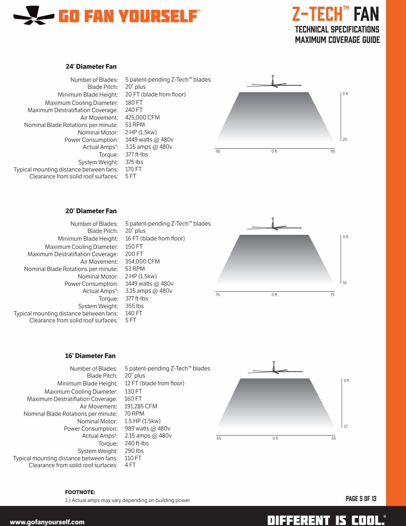
24’ Diameter Fan
Number of Blades:Blade Pitch:
Minimum Blade Height:
Maximum Cooling Diameter:Maximum Destratifiation Coverage:
Air Movement:Nominal Blade Rotations per minute:
Nominal Motor:Power Consumption:
Actual Amps1:
Torque:
System Weight:Typical mounting distance between fans:
Clearance from solid roof surfaces:
20’ Diameter Fan
5 patent-pending Z-Tech™ blades20° plus
20 FT (blade from floor)
180 FT240 FT
425,000 CFM53 RPM
2 HP (1.5kw)1449 wa�s @ 480v3.15 amps @ 480v
377 �-lbs
375 lbs170 FT5 FT
Number of Blades:Blade Pitch:
Minimum Blade Height:
Maximum Cooling Diameter:Maximum Destratifiation Coverage:
Air Movement:Nominal Blade Rotations per minute:
Nominal Motor:Power Consumption:
Actual Amps1:
Torque:
System Weight:Typical mounting distance between fans:
Clearance from solid roof surfaces:
5 patent-pending Z-Tech™ blades20° plus
16 FT (blade from floor)
150 FT200 FT
354,000 CFM53 RPM
2 HP (1.5kw)1449 wa�s @ 480v3.15 amps @ 480v
377 �-lbs
355 lbs140 FT5 FT
16’ Diameter Fan
Number of Blades:Blade Pitch:
Minimum Blade Height:
Maximum Cooling Diameter:Maximum Destratifiation Coverage:
Air Movement:Nominal Blade Rotations per minute:
Nominal Motor:Power Consumption:
Actual Amps1:
Torque:
System Weight:Typical mounting distance between fans:
Clearance from solid roof surfaces:
5 patent-pending Z-Tech™ blades20° plus
12 FT (blade from floor)
130 FT160 FT
191,285 CFM70 RPM
1.5 HP (1.5kw)989 wa�s @ 480v2.15 amps @ 480v
240 �-lbs
290 lbs110 FT4 FT
FOOTNOTE:
1.) Actual amps may vary depending on building power
90 900 �
20
0 �
75 750 �
16
0 �
65 650 �
12
0 �
®
www.gofanyourself.com®

www.gofanyourself.com
Z-Tech™ Fan technical specifications maximum coverage guide
page 6 of 13
12’ Diameter Fan
Number of Blades:Blade Pitch:
Minimum Blade Height:
Maximum Cooling Diameter:Maximum Destratifiation Coverage:
Air Movement:Nominal Blade Rotations per minute:
Nominal Motor:Power Consumption:
Actual Amps1:
Torque:
System Weight:Typical mounting distance between fans:
Clearance from solid roof surfaces:
8’ Diameter Fan
5 patent-pending Z-Tech™ blades20° plus
10 FT (blade from floor)
90 FT120 FT
140,860 CFM100 RPM
1HP (0.75kw)892 wa�s @ 480v1.94 amps @ 480v
243 �-lbs
255 lbs80 FT3 FT
Number of Blades:Blade Pitch:
Minimum Blade Height:
Maximum Cooling Diameter:Maximum Destratifiation Coverage:
Air Movement:Nominal Blade Rotations per minute:
Nominal Motor:Power Consumption:
Actual Amps1:
Torque:
System Weight:Typical mounting distance between fans:
Clearance from solid roof surfaces:
5 patent-pending Z-Tech™ blades20° plus
10 FT (blade from floor)
60 FT80 FT
44,425 CFM100 RPM
1 HP (0.75kw)892 wa�s @ 480v1.94 amps @ 480v
243 �-lbs
230 lbs50 FT3 FT
Additional Specifications:
• Maintain a minimum 2� clearance from tip of blade from obstructions• Maintain a minimum 2� below truss with any fan diameter• Location of fan should maintain a minimum of 20� away from a heat source• Location of fan should maintain a minimum of 20� away from any exhaust fans• Location of fan should be centered between sprinkler heads but maintain 2� clearance from tip of blade• Lights to be spaced 2� or greater away from the tip of the fan blade to prevent shadowing and strobe effect
Refer to Fan Application Diameter Rule Guidelines in this spec sheet for additional details
FOOTNOTE:
1.) Actual amps may vary depending on building power
45 450 �
10
0 �
30 300 �
10
0 �
®
www.gofanyourself.com®

www.gofanyourself.com
Z-Tech™ Fan typical mount details
page 7 of 13
• The 3” x 3” x 1/4” steel angles must be supplied by the installing contractor. Hardware used to secure the angles to the mounting structure is not included
• If the truss span is wider than 8FT, four steel angles are required. Reference the Installation & Technical Operations
Guide or contact Go Fan Yourself® for addtional instructions
• If the installation is in a seismic zone, contact a local structural engineer to verify fan mount requirements.
Top Chord Angle Mount
Bo�om Chord Angle Mount
• The 3” x 3” x 1/4” steel angles must be supplied by the installing contractor. Hardware used to secure the angles to the mounting structure is not included
• A 2FT down tube is required with 20FT and 24FT fans to provide the required 5FT of clearance above the fan when utilizing the Top Chord Angle Mount.
• If the truss span is wider than 8FT, four steel angles and the XL mount are required. Reference the Installation &
Technical Operations Guide or contact Go Fan Yourself® for additional instructions
• If the installation is in a seismic zone, contact a local structural engineer to verify fan mount requirements.
www.gofanyourself.com®
®

www.gofanyourself.com
Z-Tech™ Fan typical mount details
page 8 of 13
Z-Purlin Requirements
• The 3” x 3” x 1/4” steel angles must be supplied by the installing contractor
• A 2FT down tube is required with 20FT and 24FT fans to provide the required 5FT of clearance above the fan when utilizing Z-Purlin mount.
• Maximum unsupported length (see chart)
• Spacing between Z-Purlins should be 5FT or less
• Z-Purlins must be a minimum of 14 gauge steel
• This mouting system may also be required to span concrete beams. Consult a local structural engineer for any concrete beam applications
• If the installation is in a seismic zone, contact a local structural engineer to verify fan mount requirements.
Wood Beam Requirements
• Installing contractor must supply L-bracket anchor hardware as described below:
• (2) 1/2” - 13 x 1 1/2” longer than the support structure Grade 8 Hex Cap Screw
• (4) 1/2” ASTM F436 Type 1 Grade 8 Mechanical Galvanized Steel Structural Flat Washer
• (2) 1/2” - 13 Grade 8 Steel Nylock Nut
• If the installation is in a seismic zone, contact a local structural engineer to verify fan mount requirements.
Z-Purlin Mount
Wood Beam Mount
Purlin Height
8” (20.3 cm) 9” (22.9 cm) 10” (25.4 cm)
Purlin Length
<20’ (6.1 m) Intended Use Intended Use Intended Use
<25’ (7.6 m) N/A Intended Use Intended Use
<30’ (9.1 m) N/A N/A Intended Use
www.gofanyourself.com®
®

www.gofanyourself.com
Z-Tech™ FanMotor specifications
page 9 of 13
Go Fan Yourself Helical Gearmotor Specifications
2HP 1.5HP 1HP
Motor Speed (RPM) 1,660 1,660 1,650
Ratio 31.16 23.74 12.20
Output Speed (RPM) 53 70 100
Service Factor 1.90 2.10 6.20
Nominal Output Torque (lb-in) 2,366 1,352 466
Maximum Torque Capacity (lb-in) 4,532 2,885 2,912
Voltage – Single Phase (V) 200-240 100-120 100-120
Voltage – Three Phase (V) 200-240 380-480 500-600
200-240 380-480 500-600
200-240 380-480 500-600
Frequency (Hz) 60 60 60
Motor Enclosure Type IP 55 IP 55 IP 55
Insulation Class F F F
Rated Current 1 (200-240 VAC) 6.34 4.84 3.66
Rated Current 2 (380-480 VAC) 3.17 2.42 1.83
Environmental Temp 50° C 50° C 50° C
Breather Autovent Autovent Autovent
Sha� Seal Dual Output Dual Output Dual Output
NORD™ motors are quality assured based on ISO 9000 standards and designed and manufactured up to AGMA Class 13 with case-hardened steel and exceptional hardness of 60 Rc. IP 55 and UL 1004 listed; 120/230/460/575v; single and three phase.
The Helical In-Line gearbox from NORD™ utilizes UNICASE cast iron housing with a precise sha� and gear alignment that has a high load bearing capacity with a long operating life. NORD™ gearboxes are complimented frequently on quiet running operation.
The Unicase housing from NORD™ is a single housing block in which all bearing points are integrated. In this way, no sealing faces are subjected to torque or lateral forces caused by flanges or bearing points that are screwed on. All axes and sealing faces of the gear block are machined in a single setup on the most modern CNC-controlled production lines, which translates to the highest degree of manufacturing accuracy.
NORD™ utilizes heavy duty (VL) bearings over standard bearings so the bearing sizes are larger and offer high load capacity. The thick wall housings provide stable sha� and bearing centers which promotes higher bearing and gearing life. The housing features a high quality paint system. The housing is primed, then a Polyurethane coating is applied and each unit is hand sprayed to cover all surfaces and inspected to high standards.
Protective features to eliminate damage include Autovent and Quadralip.
• Autovent helps prevent bearing and gear damage by utilizing cleaner gearbox oil with an extended lubrication life and longer lasting seals, gears and bearings. The Autovent system is not open to the atmosphere, yet allows the internal of the unit to release pressure, if needed, in extreme thermal conditions. The ball-check valve is spring loaded to release at 2-3 PSI.
• The Quadralip sealing provides superior protection against leaks and contaminants. Two-component paint resin withstands exposure to acids, alkalis, solvents and oil based product with enhanced chemical resistant and USDA approved standard paint.
www.gofanyourself.com®
®
Z-Tech™ Fan ABB variable frequency drives
page 10 of 13
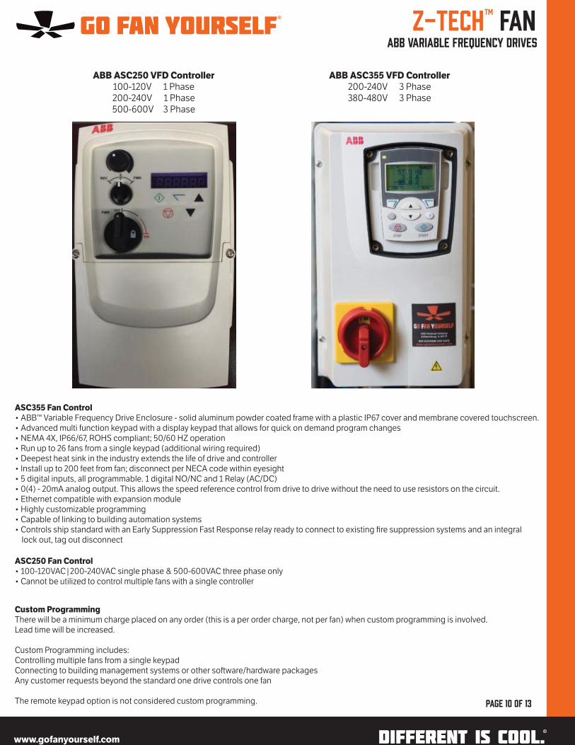
ABB ASC250 VFD Controller
100-120V 1 Phase200-240V 1 Phase500-600V 3 Phase
ABB ASC355 VFD Controller
200-240V 3 Phase380-480V 3 Phase
ASC355 Fan Control
• ABB™ Variable Frequency Drive Enclosure - solid aluminum powder coated frame with a plastic IP67 cover and membrane covered touchscreen.• Advanced multi function keypad with a display keypad that allows for quick on demand program changes• NEMA 4X, IP66/67, ROHS compliant; 50/60 HZ operation• Run up to 26 fans from a single keypad (additional wiring required)• Deepest heat sink in the industry extends the life of drive and controller• Install up to 200 feet from fan; disconnect per NECA code within eyesight• 5 digital inputs, all programmable. 1 digital NO/NC and 1 Relay (AC/DC)• 0(4) - 20mA analog output. This allows the speed reference control from drive to drive without the need to use resistors on the circuit.• Ethernet compatible with expansion module• Highly customizable programming• Capable of linking to building automation systems• Controls ship standard with an Early Suppression Fast Response relay ready to connect to existing fire suppression systems and an integral lock out, tag out disconnect
Custom Programming
There will be a minimum charge placed on any order (this is a per order charge, not per fan) when custom programming is involved. Lead time will be increased.
Custom Programming includes:Controlling multiple fans from a single keypadConnecting to building management systems or other so�ware/hardware packagesAny customer requests beyond the standard one drive controls one fan
The remote keypad option is not considered custom programming.
ASC250 Fan Control
• 100-120VAC|200-240VAC single phase & 500-600VAC three phase only• Cannot be utilized to control multiple fans with a single controller
www.gofanyourself.com®
®

www.gofanyourself.com
Z-Tech™ Fan remote mount keypad
page 11 of 13
• Optional Remote Keypad provides unlimited flexibility for your Go Fan Yourself® fan installation
• Mount the VFD controller in the ceiling or high on the column for safety and security and drop the keypad down to a user friendly mounting height
• Remote keypad option ships from Go Fan Yourself® with a 25FT CAT6 data cable allowing the keypad to be mounted approximately 25 feet below the VFD controller
• Maximum CAT6 data cable length is 300FT
• Fan mounted control option locates the VFD controller on a bracket mounting directly to the fan frame
• Access to the VFD is available without fan disassembly
• Remote mount keypad option is included in the cost of this option
• Go Fan Yourself® provides a 100FT data cable to connect the remote mount keypad option
www.gofanyourself.com®
®
www.gofanyourself.com
Z-Tech™ Fan designer series options
page 12 of 13
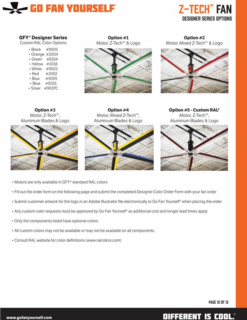
GFY® Designer SeriesCustom RAL Color Options
• Motors are only available in GFY® standard RAL colors
• Fill out the order form on the following page and submit the completed Designer Color Order Form with your fan order
• Submit customer artwork for the logo in an Adobe Illustrator file electronically to Go Fan Yourself® when placing the order
• Any custom color requests must be approved by Go Fan Yourself® as additional cost and longer lead times apply
• Only the components listed have optional colors
• All custom colors may not be available or may not be available on all components.
• Consult RAL website for color definitions (www.ralcolors.com)
www.gofanyourself.com®
®
• Black #9005• Orange #2004• Green #6024• Yellow #1018• White #9003• Red #3002• Blue #5005• Blue #5015
• Silver #9007C
Option #1
Motor, Z-Tech™ & LogoOption #2
Motor, Mixed Z-Tech™ & Logo
Option #3
Motor, Z-Tech™, Aluminum Blades & Logo
Option #4
Motor, Mixed Z-Tech™, Aluminum Blades & Logo
Option #5 - Custom RAL*
Motor, Z-Tech™, Aluminum Blades & Logo
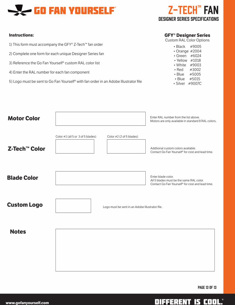
Z-Tech™ Fan designer series specifications
page 13 of 13
Instructions:
1) This form must accompany the GFY® Z-Tech™ fan order
2) Complete one form for each unique Designer Series fan
3) Reference the Go Fan Yourself® custom RAL color list
4) Enter the RAL number for each fan component
5) Logo must be sent to Go Fan Yourself® with fan order in an Adobe Illustrator file
Motor Color
Z-Tech™ Color
Blade Color
Custom Logo
Notes
Enter RAL number from the list above.Motors are only available in standard 8 RAL colors.
Addtional custom colors available. Contact Go Fan Yourself® for cost and lead time.
Enter blade color. All 5 blades must be the same RAL color.Contact Go Fan Yourself® for cost and lead time.
Logo must be sent in an Adobe Illustrator file.
Color #1 (all 5 or 3 of 5 blades) Color #2 (2 of 5 blades)
www.gofanyourself.com®
®
GFY® Designer SeriesCustom RAL Color Options
• Black #9005• Orange #2004• Green #6024• Yellow #1018• White #9003• Red #3002• Blue #5005• Blue #5015
• Silver #9007C