Embed Size (px)
Citation preview

Zilog
I
Z-80'SIOTECHNICAL MANUAL

PRICE $7,50
03-3033-01
AUGUST 1978
Copyright 1 977 Ijy Z iloq, I nc. All rights reserved. No part of this
(publication may be reproduced, stored in a retrieval system, or transmitted,
in any form or by any means, electronic, mechanical, photocopying,
recording, or otherwise, without the prior written permission of Zilog.
Ziloq assumes no responsibility for the use of any circuitry other than
circuitry embodied in a Zilog product. No other circuit patent licenses
are implied.

Z-80 S!0TECHNICAL MANUAL


Z80-SIO Technical Manual
Contents
General Information l
Pin Description 2
Architecture 5
The Data Path 5
Functional Description 7
Asynchronous Operation 9
Asynchronous Transmit 9
Asynchronous Receive 10
Synchronous Operation 13
Synchronous Transmit 14
Synchronous Receive 17
sni,C (HDiX) Operation 21
SDLC Transmit 21
SDLC Receive 25
Z80-SIO Programming 29
Write Registers 29
Read Registers 34
Applications 59
Timing 41
( iipviighl 19^S bv /ling All nglil. rcervccl

ii

General Information
The Z80-SIO (Serial Input/Output) is a dual-channel
multi-function peripheral component designed to satisfy
a wide variety of serial data communications require-
ments in microcomputer systems. Its basic function is a
serial-to-parallel, parallel-to-serial converter/controller,
but—within that role— it is configurable by systems
software so its "personality" can be optimized for a
given serial data communications application.
The Z80-SIO is capable of handling asynchronous
and synchronous byte-oriented protocols such as ibm
Bisync, and synchronous bit-oriented protocols such as
HDi.c and IBM SDLC. This versatile device can also be
used to support virtually any other serial protocol for
applications other than data communications (cassette
or floppy disk interfaces, for example).
The Z80-SIO can generate and check C RC codes in
any synchronous mode and can be programmed to
check data integrity in various modes. The device also
has facilities for modem controls in both channels, in
applications where these controls are not needed, the
modem controls can be used for general-purpose id.
STRUCTURE
N-channel silicon-gate depletion-load technology
40-pin DIP
Single 5 V power supply
Single-phase 5 V clock
All inputs and outputs tti. compatible
FKATURKS
Two independent full-duplex channels
Data rates in synchronous or isosynchronous modes:
• 0-550K bits/second with 2.5 MHz system clock
rate
• 0-880K bits/second with 4.0 MHz system clock
rate
Receiver data registers quadruply buffered; trans-
mitter doubly buffered.
Asynchronous features:
• 5, 6, 7 or 8 bits/character
• 1, 1 '/2 or 2 stop bits
• Even, odd or no parity
• xl, X 16, X 32 and x 64 clock modes
• Break generation and detection
• Parity, overrun and framing error detection
_ SERIAL DATA
' CHANNEL CLOCKS
- SYNCWAIT READY
MODEM OR
-OTHER CONTROLS
" MODEM OR
. OTHER CONTROLS
SERIAL DATA
CHANNEL CLOCKS
SYNC
WAIT REAIjY
Z80-SIO BLOCK DIAGRAM
1

Binary synchronous features:
• Internal or external character synchronization
• One or two sync characters in separate registers
• Automatic sync character insertion
• CRC generation and checking
HDLC and IBM SDi c features:
• Abort sequence generation and detection
• Automatic zero insertion and deletion
• Automatic flag insertion between messages
• Address fleld recognition
• I-field residue handling
• Valid receive messages protected from overrun
• CRC generation and checking
Separate modem control inputs and outputs for both
channels
CRC-16 or CRC-cciTT block check
Daisy-chain priority interrupt logic provides auto-
matic interrupt vectoring without external logic
Modem status can be monitored
Pin Description
D0-D7. System Data Bus (bidirectional, 3-state). The
system data bus transfers data and commands between
the CPU and the Z80-SIO. Dq is the least significant bit.
B/A. Channel A Or B Select (input, High selects Chan-
nel B). This input defines which channel is accessed
during a data transfer between the cpl and the
Z80-SIO. Address bit Aq from the CPU is often used for
the selection function.
C/D. Control Or Data Select (input, High selects Con-
trol). This input defines the type of information trans-
fer performed between the CPU and the Z80-SIO. AHigh at this input during a CPU write to the Z80-SIO
causes the information on the data bus to bejnterpreted
as a command for the channel selected by b a. A Low at
c/D means that the information on the data bus is data.
Address bit Ai is often used for this function.
CE. Chip Enable (input, active Low). A Low level at
this input enables the Z80-S1O to accept command or
data inputs from the CPU during a write cycle, or to
transmit data to the CPU during a read cycle.
^. System Clock (input). The Z80-SIO uses the stand-
ard Z80A System Clock to synchronize internal dgnals.
This is a single-phase clock.
Ml. Machine Cycle One (input from Z80-CPU, active
Low). When m1 is active and RD is also active, the
Z80-CPU is fetching an instruction from memory; when
Ml i s active while lORQ is active, the Z80-SIO accepts mi
and lORQ as an interrupt acknowledge if the Z80-SIO is
the highest priority device that has interrupted the
Z80-CPU.
lORQ. Input/Output Request (input from CPU, active
Low). lORQ is used in conjunction with B A, C D, CE
and RD to transfer commands_and data between the cpu
and the Z80-SIO. When cl, RD and iorq are all active.
CPUDATABUS
SIO
CONTROL ^•
FROM 1
CPU
CE
RESET
MJ
IORQ
RD
5U
GNO
DAISYCHAIN
INT <~lEI
lEO
RxDA
R<CA
T<DA
fiCA
SYNCA
W RDYA
RT^A
CTSA MODEM' CONTROL
RlDB_
RiTiCB
TiOB
—» SYNCB
—»- W RDYB
CTSB ! MODEMr CONTROL-» DTRB
OCDB
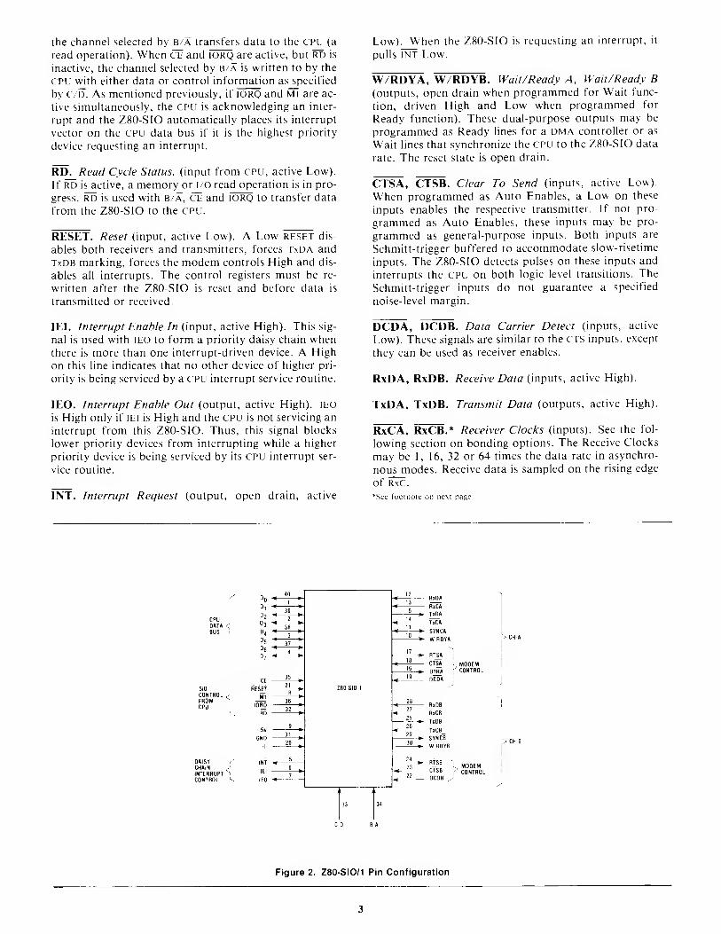
Figure 1. Z80 SIO/0 Pin Configuration
the channel selected by b/a transfers data to the CPU (a
read operation). When CE and iorq are active, but RD is
inactive, the channel selected by b/a is written to by the
CPU with either data or control information as specified
by c/D. As mentioned previously, if iorq and m1 are ac-
tive simultaneously, the CPU is acknowledging an inter-
rupt and the Z80-SIO automatically places its interrupt
vector on the CPU data bus if it is the highest priority
device requesting an interrupt.
RD. Read Cycle Status, (input from cpu, active Low).
If RD is active, a memory or i/o read operation is in pro-
gress. Rr5 is used with b/a, ce and iorq to transfer data
from the Z80-SIO to the cpu.
RESET. Reset (input, active Low). A Low RESET dis-
ables both receivers and transmitters, forces TxI5A and
TxDB marking, forces the modem controls High and dis-
ables all interrupts. The control registers must be re-
written after the Z80-SIO is reset and before data is
transmitted or received.
lEL Interrupt Enable In (input, active High). This sig-
nal is used with lEO to form a priority daisy chain whenthere is more than one interrupt-driven device. A High
on this line indicates that no other device of higher pri-
ority is being serviced by a CPU interrupt service routine.
lEO. Interrupt Enable Out (output, active High). lEO
is High only if lEi is High and the CPU is not servicing an
interrupt from this Z80-SIO. Thus, this signal blocks
lower priority devices from interrupting while a higher
priority device is being serviced by its CPU interrupt ser-
vice routine.
INT. Interrupt Request (output, open drain, active
Low). When the Z80-SIO is requesting an interrupt, it
pulls INT Low.
W/RDYA, W/RDYB. Wait/Ready A, Wait/Ready B(outputs, open drain when programmed for Wait func-
tion, driven High and Low when programmed for
Ready function). These dual-purpose outputs may be
programmed as Ready lines for a dma controller or as
Wait lines that synchronize the CPU to the Z80-SIO data
rate. The reset state is open drain.
CTSA, CTSB. Clear To Send (inputs, active Low).
When programmed as Auto Enables, a Low on these
inputs enables the respective transmitter. If not pro-
grammed as Auto Enables, these inputs may be pro-
grammed as general-purpose inputs. Both inputs are
Schmitt-trigger buffered to accommodate slow-risetime
inputs. The Z80-SIO detects pulses on these inputs and
interrupts the CPU on both logic level transitions. The
Schmitt-trigger inputs do not guarantee a specified
noise-level margin.
DCDA, DCDB. Data Carrier Detect (inputs, active
Low). These signals are similar to the cts inputs, except
they can be used as receiver enables.
RxDA, RxDB. Receive Data (inputs, active High).
TxDA, TxDB. Transmit Data (outputs, active High).
RxCA, RxCB.* Receiver Clocks (inputs). See the fol-
lowing section on bonding options. The Receive Clocks
may be 1, 16, 32 or 64 times the data rate in asynchro-
nous modes. Receive data is sampled on the rising edge
of RxC.
*See footnote on next page.
CPUD»T» <BUS
SIO
CONTROLFROMCPU
0»ISYCHAININTERRUPTCONTROL
CE
RESET
Ml
IORQ
RO
5V
GNO
INT
lEI
lEO
4 13
14
11 —10
17
18
16
19
—
28
27
25
26
29
30
24
23_
22
R«D«
RiCA
TlDA
T»CA
* S YNCA
*- WRDYA~1
RT^A
CTSA I MODEMDTRA
fCONTROL
DCDA
H<DB
RiCB
TiD6
T5CB_
SYNCB
W RDYB
J1^ ynCDB J
MODEMCONTROL
Figure 2. Z80 SIO/1 Pin Configuration
3

TxCA, TxCB.* Transmiller Clocks (inputs). See sec-
tion on bonding options. In asynchronous modes, the
Transmitter cloci>;s may be 1 ,16,32 or 64 times the data
rate. The multiplier for the transmitter and the receiver
must be the same. Both the TxC and R\C inputs are
Schmitt-trigger buffered for relaxed rise- and fall-time
requirements (no noise margin is specified). TxD changes
on the falling edge of TxC.
RTSA, RTSB. Request To Se«f/ (outputs, active Low).
When the RTS bit is set, the RTS output goes Low. Whenthe RTS bit is reset in the .Asynchronous mode, the out-
put goes High after the transmitter is empty. In Syn-
chronous modes, the RTS pin strictly follows the state of
the RTS bit. Both pins can be used as general-purpose
outputs.
DTRA, DTRB. Data Terminal Ready (outputs, active
Low). See note on bonding options. These outputs fol-
low the state programmed into the dtr bit. They can
also be programmed as general-purpose outputs.
SYNC A, SYNC B. Synchronization (inputs/outputs,
active Low). These pins can act either as inputs or out-
puts. In the Asynchronous Receive mode, they are in-
puts similar to crs and dcd. In this mode, the transi-
tions on these lines affect the state of the Sync/Hunt
status bits in rro. In the External Sync mode, these lines
also act as inputs. When external synchronization is
achieved, sync must be driven Low on the second rising
edge of RxC after that rising edge of RxC on which the
last bit of the sync character was received. In other
words, after the sync pattern is detected, the external
logic must wait for two full Receive Clock cycles to acti-
vate the sync input. Once sync is forced Low, it is wise
to keep it Low until the cpu informs the external sync
logic that synchronization has been lost or a new mes-
sage is about to start. Character assembly begins on the
rising edge of RxC that immediately precedes the falling
edge of sync in the External Sync mode.
In the Internal Synchronization mode (Monosviic
and Bisync), these pins act as outputs that are active
during the part of the receive clock (R^) cycle in vs hich
sync characters are recognized. The sync condition is
not latched, so these outputs are active each time a sync
pattern is recognized, regardless of character bounda-
ries.
BONDING OPTIONS
The constraints of a 40-pin package make it impossible
to bring out the Receive Clock, Transmit Clock, Data
Terminal Ready and Sync signals for both channels.
Therefore, Channel B must sacrifice a signal or have
two signals bonded together. Since user requirements
vary, three bondings options are offered:
• Z80-SIO/0 has all four signals, but TxCB and RnCB
are bonded together (Fig. 1).
• Z80-S1O/1 sacrifices DTRB and keeps T\( B, RxC B
and syncb (Fig. 2).
• Z80-SIO/2 sacrifices SYNCB and keeps i xCB, RxC b
and DTRB (Fig. 3).
CPUDATABUS
SIO
CONTROL.
FROMCPU
5V
GNO ^
RTSA
CTSA . MODEMDTRA -'control
RiDB
RxCB
TiOB
TxCB
W ROYB
DAISYCHAININTERRUPTCONTROL
RTSB
CTSB MODEMDTRB ' CONTROL
DCDB
Figure 3. Z80-SIO/2 Pin Configuration
These clocks may be directly driven by the Z80-CTC (Counter Timer Circuit) for fully programmable baud rate generation,
4

Architecture
The device internal structure includes a Z80-CPU inter-
face, internal control and interrupt logic, and two full-
duplex channels. Associated with each channel are read
and write registers, and discrete control and status logic
that provides the interface to modems or other external
devices.
The read and write register group includes five 8-bit
control registers, two sync-character registers and twostatus registers. The interrupt vector is written into an
additional 8-bit register (Write Register 2) in Channel Bthat may be read through Read Register 2 in Channel B.
The registers for both channels are designated in the text
as follows:
WRO-WRT — Write Registers through 7
RR0-RR2 — Read Registers through 2
The bit assignment and functional grouping of each
register is configured to simplify and organize the pro-
gramming process. Table 1 illustrates the functions
assigned to each read or write register.
Register pointers, CRC initialize, initialization com-WRO ^ ,
^
mands for the various modes, etc
Transmit/Receive interrupt and data transfer modeWR1
definition.
WR2 Interrupt vector (Ctiannel B only)
WR3 Receive parameters and controls
,.,r,, Transmit/Receive miscellaneous parameters andWR4modes
WR5 Transmit parameters and controls
WR6 Sync ctiaracter or SDLC address field
WR7 Sync ctiaracter or SDLC flag
(a) Wriie Register Functions
_ Transmit/Receive buffer status, inter'-upt status andK nU
external status
RR1 Special Receive Condition status
RR2 Modified interrupt vector (Ctiannel B only)
(b) Read Register Functions
Table 1. Functional Assignments of Read and Write Registers
The logic for both channels provides formats, syn-
chronization and validation for data transferred to andfrom the chan nel in terface. The modem contr ol inputs
Clear to Send (CTS) and Data Carrier Detect (DCD) are
monitored by the discrete control logic under program
control. All the modem control signals are general pur-
pose in nature and can be used for functions other than
modem control.
For automatic interrupt vectoring, the interrupt con-
trol logic determines which channel and which device
within the channel has the highest priority. Priority is
fixed with Channel A assigned a higher priority than
Channel B; Receive, Transmit and External/ Status in-
terrupts are prioritized in that order within each chan-
nel.
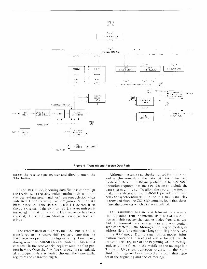
Data Path
The transmit and receive data path for each channel is
shown in Figure 4. The receiver has three 8-bit buffer
registers in a fifo arrangement (to provide a 3-byte
delay) in addition to the 8-bit receive shift register. This
arrangement creates additional time for the c ptj to ser-
vice an interrupt at the beginning of a block of high-
speed data. The receive error fifo stores parity andframing errors and other types of status information for
each of the three bytes in the receive data Fiio.
Incoming data is routed through one of several paths
depending on the mode and character length. In the
Asynchronous mode, serial data is entered in the 3-bit
buffer if it has a character length of seven or eight bits,
or is entered in the 8-bit receive shift register if it has a
length of five or six bits.
In the Synchronous mode, however, the data path is
determined by the phase of the receive process currentlv'
in operation. A Synchronous Receive operation begins
with the receiver in the Hunt phase, during which the
receiver searches the incoming data stream for a bit pat-
tern that matches the preprogramtried svnc characters
(or flags in the SDi c mode). If the device is programmedfor Monosync Hunt, a match is made with a single sync
character stored in v\R7. In Bisync Hunt, a inatch is
tnade with dual sync characters stored in w R6 and v\ r^.
In either case the incoming data passes through the
receive sync register, and is compared against the pro-
grammed sync character in v\ R6 or vvrt. In the Mono-sync mode, a match betweeti the sync character pro-
grainmed into \vr7 and the character assembled in the
receive sync register establishes synchrotii/atioti.
In the Bisync mode, however, incoming data is
shifted to the receive shift register while the next eight
bits of the message are assetnbled in the receive sync
register. The match between the assembled character in
the receive sync registers with the progratnmed svnc
character in v\ R6 and \vr7 establishes synchronization.
Once synchronization is established, incoming data by-
I DATA BUFFER
INTERNAL DATA BUS
RECEIVE
DATA
FIFO
1 BIT
DELAY
illASYNC DATA
HUNT MODE iBISYNC
T
SYNC REGISTERS ZERO DELETE
3 BITSRECEIVE
S R (8 BITSi
RECEIVE
ERROR
FIFO
RECEIVEERRORLOGIC
SYNC-CRC
WR7SYNC REGISTER
WR6SYNC REGISTER
20-BIT TRANSMIT SHIFT REGISTER
SDLCDATA
ZERO INSERT(5 BITS
CRCGENERATOH
STARTB,Jj
TRANSMIT DATA
SYNC ASYNCDATADATA ~ ^ TRANSMIT
Z. MULTIPLEXERt, Z-BIT DELAY
SYNCCRC
TRANSMITCLOCK LOGIC
RECEIVECLOCKLOGIC
CRC DELAYREGISTER(8 BITS)
CRCCHECKER
Figure 4. Transmit and Receive Data Path
passes the receive sync register and directly enters the
3-bit buffer.
In the stJi.c mode, incoming data first passes through
the receive sync register, which continuously monitors
the receive data stream and performs zero deletion whenindicated. Upon receiving five contiguous I's, the sixth
bit is inspected. If the sixth bit is a 0, it is deleted from
the data stream. If the sixth bit is a 1 , the seventh bit is
inspected. If that bit is a 0, a Flag sequence has been
received; if it is a 1, an Abort sequence has been re-
ceived.
The reformatted data enters the 3-bit buffer and is
transferred to the receive shift register. Note that the
SDIX receive operation also begins in the Hunt phase,
during which the Z80-SIO tries to match the assembled
character in the receive shift register with the flag pat-
tern in WR7. Once the first flag character is recognized,
all subsequent data is routed through the same path,
regardless of character length.
Although the same C RC checker is used for both si)i c
and synchronous data, the data path taken for each
mode is different. In Bisync protocol, a byte-oriented
operation requires that the C Pi; decide to include the
data character in CRC. To allow the C PLi ample time to
make this decision, the Z80-SIO provides an 8-bit
delay for synchronous data. In the sdi c mode, no delay
is provided since the Z80-SIO contains logic that deter-
mines the bytes on which C RC is calculated.
The transmitter has an 8-bit transmit data register
that is loaded from the internal data bus and a 20-bit
transmit shift register that can be loaded from wr6, w r?
and the transmit data register. WR6 and WR7 contain
sync characters in the Monosync or Bisync modes, or
address field (one character long) and flag respectively
in the SDLC mode. During Synchronous modes, infor-
mation contained in wr6 and wrv is loaded into the
transmit shift register at the beginning of the messageand, as a time filler, in the middle of the message if a
Transmit Underrun condition occurs. In the SDi cmode, the flags are loaded into the transmit shift regis-
ter at the beginning and end of message.
6

Asynchronous data in the transmit shift register is
formatted with start and stop bits and is shifted out to
the transmit multiplexer at the selected clock rate. Syn-
chronous (Monosync or Bisync) data is shifted out to
the transmit multiplexer and also to the CRC generator
at the X 1 clock rate.
SDLC/HDLC data is shifted out through the zero inser-
tion logic, which is disabled while the flags are being
sent. For all other fields (address, control and framecheck) a is inserted following five contiguous 1 's in the
data stream. The CRC generator result for SDi.c data is
also routed through the zero insertion logic.
Interrupts. The Z80-SIO offers an elaborate interrupt
scheme to provide fast interrupt response in real-time
applications. As mentioned earlier, Channel B registers
WR2 and RR2 contain the interrupt vector that points to
an interrupt service routine in the memory. To service
operations in both channels and to eliminate the neces-
sity of writing a status analysis routine, the Z80-S1O can
modify the interrupt vector in rr2 so it points directly to
one of eight interrupt service routines. This is doneunder program_control by setting a program bit (WRi,
D2) in Channel B called "Status Affects Vector." Whenthis bit is set, the interrupt vector in wr2 is modified
according to the assigned priority of the various inter-
rupting conditions. The table in the Write Register 1
description (Z80-SIO Programming section) shows the
modification details.
Functional Description
The functional capabilities of the Z80-SIO can be
described from two different points of view: as a data
communications device, it transmits and receives serial
data, and meets the requirements of various data com-munications protocols; as a Z80 family peripheral, it
interacts with the Z80-CPU and other Z80 peripheral
circuits, and shares their data, address and control
busses, as well as being a part of the Z80 interrupt struc-
ture. As a peripheral to other microprocessors, the
Z80-SIO offers valuable features such as non-vectored
interrupts, polling and simple handshake capabilities.
The first part of the following functional description
describes the interaction between the CPU and Z80-SIO;the second part introduces its data communicationscapabilities.
I/O CAPABILITIES
The Z80-SIO offers the choice of Polling, Interrupt
(vectored or non-vectored) and Block Transfer modes to
transfer data, status and control information to andfrom the CPU. The Block Transfer mode can be
implemented under cpu or DMA control.
Polling. The Polled mode avoids interrupts. Status
registers RRO and RRi are updated at appropriate times
for each function being performed (for example, CRCError status valid at the end of the message). All the in-
terrupt modes of the Z80-S1O must be disabled to
operate the device in a polled environment.
While in its Polling sequence, the CPU examines the
status contained in rro for each channel; the RRO status
bits serve as an acknowledge to the Poll inquiry. Thetwo RRO status bits Dq and D2 indicate that a receive or
transmit data transfer is needed. The status also in-
dicates Error or other special status conditions (see
"Z80-SIO Programming"). The Special Receive Condi-
tion status contained in RRI does not have to be read in a
Polling sequence because the status bits in rri are ac-
companied by a Receive Character Available status in
RRO.
Transmit interrupts, Receive interrupts and External/
Status interrupts are the main sources of interrupts
(Figure 5). Each interrupt source is enabled under pro-
gram control with Channel A having a higher priority
than Channel B, and with Receiver, Transmit and Ex-
ternal/Status interrupts prioritized in that order within
each channel. When the Transmit interrupt is enabled,
the CPU is interrupted by the transmit buffer becomingempty. (This implies that the transmitter must have hada data character written into it so it can become empty.)When enabled, the receiver can interrupt the CPU in oneof three ways:
• Interrupt on first receive character
• Interrupt on all receive characters
• Interrupt on a Special Receive condition
Interrupt On First Character is typically used with the
Block Transfer mode. Interrupt On All Receive Charac-
ters has the option of modifying the interrupt vector in
the event of a parity error. The Special Receive Condi-tion interrupt can occur on a character or message basis
(End Of Frame interrupt in SDLC, for example). TheSpecial Receive condition can cause an interrupt only if
the Interrupt On First Receive Character or Interrupt
On All Receive Characters mode is selected. In Inter-
rupt On First Receive Character, an interrupt can occur
from Special Receive conditions (except Parity Error)
after the first receive character interrupt (example:
Receive Overrun interrupt).
The main function of the External/Status interrupt is
to monitor the signal transitions of the CTS, dcd and
SYNC pins; however, an External/Status interrupt is also
caused by a Transmit Underrun condition or by the
detection of a Break (Asynchronous mode) or Abort
(SDUC mode) sequence in the data stream. The interrupt
caused by the Break/Abort sequence has a special
feature that allows the Z80-SIO to interrupt when the
Break/Abort sequence is detected or terminated. This
feature facilitates the proper termination of the current
message, correct initialization of the next message, and
the accurate timing of the Break/Abort condition in
external logic.
7

CPU/DMA Block Transfer. The Z80-SIO provides aBlock Transfer mode to accommodate CPU block trans-
fer functions and DMA controllers (Z80-DMA or otherdesigns ). The Block Transfer mode uses the wait/READY output in conjunction with the Wait/Ready bits
of Write Register 1. The wait/ready output can bedefined under software control as a wait line in the CPUBlock Transfer mode or as a ready line in the DMABlock Transfer mode.
To a DMA controller, the Z80-SIO ri ady outputindicates that the Z80-S1O is ready to transfer data to orfrom memory. To the CPU, the wait output indicatesthat the Z80-SIO is not ready to transfer data, therebyrequesting the CPU to extend the uo cycle. The pro-gramming of bits 5 , 6 and 7 of W rite Register 1 and thelogic states of the wait ready line are defined in the
Write Register 1 description (Z80-SIO Programmingsection.)
DATA COMMUNICATION.S ( APABIIJTIKS
In addition to the i () capabilities previously discussed,the Z80-SIO provides two independent full-duplex
channels as well as Asynchronous, Synchronous andSDLC (HDLC) operational modes. These modes facilitate
the implementation of commonly used data communi-cations protocols.
The specific features of these modes are described in
the following sections. To preserve the independenceand completeness of each section, some informationcommon to all modes is repeated.
BUFFER BECOMING EMPTY TRANSMIT INTERRUPT
Figure 5. Interrupt Structure

Asynchronous Operation
To receive or transmit data in the Asynchronous mode,the Z80-SIO must be initiahzed with the following pa-rameters: character length, clock rate, number of stopbits, even or odd parity, interrupt mode, and receiver ortransmitter enable. The parameters are loaded into the
appropriate write registers by the system program, w R4
parameters must be issued before WRi, wr3 and w R5
parameters or commands.
If the data is transmitt ed over a modem or RS232Cinterface, the R
h
qu
E
stTo send (RTS) and i5ata T[:r-MiNAi. REAi:)Y (DTR) outputs must be set along with theTransmit Enable bit. Transmission cannot begin until
the Transmit Enable bit is set.
The Auto Enables feature allows the programmer to
send the first data character of the message to the
Z80-SIO without waiting for CTS. If the Auto Enablesbit is set, the Z80-SIO will wait for the CTS pin to goLow before it begins data transmission, crs, dcd andSYNC are general-purpose i- o lines that may be used for
functions other than their labeled purposes. If CTS is
used for another purpose, the Auto Enables Bit must beprogrammed to 0.
Eigure 6 illustrates asynchronous message formats;Table 2 shows wr?, wr4 and w'R5 with bits set to indi-
cate the applicable modes, parameters and commands in
asynchronous modes. wr2 (Channel B only) stores theinterrupt vector; WRi defines the interrupt modes anddata transfer modes. \vr6 and \vr7 are not used in asyn-chronous modes. Tabic 3 shows the typical programsteps that implement a full-duplex receive/transmitoperation in either channel.
Asynchronous Transmit
The Transmit Data output ilxO) is held marking (High)when the transmitter has no data to send. Under pro-gram control, the Send Break (\\ R5, 1)4) command canbe issued to hold TxD spacing (Low) until the commandis cleared.
The Z80-S1O automatically adds the start bit, the
programmed parity bit (odd, even or no parity) and the
programmed number of stop bits to the data characterto be transmitted. When the character length is six or
seven bits, the unused bits are automatically ignored bythe Z80-S1O. If the character length is five bits or less,
refer to the table in the Write Register 5 description
(Z80-SIO Programming section) for the data format.
Serial data is shifted from at a rate equal to 1,
l/16th, i/32nd or l/64th of the clock rate supplied to
the Transmit Clock input (TxCl. Serial data is shifted
out on the falling edge of ( TxC >.
If set, the External/Status Interrupt mode monitorsthe status of dcd, crs and sync throughout the trans-
mission of the message. If these inputs change for a
period of time greater than the minimum specified pulsewidth, the interrupt is generated. In a transmit opera-tion, t his feature is used to monitor the modem controlsignal C TS.
MARKING LINE
ASYNCHRONOUS FORMAT
ALL TRANSACTIONS OCCURON AJALLING EDGEOF TxC,
N 5, 6 7, OR 8 ' /
MAY BE PRESENT ORNOT, EVEN OR ODD
MESSAGE FLOW
MARKING LINE
1, I'; OR 2 BITS
Figure 6. Asynchronous Message Format
9

Asynchronous Receive
An Asynchronous Receive operation begins when the
Receive Enable bit is set. If the Auto Enables option is
selected, ix D must be Low as well. A Low (spacing)
condition on the Receive Data input (RxD) indicates a
start bit. If this Low persists for at least one-half of a bit
time, the start bit is assumed to be valid and the data in-
put is then sampled at mid-bit time until the entire
character is assembled. This method of detecting a start
bit improves error rejection when noise spikes exist on
an otherwise marking line.
If the X 1 clock mode is selected, bit synchronization
must be accomplished externally. Receive data is sam-
pled on the rising edge of RxC. The receiver inserts I's
when a character length of other than eight bits is used.
If parity is enabled, the parity bit is not stripped from
the assembled character for character lengths other than
eight bits. For lengths other than eight bits, the receiver
assembles a character length of the required number of
data bits, plus a parity bit and I's for any unused bits.
For example, the receiver assembles a 5-bit character
with the following format: ii p D4 1)3 1^2 '^o-
Since the receiver is buffered by three 8-bit registers
in addition to the receive shift register, the CPU has
enough time to service an interrupt and to accept the
data character assembled by the Z80-SIO. The receiver
also has three buffers that store error flags for each data
character in the receive buffer. These error flags are
loaded at the same time as the data characters.
After a character is received,
following error conditions:
it is checked for the
• When parity is enabled, the Parity Error bit (RRi,
D4) is set whenever the parity bit of the character
does not match with the programmed parity. Once
this bit is set, it remains set until the Error Reset
Command (W RO) is given.
• The Framing Error bit (RRi, Oft) set if the char-
acter is assembled without any stop bits (that is, a
Low level detected for a stop bit). Unlike the Parity
Error bit, this bit is set (and not latched) only for
the character on which it occurred. Detection of
framing error adds an additional one-half of a bit
time to the character time so the framing error is
not interpreted as a new start bit.
• If the CPU fails to read a data character while more
than three characters have been recei\ed, the Re-
ceive Overrun bit (RRi, Ds) is set. When this oc-
curs, the fourth character assembled replaces the
third character in the receive buffers. With this ar-
rangement, only the character that has been writ-
ten over is flagged with the Receive Overrun Error
bit. Like Parity Error, this bit can only be reset by
the Error Reset command from the t PU. Both the
Framing Error and Receive Overrun Error cause
an interrupt with the interrupt vector indicating a
Special Receive condition (if Status Affects Vector
is selected).
Since the Parity Error and Receive Overrun Error
flags are latched, the error status that is read reflects an
error in the current word in the receive buffer plus any
Parity or Overrun Errors received since the last Error
Reset command. To keep correspondence between the
state of the error buffers and the contents of the receive
data buffers, the error status register must be read
before the data. This is easily accomplished if vectored
WR5
BIT 7 BIT 6 BIT 5 BIT 4 BIT 3 BIT 2 BIT 1 BIT
00 Rx 5 BITS CHARRx
ENABLEWR310
01
1
1
Rx 6 BITS CHARRx 7 BITS CHARRx 8 BITS CHAR
AUTOENABLES
WR4
00
01
10
1
1
1 CLOCK MODE16 CLOCK MODE
^ 32 CLOCK MODE• 64 CLOCK MODE
00
01 -
10 -
1
1
NOT USED1 STOP BIT CHARI'lSTOPBITS CHAR2STOPBITS CHAR
EVEN ODDPARITY
PARITYENABLE
DTR
GO Tx 5 BITS lOR
LESS) CHAR10 Tx 6 BITS CHAR01 - Tx 7 BITS CHAR11 Tx 8 BITS CHAR
SENDBREAK
Tx
ENABLE RTS
Table 2. Contents of Write Registers 3, 4 and 5 in Asynchronous Modes
10

FUNCTION TYPICAL PROGRAM STEPS COMMENTS
REGISTER. INFORMATION LOADED:
WRO CHANNEL RESET Reset SIO
WRO POINTER 2
WR2 INTERRUPT VECTOR Channel B only
WRO POINTER 4, RESET EXTERNAL STATUS INTERRUPT
WR4 ASYNCHRONOUS MODE, PARITY INFORMATION, STOP BITS
INFORMATION, CLOCK RATE INFORMATIONIssue parameters
INITIALIZE WRO
WR3
WRO
POINTER 3
RECEIVE ENABLE, AUTO ENABLES, RECEIVE CHARACTERLENGTH
POINTER 5
WR5 REQUEST TO SEND, TRANSMIT ENABLE, TRANSMITCHARACTER LENGTH, DATA TERMINAL READY
Receive and Transmit both fully initial-
ized. Auto Enables will enable Trans-
rriitter if CtS is active and Receiver if
DCD is active.
WRO POINTER 1, RESET EXTERNAL STATUS INTERRUPT
WRl TRANSMIT INTERRUPT ENABLE, STATUS AFFECTS VECTOR,INTERRUPT ON ALL RECEIVE CHARACTERS, DISABLE WAITREADY FUNCTION, EXTERNAL INTERRUPT ENABLE
Transmit Receive interrupt mode se-
lected. External Interrupt monitors the
status of the cTs, DCD and sync inputs
and detects the Break sequence. Status
Affects Vector in Channel B only
TRANSFER FIRST DATA BYTE TO SIO This data byte must be transferred or no
transmit interrupts will occur.
IDLE MODE EXECUTE HALT INSTRUCTION OR SOME OTHER PROGRAM Program is waiting for an interrupt from
the SIO,
Z80 INTERRUPT ACKNOWLEDGE CYCLE TRANSFERS RR2 TO CPU
IF A CHARACTER IS RECEIVED-
• TRANSFER DATA CHARACTER TO CPU• UPDATE POINTERS AND PARAMETERS• RETURN FROM INTERRUPT
When the interrupt occurs, the interrupt
vector is modified by: 1. Receive Char-
acter Available; 2. Transmit Buffer Emp-
ty; 3. External/Status change; and 4,
Special Receive condition.
DATA TRANSFER ANDERROR MONITORING
IF TRANSMITTER BUFFER IS EMPTY:• TRANSFER DATA CHARACTER TO SIO
• UPDATE POINTERS AND PARAMETERS• RETURN FROM INTERRUPT
IF EXTERNAL STATUS CHANGES:• TRANSFER RRO TO CPU• PERFORM ERROR ROUTINES (INCLUDE BREAK DETECTION)• RETURN FROM INTERRUPT
IF SPECIAL RECEIVE CONDITION OCCURS:• TRANSFER RR1 TO CPU• DO SPECIAL ERROR (E.G FRAMING ERROR) ROUTINE• RETURN FROM INTERRUPT
Program control is transferred to one of
the eight interrupt service routines.
If used with processors other than the Z80,
the modified interrupt vector (RR2) should
be returned to the CPU in the Interrupt Ac-
knowledge sequence.
TERMINATION
REDEFINE RECEIVE TRANSMIT INTERRUPT MODES
DISABLE TRANSMIT RECEIVE MODES
When transmit or receive data transfer is
complete
UPDATE MODEM CONTROL OUTPUTS (E G RTS OFF) In Transmit, the All Sent status bit indi-
cates transmission is complete.
Table 3. Asynchronous Mode
11

interrupts are used, because a special interrupt vector is
generated for these conditions.
While the External/Status interrupt is enabled, break
detection causes an interrupt and the Break Detected
status bit (RRO, 1)7) is set. The Break Detected interrupt
should be handled by issuing the Reset External/Status
Interrupt command to the Z80-SIO in response to the
first Break Detected interrupt that has a Break status of
1 (RRO, 1)7). The Z80-SIO monitors the Receive Data in-
put and waits for the Break sequence to terminate, at
which point the Z80-S1O interrupts the CPU with the
Break status set to 0. The CFL must again issue the Reset
External/Status Interrupt command in its interrupt ser-
vice routine to reinitialize the break detection logic.
The External/Status interrupt also monitors the
status of ix;i). If the dcd pin becomes inactive for a
period greater than the minimum specified pulse width,
an interrupt is generated with the ncD status bit (RRO,
1)3) set to 1. Note that the DC D input is inverted in the
RR(! status register.
If the status is read after the data, the error data for
the next word is also included if it has been stacked in
the buffer. If operations are performed rapidly enough
so the next character is not yet received, the status regis-
ter remains valid. An exception occurs v\hen the Inter-
rupt On Eirst Character Only mode is selected. A special
interrupt in this mode holds the error data and the char-
acter itself (even if read from the buffer) until the Error
Reset command is issued. This prevents further data
from becoming available in the receiver until the Reset
command is issued, and allows t Pr intervention on the
character with the error even if 1)\ia or block transfer
techniques are being used.
If Interrupt On Every Character is selected, the inter-
rupt vector is different if there is an error status in rri.
If a Receiver Overrun occurs, the most recent character
received is loaded into the buffer; the character pre-
ceding it is lost. When the character that has been writ-
ten over the other characters is read, the Receive Over-
run bit is set and the Special Receive Condition vector is
returned if Status Affects Vector is enabled.
In a polled environment, the Receive Character
.^vailable bit (RRO, Do) must be monitored so the
Z80-CPU can know when to read a character. I his bit is
automatically reset when the receive buffers are read.
To prevent overwriting data in polled operations, the
transmit buffer status must be checked before writing
into the transmitter. The Transmit Buffer Empty bit is
set to 1 whenever the transmit buffer is empty.
12

Synchronous Operation
Before describing synchronous transmission and recep-
tion, the three types of character synchronization
—
Monosync, Bisync and External Sync— require some ex-
planation. These modes use the x 1 clock for bothTransmit and Receive operations. Data is sampled onthe rising edge of the Receive Clock input (RxC). Trans-mitter data transitions occur on the falling edge of the
Transmit Clock input (fxC).
The differences between Monosync, Bisync and Ex-ternal Sync are in the manner in which initial character
synchronization is achieved. The mode of operation
must be selected before sync characters are loaded,
because the registers are used differently in the various
modes. Figure 7 shows the formats for all three of these
synchronous modes.
Monosync. In a Receive operation, matching a single
sync character (8-bit sync mode) with the programmedsync character stored in WR7 implies character synchro-
nization and enables data transfer.
Bisync. Matching two contiguous sync characters
(16-bit sync mode) with the programmed sync charac-
ters stored in w R6 and w R7 implies character synchroni-
zation. In both the Monosync and Bisync modes, syncis used as an output, and is active for the part of the
receive clock that detects the sync character.
Kxternal Sync. In this mode, character synchronization
is established externally; sync is an input that indicates
external character synchronization has been achieved.
After the sync pattern is detected, the external logic
mu st wai t for two full Receive Clock cycles to activate
the SYNC input. The sync input must be held Low until
character synchronization is lost. Character assemblybegins on the rising edge of that precedes the falling
edge of SYNC.
In all cases after a reset, the receiver is in the Huntphase, during which the Z80-S1O looks for character
synchronization. The hunt can begin only when the
receiver is enabled, and data transfer can begin onl\
when character synchronization has been achieved. If
character synchronization is lost, the Hunt phase can be
re-entered by writing a control word with the Enter
Hunt Phase bit set (WR.i, D4). In the Transmit mode, the
transmitter always sends the programmed number of
sync bits (8 or 16). In the Monosync mode, the trans-
mitter transmits from \\'R6; the receiver comparesagainst wr7.
In the Monosync, Bisync and External Sync modes,assembly of received data continues until the Z80-SIO is
reset, o r until the receiver is disabled (by command or
by DCD in the Auto Enables mode), or until the cpl sets
the Enter Hunt Phase bit.
MESSAGE FLOW
(A) MONOSYNC MESSAGE FORMAT (INTERNAL SYNC DETECT)
(B) BISYNC MESSAGE FORMAT (INTERNAL SYNC DETECT)
(C) EXTERNAL SYNC DETECT FORMAT
Figure 7. Synchronous Formats
13

After initial synchronization has been achieved, the
operation of the Monosync, Bisync and External Syncmodes is quite similar. Any differences are specified in
the following text.
Table 4 shows how wr3, wr4 and wr5 are used in
synchronous receive and transmit operations. WROpoints to other registers and issues various commands,WRi defines the interrupt modes, wr2 stores the inter-
rupt vector, and wr6 and wr7 store sync characters.
Table 5 illustrates the typical program steps that imple-
ment a half-duplex Bisync transmit operation.
Synchronous Transmit
can be selected to transfer the data. The External/Status
interrupt mode is used to monitor the status of the
CLEAR TO SEND input as well as the Transmit Under-
run/EOM latch. Optionally, the Auto Enables feature
can be used to enable the transmitter when c ts is active.
The first data transfer to the Z80-SIO can begin whenthe External/Status interrupt occurs (cts status bit set)
or immediately following the Transmit Enable com-mand (if the Auto Enables modes is set).
Transmit data is held marking after reset or if the
transmitter is not enabled. Break may be programmedto generate a spacing line that begins as soon as the SendBreak bit is set. With the transmitter fully initialized andenabled, the default condition is continuous transmis-
sion of the 8- or 16-bit sync character.
INITIALIZATION
The system program must initialize the transmitter with
the following parameters: odd or even parity, x 1 clock
mode, 8- or 16-bit sync character(s), CRC polynomial.
Transmitter Enables, Request To Send, Data Terminal
Ready, interrupt modes and transmit character length.
WR4 parameters must be issued before WRi, wr3, wrs,WR6 and WR7 parameters or commands.
One of two polynomials—CRC-i 6 (X'^-i- X'^ -(- -I- 1)
or SDix- (X'6+ X'2-i- X^ -I- 1)—may be used with syn-
chronous modes. In either case (sdlc mode not
selected), the CRC generator and checker are reset to all
O's. In the transmit initialization process, the CRCgenerator is initialized by setting the Reset TransmitCRC Generator command bits (WRO). Both the trans-
mitter and the receiver use the same polynomial.
Transmit Interrupt Enable or Wait/Ready Enable
DATA TRANSFER AND STATUS MONITORING
In this phase, there are several combinations of inter-
rupts and Wait/Ready.
Data Transfer Using Interrupts. If the Transmit Inter-
rupt Enable bit (WRi, D]) is set, an interrupt is generated
each time the transmit buffer becomes empty. The inter-
rupt can be satisfied either by writing another character
into the transmitter or by resetting the Transmitter In-
terrupt Pending latch with a Reset Transmitter Pending
command (WRO, CMD5). If the interrupt is satisfied with
this command and nothing more is written into the
transmitter, there can be no further Transmit Buffer
Empty interrupts, because it is the process of the buffer
becoming empty that causes the interrupts and the buf-
fer cannot become empty when it is already empty. This
situation does cause a Transmit Underrun condition,
which is explained in the "Bisync Transmit Underrun"section.
BIT 7 BIT 6 BIT 5 BIT 4 BIT 3 BIT 2 BIT 1 BIT
WR3
00 - Rx 5 BITS CHAR10 - Rx 6 BITS CHAR01 Rx 7 BITS CHAR11 Rx 8 BITS CHAR
AUTOENABLES
ENTERHUNTMODE
Rx CRCENABLE
SYNCCHARLOADINHIBIT
RXENABLE
00 - 8-BIT SYNC CHAR„ 01 - 16-BIT SYNC CHAR EVEN ODD PARITY
10 -SDLC MODE SELECTS SYNC PARITY ENABLE11 - EXT SYNC MODE MODES
00 - Tx 5 BITS (ORLESS) CHAR 1
WR5 DTR 10 - Tx 6 BITS CHAR y"^^" cmao, c SELECTS RTS cm„p,c01 Tx 7 BITS CHAR ^"^^^^ ^^^^^E ENABLE
11 - Tx 8 BITS CHAR
Table 4. Contents of Write Registers 3, 4 and 5 in Synchronous Modes
14

Data Transfer Using wait/ready. To the cpu, theactivation of wait indicates that the Z80-SIO is notready to accept data and that the cpu must extend theoutput cycle. To a dma controller, ready indicates that
the transmit buffer is empty and that the Z80-SIO is
ready to accept the next data character. If the datacharacter is not loaded into the Z80-S1O by the time thetransmit shift register is empty, the Z80-SIO enters theTransmit Underrun condition.
Bisync Transmit Underrun. In Bisync protocol, filler
characters are inserted to maintain synchronizationwhen the transmitter has no data to send (TransmitUnderrun condition). The Z80-SIO has two program-mable options for solving this situation: it can insert
sync characters, or it can send the CRC characters gener-
ated so far, followed by sync characters.
These options are under the control of the ResetTransmit Underrun/r:oM command in who. Following achip or channel reset, the Transmit Underrun/EOMstatus bit (RRO, D(,) is in a set condition and allows the
insertion of sync characters when there is no data to
send. CRC is not calculated on the automatically inserted
sync characters. When the CPU detects the end of mes-sage, a Reset Transmit Underrun/HOM command can beissued. This allows CRC to be sent when the transmitterhas no data. In this case, the Z80-SIO sends crc,followed by sync characters, to terminate the message.
There is no restriction as to when in the message the
Transmit Underrun/EOM bit can be reset. If Reset is
issued after the first data character has been loaded the
16-bit CRC is sent and followed by sync characters the
first time the transmitter has no data to send. Because ofthe Transmit Underrun condition, an External/Statusinterrupt is generated whenever the Transmit Under-run/i:OM bit becomes set.
In the case of sync insertion, an interrupt is generatedonly after the first automatically inserted sync characterhas been loaded. The status indicates the TransmitUnderrun/EOM bit and the Transmit Buffer Empty bit
are set.
In the case of CRC insertion, the Transmit Underrun/EOM bit is set and the Transmit Buffer Empty bit is reset
while CRC is being sent. When crc has been completelysent, the Transmit Buffer Empty status bit is set and aninterrupt is generated to indicate to the CPU that anothermessage can begin (this interrupt occurs because CRChas been sent and sync has been loaded). If no moremessages are to be sent, the program can terminatetransmission by resetting rts, and disabling the
transmitter (wr5, D3).
Pad characters may be sent by setting the Z80-SIO to
8 bits/transmit character and writing ff to the transmit-
ter while CRC is being sent. Alternatively, the sync char-
acters can be redefined as pad characters during this
time. The following example is included to clarify this
point.
The Z80-SIO interrupts with the Transmit Buffer Empty bit
set.
The CPU recognizes that the last character itTx of themessage has already been sent to the Z80-SIO by examiningthe internal program status.
To force the Z80-SIO to send crc, the cpu issues the ResetTransmit Underrun/EOM Latch command wroi and satisfies
the interrupt with the Reset Transmit Interrupt Pendingcommand. (This command prevents the Z80-SIO from re-
questing more data.) Because of the transmit underruncaused by this command, the Z80-SIO starts sending crcThe Z80-SIO also causes an External/Status interrupt with
the Transmit Underrun/EOM latch set.
The CPU satisfies this interrupt by loading pad characters in-
to the transmit buffer and issuing the Reset External/StatusInterrupt command.
With this sequence, crc is followed by a pad character in-
stead of a sync character. Note that the Z80-SIO will inter-
rupt with a Transmit Buffer Empty interrupt when crc is
completely sent and that the pad character is loaded into
the transmit shift register.
From this point on the cpu can send more pad characters or
sync characters.
Bisync CRC Generation. Setting the Transmit c Rcenable bit (wr5. Do) initiates crc accumulation whenthe program sends the first data character to the
Z80-SIO. Although the Z80-SIO automatically trans-
mits up to two sync characters (16-bit sync), it is wise to
send a few more sync characters ahead of the message(before enabling Transmit crc ) to ensure synchroniza-
tion at the receiving end.
The transmit CRC Enable bit can be changed on the
fly any time in the message to include or exclude a par-
ticular data character from crc accumulation. TheTransmit CRC Enable bit should be in the desired state
when the data character is loaded from the transmit
data buffer into the transmit shift register. To ensurethis bit is in the proper state, the Transmit crc Enablebit must be issued before sending the data character to
the Z80-SIO.
Transmit Transparent Mode. Transparent mode (Bi-
sync protocol) operation is made possible by the ability
to change Transmit crc Enable on the fly and by the
additional capability of inserting 16-bit sync characters.
Exclusion of dle characters from crc calculation canbe achieved by disabling crc calculation immediatelypreceding the dle character transfer to the Z80-SIO.
In the case of a Transmit Underrun condition in the
Transparent mode, a pair of dle-syn characters are
sent. The Z80-SIO can be programmed to send the di e-
SYN sequence by loading a dle character into wr6 and a
sync character into wr7.
Transmit Termination. The Z80-SIO is equipped with a
special termination feature that maintains data integrity
and validity. If the transmitter is disabled while a dataor sync character is being sent, that character is sent as
usual, but is followed by a marking line rather than crcor sync characters. When the transmitter is disabled, a
15
FUNCTION TYPICAL PROGRAM STEPS COMMENTS
REGISTER: INFORMATION LOADED:
WRO CHANNEL RESET, RESET TRANSMIT CRC GENERATOR
WRO POINTER 2
WR2 INTERRUPT VECTOR
WRO POINTER 3
WR3 AUTO ENABLES
Reset SIO, initilize CRC generator.
Ctianriel B only
Transmission begins only after CTS is
detected.
INITIALIZE
WRO
WR4
WRO
WR6
WRO
WR7
WRO
WR1
WRO
WR5
POINTER 4
PARITY INFORMATION. SYNC MODES INFORMATION, -< 1
CLOCK MODE
POINTER 6
SYNC CHARACTER 1
POINTER 7. RESET EXTERNAL STATUS INTERRUPTS
SYNC CHARACTER 2
POINTER 1, RESET EXTERNAL STATUS INTERRUPTS
STATUS AFFECTS VECTOR. EXTERNAL INTERRUPT ENABLE.
TRANSMIT INTERRUPT ENABLE OR WAIT READY MODE ENABLE
POINTER 5
REQUEST TO SEND. TRANSMIT ENABLE. BISYNC CRC.
TRANSMIT CHARACTER LENGTH
FIRST SYNC BYTE TO SIO
Issue transmit parameters.
IDLE MODE EXECUTE HALT INSTRUCTION OR SOME OTHER PROGRAM
DATA TRANSFER ANDSTATUS MONITORING
WHEN INTERRUPT (WAIT READY) OCCURS:• INCLUDE EXECLUDE DATA BYTE FROM CRCACCUMULATION (IN SIO).
• TRANSFER DATA BYTE FROM CPU (OR MEMORY) TO SIO.
• DETECT AND SET APPROPRIATE FLAGS FOR CONTROLCHARACTERS (IN CPU).
• RESET Tx UNDERRUN'EOM LATCH (WRO) IF LAST CHARACTEROF MESSAGE IS DETECTED.
• UPDATE POINTERS AND PARAMETERS (CPU).
• RETURN FROM INTERRUPT.
IF ERROR CONDITION OR STATUS CHANGE OCCURS;• TRANSFER RRO TO CPU• EXECUTE ERROR ROUTINE.• RETURN FROM INTERRUPT
TERMINATION
REDEFINE INTERRUPT MODES.
UPDATE MODEM CONTROL OUTPUTS (E G. TURN OFF RTS)
DISABLE TRANSMIT MODE
External Interrupt mode monitors ttie
status of CTS and DCD input pins as well
as the status of Tx Underrun EOM latch.
Transmit Interrupt Enable interrupts
when the Transmit buffer becomes
empty; the Wait Ready mode can be used
to transfer data using DMA or CPU Block
Transfer.
Status Affects Vector (Channel B only).
Transmit CRC Enable should be set when
first non-sync data is sent to Z80-SIO.
Need several sync characters in the be-
ginning of message. Transmitter is fully
initialized.
Waiting for interrupt or Wait Ready output
to transfer data.
Interrupt occurs (Wait/Ready becomes
active) when first data byte is being sent.
Wait mode allows CPU block transfer
from memory to SIO: Ready mode allows
DMA block transfer from memory to SIO.
The DMA chip can be programmed to cap-
ture special control characters (by ex-
amining only the bits that specify ASCII or
EBCDIC control characters), and interrupt
CPU.
Tx Underrun EOM indicates either trans-
mit underrun (sync character being sent)
or end of message (CRC-16 being
sent).
Program should gracefully terminate
message.
Table 5. Bisync Transmit Mode
16
character in the buffer remains in the buffer. If the
transmitter is disabled while CRC is being sent, the 16-bit
transmission is completed, but sync is sent instead of
CRC.
A programmed break is effective as soon as it is writ-
ten into the control register; characters in the transmit
buffer and shift register are lost.
In all modes, characters are sent with the least signifi-
cant bits first. This requires right-hand justification of
transmitted data if the word length is less than eight
bits. If the word length is five bits or less, the special
technique described in the Write Register 5 discussion
(Z80-SIO Programming section) must be used for the
data format. The states of any unused bits in a data
character are irrelevant, except when in the Five Bits OrLess mode.
If the External/Status Interrupt Enable bit is set,
transmitter conditions such as "starting to send CRCcharacters," "starting to send sync characters," andCTS changing state cause interrupts that have a uniquevector if Status Affects Vector is set. This interrupt
mode may be used during block transfers.
All interrupts may be disabled for operation in a
Polled mode, or to avoid interrupts at inappropriate
times during the execution of a program.
Synchronous Receive
INITIALIZATION
The system program initiates the Synchronous Receive
operation with the following parameters: odd or even
parity, 8- or 16-bit sync characters, x 1 clock mode,CRC polynomial, receive character length, etc. Synccharacters must be loaded into registers wr6 and wr7.The receivers can be enabled only after all receive pa-
rameters are set. wr4 parameters must be issued before
WRi , w K3, WR5, \VR6 and WR7 parameters or commands.
After this is done, the receiver is in the Hunt phase. It
remains in this phase until character synchronization is
achieved. Note that, under program control, all the
leading sync characters of the message can be inhibited
from loading the receive buffers by setting the SyncCharacter Load Inhibit bit in wr3.
DATA TRANSFER AND STATUS MONITORING
After character synchronization is achieved, the as-
sembled characters are transferred to the receive data
m o. The following four interrupt modes are available
to transfer the data and its associated status to the CPU.
.No Interrupts Knabled. This mode is used for a purely
polled operation or for off-line conditions.
Interrupt On First Character Only. This mode is norm-ally used to start a polling loop or a Block Transfer in-
struction using wait/ready to synchronize the cpi; or
the DMA device to the incoming data rate. In this mode,the Z80-SIO interrupts on the first character and there-
after interrupts only if Special Receive conditions are
detected. The mode is reinitialized with the Enable In-
terrupt On Next Receive Character command to allow
the next character received to generate an interrupt.
Parity errors do not cause interrupts in this mode, but
End Of Frame (SDLC mode) and Receive Overrun do.
If External/Status interrupts are enabled, they mayinterrupt any time dcd changes state.
Interrupt On Every Character. Whenever a character
enters the receive buffer, an interrupt is generated.
Error and Special Receive conditions generate a special
vector if Status Affects Vector is selected. Optionally, a
Parity Error may be directed not to generate the special
interrupt vector.
Special Receive Condition Interrupts. The Special
Receive Condition interrupt can occur only if either the
Receive Interrupt On First Character Only or Interrupt
On Every Receive Character modes is also set. TheSprecial Receive Condition interrupt is caused by the
Receive Overrun error condition. Since the Receive
Overrun and Parity error status bits are latched, the
error status—when read— reflects an error in the current
word in the receive buffer in addition to any Parity or
Overrun errors received since the last Error Reset com-mand. These status bits can only be reset by the Error
reset command.
CRC Error Checking and Termination. A c RC error
check on the receive message can be performed on a per
character basis under program control. The Receive
CRC Enable bit (wr3, Dj) must be set/reset by the pro-
gram before the next character is transferred from the
receive shift register into the receive buffer register. This
ensures proper inclusion or exclusion of data characters
in the CRC check.
To allow the CPU ample time to enable or disable the
CRC check on a particular character, the Z80-SIO calcu-
lates CRC eight bit times after the character has beentransferred to the receive buffer. If CRC is enabled
before the next character is transferred, CRC is calcu-
lated on the transferred character. If CRC is disabled
before the time of the next transfer, calculation pro-
ceeds on the word in progress, but the word just trans-
ferred to the buffer is not included. When these require-
ments are satisfied, the 3-byte receive data buffer is, in
effect, unusable in Bisync operation. CRC may be enabl-
ed and disabled as many times as necessary for a given
calculation.
In the Monosync, Bisync and External Sync modes,the CRC/Framing Error bit (RRI, Df,) contains the com-parison result of the CRC checker 16 bit times (eight bits
delay and eight shifts for CRC) after the character has
been transferred from the receive shift register to the
buffer. The result should be zero, indicating an error-
17
free transmission. (Note that the resuh is valid only at
the end of CRC calculation. If the result is examined
before this time, it usually indicates an error.) The com-
parison is made with each transfer and is valid only as
long as the character remains in the receive fifo.
Following is an example of the CRC checking opera-
tion when four characters (A, B, C and D) are received
in that order.
Character A loaded into buffer
Character B loaded into buffer
If CRC is disabled before C is in the buffer, CRC is not
calculated on B.
Character C loaded into buffer
After C is loaded, the CRC/Framing Error bit shows the
result of the comparison through character A.
Character D loaded into buffer
After D is in the buffer, the CRC Error bit shows the
result of the comparison through character B whether or
not B was included in the CRC calculations.
Due to the serial nature of CRC calculation, the
Receive Clock (iuC) must cycle 16 times (8-bit delay plus
8-bit CRC shift) after the second CRC character has been
loaded into the receive buffer, or 20 times (the previous
16 plus 3-bit buffer delay and 1-bit input delay) after the
last bit is at the RxD input, before CRC calculation is
complete. A faster external clock can be gated into the
Receive Clock input to supply the required 16 cycles.
The Transmit and Receive Data Path diagram (Figure 4)
illustrates the various points of delay in the CRC path.
The typical program steps that implement a half-
duplex Bisync Receive mode are illustrated in Table 6.
The complete set of command and status bit definitions
are explained under "Z80-SIO Programming."
FUNCTION TYPICAL PROGRAM STEPS COMMENTS
INITIALIZE
REGISTER: INFORMATION LOADED
WRO CHANNEL RESET, RESET RECEIVE CRC CHECKER
WRO POINTER 2
WR2 INTERRUPT VECTOR
WRO POINTER 4
WR4 PARITY INFORMATION, SYNC MODES INFORt^ATION. x1
CLOCK MODE
WRO POINTER 5, RESET EXTERNAL STATUS INTERRUPT
WR5 BISYNC CRC-16, DATA TERMINAL READY
WRO POINTER 3
WR3 SYNC CHARACTER LOAD INHIBIT, RECEIVE CRC ENABLE;
ENTER HUNT MODE, AUTO ENABLES, RECEIVE CHARACTER
LENGTH
Reset SIC; initialize Receive CRC checker.
Channel B only
Issue receive parameters.
Sync character load inhibit strips all the
leading sync characters at the beginning
of the message. Auto Enables enables
the receiver to accept data only after the
dCd input is active.
WRO POINTER 6
WR6 SYNC CHARACTER 1
WRO POINTER 7
WR7 SYNC CHARACTER 2
WRO POINTER 1. RESET EXTERNAL STATUS INTERRUPT
WR1 STATUS AFFECTS VECTOR, EXTERNAL INTERRUPT ENABLE,
RECEIVE INTERRUPT ON FIRST CHARACTER ONLYIn this interrupt mode, only the first non-
sync data character is transferred to the
CPU, All subsequent data is transferred
on a DMA basis; however Special Re-
ceive Condition interrupts will interrupt
the CPU. Status Affects Vector used in
Channel B only.
Table 6. Bisync Receive Mode
18

FUNCTION TYPICAL PROGRAM STEPS COMMENTS
iNITIALIZE
(CONTINUED)
WRO POINTERS. ENABLE INTERRUPT ON NEXT RECEIVE CHARACTER
WR3 RECEIVE ENABLE, SYNC CHARACTER LOAD INHIBIT, ENTERHUNT MODE. AUTO ENABLE. RECEIVE WORD LENGTH
Resetting this
simple progra"":
next transactic
WR3 is reissue;':
ceive CRC Eri-,:
ceiving SOH ^i;
IDLE MODE EXECUTE HALT INSTRUCTION OR SOME OTHER PROGRAMReceive moovsystem is wacharacter.
DATA TRANSFER ANDSTATUS MONITORING
WHEN INTERRUPT ON FIRST CHARACTER OCCURS. THE CPU DOES THEFOLLOWING:
• TRANSFERS DATA BYTE TO CPU• DETECTS AND SETS APPROPRIATE FLAGS FOR CONTROL CHAR-ACTERS (IN CPU)
• INCLUDES: EXCLUDES DATA BYTE IN CRC CHECKER• UPDATES POINTERS AND OTHER PARAMETERS• ENABLES WAIT READY FOR DMA OPERATION• ENABLES DMA CONTROLLER• RETURNS FROM INTERRUPT
WHEN WAIT READY BECOMES ACTIVE. THE DMA CONTROLLER DOES THEFOLLOWING:
• TRANSFERS DATA BYTE TO MEMORY• INTERRUPTS CPU IF A SPECIAL CHARACTER IS CAPTURED BY THEDMA CONTROLLER
• INTERRUPTS THE CPU IF THE LAST CHARACTER OF THE MESSAGEIS DETECTED
FOR MESSAGE TERMINATION. THE CPU DOES THE FOLLOWING:• TRANSFERS RR1 TO THE CPU• SETS ACK NAK REPLY FLAG BASED ON CRC RESULT• UPDATES POINTERS AND PARAMETERS• RETURNS FROM INTERRUPT
During the Hutwo contiguc-.
synchronizat'i
DMA mode an
acters are tra'
troller. The ccto capture spi
ining only tht
EBCDIC contn
the CPU upcthe CPU exai^'
characters ano
{e,g, CRC Ena:
The SlO interri.r:
dition, and the
present messat;
tion, and repe,:V-
TERMINATION
REDEFINE INTERRUPT MODES AND SYNC MODES
UPDATE MODEM CONTROLS
DISABLES RECEIVE MODE
Table 6. BIsync Receive Mode (Continued)
19

20

SDLC (HDLC) Operation
The Z80-SIO is capable of handling both High-level
Synchronous Data Link Control (HDLC) and IBM Syn-
chronous Data Link Control (SDLC) protocols. In the
following text, only SDLC is referred to because of the
high degree of similarity between sdlc and hdi.c.
The SDi.c mode is considerably different than Syn-
chronous Bisync protocol because it is bit oriented
rather than character oriented and, therefore, can natu-
rally handle transparent operation. Bit orientation
makes SDi.c a flexible protocol in terms of messagelength and bit patterns. The Z80-SIO has several built-in
features to handle variable message length. Detailed in-
formation concerning sdlc protocol can be found in
literature published on this subject, such as IBM docu-ment GA27-3093.
The SDi c message, called the frame (Figure 8), is
opened and closed by flags that are similar to the sync
characters in Bisync protocol. The Z80-S1O handles the
transmission and recognition of the flag characters that
mark the beginning and end of the frame. Note that the
Z80-S1O can receive shared-zero flags, but cannot trans-
mit them. The 8-bit address field of an SDLC frame con-
tains the secondary station address. The Z80-SIO has an
Address Search mode that recognizes the secondary sta-
tion address so it can accept or reject the frame.
Since the control field of the sdlc frame is transpar-
ent to the Z8()-SIO, it is simply transferred to the CPU.
The Z80-SIO handles the Frame Check sequence in a
manner that simplifies the program by incorporating
features such as initializing the CRC generator to all 1 's,
resetting the c RC checker when the opening flag is
detected in the Receive mode, and sending the FrameCheck/Flag sequence in the Transmit mode. Controller
hardware is simplified by automatic zero insertion anddeletion logic contained in the Z80-SIO.
Table 7 shows the contents of w R3, w R4 and wrs dur-
ing SDi ( Receive and Transmit modes, wro points to
other registers and issues various commands. WRI
defines the interrupt modes, w R2 stores the interrupt
vector, w R7 stores the flag character and VVR6 the sec-
ondary address.
SDLC Transmit
INITIALIZATION
Like Synchronous operation, the sdlc Transmit modemust be initialized with the following parameters: soixmode, sdlc polynomial. Request To Send, Data Ter-
minal Ready, transmit character length, transmit inter-
rupt modes (or Wait/Ready function). Transmit En-able, Auto Enables and External/Status interrupt.
Selecting the sdlc mode and the SDi c polynomialenables the Z80-SIO to initialize the CRC Generator to
all I's. This is accomplished by issuing the Reset
Transmit CRC Generator command (WRO). Refer to the
Synchronous Operation section for more details on the
interrupt modes.
After reset, or when the transmitter is not enabled,
the Transmit Data output is held marking. Break maybe programmed to generate a spacing line. With the
transmitter fully initialized and enabled, continuous
flags are transmitted on the Transmit Data output.
An abort sequence may be sent by issuing the SendAbort command (Wro, cmDj). This causes at least eight,
but less than fourteen, I's to be sent before the line
reverts to continuous flags. It is possible that the Abortsequence (eight 1 's) could follow up to five continuous I
bits (allowed by the zero insertion logic) and thus cause
up to thirteen 1 's to be sent. Any data being transmitted
and any data in the transmit buffer is lost when an abort
is issued.
When required, an extra is automatically inserted
when there are five contiguous I's in the data stream.
This does not apply to flags or aborts.
DATA TRANSFER AND STATUS MONITORING
There are several combinations of interrupts and the
Wait/Ready function in the slijc mode.
CLOSINGFLAG
01111110
MESSAGE FLOW
Figure 8. Transmit/Receive SDLC/HDLC Message Format
21

sinj; Interrupts. If the Transmit Inter-
act , an interrupt is generated each time
r-js empty. The interrupt may be satis-
uing another character into the trans-
•.liing the Transmit Interrupt Pending
I Transmitter Pending command (WRO,
lerrupt is satisfied with this commandic is written into the transmitter, there
raiismitter interrupts. The result is a
'ir, condition. When another character
lit out, the transmitter can again
iiid interrupt the CPU. Following the
^iperation, the 8-bit address field, con-
irmation field may be sent to the
tic Transmit Interrupt mode. Thehe Frame Check sequence using the
!i feature.
i^Miiitter is first enabled, it is already
, I : . cannot then become empty. There-
. j'.iiffer Empty interrupts can occur
! .iata character is written.
, Winter is first enabled, it is already
'iicn become empty. Therefore, no
:npiy interrupts can occur until after
a .cr is written.
.issa Wait/Ready. If the Wait/Ready;i selected, WAIT indicates to the CPU
;ot ready to accept the data and the
'ic I () cycle. To a DMA controller,
; ai the transmitter buffer is empty and
! ady to accept the next character. If
iiot loaded into the Z80-S1O by the
i iiitt register is empty, the Z80-SIO' L nderrun condition. Address, con-
a;-'ii fields may be transferred to the
mode using the Wait/Ready func-
> iransmits the Frame Check sequence
V ' I . nderrun feature.
SDLC Transmit Underrun/End Of Message. SDi C -like
protocols do not have provisions for fill characters with-
in a message. The Z80-SIO therefore automatically ter-
minates an SDi.C frame when the transmit data buffer
and output shift register have no more bits to send. It
does this by first sending the two bytes of c RC and
following these with one or more flags. This technique
allows very high-speed transmissions under dma or c pl'
block I/O control without requiring the cpu to respond
quickly to the end of message situation.
The action that the Z80-SIO takes in the underrun sit-
uation depends on the state of the Transmit Underrun/EOM command. Following a reset, the Transmit Under-run/EOM status bit is in the set state and prevents the in-
sertion of CRC characters during the time there is nodata to send. Consequently, flag characters are sent.
The Z80-SIO begins to send the frame as data is written
into the transmit buffer. Between the time the first data
byte is written and the end of the message, the Reset
Transmit Underrun/EOM command must be issued.
Thus the Transmit Underrun/EOM status bit is in the
reset state at the end of the message (when underrun oc-
curs), which automatically sends the crc characters.
The sending of crc again sets the Transmit/Underrun/EOM status bit.
Although there is no restriction as to when the Trans-
mit Underrun/EOM bit can be reset within a message, it
is usually reset after the first data character (secondary
address) is sent to the Z80-SIO. Resetting this bit allows
crc and flags to be sent when there is no data to send
which gives additional time to the cpu for recognizing
the fault and responding with an abort command. By re-
setting it early in the message, the entire message has the
maximum amount of CPU response time in an uninten-
tional transmit underrun situation.
HiT 7 BIT 6 BIT 5 BIT 4 BIT 3 BIT 2 BIT 1 BIT
Rx 5 BITS CHARRx 6 BITS CHARRx 7 BITS CHARRx 8 BITS CHAR
AUTOENABLES
ENTER HUNT(WODE ilF
INCOMINGDATA NOTNEEDED)
Rx CRCEI^ABLE
ADDRESSSEARCHIVIODE
Rx
ENABLE
SELECTS SDLCIVIODE
00 Tx 5 BITS (OR
LESS) CHAR10 Tx 6 BITS CHAR01 Tx 7 BITS CHAR11 Tx 8 BITS CHAR
Tx
ENABLESELECTSSDLCCRC
RTSTx CRCENABLE
Table 7. Contents of Write Registers 3, 4 and 5 in SDLC Modes
22
When the External/Status interrupt is set and while
CRC is being sent, the Transmit Underrun/EOM bit is set
and the Transmit Buffer Empty bit is reset to indicate
that the transmit register is full of CRC data. When CRChas been completely sent, the Transmit Buffer Emptystatus bit is set and an interrupt is generated to indicate
to the ctHJ that another message can begin. This inter-
rupt occurs because CRC has been sent and the flag has
been loaded. If no more messages are to be sent, the
program can terminate transmission by resetting rts,
and disabling the transmitter.
In the SDi.c mode, it is good practice to reset the
Transmit Underrun/EOM status bit immediately after
the first character is sent to the Z80-SIO. When the
Transmit Underrun is detected, this ensures that the
transmission time is filled by CRC characters, giving the
CPU enough time to issue the Send Abort command.This also stops the flags from going on the line prema-turely and eliminates the possibility of the receiver ac-
cepting the frame as valid data. The situation can hap-
pen because it is possible that—at the receiving end—the
data pattern immediately preceding the automatic flag
insertion could match the CRC checker, giving a false
CRC check result. The External/Status interrupt is gen-
erated whenever the Transmit Underrun/EOM bit is set
because of the Transmit Underrun condition.
The transmit underrun logic provides additional pro-
tection against premature flag insertion if the proper
response is given to the Z80-SIO by the CPU interrupt
service routine. The following example is given to clar-
ify this point:
The Z80-SIO raises an interrupt with the Transmit Buffer
Empty status bit set.
The CPU does not respond in time and causes a TransmitUnderrun condition.
The Z80-SIO starts sending crc characters (two bytes).
The CPU eventually satisfies the Transmit Buffer Empty in-
terrupt with a data character that follows the crc character
being transmitted.
The Z80-SIO sets the External/Status interrupt with the
Transmit Underrun/EOM status bit set.
The GPU recognizes the Transmit Underrun/EOM status anddetermines from its internal program status that the inter-
rupt IS not for "end of message".
The CPU immediately issues a Send Abort Command (wro) to
the Z80-SIO.
The Z80-SIO sends the Abort sequence by destroying what-
ever data (CRC. data or flag) is being sent.
This sequence illustrates that the CPU has a protec-
tion of 22 minimum and 30 maximum transmit clock
cycles.
SDLC CRC Generation. The crc generator must be
reset to all 1 's at the beginning of each frame before crcaccumulation can begin. Actual accumulation begins
when the program sends the address field (eight bits) to
the Z80-SIO. Although the Z80-SIO automatically
transmits one flag character following the Transmit
Enable, it may be wise to send a few more flag charac-
ters ahead of the message to ensure character synchroni-
zation at the receiving end. This can be done by exter-
nally timing out after enabling the transmitter and
before loading the first character.
The Transmit CRC Enable (wr5, Dq) should be en-
abled prior to sending the address field. In the St)t c
mode all the characters between the opening and closing
flags are included in crc accumulation, and the crc
generated in the Z80-SIO transmitter is inverted before
it is sent on the line.
Transmit Termination. If the transmitter is disabled
while a character is being sent, that character (data or
flag) is sent in the normal fashion, but is followed by a
marking line rather than CRC or flag characters.
A character in the buffer when the transmitter is dis-
abled remains in the buffer; however, a programmedAbort sequence is effective as soon as it is written into
the control register. Characters being transmitted, if
any, are lost. In the case of CRC, the 16-bit transmission
is completed if the transmitter is disabled; however,
flags are sent in place of crc.
In all modes, characters are sent with the least-signifi-
cant bits first. This requires right-hand justification of
data to be transmitted if the word length is less than
eight bits. If the word length is five bits or less, the
special technique described in the Write Register 5 sec-
tion ("Z80-S1O Programming" chapter; "Write Regis-
ters" section) must be used.
Since the number of bits/character can be changed
on the fly, the data field can be filled with any number
of bits. When used in conjunction with the Receiver
Residue codes, the Z80-SIO can receive a message that
has a variable 1-field and retransmit it exactly as re-
ceived with no previous information about the character
structure of the I-field (if any). A change in the number
of bits does not affect the character in the process of
being shifted out. Characters are sent with the number
of bits programmed at the time that the character is
loaded from the transmit buffer to the transmitter.
If the External/Status Interrupt Enable is set, trans-
mitter conditions such as "starting to send crc charac-
ters," "starting to send flag characters," and CTS
changing state cause interrupts that have a unique vec-
tor if Status Affects Vector is set. All interrupts can be
disabled for operation in a polled mode.
Table 8 shows the typical program steps that imple-
ment the half-duplex SDLC Transmit mode.
23

FUNCTION TYPICAL PROGRAM STEPS COMMENTS
REGISTER: INFORMATION LOADED:
WRO CHANNEL RESET
WRO POINTER 2
WR2 INTERRUPT VECTOR
WRO POINTER 3
WR3 AUTO ENABLES
WRO POINTER 4, RESET EXTERNAL STATUS INTERRUPTS
WR4 PARITY INFORMATION. SDLC MODE, x 1 CLOCK MODE
WRO POINTER 1. RESET EXTERNAL STATUS INTERRUPTS
WR1 EXTERNAL INTERRUPT ENABLE. STATUS AFFECTS VECTOR.TRANSMIT INTERRUPT ENABLE OR WAIT READYMODE .ENABLE
INITIALIZE
Reset SlO
Channel B only
Transmitter sends data only after GTS is
detected.
The External Interrupt mode monitors the
status of the CTs and dcd inputs, as well
as the status of Tx Underrun EOM latch.
Transmit Interrupt interrupts when the
Transmit buffer becomes empty: the
Wait Ready mode can be used to transfer
data on a DMA or Block Transfer basis.
The first interrupt occurs when CTS
becomes active, at which point flags are
transmitted by the zso-sio. The first data
byte (address field) can be loaded m the
Z80-SIO after this interrupt. Flags cannot
be sent to the zso-sio as data. Status
Affects Vector used in Channel B only.
WRO POINTER 5
WR5 TRANSMIT CRC ENABLE. REQUEST TO SEND, SDLC-CRC,TRANSMIT ENABLE, TRANSMIT WORD LENGTH, DATATERMINAL READY
WRO RESET TRANSMIT CRC GENERATOR
SDLC-CRC mode must be defined before
initializing transmit crc generator.
Initialize CRC generator to all 1 s.
IDLE MODE EXECUTE HALT INSTRUCTION OR SOME OTHER PROGRAMWaiting for Interrupt or Wait Ready output
to transfer data.
DATA TRANSFER ANDSTATUS MONITORING
WHEN INTERRUPT (WAIT READY) OCCURS. THE CPU DOESTHE FOLLOWING.
• CHANGES TRANSMIT WORD LENGTH (IF NECESSARY)• TRANSFERS DATA BYTE FROM CPU (MEMORY) TO SlO
• RESETS Tx UNDERRUN EOM LATCH (WRO)
IF LAST CHARACTER OF THE l-FIELD IS SENT. THE SlO DOESTHE FOLLOWING:
• SENDS CRC• SENDS CLOSING FLAG• INTERRUPTS CPU WITH BUFFER EMPTY STATUS
CPU DOES THE FOLLOWING:• ISSUES RESET Tx INTERRUPT PENDING COMMAND TO THE Z80-SIO
• UPDATES NS COUNT• REPEATS THE PROCESS FOR NEXT MESSAGE. ETC,
IF THE VECTOR INDICATES AN ERROR. THE CPU DOES THE FOLLOWING:• SENDS ABORT• EXECUTES ERROR ROUTINE• UPDATES PARAMETERS, MODES, ETC,
• RETURNS FROM INTERRUPT
Flags are transmitted by the SlO as soon
as Transmit Enable is set and cTs be-
comes active. The CTS status change is
the first interrupt that occurs and is fol-
lowed by transmit buffer empty for
subsequent transfers.
Word length can be changed ' on the fly'
for variable l-field length. The data byte
can contain address, control, or l-field
information (never a flag). It is a good
practice to reset Tx Underrun EOM latch
in the beginning of the message to avoid a
false end-of-frame detection at the
receiving end. This ensures that, whenunderrun occurs, CRC is transmitted and
underrun interrupt (Tx Underrun EOMlatch active) occurs. Note that 'Send
Abort" can be issued to the SlO in re-
sponse to any interrupting continuing to
abort the transmission.
TERMINATION
REDEFINE INTERRUPT MODES
UPDATE MODEM CONTROL OUTPUTS
DISABLE TRANSMIT MODE
Terminate gracefully
Table 8. SDLC Transmit Mode
24

SDLC Receive Of Frame and Receiver Overrun also cause interrupts.
The End Of Frame interrupt can be used to exit the
Bloci< Transfer mode.
INITIALIZATION
The SDi.c Receive mode is initialized by the system with
the following parameters: SDi.c mode, x 1 clock mode,SDi X polynomial, receive word length, etc. The flag
characters must also be loaded in W'R7 and the secondary
address field loaded in wr6. The receiver is enabled only
after all the receive parameters have been set. After all
this has been done, the receiver is in the Hunt phase andremains in this phase until the first flag is received.
While in the SI)! c mode, the receiver never re-enters the
Hunt phase, unless specifically instructed to do so by
the program. The wr4 parameters must be issued prior
to the WRi, WR3, WR5, WR6 and wr7 parameters.
Under program control, the receiver can enter the
Address Search mode. If the Address Search bit (wr3,
152) 's set, a character following the flag (first non-flag
character) is compared against the programmed address
in w R6 and the hardwired global address (11111111). If
the SDI c frame address field matches either address,
data transfer begins.
Since the Z80-SIO is capable of matching only oneaddress character, extended address field recognition
must be done by the CPU. In this case, the Z80-S1Osimply transfers the additional address bytes to the CPLas if they were data characters. If the CPU determines
that the frame does not have the correct address field, it
can set the Hunt bit, and the Z80-SIO suspends recep-
tion and searches for a new message headed by a flag.
Since the control field of the frame is transparent to the
Z80-SIO, it is transferred to the CPU as a data character.
Extra zeros inserted in the data stream are automatically
deleted; flags are not transferred to the CPU.
DATA TRANSFER AND STATUS MONITORING
After receipt of a valid flag, the assembled characters
are transferred to the receive data fifo. The following
four interrupt modes are available to transfer this data
and its associated status.
No Interrupts Enabled. This mode is used for purely
polled operations or for off-line conditions.
Interrupt On First Character Only. This mode is nor-
mally used to start a software polling loop or a BlockTransfer instruction using wait- READY to synchronize
the CPU or DMA device to the incoming data rate. In this
mode, the Z80-SIO interrupts on the first character andthereafter only interrupts if Special Receive conditions
are detected. The mode is reinitialized with the Enable
Interrupt On Next Receive Character Command.
The first character received after this command is
issued causes an interrupt. If External/Status interrupts
are enabled, they may interrupt any time the dcd input
changes state. Special Receive conditions such as End
Interrupt On Every Character. An interrupt is genera
ted whenever the receive 1 no contains a character.
Error and Special Receive conditions generate a special
vector if Status Affects Vector is selected.
Special Receive Condition Interrupts. 1 he Special
Receive Condition interrupt is not, as such, a separate
interrupt mode. Before the Special Receive condition
can cause an interrupt, either Interrupt On First Receive
Character Only or Interrupt On Every Character mustbe selected. The Special Receive Condition interrupt is
caused by a Receive Overrun or End Of Frame detec-
tion. Since the Receive Overrun status bit is latched, the
error status read reflects an error in the current word in
the receive buffer in addition to any errors received
since the last Error Reset command. The Receive Over-
run status bit can only be reset by the Error Reset com-mand. The End Of Frame status bit indicates that a
valid ending flag has been received and that the c rc
Error and Residue codes are also valid.
Character length may be changed on the fly. If the
address and control bytes are processed as 8-bit charac-
ters, the receiver may be switched to a shorter character
length during the time that the first information charac-
ter is being assembled. This change must be made fast
enough so it is effective before the number of bits speci-
fied for the character length have been assembled. For
example, if the change is to be from the 8-bit control
field to a 7-bit information field, the change must be
made before the first seven bits of the 1-field are
assembled.
SDLC Receive CRC Checking. Control of the receive
CRC checker is automatic. It is reset by the leading flag
and CRC is calculated up to the final flag. The byte that
has the End Of Frame bit set is the byte that contains the
result of the c RC check. If the CRC/Framing Error bit is
not set, the CRC indicates a valid message. A special
check sequence is used for the SDt.c check because the
transmitted CRC check is inverted. The final check must
be 0001 1 lOlOOOOl 1 1 1 . The 2-byte c rc check characters
must be read by the CPL' and discarded because the
Z80-SIO, while using them for CRC checking, treats
them as ordinary data.
SDLC Receive Termination. If enabled, a special vec-
tor is generated when the closing flag is received. This
signals that the byte with the End Of Frame bit set has
been received. In addition to the results of the c RC
check, RRI has three bits of Residue code valid at this
time. For those cases in which the number of bits in the
I-field is not an integral multiple of the character length
used, these bits indicate the boundary between the c rc
check bits and the 1-field bits. For a detailed description
of the meaning of these bits, see the description of the
residue codes in RRI under "Z80-SIO Programming."
Any frame can be prematurely aborted by an Abort
sequence. Aborts are detected if seven or more 1 's occur
25

and cause an External/Status interrupt (if enabled) with
the Break/Abort bit in RRO set. After the Reset Exter-
nal/Status interrupts command has been issued a sec-
ond interrupt occurs when the continuous I's condition
has been cleared. This can be used to distinguish be-
tween the Abort and Idle line conditions.
Unlike the synchronous mode, CRC calculation in
SI5LC does not have an 8-bit delay since all the charac-
ters are included in CRC calculation. When the second
CRC character is loaded into the receive buffer, CRC
calculation is complete.
Table 9 shows the typical steps required to implement
a half-duplex sdlc receive mode. The complete set of
command and status bit definitions is found in the next
section.
FUNCTION TYPICAL PROGRAM STEPS COMMENTS
REGISTER: INFORMATION LOADED:
WRO CHANNEL 2
WRO POINTER 2
WR2 INTERRUPT VECTOR
WRO POINTER 4
WR4 PARITY INFORMATION. SYNC MODE, SDLC MODE, x1 CLOCKMODE
WRO POINTER 5, RESET EXTERNAL STATUS INTERRUPTS
WR5 SDLC-CRC, DATA TERMINAL READY
WRO POINTER 3
WR3 RECEIVE CRC ENABLE. ENTER HUNT MODE. AUTO ENABLES,
RECEIVE CHARACTER LENGTH, ADDRESS SEARCH MODE
Reset Sio
Channel B only
Auto Enables' enables the receiver to
accept data only after dcd becomes
active. Address Search Mode enables
Sio to match the message address with
the programmed address or the global
address.
INITIALIZE
IDLE MODE
WRO POINTER 6
WR6 SECONDARY ADDRESS FIELD
WRO POINTER 7
WR7 SDLC FLAG 01111110
WRO POINTER 1, RESET EXTERNALSTATUS INTERRUPTS
WR1 STATUS AFFECTS VECTOR, EXTERNAL INTERRUPT ENABLE,
RECEIVE INTERRUPT ON FIRST CHARACTER ONLY,
WRO POINTER 3, ENABLE INTERRUPT ON NEXT RECEIVE
CHARACTER
WR3 RECEIVE ENABLE, RECEIVE CRC ENABLE, ENTER HUNT MODE,
AUTO ENABLES, RECEIVER CHARACTER LENGTH, ADDRESSSEARCH MODE
This address is matched against the mes-
sage address in an SDLC poll operation.
This flag detects the start and end of
frame in an SDLC operation.
In this interrupt mode, only the Address
Field (1 character only) is transferred to
the CPU. All subsequent fields (Control.
Information, etc.) are transferred on a
DMA basis. Status Affects Vector in
Channel B only.
Used to provide simple loop-back entry
point for next transaction.
WR3 reissued to enable receiver
EXECUTE HALT INSTRUCTION OR SOME OTHER PROGRAM
SDLC Receive Mode is fully initialized
and SIO IS waiting for the opening flag
followed by a matching address field to
interrupt the CPU
Table 9. SDLC Receive Mode
26

FUNCTION TYPICAL PROGRAM STEPS COMMENTS
WHEN INTERRUPT ON FIRST CHARACTER OCCURS. THE CPUDOES THE FOLLOWING:
• TRANSFERS DATA BYTE (ADDRESS BYTE) TO CPU• DETECTS AND SETS APPROPRIATE FLAG FOR EXTENDEDADDRESS FIELD
• UPDATES POINTERS AND PARAMETERS• ENABLES DMA CONTROLLER• ENABLES WAIT READY FUNCTION IN SIO
• RETURNS FROM INTERRUPT
During the Hunt ptiase, the SlO interrupts
when the programmed address matches
the message address. The CPU estab-
lishes the DMA mode and all subsequent
data characters are transferred by the
DMA controller to memon/.
DATA TRANSFER ANDSTATUS MONITORING
WHEN THE READY OUTPUT BECOMES ACTIVE, THE DMA CONTROLLERDOES THE FOLLOWING:
• TRANSFERS THE DATA BYTE TO MEMORY• UPDATES THE POINTERS
WHEW END OF FRAME INTERRUPT OCCURS. THE CPU DOESTHE FOLLOWING:
• EXITS DMA MODE (DISABLES WAIT'READY)• TRANSFERS RR1 TO THE CPU• CHECKS THE CRC ERROR BIT STATUS AND RESIDUE CODES• UPDATES NR COUNT• ISSUES ERROR RESET' COMMAND TO SIO
During the DMA operation, the SiO
monitors the dcd input and the Abort
sequence in the data stream to interrupt
the CPU with External Status error. TheSpecial Receive condition interrupt is
caused by Receive Overrun error.
Detection of End of Frame (Flag) causes
interrupt and deactivates the Wait Ready
function. Residue codes indicate the bit
structure of the last two bytes of the
message, which were transferred to
memory under DMA Error Reset' is
issued to clear the special condition.
WHEN ABORT SEQUENCE DETECTED' INTERRUPT OCCURS.THE CPU DOES THE FOLLOWING:
• TRANSFERS RRO TO THE CPU• EXITS DMA MODE• ISSUES THE RESET EXTERNAL STATUS INTERRUPT COMMANDTO THE SIO
• ENTERS THE IDLE MODE
Abort sequence is detected when seven
or more 1 's are found in the data stream.
CPU IS waiting for Abort Sequence to
terminate. Termination clears the Break
Abort status bit and causes interrupt.
WHEN THE SECOND ABORT SEQUENCE INTERRUPT OCCURS.THE CPU DOES THE FOLLOWING:
• ISSUES THE RESET EXTERNAL STATUS INTERRUPT COMMANDTO THE SIO
At this point, the program proceeds to
terminate this message.
TERMINATION REDEFINE INTERRUPT MODES, SYNC MODE AND SDLC MODESDISABLE RECEIVE MODE
Table 9. SDLC Receive Mode (Continued)
27

28

Z80-SIO Programming
To program the Z80-SIO, the system program first
issues a series of commands that initialize the basic
mode of operation and then other commands that qual-
ify conditions within the selected mode. For example,
the Asynchronous mode, character length, clock rate,
number of stop bits, even or odd parity are first set,
then the interrupt mode and, finally, receiver or
transmitter enable. The WR4 parameters must be issued
before any other parameters are issued in the initializa-
tion routine.
Both channels contain command registers that mustbe programmed via the system program prior to opera-
tion. The Channel Select input (B/A) and the Control/
Data input (CD) are the command structure addressing
controls, and are normally controlled by the C PU ad-
dress bus. Figure 14 illustrates the timing relationships
for programming the write registers, and transferring
data and status.
WRITE REGISTER
WRO is the command register; however, it is also used for
CRC reset codes and to point to the other registers.
7 De D5 D4 D3 D2 Di Do
CRC ORG CMD CMD CMD PTR PTR PTR
Reset Reset 2 1 2 10Code Code
1
Pointer Bits (D0-D2). Bits D0-D2 are pointer bits that
determine which other write register the next byte is to
be written into or which read register the next byte is to
be read from. The first byte written into each channel
after a reset (either by a Reset command or by the exter-
nal reset input) goes into wro. Following a read or write
to any register (except wro), the pointer will point to
WRO.
C/D
1
1
B/A
1
1
Function
Channel A Data
Channel B Data
Channel A Commands/StatusChannel B Commands/Status
Command Bits (D3-D5). Three bits, D3-D5, are encoded
to issue the seven basic Z80-S1O commands.
Write Registers
The Z80-SIO contains eight registers iwro-wr?) in each
channel that are programmed separately by the system
program to configure the functional personality of the
channels. With the exception of wro, programming the
write registers requires two bytes. The first byte contains
three bits (D()-D2) that point to the selected register; the
second byte is the actual control word that is written
into the register to configure the Z80-SIO.
Note that the programiner has complete freedom,
after pointing to the selected register, of either reading
to test the read register or writing to initialize the write
register. By designing software to initialize the Z80-S1O
in a modular and structured fashion, the programmer
can use powerful block 10 instructions.
wro is a special case in that all the basic commands(CMDq-cmdt) can be accessed with a single byte. Reset
(internal or external) initializes the pointer bits DQ-D2 to
point to WRO.
The basic commands (CMD0-CMD2) and the CRC con-
trols (CRCq, c rc'|) are contained in the first byte of any
write register access. This maintains maximum flexibil-
ity and system control. Each channel contains the fol-
lowing control registers. These registers are addressed as
commands (not data).
Command CMD2 CMD-| CMDo
Null Command (no effect)
Send Abort (SDLC Mode)
Reset External/Status
Interrupts
Channel Reset
Enable Interrupt on next
Rx Character
Reset Transmitter Inter-
rupt Pending
Error Reset (latches)
Return from Interrupt
(Channel A)
Command (Null). The Null command has no effect.
Its normal use is to cause the Z80-SiO to do nothing
while the pointers are set for the following byte.
Command I (Send Abort). This command is used only
with the SDix" mode to generate a sequence of eight to
thirteen 1 's.
Command 2 (Reset External/Status Interrupts). After
an External/Status interrupt (a change on a modem line
or a break condition, for example), the status bits of kro
are latched. This command re-enables them and allows
interrupts to occur again. Latching the status bits cap-
tures short pulses until the CPU has time to read the
change.
Command 3 (Channel Reset). This command performs
the same function as an External Reset, but only on a
single channel. Channel A Reset also resets the interrupt
prioritization logic. All control registers for the channel
must be rewritten after a Channel Reset command.
29

WRITE REGISTER WRITE REGISTER 4
D7 D6 J D5 I D4 ]"d3J D2 D1 DO
REGISTERREGISTER 1
REGISTER 2
REGISTER 3
REGISTER 4
REGISTER 5
REGISTER 6
REGISTER 7
NULL CODESEND ABORT (SDLC)
RESET EXT STATUS INTERRUPTSCHANNEL RESETENABLE INT ON NEXT Rx CHARACTERRESET TxINT PENDINGERROR RESETRETURN FROM INT (CH-A ONLY)
rD7I
06I
05 03 02 01 DOJPARITY ENABLE_PARITY EVEN ODD
SYNC MODES ENABLE1 1 STOP BIT/CHARACTER
1 1' 2 STOP BITS CHARACTER1 1 2 STOP BITS CHARACTER
8 BIT SYNC CHARACTER16 BIT SYNC CHARACTERSDLC MODE (01111110 FLAG)
EXTERNAL SYNC MODE
XI CLOCK MODE1 X16 CLOCK MODEG X32 CLOCK MODE1 X64 CLOCK MODE
NULL CODE1 RESET Rx CRC CHECKER
1 RESET Tx CRC GENERATOR1 1 RESET Tx UNDERRUN/EOM LATCH
WRITE REGISTER 1 WRITE REGISTER 5
07 06 D5 04I
03"\ 02[
01 DO
i EXT INT ENABLE' Tx INT ENABLE
STATUS AFFECTS VECTORI
I
(CH. B ONLY)
Rx INT DISABLE1 Rx INT ON FIRST CHARACTER I
1 INT ON ALL Rx CHARACTERS (PARITY AFFECTS VECTOR)
1 1 INT ON ALL Rx CHARACTERS (PARITY DOES NOT AFFECT I
VECTOR)
_07 I 06{
05 [_D4_j 03J
02|
D1 i DO j
'T
WAIT/READY ON R/T
WAIT/READY FUNCTIONWAIT/READY ENABLE
* OR ONSPECIALCONDITION
Tx CRC ENABLE
RJSSDLC/CRC-16Tx ENABLESEND BREAK
Tx 5 BITS (OR LESS)/CHARACTER1 Tx 7 BITS/CHARACTER
1 Tx 6 BITS/CHARACTER1 1 Tx 8 BITS/CHARACTER
OTR
WRITE REGISTER 2 (CHANNEL B ONLY)
07^^06 y"D5 ] Ot '^_D3^ 02 J 01|
DO
WRITE REGISTER 6
rD7~TD6~rD510^03^1 D^/J-Pjljl]
-VO- VI
-V2-V3 I INTERRUPT-V4
i VECTOR-V5-V6-V7
ALSO SDLC ADDRESS FIELD
SYNC BIT
SYNC BIT
SYNC BIT 2
SYNC BIT 3
SYNC BIT 4
SYNC BIT 5
SYNC BIT 6
SYNC BIT 7
3 '
WRITER REGISTER 3WRITE REGISTER 7
07 ! 06 i 05 ' 04 I 03 I D2 I01 1 DO
L_D7I
06'"J05
I
04;
03i
02 iD1
|00
Rx 5 BITS/CHARACTERRx 7 BITS CHARACTERRx 6 BITS CHARACTERRx 8 BITS/CHARACTER
- Rx ENABLE-SYNC CHARACTER LOAD INHIBIT
-ADDRESS SEARCH MODE (SDLC)- Rx CRC ENABLE-ENTER HUNT PHASEAUTO ENABLES
FOR SDLC IT MUST BE PROGRAMMEDTO "01111110 ' FOR FLAG RECOGNITION
SYNC BIT 8 ,
SYNC BIT 9
SYNC BIT 10I
SYNC BIT 11'
SYNC BIT 12I
SYNC BIT 13 '
SYNC BIT 14
SYNC BIT 15
Figure 9. Write Register Bit Functions
30

After a Channel Reset, four extra system clock cycles
should be allowed for Z80-S1O reset time before any
additional commands or controls are written into that
channel. This can normally be the time used by the cpu
to fetch the next op code.
Command 4 (Enable Interrupt On Next Receive Charac-
ter). If the Interrupt On First Receive Character mode
is selected, this command reactivates that mode after
each complete message is received to prepare the
Z80-SIO for the next message.
D3
Receive
Interrupt
Mode
D2
Status
Affects
Vector
D1
TransmitInterrupt
Enable
Do
External
Interrupts
Enable
External/Status Interrupt Enable (Dq). The External/
Status Interrupt Enable allows interrup ts to occur as a
result of transitions on the DCii, CTS or sync inputs, as
a result of a Break/Abort detection and termination, or
at the beginning of CRC or sync character transmission
when the Transmit Underrun/EOM latch becomes set.
Commands (Reset Transmitter Interrupt Pending). The
transmitter interrupts when the transmit buffer becomes
empty if the Transmit Interrupt Enable mode is se-
lected. In those cases where there are no more characters
to be sent (at the end of message, for example), issuing
this command prevents further transmitter interrupts
until after the next character has been loaded into the
transmit buffer or until CRC has been completely sent.
Command 6 (Error Reset). This command resets the
error latches. Parity and Overrun errors are latched in
RRi until they are reset with this command. With this
scheme, parity errors occurring in block transfers can be
examined at the end of the block.
Command 7 (Return From Interrupt). This command
must be issued in Channel A and is interpreted by the
Z80-SIO in exactly the same way it would interpret an
RETi command on the data bus. It resets the interrupt-
under-service latch of the highest-priority internal
device under service and thus allows lower priority
devices to interrupt via the daisy chain. This command
allows use of the internal daisy chain even in systems
with no external daisy chain or RETl command.
Transmitter Interrupt Enable (D,). If enabled, inter-
rupts occur whenever the transmitter buffer becomes
empty.
Status Affects Vector (D2). This bit is active in Channel
B only. If this bit is not set, the fixed vector program-
med in WR2 is returned from an interrupt acknowledge
sequence. If this bit is set, the vector returned from an
interrupt acknowledge is variable according to the fol-
lowing interrupt conditions:
Cti B
Cti A
V3 V2 Vi
Cfi B Transmit Buffer Empty
1 Cti B External/Status Ctiange
1 Cti B Receive Ctiaracter Available
1 1 Cfi B Special Receive Condition*
1 Cfi A Transmit Buffer Empty
1 1 Cti A External/Status Cfiange
1 1 Cfi A Receive Ctiaracter Available
1 1 1 Cti A Special Receive Condition"
•Special Receive Conditions: Parity Error, Rx Overrun Error.
Framing Error, End Of Frame (SDLC).
CRC Reset Codes and 1 (D6 and D7). Together, these
bits select one of the three following reset commands:
CRC Reset CRC Reset
Code 1 Code
Null Code (no affect)
1 Reset Receive CRC Checker
Reset Transmit CRC Generator
1 Reset Tx Underrun/End Of Message
latcti
The Reset Transmit CRC Generator command nor-
mally initializes the C RC generator to all O's. If the SL5I C
mode is selected, this command initializes the CRC gen-
erator to all I's. The Receive CRC checker is also in-
itialized to all I's for the SDi c mode.
WRITE REGISTER 1
WRi contains the control bits for the various interrupt
and Wait/Ready modes.
D7
Wait/ReadyEnable
D6
wilt Or
ReadyFunction
D5
Wait/Ready
On Receive/
Transmit
D4
ReceiveInterrupt
Mode 1
Receive Interrupt Modes and 1 (D3 and D4). Together
these two bits specify the various character-available
conditions. In Receive Interrupt modes 1, 2 and 3, a
Special Receive Condition can cause an interrupt and
modify the interrupt vector.
D4ReceiveInterrupt
Mode 1
D3ReceiveInterrupt
Mode
1
0- Receive Interrupts Disabled
1, Receive Interrupt On First Cfiaracter
Only
2, Interrupt On All Receive Cfiaracters—parity error is a Special Receive
condition
3, Interrupt On All Receive Ctiaracters—parity error is not a Special
Receive condition
Wait/Ready Function Selection (D5-D7). The Wait and
Ready functions are selected by controlling D5, d^, and
D7. Wait/Ready function is enabled by setting Wait/
Ready Enable (WRi, D7) to 1. The Ready function is
selected by setting 05 (Wait/Ready function) to 1.If this
bit is 1, the WAIT/READY Output switches from High to
Low when the Z80-SIO is ready to transfer data. The
Wait function is selected by setting 05 to 0. If this bit is
31

0, the WAiT 'Ri ADY output is in the open-drain state and
goes Low when active.
Both the Wait and Ready functions can be used in
either the Transmit or Receive modes, but not both
simukaneousiy. If D5 (Wait/Ready on Receive/Trans-
mit) is set to 1 , the Wait/Ready function responds to the
condition of the receive buffer (empty or full). If Ds is
set to 0, the Wait/Ready function responds to the condi-
tion of the transmit buffer (empty or full).
The logic states of the wait/ready output when ac-
tive or inactive depend on the combination of modesselected. Following is a summary of these combinations:
And Dfi = 1
READY is High
And 05 =
If D7 =
If D7 = 1
And De =
WAIT is floating
And 05 = 1
READY Is High when transmit
buffer is full.
WAIT Is Low when transmit
buffer IS full and an
S!0 data port is
selected.
READY Is Low when transmit
buffer IS empty.
WAIT Is floating whentransmit buffer is
empty.
READY Is High when receive
buffer is empty.
WAIT Is Low when receive
buffer is empty andan SIO data port is
selected.
READY Is Low when receive
buffer is full.
WAIT Is floating whenreceive iDuffer is full.
The w.AiT output High-to-Low transition occurs with
the delay time 1[:)IC(WR) after the 1/0 request. The Low-to-High transition occurs with the delay t[)H(/)(WR) fromthe falling edge of 0. The READY output High-to-Lowtransition occurs with the delay tL-)L0(WR) from the rising
edge of (p. The READY output Low-to-High transition
occurs with the delay tpiC(WR) after lORQ falls.
The Ready function can occur any time the Z80-SIOis not selected. When the ready output becomes active
(Low), the DMA controller issues fORQ and the corre-
sponding a/ A and c /d inputs to the Z80-SIO to transfer
data. The ready output becomes inactive as soon as
lORQ and cs become active. Since the Ready function
can occur internally in the Z80-S1O whether it is ad-
dressed or not, the ready output becomes inactive
when any CPU data or command transfer takes place.
This does not cause problems because the dma con-
troller is not enabled when the CPU transfer takes place.
The Wait function—on the other hand— is active
only if the CPU attempts to read Z80-SIO data that has
not yet been received, which occurs frequently whenblock transfer instructions are used. The Wait function
can also become active (under program control) if the
CPU tries to write data while the transmit buffer is still
full. The fact that the wait output for either channel
can become active when the opposite channel is ad-
dressed (because the Z80-SIO is addressed) does not
affect operation of software loops or block move in-
structions.
WRITE REGISTER 2
\VR2 is the interrupt vector register; it exists in ChannelB only. V4-V7 and Vq are always returned exactly as
written; V1-V3 are returned as written if the Status Af-
fects Vector (WRi, D2) control bit is 0. If this bit is 1.
they are modified as explained in the previous section.
O7
V7
D6
V6
D5
V5
D4
V4
D3
V3
D2
V2
D1
V1
Do
vo
WRITE REGISTER 3
WR3 contains receiver logic control bits and parameters.
D7
Receiver
Bits/
Char 1
D3
D6
Receiver
Bits/
Char
D5
AutoEnables
Receiver
CRCEnable
D2
AddressSearchMode
Sync CharLoadInhibit
D4
Enter
HuntPhase
Do
Receiver
Enable
Receiver Enable (Dq). A I programmed into this bit
allows receive operations to begin. This bit should be set
only after all other receive parameters are set andreceiver is completely initialized.
Sync Character Load Inhibit (Dj). Sync characters pre-
ceding the message (leading sync characters) are not
loaded into the receive buffers if this option is selected.
Because CRC calculations are not stopped by sync char-
acter stripping, this feature should be enabled only at
the beginning of the message.
Address Search Mode (D2). If SDi.c is selected, setting
this mode causes messages with addresses not matching
the programmed address in wr6 or the global (1 1111111)
address to be rejected. In other words, no receive inter-
rupts can occur in the Address Search mode unless there
is an address match.
Receiver CRC Enable (D3). If this bit is set, CRC calcu-
lation starts (or restarts) at the beginning of the last
character transferred from the receive shift register to
the buffer stack, regardless of the number of characters
in the stack. See "SDLC Receive CRC Checking"
(SDLC Receive section) and "CRC Error Checking"
(Synchronous Receive section) for details regarding
when this bit should be set.
Enter Hunt Phase (D4). The Z80-SIO automatically
enters the Hunt phase after a reset; however, it can be
re-entered if character synchronization is lost for any
reason (Synchronous mode) or if the contents of an in-
coming message are not needed (sdlc mode). The Hunt
phase is re-entered by writing a 1 into bit D4. This sets
the Sync/Hunt bit (D4) in rro.
32

Auto Enables (Dj). If this mode is selected, dcd andc TS become the receiver and transmitter enables, respec-
tively. If this bit is not set, DC D and crs are simply in-
puts to their corresponding status bits in RRO.
Receiver Bits/Characters 1 and (D7 and Dg). To-gether, these bits determine the number of serial receive
bits assembled to form a character. Both bits may bechanged during the time that a character is being as-
sembled, but they must be changed before the numberof bits currently programmed is reached.
D7
1
1
D6
1
1
Bits/Character
5
7
6
Clock Rate and 1 (D^ and D7). These bits specify the
multiplier between the clock (T^ and rZ) and datarates. For synchronous modes, the x 1 clock rate mustbe specified. Any rate may be specified for asynchro-nous modes; however, the same rate must be used for
both the receiver and transmitter. The system clock in
all modes must be at least 4.5 times the data rate. If the
X I clock rate is selected, bit synchronization must be
accomplished externally.
Clock Rate 1 Clock Rate
Data Rate x 1 = Clock Rate
Data Rate x 16 = Clock Rate
Data Rate x 32 = Clock Rate
Data Rate x 64 = Clock Rate
WRITE REGISTER 4
WR4 contains the control bits that affect both the
receiver and transmitter. In the transmit and receive in-
itialization routine, these bits should be set before issu-
ing WRI, WR3, WR5, WR6, and \VR7.
D7 Dg D5 D4 D3 D2 D1 Do
Clock Clock Sync Sync Stop Stop Parity Parity
Rate Rate Modes Modes Bits Bits Even/10 1 10 Odd
Parity (Do). If this bit is set, an additional bit position
(in addition to those specified in the bits/character con-
trol) is added to transmitted data and is expected in
receive data. In the Receive mode, the parity bit received
is transferred to the CPU as part of the character, unless
8 bits/character is selected.
Parity Even/Odd (D,). If parity is specified, this bit
determines whether it is sent and checked as even or odd(1 = even).
Stop Bits and 1 (1)2 and D3). These bits determine the
number of stop bits added to each asynchronous char-
acter sent. The receiver always checks for one stop bit.
A special mode (00) signifies that a synchronous mode is
to be selected.
D3Stop Bits 1
1
1
D2Stop Bits
1
1
Sync modes1 stop bit per ctiaracter
1 V'2 stop bits per character
2 stop bits per character
Sync Modes and 1 (D4 and D5). These bits select the
various options for character synchronization.
SyncMode 1
1
1
SyncMode
8-bit programmed sync
16-bit programmed sync
SDLC mode (01111110 flag pattern)
External Sync mode
WRITE REGISTER 5
WR5 contains control bits that affect the operation of
transmitter, with the exception of Dt, which affects the
transmitter and receiver.
D7 De
DTR Tx
Bits/
Char 1
D5
Tx
Bits/
Char
D4
SendBreak
D3
Tx
Enable
D2 D1 Do
C RC-16 / RTSSDLC
Tx
CRCEnable
Transmit CRC Enable (Dy). This bit determines if CRCis calculated on a particular transmit character. If it is
set at the time the character is loaded from the transmit
buffer into the transmit shift register, CRC is calculated
on the character. CRC is not automatically sent unless
this bit is set when the Transmit Underrun condition
exists.
Request To Send (D|) . This is the control bit for the
RTS pin. When the rts bit is set, the rts pin goes Low;when reset, rts goes High. In the Asynchronous mode,RTS goes High only after all the bits of the character are
transmitted and the transmitter buffer is empty. In Syn-chronous modes, the pin directly follows the state of the
bit.
CRC-16/SDLC (D2). This bit selects the CRC poly-
nomial used by both the transmitter and receiver. Whenset, the CRC-16 polynomial (X"'-i-
X'-'^-h X-+ 1) is used;
when reset the SDLX' polynomial (X'^-i- X'- + .X-V 1) is
used. If the sdlc mode is selected, the CRC generator
and checker are preset to all 1 's and a special check se-
quence is used. The SDic CRC polnomial must be
selected when the SDt c mode is selected. If the sdi.c
mode is not selected, the CRC generator and checker are
preset to all O's (for both polynomials).
Transmit Enable (D3). Data is not transmitted until this
bit is set, and the Transmit Data output is held marking.
Data or sync characters in the process of being trans-
mitted are completely sent if this bit is reset after trans-
mission has started. If the transmitter is disabled during
the transmission of a crc character, sync or Hag char-
acters are sent instead of crc.
33

Send Break (1)4). When set. this bit immediately forces
the Transmit Data output to the spacing condition,
regardless of an\ data being transmitted. When reset,
[\D returns to niarl<ing.
Transmit Bits/Characters and 1 (1)5 and Dfi). To-
gether, Dft and iJs control the number of bits in each byte
transferred to the transmit buffer.
D6 D5Transmit Bits/ Transmit Bits/
Character 1 Character Bits/Character
Five or less
1 7
1 6
! 1 8
Read Registers
The Z80-SIO contains three legisters, kko kr: (1 igiire
10), that can be read to obtain the status in f ormal ion
for each channel (except for rr2—Channel B only). The
status information includes error conditions, interrupt
vector and standard communications-interface signals.
T o read the contents of a selected read register other
than RRO, the system program must first vsrite the
pointer byte to vvro in exacth the same v\a\ as a write
register operation. Then, by executing an input instruc-
tion, the contents of the addressed read register can be
read by the c Pi .
R\is to be sent must be right justified, least-
significant bits first. The Five Or Less mode allows
transmission of one to five bits per character; however,
the c (>i should formal the data character as shown in
the following table.
The status bits of RRO and KRi are carefully grouped
to simplifv status monitoring. For example, when the
interrupt vector indicates that a Special Receive Condi-
tion interrupt has occurred, all the appropriate error
bits can be read from a single register (RRii.
D6 D5 D4 D3 02 D1 Do
1 1 1 D Sends one data bit
1 1 D D Sends two data bits
1 D D D Sends three data bits
D D D D Sends four data bits
D D D D D Sends five data bits
RKAI) REGISTER
This register contains the status of the receiv e and trans-
mit buffers; the tX D, CTS and sync inputs; the Trans-
mit Underrun/i OM latch; and the Break '.Abori latch.
Data Terminal Ready (1)7). This is the control bit for
the uiR pin. When set. DTK is active (Fovv); when reset,
DTK is inactive (High).
W RI l E REGISTER 6
Fhi^ register is programmed to contain the transmit sync
character in the Monosync mode, the first eight bits of a
16-bi! sync character in the Bisync mode, or a transmit
sv nc character in the External Sync mode. In the Si)i f
mode, it is programmed to contain the secondary ad-
dress field used to compare against the address field of
the SDI ( frame.
D7 Dg D5 D4 D3 D2 Di Do
Sync/' Sync 6 Sync 5 Sync 4 Sync 3 Sync 2 Sync 1 Sync
WRETE REf.lSTER 7
This register is programmed to contain the receive sync
character in the Monosync mode, a second byte (last
eight bits) of a 16-bit sync character in the Bisync mode,
or a flag character (011111 10) in the Si:)i ( mode, wr^ is
not used in the External Sync mode.
D7 Dg D5 D4 D3 D2 Di Do
5/nc 15 Sync 14 Sync 13 Sync 12 Sync 1 1 Sync 10 Sync 9 Sync 8
D7 De D5 D4 D3 D2 Di Do
BieakI Trans- CTS Sync/ DCD Trans- Inter- Receive
Abort mit Hunt mit rupt Charac-
Under- Buffer Pend- ter
run/ Empty ing Avail-
EOfy^ (Cti. A able
only)
Receive Character Available (Do). This bit is set whenat least one character is available in the receive buffer; it
is reset when the receive i iio is completeK emptv
.
Interrupt Pending (Dj). .'\ny interrupting condition in
the Z80-SIO causes this bit to be set; however, it is read-
able only in Channel A. This bit is mainly used in appli-
cations that do not have vectored interrupts available.
During the interrupt service routine in these applica-
tions, this bit indicates if any interrupt conditions are
present in the Z80-SIO. This eliminates the need for
analyzing all the bits of RRO in both Channels A and B.
Bit D| is reset when all the interrupting conditions are
satisfied. This bit is always in Channel B.
Transmit Buffer Empty (D2)- This bit is set whenever
the transmit buffer becomes empty, except when a c Kc
character is being sent in a synchronous or si)[ c mode.Fhe bit is reset when a character is loaded into the trans-
mit btiffer. This bit is in the set condition after a reset.
Data Carrier Detect (D3). The lit i) bit shows the state
of the Ik:d input at the time of the last change of anv of
the five External/Status bits (ix i). c rs. Sync Hunt.
Break/ Abort or Transmit Underrun' t ()\i). Any transi-
tion of the DcB input causes the bit to be latched
34

and causes an External/Status interrupt. To read the
current state of the ix i) bit, this bit inust be read im-mediately following a Reset External/Status Interrupt
command.
Sync/Hunt (D4). .Since this bit is controlled differently
in the Asynchronous, Synchronous and SDLC modes, its
operation is somewhat more complex than that of the
other bits and therefore requires more explanation.
READ REGISTER
D7 D6 D5 D4 D3 D2 D1 DO-r -T
——
r
- Rx CHARACTER AVAILABLEINT PENDING (CH. A ONLY)Tx BUFFER EMPTYDCDSYNC/HUNTCTSTx UNOERRUN EOMBREAK/ABORT
In asynchronous modes, the operation of this bit is
similar to the DC [:> stat us bi t, except that Sync/Huntshows the state of the SVNC input. Any High-to-Lowtransition on the sync pin sets this bit and causes an Ex-ternal/Status interrupt (if enabled). The Reset External/
Status Interrupt command is issued to clear the inter-
rupt. A Eow-to-High transition clears this bit and sets
the External/Status interrupt. When the External/
Status interrupt is set by the change in state of any other
inp ut or condition, this bit shows the inverted state ofthe SVNC pin at the time of the change. This bit must beread immediately following a Reset External/Status In-
terrupt command to read the current state of the SYNCinput.
In the External Sync mode, the Sync/Hunt bit oper-
ates in a fashion similar to the Asynchronous mode, ex-
cept the Enter Hunt Mode control bit enables the exter-
nal sync detection logic. When the External Sync Modeand Enter Hunt Mode bits are set (for example, whenthe receiver is enabled following a reset), the sync input
must be held High by the external logic until external
character synchronization is achieved. A High at the
SVNC input holds the Sync/Hunt status bit in the reset
condition.
USED WITHINTERRUPT'
EXTERNAL/STATUSMODE
When external synchronization is achieved, syncmust be driven Low on the second rising edge of RxCafter that rising edge of R\C on which the last bit of the
sync character was received. In other words, after the
sync pattern is detected, the external logic must wait for
two full Receive Clock cycles to activate the sync input.
Once SYNC is forced Low , it is a good practice to keep it
Low until the c Pt; informs the external sync logic that
synchronization has been lost or a new message is aboutto start. Refer to Eigure 18 for timing details. The High-to-Low transition of the SVNC input sets the Sync/Huntbit, which— in turn— sets the External/Status interrupt.
The c IH, must clear the interrupt by issuing the Reset
External/Status Interrupt command.
READ REGISTER 1
1
D7ID6
ID5
I
D4I
03 D2 D1 DO
-ALL SENT
I FIELD BITSIN PREVIOUS
BYTE
1
-PARITY ERROR
-Rx OVERRUN ERROR
-CRC/FRAMING ERROR
-END OF FRAME (SDLC)
t USED WITH SPECIAL RECEIVE CONDITION MODE
I FIELD BITS IN
SECOND PREVIOUSBYTE
3
4
5
6
7
• RESIDUE DATA FOR EIGHTRx BITS/CHARACTER PROGRAMMED
When the sync input goes High again, another Ex-
ternal/Status interrupt is generated that must also be
cleared. The Enter Hunt Mode control bit is set when-ever character synchronization is lost or the end of mes-sage is detected. In this case, the Z80-SIO again looks
for a High-to-Low transition on the sv nc input and the
operation repeats as explained previously. This implies
the c PL should also inform the external logic that char-
acter synchronization has been lost and that the
Z80-SIO is waitine for sTnc to become active.
READ REGISTER 2
07 06 D5 04 03 D2 01 DO
tVARIABLE IF "STATUS AFFECTSVECTOR ' IS PROGRAMMED
voVI
V2:- V3V4V5V6V7
INTERRUPTVECTOR
In the Monosync and Bisync Receive modes, the
Sync/Hunt status bit is initially set to 1 by the Enter
Hunt Mode bit. The Sync/Hunt bit is reset when the
Z80-SIO establishes character synchronization. TheFigure 10. Read Register Bit Functions
35

High-to-Low transition of the Sync/Hunt bit causes an
External/Status interrupt that must be cleared by the
CPU issuing the Reset External/Status Interrupt com-mand. This enables the Z80-SIO to detect the next tran-
sition of other External/Status bits.
When the CPU detects the end of message or that
character synchronization is lost, it sets the Enter Hunt
Mode control bit, which— in turn—sets the Sync/Huntbit to 1 . The Low-to-High transition of the Sync/Hunt
bit sets the External/Status interrupt, which must also
be cleared by the Reset External/Status Interrupt com-
mand. Note that the sync pin acts as an output in this
mode and goes Eow every time a sync pattern is detected
in the data stream.
In the SDLC mode, the Sync/Hunt bit is initially set
by the Enter Hunt mode bit, or when the receiver is dis-
abled. In any case, it is reset to when the opening flag
of the first frame is detected by the Z80-SIO. The Exter-
nal/Status interrupt is also generated, and should be
handled as discussed previously.
Unlike the Monosync and Bisync modes, once the
Sync/Hunt bit is reset in the sdlc mode, it does not
need to be set when the end of message is detected. TheZ80-SIO automatically maintains synchronization. Theonly way the Sync/Hunt bit can be set again is by the
Enter Hunt Mode bit, or by disabling the receiver.
Clear To Send (D5). This bit is similar to the dcd bit,
except that it shows the inverted state of the CTS pin.
Transmit Underrun/End Of Message (D^). This bit is
in a set condition following a reset (internal or external).
The only command that can reset this bit is the Reset
Transmit Underrun/EOM Latch command (wro, D(, and
D7). When the Transmit Underrun condition occurs,
this bit is set; its becoming set causes the External/
Status interrupt, which must be reset by issuing the
Reset External/Status Interrupt command bits (WRO).
This status bit plays an important role in conjunction
with other control bits in controlling a transmit opera-
tion. Refer to "Bisync Transmit Underrun" and
"SDLC Transmit Underrun" for additional details.
Break/Abort (D7). In the Asynchronous Receive mode,
this bit is set when a Break sequence (null character plus
framing error) is detected in the data stream. The Exter-
nal/Status interrupt, if enabled, is set when Break is
detected. The interrupt service routine must issue the
Reset External/Status Interrupt command (WRO, CMD2)
to the break detection logic so the Break sequence ter-
mination can be recognized.
The Break/Abort bit is reset when the termination of
the Break sequence is detected in the incoming data
stream. The termination of the Break sequence also
causes the External/Status interrupt to be set. The Reset
External/Status Interrupt command must be issued to
enable the break detection logic to look for the next
Break sequence. A single extraneous null character is
present in the receiver after the termination of a break;
it should be read and discarded.
in the SDLC Receive mode, this status bit is set by the
detection of an Abort sequence (seven or more 1 's). TheExternal/Status interrupt is handled the same way as in
the case of a Break. The Break/Abort bit is not used in
the Synchronous Receive mode.
READ REGISTER 1
This register contains the Special Receive condition
status bits and Residue codes for the 1-field in the si5i c
Receive Mode.
D7 De D5 D4 D3 D2 Di Do
End Of CRC/ Receiver Parity Residue Residue Residue All
Frame Framing Overrun Error Code 2 Code 1 Code Sent
(SDLC) Error Error
All Sent (Do). In asynchronous modes, this bit is set
when all the characters have completely cleared the
transmitter. Transitions of this bit do not cause inter-
rupts. It is always set in synchronous modes.
Residue Codes 0, 1 and 2 (D1-D3). In those cases of the
SDLC receive mode where the I-field is not an integral
multiple of the character length, these three bits indicate
the length of the I-field. These codes are meaningful on-
ly for the transfer in which the End Of Frame bit is set
(SDLC). For a receive character length of eight bits per
character, the codes signify the following:
l-Field Bits I'Field Bits
Residue Residue Residue In Previous In SecondCode 2 Code 1 Code Byte Previous Byte
1 310 4110 510 610 10 7110 81111 8
2 8
l-Field bits are right-justified in all cases
If a receive character length different from eight bits
is used for the I-field, a table similar to the previous one
may be constructed for each different character length.
For no residue (that is, the last character boundary coin-
cides with the boundary of the I-field and CRC field), the
Residue codes are:
Residue Residue Residue
Bits per Character Code 2 Code 1 Code
8 Bits per Cfiaracter 1 1
7 Bits per Chiaracter
6 Bits per Cfiaracter 1
5 Bits per Character 1
36

Parity Error (D4). When parity is enabled, this bit is set
for those characters whose parity does not match the
programmed sense (even/odd). The bit is latched, so
once an error occurs, it remains set until the Error Reset
command (WRO) is given.
Receive Overrun Error (D5). This bit indicates that
more than three characters have been received without a
read from the CPU. Only the character that has beenwritten over is flagged with this error, but when this
character is read, the error condition is latched until
reset by the Error Reset command. If Status Affects
Vector is enabled, the character that has been overruninterrupts with a Special Receive Condition vector.
CRC/Framing Error (D5). If a Framing Error occurs
(asynchronous modes), this bit is set (and not latched)
for the receive character in which the Framing Erroroccurred. Detection of a Framing Error adds an addi-
tional one-half of a bit time to the character time so the
Framing Error is not interpreted as a new start bit. In
synchronous and SDic modes, this bit indicates the
result of comparing the CRC checker to the appropriate
check value. This bit is reset by issuing an Error Reset
command. The bit is not latched, so it is always updatedwhen the next character is received. When used for CRCerror and status in synchronous modes, it is usually set
since most bit combinations result in a non-zero CRCexcept for a correctly completed message.
End Of Frame (D7). This bit is used only with the SDi.c
mode and indicates that a valid ending flag has beenreceived and that the CRC Error and Residue codes are
also valid. This bit can be reset by issuing the ErrorReset command. It is also updated by the first character
of the following frame.
READ REGISTER 2 (Ch. B Only)
This register contains the interrupt vector written into
WR2 if the Status Affects Vector control bit is not set. If
the control bit is set, it contains the modified vector
shown in the Status Affects Vector paragraph of the
Write Register 1 section. When this register is read, the
vector returned is modified by the highest priority inter-
rupting condition at the time of the read. If no inter-
rupts are pending, the vector is modified with V^ = 0,
V2=l and V| = l. This register may be read only
through Channel B.
D7 De D5 D4 D3 D2 Di Do
V7 V6 V5 V4 V3 V2 Vi Vo
Variable if Status
Affects Vector is
enabled

38

Applications
The flexibility and versatility of the Z80-SIO tnake u
useful for numerous applications, a tew of v\hich are in-
cluded here. These examples show several applieatiotis
that combine the Z8()-S10 vvitli other members of the
Z80 family.
f igure II shows simple proees^oi -to-processoi com-mumcation over a direct line. Fioth remote processors ni
this sysietri can communicate to the Z8{)-CPLi with dif-
ferent protocols and data rates. Depending on the complexitv ol' the application, other Z80 peripheral circuits
(Z8()-CTC', I'or example) may be reqmred. The unused
channel ol the Z8()-SK) can be used to control other
peripherals or they can be connected to other remote
processor^,
Figine 12 illustrates how both chaitncls of a single
Z8()-S10 are used with modems that have pritiiary and
secondary, ot reverse channel options. .Alternatively,
two modems without tliese options can be connected to
the Z80-S1O. A suitable baud-rale generator (Z80-C IC)
must be used for asynchronous modetus.
Figure 1? shows the Z80-S1O in a data concentrator,
a relatively complex application that uses two Z8()-SI()s
to perf(.irni a variety of fimctions. Flie data concen-
trator can be used to collect data from manv terminals
over low -speed lines and transmit it over a xineii higi.
speed line alter editing and reformatting.
The Z80-r)M,'\ controller circuit is iiscd wiifi
Z80-SIO #2 to transmit the relormattcd data ai hiuli
speed vvith the required protocol. The hlgll-'^peed
modem provide- the transmit clock for this channel
The Z80-C"TC' counter-timer circuit supplies the tr.tn^-
mit and receive clocks for the low- speed lines and is also
used as ;i time-out counter for various tunclicHis,
Z.8()-S10 #i ccMitrols local or remote teiminaK, \
single intelligent terminal is shown within the tlaslicvi
lines. The terminal emplovs a Z80-SI() lo communicaicto the data conceturator on one channel while providing
the intertace to a ime printer over its second cliariiici.
The intelligent terminal shown could be designed lo
operate interactively with the operamr.
Depending on the sof tware and hardware capabilities
built into this system, the data concentrator can emplov
store-and-forvvard or hold-and-lf)rward methods tor
regulating information traffic between sUiw terminals
and the high-speed remote processor. If the high-speed
channel is provided vvith a dial-out option, the channel
can be connected to a number of remote processors {i\ er
a switched line.
Z80CPU
Z80
SIO
(RSXYZ
DRIVERSRECEIVERS
RSXYZ>
Z80 Z801 DRIVERS SIO CPURECEIVERS
RSXYZ) DRIVERSRECEIVERS
Z80SIO
^'>
Z8()
CPU
Figure 11. Synchronous/Asynchrono!;s Processor to-Processor Communcation (Direci Wire to Two Remote Locations)
Z80CPU
CH. A
Z80SIO
CH. B
PRIMARYCHANNEL
SECONDARYCHANNEL
RS 232DRIVERRECEIVER
MODEM.'SYNC ORASYNC)
DATA LINK TOREMOTE PROCESSOR
Hgure 12. Synchronous/Asynchronous Processor-to-Processor Communication (Using Telephone Line;
7»

oo
40

Timing
READ CYCLE
The liming signals generated by a Z80-CPU input in-
struction to read a Data or Status byte from theZ80-SIO are illustrated in Figure 14a.
Ml
DATA ( OUT )
Figure 14a. Read Cycle
INTERRUPT ACKNOWLEDGE CYCLE
After receiving an Interrupt Request signal (Fnt pulledLow), the Z80-CPU sends an Interrupt Acknowledgesignal (Ml and iorq both Low). The daisy-chained in-
terrupt circuits determine the highest priority interruptrequestor. The ii.i of the highest priority peripheral is
terminated High. For any peripheral that has no inter-
rupt pending or under service, iFO=i[-;i. Any peripheralthat does have an interrupt pending or under service
forces its no Low.
To insure stable conditions in the daisy chain, all in-
terrupt status sign als a re prevented from changing whileMl is Low. When iorq is Low, the highest priority inter-
rupt requestor (the one with lEl High) places its inter-
rupt vector on the data bus and sets its internal
interrupt-under-service latch.
1 ^2 T^^ T^^ T3 T4
IORQ \ /
RD
:::::i::::::7 "x::::
DATA -—( vector")
Figure 14c. Interrupt Acknowledge Cycle
WRITE CYCLE
Figure 14b illustrates the timing and data signals gener-
ated by a Z80-CPU output instruction to write a Data orControl bvte into the Z80-SIO.
Ti T2 Tw T3 T,
RD
Ml
Figure 14b. Write Cycle
RETURN FROM INTERRUPT CYCLE
Normally, the Z80-CPU issues a RETI (REiturn from in-
terrupt) instruction at the end of an interrupt service
routine. RETi is a 2-byte opcode (ED-41:)) that resets the
interrupt-under-service latch to terminate the interruptthat has just been processed. This is accomplished bymanipulating the daisy chain in the following way.
The normal daisy chain operation can be used to
detect a pending interrupt; however, it cannot distin-
guish between an interrupt under service and a pendingunacknowledged interrupt of a higher priority. When-ever "ED" is decoded, the daisy chain is modified byforcing High the lEO of any interrupt thai has not yet
been acknowledged. Thus the daisy chain identifies the
device presently under service as the only one with an it !
High and an lEO Low. If the next opcode byte is "4D,"the interrupt-under-service latch is reset.
M1 ^\ / \ / \—
"~\/ \—
D0-D7 —
—
(W) <ir>—I
—
^I
lEI / I
/I
I ^lEO 1/^
Figure 14d. Return from Interrupt Cycle
41

The ripple time of the interrupt daisy ehain (both the
High-to-Low and the Low-to-High transitions) limits
the nimiber of devices that can be placed in the daisy
chain. Ripple time can be improved with carry-look-
ahead, or by extending the interrupt acknowledge cycle.
1 or f urther information about techniques for increasing
the number of daisy-chained devices, refer to Zilog
Application Note 03-0041 -01 (The Z80 Family Program
Interrupt Structure).
DAISY CHAIN INTERRUPT NESTING
Figure 15 illustrates the daisy chain configuration of in-
terrupt circuits and their behavior with nested interrupts
(an interrupt that is interrupted by another with a higher
prioritv ).
Each box in the illustration could be a separate exter-
nal Z80 peripheral circuit with a user-defined order of
interrupt priorities. However, a similar daisv chain
structure also exists inside the Z80-SI(), which ha'^ si\
interrupt levels with a fixed order of priorities.
The case illustrated occurs when the transmiiici ot
Channel B interrupts and is granted service. While this
interrupt is being serviced, it is interrupted by a higher
priority interrupt from Channel A. The second interrupi
is serviced and—upon completion— a Rt ii instruction is
executed or a Rl-li command is written into the
Z80-SIO, resetting the interrupt-under-serMce latch of
the Channel .\ interrupt. At this time, the service rou-
tine for Channel B is resumed. When it is completed,
another RETI instruction is executed to complete the in-
terrupt service.
CHANN[-L A
CHANNEL A
RECEIVERCHANNEL A
TRANSMITTEREXTERNALSTATUS
CHANNEi B
RECEIVER
HIGH HIGHj
HIGH HIGH HIGH
El lEO El iEO lEI lE^O lEi IEO
CHANNEL B
RANSMITTER
CHATjNEL B
EXTERNALSTATUS
lEI iEO
1. PRIORITY INTERRUPT DAISY CHAIN BEFORE ANY INTERRUPT OCCURS.
UNDER SERVICE
HIGH
lEI IEO
HIGH
Ei IEO
HIGH
!EI IEO
HIGH
Ei IEO
HIGH
El IEO lEi 'EC
LOW 1 ovv
2, CHANNEL B TRANSMITTER INTERRUPTS AND IS ACKNOWLEDGED.
JNLIER SERVIO' SERVlCt SU-iPLNL'!
1
HIGH HIGH HiGH
E! IEO lEI IEO lEI IEO
LOW LOW
PC
3. EXTERNAL/STATUS OF CHANNEL A INTERRUPTS SUSPENDING SERVICE OF CHANNEL B
TRANSMITTER.
SERVICE COMPLETED
HIGH HiGH HIGH HIGH
lEI IEO IE! EO IE ISO El IEO
SERVICF
HiGH
IE EOj
LOW
4 CHANNEL A EXTERNAL/STATUS ROUTINE COMPLETE. RETI ISSUED. CHANNEL B
TRANSMITTER SERVICE RESUMED.
1
HIGH HIGH HIGH
E IEO lEI IEO IEO
SERVICE COMPLETEDHIGHhi(;h HIGH
IE EO E! EO
5. CHANNEL B TRANSMITTER SERVICE ROUTINE COMPLETE. SECOND RETI ISSUED.
Figure 15. Typical Interrupt Sequence
42

AC Characteristics
Ta = 0°C to 70°C, Vcc=+5V, ±5%
j ^
\
T2 T3TW T4T3
<
-Is,,, (Ml!
\lOLdOl
ls,|,IIRlU
lS.|,ID)
/
IsllEII-
tn(CSi
Signal Symbol Parameter MIn Max Min Max Unit
Clock Penovd 400 4000 250 400C ns
l,vi.'.H,i Clock Pulse Width clock HIGH 170 2000 105 2000 ns
Clock Pulse Width clock LOW '70 2000 105 2000 ns
Clock Rise and Fall Times 30 30Any Unspecitied Hok3 Time for setup times ns
SDecitied below
t.,.;CS Control Signal Setup Time to rising edge ot 160 145 nsCT.) lORO
''i during Read or Write Cycle
Data Output Delay fiom rising edge o' duung 240 220 ns
Read Cycle
:,.iU Data Setup Timie to rising edge (.T «.'> ducrq 50 50Write or Ml Cycle
•.'D.i Data Output Delay froiTi falling edge o' ORO 340 150 ns
during INTA Cycie
•,|D, Delay to Floating Bus loutprjf n,jffei disaoie time 230 r ns
:F t,HEi lEI ,Setup Time to falling edge of lORO during 200 140
INTA Cycle
EO Delay Tirne frr-.m nsing edge of IE 1 50 '00 ns
(affei ED itecodeiFO t-,.(IO) lEO Delay Time frorn falheg edge of lEl 150 1 00
lEO Delay Time ''orn falling edge of fjt cnferrupt 300 190 ns
occurring |ust pnor fo Ml i
M! fvtl Setup Time to rising edge of i,'i during INTA 210 90 ns
or M 1 Cycle
HD !s,.,lRDi RD SetuD Time to rising edge of i,'. during Read 240 1 15 ns
or Mt Cycle
If W AIT from the SIO is to be used, CE, lORQ, C/D and MI mu,,t be valid for as long as the Wait condition is to persist.
43

AC Characteristics (Continued)
CTS, DCD. SYNC
-'wITcM-
J
* ^
—^
RxC JUST BIT OFSYNC CHARACTER
ffJT
1|.(R,C|-
-|„(RCL|-
FIRST BIT OFDATA CHARACTER— t,,(RCH|-
tDRxllT)
IjiRxC) l^lflxCl
NOTES:
1 . The SYNC input must be driven Low on the rising edge of RxC delay ed two complete ciocl: cycles from the last bit of the
sync character.
2. Data character assembly begins on the next Receive Clock cvcle after the last bit of the sync character is received.
Z80-SIO Z80A-SIO
Signal Symbol Parameter Min Max MIn Max Unit
Idr.IITi INT Delay Time from rising ecjge of RxC 10 13 10 13 1,') penods
tDi.llTl INT Delay Time from transition of Xmit Data Bit 5 9 5 9 4' penods
!.viPHl Minimum HIGH Pulse Widtft for latching state 200 200 ns
CfrSA, CTSB into register and generating interrupt
DCDA, SCDB, t«lPL) Minimum LOW Pulse Wiatti for iatctiing state 200 200 ns
SYNCA, SYNCB into register and generating interrupt
IdliSY Sync Pulse Delay Time from rising edge of RxC 4 7 4 7 i/> penods
SYNCA, SYNCB Output Modestoo 100!'j«,ciSYi Sync Pulse Delay Time from rising edge of RxC ns
External Sync Mode
IclTxCi Transmit Clock Period 400 400 ns
fxCA TxCB l^iTCHi Transmit Clock Pulse Widtti, clock HIGH 180 180 ns
;„iTCLl Transmit Clock Pulse Width, clock LOW 180 180 ns
TxDA, TxDB TxD Output Delay from falling Edge ot TxC 400 300 ns
(x1 Clock Mode)
'c(RxC) Receive Clock Period 400 400 ns
RxCA RxCB twiRCHl Receive Clock Pulse Width, clock HIGH 180 180 ns
t„(RCL) Receive Clock Pulse Width, clock LOW 180 180 ns
RxDA RxDB tslRxC; Setup Time to rising edge of RxC x1 mode ns
t„(RxC) Hold Time from rising edge of RxC. x1 mode 140 140 ns
In all modes, the system clock {(b) rate must be at least 4.5 times the maximum data rate.
RESET must be active a minimum of one complete 6 cycle.
44

AC Characteristics (Continued)
WAIT FUNCTION
J \ '
\ /^
i / \' \
\
'doIit)
1
/
REAOY FUNCTION
Signal Symbol
lo*(IT) INT Delay Time Irom nsing edge of ii>
Z80-SIO
Min Max
ZgOA-SIO
MIn Max
200 ns
WAIT READY
t„IClW Ri
toH(i|W R}
t„Rx(W R)
l^TxlW R)
tL*(W R)
WAIT READY Delay Time from lORQ or CE in
Wail ModeWAIT READY Delay Time from falling edge of ^WAIT READY HIGH, Wail ModeWAIT READY Delay Time from nsing edge of RxCData Bi! Read y ModeWAIT READY Delay Time from center of Transmit
Data Bit, Ready ModeWAIT READY Delay Time from nsing edge of 6WMJ READY LOW Ready Mode
10
5
180
150
13
9
120
10
5
130 ns
130 ns
1 3 <i> penods
9 4 penods
120 ns
DC Characteristics
Ta-0°C to 70°C, Vcc=+5V, ±5%Symbol Parameter Min. Max. Unit Test Condition
V Cio.', Input Low Vo taqe - 3 + 0.46 V
V ... C.QCK Input Hign Voltage V,-c - 6 + 5.5 V
V ln[,i.,t Low Voltage 3 + 0.8 V
V nput High Voltage + 20 + 55 V
V.,, Outppl Low Voltage * 0.4 V 1,; = 2 mA
V „ Output High Voltage + 24 V = - 250 „A
Input Leakage Current - 10 + 10 uA V„. 1 V,, ,
l_. 3-Stale Outnut..''Data Bus Irrput Leakage Current - 10 . 10 uA r. V ,js, V, ...
1 .
,SYNC Pin Leakage Current - 40 + 10 uA
i. . Power Supply Current 100 mA
CapacitanceTa = 25°C, f = 1 MHz
Symbol Parameter
C Clock Capacitance
C|^, Input Capacitance
Cqjt Output Capacitance
Max.
40
5
10
Unit
pF
pF
Test Condition
Unmeasured
pins returned
to ground
>R, Z IK'
FHIJMOUTPUT -
UNGEHTEST —I C|_ = 50 pF. Increase delay by 10 ns for each 50 pF in-
crease in Cl, up to 200 pF maximum.
45

Package Configurations
D, -
03 '
D, .
INT .
lEI -
lEO .
mT -
W/ROYft
SYNC« .
RxDft -
RkCA .
TiCA -
TxDA .
OTRA .
RTSA .
CTSA _
DCDA.
2
3
i
i
b
3
9
10
1
1
12
13
U
13
16
17
18
19
20
40
39
38
37
36
35
34
33
32
31
30
29
28
27
26
25
24
23
22
21
Do
. 02
D4
°6
ima
cF
b7a
. C/D
, RD
, GND
SYNCB
R<D8
RxTxCB
. TxDB
. DTHB
. RTSB
. CTSB
. DCDB
. RESET
»1
03 -
D5 -
D? -
INT .
W/ROYA ,
s y"nca .
R<DA -
RiCA -
tTca -
T<DA .
OTRA ,
RTSA .
CTSA -
DCDA.
40
39
38
37
36
35
34
33
32
31
30
29
28
27
26
25
24
23
22
21
Do
^ D2
. D4
. Do
. ma
. cF
. B/l
. C/D
. Bd
. W/ROYB
. SYNCB
. RxDB
. RxCB
- tTcb
. TxDB
. RTSB
CTSB
. DCDB
_ RESET
Dl -
O3 •
D5-
D7 -
INT .
lEI -
lEO .
mT -
«DD -
W/ROYA .
SYNCA .
RxOA -
RxCA -
TxCA .
TxDA -
OTRA -
RTSA .
CTSA -
OCDA
40
39
38
3;
36
35
3.1
33
32
31
30
29
28
27
26
25
24
23
22
Do
D?
D4
. 06
lOHO
B'l
. C'iT
. im
. GND
, W/ROYB
RillB
Rx'CB
fxCB
. TxDB
. oTrI
. RTSB
CTSB
_ DCDB
. RESET
Package Outlines
ri n -1 r, r-i r-, r-i n n n n 1-̂ n n n ^^^j^-^
J i tl W \\ \i
^ J
40-Pin Plastic40-Pin Ceramic
Ordering Information
C — Ceramic
P — Plastic
S — Standard 5V ±5%, 0° to 70 °C
E — Extended 5V ±5<Vo, -40°to85°CM — Military 5V ± 10%, - 55 ° to 125 °C
/O — Type Bonding
/I — Type 1 Bonding
/2 — Type 2 Bonding
Example:
Z80-SIO/1 CS (Ceramic—Standard Range—Type 1
Bonding)
Z80-SIO/0 PS (Plastic — Standard Range — Type
Bonding)
46

47

48

READER'S COMMENTS
Your feedback about this document is important to us: only in this way can we ascertain your
needs and fulfill them in the future. Please take the time to fill out this questionnaire and return
it to us. This information will be helpful to us, and, in time, to the future users of Zilog systems.
Thank you.
Your Name:_
Company Name:
Address:
Title of this document:
What software products do you have?.
What is your hardware configuration (including memory size)?_
Does this publication meet your needs? [ZlYes I INo
If not, why not?
How do you use this publication? (Check all that apply)
Q As an introduction to the subject?
n As a reference manual?
O As an instructor or student?
How do you find the material?
Excellent Good Poor
Technicality
Organization
Completeness
What would have improved the material?
Other comments, suggestions or corrections:
If you found any mistakes in this document, please let us know what and where they were:

Business Reply Mail
No Postage Necessary if Mailed in the United States
Postage Will Be Paid By
ZilogSoftware Department Librarian
10460 Bubb RoadCupertino, California 95014

I

Printed in USA


![SIO IO Modules User Manual€¦ · 4.2.6 Modbus Mapping Table ... 3.2 SIO-8TC / SIO-16TC [8 / 16 Channels Thermocouple Input Module] 3.2.1 Terminal Assignment 3-9 SIO-8TC Terminal](https://img.pdfslide.us/doc/110x75/5f5bd9f04e6f74548c314b5a/sio-io-modules-user-manual-426-modbus-mapping-table-32-sio-8tc-sio-16tc.jpg)


![TC 80-120 Z/ZNT...Tabela 1: Tehni čne lastnosti sanitarne toplotne črpalke Tip TC 80 Z TC 80 ZNT TC 100 Z TC 100 ZNT TC 120 Z TC 120 ZNT Prostornina [l] 80 100 120 Nazivni tlak [MPa]](https://img.pdfslide.us/doc/110x75/60bd04d3de8c6c1f3a40f2ec/tc-80-120-z-tabela-1-tehni-ne-lastnosti-sanitarne-toplotne-rpalke-tip.jpg)