Embed Size (px)
Citation preview

Automatic Man
LDG1445 Par
St. LeonardPhone: 410-58
ldg@ldgelectronic
Z-100
Antenna Tunerual Version 1.0
Electronics ran Road, PO Box 48 MD 20685-2903 USA
6-2177 Fax: 410-586-8475 s.com www.ldgelectronics.com

LDG Z-100 Automatic Antenna Tuner Table of Contents Introduction 2
Jumpstart, or “Real hams don’t read manuals!” 2
Features 3
Specifications 3
Getting to know your Z-100 3
Installation 5
An important word about power levels: 6
Operating Instructions 8
Full Tuning Cycle (Long press) 8
Memory Tuning Cycle (Medium press) 8
Off Mode 9
Theory of Operation 10
Some basic ideas about impedance 10
Transmitters, transmission lines, antennas and impedance 10
The LDG Z-100 12
A word about tuning etiquette 12
Trouble shooting tips 12
Care and Maintenance 13
Technical Support 13
Warranty and Service 13
1

Introduction Congratulations on selecting the LDG Z-100 tuner. The Z-100 provides fully automatic antenna tuning across the entire HF range for less than the cost of many manual tuners. It will tune dipoles, verticals, Yagis or virtually any coax-fed antenna. It will match an amazing range of antennas and impedances, far greater than some other tuners you may have considered. Also, it consumes very little power making it ideal for battery-powered operations. LDG pioneered the automatic, wide-range switched-L tuner in 1995. From its laboratories near the nation’s capitol, LDG continues to define the state of the art in this field with innovative automatic tuners and related products for every amateur need. Jumpstart, or “Real hams don’t read manuals!” Ok, but at least read this one section before you transmit:
1. Connect your Z-100 to a source of 7 - 18 volts DC @ 300mA via the 2.5 by 5.5 mm power jack on the back (center positive).
2. Connect the antenna jack on your transceiver to the Transmitter jack on your Z-100 tuner using an RG-8X coaxial cable jumper.
3. Connect your antenna coax lead to the Antenna jack on the back of your Z-100.
4. Power up your transceiver and select the desired operating frequency.
5. Select AM, FM, CW or PKT mode, then key down to transmit a carrier1.
6. Press and hold the Tune button on the front panel of your Z-100 until the red LED comes on, then release; a tuning cycle will start and the red LED will come on.
7. Wait for the tuning cycle to end (red LED goes out, 1 – 6 seconds), and then unkey.
8. Reset your transceiver to your desired operating mode.
9. You’re ready to transmit.
2
1 You can tune while transmitting up to 125 watts if your transceiver has a “roll-back circuit” to protect it from high SWR. If it does not have a roll-back circuit, limit power when tuning to 10 watts.
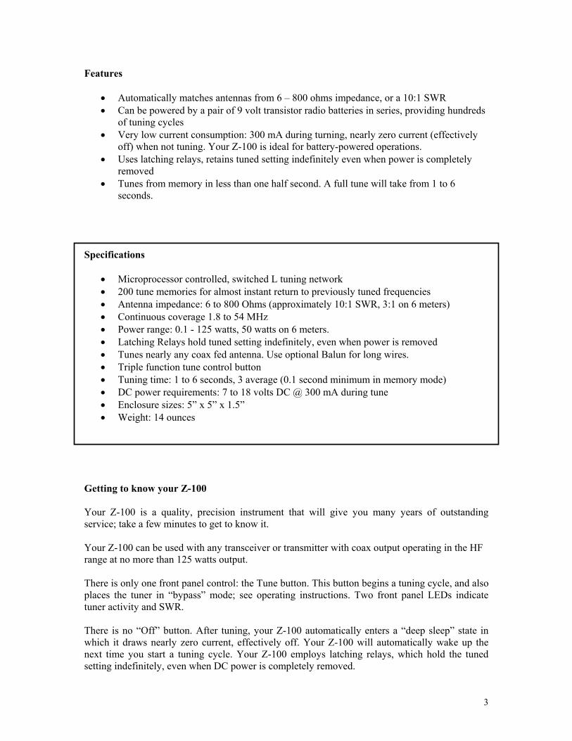
Features
• Automatically matches antennas from 6 – 800 ohms impedance, or a 10:1 SWR • Can be powered by a pair of 9 volt transistor radio batteries in series, providing hundreds
of tuning cycles • Very low current consumption: 300 mA during turning, nearly zero current (effectively
off) when not tuning. Your Z-100 is ideal for battery-powered operations. • Uses latching relays, retains tuned setting indefinitely even when power is completely
removed • Tunes from memory in less than one half second. A full tune will take from 1 to 6
seconds. Specifications
• Microprocessor controlled, switched L tuning network • 200 tune memories for almost instant return to previously tuned frequencies • Antenna impedance: 6 to 800 Ohms (approximately 10:1 SWR, 3:1 on 6 meters) • Continuous coverage 1.8 to 54 MHz • Power range: 0.1 - 125 watts, 50 watts on 6 meters. • Latching Relays hold tuned setting indefinitely, even when power is removed • Tunes nearly any coax fed antenna. Use optional Balun for long wires. • Triple function tune control button • Tuning time: 1 to 6 seconds, 3 average (0.1 second minimum in memory mode) • DC power requirements: 7 to 18 volts DC @ 300 mA during tune • Enclosure sizes: 5” x 5” x 1.5” • Weight: 14 ounces
Getting to know your Z-100 Your Z-100 is a quality, precision instrument that will give you many years of outstanding service; take a few minutes to get to know it. Your Z-100 can be used with any transceiver or transmitter with coax output operating in the HF range at no more than 125 watts output. There is only one front panel control: the Tune button. This button begins a tuning cycle, and also places the tuner in “bypass” mode; see operating instructions. Two front panel LEDs indicate tuner activity and SWR. There is no “Off” button. After tuning, your Z-100 automatically enters a “deep sleep” state in which it draws nearly zero current, effectively off. Your Z-100 will automatically wake up the next time you start a tuning cycle. Your Z-100 employs latching relays, which hold the tuned setting indefinitely, even when DC power is completely removed.
3
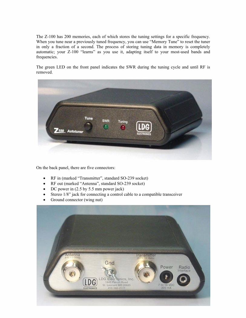
The Z-100 has 200 memories, each of which stores the tuning settings for a specific frequency. When you tune near a previously tuned frequency, you can use “Memory Tune” to reset the tuner in only a fraction of a second. The process of storing tuning data in memory is completely automatic; your Z-100 “learns” as you use it, adapting itself to your most-used bands and frequencies. The green LED on the front panel indicates the SWR during the tuning cycle and until RF is removed.
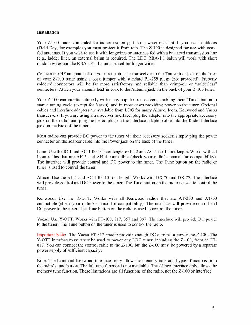
On the back panel, there are five connectors:
• RF in (marked “Transmitter”, standard SO-239 socket) • RF out (marked “Antenna”, standard SO-239 socket) • DC power in (2.5 by 5.5 mm power jack) • Stereo 1/8” jack for connecting a control cable to a compatible transceiver • Ground connector (wing nut)
4
Installation Your Z-100 tuner is intended for indoor use only; it is not water resistant. If you use it outdoors (Field Day, for example) you must protect it from rain. The Z-100 is designed for use with coax-fed antennas. If you wish to use it with longwires or antennas fed with a balanced transmission line (e.g., ladder line), an external balun is required. The LDG RBA-1:1 balun will work with short random wires and the RBA-1 4:1 balun is suited for longer wires. Connect the HF antenna jack on your transmitter or transceiver to the Transmitter jack on the back of your Z-100 tuner using a coax jumper with standard PL-259 plugs (not provided). Properly soldered connectors will be far more satisfactory and reliable than crimp-on or “solderless” connectors. Attach your antenna lead-in coax to the Antenna jack on the back of your Z-100 tuner. Your Z-100 can interface directly with many popular transceivers, enabling their “Tune” button to start a tuning cycle (except for Yaesu), and in most cases providing power to the tuner. Optional cables and interface adapters are available from LDG for many Alinco, Icom, Kenwood and Yaesu transceivers. If you are using a transceiver interface, plug the adapter into the appropriate accessory jack on the radio, and plug the stereo plug on the interface adapter cable into the Radio Interface jack on the back of the tuner. Most radios can provide DC power to the tuner via their accessory socket; simply plug the power connector on the adapter cable into the Power jack on the back of the tuner. Icom: Use the IC-1 and AC-1 for 10-foot length or IC-2 and AC-1 for 1-foot length. Works with all Icom radios that are AH-3 and AH-4 compatible (check your radio’s manual for compatibility). The interface will provide control and DC power to the tuner. The Tune button on the radio or tuner is used to control the tuner. Alinco: Use the AL-1 and AC-1 for 10-foot length. Works with DX-70 and DX-77. The interface will provide control and DC power to the tuner. The Tune button on the radio is used to control the tuner. Kenwood: Use the K-OTT. Works with all Kenwood radios that are AT-300 and AT-50 compatible (check your radio’s manual for compatibility). The interface will provide control and DC power to the tuner. The Tune button on the radio is used to control the tuner. Yaesu: Use Y-OTT. Works with FT-100, 817, 857 and 897. The interface will provide DC power to the tuner. The Tune button on the tuner is used to control the radio. Important Note: The Yaesu FT-817 cannot provide enough DC current to power the Z-100. The Y-OTT interface must never be used to power any LDG tuner, including the Z-100, from an FT-817. You can connect the control cable to the Z-100, but the Z-100 must be powered by a separate power supply of sufficient capacity. Note: The Icom and Kenwood interfaces only allow the memory tune and bypass functions from the radio’s tune button. The full tune function is not available. The Alinco interface only allows the memory tune function. These limitations are all functions of the radio, not the Z-100 or interface.
5
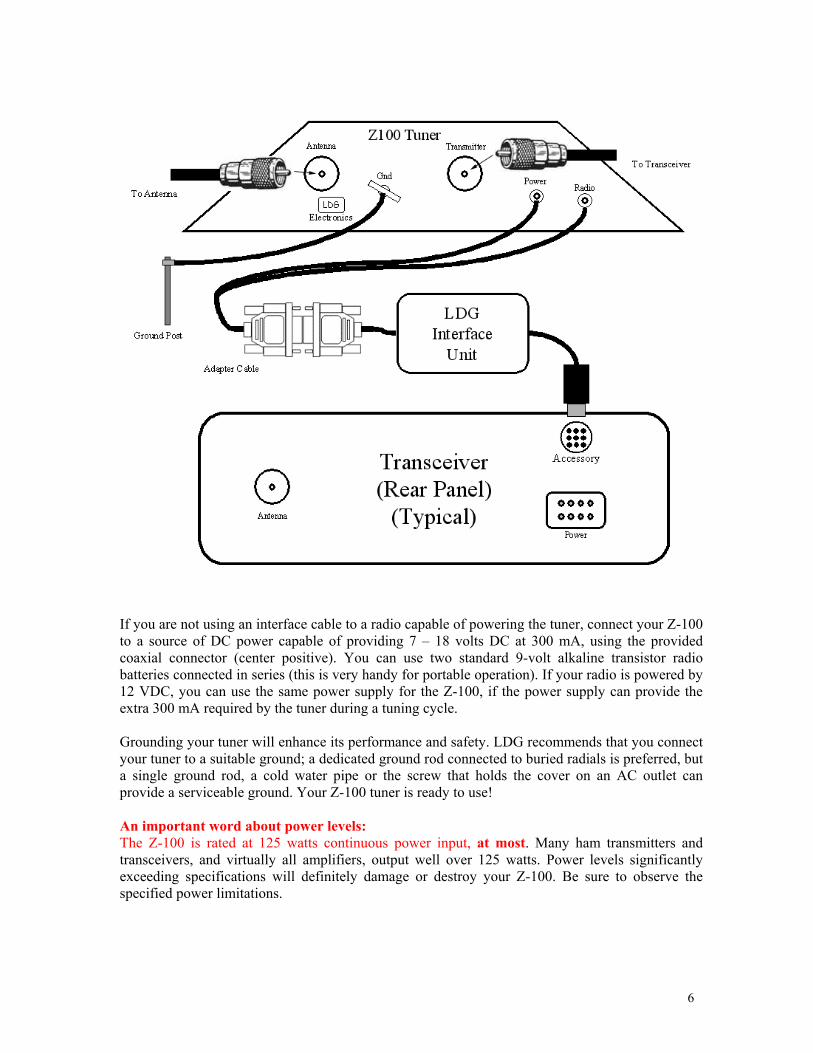
If you are not using an interface cable to a radio capable of powering the tuner, connect your Z-100 to a source of DC power capable of providing 7 – 18 volts DC at 300 mA, using the provided coaxial connector (center positive). You can use two standard 9-volt alkaline transistor radio batteries connected in series (this is very handy for portable operation). If your radio is powered by 12 VDC, you can use the same power supply for the Z-100, if the power supply can provide the extra 300 mA required by the tuner during a tuning cycle. Grounding your tuner will enhance its performance and safety. LDG recommends that you connect your tuner to a suitable ground; a dedicated ground rod connected to buried radials is preferred, but a single ground rod, a cold water pipe or the screw that holds the cover on an AC outlet can provide a serviceable ground. Your Z-100 tuner is ready to use! An important word about power levels: The Z-100 is rated at 125 watts continuous power input, at most. Many ham transmitters and transceivers, and virtually all amplifiers, output well over 125 watts. Power levels significantly exceeding specifications will definitely damage or destroy your Z-100. Be sure to observe the specified power limitations.
6
6
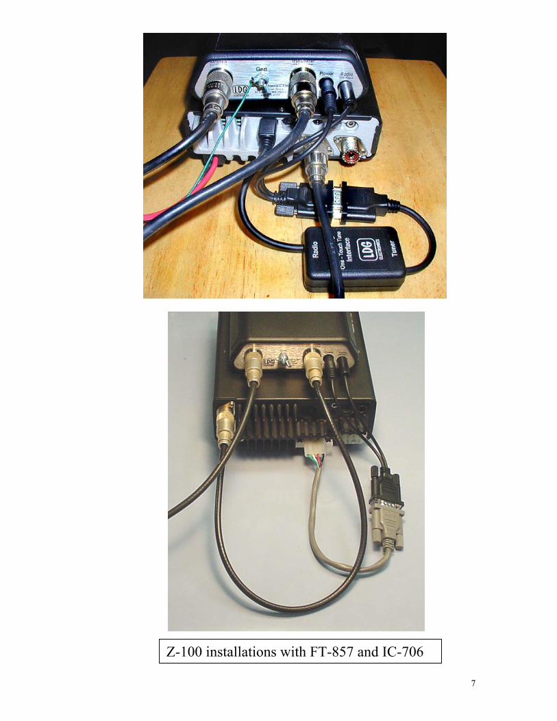
Z-100 installations with FT-857 and IC-70
7

Operating Instructions Basic operation: All functions are controlled through the Tune button. In every case, action occurs when you release the button. Various commands are indicated by the length of time you hold the Tune button before releasing it. There are three lengths of press: short (less than .5 seconds), medium (.5 – 3 seconds) and long (more than 3 seconds). This sounds a lot more complicated than actually it is; this interface will quickly become familiar and easy. Function 1: Bypass mode (Short press) To place your Z-100 in bypass mode, press the Tune button less than a half-second. The tuner will switch to bypass. The green LED will blink fast for a half-second to indicate bypass mode has been selected. In bypass mode, RF from your transmitter goes directly to the antenna with no matching. Function 2: Memory Tuning Cycle (Medium press) If you are tuning near a frequency at which you have already completed a full tuning cycle, you can reset the tuner very quickly by using a Memory Tuning Cycle. Key your transmitter and press and hold the Tune button for .5 to 3 seconds, then release. The red LED will light in the .5 – 3 second period to show that you are in the memory tune range of the Tune button. The tuner will automatically check for a saved tuning setting, and if present will restore that setting in a small fraction of a second. If no tuned setting is saved near the present frequency, the tuner will begin a full tuning cycle, saving the result when finished for future operation on that frequency. In this way, the Z-100 “learns”; the longer you use it, the more closely it adapts itself to your most often used bands and frequencies. You will probably use Memory Tuning most of the time; it takes advantage of any stored tuning settings, but automatically defaults to a Full Tuning cycle if no stored data is available.
Press Tune > .5second
Releasebefore redLED goesout (3 sec)
Memory TuneStarts
Tuning Cycle EndsAutomatically
Function 3: Full Tuning Cycle (Long press) Set your transmitter or transceiver to AM, FM, CW or Packet mode, and a power level of no more than 125 watts if your radio has a power rollback circuit. If your radio lacks a rollback circuit (see your owner’s manual), set the power level to no more than 10 watts.
Holdfor > 3
sec
Release;full tuningcycle starts
Red LED goes out Red LED onPress Tune
8
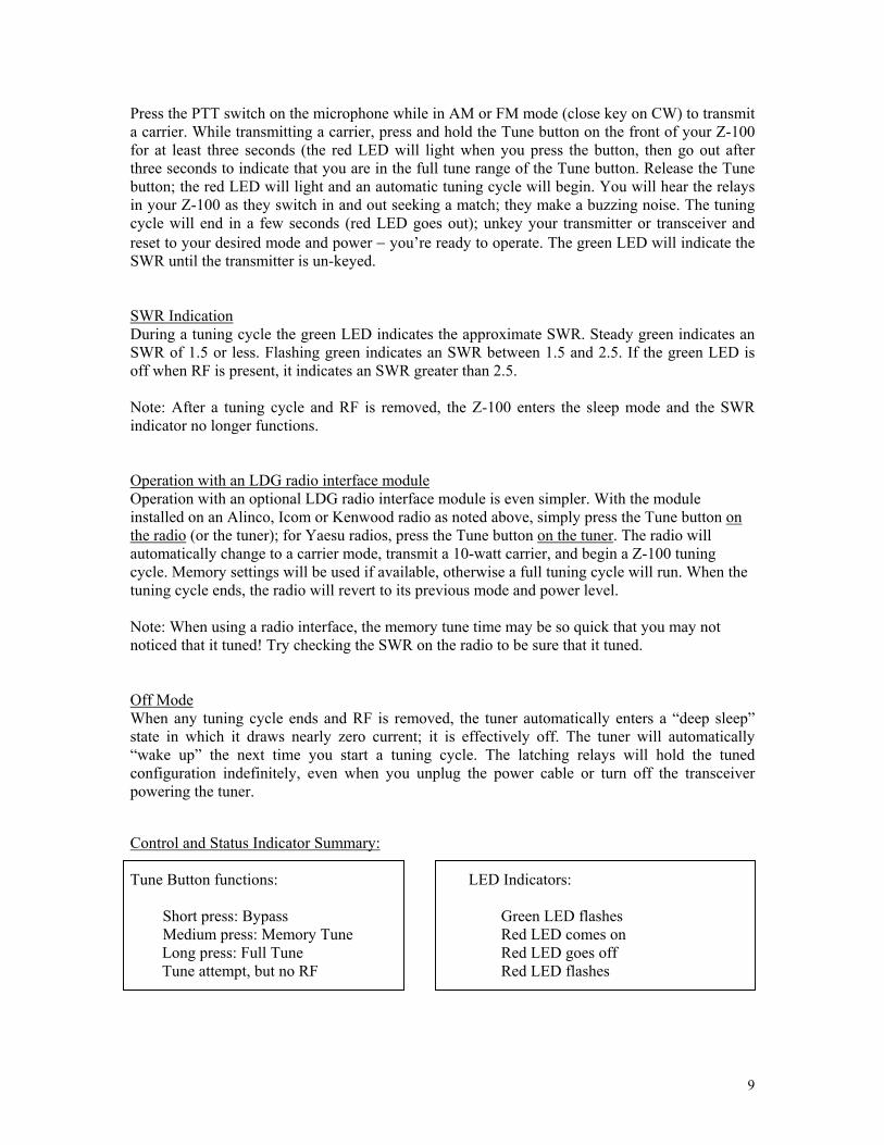
Press the PTT switch on the microphone while in AM or FM mode (close key on CW) to transmit a carrier. While transmitting a carrier, press and hold the Tune button on the front of your Z-100 for at least three seconds (the red LED will light when you press the button, then go out after three seconds to indicate that you are in the full tune range of the Tune button. Release the Tune button; the red LED will light and an automatic tuning cycle will begin. You will hear the relays in your Z-100 as they switch in and out seeking a match; they make a buzzing noise. The tuning cycle will end in a few seconds (red LED goes out); unkey your transmitter or transceiver and reset to your desired mode and power − you’re ready to operate. The green LED will indicate the SWR until the transmitter is un-keyed. SWR Indication During a tuning cycle the green LED indicates the approximate SWR. Steady green indicates an SWR of 1.5 or less. Flashing green indicates an SWR between 1.5 and 2.5. If the green LED is off when RF is present, it indicates an SWR greater than 2.5. Note: After a tuning cycle and RF is removed, the Z-100 enters the sleep mode and the SWR indicator no longer functions. Operation with an LDG radio interface module Operation with an optional LDG radio interface module is even simpler. With the module installed on an Alinco, Icom or Kenwood radio as noted above, simply press the Tune button on the radio (or the tuner); for Yaesu radios, press the Tune button on the tuner. The radio will automatically change to a carrier mode, transmit a 10-watt carrier, and begin a Z-100 tuning cycle. Memory settings will be used if available, otherwise a full tuning cycle will run. When the tuning cycle ends, the radio will revert to its previous mode and power level. Note: When using a radio interface, the memory tune time may be so quick that you may not noticed that it tuned! Try checking the SWR on the radio to be sure that it tuned. Off Mode When any tuning cycle ends and RF is removed, the tuner automatically enters a “deep sleep” state in which it draws nearly zero current; it is effectively off. The tuner will automatically “wake up” the next time you start a tuning cycle. The latching relays will hold the tuned configuration indefinitely, even when you unplug the power cable or turn off the transceiver powering the tuner. Control and Status Indicator Summary: Tune Button functions:
Short press: Bypass Medium press: Memory Tune
Long press: Full Tune Tune attempt, but no RF
LED Indicators:
Green LED flashes Red LED comes on Red LED goes off Red LED flashes
9

Theory of Operation Some basic ideas about impedance The theory underlying antennas and transmission lines is fairly complex, and in fact employs a mathematical notation called “complex numbers” that have “real” and “imaginary” parts2. It is beyond the scope of this manual to present a tutorial on this subject, but a little background will help you understand what your Z-100 is doing, and how it does it. In simple DC circuits, the wire resists the current flow, converting some of it into heat. The relationship between voltage, current and resistance is described by the elegant and well-known “Ohm’s Law”, named for Sir George Simon Ohm of England, who first described it in 1826. In RF circuits, an analogous but far more complicated relationship exists. RF circuits also resist the flow of electricity. However, the presence of capacitive and inductive elements causes the voltage in the circuit to lead or lag the current, respectively. In RF circuits this resistance to the flow of electricity is called “impedance”, and can include all three elements: resistive, capacitive, and inductive.
Capacitive Reactance
Inductive Reactance
The output circuit of your transmitter consists of inductors and capacitors, usually in a series/parallel configuration called a “pi network”. The transmission line can be thought of as a long string of capacitors and inductors in series/parallel, and the antenna is a kind of resonant circuit. At any given RF frequency, each of these can exhibit resistance, and impedance in the form of capacitive or inductive “reactance”. Transmitters, transmission lines, antennas and impedance The output circuit of your transmitter, the transmission line, and the antenna all have characteristic impedance. For reasons too complicated to go into here, the standard impedance is about 50 ohms resistive, with zero capacitive and inductive components. When all three parts of the system have the same impedance, the system is said to be “matched”, and maximum transfer of power from the transmitter to the antenna occurs. While the transmitter output circuit and transmission line are of fixed, carefully designed impedance, the antenna presents a 50-ohm, non-reactive load only at its natural resonant frequencies. At other frequencies, it will exhibit capacitive or inductive reactance, causing it to have an impedance different from 50 ohms. When the impedance of the antenna is different from that of the transmitter and transmission line, a “mismatch” is said to exist. In this case, some of the RF energy from the transmitter is reflected from the antenna back down the transmission line, and into the transmitter. If this reflected energy is strong enough it can damage the transmitter’s output circuits. The ratio of transmitted to reflected energy is called the “standing wave ratio”, or SWR. An SWR of 1 (sometimes written 1:1) indicates a perfect match. As more energy is reflected, the SWR rises to 2, 3 or higher. As a general rule, modern solid state transmitters must operate with an 2 For a very complete treatment of this subject, see any edition of the ARRL Radio Amateur’s Handbook
10

SWR of 3 or less. Tube exciters are somewhat more tolerant of high SWR. If your 50-ohm antenna is resonant at your operating frequency, it will show an SWR of 1. However, this is usually not the case; operators often need to transmit at frequencies other than resonance, resulting in a reactive antenna and a higher SWR.
FRFRSWR
/1/1
−+
=
where F = Forward power (watts), R = Reflected power (watts)
SWR is measured using a device called an “SWR bridge”, inserted in the transmission line between the transmitter and antenna. This circuit measures forward and reverse power from which SWR may be calculated (some meters calculate SWR for you). More advanced units can measure forward and reverse power simultaneously, and show these values and SWR at the same time. An antenna tuner is a device used to cancel out the effects of antenna reactance. Tuners add capacitance to cancel out inductive reactance in the antenna, and vice versa. Simple tuners use variable capacitors and inductors. The operator adjusts them by hand while observing reflected power on the SWR meter until a minimum SWR is reached. Your LDG Z-100 automates this process. No tuner will fix a bad antenna. If your antenna is far from resonance, the inefficiencies inherent in such operation are inescapable; it’s simple physics. Much of your transmitted power may be dissipated in the tuner as heat, never reaching the antenna at all. A tuner simply “fools” your transmitter into behaving as though the antenna were resonant, avoiding any damage that might otherwise be caused by high reflected power. Your antenna should always be as close to resonance as practical.
11
Forward Power (Watts)20 30 40 50 60 70 80 90 100
2 1.92 1.70 1.58 1.50 1.45 1.41 1.38 1.35 1.334 2.62 2.15 1.92 1.79 1.70 1.63 1.58 1.53 1.506 3.42 2.62 2.26 2.06 1.92 1.83 1.75 1.70 1.658 4.44 3.14 2.62 2.33 2.15 2.02 1.92 1.85 1.79
10 5.83 3.73 3.00 2.62 2.38 2.22 2.09 2.00 1.9212 7.87 4.44 3.42 2.92 2.62 2.41 2.26 2.15 2.0614 11.24 5.31 3.90 3.25 2.87 2.62 2.44 2.30 2.2016 17.94 6.42 4.44 3.60 3.14 2.83 2.62 2.46 2.3318 37.97 7.87 5.08 4.00 3.42 3.06 2.80 2.62 2.4720 - 9.90 5.83 4.44 3.73 3.30 3.00 2.78 2.6222 - 12.92 6.74 4.94 4.07 3.55 3.21 2.96 2.7724 - 17.94 7.87 5.51 4.44 3.83 3.42 3.14 2.9226 - 27.96 9.32 6.17 4.85 4.12 3.65 3.32 3.0828 - 57.98 11.24 6.95 5.31 4.44 3.90 3.52 3.2530 - - 13.93 7.87 5.83 4.79 4.16 3.73 3.4232 - - 17.94 9.00 6.42 5.18 4.44 3.95 3.6034 - - 24.63 10.40 7.09 5.60 4.75 4.19 3.8036 - - 37.97 12.20 7.87 6.07 5.08 4.44 4.0038 - - 77.99 14.60 8.80 6.60 5.44 4.71 4.2140 - - - 17.94 9.90 7.19 5.83 5.00 4.4442 - - - 22.96 11.24 7.87 6.26 5.31 4.6844 - - - 31.30 12.92 8.65 6.74 5.65 4.9446 - - - 47.98 15.08 9.56 7.27 6.02 5.2248 - - - 97.99 17.94 10.63 7.87 6.42 5.5150 - - - - 21.95 11.92 8.55 6.85 5.83
Ref
lect
ed P
ower
(Wat
ts)
SWR Lookup Table Find SWR at intersection of forward power
column and reflected power row.
12
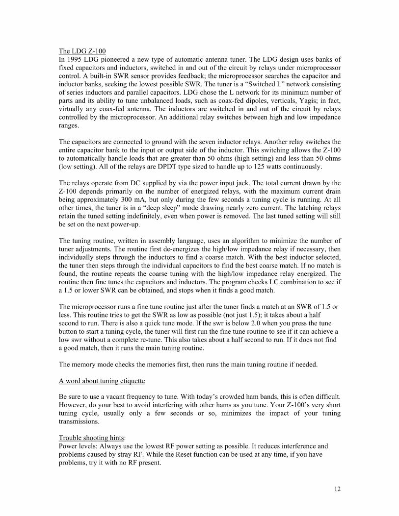
The LDG Z-100 In 1995 LDG pioneered a new type of automatic antenna tuner. The LDG design uses banks of fixed capacitors and inductors, switched in and out of the circuit by relays under microprocessor control. A built-in SWR sensor provides feedback; the microprocessor searches the capacitor and inductor banks, seeking the lowest possible SWR. The tuner is a “Switched L” network consisting of series inductors and parallel capacitors. LDG chose the L network for its minimum number of parts and its ability to tune unbalanced loads, such as coax-fed dipoles, verticals, Yagis; in fact, virtually any coax-fed antenna. The inductors are switched in and out of the circuit by relays controlled by the microprocessor. An additional relay switches between high and low impedance ranges. The capacitors are connected to ground with the seven inductor relays. Another relay switches the entire capacitor bank to the input or output side of the inductor. This switching allows the Z-100 to automatically handle loads that are greater than 50 ohms (high setting) and less than 50 ohms (low setting). All of the relays are DPDT type sized to handle up to 125 watts continuously. The relays operate from DC supplied by via the power input jack. The total current drawn by the Z-100 depends primarily on the number of energized relays, with the maximum current drain being approximately 300 mA, but only during the few seconds a tuning cycle is running. At all other times, the tuner is in a “deep sleep” mode drawing nearly zero current. The latching relays retain the tuned setting indefinitely, even when power is removed. The last tuned setting will still be set on the next power-up. The tuning routine, written in assembly language, uses an algorithm to minimize the number of tuner adjustments. The routine first de-energizes the high/low impedance relay if necessary, then individually steps through the inductors to find a coarse match. With the best inductor selected, the tuner then steps through the individual capacitors to find the best coarse match. If no match is found, the routine repeats the coarse tuning with the high/low impedance relay energized. The routine then fine tunes the capacitors and inductors. The program checks LC combination to see if a 1.5 or lower SWR can be obtained, and stops when it finds a good match. The microprocessor runs a fine tune routine just after the tuner finds a match at an SWR of 1.5 or less. This routine tries to get the SWR as low as possible (not just 1.5); it takes about a half second to run. There is also a quick tune mode. If the swr is below 2.0 when you press the tune button to start a tuning cycle, the tuner will first run the fine tune routine to see if it can achieve a low swr without a complete re-tune. This also takes about a half second to run. If it does not find a good match, then it runs the main tuning routine. The memory mode checks the memories first, then runs the main tuning routine if needed. A word about tuning etiquette Be sure to use a vacant frequency to tune. With today’s crowded ham bands, this is often difficult. However, do your best to avoid interfering with other hams as you tune. Your Z-100’s very short tuning cycle, usually only a few seconds or so, minimizes the impact of your tuning transmissions. Trouble shooting hints: Power levels: Always use the lowest RF power setting as possible. It reduces interference and problems caused by stray RF. While the Reset function can be used at any time, if you have problems, try it with no RF present.
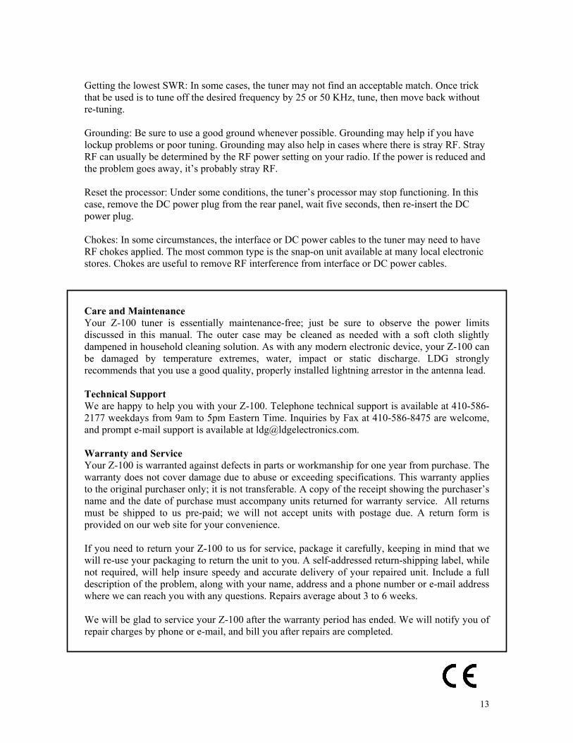
Getting the lowest SWR: In some cases, the tuner may not find an acceptable match. Once trick that be used is to tune off the desired frequency by 25 or 50 KHz, tune, then move back without re-tuning. Grounding: Be sure to use a good ground whenever possible. Grounding may help if you have lockup problems or poor tuning. Grounding may also help in cases where there is stray RF. Stray RF can usually be determined by the RF power setting on your radio. If the power is reduced and the problem goes away, it’s probably stray RF. Reset the processor: Under some conditions, the tuner’s processor may stop functioning. In this case, remove the DC power plug from the rear panel, wait five seconds, then re-insert the DC power plug. Chokes: In some circumstances, the interface or DC power cables to the tuner may need to have RF chokes applied. The most common type is the snap-on unit available at many local electronic stores. Chokes are useful to remove RF interference from interface or DC power cables. Care and Maintenance Your Z-100 tuner is essentially maintenance-free; just be sure to observe the power limits discussed in this manual. The outer case may be cleaned as needed with a soft cloth slightly dampened in household cleaning solution. As with any modern electronic device, your Z-100 can be damaged by temperature extremes, water, impact or static discharge. LDG strongly recommends that you use a good quality, properly installed lightning arrestor in the antenna lead. Technical Support We are happy to help you with your Z-100. Telephone technical support is available at 410-586-2177 weekdays from 9am to 5pm Eastern Time. Inquiries by Fax at 410-586-8475 are welcome, and prompt e-mail support is available at [email protected]. Warranty and Service Your Z-100 is warranted against defects in parts or workmanship for one year from purchase. The warranty does not cover damage due to abuse or exceeding specifications. This warranty applies to the original purchaser only; it is not transferable. A copy of the receipt showing the purchaser’s name and the date of purchase must accompany units returned for warranty service. All returns must be shipped to us pre-paid; we will not accept units with postage due. A return form is provided on our web site for your convenience. If you need to return your Z-100 to us for service, package it carefully, keeping in mind that we will re-use your packaging to return the unit to you. A self-addressed return-shipping label, while not required, will help insure speedy and accurate delivery of your repaired unit. Include a full description of the problem, along with your name, address and a phone number or e-mail address where we can reach you with any questions. Repairs average about 3 to 6 weeks. We will be glad to service your Z-100 after the warranty period has ended. We will notify you of repair charges by phone or e-mail, and bill you after repairs are completed.
13