Embed Size (px)
Citation preview
LDG RT-600
600 WATT REMOTE
AUTOMATIC TUNER
LDG Electronics 1445 Parran Road
St. Leonard MD 20685-2903 USA
Phone: 410-586-2177
Fax: 410-586-8475
www.ldgelectronics.com
RT-600 Operations Manual Version 1.0
2
Introduction 3
Quickstart Guide 3
Specifications 4
An Important Word About Power Levels 4
Getting to know your RT-600 5
RC-600 Front Panel 5
Connections 6
Installation 7
Overview 7
Basic Installation 7
Secure the RT-600 to a Mast 8
Tips for Outdoor Installation 9
SWR Meter 11
Bias Tee Information 11
Operation 13
Operation Overview 13
Memory Tuning Cycle 13
Full Tuning Cycle 13
Bypass 14
Relay Protection 14
Re-tuning Prohibition 14
MARS/CAP Coverage 14
A Word About Tuning Etiquette 15
Care and Maintenance 15
Technical Support 15
Two-Year Transferrable Warranty 15
Out of Warranty Service 16
Returning Your Product For Service 16
Product Feedback 16
Table of Contents
RT-600 Operations Manual Version 1.0
3
Introduction
LDG pioneered the automatic, wide-range switched-L tuner in 1995. From its
laboratories in St. Leonard, Maryland LDG continues to define the state of the art in
this field with innovative automatic tuners and related products for every amateur
need.
Congratulations on selecting the RT-600 600-watt remote automatic tuner. The RT-
600 provides full- and semi-automatic antenna tuning across the entire HF spectrum
plus 6 meters, at power levels up to 600 watts peak. It will tune dipoles, verticals,
Yagis, or virtually any coax-fed antenna. It will match an amazing range of antennas
and impedances, far greater than some other tuners you may have considered,
including the built-in tuners on many radios.
The RT-600 is similar to previous LDG tuners, but is weatherproof and can be
installed outdoors as near to the antenna as possible, reducing or eliminating coax
SWR losses. The tuner is powered over the coax feedline, so no additional cables are
required. The included RC-600 control unit provides DC power injection, as well as a
convenient on/off switch, power indicator, and a TUNE button.
Quickstart Guide
1. Turn off power to your radio and amplifier.
2. Connect the antenna jack on your amplifier to the “Radio” jack on the RC-
600.
3. Connect the “Tuner” jack of the RC-600 controller to the “Radio” jack on the
RT-600 via a suitable coax feedline.
4. Connect the antenna to the “Ant” jack on the RT-600.
5. Connect a source of 12VDC, 1000mA to the Power jack on the RC-600, and
turn on your transceiver and amplifier. The power jack is center-positive.
6. Bypass your amplifier; never tune with more than 100 watts.
7. Begin transmitting; the tuner will automatically begin a tuning cycle if there is
an SWR mismatch.
8. When tuning is complete, un-bypass your amplifier; you are ready to transmit.
The RT-600
mounts remotely
at the antenna,
eliminating coax
losses.
You should really
read the whole
manual, but this
summary will get
you started.
RT-600 Operations Manual Version 1.0
4
Specifications
3 to 600 watts SSB and CW peak power, 250W PSK and digital modes and 6
meters.
2,000+ memories for instantaneous frequency and band changing.
Power: 12VDC, 1000mA, carried on the coax feedline.
1.8 to 54.0 MHz coverage.
Tunes 4 to 800 ohm loads (16 to 150 on 6M), 16 to 3200 ohms with external
4:1 Balun.
For Dipoles, Verticals, Vees, Beams or any Coax Fed Antenna.
External balun allows tuning of random length, long wire or ladder line fed
antennas.
Included RC-600 controller provides DC power injection, On/Off switch, and
Tune button.
Dimensions: RT-600: 9”L x 8.5”W x 3”H; RC-600: 4”L x 3”W x 2”H
Weight: RT-600: 3 lb.; RC-600: 8oz.
An Important Word About Power Levels
The RT-600 is rated at 650 watts peak power input at most. Many amateur amplifiers
are capable of transmitting well over 650 watts. Power levels that significantly exceed
specifications will definitely damage or destroy your RT-600. If your tuner fails
under overload, it could also damage your transmitter or transceiver. Be sure to
observe the specified power limitations.
Operating instructions in this manual direct you to “bypass” your amplifier for tuning.
This means turning your amplifier off or placing it in standby mode, connecting your
transceiver or transmitter directly to the tuner without amplification. Never tune at
more than 100 watts.
Never install antennas, supports or transmission lines over or near power lines. You
can be seriously injured or killed if any part of the antenna, support or transmission
line touches a power line. Always follow this antenna safety rule: the distance to the
nearest power line should be at least twice the length of the longest antenna, support
or transmission line dimension.
Always operate
within specified
limits.
IMPORTANT
SAFETY
WARNING
Never exceed 600
watts peak on
SSB/CW, or 250
watts on 100%
duty cycle modes.

RT-600 Operations Manual Version 1.0
5
Getting to know your RT-600 Your RT-600 is a quality, precision instrument that will give you many years of
outstanding service; take a few minutes to get to know it.
The RT-600 tuner is designed to be used remotely, powered over the coax cable that
carries both the RF energy and DC power. An internal “Bias Tee” circuit separates
the RF from the DC power with virtually no loss. The included RC-600 controller
injects DC power at the radio end of the coax, and provides Power and Tune control
buttons, and a Status LED.
The RT-600 has 2,000 frequency memories. When tuning on or near a previously
tuned frequency, the RT-600 uses “Memory Tune” to recall the previous tuning
parameters in a fraction of a second. If no memorized settings are available, the tuner
runs a full tuning cycle, storing the parameters for near-instant recall on subsequent
tuning cycles on that frequency. In this manner, the RT-600 “learns” as you use it,
adapting to your bands, frequencies and antennas. The RT-600’s latching relays hold
the tuned configuration indefinitely, even when DC power is completely removed.
Tuning memories are stored indefinitely in non-volatile flash memory.
RC-600 Front Panel
The included RC-600 controller inserts 12 volts DC onto the coax feedline, and
provides controls and status information.
The RC-600 controller has two pushbuttons and one LED indicator light.
Power: Turns DC power on and off.
Tune: Initiates a tuning cycle
Status LED: lights when the RT-600 is powered on.
You’ll be using
your RT-600 for
a long time; take
a few minutes to
get to know it.
The included
RC-600 injects
DC power onto
the feedline and
controls the
remote tuner.
The RT-600 has
2,000 memories.

RT-600 Operations Manual Version 1.0
6
Connections
The RT-600 has three connectors:
Antenna SO-239: Output to the antenna. Connect the antenna to this SO-239
using the shortest practical coax cable.
Gnd (wingnut): Connect to antenna system ground.
Radio SO-239: Connect to the feedline which comes from the RC-600
controller.
The RC-600 controller has three connectors:
Tuner: connects via coaxial cable to the Radio port on the RT-600.
The RT-600 uses
standard SO-239
connectors.
RT-600 Operations Manual Version 1.0
7
Radio: connects via coaxial cable to the Antenna port on your amplifier.
Power: connects to a source of 12 volts DC, 1000 mA (center positive).
Installation
Overview The RT-600 tuner is designed for outdoor use; it is weather resistant. However, LDG
recommends using silicone coax sealing tape on the coax connections after
installation to help keep rainwater out of the connections. The RT-600 is designed for
use with coax-fed antennas; an external balun is required to use it with longwires or
antennas fed by ladder line. To avoid damage always turn your radio and amplifier
off before connecting or disconnecting anything.
Basic Installation
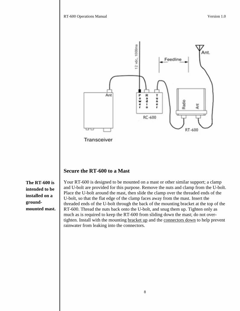
Place the RT-600 tuner as near the antenna feed point as possible. Place the included
RC-600 controller in a convenient position near your amplifier. Connect a 50-ohm
coax jumper from the amplifier’s antenna jack to the RC-600’s Radio jack. Connect a
50-ohm coax cable from the RT-600 tuner’s Antenna jack to the antenna. Connect
the RT-600’s Radio jack to the RC-600’s Tuner jack via a suitable coax cable. LDG
recommends grounding the RT-600 tuner via the wingnut marked Gnd. Connect the
RC-600 to a source of 12Volt DC power, 1000 mA.
Your RT-600
is designed for
outdoor use.
Install the RT-
600 as close as
possible to the
antenna.
RT-600 Operations Manual Version 1.0
8
Secure the RT-600 to a Mast
Your RT-600 is designed to be mounted on a mast or other similar support; a clamp
and U-bolt are provided for this purpose. Remove the nuts and clamp from the U-bolt.
Place the U-bolt around the mast, then slide the clamp over the threaded ends of the
U-bolt, so that the flat edge of the clamp faces away from the mast. Insert the
threaded ends of the U-bolt through the back of the mounting bracket at the top of the
RT-600. Thread the nuts back onto the U-bolt, and snug them up. Tighten only as
much as is required to keep the RT-600 from sliding down the mast; do not over-
tighten. Install with the mounting bracket up and the connectors down to help prevent
rainwater from leaking into the connectors.
The RT-600 is
intended to be
installed on a
ground-
mounted mast.

RT-600 Operations Manual Version 1.0
9
Although the U-bolt is electroplated to resist corrosion, you may wish to apply a thin
layer of grease to the threads to help prevent rust and aid in later removal. If you wish
to use a larger U-bolt (to bolt the tuner to a larger mast, or other support), refer to the
RT-600 mounting bracket dimensions below for sizing.
Tips for Outdoor Installation
The RT-600 is weather resistant and suitable for permanent outdoor installation, but it
may leak if immersed. The RT-600 should be mounted on a mast with the mounting
bracket facing upward, and the SO-239 jacks facing down; do not simply lay it on the
ground, as a puddle could form around it. If necessary, install a short ground mast
near your antenna to mount the RT-600.
Mount the RT-
600 on a mast. Do
not simply lay it
on the ground.
RT-600 Operations Manual Version 1.0
10
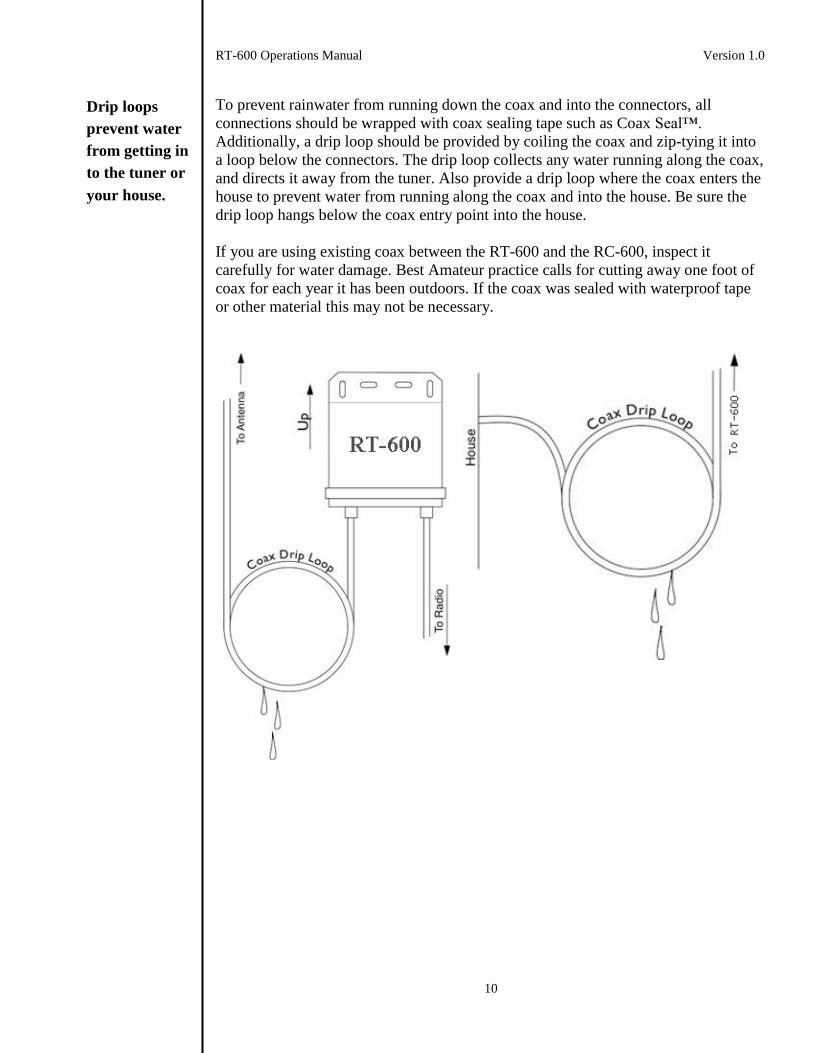
To prevent rainwater from running down the coax and into the connectors, all
connections should be wrapped with coax sealing tape such as Coax Seal™.
Additionally, a drip loop should be provided by coiling the coax and zip-tying it into
a loop below the connectors. The drip loop collects any water running along the coax,
and directs it away from the tuner. Also provide a drip loop where the coax enters the
house to prevent water from running along the coax and into the house. Be sure the
drip loop hangs below the coax entry point into the house.
If you are using existing coax between the RT-600 and the RC-600, inspect it
carefully for water damage. Best Amateur practice calls for cutting away one foot of
coax for each year it has been outdoors. If the coax was sealed with waterproof tape
or other material this may not be necessary.
Drip loops
prevent water
from getting in
to the tuner or
your house.
RT-600 Operations Manual Version 1.0
11
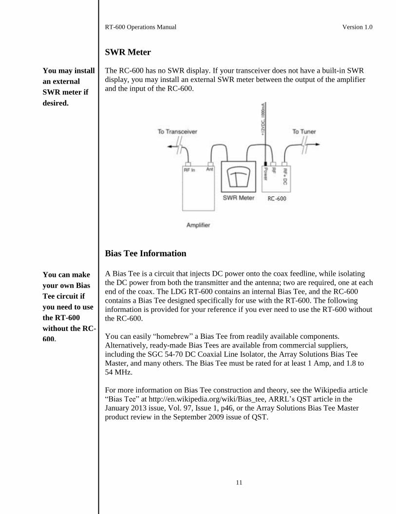
SWR Meter
The RC-600 has no SWR display. If your transceiver does not have a built-in SWR
display, you may install an external SWR meter between the output of the amplifier
and the input of the RC-600.
Bias Tee Information
A Bias Tee is a circuit that injects DC power onto the coax feedline, while isolating
the DC power from both the transmitter and the antenna; two are required, one at each
end of the coax. The LDG RT-600 contains an internal Bias Tee, and the RC-600
contains a Bias Tee designed specifically for use with the RT-600. The following
information is provided for your reference if you ever need to use the RT-600 without
the RC-600.
You can easily “homebrew” a Bias Tee from readily available components.
Alternatively, ready-made Bias Tees are available from commercial suppliers,
including the SGC 54-70 DC Coaxial Line Isolator, the Array Solutions Bias Tee
Master, and many others. The Bias Tee must be rated for at least 1 Amp, and 1.8 to
54 MHz.
For more information on Bias Tee construction and theory, see the Wikipedia article
“Bias Tee” at http://en.wikipedia.org/wiki/Bias_tee, ARRL’s QST article in the
January 2013 issue, Vol. 97, Issue 1, p46, or the Array Solutions Bias Tee Master
product review in the September 2009 issue of QST.
You may install
an external
SWR meter if
desired.
You can make
your own Bias
Tee circuit if
you need to use
the RT-600
without the RC-
600.
RT-600 Operations Manual Version 1.0
12
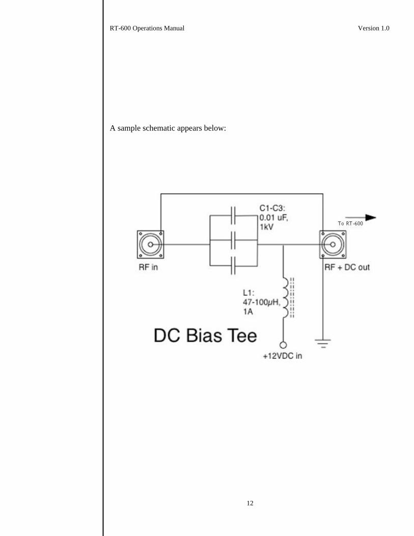
A sample schematic appears below:
RT-600 Operations Manual Version 1.0
13
Operation
Operation Overview
Two types of tuning cycles are available; a Memory Tuning cycle and a Full Tuning
cycle. A memory tuning cycle restores parameters saved after an earlier successful
tune on the present frequency. Those settings are checked to see that an acceptable
SWR match is found. If this fails, then a full tuning cycle automatically begins. A full
tuning cycle “starts from scratch”, rapidly trying combinations of inductance and
capacitance values, converging on the best possible match. When the tuning cycle
ends successfully, the inductance and capacitance settings are saved in a memory
associated with the present frequency so that they can be recalled in a future memory
tuning cycle. In this manner the RT-600 “learns” as you use it, adapting itself to the
bands, frequencies and antennas you use.
The RT-600 always powers up in fully automatic Memory Tuning mode. This means
that whenever RF is present, if the SWR is too high a memory tuning cycle will
automatically begin. You will probably use memory tuning most of the time; it takes
advantage of any saved tuning settings, but defaults to a full tuning cycle if no stored
data is available.
NOTE: Before beginning a tuning cycle always bypass the amplifier. Tuning should
always be performed with 100 watts or less of forward power. Typically tuning will
occur when you make large frequency changes, or change bands.
Memory Tuning Cycle
To begin operation first bypass the amplifier. Tune the radio to the desired frequency,
press the Power button on the RC-600 to power up the RT-600, bypass your amplifier
and begin transmitting. If a high SWR condition is detected, the RT-600 Tuner will
begin tuning. To watch the progress of the tuning cycle, observe your radio’s built-in
SWR meter (or external SWR meter, if applicable). The SWR needle will oscillate as
the tuner seeks a match, and will then settle to a low SWR value when tuning is
complete. If operating on a previously memorized frequency, the tuning cycle will
last only a fraction of a second while memory settings are restored and verified. Once
tuning is complete, un-bypass the amplifier and operate normally.
Full Tuning Cycle
In some circumstances you may want the RT-600 to perform a full tuning cycle
instead of the usual memory cycle. To do this, first bypass the amplifier. Press the
Tune button on the RC-600, begin transmitting a carrier, and while still keying the
radio, release the Tune button. Continue transmitting the carrier until the SWR settles
to a low value. When tuning is complete un-key, un-bypass the amplifier and begin
normal operation.
You will
probably use
fully automatic
tuning most of
the time.
Never tune at
high power.
Tuning is fully
automatic.
You can
force a full
tuning cycle.
RT-600 Operations Manual Version 1.0
14
Bypass
Whenever the RT-600 is turned off (Power button in the Off position, Status LED
off), the tuner is bypassed; RF from the amplifier is passed directly to the antenna
with no matching. When the tuner is powered up again, it restores the most recent
tuned state it held when last powered down.
Relay Protection
The RT-600 software disables tuning if the input power exceeds 200W, or 150W if
the SWR exceeds 3:1. This protects the relay contacts from arcing damage caused by
switching under high power. Always bypass your amplifier during tuning; you may
place your amplifier back in normal operating mode once tuning is complete.
Re-tuning Prohibition
In some rare cases, when an antenna is tuned far from its resonant frequency, the RT-
600 may erroneously attempt to re-tune even though it has already found an
acceptable match. In these cases the following procedure may be used to place the
RT-600 into non-tuning mode:
1. Turn off power to the RT-600, wait for one full second.
2. Turn on power to the RT-600 wait for one full second. Do not transmit.
3. Repeat this cycle three times. In other words, turn power off and back on
slowly three times in a row, but do not transmit during this time.
The RT-600 is now in active, non-tuning mode; it will hold the current tuning
settings, but will not re-tune. This mode is useful for antennas tuned far from their
resonant frequency, where the final SWR match found by the RT-600 is perhaps
higher than usual. By placing the RT-600 in active, non-tuning mode, you can
transmit without the RT-600 continuously attempting to re-tune this high SWR load.
To return to normal mode, simply initiate a full tuning cycle: press the Tune button
on the RC-600, begin transmitting, and while transmitting release the Tune button on
the RC-600.
MARS/CAP Coverage
The RT-600 provides continuous tuning coverage over its specified range, not just in
the amateur bands. This makes it useful for MARS or CAP, or any other legal HF
operation.
The RT-600
automatically
protects itself
from tuning at
high power.
The RT-600
1.8-54 MHz
continuously,
not just in the
ham bands.
RT-600 Operations Manual Version 1.0
15
A Word About Tuning Etiquette Be sure to use a vacant frequency when tuning. With today’s crowded ham bands this
is often difficult. However, causing interference to other hams should be avoided
whenever possible. The RT-600’s very short tuning cycle minimizes the impact of
tuning transmissions.
Care and Maintenance
The RT-600 tuner and RC-600 controller are essentially maintenance-free. You
should always strictly observe the power limits specified in this manual. The outer
cases may be cleaned as needed with a soft cloth slightly dampened with household
cleaning solution. As with any modern electronic device, the RT-600 and RC-600 can
be damaged by temperature extremes, water leakage, impact, or static discharge.
LDG strongly recommends using a good quality, properly installed lightning arrestor
in the antenna lead.
Technical Support
Technical support is always available by e-mail ([email protected]).
We’ve placed answers to common questions in the FAQ section of our web page.
LDG also keeps up-to-date product information on our web site, including product
manuals if you need a replacement. When you consider buying another LDG product,
our website has complete specifications and photographs you can use to help make
your purchase decision. There are also links to all of the quality LDG dealers who are
ready to help you make your purchase decision.
Two-Year Transferrable Warranty
Your LDG product is warranted against manufacturer defects in parts and labor for
two full years from the date of purchase. This two-year warranty is transferable; when
you sell or give away your LDG product include the original sales receipt, and the
two-year warranty goes with the product to the new owner. There is no need to
complete a warranty card or to register an LDG product; your receipt establishes
eligibility for warranty service, so be sure to save it. Include a copy of your receipt
whenever you send your product to LDG for warranty repair. Products sent to LDG
without a receipt are considered requests for out-of-warranty repair. The warranty
does not cover damage or abuse; a failure caused by the customer or by a natural
calamity (e.g. lightning), as determined by LDG, is not covered under the two-year
warranty. Damage can be caused by failure to observe the product’s published
limitations and specifications, or by not following good Amateur practice.
Be careful not
to interfere
with other
stations when
you tune.
Email if you
have questions
or need help.
Your two-year
warranty is
transferable.

RT-600 Operations Manual Version 1.0
16
Out of Warranty Service
LDG will repair your product even after the warranty has expired; a reasonable fee
will apply. We will troubleshoot the problem, and based on your instructions either
contact you with an estimate, or fix it and bill you for any repair charges. Check our
web site for the latest information on obtaining out of warranty service.
Returning Your Product For Service
LDG does not require a return merchandise authorization, and there is no need to
contact LDG before returning your product. Download the LDG Product Repair Form
from our web site. On the Repair Form describe the problems you’re experiencing.
Our technician attempts to duplicate the problems you describe, so please be accurate
and complete. LDG recommends using a shipper that provides a tracking number.
Include your email address so our return shipper can alert you when your product is
in-route. Repairs can take six to eight weeks, but are often faster; we appreciate your
patience. Current information on returning products for service is found on the LDG
website under the Support menu item, then under the Tech Support sub-menu.
Send your carefully packaged unit with the Repair Form and a copy of your receipt
to:
LDG Electronics, Inc.
Attn: Repair Department
1445 Parran Rd
St. Leonard, MD 20685
Product Feedback
We encourage product feedback; tell us what you think of your LDG product. In a
card, letter, or email (preferred) tell us how you used the product, how well it worked
in your application, and any suggestions you have for enhancements or new products.
Send along a photo or even a schematic or drawing to illustrate your narrative. We
like to share your comments with our staff, our dealers, and even other customers on
the LDG website:
http://www.ldgelectronics.com/
We’ll be happy
to fix your tuner
even if it’s out of
warranty.
Pack it carefully,
include your
receipt for
warranty service,
and ship it to us;
no RMA is
required.
We love to hear
from our
customers.