Embed Size (px)
Citation preview
YZ23B SYNOPTOPHORE INSTRUCTION MANUAL
2
\
Preface
Thank you for your purchasing our YZ23B Synoptophore. Please read this manual
carefully for the sake of your best use.
General Requirements for Safety
Please read carefully about the following precautions to avoid unexpected personal
injury as well as the product being damaged and other possible dangers.
Precautions
1. Not to use this instrument in the environment where is prone to fire
and to blast or where there is much dust and high temperature. Use it
in the room and simultaneously be careful to keep it clean and dry.
2. Check that all the wires are correctly and firmly connected before use.
Because that the instrument is well grounded.
3. Please pay attention to all the rating of the electrical connecting
terminal.
4. Please only use the fuse according to the specifications and rated
stipulated by our product.
5. Use the power cable supplied with this instrument.
6. Don’t touch the surface of the lens and prism with hand or hard objects.
7. Turn off the main power first before replacing the main bulb and fuse.
8. To prevent the instrument from falling down to floor, it should be
placed on the floor where the inclination angle is less than 10°.
9. Turn off the power and cover the instrument with dustproof cover when
it is not in use.
10. In case there is any trouble, please first refer to the trouble-shooting
guide. If it still can’t work, please make contact with the authorized
distributor or our After-Sales Service Department.
3
★ THE SAFETY MARKS USED IN THIS INSTRUMENT
ATTENTION TERMINAL OF THE
TYPE B PLEASE REFER TO THIS MANUAL PROTECTIVE GROUNDING
Contents
1. Usage and Specification………………………………………...….…… ……..4
1.1 Usage...………………...………………………………………………… …….4
1.2 Specification…………………………...………………………………………..4
2. The Nomenclature of the Parts………………………………….………….…...6
3. Assembly………………………………………………………………………..9
3.1 Listing of accessories………….………………...………………………….…..9
3.2 Assembly Procedure………………………………...…………………………..9
4. Instruction….……………………………………………………………..…....10
5. Operation Procedure……….…………………………………………………..13
5.1 Preparing before the Examination…………...……...………………..…….….13
5.2 Measuring the angle Kappa………...…………………………………..….…..14
5.3 Measuring of the subjective angle (e.g. the tiger and the cage slides, etc…)…14
5.4 Measuring the objective and retinal correspondence……………………...…..14
5.5 Examining the fusion series functions (after the simultaneous perception series,
e.g. a set of slides of one car with left wheels and anther with right wheels,
etc ...)………………………………………………………………….….…15
5.6 Examining the Stereoscopic Vision Series Functions (Qualitative
Examination)………………………………………………………………..15
5.7 Fusion series ability training………….…….……………………..…….…… 15
5.8 Abnormal retinal correspondence training……………………………..……...15
5.8.1 Treatment for the children…………………………………………..……...15
5.8.2 Flashing training……………………………………………………………15
5.8.3 Watching training……………………………………………….……… ....15
5.8.4 After-image training…………………………………… …………….…....15
5.8.5 Haidinger’s Brush training…… ………… ……… ……… ………………16
5.9 Stereoscopic vision training……………………………………….…….….…..16
5.10 Specs of the slides……………………………………………………………..16
4
6. Maintenance………………………………………………….………………..17
7. Trouble Shooting Guide………………………………………………….……18
8. Responsibility…………………………………….………………………..…..18
9. Transportation and Storage…………………….…………………………… ...19
1. Usage and Specification
1.1 Usage
YZ23B Synoptophore integrates light, machine and electricity. It can examine,
diagnose and treat the cockeye, amblyopia, diplopia and heterophoria of the patients by
selecting different angle simultaneous perception series, fusion series, stereoscopic
vision series and after-image slide. It can enhance the patients’ sight. To those patients
who need operations, it can be used to confirm the confines of the operations. It also
can be used for the training for the function of the eyesight before or after the
operations, and the probability of success will be improved.
YZ23B Synoptophore has half-transmitting mirrors in its optical system. The
doctor can observe the actions of the patients’ eyeball and the light reflecting by the
cornea expediently.
There are not only Haidinger’s Brushes but also red light (λ =640nm) flashing
device in this instrument for the convenience of treating paracentral fixation amblyopia.
Environment for use
a) Temperature: 5℃~40℃.
b) Relative humidity: 30%~80%.
c) Atmospheric pressure: 700hPa~1060hPa.
1.2 Specification
1.2.1 Optics capability
Multiple 1.65x, the Field of Vision≥56mm.
1.2.2 Structure capability
The left and right eyepiece lens can rotate round the vertical axis: shut to 50°,
disperse to 40°.
The left and right eyepiece lens can rotate round the horizontal axis: ±30°.
The left and right eyepiece lens’ slides can be 10△ up and 10△ down about the
light axis.
The left and right eyepiece lens’ slides can rotate round the light axis ±20°.
The confines of the interpupillary distance adjusted: 45~75mm.
The confines of the forehead rest adjusted: 25mm up to down, 40mm front to
back.
The confines of the chinrest adjusted: 75~125mm distance of drawtube axis.
5
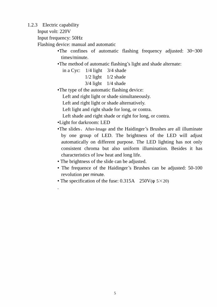
1.2.3 Electric capability
Input volt: 220V
Input frequency: 50Hz
Flashing device: manual and automatic
▪The confines of automatic flashing frequency adjusted: 30~300
times/minute.
▪The method of automatic flashing’s light and shade alternate:
in a Cyc: 1/4 light 3/4 shade
1/2 light 1/2 shade
3/4 light 1/4 shade
▪The type of the automatic flashing device:
Left and right light or shade simultaneously.
Left and right light or shade alternatively.
Left light and right shade for long, or contra.
Left shade and right shade or right for long, or contra.
▪Light for darkroom: LED
▪The slides、After-Image and the Haidinger’s Brushes are all illuminate
by one group of LED. The brightness of the LED will adjust
automatically on different purpose. The LED lighting has not only
consistent chroma but also uniform illumination. Besides it has
characteristics of low heat and long life.
▪ The brightness of the slide can be adjusted.
▪ The frequence of the Haidinger’s Brushes can be adjusted: 50-100
revolution per minute.
▪ The specification of the fuse: 0.315A 250V(φ 5×20)
.
6
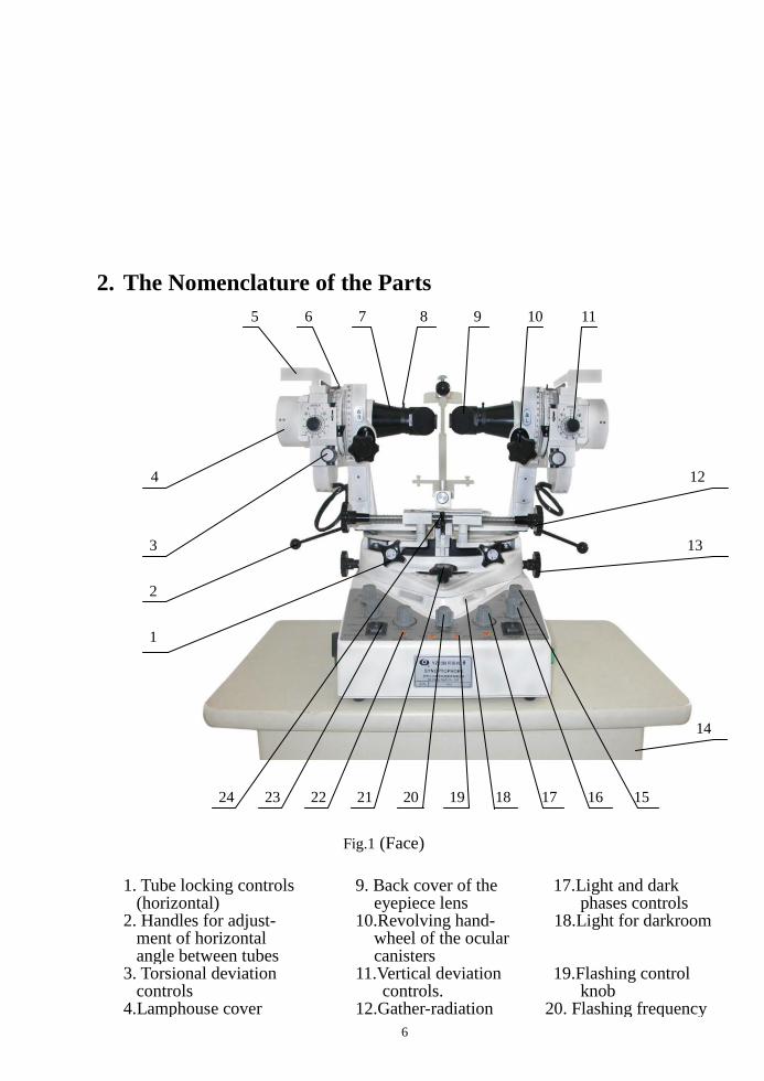
2. The Nomenclature of the Parts
5 6 7 8 9 10 11
4 12
3 13
2
1
14
24 23 22 21 20 19 18 17 16 15
Fig.1 (Face)
1. Tube locking controls (horizontal)
9. Back cover of the eyepiece lens
17.Light and dark phases controls
2. Handles for adjust- ment of horizontal angle between tubes
10.Revolving hand- wheel of the ocular canisters
18.Light for darkroom
3. Torsional deviation controls
11.Vertical deviation controls.
19.Flashing control knob
4.Lamphouse cover 12.Gather-radiation 20. Flashing frequency
7
handwheel knob 5. Haidinger’s brush 13.Interpupillary
distance selection controls
21. Chinrest height control
6. Iris diaphragms 14. Slides drawer 22. On/off switches (after-image lamp)
7. Eyepiece lens 15. Pulse-width selector
23. Reversing switches (Haidinger’s brush)
8.Red light flashing slice 16.Speed control 24. Central lock
25 26 27
28
29
30
31
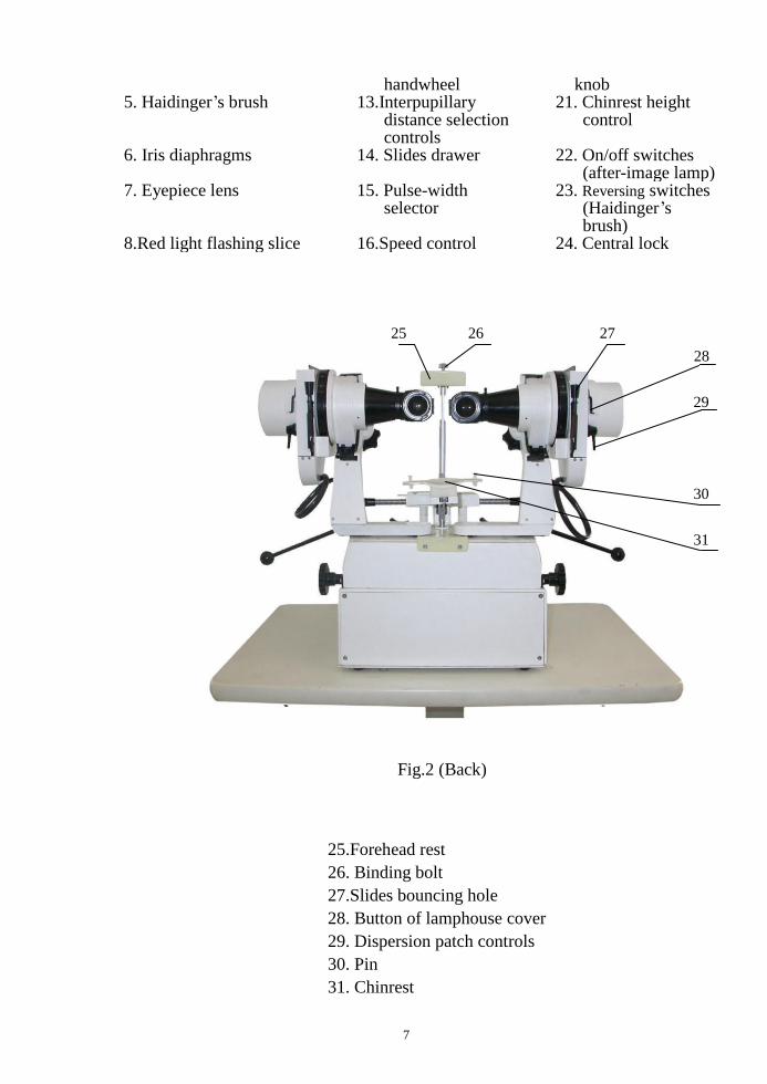
Fig.2 (Back)
25.Forehead rest
26. Binding bolt
27.Slides bouncing hole
28. Button of lamphouse cover
29. Dispersion patch controls
30. Pin
31. Chinrest
8
32 33 34
Fig.3 (Left)
35 36 37
32. Uplift hollowness
33. Timer switch
34.Light for darkroom switch
9
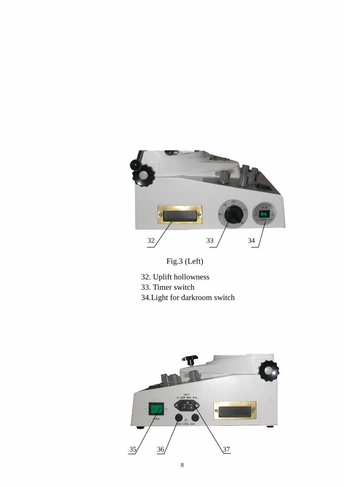
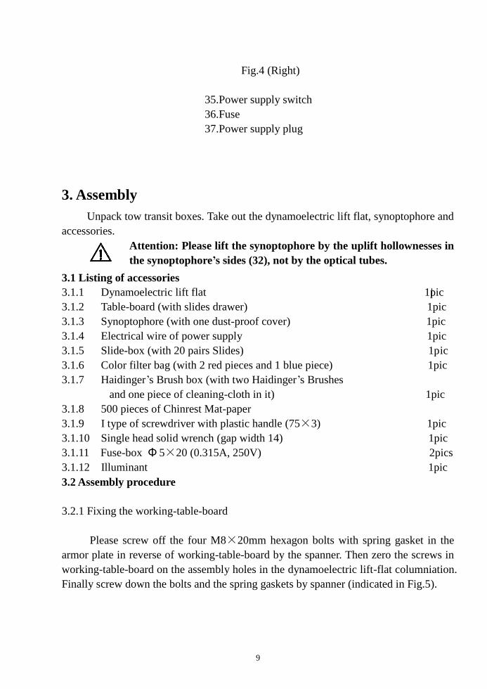
Fig.4 (Right)
35.Power supply switch
36.Fuse
37.Power supply plug
3. Assembly
Unpack tow transit boxes. Take out the dynamoelectric lift flat, synoptophore and
accessories.
Attention: Please lift the synoptophore by the uplift hollownesses in
the synoptophore’s sides (32), not by the optical tubes.
3.1 Listing of accessories
3.1.1 Dynamoelectric lift flat 1pic
3.1.2 Table-board (with slides drawer) 1pic
3.1.3 Synoptophore (with one dust-proof cover) 1pic
3.1.4 Electrical wire of power supply 1pic
3.1.5 Slide-box (with 20 pairs Slides) 1pic
3.1.6 Color filter bag (with 2 red pieces and 1 blue piece) 1pic
3.1.7 Haidinger’s Brush box (with two Haidinger’s Brushes
and one piece of cleaning-cloth in it) 1pic
3.1.8 500 pieces of Chinrest Mat-paper
3.1.9 I type of screwdriver with plastic handle (75×3) 1pic
3.1.10 Single head solid wrench (gap width 14) 1pic
3.1.11 Fuse-box Φ 5×20 (0.315A, 250V) 2pics
3.1.12 Illuminant 1pic
3.2 Assembly procedure
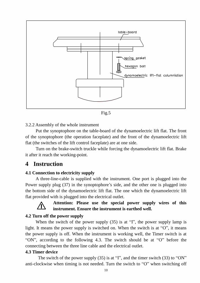
3.2.1 Fixing the working-table-board
Please screw off the four M8×20mm hexagon bolts with spring gasket in the
armor plate in reverse of working-table-board by the spanner. Then zero the screws in
working-table-board on the assembly holes in the dynamoelectric lift-flat columniation.
Finally screw down the bolts and the spring gaskets by spanner (indicated in Fig.5).
10
Fig.5
3.2.2 Assembly of the whole instrument
Put the synoptophore on the table-board of the dynamoelectric lift flat. The front
of the synoptophore (the operation faceplate) and the front of the dynamoelectric lift
flat (the switches of the lift control faceplate) are at one side.
Turn on the brake-switch truckle while forcing the dynamoelectric lift flat. Brake
it after it reach the working-point.
4 Instruction
4.1 Connection to electricity supply
A three-line-cable is supplied with the instrument. One port is plugged into the
Power supply plug (37) in the synoptophore’s side, and the other one is plugged into
the bottom side of the dynamoelectric lift flat. The one which the dynamoelectric lift
flat provided with is plugged into the electrical outlet.
Attention: Please use the special power supply wires of this
instrument. Ensure the instrument is earthed well.
4.2 Turn off the power supply
When the switch of the power supply (35) is at “I”, the power supply lamp is
light. It means the power supply is switched on. When the switch is at “O”, it means
the power supply is off. When the instrument is working well, the Timer switch is at
“ON”, according to the following 4.3. The switch should be at “O” before the
connecting between the three line cable and the electrical outlet.
4.3 Timer device
The switch of the power supply (35) is at “I”, and the timer switch (33) to “ON”
anti-clockwise when timing is not needed. Turn the switch to “O” when switching off
11
the instrument.
The switch of the power supply (35) is at “I”, and rotate the timer switch (33) to
the needed time clockwise when timing is needed. The timer switch will automatically
go to “OFF” and shut down on time. The instrument will end the working.
Attention: Do turn the switch to the “O” while ending the working.
4.4 Set the chinrest padding-paper
Pull out the two pins (30) and place 50~80 pieces of chinrest padding-paper on
the chinrest. Insert the pins after all the holes are zeroed in. Take down one piece of the
padding-paper when the last patient’s operation is finished and the next patient’s
operation is ready.
4.5 Adjustment of the chinrest
Rotate the chinrest height control (21) to adjust the vertical position. Loosen the
tightening-bolts of the chinrest to adjust the position of fore-back. It can make the
patient’s sight line concurrent with the eyepieces’ centre.
4.6 Adjustment of the forehead rest
Loosen the tight-bolts in the underside of the forehead rest pole to adjust the
vertical position of the forehead rest. Loosen the Binding bolt (26) in the upside of the
chinrest pole to adjust the fore-back position of the forehead rest. It keeps the distance
around 10~15mm between the patient’s eyes and the eyepieces.
4.7 Adjustment of the interpupillary distance
Rotate the interpupillary distance selection controls (13) to make the light-axis
distance between the left eyepiece and the right eyepiece to be equal to the patient’s
interpupillary distance. Then the numerical value of the interpupillary distance can be
read from the interpupillary distance scale.
4.8 Adjustment the position of the left and right eyepieces
Loosen the tube locking controls (horizontal) (1), and pull the handles for
adjustment of horizontal angle between tubes (2). The left and right eyepieces can
close or open separately. The numerical data can be read from the left and right scales.
Lock the tube locking controls (horizontal) (1) and pull the central lock (24) up,
so that the central lock can lock the screw. Rotate the Gather-radiation handwheel (12),
so that the left and right eyepieces can close and open synchronously. The numerical
data can be read from the scales.
Lock the tube locking controls (horizontal) (1) and pull the central lock (24)
down. Pull the handles for adjustment of horizontal angle between tubes (2) fore or
back, so that the left and right eyepieces can move to the same direction
synchronously.
Rotate the Revolving hand-wheel of the ocular canisters (10),so that the left and
the right eyepieces can rotate round the transverse axis. The numerical data of the
angle can be read from the elevation and depression scales.
4.9 Adjustment of the slides’ position
12
Rotate the vertical deviation controls (11), so that the slides can move relative to
the eyepieces. The angle of view can be read from the vertical deviation scales (prism
degree).
Rotate the torsional deviation controls (3), so that the slides can rotate round the
eyepieces’ light-axis. The angle can be read from the lamp-box scales.
Press the slides’ bouncing hole (27) and take out the slides. According to the
demand, the slides can also bounce.
4.10 Light for darkroom
Press the light for darkroom switch (34), so that the light for darkroom (18) can
be on in order to observe and operate the panel.
4.11 Adjustment the brightness of the slide light
Rotate the light and dark phases controls (17), so that the brightness of the slides
can be adjusted the fitting lightness.
Attention: When you want to change the illumination mode from
after-image or Haidinger’s brush lighting to slides lighting, you
must first switch the On/off switches (after-image lamp) (22) in
order to turn off the after-image or Haidinger’s brush lighting.
4.12 Flashing device
There are all together two types of flashing device, one is manual and the other is
automatic
4.12.1 Manual flashing
Rotate the two Pulse-width selectors (15) to on or off (on means turning on
generally, and off means turning off usually). Put your two fingers on the Flashing
control knobs (19). The lamp will be light once or dark once for once press.
4.12.2 Automatic flashing
Rotate the two Pulse-width selectors (15) to “1/4”~ “3/4”, then the system come
into automatic flashing state.
(a) Meanings of Pulse-width selector’s pointing
Rotate the two Pulse-width selectors (15) to “1/4”, then the left and the right
lamp flash synchronously. In a Cyc, 1/4 Cyc is light, 3/4 Cyc is dark.
Rotate the two Pulse-width selectors (15) to “3/4”, then the left and the right
lamp flash synchronously. In a Cyc, 3/4 Cyc is light, 1/4 Cyc is dark.
Rotate the two Pulse-width selectors (15) to “1/2 same”, then the left and the
right lamp flash synchronously. In a Cyc,1/2 Cyc is light, 1/2 Cyc is dark.
Rotate the two Pulse-width selectors (15) to “1/2 alternate”, then the left and the
right lamp flash synchronously. In a Cyc,1/2 Cyc one is light the other is dark, 1/2 Cyc
one is dark the other is light.
Rotate one Pulse-width selector to “1/4” or “3/4”, the other to “3/4” or “1/4”. In a
Cyc, one lamp is light in 1/4 Cyc or in 3/4 Cyc, and is dark in 3/4 Cyc or in 1/4 Cyc.
The other lamp is contrary.
(b) Adjustment the frequency of the automatic flashing
13
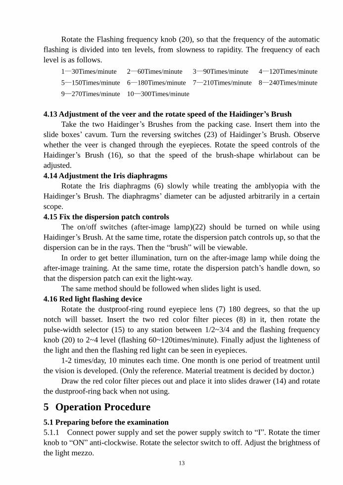
Rotate the Flashing frequency knob (20), so that the frequency of the automatic
flashing is divided into ten levels, from slowness to rapidity. The frequency of each
level is as follows.
1—30Times/minute 2—60Times/minute 3—90Times/minute 4—120Times/minute
5—150Times/minute 6—180Times/minute 7—210Times/minute 8—240Times/minute
9—270Times/minute 10—300Times/minute
4.13 Adjustment of the veer and the rotate speed of the Haidinger’s Brush
Take the two Haidinger’s Brushes from the packing case. Insert them into the
slide boxes’ cavum. Turn the reversing switches (23) of Haidinger’s Brush. Observe
whether the veer is changed through the eyepieces. Rotate the speed controls of the
Haidinger’s Brush (16), so that the speed of the brush-shape whirlabout can be
adjusted.
4.14 Adjustment the Iris diaphragms
Rotate the Iris diaphragms (6) slowly while treating the amblyopia with the
Haidinger’s Brush. The diaphragms’ diameter can be adjusted arbitrarily in a certain
scope.
4.15 Fix the dispersion patch controls
The on/off switches (after-image lamp)(22) should be turned on while using
Haidinger’s Brush. At the same time, rotate the dispersion patch controls up, so that the
dispersion can be in the rays. Then the “brush” will be viewable.
In order to get better illumination, turn on the after-image lamp while doing the
after-image training. At the same time, rotate the dispersion patch’s handle down, so
that the dispersion patch can exit the light-way.
The same method should be followed when slides light is used.
4.16 Red light flashing device
Rotate the dustproof-ring round eyepiece lens (7) 180 degrees, so that the up
notch will basset. Insert the two red color filter pieces (8) in it, then rotate the
pulse-width selector (15) to any station between 1/2~3/4 and the flashing frequency
knob (20) to 2~4 level (flashing 60~120times/minute). Finally adjust the lighteness of
the light and then the flashing red light can be seen in eyepieces.
1-2 times/day, 10 minutes each time. One month is one period of treatment until
the vision is developed. (Only the reference. Material treatment is decided by doctor.)
Draw the red color filter pieces out and place it into slides drawer (14) and rotate
the dustproof-ring back when not using.
5 Operation Procedure
5.1 Preparing before the examination
5.1.1 Connect power supply and set the power supply switch to “I”. Rotate the timer
knob to “ON” anti-clockwise. Rotate the selector switch to off. Adjust the brightness of
the light mezzo.
14
5.1.2 Set all the pointers of dial at zero.
5.1.3 Let the patient sit in the work chair. Set his chin on the chinrest. Set his
forehead abut on the forehead rest. Adjust the height of the lift flat and the chinrest, so
that the centre of the patient’s eyes is at the same horizon with the light-axis of the
eyepieces.
5.1.4 Adjust the interpupillary distance selection controls, and make the light-axis
distance between the left eyepiece and the right eyepiece equal to the patient’s
interpupillary distance. Then the numerical data of the interpupillary distance can be
read from the interpupillary distance scale.
5.1.5 Open the elliptic back cover of the eyepiece lens (9) at 45 degrees and look into
directly through the half-transmitting mirrors when doctors want to observe the actions
of the patients’ eyeballs and the light reflecting by the cornea. Close the cover with that
when no using.
5.2 Measuring the angle Kappa
There is a row of small square grid on the slide which measuring the angle
kappa. In each grid there is letters, numbers or images. The angle of every two near
grids is 1 degree. “0” is in the center of the grids.
Place the slide in the slide boxes and instruct the patient to look at the zero
mark with simple eye. The doctor press the synoptophore’s flashing button, and
observe the reflection of the light on the patient’s cornea. The kappa angle will be
positive when nasal lean, and negative when temporal lean if the reflected light is not
in the centre of the pupil. Then the patient should be instructed to look at successive
numbers, or letters, until the reflection is in the centre. Numerate the kappa angle by
which is looking at. The same procedure should be carried out with the other eye.
5.3 Measuring of the subjective strabismic angle (e.g. the tiger and the cage slides)
Place a set of simultaneous perception series slides in the slide boxes. The cage
slides is in front of the regardant eye and the tiger slide is in front of the suffering eye.
Lock the lens arm in front of the regardant eye at the zero. Let the patient move the
handles for adjustment of horizontal angle between tubes fore or back by the side of
his suffering eye till the tiger enter into the cage. Then the scale value by the side of the
suffering eye is the subjective strabismic angle.
5.4 Measuring the objective strabismic angle and retinal correspondence
Light and extinguish the left and right optical tubes’ lamp alternately and lock
the arm by the side of the watching eye at zero after measuring the subjective angle.
Observe any eye-position movement to take place. If no movement, the objective angle
corresponds to the subjective angle, and it is normal retinal correspondence. If there is
any movement, the patient should move the optical tube by the side of the suffering
eye or adjust the slide vertical deviation handle until the reflection of the light is in the
centre of the pupil. The scale value by the side of the suffering eye is the objective
angle if the eye-position doesn’t move when the bulbs is extinguished alternately. If the
objective angle doesn’t correspond to the subjective angle, it is the abnormal retinal
15
correspondence and the margin of the two angles is the abnormal angle. Then the
examination is repeated with the other eye.
5.5 Examining the fusion series functions (after the simultaneous perception series,
e.g. a set of slides of one car with front-wheel and anther with rear wheel)
5.5.1 Place the slides in the slide boxes, and let the patient observe the slides. Move
the handles for adjustment of horizontal angle between tubes fore or back at the same
time, so that the two images can inosculate to be an integrated image that means an
integrated car with front-wheel and rear wheel. If the images can’t inosculate to be an
integrated image, then choose the larger angle fusion slides.
5.5.2 After the images inosculating and the optical tubes’ arms being locked, open
and close separately, till the two images are detached to a small extent. The open and
close angles’ summation at the two sides’ scales shows the fusion series ability.
5.5.3 Third dimension will come into being while observing the fusion series slides
expect for the above two functions.
5.6 Examining the stereoscopic vision series functions (qualitative examination)
Use the tailor-made stereoscopic vision slides for observing. If the patient can
perceive the third dimension, he is provided with a certain extent stereoscopic vision.
(It’s qualitative testing.)
Our company has manufactured a suit of stochastic dots slides by what we can
quantificationally measure the visual- acutance (40″-1000″) of the stereoscopic
vision series functions. (For choose and buy)
5.7 Fusion series ability training
The doctor places the lens arms at the fusion point, and lock the two lens arms.
Then do the open and close movement.
5.8 Abnormal retinal correspondence training
5.8.1 Treatment for the children: Because of their little age, their discretion is infirm.
Select the larger simultaneous perception series images. Place the slides in the slide
boxes and lock the lens arms. The doctor makes the other lens arm out and in, so that
the two images is crossed at the objective angle from far to near, and the superposition
will keep a period of time.
5.8.2 Flashing training: Use the smallest concave simultaneous perception series
images in the yellow spot centre. Place the optical tubes in the objective angle. Light
and extinguish the two optical tubes alternately with the automatic device. The two
images will overlap at the objective angle when the lighting lights in front of the eyes
from slowness to rapidity.
5.8.3 Watching training: The simultaneous perception series images are used. Place
the optical tubes in the objective angle. One eye of the patient watches at the cage, the
other watches at the tiger. Move the lens arms, so that the tiger go forward or back off
to pass through the cage. Do this training time after time, and it will be normal retinal
correspondence.
5.8.4 After-image training: Place the after-image slides in the two slide boxes. Turn
16
on the special after-image lamps and flash them alternately to form the after-image.
Then the patient should watch at the after-image continuously. After seeing the
integrated cross from the horizontal and vertical lines, insert the simultaneous
perception series image, so that the two images will overlap.
5.8.5 Haidinger’s Brush training: Take out the slides and insert the accessories of
the Haidinger’s Brush. First, let the patient learn to observe the “light brush”
phenomena. The patient will see the phenomena as long as he fixes attention on it and
watch some point on the blue glass with one eye. The color of the “light brush” is
blue-purple which is darker than the color of the background. It will circumrotate
slowly and its rotary speed can be adjusted in a stated bound. The rotary “light brush”
is used to stimulate the central concave’s restrainability to activation the cone cells.
After the patient has the ability of watching “light brush”, Reduce the iris
diaphragm gradually. This can constrain the patient transfer from paracentral fixation
to central fixation gradually. When patient can see “light brush” in an area about 10mm
diameter, doctor can insert the airplane -image slide. Tell patient looking the “light
brush” as the airscrew of airplane in order to improve the interest and consolidate the
curative effect.
When simple eye is training, insert the blue color filter into the other drawtube’s
notch. Blue light can be seen with double eyes.
5.9 Stereoscopic vision training
Observe the tailor-made stereoscopic slides again and again to solidify and
advance the treatment effect of cockeye and amblyopia. And it also gathers ahead the
third dimension ability.
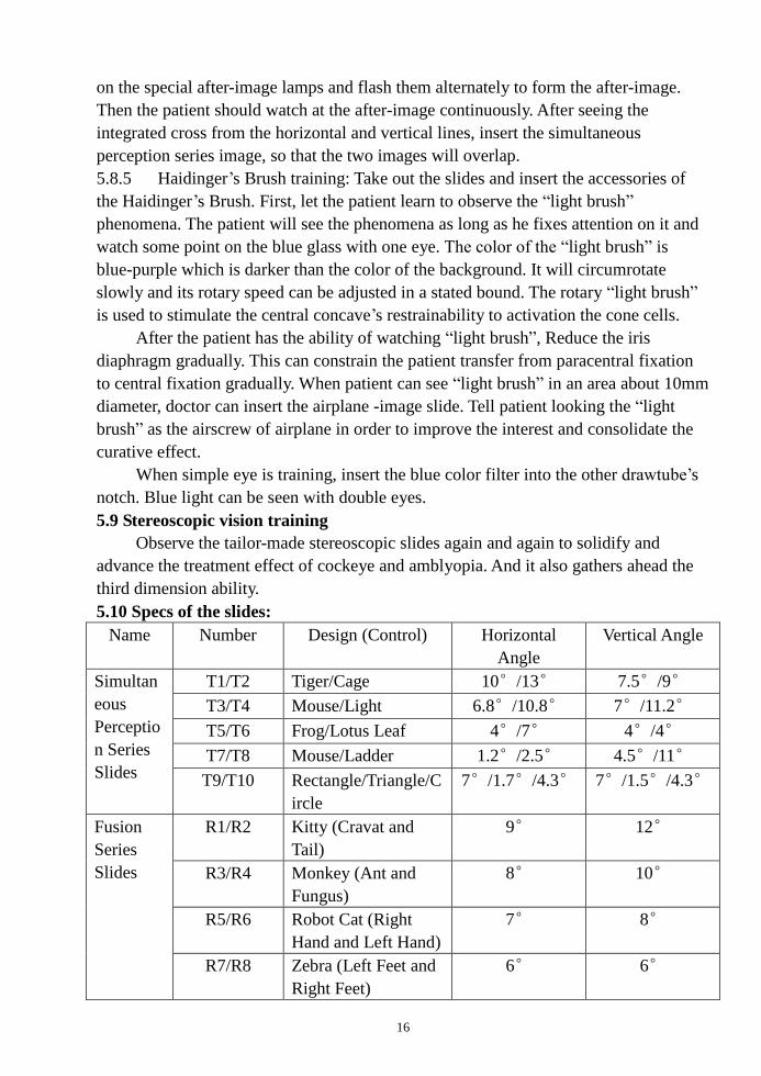
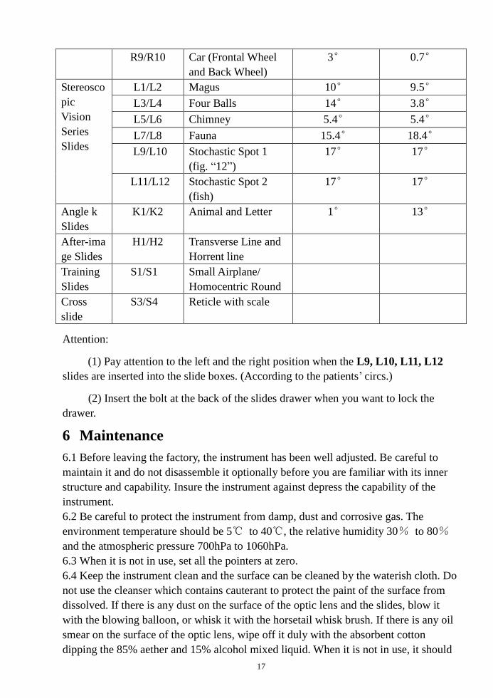
5.10 Specs of the slides:
Name Number Design (Control) Horizontal
Angle
Vertical Angle
Simultan
eous
Perceptio
n Series
Slides
T1/T2 Tiger/Cage 10°/13° 7.5°/9°
T3/T4 Mouse/Light 6.8°/10.8° 7°/11.2°
T5/T6 Frog/Lotus Leaf 4°/7° 4°/4°
T7/T8 Mouse/Ladder 1.2°/2.5° 4.5°/11°
T9/T10 Rectangle/Triangle/C
ircle
7°/1.7°/4.3° 7°/1.5°/4.3°
Fusion
Series
Slides
R1/R2 Kitty (Cravat and
Tail)
9° 12°
R3/R4 Monkey (Ant and
Fungus)
8° 10°
R5/R6 Robot Cat (Right
Hand and Left Hand)
7° 8°
R7/R8 Zebra (Left Feet and
Right Feet)
6° 6°
17
R9/R10 Car (Frontal Wheel
and Back Wheel)
3° 0.7°
Stereosco
pic
Vision
Series
Slides
L1/L2 Magus 10° 9.5°
L3/L4 Four Balls 14° 3.8°
L5/L6 Chimney 5.4° 5.4°
L7/L8 Fauna 15.4° 18.4°
L9/L10 Stochastic Spot 1
(fig. “12”)
17° 17°
L11/L12 Stochastic Spot 2
(fish)
17° 17°
Angle k
Slides
K1/K2 Animal and Letter 1° 13°
After-ima
ge Slides
H1/H2 Transverse Line and
Horrent line
Training
Slides
S1/S1 Small Airplane/
Homocentric Round
Cross
slide
S3/S4 Reticle with scale
Attention:
(1) Pay attention to the left and the right position when the L9, L10, L11, L12
slides are inserted into the slide boxes. (According to the patients’ circs.)
(2) Insert the bolt at the back of the slides drawer when you want to lock the
drawer.
6 Maintenance
6.1 Before leaving the factory, the instrument has been well adjusted. Be careful to
maintain it and do not disassemble it optionally before you are familiar with its inner
structure and capability. Insure the instrument against depress the capability of the
instrument.
6.2 Be careful to protect the instrument from damp, dust and corrosive gas. The
environment temperature should be 5℃ to 40℃, the relative humidity 30% to 80%
and the atmospheric pressure 700hPa to 1060hPa.
6.3 When it is not in use, set all the pointers at zero.
6.4 Keep the instrument clean and the surface can be cleaned by the waterish cloth. Do
not use the cleanser which contains cauterant to protect the paint of the surface from
dissolved. If there is any dust on the surface of the optic lens and the slides, blow it
with the blowing balloon, or whisk it with the horsetail whisk brush. If there is any oil
smear on the surface of the optic lens, wipe off it duly with the absorbent cotton
dipping the 85% aether and 15% alcohol mixed liquid. When it is not in use, it should
18
be covered by the mantle.
6.5 When the Haidinger’s Brush is not in use, it should be conserved in the
appropriative case.
6.6 When the light doesn’t work, shut off the power first, then open the lamphouse
cover (4) by screw off the two bolts on the surface with small screwdriver. Take out
the bad light and pull out the power plug. Remove the two stanchions to the new light
and plug into the power plug. Place it into the lamphouse in the end.
6.7 After fusion, bear out the cause for it and screw off the fuse box cap with a
screwdriver. Then replace the same specs new fuse with the same specifications.
6.8 Replace the patient, and rip off the chinrest padding-paper. The forehead rest
should be cleaned with the disinfectant liquid too.
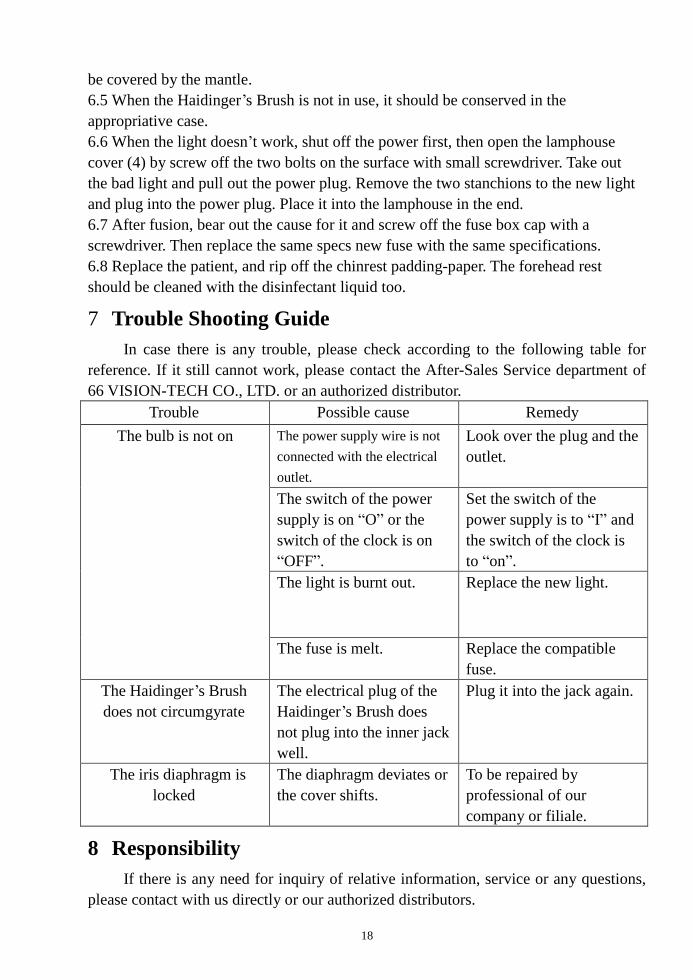
7 Trouble Shooting Guide
In case there is any trouble, please check according to the following table for
reference. If it still cannot work, please contact the After-Sales Service department of
66 VISION-TECH CO., LTD. or an authorized distributor.
Trouble Possible cause Remedy
The bulb is not on The power supply wire is not
connected with the electrical
outlet.
Look over the plug and the
outlet.
The switch of the power
supply is on “O” or the
switch of the clock is on
“OFF”.
Set the switch of the
power supply is to “I” and
the switch of the clock is
to “on”.
The light is burnt out. Replace the new light.
The fuse is melt. Replace the compatible
fuse.
The Haidinger’s Brush
does not circumgyrate
The electrical plug of the
Haidinger’s Brush does
not plug into the inner jack
well.
Plug it into the jack again.
The iris diaphragm is
locked
The diaphragm deviates or
the cover shifts.
To be repaired by
professional of our
company or filiale.
8 Responsibility
If there is any need for inquiry of relative information, service or any questions,
please contact with us directly or our authorized distributors.

19
9 Transportation and Storage
9.1 Before leaving the factory, the instrument has been well adjusted, don’t
disassemble it anyway.
9.2 During the transportation, be careful to protect it from wetness, upside down and
violent vibration.
9.3 This instrument should be stored in a well ventilated room without corrosive gas
where the relative humidity should be 10%~80% and environment temperature should
be -40℃~40℃.
★ We will not notice you otherwise if the design, specification or the slide’s
content are changed.

20