Embed Size (px)
Citation preview
TM 11-6625-274-12D E P A R T M E N T O F T H E A R M Y T E C H N I C A L M A N U A L
O P E R A T O R ’ S A N D O R G A N I Z A T I O N A L
M A I N T E N A N C E M A N U A L
T E S T S E T S , E L E C T R O N T U B E T V - 7 / U ,
T V - 7 A / U , T V - 7 B / U A N D T V - 7 D / U
T h i s c o p y i s a r e p r i n t w h i c h i n c l u d e s c u r r e n t
p a g e s f r o n t C h a r g e s 6 a n d 7 .
H E A D Q U A R T E R S , D E P A R T M E N T O F T H E A R M Y
14 JUNE 1960

W A R N I N G
Be careful not to contact high-voltage connections or the 115-volt acinput connections when replacing tubes in the test set. Voltages up to300 volts ac may be encountered in this equipment. Serious injury ordeath may result from contact with these connections.
DON’T TAKE CHANCES!
Changes in force: C6 and C7
TM 11-6625-274-12*C7
CHANGE H E A D Q U A R T E R S
D E P A R T M E N T O F T H E A R M YNO. 7 W a s h i n g t o n , D C , 9 J a n u a r y 1 9 8 4
O P E R A T O R ’ S A N D O R G A N I Z A T I O N A L M A I N T E N A N C E
M A N U A L T E S T S E T S , E L E C T R O N T U B E
T V - 7 / U ( N S N 6 6 2 5 - 0 0 - 3 7 6 - 4 9 3 9 ) ,
T V - 7 A / U ( N S N 6 6 2 5 - 0 0 - 3 7 6 - 4 9 3 9 ) ,
T V - 7 B / U ( N S N 6 6 2 5 - 0 0 - 3 7 6 - 4 9 3 9 ) ,
A N D
T V - 7 D / U ( N S N 6 6 2 5 - 0 0 - 8 2 0 - 0 0 6 4 )
T M 1 1 - 6 6 2 5 - 2 7 4 - 1 2 , 1 4 J u n e 1 9 6 0 , i s c h a n g e d
as fo l lows:
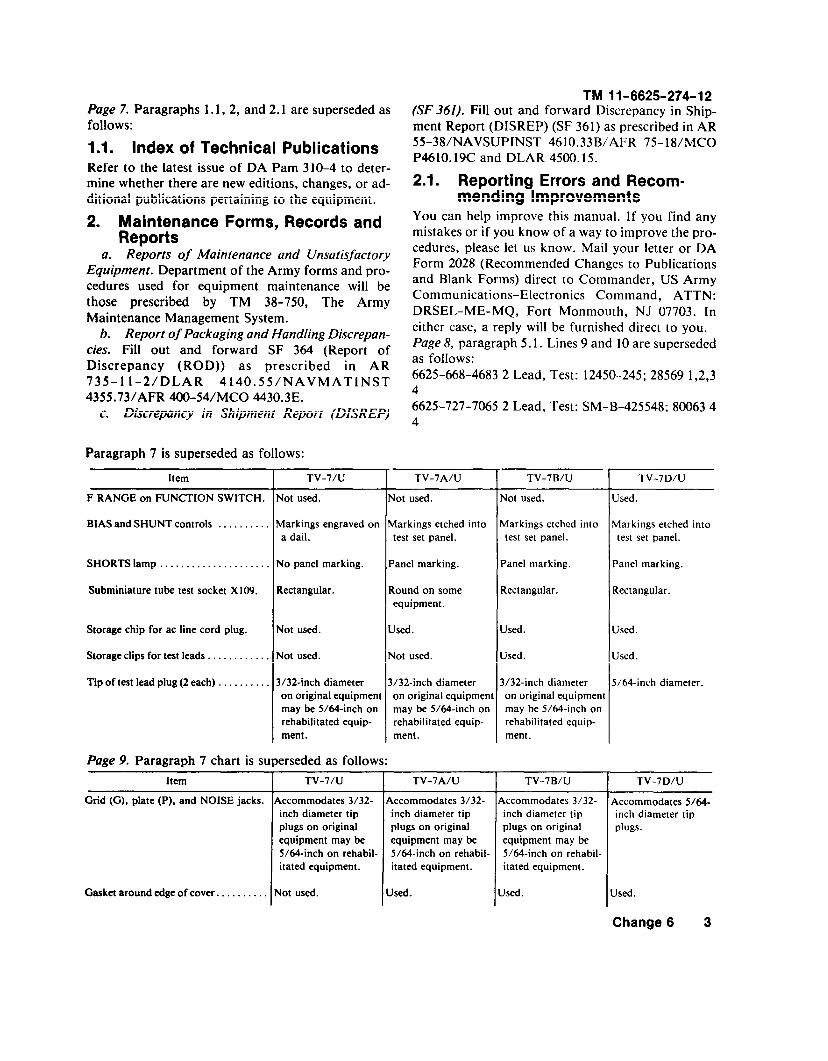
Page 7. Delete paragraphs 1 .1 , 2 , and 2 .1 and
s u b s t i t u t e :
1.1 . Consol idated Index of Army Publ icat ions
and Blank Forms
R e f e r t o t h e l a t e s t i s s u e o f D A P a m 3 1 0 - 1 t o
d e t e r m i n e w h e t h e r t h e r e a r e n e w e d i t i o n s ,
changes or add i t iona l pub l ica t ions per ta in ing to
t h e e q u i p m e n t .
2. Maintenance Forms, Records, and Reports
a. Repor ts o f Main tenance and Unsat is fac tory
E q u i p m e n t . D e p a r t m e n t o f t h e A r m y f o r m s a n d
procedures used for equ ipment main tenance wi l l
b e t h o s e p r e s c r i b e d b y T M 3 8 - 7 5 0 , T h e A r m y
Maintenance Management System.
b. Repor t o f Packaging and Handl ing Def ic i -
e n c i e s . Fi l l out and forward SF 364 (Repor t o f
D i s c r e p a n c y ( R O D ) ) a n d p r e s c r i b e d i n A R
735-11-2/DLAR 4140.55/NAVMATINST 4355.
7 3 A / A F R 4 0 0 - 5 4 / M C O 4 4 3 0 . 3 F .
c. Discrepancy in Sh ipment Repor t (DISREP)
( S F 3 6 1 ) . F i l l o u t a n d f o r w a r d D i s c r e p a n c y i n
S h i p m e n t R e p o r t ( D I S R E P ) ( S F 3 6 1 ) a s p r e -
s c r i b e d i n A R 5 5 - 3 8 / N A V S U P I N S T 4 6 1 0 . 3 3 C /
A F R 7 5 - 1 8 / M C O P 4 6 1 0 . 1 9 D / D L A R 4 5 0 0 . 1 5 .
2.1. Reporting Errors and RecommendingImprovements
Y o u c a n h e l p i m p r o v e t h i s m a n u a l . I f y o u f i n d
a n y m i s t a k e s o r i f y o u k n o w o f a w a y t o i m -
prove the procedures, p lease le t us know. Mai l
y o u r l e t t e r o r D A F o r m 2 0 2 8 ( R e c o m m e n d e d
C h a n g e s t o P u b l i c a t i o n s a n d B l a n k F o r m s )
d i r e c t t o : C o m m a n d e r , U S A r m y C o m m u n i -
c a t i o n s - E l e c t r o n i c s C o m m a n d a n d F o r t M o n -
m o u t h , A T T N : D R S E L - M E - M P , F o r t M o n -
M o u t h , N e w J e r s e y 0 7 7 0 3 . I n e i t h e r c a s e , a
rep ly w i l l be furn ished d i rec t to you.
Paragraphs 2.2, 2 .3 and 2.4 are added af ter
paragraph 2.1.
2.2 . Report ing Equipment i m p r o v e m e n t
R e c o m m e n d a t i o n s ( E l R )
If your electron tube test set needs improvement,let us know. Send us an EIR. You, the user, are
the only one who can tell us what you don’t l ike
a b o u t y o u r e q u i p m e n t . L e t u s k n o w w h y y o u
d o n ’ t l i k e t h e d e s i g n . P u t i t o n a n S F 3 6 8
( Q u a l i t y D e f i c i e n c y R e p o r t ) . M a i l i t t o C o m -
m a n d e r , U S A r m y C o m m u n i c a t i o n s - E l e c t r o n i c s
C o m m a n d a n d F o r t M o n m o u t h , A T T N :
D R S E L - M E - M P , F o r t M o n m o u t h , N e w J e r s e y
07703. We’ l l send you a rep ly .
2.3 . Administrat ive Storage
A d m i n i s t r a t i v e S t o r a g e o f e q u i p m e n t i s s u e d t o
and used by Army ac t iv i t ies w i l l have prevent ive
m a i n t e n a n c e p e r f o r m e d i n a c c o r d a n c e w i t h t h e
PMCS char ts before s tor ing . When remov ing the
e q u i p m e n t f r o m a d m i n i s t r a t i v e s t o r a g e t h e
PMCS should be performed to assure operational
read iness. D isassembly and repack ing o f equ ip-
ment for shipment or l imited storage are covered
in chapter 4 and TM 740-90-1.
2.4 . Destruct ion of Army Electronics Mater ie l
Dest ruct ion o f Army e lec t ron ics mater ie l to pre-
vent enemy use sha l l be in accordance wi th TM
7 5 0 - 2 4 4 - 2 .
*This change supersedes C2, 30 Jan 1963; C4, 22 June 1966 and C5, 30 April 1974. 1
C7, TM 11-6625-274-12
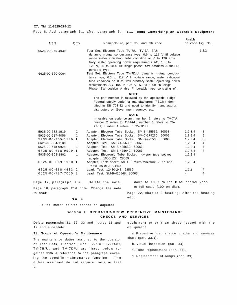
Page 8. A d d p a r a g r a p h 5 . 1 a f t e r p a r a g r a p h 5 . 5.1. I tems Comprising an Operable Equipment
UsableNSN Q T Y Nomenclature, part No., and mfr code on code Fig. No.
6625-00-820-0064
6625-00-376-4939 Test Set, Electron Tube TV-7/U, TV-7A, B/U:dynamic mutual conductance type; 0.6 to 117 V fil voltagerange meter indication; tube condition on 0 to 120 arbi-trary scale; operating power requirements AC, 105 to125 V, 50 to 1000 Hz single phase; SW positions A thru E;portable type
Test Set, Electron Tube TV-7D/U: dynamic mutual conduc-tance type; 0.6 to 117 V fil voltage range; meter indication;tube condition on 0 to 120 arbitrary scale; operating powerrequirements AC, 105 to 125 V, 50 to 1000 Hz singlePhase; SW position A thru F, portable type consisting of:
NOTEThe part number is followed by the applicable 5-digitFederal supply code for manufacturers (FSCM) iden-tified in SB 708-42 and used to identify manufacturer,distributor, or Government agency, etc.
NOTEIn usable on code column, number 1 refers to TV-7/U;number 2 refers to TV-7A/U; number 3 refers to TV-7B/U; number 4 refers to TV-7D/U.
5935-00-732-1919 1 Adapter, Electron Tube Socket: SM-B-425536; 800635935-00-537-4056 1 Adapter, Electron Tube Socket: SM-C-179260; 800635 9 3 5 - 0 0 - 3 0 5 - 1 1 8 9 1 Adapter, Electron Tube Socket: SM-B-425538; 800636625-00-684-1189 1 Adapter, Test: SM-B-425638; 800636625-00-618-9928 1 Adapter, Test: SM-B-425639; 800636 6 2 5 - 0 0 - 6 1 8 - 9 9 2 9 1 Adapter, Test: SM-B-425640; 800635935-00-808-1802 1 Adapter, Electronic Tube Socket: nuvistor tube socket
adapter; 1050-127; 285696 6 2 5 - 0 0 - 0 6 9 - 1 9 6 0 1 Adapter, Test: socket for GE Micro-Miniature 7077 and
7486; 86-060; 044356 6 2 5 - 0 0 - 6 6 8 - 4 6 8 3 2 Lead, Test: 12450-245; 285696 6 2 5 - 0 0 - 7 2 7 - 7 0 6 5 2 Lead, Test: SM-B-425548; 80063
1,2,3,41,2,3,41,2,3,41,2,3,41,2,3,41,2,3,41,2,3,4
1,2,3,4
1,2,34
1,2,3
888444
44
P a g e 1 7 , p a r a g r a p h 1 8 c . D e l e t e t h e n o t e . down to 10, tu rn the BIAS cont ro l knob
Page 18, paragraph 21d note. Change the note to full scale (100 on dial).
to read: P a g e 2 2 , c h a p t e r 3 h e a d i n g . A f t e r t h e h e a d i n g
N O T E a d d :
I f the meter po in ter cannot be ad jus ted
S e c t i o n I . O P E R A T O R / C R E W P R E V E N T I V E M A I N T E N A N C E
C H E C K S A N D S E R V I C E S
Delete paragraphs 31, 32, 33 and figures 11 and e q u i p m e n t o t h e r t h a n t h o s e i s s u e d w i t h t h e
12 and subst i tu te: e q u i p m e n t .
31. Scope of Operator’s Maintenance a. Preventive maintenance checks and services
The maintenance duties assigned to the operator char t (par . 33 .1) .
o f T e s t S e t s , E l e c t r o n T u b e T V - 7 / U , T V - 7 A / U , b. Visual inspection (par. 34).
T V - 7 B / U , a n d T V - 7 D / U a r e l i s t e d b e l o w t o -C . Tube replacement (par . 37) .
gether wi th a re ference to the paragraph cover-
i n g t h e s p e c i f i c m a i n t e n a n c e f u n c t i o n . T h e d. Replacement o f lamps (par . 39) .
d u t i e s a s s i g n e d d o n o t r e q u i r e t o o l s o r t e s t
2
3 2 . G e n e r a l
N O T E
R e f e r t o T M 7 5 0 - 2 4 4 - 2 f o r p r o p e r p r o -
c e d u r e s f o r d e s t r u c t i o n o f t h i s e q u i p -
ment to prevent enemy use.
a. O p e r a t o r / c r e w p r e v e n t i v e m a i n t e n a n c e i s
the sys temat ic care , serv ic ing and inspect ion o f
equipment to prevent the occurrence of t rouble ,
to reduce downt ime, and to mainta in equipment
i n s e r v i c e a b l e c o n d i t i o n . T o b e s u r e t h a t y o u r
e lec t ron tube tes t se t is a lways ready for your
m i s s i o n , y o u m u s t d o s c h e d u l e d p r e v e n t i v e
maintenance checks and services (PMCS).
( 1 ) B E F O R E O P E R A T I O N , p e r f o r m y o u r B
PMCS to be sure that your equipment is ready
to go.
(2) When an item of equipment is reinstalled
a f t e r r e m o v a l , f o r a n y r e a s o n , p e r f o r m t h e
necessary B PMCS to be sure the item meets the
readiness reporting criteria.
(3) Use the ITEM NO. co lumn in the PMCS
table to get the number to be used in the TM
I T E M N O . c o l u m n o n D A F o r m 2 4 0 4 ( E q u i p -
m e n t I n s p e c t i o n a n d M a i n t e n a n c e W o r k s h e e t )
when you f i l l out the form.
b. R o u t i n e c h e c k s l i k e C L E A N I N G , D U S T -
I N G , W A S H I N G , C H E C K I N G F O R F R A Y E D
C A B L E S , S T O W I N G I T E M S N O T I N U S E ,
C O V E R I N G U N U S E D R E C E P T A C L E S ,
C H E C K I N G F O R L O O S E N U T S A N D B O L T S
A N D C H E C K I N G F O R C O M P L E T E N E S S a r e
not l isted as PMCS checks. They are things that
you shou ld do any t ime you see they must be
d o n e . I f y o u f i n d a r o u t i n e c h e c k l i k e o n e o f
o p e r a t o r s r e p o r t e d p r o b l e m s w i t h t h i s i t e m .
N O T E
W h e n y o u a r e d o i n g a n y P M C S o r
rout ine checks, keep in mind the warn-
ings and cautions.
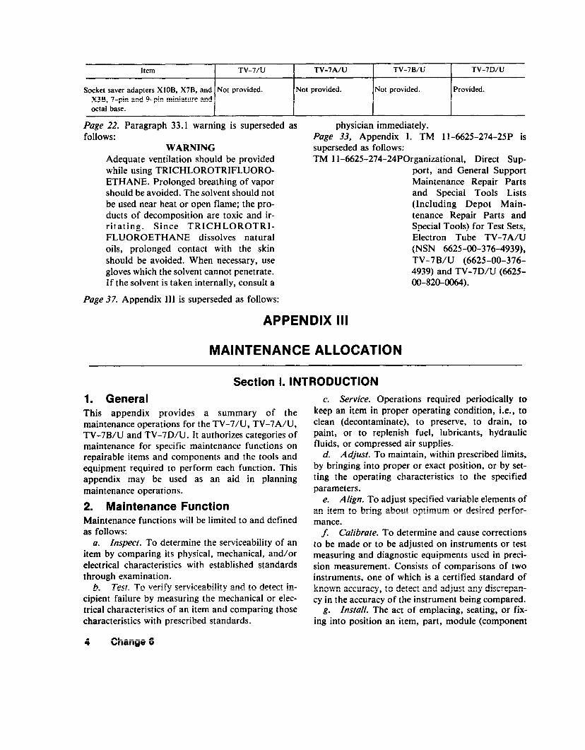
W A R N I N G S
A d e q u a t e v e n t i l a t i o n s h o u l d b e p r o v i d e d
w h i l e u s i n g T R I C H L O R O T R I F L U O R O -
E T H A N E . P r o l o n g e d b r e a t h i n g o f v a p o r
s h o u l d b e a v o i d e d . T h e s o l v e n t s h o u l d
not be used near heat or open flame; the
products o f decompos i t ion are tox ic and
i r r i t a t i n g . S i n c e T R I C H L O R O T R I -
F L U O R O E T H A N E d i s s o l v e s n a t u r a l o i l s ,
p r o l o n g e d c o n t a c t w i t h s k i n s h o u l d b e
C7, TM 11-6625-274-12
a v o i d e d . When necessary , use g loves
w h i c h t h e s o l v e n t c a n n o t p e n e t r a t e . I f
t h e s o l v e n t i s t a k e n i n t e r n a l l y , c o n s u l t
a phys ic ian immediate ly .
C o m p r e s s e d a i r i s d a n g e r o u s a n d c a n
c a u s e s e r i o u s b o d i l y h a r m i f p r o t e c t i v e
m e a n s o r m e t h o d s a r e n o t o b s e r v e d t o
p r e v e n t a c h i p o r p a r t i c l e ( o f w h a t e v e r
s ize) f rom being b lown in to the eyes or
u n b r o k e n s k i n o f t h e o p e r a t o r o r o t h e r
personnel . Goggles must be worn a t a l l
t i m e s w h i l e c l e a n i n g w i t h c o m p r e s s e d
air. Compressed a i r sha l l no t be used
f o r c l e a n i n g p u r p o s e s e x c e p t w h e r e
r e d u c e d t o l e s s t h a n 2 9 p o u n d s p e r
s q u a r e i n c h g a g e ( p s i g ) a n d t h e n o n l y
w i t h e f f e c t i v e c h i p g u a r d i n g a n d p e r -
s o n n e l p r o t e c t i v e e q u i p m e n t . D o n o t
u s e c o m p r e s s e d a i r t o d r y p a r t s w h e n
t r i c h l o r o t r i f l u o r o e t h a n e h a s b e e n u s e d .
N O T E S
T h e P R O C E D U R E S c o l u m n i n y o u r
P M C S c h a r t s i n s t r u c t h o w t o p e r f o r m
the requ i red checks and serv ices. Care-
f u l l y f o l l o w t h e s e i n s t r u c t i o n s a n d , i f
t o o l s a r e n e e d e d o r t h e c h a r t s o i n -
s t r u c t s , g e t o r g a n i z a t i o n a l m a i n t e n a n c e
to do the necessary work.
I f y o u r e q u i p m e n t m u s t b e i n o p e r a t i o n
a l l the t ime, check those i tems that can
b e c h e c k e d a n d s e r v i c e d w i t h o u t d i s -
t u r b i n g o p e r a t i o n . M a k e t h e c o m p l e t e
checks and serv ices when the equ ipment
can be shut down.
c. Def ic ienc ies tha t cannot be cor rec ted must
b e r e p o r t e d t o h i g h e r c a t e g o r y m a i n t e n a n c e
personnel . R e c o r d s a n d r e p o r t s o f p r e v e n t i v e
m a i n t e n a n c e m u s t b e m a d e i n a c c o r d a n c e w i t h
procedures given in TM 38-750.
33. Operator /Crew Prevent ive MaintenanceChecks and Services
P e r f o r m b e f o r e o p e r a t i o n P M C S i f y o u a r e
operating the item for the first t ime.
N O T E
The checks in the interval column are to
be performed in the order l isted.
Page 23. Add paragraph 33.1 after paragraph 33.
3
C7, TM 11-6625-274-12
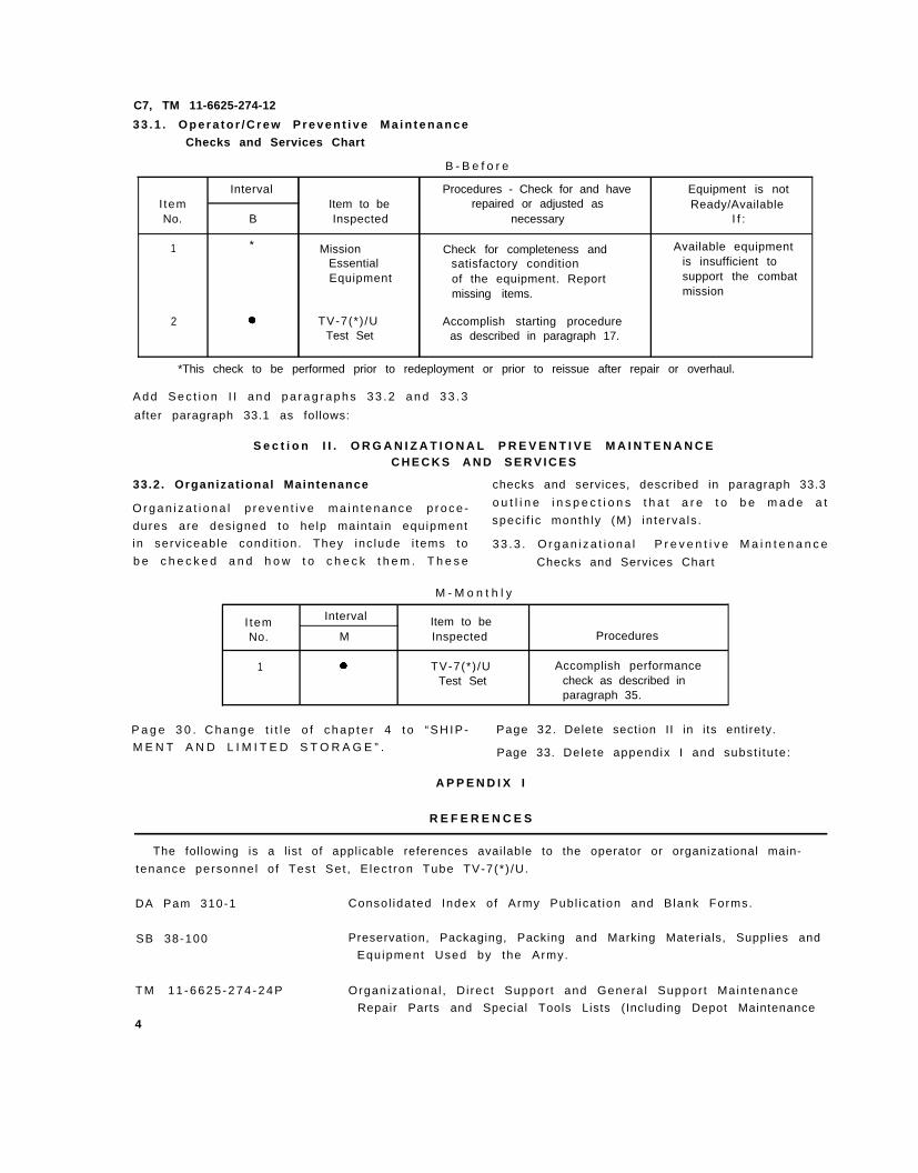
3 3 . 1 . O p e r a t o r / C r e w P r e v e n t i v e M a i n t e n a n c e
Checks and Services Chart
B - B e f o r e
Interval Procedures - Check for and have Equipment is notI tem Item to be repaired or adjusted as Ready/AvailableNo. B Inspected necessary I f :
1 * Mission Check for completeness and Available equipmentEssential satisfactory condition is insufficient toEquipment of the equipment. Report support the combat
missing items. mission
2 TV-7(*) /U Accomplish starting procedureTest Set as described in paragraph 17.
*This check to be performed prior to redeployment or prior to reissue after repair or overhaul.
A d d S e c t i o n I I a n d p a r a g r a p h s 3 3 . 2 a n d 3 3 . 3
after paragraph 33.1 as follows:
S e c t i o n I I . O R G A N I Z A T I O N A L P R E V E N T I V E M A I N T E N A N C EC H E C K S A N D S E R V I C E S
33.2 . Organizat ional Maintenance checks and services, described in paragraph 33.3
O r g a n i z a t i o n a l p r e v e n t i v e m a i n t e n a n c e p r o c e - o u t l i n e i n s p e c t i o n s t h a t a r e t o b e m a d e a t
dures are des igned to he lp mainta in equipment spec i f i c month ly (M) in terva ls .
in serv iceab le cond i t ion . They inc lude i tems to 3 3 . 3 . O r g a n i z a t i o n a l P r e v e n t i v e M a i n t e n a n c e
b e c h e c k e d a n d h o w t o c h e c k t h e m . T h e s e Checks and Services Chart
M - M o n t h l y
I tem Interval Item to beNo. M Inspected Procedures
1 TV-7(*) /U Accomplish performanceTest Set check as described in
paragraph 35.
P a g e 3 0 . C h a n g e t i t l e o f c h a p t e r 4 t o “ S H I P - Page 32. Delete section II in its entirety.
M E N T A N D L I M I T E D S T O R A G E ” . Page 33. Delete appendix I and subst i tu te :
A P P E N D I X I
R E F E R E N C E S
The following is a l ist of applicable references available to the operator or organizational main-
tenance personne l o f Test Set , E lec t ron Tube TV-7(* ) /U.
DA Pam 310-1 Consol idated Index o f Army Publ icat ion and Blank Forms.
SB 38-100 Preservation, Packaging, Packing and Marking Materials, Supplies and
Equipment Used by the Army.
T M 1 1 - 6 6 2 5 - 2 7 4 - 2 4 P Organizat iona l , D i rec t Suppor t and Genera l Suppor t Main tenance
Repair Parts and Special Tools Lists (Including Depot Maintenance4
C7, TM 11-6625-274-12Repair Parts and Special Tools) for Test Sets, Electron Tube TV-
7 A / U . ( N S N 6 6 2 5 - 0 0 - 3 7 6 - 4 9 3 9 ) , T V - 7 B / U ( 6 6 2 5 - 0 0 - 3 7 6 - 4 9 3 9 )
a n d T V - 7 D / U ( 6 6 2 5 - 0 0 - 8 2 0 - 0 0 6 4 ) .
T M 3 8 - 7 5 0 T h e A r m y M a i n t e n a n c e M a n a g e m e n t S y s t e m ( T A M M S ) .
T M 7 4 0 - 9 0 - 1 Admin is t ra t ive Storage of Equipment ,
T M 7 5 0 - 2 4 4 - 2 Procedures fo r Dest ruc t ion o f E lec t ron ics Mater ie l to Prevent
Enemy Use.
Page 34. Appendix I I de leted.
5
By Order of the Secretary of the Army:
O f f i c i a l :
J O H N A . W I C K H A M J R .
General, United States Army
Chief of Staf f
R O B E R T M . J O Y C E
Major General, United States Army
The Adju tant Genera l
DISTRIBUTION:
To be distributed in accordance with DA Form 12-36B, Operator
and Crew Maintenance requirements for TV-7A-D/U.
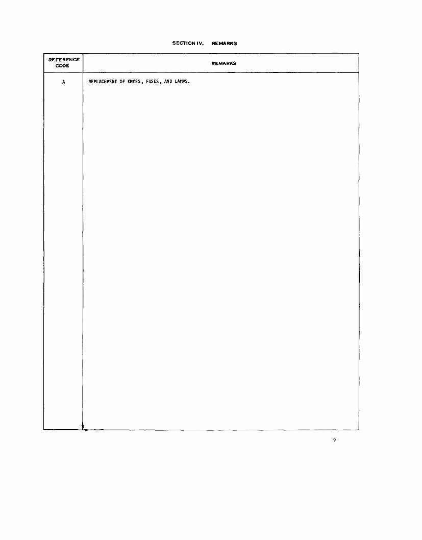
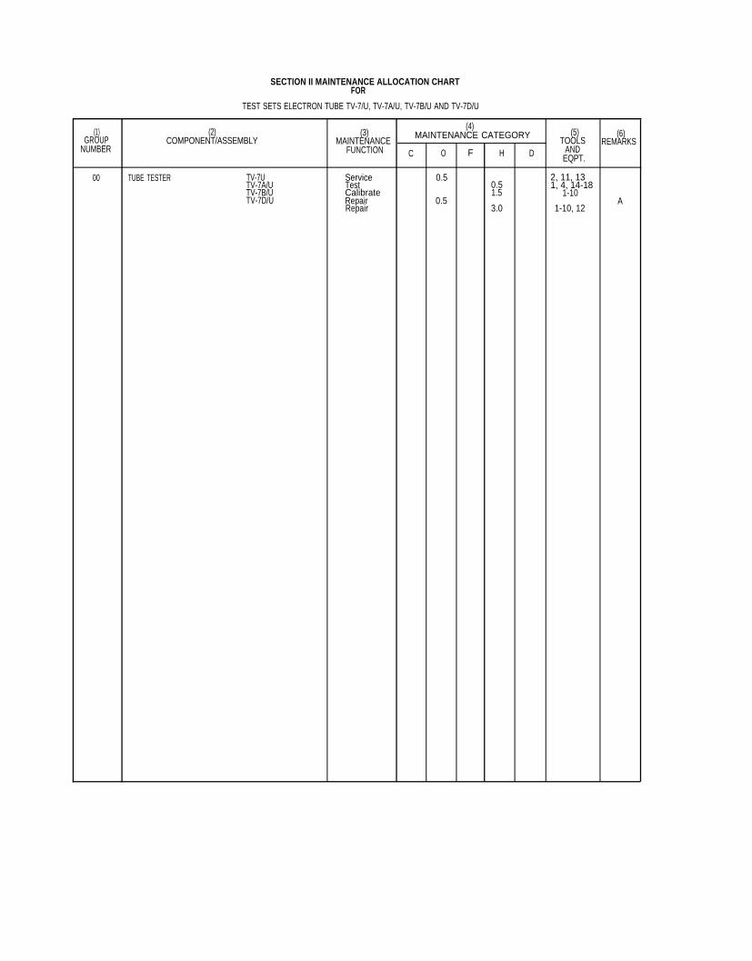
SECTION II MAlNTENANCE ALLOCATION CHARTFOR
TEST SETS ELECTRON TUBE TV-7/U, TV-7A/U, TV-7B/U AND TV-7D/U
(1) (2) (3)(4)
(5)GROUP MAINTENANCE CATEGORY (6)
COMPONENT/ASSEMBLY MAINTENANCE TOOLSNUMBER
REMARKSFUNCTION C O F H D AND
EQPT.
00 TUBE TESTER TV-7U Service 0.5 2, 11, 13TV-7A/U Test 0.5 1, 4, 14-18TV-7B/U Calibrate 1.5 1-10TV-7D/U Repair 0.5 A
Repair 3.0 1-10, 12
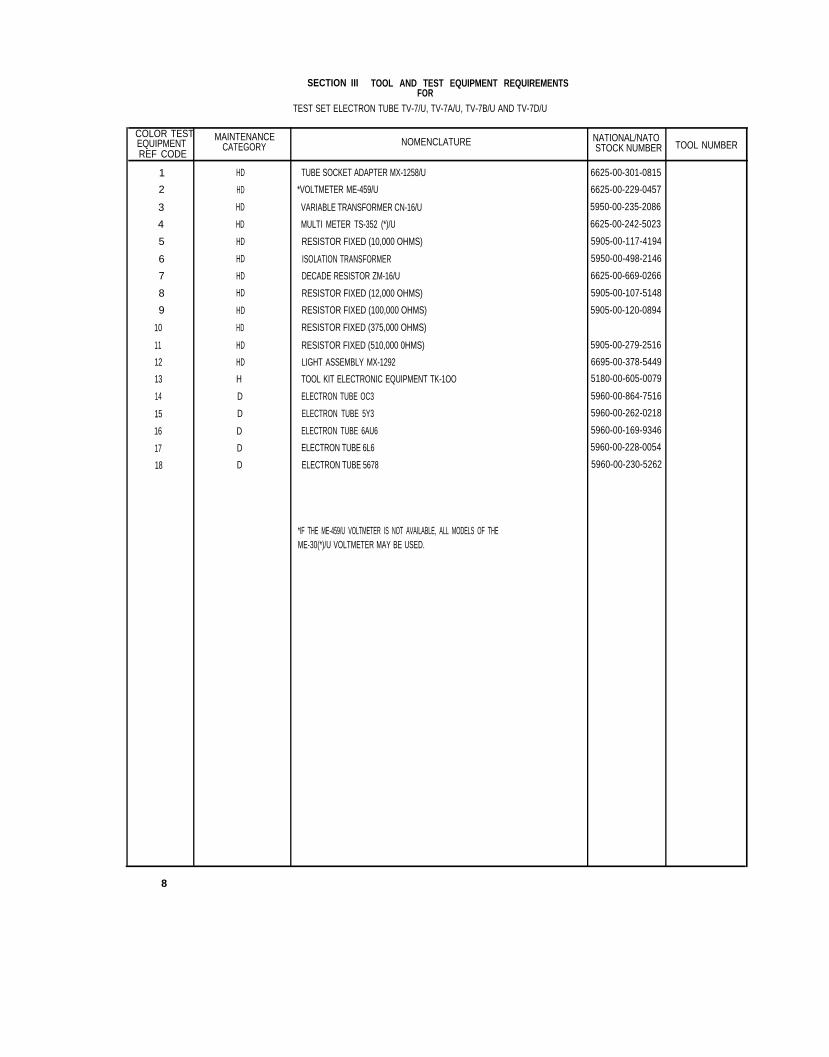
SECTION III TOOL AND TEST EQUIPMENT REQUIREMENTSFOR
TEST SET ELECTRON TUBE TV-7/U, TV-7A/U, TV-7B/U AND TV-7D/U
COLOR TESTEQUIPMENT
MAINTENANCE NOMENCLATURE NATIONAL/NATOCATEGORY
REF CODE STOCK NUMBER TOOL NUMBER
1 HD TUBE SOCKET ADAPTER MX-1258/U 6625-00-301-0815
2 HD *VOLTMETER ME-459/U 6625-00-229-0457
3 HD VARIABLE TRANSFORMER CN-16/U 5950-00-235-2086
4 HD MULTI METER TS-352 (*)/U 6625-00-242-5023
5 HD RESISTOR FIXED (10,000 OHMS) 5905-00-117-4194
6 HD ISOLATION TRANSFORMER 5950-00-498-2146
7 HD DECADE RESISTOR ZM-16/U 6625-00-669-0266
8 HD RESISTOR FIXED (12,000 OHMS) 5905-00-107-5148
9 HD RESISTOR FIXED (100,000 OHMS) 5905-00-120-0894
10 HD RESISTOR FIXED (375,000 OHMS)
11 HD RESISTOR FIXED (510,000 0HMS) 5905-00-279-2516
12 HD LIGHT ASSEMBLY MX-1292 6695-00-378-5449
13 H TOOL KIT ELECTRONIC EQUIPMENT TK-1OO 5180-00-605-0079
14 D ELECTRON TUBE OC3 5960-00-864-7516
15 D ELECTRON TUBE 5Y3 5960-00-262-0218
16 D ELECTRON TUBE 6AU6 5960-00-169-9346
17 D ELECTRON TUBE 6L6 5960-00-228-0054
18 D ELECTRON TUBE 5678 5960-00-230-5262
*IF THE ME-459/U VOLTMETER IS NOT AVAILABLE, ALL MODELS OF THEME-30(*)/U VOLTMETER MAY BE USED.
8
T E C H N I C A L M A N U A L
No. 11-6625-274-12
* T M 1 1 - 6 6 2 5 - 2 7 4 - 1 2
H E A D Q U A R T E R S
D E P A R T M E N T O F T H E A R M Y
W A S H I N G T O N 2 5 , D . C . , 1 4 J u n e 1 9 6 0
CHAPTER 1 .
S e c t i o n I .
I I .
CHAPTER 2 .
S e c t i o n I .
I I .
I I I .
I V .
T E S T S E T S , E L E C T R O N T U B E
T V - 7 / U , T V - 7 A / U , T V - 7 B / U , A N D T V - 7 D / U
I N T R O D U C T I O N
General
Scope . . . . . . . . . . . . . . . . . . . . . . . . . . . . . . . . . . . . . . . . . . . . . . . . . . . . . . . . . . . . . . . . . . . . . . . . . . . . . . .
Forms and records . . . . . . . . . . . . . . . . . . . . . . . . . . . . . . . . . . . . . . . . . . . . . . . . . . . . . . . . . .
Description and data
Purpose and use . . . . . . . . . . . . . . . . . . . . . . . . . . . . . . . . . . . . . . . . . . . . . . . . . . . . . . . . . .
Technical characteristics . . . . . . . . . . . . . . . . . . . . . . . . . . . . . . . . . . . . . . . . . . . . . . . . . . . . . . . . . . . . . . . . .
Table of components . . . . . . . . . . . . . . . . . . . . . . . . . . . . . . . . . . . . . . . . . . . . . . . . . . . . . . . . . . . . . .
Description of test set . . . . . . . . . . . . . . . . . . . . . . . . . . . . . . . . . . . . . . . . . . . . . . . . . . . . . . . . .
Differences in models . . . . . . . . . . . . . . . . . . . . . . . . . . . . . . . . . . . . . . . . . . . . . . . . . . . . . . . . .
I N S T A L L A T I O N A N D O P E R A T I N G I N S T R U C T I O N S
Service upon receipt of equipment
Unpack ing . . . . . . . . . . . . . . . . . . . . . . . . . . . . . . . . . . . . . . . . . . . . . . . . . . . . . . . . . . . . . .
Checking unpacked equipment. . . . . . . . . . . . . . . . . . . . . . . . . . . . . . . . . . . . . . . . . . . . . . . . . . .
Controls and indicator
General . . . . . . . . . . . . . . . . . . . . . . . . . . . . . . . . . . . . . . . . . . . . . . . . . . . . . . . . . . . . . . . . . . . . . . . . . . . . . . . . . .Controls, indicators, and jacks . . . . . . . . . . . . . . . . . . . . . . . . . . . . . . . . . . . . . . . . . . . . . . . . . . . . . . . . . . .
Operation under usual conditions
General instructions . . . . . . . . . . . . . . . . . . . . . . . . . . . . . . . . . . . . . . . . . . . . . . . . . . . . . . . . . . . .
Test leads . . . . . . . . . . . . . . . . . . . . . . . . . . . . . . . . . . . . . . . . . . . . . . . . . . . . . . . . . . . . . . . . . . . . . . . .
Tube test sockets . . . . . . . . . . . . . . . . . . . . . . . . . . . . . . . . . . . . . . . . . . . . . . . . . . . . . . . . . . . . . . . . .
Tube test data. . . . . . . . . . . . . . . . . . . . . . . . . . . . . . . . . . . . . . . . . . . . . . . . . . . . . . . . . . . . . . . . . . . . .
Adapters . . . . . . . . . . . . . . . . . . . . . . . . . . . . . . . . . . . . . . . . . . . . . . . . . . . . . . . . . . . . . . . . . . . . . . .
Operating test set
Starting procedure . . . . . . . . . . . . . . . . . . . . . . . . . . . . . . . . . . . . . . . . . . . . . . . . . . . . . . . . . . . . . . . .
Operating procedure. . . . . . . . . . . . . . . . . . . . . . . . . . . . . . . . . . . . . . . . . . . . . . . . . . . . . . . . . . . . . . . . . . . . .
Checking filament continuity (12-volt Filament tubes) . . . . . . . . . . . . . . . . . . . . . . . . . . . .
Reading meter . . . . . . . . . . . . . . . . . . . . . . . . . . . . . . . . . . . . . . . . . . . . . . . . . . . . . . . . . . . . . . . . . . . . . . . . . .
Gas test . . . . . . . . . . . . . . . . . . . . . . . . . . . . . . . . . . . . . . . . . . . . . . . . . . . . . . . . . . . . . . . . . . . . . . . . . . . . . . .
Noise test . . . . . . . . . . . . . . . . . . . . . . . . . . . . . . . . . . . . . . . . . . . . . . . . . . . . . . . . . . . . . . . . . . . . . . . .
Panel lamp test . . . . . . . . . . . . . . . . . . . . . . . . . . . . . . . . . . . . . . . . . . . . . . . . . . . . . . . . . . . . . . . . . . . . . . . . .
Testing special tube types . . . . . . . . . . . . . . . . . . . . . . . . . . . . . . . . . . . . . . . . . . . . . . . . . . . . . . . . . . .
Testing subminiature tubes . . . . . . . . . . . . . . . . . . . . . . . . . . . . . . . . . . . . . . . . . . . . . . . . . . . . . . . . . .
Stopping procedure . . . . . . . . . . . . . . . . . . . . . . . . . . . . . . . . . . . . . . . . . . . . . . . . . . . . . . . . . . . . . . . . . . .
Paragraph
1
2
3
4
5
6
7
8
9
10
11
12
13
14
15
16
17
18
19
20
21
22
23
24
25
26
Page
3
7
7
7
7
8
8
10
11
11
11
13
14
14
14
15
16
16
17
18
18
19
19
19
19
20
*This manual supersedes so much of TM 11-5083, 29 September 1953, including C1, 2 September 1955; C2, 8February 1956, and C3, 1 April 1959, as pertains to operation and organizational maintenance; so much of C4, 26August 1959, as pertains to packaging and repackaging; TM 11-6625-274-10P, 11 June 1959, and so much of TM11-6625-274-20P, 11 June 1959, as pertains to the maintenance allocation chart.
1
Paragraph
v.
CHAPTER 3.
CHAPTER 4.
Section I.
II.
APPENDIX I.
II.
III.
Operation under unusual conditionsGeneral . . . . . . . . . . . . . . . . . . . . . . . . . . . . . . . . . . . . . . . . . . . . . . . . . . . . . . . . . . . . . . . . . . . . . . . . . . . . . . . . . . . . . . . . . . . . . . . . . . . . . . . . . . . . . . . .Operation at low temperatures . . . . . . . . . . . . . . . . . . . . . . . . . . . . . . . . . . . . . . . . . . . . . . . . . . . . . . . . . . . . . . . . . . . . .Operation under tropical conditions . . . . . . . . . . . . . . . . . . . . . . . . . . . . . . . . . . . . . . . . . . . . . . . . . . . . . . . . . . . .Operation in desert climates . . . . . . . . . . . . . . . . . . . . . . . . . . . . . . . . . . . . . . . . . . . . . . . . . . . . . . . . . . . . . . . . . . . ....
MAINTENANCE INSTRUCTIONSGeneral . . . . . . . . . . . . . . . . . . . . . . . . . . . . . . . . . . . . . . . . . . . . . . . . . . . . . . . . . . . . . . . . . . . . . . . . . . . . . . . . . . . . . . . . . . . . . . . . . . . . . . . . . . . . . . .Materials required . . . . . . . . . . . . . . . . . . . . . . . . . . . . . . . . . . . . . . . . . . . . . . . . . . . . . . . . . . . . . . . . . . . . . . . . . . . . . . . . . . . . . . . . . . . .Preventive maintenance . . . . . . . . . . . . . . . . . .. . . . . . . . . . . . . . . . . . . . . . . . . . . . . . . . . . . . . . . . . .. . . . . . . . ......Visual inspection . . . . . . . . . . . . . . . . . . . . . . . . . . . . . . . . . . . . . . . . . . . . . . . . . . . . . . . . . . . . . . . . . . . . . . . . . . . . . . . . . . . . . . . . . . . . .Equipment performance checklist . . . . . . . . . . . . . . . . . . . . . . . . . . . . . . . . . . . . . . . . . . . . . . . . . . . . . . . . . . . . . . .Removal of chassis . . . . . . . . . . . . . . . . . . . . . . . . . . . . . . . . . . . . . . . . . . . . . . . . . . . . . . . . . . . . . . . . . . . . . . . . . . . . . . . . . . . . . . . . . .Tube replacement . . . . . . . . . . . . . . . . . . . . . . . . . . . . . . . . . . . . . . . . . . . . . . . . . . . . . . . . . . . . . . . . . . . . . . . . . . . . . . . . . . . . . . . . . . . . .Preferred-type tubes . . . . . . . . . . . . . . . . . . . . . . . . . . . . . . . . . . . . . . . . . . . . . . . . . . . . . . . . . . . . . . . . . . . . . . . . . . . . . . . . . . . . . . .Replacement of lamps . . . . . . . . . . . . . . . . . . . . . . . . . . . . . . . . . . . . . . . . . . . . . . . . . . . . . . . . . . . . . . . . . . . . . . . . . . . . . . . . . . . . . . .
SHIPMENT, LIMITED STORAGE, AND DEMOLITIONTO PREVENT ENEMY USE
Shipment and limited storageRemoval from service . . . . . . . . . . . . . . . . . . . . . . . . . . . . . . . . . . . . . . . . . . . . . . . . . . . . . . . . . . . . . . . . . . . . . . . . . . . . . . . . . . . . .Repackaging for shipment or limited storage . . . . . . . . . . . . . . . . . . . . . . . . . . . . . . . . . . . . . . . . . . .Demolition of materiel to prevent enemy useAuthority for demolition . . . . . . . . . . . . . . . . . . . . . . . . . . . . . . . . . . . . . . . . . . . . . . . . . . . . . . . . . . . . . . . . . . . . . . . . . . . . . . .Methods of destruction . . . . . . . . . . . . . . . . . . . . . . . . . . . . . . . . . . . . . . . . . . . . . . . . . . . . . . . . . . . . . . . . . . . . . . . . . . . . . . . . . . . .
27282930
313233343536373839
4041
4243
REFERENCES . . . . . . . . . . . . . . . . . . . . . . . . . . . . . . . . . . . . . . . . . . . . . . . . . . . . . . . . . . . . . . . . . . . . . . . . . . . . . . . . . . . . . . . . . . . . . . . . . . . . . . . . . . . .
OPERATOR’S MAINTENANCE REPAIR PARTS ANDSPECIAL TOOLS LIST . . . . . . . . . . . . . . . . . . . . . . . . . . . . . . . . . . . . . . . . . . . . . . . . . . . . . . . . . . . . . . . . . . . . . . . . . . . . . . . . . . . . . . . .
MAINTENANCE ALLOCATION CHART . . . . . . . . . . . . . . . . . . . . . . . . . . . . . . . . . . . . . . . . . . . . . . . . . . . . . . . . . . . . .
Page
20212121
222222252527272828
3030
3232
33
34
37
2
C H A P T E R 1
I N T R O D U C T I O N
S e c t i o n I . G E N E R A L
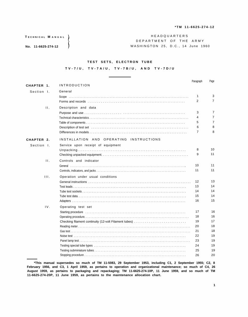
1 . S c o p e
a. This manua l descr ibes Test Sets , ELect ron s t r u c t i o n s f o r o p e r a t i o n u n d e r u s u a l a n d u n -T u b e T V - 7 / U ( f i g . 1 ) , T V - 7 A / U ( f i g . 2 ) , u s u a l c o n d i t i o n s , c l e a n i n g a n d i n s p e c t i o n o fT V - 7 B / U ( f i g . 3 ) , a n d T V - 7 D / U ( f i g . 4 ) , a n d the equipment , and rep lacement o f par ts ava i l -c o v e r s i n s t a l l a t i o n , o p e r a t i o n , a n d f i r s t a n d a b l e t o f i r s t a n d s e c o n d e c h e l o n m a i n t e n a n c es e c o n d e c h e l o n m a i n t e n a n c e . I t i n c l u d e s i n - p e r s o n n e l .
TM6625-274-12-1
Figure 1. Test Set, Electron Tube TV-7/U, less running spares.
3
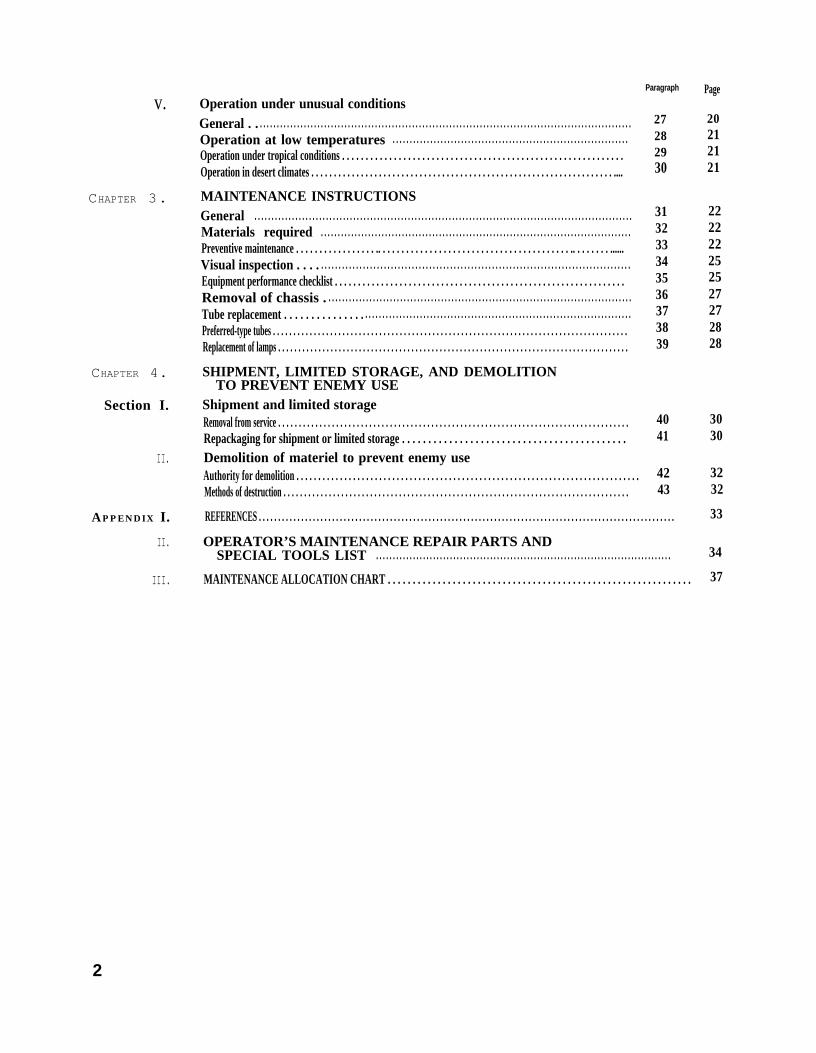
T M 6 6 2 5 - 2 7 4 - 1 2 - 1 4
Figure 2. Test Set, Electron Tube TV-7A/U, less running Spares.
4
T M 6 6 2 5 - 2 7 4 - 1 2 - 2
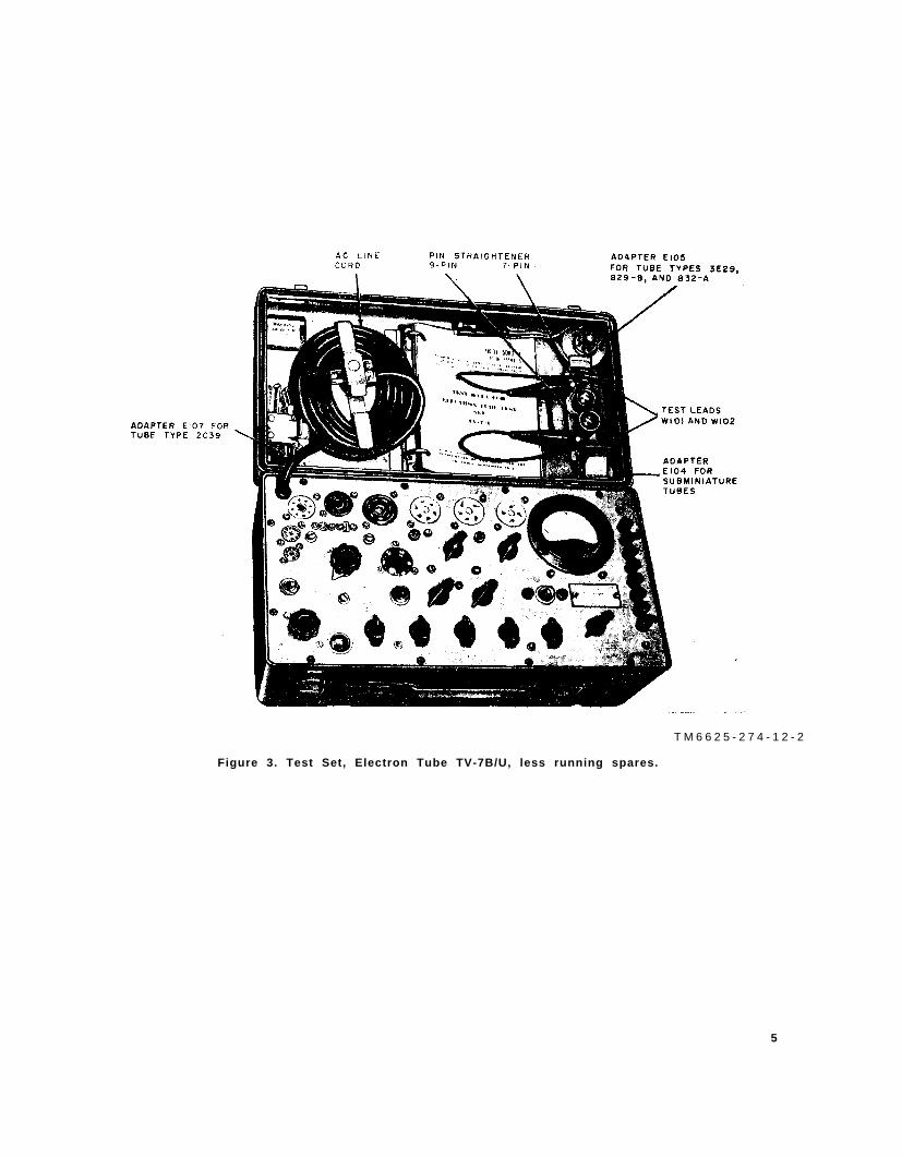
Figure 3. Test Set, Electron Tube TV-7B/U, less running spares.
5
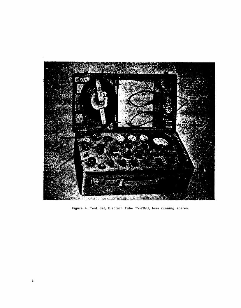
Figure 4. Test Set, Electron Tube TV-7D/U, less running spares.
6
b. O f f i c i a l n o m e n c l a t u r e f o l l o w e d b y ( * ) i s
u s e d t o i n d i c a t e a l l m o d e l s o f t h e e q u i p m e n t
i t e m c o v e r e d i n t h i s m a n u a l . T h u s , T e s t S e t ,
E l e c t r o n T u b e T V - 7 ( * ) / U r e p r e s e n t s T e s t
S e t s , E l e c t r o n T u b e T V - 7 / U , T V - 7 A / U , T V -
7 B / U , a n d T V - 7 D / U .
2 . F o r m s a n d R e c o r d s
a . E l e c t r o n i c F a i l u r e R e p o r t . F i l l o u t a n d
f o r w a r d D D F o r m 7 8 7 - 1 , E l e c t r o n i c F a i l u r e
R e p o r t - S i g n a l E q u i p m e n t , t o t h e C o m m a n d i n g
O f f i c e r , U . S . A r m y S i g n a l E q u i p m e n t S u p p o r t
A g e n c y , F o r t M o n m o u t h , N . J . , a s p r e s c r i b e d
i n A R 7 0 0 - 3 9 .
b . U n s a t i s f a c t o r y E q u i p m e n t R e p o r t . F i l l
o u t a n d f o r w a r d A F T O F o r m 2 9 , U n s a t i s -
f a c t o r y R e p o r t , t o t h e C o m m a n d e r , A i r M a t e -
r i e l C o m m a n d , W r i g h t - P a t t e r s o n A i r F o r c e
Base, Oh io , as prescr ibed in AF TO 00-35D-54.
c . R e p o r t o f D a m a g e d o r I m p r o p e r S h i p -
m e n t . F i l l o u t a n d f o r w a r d D D F o r m 6 , R e -
p o r t o f D a m a g e d o r I m p r o p e r S h i p m e n t , a s
p r e s c r i b e d i n A R 7 0 0 - 5 8 ( A r m y ) , N a v y S h i p -
p i n g G u i d e , A r t i c l e 1 8 5 0 - 4 ( N a v y ) , a n d A F R
7 1 - 4 ( A i r F o r c e ) .
d . P r e v e n t i v e M a i n t e n a n c e F o r m . P r e p a r e
DA Form 11-266 ( f ig . 11 and 12) , Main tenance
C h e c k L i s t f o r S i g n a l E q u i p m e n t ( T e s t E q u i p -
m e n t ) , i n a c c o r d a n c e w i t h i n s t r u c t i o n s o n t h e
f o r m .
e . P a r t s L i s t F o r m . A n y c o m m e n t s c o n -
c e r n i n g o m i s s i o n s a n d d i s c r e p a n c i e s i n a p p e n -
d i x I I o r I I I i n t h i s m a n u a l w i l l b e p r e p a r e d
o n D A F o r m 2 0 2 8 a n d f o r w a r d e d d i r e c t l y t o
t h e C o m m a n d i n g O f f i c e r , U . S . A r m y S i g n a l
E q u i p m e n t S u p p o r t A g e n c y , F o r t M o n m o u t h ,
N . J . A T T N : S I G F M / E S - M L .
f . C o m m e n t s o n M a n u a l . F o r w a r d a l l o t h e r
c o m m e n t s o n t h i s m a n u a l d i r e c t t o t h e C o m -
m a n d i n g O f f i c e r , U . S . A r m y S i g n a l P u b l i c a -
t i o n s A g e n c y , F o r t M o n m o u t h , N . J .
S e c t i o n I I D E S C R I P T I O N A N D D A T A
3 . P u r p o s e a n d U s e
T e s t S e t E l e c t r o n T u b e T V - 7 ( * ) / U i s a
p o r t a b l e t u b e t e s t e r o f t h e d y n a m i c m u t u a l
c o n d u c t a n c e t y p e . I t i s u s e d t o t e s t a n d t o
m e a s u r e p e r f o r m a n c e c a p a b i l i t i e s a n d t o d e -
termine re jec t ion l imi ts fo r e lec t ron tubes used
i n r e c e i v e r s , l o w - p o w e r e d t r a n s m i t t e r s , a n d
m a n y o t h e r e l e c t r o n i c e q u i p m e n t s . T h e f o l l o w -
i n g t e s t s c a n b e m a d e w i t h T e s t S e t E l e c t r o n
T u b e T V - 7 ( * ) / U :
a. C o n t i n u i t y t e s t ( b a l l a s t t u b e s ) .
b. D y n a m i c m u t u a l c o n d u c t a n c e t e s t ( a m -
p l i f i e r t u b e s ) .
c . E m i s s i o n t e s t ( r e c t i f i e r t u b e s ) .
d . G a s t e s t ( a m p l i f i e r t u b e s ) .
e. N o i s e t e s t .
f . P a n e l l a m p t e s t .
g . S h o r t s t e s t .
4 . T e c h n i c a l C h a r a c t e r i s t i c s
P o w e r S u p p l y :
Input voltage . . . . . . 103.5 to 126.5 Volts ac,
s ingle phase.
F r e q u e n c y . . . . . . 50 to 1,000 cps.
P o w e r c o n s u m p t i o n . . 4 5 w a t t s a t 1 1 5 v o l t s ,
50 cps .
M e t e r . . . . . . . . . . . . . . . . . . . . . 0 to 120 arbitrary
u n i t s .
O p e r a t i n g t e m p e r a - - 4 0 ° t o + 1 2 5 °
t u r e l i m i t s F a h r e n h e i t .
Number of tubes . . . . . . . 2.
I n d i c a t o r l i g h t s :
PILOT . . . . . . . . . . . . . . . . O n e t y p e 4 7 .
SHORTS . . . . . . . . . . . . . O n e t y p e N E - 4 5 .
FUSE . . . . . . . . . . . . . . . . . . O n e t y p e 8 1 .
5 . T a b l e o f C o m p o n e n t s
T h e c o m p o n e n t s o f T e s t S e t , E l e c t r o n T u b e
T V - 7 ( * ) / U a r e l i s t e d i n a b e l o w a n d t h e s p a r e
par ts in b b e l o w .
7
a . C o m p o n e n t s .
Dimensions (In.)Quantity
1
1
1
1
1
1
1
2
1 set
ItemDepth Length
U n i tweight (lb)
Test set including tubes and lamps . . . . . . . . . . . . . . . . . . . . . . . . . . . . . . .
Adapter E105: 3E29, 829-B or 832-A tubes . . . . . . . . . . . . . . . . . .
Adapter E107: 2C39 tube . . . . . . . . . . . . . . . . . . . . . . . . . . . . . . . . . . . . . . . . . . . .
Adapter E104: Subminiature tubes . . . . . . . . . . . . . . . . . . . . . . . . . . . . . . . . . . .
Adapter X10B: socket saver, 7-pin miniature (TV-7D/U) . . . . . . .
Adapter X7B: socket saver, 9-pin miniature (TV-7D/U). . . . . . . .
Adapter X3B: socket saver, octal (TV-7D/U) . . . . . . . . . . . . . . . . . . . . .
Test leads . . . . . . . . . . . . . . . . . . . . . . . . . . . . . . . . . . . . . . . . . . . . . . . . . . . . . . . . . .
Running spares (b below) . . . . . . . . . . . . . . . . . . . . . . . . . . . . . . . . . . . . . . . . . .
18
1 5
b . S p a r e P a r t s .
Quantity
1
1
1
1
1
I tem
Electron tube, type 5Y3WGTA
Electron tube, type 83
Lamp, neon NE-45
Lamp, incandescent No. 47
Lamp, incandescent No. 81
6 . D e s c r i p t i o n o f T e s t S e t
( f i g . 1 - 4 )
a . T e s t S e t , E l e c t r o n T u b e T V - 7 ( * ) / U
( t e s t s e t ) i s s e l f - c o n t a i n e d i n a c a r r y i n g c a s e
e q u i p p e d w i t h a c a r r y i n g h a n d l e . T h e c o v e r
is secured to the case by luggage- type fas ten-
e r s . R e t a i n e r b r a c k e t s o n t h e i n s i d e o f t h e
cover are used to secure and s tore the power
cable, p in s t ra ighteners for 7- and 9-p in min ia-
t u r e t u b e s , a n d a d a p t e r s ( p a r . 1 6 ) . A r i n g
Item TV-7/U
F RANGE on FUNCTIONSWITCH.
BIAS and SHUNT controls . . . . . . . .
SHORTS lamp . . . . . . . . . . . . . . . . . . .
Subminiature tube test socketX109.
Storage clip for ac line cord plug.
Storage clips for test leads . . . . . . . .
Tip of test lead plug (2 each) . . . .
8
Not used.
Markings en-graved on adial.
No panelmarking.
Rectangular.
Not used.
Not used.
3/32-inchdiameter.
Height
6 1/16
b i n d e r i n s i d e t h e c o v e r h o l d s T B 1 1 - 5 0 8 3 - 1
( t u b e t e s t d a t a b o o k ( p a r . 1 5 ) ) . T h e c o v e r i s
h inged by s l ip h inges and can be removed f rom
the case.
b . A n i n d i c a t i n g m e t e r a n d a l l c o n t r o l s ,
k n o b s , p u s h b u t t o n s , s o c k e t s , a n d i n d i c a t i n g
l a m p s a r e o n t h e f r o n t p a n e l . T h e n e c e s s a r y
d a t a f o r s e t t i n g a n d o p e r a t i n g t h e c o n t r o l s t o
test the various tube types are contained in the
tube tes t data book (a a b o v e ) . O n e e n d o f t h e
a l t e r n a t i n g c u r r e n t ( a c ) l i n e c o r d i s p e r m a -
n e n t l y a t t a c h e d t o t h e p a n e l ; t h e o t h e r e n d
t e r m i n a t e s i n a m a l e p l u g .
7 . D i f f e r e n c e s i n M o d e l s
T e s t S e t s , E l e c t r o n T u b e T V - 7 ( * ) / U a r e
s imi lar in purpose, operat ion, and appearance.
S o m e m o d e l s h a v e b e e n m o d i f i e d t o i m p r o v e
o p e r a t i o n a l f e a t u r e s . E x t e r n a l d i f f e r e n c e s a r e
a s f o l l o w s :
TV-7A/U
Not used.
Markings etchedinto test setpanel.
Panel marking.
Round on someequipments.
Used.
Not used.
5/64-inchdiameter.
TV-7B/7
Not used.
Markings etchedinto test setpanel.
Panel marking.
Rectangular.
Used.
Used.
3/32-inchdiameter.
TV-7D/U
Used.
Markings etchedinto test setpanel.
Panel marking.
Rectangular.
Used.
Used.
3/32-inchdiameter.
9
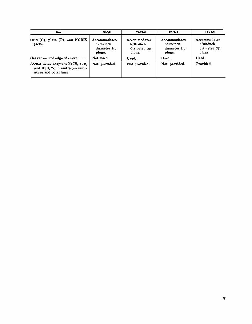
nom TV-71U TV-7A/U I Tv.78/u TV-7D/UI
Grid (G), plate (P), and NOISE Accommodates Accommodates Accommodates Accommodatesjacks. 3 I 32-inch 6/64-inch 3132-inch 3132-inch
diameter tip diameter tip diameter tip diameter tipplugs. plugs. plugs. plugs.
Gasket around edge of cover . . . . . . Not used. Used. Used. used.Socket saver adapters X1OB, X7B, Not provided. Not provided. Not provided. Provided.
and X3B, 7-pin and 9-pin mini-ature and octal base.
TM6625-274-12-4
C H A P T E R 2
I N S T A L L A T I O N A N D O P E R A T I N G I N S T R U C T I O N S
S e c t i o n I S E R V I C E U P O N R E C E I P T O F E Q U I P M E N T
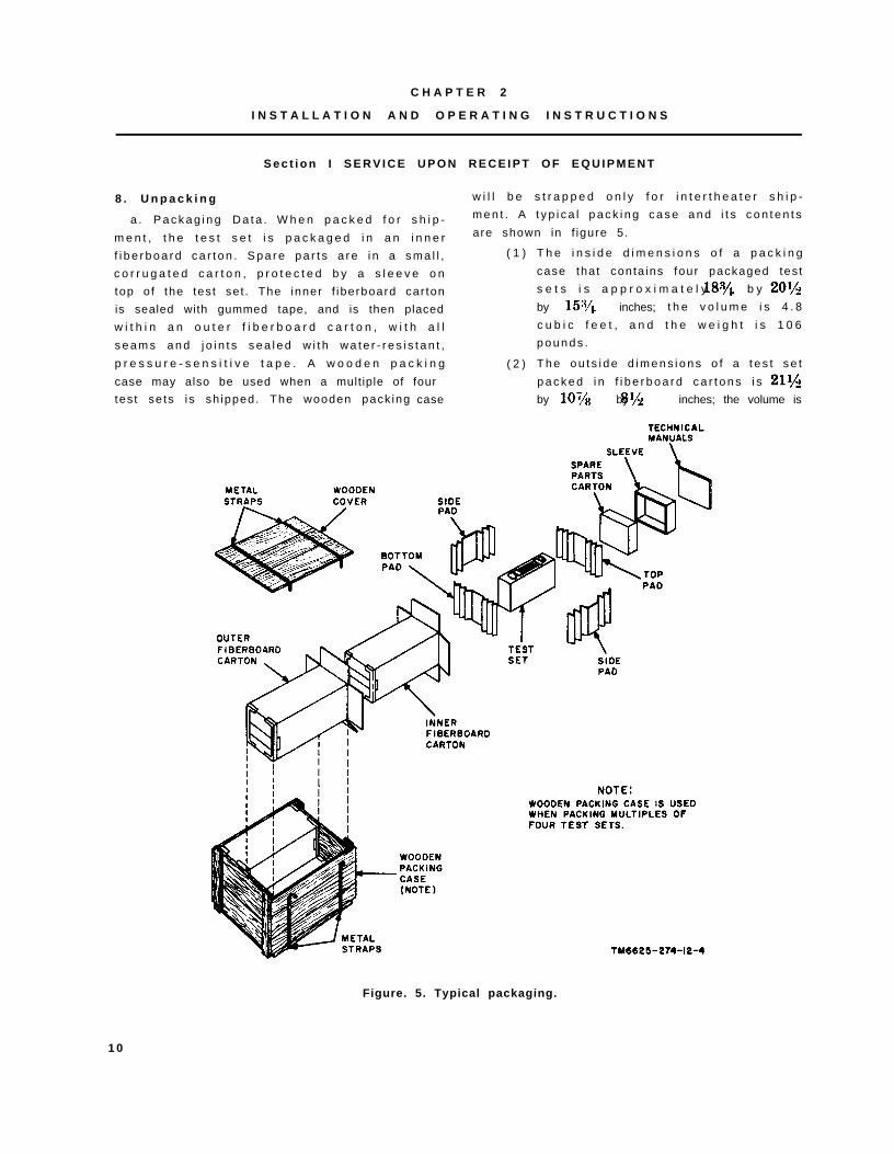
8 . U n p a c k i n g
a . P a c k a g i n g D a t a . W h e n p a c k e d f o r s h i p -
m e n t , t h e t e s t s e t i s p a c k a g e d i n a n i n n e r
f i b e r b o a r d c a r t o n . S p a r e p a r t s a r e i n a s m a l l ,
c o r r u g a t e d c a r t o n , p r o t e c t e d b y a s l e e v e o n
top o f the tes t se t . The inner f iberboard car ton
is sealed with gummed tape, and is then placed
w i t h i n a n o u t e r f i b e r b o a r d c a r t o n , w i t h a l l
s e a m s a n d j o i n t s s e a l e d w i t h w a t e r - r e s i s t a n t ,
p r e s s u r e - s e n s i t i v e t a p e . A w o o d e n p a c k i n g
case may also be used when a mult iple of four
tes t se ts is sh ipped. The wooden pack ing case
w i l l b e s t r a p p e d o n l y f o r i n t e r t h e a t e r s h i p -
m e n t . A t y p i c a l p a c k i n g c a s e a n d i t s c o n t e n t s
are shown in f igure 5.
( 1 )
( 2 )
T h e i n s i d e d i m e n s i o n s o f a p a c k i n g
case tha t conta ins four packaged tes t
s e t s i s a p p r o x i m a t e l y b y
by inches; t h e v o l u m e i s 4 . 8
c u b i c f e e t , a n d t h e w e i g h t i s 1 0 6
p o u n d s .
T h e o u t s i d e d i m e n s i o n s o f a t e s t s e t
p a c k e d i n f i b e r b o a r d c a r t o n s i s
by by inches; the volume is
Figure. 5. Typical packaging.
1 0
1.2 cubic feet, and the weight is ( 6 ) O p e n t h e i n n e r f i b e r b o a r d c a r t o n a n d
p o u n d s . remove the contents .
b . R e m o v i n g C o n t e n t s . 9 . C h e c k i n g U n p a c k e d E q u i p m e n t
( 1 )
( 2 )
( 3 )
( 4 )
( 5 )
C u t a n d f o l d b a c k t h e m e t a l s t r a p s
( w h e n u s e d ) .
R e m o v e t h e n a i l s f r o m t h e w o o d e n
c o v e r a n d o n e s i d e o f t h e w o o d e n
p a c k i n g c a s e w i t h a n a i l p u l l e r . R e -
m o v e t h e c o v e r a n d t h e s i d e . D o n o t
a t t e m p t t o p r y o f f t h e c o v e r o r t h e
s i d e ; p r y i n g m a y d a m a g e t h e e q u i p -
m e n t .
Remove the enve lope that conta ins the
t e c h n i c a l m a n u a l s .
R e m o v e t h e o u t e r f i b e r b o a r d c a r t o n
f r o m t h e w o o d e n p a c k i n g c a s e .
O p e n t h e o u t e r f i b e r b o a r d c a r t o n a n d
C h e c k t h e e q u i p m e n t a g a i n s t t h e p a c k i n g
l i s t . W h e n n o p a c k i n g l i s t a c c o m p a n i e s t h e
e q u i p m e n t , u s e t h e t a b l e o f c o m p o n e n t s ( p a r .
5 ) a s a g e n e r a l c h e c k . I f t h e e q u i p m e n t i s
damaged, re fer to paragraph 2. Af ter a test set
i s r e m o v e d f r o m i t s f i b e r b o a r d c o n t a i n e r , r e -
lease the fasteners, open the cover, and proceed
a s f o l l o w s :
a . C h e c k t o s e e t h a t t h e a d a p t e r s ( f i g . 8 )
a r e h e l d f i r m l y t o t h e c o v e r .
b . C h e c k a l l c o n t r o l s f o r e a s e o f r o t a t i o n .
T i g h t e n l o o s e k n o b s .
c . C h e c k f o r a b r o k e n m e t e r g l a s s a n d
b r o k e n l a m p s .
d . C h e c k t h e a c l i n e c o r d , t e s t l e a d s , a n d
r u b b e r g a s k e t a r o u n d t h e e d g e o f t h e c o v e r
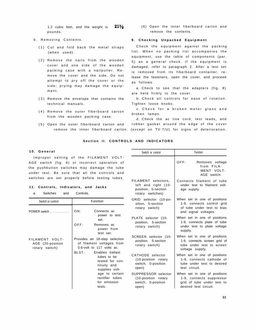
1 0 . G e n e r a l
r e m o v e t h e i n n e r f i b e r b o a r d c a r t o n . ( e x c e p t o n T V - 7 / U ) f o r s i g n s o f d e t e r i o r a t i o n .
S e c t i o n I I . C O N T R O L S A N D I N D I C A T O R S
I m p r o p e r s e t t i n g o f t h e F I L A M E N T V O L T -
A G E s w i t c h ( f i g . 6 ) o r i n c o r r e c t o p e r a t i o n o f
t h e p u s h b u t t o n s w i t c h e s m a y d a m a g e t h e t u b e
u n d e r t e s t . B e s u r e t h a t a l l t h e c o n t r o l s a n d
swi tches are se t p roper ly be fore tes t ing tubes.
1 1 . C o n t r o l s , I n d i c a t o r s , a n d J a c k s
a. Switches and Controls.
Switch or control
POWER switch . . . . . . . . . . . .
Function
F I L A M E N T V O L T -AGE (20-positionrotary switch)
ON: Connects acpower to testset.
O F F : Removes acpower fromtest set.
Provides an 18-step selectionof f i lament voltages from0.6-volt to 117 volts ac.
BLST.: Enables ballasttubes to betested for con-tinuity andsupplies volt-age to certainrectifier tubesfor emissiontests.
Switch or control
FILAMENT selectors,le f t and r ight (10-position, 5-sectionrotary switches)
GRID selector (10-po-sition, 5-sectionrotary switch)
PLATE selector (10-position, 5-sectionrotary switch)
SCREEN selector (10-position, 5-sectionrotary switch)
CATHODE selector(10-position rotaryswitch, 0-positionopen)
SUPPRESSOR selector(10-position rotaryswitch, 0-positionopen)
Function
O F F : Removes voltagef r o m F I L A -MENT VOLT-AGE switch.
Connects f i lament o f tubeunder test to filament volt-age supply.
When set in one of positions1-9, connects control gridof tube under test to biasand signal voltages.
When set in one of positions1-9, connects plate of tubeunder test to plate voltagesupply.
When set in one of positions1-9, connects screen grid oftube under test to screenvoltage supply.
When set in one of positions1-9, connects cathode oftube under test to desiredtest circuit.
When set in one of positions1-9, connects suppressorgrid of tube under test todesired test circuit.
11
Switch or control Function
FUNCTION SWITCH(11-position, 8-sec-tion rotary switch(TV-7D/U), 10-position, 6-sectionrotary switch on allother models)
LINE ADJUST control
BIAS control. . . . . . . . . . . . . .
SHUNT control . . . . . . . . . . .
Function
SHORTS: Positions 1-5 con-nect variouselements oftube under testto shorts testcircuit.
RANGES: Posit ions A-E(A-F, TV-7D/U) cont ro lsensitivity ofmeter circuitand magnitudeof signal volt-age.
Adjusts amount of inputvoltage to power trans-former.
Adjusts amount of bias volt-age applied to tube undertest.
Adjusts sensitivity of metercircuit.
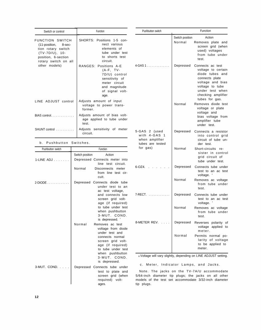
b . P u s h b u t t o n S w i t c h e s .
Pushbutton switch
1-LINE ADJ . . . . . . .
2-DIODE . . . . . . . . . . . . .
3-MUT. COND. . . . .
Function
Switch position Action
Depressed Connects meter intoline test circuit.
Normal Disconnects meterfrom line test cir-cuit.
Depressed Connects diode tubeunder test to anac test voltage,and connects lowscreen grid volt-age (if required)to tube under testwhen pushbutton3 - M U T . C O N D .is depressed. a
Normal Removes ac testvoltage from diodeunder test andconnects normalscreen grid volt-age (if required)to tube under testwhen pushbutton3 - M U T . C O N D .is depressed.
Depressed Connects tube undertest to plate andscreen grid (whenrequired) volt-ages.
Pushbutton switch
4-GAS 1 . . . . . . . . . . . . . .
5-GAS 2 (usedw i t h 4 - G A S 1when amplifiertubes are testedfor gas)
6-OZ4. . . . . . .
7-RECT. . . . . . . . . . . . . .
8-METER REV. . . . .
Switch position
Normal
Depressed
Normal
Depressed
Normal
Depressed
Normal
Depressed
Normal
Depressed
Normal
Action
Removes plate andscreen grid (whenused) voltagesfrom tube undertest.
Connects ac testvoltage to certaindiode tubes andconnects platevoltage and biasvoltage to tubeunder test whenchecking amplifiertubes for gas.
Removes diode testvoltage or platevoltage andbias voltage fromamplifier tubeunder test.
Connects a resistorin to cont ro l g r idcircuit of tube un-der test.
Short-circuits re-s is te r in cont ro lgrid circuit oftube under test.
Connects tube undertest to an ac testvoltage. a
Removes ac voltagefrom tube undertest.
Connects tube undertest to an ac testvoltage. a
Removes ac voltagefrom tube undertest.
Reverses polarity ofvoltage applied tom e t e r .
Permits normal po-la r i ty o f vo l tageto be applied tometer.
a Voltage will vary slightly, depending on LINE ADJUST setting.
c . M e t e r , I n d i c a t o r L a m p s , a n d J a c k s .
Note. The jacks on the TV-7A/U accommodate5/64-inch diameter tip plugs; the jacks on all othermodels of the test set accommodate 3/32-inch diametertip plugs.
12
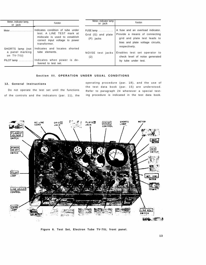
Meter, indicator lamp,or jack
Meter, indicator lampor jack
Meter . . . . . . . . . . . . . . . . . .
SHORTS lamp (nota panel mark ingon TV-7/U)
PILOT lamp . . . . . . . . . .
Function
Indicates condition of tube undertest. A LINE TEST mark atmidscale is used to establishcorrect input voltage to powertransformer.
Indicates and locates shortedtube elements.
Ind icates when power is de-livered to test set.
Function
FUSE lamp . . . . . . . . . . .
Grid (G) and plate
(P) jacks
N O I S E t e s t j a c k s
(2)
A fuse and an overload indicator.
Provide a means of connecting
grid and plate test leads to
bias and plate voltage circuits,
respectively.
Enab les tes t se t opera tor to
check level of noise generated
by tube under test.
S e c t i o n I I I . O P E R A T I O N U N D E R U S U A L C O N D I T I O N S
1 2 . G e n e r a l I n s t r u c t i o n s o p e r a t i n g p r o c e d u r e ( p a r . 1 8 ) , a n d t h e u s e o f
Do not operate the test set unti l the functionst h e t e s t d a t a b o o k ( p a r . 1 5 ) a r e u n d e r s t o o d .
Refer to paragraph 24 whenever a spec ia l tes t -
o f the cont ro ls and the ind ica tors (par . 11) , the ing procedure is indicated in the test data book.
Figure 6. Test Set, Electron Tube TV-7/U, front panel.
1 3
TM6625-274-12-5
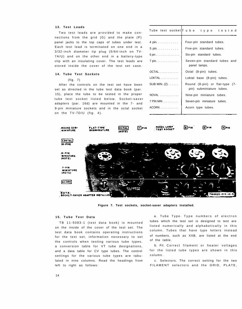
1 3 . T e s t L e a d s
T w o t e s t l e a d s a r e p r o v i d e d t o m a k e c o n -T u b e t e s t s o c k e t T u b e t y p e t e s t e d
n e c t i o n s f r o m t h e g r i d ( G ) a n d t h e p l a t e ( P )
panel jacks to the top caps of tubes under test.
E a c h t e s t l e a d i s t e r m i n a t e d o n o n e e n d i n a
3 / 3 2 - i n c h d i a m e t e r t i p p l u g ( 5 / 6 4 - i n c h o n T V -
7 A / U ) a n d o n t h e o t h e r e n d i n a b a t t e r y - t y p e
c l ip w i th an insu la t ing cover . The tes t leads are
s t o r e d i n s i d e t h e c o v e r o f t h e t e s t s e t c a s e .
1 4 . T u b e T e s t S o c k e t s
( f ig. 7)
Af ter the cont ro ls on the tes t se t have been
set as d i rected in the tube test data book (par .
15) , p lace the tube to be tested in the proper
t u b e t e s t s o c k e t l i s t e d b e l o w . S o c k e t - s a v e r
adapters (par . 16d) are mounted in the 7- and
9-p in min ia ture sockets and in the oc ta l socket
o n t h e T V - 7 D / U ( f i g . 4 ) .
4 pin. . . . . . . . . . .
5 pin. . . . . . . . . . .
6 pin . . . . . . . . . . . . . . . .
7 pin. . . . . . . . . . . . . .
OCTAL. . . . . . . . . . . . .
LOKTAL . . . . . . . . . . . .
SUB MIN. (2) . . . . . .
NOVAL . . . . . . . . . . . . .
7 PIN MIN . . . . . . . . . .
ACORN . . . . . . . . . . . .
Four-pin standard tubes.
Five-pin standard tubes.
Six-pin standard tubes.
Seven-pin standard tubes and
panel lamps.
Octal (8-pin) tubes.
Loktal base (8-pin) tubes.
Round (8-pin) or f lat-type (7-
pin) subminiature tubes.
Nine-pin miniature tubes.
Seven-pin miniature tubes.
Acorn type tubes.
Figure 7. Test sockets, socket-saver adapters installed.
1 5 . T u b e T e s t D a t a a . T u b e T y p e . T y p e n u m b e r s o f e l e c t r o n
T B 1 1 - 5 0 8 3 - 1 ( t e s t d a t a b o o k ) i s m o u n t e d tubes which the test set is designed to test are
on the ins ide o f the cover o f the tes t se t . The l i s t e d n u m e r i c a l l y a n d a l p h a b e t i c a l l y i n t h i s
t e s t d a t a b o o k c o n t a i n s o p e r a t i n g i n s t r u c t i o n sc o l u m n . T u b e s t h a t h a v e t y p e l e t t e r s i n s t e a d
f o r t h e t e s t s e t , i n f o r m a t i o n n e c e s s a r y t o s e t of numbers, such as XXB, are l isted at the end
t h e c o n t r o l s w h e n t e s t i n g v a r i o u s t u b e t y p e s , of the table.
a c o n v e r s i o n t a b l e f o r V T t u b e d e s i g n a t i o n s , b. Fil. C o r r e c t f i l a m e n t o r h e a t e r v o l t a g e s
and a data table for CV type tubes. The control f o r t h e l i s t e d t u b e t y p e s a r e s h o w n i n t h i s
s e t t i n g s f o r t h e v a r i o u s t u b e t y p e s a r e t a b u - c o l u m n .
la ted in n ine co lumns. Read the headings f rom c . Se lec tors . The cor rec t se t t ing fo r the two
le f t to r igh t as fo l lows: F I L A M E N T s e l e c t o r s a n d t h e G R I D , P L A T E ,
14
S C R E E N , C A T H O D E , a n d S U P P R E S S O R
selectors are l is ted in th is co lumn. The set t ings
a r e s h o w n i n t h e s a m e o r d e r i n w h i c h t h e
s w i t c h e s a p p e a r o n t h e p a n e l , l i s t i n g f i r s t t h e
t w o F I L A M E N T s e l e c t o r s a n d t h e n c o n t i n u i n g ,
f rom le f t to r ight , w i th the remain ing se lectors .
d . B i a s . T h i s c o l u m n l i s t s t h e s e t t i n g f o r
t h e B I A S c o n t r o l .
e . S h u n t . T h i s c o l u m n l i s t s t h e s e t t i n g f o r
t h e S H U N T c o n t r o l . S e t t i n g o f t h i s c o n t r o l i s
r e q u i r e d o n l y w h e n t h e F U N C T I O N S W I T C H
i s i n t h e R A N G E S A S H U N T p o s i t i o n .
f . R a n g e . T h e s e t t i n g s f o r t h e F U N C T I O N
S W I T C H a r e l i s t e d i n t h i s c o l u m n . T h e l e t t e r s
A t h r o u g h E ( A t h r o u g h F , T V - 7 D / U ) c o r r e s -
p o n d t o t h e R A N G E S m a r k i n g s f o r t h e F U N C -
T I O N S W I T C H .
g . P r e s s . U n d e r t h i s h e a d i n g a r e l i s t e d t h e
t e s t p u s h b u t t o n s t h a t a r e u s e d f o r t h e v a r i o u s
t u b e t y p e s a n d t h e i r i n d i v i d u a l s e c t i o n s i n t h e
case o f mul t ipurpose tubes.
h . M i n V a l u e . T h e m i n i m u m , n u m e r i c a l
va lues o f meter ind icat ion for the var ious tubes
a n d i n d i v i d u a l s e c t i o n s o f m u l t i p u r p o s e t u b e s
a r e s h o w n i n t h i s c o l u m n . A n y t u b e s h o w i n g
a m e t e r r e a d i n g l e s s t h a n t h e v a l u e i n d i c a t e d
in th is co lumn should be rep laced.
i . N o t a t i o n s . S p e c i a l i n f o r m a t i o n p e r t a i n -
ing to par t icu lar tube types is l i s ted under th is
h e a d i n g .
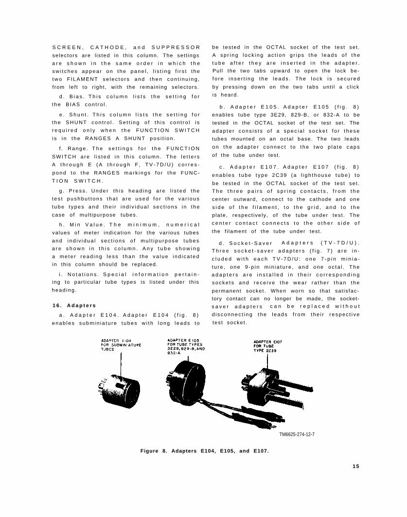
1 6 . A d a p t e r s
a . A d a p t e r E 1 0 4 . A d a p t e r E 1 0 4 ( f i g . 8 )
e n a b l e s s u b m i n i a t u r e t u b e s w i t h l o n g l e a d s t o
be tes ted in the OCTAL socket o f the tes t se t .
A s p r i n g l o c k i n g a c t i o n g r i p s t h e l e a d s o f t h e
t u b e a f t e r t h e y a r e i n s e r t e d i n t h e a d a p t e r .
Pul l the two tabs upward to open the lock be-
f o r e i n s e r t i n g t h e l e a d s . T h e l o c k i s s e c u r e d
by press ing down on the two tabs unt i l a c l ick
is heard .
b . A d a p t e r E 1 0 5 . A d a p t e r E 1 0 5 ( f i g . 8 )
enables tube type 3E29, 829-B, or 832-A to be
tested in the OCTAL socket of the test set. The
a d a p t e r c o n s i s t s o f a s p e c i a l s o c k e t f o r t h e s e
tubes mounted on an octa l base. The two leads
o n t h e a d a p t e r c o n n e c t t o t h e t w o p l a t e c a p s
of the tube under test .
c . A d a p t e r E 1 0 7 . A d a p t e r E 1 0 7 ( f i g . 8 )
e n a b l e s t u b e t y p e 2 C 3 9 ( a l i g h t h o u s e t u b e ) t o
be tes ted in the OCTAL socket o f the tes t se t .
T h e t h r e e p a i r s o f s p r i n g c o n t a c t s , f r o m t h e
center outward, connect to the cathode and one
s i d e o f t h e f i l a m e n t , t o t h e g r i d , a n d t o t h e
p la te , respect ive ly , o f the tube under tes t . The
c e n t e r c o n t a c t c o n n e c t s t o t h e o t h e r s i d e o f
the f i lament of the tube under test .
d . S o c k e t - S a v e r A d a p t e r s ( T V - 7 D / U ) .
T h r e e s o c k e t - s a v e r a d a p t e r s ( f i g . 7 ) a r e i n -
c l u d e d w i t h e a c h T V - 7 D / U : o n e 7 - p i n m i n i a -
t u r e , o n e 9 - p i n m i n i a t u r e , a n d o n e o c t a l . T h e
a d a p t e r s a r e i n s t a l l e d i n t h e i r c o r r e s p o n d i n g
s o c k e t s a n d r e c e i v e t h e w e a r r a t h e r t h a n t h e
permanent socket . When worn so that sat is fac-
tory contact can no longer be made, the socket-
s a v e r a d a p t e r s c a n b e r e p l a c e d w i t h o u t
d i s c o n n e c t i n g t h e l e a d s f r o m t h e i r r e s p e c t i v e
tes t socke t .
TM6625-274-12-7
Figure 8. Adapters E104, E105, and E107.
1 5
S e c t i o n I V . O P E R A T I N G T E S T S E T
1 7 . S t a r t i n g P r o c e d u r e
B e f o r e o p e r a t i n g t h e t e s t s e t , p e r f o r m t h e
s t a r t i n g p r o c e d u r e b e l o w t o c h e c k t h e g e n e r a l
o p e r a t i o n o f t h e e q u i p m e n t . I f t h e r e s u l t s o b -
t a i n e d f r o m t h e p r o c e d u r e s i n b t h r o u g h e b e -
l o w a r e s a t i s f a c t o r y , t h e t e s t s e t i s r e a d y f o r
o p e r a t i o n .
Note. If an abnormal indication is obtained duringthe starting procedure, refer to the equipment perfor-mance checklist (par. 35) for corrective measures.
a. Connect the tes t set to a 115-vo l t ac , 50-
to 1 ,000-cyc le per second (C P S) , power source .
b. S e t t h e P O W E R s w i t c h t o t h e O N p o s i -
t ion; the PILOT lamp should l ight .
c . P r e s s p u s h b u t t o n 1 - L I N E A D J . R o -
t a t e t h e L I N E A D J U S T c o n t r o l k n o b u n t i l t h e
m e t e r p o i n t e r r e s t s o v e r t h e L I N E T E S T m a r k
on the meter face.
d . R e l e a s e p u s h b u t t o n 1 - L I N E A D J .
e. C h e c k t h e s h o r t t e s t c i r c u i t .
( 1 )
( 2 )
S e t t h e l e f t F I L A M E N T s e l e c t o r a t
A , t h e r i g h t F I L A M E N T s e l e c t o r a t
P , a n d t h e G R I D , P L A T E , S C R E E N ,
C A T H O D E , a n d S U P P R E S S O R s e -
lectors at 0, 0, 0, 2, and 2, respectively.
R o t a t e t h e F U N C T I O N S W I T C H
t h r o u g h t h e f i v e S H O R T S p o s i t i o n s .
T h e n e o n S H O R T S l a m p ( f i g . 6 )
s h o u l d g l o w i n p o s i t i o n s 2 a n d 3 o f
t h e F U N C T I O N S W I T C H t o i n d i c a t e
that the shor t tes t c i rcu i t i s funct ion-
i n g p r o p e r l y .
f. S e t t h e P O W E R s w i t c h t o t h e O F F p o s i -
t i o n .
1 8 . O p e r a t i n g P r o c e d u r e
The procedures be low app ly to s ing le-sect ion
a n d m u l t i p u r p o s e t u b e s ( t u b e s t h a t h a v e m o r e
than one set of elements in the same envelope).
T e s t e a c h s e c t i o n o r g r o u p o f e l e m e n t s o f a
mul t ipurpose tube separate ly . Test data for the
m u l t i p u r p o s e t u b e t y p e s a r e l i s t e d b y s e c t i o n s
(pentode sec t . , t r iode sec t . , d iode sec t . , e tc ) in
the test data book.
C a u t i o n : D o n o t i n s e r t a t u b e i n t o a t e s t
s o c k e t u n t i l a l l t h e c o n t r o l s h a v e b e e n s e t i n
a c c o r d a n c e w i t h t h e i n s t r u c t i o n s b e l o w .
a . S e l e c t o r s . T h e F I L A M E N T ( l e f t a n d
r i g h t ) , G R I D , P L A T E , S C R E E N , C A T H O D E ,
1 6
and SUPPRESSOR se lec to r sw i tches se lec t the
test socket connections so that correct test volt-
a g e s a r e a p p l i e d t o t h e e l e m e n t s o f t h e t u b e
under tes t . For c lar i ty , these se lec tor swi tches
w i l l , i n s o m e i n s t a n c e s , b e r e f e r r e d t o c o l l e c -
t ive ly as “ the se lec tors” . When re fer red to co l -
lec t ive ly , they are cons idered in the same order
as above.
b . S e t t i n g C o n t r o l s .
( 1 )
( 2 )
( 3 )
( 4 )
( 5 )
( 6 )
( 7 )
L o c a t e t h e t y p e n u m b e r o f t h e t u b e
to be tested in the test data book (f ig.
1 - 4 ) .
T u r n t h e F I L A M E N T V O L T A G E
knob to the pos i t ion shown in the F i l
column of the test data book.
Set the selectors to the letters and the
n u m b e r s i n d i c a t e d i n t h e S e l e c t o r s
co lumn in the tes t data book. Be sure
the numbers ind icated by the se lector
knobs are the same, i f read f rom le f t
t o r i g h t , a s t h e n u m b e r s i n t h e t e s t
data book.
Example: To test a tube type 6SN7, theSelectors column in the test data book indi-cates that the selectors are to be set atHY4-5062. Start at the left and turn theFILAMENT (left) selector knob to H, andthe FILAMENT (right) selector knob to Y.Turn the GRID selector knob to number 4;the PLATE selector knob to number 5; theSCREEN selector knob to number 0; theCATHODE selector knob to number 6; andthe SUPPRESSOR selector knob to 2. Thesequence of letters and numbers thus se-lected (HY4-5062) is identical with thatlisted in the test data book. The selectors areinterconnected electrically so that two differ-ent voltages cannot be applied to the sametube pin at the same time. Therefore, acci-dental shorts are avoided.
S e t t h e B I A S c o n t r o l t o t h e n u m b e r
i n d i c a t e d i n t h e B i a s c o l u m n o f t h e
tes t data book.
Set the SHUNT cont ro l to the number
ind icated in the S h u n t c o l u m n o f t h e
t e s t d a t a b o o k . I f n o s e t t i n g i s i n d i -
ca ted, d is regard th is s tep and proceed
with the steps below.
S e t t h e F U N C T I O N S W I T C H k n o b
to 1.
I n s e r t t h e t u b e t o b e t e s t e d i n t h e
( 8 )
( 9 )
proper tes t socket ( f ig . 7 ) and, i f the
i n s t r u c t i o n s i n t h e N o t a t i o n s c o l u m n
requi re i t , connect panel jacks G or P
t o t h e t u b e c a p s w i t h t h e t e s t l e a d s .
S e t t h e P O W E R s w i t c h t o t h e O N
p o s i t i o n . T h e P I L O T l a m p s h o u l d
l i g h t .
Note. For tubes of the heater cathodetype, allow approximately 5 to 10 secondsfor the cathode to reach operating tempera-ture before testing the tube.
A d j u s t t h e m e t e r p o i n t e r ( p a r . 1 7 c
a n d d ) t o t h e L I N E T E S T m a r k o n
the meter sca le .
Note. Some tubes, such as the 17DE4 andthe 32ET5, require the meter pointer to beset at a position other than the LINE TESTmark. Refer to the Notations column of thetest data book before testing the tube.
C . S h o r t s T e s t .
( 1 )
( 2 )
( 3 )
( 4 )
( 5 )
T u r n t h e F U N C T I O N S W I T C H k n o b
f r o m p o s i t i o n 1 t o p o s i t i o n 5 ; m e a n -
w h i l e t a p t h e t u b e l i g h t l y a n d w a t c h
t h e n e o n S H O R T S l a m p o n e a c h
s w i t c h p o s i t i o n . T u b e s w i t h s h o r t e d
elements wi l l cause the lamp to g low.
Note. A list of tubes that are not to betapped during the shorts test is containedin the test data book.
A shor t is ind icated by a s teady g low
on b o t h h a l v e s o f t h e S H O R T S l a m p .
A f l a s h w h e n t h e s w i t c h i s t u r n e d
from one pos i t ion to another does not
i n d i c a t e a d e f e c t i v e t u b e . I n t e r m i t t e n t
f l a s h i n g w h e n t h e t u b e i s t a p p e d i n -
dicates the existence of loose elements
w h i c h c a n c a u s e n o i s y o r e r r a t i c
o p e r a t i o n .
T u b e s t h a t h a v e m o r e t h a n o n e s e c -
tion, such as the 25D8, must be tested
for shor ts on each sec t ion .
D i s c a r d a s h o r t e d t u b e w i t h o u t f u r -
ther tes ts .
Note. Some tubes wil l show a shortedcondition on certain positions of the FUNC-TION SWITCH even though they are goodtubes. Check the Notations column in thetest data book for remarks. “Short on 1and 2” would mean that a short indicationin positions 1 and 2 is normal.
I f the tube is not shor ted, o ther tes ts
m a y b e p e r f o r m e d a s r e q u i r e d .
d . S e l e c t i o n o f R a n g e . T u r n t h e F U N C -
T I O N S W I T C H k n o b f r o m t h e S H O R T S s i d e
of the swi tch to the RANGES pos i t ion ind ica ted
in the tes t data book under the co lumn headed
R a n g e . T h i s a u t o m a t i c a l l y s e t s t h e s e n s i t i v i t y
o f the meter c i rcu i t to the proper leve l fo r the
tube under test .
e . O p e r a t i n g P u s h b u t t o n s .
C a u t i o n : Do not press pushbutton 3 - M U T .
COND. when test ing rect i f ier tubes.
( 1 )
( 2 )
( 3 )
P r e s s t h e p u s h b u t t o n ( p a r . 1 1 b ) t h a t
is indicated in the P r e s s co lumn of the
tes t data book.
Caut ion: Release the pushbutton as
soon as the meter pointer comes to
rest and the meter indication is read.
I f t h e p u s h b u t t o n i s d e p r e s s e d t o o
l o n g , t h e t u b e u n d e r t e s t m a y b e
damaged.
R e f e r t o t h e N o t a t i o n s c o l u m n f o r
s p e c i a l i n f o r m a t i o n p e r t a i n i n g t o s p e -
cif ic tube types.
W h e n t h e c o r r e c t p u s h b u t t o n i s d e -
p r e s s e d , t h e m e t e r w i l l i n d i c a t e t h e
c o n d i t i o n o f t h e t u b e . C o m p a r e t h e
m e t e r r e a d i n g t o t h e v a l u e i n d i c a t e d
in the M i n v a l u e c o l u m n o f t h e t e s t
d a t a b o o k .
1 9 . C h e c k i n g F i l a m e n t C o n t i n u i t y ( 1 2 - V o l t
F i l a m e n t T u b e s )
C e r t a i n e l e c t r o n t u b e s i n t h e 1 2 - s e r i e s m a y
h a v e o p e n f i l a m e n t c e n t e r t a p s t h a t m a y n o t
a f f e c t t h e t e s t i n g o r t h e o p e r a t i o n o f t h e s e
tubes, i f the tube is used in a 12-vo l t f i lament
c i r c u i t . T h e t e s t s e t d o e s n o t h a v e a s p e c i f i c
f i l a m e n t c o n t i n u i t y t e s t c i r c u i t . A v i s u a l c h e c k
f o r f i l a m e n t c o n t i n u i t y o f t u b e t y p e s 1 2 A T 7 ,
1 2 A U 7 , 1 2 A V 7 , 1 2 A X 7 , a n d 1 2 A Z 7 c a n b e
made as fo l lows:
a . P e r f o r m t h e s t a r t i n g p r o c e d u r e s ( p a r .
1 7 ) .
b . S e t t h e F I L A M E N T V O L T A G E s w i t c h
t o 1 2 . 6 .
c . S e t t h e l e f t a n d r i g h t F I L A M E N T s e l e c -
to r sw i tches to E and to V, respect ive ly .
d . S e t t h e G R I D , P L A T E , S C R E E N ,
C A T H O D E , a n d S U P P R E S S O R s e l e c t o r
switches each at zero.
1 7
e . I n s e r t t h e t u b e i n i t s p r o p e r t e s t s o c k e t
a n d p e r f o r m t h e p r o c e d u r e s i n p a r a g r a p h 1 7 b
t h r o u g h d .
f. O b s e r v e t h e f i l a m e n t o f t h e t u b e ; b o t h
s ides should be l ighted.Note. DO not prolong the continuity test; keep the
filament lighted just long enough to make a thoroughobservation.
g. S e t t h e P O W E R s w i t c h t o t h e O F F p o s i -
t i o n , a n d s e t t h e F I L A M E N T V O L T A G E
switch to 6.3.
h. S e t t h e l e f t a n d r i g h t F I L A M E N T s e l e c -
t o r s w i t c h e s t o K a n d V , r e s p e c t i v e l y .
i . P e r f o r m t h e p r o c e d u r e s i n p a r a g r a p h
1 7 b t h r o u g h d .
j. O b s e r v e t h e f i l a m e n t o f t h e t u b e ; o n l y
one-hal f the f i lament should be l ighted.
k. S e t t h e P O W E R s w i t c h t o t h e O F F p o s i -
t i o n , a n d s e t t h e l e f t a n d r i g h t F I L A M E N T
se lec tor sw i tches to E and Z , respect ive ly .
l. P e r f o r m t h e p r o c e d u r e s i n p a r a g r a p h 1 7 b
t h r o u g h d .
m . O b s e r v e t h e f i l a m e n t o f t h e t u b e ; t h e
o t h e r h a l f o f t h e f i l a m e n t s h o u l d b e l i g h t e d .
n . I f t h e t u b e s h o w s f i l a m e n t c o n t i n u i t y ,
proceed to tes t the tube in accordance wi th the
inst ruct ions in paragraphs 20 through 22.
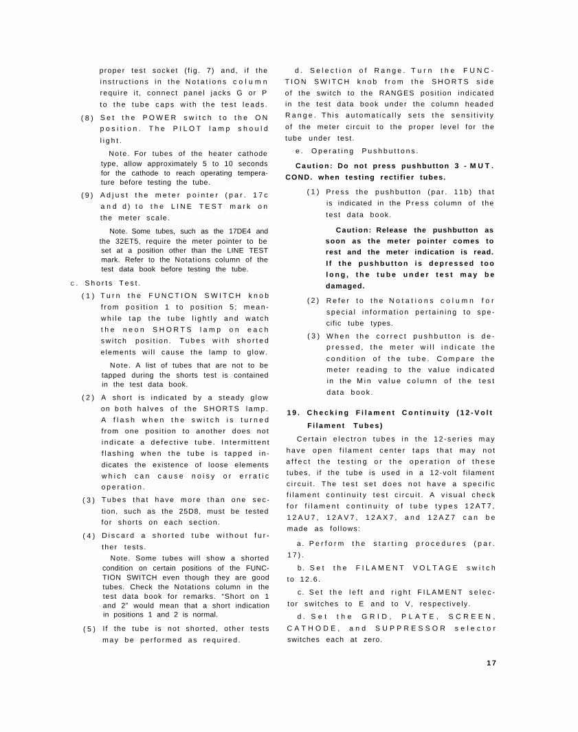
2 0 . R e a d i n g M e t e r
T h e m e t e r s c a l e i s c a l i b r a t e d i n d i v i s i o n s
f r o m 0 t o 1 2 0 . W h e n t h e p r o p e r p u s h b u t t o n i s
d e p r e s s e d , t h e m e t e r p o i n t e r w i l l i n d i c a t e t h e
condi t ion o f the tube under tes t as a numer ica l
v a l u e . T h e n u m e r i c a l v a l u e o f t h e m e t e r r e a d -
ing is then compared to the min imum accepta-
b le va lue in the M i n v a l u e c o l u m n i n t h e t e s t
d a t a b o o k . I f t h e n u m b e r i n d i c a t e d o n t h e
m e t e r i s l e s s t h a n t h e l i s t e d m i n i m u m v a l u e ,
t h e t u b e s h o u l d b e r e p l a c e d . T h e f o l l o w i n g
c h a r t m a y b e u s e d t o c o n v e r t t h e n u m e r i c a l
v a l u e o f t h e m e t e r r e a d i n g t o m u t u a l c o n d u c t -
ance in micromhos.
Mat rodh#
o . . . . . . . . . . . . . . . . . . . . . . . . . .
10 . . . . . . . . . . . . . . . . . . . . . . . . . .
20 . . . . . . . . . . . . . . . . . . . . . . . . . .
80 . . . . . . . . . . . . . . . . . . . . . . . . . .
40 . . . . . . . . . . . . . . . . . . . . . . . . . .
1 8
COXiq nlw h miwoah09
Ran@ B
o
260
500
750
1,000
Reap c
o
Soo
1,000
1,500
2,000
kqo D
o
1,260
2,s00
3,750
5,000
Rng, E(not,)
o
2,500
6,000
7,500
10,OOO
-* -s R91goc
60 . . . . . . . . . . . . . . . . . . . . . . . . . . 12s0 2,600
60 . . . . . . . . . . . . . . . . . . . . . . . . . . 1,600 woo
70 . . . . . . . . . . . . . . . . . . . . . . . . . . 1,760 S,600
80 . . . . . . . . . . . . . . . . . . . . . . . . . 2,000 4,000
90 . . . . . . . . . . . . . . . . . . . . . . . . . . 2~60 4,600
100 . . . . . . . . . . . . . . . . . . . . . . . . . . 2,500 6,000
110 . . . . . . . . . . . . . . . . . . . . . . . . . . 2,760 6,600
120 . . . . . . . . . . . . . . . . . . . . . . . . . . 8,000 6,000
Now nm I ad r, Tv-m/u.
2 1 . G a s T e s t
6260 12,600
7,s00 16,000
8,760 17,600
10,OOO 20,000
11*O 22,600
12,600 25,000
18,760 27,600
16,000 80,000
P u s h b u t t o n s 4 - G A S 1 a n d 5 - G A S 2 a r e
used when test ing ampl i f ie r tubes for gas con-
t e n t . M u l t i p u r p o s e t u b e s a r e t e s t e d f o r g a s
only on the amplif ier sections; the gas test does
not apply to diode sections or to rectif ier tubes.
Allow tubes of the fi lament type to warm up be-
fore test ing the tube for gas content .
a . P e r f o r m t h e p r o c e d u r e s i n p a r a g r a p h
1 7 a t h r o u g h d a n d f .
b . S e t t h e c o n t r o l s a s i n d i c a t e d i n t h e t e s t
data book.
c . I n s e r t t h e t u b e i n t h e p r o p e r t e s t s o c k e t
a n d s e t t h e P O W E R s w i t c h t o O N .
d . H o l d d o w n p u s h b u t t o n 4 - G A S 1 a n d
adjust the BIAS cont ro l ( f ig . 6) unt i l the meter
pointer ind icates 10 on the sca le .Note. If the meter pointer cannot be adjusted down
to 10, turn the BIAS control knob until the meter read-ing is 100.
e . H o l d d o w n p u s h b u t t o n 4 - G A S 1 a n d
press pushbut ton 5 - GAS 2 .
f . I f t h e t u b e c o n t a i n s g a s , t h e m e t e r
po in ter wi l l move up the sca le . A movement o f
m o r e t h a n 1 d i v i s i o n o n t h e s c a l e i n d i c a t e s a
gassy tube.
g . T u r n o f f t h e t e s t s e t ( p a r . 2 6 ) .
2 2 . N o i s e T e s t
T h e N O I S E t e s t j a c k s o n e i t h e r s i d e o f t h e
S H O R T S l a m p ( f i g . 6 ) a r e u s e d w h e n t e s t i n g
e l e c t r o n t u b e s f o r n o i s e . A r a d i o r e c e i v e r o r
a n a u d i o a m p l i f i e r w i t h a l o u d s p e a k e r , a n d a
s e t o f t e s t l e a d s , a r e r e q u i r e d t o p e r f o r m t h e
t e s t .
a . P e r f o r m t h e s t a r t i n g p r o c e d u r e s ( p a r .
1 7 ) .
b. S e t t h e c o n t r o l s f o r t h e t u b e u n d e r t e s t
as ind icated in the tes t data book, and set the
P O W E R s w i t c h t o O N .
c . S e t t h e F U N C T I O N S W I T C H t o
S H O R T S 1 .
d. Connect a tes t lead to each of the NOISE
j a c k s .
e. C o n n e c t t h e t e s t l e a d f r o m t h e l e f t - h a n d
N O I S E j a c k t o t h e c h a s s i s o f t h e r a d i o r e -
c e i v e r o r t h e a u d i o a m p l i f i e r .
f . C o n n e c t t h e t e s t l e a d f r o m t h e r i g h t -
h a n d N O I S E j a c k t o e i t h e r t h e a n t e n n a o f a
rad io receiver or to the input o f an audio am-
p l i f i e r . T u r n t h e r a d i o r e c e i v e r o r t h e a u d i o
ampl i f ie r power swi tch to the on pos i t ion.
g. T a p t h e t u b e u n d e r t e s t w h i l e t h e F U N C -
T I O N S W I T C H i s t u r n e d f r o m p o s i t i o n 1
t h r o u g h p o s i t i o n 5 .
h . I n t e r m i t t e n t d i s t u r b a n c e s w i t h i n t h e
t u b e w h i c h a r e t o o b r i e f t o r e g i s t e r o n t h e
S H O R T S l a m p w i l l b e r e p r o d u c e d a s s t a t i c b y
the loudspeaker .
i. T u r n o f f t h e t e s t s e t ( p a r . 2 6 ) .
2 3 . P a n e l L a m p T e s t
T h e r e c e p t a c l e i n t h e c e n t e r o f t h e l a r g e ,
7 - p i n s o c k e t ( f i g . 7 ) i s u s e d t o c h e c k p a n e l
l a m p s .
a . P e r f o r m t h e p r o c e d u r e s i n p a r a g r a p h
1 7 a t h r o u g h d a n d f .
b . S e t t h e F I L A M E N T s e l e c t o r s w i t c h e s t o
H R .
c . S e t t h e F I L A M E N T V O L T A G E s w i t c h
to the proper vo l tage for the lamp to be tested.
I f t h e e x a c t v o l t a g e i s n o t k n o w n , s e t t h e
F I L A M E N T V O L T A G E s w i t c h t o 0 . 6 v o l t
a n d i n c r e a s e t h e v o l t a g e a s r e q u i r e d .
d . I n s e r t t h e l a m p i n t h e r e c e p t a c l e a n d
p r e s s t h e c e n t e r c o n t a c t o f t h e l a m p f i r m l y
a g a i n s t t h e b o t t o m o f t h e r e c e p t a c l e ; t h e n t i l t
t h e l a m p u n t i l t h e m e t a l s h e l l m a k e s c o n t a c t
w i t h t h e r i m o f t h e r e c e p t a c l e . A d e f e c t i v e
l a m p w i l l n o t l i g h t .
e. T u r n o f f t h e t e s t s e t ( p a r . 2 6 ) .
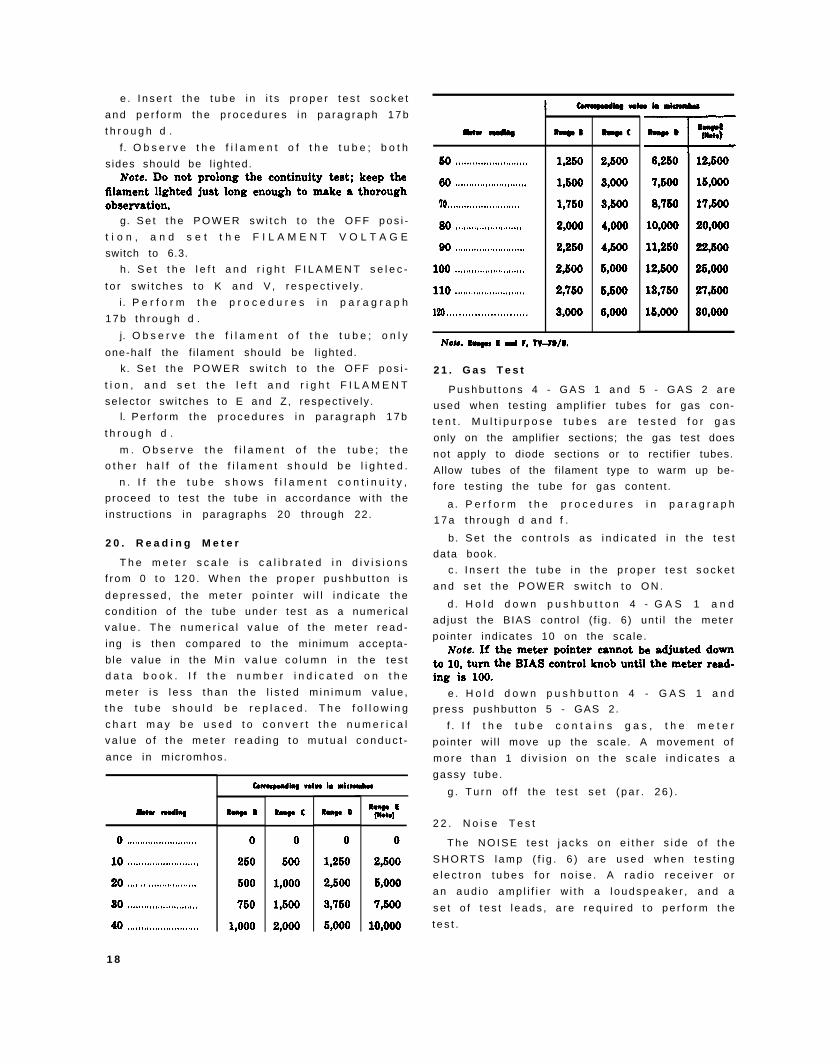
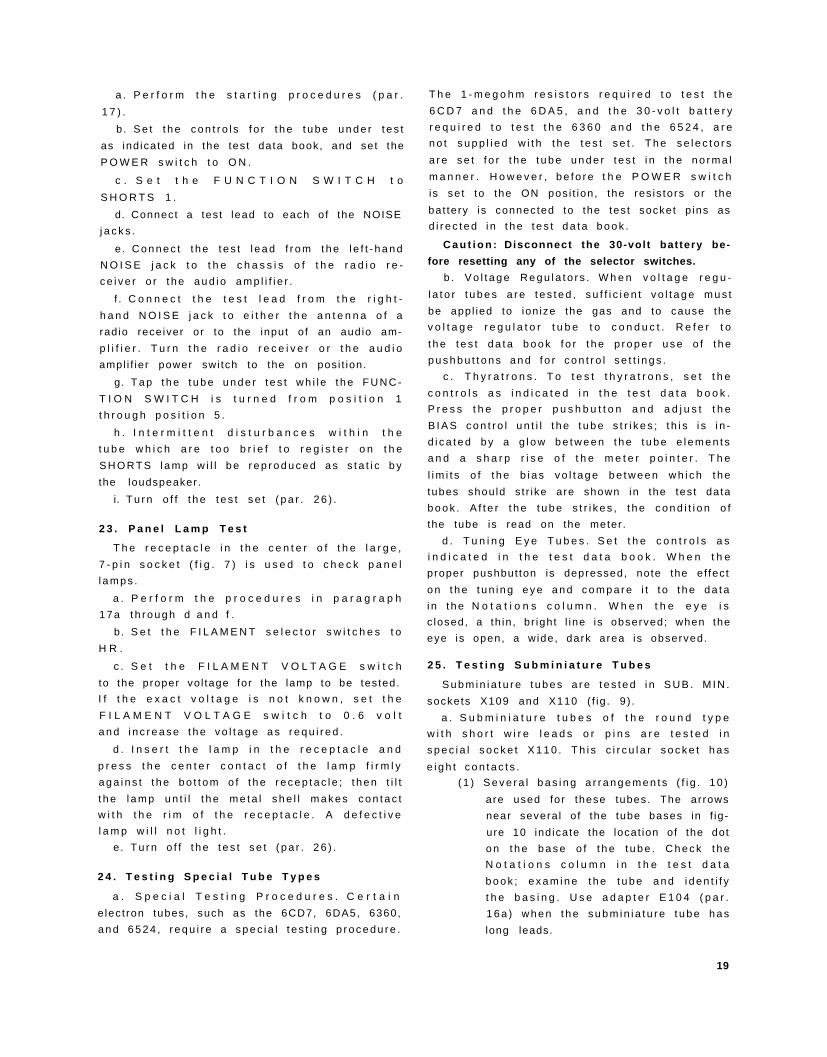
2 4 . T e s t i n g S p e c i a l T u b e T y p e s
a . S p e c i a l T e s t i n g P r o c e d u r e s . C e r t a i n
e lec t ron tubes, such as the 6CD7, 6DA5, 6360,
a n d 6 5 2 4 , r e q u i r e a s p e c i a l t e s t i n g p r o c e d u r e .
T h e 1 - m e g o h m r e s i s t o r s r e q u i r e d t o t e s t t h e
6 C D 7 a n d t h e 6 D A 5 , a n d t h e 3 0 - v o l t b a t t e r y
r e q u i r e d t o t e s t t h e 6 3 6 0 a n d t h e 6 5 2 4 , a r e
n o t s u p p l i e d w i t h t h e t e s t s e t . T h e s e l e c t o r s
a r e s e t f o r t h e t u b e u n d e r t e s t i n t h e n o r m a l
m a n n e r . H o w e v e r , b e f o r e t h e P O W E R s w i t c h
is se t to the ON pos i t ion , the res is tors or the
bat tery is connected to the tes t socket p ins as
d i r e c t e d i n t h e t e s t d a t a b o o k .
C a u t i o n : Disconnect the 30-volt battery be-
fore resetting any of the selector switches.
b . V o l t a g e R e g u l a t o r s . W h e n v o l t a g e r e g u -
l a t o r t u b e s a r e t e s t e d , s u f f i c i e n t v o l t a g e m u s t
be app l ied to ion ize the gas and to cause the
v o l t a g e r e g u l a t o r t u b e t o c o n d u c t . R e f e r t o
t h e t e s t d a t a b o o k f o r t h e p r o p e r u s e o f t h e
p u s h b u t t o n s a n d f o r c o n t r o l s e t t i n g s .
c . T h y r a t r o n s . T o t e s t t h y r a t r o n s , s e t t h e
c o n t r o l s a s i n d i c a t e d i n t h e t e s t d a t a b o o k .
P r e s s t h e p r o p e r p u s h b u t t o n a n d a d j u s t t h e
B I A S c o n t r o l u n t i l t h e t u b e s t r i k e s ; t h i s i s i n -
d i c a t e d b y a g l o w b e t w e e n t h e t u b e e l e m e n t s
a n d a s h a r p r i s e o f t h e m e t e r p o i n t e r . T h e
l i m i t s o f t h e b i a s v o l t a g e b e t w e e n w h i c h t h e
tubes shou ld s t r ike are shown in the tes t da ta
b o o k . A f t e r t h e t u b e s t r i k e s , t h e c o n d i t i o n o f
the tube is read on the meter .
d . T u n i n g E y e T u b e s . S e t t h e c o n t r o l s a s
i n d i c a t e d i n t h e t e s t d a t a b o o k . W h e n t h e
proper pushbut ton is depressed, note the e f fec t
o n t h e t u n i n g e y e a n d c o m p a r e i t t o t h e d a t a
i n t h e N o t a t i o n s c o l u m n . W h e n t h e e y e i s
c losed, a th in , b r igh t l ine is observed; when the
eye is open, a w ide, dark area is observed.
2 5 . T e s t i n g S u b m i n i a t u r e T u b e s
S u b m i n i a t u r e t u b e s a r e t e s t e d i n S U B . M I N .
sockets X109 and X110 ( f ig . 9 ) .
a . S u b m i n i a t u r e t u b e s o f t h e r o u n d t y p e
w i t h s h o r t w i r e l e a d s o r p i n s a r e t e s t e d i n
s p e c i a l s o c k e t X 1 1 0 . T h i s c i r c u l a r s o c k e t h a s
e i g h t c o n t a c t s .
( 1 ) S e v e r a l b a s i n g a r r a n g e m e n t s ( f i g . 1 0 )
are used for these tubes. The ar rows
near severa l o f the tube bases in f ig-
ure 10 ind icate the locat ion of the dot
o n t h e b a s e o f t h e t u b e . C h e c k t h e
N o t a t i o n s c o l u m n i n t h e t e s t d a t a
b o o k ; e x a m i n e t h e t u b e a n d i d e n t i f y
t h e b a s i n g . U s e a d a p t e r E 1 0 4 ( p a r .
1 6 a ) w h e n t h e s u b m i n i a t u r e t u b e h a s
long leads.
19
( 2 ) Inser t the leads or p ins in the cor res-
p o n d i n g c o n t a c t s o f s o c k e t X 1 1 0 . I f
t h e l e a d s a r e l o n g e n o u g h , s e t t h e
P O W E R s w i t c h t o t h e O F F p o s i t i o n ,
grasp each lead about one-e ighth inch
f rom i ts end wi th the t ips of a pa i r o f
long-nosed p l iers , and inser t the leads
i n t o t h e p r o p e r s o c k e t c o n t a c t s . S e t
t h e P O W E R s w i t c h t o t h e O N p o s i -
t i o n a n d t e s t t h e t u b e .
b. S u b m i n i a t u r e t u b e s o f t h e f l a t o r i n - l i n e -
c o n t a c t t y p e w i t h p i n s o r l e a d s a r e t e s t e d i n
f l a t s o c k e t X 1 0 9 ( f i g . 9 ) . T h e t u b e p i n s o r
leads must be inser ted so that the dot on the
b a s e o f t h e t u b e i s d i r e c t l y i n l i n e w i t h t h e
small, molded dot on the socket.
c. S u b m i n i a t u r e t u b e t y p e s a r e i d e n t i f i e d i n
t h e t e s t d a t a b o o k b y a s t a r b e s i d e t h e t y p e
n u m b e r . T h e a p p l i c a b l e b a s i n g f o r t h e v a r i o u s
round types is ind ica ted in the N o t a t i o n s c o l -
u m n . T h e b a s i n g d e s i g n a t i o n l e t t e r r e f e r s t o
t h e d i a g r a m s s h o w n i n f i g u r e 1 0 .
TM6625-274-12-8
Figure 9. Top view of sockets X109 (flat)and X110 (c i rcu lar ) .
2 6 . S t o p p i n g P r o c e d u r e
a. S e t t h e P O W E R s w i t c h t o
s i t i o n .
t h e O F F p o -
TM6625-274-12-9
Figure 10. Bas ing d iagrams for submin ia ture
tubes (letters, A, B, C, D, E, and F identify
basing for use with test data book).
b . R e m o v e t h e t u b e u n d e r t e s t f r o m t h e
tes t socke t .
c . P l a c e t h e a d a p t e r s , i f u s e d , u n d e r t h e
c lamps on the ins ide o f the cover .
d . D i s c o n n e c t t h e a c l i n e c o r d f r o m t h e
p o w e r s o u r c e a n d w i n d i t c o u n t e r c l o c k w i s e
a r o u n d t h e r e t a i n e r b r a c k e t o n t h e i n s i d e o f
t h e c o v e r . S e c u r e t h e p l u g u n d e r t h e s t o r a g e
c l i p ( T V - 7 B / U a n d T V - 7 D / U , f i g . 3 a n d 4 ) ,
o r u n d e r t h e c o i l e d a c l i n e c o r d ( T V - 7 / U a n d
T V 7 A / U ) .
e. Place the tes t leads, i f used, in the s tor -
a g e c l i p s ( n o t o n T V - 7 / U ) . O n t h e T V - 7 / U ,
s t o r e t h e t e s t l e a d s u n d e r t h e c o i l e d a c l i n e
cord or as shown in f igure 1 .
f. Close the cover and secure the fas teners .
S e c t i o n V . O P E R A T I O N U N D E R U N U S U A L C O N D I T I O N S
2 7 . G e n e r a l
The tes t se t is des igned for normal operat ion
t h r o u g h a t e m p e r a t u r e r a n g e f r o m - 4 0 ° F t o
+ 1 2 5 ° F . T h e o p e r a t i o n o f t h e e q u i p m e n t m a y
be more d i f f icu l t in reg ions where ext reme co ld ,
h e a t , h u m i d i t y , o r m o i s t u r e c o n d i t i o n s p r e v a i l .
P a r a g r a p h s 2 8 t h r o u g h 3 0 p r o v i d e o p e r a t i o n a l
i n f o r m a t i o n t h a t m a y b e u s e d t o m i n i m i z e t h e
ef fec ts o f reg iona l ex t remes.
2 8 . O p e r a t i o n a t L o w T e m p e r a t u r e s
S u b z e r o t e m p e r a t u r e s a n d c l i m a t i c c o n d i -
t i o n s a s s o c i a t e d w i t h c o l d w e a t h e r m a y e f f e c t
t h e e f f i c i e n t o p e r a t i o n o f t h e t e s t s e t .
a. Ext reme co ld makes the ac l ine cord and
o t h e r r u b b e r p a r t s s t i f f a n d b r i t t l e . H a n d l e
t h e e q u i p m e n t c a r e f u l l y t o a v o i d c r a c k i n g t h e
insu la t ion on the ac l ine cord and on the test
leads.
20
b . K e e p t h e e q u i p m e n t i n a w a r m , d r y l o -
cation. If possible, keep the test set in a heated
e n c l o s u r e . A s t a n d b y h e a t e r i s n o t p r o v i d e d ;
therefore, leave the tes t set turned on i f poss i -
ble.
c . A l l o w t h e t e s t s e t t o w a r m u p f o r 1 0 t o
1 5 m i n u t e s b e f o r e t e s t i n g t u b e s . T h e l e n g t h
o f w a r m u p t i m e d e p e n d s u p o n t h e t e m p e r a t u r e
o f t h e s u r r o u n d i n g a i r .
d. I f e q u i p m e n t t h a t h a s b e e n e x p o s e d t o
the co ld is brought in to a warm room, mois ture
w i l l f o r m o n i t a n d m a y c a u s e f o g g i n g o f t h e
m e t e r g l a s s . D r y t h e e q u i p m e n t t h o r o u g h l y .
e. K e e p t h e c o v e r o f t h e t e s t s e t c l o s e d a t
a l l t i m e s w h e n t h e e q u i p m e n t i s n o t i n o p e r a -
t i o n . T h i s w i l l p r e v e n t a n a c c u m u l a t i o n o f
mois ture wi th in the equipment due to sweat ing.
2 9 . O p e r a t i o n U n d e r T r o p i c a l C o n d i t i o n s
W a r m , d a m p c l i m a t e s e x p o s e t h e e q u i p m e n t
t o d a m a g e f r o m m o i s t u r e a n d f u n g u s . T h e
h i g h r e l a t i v e h u m i d i t y c a u s e s c o n d e n s a t i o n
w h e n t h e t e m p e r a t u r e o f t h e e q u i p m e n t d r o p s
b e l o w t h a t o f t h e s u r r o u n d i n g a i r . A d e q u a t e
v e n t i l a t i o n w i l l m i n i m i z e t h i s c o n d i t i o n . K e e p
t h e c o v e r o f t h e t e s t s e t c l o s e d a s m u c h a s
p o s s i b l e . W i p e a l l m o i s t u r e a n d f u n g u s f r o m
t h e e x t e r i o r o f t h e t e s t s e t w i t h a c l e a n , l i n t -
f r e e c l o t h .
3 0 . O p e r a t i o n i n D e s e r t C l i m a t e s
Desert cl imates expose the test set to damage
f rom d i r t , dus t , sand, and the e f fec ts o f s t rong
s u n l i g h t . P r o v i d e m e a n s f o r k e e p i n g d u s t a n d
sand from entering the holes in the test sockets,
a d a p t e r s , a n d j a c k s , a n d f r o m a c c u m u l a t i n g
around the pushbut tons and other moving par ts
of the test set . C lean and dust the equipment
f r e q u e n t l y . W h e n n o t i n u s e , k e e p t h e c o v e r
closed to keep dust and dirt out of the exposed
p a r t s .
21
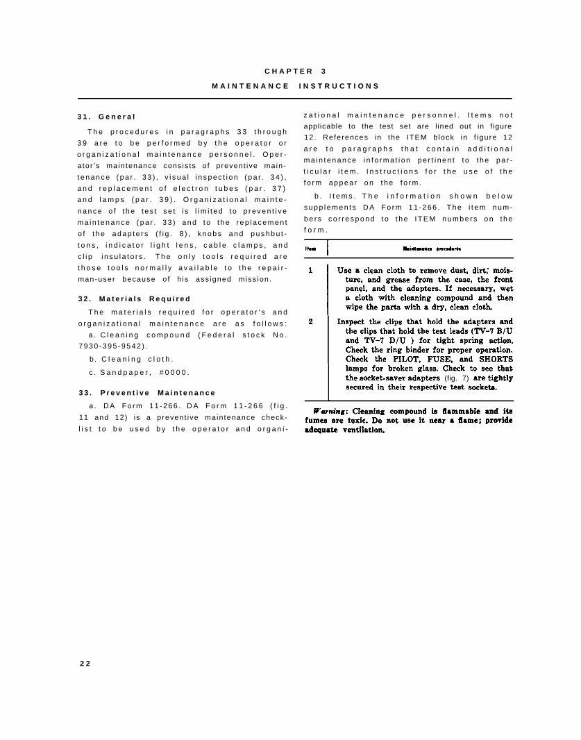
C H A P T E R 3
M A I N T E N A N C E I N S T R U C T I O N S
3 1 . G e n e r a l
T h e p r o c e d u r e s i n p a r a g r a p h s 3 3 t h r o u g h
3 9 a r e t o b e p e r f o r m e d b y t h e o p e r a t o r o r
o r g a n i z a t i o n a l m a i n t e n a n c e p e r s o n n e l . O p e r -
a tor ’s main tenance cons is ts o f prevent ive main-
t e n a n c e ( p a r . 3 3 ) , v i s u a l i n s p e c t i o n ( p a r . 3 4 ) ,
a n d r e p l a c e m e n t o f e l e c t r o n t u b e s ( p a r . 3 7 )
a n d l a m p s ( p a r . 3 9 ) . O r g a n i z a t i o n a l m a i n t e -
n a n c e o f t h e t e s t s e t i s l i m i t e d t o p r e v e n t i v e
m a i n t e n a n c e ( p a r . 3 3 ) a n d t o t h e r e p l a c e m e n t
o f t h e a d a p t e r s ( f i g . 8 ) , k n o b s a n d p u s h b u t -
t o n s , i n d i c a t o r l i g h t l e n s , c a b l e c l a m p s , a n d
c l i p i n s u l a t o r s . T h e o n l y t o o l s r e q u i r e d a r e
t h o s e t o o l s n o r m a l l y a v a i l a b l e t o t h e r e p a i r -
man-user because o f h is ass igned miss ion.
3 2 . M a t e r i a l s R e q u i r e d
T h e m a t e r i a l s r e q u i r e d f o r o p e r a t o r ’ s a n d
o r g a n i z a t i o n a l m a i n t e n a n c e a r e a s f o l l o w s :
a. C l e a n i n g c o m p o u n d ( F e d e r a l s t o c k N o .
7 9 3 0 - 3 9 5 - 9 5 4 2 ) .
b. C l e a n i n g c l o t h .
c. S a n d p a p e r , # 0 0 0 0 .
3 3 . P r e v e n t i v e M a i n t e n a n c e
a . D A F o r m 1 1 - 2 6 6 . D A F o r m 1 1 - 2 6 6 ( f i g .
11 and 12) is a prevent ive maintenance check-
l i s t t o b e u s e d b y t h e o p e r a t o r a n d o r g a n i -
z a t i o n a l m a i n t e n a n c e p e r s o n n e l . I t e m s n o t
applicable to the test set are l ined out in f igure
12. References in the ITEM b lock in f igure 12
a r e t o p a r a g r a p h s t h a t c o n t a i n a d d i t i o n a l
m a i n t e n a n c e i n f o r m a t i o n p e r t i n e n t t o t h e p a r -
t i c u l a r i t e m . I n s t r u c t i o n s f o r t h e u s e o f t h e
f o r m a p p e a r o n t h e f o r m .
b . I t e m s . T h e i n f o r m a t i o n s h o w n b e l o w
s u p p l e m e n t s D A F o r m 1 1 - 2 6 6 . T h e i t e m n u m -
b e r s c o r r e s p o n d t o t h e I T E M n u m b e r s o n t h e
f o r m .
ItHlI
Maintmmc* pmcodurcs
1II
Use a clean cloth to remove dust, dirt; mois-ture, and grease from the case, the front
I
panel, and the adapters. If necessary, weta cloth with cleaning compound and thenwipe the parts with a dry, clean cloth.
2 Inspect the clips that hold the adapters andthe clips that hold the test leads (TV-7 B/Uand TV-7 D/U ) for tight spring action.Check the ring binder for proper operation.Check the PILOT, FUSE, and SHORTSlamps for broken glass. Check to see thatthe socket-saver adapters (fig. 7) are tightlysecured in their respective test sockets.
I
Warning: Cieaning compound is fiammabie and itafumes are toxic. Do not use it near a iiame; proyideadequate ventilation.
2 2
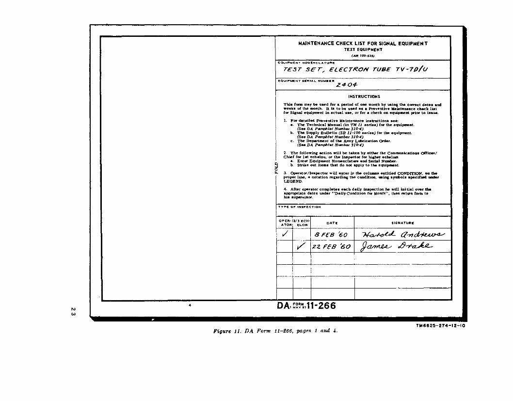
Figure 11
TM
6625-274-12-10
23
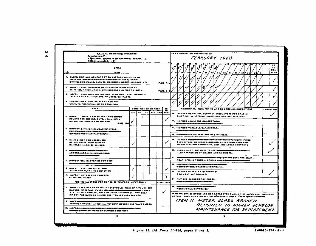
Figure 12.
TM
6625-274-12-11
24
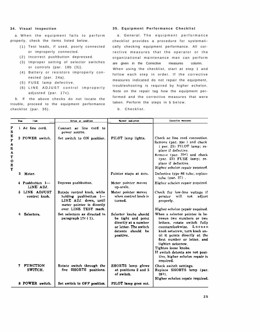
3 4 . V i s u a l I n s p e c t i o n
a . W h e n t h e e q u i p m e n t f a i l s t o p e r f o r m
proper ly , check the i tems l i s ted be low.
( 1 )
( 2 )
( 3 )
( 4 )
( 5 )
( 6 )
b. If
T e s t l e a d s , i f u s e d , p o o r l y c o n n e c t e d
o r i m p r o p e r l y c o n n e c t e d .
I n c o r r e c t p u s h b u t t o n d e p r e s s e d .
I m p r o p e r s e t t i n g o f s e l e c t o r s w i t c h e s
o r c o n t r o l s ( p a r . 1 8 b ( 3 ) ) .
B a t t e r y o r r e s i s t o r s i m p r o p e r l y c o n -
n e c t e d ( p a r . 2 4 a ) .
F U S E l a m p d e f e c t i v e .
L I N E A D J U S T c o n t r o l i m p r o p e r l y
a d j u s t e d ( p a r . 1 7 c ) .
t h e a b o v e c h e c k s d o n o t l o c a t e t h e
t roub le , proceed to the equ ipment per formance
c h e c k l i s t ( p a r . 3 5 ) .
Shp I f.m
P 1 Ac line cord.REP
2 POWER switch.
ARAToRY
3 Meter.
4 Pushbutton l—LINE” ADJ.
5 LINE ADJUSTcontrol knob.
6 Selectors.
7 FUNCTIONSWITCH.
8 POWER switch.
Adion or csmditiem
Connect ac line cord topower source.
Set switch to ON position.
Depress pushbutton.
Rotate control knob, whileholding pushbutton l—LINE ADJ. down, untilmeter pointer is directlyover LINE TEST mark.
Set selectors as directed inparagraph 17e ( 1).
Rotate switch through thefive SHORTS positions.
Set switch to OFF position.
3 5 . E q u i p m e n t P e r f o r m a n c e C h e c k l i s t
a . G e n e r a l . T h e e q u i p m e n t p e r f o r m a n c e
c h e c k l i s t p r o v i d e s a p r o c e d u r e f o r s y s t e m a t i -
ca l ly check ing equipment per formance. A l l cor -
r e c t i v e m e a s u r e s t h a t t h e o p e r a t o r o r t h e
o r g a n i z a t i o n a l m a i n t e n a n c e m a n c a n p e r f o r m
are given in the Corrective measures column.
W h e n u s i n g t h e c h e c k l i s t , s t a r t a t s t e p 1 a n d
f o l l o w e a c h s t e p i n o r d e r . I f t h e c o r r e c t i v e
measures ind icated do not repai r the equipment ,
t r o u b l e s h o o t i n g i s r e q u i r e d b y h i g h e r e c h e l o n .
Note on the repai r tag how the equipment per-
f o r m e d a n d t h e c o r r e c t i v e m e a s u r e s t h a t w e r e
taken. Per form the s teps in b b e l o w .
b . C h e c k l i s t .
PILOT lamp lights.
Pointer stays at zero.
Meter pointer movesup-scale.
Meter pointer moveswhen control knob isturned.
Selector knobs shouldbe tight and pointdirectly at a numberor letter. The switchdetents should bepositive.
SHORTS lamp glowsat positions 2 and 3of switch.
PILOT lamp goes out.
Corredi.* meosurm
Check ac line cord connection.Remove (par. 39a ) and check
( par. 23) PILOT lamp; re-place if defective.
Remove (par. 39fl) and check(par. 23) FUSE lamp; re-place if defective.
Higher echelon repair required.
Defective type 86 tube; replacetube (par. 37) .
Higher echelon repair required.
Check for low-line voltage ifpointer will not adjustproperly.
Higher echelon repair required.
When a selector pointer is be-tween two numbers or twoletters, rotate switch fullycounterclockwise. Loosenknob setscrew, turn knob un-til it points directly at thefirst number or Ietter, andtighten setscrew.
Tighten I,oose knobs.If switch detents are not posi-
tive, higher echelon repair isrequired.
Check switch settings.Replace SHORTS lamp (par.
39 b).Higher echelon repair required.
2 5
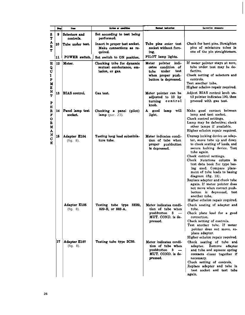
* Itm dab w CdhIa
s 9 Seleetore and Set according to test beingT controls. performed.
; 10 Tube under teat. Insert in proper test socket.
TMake connections 8s re-quired.
In I POWER switch. ! Set stitch ti ON position.
EQuIPMENT
PERFoRMANcE
12
18
14
1s
Meter.
BIAS controL
Panel lamp testsocket.
Adapter E104(fig. 8).
Adapter E106(fig. 8).
17 Adapter E107(fig. 8).
Checking tube for dynamicmutual conductance, em-ission, or gas.
Gas test.
Checking a panel (pilot)lamp (par. 23).
Testing long lead subminia-ture tube.
Testing tube type 3E29,829-B, or 832-A.
Testing tube type 2C89.
Tube pins enter test Check for bent pins. Straightensocket without forc- pins of miniature tubes ining. one of the pin straighteners.
PILOT lamp lights.
Meter pointer indi- If meter pointer stays at zero,catas condition of tube under test may be de-tube under test fective.when proper push- Check setting of selectors andbutton is depressed. controls.
Test another tube.Higher echelon repair required.
Meter pointer can be Adjust BIAS control knob un-adjusted to 10 by til pointer indicates 100, thenturning controlknob.
A good lamp willlight.
Meter indicates condi-tion of tube whenproper pushbuttonis depressed.
Meter indicates condi-tion of tube whenpushbutton 3 —MUT. COND. is de-pressed.
proceed with gas test.
Make good contact betweenlamp and test socket.
Check c~ntrol settings.Lamp may be defective; check
other lamps if available.Higher echelon repair required.
Unsnap locking device on adap-ter, move tube up and downto check seating of leads, andsecure locking device. Testtube again.
Check control settings.Check ~otatio~ column in
test data book for type bas-ing used. Compare place-ment of tube leads to basingdiagram (fig. 10).
Replace adapter and check tubeagain. If meter pointer doesnot move when correct push-button is depressed, testanother tube.
Higher echelon repair required.Check seating of adapter and
tube.Check plate lead for a good
connection.Check setting of controls.Test another tube. If meter
pointer does not move, re-place adapter.
Higher echelon repair required.Meter indicates condi- Check seating of tube and
tion of tube when adapter. Remove adapterpushbutton 3 —MUT. COND. is de-pressed,
and tube and squeeze springcontacts closer together ifnecessary.
Check setting of controls.Replace adapter and tube in
test socket and test tubeagain.
26
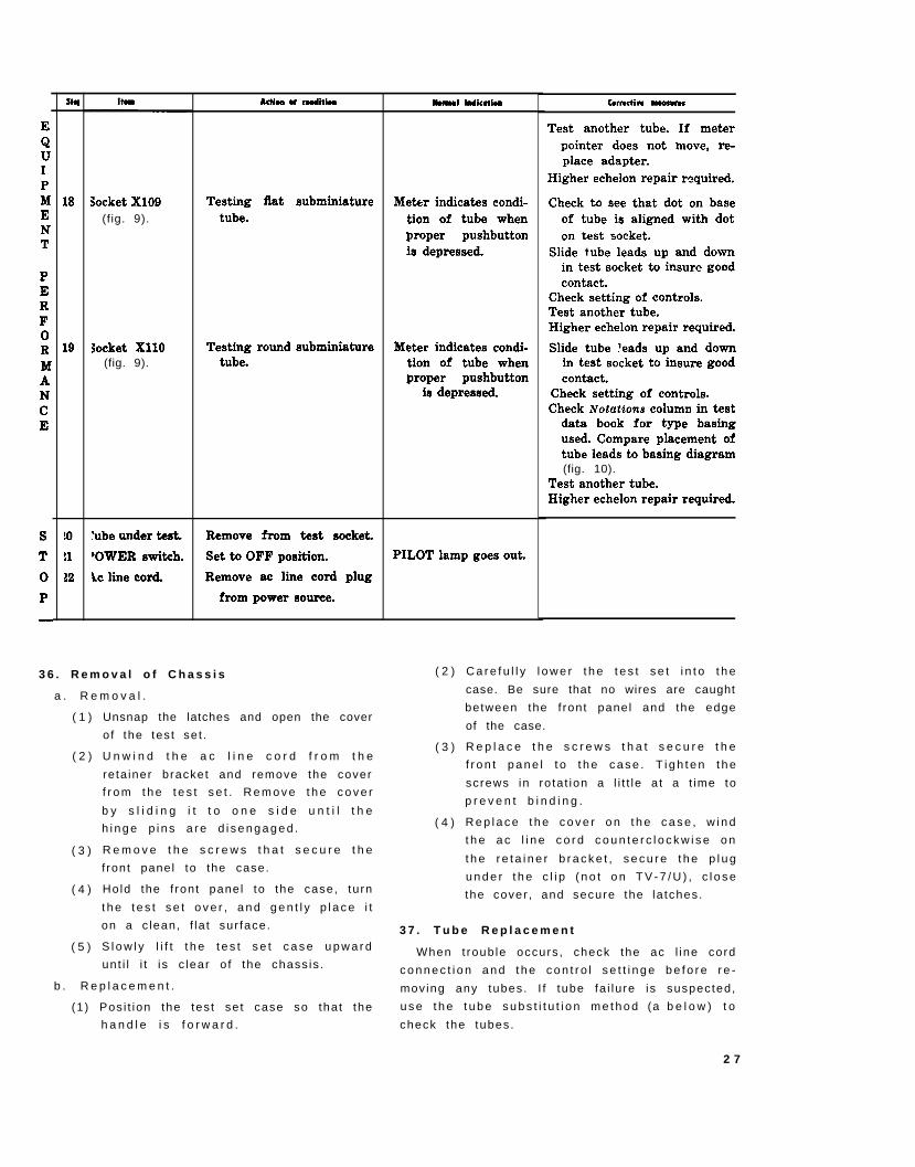
E
QuIPMENT
PERFoRMANcE
s
T
o
P
—
Shl
18
19
!0
!1
82
Socket X109(fig. 9).
Socket X11O(fig. 9).
‘ube under tesk
‘OWER switch,
ic line cord.
Adu w Cditlu
Testing flat subminiaturetube.
Testing round subminiaturetube.
Remove from test socket.
Set to OFF position.
Remove ac line cord plug
from power source.
3 6 . R e m o v a l o f C h a s s i s
a . R e m o v a l .
( 1 )
( 2 )
( 3 )
( 4 )
( 5 )
Unsnap the latches and open the cover
o f the tes t se t .
U n w i n d t h e a c l i n e c o r d f r o m t h e
reta iner bracket and remove the cover
f r o m t h e t e s t s e t . R e m o v e t h e c o v e r
b y s l i d i n g i t t o o n e s i d e u n t i l t h e
h i n g e p i n s a r e d i s e n g a g e d .
R e m o v e t h e s c r e w s t h a t s e c u r e t h e
f ront panel to the case.
Hold the f ront pane l to the case, tu rn
t h e t e s t s e t o v e r , a n d g e n t l y p l a c e i t
on a c lean, f la t sur face.
S l o w l y l i f t t h e t e s t s e t c a s e u p w a r d
unt i l i t i s c lear o f the chass is .
b . R e p l a c e m e n t .
(1 ) Pos i t ion the tes t se t case so tha t the
h a n d l e i s f o r w a r d .
NwR91 indication
Meter indicates condi-
tion of tube whenproper pushbuttonis depressed.
Meter indicates condi-tion of tube whenproper pushbutton
is depressed.
PILOT lamp goes out.
( 2 )
( 3 )
( 4 )
COrmtivc MOOlurw
Test another tube. If meter
pointer does not move, re-place adapter.
Higher echelon repair required.
Check to see that dot on baseof tube is aligned with doton test socket.
Slide tube leads up and downin test socket to insure goodcontact.
Check setting of controls.Test another tube.Higher echelon repair required.
Slide tube leads up and downin test socket to insure goodcontact.
Check setting of controls.Check Notations column in test
data book for type basingused. Compare placement oftube leads to basing diagram(fig. 10).
Test another tube.Higher echelon repair required.
C a r e f u l l y l o w e r t h e t e s t s e t i n t o t h e
case. Be sure that no wires are caught
between the f ront panel and the edge
of the case.
R e p l a c e t h e s c r e w s t h a t s e c u r e t h e
f r o n t p a n e l t o t h e c a s e . T i g h t e n t h e
screws in ro ta t ion a l i t t le a t a t ime to
p r e v e n t b i n d i n g .
R e p l a c e t h e c o v e r o n t h e c a s e , w i n d
t h e a c l i n e c o r d c o u n t e r c l o c k w i s e o n
t h e r e t a i n e r b r a c k e t , s e c u r e t h e p l u g
u n d e r t h e c l i p ( n o t o n T V - 7 / U ) , c l o s e
the cover , and secure the la tches.
3 7 . T u b e R e p l a c e m e n t
When t roub le occurs , check the ac l ine cord
c o n n e c t i o n a n d t h e c o n t r o l s e t t i n g e b e f o r e r e -
mov ing any tubes. I f tube fa i lu re is suspected,
u s e t h e t u b e s u b s t i t u t i o n m e t h o d (a b e l o w ) t o
check the tubes .
2 7
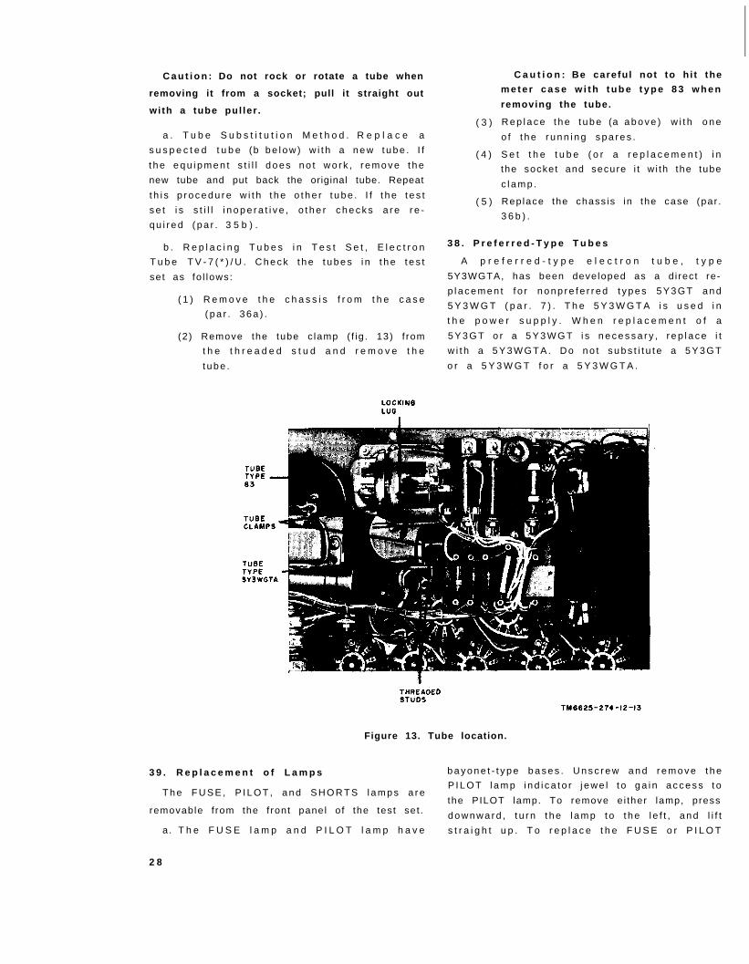
TM6625-274-12-13
C a u t i o n : Do not rock or rotate a tube when
removing it from a socket; pull it straight out
wi th a tube pul ler .
a . T u b e S u b s t i t u t i o n M e t h o d . R e p l a c e a
s u s p e c t e d t u b e (b b e l o w ) w i t h a n e w t u b e . I f
t h e e q u i p m e n t s t i l l d o e s n o t w o r k , r e m o v e t h e
new tube and put back the original tube. Repeat
t h i s p r o c e d u r e w i t h t h e o t h e r t u b e . I f t h e t e s t
s e t i s s t i l l i n o p e r a t i v e , o t h e r c h e c k s a r e r e -
q u i r e d ( p a r . 3 5 b ) .
b . R e p l a c i n g T u b e s i n T e s t S e t , E l e c t r o n
T u b e T V - 7 ( * ) / U . C h e c k t h e t u b e s i n t h e t e s t
se t as fo l lows:
( 1 ) R e m o v e t h e c h a s s i s f r o m t h e c a s e
( p a r . 3 6 a ) .
(2) Remove the tube c lamp ( f ig . 13) f rom
t h e t h r e a d e d s t u d a n d r e m o v e t h e
t u b e .
( 3 )
( 4 )
( 5 )
C a u t i o n : Be careful not to h i t the
m e t e r c a s e w i t h t u b e t y p e 8 3 w h e n
removing the tube.
R e p l a c e t h e t u b e (a a b o v e ) w i t h o n e
o f t h e r u n n i n g s p a r e s .
S e t t h e t u b e ( o r a r e p l a c e m e n t ) i n
the socket and secure i t w i th the tube
c l a m p .
Rep lace the chass is in the case (par .
3 6 b ) .
3 8 . P r e f e r r e d - T y p e T u b e s
A p r e f e r r e d - t y p e e l e c t r o n t u b e , t y p e
5Y3WGTA, has been developed as a d i rec t re-
p l a c e m e n t f o r n o n p r e f e r r e d t y p e s 5 Y 3 G T a n d
5 Y 3 W G T ( p a r . 7 ) . T h e 5 Y 3 W G T A i s u s e d i n
t h e p o w e r s u p p l y . W h e n r e p l a c e m e n t o f a
5 Y 3 G T o r a 5 Y 3 W G T i s n e c e s s a r y , r e p l a c e i t
w i t h a 5 Y 3 W G T A . D o n o t s u b s t i t u t e a 5 Y 3 G T
o r a 5 Y 3 W G T f o r a 5 Y 3 W G T A .
Figure 13. Tube location.
3 9 . R e p l a c e m e n t o f L a m p s b a y o n e t - t y p e b a s e s . U n s c r e w a n d r e m o v e t h e
T h e F U S E , P I L O T , a n d S H O R T S l a m p s a r eP I L O T l a m p i n d i c a t o r j e w e l t o g a i n a c c e s s t o
the PILOT lamp. To remove e i ther lamp, pressremovable f rom the f ront panel o f the test set . d o w n w a r d , t u r n t h e l a m p t o t h e l e f t , a n d l i f t
a. T h e F U S E l a m p a n d P I L O T l a m p h a v e s t r a i g h t u p . T o r e p l a c e t h e F U S E o r P I L O T
2 8

lamp, inser t the lamp in the appropr ia te socket , b . T h e S H O R T S l a m p h a s a s c r e w - t y p e
p r e s s d o w n w a r d , t u r n t h e l a m p t o t h e r i g h t , b a s e . R e m o v e t h e l a m p b y t u r n i n g i t t o t h e
a n d r e l e a s e i t . R e p l a c e t h e P I L O T l a m p i n d i - l e f t ; r e p l a c e t h e l a m p b y t u r n i n g i t t o t h e
c a t e r j e w e l . r i g h t .
2 9
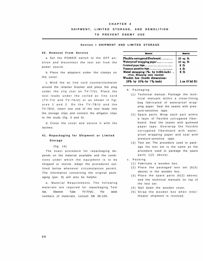
C H A P T E R 4
S H I P M E N T , L I M I T E D S T O R A G E , A N D D E M O L I T I O N
T O P R E V E N T E N E M Y U S E
S e c t i o n I S H I P M E N T A N D L I M I T E D S T O R A G E
4 0 . R e m o v a l F r o m S e r v i c e
a. S e t t h e P O W E R s w i t c h t o t h e O F F p o -
s i t i o n a n d d i s c o n n e c t t h e t e s t s e t f r o m t h e
p o w e r s o u r c e .
b. P l a c e t h e a d a p t e r s u n d e r t h e c l a m p s o n
t h e c o v e r .
c . W i n d t h e a c l i n e c o r d c o u n t e r c l o c k w i s e
around the re ta iner bracket and p lace the p lug
u n d e r t h e c l i p ( n o t o n T V - 7 / U ) . P l a c e t h e
t e s t l e a d s u n d e r t h e c o i l e d a c l i n e c o r d
( T V - 7 / U a n d T V - 7 A / U ) o r a s s h o w n i n f i g -
u r e s 1 a n d 2 . O n t h e T V - 7 B / U a n d t h e
TV-7D/U, inser t one end o f the tes t leads in to
the s torage c l ips and connect the a l l igator c l ips
to the s tuds ( f ig . 3 and 4) .
d . C l o s e t h e c o v e r a n d s e c u r e i t w i t h t h e
la tches .
4 1 . R e p a c k a g i n g f o r S h i p m e n t o r L i m i t e d
S t o r a g e
( f i g . 1 4 )
T h e e x a c t p r o c e d u r e f o r r e p a c k a g i n g d e -
pends on the mater ia l ava i lab le and the condi -
t i o n s u n d e r w h i c h t h e e q u i p m e n t i s t o b e
s h i p p e d o r s t o r e d . A d a p t t h e p r o c e d u r e s o u t -
l i n e d b e l o w w h e n e v e r c i r c u m s t a n c e s p e r m i t .
T h e i n f o r m a t i o n c o n c e r n i n g t h e o r i g i n a l p a c k -
aging (par . 8) wi l l a lso be helpfu l .
a . M a t e r i a l R e q u i r e m e n t s . T h e f o l l o w i n g
m a t e r i a l s a r e r e q u i r e d f o r r e p a c k a g i n g T e s t
Set, Electron Tube TV-7(*)/U. For stock
numbers o f mater ia ls , consul t SB 38-100.
Flexible corrugated fiberboard . . . . . . . . . . . .Waterproof wrapping paper . . . . . . . . . . . . . . . .Gummed paper tape . . . . . . . . . . . . . . . . . . . . . . . . . . . . . .Pressure-sensitive tape . . . . . . . . . . . . . . . . . . . . . . . .Metal strapping (%- by 0.020-inch) . .
(Nok Strapping seal. required)Wooden box (inside dimensions:
189$ by 10?4-by 7%-inch)
10 Sq ft10 Sq ft3 ft4 ft8 ft
1 ea (9 bd ft)
b . P a c k a g i n g .
( 1 )
( 2 )
( 3 )
T e c h n i c a l m a n u a l . P a c k a g e t h e t e c h -
n i c a l m a n u a l s w i t h i n a c l o s e - f i t t i n g
b a g f a b r i c a t e d o f w a t e r p r o o f w r a p -
p ing paper . Seal the seams wi th pres-
sure-sens i t i ve tape.
S p a r e p a r t s . W r a p e a c h p a r t w i t h i n
a l a y e r o f f l e x i b l e c o r r u g a t e d f i b e r -
b o a r d . S e a l t h e s e a m s w i t h g u m m e d
p a p e r t a p e . O v e r w r a p t h e f l e x i b l e
c o r r u g a t e d f i b e r b o a r d w i t h w a t e r -
p r o o f w r a p p i n g p a p e r a n d s e a l w i t h
pressure-sens i t i ve tape.
Test set. The procedure used to pack-
a g e t h e t e s t s e t i s t h e s a m e a s t h e
procedure used to package the spare
p a r t s ( ( 2 ) a b o v e ) .
c . P a c k i n g .
( 1 )
( 2 )
( 3 )
( 4 )
( 5 )
F a b r i c a t e a w o o d e n b o x .
P l a c e t h e p a c k a g e d t e s t s e t ( b ( 3 )
above) in the wooden box.
P l a c e t h e s p a r e p a r t s ( b ( 2 ) a b o v e )
a n d t h e t e c h n i c a l m a n u a l s o n t o p o f
t h e t e s t s e t .
N a i l d o w n t h e w o o d e n c o v e r .
S t r a p t h e w o o d e n b o x w h e n i n t e r -
t h e a t e r s h i p m e n t i s i n v o l v e d .
3 0
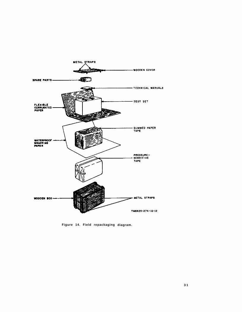
TM6625-274-12-12
Figure 14. Field repackaging diagram.
3 1
S e c t i o n I l . D E M O L I T I O N O F M A T E R I E L T O P R E V E N T E N E M Y U S E
4 2 . A u t h o r i t y f o r D e m o l i t i o n
The dest ruct ion procedures out l ined in para-
g r a p h 4 3 w i l l b e u s e d t o p r e v e n t f u r t h e r u s e
o f t h e e q u i p m e n t . D e m o l i t i o n o f t h e e q u i p m e n t
w i l l b e a c c o m p l i s h e d o n l y u p o n t h e o r d e r o f
t h e c o m m a n d e r .
4 3 . M e t h o d s o f D e s t r u c t i o n
A n y o r a l l o f t h e m e t h o d s o f d e s t r u c t i o n
given below may be used.
a . S m a s h . U s e s l e d g e s , a x e s , h a m m e r s ,
c r o w b a r s , o r a n y o t h e r h e a v y t o o l s a v a i l a b l e ;
s m a s h t h e c a s e , c o v e r , a d a p t e r s , f r o n t p a n e l ,
a n d m e t e r .
b. Cut . U s e a x e s , h a n d a x e s , m a c h e t e s , o r
kn ives ; cu t the ac l ine cord and tes t leads.
c . Burn . U s e g a s o l i n e , k e r o s e n e , o i l , f l a m e -
t h r o w e r s , o r i n c e n d i a r y g r e n a d e s ; b u m t h e
technica l manuals and test data book.
Warning: Be extremely careful wi th explo-
sive and incendiary devices. Use these i tems
only when the need is urgent .
d . E x p l o d e . U s e g r e n a d e s , T N T , o r f i r e -
arms, i f exp los ives are necessary .
e . D i s p o s e . B u r y o r s c a t t e r d e s t r o y e d p a r t s
o r t h r o w t h e m i n t o n e a r b y w a t e r w a y s .
3 2
A P P E N D I X I
R E F E R E N C E S
F o l l o w i n g i s a l i s t o f a p p l i c a b l e r e f e r e n c e s
a v a i l a b l e t o t h e o p e r a t o r o r o r g a n i z a t i o n a l
m a i n t e n a n c e p e r s o n n e l o f T e s t S e t , E l e c t r o n
T u b e T V - 7 ( * ) / U :
S B 3 8 - 1 0 0 P r e s e r v a t i o n , P a c k a g -
i n g a n d P a c k i n g M a -
t e r i a l s , S u p p l i e s a n d
E q u i p m e n t U s e d b y
t h e A r m y
T B 1 1 - 5 0 8 3 - 1 T u b e T e s t D a t a f o r
E l e c t r o n T u b e T e s t
S e t s T V - 7 / U , T V -
7 A / U , T V - 7 B / U ,
a n d T V - 7 D / U
T M 1 1 - 6 6 2 5 - 2 7 4 - 2 0 P O r g a n i z a t i o n a l M a i n t e -
n a n c e R e p a i r P a r t s
a n d S p e c i a l T o o l s
L i s t a n d M a i n t e -
n a n c e A l l o c a t i o n
C h a r t f o r T e s t S e t s ,
E l e c t r o n T u b e T V -
7 / U , T V - 7 A / U ,
T V - 7 B / U a n d T V -
7 D / U
33
A P P E N D I X I I
O P E R A T O R ’ S M A I N T E N A N C E R E P A I R P A R T S
A N D S P E C I A L T O O L S L I S T
S e c t i o n I I N T R O D U C T I O N
1 . S c o p e
a . G e n e r a l . T h i s a p p e n d i x l i s t s i t e m s s u p -
p l i e d f o r i n i t i a l o p e r a t i o n a n d f o r r u n n i n g
s p a r e s . T h e l i s t i n c l u d e s t o o l s , a c c e s s o r i e s ,
par ts , and mater ia l i ssued as par t o f t h e m a j o r
i t e m , a n d a l l i t e m s a u t h o r i z e d f o r b a s i c o p e r -
a t o r m a i n t e n a n c e o f t h e e q u i p m e n t . E n d i t e m s
of equipment are issued on the bas is o f a l low-
a n c e s p r e s c r i b e d i n e q u i p m e n t a u t h o r i z a t i o n
t a b l e s a n d o t h e r d o c u m e n t s t h a t a r e a b a s i s
f o r r e q u i s i t i o n i n g .
b . C o l u m n s . T h e c o l u m n s a r e a s f o l l o w s :
( 1 )
( 2 )
( 3 )
( 4 )
( 5 )
S o u r c e , m a i n t e n a n c e , a n d r e c o v e r a -
b i l i t y code. N o t u s e d .
F e d e r a l s t o c k n u m b e r . T h i s c o l u m n
l i s t s t h e 1 1 - d i g i t F e d e r a l s t o c k n u m -
b e r .
Designat ion by model . A dagger
ind icates the model in which the par t
is used.
D e s c r i p t i o n . N o m e n c l a t u r e o r t h e
s t a n d a r d i t e m n a m e a n d b r i e f i d e n t i -
fy ing data for each i tem are l i s ted in
t h i s c o l u m n . W h e n r e q u i s i t i o n i n g ,
e n t e r t h e n o m e n c l a t u r e a n d d e s c r i p -
t i o n o n t h e r e q u i s i t i o n .
Uni t o f i ssue. The un i t o f i ssue is the
s u p p l y t e r m b y w h i c h t h e i n d i v i d u a l
i t e m i s c o u n t e d f o r p r o c u r e m e n t ,
( 6 )
( 7 )
( 8 )
( 9 )
s t o r a g e , r e q u i s i t i o n i n g , a l l o w a n c e s ,
and issue purposes.
E x p e n d a b i l i t y . E x p e n d a b l e i t e m s a r e
i n d i c a t e d b y X ; n o n e x p e n d a b l e i t e m s
a r e i n d i c a t e d b y N X .
Q u a n t i t y a u t h o r i z e d . U n d e r “ I t e m s
C o m p r i s i n g a n O p e r a b l e E q u i p m e n t , ”
the co lumn l is ts the quant i ty o f i tems
s u p p l i e d f o r t h e i n i t i a l o p e r a t i o n o f
t h e e q u i p m e n t . U n d e r “ R u n n i n g
S p a r e s a n d A c c e s s o r y I t e m s ” t h e
q u a n t i t i e s a r e t h o s e i s s u e d i n i t i a l l y
w i t h t h e e q u i p m e n t a s s p a r e p a r t s .
T h e q u a n t i t i e s a r e a u t h o r i z e d t o b e
k e p t o n h a n d b y t h e o p e r a t o r f o r
m a i n t e n a n c e o f t h e e q u i p m e n t .
I l lus t ra t ra t ions (F igure No. ) . T h e n u m -
bers in th is co lumn refer to the i l lus-
t r a t i o n o r i l l u s t r a t i o n s w h e r e t h e p a r t
i s shown.
I l l u s t r a t i o n s ( I t e m N o . ) . T h i s c o l u m n
l i s t s t h e r e f e r e n c e s y m b o l s u s e d f o r
i d e n t i f i c a t i o n o f i t e m s i n t h e i l l u s t r a -
t ions or text o f the manual .
2 . C r i t i c a l I t e m s
A zero s lash (0) in the “Descr ip t ion” co lumn
ind icates i tems that are expected to fa i l dur ing
t h e f i r s t y e a r ; a l s o i t e m s t h a t w i l l m a k e t h e
e q u i p m e n t i n o p e r a t i v e i f t h e y f a i l .
3 4
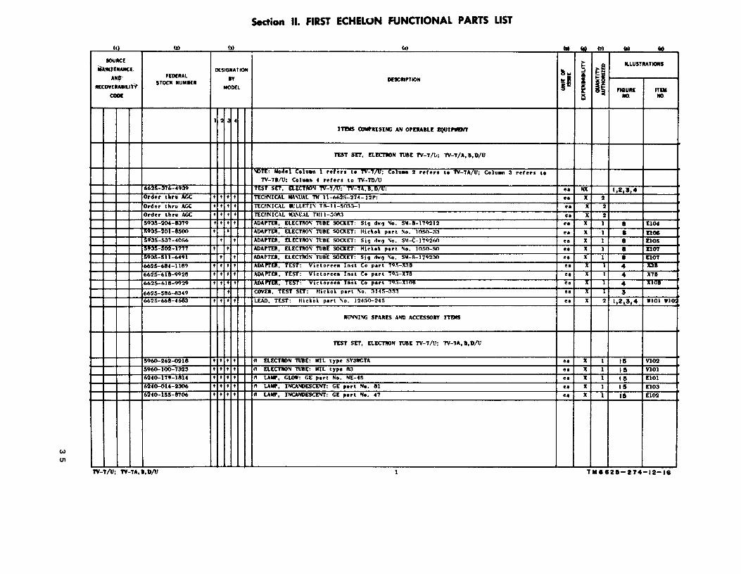
Section II
TM
6625-274-12-16
35
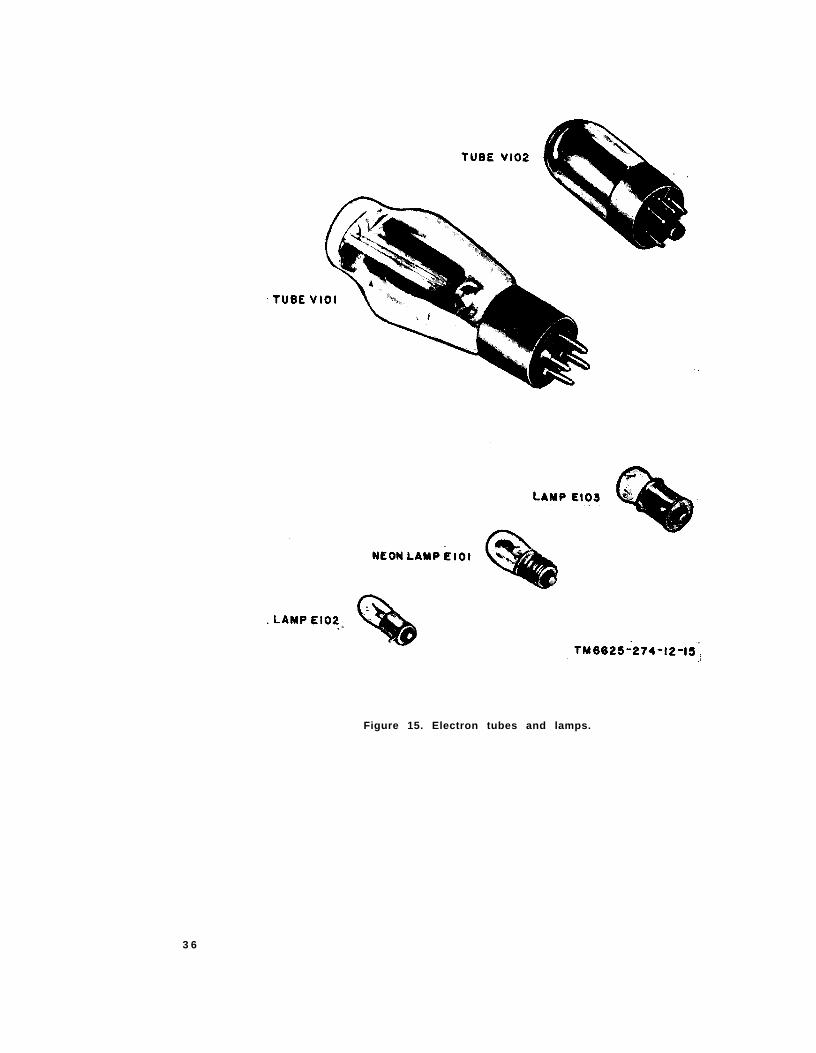
TM6625-274-12-15
Figure 15. Electron tubes and lamps.
3 6
A P P E N D I X I I I
M A I N T E N A N C E A L L O C A T I O N C H A R T
S e c t i o n I I N T R O D U C T I O N
1 . S c o p e
a . G e n e r a l . T h i s a p p e n d i x a s s i g n s m a i n t e -
n a n c e f u n c t i o n s a n d r e p a i r o p e r a t i o n s t o b e
p e r f o r m e d b y t h e l o w e s t a p p r o p r i a t e m a i n t e -
nance echelon.
b . A l l o c a t i o n o f M a i n t e n a n c e F u n c t i o n s .
C o l u m n s i n s e c t i o n I I , A l l o c a t i o n o f M a i n t e -
nance Funct ions, are def ined as fo l lows:
( 1 )
( 2 )
P a r t o r c o m p o n e n t . T h i s c o l u m n
shows on ly the nomencla ture or s tand-
a r d i t e m . A d d i t i o n a l d e s c r i p t i v e d a t a
a r e i n c l u d e d o n l y w h e r e c l a r i f i c a t i o n
is necessary to ident i fy the par t . Com-
ponents and par ts compr is ing a major
end i tem are l is ted a lphabet ica l ly . As-
s e m b l i e s a n d s u b a s s e m b l i e s a r e i n
a lphabet ica l sequence wi th the i r com-
p o n e n t s l i s t e d a l p h a b e t i c a l l y i m m e d i -
a t e l y b e l o w t h e a s s e m b l y l i s t i n g .
M a i n t e n a n c e f u n c t i o n . T h i s c o l u m n
i n d i c a t e s t h e v a r i o u s m a i n t e n a n c e
f u n c t i o n s a l l o c a t e d t o t h e e c h e l o n
c a p a b l e o f p e r f o r m i n g t h e o p e r a t i o n s .
( a )
( b )
( c )
( d )
( e )
( f )
S e r v i c e . To c lean, to preserve, and
t o r e p l e n i s h f u e l a n d l u b r i c a n t s .
A d j u s t . T o r e g u l a t e p e r i o d i c a l l y t o
p r e v e n t m a l f u n c t i o n .
I n s p e c t . To ver i fy serv iceab i l i t y and
t o d e t e c t i n c i p i e n t e l e c t r i c a l o r
m e c h a n i c a l f a i l u r e b y s c r u t i n y .
T e s t . T o v e r i f y s e r v i c e a b i l i t y a n d
t o d e t e c t i n c i p i e n t e l e c t r i c a l o r
mechan ica l fa i lu re by use o f spec ia l
e q u i p m e n t s u c h a s g a g e s , m e t e r s ,
e tc .
R e p l a c e . T o s u b s t i t u t e s e r v i c e a b l e
assemblies, subassemblies, and parts
f o r u n s e r v i c e a b l e c o m p o n e n t s .
R e p a i r . T o r e s t o r e t o a s e r v i c e a b l e
c o n d i t i o n b y r e p l a c i n g u n s e r v i c e -
able parts or by any other action re-
q u i r e d u t i l i z i n g t o o l s , e q u i p m e n t ,
and sk i l ls ava i lab le , to inc lude weld-
i n g , g r i n d i n g , r i v e t i n g , s t r a i g h t e n -
i n g , a d j u s t i n g , e t c .
( g )
( h )
( 3 )
( 4 )
( 5 )
C a l i b r a t e . T o d e t e r m i n e , c h e c k , o r
r e c t i f y t h e g r a d u a t i o n o f a n i n s t r u -
m e n t , w e a p o n , o r w e a p o n s s y s t e m ,
or components of a weapons system.
R e b u i l d . T o r e s t o r e t o a c o n d i t i o n
c o m p a r a b l e t o n e w b y d i s a s s e m -
bl ing the i tem to determine the con-
d i t i o n o f i t s c o m p o n e n t p a r t s a n d
r e a s s e m b l i n g i t u s i n g s e r v i c e a b l e ,
r e b u i l t , o r n e w a s s e m b l i e s , s u b a s -
sembl ies , and par ts .
1st, 2d, 3d, 4th, 5th echelon. T h e s y m -
bol X ind icates the echelon respons i -
b l e f o r p e r f o r m i n g t h a t p a r t i c u l a r
m a i n t e n a n c e o p e r a t i o n , b u t d o e s n o t
n e c e s s a r i l y i n d i c a t e t h a t r e p a i r p a r t s
wi l l be s tocked at that leve l . Echelons
h i g h e r t h a n t h e e c h e l o n m a r k e d b y X
a r e a u t h o r i z e d t o p e r f o r m t h e i n d i -
cated operation. Column 5 is not used.
Tools requ i red. T h i s c o l u m n i n d i c a t e s
the too l , test , and maintenance equip-
m e n t s r e q u i r e d t o p e r f o r m t h e m a i n -
tenance funct ions. These numbers are
i d e n t i f i e d i n s e c t i o n I I I , A l l o c a t i o n o f
T o o l s f o r M a i n t e n a n c e F u n c t i o n s .
R e m a r k s . T h i s c o l u m n c o n t a i n s a n y
n o t a t i o n s n e c e s s a r y t o c l a r i f y t h e
data c i ted in the preceding co lumns.
c . A l l o c a t i o n o f T o o l s f o r M a i n t e n a n c e
F u n c t i o n s . C o l u m n s i n s e c t i o n I I I , A l l o c a t i o n
o f T o o l s f o r M a i n t e n a n c e F u n c t i o n s , a r e a s
f o l l o w s :
( 1 )
( 2 )
( 3 )
T o o l s r e q u i r e d f o r m a i n t e n a n c e f u n c -
t i o n s . This co lumn l i s ts the too ls and
t e s t e q u i p m e n t r e q u i r e d t o p e r f o r m
t h e m a i n t e n a n c e f u n c t i o n s .
1st , 2nd, 3rd , 4 th , and 5 th eche lon. A
dagger in columns 3, 5, and 6
i n d i c a t e s t h a t t h e t o o l o r t e s t e q u i p -
ment is a l located to that echelon. Col -
umns 2 and 4 are not used.
T o o l c o d e . T h i s c o l u m n l i s t s t h e t o o l
code ass igned. The numbers are used
3 7
i n t h e m a i n t e n a n c e a l l o c a t i o n c h a r t
t o r e f e r t o t h e i n d i c a t e d i t e m .
(4) R e m a r k s . N o t u s e d .
2 . M a i n t e n a n c e b y U s i n g O r g a n i z a t i o n s
When th is equ ipment is used by s igna l serv-
i c e o r g a n i z a t i o n s o r g a n i c t o t h e a t e r h e a d q u a r -
ters or communicat ion zones to prov ide theater
c o m m u n i c a t i o n s , t h o s e m a i n t e n a n c e f u n c t i o n s
a l l o c a t e d u p t o a n d i n c l u d i n g f o u r t h e c h e l o n
a r e a u t h o r i z e d t o t h e o r g a n i z a t i o n o p e r a t i n g
t h i s e q u i p m e n t .
3 . M o u n t i n g H a r d w a r e
T h e b a s i c e n t r i e s o f t h e m a i n t e n a n c e a l l o -
cat ion char t do not inc lude mount ing hardware
such as sc rews, nu ts , bo l ts , washers , b racke ts ,
a n d c l a m p s .
3 8
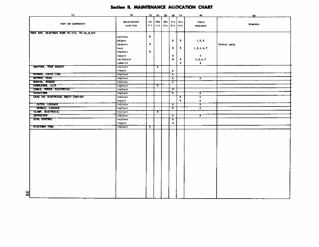
Section II
39
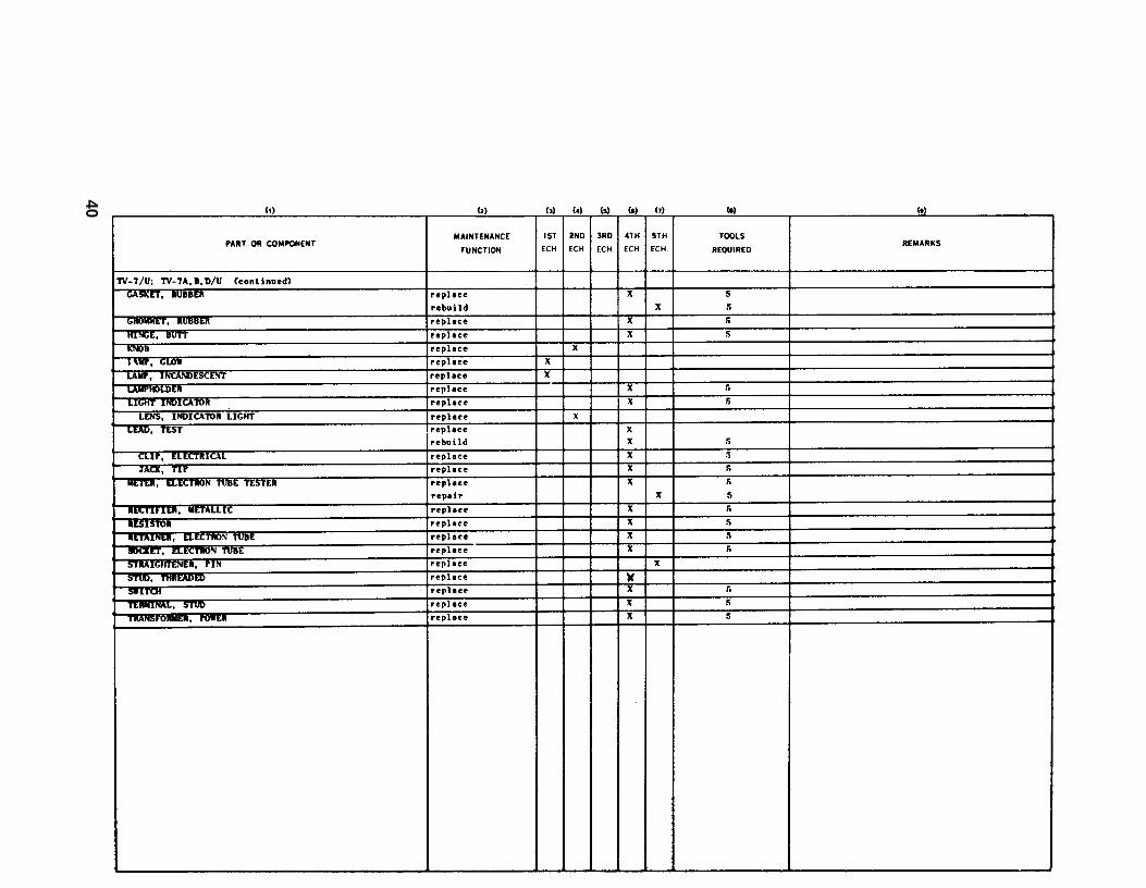
40
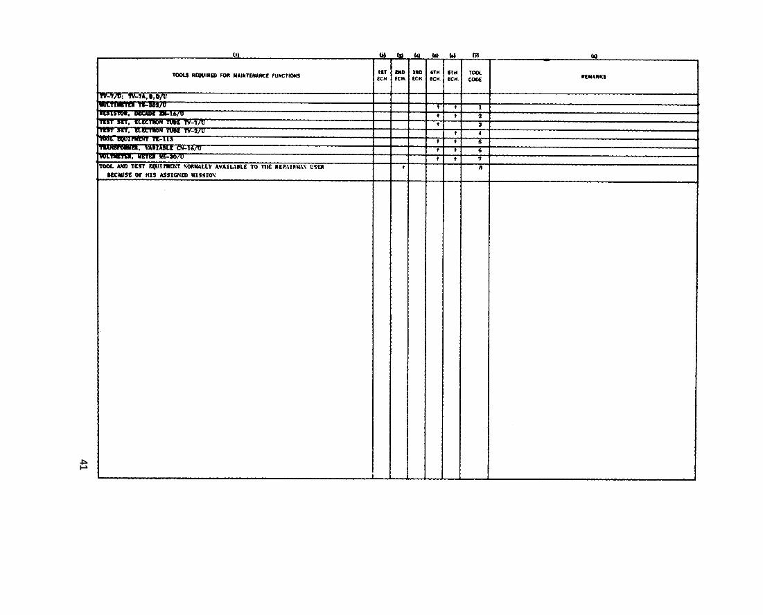
41
By Order of Wilber M. Brucker, Secretary of the Army:
L. L. LEMNITZERGeneral, United States Army,
Official: Chief of Staff.R. V. LEE,
Major General, United States Army,The Adjutant General.
Distribution:
Active Army:
To be distributed in accordance with DA Form 12-7 requirements for TM 11 Series plus the followingadditional formula:
USASA (1) 6-848CNGB (1) 6-866Def Atomic Spt Agcy (6) 6-856Tech Sti, DA (1) except 6-878
CSigO (18) 6-876USA Abn & Elct Bd (1) 6-415USA ATB (1) 6-416US ARADCOM (2) 6-600 (AA-AD)US ARADCOM Rgn (2)MDW (1) 6-606Seventh, US Army (5) 6-617EUSA (6) 6-627Corps (2) 6-1ooUSASCS (26) 6-101JBUSMC (2) 6-115Units org under the fol TOE: (2 copies 6-116
each) 6-1261-7 6-1261-17 6-1861-26 6-1861-27 6-2001-87 6-2011-67 6-8001-107 6-8011-207 6-3156-s 6-8166-6 6-8266-7 6-8266-8 6-4016-16 6-4166-16 6-416S-17 6-6006-35 6-5016-86 6-6255-87 6-6865-188 6-6866-192 6-6876-216 6-6466-216 6-6686-217 6-6766-218 6-6765-226 6-6776-2265-227 6-6116-278 6-680
42
6-631
77-27-117-127-167-167-197-267-267-277-817-827-627-957-963-168-168-768-1878-600 (AA-AH)+229-478-669+69-76
8-2178-8779-600 (AA-AC)1*2210+771*68611-611-611-711-811-1611-1611-1711-1811-2611-3711-S811-8911-4611-4611-4711-6611-S611-6711-6811-9611-9611-9711-9811-9911-11711-16s11-16611-167
11-16811-600 (AA-AE)11-66611-66711-66311-68711-69211-69711-60812-1712-821717-217-1717-2217-2617-2617-2717-8217-8617-3617-3717-4617-4617-6117-5217-6817-6517-6617-6717-6217-6517-6617-6717-8617-8617-8717-11617-11617-11717-12517-12617-12719-2719-2919-9519-3719-6519-6719-21719-500 (AA-AE)20-4620-4629-5680-1630-1980-2282-6182-5682-6782-60038-2
4 3
44-447
88-67 (AA-AC)44-600
88-610 (AAj AB) 44-686
86-6189-62 44-68788-6186+189-401 44-646
44-647
4+18 44-64944-16 46-600 (AA-AC)U-16 66-11
66-M66-16
44-87 66-8766-86
44-7066-4766-67
44-87 66+644-101 6H644-11644-116 6H16u-286 66+644-286 M-m44-287 66-12844-246 66-12644-486 66-15744-486 66-500 (AA-AE)44-487 6744-446
NC/ Stati AG (8); tl~ame M Active Army except l llowance ie one copy te eaeh unk
USARt None
For explanation of l bbrevixtione uee& eee AR H.
4 4


![POC - Heska · Element POC Blood Gas & Electrolyte Analyzer B Preface Element POC [epoc ®] Blood Gas & Electrolyte Analyzer The Element POC® portable device consists of the blood](https://img.pdfslide.us/doc/110x75/5edb6ef2ad6a402d6665a6de/poc-heska-element-poc-blood-gas-electrolyte-analyzer-b-preface-element-poc.jpg)