Embed Size (px)
Citation preview

0
20
40
go inside
Issued byFachbereich Elektronik und EDV
im Bundesverband öffentlich bestellterund vereidigter sowie qualifizierter
Sachverständiger e.V.BVS
Peter Gabler
Installation guide for protection againstundefined system faults as well as surge
voltage, lightning and power failure
“Your computerdoes not run
on every socket!”

German Library – Standard CIP Record
A catalogue record for this publication is available from Die Deutsche Bibliothek.
ISBN 3-89639-232-8
1. Edition 2000
© Wißner-Verlag, Augsburg 2000
This work and its parts are protected by copyright. Therefore, allutilisation other than in the legally permitted cases requires priorwritten permission from the publisher.
Staggered prices for large-quantity ordersPlease enquire about our low staggered prices if you should needlarge quantities of this brochure, for example as the basis for aseminar or for customer talks.

Peter Gabler
“Your computer does notrun on every socket!!”
Installation guide for protection againstundefined system faults as well as surgevoltage, lightning and power failure
Issued by Fachbereich Elektronik und EDV imBundesverband öffentlich bestellterund vereidigter sowie qualifizierterSachverständiger e.V. (BVS)

Peter Gabler is an electronics technician and has worked in theareas of hardware and software since 1970. He started with amanufacturer of mainframes and later went on to work as after-sales manager with a nationwide systems house for small andmedium companies in selected sectors. During some of theseyears he was in charge of the central hotline and service mar-keting for product-oriented services. The focus was on prevention,i.e. fault-free installation and safe operation of PCs and networkelectronics systems.He has been a freelance consultant since 1993, advising systemshouses in how to design services as marketable products.He is a publicly certified expert on damage to electronic systemscaused by surge voltage.
Peter GablerSperberweg 771691 Freiberg a. N.
Phone:0 71 41-7 53 10Fax:0 71 41-7 68 74Mobile:01 71-7 71 11 48
3
Contents
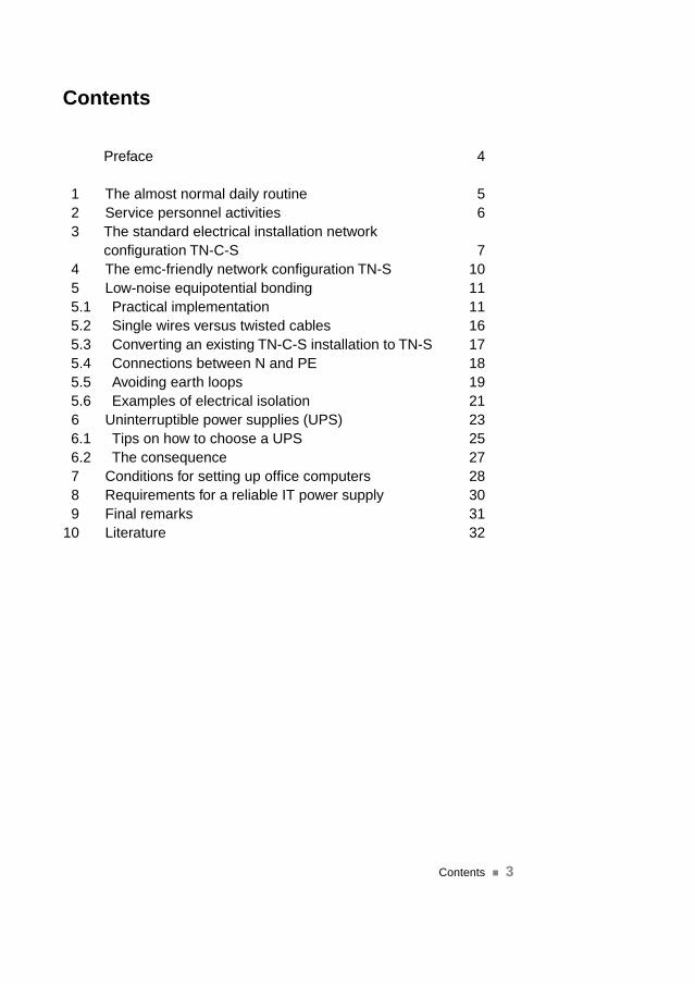
Preface 4
1 The almost normal daily routine 52 Service personnel activities 63 The standard electrical installation network
configuration TN-C-S 74 The emc-friendly network configuration TN-S 105 Low-noise equipotential bonding 115.1 Practical implementation 115.2 Single wires versus twisted cables 165.3 Converting an existing TN-C-S installation to TN-S 175.4 Connections between N and PE 185.5 Avoiding earth loops 195.6 Examples of electrical isolation 216 Uninterruptible power supplies (UPS) 236.1 Tips on how to choose a UPS 256.2 The consequence 277 Conditions for setting up office computers 288 Requirements for a reliable IT power supply 309 Final remarks 31
10 Literature 32
Contents ��

Preface��4
Preface
It is a widely spread opinion that PCs, networks and other net-worked electronics systems can be installed swiftly and easilybecause there are socket outlets everywhere. But, whenever il-logical and undefined faults occur, it transpires that problems canoften be ascribed to faults in the cabling (230 V~/data cables).
In the interests of system users, it is important to avoid malfunc-tions and destruction. The cost of a production outage are muchhigher than the cost of an electrical installation that does justice toIT requirements or in comparison with the replacement of defec-tive hardware. The overall entrepreneurial risk cannot be insuredand is economically not justifiable.
This installation guide is the result of more than 15 years of safetyand environmental analyses in the area of PCs, mainframes andnetworked electronics systems. It was drawn up with great careand attention and has been put to use in innumerable informativetalks with end customers and their electrical installation techni-cians. A large number of installations has been successfully con-verted in accordance with the contents of this guide. On the onehand, this guide was conceived as lightweight food for thought forinterested readers, and on the other hand, as the basis for con-ducting talks with the user. In this way, users are able to realisethat an installation not only involves setting up hardware andloading and configuring software, but begins much earlier.

1The almost normal daily routine
�� Just before you finish your day’s work, the PC simply stops orthe network hangs.
�� Without any prompting whatever, the load in the networkincreases from about 10% to more than 30%. Networkperformance is poor.
�� You enter data on a workstation that gets sent off practically inone packet with a clearly visible delay.
�� Several memory errors are recorded in a system’s error log.�� In a system’s cache, individual status bits are altered, locking
access to the hard disks. The data is lost.�� A successful data backup is displayed, despite the fact that the
data cannot be accessed in the restore process.�� For no apparent reason, the coupon printer sequence is
changed over on a cash register system. The printout isuseless.
�� New workstations are installed and are integrated into anetwork. A connection cannot be established until the datatransfer rate is reduced from 100 Mbits/s to 10 Mbits/s.
�� Read/write errors on hard disks are reported.�� You cannot get to grips with the parameters of an air condi-
tioning system. The temperature falls below the dew point andthe valuable stucco “drips” from the ceiling.
�� The fire brigade arrives several times as the result of falsealarms by the fire alarm system.
�� Without any apparent reason, the UPS system switches tobypass and the screen display jitters.
The almost normal daily routine �� 5
Undefined faultswithout any
recognisable logical connection

2Service personnel activities
The service technician goes to a location and does not im-mediately find any faults. A short time later the same symptomsmanifest themselves to the technician. Now, hardware is replacedbecause he has to show that he has done something. The moduleis deposited at the service base and is placed in intermediatestorage. A short time later, the same symptoms appear. The soft-ware specialist does not find any faults either. Updates do notbring any improvements.When computers, printers or modules are tested at the servicebase, though, no faults appear.
Surveys undertaken with renowned German computer manu-facturers have shown that between 70% and 80% of the networkcards sent in for module replacement are not defective.
6 Service personnel activities��
5 % Surge voltage
15 % Capacitive and inductive interference
80 % Potential differences in the PE conductor system
Causes of malfunctions and destruction from an analysis ofdamage
Defective systemsare diagnosed atthe service baseand found to befaultless

3The standard electrical installation networkconfiguration TN-C-S
Up to now, and still today, the network configuration TN-C-S hasbeen and is usually installed in new buildings. (The network config-uration TT is prescribed in a small number of regions in Germany.)The TN-C or TN-C-S network configuration (vertical TN-C/ horizon-tal TN-S) is the network configuration that is encountered mostfrequently in the event of malfunctions and destruction of electro-nics systems. It is therefore referred to in the most recent litera-ture as being unfavourable in terms of EMC. As specified in VDE,in this network configuration the PE and N conductors may berouted in part of the network system as a common PEN conduc-tor provided its cross-section is at least 10 mm² Cu or 16 mm² Al.
This installation is the cheapest minimum configuration that pro-tects persons if installed skilfully and expertly. Nevertheless, thisnetwork configuration cannot by far offer protection for functions.As one PEN conductor is permitted in this network configuration,the neutral conductor currents inevitably flow through the PE con-ductor.
The standard electrical installation network configuration TN-C-S �� 7
· · ·
·····
L1
L2
L3
PE
N
��
��
·B
etr
iebserd
er
Betr
iebsm
itte
l
····
��
��
·
··
PE
N
Tra
nsfo
rmato
r
TN-C-System
Neutral conductorcurrents are forced
through the PEconductor
Tran
sfor
mer
Ope
ratio
n ea
rth-
ing
elec
trod
eE
quip
men
t
L 1 L 2 L 3

A multiply earthed PEN conductor, however, is simultaneouslyconnected to the relevant earthing system and generates inter-ference voltages and potential differences between the systemsbelonging to the various subdistribution boards. These currentsare distributed randomly depending on the quality or lowimpedance of connections.
The figure shows the example of a current distribution system in abuilding as well as its earthing and equipotential bonding system.These currents are able to flow as soon as one PEN conductor isearthed at least twice.
8 The standard electrical installation network configuration TN-C-S��
Source: d
rawing by
the author
Possible distribu-tion of current inan equipotentialbonding system

In many cases, an attempt is made to solve the problems withUPS. Despite electrical isolation at N and L, there is no remedybecause the PE conductor must be connected through contin-uously to provide protection against shock hazards. Compen-sating currents can nevertheless flow.In this environment, there is no “low-noise equipotential bonding”as stipulated in VDE 0100 Part 540 of November 1991.
The screen and reference conductor of the signal wires areconnected to the PEN conductor. In a system with one or severalPEN conductors, the return currents of the N conductor flow on alllines that are connected to the earthed PEN conductor.
What we have just said about the standard installation ensuresprotection of persons if it is installed skilfully and expertly. In thisenvironment, non-networked standalone devices are also capableof functioning (PC, printer, monitor, copier and fax machine).
If several devices are networked, e.g. across several floors,buildings or subdistribution boards, then a completely differentsituation suddenly prevails, calling for an improved, PEN-freesystem environment.
In the buildings, electromagnetic compatibility between thesystems must be ensured in conformity with VDE 0100 and itsparts.
The standard electrical installation network configuration TN-C-S �� 9
···
·· ·
L1
L2
L3
PEN
·IT
IT
··
IT
·· ·
·IT
IT
··
IT
·· ·
·IT
IT
·
IT
� � � �
IT
IT
IT
I
EBShielded cable for IT andtelekommunications systems
I
I
No low-noise equipotential bonding
From Kiefer: VDE 0100 und die Praxis, Page 271
Neutral conductorcurrents in all
earthed parts of anIT system

4The EMC-friendly network configuration TN-S
Since mid 1980, the German Post Office, German Rail and broad-cast authorities have prescribed for their internal purposes thatthe TN-S network configuration must be installed in a building iftelecommunications and information processing equipment areinstalled there.
Since November 1991, VDE 0100 Part 540 has prescribed inAppendix C2 that low-noise equipotential bonding can only beachieved with the TN-S network configuration.
In principle, this means that the N and PE conductors are routedseparately as from the transformer or the feeding point and acontinuous 5-conductor network L1/L2/L3/N/PE must exist in thebuilding up to the last socket. In principle, throughout the instal-lation the N conductor must be handled and routed like an insu-lated phase conductor. In the entire building, the N conductormust no longer be connected anywhere to the PE conductor (noPEN jumpers). The aim of this is to ensure that no operationalworking currents are able to flow through the PE conductor.
10 The EMC-friendly network configuration TN-S��
TN-S-System
· · · ·
·····
L1
L2
L3
N PE
��
��
·B
etr
iebserd
er
Betr
iebsm
itte
l
Tra
nsfo
rmato
r
Prerequisite for aclean system en-vironment: networkconfiguration TN-S!
Tran
sfor
mer
Ope
ratio
n ea
rth-
ing
elec
trod
eE
quip
men
t
L 1 L 2 L 3
5Low-noise equipotential bonding
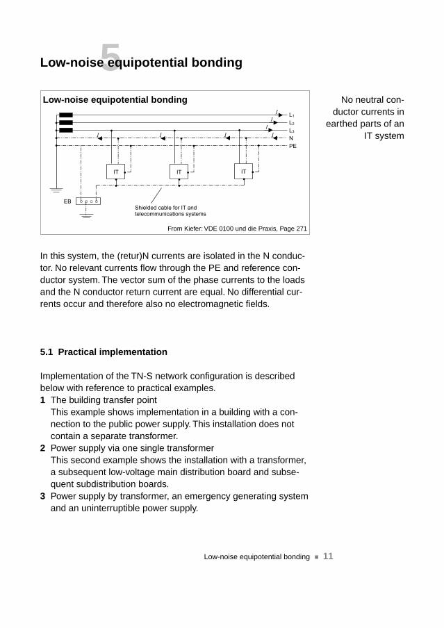
In this system, the (retur)N currents are isolated in the N conduc-tor. No relevant currents flow through the PE and reference con-ductor system. The vector sum of the phase currents to the loadsand the N conductor return current are equal. No differential cur-rents occur and therefore also no electromagnetic fields.
5.1 Practical implementation
Implementation of the TN-S network configuration is describedbelow with reference to practical examples.1 The building transfer point
This example shows implementation in a building with a con-nection to the public power supply. This installation does notcontain a separate transformer.
2 Power supply via one single transformerThis second example shows the installation with a transformer,a subsequent low-voltage main distribution board and subse-quent subdistribution boards.
3 Power supply by transformer, an emergency generating systemand an uninterruptible power supply.
Low-noise equipotential bonding �� 11
····
··
·
L1
L2
L3
N
PE
·IT
··
··
·
·IT
··
··
·
·IT
·
� � � �
I
EBShielded cable for IT andtelecommunications systems
I I I I
I
I
Low-noise equipotential bonding
From Kiefer: VDE 0100 und die Praxis, Page 271
No neutral con-ductor currents in
earthed parts of anIT system
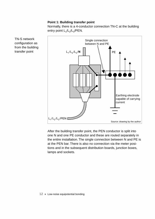
Point 1: Building transfer pointNormally, there is a 4-conductor connection TN-C at the buildingentry point L1/L2/L3/PEN.
After the building transfer point, the PEN conductor is split intoone N and one PE conductor and these are routed separately inthe entire installation. The single connection between N and PE isat the PEN bar. There is also no connection via the meter posi-tions and in the subsequent distribution boards, junction boxes,lamps and sockets.
12 Low-noise equipotential bonding��
Single connection between N and PE
/ / /
/ / /
Earthing electrode capable of carrying current
Source: drawing by the author
TN-S networkconfiguration asfrom the buildingtransfer point
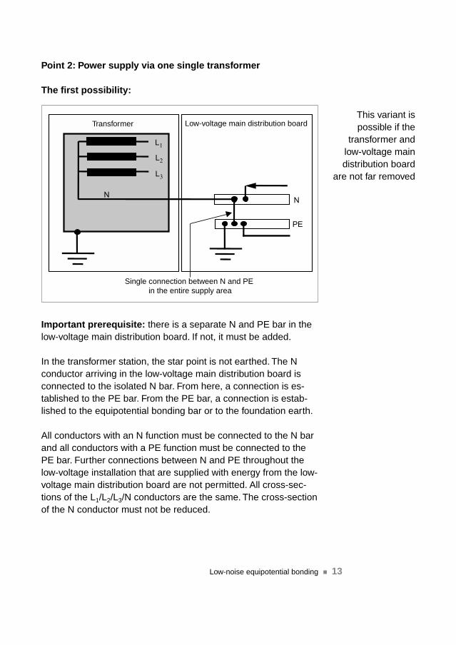
Point 2: Power supply via one single transformer
The first possibility:
Important prerequisite: there is a separate N and PE bar in thelow-voltage main distribution board. If not, it must be added.
In the transformer station, the star point is not earthed. The Nconductor arriving in the low-voltage main distribution board isconnected to the isolated N bar. From here, a connection is es-tablished to the PE bar. From the PE bar, a connection is estab-lished to the equipotential bonding bar or to the foundation earth.
All conductors with an N function must be connected to the N barand all conductors with a PE function must be connected to thePE bar. Further connections between N and PE throughout thelow-voltage installation that are supplied with energy from the low-voltage main distribution board are not permitted. All cross-sec-tions of the L1/L2/L3/N conductors are the same. The cross-sectionof the N conductor must not be reduced.
Low-noise equipotential bonding �� 13
Transformer Low-voltage main distribution board
Single connection between N and PE in the entire supply area
This variant is possible if the
transformer andlow-voltage maindistribution board
are not far removed

The second possibility:
Important prerequisite: There is a separate N and PE bar in thelow-voltage main distribution board. If not, it must be added.
As from the transformer’s star point, identical cross-sections ofthe L1/L2/L3 and N conductors are laid. The PE may be reduced.Preferably cables (e.g. NYCWY) should be laid, not single wires.
N and PE are single jumpered at the transformer. There are nofurther PE end jumpers in the installation.
14 Low-noise equipotential bonding��
Single connection between N and PE in the entire supply area
Low-voltage main distribution boardTransformerLarge distancesbetween trans-former and low-voltage main dis-tribution board

Point 3: Power supply by transformer, emergency generatingsystem and uninterruptible power supply
The star points must not be earthed if these components arecombined in a power supply concept. Every incoming star pointconductor must be connected to the N bar in the low-voltage maindistribution board. This meets the requirement for the TN-S net-work configuration according to which the star point must only beearthed once and therefore connected only once to PE.
In this case also, the earthing electrode should be capable ofcarrying currents which, in cases of doubt, must be measuredthroughout.
As far as possible, the connections from the energy sources tothe low-voltage main distribution board should not consist ofsingle wires, but of twisted cables.
All N conductors have the same cross-section as the phaseconductors.
Low-noise equipotential bonding �� 15
Single connection between N and PE in the entire supply area
Transformer Generator UPS Set up the N bus system!

5.2 Single wire versus twisted cables
As already shown in relation to the transformer connections to thelow-voltage main distribution board, the connections from the low-voltage main distribution board to the subsequent subdistributionboards should not consist of single wires (e.g. NYY-0), but oftwisted cables (e.g. NYCWC). Several twisted cables should beconnected in parallel if the cross-section of one cable is notsufficient for the load.
Reason: if several single wires are lying in parallel on a cablerack, the individual wires’ magnetic fields can no longer canceleach other out. This results in substantial interference of monitorsthat are located one floor above the rack or in a room next to it, forexample.
Values from practice: in an establishment, approximately 700 Arms flowed per subdistribution board and phase. In an office roomdirectly behind, a magnetic field strength of 20 µ Tesla could stillbe measured at a distance of about two meters.
Important note: a monitor image begins to flicker at about 0.7 to1 µ Tesla.
If the wires in a cable are twisted, the magneticfields of the total currents in the phase conduc-tors to the load and the return current in the Nconductor can cancel each other out if theamount is the same and the sign is inverted.
16 Low-noise equipotential bonding��
The magnetic fields cannot cancel each other out
Avoid single wiresand use multiple-conductor cables
The magnetic fieldscancel each otherout

5.3 Converting an existing TN-C-S installation to TN-S
An existing TN-C-S installation can be converted to a TN-Sinstallation.
Low-noise equipotential bonding �� 17
Subdistribu-tion board
Subdistribu-tion board
Subdistribu-tion board
PEN must become N and must stay in the
cable with the phases!
Condition: in the supply lines from the low-voltage main distribu-tion board to the subdistribution boards, the previous PEN con-ductor at least has the same cross-section as the phase conductors(no reduced cross-section of thePEN). In this case, it can be con-verted to an N conductor. The pre-vious blue phase conductor ismarked black at both ends andover its entire visible length and the previous yellow/green PEN ismarked blue at both ends over itsentire visible length. A yellow/greenPE conductor can be pulled to theoutside. This is permitted by Sec-tion 5.1.4 of VDE 0100 Part 510,February 1996.A reduced PEN in a cable must notbe converted to a PE because themagnetic fields of the phase cur-rents can no longer cancel eachother out owing to the missing Ncurrent. The differential current isinductively impressed into the PE.
Converting a PENconductor to an N
conductor
PE can be pulled tothe outside
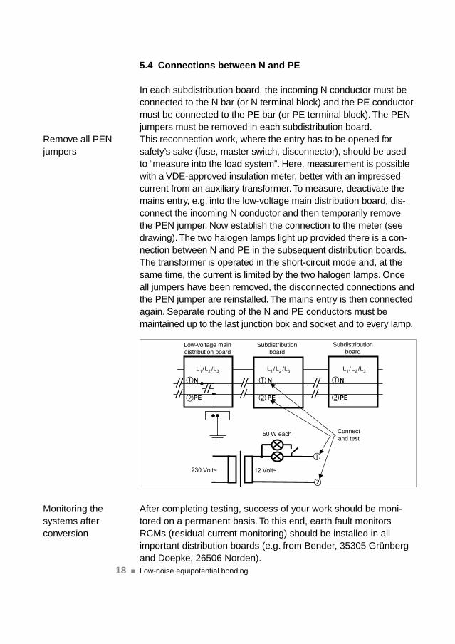
5.4 Connections between N and PE
In each subdistribution board, the incoming N conductor must beconnected to the N bar (or N terminal block) and the PE conductormust be connected to the PE bar (or PE terminal block). The PENjumpers must be removed in each subdistribution board.This reconnection work, where the entry has to be opened forsafety’s sake (fuse, master switch, disconnector), should be usedto “measure into the load system”. Here, measurement is possiblewith a VDE-approved insulation meter, better with an impressedcurrent from an auxiliary transformer. To measure, deactivate themains entry, e.g. into the low-voltage main distribution board, dis-connect the incoming N conductor and then temporarily removethe PEN jumper. Now establish the connection to the meter (seedrawing). The two halogen lamps light up provided there is a con-nection between N and PE in the subsequent distribution boards.The transformer is operated in the short-circuit mode and, at thesame time, the current is limited by the two halogen lamps. Onceall jumpers have been removed, the disconnected connections andthe PEN jumper are reinstalled. The mains entry is then connectedagain. Separate routing of the N and PE conductors must bemaintained up to the last junction box and socket and to every lamp.
After completing testing, success of your work should be moni-tored on a permanent basis. To this end, earth fault monitorsRCMs (residual current monitoring) should be installed in allimportant distribution boards (e.g. from Bender, 35305 Grünbergand Doepke, 26506 Norden).
18 Low-noise equipotential bonding��
Low-voltage maindistribution board
Subdistributionboard
Subdistributionboard
50 W each Connectand test
/ / / / / /
Remove all PENjumpers
Monitoring thesystems afterconversion

5.5 Avoiding earth loops
For IT systems, the power supply should be structured in such away that all components connected to the system are poweredfrom one point (single point earthed principle).
In the following example, two power supply segments within onebuilding are structured in accordance with the TN-S network con-figuration. As both low-voltage distribution boards have an entrywith a PEN conductor, the TN-C-S network configuration is rea-lised in the overall installation. Owing to the return current in the(PE)N conductor, at any one time the voltage or potential differ-ence is ≠ 0. If use is made of data cables with shielding that areconnected to the relevant earthing system, then compensatingcurrents flow through these signal lines that will lead to malfunc-tions and destruction of terminal devices.
For such cases, VDE 0800 Part 2 stipulates the use of fibre-opticconductors.
Low-noise equipotential bonding �� 19
Fibre-opticconductorTransformer
/ / /
Caution: despiteTN-S segments,
the overall systemconsists of TN-C-S

In practice, this means that the data cabling in the supply seg-ments in which a clean TN-S network is installed with an un-loaded PE can consist of copper data cable. Then, a fibre-opticcable must be used at the transition from one power supplysegment to the other to avoid malfunctions and destruction.
This is why interfaces and the devices connected to themfrequently suffer damage:
�� Serial interfaces and units RS232/422/485�� Time recording, access control, production data acquisition
hardware
�� Network cards and components
�� Twinax and token ring�� Ethernet
�� Parallel interfaces and printers
�� Modems, active hubs, star couplers
�� PLCs
�� etc.
20 Low-noise equipotential bonding��
The most frequentfailures occur atinterfaces

5.6 Examples of electrical isolation
An establishment consists of several buildings, an office, pro-duction, logistics and a warehouse. Production control, productiondata acquisition, access control and time recording facilities areinstalled in these buildings. To some extent, office workplaces withnetworked PCs and production machines are accommodated insuch buildings.These buildings are connected to the power supply via a 4-con-ductor cable. The basic prerequisite is that the TN-S network con-figuration is realised in the individual buildings. If these devicesare connected to one another via copper data lines, then the TN-C-S network configuration is realised in the overall installationthanks to the PEN conductor. Earth loops inevitably occur.
Therefore, solutions containing fibre-optic cables should be usedhere to avoid the occurrence of earth loops and to prevent com-pensating currents from flowing.
Possible alternativesElectrical isolation by means of an isolator can be realised if thenetwork office communication is concentrated in one building andonly one time recording unit is installed in each further building,for instance. These isolators must be chosen according to theinterface type, the data protocols and cable lengths.The same principle should also be applied to access controldevices.
Low-noise equipotential bonding �� 21
Fibre-opticconductor
Transformer
/ / /
Fibre-optic con-ductors help toavoid problems

Otherwise, current probes on the data lines must be used tomeasure the presence of currents.
Example: time recording and access controls
Example: design area and PPS systems
There are areas where the design department is connecteddirectly to the machining centres in production. If these two areasare powered via different subdistribution boards that receive theirentry via a 4-conductor network (TN-C-S network), fibre-opticcables should be used in this area or the data link to the machin-ing centers should be isolated electrically by means of isolators.
22 Low-noise equipotential bonding��
Data line Isolate electricallywith isolators!!
DesignDevelopment
Production datamonitoring
Isolators or fibre-optic conductor
Every device isconnected onceonly to the PEconductor
Avoiding earthloops with the aidof fibre-optic con-ductors or isolators
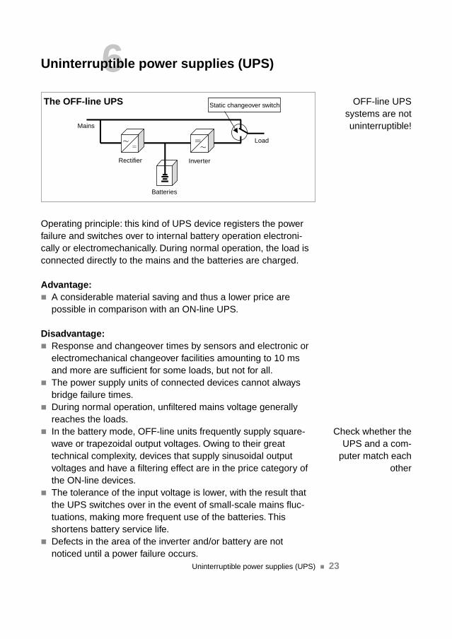
6Uninterruptible power supplies (UPS)
Operating principle: this kind of UPS device registers the powerfailure and switches over to internal battery operation electroni-cally or electromechanically. During normal operation, the load isconnected directly to the mains and the batteries are charged.
Advantage:�� A considerable material saving and thus a lower price are
possible in comparison with an ON-line UPS.
Disadvantage:�� Response and changeover times by sensors and electronic or
electromechanical changeover facilities amounting to 10 msand more are sufficient for some loads, but not for all.
�� The power supply units of connected devices cannot alwaysbridge failure times.
�� During normal operation, unfiltered mains voltage generallyreaches the loads.
�� In the battery mode, OFF-line units frequently supply square-wave or trapezoidal output voltages. Owing to their greattechnical complexity, devices that supply sinusoidal outputvoltages and have a filtering effect are in the price category ofthe ON-line devices.
�� The tolerance of the input voltage is lower, with the result thatthe UPS switches over in the event of small-scale mains fluc-tuations, making more frequent use of the batteries. Thisshortens battery service life.
�� Defects in the area of the inverter and/or battery are notnoticed until a power failure occurs.
Uninterruptible power supplies (UPS) �� 23
Static changeover switch
Mains
Rectifier
Load
Inverter
Batteries
The OFF-line UPS OFF-line UPSsystems are notuninterruptible!
Check whether theUPS and a com-
puter match eachother
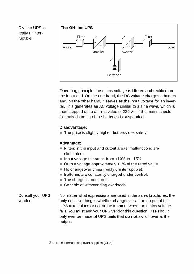
Operating principle: the mains voltage is filtered and rectified onthe input end. On the one hand, the DC voltage charges a batteryand, on the other hand, it serves as the input voltage for an inver-ter. This generates an AC voltage similar to a sine wave, which isthen stepped up to an rms value of 230 V~. If the mains shouldfail, only charging of the batteries is suspended.
Disadvantage:�� The price is slightly higher, but provides safety!
Advantage:�� Filters in the input and output areas; malfunctions are
eliminated.�� Input voltage tolerance from +10% to –15%.�� Output voltage approximately ±1% of the rated value.�� No changeover times (really uninterruptible).�� Batteries are constantly charged under control.�� The charge is monitored.�� Capable of withstanding overloads.
No matter what expressions are used in the sales brochures, theonly decisive thing is whether changeover at the output of theUPS takes place or not at the moment when the mains voltagefails.You must ask your UPS vendor this question. Use shouldonly ever be made of UPS units that do not switch over at theoutput.
24 Uninterruptible power supplies (UPS)��
Mains
Filter
Rectifier InverterLoad
Batteries
Filter
The ON-line UPSON-line UPS isreally uninter-ruptible!
Consult your UPSvendor

6.1 Tips on how to choose a UPS
Crest factor Computers represent a non-linear load and draw a high peak valueout of the mains in relation to the rms value. This ratio is referredto as the crest factor, which may differ from one computer to ano-ther. Therefore, ask your system supplier about the crest factor ofthe computer or computers (typically 3) that is or are to be con-nected to the UPS. The UPS must at least provide this power atthe moment of switching over. If it does not, the system will crashat that moment. Therefore, the crest factor is an important variablethat describes the performance of a UPS (see also rated power).
Stored energy timeThe stored energy time during which the loads are powered solelyby the batteries used in the UPS should be coordinated. On theone hand, it may depend on the organisational needs of the oper-ational process and, on the other hand, it may depend on the timea system needs to reliably close all files and save them on thehard disk. Typical times are 5 to 15 minutes.
Rated powerThe rated power of the UPS must be coordinated to the needs ofthe powered system. The average rms current and peak currentvalues of the system are related to the UPS’s crest factor. Depend-ing on the result, it may be that a UPS with a rated capacity of 20KVA, for example, may only be loaded with a maximum of 80%,i.e. a maximum of 16 KVA. If this ratio has not been observed,failures may already occur during normal operation. The peakcurrent must not be confused with the power-on surge current thatoccurs when the system is switched on.
CommunicationCommunication equipment (interfaces/software) between the UPSand the system is available for almost all UPSs (standard/option).Such equipment ensures a controlled shutdown, i.e. backing up ofthe data and shutdown of the system. Have the reliable process foryour configuration demonstrated. If, for organisation reasons, youshould additionally need automatic system restarting, then havethis process demonstrated.
Uninterruptible power supplies (UPS) �� 25

Further tips
UPS temperatureThe UPS must only be operated within the boundaries of the maxi-mum limits stated in the specifications. If ambient temperatures arebelow theses maximum limits, the reliability of a system, e.g. in theevent of an overload, is increased. Air conditioning may be neces-sary if a UPS is operated in a room that does not have windows.
Temperature of batteriesIn most cases, the permissible ambient temperatures for batteriesare below the temperatures for the UPS system. It is imperative tokeep to these values. Capacity is reduced if temperatures are toolow over a prolonged period of time. Lifetime is shortened iftemperatures are too high.
Setting upUPS systems produce dissipated heat and noise. This should betaken into account when choosing a location. Small to medium-sized units should not be placed directly in front of a wall, wherethe warm outgoing air cannot flow off unobstructed.The actual space requirement of the UPS and no-problem trans-port to the installation location should be checked. Access shouldbe available for maintenance personnel. If separate areas areplanned for the UPS and the batteries, attention must be paid tothe regulations that are applicable to handling acids.
Maintenance/remote maintenanceIn the case of medium to large systems and depending on theminimum availability of a UPS system, it is possible to obtaininformation about the performance capabilities of a UPS bymeans of an online diagnosis. Periodic tests can be arranged bycontract partners. These include a status report containing an up-to-date status description.
Future capacityPlan for system expansions in good time.You can assume thatfuture electronics systems will consume less power than nowa-days. Some UPS systems are based on a modular structure andare able to grow with the required power.
26 Uninterruptible power supplies (UPS)��

6.2 The consequence
If the symptoms described on Page 8 occur during the “normaldaily routine”, an attempt is frequently made to get to grips withthe problems by using a UPS system. Almost without exception,interference from the 230 V~ network is spoken of, which can beeliminated by means of electrical isolation.System faults that can be ascribed to vagabond currents in thePE and reference conductor system cannot be eliminated by aUPS.
Consequently, this means:Always first set up the EMC-friendly TN-S network configuration.The principle of the closed circuit must be realised. Neutral con-ductor currents must be returned to the feeding source in theneutral conductor. They must not be fed into the earthing system.Insofar as this is concerned, and as already described, TN-C andTN-C-S systems with PEN conductors are highly problematic inbuildings from the point of view of EMC and must be consistentlyavoided.
Only then can and should a UPS be installed, not vice versa.
Uninterruptible power supplies (UPS) �� 27
The UPS is no pan-acea for occurring
problems.
A TN-C-S system
In the UPS, only the phase and the neutralconductor are electrically isolated. The PEconductor must be connected throughcontinuously!

7Conditions for setting up office computers
These setting up conditions can be found with almost identicalwording in the documentation issued by all renowned PC andcomputer manufacturers.
1 IntroductionProper setting up and installation are an essential prerequisite forthe operating reliability of PCs and networks. This is why the appli-cable setting up conditions must be observed. In conformity withour general terms and conditions of business, we are not liable fordamage resulting from failure to observe our setting up conditions.
2 Safety rulesThe electrical installation of the system power supply must be setup and maintained in accordance with the generally recognisedelectrotechnical regulations and the accident prevention regula-tions. The technical connection conditions of the local electricitysupply companies also apply.
3 Setting up and installationOnly our service employees are entitled to set up, commission,repair and maintain the computer systems including peripherals.The electrical installation must be created by electricians in con-formity with the applicable VDE and DIN regulations. The locationmust be chosen so as to ensure that the system, including allperipheral devices, is protected against vibrations, dust, moistureand direct sunlight. Attention must also be paid to ensuring thatneither the heating nor a ventilation window will have an influenceon the cooling system.
Climate: the room temperature and air humidity are two essentialfactors when it comes to static charges.Room temperature: 21 ± 4°CTemperature gradient: < 5°C/hourRoom humidity: 40-60% rHThe room air must be humidified in accordance with theevaporation principle because the spring principle involves scaledeposits. The distance from radiators must be > 50 cm.
28 Conditions for setting up office computers��

Electrostatic charges: functioning of computer systems may bedisturbed by static electricity, or they may even be destroyed. Thisis also a nuisance to operating personnel.The occurrence of static electricity primarily depends on air humi-dity in conjunction with the flooring and the soles of shoes wornby persons. Operators’ clothing and chairs also have an influenceon the occurrence of static charges. Therefore, the following notesapply to the avoidance of static charges:�� Reduce the electrical resistance of the flooring.�� Keep to a relative humidity of 40-60% rH.
Power supply: as specified in VDE 0100, the power supply mustbe installed by an electrician. The computer system must be con-nected to a building or storey distribution board. This IT networksupplies all devices belonging to the system (single point earthingconcept). No other components may be connected. A phase mustbe chosen that has as low a load as possible and which is noise-free.Operating voltage: 230 V ± 10%Operating frequency: 50 Hz ± 1%Harmonic distortion: max. 5% of the rated voltage, harmoniccomponent < 3%.Mains voltage drops > 5 ms are not acceptable.
4 Notes on networked systemsAll mains connections leads must be connected to permanentlyinstalled shock proof sockets (IT network). Screened network anddata cables are laid together. Cable connection lies within theresponsible of the customer.
Protective system earthing: the earthing must be set up so asto ensure that all IT devices are connected to one earthing point.Corresponding cable cross-sections must be planned. The for-mation of earth loops must be avoided. The PE system must beunloaded (prove by measurement!).
5 RegulationsVDE 0100: regulations for the erection of power installationsVDE 0800 Part 2: regulations for equipment and operation oftelecommunications systems including information systems.
Conditions for setting up office computers �� 29
8Requirements for a reliable IT power supply
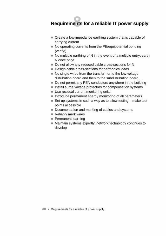
�� Create a low-impedance earthing system that is capable ofcarrying current
�� No operating currents from the PE/equipotential bonding(verify!)
�� No multiple earthing of N in the event of a multiple entry; earthN once only!
�� Do not allow any reduced cable cross-sections for N�� Design cable cross-sections for harmonics loads�� No single wires from the transformer to the low-voltage
distribution board and then to the subdistribution board�� Do not permit any PEN conductors anywhere in the building�� Install surge voltage protectors for compensation systems�� Use residual current monitoring units�� Introduce permanent energy monitoring of all parameters�� Set up systems in such a way as to allow testing – make test
points accessible�� Documentation and marking of cables and systems�� Reliably mark wires�� Permanent learning�� Maintain systems expertly; network technology continues to
develop
30 Requirements for a reliable IT power supply��

9Final remarks
The relationships described in this installation brochure are basicprerequisites that should be urgently created for a functioningelectronic IT system.
From the point of view of EMC, it is imperative to avoid a flow ofoperating currents in the earthing system.
This creates favourable prerequisites because not only can oper-ating currents at the basic frequency of 50 Hz be avoided, butalso currents with harmonics and sub-harmonics of 150 Hz andmore in the PE system.
If these currents still flow through the PE conductor and theequipotential bonding system, then they flow in all parts of thesystem that are earthed or which are connected to one anothervia an equipotential bonding system.Practical experience has shown that interference and destructioncan be ascribed to these currents in the earthing system.
Even when potential has been boosted by atmospheric dis-charges (indirect lightning discharges), it has been possible toobserve that, if a TN-S network is set up properly, no damage atall or only very slight damage occurs, even when no surge pro-tection equipment is installed.
Surge voltage protection in low-voltage main distribution boardsand subdistribution boards that is planned in a targeted fashionand which is used conscientiously is capable of dissipating oc-curring surge voltages that penetrate into installations throughmains feeders.
This installation guide has not discussed the issue of harmonics.Refer to VDE 0839 and its parts, Compatibility Levels in Low-Voltage Networks, Medium-Voltage Networks and IndustrialInstallations.
Final remarks �� 31
10Literature
VDE 0100 Part 300VDE 0100 Part 510VDE 0100 Part 540VDE 0800 Part 2Karl Heinz Otto: Die verPENnte Elektroinstallation, DS 6/99Pages 8-12Rudoph/Winter: EMV nach VDE 0100; Schriftenreihe 66 VDEVerlagA. Kohling: EMV von Gebäuden, Anlagen und Geräten; VDEVerlagG. KIEFER: VDE 0100 und die Praxis; VDE VerlagNiemand/Kunz: Erdungsanlagen; VWEW/VDE VerlagBellaire/Hergesell; Standortplanung AS/400, IBM StuttgartWiesemann Thies, Wuppertal: Isolatoren (Datenbuch 98)Bender, Grünberg: RCM FehlerstromüberwachungsgeräteDoepke, Norden: RCM FehlerstromüberwachungsgeräteSilcon, Langenfeld: USV Unterbrechungsfreie StromversorgungenProf. Dr. Dipl-Ing. Schlabbach: NetzrückwirkungenProf. Dr. -Ing. habil Friedheim Noack: Blitzstörbeeinflussung inNiederspannungsnetzenSiemens; Technische Mitteilung 08/1997 TM 6014, Überspan-nungsschäden durch ungünstige NetzkonstellationWißner: Tela CD
32 Literature��

It is a widely spread opinion that PCs, networks and othernetworked electronics systems can be installed swiftly andeasily because there are socket outlets everywhere. But,whenever illogical and undefined faults occur, it transpiresthat problems can often be ascribed to faults in the cabling(230 V~/data cables).In the interests of system users, it is important to avoid mal-functions and destruction. The cost of a production outageare much higher than the cost of an electrical installationthat does justice to IT requirements or in comparison withthe replacement of defective hardware. The overall entre-preneurial risk cannot be insured and is economically notjustifiable.This installation guide is the result of more than 15 years ofsafety and environmental analyses in the area of PCs,mainframes and networked electronics systems. It wasdrawn up with great care and attention and has been put touse in innumerable informative talks with end customersand their electrical installation technicians. A large numberof installations has been successfully converted in accord-ance with the contents of this guide. On the one hand, thisguide was conceived as lightweight food for thought for in-terested readers, and on the other hand, as the basis forconducting talks with the user. In this way, users are able torealise that an installation not only involves setting up hard-ware and loading and configuring software, but beginsmuch earlier.
ISBN 3-89639-232-815.– DM