Embed Size (px)
Citation preview
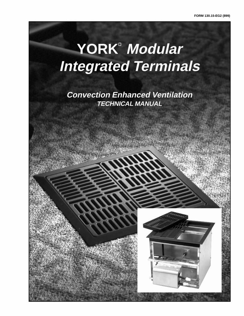
FORM 130.15-EG2 (899)
YORK ModularIntegrated Terminals
Convection Enhanced VentilationTECHNICAL MANUAL
2 YORK INTERNATIONAL
This page intentionally left blank.
YORK INTERNATIONAL 3
FORM 130.15-EG2
1. About This Manual .................................................................................. 4
2. Convection Enhanced Ventilation (CEV) Description ............................... 4
3. Comfort with the MIT ............................................................................... 6
4. York MIT Terminal Description ................................................................. 8
5. Energy Considerations............................................................................ 10
6. Indoor Air Quality .................................................................................... 12
7. Issues That Affect Load Calculations ...................................................... 12
7.1 Location of cooling loads in the space
7.2 Return Air Location
7.3 Thermal decay (loss of supply air cooling ability)
7.4 Thermal increase (decrease in return air temperature)
7.5 Thermal storage due to building mass
7.6 Load diversity
7.7 Stratification and ceiling height
8. Psychrometric Considerations ................................................................ 16
9. Choosing the Best Locations for the MIT Terminals ................................. 19
10. Plenum Based Air Distribution ................................................................ 19
10.1 Moisture and Condensation
10.2 Locating Floor Air Supply Points
10.3 Plenum Air Velocity and Air Pressure Drop
11. Ducted Air Distribution ............................................................................ 21
12. Heating .................................................................................................. 22
13. Zoning .................................................................................................. 23
14. Fire, Smoke, and Other Code Issues ...................................................... 24
15. Air Handling System Features ................................................................ 24
15.1 “Plug” (plenum) Fans
15.2 Sidestream Filtration
15.3 Direct Expansion Applications
16. System Controls and Air Handling Unit Operational Sequence................ 26
16.1 Discharge air control – full economizer mode
16.2 Discharge air control – no economizer mode
16.3 Cooling coil discharge air control – no economizer mode
16.4 Discharge air reset program
16.5 Plenum and duct distribution pressure
16.6 Supply air drybulb temperature reset
16.7 Space pressure control
17. Applications ............................................................................................ 29
17.1 Occupancy Types
17.2 Control and Other Cost Issues
17.3 System Choice Issues
18. Comparison of Technologies ................................................................... 33
19. Additional Information ............................................................................. 34
Table of Contents
4 YORK INTERNATIONAL
YORK is developing new products that are intended tooffer unique and cost effective opportunities for solvingmany of the commonplace problems associated with tra-ditional commercial air-conditioning systems. One excit-ing new product is the Modular Integrated Terminal (MIT)that is used for the floor up supply of conditioned air.Floor up systems are not new but they have never beenwidely used in the United States. These “upside down”airside systems offer the potential to solve energy andindoor air quality problems better than conventional sys-tems. The new YORK MIT is an enhancement or secondgeneration product that resolves many limitations of pre-vious products while adding features needed for the U.S.market.
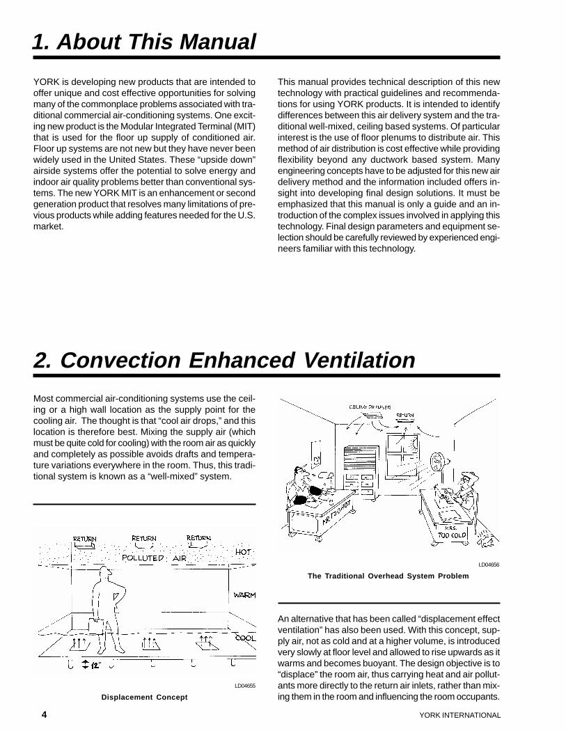
An alternative that has been called “displacement effectventilation” has also been used. With this concept, sup-ply air, not as cold and at a higher volume, is introducedvery slowly at floor level and allowed to rise upwards as itwarms and becomes buoyant. The design objective is to“displace” the room air, thus carrying heat and air pollut-ants more directly to the return air inlets, rather than mix-ing them in the room and influencing the room occupants.
LD04656
The Traditional Overhead System Problem
LD04655
Displacement Concept
This manual provides technical description of this newtechnology with practical guidelines and recommenda-tions for using YORK products. It is intended to identifydifferences between this air delivery system and the tra-ditional well-mixed, ceiling based systems. Of particularinterest is the use of floor plenums to distribute air. Thismethod of air distribution is cost effective while providingflexibility beyond any ductwork based system. Manyengineering concepts have to be adjusted for this new airdelivery method and the information included offers in-sight into developing final design solutions. It must beemphasized that this manual is only a guide and an in-troduction of the complex issues involved in applying thistechnology. Final design parameters and equipment se-lection should be carefully reviewed by experienced engi-neers familiar with this technology.
1. About This Manual
2. Convection Enhanced Ventilation
Most commercial air-conditioning systems use the ceil-ing or a high wall location as the supply point for thecooling air. The thought is that “cool air drops,” and thislocation is therefore best. Mixing the supply air (whichmust be quite cold for cooling) with the room air as quicklyand completely as possible avoids drafts and tempera-ture variations everywhere in the room. Thus, this tradi-tional system is known as a “well-mixed” system.
YORK INTERNATIONAL 5
FORM 130.15-EG2
York International now proposes a hybrid system, offer-ing advantages of both the “well-mixed” and the “displace-ment” types of air distribution, while at the same timeovercoming their disadvantages.
It is named “Convection Enhanced Ventilation,” or simply“CEV,” and it has additional features that make it supe-rior to both previous approaches. It uses a completelynew variable air volume distribution device that is installedin raised flooring systems.
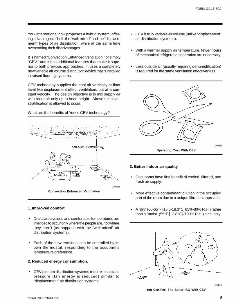
CEV technology supplies the cool air vertically at floorlevel like displacement effect ventilation, but at a con-stant velocity. The design objective is to mix supply airwith room air only up to head height. Above this level,stratification is allowed to occur.
What are the benefits of York’s CEV technology?
1. Improved comfort
• Drafts are avoided and comfortable temperatures areintended to occur only where the people are, not wherethey aren't (as happens with the “well-mixed” airdistribution systems).
• Each of the new terminals can be controlled by itsown thermostat, responding to the occupant'stemperature preference.
2. Reduced energy consumption.
• CEV plenum distribution systems require less staticpressure (fan energy is reduced) similar to“displacement” air distribution systems.
LD04658
Convection Enhanced Ventilation
• CEV is truly variable air volume (unlike “displacement”air distribution systems).
• With a warmer supply air temperature, fewer hoursof mechanical refrigeration operation are necessary.
• Less outside air (usually requiring dehumidification)is required for the same ventilation effectiveness.
3. Better indoor air quality
• Occupants have first benefit of cooled, filtered, andfresh air supply.
• More effective contaminant dilution in the occupiedpart of the room due to a unique filtration approach.
• A “dry” (60-65°F [15.6-18.3°C] 65%-80% R.H.) ratherthan a “moist” (55°F [12.8°C] /100% R.H.) air supply.
LD04657
You Can Feel The Better IAQ With CEV
LD04656
Operating Cost With CEV
6 YORK INTERNATIONAL
4. More flexibility
• The air terminals can be relocated quickly and easily,changing from “master” units thermostaticallycontrolling temperatures to “slaves” (and vice versa).
5. Lower installed costs
• When compared to quality conventional systemsoffering only some of the CEV system's features.
The first under floor air-conditioning systems performedbest at full-load, or nearly full-load, conditions. This wasoften acceptable, because they were used in areas withlittle variation in cooling load. However, for areas whereloads did vary, such as perimeter zones during interme-diate seasons, when transmission and/or solar loads wereless than design conditions, or in other spaces wherepeople and lighting loads could decrease, over-coolingcould occur.
The result is a lower “comfort level” than would occur withconventional overhead systems. If heating was requiredin perimeter zones, these early under floor systemscouldn't handle this very well. They were inflexible, un-able to adapt easily to changes, such as relocation ofwalls or office layouts, or even the movements of officeequipment. Early under floor air-conditioning systems didnot allow users to control their own temperature: theysimply were not “people oriented.”
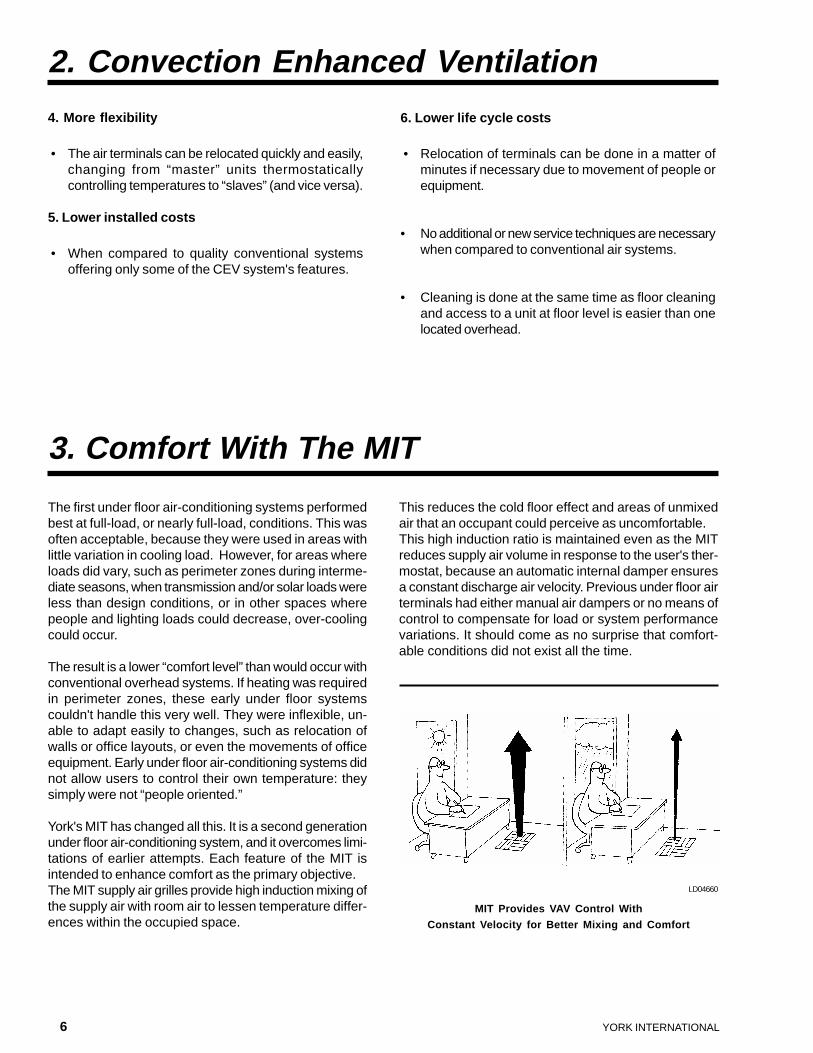
York's MIT has changed all this. It is a second generationunder floor air-conditioning system, and it overcomes limi-tations of earlier attempts. Each feature of the MIT isintended to enhance comfort as the primary objective.The MIT supply air grilles provide high induction mixing ofthe supply air with room air to lessen temperature differ-ences within the occupied space.
This reduces the cold floor effect and areas of unmixedair that an occupant could perceive as uncomfortable.This high induction ratio is maintained even as the MITreduces supply air volume in response to the user's ther-mostat, because an automatic internal damper ensuresa constant discharge air velocity. Previous under floor airterminals had either manual air dampers or no means ofcontrol to compensate for load or system performancevariations. It should come as no surprise that comfort-able conditions did not exist all the time.
3. Comfort With The MIT
LD04660
MIT Provides VAV Control With
Constant Velocity for Better Mixing and Comfort
2. Convection Enhanced Ventilation
6. Lower life cycle costs
• Relocation of terminals can be done in a matter ofminutes if necessary due to movement of people orequipment.
• No additional or new service techniques are necessarywhen compared to conventional air systems.
• Cleaning is done at the same time as floor cleaningand access to a unit at floor level is easier than onelocated overhead.
YORK INTERNATIONAL 7
FORM 130.15-EG2
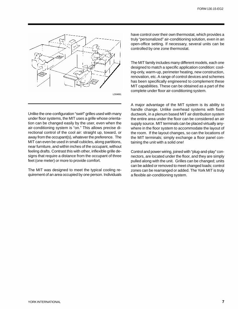
Unlike the one-configuration “swirl” grilles used with manyunder floor systems, the MIT uses a grille whose orienta-tion can be changed easily by the user, even when theair-conditioning system is “on.” This allows precise di-rectional control of the cool air: straight up, toward, oraway from the occupant(s), whatever the preference. TheMIT can even be used in small cubicles, along partitions,near furniture, and within inches of the occupant, withoutfeeling drafts. Contrast this with other, inflexible grille de-signs that require a distance from the occupant of threefeet (one meter) or more to provide comfort.
The MIT was designed to meet the typical cooling re-quirement of an area occupied by one person. Individuals
have control over their own thermostat, which provides atruly “personalized” air-conditioning solution, even in anopen-office setting. If necessary, several units can becontrolled by one zone thermostat.
The MIT family includes many different models, each onedesigned to match a specific application condition: cool-ing-only, warm-up, perimeter heating, new construction,renovation, etc. A range of control devices and schemeshas been specifically engineered to complement theseMIT capabilities. These can be obtained as a part of thecomplete under floor air-conditioning system.
A major advantage of the MIT system is its ability tohandle change. Unlike overhead systems with fixedductwork, in a plenum based MIT air distribution systemthe entire area under the floor can be considered an airsupply source. MIT terminals can be placed virtually any-where in the floor system to accommodate the layout ofthe room. If the layout changes, so can the locations ofthe MIT terminals; simply exchange a floor panel con-taining the unit with a solid one!
Control and power wiring, joined with “plug-and-play” con-nectors, are located under the floor, and they are simplypulled along with the unit. Grilles can be changed; unitscan be added or removed to meet changed loads; controlzones can be rearranged or added. The York MIT is trulya flexible air-conditioning system.
LD04661
8 YORK INTERNATIONAL
MIT is an acronym for Modular Integrated Terminal. AnMIT differs significantly from all other air terminals andencompasses a whole family of configurations. The fol-lowing MIT models allow a wide range of specific air dis-tribution application needs to be met in an optimum man-ner:
MIT- A
A pressure dependent, constant velocity, constant airvolume (no air damper), under floor air terminal with nocontrols. Nominal capacity of 150 CFM (71 l/s) at 0.05"w.g. (12.5 Pa) for use with pressurized cool air from un-der floor plenum.
MIT- B
A pressure dependent, constant velocity, constant airvolume (no air damper), under floor terminal with no con-trols. Nominal capacity of 150 CFM (71 l/s) at 0.05" w.g.(12.5 Pa) for use with ducted cool air supply.
MIT- C
A pressure dependent, constant velocity, variable air vol-ume (with air damper) under floor terminal with nominalcapacity of 0 to 150 CFM (71 l/s) at 0.05" w.g. (12.5 Pa)for use with pressurized cool air from under floor plenum.
MIT- D
A pressure dependent, constant velocity, variable air vol-ume (with air damper) under floor terminal with nominalcapacity of 0 to 150 CFM (71 l/s) at 0.05" w.g. (12.5 Pa)for use with ducted cool air supply.
MIT- E
A pressure dependent, constant velocity, variable air vol-ume (with air damper) under floor terminal with nominalcapacity of 0 to 150 CFM (71 l/s) at 0.05" w.g. (12.5 Pa)for use with ducted cold air supply plus pressurized warmair from under floor plenum that has been transferred fromceiling or occupied space.
MIT- F
A pressure independent, constant velocity, variable airvolume (with air damper) under floor terminal with nomi-nal capacity of 0 to 150 CFM (71 l/s) at 0.20" w.g. (49.8Pa) for use with raised floors, 6 in. (15.24 cm) or higherwith pressurized cool air from under floor plenum.
MIT- G
A pressure dependent, constant velocity, variable air vol-ume (with air damper) under floor terminal with nominalcapacity of 0 to 150 CFM (71 l/s) at 0.05" w.g. (12.5 Pa)for use with pressurized under floor plenum plus ductedhot air supply.
MIT- H
A pressure dependent, constant velocity, constant airvolume under floor air terminal with manual volume ad-justment but no controls. Nominal capacity of 150 CFM(71 l/s) at 0.05" w.g. (12.5 Pa) for use with pressurizedcool air from under floor plenum.
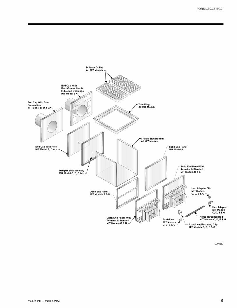
This MIT family shares many components in an inter-changeable and modular manner. Putting the parts to-gether in the factory or assembly in the field can be ac-complished with simple hand tools like a screwdriver. MITsare designed to be reusable, re-locatable and recycledfor the benefit of the environment. Ideally the MIT shouldoutlast the building itself with proper maintenance.
As this exploded view indicates, a common chassis isused as a platform for the assembly of several end capand damper configurations that can be combined to makethe various models as described. This modularity allowsfor quick and easy installation and repair. For example,the grilles easily remove for cleaning or adjustment of airpattern.
4. York MIT Air Terminal
YORK INTERNATIONAL 9
FORM 130.15-EG2
LD04662
10 YORK INTERNATIONAL
5. Energy Considerations
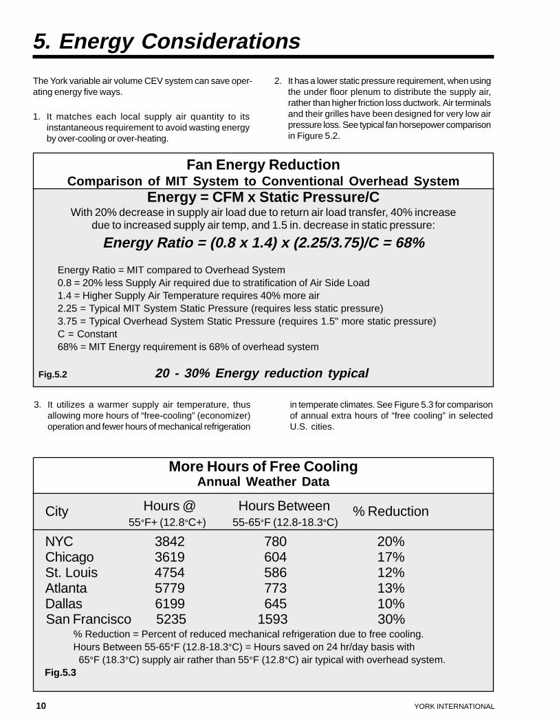
3. It utilizes a warmer supply air temperature, thusallowing more hours of “free-cooling” (economizer)operation and fewer hours of mechanical refrigeration
in temperate climates. See Figure 5.3 for comparisonof annual extra hours of “free cooling” in selectedU.S. cities.
The York variable air volume CEV system can save oper-ating energy five ways.
1. It matches each local supply air quantity to itsinstantaneous requirement to avoid wasting energyby over-cooling or over-heating.
2. It has a lower static pressure requirement, when usingthe under floor plenum to distribute the supply air,rather than higher friction loss ductwork. Air terminalsand their grilles have been designed for very low airpressure loss. See typical fan horsepower comparisonin Figure 5.2.
Fan Energy ReductionComparison of MIT System to Conventional Overhead System
Energy = CFM x Static Pressure/CWith 20% decrease in supply air load due to return air load transfer, 40% increase
due to increased supply air temp, and 1.5 in. decrease in static pressure:
Energy Ratio = (0.8 x 1.4) x (2.25/3.75)/C = 68%
Energy Ratio = MIT compared to Overhead System0.8 = 20% less Supply Air required due to stratification of Air Side Load1.4 = Higher Supply Air Temperature requires 40% more air2.25 = Typical MIT System Static Pressure (requires less static pressure)3.75 = Typical Overhead System Static Pressure (requires 1.5" more static pressure)C = Constant68% = MIT Energy requirement is 68% of overhead system
Fig.5.2 20 - 30% Energy reduction typical
More Hours of Free CoolingAnnual Weather Data
City Hours @ Hours Between % Reduction55°F+ (12.8°C+) 55-65°F (12.8-18.3°C)
NYC 3842 780 20%Chicago 3619 604 17%St. Louis 4754 586 12%Atlanta 5779 773 13%Dallas 6199 645 10%San Francisco 5235 1593 30%
% Reduction = Percent of reduced mechanical refrigeration due to free cooling.Hours Between 55-65°F (12.8-18.3°C) = Hours saved on 24 hr/day basis with65°F (18.3°C) supply air rather than 55°F (12.8°C) air typical with overhead system.
Fig.5.3
YORK INTERNATIONAL 11
FORM 130.15-EG2
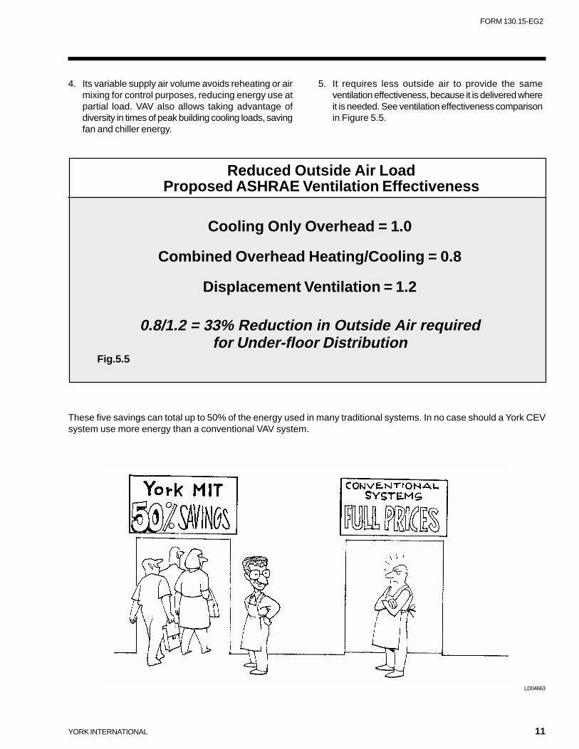
4. Its variable supply air volume avoids reheating or airmixing for control purposes, reducing energy use atpartial load. VAV also allows taking advantage ofdiversity in times of peak building cooling loads, savingfan and chiller energy.
These five savings can total up to 50% of the energy used in many traditional systems. In no case should a York CEVsystem use more energy than a conventional VAV system.
Reduced Outside Air LoadProposed ASHRAE Ventilation Effectiveness
Cooling Only Overhead = 1.0
Combined Overhead Heating/Cooling = 0.8
Displacement Ventilation = 1.2
0.8/1.2 = 33% Reduction in Outside Air requiredfor Under-floor Distribution
Fig.5.5
5. It requires less outside air to provide the sameventilation effectiveness, because it is delivered whereit is needed. See ventilation effectiveness comparisonin Figure 5.5.
LD04663
12 YORK INTERNATIONAL
dissipate the mixture out from above. As a result, if aconvective heat source is above head level (6 feet, 2.8m), it does not influence the air temperature in the occu-pied space. Ceiling mounted lights and light shelves areexamples of this type of heat source.In open plan spaces with no “hard” perimeter wall and noblinds, solar radiation load can be spread into the interiorof the space much farther than the traditional 12-14 ft. (4-5 m) perimeter depth. This helps to relieve the concentra-tion of diffusers at the skin and permits the MIT perimetersystem to perform well with much higher solar loads.
6. Indoor Air Quality
The CEV air-moving concept affects load calculationsdifferently from conventional systems in several ways.The following points should be taken into considerationwhen designing a CEV under floor air-conditioning sys-tem.
7.1 Location of cooling loads in the space
CEV systems supply cooling air from below, mix it withroom air as it passes through the occupied space pick-ing up heat and contaminants from the room, and then
The design and operational characteristics of CEV sys-tems give several possibilities for improving a building'sindoor air quality. The following are some of them.
1. Under floor air-conditioning uses warmer supply airtemperature. A “purpose built” air handling unit hasbeen especially designed with this in mind. It has itscooling coil in parallel with high efficiency filters,yielding improved filtration of small particles (suchas smoke, pollen, and organic compounds) withoutthe usual penalty of additional high static pressureloss. Cold air from the pre-filter and cooling coil mixeswith clean (but warm) air that has passed throughthe pre-filter and final high efficiency filter, to producethe proper temperature air for the under floor plenum.
2. Many particles that might be in the supply air stream“drop out” when the air reaches the under floor plenum,because the air velocity there is very low.
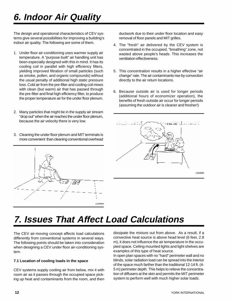
3. Cleaning the under floor plenum and MIT terminals ismore convenient than cleaning conventional overhead
ductwork due to their under floor location and easyremoval of floor panels and MIT grilles.
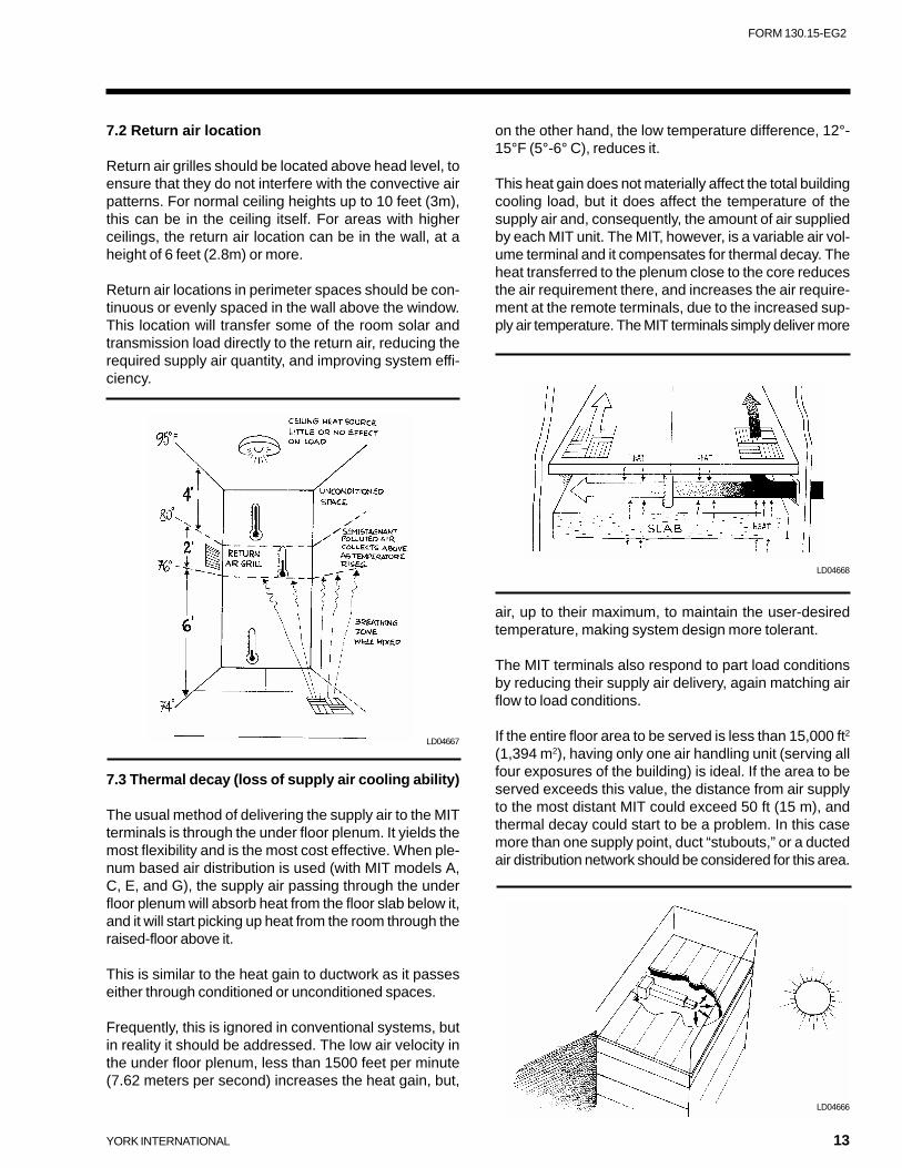
4. The “fresh” air delivered by the CEV system isconcentrated in the occupied, “breathing” zone, notwasted above people's heads. This increases theventilation effectiveness.
5. This concentration results in a higher effective “airchange” rate. The air contaminants rise by convectiondirectly to the air return locations.
6. Because outside air is used for longer periods(additional hours of economizer operation), thebenefits of fresh outside air occur for longer periods(assuming the outdoor air is cleaner and fresher!)
7. Issues That Affect Load Calculations
LD04665
LD04664
YORK INTERNATIONAL 13
FORM 130.15-EG2
7.2 Return air location
Return air grilles should be located above head level, toensure that they do not interfere with the convective airpatterns. For normal ceiling heights up to 10 feet (3m),this can be in the ceiling itself. For areas with higherceilings, the return air location can be in the wall, at aheight of 6 feet (2.8m) or more.
Return air locations in perimeter spaces should be con-tinuous or evenly spaced in the wall above the window.This location will transfer some of the room solar andtransmission load directly to the return air, reducing therequired supply air quantity, and improving system effi-ciency.
on the other hand, the low temperature difference, 12°-15°F (5°-6° C), reduces it.
This heat gain does not materially affect the total buildingcooling load, but it does affect the temperature of thesupply air and, consequently, the amount of air suppliedby each MIT unit. The MIT, however, is a variable air vol-ume terminal and it compensates for thermal decay. Theheat transferred to the plenum close to the core reducesthe air requirement there, and increases the air require-ment at the remote terminals, due to the increased sup-ply air temperature. The MIT terminals simply deliver more
LD04666
7.3 Thermal decay (loss of supply air cooling ability)
The usual method of delivering the supply air to the MITterminals is through the under floor plenum. It yields themost flexibility and is the most cost effective. When ple-num based air distribution is used (with MIT models A,C, E, and G), the supply air passing through the underfloor plenum will absorb heat from the floor slab below it,and it will start picking up heat from the room through theraised-floor above it.
This is similar to the heat gain to ductwork as it passeseither through conditioned or unconditioned spaces.
Frequently, this is ignored in conventional systems, butin reality it should be addressed. The low air velocity inthe under floor plenum, less than 1500 feet per minute(7.62 meters per second) increases the heat gain, but,
LD04667
air, up to their maximum, to maintain the user-desiredtemperature, making system design more tolerant.
The MIT terminals also respond to part load conditionsby reducing their supply air delivery, again matching airflow to load conditions.
If the entire floor area to be served is less than 15,000 ft2
(1,394 m2), having only one air handling unit (serving allfour exposures of the building) is ideal. If the area to beserved exceeds this value, the distance from air supplyto the most distant MIT could exceed 50 ft (15 m), andthermal decay could start to be a problem. In this casemore than one supply point, duct “stubouts,” or a ductedair distribution network should be considered for this area.
LD04668
14 YORK INTERNATIONAL
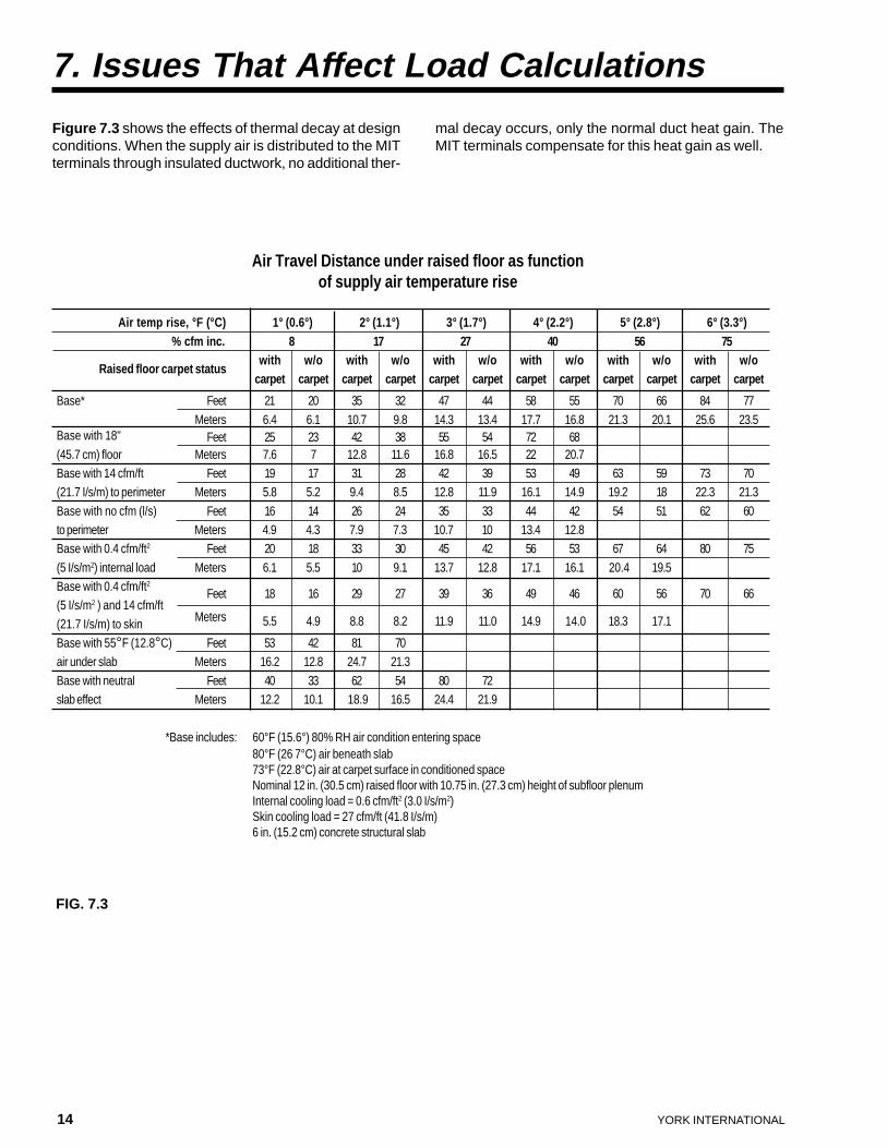
Figure 7.3 shows the effects of thermal decay at designconditions. When the supply air is distributed to the MITterminals through insulated ductwork, no additional ther-
Air temp rise, °F (°C) 1° (0.6°) 2° (1.1°) 3° (1.7°) 4° (2.2°) 5° (2.8°) 6° (3.3°)% cfm inc. 8 17 27 40 56 75
Raised floor carpet statuswith w/o with w/o with w/o with w/o with w/o with w/o
carpet carpet carpet carpet carpet carpet carpet carpet carpet carpet carpet carpet
Base* Feet 21 20 35 32 47 44 58 55 70 66 84 77
Meters 6.4 6.1 10.7 9.8 14.3 13.4 17.7 16.8 21.3 20.1 25.6 23.5Base with 18" Feet 25 23 42 38 55 54 72 68(45.7 cm) floor Meters 7.6 7 12.8 11.6 16.8 16.5 22 20.7Base with 14 cfm/ft Feet 19 17 31 28 42 39 53 49 63 59 73 70(21.7 I/s/m) to perimeter Meters 5.8 5.2 9.4 8.5 12.8 11.9 16.1 14.9 19.2 18 22.3 21.3
Base with no cfm (l/s) Feet 16 14 26 24 35 33 44 42 54 51 62 60to perimeter Meters 4.9 4.3 7.9 7.3 10.7 10 13.4 12.8Base with 0.4 cfm/ft2 Feet 20 18 33 30 45 42 56 53 67 64 80 75
(5 I/s/m2) internal load Meters 6.1 5.5 10 9.1 13.7 12.8 17.1 16.1 20.4 19.5Base with 0.4 cfm/ft2
Feet 18 16 29 27 39 36 49 46 60 56 70 66(5 I/s/m2 ) and 14 cfm/ft
Meters 5.5 4.9 8.8 8.2 11.9 11.0 14.9 14.0 18.3 17.1(21.7 I/s/m) to skinBase with 55°F (12.8°C) Feet 53 42 81 70air under slab Meters 16.2 12.8 24.7 21.3
Base with neutral Feet 40 33 62 54 80 72slab effect Meters 12.2 10.1 18.9 16.5 24.4 21.9
*Base includes: 60°F (15.6°) 80% RH air condition entering space80°F (26 7°C) air beneath slab73°F (22.8°C) air at carpet surface in conditioned spaceNominal 12 in. (30.5 cm) raised floor with 10.75 in. (27.3 cm) height of subfloor plenumInternal cooling load = 0.6 cfm/ft2 (3.0 I/s/m2)Skin cooling load = 27 cfm/ft (41.8 I/s/m)6 in. (15.2 cm) concrete structural slab
Air Travel Distance under raised floor as functionof supply air temperature rise
mal decay occurs, only the normal duct heat gain. TheMIT terminals compensate for this heat gain as well.
7. Issues That Affect Load Calculations
FIG. 7.3
YORK INTERNATIONAL 15
FORM 130.15-EG2
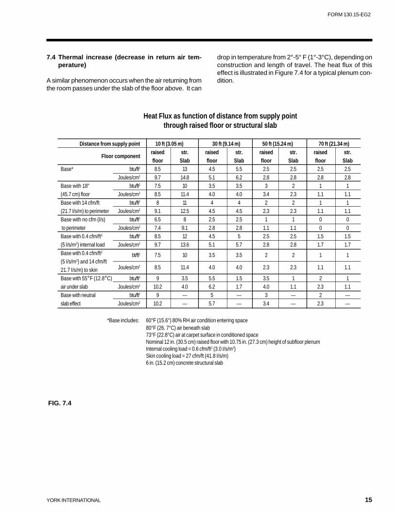
7.4 Thermal increase (decrease in return air tem-perature)
A similar phenomenon occurs when the air returning fromthe room passes under the slab of the floor above. It can
drop in temperature from 2°-5° F (1°-3°C), depending onconstruction and length of travel. The heat flux of thiseffect is illustrated in Figure 7.4 for a typical plenum con-dition.
Heat Flux as function of distance from supply pointthrough raised floor or structural slab
Distance from supply point 10 ft (3.05 m) 30 ft (9.14 m) 50 ft (15.24 m) 70 ft (21.34 m)
Floor componentraised str. raised str. raised str. raised str.floor Slab floor Slab floor Slab floor Slab
Base* btu/ft2 8.5 13 4.5 5.5 2.5 2.5 2.5 2.5
Joules/cm2 9.7 14.8 5.1 6.2 2.8 2.8 2.8 2.8Base with 18" btu/ft2 7.5 10 3.5 3.5 3 2 1 1(45.7 cm) floor Joules/cm2 8.5 11.4 4.0 4.0 3.4 2.3 1.1 1.1
Base with 14 cfm/ft btu/ft2 8 11 4 4 2 2 1 1(21.7 I/s/m) to perimeter Joules/cm2 9.1 12.5 4.5 4.5 2.3 2.3 1.1 1.1Base with no cfm (l/s) btu/ft2 6.5 8 2.5 2.5 1 1 0 0
to perimeter Joules/cm2 7.4 9.1 2.8 2.8 1.1 1.1 0 0Base with 0.4 cfm/ft2 btu/ft2 8.5 12 4.5 5 2.5 2.5 1.5 1.5(5 I/s/m2) internal load Joules/cm2 9.7 13.6 5.1 5.7 2.8 2.8 1.7 1.7
Base with 0.4 cfm/ft2bt/ft2 7.5 10 3.5 3.5 2 2 1 1
(5 I/s/m2) and 14 cfm/ft21.7 I/s/m) to skin Joules/cm2 8.5 11.4 4.0 4.0 2.3 2.3 1.1 1.1
Base with 55°F (12.8°C) btu/ft2 9 3.5 5.5 1.5 3.5 1 2 1air under slab Joules/cm2 10.2 4.0 6.2 1.7 4.0 1.1 2.3 1.1Base with neutral btu/ft2 9 — 5 — 3 — 2 —
slab effect Joules/cm2 10.2 — 5.7 — 3.4 — 2.3 —
*Base includes: 60°F (15.6°) 80% RH air condition entering space80°F (26. 7°C) air beneath slab73°F (22.8°C) air at carpet surface in conditioned spaceNominal 12 in. (30.5 cm) raised floor with 10.75 in. (27.3 cm) height of subfloor plenumInternal cooling load = 0.6 cfm/ft2 (3.0 I/s/m2)Skin cooling load = 27 cfm/ft (41.8 I/s/m)6 in. (15.2 cm) concrete structural slab
FIG. 7.4
16 YORK INTERNATIONAL
7.5 Thermal storage due to building mass
Thermal storage can reduce the required supply air quan-tity. Many times thermal storage allows smaller systemcomponents and fewer MIT terminals simply by recog-nizing that the materials surrounding the under floor ple-num absorb heat during periods of peak building loads.Thermal storage affects the system design and opera-tion as follows.
During normal operation, the building materials surround-ing the under floor plenum cool down, almost to the sup-ply air temperature. Thus, the system can be startedseveral hours, or run the whole night, before occupantsarrive, when especially hot weather is anticipated. In thismanner, there is a residual “heat sink” ready to provideadditional cooling when it is needed.
There is no easy calculation to determine how much ben-efit is obtained from thermal storage; it is a matter ofexperimentation during system operation to determinethe optimum time to “pre-start” the under floor system toobtain the desired “pre-cooling.” Peak solar load savingsof 20 - 30% are normal. These should not be consideredan addition to normal air-conditioning thermal storage,but as part of it. The operating energy consumption of theMIT system will reflect the positive benefits of thermalstorage even if it is not considered in the load calcula-tion.
7.6 Load diversity
The MIT system is truly variable air volume: it providescooling only where and when it is needed. Maximum cool-
ing loads occur at different exposures of a building atdifferent times depending primarily on the sun. With anMIT system, it is possible to select air handling equip-ment and chillers that are smaller than the sum of themaximum cooling loads of all areas.
To achieve this benefit, air handling units must serve morethan one type of functional area or more than one solarexposure. For example, in a building with conferencerooms, a dining area, and offices, the same people movefrom place to place during the day, and the sun can shineon only one side of the building at a time. The typical“block load” (maximum instantaneous) is 20 - 40% lessthan the sum of the maximum cooling loads of the indi-vidual areas.
7.7 Stratification and ceiling height
Theoretically, there is a reduction in the amount of sys-tem cooling capacity required due to warmer tempera-tures being allowed to occur above head height. This re-sults from less temperature difference across the upperpart of the perimeter wall and glass and from a higherenthalpy of the exhaust air than with conventional de-sign, thus reducing sensible load. It is better to calcu-late the room load and resultant air-flow the same way asa conventional variable air volume system unless the ceil-ing height is much greater than the normal 10 feet (3m)or exact calculations can not be made to determine if thereduction in transmission is significant. The operatingenergy consumption of the MIT system will reflect anyactual reduction in transmission load even if it is not con-sidered in the load calculation.
7. Issues That Affect Load Calculations
When plenum based air distribution is used, the supplyair temperature generally should not be lower than 60°F(15.6°C) leaving the air handling unit or coldest air termi-nal. The minimum allowable supply air temperature isaffected by thermal resistance of the floor, sealing effec-tiveness between floor panels, type of carpeting (if any),activity level and amount of space per occupant, theirdress, etc. But, only in exceptional cases should a sup-ply air temperature less than 60°F (15.6°C) be consid-ered. The MIT model E is fed both with pressurized ple-num air and ducted air. In this case, the temperature ofthe ducted air supply can be as low as 40°F (4.4°C),because it is mixed with the warmer plenum air prior tobeing introduced into the occupied space.
A psychrometric evaluation shows that mixing outsideair at typical conditions with return air, and then coolingthe mixture to 60°F (15.6°C), will not produce an accept-able humidity level. Some other approach is necessaryto ensure adequate dehumidification.
Cooling the air mixture to a lower temperature and thenre-heating it to avoid over-cooling the space and/or toensure adequate ventilation air was an accepted approachin the past.
8. Psychrometric Considerations
YORK INTERNATIONAL 17
FORM 130.15-EG2
Reheat, using new energy, is wasteful, and is not permit-ted by most energy codes now, except in special situa-tions. Reclaimed heat, however, can be used with theYork MIT system to achieve the proper supply air condi-tions. A different approach, however, is more commonwith the MIT. It mixes some of the return air with theoutside air, and then cools and dehumidifies this mixtureto the same conditions as a conventional system. Thisair is mixed with the remainder of the return air from aseparate air handling unit or bypassed around the cool-ing coil to achieve the desired 60°- 65°F (15.6°-18.3°C)drybulb supply air temperature. This ensures comfort-able conditions but with a low enough moisture contentto provide humidity control.York provides air handling designs that can accomplishthis. One airstream, supplied with face dampers, feedsthe cooling coil, and the other airstream bypasses thecooling coil. The two airstreams then mix, and the sup-ply air fan discharges the mixture into the under floorplenum, ductwork leading to the under floor plenums, orductwork leading to the MIT terminals. The required sup-ply air temperature is controlled by the amount of by-passed air. As the humidity in the space decreases, thesupply air temperature leaving the cooling coil can bereset up to save energy.
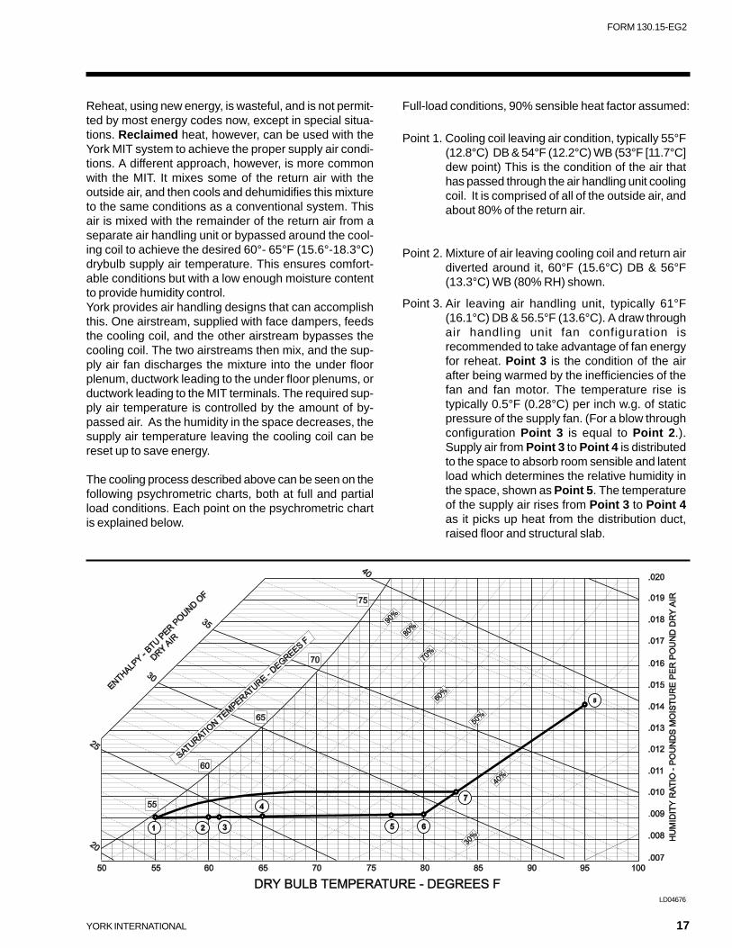
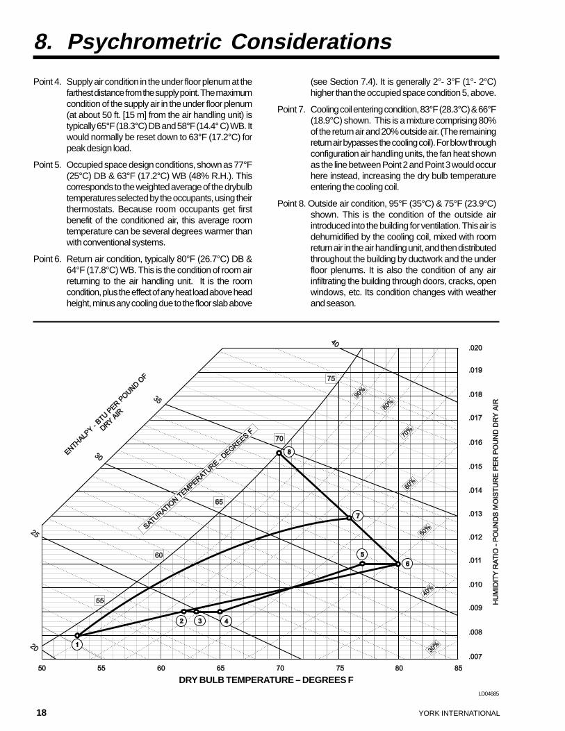
The cooling process described above can be seen on thefollowing psychrometric charts, both at full and partialload conditions. Each point on the psychrometric chartis explained below.
Full-load conditions, 90% sensible heat factor assumed:
Point 1. Cooling coil leaving air condition, typically 55°F(12.8°C) DB & 54°F (12.2°C) WB (53°F [11.7°C]dew point) This is the condition of the air thathas passed through the air handling unit coolingcoil. It is comprised of all of the outside air, andabout 80% of the return air.
Point 2. Mixture of air leaving cooling coil and return airdiverted around it, 60°F (15.6°C) DB & 56°F(13.3°C) WB (80% RH) shown.
Point 3. Air leaving air handling unit, typically 61°F(16.1°C) DB & 56.5°F (13.6°C). A draw throughair handling unit fan configuration isrecommended to take advantage of fan energyfor reheat. Point 3 is the condition of the airafter being warmed by the inefficiencies of thefan and fan motor. The temperature rise istypically 0.5°F (0.28°C) per inch w.g. of staticpressure of the supply fan. (For a blow throughconfiguration Point 3 is equal to Point 2.).Supply air from Point 3 to Point 4 is distributedto the space to absorb room sensible and latentload which determines the relative humidity inthe space, shown as Point 5. The temperatureof the supply air rises from Point 3 to Point 4as it picks up heat from the distribution duct,raised floor and structural slab.
LD04676
18 YORK INTERNATIONAL
Point 4. Supply air condition in the under floor plenum at thefarthest distance from the supply point. The maximumcondition of the supply air in the under floor plenum(at about 50 ft. [15 m] from the air handling unit) istypically 65°F (18.3°C) DB and 58°F (14.4° C) WB. Itwould normally be reset down to 63°F (17.2°C) forpeak design load.
Point 5. Occupied space design conditions, shown as 77°F(25°C) DB & 63°F (17.2°C) WB (48% R.H.). Thiscorresponds to the weighted average of the drybulbtemperatures selected by the occupants, using theirthermostats. Because room occupants get firstbenefit of the conditioned air, this average roomtemperature can be several degrees warmer thanwith conventional systems.
Point 6. Return air condition, typically 80°F (26.7°C) DB &64°F (17.8°C) WB. This is the condition of room airreturning to the air handling unit. It is the roomcondition, plus the effect of any heat load above headheight, minus any cooling due to the floor slab above
8. Psychrometric Considerations
(see Section 7.4). It is generally 2°- 3°F (1°- 2°C)higher than the occupied space condition 5, above.
Point 7. Cooling coil entering condition, 83°F (28.3°C) & 66°F(18.9°C) shown. This is a mixture comprising 80%of the return air and 20% outside air. (The remainingreturn air bypasses the cooling coil). For blow throughconfiguration air handling units, the fan heat shownas the line between Point 2 and Point 3 would occurhere instead, increasing the dry bulb temperatureentering the cooling coil.
Point 8. Outside air condition, 95°F (35°C) & 75°F (23.9°C)shown. This is the condition of the outside airintroduced into the building for ventilation. This air isdehumidified by the cooling coil, mixed with roomreturn air in the air handling unit, and then distributedthroughout the building by ductwork and the underfloor plenums. It is also the condition of any airinfiltrating the building through doors, cracks, openwindows, etc. Its condition changes with weatherand season.
LD04685
DRY BULB TEMPERATURE – DEGREES F
YORK INTERNATIONAL 19
FORM 130.15-EG2
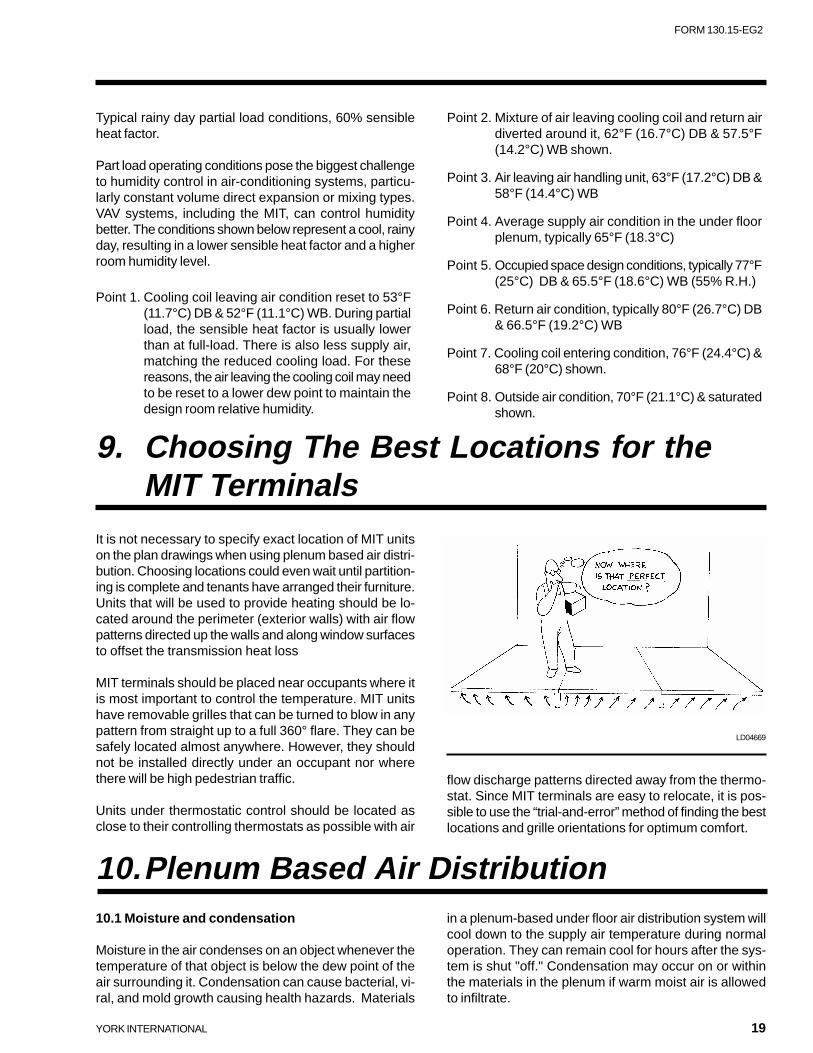
Typical rainy day partial load conditions, 60% sensibleheat factor.
Part load operating conditions pose the biggest challengeto humidity control in air-conditioning systems, particu-larly constant volume direct expansion or mixing types.VAV systems, including the MIT, can control humiditybetter. The conditions shown below represent a cool, rainyday, resulting in a lower sensible heat factor and a higherroom humidity level.
Point 1. Cooling coil leaving air condition reset to 53°F(11.7°C) DB & 52°F (11.1°C) WB. During partialload, the sensible heat factor is usually lowerthan at full-load. There is also less supply air,matching the reduced cooling load. For thesereasons, the air leaving the cooling coil may needto be reset to a lower dew point to maintain thedesign room relative humidity.
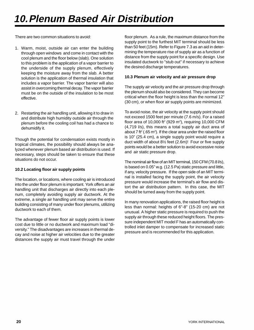
It is not necessary to specify exact location of MIT unitson the plan drawings when using plenum based air distri-bution. Choosing locations could even wait until partition-ing is complete and tenants have arranged their furniture.Units that will be used to provide heating should be lo-cated around the perimeter (exterior walls) with air flowpatterns directed up the walls and along window surfacesto offset the transmission heat loss
MIT terminals should be placed near occupants where itis most important to control the temperature. MIT unitshave removable grilles that can be turned to blow in anypattern from straight up to a full 360° flare. They can besafely located almost anywhere. However, they shouldnot be installed directly under an occupant nor wherethere will be high pedestrian traffic.
Units under thermostatic control should be located asclose to their controlling thermostats as possible with air
Point 2. Mixture of air leaving cooling coil and return airdiverted around it, 62°F (16.7°C) DB & 57.5°F(14.2°C) WB shown.
Point 3. Air leaving air handling unit, 63°F (17.2°C) DB &58°F (14.4°C) WB
Point 4. Average supply air condition in the under floorplenum, typically 65°F (18.3°C)
Point 5. Occupied space design conditions, typically 77°F(25°C) DB & 65.5°F (18.6°C) WB (55% R.H.)
Point 6. Return air condition, typically 80°F (26.7°C) DB& 66.5°F (19.2°C) WB
Point 7. Cooling coil entering condition, 76°F (24.4°C) &68°F (20°C) shown.
Point 8. Outside air condition, 70°F (21.1°C) & saturatedshown.
9. Choosing The Best Locations for theMIT Terminals
flow discharge patterns directed away from the thermo-stat. Since MIT terminals are easy to relocate, it is pos-sible to use the “trial-and-error” method of finding the bestlocations and grille orientations for optimum comfort.
10.Plenum Based Air Distribution10.1 Moisture and condensation
Moisture in the air condenses on an object whenever thetemperature of that object is below the dew point of theair surrounding it. Condensation can cause bacterial, vi-ral, and mold growth causing health hazards. Materials
LD04669
in a plenum-based under floor air distribution system willcool down to the supply air temperature during normaloperation. They can remain cool for hours after the sys-tem is shut "off." Condensation may occur on or withinthe materials in the plenum if warm moist air is allowedto infiltrate.
20 YORK INTERNATIONAL
There are two common situations to avoid:
1. Warm, moist, outside air can enter the buildingthrough open windows and come in contact with thecool plenum and the floor below (slab). One solutionto this problem is the application of a vapor barrier tothe underside of the supply plenum, effectivelykeeping the moisture away from the slab. A bettersolution is the application of thermal insulation thatincludes a vapor barrier. The vapor barrier will alsoassist in overcoming thermal decay. The vapor barriermust be on the outside of the insulation to be mosteffective.
2. Restarting the air handling unit, allowing it to draw inand distribute high humidity outside air through theplenum before the cooling coil has had a chance todehumidify it.
Though the potential for condensation exists mostly intropical climates, the possibility should always be ana-lyzed whenever plenum based air distribution is used. Ifnecessary, steps should be taken to ensure that thesesituations do not occur.
10.2 Locating floor air supply points
The location, or locations, where cooling air is introducedinto the under floor plenum is important. York offers an airhandling unit that discharges air directly into each ple-num, completely avoiding supply air ductwork. At theextreme, a single air handling unit may serve the entirebuilding consisting of many under floor plenums, utilizingductwork to each of them.
The advantage of fewer floor air supply points is lowercost due to little or no ductwork and maximum load “di-versity.” The disadvantages are increases in thermal de-cay and noise at higher air velocities due to the greaterdistances the supply air must travel through the under
floor plenum. As a rule, the maximum distance from thesupply point to the furthest MIT terminal should be lessthan 50 feet (15m). Refer to Figure 7.3 as an aid in deter-mining the temperature rise of supply air as a function ofdistance from the supply point for a specific design. Useinsulated ductwork to "stub out" if necessary to achievethe desired discharge temperatures.
10.3 Plenum air velocity and air pressure drop
The supply air velocity and the air pressure drop throughthe plenum should also be considered. They can becomecritical when the floor height is less than the normal 12"(30 cm), or when floor air supply points are minimized.
To avoid noise, the air velocity at the supply point shouldnot exceed 1500 feet per minute (7.6 m/s). For a raisedfloor area of 10,000 ft2 (929 m2), requiring 10,000 CFM(4,719 l/s), this means a total supply air duct area ofabout 7 ft2 (.65 m2). If the clear area under the raised flooris 10” (25.4 cm), a single supply point would require aduct width of about 8½ feet (2.6m)! Four or five supplypoints would be a better solution to avoid excessive noiseand air static pressure drop.
The nominal air flow of an MIT terminal, 150 CFM (70.8 l/s),is based on 0.05” w.g. (12.5 Pa) static pressure and little,if any, velocity pressure. If the open side of an MIT termi-nal is installed facing the supply point, the air velocitypressure would increase the terminal's air flow and dis-tort the air distribution pattern. In this case, the MITshould be turned away from the supply point.
In many renovation applications, the raised floor height isless than normal: heights of 6"-8" (15-20 cm) are notunusual. A higher static pressure is required to push thesupply air through these reduced height floors. The pres-sure independent MIT model F has an automatically con-trolled inlet damper to compensate for increased staticpressure and is recommended for this application.
10.Plenum Based Air Distribution
YORK INTERNATIONAL 21
FORM 130.15-EG2
If plenum based air distribution is inappropriate, the MITterminals can be individually supplied with cool or coldair from insulated ductwork. Perimeter areas with veryhigh cooling and/or heating requirements are better servedby ducted MIT terminals.
The MIT family includes models MIT-B, MIT-D, MIT-E,and MIT-F, that are designed for ducted supply systems.These models have an inlet air connection on the side ofthe chassis that is open on the other models. Their appli-cation follows standard duct practice for pressure depen-dent terminals, with a duct static pressure of 0.05” w.g.(12.5 Pa) required to obtain the nominal 150 CFM (71 l/s).
The MIT, model B, is constant volume with no damper.The model D is variable volume with a damper. The modelE is variable volume with an open side in addition to theinlet air connection. It mixes cold supply air from theductwork with warmer plenum air. The static pressures ofthe two air supplies must be controlled to achieve thedesired mixed air temperature.
Plenum based air distribution should be used whereverpossible since ductwork adds to the cost and some sys-tem flexibility is lost. However, there are situations whenducted air distribution is justified:
1. When the distance from the supply point to the MITis long, a ducted system or a few ducted MITterminals serving the building skin will overcome anyproblem of thermal decay.
2. Ducting unvitiated air from areas adjacent to criticalzones may also reduce the outside air requirement,when allowed by the ventilation code.
3. When a cool plenum could cause condensation onthe surrounding slab or wall construction, either insideor outside.
4. When a changeover heating/cooling system isemployed.
5. For special purpose areas, like conference rooms,which might overcool during unoccupied “lights off”periods due to a cold floor.
6. For nurseries and children's playrooms where warmair in the plenum keeps the floor warm and cool airsupplied through the ductwork conditions the space.
7. For space over an area such as a parking garagethat will have the plenum temperature affected byexposure (It could be hot in summer and cold inwinter).
A pressure damper or VAV box should be used to controlstatic air pressure if that pressure to the MIT cannot bemaintained at a constant 0.05" w.g. (12.5 Pa). Ductedand plenum fed MIT terminals can both be used in thesame building and in the same areas.
It is desirable to use multiple ducts which fit betweenstandard 2 x 2 ft. (0.61 x 0.61 m) raised floor supportpedestals. A maximum width of 22" (60 cm) permits fit-ting between pedestals. With a 12" (30 cm) raised floorsystem, a 10" x 22" (25.4 cm x 60 cm) sheet metal ductwith half-inch (13 mm) thick lining will carry 1970 cfm(930 l/s) at 1500 fpm (7.6 m/s). An 8" x 22" (20 cm x 60cm) will carry 1530 cfm (722 l/s) at 1500 fpm (7.6 m/s)which is the maximum velocity recommended for freedischarge into the floor plenum. Higher velocities can beused in fully ducted systems in accordance with gooddesign principles.
If “plug and play” cabling is used, it is recommended thatduct be sized to permit about 1 in. (2.5 cm) of clear spaceunderneath for passing cables and for air movement.
11. Ducted Air Distributuion
22 YORK INTERNATIONAL
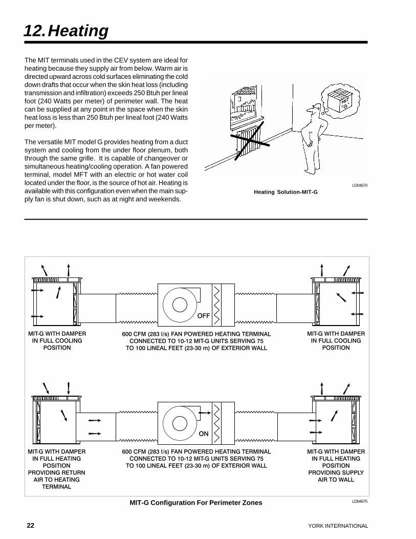
The MIT terminals used in the CEV system are ideal forheating because they supply air from below. Warm air isdirected upward across cold surfaces eliminating the colddown drafts that occur when the skin heat loss (includingtransmission and infiltration) exceeds 250 Btuh per linealfoot (240 Watts per meter) of perimeter wall. The heatcan be supplied at any point in the space when the skinheat loss is less than 250 Btuh per lineal foot (240 Wattsper meter).
The versatile MIT model G provides heating from a ductsystem and cooling from the under floor plenum, boththrough the same grille. It is capable of changeover orsimultaneous heating/cooling operation. A fan poweredterminal, model MFT with an electric or hot water coillocated under the floor, is the source of hot air. Heating isavailable with this configuration even when the main sup-ply fan is shut down, such as at night and weekends.
12.Heating
LD04670
LD04675MIT-G Configuration For Perimeter Zones
Heating Solution-MIT-G
YORK INTERNATIONAL 23
FORM 130.15-EG2
13.Zoning
Some air-conditioning systems do not allow the buildingto be split into separate sections to match diverse loadsand different temperature preferences. These sectionsare called “zones” (each is an area of homogeneous load-ing and a single desired temperature).Early under floor systems supplied the same tempera-ture air everywhere with no means to vary its quantity tomatch changing loads or differing temperature preferences.Sometimes the under floor plenum was roughly “parti-tioned” to separate areas having different load character-istics. This approach was costly and did not grant futureflexibility when conditions changed.
The MIT-G supplies a constant air volume when in theheating mode. It operates as a VAV device when in thecooling mode. It can perform another function, too. Itcan serve as a return air device supplying air to the MFTfan powered terminal in the heating mode. It operates inthe cooling mode when the fan is "off." This dual functionreduces the total number of required MIT terminals.
The MIT-G includes a minimum damper position “stop”that permits the introduction of fresh air from the under
floor plenum while recirculating air from the space. Thisfeature allows the unit to maintain minimum ventilationwhile in the heating mode.
Other MIT models can be used for heating with the properthermostat selection. Completely separate heating sys-tems, such as baseboard radiation or ceiling radiantpanels, can also be used with cooling-only MIT systems.
LD04671
MIT models A and B can function as constant volumeterminals. This is often how conditioned air is delivered tospecial purpose areas, such as conference rooms. Oftenthese areas are served by individual air handling unitsfeeding the constant volume MIT models.
The recommended minimum number of thermal zonesper floor on a rectangular free-standing building is nine:four on the corners, four between corners, and one in thecenter. However, more zones offer greater flexibility, im-proved comfort, and more energy savings.
An MIT system permits an almost unlimited number ofzones, as many as one per person, if desired. The vari-able air volume feature delivers only the quantity of cool-ing air necessary to offset the heat in each area to main-tain the user-preferred temperature.
However, increasing the number of zones will increasethe cost of any air-conditioning system. Thermostats,controls, and air dampers all add to the cost. The in-creased cost of more zones must be justified throughincreased comfort by putting the user “in control” of hisenvironment.
An investment can be made at any time with the MITsystem: during the initial installation or after tenants havemoved in and the system is in operation. Grilles can bechanged, control zones can be rearranged or added, andunits can be added or removed to meet load changes orhigher comfort expectations. MIT units installed in a VAVsystem can be used to shut off individual tenant spacesin a multiple tenant building during unoccupied periodsfor proper apportionment of Air Conditioning costs.
24 YORK INTERNATIONAL
14.Fire, Smoke, and Other Code Issues
York has incorporated specific features into some of itsair handling units to allow the benefits of MIT terminalsand CEV performance to be fully realized.
15.1 “Plug” (plenum) fans
Plenum based CEV systems operate at lower static pres-sures. Total system pressure drop can be 1.5" to 2.5"w.g. (375 - 625 Pa) less than conventional overhead VAVsystems.
“Plug” (plenum) fans are a good choice because they areefficient and quieter when operating at these lower staticpressures. The York Airpak, CurbPak, and Curbmasterair handling units offer the plenum fan option. The supplyair can be discharged from an area as large as the airhandling unit's bottom panel, ensuring minimum staticpressure loss and no regenerated noise. Additionally, airsplitters can be provided to reduce discharge noise fur-ther.
15.2 Sidestream Filtration
CEV air-conditioning uses warmer supply air tempera-ture than conventional overhead VAV systems, and soface-and-bypass control on the air handling unit is a bet-
All members of the MIT family have been designed andare manufactured to comply with U.S. codes NFPA 90A,BOCA, UBC, and SBC. UL listing and other normal HVACproduct requirements are also met.
Local building codes and officials' interpretations mayaffect the installation of a plenum air distribution basedsystem. Every project should have their approval. Theunder floor plenum's construction, its size, the need forfire detection and suppression methods should all be re-viewed.
It is important to recognize that code officials may not befamiliar with the characteristics of an under floor HVACsystem. Also, they may incorrectly try to apply com-puter room standards to the access floor used in otheroccupancies and applications.
Because of this situation, it may be important to beginwork early with code officials to help them appreciate thebenefits this new system offers.
15.Air Handling System Features
ter way to ensure adequate dehumidification, while stillensuring the proper mixed supply air temperature.
The York Airpak, CurbPak, and Curbmaster air handlingunits offer a pre-engineered, purpose-built “face-and-by-pass” option for CEV systems with the cooling coil inparallel with high efficiency filters that are located in thebypass air stream. The outside air inlet is aligned withthe dehumidifying coil to ensure that no outside air isbypassed around the cooling coil.
The dampering arrangement then mixes cold air from thecooling/dehumidifying coil with clean (but warm) air thathas passed through the sidestream filter to produce theproper temperature air for the under floor plenum.
This design yields improved filtration of small particles(smoke, pollen, and organic compounds) without the usualoperating cost penalty that would result from additionalhigh static pressure loss if the filters were in series withthe cooling coil.
These air handling units are designed in the draw-througharrangement to allow the fan heat to help warm the sup-ply air mixture to the desired temperature.
YORK INTERNATIONAL 25
FORM 130.15-EG2
LD0467?
About 60% of the supply air passes through the dehu-midifying coil at design conditions. This represents all ofthe minimum outside ventilation air quantity plus a suffi-cient quantity of return air to maintain the required supplyair temperature. The other 40% passes through the highefficiency, sidestream filters only.
These air handlers can also operate in the “economizer”(free-cooling) mode, with the refrigeration system turned“off,” so that the savings in operating energy can be real-ized.
15.3 Direct Expansion Applications
York variable air volume CEV systems can use directexpansion air handling equipment as well as chilled wa-ter. Many smaller installations will benefit from this op-tion. With direct expansion systems there are severalspecific design and operating requirements. These in-clude:
1. Sufficient steps of condensing unit unloading to limitleaving air temperature fluctuation to 3°F (1.7°C) andto avoid coil freeze-up at minimum load.
2. At least five minute time delay on compressorrestarting.
3. Face-split or interlaced cooling coils to avoid thebypass of non-conditioned air.
4. Hot gas bypass if the minimum anticipated load isless than the last step of condensing unit unloadingcapacity.
5. Sufficient system safety controls to ensure properoperation, including coil freeze-up, low air flow, dirtyfilter indication, high compressor head pressure.
If the above requirements cannot be met, a chilled watersystem can also be used for the smaller installations.
A unique direct expansion system approach, more ap-propriate for larger installations, is the use of multiplepackaged roof top units arranged in a “primary/second-ary” supply air loop.
The primary loop consists of several constant tempera-ture, constant volume direct expansion air handling units,operating in parallel. The secondary loop consists of avariable volume supply air fan, an exhaust fan, econo-mizer outside air dampers, and filters.Cool air is drawn off the primary loop to the secondaryloop by means of a supply and return damper arrange-ment, as needed to match the building's cooling load.
As the building's cooling load reduces, and less supplyair is required, the air handlers in the primary loop areshut down, one-by-one, and dampered out of the loop. Abypass allows the primary loop to be controlled at a con-stant temperature. The last unit to shut down would nor-mally be sized to deliver the minimum fresh air quantity,thus assuring constant outside air ventilation when me-chanical refrigeration is in operation.
When operating in economizer (free cooling) mode, theprimary loop is shut down, and the static pressure loss(usually about 1” [250 Pa]) through its dehumidifying coilsand filters is avoided. The outside air, now delivered di-rectly into the secondary loop, can be filtered as required.
Supply air pressure is maintained by modulation of thesecondary fan to maintain the designed duct system pres-sure. Individual floor smoke/fire control dampers modu-late the supply air to maintain the under floor plenumpressure constant at varying air volumes. Building staticpressure is controlled by the powered exhaust. Individualcontrol dampers should be used at the exhaust to main-tain space pressure and to deal with stack effect.
26 YORK INTERNATIONAL
The most comfortable conditions can be obtained onlywhen the MIT system is properly controlled. The systemparameters whose values must be controlled are the sup-ply air drybulb temperature, the dew point of the air leav-ing the cooling coil, and the under floor plenum supply airstatic pressure (or supply duct, if the system is ductfed).
The supply air is a mixture of dehumidified air from thecooling coil and return air diverted around it. Its dry bulbtemperature must be maintained at a level that will en-sure that the farthest MIT terminal is supplied with aircool enough to do its required sensible cooling when de-livering its nominal air volume. This is accomplished byadjusting the mixture of dehumidified and bypassed re-turn air in the air handling unit. The dew point of the airleaving the cooling coil must be maintained at a level lowenough to ensure the supply air mixture performs therequired latent cooling.
If the supply air static pressure at the MIT terminal is toolow (<0.05" w.g. [12.5 Pa]), the unit will not deliver suffi-cient air, and the room temperature may increase be-yond the user selected temperature. If it is too high (>0.06"w.g. [15 Pa]), the unit will not provide the desired air dis-charge patterns, and floor leakage could cause a prob-lem.
Supply air drybulb temperature is not a single value, buta range. It need only be cool enough to do the required
cooling, but must not be allowed to drop to the pointwhere condensation forms on surfaces it contacts, nor tocause the raised floor to become too cool and uncomfort-able. This minimum value depends on the type of floorcovering, but generally should be limited to not less than60°F (15.6°C).
16.1 Discharge air control – full economizer mode
When the air handling unit controller has determined thatthe dew point of the outside air is sufficiently low to pro-vide cooling without mechanical refrigeration, it shall:
1. Shut down the chiller.
2. Open the cooling coil and bypass dampers.
3. Take input from the discharge sensor:
A. On a rise in temperature, modulate the dampersfor outside air and exhaust air open whilesimultaneously closing the return air damper.
B. On a fall in temperature, reverse the sequence.
16. System Controls and Air Handling Unit Operational Sequence
YORK INTERNATIONAL 27
FORM 130.15-EG2
16.2 Discharge air control – no economizer mode
When the air handling unit controller has determined thatthe dew point of the outside air is not sufficiently low toprovide cooling without mechanical refrigeration, it shall:
1. Energize the chiller circuit.
2. Position outside, exhaust, and return air dampers intheir normal position.
3. Enable minimum outside air ventilation sequence.
4. Close cooling coil damper and open bypass airdamper.
5. Take input from the discharge sensor and on a rise intemperature modulate the cooling coil damper open.
6. On a continued rise in temperature (when the coolingcoil damper has reached the full open position), thebypass damper shall modulate closed to maintainair handling unit discharge temperature.
7. On a fall in temperature the bypass damper shallmodulate open.
8. On a continued fall in discharge temperature (withthe bypass damper fully open), the cooling coildamper shall modulate closed to maintain air handlingunit discharge temperature.
16.3 Cooling coil discharge air control – no econo-mizer mode
When the air handling unit controller has determined thatthe dew point of the outside air is not sufficiently low to
provide cooling without mechanical refrigeration, the cool-ing coil discharge control loop shall be enabled.
The cooling coil discharge sensor acting through the airhandling unit controller shall, on a rise in temperature,modulate the chilled water valve open to maintain coolingcoil discharge temperature. The reverse shall occur on afall in temperature.
16.4 Discharge air reset program
The RTU discharge air temperature setpoint will be reset(via the communications interface) to maintain proper ple-num temperatures under the floor and to ensure that nocondensation occurs. Condensation can occur when theplenum, floor tiles, and concrete floor temperature arelower than the RTU discharge air dew point temperature.
This could occur during prolonged shutdowns during coldweather. The BAS will monitor plenum temperature andhumidity, and space temperature. Plenum dew point shallbe calculated from humidity and temperature sensors andwill be used first to reset the RTU cooling coil dischargetemperature setpoint so that the RTU discharge air dewpoint is below that of the plenum.
If the discharge air dew point is not low enough to preventany condensation then the RTU discharge setpoint willbe reset to lower the discharge air dew point. If the dis-charge dew point continues to stay above the level of theplenum temperature for more than five minutes, an alarmwill be generated at the BAS.
16.5 Plenum and duct distribution pressure
If there are main supply ducts, the static pressure shouldbe controlled the same as conventional VAV systems,i.e., a duct static pressure transmitter located 2/3 of thedistance from the air handling unit to the end of the duct.This transmitter should control the inlet or outlet damp-ers of the air handling unit, variable speed drive, or othermeans to set precisely the volume and pressure of thefan.

28 YORK INTERNATIONAL
With plenum based air distribution, the under floor ple-num pressures should also be controlled at 0.05” w.g.(12.5 Pa). Pressure reducing modulating dampers maybe required at the floor air supply points. They should becontrolled by an electronic differential pressure sensormeasuring the under floor pressure relative to the roomabove. Typically, a sampling tube with holes located ev-ery few feet will represent the average under floor pres-sure well. One transmitter per floor, or maximum area of15,000 ft2 (1,394 m2) is sufficient.
The reaction time of the plenum pressure control shouldbe faster than that of the air handling unit to ensure airpressure and volume stability.
The control loops can be interactive, so the worst caseplenum pressure modulating damper is fully open at thesupply duct static setpoint. This “resetting” of duct staticpressure can be achieved by monitoring the positions ofthe plenum supply dampers and adjusting the duct pres-sure to keep at least one plenum damper fully open.
The static pressure sensor, acting through the air han-dling unit controller shall, on a decrease in downstreamduct static pressure, increase the speed signal to thesupply fan variable speed drive. On a rise in downstreamduct static pressure, the reverse shall occur. The variablespeed fan drive shall have necessary ramp-up and ramp-down parameters set to keep the fan current within nor-mal operating ranges during speed changes.
16.6 Supply air drybulb temperature reset
The supply air temperature to the MIT at maximum loadconditions should not be allowed to fall below 60°F(15.6°C). However, at times when there is less than thedesign load, it can be reset upwards, ensuring that therequired dehumidification is not impaired (see Section8). This improves system efficiency and ensures ventila-tion effectiveness.
The system needs to measure the demand for cooling toimplement this function. This can be accomplished bymeasuring fan energy consumption, air volume, and rela-tive damper positions. Based on this measurement, the
supply air temperature can be reset upwards as demandreduces. It can be accomplished automatically throughthe building's control system. A simple manual adjust-ment can be made by the building system operator forsmall systems.
16.7 Space pressure control
The building should be maintained at a very slight posi-tive air pressure to limit the infiltration of non-conditionedair. A pressure that is too low would cause an increase insystem energy consumption and lower air quality. A pres-sure that is too high would cause a loss of conditionedair to the outside.
A high precision electronic space differential pressuretransducer is necessary to achieve precise space pres-sure control. It compares outside pressure with insidepressure, and then signals the modulating return air damp-ers. The damper is closed to increase space pressureand opened to reduce it.
Because plenum based under floor systems operate at avery low static pressure, the accuracy and stability ofspace pressure control are essential. A careful choice ofinstrumentation and loop tuning is needed to producestable and reliable system operation.
LD04672
16. System Controls and Air Handling Unit Operational Sequence
YORK INTERNATIONAL 29
FORM 130.15-EG2
17.1 Occupancy types
1. The MIT excels in providing comfort in office buildings, especially with high densities, small cubicles and highchurn rates that need flexibility.
2. Any building that uses a raised floor for other purposes should use a raised floor for HVAC with the exception ofclean room applications that benefit from floor return systems.
3. Schools and light manufacturing applications that do not involve the spillage of liquids into the floor are alsogood candidates.
4. Any high ceiling area or room such as an auditorium, theater, conference room or converted warehousespace makes an ideal MIT application.
5. CEV and MIT work well when low noise and high air quality are issues. This applies to television studios that havehigh heat loads and need to cool people at the floor in a silent manner.
6. If the occupancy demands or wants many control zones, MIT is the answer. It can provide personal zoning ifdesired, in a manner that is more cost effective than any other system.
7. MIT with an access floor can solve retrofit and refurbishment problems with buildings that do not have room for ductsin the ceilings or those that want to avoid touching ceiling spaces (hazardous material abatement).
8. MIT is ideal for both high-end and low-end budgets because it offers high end features at low end first cost.
9. Because MIT has the best life cycle cost, it should be of primary interest to owner occupied buildings.
10. Because MIT can be relocated like furniture, it can appeal to lower depreciation cycles and “green” concept of reuse(lower depreciated life implies a payback in fewer years).
17.Applications
30 YORK INTERNATIONAL
17.2 Control and other cost issues
1. More controls usually provide more comfort; theyalways result in more cost. Smaller control zones(and consequently more of them) ensure personalizedcomfort conditions, but remember that an MITthermostatically controlled unit (model C) costs abouttwice as much as a slave unit (model A). Fortunately,control units can be added after the installation iscompleted, when and where they are justified.Conversion kits are available to field modify MIT’sfrom manual or no control to full control.
2. Fully networked building control systems, includingthe MIT’s operation, are more expensive than usinglocal control devices on the terminals. The level ofsophistication is limited by the control systemconnected to the MIT network. Because MIT usesan open protocol, there are no proprietary interfaceproblems.
3. “Plug-and-play” wiring is intended to be used withthe MIT controls. It requires no special skills to installor maintain, and in a matter of seconds the wiring issnapped onto the MIT. This method of wiring not onlyreduces initial costs, but also the cost of anysubsequent reconfiguring. In many locations only onetrade is needed to do the complete MIT installation.
4. Not only do the MIT damper actuators take theirelectrical power from the under floor wiring, but thefan powered heaters, including resistance heaters,when fitted, can be powered from this convenientsource. If modular wiring is used throughout theunderfloor system, wiring costs are reduced. Itemslike disconnects and conduit can be replaced withplug-in cables.
17.Applications
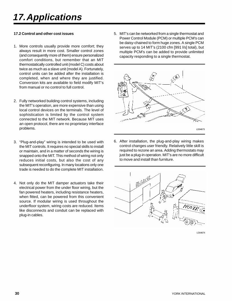
5. MIT’s can be networked from a single thermostat andPower Control Module (PCM) or multiple PCM's canbe daisy-chained to form huge zones. A single PCMserves up to 14 MIT’s (2100 cfm [991 l/s] total), butmultiple PCM's can be added to provide unlimitedcapacity responding to a single thermostat.
6. After installation, the plug-and-play wiring makescontrol changes user friendly. Relatively little skill isrequired to rezone an area. Adding thermostats mayjust be a plug-in operation. MIT’s are no more difficultto move and install than furniture.
LD04673
LD04674
YORK INTERNATIONAL 31
FORM 130.15-EG2
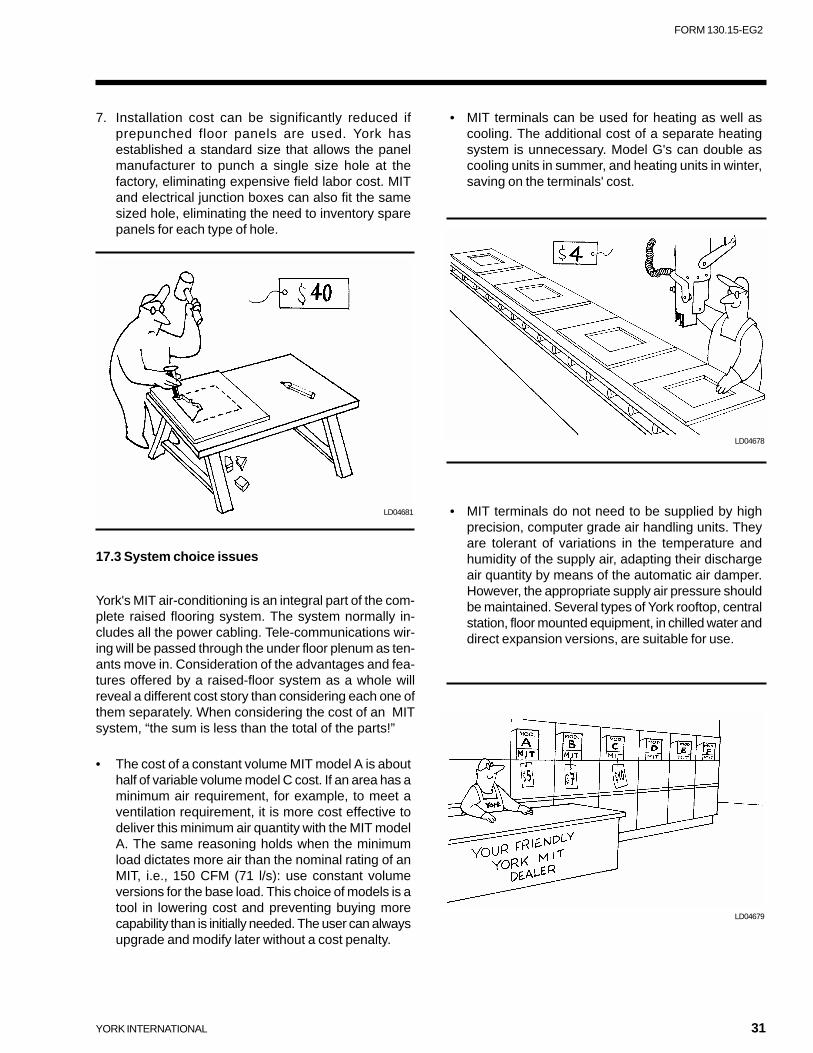
7. Installation cost can be significantly reduced ifprepunched floor panels are used. York hasestablished a standard size that allows the panelmanufacturer to punch a single size hole at thefactory, eliminating expensive field labor cost. MITand electrical junction boxes can also fit the samesized hole, eliminating the need to inventory sparepanels for each type of hole.
17.3 System choice issues
York's MIT air-conditioning is an integral part of the com-plete raised flooring system. The system normally in-cludes all the power cabling. Tele-communications wir-ing will be passed through the under floor plenum as ten-ants move in. Consideration of the advantages and fea-tures offered by a raised-floor system as a whole willreveal a different cost story than considering each one ofthem separately. When considering the cost of an MITsystem, “the sum is less than the total of the parts!”
• The cost of a constant volume MIT model A is abouthalf of variable volume model C cost. If an area has aminimum air requirement, for example, to meet aventilation requirement, it is more cost effective todeliver this minimum air quantity with the MIT modelA. The same reasoning holds when the minimumload dictates more air than the nominal rating of anMIT, i.e., 150 CFM (71 l/s): use constant volumeversions for the base load. This choice of models is atool in lowering cost and preventing buying morecapability than is initially needed. The user can alwaysupgrade and modify later without a cost penalty.
LD04681
LD04678
LD04679
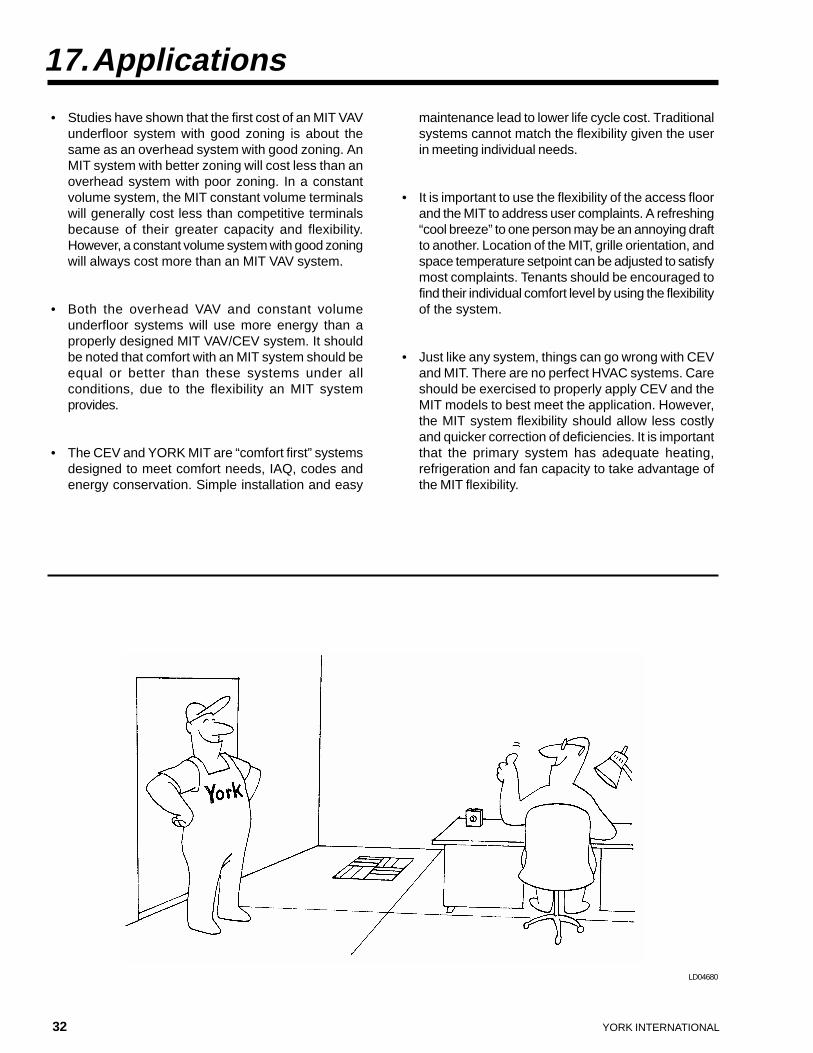
• MIT terminals can be used for heating as well ascooling. The additional cost of a separate heatingsystem is unnecessary. Model G's can double ascooling units in summer, and heating units in winter,saving on the terminals' cost.
• MIT terminals do not need to be supplied by highprecision, computer grade air handling units. Theyare tolerant of variations in the temperature andhumidity of the supply air, adapting their dischargeair quantity by means of the automatic air damper.However, the appropriate supply air pressure shouldbe maintained. Several types of York rooftop, centralstation, floor mounted equipment, in chilled water anddirect expansion versions, are suitable for use.
32 YORK INTERNATIONAL
• Studies have shown that the first cost of an MIT VAVunderfloor system with good zoning is about thesame as an overhead system with good zoning. AnMIT system with better zoning will cost less than anoverhead system with poor zoning. In a constantvolume system, the MIT constant volume terminalswill generally cost less than competitive terminalsbecause of their greater capacity and flexibility.However, a constant volume system with good zoningwill always cost more than an MIT VAV system.
• Both the overhead VAV and constant volumeunderfloor systems will use more energy than aproperly designed MIT VAV/CEV system. It shouldbe noted that comfort with an MIT system should beequal or better than these systems under allconditions, due to the flexibility an MIT systemprovides.
• The CEV and YORK MIT are “comfort first” systemsdesigned to meet comfort needs, IAQ, codes andenergy conservation. Simple installation and easy
17.Applications
maintenance lead to lower life cycle cost. Traditionalsystems cannot match the flexibility given the userin meeting individual needs.
• It is important to use the flexibility of the access floorand the MIT to address user complaints. A refreshing“cool breeze” to one person may be an annoying draftto another. Location of the MIT, grille orientation, andspace temperature setpoint can be adjusted to satisfymost complaints. Tenants should be encouraged tofind their individual comfort level by using the flexibilityof the system.
• Just like any system, things can go wrong with CEVand MIT. There are no perfect HVAC systems. Careshould be exercised to properly apply CEV and theMIT models to best meet the application. However,the MIT system flexibility should allow less costlyand quicker correction of deficiencies. It is importantthat the primary system has adequate heating,refrigeration and fan capacity to take advantage ofthe MIT flexibility.
LD04680
YORK INTERNATIONAL 33
FORM 130.15-EG2
18.Comparison of Technologies
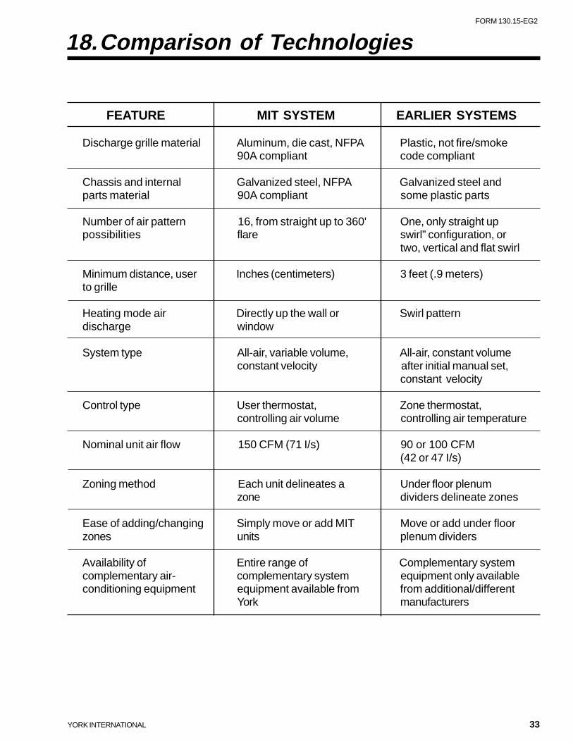
FEATURE MIT SYSTEM EARLIER SYSTEMS
Discharge grille material Aluminum, die cast, NFPA Plastic, not fire/smoke90A compliant code compliant
Chassis and internal Galvanized steel, NFPA Galvanized steel andparts material 90A compliant some plastic parts
Number of air pattern 16, from straight up to 360' One, only straight uppossibilities flare swirl” configuration, or
two, vertical and flat swirl
Minimum distance, user Inches (centimeters) 3 feet (.9 meters)to grille
Heating mode air Directly up the wall or Swirl patterndischarge window
System type All-air, variable volume, All-air, constant volumeconstant velocity after initial manual set,
constant velocity
Control type User thermostat, Zone thermostat,controlling air volume controlling air temperature
Nominal unit air flow 150 CFM (71 I/s) 90 or 100 CFM(42 or 47 I/s)
Zoning method Each unit delineates a Under floor plenumzone dividers delineate zones
Ease of adding/changing Simply move or add MIT Move or add under floorzones units plenum dividers
Availability of Entire range of Complementary systemcomplementary air- complementary system equipment only availableconditioning equipment equipment available from from additional/different
York manufacturers
34 YORK INTERNATIONAL
In conjunction with this manual, there are product datasheets that fully describe the performance of all MIT ter-minals and associated components of the CEV systemprovided by YORK. These products are constantly beingupdated and improved so it is important to get the latestavailable information on this new technology. Also, spe-cific application guides have been prepared that illus-trate the concepts presented in this manual. For easy
19.Additional Information
reference, annotated guide specifications are alsoavailable that cover all the CEV products available fromYORK. Together these items and this manual provide acomplete description of the CEV technology.
For additional information, contact your local YORKdealer.
YORK INTERNATIONAL 35
FORM 130.15-EG2
This page intentionally left blank.
P.O. Box 1592, York, Pennsylvania USA 17405-1592 Subject to change without notice. Printed in USACopyright © by York International Corporation 1999 ALL RIGHTS RESERVED
Form 130.15-EG2 (899)Supersedes: 130.15-EG2 (1298)


![Index []Expandite & Block Extension Reel Cord Components 8 Y-Terminals Quick Connect Crimps Grommets Toroid U.S. Modular Sockets 8 PCB Mount Sockets Case …](https://img.pdfslide.us/doc/110x75/60b03ae11ac12251e76c917b/index-expandite-block-extension-reel-cord-components-8-y-terminals-quick.jpg)