Embed Size (px)
Citation preview
1
CONNECTORS & TERMINALSShearBolt ConnectorsAluminum ShearBolt Splice Connectors . . . . . . . . . . . . . . . . . . . . . 2Copper ShearBolt Splice Connectors . . . . . . . . . . . . . . . . . . . . . . . 3Aluminum ShearBolt Terminal Connectors . . . . . . . . . . . . . . . . . . . 4
Compression ConnectorsCopper Compression Terminals . . . . . . . . . . . . . . . . . . . . . . . . . . . 5Copper Compression Splices . . . . . . . . . . . . . . . . . . . . . . . . . . . . . 7
Insulation Piercing ConnectorsInsulation Piercing Connectors . . . . . . . . . . . . . . . . . . . . . . . . . . . . 8
Wedge Pressure ConnectorsWedge Pressure Technology. . . . . . . . . . . . . . . . . . . . . . . . . . . . . . 9AMPACT Aluminum Tap System . . . . . . . . . . . . . . . . . . . . . . . . . . . 9AMPACT EL . . . . . . . . . . . . . . . . . . . . . . . . . . . . . . . . . . . . . . . . . . 13AMPACT HTT . . . . . . . . . . . . . . . . . . . . . . . . . . . . . . . . . . . . . . . . 13Stirrups. . . . . . . . . . . . . . . . . . . . . . . . . . . . . . . . . . . . . . . . . . . . . . 14AMPACT Stud Disconnect System . . . . . . . . . . . . . . . . . . . . . . . . 15Identifi er Plates . . . . . . . . . . . . . . . . . . . . . . . . . . . . . . . . . . . . . . . 15AMPACT Deadend Clamp Assembly . . . . . . . . . . . . . . . . . . . . . . 16AMPACT In-Line Disconnect Switch . . . . . . . . . . . . . . . . . . . . . . . 17
AMPACT AccessoriesTerminal Lugs. . . . . . . . . . . . . . . . . . . . . . . . . . . . . . . . . . . . . . . . . 19URD Tap Cover . . . . . . . . . . . . . . . . . . . . . . . . . . . . . . . . . . . . . . . 20GelPact Cover . . . . . . . . . . . . . . . . . . . . . . . . . . . . . . . . . . . . . . . . 20Tap Cover. . . . . . . . . . . . . . . . . . . . . . . . . . . . . . . . . . . . . . . . . . . . 20AMPACT Tool. . . . . . . . . . . . . . . . . . . . . . . . . . . . . . . . . . . . . . . . . 21AMPACT EZ Load . . . . . . . . . . . . . . . . . . . . . . . . . . . . . . . . . . . . . 22Cartridges. . . . . . . . . . . . . . . . . . . . . . . . . . . . . . . . . . . . . . . . . . . . 22Inhibitor Compound & NEMA Hinge . . . . . . . . . . . . . . . . . . . . . . . 22Cleaning Tool . . . . . . . . . . . . . . . . . . . . . . . . . . . . . . . . . . . . . . . . . 23Take-off Clip . . . . . . . . . . . . . . . . . . . . . . . . . . . . . . . . . . . . . . . . . . 23Auxillary Platform . . . . . . . . . . . . . . . . . . . . . . . . . . . . . . . . . . . . . . 23Accessories Bag . . . . . . . . . . . . . . . . . . . . . . . . . . . . . . . . . . . . . . 23Transverse Wedge Connectors . . . . . . . . . . . . . . . . . . . . . . . . . . . 23Hot-Stick. . . . . . . . . . . . . . . . . . . . . . . . . . . . . . . . . . . . . . . . . . . . . 26
MINIWEDGE ConnectorsService Entrance Connector System. . . . . . . . . . . . . . . . . . . . . . . 27GHFC MW Closure . . . . . . . . . . . . . . . . . . . . . . . . . . . . . . . . . . . . 27
Copper GroundingAMPACT Copper Wire Tap . . . . . . . . . . . . . . . . . . . . . . . . . . . . . . 32Copper Terminal Lug . . . . . . . . . . . . . . . . . . . . . . . . . . . . . . . . . . . 35SHEAR-LOK Grounding Connector . . . . . . . . . . . . . . . . . . . . . . . 35WRENCH-LOK Grounding Connector . . . . . . . . . . . . . . . . . . . . . 36Universal Distribution Connector . . . . . . . . . . . . . . . . . . . . . . . . . . 40
Symmetrical Connector Selection Chart . . . . . . . . . . . . . . . . . . . . . . . . . . . . . . . . . . 44
AMPACT Selection GuideAluminum Taps. . . . . . . . . . . . . . . . . . . . . . . . . . . . . . . . . . . . . . . . 45Copper Taps. . . . . . . . . . . . . . . . . . . . . . . . . . . . . . . . . . . . . . . . . . 80Stirrups. . . . . . . . . . . . . . . . . . . . . . . . . . . . . . . . . . . . . . . . . . . . . . 97
1RAYCHEM cable accessories ALR photocontrols AMP connectors
2
CO
NN
EC
TO
RS
& T
ER
MIN
AL
SShearBolt Connector
Aluminum ShearBolt Splice Connectors#2 AWG Compact to 1000 kcmil Stranded
TE Connectivity's Aluminum ShearBolt connectors are range- taking mechanical connectors. Just six connectors will accommodate a wide range of aluminum and copper conductors from #2 AWG compact stranded to 1000 kcmil standard stranded class B. The primary application of Aluminum ShearBolt connectors is for underground splices up to 35 kV.
ShearBolt connectors are ideally suited for aluminum to aluminum, aluminum to copper and copper to copper applications making them the universal connector solution. Please refer to tests listed below.
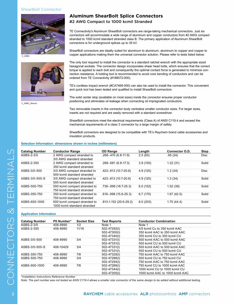
The only tool required to install the connector is a standard ratchet wrench with the appropriate sized hexagonal sockets. The connector design incorporates shear head bolts, which ensures that the correct torque is applied to each bolt and consequently the optimal contact force is generated to minimize con-nection resistance. A holding tool is recommended to avoid core bending of conductors and can be ordered from TE Connectivity (#188072-000).
TE's cordless impact wrench (#CA7469-000) can also be used to install the connector. This convenient and quick tool has been tested and qualified to install ShearBolt connectors.
The solid center stop (available on most sizes) inside the connector ensures proper conductor positioning and eliminates oil leakage when connecting oil impregnated conductors.
Two removable inserts in the connector body centralize smaller conductor sizes. For larger sizes, inserts are not required and are easily removed with a standard screwdriver.
ShearBolt connectors meet the electrical requirements (Class A) of ANSI C119.4 and exceed the mechanical requirements of a class 3 connector by a large margin of safety.
ShearBolt connectors are designed to be compatible with TE’s Raychem brand cable accessories and insulation products.
Selection Information: dimensions shown in inches (millimeters)
Catalog Number Conductor Range OD Range Length Connector O.D. StopASBS-2-3/0 2 AWG compact stranded to .268-.470 (6.8-11.9) 2.5 (65) .95 (24) Disc 3/0 AWG standard stranded ASBS-2-350 2 AWG compact stranded to .268-.681 (6.8-17.3) 3.9 (100) 1.22 (31) Solid 350 kcmil standard stranded ASBS-3/0-500 3/0 AWG compact stranded to .423-.813 (10.7-20.6) 4.9 (125) 1.3 (34) Disc 500 kcmil standard stranded ASBS-3/0-500-S 3/0 AWG compact stranded to .423-.813 (10.7-20.6) 4.9 (125) 1.3 (34) Solid 500 kcmil standard strandedASBS-500-750 500 kcmil compact stranded to .736-.998 (18.7-25.3) 6.0 (152) 1.52 (39) Solid 750 kcmil standard stranded ASBS-350-750 350 kcmil compact stranded to .616-.998 (15.6-25.3) 6.7 (170) 1.67 (42.5) Solid 750 kcmil standard stranded ASBS-600-1000 600 kcmil compact stranded to .813-1.152 (20.6-29.2) 8.0 (203) 1.75 (44.4) Solid 1000 kcmil standard stranded
Application Information Catalog Number PII Number* Socket Size Test Reports Conductor CombinationASBS-2-3/0 408-8990 1/2 Note 1 Note 1ASBS-2-350 408-8990 11/16 502-47292(I) 4/0 kcmil Cu to 350 kcmil AAC 502-47300(I) 350 kcmil AAC to 350 kcmil AAC 502-47340(I) 350 kcmil CU to 350 kcmil CUASBS-3/0-500 408-8990 3/4 502-47331(I) 500 kcmil AAC to 500 kcmil AAC 502-47331(I) 500 kcmil CU to 500 kcmil CUASBS-3/0-500-S 408-10429 3/4 502-47331(I) 500 kcmil AAC to 500 kcmil AAC 502-47331(I) 500 kcmil CU to 500 kcmil CUASBS-350-750 408-8990 7/8 502-47329(I) 750 kcmil AAC to 750 kcmil AACASBS-500-750 408-8990 3/4 502-47288(I) 500 kcmil CU to 750 kcmil CU 502-47294(I) 750 kcmil AAC to 750 kcmil AACASBS-600-1000 408-8990 7/8 502-47289(I) 750 kcmil CU to 1000 kcmil AAC 502-47344(I) 1000 kcmil CU to 1000 kcmil CU 502-47305(I) 1000 kcmil AAC to 1000 kcmil AAC*Installation Instructions Reference NumberNote: The part number was not tested as ANSI C119.4 allows a smaller size connector of the same design to be added without additional testing.
C_ASBC
C_ASBC_Wrench
2 RAYCHEM cable accessories ALR photocontrols AMP connectors
3
CO
NN
EC
TO
RS
& T
ER
MIN
AL
SShearBolt Connector
Copper ShearBolt Splice Connectors#2 AWG Compact to 1000 kcmil Stranded
TE Connectivity’s Copper ShearBolt connectors are range-taking, mechanical connectors that will accommodate a wide range of copper cables from #2 AWG compact stranded to 1000 kcmil compact stranded. The primary application is for underground splices up to 35 kV.
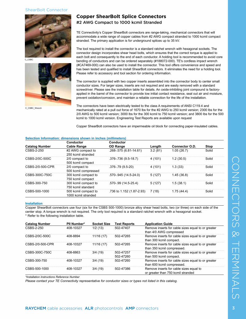
The tool required to install the connector is a standard ratchet wrench with hexagonal sockets. The connector design incorporates shear head bolts, which ensures that the correct torque is applied to each bolt and consequently to the end of each conductor. A holding tool is recommended to avoid core bending of conductors and can be ordered separately (#188072-000). TE's cordless impact wrench (#CA7469-000) can also be used to install the connector. This tool offers convenience and speed and has been tested and qualified to install ShearBolt connectors. It eliminates the need for a holding tool. Please refer to accessory and tool section for ordering information.
The connector is supplied with two copper inserts assembled into the connector body to center small conductor sizes. For larger sizes, inserts are not required and are easily removed with a standard screwdriver. Please see the installation table for details. An oxide-inhibiting joint compound is factory-applied in the barrel of the connector to provide low initial contact resistance, seal out air and moisture, prevent oxidation/corrosion, and maintain a reliable connection for the life of the installation.
The connectors have been electrically tested to the class A requirements of ANSI C119.4 and mechanically rated at a pull out force of 1670 lbs for the #2 AWG to 250 kcmil version; 2300 lbs for the 2/0 AWG to 500 kcmil version; 3000 lbs for the 300 kcmil to 750 kcmil version; and 3800 lbs for the 500 kcmil to 1000 kcmil version. Engineering Test Reports are available upon request
Copper ShearBolt connectors have an impermeable oil block for connecting paper-insulated cables.
Selection Information: dimensions shown in inches (millimeters)Conductor Conductor
Catalog Number Cable Range OD Range Length Connector O.D. StopCSBS-2-250 #2 AWG compact to .268-.575 (6.81-14.61) 3.2 (81) 1.05 (26.7) Solid
250 kcmil strandedCSBS-2/0C-500C 2/0 compact to .376-.736 (9.5-18.7) 4 (101) 1.2 (30.5) Solid
500 kcmil compact CSBS-2/0-500-CPR 2/0 compact to .376-.79 (9.5-20) 4 (101) 1.3 (33) Solid
500 kcmil compressed CSBS-300C-750C 300 kcmil compact to .570-.945 (14.5-24.0) 5 (127) 1.45 (36.8) Solid
750 kcmil compact CSBS-300-750 300 kcmil compact to .570-.99 (14.5-25.4) 5 (127) 1.5 (38.1) Solid
750 kcmil standard CSBS-500-1000 500 kcmil compact to .736 to 1.152 (1.87-2.93) 7 (18) 1.75 (44.4) Solid
1000 kcmil stranded
InstallationCopper ShearBolt connectors use four (six for the CSBS 500-1000) bronze alloy shear head bolts, two (or three) on each side of the center stop. A torque wrench is not required. The only tool required is a standard ratchet wrench with a hexagonal socket. * Refer to the following installation table.
Catalog Number PII Number* Socket Size Test Reports Application GuideCSBS-2-250 408-10327 1/2 (13) 502-47407 Remove inserts for cable sizes equal to or greater than 4/0 AWG compressed CSBS-2/0C-500C 408-8894 11/16 (17) 502-47265 Remove inserts for cable sizes equal to or greater than 300 kcmil compact.CSBS-2/0-500-CPR 408-10327 11/16 (17) 502-47265 Remove inserts for cable sizes equal to or greater than 350 kcmil compressed.CSBS-300C-750C 408-8863 3/4 (19) 502-47257 Remove inserts for cable sizes equal to or greater 502-47260 than 500 kcmil compact.CSBS-300-750 408-10327 3/4 (19) 502-47260 Remove inserts for cable sizes equal to or greater than 600 kcmil compressed.CSBS-500-1000 408-10327 3/4 (19) 502-47386 Remove inserts for cable sizes equal to or greater than 750 kcmil stranded*Installation Instructions Reference NumberPlease contact your TE Connectivity representative for conductor sizes or types not listed in this catalog.
C_CSBC
C_CSBC_Wrench
3RAYCHEM cable accessories ALR photocontrols AMP connectors
4
CO
NN
EC
TO
RS
& T
ER
MIN
AL
SShearBolt Connectors
Aluminum ShearBolt Terminal Connectors#2 AWG Compact to 1000 kcmil Stranded
TE Connectivity's Aluminum ShearBolt Terminals (ASBT) are range-taking mechanical connectors that will accommodate a conductor range from #2 compact stranded to 1000 kcmil stranded, Class B. The primary application of the ASBT is for power cable terminations, both underground and above ground at voltages up to 35 kV. ASBT is ideally suited for making aluminum or copper cable connections to flat bar or equipment pads equipped with 2-hole NEMA spacing.
To extend the range of each connector, an aluminum insert is assembled into the connector body, which centers the smaller conductor sizes in the barrel of the connector. For larger sizes the insert is not required and is easily removed with a standard screwdriver. An oxide-inhibiting joint compound is factory applied in the connector barrel to maintain a reliable connection for the life of the installation.
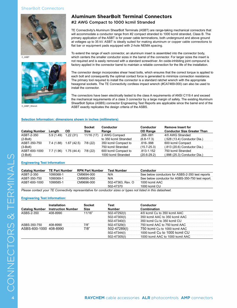
The connector design incorporates shear head bolts, which ensures that the correct torque is applied to each bolt and consequently the optimal contact force is generated to minimize connection resistance. The primary tool required to install the connector is a standard ratchet wrench with the appropriate hexagonal sockets. The TE Connectivity cordless impact wrench (#CA7469-000) can also be used to install the connector. The connectors have been electrically tested to the class A requirements of ANSI C119.4 and exceed the mechanical requirements of a class 3 connector by a large margin of safety. The existing Aluminum ShearBolt Splice (ASBS) connector Engineering Test Reports are applicable since the barrel end of the ASBT exactly replicates the design criteria of the ASBS.
Selection Information: dimensions shown in inches (millimeters)
Socket Conductor Conductor Remove Insert forCatalog Number Length OD Size Range OD Range Conductor Size Greater ThanASBT-2-350 5.9 (1.49) 1.22 (31) 11/16 (17) 2 AWG Compact .268-.681 4/0 AWG Stranded(2-Bolt) to 350 kcmil Stranded (6.8-17.3) (.528 (13.4) Conductor Dia.)ASBT-350-750 7.4 (1.88) 1.67 (42.5) 7/8 (22) 350 kcmil Compact to .616-.998 600 kcmil Compact(3-Bolt) 750 kcmil Stranded (15.7-25.3) (.813 (20.6) Conductor Dia.)ASBT-600-1000 7.7 (1.96) 1.75 (44.4) 7/8 (22) 600 kcmil Compact to .813-1.152 750 kcmil Stranded (3-Bolt) 1000 kcmil Stranded (20.6-29.2) (.998 (25.3) Conductor Dia.)
Engineering Test Information
Catalog Number TE Part Number RPN Part Number Test Number ConductorASBT-2-350 1099368-1 CM9694-000 N/A See below conductors for ASBS-2-350 test reportsASBT-350-750 1099369-1 CM9695-000 N/A See below conductor for ASBS-350-750 test report.ASBT-600-1000 1099585-1 CM9696-000 502-47363, Rev. O 1000 kcmil AAC
502-47370 1000 kcmil CUPlease contact your TE Connectivity representative for conductor sizes or types not listed in this datasheet.
Engineering Test Information:
Installation Socket Test Conductor Catalog Number Instruction Number Size Number CombinationASBS-2-350 408-8990 11/16” 502-47292(I) 4/0 kcmil Cu to 350 kcmil AAC
502-47300(I) 350 kcmil AAC to 350 kcmil AAC 502-47340(I) 350 kcmil Cu to 350 kcmil CUASBS-350-750 408-8990 7/8” 502-47329(I) 750 kcmil AAC to 750 kcmil AACASBS-600-1000 408-8990 7/8” 502-47289(I) 750 kcmil Cu to 1000 kcmil AAC 502-47344(I) 1000 kcmil Cu to 1000 kcmil CU 502-47305(I) 1000 kcmil AAC to 1000 kcmil AAC
C_ASBT
C_ASBT_Wrench
4 RAYCHEM cable accessories ALR photocontrols AMP connectors
CO
NN
EC
TO
RS
& T
ER
MIN
AL
S
5
CO
NN
EC
TO
RS
& T
ER
MIN
AL
SCompression Connectors
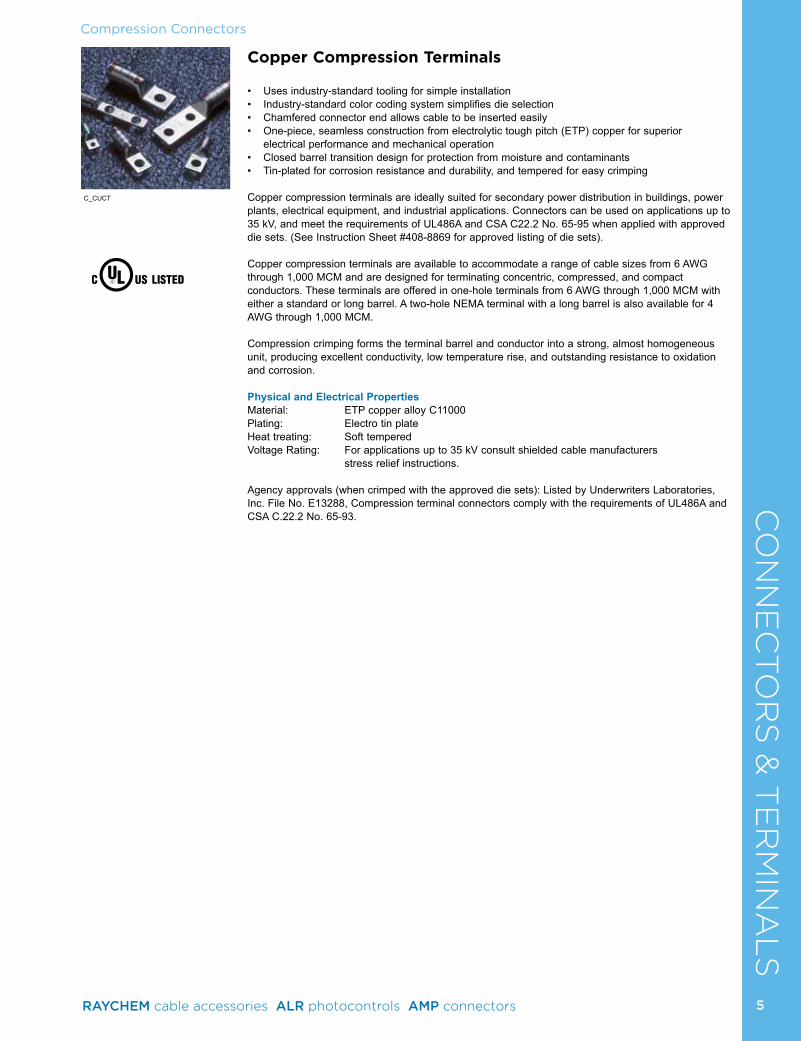
Copper Compression Terminals
• Uses industry-standard tooling for simple installation• Industry-standard color coding system simplifies die selection• Chamfered connector end allows cable to be inserted easily• One-piece, seamless construction from electrolytic tough pitch (ETP) copper for superior
electrical performance and mechanical operation• Closed barrel transition design for protection from moisture and contaminants• Tin-plated for corrosion resistance and durability, and tempered for easy crimping
Copper compression terminals are ideally suited for secondary power distribution in buildings, power plants, electrical equipment, and industrial applications. Connectors can be used on applications up to 35 kV, and meet the requirements of UL486A and CSA C22.2 No. 65-95 when applied with approved die sets. (See Instruction Sheet #408-8869 for approved listing of die sets).
Copper compression terminals are available to accommodate a range of cable sizes from 6 AWG through 1,000 MCM and are designed for terminating concentric, compressed, and compact conductors. These terminals are offered in one-hole terminals from 6 AWG through 1,000 MCM with either a standard or long barrel. A two-hole NEMA terminal with a long barrel is also available for 4 AWG through 1,000 MCM.
Compression crimping forms the terminal barrel and conductor into a strong, almost homogeneous unit, producing excellent conductivity, low temperature rise, and outstanding resistance to oxidation and corrosion.
Physical and Electrical PropertiesMaterial: ETP copper alloy C11000 Plating: Electro tin plateHeat treating: Soft temperedVoltage Rating: For applications up to 35 kV consult shielded cable manufacturers
stress relief instructions.
Agency approvals (when crimped with the approved die sets): Listed by Underwriters Laboratories, Inc. File No. E13288, Compression terminal connectors comply with the requirements of UL486A and CSA C.22.2 No. 65-93.
C_CUCT
5RAYCHEM cable accessories ALR photocontrols AMP connectors
6
CO
NN
EC
TO
RS
& T
ER
MIN
AL
SCompression Connectors
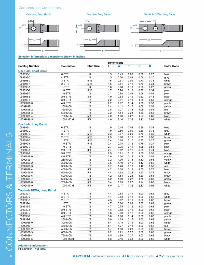
Selection Information: dimensions shown in inches
Dimensions Catalog Number Conductor Stud Size L W T D N Color Code
One Hole, Short Barrel1099898-1 6 STR. 1/4 1.5 0.45 0.08 0.56 0.27 blue1099898-2 4 STR. 1/4 1.5 0.50 0.09 0.56 0.27 gray1099898-3 3 STR. 5/16 1.6 0.57 0.09 0.70 0.34 white1099898-4 2 STR. 5/16 1.6 0.61 0.11 0.70 0.34 brown1099898-5 1 STR. 1/4 1.6 0.68 0.10 0.56 0.27 green1099898-6 1/0 STR. 5/16 1.7 0.74 0.12 0.70 0.34 pink1099898-7 1/0 STR. 1/2 2.1 0.88 0.09 1.08 0.53 pink1099898-8 2/0 STR. 3/8 1.9 0.83 0.12 0.83 0.41 black1099898-9 3/0 STR. 1/2 2.2 0.91 0.13 1.08 0.53 orange1-1099898-0 4/0 STR. 1/2 2.2 1.02 0.14 1.08 0.53 purple1-1099898-1 250 MCM 1/2 2.4 1.11 0.16 1.08 0.53 yellow1-1099898-2 350 MCM 1/2 2.5 1.27 0.18 1.08 0.53 red1-1099898-3 500 MCM 1/2 3.2 1.54 0.23 1.30 0.65 brown1-1099898-4 750 MCM 5/8 4.0 1.88 0.27 1.94 0.88 black1-1099898-5 1000 MCM 5/8 4.9 2.16 0.32 2.12 0.94 white
One Hole, Long Barrel1099899-1 6 STR. 1/4 1.9 0.45 0.08 0.56 0.34 blue1099899-2 4 STR. 1/4 1.9 0.50 0.09 0.56 0.38 gray1099899-3 3 STR. 5/16 2.3 0.57 0.09 0.70 0.38 white1099899-4 2 STR. 5/16 2.3 0.60 0.11 0.75 0.38 brown1099899-5 1 STR. 5/16 2.4 0.68 0.10 0.75 0.27 green1099899-6 1/0 STR. 5/16 2.4 0.74 0.12 0.75 0.27 pink1099899-7 1/0 STR. 1/2 2.7 0.75 0.11 1.08 0.53 pink1099899-8 2/0 STR. 3/8 2.7 0.82 0.12 0.88 0.44 black1099899-9 3/0 STR. 1/2 2.9 0.91 0.13 1.08 0.53 orange1-1099899-0 4/0 STR. 1/2 3.0 1.00 0.14 1.08 0.53 purple1-1099899-1 250 MCM 1/2 3.2 1.09 0.16 1.12 0.56 yellow1-1099899-2 300 MCM 1/2 3.6 1.19 0.16 1.12 0.56 white1-1099899-3 350 MCM 1/2 3.7 1.28 0.18 1.12 0.56 red1-1099899-4 400 MCM 5/8 4.2 1.38 0.19 1.50 0.75 blue1-1099899-5 500 MCM 5/8 4.4 1.52 0.23 1.50 0.75 brown1-1099899-6 500 MCM 1/2 4.2 1.54 0.23 1.30 0.65 brown1-1099899-7 600 MCM 5/8 5.2 1.69 0.27 1.75 0.88 green1-1099899-8 750 MCM 5/8 5.4 1.89 0.27 1.94 0.88 black1-1099899-9 1000 MCM 5/8 6.0 2.17 0.32 2.12 0.94 white
Two-Hole NEMA, Long Barrel1099939-1 4 STR. 1/2 4.4 0.83 0.11 3.00 0.62 gray1099939-2 3 STR. 1/2 4.4 0.83 0.11 3.00 0.62 white1099939-3 2 STR. 1/2 4.5 0.82 0.11 3.00 0.62 brown1099939-4 1 STR. 1/2 4.7 0.80 0.09 3.00 0.62 green1099939-5 1/0 STR. 1/2 4.7 0.75 0.12 3.00 0.62 pink1099939-6 2/0 STR. 1/2 4.8 0.82 0.12 3.00 0.62 black1099939-7 3/0 STR. 1/2 4.8 0.90 0.12 3.00 0.62 orange1099939-8 4/0 STR. 1/2 5.0 1.00 0.14 3.00 0.62 purple1099939-9 250 MCM 1/2 5.0 1.09 0.16 3.00 0.62 yellow1-1099939-0 300 MCM 1/2 5.4 1.18 0.16 3.00 0.62 white1-1099939-1 350 MCM 1/2 5.4 1.27 0.18 3.00 0.62 red1-1099939-2 500 MCM 1/2 5.7 1.53 0.23 3.00 0.62 brown1-1099939-3 600 MCM 1/2 6.2 1.71 0.27 3.00 0.62 green1-1099939-4 750 MCM 1/2 6.5 1.89 0.27 3.00 0.62 black1-1099939-5 1000 MCM 1/2 6.8 2.16 0.33 3.00 0.62 white
Additional Information:PII Number 408-8869
6 RAYCHEM cable accessories ALR photocontrols AMP connectors
One Hole, Short Barrel One Hole, Long Barrel
L
D
T T T
WWW
N N N 1.75
W/2 W/2 W/2
D D
L L
Two-Hole NEMA, Long Barrel
7
CO
NN
EC
TO
RS
& T
ER
MIN
AL
SCompression Connectors
Con
duct
or
Part
No.
Col
or
OE
Inde
x
Con
duct
or
Part
No.
Col
or
OE
Inde
x
D
L2
L
Con
duct
or
Part
No.
Col
or
OE
Inde
x
Con
duct
or
Part
No.
Col
or
OE
Inde
x
L
D
L2
Long Barrel Splice
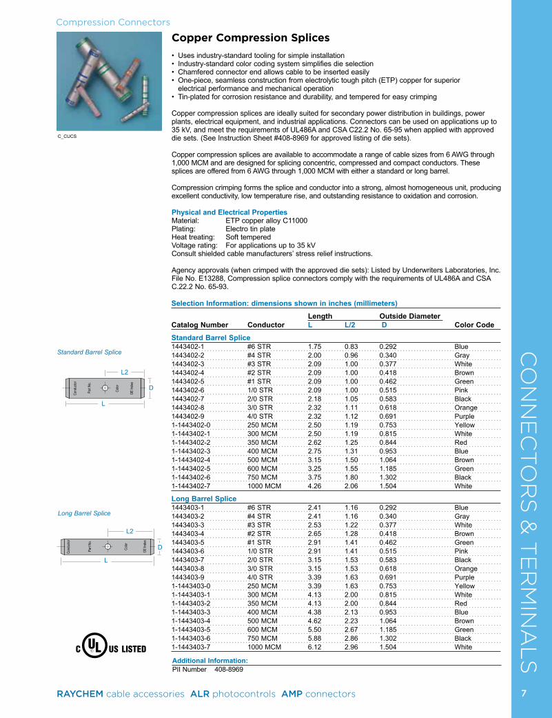
Standard Barrel Splice
Copper Compression Splices
• Uses industry-standard tooling for simple installation• Industry-standard color coding system simplifies die selection• Chamfered connector end allows cable to be inserted easily• One-piece, seamless construction from electrolytic tough pitch (ETP) copper for superior
electrical performance and mechanical operation• Tin-plated for corrosion resistance and durability, and tempered for easy crimping
Copper compression splices are ideally suited for secondary power distribution in buildings, power plants, electrical equipment, and industrial applications. Connectors can be used on applications up to 35 kV, and meet the requirements of UL486A and CSA C22.2 No. 65-95 when applied with approved die sets. (See Instruction Sheet #408-8969 for approved listing of die sets).
Copper compression splices are available to accommodate a range of cable sizes from 6 AWG through 1,000 MCM and are designed for splicing concentric, compressed and compact conductors. These splices are offered from 6 AWG through 1,000 MCM with either a standard or long barrel.
Compression crimping forms the splice and conductor into a strong, almost homogeneous unit, producing excellent conductivity, low temperature rise, and outstanding resistance to oxidation and corrosion.
Physical and Electrical PropertiesMaterial: ETP copper alloy C11000 Plating: Electro tin plateHeat treating: Soft temperedVoltage rating: For applications up to 35 kV Consult shielded cable manufacturers’ stress relief instructions.
Agency approvals (when crimped with the approved die sets): Listed by Underwriters Laboratories, Inc. File No. E13288, Compression splice connectors comply with the requirements of UL486A and CSA C.22.2 No. 65-93.
C_CUCS
Selection Information: dimensions shown in inches (millimeters)
Length Outside DiameterCatalog Number Conductor L L/2 D Color Code
Standard Barrel Splice1443402-1 #6 STR 1.75 0.83 0.292 Blue1443402-2 #4 STR 2.00 0.96 0.340 Gray1443402-3 #3 STR 2.09 1.00 0.377 White1443402-4 #2 STR 2.09 1.00 0.418 Brown1443402-5 #1 STR 2.09 1.00 0.462 Green1443402-6 1/0 STR 2.09 1.00 0.515 Pink1443402-7 2/0 STR 2.18 1.05 0.583 Black1443402-8 3/0 STR 2.32 1.11 0.618 Orange1443402-9 4/0 STR 2.32 1.12 0.691 Purple1-1443402-0 250 MCM 2.50 1.19 0.753 Yellow1-1443402-1 300 MCM 2.50 1.19 0.815 White1-1443402-2 350 MCM 2.62 1.25 0.844 Red1-1443402-3 400 MCM 2.75 1.31 0.953 Blue1-1443402-4 500 MCM 3.15 1.50 1.064 Brown1-1443402-5 600 MCM 3.25 1.55 1.185 Green1-1443402-6 750 MCM 3.75 1.80 1.302 Black1-1443402-7 1000 MCM 4.26 2.06 1.504 White
Long Barrel Splice1443403-1 #6 STR 2.41 1.16 0.292 Blue1443403-2 #4 STR 2.41 1.16 0.340 Gray1443403-3 #3 STR 2.53 1.22 0.377 White1443403-4 #2 STR 2.65 1.28 0.418 Brown1443403-5 #1 STR 2.91 1.41 0.462 Green1443403-6 1/0 STR 2.91 1.41 0.515 Pink1443403-7 2/0 STR 3.15 1.53 0.583 Black1443403-8 3/0 STR 3.15 1.53 0.618 Orange1443403-9 4/0 STR 3.39 1.63 0.691 Purple1-1443403-0 250 MCM 3.39 1.63 0.753 Yellow1-1443403-1 300 MCM 4.13 2.00 0.815 White1-1443403-2 350 MCM 4.13 2.00 0.844 Red1-1443403-3 400 MCM 4.38 2.13 0.953 Blue1-1443403-4 500 MCM 4.62 2.23 1.064 Brown1-1443403-5 600 MCM 5.50 2.67 1.185 Green1-1443403-6 750 MCM 5.88 2.86 1.302 Black1-1443403-7 1000 MCM 6.12 2.96 1.504 White
7RAYCHEM cable accessories ALR photocontrols AMP connectors
Additional Information:PII Number 408-8969
8
CO
NN
EC
TO
RS
& T
ER
MIN
AL
SInsulation Piercing Connectors
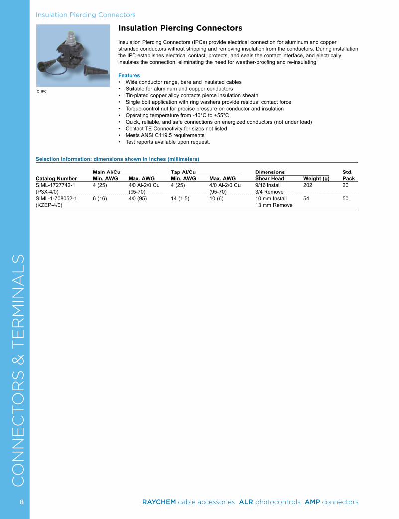
Insulation Piercing Connectors (IPCs) provide electrical connection for aluminum and copper stranded conductors without stripping and removing insulation from the conductors. During installation the IPC establishes electrical contact, protects, and seals the contact interface, and electrically insulates the connection, eliminating the need for weather-proofing and re-insulating.
Features• Wide conductor range, bare and insulated cables• Suitable for aluminum and copper conductors• Tin-plated copper alloy contacts pierce insulation sheath• Single bolt application with ring washers provide residual contact force• Torque-control nut for precise pressure on conductor and insulation• Operating temperature from -40°C to +55°C• Quick, reliable, and safe connections on energized conductors (not under load)• Contact TE Connectivity for sizes not listed• Meets ANSI C119.5 requirements• Test reports available upon request.
Selection Information: dimensions shown in inches (millimeters)
Main Al/Cu Tap Al/Cu Dimensions Std.Catalog Number Min. AWG Max. AWG Min. AWG Max. AWG Shear Head Weight (g) PackSIML-1727742-1 4 (25) 4/0 Al-2/0 Cu 4 (25) 4/0 Al-2/0 Cu 9/16 Install 202 20(P3X-4/0) (95-70) (95-70) 3/4 Remove SIML-1-708052-1 6 (16) 4/0 (95) 14 (1.5) 10 (6) 10 mm Install 54 50(KZEP-4/0) 13 mm Remove
Insulation Piercing Connectors
C_IPC
8 RAYCHEM cable accessories ALR photocontrols AMP connectors
9
CO
NN
EC
TO
RS
& T
ER
MIN
AL
SWedge Connectors
C_wedge
C_ampactAtap
Listed File No. E13288
RUS: ANSI C119.4 Class AA - Electrical Class 1 - Mechanical
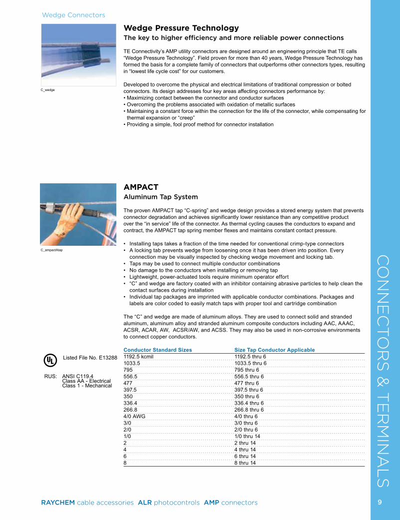
AMPACTAluminum Tap System
The proven AMPACT tap “C-spring” and wedge design provides a stored energy system that prevents connector degradation and achieves significantly lower resistance than any competitive product over the “in service” life of the connector. As thermal cycling causes the conductors to expand and contract, the AMPACT tap spring member flexes and maintains constant contact pressure.
• Installing taps takes a fraction of the time needed for conventional crimp-type connectors• A locking tab prevents wedge from loosening once it has been driven into position. Every
connection may be visually inspected by checking wedge movement and locking tab.• Taps may be used to connect multiple conductor combinations• No damage to the conductors when installing or removing tap• Lightweight, power-actuated tools require minimum operator effort• “C” and wedge are factory coated with an inhibitor containing abrasive particles to help clean the
contact surfaces during installation• Individual tap packages are imprinted with applicable conductor combinations. Packages and
labels are color coded to easily match taps with proper tool and cartridge combination
The “C” and wedge are made of aluminum alloys. They are used to connect solid and stranded aluminum, aluminum alloy and stranded aluminum composite conductors including AAC, AAAC, ACSR, ACAR, AW, ACSR/AW, and ACSS. They may also be used in non-corrosive environments to connect copper conductors.
Conductor Standard Sizes Size Tap Conductor Applicable1192.5 kcmil 1192.5 thru 61033.5 1033.5 thru 6795 795 thru 6556.5 556.5 thru 6477 477 thru 6397.5 397.5 thru 6350 350 thru 6336.4 336.4 thru 6266.8 266.8 thru 64/0 AWG 4/0 thru 63/0 3/0 thru 62/0 2/0 thru 61/0 1/0 thru 142 2 thru 144 4 thru 146 6 thru 148 8 thru 14
Wedge Pressure TechnologyThe key to higher efficiency and more reliable power connections
TE Connectivity’s AMP utility connectors are designed around an engineering principle that TE calls “Wedge Pressure Technology”. Field proven for more than 40 years, Wedge Pressure Technology has formed the basis for a complete family of connectors that outperforms other connectors types, resulting in “lowest life cycle cost” for our customers.
Developed to overcome the physical and electrical limitations of traditional compression or bolted connectors. Its design addresses four key areas affecting connectors performance by:• Maximizing contact between the connector and conductor surfaces• Overcoming the problems associated with oxidation of metallic surfaces• Maintaining a constant force within the connection for the life of the connector, while compensating for
thermal expansion or “creep”• Providing a simple, fool proof method for connector installation
9RAYCHEM cable accessories ALR photocontrols AMP connectors
10
CO
NN
EC
TO
RS
& T
ER
MIN
AL
SWedge Connectors
AMPACT Aluminum Tap System Selection Guide
Catalog Number Wire Combinations
Type II Street Light Taps (White Cartridge P/N 69338-5 separately)83653-1 1/0-10-12-1483653-2 2-10-12-1483653-5 4-10-12-1483653-3 6-10-12-1483653-4 8-10-12-14
Type II Taps (White Cartridge P/N 69338-5 separately)602283 1/0-2602283-1 2-2; 1/0-4602283-2 2-4; 1/0-6602283-3 4-4; 2-6602283-4 6-6; 4-6602283-5 8-8602283-6 1/0-8602283-7 2-8602283-8 6-8; 4-8
Medium Taps (Blue Cartridge P/N 69338-1 separately)600403 1/0-1/0; 2/0-2; 1/0-2600411 2/0-2/0; 3/0-1/0; 4/0-2600446 3/0-6; 2/0-6600447 2/0-4; 3/0-4600448 2/0-1/0; 3/0-2600455 4/0-4600456 4/0-4600458 3/0-2/0; 4/0-1/0600459 3/0-3/0; 4/0-2/0600465 4/0-3/0600466 4/0-4/0
266.8 kcmil Taps (Blue Cartridge P/N 69338-1 separately)602046-1 266.86602046-2 266.8-4602046-3 266.8-2602046-4 266.8-1/0602046-5 266.8-2/0602046-6 266.8-3/0602046-7 266.8-4/0602046-9 266.8-266.8
350 kcmil Taps (Blue Cartridge P/N 69338-1 separately)602380 350-6602380-1 350-4602380-2 350-2602380-3 350-1/0602380-4 350-2/0602380-5 350-3/0602380-6 350-4/0602380-7 350-350
336.4-477-556.5 kcmil Taps (Yellow Cartridge P/N 69338-4 separately)602014 336.4-6602013 336.4-4602000 336.4-2602001 336.4-1/0602002 336.4-2/0602003 336.4-3/0602004 336.4-4/0602006 336.4-266.8602007 336.4-336.4602031-8 477.0-2, 3602031-9 477.0-4, 51-602031-0 477.0-61-602031-2 556.5-477.0; 556.51-602031-3 477.0-477.0; 556.5-336.41-602031-4 477.0-336.4; 556.5-266.81-602031-5 477.0-266.8; 556.5-3/0; 4/01-602031-6 477.0-4/0; 556.5-2/01-602031-7 477.0-3/0; 556.5-1/01-602031-8 477.0-2/0; 556.5-11-602031-9 477.0-1/0; 556.5-22-602031-0 556.5-2; 32-602031-1 556.5-4; 52-602031-2 556.5-6
Tap Catalog Number Wire Combinations
795 kcmil Taps (Yellow Cartridge P/N 69338-4 separately)602121 795-795602121-1 795-715602121-2 795-636602121-3 795-556.5602121-4 795-477602121-5 795-397.5602121-6 795-336.4602121-7 795-266.8602121-8 795-4/0602121-9 795-3/01-602121-0 795-2/01-602121-1 795-1/01-602121-2 795-21-602121-3 795-41-602121-4 795-6
1033.5 kcmil Taps (Yellow Cartridge P/N 69338-4 separately)602180 1033.5-1033.5602180-1 1033.5-954.0602180-2 1033.5-795.0602180-3 1033.5-715.5602180-4 1033.5-636.0602180-5 1033.5-556.5602180-6 1033.5-477.0602180-7 1033.5-397.5602180-8 1033.5-336.4602180-9 1033.5-266.81-602180-0 1033.5-4/01-602180-1 1033.5-3/01-602180-2 1033.5-2/01-602180-3 1033.5-1/01-602180-4 1033.5-21-602180-5 1033.5-41-602180-6 1033.5-6
1192.5 kcmil Taps (Yellow Cartridge P/N 69338-4 separately)602300 1192.5-1192.5602300-1 1192.5-1033.5602300-2 1192.5-954.0602300-3 1192.5-795.0602300-4 1192.5-715.5602300-5 1192.5-636.0602300-6 1192.5-556.5602300-7 1192.5-477.0602300-8 1192.5-397.5602300-9 1192.5-336.41-602300-0 1192.5-266.81-602300-1 1192.5-4/01-602300-2 1192.5-3/01-602300-3 1192.5-2/01-602300-4 1192.5-1/01-602300-5 1192.5-21-602300-6 1192.5-41-602300-7 1192.5-6Note: For specific wire sizes refer to the AMPACT Tap Selection Guide.
10 RAYCHEM cable accessories ALR photocontrols AMP connectors
11
Wedge ConnectorsC
ON
NE
CTO
RS
& T
ER
MIN
AL
SAMPACT Aluminum Tap System Diameter Limits Selection Guide (Dimensions shown in inches (millimeters)
(Large Groove ) (Small Groove) Sum of Diameters Through Wire Diameter Tap Wire Diameter
Catalog Number Max. Min. Max. Min. Max. Min.
Type II Taps (White Coded)602283 .724 (18.39) .583 (14.81) .398 (10.11) .257 (6.53) .398 (10.11) .257 (6.53)602283-1 .656 (16.66) .515 (13.08) .398 (10.11) .257 (6.53) .330 (8.38) .204 (5.18)602283-2 .602 (15.29) .464 (11.79) .398 (10.11) .257 (6.53) .258 (6.55) .162 (4.11)602283-3 .530 (13.46) .410 (10.41) .330 (8.38) .204 (5.18) .258 (6.55) .162 (4.11)602283-4 .456 (11.58) .331 (8.41) .258 (6.55) .162 (4.11) .230 (5.84) .162 (4.11)602283-5 .324 (8.23) .256 (6.50) .162 (4.11) .128 (3.25) .162 (4.11) .128 (3.25)602283-6 .560 (14.22) .452 (11.48) .398 (10.11) .257 (6.53) .162 (4.11) .128 (3.25)602283-7 .488 (12.40) .387 (9.83) .398 (10.11) .257 (6.53) .162 (4.11) .128 (3.25)602283-8 .416 (10.57) .297 (7.54) .258 (6.55) .162 (4.11) .162 (4.11) .128 (3.25)
Medium Wire Range Taps (Blue Coded)600403 .796 (20.22) .621 (15.77) .500 (12.70) .324 (8.23) .464 (11.79) .257 (6.53)600411 .901 (22.89) .736 (18.69) .572 (14.53) .364 (9.25) .464 (11.79) .257 (6.53)600446 .707 (17.96) .526 (13.36) .572 (14.53) .364 (9.25) .204 (5.18) .162 (4.11)600447 .761 (19.33) .570 (14.48) .572 (14.53) .364 (9.25) .258 (6.55) .204 (5.18)600448 .846 (21.49) .690 (17.53) .572 (14.53) .364 (9.25) .398 (10.11) .257 (6.53)600455 .769 (19.53) .622 (15.80) .572 (14.53) .364 (9.25) .204 (5.18) .162 (4.11)600456 .823 (20.90) .664 (16.87) .572 (14.53) .364 (9.25) .258 (6.55) .204 (5.18)600458 .963 (24.46) .804 (20.42) .572 (14.53) .364 (9.25) .464 (11.79) .257 (6.53)600459 1.013 (25.73) .858 (21.79) .572 (14.53) .364 (9.25) .572 (14.53) .364 (9.25)600465 1.068 (27.13) .938 (23.83) .572 (14.53) .364 (9.25) .572 (14.53) .364 (9.25)600466 1.130 (28.70) .956 (24.28) .572 (14.53) .364 (9.25) .572 (14.53) .364 (9.25)
226.8 kcmil Range Taps (Blue Coded)602046-1 .846 (21.49) .699 (17.75) .650 (16.51) .525 (13.34) .204 (5.18) .162 (4.11)602046-2 .900 (22.86) .755 (19.18) .650 (16.51) .525 (13.34) .258 (6.55) .204 (5.18)602046-3 .972 (24.69) .818 (20.78) .650 (16.51) .525 (13.34) .330 (8.38) .257 (6.53)602046-4 1.052 (26.72) .897 (22.78) .650 (16.51) .525 (13.34) .500 (12.70) .324 (8.23)602046-5 1.104 (28.04) .963 (24.46) .650 (16.51) .525 (13.34) .562 (14.27) .364 (9.25)602046-6 1.159 (29.44) 1.015 (25.78) .650 (16.51) .525 (13.34) .562 (14.27) .409 (10.39)602046-7 1.217 (30.91) 1.080 (27.43) .650 (16.51) .525 (13.34) .575 (14.61) .460 (11.68)602046-9 1.284 (32.61) 1.149 (29.18) .650 (16.51) .525 (13.34) .650 (16.51) .525 (13.34)
350 kcmil Range Taps (Blue Coded)602380 .885 (22.48) .738 (18.75) .684 (17.37) .600 (15.24) .204 (5.18) .162 (4.11)602380-1 .939 (23.85) .794 (20.17) .684 (17.37) .600 (15.24) .258 (6.55) .204 (5.18)602380-2 1.011 (25.68) .857 (21.77) .684 (17.37) .600 (15.24) .333 (8.46) .257 (6.53)602380-3 1.091 (27.71) .936 (23.77) .684 (17.37) .600 (15.24) .500 (12.70) .324 (8.23)602380-4 1.143 (29.03) 1.002 (25.45) .684 (17.37) .600 (15.24) .562 (14.27) .364 (9.25)602380-5 1.198 (30.43) 1.054 (26.77) .684 (17.37) .600 (15.24) .562 (14.27) .409 (10.39)602380-6 1.284 (32.61) 1.119 (28.42) .684 (17.37) .600 (15.24) .600 (15.24) .460 (11.68)602380-7 1.368 (34.75) 1.188 (30.18) .684 (17.37) .600 (15.24) .684 (17.37) .600 (15.24)
336.4 kcmil Range Taps (Yellow Coded)602000 1.069 (27.15) .860 (21.84) .750 (19.05) .524 (13.31) .355 (9.02) .257 (6.53)602001 1.141 (28.98) .927 (23.55) .750 (19.05) .524 (13.31) .557 (14.15) .324 (8.23)602002 1.190 (30.23) .967 (24.56) .750 (19.05) .524 (13.31) .619 (15.72) .364 (9.25)602003 1.245 (31.62) 1.012 (25.70) .750 (19.05) .524 (13.31) .619 (15.72) .409 (10.39)602004 1.306 (33.17) 1.063 (27.00) .750 (19.05) .524 (13.31) .630 (16.00) .460 (11.68)602006 1.370 (34.08) 1.140 (28.96) .750 (19.05) .524 (13.31) .750 (19.05) .524 (13.31)602007 1.456 (36.98) 1.206 (30.63) .750 (19.05) .524 (13.31) .750 (19.05) .524 (13.31)602013 .999 (25.37) .807 (20.50) .750 (19.05) .524 (13.31) .258 (6.55) .204 (5.18)602014 .932 (23.67) .765 (19.43) .750 (19.05) .524 (13.31) .204 (5.18) .162 (4.11)
477.0 kcmil Range Taps (Yellow Coded) 602031-8 1.185 (30.10) .995 (25.27) .893 (22.68) .666 (16.92) .326 (8.28) .257 (6.53)602031-9 1.118 (28.40) .942 (23.93) .893 (22.68) .666 (16.92) .258 (6.55) .204 (5.18)1-602031-0 1.056 (26.82) .900 (22.86) .893 (22.68) .666 (16.92) .199 (5.05) .162 (4.11)
11RAYCHEM cable accessories ALR photocontrols AMP connectors
12
Wedge ConnectorsC
ON
NE
CTO
RS
& T
ER
MIN
AL
SAMPACT Aluminum Tap System Diameter Limits Selection Guide continues
(Large Groove) (Small Groove)Sum of Diameters Through Wire Diameter Tap Wire Diameter
Catalog Number Max. Min. Max. Min. Max. Min.
477.0/556.5 kcmil Range Taps (Yellow Coded)1-602031-2 1.854 (47.09) 1.692 (42.98) .950 (24.13) .722 (18.34) .950 (24.13) .722 (18.34)1-602031-3 1.741 (44.22) 1.524 (38.71) .940 (23.88) .666 (16.92) .940 (23.88) .666 (16.92)1-602031-4 1.587 (40.31) 1.366 (34.70) .940 (23.88) .666 (16.92) .750 (19.05) .573 (14.55)1-602031-5 1.500 (38.10) 1.297 (32.94) .940 (23.88) .666 (16.92) .750 (19.05) .481 (12.22)1-602031-6 1.421 (36.09) 1.216 (30.89) .940 (23.88) .666 (16.92) .650 (16.51) .436 (11.07)1-602031-7 1.360 (34.54) 1.147 (29.13) .940 (23.88) .666 (16.92) .562 (14.27) .382 (9.70)1-602031-8 1.305 (33.15) 1.102 (27.99) .940 (23.88) .666 (16.92) .562 (14.27) .346 (8.79)1-602031-9 1.270 (32.26) 1.062 (26.97) .940 (23.88) .666 (16.92) .450 (11.43) .324 (8.23)2-602031-0 1.247 (31.67) 1.115 (28.32) .940 (23.88) .666 (16.92) .326 (8.28) .257 (6.53)2-602031-1 1.181 (30.00) 1.062 (26.97) .940 (23.88) .666 (16.92) .258 (6.55) .204 (5.18)2-602031-2 1.126 (28.60) 1.020 (25.91) .940 (23.88) .666 (16.92) .199 (5.05) .162 (4.11)
795.0 kcmil Range Taps (Yellow Coded)602121 2.216 (56.29) 2.072 (52.63) 1.156 (29.36) .858 (21.79) 1.158 (29.41) .858 (21.79)602121-1 2.159 (54.84) 2.002 (50.85) 1.156 (29.36) .858 (21.79) 1.156 (29.36) .858 (21.79)602121-2 2.098 (53.29) 1.946 (49.43) 1.156 (29.36) .858 (21.79) 1.156 (29.36) .858 (21.79)602121-3 2.035 (51.69) 1.891 (48.03) 1.156 (29.36) .858 (21.79) 1.156 (29.36) .858 (21.79)602121-4 1.966 (49.94) 1.822 (46.28) 1.156 (29.36) .858 (21.79) .900 (22.86) .700 (17.78)602121-5 1.891 (48.03) 1.747 (44.37) 1.156 (29.36) .858 (21.79) .900 (22.86) .700 (17.78)602121-6 1.829 (46.46) 1.685 (42.80) 1.156 (29.36) .858 (21.79) .750 (19.05) .525 (13.34)602121-7 1.750 (44.45) 1.606 (40.79) 1.156 (29.36) .858 (21.79) .722 (18.34) .525 (13.34)602121-8 1.670 (42.42) 1.526 (38.76) 1.156 (29.36) .858 (21.79) .722 (18.34) .364 (9.25)602121-9 1.610 (40.89) 1.466 (37.24) 1.156 (29.36) .858 (21.79) .608 (15.44) .364 (9.25)1-602121-0 1.555 (39.50) 1.411 (35.84) 1.156 (29.36) .858 (21.79) .608 (15.44) .364 (9.25)1-602121-1 1.506 (38.25) 1.362 (34.59) 1.156 (29.36) .858 (21.79) .436 (11.07) .324 (8.23)1-602121-2 1.434 (36.42) 1.290 (32.77) 1.156 (29.36) .858 (21.79) .398 (10.11) .257 (6.53)1-602121-3 1.365 (34.67) 1.221 (31.01) 1.156 (29.36) .858 (21.79) .312 (7.92) .204 (5.18)1-602121-4 1.306 (33.17) 1.162 (29.51) 1.156 (29.36) .858 (21.79) .250 (6.35) .162 (4.11)
1033.5 kcmil Range Taps (Yellow Coded)602180 2.496 (63.40) 2.332 (59.23) 1.250 (31.75) .856 (21.74) 1.250 (31.75) .856 (21.74)602180-1 2.411 (61.24) 2.251 (57.18) 1.250 (31.75) .856 (21.74) 1.250 (31.75) .856 (21.74)602180-2 2.354 (59.79) 2.194 (55.73) 1.250 (31.75) .856 (21.74) 1.250 (31.75) .856 (21.74)602180-3 2.297 (58.34) 2.137 (54.28) 1.250 (31.75) .856 (21.74) 1.250 (31.75) .856 (21.74)602180-4 2.236 (56.79) 2.076 (52.73) 1.250 (31.75) .856 (21.74) 1.250 (31.75) .856 (21.74)602180-5 2.173 (55.19) 2.013 (51.13) 1.250 (31.75) .856 (21.74) 1.250 (31.75) .856 (21.74)602180-6 2.104 (53.44) 1.944 (49.38) 1.250 (31.75) .856 (21.74) .900 (22.86) .700 (17.78)602180-7 2.029 (51.54) 1.869 (47.47) 1.250 (31.75) .856 (21.74) .900 (22.86) .700 (17.78)602180-8 1.967 (49.96) 1.807 (45.90) 1.250 (31.75) .856 (21.74) .750 (19.05) .525 (13.34)602180-9 1.888 (47.96) 1.728 (43.89) 1.250 (31.75) .856 (21.74) .722 (18.34) .525 (13.34)1-602180-0 1.808 (45.92) 1.648 (41.86) 1.250 (31.75) .856 (21.74) .608 (15.44) .364 (9.25)1-602180-1 1.748 (44.40) 1.588 (40.34) 1.250 (31.75) .856 (21.74) .608 (15.44) .364 (9.25)1-602180-2 1.693 (43.00) 1.533 (38.94) 1.250 (31.75) .856 (21.74) .608 (15.44) .364 (9.25)1-602180-3 1.644 (41.76) 1.484 (37.69) 1.250 (31.75) .856 (21.74) .398 (10.11) .324 (8.23)1-602180-4 1.572 (39.93) 1.412 (35.86) 1.250 (31.75) .856 (21.74) .326 (8.28) .257 (6.53)1-602180-5 1.503 (38.18) 1.343 (34.11) 1.250 (31.75) .856 (21.74) .258 (6.55) .204 (5.18)1-602180-6 1.444 (36.68) 1.284 (32.61) 1.250 (31.75) .856 (21.74) .198 (5.03) .162 (4.11)
1192.5 kcmil Range Taps (Yellow Coded)602300 2.604 (66.14) 2.516 (63.91) 1.375 (34.93) .856 (21.74) 1.375 (34.93) .856 (21.74)602300-1 2.548 (64.72) 2.448 (62.18) 1.375 (34.93) .856 (21.74) 1.375 (34.93) .856 (21.74)602300-2 2.498 (63.45) 2.398 (60.91) 1.375 (34.93) .856 (21.74) 1.375 (34.93) .856 (21.74)602300-3 2.410 (61.21) 2.310 (58.67) 1.375 (34.93) .856 (21.74) 1.375 (34.93) .856 (21.74)602300-4 2.353 (59.77) 2.253 (57.23) 1.375 (34.93) .856 (21.74) 1.375 (34.93) .856 (21.74)602300-5 2.292 (58.22) 2.192 (55.68) 1.375 (34.93) .856 (21.74) 1.375 (34.93) .856 (21.74)602300-6 2.229 (56.62) 2.129 (54.08) 1.375 (34.93) .856 (21.74) 1.375 (34.93) .856 (21.74)602300-7 2.160 (54.86) 2.060 (52.32) 1.375 (34.93) .856 (21.74) .900 (22.86) .700 (17.78)602300-8 2.085 (52.96) 1.985 (50.42) 1.375 (34.93) .856 (21.74) .900 (22.86) .700 (17.78)602300-9 2.023 (51.38) 1.923 (48.84) 1.375 (34.93) .856 (21.74) .750 (19.05) .525 (13.34)1-602300-0 1.944 (49.38) 1.844 (46.84) 1.375 (34.93) .856 (21.74) .722 (18.34) .525 (13.34)1-602300-1 1.865 (47.37) 1.765 (44.83) 1.375 (34.93) .856 (21.74) .608 (15.44) .364 (9.25)1-602300-2 1.804 (45.82) 1.704 (43.28) 1.375 (34.93) .856 (21.74) .608 (15.44) .364 (9.25)1-602300-3 1.749 (44.42) 1.649 (41.88) 1.375 (34.93) .856 (21.74) .608 (15.44) .364 (9.25)1-602300-4 1.701 (43.21) 1.601 (40.67) 1.375 (34.93) .856 (21.74) .398 (10.11) .324 (8.23)1-602300-5 1.627 (41.33) 1.527 (38.79) 1.375 (34.93) .856 (21.74) .326 (8.28) .257 (6.53)1-602300-6 1.559 (39.60) 1.459 (37.06) 1.375 (34.93) .856 (21.74) .258 (6.55) .204 (5.18)1-602300-7 1.500 (38.10) 1.400 (35.56) 1.375 (34.93) .856 (21.74) .198 (5.03) .162 (4.11)
12 RAYCHEM cable accessories ALR photocontrols AMP connectors
13
Wedge ConnectorsC
ON
NE
CTO
RS
& T
ER
MIN
AL
S
Selection Information Sum of Large SmallCatalog Number Connector Description Diameter Groove Groove1443208-1 2500 AAC - 2500 AAC 3.648 1.824 1.8241443209-1 1351.5 ACSR (54/19)-636 ACSR (26/7) 2.414 1.424 .099109423-1 1590 AAC (61)-795 AAC (61) 2.482 1.454 1.028276915-1 1590 ACSR (45/7)-1590 ACSR (45/7) 3.008 1.504 1.50481673-1 1590 ACSR (45/7)-1272 ACSR (45/7) 2.849 1.504 1.34581673-2 1590 ACSR (45/7)-795 ACSR (45/7) 2.567 1.504 1.06381673-3 1590 ACSR (45/7)-336.4 ACSR (26/7) 2.225 1.504 0.72183086-1 1590 ACSR (45/7)-336 ACSR (26/7) 2.225 1.504 0.72183086-2 1590 ACSR (45/7)-4/0 AAC (SOL) 1.964 1.504 0.460109424-1 1351.5 ACSR (54/19)-1351.5 ACSR (54/19) 2.848 1.424 1.424109703-1 1351.5 ACSR (54/19)-397.5 ACSR (18/1) 2.167 1.424 0.743276548-1 1843.2 ACSR (72/7)-795.5 ACSR (27/7) 2.712 1.604 1.108602080-0 2500 AAC (X)-500 AAC (19), 500 CU (19) 2.635 2.634 1.824 0.811 0.810602080-1 2500 AAC (X)-500 AAC (19), 500 CU (19) 2.635 2.634 1.824 0.811 0.810109433-1 1272 ACSR (45/7)-954 ACSR (45/7) 2.510 1.345 1.165276300-1 1272 ACSR (45/7), (36/1)-1272 ACSR (45/7), (36/1) 2.690 2.632 1.345 1.316 1.345 1.3161443268-1 1272 ACSR (54/19)-1272 ACSR (54/19) 2.764 1.382 1.382 850 mm2 HAL-660 mm2 HAL* 2.799 1.488 1.31181698-1 2167 ACSR (72/7-556.5 ACSR (24/7) 2.651 1.737 0.91483861-1 143 AAC (61)-1272 ACSR (45/7) 2.724 1.379 1.3451443259-1 1351.5 ACSR (54/19-397.5) ACSR (18/1) 2.167 1.424 0.743*Use yellow cartridge 69338-4, HAL - Hard Drawn Aluminum, use AMPACT tool 69611 to apply tapsContact your TE sales representative for additional sizes.
AMPACT EL
AMPACT EL connectors are designed for use on a larger conductor that is used on transmission lines. AMPACT EL connectors can be used in high voltage applications up to 230 kV. 500 kV lines will require a corona ring. AMPACT EL connectors can be used on solid and stranded aluminum, aluminum alloy and stranded aluminum composite conductors including AAC, AAAC, ACSR, ACAR, AW, ACSR/AW and ACSS. Below are conductor combinations already available. Contact your TE representatives for your individual needs.
AMPACT HTTHigh Temperature Tap
To provide a new family of wedge technology products suitable for use on ACSS overhead lines operating at temperatures up to 250°C, TE Connectivity has developed a new contact-aid compound (corrosion inhibitor). This inhibitor compound is capable of sealing the electrical contact area of the connectors while exposed to high operating temperatures. This new compound is incorporated in TE’s AMPACT HTT (high temperature tap), expanding the AMPACT connector family of products to provide increased reliability of connectors for ACSS applications.
• Synthetic lubricant will not degrade insulating materials. It is safe to use and will not damage conductor insulation.
• Integrated, large, hard, conductive metal alloy particles scrub the conductor during wedge travel, so the conductor is abraded during the connection installation process.
• Metal-to-metal contact areas are established and sealed.• Wedge technology combined with a proprietary high-temperature corrosion inhibitor enhances
connector reliability on ACSS conductors.• Exceeds ANSI C119.4 AA standard current cycling test specifications• Meets mechanical pull test and corrosion requirements• Accommodates a wide range of cable diameters• AMPACT HTT are installed with standard AMPACT tools.• HT Inhibitor may be purchased separately for any HT application.
Selection Information
Catalog Number Description Size1443316-2 AMPACT High Temperature Inhibitor 1-pound cartridge
C_ampact_el
C_ampact_hht
13RAYCHEM cable accessories ALR photocontrols AMP connectors
Wedge ConnectorsC
ON
NE
CTO
RS
& T
ER
MIN
AL
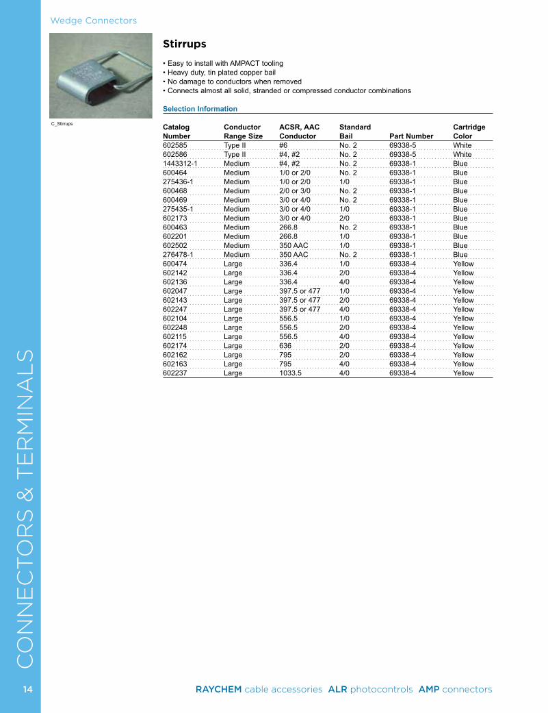
SStirrups
• Easy to install with AMPACT tooling• Heavy duty, tin plated copper bail• No damage to conductors when removed• Connects almost all solid, stranded or compressed conductor combinations
Selection Information
Catalog Conductor ACSR, AAC Standard Cartridge Number Range Size Conductor Bail Part Number Color602585 Type II #6 No. 2 69338-5 White602586 Type II #4, #2 No. 2 69338-5 White1443312-1 Medium #4, #2 No. 2 69338-1 Blue600464 Medium 1/0 or 2/0 No. 2 69338-1 Blue275436-1 Medium 1/0 or 2/0 1/0 69338-1 Blue600468 Medium 2/0 or 3/0 No. 2 69338-1 Blue600469 Medium 3/0 or 4/0 No. 2 69338-1 Blue275435-1 Medium 3/0 or 4/0 1/0 69338-1 Blue 602173 Medium 3/0 or 4/0 2/0 69338-1 Blue600463 Medium 266.8 No. 2 69338-1 Blue602201 Medium 266.8 1/0 69338-1 Blue602502 Medium 350 AAC 1/0 69338-1 Blue276478-1 Medium 350 AAC No. 2 69338-1 Blue600474 Large 336.4 1/0 69338-4 Yellow602142 Large 336.4 2/0 69338-4 Yellow602136 Large 336.4 4/0 69338-4 Yellow602047 Large 397.5 or 477 1/0 69338-4 Yellow602143 Large 397.5 or 477 2/0 69338-4 Yellow602247 Large 397.5 or 477 4/0 69338-4 Yellow602104 Large 556.5 1/0 69338-4 Yellow602248 Large 556.5 2/0 69338-4 Yellow602115 Large 556.5 4/0 69338-4 Yellow602174 Large 636 2/0 69338-4 Yellow602162 Large 795 2/0 69338-4 Yellow602163 Large 795 4/0 69338-4 Yellow602237 Large 1033.5 4/0 69338-4 Yellow
C_Stirrups
14 RAYCHEM cable accessories ALR photocontrols AMP connectors
Wedge ConnectorsC
ON
NE
CTO
RS
& T
ER
MIN
AL
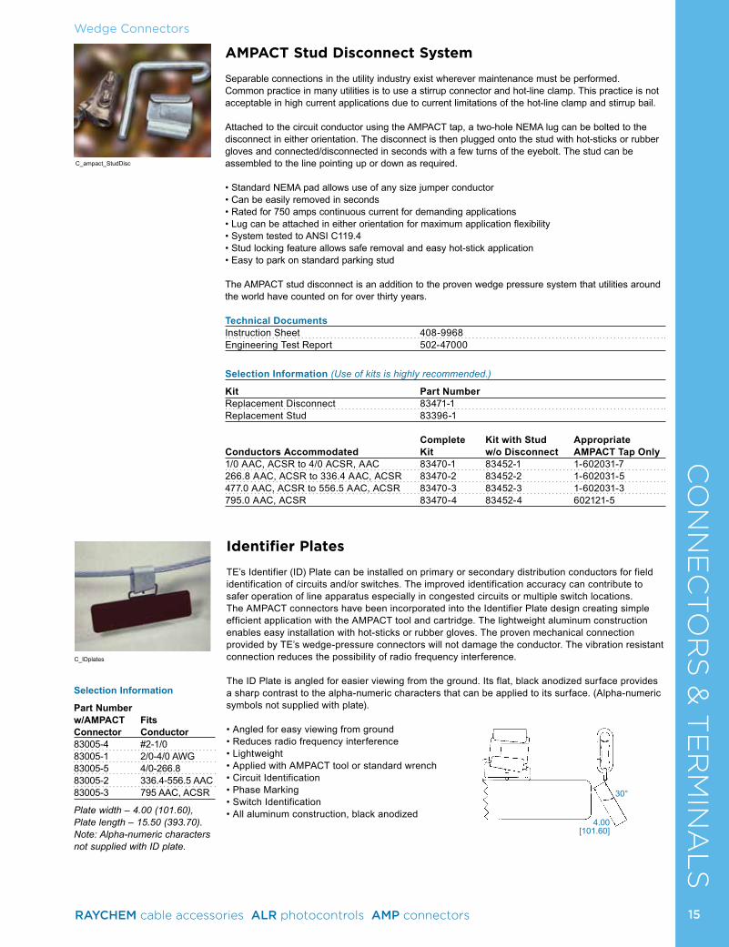
SAMPACT Stud Disconnect System
Separable connections in the utility industry exist wherever maintenance must be performed. Common practice in many utilities is to use a stirrup connector and hot-line clamp. This practice is not acceptable in high current applications due to current limitations of the hot-line clamp and stirrup bail.
Attached to the circuit conductor using the AMPACT tap, a two-hole NEMA lug can be bolted to the disconnect in either orientation. The disconnect is then plugged onto the stud with hot-sticks or rubber gloves and connected/disconnected in seconds with a few turns of the eyebolt. The stud can be assembled to the line pointing up or down as required.
• Standard NEMA pad allows use of any size jumper conductor• Can be easily removed in seconds• Rated for 750 amps continuous current for demanding applications• Lug can be attached in either orientation for maximum application flexibility• System tested to ANSI C119.4• Stud locking feature allows safe removal and easy hot-stick application• Easy to park on standard parking stud
The AMPACT stud disconnect is an addition to the proven wedge pressure system that utilities around the world have counted on for over thirty years.
Technical DocumentsInstruction Sheet 408-9968Engineering Test Report 502-47000
Selection Information (Use of kits is highly recommended.)
Kit Part Number Replacement Disconnect 83471-1Replacement Stud 83396-1
Complete Kit with Stud Appropriate Conductors Accommodated Kit w/o Disconnect AMPACT Tap Only1/0 AAC, ACSR to 4/0 ACSR, AAC 83470-1 83452-1 1-602031-7266.8 AAC, ACSR to 336.4 AAC, ACSR 83470-2 83452-2 1-602031-5477.0 AAC, ACSR to 556.5 AAC, ACSR 83470-3 83452-3 1-602031-3795.0 AAC, ACSR 83470-4 83452-4 602121-5
Identifier Plates
TE’s Identifier (ID) Plate can be installed on primary or secondary distribution conductors for field identification of circuits and/or switches. The improved identification accuracy can contribute to safer operation of line apparatus especially in congested circuits or multiple switch locations. The AMPACT connectors have been incorporated into the Identifier Plate design creating simple efficient application with the AMPACT tool and cartridge. The lightweight aluminum construction enables easy installation with hot-sticks or rubber gloves. The proven mechanical connection provided by TE’s wedge-pressure connectors will not damage the conductor. The vibration resistant connection reduces the possibility of radio frequency interference.
The ID Plate is angled for easier viewing from the ground. Its flat, black anodized surface provides a sharp contrast to the alpha-numeric characters that can be applied to its surface. (Alpha-numeric symbols not supplied with plate).
• Angled for easy viewing from ground• Reduces radio frequency interference• Lightweight• Applied with AMPACT tool or standard wrench• Circuit Identification• Phase Marking• Switch Identification• All aluminum construction, black anodized
4.00[101.60]
30°
Selection Information
Part Numberw/AMPACT FitsConnector Conductor83005-4 #2-1/083005-1 2/0-4/0 AWG83005-5 4/0-266.883005-2 336.4-556.5 AAC83005-3 795 AAC, ACSR
Plate width – 4.00 (101.60), Plate length – 15.50 (393.70). Note: Alpha-numeric characters not supplied with ID plate.
C_ampact_StudDisc
C_IDplates
15RAYCHEM cable accessories ALR photocontrols AMP connectors
CO
NN
EC
TO
RS
& T
ER
MIN
AL
SAMPACT Deadend Clamp Assembly
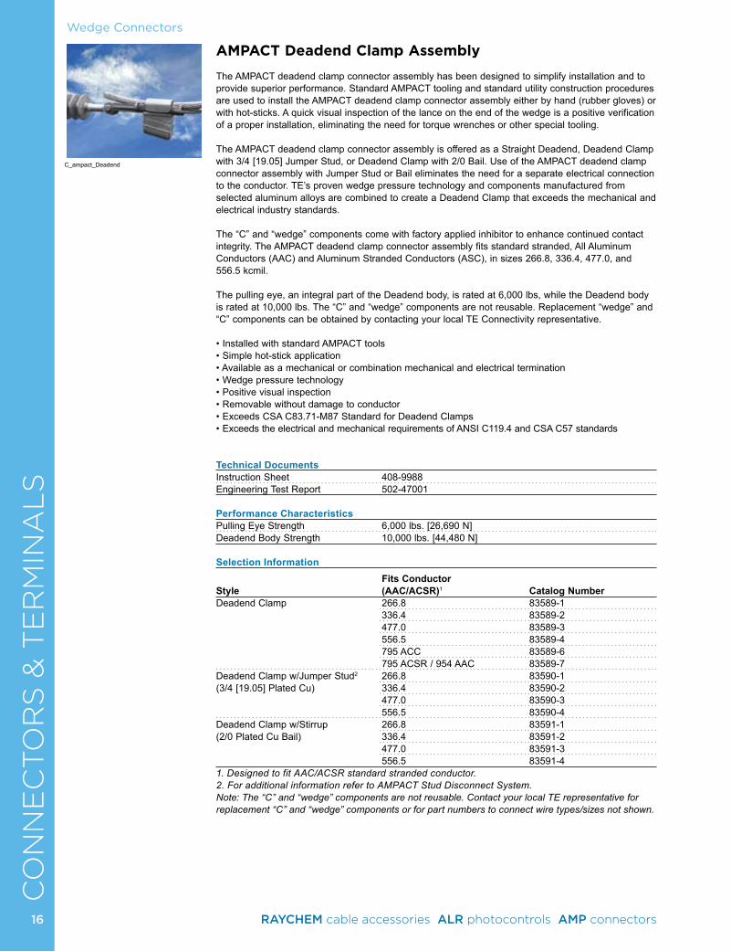
The AMPACT deadend clamp connector assembly has been designed to simplify installation and to provide superior performance. Standard AMPACT tooling and standard utility construction procedures are used to install the AMPACT deadend clamp connector assembly either by hand (rubber gloves) or with hot-sticks. A quick visual inspection of the lance on the end of the wedge is a positive verification of a proper installation, eliminating the need for torque wrenches or other special tooling.
The AMPACT deadend clamp connector assembly is offered as a Straight Deadend, Deadend Clamp with 3/4 [19.05] Jumper Stud, or Deadend Clamp with 2/0 Bail. Use of the AMPACT deadend clamp connector assembly with Jumper Stud or Bail eliminates the need for a separate electrical connection to the conductor. TE’s proven wedge pressure technology and components manufactured from selected aluminum alloys are combined to create a Deadend Clamp that exceeds the mechanical and electrical industry standards.
The “C” and “wedge” components come with factory applied inhibitor to enhance continued contact integrity. The AMPACT deadend clamp connector assembly fits standard stranded, All Aluminum Conductors (AAC) and Aluminum Stranded Conductors (ASC), in sizes 266.8, 336.4, 477.0, and 556.5 kcmil.
The pulling eye, an integral part of the Deadend body, is rated at 6,000 lbs, while the Deadend body is rated at 10,000 lbs. The “C” and “wedge” components are not reusable. Replacement “wedge” and “C” components can be obtained by contacting your local TE Connectivity representative.
• Installed with standard AMPACT tools• Simple hot-stick application• Available as a mechanical or combination mechanical and electrical termination • Wedge pressure technology• Positive visual inspection• Removable without damage to conductor• Exceeds CSA C83.71-M87 Standard for Deadend Clamps• Exceeds the electrical and mechanical requirements of ANSI C119.4 and CSA C57 standards
Technical DocumentsInstruction Sheet 408-9988Engineering Test Report 502-47001
Performance CharacteristicsPulling Eye Strength 6,000 lbs. [26,690 N]Deadend Body Strength 10,000 lbs. [44,480 N]
Selection InformationFits Conductor
Style (AAC/ACSR)1 Catalog NumberDeadend Clamp 266.8 83589-1 336.4 83589-2 477.0 83589-3 556.5 83589-4 795 ACC 83589-6 795 ACSR / 954 AAC 83589-7 Deadend Clamp w/Jumper Stud2 266.8 83590-1 (3/4 [19.05] Plated Cu) 336.4 83590-2 477.0 83590-3 556.5 83590-4 Deadend Clamp w/Stirrup 266.8 83591-1 (2/0 Plated Cu Bail) 336.4 83591-2 477.0 83591-3 556.5 83591-4 1. Designed to fit AAC/ACSR standard stranded conductor.2. For additional information refer to AMPACT Stud Disconnect System.Note: The “C” and “wedge” components are not reusable. Contact your local TE representative for replacement “C” and “wedge” components or for part numbers to connect wire types/sizes not shown.
Wedge Connectors
C_ampact_Deadend
16 RAYCHEM cable accessories ALR photocontrols AMP connectors
CO
NN
EC
TO
RS
& T
ER
MIN
AL
SAMPACT In-Line Disconnect Switch (ILD-II)15 kV to 69 kV Class
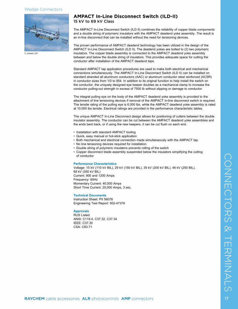
The AMPACT In-Line Disconnect Switch (ILD II) combines the reliability of copper blade components and a double string of polymeric insulators with the AMPACT deadend yoke assembly. The result is an in-line disconnect that can be installed without the need for tensioning devices.
The proven performance of AMPACT deadend technology has been utilized in the design of the AMPACT In-Line Disconnect Switch (ILD II). The deadend yokes are bolted to (2) two polymeric insulators. The copper blade assembly is connected to the AMPACT deadend yoke assembly between and below the double string of insulators. This provides adequate space for cutting the conductor after installation of the AMPACT deadend taps.
Standard AMPACT tap application procedures are used to make both electrical and mechanical connections simultaneously. The AMPACT In-Line Disconnect Switch (ILD II) can be installed on standard stranded all aluminum conductors (AAC) or aluminum conductor steel reinforced (ACSR) in conductor sizes from 1/0 to 954. In addition to its original function to help install the switch on the conductor, the uniquely designed eye keeper doubles as a mechanical clamp to increase the conductor pulling-out strength in excess of 7500 lb without slipping or damage to conductor.
The integral pulling eye on the body of the AMPACT deadend yoke assembly is provided to the attachment of line tensioning devices if removal of the AMPACT in-line disconnect switch is required. The tensile rating of the pulling eye is 6,000 lbs, while the AMPACT deadend yoke assembly is rated at 10,000 lbs tensile. Electrical ratings are provided in the performance characteristic tables.
The unique AMPACT In-Line Disconnect design allows for positioning of cutters between the double insulator assembly. The conductor can be cut between the AMPACT deadend yoke assemblies and the ends bent back, or if using the new keepers, it can be cut flush on each end.
• Installation with standard AMPACT tooling• Quick, easy manual or hot-stick application• Both mechanical and electrical connection made simultaneously with the AMPACT tap• No line tensioning devices required for installation• Double string of polymeric insulators prevents rolling of the switch • Copper disconnect blade assembly suspended below the insulators simplifying the cutting
of conductor
Performance Characteristics Voltage: 15 kV (110 kV BIL), 29 kV (150 kV BIL), 35 kV (200 kV BIL), 46 kV (250 BIL), 69 kV (350 kV BIL) Current: 900 and 1200 AmpsFrequency: 60HzMomentary Current: 40,000 AmpsShort Time Current: 25,000 Amps, 3 sec.
Technical DocumentsInstruction Sheet: PII 56078Engineering Test Report: 502-47376
ApprovalsRUS ListedANSI: C119.4, C37.32, C37.34IEEE: C37.30CSA: C83.71
Wedge Connectors
C_ampact_ILD
17RAYCHEM cable accessories ALR photocontrols AMP connectors
CO
NN
EC
TO
RS
& T
ER
MIN
AL
SSelection Information
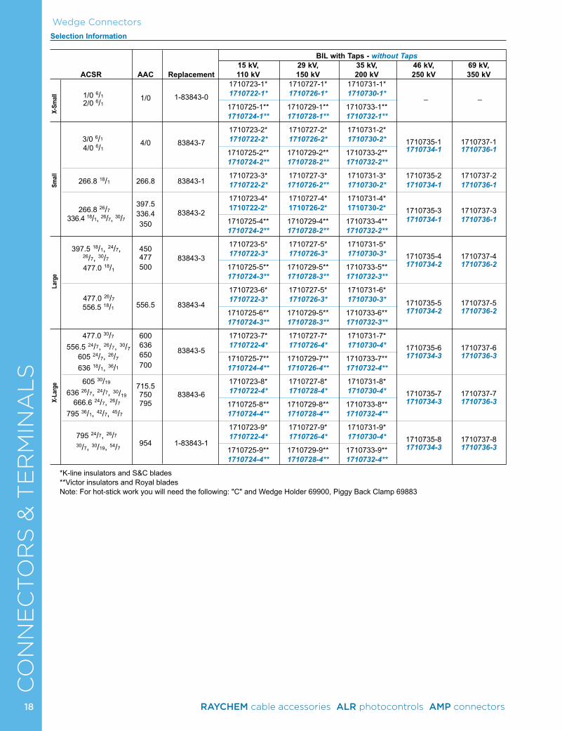
Wedge Connectors
BIL with Taps - without Taps 15 kV, 29 kV, 35 kV, 46 kV, 69 kV, ACSR AAC Replacement 110 kV 150 kV 200 kV 250 kV 350 kV
1/0
1-83843-0
1710723-1* 1710727-1* 1710731-1* _ _ 1/0 6/1 1710722-1* 1710726-1* 1710730-1*
2/0 6/1 1710725-1** 1710729-1** 1710733-1** 1710724-1** 1710728-1** 1710732-1**
3/0 6/1
4/0
83843-7
1710723-2* 1710727-2* 1710731-2* 1710735-1 1710737-1 1710722-2* 1710726-2* 1710730-2* 1710734-1 1710736-1 4/0 6/1 1710725-2** 1710729-2** 1710733-2**
1710724-2** 1710728-2** 1710732-2**
266.8 18/1 266.8 83843-1
1710723-3* 1710727-3* 1710731-3* 1710735-2 1710737-2 1710722-2* 1710726-2** 1710730-2* 1710734-1 1710736-1
1710723-4* 1710727-4* 1710731-4* 266.8 26/7
397.5 1710722-2* 1710726-2* 1710730-2* 1710735-3 1710737-3 336.4 18/1, 26/7, 30/7
336.4
83843-2 1710725-4** 1710729-4** 1710733-4** 1710734-1 1710736-1
350
1710724-2** 1710728-2** 1710732-2**
397.5 18/1, 24/7, 450
83843-3
1710723-5* 1710727-5* 1710731-5* 26/7, 30/7
477 1710722-3* 1710726-3* 1710730-3* 1710735-4 1710737-4 477.0 18/1 500 1710725-5** 1710729-5** 1710733-5** 1710734-2 1710736-2 1710724-3** 1710728-3** 1710732-3**
477.0 26/7
556.5 83843-4
1710723-6* 1710727-5* 1710731-6* 1710722-3* 1710726-3* 1710730-3* 1710735-5 1710737-5 556.5 18/1
1710725-6** 1710729-5** 1710733-6** 1710734-2 1710736-2 1710724-3** 1710728-3** 1710732-3**
477.0 30/7 600
83843-5
1710723-7* 1710727-7* 1710731-7* 556.5 24/7, 26/7, 30/7 636 1710722-4* 1710726-4* 1710730-4* 1710735-6 1710737-6
605 24/7, 26/7 650 1710725-7** 1710729-7** 1710733-7** 1710734-3 1710736-3 636 18/1, 36/1
700 1710724-4** 1710726-4** 1710732-4**
605 30/19 715.5
83843-6
1710723-8* 1710727-8* 1710731-8* 636 26/7, 24/7, 30/19
750 1710722-4* 1710728-4* 1710730-4* 1710735-7 1710737-7 666.6 24/7, 26/7 795 1710725-8** 1710729-8** 1710733-8** 1710734-3 1710736-3 795 36/1, 42/7, 45/7 1710724-4** 1710728-4** 1710732-4**
954
1-83843-1
1710723-9* 1710727-9* 1710731-9* 795 24/7, 26/7 1710722-4* 1710726-4* 1710730-4* 1710735-8 1710737-8
30/7, 30/19, 54/7 1710725-9** 1710729-9** 1710733-9** 1710734-3 1710736-3 1710724-4** 1710728-4** 1710732-4**
*K-line insulators and S&C blades**Victor insulators and Royal bladesNote: For hot-stick work you will need the following: "C" and Wedge Holder 69900, Piggy Back Clamp 69883
X-L
arge
L
arge
Sm
all
X-
Small
18 RAYCHEM cable accessories ALR photocontrols AMP connectors
CO
NN
EC
TO
RS
& T
ER
MIN
AL
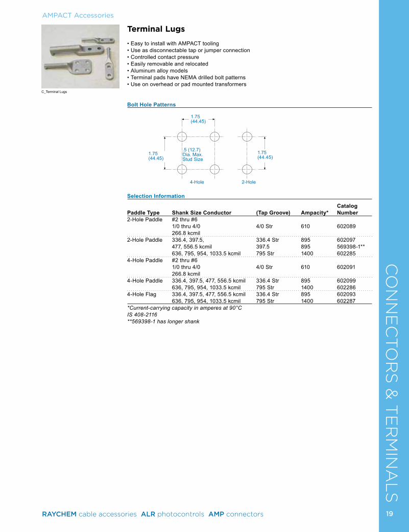
STerminal Lugs
• Easy to install with AMPACT tooling• Use as disconnectable tap or jumper connection• Controlled contact pressure• Easily removable and relocated• Aluminum alloy models• Terminal pads have NEMA drilled bolt patterns• Use on overhead or pad mounted transformers
Bolt Hole Patterns
Selection Information
Catalog Paddle Type Shank Size Conductor (Tap Groove) Ampacity* Number2-Hole Paddle #2 thru #6 1/0 thru 4/0 4/0 Str 610 602089 266.8 kcmil 2-Hole Paddle 336.4, 397.5, 336.4 Str 895 602097 477, 556.5 kcmil 397.5 895 569398-1** 636, 795, 954, 1033.5 kcmil 795 Str 1400 6022854-Hole Paddle #2 thru #6 1/0 thru 4/0 4/0 Str 610 602091 266.8 kcmil4-Hole Paddle 336.4, 397.5, 477, 556.5 kcmil 336.4 Str 895 602099 636, 795, 954, 1033.5 kcmil 795 Str 1400 6022864-Hole Flag 336.4, 397.5, 477, 556.5 kcmil 336.4 Str 895 602093 636, 795, 954, 1033.5 kcmil 795 Str 1400 602287*Current-carrying capacity in amperes at 90°CIS 408-2116**569398-1 has longer shank
.5 (12.7)Dia. Max.Stud Size
4-Hole 2-Hole
1.75(44.45)
1.75(44.45)
1.75(44.45)
AMPACT Accessories
C_Terminal Lugs
19RAYCHEM cable accessories ALR photocontrols AMP connectors
CO
NN
EC
TO
RS
& T
ER
MIN
AL
S
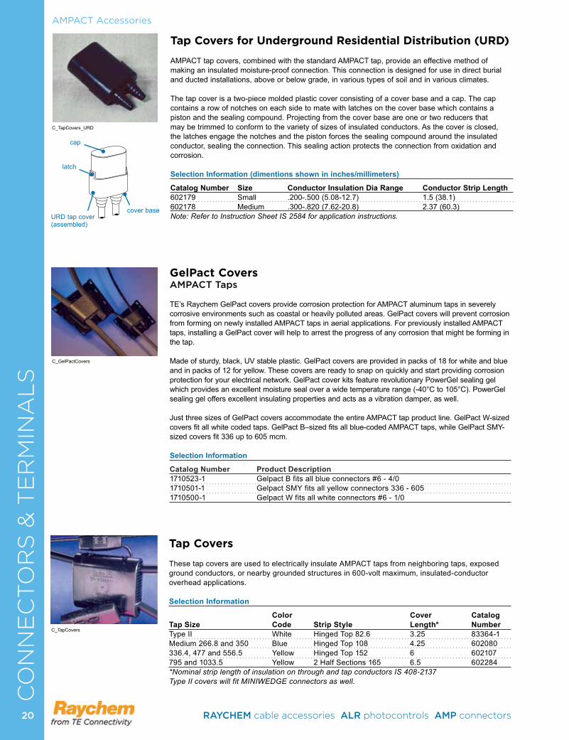
cover baseURD tap cover (assembled)
cap
latch
Tap Covers for Underground Residential Distribution (URD)
AMPACT tap covers, combined with the standard AMPACT tap, provide an effective method of making an insulated moisture-proof connection. This connection is designed for use in direct burial and ducted installations, above or below grade, in various types of soil and in various climates.
The tap cover is a two-piece molded plastic cover consisting of a cover base and a cap. The cap contains a row of notches on each side to mate with latches on the cover base which contains a piston and the sealing compound. Projecting from the cover base are one or two reducers that may be trimmed to conform to the variety of sizes of insulated conductors. As the cover is closed, the latches engage the notches and the piston forces the sealing compound around the insulated conductor, sealing the connection. This sealing action protects the connection from oxidation and corrosion.
Selection Information (dimentions shown in inches/millimeters)
Catalog Number Size Conductor Insulation Dia Range Conductor Strip Length602179 Small .200-.500 (5.08-12.7) 1.5 (38.1)602178 Medium .300-.820 (7.62-20.8) 2.37 (60.3)Note: Refer to Instruction Sheet IS 2584 for application instructions.
GelPact CoversAMPACT Taps
TE’s Raychem GelPact covers provide corrosion protection for AMPACT aluminum taps in severely corrosive environments such as coastal or heavily polluted areas. GelPact covers will prevent corrosion from forming on newly installed AMPACT taps in aerial applications. For previously installed AMPACT taps, installing a GelPact cover will help to arrest the progress of any corrosion that might be forming in the tap.
Made of sturdy, black, UV stable plastic. GelPact covers are provided in packs of 18 for white and blue and in packs of 12 for yellow. These covers are ready to snap on quickly and start providing corrosion protection for your electrical network. GelPact cover kits feature revolutionary PowerGel sealing gel which provides an excellent moisture seal over a wide temperature range (-40°C to 105°C). PowerGel sealing gel offers excellent insulating properties and acts as a vibration damper, as well.
Just three sizes of GelPact covers accommodate the entire AMPACT tap product line. GelPact W-sized covers fit all white coded taps. GelPact B–sized fits all blue-coded AMPACT taps, while GelPact SMY-sized covers fit 336 up to 605 mcm.
Selection Information
Catalog Number Product Description1710523-1 Gelpact B fits all blue connectors #6 - 4/0 1710501-1 Gelpact SMY fits all yellow connectors 336 - 605 1710500-1 Gelpact W fits all white connectors #6 - 1/0
Tap Covers
These tap covers are used to electrically insulate AMPACT taps from neighboring taps, exposed ground conductors, or nearby grounded structures in 600-volt maximum, insulated-conductor overhead applications.
Selection Information
Color Cover CatalogTap Size Code Strip Style Length* NumberType II White Hinged Top 82.6 3.25 83364-1Medium 266.8 and 350 Blue Hinged Top 108 4.25 602080336.4, 477 and 556.5 Yellow Hinged Top 152 6 602107795 and 1033.5 Yellow 2 Half Sections 165 6.5 602284*Nominal strip length of insulation on through and tap conductors IS 408-2137Type II covers will fit MINIWEDGE connectors as well.
AMPACT Accessories
C_TapCovers_URD
C_GelPactCovers
C_TapCovers
20 RAYCHEM cable accessories ALR photocontrols AMP connectors
AMPACT Accessories
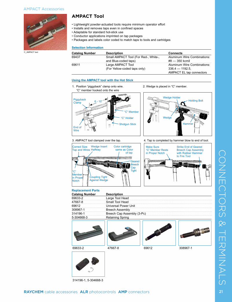
69633-2 47667-8 69612 308967-1
314196-1, 5-304668-3
1. Position “piggyback” clamp onto wire. 2. Wedge is placed in “C” member. “C” member hooked onto the wire
3. AMPACT tool clamped over the tap. 4. Tap is completed by hammer blow to end of tool.
AMPACT Tool
• Lightweight powder-actuated tools require minimum operator effort • Installs and removes taps even in confined spaces• Adaptable for standard hot-stick use• Conductor applications imprinted on tap packages• Packages and labels color coded to match taps to tools and cartridges
Selection Information
Catalog Number Description Connects69437 Small AMPACT Tool (For Red-, White-, Aluminum Wire Combinations: and Blue-coded taps) #8 — 350 kcmil69611 Large AMPACT Tool Aluminum Wire Combinations: (For Yellow-coded taps only) 336.4 — 1192.5, AMPACT EL tap connectors Using the AMPACT tool with the Hot Stick
Make Sure“C” Member Restsin Proper Notch
Strike End of GearedBreech Cap Assembly with Rubber Hammer to Fire Tool
Correct SizeTap and Wires
“C” Memberin Proper Notch
Coupling TightAgainst Wedge
Wedge Insert Color cartridgeHalfway same as Color of tap
GearedBreechCapTight
Wedge Holder Holding Bolt
Wedge
Hammer
PiggybackClamp
End ofWire
“C” Member
“C” Holder
Shotgun Stick
6 - 10”
C_AMPACT tool
Replacement Parts Catalog Number Description69633-2 Large Tool Head47667-8 Small Tool Head69612 Universal Power Unit308967-1 Breech Assembly314196-1 Breech Cap Assembly (3-Pc)5-304668-3 Retaining Spring
CO
NN
EC
TO
RS
& T
ER
MIN
AL
S
21RAYCHEM cable accessories ALR photocontrols AMP connectors
CO
NN
EC
TO
RS
& T
ER
MIN
AL
S
Cleaning Tool
Part Number Description314199-1 Cleaning Tool
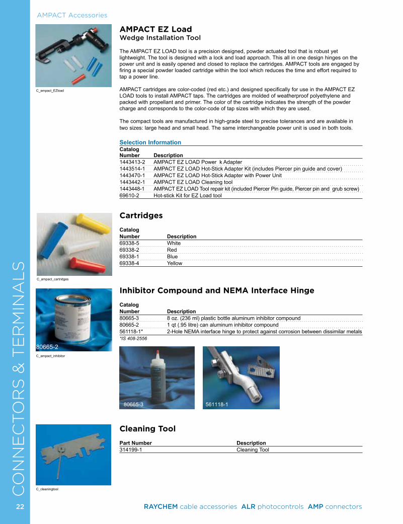
AMPACT EZ LoadWedge Installation Tool
The AMPACT EZ LOAD tool is a precision designed, powder actuated tool that is robust yet lightweight. The tool is designed with a lock and load approach. This all in one design hinges on the power unit and is easily opened and closed to replace the cartridges. AMPACT tools are engaged by firing a special powder loaded cartridge within the tool which reduces the time and effort required to tap a power line.
AMPACT cartridges are color-coded (red etc.) and designed specifically for use in the AMPACT EZ LOAD tools to install AMPACT taps. The cartridges are molded of weatherproof polyethylene and packed with propellant and primer. The color of the cartridge indicates the strength of the powder charge and corresponds to the color-code of tap sizes with which they are used.
The compact tools are manufactured in high-grade steel to precise tolerances and are available in two sizes: large head and small head. The same interchangeable power unit is used in both tools.
Selection InformationCatalogNumber Description1443413-2 AMPACT EZ LOAD Power k Adapter1443514-1 AMPACT EZ LOAD Hot-Stick Adapter Kit (includes Piercer pin guide and cover)1443470-1 AMPACT EZ LOAD Hot-Stick Adapter with Power Unit1443442-1 AMPACT EZ LOAD Cleaning tool1443448-1 AMPACT EZ LOAD Tool repair kit (included Piercer Pin guide, Piercer pin and grub screw)69610-2 Hot-stick Kit for EZ Load tool
Cartridges
Catalog Number Description69338-5 White69338-2 Red69338-1 Blue69338-4 Yellow
Inhibitor Compound and NEMA Interface Hinge
Catalog Number Description 80665-3 8 oz. (236 ml) plastic bottle aluminum inhibitor compound80665-2 1 qt (.95 litre) can aluminum inhibitor compound561118-1* 2-Hole NEMA interface hinge to protect against corrosion between dissimilar metals*IS 408-2556
80665-3 561118-1
AMPACT Accessories
C_ampact_cartridges
C_ampact_EZload
C_cleaningtool
C_ampact_inhibitor
80665-2
22 RAYCHEM cable accessories ALR photocontrols AMP connectors
CO
NN
EC
TO
RS
& T
ER
MIN
AL
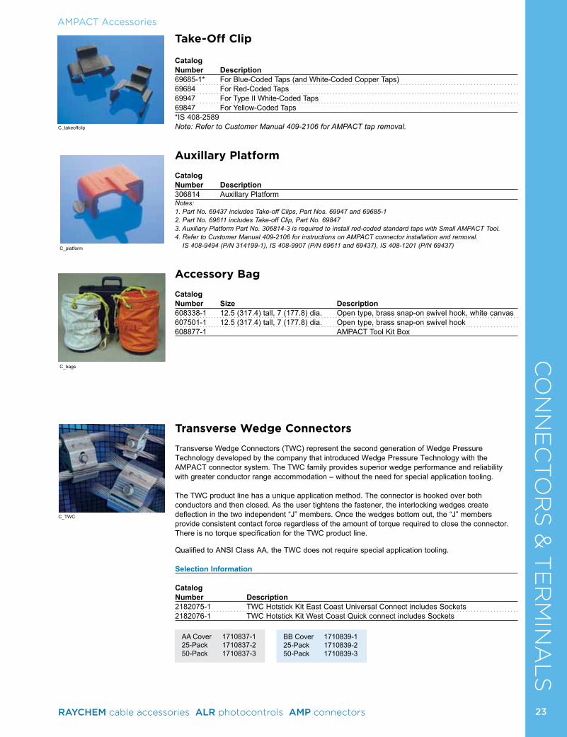
STake-Off Clip
CatalogNumber Description69685-1* For Blue-Coded Taps (and White-Coded Copper Taps)69684 For Red-Coded Taps69947 For Type II White-Coded Taps69847 For Yellow-Coded Taps*IS 408-2589Note: Refer to Customer Manual 409-2106 for AMPACT tap removal.
Auxillary Platform
CatalogNumber Description306814 Auxillary PlatformNotes: 1. Part No. 69437 includes Take-off Clips, Part Nos. 69947 and 69685-12. Part No. 69611 includes Take-off Clip, Part No. 698473. Auxiliary Platform Part No. 306814-3 is required to install red-coded standard taps with Small AMPACT Tool.4. Refer to Customer Manual 409-2106 for instructions on AMPACT connector installation and removal.
IS 408-9494 (P/N 314199-1), IS 408-9907 (P/N 69611 and 69437), IS 408-1201 (P/N 69437)
Accessory Bag
Catalog Number Size Description608338-1 12.5 (317.4) tall, 7 (177.8) dia. Open type, brass snap-on swivel hook, white canvas607501-1 12.5 (317.4) tall, 7 (177.8) dia. Open type, brass snap-on swivel hook608877-1 AMPACT Tool Kit Box
AMPACT Accessories
C_takeoffclip
C_bags
C_platform
Transverse Wedge Connectors
Transverse Wedge Connectors (TWC) represent the second generation of Wedge Pressure Technology developed by the company that introduced Wedge Pressure Technology with the AMPACT connector system. The TWC family provides superior wedge performance and reliability with greater conductor range accommodation – without the need for special application tooling.
The TWC product line has a unique application method. The connector is hooked over both conductors and then closed. As the user tightens the fastener, the interlocking wedges create deflection in the two independent “J” members. Once the wedges bottom out, the “J” members provide consistent contact force regardless of the amount of torque required to close the connector. There is no torque specification for the TWC product line.
Qualified to ANSI Class AA, the TWC does not require special application tooling.
Selection Information Catalog Number Description2182075-1 TWC Hotstick Kit East Coast Universal Connect includes Sockets2182076-1 TWC Hotstick Kit West Coast Quick connect includes Sockets
C_TWC
AA Cover 1710837-125-Pack 1710837-250-Pack 1710837-3
BB Cover 1710839-125-Pack 1710839-250-Pack 1710839-3
23RAYCHEM cable accessories ALR photocontrols AMP connectors
CO
NN
EC
TO
RS
& T
ER
MIN
AL
SAMPACT Accessories
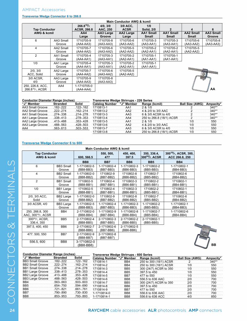
Transverse Wedge Connector 6 to 266.8 Main Conductor AWG & kcmil
266.818/1 4/0, 3/0 3/0 ACC, 1/0 Tap Conductor ACSR, 266.8 AAC, 250 ACSR Solid, 2/0 2 4 6 AWG & kcmil AA4 AA3 Large AA2 Large AA1 Small AA1 Small AA2 Small AA3 Small Large Groove Large Small Small Small Groove 6 AA3 Small 1710705-9 1710705-8 1710705-6 1710705-3 1710705-3 1710705-6 1710705-8 Groove (AA4-AA3) (AA3-AA3) (AA3-AA2) (AA3-AA1) (AA3-AA1) (AA3-AA2) (AA3-AA3) 4 AA2 Small 1710705-7 1710705-6 1710705-5 1710705-2 1710705-2 1710705-5 Groove (AA4-AA2) (AA3-AA2) (AA2-AA2) (AA2-AA1) (AA2-AA1) (AA2-AA2) 2 AA1 Small 1710705-4 1710705-3 1710705-2 1710705-1 1710705-1 Groove (AA4-AA1) (AA3-AA1) (AA2-AA1) (AA1-AA1) (AA1-AA1) 1/0 AA1 Large 1710705-4 1710705-3 1710705-2 1710705-1 Groove (AA4-AA1) (AA3-AA1) (AA2-AA1) (AA1-AA1) 2/0, 3/0 AA2 Large 1710705-7 1710705-6 1710705-5 ACC, Solid Groove (AA4-AA2) (AA3-AA2) (AA2-AA2) 3/0 ACSR, AA3 Large 1710705-9 1710705-8 4/0 Groove (AA4-AA3) (AA3-AA3)250, 226.8, ACC, AA4 1-1710705-0 266.818/1, ACSR (AA4-AA4)
Conductor Diameter Range (inches) “J” Member Stranded SolidAA3 Small Groove .182-.222 .122-.162AA2 Small Groove .222-.274 .162-.214AA1 Small Groove .274-.338 .214-.278AA1 Large Groove .338-.413 .278-.353AA2 Large Groove .413-.488 .353-.428AA3 Large Groove .488-.563 .428-.503AA4 .563-.613 .503-.553
Transverse Wedge Strirrups - 226 Series Catalog Number "J" Member Range (kcmil) Ball Size (AWG) Ampacity*1710813-1 AA1 2 & 1/0 2 340**1710813-2 AA2 4 & 2/0 to 3/0 AAC 2 340**1710813-3 AA3 6 & 3/0 ACSR to 4/0 2 340**1710813-4 AA4 250 to 266.8 (18/1) ACSR 2 340**1710813-5 AA1 2 & 1/0 1/0 5501710813-6 AA2 4 & 2/0 to 3/0 AAC 1/0 5501710813-7 AA3 6 & 3/0 ACSR to 4/0 1/0 5501710813-8 AA4 250 to 266.8 (18/1) ACSR 1/0 550
Transverse Wedge Strirrups - 600 Series Catalog Number "J" Member Range (kcmil) Ball Size (AWG) Ampacity*1710814-1 BB4 250 to 300 (18/1) ACSR 2 340**1710814-2 BB4 250 to 300 (18/1) ACSR 1/0 5501710814-3 BB5 300 (24/7) ACSR to 350 1/0 5501710814-4 BB5 397.5 to 450 1/0 5501710814-5 BB7 477 to 550 1/0 5501710814-6 BB8 556.5 to 636 AAC 2/0 7001710814-7 BB5 300 (24/7) ACSR to 350 2/0 7001710814-8 BB6 397.5 to 450 2/0 7001710814-9 BB7 477 to 550 2/0 7001-1710814-0 BB8 556.6 to 636 AAC 2/0 7001-1710814-1 BB8 556.6 to 636 ACC 4/0 850
AA
Transverse Wedge Connector 6 to 600 Main Conductor AWG & kcmil Tap Conductor 550, 500, 450, 400, 350, 336.4, 30018/1, ACSR, 300, AWG & kcmil 600, 566.5 477 397.5 30024/7, ACSR ACC 266.8, 250 BB8 BB7 BB6 BB5 BB4 6 BB3 Small 1-1710802-5 1-1710802-4 1-1710802-3 1-1710802-2 1-1710802-1 Groove (BB8-BB3) (BB7-BB3) (BB6-BB3) (BB5-BB3) (BB4-BB3) 4 BB2 Small 1-1710802-0 1710802-9 1710802-8 1710802-7 1710802-6 Groove (BB8-BB2) (BB7-BB2) (BB6-BB2) (BB5-BB2) (BB4-BB2) 2 BB1 Small 1710802-5 1710802-4 1710802-3 1710802-2 1710802-1 Groove (BB8-BB1) (BB7-BB1) (BB6-BB1) (BB5-BB1) (BB4-BB1) 1/0 BB1 Large 1710802-5 1710802-4 1710802-3 1710802-2 1710802-1 Groove (BB8-BB1) (BB7-BB1) (BB6-BB1) (BB5-BB1) (BB4-BB1) 2/0, 3/0 ACC, BB2 Large 1-1710802-0 1710802-9 1710802-8 1710802-7 1710802-6 Solid Groove (BB8-BB2) (BB7-BB2) (BB6-BB2) (BB5-BB2) (BB4-BB2) 3/0 ACSR, 4/0 BB3 Large 1-1710802-5 1-1710802-4 1-1710802-3 1-1710802-2 1-1710802-1 Groove (BB8-BB3) (BB7-BB3) (BB6-BB3) (BB5-BB3) (BB4-BB3) 250, 266.8, 300 BB4 2-1710802-0 1-1710802-9 1-1710802-8 1-1710802-7 1-1710802-6 AAC, 30018/1, ACSR (BB8-BB4) (BB7-BB4) (BB6-BB4) (BB5-BB4) (BB4-BB4) 30024/7, ACSR, BB5 2-1710802-4 2-1710802-3 2-1710802-2 2-1710802-1 336.4, 350 (BB8-BB5) (BB7-BB5) (BB6-BB5) (BB5-BB5) 397.5, 400, 450 BB6 2-1710802-7 2-1710802-6 2-1710802-5 (BB8-BB6) (BB7-BB6) (BB6-BB6) 477. 500, 550 BB7 2-1710802-9 2-1710802-8 (BB8-BB7) (BB7-BB7) 556.5, 600 BB8 3-1710802-0 (BB8-BB8) BB
Conductor Diameter Range (inches) “J” Member Stranded SolidBB3 Small Groove .182-.222 .122-.162BB2 Small Groove .222-.274 .162-.214BB1 Small Groove .274-.338 .214-.278BB1 Large Groove .338-.413 .278-.353BB2 Large Groove .413-.488 .353-.428BB3 Large Groove .488-.563 .428-.503BB4 .563-.663 .503-.603BB5 .654-.750 .594-.690BB6 .721-.821 .661-.761BB7 .790-.890 .730-.830BB8 .853-.953 .793-.893
24 RAYCHEM cable accessories ALR photocontrols AMP connectors
CO
NN
EC
TO
RS
& T
ER
MIN
AL
SAMPACT Accessories
Transverse Wedge Connector 6 to 1192
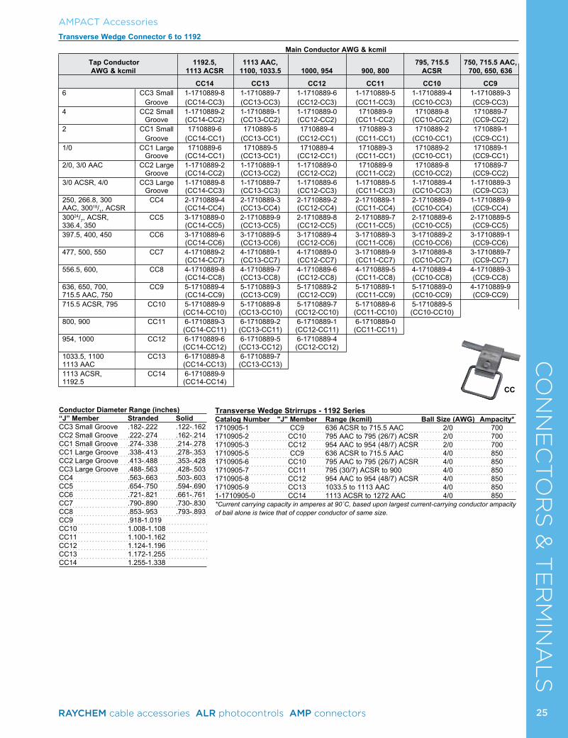
Main Conductor AWG & kcmil
Tap Conductor 1192.5, 1113 AAC, 795, 715.5 750, 715.5 AAC, AWG & kcmil 1113 ACSR 1100, 1033.5 1000, 954 900, 800 ACSR 700, 650, 636
CC14 CC13 CC12 CC11 CC10 CC96 CC3 Small 1-1710889-8 1-1710889-7 1-1710889-6 1-1710889-5 1-1710889-4 1-1710889-3 Groove (CC14-CC3) (CC13-CC3) (CC12-CC3) (CC11-CC3) (CC10-CC3) (CC9-CC3)4 CC2 Small 1-1710889-2 1-1710889-1 1-1710889-0 1710889-9 1710889-8 1710889-7 Groove (CC14-CC2) (CC13-CC2) (CC12-CC2) (CC11-CC2) (CC10-CC2) (CC9-CC2)2 CC1 Small 1710889-6 1710889-5 1710889-4 1710889-3 1710889-2 1710889-1 Groove (CC14-CC1) (CC13-CC1) (CC12-CC1) (CC11-CC1) (CC10-CC1) (CC9-CC1)1/0 CC1 Large 1710889-6 1710889-5 1710889-4 1710889-3 1710889-2 1710889-1 Groove (CC14-CC1) (CC13-CC1) (CC12-CC1) (CC11-CC1) (CC10-CC1) (CC9-CC1)2/0, 3/0 AAC CC2 Large 1-1710889-2 1-1710889-1 1-1710889-0 1710889-9 1710889-8 1710889-7 Groove (CC14-CC2) (CC13-CC2) (CC12-CC2) (CC11-CC2) (CC10-CC2) (CC9-CC2)3/0 ACSR, 4/0 CC3 Large 1-1710889-8 1-1710889-7 1-1710889-6 1-1710889-5 1-1710889-4 1-1710889-3 Groove (CC14-CC3) (CC13-CC3) (CC12-CC3) (CC11-CC3) (CC10-CC3) (CC9-CC3)250, 266.8, 300 CC4 2-1710889-4 2-1710889-3 2-1710889-2 2-1710889-1 2-1710889-0 1-1710889-9 AAC, 30018/1, ACSR (CC14-CC4) (CC13-CC4) (CC12-CC4) (CC11-CC4) (CC10-CC4) (CC9-CC4)30024/7, ACSR, CC5 3-1710889-0 2-1710889-9 2-1710889-8 2-1710889-7 2-1710889-6 2-1710889-5 336.4, 350 (CC14-CC5) (CC13-CC5) (CC12-CC5) (CC11-CC5) (CC10-CC5) (CC9-CC5)397.5, 400, 450 CC6 3-1710889-6 3-1710889-5 3-1710889-4 3-1710889-3 3-1710889-2 3-1710889-1 (CC14-CC6) (CC13-CC6) (CC12-CC6) (CC11-CC6) (CC10-CC6) (CC9-CC6)477, 500, 550 CC7 4-1710889-2 4-1710889-1 4-1710889-0 3-1710889-9 3-1710889-8 3-1710889-7 (CC14-CC7) (CC13-CC7) (CC12-CC7) (CC11-CC7) (CC10-CC7) (CC9-CC7)556.5, 600, CC8 4-1710889-8 4-1710889-7 4-1710889-6 4-1710889-5 4-1710889-4 4-1710889-3 (CC14-CC8) (CC13-CC8) (CC12-CC8) (CC11-CC8) (CC10-CC8) (CC9-CC8)636, 650, 700, CC9 5-1710889-4 5-1710889-3 5-1710889-2 5-1710889-1 5-1710889-0 4-1710889-9 715.5 AAC, 750 (CC14-CC9) (CC13-CC9) (CC12-CC9) (CC11-CC9) (CC10-CC9) (CC9-CC9)715.5 ACSR, 795 CC10 5-1710889-9 5-1710889-8 5-1710889-7 5-1710889-6 5-1710889-5 (CC14-CC10) (CC13-CC10) (CC12-CC10) (CC11-CC10) (CC10-CC10)800, 900 CC11 6-1710889-3 6-1710889-2 6-1710889-1 6-1710889-0 (CC14-CC11) (CC13-CC11) (CC12-CC11) (CC11-CC11)954, 1000 CC12 6-1710889-6 6-1710889-5 6-1710889-4 (CC14-CC12) (CC13-CC12) (CC12-CC12)1033.5, 1100 CC13 6-1710889-8 6-1710889-7 1113 AAC (CC14-CC13) (CC13-CC13)1113 ACSR, CC14 6-1710889-9 1192.5 (CC14-CC14)
Conductor Diameter Range (inches) “J” Member Stranded SolidCC3 Small Groove .182-.222 .122-.162CC2 Small Groove .222-.274 .162-.214CC1 Small Groove .274-.338 .214-.278CC1 Large Groove .338-.413 .278-.353CC2 Large Groove .413-.488 .353-.428CC3 Large Groove .488-.563 .428-.503CC4 .563-.663 .503-.603CC5 .654-.750 .594-.690CC6 .721-.821 .661-.761CC7 .790-.890 .730-.830CC8 .853-.953 .793-.893CC9 .918-1.019CC10 1.008-1.108CC11 1.100-1.162CC12 1.124-1.196CC13 1.172-1.255CC14 1.255-1.338
CC
Transverse Wedge Strirrups - 1192 SeriesCatalog Number "J" Member Range (kcmil) Ball Size (AWG) Ampacity*1710905-1 CC9 636 ACSR to 715.5 AAC 2/0 7001710905-2 CC10 795 AAC to 795 (26/7) ACSR 2/0 7001710905-3 CC12 954 AAC to 954 (48/7) ACSR 2/0 7001710905-5 CC9 636 ACSR to 715.5 AAC 4/0 8501710905-6 CC10 795 AAC to 795 (26/7) ACSR 4/0 8501710905-7 CC11 795 (30/7) ACSR to 900 4/0 8501710905-8 CC12 954 AAC to 954 (48/7) ACSR 4/0 8501710905-9 CC13 1033.5 to 1113 AAC 4/0 8501-1710905-0 CC14 1113 ACSR to 1272 AAC 4/0 850*Current carrying capacity in amperes at 90˚C, based upon largest current-carrying conductor ampacity of bail alone is twice that of copper conductor of same size.
25RAYCHEM cable accessories ALR photocontrols AMP connectors
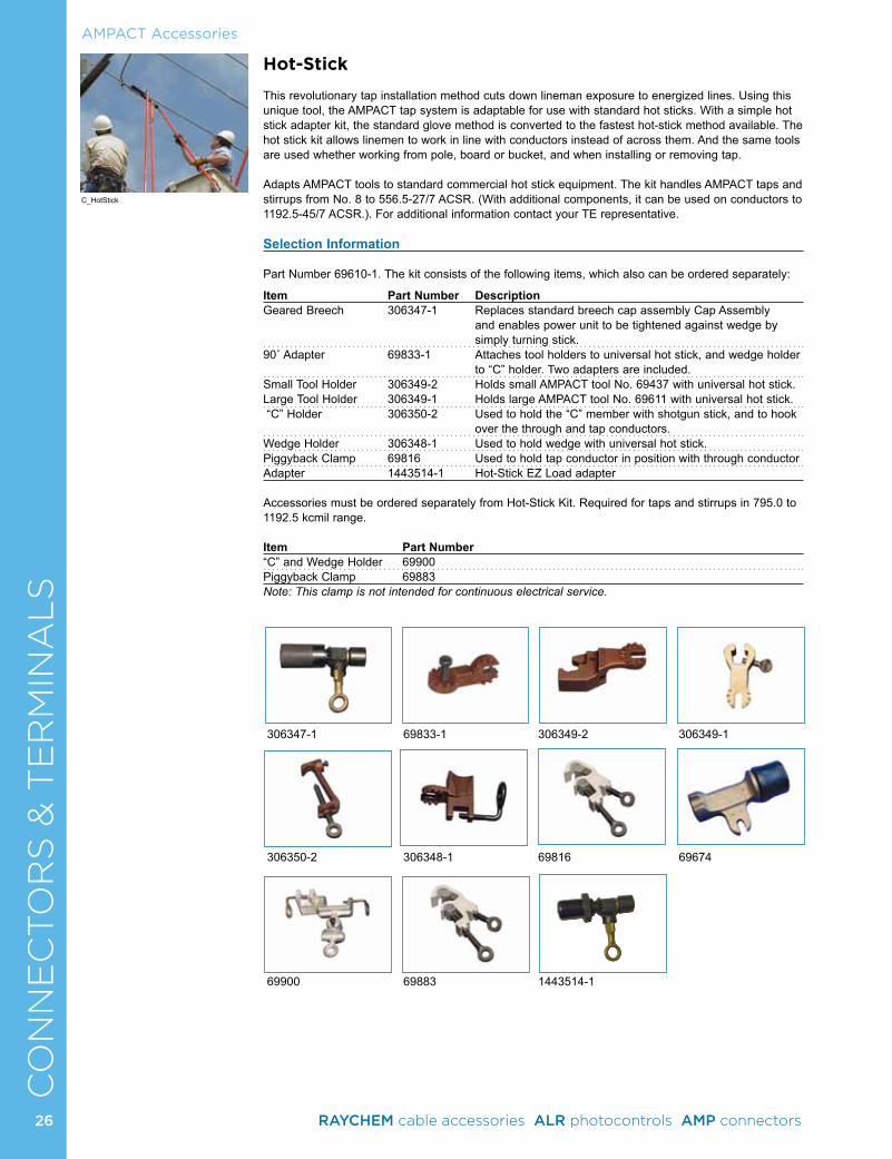
26
CO
NN
EC
TO
RS
& T
ER
MIN
AL
S
306347-1 69833-1 306349-2 306349-1
306350-2 306348-1 69816 69674
69900 69883 1443514-1
Hot-Stick
This revolutionary tap installation method cuts down lineman exposure to energized lines. Using this unique tool, the AMPACT tap system is adaptable for use with standard hot sticks. With a simple hot stick adapter kit, the standard glove method is converted to the fastest hot-stick method available. The hot stick kit allows linemen to work in line with conductors instead of across them. And the same tools are used whether working from pole, board or bucket, and when installing or removing tap.
Adapts AMPACT tools to standard commercial hot stick equipment. The kit handles AMPACT taps and stirrups from No. 8 to 556.5-27/7 ACSR. (With additional components, it can be used on conductors to 1192.5-45/7 ACSR.). For additional information contact your TE representative.
Selection Information
Part Number 69610-1. The kit consists of the following items, which also can be ordered separately:
Item Part Number Description Geared Breech 306347-1 Replaces standard breech cap assembly Cap Assembly
and enables power unit to be tightened against wedge by simply turning stick.
90˚ Adapter 69833-1 Attaches tool holders to universal hot stick, and wedge holder to “C” holder. Two adapters are included.
Small Tool Holder 306349-2 Holds small AMPACT tool No. 69437 with universal hot stick.Large Tool Holder 306349-1 Holds large AMPACT tool No. 69611 with universal hot stick. “C” Holder 306350-2 Used to hold the “C” member with shotgun stick, and to hook
over the through and tap conductors.Wedge Holder 306348-1 Used to hold wedge with universal hot stick.Piggyback Clamp 69816 Used to hold tap conductor in position with through conductorAdapter 1443514-1 Hot-Stick EZ Load adapter Accessories must be ordered separately from Hot-Stick Kit. Required for taps and stirrups in 795.0 to 1192.5 kcmil range.
Item Part Number “C” and Wedge Holder 69900Piggyback Clamp 69883Note: This clamp is not intended for continuous electrical service.
AMPACT Accessories
C_HotStick
26 RAYCHEM cable accessories ALR photocontrols AMP connectors
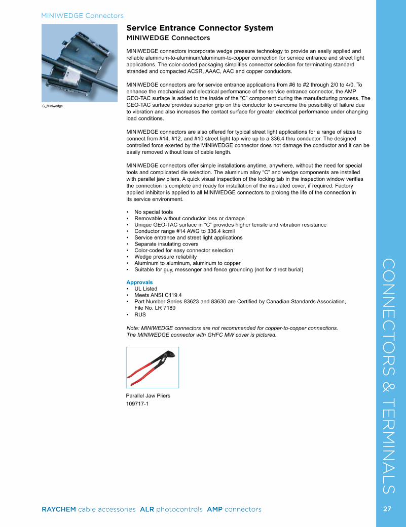
27
CO
NN
EC
TO
RS
& T
ER
MIN
AL
SService Entrance Connector SystemMINIWEDGE Connectors
MINIWEDGE connectors incorporate wedge pressure technology to provide an easily applied and reliable aluminum-to-aluminum/aluminum-to-copper connection for service entrance and street light applications. The color-coded packaging simplifies connector selection for terminating standard stranded and compacted ACSR, AAAC, AAC and copper conductors.
MINIWEDGE connectors are for service entrance applications from #6 to #2 through 2/0 to 4/0. To enhance the mechanical and electrical performance of the service entrance connector, the AMP GEO-TAC surface is added to the inside of the “C” component during the manufacturing process. The GEO-TAC surface provides superior grip on the conductor to overcome the possibility of failure due to vibration and also increases the contact surface for greater electrical performance under changing load conditions.
MINIWEDGE connectors are also offered for typical street light applications for a range of sizes to connect from #14, #12, and #10 street light tap wire up to a 336.4 thru conductor. The designed controlled force exerted by the MINIWEDGE connector does not damage the conductor and it can be easily removed without loss of cable length.
MINIWEDGE connectors offer simple installations anytime, anywhere, without the need for special tools and complicated die selection. The aluminum alloy “C” and wedge components are installed with parallel jaw pliers. A quick visual inspection of the locking tab in the inspection window verifies the connection is complete and ready for installation of the insulated cover, if required. Factory applied inhibitor is applied to all MINIWEDGE connectors to prolong the life of the connection in its service environment.
• No special tools• Removable without conductor loss or damage• Unique GEO-TAC surface in “C” provides higher tensile and vibration resistance• Conductor range #14 AWG to 336.4 kcmil• Service entrance and street light applications• Separate insulating covers• Color-coded for easy connector selection• Wedge pressure reliability• Aluminum to aluminum, aluminum to copper• Suitable for guy, messenger and fence grounding (not for direct burial)
Approvals• UL Listed• Meets ANSI C119.4• Part Number Series 83623 and 83630 are Certified by Canadian Standards Association,
File No. LR 7189 • RUS
Note: MINIWEDGE connectors are not recommended for copper-to-copper connections. The MINIWEDGE connector with GHFC MW cover is pictured.
C_Miniwedge
MINIWEDGE Connectors
Parallel Jaw Pliers 109717-1
27RAYCHEM cable accessories ALR photocontrols AMP connectors
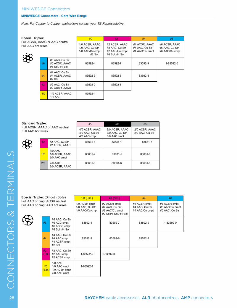
28
CO
NN
EC
TO
RS
& T
ER
MIN
AL
SMINIWEDGE Connectors
MINIWEDGE Connectors - Core Wire Range
Note: For Copper to Copper applications contact your TE Representative.
Special Triplex Full ACSR, AAAC or AAC neutralFull AAC hot wires
Standard TriplexFull ACSR, AAAC or AAC neutralFull AAC hot wires
1/0 #2 #4 #6
1/0 ACSR, AAAC #2 ACSR, AAAC #4 ACSR, AAAC #6 ACSR, AAAC 1/0 AAC, Cu Str #2 AAC, Cu Str #4 AAC, Cu Str #6 AAC, Cu Str 1/0 AAC/Cu cmpt #2 AAC/Cu cmpt #4 AAC/Cu cmpt #6 AAC/Cu cmpt #2 Sol #6 Sol, #4 Sol
#6 AAC, Cu Str #6 #6 ACSR, AAAC 83592-4 83592-7 83592-9 1-83592-0 #6 Sol, #4 Sol
#4 AAC, Cu Str #4 #4 ACSR, AAAC 83592-3 83592-6 83592-8 #2 Sol
#2 #2 AAC, Cu Str 83592-2 83592-5 #2 ACSR, AAAC
1/0 1/0 ACSR, AAAC 83592-1 1/0 AAC
4/0 3/0 2/0
4/0 ACSR, AAAC 3/0 ACSR, AAAC 2/0 ACSR, AAAC 4/0 AAC, Cu Str 3/0 AAC, Cu Str 2/0 AAC, Cu Str 4/0 AAC cmpt 3/0 AAC cmpt
#2 #2 AAC, Cu Str 83631-1 83631-4 83631-7 #2 ACSR, AAAC
1/0 AAC 1/0 1/0 ACSR, AAAC 83631-2 83631-5 83631-8 2/0 AAC cmpt
2/0 2/0 AAC 83631-3 83631-6 83631-9 2/0 ACSR, AAAC
Special Triplex (Smooth Body)Full AAC or cmpt ACSR neutralFull AAC or cmpt AAC hot wires
1/0 (S.B.) #2 (S.B.) #4 #6
1/0 ACSR cmpt #2 ACSR cmpt #4 ACSR cmpt #6 ACSR cmpt 1/0 AAC, Cu Str #2 AAC, Cu Str #4 AAC, Cu Str #6 AAC/Cu cmpt 1/0 AAC/Cu cmpt #2 AAC/Cu cmpt #4 AAC/Cu cmpt #6 AAC, Cu Str #2 Sol #6 Sol, #4 Sol
#6 AAC, Cu Str #6 #6 ACC cmpt 83592-4 83592-7 83592-9 1-83592-0 #6 ACSR cmpt #6 Sol, #4 Sol
#4 AAC, Cu Str #4 #4 AAC cmpt 83592-3 83592-6 83592-8 #4 ACSR cmpt #2 Sol
#2 #2 AAC, Cu Str (S.B.) #2 AAC cmpt 1-83592-2 1-83592-3 #2 ACSR cmpt
1/0 AAC 1/0 1/0 AAC cmpt 1-83592-1 (S.B.) 1/0 ACSR cmpt 2/0 AAC cmpt
28 RAYCHEM cable accessories ALR photocontrols AMP connectors
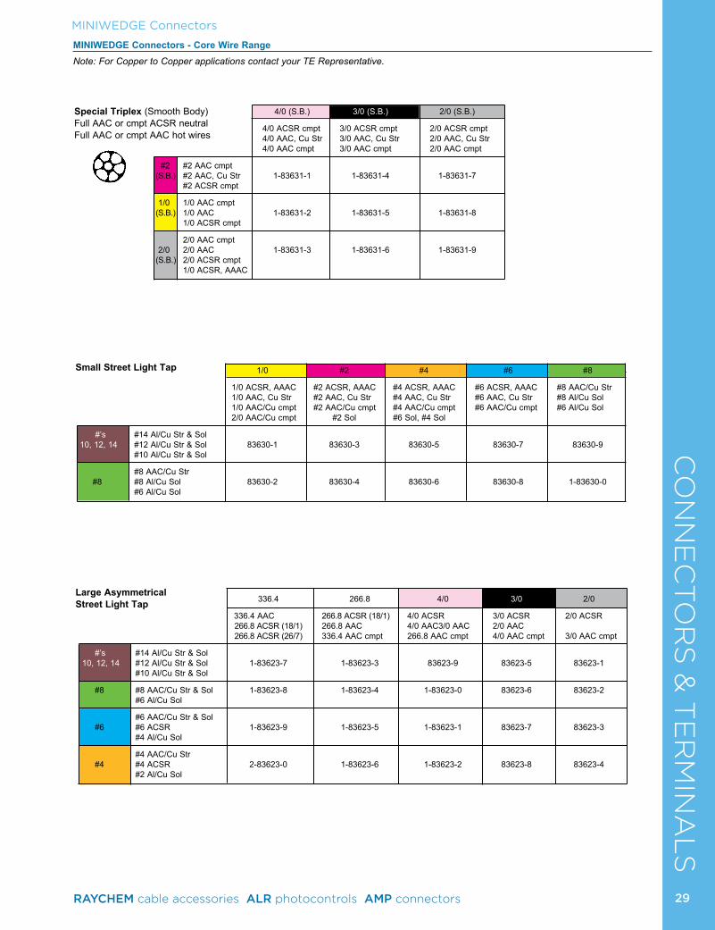
29
CO
NN
EC
TO
RS
& T
ER
MIN
AL
SMINIWEDGE Connectors
MINIWEDGE Connectors - Core Wire RangeNote: For Copper to Copper applications contact your TE Representative.
Special Triplex (Smooth Body)Full AAC or cmpt ACSR neutralFull AAC or cmpt AAC hot wires
Large Asymmetrical Street Light Tap
Small Street Light Tap
336.4 266.8 4/0 3/0 2/0
336.4 AAC 266.8 ACSR (18/1) 4/0 ACSR 3/0 ACSR 2/0 ACSR 266.8 ACSR (18/1) 266.8 AAC 4/0 AAC 3/0 AAC 2/0 AAC 266.8 ACSR (26/7) 336.4 AAC cmpt 266.8 AAC cmpt 4/0 AAC cmpt 3/0 AAC cmpt
#’s #14 Al/Cu Str & Sol 10, 12, 14 #12 Al/Cu Str & Sol 1-83623-7 1-83623-3 83623-9 83623-5 83623-1 #10 Al/Cu Str & Sol
#8 #8 AAC/Cu Str & Sol 1-83623-8 1-83623-4 1-83623-0 83623-6 83623-2 #6 Al/Cu Sol
#6 AAC/Cu Str & Sol #6 #6 ACSR 1-83623-9 1-83623-5 1-83623-1 83623-7 83623-3 #4 Al/Cu Sol
#4 AAC/Cu Str #4 #4 ACSR 2-83623-0 1-83623-6 1-83623-2 83623-8 83623-4 #2 Al/Cu Sol
4/0 (S.B.) 3/0 (S.B.) 2/0 (S.B.)
4/0 ACSR cmpt 3/0 ACSR cmpt 2/0 ACSR cmpt 4/0 AAC, Cu Str 3/0 AAC, Cu Str 2/0 AAC, Cu Str 4/0 AAC cmpt 3/0 AAC cmpt 2/0 AAC cmpt
#2 #2 AAC cmpt (S.B.) #2 AAC, Cu Str 1-83631-1 1-83631-4 1-83631-7 #2 ACSR cmpt
1/0 1/0 AAC cmpt (S.B.) 1/0 AAC 1-83631-2 1-83631-5 1-83631-8 1/0 ACSR cmpt
2/0 AAC cmpt 2/0 2/0 AAC 1-83631-3 1-83631-6 1-83631-9 (S.B.) 2/0 ACSR cmpt 1/0 ACSR, AAAC
1/0 #2 #4 #6 #8
1/0 ACSR, AAAC #2 ACSR, AAAC #4 ACSR, AAAC #6 ACSR, AAAC #8 AAC/Cu Str 1/0 AAC, Cu Str #2 AAC, Cu Str #4 AAC, Cu Str #6 AAC, Cu Str #8 Al/Cu Sol 1/0 AAC/Cu cmpt #2 AAC/Cu cmpt #4 AAC/Cu cmpt #6 AAC/Cu cmpt #6 Al/Cu Sol 2/0 AAC/Cu cmpt #2 Sol #6 Sol, #4 Sol
#’s #14 Al/Cu Str & Sol 10, 12, 14 #12 Al/Cu Str & Sol 83630-1 83630-3 83630-5 83630-7 83630-9 #10 Al/Cu Str & Sol
#8 AAC/Cu Str #8 #8 Al/Cu Sol 83630-2 83630-4 83630-6 83630-8 1-83630-0 #6 Al/Cu Sol
29RAYCHEM cable accessories ALR photocontrols AMP connectors
CO
NN
EC
TO
RS
& T
ER
MIN
AL
SSelection Information by Wire Diameter Limits: dimensions shown in inches (millimeters)
Catalog Wire Marking Sum of Diameters Groove 1 Diameter Groove 2 DiameterNumbers Groove 1 Groove 2 Max. Min. Max. Min. Max. Min.
Core83592-1 1/0 1/0 .796 (20.22) .696 (17.68) .398 (10.11) .315 (8.00) .398 (10.11) .315 (8.00)83592-2 1/0 #2 .723 (18.36) .618 (15.70) .398 (10.11) .315 (8.00) .336 (8.53) .260 (6.60)83592-3 1/0 #4 .656 (16.66) .549 (13.94) .398 (10.11) .315 (8.00) .268 (6.81) .205 (5.21)83592-4 1/0 #6 .602 (15.29) .498 (12.65) .398 (10.11) .315 (8.00) .215 (5.46) .138 (3.51)83592-5 #2 #2 .650 (16.51) .550 (13.97) .336 (8.53) .260 (6.60) .336 (8.53) .260 (6.60)83592-6 #2 #4 .583 (14.81) .481 (12.22) .336 (8.53) .260 (6.60) .268 (6.81) .205 (5.21)83592-7 #2 #6 .529 (13.44) .429 (10.90) .336 (8.53) .260 (6.60) .215 (5.46) .138 (3.51)83592-8 #4 #4 .516 (13.11) .416 (10.57) .268 (6.81) .205 (5.21) .268 (6.81) .205 (5.21)83592-9 #4 #6 .462 (11.73) .362 (9.19) .268 (6.81) .205 (5.21) .215 (5.46) .138 (3.51)1-83592-0 #6 #6 .408 (10.36) .308 (7.82) .215 (5.46) .138 (3.51) .215 (5.46) .138 (3.51)1-83592-1 1/0 SB 1/0 SB .752 (19.10) .652 (16.56) .398 (10.11) .315 (8.00) .398 (10.11) .315 (8.00)1-83592-2 1/0 SB #2 SB .670 (17.02) .570 (14.48) .398 (10.11) .315 (8.00) .336 (8.53) .260 (6.60)1-83592-3 #2 SB #2 SB .600 (15.24) .500 (12.70) .336 (8.53) .260 (6.60) .336 (8.53) .260 (6.60)
Service Connectors83631-1 4/0 #2 .888 (22.56) .788 (20.02) .570 (14.48) .473 (12.01) .336 (8.53) .260 (6.60)83631-2 4/0 1/0 .961 (24.41) .861 (21.87) .570 (14.48) .473 (12.01) .398 (10.11) .315 (8.00)83631-3 4/0 2/0 1.010 (25.65) .907 (23.04) .570 (14.48) .473 (12.01) .470 (11.94) .375 (9.53)83631-4 3/0 #2 .827 (21.01) .731 (18.57) .515 (13.08) .420 (10.67) .336 (8.53) .260 (6.60)83631-5 3/0 1/0 .900 (22.86) .809 (20.55) .515 (13.08) .420 (10.67) .398 (10.11) .315 (8.00)83631-6 3/0 2/0 .949 (24.10) .849 (21.56) .515 (13.08) .420 (10.67) .470 (11.94) .375 (9.53)83631-7 2/0 #2 .772 (19.61) .682 (17.32) .470 (11.94) .375 (9.53) .336 (8.53) .260 (6.60)83631-8 2/0 1/0 .845 (21.46) .760 (19.30) .470 (11.94) .375 (9.53) .398 (10.11) .315 (8.00)83631-9 2/0 2/0 .894 (22.71) .800 (20.32) .470 (11.94) .375 (9.53) .470 (11.94) .375 (9.53)1-83631-1 4/0 SB #2 SB .820 (20.83) .720 (18.29) .570 (14.48) .473 (12.01) .336 (8.53) .260 (6.60)1-83631-2 4/0 SB 1/0 SB .901 (22.89) .811 (20.60) .570 (14.48) .473 (12.01) .398 (10.11) .315 (8.00)1-83631-3 4/0 SB 2/0 SB .942 (23.93) .851 (21.62) .570 (14.48) .473 (12.01) .470 (11.94) .375 (9.53)1-83631-4 3/0 SB #2 SB .756 (19.20) .660 (16.76) .515 (13.08) .420 (10.67) .336 (8.53) .260 (6.60)1-83631-5 3/0 SB 1/0 SB .837 (21.26) .759 (19.28) .515 (13.08) .420 (10.67) .398 (10.11) .315 (8.00)1-83631-6 3/0 SB 2/0 SB .878 (22.30) .799 (20.29) .515 (13.08) .420 (10.67) .470 (11.94) .375 (9.53)1-83631-7 2/0 SB #2 SB .706 (17.93) .620 (15.75) .470 (11.94) .375 (9.53) .336 (8.53) .260 (6.60)1-83631-8 2/0 SB 1/0 SB .787 (19.99) .700 (17.78) .470 (11.94) .375 (9.53) .398 (10.11) .315 (8.00)1-83631-9 2/0 SB 2/0 SB .828 (21.03) .740 (18.80) .470 (11.94) .375 (9.53) .470 (11.94) .375 (9.53)
Large Asymmetrical Street Light2-83623-0 336.4 #4 .924 (23.47) .822 (20.88) .675 (17.15) .590 (14.99) .268 (6.81) .205 (5.21)1-83623-9 336.4 #6 .870 (22.10) .771 (19.58) .675 (17.15) .590 (14.99) .215 (5.46) .138 (3.51)1-83623-8 336.4 #8 .828 (21.03) .725 (18.42) .675 (17.15) .590 (14.99) .198 (5.03) .115 (2.92)1-83623-7 336.4 #10 - #14 .782 (19.86) .673 (17.09) .675 (17.15) .590 (14.99) .125 (3.18) .055 (1.40)1-83623-6 266.8 #4 .867 (22.02) .788 (20.02) .620 (15.75) .540 (13.72) .268 (6.81) .205 (5.21)1-83623-5 266.8 #6 .813 (20.65) .737 (18.72) .620 (15.75) .540 (13.72) .215 (5.46) .138 (3.51)1-83623-4 266.8 #8 .771 (19.58) .691 (17.55) .620 (15.75) .540 (13.72) .198 (5.03) .115 (2.92)1-83623-3 266.8 #10 - #14 .725 (18.42) .639 (16.23) .620 (15.75) .540 (13.72) .125 (3.18) .055 (1.40)1-83623-2 4/0 #4 .821 (20.85) .720 (18.29) .570 (14.48) .473 (12.01) .268 (6.81) .205 (5.21)1-83623-1 4/0 #6 .767 (19.48) .669 (16.99) .570 (14.48) .473 (12.01) .215 (5.46) .138 (3.51)1-83623-0 4/0 #8 .725 (18.42) .623 (15.82) .570 (14.48) .473 (12.01) .198 (5.03) .115 (2.92)83623-9 4/0 #10 - #14 .679 (17.25) .571 (14.50) .570 (14.48) .473 (12.01) .125 (3.18) .055 (1.40)83623-8 3/0 #4 .760 (19.30) .662 (16.81) .515 (13.08) .420 (10.67) .268 (6.81) .205 (5.21)83623-7 3/0 #6 .706 (17.93) .611 (15.52) .515 (13.08) .420 (10.67) .215 (5.46) .138 (3.51)83623-6 3/0 #8 .664 (16.87) .565 (14.35) .515 (13.08) .420 (10.67) .198 (5.03) .115 (2.92)83623-5 3/0 #10 - #14 .618 (15.70) .513 (13.03) .515 (13.08) .420 (10.67) .125 (3.18) .055 (1.40)83623-4 2/0 #4 .705 (17.91) .613 (15.57) .470 (11.94) .375 (9.53) .268 (6.81) .205 (5.21)83623-3 2/0 #6 .651 (16.54) .562 (14.27) .470 (11.94) .375 (9.53) .215 (5.46) .138 (3.51)83623-2 2/0 #8 .609 (15.47) .516 (13.11) .470 (11.94) .375 (9.53) .198 (5.03) .115 (2.92)83623-1 2/0 #10 - #14 .563 (14.30) .464 (11.79) .470 (11.94) .375 (9.53) .125 (3.18) .055 (1.40)
Small Street Light83630-1 1/0 #10 - #14 .514 (13.06) .400 (10.16) .398 (10.11) .315 (8.00) .125 (3.18) .055 (1.40)83630-2 1/0 #8 .560 (14.22) .460 (11.68) .398 (10.11) .315 (8.00) .198 (5.03) .115 (2.92)83630-3 #2 #10 - #14 .441 (11.20) .332 (8.43) .336 (8.53) .260 (6.60) .125 (3.18) .055 (1.40)83630-4 #2 #8 .487 (12.37) .384 (9.75) .336 (8.53) .260 (6.60) .198 (5.03) .115 (2.92)83630-5 #4 #10 - #14 .374 (9.50) .274 (6.96) .268 (6.81) .205 (5.21) .125 (3.18) .055 (1.40)83630-6 #4 #8 .420 (10.67) .320 (8.13) .268 (6.81) .205 (5.21) .198 (5.03) .115 (2.92)83630-7 #6 #10 - #14 .320 (8.13) .220 (5.59) .215 (5.46) .138 (3.51) .125 (3.18) .055 (1.40)83630-8 #6 #8 .366 (9.30) .266 (6.76) .215 (5.46) .138 (3.51) .198 (5.03) .115 (2.92)83630-9 #8 #10 - #14 .278 (7.06) .178 (4.52) .198 (5.03) .115 (2.92) .125 (3.18) .055 (1.40)1-83630-0 #8 #8 .324 (8.23) .224 (5.69) .198 (5.03) .115 (2.92) .198 (5.03) .115 (2.92)
MINIWEDGE Connectors
30 RAYCHEM cable accessories ALR photocontrols AMP connectors

CO
NN
EC
TO
RS
& T
ER
MIN
AL
SMINIWEDGE Connectors
GHFC MW ClosureGel Cover for Use with MINIWEDGE Connectors
The Raychem GHFC MW closure was specifically designed to provide sealing and corrosion protection for MINIWEDGE connectors installed overhead for corrosion protection or in direct buried applications up to 1000 volts. In either case, it is as easy as simply snapping the closure over the connector.
Suitable for aluminum-to-aluminum and aluminum-to-copper connections. Fits most MINIWEDGE connector applications.
Selection Information: dimensions shown in inches (millimeters) Catalog Number Description Main Tap Std. PackGHFC-MW Gel cover for sealing #8-4/0 (10-95) #14-2/0 (1.5-70) 10
and insulating
Ordering Information1. Package does not contain MINIWEDGE connectors, which must be ordered separately2. Standard package: 10 kits/box3. Related test reports: EDR-5340, 502-47233
C_GHFC_MW
31RAYCHEM cable accessories ALR photocontrols AMP connectors
CO
NN
EC
TO
RS
& T
ER
MIN
AL
SCopper Grounding
AMPACT Copper Wire Tap Selectionn Information
Groove Size Groove Conductor Diameter kcmil or AWG Code Minimum Maximum500 A .785 (19.9) .813 (20.7)450 B .745 (18.9) .784 (19.9)400 E .700 (17.8) .744 (18.9)350 G .650 (16.5) .699 (17.8)300 H .620 (15.7) .649 (16.5)250 K (R)†† .561 (14.2) .625 (15.9)4/0 L .506 (12.9) .560 (14.2)3/0 M .451 (11.5) .505 (12.8)2/0 N .401 (10.2) .450 (11.4)1/0 O .355 (9.0) .400 (10.2)No. 2 T .280 (7.1) .354 (9.0)No. 4 W .216 (5.5) .279 (7.1)No. 6 X .182 (4.6) .215 (5.5)
†† 250 kcmil groove is identified with the letter “K” when paired with 300 through 500 kcmil grooves, and with letter “R” when paired with No. 6 AWG through 250 kcmil grooves.
Designated Size Wire Size Actual Diameter3/8 (9.53) 1/0 AWG .355 (9.02)1/2 (12.70) 3/0 AWG .475 (12.06)5/8 (15.88) 250 kcmil .563 (14.30)3/4 (19.05) 350 kcmil .682 (17.32)
Galvanized Steel 3/8 (9.53) 1/0 AWG .375 (9.53)1/2 (12.70) 3/0 AWG .500 (12.70)5/8 (15.88) 300 kcmil .625 (15.88)3/4 (19.05) 450 kcmil .750 (19.05)
Ground Rod Applications Copper-Clad
AMPACT Copper Wire Taps
AMPACT copper taps are used when you need a permanent connection. They resist corrosion and will not loosen. The unique design, incorporating a tapered “C” member and wedge, permits easy installation in only a fraction of the time required for conventional crimp-type or molded joints.
The tap’s “C” member is composed of an aluminum bronze alloy and the wedge of a copper alloy very close to pure copper. Built-in spring tension causes the tap to maintain constant mechanical pressure for optimum electrical conductivity. The taps will provide secure connections on both stranded wire or solid rod.
When properly matched and applied, AMPACT taps exceed the current-carrying capacity of the conductors they are connecting. A locking tab prevents the tapered locked wedge from loosening once it has been driven into position. Taps stay permanently locked during power surges, yet may be removed if necessary without damage to cables or rods. To make operations even easier, AMPACT taps may be visually inspected by verifying wedge position and locking tab. Installers can check the connection immediately — speeding application.
• Unique design provides firm, sure contact for consistent, all weather, wire-to-wire, low resistance grounding connections
• Compact, lightweight application tool permits easy installation almost anywhere, without bulky equipment, heat, or external power
• Simple installation system greatly reduces exposure to energized lines• Connectors may be checked visually — speeding inspection and practically eliminating callbacks• Electrical joints are stable and effective for optimum electrical contact, even under conditions of
creep and cold flow• Taps will not penetrate copper plating, allowing secure connections from copper conductors to
ground rods, reinforcing bars or conductors of any type• AMPACT copper taps are made of quality alloys for low resistivity and superior corrosion resistance
Technical DocumentsCustomer Manual 409-2106Department Publications 410-5810, 410-5811Product Specifications 108-13011, 108-13012, 108-13015Safety Publication 125-6217General Publication 408-3010-1 through -4, GP 1931
Listed by Underwriters Laboratories Inc., File No. E69905
Certified by Canadian Standards Association, File No. LR 56476
REA Letter of Technical Acceptance (Grounding Taps)
C_ampact_Coppertaps
32 RAYCHEM cable accessories ALR photocontrols AMP connectors
Copper GroundingC
ON
NE
CTO
RS
& T
ER
MIN
AL
SAMPACT Copper Tap Selection for Wire to Ground Rod† or Solid Pin
3/8” 1/2” 5/8” 3/4”Copper Ground Rod/Pin Ground Rod/Pin Ground Rod Ground Rod/Pin Ground Rod Ground Rod/PinConductor Dia. Range Dia. Range Diameter Diameter Diameter Diameter (kcmil/AWG) .355-.375 (9.02-9.53) .475-.500 (12.07-12.7) .563 (14.3) .625 (15.88) .682 (17.32) .750 (19.05)500 1-276337-4 1-276337-3 276337-9 1-276337-2 1-276337-1 276337-1 450 2-276337-5 2-276337-4 2-276337-3 2-276337-2 2-276337-1 1-276337-9 400 3-276337-7 3-276337-5 3-276337-3 3-276337-2 3-276337-1 2-276337-0 350 4-276337-9 4-276337-7 4-276337-5 4-276337-4 4-276337-3 2-276337-1 300 6-276337-0 5-276337-8 5-276337-6 5-276337-5 4-276337-4 2-276337-2 250 275187-4 275187-2 2-275187-8 5-276337-6 4-276337-5 2-276337-3 4/0 275187-9 275187-7 275187-1 5-276337-7 4-276337-6 276337-2 3/0 1-275187-3 1-275187-1 275187-2 5-276337-8 4-276337-7 2-276337-4 2/0 1-275187-6 1-275187-2 275187-3 5-276337-9 4-276337-8 276337-3 1/0 1-275187-8 1-275187-3 275187-4 6-276337-0 4-276337-9 2-276337-5 No. 2 277060-1 1-275187-4 275187-5 6-276337-2 5-276337-1 276337-4 No. 4 277060-1 3-275187-6 3-275187-0 6-276337-4 5-276337-3 2-276337-8 No. 6 277060-2 3-275187-7 3-275187-1 6-276337-5 5-276337-4 2-276337-9
† Some Ground Rods have a designated or descriptive diameter that is different from the Actual Diameter. The Actual Diameter must be determined and used with the top chart for correct tap selection.
AMPACT Copper Tap Selection for Wire-to-Wire Applications
Typical Example:500 to 350 kcmil = Groove Code AG = Part No. 1-276337-1 Through Conductor
Wire Identification Groove Code
Red Shells White Shells Blue Shells Yellow (69338-2) (69338-5) (69338-1) (69338-4) Wire X W T O N M L K ( R) H G E B A 750 Size* 5,6 4 2 1/0 2/0 3/0 4/0 250 300 350 400 450 500 (61) X 277060-4 277060-4 277060-2 277060-2 4-275187-0 3-275187-7 3-275187-4 3-275187-1 6-276337-5 5-276337-4 4-276337-2 2-276337-9 1-276337-8 1-81723-3* 5,6 W 277060-3 277060-2 277060-1 3-275187-9 3-275187-6 3-275187-3 3-275187-0 6-276337-4 5-276337-3 4-276337-1 2-276337-8 1-276337-7 1-81723-3* 4 T 277060-1 277060-1 1-275187-7 1-275187-4 1-275187-0 275187-5 6-276337-2 5-276337-1 3-276337-9 276337-4 276337-8 1-81723-2* 2 O 1-275187-8 1-275187-6 1-275187-3 275187-9 275187-4 6-276337-0 4-276337-9 3-276337-7 2-276337-5 1-276337-4 1-81723-2* 1/0 N 1-275187-5 1-275187-2 275187-8 275187-3 5-276337-9 4-276337-8 3-276337-6 276337-3 276337-7 1-81723-1* 2/0 M 1-275187-1 275187-7 275187-2 5-276337-8 4-276337-7 3-276337-5 2-276337-4 1-276337-3 1-81723-0* 3/0 L 275187-6 275187-1 5-276337-7 4-276337-6 3-276337-4 276337-2 276337-6 81723-9* 4/0 K (R) 2-275187-8 5-276337-6 4-276337-5 3-276337-3 2-276337-3 276337-9 81723-8* 250 H 5-276337-5 4-276337-4 3-276337-2 2-276337-2 1-276337-2 ****** 300 G 4-276337-3 3-276337-1 2-276337-1 1-276337-1 ****** 350 E 3-276337-0 2-276337-0 1-276337-0 ****** 400 B 1-276337-9 276337-1 ****** 450 A 276337-5 81723-2 500 750 81723-1 (61) For additional sizes not listed, contact your TE Representative.
33RAYCHEM cable accessories ALR photocontrols AMP connectors
Copper GroundingC
ON
NE
CTO
RS
& T
ER
MIN
AL
SAMPACT copper taps have been tested for the most severe service environment that they would normally be exposed to under both distribution and grounding applications. They have been tested to meet or exceed the requirements of ANSI C119.4-1976 (TDJ-162), NEMA CC3-1973, Class A 500 cycles. The chart shows the average DC resistance normalized to 20°C for P/N 2-275187-8 applied to 250 kcmil Cu 37 strand conductor.
AMPACT copper taps have been tested at 36,000 amps symmetrical RMS for 4 seconds or 248 cycles on 500 to 500 kcmil copper conductor per IEEE 80, IEEE guide for Safety in AC Substation Grounding. They are tested and rated for use on conductors that will be exposed to temperatures up to and including 800°C. AMPACT copper taps frequently run 500°C cooler than the conductor to which they are applied.
The AMPACT copper tap meets all mechanical requirements of ANSI C119.4 and is rated as a Class 3 minimum-tension connector.
One of the most severe requirements placed on a connector for below grade grounding applications is corrosion resistance. In order to make our corrosion testing more severe and more realistic, we first subject the electrical connections to thermal shock. Our procedure for subjecting a connector to thermal shock is as follows:
Thermal ShockSpecification 109-13009Ea. cycle = 150 minutes - 150°C oven 15 minutes- ice water 30 minutes - 150°C oven 60 minutes - room temp. (Test repeated for 5 complete cycles)
Typical results of testing after thermal shock and corrosion are shown below.
DC Resistance–Milliohms measured at 60 amperes Initial After Thermal Shock After CorrosionMin. .087 .080 .078 Max. .093 .089 .086 Avg. .089 .083 .082 EWL .100 .098 .102
EWL - Equal wire length
Catalog NumbersTap Cartridge275187-1 69338-5275187-2 69338-5275187-3 69338-5275187-4 69338-5275187-5 69338-5275187-6 69338-5275187-7 69338-5275187-8 69338-5275187-9 69338-51-275187-0 69338-51-275187-1 69338-51-275187-2 69338-51-275187-3 69338-51-275187-4 69338-51-275187-5 69338-51-275187-6 69338-51-275187-7 69338-51-275187-8 69338-52-275187-8 69338-53-275187-0 69338-53-275187-1 69338-53-275187-3 69338-53-275187-4 69338-53-275187-6 69338-53-275187-7 69338-53-275187-9 69338-54-275187-0 69338-5276337-1 69338-1276337-2 69338-1276337-3 69338-1276337-4 69338-1276337-5 69338-1276337-6 69338-1276337-7 69338-1276337-8 69338-1276337-9 69338-11-276337-0 69338-11-276337-1 69338-11-276337-2 69338-11-276337-3 69338-11-276337-4 69338-11-276337-7 69338-11-276337-8 69338-1
Catalog NumbersTap Cartridge 1-276337-9 69338-12-276337-0 69338-1 2-276337-1 69338-12-276337-2 69338-12-276337-3 69338-12-276337-4 69338-12-276337-5 69338-12-276337-8 69338-12-276337-9 69338-13-276337-0 69338-13-276337-1 69338-13-276337-2 69338-13-276337-3 69338-13-276337-4 69338-13-276337-5 69338-13-276337-6 69338-13-276337-7 69338-13-276337-9 69338-14-276337-1 69338-1 4-276337-2 69338-14-276337-3 69338-14-276337-4 69338-14-276337-5 69338-14-276337-6 69338-14-276337-7 69338-14-276337-8 69338-14-276337-9 69338-15-276337-1 69338-15-276337-3 69338-15-276337-4 69338-15-276337-5 69338-15-276337-6 69338-15-276337-7 69338-15-276337-8 69338-15-276337-9 69338-16-276337-0 69338-16-276337-2 69338-16-276337-4 69338-16-276337-5 69338-1277060-1 69338-2277060-2 69338-2277060-3 69338-2277060-4 69338-2
AMPACT Copper Wire Taps AMPACT Copper Taps Technical Data
34 RAYCHEM cable accessories ALR photocontrols AMP connectors
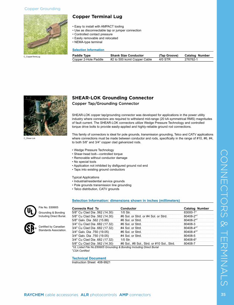
Copper GroundingC
ON
NE
CTO
RS
& T
ER
MIN
AL
SCopper Terminal Lug
• Easy to install with AMPACT tooling• Use as disconnectable tap or jumper connection• Controlled contact pressure• Easily removable and relocated• NEMA-type terminal
Selection Information
Paddle Type Shank Size Conductor (Tap Groove) Catalog NumberCopper 2-Hole Paddle #2 to 500 kcmil Copper Cable 4/0 STR 276762-1
SHEAR-LOK Grounding ConnectorCopper Tap/Grounding Connector
SHEAR-LOK copper tap/grounding connector was developed for applications in the power utility industry where connectors are required to withstand mid-range (20 kA symmetrical RMS) magnitudes of fault current. The SHEAR-LOK connectors utilize Wedge Pressure Technology and controlled torque drive bolts to provide easily-applied and highly-reliable ground rod connections.
This family of connectors is ideal for pole grounds, transmission grounding, Telco and CATV applications where connections must be made between conductor and rods, specifically in the range of #10, #6, #4, to both 5/8” and 3/4” copper clad galvanized rods.
• Wedge Pressure Technology• Shear-head bolt—controlled torque• Removable without conductor damage• No special tools• Application not inhibited by disfigured ground rod end• Taps into existing ground conductors
Typical Applications• Industrial/residential service grounds• Pole grounds transmission line grounding• Telco distribution, CATV grounds
Selection Information: dimensions shown in inches (millimeters)
Connects Rod To Conductor Catalog Number5/8" Cu Clad Dia .562 (14.30) 1/0 Str. 83000-1*5/8" Cu Clad Dia .562 (14.30) #6 Sol. or Strd. or #4 Sol. or Strd. 80408-2*†
5/8" Galv. Dia .562 (15.88) #6 Sol. or Strd. 80408-2*†
3/4" Cu Clad Dia .682 (17.32) #6 Sol. or Strd. 80408-33/4" Cu Clad Dia .682 (17.32) #4 Sol. or Strd. 80408-4*†
3/4" Galv. Dia .750 (19.05) #6 Sol. or Strd. 80408-4*†
3/4" Galv. Dia .750 (19.05) #4 Sol. or Strd. 80408-53/4" Cu Clad Dia .682 (17.32) 1/0 Str. 80408-6*5/8" Cu Clad Dia .562 (14.30) #6 Sol., #8 Sol., Strd. or #10 Sol., Strd. 80408-7*UL Listed File No.E69905 Grounding & Bonding Including Direct Burial†CSA Certified
Technical DocumentInstruction Sheet 408-9921
C_Shear-Lok
C_CopperTermLug
®
File No. E69905
Grounding & Bonding Including Direct Burial.
Certified by Canadian Standards Association.
35RAYCHEM cable accessories ALR photocontrols AMP connectors
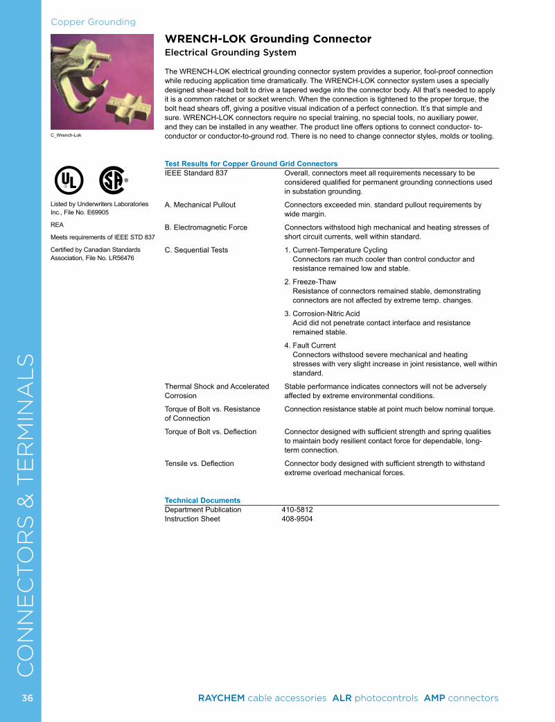
Copper GroundingC
ON
NE
CTO
RS
& T
ER
MIN
AL
SWRENCH-LOK Grounding ConnectorElectrical Grounding System
The WRENCH-LOK electrical grounding connector system provides a superior, fool-proof connection while reducing application time dramatically. The WRENCH-LOK connector system uses a specially designed shear-head bolt to drive a tapered wedge into the connector body. All that’s needed to apply it is a common ratchet or socket wrench. When the connection is tightened to the proper torque, the bolt head shears off, giving a positive visual indication of a perfect connection. It’s that simple and sure. WRENCH-LOK connectors require no special training, no special tools, no auxiliary power, and they can be installed in any weather. The product line offers options to connect conductor- to-conductor or conductor-to-ground rod. There is no need to change connector styles, molds or tooling.
Test Results for Copper Ground Grid Connectors IEEE Standard 837 Overall, connectors meet all requirements necessary to be
considered qualified for permanent grounding connections used in substation grounding.
A. Mechanical Pullout Connectors exceeded min. standard pullout requirements by wide margin.
B. Electromagnetic Force Connectors withstood high mechanical and heating stresses of short circuit currents, well within standard.
C. Sequential Tests 1. Current-Temperature Cycling Connectors ran much cooler than control conductor and resistance remained low and stable.
2. Freeze-Thaw Resistance of connectors remained stable, demonstrating connectors are not affected by extreme temp. changes.
3. Corrosion-Nitric Acid Acid did not penetrate contact interface and resistance remained stable.
4. Fault Current Connectors withstood severe mechanical and heating stresses with very slight increase in joint resistance, well within standard.
Thermal Shock and Accelerated Stable performance indicates connectors will not be adversely Corrosion affected by extreme environmental conditions.
Torque of Bolt vs. Resistance Connection resistance stable at point much below nominal torque.of Connection
Torque of Bolt vs. Deflection Connector designed with sufficient strength and spring qualities to maintain body resilient contact force for dependable, long- term connection.
Tensile vs. Deflection Connector body designed with sufficient strength to withstand extreme overload mechanical forces.
Technical DocumentsDepartment Publication 410-5812Instruction Sheet 408-9504
C_Wrench-Lok
Listed by Underwriters Laboratories Inc., File No. E69905
REA
Meets requirements of IEEE STD 837
Certified by Canadian Standards Association, File No. LR56476
®
36 RAYCHEM cable accessories ALR photocontrols AMP connectors
Copper GroundingC
ON
NE
CTO
RS
& T
ER
MIN
AL
SGround Rod-to-Conductor3/8 1/2 5/8 3/4Copper Galv. Copper Galv. Copper Galv. Copper Galv. Clad Steel Clad Steet Clad Steel Clad Steel .355 (9.02) .375 (9.52) .475 (12.06) .500 (12.70) .563 (14.30) .625 (15.88) .682 (17.32) .750 (19.05) Conductor83747-2 83747-2 83747-4 83747-4 83749-1 83749-2 83749-3 83749-4 #2 sol, str, cmpt83747-3 83747-3 83749-1 83749-1 83749-2 83749-3 83749-4 83748-3 1/0 str, cmpt83747-4 83747-4 83749-2 83749-2 83749-3 83748-1 83748-3 83748-4 2/0 str, cmpt 83749-2 83749-3 83748-1 83748-2 83748-4 83751-1 3/0 str, cmpt 83748-1 83748-1 83748-2 83748-4 83751-1 83751-2 4/0 str, cmpt 83750-1 83748-4 83751-1 83751-2 250 compacted 83750-1 83751-1 83751-2 83751-3 250 str 83751-1 83751-2 83751-3 300 compacted 83751-2 83751-3 83751-4 300 str 83751-2 83751-3 83751-4 350 compacted 83751-3 83750-2 350 str 83751-3 83751-4 400 compacted 83750-3 500 str
Conductor-to-Conductor (Standard Round)
#2 sol,str 1/0 str 2/0 str 3/0 str 4/0 str 250 str 300 str 350 str 400 str 450 str 500 str Conductor83747-1 83747-2 83747-2 83747-3 83747-4 83747-1 83749-2 83749-3 83749-4 83749-4 --- #2 sol,str 83747-3 83747-3 83747-4 83749-1 83749-2 83749-3 83748-1 83749-3 83749-3 83751-1 1/0 str 83747-4 83749-1 83749-2 83749-3 83748-1 83748-2 83748-3 83748-4 83751-1 2/0 str 83749-2 83749-3 83748-1 83748-2 83748-3 83748-4 83751-1 83751-2 3/0 str 83748-2 83748-2 83748-4 83751-1 83751-1 83751-2 83751-3 4/0 str 83750-1 83751-1 83751-2 83751-2 83751-3 83751-4 250 str 83750-2 83751-2 83751-3 83751-4 83750-2 300 str 83751-3 83751-4 83750-2 83750-3 350 str 83750-2 83750-4 83750-5 400 str 83750-5 83750-4 450 str 83750-6 500 str
Wrench-Lok Copper Grounding Connector System Selection Charts
Replacement Bolts Part NumbersSmall Body 81249-4Large Body 81249-2
Conductors listed are for Stranded Copper Standard Round
Conductor-to-Conductor (Compacted)
#2 1/0 2/0 3/0 4/0 250 300 350 400 450 500 Conductor 83747-1 83747-2 83747-2 83747-3 83747-4 83747-4 83749-1 83749-2 83749-3 83749-3 83749-4 #2 83747-3 83747-3 83747-4 83749-1 83749-2 83749-2 83749-3 83749-1 83749-1 83749-3 1/0 83747-4 83747-1 83749-2 83749-2 83749-3 83748-1 83748-2 83748-3 83748-4 2/0 83749-2 83749-3 83748-1 83748-1 83748-2 83748-3 83748-4 83751-1 3/0 83748-1 83748-2 83748-2 83748-4 83748-4 83751-1 83751-1 4/0 83750-1 83750-1 83748-4 83751-1 83751-2 83751-2 250 83750-1 83751-1 83751-1 83751-2 83751-3 300 83751-2 83751-2 83751-3 83751-3 350 83751-3 83751-4 83751-4 400 83750-2 83750-2 450 83750-3 500
37RAYCHEM cable accessories ALR photocontrols AMP connectors
CO
NN
EC
TO
RS
& T
ER
MIN
AL
SWrench-Lok Copper Grounding Connector System Selection Information
Catalog Number DescriptionSmall Body Standard Round Compacted Conductor to Ground Rod
83747-1 #2 sol., str.-#2 sol., str. 2-#283747-2 1/0, 2/0 str.-#2 sol., str. 1/0, 2/0-#2 3/8 Clad or Galv.-#283747-3 1/0, 2/0 str.-1/0 str. 1/0, 2/0-1/0 3/8 Clad or Galv.-1/0 3/0 str.-#2 sol, str. 3/0-#283747-4 2/0 str.-2/0 str. 2/0-2/0 3/8 Clad or Galv.-2/0 3/0 str.-1/0 str. 3/0-1/0 1/2 Clad or Galv.-#2 4/0 str.-#2 sol, str. 4/0, 250-#283749-1 3/0 str.-#2 str. 3/0-2/0 1/2 Clad or Galv.-1/0 4/0 str.-1/0 str. 4/0-1/0 5/8 Clad - #2 250 str.-#2 sol., str. 300-#283749-2 3/0 str.-3/0,str. 3/0-3/0 1/2 Clad or Galv.-2/0 4/0 str.-2/0 str. 4/0, 250-2/0 5/8 Clad-1/0 250 str.-1/0 str. 250/300-1/0 5/8 Galv.-#2 300 str.-#2 sol., str. 350-#283749-3 4/0 str.-3/0 str. 4/0-3/0 1/2 Clad or Galv.-3/0 250 str.-2/0 str. 300-2/0 5/8 Clad-2/0 300 str.-1/0 str. 350-1/0 5/8 Galv.-1/0 350 str.-#2 sol., str. 400, 450-#2 3/4 Clad-#283748-1 4/0 str.-4/0 str. 4/0-4/0 1/2 Clad or Galv.-4/0 250 str.-3/0 str. 250, 300-3/0 5/8 Clad-3/0 300 str.-2/0 str. 350-2/0 5/8 Galv.-2/0 350 str.-1/0 str. 400-1/083748-2 4/0 str.-4/0 str. 250, 300-4/0 5/8 Clad-4/0 300 str.-3/0 str. 350-3/0 5/8 Galv.-3/0 350 str.-2/0 str. 400-2/083749-4 400, 450 str.-#2 sol., str. 450-1/0 3/4 Clad-1/0 500-#2 3/4 Galv.-#283748-3 350 str.-3/0 str. 400-3/0 3/4 Clad-2/0 400 str.-2/0, 1/0 str. 450-2/0 3/4 Galv.-1/0 450 str.-1/0 str. 500-1/083748-4 300 str.-4/0 str. 350-4/0, 250 5/8 Galv.-4/0 400 str.-3/0 str. 400-4/0 5/8 Galv.-250 cmpt. 450 str.-2/0 str. 450-3/0 3/4 Clad-3/0 500 - 2/0 3/4 Galv.-2/083750-1 250 str.-250 str. 250, 300-250, 300 5/8 Clad-250 str., cmpt.83751-1 300 str.-250 str. 350, 400-300 5/8 Galv.-250 str., 300 cmpt. 350, 400 str.-4/0 str. 400-250 3/4 Clad-4/0,250 cmpt. 450 str.-3/0 str. 450-4/0 3/4 Galv.-3/0 500 str. - 2/0 str. 500-3/083751-2 300, 350 str.-300 str. 350, 400-350 5/8 Galv.-350 cmpt, 300 str. 350, 400 str.-250 str. 450-300, 250 3/4 Clad-250 str., 300 cmpt. 450 str.-4/0 str. 500-250 3/4 Galv.-4/0, 250 cmpt. 500 str.-3/0 str.83751-3 350 str.-350 str. 400-400 3/4 Clad-300 str., 350 cmpt, str., 400 cmpt. 400 str.-300 str. 450-350 3/4 Galv.-250 str., 300 cmpt. 450 str.-250 str. 500-350, 300 500 str.-4/0 str.83751-4 400 str.-350 str. 400, 500-400 3/4 Galv.-300 str., 350 cmpt, 400 cmpt. 450 str.-300 str. 500 str.-250 str.83750-2 400 str.-400 str. 450, 500-450 3/4 Galv.-350 str., 450 cmpt. 450 str.-350 str. 500 str.-300 str.83750-3 450 str.-400 str. 500-500 3/4 Galv.-400 str., 500 cmpt. 450 str.-400 str. 500 str.-350 str.83750-5 450 str.-450 str. 500 str.-400 str.83750-4 500 str.-450 str.83750-6 500 str.-500 str.
Copper Grounding
38 RAYCHEM cable accessories ALR photocontrols AMP connectors
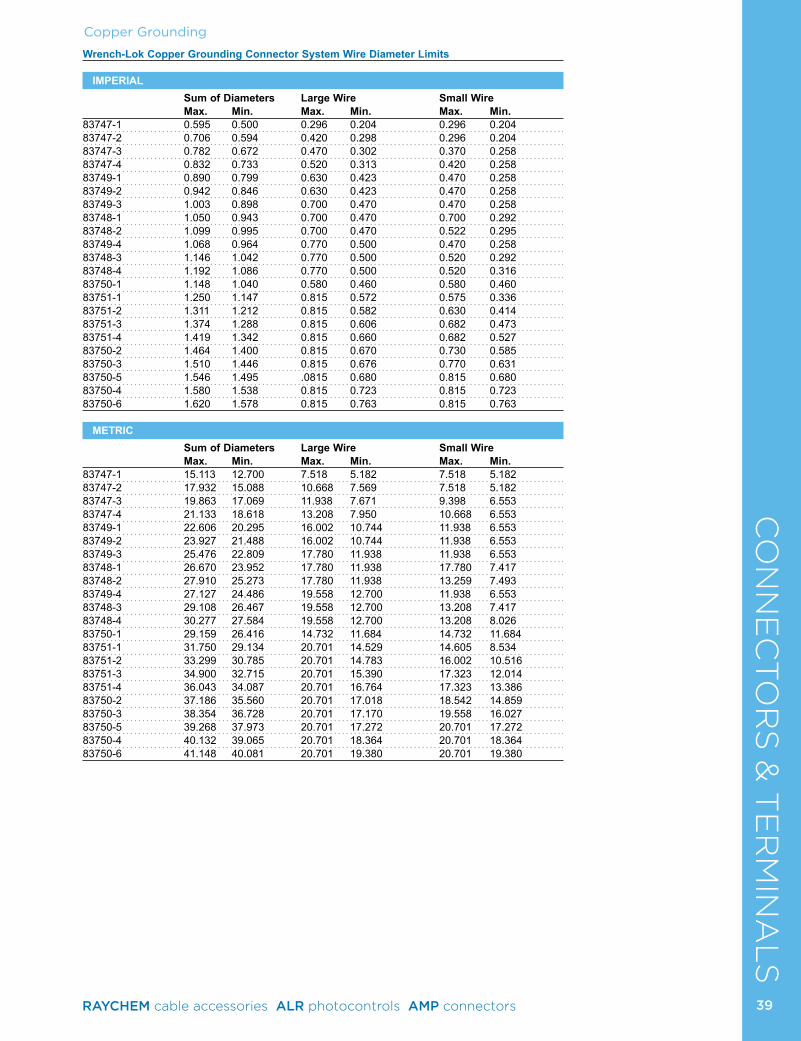
CO
NN
EC
TO
RS
& T
ER
MIN
AL
SCopper Grounding
Wrench-Lok Copper Grounding Connector System Wire Diameter Limits
IMPERIAL Sum of Diameters Large Wire Small Wire Max. Min. Max. Min. Max. Min.83747-1 0.595 0.500 0.296 0.204 0.296 0.20483747-2 0.706 0.594 0.420 0.298 0.296 0.20483747-3 0.782 0.672 0.470 0.302 0.370 0.25883747-4 0.832 0.733 0.520 0.313 0.420 0.25883749-1 0.890 0.799 0.630 0.423 0.470 0.25883749-2 0.942 0.846 0.630 0.423 0.470 0.25883749-3 1.003 0.898 0.700 0.470 0.470 0.25883748-1 1.050 0.943 0.700 0.470 0.700 0.29283748-2 1.099 0.995 0.700 0.470 0.522 0.29583749-4 1.068 0.964 0.770 0.500 0.470 0.25883748-3 1.146 1.042 0.770 0.500 0.520 0.29283748-4 1.192 1.086 0.770 0.500 0.520 0.31683750-1 1.148 1.040 0.580 0.460 0.580 0.46083751-1 1.250 1.147 0.815 0.572 0.575 0.33683751-2 1.311 1.212 0.815 0.582 0.630 0.41483751-3 1.374 1.288 0.815 0.606 0.682 0.47383751-4 1.419 1.342 0.815 0.660 0.682 0.52783750-2 1.464 1.400 0.815 0.670 0.730 0.58583750-3 1.510 1.446 0.815 0.676 0.770 0.63183750-5 1.546 1.495 .0815 0.680 0.815 0.68083750-4 1.580 1.538 0.815 0.723 0.815 0.72383750-6 1.620 1.578 0.815 0.763 0.815 0.763
METRIC Sum of Diameters Large Wire Small Wire Max. Min. Max. Min. Max. Min.83747-1 15.113 12.700 7.518 5.182 7.518 5.18283747-2 17.932 15.088 10.668 7.569 7.518 5.18283747-3 19.863 17.069 11.938 7.671 9.398 6.55383747-4 21.133 18.618 13.208 7.950 10.668 6.55383749-1 22.606 20.295 16.002 10.744 11.938 6.55383749-2 23.927 21.488 16.002 10.744 11.938 6.55383749-3 25.476 22.809 17.780 11.938 11.938 6.55383748-1 26.670 23.952 17.780 11.938 17.780 7.41783748-2 27.910 25.273 17.780 11.938 13.259 7.49383749-4 27.127 24.486 19.558 12.700 11.938 6.55383748-3 29.108 26.467 19.558 12.700 13.208 7.41783748-4 30.277 27.584 19.558 12.700 13.208 8.02683750-1 29.159 26.416 14.732 11.684 14.732 11.68483751-1 31.750 29.134 20.701 14.529 14.605 8.53483751-2 33.299 30.785 20.701 14.783 16.002 10.51683751-3 34.900 32.715 20.701 15.390 17.323 12.01483751-4 36.043 34.087 20.701 16.764 17.323 13.38683750-2 37.186 35.560 20.701 17.018 18.542 14.85983750-3 38.354 36.728 20.701 17.170 19.558 16.02783750-5 39.268 37.973 20.701 17.272 20.701 17.27283750-4 40.132 39.065 20.701 18.364 20.701 18.36483750-6 41.148 40.081 20.701 19.380 20.701 19.380
39RAYCHEM cable accessories ALR photocontrols AMP connectors
Copper GroundingC
ON
NE
CTO
RS
& T
ER
MIN
AL
S
• Telephone grounding• Street lights• Service entrance drops• Aerial connections
Consumer Entrance Service
Consumer Entrance Service
Copper secondary service drop
Aluminum secondary service drop using“AMPACT Stirrup” for low voltage Street light connection
Residential/CommercialGrounding
Universal Distribution Connectors
Universal Distribution Connectors are composed of a “C” component and a “Wedge” component, both made of a tin-plated copper alloy, in a configuration that creates a spring action. They are recommended for connecting conductors of aluminum, copper, steel and their alloys regardless of the combination (i.e., AI to AI, AI to Cu, Cu to Cu) in normal corrosive environments. Their technical design and construction are such that they have neither the disadvantages of some screw connectors, which must be periodically readjusted and retightened, nor the drawbacks of compression-type connectors, which are difficult to select and install, and which, once applied, cannot be removed without rendering the conductors useless. In addition to these technical features, the Universal Distribution Connector provides a noncorrosive connection that is protected against temperature variation and overloading.
The Universal Distribution Connector can be rapidly and safely installed without special tools. Conventional “parallel jaw” pliers are used to make the connection. A good connection can be easily verified by visual inspection. A wide range of connectors cover combinations of conductors ranging from 14 AWG to 4/0 AWG [1.5 mm2 to 120 mm2], and all can be removed without damaging the conductors.
The reinforced version was developed to comply to ANSI C119.4 “Pull-Out” test and can be used in high cable tension applications. Both connector versions comply with all other specifications/ tests of ANSI C119.4 Standard.
Technical DocumentsProduct Specifications 108-37019Instruction Sheet 411-37014
“C” component configuration before
application
Double spring action exerted by the “C” and
the “Wedge” components maintain a permanent
contact force, providing a safe and efficient
electrical connection
Large wire groove
Wedge component configuration before application
C_UDC
40 RAYCHEM cable accessories ALR photocontrols AMP connectors
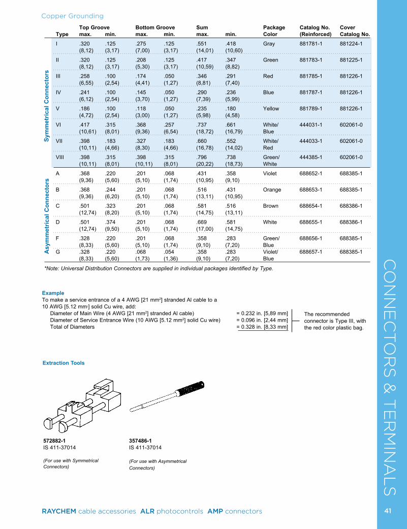
Copper GroundingC
ON
NE
CTO
RS
& T
ER
MIN
AL
S Top Groove Bottom Groove Sum Package Catalog No. Cover Type max. min. max. min. max. min. Color (Reinforced) Catalog No.
I .320 .125 .275 .125 .551 .418 Gray 881781-1 881224-1 (8,12) (3,17) (7,00) (3,17) (14,01) (10,60)
II .320 .125 .208 .125 .417 .347 Green 881783-1 881225-1 (8,12) (3,17) (5,30) (3,17) (10,59) (8,82)
III .258 .100 .174 .050 .346 .291 Red 881785-1 881226-1 (6,55) (2,54) (4,41) (1,27) (8,81) (7,40)
IV .241 .100 .145 .050 .290 .236 Blue 881787-1 881226-1 (6,12) (2,54) (3,70) (1,27) (7,39) (5,99)
V .186 .100 .118 .050 .235 .180 Yellow 881789-1 881226-1 (4,72) (2,54) (3,00) (1,27) (5,98) (4,58)
VI .417 .315 .368 .257 .737 .661 White/ 444031-1 602061-0 (10,61) (8,01) (9,36) (6,54) (18,72) (16,79) Blue
VII .398 .183 .327 .183 .660 .552 White/ 444033-1 602061-0 (10,11) (4,66) (8,30) (4,66) (16,78) (14,02) Red
VIII .398 .315 .398 .315 .796 .738 Green/ 444385-1 602061-0 (10,11) (8,01) (10,11) (8,01) (20,22) (18,73) White
A .368 .220 .201 .068 .431 .358 Violet 688652-1 688385-1 (9,36) (5,60) (5,10) (1,74) (10,95) (9,10)
B .368 .244 .201 .068 .516 .431 Orange 688653-1 688385-1 (9,36) (6,20) (5,10) (1,74) (13,11) (10,95)
C .501 .323 .201 .068 .581 .516 Brown 688654-1 688386-1 (12,74) (8,20) (5,10) (1,74) (14,75) (13,11)
D .501 .374 .201 .068 .669 .581 White 688655-1 688386-1 (12,74) (9,50) (5,10) (1,74) (17,00) (14,75)
F .328 .220 .201 .068 .358 .283 Green/ 688656-1 688385-1 (8,33) (5,60) (5,10) (1,74) (9,10) (7,20) Blue G .328 .220 .068 .054 .358 .283 Violet/ 688657-1 688385-1 (8,33) (5,60) (1,73) (1,36) (9,10) (7,20) Blue
*Note: Universal Distribution Connectors are supplied in individual packages identified by Type.
Sym
met
rical
Con
nect
ors
Asy
mm
etric
al C
onne
ctor
s
ExampleTo make a service entrance of a 4 AWG [21 mm2] stranded Al cable to a 10 AWG [5.12 mm2] solid Cu wire, add: Diameter of Main Wire (4 AWG [21 mm2] stranded Al cable) = 0.232 in. [5,89 mm] Diameter of Service Entrance Wire (10 AWG [5.12 mm2] solid Cu wire) = 0.096 in. [2,44 mm] Total of Diameters = 0.328 in. [8,33 mm]
The recommended connector is Type III, with the red color plastic bag.
Extraction Tools
572882-1IS 411-37014
(For use with Symmetrical Connectors)
357486-1IS 411-37014
(For use with Asymmetrical Connectors)
41RAYCHEM cable accessories ALR photocontrols AMP connectors
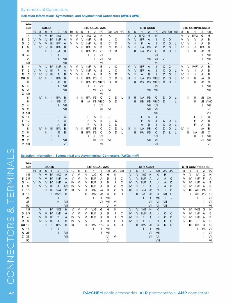
Symmetrical ConnectorsC
ON
NE
CTO
RS
& T
ER
MIN
AL
S Wire Size SOLID STR CU/AL AAC STR ACSR STR COMPRESSED 10 8 6 4 2 1/0 10 8 6 4 2 1/0 2/0 3/0 4/0 8 6 4 2 1/0 2/0 3/0 4/0 8 6 4 2 1/0 14 V V IV III/G V V IV III/G G K K V IV III/G H K V IV IV/G G H S 12 V V IV IV III/F A V V IV III/F A B J C IV IV III/F A J C D V IV IV A B O 10 V V V III II/F A V IV IV III/F A B C C IV III F A J C D L IV IV III A B L 8 IV IV III II/A B IV III II/A B B C F L IV III II/A I/B C C D L IV III III II/A B I 6 III II I/A B III II/A I/B C C D II II/A I/B C D D L III II I/B C D 4 II I I I VII I I VII I VII 2 I VII I VII VI VII VII VI I VII 1/0 VII VI VI VI S 14 V IV IV III/F A V V IV III/F A B J C V IV III/F A J C C V IV IV/F A B T 12 V V IV III F A V IV IV III/F A B J C IV IV III/F A J C D L V IV III A B R 10 V IV IV III A B V IV III F A B C D IV III A B J C D L IV III III A BCU 8 IV III II II/A B III III II/A I/B B C D L III III II/A I/B VII/C D D L IV III II I/A B 6 II I/B B III II/A I/B VII/C D D II I/B I/B VII/D D D L II I/B C A 4 I VII I I VII I I VI I VII A 2 VII VII VII VI VII VIII VII C 1/0 VI 8 IV III II II/A B III III II/A I/B C C D L III II II/A I/B C D D L III II I/B CA 6 II I/B C II I/A I/B VII/C D D II I/B I/B VII/D D L II I/B VII/C C 4 I VII I VII I VII VII I VII S 2 VII VI VI VII VI VI R 1/0 VIII VIII S 14 F A F A B J F A J F F B T 12 F A F A B J C F A J C D L F A B R 10 A B F A B C D A B J C D L F A B 8 IV III III II/A B IV III II/A I/B C C D L III III II/A I/B C D D L IV III I/A B C 6 III II I/B B II II/A I/B C D D L II I/A I/B C D L L II II/A I/B C O 4 II I I I VII I I VII II I VII M 2 II VII VII VII VI VII VI VII VII P 1/0 VI VI VII VI
Selection Information: Symmetrical and Asymmetrical Connectors (AWGx mm2) Wire Size SOLID STR CU/AL AAC STR ACSR STR COMPRESSED 10 8 6 4 2 1/0 10 8 6 4 2 1/0 2/0 3/0 8 6 4 2 1/0 2/0 3/0 8 6 4 2 1/0 1.5 V V IV III/G A V V IV IV/G G H K V IV III/G H K H V V IV G H S 2.5 V V IV III/F A V V IV III/F A B J C V IV III/F A J A C V IV III/F F A O 4 V V IV IV III/F A IV V IV III/F A B J C IV IV III/F A J A D V IV III/F A B L 6 V IV III A A/B IV IV IV III/F A B C C IV III F A J A D IV IV III/F A B I 10 III III IV/A B III IV III II/A I/A B C D III III IV/A I/B C I D IV III A/II I/A B D 16 II I/A/B B II II/A I/B C D D II I/A I/B C I/B D II A/II I/B C 25 I I I VII I I VII I L I I VII 35 H VII VII VII VI VII VI VII I VII 50 VII VI VI VII VI VII VI 1.5 V IV III/G H V V V IV/G G H K V IV III/G H K V IV IV/G G H S 2.5 V V IV III/F A V V V III/F A B J C IV IV III/F A J C C V IV III/F A B T 4 V V III F A IV IV V III/F A B J C IV III F A J C D IV IV III/F A B R 6 IV IV III A B IV IV IV F A B C D IV III A B C C D IV III F A BCU 10 III II II/A B III III II/A 1/B C C D II II/A I/B C D D III II/A B C A 16 II I I I VII I I VII I I/B VII A 25 I VII I VII VII VII I VII C 35 VII VI VI VII VI I VII 50 VI VIII VI
Selection Information: Symmetrical and Asymmetrical Connectors (AWGx AWG)
42 RAYCHEM cable accessories ALR photocontrols AMP connectors
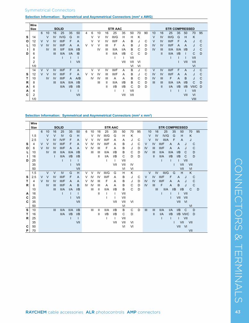
Symmetrical ConnectorsC
ON
NE
CTO
RS
& T
ER
MIN
AL
SSelection Information: Symmetrical and Asymmetrical Connectors (mm2 x AWG) Wire
Size SOLID STR AAC STR COMPRESSED 6 10 16 25 35 50 4 6 10 16 25 35 50 70 90 10 16 25 35 50 70 95 S 14 V IV IV/G G H V V IV III/G H H K V IV III/G G H K O 12 V V IV III/F F A V V IV III/F A B J C V IV III/F F A J C L 10 V IV IV III/F A A V V V III F A B J D IV IV III/F A A J C I 8 IV III II/F II/A I/B IV III II/A I/A B C D IV III II/A II/A I/B J C D 6 III II/A I/A IB II II/A I/B C C D II II/A I/B I C D 4 I I I I I VII I I I VII 2 I VII VII VII VI I VII VII 1/0 VI VI VI 14 V V IV III/F F A V V IV III/F A B J C V IV III/F F A J C S 12 V V IV III/F F A V V IV III III/F A B J C IV IV III/F A A J C T 10 IV IV III/F A A/B IV IV III A A B C D IV III F A B J C R 8 III II/A II/A I/B III II II/A I/B B C D III III II/A I/A I/B C D A 6 II/A I/B I/B II I/B I/B C D D II I/A I/B I/B VII/C D A 4 I I I I VII I I I VII C 2 VII VII VII VII VI 1/0 VIII
Selection Information: Symmetrical and Asymmetrical Connectors (mm2 x mm2)
Wire Size SOLID STR AAC STR COMPRESSED 6 10 16 25 35 50 6 10 16 25 35 50 70 95 10 16 25 35 50 70 95 1.5 V V IV G H V IV III/G G H K V IV IV/G G H K 2.5 V IV IV/F F A V V IV III/F A A J C V IV III/A F A J S 4 V V IV III/F F A V IV IV III/F A B J C V IV III/F A A J C O 6 V IV IV III/F A A V IV III F A B J D IV III III/F A A J C L 10 IV III II/A II/A I/B III III II/A I/B B C D IV III II/A II/A I/B C D I 16 I II/A I/B I/B II I/A I/B C D D II II/A I/B I/B C D D 25 I I I I I VII I I I VII 35 I VII VII VII IV I VII VII 50 VII VI VI VII VI 1.5 V V IV G H V V IV III/G G H K V IV III/G G H K S 2.5 V V IV III/F F A V IV IV III/F A B J C V IV III/F F A J C T 4 V IV IV III/F A A V IV III F A B J D IV IV III/F A A J C R 6 IV III III/F A B IV IV III A A B C D IV III F A B J C 10 III II/A I/A I/B III II II/A I/B B C D III II/A I/B I/B C D A 16 I I I II I I VII I I I VII C 25 I VII I I VII I VII VII C 35 VII VII VII VI VII VI 50 VI VI S 10 III II/A II/A I/B III II II/A I/B B C D III III II/A I/A I/B C D T 16 II/A I/B I/B II I/B I/B C D II I/A I/B I/B VII/C D R 25 I I I I VII I I I VII 35 VII VII VII VI I VII VII C 50 VI VI VII VI P 70 VII
43RAYCHEM cable accessories ALR photocontrols AMP connectors
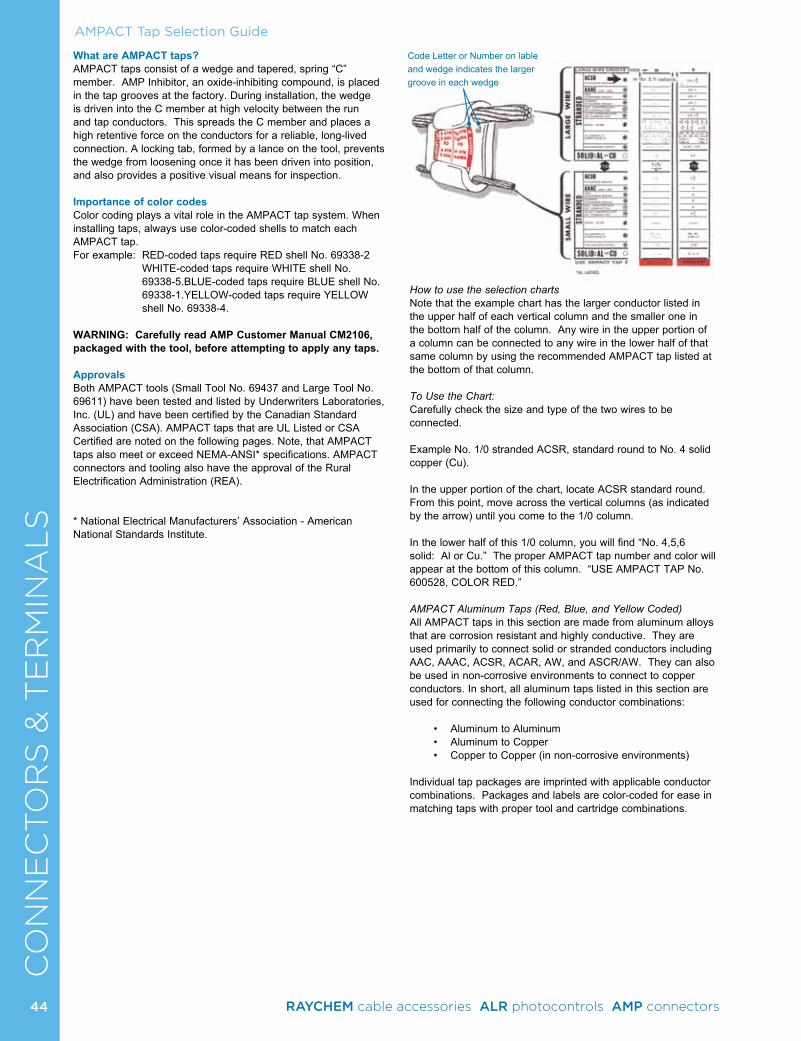
AMPACT Tap Selection GuideC
ON
NE
CTO
RS
& T
ER
MIN
AL
SWhat are AMPACT taps?AMPACT taps consist of a wedge and tapered, spring “C” member. AMP Inhibitor, an oxide-inhibiting compound, is placed in the tap grooves at the factory. During installation, the wedge is driven into the C member at high velocity between the run and tap conductors. This spreads the C member and places a high retentive force on the conductors for a reliable, long-lived connection. A locking tab, formed by a lance on the tool, prevents the wedge from loosening once it has been driven into position, and also provides a positive visual means for inspection.
Importance of color codesColor coding plays a vital role in the AMPACT tap system. When installing taps, always use color-coded shells to match each AMPACT tap. For example: RED-coded taps require RED shell No. 69338-2
WHITE-coded taps require WHITE shell No. 69338-5.BLUE-coded taps require BLUE shell No. 69338-1.YELLOW-coded taps require YELLOW shell No. 69338-4.
WARNING: Carefully read AMP Customer Manual CM2106, packaged with the tool, before attempting to apply any taps.
ApprovalsBoth AMPACT tools (Small Tool No. 69437 and Large Tool No. 69611) have been tested and listed by Underwriters Laboratories, Inc. (UL) and have been certified by the Canadian Standard Association (CSA). AMPACT taps that are UL Listed or CSA Certified are noted on the following pages. Note, that AMPACT taps also meet or exceed NEMA-ANSI* specifications. AMPACT connectors and tooling also have the approval of the Rural Electrification Administration (REA).
* National Electrical Manufacturers’ Association - American National Standards Institute.
How to use the selection chartsNote that the example chart has the larger conductor listed in the upper half of each vertical column and the smaller one in the bottom half of the column. Any wire in the upper portion of a column can be connected to any wire in the lower half of that same column by using the recommended AMPACT tap listed at the bottom of that column.
To Use the Chart:Carefully check the size and type of the two wires to be connected.
Example No. 1/0 stranded ACSR, standard round to No. 4 solid copper (Cu).
In the upper portion of the chart, locate ACSR standard round. From this point, move across the vertical columns (as indicated by the arrow) until you come to the 1/0 column.
In the lower half of this 1/0 column, you will find “No. 4,5,6 solid: Al or Cu.” The proper AMPACT tap number and color will appear at the bottom of this column. “USE AMPACT TAP No. 600528, COLOR RED.”
AMPACT Aluminum Taps (Red, Blue, and Yellow Coded)All AMPACT taps in this section are made from aluminum alloys that are corrosion resistant and highly conductive. They are used primarily to connect solid or stranded conductors including AAC, AAAC, ACSR, ACAR, AW, and ASCR/AW. They can also be used in non-corrosive environments to connect to copper conductors. In short, all aluminum taps listed in this section are used for connecting the following conductor combinations:
• Aluminum to Aluminum• Aluminum to Copper• Copper to Copper (in non-corrosive environments)
Individual tap packages are imprinted with applicable conductor combinations. Packages and labels are color-coded for ease in matching taps with proper tool and cartridge combinations.
Code Letter or Number on lable and wedge indicates the larger groove in each wedge
44 RAYCHEM cable accessories ALR photocontrols AMP connectors
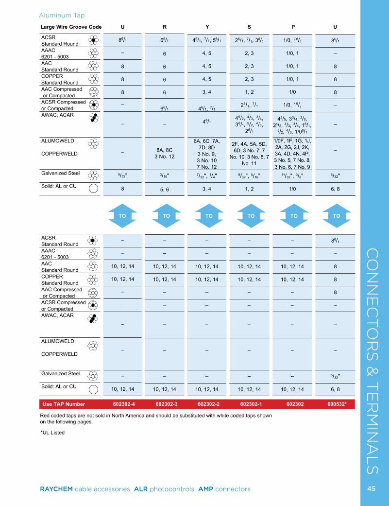
86/1
_
8 8 8
_
_
_
5/32"
6, 8
86/1
_
8 8 8
_
_
_
5/32"
6, 8
Aluminum TapC
ON
NE
CTO
RS
& T
ER
MIN
AL
SLarge Wire Groove Code U R Y S P U
Use TAP Number 602302-4 602302-3 602302-2 602302-1 602302 600532*
86/1
_
8 8 8
_
_
_
5/32"
8
_
_
10, 12, 14
10, 12, 14
_
_
_
_
_
10, 12, 14
66/1
6 6 6 6
66/1
_
8A, 8C 3 No. 12
3/16"
5, 6
_
_
10, 12, 14
10, 12, 14
_
_
_
_
_
10, 12, 14
46/1, 7/1, 56/1
4, 5
4, 5
4, 5
3, 4
46/1, 7/1
46/1
6A, 6C, 7A, 7D, 8D 3 No. 9, 3 No. 10 7 No. 12
7/32", 1/4"
3, 4
_
_
10, 12, 14
10, 12, 14
_
_
_
_
_
10, 12, 14
26/1, 7/1, 36/1
2, 3
2, 3
2, 3
1, 2
26/1, 7/1
45/2, 4/3, 3/4, 36/1, 5/2, 4/3,
26/1
2F, 4A, 5A, 5D, 6D, 3 No. 7, 7
No. 10, 3 No. 8, 7 No. 11
9/32", 5/16"
1, 2
_
_
10, 12, 14
10, 12, 14
_
_
_
_
_
10, 12, 14
1/0, 16/1
1/0, 1
1/0, 1
1/0, 1
1/0
1/0, 16/1
42/5, 33/4, 2/5, 25/2, 4/3, 3/4, 16/1,
5/2, 4/3, 1/06/1
1/0F, 1F, 1G, 1J, 2A, 2G, 2J, 2K, 3A, 4D, 4N, 4P, 3 No. 5, 7 No. 8, 3 No. 6, 7 No. 9
11/32", 3/8"
1/0
_
_
10, 12, 14
10, 12, 14
_
_
_
_
_
10, 12, 14
TO TOTO TO TO TO
Red coded taps are not sold in North America and should be substituted with white coded taps shown on the following pages.
ACSR Standard RoundAAAC 6201 - 5003AAC Standard RoundCOPPER Standard RoundAAC Compressed or CompactedACSR Compressed or CompactedAWAC, ACAR
ALUMOWELD
COPPERWELD
Galvanized Steel
Solid: AL or CU
ACSR Standard RoundAAAC 6201 - 5003AAC Standard RoundCOPPER Standard RoundAAC Compressed or CompactedACSR Compressed or CompactedAWAC, ACAR
ALUMOWELD
COPPERWELD
Galvanized Steel
Solid: AL or CU
*UL Listed
45RAYCHEM cable accessories ALR photocontrols AMP connectors
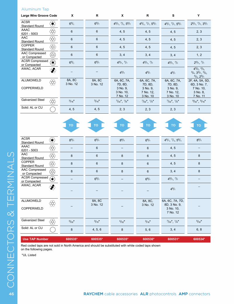
CO
NN
EC
TO
RS
& T
ER
MIN
AL
SACSR Standard RoundAAAC 6201 - 5003AAC Standard RoundCOPPER Standard RoundAAC Compressed or CompactedACSR Compressed or CompactedAWAC, ACAR
ALUMOWELD COPPERWELD
Galvanized Steel
Solid: AL or CU
ACSR Standard RoundAAAC 6201 - 5003AAC Standard RoundCOPPER Standard RoundAAC Compressed or CompactedACSR Compressed or CompactedAWAC, ACAR
ALUMOWELD COPPERWELD
Galvanized Steel
Solid: AL or CU
Aluminum Tap
Large Wire Groove Code X R X R S Y
Use TAP Number 600535* 600535* 600535* 600530* 600531* 600534*
TO TOTO TO TO TO
*UL Listed
Red coded taps are not sold in North America and should be substituted with white coded taps shown on the following pages.
66/1
6 6 6 6
66/1
_
8A, 8C 3 No. 12
3/16"
4, 5
86/1
_
8 8 8
_
_
_
5/32"
8
66/1
6 6 6 6
66/1
_
8A, 8C 3 No. 12
3/16"
4, 5
66/1
6 6 6 6
66/1
_
8A, 8C 3 No. 12
3/16"
4, 5, 6
46/1, 7/1, 56/1
4, 5
4, 5
4, 5
3, 4
46/1, 7/1
46/1
6A, 6C, 7A, 7D, 8D, 3 No. 9, 7 No. 12, 3 No. 10 7/32", 1/4"
2, 3
66/1
6 6 6 6
66/1
_
8A, 8C, 3 No. 12
3/16"
5, 6
26/1, 7/1, 36/1
2, 3
2, 3
2, 3
1, 2
26/1, 7/1
45/2, 4/3, 3/4, 36/1, 5/2,
4/3, 26/1
2F, 4A, 5A, 5D, 6D, 3 No. 7,
7 No. 10, 3 No. 8, 7 No. 11
9/32", 5/16" 1
86/1
_
8 8 8
_
_
_
5/32"
6, 8
46/1, 7/1, 56/1
4, 5
4, 5
4, 5
3, 4
46/1, 7/1
46/1
6A, 6C, 7A, 7D, 8D, 3 No. 9, 3 No. 10, 7 No. 12
7/32", 1/4"
2, 3
86/1
_
8 8 8
_
_
_
5/32" 8
46/1, 7/1, 56/1
4, 5
4, 5
4, 5
3, 4
46/1, 7/1
46/1
6A, 6C, 7A, 7D, 8D, 3 No. 9, 7 No. 12, 3 No. 10
7/32", 1/4"
2, 3
46/1, 7/1, 56/1
4, 5
4, 5
4, 5
3, 4
46/1, 7/1
46/1
6A, 6C, 7A, 7D, 8D, 3 No. 9,
3 No. 10, 7 No. 12
7/32", 1/4"
3, 4
46 RAYCHEM cable accessories ALR photocontrols AMP connectors
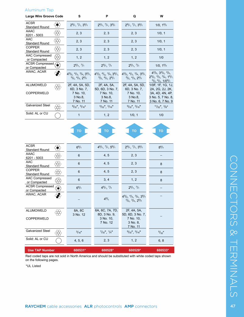
ACSR Standard RoundAAAC 6201 - 5003AAC Standard RoundCOPPER Standard RoundAAC Compressed or CompactedACSR Compressed or CompactedAWAC, ACAR
ALUMOWELD
COPPERWELD
Galvanized Steel
Solid: AL or CU
ACSR Standard RoundAAAC 6201 - 5003AAC Standard RoundCOPPER Standard RoundAAC Compressed or CompactedACSR Compressed or CompactedAWAC, ACAR
ALUMOWELD
COPPERWELD
Galvanized Steel
Solid: AL or CU
Aluminum TapC
ON
NE
CTO
RS
& T
ER
MIN
AL
S
Use TAP Number 600531* 600528* 600529* 600533*
Large Wire Groove Code S P Q W
TOTO TO TO
*UL Listed
Red coded taps are not sold in North America and should be substituted with white coded taps shown on the following pages.
26/1, 7/1, 36/1
2, 3
2, 3
2, 3
1, 2
26/1, 7/1
45/2, 4/3, 3/4, 36/1, 5/2, 4/3, 26/1
2F, 4A, 5A, 5D, 6D, 3 No. 7,
7 No. 10, 3 No.8, 7 No. 11
9/32", 5/16"
1/0, 1
26/1, 7/1, 36/1
2, 3
2, 3
2, 3
1, 2
26/1, 7/1
45/2, 4/3, 3/4, 36/1 5/2, 3/4, 26/1
2F, 4A, 5A, 5D, 6D, 3 No. 7,
7 No. 10, 3 No. 8, 7 No. 11
9/32", 5/16"
1, 2
1/0, 16/1
1/0, 1
1/0, 1
1/0, 1
1/0
1/0, 16/1
42/5, 34/3, 2/5,
25/2, 4/3, 3/4, 16/1, 5/2, 4/3, 1/06/1
1/0F, 1F, 1G, 1J, 2A, 2G, 2J, 2K, 3A, 4D, 4N, 4P, 3 No. 5, 7 No. 8, 3 No. 6, 7 No. 9
11/32", 3/8"
1/0
86/1
_
8 8 8
_
_
_
5/32"
6, 8
26/1, 7/1, 36/1
2, 3
2, 3
2, 3
1, 2
26/1, 7/1
45/2, 4/3, 3/4, 36/1,
5/2, 4/3, 26/1
2F, 4A, 5A, 5D, 6D, 3 No. 7,
7 No. 10, 3 No.8, 7 No. 11
9/32", 5/16" 1
66/1
6 6 6 6
66/1
_
8A, 8C 3 No. 12
3/16"
4, 5, 6
26/1, 7/1, 36/1
2, 3
2, 3
2, 3
1, 2
26/1, 7/1
45/2, 4/3, 3/4, 36/1,
5/2, 4/3, 26/1
2F, 4A, 5A, 5D, 6D, 3 No. 7,
7 No. 10, 3 No.8, 7 No. 11
9/32", 5/16"
1, 2
46/1, 7/1, 56/1
4, 5
4, 5
4, 5
3, 4
46/1, 7/1
46/1
6A, 6C, 7A, 7D, 8D, 3 No. 9,
3 No. 10, 7 No. 12
7/32", 1/4"
2, 3
47RAYCHEM cable accessories ALR photocontrols AMP connectors
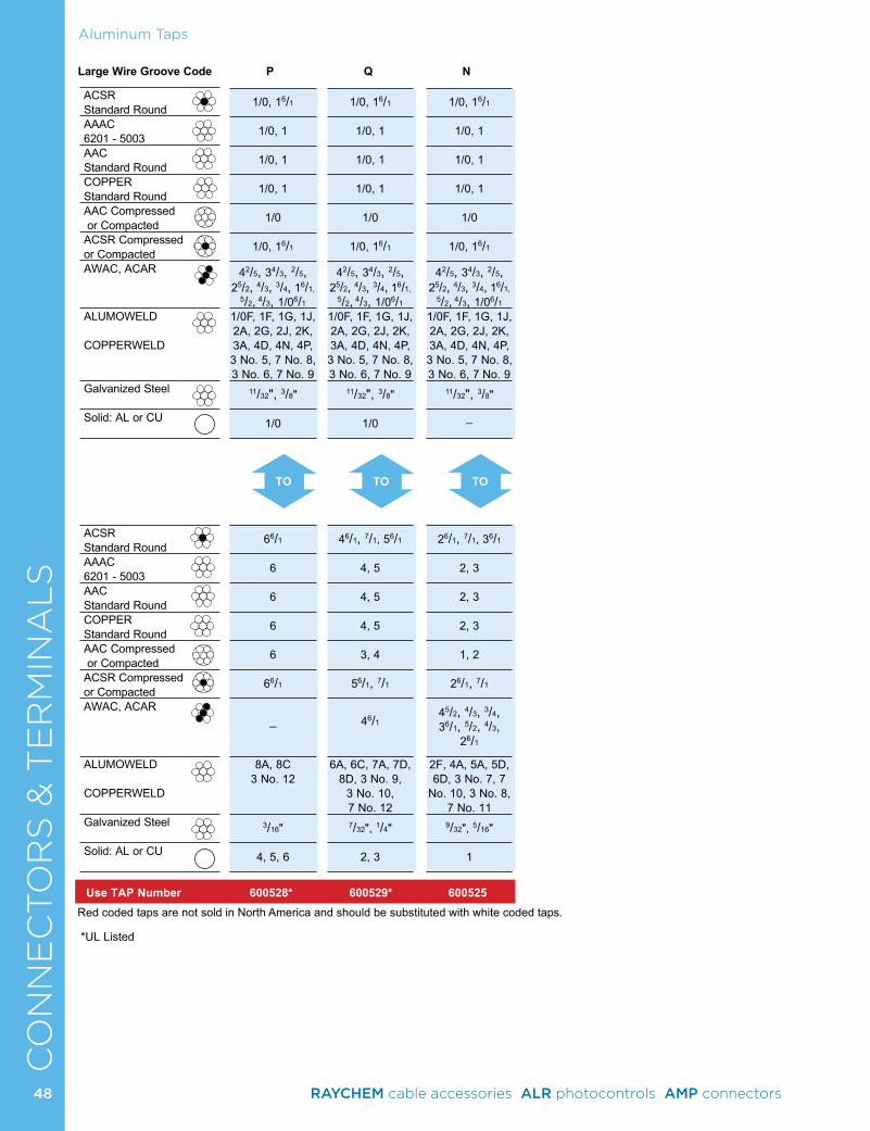
CO
NN
EC
TO
RS
& T
ER
MIN
AL
SAluminum Taps
*UL Listed
ACSR Standard RoundAAAC 6201 - 5003AAC Standard RoundCOPPER Standard RoundAAC Compressed or CompactedACSR Compressed or CompactedAWAC, ACAR
ALUMOWELD COPPERWELD
Galvanized Steel
Solid: AL or CU
ACSR Standard RoundAAAC 6201 - 5003AAC Standard RoundCOPPER Standard RoundAAC Compressed or CompactedACSR Compressed or CompactedAWAC, ACAR
ALUMOWELD COPPERWELD
Galvanized Steel
Solid: AL or CU
Use TAP Number 600528* 600529* 600525
Large Wire Groove Code P Q N
Red coded taps are not sold in North America and should be substituted with white coded taps.
TOTOTO
1/0, 16/1
1/0, 1
1/0, 1
1/0, 1
1/0
1/0, 16/1
42/5, 34/3, 2/5,
25/2, 4/3, 3/4, 16/1, 5/2, 4/3, 1/06/1
1/0F, 1F, 1G, 1J, 2A, 2G, 2J, 2K, 3A, 4D, 4N, 4P, 3 No. 5, 7 No. 8, 3 No. 6, 7 No. 9
11/32", 3/8"
1/0
66/1
6 6 6 6
66/1
_
8A, 8C 3 No. 12
3/16"
4, 5, 6
1/0, 16/1
1/0, 1
1/0, 1
1/0, 1
1/0
1/0, 16/1
42/5, 34/3, 2/5,
25/2, 4/3, 3/4, 16/1, 5/2, 4/3, 1/06/1
1/0F, 1F, 1G, 1J, 2A, 2G, 2J, 2K, 3A, 4D, 4N, 4P, 3 No. 5, 7 No. 8, 3 No. 6, 7 No. 9
11/32", 3/8"
1/0
46/1, 7/1, 56/1
4, 5
4, 5
4, 5
3, 4
56/1, 7/1
46/1
6A, 6C, 7A, 7D, 8D, 3 No. 9,
3 No. 10, 7 No. 12
7/32", 1/4"
2, 3
1/0, 16/1
1/0, 1
1/0, 1
1/0, 1
1/0
1/0, 16/1
42/5, 34/3, 2/5,
25/2, 4/3, 3/4, 16/1, 5/2, 4/3, 1/06/1
1/0F, 1F, 1G, 1J, 2A, 2G, 2J, 2K, 3A, 4D, 4N, 4P, 3 No. 5, 7 No. 8, 3 No. 6, 7 No. 9
11/32", 3/8"
_
26/1, 7/1, 36/1
2, 3
2, 3
2, 3
1, 2
26/1, 7/1
45/2, 4/3, 3/4, 36/1, 5/2, 4/3,
26/1
2F, 4A, 5A, 5D, 6D, 3 No. 7, 7
No. 10, 3 No. 8, 7 No. 11
9/32", 5/16"
1
48 RAYCHEM cable accessories ALR photocontrols AMP connectors
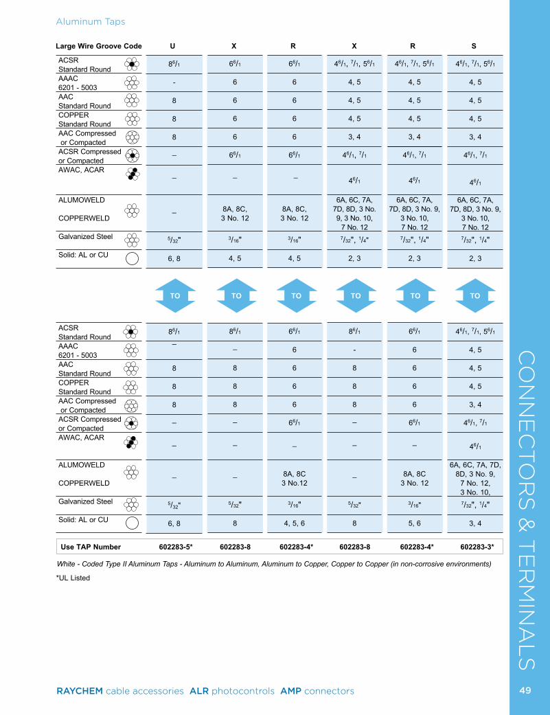
Aluminum TapsC
ON
NE
CTO
RS
& T
ER
MIN
AL
S
White - Coded Type II Aluminum Taps - Aluminum to Aluminum, Aluminum to Copper, Copper to Copper (in non-corrosive environments)
Large Wire Groove Code U X R X R S
TOTO TOTO TO TO
Use TAP Number 602283-5* 602283-8 602283-4* 602283-8 602283-4* 602283-3*
*UL Listed
ACSR Standard RoundAAAC 6201 - 5003AAC Standard RoundCOPPER Standard RoundAAC Compressed or CompactedACSR Compressed or CompactedAWAC, ACAR
ALUMOWELD
COPPERWELD
Galvanized Steel
Solid: AL or CU
ACSR Standard RoundAAAC 6201 - 5003AAC Standard RoundCOPPER Standard RoundAAC Compressed or CompactedACSR Compressed or CompactedAWAC, ACAR
ALUMOWELD
COPPERWELD
Galvanized Steel
Solid: AL or CU
46/1, 7/1, 56/1
4, 5
4, 5
4, 5
3, 4
46/1, 7/1
46/1
6A, 6C, 7A, 7D, 8D, 3 No. 9,
3 No. 10, 7 No. 12
7/32", 1/4"
2, 3
46/1, 7/1, 56/1
4, 5
4, 5
4, 5
3, 4
46/1, 7/1
46/1
6A, 6C, 7A, 7D, 8D, 3 No. 9,
7 No. 12, 3 No. 10,
7/32", 1/4"
3, 4
86/1
- 8 8 8
_
_
_
5/32"
6, 8
86/1
_
8 8 8
_
_
_
5/32"
6, 8
66/1
6 6 6 6
66/1
_
8A, 8C, 3 No. 12
3/16"
4, 5
86/1
_
8 8 8
_
_
_
5/32" 8
66/1
6 6 6 6
66/1
_
8A, 8C, 3 No. 12
3/16"
4, 5
66/1
6 6 6 6
66/1
_
8A, 8C 3 No.12
3/16"
4, 5, 6
46/1, 7/1, 56/1
4, 5
4, 5
4, 5
3, 4
46/1, 7/1
46/1
6A, 6C, 7A, 7D, 8D, 3 No. 9, 3 No. 10,
7 No. 12 7/32", 1/4"
2, 3
86/1
- 8 8 8
_
_
_
5/32"
8
46/1, 7/1, 56/1
4, 5
4, 5
4, 5
3, 4
46/1, 7/1
46/1
6A, 6C, 7A, 7D, 8D, 3 No. 9,
3 No. 10, 7 No. 12
7/32", 1/4"
2, 3
66/1
6 6 6 6
66/1
_
8A, 8C3 No. 12
3/16"
5, 6
49RAYCHEM cable accessories ALR photocontrols AMP connectors
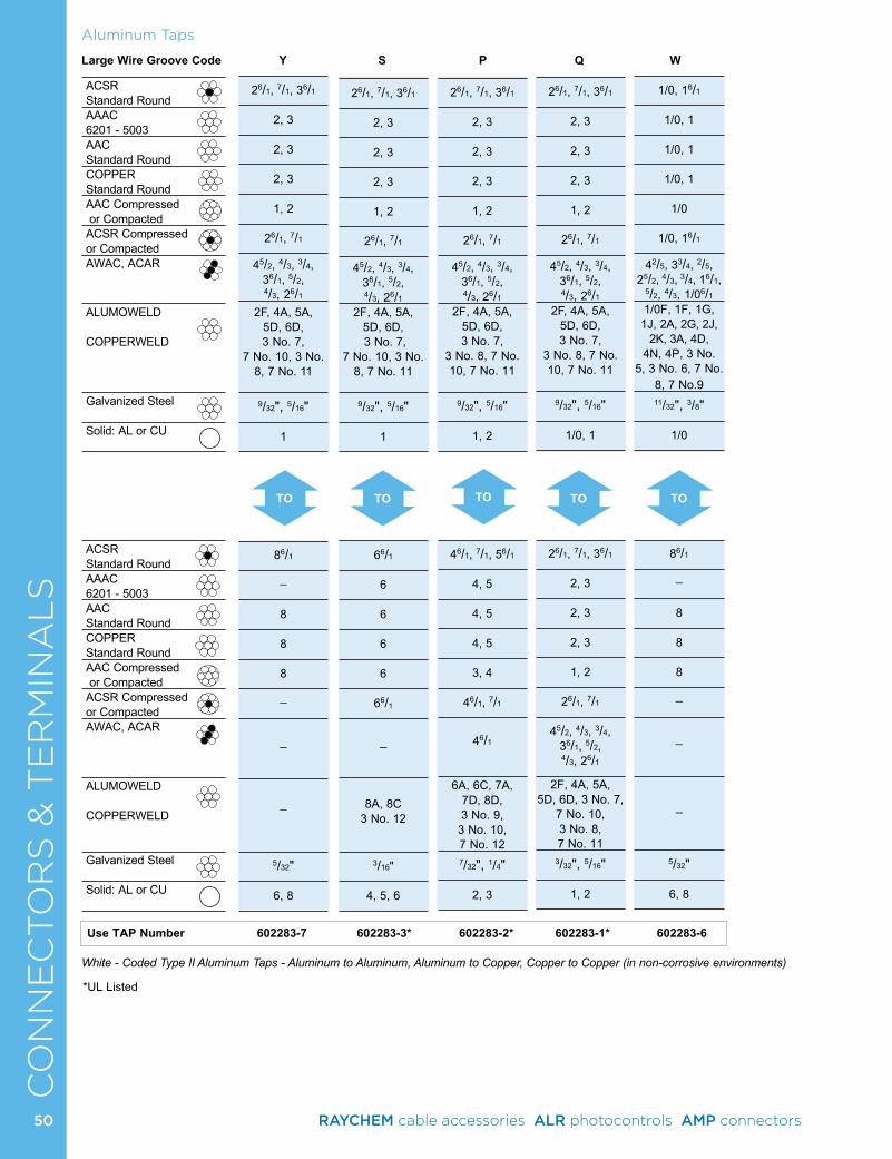
CO
NN
EC
TO
RS
& T
ER
MIN
AL
SAluminum Taps
*UL Listed
TO TOTO TO
White - Coded Type II Aluminum Taps - Aluminum to Aluminum, Aluminum to Copper, Copper to Copper (in non-corrosive environments)
Use TAP Number 602283-7 602283-3* 602283-2* 602283-1* 602283-6
Large Wire Groove Code Y S P Q W
ACSR Standard RoundAAAC 6201 - 5003AAC Standard RoundCOPPER Standard RoundAAC Compressed or CompactedACSR Compressed or CompactedAWAC, ACAR
ALUMOWELD COPPERWELD
Galvanized Steel
Solid: AL or CU
ACSR Standard RoundAAAC 6201 - 5003AAC Standard RoundCOPPER Standard RoundAAC Compressed or CompactedACSR Compressed or CompactedAWAC, ACAR
ALUMOWELD COPPERWELD
Galvanized Steel
Solid: AL or CU
TO
1/0, 16/1
1/0, 1
1/0, 1
1/0, 1
1/0
1/0, 16/1
42/5, 33/4, 2/5, 25/2, 4/3, 3/4, 16/1,
5/2, 4/3, 1/06/1
1/0F, 1F, 1G, 1J, 2A, 2G, 2J,
2K, 3A, 4D, 4N, 4P, 3 No.
5, 3 No. 6, 7 No. 8, 7 No.9 11/32", 3/8"
1/0
86/1
_
8 8 8
_
_
_
5/32"
6, 8
26/1, 7/1, 36/1
2, 3
2, 3
2, 3
1, 2
26/1, 7/1
45/2, 4/3, 3/4, 36/1, 5/2, 4/3, 26/1
2F, 4A, 5A, 5D, 6D, 3 No. 7,
7 No. 10, 3 No. 8, 7 No. 11
9/32", 5/16"
1
86/1
_
8 8 8
_
_
_
5/32"
6, 8
26/1, 7/1, 36/1
2, 3
2, 3
2, 3
1, 2
26/1, 7/1
45/2, 4/3, 3/4, 36/1, 5/2, 4/3, 26/1
2F, 4A, 5A, 5D, 6D, 3 No. 7,
7 No. 10, 3 No. 8, 7 No. 11
9/32", 5/16" 1
66/1
6 6 6 6
66/1
_
8A, 8C3 No. 12
3/16"
4, 5, 6
26/1, 7/1, 36/1
2, 3
2, 3
2, 3
1, 2
26/1, 7/1
45/2, 4/3, 3/4, 36/1, 5/2, 4/3, 26/1
2F, 4A, 5A, 5D, 6D, 3 No. 7,
3 No. 8, 7 No. 10, 7 No. 11
9/32", 5/16"
1, 2
46/1, 7/1, 56/1
4, 5
4, 5
4, 5
3, 4
46/1, 7/1
46/1
6A, 6C, 7A, 7D, 8D, 3 No. 9, 3 No. 10, 7 No. 12 7/32", 1/4"
2, 3
26/1, 7/1, 36/1
2, 3
2, 3
2, 3
1, 2
26/1, 7/1
45/2, 4/3, 3/4, 36/1, 5/2, 4/3, 26/1
2F, 4A, 5A, 5D, 6D, 3 No. 7,
3 No. 8, 7 No. 10, 7 No. 11
9/32", 5/16"
1/0, 1
26/1, 7/1, 36/1
2, 3
2, 3
2, 3
1, 2
26/1, 7/1
45/2, 4/3, 3/4, 36/1, 5/2, 4/3, 26/1
2F, 4A, 5A, 5D, 6D, 3 No. 7,
7 No. 10, 3 No. 8, 7 No. 11
3/32", 5/16"
1, 2
50 RAYCHEM cable accessories ALR photocontrols AMP connectors
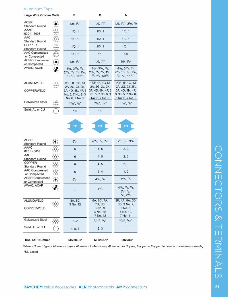
Aluminum TapsC
ON
NE
CTO
RS
& T
ER
MIN
AL
S
White - Coded Type II Aluminum Taps - Aluminum to Aluminum, Aluminum to Copper, Copper to Copper (in non-corrosive environments)
Large Wire Groove Code P Q N
TO TOTO
Use TAP Number 602283-2* 602283-1* 602283*
*UL Listed
ACSR Standard RoundAAAC 6201 - 5003AAC Standard RoundCOPPER Standard RoundAAC Compressed or CompactedACSR Compressed or CompactedAWAC, ACAR
ALUMOWELD
COPPERWELD
Galvanized Steel
Solid: AL or CU
ACSR Standard RoundAAAC 6201 - 5003AAC Standard RoundCOPPER Standard RoundAAC Compressed or CompactedACSR Compressed or CompactedAWAC, ACAR
ALUMOWELD
COPPERWELD
Galvanized Steel
Solid: AL or CU
1/0, 16/1
1/0, 1
1/0, 1
1/0, 1
1/0, 1
1/0, 16/1
42/5, 33/4, 2/5, 25/2, 4/3, 3/4, 16/1,
5/2, 4/3, 1/06/1
1/0F, 1F, 1G, 1J, 2A, 2G, 2J, 2K,
3A, 4D, 4N, 4P, 3 No. 5, 7 No. 8, 3 No. 6, 7 No. 9
11/32", 3/8"
1/0
66/1
6 6 6 6
66/1
_
8A, 8C3 No. 12
3/16"
4, 5, 6
1/0, 16/1
1/0, 1
1/0, 1
1/0, 1
1/0
1/0, 16/1
42/5, 33/4, 2/5, 25/2, 4/3, 3/4, 16/1,
5/2, 4/3, 1/06/1
1/0F, 1F, 1G,1J, 2A, 2G, 2J, 2K,
3A, 4D, 4N, 4P, 3 No. 5, 7 No. 8, 3 No. 6, 7 No. 9
11/32", 3/8"
1/0
46/1, 7/1, 56/1
4, 5
4, 5
4, 5
3, 4
46/1, 7/1
46/1
6A, 6C, 7A, 7D, 8D, 3 No. 9, 3 No. 10, 7 No. 12
7/32", 1/4"
2, 3
1/0, 16/1, 26/1, 7/1
1/0, 1
1/0, 1
1/0, 1
1/0
1/0, 16/1
42/5, 33/4, 2/5, 25/2, 4/3, 3/4, 16/1,
5/2, 4/3, 1/06/1
1/0F, 1F, 1G, 1J, 2A, 2G, 2J, 2K, 3A, 4D, 4N, 4P, 3 No. 5, 7 No. 8, 3 No. 6, 7 No. 9
11/32", 3/8"
_
26/1, 7/1, 36/1
2, 3
2, 3
2, 3
1, 2
26/1, 7/1
45/2, 4/3, 3/4, 36/1, 5/2,
4/3, 26/1
2F, 4A, 5A, 5D, 6D, 3 No. 7,
3 No. 8, 7 No. 10, 7 No. 11
9/32", 5/16" 1
51RAYCHEM cable accessories ALR photocontrols AMP connectors
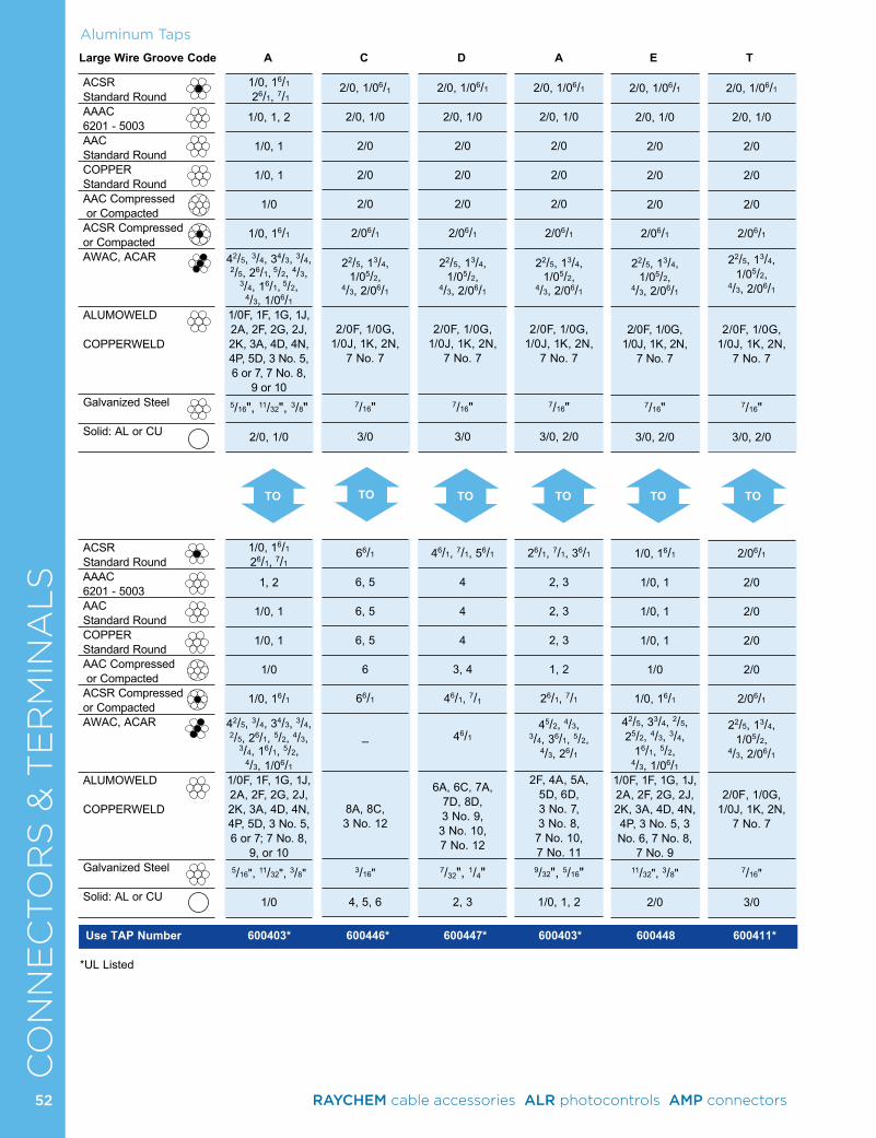
CO
NN
EC
TO
RS
& T
ER
MIN
AL
SAluminum Taps
2/0, 1/06/1
2/0, 1/0
2/0
2/0
2/0
2/06/1
22/5, 13/4, 1/05/2,
4/3, 2/06/1
2/0F, 1/0G,
1/0J, 1K, 2N, 7 No. 7
7/16"
3/0, 2/0
2/06/1
2/0
2/0
2/0
2/0
2/06/1
22/5, 13/4, 1/05/2,
4/3, 2/06/1
2/0F, 1/0G,
1/0J, 1K, 2N, 7 No. 7
7/16"
3/0
*UL Listed
Large Wire Groove Code A C D A E T
TO TOTO TO TO TO
Use TAP Number 600403* 600446* 600447* 600403* 600448 600411*
1/0, 16/1
26/1, 7/1
1/0, 1, 2
1/0, 1
1/0, 1
1/0
1/0, 16/1
42/5, 3/4, 34/3, 3/4, 2/5, 26/1, 5/2, 4/3,
3/4, 16/1, 5/2, 4/3, 1/06/1
1/0F, 1F, 1G, 1J, 2A, 2F, 2G, 2J, 2K, 3A, 4D, 4N, 4P, 5D, 3 No. 5, 6 or 7, 7 No. 8,
9 or 10 5/16", 11/32", 3/8"
2/0, 1/0
1/0, 16/1 26/1, 7/1
1, 2
1/0, 1
1/0, 1
1/0
1/0, 16/1
42/5, 3/4, 34/3, 3/4, 2/5, 26/1, 5/2, 4/3,
3/4, 16/1, 5/2, 4/3, 1/06/1
1/0F, 1F, 1G, 1J, 2A, 2F, 2G, 2J, 2K, 3A, 4D, 4N, 4P, 5D, 3 No. 5, 6 or 7; 7 No. 8,
9, or 10 5/16", 11/32", 3/8"
1/0
2/0, 1/06/1
2/0, 1/0
2/0
2/0
2/0
2/06/1
22/5, 13/4, 1/05/2,
4/3, 2/06/1
2/0F, 1/0G,
1/0J, 1K, 2N, 7 No. 7
7/16"
3/0
66/1
6, 5
6, 5
6, 5
6
66/1
_
8A, 8C, 3 No. 12
3/16"
4, 5, 6
2/0, 1/06/1
2/0, 1/0
2/0
2/0
2/0
2/06/1
22/5, 13/4, 1/05/2,
4/3, 2/06/1
2/0F, 1/0G,
1/0J, 1K, 2N, 7 No. 7
7/16"
3/0
46/1, 7/1, 56/1
4 4 4
3, 4
46/1, 7/1
46/1
6A, 6C, 7A, 7D, 8D, 3 No. 9, 3 No. 10, 7 No. 12
7/32", 1/4"
2, 3
2/0, 1/06/1
2/0, 1/0
2/0
2/0
2/0
2/06/1
22/5, 13/4, 1/05/2,
4/3, 2/06/1
2/0F, 1/0G,
1/0J, 1K, 2N, 7 No. 7
7/16"
3/0, 2/0
26/1, 7/1, 36/1
2, 3
2, 3
2, 3
1, 2
26/1, 7/1
45/2, 4/3, 3/4, 36/1, 5/2,
4/3, 26/1
2F, 4A, 5A, 5D, 6D, 3 No. 7, 3 No. 8, 7 No. 10, 7 No. 11
9/32", 5/16"
1/0, 1, 2
2/0, 1/06/1
2/0, 1/0
2/0
2/0
2/0
2/06/1
22/5, 13/4, 1/05/2,
4/3, 2/06/1
2/0F, 1/0G,
1/0J, 1K, 2N, 7 No. 7
7/16"
3/0, 2/0
1/0, 16/1
1/0, 1
1/0, 1
1/0, 1
1/0
1/0, 16/1
42/5, 33/4, 2/5, 25/2, 4/3, 3/4,
16/1, 5/2, 4/3, 1/06/1
1/0F, 1F, 1G, 1J, 2A, 2F, 2G, 2J, 2K, 3A, 4D, 4N, 4P, 3 No. 5, 3 No. 6, 7 No. 8,
7 No. 9 11/32", 3/8"
2/0
ACSR Standard RoundAAAC 6201 - 5003AAC Standard RoundCOPPER Standard RoundAAC Compressed or CompactedACSR Compressed or CompactedAWAC, ACAR
ALUMOWELD COPPERWELD
Galvanized Steel
Solid: AL or CU
ACSR Standard RoundAAAC 6201 - 5003AAC Standard RoundCOPPER Standard RoundAAC Compressed or CompactedACSR Compressed or CompactedAWAC, ACAR
ALUMOWELD COPPERWELD
Galvanized Steel
Solid: AL or CU
52 RAYCHEM cable accessories ALR photocontrols AMP connectors
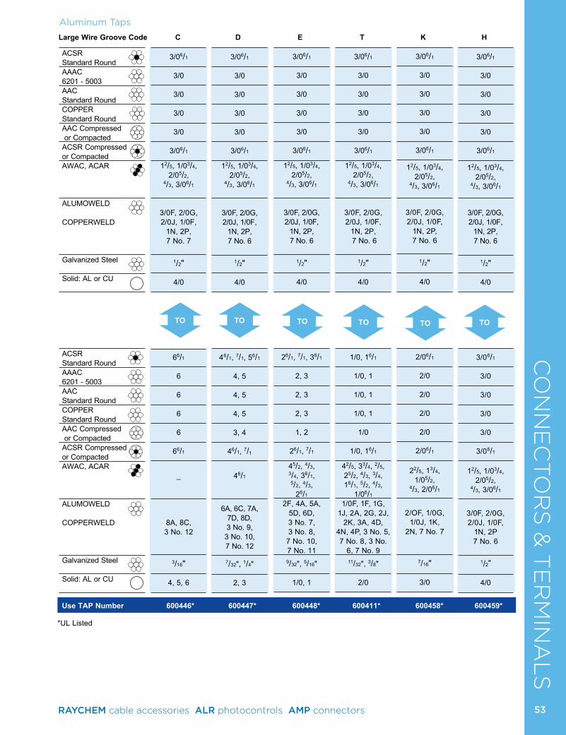
Aluminum TapsC
ON
NE
CTO
RS
& T
ER
MIN
AL
SLarge Wire Groove Code C D E T K H
TO TOTO TO TO
Use TAP Number 600446* 600447* 600448* 600411* 600458* 600459*
*UL Listed
ACSR Standard RoundAAAC 6201 - 5003AAC Standard RoundCOPPER Standard RoundAAC Compressed or CompactedACSR Compressed or CompactedAWAC, ACAR
ALUMOWELD COPPERWELD
Galvanized Steel
Solid: AL or CU
ACSR Standard RoundAAAC 6201 - 5003AAC Standard RoundCOPPER Standard RoundAAC Compressed or CompactedACSR Compressed or CompactedAWAC, ACAR
ALUMOWELD COPPERWELD
Galvanized Steel
Solid: AL or CU
TO
3/06/1
3/0
3/0
3/0
3/0
3/06/1
12/5, 1/03/4, 2/05/2,
4/3, 3/06/1
3/0F, 2/0G, 2/0J, 1/0F,
1N, 2P, 7 No. 7
1/2"
4/0
66/1
6 6 6 6
66/1
_
8A, 8C, 3 No. 12
3/16"
4, 5, 6
3/06/1
3/0
3/0
3/0
3/0
3/06/1
12/5, 1/03/4, 2/05/2,
4/3, 3/06/1
3/0F, 2/0G, 2/0J, 1/0F,
1N, 2P, 7 No. 6
1/2"
4/0
46/1, 7/1, 56/1
4, 5
4, 5
4, 5
3, 4
46/1, 7/1
46/1
6A, 6C, 7A, 7D, 8D, 3 No. 9, 3 No. 10, 7 No. 12
7/32", 1/4"
2, 3
3/06/1
3/0
3/0
3/0
3/0
3/06/1
12/5, 1/03/4, 2/05/2,
4/3, 3/06/1
3/0F, 2/0G, 2/0J, 1/0F,
1N, 2P, 7 No. 6
1/2"
4/0
26/1, 7/1, 36/1
2, 3
2, 3
2, 3
1, 2
26/1, 7/1
45/2, 4/3, 3/4, 36/1, 5/2, 4/3,
26/1
2F, 4A, 5A, 5D, 6D, 3 No. 7, 3 No. 8, 7 No. 10, 7 No. 11
9/32", 5/16"
1/0, 1
3/06/1
3/0
3/0
3/0
3/0
3/06/1
12/5, 1/03/4, 2/05/2,
4/3, 3/06/1
3/0F, 2/0G, 2/0J, 1/0F,
1N, 2P, 7 No. 6
1/2"
4/0
1/0, 16/1
1/0, 1
1/0, 1
1/0, 1
1/0
1/0, 16/1
42/5, 33/4, 2/5, 25/2, 4/3, 3/4, 16/1, 5/2, 4/3,
1/06/1
1/0F, 1F, 1G, 1J, 2A, 2G, 2J,
2K, 3A, 4D, 4N, 4P, 3 No. 5, 7 No. 8, 3 No.
6, 7 No. 9 11/32", 3/8"
2/0
3/06/1
3/0
3/0
3/0
3/0
3/06/1
12/5, 1/03/4, 2/05/2,
4/3, 3/06/1
3/0F, 2/0G, 2/0J, 1/0F,
1N, 2P, 7 No. 6
1/2"
4/0
2/06/1
2/0
2/0
2/0
2/0
2/06/1
22/5, 13/4, 1/05/2,
4/3, 2/06/1
2/OF, 1/0G,
1/0J, 1K, 2N, 7 No. 7
7/16"
3/0
3/06/1
3/0
3/0
3/0
3/0
3/06/1
12/5, 1/03/4, 2/05/2,
4/3, 3/06/1
3/0F, 2/0G, 2/0J, 1/0F,
1N, 2P, 7 No. 6
1/2"
4/0
3/06/1
3/0
3/0
3/0
3/0
3/06/1
12/5, 1/03/4, 2/05/2,
4/3, 3/06/1
3/0F, 2/0G, 2/0J, 1/0F,
1N, 2P 7 No. 6
1/2"
4/0
53RAYCHEM cable accessories ALR photocontrols AMP connectors
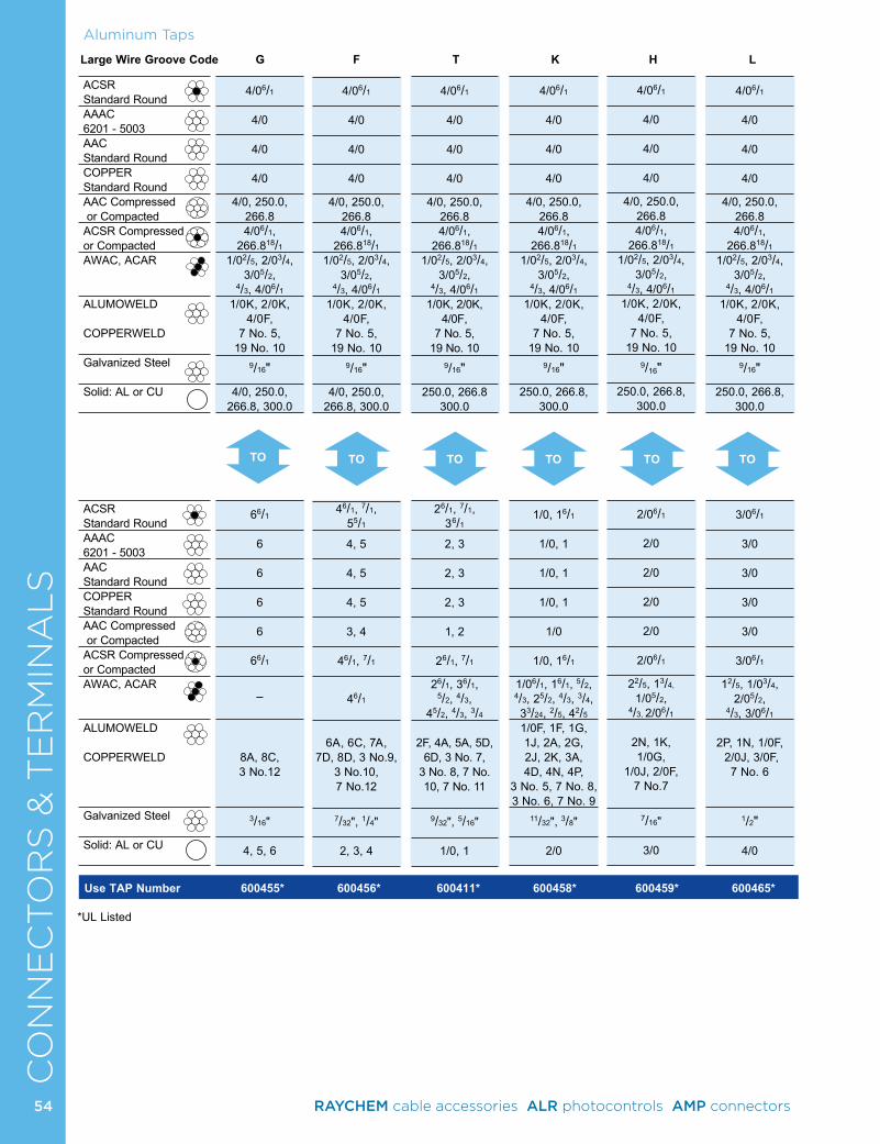
CO
NN
EC
TO
RS
& T
ER
MIN
AL
SAluminum Taps
*UL Listed
Use TAP Number 600455* 600456* 600411* 600458* 600459* 600465*
ACSR Standard RoundAAAC 6201 - 5003AAC Standard RoundCOPPER Standard RoundAAC Compressed or CompactedACSR Compressed or CompactedAWAC, ACAR
ALUMOWELD COPPERWELD
Galvanized Steel
Solid: AL or CU
ACSR Standard RoundAAAC 6201 - 5003AAC Standard RoundCOPPER Standard RoundAAC Compressed or CompactedACSR Compressed or CompactedAWAC, ACAR
ALUMOWELD COPPERWELD
Galvanized Steel
Solid: AL or CU
Large Wire Groove Code G F T K H L
TO TO TO TO TO TO
4/06/1
4/0
4/0
4/0
4/0, 250.0, 266.84/06/1,
266.818/1
1/02/5, 2/03/4, 3/05/2,
4/3, 4/06/1
1/0K, 2/0K, 4/0F,
7 No. 5, 19 No. 10
9/16"
4/0, 250.0, 266.8, 300.0
66/1
6 6 6 6
66/1
_
8A, 8C, 3 No.12
3/16"
4, 5, 6
4/06/1
4/0
4/0
4/0
4/0, 250.0, 266.84/06/1,
266.818/1
1/02/5, 2/03/4, 3/05/2,
4/3, 4/06/1
1/0K, 2/0K, 4/0F,
7 No. 5, 19 No. 10
9/16"
250.0, 266.8 300.0
26/1, 7/1, 36/1
2, 3
2, 3
2, 3
1, 2
26/1, 7/1
26/1, 36/1, 5/2, 4/3,
45/2, 4/3, 3/4
2F, 4A, 5A, 5D,
6D, 3 No. 7, 3 No. 8, 7 No. 10, 7 No. 11
9/32", 5/16"
1/0, 1
4/06/1
4/0
4/0
4/0
4/0, 250.0, 266.84/06/1,
266.818/1
1/02/5, 2/03/4, 3/05/2,
4/3, 4/06/1
1/0K, 2/0K, 4/0F,
7 No. 5, 19 No. 10
9/16"
250.0, 266.8, 300.0
1/0, 16/1
1/0, 1
1/0, 1
1/0, 1
1/0
1/0, 16/1
1/06/1, 16/1, 5/2, 4/3, 25/2, 4/3, 3/4, 33/24, 2/5, 42/5
1/0F, 1F, 1G, 1J, 2A, 2G, 2J, 2K, 3A, 4D, 4N, 4P,
3 No. 5, 7 No. 8, 3 No. 6, 7 No. 9
11/32", 3/8"
2/0
4/06/1
4/0
4/0
4/0
4/0, 250.0, 266.84/06/1,
266.818/1
1/02/5, 2/03/4, 3/05/2,
4/3, 4/06/1
1/0K, 2/0K, 4/0F,
7 No. 5, 19 No. 10
9/16"
250.0, 266.8, 300.0
2/06/1
2/0
2/0
2/0
2/0
2/06/1
22/5, 13/4,
1/05/2, 4/3, 2/06/1
2N, 1K, 1/0G,
1/0J, 2/0F, 7 No.7
7/16"
3/0
4/06/1
4/0
4/0
4/0
4/0, 250.0, 266.84/06/1,
266.818/1
1/02/5, 2/03/4, 3/05/2,
4/3, 4/06/1
1/0K, 2/0K, 4/0F,
7 No. 5, 19 No. 10
9/16"
250.0, 266.8, 300.0
3/06/1
3/0
3/0
3/0
3/0
3/06/1
12/5, 1/03/4, 2/05/2,
4/3, 3/06/1
2P, 1N, 1/0F, 2/0J, 3/0F,
7 No. 6
1/2"
4/0
4/06/1
4/0
4/0
4/0
4/0, 250.0,266.84/06/1,
266.818/1
1/02/5, 2/03/4, 3/05/2,
4/3, 4/06/1
1/0K, 2/0K, 4/0F,
7 No. 5, 19 No. 10
9/16"
4/0, 250.0, 266.8, 300.0
46/1, 7/1, 55/1
4, 5
4, 5
4, 5
3, 4
46/1, 7/1
46/1
6A, 6C, 7A,
7D, 8D, 3 No.9, 3 No.10, 7 No.12
7/32", 1/4"
2, 3, 4
54 RAYCHEM cable accessories ALR photocontrols AMP connectors
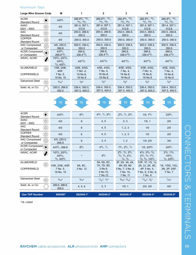
TO TOTO TO TO TO
Aluminum TapsC
ON
NE
CTO
RS
& T
ER
MIN
AL
SLarge Wire Groove Code M 1 2 3 4 5
Use TAP Number 600466* 602046-1* 602046-2* 602046-3* 602046-4* 602046-5*
*UL Listed
ACSR Standard RoundAAAC 6201 - 5003AAC Standard RoundCOPPER Standard RoundAAC Compressed or CompactedACSR Compressed or CompactedAWAC, ACAR
ALUMOWELD COPPERWELD
Galvanized Steel
Solid: AL or CU
ACSR Standard RoundAAAC 6201 - 5003AAC Standard RoundCOPPER Standard RoundAAC Compressed or CompactedACSR Compressed or CompactedAWAC, ACAR
ALUMOWELD COPPERWELD
Galvanized Steel
Solid: AL or CU
266.86/7, 18/1, 24/7, 26/7
281.4, 307.1, 312.8
250.0, 266.8, 300.0
250.0, 300.0
300.0, 336.4, 350.0266.8,
336.418/1
4/015/4
4/0E, 4/0G, 7 No. 4, 19 No.8, 19 No.9
5/8"
336.4, 350.0, 397.5, 400.0
26/1, 7/1, 36/1
2, 3
1, 2, 3
1, 2, 3
1, 2
16/1, 26/1, 7/1
26/1, 5/2, 36/1, 5/2, 4/3, 44/3,
3/4, 5/2
2F, 2G 3A, 4A, 4N, 5D, 6D
3 No. 7, 3 No. 8, 7 No. 10, 7 No. 11
9/32", 5/16"
1/0, 1
266.86/7, 18/1, 24/7, 26/7
281.4, 307.1, 312.8
250.0, 266.8, 300.0
250.0, 300.0
300.0, 336.4, 350.0266.8,
336.418/1
4/015/4
4/0E, 4/0G, 7 NO .4, 19 No.8, 19 No.9
5/8"
336.4, 350.0, 397.5, 400.0
1/0, 16/1
1/0, 1
1/0
1/0
1/0, 2/0
1/0, 2/06/1
42/5, 33/4, 2/5, 24/3, 3/4, 16/1, 5/2, 4/3, 1/06/1
1/0F, 1F, 1G, 1J, 2A, 2J, 2K, 4D,
4P, 3 No. 5, 7 No. 8, 3 No. 6,
7 No. 9 11/32", 3/8"
2/0, 3/0
266.86/7, 18/1, 24/7, 26/7
281.4, 307.1, 312.8
250.0, 266.8, 300.0
250.0, 300.0
300.0, 336.4, 350.0266.8,
336.418/1
4/015/4
4/0E, 4/0G, 7 No. 4, 19 No.8, 19 No.9
5/8"
336.4, 350.0, 397.5, 400.0
2/06/1
2/0
2/0
2/0
3/0
3/06/1
22/5, 13/4, 1/05/2,
4/3, 2/06/1
1K, 1/0G, 1/0J, 2N, 2P, 2/0F,
7 No. 7
7/16"
4/0
4/06/1
4/0
4/0
4/0
4/0, 250.0, 266.84/06/1,
266.818/1
1/02/5, 2/03/4, 3/05/2,
4/3, 4/06/1
1/0K, 2/0K, 4/0F,
7 No. 5, 19 No. 10
9/16"
250.0, 266.8 300.0
4/06/1
4/0
4/0
4/0
4/0, 250.0, 266.8
4/06/1, 266.8
1/02/5, 2/03/4, 3/05/2,
4/3, 4/06/1
1/0K, 2/0K, 4/0F,
7 No. 5, 19 No. 10
9/16"
250.0, 266.8,300.0
266.86/7, 18/1, 24/7, 26/7
281.4, 307.1, 312.8
250.0, 266.8, 300.0
250.0, 300.0
300.0, 336.4, 350.0266.8,
336.418/1
4/015/4
4/0E, 4/0G, 7 NO .4, 19 No.8, 19 No.9
5/8"
336.4, 350.0, 397.5, 400.0
66/1
6 6 6 6
66/1
_
8A, 8C, 3 No. 12
3/16"
4, 5, 6
266.86/7, 18/1, 24/7, 26/7
281.4, 307.1, 312.8
250.0, 266.8, 300.0
250.0, 300.0
300.0, 336.4, 350.0266.8,
336.418/1
4/015/4
4/0E, 4/0G, 7 No. 4, 19 No.8, 19 No.9
5/8"
336.4, 350.0, 397.5, 400.0
46/1, 7/1, 56/1
4, 5
4, 5
4, 5
3, 4
46/1, 7/1
46/1
5A, 6A, 6C, 7A, 7D, 8D,
3 No.9, 3 No.10, 7 No.12
7/32", 1/4"
2, 3
55RAYCHEM cable accessories ALR photocontrols AMP connectors
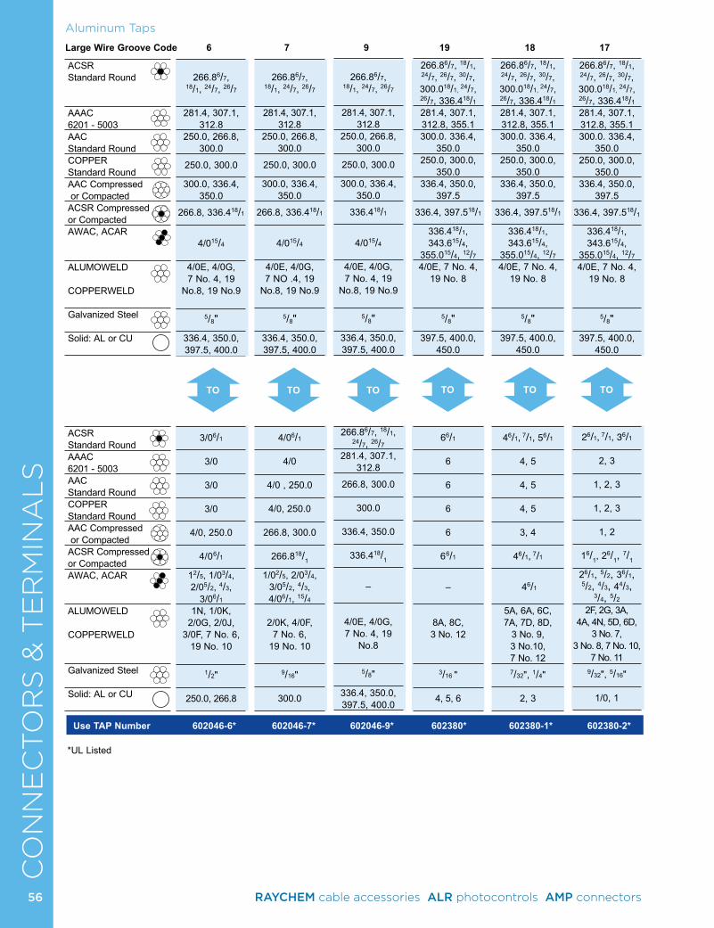
CO
NN
EC
TO
RS
& T
ER
MIN
AL
S266.86/7, 18/1, 24/7, 26/7, 30/7, 300.018/1, 24/7, 26/7, 336.418/1
281.4, 307.1, 312.8, 355.1300.0. 336.4,
350.0250.0, 300.0,
350.0336.4, 350.0,
397.5 336.4, 397.518/1
336.418/1, 343.615/4,
355.015/4, 12/7
4/0E, 7 No. 4, 19 No. 8
5/8"
397.5, 400.0, 450.0
66/1 6 6 6 6
66/1
–
8A, 8C, 3 No. 12
3/16 "
4, 5, 6
266.86/7, 18/1, 24/7, 26/7, 30/7, 300.018/1, 24/7, 26/7, 336.418/1
281.4, 307.1, 312.8, 355.1300.0. 336.4,
350.0250.0, 300.0,
350.0336.4, 350.0,
397.5 336.4, 397.518/1
336.418/1, 343.615/4,
355.015/4, 12/7
4/0E, 7 No. 4, 19 No. 8
5/8"
397.5, 400.0, 450.0
46/1, 7/1, 56/1
4, 5
4, 5
4, 5
3, 4
46/1,
7/1
46/1
5A, 6A, 6C, 7A, 7D, 8D,
3 No. 9, 3 No.10, 7 No. 12
7/32", 1/4"
2, 3
266.86/7, 18/1, 24/7, 26/7, 30/7, 300.018/1, 24/7, 26/7, 336.418/1
281.4, 307.1, 312.8, 355.1300.0. 336.4,
350.0250.0, 300.0,
350.0336.4, 350.0,
397.5 336.4, 397.518/1
336.418/1, 343.615/4,
355.015/4, 12/7
4/0E, 7 No. 4, 19 No. 8
5/8"
397.5, 400.0, 450.0
26/1, 7/1, 36/1
2, 3
1, 2, 3
1, 2, 3
1, 2
16/1, 2
6/1, 7/1
26/1, 5/2, 36/1, 5/2, 4/3, 44/3,
3/4, 5/2
2F, 2G, 3A, 4A, 4N, 5D, 6D,
3 No. 7, 3 No. 8, 7 No. 10,
7 No. 11 9/32", 5/16"
1/0, 1
266.86/7,
18/1, 24/7, 26/7
281.4, 307.1, 312.8
250.0, 266.8, 300.0
250.0, 300.0
300.0, 336.4, 350.0
266.8, 336.418/1
4/015/4
4/0E, 4/0G, 7 No. 4, 19
No.8, 19 No.9
5/8"
336.4, 350.0, 397.5, 400.0
3/06/1
3/0
3/0
3/0
4/0, 250.0
4/06/1
12/5, 1/03/4, 2/05/2, 4/3,
3/06/1
1N, 1/0K, 2/0G, 2/0J,
3/0F, 7 No. 6, 19 No. 10
1/2"
250.0, 266.8
266.86/7,
18/1, 24/7, 26/7
281.4, 307.1, 312.8
250.0, 266.8, 300.0
250.0, 300.0
300.0, 336.4, 350.0
266.8, 336.418/1
4/015/4
4/0E, 4/0G, 7 NO .4, 19
No.8, 19 No.9
5/8"
336.4, 350.0, 397.5, 400.0
4/06/1
4/0
4/0 , 250.0
4/0, 250.0
266.8, 300.0
266.818/1
1/02/5, 2/03/4, 3/05/2, 4/3, 4/06/1, 15/4
2/0K, 4/0F, 7 No. 6,
19 No. 10
9/16"
300.0
266.86/7,
18/1, 24/7, 26/7
281.4, 307.1, 312.8
250.0, 266.8, 300.0
250.0, 300.0
300.0, 336.4, 350.0
336.418/1
4/015/4
4/0E, 4/0G, 7 No. 4, 19
No.8, 19 No.9
5/8"
336.4, 350.0, 397.5, 400.0
266.86/7, 18/1, 24/7, 26/7
281.4, 307.1, 312.8
266.8, 300.0
300.0
336.4, 350.0
336.418/1
–
4/0E, 4/0G, 7 No. 4, 19
No.8
5/8"
336.4, 350.0, 397.5, 400.0
Aluminum Taps
Large Wire Groove Code 6 7 9 19 18 17
Use TAP Number 602046-6* 602046-7* 602046-9* 602380* 602380-1* 602380-2*
*UL Listed
ACSR Standard Round
AAAC 6201 - 5003AAC Standard RoundCOPPER Standard RoundAAC Compressed or CompactedACSR Compressed or CompactedAWAC, ACAR
ALUMOWELD COPPERWELD
Galvanized Steel
Solid: AL or CU
ACSR Standard RoundAAAC 6201 - 5003AAC Standard RoundCOPPER Standard RoundAAC Compressed or CompactedACSR Compressed or CompactedAWAC, ACAR
ALUMOWELD COPPERWELD
Galvanized Steel
Solid: AL or CU
TO TO TO TO TO TO
56 RAYCHEM cable accessories ALR photocontrols AMP connectors
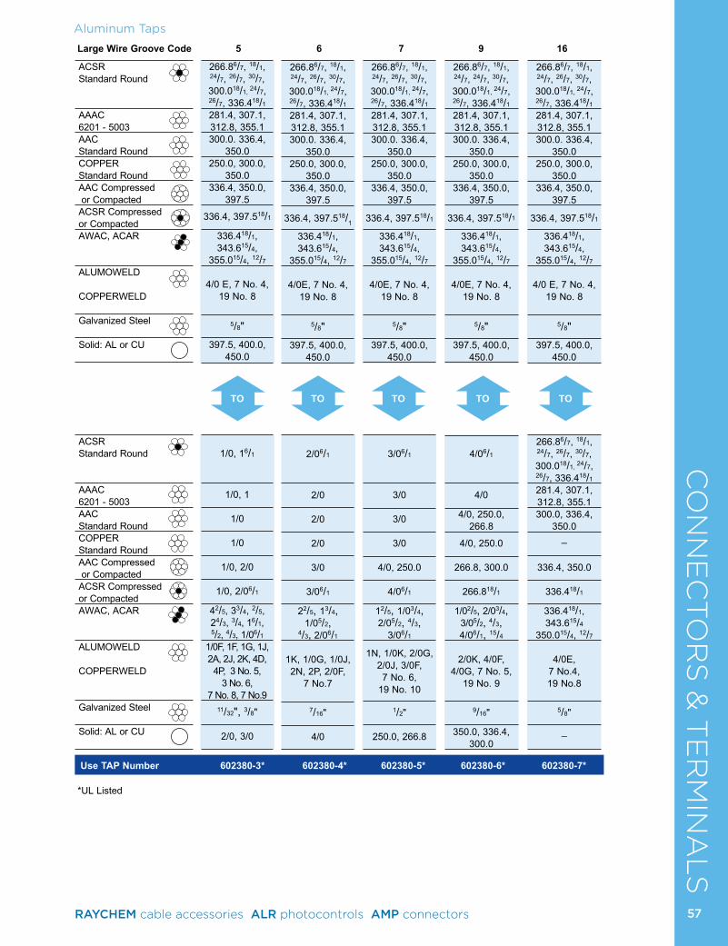
CO
NN
EC
TO
RS
& T
ER
MIN
AL
SAluminum Taps
Large Wire Groove Code 5 6 7 9 16
Use TAP Number 602380-3* 602380-4* 602380-5* 602380-6* 602380-7*
*UL Listed
ACSR Standard Round
AAAC 6201 - 5003AAC Standard RoundCOPPER Standard RoundAAC Compressed or CompactedACSR Compressed or CompactedAWAC, ACAR
ALUMOWELD COPPERWELD
Galvanized Steel
Solid: AL or CU
ACSR Standard Round
AAAC 6201 - 5003AAC Standard RoundCOPPER Standard RoundAAC Compressed or CompactedACSR Compressed or CompactedAWAC, ACAR
ALUMOWELD COPPERWELD
Galvanized Steel
Solid: AL or CU
TOTOTOTOTO
266.86/7, 18/1, 24/7, 26/7, 30/7, 300.018/1, 24/7, 26/7, 336.418/1
281.4, 307.1, 312.8, 355.1300.0. 336.4,
350.0250.0, 300.0,
350.0336.4, 350.0,
397.5 336.4, 397.518/1
336.418/1, 343.615/4,
355.015/4, 12/7
4/0 E, 7 No. 4,
19 No. 8
5/8"397.5, 400.0,
450.0
1/0, 16/1
1/0, 1
1/0
1/0
1/0, 2/0
1/0, 2/06/1
42/5, 33/4, 2/5, 24/3, 3/4, 16/1, 5/2, 4/3, 1/06/1
1/0F, 1F, 1G, 1J, 2A, 2J, 2K, 4D,
4P, 3 No. 5, 3 No. 6,
7 No. 8, 7 No.9 11/32", 3/8"
2/0, 3/0
266.86/7, 18/1, 24/7, 26/7, 30/7, 300.018/1, 24/7, 26/7, 336.418/1
281.4, 307.1, 312.8, 355.1300.0. 336.4,
350.0250.0, 300.0,
350.0336.4, 350.0,
397.5 336.4, 397.518/1
336.418/1, 343.615/4,
355.015/4, 12/7
4/0E, 7 No. 4,
19 No. 8
5/8"
397.5, 400.0, 450.0
2/06/1
2/0
2/0
2/0
3/0
3/06/1
22/5, 13/4, 1/05/2,
4/3, 2/06/1
1K, 1/0G, 1/0J, 2N, 2P, 2/0F,
7 No.7
7/16"
4/0
266.86/7, 18/1, 24/7, 26/7, 30/7, 300.018/1, 24/7, 26/7, 336.418/1
281.4, 307.1, 312.8, 355.1300.0. 336.4,
350.0250.0, 300.0,
350.0336.4, 350.0,
397.5 336.4, 397.518/1
336.418/1, 343.615/4,
355.015/4, 12/7
4/0E, 7 No. 4,
19 No. 8
5/8"
397.5, 400.0, 450.0
3/06/1
3/0
3/0
3/0
4/0, 250.0
4/06/1
12/5, 1/03/4, 2/05/2, 4/3,
3/06/1
1N, 1/0K, 2/0G, 2/0J, 3/0F, 7 No. 6,
19 No. 10
1/2"
250.0, 266.8
266.86/7, 18/1, 24/7, 24/7, 30/7, 300.018/1, 24/7, 26/7, 336.418/1
281.4, 307.1, 312.8, 355.1300.0. 336.4,
350.0250.0, 300.0,
350.0336.4, 350.0,
397.5 336.4, 397.518/1
336.418/1, 343.615/4,
355.015/4, 12/7
4/0E, 7 No. 4,
19 No. 8
5/8"
397.5, 400.0, 450.0
4/06/1
4/0
4/0, 250.0, 266.8
4/0, 250.0
266.8, 300.0
266.818/1
1/02/5, 2/03/4, 3/05/2, 4/3, 4/06/1, 15/4
2/0K, 4/0F,
4/0G, 7 No. 5, 19 No. 9
9/16"
350.0, 336.4, 300.0
266.86/7, 18/1, 24/7, 26/7, 30/7, 300.018/1, 24/7, 26/7, 336.418/1
281.4, 307.1, 312.8, 355.1300.0. 336.4,
350.0250.0, 300.0,
350.0336.4, 350.0,
397.5 336.4, 397.518/1
336.418/1, 343.615/4,
355.015/4, 12/7
4/0 E, 7 No. 4,
19 No. 8
5/8"
397.5, 400.0, 450.0
266.86/7, 18/1, 24/7, 26/7, 30/7, 300.018/1, 24/7, 26/7, 336.418/1
281.4, 307.1, 312.8, 355.1300.0, 336.4,
350.0_
336.4, 350.0
336.418/1
336.418/1, 343.615/4
350.015/4, 12/7
4/0E,
7 No.4, 19 No.8
5/8"
_
57RAYCHEM cable accessories ALR photocontrols AMP connectors
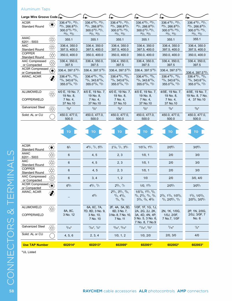
CO
NN
EC
TO
RS
& T
ER
MIN
AL
SAluminum Taps
Large Wire Groove Code
Use TAP Number 602014* 602013* 602000* 602001* 602002* 602003*
*UL Listed
ACSR Standard Round
AAAC 6201 - 5003AAC Standard RoundCOPPER Standard RoundAAC Compressed or CompactedACSR Compressed or CompactedAWAC, ACAR
ALUMOWELD COPPERWELD
Galvanized Steel
Solid: AL or CU
ACSR Standard RoundAAAC 6201 - 5003AAC Standard RoundCOPPER Standard RoundAAC Compressed or CompactedACSR Compressed or CompactedAWAC, ACAR
ALUMOWELD COPPERWELD
Galvanized Steel
Solid: AL or CU
TO TOTO TO TO TO
336.418/1, 24/7, 26/7, 266.830/7,
300.018/1 24/7, 26/7, 30/7
355.1
336.4, 350.0 397.5, 400.0
350.0, 400.0
336.4, 350.0, 397.5
336.4, 397.518/1
336.418/1, 16/3, 15/4, 343.615/4, 355.015/4, 12/7
4/0 E, 19 No. 7, 19 No. 8, 7 No. 4, 37 No.10
5/8"
450.0, 477.0, 500.0
6/1 6 6 6 6
66/1
_
8A, 8C, 3 No. 12
3/16"
4, 5, 6
336.418/1, 24/7, 26/7, 266.830/7,
300.018/1 24/7, 26/7, 30/7
355.1
336.4, 350.0 397.5, 400.0
350.0, 400.0
336.4, 350.0, 397.5
336.4, 397.518/1
336.418/1, 16/3, 15/4, 343.615/4, 355.015/4, 12/7
4/0 E, 19 No. 7, 19 No. 8, 7 No. 4, 37 No.10
5/8"
450.0, 477.0, 500.0
46/1, 7/1, 56/1
4, 5
4, 5
4, 5
3, 4
46/1, 7/1
46/1
6A, 6C, 7A, 7D, 8D, 3 No. 9,
3 No. 10, 7 No. 10
7/32", 1/4"
2, 3, 4
336.418/1, 24/7, 26/7, 266.830/7,
300.018/1 24/7, 26/7, 30/7
355.1
336.4, 350.0 397.5, 400.0
350.0, 400.0
336.4, 350.0, 397.5
336.4, 397.518/1
336.418/1, 16/3, 15/4, 343.615/4, 355.015/4, 12/7
4/0 E, 19 No. 7, 19 No. 8, 7 No. 4, 37 No.10
5/8"
450.0, 477.0, 500.0
21/6, 7/1, 36/1
2, 3
2, 3
2, 3
1, 2
26/1, 7/1
26/1, 36/1, 5/2, 4/3, 45/2,
4/3, 3/4
2F, 4A, 5A, 5D, 6D, 3 No. 7,
3 No. 8, 7 No. 10, 7 No. 11
9/32", 5/16"
1/0, 1, 2
336.418/1, 24/7, 26/7, 266.830/7,
300.018/1 24/7, 26/7, 30/7
355.1
336.4, 350.0 397.5, 400.0
350.0, 400.0
336.4, 350.0, 397.5
336.4, 397.518/1
336.418/1, 16/3, 15/4, 343.615/4, 355.015/4, 12/7
4/0 E, 19 No. 7, 19 No. 8, 7 No. 4, 37 No.10
5/8"
450.0, 477.0, 500.0
1/01/6, 16/1
1/0, 1
1/0, 1
1/0, 1
1/0
1/0, 16/1
1/01/6, 16/1, 5/2, 4/3, 25/2, 4/3, 3/4,
33/4, 2/5, 42/5
1/0F, 1F, 1G, 1J, 2A, 2G, 2J, 2K, 3A, 4D, 4N, 4P, 3 No. 5, 3 No. 6, 7 No. 8, 7 No.9
11/32", 3/0"
1/0, 2/0
336.418/1, 24/7, 26/7, 266.830/7,
300.018/1 24/7, 26/7, 30/7
355.1
336.4, 350.0 397.5, 400.0
350.0, 400.0
336.4, 350.0, 397.5
336.4, 397.518/1
336.418/1, 16/3, 15/4, 343.615/4, 355.015/4, 12/7
4/0E, 19 No. 7, 19 No. 8, 7 No. 4, 37 No.10
5/8"
450.0, 477.0, 500.0
2/06/1
2/0
2/0
2/0
2/0
2/06/1
22/5, 13/4, 1/05/2,
4/3, 2/06/1, 4/3
2N, 1K, 1/0G,
1/0J, 2/0F, 7 No.7, 1/0F
7/16"
2/0, 3/0
336.418/1, 24/7, 26/7, 266.830/7,
300.018/1 24/7, 26/7, 30/7
355.1
336.4, 350.0 397.5, 400.0
350.0, 400.0
336.4, 350.0, 397.5
336.4, 397.518/1
336.418/1, 16/3, 15/4, 343.615/4, 355.015/4, 12/7
4/0E, 19 No. 7, 19 No. 8, 7 No.
4, 37 No.10
5/8"
450.0, 477.0, 500.0
3/06/1
3/0
3/0
3/0
3/0, 4/0
3/06/1
12/5, 1/03/4,
2/05/2, 3/06/1
2P, 1N, 2/0G, 2/0J, 3/0F, 7
No. 6
1/2"
4/0
58 RAYCHEM cable accessories ALR photocontrols AMP connectors
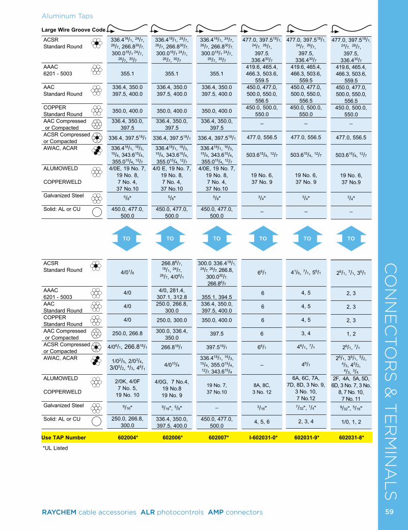
CO
NN
EC
TO
RS
& T
ER
MIN
AL
SAluminum Taps
Use TAP Number 602004* 602006* 602007* I-602031-0* 602031-9* 602031-8*
*UL Listed
Large Wire Groove Code
ACSR Standard Round
AAAC 6201 - 5003
AAC Standard Round
COPPER Standard RoundAAC Compressed or CompactedACSR Compressed or CompactedAWAC, ACAR
ALUMOWELD COPPERWELD
Galvanized Steel
Solid: AL or CU
ACSR Standard Round
AAAC 6201 - 5003AAC Standard RoundCOPPER Standard RoundAAC Compressed or CompactedACSR Compressed or CompactedAWAC, ACAR
ALUMOWELD COPPERWELD
Galvanized Steel
Solid: AL or CU
TO TOTO TO TO TO
336.418/1, 24/7, 26/7, 266.830/7,
300.018/1 24/7, 26/7, 30/7
355.1
336.4, 350.0 397.5, 400.0
350.0, 400.0
336.4, 350.0, 397.5
336.4, 397.518/1
336.418/1, 16/3, 15/4, 343.615/4, 355.015/4, 12/7
4/0E, 19 No. 7, 19 No. 8, 7 No. 4, 37 No.10
5/8"
450.0, 477.0, 500.0
4/01/6
4/0
4/0
4/0
250.0, 266.8
4/06/1, 266.818/1
1/02/5, 2/03/4, 3/05/2, 4/3, 46/1
2/0K, 4/0F 7 No. 5,
19 No. 10
9/16"
250.0, 266.8, 300.0
336.418/1, 24/7, 26/7, 266.830/7,
300.018/1 24/7, 26/7, 30/7
355.1
336.4, 350.0 397.5, 400.0
350.0, 400.0
336.4, 350.0, 397.5
336.4, 397.518/1
336.418/1, 16/3, 15/4, 343.615/4, 355.015/4, 12/7
4/0 E, 19 No. 7, 19 No. 8, 7 No. 4, 37 No.10
5/8"
450.0, 477.0, 500.0
266.86/7, 18/1, 24/7,
26/7, 4/06/1
4/0, 281.4, 307.1, 312.8250.0, 266.8,
300.0 250.0, 300.0
300.0, 336.4, 350.0
266.818/1
4/015/4
4/0G, 7 No.4, 19 No.8 19 No. 9
9/16", 5/8"
336.4, 350.0, 397.5, 400.0
336.418/1, 24/7, 26/7, 266.830/7,
300.018/1 24/7, 26/7, 30/7
355.1
336.4, 350.0 397.5, 400.0
350.0, 400.0
336.4, 350.0, 397.5
336.4, 397.518/1
336.418/1, 16/3, 15/4, 343.615/4, 355.015/4, 12/7
4/0E, 19 No. 7, 19 No. 8, 7 No. 4, 37 No.10
5/8"
450.0, 477.0, 500.0
300.0, 336.418/1, 24/7, 26/7, 266.8,
300.030/7,
266.86/7
355.1, 394.5336.4, 350.0, 397.5, 400.0
350.0, 400.0
397.5
397.518/1
336.418/1, 16/3, 15/4, 355.015/4, 12/7, 343.615/4
19 No. 7, 37 No.10
_
450.0, 477.0, 500.0
477.0, 397.518/1, 24/7, 26/7, 397.5,
336.430/7
419.6, 465.4, 466.3, 503.6,
559.5450.0, 477.0, 500.0, 550.0,
556.5450.0, 500.0,
550.0_
477.0, 556.5
503.615/4, 12/7
19 No. 6, 37 No. 9
3/4"
_
66/1
6
6
6 6
66/1
–
8A, 8C, 3 No. 12
3/16"
4, 5, 6
477.0, 397.518/1, 24/7, 26/7, 397.5,
336.430/7
419.6, 465.4, 466.3, 503.6,
559.5450.0, 477.0, 500.0, 550.0,
556.5450.0, 500.0,
550.0_
477.0, 556.5
503.615/4, 12/7
19 No. 6, 37 No. 9
3/4"
_
41/6, 7/1, 56/1
4, 5
4, 5
4, 5
3, 4
46/1, 7/1
46/1
6A, 6C, 7A, 7D, 8D, 3 No. 9,
3 No. 10, 7 No.12 7/32", 1/4"
2, 3, 4
477.0, 397.518/1, 24/7, 26/7, 397.5,
336.430/7
419.6, 465.4, 466.3, 503.6,
559.5450.0, 477.0, 500.0, 550.0,
556.5450.0, 500.0,
550.0_
477.0, 556.5
503.615/4, 12/7
19 No. 6, 37 No.9
3/4"
_
26/1, 7/1, 36/1
2, 3
2, 3
2, 3
1, 2
26/1, 7/1
26/1, 36/1, 5/2, 4/3, 45/2,
4/3, 3/4
2F, 4A, 5A, 5D, 6D, 3 No. 7, 3 No.
8, 7 No. 10, 7 No. 11
9/32", 5/16"
1/0, 1, 2
59RAYCHEM cable accessories ALR photocontrols AMP connectors
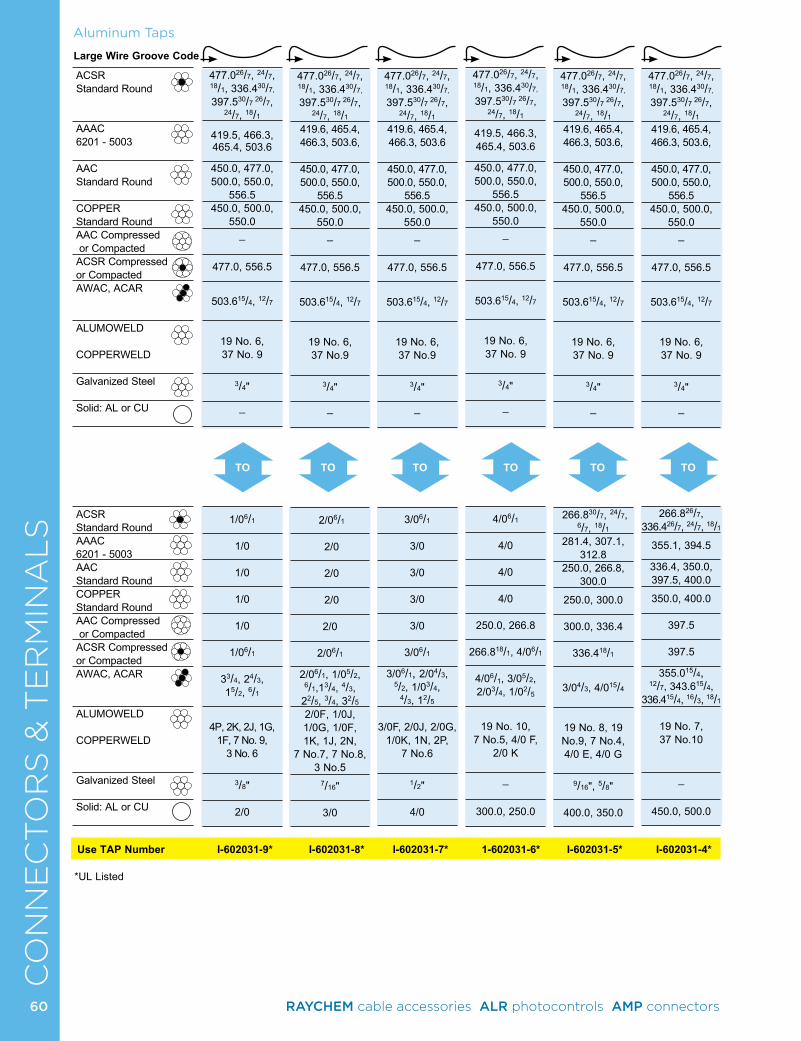
CO
NN
EC
TO
RS
& T
ER
MIN
AL
SAluminum Taps
Use TAP Number I-602031-9* I-602031-8* I-602031-7* 1-602031-6* I-602031-5* I-602031-4*
*UL Listed
Large Wire Groove Code
ACSR Standard Round
AAAC 6201 - 5003
AAC Standard Round
COPPER Standard RoundAAC Compressed or CompactedACSR Compressed or CompactedAWAC, ACAR
ALUMOWELD COPPERWELD
Galvanized Steel
Solid: AL or CU
ACSR Standard RoundAAAC 6201 - 5003AAC Standard RoundCOPPER Standard RoundAAC Compressed or CompactedACSR Compressed or CompactedAWAC, ACAR
ALUMOWELD COPPERWELD
Galvanized Steel
Solid: AL or CU
TO TOTO TO TO TO
477.026/7, 24/7, 18/1, 336.430/7,
397.530/7 26/7, 24/7, 18/1
419.5, 466.3, 465.4, 503.6
450.0, 477.0, 500.0, 550.0,
556.5450.0, 500.0,
550.0_
477.0, 556.5
503.615/4, 12/7
19 No. 6, 37 No. 9
3/4"
_
1/06/1
1/0
1/0
1/0
1/0
1/06/1
33/4, 24/3, 15/2, 6/1
4P, 2K, 2J, 1G,
1F, 7 No. 9, 3 No. 6
3/8"
2/0
477.026/7, 24/7, 18/1, 336.430/7,
397.530/7 26/7, 24/7, 18/1
419.6, 465.4, 466.3, 503.6,
450.0, 477.0, 500.0, 550.0,
556.5450.0, 500.0,
550.0_
477.0, 556.5
503.615/4, 12/7
19 No. 6, 37 No.9
3/4"
_
2/06/1
2/0
2/0
2/0
2/0
2/06/1
2/06/1, 1/05/2, 6/1,13/4, 4/3,
22/5, 3/4, 32/5
2/0F, 1/0J, 1/0G, 1/0F, 1K, 1J, 2N,
7 No.7, 7 No.8, 3 No.5
7/16"
3/0
477.026/7, 24/7, 18/1, 336.430/7,
397.530/7 26/7, 24/7, 18/1
419.6, 465.4, 466.3, 503.6
450.0, 477.0, 500.0, 550.0,
556.5450.0, 500.0,
550.0_
477.0, 556.5
503.615/4, 12/7
19 No. 6, 37 No.9
3/4"
_
3/06/1
3/0
3/0
3/0
3/0
3/06/1
3/06/1, 2/04/3, 5/2, 1/03/4,
4/3, 12/5
3/0F, 2/0J, 2/0G,
1/0K, 1N, 2P, 7 No.6
1/2"
4/0
477.026/7, 24/7, 18/1, 336.430/7,
397.530/7 26/7, 24/7, 18/1
419.5, 466.3, 465.4, 503.6
450.0, 477.0, 500.0, 550.0,
556.5450.0, 500.0,
550.0_
477.0, 556.5
503.615/4, 12/7
19 No. 6, 37 No. 9
3/4"
_
4/06/1
4/0
4/0
4/0
250.0, 266.8
266.818/1, 4/06/1
4/06/1, 3/05/2, 2/03/4, 1/02/5
19 No. 10,
7 No.5, 4/0 F, 2/0 K
_
300.0, 250.0
477.026/7, 24/7, 18/1, 336.430/7,
397.530/7 26/7, 24/7, 18/1
419.6, 465.4, 466.3, 503.6,
450.0, 477.0, 500.0, 550.0,
556.5450.0, 500.0,
550.0_
477.0, 556.5
503.615/4, 12/7
19 No. 6, 37 No. 9
3/4"
_
266.830/7, 24/7, 6/7, 18/1
281.4, 307.1, 312.8
250.0, 266.8, 300.0
250.0, 300.0
300.0, 336.4
336.418/1
3/04/3, 4/015/4
19 No. 8, 19 No.9, 7 No.4, 4/0 E, 4/0 G
9/16", 5/8"
400.0, 350.0
477.026/7, 24/7, 18/1, 336.430/7,
397.530/7 26/7, 24/7, 18/1
419.6, 465.4, 466.3, 503.6,
450.0, 477.0, 500.0, 550.0,
556.5450.0, 500.0,
550.0_
477.0, 556.5
503.615/4, 12/7
19 No. 6, 37 No. 9
3/4"
_
266.826/7, 336.426/7, 24/7, 18/1
355.1, 394.5
336.4, 350.0, 397.5, 400.0
350.0, 400.0
397.5
397.5
355.015/4, 12/7, 343.615/4,
336.415/4, 16/3, 18/1
19 No. 7, 37 No.10
_
450.0, 500.0
60 RAYCHEM cable accessories ALR photocontrols AMP connectors
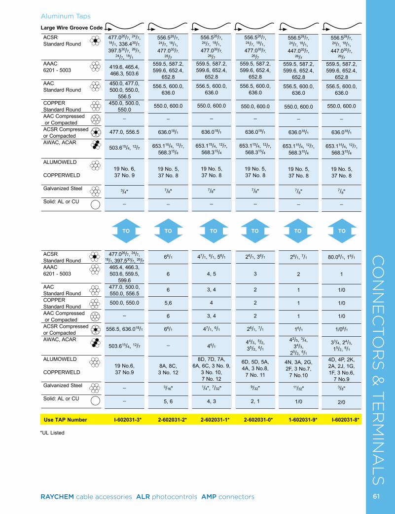
CO
NN
EC
TO
RS
& T
ER
MIN
AL
SAluminum Taps
Use TAP Number I-602031-3* 2-602031-2* 2-602031-1* 2-602031-0* 1-602031-9* I-602031-8*
*UL Listed
Large Wire Groove Code
ACSR Standard Round
AAAC 6201 - 5003
AAC Standard Round
COPPER Standard RoundAAC Compressed or CompactedACSR Compressed or CompactedAWAC, ACAR
ALUMOWELD COPPERWELD
Galvanized Steel
Solid: AL or CU
ACSR Standard RoundAAAC 6201 - 5003
AAC Standard RoundCOPPER Standard RoundAAC Compressed or CompactedACSR Compressed or CompactedAWAC, ACAR
ALUMOWELD COPPERWELD
Galvanized Steel
Solid: AL or CU
TO TOTO TO TO TO
477.026/7, 24/7, 18/1, 336.430/7,
397.530/7, 26/7, 24/7, 18/1
419.6, 465.4, 466.3, 503.6
450.0, 477.0, 500.0, 550.0,
556.5450.0, 500.0,
550.0_
477.0, 556.5
503.615/4, 12/7
19 No. 6, 37 No. 9
3/4"
_
477.026/7, 24/7, 18/1, 397.530/7, 26/7
465.4, 466.3, 503.6, 559.5,
599.6477.0, 500.0, 550.0, 556.5
500.0, 550.0
_
556.5, 636.018/1
503.615/4, 12/7
19 No.6, 37 No.9
_
_
556.526/7, 24/7, 18/1, 477.030/7,
26/7
559.5, 587.2, 599.6, 652.4,
652.8 556.5, 600.0,
636.0
550.0, 600.0
_
636.018/1
653.115/4, 12/7, 568.315/4
19 No. 5, 37 No. 8
7/8"
_
66/1
6
6
5,6 6
66/1
_
8A, 8C, 3 No. 12
3/16"
5, 6
556.526/7, 24/7, 18/1, 477.030/7,
26/7
559.5, 587.2, 599.6, 652.4,
652.8 556.5, 600.0,
636.0
550.0, 600.0
_
636.018/1
653.115/4, 12/7, 568.315/4
19 No. 5, 37 No. 8
7/8"
_
47/1, 6/1, 56/1
4, 5
3, 4
4
3, 4
47/1, 6/1
46/1
8D, 7D, 7A, 6A, 6C, 3 No. 9,
3 No. 10, 7 No. 12
1/4", 7/32"
4, 3
556.526/7, 24/7, 18/1, 477.030/7,
26/7
559.5, 587.2, 599.6, 652.4,
652.8 556.5, 600.0,
636.0
550.0, 600.0
_
636.018/1
653.115/4, 12/7, 568.315/4
19 No. 5, 37 No. 8
7/8"
_
26/1, 36/1 3
2 2 2
26/1, 7/1
44/3, 5/2, 35/2, 6/1
6D, 5D, 5A, 4A, 3 No.8,
7 No. 11
9/32"
2, 1
556.526/7, 24/7, 18/1, 447.030/7,
26/7559.5, 587.2, 599.6, 652.4,
652.8 556.5, 600.0,
636.0
550.0, 600.0
_
636.018/1
653.115/4, 12/7, 568.315/4
19 No. 5, 37 No. 8
7/8"
_
26/1, 7/1
2
1 1 1
16/1
42/5, 3/4, 34/3,
25/2, 6/1
4N, 3A, 2G, 2F, 3 No.7,
7 No.10
11/32"
1/0
556.526/7, 24/7, 18/1, 447.030/7,
26/7559.5, 587.2, 599.6, 652.4,
652.8 556.5, 600.0,
636.0
550.0, 600.0
_
636.018/1
653.115/4, 12/7, 568.315/4
19 No. 5, 37 No. 8
7/8"
_
80.08/1, 16/1 1
1/0
1/0
1/0
1/06/1
33/4, 24/3, 15/2, 6/1
4D, 4P, 2K, 2A, 2J, 1G, 1F, 3 No.6,
7 No.9
3/8"
2/0
61RAYCHEM cable accessories ALR photocontrols AMP connectors
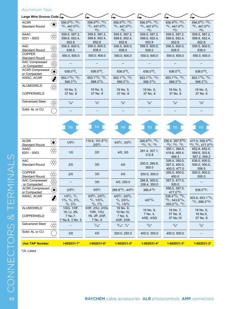
CO
NN
EC
TO
RS
& T
ER
MIN
AL
SAluminum Taps
TO TOTO TO TO
Use TAP Number I-602031-7* I-602031-6* 1-602031-5* 1-602031-4* 1-602031-3* 1-602031-2*
*UL Listed
Large Wire Groove Code
ACSR Standard Round
AAAC 6201 - 5003
AAC Standard RoundCOPPER Standard RoundAAC Compressed or CompactedACSR Compressed or CompactedAWAC, ACAR
ALUMOWELD COPPERWELD
Galvanized Steel
Solid: AL or CU
ACSR Standard RoundAAAC 6201 - 5003
AAC Standard Round
COPPER Standard RoundAAC Compressed or CompactedACSR Compressed or CompactedAWAC, ACAR
ALUMOWELD COPPERWELD
Galvanized Steel
Solid: AL or CU
TO
556.526/7, 24/7, 18/1, 447.030/7,
26/7559.5, 587.2, 599.6, 652.4,
652.8556.5, 600.0,
636.0 550.0, 600.0
_
636.018/1
653.115/4, 12/7, 568.315/4
19 No. 5, 37 No. 8
7/8"
_
1/06/1
1/0
2/0
2/0
_
2/06/1
1/05/2, 6/1, 13/4, 4/3, 22/5,
3/4, 32/5 1/0G, 1/0F, 1K,1J, 2N,
7 No.7, 7 No.8, 3 No. 5
_
3/0
556.526/7, 24/7, 18/1, 447.030/7,
26/7559.5, 587.2, 599.6, 652.4,
652.8556.5, 600.0,
636.0 550.0, 600.0
_
636.018/1
653.115/4, 12/7, 568.315/4
19 No. 5, 37 No. 8
7/8"
_
110.8, 101.812/7, 2/06/1
2/0
3/0
3/0
3/0
3/06/1
3/06/1, 2/05/2, 6/1, 1/03/4,
4/3, 12/5
3/0F, 2/0J, 2/0G, 1/0K, 1/0J,
1N, 2P, 2/0F, 7 No. 6
7/16"
4/0
556.526/7, 24/7, 18/1, 447.030/7,
26/7559.5, 587.2, 599.6, 652.4,
652.8556.5, 600.0,
636.0 550.0, 600.0
_
636.018/1
653.115/4, 12/7, 568.315/4
19 No. 5, 37 No. 8
7/8"
_
4/06/1, 3/06/1
4/0, 3/0
4/0
4/0
4/0, 250.0
266.818/1, 4/06/1
4/06/1, 3/05/2, 4/3, 2/03/4, 4/3, 1/02/5
19 No. 9, 19 No.10, 7 No. 5,
4/0F, 2/0K
9/16", 1/2"
300.0, 250.0
556.526/7, 24/7, 18/1, 447.030/7,
26/7559.5, 587.2, 599.6, 652.4,
652.8556.5, 600.0,
636.0 550.0, 600.0
_
636.018/1
653.115/4, 12/7, 568.315/4
19 No. 5, 37 No. 8
7/8"
_
266.830/7, 26/7, 24/7, 6/7, 18/1
281.4, 307.1, 312.8
250.0, 266.8, 300.0
250.0, 300.0
266.8, 300.0, 336.4, 350.0
366.418/1
4/015/4
19 No. 8, 7 No. 4,
4/0E, 4/0G
5/8"
400.0, 350.0
556.526/7, 24/7, 18/1, 447.030/7,
26/7559.5, 587.2, 599.6, 652.4,
652.8556.5, 600.0,
636.0 550.0, 600.0
_
636.018/1
653.115/4, 12/7, 568.315/4
19 No. 5, 37 No. 8
7/8"
_
336.4, 397.530/7, 26/7, 24/7, 18/1
355.1, 394.5, 419.6, 465.4,
466.3336.4, 350.0, 397.5, 400.0, 450.0, 477.0350.0, 400.0,
450.0397.5, 477.0,
500.0556.5, 397.5,
477.018/1336.415/4, 16/3, 18/1, 343.615/4, 355.015/4, 12/7
19 No. 7, 37 No. 9, 37 No.10
3/4"
450.0, 500.0
556.526/7, 24/7, 18/1, 447.030/7,
26/7559.5, 587.2, 599.6, 652.4,
652.8556.5, 600.0,
636.0 550.0, 600.0
_
636.018/1
653.115/4, 12/7, 568.315/4
19 No. 5, 37 No. 8
7/8"
_
477.0, 556.526/7, 24/7,18/1, 477.030/7
652.8, 652.4, 599.6, 503.6, 587.2, 559.2636.0, 600.0, 500.0, 550.0,
556.5500.0, 600.0,
550.0_
636.018/1
503.6, 653.115/4, 12/7, 568.315/4
19 No. 6, 19 No.5, 37 No. 8
7/8"
_
62 RAYCHEM cable accessories ALR photocontrols AMP connectors
CO
NN
EC
TO
RS
& T
ER
MIN
AL
SLarge Wire Groove Code
ACSR Standard Round
AAAC 6201 - 5003AAC Standard RoundCOPPER Standard RoundAAC Compressed or CompactedACSR Compressed or CompactedAWAC, ACAR
ALUMOWELD COPPERWELD
Galvanized Steel
Solid: AL or CU
ACSR Standard RoundAAAC 6201 - 5003AAC Standard RoundCOPPER Standard RoundAAC Compressed or CompactedACSR Compressed or CompactedAWAC, ACAR
ALUMOWELD COPPERWELD
Galvanized Steel
Solid: AL or CU
Use TAP Number I-60121-4* I-602121-3* I-602121-2* 1-602121-1* 1-602121-0* 602121-9*
Aluminum Taps
*UL Listed
TO TOTO TO TOTO
605.054/7, 24/7, 653.918/3, 556.5 30/7
_
_
_
_
_
_
_
_
_
47/1, 6/1, 56/1
4, 5
3, 4, 5
4, 5
3, 4
47/1, 6/1
46/1
5A, 6A, 6C, 7A, 7D, 8D, 7 No. 12, 3 No.10, 3 No.9
1/4", 7/32"
2, 3, 4
605.054/7, 24/7, 653.918/3, 556.5 30/7
_
_
_
_
_
_
_
_
_
27/1, 6/1, 36/1
2, 3 2
2, 3
1, 2
27/1, 6/1, 16/1
26/1, 35/2, 4/3, 6/1, 44/3, 3/4
2F, 3A, 4A, 5D, 6D, 3 No. 8,
3 No. 7, 7 No. 10, 7 No.11
5/16", 9/32"
1/0, 1
605.054/7, 24/7, 653.918/3, 556.5 30/7
_
_
_
_
_
_
_
_
_
1/06/1, 16/1, 80.08/1 1/0, 1
1/0
1/0
2/0, 1/0
1/06/1
1/06/1, 15/2, 4/3, 6/1, 24/3, 3/4, 33/4, 2/5, 42/5
1J, 1G, 1F, 2K, 2J, 2A,
4D, 4P, 1/0F, 3 No. 6, 3 No.5, 7 No.8, 7 No.9
3/8", 11/32"
2/0
605.054/7, 24/7, 653.918/3, 556.5 30/7
_
_
_
_
_
_
_
_
_
2/06/1
2/0
2/0
2/0
3/0
2/06/1
2/06/1, 1/05/2, 4/3, 13/4 , 2
2/5
2/0F, 1/0G,
1/0J, 1K, 2N, 7 No.7
7/16"
3/0
605.054/7, 24/7, 653.918/3, 556.5 30/7
_
_
_
_
_
_
_
_
_
3/06/1, 101.8, 110.8, 134.612/7
3/0
3/0
3/0
250.0, 4/0
4/06/1, 3/06/1
2/05/2, 4/3, 3/05/2, 6/1, 1/03/4, 12/53/0F, 2/0J, 2/0G, 1/0K,
1N, 2P, 7 No. 6, 19 No.10
1/2"
250.0, 266.8, 4/0
605.054/7, 24/7, 653.918/3, 556.5 30/7
_
_
_
_
_
_
_
_
_
4/06/1, 159.012/7
4/0
250.0, 4/0
250.0, 4/0
266.8, 300.0
266.818/1
4/015/4, 6/1, 3/04/3, 2/03/4,
1/02/5
4/0G, 4/0F, 2/0K, 19 No. 9,
7 No. 5
9/16"
300.0, 336.4
63RAYCHEM cable accessories ALR photocontrols AMP connectors
CO
NN
EC
TO
RS
& T
ER
MIN
AL
SAluminum Taps
Use TAP Number 602121-8* 602121-7* 602121-6* 602121-5* 602121-4* 602121-3*
*UL Listed
Large Wire Groove Code
ACSR Standard Round
AAAC 6201 - 5003AAC Standard RoundCOPPER Standard RoundAAC Compressed or CompactedACSR Compressed or CompactedAWAC, ACAR
ALUMOWELD COPPERWELD
Galvanized Steel
Solid: AL or CU
ACSR Standard Round
AAAC 6201 - 5003AAC Standard RoundCOPPER Standard RoundAAC Compressed or CompactedACSR Compressed or CompactedAWAC, ACAR
ALUMOWELD COPPERWELD
Galvanized Steel
Solid: AL or CU
TO TOTO TO TOTO
605.054/7, 24/7, 653.918/3, 556.5 30/7
_
_
_
_
_
_
_
_
_
336.426/7, 24/7, 18/1, 211.312/7,
203.216/19
355.1, 394.5
336.4, 350.0
350.0, 400.0
397.5, 477.0
397.518/1
355.015/4, 12/7, 343.615/4, 336.415/4,
16/3, 18/1
19 No. 7, 37 No. 10
_
450.0, 477.0, 500.0
605.054/7, 24/7, 653.918/3, 556.5 30/7
_
_
_
_
_
_
_
_
_
266.830/7, 26/7, 24/7, 18/1, 6/7,
300.030/7, 26/7, 24/7, 18/1,
176.9, 190.812/7281.4, 307.1,
312.8 266.8, 300.0
300.0
336.4, 350.0
336.4, 18/1
_
4/0E, 19 No. 8,
7 No. 4
5/8"
350.0, 397.5, 400.0
605.054/7, 24/7, 653.918/3, 556.5 30/7
_
_
_
_
_
_
_
_
_
397.518/1, 336.430/7
419.6
_
_
500.0
477.018/1
_
_
3/4"
_
605.054/7, 24/7, 653.918/3, 556.5 30/7
_
_
_
_
_
_
_
_
_
477.030/7, 26/7,
24/7, 18/1, 397.530/7
503.6, 559.5, 587.2, 599.6
500.0, 550.0, 556.5
500.0, 550.0
636.0
556.5, 636.018/1
568.315/4,
503.615/4, 12/7
19 No. 6, 37 No. 9
7/8"
_
605.054/7, 24/7, 653.918/3, 556.530/7
_
_
_
_
_
_
_
_
_
556.518/1, 500.030/7
_
600.0
600.0
_
_
_
37 No. 8
_
_
605.054/7, 24/7, 653.918/3, 556.5 30/7
_
_
_
_
_
_
_
_
_
636.054/7, 30/19, 30/7, 26/7, 24/7,
18/1, 605.0, 653.918/3, 556.530/7704.6,
740.8, 746.1700.0,
715.5, 750.0 700.0, 750.0
874.5
874.536/1
739.830/7, 33/4, 24/13, 18/19
_
1"
_
64 RAYCHEM cable accessories ALR photocontrols AMP connectors
CO
NN
EC
TO
RS
& T
ER
MIN
AL
SLarge Wire Groove Code
ACSR Standard Round
AAAC 6201 - 5003AAC Standard RoundCOPPER Standard RoundAAC Compressed or CompactedACSR Compressed or CompactedAWAC, ACAR
ALUMOWELD COPPERWELD
Galvanized Steel
Solid: AL or CU
ACSR Standard Round
AAAC 6201 - 5003AAC Standard RoundCOPPER Standard RoundAAC Compressed or CompactedACSR Compressed or CompactedAWAC, ACAR
ALUMOWELD COPPERWELD
Galvanized Steel
Solid: AL or CU
TO TOTO TO TOTO
Aluminum Taps
Use TAP Number 602121-2* 602121-1* 602121* I-602121-4* I-602121-3* 1-602121-2*
*UL Listed
605.054/7, 24/7,
653.918/3, 556.5 30/7
_
_
_
_
_
_
_
_
_
715.554/7, 45/7, 26/7, 24/7, 666.654/7, 26/7, 24/7, 795.036/1
833.6
795.0, 800.0
800.0
954.0
954.036/1
853.730/7, 24/13, 18/19, 862.718/19,
840.224/13, 819.230/7
37 No. 7
_
_
605.054/7, 24/7,
653.918/3, 556.5 30/7
_
_
_
_
_
_
_
_
_
795.054/7, 45/7, 30/19,
30/7, 26/7, 24/7, 874.554/7, 45/7, 715.530/19, 30/7
927.2, 932.6
874.5, 900.0
850.0, 900.0
_
_
927.230/7, 24/13, 18/19
37 No. 6
_
_
636.030/19, 30/7, 26/7, 24/7, 666.654/7, 26/7, 24/7, 715.545/7, 605.030/19, 30/7
740.8, 746.1
715.5, 750.0
750.0
874.5
874.536/1
739.830/7, 33/4, 24/13, 18/19
37 No. 7
1"
_
27/1, 6/1, 16/1,
80.08/1
1, 2
1/0, 1
1/0, 1
2/0, 1/0
1/0, 16/1
1/06/1, 15/2, 6/1, 24/3, 5/2, 3/4, 34/3, 2/5,
3/4, 42/5
1/0F, 1F, 1G, 2A, 2G, 2J, 2K, 3A, 4D, 4N, 4P,
3 No. 6, 7 No. 8, 7 No. 9
3/8", 11/32", 5/16"
2/0, 1/0
605.054/7, 24/7,
653.918/3,
556.5 30/7
_
_
_
_
_
_
_
_
_
954.036/1, 900.045/7
_
954.0, 1000.0
1000.0
_
_
1012.224/13,
983.130/7
_
_
_
636.030/19, 30/7, 26/7, 24/7, 666.654/7, 26/7, 24/7, 715.545/7, 605.030/19, 30/7,
740.8, 746.1
715.5, 750.0
750.0
874.5
874.536/1
739.830/7, 33/4, 24/13, 18/19
37 No. 7
1"
_
66/1, 56/1
5, 6
4, 5, 6
4, 5, 6
3, 4
47/1, 6/1
46/1
6A, 6C, 7A, 7D, 8A, 8D, 3 No. 10, 7 No. 12
1/4", 7/32", 3/16"
3, 4, 5
636.030/19, 30/7, 26/7, 24/7,
666.654/7, 26/7, 24/7, 715.545/7, 605.030/19, 30/7
740.8, 746.1
715.5, 750.0
750.0
874.5
874.536/1
739.830/7, 33/4, 24/13, 18/19
37 No. 7
1"
_
47/1, 6/1, 36/1,
3, 4
2, 3
2, 3
1, 2
27/1, 6/1
26/1, 35/2, 6/1, 44/3, 5/2, 3/4
2F, 4A, 5A, 5D, 6A, 3 No. 7,
3 No. 8, 3 No. 9, 7 No. 10, 7 No. 11
9/32"
1, 2
65RAYCHEM cable accessories ALR photocontrols AMP connectors
CO
NN
EC
TO
RS
& T
ER
MIN
AL
S
Use TAP Number 1-602121-1* 1-602121-0* 602121-9* 602121-8* 602121-7* 602121-6*
Aluminum Taps
*UL Listed
Large Wire Groove Code
ACSR Standard Round
AAAC 6201 - 5003AAC Standard RoundCOPPER Standard RoundAAC Compressed or CompactedACSR Compressed or CompactedAWAC, ACAR
ALUMOWELD COPPERWELD
Galvanized Steel
Solid: AL or CU
ACSR Standard Round
AAAC 6201 - 5003AAC Standard RoundCOPPER Standard RoundAAC Compressed or CompactedACSR Compressed or CompactedAWAC, ACAR
ALUMOWELD COPPERWELD
Galvanized Steel
Solid: AL or CU
TO TOTO TO TOTO
636.030/19, 30/7, 26/7, 24/7, 666.654/7, 26/7, 24/7, 715.545/7, 605.030/19, 30/7
740.8, 746.1
715.5, 750.0
750.0
874.5
874.536/1
739.830/7, 33/4, 24/13, 18/19
37 No. 7
1"
_
1/06/1
1/0
2/0
2/0
3/0
2/06/1
2/06/1, 1/05/2, 13/4, 4/3,
22/5
2/0 F, 1/0 G, 1/0 J, 1J, 1K, 2N, 7 No. 7,
3 No. 5 7/16"
3/0
636.030/19, 30/7, 26/7, 24/7, 666.654/7, 26/7, 24/7, 715.545/7, 605.030/19, 30/7
740.8, 746.1
715.5, 750.0
750.0
874.5
874.536/1
739.830/7, 33/4, 24/13, 18/19
37 No. 7
1"
_
3/06/1, 2/06/1,
101.8, 110.812/7
2/0, 3/0
3/0
3/0
4/0
3/06/1
3/06/1, 2/05/2, 1/04/3, 3/4,
12/5
3/0F, 2/0J, 2/0G, 1/0K,
1N, 2P, 7 No. 6
_
4/0
636.030/19, 30/7, 26/7, 24/7, 666.654/7, 26/7, 24/7, 715.545/7, 605.030/19, 30/7
740.8, 746.1
715.5, 750.0
750.0
874.5
874.536/1
739.830/7, 33/4, 24/13, 18/19
37 No. 7
1"
_
4/06/1,
134.612/7
4/0
4/0
4/0
250.0, 266.8
266.818/1, 4/06/1
4/06/1, 3/04/3, 5/2, 2/04/3, 3/4, 1/02/5
4/0F, 2/0K, 19 No. 10,
7 No. 5
9/16", 1/2"
250.0, 266.8 300.0
636.030/19, 30/7, 26/7, 24/7, 666.654/7, 26/7, 24/7, 715.545/7, 605.030/19, 30/7
740.8, 746.1
715.5, 750.0
750.0
874.5
874.536/1
739.830/7, 33/4, 24/13, 18/19
37 No. 7
1"
_
266.826/7, 24/7, 18/1, 6/7,
176.9, 159.0, 190.812/7
281.4, 307.1, 312.8
250.0, 266.8, 300.0
250.0, 300.0
300.0, 336.4, 350.0
336.418/1
4/015/4
4/0 E, 4/0 G, 19 N0. 9, 7 No. 4
5/8"
336.4, 350.0, 397.5, 400.0
636.030/19, 30/7, 26/7, 24/7, 666.654/7, 26/7, 24/7, 715.545/7, 605.030/19, 30/7
740.8, 746.1
715.5, 750.0
750.0
874.5
874.536/1
739.830/7, 33/4, 24/13, 18/19
37 No. 7
1"
_
336.426/7, 24/7, 18/1, 266.830/7,
211.312/7, 300.030/7, 26/7,
24/7, 18/1
355.1, 394.5
336.4, 350.0
350.0
397.5, 477.0
397.518/1
355.015/4, 12/7, 343.615/4,
336.416/3, 18/1
19 No. 8
_
450.0, 477.0,
500.0
636.030/19, 30/7, 26/7, 24/7, 666.654/7, 26/7, 24/7, 715.545/7, 605.030/19, 30/7
740.8, 746.1
715.5, 750.0
750.0
874.5
874.536/1
739.830/7, 33/4, 24/13, 18/19
37 No. 7
1"
_
397.526/7, 24/7, 18/1, 336.430/7,
203.216/19
419.6, 465.4, 466.3
397.5, 400.0, 450.0
400.0, 450.0
500.0, 556.5
477.018/1
336.415/4
37 No. 10, 19 No. 7
3/4"
_
66 RAYCHEM cable accessories ALR photocontrols AMP connectors
CO
NN
EC
TO
RS
& T
ER
MIN
AL
S
Use TAP Number 602121-5* 602121-4* 602121-3* 602121-2* 602121-1* 602121*
Aluminum Taps
*UL Listed
Large Wire Groove Code
ACSR Standard Round
AAAC 6201 - 5003AAC Standard RoundCOPPER Standard RoundAAC Compressed or CompactedACSR Compressed or CompactedAWAC, ACAR
ALUMOWELD COPPERWELD
Galvanized Steel
Solid: AL or CU
ACSR Standard Round
AAAC 6201 - 5003AAC Standard RoundCOPPER Standard RoundAAC Compressed or CompactedACSR Compressed or CompactedAWAC, ACAR
ALUMOWELD COPPERWELD
Galvanized Steel
Solid: AL or CU
TO TOTO TO TOTO
636.030/19, 30/7, 26/7, 24/7, 666.654/7, 26/7, 24/7, 715.545/7, 605.030/19, 30/7
740.8, 746.1
715.5, 750.0
750.0
874.5
874.536/1
739.830/7, 33/4, 24/13, 18/19
37 No. 7
1"
_
477.026/7, 24/7, 18/1, 397.530/7
503.6
477.0, 500.0
500.0
636.0
556.518/1
503.615/4, 12/7
19 No. 6, 37 No. 9
_
_
636.030/19, 30/7, 26/7, 24/7, 666.654/7, 26/7, 24/7, 715.545/7, 605.030/19, 30/7
740.8, 746.1
715.5, 750.0
750.0
874.5
874.536/1
739.830/7, 33/4, 24/13, 18/19
37 No. 7
1"
_
556.526/7, 24/7,
18/1, 477.0, 500.030/7
559.5, 587.2, 599.6
550.0, 556.5, 600.0
550.0, 600.0
_
636.018/1
653.115/4, 12/7,
568.315/4
37 No. 8 19 No. 5
7/8"
_
636.030/19, 30/7, 26/7, 24/7, 666.654/7, 26/7, 24/7, 715.545/7, 605.030/19, 30/7,
740.8, 746.1
715.5, 750.0
750.0
874.5
874.536/1
739.830/7, 30/7, 33/4, 24/13, 18/19
37 No. 7
1"
_
636.054/7, 26/7, 24/7, 36/1, 18/1,
605.054/7, 30/7, 26/7, 24/7,
556.530/7 652.4, 652.8, 704.6, 740.8 636.0, 650.0, 715.5, 700.0 650.0, 700.0
795.0, 874.5
874.5, 795.036/1
739.830/7, 33/4,
24/3, 18/9
_
_
_
636.030/19, 30/7, 26/7, 24/7, 666.654/7, 26/7, 24/7, 715.545/7, 605.030/19, 30/7
740.8, 746.1
715.5, 750.0
750.0
874.5
874.536/1
739.830/7, 33/4, 24/13, 18/19
37 No. 7
1"
_
666.654/7, 26/7, 24/7, 636.030/19, 30/7, 715.545/7
_
750.0
750.0
_
_
_
37 No. 7
1"
_
636.030/19, 30/7, 26/7, 24/7, 666.654/7, 26/7, 24/7, 715.545/7, 605.030/19, 30/7
740.8, 746.1
715.5, 750.0
750.0
874.5
874.536/1
739.830/7, 33/4, 24/13, 18/19
37 No. 7
1"
_
795.054/7, 45/7, 26/7, 24/7, 36/1,
715.554/7, 26/7, 24/7, 30/19, 30/7
833.6
795.0, 800.0 874.5, 900.0
800.0 850.0, 900.0
954.0
954.036/1
853.730/7, 24/13, 18/19, 862.718/19,
840.224/13, 819.230/7
_
_ _
636.030/19, 30/7, 26/7, 24/7, 666.654/7, 26/7, 24/7, 715.545/7, 605.030/19, 30/7,
740.8, 746.1
715.5, 750.0
750.0
874.5
874.536/1
739.830/7, 30/7, 33/4, 24/13, 18/19
37 No. 7
1"
_
795.030/7, 30/19, 954.036/1,
900.045/7, 874.554/7, 45/7
927.2, 932.6
954.0, 1000.0
1000.0
_
_
1012.224/13, 983.130/7, 927.230/7 24/13, 18/19
37 No. 6
_
_
67RAYCHEM cable accessories ALR photocontrols AMP connectors
CO
NN
EC
TO
RS
& T
ER
MIN
AL
SAluminum Taps
Use TAP Number 1-602121-4* 1-602121-3* 1-602121-2* 1-602121-1* 1-602121-0* 602121-9*
*UL Listed
Large Wire Groove Code
ACSR Standard Round
AAAC 6201 - 5003AAC Standard RoundCOPPER Standard RoundAAC Compressed or CompactedACSR Compressed or CompactedAWAC, ACAR
ALUMOWELD COPPERWELD
Galvanized Steel
Solid: AL or CU
ACSR Standard RoundAAAC 6201 - 5003AAC Standard RoundCOPPER Standard RoundAAC Compressed or CompactedACSR Compressed or CompactedAWAC, ACAR
ALUMOWELD COPPERWELD
Galvanized Steel
Solid: AL or CU
TO TOTO TO TOTO
795.054/7, 45/7, 26/7, 24/7, 36/1,
715.554/7, 30/19, 30/7, 26/7, 24/7
833.6, 927.2, 932.6
795.0, 800.0 874.5, 900.0
800.0 850.0, 900.0
954.0
954.036/1
853.7, 927.230/7, 24/13, 18/19, 862.7 18/19, 840.224/13,
819.230/7
_
_
_
66/1
6 6 6 6
66/1_
8A, 8C
3 No. 12
3/16"
5, 6
795.054/7, 45/7, 26/7, 24/7, 36/1,
715.554/7, 30/19, 30/7, 26/7, 24/7
833.6, 927.2, 932.6
795.0, 800.0 874.5, 900.0
800.0 850.0, 900.0
954.0
954.036/1
853.7, 927.230/7, 24/13, 18/19, 862.7 18/19, 840.224/13,
819.230/7
_
_
_
47/1, 6/1, 56/1
4, 5
3, 4, 5
3, 4, 5
3, 4
47/1,
6/1
45/2, 6/1
5A, 6A, 6C, 7A, 7D, 8D, 7 No. 12, 3 No. 9, 3 No. 10
1/4", 7/32"
2, 3, 4
795.054/7, 45/7, 26/7, 24/7, 36/1,
715.554/7, 30/19, 30/7, 26/7, 24/7
833.6, 927.2, 932.6
795.0, 800.0 874.5, 900.0
800.0 850.0, 900.0
954.0
954.036/1
853.7, 927.230/7, 24/13, 18/19, 862.7 18/19, 840.224/13,
819.230/7
_
_
_
27/1, 6/1, 36/1
2, 3
1, 2
1, 2
2
16/1, 27/1, 6/1
25/2, 6/1, 34/3, 5/2, 6/1,
43/4, 4/32F, 2G, 3A, 4A, 4N, 5D, 6D, 3 No. 7,
3 No. 8, 7 No. 10, 7 No. 11
5/16", 9/32"
1/0, 1
795.054/7, 45/7, 26/7, 24/7, 36/1,
715.554/7, 30/19, 30/7, 26/7, 24/7
833.6, 927.2, 932.6
795.0, 800.0 874.5, 900.0
800.0 850.0, 900.0
954.0
954.036/1
853.7, 927.230/7, 24/13, 18/19, 862.7 18/19, 840.224/13,
819.230/7
_
_
_
1/06/1, 16/1, 80.08/1
1/0, 1
1/0
1/0
2/0, 1/0
1/06/1
1/06/1, 15/2, 6/1, 24/3, 3/4, 32/5,
3/4, 42/5 1/0 F, 1F, 1G,
1J, 2A, 2J, 2K, 4D, 4P, 3 No. 5, 3 No. 6,
7 No. 8, 7 No. 9 3/8", 11/32"
2/0
795.054/7, 45/7, 26/7, 24/7, 36/1,
715.554/7, 30/19, 30/7, 26/7, 24/7
833.6, 927.2, 932.6
795.0, 800.0 874.5, 900.0
800.0 850.0, 900.0
954.0
954.036/1
853.7, 927.230/7, 24/13, 18/19, 862.7 18/19, 840.224/13,
819.230/7
_
_
_
3/06/1, 101.8, 110.812/7
3/0
3/0
3/0
4/0
3/06/1
3/06/1, 2/05/2, 1/03/4, 12/5
3/0F, 2/0G, 2/0J,
1/0K, 1N, 2P, 7 No. 6
1/2"
250.0, 4/0
795.054/7, 45/7, 26/7, 24/7, 36/1,
715.554/7, 30/19, 30/7, 26/7, 24/7
833.6, 927.2, 932.6
795.0, 800.0 874.5, 900.0
800.0 850.0, 900.0
954.0
954.036/1
853.7, 927.230/7, 24/13, 18/19, 862.7 18/19, 840.224/13,
819.230/7
_
_
_
2/06/1
2/0
2/0
2/0
3/0
2/06/1
2/06/1, 1/05/2, 4/3, 13/4, 4/3, 22/5
2/0F, 1/0G,
1/0F, 1K, 2N, 7 No. 7
7/16"
3/0
68 RAYCHEM cable accessories ALR photocontrols AMP connectors
CO
NN
EC
TO
RS
& T
ER
MIN
AL
SAluminum Taps
*UL Listed
Large Wire Groove Code
ACSR Standard Round
AAAC 6201 - 5003AAC Standard RoundCOPPER Standard RoundAAC Compressed or CompactedACSR Compressed or CompactedAWAC, ACAR
ALUMOWELD COPPERWELD
Galvanized Steel
Solid: AL or CU
ACSR Standard Round
AAAC 6201 - 5003AAC Standard RoundCOPPER Standard RoundAAC Compressed or CompactedACSR Compressed or CompactedAWAC, ACAR
ALUMOWELD COPPERWELD
Galvanized Steel
Solid: AL or CU
TO TOTO TO TOTO
Use TAP Number 602121-8* 602121-7* 602121-6* 602121-5* 602121-4* 602121-3*
795.054/7, 45/7, 26/7, 24/7, 36/1,
715.554/7, 30/19, 30/7, 26/7, 24/7
833.6, 927.2, 932.6
795.0, 800.0 874.5, 900.0
800.0 850.0, 900.0
954.0
954.036/1
853.7, 927.230/7, 24/13, 18/19, 862.7 18/19, 840.224/13,
819.230/7_
_
_
477.026/7, 24/7, 18/1, 397.530/7
503.6, 559.5, 599.6
500.0, 550.0
500.0, 550.0
636.0
_
503.615/4, 12/7
19 No. 6
_
_
795.054/7, 45/7, 26/7, 24/7, 36/1,
715.554/7, 30/19, 30/7, 26/7, 24/7
833.6, 927.2, 932.6
795.0, 800.0 874.5, 900.0
800.0 850.0, 900.0
954.0
954.036/1
853.7, 927.230/7, 24/13, 18/19, 862.7 18/19, 840.224/13,
819.230/7
_
_
_
336.426/7, 24/7, 18/1, 300.030/7,
26/7, 24/7, 266.830/7, 211.312/7, 203.216/19
355.1, 394.5
336.4, 350.0
350.0
397.5
397.518/1
355.015/4, 12/7 343.615/4,
336.416/3, 18/1
37 No. 10, 19 No. 7
_
450.0, 477.0, 500.0
795.054/7, 45/7, 26/7, 24/7, 36/1,
715.554/7, 30/19, 30/7, 26/7, 24/7
833.6, 927.2, 932.6
795.0, 800.0 874.5, 900.0
800.0 850.0, 900.0
954.0
954.036/1
853.7, 927.230/7, 24/13, 18/19, 862.7 18/19, 840.224/13,
819.230/7
_
_
_
397.526/7, 24/7, 18/1, 336.430/7
419.6, 465.4, 466.3397.5, 400.0, 450.0, 477.0
400.0, 450.0
477.0, 500.0 556.5
477.0, 556.618/1
336.415/4
37 No. 9
3/4"
_
795.054/7, 45/7, 26/7, 24/7, 36/1,
715.554/7, 30/19, 30/7, 26/7, 24/7
833.6, 927.2, 932.6
795.0, 800.0 874.5, 900.0
800.0 850.0, 900.0
954.0
954.036/1
853.7, 927.230/7, 24/13, 18/19, 862.7 18/19, 840.224/13,
819.230/7 _
_
_
4/06/1,
134.612/7
4/0
4/0
4/0
250.0, 266.8
266.818/1, 4/06/1
4/06/1, 3/04/3, 5/2, 2/04/3, 3/4, 1/02/5
4/0F, 2/0K, 19 No. 10,
7 No. 5
9/16"
266.8, 300.0
795.054/7, 45/7, 26/7, 24/7, 36/1,
715.554/7, 30/19, 30/7, 26/7, 24/7
833.6, 927.2, 932.6
795.0, 800.0 874.5, 900.0
800.0 850.0, 900.0
954.0
954.036/1
853.7, 927.230/7, 24/13, 18/19, 862.7 18/19, 840.224/13,
819.230/7
_
_
_
266.826/7, 24/7, 18/1, 6/7, 300.018/1,
159.0, 190.8, 176.912/7
281.4, 307.1, 312.8
250.0, 266.8, 300.0
250.0, 300.0300.0, 336.4,
350.0 336/418/1
4/015/4
4/0E, 4/0G, 19 No. 8, 19
No. 9, 7 No. 4
5/8"
336.4, 350.0, 397.5, 400.0
795.054/7, 45/7, 26/7, 24/7, 36/1,
715.554/7, 30/19, 30/7, 26/7, 24/7
833.6, 927.2, 932.6
795.0, 800.0 874.5, 900.0
800.0 850.0, 900.0
954.0
954.036/1
853.7, 927.230/7, 24/13, 18/19, 862.7 18/19, 840.224/13,
819.230/7
_
_
_
556.526/7, 18/1,
477.0, 500.030/7
587.2, 652.4, 652.8
556.5, 600.0
600.0
_
636.018/1
653.115/4, 12/7, 568.315/4
37 No. 8 19 No. 5
7/8"
_
69RAYCHEM cable accessories ALR photocontrols AMP connectors
CO
NN
EC
TO
RS
& T
ER
MIN
AL
SAluminum Taps
*UL Listed
Large Wire Groove Code ACSR Standard Round
AAAC 6201 - 5003AAC Standard RoundCOPPER Standard RoundAAC Compressed or CompactedACSR Compressed or CompactedAWAC, ACAR
ALUMOWELD COPPERWELD
Galvanized Steel
Solid: AL or CU
ACSR Standard Round
AAAC 6201 - 5003AAC Standard RoundCOPPER Standard RoundAAC Compressed or CompactedACSR Compressed or CompactedAWAC, ACAR
ALUMOWELD COPPERWELD
Galvanized Steel
Solid: AL or CU
TO TOTO TO TOTO
Use TAP Number 602121* 1-602180-6* 1-602180-5* 1-602180-4* 1-602180-3* 1-602180-2*
795.054/7, 45/7, 26/7, 24/7, 36/1,
715.554/7, 30/19, 30/7, 26/7, 24/7
833.6, 927.2, 932.6
795.0, 800.0 874.5, 900.0
800.0 850.0, 900.0
954.0
954.036/1
853.7, 927.230/7, 24/13, 18/19, 862.718/19, 840.224/13, 819.230/7
_
_
_
715.554/7, 45/7, 26/7, 24/7,
795.036/1, 666.654/7, 26/7,
24/7, 636.030/19, 30/7
4/0
4/0
4/0
250.0, 266.8
266.818/1, 4/06/1
4/06/1, 3/04/3,
2/04/3, 3/4, 1/02/5
4/0F, 2/0K, 19 No. 10,
7 No. 5
9/16"
266.8, 300.0
795.054/7, 45/7, 26/7, 24/7, 36/1,
715.554/7, 30/19, 30/7, 26/7, 24/7
833.6, 927.2, 932.6800.0
874.5, 900.0800.0
850.0, 900.0
954.0
954.036/1
853.7, 927.230/7, 24/13, 18/19, 862.718/19, 840.224/13, 819.230/7
_
_
_
636.054/7, 26/7, 24/7, 36/1, 18/1,
605.054/7, 26/7, 24/7, 30/19, 30/7, 556.530/7,
653.918/3
704.6
636.0, 650.0, 700.0, 795.0
650.0, 700.0
795.0
795.036/1
_
_
_
_
954.045/7, 36/1, 900.054/7, 45/7,
874.554/7, 795.030/7, 30/19
_
954.0, 1000.0
1000.0
_
_
1024.530/7, 24/13, 18/19, 1012.224/13,
983.130/7
37 No. 6
_
_
16/1, 27/1, 6/1
1, 2, 3
1, 2
1, 2
1/0, 1
16/1, 27/1, 6/1
16/1, 24/3, 5/2, 6/1, 33/4, 4/3, 5/2, 6/1, 42/5,
3/4, 4/31F, 2F, 2G, 2J, 3A, 4A, 4D, 4N, 5D, 6D, 3 No. 6, 3 No. 7, 3 No. 8, 7 No. 9, 7 No. 10
3/8", 5/16", 9/32", 11/32"
1/0, 1
954.045/7, 36/1, 900.054/7, 45/7,
874.554/7, 795.030/7, 30/19
_
954.0, 1000.0
1000.0
_
_
1024.530/7, 24/13, 18/19, 1012.224/13,
983.130/7
37 No. 6
_
_
66/1
6
5, 6
5, 6
4, 6
66/1
_
8A, 8C, 3 No. 12
3/16"
4, 5, 6
954.045/7, 36/1, 900.054/7, 45/7,
874.554/7, 795.030/7, 30/19
_
954.0, 1000.0
1000.0
_
_
1024.530/7, 24/13, 18/19, 1012.224/13,
983.130/7
37 No. 6
_
_
47/1, 6/1, 56/1
4, 5
3, 4
3, 4
2, 3
47/1, 6/1
45/2, 6/1
5A, 6A, 6C, 7A, 7D, 8D,
3 No. 9, 3 No. 10, 7 No. 11,
7 No. 12
7/32", 9/32", 1/4"
2, 3
795.054/7, 45/7, 26/7, 24/7, 36/1,
715.554/7, 30/19, 30/7, 26/7, 24/7
833.6, 927.2, 932.6800.0
874.5, 900.0800.0
850.0, 900.0
954.0
954.036/1
853.7, 927.230/7, 24/13, 18/19, 862.718/19, 840.224/13, 819.230/7
_
_
_
795.054/7, 45/7,
26/7, 24/7, 715.530/19,
30/7
927.2
795.0, 800.0 874.5, 900.0
_
_
_
853.7, 927.230/7 24/13, 18/19, 862.718/19, 840.223/13
_
_
_
70 RAYCHEM cable accessories ALR photocontrols AMP connectors
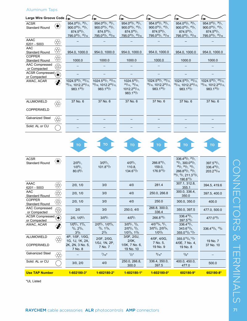
CO
NN
EC
TO
RS
& T
ER
MIN
AL
SAluminum Taps
Use TAP Number 1-602180-3* 1-602180-2* 1-602180-1* 1-602180-0* 602180-9* 602180-8*
*UL Listed
Large Wire Groove Code ACSR Standard Round
AAAC 6201 - 5003AAC Standard RoundCOPPER Standard RoundAAC Compressed or CompactedACSR Compressed or CompactedAWAC, ACAR
ALUMOWELD
COPPERWELD
Galvanized Steel
Solid: AL or CU
ACSR Standard Round
AAAC 6201 - 5003AAC Standard RoundCOPPER Standard RoundAAC Compressed or CompactedACSR Compressed or CompactedAWAC, ACAR
ALUMOWELD
COPPERWELD
Galvanized Steel
Solid: AL or CU
TO TOTO TO TOTO
954.045/7, 36/1, 900.054/7, 45/7,
874.554/7, 795.030/7, 30/19
_
954.0, 1000.0
1000.0
_
_
1024.530/7, 24/13, 18/19, 1012.224/13,
983.130/7
37 No. 6
_
_
2/06/1, 1/06/1, 80.08/1
2/0, 1/0
2/0, 1/0
2/0, 1/0
2/0
2/0, 1/06/1
1/06/1, 14/3, 5/2, 23/4,
32/54P, 1/0F, 1/0G, 1G, 1J, 1K, 2A, 2K, 2N, 3 No. 5,
7 No. 8_
3/0, 2/0
954.045/7, 36/1, 900.054/7, 45/7,
874.554/7, 795.030/7, 30/19
_
954.0, 1000.0
1000.0
_
_
1024.530/7, 24/13, 18/19, 1012.224/13,
983.130/7
37 No. 6
_
_
397.518/1, 336.430/7, 203.216/19
394.5, 419.6
397.5, 400.0
400.0
477.0, 500.0
477.018/1
336.416/3, 15/4
19 No. 7 37 No. 10
_
500.0
954.045/7, 36/1, 900.054/7, 45/7,
874.554/7, 795.030/7, 30/19
_
954.0, 1000.0
1000.0
_
_
1024.530/7, 24/13, 18/19, 1012.224/13,
983.130/7
37 No. 6
_
_
266.818/1,
159.0, 176.912/7
281.4
250.0, 266.8
250.0
266.8, 300.0, 336.4
266.818/1
4/015/4, 6/1, 3/04/3, 2/03/4,
1/02/5
4/0F, 4/0G, 7 No. 5, 19 No. 9
9/16"
336.4, 350.0, 397.5
954.045/7, 36/1, 900.054/7, 45/7,
874.554/7, 795.030/7, 30/19
_
954.0, 1000.0
1000.0
_
_
1024.530/7, 24/13, 18/19, 1012.224/13,
983.130/7
37 No. 6
_
_
336.426/7, 24/7, 18/1, 300.030/7, 26/7, 24/7, 18/1, 266.830/7, 26/7,
24/7, 6/7, 211.312/7, 190.812/7
307.1, 312.8, 355.1
300.0, 336.4, 350.0
300.0, 350.0
350.0, 397.5
336.418/1, 397.518/1
336.418/1, 343.615/4,
355.015/4 12/7
355.015/4,12/7 4/0E, 7 No. 4,
19 No. 8
5/8"
400.0, 450.0, 477.0
954.045/7, 36/1, 900.054/7, 45/7,
874.554/7, 795.030/7, 30/19
_
954.0, 1000.0
1000.0
_
_
1024.530/7, 24/13, 18/19, 1012.224/13,
983.130/7
37 No. 6
_
_
3/06/1,
101.812/7
3/0
3/0
3/0
3/0
3/06/1
2/06/1, 1/04/3, 5/2, 13/4,
22/5
2/0F, 2/0G, 1/0J, 1N, 2P,
7 No. 7
7/16"
4/0
954.045/7, 36/1, 900.054/7, 45/7,
874.554/7, 795.030/7, 30/19
_
954.0, 1000.0
1000.0
_
_
1024.530/7, 24/13, 18/19,
1012.224/13, 983.130/7
37 No. 6
_
_
4/06/1, 110.8,
134.612/7
4/0
4/0
4/0
250.0, 4/0
4/06/1
3/06/1, 5/2, 2/04/3, 5/2, 1/03/4, 12/53/0F, 2/0J,
2/0K, 1/0K, 7 No. 6,
19 No. 10
1/2"
250.0, 266.8, 300.0
71RAYCHEM cable accessories ALR photocontrols AMP connectors
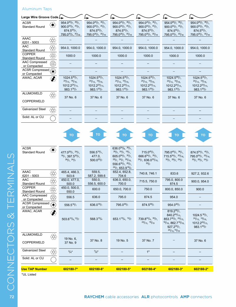
CO
NN
EC
TO
RS
& T
ER
MIN
AL
SAluminum Taps
Use TAP Number 602180-7* 602180-6* 602180-5* 602180-4* 602180-3* 602180-2**UL Listed
Large Wire Groove Code
ACSR Standard Round
AAAC 6201 - 5003AAC Standard RoundCOPPER Standard RoundAAC Compressed or CompactedACSR Compressed or CompactedAWAC, ACAR
ALUMOWELD COPPERWELD
Galvanized Steel
Solid: AL or CU
ACSR Standard Round
AAAC 6201 - 5003AAC Standard RoundCOPPER Standard RoundAAC Compressed or CompactedACSR Compressed or CompactedAWAC, ACAR
ALUMOWELD COPPERWELD
Galvanized Steel
Solid: AL or CU
TO TOTO TO TOTO
954.045/7, 36/1, 900.054/7, 45/7,
874.554/7, 795.030/7, 30/19
_
954.0, 1000.0
1000.0
_
_
1024.530/7, 24/13, 18/19,
1012.224/13, 983.130/7
37 No. 6
_
_
477.026/7, 24/7, 18/1, 397.530/7,
26/7, 24/7
465.4, 466.3, 503.6
450.0, 477.0, 500.0
450.0, 500.0, 550.0
556.5
556.518/1
503.615/4,12/7
19 No. 6, 37 No. 9
3/4"
_
954.045/7, 36/1, 900.054/7, 45/7,
874.554/7, 795.030/7, 30/19
_
954.0, 1000.0
1000.0
_
_
1024.530/7, 24/13, 18/19,
1012.224/13, 983.130/7
37 No. 6
_
_
874.554/7, 45/7, 795.054/7, 30/19,
30/7, 26/7, 24/7
927.2, 932.6
900.0, 954.0
900.0
_
_
1024.5 30/7, 24/13, 18/19,
1012.224/13, 983.130/7
37 No. 6
_
_
954.045/7, 36/1, 900.054/7, 45/7,
874.554/7, 795.030/7, 30/19
_
954.0, 1000.0
1000.0
_
_
1024.530/7, 24/13, 18/19,
1012.224/13, 983.130/7
37 No. 6
_
_
715.045/7,
666.654/7, 26/7, 24/7, 636.030/19,
30/7
740.8, 746.1
715.5, 750.0
750.0
874.5
874.536/1
739.833/4, 30/7, 24/13, 18/19
37 No. 7
1"
_
954.045/7, 36/1, 900.054/7, 45/7,
874.554/7, 795.030/7, 30/19
_
954.0, 1000.0
1000.0
_
_
1024.530/7, 24/13, 18/19,
1012.224/13, 983.130/7
37 No. 6
_
_
795.045/7, 36/1, 715.554/7, 30/19,
30/7, 26/7, 24/7
833.6
795.0, 800.0 874.5
800.0, 850.0
954.0
954.036/1
819.230/7, 840.224/13,
853.730/7, 24/13, 18/19, 862.718/19,
927.230/7, 24/13,18/19
_
_
_
954.045/7, 36/1, 900.054/7, 45/7,
874.554/7, 795.030/7, 30/19
_
954.0, 1000.0
1000.0
_
_
1024.530/7, 24/13, 18/19,
1012.224/13, 983.130/7
37 No. 6
_
_
556.518/1,
477.0, 500.030/7
559.5, 587.2, 599.6
550.0, 556.5, 600.0
600.0
636.0
636.018/1
568.315/4
37 No. 8
7/8"
_
954.045/7, 36/1, 900.054/7, 45/7,
874.554/7, 795.030/7, 30/19
_
954.0, 1000.0
1000.0
_
_
1024.530/7, 24/13, 18/19,
1012.224/13, 983.130/7
37 No. 6
_
_
636.054/8, 36/1, 26/7, 24/7, 18/1, 605.054/7, 30/7, 26/7, 24/7, 30/19, 556.630/7, 26/7, 24/7, 653.918/3652.4, 652.8,
704.6636.0, 650.0,
700.0 650.0, 700.0
795.0
795.036/1
653.115/4, 12/7
19 No. 5
_
_
72 RAYCHEM cable accessories ALR photocontrols AMP connectors
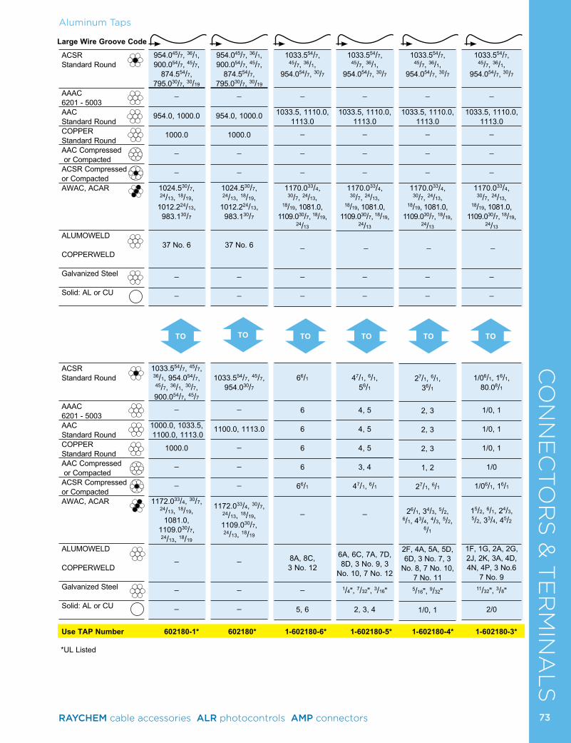
CO
NN
EC
TO
RS
& T
ER
MIN
AL
SAluminum Taps
*UL Listed
Large Wire Groove Code
ACSR Standard Round
AAAC 6201 - 5003AAC Standard RoundCOPPER Standard RoundAAC Compressed or CompactedACSR Compressed or CompactedAWAC, ACAR
ALUMOWELD COPPERWELD
Galvanized Steel
Solid: AL or CU
ACSR Standard Round
AAAC 6201 - 5003AAC Standard RoundCOPPER Standard RoundAAC Compressed or CompactedACSR Compressed or CompactedAWAC, ACAR
ALUMOWELD COPPERWELD
Galvanized Steel
Solid: AL or CU
TO TOTO TO TOTO
Use TAP Number 602180-1* 602180* 1-602180-6* 1-602180-5* 1-602180-4* 1-602180-3*
1033.554/7, 45/7, 36/1,
954.054/7, 30/7
_
1033.5, 1110.0, 1113.0
_
_
_
1170.033/4, 30/7, 24/13,
18/19, 1081.0, 1109.030/7, 18/19,
24/13
_
_
_
27/1, 6/1,
36/1
2, 3
2, 3
2, 3
1, 2
27/1, 6/1
26/1, 34/3, 5/2,
6/1, 43/4, 4/3, 5/2, 6/1
2F, 4A, 5A, 5D, 6D, 3 No. 7, 3
No. 8, 7 No. 10, 7 No. 11
5/16", 9/32"
1/0, 1
1033.554/7, 45/7, 36/1,
954.054/7, 30/7
_
1033.5, 1110.0, 1113.0
_
_
_
1170.033/4, 30/7, 24/13,
18/19, 1081.0, 1109.030/7, 18/19,
24/13
_
_
_
1/06/1, 16/1,
80.08/1
1/0, 1
1/0, 1
1/0, 1
1/0
1/06/1, 16/1
15/2, 6/1, 24/3, 5/2, 33/4, 45/2
1F, 1G, 2A, 2G, 2J, 2K, 3A, 4D, 4N, 4P, 3 No.6
7 No. 9 11/32", 3/8"
2/0
1033.554/7, 45/7, 36/1,
954.054/7, 30/7
_
1033.5, 1110.0, 1113.0
_
_
_
1170.033/4, 30/7, 24/13,
18/19, 1081.0, 1109.030/7, 18/19,
24/13
_
_
_
66/1
6 6 6 6
66/1
_
8A, 8C, 3 No. 12
_
5, 6
1033.554/7, 45/7, 36/1,
954.054/7, 30/7
_
1033.5, 1110.0, 1113.0
_
_
_
1170.033/4, 30/7, 24/13,
18/19, 1081.0, 1109.030/7, 18/19,
24/13
_
_
_
47/1, 6/1,
56/1
4, 5
4, 5
4, 5
3, 4
47/1, 6/1
_
6A, 6C, 7A, 7D, 8D, 3 No. 9, 3
No. 10, 7 No. 12
1/4", 7/32", 3/16"
2, 3, 4
954.045/7, 36/1, 900.054/7, 45/7,
874.554/7, 795.030/7, 30/19
_
954.0, 1000.0
1000.0
_
_
1024.530/7, 24/13, 18/19,
1012.224/13, 983.130/7
37 No. 6
_
_
1033.554/7, 45/7, 36/1, 954.054/7, 45/7, 36/1, 30/7, 900.054/7, 45/7
_
1000.0, 1033.5, 1100.0, 1113.0
1000.0
_
_
1172.033/4, 30/7, 24/13, 18/19, 1081.0,
1109.030/7, 24/13, 18/19
_
_
_
954.045/7, 36/1, 900.054/7, 45/7,
874.554/7, 795.030/7, 30/19
_
954.0, 1000.0
1000.0
_
_
1024.530/7, 24/13, 18/19,
1012.224/13, 983.130/7
37 No. 6
_
_
1033.554/7, 45/7,
954.030/7
_ 1100.0, 1113.0
_
_
_
1172.033/4, 30/7, 24/13, 18/19, 1109.030/7, 24/13, 18/19
_
_
_
73RAYCHEM cable accessories ALR photocontrols AMP connectors
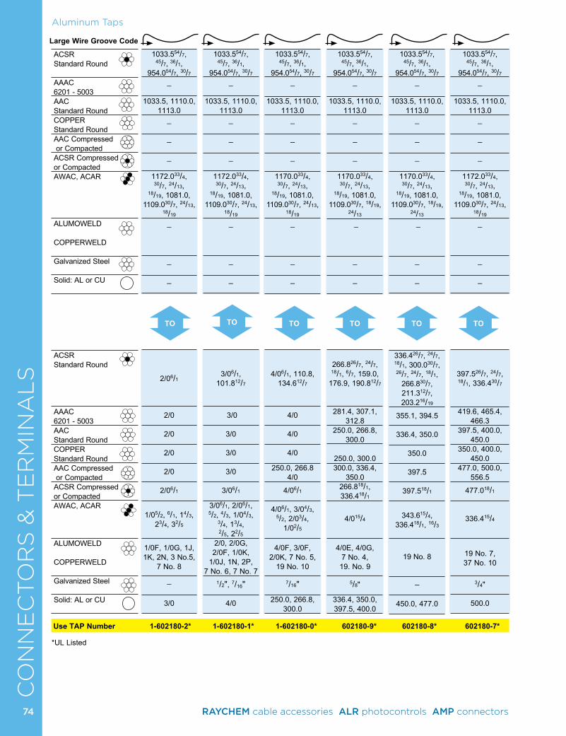
CO
NN
EC
TO
RS
& T
ER
MIN
AL
SLarge Wire Groove Code
ACSR Standard Round
AAAC 6201 - 5003AAC Standard RoundCOPPER Standard RoundAAC Compressed or CompactedACSR Compressed or CompactedAWAC, ACAR
ALUMOWELD COPPERWELD
Galvanized Steel
Solid: AL or CU
ACSR Standard Round
AAAC 6201 - 5003AAC Standard RoundCOPPER Standard RoundAAC Compressed or CompactedACSR Compressed or CompactedAWAC, ACAR
ALUMOWELD COPPERWELD
Galvanized Steel
Solid: AL or CU
TO TOTO TO TOTO
Aluminum Taps
Use TAP Number 1-602180-2* 1-602180-1* 1-602180-0* 602180-9* 602180-8* 602180-7*
*UL Listed
1033.554/7, 45/7, 36/1,
954.054/7, 30/7_
1033.5, 1110.0, 1113.0
_
_
_
1170.033/4, 30/7, 24/13,
18/19, 1081.0, 1109.030/7, 18/19,
24/13
_
_
_
336.426/7, 24/7, 18/1, 300.030/7, 26/7, 24/7, 18/1,
266.830/7, 211.312/7, 203.216/19
355.1, 394.5
336.4, 350.0
350.0
397.5
397.518/1
343.615/4,
336.418/1, 16/3
19 No. 8
_
450.0, 477.0
1033.554/7, 45/7, 36/1,
954.054/7, 30/7_
1033.5, 1110.0, 1113.0
_
_
_
1170.033/4, 30/7, 24/13,
18/19, 1081.0, 1109.030/7, 24/13,
18/19 _
_
_
4/06/1, 110.8, 134.612/7
4/0
4/0
4/0
250.0, 266.8 4/0
4/06/1
4/06/1, 3/04/3, 5/2, 2/03/4,
1/02/5
4/0F, 3/0F, 2/0K, 7 No. 5,
19 No. 10
7/16"
250.0, 266.8, 300.0
1033.554/7, 45/7, 36/1,
954.054/7, 30/7_
1033.5, 1110.0, 1113.0
_
_
_
1170.033/4, 30/7, 24/13,
18/19, 1081.0, 1109.030/7, 18/19,
24/13
_
_
_
266.826/7, 24/7, 18/1, 6/7, 159.0,
176.9, 190.812/7
281.4, 307.1, 312.8
250.0, 266.8, 300.0
250.0, 300.0300.0, 336.4,
350.0266.818/1, 336.418/1
4/015/4
4/0E, 4/0G, 7 No. 4, 19. No. 9
5/8"
336.4, 350.0, 397.5, 400.0
1033.554/7, 45/7, 36/1,
954.054/7, 30/7_
1033.5, 1110.0, 1113.0
_
_
_
1172.033/4, 30/7, 24/13,
18/19, 1081.0, 1109.030/7, 24/13,
18/19
_
_
_
2/06/1
2/0
2/0
2/0
2/0
2/06/1
1/05/2, 6/1, 14/3,
23/4, 32/5
1/0F, 1/0G, 1J, 1K, 2N, 3 No.5,
7 No. 8
_
3/0
1033.554/7, 45/7, 36/1,
954.054/7, 30/7_
1033.5, 1110.0, 1113.0
_
_
_
1172.033/4, 30/7, 24/13,
18/19, 1081.0, 1109.030/7, 24/13,
18/19
_
_
_
3/06/1, 101.812/7
3/0
3/0
3/0
3/0
3/06/1
3/06/1, 2/06/1, 5/2, 4/3, 1/04/3,
3/4, 13/4, 2/5, 22/5
2/0, 2/0G, 2/0F, 1/0K,
1/0J, 1N, 2P, 7 No. 6, 7 No. 7
1/2", 7/16"
4/0
1033.554/7, 45/7, 36/1,
954.054/7, 30/7_
1033.5, 1110.0, 1113.0
_
_
_
1172.033/4, 30/7, 24/13,
18/19, 1081.0, 1109.030/7, 24/13,
18/19
_
_
_
397.526/7, 24/7, 18/1, 336.430/7
419.6, 465.4, 466.3
397.5, 400.0, 450.0
350.0, 400.0, 450.0
477.0, 500.0, 556.5
477.018/1
336.415/4
19 No. 7, 37 No. 10
3/4"
500.0
74 RAYCHEM cable accessories ALR photocontrols AMP connectors
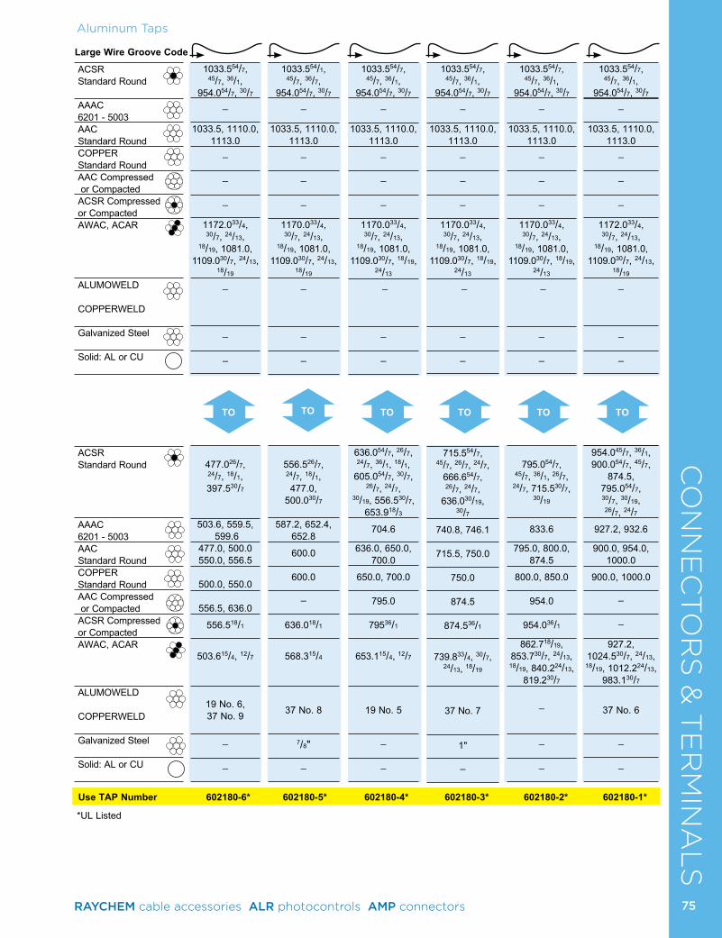
CO
NN
EC
TO
RS
& T
ER
MIN
AL
SAluminum Taps
Use TAP Number 602180-6* 602180-5* 602180-4* 602180-3* 602180-2* 602180-1*
*UL Listed
Large Wire Groove Code
ACSR Standard Round
AAAC 6201 - 5003AAC Standard RoundCOPPER Standard RoundAAC Compressed or CompactedACSR Compressed or CompactedAWAC, ACAR
ALUMOWELD COPPERWELD
Galvanized Steel
Solid: AL or CU
ACSR Standard Round
AAAC 6201 - 5003AAC Standard RoundCOPPER Standard RoundAAC Compressed or CompactedACSR Compressed or CompactedAWAC, ACAR
ALUMOWELD COPPERWELD
Galvanized Steel
Solid: AL or CU
TO TOTO TO TOTO
1033.554/1, 45/7, 36/7,
954.054/7, 30/7_
1033.5, 1110.0, 1113.0
_
_
_
1170.033/4, 30/7, 24/13,
18/19, 1081.0, 1109.030/7, 24/13,
18/19 _
_
_
556.526/7, 24/7, 18/1, 477.0,
500.030/7
587.2, 652.4, 652.8
600.0
600.0
_
636.018/1
568.315/4
37 No. 8
7/8"
_
1033.554/7, 45/7, 36/1,
954.054/7, 30/7_
1033.5, 1110.0, 1113.0
_
_
_
1172.033/4, 30/7, 24/13,
18/19, 1081.0, 1109.030/7, 24/13,
18/19
_
_
_
477.026/7, 24/7, 18/1, 397.530/7
503.6, 559.5, 599.6
477.0, 500.0 550.0, 556.5
500.0, 550.0
556.5, 636.0
556.518/1
503.615/4, 12/7
19 No. 6, 37 No. 9
_
_
1033.554/7, 45/7, 36/1,
954.054/7, 30/7_
1033.5, 1110.0, 1113.0
_
_
_
1170.033/4, 30/7, 24/13,
18/19, 1081.0, 1109.030/7, 18/19,
24/13
_
_
_
715.554/7, 45/7, 26/7, 24/7,
666.654/7, 26/7, 24/7,
636.030/19, 30/7
740.8, 746.1
715.5, 750.0
750.0
874.5
874.536/1
739.833/4, 30/7,
24/13, 18/19
37 No. 7
1"
_
1033.554/7, 45/7, 36/1,
954.054/7, 30/7_
1033.5, 1110.0, 1113.0
_
_
_
1170.033/4, 30/7, 24/13,
18/19, 1081.0, 1109.030/7, 18/19,
24/13
_
_
_
795.054/7,
45/7, 36/1, 26/7, 24/7, 715.530/7,
30/19
833.6
795.0, 800.0, 874.5
800.0, 850.0
954.0
954.036/1
862.718/19, 853.730/7, 24/13, 18/19, 840.224/13,
819.230/7 _
_
_
1033.554/7, 45/7, 36/1,
954.054/7, 30/7_
1033.5, 1110.0, 1113.0
_
_
_
1170.033/4, 30/7, 24/13,
18/19, 1081.0, 1109.030/7, 18/19,
24/13
_
_
_
636.054/7, 26/7, 24/7, 36/1, 18/1,
605.054/7, 30/7, 26/7, 24/7,
30/19, 556.530/7, 653.918/3
704.6
636.0, 650.0, 700.0
650.0, 700.0
795.0
79536/1
653.115/4, 12/7
19 No. 5
_
_
1033.554/7, 45/7, 36/1,
954.054/7, 30/7_
1033.5, 1110.0, 1113.0
_
_
_
1172.033/4, 30/7, 24/13,
18/19, 1081.0, 1109.030/7, 24/13,
18/19
_
_
_
954.045/7, 36/1, 900.054/7, 45/7,
874.5, 795.054/7, 30/7, 30/19, 26/7, 24/7
927.2, 932.6
900.0, 954.0, 1000.0
900.0, 1000.0
_
_
927.2, 1024.530/7, 24/13,
18/19, 1012.224/13, 983.130/7
37 No. 6
_
_
75RAYCHEM cable accessories ALR photocontrols AMP connectors
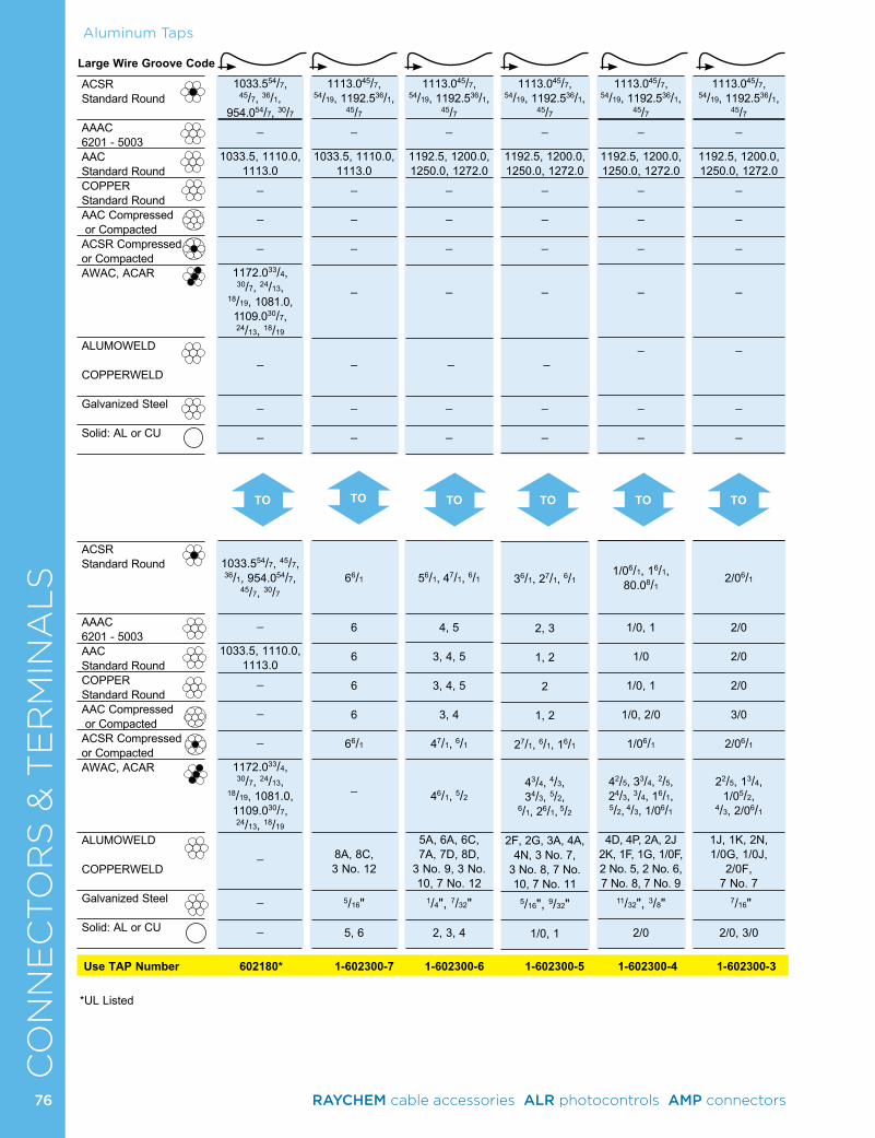
CO
NN
EC
TO
RS
& T
ER
MIN
AL
SLarge Wire Groove Code
ACSR Standard Round
AAAC 6201 - 5003AAC Standard RoundCOPPER Standard RoundAAC Compressed or CompactedACSR Compressed or CompactedAWAC, ACAR
ALUMOWELD COPPERWELD
Galvanized Steel
Solid: AL or CU
ACSR Standard Round
AAAC 6201 - 5003AAC Standard RoundCOPPER Standard RoundAAC Compressed or CompactedACSR Compressed or CompactedAWAC, ACAR
ALUMOWELD COPPERWELD
Galvanized Steel
Solid: AL or CU
TO TOTO TO TOTO
Aluminum Taps
Use TAP Number 602180* 1-602300-7 1-602300-6 1-602300-5 1-602300-4 1-602300-3
*UL Listed
1113.045/7, 54/19, 1192.536/1,
45/7_
1192.5, 1200.0, 1250.0, 1272.0
_
_
_
_
_
_
_
36/1, 27/1, 6/1
2, 3
1, 2 2
1, 2
27/1, 6/1, 16/1
43/4, 4/3, 34/3, 5/2,
6/1, 26/1, 5/2
2F, 2G, 3A, 4A, 4N, 3 No. 7,
3 No. 8, 7 No. 10, 7 No. 11
5/16", 9/32"
1/0, 1
1113.045/7, 54/19, 1192.536/1,
45/7_
1033.5, 1110.0, 1113.0
_
_
_
_
_
_
_
66/1
6 6 6 6
66/1
_
8A, 8C, 3 No. 12
5/16"
5, 6
1113.045/7, 54/19, 1192.536/1,
45/7_
1192.5, 1200.0, 1250.0, 1272.0
_
_
_
_
_
_
_
56/1, 47/1, 6/1
4, 5
3, 4, 5
3, 4, 5
3, 4
47/1, 6/1
46/1, 5/2
5A, 6A, 6C, 7A, 7D, 8D,
3 No. 9, 3 No. 10, 7 No. 12
1/4", 7/32"
2, 3, 4
1033.554/7, 45/7, 36/1,
954.054/7, 30/7_
1033.5, 1110.0, 1113.0
_
_
_
1172.033/4, 30/7, 24/13,
18/19, 1081.0, 1109.030/7, 24/13, 18/19
_
_
_
1033.554/7, 45/7, 36/1, 954.054/7,
45/7, 30/7
_
1033.5, 1110.0, 1113.0
_
_
_
1172.033/4, 30/7, 24/13,
18/19, 1081.0, 1109.030/7, 24/13, 18/19
_
_
_
1113.045/7, 54/19, 1192.536/1,
45/7_
1192.5, 1200.0, 1250.0, 1272.0
_
_
_
_
_
_
_
1/06/1, 16/1, 80.08/1
1/0, 1
1/0
1/0, 1
1/0, 2/0
1/06/1
42/5, 33/4, 2/5, 24/3, 3/4, 16/1, 5/2, 4/3, 1/06/1
4D, 4P, 2A, 2J 2K, 1F, 1G, 1/0F, 2 No. 5, 2 No. 6, 7 No. 8, 7 No. 9
11/32", 3/8"
2/0
1113.045/7, 54/19, 1192.536/1,
45/7_
1192.5, 1200.0, 1250.0, 1272.0
_
_
_
_
_
_
_
2/06/1
2/0
2/0
2/0
3/0
2/06/1
22/5, 13/4,
1/05/2, 4/3, 2/06/1
1J, 1K, 2N, 1/0G, 1/0J,
2/0F, 7 No. 7
7/16"
2/0, 3/0
76 RAYCHEM cable accessories ALR photocontrols AMP connectors
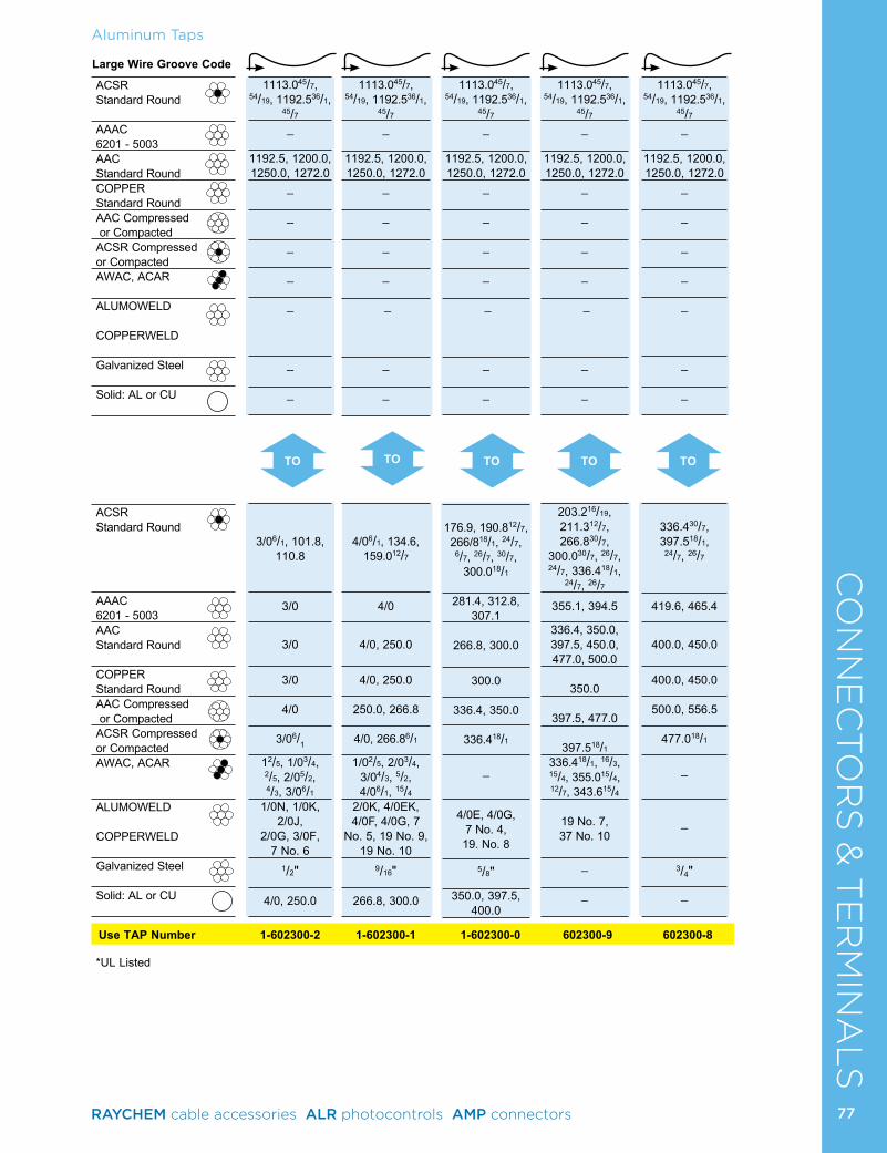
CO
NN
EC
TO
RS
& T
ER
MIN
AL
SLarge Wire Groove Code
ACSR Standard Round
AAAC 6201 - 5003AAC Standard RoundCOPPER Standard RoundAAC Compressed or CompactedACSR Compressed or CompactedAWAC, ACAR
ALUMOWELD COPPERWELD
Galvanized Steel
Solid: AL or CU
ACSR Standard Round
AAAC 6201 - 5003AAC Standard Round
COPPER Standard RoundAAC Compressed or CompactedACSR Compressed or CompactedAWAC, ACAR
ALUMOWELD COPPERWELD
Galvanized Steel
Solid: AL or CU
TO TOTO TOTO
Aluminum Taps
Use TAP Number 1-602300-2 1-602300-1 1-602300-0 602300-9 602300-8
*UL Listed
1113.045/7, 54/19, 1192.536/1,
45/7_
1192.5, 1200.0, 1250.0, 1272.0
_
_
_
_
_
_
_
176.9, 190.812/7, 266/818/1, 24/7,
6/7, 26/7, 30/7, 300.018/1
281.4, 312.8, 307.1
266.8, 300.0
300.0
336.4, 350.0
336.418/1
_
4/0E, 4/0G, 7 No. 4, 19. No. 8
5/8"
350.0, 397.5, 400.0
1113.045/7, 54/19, 1192.536/1,
45/7_
1192.5, 1200.0, 1250.0, 1272.0
_
_
_
_
_
_
_
203.216/19, 211.312/7, 266.830/7,
300.030/7, 26/7, 24/7, 336.418/1,
24/7, 26/7
355.1, 394.5
336.4, 350.0, 397.5, 450.0, 477.0, 500.0
350.0
397.5, 477.0
397.518/1
336.418/1, 16/3, 15/4, 355.015/4, 12/7, 343.615/4
19 No. 7, 37 No. 10
_
_
1113.045/7, 54/19, 1192.536/1,
45/7_
1192.5, 1200.0, 1250.0, 1272.0
_
_
_
_
_
_
_
3/06/1, 101.8, 110.8
3/0
3/0
3/0
4/0
3/06/1
12/5, 1/03/4, 2/5, 2/05/2, 4/3, 3/06/1
1/0N, 1/0K, 2/0J,
2/0G, 3/0F, 7 No. 6
1/2"
4/0, 250.0
1113.045/7, 54/19, 1192.536/1,
45/7_
1192.5, 1200.0, 1250.0, 1272.0
_
_
_
_
_
_
_
4/06/1, 134.6, 159.012/7
4/0
4/0, 250.0
4/0, 250.0
250.0, 266.8
4/0, 266.86/1
1/02/5, 2/03/4, 3/04/3, 5/2, 4/06/1, 15/4
2/0K, 4/0EK, 4/0F, 4/0G, 7
No. 5, 19 No. 9, 19 No. 10
9/16"
266.8, 300.0
1113.045/7, 54/19, 1192.536/1,
45/7_
1192.5, 1200.0, 1250.0, 1272.0
_
_
_
_
_
_
_
336.430/7, 397.518/1,
24/7, 26/7
419.6, 465.4
400.0, 450.0
400.0, 450.0
500.0, 556.5
477.018/1
_
_
3/4"
_
77RAYCHEM cable accessories ALR photocontrols AMP connectors
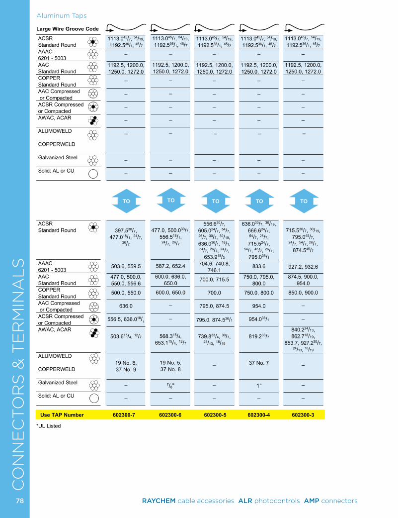
CO
NN
EC
TO
RS
& T
ER
MIN
AL
SLarge Wire Groove Code
ACSR Standard RoundAAAC 6201 - 5003AAC Standard RoundCOPPER Standard RoundAAC Compressed or CompactedACSR Compressed or CompactedAWAC, ACAR
ALUMOWELD COPPERWELD
Galvanized Steel
Solid: AL or CU
ACSR Standard Round
AAAC 6201 - 5003AAC Standard RoundCOPPER Standard RoundAAC Compressed or CompactedACSR Compressed or CompactedAWAC, ACAR
ALUMOWELD COPPERWELD
Galvanized Steel
Solid: AL or CU
TO TOTO TOTO
Aluminum Taps
Use TAP Number 602300-7 602300-6 602300-5 602300-4 602300-3
*UL Listed
1113.045/7, 54/19, 1192.536/1, 45/7
_
1192.5, 1200.0, 1250.0, 1272.0
_
_
_
_
_
_
_
636.030/7, 30/19, 666.624/7, 54/7, 26/7, 715.524/7,
54/7, 45/7, 26/7, 795.036/1
833.6
750.0, 795.0, 800.0
750.0, 800.0
954.0
954.036/1
819.230/7
37 No. 7
1"
_
1113.045/7, 54/19, 1192.536/1, 45/7
_
1192.5, 1200.0, 1250.0, 1272.0
_
_
_
_
_
_
_
477.0, 500.030/7,
556.518/1, 24/7, 26/7
587.2, 652.4
600.0, 636.0, 650.0
600.0, 650.0
_
_
568.315/4,
653.115/4, 12/7
19 No. 5, 37 No. 8
7/8"
_
1113.045/7, 54/19, 1192.536/1, 45/7
_
1192.5, 1200.0, 1250.0, 1272.0
_
_
_
_
_
_
_
556.630/7, 605.024/7, 54/7, 26/7, 30/7, 30/19, 636.036/1, 18/1, 54/7, 26/7, 24/7,
653.918/3
704.6, 740.8, 746.1
700.0, 715.5
700.0
795.0, 874.5
795.0, 874.536/1
739.833/4, 30/7,
24/13, 18/19
_
_
_
1113.045/7, 54/19, 1192.536/1, 45/7
_
1192.5, 1200.0, 1250.0, 1272.0
_
_
_
_
_
_
_
397.530/7,
477.018/1, 24/7, 26/7
503.6, 559.5
477.0, 500.0, 550.0, 556.6
500.0, 550.0
636.0
556.5, 636.018/1
503.615/4, 12/7
19 No. 6, 37 No. 9
_ _
1113.045/7, 54/19, 1192.536/1, 45/7
_
1192.5, 1200.0, 1250.0, 1272.0
_
_
_
_
_
_
_
715.530/7, 30/19,
795.045/7, 24/7, 54/7, 26/7,
874.545/7
927.2, 932.6
874.5, 900.0, 954.0
850.0, 900.0
_
_
840.224/13, 862.718/19,
853.7, 927.230/7, 24/13, 18/19
_
_
_
78 RAYCHEM cable accessories ALR photocontrols AMP connectors
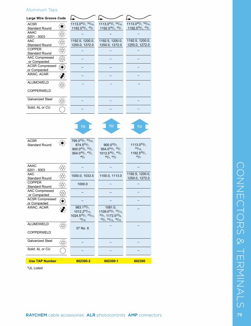
CO
NN
EC
TO
RS
& T
ER
MIN
AL
SAluminum Taps
Use TAP Number 602300-2 602300-1 602300
*UL Listed
Large Wire Groove Code
ACSR Standard RoundAAAC 6201 - 5003AAC Standard RoundCOPPER Standard RoundAAC Compressed or CompactedACSR Compressed or CompactedAWAC, ACAR
ALUMOWELD COPPERWELD
Galvanized Steel
Solid: AL or CU
ACSR Standard Round
AAAC 6201 - 5003AAC Standard RoundCOPPER Standard RoundAAC Compressed or CompactedACSR Compressed or CompactedAWAC, ACAR
ALUMOWELD COPPERWELD
Galvanized Steel
Solid: AL or CU
TO TOTO
1113.045/7, 54/19, 1192.536/1, 45/7
_
1192.5, 1200.0, 1250.0, 1272.0
_
_
_
_
_
_
_
795.030/7, 30/19, 874.554/7,
900.045/7, 54/7, 954.036/1, 45/7,
48/7
_
1000.0, 1033.5
1000.0
_
_
983.130/7, 1012.224/13,
1024.530/7, 24/13, 18/19
37 No. 6
_
_
1113.045/7, 54/19, 1192.536/1, 45/7
_
1192.5, 1200.0, 1250.0, 1272.0
_
_
_
_
_
_
_
900.030/7,
954.054/7, 30/7 1013.536/1, 45/7,
48/7, 54/7
_
1100.0, 1113.0
_
_
_
1081.0, 1109.030/7, 24/13, 30/7, 1172.033/4, 30/7, 24/13, 18/19
_
_
_
1113.045/7, 54/19, 1192.536/1, 45/7
_
1192.5, 1200.0, 1250.0, 1272.0
_
_
_
_
_
_
_
1113.045/7,
54/19, 1192.536/1,
45/7
_
1192.5, 1200.0, 1250.0, 1272.0
_
_
_
_
_
_
_
79RAYCHEM cable accessories ALR photocontrols AMP connectors
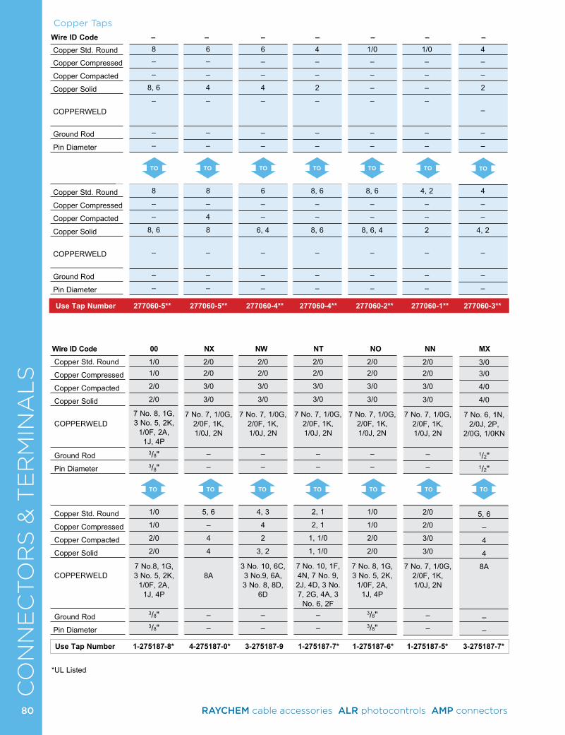
CO
NN
EC
TO
RS
& T
ER
MIN
AL
S
TO TO TO TO TO TO TO
Copper Taps
8–
–
8, 6
–
–
–
8
–
–
8, 6
–
–
–
6–
–
4
–
–
–
8
–
4
8
–
–
–
6–
–
4
–
–
–
6
–
–
6, 4
–
–
–
4–
–
2
–
–
–
8, 6
–
–
8, 6
–
–
–
1/0–
–
–
–
–
–
8, 6
–
–
8, 6, 4
–
–
–
1/0–
–
–
–
–
–
4, 2
–
–
2
–
–
–
Copper Std. Round
Copper Compressed
Copper Compacted
Copper Solid
COPPERWELD
Ground Rod
Pin Diameter
Copper Std. Round
Copper Compressed
Copper Compacted
Copper Solid
COPPERWELD
Ground Rod
Pin Diameter
Use Tap Number 277060-5** 277060-5** 277060-4** 277060-4** 277060-2** 277060-1** 277060-3**
4–
–
2
–
–
–
4
–
–
4, 2
–
–
–
Copper Std. Round
Copper Compressed
Copper Compacted
Copper Solid
COPPERWELD
Ground Rod
Pin Diameter
Copper Std. Round
Copper Compressed
Copper Compacted
Copper Solid
COPPERWELD
Ground Rod
Pin Diameter
Wire ID Code 00 NX NW NT NO NN MX
Wire ID Code – – – – – – –
TO TO TO TO TO TO
Use Tap Number 1-275187-8* 4-275187-0* 3-275187-9 1-275187-7* 1-275187-6* 1-275187-5* 3-275187-7*
TO
1/01/0
2/0
2/0
7 No. 8, 1G, 3 No. 5, 2K,
1/0F, 2A, 1J, 4P
3/8"3/8"
1/0
1/0
2/0
2/0
7 No.8, 1G, 3 No. 5, 2K,
1/0F, 2A, 1J, 4P
3/8"3/8"
2/02/0
3/0
3/0
7 No. 7, 1/0G, 2/0F, 1K, 1/0J, 2N
–
–
5, 6
–
4
4
8A
–
–
2/02/0
3/0
3/0
7 No. 7, 1/0G, 2/0F, 1K, 1/0J, 2N
–
–
4, 3
4
2
3, 2
3 No. 10, 6C, 3 No.9, 6A, 3 No. 8, 8D,
6D
–
–
2/02/0
3/0
3/0
7 No. 7, 1/0G, 2/0F, 1K, 1/0J, 2N
–
–
2, 1
2, 1
1, 1/0
1, 1/0
7 No. 10, 1F, 4N, 7 No. 9, 2J, 4D, 3 No. 7, 2G, 4A, 3
No. 6, 2F–
–
2/02/0
3/0
3/0
7 No. 7, 1/0G, 2/0F, 1K, 1/0J, 2N
–
–
1/0
1/0
2/0
2/0
7 No. 8, 1G, 3 No. 5, 2K,
1/0F, 2A, 1J, 4P
3/8"3/8"
2/02/0
3/0
3/0
7 No. 7, 1/0G, 2/0F, 1K, 1/0J, 2N
–
–
2/0
2/0
3/0
3/0
7 No. 7, 1/0G, 2/0F, 1K, 1/0J, 2N
–
–
3/03/0
4/0
4/0
7 No. 6, 1N, 2/0J, 2P,
2/0G, 1/0KN
1/2"1/2"
5, 6
–
4
4
8A
–
–
*UL Listed
80 RAYCHEM cable accessories ALR photocontrols AMP connectors
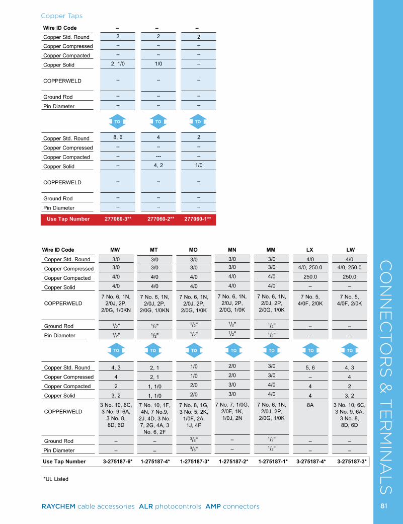
CO
NN
EC
TO
RS
& T
ER
MIN
AL
S
TO TO TO
Copper Taps
Copper Std. Round
Copper Compressed
Copper Compacted
Copper Solid
COPPERWELD
Ground Rod
Pin Diameter
Copper Std. Round
Copper Compressed
Copper Compacted
Copper Solid
COPPERWELD
Ground Rod
Pin Diameter
2–
–
2, 1/0
–
–
–
8, 6
–
–
–
–
–
–
2–
–
1/0
–
–
–
4
–
---
4, 2
–
–
–
2–
–
–
–
–
–
2
–
–
1/0
–
–
–
Copper Std. Round
Copper Compressed
Copper Compacted
Copper Solid
COPPERWELD
Ground Rod
Pin Diameter
Copper Std. Round
Copper Compressed
Copper Compacted
Copper Solid
COPPERWELD
Ground Rod
Pin Diameter
Wire ID Code – – –
Use Tap Number 277060-3** 277060-2** 277060-1**
Use Tap Number 3-275187-6* 1-275187-4* 1-275187-3* 1-275187-2* 1-275187-1* 3-275187-4* 3-275187-3*
Wire ID Code MW MT MO MN MM LX LW
TO TO TO TO TOTOTO
3/03/0
4/0
4/0
7 No. 6, 1N, 2/0J, 2P,
2/0G, 1/0K
1/2"1/2"
2/0
2/0
3/0
3/0
7 No. 7, 1/0G, 2/0F, 1K, 1/0J, 2N
–
–
3/03/0
4/0
4/0
7 No. 6, 1N, 2/0J, 2P,
2/0G, 1/0K
1/2"1/2"
3/0
3/0
4/0
4/0
7 No. 6, 1N, 2/0J, 2P,
2/0G, 1/0K
1/2"1/2"
3/03/0
4/0
4/0
7 No. 6, 1N, 2/0J, 2P,
2/0G, 1/0KN
1/2"1/2"
4, 3
4
2
3, 2
3 No. 10, 6C, 3 No. 9, 6A,
3 No. 8, 8D, 6D
–
–
3/03/0
4/0
4/0
7 No. 6, 1N, 2/0J, 2P,
2/0G, 1/0KN
1/2"1/2"
2, 1
2, 1
1, 1/0
1, 1/0
7 No. 10, 1F, 4N, 7 No.9,
2J, 4D, 3 No. 7, 2G, 4A, 3
No. 6, 2F
–
–
4/04/0, 250.0
250.0
–
7 No. 5, 4/0F, 2/0K
–
–
5, 6
–
4
4
8A
–
–
4/04/0, 250.0
250.0
–
7 No. 5, 4/0F, 2/0K
–
–
4, 3
4
2
3, 2
3 No. 10, 6C, 3 No. 9, 6A,
3 No. 8, 8D, 6D
–
–
3/03/0
4/0
4/0
7 No. 6, 1N, 2/0J, 2P,
2/0G, 1/0K
1/2"1/2"
1/0
1/0
2/0
2/0
7 No. 8, 1G, 3 No. 5, 2K,
1/0F, 2A, 1J, 4P
3/8"3/8"
*UL Listed
81RAYCHEM cable accessories ALR photocontrols AMP connectors
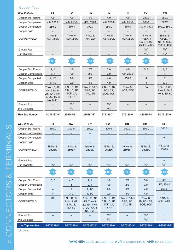
CO
NN
EC
TO
RS
& T
ER
MIN
AL
S
TO TO TO TO TO TO TO
Copper Std. Round
Copper Compressed
Copper Compacted
Copper Solid
COPPERWELD
Ground Rod
Pin Diameter
Copper Std. Round
Copper Compressed
Copper Compacted
Copper Solid
COPPERWELD
Ground Rod
Pin Diameter
Wire ID Code LT LO LN LM LL RX RW
Use Tap Number 1-275187-0* 275187-9* 275187-8* 275187-7* 275187-6* 3-275187-1* 3-275187-0*
Copper Taps
TO TO TO TO TO TO TO
Copper Std. Round
Copper Compressed
Copper Compacted
Copper Solid
COPPERWELD
Ground Rod
Pin Diameter
Copper Std. Round
Copper Compressed
Copper Compacted
Copper Solid
COPPERWELD
Ground Rod
Pin Diameter
Wire ID Code HX HW HT HO HN HM HL
Use Tap Number 6-276337-5* 6-276337-4* 6-276337-2* 6-276337-0* 5-276337-9* 5-276337-8* 5-276337-7*
4/0
4/0, 250/0
250.0
–
7 No. 5, 4/0F, 2/0K
–
–
1/0
1/0
2/0
2/0
7 No. 8, 1G, 3 No. 5, 2K,
1/0F, 2A, 1J, 4P
3/8"3/8"
4/0
4/0, 250/0
250.0
–
7 No. 5, 4/0F, 2/0K
–
–
2/0
2/0
3/0
3/0
7 No. 7, 1/0G, 2/0F, 1K, 1/0J, 2N
–
–
4/0
4/0, 250/0
250.0
–
7 No. 5, 4/0F, 2/0K
–
–
3/0
3/0
4/0
4/0
7 No. 6, 1N, 2/0J, 2P,
2/0G, 1/0K
1/2"1/2"
4/0
4/0, 250/0
250.0
–
7 No. 5, 4/0F, 2/0K
–
–
4/0
4/0, 250.0
250.0
–
7 No. 5, 4/0F, 2/0K
–
–
250.0
300/0
300.0, 350.0
–
19 No. 9, 4/0EK, 7
No. 4, 4/0E, 250EK, 4/0G
5/8"9/16"
5, 6
–
4
4
8A
–
–
250.0
300/0
300.0, 350.0
–
19 No. 9, 4/0EK, 7
No. 4, 4/0E, 250EK, 4/0G
5/8"9/16"
4, 3
4
2
3, 2
3 No. 10, 6C, 3 No. 9, 6A, 3 No. 8, 8D, 6D
–
–
300.0
–
–
–
19 No. 8, 250EK
–5/8"
5, 6
–
4
4
8A
–
–
300.0
–
–
–
19 No. 8, 250EK
–5/8"
4, 3
4
2
3, 2
3 No. 10, 6C, 3 No. 9, 6A,
3 No. 8, 8D, 6D
–
–
300.0
–
–
–
19 No. 8, 250EK
–5/8"
2, 1
2, 1
1, 1/0
1, 1/0
7 No. 10, 1F, 4N, 7 No.9,
2J, 4D, 3 No. 7, 2G, 4A, 3
No. 6 2F
–
–
300.0
–
–
–
19 No. 8, 250EK
–5/8"
1/0
1/0
2/0
2/0
7 No. 8, 1G, 3 No. 5, 2K,
1/0F, 2A, 1J, 4P
3/8"3/8"
300.0
–
–
–
19 No. 8, 250EK
–5/8"
2/0
2/0
3/0
3/0
7 No. 7, 1/0G, 2/0F, 1K, 1/0J, 2N
–
–
300.0
–
–
–
19 No. 8, 250EK
–5/8"
3/0
3/0
4/0
4/0
7 No. 6, 1N,2/0J, 2P, 2/0G, 1/0K
1/2"1/2"
300.0
–
–
–
19 No. 8, 250EK
–5/8"
4/0
4/0, 250.0
250.0
–
7 No. 5, 4/0F, 2/0K
–
–
4/0
4/0, 250.0
250.0
–
7 No. 5, 4/0F, 2/0K
–
–
2, 1
2, 1
1, 1/0
1, 1/0
7 No. 10, 1F, 4N, 7 No.9,
2J, 4D, 3 No. 7, 2G, 4A, 3
No. 6, 2F
–
–
*UL Listed
82 RAYCHEM cable accessories ALR photocontrols AMP connectors
CO
NN
EC
TO
RS
& T
ER
MIN
AL
S
Use Tap Number 275187-5* 275187-4* 275187-3* 275187-2* 275187-1* 2-275187-8*
Wire ID Code RT RO RN RM RL RR
TO TO TO TOTO
Copper Taps
250.0
300.0
300.0, 350.0
–
19 No. 9, 4/0EK, 7
No. 4, 4/0E, 250EK, 4/0G
5/8"9/16"
2, 1
2, 1
1, 1/0
1, 1/0
7 No. 10, 1F, 4N, 7 No. 9, 2J, 4D, 3 No. 7, 2G, 4A, 3
No. 6, 2F
–
–
250.0
300.0
300.0, 350.0
–
19 No. 9, 4/0EK, 7
No. 4, 4/0E, 250EK, 4/0G
5/8"9/16"
1/0
1/0
2/0
2/0
7 No. 8, 1G, 3 No. 5, 2K,
1/0F, 2A, 1J, 4P
3/8"3/8"
250.0
300.0
300.0, 350.0
–
19 No. 9, 4/0EK, 7
No. 4, 4/0E, 250EK, 4/0G
5/8"9/16"
2/0
2/0
3/0
3/0
7 No. 7, 1/0G, 2/0F, 1K, 1/0J, 2N
–
–
250.0
300.0
300.0, 350.0
–
19 No. 9, 4/0EK, 7
No. 4, 4/0E, 250EK, 4/0G
5/8"9/16"
3/0
3/0
4/0
4/0
7 No. 6, 1N, 2/0J, 2P,
2/0G, 1/0K
1/2"1/2"
250.0
300.0
300.0, 350.0
–
19 No. 9, 4/0EK, 7
No. 4, 4/0E, 250EK, 4/0G
5/8"9/16"
4/0
4/0, 250.0
250.0
–
7 No. 5, 4/0F, 2/0K
–
–
250.0
300.0
300.0, 350.0
–
19 No. 9, 4/0EK, 7
No. 4, 4/0E, 250EK, 4/0G
5/8"9/16"
250.0
300.0
300.0, 350.0
–
19 No. 9, 4/0EK, 7
No. 4, 4/0E, 250EK, 4/0G
5/8"9/16"
Copper Std. Round
Copper Compressed
Copper Compacted
Copper Solid
COPPERWELD
Ground Rod
Pin Diameter
Copper Std. Round
Copper Compressed
Copper Compacted
Copper Solid
COPPERWELD
Ground Rod
Pin Diameter
Use Tap Number 5-276337-6* 5-276337-5* 5-276337-4* 5-276337-3* 5-276337-1* 4-276337-9* 4-276337-8*
Wire ID Code HK HH GX GW GT GO GN
TO TO TO TO TOTOTO
300.0
–
–
–
19 No. 8, 250EK
–5/8"
250.0
300.0
300.0
300.0. 350.0
19 No. 9, 4/0EK, 7
No.4, 4/0E, 250EK, 4/0G
5/8"–
300.0
–
–
–
19 No. 8, 250EK
–5/8"
300.0
–
–
–
19 No. 8, 250EK
–5/8"
350.0
350.0
400.0
–
300EK, 250EK
3/4"–
5, 6
–
4
4
8A
–
–
350.0
350.0
400.0
–
300EK, 250EK
3/4"–
4, 3
4
2
3, 2
3 No. 10, 6C, 3 No. 9, 6A,
3 No. 8, 8D, 6D
–
–
350.0
350.0
400.0
–
300EK, 250EK
3/4"–
2, 1
2, 1
1, 1/0
1, 1/0
7 No. 10, 1F, 4N, 7 No.9,
2J, 4D, 3 No. 7, 2G, 4A, 3
No. 6, 2F
–
–
350.0
350.0
400.0
–
300EK, 250EK
3/4"–
1/0
1/0
2/0
2/0
7 No. 8, 1G, 3 No. 5, 2K,
1/0F, 2A, 1J, 4P
3/8"3/8"
350.0
350.0
400.0
–
300EK, 250EK
3/4"–
2/0
2/0
3/0
3/0
7 No. 7, 1/0G, 2/0F, 1K, 1/0J, 2N
–
–
Copper Std. Round
Copper Compressed
Copper Compacted
Copper Solid
COPPERWELD
Ground Rod
Pin Diameter
Copper Std. Round
Copper Compressed
Copper Compacted
Copper Solid
COPPERWELD
Ground Rod
Pin Diameter
TO
*UL Listed
83RAYCHEM cable accessories ALR photocontrols AMP connectors
CO
NN
EC
TO
RS
& T
ER
MIN
AL
SCopper Taps
Copper Std. Round
Copper Compressed
Copper Compacted
Copper Solid
COPPERWELD
Ground Rod
Pin Diameter
Copper Std. Round
Copper Compressed
Copper Compacted
Copper Solid
COPPERWELD
Ground Rod
Pin Diameter
Copper Std. Round
Copper Compressed
Copper Compacted
Copper Solid
COPPERWELD
Ground Rod
Pin Diameter
Copper Std. Round
Copper Compressed
Copper Compacted
Copper Solid
COPPERWELD
Ground Rod
Pin Diameter
Wire ID Code GM GL GK GH GG EX EW
Wire ID Code EG EE BX BW BT BO BN
TO
TO
TO
TO
TO
TO
TO
TO
TO
TO
TO
TO
TO
TO
Use Tap Number 4-276337-7* 4-276337-6* 4-276337-5* 4-276337-4* 4-276337-3* 4-276337-2* 4-276337-1*
Use Tap Number 3-276337-1* 3-276337-0* 2-276337-9* 2-276337-8* 276337-4* 2-276337-5* 276337-3*
400.0
400.0
450.0, 500.0
–
300E, 350EK, 19 No. 7, 37
No. 10
–
–
350.0
350.0
400.0
–
300EK, 250EK
3/4"–
400.0
400.0
450.0, 500.0
–
300E, 350EK, 19 No. 7, 37
No. 10
–
–
400.0
400.0
450.0, 500.0
–
300E, 350EK,
19 No. 7, 37 No. 10
–
–
450.0
450.0
550.0
–
–
–3/4"
5, 6
–
4
4
#8A
–
–
450.0
450.0
550.0
–
–
–3/4"
2, 1
2, 1
1, 1/0
1, 1/0
7 No. 10, 1F, 4N, 7 No.9,
2J, 4D, 3 No. 7, 2G, 4A, 3
No. 6, 2F
–
–
450.0
450.0
550.0
–
–
–3/4"
4, 3
4
2
3, 2
3 No. 10, 6C, 3 No. 9, 6A, 3 No. 8, 8D,
#6D
–
–
450.0
450.0
550.0
–
–
–3/4"
1/0
1/0
2/0
2/0
7 No. 8, 1G, 3 No. 5, 2K,
1/0F, 2A, 1J, 4P
3/8"3/8"
450.0
450.0
550.0
–
–
–3/4"
2/0
2/0
3/0
3/0
7 No. 7, 1/0G, 2/0F, 1K, 1/0J, 2N
–
–
350.0
350.0
400.0
–
300EK, 250EK
3/4"–
3/0
3/0
4/0
4/0
7 No. 6, 1N, 2/0J, 2P,
2/0G, 1/0K
1/2"1/2"
350.0
350.0
400.0
–
300EK, 250EK
3/4"–
300
–
–
–
19 No. 8, 250EK
–5/8"
350.0
350.0
400.0
–
300EK, 250EK
3/4"–
350.0
350.0
400.0
–
300EK, 250EK
3/4"–
350.0
350.0
400.0
–
300EK, 250EK
3/4"–
4/0
4/0, 250.0
250.0
–
7 No. 5, 4/0F, 2/0K
–
–
400.0
400.0
450.0, 500.0
–
300E, 350EK, 19 No. 7, 37
No. 10
–
–
5, 6
–
4
4
#8A
–
–
350.0
350.0
400.0
–
300EK, 250EK
3/4"–
250.0
300.0
300.0, 350.0
–
19 No. 9, 4/0EK, 7
No. 4, 4/0E, 250EK, 4/0G
5/8"9/16"
400.0
400.0
450.0, 500.0
–
300E, 350EK, 19 No. 7, 37
No. 10
–
–
4, 3
4
2
3, 2
3 No. 10, 6C, 3 No. 9, 6A, 3 No. 8, 8D,
#6D
–
–
*UL Listed
84 RAYCHEM cable accessories ALR photocontrols AMP connectors
CO
NN
EC
TO
RS
& T
ER
MIN
AL
SCopper Taps
Copper Std. Round
Copper Compressed
Copper Compacted
Copper Solid
COPPERWELD
Ground Rod
Pin Diameter
Copper Std. Round
Copper Compressed
Copper Compacted
Copper Solid
COPPERWELD
Ground Rod
Pin Diameter
Use Tap Number 3-276337-9* 3-276337-7* 3-276337-6* 3-276337-5* 3-276337-4* 3-276337-3* 4-276337-2*
Use Tap Number 2-276337-4* 276337-2* 2-276337-3* 2-276337-2* 2-276337-1* 2-276337-0* 1-276337-9*
Wire ID Code ET EO EN EM EL EK EH
Wire ID Code BM BL BK BH BG BE BB
TO TO
TO
TO
TO
TO
TO
TO
TO
TO
TO TO
TO
TO
Copper Std. Round
Copper Compressed
Copper Compacted
Copper Solid
COPPERWELD
Ground Rod
Pin Diameter
Copper Std. Round
Copper Compressed
Copper Compacted
Copper Solid
COPPERWELD
Ground Rod
Pin Diameter
400.0
400.0
450.0, 500.0
–
300E, 350EK, 19 No. 7, 37
No. 10
–
–
2/0
2/0
3/0
3/0
7 No. 7, 1/0G, 2/0F, 1K, 1/0J, 2N
–
–
400.0
400.0
450.0, 500.0
–
300E, 350EK, 19 No. 7, 37
No. 10
–
–
3/0
3/0
4/0
4/0
7 No. 6, 1N, 2/0J, 2P,
2/0G, 1/0K
1/2"1/2"
400.0
400.0
450.0, 500.0
–
300E, 350EK, 19 No. 7, 37
No. 10
–
–
4/0
4/0, 250.0
250.0
–
7 No. 5, 4/0F, 2/0K
–
–
400.0
400.0
450.0, 500.0
–
300E, 350EK, 19 No. 7, 37
No. 10
–
–
250.0
300.0
300.0, 350.0
–
19 No. 9, 4/0EK, 7
No. 4, 4/0E, 250EK, 4/0G
5/8"9/16"
400.0
400.0
450.0, 500.0
–
300E, 350EK, 19 No. 7, 37
No. 10
–
–
300.0
–
–
–
19 No. 8, 250EK
–5/8"
400.0
400.0
450.0, 500.0
–
300E, 350EK, 19 No. 7, 37
No. 10
–
–
2, 1
2, 1
1, 1/0
1, 1/0
7 No. 10, 1F, 4N, 7 No.9,
2J, 4D, 3 No. 7, 2G, 4A, 3
No. 6, 2F
–
–
400.0
400.0
450.0, 500.0
–
300E, 350EK, 19 No. 7, 37
No. 10
–
–
1/0
1/0
2/0
2/0
7 No. 8, 1G, 3 No. 5, 2K,
1/0F, 2A, 1J, 4P
3/8"3/8"
450.0
450.0
550.0
–
–
–3/4"
450.0
450.0
550.0
–
–
–3/4"
450.0
450.0
550.0
–
–
–3/4"
3/0
3/0
4/0
4/0
7 No. 6, 1N, 2/0J, 2P,
2/0G, 1/0K
1/2"1/2"
450.0
450.0
550.0
–
–
–3/4"
4/0
4/0, 250.0
250.0
–
7 No. 5, 4/0F, 2/0K
–
–
450.0
450.0
550.0
–
–
–3/4"
300
–
–
–
19 No. 8, 250EK
–5/8"
450.0
450.0
550.0
–
–
–3/4"
350.0
350.0
400.0
–
300EK, 250EK
3/4"–
450.0
450.0
550.0
–
–
–3/4"
400.0
400.0
450.0, 500.0
–
300E, 350EK,
19 No. 7, 37 No. 10
–
–
450.0
450.0
550.0
–
–
–3/4"
250.0
300.0
300.0, 350.0
–
19 No. 9, 4/0EK, 7
No. 4, 4/0E, 250EK, 4/0G
5/8"9/16"
*UL Listed
85RAYCHEM cable accessories ALR photocontrols AMP connectors
86
CO
NN
EC
TO
RS
& T
ER
MIN
AL
SCopper Taps
Copper Std. Round
Copper Compressed
Copper Compacted
Copper Solid
COPPERWELD
Ground Rod
Pin Diameter
Copper Std. Round
Copper Compressed
Copper Compacted
Copper Solid
COPPERWELD
Ground Rod
Pin Diameter
Copper Std. Round
Copper Compressed
Copper Compacted
Copper Solid
COPPERWELD
Ground Rod
Pin Diameter
Copper Std. Round
Copper Compressed
Copper Compacted
Copper Solid
COPPERWELD
Ground Rod
Pin Diameter
Wire ID Code AX AW AT AO AN AM AL
TO TO TOTO TO TO TO
Use Tap Number 1-276337-8* 1-276337-7* 276337-8* 1-276337-4* 276337-7* 1-276337-3* 276337-6*
Use Tap Number 276337-9* 1-276337-2* 1-276337-1* 1-276337-0* 276337-1* 276337-5*
Wire ID Code AK AH AG AE AB AA
TO TO TOTOTOTO
500.0
500.0
600.0
–
350E, 19 No.6, 37 No. 9
–
–
350.0
350.0
400.0
–
300EK, 250EK
3/4"–
500.0
500.0
600.0
–
350E, 19 No.6, 37 No. 9
–
–
5, 6
–
4
4
8A
–
–
500.0
500.0
600.0
–
350E, 19 No.6, 37 No. 9
–
–
4, 3
4
2
3, 2
3 No. 10, 6C, 3 No. 9, 6A,
3 No. 8, 8D, 6D
–
–
500.0
500.0
600.0
–
350E, 19 No.6, 37 No. 9
–
–
4/0
4/0, 250.0
250.0
–
7 No. 5, 4/0F, 2/0K
–
–
500.0
500.0
600.0
–
350E, 19 No.6, 37 No. 9
–
–
250.0
300.0
300.0, 350.0
–
19 No. 9, 4/0EK, 7
No. 4, 4/0E, 250EK, 4/0G
5/8"5/8"
500.0
500.0
600.0
–
350E, 19 No.6, 37 No. 9
–
–
300.0
–
–
–
19 No. 8, 250EK
–5/8"
500.0
500.0
600.0
–
350E, 19 No.6, 37 No. 9
–
–
2, 1
2, 1
1, 1/0
1, 1/0
7 No. 10, 1F, 4N, 7 No. 9, 2J, 4D, 3 No. 7, 2G, 4A, 3
No. 6, 2F
–
–
500.0
500.0
600.0
–
350E, 19 No.6, 37 No. 9
–
–
400.0
400.0
450.0, 500.0
–
300E, 350EK,
19 No. 7, 37 No. 10
–
–
500.0
500.0
600.0
–
350E, 19 No.6, 37 No. 9
–
–
450.0
450.0
550.0
–
–
–3/4"
500.0
500.0
600.0
–
350E, 19 No.6, 37 No. 9
–
–
500.0
500.0
600.0
–
350EK, 19 No. 6, 37 No. 9
–
–
500.0
500.0
600.0
–
350E, 19 No.6, 37 No. 9
–
–
1/0
1/0
2/0
2/0
7 No. 8, 1G, 3 No. 5, 2K,
1/0F, 2A, 1J, 4P
3/8"3/8"
500.0
500.0
600.0
–
350E, 19 No.6, 37 No. 9
–
–
2/0
2/0
3/0
3/0
7 No. 7, 1/0G, 2/0F, 1K, 1/0J, 2N
–
–
500.0
500.0
600.0
–
350E, 19 No.6, 37 No. 9
–
–
3/0
3/0
4/0
4/0
7 No. 6, 1N, 2/0J, 2P,
2/0G, 1/0K
1/2"1/2"
*UL Listed
86 RAYCHEM cable accessories ALR photocontrols AMP connectors
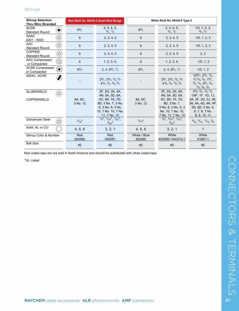
87
CO
NN
EC
TO
RS
& T
ER
MIN
AL
SC
ON
NE
CTO
RS
& T
ER
MIN
AL
SStirrups
Use Tap Number 1-276337-8* 1-276337-7* 276337-8* 1-276337-4* 276337-7* 1-276337-3* 276337-6*
Stirrup Selection Thru Wire StrandedACSR Standard RoundAAAC 6201 - 5003AAC Standard RoundCOPPER Standard RoundAAC Compressed or CompactedACSR Compressed or CompactedAWAC, ACAR
ALUMOWELD
COPPERWELD
Galvanized Steel
Solid: AL or CU
Stirrup Color & Number
Ball Size
Red Shell No. 69338-2 Small Wire Range White Shell No. 69338-5 Type II
66/1
6
6
6
6
66/1
_
8A, 8C, 3 No. 12
3/16"
4, 5, 6
Red 600580
#2
2, 3, 4, 5, 6/1, 7/1
2, 3, 4, 5
2, 3, 4, 5
2, 3, 4, 5
1, 2, 3, 4,
2, 4, 66/1, 7/1
26/1, 34/3, 5/2, 6/1
43/4, 4/3, 5/2, 6/1
2F, 2G, 3A, 4A, 4N, 5A, 5D, 6A, 6C, 6K, 7A, 7D,
8D, 3 No. 7, 3 No. 8, 3 No. 9, 3 No.
10, 7 No. 10, 7 No. 11, 7 No. 12
1/4", 5/16", 7/32", 9/32"
3, 2, 1
Red 600581
#2
2, 3, 4, 5, 6/1, 7/1
2, 3, 4, 5
2, 3, 4, 5
2, 3, 4, 5
1, 2, 3, 4,
2, 4, 66/1, 7/1
26/1, 34/3, 5/2, 6/1
43/4, 4/3, 5/2, 6/1
2F, 2G, 3A, 4A, 4N, 5A, 5D, 6A, 6C, 6D, 7A, 7D,
8D, 3 No. 7, 3 No. 8, 3 No. 9, 3 No. 10, 7 No. 10,
7 No. 11, 7 No. 121/4", 5/16", 7/32",
9/32" 3, 2, 1
White 602586 / 1443312-1
#2
66/1
6
6
6
6
66/1
_
8A, 8C, 3 No. 12
3/16"
4, 5, 6
White / Blue 602585
#2
1/0, 1, 2, 3, 6/1, 7/1
1/0, 1, 2, 3
1/0, 1, 2, 3
2, 3
1/0, 1, 2
1/0, 1, 2
1/06/1, 26/1, 5/2, 4/3 3/4, 2/5, 16/1, 5/2, 4/3, 36/1, 5/2,
4/3, 3/4, 2/545/2, 4/3, 3/4, 5/2,
1/0F, 1F, 1G, 1J, 2A, 2F, 2G, 2J, 2K, 3A, 4A, 4D, 4N, 4P,
5D, 6D, 3 No. 5, 6, 7, 8, 7 No. 8, 9, 10, 11
9/32,
5/16, 11/32, 3/8
1
White 81667-1
#2
Red coded taps are not sold in North America and should be substituted with white coded taps.
*UL Listed
87RAYCHEM cable accessories ALR photocontrols AMP connectors
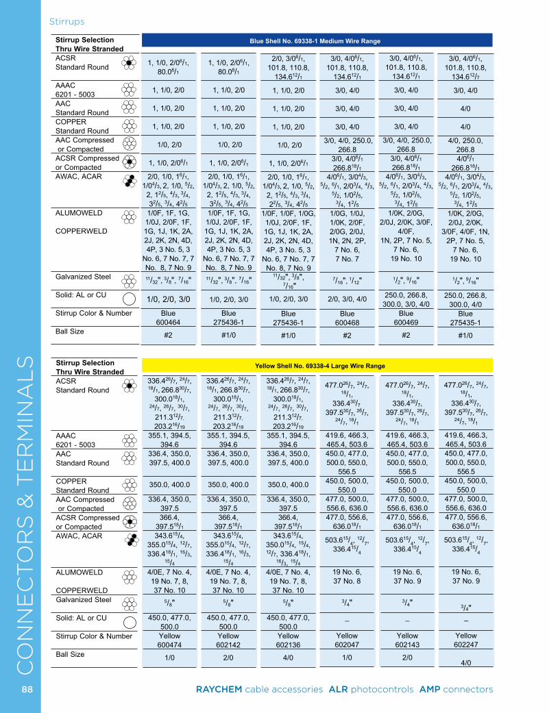
CO
NN
EC
TO
RS
& T
ER
MIN
AL
SStirrups
Stirrup Selection Thru Wire StrandedACSR Standard Round
AAAC 6201 - 5003AAC Standard RoundCOPPER Standard RoundAAC Compressed or CompactedACSR Compressed or CompactedAWAC, ACAR
ALUMOWELD COPPERWELD
Galvanized Steel
Solid: AL or CU
Stirrup Color & Number
Ball Size
Blue Shell No. 69338-1 Medium Wire Range
1, 1/0, 2/06/1, 80.08/1
1, 1/0, 2/0
1, 1/0, 2/0
1, 1/0, 2/0
1/0, 2/0
1, 1/0, 2/06/1
2/0, 1/0, 16/1, 1/04/3, 2, 1/0, 5/2,
2, 12/5, 4/3, 3/4, 32/5, 3/4, 42/51/0F, 1F, 1G, 1/0J, 2/0F, 1F, 1G, 1J, 1K, 2A, 2J, 2K, 2N, 4D, 4P, 3 No. 5, 3
No. 6, 7 No. 7, 7 No. 8, 7 No. 9
11/32",
3/8", 7/16"
1/0, 2/0, 3/0
Blue 600464
#2
1, 1/0, 2/06/1, 80.08/1
1, 1/0, 2/0
1, 1/0, 2/0
1, 1/0, 2/0
1/0, 2/0
1, 1/0, 2/06/1
2/0, 1/0, 16/1, 1/04/3, 2, 1/0, 5/2,
2, 12/5, 4/3, 3/4, 32/5, 3/4, 42/51/0F, 1F, 1G, 1/0J, 2/0F, 1F, 1G, 1J, 1K, 2A, 2J, 2K, 2N, 4D, 4P, 3 No. 5, 3
No. 6, 7 No. 7, 7 No. 8, 7 No. 9
11/32",
3/8", 7/16"
1/0, 2/0, 3/0
Blue 275436-1
#1/0
2/0, 3/06/1, 101.8, 110.8,
134.612/1
1, 1/0, 2/0
1, 1/0, 2/0
1, 1/0, 2/0
1/0, 2/0
1, 1/0, 2/06/1
2/0, 1/0, 16/1, 1/04/3, 2, 1/0, 5/2,
2, 12/5, 4/3, 3/4, 22/5, 3/4, 42/5
1/0F, 1/0F, 1/0G, 1/0J, 2/0F, 1F, 1G, 1J, 1K, 2A, 2J, 2K, 2N, 4D, 4P, 3 No. 5, 3
No. 6, 7 No. 7, 7 No. 8, 7 No. 9
11/32", 3/8", 7/16"
1/0, 2/0, 3/0
Blue 275436-1
#1/0
3/0, 4/06/1, 101.8, 110.8,
134.612/1
3/0, 4/0
3/0, 4/0
3/0, 4/0
3/0, 4/0, 250.0, 266.8
3/0, 4/06/1 266.818/1
4/06/1, 3/04/3, 5/2, 6/1, 2/03/4, 4/3,
5/2, 1/02/5, 3/4, 12/5
1/0G, 1/0J, 1/0K, 2/0F, 2/0G, 2/0J, 1N, 2N, 2P,
7 No. 6, 7 No. 7
7/16",
1/12"
2/0, 3/0, 4/0
Blue 600468
#2
3/0, 4/06/1, 101.8, 110.8,
134.612/1
3/0, 4/0
3/0, 4/0
3/0, 4/0
3/0, 4/0, 250.0, 266.8
3/0, 4/06/1 266.818/1
4/06/1, 3/04/3, 5/2, 6/1, 2/03/4, 4/3,
5/2, 1/02/5, 3/4, 12/5
1/0K, 2/0G, 2/0J, 2/0K, 3/0F,
4/0F, 1N, 2P, 7 No. 5,
7 No. 6, 19 No. 10
1/2",
9/16"
250.0, 266.8, 300.0, 3/0, 4/0
Blue 600469
#2
3/0, 4/06/1, 101.8, 110.8,
134.612/7
3/0, 4/0
4/0
4/0
4/0, 250.0, 266.84/06/1
266.818/14/06/1, 3/04/3,
5/2, 6/1, 2/03/4, 4/3, 5/2, 1/02/5,
3/4, 12/51/0K, 2/0G, 2/0J, 2/0K,
3/0F, 4/0F, 1N, 2P, 7 No. 5,
7 No. 6, 19 No. 10
1/2",
9/16"
250.0, 266.8, 300.0, 4/0
Blue 275435-1
#1/0
Stirrup Selection Thru Wire StrandedACSR Standard Round
AAAC 6201 - 5003AAC Standard Round
COPPER Standard RoundAAC Compressed or CompactedACSR Compressed or CompactedAWAC, ACAR
ALUMOWELD COPPERWELDGalvanized Steel
Solid: AL or CU
Stirrup Color & Number
Ball Size
Yellow Shell No. 69338-4 Large Wire Range
336.426/7, 24/7, 18/1, 266.830/7,
300.018/1, 24/7, 26/7, 30/7,
211.312/7,
203.216/19
355.1, 394.5, 394.6
336.4, 350.0, 397.5, 400.0
350.0, 400.0
336.4, 350.0, 397.5366.4,
397.518/1343.615/4,
355.015/4, 12/7, 336.418/1, 16/3,
15/4 4/0E, 7 No. 4, 19 No. 7, 8, 37 No. 10
5/8"
450.0, 477.0, 500.0Yellow 600474
1/0
336.426/7, 24/7, 18/1, 266.830/7,
300.018/1, 24/7, 26/7, 30/7,
211.312/7,
203.216/19
355.1, 394.5, 394.6
336.4, 350.0, 397.5, 400.0
350.0, 400.0
336.4, 350.0, 397.5366.4,
397.518/1343.615/4,
355.015/4, 12/7, 336.418/1, 16/3,
15/4 4/0E, 7 No. 4, 19 No. 7, 8, 37 No. 10
5/8"
450.0, 477.0, 500.0Yellow 602142
2/0
336.426/7, 24/7, 18/1, 266.830/7,
300.018/1, 24/7, 26/7, 30/7,
211.312/7,
203.216/19
355.1, 394.5, 394.6
336.4, 350.0, 397.5, 400.0
350.0, 400.0
336.4, 350.0, 397.5366.4,
397.518/1343.615/4,
350.015/4, 15/4, 12/7, 336.418/1,
16/3, 15/4 4/0E, 7 No. 4, 19 No. 7, 8, 37 No. 10
5/8"
450.0, 477.0, 500.0Yellow 602136
4/0
477.026/7, 24/7, 18/1,
336.430/7, 397.530/7, 26/7,
24/7, 18/1
419.6, 466.3, 465.4, 503.6450.0, 477.0, 500.0, 550.0,
556.5450.0, 500.0,
550.0477.0, 500.0, 556.6, 636.0477.0, 556.6,
636.018/1
503.615/4, 12/7,
336.415/4
19 No. 6, 37 No. 8
3/4"
_
Yellow 602047
1/0
477.026/7, 24/7, 18/1,
336.430/7, 397.530/7, 26/7,
24/7, 18/1
419.6, 466.3, 465.4, 503.6450.0, 477.0, 500.0, 550.0,
556.5450.0, 500.0,
550.0477.0, 500.0, 556.6, 636.0477.0, 556.6,
636.018/1
503.615/4, 12/7,
336.415/4
19 No. 6, 37 No. 9
3/4"
_
Yellow 602143
2/0
477.026/7, 24/7, 18/1,
336.430/7, 397.530/7, 26/7,
24/7, 18/1
419.6, 466.3, 465.4, 503.6450.0, 477.0, 500.0, 550.0,
556.5450.0, 500.0,
550.0477.0, 500.0, 556.6, 636.0477.0, 556.6,
636.018/1
503.615/4, 12/7,
336.415/4
19 No. 6, 37 No. 9
3/4"_
Yellow 602247
4/0
88 RAYCHEM cable accessories ALR photocontrols AMP connectors
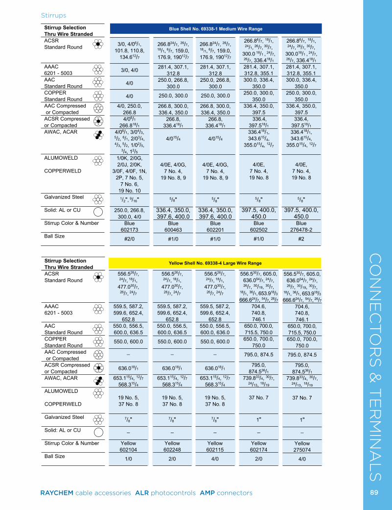
CO
NN
EC
TO
RS
& T
ER
MIN
AL
SStirrups
Blue Shell No. 69338-1 Medium Wire Range
Yellow Shell No. 69338-4 Large Wire Range
Stirrup Selection Thru Wire StrandedACSR Standard Round
AAAC 6201 - 5003AAC Standard RoundCOPPER Standard RoundAAC Compressed or CompactedACSR Compressed or CompactedAWAC, ACAR
ALUMOWELD
COPPERWELD
Galvanized Steel
Solid: AL or CU
Stirrup Color & Number
Ball Size
3/0, 4/06/1, 101.8, 110.8,
134.612/7
3/0, 4/0
4/0
4/0
4/0, 250.0, 266.84/06/1
266.818/14/06/1, 3/04/3, 5/2, 6/1, 2/03/4, 4/3, 5/2, 1/02/5,
3/4, 12/51/0K, 2/0G, 2/0J, 2/0K,
3/0F, 4/0F, 1N, 2P, 7 No. 5,
7 No. 6, 19 No. 10
1/2",
9/16"
250.0, 266.8, 300.0, 4/0
Blue 602173
#2/0
Stirrup Selection Thru Wire StrandedACSR Standard Round
AAAC 6201 - 5003
AAC Standard RoundCOPPER Standard RoundAAC Compressed or CompactedACSR Compressed or CompactedAWAC, ACAR
ALUMOWELD COPPERWELD
Galvanized Steel
Solid: AL or CU
Stirrup Color & Number
Ball Size
556.526/7, 24/7, 18/1,
477.030/7, 26/7, 24/7
559.5, 587.2, 599.6, 652.4,
652.8550.0, 556.5, 600.0, 636.5
550.0, 600.0
_
636.018/1
653.115/4, 12/7 568.315/4
19 No. 5, 37 No. 8
7/8"
_
Yellow 602104
1/0
556.526/7, 24/7, 18/1,
477.030/7, 26/7, 24/7
559.5, 587.2, 599.6, 652.4,
652.8550.0, 556.5, 600.0, 636.5
550.0, 600.0
_
636.018/1
653.115/4, 12/7 568.315/4
19 No. 5, 37 No. 8
7/8"
_
Yellow 602248
2/0
556.526/7, 24/7, 18/1,
477.030/7, 26/7, 24/7
559.5, 587.2, 599.6, 652.4,
652.8550.0, 556.5, 600.0, 636.0
550.0, 600.0
_
636.018/1
653.115/4, 12/7 568.315/4
19 No. 5, 37 No. 8
7/8"
_
Yellow 602115
4/0
556.530/7, 605.0, 636.054/7, 24/7, 26/7, 30/19, 30/7,
18/1, 36/1, 653.918/3 666.624/7, 54/7, 26/7
704.6, 740.8, 746.1
650.0, 700.0, 715.5, 750.0650.0, 700.0,
750.0 795.0, 874.5
795.0, 874.536/1
739.833/4, 30/7, 24/13, 18/19
37 No. 7
1"
_
Yellow 602174
2/0
556.530/7, 605.0, 636.054/7, 24/7, 26/7, 30/19, 30/7,
18/1, 36/1, 653.918/3 666.624/7, 54/7, 26/7
704.6, 740.8, 746.1
650.0, 700.0, 715.5, 750.0650.0, 700.0,
750.0 795.0, 874.5
795.0, 874.536/1
739.833/4, 30/7, 24/13, 18/19
37 No. 7
1"
_
Yellow 275074
4/0
266.824/7, 26/7, 18/1, 6/7, 159.0, 176.9, 19012/7
281.4, 307.1, 312.8
250.0, 266.8, 300.0
250.0, 300.0
266.8, 300.0, 336.4, 350.0
266.8, 336.418/1
4/015/4
4/0E, 4/0G,
7 No. 4, 19 No. 8, 9
5/8"
336.4, 350.0, 397.6, 400.0
Blue 600463
#1/0
266.824/7, 26/7, 18/1, 6/7, 159.0, 176.9, 19012/7
281.4, 307.1, 312.8
250.0, 266.8, 300.0
250.0, 300.0
266.8, 300.0, 336.4, 350.0
266.8, 336.418/1
4/015/4
4/0E, 4/0G,
7 No. 4, 19 No. 8, 9
5/8"
336.4, 350.0, 397.6, 400.0
Blue 602201
#1/0
266.86/7, 18/1, 24/1, 26/7, 30/7,
300.0 18/1 , 24/7, 26/7, 336.418/1281.4, 307.1, 312.8, 355.1300.0, 336.4,
350.0250.0, 300.0,
350.0336.4, 350.0,
397.5 336.4,
397.518/1336.418/1, 343.615/4,
355.015/4, 12/7
4/0E,
7 No. 4, 19 No. 8
5/8"
397.5, 400.0, 450.0Blue
602502 #1/0
266.86/7, 18/1, 24/7, 26/7, 30/7,
300.018/1 , 24/7, 26/7, 336.418/1281.4, 307.1, 312.8, 355.1300.0, 336.4,
350.0250.0, 300.0,
350.0336.4, 350.0,
397.5336.4,
397.518/1336.418/1, 343.615/4,
355.015/4, 12/7
4/0E,
7 No. 4, 19 No. 8
5/8"
397.5, 400.0, 450.0Blue
276478-2 #2
89RAYCHEM cable accessories ALR photocontrols AMP connectors
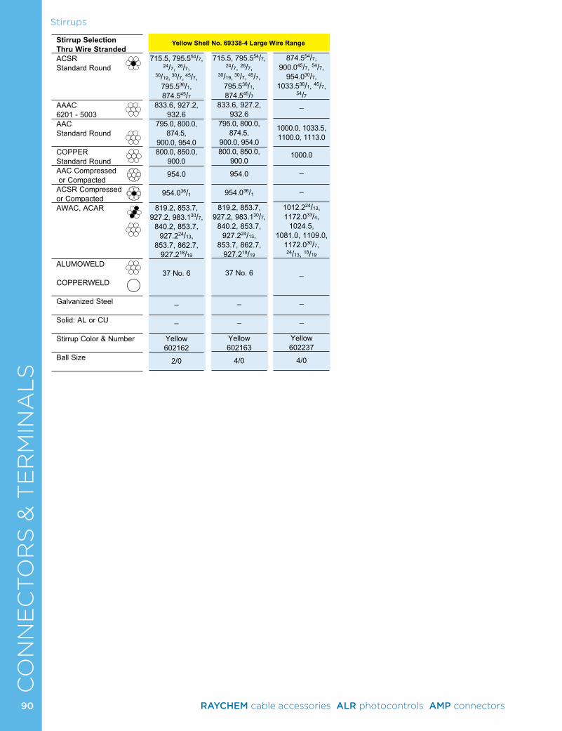
CO
NN
EC
TO
RS
& T
ER
MIN
AL
SStirrups
Stirrup Selection Thru Wire StrandedACSR Standard Round
AAAC 6201 - 5003AAC Standard Round
COPPER Standard RoundAAC Compressed or CompactedACSR Compressed or CompactedAWAC, ACAR
ALUMOWELD COPPERWELD
Galvanized Steel
Solid: AL or CU
Stirrup Color & Number
Ball Size
Yellow Shell No. 69338-4 Large Wire Range
715.5, 795.554/7, 24/7, 26/7,
30/19, 30/7, 45/7, 795.536/1, 874.545/7
833.6, 927.2, 932.6
795.0, 800.0, 874.5,
900.0, 954.0800.0, 850.0,
900.0 954.0
954.036/1
819.2, 853.7, 927.2, 983.130/7,
840.2, 853.7, 927.224/13,
853.7, 862.7, 927.218/19
37 No. 6
_
_
Yellow 602162
2/0
715.5, 795.554/7, 24/7, 26/7,
30/19, 30/7, 45/7, 795.536/1, 874.545/7
833.6, 927.2, 932.6
795.0, 800.0, 874.5,
900.0, 954.0800.0, 850.0,
900.0 954.0
954.036/1
819.2, 853.7, 927.2, 983.130/7,
840.2, 853.7, 927.224/13,
853.7, 862.7, 927.218/19
37 No. 6
_
_
Yellow 602163
4/0
874.554/7, 900.045/7, 54/7,
954.030/7, 1033.536/1, 45/7,
54/7_
1000.0, 1033.5, 1100.0, 1113.0
1000.0
_
_
1012.224/13, 1172.033/4,
1024.5, 1081.0, 1109.0,
1172.030/7, 24/13, 18/19
_
_
_
Yellow 602237
4/0
90 RAYCHEM cable accessories ALR photocontrols AMP connectors
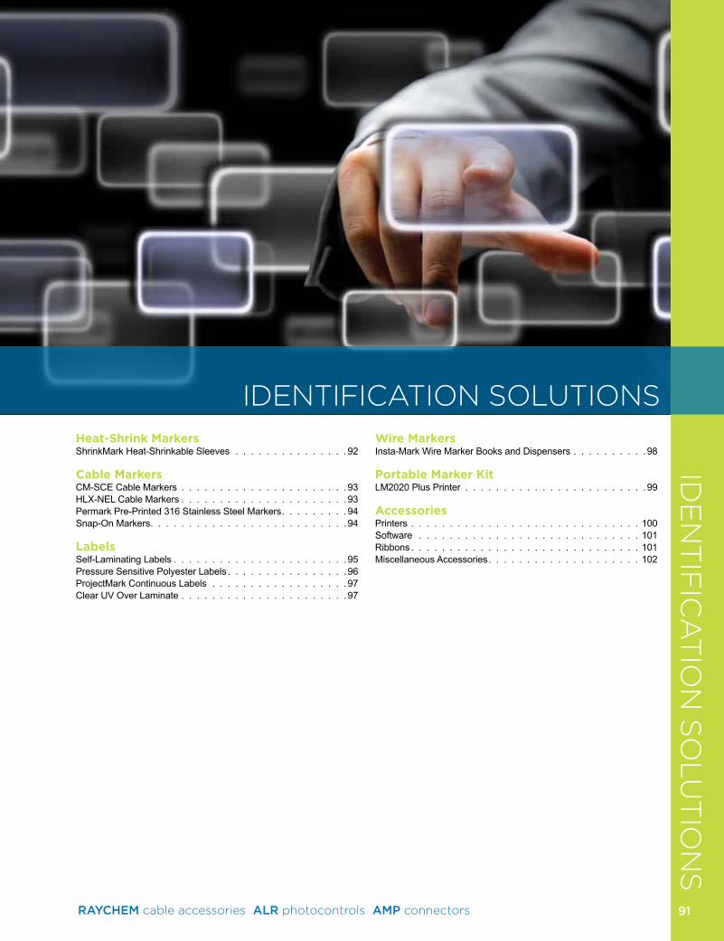
Product
Heat-Shrink MarkersShrinkMark Heat-Shrinkable Sleeves 92
Cable MarkersCM-SCE Cable Markers 93HLX-NEL Cable Markers 93Permark Pre-Printed 316 Stainless Steel Markers 94Snap-On Markers 94
LabelsSelf-Laminating Labels 95Pressure Sensitive Polyester Labels 96ProjectMark Continuous Labels 97Clear UV Over Laminate 97
Wire MarkersInsta-Mark Wire Marker Books and Dispensers 98
Portable Marker KitLM2020 Plus Printer 99
AccessoriesPrinters 100Software 101Ribbons 101Miscellaneous Accessories 102
IDE
NT
IFIC
AT
ION
SO
LU
TIO
NS
91
IDENTIFICATION SOLUTIONS
RAYCHEM cable accessories ALR photocontrols AMP connectors 91
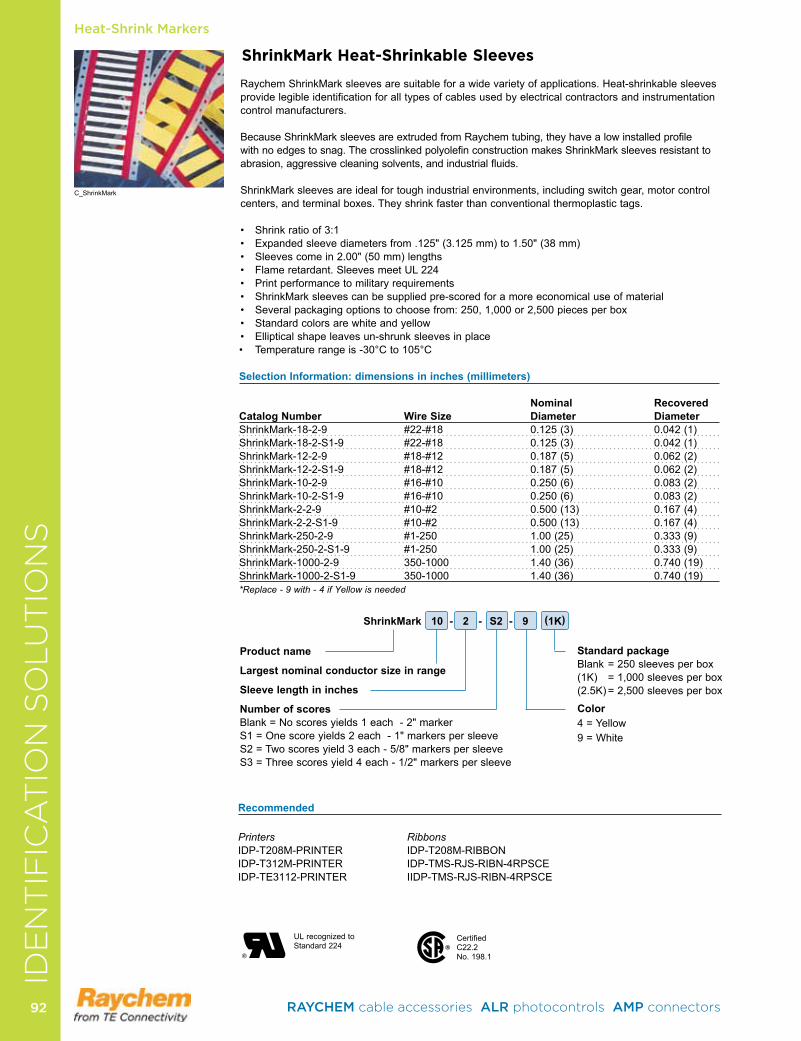
ShrinkMark Heat-Shrinkable Sleeves
Raychem ShrinkMark sleeves are suitable for a wide variety of applications Heat-shrinkable sleeves provide legible identification for all types of cables used by electrical contractors and instrumentation control manufacturers
Because ShrinkMark sleeves are extruded from Raychem tubing, they have a low installed profile with no edges to snag The crosslinked polyolefin construction makes ShrinkMark sleeves resistant to abrasion, aggressive cleaning solvents, and industrial fluids
ShrinkMark sleeves are ideal for tough industrial environments, including switch gear, motor control centers, and terminal boxes They shrink faster than conventional thermoplastic tags
• Shrinkratioof3:1• Expandedsleevediametersfrom.125"(3.125mm)to1.50"(38mm)• Sleevescomein2.00"(50mm)lengths• Flameretardant.SleevesmeetUL224• Printperformancetomilitaryrequirements• ShrinkMarksleevescanbesuppliedpre-scoredforamoreeconomicaluseofmaterial• Severalpackagingoptionstochoosefrom:250,1,000or2,500piecesperbox• Standardcolorsarewhiteandyellow• Ellipticalshapeleavesun-shrunksleevesinplace• Temperaturerangeis-30°Cto105°C
Selection Information: dimensions in inches (millimeters)
Nominal Recovered Catalog Number Wire Size Diameter DiameterShrinkMark-18-2-9 #22-#18 0.125(3) 0.042(1)ShrinkMark-18-2-S1-9 #22-#18 0.125(3) 0.042(1)ShrinkMark-12-2-9 #18-#12 0.187(5) 0.062(2)ShrinkMark-12-2-S1-9 #18-#12 0.187(5) 0.062(2)ShrinkMark-10-2-9 #16-#10 0.250(6) 0.083(2)ShrinkMark-10-2-S1-9 #16-#10 0.250(6) 0.083(2)ShrinkMark-2-2-9 #10-#2 0.500(13) 0.167(4)ShrinkMark-2-2-S1-9 #10-#2 0.500(13) 0.167(4)ShrinkMark-250-2-9 #1-250 1.00(25) 0.333(9)ShrinkMark-250-2-S1-9 #1-250 1.00(25) 0.333(9)ShrinkMark-1000-2-9 350-1000 1.40(36) 0.740(19)ShrinkMark-1000-2-S1-9 350-1000 1.40(36) 0.740(19)*Replace - 9 with - 4 if Yellow is needed
Product name
Largest nominal conductor size in range
Sleeve length in inches
Number of scoresBlank=Noscoresyields1each-2"markerS1=Onescoreyields2each-1"markerspersleeveS2=Twoscoresyield3each-5/8"markerspersleeveS3=Threescoresyield4each-1/2"markerspersleeve
Standard packageBlank = 250 sleeves per box(1K) =1,000sleevesperbox(2.5K)=2,500sleevesperbox
Color 4 = Yellow9 = White
®�
UL recognized to Standard 224 ®
CertifiedC22 2 No 198 1
Recommended
Printers RibbonsIDP-T208M-PRINTER IDP-T208M-RIBBONIDP-T312M-PRINTER IDP-TMS-RJS-RIBN-4RPSCEIDP-TE3112-PRINTER IIDP-TMS-RJS-RIBN-4RPSCE
ShrinkMark 10 - 2 - S2 - 9 (1K)
Heat-Shrink Markers
C_ShrinkMark
IDE
NT
IFIC
AT
ION
SO
LU
TIO
NS
RAYCHEM cable accessories ALR photocontrols AMP connectors 9292
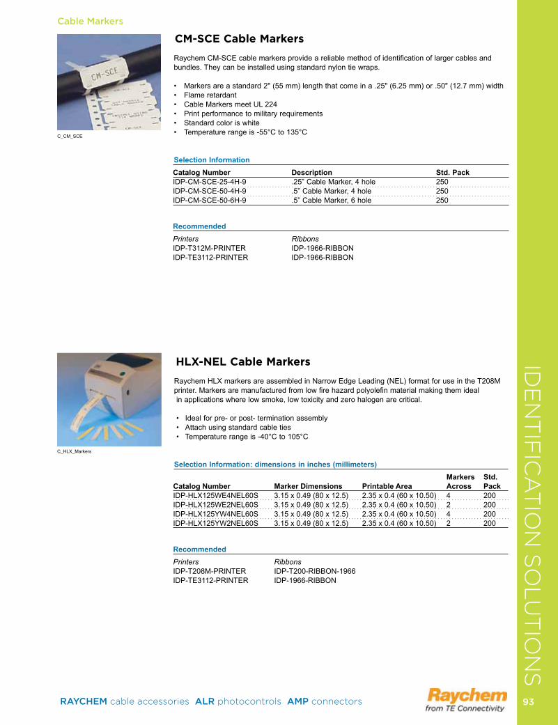
Cable Markers
CM-SCE Cable Markers
Raychem CM-SCE cable markers provide a reliable method of identification of larger cables and bundles They can be installed using standard nylon tie wraps
• Markersareastandard2"(55mm)lengththatcomeina.25"(6.25mm)or.50"(12.7mm)width• Flameretardant• CableMarkersmeetUL224• Printperformancetomilitaryrequirements• Standardcoloriswhite• Temperaturerangeis-55°Cto135°C
Selection Information Catalog Number Description Std. PackIDP-CM-SCE-25-4H-9 25” Cable Marker, 4 hole 250IDP-CM-SCE-50-4H-9 5” Cable Marker, 4 hole 250IDP-CM-SCE-50-6H-9 5” Cable Marker, 6 hole 250
RecommendedPrinters RibbonsIDP-T312M-PRINTER IDP-1966-RIBBONIDP-TE3112-PRINTER IDP-1966-RIBBON
HLX-NEL Cable Markers
RaychemHLXmarkersareassembledinNarrowEdgeLeading(NEL)formatforuseintheT208Mprinter Markers are manufactured from low fire hazard polyolefin material making them ideal in applications where low smoke, low toxicity and zero halogen are critical
• Idealforpre-orpost-terminationassembly• Attachusingstandardcableties• Temperaturerangeis-40°Cto105°C
Selection Information: dimensions in inches (millimeters) Markers Std. Catalog Number Marker Dimensions Printable Area Across PackIDP-HLX125WE4NEL60S 3.15x0.49(80x12.5) 2.35x0.4(60x10.50) 4 200IDP-HLX125WE2NEL60S 3.15x0.49(80x12.5) 2.35x0.4(60x10.50) 2 200IDP-HLX125YW4NEL60S 3.15x0.49(80x12.5) 2.35x0.4(60x10.50) 4 200IDP-HLX125YW2NEL60S 3.15x0.49(80x12.5) 2.35x0.4(60x10.50) 2 200
RecommendedPrinters RibbonsIDP-T208M-PRINTER IDP-T200-RIBBON-1966IDP-TE3112-PRINTER IDP-1966-RIBBON
C_CM_SCE
C_HLX_Markers
IDE
NT
IFIC
AT
ION
SO
LU
TIO
NS
RAYCHEM cable accessories ALR photocontrols AMP connectors 93 93
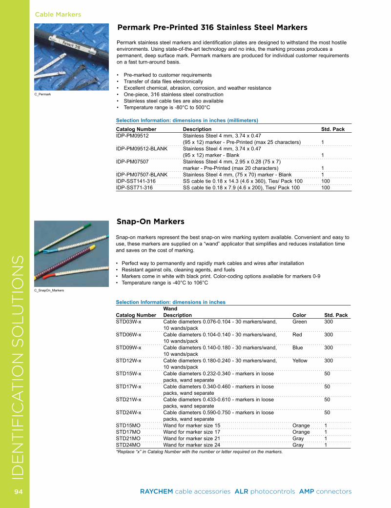
Cable Markers
Snap-On Markers
Snap-on markers represent the best snap-on wire marking system available Convenient and easy to use, these markers are supplied on a “wand” applicator that simplifies and reduces installation time and saves on the cost of marking
• Perfectwaytopermanentlyandrapidlymarkcablesandwiresafterinstallation• Resistantagainstoils,cleaningagents,andfuels• Markerscomeinwhitewithblackprint.Color-codingoptionsavailableformarkers0-9• Temperaturerangeis-40°Cto106°C
Selection Information: dimensions in inches Wand Catalog Number Description Color Std. PackSTD03W-x Cable diameters 0 076-0 104 - 30 markers/wand, Green 300
10 wands/packSTD06W-x Cable diameters 0 104-0 140 - 30 markers/wand, Red 300
10 wands/packSTD09W-x Cable diameters 0 140-0 180 - 30 markers/wand, Blue 300
10 wands/packSTD12W-x Cable diameters 0 180-0 240 - 30 markers/wand, Yellow 300
10 wands/packSTD15W-x Cable diameters 0 232-0 340 - markers in loose 50
packs, wand separateSTD17W-x Cable diameters 0 340-0 460 - markers in loose 50
packs, wand separateSTD21W-x Cable diameters 0 433-0 610 - markers in loose 50
packs, wand separateSTD24W-x Cable diameters 0 590-0 750 - markers in loose 50
packs, wand separateSTD15MO Wand for marker size 15 Orange 1STD17MO Wand for marker size 17 Orange 1STD21MO Wand for marker size 21 Gray 1STD24MO Wand for marker size 24 Gray 1*Replace “x” in Catalog Number with the number or letter required on the markers.
C_SnapOn_Markers
Permark Pre-Printed 316 Stainless Steel Markers
Permark stainless steel markers and identification plates are designed to withstand the most hostile environments Using state-of-the-art technology and no inks, the marking process produces a permanent,deepsurfacemark.Permarkmarkersareproducedforindividualcustomerrequirementson a fast turn-around basis
• Pre-markedtocustomerrequirements• Transferofdatafileselectronically• Excellentchemical,abrasion,corrosion,andweatherresistance• One-piece,316stainlesssteelconstruction• Stainlesssteelcabletiesarealsoavailable• Temperaturerangeis-80°Cto500°C
Selection Information: dimensions in inches (millimeters)Catalog Number Description Std. PackIDP-PM09512 Stainless Steel 4 mm, 3 74 x 0 47 (95x12)marker-Pre-Printed(max25characters) 1IDP-PM09512-BLANK StainlessSteel4mm,3.74x0.47 (95x12)marker-Blank 1IDP-PM07507 StainlessSteel4mm,2.95x0.28(75x7) marker-Pre-Printed(max20characters) 1IDP-PM07507-BLANK StainlessSteel4mm,(75x70)marker-Blank 1IDP-SST141-316 SScabletie0.18x14.3(4.6x360),Ties/Pack100 100IDP-SST71-316 SScabletie0.18x7.9(4.6x200),Ties/Pack100 100
C_Permark
IDE
NT
IFIC
AT
ION
SO
LU
TIO
NS
RAYCHEM cable accessories ALR photocontrols AMP connectors 9494
Labels
Selection Information: dimensions in inches (millimeters)
Maximum Print Area LabelCatalog Number Cable OD Height Width Height Labels/RollIDP-SB050100WE10 .20(5.1) .33(8.5) .50(12.7) 1.00(25.4) 10,000IDP-SB050143WE10 .30(7.6) .50(12.7) .50(12.7) 1.437(36.5) 10,000IDP-SB100143WE5 .30(7.6) .50(12.7) 1.00(25.4) 1.437(36.5) 5,000IDP-SB200143WE2.5 .30(7.6) .50(12.7) 2.00(50.8) 1.437(36.5) 2,500IDP-SB080150WE10 .30(7.6) .50(12.7) .80(20.3) 1.50(38.1) 10,000IDP-SB100225WE5 .48(12.2) .75(19) 1.00(24.4) 2.25(57.2) 5,000IDP-SB200225WE2.5 .48(12.2) .75(19) 2.00(50.8) 2.25(57.2) 2,500IDP-SB100375WE2.5 .88(22.4) 1.00(25.4) 1.00(25.4) 3.75(95.3) 2,500IDP-SB200375WE2.5 .88(22.4) 1.00(25.4) 2.00(50.8) 3.75(95.3) 2,500IDP-SB100594WE1 1.40(35.5) 1.50(38.1) 1.00(25.4) 5.94(151) 1,000IDP-SB190594WE1 1.40(35.5) 1.50(38.1) 1.90(48.3) 5.94(151) 1,000IDP-SB200743WE1 1.90(48.3) 1.50(38.1) 2.00(50.8) 7.437(189) 1,000These standard labels fit inside the T312M Printer or they can feed into a T208M Printer using the IDP-T200-SPINDLE
T208M Size RollsIDP-SB050100WE5-T200 .20(5.1) .33(8.5) .50(12.7) 1.00(25.4) 5,000IDP-SB050143WE5-T200 .30(7.6) .50(12.7) .50(12.7) 1.437(36.5) 5,000IDP-SB100143WE2.5-T200 .30(7.6) .50(12.7) 1.00(25.4) 1.437(36.5) 2,500IDP-SB080150WE5-T200 .30(7.6) .50(12.7) .80(20.3) 1.50(57.2) 5,000IDP-SB100225WE2.5-T200 .48(12.2) .75(19) 1.00(25.4) 2.25(57.2) 2,500IDP-SB200225WE1-T200 .48(12.2) .75(19) 2.00(50.8) 2.25(57.2) 1,000IDP-SB100375WE1-T200 .88(22.4) 1.00(25.4) 1.00(25.4) 3.75(95.3) 1,000IDP-SB200375WE1-T200 .88(22.4) 1.00(25.4) 2.00(50.8) 3.75(95.3) 1,000IDP-SB100594WE0.5-T200 1.40(35.5) 1.50(38.1) 1.00(25.4) 5.94(151) 500IDP-SB200743WE0.5-T200 1.90(48.3) 1.50(38.1) 2.00(50.8) 7.734(189) 500These labels have a smaller core that allows them to fit inside of the T208M Printer. However, these are not recommended for the T312M Printer.
Recommended
Printers RibbonsIDP-T208M-PRINTER IDP-T208M-RIBBONIDP-T312M-PRINTER IDP-TMS-RJS-RIBN-4RPSCEIDP-TE3112-PRINTER IDP-1330-0607-10
Self-Laminating Labels
Raychem Self-Laminating labels offer a fast and inexpensive way to identify wire and cable Because these labels wrap over themselves, creating a seal, the printed surface is protected from solvents, oil, water, and abrasion Self-Laminating labels can be printed using various thermal transfer printers
• Self-Laminatinglabelsofferawhiteareaforprintedorhandwritteninformationandaclearwrapthat winds around and protects the information
• Protectsprintedinformationfromchemicalsandfrequenthandling• Designedtowithstandexposuretooil,solvents,andwater• Vinylmaterialwithacrylicadhesive• ULrecognizedforindooruse• TemperatureRange:-40˚Cto80˚C
C_SelfLam_Labels
IDE
NT
IFIC
AT
ION
SO
LU
TIO
NS
RAYCHEM cable accessories ALR photocontrols AMP connectors 95 95
IDE
NT
IFIC
AT
ION
SO
LU
TIO
NS
Labels
Selection Information: dimensions in inches (millimeters) LabelCatalog Number Width Height Material T208M Labels per Roll IDP-MP-191064-10-8A .75(19) .25(6.4) MetalizedPolyester No 10,000IDP-MP-203127-10-8A .80(20.3) .50(12.7) MetalizedPolyester No 10,000IDP-MP-254127-10-8A 1.00(25.4) .50(12.7) MetalizedPolyester Yes 10,000IDP-MP-254254-10-8A 1.00(25.4) 1.00(25.4) MetalizedPolyester Yes 10,000IDP-MP-381064-10-8A 1.50(38.1) .25(6.4) MetalizedPolyester Yes 10,000IDP-MP-381191-5-8A 1.50(38.1) .75(19) MetalizedPolyester No 5,000IDP-MP-508254-5-8A 2.00(50.8) 1.00(25.4) MetalizedPolyester Yes 5,000IDP-MP-508318-2.5-8A 2.00(50.8) 1.25(31.8) MetalizedPolyester Yes 2,500IDP-MP-699254-5-8A 2.75(70) 1.00(25.4) MetalizedPolyester Yes 5,000IDP-MP-762381-2.5-8A 3.00(76.2) 1.50(38.1) MetalizedPolyester Yes 2,500IDP-MP-762508-2.5-8A 3.00(76.2) 2.00(50.8) MetalizedPolyester Yes 2,500IDP-MP-101635-2.5-8A 4.00(101.6) 2.50(63.5) MetalizedPolyester Yes 2,500IDP-WP-040040-25-9 .157(4) .157(4) WhitePolyester No 25,000IDP-WP-064064-25-9 .25(6.4) .25(6.4) WhitePolyester No 25,000IDP-WP-080080-10-9 .315(8) .315(8) WhitePolyester No 10,000IDP-WP-950950-10-9 .375(9.5) .375(9.5) WhitePolyester Yes 10,000IDP-WP-114040-25-9 .45(11.4) .157(4) WhitePolyester No 25,000IDP-WP-127111-10-9 .50(12.7) .437(11.1) WhitePolyester Yes 10,000IDP-WP-165102-10-9 .65(16.5) .40(10.2) WhitePolyester Yes 10,000IDP-WP-165051-25-9 .65(16.5) .20(5.1) WhitePolyester No 25,000IDP-WP-178095-10-9 .70(17.8) .375(9.5) WhitePolyester No 10,000IDP-WP-191064-10-9 .75(19) .25(6.4) WhitePolyester No 10,000IDP-WP-203127-10-9 .80(20.3) .50(12.7) WhitePolyester No 10,000IDP-WP-229064-10-9 .90(22.9) .25(6.4) WhitePolyester Yes 10,000IDP-WP-254097-10-9 1.00(25.4) .38(9.7) WhitePolyester Yes 10,000IDP-WP-254127-10-9 1.00(25.4) .50(12.7) WhitePolyester Yes 10,000IDP-WP-254254-10-9 1.00(25.4) 1.00(25.4) WhitePolyester Yes 10,000IDP-WP-318064-10-9 1.25(31.8) .25(6.4) WhitePolyester Yes 10,000IDP-WP-381020-10-9 1.50(38.1) .08(2) WhitePolyester Yes 10,000IDP-WP-381064-10-9 1.50(38.1) .25(6.4) WhitePolyester Yes 10,000IDP-WP-381191-5-9 1.50(38.1) .75(19) WhitePolyester No 5,000IDP-WP-508127-5-9 2.00(50.8) .5(12.7) WhitePolyester Yes 10,000IDP-WP-508254-5-9 2.00(50.8) 1.00(25.4) WhitePolyester Yes 5,000IDP-WP-508318-2.5-9 2.00(50.8) 1.25(31.8) WhitePolyester Yes 2,500IDP-WP-508064-10-9 2.0050.8) .25(6.4) WhitePolyester Yes 10,000IDP-WP-523841-1.5-9 2.06(52.3) 3.31(84.1) WhitePolyester Yes 1,500IDP-WP-700254-5-9 2.75(70) 1.00(25.4) WhitePolyester Yes 5,000IDP-WP-762381-2.5-9 3.00(76.2) 1.50(38.1) WhitePolyester Yes 2,500IDP-WP-762508-2.5-9 3.00(76.2) 2.0(50.8) WhitePolyester Yes 2,500IDP-WP-101635-2.5-9 4.00(101.6) 2.50(63.5) WhitePolyester Yes 2,500IDP-WP-101165-0.85-9 4.00(101.6) 6.50(165) WhitePolyester Yes 900* All labels are compatible with T312M-Printer, but only those marked “Yes” in the T208M column are compatible with T208M Printer.
Recommended
Printers Ribbons IDP-T208M-PRINTER IDP-1330-0607-T200IDP-T312M-PRINTER IDP-1330-0607-10IDP-TE3112-PRINTER IDP-1330-0607-10
Pressure Sensitive Polyester Labels
TE’s Raychem offers a wide range of label products for thermal transfer printing applications Several material types and adhesives are available providing guaranteed results for your application TE Connectivity is a UL recognized label supplier
• Labelsmadeofpolyesterprovidethebestmaterialforyourapplication• Permanentacrylicadhesiveprovidesexcellentbondtomanysurfaces:tubing,wiring,
cables or panels• Noheatcuringprocessrequired• Excellentforbarcodeapplications• Multipledie-cutsizesavailable• MP=MetalizedPolyester• WP=WhitePolyester• Temperaturerangeis-40°Cto150°C
C_Pressure_Labels
IDE
NT
IFIC
AT
ION
SO
LU
TIO
NS
RAYCHEM cable accessories ALR photocontrols AMP connectors 9696
IDE
NT
IFIC
AT
ION
SO
LU
TIO
NS
Labels
ProjectMark Continuous Labels
TheRaychemProjectMark(TTPA)isadurable,highstrengthpolyestermaterialthatcanbeusedas warning and service labels, rating plates, and a way to identify cable trays—all of which can be produced on demand
• Hightackacrylicadhesive• Resistanttomoisture/humidity• 4printablecontinuouswidthsinseveralcolors• Materialcomesona100’reelandrangesfrom1.0"(25mm)to4.0"(100mm)wide• StandardwhiteProjectMarklabelshavea5-7yearoutdoorlife• ApplyaUVprotectionlaminate(IDP-NPVF)toprovide15yearprotection• Temperaturerangeis-40°Cto150°C
StandardColorsareWhite(WE)andMetalizedPolyester(MP).Additionalcolorsincludethefollowing:OE=Orange,GN=Green,BE=Blue,RD=Red,BK=Black,YW=Yellow,CL=Clear.High Performance Ribbon is recommended for colors other than White and/or Clear
Selection Information: dimensions in inches/feet Std. Catalog Number Description Color PackIDP-TTPA100WE-10* ContinuousPolyester100FtRoll-1”Wide White(WE) 1IDP-TTPA100YW-10* ContinuousPolyester100FtRoll-1”Wide Yellow(YW) 1IDP-TTPA200MP-10 ContinuousPolyester100FtRoll-2”Wide MetalizedPoly(MP) 1IDP-TTPA200WE-10 ContinuousPolyester100FtRoll-2”Wide White(WE) 1IDP-TTPA300MP-10 ContinuousPolyester100FtRoll-3”Wide MetalizedPoly(MP) 1IDP-TTPA300WE-10 ContinuousPolyester100FtRoll-3”Wide White(WE) 1IDP-TTPA400MP-10 ContinuousPolyester100FtRoll-4”Wide MetalizedPoly(MP) 1IDP-TTPA400WE-10 ContinuousPolyester100FtRoll-4”Wide White(WE) 1*1 inch wide rolls are only available in White and Yellow.
Recommended Printers RibbonsIDP-T312M-PRINTER IDP-1330-0607-10 Standard Ribbon IDP-1330-0619-10 High Performance RibbonIDP-T208M-PRINTER* IDP-1330-0607-T200 Standard Ribbon IDP-1330-0619-T200 High Performance RibbonIDP-TE3112-PRINTER IDP-1330-0607-10
*Software adjustments required to use the T208M with ProjectMark. Call 866-374-9655 for support.
Clear UV Over Laminate
TheRaychemNPVF-CLseriesisarangeofclearnon-printablepolyvinylfluoridetapesdesignedforuseasanoverlaminateonwires/bundleidentifierswhereadditionalUVprotectionisrequired.Thesetapes can be used over various types of identifiers like wraparound labels, heat-shrink labels, tie-on cable labels and pressure-sensitive labels This material can also be applied on top of ProjectMark labels when used in an outdoor environment
• Resistswater,oil,conventionalcleaningagents,andoilbasedsolvents• FiltersUVlight• Exhibitshighdegreeofresistancetoaging• MeetstherequirementsofMIL-M-87958• Temperaturerange-40°Cto130°C
Selection Information: dimensions in inches/feet Std. Catalog Number Description Color PackIDP-NPVF200CL-100 2"x100Ftroll ClearOverLaminate 1IDP-NPVF300CL-100 3"x100Ftroll ClearOverLaminate 1IDP-NPVF400CL-100 4"x100Ftroll ClearOverLaminate 1
C_ProjectMark
C_IDP_Clear_Laminate
IDE
NT
IFIC
AT
ION
SO
LU
TIO
NS
RAYCHEM cable accessories ALR photocontrols AMP connectors 97 97
Wire Markers
Selection Information: dimensions in inches
Std.Catalog Number Description PackCPGI-PPMB-01 Insta-Mark Pre-Printed Marker Book - 0-9 10CPGI-PPMB-02 Insta-Mark Pre-Printed Marker Book - A-Z, 1-15, +, -, / 10CPGI-PPMB-03 Insta-Mark Pre-Printed Marker Book - 1-45 10CPGI-PPMB-04 Insta-Mark Pre-Printed Marker Book - 1, 2, 3 10CPGI-PPMB-05 Insta-Mark Pre-Printed Marker Book - A, B, C 10CPGI-PPMB-06 Insta-Mark Pre-Printed Marker Book - T1, T2, T3 10CPGI-PPMB-07 Insta-Mark Pre-Printed Marker Book - L1, L2, L3 10CPGI-PPMB-08 Insta-Mark Pre-Printed Marker Book - 46-90 10CPGI-PPMB-09 Insta-Mark Pre-Printed Marker Book - 10 NEMA COLORS 10CPGI-PPMB-10 Insta-Mark Pre-Printed Marker Book - AC, DC, POS, NEG, GND, 10CPGI-PPMB-11 Insta-Mark Pre-Printed Marker Book - Burglar Alarm 10CPGI-PPMB-12 Insta-Mark Pre-Printed Marker Book - 0-9, L1-L3, T1-T3 10CPGI-PPMB-13 Insta-Mark Pre-Printed Marker Book - 1-30 10CPGI-PPMB-14 Insta-Mark Pre-Printed Marker Book - 1-45, +/-, L1-L3, T1-T3, 10CPGI-PPMB-15 Insta-Mark Pre-Printed Marker Book - 1, 2, 3, A, B, C, L1-L3, T1-T3 10CPGI-PPMB-16 Insta-Mark Pre-Printed Marker Book - 1-45, 46-90, A-Z, +, -, /, 0 10CPGI-PPMB-20 Insta-MarkPre-PrintedMarkerBook-CircuitBreaker(3SET) 10CPGI-PPMB-21 Insta-MarkPre-PrintedMarkerBook-CircuitBreaker(1SET) 10CPGI-PPMB-22 Insta-MarkPre-PrintedMarkerBook-FireAlarm 10CPGI-WOMB-B30 Insta-Mark Write-on Marker Book - Label Size 1 0 x 5 0 10CPGI-WOMB-B50 Insta-Mark Write-on Marker Book - Label Size 0 5 x 1 25 10CPGI-WOMB-B60 Insta-Mark Write-on Marker Book - Label Size 1 0 x 2 5 10CPGI-WOMB-B75 Insta-Mark Write-on Marker Book - Label Size 75 x 1 67 10CPGI-PPMD-0-9 Insta-Mark Preprinted Marker Dispenser 0, 1, 2, 3, 4, 5, 6, 7, 8, 9 5CPGI-PPMD-A-J Insta-MarkPreprintedMarkerDispenserA,B,C,D,E,F,G,H,I,J 5CPGI-PPMD-NEMA Preprinted Marker Dispenser NEMA COLORS (Wht,Yel,Org,Red,Blu,Grn,Vio,Brn,Gry,Blk) 5CPGI-PPMDRF-0-9 PreprintedMarkerDispenserREFILL0,1,2,3,4,5,6,7,8,9 5CPGI-PPMDRF-A-J PreprintedMarkerDispenserREFILLA,B,C,D,E,F,G,H,I,J 5CPGI-PPMDRF-NEMA PreprintedMarkerDispenserREFILLNEMACOLORS (Wht,Yel,Org,Red,Blu,Grn,Vio,Brn,Gry,Blk) 5CPGI-WOMD-13 Insta-MarkWrite-onMarkerDispensers-LabelSize.75"x3.0" 5CPGI-WOMD-16 Insta-MarkWrite-onMarkerDispensers-LabelSize.75"x6.0" 5CPGI-WOMD-51 Insta-MarkWrite-onMarkerDispensers-LabelSize.75"x1.25" 5CPGI-WOMD-52 Insta-MarkWrite-onMarkerDispensers-LabelSize.75"x1.75" 5
Insta-Mark Wire Marker Books & Dispensers
Raychem Insta-Mark Wire Marker Books and Dispensers offer a portable and convenient pocket-sized solution of vinyl impregnated cloth tape wire markers and self-laminating labels Each item is packaged for Point-of-Purchase merchandising and provides an array of letters, numbers, symbols, or colors to easily identify any type of wire and/or terminal block
Pre-PrintedMarkerBooks(PPMB)contain10pagesofpre-cutmarkers1.25"long,totaling450wiremarkerswith450matchingterminalmarkerssized.1875"x.1875".
Write-On Self-Laminating Marker Books contain 10 pages of pre-cut self laminating markers made of.004"thickclearvinylfilm,usinganacrylicadhesiveandmountedonasiliconereleaseliner.Theservicetemperatureis-40°Fto+200°F.
Pre-PrintedMarkerDispensers(PPMD)areportablewiremarkersystems.Eachdispensercontains10 rolls of marker tape Each roll contains 76 individual markers with a pre-determined length of 1.25"andawidthof.25".Legendsavailableare0-9,A-JortheNEMAcolors.
Write-OnMarkerDispensers(WOMD)areaportableanddisposabledispensercontainingarollofpre-cut Self-Laminating Wire Markers Each marker has a white area available for legend inscription using a pen or pencil The adhesive is an aggressive acrylic that is impervious to oil and water with a servicetemperaturerangeof-40°Fto+250°F.
C_InstaMark
IDE
NT
IFIC
AT
ION
SO
LU
TIO
NS
RAYCHEM cable accessories ALR photocontrols AMP connectors 9898
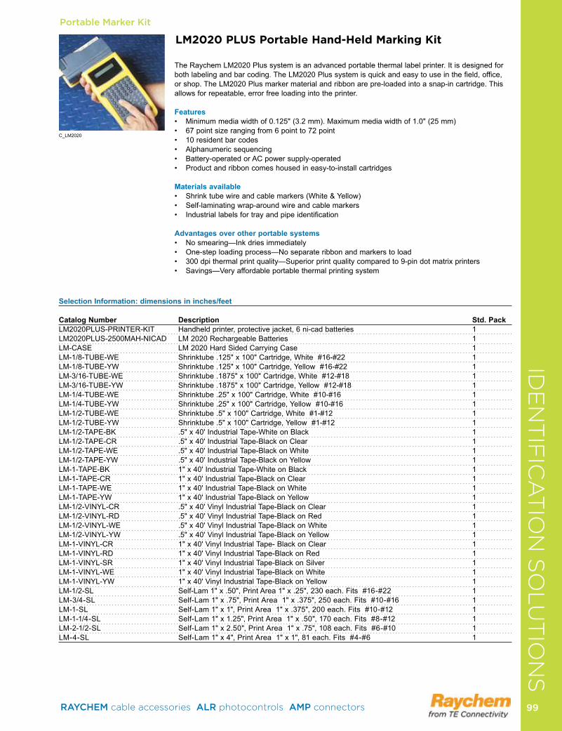
Portable Marker Kit
Selection Information: dimensions in inches/feet
Catalog Number Description Std. PackLM2020PLUS-PRINTER-KIT Handheldprinter,protectivejacket,6ni-cadbatteries 1LM2020PLUS-2500MAH-NICAD LM 2020 Rechargeable Batteries 1LM-CASE LM 2020 Hard Sided Carrying Case 1LM-1/8-TUBE-WE Shrinktube.125"x100"Cartridge,White#16-#22 1LM-1/8-TUBE-YW Shrinktube.125"x100"Cartridge,Yellow#16-#22 1LM-3/16-TUBE-WE Shrinktube.1875"x100"Cartridge,White#12-#18 1LM-3/16-TUBE-YW Shrinktube.1875"x100"Cartridge,Yellow#12-#18 1LM-1/4-TUBE-WE Shrinktube.25"x100"Cartridge,White#10-#16 1LM-1/4-TUBE-YW Shrinktube.25"x100"Cartridge,Yellow#10-#16 1LM-1/2-TUBE-WE Shrinktube.5"x100"Cartridge,White#1-#12 1LM-1/2-TUBE-YW Shrinktube.5"x100"Cartridge,Yellow#1-#12 1LM-1/2-TAPE-BK .5"x40'IndustrialTape-WhiteonBlack 1LM-1/2-TAPE-CR .5"x40'IndustrialTape-BlackonClear 1LM-1/2-TAPE-WE .5"x40'IndustrialTape-BlackonWhite 1LM-1/2-TAPE-YW .5"x40'IndustrialTape-BlackonYellow 1LM-1-TAPE-BK 1"x40'IndustrialTape-WhiteonBlack 1LM-1-TAPE-CR 1"x40'IndustrialTape-BlackonClear 1LM-1-TAPE-WE 1"x40'IndustrialTape-BlackonWhite 1LM-1-TAPE-YW 1"x40'IndustrialTape-BlackonYellow 1LM-1/2-VINYL-CR .5"x40'VinylIndustrialTape-BlackonClear 1LM-1/2-VINYL-RD .5"x40'VinylIndustrialTape-BlackonRed 1LM-1/2-VINYL-WE .5"x40'VinylIndustrialTape-BlackonWhite 1LM-1/2-VINYL-YW .5"x40'VinylIndustrialTape-BlackonYellow 1LM-1-VINYL-CR 1"x40'VinylIndustrialTape-BlackonClear 1LM-1-VINYL-RD 1"x40'VinylIndustrialTape-BlackonRed 1LM-1-VINYL-SR 1"x40'VinylIndustrialTape-BlackonSilver 1LM-1-VINYL-WE 1"x40'VinylIndustrialTape-BlackonWhite 1LM-1-VINYL-YW 1"x40'VinylIndustrialTape-BlackonYellow 1LM-1/2-SL Self-Lam1"x.50",PrintArea1"x.25",230each.Fits#16-#22 1LM-3/4-SL Self-Lam1"x.75",PrintArea1"x.375",250each.Fits#10-#16 1LM-1-SL Self-Lam1"x1",PrintArea1"x.375",200each.Fits#10-#12 1LM-1-1/4-SL Self-Lam1"x1.25",PrintArea1"x.50",170each.Fits#8-#12 1LM-2-1/2-SL Self-Lam1"x2.50",PrintArea1"x.75",108each.Fits#6-#10 1LM-4-SL Self-Lam1"x4",PrintArea1"x1",81each.Fits#4-#6 1
LM2020 PLUS Portable Hand-Held Marking Kit
The Raychem LM2020 Plus system is an advanced portable thermal label printer It is designed for bothlabelingandbarcoding.TheLM2020Plussystemisquickandeasytouseinthefield,office,or shop The LM2020 Plus marker material and ribbon are pre-loaded into a snap-in cartridge This allows for repeatable, error free loading into the printer
Features• Minimummediawidthof0.125"(3.2mm).Maximummediawidthof1.0"(25mm)• 67pointsizerangingfrom6pointto72point• 10residentbarcodes• Alphanumericsequencing• Battery-operatedorACpowersupply-operated• Productandribboncomeshousedineasy-to-installcartridges
Materials available• Shrinktubewireandcablemarkers(White&Yellow)• Self-laminatingwrap-aroundwireandcablemarkers• Industriallabelsfortrayandpipeidentification
Advantages over other portable systems• Nosmearing—Inkdriesimmediately• One-steploadingprocess—Noseparateribbonandmarkerstoload• 300dpithermalprintquality—Superiorprintqualitycomparedto9-pindotmatrixprinters • Savings—Veryaffordableportablethermalprintingsystem
C_LM2020
IDE
NT
IFIC
AT
ION
SO
LU
TIO
NS
RAYCHEM cable accessories ALR photocontrols AMP connectors 99 99
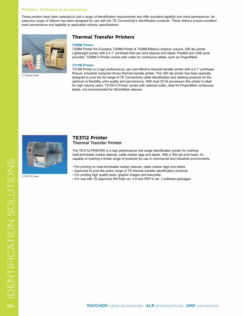
Printers, Software & Accessories
Thermal Transfer Printers
T208M PrinterT208MPrinterKit(ContainsT208M-Printer&T208M-Ribbon)mediumvolume,200dpiprinter.Lightweight printer with a 4 1” printhead that can print sleeves and labels Parallel and USB ports provided T208M-C-Printer comes with cutter for continuous labels, such as ProjectMark
T312M PrinterT312M Printer is a high performance, yet cost effective thermal transfer printer with a 4 1” printhead Robust, industrial computer-driven thermal transfer printer This 300 dpi printer has been specially designed to print the full range of TE Connectivity cable identification and labeling products for the optimuminflexibility,printqualityandpermanence.Withdual32bitprocessorsthisprinterisidealfor high volume users T312S-C-Printer comes with optional cutter, ideal for ProjectMark continuous labels, not recommended for ShrinkMark sleeves
TE3112 PrinterThermal Transfer Printer
The TE3112-PRINTER is a high performance mid-range Identification printer for markingheat-shrinkable marker sleeves, cable marker tags and labels With a 300 dpi print head, it’scapable of marking a broad range of products for use in commercial and industrial environments
•Forprintingonheat-shrinkablemarkersleeves,cablemarkertagsandlabels•ApprovedtoprinttheentirerangeofTEthermaltransferidentificationproducts•Forprintinghighqualitytexts,graphicimagesandbarcodes•ForusewithTEapprovedWinTotalver.4.9andPEP-5ver.3softwarepackages.
C_Thermal_Printer
C_TE3112_Printer
These printers have been selected to suit a range of identification requirements and offer excellent legibility and mark permanence. An extensive range of ribbons has been designed for use with the TE Connectivity’s identification products. These ribbons ensure excellent mark permanence and legibility to applicable industry specifications.
IDE
NT
IFIC
AT
ION
SO
LU
TIO
NS
RAYCHEM cable accessories ALR photocontrols AMP connectors 100100
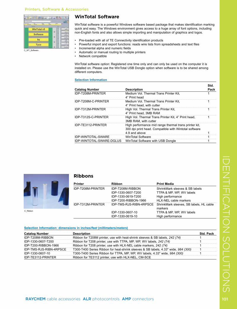
Printers, Software & Accessories
WinTotal Software
WinTotal software is a powerful Windows software based package that makes identification marking quickandeasy.TheWindowsenvironmentgivesaccesstoahugearrayoffontoptions,includingnon-English fonts and also allows simple importing and manipulation of graphics and logos
• Pre-loadedwithallofTEConnectivityidentificationproducts• Powerfulimportandexportfunctions:readswirelistsfromspreadsheetsandtextfiles• Incrementalalphaandnumericfields• Automaticormanualroutingtomultipleprinters• Networkcompatible
WinTotalsoftwareoption:Registeredonetimeonlyandcanonlybeusedonthecomputeritisinstalled on Please use the WinTotal USB Dongle option when software is to be shared among different computers
Selection Information
Std. Catalog Number Description PackIDP-T208M-PRINTER MediumVol.ThermalTransPrinterKit, 1 4” Print headIDP-T208M-C-PRINTER MediumVol.ThermalTransPrinterKit, 1 4” Print head, with cutterIDP-T312M-PRINTER HighVol.ThermalTransPrinterKit, 1 4” Print head, 3MB RAMIDP-T312S-C-PRINTER HighVol.ThermalTransPrinterKit,4”Printhead, 1 3MB RAM, with cutterIDP-TE3112-PRINTER High performance mid range thermal trans printer kit, 300 dpi print head Compatible with Wintotal software 4 9 and above 1IDP-WINTOTAL-SWARE WinTotal Software 1IDP-WINTOTAL-SWARE-DGLUS WinTotal Software with USB Dongle 1
C_WT_Software
Selection Information: dimensions in inches/feet (millimeters/meters)
Catalog Number Description Std. PackIDP-T208M-RIBBON RibbonforT208Mprinter,usewithheat-shrinksleeves&SBlabels,242 (74) 1IDP-1330-0607-T200 Ribbon for T208 printer, use with TTPA, MP, WP, WV labels, 242 (74) 1IDP-T200-RIBBON-1966 Ribbon for T208 printer, use with HLX-NEL cable markers, 242 (74) 1IDP-TMS-RJS-RIBN-4RPSCE T300-T400SeriesRibbonforheat-shrinksleeves&SBlabels,4.33"wide,984 (300) 1IDP-1330-0607-10 T300-T400SeriesRibbonforTTPA,MP,WP,WVlabels,4.33"wide,984 (300) 1IDP-TE3112-PRINTER Ribbon for TE3112 printer, use with HLX-NEL, CM-SCE
Ribbons
Printer Ribbon Print MediaIDP-T208M-PRINTER IDP-T208M-RIBBON ShrinkMarksleeves&SBlabels IDP-1330-0607-T200 TTPA&MP,WP,WVlabels IDP-1330-0619-T200 High performance IDP-T200-RIBBON-1966 HLX-NEL cable markersIDP-T312M-PRINTER IDP-TMS-RJS-RIBN-4RPSCE ShrinkMark sleeves, SB labels, HL cable
markers IDP-1330-0607-10 TTPA&MP,WP,WVlabels IDP-1330-0619-10 High performance
C_Ribbon
IDE
NT
IFIC
AT
ION
SO
LU
TIO
NS
RAYCHEM cable accessories ALR photocontrols AMP connectors 101 101
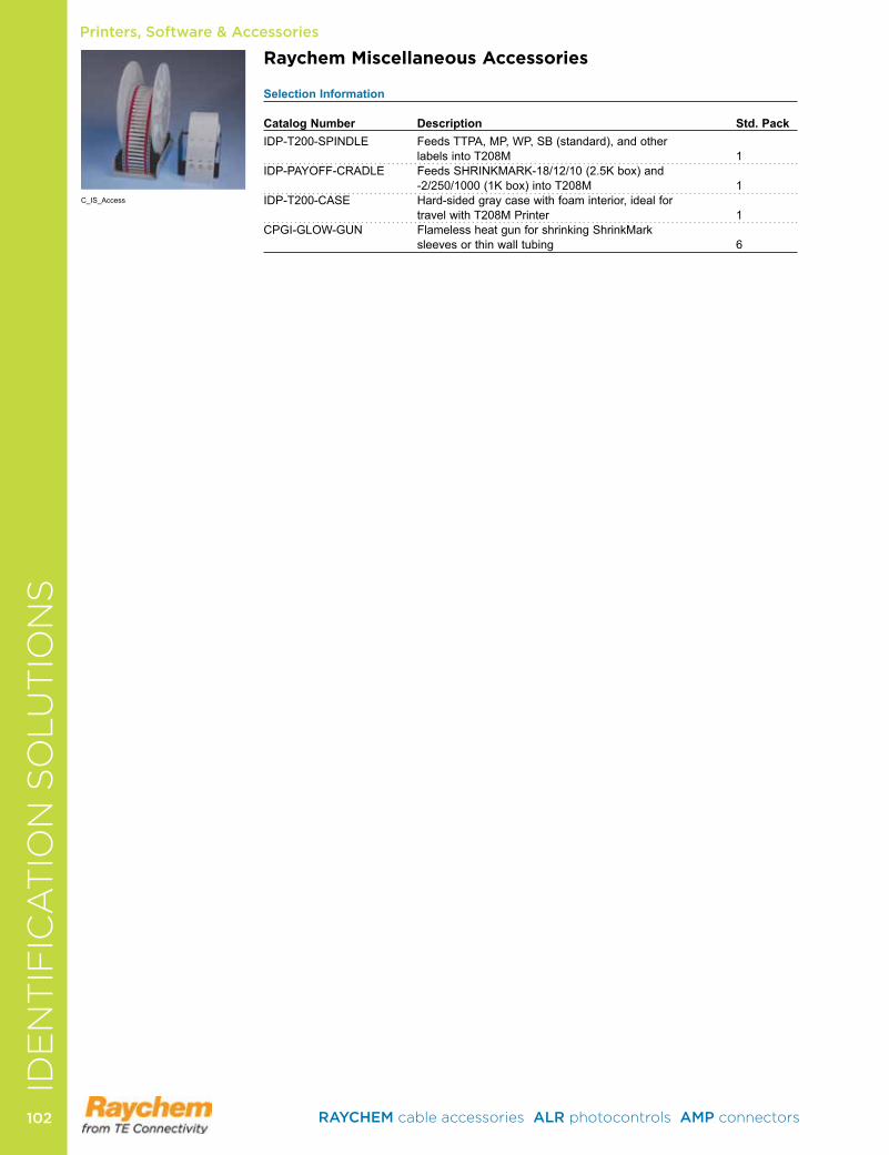
Printers, Software & AccessoriesID
EN
TIF
ICA
TIO
N S
OLU
TIO
NS
Raychem Miscellaneous Accessories Selection Information Catalog Number Description Std. PackIDP-T200-SPINDLE FeedsTTPA,MP,WP,SB(standard),andother
labels into T208M 1IDP-PAYOFF-CRADLE FeedsSHRINKMARK-18/12/10(2.5Kbox)and
-2/250/1000(1Kbox)intoT208M 1IDP-T200-CASE Hard-sided gray case with foam interior, ideal for
travel with T208M Printer 1CPGI-GLOW-GUN FlamelessheatgunforshrinkingShrinkMark
sleeves or thin wall tubing 6
C_IS_Access
RAYCHEM cable accessories ALR photocontrols AMP connectors 102102

Low Voltage In-Line SplicesCold-AppliedGelWrap Splice Closures . . . . . . . . . . . . . . . . . . . . . . . . . . . . 104GILS In-Line Splices . . . . . . . . . . . . . . . . . . . . . . . . . . . . . . . . . 105Rayvolve RVS Splices . . . . . . . . . . . . . . . . . . . . . . . . . . . . . . . 105
Heat-ShrinkMWTM Tubing . . . . . . . . . . . . . . . . . . . . . . . . . . . . . . . . . . . . . 106WCSM Tubing . . . . . . . . . . . . . . . . . . . . . . . . . . . . . . . . . . . . . 107FCSM Tubing . . . . . . . . . . . . . . . . . . . . . . . . . . . . . . . . . . . . . . 109CRSM Sleeves . . . . . . . . . . . . . . . . . . . . . . . . . . . . . . . . . . . . . .110CRSM CT Cable Tap Splices . . . . . . . . . . . . . . . . . . . . . . . . . . .111MRS Repair Sleeves . . . . . . . . . . . . . . . . . . . . . . . . . . . . . . . . .112ALK Splice Sealing Kit . . . . . . . . . . . . . . . . . . . . . . . . . . . . . . . .113LVSA-3 Splice . . . . . . . . . . . . . . . . . . . . . . . . . . . . . . . . . . . . . . .113LV-MSK Splice . . . . . . . . . . . . . . . . . . . . . . . . . . . . . . . . . . . . . .114
Low Voltage Stub Splices & Motor Connection KitsGelCap Splice Covers . . . . . . . . . . . . . . . . . . . . . . . . . . . . . . . .115Rayvolve RVC Splice Cover Kits . . . . . . . . . . . . . . . . . . . . . . . .116MCK Motor Connection Kits . . . . . . . . . . . . . . . . . . . . . . . . . . .117
Low Voltage TapsGTAP Splices . . . . . . . . . . . . . . . . . . . . . . . . . . . . . . . . . . . . . .118GelCap SL Splice Covers . . . . . . . . . . . . . . . . . . . . . . . . . . . . .119GHFC H-Frame Closures . . . . . . . . . . . . . . . . . . . . . . . . . . . . 120GelPort Connectors . . . . . . . . . . . . . . . . . . . . . . . . . . . . . . . . . 121
Network ProtectionSmart Limiter . . . . . . . . . . . . . . . . . . . . . . . . . . . . . . . . . . . . . . 122
LOW VOLTAGE SPLICES & TAPS
RAYCHEM cable accessories ALR photocontrols AMP connectors 103 103
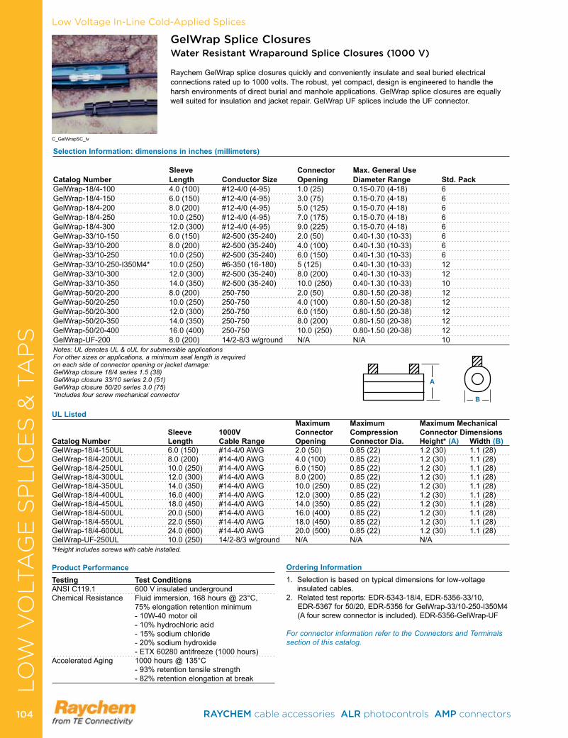
Low Voltage In-Line Cold-Applied Splices
GelWrap Splice Closures Water Resistant Wraparound Splice Closures (1000 V)
Raychem GelWrap splice closures quickly and conveniently insulate and seal buried electrical connections rated up to 1000 volts . The robust, yet compact, design is engineered to handle the harsh environments of direct burial and manhole applications . GelWrap splice closures are equally well suited for insulation and jacket repair . GelWrap UF splices include the UF connector .
Selection Information: dimensions in inches (millimeters) Sleeve Connector Max. General Use Catalog Number Length Conductor Size Opening Diameter Range Std. PackGelWrap-18/4-100 4 .0 (100) #12-4/0 (4-95) 1 .0 (25) 0 .15-0 .70 (4-18) 6GelWrap-18/4-150 6 .0 (150) #12-4/0 (4-95) 3 .0 (75) 0 .15-0 .70 (4-18) 6GelWrap-18/4-200 8 .0 (200) #12-4/0 (4-95) 5 .0 (125) 0 .15-0 .70 (4-18) 6GelWrap-18/4-250 10 .0 (250) #12-4/0 (4-95) 7 .0 (175) 0 .15-0 .70 (4-18) 6GelWrap-18/4-300 12 .0 (300) #12-4/0 (4-95) 9 .0 (225) 0 .15-0 .70 (4-18) 6GelWrap-33/10-150 6 .0 (150) #2-500 (35-240) 2 .0 (50) 0 .40-1 .30 (10-33) 6GelWrap-33/10-200 8 .0 (200) #2-500 (35-240) 4 .0 (100) 0 .40-1 .30 (10-33) 6GelWrap-33/10-250 10 .0 (250) #2-500 (35-240) 6 .0 (150) 0 .40-1 .30 (10-33) 6GelWrap-33/10-250-I350M4* 10 .0 (250) #6-350 (16-180) 5 (125) 0 .40-1 .30 (10-33) 12GelWrap-33/10-300 12 .0 (300) #2-500 (35-240) 8 .0 (200) 0 .40-1 .30 (10-33) 12GelWrap-33/10-350 14 .0 (350) #2-500 (35-240) 10 .0 (250) 0 .40-1 .30 (10-33) 10GelWrap-50/20-200 8 .0 (200) 250-750 2 .0 (50) 0 .80-1 .50 (20-38) 12GelWrap-50/20-250 10 .0 (250) 250-750 4 .0 (100) 0 .80-1 .50 (20-38) 12GelWrap-50/20-300 12 .0 (300) 250-750 6 .0 (150) 0 .80-1 .50 (20-38) 12GelWrap-50/20-350 14 .0 (350) 250-750 8 .0 (200) 0 .80-1 .50 (20-38) 12GelWrap-50/20-400 16 .0 (400) 250-750 10 .0 (250) 0 .80-1 .50 (20-38) 12GelWrap-UF-200 8 .0 (200) 14/2-8/3 w/ground N/A N/A 10Notes: UL denotes UL & cUL for submersible applicationsFor other sizes or applications, a minimum seal length is required on each side of connector opening or jacket damage:GelWrap closure 18/4 series 1.5 (38)GelWrap closure 33/10 series 2.0 (51)GelWrap closure 50/20 series 3.0 (75)*Includes four screw mechanical connector
Ordering Information1 . Selection is based on typical dimensions for low-voltage
insulated cables .2 . Related test reports: EDR-5343-18/4, EDR-5356-33/10,
EDR-5367 for 50/20, EDR-5356 for GelWrap-33/10-250-I350M4 (A four screw connector is included) . EDR-5356-GelWrap-UF
For connector information refer to the Connectors and Terminals section of this catalog.
Product PerformanceTesting Test ConditionsANSI C119 .1 600 V insulated underground Chemical Resistance Fluid immersion, 168 hours @ 23°C,
75% elongation retention minimum- 10W-40 motor oil- 10% hydrochloric acid- 15% sodium chloride- 20% sodium hydroxide- ETX 60280 antifreeze (1000 hours)
Accelerated Aging 1000 hours @ 135°C- 93% retention tensile strength- 82% retention elongation at break
UL ListedMaximum Maximum Maximum Mechanical
Sleeve 1000V Connector Compression Connector DimensionsCatalog Number Length Cable Range Opening Connector Dia. Height* (A) Width (B)GelWrap-18/4-150UL 6 .0 (150) #14-4/0 AWG 2 .0 (50) 0 .85 (22) 1 .2 (30) 1 .1 (28)GelWrap-18/4-200UL 8 .0 (200) #14-4/0 AWG 4 .0 (100) 0 .85 (22) 1 .2 (30) 1 .1 (28)GelWrap-18/4-250UL 10 .0 (250) #14-4/0 AWG 6 .0 (150) 0 .85 (22) 1 .2 (30) 1 .1 (28)GelWrap-18/4-300UL 12 .0 (300) #14-4/0 AWG 8 .0 (200) 0 .85 (22) 1 .2 (30) 1 .1 (28)GelWrap-18/4-350UL 14 .0 (350) #14-4/0 AWG 10 .0 (250) 0 .85 (22) 1 .2 (30) 1 .1 (28)GelWrap-18/4-400UL 16 .0 (400) #14-4/0 AWG 12 .0 (300) 0 .85 (22) 1 .2 (30) 1 .1 (28)GelWrap-18/4-450UL 18 .0 (450) #14-4/0 AWG 14 .0 (350) 0 .85 (22) 1 .2 (30) 1 .1 (28)GelWrap-18/4-500UL 20 .0 (500) #14-4/0 AWG 16 .0 (400) 0 .85 (22) 1 .2 (30) 1 .1 (28)GelWrap-18/4-550UL 22 .0 (550) #14-4/0 AWG 18 .0 (450) 0 .85 (22) 1 .2 (30) 1 .1 (28)GelWrap-18/4-600UL 24 .0 (600) #14-4/0 AWG 20 .0 (500) 0 .85 (22) 1 .2 (30) 1 .1 (28)GelWrap-UF-250UL 10 .0 (250) 14/2-8/3 w/ground N/A N/A N/A*Height includes screws with cable installed.
A
B
C_GelWrapSC_lv
LO
W V
OLT
AG
E S
PL
ICE
S &
TA
PS
RAYCHEM cable accessories ALR photocontrols AMP connectors 104104

LO
W V
OLT
AG
E S
PL
ICE
S &
TA
PS
Low Voltage In-Line Cold-Applied Splices
Gel In-Line Splices (GILS)Water Resistant Splice Kit for Power Cable (1000 V)
Raychem Gel in-line splice (GILS) kits offer a state-of-the-art sealed splice for underground, buried, and overhead applications . GILS closures offer a fast and simple method for splicing, insulating, and environmentally sealing low-voltage cable splices .
The GILS closure, with its revolutionary PowerGel sealant, covers and seals the splice quickly and easily, saving both time and effort .
Simply install the connector, place on the closure, and snap closed . It’s that easy—no tapes, mastic, tools or mixing are required . The splice is ready to bury-no waiting to cure .
• Connectoraccommodatescopperand/oraluminumcables• QualifiedtoANSIC119forundergroundsplicing• UVresistant• Qualifiedfortemperaturesfrom-40°Cto90°C• Connectorincluded• RUSacceptedconnectorblocksandsplicesforsecondary.• Water-tightforuseinalllocations
Selection Information
Catalog Number Conductor Size (AWG/kcmil) Std. PackGILS-4/0 #2-4/0 18 or 72 eachGILS-350 1/0-350 18
Ordering Information1 . Based on typical dimensions for low-voltage insulated cables .2 . Related test reports: EDR-5298, EDR-5394
C_GILS_lv
Rayvolve RVS Splice Covers“Roll-on” Splices for 1/C Power Cable (1000 V)
Raychem RVS splice cover kits are the easy “roll-on” way to insulate and seal cable connections up to 1000 V . The gripping force of the specially formulated EPDM elastomer combines with the high-performance sealant to form a water-resistant, insulating sleeve that is UL listed and CSA certified for direct burial application over in-line compression connectors .
RVS splice cover sleeves feature a dual-wall design with an entrapped lubricant, making installation fast and simple . The elastomeric sleeve rolls onto the cable with minimal effort, even at temperatures below –15°F (–25°C) . The cable can be energized immediately . It is ideal for use where gas or electric heating devices are not approved .
QualifiedtoANSIC119.1.CSAcertifiedtoC22.2No.198.2.ULlistedper96J4(fileE91151).RUSaccepted for use as a secondary tap or splice cover . For use on standard poly- or elastomeric-insulated cables . Use to insulate and seal in-line compression connectors or to seal terminal lugs .
Selection Information: dimensions in inches (millimeters)
Conductor Size Maximum Catalog Number (AWG/kcmil) Cable O.D. (Min.–Max.) Sleeve Length Connector LengthRVS-11 #8-2/0 .22- .68 (6-17) 8 .0 (205) 5 .00 (127)RVS-12 1/0-250 .50- .90 (13-23) 9 .5 (241) 4 .50 (114)RVS-13 250-600 .70-1 .20 (18-30) 12 .0 (305) 7 .00 (178)RVS-14 600-1000 .95-1 .50 (24-38) 14 .0 (356) 9 .00 (229)
C_RVS_lv
1 . Select the appropriate catalog number . Selections are based on typical dimensions of low-voltage insulated cable . Confirm selection with dimensions to assure proper sizing .
2 . Kits do not contain connectors . The RVS splice cover selection information mentioned above covers copper and aluminum in-line compression connections .
3 . Each kit contains one Rayvolve RVS splice cover sleeve and sealant strips .
4 . Standard package: 5 kits/box or 50 kits/box .5 . Related test report: EDR-5167 .
Ordering Information
RAYCHEM cable accessories ALR photocontrols AMP connectors 105 105
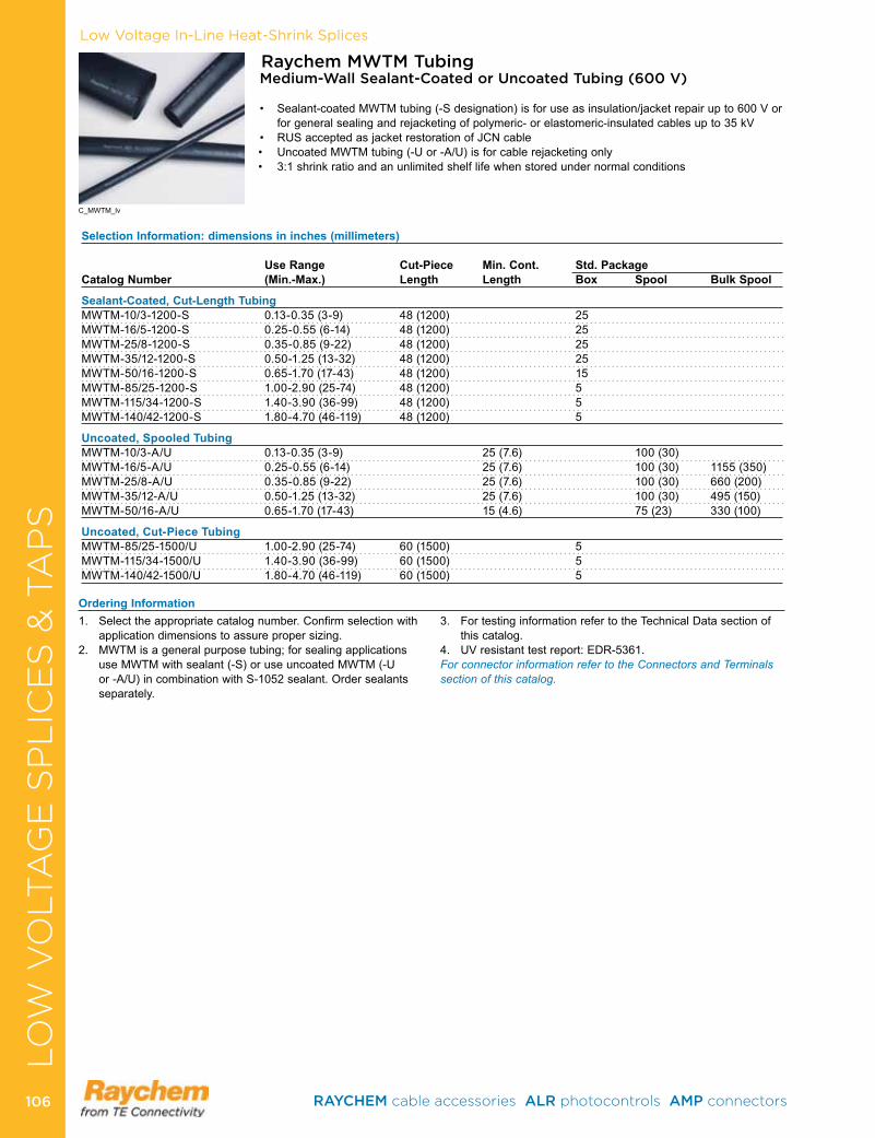
Low Voltage In-Line Heat-Shrink Splices
Raychem MWTM TubingMedium-Wall Sealant-Coated or Uncoated Tubing (600 V)
• Sealant-coatedMWTMtubing(-Sdesignation)isforuseasinsulation/jacketrepairupto600Vorfor general sealing and rejacketing of polymeric- or elastomeric-insulated cables up to 35 kV
• RUSacceptedasjacketrestorationofJCNcable• UncoatedMWTMtubing(-Uor-A/U)isforcablerejacketingonly• 3:1shrinkratioandanunlimitedshelflifewhenstoredundernormalconditions
Selection Information: dimensions in inches (millimeters)
Use Range Cut-Piece Min. Cont. Std. PackageCatalog Number (Min.-Max.) Length Length Box Spool Bulk Spool
Sealant-Coated, Cut-Length Tubing MWTM-10/3-1200-S 0 .13-0 .35 (3-9) 48 (1200) 25 MWTM-16/5-1200-S 0 .25-0 .55 (6-14) 48 (1200) 25 MWTM-25/8-1200-S 0 .35-0 .85 (9-22) 48 (1200) 25 MWTM-35/12-1200-S 0 .50-1 .25 (13-32) 48 (1200) 25 MWTM-50/16-1200-S 0 .65-1 .70 (17-43) 48 (1200) 15 MWTM-85/25-1200-S 1 .00-2 .90 (25-74) 48 (1200) 5 MWTM-115/34-1200-S 1 .40-3 .90 (36-99) 48 (1200) 5 MWTM-140/42-1200-S 1 .80-4 .70 (46-119) 48 (1200) 5
Uncoated, Spooled TubingMWTM-10/3-A/U 0 .13-0 .35 (3-9) 25 (7 .6) 100 (30) MWTM-16/5-A/U 0 .25-0 .55 (6-14) 25 (7 .6) 100 (30) 1155 (350)MWTM-25/8-A/U 0 .35-0 .85 (9-22) 25 (7 .6) 100 (30) 660 (200)MWTM-35/12-A/U 0 .50-1 .25 (13-32) 25 (7 .6) 100 (30) 495 (150)MWTM-50/16-A/U 0 .65-1 .70 (17-43) 15 (4 .6) 75 (23) 330 (100)
Uncoated, Cut-Piece TubingMWTM-85/25-1500/U 1 .00-2 .90 (25-74) 60 (1500) 5 MWTM-115/34-1500/U 1 .40-3 .90 (36-99) 60 (1500) 5 MWTM-140/42-1500/U 1 .80-4 .70 (46-119) 60 (1500) 5
C_MWTM_lv
1 . Select the appropriate catalog number . Confirm selection with application dimensions to assure proper sizing .
2 . MWTM is a general purpose tubing; for sealing applications use MWTM with sealant (-S) or use uncoated MWTM (-U or -A/U) in combination with S-1052 sealant . Order sealants separately .
3 . For testing information refer to the Technical Data section of this catalog .
4 . UV resistant test report: EDR-5361 .For connector information refer to the Connectors and Terminals section of this catalog.
Ordering Information
LO
W V
OLT
AG
E S
PL
ICE
S &
TA
PS
RAYCHEM cable accessories ALR photocontrols AMP connectors 106106
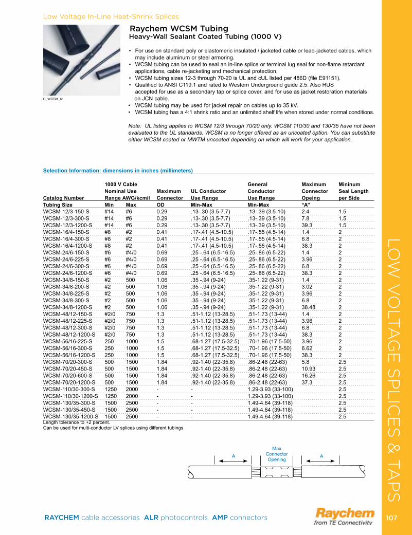
Low Voltage In-Line Heat-Shrink Splices
C_WCSM_lv
LO
W V
OLT
AG
E S
PL
ICE
S &
TA
PS
Selection Information: dimensions in inches (millimeters)
1000 V Cable General Maximum MininumNominal Use Maximum UL Conductor Conductor Connector Seal Length
Catalog Number Range AWG/kcmil Connector Use Range Use Range Opeing per SideTubing Size Min Max OD Min-Max Min-Max “A”WCSM-12/3-150-S #14 #6 0 .29 .13- .30 (3 .5-7 .7) .13- .39 (3 .5-10) 2 .4 1 .5WCSM-12/3-300-S #14 #6 0 .29 .13- .30 (3 .5-7 .7) .13- .39 (3 .5-10) 7 .8 1 .5WCSM-12/3-1200-S #14 #6 0 .29 .13- .30 (3 .5-7 .7) .13- .39 (3 .5-10) 39 .3 1 .5WCSM-16/4-150-S #8 #2 0 .41 .17- .41 (4 .5-10 .5) .17- .55 (4 .5-14) 1 .4 2WCSM-16/4-300-S #8 #2 0 .41 .17- .41 (4 .5-10 .5) .17- .55 (4 .5-14) 6 .8 2WCSM-16/4-1200-S #8 #2 0 .41 .17- .41 (4 .5-10 .5) .17- .55 (4 .5-14) 38 .3 2WCSM-24/6-150-S #6 #4/0 0 .69 .25 - .64 (6 .5-16 .5) .25- .86 (6 .5-22) 1 .4 2WCSM-24/6-225-S #6 #4/0 0 .69 .25 - .64 (6 .5-16 .5) .25- .86 (6 .5-22) 3 .96 2WCSM-24/6-300-S #6 #4/0 0 .69 .25 - .64 (6 .5-16 .5) .25- .86 (6 .5-22) 6 .8 2WCSM-24/6-1200-S #6 #4/0 0 .69 .25 - .64 (6 .5-16 .5) .25- .86 (6 .5-22) 38 .3 2WCSM-34/8-150-S #2 500 1 .06 .35 - .94 (9-24) .35-1 .22 (9-31) 1 .4 2WCSM-34/8-200-S #2 500 1 .06 .35 - .94 (9-24) .35-1 .22 (9-31) 3 .02 2WCSM-34/8-225-S #2 500 1 .06 .35 - .94 (9-24) .35-1 .22 (9-31) 3 .96 2WCSM-34/8-300-S #2 500 1 .06 .35 - .94 (9-24) .35-1 .22 (9-31) 6 .8 2WCSM-34/8-1200-S #2 500 1 .06 .35 - .94 (9-24) .35-1 .22 (9-31) 38 .48 2WCSM-48/12-150-S #2/0 750 1 .3 .51-1 .12 (13-28 .5) .51-1 .73 (13-44) 1 .4 2WCSM-48/12-225-S #2/0 750 1 .3 .51-1 .12 (13-28 .5) .51-1 .73 (13-44) 3 .96 2WCSM-48/12-300-S #2/0 750 1 .3 .51-1 .12 (13-28 .5) .51-1 .73 (13-44) 6 .8 2WCSM-48/12-1200-S #2/0 750 1 .3 .51-1 .12 (13-28 .5) .51-1 .73 (13-44) 38 .3 2WCSM-56/16-225-S 250 1000 1 .5 .68-1 .27 (17 .5-32 .5) .70-1 .96 (17 .5-50) 3 .96 2WCSM-56/16-300-S 250 1000 1 .5 .68-1 .27 (17 .5-32 .5) .70-1 .96 (17 .5-50) 6 .62 2WCSM-56/16-1200-S 250 1000 1 .5 .68-1 .27 (17 .5-32 .5) .70-1 .96 (17 .5-50) 38 .3 2WCSM-70/20-300-S 500 1500 1 .84 .92-1 .40 (22-35 .8) .86-2 .48 (22-63) 5 .8 2 .5WCSM-70/20-450-S 500 1500 1 .84 .92-1 .40 (22-35 .8) .86-2 .48 (22-63) 10 .93 2 .5WCSM-70/20-600-S 500 1500 1 .84 .92-1 .40 (22-35 .8) .86-2 .48 (22-63) 16 .26 2 .5WCSM-70/20-1200-S 500 1500 1 .84 .92-1 .40 (22-35 .8) .86-2 .48 (22-63) 37 .3 2 .5WCSM-110/30-300-S 1250 2000 - - 1 .29-3 .93 (33-100) 2 .5WCSM-110/30-1200-S 1250 2000 - - 1 .29-3 .93 (33-100) 2 .5WCSM-130/35-300-S 1500 2500 - - 1 .49-4 .64 (39-118) 2 .5WCSM-130/35-450-S 1500 2500 - - 1 .49-4 .64 (39-118) 2 .5WCSM-130/35-1200-S 1500 2500 - - 1 .49-4 .64 (39-118) 2 .5Length tolerance to +2 percent .Can be used for multi-conductor LV splices using different tubings
Raychem WCSM Tubing Heavy-Wall Sealant Coated Tubing (1000 V)
• Foruseonstandardpolyorelastomericinsulated/jacketedcableorlead-jacketedcables,whichmay include aluminum or steel armoring .
• WCSMtubingcanbeusedtosealanin-linespliceorterminallugsealfornon-flameretardantapplications, cable re-jacketing and mechanical protection .
• WCSMtubingsizes12-3through70-20isULandcULlistedper486D(fileE91151).• QualifiedtoANSIC119.1andratedtoWesternUndergroundguide2.5.AlsoRUS
accepted for use as a secondary tap or splice cover, and for use as jacket restoration materials onJCNcable.
• WCSMtubingmaybeusedforjacketrepaironcablesupto35kV.• WCSMtubinghasa4:1shrinkratioandanunlimitedshelflifewhenstoredundernormalconditions.
Note: UL listing applies to WCSM 12/3 through 70/20 only. WCSM 110/30 and 130/35 have not been evaluated to the UL standards. WCSM is no longer offered as an uncoated option. You can substitute either WCSM coated or MWTM uncoated depending on which will work for your application.
MaxConnector Opening
A A
RAYCHEM cable accessories ALR photocontrols AMP connectors 107 107
Low Voltage In-Line Heat-Shrink SplicesLO
W V
OLT
AG
E S
PL
ICE
S &
TA
PS
1 . Select the appropriate catalog number based on typical dimensions for low-voltage insulated cable . Confirm selection with dimensions to assure proper sizing . For general conductor use or UL conductor use .
2 Package does not contain connectors or lugs . Installed connector or lug diameter must be within use range .
3 . WCSM tubing may be field-cut for shorter requirements4 . Bulk packaging is available for cut lengths . Consult your
TE representative for more information .
5 . UL listing applies to WCSM 12/3 through 70/20 only . WCSM 110/30 and 130/35 are not UL listed .
6 . Related test reports: EDR 5541, PII 56428
For connector information refer to the Connectors and Terminals section of this catalog.
Ordering Information
Wire Connector System for Use With Underground Connectors 96J4
RAYCHEM cable accessories ALR photocontrols AMP connectors 108108
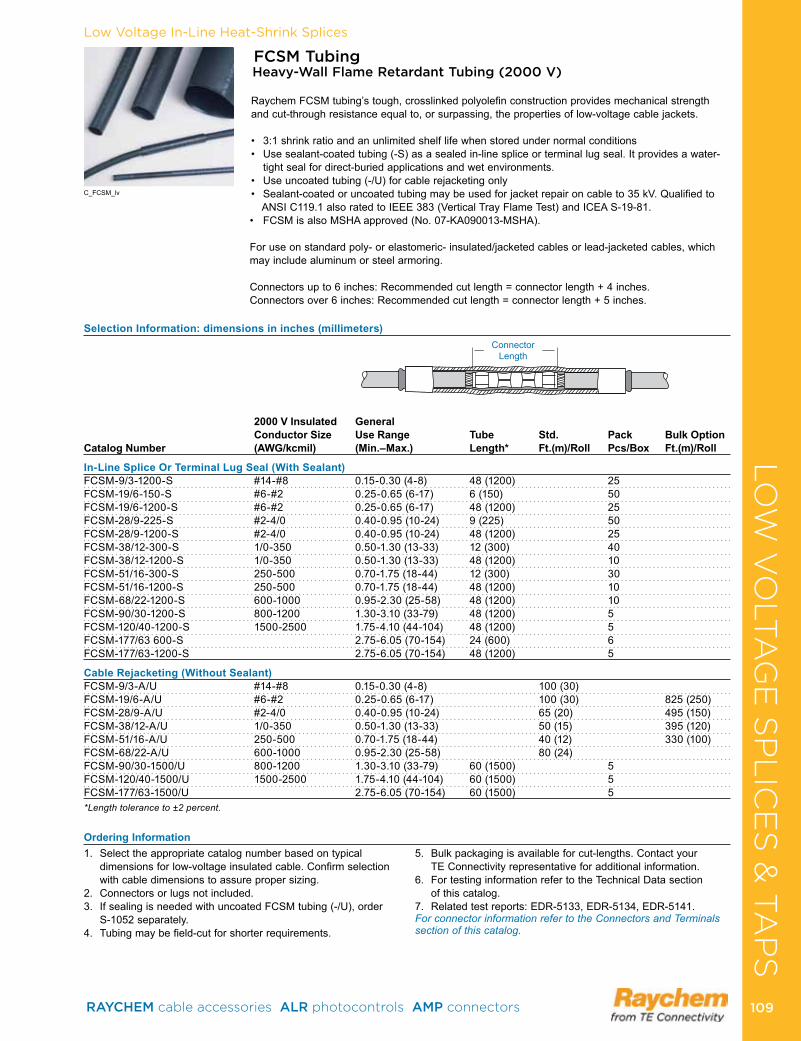
Low Voltage In-Line Heat-Shrink Splices
FCSM TubingHeavy-Wall Flame Retardant Tubing (2000 V)
Raychem FCSM tubing’s tough, crosslinked polyolefin construction provides mechanical strength and cut-through resistance equal to, or surpassing, the properties of low-voltage cable jackets .
• 3:1shrinkratioandanunlimitedshelflifewhenstoredundernormalconditions• Usesealant-coatedtubing(-S)asasealedin-linespliceorterminallugseal.Itprovidesawater-
tight seal for direct-buried applications and wet environments . • Useuncoatedtubing(-/U)forcablerejacketingonly• Sealant-coatedoruncoatedtubingmaybeusedforjacketrepaironcableto35kV.Qualifiedto
ANSI C119 .1 also rated to IEEE 383 (Vertical Tray Flame Test) and ICEA S-19-81 . • FCSMisalsoMSHAapproved(No.07-KA090013-MSHA).
For use on standard poly- or elastomeric- insulated/jacketed cables or lead-jacketed cables, which may include aluminum or steel armoring .
Connectors up to 6 inches: Recommended cut length = connector length + 4 inches .Connectors over 6 inches: Recommended cut length = connector length + 5 inches .
Selection Information: dimensions in inches (millimeters)
2000 V Insulated General Conductor Size Use Range Tube Std. Pack Bulk Option
Catalog Number (AWG/kcmil) (Min.–Max.) Length* Ft.(m)/Roll Pcs/Box Ft.(m)/Roll
In-Line Splice Or Terminal Lug Seal (With Sealant)FCSM-9/3-1200-S #14-#8 0 .15-0 .30 (4-8) 48 (1200) 25FCSM-19/6-150-S #6-#2 0 .25-0 .65 (6-17) 6 (150) 50FCSM-19/6-1200-S #6-#2 0 .25-0 .65 (6-17) 48 (1200) 25FCSM-28/9-225-S #2-4/0 0 .40-0 .95 (10-24) 9 (225) 50FCSM-28/9-1200-S #2-4/0 0 .40-0 .95 (10-24) 48 (1200) 25FCSM-38/12-300-S 1/0-350 0 .50-1 .30 (13-33) 12 (300) 40FCSM-38/12-1200-S 1/0-350 0 .50-1 .30 (13-33) 48 (1200) 10FCSM-51/16-300-S 250-500 0 .70-1 .75 (18-44) 12 (300) 30FCSM-51/16-1200-S 250-500 0 .70-1 .75 (18-44) 48 (1200) 10FCSM-68/22-1200-S 600-1000 0 .95-2 .30 (25-58) 48 (1200) 10FCSM-90/30-1200-S 800-1200 1 .30-3 .10 (33-79) 48 (1200) 5FCSM-120/40-1200-S 1500-2500 1 .75-4 .10 (44-104) 48 (1200) 5FCSM-177/63 600-S 2 .75-6 .05 (70-154) 24 (600) 6FCSM-177/63-1200-S 2 .75-6 .05 (70-154) 48 (1200) 5
Cable Rejacketing (Without Sealant)FCSM-9/3-A/U #14-#8 0 .15-0 .30 (4-8) 100 (30)FCSM-19/6-A/U #6-#2 0 .25-0 .65 (6-17) 100 (30) 825 (250)FCSM-28/9-A/U #2-4/0 0 .40-0 .95 (10-24) 65 (20) 495 (150)FCSM-38/12-A/U 1/0-350 0 .50-1 .30 (13-33) 50 (15) 395 (120)FCSM-51/16-A/U 250-500 0 .70-1 .75 (18-44) 40 (12) 330 (100)FCSM-68/22-A/U 600-1000 0 .95-2 .30 (25-58) 80 (24) FCSM-90/30-1500/U 800-1200 1 .30-3 .10 (33-79) 60 (1500) 5FCSM-120/40-1500/U 1500-2500 1 .75-4 .10 (44-104) 60 (1500) 5FCSM-177/63-1500/U 2 .75-6 .05 (70-154) 60 (1500) 5*Length tolerance to ±2 percent.
Connector Length
1 . Select the appropriate catalog number based on typical dimensions for low-voltage insulated cable . Confirm selection with cable dimensions to assure proper sizing .
2 . Connectors or lugs not included .3 . If sealing is needed with uncoated FCSM tubing (-/U), order
S-1052 separately .4 . Tubing may be field-cut for shorter requirements .
5 . Bulk packaging is available for cut-lengths . Contact your TE Connectivity representative for additional information .
6 . For testing information refer to the Technical Data section of this catalog .
7 . Related test reports: EDR-5133, EDR-5134, EDR-5141 . For connector information refer to the Connectors and Terminals section of this catalog.
Ordering Information
C_FCSM_lv
LO
W V
OLT
AG
E S
PL
ICE
S &
TA
PS
RAYCHEM cable accessories ALR photocontrols AMP connectors 109 109
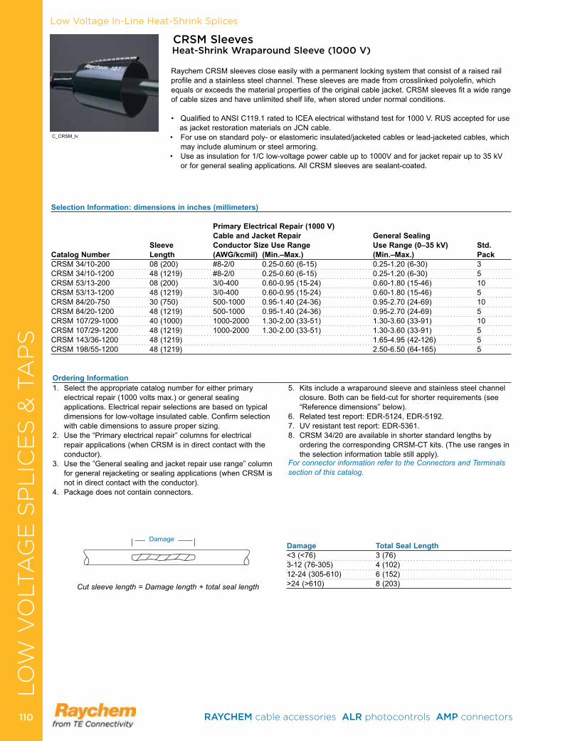
Low Voltage In-Line Heat-Shrink Splices
CRSM SleevesHeat-Shrink Wraparound Sleeve (1000 V)
Raychem CRSM sleeves close easily with a permanent locking system that consist of a raised rail profile and a stainless steel channel . These sleeves are made from crosslinked polyolefin, which equals or exceeds the material properties of the original cable jacket . CRSM sleeves fit a wide range of cable sizes and have unlimited shelf life, when stored under normal conditions .
• QualifiedtoANSIC119.1ratedtoICEAelectricalwithstandtestfor1000V.RUSacceptedforuseasjacketrestorationmaterialsonJCNcable.
• Foruseonstandardpoly-orelastomericinsulated/jacketedcablesorlead-jacketedcables,whichmay include aluminum or steel armoring .
• Useasinsulationfor1/Clow-voltagepowercableupto1000Vandforjacketrepairupto35kVor for general sealing applications . All CRSM sleeves are sealant-coated .
Selection Information: dimensions in inches (millimeters)
Primary Electrical Repair (1000 V) Cable and Jacket Repair General Sealing
Sleeve Conductor Size Use Range Use Range (0–35 kV) Std. Catalog Number Length (AWG/kcmil) (Min.–Max.) (Min.–Max.) PackCRSM 34/10-200 08 (200) #8-2/0 0 .25-0 .60 (6-15) 0 .25-1 .20 (6-30) 3CRSM 34/10-1200 48 (1219) #8-2/0 0 .25-0 .60 (6-15) 0 .25-1 .20 (6-30) 5CRSM 53/13-200 08 (200) 3/0-400 0 .60-0 .95 (15-24) 0 .60-1 .80 (15-46) 10CRSM 53/13-1200 48 (1219) 3/0-400 0 .60-0 .95 (15-24) 0 .60-1 .80 (15-46) 5CRSM 84/20-750 30 (750) 500-1000 0 .95-1 .40 (24-36) 0 .95-2 .70 (24-69) 10CRSM 84/20-1200 48 (1219) 500-1000 0 .95-1 .40 (24-36) 0 .95-2 .70 (24-69) 5CRSM 107/29-1000 40 (1000) 1000-2000 1 .30-2 .00 (33-51) 1 .30-3 .60 (33-91) 10CRSM 107/29-1200 48 (1219) 1000-2000 1 .30-2 .00 (33-51) 1 .30-3 .60 (33-91) 5CRSM 143/36-1200 48 (1219) 1 .65-4 .95 (42-126) 5CRSM 198/55-1200 48 (1219) 2 .50-6 .50 (64-165) 5
1 . Select the appropriate catalog number for either primary electrical repair (1000 volts max .) or general sealing applications . Electrical repair selections are based on typical dimensions for low-voltage insulated cable . Confirm selection with cable dimensions to assure proper sizing .
2 . Use the “Primary electrical repair” columns for electrical repair applications (when CRSM is in direct contact with the conductor) .
3 . Use the ”General sealing and jacket repair use range” column for general rejacketing or sealing applications (when CRSM is not in direct contact with the conductor) .
4 . Package does not contain connectors .
5 . Kits include a wraparound sleeve and stainless steel channel closure . Both can be field-cut for shorter requirements (see “Reference dimensions” below) .
6 . Related test report: EDR-5124, EDR-5192 .7 . UV resistant test report: EDR-5361 .8 . CRSM 34/20 are available in shorter standard lengths by
ordering the corresponding CRSM-CT kits . (The use ranges in the selection information table still apply) .
For connector information refer to the Connectors and Terminals section of this catalog.
Damage Total Seal Length<3 (<76) 3 (76)3-12 (76-305) 4 (102)12-24 (305-610) 6 (152)>24 (>610) 8 (203)Cut sleeve length = Damage length + total seal length
Damage
Ordering Information
C_CRSM_lv
LO
W V
OLT
AG
E S
PL
ICE
S &
TA
PS
RAYCHEM cable accessories ALR photocontrols AMP connectors 110110
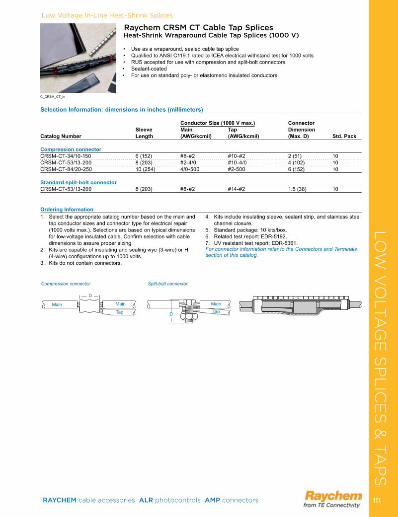
Low Voltage In-Line Heat-Shrink Splices
Selection Information: dimensions in inches (millimeters)
Conductor Size (1000 V max.) Connector Sleeve Main Tap Dimension Catalog Number Length (AWG/kcmil) (AWG/kcmil) (Max. D) Std. Pack
Compression connectorCRSM-CT-34/10-150 6 (152) #8-#2 #10-#2 2 (51) 10CRSM-CT-53/13-200 8 (203) #2-4/0 #10-4/0 4 (102) 10CRSM-CT-84/20-250 10 (254) 4/0-500 #2-500 6 (152) 10 Standard split-bolt connectorCRSM-CT-53/13-200 8 (203) #8-#2 #14-#2 1 .5 (38) 10
Raychem CRSM CT Cable Tap SplicesHeat-Shrink Wraparound Cable Tap Splices (1000 V)
• Useasawraparound,sealedcabletapsplice• QualifiedtoANSIC119.1ratedtoICEAelectricalwithstandtestfor1000volts• RUSacceptedforusewithcompressionandsplit-boltconnectors• Sealant-coated• Foruseonstandardpoly-orelastomericinsulatedconductors
1 . Select the appropriate catalog number based on the main and tap conductor sizes and connector type for electrical repair (1000 volts max .) . Selections are based on typical dimensions for low-voltage insulated cable . Confirm selection with cable dimensions to assure proper sizing .
2 . Kits are capable of insulating and sealing wye (3-wire) or H (4-wire) configurations up to 1000 volts .
3 . Kits do not contain connectors .
4 . Kits include insulating sleeve, sealant strip, and stainless steel channel closure .
5 . Standard package: 10 kits/box . 6 . Related test report: EDR-5192 .7 . UV resistant test report: EDR-5361 .For connector information refer to the Connectors and Terminals section of this catalog.
Compression connector Split-bolt connector
Main
D
D
Main MainTapTap
Ordering Information
C_CRSM_CT_lv
LO
W V
OLT
AG
E S
PL
ICE
S &
TA
PS
RAYCHEM cable accessories ALR photocontrols AMP connectors 111 111
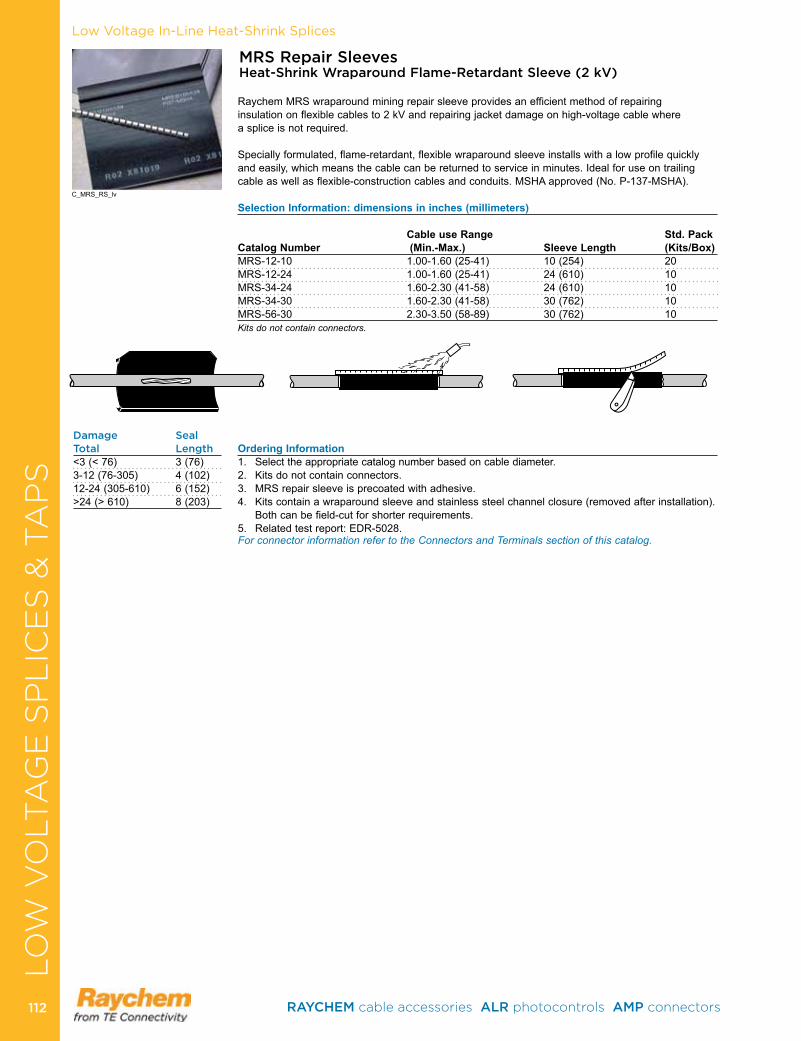
Low Voltage In-Line Heat-Shrink Splices
MRS Repair Sleeves Heat-Shrink Wraparound Flame-Retardant Sleeve (2 kV)
Raychem MRS wraparound mining repair sleeve provides an efficient method of repairing insulation on flexible cables to 2 kV and repairing jacket damage on high-voltage cable where a splice is not required .
Specially formulated, flame-retardant, flexible wraparound sleeve installs with a low profile quickly and easily, which means the cable can be returned to service in minutes . Ideal for use on trailing cable as well as flexible-construction cables and conduits . MSHA approved (No . P-137-MSHA) .
Selection Information: dimensions in inches (millimeters)
Cable use Range Std. PackCatalog Number (Min.-Max.) Sleeve Length (Kits/Box)MRS-12-10 1 .00-1 .60 (25-41) 10 (254) 20MRS-12-24 1 .00-1 .60 (25-41) 24 (610) 10MRS-34-24 1 .60-2 .30 (41-58) 24 (610) 10MRS-34-30 1 .60-2 .30 (41-58) 30 (762) 10MRS-56-30 2 .30-3 .50 (58-89) 30 (762) 10 Kits do not contain connectors.
Ordering Information1 . Select the appropriate catalog number based on cable diameter .2 . Kits do not contain connectors .3 . MRS repair sleeve is precoated with adhesive .4 . Kits contain a wraparound sleeve and stainless steel channel closure (removed after installation) .
Both can be field-cut for shorter requirements . 5 . Related test report: EDR-5028 .For connector information refer to the Connectors and Terminals section of this catalog.
Damage SealTotal Length<3 (< 76) 3 (76)3-12 (76-305) 4 (102)12-24 (305-610) 6 (152)>24 (> 610) 8 (203)
C_MRS_RS_lv
LO
W V
OLT
AG
E S
PL
ICE
S &
TA
PS
RAYCHEM cable accessories ALR photocontrols AMP connectors 112112
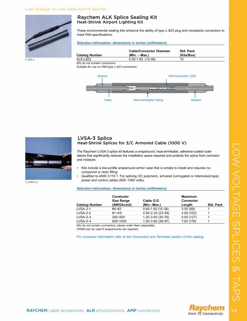
Raychem ALK Splice Sealing Kit Heat-Shrink Airport Lighting Kit
These environmental sealing kits enhance the ability of type L-823 plug and receptacle connectors to meet FAA specifications .
Selection Information: dimensions in inches (millimeters)
Cable/Connector Diameter Std. Pack Catalog Number (Min. – Max.) (Kits/Box)ALK-L823 0 .50-1 .50 (13-38) 10Kits do not contain connectors.Suitable for use on FAA-type L-823 connectors.
Cable Heat-shrinkable Tubing Sealant
Sealant FAA Connector L-823
C_ALK_lv
Low Voltage In-Line Heat-Shrink Splices
LVSA-3 SpliceHeat-Shrink Splices for 3/C Armored Cable (1000 V)
The Raychem LVSA-3 splice kit features a wraparound, heat-shrinkable, adhesive-coated outer sleeve that significantly reduces the installation space required and protects the splice from corrosion and moisture .
• Kitsincludealow-profilewraparoundarmorcasethatissimpletoinstallandrequiresnocompound or resin filling .
• QualifiedtoANSIC119.1.Forsplicing3/Cpolymeric,armored(corrugatedorinterlocked-type)power and control cables (600–1000 volts) .
Selection Information: dimensions in inches (millimeters)
Conductor Maximum Size Range Cable O.D. Connector Catalog Number (AWG/kcmil) (Min.–Max.) Length Std. PackLVSA-3-1 #6-#2 0 .60-1 .50 (15-38) 3 .50 (89) 1LVSA-3-2 #1-4/0 0 .90-2 .20 (23-56) 4 .00 (102) 1LVSA-3-3 250-500 1 .20-3 .00 (30-76) 5 .00 (127) 1LVSA-3-4 600-1000 1 .50-3 .80 (38-97) 7 .00 (178) 1Kits do not contain connectors; please order them separately.CRSM can be used if wraparounds are required.
For connector information refer to the Connectors and Terminals section of this catalog.
C_LVSA-3_lv
LO
W V
OLT
AG
E S
PL
ICE
S &
TA
PS
RAYCHEM cable accessories ALR photocontrols AMP connectors 113 113
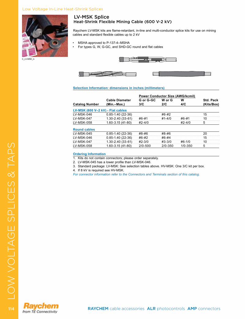
LV-MSK Splice Heat-Shrink Flexible Mining Cable (600 V-2 kV)
Raychem LV-MSK kits are flame-retardant, in-line and multi-conductor splice kits for use on mining cables and standard flexible cables up to 2 kV
• MSHAapprovedtoP-137-4--MSHA• FortypesG,W,G-GC,andSHD-GCroundandflatcables
Selection Information: dimensions in inches (millimeters)
Power Conductor Size (AWG/kcmil) Cable Diameter G or G-GC W or G W Std. Pack Catalog Number (Min.–Max.) 3/C 2/C 4/C (Kits/Box)
LV-MSK (600 V–2 kV) - Flat cablesLV-MSK-046 0 .85-1 .40 (22-36) #6-#2 15LV-MSK-047 1 .30-2 .40 (33-61) #6-#1 #1-4/0 #6-#1 10LV-MSK-058 1 .60-3 .15 (41-80) #2-4/0 #2-4/0 5
Round cablesLV-MSK-045 0 .85-1 .40 (22-36) #8-#6 #8-#6 20LV-MSK-046 0 .85-1 .40 (22-36) #6-#2 #6-#4 15LV-MSK-047 1 .30-2 .40 (33-61) #2-3/0 #3-3/0 #6-1/0 10LV-MSK-058 1 .60-3 .15 (41-80) 2/0-500 2/0-350 1/0-350 5
Ordering Information 1 . Kits do not contain connectors; please order separately .2 . LV-MSK-045 has a lower profile than LV-MSK-046 .3 . Standard package: LV-MSK: See selection tables above . HV-MSK: One 3/C kit per box . 4 . If 8 kV is required see HV-MSK .For connector information refer to the Connectors and Terminals section of this catalog.
C_LV-MSK_lv
Low Voltage In-Line Heat-Shrink SplicesLO
W V
OLT
AG
E S
PL
ICE
S &
TA
PS
RAYCHEM cable accessories ALR photocontrols AMP connectors 114114
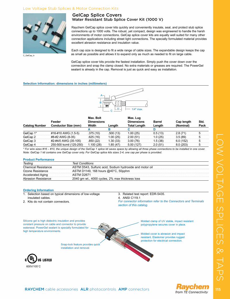
Low Voltage Stub Splices & Motor Connection Kits
600V/105˚C
Snap-lock feature provides quick installation and removal .
Silicone gel is high dielectric insulation and provides constant pressure on cable and connector to provide waterseal . PowerGel sealant is specially formulated for high temperature environments .
Molded cover is abrasion and impact resistant . Elastomer provides rugged protection for electrical connection .
Molded clamp of UV stable, impact resistant polypropylene secures cover in place .
Selection Information: dimensions in inches (millimeters)
Max. Bolt Max. Lug Feeder Dimensions Dimensions Barrel Cap length Std. Catalog Number Conductor Size (mm2) Width Length Total Length Length (Nominal) Pack A B C DGelCap 1* #16-#10 AWG (1 .5-5) .375 (10) .500 (13) 1 .00 (25) 0 .5 (13) 2 .8 (71) 5GelCap 2 #8-#2 AWG (8-35) .625 (16) 1 .00 (25) 2 .00 (51) 1 .0 (25) 3 .5 (89) 5GelCap 3 #2-#4/0 AWG (35-105) .850 (22) 1 .30 (33) 3 .00 (76) 1 .5 (38) 6 .0 (152) 5GelCap 4 250-500 kcmil (125-250) 1 .100 (28) 1 .85 (47) 5 .00 (127) 2 .0 (51) 8 .0 (203) 5* For wire sizes #16 – #10, the unique design of the GelCap 1 splice kit saves space by allowing all three phase connections to be installed in one cover. Note: GelCap 1 kit contains one GelCap cover only. For GelCap splice kits sizes 2-4, one cap per phase is provided.
Product PerformanceTesting Test ConditionsChemical Resistance ASTM D543, Sulfuric acid, Sodium hydroxide and motor oilOzone Resistance ASTM D1149, 168 hours @40°C, 50pphmAccelerated Aging ASTM D2671Abrasion Resistance 2040 gm wt ., 4000 cycles, 2% max thickness loss
GelCap Splice Covers Water Resistant Stub Splice Cover Kit (1000 V)
Raychem GelCap splice cover kits quickly and conveniently insulate, seal, and protect stub splice connections up to 1000 volts . The robust, yet compact, design was engineered to handle the harsh environments of motor connections . GelCap splice cover kits are equally well suited for many other connection applications including street light connections . The specially formulated material provides excellent abrasion resistance and insulation value .
Each cap size is designed to fit a wide range of cable sizes . The expandable design keeps the cap as small as possible and allows it to expand only as much as needed to fit on large cable .
GelCap splice cover kits provide the fastest installation . Simply push the cover down over the connection and snap the clamp closed . No extra materials or greases are required . The PowerGel sealant is already in the cap . Removal is just as quick and easy as installation .
1/4" max .
A
D
B
C
1 . Selection based on typical dimensions of low-voltage insulated cables .
2 . Kits do not contain connectors .
3 . Related test report: EDR-5435 .4 . ANSI C119 .1For connector information refer to the Connectors and Terminals section of this catalog.
Ordering Information
C_GelCap_lv
LO
W V
OLT
AG
E S
PL
ICE
S &
TA
PS
RAYCHEM cable accessories ALR photocontrols AMP connectors 115 115
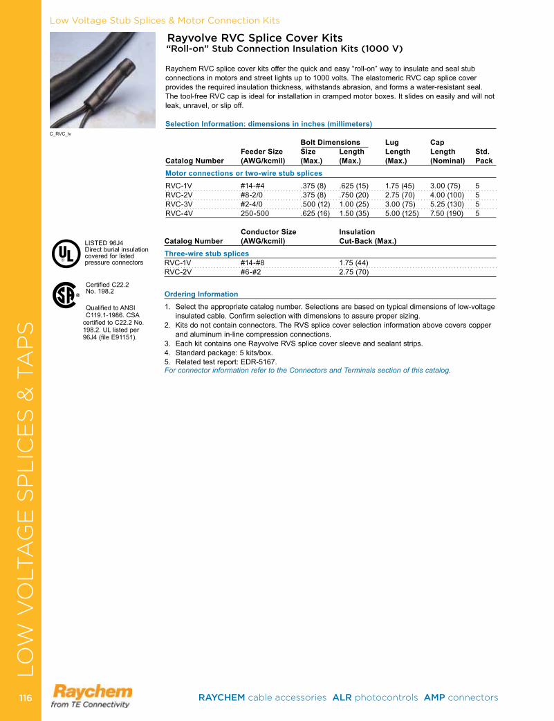
Low Voltage Stub Splices & Motor Connection Kits
Certified C22 .2 No . 198 .2
QualifiedtoANSIC119 .1-1986 . CSA
certified to C22 .2 No . 198 .2 . UL listed per 96J4(fileE91151).
®
LISTED96J4 Direct burial insulation covered for listed pressure connectors
Rayvolve RVC Splice Cover Kits “Roll-on” Stub Connection Insulation Kits (1000 V)
Raychem RVC splice cover kits offer the quick and easy “roll-on” way to insulate and seal stub connections in motors and street lights up to 1000 volts . The elastomeric RVC cap splice cover provides the required insulation thickness, withstands abrasion, and forms a water-resistant seal . The tool-free RVC cap is ideal for installation in cramped motor boxes . It slides on easily and will not leak, unravel, or slip off .
Selection Information: dimensions in inches (millimeters)
Bolt Dimensions Lug Cap Feeder Size Size Length Length Length Std. Catalog Number (AWG/kcmil) (Max.) (Max.) (Max.) (Nominal) PackMotor connections or two-wire stub splicesRVC-1V #14-#4 .375 (8) .625 (15) 1 .75 (45) 3 .00 (75) 5RVC-2V #8-2/0 .375 (8) .750 (20) 2 .75 (70) 4 .00 (100) 5RVC-3V #2-4/0 .500 (12) 1 .00 (25) 3 .00 (75) 5 .25 (130) 5RVC-4V 250-500 .625 (16) 1 .50 (35) 5 .00 (125) 7 .50 (190) 5 Conductor Size Insulation Catalog Number (AWG/kcmil) Cut-Back (Max.)Three-wire stub splicesRVC-1V #14-#8 1 .75 (44) RVC-2V #6-#2 2 .75 (70)
Ordering Information1 . Select the appropriate catalog number . Selections are based on typical dimensions of low-voltage
insulated cable . Confirm selection with dimensions to assure proper sizing .2 . Kits do not contain connectors . The RVS splice cover selection information above covers copper
and aluminum in-line compression connections .3 . Each kit contains one Rayvolve RVS splice cover sleeve and sealant strips . 4 . Standard package: 5 kits/box .5 . Related test report: EDR-5167 .For connector information refer to the Connectors and Terminals section of this catalog.
C_RVC_lv
LO
W V
OLT
AG
E S
PL
ICE
S &
TA
PS
RAYCHEM cable accessories ALR photocontrols AMP connectors 116116
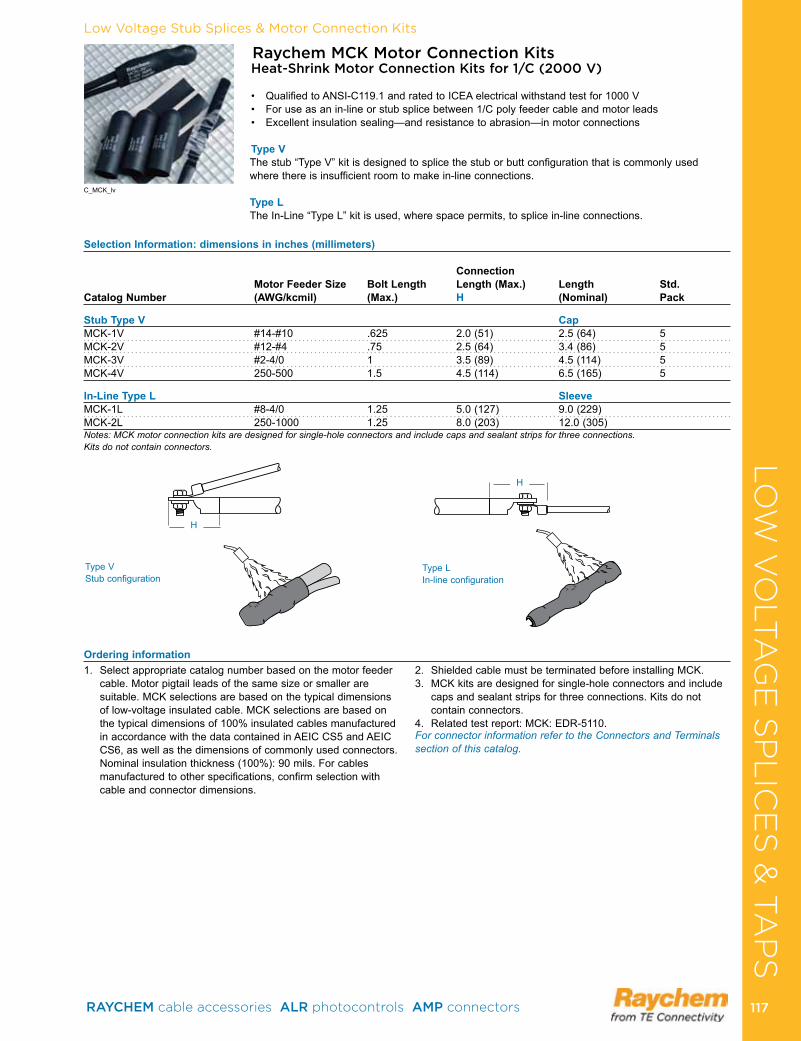
Low Voltage Stub Splices & Motor Connection Kits
Raychem MCK Motor Connection Kits Heat-Shrink Motor Connection Kits for 1/C (2000 V)
• QualifiedtoANSI-C119.1andratedtoICEAelectricalwithstandtestfor1000V• Foruseasanin-lineorstubsplicebetween1/Cpolyfeedercableandmotorleads• Excellentinsulationsealing—andresistancetoabrasion—inmotorconnections
Type VThe stub “Type V” kit is designed to splice the stub or butt configuration that is commonly used where there is insufficient room to make in-line connections .
Type LThe In-Line “Type L” kit is used, where space permits, to splice in-line connections .
Selection Information: dimensions in inches (millimeters)
Connection Motor Feeder Size Bolt Length Length (Max.) Length Std.
Catalog Number (AWG/kcmil) (Max.) H (Nominal) Pack
Stub Type V CapMCK-1V #14-#10 .625 2 .0 (51) 2 .5 (64) 5MCK-2V #12-#4 .75 2 .5 (64) 3 .4 (86) 5MCK-3V #2-4/0 1 3 .5 (89) 4 .5 (114) 5MCK-4V 250-500 1 .5 4 .5 (114) 6 .5 (165) 5
In-Line Type L Sleeve MCK-1L #8-4/0 1 .25 5 .0 (127) 9 .0 (229)MCK-2L 250-1000 1 .25 8 .0 (203) 12 .0 (305)Notes: MCK motor connection kits are designed for single-hole connectors and include caps and sealant strips for three connections. Kits do not contain connectors.
Type V Stub configuration
Type L In-line configuration
1 . Select appropriate catalog number based on the motor feeder cable . Motor pigtail leads of the same size or smaller are suitable . MCK selections are based on the typical dimensions of low-voltage insulated cable . MCK selections are based on the typical dimensions of 100% insulated cables manufactured in accordance with the data contained in AEIC CS5 and AEIC CS6, as well as the dimensions of commonly used connectors . Nominal insulation thickness (100%): 90 mils . For cables manufactured to other specifications, confirm selection with cable and connector dimensions .
2 . Shielded cable must be termi nated before installing MCK .3 . MCK kits are designed for single-hole connectors and include
caps and sealant strips for three connections . Kits do not contain connectors .
4 . Related test report: MCK: EDR-5110 . For connector information refer to the Connectors and Terminals section of this catalog.
Ordering information
H
H
C_MCK_lv
LO
W V
OLT
AG
E S
PL
ICE
S &
TA
PS
RAYCHEM cable accessories ALR photocontrols AMP connectors 117 117
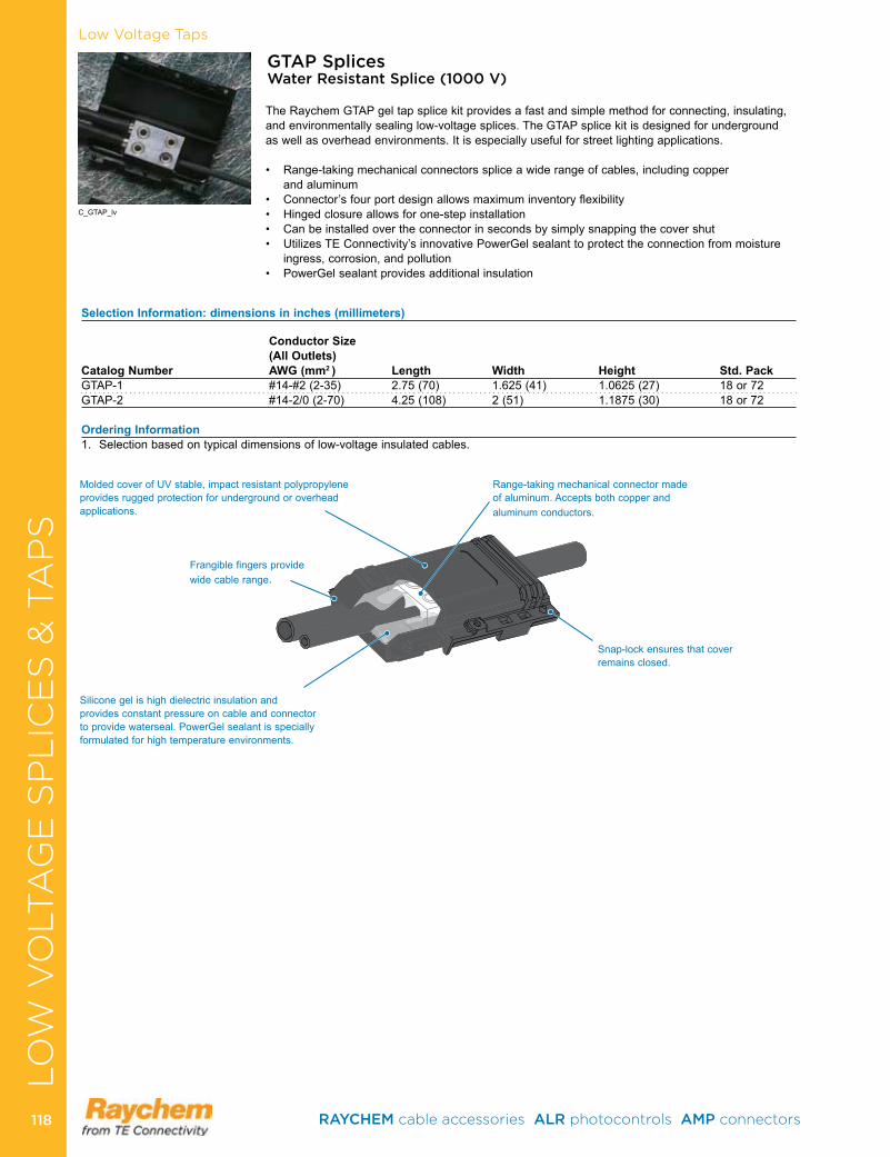
Low Voltage Taps
GTAP Splices Water Resistant Splice (1000 V)
The Raychem GTAP gel tap splice kit provides a fast and simple method for connecting, insulating, and environmentally sealing low-voltage splices . The GTAP splice kit is designed for underground as well as overhead environments . It is especially useful for street lighting applications .
• Range-takingmechanicalconnectorsspliceawiderangeofcables,includingcopper and aluminum
• Connector’sfourportdesignallowsmaximuminventoryflexibility• Hingedclosureallowsforone-stepinstallation• Canbeinstalledovertheconnectorinsecondsbysimplysnappingthecovershut• UtilizesTEConnectivity’sinnovativePowerGelsealanttoprotecttheconnectionfrommoisture
ingress, corrosion, and pollution • PowerGelsealantprovidesadditionalinsulation
Selection Information: dimensions in inches (millimeters)
Conductor Size (All Outlets) Catalog Number AWG (mm2 ) Length Width Height Std. PackGTAP-1 #14-#2 (2-35) 2 .75 (70) 1 .625 (41) 1 .0625 (27) 18 or 72GTAP-2 #14-2/0 (2-70) 4 .25 (108) 2 (51) 1 .1875 (30) 18 or 72
Ordering Information 1 . Selection based on typical dimensions of low-voltage insulated cables .
Frangible fingers provide wide cable range .
Silicone gel is high dielectric insulation and provides constant pressure on cable and connector to provide waterseal . PowerGel sealant is specially formulated for high temperature environments .
Snap-lock ensures that cover remains closed .
Molded cover of UV stable, impact resistant polypropylene provides rugged protection for underground or overhead applications .
Range-taking mechanical connector made of aluminum . Accepts both copper and aluminum conductors .
C_GTAP_lv
LO
W V
OLT
AG
E S
PL
ICE
S &
TA
PS
RAYCHEM cable accessories ALR photocontrols AMP connectors 118118
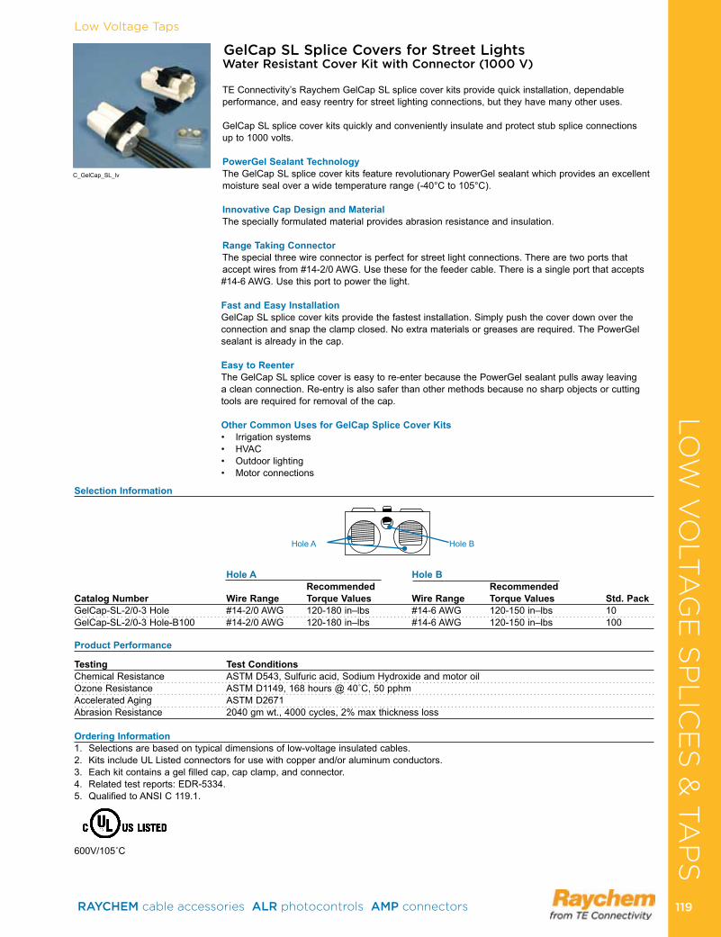
GelCap SL Splice Covers for Street LightsWater Resistant Cover Kit with Connector (1000 V)
TE Connectivity’s Raychem GelCap SL splice cover kits provide quick installation, dependable performance, and easy reentry for street lighting connections, but they have many other uses .
GelCap SL splice cover kits quickly and conveniently insulate and protect stub splice connections up to 1000 volts .
PowerGel Sealant TechnologyThe GelCap SL splice cover kits feature revolutionary PowerGel sealant which provides an excellent moisture seal over a wide temperature range (-40°C to 105°C) .
Innovative Cap Design and MaterialThe specially formulated material provides abrasion resistance and insulation .
Range Taking ConnectorThe special three wire connector is perfect for street light connections . There are two ports that accept wires from #14-2/0 AWG . Use these for the feeder cable . There is a single port that accepts #14-6 AWG . Use this port to power the light .
Fast and Easy InstallationGelCap SL splice cover kits provide the fastest installation . Simply push the cover down over the connection and snap the clamp closed . No extra materials or greases are required . The PowerGel sealant is already in the cap .
Easy to ReenterThe GelCap SL splice cover is easy to re-enter because the PowerGel sealant pulls away leaving a clean connection . Re-entry is also safer than other methods because no sharp objects or cutting tools are required for removal of the cap .
Other Common Uses for GelCap Splice Cover Kits• Irrigationsystems• HVAC• Outdoorlighting• Motorconnections
Selection Information
Hole A Hole B Recommended Recommended Catalog Number Wire Range Torque Values Wire Range Torque Values Std. PackGelCap-SL-2/0-3 Hole #14-2/0 AWG 120-180 in–lbs #14-6 AWG 120-150 in–lbs 10GelCap-SL-2/0-3 Hole-B100 #14-2/0 AWG 120-180 in–lbs #14-6 AWG 120-150 in–lbs 100
Product Performance
Testing Test ConditionsChemical Resistance ASTM D543, Sulfuric acid, Sodium Hydroxide and motor oilOzoneResistance ASTMD1149,168hours@40˚C,50pphmAccelerated Aging ASTM D2671Abrasion Resistance 2040 gm wt ., 4000 cycles, 2% max thickness loss
Ordering Information1 . Selections are based on typical dimensions of low-voltage insulated cables .2 . Kits include UL Listed connectors for use with copper and/or aluminum conductors .3 . Each kit contains a gel filled cap, cap clamp, and connector .4 . Related test reports: EDR-5334 .5. QualifiedtoANSIC119.1.
600V/105˚C
Hole A Hole B
C_GelCap_SL_lv
Low Voltage TapsLO
W V
OLT
AG
E S
PL
ICE
S &
TA
PS
RAYCHEM cable accessories ALR photocontrols AMP connectors 119 119
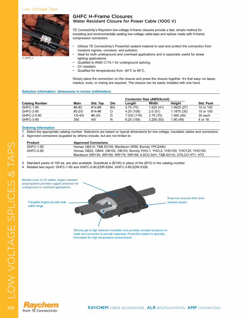
Low Voltage Taps
GHFC H-Frame Closures Water Resistant Closure for Power Cable (1000 V)
TE Connectivity’s Raychem low-voltage H-frame closures provide a fast, simple method for insulating and environmentally sealing low-voltage cable-taps and splices made with H-frame compression connectors .
• UtilizesTEConnectivity’sPowerGelsealantmaterialtosealandprotecttheconnectionfrommoisture ingress, corrosion, and pollution .
• Idealforbothundergroundandoverheadapplicationsandisespeciallyusefulforstreet lighting applications . • QualifiedtoANSIC119.1forundergroundsplicing.• UVresistant.• Qualifiedfortemperaturesfrom-40°Cto90°C.
Simply place the connection on the closure and press the closure together . It’s that easy–no tapes, mastics, tools, or mixing are required . The closure can be easily installed with one hand .
Selection Information: dimensions in inches (millimeters)
Conductor Size (AWG/kcmil) Catalog Number Main Std. Tap Die Length Width Height Std. PackGHFC-1-90 #6-#2 #14-#8 BG 2 .75 (70) 1 .625 (41) 1 .0625 (27) 10 or 100GHFC-2-90 #2-2/0 #14-#6 O 4 .25 (108) 2 .0 (51) 1 .1875 (30) 10 or 100GHFC-2 .5-90 1/0-4/0 #6-3/0 D 7 .032 (179) 2 .75 (70) 1 .560 (40) 30 eachGHFC-3-90 350 4/0 N 6 .25 (159) 3 .250 (83) 1 .90 (49) 6 or 18
Ordering Information1 . Select the appropriate catalog number . Selections are based on typical dimensions for low-voltage, insulated cables and connectors .2 . Approved connectors (supplied by others) include, but are not limited to:
Product Approved Connectors GHFC-1-90 Homac UB214; T&B 63105; Blackburn WR9; Burndy YPC2A8U GHFC-2-90 Homac OB22, OB44, OB102, OB103; Burndy YHO-1, YHO-2, YHO100, YHO125, YHO150;
Blackburn WR139, WR159, WR179, WR199; ILSCO AH1; T&B 63110; UTILCO HT1, HT2
3 . Standard packs of 100 ea . are also available . Substitute a (B100) in place of the (B10) in the catalog number . 4 . Related test report: GHFC-1-90 and GHFC-2-90,EDR-5264, GHFC-3-90,EDR-5326 .
Frangible fingers provide wide cable range .
Silicone gel is high dielectric insulation and provides constant pressure on cable and connector to provide waterseal . PowerGel sealant is specially formulated for high temperature environments .
Snap-lock ensures that cover remains closed .
Molded cover of UV stable, impact resistant polypropylene provides rugged protection for underground or overhead applications .
C_GHFC_lv
LO
W V
OLT
AG
E S
PL
ICE
S &
TA
PS
RAYCHEM cable accessories ALR photocontrols AMP connectors 120120
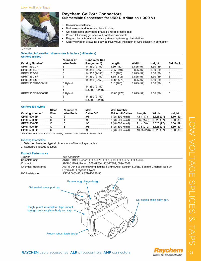
Low Voltage Taps
Raychem GelPort Connectors Submersible Connectors for URD Distribution (1000 V)
• Corrosionresistance• Noloosepartsduetoonepiecehousing• Gel-filledcableentryportsprovideareliablecableseal• PowerGelsealinggelsealsoutharshenvironments• Rugged,impact-resistanthousingstandsuptoroughinstallations• Clearviewbackallowsforeasypositivevisualindicationofwirepositioninconnector
Selection Information: dimensions in inches (millimeters)GelPort 350/500 Number of Conductor Use Catalog Number* Wire Ports Range (mm2) Length Width Height Std. PackGPRT-350-3P 3 14-350 (2-150) 4 .60 (117) 3 .825 (97) 3 .50 (89) 6GPRT-350-4P 4 14-350 (2-150) 5 .85 (149) 3 .825 (97) 3 .50 (89) 6GPRT-350-5P 5 14-350 (2-150) 7 .10 (180) 3 .825 (97) 3 .50 (89) 6GPRT-350-6P 6 14-350 (2-150) 8 .35 (212) 3 .825 (97) 3 .50 (89) 6GPRT-350-8P 8 14-350 (2-150) 10 .85 (276) 3 .825 (97) 3 .50 (89) 6GPRT-350/4P-500/1P 5 Hybrid 7 .10 (180) 3 .825 (97) 3 .50 (89) 6 4 14-350 (2-150) 1 6-500 (16-250) GPRT-350/6P-500/2P 8 Hybrid 10 .85 (276) 3 .825 (97) 3 .50 (89) 6 6 14-350 (2-150) 2 6-500 (16-250)
GelPort 500 Hybrid Clear Number of Max. Max. NumberCatalog Number* View Wire Ports Cable O.D. 500 kcmil Cables Length Width HeightGPRT-500-3P C 3 .96 1 (#6-500 kcmil) 4 .6 (117) 3 .825 (97) 3 .50 (89)GPRT-500-4P C 4 .96 2 (#6-500 kcmil) 5 .85 (149) 3 .825 (97) 3 .50 (89)GPRT-500-5P C 5 .96 3 (#6-500 kcmil) 7 .1 (180) 3 .825 (97) 3 .50 (89)GPRT-500-6P C 6 .96 4 (#6-500 kcmil) 8 .35 (212) 3 .825 (97) 3 .50 (89)GPRT-500-8P C 8 .96 6 (#6-500 kcmil) 10 .85 (276) 3 .825 (97) 3 .50 (89)*For Clear view back add “-C” to catalog number. Standard back view is black
Ordering Information1 . Selection based on typical dimensions of low voltage cables .2 . Standard package is 6/box .
Product PerformanceTesting Test ConditionComplete unit ANSI C119 .1, Report: EDR-5379, EDR-5409, EDR-5427, EDR 5463 Connector ANSI C119 .4, Report: 502-47264, 502-47302, 502-47308 Chemical Resistance ASTM D543 to the following liquids: Sulfuric Acid, Sodium Sulfate, Sodium Chloride, Sodium
Hydroxide, Ethylene GlycolUV Resistance ASTM G-53-95, ASTM-D-638-95
1
2
3
STR
IPB
AC
K L
ENG
TH
Gel sealed screw port cap
Proven robust latch design
Gel sealed cable entry port .
Proven tough hinge designCaps
Tough, puncture resistant, high impact strength polypropylene body and cap
C_GelPort_lv
LO
W V
OLT
AG
E S
PL
ICE
S &
TA
PS
RAYCHEM cable accessories ALR photocontrols AMP connectors 121 121
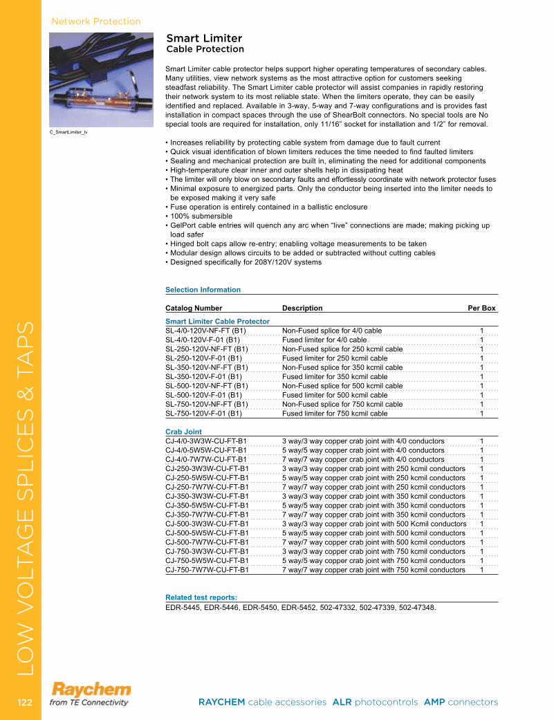
Network Protection
Smart Limiter Cable Protection
Smart Limiter cable protector helps support higher operating temperatures of secondary cables . Many utilities, view network systems as the most attractive option for customers seeking steadfast reliability . The Smart Limiter cable protector will assist companies in rapidly restoring their network system to its most reliable state . When the limiters operate, they can be easily identified and replaced . Available in 3-way, 5-way and 7-way configurations and is provides fast installation in compact spaces through the use of ShearBolt connectors . No special tools are No special tools are required for installation, only 11/16” socket for installation and 1/2” for removal .
•Increasesreliabilitybyprotectingcablesystemfromdamageduetofaultcurrent•Quickvisualidentificationofblownlimitersreducesthetimeneededtofindfaultedlimiters•Sealingandmechanicalprotectionarebuiltin,eliminatingtheneedforadditionalcomponents•High-temperatureclearinnerandoutershellshelpindissipatingheat•Thelimiterwillonlyblowonsecondaryfaultsandeffortlesslycoordinatewithnetworkprotectorfuses•Minimalexposuretoenergizedparts.Onlytheconductorbeinginsertedintothelimiterneedsto
be exposed making it very safe •Fuseoperationisentirelycontainedinaballisticenclosure•100%submersible•GelPortcableentrieswillquenchanyarcwhen“live”connectionsaremade;makingpickingup
load safer •Hingedboltcapsallowre-entry;enablingvoltagemeasurementstobetaken•Modulardesignallowscircuitstobeaddedorsubtractedwithoutcuttingcables•Designedspecificallyfor208Y/120Vsystems
Selection Information Catalog Number Description Per Box
Smart Limiter Cable ProtectorSL-4/0-120V-NF-FT (B1) Non-Fused splice for 4/0 cable 1SL-4/0-120V-F-01 (B1) Fused limiter for 4/0 cable 1SL-250-120V-NF-FT (B1) Non-Fused splice for 250 kcmil cable 1SL-250-120V-F-01 (B1) Fused limiter for 250 kcmil cable 1SL-350-120V-NF-FT (B1) Non-Fused splice for 350 kcmil cable 1SL-350-120V-F-01 (B1) Fused limiter for 350 kcmil cable 1SL-500-120V-NF-FT (B1) Non-Fused splice for 500 kcmil cable 1SL-500-120V-F-01 (B1) Fused limiter for 500 kcmil cable 1SL-750-120V-NF-FT (B1) Non-Fused splice for 750 kcmil cable 1SL-750-120V-F-01 (B1) Fused limiter for 750 kcmil cable 1
Crab JointCJ-4/0-3W3W-CU-FT-B1 3way/3waycoppercrabjointwith4/0conductors 1CJ-4/0-5W5W-CU-FT-B1 5way/5waycoppercrabjointwith4/0conductors 1CJ-4/0-7W7W-CU-FT-B1 7way/7waycoppercrabjointwith4/0conductors 1CJ-250-3W3W-CU-FT-B1 3way/3waycoppercrabjointwith250kcmilconductors 1CJ-250-5W5W-CU-FT-B1 5way/5waycoppercrabjointwith250kcmilconductors 1CJ-250-7W7W-CU-FT-B1 7way/7waycoppercrabjointwith250kcmilconductors 1CJ-350-3W3W-CU-FT-B1 3way/3waycoppercrabjointwith350kcmilconductors 1CJ-350-5W5W-CU-FT-B1 5way/5waycoppercrabjointwith350kcmilconductors 1CJ-350-7W7W-CU-FT-B1 7way/7waycoppercrabjointwith350kcmilconductors 1CJ-500-3W3W-CU-FT-B1 3way/3waycoppercrabjointwith500Kcmilconductors 1CJ-500-5W5W-CU-FT-B1 5way/5waycoppercrabjointwith500kcmilconductors 1CJ-500-7W7W-CU-FT-B1 7way/7waycoppercrabjointwith500kcmilconductors 1CJ-750-3W3W-CU-FT-B1 3way/3waycoppercrabjointwith750kcmilconductors 1CJ-750-5W5W-CU-FT-B1 5way/5waycoppercrabjointwith750kcmilconductors 1CJ-750-7W7W-CU-FT-B1 7way/7waycoppercrabjointwith750kcmilconductors 1
Related test reports: EDR-5445, EDR-5446, EDR-5450, EDR-5452, 502-47332, 502-47339, 502-47348 .
C_SmartLimiter_lv
LO
W V
OLT
AG
E S
PL
ICE
S &
TA
PS
RAYCHEM cable accessories ALR photocontrols AMP connectors 122122
In-Line SpliceHeat-ShrinkHVS-500/HVSA-500 Non-Shielded (5 kV) . . . . . . . . . . . . . . . .124HVS-J Jacketed Concentric Neutral Cables (15 kV) . . . . . . . .125HVS-J 1/C Jacketed Concentric Neutral Cables (25-35 kV) . .126HVS-C-RJ Repair Sleeve (15-25 kV) . . . . . . . . . . . . . . . . . . . .127HVS-C-1520S 1/C Shielded (15 kV) . . . . . . . . . . . . . . . . . . . . .128HVS-S-1520S 1/C Shielded with ShearBolt (15 kV) . . . . . . . . .129HVS 1/C Shielded (5-35 kV) . . . . . . . . . . . . . . . . . . . . . . . . . . .130HVS 1/C LC Shielded & Flat Strap (15 kV) . . . . . . . . . . . . . . .131HVS 1/C LC Shielded & Flat Strap (25-35 kV) . . . . . . . . . . . . .132TECK Splice for TECK Cable (1000 V-15 kV) . . . . . . . . . . . . .133HVS-Shim Kits (5-35 kV) . . . . . . . . . . . . . . . . . . . . . . . . . . . . .134HVS-3 3/C Shielded (5-25 kV) . . . . . . . . . . . . . . . . . . . . . . . . .135HVSA-3 3/C Shielded (5-15 kV) . . . . . . . . . . . . . . . . . . . . . . . .136HVS-3/C Mod Kits (5-35 kV) . . . . . . . . . . . . . . . . . . . . . . . . . .137HVSA Mod Kits (5-35 kV) . . . . . . . . . . . . . . . . . . . . . . . . . . . .138HVS/HVSR Reducer Kit (15-35 kV) . . . . . . . . . . . . . . . . . . . . .139HVS-3-1590S/HVS-3-2590S 3/C PIL (15-25 kV) . . . . . . . . . . .140HVS-T/HVSR-T Reducer Kits (15-35 kv) . . . . . . . . . . . . . . . . .141HVS-T-1590S Trifurcating Kit (15 kV) . . . . . . . . . . . . . . . . . . . .142HVS/HVSA-3-1580S Transition Kit (15 kV) . . . . . . . . . . . . . . .143HVSY Wye Tap Splice (15 kV) . . . . . . . . . . . . . . . . . . . . . . . . .144HVSH-MOD H-Configuration Kit (15 kV) . . . . . . . . . . . . . . . . .145HVES Live End Seal (15-25 kV) . . . . . . . . . . . . . . . . . . . . . . . .146HV-MSK Mining Cable (5-8 kV) . . . . . . . . . . . . . . . . . . . . . . . .147
Cold-AppliedCSJA 1/C Shielded (15-35 kV) . . . . . . . . . . . . . . . . . . . . . . . . .148CSJA JCN/EG 1/C Jacketed Concentric Neutral (15-35 kV) . .150CSJG 1/C Jacketed Concentric Neutral (15-25 kV) . . . . . . . . .1523/C CSJA 3/C Armored (15-35 kV) . . . . . . . . . . . . . . . . . . . . . .1543/C CSJA 3/C TECK (15 kV) . . . . . . . . . . . . . . . . . . . . . . . . . .156
TerminationsHeat-ShrinkHVT-50 1/C and 3/C Non-Shielded (5 kV) . . . . . . . . . . . . . . . . . 157HVT-Z-J/SJ Jacketed Concentric Neutral (15-35 kV) . . . . . . . . . 158HVT-Z Built-In Stress Control (5-35 kV) . . . . . . . . . . . . . . . . . . . 159MOD-3-HVT 3/C Modification Kit (5-35 kV) . . . . . . . . . . . . . . . . 161HVT-Z-LC/SLC LC Shielded (15-35 kV) . . . . . . . . . . . . . . . . . . . 163HVT-ZL Co-Extruded One-Piece Termination . . . . . . . . . . . . . . 164HVT/HVT-3 1/C, 3/C PILC/VCLC (15 kV) . . . . . . . . . . . . . . . . . . 165HVT-M Flexible Cable (5-25 kV) . . . . . . . . . . . . . . . . . . . . . . . . . 166
Cold-AppliedTFT-R 1/C Shielded & Non-Shielded (5-35 kV) . . . . . . . . . . . . . 167TFT-E 1/C Shielded (15-35 kV) . . . . . . . . . . . . . . . . . . . . . . . . . 168MOD-3-TFT Modification Kit (5-35 kV) . . . . . . . . . . . . . . . . . . . . 170 Motor Connection Kits & Stub SplicesGelCap 8 Motor Connection Kit (5-8 kV) . . . . . . . . . . . . . . . . . . 171MCK-5 Stub Splice (5-8 .7 kV) . . . . . . . . . . . . . . . . . . . . . . . . . . 172
Elbows & AccessoriesELB-15/28 600 Series T-Body Elbow (15-28 kV) . . . . . . . . . . . . 173ELB-35 600 Series T- Body Elbow (35 kV) . . . . . . . . . . . . . . . . . 174Deadbreak Stand-off Plug (28-35 kV) . . . . . . . . . . . . . . . . . . . . 175Deadbreak Insulating Cap (15/28 kV) . . . . . . . . . . . . . . . . . . . . 176Deadbreak Connecting Plug (15/28-35 kV) . . . . . . . . . . . . . . . . 177Deadbreak Junctions (15/28-35 kV) . . . . . . . . . . . . . . . . . . . . . . 178ELB-15/28-600 Elbow Modular System (15-35 kV) . . . . . . . . . . 180 ELB-35-600 Arrester T-Body Elbow (35 kV) . . . . . . . . . . . . . . . . 181CES Cold Applied Elbow Seal (15-35 kV) . . . . . . . . . . . . . . . . . 182ESA Elbow Sealing Adpator . . . . . . . . . . . . . . . . . . . . . . . . . . . . 183GelWrap ES Wrap-Around Sealing Adaptor . . . . . . . . . . . . . . . . 184RVS-SK Roll-On Elbow Sealing Adapter . . . . . . . . . . . . . . . . . . 185JGK-MS Grounding Kits (15-35 kV) . . . . . . . . . . . . . . . . . . . . . . 186Gelwrap MS-GRD Grounding Kits . . . . . . . . . . . . . . . . . . . . . . . 187HVE-1590 PILC Elbow Adapters (15 kV) . . . . . . . . . . . . . . . . . . 188
MEDIUM VOLTAGE CABLE ACCESSORIES
RAYCHEM cable accessories ALR photocontrols AMP connectors 123 123
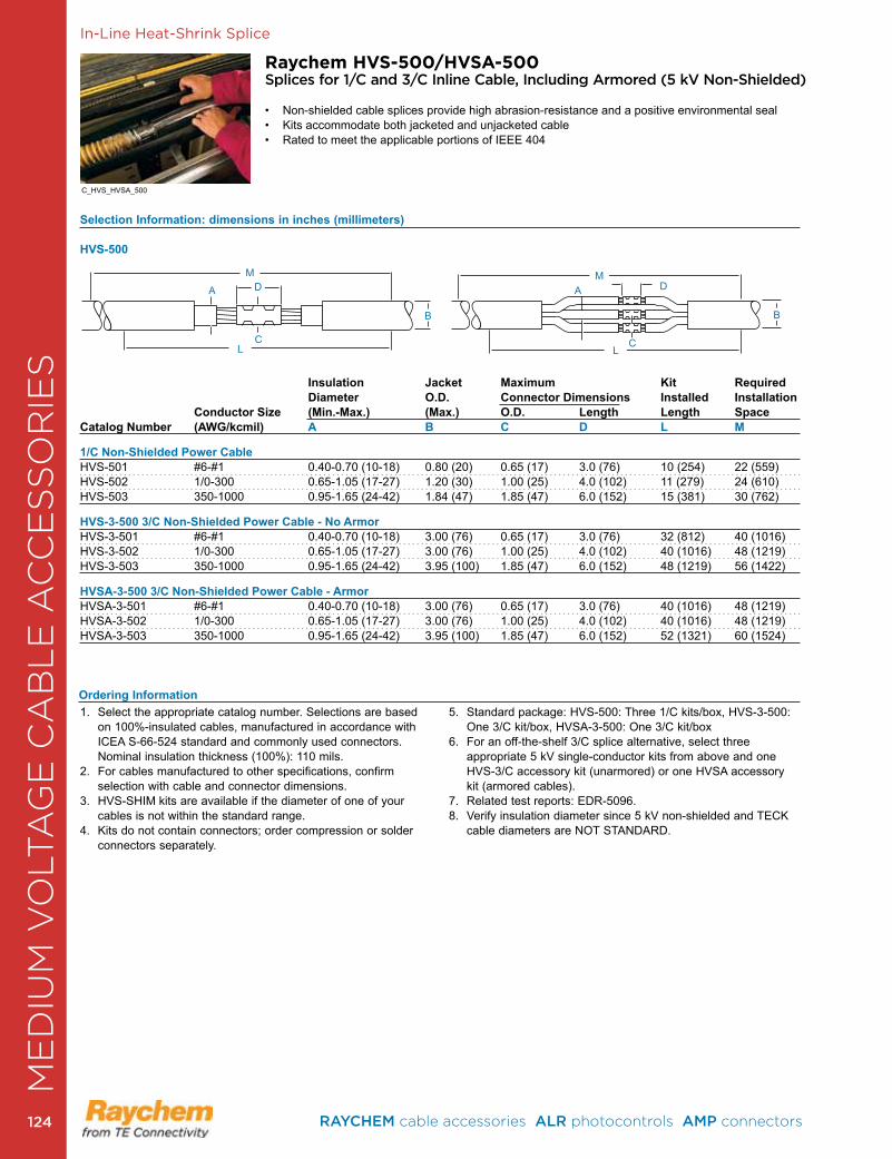
In-Line Heat-Shrink Splice
Raychem HVS-500/HVSA-500Splices for 1/C and 3/C Inline Cable, Including Armored (5 kV Non-Shielded)
• Non-shielded cable splices provide high abrasion-resistance and a positive environmental seal • Kits accommodate both jacketed and unjacketed cable• Rated to meet the applicable portions of IEEE 404
Selection Information: dimensions in inches (millimeters)
HVS-500
Insulation Jacket Maximum Kit Required Diameter O.D. Connector Dimensions Installed Installation
Conductor Size (Min.-Max.) (Max.) O.D. Length Length SpaceCatalog Number (AWG/kcmil) A B C D L M
1/C Non-Shielded Power CableHVS-501 #6-#1 0 .40-0 .70 (10-18) 0 .80 (20) 0 .65 (17) 3 .0 (76) 10 (254) 22 (559)HVS-502 1/0-300 0 .65-1 .05 (17-27) 1 .20 (30) 1 .00 (25) 4 .0 (102) 11 (279) 24 (610)HVS-503 350-1000 0 .95-1 .65 (24-42) 1 .84 (47) 1 .85 (47) 6 .0 (152) 15 (381) 30 (762)
HVS-3-500 3/C Non-Shielded Power Cable - No Armor HVS-3-501 #6-#1 0 .40-0 .70 (10-18) 3 .00 (76) 0 .65 (17) 3 .0 (76) 32 (812) 40 (1016)HVS-3-502 1/0-300 0 .65-1 .05 (17-27) 3 .00 (76) 1 .00 (25) 4 .0 (102) 40 (1016) 48 (1219)HVS-3-503 350-1000 0 .95-1 .65 (24-42) 3 .95 (100) 1 .85 (47) 6 .0 (152) 48 (1219) 56 (1422)
HVSA-3-500 3/C Non-Shielded Power Cable - Armor HVSA-3-501 #6-#1 0 .40-0 .70 (10-18) 3 .00 (76) 0 .65 (17) 3 .0 (76) 40 (1016) 48 (1219)HVSA-3-502 1/0-300 0 .65-1 .05 (17-27) 3 .00 (76) 1 .00 (25) 4 .0 (102) 40 (1016) 48 (1219)HVSA-3-503 350-1000 0 .95-1 .65 (24-42) 3 .95 (100) 1 .85 (47) 6 .0 (152) 52 (1321) 60 (1524)
1 . Select the appropriate catalog number . Selections are based on 100%-insulated cables, manufactured in accordance with ICEA S-66-524 standard and commonly used connectors . Nominal insulation thickness (100%): 110 mils .
2 . For cables manufactured to other specifications, confirm selection with cable and connector dimensions .
3 . HVS-SHIM kits are available if the diameter of one of your cables is not within the standard range .
4 . Kits do not contain connectors; order compression or solder connectors separately .
5 . Standard package: HVS-500: Three 1/C kits/box, HVS-3-500: One 3/C kit/box, HVSA-3-500: One 3/C kit/box
6 . For an off-the-shelf 3/C splice alternative, select three appropriate 5 kV single-conductor kits from above and one HVS-3/C accessory kit (unarmored) or one HVSA accessory kit (armored cables) .
7 . Related test reports: EDR-5096 .8 . Verify insulation diameter since 5 kV non-shielded and TECK
cable diameters are NOT STANDARD .
Ordering Information
A
B B
L LC C
D DM M
A
C_HVS_HVSA_500
ME
DIU
M V
OLT
AG
E C
AB
LE
AC
CE
SS
OR
IES
RAYCHEM cable accessories ALR photocontrols AMP connectors 124124
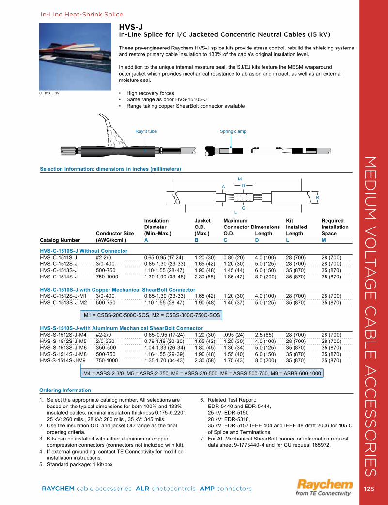
ME
DIU
M V
OLT
AG
E C
AB
LE
AC
CE
SS
OR
IES
Selection Information: dimensions in inches (millimeters)
Insulation Jacket Maximum Kit Required Diameter O.D. Connector Dimensions Installed Installation Conductor Size (Min.-Max.) (Max.) O.D. Length Length SpaceCatalog Number (AWG/kcmil) A B C D L M
HVS-C-1510S-J Without Connector HVS-C-1511S-J #2-2/0 0 .65-0 .95 (17-24) 1 .20 (30) 0 .80 (20) 4 .0 (100) 28 (700) 28 (700)HVS-C-1512S-J 3/0-400 0 .85-1 .30 (23-33) 1 .65 (42) 1 .20 (30) 5 .0 (125) 28 (700) 28 (700)HVS-C-1513S-J 500-750 1 .10-1 .55 (28-47) 1 .90 (48) 1 .45 (44) 6 .0 (150) 35 (870) 35 (870)HVS-C-1514S-J 750-1000 1 .30-1 .90 (33-48) 2 .30 (58) 1 .85 (47) 8 .0 (200) 35 (870) 35 (870)
HVS-C-1510S-J with Copper Mechanical ShearBolt Connector HVS-C-1512S-J-M1 3/0-400 0 .85-1 .30 (23-33) 1 .65 (42) 1 .20 (30) 4 .0 (100) 28 (700) 28 (700)HVS-C-1513S-J-M2 500-750 1 .10-1 .55 (28-47) 1 .90 (48) 1 .45 (37) 5 .0 (125) 35 (870) 35 (870)
HVS-S-1510S-J-with Aluminum Mechanical ShearBolt ConnectorHVS-S-1512S-J-M4 #2-2/0 0 .65-0 .95 (17-24) 1 .20 (30) .095 (24) 2 .5 (65) 28 (700) 28 (700)HVS-S-1512S-J-M5 2/0-350 0 .79-1 .19 (20-30) 1 .65 (42) 1 .25 (30) 4 .0 (100) 28 (700) 28 (700)HVS-S-1513S-J-M6 350-500 1 .04-1 .33 (26-34) 1 .80 (45) 1 .30 (34) 5 .0 (125) 35 (870) 35 (870)HVS-S-1514S-J-M8 500-750 1 .16-1 .55 (29-39) 1 .90 (48) 1 .55 (40) 6 .0 (150) 35 (870) 35 (870)HVS-S-1514S-J-M9 750-1000 1 .35-1 .70 (34-43) 2 .30 (58) 1 .75 (43) 8 .0 (200) 35 (870) 35 (870)
In-Line Heat-Shrink Splice
HVS-JIn-Line Splice for 1/C Jacketed Concentric Neutral Cables (15 kV)
These pre-engineered Raychem HVS-J splice kits provide stress control, rebuild the shielding systems, and restore primary cable insulation to 133% of the cable’s original insulation level .
In addition to the unique internal moisture seal, the SJ/EJ kits feature the MBSM wraparound outer jacket which provides mechanical resistance to abrasion and impact, as well as an external moisture seal .
• High recovery forces • Same range as prior HVS-1510S-J • Range taking copper ShearBolt connector available
1 . Select the appropriate catalog number . All selections are based on the typical dimensions for both 100% and 133% insulated cables, nominal insulation thickness 0 .175-0 .220", 25 kV: 260 mils ., 28 kV: 280 mils ., 35 kV: 345 mils .
2 . Use the insulation OD, and jacket OD range as the final ordering criteria .
3 . Kits can be installed with either aluminum or copper compression connectors (connectors not included with kit) .
4 . If external grounding, contact TE Connectivity for modified installation instructions .
5 . Standard package: 1 kit/box
6 . Related Test Report: EDR-5440 and EDR-5444, 25 kV: EDR-5150, 28 kV: EDR-5318, 35 kV: EDR-5157 IEEE 404 and IEEE 48 draft 2006 for 105˚C of Splice and Terminations .
7 . For AL Mechanical ShearBolt connector information request data sheet 9-1773440-4 and for CU request 165972 .
Ordering Information
M1 = CSBS-20C-500C-SOS, M2 = CSBS-300C-750C-SOS
M4 = ASBS-2-3/0, M5 = ASBS-2-350, M6 = ASBS-3/0-500, M8 = ASBS-500-750, M9 = ASBS-600-1000
A D
B
LC
M
Black Red Triple Layer Tube/
Rayfit tube Spring clamp
C_HVS_J_15
RAYCHEM cable accessories ALR photocontrols AMP connectors 125 125
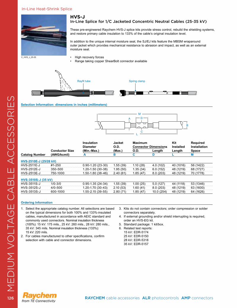
CA
BL
E R
EPA
IR &
RE
JAC
KE
TIN
G In-Line Heat-Shrink Splice
HVS-JIn-Line Splice for 1/C Jacketed Concentric Neutral Cables (25-35 kV)
These pre-engineered Raychem HVS-J splice kits provide stress control, rebuild the shielding systems, and restore primary cable insulation to 133% of the cable’s original insulation level .
In addition to the unique internal moisture seal, the SJ/EJ kits feature the MBSM wraparound outer jacket which provides mechanical resistance to abrasion and impact, as well as an external moisture seal .
• High recovery forces • Range taking copper ShearBolt connector available
Selection Information: dimensions in inches (millimeters)
Insulation Jacket Maximum Kit Required Diameter O.D. Connector Dimensions Installed Installation Conductor Size (Min.-Max.) (Max.) O.D. Length Length SpaceCatalog Number (AWG/kcmil) A B C D L M HVS-2510E-J (25/28 kV) HVS-2511E-J #1-250 0 .90-1 .20 (23-30) 1 .55 (39) 1 .10 (28) 4 .0 (102) 40 (1016) 56 (1422)HVS-2512E-J 350-500 1 .20-1 .50 (30-38) 1 .95 (50) 1 .35 (34) 6 .0 (152) 48 (1219) 68 (1727)HVS-2513E-J 750-1000 1 .50-1 .80 (38-46) 2 .40 (61) 1 .85 (47) 8 .0 (203) 48 (1219) 70 (1778)
HVS-3510S-J (35 kV) HVS-3511S-J 1/0-3/0 0 .95-1 .35 (24-34) 1 .55 (39) 1 .00 (25) 5 .0 (127) 44 (1118) 53 (1346) HVS-3512S-J 4/0-500 1 .20-1 .70 (30-43) 2 .10 (53) 1 .60 (41) 8 .0 (203) 48 (1219) 63 (1600) HVS-3513S-J 600-1000 1 .55-2 .15 (39-55) 2 .80 (71) 1 .85 (47) 10 .0 (254) 48 (1219) 64 (1626)
A D
B
LC
MBlack Red Triple Layer Tube/
Rayfit tube Spring clamp
1 . Select the appropriate catalog number . All selections are based on the typical dimensions for both 100% and 133%-insulated cables, manufactured in accordance with AEIC standard and commonly used connectors . Nominal insulation thickness (100%): 15 kV: 175 mils ., 25 kV: 260 mils ., 28 kV: 280 mils ., 35 kV: 345 mils . Nominal insulation thickness (133%): 15 kV: 220 mils .
2 . For cables manufactured to other specifications, confirm selection with cable and connector dimensions .
3 . Kits do not contain connectors; order compression or solder connectors separately .
4 . If external grounding and/or shield interrupting is required, order an HVS-EG kit .
5 . Standard package: 1 kit/box .6 . Related test reports:
15 kV: EDR-5174 25 kV: EDR-5150 28 kV: EDR-5318 35 kV: EDR-5157
Ordering Information
C_HVS_J_25-35
ME
DIU
M V
OLT
AG
E C
AB
LE
AC
CE
SS
OR
IES
RAYCHEM cable accessories ALR photocontrols AMP connectors 126126
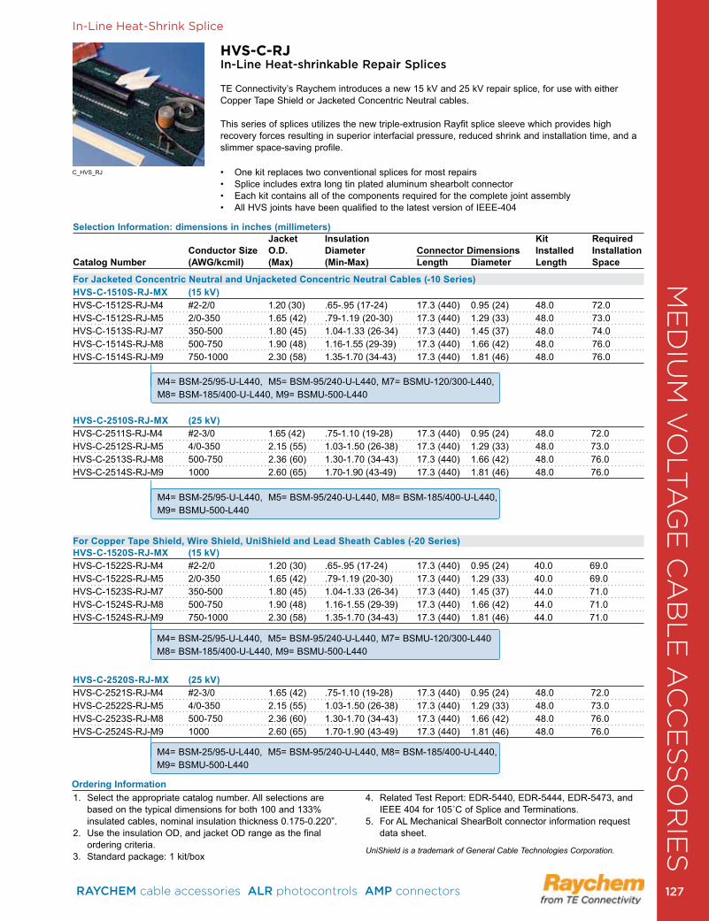
In-Line Heat-Shrink Splice
HVS-C-RJ In-Line Heat-shrinkable Repair Splices
TE Connectivity’s Raychem introduces a new 15 kV and 25 kV repair splice, for use with either Copper Tape Shield or Jacketed Concentric Neutral cables .
This series of splices utilizes the new triple-extrusion Rayfit splice sleeve which provides high recovery forces resulting in superior interfacial pressure, reduced shrink and installation time, and a slimmer space-saving profile .
• One kit replaces two conventional splices for most repairs• Splice includes extra long tin plated aluminum shearbolt connector• Each kit contains all of the components required for the complete joint assembly • All HVS joints have been qualified to the latest version of IEEE-404
C_HVS_RJ
Selection Information: dimensions in inches (millimeters) Jacket Insulation Kit Required Conductor Size O.D. Diameter Connector Dimensions Installed InstallationCatalog Number (AWG/kcmil) (Max) (Min-Max) Length Diameter Length Space
For Jacketed Concentric Neutral and Unjacketed Concentric Neutral Cables (-10 Series)HVS-C-1510S-RJ-MX (15 kV)HVS-C-1512S-RJ-M4 #2-2/0 1 .20 (30) .65- .95 (17-24) 17 .3 (440) 0 .95 (24) 48 .0 72 .0HVS-C-1512S-RJ-M5 2/0-350 1 .65 (42) .79-1 .19 (20-30) 17 .3 (440) 1 .29 (33) 48 .0 73 .0HVS-C-1513S-RJ-M7 350-500 1 .80 (45) 1 .04-1 .33 (26-34) 17 .3 (440) 1 .45 (37) 48 .0 74 .0HVS-C-1514S-RJ-M8 500-750 1 .90 (48) 1 .16-1 .55 (29-39) 17 .3 (440) 1 .66 (42) 48 .0 76 .0 HVS-C-1514S-RJ-M9 750-1000 2 .30 (58) 1 .35-1 .70 (34-43) 17 .3 (440) 1 .81 (46) 48 .0 76 .0
HVS-C-2510S-RJ-MX (25 kV)HVS-C-2511S-RJ-M4 #2-3/0 1 .65 (42) .75-1 .10 (19-28) 17 .3 (440) 0 .95 (24) 48 .0 72 .0 HVS-C-2512S-RJ-M5 4/0-350 2 .15 (55) 1 .03-1 .50 (26-38) 17 .3 (440) 1 .29 (33) 48 .0 73 .0 HVS-C-2513S-RJ-M8 500-750 2 .36 (60) 1 .30-1 .70 (34-43) 17 .3 (440) 1 .66 (42) 48 .0 76 .0 HVS-C-2514S-RJ-M9 1000 2 .60 (65) 1 .70-1 .90 (43-49) 17 .3 (440) 1 .81 (46) 48 .0 76 .0
For Copper Tape Shield, Wire Shield, UniShield and Lead Sheath Cables (-20 Series)HVS-C-1520S-RJ-MX (15 kV)HVS-C-1522S-RJ-M4 #2-2/0 1 .20 (30) .65- .95 (17-24) 17 .3 (440) 0 .95 (24) 40 .0 69 .0 HVS-C-1522S-RJ-M5 2/0-350 1 .65 (42) .79-1 .19 (20-30) 17 .3 (440) 1 .29 (33) 40 .0 69 .0 HVS-C-1523S-RJ-M7 350-500 1 .80 (45) 1 .04-1 .33 (26-34) 17 .3 (440) 1 .45 (37) 44 .0 71 .0 HVS-C-1524S-RJ-M8 500-750 1 .90 (48) 1 .16-1 .55 (29-39) 17 .3 (440) 1 .66 (42) 44 .0 71 .0 HVS-C-1524S-RJ-M9 750-1000 2 .30 (58) 1 .35-1 .70 (34-43) 17 .3 (440) 1 .81 (46) 44 .0 71 .0
HVS-C-2520S-RJ-MX (25 kV)HVS-C-2521S-RJ-M4 #2-3/0 1 .65 (42) .75-1 .10 (19-28) 17 .3 (440) 0 .95 (24) 48 .0 72 .0 HVS-C-2522S-RJ-M5 4/0-350 2 .15 (55) 1 .03-1 .50 (26-38) 17 .3 (440) 1 .29 (33) 48 .0 73 .0 HVS-C-2523S-RJ-M8 500-750 2 .36 (60) 1 .30-1 .70 (34-43) 17 .3 (440) 1 .66 (42) 48 .0 76 .0 HVS-C-2524S-RJ-M9 1000 2 .60 (65) 1 .70-1 .90 (43-49) 17 .3 (440) 1 .81 (46) 48 .0 76 .0
Ordering Information1 . Select the appropriate catalog number . All selections are
based on the typical dimensions for both 100 and 133% insulated cables, nominal insulation thickness 0 .175-0 .220” .
2. Use the insulation OD, and jacket OD range as the final ordering criteria .
3 . Standard package: 1 kit/box
4 . Related Test Report: EDR-5440, EDR-5444, EDR-5473, and IEEE 404 for 105˚C of Splice and Terminations.
5 . For AL Mechanical ShearBolt connector information request data sheet .
UniShield is a trademark of General Cable Technologies Corporation.
M4= BSM-25/95-U-L440, M5= BSM-95/240-U-L440, M7= BSMU-120/300-L440,M8= BSM-185/400-U-L440, M9= BSMU-500-L440
M4= BSM-25/95-U-L440, M5= BSM-95/240-U-L440, M8= BSM-185/400-U-L440, M9= BSMU-500-L440
M4= BSM-25/95-U-L440, M5= BSM-95/240-U-L440, M7= BSMU-120/300-L440M8= BSM-185/400-U-L440, M9= BSMU-500-L440
M4= BSM-25/95-U-L440, M5= BSM-95/240-U-L440, M8= BSM-185/400-U-L440, M9= BSMU-500-L440
ME
DIU
M V
OLT
AG
E C
AB
LE
AC
CE
SS
OR
IES
RAYCHEM cable accessories ALR photocontrols AMP connectors 127 127
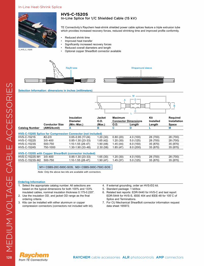
CA
BL
E R
EPA
IR &
RE
JAC
KE
TIN
GIn-Line Heat-Shrink Splice
HVS-C-1520SIn-Line Splice for 1/C Shielded Cable (15 kV)
TE Connectivity’s Raychem heat-shrink shielded power cable splices feature a triple extrusion tube which provides increased recovery forces, reduced shrinking time and improved profile conformity .
• Reduced shrink time• Improved heat transfer• Significantly increased recovery forces• Reduced overall diameters and length• Optional copper ShearBolt connector available
Selection Information: dimensions in inches (millimeters)
Insulation Jacket Maximum Kit RequiredDiameter O.D. Connector Dimensions Installed Installation
Conductor Size (Min.-Max.) (Max.) O.D. Length Length Space Catalog Number (AWG/kcmil) A B C D L M
HVS-C-1520S Splice for Compression Connector (not included)HVS-C-1521S #2-2/0 0 .65-0 .95 (17-24) 1 .20 (30) 0 .80 (20) 4 .0 (100) 28 (700) 28 (700)HVS-C-1522S 3/0-400 0 .85-1 .30 (23-33) 1 .65 (42) 1 .20 (30) 5 .0 (125) 28 (700) 28 (700)HVS-C-1523S 500-750 1 .10-1 .55 (28-47) 1 .90 (48) 1 .45 (44) 6 .0 (150) 35 (870) 35 (870)HVS-C-1524S 750-1000 1 .30-1 .90 (33-48) 2 .30 (58) 1 .85 (47) 8 .0 (200) 35 (870) 35 (870)
HVS-C-1520S with Copper ShearBolt (connector included)HVS-C-1522S-M1 3/0-400 0 .85-1 .30 (23-33) 1 .65 (30) 1 .20 (30) 4 .0 (100) 28 (700) 28 (700)HVS-C-1523S-M2 500-750 1 .10-1 .55 (28-47) 1 .90 (47) 1 .45 (37) 5 .0 (125) 35 (870) 35 (870)
Note: Only the above two kits are available with connectors.
A D
B
LC
M
Rayfit tube Wraparound sleeve
M1= CSBS-20C-500C-SOS, M2= CSBS-300C-750C-SOS
1 . Select the appropriate catalog number . All selections are based on the typical dimensions for both 100% and 133% insulated cables, nominal insulation thickness 0 .175-0 .220" .
2 . Use the insulation OD, and jacket OD range as the final ordering criteria .
3 . Kits can be installed with either aluminum or copper compression connectors (connectors not included with kit) .
4 . If external grounding, order an HVS-EG kit .5 . Standard package: 1 kit/box6 . Related test reports: EDR-5440 for HVS-C and test report
EDR-5444 for HVS-S, IEEE 404 and IEEE-48 for 105˚C of Splice and Terminations .
7 . For CU Mechanical ShearBolt connector information request data sheet 165972 .
Ordering Information
C_HVS_C_1520S
ME
DIU
M V
OLT
AG
E C
AB
LE
AC
CE
SS
OR
IES
RAYCHEM cable accessories ALR photocontrols AMP connectors 128128
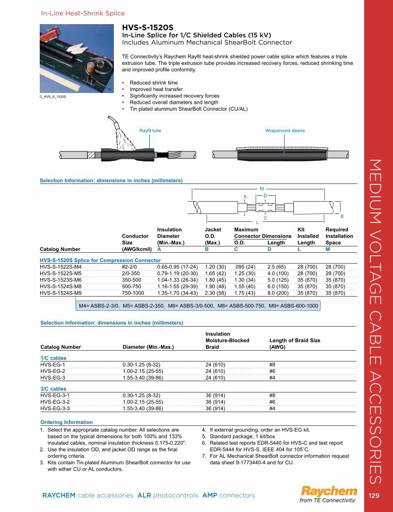
In-Line Heat-Shrink Splice
HVS-S-1520SIn-Line Splice for 1/C Shielded Cables (15 kV) Includes Aluminum Mechanical ShearBolt Connector
TE Connectivity’s Raychem Rayfit heat-shrink shielded power cable splice which features a triple extrusion tube . The triple extrusion tube provides increased recovery forces, reduced shrinking time and improved profile conformity .
• Reduced shrink time• Improved heat transfer• Significantly increased recovery forces• Reduced overall diameters and length• Tin plated aluminum ShearBolt Connector (CU/AL)
Rayfit tube Wraparound sleeve
Selection Information: dimensions in inches (millimeters)
Insulation Jacket Maximum Kit RequiredConductor Diameter O.D. Connector Dimensions Installed InstallationSize (Min.-Max.) (Max.) O.D. Length Length Space
Catalog Number (AWG/kcmil) A B C D L M
HVS-S-1520S Splice for Compression ConnectorHVS-S-1522S-M4 #2-2/0 0 .65-0 .95 (17-24) 1 .20 (30) .095 (24) 2 .5 (65) 28 (700) 28 (700)HVS-S-1522S-M5 2/0-350 0 .79-1 .19 (20-30) 1 .65 (42) 1 .25 (30) 4 .0 (100) 28 (700) 28 (700)HVS-S-1523S-M6 350-500 1 .04-1 .33 (26-34) 1 .80 (45) 1 .30 (34) 5 .0 (125) 35 (870) 35 (870)HVS-S-1524S-M8 500-750 1 .16-1 .55 (29-39) 1 .90 (48) 1 .55 (40) 6 .0 (150) 35 (870) 35 (870)HVS-S-1524S-M9 750-1000 1 .35-1 .70 (34-43) 2 .30 (58) 1 .75 (43) 8 .0 (200) 35 (870) 35 (870)
1 . Select the appropriate catalog number . All selections are based on the typical dimensions for both 100% and 133% insulated cables, nominal insulation thickness 0 .175-0 .220" .
2 . Use the insulation OD, and jacket OD range as the final ordering criteria .
3 . Kits contain Tin-plated Aluminum ShearBolt connector for use with either CU or AL conductors .
4 . If external grounding, order an HVS-EG kit .5 . Standard package: 1 kit/box6 . Related test reports EDR-5440 for HVS-C and test report
EDR-5444 for HVS-S, IEEE 404 for 105˚C.7 . For AL Mechanical ShearBolt connector information request
data sheet 9-1773440-4 and for CU .
Selection Information: dimensions in inches (millimeters)
Insulation Moisture-Blocked Length of Braid SizeCatalog Number Diameter (Min.-Max.) Braid (AWG)
1/C cablesHVS-EG-1 0 .30-1 .25 (8-32) 24 (610) #8HVS-EG-2 1 .00-2 .15 (25-55) 24 (610) #6HVS-EG-3 1 .55-3 .40 (39-86) 24 (610) #4
3/C cablesHVS-EG-3-1 0 .30-1 .25 (8-32) 36 (914) #8HVS-EG-3-2 1 .00-2 .15 (25-55) 36 (914) #6HVS-EG-3-3 1 .55-3 .40 (39-86) 36 (914) #4
Ordering Information
A D
BL
C
M
M4= ASBS-2-3/0, M5= ASBS-2-350, M6= ASBS-3/0-500, M8= ASBS-500-750, M9= ASBS-600-1000
C_HVS_S_1520S
ME
DIU
M V
OLT
AG
E C
AB
LE
AC
CE
SS
OR
IES
RAYCHEM cable accessories ALR photocontrols AMP connectors 129 129
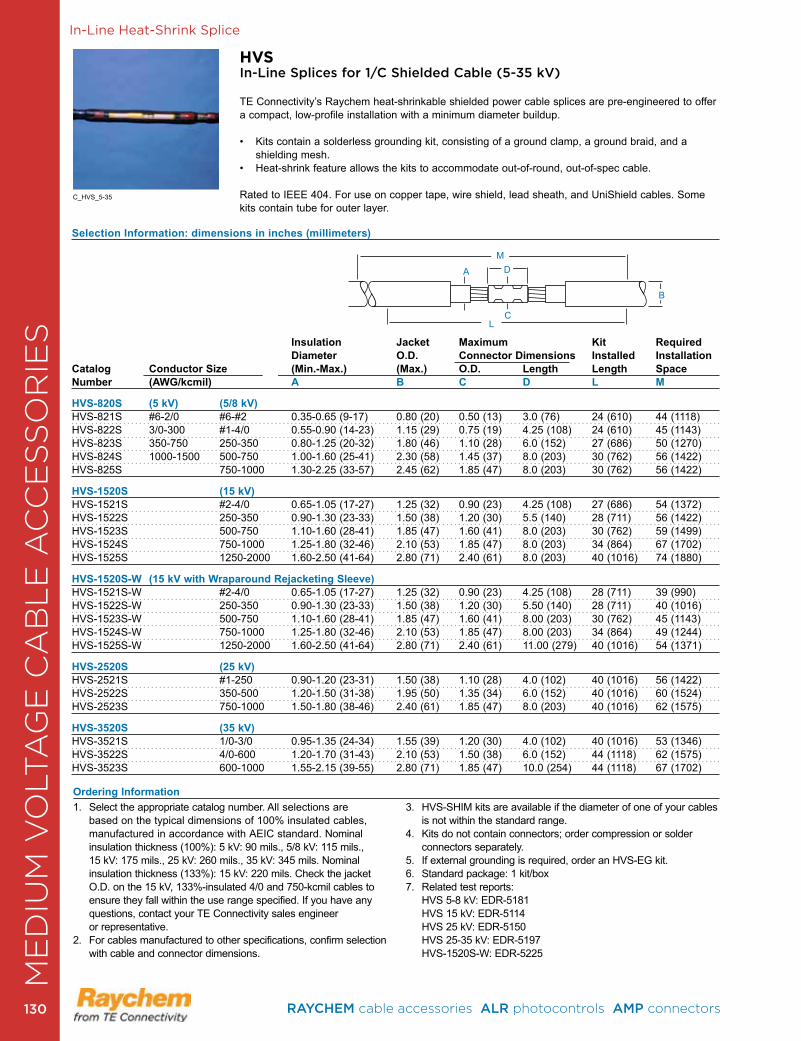
CA
BL
E R
EPA
IR &
RE
JAC
KE
TIN
G In-Line Heat-Shrink Splice
HVSIn-Line Splices for 1/C Shielded Cable (5-35 kV)
TE Connectivity’s Raychem heat-shrinkable shielded power cable splices are pre-engineered to offer a compact, low-profile installation with a minimum diameter buildup . • Kits contain a solderless grounding kit, consisting of a ground clamp, a ground braid, and a shielding mesh .• Heat-shrink feature allows the kits to accommodate out-of-round, out-of-spec cable.
Rated to IEEE 404 . For use on copper tape, wire shield, lead sheath, and UniShield cables . Some kits contain tube for outer layer .
Selection Information: dimensions in inches (millimeters)
Insulation Jacket Maximum Kit Required Diameter O.D. Connector Dimensions Installed Installation
Catalog Conductor Size (Min.-Max.) (Max.) O.D. Length Length SpaceNumber (AWG/kcmil) A B C D L M
HVS-820S (5 kV) (5/8 kV)HVS-821S #6-2/0 #6-#2 0 .35-0 .65 (9-17) 0 .80 (20) 0 .50 (13) 3 .0 (76) 24 (610) 44 (1118)HVS-822S 3/0-300 #1-4/0 0 .55-0 .90 (14-23) 1 .15 (29) 0 .75 (19) 4 .25 (108) 24 (610) 45 (1143)HVS-823S 350-750 250-350 0 .80-1 .25 (20-32) 1 .80 (46) 1 .10 (28) 6 .0 (152) 27 (686) 50 (1270)HVS-824S 1000-1500 500-750 1 .00-1 .60 (25-41) 2 .30 (58) 1 .45 (37) 8 .0 (203) 30 (762) 56 (1422)HVS-825S 750-1000 1 .30-2 .25 (33-57) 2 .45 (62) 1 .85 (47) 8 .0 (203) 30 (762) 56 (1422)
HVS-1520S (15 kV)HVS-1521S #2-4/0 0 .65-1 .05 (17-27) 1 .25 (32) 0 .90 (23) 4 .25 (108) 27 (686) 54 (1372)HVS-1522S 250-350 0 .90-1 .30 (23-33) 1 .50 (38) 1 .20 (30) 5 .5 (140) 28 (711) 56 (1422)HVS-1523S 500-750 1 .10-1 .60 (28-41) 1 .85 (47) 1 .60 (41) 8 .0 (203) 30 (762) 59 (1499)HVS-1524S 750-1000 1 .25-1 .80 (32-46) 2 .10 (53) 1 .85 (47) 8 .0 (203) 34 (864) 67 (1702)HVS-1525S 1250-2000 1 .60-2 .50 (41-64) 2 .80 (71) 2 .40 (61) 8 .0 (203) 40 (1016) 74 (1880)
HVS-1520S-W (15 kV with Wraparound Rejacketing Sleeve)HVS-1521S-W #2-4/0 0 .65-1 .05 (17-27) 1 .25 (32) 0 .90 (23) 4 .25 (108) 28 (711) 39 (990)HVS-1522S-W 250-350 0 .90-1 .30 (23-33) 1 .50 (38) 1 .20 (30) 5 .50 (140) 28 (711) 40 (1016)HVS-1523S-W 500-750 1 .10-1 .60 (28-41) 1 .85 (47) 1 .60 (41) 8 .00 (203) 30 (762) 45 (1143)HVS-1524S-W 750-1000 1 .25-1 .80 (32-46) 2 .10 (53) 1 .85 (47) 8 .00 (203) 34 (864) 49 (1244)HVS-1525S-W 1250-2000 1 .60-2 .50 (41-64) 2 .80 (71) 2 .40 (61) 11 .00 (279) 40 (1016) 54 (1371)
HVS-2520S (25 kV)HVS-2521S #1-250 0 .90-1 .20 (23-31) 1 .50 (38) 1 .10 (28) 4 .0 (102) 40 (1016) 56 (1422) HVS-2522S 350-500 1 .20-1 .50 (31-38) 1 .95 (50) 1 .35 (34) 6 .0 (152) 40 (1016) 60 (1524) HVS-2523S 750-1000 1 .50-1 .80 (38-46) 2 .40 (61) 1 .85 (47) 8 .0 (203) 40 (1016) 62 (1575)
HVS-3520S (35 kV)HVS-3521S 1/0-3/0 0 .95-1 .35 (24-34) 1 .55 (39) 1 .20 (30) 4 .0 (102) 40 (1016) 53 (1346)HVS-3522S 4/0-600 1 .20-1 .70 (31-43) 2 .10 (53) 1 .50 (38) 6 .0 (152) 44 (1118) 62 (1575) HVS-3523S 600-1000 1 .55-2 .15 (39-55) 2 .80 (71) 1 .85 (47) 10 .0 (254) 44 (1118) 67 (1702)
A D
B
LC
M
1 . Select the appropriate catalog number . All selections are based on the typical dimensions of 100% insulated cables, manufactured in accordance with AEIC standard . Nominal insulation thickness (100%): 5 kV: 90 mils ., 5/8 kV: 115 mils ., 15 kV: 175 mils ., 25 kV: 260 mils ., 35 kV: 345 mils . Nominal insulation thickness (133%): 15 kV: 220 mils. Check the jacket O .D . on the 15 kV, 133%-insulated 4/0 and 750-kcmil cables to ensure they fall within the use range specified . If you have any questions, contact your TE Connectivity sales engineer or representative .
2 . For cables manufactured to other specifications, confirm selection with cable and connector dimensions .
3 . HVS-SHIM kits are available if the diameter of one of your cables is not within the standard range .
4 . Kits do not contain connectors; order compression or solder connectors separately .
5 . If external grounding is required, order an HVS-EG kit . 6 . Standard package: 1 kit/box7 . Related test reports:
HVS 5-8 kV: EDR-5181 HVS 15 kV: EDR-5114 HVS 25 kV: EDR-5150 HVS 25-35 kV: EDR-5197 HVS-1520S-W: EDR-5225
Ordering Information
C_HVS_5-35
ME
DIU
M V
OLT
AG
E C
AB
LE
AC
CE
SS
OR
IES
RAYCHEM cable accessories ALR photocontrols AMP connectors 130130
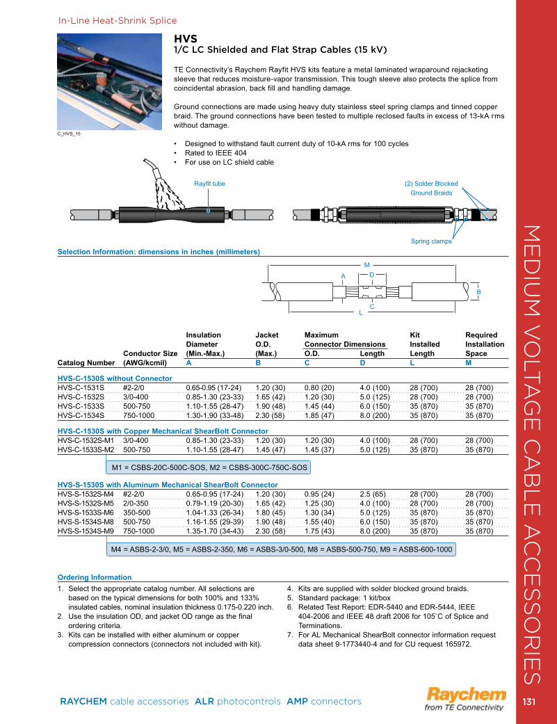
In-Line Heat-Shrink Splice
HVS1/C LC Shielded and Flat Strap Cables (15 kV)
TE Connectivity’s Raychem Rayfit HVS kits feature a metal laminated wraparound rejacketing sleeve that reduces moisture-vapor transmission . This tough sleeve also protects the splice from coincidental abrasion, back fill and handling damage .
Ground connections are made using heavy duty stainless steel spring clamps and tinned copper braid . The ground connections have been tested to multiple reclosed faults in excess of 13-kA rms without damage .
• Designed to withstand fault current duty of 10-kA rms for 100 cycles• Rated to IEEE 404 • For use on LC shield cable
1 . Select the appropriate catalog number . All selections are based on the typical dimensions for both 100% and 133% insulated cables, nominal insulation thickness 0 .175-0 .220 inch .
2 . Use the insulation OD, and jacket OD range as the final ordering criteria .
3 . Kits can be installed with either aluminum or copper compression connectors (connectors not included with kit) .
4 . Kits are supplied with solder blocked ground braids .5 . Standard package: 1 kit/box6 . Related Test Report: EDR-5440 and EDR-5444, IEEE
404-2006 and IEEE 48 draft 2006 for 105˚C of Splice and Terminations .
7 . For AL Mechanical ShearBolt connector information request data sheet 9-1773440-4 and for CU request 165972 .
Selection Information: dimensions in inches (millimeters)
Insulation Jacket Maximum Kit Required Diameter O.D. Connector Dimensions Installed Installation Conductor Size (Min.-Max.) (Max.) O.D. Length Length SpaceCatalog Number (AWG/kcmil) A B C D L M
HVS-C-1530S without Connector HVS-C-1531S #2-2/0 0 .65-0 .95 (17-24) 1 .20 (30) 0 .80 (20) 4 .0 (100) 28 (700) 28 (700)HVS-C-1532S 3/0-400 0 .85-1 .30 (23-33) 1 .65 (42) 1 .20 (30) 5 .0 (125) 28 (700) 28 (700)HVS-C-1533S 500-750 1 .10-1 .55 (28-47) 1 .90 (48) 1 .45 (44) 6 .0 (150) 35 (870) 35 (870)HVS-C-1534S 750-1000 1 .30-1 .90 (33-48) 2 .30 (58) 1 .85 (47) 8 .0 (200) 35 (870) 35 (870) HVS-C-1530S with Copper Mechanical ShearBolt ConnectorHVS-C-1532S-M1 3/0-400 0 .85-1 .30 (23-33) 1 .20 (30) 1 .20 (30) 4 .0 (100) 28 (700) 28 (700)HVS-C-1533S-M2 500-750 1 .10-1 .55 (28-47) 1 .45 (47) 1 .45 (37) 5 .0 (125) 35 (870) 35 (870)
HVS-S-1530S with Aluminum Mechanical ShearBolt Connector HVS-S-1532S-M4 #2-2/0 0 .65-0 .95 (17-24) 1 .20 (30) 0 .95 (24) 2 .5 (65) 28 (700) 28 (700)HVS-S-1532S-M5 2/0-350 0 .79-1 .19 (20-30) 1 .65 (42) 1 .25 (30) 4 .0 (100) 28 (700) 28 (700)HVS-S-1533S-M6 350-500 1 .04-1 .33 (26-34) 1 .80 (45) 1 .30 (34) 5 .0 (125) 35 (870) 35 (870)HVS-S-1534S-M8 500-750 1 .16-1 .55 (29-39) 1 .90 (48) 1 .55 (40) 6 .0 (150) 35 (870) 35 (870)HVS-S-1534S-M9 750-1000 1 .35-1 .70 (34-43) 2 .30 (58) 1 .75 (43) 8 .0 (200) 35 (870) 35 (870)
Ordering Information
A D
B
LC
M
M1 = CSBS-20C-500C-SOS, M2 = CSBS-300C-750C-SOS
M4 = ASBS-2-3/0, M5 = ASBS-2-350, M6 = ASBS-3/0-500, M8 = ASBS-500-750, M9 = ASBS-600-1000
C_HVS_15
Rayfit tube (2) Solder Blocked Ground Braids
Spring clamps
ME
DIU
M V
OLT
AG
E C
AB
LE
AC
CE
SS
OR
IES
RAYCHEM cable accessories ALR photocontrols AMP connectors 131 131
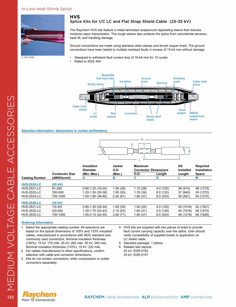
In-Line Heat-Shrink Splice
HVSSplice Kits for 1/C LC and Flat Strap Shield Cable (25-35 kV)
The Raychem HVS kits feature a metal laminated wraparound rejacketing sleeve that reduces moisture-vapor transmission . This tough sleeve also protects the splice from coincidental abrasion, back fill, and handling damage .
Ground connections are made using stainless steel clamps and tinned copper braid . The ground connections have been tested to multiple reclosed faults in excess of 13-kA rms without damage .
• Designed to withstand fault current duty of 10-kA rms for 10 cycles• Rated to IEEE 404
Selection Information: dimensions in inches (millimeters)
Insulation Jacket Maximum Kit Required Diameter O.D. Connector Dimensions Installed Installation Conductor Size (Min.-Max.) (Max.) O.D. Length Length SpaceCatalog Number (AWG/kcmil) A B C D L M
HVS-2530-LC (25 kV)HVS-2531-LC #1-250 0 .90-1 .20 (16-24) 1 .55 (39) 1 .10 (28) 4 .0 (102) 36 (914) 48 (1219)HVS-2532-LC 350-500 1 .20-1 .50 (30-38) 1 .95 (50) 1 .35 (34) 6 .0 (152) 37 (940) 50 (1270)HVS-2533-LC 750-1000 1 .50-1 .80 (38-46) 2 .40 (61) 1 .85 (47) 8 .0 (203) 39 (991) 54 (1372)
HVS-3530-LC (35 kV)HVS-3531-LC 1/0-3/0 0 .95-1 .35 (29-34) 1 .55 (39) 1 .00 (25) 4 .0 (102) 40 (1016) 52 (1321)HVS-3532-LC 4/0-500 1 .30-1 .70 (33-43) 2 .10 (53) 1 .60 (41) 5 .5 (140) 40 (1016) 58 (1473)HVS-3533-LC 750-1000 1 .65-2 .15 (42-55) 2 .80 (71) 1 .85 (47) 8 .0 (203) 48 (1219) 64 (1626)
Ordering Information1 . Select the appropriate catalog number . All selections are
based on the typical dimensions of 100% and 133% insulated cables, manufactured in accordance with AEIC standard and commonly used connectors . Nominal insulation thickness (100%): 15 kV: 175 mils . 25 kV: 260 mils . 35 kV: 345 mils . Nominal insulation thickness (133%): 15 kV: 220 mils .
2 . For cables manufactured to other specifications, confirm selection with cable and connector dimensions .
3 . Kits do not contain connectors; order compression or solder connectors separately .
4 . HVS kits are supplied with two pieces of braid to provide fault current carrying capacity over the splice . User should verify compatibility of supplied braids to application on LC shield cable .
5 . Standard package: 1 kit/box6 . Related test reports: 25 kV: EDR-5150 35 kV: EDR-5157
A D
B
LC
M
Cable outerjacket
Black/Reddual layer tube
ConnectorRedsealant
LCshield
Spring clamp SemiconInsulation
Black sealant
Cable outerjacket
Shieldingmesh
Groundbraid
MBSMwraparoundsleeve
Stress reliefmastic
C_HVS_25/35
ME
DIU
M V
OLT
AG
E C
AB
LE
AC
CE
SS
OR
IES
RAYCHEM cable accessories ALR photocontrols AMP connectors 132132
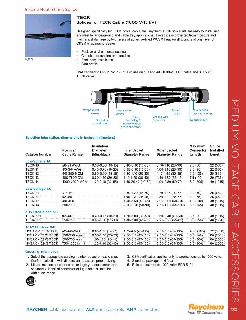
In-Line Heat-Shrink Splice
TECKSplices for TECK Cable (1000 V-15 kV)
Designed specifically for TECK power cable, the Raychem TECK splice kits are easy to install and are ideal for underground and cable tray applications . The splice is protected from moisture and mechanical damage by two layers of adhesive-lined WCSM heavy-wall tubing and one layer of CRSM wraparound sleeve .
• Positive environmental sealing • Complete grounding and bonding • Fast, easy installation • Slim profile
CSA certified to C22 .2, No . 198 .2 . For use on 1/C and 4/C 1000-V TECK cable and 3/C 5 kV TECK cable .
Selection Information: dimensions in inches (millimeters)
Insulation Maximum Splice Nominal Diameter Inner Jacket Outer Jacket Connector Installed Catalog Number Cable Range (Min.-Max.) Diameter Range Diameter Range Length Length
Low-Voltage 1/CTECK-10 #6-#1 AWG 0 .30-0 .50 (10-15) 0 .40-0 .80 (10-20) 0 .70-1 .10 (20-30) 2 .0 (50) 22 (560)TECK-11 1/0-3/0 AWG 0 .45-0 .70 (10-20) 0 .65-0 .90 (15-25) 1 .00-1 .15 (25-30) 3 .5 (90) 22 (560)TECK-12 4/0-350 MCM 0 .60-0 .90 (15-25) 0 .80-1 .10 (20-30) 1 .10-1 .45 (30-35) 5 .0 (125) 25 (635)TECK-13 400-750MCM 0 .80-1 .20 (20-30) 1 .10-1 .50 (30-40) 1 .40-1 .80 (35-45) 7 .5 (190) 29 (735)TECK-14 1000-2000 MCM 1 .20-2 .10 (30-55) 1 .50-20 .40 (40-60) 1 .90-2 .80 (50-70) 8 .0 (205) 40 (1015)
Low-Voltage 4/C TECK-41 #14-#4 0 .50-1 .20 (15-30) 0 .70-1 .45 (20-35) 2 .0 (50) 25 (650)TECK-42 #2-3/0 1 .00-1 .70 (25-45) 1 .30-2 .10 (35-55) 3 .0 (75) 25 (650)TECK-43 4/0-400 1 .50-2 .50 (40-65) 2 .00-3 .00 (50-70) 4 .0 (100) 40 (1015)TECK-44 500-1000 2 .00-3 .50 (50-90) 2 .50-4 .00 (65-100) 6 .5 (165) 40 (1015)
5 kV Unshielded 3/CTECK-531 #2-4/0 0 .40-0 .75 (10-20) 1 .20-2 .00 (30-50) 1 .50-2 .40 (40-60) 3 .5 (90) 40 (1015)TECK-532 250-750 0 .65-1 .20 (15-30) 1 .80-3 .00 (45-75) 2 .20-3 .25 (55-85) 6 .0 (150) 48 (1220)
15 kV Shielded 3/CHVSA-3-1521S-TECK #2-4/0AWG 0 .65-1/05 (17-27) 1 .75-4 .5 (45-115) 2 .50-6 .5 (65-165) 4 .25 (105) 72 (1830)HVSA-3-1522S-TECK 250-350 kcmil 0 .90-1 .30 (23-33) 2 .50-6 .0 (65-150) 2 .50-6 .5 (65-165) 5 .5 (140) 80 (2030)HVSA-3-1523S-TECK 500-750 kcmil 1 .10-1 .60 (28-41) 2 .50-6 .0 (65-150) 2 .50-6 .5 (65-165) 8 .0 (200) 80 (2030)HVSA-3-1524S-TECK 750-1000 kcmil 1 .25-1 .80 (32-46) 2 .50-6 .0 (65-150) 2 .50-6 .5 (65-165) 8 .0 (200) 80 (2030)
Ordering information1 . Select the appropriate catalog number based on cable size .
Confirm selection with dimensions to assure proper sizing .2 . Kits do not contain connectors or lugs; you must order them
separately . Installed connector or lug diameter must be within use range .
3 . CSA certification applies only to applications up to 1000 volts .4 . Standard package: 1 kit/box5 . Related test report: 1000 volts: EDR-5194
C_TECK
Wraparoundsleeve
Solderlessground clamp
Groundbraid
Phaseinsulating &
sealing sleeve(over connector)
Inner sealingsleeve
Copper mesh
Solderlessground clamp
Ground wireconnector
ME
DIU
M V
OLT
AG
E C
AB
LE
AC
CE
SS
OR
IES
RAYCHEM cable accessories ALR photocontrols AMP connectors 133 133
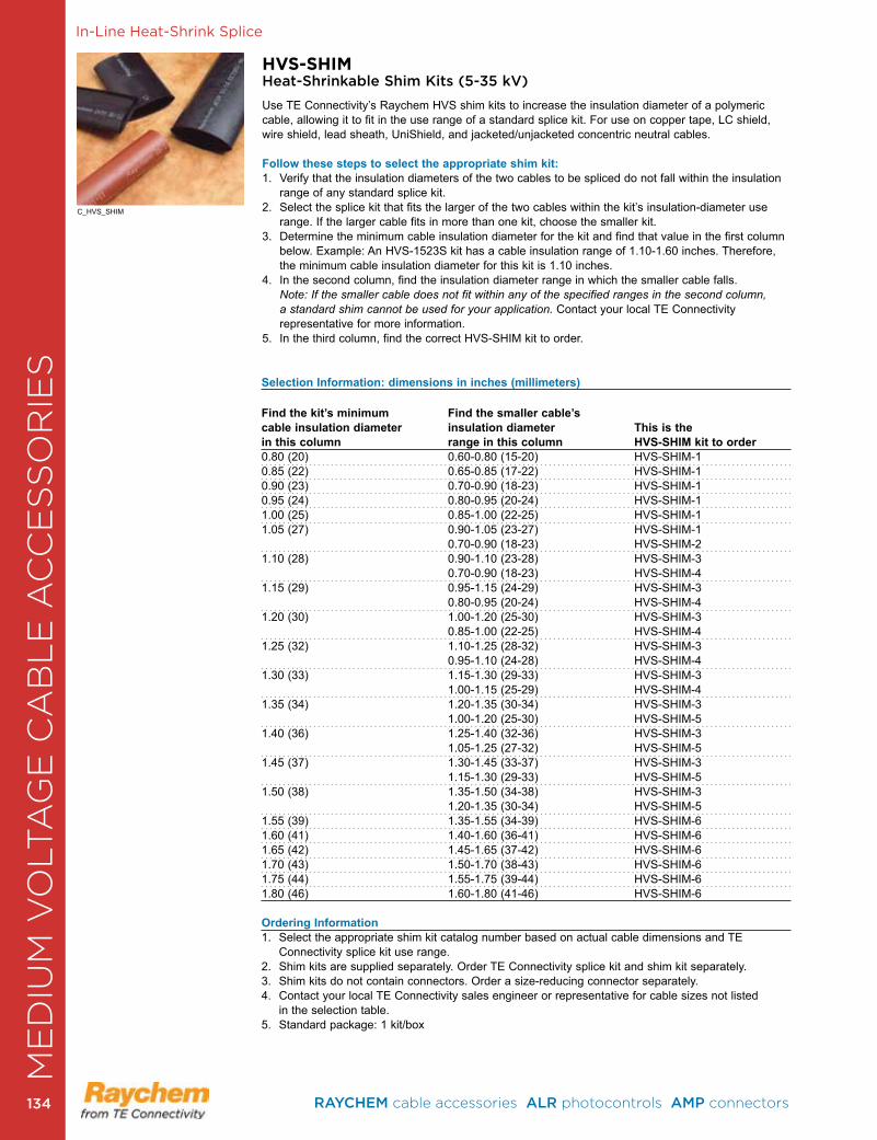
In-Line Heat-Shrink Splice
HVS-SHIMHeat-Shrinkable Shim Kits (5-35 kV)
Use TE Connectivity’s Raychem HVS shim kits to increase the insulation diameter of a polymeric cable, allowing it to fit in the use range of a standard splice kit . For use on copper tape, LC shield, wire shield, lead sheath, UniShield, and jacketed/unjacketed concentric neutral cables.
Follow these steps to select the appropriate shim kit:1 . Verify that the insulation diameters of the two cables to be spliced do not fall within the insulation
range of any standard splice kit .2 . Select the splice kit that fits the larger of the two cables within the kit’s insulation-diameter use
range . If the larger cable fits in more than one kit, choose the smaller kit .3 . Determine the minimum cable insulation diameter for the kit and find that value in the first column
below . Example: An HVS-1523S kit has a cable insulation range of 1 .10-1 .60 inches . Therefore, the minimum cable insulation diameter for this kit is 1 .10 inches .
4 . In the second column, find the insulation diameter range in which the smaller cable falls . Note: If the smaller cable does not fit within any of the specified ranges in the second column, a standard shim cannot be used for your application. Contact your local TE Connectivity representative for more information .
5 . In the third column, find the correct HVS-SHIM kit to order .
Selection Information: dimensions in inches (millimeters)
Find the kit’s minimum Find the smaller cable’s cable insulation diameter insulation diameter This is the in this column range in this column HVS-SHIM kit to order0 .80 (20) 0 .60-0 .80 (15-20) HVS-SHIM-10 .85 (22) 0 .65-0 .85 (17-22) HVS-SHIM-10 .90 (23) 0 .70-0 .90 (18-23) HVS-SHIM-10 .95 (24) 0 .80-0 .95 (20-24) HVS-SHIM-11 .00 (25) 0 .85-1 .00 (22-25) HVS-SHIM-11 .05 (27) 0 .90-1 .05 (23-27) HVS-SHIM-1 0 .70-0 .90 (18-23) HVS-SHIM-21 .10 (28) 0 .90-1 .10 (23-28) HVS-SHIM-3 0 .70-0 .90 (18-23) HVS-SHIM-41 .15 (29) 0 .95-1 .15 (24-29) HVS-SHIM-3 0 .80-0 .95 (20-24) HVS-SHIM-41 .20 (30) 1 .00-1 .20 (25-30) HVS-SHIM-3 0 .85-1 .00 (22-25) HVS-SHIM-41 .25 (32) 1 .10-1 .25 (28-32) HVS-SHIM-3 0 .95-1 .10 (24-28) HVS-SHIM-41 .30 (33) 1 .15-1 .30 (29-33) HVS-SHIM-3 1 .00-1 .15 (25-29) HVS-SHIM-41 .35 (34) 1 .20-1 .35 (30-34) HVS-SHIM-3 1 .00-1 .20 (25-30) HVS-SHIM-51 .40 (36) 1 .25-1 .40 (32-36) HVS-SHIM-3 1 .05-1 .25 (27-32) HVS-SHIM-51 .45 (37) 1 .30-1 .45 (33-37) HVS-SHIM-3 1 .15-1 .30 (29-33) HVS-SHIM-51 .50 (38) 1 .35-1 .50 (34-38) HVS-SHIM-3 1 .20-1 .35 (30-34) HVS-SHIM-51 .55 (39) 1 .35-1 .55 (34-39) HVS-SHIM-61 .60 (41) 1 .40-1 .60 (36-41) HVS-SHIM-61 .65 (42) 1 .45-1 .65 (37-42) HVS-SHIM-61 .70 (43) 1 .50-1 .70 (38-43) HVS-SHIM-61 .75 (44) 1 .55-1 .75 (39-44) HVS-SHIM-61 .80 (46) 1 .60-1 .80 (41-46) HVS-SHIM-6
Ordering Information1 . Select the appropriate shim kit catalog number based on actual cable dimensions and TE
Connectivity splice kit use range .2 . Shim kits are supplied separately . Order TE Connectivity splice kit and shim kit separately .3 . Shim kits do not contain connectors . Order a size-reducing connector separately .4 . Contact your local TE Connectivity sales engineer or representative for cable sizes not listed
in the selection table .5 . Standard package: 1 kit/box
C_HVS_SHIM
ME
DIU
M V
OLT
AG
E C
AB
LE
AC
CE
SS
OR
IES
RAYCHEM cable accessories ALR photocontrols AMP connectors 134134
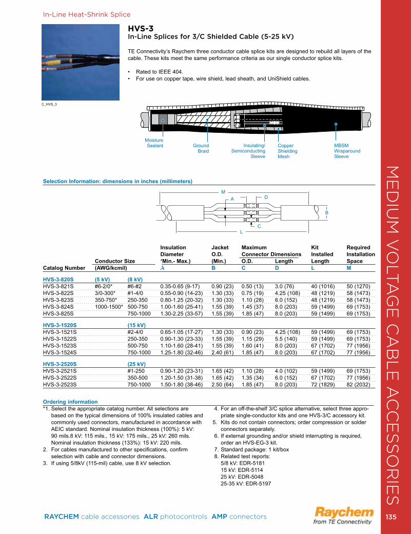
In-Line Heat-Shrink Splice
Selection Information: dimensions in inches (millimeters)
Insulation Jacket Maximum Kit Required Diameter O.D. Connector Dimensions Installed Installation
Conductor Size (Min.- Max.) (Min.) O.D. Length Length SpaceCatalog Number (AWG/kcmil) A B C D L M
HVS-3-820S (5 kV) (8 kV)HVS-3-821S #6-2/0* #6-#2 0 .35-0 .65 (9-17) 0 .90 (23) 0 .50 (13) 3 .0 (76) 40 (1016) 50 (1270)HVS-3-822S 3/0-300* #1-4/0 0 .55-0 .90 (14-23) 1 .30 (33) 0 .75 (19) 4 .25 (108) 48 (1219) 58 (1473)HVS-3-823S 350-750* 250-350 0 .80-1 .25 (20-32) 1 .30 (33) 1 .10 (28) 6 .0 (152) 48 (1219) 58 (1473)HVS-3-824S 1000-1500* 500-750 1 .00-1 .60 (25-41) 1 .55 (39) 1 .45 (37) 8 .0 (203) 59 (1499) 69 (1753)HVS-3-825S 750-1000 1 .30-2 .25 (33-57) 1 .55 (39) 1 .85 (47) 8 .0 (203) 59 (1499) 69 (1753)
HVS-3-1520S (15 kV)HVS-3-1521S #2-4/0 0 .65-1 .05 (17-27) 1 .30 (33) 0 .90 (23) 4 .25 (108) 59 (1499) 69 (1753)HVS-3-1522S 250-350 0 .90-1 .30 (23-33) 1 .55 (39) 1 .15 (29) 5 .5 (140) 59 (1499) 69 (1753)HVS-3-1523S 500-750 1 .10-1 .60 (28-41) 1 .55 (39) 1 .60 (41) 8 .0 (203) 67 (1702) 77 (1956)HVS-3-1524S 750-1000 1 .25-1 .80 (32-46) 2 .40 (61) 1 .85 (47) 8 .0 (203) 67 (1702) 77 (1956)
HVS-3-2520S (25 kV)HVS-3-2521S #1-250 0 .90-1 .20 (23-31) 1 .65 (42) 1 .10 (28) 4 .0 (102) 59 (1499) 69 (1753) HVS-3-2522S 350-500 1 .20-1 .50 (31-38) 1 .65 (42) 1 .35 (34) 6 .0 (152) 67 (1702) 77 (1956) HVS-3-2523S 750-1000 1 .50-1 .80 (38-46) 2 .50 (64) 1 .85 (47) 8 .0 (203) 72 (1829) 82 (2032)
HVS-3In-Line Splices for 3/C Shielded Cable (5-25 kV)
TE Connectivity’s Raychem three conductor cable splice kits are designed to rebuild all layers of the cable . These kits meet the same performance criteria as our single conductor splice kits .
• Rated to IEEE 404. • For use on copper tape, wire shield, lead sheath, and UniShield cables.
MD
C
B
A
L
Ordering information*1 . Select the appropriate catalog number . All selections are
based on the typical dimensions of 100% insulated cables and commonly used connectors, manufactured in accordance with AEIC standard . Nominal insulation thickness (100%): 5 kV: 90 mils .8 kV: 115 mils ., 15 kV: 175 mils ., 25 kV: 260 mils . Nominal insulation thickness (133%): 15 kV: 220 mils .
2 . For cables manufactured to other specifications, confirm selection with cable and connector dimensions .
3 . If using 5/8kV (115-mil) cable, use 8 kV selection .
4 . For an off-the-shelf 3/C splice alternative, select three appro-priate single-conductor kits and one HVS-3/C accessory kit .
5 . Kits do not contain connectors; order compression or solder connectors separately .
6 . If external grounding and/or shield interrupting is required, order an HVS-EG-3 kit .
7 . Standard package: 1 kit/box 8 . Related test reports: 5/8 kV: EDR-5181 15 kV: EDR-5114 25 kV: EDR-5048 25-35 kV: EDR-5197
C_HVS_3
MBSM Wraparound Sleeve
MoistureSealant Ground
BraidCopper Shielding Mesh
Insulating/Semiconducting
Sleeve ME
DIU
M V
OLT
AG
E C
AB
LE
AC
CE
SS
OR
IES
RAYCHEM cable accessories ALR photocontrols AMP connectors 135 135
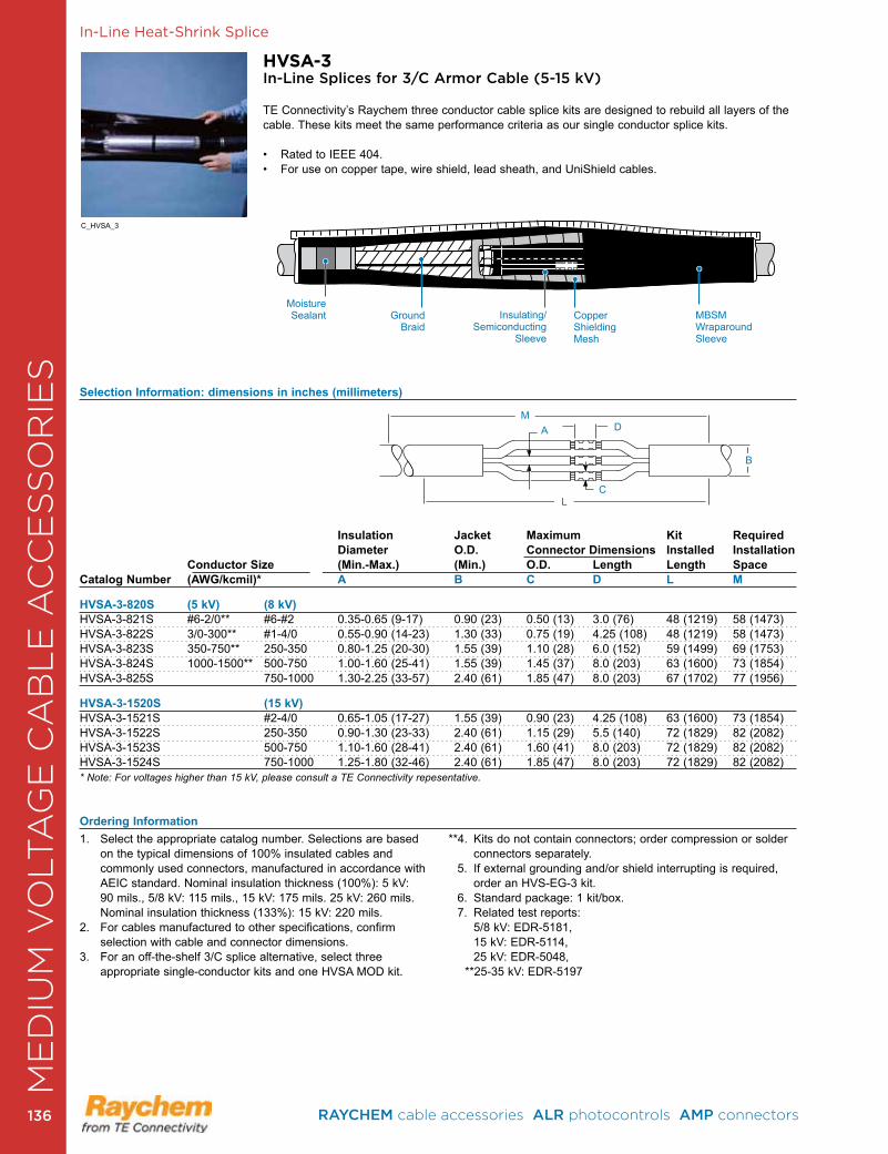
In-Line Heat-Shrink Splice
Selection Information: dimensions in inches (millimeters)
Insulation Jacket Maximum Kit Required Diameter O.D. Connector Dimensions Installed Installation
Conductor Size (Min.-Max.) (Min.) O.D. Length Length SpaceCatalog Number (AWG/kcmil)* A B C D L M
HVSA-3-820S (5 kV) (8 kV)HVSA-3-821S #6-2/0** #6-#2 0 .35-0 .65 (9-17) 0 .90 (23) 0 .50 (13) 3 .0 (76) 48 (1219) 58 (1473)HVSA-3-822S 3/0-300** #1-4/0 0 .55-0 .90 (14-23) 1 .30 (33) 0 .75 (19) 4 .25 (108) 48 (1219) 58 (1473)HVSA-3-823S 350-750** 250-350 0 .80-1 .25 (20-30) 1 .55 (39) 1 .10 (28) 6 .0 (152) 59 (1499) 69 (1753)HVSA-3-824S 1000-1500** 500-750 1 .00-1 .60 (25-41) 1 .55 (39) 1 .45 (37) 8 .0 (203) 63 (1600) 73 (1854)HVSA-3-825S 750-1000 1 .30-2 .25 (33-57) 2 .40 (61) 1 .85 (47) 8 .0 (203) 67 (1702) 77 (1956)
HVSA-3-1520S (15 kV)HVSA-3-1521S #2-4/0 0 .65-1 .05 (17-27) 1 .55 (39) 0 .90 (23) 4 .25 (108) 63 (1600) 73 (1854)HVSA-3-1522S 250-350 0 .90-1 .30 (23-33) 2 .40 (61) 1 .15 (29) 5 .5 (140) 72 (1829) 82 (2082)HVSA-3-1523S 500-750 1 .10-1 .60 (28-41) 2 .40 (61) 1 .60 (41) 8 .0 (203) 72 (1829) 82 (2082)HVSA-3-1524S 750-1000 1 .25-1 .80 (32-46) 2 .40 (61) 1 .85 (47) 8 .0 (203) 72 (1829) 82 (2082)* Note: For voltages higher than 15 kV, please consult a TE Connectivity repesentative.
Ordering Information
HVSA-3In-Line Splices for 3/C Armor Cable (5-15 kV)
TE Connectivity’s Raychem three conductor cable splice kits are designed to rebuild all layers of the cable . These kits meet the same performance criteria as our single conductor splice kits .
• Rated to IEEE 404. • For use on copper tape, wire shield, lead sheath, and UniShield cables.
1 . Select the appropriate catalog number . Selections are based on the typical dimensions of 100% insulated cables and commonly used connectors, manufactured in accordance with AEIC standard . Nominal insulation thickness (100%): 5 kV: 90 mils ., 5/8 kV: 115 mils ., 15 kV: 175 mils . 25 kV: 260 mils . Nominal insulation thickness (133%): 15 kV: 220 mils .
2 . For cables manufactured to other specifications, confirm selection with cable and connector dimensions .
3 . For an off-the-shelf 3/C splice alternative, select three appropriate single-conductor kits and one HVSA MOD kit .
**4 . Kits do not contain connectors; order compression or solder connectors separately .
5 . If external grounding and/or shield interrupting is required, order an HVS-EG-3 kit .
6 . Standard package: 1 kit/box . 7 . Related test reports: 5/8 kV: EDR-5181, 15 kV: EDR-5114, 25 kV: EDR-5048, **25-35 kV: EDR-5197
MD
C
B
A
L
C_HVSA_3
MBSM Wraparound Sleeve
MoistureSealant Ground
BraidCopper Shielding Mesh
Insulating/Semiconducting
Sleeve
ME
DIU
M V
OLT
AG
E C
AB
LE
AC
CE
SS
OR
IES
RAYCHEM cable accessories ALR photocontrols AMP connectors 136136
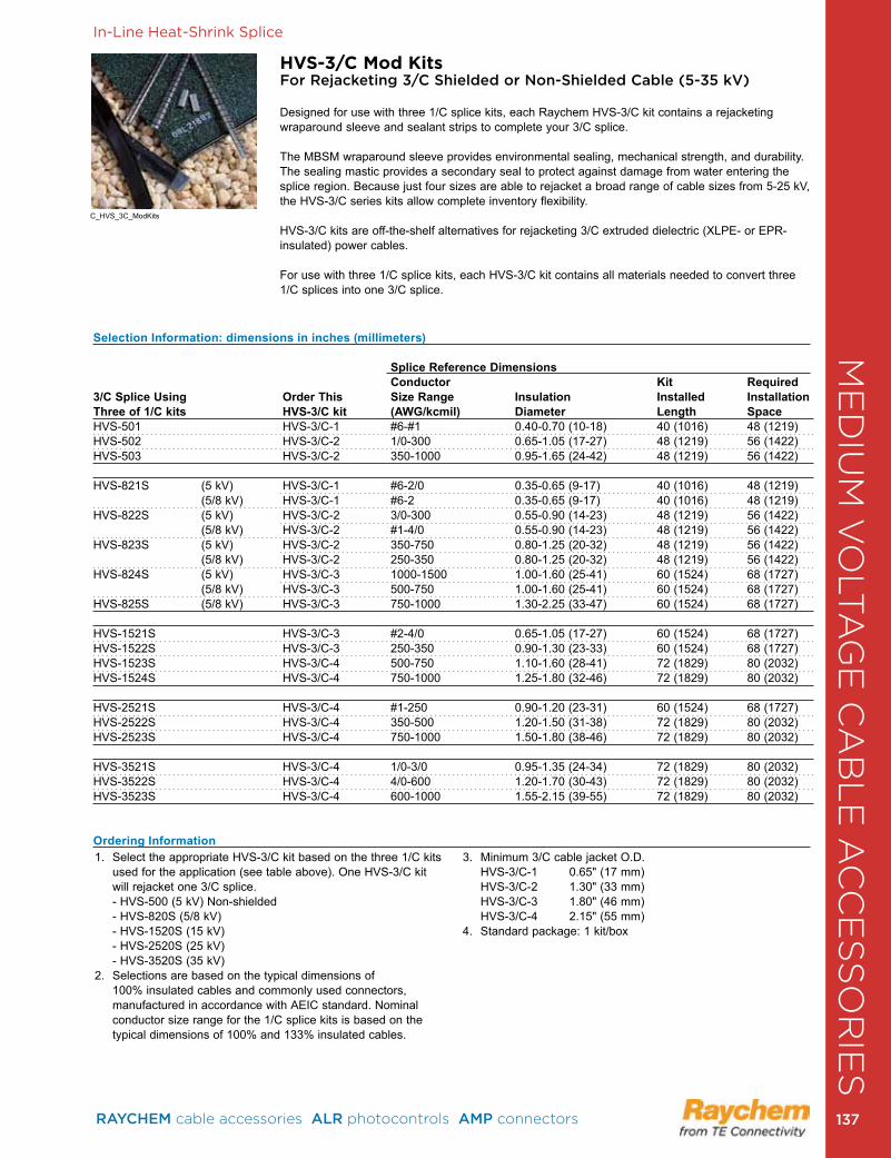
In-Line Heat-Shrink Splice
HVS-3/C Mod KitsFor Rejacketing 3/C Shielded or Non-Shielded Cable (5-35 kV)
Designed for use with three 1/C splice kits, each Raychem HVS-3/C kit contains a rejacketing wraparound sleeve and sealant strips to complete your 3/C splice .
The MBSM wraparound sleeve provides environmental sealing, mechanical strength, and durability . The sealing mastic provides a secondary seal to protect against damage from water entering the splice region. Because just four sizes are able to rejacket a broad range of cable sizes from 5-25 kV, the HVS-3/C series kits allow complete inventory flexibility .
HVS-3/C kits are off-the-shelf alternatives for rejacketing 3/C extruded dielectric (XLPE- or EPR-insulated) power cables .
For use with three 1/C splice kits, each HVS-3/C kit contains all materials needed to convert three 1/C splices into one 3/C splice .
1 . Select the appropriate HVS-3/C kit based on the three 1/C kits used for the application (see table above) . One HVS-3/C kit will rejacket one 3/C splice.
- HVS-500 (5 kV) Non-shielded - HVS-820S (5/8 kV) - HVS-1520S (15 kV) - HVS-2520S (25 kV) - HVS-3520S (35 kV)
2 . Selections are based on the typical dimensions of 100% insulated cables and commonly used connectors, manufactured in accordance with AEIC standard . Nominal conductor size range for the 1/C splice kits is based on the typical dimensions of 100% and 133% insulated cables .
3. Minimum 3/C cable jacket O.D. HVS-3/C-1 0 .65" (17 mm) HVS-3/C-2 1 .30" (33 mm) HVS-3/C-3 1 .80" (46 mm) HVS-3/C-4 2 .15" (55 mm)
4 . Standard package: 1 kit/box
Selection Information: dimensions in inches (millimeters)
Splice Reference Dimensions Conductor Kit Required
3/C Splice Using Order This Size Range Insulation Installed Installation Three of 1/C kits HVS-3/C kit (AWG/kcmil) Diameter Length SpaceHVS-501 HVS-3/C-1 #6-#1 0 .40-0 .70 (10-18) 40 (1016) 48 (1219)HVS-502 HVS-3/C-2 1/0-300 0 .65-1 .05 (17-27) 48 (1219) 56 (1422)HVS-503 HVS-3/C-2 350-1000 0 .95-1 .65 (24-42) 48 (1219) 56 (1422)
HVS-821S (5 kV) HVS-3/C-1 #6-2/0 0 .35-0 .65 (9-17) 40 (1016) 48 (1219)(5/8 kV) HVS-3/C-1 #6-2 0 .35-0 .65 (9-17) 40 (1016) 48 (1219)
HVS-822S (5 kV) HVS-3/C-2 3/0-300 0 .55-0 .90 (14-23) 48 (1219) 56 (1422)(5/8 kV) HVS-3/C-2 #1-4/0 0 .55-0 .90 (14-23) 48 (1219) 56 (1422)
HVS-823S (5 kV) HVS-3/C-2 350-750 0 .80-1 .25 (20-32) 48 (1219) 56 (1422)(5/8 kV) HVS-3/C-2 250-350 0 .80-1 .25 (20-32) 48 (1219) 56 (1422)
HVS-824S (5 kV) HVS-3/C-3 1000-1500 1 .00-1 .60 (25-41) 60 (1524) 68 (1727)(5/8 kV) HVS-3/C-3 500-750 1 .00-1 .60 (25-41) 60 (1524) 68 (1727)
HVS-825S (5/8 kV) HVS-3/C-3 750-1000 1 .30-2 .25 (33-47) 60 (1524) 68 (1727)
HVS-1521S HVS-3/C-3 #2-4/0 0 .65-1 .05 (17-27) 60 (1524) 68 (1727)HVS-1522S HVS-3/C-3 250-350 0 .90-1 .30 (23-33) 60 (1524) 68 (1727)HVS-1523S HVS-3/C-4 500-750 1 .10-1 .60 (28-41) 72 (1829) 80 (2032)HVS-1524S HVS-3/C-4 750-1000 1 .25-1 .80 (32-46) 72 (1829) 80 (2032)
HVS-2521S HVS-3/C-4 #1-250 0 .90-1 .20 (23-31) 60 (1524) 68 (1727)HVS-2522S HVS-3/C-4 350-500 1 .20-1 .50 (31-38) 72 (1829) 80 (2032)HVS-2523S HVS-3/C-4 750-1000 1 .50-1 .80 (38-46) 72 (1829) 80 (2032)
HVS-3521S HVS-3/C-4 1/0-3/0 0 .95-1 .35 (24-34) 72 (1829) 80 (2032)HVS-3522S HVS-3/C-4 4/0-600 1 .20-1 .70 (30-43) 72 (1829) 80 (2032)HVS-3523S HVS-3/C-4 600-1000 1 .55-2 .15 (39-55) 72 (1829) 80 (2032)
Ordering Information
C_HVS_3C_ModKits
ME
DIU
M V
OLT
AG
E C
AB
LE
AC
CE
SS
OR
IES
RAYCHEM cable accessories ALR photocontrols AMP connectors 137 137
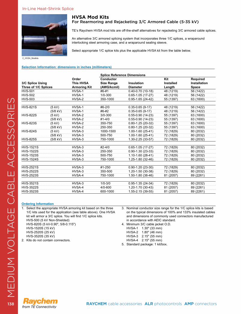
In-Line Heat-Shrink Splice
Selection Information: dimensions in inches (millimeters)
Splice Reference Dimensions Order Conductor Kit Required
3/C Splice Using This HVSA Size Range Insulation Installed Installation Three of 1/C Splices Armoring Kit (AWG/kcmil) Diameter Length SpaceHVS-501 HVSA-1 #6-#1 0 .40-0 .70 (10-18) 48 (1219) 56 (1422)HVS-502 HVSA-1 1/0-300 0 .65-1 .05 (17-27) 48 (1219) 56 (1422)HVS-503 HVSA-2 350-1000 0 .95-1 .65 (24-42) 55 (1397) 63 (1600)
HVS-821S (5 kV) HVSA-1 #6-2/0 0 .35-0 .65 (9-17) 48 (1219) 56 (1422)(5/8 kV) HVSA-1 #6-#2 0 .35-0 .65 (9-17) 48 (1219) 56 (1422)
HVS-822S (5 kV) HVSA-2 3/0-300 0 .55-0 .90 (14-23) 55 (1397) 63 (1600)(5/8 kV) HVSA-2 #1-4/0 0 .55-0 .90 (14-23) 55 (1397) 63 (1600)
HVS-823S (5 kV) HVSA-2 350-750 0 .80-1 .25 (20-32) 55 (1397) 63 (1600)(5/8 kV) HVSA-2 250-350 0 .80-1 .25 (20-32) 55 (1397) 63 (1600)
HVS-824S (5 kV) HVSA-3 1000-1500 1 .00-1 .60 (25-41) 72 (1829) 80 (2032)(5/8 kV) HVSA-3 500-750 1 .00-1 .60 (25-41) 72 (1829) 80 (2032)
HVS-825S (5/8 kV) HVSA-3 750-1000 1 .30-2 .25 (33-57) 72 (1829) 80 (2032)
HVS-1521S HVSA-3 #2-4/0 0 .65-1 .05 (17-27) 72 (1829) 80 (2032)HVS-1522S HVSA-3 250-350 0 .90-1 .30 (23-33) 72 (1829) 80 (2032)HVS-1523S HVSA-3 500-750 1 .10-1 .60 (28-41) 72 (1829) 80 (2032)HVS-1524S HVSA-3 750-1000 1 .25-1 .80 (32-46) 72 (1829) 80 (2032)
HVS-2521S HVSA-3 #1-250 0 .90-1 .20 (23-30) 72 (1829) 80 (2032)HVS-2522S HVSA-3 350-500 1 .20-1 .50 (30-38) 72 (1829) 80 (2032)HVS-2523S HVSA-4 750-1000 1 .50-1 .80 (38-46) 81 (2057) 89 (2261)
HVS-3521S HVSA-3 1/0-3/0 0 .95-1 .35 (24-34) 72 (1829) 80 (2032)HVS-3522S HVSA-4 4/0-600 1 .20-1 .70 (30-43) 81 (2057) 89 (2261)HVS-3523S HVSA-4 600-1000 1 .55-2 .15 (39-55) 81 (2057) 89 (2261)
Ordering Information
HVSA Mod KitsFor Rearmoring and Rejacketing 3/C Armored Cable (5-35 kV)
TE’s Raychem HVSA mod kits are off-the-shelf alternatives for rejacketing 3/C armored cable splices.
An alternative 3/C armored splicing system that incorporates three 1/C splices, a wraparound interlocking steel armoring case, and a wraparound sealing sleeve .
Select appropriate 1/C splice kits plus the applicable HVSA kit from the table below .
1 . Select the appropriate HVSA armoring kit based on the three 1/C kits used for the application (see table above) . One HVSA kit will armor a 3/C splice . You will find 1/C splice kits . HVS-500 (5 kV Non-Shielded) HVS-820S (5 kV-0 .90", 5/8-0 .115") HVS-1520S (15 kV) HVS-2520S (25 kV) HVS-3520S (35 kV)
2 . Kits do not contain connectors .
3 . Nominal conductor size range for the 1/C splice kits is based on the typical dimensions of 100% and 133% insulated cables and dimensions of commonly used connectors manufactured in accordance with AEIC standard .
4. Minimum 3/C cable jacket O.D. HVSA-1 1 .30" (33 mm) HVSA-2 1 .80" (46 mm) HVSA-3 2 .15" (55 mm) HVSA-4 2 .15" (55 mm)5 . Standard package: 1 kit/box .
C_HVSA_Modkits
ME
DIU
M V
OLT
AG
E C
AB
LE
AC
CE
SS
OR
IES
RAYCHEM cable accessories ALR photocontrols AMP connectors 138138
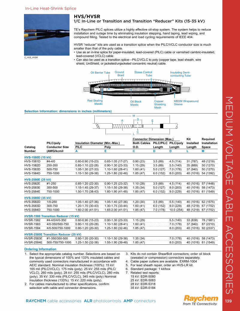
In-Line Heat-Shrink Splice
HVS/HVSR1/C In-Line or Transition and Transition “Reducer” Kits (15-35 kV)
TE’s Raychem PILC splices utilize a highly effective oil-stop system . The system helps to reduce installation and outage time by eliminating insulation stepping, hand taping, lead wiping, and compound filling . Tested to the electrical and load cycling requirements of IEEE 404 .
HVSR “reducer” kits are used as a transition splice when the PILC/VCLC conductor size is much smaller than that of the poly cable .• Use as an in-line splice for paper- insulated, lead-covered (PILC) cable or varnished cambric-insulated,
lead- covered (VCLC) cable • Can also be used as a transition splice—PILC/VCLC to poly (copper tape, lead sheath, wire
shield, UniShield, or jacketed/unjacketed concentric neutral) cable.
1 . Select the appropriate catalog number . Selections are based on the typical dimensions of 100% and 133% insulated cables and commonly used connectors manufactured in accordance with AEIC standard . Nominal insulation thickness (100%): 15 kV: 165 mil (PILC/VCLC) . 175 mils (poly) . 25 kV: 255 mils (PILC/VCLC), 260 mils (poly) . 28 kV: 255 mils (PILC/VCLC), 280 mils (poly) . 35 kV: 330 mils (PILC/VCLC), 345 mils (poly) Nominal insulation thickness (133%): 15 kV: 220 mils (poly) .
2 . For cables manufactured to other specifications, confirm selection with cable and connector dimensions .
3 . Kits do not contain ShearBolt connectors; order oil block (sweated or compression) connectors separately .
4. Cable paper cutters are available. EXRM-10045 . For lead sheath repair, order an HVS-LR kit .6 . Standard package: 1 kit/box7 . Related test reports: 15 kV: EDR-5080 25 kV: EDR-5083 28 kV: EDR-5318 35 kV: EDR-5184
Selection Information: dimensions in inches (millimeters)
Connector Dimension (Max.) Kit Required PILC/poly Insulation Diameter (Min.-Max.) Both Cables PILC/PILC PILC/poly Installed InstallationCatalog Conductor Size PILC Poly O.D. Length Length Length SpaceNumber (AWG/kcmil A E C D D L M
HVS-1580D (15 kV)HVS-1581D #4-4/0 0 .60-0 .90 (15-23) 0 .65-1 .05 (17-27) 0 .90 (23) 3 .5 (89) 4 .5 (114) 31 (787) 48 (1219)HVS-1582D 250-350 0 .85-1 .10 (22-28) 0 .90-1 .30 (23-33) 1 .15 (29) 3 .5 (89) 5 .5 (140) 35 (889) 50 (1270)HVS-1583D 500-750 1 .05-1 .30 (27-33) 1 .10-1 .60 (28-41) 1 .60 (41) 5 .0 (127) 7 .0 (178) 37 (940) 50 (1270)HVS-1584D 750-1000 1 .15-1 .50 (29-38) 1 .25-1 .80 (32-46) 1 .85 (47) 6 .0 (152) 8 .0 (203) 40 (1016) 54 (1392)
HVS-2580E (25 kV)HVS-2582E #1-250 0 .85-1 .20 (22-30) 0 .90-1 .25 (23-32) 1 .10 (28) 3 .5 (89) 4 .5 (114) 40 (1016) 57 (1448)HVS-2583E 350-500 1 .15-1 .45 (29-37) 1 .15-1 .50 (29-38) 1 .35 (34) 5 .0 (127) 8 .0 (203) 40 (1016) 58 (1473)HVS-2584E 750-1000 1 .50-1 .70 (38-43) 1 .60-1 .90 (41-48) 1 .85 (47) 6 .0 (152) 9 .0 (229) 40 (1016) 61 (1549)
HVS-3580D (35 kV)HVS-3582D 1/0-250 1 .05-1 .40 (27-36) 1 .05-1 .40 (27-36) 1 .20 (30) 3 .5 (89) 5 .5 (140) 40 (1016) 62 (1575)HVS-3583D 300-750 1 .20-1 .70 (30-43) 1 .30-1 .75 (33-44) 1 .60 (41) 6 .0 (152) 9 .0 (229) 48 (1219) 67 (1702)HVS-3584D 750-1000 1 .60-2 .00 (41-51) 1 .65-2 .00 (41-51) 1 .85 (47) 7 .0 (178) 10 .0 (254) 48 (1219) 67 (1702)
HVSR-1580 Transition Reducer (15 kV) HVSR-1582 #4-4/0/4/0-350 0 .60-0 .90 (15-23) 0 .90-1 .30 (23-33) 1 .15 (29) 5 .5 (140) 33 (838) 78 (1981)HVSR-1583 4/0-350/500-750 0 .80-1 .10 (20-28) 1 .10-1 .60 (28- 41) 1 .60 (41) 7 .0 (178) 37 (940) 87 (2210)HVSR-1584 4/0-500/750-1000 0 .80-1 .20 (20-30) 1 .25-1 .80 (32-46) 1 .85 (47) 8 .0 (203) 40 (1016) 92 (2337)
HVSR-2580E Transition Reducer (25 kV) HVSR-2583E #1-350/350-500 0 .80-1 .20 (20-30) 1 .15-1 .50 (29-38) 1 .35 (34) 7 .0 (178) 40 (1016) 58 (1473)HVSR-2584E 500-750/750-1000 1 .25-1 .50 (32-38) 1 .55-1 .90 (39-48) 1 .85 (47) 8 .0 (203) 40 (1016) 61 (1549)
MD
L
A E
C
Ordering Information
C_HVS_HVSR
Red Sealing Mastic
Oil Barrier Tube GroundBraid
Oil Block Mastic
Stress Control Tube
Copper Shielding Mesh
MBSM Wraparound Sleeve
Insulating Semi-conducting Tube
ME
DIU
M V
OLT
AG
E C
AB
LE
AC
CE
SS
OR
IES
RAYCHEM cable accessories ALR photocontrols AMP connectors 139 139
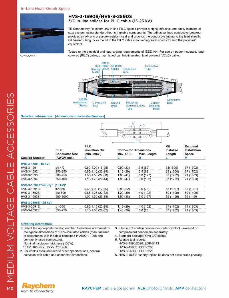
In-Line Heat-Shrink Splice
HVS-3-1590S/HVS-3-2590S3/C In-line splices for PILC cable (15-25 kV)
TE Connectivity Raychem 3/C in-line PILC splices provide a highly effective and easily installed oil stop system, using standard heat-shrinkable components . The adhesive-lined conductive breakout provides an oil- and pressure-resistant seal and grounds the conductive tubing to the lead sheath . Oil barrier tubing locks the oil in the PILC cables, converting each conductor into the polymeric equivalent .
Tested to the electrical and load cycling requirements of IEEE 404 . For use on paper-insulated, lead-covered (PILC) cable, or varnished cambric-insulated, lead covered (VCLC) cable .
PILC Kit Required PILC Insulation Dia. Connector Dimensions Installed Installation Conductor Size (min.–max.) Max. O.D. Max. Length Length SpaceCatalog Number (AWG/kcmil) A C D L M HVS-3-1590 (15 kV) HVS-3-1591 #4-4/0 0 .60-1 .00 (15-25) 0 .90 (23) 3 .5 (89) 63(1600) 67 (1702)HVS-3-1592 250-350 0 .85-1 .10 (22-28) 1 .15 (29) 3 .5 (89) 63 (1600) 67 (1702)HVS-3-1593 500-750 1 .05-1 .50 (27-38) 1 .60 (41) 5 .0 (127) 67 (1702) 71 (1803)HVS-3-1594 750-1000 1 .15-1 .75 (29-44) 1 .85 (47) 6 .0 (152) 67 (1702) 71 (1803)
HVS-3-1590S “shorty” (15 kV)*HVS-3-1591S #2-350 0 .65-1 .00 (17-25) 0 .85 (22) 3 .0 (76) 55 (1397) 55 (1397)HVS-3-1592S 4/0-600 0 .85-1 .25 (22-32) 1 .20 (30) 4 .0 (102) 59 (1499) 59 (1499)HVS-3-1593S 500-1000 1 .00-1 .50 (25-38) 1 .50 (38) 5 .0 (127) 59 (1499) 59 (1499
HVS-3-2590E (25 kV) HVS-3-2591E #1-350 0 .85-1 .15 (22-29) 1 .15 (29) 4 .0 (102) 67 (1702) 71 (1803)HVS-3-2592E 350-750 1 .10-1 .50 (28-32) 1 .40 (36) 5 .0 (25) 67 (1702) 71 (1803)
Ordering information
Selection information: (dimensions in inches/millimeters)
1 . Select the appropriate catalog number . Selections are based on the typical dimensions of 100%-insulated cables (manufactured in accordance with the data contained in AEIC 1-1968 and commonly used connectors) . Nominal insulation thickness (100%):
15 kV: 165 mils ., 25 kV: 255 mils . 2 . For cables manufactured to other specifications, confirm
selection with cable and connector dimensions .
3 . Kits do not contain connectors; order oil block (sweated or compression) connectors separately .
4 . Standard package: One 3/C kit/box .5 . Related test reports:
HVS-3-1590/2590: EDR-5143 HVS-3-1590S: EDR-5250 HVS-3-2590E: EDR-5223
6 . HVS-3-1590S “shorty“ splice kit does not allow cross phasing .
D
C
M
L
A
C_HVS_3_1590S
ConductiveBoot
ConductiveTubeConductive
Tube
Oil BlockMastic
Stress Relief Mastic
RedSealing Mastic
CopperShielding
Mesh
Insulating/SemiconductingTube
GroundBraid
ConductiveBoot
MBSM Wraparound
Sleeve
ME
DIU
M V
OLT
AG
E C
AB
LE
AC
CE
SS
OR
IES
RAYCHEM cable accessories ALR photocontrols AMP connectors 140140
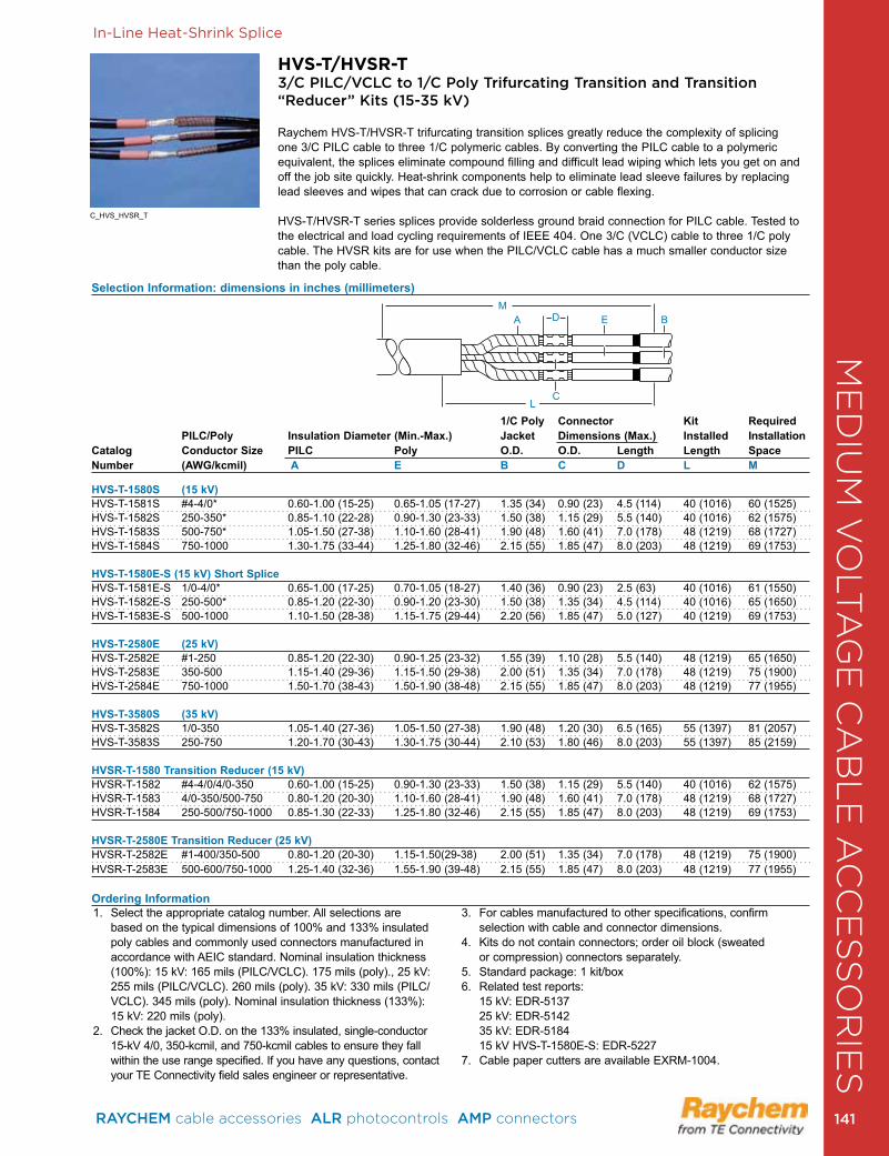
In-Line Heat-Shrink Splice
HVS-T/HVSR-T3/C PILC/VCLC to 1/C Poly Trifurcating Transition and Transition “Reducer” Kits (15-35 kV)
Raychem HVS-T/HVSR-T trifurcating transition splices greatly reduce the complexity of splicing one 3/C PILC cable to three 1/C polymeric cables . By converting the PILC cable to a polymeric equivalent, the splices eliminate compound filling and difficult lead wiping which lets you get on and off the job site quickly. Heat-shrink components help to eliminate lead sleeve failures by replacing lead sleeves and wipes that can crack due to corrosion or cable flexing .
HVS-T/HVSR-T series splices provide solderless ground braid connection for PILC cable . Tested to the electrical and load cycling requirements of IEEE 404 . One 3/C (VCLC) cable to three 1/C poly cable . The HVSR kits are for use when the PILC/VCLC cable has a much smaller conductor size than the poly cable .
Selection Information: dimensions in inches (millimeters)
1/C Poly Connector Kit Required PILC/Poly Insulation Diameter (Min.-Max.) Jacket Dimensions (Max.) Installed InstallationCatalog Conductor Size PILC Poly O.D. O.D. Length Length SpaceNumber (AWG/kcmil) A E B C D L M
HVS-T-1580S (15 kV) HVS-T-1581S #4-4/0* 0 .60-1 .00 (15-25) 0 .65-1 .05 (17-27) 1 .35 (34) 0 .90 (23) 4 .5 (114) 40 (1016) 60 (1525)HVS-T-1582S 250-350* 0 .85-1 .10 (22-28) 0 .90-1 .30 (23-33) 1 .50 (38) 1 .15 (29) 5 .5 (140) 40 (1016) 62 (1575)HVS-T-1583S 500-750* 1 .05-1 .50 (27-38) 1 .10-1 .60 (28-41) 1 .90 (48) 1 .60 (41) 7 .0 (178) 48 (1219) 68 (1727)HVS-T-1584S 750-1000 1 .30-1 .75 (33-44) 1 .25-1 .80 (32-46) 2 .15 (55) 1 .85 (47) 8 .0 (203) 48 (1219) 69 (1753)
HVS-T-1580E-S (15 kV) Short SpliceHVS-T-1581E-S 1/0-4/0* 0 .65-1 .00 (17-25) 0 .70-1 .05 (18-27) 1 .40 (36) 0 .90 (23) 2 .5 (63) 40 (1016) 61 (1550)HVS-T-1582E-S 250-500* 0 .85-1 .20 (22-30) 0 .90-1 .20 (23-30) 1 .50 (38) 1 .35 (34) 4 .5 (114) 40 (1016) 65 (1650)HVS-T-1583E-S 500-1000 1 .10-1 .50 (28-38) 1 .15-1 .75 (29-44) 2 .20 (56) 1 .85 (47) 5 .0 (127) 40 (1219) 69 (1753)
HVS-T-2580E (25 kV) HVS-T-2582E #1-250 0 .85-1 .20 (22-30) 0 .90-1 .25 (23-32) 1 .55 (39) 1 .10 (28) 5 .5 (140) 48 (1219) 65 (1650)HVS-T-2583E 350-500 1 .15-1 .40 (29-36) 1 .15-1 .50 (29-38) 2 .00 (51) 1 .35 (34) 7 .0 (178) 48 (1219) 75 (1900)HVS-T-2584E 750-1000 1 .50-1 .70 (38-43) 1 .50-1 .90 (38-48) 2 .15 (55) 1 .85 (47) 8 .0 (203) 48 (1219) 77 (1955)
HVS-T-3580S (35 kV) HVS-T-3582S 1/0-350 1 .05-1 .40 (27-36) 1 .05-1 .50 (27-38) 1 .90 (48) 1 .20 (30) 6 .5 (165) 55 (1397) 81 (2057)HVS-T-3583S 250-750 1 .20-1 .70 (30-43) 1 .30-1 .75 (30-44) 2 .10 (53) 1 .80 (46) 8 .0 (203) 55 (1397) 85 (2159)
HVSR-T-1580 Transition Reducer (15 kV) HVSR-T-1582 #4-4/0/4/0-350 0 .60-1 .00 (15-25) 0 .90-1 .30 (23-33) 1 .50 (38) 1 .15 (29) 5 .5 (140) 40 (1016) 62 (1575)HVSR-T-1583 4/0-350/500-750 0 .80-1 .20 (20-30) 1 .10-1 .60 (28-41) 1 .90 (48) 1 .60 (41) 7 .0 (178) 48 (1219) 68 (1727)HVSR-T-1584 250-500/750-1000 0 .85-1 .30 (22-33) 1 .25-1 .80 (32-46) 2 .15 (55) 1 .85 (47) 8 .0 (203) 48 (1219) 69 (1753)
HVSR-T-2580E Transition Reducer (25 kV) HVSR-T-2582E #1-400/350-500 0 .80-1 .20 (20-30) 1 .15-1 .50(29-38) 2 .00 (51) 1 .35 (34) 7 .0 (178) 48 (1219) 75 (1900) HVSR-T-2583E 500-600/750-1000 1 .25-1 .40 (32-36) 1 .55-1 .90 (39-48) 2 .15 (55) 1 .85 (47) 8 .0 (203) 48 (1219) 77 (1955)
Ordering Information1 . Select the appropriate catalog number . All selections are
based on the typical dimensions of 100% and 133% insulated poly cables and commonly used connectors manufactured in accordance with AEIC standard . Nominal insulation thickness (100%): 15 kV: 165 mils (PILC/VCLC) . 175 mils (poly) ., 25 kV: 255 mils (PILC/VCLC) . 260 mils (poly) . 35 kV: 330 mils (PILC/VCLC) . 345 mils (poly) . Nominal insulation thickness (133%): 15 kV: 220 mils (poly) .
2. Check the jacket O.D. on the 133% insulated, single-conductor 15-kV 4/0, 350-kcmil, and 750-kcmil cables to ensure they fall within the use range specified . If you have any questions, contact your TE Connectivity field sales engineer or representative .
3 . For cables manufactured to other specifications, confirm selection with cable and connector dimensions .
4 . Kits do not contain connectors; order oil block (sweated or compression) connectors separately .
5 . Standard package: 1 kit/box6 . Related test reports: 15 kV: EDR-5137 25 kV: EDR-5142 35 kV: EDR-5184 15 kV HVS-T-1580E-S: EDR-52277. Cable paper cutters are available EXRM-1004.
MDA E B
CL
C_HVS_HVSR_T
ME
DIU
M V
OLT
AG
E C
AB
LE
AC
CE
SS
OR
IES
RAYCHEM cable accessories ALR photocontrols AMP connectors 141 141
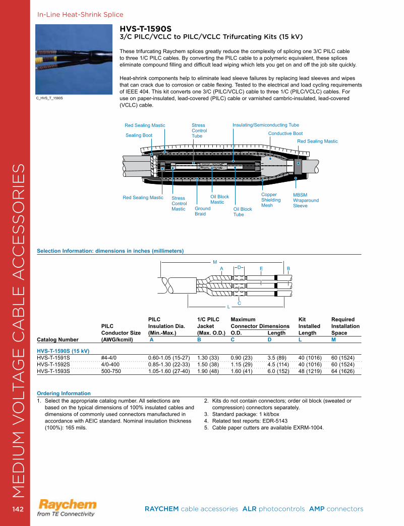
HVS-T-1590S3/C PILC/VCLC to PILC/VCLC Trifurcating Kits (15 kV)
These trifurcating Raychem splices greatly reduce the complexity of splicing one 3/C PILC cable to three 1/C PILC cables . By converting the PILC cable to a polymeric equivalent, these splices eliminate compound filling and difficult lead wiping which lets you get on and off the job site quickly.
Heat-shrink components help to eliminate lead sleeve failures by replacing lead sleeves and wipes that can crack due to corrosion or cable flexing . Tested to the electrical and load cycling requirements of IEEE 404 . This kit converts one 3/C (PILC/VCLC) cable to three 1/C (PILC/VCLC) cables . For use on paper-insulated, lead-covered (PILC) cable or varnished cambric-insulated, lead- covered (VCLC) cable .
Selection Information: dimensions in inches (millimeters)
PILC 1/C PILC Maximum Kit Required PILC Insulation Dia. Jacket Connector Dimensions Installed Installation Conductor Size (Min.-Max.) (Max. O.D.) O.D. Length Length SpaceCatalog Number (AWG/kcmil) A B C D L M
HVS-T-1590S (15 kV) HVS-T-1591S #4-4/0 0 .60-1 .05 (15-27) 1 .30 (33) 0 .90 (23) 3 .5 (89) 40 (1016) 60 (1524)HVS-T-1592S 4/0-400 0 .85-1 .30 (22-33) 1 .50 (38) 1 .15 (29) 4 .5 (114) 40 (1016) 60 (1524)HVS-T-1593S 500-750 1 .05-1 .60 (27-40) 1 .90 (48) 1 .60 (41) 6 .0 (152) 48 (1219) 64 (1626)
Ordering Information1 . Select the appropriate catalog number . All selections are
based on the typical dimensions of 100% insulated cables and dimensions of commonly used connectors manufactured in accordance with AEIC standard . Nominal insulation thickness (100%): 165 mils .
2 . Kits do not contain connectors; order oil block (sweated or compression) connectors separately .
3 . Standard package: 1 kit/box4 . Related test reports: EDR-51435. Cable paper cutters are available EXRM-1004.
MDA E B
CL
In-Line Heat-Shrink Splice
C_HVS_T_1590S
Sealing Boot
Red Sealing Mastic
Red Sealing Mastic
Red Sealing Mastic Stress Control Mastic Ground
Braid
Oil Block Mastic
Oil BlockTube
Copper Shielding Mesh
MBSM Wraparound Sleeve
Stress Control Tube Conductive Boot
Insulating/Semiconducting Tube
ME
DIU
M V
OLT
AG
E C
AB
LE
AC
CE
SS
OR
IES
RAYCHEM cable accessories ALR photocontrols AMP connectors 142142
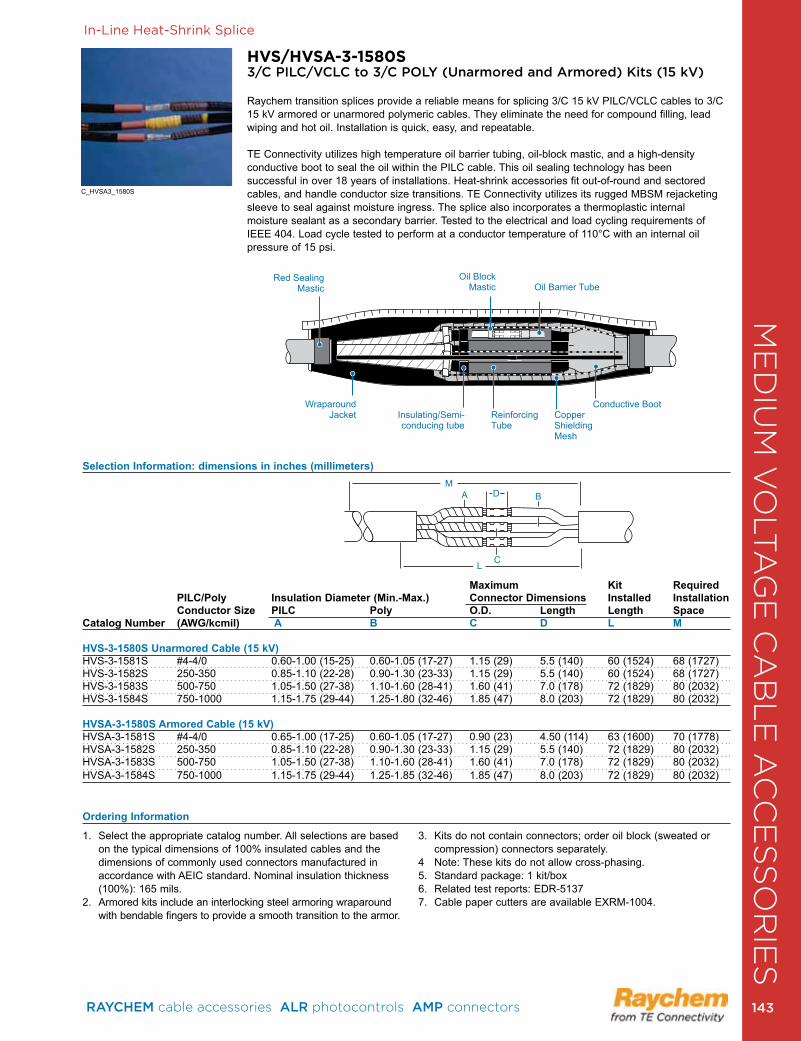
HVS/HVSA-3-1580S3/C PILC/VCLC to 3/C POLY (Unarmored and Armored) Kits (15 kV)
Raychem transition splices provide a reliable means for splicing 3/C 15 kV PILC/VCLC cables to 3/C 15 kV armored or unarmored polymeric cables . They eliminate the need for compound filling, lead wiping and hot oil . Installation is quick, easy, and repeatable .
TE Connectivity utilizes high temperature oil barrier tubing, oil-block mastic, and a high-density conductive boot to seal the oil within the PILC cable . This oil sealing technology has been successful in over 18 years of installations . Heat-shrink accessories fit out-of-round and sectored cables, and handle conductor size transitions. TE Connectivity utilizes its rugged MBSM rejacketing sleeve to seal against moisture ingress . The splice also incorporates a thermoplastic internal moisture sealant as a secondary barrier . Tested to the electrical and load cycling requirements of IEEE 404 . Load cycle tested to perform at a conductor temperature of 110°C with an internal oil pressure of 15 psi .
Selection Information: dimensions in inches (millimeters)
Maximum Kit Required PILC/Poly Insulation Diameter (Min.-Max.) Connector Dimensions Installed Installation Conductor Size PILC Poly O.D. Length Length SpaceCatalog Number (AWG/kcmil) A B C D L M
HVS-3-1580S Unarmored Cable (15 kV) HVS-3-1581S #4-4/0 0 .60-1 .00 (15-25) 0 .60-1 .05 (17-27) 1 .15 (29) 5 .5 (140) 60 (1524) 68 (1727)HVS-3-1582S 250-350 0 .85-1 .10 (22-28) 0 .90-1 .30 (23-33) 1 .15 (29) 5 .5 (140) 60 (1524) 68 (1727)HVS-3-1583S 500-750 1 .05-1 .50 (27-38) 1 .10-1 .60 (28-41) 1 .60 (41) 7 .0 (178) 72 (1829) 80 (2032)HVS-3-1584S 750-1000 1 .15-1 .75 (29-44) 1 .25-1 .80 (32-46) 1 .85 (47) 8 .0 (203) 72 (1829) 80 (2032)
HVSA-3-1580S Armored Cable (15 kV) HVSA-3-1581S #4-4/0 0 .65-1 .00 (17-25) 0 .60-1 .05 (17-27) 0 .90 (23) 4 .50 (114) 63 (1600) 70 (1778)HVSA-3-1582S 250-350 0 .85-1 .10 (22-28) 0 .90-1 .30 (23-33) 1 .15 (29) 5 .5 (140) 72 (1829) 80 (2032)HVSA-3-1583S 500-750 1 .05-1 .50 (27-38) 1 .10-1 .60 (28-41) 1 .60 (41) 7 .0 (178) 72 (1829) 80 (2032)HVSA-3-1584S 750-1000 1 .15-1 .75 (29-44) 1 .25-1 .85 (32-46) 1 .85 (47) 8 .0 (203) 72 (1829) 80 (2032)
Ordering Information
1 . Select the appropriate catalog number . All selections are based on the typical dimensions of 100% insulated cables and the dimensions of commonly used connectors manufactured in accordance with AEIC standard . Nominal insulation thickness (100%): 165 mils .
2 . Armored kits include an interlocking steel armoring wraparound with bendable fingers to provide a smooth transition to the armor .
3 . Kits do not contain connectors; order oil block (sweated or compression) connectors separately .
4 Note: These kits do not allow cross-phasing .5 . Standard package: 1 kit/box6 . Related test reports: EDR-51377. Cable paper cutters are available EXRM-1004.
MDA B
CL
In-Line Heat-Shrink Splice
C_HVSA3_1580S
Red Sealing Mastic
Wraparound Jacket
Conductive Boot
Oil Barrier TubeOil Block
Mastic
Insulating/Semi- conducing tube
Reinforcing Tube
Copper Shielding Mesh
ME
DIU
M V
OLT
AG
E C
AB
LE
AC
CE
SS
OR
IES
RAYCHEM cable accessories ALR photocontrols AMP connectors 143 143
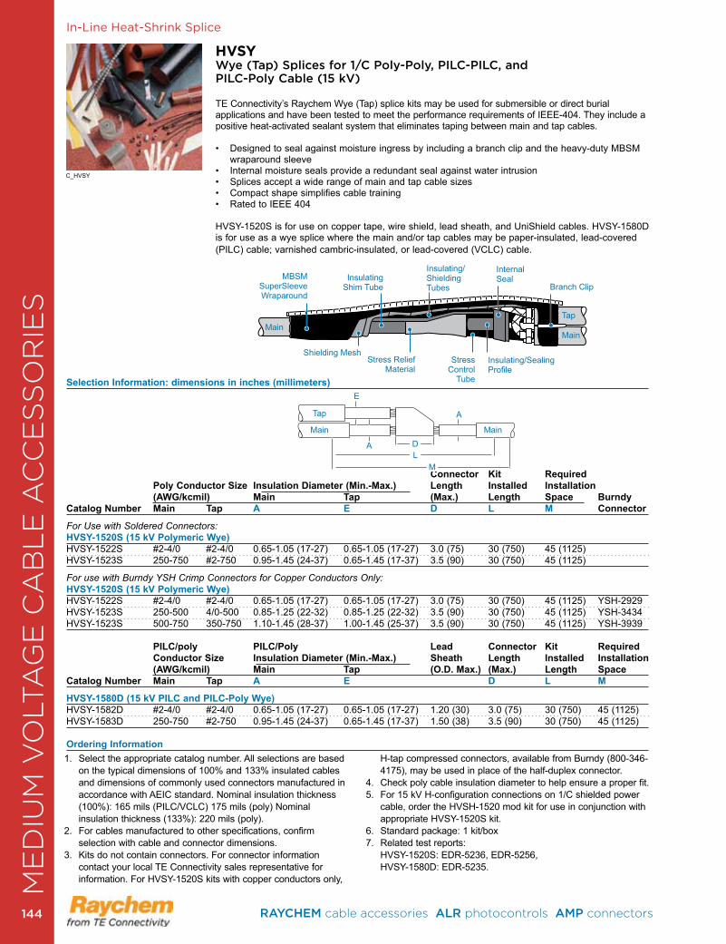
Selection Information: dimensions in inches (millimeters)
Connector Kit Required Poly Conductor Size Insulation Diameter (Min.-Max.) Length Installed Installation (AWG/kcmil) Main Tap (Max.) Length Space BurndyCatalog Number Main Tap A E D L M Connector
For Use with Soldered Connectors:HVSY-1520S (15 kV Polymeric Wye)HVSY-1522S #2-4/0 #2-4/0 0 .65-1 .05 (17-27) 0 .65-1 .05 (17-27) 3 .0 (75) 30 (750) 45 (1125) HVSY-1523S 250-750 #2-750 0 .95-1 .45 (24-37) 0 .65-1 .45 (17-37) 3 .5 (90) 30 (750) 45 (1125)
For use with Burndy YSH Crimp Connectors for Copper Conductors Only:HVSY-1520S (15 kV Polymeric Wye) HVSY-1522S #2-4/0 #2-4/0 0 .65-1 .05 (17-27) 0 .65-1 .05 (17-27) 3 .0 (75) 30 (750) 45 (1125) YSH-2929HVSY-1523S 250-500 4/0-500 0 .85-1 .25 (22-32) 0 .85-1 .25 (22-32) 3 .5 (90) 30 (750) 45 (1125) YSH-3434HVSY-1523S 500-750 350-750 1 .10-1 .45 (28-37) 1 .00-1 .45 (25-37) 3 .5 (90) 30 (750) 45 (1125) YSH-3939
PILC/poly PILC/Poly Lead Connector Kit Required Conductor Size Insulation Diameter (Min.-Max.) Sheath Length Installed Installation (AWG/kcmil) Main Tap (O.D. Max.) (Max.) Length SpaceCatalog Number Main Tap A E D L M
HVSY-1580D (15 kV PILC and PILC-Poly Wye)HVSY-1582D #2-4/0 #2-4/0 0 .65-1 .05 (17-27) 0 .65-1 .05 (17-27) 1 .20 (30) 3 .0 (75) 30 (750) 45 (1125)HVSY-1583D 250-750 #2-750 0 .95-1 .45 (24-37) 0 .65-1 .45 (17-37) 1 .50 (38) 3 .5 (90) 30 (750) 45 (1125)
Ordering Information
HVSYWye (Tap) Splices for 1/C Poly-Poly, PILC-PILC, and PILC-Poly Cable (15 kV)
TE Connectivity’s Raychem Wye (Tap) splice kits may be used for submersible or direct burial applications and have been tested to meet the performance requirements of IEEE-404 . They include a positive heat-activated sealant system that eliminates taping between main and tap cables .
• Designed to seal against moisture ingress by including a branch clip and the heavy-duty MBSM wraparound sleeve
• Internal moisture seals provide a redundant seal against water intrusion• Splices accept a wide range of main and tap cable sizes • Compact shape simplifies cable training• Rated to IEEE 404
HVSY-1520S is for use on copper tape, wire shield, lead sheath, and UniShield cables . HVSY-1580D is for use as a wye splice where the main and/or tap cables may be paper-insulated, lead-covered (PILC) cable; varnished cambric-insulated, or lead-covered (VCLC) cable .
LD
M
MainMain
Tap
A
A
E
In-Line Heat-Shrink Splice
C_HVSY
1 . Select the appropriate catalog number . All selections are based on the typical dimensions of 100% and 133% insulated cables and dimensions of commonly used connectors manufactured in accordance with AEIC standard . Nominal insulation thickness (100%): 165 mils (PILC/VCLC) 175 mils (poly) Nominal insulation thickness (133%): 220 mils (poly) .
2 . For cables manufactured to other specifications, confirm selection with cable and connector dimensions .
3 . Kits do not contain connectors . For connector information contact your local TE Connectivity sales representative for information . For HVSY-1520S kits with copper conductors only,
H-tap compressed connectors, available from Burndy (800-346-4175), may be used in place of the half-duplex connector .
4 . Check poly cable insulation diameter to help ensure a proper fit .5 . For 15 kV H-configuration connections on 1/C shielded power
cable, order the HVSH-1520 mod kit for use in conjunction with appropriate HVSY-1520S kit .
6 . Standard package: 1 kit/box7 . Related test reports: HVSY-1520S: EDR-5236, EDR-5256, HVSY-1580D: EDR-5235 .
Internal Seal
Insulating/Sealing Profile
Branch Clip
Stress Control
Tube
Insulating/Shielding Tubes
Stress Relief Material
Shielding Mesh
Insulating Shim Tube
MBSM SuperSleeve Wraparound
MainMain
Tap
ME
DIU
M V
OLT
AG
E C
AB
LE
AC
CE
SS
OR
IES
RAYCHEM cable accessories ALR photocontrols AMP connectors 144144
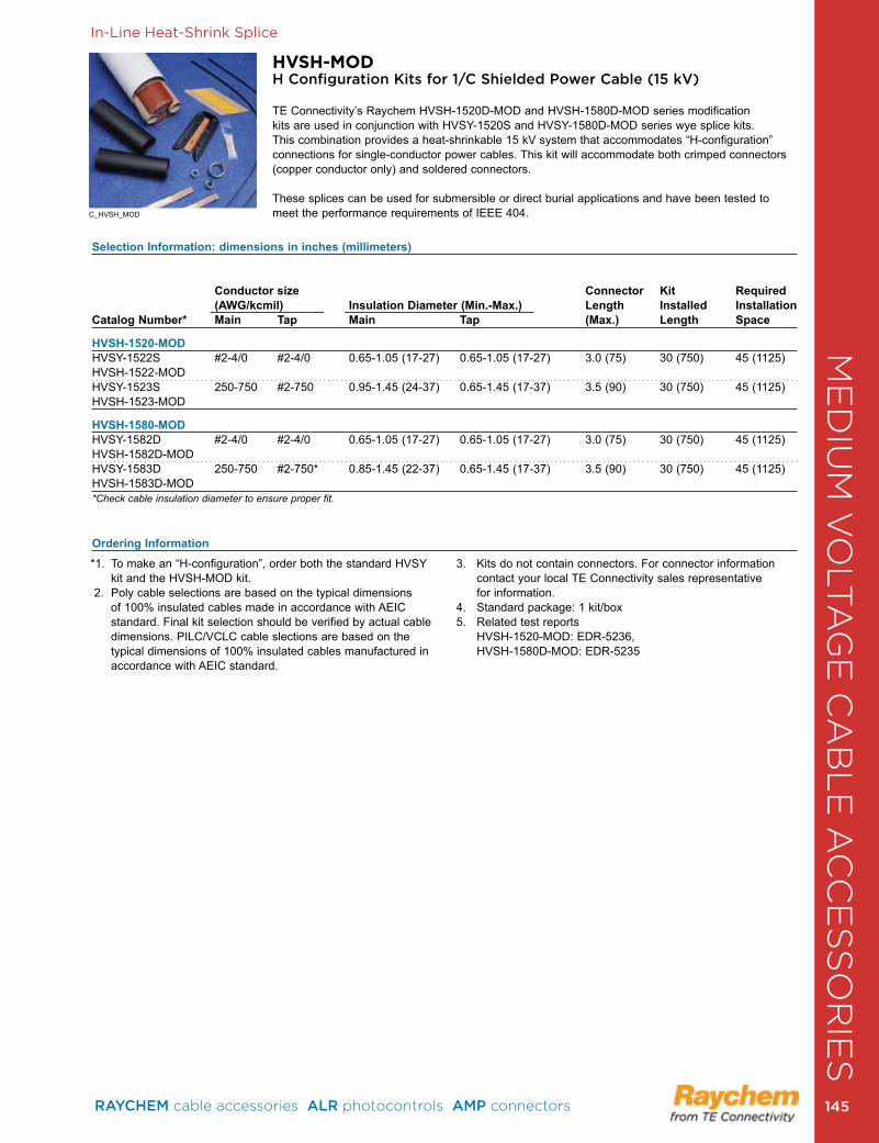
In-Line Heat-Shrink Splice
HVSH-MODH Configuration Kits for 1/C Shielded Power Cable (15 kV)
TE Connectivity’s Raychem HVSH-1520D-MOD and HVSH-1580D-MOD series modification kits are used in conjunction with HVSY-1520S and HVSY-1580D-MOD series wye splice kits. This combination provides a heat-shrinkable 15 kV system that accommodates “H-configuration” connections for single-conductor power cables . This kit will accom modate both crimped connectors (copper conductor only) and soldered connectors .
These splices can be used for submersible or direct burial applications and have been tested to meet the performance requirements of IEEE 404 .
*1 . To make an “H-configuration”, order both the standard HVSY kit and the HVSH-MOD kit .
2 . Poly cable selections are based on the typical dimensions of 100% insulated cables made in accordance with AEIC standard . Final kit selection should be verified by actual cable dimensions . PILC/VCLC cable slections are based on the typical dimensions of 100% insulated cables manufactured in accordance with AEIC standard .
3 . Kits do not contain connectors . For connector information contact your local TE Connectivity sales representative for information .
4 . Standard package: 1 kit/box5 . Related test reports HVSH-1520-MOD: EDR-5236, HVSH-1580D-MOD: EDR-5235
Selection Information: dimensions in inches (millimeters)
Conductor size Connector Kit Required (AWG/kcmil) Insulation Diameter (Min.-Max.) Length Installed InstallationCatalog Number* Main Tap Main Tap (Max.) Length Space
HVSH-1520-MOD HVSY-1522S #2-4/0 #2-4/0 0 .65-1 .05 (17-27) 0 .65-1 .05 (17-27) 3 .0 (75) 30 (750) 45 (1125) HVSH-1522-MOD HVSY-1523S 250-750 #2-750 0 .95-1 .45 (24-37) 0 .65-1 .45 (17-37) 3 .5 (90) 30 (750) 45 (1125) HVSH-1523-MOD
HVSH-1580-MODHVSY-1582D #2-4/0 #2-4/0 0 .65-1 .05 (17-27) 0 .65-1 .05 (17-27) 3 .0 (75) 30 (750) 45 (1125) HVSH-1582D-MOD HVSY-1583D 250-750 #2-750* 0 .85-1 .45 (22-37) 0 .65-1 .45 (17-37) 3 .5 (90) 30 (750) 45 (1125) HVSH-1583D-MOD *Check cable insulation diameter to ensure proper fit.
Ordering Information
C_HVSH_MOD
ME
DIU
M V
OLT
AG
E C
AB
LE
AC
CE
SS
OR
IES
RAYCHEM cable accessories ALR photocontrols AMP connectors 145 145
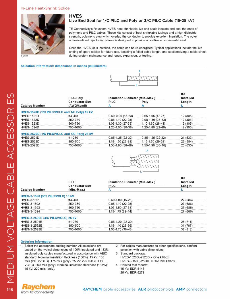
In-Line Heat-Shrink Splice
HVESLive End Seal for 1/C PILC and Poly or 3/C PILC Cable (15-25 kV)
TE Connectivity’s Raychem HVES heat-shrinkable live end seals insulate and seal the ends of polymeric and PILC cables . These kits consist of heat-shrinkable tubings and a high-dielectric strength, polymeric plug which overlap the conductor to provide excellent insulation . The outer adhesive-lined rejacketing sleeve is designed to provide a positive environmental seal.
Once the HVES kit is installed, the cable can be re-energized . Typical applications include the live ending of spare cables for future use, isolating a failed cable length, and sectionalizing a cable circuit during system maintenance and repair, expansion, or testing .
Selection Information: dimensions in inches (millimeters)
Kit PILC/Poly Insulation Diameter (Min.-Max.) Installed Conductor Size PILC Poly LengthCatalog Number (AWG/kcmil) A A L
HVES-1520D (1/C PILC/VCLC and 1/C Poly) 15 kVHVES-1521D #4-4/0 0 .60-0 .90 (15-23) 0 .65-1 .05 (17-27) 12 (305)HVES-1522D 250-350 0 .85-1 .10 (22-28) 0 .90-1 .30 (23-33) 12 (305)HVES-1523D 500-750 1 .05-1 .30 (27-33) 1 .10-1 .60 (28-41) 12 (305)HVES-1524D 750-1000 1 .20-1 .50 (30-38) 1 .25-1 .80 (32-46) 12 (305)
HVES-2520D (1/C PILC/VCLC and 1/C Poly) 25 kVHVES-2521D #1-250 0 .85-1 .25 (22-32) 0 .85-1 .25 (22-32) 21 (533)HVES-2522D 350-500 1 .15-1 .50 (29-38) 1 .15-1 .50 (29-38) 23 (584)HVES-2523D 750-1000 1 .50-1 .90 (38-48) 1 .50-1 .90 (38-48) 25 (635)
Kit PILC Insulation Diameter (Min.-Max.) Installed Conductor Size PILC LengthCatalog Number (Min.-Max.) A L
HVES-3-1590 (3/C PILC/VCLC) 15 kVHVES-3-1591 #4-4/0 0 .60-1 .00 (15-25) 27 (686)HVES-3-1592 250-350 0 .85-1 .10 (22-28) 27 (686)HVES-3-1593 500-750 1 .05-1 .50 (27-38) 27 (686)HVES-3-1594 750-1000 1 .15-1 .75 (29-44) 27 (686)
HVES-3-2590E (3/C PILC/VCLC) 25 kVHVES-3-2591E #1-250 0 .85-1 .20 (22-30) 28 (711)HVES-3-2592E 350-500 1 .15-1 .40 (28-36) 31 (787)HVES-3-2593E 750-1000 1 .50-1 .70 (38-43) 32 (813)
Ordering Information1 . Select the appropriate catalog number . All selections are
based on the typical dimensions of 100% insulated and 133% insulated poly cables manufactured in accordance with AEIC standard . Nominal insulation thickness (100%): 15 kV: 165 mils (PILC/VCLC) . 175 mils (poly) . 25 kV: 225 mils (PILC/VCLC) . 260 mils (poly) . Nominal insulation thickness (133%): 15 kV: 220 mils (poly) .
2 . For cables manufactured to other specifications, confirm selection with cable dimensions .
3 . Standard package: HVES-1520D,-2520D = One kit/box HVES-3-1590,-2590E = One 3/C kit/box4 . Related test reports: 15 kV: EDR-5146 25 kV: EDR-5273
L
A
L
A
C_HVES
ME
DIU
M V
OLT
AG
E C
AB
LE
AC
CE
SS
OR
IES
RAYCHEM cable accessories ALR photocontrols AMP connectors 146146
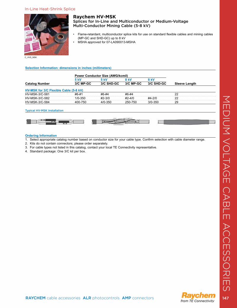
In-Line Heat-Shrink Splice
Raychem HV-MSKSplices for In-Line and Multiconductor or Medium-Voltage Multi-Conductor Mining Cable (5-8 kV)
• Flame-retardant, multiconductor splice kits for use on standard flexible cables and mining cables (MP-GC and SHD-GC) up to 8 kV
• MSHA approved for 07-LA090013-MSHA
Selection Information: dimensions in inches (millimeters)
Power Conductor Size (AWG/kcmil) 5 kV 5 kV 8 kV 8 kVCatalog Number 3/C MP-GC 3/C SHD-GC 3/C MP-GC 3/C SHD-GC Sleeve Length
HV-MSK for 3/C Flexible Cable (5-8 kV)HV-MSK-3/C-581 #6-#1 #6-#4 #6-#4 22HV-MSK-3/C-582 1/0-350 #2-3/0 #2-4/0 #4-2/0 22HV-MSK-3/C-584 400-750 4/0-350 250-750 3/0-350 29
Typical HV-MSK installation
Ordering Information1 . Select appropriate catalog number based on conductor size for your cable type . Confirm selection with cable diameter range .2 . Kits do not contain connectors; please order separately .3 . For cable types not listed in this catalog, contact your local TE Connectivity representative .4 . Standard package: One 3/C kit per box .
C_HVS_MSK
ME
DIU
M V
OLT
AG
E C
AB
LE
AC
CE
SS
OR
IES
RAYCHEM cable accessories ALR photocontrols AMP connectors 147 147
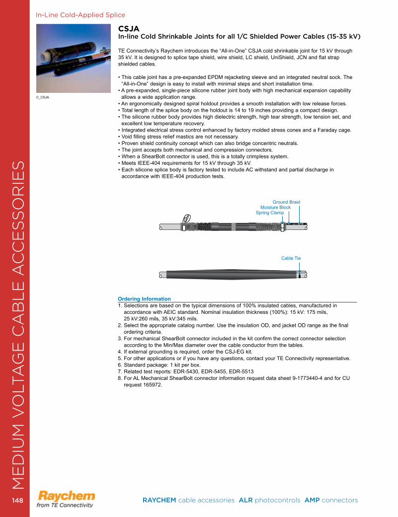
In-Line Cold-Applied Splice
CSJAIn-line Cold Shrinkable Joints for all 1/C Shielded Power Cables (15-35 kV)
TE Connectivity’s Raychem introduces the “All-in-One” CSJA cold shrinkable joint for 15 kV through 35 kV . It is designed to splice tape shield, wire shield, LC shield, UniShield, JCN and flat strap shielded cables .
• This cable joint has a pre-expanded EPDM rejacketing sleeve and an integrated neutral sock. The “All-in-One” design is easy to install with minimal steps and short installation time .
• A pre-expanded, single-piece silicone rubber joint body with high mechanical expansion capability allows a wide application range .
• An ergonomically designed spiral holdout provides a smooth installation with low release forces. • Total length of the splice body on the holdout is 14 to 19 inches providing a compact design.• The silicone rubber body provides high dielectric strength, high tear strength, low tension set, and
excellent low temperature recovery .• Integrated electrical stress control enhanced by factory molded stress cones and a Faraday cage.• Void filling stress relief mastics are not necessary.• Proven shield continuity concept which can also bridge concentric neutrals.• The joint accepts both mechanical and compression connectors.• When a ShearBolt connector is used, this is a totally crimpless system.• Meets IEEE-404 requirements for 15 kV through 35 kV.• Each silicone splice body is factory tested to include AC withstand and partial discharge in
accordance with IEEE-404 production tests .
Ordering Information1 . Selections are based on the typical dimensions of 100% insulated cables, manufactured in
accordance with AEIC standard . Nominal insulation thickness (100%): 15 kV: 175 mils, 25 kV:260 mils, 35 kV:345 mils .
2. Select the appropriate catalog number. Use the insulation OD, and jacket OD range as the final ordering criteria .
3 . For mechanical ShearBolt connector included in the kit confirm the correct connector selection according to the Min/Max diameter over the cable conductor from the tables .
4 . If external grounding is required, order the CSJ-EG kit .5 . For other applications or if you have any questions, contact your TE Connectivity representative .6 . Standard package: 1 kit per box .7 . Related test reports: EDR-5430, EDR-5455, EDR-55138 . For AL Mechanical ShearBolt connector information request data sheet 9-1773440-4 and for CU
request 165972 .
Cable Tie
C_CSJA
Ground Braid Moisture Block
Spring Clamp
ME
DIU
M V
OLT
AG
E C
AB
LE
AC
CE
SS
OR
IES
RAYCHEM cable accessories ALR photocontrols AMP connectors 148148
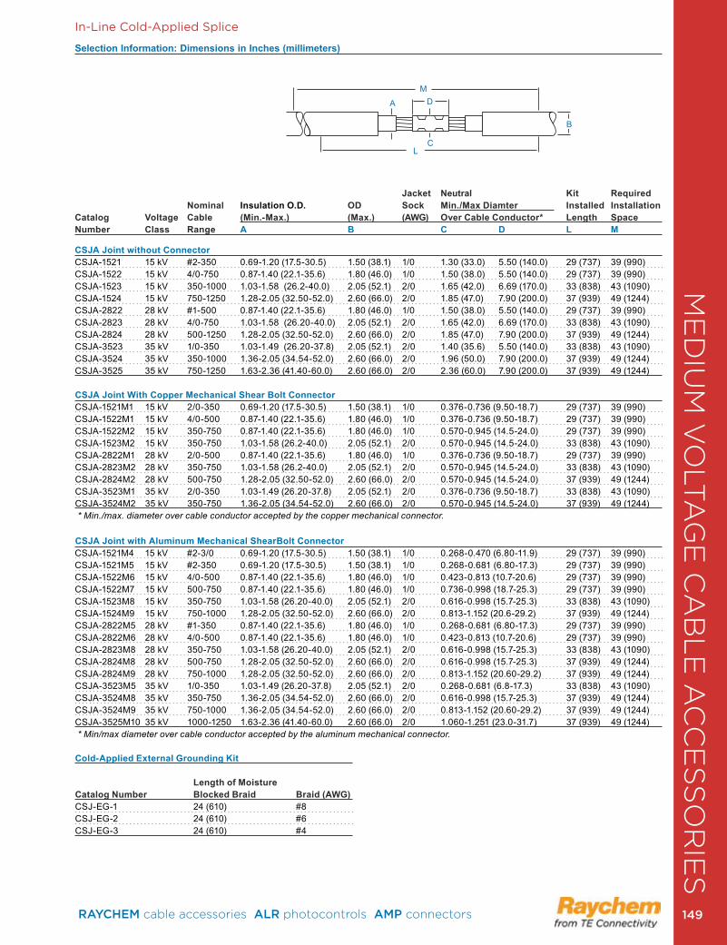
Selection Information: Dimensions in Inches (millimeters)
Jacket Neutral Kit Required
Nominal Insulation O.D. OD Sock Min./Max Diamter Installed InstallationCatalog Voltage Cable (Min.-Max.) (Max.) (AWG) Over Cable Conductor* Length SpaceNumber Class Range A B C D L M
CSJA Joint without Connector CSJA-1521 15 kV #2-350 0 .69-1 .20 (17 .5-30 .5) 1 .50 (38 .1) 1/0 1 .30 (33 .0) 5 .50 (140 .0) 29 (737) 39 (990)CSJA-1522 15 kV 4/0-750 0 .87-1 .40 (22 .1-35 .6) 1 .80 (46 .0) 1/0 1 .50 (38 .0) 5 .50 (140 .0) 29 (737) 39 (990)CSJA-1523 15 kV 350-1000 1 .03-1 .58 (26 .2-40 .0) 2 .05 (52 .1) 2/0 1 .65 (42 .0) 6 .69 (170 .0) 33 (838) 43 (1090)CSJA-1524 15 kV 750-1250 1 .28-2 .05 (32 .50-52 .0) 2 .60 (66 .0) 2/0 1 .85 (47 .0) 7 .90 (200 .0) 37 (939) 49 (1244)CSJA-2822 28 kV #1-500 0 .87-1 .40 (22 .1-35 .6) 1 .80 (46 .0) 1/0 1 .50 (38 .0) 5 .50 (140 .0) 29 (737) 39 (990)CSJA-2823 28 kV 4/0-750 1 .03-1 .58 (26 .20-40 .0) 2 .05 (52 .1) 2/0 1 .65 (42 .0) 6 .69 (170 .0) 33 (838) 43 (1090)CSJA-2824 28 kV 500-1250 1 .28-2 .05 (32 .50-52 .0) 2 .60 (66 .0) 2/0 1 .85 (47 .0) 7 .90 (200 .0) 37 (939) 49 (1244)CSJA-3523 35 kV 1/0-350 1 .03-1 .49 (26 .20-37 .8) 2 .05 (52 .1) 2/0 1 .40 (35 .6) 5 .50 (140 .0) 33 (838) 43 (1090)CSJA-3524 35 kV 350-1000 1 .36-2 .05 (34 .54-52 .0) 2 .60 (66 .0) 2/0 1 .96 (50 .0) 7 .90 (200 .0) 37 (939) 49 (1244)CSJA-3525 35 kV 750-1250 1 .63-2 .36 (41 .40-60 .0) 2 .60 (66 .0) 2/0 2 .36 (60 .0) 7 .90 (200 .0) 37 (939) 49 (1244)
CSJA Joint With Copper Mechanical Shear Bolt Connector CSJA-1521M1 15 kV 2/0-350 0 .69-1 .20 (17 .5-30 .5) 1 .50 (38 .1) 1/0 0 .376-0 .736 (9 .50-18 .7) 29 (737) 39 (990)CSJA-1522M1 15 kV 4/0-500 0 .87-1 .40 (22 .1-35 .6) 1 .80 (46 .0) 1/0 0 .376-0 .736 (9 .50-18 .7) 29 (737) 39 (990)CSJA-1522M2 15 kV 350-750 0 .87-1 .40 (22 .1-35 .6) 1 .80 (46 .0) 1/0 0 .570-0 .945 (14 .5-24 .0) 29 (737) 39 (990)CSJA-1523M2 15 kV 350-750 1 .03-1 .58 (26 .2-40 .0) 2 .05 (52 .1) 2/0 0 .570-0 .945 (14 .5-24 .0) 33 (838) 43 (1090)CSJA-2822M1 28 kV 2/0-500 0 .87-1 .40 (22 .1-35 .6) 1 .80 (46 .0) 1/0 0 .376-0 .736 (9 .50-18 .7) 29 (737) 39 (990)CSJA-2823M2 28 kV 350-750 1 .03-1 .58 (26 .2-40 .0) 2 .05 (52 .1) 2/0 0 .570-0 .945 (14 .5-24 .0) 33 (838) 43 (1090)CSJA-2824M2 28 kV 500-750 1 .28-2 .05 (32 .50-52 .0) 2 .60 (66 .0) 2/0 0 .570-0 .945 (14 .5-24 .0) 37 (939) 49 (1244)CSJA-3523M1 35 kV 2/0-350 1 .03-1 .49 (26 .20-37 .8) 2 .05 (52 .1) 2/0 0 .376-0 .736 (9 .50-18 .7) 33 (838) 43 (1090)CSJA-3524M2 35 kV 350-750 1 .36-2 .05 (34 .54-52 .0) 2 .60 (66 .0) 2/0 0 .570-0 .945 (14 .5-24 .0) 37 (939) 49 (1244) * Min./max. diameter over cable conductor accepted by the copper mechanical connector. CSJA Joint with Aluminum Mechanical ShearBolt Connector CSJA-1521M4 15 kV #2-3/0 0 .69-1 .20 (17 .5-30 .5) 1 .50 (38 .1) 1/0 0 .268-0 .470 (6 .80-11 .9) 29 (737) 39 (990)CSJA-1521M5 15 kV #2-350 0 .69-1 .20 (17 .5-30 .5) 1 .50 (38 .1) 1/0 0 .268-0 .681 (6 .80-17 .3) 29 (737) 39 (990)CSJA-1522M6 15 kV 4/0-500 0 .87-1 .40 (22 .1-35 .6) 1 .80 (46 .0) 1/0 0 .423-0 .813 (10 .7-20 .6) 29 (737) 39 (990)CSJA-1522M7 15 kV 500-750 0 .87-1 .40 (22 .1-35 .6) 1 .80 (46 .0) 1/0 0 .736-0 .998 (18 .7-25 .3) 29 (737) 39 (990)CSJA-1523M8 15 kV 350-750 1 .03-1 .58 (26 .20-40 .0) 2 .05 (52 .1) 2/0 0 .616-0 .998 (15 .7-25 .3) 33 (838) 43 (1090)CSJA-1524M9 15 kV 750-1000 1 .28-2 .05 (32 .50-52 .0) 2 .60 (66 .0) 2/0 0 .813-1 .152 (20 .6-29 .2) 37 (939) 49 (1244)CSJA-2822M5 28 kV #1-350 0 .87-1 .40 (22 .1-35 .6) 1 .80 (46 .0) 1/0 0 .268-0 .681 (6 .80-17 .3) 29 (737) 39 (990)CSJA-2822M6 28 kV 4/0-500 0 .87-1 .40 (22 .1-35 .6) 1 .80 (46 .0) 1/0 0 .423-0 .813 (10 .7-20 .6) 29 (737) 39 (990)CSJA-2823M8 28 kV 350-750 1 .03-1 .58 (26 .20-40 .0) 2 .05 (52 .1) 2/0 0 .616-0 .998 (15 .7-25 .3) 33 (838) 43 (1090)CSJA-2824M8 28 kV 500-750 1 .28-2 .05 (32 .50-52 .0) 2 .60 (66 .0) 2/0 0 .616-0 .998 (15 .7-25 .3) 37 (939) 49 (1244)CSJA-2824M9 28 kV 750-1000 1 .28-2 .05 (32 .50-52 .0) 2 .60 (66 .0) 2/0 0 .813-1 .152 (20 .60-29 .2) 37 (939) 49 (1244)CSJA-3523M5 35 kV 1/0-350 1 .03-1 .49 (26 .20-37 .8) 2 .05 (52 .1) 2/0 0 .268-0 .681 (6 .8-17 .3) 33 (838) 43 (1090)CSJA-3524M8 35 kV 350-750 1 .36-2 .05 (34 .54-52 .0) 2 .60 (66 .0) 2/0 0 .616-0 .998 (15 .7-25 .3) 37 (939) 49 (1244)CSJA-3524M9 35 kV 750-1000 1 .36-2 .05 (34 .54-52 .0) 2 .60 (66 .0) 2/0 0 .813-1 .152 (20 .60-29 .2) 37 (939) 49 (1244)CSJA-3525M10 35 kV 1000-1250 1 .63-2 .36 (41 .40-60 .0) 2 .60 (66 .0) 2/0 1 .060-1 .251 (23 .0-31 .7) 37 (939) 49 (1244) * Min/max diameter over cable conductor accepted by the aluminum mechanical connector. Cold-Applied External Grounding Kit Length of MoistureCatalog Number Blocked Braid Braid (AWG)CSJ-EG-1 24 (610) #8CSJ-EG-2 24 (610) #6CSJ-EG-3 24 (610) #4
In-Line Cold-Applied Splice
A D
B
LC
M
ME
DIU
M V
OLT
AG
E C
AB
LE
AC
CE
SS
OR
IES
RAYCHEM cable accessories ALR photocontrols AMP connectors 149 149
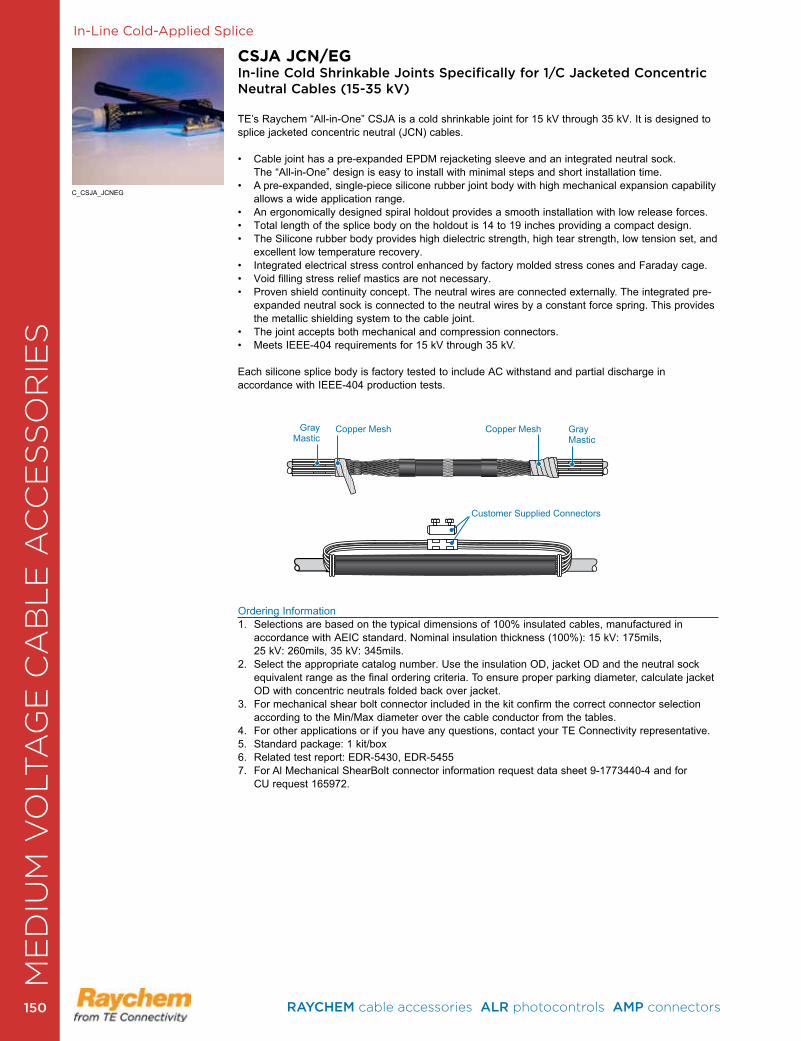
In-Line Cold-Applied Splice
Ordering Information1 . Selections are based on the typical dimensions of 100% insulated cables, manufactured in
accordance with AEIC standard . Nominal insulation thickness (100%): 15 kV: 175mils, 25 kV: 260mils, 35 kV: 345mils .
2. Select the appropriate catalog number. Use the insulation OD, jacket OD and the neutral sock equivalent range as the final ordering criteria. To ensure proper parking diameter, calculate jacket OD with concentric neutrals folded back over jacket.
3 . For mechanical shear bolt connector included in the kit confirm the correct connector selection according to the Min/Max diameter over the cable conductor from the tables .
4 . For other applications or if you have any questions, contact your TE Connectivity representative .5 . Standard package: 1 kit/box6 . Related test report: EDR-5430, EDR-54557 . For Al Mechanical ShearBolt connector information request data sheet 9-1773440-4 and for
CU request 165972 .
C_CSJA_JCNEG
CSJA JCN/EGIn-line Cold Shrinkable Joints Specifically for 1/C Jacketed Concentric Neutral Cables (15-35 kV)
TE’s Raychem “All-in-One” CSJA is a cold shrinkable joint for 15 kV through 35 kV. It is designed to splice jacketed concentric neutral (JCN) cables.
• Cable joint has a pre-expanded EPDM rejacketing sleeve and an integrated neutral sock. The “All-in-One” design is easy to install with minimal steps and short installation time .
• A pre-expanded, single-piece silicone rubber joint body with high mechanical expansion capability allows a wide application range .
• An ergonomically designed spiral holdout provides a smooth installation with low release forces. • Total length of the splice body on the holdout is 14 to 19 inches providing a compact design.• The Silicone rubber body provides high dielectric strength, high tear strength, low tension set, and
excellent low temperature recovery .• Integrated electrical stress control enhanced by factory molded stress cones and Faraday cage.• Void filling stress relief mastics are not necessary.• Proven shield continuity concept. The neutral wires are connected externally. The integrated pre-
expanded neutral sock is connected to the neutral wires by a constant force spring . This provides the metallic shielding system to the cable joint.
• The joint accepts both mechanical and compression connectors.• Meets IEEE-404 requirements for 15 kV through 35 kV.
Each silicone splice body is factory tested to include AC withstand and partial discharge in accordance with IEEE-404 production tests .
Customer Supplied Connectors
Gray Mastic
Gray Mastic
Copper MeshCopper Mesh
ME
DIU
M V
OLT
AG
E C
AB
LE
AC
CE
SS
OR
IES
RAYCHEM cable accessories ALR photocontrols AMP connectors 150150
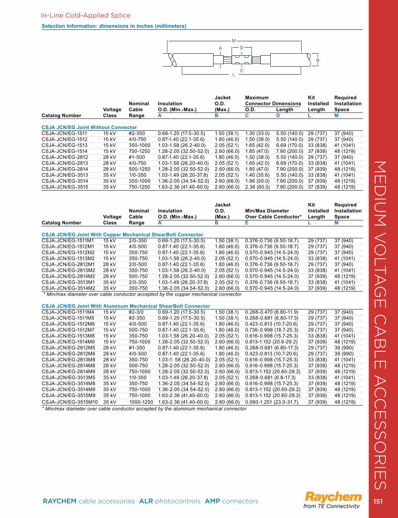
In-Line Cold-Applied Splice
Selection Information: dimensions in inches (millimeters)
Jacket Maximum Kit Required Nominal Insulation O.D. Connector Dimensions Installed Installation Voltage Cable O.D. (Min.-Max.) (Max.) O.D. Length Length SpaceCatalog Number Class Range A B C D L M
CSJA JCN/EG Joint Without ConnectorCSJA-JCN/EG-1511 15 kV #2-350 0 .69-1 .20 (17 .5-30 .5) 1 .50 (38 .1) 1 .30 (33 .0) 5 .50 (140 .0) 29 (737) 37 (940)CSJA-JCN/EG-1512 15 kV 4/0-750 0 .87-1 .40 (22 .1-35 .6) 1 .80 (46 .0) 1 .50 (38 .0) 5 .50 (140 .0) 29 (737) 37 (940)CSJA-JCN/EG-1513 15 kV 350-1000 1 .03-1 .58 (26 .2-40 .0) 2 .05 (52 .1) 1 .65 (42 .0) 6 .69 (170 .0) 33 (838) 41 (1041)CSJA-JCN/EG-1514 15 kV 750-1250 1 .28-2 .05 (32 .50-52 .0) 2 .60 (66 .0) 1 .85 (47 .0) 7 .90 (200 .0) 37 (939) 48 (1219)CSJA-JCN/EG-2812 28 kV #1-500 0 .87-1 .40 (22 .1-35 .6) 1 .80 (46 .0) 1 .50 (38 .0) 5 .50 (140 .0) 29 (737) 37 (940)CSJA-JCN/EG-2813 28 kV 4/0-750 1 .03-1 .58 (26 .20-40 .0) 2 .05 (52 .1) 1 .65 (42 .0) 6 .69 (170 .0) 33 (838) 41 (1041)CSJA-JCN/EG-2814 28 kV 500-1250 1 .28-2 .05 (32 .50-52 .0) 2 .60 (66 .0) 1 .85 (47 .0) 7 .90 (200 .0) 37 (939) 48 (1219)CSJA-JCN/EG-3513 35 kV 1/0-350 1 .03-1 .49 (26 .20-37 .8) 2 .05 (52 .1) 1 .40 (35 .6) 5 .50 (140 .0) 33 (838) 41 (1041)CSJA-JCN/EG-3514 35 kV 350-1000 1 .36-2 .05 (34 .54-52 .0) 2 .60 (66 .0) 1 .96 (50 .0) 7 .90 (200 .0) 37 (939) 48 (1219)CSJA-JCN/EG-3515 35 kV 750-1250 1 .63-2 .36 (41 .40-60 .0) 2 .60 (66 .0) 2 .36 (60 .0) 7 .90 (200 .0) 37 (939) 48 (1219) Jacket Kit Required Nominal Insulation O.D. Min/Max Diameter Installed Installation Voltage Cable O.D. (Min.-Max.) (Max.) Over Cable Conductor* Length SpaceCatalog Number Class Range A B E L M
CSJA JCN/EG Joint With Copper Mechanical ShearBolt ConnectorCSJA-JCN/EG-1511M1 15 kV 2/0-350 0 .69-1 .20 (17 .5-30 .5) 1 .50 (38 .1) 0 .376-0 .736 (9 .50-18 .7) 29 (737) 37 (940)CSJA-JCN/EG-1512M1 15 kV 4/0-500 0 .87-1 .40 (22 .1-35 .6) 1 .80 (46 .0) 0 .376-0 .736 (9 .50-18 .7) 29 (737) 37 (940)CSJA-JCN/EG-1512M2 15 kV 350-750 0 .87-1 .40 (22 .1-35 .6) 1 .80 (46 .0) 0 .570-0 .945 (14 .5-24 .0) 29 (737) 37 (940)CSJA-JCN/EG-1513M2 15 kV 350-750 1 .03-1 .58 (26 .2-40 .0) 2 .05 (52 .1) 0 .570-0 .945 (14 .5-24 .0) 33 (838) 41 (1041)CSJA-JCN/EG-2812M1 28 kV 2/0-500 0 .87-1 .40 (22 .1-35 .6) 1 .80 (46 .0) 0 .376-0 .736 (9 .50-18 .7) 29 (737) 37 (940)CSJA-JCN/EG-2813M2 28 kV 350-750 1 .03-1 .58 (26 .2-40 .0) 2 .05 (52 .1) 0 .570-0 .945 (14 .5-24 .0) 33 (838) 41 (1041)CSJA-JCN/EG-2814M2 28 kV 500-750 1 .28-2 .05 (32 .50-52 .0) 2 .60 (66 .0) 0 .570-0 .945 (14 .5-24 .0) 37 (939) 48 (1219)CSJA-JCN/EG-3513M1 35 kV 2/0-350 1 .03-1 .49 (26 .20-37 .8) 2 .05 (52 .1) 0 .376-0 .736 (9 .50-18 .7) 33 (838) 41 (1041)CSJA-JCN/EG-3514M2 35 kV 350-750 1 .36-2 .05 (34 .54-52 .0) 2 .60 (66 .0) 0 .570-0 .945 (14 .5-24 .0) 37 (939) 48 (1219) * Min/max diameter over cable conductor accepted by the copper mechanical connector.
CSJA JCN/EG Joint With Aluminum Mechanical ShearBolt ConnectorCSJA-JCN/EG-1511M4 15 kV #2-3/0 0 .69-1 .20 (17 .5-30 .5) 1 .50 (38 .1) 0 .268-0 .470 (6 .80-11 .9) 29 (737) 37 (940)CSJA-JCN/EG-1511M5 15 kV #2-350 0 .69-1 .20 (17 .5-30 .5) 1 .50 (38 .1) 0 .268-0 .681 (6 .80-17 .3) 29 (737) 37 (940)CSJA-JCN/EG-1512M6 15 kV 4/0-500 0 .87-1 .40 (22 .1-35 .6) 1 .80 (46 .0) 0 .423-0 .813 (10 .7-20 .6) 29 (737) 37 (940)CSJA-JCN/EG-1512M7 15 kV 500-750 0 .87-1 .40 (22 .1-35 .6) 1 .80 (46 .0) 0 .736-0 .998 (18 .7-25 .3) 29 (737) 37 (940)CSJA-JCN/EG-1513M8 15 kV 350-750 1 .03-1 .58 (26 .20-40 .0) 2 .05 (52 .1) 0 .616-0 .998 (15 .7-25 .3) 33 (838) 41 (1041)CSJA-JCN/EG-1514M9 15 kV 750-1000 1 .28-2 .05 (32 .50-52 .0) 2 .60 (66 .0) 0 .813-1 .152 (20 .6-29 .2) 37 (939) 48 (1219)CSJA-JCN/EG-2812M5 28 kV #1-350 0 .87-1 .40 (22 .1-35 .6) 1 .80 (46 .0) 0 .268-0 .681 (6 .80-17 .3) 29 (737) 39 (990)CSJA-JCN/EG-2812M6 28 kV 4/0-500 0 .87-1 .40 (22 .1-35 .6) 1 .80 (46 .0) 0 .423-0 .813 (10 .7-20 .6) 29 (737) 39 (990)CSJA-JCN/EG-2813M8 28 kV 350-750 1 .03-1 . 58 (26 .20-40 .0) 2 .05 (52 .1) 0 .616-0 .998 (15 .7-25 .3) 33 (838) 41 (1041)CSJA-JCN/EG-2814M8 28 kV 500-750 1 .28-2 .05 (32 .50-52 .0) 2 .60 (66 .0) 0 .616-0 .998 (15 .7-25 .3) 37 (939) 48 (1219)CSJA-JCN/EG-2814M9 28 kV 750-1000 1 .28-2 .05 (32 .50-52 .0) 2 .60 (66 .0) 0 .813-1 .152 (20 .60-29 .2) 37 (939) 48 (1219)CSJA-JCN/EG-3513M5 35 kV 1/0-350 1 .03-1 .49 (26 .20-37 .8) 2 .05 (52 .1) 0 .268-0 .681 (6 .8-17 .3) 33 (838) 41 (1041)CSJA-JCN/EG-3514M8 35 kV 350-750 1 .36-2 .05 (34 .54-52 .0) 2 .60 (66 .0) 0 .616-0 .998 (15 .7-25 .3) 37 (939) 48 (1219)CSJA-JCN/EG-3514M9 35 kV 750-1000 1 .36-2 .05 (34 .54-52 .0) 2 .60 (66 .0) 0 .813-1 .152 (20 .60-29 .2) 37 (939) 48 (1219)CSJA-JCN/EG-3515M9 35 kV 750-1000 1 .63-2 .36 (41 .40-60 .0) 2 .60 (66 .0) 0 .813-1 .152 (20 .60-29 .2) 37 (939) 48 (1219)CSJA-JCN/EG-3515M10 35 kV 1000-1250 1 .63-2 .36 (41 .40-60 .0) 2 .60 (66 .0) 0 .060-1 .251 (23 .0-31 .7) 37 (939) 48 (1219)* Min/max diameter over cable conductor accepted by the aluminum mechanical connector.
DM
A
B
LC
ME
DIU
M V
OLT
AG
E C
AB
LE
AC
CE
SS
OR
IES
RAYCHEM cable accessories ALR photocontrols AMP connectors 151 151
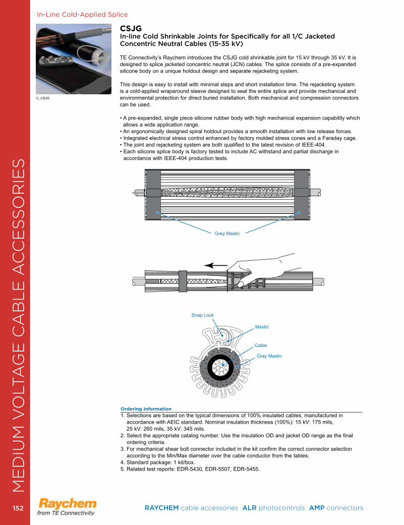
In-Line Cold-Applied Splice
CSJGIn-line Cold Shrinkable Joints for Specifically for all 1/C Jacketed Concentric Neutral Cables (15-35 kV)
TE Connectivity’s Raychem introduces the CSJG cold shrinkable joint for 15 kV through 35 kV. It is designed to splice jacketed concentric neutral (JCN) cables. The splice consists of a pre-expanded silicone body on a unique holdout design and separate rejacketing system. This design is easy to install with minimal steps and short installation time. The rejacketing system is a cold-applied wraparound sleeve designed to seal the entire splice and provide mechanical and environmental protection for direct buried installation . Both mechanical and compression connectors can be used .
• A pre-expanded, single piece silicone rubber body with high mechanical expansion capability which allows a wide application range .
• An ergonomically designed spiral holdout provides a smooth installation with low release forces.• Integrated electrical stress control enhanced by factory molded stress cones and a Faraday cage.• The joint and rejacketing system are both qualified to the latest revision of IEEE-404.• Each silicone splice body is factory tested to include AC withstand and partial discharge in
accordance with IEEE-404 production tests .
C_CSJG
Ordering Information
1 . Selections are based on the typical dimensions of 100% insulated cables, manufactured in accordance with AEIC standard . Nominal insulation thickness (100%): 15 kV: 175 mils, 25 kV: 260 mils, 35 kV: 345 mils .
2. Select the appropriate catalog number. Use the insulation OD and jacket OD range as the final ordering criteria .
3 . For mechanical shear bolt connector included in the kit confirm the correct connector selection according to the Min/Max diameter over the cable conductor from the tables .
4 . Standard package: 1 kit/box .5 . Related test reports: EDR-5430, EDR-5507, EDR-5455 .
Grey Mastic
Mastic
Snap Lock
Cable
Gray Mastic
ME
DIU
M V
OLT
AG
E C
AB
LE
AC
CE
SS
OR
IES
RAYCHEM cable accessories ALR photocontrols AMP connectors 152152
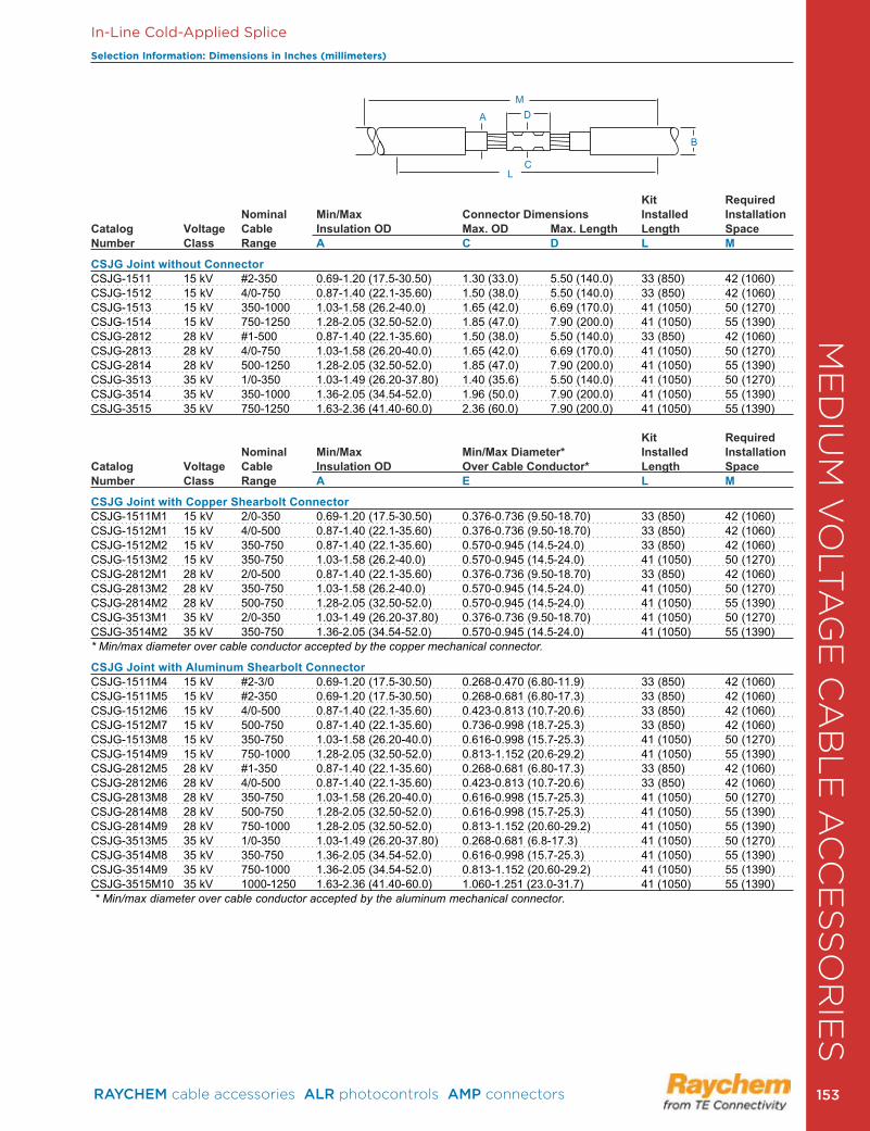
In-Line Cold-Applied Splice
Selection Information: Dimensions in Inches (millimeters)
Kit Required Nominal Min/Max Connector Dimensions Installed Installation
Catalog Voltage Cable Insulation OD Max. OD Max. Length Length SpaceNumber Class Range A C D L M
CSJG Joint without ConnectorCSJG-1511 15 kV #2-350 0 .69-1 .20 (17 .5-30 .50) 1 .30 (33 .0) 5 .50 (140 .0) 33 (850) 42 (1060) CSJG-1512 15 kV 4/0-750 0 .87-1 .40 (22 .1-35 .60) 1 .50 (38 .0) 5 .50 (140 .0) 33 (850) 42 (1060)CSJG-1513 15 kV 350-1000 1 .03-1 .58 (26 .2-40 .0) 1 .65 (42 .0) 6 .69 (170 .0) 41 (1050) 50 (1270)CSJG-1514 15 kV 750-1250 1 .28-2 .05 (32 .50-52 .0) 1 .85 (47 .0) 7 .90 (200 .0) 41 (1050) 55 (1390)CSJG-2812 28 kV #1-500 0 .87-1 .40 (22 .1-35 .60) 1 .50 (38 .0) 5 .50 (140 .0) 33 (850) 42 (1060)CSJG-2813 28 kV 4/0-750 1 .03-1 .58 (26 .20-40 .0) 1 .65 (42 .0) 6 .69 (170 .0) 41 (1050) 50 (1270)CSJG-2814 28 kV 500-1250 1 .28-2 .05 (32 .50-52 .0) 1 .85 (47 .0) 7 .90 (200 .0) 41 (1050) 55 (1390)CSJG-3513 35 kV 1/0-350 1 .03-1 .49 (26 .20-37 .80) 1 .40 (35 .6) 5 .50 (140 .0) 41 (1050) 50 (1270)CSJG-3514 35 kV 350-1000 1 .36-2 .05 (34 .54-52 .0) 1 .96 (50 .0) 7 .90 (200 .0) 41 (1050) 55 (1390)CSJG-3515 35 kV 750-1250 1 .63-2 .36 (41 .40-60 .0) 2 .36 (60 .0) 7 .90 (200 .0) 41 (1050) 55 (1390)
Kit Required Nominal Min/Max Min/Max Diameter* Installed Installation
Catalog Voltage Cable Insulation OD Over Cable Conductor* Length SpaceNumber Class Range A E L M
CSJG Joint with Copper Shearbolt ConnectorCSJG-1511M1 15 kV 2/0-350 0 .69-1 .20 (17 .5-30 .50) 0 .376-0 .736 (9 .50-18 .70) 33 (850) 42 (1060)CSJG-1512M1 15 kV 4/0-500 0 .87-1 .40 (22 .1-35 .60) 0 .376-0 .736 (9 .50-18 .70) 33 (850) 42 (1060)CSJG-1512M2 15 kV 350-750 0 .87-1 .40 (22 .1-35 .60) 0 .570-0 .945 (14 .5-24 .0) 33 (850) 42 (1060)CSJG-1513M2 15 kV 350-750 1 .03-1 .58 (26 .2-40 .0) 0 .570-0 .945 (14 .5-24 .0) 41 (1050) 50 (1270)CSJG-2812M1 28 kV 2/0-500 0 .87-1 .40 (22 .1-35 .60) 0 .376-0 .736 (9 .50-18 .70) 33 (850) 42 (1060)CSJG-2813M2 28 kV 350-750 1 .03-1 .58 (26 .2-40 .0) 0 .570-0 .945 (14 .5-24 .0) 41 (1050) 50 (1270)CSJG-2814M2 28 kV 500-750 1 .28-2 .05 (32 .50-52 .0) 0 .570-0 .945 (14 .5-24 .0) 41 (1050) 55 (1390)CSJG-3513M1 35 kV 2/0-350 1 .03-1 .49 (26 .20-37 .80) 0 .376-0 .736 (9 .50-18 .70) 41 (1050) 50 (1270)CSJG-3514M2 35 kV 350-750 1 .36-2 .05 (34 .54-52 .0) 0 .570-0 .945 (14 .5-24 .0) 41 (1050) 55 (1390) * Min/max diameter over cable conductor accepted by the copper mechanical connector.
CSJG Joint with Aluminum Shearbolt ConnectorCSJG-1511M4 15 kV #2-3/0 0 .69-1 .20 (17 .5-30 .50) 0 .268-0 .470 (6 .80-11 .9) 33 (850) 42 (1060)CSJG-1511M5 15 kV #2-350 0 .69-1 .20 (17 .5-30 .50) 0 .268-0 .681 (6 .80-17 .3) 33 (850) 42 (1060)CSJG-1512M6 15 kV 4/0-500 0 .87-1 .40 (22 .1-35 .60) 0 .423-0 .813 (10 .7-20 .6) 33 (850) 42 (1060)CSJG-1512M7 15 kV 500-750 0 .87-1 .40 (22 .1-35 .60) 0 .736-0 .998 (18 .7-25 .3) 33 (850) 42 (1060)CSJG-1513M8 15 kV 350-750 1 .03-1 .58 (26 .20-40 .0) 0 .616-0 .998 (15 .7-25 .3) 41 (1050) 50 (1270)CSJG-1514M9 15 kV 750-1000 1 .28-2 .05 (32 .50-52 .0) 0 .813-1 .152 (20 .6-29 .2) 41 (1050) 55 (1390)CSJG-2812M5 28 kV #1-350 0 .87-1 .40 (22 .1-35 .60) 0 .268-0 .681 (6 .80-17 .3) 33 (850) 42 (1060)CSJG-2812M6 28 kV 4/0-500 0 .87-1 .40 (22 .1-35 .60) 0 .423-0 .813 (10 .7-20 .6) 33 (850) 42 (1060)CSJG-2813M8 28 kV 350-750 1 .03-1 .58 (26 .20-40 .0) 0 .616-0 .998 (15 .7-25 .3) 41 (1050) 50 (1270)CSJG-2814M8 28 kV 500-750 1 .28-2 .05 (32 .50-52 .0) 0 .616-0 .998 (15 .7-25 .3) 41 (1050) 55 (1390)CSJG-2814M9 28 kV 750-1000 1 .28-2 .05 (32 .50-52 .0) 0 .813-1 .152 (20 .60-29 .2) 41 (1050) 55 (1390)CSJG-3513M5 35 kV 1/0-350 1 .03-1 .49 (26 .20-37 .80) 0 .268-0 .681 (6 .8-17 .3) 41 (1050) 50 (1270)CSJG-3514M8 35 kV 350-750 1 .36-2 .05 (34 .54-52 .0) 0 .616-0 .998 (15 .7-25 .3) 41 (1050) 55 (1390)CSJG-3514M9 35 kV 750-1000 1 .36-2 .05 (34 .54-52 .0) 0 .813-1 .152 (20 .60-29 .2) 41 (1050) 55 (1390)CSJG-3515M10 35 kV 1000-1250 1 .63-2 .36 (41 .40-60 .0) 1 .060-1 .251 (23 .0-31 .7) 41 (1050) 55 (1390) * Min/max diameter over cable conductor accepted by the aluminum mechanical connector.
A D
B
LC
M
ME
DIU
M V
OLT
AG
E C
AB
LE
AC
CE
SS
OR
IES
RAYCHEM cable accessories ALR photocontrols AMP connectors 153 153
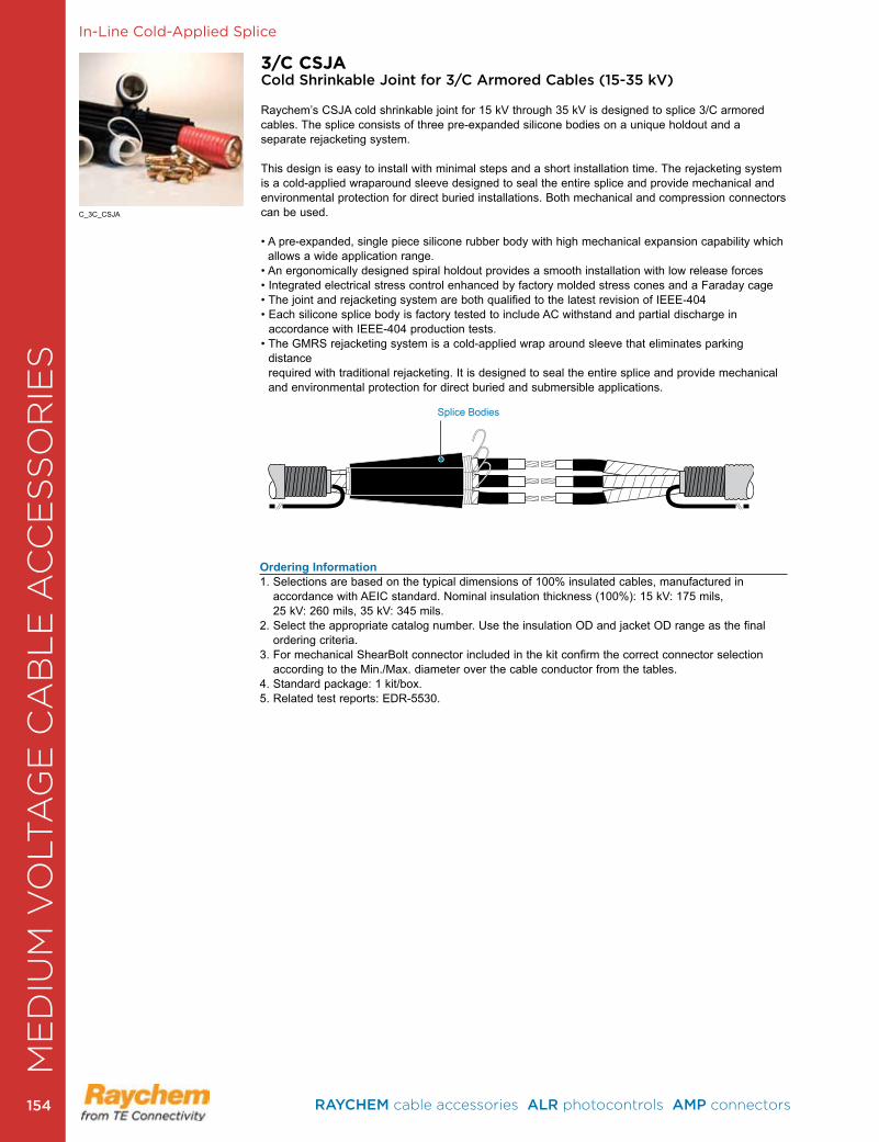
In-Line Cold-Applied Splice
3/C CSJACold Shrinkable Joint for 3/C Armored Cables (15-35 kV)
Raychem’s CSJA cold shrinkable joint for 15 kV through 35 kV is designed to splice 3/C armored cables . The splice consists of three pre-expanded silicone bodies on a unique holdout and a separate rejacketing system. This design is easy to install with minimal steps and a short installation time. The rejacketing system is a cold-applied wraparound sleeve designed to seal the entire splice and provide mechanical and environmental protection for direct buried installations . Both mechanical and compression connectors can be used .
• A pre-expanded, single piece silicone rubber body with high mechanical expansion capability which allows a wide application range .
• An ergonomically designed spiral holdout provides a smooth installation with low release forces• Integrated electrical stress control enhanced by factory molded stress cones and a Faraday cage• The joint and rejacketing system are both qualified to the latest revision of IEEE-404• Each silicone splice body is factory tested to include AC withstand and partial discharge in
accordance with IEEE-404 production tests .• The GMRS rejacketing system is a cold-applied wrap around sleeve that eliminates parking
distance required with traditional rejacketing. It is designed to seal the entire splice and provide mechanical and environmental protection for direct buried and submersible applications .
C_3C_CSJA
Ordering Information1 . Selections are based on the typical dimensions of 100% insulated cables, manufactured in
accordance with AEIC standard . Nominal insulation thickness (100%): 15 kV: 175 mils, 25 kV: 260 mils, 35 kV: 345 mils .
2. Select the appropriate catalog number. Use the insulation OD and jacket OD range as the final ordering criteria .
3 . For mechanical ShearBolt connector included in the kit confirm the correct connector selection according to the Min ./Max . diameter over the cable conductor from the tables .
4 . Standard package: 1 kit/box .5 . Related test reports: EDR-5530 .
Splice Bodies
ME
DIU
M V
OLT
AG
E C
AB
LE
AC
CE
SS
OR
IES
RAYCHEM cable accessories ALR photocontrols AMP connectors 154154
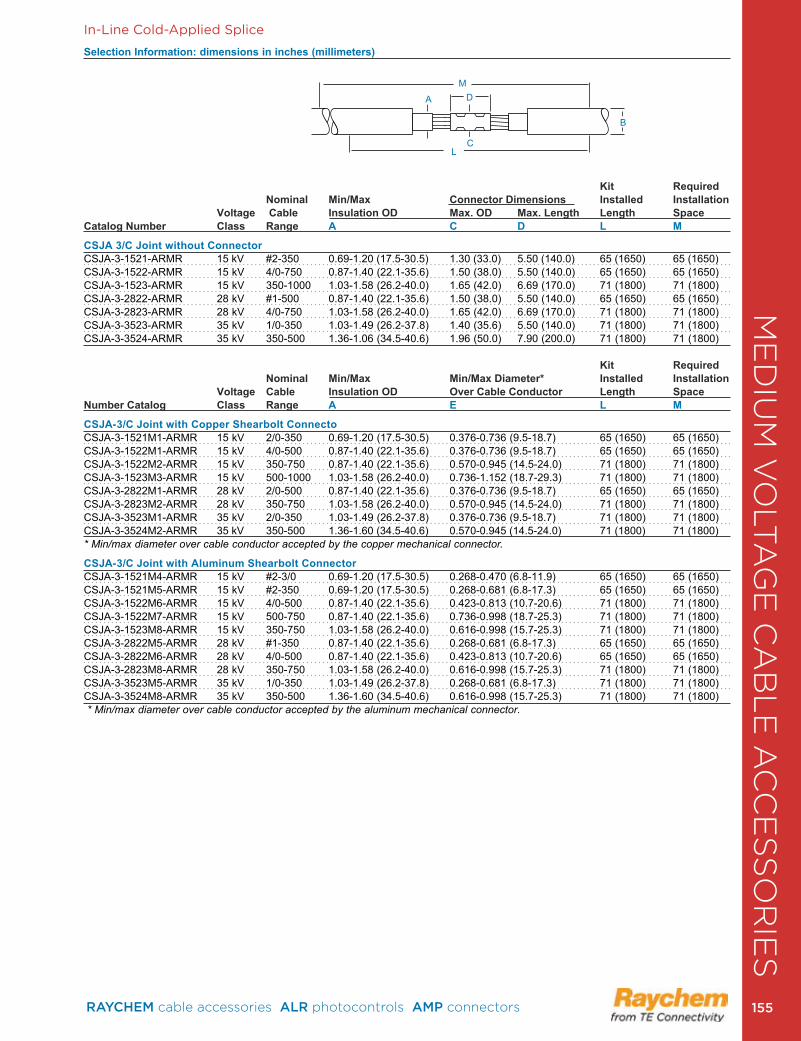
In-Line Cold-Applied Splice
Selection Information: dimensions in inches (millimeters)
Kit Required Nominal Min/Max Connector Dimensions Installed InstallationVoltage Cable Insulation OD Max. OD Max. Length Length Space
Catalog Number Class Range A C D L M
CSJA 3/C Joint without Connector CSJA-3-1521-ARMR 15 kV #2-350 0 .69-1 .20 (17 .5-30 .5) 1 .30 (33 .0) 5 .50 (140 .0) 65 (1650) 65 (1650) CSJA-3-1522-ARMR 15 kV 4/0-750 0 .87-1 .40 (22 .1-35 .6) 1 .50 (38 .0) 5 .50 (140 .0) 65 (1650) 65 (1650)CSJA-3-1523-ARMR 15 kV 350-1000 1 .03-1 .58 (26 .2-40 .0) 1 .65 (42 .0) 6 .69 (170 .0) 71 (1800) 71 (1800) CSJA-3-2822-ARMR 28 kV #1-500 0 .87-1 .40 (22 .1-35 .6) 1 .50 (38 .0) 5 .50 (140 .0) 65 (1650) 65 (1650)CSJA-3-2823-ARMR 28 kV 4/0-750 1 .03-1 .58 (26 .2-40 .0) 1 .65 (42 .0) 6 .69 (170 .0) 71 (1800) 71 (1800) CSJA-3-3523-ARMR 35 kV 1/0-350 1 .03-1 .49 (26 .2-37 .8) 1 .40 (35 .6) 5 .50 (140 .0) 71 (1800) 71 (1800) CSJA-3-3524-ARMR 35 kV 350-500 1 .36-1 .06 (34 .5-40 .6) 1 .96 (50 .0) 7 .90 (200 .0) 71 (1800) 71 (1800)
Kit RequiredNominal Min/Max Min/Max Diameter* Installed Installation
Voltage Cable Insulation OD Over Cable Conductor Length SpaceNumber Catalog Class Range A E L M
CSJA-3/C Joint with Copper Shearbolt Connecto CSJA-3-1521M1-ARMR 15 kV 2/0-350 0 .69-1 .20 (17 .5-30 .5) 0 .376-0 .736 (9 .5-18 .7) 65 (1650) 65 (1650)CSJA-3-1522M1-ARMR 15 kV 4/0-500 0 .87-1 .40 (22 .1-35 .6) 0 .376-0 .736 (9 .5-18 .7) 65 (1650) 65 (1650)CSJA-3-1522M2-ARMR 15 kV 350-750 0 .87-1 .40 (22 .1-35 .6) 0 .570-0 .945 (14 .5-24 .0) 71 (1800) 71 (1800)CSJA-3-1523M3-ARMR 15 kV 500-1000 1 .03-1 .58 (26 .2-40 .0) 0 .736-1 .152 (18 .7-29 .3) 71 (1800) 71 (1800)CSJA-3-2822M1-ARMR 28 kV 2/0-500 0 .87-1 .40 (22 .1-35 .6) 0 .376-0 .736 (9 .5-18 .7) 65 (1650) 65 (1650)CSJA-3-2823M2-ARMR 28 kV 350-750 1 .03-1 .58 (26 .2-40 .0) 0 .570-0 .945 (14 .5-24 .0) 71 (1800) 71 (1800)CSJA-3-3523M1-ARMR 35 kV 2/0-350 1 .03-1 .49 (26 .2-37 .8) 0 .376-0 .736 (9 .5-18 .7) 71 (1800) 71 (1800)CSJA-3-3524M2-ARMR 35 kV 350-500 1 .36-1 .60 (34 .5-40 .6) 0 .570-0 .945 (14 .5-24 .0) 71 (1800) 71 (1800) * Min/max diameter over cable conductor accepted by the copper mechanical connector.
CSJA-3/C Joint with Aluminum Shearbolt ConnectorCSJA-3-1521M4-ARMR 15 kV #2-3/0 0 .69-1 .20 (17 .5-30 .5) 0 .268-0 .470 (6 .8-11 .9) 65 (1650) 65 (1650)CSJA-3-1521M5-ARMR 15 kV #2-350 0 .69-1 .20 (17 .5-30 .5) 0 .268-0 .681 (6 .8-17 .3) 65 (1650) 65 (1650)CSJA-3-1522M6-ARMR 15 kV 4/0-500 0 .87-1 .40 (22 .1-35 .6) 0 .423-0 .813 (10 .7-20 .6) 71 (1800) 71 (1800)CSJA-3-1522M7-ARMR 15 kV 500-750 0 .87-1 .40 (22 .1-35 .6) 0 .736-0 .998 (18 .7-25 .3) 71 (1800) 71 (1800)CSJA-3-1523M8-ARMR 15 kV 350-750 1 .03-1 .58 (26 .2-40 .0) 0 .616-0 .998 (15 .7-25 .3) 71 (1800) 71 (1800)CSJA-3-2822M5-ARMR 28 kV #1-350 0 .87-1 .40 (22 .1-35 .6) 0 .268-0 .681 (6 .8-17 .3) 65 (1650) 65 (1650)CSJA-3-2822M6-ARMR 28 kV 4/0-500 0 .87-1 .40 (22 .1-35 .6) 0 .423-0 .813 (10 .7-20 .6) 65 (1650) 65 (1650)CSJA-3-2823M8-ARMR 28 kV 350-750 1 .03-1 .58 (26 .2-40 .0) 0 .616-0 .998 (15 .7-25 .3) 71 (1800) 71 (1800)CSJA-3-3523M5-ARMR 35 kV 1/0-350 1 .03-1 .49 (26 .2-37 .8) 0 .268-0 .681 (6 .8-17 .3) 71 (1800) 71 (1800)CSJA-3-3524M8-ARMR 35 kV 350-500 1 .36-1 .60 (34 .5-40 .6) 0 .616-0 .998 (15 .7-25 .3) 71 (1800) 71 (1800)* Min/max diameter over cable conductor accepted by the aluminum mechanical connector.
A D
B
LC
M
ME
DIU
M V
OLT
AG
E C
AB
LE
AC
CE
SS
OR
IES
RAYCHEM cable accessories ALR photocontrols AMP connectors 155 155
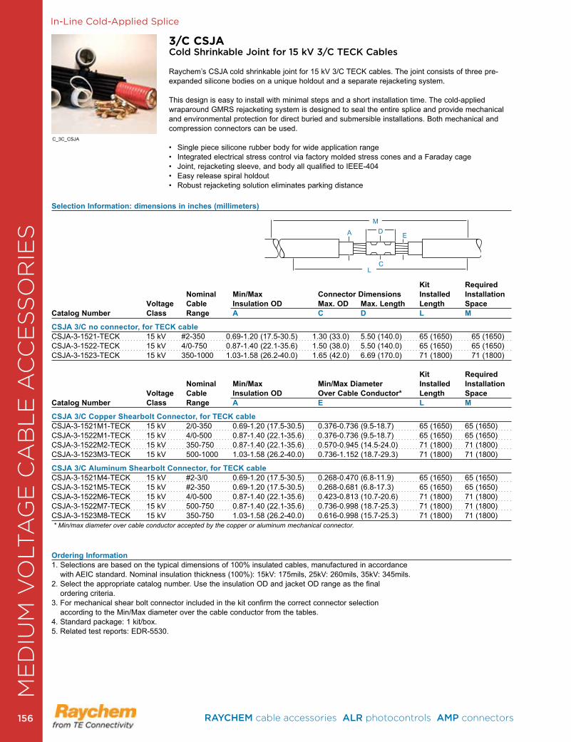
In-Line Cold-Applied Splice
3/C CSJACold Shrinkable Joint for 15 kV 3/C TECK Cables
Raychem’s CSJA cold shrinkable joint for 15 kV 3/C TECK cables. The joint consists of three pre-expanded silicone bodies on a unique holdout and a separate rejacketing system. This design is easy to install with minimal steps and a short installation time . The cold-applied wraparound GMRS rejacketing system is designed to seal the entire splice and provide mechanical and environmental protection for direct buried and submersible installations . Both mechanical and compression connectors can be used .
• Single piece silicone rubber body for wide application range• Integrated electrical stress control via factory molded stress cones and a Faraday cage• Joint, rejacketing sleeve, and body all qualified to IEEE-404• Easy release spiral holdout• Robust rejacketing solution eliminates parking distance
Kit Required Nominal Min/Max Connector Dimensions Installed Installation Voltage Cable Insulation OD Max. OD Max. Length Length Space Catalog Number Class Range A C D L M
CSJA 3/C no connector, for TECK cable CSJA-3-1521-TECK 15 kV #2-350 0 .69-1 .20 (17 .5-30 .5) 1 .30 (33 .0) 5 .50 (140 .0) 65 (1650) 65 (1650) CSJA-3-1522-TECK 15 kV 4/0-750 0 .87-1 .40 (22 .1-35 .6) 1 .50 (38 .0) 5 .50 (140 .0) 65 (1650) 65 (1650)CSJA-3-1523-TECK 15 kV 350-1000 1 .03-1 .58 (26 .2-40 .0) 1 .65 (42 .0) 6 .69 (170 .0) 71 (1800) 71 (1800)
Kit Required Nominal Min/Max Min/Max Diameter Installed Installation Voltage Cable Insulation OD Over Cable Conductor* Length Space Catalog Number Class Range A E L M
CSJA 3/C Copper Shearbolt Connector, for TECK cableCSJA-3-1521M1-TECK 15 kV 2/0-350 0 .69-1 .20 (17 .5-30 .5) 0 .376-0 .736 (9 .5-18 .7) 65 (1650) 65 (1650)CSJA-3-1522M1-TECK 15 kV 4/0-500 0 .87-1 .40 (22 .1-35 .6) 0 .376-0 .736 (9 .5-18 .7) 65 (1650) 65 (1650)CSJA-3-1522M2-TECK 15 kV 350-750 0 .87-1 .40 (22 .1-35 .6) 0 .570-0 .945 (14 .5-24 .0) 71 (1800) 71 (1800)CSJA-3-1523M3-TECK 15 kV 500-1000 1 .03-1 .58 (26 .2-40 .0) 0 .736-1 .152 (18 .7-29 .3) 71 (1800) 71 (1800)
CSJA 3/C Aluminum Shearbolt Connector, for TECK cable CSJA-3-1521M4-TECK 15 kV #2-3/0 0 .69-1 .20 (17 .5-30 .5) 0 .268-0 .470 (6 .8-11 .9) 65 (1650) 65 (1650)CSJA-3-1521M5-TECK 15 kV #2-350 0 .69-1 .20 (17 .5-30 .5) 0 .268-0 .681 (6 .8-17 .3) 65 (1650) 65 (1650)CSJA-3-1522M6-TECK 15 kV 4/0-500 0 .87-1 .40 (22 .1-35 .6) 0 .423-0 .813 (10 .7-20 .6) 71 (1800) 71 (1800)CSJA-3-1522M7-TECK 15 kV 500-750 0 .87-1 .40 (22 .1-35 .6) 0 .736-0 .998 (18 .7-25 .3) 71 (1800) 71 (1800)CSJA-3-1523M8-TECK 15 kV 350-750 1 .03-1 .58 (26 .2-40 .0) 0 .616-0 .998 (15 .7-25 .3) 71 (1800) 71 (1800) * Min/max diameter over cable conductor accepted by the copper or aluminum mechanical connector.
Ordering Information1 . Selections are based on the typical dimensions of 100% insulated cables, manufactured in accordance
with AEIC standard . Nominal insulation thickness (100%): 15kV: 175mils, 25kV: 260mils, 35kV: 345mils .2. Select the appropriate catalog number. Use the insulation OD and jacket OD range as the final
ordering criteria .3 . For mechanical shear bolt connector included in the kit confirm the correct connector selection
according to the Min/Max diameter over the cable conductor from the tables . 4 . Standard package: 1 kit/box .5 . Related test reports: EDR-5530 .
A D E
LC
M
Selection Information: dimensions in inches (millimeters)
C_3C_CSJA
ME
DIU
M V
OLT
AG
E C
AB
LE
AC
CE
SS
OR
IES
RAYCHEM cable accessories ALR photocontrols AMP connectors 156156
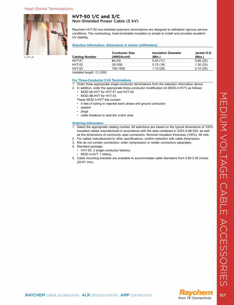
ME
DIU
M V
OLT
AG
E C
AB
LE
AC
CE
SS
OR
IES
Heat-Shrink Terminations
HVT-50 1/C and 3/C Non-Shielded Power Cable (5 kV)
Raychem HVT-50 non-shielded polymeric terminations are designed to withstand rigorous service conditions . The nontracking, heat-shrinkable insulation is simple to install and provides excellent UV stability .
Selection Information: dimensions in inches (millimeters)
Conductor Size Insulation Diameter Jacket O.D.Catalog Number (AWG/kcmil) (Min.) (Max.)HVT-51 #4-2/0 0 .45 (11) 0 .85 (22)HVT-52 3/0-500 0 .70 (18) 1 .30 (33)HVT-53 750-1500 1 .10 (28) 2 .15 (55)Installed length: 12 (300)
For Three-Conductor 5 kV Terminations1 . Order three appropriate single-conductor terminations from the selection information above .2 . In addition, order the appropriate three-conductor modification kit (MOD-3-HVT) as follows:
• MOD-3A-HVT for HVT-51 and HVT-52 • MOD-3B-HVT for HVT-53
These MOD-3-HVT kits contain: • 4 feet of tubing to rejacket each phase and ground conductor • sealant • plugs • cable breakout to seal the crotch area
Ordering Information1 . Select the appropriate catalog number . All selections are based on the typical dimensions of 100%
insulated cables manufactured in accordance with the data contained in ICEA S-66-524, as well as the dimensions of commonly used connectors . Nominal insulation thickness (100%): 90 mils .
2 . For cables manufactured to other specifications, confirm selection with cable dimensions .3 . Kits do not contain connectors; order compression or solder connectors separately .4 . Standard package: • HVT-50: 3 single-conductor kits/box. • MOD-3-HVT: 1 kit/box. 5 . Cable mounting brackets are available to accommodate cable diameters from 0 .80-2 .40 inches
(20-61 mm) .
C_HVT_50
ME
DIU
M V
OLT
AG
E C
AB
LE
AC
CE
SS
OR
IES
RAYCHEM cable accessories ALR photocontrols AMP connectors 157 157
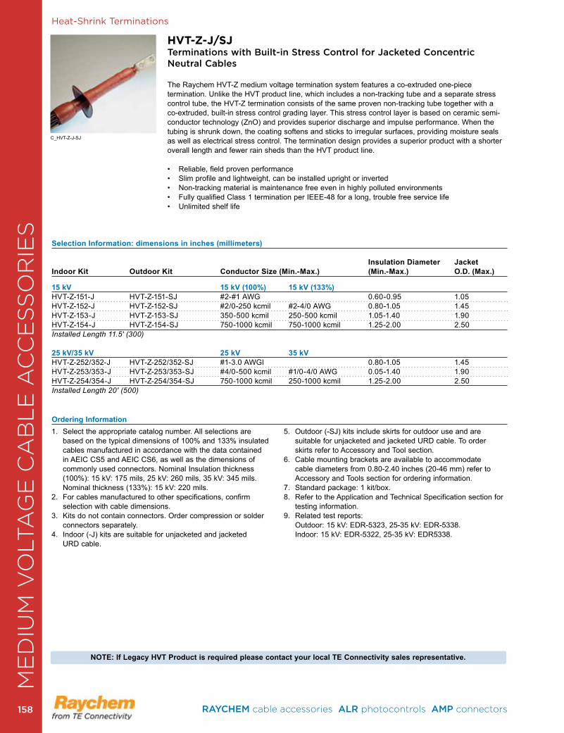
Heat-Shrink Terminations
HVT-Z-J/SJTerminations with Built-in Stress Control for Jacketed Concentric Neutral Cables
The Raychem HVT-Z medium voltage termination system features a co-extruded one-piece termination . Unlike the HVT product line, which includes a non-tracking tube and a separate stress control tube, the HVT-Z termination consists of the same proven non-tracking tube together with a co-extruded, built-in stress control grading layer . This stress control layer is based on ceramic semi-conductor technology (ZnO) and provides superior discharge and impulse performance . When the tubing is shrunk down, the coating softens and sticks to irregular surfaces, providing moisture seals as well as electrical stress control . The termination design provides a superior product with a shorter overall length and fewer rain sheds than the HVT product line .
• Reliable, field proven performance• Slim profile and lightweight, can be installed upright or inverted• Non-tracking material is maintenance free even in highly polluted environments• Fully qualified Class 1 termination per IEEE-48 for a long, trouble free service life• Unlimited shelf life
Selection Information: dimensions in inches (millimeters) Insulation Diameter JacketIndoor Kit Outdoor Kit Conductor Size (Min.-Max.) (Min.-Max.) O.D. (Max.)
15 kV 15 kV (100%) 15 kV (133%)HVT-Z-151-J HVT-Z-151-SJ #2-#1 AWG 0 .60-0 .95 1 .05HVT-Z-152-J HVT-Z-152-SJ #2/0-250 kcmil #2-4/0 AWG 0 .80-1 .05 1 .45HVT-Z-153-J HVT-Z-153-SJ 350-500 kcmil 250-500 kcmil 1 .05-1 .40 1 .90 HVT-Z-154-J HVT-Z-154-SJ 750-1000 kcmil 750-1000 kcmil 1 .25-2 .00 2 .50Installed Length 11.5' (300)
25 kV/35 kV 25 kV 35 kVHVT-Z-252/352-J HVT-Z-252/352-SJ #1-3 .0 AWGl 0 .80-1 .05 1 .45HVT-Z-253/353-J HVT-Z-253/353-SJ #4/0-500 kcmil #1/0-4/0 AWG 0 .05-1 .40 1 .90HVT-Z-254/354-J HVT-Z-254/354-SJ 750-1000 kcmil 250-1000 kcmil 1 .25-2 .00 2 .50Installed Length 20' (500)
Ordering Information1 . Select the appropriate catalog number . All selections are
based on the typical dimensions of 100% and 133% insulated cables manufactured in accordance with the data contained in AEIC CS5 and AEIC CS6, as well as the dimensions of commonly used connectors . Nominal Insulation thickness (100%): 15 kV: 175 mils, 25 kV: 260 mils, 35 kV: 345 mils . Nominal thickness (133%): 15 kV: 220 mils .
2 . For cables manufactured to other specifications, confirm selection with cable dimensions .
3 . Kits do not contain connectors . Order compression or solder connectors separately .
4. Indoor (-J) kits are suitable for unjacketed and jacketed URD cable .
5 . Outdoor (-SJ) kits include skirts for outdoor use and are suitable for unjacketed and jacketed URD cable. To order skirts refer to Accessory and Tool section .
6 . Cable mounting brackets are available to accommodate cable diameters from 0 .80-2 .40 inches (20-46 mm) refer to Accessory and Tools section for ordering information .
7 . Standard package: 1 kit/box . 8 . Refer to the Application and Technical Specification section for
testing information .9 . Related test reports: Outdoor: 15 kV: EDR-5323, 25-35 kV: EDR-5338 . Indoor: 15 kV: EDR-5322, 25-35 kV: EDR5338 .
NOTE: If Legacy HVT Product is required please contact your local TE Connectivity sales representative.
C_HVT-Z-J-SJ
ME
DIU
M V
OLT
AG
E C
AB
LE
AC
CE
SS
OR
IES
RAYCHEM cable accessories ALR photocontrols AMP connectors 158158
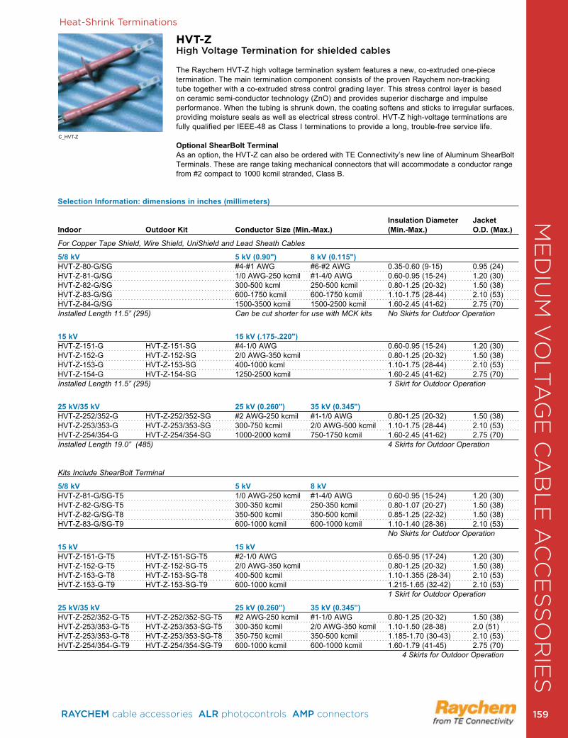
Heat-Shrink Terminations
HVT-ZHigh Voltage Termination for shielded cables
The Raychem HVT-Z high voltage termination system features a new, co-extruded one-piece termination . The main termination component consists of the proven Raychem non-tracking tube together with a co-extruded stress control grading layer . This stress control layer is based on ceramic semi-conductor technology (ZnO) and provides superior discharge and impulse performance . When the tubing is shrunk down, the coating softens and sticks to irregular surfaces, providing moisture seals as well as electrical stress control . HVT-Z high-voltage terminations are fully qualified per IEEE-48 as Class I terminations to provide a long, trouble-free service life .
Optional ShearBolt TerminalAs an option, the HVT-Z can also be ordered with TE Connectivity’s new line of Aluminum ShearBolt Terminals . These are range taking mechanical connectors that will accommodate a conductor range from #2 compact to 1000 kcmil stranded, Class B .
Selection Information: dimensions in inches (millimeters)
Insulation Diameter JacketIndoor Outdoor Kit Conductor Size (Min.-Max.) (Min.-Max.) O.D. (Max.)
For Copper Tape Shield, Wire Shield, UniShield and Lead Sheath Cables
5/8 kV 5 kV (0.90") 8 kV (0.115")HVT-Z-80-G/SG #4-#1 AWG #6-#2 AWG 0 .35-0 .60 (9-15) 0 .95 (24)HVT-Z-81-G/SG 1/0 AWG-250 kcmil #1-4/0 AWG 0 .60-0 .95 (15-24) 1 .20 (30)HVT-Z-82-G/SG 300-500 kcml 250-500 kcmil 0 .80-1 .25 (20-32) 1 .50 (38)HVT-Z-83-G/SG 600-1750 kcmil 600-1750 kcmil 1 .10-1 .75 (28-44) 2 .10 (53)HVT-Z-84-G/SG 1500-3500 kcmil 1500-2500 kcmil 1 .60-2 .45 (41-62) 2 .75 (70)Installed Length 11.5” (295) Can be cut shorter for use with MCK kits No Skirts for Outdoor Operation
15 kV 15 kV (.175-.220")HVT-Z-151-G HVT-Z-151-SG #4-1/0 AWG 0 .60-0 .95 (15-24) 1 .20 (30)HVT-Z-152-G HVT-Z-152-SG 2/0 AWG-350 kcmil 0 .80-1 .25 (20-32) 1 .50 (38)HVT-Z-153-G HVT-Z-153-SG 400-1000 kcml 1 .10-1 .75 (28-44) 2 .10 (53)HVT-Z-154-G HVT-Z-154-SG 1250-2500 kcmil 1 .60-2 .45 (41-62) 2 .75 (70)Installed Length 11.5” (295) 1 Skirt for Outdoor Operation
25 kV/35 kV 25 kV (0.260") 35 kV (0.345")HVT-Z-252/352-G HVT-Z-252/352-SG #2 AWG-250 kcmil #1-1/0 AWG 0 .80-1 .25 (20-32) 1 .50 (38)HVT-Z-253/353-G HVT-Z-253/353-SG 300-750 kcmil 2/0 AWG-500 kcmil 1 .10-1 .75 (28-44) 2 .10 (53)HVT-Z-254/354-G HVT-Z-254/354-SG 1000-2000 kcmil 750-1750 kcmil 1 .60-2 .45 (41-62) 2 .75 (70)Installed Length 19.0” (485) 4 Skirts for Outdoor Operation
Kits Include ShearBolt Terminal
5/8 kV 5 kV 8 kV HVT-Z-81-G/SG-T5 1/0 AWG-250 kcmil #1-4/0 AWG 0 .60-0 .95 (15-24) 1 .20 (30)HVT-Z-82-G/SG-T5 300-350 kcmil 250-350 kcmil 0 .80-1 .07 (20-27) 1 .50 (38)HVT-Z-82-G/SG-T8 350-500 kcmil 350-500 kcmil 0 .85-1 .25 (22-32) 1 .50 (38)HVT-Z-83-G/SG-T9 600-1000 kcmil 600-1000 kcmil 1 .10-1 .40 (28-36) 2 .10 (53) No Skirts for Outdoor Operation
15 kV 15 kV HVT-Z-151-G-T5 HVT-Z-151-SG-T5 #2-1/0 AWG 0 .65-0 .95 (17-24) 1 .20 (30)HVT-Z-152-G-T5 HVT-Z-152-SG-T5 2/0 AWG-350 kcmil 0 .80-1 .25 (20-32) 1 .50 (38)HVT-Z-153-G-T8 HVT-Z-153-SG-T8 400-500 kcmil 1 .10-1 .355 (28-34) 2 .10 (53)HVT-Z-153-G-T9 HVT-Z-153-SG-T9 600-1000 kcmil 1 .215-1 .65 (32-42) 2 .10 (53) 1 Skirt for Outdoor Operation
25 kV/35 kV 25 kV (0.260”) 35 kV (0.345”)HVT-Z-252/352-G-T5 HVT-Z-252/352-SG-T5 #2 AWG-250 kcmil #1-1/0 AWG 0 .80-1 .25 (20-32) 1 .50 (38)HVT-Z-253/353-G-T5 HVT-Z-253/353-SG-T5 300-350 kcmil 2/0 AWG-350 kcmil 1 .10-1 .50 (28-38) 2 .0 (51)HVT-Z-253/353-G-T8 HVT-Z-253/353-SG-T8 350-750 kcmil 350-500 kcmil 1 .185-1 .70 (30-43) 2 .10 (53)HVT-Z-254/354-G-T9 HVT-Z-254/354-SG-T9 600-1000 kcmil 600-1000 kcmil 1 .60-1 .79 (41-45) 2 .75 (70) 4 Skirts for Outdoor Operation
C_HVT-Z
ME
DIU
M V
OLT
AG
E C
AB
LE
AC
CE
SS
OR
IES
RAYCHEM cable accessories ALR photocontrols AMP connectors 159 159
Heat-Shrink Terminations
Selection Information: dimensions in inches (millimeters) Insulation Diameter Jacket
Indoor Outdoor Kit Conductor Size (Min.-Max.) (Min.-Max.) O.D. (Max.)
For Copper Tape Shield, Wire Shield, UniShield and Lead Sheath Cables
5/8 kV 5 kV (0.90”) 8 kV (0.115”)HVT-Z-80-G/SG #4-#1 AWG #6-#2 AWG 0 .35-0 .60 (9-15) 0 .95 (24)HVT-Z-81-G/SG 1/0 AWG-250 kcmil #1-4/0 AWG 0 .60-0 .95 (15-24) 1 .20 (30)HVT-Z-82-G/SG 300-500 kcml 250-500 kcmil 0 .80-1 .25 (20-32) 1 .50 (38)HVT-Z-83-G/SG 600-1750 kcmil 600-1750 kcmil 1 .10-1 .75 (28-44) 2 .10 (53)HVT-Z-84-G/SG 1500-3500 kcmil 1500-2500 kcmil 1 .60-2 .45 (41-62) 2 .75 (70)Installed Length 11.5” (295) Can be cut shorter for use with MCK kits No Skirts for Outdoor Operation
15 kV 15 kV (.175-.220”)HVT-Z-151-G HVT-Z-151-SG #4-1/0 AWG 0 .60-0 .95 (15-24) 1 .20 (30)HVT-Z-152-G HVT-Z-152-SG 2/0 AWG-350 kcmil 0 .80-1 .25 (20-32) 1 .50 (38)HVT-Z-153-G HVT-Z-153-SG 400-1000 kcml 1 .10-1 .75 (28-44) 2 .10 (53)HVT-Z-154-G HVT-Z-154-SG 1250-2500 kcmil 1 .60-2 .45 (41-62) 2 .75 (70)Installed Length 11.5” (295) 1 Skirt for Outdoor Operation
25 kV/35 kV 25 kV (0.260”) 35 kV (0.345”)HVT-Z-252/352-G HVT-Z-252/352-SG #2 AWG-250 kcmil #1-1/0 AWG 0 .80-1 .25 (20-32) 1 .50 (38)HVT-Z-253/353-G HVT-Z-253/353-SG 300-750 kcmil 2/0 AWG-500 kcmil 1 .10-1 .75 (28-44) 2 .10 (53)HVT-Z-254/354-G HVT-Z-254/354-SG 1000-2000 kcmil 750-1750 kcmil 1 .60-2 .45 (41-62) 2 .75 (70)Installed Length 19.0” (485) 4 Skirts for Outdoor Operation
Kits Include ShearBolt Terminal
5/8 kV 5 kV 8 kV HVT-Z-81-G/SG-T5 1/0 AWG-250 kcmil #1-4/0 AWG 0 .60-0 .95 (15-24) 1 .20 (30)HVT-Z-82-G/SG-T5 300-350 kcmil 250-350 kcmil 0 .80-1 .07 (20-27) 1 .50 (38)HVT-Z-82-G/SG-T8 350-500 kcmil 350-500 kcmil 0 .85-1 .25 (22-32) 1 .50 (38)HVT-Z-83-G/SG-T9 600-1000 kcmil 600-1000 kcmil 1 .10-1 .40 (28-36) 2 .10 (53)
No Skirts for Outdoor Operation
15 kV 15 kV HVT-Z-151-G-T5 HVT-Z-151-SG-T5 #2-1/0 AWG 0 .65-0 .95 (17-24) 1 .20 (30)HVT-Z-152-G-T5 HVT-Z-152-SG-T5 2/0 AWG-350 kcmil 0 .80-1 .25 (20-32) 1 .50 (38)HVT-Z-153-G-T8 HVT-Z-153-SG-T8 400-500 kcmil 1 .10-1 .355 (28-34) 2 .10 (53)HVT-Z-153-G-T9 HVT-Z-153-SG-T9 600-1000 kcmil 1 .215 -1 .65 (32-42) 2 .10 (53)
1 Skirt for Outdoor Operation
25 kV/35 kV 25 kV (0.260") 35 kV (0.345")HVT-Z-252/352-G-T5 HVT-Z-252/352-SG-T5 #2 AWG-250 kcmil #1-1/0 AWG 0 .80-1 .25 (20-32) 1 .50 (38)HVT-Z-253/353-G-T5 HVT-Z-253/353-SG-T5 300-350 kcmil 2/0 AWG-350 kcmil 1 .10-1 .50 (28-38) 2 .0 (51)HVT-Z-253/353-G-T8 HVT-Z-253/353-SG-T8 350-750 kcmil 350-500 kcmil 1 .185-1 .70 (30-43) 2 .10 (53)HVT-Z-254/354-G-T9 HVT-Z-254/354-SG-T9 600-1000 kcmil 600-1000 kcmil 1 .60-1 .79 (41-45) 2 .75 (70)
4 Skirts for Outdoor Operation
ME
DIU
M V
OLT
AG
E C
AB
LE
AC
CE
SS
OR
IES
RAYCHEM cable accessories ALR photocontrols AMP connectors 160160
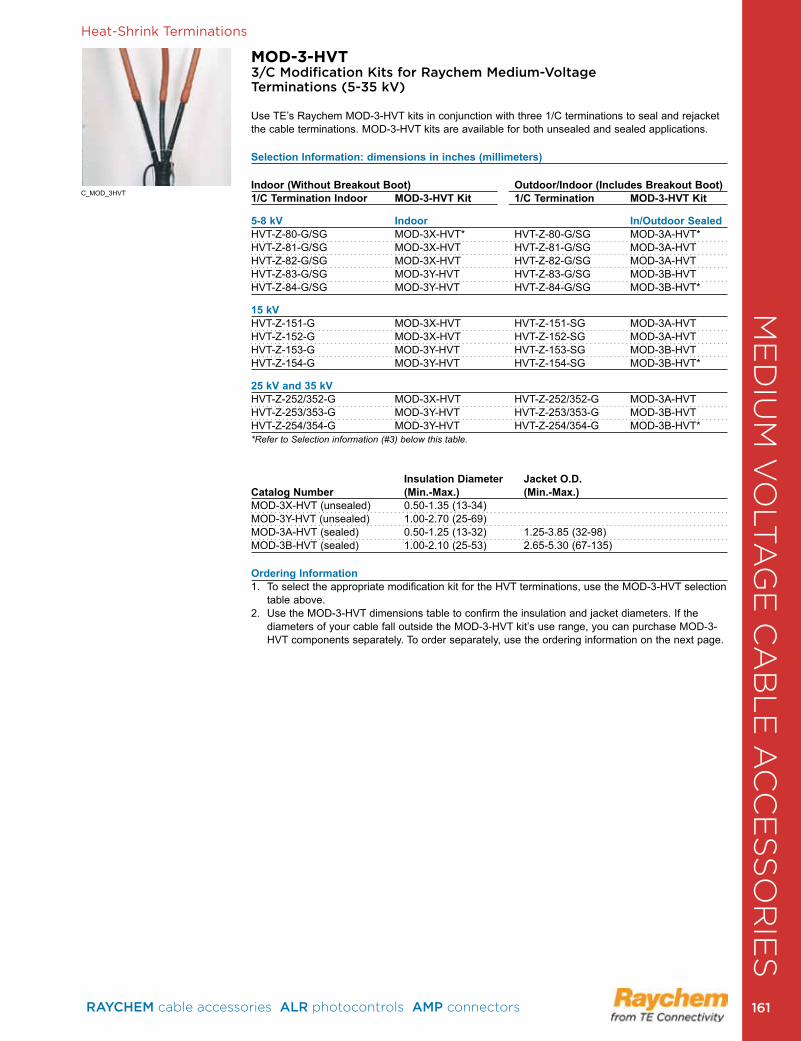
Heat-Shrink Terminations
MOD-3-HVT 3/C Modification Kits for Raychem Medium-Voltage Terminations (5 -35 kV)
Use TE’s Raychem MOD-3-HVT kits in conjunction with three 1/C terminations to seal and rejacket the cable terminations . MOD-3-HVT kits are available for both unsealed and sealed applications .
Selection Information: dimensions in inches (millimeters)
Indoor (Without Breakout Boot) Outdoor/Indoor (Includes Breakout Boot)1/C Termination Indoor MOD-3-HVT Kit 1/C Termination MOD-3-HVT Kit
5-8 kV Indoor In/Outdoor SealedHVT-Z-80-G/SG MOD-3X-HVT* HVT-Z-80-G/SG MOD-3A-HVT*HVT-Z-81-G/SG MOD-3X-HVT HVT-Z-81-G/SG MOD-3A-HVTHVT-Z-82-G/SG MOD-3X-HVT HVT-Z-82-G/SG MOD-3A-HVTHVT-Z-83-G/SG MOD-3Y-HVT HVT-Z-83-G/SG MOD-3B-HVTHVT-Z-84-G/SG MOD-3Y-HVT HVT-Z-84-G/SG MOD-3B-HVT*
15 kVHVT-Z-151-G MOD-3X-HVT HVT-Z-151-SG MOD-3A-HVTHVT-Z-152-G MOD-3X-HVT HVT-Z-152-SG MOD-3A-HVTHVT-Z-153-G MOD-3Y-HVT HVT-Z-153-SG MOD-3B-HVTHVT-Z-154-G MOD-3Y-HVT HVT-Z-154-SG MOD-3B-HVT*
25 kV and 35 kVHVT-Z-252/352-G MOD-3X-HVT HVT-Z-252/352-G MOD-3A-HVTHVT-Z-253/353-G MOD-3Y-HVT HVT-Z-253/353-G MOD-3B-HVTHVT-Z-254/354-G MOD-3Y-HVT HVT-Z-254/354-G MOD-3B-HVT**Refer to Selection information (#3) below this table.
Insulation Diameter Jacket O.D. Catalog Number (Min.-Max.) (Min.-Max.)MOD-3X-HVT (unsealed) 0.50-1.35 (13-34) MOD-3Y-HVT (unsealed) 1 .00-2 .70 (25-69) MOD-3A-HVT (sealed) 0 .50-1 .25 (13-32) 1 .25-3 .85 (32-98)MOD-3B-HVT (sealed) 1 .00-2 .10 (25-53) 2 .65-5 .30 (67-135)
Ordering Information1 . To select the appropriate modification kit for the HVT terminations, use the MOD-3-HVT selection
table above . 2. Use the MOD-3-HVT dimensions table to confirm the insulation and jacket diameters. If the
diameters of your cable fall outside the MOD-3-HVT kit’s use range, you can purchase MOD-3-HVT components separately . To order separately, use the ordering information on the next page .
C_MOD_3HVT
ME
DIU
M V
OLT
AG
E C
AB
LE
AC
CE
SS
OR
IES
RAYCHEM cable accessories ALR photocontrols AMP connectors 161 161
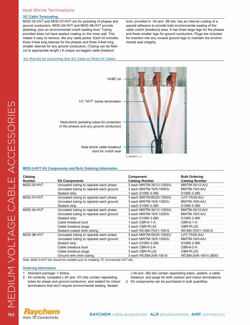
Heat-Shrink Terminations
3/C Cable Terminating
1 . Standard package: 1 kit/box .2. Kit contents: Unsealed (-3X and -3Y) kits contain rejacketing
tubes for phase and ground conductors, and sealant for indoor terminations that don’t require environmental sealing . Sealed
(-3A and -3B) kits contain rejacketing tubes, sealant, a cable breakout, and plugs for both outdoor and indoor terminations .
3 . Kit components can be purchased in bulk quantities .
3/C Mod Kit for Converting One 3/C Cable to Three 1/C Cables
HVBC kit
1/C “HVT” series termination
Heat-shrink jacketing tubes for protection of the phases and any ground conductors
Heat-shrink cable breakout boot for crotch seal
MOD-3-HVT Kit Components and Bulk Ordering Information Catalog Component Bulk Ordering Number Kit Components Catalog Number Catalog NumberMOD-3X-HVT Uncoated tubing to rejacket each phase 3 each MWTM-35/12-1200/U MWTM-35/12-A/U Uncoated tubing to rejacket each ground 3 each MWTM-16/5-1500/U MWTM-16/5-A/U Sealant strip 1 each S1085-3-380 S1085-3-380MOD-3Y-HVT Uncoated tubing to rejacket each phase 3 each MWTM-85/25-1500/U LVIT-75/25-A/U Uncoated tubing to rejacket each ground 3 each MWTM-16/5-1200/U MWTM-16/5-A/U Sealant strip 1 each S1085-3-380 S1085-3-380MOD-3A-HVT Uncoated tubing to rejacket each phase 3 each MWTM-35/12-1200/U MWTM-35/12-A/U Uncoated tubing to rejacket each ground 3 each MWTM-16/5-1200/U MWTM-16/5-A/U Sealant strip 1 each S1085-3-380 S1085-3-380 Cable breakout boot 1 each CBR-6-1-A CBR-6-1-A Cable breakout plugs 3 each CBR-PLUG CBR-PLUG Sealant-coated shim tubing 1 each WCSM-70/21-150-S WCSM-70/21-1200-SMOD-3B-HVT Uncoated tubing to rejacket each phase 3 each MWTM-85/25-1500/U LVIT-75/25-A/U Uncoated tubing to rejacket each ground 3 each MWTM-16/5-1200/U MWTM-16/5-A/U Sealant strip 1 each S1085-3-380 S1085-3-380 Cable breakout boot 1 each CBR-6-2-A CBR-6-2-A Cable breakout plugs 3 each CBR-PLUG CBR-PLUG Ground wire shim tubing 3 each WCSM-20/6-150-S WCSM-20/6-150-S (B50)Note: MOD-3-HVT kits should be installed prior to installing TE Connectivity HVT kits.
Ordering Information
MOD-3X-HVT and MOD-3Y-HVT are for jacketing of phases and ground conductors . MOD-3A-HVT and MOD-3B-HVT provide jacketing, plus an environmental crotch sealing boot. Tubing provided does not have sealant coating on the inner wall . This makes it easy to remove, like any cable jacket. Each kit includes three 4-feet long sleeves for the phases and three 4-feet long smaller sleeves for any ground conductors . (Tubing can be field-cut to appropriate length .) A unique six-legged cable breakout
boot, provided in -3A and -3B kits, has an internal coating of a special adhesive to provide total environmental sealing of the cable crotch (breakout) area . It has three large legs for the phases and three smaller legs for ground conductors . Plugs are included for insertion into any unused ground legs to maintain the environ-mental seal integrity .
C_MODHVT_I_3
ME
DIU
M V
OLT
AG
E C
AB
LE
AC
CE
SS
OR
IES
RAYCHEM cable accessories ALR photocontrols AMP connectors 162162
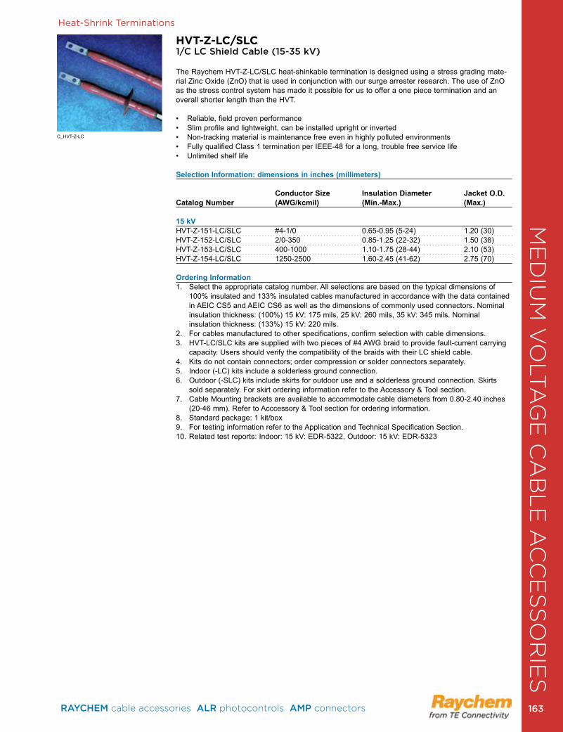
Heat-Shrink Terminations
HVT-Z-LC/SLC1/C LC Shield Cable (15-35 kV)
The Raychem HVT-Z-LC/SLC heat-shinkable termination is designed using a stress grading mate-rial Zinc Oxide (ZnO) that is used in conjunction with our surge arrester research. The use of ZnO as the stress control system has made it possible for us to offer a one piece termination and an overall shorter length than the HVT .
• Reliable, field proven performance• Slim profile and lightweight, can be installed upright or inverted• Non-tracking material is maintenance free even in highly polluted environments• Fully qualified Class 1 termination per IEEE-48 for a long, trouble free service life• Unlimited shelf life
Selection Information: dimensions in inches (millimeters)
Conductor Size Insulation Diameter Jacket O.D. Catalog Number (AWG/kcmil) (Min.-Max.) (Max.)
15 kVHVT-Z-151-LC/SLC #4-1/0 0 .65-0 .95 (5-24) 1 .20 (30)HVT-Z-152-LC/SLC 2/0-350 0 .85-1 .25 (22-32) 1 .50 (38)HVT-Z-153-LC/SLC 400-1000 1 .10-1 .75 (28-44) 2 .10 (53)HVT-Z-154-LC/SLC 1250-2500 1 .60-2 .45 (41-62) 2 .75 (70)
Ordering Information1 . Select the appropriate catalog number . All selections are based on the typical dimensions of
100% insulated and 133% insulated cables manufactured in accordance with the data contained in AEIC CS5 and AEIC CS6 as well as the dimensions of commonly used connectors . Nominal insulation thickness: (100%) 15 kV: 175 mils, 25 kV: 260 mils, 35 kV: 345 mils . Nominal insulation thickness: (133%) 15 kV: 220 mils .
2 . For cables manufactured to other specifications, confirm selection with cable dimensions . 3 . HVT-LC/SLC kits are supplied with two pieces of #4 AWG braid to provide fault-current carrying
capacity . Users should verify the compatibility of the braids with their LC shield cable . 4 . Kits do not contain connectors; order compression or solder connectors separately . 5 . Indoor (-LC) kits include a solderless ground connection .6 . Outdoor (-SLC) kits include skirts for outdoor use and a solderless ground connection . Skirts
sold separately . For skirt ordering information refer to the Accessory & Tool section . 7 . Cable Mounting brackets are available to accommodate cable diameters from 0 .80-2 .40 inches
(20-46 mm) . Refer to Acccessory & Tool section for ordering information .8 . Standard package: 1 kit/box9 . For testing information refer to the Application and Technical Specification Section .10 . Related test reports: Indoor: 15 kV: EDR-5322, Outdoor: 15 kV: EDR-5323
C_HVT-Z-LC
ME
DIU
M V
OLT
AG
E C
AB
LE
AC
CE
SS
OR
IES
RAYCHEM cable accessories ALR photocontrols AMP connectors 163 163
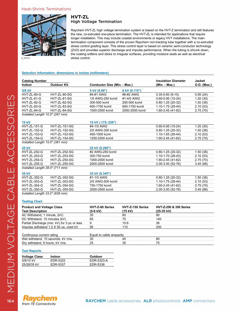
Heat-Shrink Terminations
HVT-ZLHigh Voltage Termination
Raychem HVT-ZL high voltage termination system is based on the HVT-Z termination and still features the new, co-extruded one-piece termination . The HVT-ZL is intended for applications that require longer installation . This may include coastal environments or legacy HVT installations . The main termination component consists of the proven Raychem non-tracking tube together with a co-extruded stress control grading layer . This stress control layer is based on ceramic semi-conductor technology (ZnO) and provides superior discharge and impulse performance . When the tubing is shrunk down, the coating softens and sticks to irregular surfaces, providing moisture seals as well as electrical stress control .
Selection Information: dimensions in inches (millimeters) Catalog Number Insulation Diameter JacketIndoor Outdoor Kit Conductor Size (Min. - Max.) (Min. - Max.) O.D. (Max.)
5/8 kV 5 kV (0.90") 8 kV (0.115")HVT-ZL-80-G HVT-ZL-80-SG #4-#1 AWG #6-#2 AWG 0 .35-0 .60 (9-15) 0 .95 (24)HVT-ZL-81-G HVT-ZL-81-SG 1/0 AWG-250 kcmil #1-4/0 AWG 0 .60-0 .95 (15-24) 1 .20 (30)HVT-ZL-82-G HVT-ZL-82-SG 300-500 kcml 250-500 kcmil 0 .80-1 .25 (20-32) 1 .50 (38)HVT-ZL-83-G HVT-ZL-83-SG 600-1750 kcmil 600-1750 kcmil 1 .10-1 .75 (28-44) 2 .10 (53)HVT-ZL-84-G HVT-ZL-84-SG 1500-2500 kcmil 2000-2500 kcmil 1 .60-2 .45 (41-62) 2 .75 (70)Installed Length 10.5" (267 mm)
15 kV 15 kV (.175-.220")HVT-ZL-151-G HVT-ZL-151-SG #4-1/0 AWG 0 .60-0 .95 (15-24) 1 .20 (30)HVT-ZL-152-G HVT-ZL-152-SG 2/0 AWG-350 kcmil 0 .80-1 .25 (20-32) 1 .50 (38)HVT-ZL-153-G HVT-ZL-153-SG 400-1000 kcml 1 .10-1 .65 (28-44) 2 .10 (53)HVT-ZL-154-G HVT-ZL-154-SG 1250-2500 kcmil 1 .60-2 .45 (41-62) 2 .75 (70)Installed Length 15.0" (381 mm)
25 kV 25 kV (0.260") HVT-ZL-252-G HVT-ZL-252-SG #2 AWG-250 kcmil 0 .80-1 .25 (20-32) 1 .50 (38)HVT-ZL-253-G HVT-ZL-253-SG 300-750 kcmil 1 .10-1 .70 (28-43) 2 .10 (53)HVT-ZL-254-G HVT-ZL-254-SG 1000-2000 kcmil 1 .60-2 .45 (41-62) 2 .75 (70)HVT-ZL-255-G HVT-ZL-255-SG 2000-2500 kcmil 2 .05-3 .00 (52-76) 3 .45 (88)Installed Length 28.0" (711 mm)
35 kV 35 kV (0.345")HVT-ZL-352-G HVT-ZL-352-SG #1-1/0 AWG 0 .80-1 .25 (20-32) 1 .50 (38)HVT-ZL-353-G HVT-ZL-353-SG 2/0 AWG-500 kcmil 1 .10-1 .75 (28-44) 2 .10 (53)HVT-ZL-354-G HVT-ZL-354-SG 750-1750 kcmil 1 .60-2 .45 (41-62) 2 .75 (70)HVT-ZL-355-G HVT-ZL-355-SG 2000-2500 kcmil 2 .05-3 .00 (52-76) 3 .45 (88)Installed Length 33.0" (838 mm) Testing Chart
Product and Voltage Class HVT-Z-80 Series HVT-Z-150 Series HVT-Z-250 & 350 SeriesTest Description (5-8 kV) (15 kV) (25-35 kV)AC Withstand, 1 minute, (kV) 35 60 90DC Withstand, 15 minutes (kV) 65 75 140Partial Discharge (min . kV) for 3 pc or less 9 15 .6 36Impulse withstand 1.2 X 50 us, crest kV 95 110 200 Continuous current rating Equal to cable ampacity Wet withstand, 10 seconds, kV rms . 30 45 80Dry withstand, 6 hours, kV rms . 25 35 75 Test Reports
Voltage Class Indoor Outdoor 5/8/15 kV EDR-5322 EDR-5323-A 25/28/35 kV EDR-5337 EDR-5338
C_HVT-Z
ME
DIU
M V
OLT
AG
E C
AB
LE
AC
CE
SS
OR
IES
RAYCHEM cable accessories ALR photocontrols AMP connectors 164164
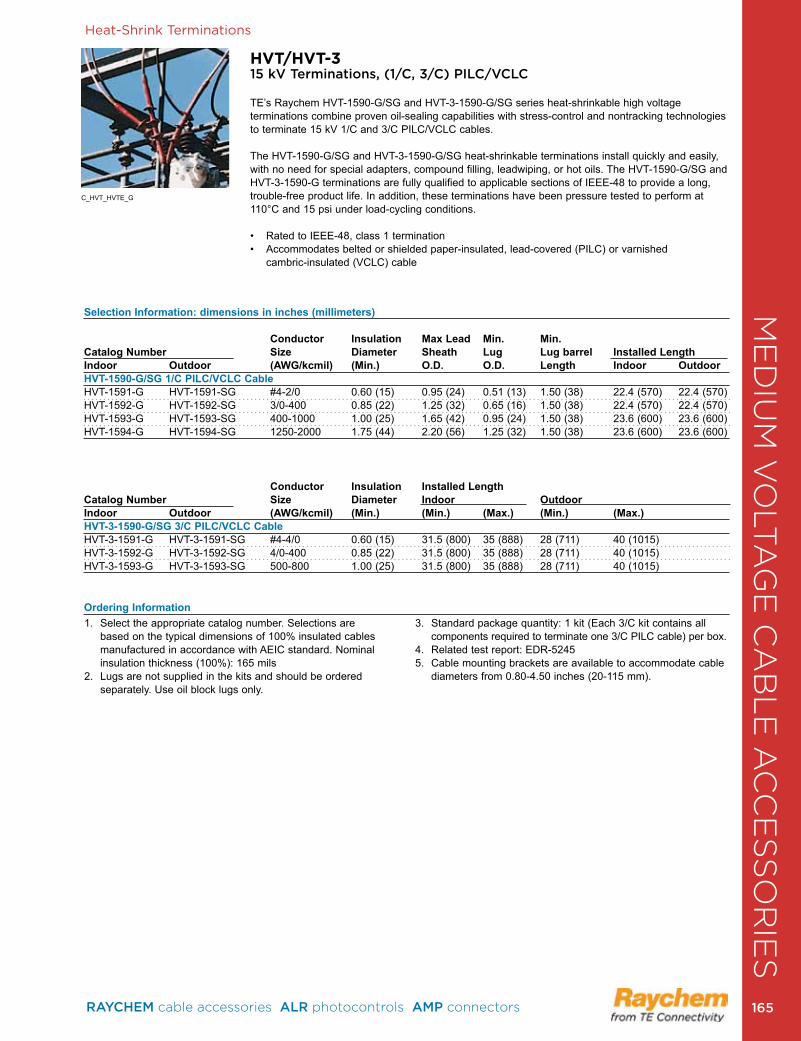
Heat-Shrink Terminations
HVT/HVT-315 kV Terminations, (1/C, 3/C) PILC/VCLC
TE’s Raychem HVT-1590-G/SG and HVT-3-1590-G/SG series heat-shrinkable high voltage terminations combine proven oil-sealing capabilities with stress-control and nontracking technologies to terminate 15 kV 1/C and 3/C PILC/VCLC cables .
The HVT-1590-G/SG and HVT-3-1590-G/SG heat-shrinkable terminations install quickly and easily, with no need for special adapters, compound filling, leadwiping, or hot oils . The HVT-1590-G/SG and HVT-3-1590-G terminations are fully qualified to applicable sections of IEEE-48 to provide a long, trouble-free product life . In addition, these terminations have been pressure tested to perform at 110°C and 15 psi under load-cycling conditions .
• Rated to IEEE-48, class 1 termination • Accommodates belted or shielded paper-insulated, lead-covered (PILC) or varnished cambric-insulated (VCLC) cable
Selection Information: dimensions in inches (millimeters) Conductor Insulation Max Lead Min. Min. Catalog Number Size Diameter Sheath Lug Lug barrel Installed LengthIndoor Outdoor (AWG/kcmil) (Min.) O.D. O.D. Length Indoor OutdoorHVT-1590-G/SG 1/C PILC/VCLC CableHVT-1591-G HVT-1591-SG #4-2/0 0 .60 (15) 0 .95 (24) 0 .51 (13) 1 .50 (38) 22 .4 (570) 22 .4 (570)HVT-1592-G HVT-1592-SG 3/0-400 0 .85 (22) 1 .25 (32) 0 .65 (16) 1 .50 (38) 22 .4 (570) 22 .4 (570)HVT-1593-G HVT-1593-SG 400-1000 1 .00 (25) 1 .65 (42) 0 .95 (24) 1 .50 (38) 23 .6 (600) 23 .6 (600)HVT-1594-G HVT-1594-SG 1250-2000 1 .75 (44) 2 .20 (56) 1 .25 (32) 1 .50 (38) 23 .6 (600) 23 .6 (600)
Conductor Insulation Installed LengthCatalog Number Size Diameter Indoor OutdoorIndoor Outdoor (AWG/kcmil) (Min.) (Min.) (Max.) (Min.) (Max.)HVT-3-1590-G/SG 3/C PILC/VCLC CableHVT-3-1591-G HVT-3-1591-SG #4-4/0 0 .60 (15) 31 .5 (800) 35 (888) 28 (711) 40 (1015)HVT-3-1592-G HVT-3-1592-SG 4/0-400 0 .85 (22) 31 .5 (800) 35 (888) 28 (711) 40 (1015)HVT-3-1593-G HVT-3-1593-SG 500-800 1 .00 (25) 31 .5 (800) 35 (888) 28 (711) 40 (1015)
Ordering Information1 . Select the appropriate catalog number . Selections are
based on the typical dimensions of 100% insulated cables manufactured in accordance with AEIC standard . Nominal insulation thickness (100%): 165 mils
2 . Lugs are not supplied in the kits and should be ordered separately . Use oil block lugs only .
3 . Standard package quantity: 1 kit (Each 3/C kit contains all components required to terminate one 3/C PILC cable) per box .
4 . Related test report: EDR-52455 . Cable mounting brackets are available to accommodate cable
diameters from 0 .80-4 .50 inches (20-115 mm) .
C_HVT_HVTE_G
ME
DIU
M V
OLT
AG
E C
AB
LE
AC
CE
SS
OR
IES
RAYCHEM cable accessories ALR photocontrols AMP connectors 165 165
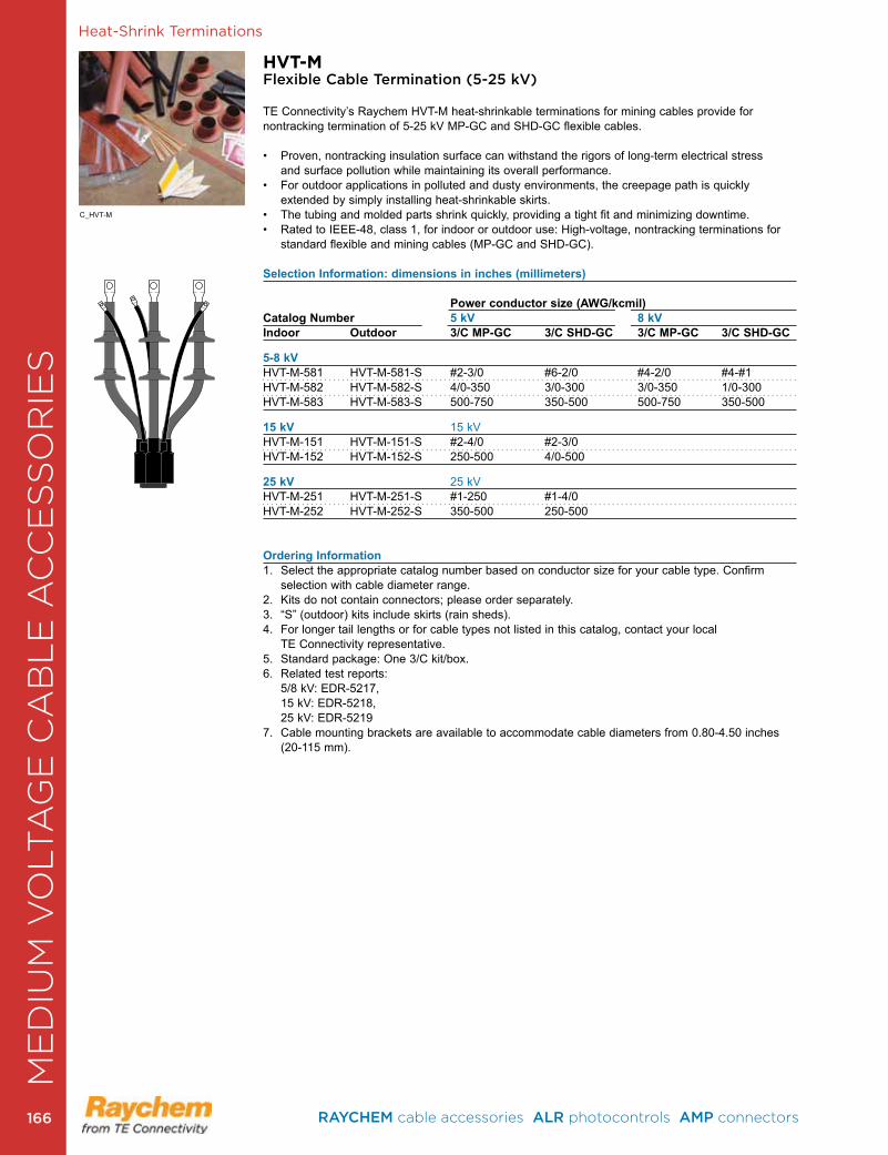
Heat-Shrink Terminations
HVT-MFlexible Cable Termination (5-25 kV)
TE Connectivity’s Raychem HVT-M heat-shrinkable terminations for mining cables provide for nontracking termination of 5-25 kV MP-GC and SHD-GC flexible cables .
• Proven, nontracking insulation surface can withstand the rigors of long-term electrical stress and surface pollution while maintaining its overall performance .
• For outdoor applications in polluted and dusty environments, the creepage path is quickly extended by simply installing heat-shrinkable skirts .
• The tubing and molded parts shrink quickly, providing a tight fit and minimizing downtime.• Rated to IEEE-48, class 1, for indoor or outdoor use: High-voltage, nontracking terminations for
standard flexible and mining cables (MP-GC and SHD-GC) .
Selection Information: dimensions in inches (millimeters)
Power conductor size (AWG/kcmil)Catalog Number 5 kV 8 kV Indoor Outdoor 3/C MP-GC 3/C SHD-GC 3/C MP-GC 3/C SHD-GC
5-8 kVHVT-M-581 HVT-M-581-S #2-3/0 #6-2/0 #4-2/0 #4-#1HVT-M-582 HVT-M-582-S 4/0-350 3/0-300 3/0-350 1/0-300HVT-M-583 HVT-M-583-S 500-750 350-500 500-750 350-500
15 kV 15 kVHVT-M-151 HVT-M-151-S #2-4/0 #2-3/0 HVT-M-152 HVT-M-152-S 250-500 4/0-500
25 kV 25 kVHVT-M-251 HVT-M-251-S #1-250 #1-4/0 HVT-M-252 HVT-M-252-S 350-500 250-500
Ordering Information1 . Select the appropriate catalog number based on conductor size for your cable type . Confirm
selection with cable diameter range .2 . Kits do not contain connectors; please order separately . 3 . “S” (outdoor) kits include skirts (rain sheds) .4 . For longer tail lengths or for cable types not listed in this catalog, contact your local
TE Connectivity representative .5 . Standard package: One 3/C kit/box .6 . Related test reports: 5/8 kV: EDR-5217, 15 kV: EDR-5218, 25 kV: EDR-5219 7 . Cable mounting brackets are available to accommodate cable diameters from 0 .80-4 .50 inches
(20-115 mm) .
C_HVT-M
ME
DIU
M V
OLT
AG
E C
AB
LE
AC
CE
SS
OR
IES
RAYCHEM cable accessories ALR photocontrols AMP connectors 166166
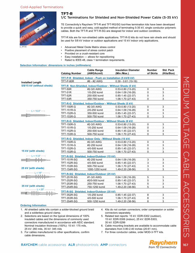
Cold-Applied Terminations
TFT-R1/C Terminations for Shielded and Non-Shielded Power Cable (5-35 kV)
TE Connectivity’s Raychem TFT-R and TFT-RG/SG tool-free termination kits have been developed to provide a quick and easy, cold-applied method of terminating 5-35 kV, single conductor polymeric cables . Both the TFT-R and TFT-R-SG are designed for indoor and outdoor conditions .
TFT-R kits are for non-shielded cable applications . TFT-R-G kits do not have rain sheds and should be used for 5/8 kV indoor or outdoor applications and 15 kV indoor only applications .
• Advanced Metal Oxide Matrix stress control• Positive placement of stress control patch• Provided on a crush-resistant core• Easy installation — allows for repositioning• Rated to IEEE-48, class 1 termination requirements.
Cable Range Insulation Diameter Number Std. Pack Catalog Number (AWG/kcmil) (Min./Max.) of Skirts (Kits/Box)
TFT-P-R Shielded, Indoor - Push on Installation (5 kV/8 kV)TFT-P-80R #6 - #2 AWG 0 .39 - 0 .61 (10-16)
TFT-R Non-Shielded, Indoor/Outdoor - Without Sheds (5 kV)TFT-50R #2-3/0 AWG 0 .53-0 .80 (13-20) 0 3TFT-51R 1/0-250 kcmil 0 .64-1 .09 (16-28) 0 3TFT-52R 250-500 kcmil 0 .85-1 .45 (22-37) 0 3TFT-53R 350-750 kcmil 1 .06-1 .70 (27-43) 0 3
TFT-R-G Shielded, Indoor/Outdoor - Without Sheds (5 kV) TFT-150R-G #2-3/0 AWG 0 .53-0 .80 (13-20) 0 3TFT-151R-G 2/0-250 kcmil 0 .64-1 .09 (16-28) 0 3TFT-152R-G 350-500 kcmil 0 .85-1 .45 (22-37) 0 3TFT-153R-G 500-750 kcmil 1 .06-1 .70 (27-43) 0 3
TFT-R-G Shielded, Indoor/Outdoor - Without Sheds (8 kV)TFT-150R-G #2-3/0 AWG 0 .53-0 .80 (13-20) 0 3TFT-151R-G 1/0-250 kcmil 0 .64-1 .09 (16-28) 0 3TFT-152R-G 250-500 kcmil 0 .85-1 .45 (22-37) 0 3TFT-153R-G 500-750 kcmil 1 .06-1 .70 (27-43) 0 3
TFT-R-G Shielded, Indoor Only - Without Sheds (15 kV) TFT-150R-G #2-3/0 AWG 0 .53-0 .80 (13-20) 0 3TFT-151R-G #2-250 kcmil 0 .64-1 .09 (16-28) 0 3TFT-152R-G 4/0-500 kcmil 0 .85-1 .45 (22-37) 0 3TFT-153R-G 500-750 kcmil 1 .06-1 .70 (27-43) 0 3
TFT-R-SG Shielded, Indoor/Outdoor (15 kV)TFT-151R-SG #2-250 kcmil 0 .64-1 .09 (16-28) 3 3TFT-152R-SG 4/0-500 kcmil 0 .85-1 .45 (22-37) 3 3TFT-153R-SG 500-750 kcmil 1 .06-1 .70 (27-43) 3 3TFT-154R-SG 1000-1250 kcmil 1 .49-2 .20 (38-56) 3 3
TFT-R-SG Shielded, Indoor/Outdoor (25 kV)TFT-251R-SG #1-3/0 AWG 0 .64-1 .09 (16-28) 5 3TFT-252R-SG #2/0-500 kcmil 0 .85-1 .45 (22-37) 5 3TFT-253R-SG 250-750 kcmil 1 .06-1 .70 (27-43) 5 3TFT-254R-SG 750-1250 kcmil 1 .49-2 .20 (38-56) 5 3
TFT-R-SG Shielded, Indoor/Outdoor (35 kV) TFT-352R-SG 1/0-250 kcmil 0 .85-1 .45 (22-37) 8 3TFT-353R-SG 4/0-500 kcmil 1 .06-1 .70 (27-43) 8 3TFT-354R-SG 500-1250 kcmil 1 .49-2 .20 (38-56) 8 3
1 . All shielded cable kits contain a solder-blocked ground braid
and a solderless ground clamp .2 . Selections are based on the typical dimensions of 100%
insulated cables and the dimensions of commonly used connectors manufactured in accordance with AEIC standard . Nominal insulation thickness (100%): 15 kV: 175 mils, 25 kV: 260 mils, 35 kV: 345 mils
3 . For cables manufactured to other specifications, confirm cable dimensions .
4 . Kits do not contain connectors; order compression or solder connectors separately .
5 . Related test reports: 15 kV: EDR-5302 (outdoor), 15 kV: EDR-5306 (indoor), 25 kV: EDR-5303, 35 kV: EDR-5299
6 . Cable mounting brackets are available to accommodate cable diameters from 0 .80-2 .40 inches (20-61 mm) .
7 . For three conductor cables, order MOD-3-TFT kits .
Installed Length5/8/15 kV (without sheds)
15 kV (with sheds)
25 kV (with sheds)
35 kV (with sheds)
Ordering Information
Selection Information: dimensions in inches (millimeters)
L = 25"
L = 15"
L = 11 .5"
L = 10 .5"
C_TFT-R
ME
DIU
M V
OLT
AG
E C
AB
LE
AC
CE
SS
OR
IES
RAYCHEM cable accessories ALR photocontrols AMP connectors 167 167
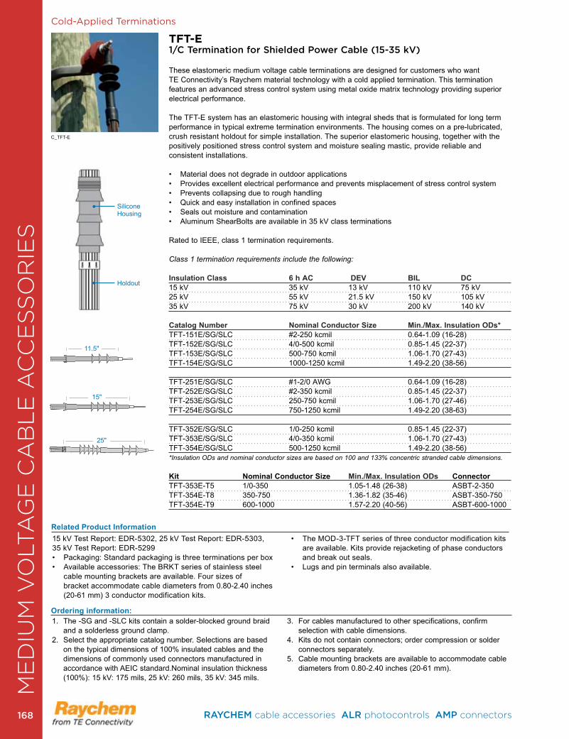
Cold-Applied Terminations
TFT-E1/C Termination for Shielded Power Cable (15-35 kV)
These elastomeric medium voltage cable terminations are designed for customers who want TE Connectivity’s Raychem material technology with a cold applied termination . This termination features an advanced stress control system using metal oxide matrix technology providing superior electrical performance .
The TFT-E system has an elastomeric housing with integral sheds that is formulated for long term performance in typical extreme termination environments . The housing comes on a pre-lubricated, crush resistant holdout for simple installation . The superior elastomeric housing, together with the positively positioned stress control system and moisture sealing mastic, provide reliable and consistent installations .
• Material does not degrade in outdoor applications• Provides excellent electrical performance and prevents misplacement of stress control system• Prevents collapsing due to rough handling• Quick and easy installation in confined spaces • Seals out moisture and contamination• Aluminum ShearBolts are available in 35 kV class terminations
Rated to IEEE, class 1 termination requirements .
Class 1 termination requirements include the following:
Insulation Class 6 h AC DEV BIL DC15 kV 35 kV 13 kV 110 kV 75 kV25 kV 55 kV 21 .5 kV 150 kV 105 kV35 kV 75 kV 30 kV 200 kV 140 kV
Catalog Number Nominal Conductor Size Min./Max. Insulation ODs*TFT-151E/SG/SLC #2-250 kcmil 0 .64-1 .09 (16-28)TFT-152E/SG/SLC 4/0-500 kcmil 0 .85-1 .45 (22-37)TFT-153E/SG/SLC 500-750 kcmil 1 .06-1 .70 (27-43)TFT-154E/SG/SLC 1000-1250 kcmil 1 .49-2 .20 (38-56)
TFT-251E/SG/SLC #1-2/0 AWG 0 .64-1 .09 (16-28)TFT-252E/SG/SLC #2-350 kcmil 0 .85-1 .45 (22-37)TFT-253E/SG/SLC 250-750 kcmil 1 .06-1 .70 (27-46)TFT-254E/SG/SLC 750-1250 kcmil 1 .49-2 .20 (38-63)
TFT-352E/SG/SLC 1/0-250 kcmil 0 .85-1 .45 (22-37)TFT-353E/SG/SLC 4/0-350 kcmil 1 .06-1 .70 (27-43)TFT-354E/SG/SLC 500-1250 kcmil 1 .49-2 .20 (38-56)*Insulation ODs and nominal conductor sizes are based on 100 and 133% concentric stranded cable dimensions.
Kit Nominal Conductor Size Min./Max. Insulation ODs ConnectorTFT-353E-T5 1/0-350 1 .05-1 .48 (26-38) ASBT-2-350TFT-354E-T8 350-750 1 .36-1 .82 (35-46) ASBT-350-750TFT-354E-T9 600-1000 1 .57-2 .20 (40-56) ASBT-600-1000
Related Product Information15 kV Test Report: EDR-5302, 25 kV Test Report: EDR-5303,35 kV Test Report: EDR-5299• Packaging: Standard packaging is three terminations per box• Available accessories: The BRKT series of stainless steel
cable mounting brackets are available . Four sizes of bracket accommodate cable diameters from 0 .80-2 .40 inches (20-61 mm) 3 conductor modification kits .
• The MOD-3-TFT series of three conductor modification kits are available. Kits provide rejacketing of phase conductors and break out seals .
• Lugs and pin terminals also available.
1 . The -SG and -SLC kits contain a solder-blocked ground braid and a solderless ground clamp .
2 . Select the appropriate catalog number . Selections are based on the typical dimensions of 100% insulated cables and the dimensions of commonly used connectors manufactured in accordance with AEIC standard .Nominal insulation thickness (100%): 15 kV: 175 mils, 25 kV: 260 mils, 35 kV: 345 mils .
3 . For cables manufactured to other specifications, confirm selection with cable dimensions .
4 . Kits do not contain connectors; order compression or solder connectors separately .
5 . Cable mounting brackets are available to accommodate cable diameters from 0 .80-2 .40 inches (20-61 mm) .
Ordering information:
25"
15"
11 .5"
Holdout
Silicone Housing
C_TFT-E
ME
DIU
M V
OLT
AG
E C
AB
LE
AC
CE
SS
OR
IES
RAYCHEM cable accessories ALR photocontrols AMP connectors 168168
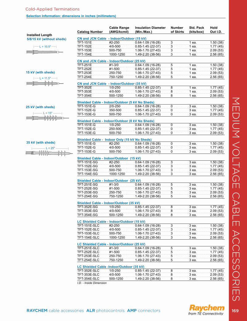
Cold-Applied Terminations
Installed Length5/8/15 kV (without sheds)
15 kV (with sheds)
25 kV (with sheds)
35 kV (with sheds)
Cable Range Insulation Diameter Number Std. Pack Hold Catalog Number (AWG/kcmil) (Min./Max.) of Skirts (kits/box) Out I.D.
CN and JCN Cable - Indoor/Outdoor (15 kV)TFT-151E #2-250 0 .64-1 .09 (16-28) 3 1 ea . 1 .50 (38)TFT-152E 4/0-500 0 .85-1 .45 (22-37) 3 1 ea . 1 .77 (45)TFT-153E 500-750 1 .06-1 .70 (27-43) 3 1 ea . 2 .09 (53)TFT-154E 1000-1250 1 .49-2 .20 (38-56) 3 1 ea . 2 .56 (65)
CN and JCN Cable - Indoor/Outdoor (25 kV) TFT-251E #1-3/0 0 .64-1 .09 (16-28) 5 1 ea . 1 .50 (38)TFT-252E #1-500 0 .85-1 .45 (22-37) 5 1 ea . 1 .77 (45)TFT-253E 250-750 1 .06-1 .70 (27-43) 5 1 ea . 2 .09 (53)TFT-254E 750-1250 1 .49-2 .20 (38-56) 5 1 ea . 2 .56 (65)
CN and JCN Cable - Indoor/Outdoor (35 kV) TFT-352E 1/0-250 0 .85-1 .45 (22-37) 8 1 ea . 1 .77 (45)TFT-353E 4/0-500 1 .06-1 .70 (27-43) 8 1 ea . 2 .09 (53)TFT-354E 500-1250 1 .49-2 .20 (38-56) 8 1 ea . 2 .56 (65)
Shielded Cable - Indoor/Outdoor (5 kV No Sheds)TFT-151E-G 2/0-250 0 .64-1 .09 (16-28) 0 3 ea . 1 .50 (38)TFT-152E-G 350-500 0 .85-1 .45 (22-37) 0 3 ea . 1 .77 (45)TFT-153E-G 500-750 1 .06-1 .70 (27-43) 0 3 ea . 2 .09 (53)
Shielded Cable - Indoor/Outdoor (8 kV No Sheds)TFT-151E-G 1/0-250 0 .64-1 .09 (16-28) 0 3 ea . 1 .50 (38)TFT-152E-G 250-500 0 .85-1 .45 (22-37) 0 3 ea . 1 .77 (45)TFT-153E-G 500-750 1 .06-1 .70 (27-43) 0 3 ea . 2 .09 (53)
Shielded Cable - Indoor Only (15 kV No Sheds)TFT-151E-G #2-250 0 .64-1 .09 (16-28) 0 3 ea . 1 .50 (38)TFT-152E-G 4/0-500 0 .85-1 .45 (22-37) 0 3 ea . 1 .77 (45)TFT-153E-G 500-750 1 .06-1 .70 (27-43) 0 3 ea . 2 .09 (53)
Shielded Cable - Indoor/Outdoor (15 kV) TFT-151E-SG #2-250 0 .64-1 .09 (16-28) 3 3 ea . 1 .50 (38)TFT-152E-SG 4/0-500 0 .85-1 .45 (22-37) 3 3 ea . 1 .77 (45)TFT-153E-SG 500-750 1 .06-1 .70 (27-43) 3 3 ea . 2 .09 (53)TFT-154E-SG 1000-1250 1 .49-2 .20 (38-56) 3 3 ea . 2 .56 (65)
Shielded Cable - Indoor/Outdoor (25 kV)TFT-251E-SG #1-3/0 0 .64-1 .09 (16-28) 5 3 ea . 1 .50 (38)TFT-252E-SG #1-500 0 .85-1 .45 (22-37) 5 3 ea . 1 .77 (45)TFT-253E-SG 250-750 1 .06-1 .70 (27-43) 5 3 ea . 2 .09 (53)TFT-254E-SG 750-1250 1 .49-2 .20 (38-56) 5 3 ea . 2 .56 (65)
Shielded Cable - Indoor/Outdoor (35 kV)TFT-352E-SG 1/0-250 0 .85-1 .45 (22-37) 8 3 ea . 1 .77 (45)TFT-353E-SG 4/0-500 1 .06-1 .70 (27-43) 8 3 ea . 2 .09 (53)TFT-354E-SG 500-1250 1 .49-2 .20 (38-56) 8 3 ea . 2 .56 (65)
LC Shielded Cable - Indoor/Outdoor (15 kV)TFT-151E-SLC #2-250 0 .64-1 .09 (16-28) 3 3 ea . 1 .50 (38)TFT-152E-SLC 4/0-500 0 .85-1 .45 (22-37) 3 3 ea . 1 .77 (45)TFT-153E-SLC 500-750 1 .06-1 .70 (27-43) 3 3 ea . 2 .09 (53)TFT-154E-SLC 1000-1250 1 .49-2 .20 (38-56) 3 3 ea . 2 .56 (65)
LC Shielded Cable - Indoor/Outdoor (25 kV)TFT-251E-SLC #1-3/0 0 .64-1 .09 (16-28) 5 3 ea . 1 .50 (38)TFT-252E-SLC #1-500 0 .85-1 .45 (22-37) 5 3 ea . 1 .77 (45)TFT-253E-SLC 250-750 1 .06-1 .70 (27-43) 5 3 ea . 2 .09 (53)TFT-254E-SLC 750-1250 1 .49-2 .20 (38-56) 5 3 ea . 2 .56 (65)
LC Shielded Cable -Indoor/Outdoor (35 kV)TFT-352E-SLC 1/0-250 0 .85-1 .45 (22-37) 8 3 ea . 1 .77 (45)TFT-353E-SLC 4/0-500 1 .06-1 .70 (27-43) 8 3 ea . 2 .09 (53)TFT-354E-SLC 500-1250 1 .49-2 .20 (38-56) 8 3 ea . 2 .56 (65)I.D. - Inside Dimension
Selection Information: dimensions in inches (millimeters)
L = 25"
L = 15"
L = 11 .5"
L = 10 .5"
ME
DIU
M V
OLT
AG
E C
AB
LE
AC
CE
SS
OR
IES
RAYCHEM cable accessories ALR photocontrols AMP connectors 169 169
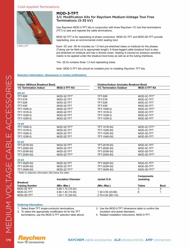
Cold-Applied Terminations
MOD-3-TFT3/C Modification Kits for Raychem Medium-Voltage Tool Free Terminations (5-35 kV)
Use Raychem MOD-3-TFT kits in conjunction with three Raychem 1/C tool free terminations (TFT) to seal and rejacket the cable terminations.
MOD-3Z-TFT is for rejacketing of phase conductors. MOD-3C-TFT and MOD-3D-TFT provide rejacketing, plus an environmental crotch sealing boot.
Each -3C and -3D kit includes six 1 .5 foot pre-stretched tubes on holdouts for the phases . (Tubing can be field-cut to appropriate length) . A three-legged cable breakout boot is also pre-stretched on holdouts and has a domed crown . Sealing is insured by pressure sensitive mastic to be applied under the breakout boot body as well as at the tubing interfaces .
The -3Z kit contains three 1.5 foot rejacketing tubes.
Note: MOD-3-TFT kits should be installed prior to installing Raychem TFT kits.
1 . Select three TFT single-conductor terminations .2 . To select the appropriate modification kit for the TFT
terminations, use the MOD-3-TFT selection table above .
3 . Use the MOD-3-TFT dimensions table to confirm the insulation and jacket diameters.
4 . Related installation instructions: MOD-3-TFT .
Selection Information: dimensions in inches (millimeters)
Indoor (Without Breakout Boot) Outdoor/Indoor (Includes Breakout Boot) 1/C Termination Indoor MOD-3-TFT Kit 1/C Termination Outdoor MOD-3-TFT Kit
5/8 kV TFT-50R MOD-3Z-TFT* TFT-50R MOD-3C-TFT* TFT-51R MOD-3Z-TFT TFT-51R MOD-3C-TFT TFT-52R MOD-3Z-TFT TFT-52R MOD-3C-TFT TFT-53R MOD-3Z-TFT TFT-53R MOD-3D-TFT TFT-150R-G MOD-3Z-TFT* TFT-150R-G MOD-3C-TFT* TFT-151R-G MOD-3Z-TFT TFT-151R-G MOD-3C-TFT TFT-152R-G MOD-3Z-TFT TFT-152R-G MOD-3C-TFT TFT-153R-G MOD-3Z-TFT TFT-153R-G MOD-3D-TFT
15 kV TFT-150R-G MOD-3Z-TFT* TFT-151R-SG MOD-3C-TFT* TFT-151R-G MOD-3Z-TFT TFT-152R-SG MOD-3C-TFT TFT-152R-G MOD-3Z-TFT TFT-153R-SG MOD-3D-TFT TFT-153R-G MOD-3Z-TFT TFT-154R-SG MOD-3D-TFT
25 kV TFT-251R-SG MOD-3Z-TFT TFT-251R-SG MOD-3C-TFT TFT-252R-SG MOD-3Z-TFT TFT-252R-SG MOD-3C-TFT TFT-253R-SG MOD-3Z-TFT TFT-253R-SG MOD-3D-TFT TFT-254R-SG MOD-3Z-TFT* TFT-254R-SG MOD-3D-TFT*
35 kV TFT-352R-SG MOD-3Z-TFT TFT-352R-SG MOD-3C-TFT TFT-353R-SG MOD-3Z-TFT TFT-353R-SG MOD-3D-TFT TFT-354R-SG MOD-3Z-TFT* TFT-354R-SG MOD-3D-TFT** Refer to Selection information (#3) below this table. Components Insulation Diameter Jacket O.D. Jacketing BreakoutCatalog Number (Min.-Max.) (Min.-Max.) Tubes BootMOD-3Z-TFT 0 .60-1 .72 (15-43) 3 0MOD-3C-TFT 0 .60-1 .40 (15-35) 1 .30-3 .50 (33-89) 6 1MOD-3D-TFT 1 .20-1 .72 (30-43) 2 .70-4 .50 (69-114)
Ordering Information
C_MOD_3_TFT
ME
DIU
M V
OLT
AG
E C
AB
LE
AC
CE
SS
OR
IES
RAYCHEM cable accessories ALR photocontrols AMP connectors 170170
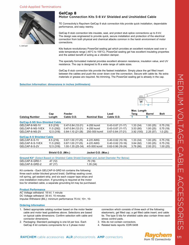
Cold-Applied Terminations
GelCap 8Motor Connection Kits 5-8 kV Shielded and Unshielded Cable
TE Connectivity’s Raychem GelCap 8 stub connection kits provide quick installation, dependable performance, and easy reentry .
GelCap 8 stub connection kits insulate, seal, and protect stub splice connections up to 8 kV . The design was engineered to provide quick, secure installation and protection of the electrical connection from both physical and chemical attacks common in the harsh environment of motor connections .
Kits feature revolutionary PowerGel sealing gel which provides an excellent moisture seal over a wide temperature range (-40°C to 105°C) . PowerGel sealing gel has excellent insulating properties and the added benefit of acting as a vibration damper .
The specially formulated material provides excellent abrasion resistance, insulation value, and UV resistance . The cap is designed to fit a wide range of cable sizes .
GelCap 8 stub connection kits provide the fastest installation . Simply place the gel filled insert between the cables and push the cover down over the connection . Secure with cable tie . No extra materials or grease are required . No trimming . The PowerGel sealing gel is already in the cap .
Selection Information: dimensions in inches (millimeters)
Max. Length Cap Feeder Lead Tang Barrel BoltCatalog Number Length Cable O.D. Nominal Size Cable O.D. T B
GelCap-8-NS Non-Shielded CableGELCAP-8-NS-1V 8 .5 (216) 0 .47-0 .84 (12-21) 4-250 kcmil 0 .43-0 .67 (11-17) 1 .33 (34) 1 .00 (25) 0 .75 (19)GELCAP-8-NS-1VEX 11.5 (292) 0.47-0.84 (12-21) 4-250 kcmil 0.43-0.67 (11-17) 3.53 (90) 1.00 (25) 0.75 (19)GELCAP-8-NS-2V 12 .5 (318) 0 .84-1 .10 (21-28) 250-500 kcmil 0 .67-0 .84 (17-21) 3 .92 (100) 2 .25 (57) 1 .0 (25)
GelCap-8-S Shielded CableGELCAP-8-S-1V 8 .5 (216) 0 .67-1 .00 (17-25) 4-2/0 AWG 0 .40-0 .62 (10-16) 1 .33 (34) 1 .00 (25) 0 .75 (19)GELCAP-8-S-1VEX 11.5 (292) 0.67-1.00 (17-25) 4-2/0 AWG 0.40-0.62 (10-16) 3.64 (92) 1.00 (25) 0.75 (19)GELCAP-8-S-2V 12 .5 (318) 1 .00-1 .35 (25-34) 4/0-500 kcmil 0 .62-0 .96 (16-24) 3 .79 (96) 2 .00 (51) 1 .00 (25) Shield O.D. (Min.) Jacket O.D. (Max.) Ground Kit* (Select Based on Shielded Cable Shield Diameter and Jacket Diameter Per Below)GELCAP-8-GRD-1 .47 (12) .70 (18) GELCAP-8-GRD-2 .67 (17) 1 .35 (34)
Kit contents - Each GELCAP-8-GRD kit contains the following: three each solder blocked ground braid, GelWrap sealing cover, roll spring, gel sealant strip, and six each copper tape strips and one installation instruction . If grounding is required at the motor box for shielded cable, a separate grounding kit may be purchased .
Product PerformanceAC Voltage withstand: 18 kV, 1 minuteDC Voltage withstand: 35 kV, 15 minutesImpulse Withstand (BIL): minimum performance 75 kV, 10+, 10-
Ordering Information
T B
1 . Select appropriate catalog number based on the motor feeder cable and motor lead guidelines above . Selections are based on typical cable dimensions . Confirm selection with cable and connector dimensions .
2 . Packaging: Standard packaging is one kit per box . Each GelCap 8 kit contains components for a 3 phase motor
connection which consists of three each of the following: elastomeric, gel filled cap; a gel filled cable insert; and cable tie . The type S kits for shielded cable also contain three each stress control pads .
3 . Kits do not contain connectors .4 . Related tests reports: EDR-5408
C_GelCap8
ME
DIU
M V
OLT
AG
E C
AB
LE
AC
CE
SS
OR
IES
RAYCHEM cable accessories ALR photocontrols AMP connectors 171 171
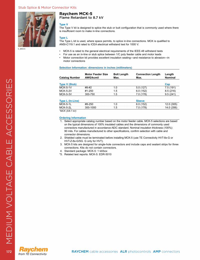
Stub Splice & Motor Connector Kits
Raychem MCK-5Flame Retardant to 8.7 kV
Type VThe Type V kit is designed to splice the stub or butt configuration that is commonly used where there is insufficient room to make in-line connections .
Type LThe Type L kit is used, where space permits, to splice in-line connections . MCK is qualified to ANSI-C119 .1 and rated to ICEA electrical withstand test for 1000 V .
• MCK-5 is rated to the general electrical requirements of the IEEE-48 withstand tests • For use as an in-line or stub splice between 1/C poly feeder cable and motor leads• Motor connection kit provides excellent insulation sealing—and resistance to abrasion—in
motor connections
Selection Information: dimensions in inches (millimeters) Motor Feeder Size Bolt Length Connection Length Length Catalog Number AWG/kcmil Max. Max. Nominal Type V (Stub) CapMCK-5-1V #8-#2 1 .0 5 .0 (127) 7 .5 (191)MCK-5-2V #1-250 1 .5 6 .0 (152) 8 .5 (216)MCK-5-3V 300-750 1 .5 7 .0 (178) 9 .5 (241)
Type L (In-Line) Sleeve MCK-5-1L #8-250 1 .0 6 .0 (152) 12 .0 (305)MCK-5-2L 300-1000 1 .5 7 .0 (178) 14 .0 (356)*MCK (5/8.7 kV)
Ordering Information 1 . Select appropriate catalog number based on the motor feeder cable . MCK-5 selections are based
on the typical dimensions of 100% insulated cables and the dimensions of commonly used connectors manufactured in accordance AEIC standard . Nominal insulation thickness (100%): 90 mils . For cables manufactured to other specifications, confirm selection with cable and connector dimensions .
2 . Shielded cable must be termi nated before installing MCK-5 (use TE Connectivity HVT-8x-G or HVT-Z-8x-G/SG . G only for HVT) .
3 . MCK-5 kits are designed for single-hole connectors and include caps and sealant strips for three connections . Kits do not contain connectors .
4 . Standard package: MCK-5: 1 kit/box*5 . Related test reports: MCK-5: EDR-5010
C_MCK-5
ME
DIU
M V
OLT
AG
E C
AB
LE
AC
CE
SS
OR
IES
RAYCHEM cable accessories ALR photocontrols AMP connectors 172172
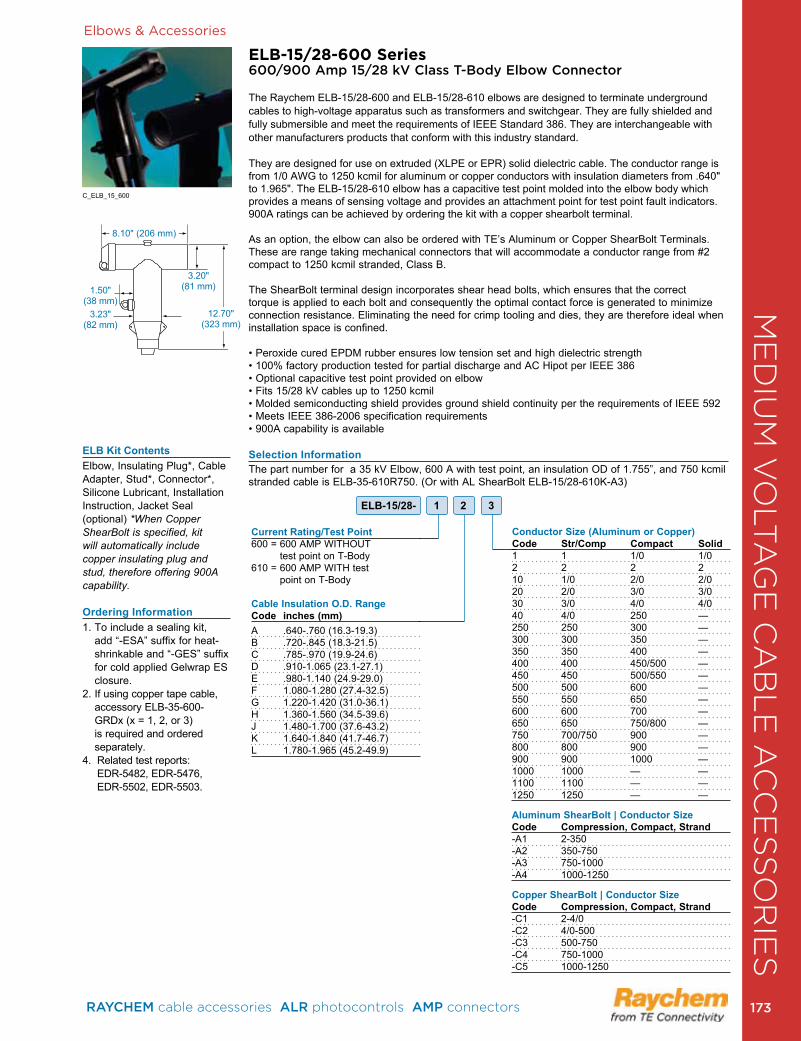
Elbows & Accessories
ELB-15/28-600 Series600/900 Amp 15/28 kV Class T-Body Elbow Connector
The Raychem ELB-15/28-600 and ELB-15/28-610 elbows are designed to terminate underground cables to high-voltage apparatus such as transformers and switchgear . They are fully shielded and fully submersible and meet the requirements of IEEE Standard 386 . They are interchangeable with other manufacturers products that conform with this industry standard .
They are designed for use on extruded (XLPE or EPR) solid dielectric cable. The conductor range is from 1/0 AWG to 1250 kcmil for aluminum or copper conductors with insulation diameters from .640" to 1 .965" . The ELB-15/28-610 elbow has a capacitive test point molded into the elbow body which provides a means of sensing voltage and provides an attachment point for test point fault indicators . 900A ratings can be achieved by ordering the kit with a copper shearbolt terminal .
As an option, the elbow can also be ordered with TE’s Aluminum or Copper ShearBolt Terminals . These are range taking mechanical connectors that will accommodate a conductor range from #2 compact to 1250 kcmil stranded, Class B .
The ShearBolt terminal design incorporates shear head bolts, which ensures that the correct torque is applied to each bolt and consequently the optimal contact force is generated to minimize connection resistance . Eliminating the need for crimp tooling and dies, they are therefore ideal when installation space is confined .
• Peroxide cured EPDM rubber ensures low tension set and high dielectric strength• 100% factory production tested for partial discharge and AC Hipot per IEEE 386 • Optional capacitive test point provided on elbow • Fits 15/28 kV cables up to 1250 kcmil• Molded semiconducting shield provides ground shield continuity per the requirements of IEEE 592• Meets IEEE 386-2006 specification requirements• 900A capability is available
Selection InformationThe part number for a 35 kV Elbow, 600 A with test point, an insulation OD of 1 .755”, and 750 kcmil stranded cable is ELB-35-610R750 . (Or with AL ShearBolt ELB-15/28-610K-A3)
Current Rating/Test Point 600 = 600 AMP WITHOUT
test point on T-Body610 = 600 AMP WITH test
point on T-Body
Cable Insulation O.D. RangeCode inches (mm) A .640- .760 (16 .3-19 .3)B .720- .845 (18 .3-21 .5)C .785- .970 (19 .9-24 .6) D .910-1 .065 (23 .1-27 .1)E .980-1 .140 (24 .9-29 .0)F 1 .080-1 .280 (27 .4-32 .5)G 1 .220-1 .420 (31 .0-36 .1)H 1 .360-1 .560 (34 .5-39 .6)J 1 .480-1 .700 (37 .6-43 .2)K 1 .640-1 .840 (41 .7-46 .7)L 1 .780-1 .965 (45 .2-49 .9)
ELB-15/28- 1 2 3
ELB Kit ContentsElbow, Insulating Plug*, Cable Adapter, Stud*, Connector*, Silicone Lubricant, Installation Instruction, Jacket Seal (optional) *When Copper ShearBolt is specified, kit will automatically include copper insulating plug and stud, therefore offering 900A capability.
Ordering Information1 . To include a sealing kit,
add “-ESA” suffix for heat-shrinkable and “-GES” suffix for cold applied Gelwrap ES closure .
2 . If using copper tape cable, accessory ELB-35-600-GRDx (x = 1, 2, or 3) is required and ordered separately .
4 . Related test reports: EDR-5482, EDR-5476, EDR-5502, EDR-5503 .
Conductor Size (Aluminum or Copper)Code Str/Comp Compact Solid1 1 1/0 1/02 2 2 210 1/0 2/0 2/020 2/0 3/0 3/030 3/0 4/0 4/040 4/0 250 —250 250 300 —300 300 350 —350 350 400 —400 400 450/500 —450 450 500/550 —500 500 600 —550 550 650 —600 600 700 —650 650 750/800 —750 700/750 900 —800 800 900 —900 900 1000 —1000 1000 — —1100 1100 — —1250 1250 — —
Aluminum ShearBolt | Conductor SizeCode Compression, Compact, Strand-A1 2-350 -A2 350-750 -A3 750-1000 -A4 1000-1250
Copper ShearBolt | Conductor SizeCode Compression, Compact, Strand-C1 2-4/0 -C2 4/0-500 -C3 500-750 -C4 750-1000 -C5 1000-1250
1 .50" (38 mm)
3 .23" (82 mm)
3 .20" (81 mm)
8 .10" (206 mm)
12 .70" (323 mm)
C_ELB_15_600
ME
DIU
M V
OLT
AG
E C
AB
LE
AC
CE
SS
OR
IES
RAYCHEM cable accessories ALR photocontrols AMP connectors 173 173
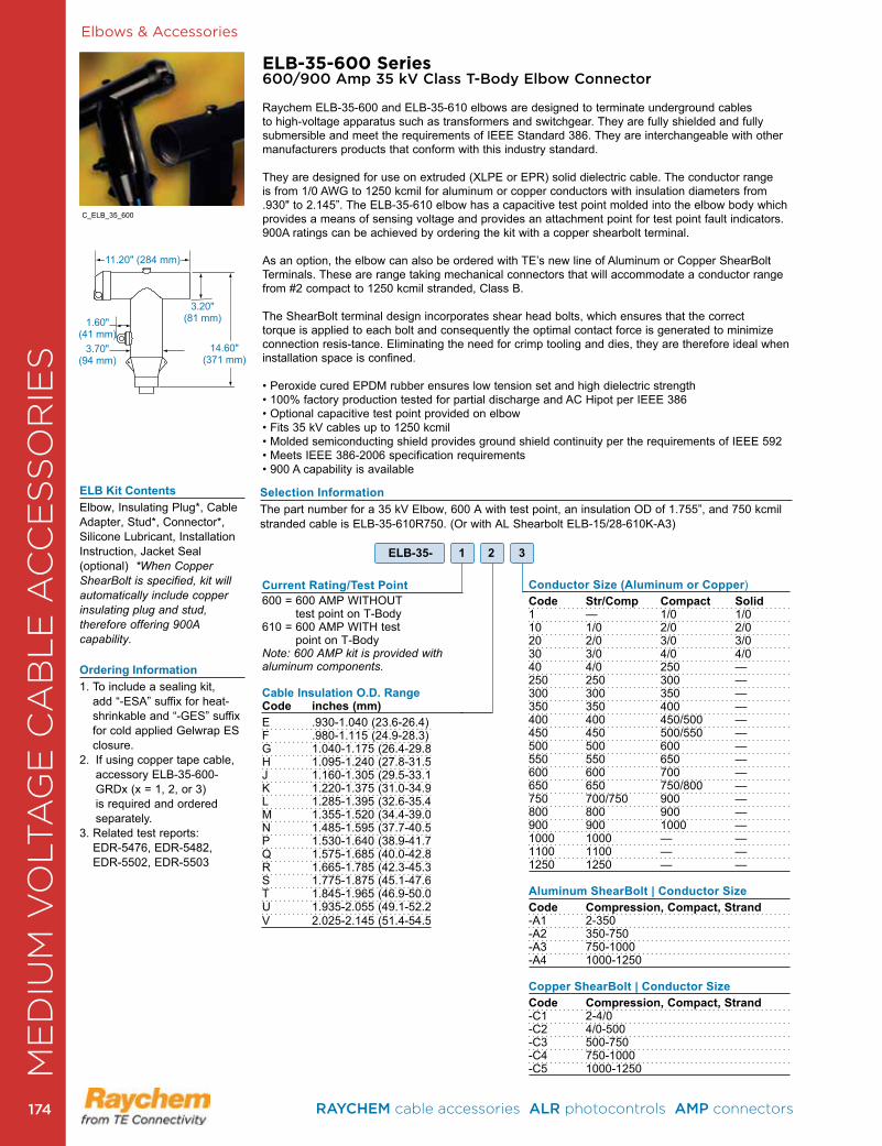
1 .60" (41 mm)
3 .70" (94 mm)
3 .20" (81 mm)
Elbows & Accessories
ELB-35-600 Series600/900 Amp 35 kV Class T-Body Elbow Connector
Raychem ELB-35-600 and ELB-35-610 elbows are designed to terminate underground cables to high-voltage apparatus such as transformers and switchgear . They are fully shielded and fully submersible and meet the requirements of IEEE Standard 386 . They are interchangeable with other manufacturers products that conform with this industry standard .
They are designed for use on extruded (XLPE or EPR) solid dielectric cable. The conductor range is from 1/0 AWG to 1250 kcmil for aluminum or copper conductors with insulation diameters from .930" to 2 .145” . The ELB-35-610 elbow has a capacitive test point molded into the elbow body which provides a means of sensing voltage and provides an attachment point for test point fault indicators . 900A ratings can be achieved by ordering the kit with a copper shearbolt terminal .
As an option, the elbow can also be ordered with TE’s new line of Aluminum or Copper ShearBolt Terminals . These are range taking mechanical connectors that will accommodate a conductor range from #2 compact to 1250 kcmil stranded, Class B .
The ShearBolt terminal design incorporates shear head bolts, which ensures that the correct torque is applied to each bolt and consequently the optimal contact force is generated to minimize connection resis-tance . Eliminating the need for crimp tooling and dies, they are therefore ideal when installation space is confined .
• Peroxide cured EPDM rubber ensures low tension set and high dielectric strength • 100% factory production tested for partial discharge and AC Hipot per IEEE 386 • Optional capacitive test point provided on elbow • Fits 35 kV cables up to 1250 kcmil• Molded semiconducting shield provides ground shield continuity per the requirements of IEEE 592• Meets IEEE 386-2006 specification requirements• 900 A capability is available
Selection InformationThe part number for a 35 kV Elbow, 600 A with test point, an insulation OD of 1 .755”, and 750 kcmil stranded cable is ELB-35-610R750 . (Or with AL Shearbolt ELB-15/28-610K-A3)
Current Rating/Test Point600 = 600 AMP WITHOUT
test point on T-Body610 = 600 AMP WITH test
point on T-BodyNote: 600 AMP kit is provided with aluminum components.
Cable Insulation O.D. RangeCode inches (mm) E .930-1 .040 (23 .6-26 .4)F .980-1 .115 (24 .9-28 .3)G 1 .040-1 .175 (26 .4-29 .8) H 1 .095-1 .240 (27 .8-31 .5)J 1 .160-1 .305 (29 .5-33 .1)K 1 .220-1 .375 (31 .0-34 .9)L 1 .285-1 .395 (32 .6-35 .4)M 1 .355-1 .520 (34 .4-39 .0)N 1 .485-1 .595 (37 .7-40 .5)P 1 .530-1 .640 (38 .9-41 .7)Q 1.575-1.685 (40.0-42.8)R 1 .665-1 .785 (42 .3-45 .3)S 1 .775-1 .875 (45 .1-47 .6)T 1 .845-1 .965 (46 .9-50 .0)U 1 .935-2 .055 (49 .1-52 .2)V 2 .025-2 .145 (51 .4-54 .5)
Conductor Size (Aluminum or Copper)Code Str/Comp Compact Solid1 — 1/0 1/010 1/0 2/0 2/020 2/0 3/0 3/030 3/0 4/0 4/040 4/0 250 —250 250 300 —300 300 350 —350 350 400 —400 400 450/500 —450 450 500/550 —500 500 600 —550 550 650 —600 600 700 —650 650 750/800 —750 700/750 900 —800 800 900 —900 900 1000 —1000 1000 — —1100 1100 — —1250 1250 — —
Aluminum ShearBolt | Conductor SizeCode Compression, Compact, Strand-A1 2-350 -A2 350-750 -A3 750-1000 -A4 1000-1250
Copper ShearBolt | Conductor SizeCode Compression, Compact, Strand-C1 2-4/0 -C2 4/0-500 -C3 500-750 -C4 750-1000 -C5 1000-1250
ELB-35- 1 2 3
C_ELB_35_600
ELB Kit ContentsElbow, Insulating Plug*, Cable Adapter, Stud*, Connector*, Silicone Lubricant, Installation Instruction, Jacket Seal (optional) *When Copper ShearBolt is specified, kit will automatically include copper insulating plug and stud, therefore offering 900A capability.
Ordering Information1 . To include a sealing kit,
add “-ESA” suffix for heat-shrinkable and “-GES” suffix for cold applied Gelwrap ES closure .
2 . If using copper tape cable, accessory ELB-35-600-GRDx (x = 1, 2, or 3) is required and ordered separately .
3 . Related test reports: EDR-5476, EDR-5482, EDR-5502, EDR-5503
11 .20" (284 mm)
14 .60" (371 mm)
ME
DIU
M V
OLT
AG
E C
AB
LE
AC
CE
SS
OR
IES
RAYCHEM cable accessories ALR photocontrols AMP connectors 174174
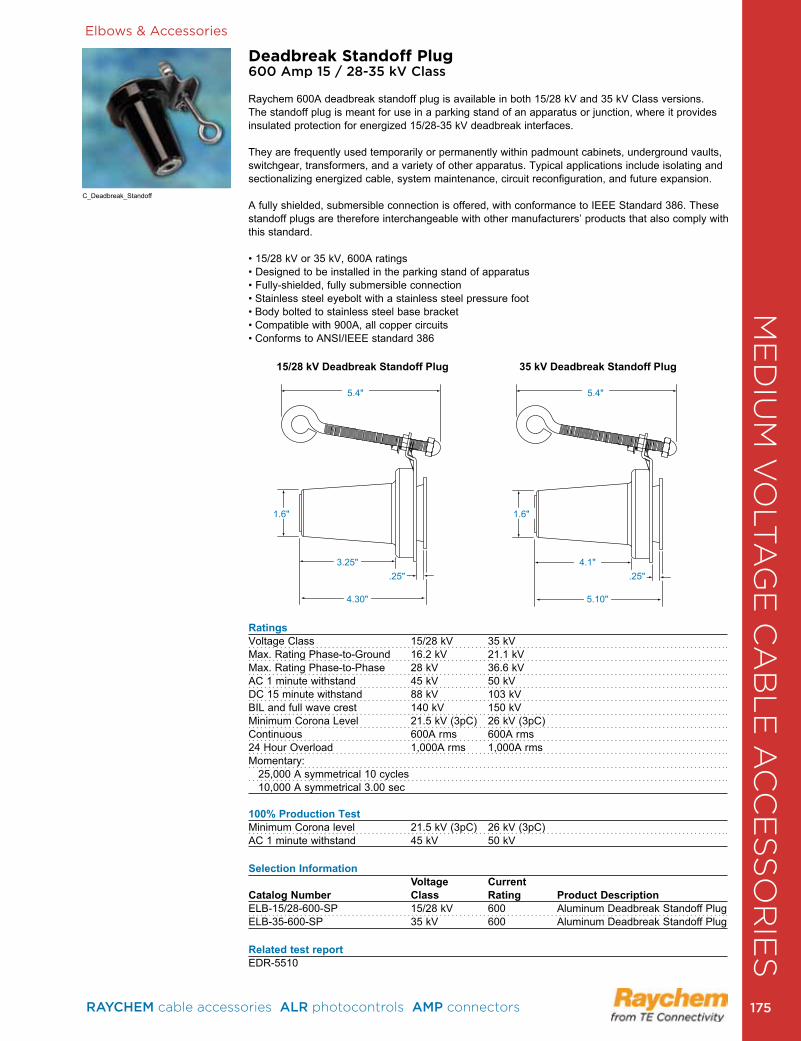
C_Deadbreak_Standoff
Elbows & Accessories
Deadbreak Standoff Plug600 Amp 15 / 28-35 kV Class
Raychem 600A deadbreak standoff plug is available in both 15/28 kV and 35 kV Class versions . The standoff plug is meant for use in a parking stand of an apparatus or junction, where it provides insulated protection for energized 15/28-35 kV deadbreak interfaces .
They are frequently used temporarily or permanently within padmount cabinets, underground vaults, switchgear, transformers, and a variety of other apparatus . Typical applications include isolating and sectionalizing energized cable, system maintenance, circuit reconfiguration, and future expansion .
A fully shielded, submersible connection is offered, with conformance to IEEE Standard 386 . These standoff plugs are therefore interchangeable with other manufacturers’ products that also comply with this standard .
• 15/28 kV or 35 kV, 600A ratings• Designed to be installed in the parking stand of apparatus• Fully-shielded, fully submersible connection• Stainless steel eyebolt with a stainless steel pressure foot • Body bolted to stainless steel base bracket• Compatible with 900A, all copper circuits• Conforms to ANSI/IEEE standard 386
RatingsVoltage Class 15/28 kV 35 kVMax . Rating Phase-to-Ground 16 .2 kV 21 .1 kVMax . Rating Phase-to-Phase 28 kV 36 .6 kVAC 1 minute withstand 45 kV 50 kVDC 15 minute withstand 88 kV 103 kVBIL and full wave crest 140 kV 150 kVMinimum Corona Level 21 .5 kV (3pC) 26 kV (3pC)Continuous 600A rms 600A rms24 Hour Overload 1,000A rms 1,000A rmsMomentary: 25,000 A symmetrical 10 cycles 10,000 A symmetrical 3 .00 sec
100% Production TestMinimum Corona level 21 .5 kV (3pC) 26 kV (3pC)AC 1 minute withstand 45 kV 50 kV
Selection Information Voltage Current Catalog Number Class Rating Product Description ELB-15/28-600-SP 15/28 kV 600 Aluminum Deadbreak Standoff PlugELB-35-600-SP 35 kV 600 Aluminum Deadbreak Standoff Plug
Related test reportEDR-5510
4 .30" 5 .10"
.25" .25"3 .25" 4 .1"
1 .6" 1 .6"
5 .4" 5 .4"
15/28 kV Deadbreak Standoff Plug 35 kV Deadbreak Standoff Plug
ME
DIU
M V
OLT
AG
E C
AB
LE
AC
CE
SS
OR
IES
RAYCHEM cable accessories ALR photocontrols AMP connectors 175 175
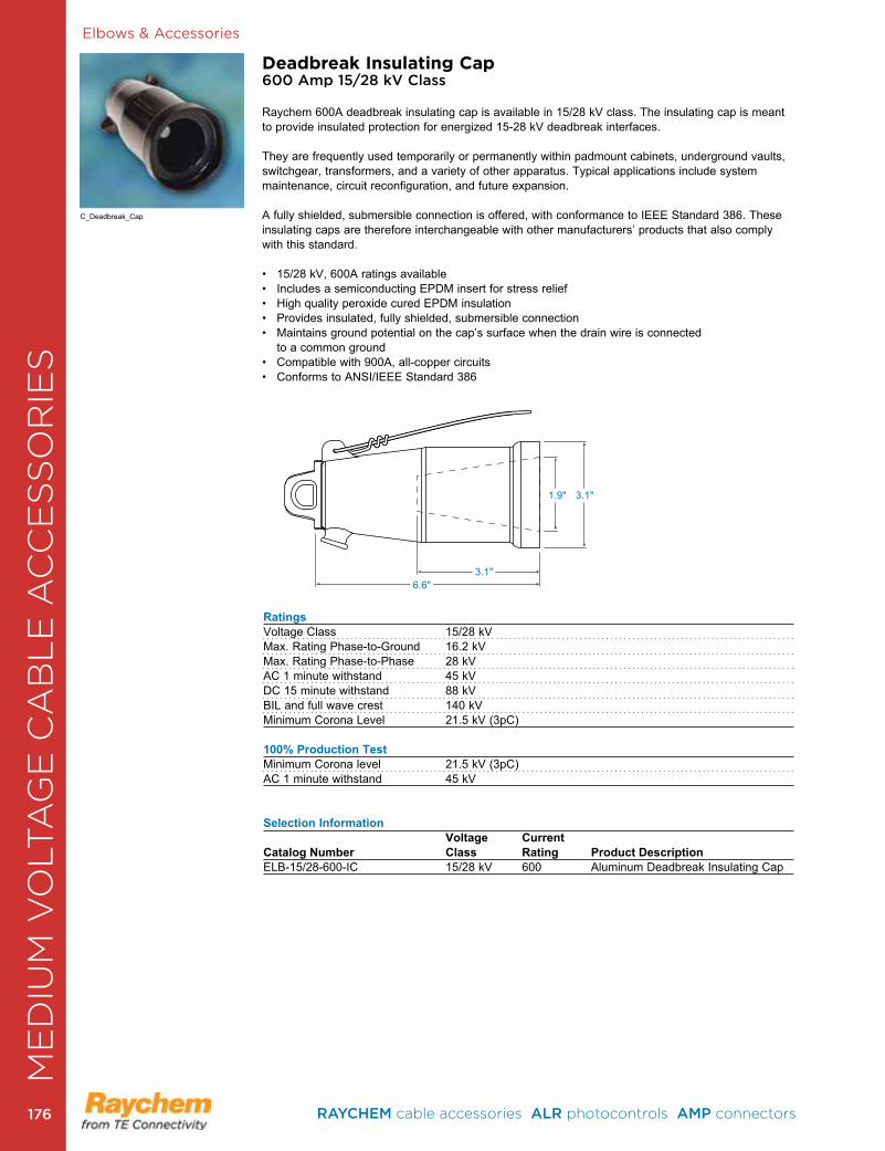
Elbows & Accessories
Deadbreak Insulating Cap600 Amp 15/28 kV Class
Raychem 600A deadbreak insulating cap is available in 15/28 kV class . The insulating cap is meant to provide insulated protection for energized 15-28 kV deadbreak interfaces .
They are frequently used temporarily or permanently within padmount cabinets, underground vaults, switchgear, transformers, and a variety of other apparatus . Typical applications include system maintenance, circuit reconfiguration, and future expansion .
A fully shielded, submersible connection is offered, with conformance to IEEE Standard 386 . These insulating caps are therefore interchangeable with other manufacturers’ products that also comply with this standard .
• 15/28 kV, 600A ratings available• Includes a semiconducting EPDM insert for stress relief• High quality peroxide cured EPDM insulation• Provides insulated, fully shielded, submersible connection• Maintains ground potential on the cap’s surface when the drain wire is connected
to a common ground• Compatible with 900A, all-copper circuits• Conforms to ANSI/IEEE Standard 386
RatingsVoltage Class 15/28 kVMax . Rating Phase-to-Ground 16 .2 kVMax . Rating Phase-to-Phase 28 kVAC 1 minute withstand 45 kVDC 15 minute withstand 88 kVBIL and full wave crest 140 kVMinimum Corona Level 21 .5 kV (3pC)
100% Production TestMinimum Corona level 21 .5 kV (3pC)AC 1 minute withstand 45 kV
Selection Information Voltage CurrentCatalog Number Class Rating Product DescriptionELB-15/28-600-IC 15/28 kV 600 Aluminum Deadbreak Insulating Cap
6 .6"3 .1"
3 .1"1 .9"
C_Deadbreak_Cap
ME
DIU
M V
OLT
AG
E C
AB
LE
AC
CE
SS
OR
IES
RAYCHEM cable accessories ALR photocontrols AMP connectors 176176
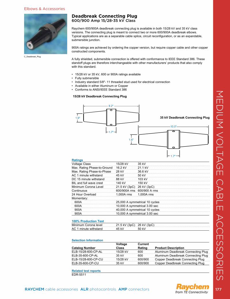
Elbows & Accessories
Deadbreak Connecting Plug600/900 Amp 15/28-35 kV Class
Raychem 600/900A deadbreak connecting plug is available in both 15/28 kV and 35 kV class versions . The connecting plug is meant to connect two or more 600/900A deadbreak elbows . Typical applications are as a separable cable splice, circuit reconfiguration, or as an expandable, submersible junction.
900A ratings are achieved by ordering the copper version, but require copper cable and other copper constructed components .
A fully shielded, submersible connection is offered with conformance to IEEE Standard 386 . These standoff plugs are therefore interchangeable with other manufacturers’ products that also comply with this standard .
• 15/28 kV or 35 kV, 600 or 900A ratings available• Fully submersible• Industry standard 5/8"- 11 threaded stud used for electrical connection• Available in either Aluminum or Copper• Conforms to ANSI/IEEE Standard 386
RatingsVoltage Class 15/28 kV 35 kVMax . Rating Phase-to-Ground 16 .2 kV 21 .1 kVMax . Rating Phase-to-Phase 28 kV 36 .6 kVAC 1 minute withstand 45 kV 50 kVDC 15 minute withstand 88 kV 103 kVBIL and full wave crest 140 kV 150 kVMinimum Corona Level 21 .5 kV (3pC) 26 kV (3pC)Continuous 600/900A rms 600/900 A rms24 Hour Overload 1,000A rms 1,000A rmsMomentary: 600A 25,000 A symmetrical 10 cycles 600A 10,000 A symmetrical 3 .00 sec 900A 40,000 A symmetrical 10 cycles 900A 10,000 A symmetrical 3 .00 sec
100% Production TestMinimum Corona level 21 .5 kV (3pC) 26 kV (3pC)AC 1 minute withstand 45 kV 50 kV
Selection Information Voltage Current Catalog Number Class Rating Product Description ELB-15/28-600-CP-AL 15/28 kV 600 Aluminum Deadbreak Connecting PlugELB-35-600-CP-AL 35 kV 600 Aluminum Deadbreak Connecting PlugELB-15/28-600-CP-CU 15/28 kV 600/900 Copper Deadbreak Connecting PlugELB-35-600-CP-CU 35 kV 600/900 Copper Deadbreak Connecting Plug
Related test reportsEDR-5511
1 .6"
1 .6"
8 .2"
10 .0"
1 .7"
1 .7"
15/28 kV Deadbreak Connecting Plug
35 kV Deadbreak Connecting Plug
C_Deadbreak_Plug
ME
DIU
M V
OLT
AG
E C
AB
LE
AC
CE
SS
OR
IES
RAYCHEM cable accessories ALR photocontrols AMP connectors 177 177
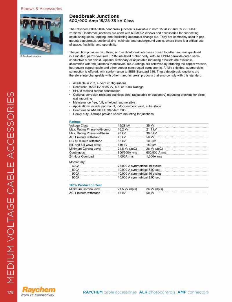
Elbows & Accessories
Deadbreak Junctions600/900 Amp 15/28-35 kV Class
The Raychem 600A/900A deadbreak junction is available in both 15/28 kV and 35 kV Class versions. Deadbreak junctions are used with 600/900A elbows and accessories for connecting, establishing loops, tapping, and facilitating apparatus change out . They are commonly used in pad-mounted apparatus, sectionalizing cabinets, and underground vaults, where there is a critical use of space, flexibility, and operability .
The junction provides two, three, or four deadbreak interfaces bused together and encapsulated in a molded, peroxide-cured EPDM insulated rubber body, with an EPDM peroxide-cured semi-conductive outer shield. Optional stationary or adjustable mounting brackets are available, assembled with the junctions themselves. 900A ratings are achieved by ordering the copper version, but require copper cable and other copper constructed components . A fully shielded, submersible connection is offered, with conformance to IEEE Standard 386. These deadbreak junctions are therefore interchangeable with other manufacturers’ products that also comply with this standard .
• Available in 2, 3, 4 point configurations• Deadfront, 15/28 kV or 35 kV, 600 or 900A Ratings• EPDM molded rubber construction• Optional corrosion resistant stainless steel (adjustable or stationary) mounting brackets for direct
wall mounting• Maintenance free, fully shielded, submersible• Applications include padmount, indoor/outdoor vault, subsurface• Conforms to ANSI/IEEE Standard 386• Heavy duty U-straps provide secure mounting for junctions RatingsVoltage Class 15/28 kV 35 kVMax . Rating Phase-to-Ground 16 .2 kV 21 .1 kVMax . Rating Phase-to-Phase 28 kV 36 .6 kVAC 1 minute withstand 45 kV 50 kVDC 15 minute withstand 88 kV 103 kVBIL and full wave crest 140 kV 150 kVMinimum Corona Level 21 .5 kV (3pC) 26 kV (3pC)Continuous 600/900A rms 600/900 A rms24 Hour Overload 1,000A rms 1,000A rms
Momentary: 600A 25,000 A symmetrical 10 cycles 600A 10,000 A symmetrical 3 .00 sec 900A 40,000 A symmetrical 10 cycles 900A 10,000 A symmetrical 3 .00 sec
100% Production TestMinimum Corona level 21 .5 kV (3pC) 26 kV (3pC)AC 1 minute withstand 45 kV 50 kV
C_Deadbreak_Junction
ME
DIU
M V
OLT
AG
E C
AB
LE
AC
CE
SS
OR
IES
RAYCHEM cable accessories ALR photocontrols AMP connectors 178178
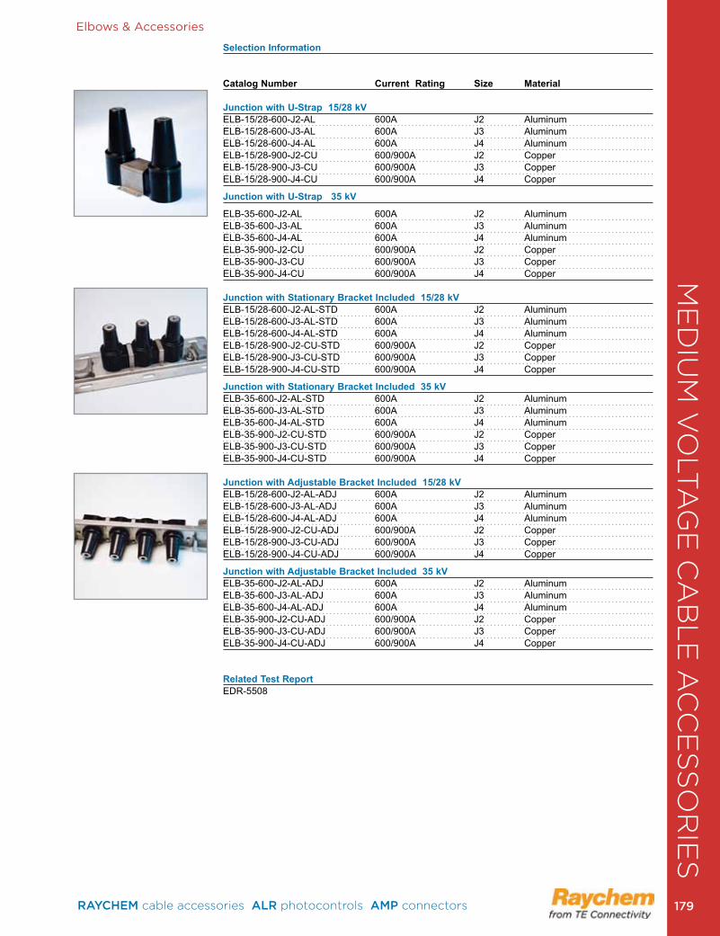
Elbows & Accessories
Selection Information
Catalog Number Current Rating Size Material Junction with U-Strap 15/28 kV ELB-15/28-600-J2-AL 600A J2 Aluminum ELB-15/28-600-J3-AL 600A J3 AluminumELB-15/28-600-J4-AL 600A J4 Aluminum ELB-15/28-900-J2-CU 600/900A J2 CopperELB-15/28-900-J3-CU 600/900A J3 Copper ELB-15/28-900-J4-CU 600/900A J4 Copper
Junction with U-Strap 35 kV
ELB-35-600-J2-AL 600A J2 Aluminum ELB-35-600-J3-AL 600A J3 Aluminum ELB-35-600-J4-AL 600A J4 Aluminum ELB-35-900-J2-CU 600/900A J2 Copper ELB-35-900-J3-CU 600/900A J3 Copper ELB-35-900-J4-CU 600/900A J4 Copper Junction with Stationary Bracket Included 15/28 kV ELB-15/28-600-J2-AL-STD 600A J2 AluminumELB-15/28-600-J3-AL-STD 600A J3 AluminumELB-15/28-600-J4-AL-STD 600A J4 Aluminum ELB-15/28-900-J2-CU-STD 600/900A J2 Copper ELB-15/28-900-J3-CU-STD 600/900A J3 CopperELB-15/28-900-J4-CU-STD 600/900A J4 Copper
Junction with Stationary Bracket Included 35 kV ELB-35-600-J2-AL-STD 600A J2 Aluminum ELB-35-600-J3-AL-STD 600A J3 AluminumELB-35-600-J4-AL-STD 600A J4 Aluminum ELB-35-900-J2-CU-STD 600/900A J2 CopperELB-35-900-J3-CU-STD 600/900A J3 Copper ELB-35-900-J4-CU-STD 600/900A J4 Copper Junction with Adjustable Bracket Included 15/28 kV ELB-15/28-600-J2-AL-ADJ 600A J2 Aluminum ELB-15/28-600-J3-AL-ADJ 600A J3 Aluminum ELB-15/28-600-J4-AL-ADJ 600A J4 Aluminum ELB-15/28-900-J2-CU-ADJ 600/900A J2 Copper ELB-15/28-900-J3-CU-ADJ 600/900A J3 Copper ELB-15/28-900-J4-CU-ADJ 600/900A J4 Copper
Junction with Adjustable Bracket Included 35 kV ELB-35-600-J2-AL-ADJ 600A J2 Aluminum ELB-35-600-J3-AL-ADJ 600A J3 Aluminum ELB-35-600-J4-AL-ADJ 600A J4 Aluminum ELB-35-900-J2-CU-ADJ 600/900A J2 Copper ELB-35-900-J3-CU-ADJ 600/900A J3 Copper ELB-35-900-J4-CU-ADJ 600/900A J4 Copper
Related Test ReportEDR-5508
ME
DIU
M V
OLT
AG
E C
AB
LE
AC
CE
SS
OR
IES
RAYCHEM cable accessories ALR photocontrols AMP connectors 179 179

Elbows & Accessories
ELB-15/28-600 Elbow Modular Splicing Systems600 Amp (15-35 kV) Class for Deadbreak T-body Elbow Connector
TE’s Raychem Elbow Modular Splicing System offers separable solutions to fit a variety of needs which include: splicing, connecting to apparatus, dead-ending, and the ability to easily reconfigure circuits . At 15-35 kV 600 Amp, the following options are available: 2-way, 3-way, 4-way, or dead-end connections .
These kits use TE Connectivity’s standard T-bodies, connecting plugs, insulating plugs, and conductive caps . They are fully shielded and fully submersible and meet the requirements of IEEE Standard 386 . They are interchangeable with other manufacturers’ products that conform with this industry standard .
• Peroxide cured EPDM rubber ensures low tension set and high dielectric strength• 100% factory production tested for partial discharge and AC Hipot per IEEE 386• Fits 15-35 kV cables up to 1250 kcmil• Both compression lugs and range taking shearbolt connectors are available, along with the
required cable adapter (sold separately)• Designed for use on extruded (XLPE or EPR) solid dielectric cable
Selection Information: dimensions in inches (millimeters) Approximate Width of Splicing SystemAssembly 15/28 kV 35 kVDeadend (One Way) 10 .1 (256) 12 .1 (307)Two Way 19 .0 (483) 23 .0 (584)Three Way 27 .9 (709) 33 .9 (861)Four Way 36 .8 (935) 44 .8 (1138)
Ordering Information1 . Due to the variety of configurations possible, cable adapters and connectors are not included as part
of this kit . Each one sold separately . Contact your local TE sales representative for assistance .2 . A spanner wrench (ELB-600-SPANNER, sold separately) may be required for proper installation .3 . If using copper tape cable, accessory ELB-35-600-GRDx (x = 1, 2 or 3) is required and
ordered separately .4 . Sealing kits are available separately: the ESA for heatshrink, GES for cold-applied Gelwrap ES
closure, and CES for cold-applied rip-cord style .5 . Related test reports: EDR-5482, EDR-5476, EDR-5502, EDR-5503, EDR-5511 .
ELB-15/28-600-T1WAYELB-15/28-610-T1WAYELB-35-600-T1WAYELB-35-610-T1WAY
ELB-15/28-600-T2WAYELB-15/28-610-T2WAYELB-35-600-T2WAYELB-35-610-T2WAY
ELB-15/28-600-T3WAYELB-15/28-610-T3WAYELB-35-600-T3WAYELB-35-610-T3WAY
ELB-15/28-600-T4WAYELB-15/28-610-T4WAYELB-35-600-T4WAYELB-35-610-T4WAY
Kit Description Assembly
Note: 600 version is without testpoint and 610 version is with test point . Modular Elbow Splice kits do not include connectors or cable adapters .
C_ELB_15_28_600
ME
DIU
M V
OLT
AG
E C
AB
LE
AC
CE
SS
OR
IES
RAYCHEM cable accessories ALR photocontrols AMP connectors 180180
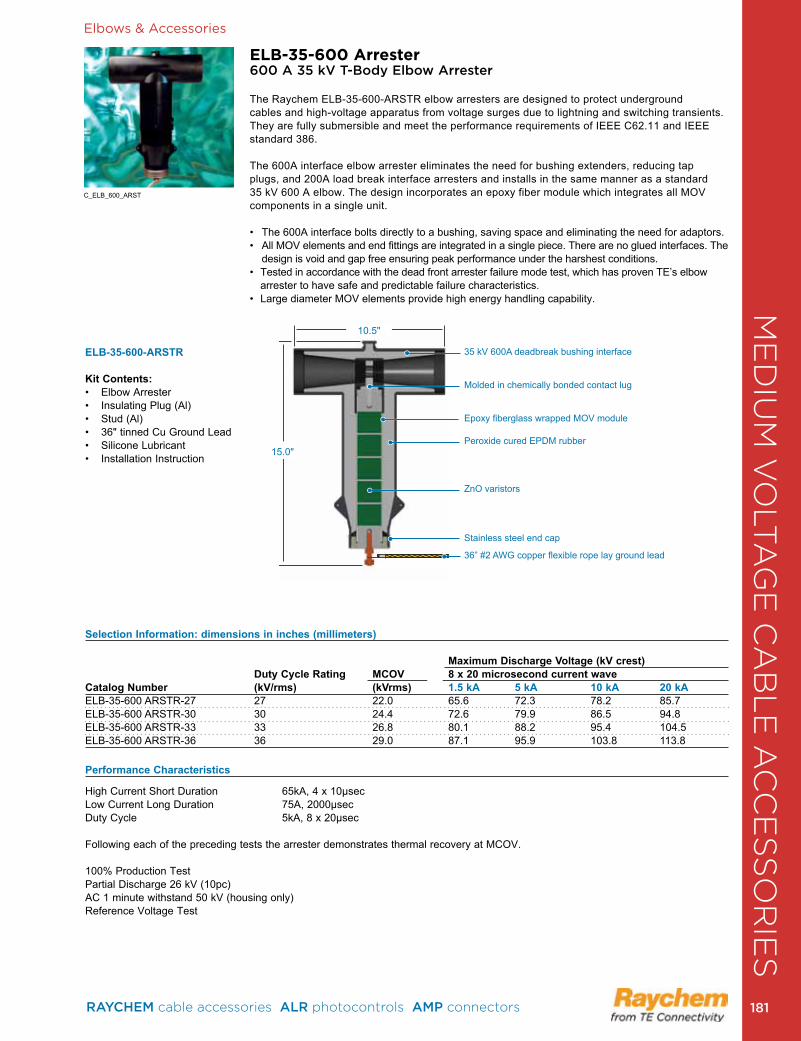
Elbows & Accessories
ELB-35-600 Arrester600 A 35 kV T-Body Elbow Arrester
The Raychem ELB-35-600-ARSTR elbow arresters are designed to protect underground cables and high-voltage apparatus from voltage surges due to lightning and switching transients . They are fully submersible and meet the performance requirements of IEEE C62 .11 and IEEE standard 386 .
The 600A interface elbow arrester eliminates the need for bushing extenders, reducing tap plugs, and 200A load break interface arresters and installs in the same manner as a standard 35 kV 600 A elbow . The design incorporates an epoxy fiber module which integrates all MOV components in a single unit .
• The 600A interface bolts directly to a bushing, saving space and eliminating the need for adaptors. • All MOV elements and end fittings are integrated in a single piece . There are no glued interfaces . The
design is void and gap free ensuring peak performance under the harshest conditions .• Tested in accordance with the dead front arrester failure mode test, which has proven TE’s elbow
arrester to have safe and predictable failure characteristics .• Large diameter MOV elements provide high energy handling capability.
ELB-35-600-ARSTR
Kit Contents:• Elbow Arrester• Insulating Plug (Al)• Stud (Al) • 36" tinned Cu Ground Lead• Silicone Lubricant• Installation Instruction
C_ELB_600_ARST
Selection Information: dimensions in inches (millimeters) Maximum Discharge Voltage (kV crest) Duty Cycle Rating MCOV 8 x 20 microsecond current waveCatalog Number (kV/rms) (kVrms) 1.5 kA 5 kA 10 kA 20 kAELB-35-600 ARSTR-27 27 22 .0 65 .6 72 .3 78 .2 85 .7ELB-35-600 ARSTR-30 30 24 .4 72 .6 79 .9 86 .5 94 .8ELB-35-600 ARSTR-33 33 26 .8 80 .1 88 .2 95 .4 104 .5ELB-35-600 ARSTR-36 36 29 .0 87 .1 95 .9 103 .8 113 .8
Performance Characteristics
High Current Short Duration 65kA, 4 x 10µsecLow Current Long Duration 75A, 2000µsecDuty Cycle 5kA, 8 x 20µsec
Following each of the preceding tests the arrester demonstrates thermal recovery at MCOV .
100% Production TestPartial Discharge 26 kV (10pc)AC 1 minute withstand 50 kV (housing only)Reference Voltage Test
35 kV 600A deadbreak bushing interface
Molded in chemically bonded contact lug
Epoxy fiberglass wrapped MOV module
Peroxide cured EPDM rubber
ZnO varistors
Stainless steel end cap
36” #2 AWG copper flexible rope lay ground lead
15 .0"
10 .5"
ME
DIU
M V
OLT
AG
E C
AB
LE
AC
CE
SS
OR
IES
RAYCHEM cable accessories ALR photocontrols AMP connectors 181 181
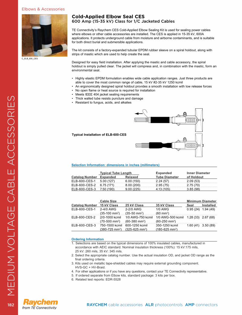
Elbows & Accessories
Cold-Applied Elbow Seal CES600 Amp (15-35 kV) Class for 1/C Jacketed Cables
TE Connectivity’s Raychem CES Cold-Applied Elbow Sealing Kit is used for sealing power cables where elbows or other cable accessories are installed . The CES is applied in 15-35 kV, 600A applications . It protects underground cable from moisture and airborne contaminants, and is suitable for both direct burial and submersible applications .
The kit consists of a factory-expanded tubular EPDM rubber sleeve on a spiral holdout, along with strips of mastic which are used to help create the seal .
Designed for easy field installation . After applying the mastic and cable accessory, the spiral holdout is simply pulled clear. The jacket will compress and, in combination with the mastic, form an environmental seal .
• Highly elastic EPDM formulation enables wide cable application ranges. Just three products are able to cover the most common range of cable, 15 kV #2-35 kV 1250 kcmil
• An ergonomically designed spiral holdout provides a smooth installation with low release forces• No open flame or heat source is required for installation• Meets IEEE 404 jacket sealing requirements• Thick walled tube resists puncture and damage• Resistant to fungus, acids, and alkalies
Typical Installation of ELB-600-CES
Selection Information: dimensions in inches (millimeters)
Typical Tube Length Expanded Inner DiameterCatalog Number Expanded Relaxed Tube Diameter of HoldoutELB-600-CES-1 5 .00 (127) 6 .00 (150) 2 .24 (57) 2 .09 (53)ELB-600-CES-2 6 .75 (171) 8 .00 (200) 2 .95 (75) 2 .75 (70)ELB-600-CES-3 7 .50 (190) 9 .00 (225) 4 .13 (105) 3 .85 (98)
Cable Size Minimum DiameterCatalog Number 15 kV Class 25 kV Class 35 kV Class Seal InstalledELB-600-CES-1 2-4/0 AWG 2-2/0 AWG 1/0 AWG 0 .95 (24) 1 .94 (49) (35-100 mm2) (35-50 mm2) (60 mm2) ELB-600-CES-2 2/0-1000 kcmil 1/0 AWG-750 kcmil 1/0 AWG-500 kcmil 1 .28 (33) 2 .67 (68) (70-500 mm2) (60-380 mm2) (60-250 mm2) ELB-600-CES-3 750-1500 kcmil 600-1250 kcmil 350-1250 kcmil 1 .60 (41) 3 .50 (89) (380-725 mm2) (325-625 mm2) (180-625 mm2)
Ordering Information1 . Selections are based on the typical dimensions of 100% insulated cables, manufactured in
accordance with AEIC standard . Nominal insulation thickness (100%): 15 kV:175 mils, 25 kV: 260 mils, 35 kV: 345 mils .
2. Select the appropriate catalog number. Use the actual insulation OD, and jacket OD range as the final ordering criteria .
3 . Kits used on metallic tape-shielded cables may require external grounding component . HVS-GC + HV-Braid .
4 . For other applications or if you have any questions, contact your TE Connectivity representative .5 . If ordered separate from Elbow kits, standard package: 3 kits per box .6 . Related test reports: EDR-5528
C_ELB_600_CES
ME
DIU
M V
OLT
AG
E C
AB
LE
AC
CE
SS
OR
IES
RAYCHEM cable accessories ALR photocontrols AMP connectors 182182
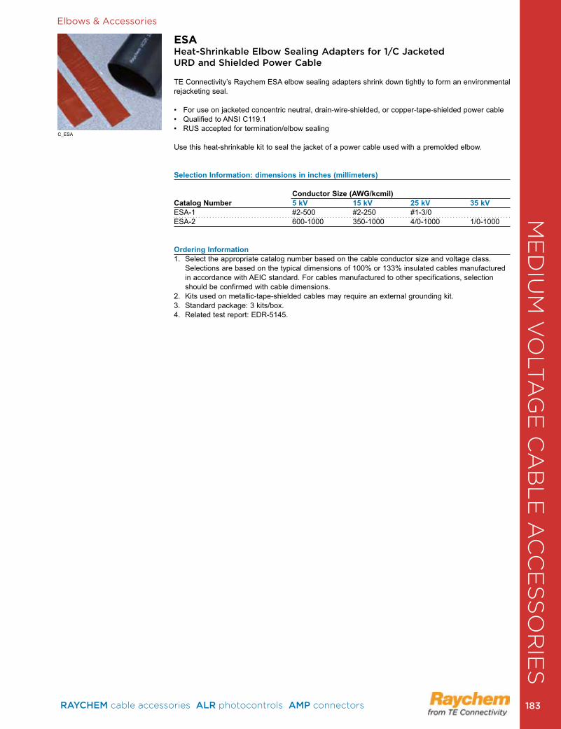
Elbows & Accessories
ESAHeat-Shrinkable Elbow Sealing Adapters for 1/C Jacketed URD and Shielded Power Cable
TE Connectivity’s Raychem ESA elbow sealing adapters shrink down tightly to form an environmental rejacketing seal.
• For use on jacketed concentric neutral, drain-wire-shielded, or copper-tape-shielded power cable• Qualified to ANSI C119.1 • RUS accepted for termination/elbow sealing
Use this heat-shrinkable kit to seal the jacket of a power cable used with a premolded elbow.
Selection Information: dimensions in inches (millimeters)
Conductor Size (AWG/kcmil)Catalog Number 5 kV 15 kV 25 kV 35 kVESA-1 #2-500 #2-250 #1-3/0 ESA-2 600-1000 350-1000 4/0-1000 1/0-1000
Ordering Information1 . Select the appropriate catalog number based on the cable conductor size and voltage class .
Selections are based on the typical dimensions of 100% or 133% insulated cables manufactured in accordance with AEIC standard . For cables manufactured to other specifications, selection should be confirmed with cable dimensions .
2 . Kits used on metallic-tape-shielded cables may require an external grounding kit . 3 . Standard package: 3 kits/box . 4 . Related test report: EDR-5145 .
C_ESA
ME
DIU
M V
OLT
AG
E C
AB
LE
AC
CE
SS
OR
IES
RAYCHEM cable accessories ALR photocontrols AMP connectors 183 183
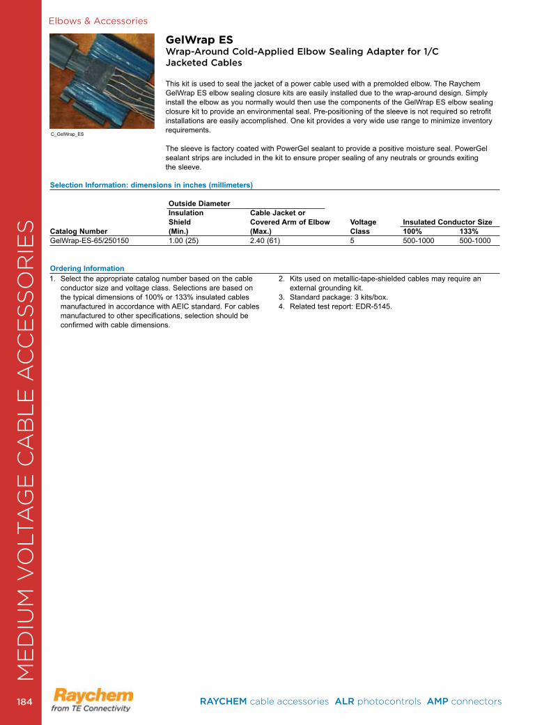
Elbows & Accessories
GelWrap ESWrap-Around Cold-Applied Elbow Sealing Adapter for 1/C Jacketed Cables
This kit is used to seal the jacket of a power cable used with a premolded elbow. The Raychem GelWrap ES elbow sealing closure kits are easily installed due to the wrap-around design . Simply install the elbow as you normally would then use the components of the GelWrap ES elbow sealing closure kit to provide an environmental seal . Pre-positioning of the sleeve is not required so retrofit installations are easily accomplished . One kit provides a very wide use range to minimize inventory requirements .
The sleeve is factory coated with PowerGel sealant to provide a positive moisture seal . PowerGel sealant strips are included in the kit to ensure proper sealing of any neutrals or grounds exiting the sleeve .
1 . Select the appropriate catalog number based on the cable conductor size and voltage class . Selections are based on the typical dimensions of 100% or 133% insulated cables manufactured in accordance with AEIC standard . For cables manufactured to other specifications, selection should be confirmed with cable dimensions .
2 . Kits used on metallic-tape-shielded cables may require an external grounding kit .
3 . Standard package: 3 kits/box . 4 . Related test report: EDR-5145 .
Selection Information: dimensions in inches (millimeters) Outside Diameter Insulation Cable Jacket or Shield Covered Arm of Elbow Voltage Insulated Conductor SizeCatalog Number (Min.) (Max.) Class 100% 133%GelWrap-ES-65/250150 1 .00 (25) 2 .40 (61) 5 500-1000 500-1000
Ordering Information
C_GelWrap_ES
ME
DIU
M V
OLT
AG
E C
AB
LE
AC
CE
SS
OR
IES
RAYCHEM cable accessories ALR photocontrols AMP connectors 184184
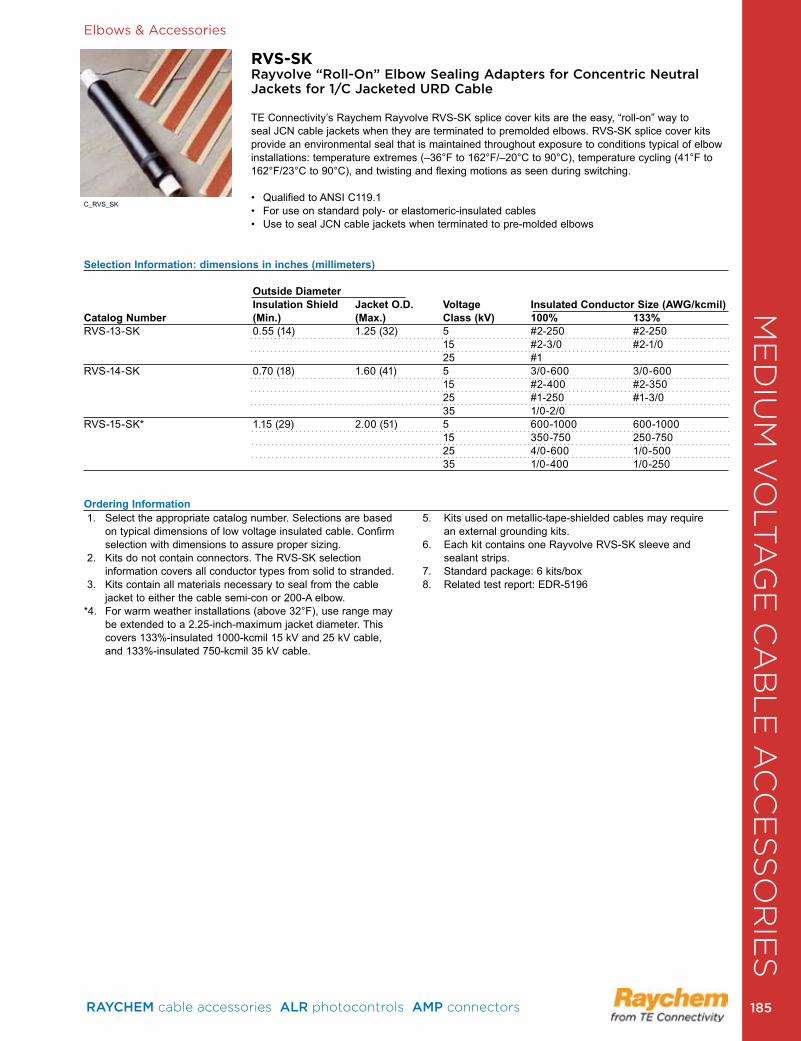
Elbows & Accessories
RVS-SKRayvolve “Roll-On” Elbow Sealing Adapters for Concentric Neutral Jackets for 1/C Jacketed URD Cable
TE Connectivity’s Raychem Rayvolve RVS-SK splice cover kits are the easy, “roll-on” way to seal JCN cable jackets when they are terminated to premolded elbows. RVS-SK splice cover kits provide an environmental seal that is maintained throughout exposure to conditions typical of elbow installations: temperature extremes (–36°F to 162°F/–20°C to 90°C), temperature cycling (41°F to 162°F/23°C to 90°C), and twisting and flexing motions as seen during switching .
• Qualified to ANSI C119.1• For use on standard poly- or elastomeric-insulated cables• Use to seal JCN cable jackets when terminated to pre-molded elbows
1 . Select the appropriate catalog number . Selections are based on typical dimensions of low voltage insulated cable . Confirm selection with dimensions to assure proper sizing .
2 . Kits do not contain connectors . The RVS-SK selection information covers all conductor types from solid to stranded .
3 . Kits contain all materials necessary to seal from the cable jacket to either the cable semi-con or 200-A elbow.
*4 . For warm weather installations (above 32°F), use range may be extended to a 2.25-inch-maximum jacket dia meter. This covers 133%-insulated 1000-kcmil 15 kV and 25 kV cable, and 133%-insulated 750-kcmil 35 kV cable .
5 . Kits used on metallic-tape-shielded cables may require an external grounding kits .
6 . Each kit contains one Rayvolve RVS-SK sleeve and sealant strips .
7 . Standard package: 6 kits/box8 . Related test report: EDR-5196
Selection Information: dimensions in inches (millimeters)
Outside Diameter Insulation Shield Jacket O.D. Voltage Insulated Conductor Size (AWG/kcmil)
Catalog Number (Min.) (Max.) Class (kV) 100% 133% RVS-13-SK 0 .55 (14) 1 .25 (32) 5 #2-250 #2-250
15 #2-3/0 #2-1/025 #1
RVS-14-SK 0 .70 (18) 1 .60 (41) 5 3/0-600 3/0-60015 #2-400 #2-35025 #1-250 #1-3/035 1/0-2/0
RVS-15-SK* 1 .15 (29) 2 .00 (51) 5 600-1000 600-1000 15 350-750 250-750 25 4/0-600 1/0-500 35 1/0-400 1/0-250
Ordering Information
C_RVS_SK
ME
DIU
M V
OLT
AG
E C
AB
LE
AC
CE
SS
OR
IES
RAYCHEM cable accessories ALR photocontrols AMP connectors 185 185
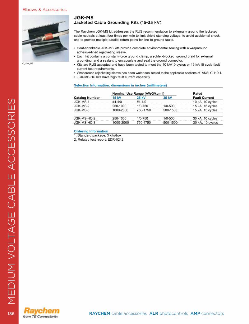
Elbows & Accessories
JGK-MSJacketed Cable Grounding Kits (15-35 kV)
The Raychem JGK-MS kit addresses the RUS recommendation to externally ground the jacketed cable neutrals at least four times per mile to limit shield standing voltage, to avoid accidental shock, and to provide multiple parallel return paths for line-to-ground faults .
• Heat-shrinkable JGK-MS kits provide complete environmental sealing with a wraparound, adhesive-lined rejacketing sleeve.
• Each kit contains a constant-force ground clamp, a solder-blocked ground braid for external grounding, and a sealant to encapsulate and seal the ground connector .
• Kits are RUS accepted and have been tested to meet the 10 kA/10 cycles or 15 kA/15 cycle fault current test requirements .
• Wraparound rejacketing sleeve has been water-seal tested to the applicable sections of ANSI C 119.1.• JGK-MS-HC kits have high fault current capability
Selection Information: dimensions in inches (millimeters)
Nominal Use Range (AWG/kcmil) RatedCatalog Number 15 kV 25 kV 35 kV Fault CurrentJGK-MS-1 #4-4/0 #1-1/0 10 kA, 10 cyclesJGK-MS-2 250-1000 1/0-750 1/0-500 15 kA, 15 cyclesJGK-MS-3 1000-2000 750-1750 500-1500 15 kA, 15 cycles
JGK-MS-HC-2 250-1000 1/0-750 1/0-500 30 kA, 10 cyclesJGK-MS-HC-3 1000-2000 750-1750 500-1500 30 kA, 10 cycles
Ordering Information1 . Standard package: 3 kits/box2 . Related test report: EDR-5242
C_JGK_MS
ME
DIU
M V
OLT
AG
E C
AB
LE
AC
CE
SS
OR
IES
RAYCHEM cable accessories ALR photocontrols AMP connectors 186186
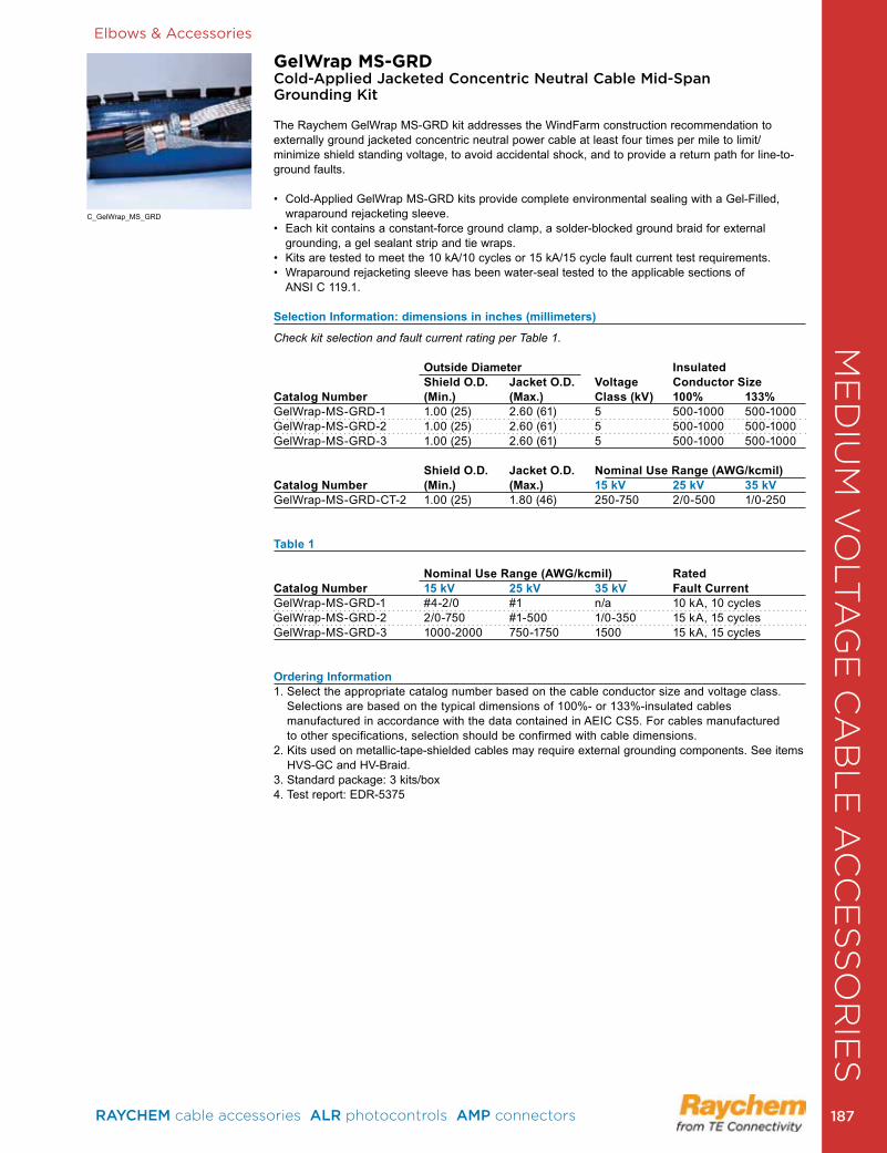
Elbows & Accessories
GelWrap MS-GRDCold-Applied Jacketed Concentric Neutral Cable Mid-Span Grounding Kit
The Raychem GelWrap MS-GRD kit addresses the WindFarm construction recommendation to externally ground jacketed concentric neutral power cable at least four times per mile to limit/minimize shield standing voltage, to avoid accidental shock, and to provide a return path for line-to-ground faults .
• Cold-Applied GelWrap MS-GRD kits provide complete environmental sealing with a Gel-Filled, wraparound rejacketing sleeve.
• Each kit contains a constant-force ground clamp, a solder-blocked ground braid for external grounding, a gel sealant strip and tie wraps .
• Kits are tested to meet the 10 kA/10 cycles or 15 kA/15 cycle fault current test requirements.• Wraparound rejacketing sleeve has been water-seal tested to the applicable sections of
ANSI C 119 .1 .
Selection Information: dimensions in inches (millimeters)
Check kit selection and fault current rating per Table 1. Outside Diameter Insulated Shield O.D. Jacket O.D. Voltage Conductor SizeCatalog Number (Min.) (Max.) Class (kV) 100% 133%GelWrap-MS-GRD-1 1 .00 (25) 2 .60 (61) 5 500-1000 500-1000 GelWrap-MS-GRD-2 1 .00 (25) 2 .60 (61) 5 500-1000 500-1000 GelWrap-MS-GRD-3 1 .00 (25) 2 .60 (61) 5 500-1000 500-1000
Shield O.D. Jacket O.D. Nominal Use Range (AWG/kcmil) Catalog Number (Min.) (Max.) 15 kV 25 kV 35 kVGelWrap-MS-GRD-CT-2 1 .00 (25) 1 .80 (46) 250-750 2/0-500 1/0-250
Table 1 Nominal Use Range (AWG/kcmil) RatedCatalog Number 15 kV 25 kV 35 kV Fault CurrentGelWrap-MS-GRD-1 #4-2/0 #1 n/a 10 kA, 10 cycles GelWrap-MS-GRD-2 2/0-750 #1-500 1/0-350 15 kA, 15 cyclesGelWrap-MS-GRD-3 1000-2000 750-1750 1500 15 kA, 15 cycles
Ordering Information1 . Select the appropriate catalog number based on the cable conductor size and voltage class .
Selections are based on the typical dimensions of 100%- or 133%-insulated cables manufactured in accordance with the data contained in AEIC CS5 . For cables manufactured to other specifications, selection should be confirmed with cable dimensions .
2 . Kits used on metallic-tape-shielded cables may require external grounding components . See items HVS-GC and HV-Braid .
3 . Standard package: 3 kits/box4 . Test report: EDR-5375
C_GelWrap_MS_GRD
ME
DIU
M V
OLT
AG
E C
AB
LE
AC
CE
SS
OR
IES
RAYCHEM cable accessories ALR photocontrols AMP connectors 187 187
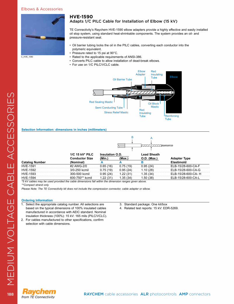
Elbows & Accessories
HVE-1590Adapts 1/C PILC Cable for Installation of Elbow (15 kV)
TE Connectivity’s Raychem HVE-1590 elbow adapters provide a highly effective and easily installed oil stop system, using standard heat-shrinkable components . The system provides an oil- and pressure-resistant seal .
• Oil barrier tubing locks the oil in the PILC cables, converting each conductor into the polymeric equivalent . • Pressure rated to 15 psi at 90°C.• Rated to the applicable requirements of ANSI-386.• Converts PILC cable to allow installation of dead-break elbows. • For use on 1/C PILC/VCLC cable.
Selection Information: dimensions in inches (millimeters)
1/C 15 kV* PILC Insulation O.D. Lead Sheath Conductor Size (Min.) (Max.) O.D. (Max.) Adapter TypeCatalog Number (Nominal) A A B Elastimold HVE-1591 #2 AWG-2/0 0 .65 (16) 0 .75 (19) 0 .95 (24) ELB-15/28-600-CA-FHVE-1592 3/0-250 kcmil 0 .75 (19) 0 .95 (24) 1 .10 (28) ELB-15/28-600-CA-G HVE-1593 300-500 kcmil 0 .95 (24) 1 .22 (31) 1 .35 (34) ELB-15/28-600-CA- HHVE-1594 600-750** kcmil 1 .22 (31) 1 .35 (34) 1 .50 (38) ELB-15/28-600-CA-L*5 kV cables may be used provided the cable dimensions fall within the dimension ranges given above. **Compact strand onlyPlease Note: The TE Connectivity kit does not include the compression connector, cable adapter or elbow.
Ordering Information1 . Select the appropriate catalog number . All selections are
based on the typical dimensions of 100% insulated cables manufactured in accordance with AEIC standard . Nominal insulation thickness (100%): 15 kV: 165 mils (PILC/VCLC) .
2 . For cables manufactured to other specifications, confirm selection with cable dimensions .
3 . Standard package: One kit/box4 . Related test reports: 15 kV: EDR-5269 .
B A
Red Sealing Mastic
Oil Barrier Tube
ElbowAdapter
Oil BlockMastic
ReinforcingTube
Elbow
Semi Conducting Tube
Stress Relief MasticRed InsulatingTube
Red InsulatingTube
C_HVE_1590
ME
DIU
M V
OLT
AG
E C
AB
LE
AC
CE
SS
OR
IES
RAYCHEM cable accessories ALR photocontrols AMP connectors 188188
Splices, Terminations & AccessoriesTorque Controlled Connectors and Lugs . . . . . . . . . . . . . . . . . .190EHVS Heat-Shrink Splices (46/69 kV) . . . . . . . . . . . . . . . . . . . .192EHVT Heat-Shrink Terminations (46/69 kV) . . . . . . . . . . . . . . . .193EHVS Three-Piece Splice (138 kV) . . . . . . . . . . . . . . . . . . . . . .194EHVS Single-Piece Splice (138/230 kV) . . . . . . . . . . . . . . . . . .195OHVT Oil-Filled Termination (69/138/230 kV) . . . . . . . . . . . . . .196OHVT Dry-Type Termination (138 kV) . . . . . . . . . . . . . . . . . . . .196PHVS/PHVT Dry Compact Switchgear and Transformer (69/138/230 kV) . . . . . . . . . . . . . . . . . . . . . . . . . . . . . . . . . . . . .197Link Boxes . . . . . . . . . . . . . . . . . . . . . . . . . . . . . . . . . . . . . . . . .197
ToolsTermination Lifting Device . . . . . . . . . . . . . . . . . . . . . . . . . . . . .198EHVT-BRKT Mounting Brackets . . . . . . . . . . . . . . . . . . . . . . . . .198EHVT-BP Mounting Base Plate . . . . . . . . . . . . . . . . . . . . . . . . .198HVIA Cable Stripper . . . . . . . . . . . . . . . . . . . . . . . . . . . . . . . . . .198Cable Heating Blanket & Accessories . . . . . . . . . . . . . . . . . . . .199Tool Box . . . . . . . . . . . . . . . . . . . . . . . . . . . . . . . . . . . . . . . . . . .199
High Voltage InsulatorsComposite Station Post (Axicom) . . . . . . . . . . . . . . . . . . . . . . . .200
HIGH VOLTAGE CABLE ACCESSORIES & INSULATORS
RAYCHEM cable accessories ALR photocontrols AMP connectors 189 189
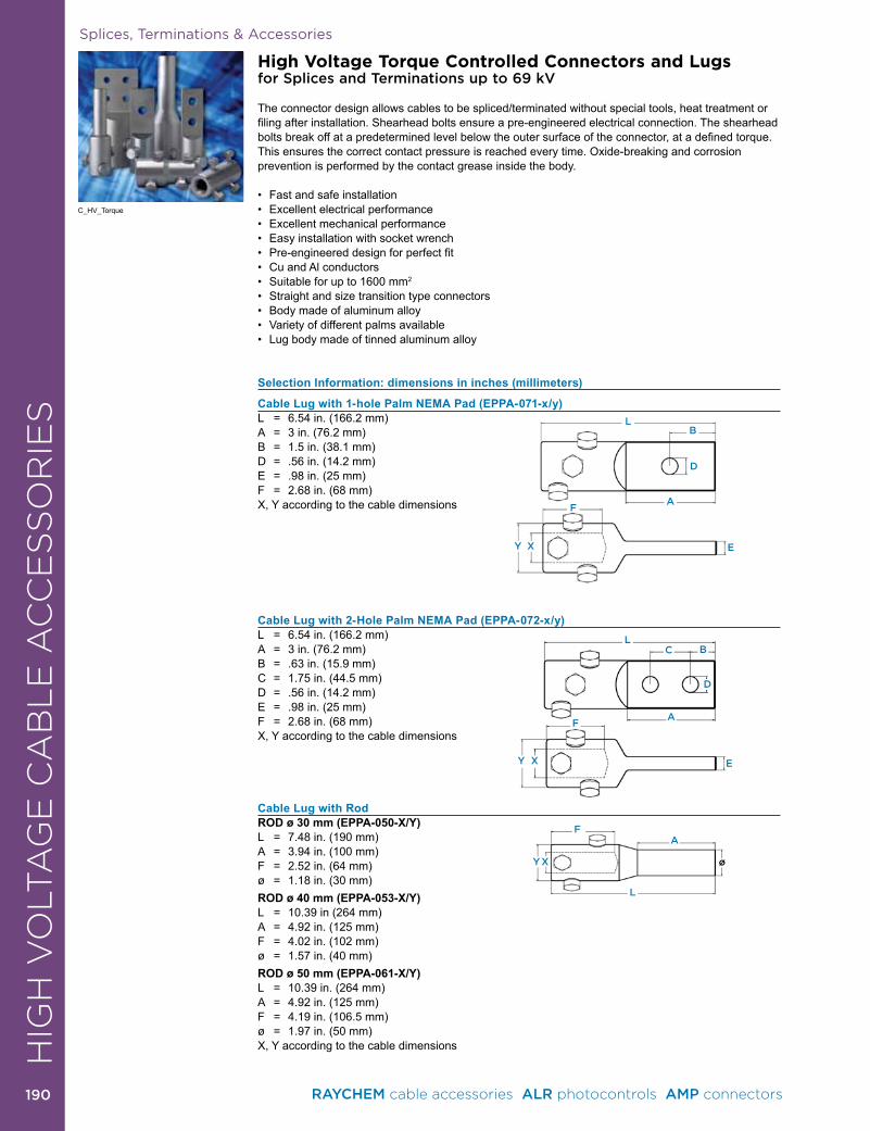
E
BCL
D
AF
XY
LB
D
A
E
F
XY
A
L
F
XY ø
Splices, Terminations & Accessories
High Voltage Torque Controlled Connectors and Lugsfor Splices and Terminations up to 69 kV
The connector design allows cables to be spliced/terminated without special tools, heat treatment or filing after installation. Shearhead bolts ensure a pre-engineered electrical connection. The shearhead bolts break off at a predetermined level below the outer surface of the connector, at a defined torque. This ensures the correct contact pressure is reached every time . Oxide-breaking and corrosion prevention is performed by the contact grease inside the body .
• Fast and safe installation• Excellent electrical performance• Excellent mechanical performance• Easy installation with socket wrench• Pre-engineered design for perfect fit• Cu and Al conductors• Suitable for up to 1600 mm2
• Straight and size transition type connectors• Body made of aluminum alloy• Variety of different palms available• Lug body made of tinned aluminum alloy
Selection Information: dimensions in inches (millimeters)
C_HV_Torque
Cable Lug with 1-hole Palm NEMA Pad (EPPA-071-x/y)L = 6 .54 in . (166 .2 mm)A = 3 in . (76 .2 mm)B = 1 .5 in . (38 .1 mm)D = .56 in . (14 .2 mm)E = .98 in . (25 mm)F = 2 .68 in . (68 mm)X, Y according to the cable dimensions
Cable Lug with 2-Hole Palm NEMA Pad (EPPA-072-x/y)L = 6 .54 in . (166 .2 mm)A = 3 in . (76 .2 mm)B = .63 in . (15 .9 mm)C = 1 .75 in . (44 .5 mm)D = .56 in . (14 .2 mm)E = .98 in . (25 mm)F = 2 .68 in . (68 mm)X, Y according to the cable dimensions
Cable Lug with RodROD ø 30 mm (EPPA-050-X/Y)L = 7 .48 in . (190 mm)A = 3 .94 in . (100 mm)F = 2 .52 in . (64 mm)ø = 1 .18 in . (30 mm)ROD ø 40 mm (EPPA-053-X/Y)L = 10 .39 in (264 mm)A = 4 .92 in . (125 mm)F = 4 .02 in . (102 mm)ø = 1 .57 in . (40 mm)ROD ø 50 mm (EPPA-061-X/Y)L = 10 .39 in . (264 mm)A = 4 .92 in . (125 mm)F = 4 .19 in . (106 .5 mm)ø = 1 .97 in . (50 mm)X, Y according to the cable dimensionsH
IGH
VO
LTA
GE
CA
BL
E A
CC
ES
SO
RIE
S
RAYCHEM cable accessories ALR photocontrols AMP connectors 190190
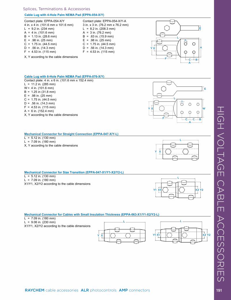
HIG
H V
OLT
AG
E C
AB
LE
AC
CE
SS
OR
IES
Splices, Terminations & Accessories
Cable Lug with 4-Hole Palm NEMA Pad (EPPA-054-X/Y)
Cable Lug with 6-Hole Palm NEMA Pad (EPPA-076-X/Y)Contact plate: 4 in . x 6 in . (101 .6 mm x 152 .4 mm)L = 11 .2 in . (285 mm)W = 4 in . (101 .6 mm)B = 1 .25 in (31 .8 mm)E = .98 in . (25 mm)C = 1 .75 in . (44 .5 mm)D = .56 in . (14 .3 mm)F = 4 .53 in . (115 mm)A = 6 in . (152 .4 mm)X, Y according to the cable dimensions
Mechanical Connector for Straight Connection (EPPA-047-X/Y-L)L = 5 .12 in . (130 mm)L = 7 .09 in . (180 mm)X, Y according to the cable dimensions
Mechanical Connector for Size Transition (EPPA-047-X1/Y1-X2/Y2-L)L = 5 .12 in . (130 mm)L = 7 .09 in . (180 mm)X1/Y1, X2/Y2 according to the cable dimensions
Mechanical Connector for Cables with Small Insulation Thickness (EPPA-063-X1/Y1-X2/Y2-L)L = 7 .09 in . (180 mm)L = 9 .06 in . (230 mm)X1/Y1, X2/Y2 according to the cable dimensions
Contact plate: EPPA-054-X/Y 4 in . x 4 in . (101 .6 mm x 101 .6 mm)L = 9 .2 in . (234 mm)A = 4 in . (101 .6 mm)B = 1 .13 in . (28 .6 mm)E = .98 in . (25 mm)C = 1 .75 in . (44 .5 mm)D = .56 in . (14 .3 mm)F = 4 .53 in . (115 mm)
Contact plate: EPPA-054-X/Y-A 3 in . x 3 in . (76 .2 mm x 76 .2 mm)L = 8 .2 in . (208 .3 mm)A = 3 in . (76 .2 mm)B = .63 in . (15 .9 mm)E = .98 in . (25 mm)C = 1 .75 in . (44 .5 mm)D = .56 in . (14 .3 mm)F = 4 .53 in . (115 mm)
X, Y according to the cable dimensions
C BCA
F
Y X
D
E
W
L
C BA
F
Y X
D
E
A
L
XY
L
X2 Y2Y1 X1
L
X2 Y2Y1 X1
L
Y X
L
RAYCHEM cable accessories ALR photocontrols AMP connectors 191 191
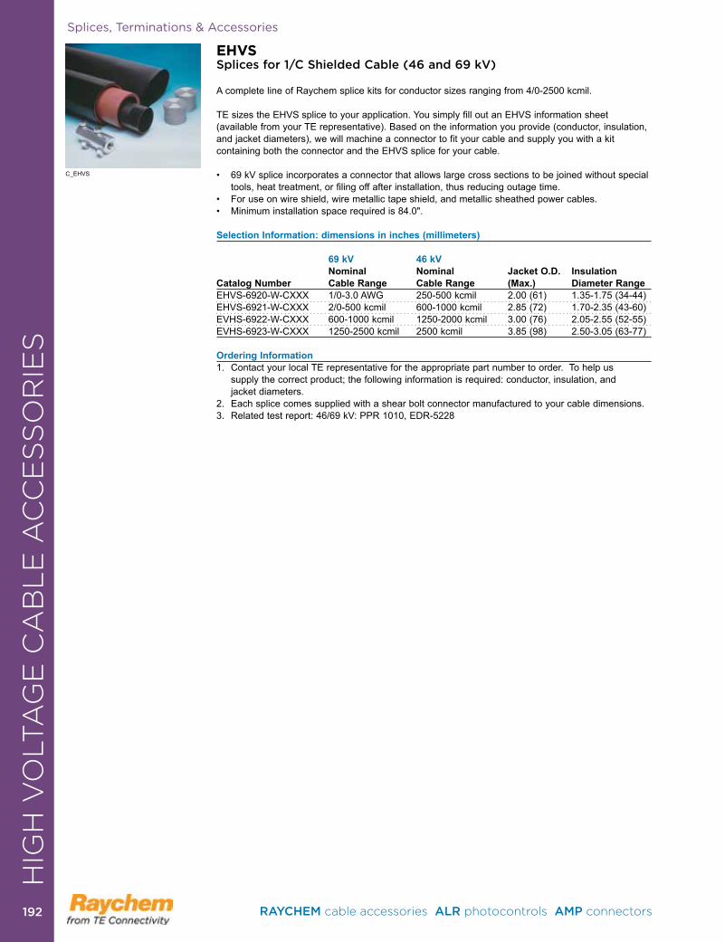
Splices, Terminations & Accessories
EHVSSplices for 1/C Shielded Cable (46 and 69 kV)
A complete line of Raychem splice kits for conductor sizes ranging from 4/0-2500 kcmil . TE sizes the EHVS splice to your application . You simply fill out an EHVS information sheet (available from your TE representative) . Based on the information you provide (conductor, insulation, and jacket diameters), we will machine a connector to fit your cable and supply you with a kit containing both the connector and the EHVS splice for your cable .
• 69 kV splice incorporates a connector that allows large cross sections to be joined without special tools, heat treatment, or filing off after installation, thus reducing outage time .• For use on wire shield, wire metallic tape shield, and metallic sheathed power cables. • Minimum installation space required is 84.0".
Selection Information: dimensions in inches (millimeters)
69 kV 46 kV Nominal Nominal Jacket O.D. Insulation Catalog Number Cable Range Cable Range (Max.) Diameter RangeEHVS-6920-W-CXXX 1/0-3 .0 AWG 250-500 kcmil 2 .00 (61) 1 .35-1 .75 (34-44)EHVS-6921-W-CXXX 2/0-500 kcmil 600-1000 kcmil 2 .85 (72) 1 .70-2 .35 (43-60)EVHS-6922-W-CXXX 600-1000 kcmil 1250-2000 kcmil 3 .00 (76) 2 .05-2 .55 (52-55)EVHS-6923-W-CXXX 1250-2500 kcmil 2500 kcmil 3 .85 (98) 2 .50-3 .05 (63-77)
Ordering Information1 . Contact your local TE representative for the appropriate part number to order . To help us
supply the correct product; the following information is required: conductor, insulation, and jacket diameters .
2 . Each splice comes supplied with a shear bolt connector manufactured to your cable dimensions .3 . Related test report: 46/69 kV: PPR 1010, EDR-5228
C_EHVS
HIG
H V
OLT
AG
E C
AB
LE
AC
CE
SS
OR
IES
RAYCHEM cable accessories ALR photocontrols AMP connectors 192192
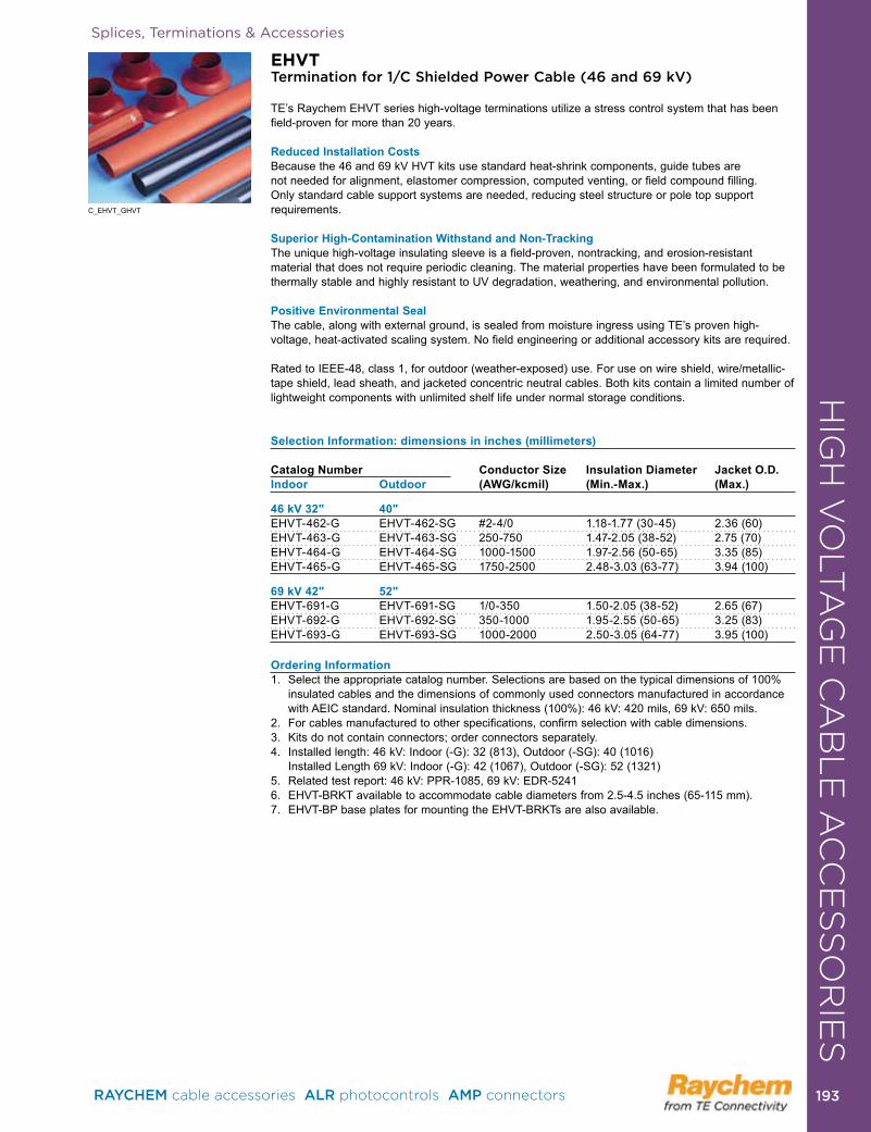
Splices, Terminations & Accessories
EHVTTermination for 1/C Shielded Power Cable (46 and 69 kV)
TE’s Raychem EHVT series high-voltage terminations utilize a stress control system that has been field-proven for more than 20 years .
Reduced Installation CostsBecause the 46 and 69 kV HVT kits use standard heat-shrink components, guide tubes are not needed for alignment, elastomer compression, computed venting, or field compound filling . Only standard cable support systems are needed, reducing steel structure or pole top support requirements .
Superior High-Contamination Withstand and Non-TrackingThe unique high-voltage insulating sleeve is a field-proven, nontracking, and erosion-resistant material that does not require periodic cleaning . The material properties have been formulated to be thermally stable and highly resistant to UV degradation, weathering, and environmental pollution .
Positive Environmental SealThe cable, along with external ground, is sealed from moisture ingress using TE’s proven high-voltage, heat-activated scaling system . No field engineering or additional accessory kits are required .
Rated to IEEE-48, class 1, for outdoor (weather-exposed) use . For use on wire shield, wire/metallic-tape shield, lead sheath, and jacketed concentric neutral cables . Both kits contain a limited number of lightweight components with unlimited shelf life under normal storage conditions .
Selection Information: dimensions in inches (millimeters) Catalog Number Conductor Size Insulation Diameter Jacket O.D. Indoor Outdoor (AWG/kcmil) (Min.-Max.) (Max.) 46 kV 32" 40"EHVT-462-G EHVT-462-SG #2-4/0 1 .18-1 .77 (30-45) 2 .36 (60)EHVT-463-G EHVT-463-SG 250-750 1 .47-2 .05 (38-52) 2 .75 (70)EHVT-464-G EHVT-464-SG 1000-1500 1 .97-2 .56 (50-65) 3 .35 (85)EHVT-465-G EHVT-465-SG 1750-2500 2 .48-3 .03 (63-77) 3 .94 (100) 69 kV 42" 52"EHVT-691-G EHVT-691-SG 1/0-350 1 .50-2 .05 (38-52) 2 .65 (67)EHVT-692-G EHVT-692-SG 350-1000 1 .95-2 .55 (50-65) 3 .25 (83)EHVT-693-G EHVT-693-SG 1000-2000 2 .50-3 .05 (64-77) 3 .95 (100)
Ordering Information1 . Select the appropriate catalog number . Selections are based on the typical dimensions of 100%
insulated cables and the dimensions of commonly used connectors manufactured in accordance with AEIC standard . Nominal insulation thickness (100%): 46 kV: 420 mils, 69 kV: 650 mils .
2 . For cables manufactured to other specifications, confirm selection with cable dimensions . 3 . Kits do not contain connectors; order connectors separately .4 . Installed length: 46 kV: Indoor (-G): 32 (813), Outdoor (-SG): 40 (1016)
Installed Length 69 kV: Indoor (-G): 42 (1067), Outdoor (-SG): 52 (1321)5 . Related test report: 46 kV: PPR-1085, 69 kV: EDR-5241 6 . EHVT-BRKT available to accommodate cable diameters from 2 .5-4 .5 inches (65-115 mm) . 7 . EHVT-BP base plates for mounting the EHVT-BRKTs are also available .
C_EHVT_GHVT
HIG
H V
OLT
AG
E C
AB
LE
AC
CE
SS
OR
IES
RAYCHEM cable accessories ALR photocontrols AMP connectors 193 193
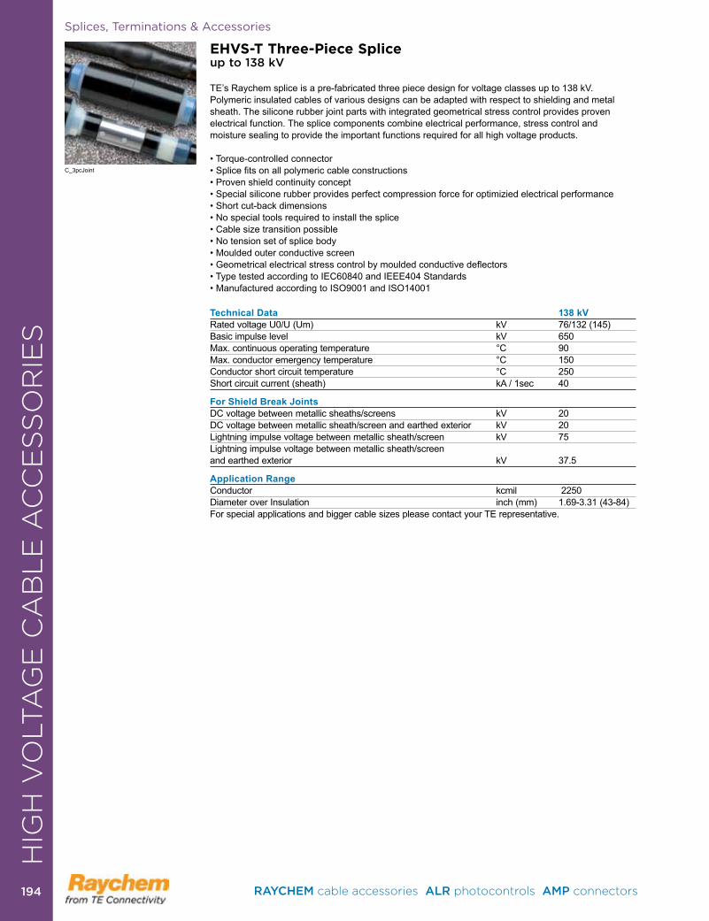
Splices, Terminations & Accessories
EHVS-T Three-Piece Spliceup to 138 kV
TE’s Raychem splice is a pre-fabricated three piece design for voltage classes up to 138 kV . Polymeric insulated cables of various designs can be adapted with respect to shielding and metal sheath . The silicone rubber joint parts with integrated geometrical stress control provides proven electrical function . The splice components combine electrical performance, stress control and moisture sealing to provide the important functions required for all high voltage products .
• Torque-controlled connector• Splice fits on all polymeric cable constructions• Proven shield continuity concept • Special silicone rubber provides perfect compression force for optimizied electrical performance• Short cut-back dimensions• No special tools required to install the splice• Cable size transition possible• No tension set of splice body• Moulded outer conductive screen• Geometrical electrical stress control by moulded conductive deflectors• Type tested according to IEC60840 and IEEE404 Standards • Manufactured according to ISO9001 and ISO14001
Technical Data 138 kVRated voltage U0/U (Um) kV 76/132 (145)Basic impulse level kV 650Max . continuous operating temperature °C 90Max . conductor emergency temperature °C 150Conductor short circuit temperature °C 250Short circuit current (sheath) kA / 1sec 40
For Shield Break JointsDC voltage between metallic sheaths/screens kV 20DC voltage between metallic sheath/screen and earthed exterior kV 20Lightning impulse voltage between metallic sheath/screen kV 75Lightning impulse voltage between metallic sheath/screen and earthed exterior kV 37 .5
Application RangeConductor kcmil 2250Diameter over Insulation inch (mm) 1 .69-3 .31 (43-84) For special applications and bigger cable sizes please contact your TE representative .
C_3pcJoint
HIG
H V
OLT
AG
E C
AB
LE
AC
CE
SS
OR
IES
RAYCHEM cable accessories ALR photocontrols AMP connectors 194194
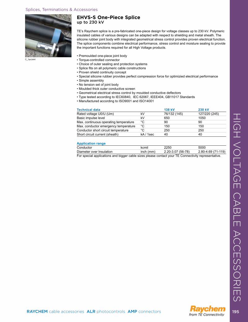
Splices, Terminations & Accessories
C_1pcJoint
HIG
H V
OLT
AG
E C
AB
LE
AC
CE
SS
OR
IES
EHVS-S One-Piece Spliceup to 230 kV
TE’s Raychem splice is a pre-fabricated one-piece design for voltage classes up to 230 kV . Polymeric insulated cables of various designs can be adapted with respect to shielding and metal sheath . The silicone rubber joint body with integrated geometrical stress control provides proven electrical function . The splice components combine electrical performance, stress control and moisture sealing to provide the important functions required for all High Voltage products .
• Premoulded one-piece joint body• Torque-controlled connector • Choice of outer sealing and protection systems• Splice fits on all polymeric cable constructions• Proven shield continuity concept • Special silicone rubber provides perfect compression force for optimizied electrical performance• Simple assembly• No tension set of joint body• Moulded thick outer conductive screen• Geometrical electrical stress control by moulded conductive deflectors • Type tested according to IEC60840, IEC 62067, IEEE404, GB11017 Standards • Manufactured according to ISO9001 and ISO14001
Technical data 138 kV 230 kVRated voltage U0/U (Um) kV 76/132 (145) 127/220 (245)Basic impulse level kV 650 1050Max . continuous operating temperature °C 90 90Max . conductor emergency temperature °C 150 150Conductor short circuit temperature °C 250 250Short circuit current (sheath) kA / 1sec 40 40 Application rangeConductor kcmil 2250 5000Diameter over Insulation inch (mm) 2 .20-3 .07 (56-78) 2 .80-4 .69 (71-119)For special applications and bigger cable sizes please contact your TE Connectivity representative .
RAYCHEM cable accessories ALR photocontrols AMP connectors 195 195
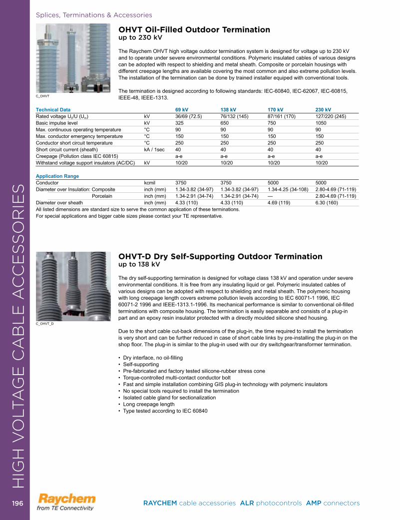
Splices, Terminations & Accessories
OHVT Oil-Filled Outdoor Terminationup to 230 kV
The Raychem OHVT high voltage outdoor termination system is designed for voltage up to 230 kV and to operate under severe environmental conditions . Polymeric insulated cables of various designs can be adopted with respect to shielding and metal sheath . Composite or porcelain housings with different creepage lengths are available covering the most common and also extreme pollution levels . The installation of the termination can be done by trained installer equiped with conventional tools .
The termination is designed according to following standards: IEC-60840, IEC-62067, IEC-60815, IEEE-48, IEEE-1313 .C_OHVT
Technical Data 69 kV 138 kV 170 kV 230 kVRated voltage U0/U (Um) kV 36/69 (72 .5) 76/132 (145) 87/161 (170) 127/220 (245)Basic impulse level kV 325 650 750 1050Max . continuous operating temperature °C 90 90 90 90Max . conductor emergency temperature °C 150 150 150 150Conductor short circuit temperature °C 250 250 250 250Short circuit current (sheath) kA / 1sec 40 40 40 40Creepage (Pollution class IEC 60815) a-e a-e a-e a-eWithstand voltage support insulators (AC/DC) kV 10/20 10/20 10/20 10/20 Application RangeConductor kcmil 3750 3750 5000 5000Diameter over Insulation: Composite inch (mm) 1 .34-3 .82 (34-97) 1 .34-3 .82 (34-97) 1 .34-4 .25 (34-108) 2 .80-4 .69 (71-119) Porcelain inch (mm) 1 .34-2 .91 (34-74) 1 .34-2 .91 (34-74) — 2 .80-4 .69 (71-119)Diameter over sheath inch (mm) 4 .33 (110) 4 .33 (110) 4 .69 (119) 6 .30 (160)All listed dimensions are standard size to serve the common application of these terminations . For special applications and bigger cable sizes please contact your TE representative .
OHVT-D Dry Self-Supporting Outdoor Terminationup to 138 kV
The dry self-supporting termination is designed for voltage class 138 kV and operation under severe environmental conditions . It is free from any insulating liquid or gel . Polymeric insulated cables of various designs can be adopted with respect to shielding and metal sheath . The polymeric housing with long creepage length covers extreme pollution levels according to IEC 60071-1 1996, IEC 60071-2 1996 and IEEE-1313.1-1996. Its mechanical performance is similar to conventional oil-filled terminations with composite housing . The termination is easily separable and consists of a plug-in part and an epoxy resin insulator protected with a directly moulded silicone shed housing .
Due to the short cable cut-back dimensions of the plug-in, the time required to install the termination is very short and can be further re duced in case of short cable links by pre-installing the plug-in on the shop floor. The plug-in is similar to the plug-in used with our dry switchgear/transformer termination.
• Dry interface, no oil-filling• Self-supporting• Pre-fabricated and factory tested silicone-rubber stress cone• Torque-controlled multi-contact conductor bolt • Fast and simple installation com bining GIS plug-in technology with polymeric insulators • No special tools required to install the termination • Isolated cable gland for sectiona li zation • Long creepage length• Type tested according to IEC 60840
C_OHVT_D
HIG
H V
OLT
AG
E C
AB
LE
AC
CE
SS
OR
IES
RAYCHEM cable accessories ALR photocontrols AMP connectors 196196
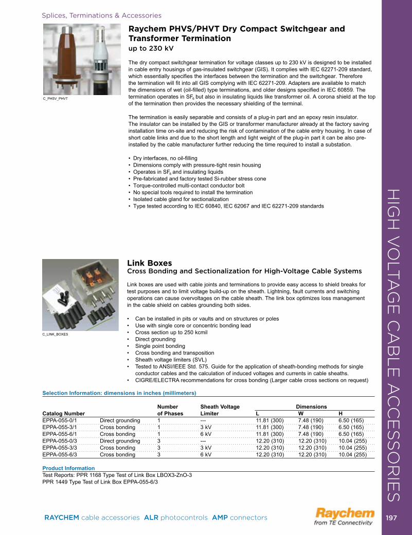
Splices, Terminations & Accessories
Raychem PHVS/PHVT Dry Compact Switchgear and Transformer Terminationup to 230 kV
The dry compact switchgear termination for voltage classes up to 230 kV is designed to be installed in cable entry housings of gas-insulated switchgear (GIS) . It complies with IEC 62271-209 standard, which essentially specifies the interfaces between the termination and the switchgear . Therefore the termination will fit into all GIS complying with IEC 62271-209 . Adapters are available to match the dimensions of wet (oil-filled) type terminations, and older designs specified in IEC 60859 . The termination operates in SF6 but also in insulating liquids like transformer oil . A corona shield at the top of the termination then provides the necessary shielding of the terminal . The termination is easily separable and consists of a plug-in part and an epoxy resin insulator . The insulator can be installed by the GIS or transformer manufacturer already at the factory saving installation time on-site and reducing the risk of contamination of the cable entry housing . In case of short cable links and due to the short length and light weight of the plug-in part it can be also pre-installed by the cable manufacturer further reducing the time required to install a substation .
• Dry interfaces, no oil-filling• Dimensions comply with pressure-tight resin housing• Operates in SF6 and insulating liquids• Pre-fabricated and factory tested Si-rubber stress cone• Torque-controlled multi-contact conductor bolt• No special tools required to install the termination• Isolated cable gland for sectio nalization• Type tested according to IEC 60840, IEC 62067 and IEC 62271-209 standards
C_PHSV_PHVT
Link BoxesCross Bonding and Sectionalization for High-Voltage Cable Systems
Link boxes are used with cable joints and terminations to provide easy access to shield breaks for test purposes and to limit voltage build-up on the sheath . Lightning, fault currents and switching operations can cause overvoltages on the cable sheath . The link box optimizes loss management in the cable shield on cables grounding both sides .
• Can be installed in pits or vaults and on structures or poles• Use with single core or concentric bonding lead• Cross section up to 250 kcmil• Direct grounding• Single point bonding • Cross bonding and transposition• Sheath voltage limiters (SVL) • Tested to ANSI/IEEE Std. 575. Guide for the application of sheath-bonding methods for single
conductor cables and the calculation of induced voltages and currents in cable sheaths .• CIGRE/ELECTRA recommendations for cross bonding (Larger cable cross sections on request)
Selection Information: dimensions in inches (millimeters)
Number Sheath Voltage DimensionsCatalog Number of Phases Limiter L W HEPPA-055-0/1 Direct grounding 1 --- 11 .81 (300) 7 .48 (190) 6 .50 (165)EPPA-055-3/1 Cross bonding 1 3 kV 11 .81 (300) 7 .48 (190) 6 .50 (165)EPPA-055-6/1 Cross bonding 1 6 kV 11 .81 (300) 7 .48 (190) 6 .50 (165)EPPA-055-0/3 Direct grounding 3 --- 12 .20 (310) 12 .20 (310) 10 .04 (255)EPPA-055-3/3 Cross bonding 3 3 kV 12 .20 (310) 12 .20 (310) 10 .04 (255)EPPA-055-6/3 Cross bonding 3 6 kV 12 .20 (310) 12 .20 (310) 10 .04 (255)
Product InformationTest Reports: PPR 1168 Type Test of Link Box LBOX3-ZnO-3PPR 1449 Type Test of Link Box EPPA-055-6/3
C_LINK_BOXES
HIG
H V
OLT
AG
E C
AB
LE
AC
CE
SS
OR
IES
RAYCHEM cable accessories ALR photocontrols AMP connectors 197 197
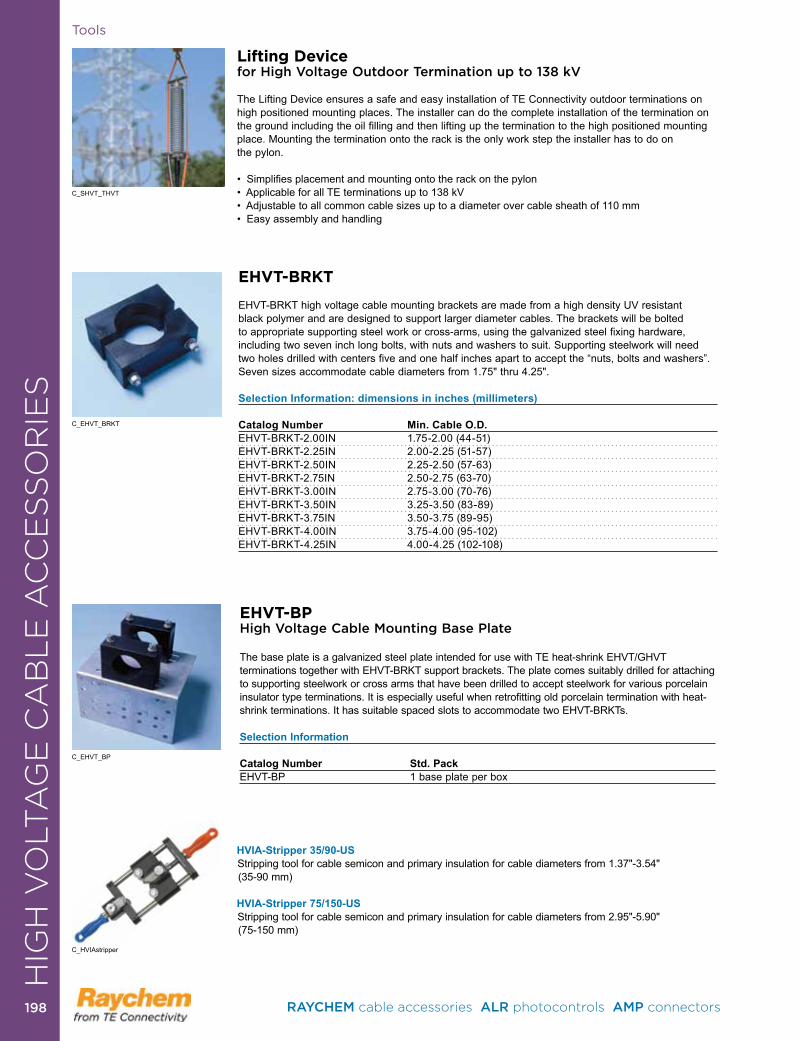
Tools
Lifting Devicefor High Voltage Outdoor Termination up to 138 kV
The Lifting Device ensures a safe and easy installation of TE Connectivity outdoor terminations on high positioned mounting places . The installer can do the complete installation of the termination on the ground including the oil filling and then lifting up the termination to the high positioned mounting place . Mounting the termination onto the rack is the only work step the installer has to do on the pylon .
• Simplifies placement and mounting onto the rack on the pylon• Applicable for all TE terminations up to 138 kV• Adjustable to all common cable sizes up to a diameter over cable sheath of 110 mm• Easy assembly and handling
C_SHVT_THVT
EHVT-BPHigh Voltage Cable Mounting Base Plate
The base plate is a galvanized steel plate intended for use with TE heat-shrink EHVT/GHVT terminations together with EHVT-BRKT support brackets . The plate comes suitably drilled for attaching to supporting steelwork or cross arms that have been drilled to accept steelwork for various porcelain insulator type terminations . It is especially useful when retrofitting old porcelain termination with heat-shrink terminations . It has suitable spaced slots to accommodate two EHVT-BRKTs .
Selection Information
Catalog Number Std. PackEHVT-BP 1 base plate per box
C_EHVT_BP
EHVT-BRKT
EHVT-BRKT high voltage cable mounting brackets are made from a high density UV resistant black polymer and are designed to support larger diameter cables . The brackets will be bolted to appropriate supporting steel work or cross-arms, using the galvanized steel fixing hardware, including two seven inch long bolts, with nuts and washers to suit . Supporting steelwork will need two holes drilled with centers five and one half inches apart to accept the “nuts, bolts and washers” . Seven sizes accommodate cable diameters from 1.75" thru 4.25".
Selection Information: dimensions in inches (millimeters)
Catalog Number Min. Cable O.D.EHVT-BRKT-2 .00IN 1 .75-2 .00 (44-51)EHVT-BRKT-2 .25IN 2 .00-2 .25 (51-57)EHVT-BRKT-2 .50IN 2 .25-2 .50 (57-63)EHVT-BRKT-2 .75IN 2 .50-2 .75 (63-70)EHVT-BRKT-3 .00IN 2 .75-3 .00 (70-76)EHVT-BRKT-3 .50IN 3 .25-3 .50 (83-89)EHVT-BRKT-3 .75IN 3 .50-3 .75 (89-95)EHVT-BRKT-4 .00IN 3 .75-4 .00 (95-102)EHVT-BRKT-4 .25IN 4 .00-4 .25 (102-108)
C_EHVT_BRKT
HVIA-Stripper 35/90-US Stripping tool for cable semicon and primary insulation for cable diameters from 1.37"-3.54" (35-90 mm)
HVIA-Stripper 75/150-USStripping tool for cable semicon and primary insulation for cable diameters from 2.95"-5.90" (75-150 mm)
C_HVIAstripper
HIG
H V
OLT
AG
E C
AB
LE
AC
CE
SS
OR
IES
RAYCHEM cable accessories ALR photocontrols AMP connectors 198198
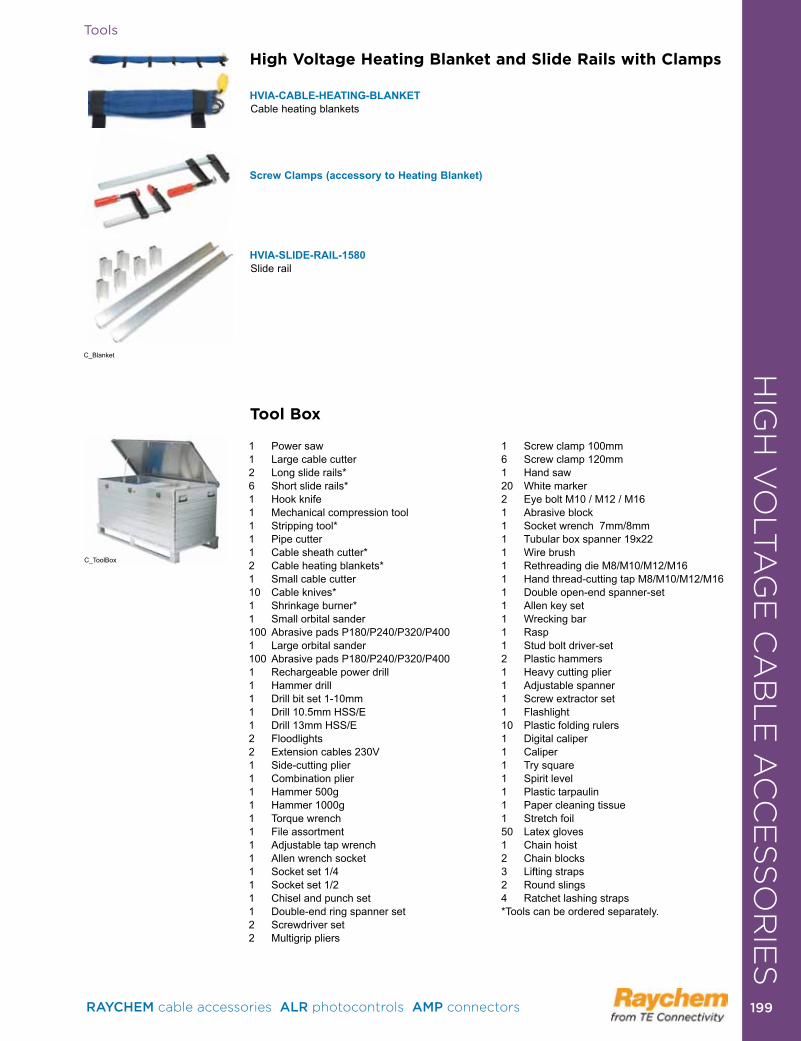
Tools
High Voltage Heating Blanket and Slide Rails with Clamps
HVIA-CABLE-HEATING-BLANKETCable heating blankets
Screw Clamps (accessory to Heating Blanket)
HVIA-SLIDE-RAIL-1580Slide rail
1 Power saw1 Large cable cutter2 Long slide rails*6 Short slide rails*1 Hook knife1 Mechanical compression tool1 Stripping tool*1 Pipe cutter1 Cable sheath cutter*2 Cable heating blankets*1 Small cable cutter10 Cable knives*1 Shrinkage burner*1 Small orbital sander100 Abrasive pads P180/P240/P320/P4001 Large orbital sander100 Abrasive pads P180/P240/P320/P4001 Rechargeable power drill1 Hammer drill1 Drill bit set 1-10mm1 Drill 10 .5mm HSS/E1 Drill 13mm HSS/E2 Floodlights2 Extension cables 230V1 Side-cutting plier1 Combination plier1 Hammer 500g1 Hammer 1000g1 Torque wrench1 File assortment1 Adjustable tap wrench1 Allen wrench socket1 Socket set 1/41 Socket set 1/21 Chisel and punch set1 Double-end ring spanner set2 Screwdriver set2 Multigrip pliers
1 Screw clamp 100mm6 Screw clamp 120mm1 Hand saw20 White marker2 Eye bolt M10 / M12 / M161 Abrasive block1 Socket wrench 7mm/8mm1 Tubular box spanner 19x221 Wire brush1 Rethreading die M8/M10/M12/M161 Hand thread-cutting tap M8/M10/M12/M161 Double open-end spanner-set1 Allen key set1 Wrecking bar1 Rasp1 Stud bolt driver-set2 Plastic hammers1 Heavy cutting plier1 Adjustable spanner1 Screw extractor set1 Flashlight10 Plastic folding rulers1 Digital caliper1 Caliper1 Try square1 Spirit level1 Plastic tarpaulin1 Paper cleaning tissue1 Stretch foil50 Latex gloves1 Chain hoist2 Chain blocks3 Lifting straps2 Round slings4 Ratchet lashing straps*Tools can be ordered separately .
Tool Box
HIG
H V
OLT
AG
E C
AB
LE
AC
CE
SS
OR
IES
C_ToolBox
C_Blanket
RAYCHEM cable accessories ALR photocontrols AMP connectors 199 199
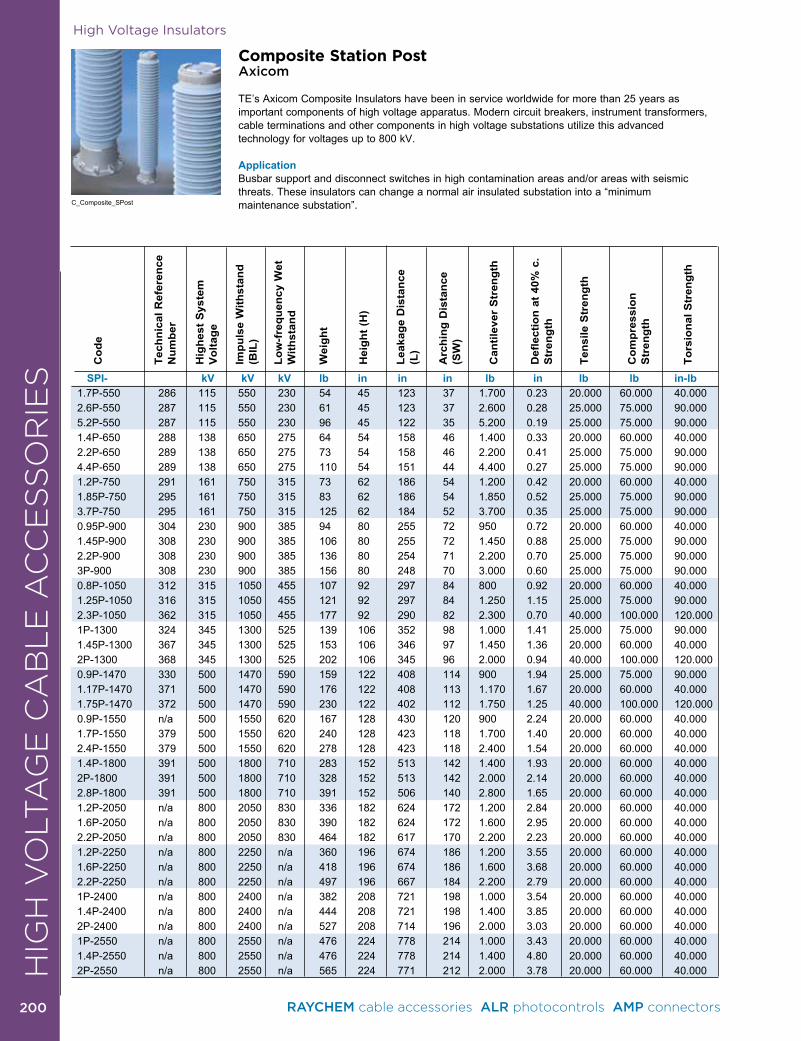
High Voltage Insulators
SPI- kV kV kV lb in in in lb in lb lb in-lb1 .7P-550 286 115 550 230 54 45 123 37 1 .700 0 .23 20 .000 60 .000 40 .0002 .6P-550 287 115 550 230 61 45 123 37 2 .600 0 .28 25 .000 75 .000 90 .0005 .2P-550 287 115 550 230 96 45 122 35 5 .200 0 .19 25 .000 75 .000 90 .0001 .4P-650 288 138 650 275 64 54 158 46 1 .400 0 .33 20 .000 60 .000 40 .0002 .2P-650 289 138 650 275 73 54 158 46 2 .200 0 .41 25 .000 75 .000 90 .0004 .4P-650 289 138 650 275 110 54 151 44 4 .400 0 .27 25 .000 75 .000 90 .0001 .2P-750 291 161 750 315 73 62 186 54 1 .200 0 .42 20 .000 60 .000 40 .0001 .85P-750 295 161 750 315 83 62 186 54 1 .850 0 .52 25 .000 75 .000 90 .0003 .7P-750 295 161 750 315 125 62 184 52 3 .700 0 .35 25 .000 75 .000 90 .0000 .95P-900 304 230 900 385 94 80 255 72 950 0 .72 20 .000 60 .000 40 .0001 .45P-900 308 230 900 385 106 80 255 72 1 .450 0 .88 25 .000 75 .000 90 .0002 .2P-900 308 230 900 385 136 80 254 71 2 .200 0 .70 25 .000 75 .000 90 .0003P-900 308 230 900 385 156 80 248 70 3 .000 0 .60 25 .000 75 .000 90 .0000 .8P-1050 312 315 1050 455 107 92 297 84 800 0 .92 20 .000 60 .000 40 .0001 .25P-1050 316 315 1050 455 121 92 297 84 1 .250 1 .15 25 .000 75 .000 90 .0002 .3P-1050 362 315 1050 455 177 92 290 82 2 .300 0 .70 40 .000 100 .000 120 .0001P-1300 324 345 1300 525 139 106 352 98 1 .000 1 .41 25 .000 75 .000 90 .0001 .45P-1300 367 345 1300 525 153 106 346 97 1 .450 1 .36 20 .000 60 .000 40 .0002P-1300 368 345 1300 525 202 106 345 96 2 .000 0 .94 40 .000 100 .000 120 .0000 .9P-1470 330 500 1470 590 159 122 408 114 900 1 .94 25 .000 75 .000 90 .0001 .17P-1470 371 500 1470 590 176 122 408 113 1 .170 1 .67 20 .000 60 .000 40 .0001 .75P-1470 372 500 1470 590 230 122 402 112 1 .750 1 .25 40 .000 100 .000 120 .0000 .9P-1550 n/a 500 1550 620 167 128 430 120 900 2 .24 20 .000 60 .000 40 .0001 .7P-1550 379 500 1550 620 240 128 423 118 1 .700 1 .40 20 .000 60 .000 40 .0002 .4P-1550 379 500 1550 620 278 128 423 118 2 .400 1 .54 20 .000 60 .000 40 .0001 .4P-1800 391 500 1800 710 283 152 513 142 1 .400 1 .93 20 .000 60 .000 40 .0002P-1800 391 500 1800 710 328 152 513 142 2 .000 2 .14 20 .000 60 .000 40 .0002 .8P-1800 391 500 1800 710 391 152 506 140 2 .800 1 .65 20 .000 60 .000 40 .0001 .2P-2050 n/a 800 2050 830 336 182 624 172 1 .200 2 .84 20 .000 60 .000 40 .0001 .6P-2050 n/a 800 2050 830 390 182 624 172 1 .600 2 .95 20 .000 60 .000 40 .0002 .2P-2050 n/a 800 2050 830 464 182 617 170 2 .200 2 .23 20 .000 60 .000 40 .0001 .2P-2250 n/a 800 2250 n/a 360 196 674 186 1 .200 3 .55 20 .000 60 .000 40 .0001 .6P-2250 n/a 800 2250 n/a 418 196 674 186 1 .600 3 .68 20 .000 60 .000 40 .0002 .2P-2250 n/a 800 2250 n/a 497 196 667 184 2 .200 2 .79 20 .000 60 .000 40 .0001P-2400 n/a 800 2400 n/a 382 208 721 198 1 .000 3 .54 20 .000 60 .000 40 .0001 .4P-2400 n/a 800 2400 n/a 444 208 721 198 1 .400 3 .85 20 .000 60 .000 40 .0002P-2400 n/a 800 2400 n/a 527 208 714 196 2 .000 3 .03 20 .000 60 .000 40 .0001P-2550 n/a 800 2550 n/a 476 224 778 214 1 .000 3 .43 20 .000 60 .000 40 .0001 .4P-2550 n/a 800 2550 n/a 476 224 778 214 1 .400 4 .80 20 .000 60 .000 40 .0002P-2550 n/a 800 2550 n/a 565 224 771 212 2 .000 3 .78 20 .000 60 .000 40 .000
Cod
e
Tech
nica
l Ref
eren
ce
Num
ber
Hig
hest
Sys
tem
V
olta
ge
Impu
lse
With
stan
d (B
IL)
Low
-fre
quen
cy W
et
With
stan
d
Wei
ght
Hei
ght (
H)
Leak
age
Dis
tanc
e (L
)
Arc
hing
Dis
tanc
e (S
W)
Can
tilev
er S
tren
gth
Def
lect
ion
at 4
0% c
. S
tren
gth
Tens
ile S
tren
gth
Com
pres
sion
S
tren
gth
Tors
iona
l Str
engt
h
C_Composite_SPost
Composite Station PostAxicom
TE’s Axicom Composite Insulators have been in service worldwide for more than 25 years as important components of high voltage apparatus . Modern circuit breakers, instrument transformers, cable terminations and other components in high voltage substations utilize this advancedtechnology for voltages up to 800 kV . ApplicationBusbar support and disconnect switches in high contamination areas and/or areas with seismic threats . These insulators can change a normal air insulated substation into a “minimum maintenance substation” .
HIG
H V
OLT
AG
E C
AB
LE
AC
CE
SS
OR
IES
RAYCHEM cable accessories ALR photocontrols AMP connectors 200200
ProductProduct
Cable Repair & RejacketingGMRS Rejacketing Sleeve . . . . . . . . . . . . . . . . . . . . . . . . . . . . . 202MBSM Wraparound Jacket Repair . . . . . . . . . . . . . . . . . . . . . . . 203HVS-LR Repair Kits . . . . . . . . . . . . . . . . . . . . . . . . . . . . . . . . . . 204CRSM Wraparound Sleeves (1000 V) . . . . . . . . . . . . . . . . . . . . 205MRS WraparoundFlame Retardant Sleeve . . . . . . . . . . . . . . . . 206
CABLE REPAIR & REJACKETING
RAYCHEM cable accessories ALR photocontrols AMP connectors 201 201
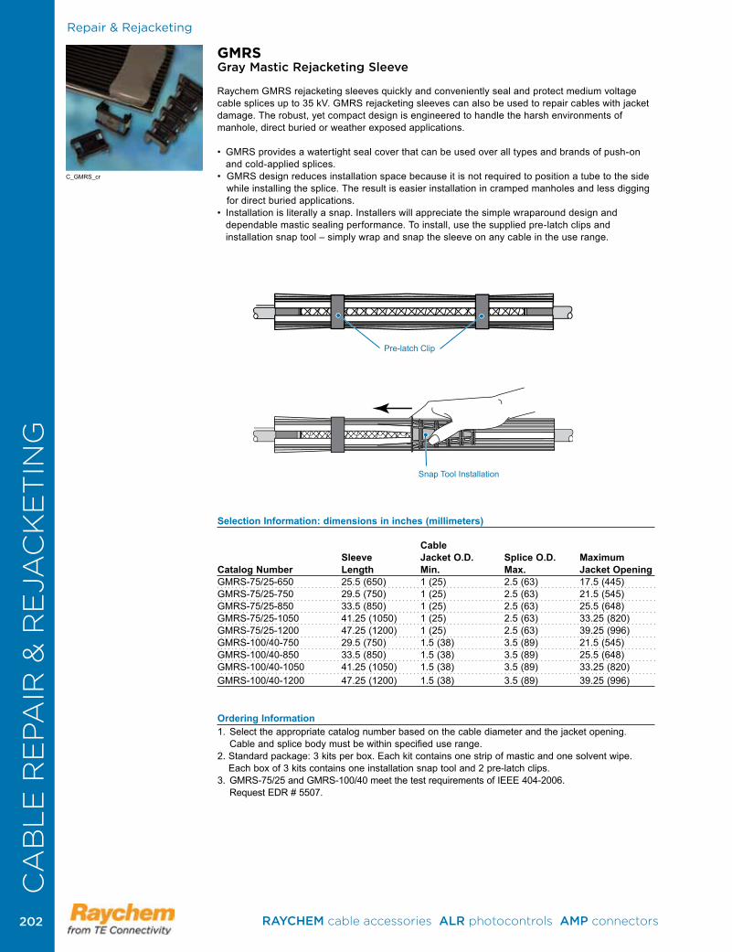
Repair & Rejacketing
GMRSGray Mastic Rejacketing Sleeve
Raychem GMRS rejacketing sleeves quickly and conveniently seal and protect medium voltage cable splices up to 35 kV . GMRS rejacketing sleeves can also be used to repair cables with jacket damage . The robust, yet compact design is engineered to handle the harsh environments of manhole, direct buried or weather exposed applications .
• GMRSprovidesawatertightsealcoverthatcanbeusedoveralltypesandbrandsofpush-onand cold-applied splices .
•GMRSdesignreducesinstallationspacebecauseitisnotrequiredtopositionatubetothesidewhile installing the splice . The result is easier installation in cramped manholes and less digging for direct buried applications .
• Installationisliterallyasnap.Installerswillappreciatethesimplewraparounddesignanddependable mastic sealing performance . To install, use the supplied pre-latch clips and installation snap tool – simply wrap and snap the sleeve on any cable in the use range .
Selection Information: dimensions in inches (millimeters)
Cable Sleeve Jacket O.D. Splice O.D. MaximumCatalog Number Length Min. Max. Jacket Opening GMRS-75/25-650 25 .5 (650) 1 (25) 2 .5 (63) 17 .5 (445) GMRS-75/25-750 29 .5 (750) 1 (25) 2 .5 (63) 21 .5 (545)GMRS-75/25-850 33 .5 (850) 1 (25) 2 .5 (63) 25 .5 (648)GMRS-75/25-1050 41 .25 (1050) 1 (25) 2 .5 (63) 33 .25 (820)GMRS-75/25-1200 47 .25 (1200) 1 (25) 2 .5 (63) 39 .25 (996)GMRS-100/40-750 29 .5 (750) 1 .5 (38) 3 .5 (89) 21 .5 (545)GMRS-100/40-850 33 .5 (850) 1 .5 (38) 3 .5 (89) 25 .5 (648)GMRS-100/40-1050 41 .25 (1050) 1 .5 (38) 3 .5 (89) 33 .25 (820)GMRS-100/40-1200 47 .25 (1200) 1 .5 (38) 3 .5 (89) 39 .25 (996)
Ordering Information1 . Select the appropriate catalog number based on the cable diameter and the jacket opening .
Cable and splice body must be within specified use range .2 . Standard package: 3 kits per box . Each kit contains one strip of mastic and one solvent wipe .
Each box of 3 kits contains one installation snap tool and 2 pre-latch clips . 3. GMRS-75/25andGMRS-100/40meetthetestrequirementsofIEEE404-2006.
Request EDR # 5507 .
C_GMRS_cr
Pre-latch Clip
SnapToolInstallation
CA
BL
E R
EPA
IR &
RE
JAC
KE
TIN
G
RAYCHEM cable accessories ALR photocontrols AMP connectors 202202
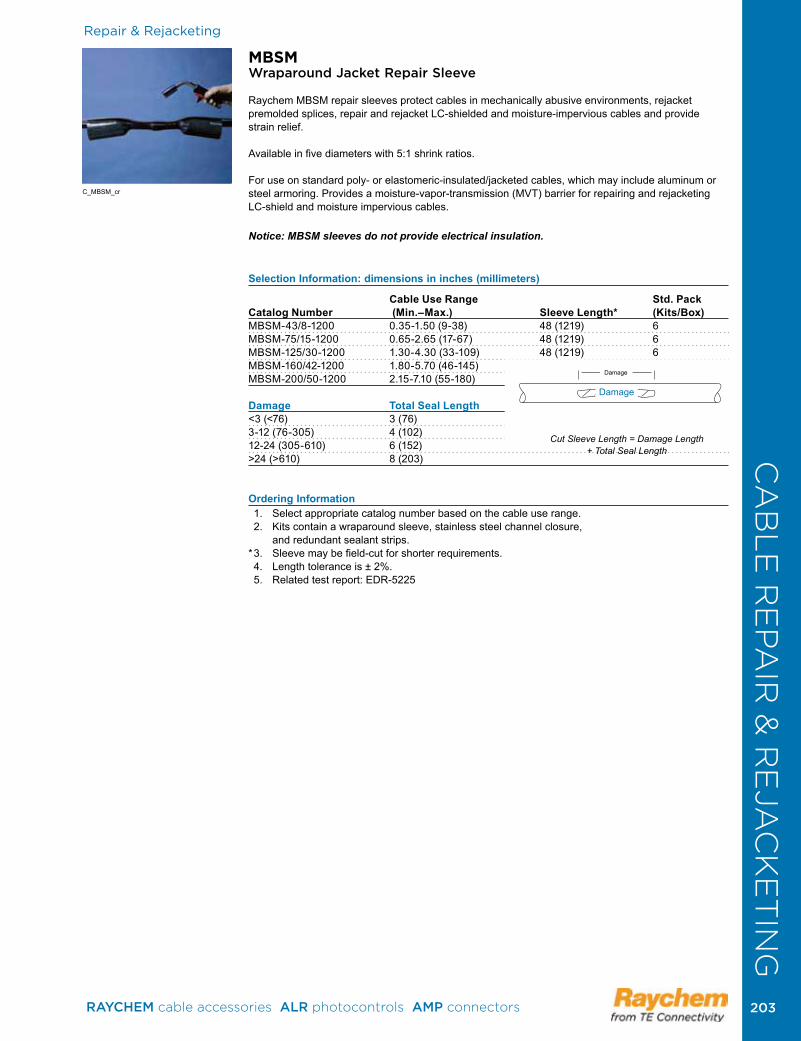
MBSMWraparound Jacket Repair Sleeve
Raychem MBSM repair sleeves protect cables in mechanically abusive environments, rejacket premolded splices, repair and rejacket LC-shielded and moisture-impervious cables and provide strain relief .
Available in five diameters with 5:1 shrink ratios .
For use on standard poly- or elastomeric-insulated/jacketed cables, which may include aluminum or steel armoring . Provides a moisture-vapor-transmission (MVT) barrier for repairing and rejacketing LC-shield and moisture impervious cables .
Notice: MBSM sleeves do not provide electrical insulation.
Selection Information: dimensions in inches (millimeters)
Cable Use Range Std. PackCatalog Number (Min.–Max.) Sleeve Length* (Kits/Box)MBSM-43/8-1200 0 .35-1 .50 (9-38) 48 (1219) 6MBSM-75/15-1200 0 .65-2 .65 (17-67) 48 (1219) 6MBSM-125/30-1200 1 .30-4 .30 (33-109) 48 (1219) 6MBSM-160/42-1200 1 .80-5 .70 (46-145) 48 (1219) 6MBSM-200/50-1200 2 .15-7 .10 (55-180) 48 (1219) 6 Damage Total Seal Length<3 (<76) 3 (76)3-12 (76-305) 4 (102)12-24 (305-610) 6 (152)>24 (>610) 8 (203)
Ordering Information 1 . Select appropriate catalog number based on the cable use range . 2 . Kits contain a wraparound sleeve, stainless steel channel closure, and redundant sealant strips .* 3 . Sleeve may be field-cut for shorter requirements . 4 . Length tolerance is ± 2% . 5 . Related test report: EDR-5225
CA
BL
E R
EPA
IR &
RE
JAC
KE
TIN
GRepair & Rejacketing
Cut Sleeve Length = Damage Length + Total Seal Length
Damage
Damage
C_MBSM_cr
RAYCHEM cable accessories ALR photocontrols AMP connectors 203 203
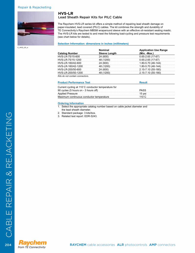
CA
BL
E R
EPA
IR &
RE
JAC
KE
TIN
G Repair & Rejacketing
HVS-LRLead Sheath Repair Kits for PILC Cable
The Raychem HVS-LR series kit offers a simple method of repairing lead sheath damage on paper-insulated,leadcovered(PILC)cables.Thekitcombinesthestrengthanddurabilityof TE Connectivity’s Raychem MBSM wraparound sleeve with an effective oil-resistant sealing mastic . The HVS-LR kits are tested to and meet the following load-cycling and pressure test requirements (see chart below for details) .
Selection Information: dimensions in inches (millimeters)
Nominal Application Use RangeCatalog Number Sleeve Length (Min. -Max.) HVS-LR-75/15-600 24 (600) 0 .65-2 .65 (17-67)HVS-LR-75/15-1200 48 (1200) 0 .65-2 .65 (17-67)HVS-LR-160/42-600 24 (600) 1 .80-5 .70 (46-144)HVS-LR-160/42-1200 48 (1200) 1 .80-5 .70 (46-144)HVS-LR-200/50-600 24 (600) 2 .15-7 .10 (55-180)HVS-LR-200/50-1200 48 (1200) 2 .15-7 .10 (55-180) Kits do not contain connectors.
Product Performance Test Result
Currentcyclingat110˚Cconductortemperaturefor90 cycles (5 hours on - 3 hours off) PASSApplied Pressure 15 psiMaximumcontinuousconductortemperature 110˚C
Ordering Information 1 . Select the appropriate catalog number based on cable jacket diameter and the lead sheath diameter .2 . Standard package: 3 kits/box .3 . Related test report: EDR-5243 .
C_HVS_LR_cr
CA
BL
E R
EPA
IR &
RE
JAC
KE
TIN
G
RAYCHEM cable accessories ALR photocontrols AMP connectors 204204
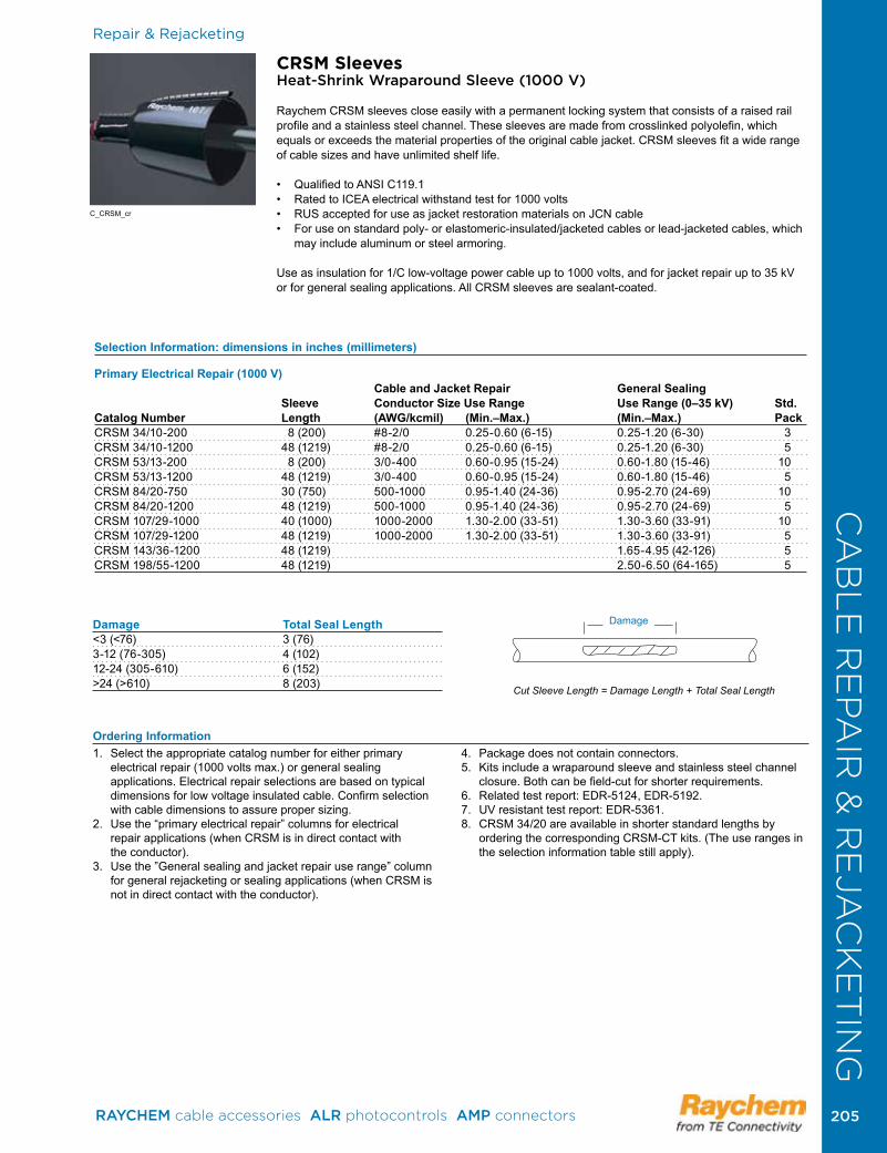
Repair & Rejacketing
Selection Information: dimensions in inches (millimeters)
Primary Electrical Repair (1000 V) Cable and Jacket Repair General Sealing Sleeve Conductor Size Use Range Use Range (0–35 kV) Std. Catalog Number Length (AWG/kcmil) (Min.–Max.) (Min.–Max.) PackCRSM 34/10-200 8 (200) #8-2/0 0 .25-0 .60 (6-15) 0 .25-1 .20 (6-30) 3CRSM 34/10-1200 48 (1219) #8-2/0 0 .25-0 .60 (6-15) 0 .25-1 .20 (6-30) 5CRSM 53/13-200 8 (200) 3/0-400 0 .60-0 .95 (15-24) 0 .60-1 .80 (15-46) 10CRSM 53/13-1200 48 (1219) 3/0-400 0 .60-0 .95 (15-24) 0 .60-1 .80 (15-46) 5CRSM 84/20-750 30 (750) 500-1000 0 .95-1 .40 (24-36) 0 .95-2 .70 (24-69) 10CRSM 84/20-1200 48 (1219) 500-1000 0 .95-1 .40 (24-36) 0 .95-2 .70 (24-69) 5CRSM 107/29-1000 40 (1000) 1000-2000 1 .30-2 .00 (33-51) 1 .30-3 .60 (33-91) 10CRSM 107/29-1200 48 (1219) 1000-2000 1 .30-2 .00 (33-51) 1 .30-3 .60 (33-91) 5CRSM 143/36-1200 48 (1219) 1 .65-4 .95 (42-126) 5CRSM 198/55-1200 48 (1219) 2 .50-6 .50 (64-165) 5
Damage Total Seal Length<3 (<76) 3 (76)3-12 (76-305) 4 (102)12-24 (305-610) 6 (152)>24 (>610) 8 (203)
CRSM SleevesHeat-Shrink Wraparound Sleeve (1000 V)
Raychem CRSM sleeves close easily with a permanent locking system that consists of a raised rail profile and a stainless steel channel . These sleeves are made from crosslinked polyolefin, which equals or exceeds the material properties of the original cable jacket . CRSM sleeves fit a wide range of cable sizes and have unlimited shelf life .
• QualifiedtoANSIC119.1• RatedtoICEAelectricalwithstandtestfor1000volts• RUSacceptedforuseasjacketrestorationmaterialsonJCNcable• Foruseonstandardpoly-orelastomeric-insulated/jacketedcablesorlead-jacketedcables,which
may include aluminum or steel armoring .
Useasinsulationfor1/Clow-voltagepowercableupto1000volts,andforjacketrepairupto35kVor for general sealing applications . All CRSM sleeves are sealant-coated .
Cut Sleeve Length = Damage Length + Total Seal Length
Damage
1 . Select the appropriate catalog number for either primary electrical repair (1000 volts max .) or general sealing applications . Electrical repair selections are based on typical dimensionsforlowvoltageinsulatedcable.Confirmselectionwith cable dimensions to assure proper sizing .
2.Usethe“primaryelectricalrepair”columnsforelectrical repair applications (when CRSM is in direct contact with the conductor) .
3. Usethe”Generalsealingandjacketrepairuserange”columnfor general rejacketing or sealing applications (when CRSM is not in direct contact with the conductor) .
4 . Package does not contain connectors .5 . Kits include a wraparound sleeve and stainless steel channel
closure.Bothcanbefield-cutforshorterrequirements.6 . Related test report: EDR-5124, EDR-5192 .7.UVresistanttestreport:EDR-5361.8 . CRSM 34/20 are available in shorter standard lengths by
ordering the corresponding CRSM-CT kits . (The use ranges in the selection information table still apply) .
Ordering Information
Damage
C_CRSM_cr
CA
BL
E R
EPA
IR &
RE
JAC
KE
TIN
G
RAYCHEM cable accessories ALR photocontrols AMP connectors 205 205
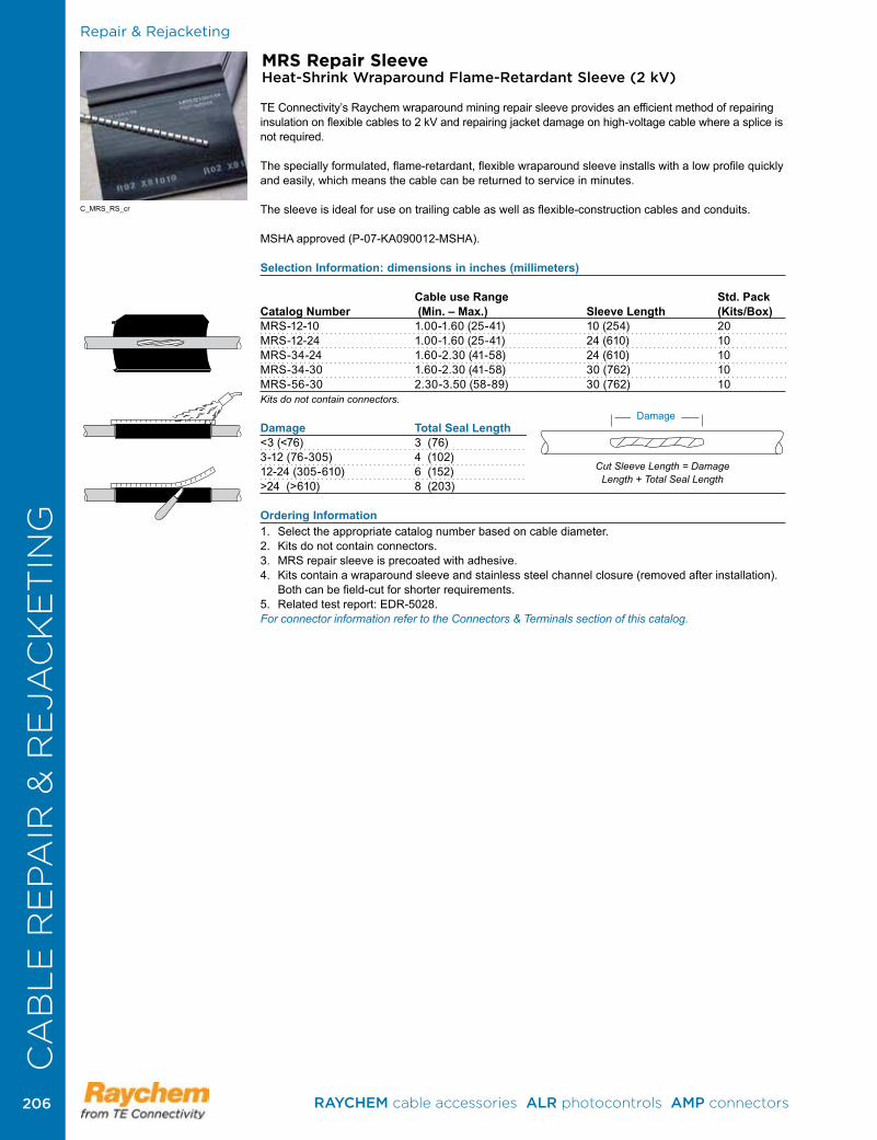
Repair & Rejacketing
MRS Repair Sleeve Heat-Shrink Wraparound Flame-Retardant Sleeve (2 kV)
TE Connectivity’s Raychem wraparound mining repair sleeve provides an efficient method of repairing insulation on flexible cables to 2 kV and repairing jacket damage on high-voltage cable where a splice is not required .
The specially formulated, flame-retardant, flexible wraparound sleeve installs with a low profile quickly and easily, which means the cable can be returned to service in minutes .
The sleeve is ideal for use on trailing cable as well as flexible-construction cables and conduits .
MSHA approved (P-07-KA090012-MSHA) .
Selection Information: dimensions in inches (millimeters)
Cable use Range Std. PackCatalog Number (Min. – Max.) Sleeve Length (Kits/Box)MRS-12-10 1 .00-1 .60 (25-41) 10 (254) 20MRS-12-24 1 .00-1 .60 (25-41) 24 (610) 10MRS-34-24 1 .60-2 .30 (41-58) 24 (610) 10MRS-34-30 1 .60-2 .30 (41-58) 30 (762) 10MRS-56-30 2 .30-3 .50 (58-89) 30 (762) 10 Kits do not contain connectors. Damage Total Seal Length<3 (<76) 3 (76)3-12 (76-305) 4 (102)12-24 (305-610) 6 (152)>24 (>610) 8 (203)
Ordering Information 1 . Select the appropriate catalog number based on cable diameter .2 . Kits do not contain connectors .3 . MRS repair sleeve is precoated with adhesive .4 . Kits contain a wraparound sleeve and stainless steel channel closure (removed after installation) .
Bothcanbefield-cutforshorterrequirements.5 . Related test report: EDR-5028 .For connector information refer to the Connectors & Terminals section of this catalog.
C_MRS_RS_cr
Cut Sleeve Length = Damage Length + Total Seal Length
DamageDamage
CA
BL
E R
EPA
IR &
RE
JAC
KE
TIN
G
RAYCHEM cable accessories ALR photocontrols AMP connectors 206206
ProductProduct
Heat-Shrink Tubing RNF-100 Tubing . . . . . . . . . . . . . . . . . . . . . . . . . . . . . . . . . . . . .208MWTM Tubing . . . . . . . . . . . . . . . . . . . . . . . . . . . . . . . . . . . . . .209WCSM Tubing . . . . . . . . . . . . . . . . . . . . . . . . . . . . . . . . . . . . . .210FCSM Tubing . . . . . . . . . . . . . . . . . . . . . . . . . . . . . . . . . . . . . . .212LVIT Tubing . . . . . . . . . . . . . . . . . . . . . . . . . . . . . . . . . . . . . . . .213
Molded PartsESC Sealing Caps . . . . . . . . . . . . . . . . . . . . . . . . . . . . . . . . . . .213CFTS Seals . . . . . . . . . . . . . . . . . . . . . . . . . . . . . . . . . . . . . . . .214CBR Breakout Boot . . . . . . . . . . . . . . . . . . . . . . . . . . . . . . . . . .215
TUBING & MOLDED PARTS
RAYCHEM cable accessories ALR photocontrols AMP connectors 207 207
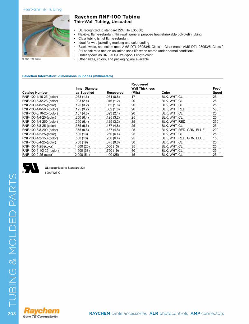
Heat-Shrink Tubing
Raychem RNF-100 TubingThin-Wall Tubing, Uncoated
• ULrecognizedtostandard224(fileE35586)•Flexible,flame-retardant,thin-wall,generalpurposeheat-shrinkablepolyolefintubing• Cleartubingisnotflame-retardant• Idealforwirejacketingmarkingandcolorcoding• Black,white,andcolorsmeetAMS-DTL-23053/5,Class1.ClearmeetsAMS-DTL-23053/5,Class2• 2:1shrinkratioandanunlimitedshelflifewhenstoredundernormalconditions• OrderspoolsasRNF-100-Size-SpoolLength-color• Othersizes,colors,andpackagingareavailable
Selection Information: dimensions in inches (millimeters)
Recovered Inner Diameter Wall Thickness Feet/
Catalog Number as Supplied Recovered (Mils) Color SpoolRNF-100-1/16-25-(color) .063(1.6) .031(0.8) 17 BLK,WHT,CL 25RNF-100-3/32-25-(color) .093(2.4) .046(1.2) 20 BLK,WHT,CL 25RNF-100-1/8-25-(color) .125(3.2) .062(1.6) 20 BLK,WHT,CL 25RNF-100-1/8-500-(color) .125(3.2) .062(1.6) 20 BLK,WHT,RED 500RNF-100-3/16-25-(color) .187(4.8) .093(2.4) 20 BLK,WHT,CL 25RNF-100-1/4-25-(color) .250(6.4) .125(3.2) 25 BLK,WHT,CL 25RNF-100-1/4-250-(color) .250(6.4) .125(3.2) 25 BLK,WHT,RED 250RNF-100-3/8-25-(color) .375(9.6) .187(4.8) 25 BLK,WHT,CL 25RNF-100-3/8-200-(color) .375(9.6) .187(4.8) 25 BLK,WHT,RED,GRN,BLUE 200RNF-100-1/2-25-(color) .500(13) .250(6.4) 25 BLK,WHT,CL 25RNF-100-1/2-150-(color) .500(13) .250(6.4) 25 BLK,WHT,RED,GRN,BLUE 150RNF-100-3/4-25-(color) .750(19) .375(9.6) 30 BLK,WHT,CL 25RNF-100-1-25-(color) 1.000(25) .500(13) 35 BLK,WHT,CL 25RNF-100-11/2-25-(color) 1.500(38) .750(19) 40 BLK,WHT,CL 25RNF-100-2-25-(color) 2.000(51) 1.00(25) 45 BLK,WHT,CL 25
UL recognized to Standard 224
600V/125˚C
C_RNF_100_tubing
TU
BIN
G &
MO
LD
ED
PA
RT
S
RAYCHEM cable accessories ALR photocontrols AMP connectors 208208
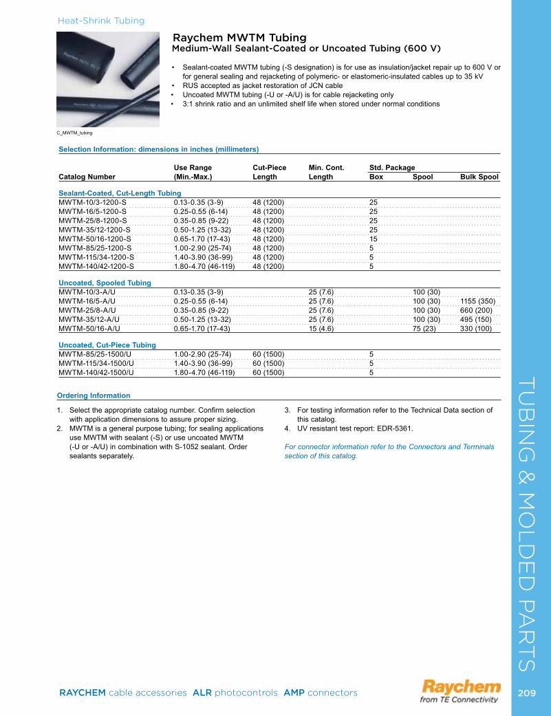
TU
BIN
G &
MO
LD
ED
PA
RT
SHeat-Shrink Tubing
Raychem MWTM TubingMedium-Wall Sealant-Coated or Uncoated Tubing (600 V)
• Sealant-coatedMWTMtubing(-Sdesignation)isforuseasinsulation/jacketrepairupto600Vorforgeneralsealingandrejacketingofpolymeric-orelastomeric-insulatedcablesupto35kV
• RUSacceptedasjacketrestorationofJCNcable• UncoatedMWTMtubing(-Uor-A/U)isforcablerejacketingonly• 3:1shrinkratioandanunlimitedshelflifewhenstoredundernormalconditions
Selection Information: dimensions in inches (millimeters)
Use Range Cut-Piece Min. Cont. Std. PackageCatalog Number (Min.-Max.) Length Length Box Spool Bulk Spool
Sealant-Coated, Cut-Length Tubing MWTM-10/3-1200-S 0.13-0.35(3-9) 48(1200) 25MWTM-16/5-1200-S 0.25-0.55(6-14) 48(1200) 25MWTM-25/8-1200-S 0.35-0.85(9-22) 48(1200) 25MWTM-35/12-1200-S 0.50-1.25(13-32) 48(1200) 25MWTM-50/16-1200-S 0.65-1.70(17-43) 48(1200) 15MWTM-85/25-1200-S 1.00-2.90(25-74) 48(1200) 5MWTM-115/34-1200-S 1.40-3.90(36-99) 48(1200) 5MWTM-140/42-1200-S 1.80-4.70(46-119) 48(1200) 5 Uncoated, Spooled TubingMWTM-10/3-A/U 0.13-0.35(3-9) 25(7.6) 100(30)MWTM-16/5-A/U 0.25-0.55(6-14) 25(7.6) 100(30) 1155(350)MWTM-25/8-A/U 0.35-0.85(9-22) 25(7.6) 100(30) 660(200)MWTM-35/12-A/U 0.50-1.25(13-32) 25(7.6) 100(30) 495(150)MWTM-50/16-A/U 0.65-1.70(17-43) 15(4.6) 75(23) 330(100) Uncoated, Cut-Piece TubingMWTM-85/25-1500/U 1.00-2.90(25-74) 60(1500) 5MWTM-115/34-1500/U 1.40-3.90(36-99) 60(1500) 5MWTM-140/42-1500/U 1.80-4.70(46-119) 60(1500) 5
1. Selecttheappropriatecatalognumber.Confirmselection withapplicationdimensionstoassurepropersizing.
2. MWTMisageneralpurposetubing;forsealingapplicationsuseMWTMwithsealant(-S)oruseuncoatedMWTM (-Uor-A/U)incombinationwithS-1052sealant.Order sealantsseparately.
3. FortestinginformationrefertotheTechnicalDatasectionofthiscatalog.
4. UVresistanttestreport:EDR-5361.
For connector information refer to the Connectors and Terminals section of this catalog.
Ordering Information
C_MWTM_tubing
RAYCHEM cable accessories ALR photocontrols AMP connectors 209 209
Heat-Shrink Tubing
Raychem WCSM Tubing Heavy-Wall Sealant Coated Tubing (1000 V)
• Foruseonstandardpolyorelastomericinsulated/jacketedcableorlead-jacketedcables,whichmayincludealuminumorsteelarmoring.
• WCSMtubingcanbeusedtosealanin-linespliceorterminallugsealfornon-flameretardantapplications,cablere-jacketingandmechanicalprotection.
• WCSMtubingsizes12-3through70-20isULandcULlistedper486D(fileE91151).• QualifiedtoANSIC119.1andratedtoWesternUndergroundguide2.5.AlsoRUS acceptedforuseasasecondarytaporsplicecover,andforuseasjacketrestorationmaterials onJCNcable.
• WCSMtubingmaybeusedforjacketrepaironcablesupto35kV.• WCSMtubinghasa4:1shrinkratioandanunlimitedshelflifewhenstoredundernormalconditions.
Note: UL listing applies to WCSM 12/3 through 70/20 only. WCSM 110/30 and 130/35 have not been evaluated to the UL standards. WCSM is no longer offered as an uncoated option. You can substitute either WCSM coated or MWTM uncoated depending on which will work for your application.
C_WCSM_tubing
TU
BIN
G &
MO
LD
ED
PA
RT
S
Selection Information: dimensions in inches (millimeters) 1000 V Cable General Maximum Mininum Nominal Use Maximum UL Conductor Conductor Connector Seal LengthCatalog Number Range AWG/kcmil Connector Use Range Use Range Opeing per SideTubing Size Min Max OD Min-Max Min-Max “A”WCSM-12/3-150-S #14 #6 0.29 .13-.30(3.5-7.7) .13-.39(3.5-10) 2.4 1.5WCSM-12/3-300-S #14 #6 0.29 .13-.30(3.5-7.7) .13-.39(3.5-10) 7.8 1.5WCSM-12/3-1200-S #14 #6 0.29 .13-.30(3.5-7.7) .13-.39(3.5-10) 39.3 1.5WCSM-16/4-150-S #8 #2 0.41 .17-.41(4.5-10.5) .17-.55(4.5-14) 1.4 2WCSM-16/4-300-S #8 #2 0.41 .17-.41(4.5-10.5) .17-.55(4.5-14) 6.8 2WCSM-16/4-1200-S #8 #2 0.41 .17-.41(4.5-10.5) .17-.55(4.5-14) 38.3 2WCSM-24/6-150-S #6 #4/0 0.69 .25-.64(6.5-16.5) .25-.86(6.5-22) 1.4 2WCSM-24/6-225-S #6 #4/0 0.69 .25-.64(6.5-16.5) .25-.86(6.5-22) 3.96 2WCSM-24/6-300-S #6 #4/0 0.69 .25-.64(6.5-16.5) .25-.86(6.5-22) 6.8 2WCSM-24/6-1200-S #6 #4/0 0.69 .25-.64(6.5-16.5) .25-.86(6.5-22) 38.3 2WCSM-34/8-150-S #2 500 1.06 .35-.94(9-24) .35-1.22(9-31) 1.4 2WCSM-34/8-200-S #2 500 1.06 .35-.94(9-24) .35-1.22(9-31) 3.02 2WCSM-34/8-225-S #2 500 1.06 .35-.94(9-24) .35-1.22(9-31) 3.96 2WCSM-34/8-300-S #2 500 1.06 .35-.94(9-24) .35-1.22(9-31) 6.8 2WCSM-34/8-1200-S #2 500 1.06 .35-.94(9-24) .35-1.22(9-31) 38.48 2WCSM-48/12-150-S #2/0 750 1.3 .51-1.12(13-28.5) .51-1.73(13-44) 1.4 2WCSM-48/12-225-S #2/0 750 1.3 .51-1.12(13-28.5) .51-1.73(13-44) 3.96 2WCSM-48/12-300-S #2/0 750 1.3 .51-1.12(13-28.5) .51-1.73(13-44) 6.8 2WCSM-48/12-1200-S #2/0 750 1.3 .51-1.12(13-28.5) .51-1.73(13-44) 38.3 2WCSM-56/16-225-S 250 1000 1.5 .68-1.27(17.5-32.5) .70-1.96(17.5-50) 3.96 2WCSM-56/16-300-S 250 1000 1.5 .68-1.27(17.5-32.5) .70-1.96(17.5-50) 6.62 2WCSM-56/16-1200-S 250 1000 1.5 .68-1.27(17.5-32.5) .70-1.96(17.5-50) 38.3 2WCSM-70/20-300-S 500 1500 1.84 .92-1.40(22-35.8) .86-2.48(22-63) 5.8 2.5WCSM-70/20-450-S 500 1500 1.84 .92-1.40(22-35.8) .86-2.48(22-63) 10.93 2.5WCSM-70/20-600-S 500 1500 1.84 .92-1.40(22-35.8) .86-2.48(22-63) 16.26 2.5WCSM-70/20-1200-S 500 1500 1.84 .92-1.40(22-35.8) .86-2.48(22-63) 37.3 2.5WCSM-110/30-300-S 1250 2000 - - 1.29-3.93(33-100) 2.5WCSM-110/30-1200-S 1250 2000 - - 1.29-3.93(33-100) 2.5WCSM-130/35-300-S 1500 2500 - - 1.49-4.64(39-118) 2.5WCSM-130/35-450-S 1500 2500 - - 1.49-4.64(39-118) 2.5WCSM-130/35-1200-S 1500 2500 - - 1.49-4.64(39-118) 2.5
RAYCHEM cable accessories ALR photocontrols AMP connectors 210210
CA
BL
E R
EPA
IR &
RE
JAC
KE
TIN
G
1.Selecttheappropriatecatalognumberbasedontypicaldimensionsforlow-voltageinsulatedcable.Confirmselectionwithdimensionstoassurepropersizing.ForgeneralconductoruseorULconductoruse.”
2 Package does not contain connectors or lugs . Installed connectororlugdiametermustbewithinuserange.
3.WCSMtubingmaybefield-cutforshorterrequirements4. Bulkpackagingisavailableforcutlengths.ConsultyourTE
representativeformoreinformation.
5.ULlistingappliestoWCSM12/3through70/20only.WCSM110/30and130/35arenotULlisted.
6.Relatedtestreports:EDR5541,PII56428
For connector information refer to the Connectors and Terminals section of this catalog.
Ordering Information
Heat-Shrink TubingT
UB
ING
& M
OL
DE
D P
AR
TS
MaxConnector Opening
A A
WireConnectorSystemforUseWithUndergroundConnectors96J4
RAYCHEM cable accessories ALR photocontrols AMP connectors 211 211
CA
BL
E R
EPA
IR &
RE
JAC
KE
TIN
G
Raychem FCSM TubingHeavy-Wall Flame Retardant Tubing (2000 V)
FCSMtubing’stough,crosslinkedpolyolefinconstructionprovidesmechanicalstrengthandcut-throughresistanceequalto,orsurpassing,thepropertiesoflow-voltagecablejackets.
• 3:1shrinkratioandanunlimitedshelflifewhenstoredundernormalconditions• Usessealant-coatedtubing(-S)asasealedin-linespliceorterminallugseal.Itprovidesa
watertightsealfordirect-buriedapplicationsandwetenvironments.• Useuncoatedtubing(-/U)forcablerejacketingonly• Sealant-coatedoruncoatedtubingmaybeusedforjacketrepaironcableto35kV.Qualifiedto
ANSIC119.1;alsoratedtoIEEE383(VerticalTrayFlameTest)andICEAS-19-81.FCSMisalsoMSHAapproved(P-07-KA090013-MSHA).
Foruseonstandardpoly-orelastomeric-insulated/jacketedcablesorlead-jacketedcables,whichmayincludealuminumorsteelarmoring.
Connectorsupto6inches:Recommendedcutlength=connectorlength+4inches.Connectorsover6inches:Recommendedcutlength=connectorlength+5inches.
Selection Information: dimensions in inches/feet (millimeters/meters)
2000 V Insulated Conductor Size General Use Range Tube Std. Pack Bulk Option
Catalog Number (AWG/kcmil) (Min.–Max.) Length* Ft.(m)/Roll Pcs/Box Ft.(m)/Roll
In-Line Splice Or Terminal Lug Seal (With Sealant)FCSM-9/3-1200-S #14-#8 0.15-0.30(4-8) 48(1200) 25FCSM-19/6-150-S #6-#2 0.25-0.65(6-17) 6(150) 50FCSM-19/6-1200-S #6-#2 0.25-0.65(6-17) 48(1200) 25FCSM-28/9-225-S #2-4/0 0.40-0.95(10-24) 9(225) 50FCSM-28/9-1200-S #2-4/0 0.40-0.95(10-24) 48(1200) 25FCSM-38/12-300-S 1/0-350 0.50-1.30(13-33) 12(300) 40FCSM-38/12-1200-S 1/0-350 0.50-1.30(13-33) 48(1200) 10FCSM-51/16-300-S 250-500 0.70-1.75(18-44) 12(300) 30FCSM-51/16-1200-S 250-500 0.70-1.75(18-44) 48(1200) 10FCSM-68/22-1200-S 600-1000 0.95-2.30(25-58) 48(1200) 10FCSM-90/30-1200-S 800-1200 1.30-3.10(33-79) 48(1200) 5FCSM-120/40-1200-S 1500-2500 1.75-4.10(44-104) 48(1200) 5FCSM-177/63600-S 2.75-6.05(70-154) 24(600) 6FCSM-177/63-1200-S 2.75-6.05(70-154) 48(1200) 5
Cable Rejacketing (Without Sealant)FCSM-9/3-A/U #14-#8 0.15-0.30(4-8) 100 (30)FCSM-19/6-A/U #6-#2 0.25-0.65(6-17) 100 (30) 825 (250)FCSM-28/9-A/U #2-4/0 0.40-0.95(10-24) 65 (20) 495 (150)FCSM-38/12-A/U 1/0-350 0.50-1.30(13-33) 50 (15) 395 (120)FCSM-51/16-A/U 250-500 0.70-1.75(18-44) 40 (12) 330 (100)FCSM-68/22-A/U 600-1000 0.95-2.30(25-58) 80 (24) FCSM-90/30-1500/U 800-1200 1.30-3.10(33-79) 60(1500) 5FCSM-120/40-1500/U 1500-2500 1.75-4.10(44-104) 60(1500) 5FCSM-177/63-1500/U 2.75-6.05(70-154) 60(1500) 5*Length tolerance to ±2 percent.
1. Selecttheappropriatecatalognumberbasedontypicaldimensionsforlow-voltageinsulatedcable.Confirmselectionwithcabledimensionstoassurepropersizing.
2 . Connectors or lugs not included .3. IfsealingisneededwithuncoatedFCSMtubing(-/U),order
S-1052separately.
4. Tubingmaybefield-cutforshorterrequirements.5. Bulkpackagingisavailableforcut-lengths.Contactyour
TEConnectivityrepresentativeforadditionalinformation.6.Relatedtestreports:EDR-5133,EDR-5134,EDR-5141.
For connector information refer to the Connectors and Terminals section of this catalog.
Ordering Information
ConnectorLength
Heat-Shrink Tubing
C_FCSM_tubing
TU
BIN
G &
MO
LD
ED
PA
RT
S
RAYCHEM cable accessories ALR photocontrols AMP connectors 212212
CA
BL
E R
EPA
IR &
RE
JAC
KE
TIN
GHeat-Shrink Tubing
Molded Parts
Selection Information: dimensions in inches (millimeters)
Busbar dimensions LVIT Tubing Dia. as Supplied & Rectangular Bar* Square Bar Round Bar Fully Recovered Std.Catalog Number (Bus Width) (Each Side) (Dia. Min.–Max.) (Min.–Max.) Pack LVIT-30/10-A/U 0.50-1.0(12-25) 0.40-1.0(11-25) 1.18-0.39(30-10) 200ft.LVIT-75/25-A/U 2.0-3.0(50-75) 1(25) 1.0-2.0(25-50) 2.95-0.98(75-25) 100ft.LVIT-150/50-A/U 4.0-6.0(100-150) 2-3(50-75) 2.0-4.0(50-100) 5.91-1.97(150-50) 100ft.*Rectangular bus thickness range is 1/4 to 5/8 inch.
Raychem ESC Sealing CapsEnd Sealing Caps for 1/C Power Cable (1000 V)
•Shrinkandcompressahot-meltadhesiveonthecablejacket,formingasecureenvironmentalseal•Fitseasilyoverthecableendandshrinksinseconds,leavingacompact,ruggedendseal• QualifiedtoANSIC119.1andratedtoICEAelectricalwithstandtestfor1000volts• Foruseonstandardpoly-orelastomericinsulated/jacketedcablesorlead-jacketedcables,whichmayincludealuminumorsteelarmoring.
Useasaliveendsealto1000volts.Useasanendsealforstorageandpullingofde-energizedcable.
Selection Information: dimensions in inches (millimeters)
Primary Insulation (1000 V) General Catalog Conductor Size Use Range Use Range Length Std. PackNumber (AWG/kcmil) (Min.–Max.) (Min.–Max.) L (Pcs/Box)ESC-1/A #12-#8 0.17-0.35(4-9) 0.15-0.30(4-8) 1.0 50ESC-2/A #6-3/0 0.31-0.71(8-18) 0.30-0.70(8-18) 2.0 50ESC-3/A 4/0-750 0.65-1.25(17-32) 0.65-1.25(17-32) 3.5 40ESC-4/A 750-1500 1.08-1.94(27-49) 1.05-1.95(27-50) 5.3 20ESC-5/A 1500-2000 1.38-2.58(35-66) 1.30-2.65(33-67) 6.7 10ESC-6/A 1.94-3.54(49-90) 1.85-3.70(47-94) 5.6 10ESC-7/A 3.02-4.25(77-108) 2.95-4.50(75-114) 5.4 10*5 packs, each with 5 pcs. per Point of Purchase Package.Each energized conductor requires a separate ESC sealing cap.
Ordering information1.Selecttheappropriatecatalognumberbasedontheconductorsizeoruserange.Confirm
selectionwithdimensionstoassurepropersizing.2.EachenergizedconductorrequiresaseparateESCsealingcap.3. Bulkoptionsalsoavailable.ConsultyourTEConnectivityrepresentativeforinformation.4.Capsarecoatedwithanadhesive.5.Relatedtestreport:EDR-5161.
LVIT TubingBusbar Insulating Tubing (1000 V)
RaychemLVITisaheat-shrinkablemedium-wall,flame-retardant,lowvoltagetubingforinsulatingstraightandbentbusbarsduringoriginalequipmentassemblyorinretrofitapplicationswhereaccesstooneendofthebusbarisavailable.
Whenusedaccordingtotheselectionguidelines,LVITmaybeusedinapplicationsupto1kVinaccordancewithANSI/IEEEC37.20specification.LVITtubingmaybeusedinapplicationsupto3.6kVinaccordancewithIECspecifications.
RatedtoANSI/IEEEC37.20.1.ULrecognizedtoStandard224(fileE137416), 600V-125°C-VW.1.
L
C_LVIT_tubing
C_ESC_Caps_tubing
TU
BIN
G &
MO
LD
ED
PA
RT
S
RAYCHEM cable accessories ALR photocontrols AMP connectors 213 213
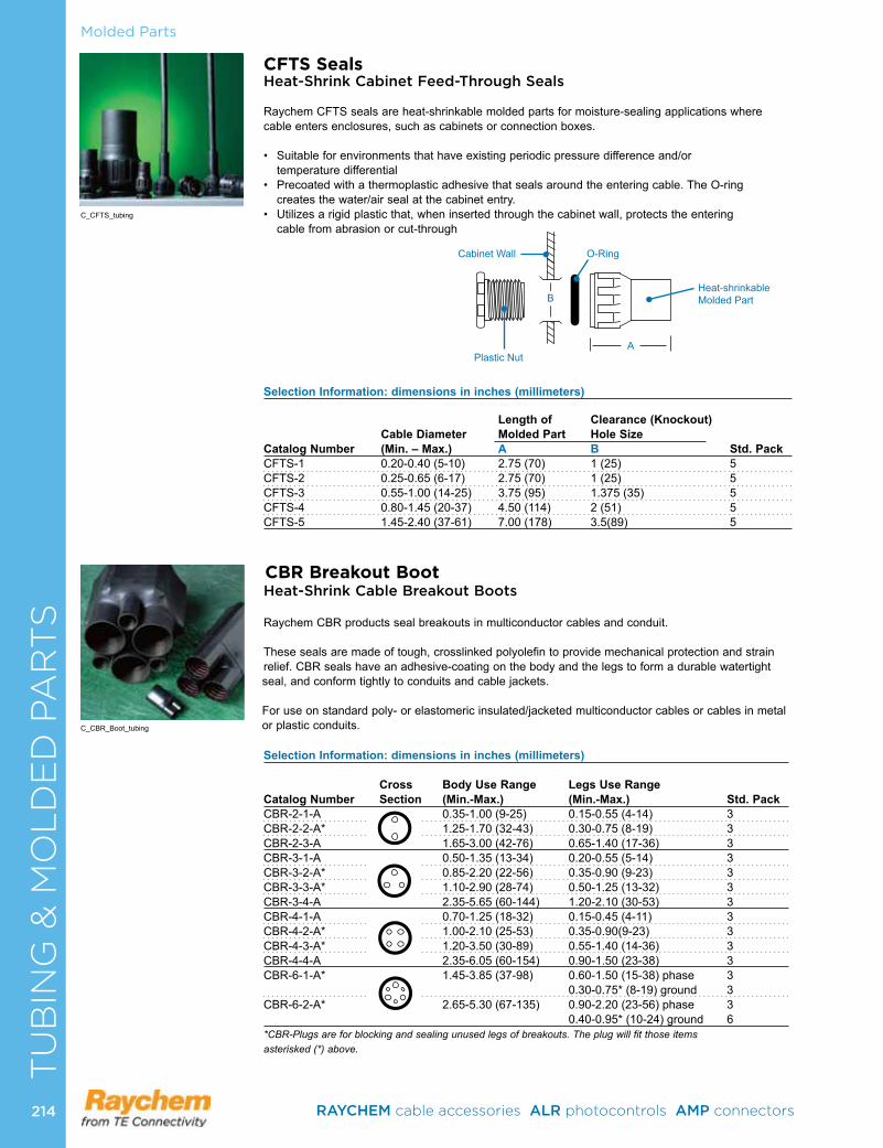
Molded PartsC
AB
LE
RE
PA
IR &
RE
JAC
KE
TIN
G
CFTS SealsHeat-Shrink Cabinet Feed-Through Seals
RaychemCFTSsealsareheat-shrinkablemoldedpartsformoisture-sealingapplicationswherecableentersenclosures,suchascabinetsorconnectionboxes.
• Suitableforenvironmentsthathaveexistingperiodicpressuredifferenceand/or temperaturedifferential
• Precoatedwithathermoplasticadhesivethatsealsaroundtheenteringcable.TheO-ring createsthewater/airsealatthecabinetentry.
• Utilizesarigidplasticthat,wheninsertedthroughthecabinetwall,protectstheentering cablefromabrasionorcut-through
Selection Information: dimensions in inches (millimeters)
Length of Clearance (Knockout) Cable Diameter Molded Part Hole Size Catalog Number (Min. – Max.) A B Std. PackCFTS-1 0.20-0.40(5-10) 2.75(70) 1(25) 5CFTS-2 0.25-0.65(6-17) 2.75(70) 1(25) 5CFTS-3 0.55-1.00(14-25) 3.75(95) 1.375(35) 5CFTS-4 0.80-1.45(20-37) 4.50(114) 2(51) 5CFTS-5 1.45-2.40(37-61) 7.00(178) 3.5(89) 5
C_CFTS_tubing
BHeat-shrinkableMolded Part
Plastic Nut
Cabinet Wall O-Ring
A
CBR Breakout BootHeat-Shrink Cable Breakout Boots
RaychemCBRproductssealbreakoutsinmulticonductorcablesandconduit.
Thesesealsaremadeoftough,crosslinkedpolyolefintoprovidemechanicalprotectionandstrainrelief.CBRsealshaveanadhesive-coatingonthebodyandthelegstoformadurablewatertightseal,andconformtightlytoconduitsandcablejackets.
Foruseonstandardpoly-orelastomericinsulated/jacketedmulticonductorcablesorcablesinmetalor plastic conduits .
Selection Information: dimensions in inches (millimeters)
Cross Body Use Range Legs Use Range Catalog Number Section (Min.-Max.) (Min.-Max.) Std. PackCBR-2-1-A 0.35-1.00(9-25) 0.15-0.55(4-14) 3CBR-2-2-A* 1.25-1.70(32-43) 0.30-0.75(8-19) 3CBR-2-3-A 1.65-3.00(42-76) 0.65-1.40(17-36) 3CBR-3-1-A 0.50-1.35(13-34) 0.20-0.55(5-14) 3CBR-3-2-A* 0.85-2.20(22-56) 0.35-0.90(9-23) 3CBR-3-3-A* 1.10-2.90(28-74) 0.50-1.25(13-32) 3CBR-3-4-A 2.35-5.65(60-144) 1.20-2.10(30-53) 3CBR-4-1-A 0.70-1.25(18-32) 0.15-0.45(4-11) 3CBR-4-2-A* 1.00-2.10(25-53) 0.35-0.90(9-23) 3CBR-4-3-A* 1.20-3.50(30-89) 0.55-1.40(14-36) 3CBR-4-4-A 2.35-6.05(60-154) 0.90-1.50(23-38) 3CBR-6-1-A* 1.45-3.85(37-98) 0.60-1.50(15-38)phase 3 0.30-0.75*(8-19)ground 3CBR-6-2-A* 2.65-5.30(67-135) 0.90-2.20(23-56)phase 3 0.40-0.95*(10-24)ground 6*CBR-Plugs are for blocking and sealing unused legs of breakouts. The plug will fit those items asterisked (*) above.
C_CBR_Boot_tubing
TU
BIN
G &
MO
LD
ED
PA
RT
S
RAYCHEM cable accessories ALR photocontrols AMP connectors 214214
ProductProduct
Tapes Raychem Electrical PVC Tape . . . . . . . . . . . . . . . . . . . . . . . . . 216CRPS Repair Tape . . . . . . . . . . . . . . . . . . . . . . . . . . . . . . . . . . 218FSTW Splicing Tape . . . . . . . . . . . . . . . . . . . . . . . . . . . . . . . . 219MVFT Medium Voltage Fusion Tape . . . . . . . . . . . . . . . . . . . . 219LVBT Busbar Tape . . . . . . . . . . . . . . . . . . . . . . . . . . . . . . . . . . 220HVBT High Voltage Busbar Insulating Tape . . . . . . . . . . . . . . . 221
Sealants Hot-Melt and Cold-Applied Sealants . . . . . . . . . . . . . . . . . . . . 222
TA
PE
S &
SE
AL
AN
TS
TAPES & SEALANTS
RAYCHEM cable accessories ALR photocontrols AMP connectors 215 215
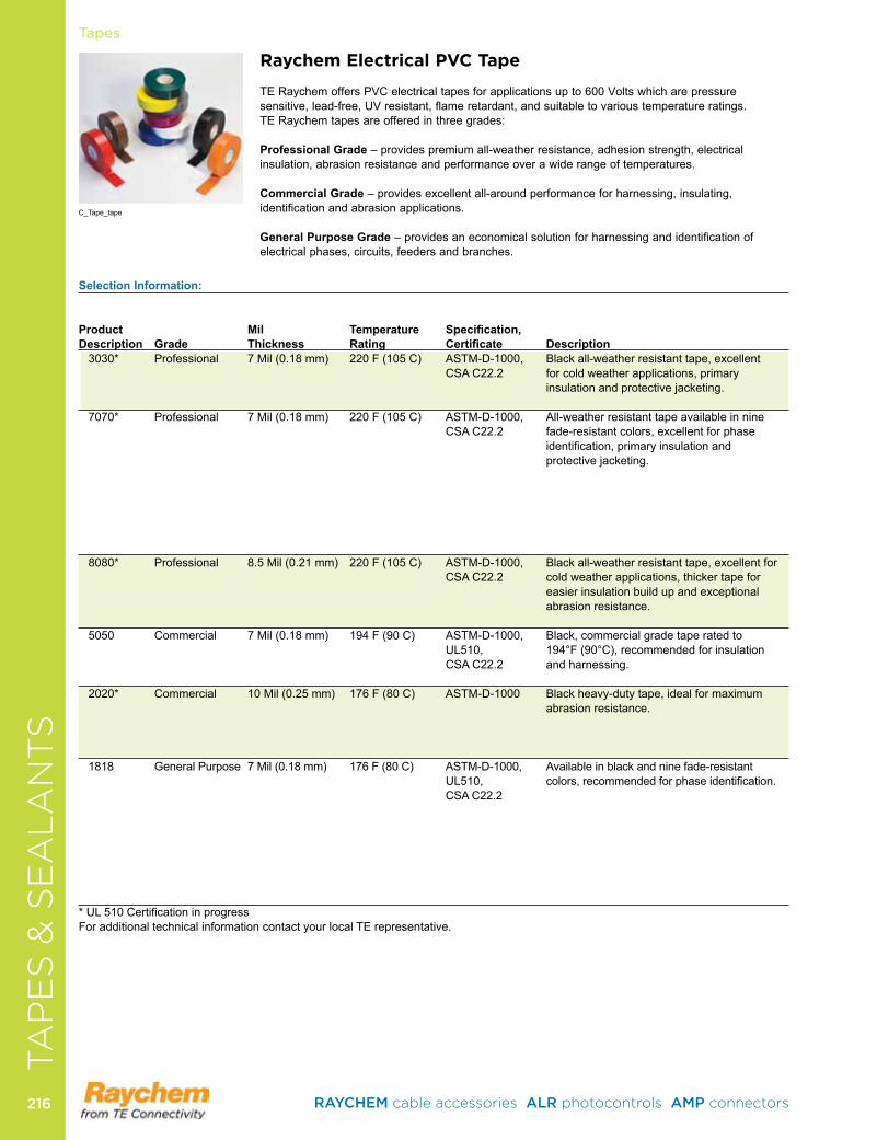
Product Mil Temperature Specification,Description Grade Thickness Rating Certificate Description 3030* Professional 7 Mil (0 .18 mm) 220 F (105 C) ASTM-D-1000, Black all-weather resistant tape, excellent
CSA C22 .2 for cold weather applications, primary insulation and protective jacketing .
7070* Professional 7 Mil (0 .18 mm) 220 F (105 C) ASTM-D-1000, All-weather resistant tape available in nine CSA C22 .2 fade-resistant colors, excellent for phase
identification,primaryinsulationand protective jacketing .
8080* Professional 8 .5 Mil (0 .21 mm) 220 F (105 C) ASTM-D-1000, Black all-weather resistant tape, excellent for CSA C22 .2 cold weather applications, thicker tape for
easier insulation build up and exceptional abrasion resistance .
5050 Commercial 7 Mil (0 .18 mm) 194 F (90 C) ASTM-D-1000, Black, commercial grade tape rated to UL510, 194°F (90°C), recommended for insulation CSA C22 .2 and harnessing .
2020* Commercial 10 Mil (0 .25 mm) 176 F (80 C) ASTM-D-1000 Black heavy-duty tape, ideal for maximum abrasion resistance .
1818 General Purpose 7 Mil (0 .18 mm) 176 F (80 C) ASTM-D-1000, Available in black and nine fade-resistant UL510, colors,recommendedforphaseidentification.
CSA C22 .2
*UL510CertificationinprogressFor additional technical information contact your local TE representative .
TapesTA
PE
S &
SE
AL
AN
TS
Raychem Electrical PVC Tape
TE Raychem offers PVC electrical tapes for applications up to 600 Volts which are pressure sensitive,lead-free,UVresistant,flameretardant,andsuitabletovarioustemperatureratings. TE Raychem tapes are offered in three grades: ProfessionalGrade – provides premium all-weather resistance, adhesion strength, electrical insulation, abrasion resistance and performance over a wide range of temperatures . CommercialGrade – provides excellent all-around performance for harnessing, insulating, identificationandabrasionapplications.
GeneralPurposeGrade–providesaneconomicalsolutionforharnessingandidentificationofelectrical phases, circuits, feeders and branches .
C_Tape_tape
RAYCHEM cable accessories ALR photocontrols AMP connectors 216216
SelectionInformation:
Product Thickness RollWidth RollLength Package CaseDescription CatalogNumber Color mil(mm) inches(mm) feet(m) Type Qty
3030* ETP-3030-0-19-20-A Black 7 (0 .18) 3/4 (19) 66 (20 .1) Cellophane 100ETP-3030-0-19-20-P-A Black 7 (0 .18) 3/4 (19) 66 (20 .1) Plastic Case 20
7070* ETP-7070-5-19-20-P-A Green 7 (0 .18) 3/4 (19) 66 (20 .1) Plastic Case 20ETP-7070-4-19-20-P-A Yellow 7 (0 .18) 3/4 (19) 66 (20 .1) Plastic Case 20ETP-7070-2-19-20-P-A Red 7 (0 .18) 3/4 (19) 66 (20 .1) Plastic Case 20ETP-7070-6-19-20-P-A Blue 7 (0 .18) 3/4 (19) 66 (20 .1) Plastic Case 20ETP-7070-9-19-20-P-A White 7 (0 .18) 3/4 (19) 66 (20 .1) Plastic Case 20ETP-7070-1-19-20-P-A Brown 7 (0 .18) 3/4 (19) 66 (20 .1) Plastic Case 20ETP-7070-3-19-20-P-A Orange 7 (0 .18) 3/4 (19) 66 (20 .1) Plastic Case 20ETP-7070-8-19-20-P-A Gray 7 (0 .18) 3/4 (19) 66 (20 .1) Plastic Case 20ETP-7070-7-19-20-P-A Violet 7 (0 .18) 3/4 (19) 66 (20 .1) Plastic Case 20
8080* ETP-8080-0-19-20-A Black 8 .5 (0 .21) 3/4 (19) 66 (20 .1) Cellophane 100ETP-8080-0-19-20-P-A Black 8 .5 (0 .21) 3/4 (19) 66 (20 .1) Plastic Case 20ETP-8080-0-25-20-B Black 8 .5 (0 .21) 1 (25 .4) 66 (20 .1) Cellophane 50ETP-8080-0-38-20-B Black 8 .5 (0 .21) 1-1/2 (38) 66 (20 .1) Cellophane 50
5050 ETP-5050-0-19-20-B Black 7 (0 .18) 3/4 (19) 66 (20 .1) Cellophane 100
2020* ETP-2020-0-25-33-B Black 10 (0 .25) 1 (25 .4) 36 yd (32 .9) Cellophane 48ETP-2020-0-51-33-B Black 10 (0 .25) 2 (51 .4) 36 yd (32 .9) Cellophane 12ETP-2020-0-38-33-B Black 10 (0 .25) 1-1/2 (38) 36 yd (32 .9) Cellophane 12ETP-2020-0-19-33-B Black 10 (0 .25) 3/4 (19) 36 yd (32 .9) Cellophane 48
1818 ETP-1818-0-19-20-B Black 7 (0 .18) 3/4 (19) 66 (20 .1) Cellophane 100ETP-1818-5-19-20-B Green 7 (0 .18) 3/4 (19) 66 (20 .1) Cellophane 100ETP-1818-4-19-20-B Yellow 7 (0 .18) 3/4 (19) 66 (20 .1) Cellophane 100ETP-1818-2-19-20-B Red 7 (0 .18) 3/4 (19) 66 (20 .1) Cellophane 100ETP-1818-6-19-20-B Blue 7 (0 .18) 3/4 (19) 66 (20 .1) Cellophane 100ETP-1818-9-19-20-B White 7 (0 .18) 3/4 (19) 66 (20 .1) Cellophane 100ETP-1818-1-19-20-B Brown 7 (0 .18) 3/4 (19) 66 (20 .1) Cellophane 100ETP-1818-3-19-20-B Orange 7 (0 .18) 3/4 (19) 66 (20 .1) Cellophane 100ETP-1818-8-19-20-B Gray 7 (0 .18) 3/4 (19) 66 (20 .1) Cellophane 100ETP-1818-7-19-20-B Violet 7 (0 .18) 3/4 (19) 66 (20 .1) Cellophane 100
*UL510Certificationinprogress Note: A = 1 inch core, B = 1-1/2 inch coreFor additional options contact your local TE representative .
TA
PE
S &
SE
AL
AN
TS
Tapes
RAYCHEM cable accessories ALR photocontrols AMP connectors 217 217
Most commonly requested part numbers:
3030 7070 8080 5050 2020 1818
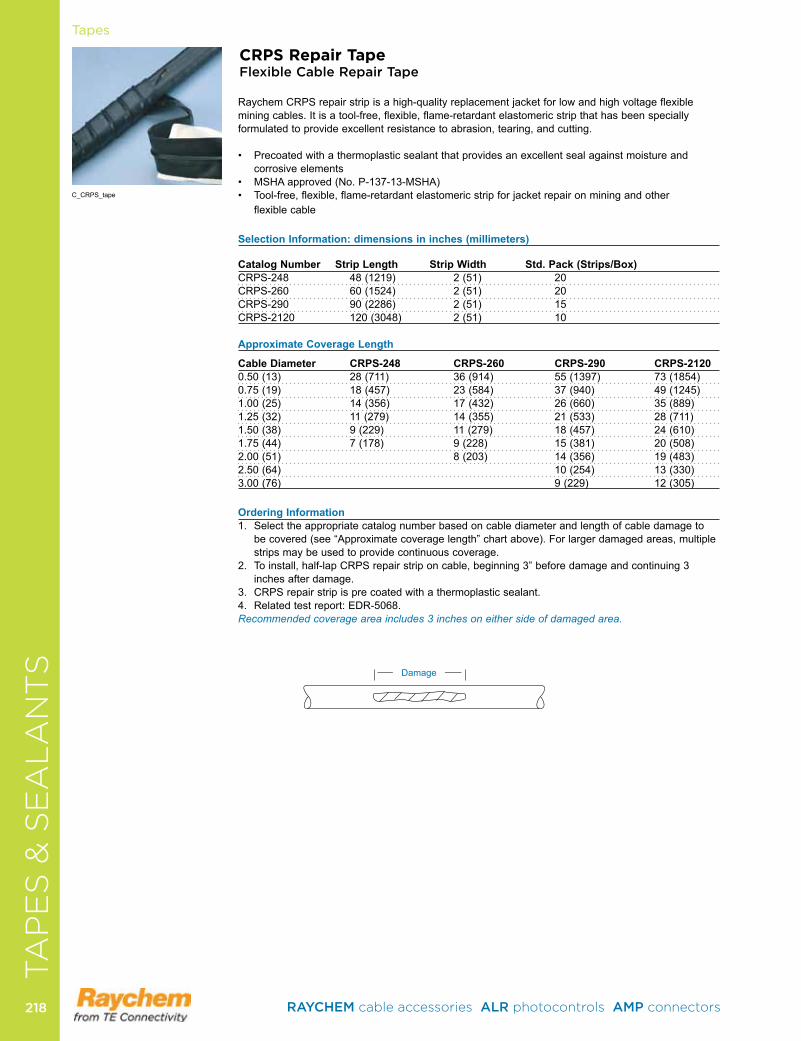
Tapes
CRPS Repair TapeFlexible Cable Repair Tape
Raychem CRPS repair strip is a high-quality replacement jacket for low and high voltage flexible mining cables . It is a tool-free, flexible, flame-retardant elastomeric strip that has been specially formulated to provide excellent resistance to abrasion, tearing, and cutting .
• Precoatedwithathermoplasticsealantthatprovidesanexcellentsealagainstmoistureandcorrosive elements
• MSHAapproved(No.P-137-13-MSHA)• Tool-free,flexible,flame-retardantelastomericstripforjacketrepaironminingandother flexible cable
SelectionInformation:dimensionsininches(millimeters)
CatalogNumber StripLength StripWidth Std.Pack(Strips/Box)CRPS-248 48 (1219) 2 (51) 20CRPS-260 60 (1524) 2 (51) 20CRPS-290 90 (2286) 2 (51) 15CRPS-2120 120 (3048) 2 (51) 10 ApproximateCoverageLength
CableDiameter CRPS-248 CRPS-260 CRPS-290 CRPS-21200 .50 (13) 28 (711) 36 (914) 55 (1397) 73 (1854)0 .75 (19) 18 (457) 23 (584) 37 (940) 49 (1245)1 .00 (25) 14 (356) 17 (432) 26 (660) 35 (889)1 .25 (32) 11 (279) 14 (355) 21 (533) 28 (711)1 .50 (38) 9 (229) 11 (279) 18 (457) 24 (610)1 .75 (44) 7 (178) 9 (228) 15 (381) 20 (508)2 .00 (51) 8 (203) 14 (356) 19 (483)2 .50 (64) 10 (254) 13 (330)3 .00 (76) 9 (229) 12 (305)
OrderingInformation1 . Select the appropriate catalog number based on cable diameter and length of cable damage to
be covered (see “Approximate coverage length” chart above) . For larger damaged areas, multiple strips may be used to provide continuous coverage .
2 . To install, half-lap CRPS repair strip on cable, beginning 3” before damage and continuing 3 inches after damage .
3 . CRPS repair strip is pre coated with a thermoplastic sealant .4 . Related test report: EDR-5068 .Recommended coverage area includes 3 inches on either side of damaged area.
Damage
C_CRPS_tape
TA
PE
S &
SE
AL
AN
TS
RAYCHEM cable accessories ALR photocontrols AMP connectors 218218
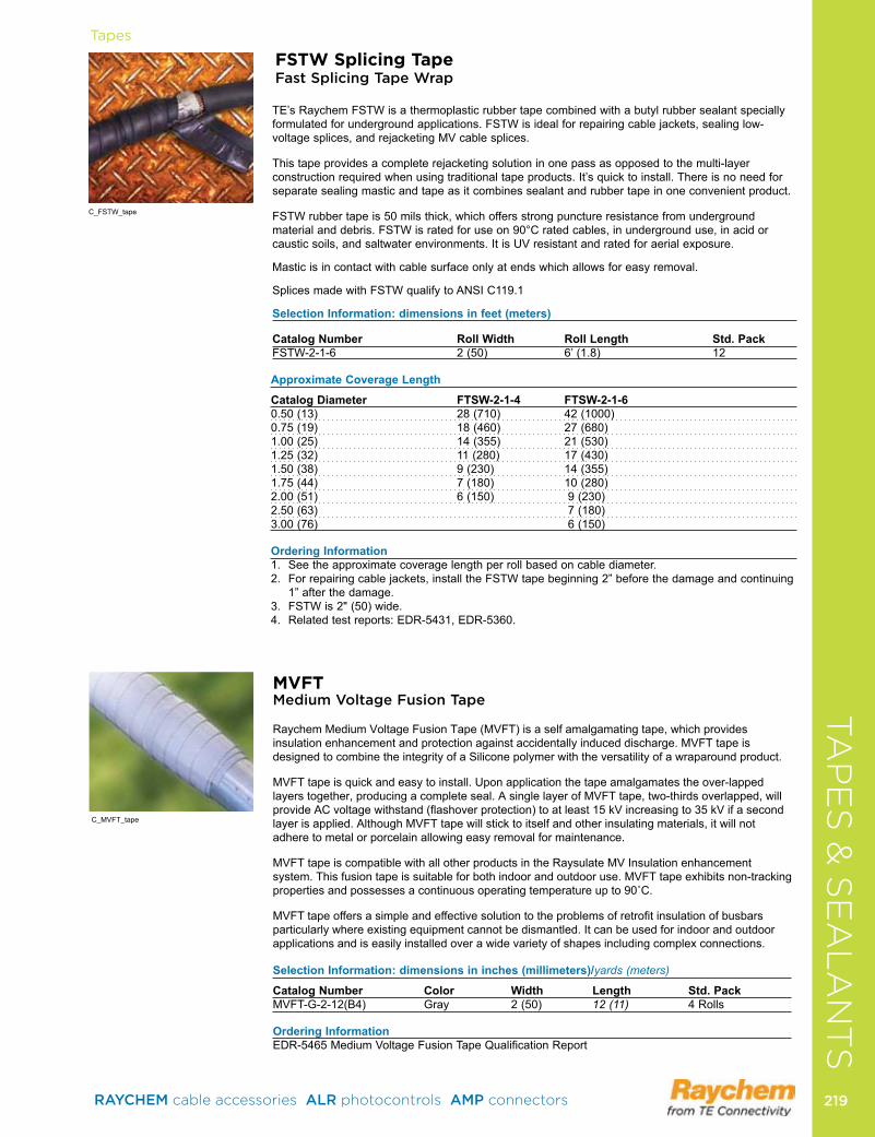
Tapes
FSTW Splicing Tape Fast Splicing Tape Wrap
TE’s Raychem FSTW is a thermoplastic rubber tape combined with a butyl rubber sealant specially formulated for underground applications . FSTW is ideal for repairing cable jackets, sealing low-voltage splices, and rejacketing MV cable splices .
This tape provides a complete rejacketing solution in one pass as opposed to the multi-layer construction required when using traditional tape products . It’s quick to install . There is no need for separate sealing mastic and tape as it combines sealant and rubber tape in one convenient product .
FSTW rubber tape is 50 mils thick, which offers strong puncture resistance from underground material and debris . FSTW is rated for use on 90°C rated cables, in underground use, in acid or caustic soils, and saltwater environments . It is UV resistant and rated for aerial exposure .
Mastic is in contact with cable surface only at ends which allows for easy removal .
Splices made with FSTW qualify to ANSI C119 .1
SelectionInformation:dimensionsinfeet(meters)
CatalogNumber RollWidth RollLength Std.PackFSTW-2-1-6 2 (50) 6’ (1 .8) 12
ApproximateCoverageLength
CatalogDiameter FTSW-2-1-4 FTSW-2-1-60 .50 (13) 28 (710) 42 (1000)0 .75 (19) 18 (460) 27 (680)1 .00 (25) 14 (355) 21 (530)1 .25 (32) 11 (280) 17 (430)1 .50 (38) 9 (230) 14 (355)1 .75 (44) 7 (180) 10 (280)2 .00 (51) 6 (150) 9 (230)2 .50 (63) 7 (180)3 .00 (76) 6 (150)
OrderingInformation1 . See the approximate coverage length per roll based on cable diameter .2 . For repairing cable jackets, install the FSTW tape beginning 2” before the damage and continuing
1” after the damage .3 . FSTW is 2" (50) wide .4 . Related test reports: EDR-5431, EDR-5360 .
C_FSTW_tape
MVFTMedium Voltage Fusion Tape
Raychem Medium Voltage Fusion Tape (MVFT) is a self amalgamating tape, which provides insulation enhancement and protection against accidentally induced discharge . MVFT tape is designed to combine the integrity of a Silicone polymer with the versatility of a wraparound product .
MVFT tape is quick and easy to install . Upon application the tape amalgamates the over-lapped layers together, producing a complete seal . A single layer of MVFT tape, two-thirds overlapped, will provide AC voltage withstand (flashover protection) to at least 15 kV increasing to 35 kV if a second layer is applied . Although MVFT tape will stick to itself and other insulating materials, it will not adhere to metal or porcelain allowing easy removal for maintenance .
MVFT tape is compatible with all other products in the Raysulate MV Insulation enhancement system . This fusion tape is suitable for both indoor and outdoor use . MVFT tape exhibits non-tracking propertiesandpossessesacontinuousoperatingtemperatureupto90˚C.
MVFT tape offers a simple and effective solution to the problems of retrofit insulation of busbars particularly where existing equipment cannot be dismantled . It can be used for indoor and outdoor applications and is easily installed over a wide variety of shapes including complex connections .
SelectionInformation:dimensionsininches(millimeters)/yards (meters)
CatalogNumber Color Width Length Std.PackMVFT-G-2-12(B4) Gray 2 (50) 12 (11) 4 Rolls
OrderingInformationEDR-5465 Medium Voltage Fusion Tape Qualification Report
C_MVFT_tape
TA
PE
S &
SE
AL
AN
TS
RAYCHEM cable accessories ALR photocontrols AMP connectors 219 219
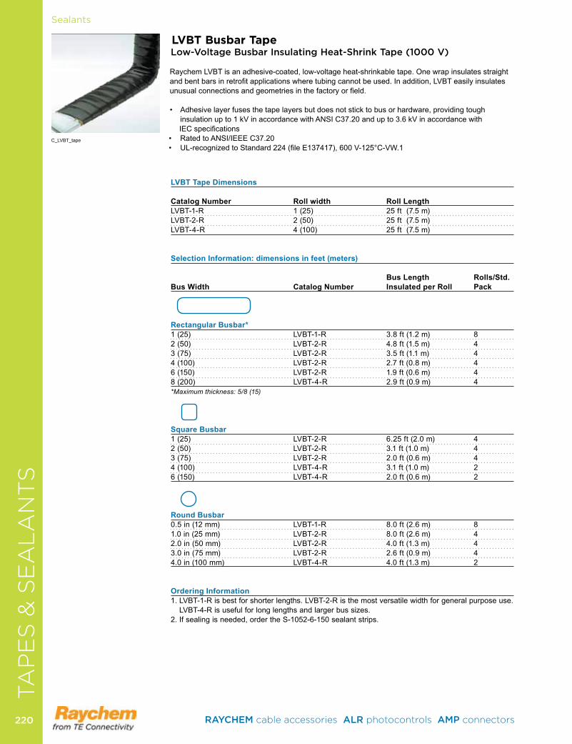
CA
BL
E R
EPA
IR &
RE
JAC
KE
TIN
GSealants
LVBT Busbar TapeLow-Voltage Busbar Insulating Heat-Shrink Tape (1000 V)
Raychem LVBT is an adhesive-coated, low-voltage heat-shrinkable tape . One wrap insulates straight and bent bars in retrofit applications where tubing cannot be used . In addition, LVBT easily insulates unusual connections and geometries in the factory or field .
• Adhesivelayerfusesthetapelayersbutdoesnotsticktobusorhardware,providingtoughinsulation up to 1 kV in accordance with ANSI C37 .20 and up to 3 .6 kV in accordance with IEC specifications
• RatedtoANSI/IEEEC37.20• UL-recognizedtoStandard224(fileE137417),600V-125°C-VW.1
LVBTTapeDimensions CatalogNumber Rollwidth RollLengthLVBT-1-R 1 (25) 25 ft (7 .5 m) LVBT-2-R 2 (50) 25 ft (7 .5 m) LVBT-4-R 4 (100) 25 ft (7 .5 m)
SelectionInformation:dimensionsinfeet(meters) BusLength Rolls/Std. BusWidth CatalogNumber InsulatedperRoll Pack
RectangularBusbar* 1 (25) LVBT-1-R 3 .8 ft (1 .2 m) 82 (50) LVBT-2-R 4 .8 ft (1 .5 m) 43 (75) LVBT-2-R 3 .5 ft (1 .1 m) 44 (100) LVBT-2-R 2 .7 ft (0 .8 m) 46 (150) LVBT-2-R 1 .9 ft (0 .6 m) 48 (200) LVBT-4-R 2 .9 ft (0 .9 m) 4*Maximum thickness: 5/8 (15)
SquareBusbar1 (25) LVBT-2-R 6 .25 ft (2 .0 m) 42 (50) LVBT-2-R 3 .1 ft (1 .0 m) 43 (75) LVBT-2-R 2 .0 ft (0 .6 m) 44 (100) LVBT-4-R 3 .1 ft (1 .0 m) 26 (150) LVBT-4-R 2 .0 ft (0 .6 m) 2
RoundBusbar0 .5 in (12 mm) LVBT-1-R 8 .0 ft (2 .6 m) 81 .0 in (25 mm) LVBT-2-R 8 .0 ft (2 .6 m) 42 .0 in (50 mm) LVBT-2-R 4 .0 ft (1 .3 m) 43 .0 in (75 mm) LVBT-2-R 2 .6 ft (0 .9 m) 44 .0 in (100 mm) LVBT-4-R 4 .0 ft (1 .3 m) 2
OrderingInformation 1 . LVBT-1-R is best for shorter lengths . LVBT-2-R is the most versatile width for general purpose use . LVBT-4-Risusefulforlonglengthsandlargerbussizes.
2 . If sealing is needed, order the S-1052-6-150 sealant strips .
C_LVBT_tape
TA
PE
S &
SE
AL
AN
TS
RAYCHEM cable accessories ALR photocontrols AMP connectors 220220
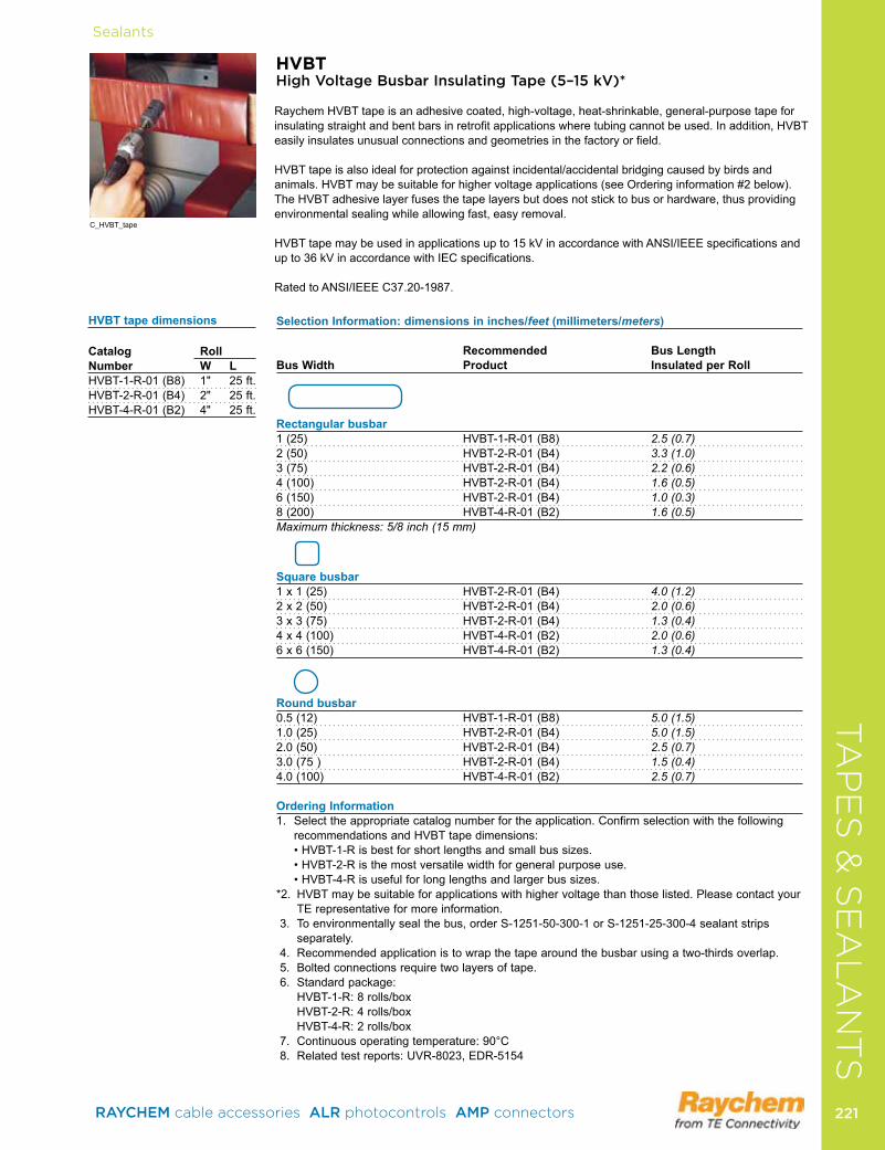
Sealants
HVBTHigh Voltage Busbar Insulating Tape (5–15 kV)*
Raychem HVBT tape is an adhesive coated, high-voltage, heat-shrinkable, gen eral- purpose tape for insulating straight and bent bars in retrofit applications where tubing cannot be used . In addition, HVBT easily insulates unusual connections and geometries in the factory or field .
HVBT tape is also ideal for protection against incidental/accidental bridging caused by birds and animals . HVBT may be suitable for higher voltage applications (see Ordering information #2 below) . The HVBT adhesive layer fuses the tape layers but does not stick to bus or hardware, thus providing environmental sealing while allowing fast, easy removal . HVBT tape may be used in applications up to 15 kV in accordance with ANSI/IEEE specifications and up to 36 kV in accordance with IEC specifications .
Rated to ANSI/IEEE C37 .20-1987 .
C_HVBT_tape
SelectionInformation:dimensionsininches/feet(millimeters/meters)
Recommended BusLengthBusWidth Product InsulatedperRoll
Rectangularbusbar1 (25) HVBT-1-R-01 (B8) 2.5 (0.7) 2 (50) HVBT-2-R-01 (B4) 3.3 (1.0) 3 (75) HVBT-2-R-01 (B4) 2.2 (0.6) 4 (100) HVBT-2-R-01 (B4) 1.6 (0.5) 6 (150) HVBT-2-R-01 (B4) 1.0 (0.3) 8 (200) HVBT-4-R-01 (B2) 1.6 (0.5) Maximum thickness: 5/8 inch (15 mm)
Squarebusbar1 x 1 (25) HVBT-2-R-01 (B4) 4.0 (1.2) 2 x 2 (50) HVBT-2-R-01 (B4) 2.0 (0.6) 3 x 3 (75) HVBT-2-R-01 (B4) 1.3 (0.4) 4 x 4 (100) HVBT-4-R-01 (B2) 2.0 (0.6) 6 x 6 (150) HVBT-4-R-01 (B2) 1.3 (0.4)
Roundbusbar0 .5 (12) HVBT-1-R-01 (B8) 5.0 (1.5) 1 .0 (25) HVBT-2-R-01 (B4) 5.0 (1.5) 2 .0 (50) HVBT-2-R-01 (B4) 2.5 (0.7) 3 .0 (75 ) HVBT-2-R-01 (B4) 1.5 (0.4) 4 .0 (100) HVBT-4-R-01 (B2) 2.5 (0.7)
OrderingInformation1 . Select the appropriate catalog number for the application . Confirm selection with the following
recommendations and HVBT tape dimensions: •HVBT-1-Risbestforshortlengthsandsmallbussizes.
•HVBT-2-Risthemostversatilewidthforgeneralpurposeuse. •HVBT-4-Risusefulforlonglengthsandlargerbussizes.*2 . HVBT may be suitable for applications with higher voltage than those listed . Please contact your
TE representative for more information . 3 . To environmentally seal the bus, order S-1251-50-300-1 or S-1251-25-300-4 sealant strips
separately . 4 . Recommended application is to wrap the tape around the busbar using a two-thirds overlap . 5 . Bolted connections require two layers of tape . 6 . Standard package: HVBT-1-R: 8 rolls/box HVBT-2-R: 4 rolls/box HVBT-4-R: 2 rolls/box 7 . Continuous operating temperature: 90°C 8 . Related test reports: UVR-8023, EDR-5154
HVBTtapedimensions
Catalog RollNumber W LHVBT-1-R-01 (B8) 1" 25 ft .HVBT-2-R-01 (B4) 2" 25 ft .HVBT-4-R-01 (B2) 4" 25 ft .
TA
PE
S &
SE
AL
AN
TS
RAYCHEM cable accessories ALR photocontrols AMP connectors 221 221
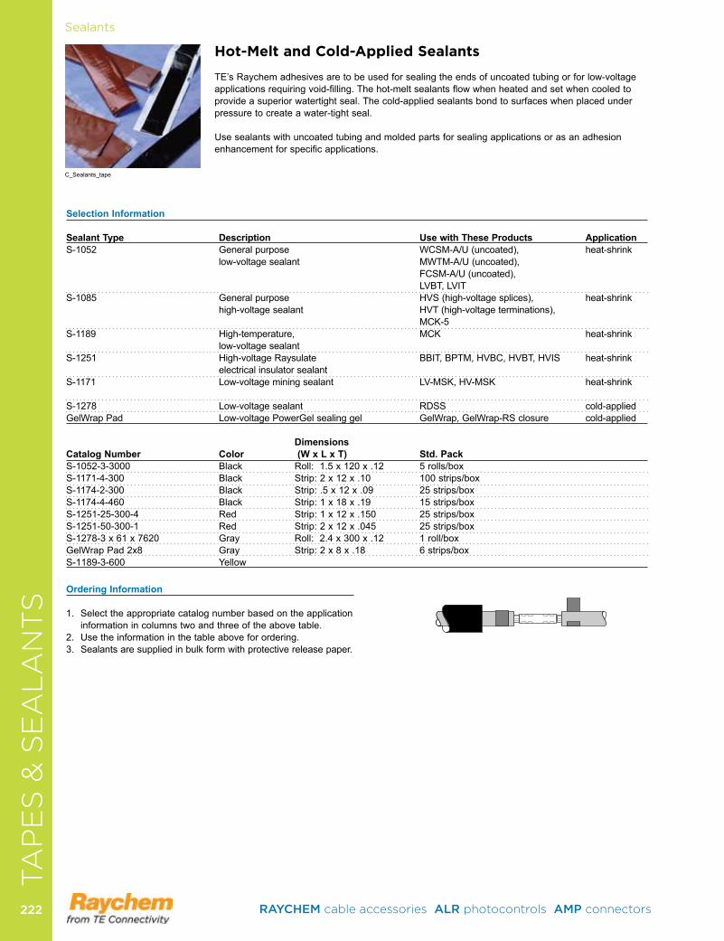
SealantsTA
PE
S &
SE
AL
AN
TS
Hot-Melt and Cold-Applied Sealants
TE’s Raychem adhesives are to be used for sealing the ends of uncoated tubing or for low-voltage applications requiring void-filling . The hot-melt sealants flow when heated and set when cooled to provide a superior watertight seal . The cold-applied sealants bond to surfaces when placed under pressure to create a water-tight seal .
Use sealants with uncoated tubing and molded parts for sealing applications or as an adhesion enhancement for specific applications .
SelectionInformation SealantType Description UsewithTheseProducts ApplicationS-1052 General purpose WCSM-A/U (uncoated), heat-shrink low-voltage sealant MWTM-A/U (uncoated), FCSM-A/U (uncoated), LVBT, LVITS-1085 General purpose HVS (high-voltage splices), heat-shrink high-voltage sealant HVT (high-voltage terminations),
MCK-5S-1189 High-temperature, MCK heat-shrink low-voltage sealantS-1251 High-voltage Raysulate BBIT, BPTM, HVBC, HVBT, HVIS heat-shrink electrical insulator sealantS-1171 Low-voltage mining sealant LV-MSK, HV-MSK heat-shrink S-1278 Low-voltage sealant RDSS cold-appliedGelWrap Pad Low-voltage PowerGel sealing gel GelWrap, GelWrap-RS closure cold-applied
DimensionsCatalogNumber Color (WxLxT) Std.PackS-1052-3-3000 Black Roll: 1 .5 x 120 x .12 5 rolls/boxS-1171-4-300 Black Strip: 2 x 12 x .10 100 strips/boxS-1174-2-300 Black Strip: .5 x 12 x .09 25 strips/boxS-1174-4-460 Black Strip: 1 x 18 x .19 15 strips/boxS-1251-25-300-4 Red Strip: 1 x 12 x .150 25 strips/boxS-1251-50-300-1 Red Strip: 2 x 12 x .045 25 strips/box S-1278-3 x 61 x 7620 Gray Roll: 2 .4 x 300 x .12 1 roll/boxGelWrap Pad 2x8 Gray Strip: 2 x 8 x .18 6 strips/boxS-1189-3-600 Yellow
OrderingInformation
1 . Select the appropriate catalog number based on the application information in columns two and three of the above table .
2 . Use the information in the table above for ordering . 3 . Sealants are supplied in bulk form with protective release paper .
C_Sealants_tape
RAYCHEM cable accessories ALR photocontrols AMP connectors 222222

CA
BL
E R
EPA
IR &
RE
JAC
KE
TIN
GProductProduct
Thermal PhotocontrolsAT Series . . . . . . . . . . . . . . . . . . . . . . . . . . . . . . . . . . . . . . . . . 224PT / SPT Series . . . . . . . . . . . . . . . . . . . . . . . . . . . . . . . . . . . . 224TL Series . . . . . . . . . . . . . . . . . . . . . . . . . . . . . . . . . . . . . . . . . 225AA Series . . . . . . . . . . . . . . . . . . . . . . . . . . . . . . . . . . . . . . . . . 225LC Series . . . . . . . . . . . . . . . . . . . . . . . . . . . . . . . . . . . . . . . . . 226BF Series . . . . . . . . . . . . . . . . . . . . . . . . . . . . . . . . . . . . . . . . . 226M Series . . . . . . . . . . . . . . . . . . . . . . . . . . . . . . . . . . . . . . . . . . 227
Electronic PhotocontrolsLM 1000 . . . . . . . . . . . . . . . . . . . . . . . . . . . . . . . . . . . . . . . . . . 2272000 Series . . . . . . . . . . . . . . . . . . . . . . . . . . . . . . . . . . . . . . . 2283000 Series . . . . . . . . . . . . . . . . . . . . . . . . . . . . . . . . . . . . . . . 2296000 Series . . . . . . . . . . . . . . . . . . . . . . . . . . . . . . . . . . . . . . . 2307000 Series . . . . . . . . . . . . . . . . . . . . . . . . . . . . . . . . . . . . . . . 2318000 Series . . . . . . . . . . . . . . . . . . . . . . . . . . . . . . . . . . . . . . . 232SST Series . . . . . . . . . . . . . . . . . . . . . . . . . . . . . . . . . . . . . . . . 233
Time Controls24 Hour Time Clocks . . . . . . . . . . . . . . . . . . . . . . . . . . . . . . . . 234Spring Wound Interval Timers . . . . . . . . . . . . . . . . . . . . . . . . . 234
Lighting AccessoriesAMR Series . . . . . . . . . . . . . . . . . . . . . . . . . . . . . . . . . . . . . . . 235Shorting and Open Caps . . . . . . . . . . . . . . . . . . . . . . . . . . . . . 235AM Series . . . . . . . . . . . . . . . . . . . . . . . . . . . . . . . . . . . . . . . . . 236US-30 Starter . . . . . . . . . . . . . . . . . . . . . . . . . . . . . . . . . . . . . . 236OLC/PL/ACL Series . . . . . . . . . . . . . . . . . . . . . . . . . . . . . . . . . 236
PHOTOCONTROLS, TIMERS & ACCESSORIES
RAYCHEM cable accessories ALR photocontrols AMP connectors 223 223
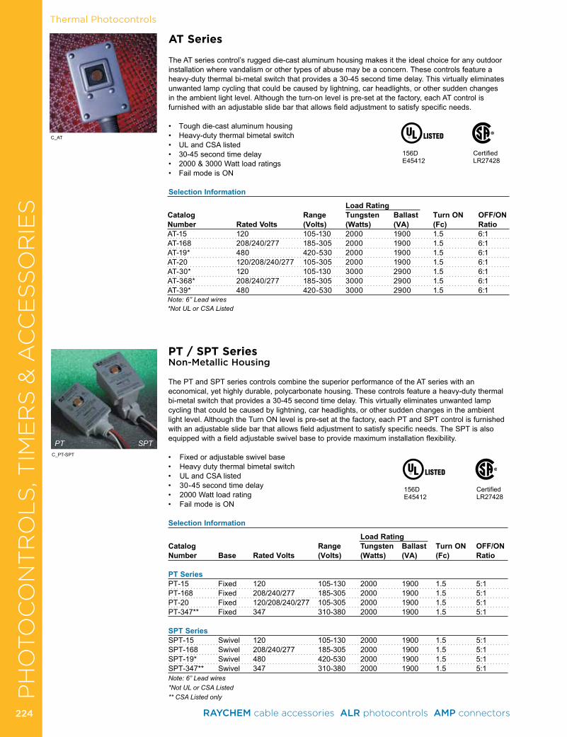
CA
BL
E R
EPA
IR &
RE
JAC
KE
TIN
GThermal Photocontrols
PT / SPT SeriesNon-Metallic Housing
The PT and SPT series controls combine the superior performance of the AT series with an economical, yet highly durable, polycarbonate housing . These controls feature a heavy-duty thermal bi-metal switch that provides a 30-45 second time delay . This virtually eliminates unwanted lamp cycling that could be caused by lightning, car headlights, or other sudden changes in the ambient light level . Although the Turn ON level is pre-set at the factory, each PT and SPT control is furnished with an adjustable slide bar that allows field adjustment to satisfy specific needs . The SPT is also equipped with a field adjustable swivel base to provide maximum installation flexibility .
• Fixedoradjustableswivelbase• Heavydutythermalbimetalswitch• ULandCSAlisted• 30-45secondtimedelay• 2000Wattloadrating• FailmodeisON
Selection Information
Load RatingCatalog Range Tungsten Ballast Turn ON OFF/ONNumber Base Rated Volts (Volts) (Watts) (VA) (Fc) Ratio PT SeriesPT-15 Fixed 120 105-130 2000 1900 1 .5 5:1PT-168 Fixed 208/240/277 185-305 2000 1900 1 .5 5:1PT-20 Fixed 120/208/240/277 105-305 2000 1900 1 .5 5:1PT-347** Fixed 347 310-380 2000 1900 1 .5 5:1
SPT SeriesSPT-15 Swivel 120 105-130 2000 1900 1 .5 5:1SPT-168 Swivel 208/240/277 185-305 2000 1900 1 .5 5:1SPT-19* Swivel 480 420-530 2000 1900 1 .5 5:1SPT-347** Swivel 347 310-380 2000 1900 1 .5 5:1Note: 6” Lead wires*Not UL or CSA Listed** CSA Listed only
AT Series
The AT series control’s rugged die-cast aluminum housing makes it the ideal choice for any outdoor installation where vandalism or other types of abuse may be a concern . These controls feature a heavy-duty thermal bi-metal switch that provides a 30-45 second time delay . This virtually eliminates unwanted lamp cycling that could be caused by lightning, car headlights, or other sudden changes in the ambient light level . Although the turn-on level is pre-set at the factory, each AT control is furnished with an adjustable slide bar that allows field adjustment to satisfy specific needs .
• Toughdie-castaluminumhousing• Heavy-dutythermalbimetalswitch• ULandCSAlisted• 30-45secondtimedelay• 2000&3000Wattloadratings• FailmodeisON
Selection Information
Load RatingCatalog Range Tungsten Ballast Turn ON OFF/ONNumber Rated Volts (Volts) (Watts) (VA) (Fc) RatioAT-15 120 105-130 2000 1900 1 .5 6:1AT-168 208/240/277 185-305 2000 1900 1 .5 6:1AT-19* 480 420-530 2000 1900 1 .5 6:1AT-20 120/208/240/277 105-305 2000 1900 1 .5 6:1AT-30* 120 105-130 3000 2900 1 .5 6:1AT-368* 208/240/277 185-305 3000 2900 1 .5 6:1AT-39* 480 420-530 3000 2900 1 .5 6:1Note: 6” Lead wires*Not UL or CSA Listed
PT SPT
CertifiedLR27428
156DE45412
CertifiedLR27428
156DE45412
C_AT
C_PT-SPT
PH
OTO
CO
NT
RO
LS
, TIM
ER
S &
AC
CE
SS
OR
IES
RAYCHEM cable accessories ALR photocontrols AMP connectors 224224
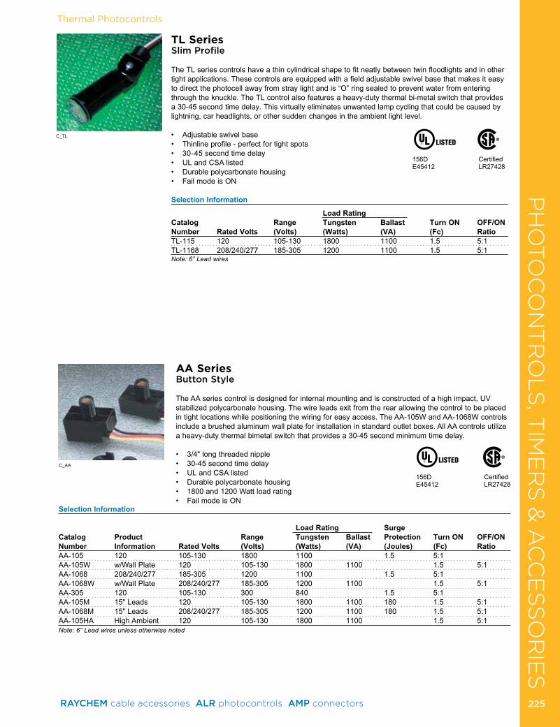
CA
BL
E R
EPA
IR &
RE
JAC
KE
TIN
GThermal Photocontrols
TL SeriesSlim Profile
The TL series controls have a thin cylindrical shape to fit neatly between twin floodlights and in other tight applications . These controls are equipped with a field adjustable swivel base that makes it easy to direct the photocell away from stray light and is “O” ring sealed to prevent water from entering through the knuckle . The TL control also features a heavy-duty thermal bi-metal switch that provides a 30-45 second time delay . This virtually eliminates unwanted lamp cycling that could be caused by lightning, car headlights, or other sudden changes in the ambient light level .
• Adjustableswivelbase• Thinlineprofile-perfectfortightspots• 30-45secondtimedelay• ULandCSAlisted• Durablepolycarbonatehousing• FailmodeisON
Selection Information
Load RatingCatalog Range Tungsten Ballast Turn ON OFF/ONNumber Rated Volts (Volts) (Watts) (VA) (Fc) RatioTL-115 120 105-130 1800 1100 1 .5 5:1TL-1168 208/240/277 185-305 1200 1100 1 .5 5:1Note: 6” Lead wires
AA SeriesButton Style
The AA series control is designed for internal mounting and is constructed of a high impact, UV stabilized polycarbonate housing . The wire leads exit from the rear allowing the control to be placed in tight locations while positioning the wiring for easy access . The AA-105W and AA-1068W controls include a brushed aluminum wall plate for installation in standard outlet boxes . All AA controls utilize a heavy-duty thermal bimetal switch that provides a 30-45 second minimum time delay .
• 3/4"longthreadednipple• 30-45secondtimedelay• ULandCSAlisted• Durablepolycarbonatehousing• 1800and1200Wattloadrating• FailmodeisON
CertifiedLR27428
156DE45412
CertifiedLR27428
156DE45412
Selection Information
Load Rating Surge Catalog Product Range Tungsten Ballast Protection Turn ON OFF/ONNumber Information Rated Volts (Volts) (Watts) (VA) (Joules) (Fc) RatioAA-105 120 105-130 1800 1100 1 .5 5:1AA-105W w/Wall Plate 120 105-130 1800 1100 1 .5 5:1 AA-1068 208/240/277 185-305 1200 1100 1 .5 5:1AA-1068W w/Wall Plate 208/240/277 185-305 1200 1100 1 .5 5:1AA-305 120 105-130 300 840 1 .5 5:1 AA-105M 15"Leads 120 105-130 1800 1100 180 1.5 5:1AA-1068M 15"Leads 208/240/277 185-305 1200 1100 180 1.5 5:1AA-105HA High Ambient 120 105-130 1800 1100 1 .5 5:1Note: 6" Lead wires unless otherwise noted
C_TL
C_AA
PH
OTO
CO
NT
RO
LS
, TIM
ER
S &
AC
CE
SS
OR
IES
RAYCHEM cable accessories ALR photocontrols AMP connectors 225 225
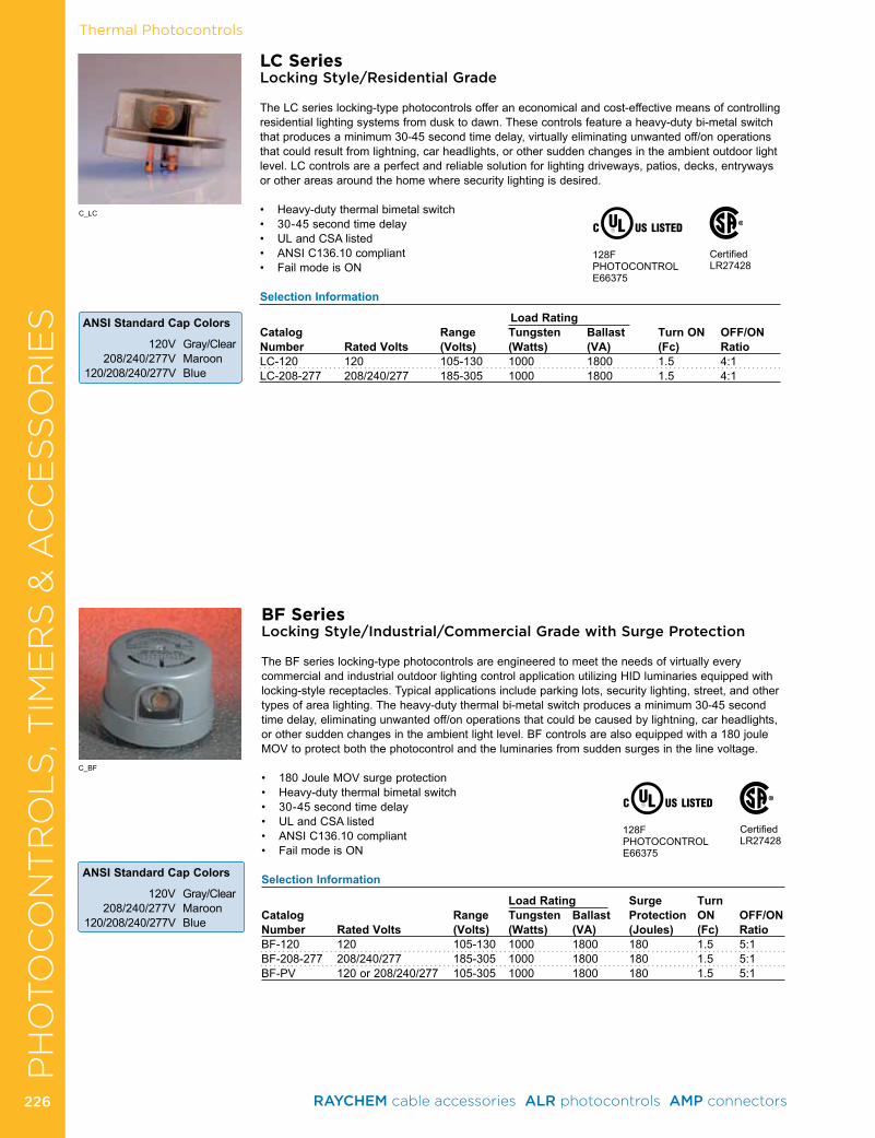
Thermal Photocontrols
LC SeriesLocking Style/Residential Grade
The LC series locking-type photocontrols offer an economical and cost-effective means of controlling residential lighting systems from dusk to dawn . These controls feature a heavy-duty bi-metal switch that produces a minimum 30-45 second time delay, virtually eliminating unwanted off/on operations that could result from lightning, car headlights, or other sudden changes in the ambient outdoor light level . LC controls are a perfect and reliable solution for lighting driveways, patios, decks, entryways or other areas around the home where security lighting is desired .
• Heavy-dutythermalbimetalswitch• 30-45secondtimedelay• ULandCSAlisted• ANSIC136.10compliant• FailmodeisON
Selection Information
Load Rating Catalog Range Tungsten Ballast Turn ON OFF/ONNumber Rated Volts (Volts) (Watts) (VA) (Fc) RatioLC-120 120 105-130 1000 1800 1 .5 4:1LC-208-277 208/240/277 185-305 1000 1800 1 .5 4:1
BF SeriesLocking Style/Industrial/Commercial Grade with Surge Protection
The BF series locking-type photocontrols are engineered to meet the needs of virtually every commercial and industrial outdoor lighting control application utilizing HID luminaries equipped with locking-style receptacles . Typical applications include parking lots, security lighting, street, and other types of area lighting . The heavy-duty thermal bi-metal switch produces a minimum 30-45 second time delay, eliminating unwanted off/on operations that could be caused by lightning, car headlights, or other sudden changes in the ambient light level . BF controls are also equipped with a 180 joule MOV to protect both the photocontrol and the luminaries from sudden surges in the line voltage .
• 180JouleMOVsurgeprotection• Heavy-dutythermalbimetalswitch• 30-45secondtimedelay• ULandCSAlisted• ANSIC136.10compliant• FailmodeisON
Selection Information
Load Rating Surge TurnCatalog Range Tungsten Ballast Protection ON OFF/ONNumber Rated Volts (Volts) (Watts) (VA) (Joules) (Fc) RatioBF-120 120 105-130 1000 1800 180 1 .5 5:1BF-208-277 208/240/277 185-305 1000 1800 180 1 .5 5:1BF-PV 120 or 208/240/277 105-305 1000 1800 180 1 .5 5:1
CertifiedLR27428
128FPHOTOCONTROLE66375
CertifiedLR27428
128FPHOTOCONTROLE66375
ANSI Standard Cap Colors
120V Gray/Clear208/240/277V Maroon
120/208/240/277V Blue
ANSI Standard Cap Colors
120V Gray/Clear 208/240/277V Maroon 120/208/240/277V Blue
C_LC
C_BF
PH
OTO
CO
NT
RO
LS
, TIM
ER
S &
AC
CE
SS
OR
IES
RAYCHEM cable accessories ALR photocontrols AMP connectors 226226
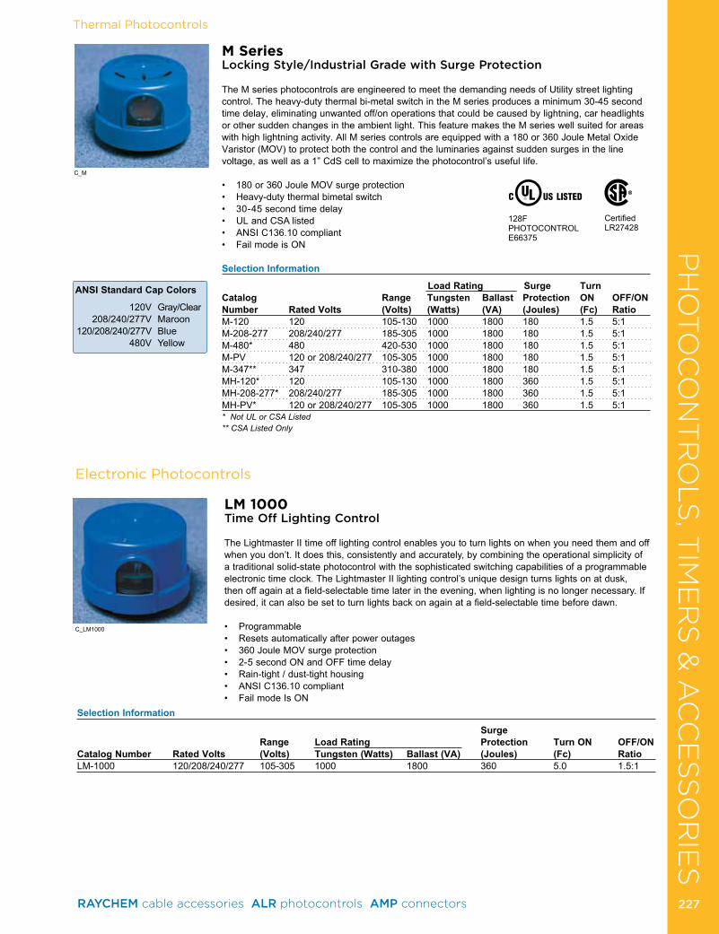
CA
BL
E R
EPA
IR &
RE
JAC
KE
TIN
G
ANSI Standard Cap Colors
120V Gray/Clear208/240/277V Maroon
120/208/240/277V Blue480V Yellow
Thermal Photocontrols
M SeriesLocking Style/Industrial Grade with Surge Protection
The M series photocontrols are engineered to meet the demanding needs of Utility street lighting control . The heavy-duty thermal bi-metal switch in the M series produces a minimum 30-45 second time delay, eliminating unwanted off/on operations that could be caused by lightning, car headlights or other sudden changes in the ambient light . This feature makes the M series well suited for areas withhighlightningactivity.AllMseriescontrolsareequippedwitha180or360JouleMetalOxideVaristor (MOV) to protect both the control and the luminaries against sudden surges in the line voltage, as well as a 1” CdS cell to maximize the photocontrol’s useful life .
• 180or360JouleMOVsurgeprotection• Heavy-dutythermalbimetalswitch• 30-45secondtimedelay• ULandCSAlisted• ANSIC136.10compliant• FailmodeisON
Selection Information
Load Rating Surge TurnCatalog Range Tungsten Ballast Protection ON OFF/ONNumber Rated Volts (Volts) (Watts) (VA) (Joules) (Fc) RatioM-120 120 105-130 1000 1800 180 1 .5 5:1M-208-277 208/240/277 185-305 1000 1800 180 1 .5 5:1M-480* 480 420-530 1000 1800 180 1 .5 5:1M-PV 120 or 208/240/277 105-305 1000 1800 180 1 .5 5:1M-347** 347 310-380 1000 1800 180 1 .5 5:1MH-120* 120 105-130 1000 1800 360 1 .5 5:1MH-208-277* 208/240/277 185-305 1000 1800 360 1 .5 5:1MH-PV* 120 or 208/240/277 105-305 1000 1800 360 1 .5 5:1* Not UL or CSA Listed** CSA Listed Only
CertifiedLR27428
128FPHOTOCONTROLE66375
C_M
Electronic Photocontrols
Selection Information
Surge Range Load Rating Protection Turn ON OFF/ONCatalog Number Rated Volts (Volts) Tungsten (Watts) Ballast (VA) (Joules) (Fc) RatioLM-1000 120/208/240/277 105-305 1000 1800 360 5 .0 1 .5:1
LM 1000Time Off Lighting Control
The Lightmaster II time off lighting control enables you to turn lights on when you need them and off when you don’t . It does this, consistently and accurately, by combining the operational simplicity of a traditional solid-state photocontrol with the sophisticated switching capabilities of a programmable electronic time clock . The Lightmaster II lighting control’s unique design turns lights on at dusk, then off again at a field-selectable time later in the evening, when lighting is no longer necessary . If desired, it can also be set to turn lights back on again at a field-selectable time before dawn .
• Programmable• Resetsautomaticallyafterpoweroutages• 360JouleMOVsurgeprotection• 2-5secondONandOFFtimedelay• Rain-tight/dust-tighthousing• ANSIC136.10compliant• FailmodeIsON
C_LM1000
PH
OTO
CO
NT
RO
LS
, TIM
ER
S &
AC
CE
SS
OR
IES
RAYCHEM cable accessories ALR photocontrols AMP connectors 227 227
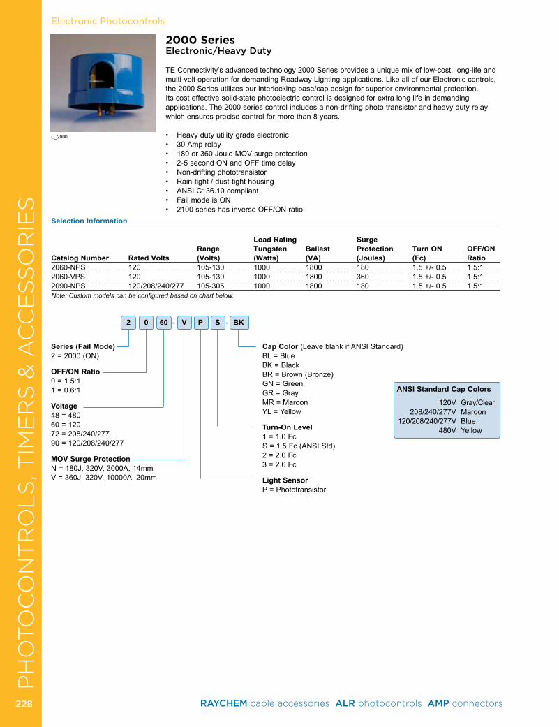
CA
BL
E R
EPA
IR &
RE
JAC
KE
TIN
G Electronic Photocontrols
2000 SeriesElectronic/Heavy Duty
TE Connectivity’s advanced technology 2000 Series provides a unique mix of low-cost, long-life and multi-volt operation for demanding Roadway Lighting applications . Like all of our Electronic controls, the 2000 Series utilizes our interlocking base/cap design for superior environmental protection . Its cost effective solid-state photoelectric control is designed for extra long life in demanding applications . The 2000 series control includes a non-drifting photo transistor and heavy duty relay, which ensures precise control for more than 8 years .
• Heavydutyutilitygradeelectronic• 30Amprelay• 180or360JouleMOVsurgeprotection• 2-5secondONandOFFtimedelay• Non-driftingphototransistor• Rain-tight/dust-tighthousing• ANSIC136.10compliant• FailmodeisON• 2100serieshasinverseOFF/ONratio
2 0 60 - V P S - BK
Series (Fail Mode)2 = 2000 (ON)
OFF/ON Ratio0 = 1 .5:11 = 0 .6:1
Voltage48 = 48060 = 12072 = 208/240/27790 = 120/208/240/277
MOV Surge ProtectionN=180J,320V,3000A,14mmV=360J,320V,10000A,20mm
Cap Color (Leave blank if ANSI Standard)BL = BlueBK = BlackBR = Brown (Bronze)GN = GreenGR = GrayMR = MaroonYL = Yellow
Turn-On Level1 = 1 .0 FcS = 1 .5 Fc (ANSI Std)2 = 2 .0 Fc3 = 2 .6 Fc
Light SensorP = Phototransistor
Selection Information
Load Rating Surge Range Tungsten Ballast Protection Turn ON OFF/ONCatalog Number Rated Volts (Volts) (Watts) (VA) (Joules) (Fc) Ratio2060-NPS 120 105-130 1000 1800 180 1 .5 +/- 0 .5 1 .5:12060-VPS 120 105-130 1000 1800 360 1 .5 +/- 0 .5 1 .5:12090-NPS 120/208/240/277 105-305 1000 1800 180 1 .5 +/- 0 .5 1 .5:1Note: Custom models can be configured based on chart below.
C_2000
ANSI Standard Cap Colors
120V Gray/Clear 208/240/277V Maroon 120/208/240/277V Blue 480V Yellow
PH
OTO
CO
NT
RO
LS
, TIM
ER
S &
AC
CE
SS
OR
IES
RAYCHEM cable accessories ALR photocontrols AMP connectors 228228
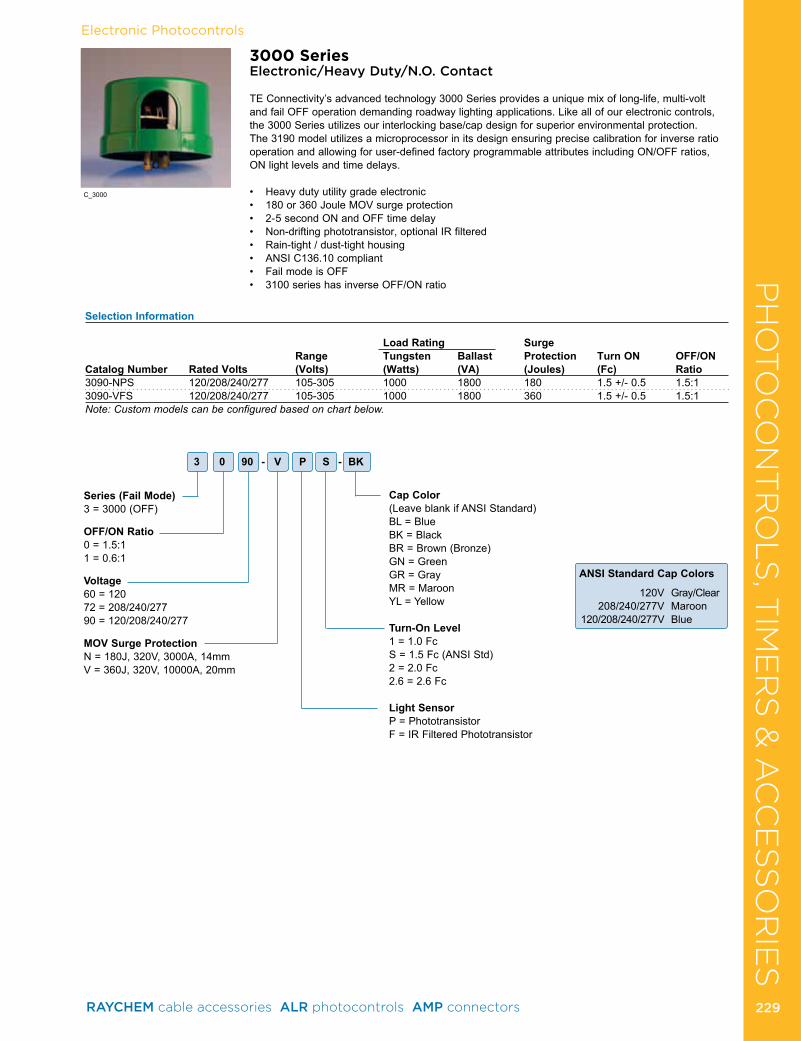
CA
BL
E R
EPA
IR &
RE
JAC
KE
TIN
GElectronic Photocontrols
3000 SeriesElectronic/Heavy Duty/N.O. Contact
TE Connectivity’s advanced technology 3000 Series provides a unique mix of long-life, multi-volt and fail OFF operation demanding roadway lighting applications . Like all of our electronic controls, the 3000 Series utilizes our interlocking base/cap design for superior environmental protection . The 3190 model utilizes a microprocessor in its design ensuring precise calibration for inverse ratio operation and allowing for user-defined factory programmable attributes including ON/OFF ratios, ON light levels and time delays .
• Heavydutyutilitygradeelectronic• 180or360JouleMOVsurgeprotection• 2-5secondONandOFFtimedelay• Non-driftingphototransistor,optionalIRfiltered• Rain-tight/dust-tighthousing• ANSIC136.10compliant• FailmodeisOFF• 3100serieshasinverseOFF/ONratio
Series (Fail Mode)3 = 3000 (OFF)
OFF/ON Ratio0 = 1 .5:11 = 0 .6:1
Voltage60 = 12072 = 208/240/27790 = 120/208/240/277
MOV Surge ProtectionN=180J,320V,3000A,14mmV=360J,320V,10000A,20mm
Cap Color(Leave blank if ANSI Standard)BL = BlueBK = BlackBR = Brown (Bronze)GN = GreenGR = GrayMR = MaroonYL = Yellow
Turn-On Level1 = 1 .0 FcS = 1 .5 Fc (ANSI Std)2 = 2 .0 Fc2 .6 = 2 .6 Fc
Light SensorP = PhototransistorF = IR Filtered Phototransistor
Selection Information
Load Rating Surge Range Tungsten Ballast Protection Turn ON OFF/ONCatalog Number Rated Volts (Volts) (Watts) (VA) (Joules) (Fc) Ratio3090-NPS 120/208/240/277 105-305 1000 1800 180 1 .5 +/- 0 .5 1 .5:13090-VFS 120/208/240/277 105-305 1000 1800 360 1 .5 +/- 0 .5 1 .5:1Note: Custom models can be configured based on chart below.
3 0 90 - V P S - BK
C_3000
ANSI Standard Cap Colors
120V Gray/Clear 208/240/277V Maroon 120/208/240/277V Blue
PH
OTO
CO
NT
RO
LS
, TIM
ER
S &
AC
CE
SS
OR
IES
RAYCHEM cable accessories ALR photocontrols AMP connectors 229 229
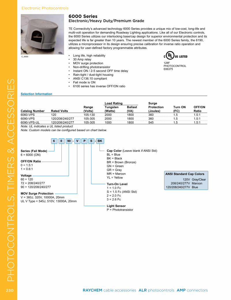
Electronic PhotocontrolsC
AB
LE
RE
PA
IR &
RE
JAC
KE
TIN
G
6000 SeriesElectronic/Heavy Duty/Premium Grade
TE Connectivity’s advanced technology 6000 Series provides a unique mix of low-cost, long-life and multi-volt operation for demanding Roadway Lighting applications . Like all of our Electronic controls, the 6000 Series utilizes our interlocking base/cap design for superior environmental protection and its expected life is far greater than 10 years . The newest member of the 6000 Series family, the 6190, utilizes a microprocessor in its design ensuring precise calibration for inverse ratio operation and allowing for user-defined factory programmable attributes .
• Longlife,highreliability• 30Amprelay• MOVsurgeprotection• Non-driftingphototransistor• InstantON/2-5secondOFFtimedelay• Rain-tight/dust-tighthousing• ANSIC136.10compliant• FailmodeisON• 6100serieshasinverseOFF/ONratio
Series (Fail Mode)6 = 6000 (ON)
OFF/ON Ratio0 = 1 .5:11 = 0 .6:1
Voltage60 = 12072 = 208/240/27790 = 120/208/240/277
MOV Surge ProtectionV=360J,320V,10000A,20mmULVType=545J,510V,13000A,20mm
Cap Color (Leave blank if ANSI Std)BL = BlueBK = BlackBR = Brown (Bronze)GN = GreenGR = GrayMR = MaroonYL = Yellow
Turn-On Level1 = 1 .0 FcS = 1 .5 Fc (ANSI Std)2 = 2 .0 Fc3 = 2 .6 Fc
Light SensorP = Phototransistor
Selection Information
Load Rating Surge Range Tungsten Ballast Protection Turn ON OFF/ON
Catalog Number Rated Volts (Volts) (Watts) (VA) (Joules) (FC) Ratio6060-VPS 120 105-130 2000 1800 360 1 .5 1 .5:16090-VPS 120/208/240/277 105-305 2000 1800 360 1 .5 1 .5:16090-VPS-UL 120/208/240/277 105-305 1000 1800 545 1 .5 1 .5:1Note: UL indicates a UL listed productNote: Custom models can be configured based on chart below.
128FPHOTOCONTROLE66375
6 0 90 - V P S - BK
C_6000
ANSI Standard Cap Colors
120V Gray/Clear 208/240/277V Maroon 120/208/240/277V Blue
PH
OTO
CO
NT
RO
LS
, TIM
ER
S &
AC
CE
SS
OR
IES
RAYCHEM cable accessories ALR photocontrols AMP connectors 230230
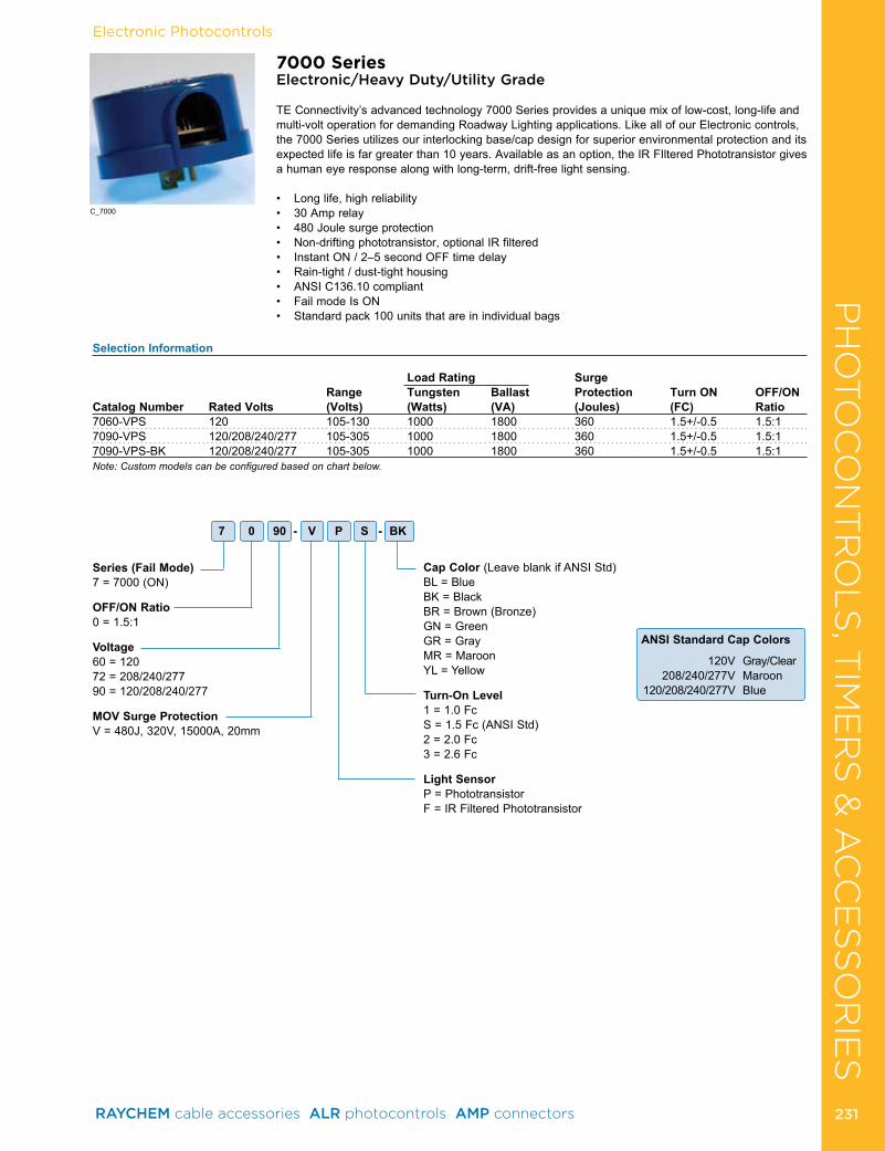
Electronic Photocontrols
7000 SeriesElectronic/Heavy Duty/Utility Grade
TE Connectivity’s advanced technology 7000 Series provides a unique mix of low-cost, long-life and multi-volt operation for demanding Roadway Lighting applications . Like all of our Electronic controls, the 7000 Series utilizes our interlocking base/cap design for superior environmental protection and its expected life is far greater than 10 years . Available as an option, the IR FIltered Phototransistor gives a human eye response along with long-term, drift-free light sensing .
• Longlife,highreliability• 30Amprelay• 480Joulesurgeprotection• Non-driftingphototransistor,optionalIRfiltered• InstantON/2–5secondOFFtimedelay• Rain-tight/dust-tighthousing• ANSIC136.10compliant• FailmodeIsON• Standardpack100unitsthatareinindividualbags
Series (Fail Mode)7 = 7000 (ON)
OFF/ON Ratio0 = 1 .5:1
Voltage60 = 12072 = 208/240/27790 = 120/208/240/277
MOV Surge ProtectionV=480J,320V,15000A,20mm
Cap Color (Leave blank if ANSI Std)BL = BlueBK = BlackBR = Brown (Bronze)GN = GreenGR = GrayMR = MaroonYL = Yellow
Turn-On Level1 = 1 .0 FcS = 1 .5 Fc (ANSI Std)2 = 2 .0 Fc3 = 2 .6 Fc
Light SensorP = PhototransistorF = IR Filtered Phototransistor
Selection Information
Load Rating Surge Range Tungsten Ballast Protection Turn ON OFF/ON
Catalog Number Rated Volts (Volts) (Watts) (VA) (Joules) (FC) Ratio7060-VPS 120 105-130 1000 1800 360 1 .5+/-0 .5 1 .5:17090-VPS 120/208/240/277 105-305 1000 1800 360 1 .5+/-0 .5 1 .5:17090-VPS-BK 120/208/240/277 105-305 1000 1800 360 1 .5+/-0 .5 1 .5:1Note: Custom models can be configured based on chart below.
7 0 90 - V P S - BK
C_7000
ANSI Standard Cap Colors
120V Gray/Clear 208/240/277V Maroon 120/208/240/277V Blue
PH
OTO
CO
NT
RO
LS
, TIM
ER
S &
AC
CE
SS
OR
IES
RAYCHEM cable accessories ALR photocontrols AMP connectors 231 231
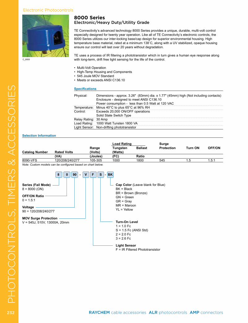
Electronic Photocontrols
C_8000
8000 SeriesElectronic/Heavy Duty/Utility Grade
TE Connectivity’s advanced technology 8000 Series provides a unique, durable, multi-volt control especially designed for twenty year operation . Like all of TE Connectivity’s electronic controls, the 8000 Series utilizes our inter-locking base/cap design for superior environmental housing . High temperaturebasematerial,ratedataminimum138˚C,alongwithaUVstabilized,opaquehousingensure our control will last over 20 years without degradation .
TE uses a process of IR filtering a phototransistor which in turn gives a human eye response along with long-term, drift free light sensing for the life of the control .
•Multi-VoltOperation•High-TempHousingandComponents•545JouleMOVStandard•MeetsorexceedsANSIC136.10
Specifications
Physical: Dimensions-approx.3.26"(83mm)dia.x1.77"(45mm)high(Notincludingcontacts) Enclosure - designed to meet ANSI C136 .10 Power consumption - less than 0 .5 Watt at 120 VACTemperature: Minus 40°C to plus 65°C at 96% RHControl: Exceeds 20,000 ON/OFF operations Solid State Switch TypeRelay Rating: 30 AmpLoad Rating: 1000 Watt Tunsten 1800 VALight Sensor: Non-drifting phototransistor
Series (Fail Mode)8 = 8000 (ON)
OFF/ON Ratio0 = 1 .5:1
Voltage90 = 120/208/240/277
MOV Surge ProtectionV=545J,510V,13000A,20mm
Cap Color (Leave blank for Blue)BK = BlackBR = Brown (Bronze)GN = GreenGR = GrayMR = MaroonYL = Yellow
Turn-On Level1 = 1 .0 FcS = 1 .5 Fc (ANSI Std)2 = 2 .0 Fc3 = 2 .6 Fc
Light SensorF = IR Filtered Phototransistor
8 0 90 - V F S - BK
Selection Information
Load Rating Surge Range Tungsten Ballast Protection Turn ON OFF/ON
Catalog Number Rated Volts (Volts) (Watts) (VA) (Joules) (FC) Ratio
8090-VFS 120/208/240/277 105-305 1000 1800 545 1 .5 1 .5:1Note: Custom models can be configured based on chart below.
PH
OTO
CO
NT
RO
LS
, TIM
ER
S &
AC
CE
SS
OR
IES
RAYCHEM cable accessories ALR photocontrols AMP connectors 232232
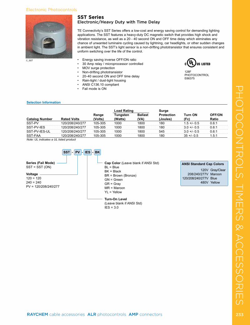
Electronic Photocontrols
Selection Information
Load Rating Surge Range Tungsten Ballast Protection Turn ON OFF/ONCatalog Number Rated Volts (Volts) (Watts) (VA) (Joules) (Fc) RatioSST-PV 120/208/240/277 105-305 1000 1800 180 1 .5 +/- 0 .5 0 .6:1 SST-PV-IES 120/208/240/277 105-305 1000 1800 180 3 .0 +/- 0 .5 0 .6:1 SST-PV-IES-UL 120/208/240/277 105-305 1000 1800 545 3 .0 +/- 0 .5 0 .6:1 SST-FAA 120/208/240/277 105-305 1000 1800 180 35 +/- 0 .5 1 .5:1 Note: UL indicates a UL listed product
SST SeriesElectronic/Heavy Duty with Time Delay
TE Connectivity’s SST Series offers a low-cost and energy saving control for demanding lighting applications . The SST features a heavy-duty DC magnetic switch that provides high shock and vibration resistance, as well as a 20 - 40 second ON and OFF time delay which eliminates any chance of unwanted luminaire cycling caused by lightning, car headlights, or other sudden changes in ambient light . The SST’s light sensor is a non-drifting phototransistor that ensures consistent and uniform switching over the life of the control .
• EnergysavinginverseOFF/ONratio• 30Amprelay/microprocessorcontrolled• MOVsurgeprotection• Non-driftingphototransistor• 20-40secondONandOFFtimedelay• Rain-tight/dust-tighthousing• ANSIC136.10compliant• FailmodeisON
Series (Fail Mode)SST = SST (ON)
Voltage120 = 120240 = 240PV = 120/208/240/277
Cap Color (Leave blank if ANSI Std)BL = BlueBK = BlackBR = Brown (Bronze)GN = GreenGR = GrayMR = MaroonYL = Yellow
Turn-On Level(Leave blank if ANSI Std) IES = 3 .0
128FPHOTOCONTROLE66375
SST - PV - IES - BK
C_SST
ANSI Standard Cap Colors
120V Gray/Clear 208/240/277V Maroon 120/208/240/277V Blue 480V Yellow
PH
OTO
CO
NT
RO
LS
, TIM
ER
S &
AC
CE
SS
OR
IES
RAYCHEM cable accessories ALR photocontrols AMP connectors 233 233
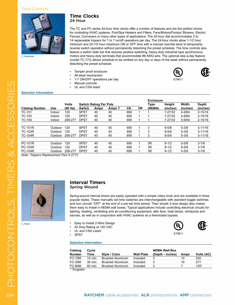
Time Controls
Time Clocks24 Hour
The TC and PC series 24-hour time clocks offer a number of features and are the perfect choice for controlling HVAC systems, Pool/Spa Heaters and Filters, Fans/Motors/Pumps/ Blowers, Electric Fences, Conveyers or many other types of applications . The 24-hour dial accommodates 2 to 14 replaceable trippers for 1 to 7 on/off operations per day . The 24-hour clocks allow 1-1/2 hour minimum and 22-1/2 hour maximum ON or OFF time with a manual override lever to temporarily reverse switch operation without permanently disturbing the preset schedule . The time controls also feature a switch slide bar that assures positive switching, heavy-duty industrial type synchronous motors and heavy-duty terminals that accommodate #8 AWG wire . The optional skip-a-day feature (model TC-173) allows schedule to be omitted on any day or days of the week without permanently disturbing the preset schedule .
• Tamperproofenclosure• All-steelmechanism• 1-7ON/OFFoperationsperday• Manualoverride• ULandCSAlisted
Selection Information
Enclosure Volts Switch Rating Per Pole Type Height Width DepthCatalog Number Use (60 Hz) Switch Amps Amps T VA HP (NEMA) (inches) (inches) (inches)TC-101 Indoor 120 SPST 40 40 690 1 1 7-27/32 4-9/64 2-15/16TC-103 Indoor 120 DPST 40 40 690 1 1 7-27/32 4-9/64 2-15/16TC-104 Indoor 208-277 DPST 40 40 690 1 1 7-27/32 5-9/64 2-15/16 TC-101R Outdoor 120 SPST 40 40 690 1 3 9-5/8 5-3/8 3-11/16TC-103R Outdoor 120 DPST 40 40 690 1 3 9-5/8 5-3/8 3-11/16TC-104R Outdoor 208-277 DPST 40 40 690 1 3 9-5/8 5-3/8 3-11/16 PC-101R Outdoor 120 SPST 40 40 690 1 3R 8-1/2 5-5/8 3-7/8PC-103R Outdoor 120 DPST 40 40 690 1 3R 8-1/2 5-5/8 3-7/8PC-104R Outdoor 208-277 DPST 40 40 690 1 3R 8-1/2 5-5/8 3-7/8Note: Trippers Replacement Part X-2772
Interval TimersSpring Wound
Spring-wound interval timers are easily operated with a simple rotary knob and are available in three popular styles . These manually set time switches are interchangeable with standard toggle switches and turn circuits “OFF” at the end of a pre-set time period . Their simple 2-wire design also makes them easy to install in NEMA wall boxes . Typical applications include controlling electrical circuits for lighting, heating, ventilating and air-conditioning equipment, attic fans, heat lamps, whirlpools and saunas, as well as in conjunction with HVAC systems as a thermostat bypass .
• EasytoInstall2-WireDesign• 20AmpRatingat120VAC• ULandCSAListed• SPST
Selection Information
Catalog Cycle NEMA Wall Box Number Time Style / Color Wall Plate (Depth - inches) Amps Volts (AC)FC-15M 15 min . Brushed Aluminum Included 3 10 250FC-30M 30 min . Brushed Aluminum Included 3 10 277FC-60M 60 min . Brushed Aluminum Included 3 7 125** Tungsten
E79611
E79611
C_TimeClocks
C_Timers
PH
OTO
CO
NT
RO
LS
, TIM
ER
S &
AC
CE
SS
OR
IES
RAYCHEM cable accessories ALR photocontrols AMP connectors 234234
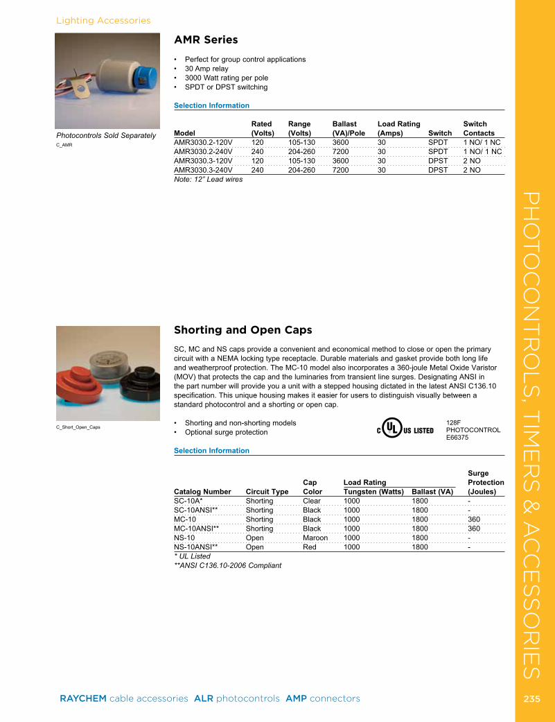
PH
OTO
CO
NT
RO
LS
, TIM
ER
S &
AC
CE
SS
OR
IES
Lighting Accessories
Shorting and Open Caps
SC, MC and NS caps provide a convenient and economical method to close or open the primary circuit with a NEMA locking type receptacle . Durable materials and gasket provide both long life and weatherproof protection . The MC-10 model also incorporates a 360-joule Metal Oxide Varistor (MOV) that protects the cap and the luminaries from transient line surges . Designating ANSI in the part number will provide you a unit with a stepped housing dictated in the latest ANSI C136 .10 specification . This unique housing makes it easier for users to distinguish visually between a standard photocontrol and a shorting or open cap .
• Shortingandnon-shortingmodels• Optionalsurgeprotection
Selection Information
Surge Cap Load Rating ProtectionCatalog Number Circuit Type Color Tungsten (Watts) Ballast (VA) (Joules)SC-10A* Shorting Clear 1000 1800 -SC-10ANSI** Shorting Black 1000 1800 -MC-10 Shorting Black 1000 1800 360MC-10ANSI** Shorting Black 1000 1800 360NS-10 Open Maroon 1000 1800 -NS-10ANSI** Open Red 1000 1800 -* UL Listed**ANSI C136.10-2006 Compliant
128FPHOTOCONTROLE66375
C_Short_Open_Caps
C_AMR
AMR Series
• Perfectforgroupcontrolapplications• 30Amprelay• 3000Wattratingperpole• SPDTorDPSTswitching
Selection Information Rated Range Ballast Load Rating SwitchModel (Volts) (Volts) (VA)/Pole (Amps) Switch ContactsAMR3030 .2-120V 120 105-130 3600 30 SPDT 1 NO/ 1 NCAMR3030 .2-240V 240 204-260 7200 30 SPDT 1 NO/ 1 NCAMR3030 .3-120V 120 105-130 3600 30 DPST 2 NOAMR3030 .3-240V 240 204-260 7200 30 DPST 2 NONote: 12” Lead wires
Photocontrols Sold Separately
PH
OTO
CO
NT
RO
LS
, TIM
ER
S &
AC
CE
SS
OR
IES
RAYCHEM cable accessories ALR photocontrols AMP connectors 235 235
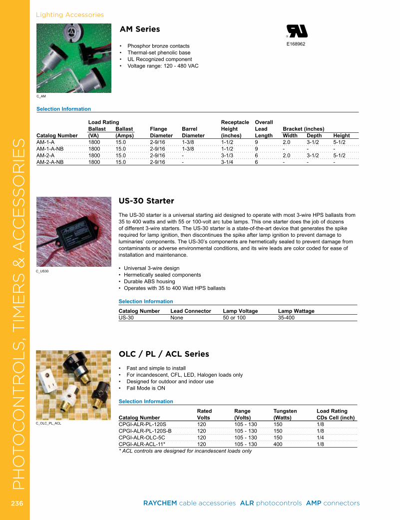
US-30 Starter
The US-30 starter is a universal starting aid designed to operate with most 3-wire HPS ballasts from 35 to 400 watts and with 55 or 100-volt arc tube lamps . This one starter does the job of dozens of different 3-wire starters . The US-30 starter is a state-of-the-art device that generates the spike required for lamp ignition, then discontinues the spike after lamp ignition to prevent damage to luminaries’ components . The US-30’s components are hermetically sealed to prevent damage from contaminants or adverse environmental conditions, and its wire leads are color coded for ease of installation and maintenance .
• Universal3-wiredesign• Hermeticallysealedcomponents• DurableABShousing• Operateswith35to400WattHPSballasts
Selection Information
Catalog Number Lead Connector Lamp Voltage Lamp WattageUS-30 None 50 or 100 35-400
C_OLC_PL_ACL
OLC / PL / ACL Series
• Fastandsimpletoinstall• Forincandescent,CFL,LED,Halogenloadsonly• Designedforoutdoorandindooruse• FailModeisON
Selection Information
Rated Range Tungsten Load RatingCatalog Number Volts (Volts) (Watts) CDs Cell (inch)CPGI-ALR-PL-120S 120 105 - 130 150 1/8CPGI-ALR-PL-120S-B 120 105 - 130 150 1/8CPGI-ALR-OLC-5C 120 105 - 130 150 1/4CPGI-ALR-ACL-11* 120 105 - 130 400 1/8* ACL controls are designed for incandescent loads only
Lighting AccessoriesP
HO
TO
CO
NT
RO
LS
, TIM
ER
S &
AC
CE
SS
OR
IES
E168962
AM Series
• Phosphorbronzecontacts• Thermal-setphenolicbase• ULRecognizedcomponent• Voltagerange:120-480VAC
Selection Information Load Rating Receptacle Overall Ballast Ballast Flange Barrel Height Lead Bracket (inches)Catalog Number (VA) (Amps) Diameter Diameter (inches) Length Width Depth HeightAM-1-A 1800 15 .0 2-9/16 1-3/8 1-1/2 9 2 .0 3-1/2 5-1/2AM-1-A-NB 1800 15 .0 2-9/16 1-3/8 1-1/2 9 - - -AM-2-A 1800 15 .0 2-9/16 - 3-1/3 6 2 .0 3-1/2 5-1/2AM-2-A-NB 1800 15 .0 2-9/16 - 3-1/4 6 - - -
C_AM
C_US30
RAYCHEM cable accessories ALR photocontrols AMP connectors 236236

ProductProduct
BUS Insulation & Wildlife ProtectionHVBT High Voltage Busbar Insulating Tape (5-35 kV) . . . . . . . . 238BBIT/BPTM Insulating Busbar Tubing (5-35 kV) . . . . . . . . . . . . . 239HVIS High Voltage Insulating Sheet (5-15 kV) . . . . . . . . . . . . . . 240RRBB Insulating Barrier Board . . . . . . . . . . . . . . . . . . . . . . . . . . 241HVBC Raysulate Electrical Insulator . . . . . . . . . . . . . . . . . . . . . . 241
Substations BISG Bus Insulator Squirrel Guard . . . . . . . . . . . . . . . . . . . . . . . 242BCAC Bushing Connection Animal Cover . . . . . . . . . . . . . . . . . . 243BCAC-IC Bushing Connection Inspection Cover . . . . . . . . . . . . 244BCIC Bus Connection Insulating Cover . . . . . . . . . . . . . . . . . . . . 245MVFT Medium Voltage Fusion Tape . . . . . . . . . . . . . . . . . . . . . . 251MVCC Medium Voltage Conductor Covers . . . . . . . . . . . . . . . . . 251
OverheadBCIC Raptor Protection Cover . . . . . . . . . . . . . . . . . . . . . . . . . . . 252BCAC/BCIC Distribution Covers . . . . . . . . . . . . . . . . . . . . . . . . . 253BCIC Recloser Insulating Covers . . . . . . . . . . . . . . . . . . . . . . . . 254BCIC-115-PH Transmission Flashover Protection . . . . . . . . . . . 255MVLC Medium Voltage Line Cover (5-25 kV) . . . . . . . . . . . . . . . 255
Contamination/Flashover PreventionHVCE High Voltage Creepage Extenders . . . . . . . . . . . . . . . . . . 257HVCE-WA Wraparound High Voltage Creepage Extenders . . . . 258HVBS Booster Shed . . . . . . . . . . . . . . . . . . . . . . . . . . . . . . . . . . 259RRGS Guano Shield . . . . . . . . . . . . . . . . . . . . . . . . . . . . . . . . . . 260
ASSET & WILDLIFE PROTECTION
RAYCHEM cable accessories ALR photocontrols AMP connectors 237 237
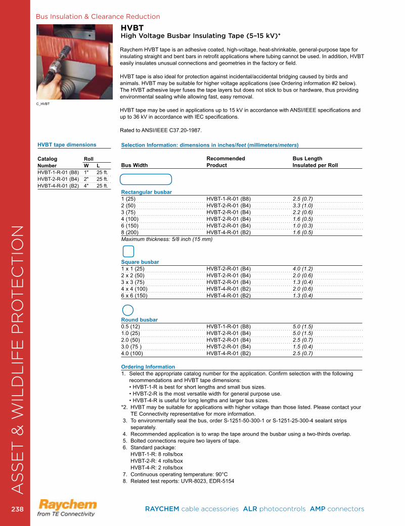
Bus Insulation & Clearance ReductionA
SS
ET
& W
ILD
LIF
E P
RO
TE
CT
ION
HVBTHigh Voltage Busbar Insulating Tape (5–15 kV)*
Raychem HVBT tape is an adhesive coated, high-voltage, heat-shrinkable, gen eral- purpose tape for insulating straight and bent bars in retrofit applications where tubing cannot be used . In addition, HVBT easily insulates unusual connections and geometries in the factory or field .
HVBT tape is also ideal for protection against incidental/accidental bridging caused by birds and animals . HVBT may be suitable for higher voltage applications (see Ordering information #2 below) . The HVBT adhesive layer fuses the tape layers but does not stick to bus or hardware, thus providing environmental sealing while allowing fast, easy removal . HVBT tape may be used in applications up to 15 kV in accordance with ANSI/IEEE specifications and up to 36 kV in accordance with IEC specifications .
Rated to ANSI/IEEE C37 .20-1987 .
C_HVBT
Selection Information: dimensions in inches/feet (millimeters/meters) Recommended Bus LengthBus Width Product Insulated per Roll
Rectangular busbar1 (25) HVBT-1-R-01 (B8) 2.5 (0.7) 2 (50) HVBT-2-R-01 (B4) 3.3 (1.0) 3 (75) HVBT-2-R-01 (B4) 2.2 (0.6) 4 (100) HVBT-2-R-01 (B4) 1.6 (0.5) 6 (150) HVBT-2-R-01 (B4) 1.0 (0.3) 8 (200) HVBT-4-R-01 (B2) 1.6 (0.5) Maximum thickness: 5/8 inch (15 mm)
Square busbar1 x 1 (25) HVBT-2-R-01 (B4) 4.0 (1.2) 2 x 2 (50) HVBT-2-R-01 (B4) 2.0 (0.6) 3 x 3 (75) HVBT-2-R-01 (B4) 1.3 (0.4) 4 x 4 (100) HVBT-4-R-01 (B2) 2.0 (0.6) 6 x 6 (150) HVBT-4-R-01 (B2) 1.3 (0.4)
Round busbar0 .5 (12) HVBT-1-R-01 (B8) 5.0 (1.5) 1 .0 (25) HVBT-2-R-01 (B4) 5.0 (1.5) 2 .0 (50) HVBT-2-R-01 (B4) 2.5 (0.7) 3 .0 (75 ) HVBT-2-R-01 (B4) 1.5 (0.4) 4 .0 (100) HVBT-4-R-01 (B2) 2.5 (0.7)
Ordering Information 1 . Select the appropriate catalog number for the application . Confirm selection with the following
recommendations and HVBT tape dimensions: • HVBT-1-R is best for short lengths and small bus sizes.
• HVBT-2-R is the most versatile width for general purpose use. • HVBT-4-R is useful for long lengths and larger bus sizes.*2 . HVBT may be suitable for applications with higher voltage than those listed . Please contact your
TE Connectivity representative for more information . 3 . To environmentally seal the bus, order S-1251-50-300-1 or S-1251-25-300-4 sealant strips
separately . 4 . Recommended application is to wrap the tape around the busbar using a two-thirds overlap . 5 . Bolted connections require two layers of tape . 6 . Standard package: HVBT-1-R: 8 rolls/box HVBT-2-R: 4 rolls/box HVBT-4-R: 2 rolls/box 7 . Continuous operating temperature: 90°C 8 . Related test reports: UVR-8023, EDR-5154
HVBT tape dimensions
Catalog RollNumber W LHVBT-1-R-01 (B8) 1" 25 ft .HVBT-2-R-01 (B4) 2" 25 ft .HVBT-4-R-01 (B2) 4" 25 ft .
RAYCHEM cable accessories ALR photocontrols AMP connectors 238238
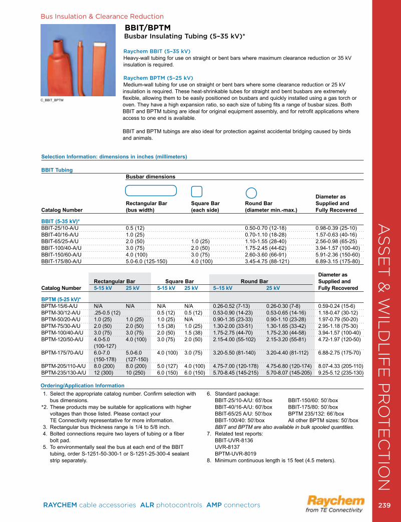
AS
SE
T &
WIL
DL
IFE
PR
OT
EC
TIO
NBus Insulation & Clearance Reduction
BBIT/BPTMBusbar Insulating Tubing (5–35 kV)*
Raychem BBIT (5–35 kV) Heavy-wall tubing for use on straight or bent bars where maximum clearance reduction or 35 kV insulation is required . Raychem BPTM (5–25 kV) Medium-wall tubing for use on straight or bent bars where some clearance reduction or 25 kV insulation is required . These heat-shrinkable tubes for straight and bent busbars are extremely flexible, allowing them to be easily positioned on busbars and quickly installed using a gas torch or oven. They have a high expansion ratio, so each size of tubing fits a range of busbar sizes. Both BBIT and BPTM tubing are ideal for original equipment assembly, and for retrofit applications where access to one end is available .
BBIT and BPTM tubings are also ideal for protection against accidental bridging caused by birds and animals .
C_BBIT_BPTM
Selection Information: dimensions in inches (millimeters)
BBIT Tubing Busbar dimensions Diameter as Rectangular Bar Square Bar Round Bar Supplied and Catalog Number (bus width) (each side) (diameter min.-max.) Fully Recovered
BBIT (5-35 kV)*BBIT-25/10-A/U 0 .5 (12) 0 .50-0 .70 (12-18) 0 .98-0 .39 (25-10)BBIT-40/16-A/U 1 .0 (25) 0 .70-1 .10 (18-28) 1 .57-0 .63 (40-16)BBIT-65/25-A/U 2 .0 (50) 1 .0 (25) 1 .10-1 .55 (28-40) 2 .56-0 .98 (65-25)BBIT-100/40-A/U 3 .0 (75) 2 .0 (50) 1 .75-2 .45 (44-62) 3 .94-1 .57 (100-40)BBIT-150/60-A/U 4 .0 (100) 3 .0 (75) 2 .60-3 .60 (66-91) 5 .91-2 .36 (150-60)BBIT-175/80-A/U 5 .0-6 .0 (125-150) 4 .0 (100) 3 .45-4 .75 (88-121) 6 .89-3 .15 (175-80)
Diameter as Rectangular Bar Square Bar Round Bar Supplied andCatalog Number 5-15 kV 25 kV 5-15 kV 25 kV 5–15 kV 25 kV Fully Recovered
BPTM (5-25 kV)*BPTM-15/6-A/U N/A N/A N/A N/A 0 .26-0 .52 (7-13) 0 .26-0 .30 (7-8) 0 .59-0 .24 (15-6)BPTM-30/12-A/U .25-0 .5 (12) 0 .5 (12) 0 .5 (12) 0 .53-0 .90 (14-23) 0 .53-0 .65 (14-16) 1 .18-0 .47 (30-12)BPTM-50/20-A/U 1 .0 (25) 1 .0 (25) 1 .0 (25) N/A 0 .90-1 .35 (23-33) 0 .90-1 .10 (23-28) 1 .97-0 .79 (50-20)BPTM-75/30-A/U 2 .0 (50) 2 .0 (50) 1 .5 (38) 1 .0 (25) 1 .30-2 .00 (33-51) 1 .30-1 .65 (33-42) 2 .95-1 .18 (75-30)BPTM-100/40-A/U 3 .0 (75) 3 .0 (75) 2 .0 (50) 1 .5 (38) 1 .75-2 .75 (44-70) 1 .75-2 .30 (44-58) 3 .94-1 .57 (100-40)BPTM-120/50-A/U 4 .0-5 .0 4 .0 (100) 3 .0 (75) 2 .0 (50) 2 .15-4 .00 (55-102) 2 .15-3 .20 (55-81) 4 .72-1 .97 (120-50) (100-127)BPTM-175/70-A/U 6 .0-7 .0 5 .0-6 .0 4 .0 (100) 3 .0 (75) 3 .20-5 .50 (81-140) 3 .20-4 .40 (81-112) 6 .88-2 .75 (175-70) (150-178) (127-150)BPTM-205/110-A/U 8 .0 (200) 8 .0 (200) 5 .0 (127) 4 .0 (100) 4 .75-7 .00 (120-178) 4 .75-6 .80 (120-174) 8 .07-4 .33 (205-110)BPTM-235/130-A/U 12 (300) 10 (250) 6 .0 (150) 6 .0 (150) 5 .70-8 .45 (145-215) 5 .70-8 .07 (145-205) 9 .25-5 .12 (235-130)
Ordering/Application Information 1 . Select the appropriate catalog number . Confirm selection with
bus dimensions .*2 . These products may be suitable for applications with higher
voltages than those listed . Please contact your TE Connectivity representative for more information .
3 . Rectangular bus thickness range is 1/4 to 5/8 inch . 4 . Bolted connections require two layers of tubing or a fiber
bolt pad . 5 . To environmentally seal the bus at each end of the BBIT
tubing, order S-1251-50-300-1 or S-1251-25-300-4 sealant strip separately .
6 . Standard package: BBIT-25/10-A/U: 65'/box BBIT-150/60: 50’/box BBIT-40/16-A/U: 60'/box BBIT-175/80: 50’/box BBIT-65/25 A/U: 50'/box BPTM 235/132: 66’/box BBIT-100/40: 50'/box All other BPTM sizes: 50’/box BBIT and BPTM are also available in bulk spooled quantities.7 . Related test reports: BBIT-UVR-8136 UVR-8137 BPTM-UVR-80198 . Minimum continuous length is 15 feet (4 .5 meters) .
RAYCHEM cable accessories ALR photocontrols AMP connectors 239 239

Bus Insulation & Clearance Reduction
HVISHigh Voltage Busbar Insulating Sheet (5–15 kV)*
Raychem HVIS is an adhesive coated, heat-shrinkable sheet that shrinks in two directions to tightly conform to complex shapes . It is ideal for insulating busbar tees, elbows, and other connections where tubing or tape cannot be used . HVIS may also be used in conjunction with Raysulate electrical insulating tapes and tubings or alone to help protect against accidental bridging caused by birds and animals .
Rated to ANSI/IEEE C37 .20-1987 .C_HVIS
Selection Information: dimensions in inches/feet (millimeters/meters)
Catalog Number Width Length PackagingHVIS-05-(B3) NS 26 (660) 20 (508) SheetHVIS-10-(B1) NS 26 (660) 33 ft (10 m) Roll
Number of Installations Per Sheet/RollBus Width Cut Size Needed HVIS-05 Sheet HVIS-10 Roll
T Connection1 (25) 11 x 9 (275 x 225) 4 882 (50) 13 x 10 (325 x 250) 4 783 (75) 16 x 11 (400 x 275) 2 484 (100) 18 x 13 (450 x 325) 2 446 (150) 22 x 17 (550 x 425) 1 23
Elbow Connection1 (25) 11 x 7 (275 x 175) 4 1122 (50) 13 x 9 (325 x 225) 4 883 (75) 15 x 10 (375 x 250) 2 524 (100) 18 x 11 (450 x 275) 2 446 (150) 22 x 13 (550 x 325) 1 36
Catalog Number Description Std. Pack
Sheet (HVIS) AccessoriesHVIS-Flat (B12) 36" flat bracket for clamping HVIS on straight runs 12 ea .HVIS-Angle (B12) Angle brackets for clamping HVIS at 90° angles 12 ea .HVIS-Clamp (B25) Spring clamps to hold brackets on HVIS . 25 ea .
Ordering/Application Information 1 . Select the appropriate catalog number . Confirm selection with dimensions .2 Busbars are assumed to be insulated to within 1 inch of the joint. Cut size should extend a minimum
of 4 inches onto each leg of the joint before shrinking .3 The above table should be used as a guide only; experiment to confirm final cut size. Table is based
on 5/8-inch bus thickness .4 . To environmentally seal each leg of the bus, order S-1251-50-300-1 or S-1251-25-300-4 sealant
strips separately .5 . HVIS may be rated for applications up to 35 kV . Please contact your TE representative for more
information . 6 . Standard package: HVIS-05: 3 sheets/box, HVIS-10: 1 roll/box 7 . Related test report: EDR-5175
AS
SE
T &
WIL
DL
IFE
PR
OT
EC
TIO
N
Angle ClampBracket
Flat bracket
RAYCHEM cable accessories ALR photocontrols AMP connectors 240240

Bus Insulation & Clearance Reduction
HVBCElectrical Insulator Cable-to-Bus Connection Kit (5–15 kV)
The Raychem HVBC kit contains heat-shrinkable insu lating tubing and sealant strips for insulating and environmentally sealing high-voltage in-line cable-to-busbar connections . For multiple cable connections, the kit also contains a heat-shrinkable sealing boot . The kit greatly simplifies field installation and eliminates the labor and skill needed for tape-and-putty methods .
When HVBC kits are used with TE Connectivity’s high voltage terminations, the diameter build-up over the cable is minimal . This increas es working space in cramped areas and allows up to four cable connections . HVBC may be used in applications up to 15 kV in accordance with ANSI/IEEE specifications, and up to 36 kV in accordance with IEC applications . Rated to ANSI/IEEE C37 .20-1987 .
Selection Information: dimensions in inches (millimeters)
Catalog Number Number of Cable Size RangeBus Width: 2–4 inches Bus Width: 5–6 inches Cables (Min.–Max.)HVBC-41 HVBC-61 1 #4–1000 kcmilHVBC-42 HVBC-62 2 #4–1000 kcmilHVBC-43 HVBC-63 3 #4–1000 kcmilHVBC-44 HVBC-64 4 #4–1000 kcmil
Accessory DescriptionBP-46 Bolt Pad
Ordering/Application Information1 . Select the appropriate catalog number . Confirm selection with dimensions . One HVBC kit
insulates one phase of an in-line cable-to-bus connection . • Maximum bolt length: 2 inches • Maximum busbar thickness: 5/8 inch
• Maximum bare bus length: 9 inches2 . BBIT tubing, BPTM tubing, or HVBT tape, can be used to insulate the exposed busbar before
installing the HVBC products .3 . Shielded cable must be ter mi n ated before installing HVBC products; use TE’s HVT terminations .4 . Standard package: 3 kits/box5 . Related test report: EDR-5103
C_HVBC
C_RRBB
RRBBInterphase Insulating Barrier Board
Raychem RRBB board is a non-structural, interphase barrier for switchgear applications . The RRBB board is made from a homogeneous polymer and has excellent track resistance, especially following a power-arc . Easily fabricated into a shape, it produces less nuisance dust and less tooling wear than other boards .
ApplicationsRRBB barriers protect switchgear cabinets against interphase flashovers that can be caused by contaminants, moisture and animals .
• Excellent tracking resistant properties provide longevity not found in typical polymers• UV properties of the barrier boards are suitable for outdoor applications• Extremely durable barrier boards resist damage from solvents, mechanical impact and general
wear and tear• Machining properties allow it to be cut and drilled for mounting without requiring special safety equipment• Innovative cross-linking polymer withstands power-arcs without compromising its physical shape• High temperature resistant material can be wiped clean after power-arc events resulting in no visible effects or surface damage
Selection Information: dimensions in inches (millimeters)
Catalog Number Width Length ThicknessRRBB-6-1 .25Mx1 .25M-(B3) 48 (1220) 48 (1220) 0 .250 (6)RRBB-2440/1220-6 .2-BP 48 (1220) 96 (2440) 0 .250 (6)
Product InformationRelated Test Report: EDR-5311 A
SS
ET
& W
ILD
LIF
E P
RO
TE
CT
ION
RAYCHEM cable accessories ALR photocontrols AMP connectors 241 241
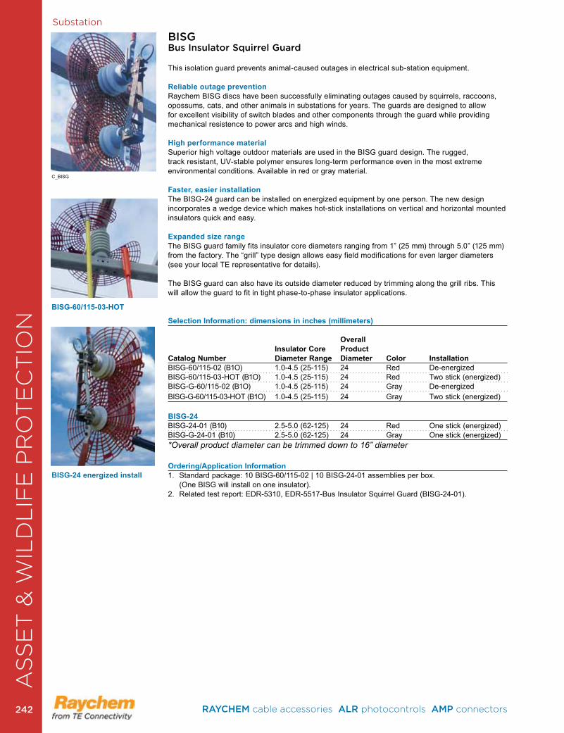
Substation
BISGBus Insulator Squirrel Guard
This isolation guard prevents animal-caused outages in electrical sub-station equipment .
Reliable outage preventionRaychem BISG discs have been successfully eliminating outages caused by squirrels, raccoons, opossums, cats, and other animals in substations for years . The guards are designed to allow for excellent visibility of switch blades and other components through the guard while providing mechanical resistence to power arcs and high winds .
High performance materialSuperior high voltage outdoor materials are used in the BISG guard design . The rugged, track resistant, UV-stable polymer ensures long-term performance even in the most extreme environmental conditions . Available in red or gray material .
Faster, easier installationThe BISG-24 guard can be installed on energized equipment by one person. The new design incorporates a wedge device which makes hot-stick installations on vertical and horizontal mounted insulators quick and easy .
Expanded size rangeThe BISG guard family fits insulator core diameters ranging from 1” (25 mm) through 5 .0” (125 mm) from the factory . The “grill” type design allows easy field modifications for even larger diameters (see your local TE representative for details) .
The BISG guard can also have its outside diameter reduced by trimming along the grill ribs . This will allow the guard to fit in tight phase-to-phase insulator applications .
Selection Information: dimensions in inches (millimeters)
Overall Insulator Core Product Catalog Number Diameter Range Diameter Color InstallationBISG-60/115-02 (B1O) 1.0-4.5 (25-115) 24 Red De-energized BISG-60/115-03-HOT (B1O) 1.0-4.5 (25-115) 24 Red Two stick (energized)BISG-G-60/115-02 (B1O) 1.0-4.5 (25-115) 24 Gray De-energized BISG-G-60/115-03-HOT (B1O) 1.0-4.5 (25-115) 24 Gray Two stick (energized) BISG-24BISG-24-01 (B10) 2.5-5.0 (62-125) 24 Red One stick (energized)BISG-G-24-01 (B10) 2.5-5.0 (62-125) 24 Gray One stick (energized) *Overall product diameter can be trimmed down to 16” diameter
Ordering/Application Information1 . Standard package: 10 BISG-60/115-02 | 10 BISG-24-01 assemblies per box . (One BISG will install on one insulator) .2 . Related test report: EDR-5310, EDR-5517-Bus Insulator Squirrel Guard (BISG-24-01) .
BISG-60/115-03-HOT
BISG-24 energized install
C_BISG
AS
SE
T &
WIL
DL
IFE
PR
OT
EC
TIO
N
RAYCHEM cable accessories ALR photocontrols AMP connectors 242242

Substations
BCACBushing Connection Animal Cover
These insulating covers are designed to prevent animal caused outages on bushings ranging from 15 to 35 kV. They fit a wide range of bushing sizes and are suitable for substation and distribution applications .
Reliable Outage Protection TE’s Raychem insulating covers have been successfully eliminating outages from all types of animals for years . These covers have been designed to provide the same great protection with enhanced features .
Fast and Versatile Installation These BCACs are fast and easy to install . No trimming is required and they fit a wide range of bushing skirt diameters (see chart below). If needed, they can be installed on energized equipment as well. The feathered edges of these covers allow for conductor exits in both vertical and horizontal directions . These same edges act as thermal scan sites for true temperature evaluation of the covered hardware .
High Performance MaterialSuperior high-voltage outdoor materials are used in the BCAC cover design . The rugged, non-tracking, UV-resistant polymer ensures long-term performance even in the most extreme environmental conditions .
Selection Information: dimensions in inches (millimeters) Max. ShedCatalog Number Diameter Cover Height ColorBCAC-5D/8 (B12) 4 .8 (122) 8 .0 (203) RedBCAC-7D/10 (B6) 6 .8 (172) 10 .5 (266) RedBCAC-8D/14 (B6) 8 .0 (203) 14 .0 (355) RedBCAC-G-5D/8 (B12) 4 .8 (122) 8 .0 (203) GrayBCAC-G-7D/10 (B6) 6 .8 (172) 10 .5 (266) GrayBCAC-G-8D/14 (B6) 8 .0 (203) 14 .0 (355) Gray
Ordering/Application Information 1. Standard package: 12 or 6 units per box, depending on size of cover. (One BCAC will install on
one insulator .)2 Related test reports: EDR-5339, UVR-8209
Max. ShedCatalog Number Diameter Cover Height ColorBCAC-BYPASS-01 (B6) 6 .8 (172) 10 .6 (266) RedBCAC-BYPASS-02 (B6) 8 .0 (203) 14 .0 (355) Red
The BCAC covers are also kitted for voltage regulator applications . The kit includes two bushing covers and a center arrester cover .
BCAC-5D/8
BCAC-8D/14
BCAC-BYPASS
AS
SE
T &
WIL
DL
IFE
PR
OT
EC
TIO
N
C_BCAC
RAYCHEM cable accessories ALR photocontrols AMP connectors 243 243
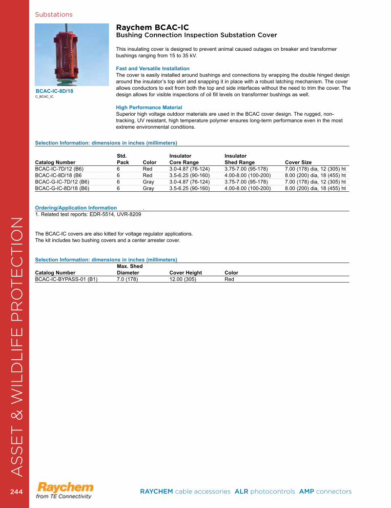
Substations
Selection Information: dimensions in inches (millimeters)
Std. Insulator InsulatorCatalog Number Pack Color Core Range Shed Range Cover SizeBCAC-IC-7D/12 (B6) 6 Red 3 .0-4 .87 (76-124) 3 .75-7 .00 (95-178) 7 .00 (178) dia, 12 (305) htBCAC-IC-8D/18 (B6 6 Red 3 .5-6 .25 (90-160) 4 .00-8 .00 (100-200) 8 .00 (200) dia, 18 (455) htBCAC-G-IC-7D/12 (B6) 6 Gray 3 .0-4 .87 (76-124) 3 .75-7 .00 (95-178) 7 .00 (178) dia, 12 (305) htBCAC-G-IC-8D/18 (B6) 6 Gray 3 .5-6 .25 (90-160) 4 .00-8 .00 (100-200) 8 .00 (200) dia, 18 (455) ht
Ordering/Application Information . 1 . Related test reports: EDR-5514, UVR-8209
The BCAC-IC covers are also kitted for voltage regulator applications . The kit includes two bushing covers and a center arrester cover .
Selection Information: dimensions in inches (millimeters) Max. ShedCatalog Number Diameter Cover Height ColorBCAC-IC-BYPASS-01 (B1) 7 .0 (178) 12 .00 (305) Red
Raychem BCAC-ICBushing Connection Inspection Substation Cover
This insulating cover is designed to prevent animal caused outages on breaker and transformer bushings ranging from 15 to 35 kV .
Fast and Versatile Installation The cover is easily installed around bushings and connections by wrapping the double hinged design around the insulator’s top skirt and snapping it in place with a robust latching mechanism . The cover allows conductors to exit from both the top and side interfaces without the need to trim the cover . The design allows for visible inspections of oil fill levels on transformer bushings as well .
High Performance MaterialSuperior high voltage outdoor materials are used in the BCAC cover design . The rugged, non-tracking, UV resistant, high temperature polymer ensures long-term performance even in the most extreme environmental conditions .
BCAC-IC-8D/18
AS
SE
T &
WIL
DL
IFE
PR
OT
EC
TIO
N
C_BCAC_IC
RAYCHEM cable accessories ALR photocontrols AMP connectors 244244
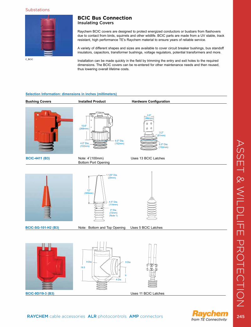
Substations
BCIC Bus ConnectionInsulating Covers
Raychem BCIC covers are designed to protect energized conductors or busbars from flashovers due to contact from birds, squirrels and other wildlife . BCIC parts are made from a UV stable, track resistant, high performance TE’s Raychem material to ensure years of reliable service .
A variety of different shapes and sizes are available to cover circuit breaker bushings, bus standoff insulators, capacitors, transformer bushings, voltage regulators, potential transformers and more .
Installation can be made quickly in the field by trimming the entry and exit holes to the required dimensions . The BCIC covers can be re-entered for other maintenance needs and then reused, thus lowering overall lifetime costs .
C_BCIC
3.5"(88mm)
3.2"(81mm)
6.0" Dia.(152mm)
10.6"(268mm)
4.0" Dia.(102mm)
6.0" Dia.(152mm)
BCIC-4411 (B3) Note: 4˝(100mm) Uses 13 BCIC Latches Bottom Port Opening
Bushing Covers Installed Product Hardware Configuration
Selection Information: dimensions in inches (millimeters)
12"(305mm)
1.125" Dia.(29mm)
4.5" Dia.(114mm)
3" Dia.(72mm)(Note 1)
BCIC-SG-101-H2 (B3) Note: Bottom and Top Opening Uses 5 BCIC Latches
9 Dia9 Dia
4 Dia
18.5
9
BCIC-9D/19-3 (B3) Uses 11 BCIC Latches
AS
SE
T &
WIL
DL
IFE
PR
OT
EC
TIO
N
RAYCHEM cable accessories ALR photocontrols AMP connectors 245 245
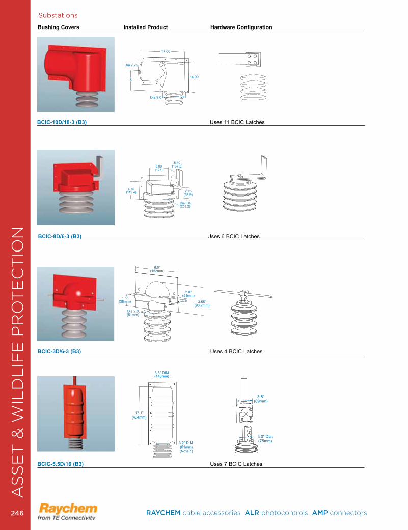
Substations
Bushing Covers Installed Product Hardware Configuration
Dia 7.75
Dia 9.0
14.00
17.00
8
BCIC-10D/18-3 (B3) Uses 11 BCIC Latches
5.5" DIM(140mm)
3.2" DIM (81mm)(Note 1)
17.1"(434mm)
3.5"(89mm)
3.0" Dia.(75mm)
5.00(127)
4.70(119.4)
Dia 8.0(203.2)
2.75(69.9)
5.40(137.2)
6.0"(152mm)
Dia 2.0(51mm)
3.55"(90.2mm)
2.0"(51mm)
1.5"(38mm)
BCIC-3D/6-3 (B3) Uses 4 BCIC Latches
BCIC-5.5D/16 (B3) Uses 7 BCIC Latches
BCIC-8D/6-3 (B3) Uses 6 BCIC Latches
AS
SE
T &
WIL
DL
IFE
PR
OT
EC
TIO
N
RAYCHEM cable accessories ALR photocontrols AMP connectors 246246
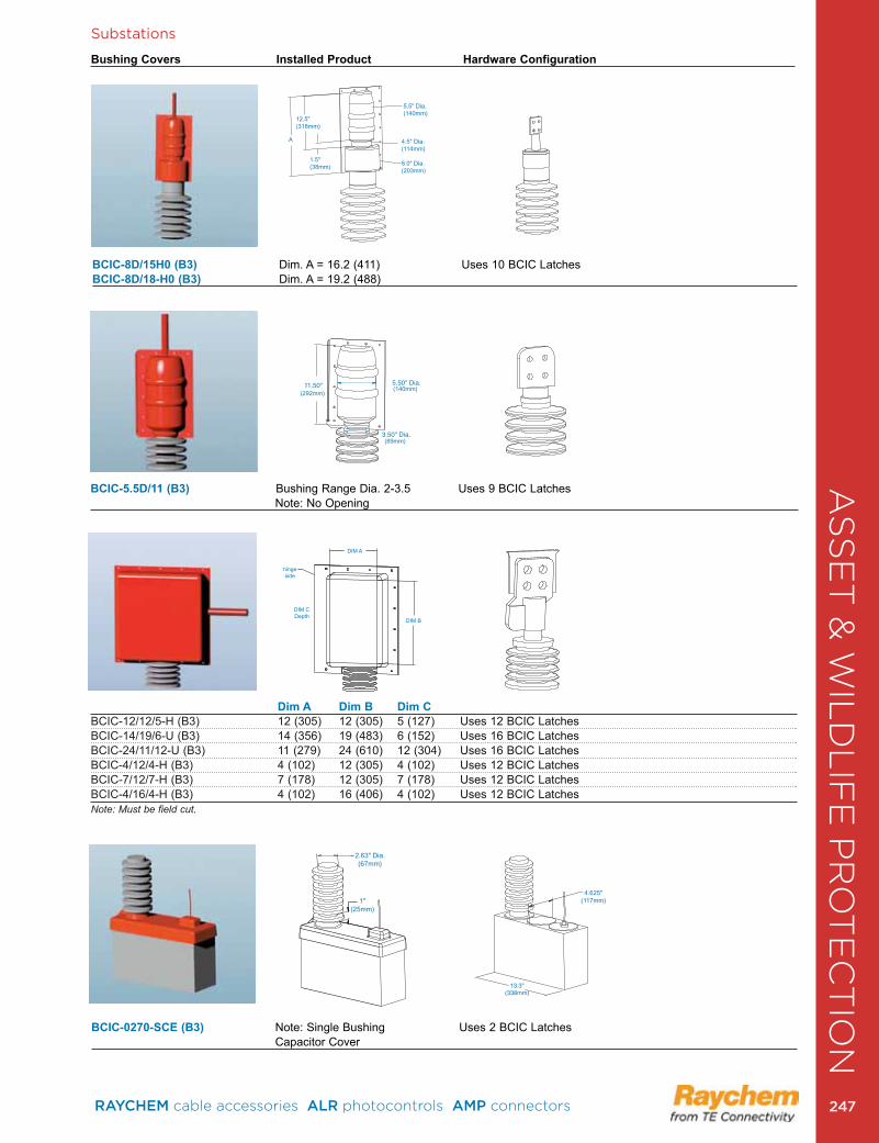
Substations
Bushing Covers Installed Product Hardware Configuration
12.5"(318mm)
1.5" (38mm)
5.5" Dia.(140mm)
4.5" Dia. (114mm)
8.0" Dia.(203mm)
A
BCIC-8D/15H0 (B3) Dim . A = 16 .2 (411) Uses 10 BCIC Latches BCIC-8D/18-H0 (B3) Dim . A = 19 .2 (488)
11.50" 5.50" Dia.
3.50" Dia.
(140mm)
(89mm)
(292mm)
DIM A
hingeside
DIM CDepth
DIM B
BCIC-5.5D/11 (B3) Bushing Range Dia . 2-3 .5 Uses 9 BCIC Latches Note: No Opening
Dim A Dim B Dim CBCIC-12/12/5-H (B3) 12 (305) 12 (305) 5 (127) Uses 12 BCIC LatchesBCIC-14/19/6-U (B3) 14 (356) 19 (483) 6 (152) Uses 16 BCIC LatchesBCIC-24/11/12-U (B3) 11 (279) 24 (610) 12 (304) Uses 16 BCIC LatchesBCIC-4/12/4-H (B3) 4 (102) 12 (305) 4 (102) Uses 12 BCIC LatchesBCIC-7/12/7-H (B3) 7 (178) 12 (305) 7 (178) Uses 12 BCIC LatchesBCIC-4/16/4-H (B3) 4 (102) 16 (406) 4 (102) Uses 12 BCIC LatchesNote: Must be field cut.
2.63" Dia.(67mm)
1"(25mm)
4.625"(117mm)
13.3"(338mm)
BCIC-0270-SCE (B3) Note: Single Bushing Uses 2 BCIC Latches Capacitor Cover
AS
SE
T &
WIL
DL
IFE
PR
OT
EC
TIO
N
RAYCHEM cable accessories ALR photocontrols AMP connectors 247 247
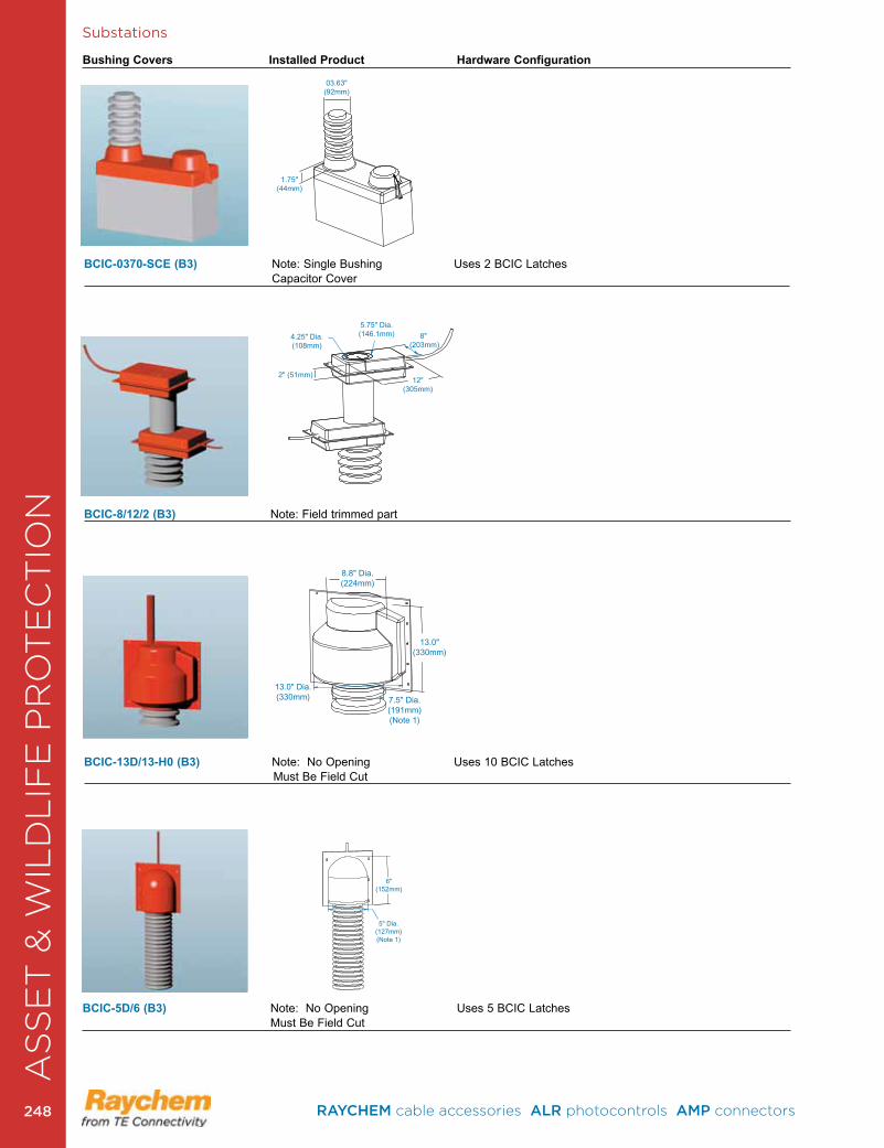
Substations
6"(152mm)
5" Dia.(127mm)(Note 1)
BCIC-5D/6 (B3) Note: No Opening Uses 5 BCIC Latches Must Be Field Cut
8.8" Dia.(224mm)
13.0" Dia.(330mm) 7.5" Dia.
(191mm)(Note 1)
13.0"(330mm)
BCIC-13D/13-H0 (B3) Note: No Opening Uses 10 BCIC Latches Must Be Field Cut
1.75"(44mm)
03.63"(92mm)
BCIC-0370-SCE (B3) Note: Single Bushing Uses 2 BCIC Latches Capacitor Cover
BCIC-8/12/2 (B3) Note: Field trimmed part
4.25" Dia.(108mm)
2" (51mm)12"
(305mm)
8" (203mm)
5.75" Dia.(146.1mm)
Bushing Covers Installed Product Hardware ConfigurationA
SS
ET
& W
ILD
LIF
E P
RO
TE
CT
ION
RAYCHEM cable accessories ALR photocontrols AMP connectors 248248

Substations
4.00(102)
4.00 Dia(102)
BCIC-4D/4 (B3) Uses 5 BCIC Latches
Bushing Covers Installed Product Hardware Configuration
10.4"(264mm)
Dia. 7.5" (191mm)
20.0"(508mm)
Dia. Range4.5 - 6.75"
(114-171mm)
Dia. Range2-3" (50-76mm)
BCIC-7.5D/18-3 (B3) Bus Bar Dia . 2-3 (50-75) Uses 8 BCIC Latches Angle Bus Double 3 (75)
4.0" Max. Dia.(102mm)
8.05"(204.5mm) 3.0"
(76mm) 5.25" Dia.(133.4mm)
17.5"(445mm)
8.25"(209.6mm) 7.25"
(184.2mm)
BCIC-SG-201 (B3) Max . Bus Bar Dia . 4 (100) Uses 10 BCIC Latches
3.0"(76mm)
3.0" (76mm)
2.2"(56mm)
3.75" Dia.(95mm)
17.0"(432mm)
(Note 1)
4.25"(108mm)
7.5"(191mm)
2.25" Dia.(57mm)
BCIC-TR205-L (B3) Note: No Opening Uses 10 BCIC Latches Must Be Field Cut
AS
SE
T &
WIL
DL
IFE
PR
OT
EC
TIO
N
RAYCHEM cable accessories ALR photocontrols AMP connectors 249 249

Substations
8.0"(203mm)
5.5"(140mm)
2.0"(51mm) 4.5" Dia.
(114mm)(Note 1)
4.25"(108mm)
1.25" Dia.(32mm)
BCIC-TR205-R (B3) Note: 4 .5 (114) Dia . Bottom Port Opening Uses 10 BCIC Latches
Bushing Covers Installed Product Hardware Configuration
12"(305mm)
4.125" Dia.(105)
3.5"(89mm)
BCIC-3212-01 (B3) Note: Bottom Port Has Opening Uses 8 BCIC Latches
8.00 DIA
3.75 DIA
10.00
3.754.00
7.00
19.00 MAX
BCIC-BYPASS (B1) Note: 3 .75 (95) Dia . Bottom Port Opening Uses 60-8" Long Tywraps
.700 Dia.
.800
BCIC-LATCH (B250) Std . Pack = 250 Latches or 1000 Latches
AS
SE
T &
WIL
DL
IFE
PR
OT
EC
TIO
N
RAYCHEM cable accessories ALR photocontrols AMP connectors 250250

Substations
MVFTMedium Voltage Fusion Tape
Raychem Medium Voltage Fusion Tape (MVFT) is a self amalgamating tape that provides insulation enhancement and protection against accidentally induced discharge . MVFT tape is designed to combine the integrity of a silicone polymer with the versatility of a wraparound product .
Fast and Versatile InstallationMVFT tape is quick and easy to install . Upon application the tape amalgamates the over-lapped layers together, producing a complete seal . A single layer of MVFT tape, two-thirds overlapped, will provide AC voltage withstand (flashover protection) to at least 15 kV increasing to 35 kV if a second layer is applied . Although MVFT tape will stick to itself and other insulating materials, it will not adhere to metal or porcelain allowing easy removal for maintenance .
FeaturesMVFT tape is compatible with all other products in the Raysulate MV Insulation Enhancement System . This fusion tape is suitable for both Indoor and outdoor use . MVFT tape exhibits non-tracking properties and possesses a continuous operating temperature up to 90˚C.
ApplicationsMVFT tape offers a simple and effective solution to the problems of retrofit insulation of busbars particularly where existing equipment cannot be dismantled . It can be used for indoor and outdoor applications and is easily installed over a wide variety of shapes including complex connections .
Selection Information: dimensions in inches (millimeters) / yards (meters) Supplied Catalog Number Color Width Length Std. PackMVFT-G-2-12(B4) Gray 2 (50) 12 (11) 4 Rolls
Product InformationEDR-5465 Medium Voltage Fusion Tape Qualification Report
MVCCMedium Voltage Conductor Covers for Outage Prevention
Raychem Medium Voltage Conductor Covers (MVCC) provide high quality electrical insulation for substation leads and jumpers . These covers are made from a non-tracking silicone material that is suitable for harsh medium voltage outdoor environments . MVCC covers are split for easy installation . The MVCC’s flexibility allows installation on tight bends which makes it ideal for substation applications. These covers are designed to protect energized conductors from flashovers due to contact from birds and animals . The MVCC is suitable for applications up to 25 kV phase to ground. They are currently available in four sizes that will fit conductors with diameters ranging up to 1 .75 inch .
Selection Information: dimensions in inches (millimeters) / feet (meters)
Conductor Diameter Catalog Number Use Range Color Supplied LengthMVCC-10/ .40 (B100) up to .450 (11) Red 2 pieces @ 50 (15.24)MVCC-G-10/ .40 (B100) up to .450 (11) Gray 2 pieces @ 50 (15.24)MVCC-19/0 .750 (B50) .50- .75 (12-19) Red 2 pieces @ 25 (7.6)MVCC-G-19/0 .750 (B50) .50- .75 (12-19) Gray 1 piece @ 25 (7.6)MVCC-25/1 .0 (B25) .75-1 .125 (19-28) Red 1 piece @ 25 (7.6)MVCC-G-25/1 .0 (B25) .75-1 .125 (19-28) Gray 6 pieces @ 4 (1.2)MVCC-45/1 .75 x 4 (B24) 1 .125-1 .75 (28-44) Red 6 pieces @ 4 (1.2)MVCC-G-45/1 .75 x4 (B24) 1 .125-1 .75 (28-44) Gray 6 pieces @ 4 (1.2)
Product InformationRelated Test Report: EDR-5461 Medium Voltage Conductor Cover Electrical Testing
C_MVFT
C_MVCC
AS
SE
T &
WIL
DL
IFE
PR
OT
EC
TIO
N
RAYCHEM cable accessories ALR photocontrols AMP connectors 251 251

Overhead
C_BCIC_Pro_Cover
BCIC Raptor Protection CoverInsulating Covers
These hot-stickable insulating covers are designed to prevent raptor caused outages on medium voltage distribution lines . This family of products fits a variety of polymeric and porcelain insulator configurations— including pin type insulators, horizontal post insulators and dead end insulators.
Reliable Outage ProtectionTE’s Raychem insulating covers have been successfully eliminating outages from all types of animals for years . These covers have been designed to provide the same great protection with enhanced features .
Fast and Versatile InstallationThese BCIC Raptor protection covers use a patented bimaterial design to allow for hot-stick installations . The main covers and extension arms are built with rigid clips to provide a reliable mechanical hold. Up to 10 feet of coverage on conductor sizes ranging from #2 to 795 can be achieved when one cover and two arms are installed together . The arms are designed to nest over vibration dampers . The flexible covers allow conductors to exit at up to 30 degree angles from any axis .
High Performance MaterialSuperior high voltage outdoor materials are used in the BCIC cover design . The rugged, track resistant, UV resistant polymer ensures long-term performance even in the most extreme environmental conditions .
Selection Information: dimensions in inches
Conductor Cover Std.Catalog Number Application Range Length Insulator Type/ ANSI PackBCIC-G-PIN-556-01 (B6) Porcelain PIN #6-556 42 55-2, 55-3, 55-4, 55-5 6BCIC-G-SMPIN-795-01 (B6) Porcelain PIN #6-795 42 55-2, 55-3, 55-4, 55-5 6BCIC-G-PIN-795-01 (B6) Porcelain PIN #6-795 32 55-5, 55-6, 55-7, 56-1, 56-2, 56-3 6BCIC-G-DPIN-795-01 (B6) Double Porcelain PIN #6-795 41 55-5, 55-6, 55-7, 56-1, 56-2, 56-3 6BCIC-G-DPIN-556-01 (B6) Double Porcelain PIN #6-556 42 55-2, 55-3, 55-4, 55-5 6BCIC-G-DSMPIN-795-01 (B6) Double Porcelain PIN #6-795 42 55-5, 55-6, 55-7, 56-1, 56-2, 56-3 6BCIC-G-HZ-795-01 (B6) Horizontal Post #6-795 29 Polymeric 6BCIC-G-HZ-795-XL (B6) Horizontal Post #6-795 41 Polymeric 6BCIC-G-HZPOR/3.5D-795-01 (B6) Horizontal Post #6-795 29 Porcelain >35kV 6BCIC-G-HZPOR/4.5D-795-01 (B6) Horizontal Post #6-795 29 Porcelain 25 to 35kV 6BCIC-G-PIN-556/55-01 (B6) Line Post #6-556 55 Polymeric 6BCIC-G-POR-228-795-01 (B6) Line Post #6-795 55 Porcelain 7-9 inch diameter 6BCIC-G-DE/CL-01(B6) Dead End #6-795 27 Conductor 6
BCIC-G-ARM-48-01 (B12) Extension ARM #6-795 48 Conductor 12BCIC-G-ARM-24-01 (B12) Extension ARM #6-795 24 Conductor 12
Product InformationRelated Test Report: EDR-5369 Raptor Protection Cover (BCIC-795) Mechanical/Electrical Evaluation EDR-5311 Rigid Red Barrier Board Qualification EDR-5314 EMMAQUA Testing of BCIS
BCIC-G-PIN-795-01
BCIC-G-HZ-795-01
AS
SE
T &
WIL
DL
IFE
PR
OT
EC
TIO
N
RAYCHEM cable accessories ALR photocontrols AMP connectors 252252

C_BCAC_Dis_Cover
Overhead
BCAC | BCICDistribution Covers for Animal Protection
These Raychem insulating covers are designed to prevent raptor caused outages on distribution equipment ranging from 15 to 35 kV . Covers are available for terminations, reclosures, lightning arresters, and fuse cutouts .
Transformer Bushing The BCAC-G-4D/13-2 covers a wide variety of termination sizes. The cover is easily installed on top of the first termination skirt. No trimming is required and the cover fits terminations ranging in size from #1 to 750 kcml . Extensive testing has ensured that the cover will not damage or deteriorate the terminations .
Fast and Versatile Installation
These BCACs are fast and easy to install . No trimming is required and they fit a wide range of bushing skirt diameters. If needed, they can be installed on energized equipment as well. The feathered edges of these covers allow for conductor exits in both vertical and horizontal directions. These same edges act as thermal scan sites for true temperature evaluation of the covered hardware .
Lightning ArrestersDistribution surge arrester caps protect against unwanted animal and bird outages . The unique design covers the first skirt which improves the level of protection . The cap is easily installed and attaches to both the stud and the conductor so that it will stay secure even in high winds . Three different covers are available .
Fuse CutoutsThe BCAC-G-CUTOUT hot-stickable insulating cover is designed to protect fused cutout switch applications up to 25 kV . The unique omega shaped attachment area easily clips onto the cutout insulator between the first and second skirt . The insulated conductor is captured securely as well to ensure retention even in high winds . Two different covers are available for 100 and 200 amp applications .
High Performance MaterialSuperior high voltage outdoor materials are used in all of these BCIC cover designs . The rugged, track resistant, UV resistant polymer ensures long-term performance even in the most extreme environmental conditions .
Selection Information: dimensions in inches (millimeters) Catalog Number HardwareBCAC-G-4D/13-2 (B18) TerminationsBCAC-G-5D/8-01 (B12) Transformer BushingBCAC-G-AR-5D-2 (B24) Ohio Brass ArresterBCAC-G-AR-4D-2 (B24) TE ArresterBCAC-G-AR-3 .75D-2 (B24) Cooper ArresterBCAC-G-CUTOUT-100-01 (B12) Fuse Cutout Switch (100 AMP) Porcelain StyleBCAC-G-CUTOUT-200 (B3) Fuse Cutout Switch (200 AMP) Porcelain StyleBCAC-G-CUTOUT-100-P-B12 Fuse Cutout Switch (100 AMP) Polymeric Style
BCAC-G-5D/8-01BCAC-G-AR-5D-2
BCAC-G-4D/13-2
BCAC-G-CUTOUT-100-01
AS
SE
T &
WIL
DL
IFE
PR
OT
EC
TIO
N
RAYCHEM cable accessories ALR photocontrols AMP connectors 253 253
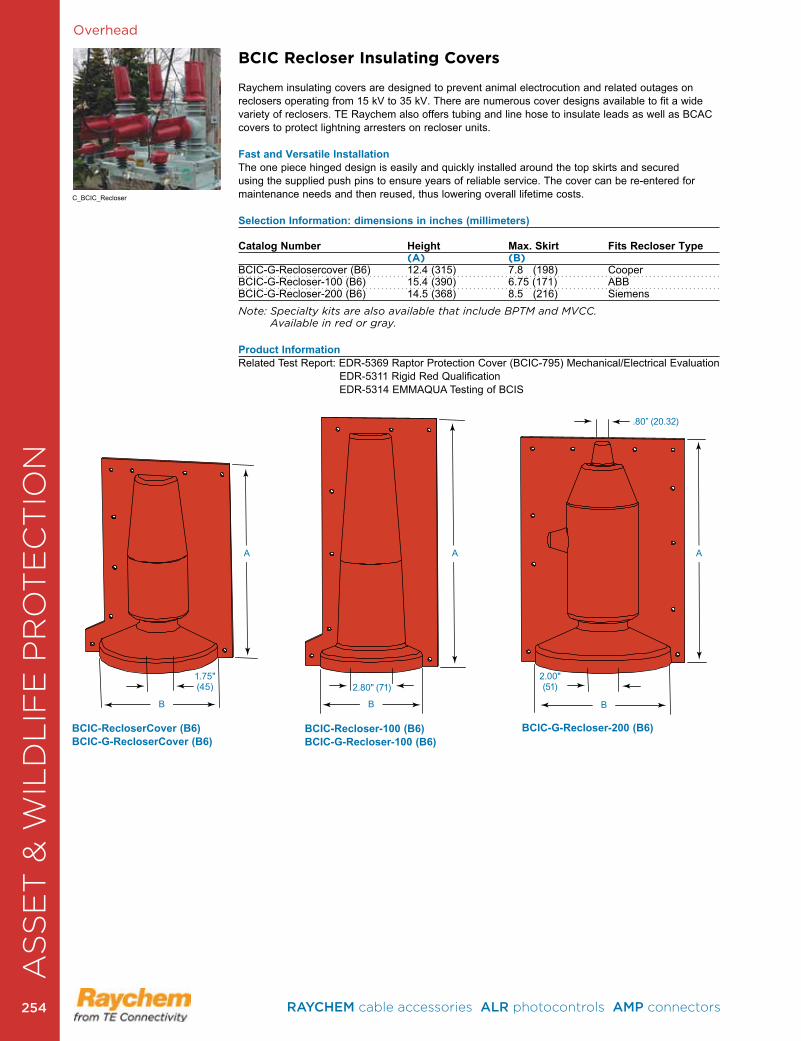
Overhead
BCIC Recloser Insulating Covers
Raychem insulating covers are designed to prevent animal electrocution and related outages on reclosers operating from 15 kV to 35 kV . There are numerous cover designs available to fit a wide variety of reclosers . TE Raychem also offers tubing and line hose to insulate leads as well as BCAC covers to protect lightning arresters on recloser units .
Fast and Versatile Installation The one piece hinged design is easily and quickly installed around the top skirts and secured using the supplied push pins to ensure years of reliable service . The cover can be re-entered for maintenance needs and then reused, thus lowering overall lifetime costs .
Selection Information: dimensions in inches (millimeters)
Catalog Number Height Max. Skirt Fits Recloser Type (A) (B)BCIC-G-Reclosercover (B6) 12 .4 (315) 7 .8 (198) Cooper BCIC-G-Recloser-100 (B6) 15 .4 (390) 6 .75 (171) ABBBCIC-G-Recloser-200 (B6) 14 .5 (368) 8 .5 (216) SiemensNote: Specialty kits are also available that include BPTM and MVCC. Available in red or gray.
Product InformationRelated Test Report: EDR-5369 Raptor Protection Cover (BCIC-795) Mechanical/Electrical Evaluation EDR-5311 Rigid Red Qualification EDR-5314 EMMAQUA Testing of BCIS
BCIC-RecloserCover (B6)BCIC-G-RecloserCover (B6)
BCIC-Recloser-100 (B6)BCIC-G-Recloser-100 (B6)
BCIC-G-Recloser-200 (B6)
1 .75" (45) 2 .80" (71)
.80” (20 .32)
2 .00" (51)
B B B
A A A
AS
SE
T &
WIL
DL
IFE
PR
OT
EC
TIO
N
C_BCIC_Recloser
RAYCHEM cable accessories ALR photocontrols AMP connectors 254254
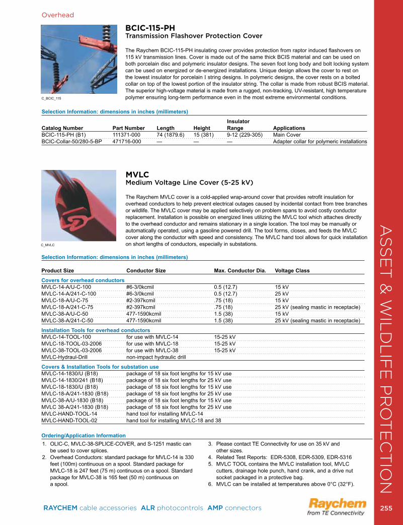
C_BCIC_115
C_MVLC
Overhead
MVLCMedium Voltage Line Cover (5-25 kV)
The Raychem MVLC cover is a cold-applied wrap-around cover that provides retrofit insulation for overhead conductors to help prevent electrical outages caused by incidental contact from tree branches or wildlife . The MVLC cover may be applied selectively on problem spans to avoid costly conductor replacement. Installation is possible on energized lines utilizing the MVLC tool which attaches directly to the overhead conductor and remains stationary in a single location . The tool may be manually or automatically operated, using a gasoline powered drill . The tool forms, closes, and feeds the MVLC cover along the conductor with speed and consistency . The MVLC hand tool allows for quick installation on short lengths of conductors, especially in substations .
Selection Information: dimensions in inches (millimeters)
Product Size Conductor Size Max. Conductor Dia. Voltage Class
Covers for overhead conductorsMVLC-14-A/U-C-100 #6-3/0kcmil 0 .5 (12 .7) 15 kVMVLC-14-A/241-C-100 #6-3/0kcmil 0 .5 (12 .7) 25 kVMVLC-18-A/U-C-75 #2-397kcmil .75 (18) 15 kV MVLC-18-A/241-C-75 #2-397kcmil .75 (18) 25 kV (sealing mastic in receptacle)MVLC-38-A/U-C-50 477-1590kcmil 1 .5 (38) 15 kVMVLC-38-A/241-C-50 477-1590kcmil 1 .5 (38) 25 kV (sealing mastic in receptacle)
Installation Tools for overhead conductorsMVLC-14-TOOL-100 for use with MVLC-14 15-25 kVMVLC-18-TOOL-03-2006 for use with MVLC-18 15-25 kVMVLC-38-TOOL-03-2006 for use with MVLC-38 15-25 kVMVLC-Hydraul-Drill non-impact hydraulic drill
Covers & Installation Tools for substation useMVLC-14-1830/U (B18) package of 18 six foot lengths for 15 kV useMVLC-14-1830/241 (B18) package of 18 six foot lengths for 25 kV useMVLC-18-1830/U (B18) package of 18 six foot lengths for 15 kV useMVLC-18-A/241-1830 (B18) package of 18 six foot lengths for 25 kV useMVLC-38-A/U-1830 (B18) package of 18 six foot lengths for 15 kV useMVLC 38-A/241-1830 (B18) package of 18 six foot lengths for 25 kV useMVLC-HAND-TOOL-14 hand tool for installing MVLC-14MVLC-HAND-TOOL-02 hand tool for installing MVLC-18 and 38
1 . OLIC-C, MVLC-38-SPLICE-COVER, and S-1251 mastic can be used to cover splices .
2 . Overhead Conductors: standard package for MVLC-14 is 330 feet (100m) continuous on a spool . Standard package for MVLC-18 is 247 feet (75 m) continuous on a spool . Standard package for MVLC-38 is 165 feet (50 m) continuous on a spool .
3 . Please contact TE Connectivity for use on 35 kV and other sizes.
4 . Related Test Reports: EDR-5308, EDR-5309, EDR-53165 . MVLC TOOL contains the MVLC installation tool, MVLC
cutters, drainage hole punch, hand crank, and a drive nut socket packaged in a protective bag .
6 . MVLC can be installed at temperatures above 0°C (32°F) .
Ordering/Application Information
BCIC-115-PHTransmission Flashover Protection Cover
The Raychem BCIC-115-PH insulating cover provides protection from raptor induced flashovers on 115 kV transmission lines . Cover is made out of the same thick BCIS material and can be used on both porcelain disc and polymeric insulator designs . The seven foot long body and bolt locking system can be used on energized or de-energized installations. Unique design allows the cover to rest on the lowest insulator for porcelain I string designs . In polymeric designs, the cover rests on a bolted collar on top of the lowest portion of the insulator string . The collar is made from robust BCIS material . The superior high-voltage material is made from a rugged, non-tracking, UV-resistant, high temperature polymer ensuring long-term performance even in the most extreme environmental conditions .
Selection Information: dimensions in inches (millimeters)
Insulator Catalog Number Part Number Length Height Range ApplicationsBCIC-115-PH (B1) 111371-000 74 (1879 .6) 15 (381) 9-12 (229-305) Main CoverBCIC-Collar-50/280-5-BP 471716-000 — — — Adapter collar for polymeric installations
AS
SE
T &
WIL
DL
IFE
PR
OT
EC
TIO
N
RAYCHEM cable accessories ALR photocontrols AMP connectors 255 255
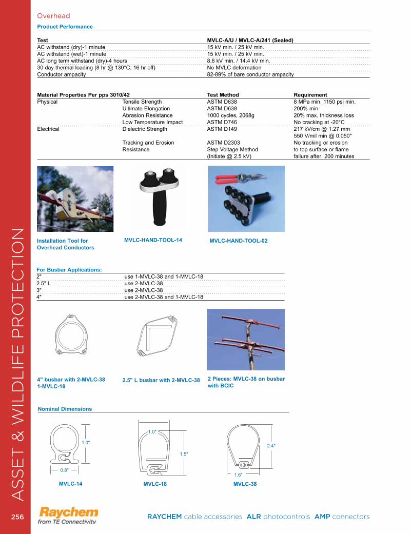
Overhead
MVLC-HAND-TOOL-02
2 Pieces: MVLC-38 on busbar with BCIC
4" busbar with 2-MVLC-381-MVLC-18
2.5" L busbar with 2-MVLC-38
For Busbar Applications:2" use 1-MVLC-38 and 1-MVLC-182 .5" L use 2-MVLC-383" use 2-MVLC-384" use 2-MVLC-38 and 1-MVLC-18
Nominal Dimensions
MVLC-HAND-TOOL-14
Product Performance
Test MVLC-A/U / MVLC-A/241 (Sealed)AC withstand (dry)-1 minute 15 kV min . / 25 kV min .AC withstand (wet)-1 minute 15 kV min . / 25 kV min .AC long term withstand (dry)-4 hours 8 .6 kV min . / 14 .4 kV min .30 day thermal loading (8 hr @ 130°C; 16 hr off) No MVLC deformationConductor ampacity 82-89% of bare conductor ampacity
Material Properties Per pps 3010/42 Test Method RequirementPhysical Tensile Strength ASTM D638 8 MPa min . 1150 psi min . Ultimate Elongation ASTM D638 200% min . Abrasion Resistance 1000 cycles, 2068g 20% max . thickness loss Low Temperature Impact ASTM D746 No cracking at -20°CElectrical Dielectric Strength ASTM D149 217 kV/cm @ 1 .27 mm 550 V/mil min @ 0 .050" Tracking and Erosion ASTM D2303 No tracking or erosion Resistance Step Voltage Method to top surface or flame (Initiate @ 2 .5 kV) failure after: 200 minutes
Installation Tool for Overhead Conductors
1 .0"
1 .0"
0 .8"
1 .5"
1 .6"
2 .4"
MVLC-14 MVLC-18 MVLC-38
AS
SE
T &
WIL
DL
IFE
PR
OT
EC
TIO
N
RAYCHEM cable accessories ALR photocontrols AMP connectors 256256
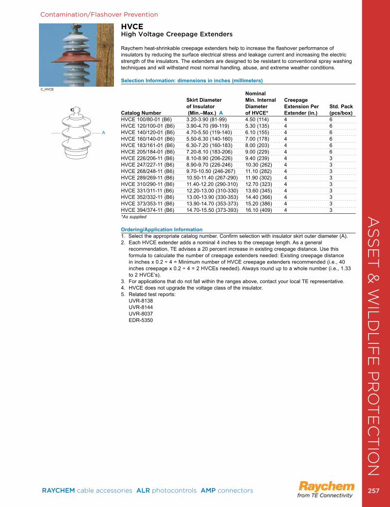
Contamination/Flashover Prevention
HVCEHigh Voltage Creepage Extenders
Raychem heat-shrinkable creepage extenders help to increase the flashover performance of insulators by reducing the surface electrical stress and leakage current and increasing the electric strength of the insulators . The extenders are designed to be resistant to conventional spray washing techniques and will withstand most normal handling, abuse, and extreme weather conditions .
Selection Information: dimensions in inches (millimeters)
Nominal Skirt Diameter Min. Internal Creepage of Insulator Diameter Extension Per Std. PackCatalog Number (Min.–Max.) A of HVCE* Extender (in.) (pcs/box)HVCE 100/80-01 (B6) 3 .20-3 .90 (81-99) 4 .50 (114) 4 6HVCE 120/100-01 (B6) 3 .90-4 .70 (99-119) 5 .30 (135) 4 6HVCE 140/120-01 (B6) 4 .70-5 .50 (119-140) 6 .10 (155) 4 6HVCE 160/140-01 (B6) 5 .50-6 .30 (140-160) 7 .00 (178) 4 6HVCE 183/161-01 (B6) 6 .30-7 .20 (160-183) 8 .00 (203) 4 6HVCE 205/184-01 (B6) 7 .20-8 .10 (183-206) 9 .00 (229) 4 6HVCE 226/206-11 (B6) 8 .10-8 .90 (206-226) 9 .40 (239) 4 3HVCE 247/227-11 (B6) 8 .90-9 .70 (226-246) 10 .30 (262) 4 3HVCE 268/248-11 (B6) 9 .70-10 .50 (246-267) 11 .10 (282) 4 3HVCE 289/269-11 (B6) 10 .50-11 .40 (267-290) 11 .90 (302) 4 3HVCE 310/290-11 (B6) 11 .40-12 .20 (290-310) 12 .70 (323) 4 3HVCE 331/311-11 (B6) 12 .20-13 .00 (310-330) 13 .60 (345) 4 3HVCE 352/332-11 (B6) 13 .00-13 .90 (330-353) 14 .40 (366) 4 3HVCE 373/353-11 (B6) 13 .90-14 .70 (353-373) 15 .20 (386) 4 3HVCE 394/374-11 (B6) 14 .70-15 .50 (373-393) 16 .10 (409) 4 3*As supplied
Ordering/Application Information1 . Select the appropriate catalog number . Confirm selection with insulator skirt outer diameter (A) .2 . Each HVCE extender adds a nominal 4 inches to the creepage length . As a general
recommendation, TE advises a 20 percent increase in existing creepage distance . Use this formula to calculate the number of creepage extenders needed: Existing creepage distance in inches x 0 .2 ÷ 4 = Minimum number of HVCE creepage extenders recommended (i .e ., 40 inches creepage x 0 .2 ÷ 4 = 2 HVCEs needed) . Always round up to a whole number (i .e ., 1 .33 to 2 HVCE’s) .
3 . For applications that do not fall within the ranges above, contact your local TE representative .4 . HVCE does not upgrade the voltage class of the insulator .5 . Related test reports: UVR-8138 UVR-8144 UVR-8037 EDR-5350
AA
C_HVCE
AS
SE
T &
WIL
DL
IFE
PR
OT
EC
TIO
N
RAYCHEM cable accessories ALR photocontrols AMP connectors 257 257
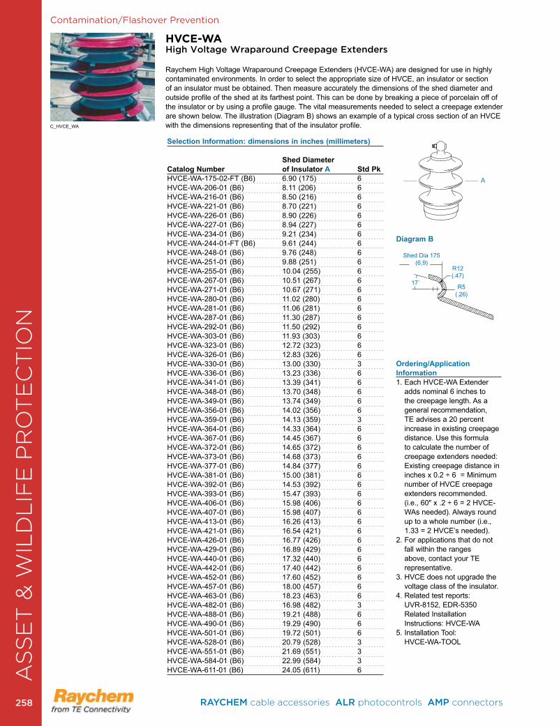
Contamination/Flashover Prevention
HVCE-WAHigh Voltage Wraparound Creepage Extenders
Raychem High Voltage Wraparound Creepage Extenders (HVCE-WA) are designed for use in highly contaminated environments. In order to select the appropriate size of HVCE, an insulator or section of an insulator must be obtained . Then measure accurately the dimensions of the shed diameter and outside profile of the shed at its farthest point . This can be done by breaking a piece of porcelain off of the insulator or by using a profile gauge . The vital measurements needed to select a creepage extender are shown below . The illustration (Diagram B) shows an example of a typical cross section of an HVCE with the dimensions representing that of the insulator profile .
Selection Information: dimensions in inches (millimeters)
Shed Diameter Catalog Number of Insulator A Std PkHVCE-WA-175-02-FT (B6) 6 .90 (175) 6HVCE-WA-206-01 (B6) 8 .11 (206) 6HVCE-WA-216-01 (B6) 8 .50 (216) 6HVCE-WA-221-01 (B6) 8 .70 (221) 6HVCE-WA-226-01 (B6) 8 .90 (226) 6HVCE-WA-227-01 (B6) 8 .94 (227) 6HVCE-WA-234-01 (B6) 9 .21 (234) 6HVCE-WA-244-01-FT (B6) 9 .61 (244) 6HVCE-WA-248-01 (B6) 9 .76 (248) 6HVCE-WA-251-01 (B6) 9 .88 (251) 6HVCE-WA-255-01 (B6) 10 .04 (255) 6HVCE-WA-267-01 (B6) 10 .51 (267) 6HVCE-WA-271-01 (B6) 10 .67 (271) 6HVCE-WA-280-01 (B6) 11 .02 (280) 6HVCE-WA-281-01 (B6) 11 .06 (281) 6HVCE-WA-287-01 (B6) 11 .30 (287) 6HVCE-WA-292-01 (B6) 11 .50 (292) 6HVCE-WA-303-01 (B6) 11 .93 (303) 6HVCE-WA-323-01 (B6) 12 .72 (323) 6HVCE-WA-326-01 (B6) 12 .83 (326) 6HVCE-WA-330-01 (B6) 13 .00 (330) 3HVCE-WA-336-01 (B6) 13 .23 (336) 6HVCE-WA-341-01 (B6) 13 .39 (341) 6HVCE-WA-348-01 (B6) 13 .70 (348) 6HVCE-WA-349-01 (B6) 13 .74 (349) 6HVCE-WA-356-01 (B6) 14 .02 (356) 6HVCE-WA-359-01 (B6) 14 .13 (359) 3HVCE-WA-364-01 (B6) 14 .33 (364) 6HVCE-WA-367-01 (B6) 14 .45 (367) 6HVCE-WA-372-01 (B6) 14 .65 (372) 6HVCE-WA-373-01 (B6) 14 .68 (373) 6HVCE-WA-377-01 (B6) 14 .84 (377) 6HVCE-WA-381-01 (B6) 15 .00 (381) 6HVCE-WA-392-01 (B6) 14 .53 (392) 6HVCE-WA-393-01 (B6) 15 .47 (393) 6HVCE-WA-406-01 (B6) 15 .98 (406) 6HVCE-WA-407-01 (B6) 15 .98 (407) 6HVCE-WA-413-01 (B6) 16 .26 (413) 6HVCE-WA-421-01 (B6) 16 .54 (421) 6HVCE-WA-426-01 (B6) 16 .77 (426) 6HVCE-WA-429-01 (B6) 16 .89 (429) 6HVCE-WA-440-01 (B6) 17 .32 (440) 6HVCE-WA-442-01 (B6) 17 .40 (442) 6HVCE-WA-452-01 (B6) 17 .60 (452) 6HVCE-WA-457-01 (B6) 18 .00 (457) 6HVCE-WA-463-01 (B6) 18 .23 (463) 6HVCE-WA-482-01 (B6) 16 .98 (482) 3HVCE-WA-488-01 (B6) 19 .21 (488) 6HVCE-WA-490-01 (B6) 19 .29 (490) 6HVCE-WA-501-01 (B6) 19 .72 (501) 6HVCE-WA-528-01 (B6) 20 .79 (528) 3HVCE-WA-551-01 (B6) 21 .69 (551) 3HVCE-WA-584-01 (B6) 22 .99 (584) 3HVCE-WA-611-01 (B6) 24 .05 (611) 6
Ordering/Application Information1 . Each HVCE-WA Extender
adds nominal 6 inches to the creepage length . As a general recommendation, TE advises a 20 percent increase in existing creepage distance . Use this formula to calculate the number of creepage extenders needed: Existing creepage distance in inches x 0 .2 ÷ 6 = Minimum number of HVCE creepage extenders recommended . (i .e ., 60" x .2 ÷ 6 = 2 HVCE-WAs needed) . Always round up to a whole number (i .e ., 1 .33 = 2 HVCE’s needed) .
2 . For applications that do not fall within the ranges above, contact your TE representative .
3 . HVCE does not upgrade the voltage class of the insulator .
4 . Related test reports: UVR-8152, EDR-5350 Related Installation Instructions: HVCE-WA
5 . Installation Tool: HVCE-WA-TOOL
Shed Dia 175(6,9)
R12(.47)
R5(.26)
17˚
AA
Diagram B
AS
SE
T &
WIL
DL
IFE
PR
OT
EC
TIO
N
C_HVCE_WA
RAYCHEM cable accessories ALR photocontrols AMP connectors 258258
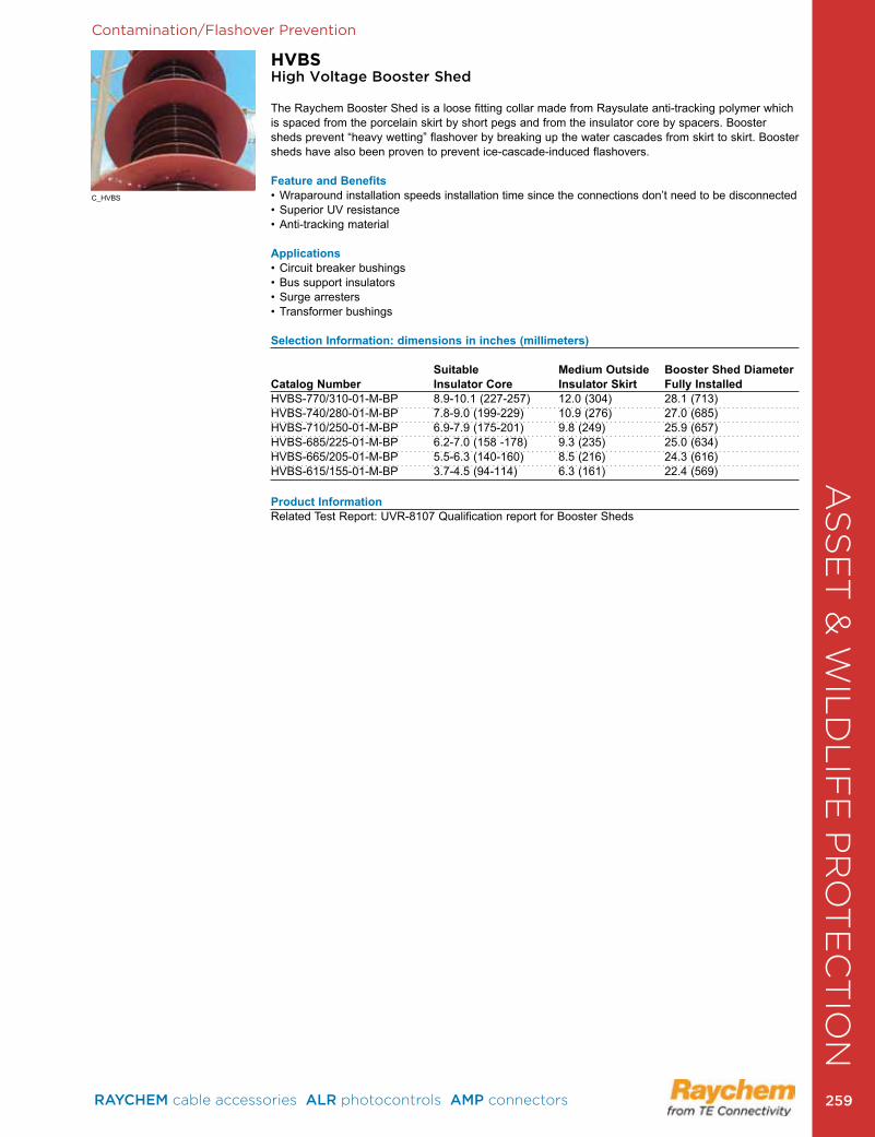
AS
SE
T &
WIL
DL
IFE
PR
OT
EC
TIO
NContamination/Flashover Prevention
HVBSHigh Voltage Booster Shed
The Raychem Booster Shed is a loose fitting collar made from Raysulate anti-tracking polymer which is spaced from the porcelain skirt by short pegs and from the insulator core by spacers . Booster sheds prevent “heavy wetting” flashover by breaking up the water cascades from skirt to skirt . Booster sheds have also been proven to prevent ice-cascade-induced flashovers .
Feature and Benefits• Wraparound installation speeds installation time since the connections don’t need to be disconnected• Superior UV resistance• Anti-tracking material
Applications• Circuit breaker bushings• Bus support insulators• Surge arresters• Transformer bushings
Selection Information: dimensions in inches (millimeters)
Suitable Medium Outside Booster Shed DiameterCatalog Number Insulator Core Insulator Skirt Fully Installed HVBS-770/310-01-M-BP 8 .9-10 .1 (227-257) 12 .0 (304) 28 .1 (713)HVBS-740/280-01-M-BP 7 .8-9 .0 (199-229) 10 .9 (276) 27 .0 (685)HVBS-710/250-01-M-BP 6 .9-7 .9 (175-201) 9 .8 (249) 25 .9 (657)HVBS-685/225-01-M-BP 6 .2-7 .0 (158 -178) 9 .3 (235) 25 .0 (634)HVBS-665/205-01-M-BP 5 .5-6 .3 (140-160) 8 .5 (216) 24 .3 (616)HVBS-615/155-01-M-BP 3 .7-4 .5 (94-114) 6 .3 (161) 22 .4 (569)
Product InformationRelated Test Report: UVR-8107 Qualification report for Booster Sheds
AS
SE
T &
WIL
DL
IFE
PR
OT
EC
TIO
N
C_HVBS
RAYCHEM cable accessories ALR photocontrols AMP connectors 259 259

Contamination/Flashover Prevention
Raychem RRGSPolymeric and Porcelain Rigid Red Guano Shield
The rigid red guano shield protects against bird streamer caused outages . There are designs to fit both porcelain bells and polymeric insulators . This two piece shield attaches easily with plastic bolts and nuts around the top of the insulator and provides protection from fecal contaminates coming from above the insulator string . For porcelain applications there are 18 inch and 24 inch diameter shield designs . For polymeric applications the shield has an 18 inch diameter .
Selection Information: dimensions in inches
Catalog Number Insulator Type Shield DiameterRRGS-35/470-FT (B12) Polymeric 18RRGS-35/600-FT (B12) Polymeric 24RRGS-35/470-M (B12) Porcelain 18RRGS-35/600-M(B12) Porcelain 24 Also available in gray.
Porcelain RRGS Shield Polymeric RRGS Shield
AS
SE
T &
WIL
DL
IFE
PR
OT
EC
TIO
NA
SS
ET
& W
ILD
LIF
E P
RO
TE
CT
ION
C_RRGS
RAYCHEM cable accessories ALR photocontrols AMP connectors 260260

Splicing Accessories HV-BRAID Ground Braid . . . . . . . . . . . . . . . . . . . . . . . . . . . . . 262HVS-MESH Shielding Mesh . . . . . . . . . . . . . . . . . . . . . . . . . . . 262JGK-MS Jacketed Cable Ground Kits (5-35 kV) . . . . . . . . . . . 262Cable Preparation Kit . . . . . . . . . . . . . . . . . . . . . . . . . . . . . . . . 263HVS-GC Grounding Clamps . . . . . . . . . . . . . . . . . . . . . . . . . . . 263HVS-LR Lead Sheath Repair Kits . . . . . . . . . . . . . . . . . . . . . . 264
Termination AccessoriesBRKT-SS Cable Mounting Brackets . . . . . . . . . . . . . . . . . . . . . 265EAKT-1520 Mounting Kits . . . . . . . . . . . . . . . . . . . . . . . . . . . . 265MOD-S Skirts . . . . . . . . . . . . . . . . . . . . . . . . . . . . . . . . . . . . . . 266
Conduit/Cable SealingRDSS Sealing System . . . . . . . . . . . . . . . . . . . . . . . . . . . . . . . 267Blank Duct Plug . . . . . . . . . . . . . . . . . . . . . . . . . . . . . . . . . . . . 268
Torches & Heat GunsTorches . . . . . . . . . . . . . . . . . . . . . . . . . . . . . . . . . . . . . . . . . . . 269Torch Accessories . . . . . . . . . . . . . . . . . . . . . . . . . . . . . . . . . . . 270Torch Kits . . . . . . . . . . . . . . . . . . . . . . . . . . . . . . . . . . . . . . . . . 270Heat Guns . . . . . . . . . . . . . . . . . . . . . . . . . . . . . . . . . . . . . . . . 271
ToolsSplicing Tools . . . . . . . . . . . . . . . . . . . . . . . . . . . . . . . . . . . . . . 272Impact Wrench . . . . . . . . . . . . . . . . . . . . . . . . . . . . . . . . . . . . . 272Wire Cutters . . . . . . . . . . . . . . . . . . . . . . . . . . . . . . . . . . . . . . . 272Cable Cutters . . . . . . . . . . . . . . . . . . . . . . . . . . . . . . . . . . . . . . 273Cable Vise . . . . . . . . . . . . . . . . . . . . . . . . . . . . . . . . . . . . . . . . 273Stripping Tools . . . . . . . . . . . . . . . . . . . . . . . . . . . . . . . . . . . . . 274Tool Sets . . . . . . . . . . . . . . . . . . . . . . . . . . . . . . . . . . . . . . . . . . 274
ACCESSORIES & TOOLS
RAYCHEM cable accessories ALR photocontrols AMP connectors 261 261
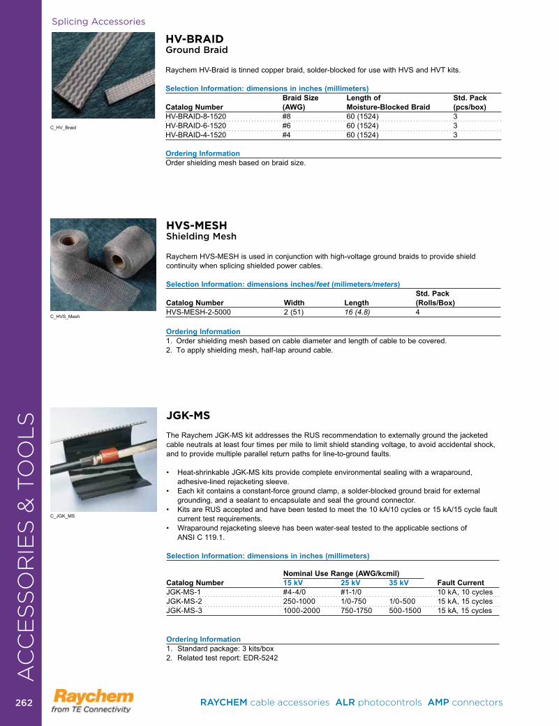
Splicing Accessories
HV-BRAIDGround Braid
Raychem HV-Braid is tinned copper braid, solder-blocked for use with HVS and HVT kits .
Selection Information: dimensions in inches (millimeters) Braid Size Length of Std. Pack Catalog Number (AWG) Moisture-Blocked Braid (pcs/box)HV-BRAID-8-1520 #8 60 (1524) 3HV-BRAID-6-1520 #6 60 (1524) 3HV-BRAID-4-1520 #4 60 (1524) 3
Ordering InformationOrder shielding mesh based on braid size .
C_HV_Braid
HVS-MESHShielding Mesh
Raychem HVS-MESH is used in conjunction with high-voltage ground braids to provide shield continuity when splicing shielded power cables .
Selection Information: dimensions inches/feet (milimeters/meters) Std. Pack Catalog Number Width Length (Rolls/Box)HVS-MESH-2-5000 2 (51) 16 (4.8) 4
Ordering Information1 . Order shielding mesh based on cable diameter and length of cable to be covered . 2 . To apply shielding mesh, half-lap around cable .
C_HVS_Mesh
JGK-MS
The Raychem JGK-MS kit addresses the RUS recommendation to externally ground the jacketed cable neutrals at least four times per mile to limit shield standing voltage, to avoid accidental shock, and to provide multiple parallel return paths for line-to-ground faults .
• Heat-shrinkableJGK-MSkitsprovidecompleteenvironmentalsealingwithawraparound,adhesive-lined rejacketing sleeve .
• Eachkitcontainsaconstant-forcegroundclamp,asolder-blockedgroundbraidforexternalgrounding, and a sealant to encapsulate and seal the ground connector .
• KitsareRUSacceptedandhavebeentestedtomeetthe10kA/10cyclesor15kA/15cyclefaultcurrent test requirements .
• Wraparoundrejacketingsleevehasbeenwater-sealtestedtotheapplicablesectionsof ANSI C 119 .1 .
Selection Information: dimensions in inches (millimeters)
Nominal Use Range (AWG/kcmil) Catalog Number 15 kV 25 kV 35 kV Fault CurrentJGK-MS-1 #4-4/0 #1-1/0 10kA,10cyclesJGK-MS-2 250-1000 1/0-750 1/0-500 15kA,15cyclesJGK-MS-3 1000-2000 750-1750 500-1500 15 kA, 15 cycles
Ordering Information1. Standardpackage:3kits/box2 . Related test report: EDR-5242
C_JGK_MS
AC
CE
SS
OR
IES
& T
OO
LS
RAYCHEM cable accessories ALR photocontrols AMP connectors 262262
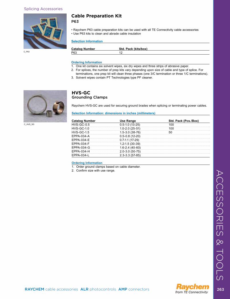
AC
CE
SS
OR
IES
& T
OO
LS
Splicing Accessories
Cable Preparation KitP63
•RaychemP63cablepreparationkitscanbeusedwithallTEConnectivitycableaccessories•UseP63kitstocleanandabradecableinsulation
Selection Information
Catalog Number Std. Pack (kits/box)P63 12
Ordering Information1 . One kit contains six solvent wipes, six dry wipes and three strips of abrasive paper .2 . For splices, the number of prep kits vary depending upon size of cable and type of splice . For
terminations,oneprepkitwillcleanthreephases(one3/Cterminationorthree1/Cterminations).3 . Solvent wipes contain PT Technologies type PF cleaner .
C_P63
HVS-GCGrounding Clamps
Raychem HVS-GC are used for securing ground brades when splicing or terminating power cables .
Selection Information: dimensions in inches (millimeters) Catalog Number Use Range Std. Pack (Pcs./Box)HVS-GC-0 .5 0 .5-1 .0 (13-25) 100HVS-GC-1 .0 1 .0-2 .0 (25-51) 100HVS-GC-1 .5 1 .5-3 .0 (38-76) 50EPPA-034-A 0 .5-0 .8 (12-20)EPPA-034-E 0 .7-1 .1 (17-29)EPPA-034-F 1 .2-1 .5 (30-39)EPPA-034-G 1 .6-2 .4 (40-60)EPPA-034-H 2 .0-3 .0 (50-75)EPPA-034-L 2 .3-3 .3 (57-85)
Ordering Information1 . Order ground clamps based on cable diameter . 2 . Confirm size with use range .
C_HVS_SG
RAYCHEM cable accessories ALR photocontrols AMP connectors 263 263
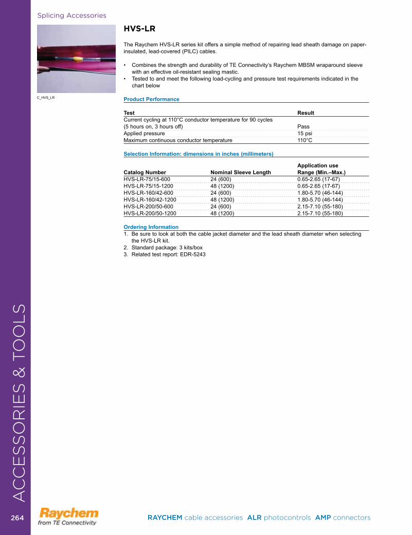
Splicing Accessories
HVS-LR
The Raychem HVS-LR series kit offers a simple method of repairing lead sheath damage on paper-insulated, lead-covered (PILC) cables .
• CombinesthestrengthanddurabilityofTEConnectivity’sRaychemMBSMwraparoundsleevewith an effective oil-resistant sealing mastic .
• Testedtoandmeetthefollowingload-cyclingandpressuretestrequirementsindicatedinthe chart below
Product Performance
Test Result Current cycling at 110°C conductor temperature for 90 cycles (5 hours on, 3 hours off) PassApplied pressure 15 psiMaximum continuous conductor temperature 110°C
Selection Information: dimensions in inches (millimeters)
Application useCatalog Number Nominal Sleeve Length Range (Min.–Max.)HVS-LR-75/15-600 24(600) 0.65-2.65(17-67)HVS-LR-75/15-1200 48(1200) 0.65-2.65(17-67)HVS-LR-160/42-600 24(600) 1.80-5.70(46-144)HVS-LR-160/42-1200 48(1200) 1.80-5.70(46-144)HVS-LR-200/50-600 24(600) 2.15-7.10(55-180)HVS-LR-200/50-1200 48(1200) 2.15-7.10(55-180)
Ordering Information1 . Be sure to look at both the cable jacket diameter and the lead sheath diameter when selecting
the HVS-LR kit .2.Standardpackage:3kits/box3 . Related test report: EDR-5243
C_HVS_LR
AC
CE
SS
OR
IES
& T
OO
LS
RAYCHEM cable accessories ALR photocontrols AMP connectors 264264
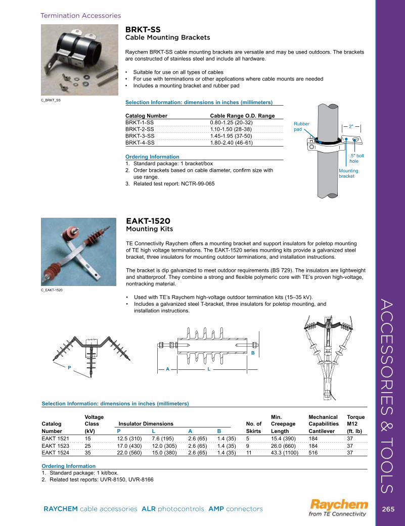
AC
CE
SS
OR
IES
& T
OO
LS
BRKT-SSCable Mounting Brackets
Raychem BRKT-SS cable mounting brackets are versatile and may be used outdoors . The brackets are constructed of stainless steel and include all hardware .
• Suitableforuseonalltypesofcables• Forusewithterminationsorotherapplicationswherecablemountsareneeded• Includesamountingbracketandrubberpad
Selection Information: dimensions in inches (millimeters) Catalog Number Cable Range O.D. RangeBRKT-1-SS 0 .80-1 .25 (20-32)BRKT-2-SS 1 .10-1 .50 (28-38)BRKT-3-SS 1 .45-1 .95 (37-50)BRKT-4-SS 1 .80-2 .40 (46-61)
Ordering Information1. Standardpackage:1bracket/box2 . Order brackets based on cable diameter, confirm size with
use range .3 . Related test report: NCTR-99-065
C_BRKT_SS
Rubberpad
.5" bolthole
Mounting bracket
2"
Termination Accessories
EAKT-1520 Mounting Kits
TE Connectivity Raychem offers a mounting bracket and support insulators for poletop mounting of TE high voltage terminations . The EAKT-1520 series mounting kits provide a galvanized steel bracket, three insulators for mounting outdoor terminations, and installation instructions .
The bracket is dip galvanized to meet outdoor requirements (BS 729) . The insulators are lightweight andshatterproof.TheycombineastrongandflexiblepolymericcorewithTE’sprovenhigh-voltage,nontracking material .
• UsedwithTE’sRaychemhigh-voltageoutdoorterminationkits(15–35kV).• IncludesagalvanizedsteelT-bracket,threeinsulatorsforpoletopmounting,and
installation instructions .
FrontSelection Information: dimensions in inches (millimeters)
Voltage Min. Mechanical Torque Catalog Class Insulator Dimensions No. of Creepage Capabilities M12Number (kV) P L A B Skirts Length Cantilever (ft. lb)EAKT 1521 15 12 .5 (310) 7 .6 (195) 2 .6 (65) 1 .4 (35) 5 15 .4 (390) 184 37 EAKT 1523 25 17 .0 (430) 12 .0 (305) 2 .6 (65) 1 .4 (35) 9 26 .0 (660) 184 37EAKT 1524 35 22 .0 (560) 15 .0 (380) 2 .6 (65) 1 .4 (35) 11 43 .3 (1100) 516 37
Ordering Information1. Standardpackage:1kit/box.2 . Related test reports: UVR-8150, UVR-8166
P A L
B
C_EAKT-1520 AC
CE
SS
OR
IES
& T
OO
LS
RAYCHEM cable accessories ALR photocontrols AMP connectors 265 265
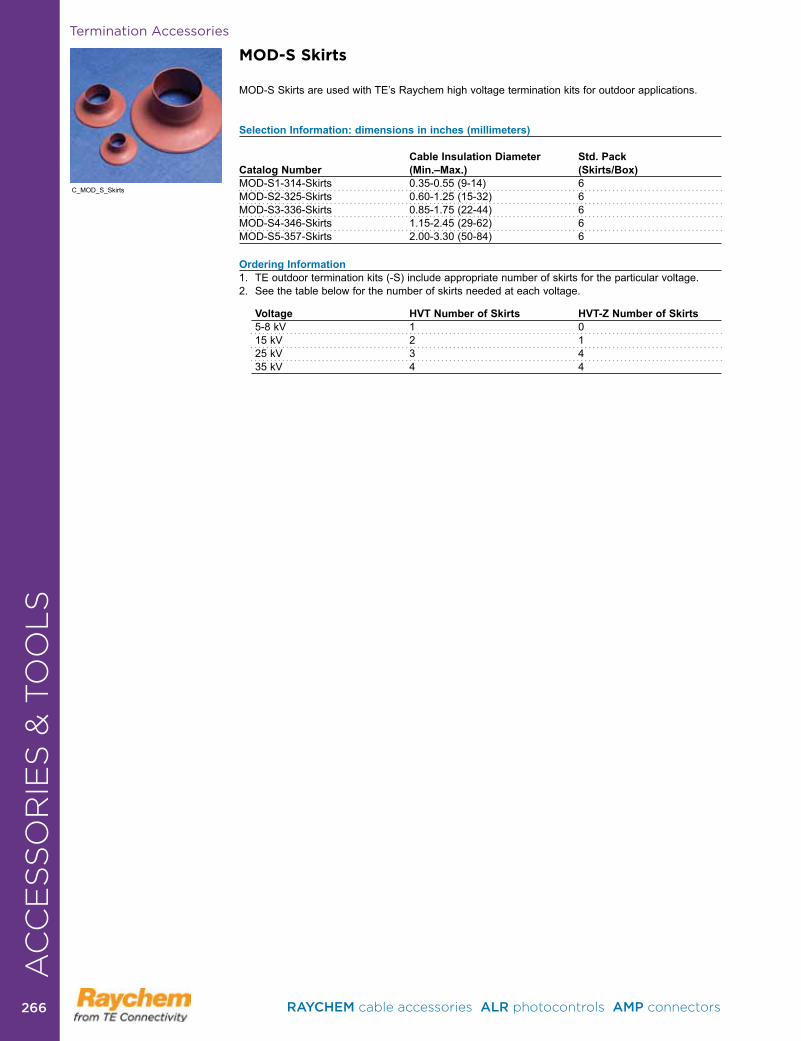
MOD-S Skirts
MOD-SSkirtsareusedwithTE’sRaychemhighvoltageterminationkitsforoutdoorapplications.
Selection Information: dimensions in inches (millimeters) Cable Insulation Diameter Std. Pack Catalog Number (Min.–Max.) (Skirts/Box)MOD-S1-314-Skirts 0 .35-0 .55 (9-14) 6MOD-S2-325-Skirts 0 .60-1 .25 (15-32) 6MOD-S3-336-Skirts 0 .85-1 .75 (22-44) 6MOD-S4-346-Skirts 1 .15-2 .45 (29-62) 6MOD-S5-357-Skirts 2 .00-3 .30 (50-84) 6
Ordering Information 1 . TE outdoor termination kits (-S) include appropriate number of skirts for the particular voltage .2 . See the table below for the number of skirts needed at each voltage .
Voltage HVT Number of Skirts HVT-Z Number of Skirts5-8 kV 1 015 kV 2 125 kV 3 435 kV 4 4
C_MOD_S_Skirts
Termination AccessoriesA
CC
ES
SO
RIE
S &
TO
OL
S
RAYCHEM cable accessories ALR photocontrols AMP connectors 266266
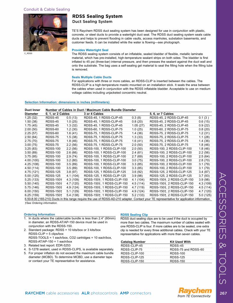
Conduit & Cable Sealing
RDSS Sealing SystemDuct Sealing System
TE’SRaychemRDSSductsealingsystemhasbeendesignedforuseinconjunctionwithplastic,concrete, or steel ducts to provide a watertight duct seal . The RDSS duct sealing system seals cable ducts and helps to prevent flooding in cable vaults, access manholes, substation basements, and customer feeds . It can be installed while the water is flowing—see photograph .
Provides Watertight SealThe RDSS sealing system consists of an inflatable, sealed bladder of flexible, metallic laminate material, which has pre-installed, high-temperature sealant strips on both sides . The bladder is first inflated to 45 psi (three-bar) internal pressure, and then presses the sealant against the duct wall and onto the substrate . The bag uses a self-sealing gel material to seal the filling hole when the filling tube is removed .
Seals Multiple Cable DuctsFor applications with three or more cables, an RDSS-CLIP is inserted between the cables . The RDSS-CLIP is a high-temperature mastic mounted on an installation stick . It seals the area between the cables when used in conjunction with the RDSS inflatable bladder . Acceptable to use on medium voltage cables including unjacketed concentric neutral .
Selection Information: dimensions in inches (millimeters) Duct Inner Number of Cables in Duct / Maximum Cable Bundle DiameterDiameter 0, 1, or 2 Cables 3 or 4 Cables 5, 6, or 7 Cables1 .25 (32) RDSS-45 0 .5 (13) RDSS-45, 1 RDSS-CLIP-45 0 .3 (8) RDSS-45, 2 RDSS-CLIP-45 0 .1 (3 )1 .50 (38) RDSS-45 1 .0 (25) RDSS-45, 1 RDSS-CLIP-45 0 .8 (20) RDSS-45, 2 RDSS-CLIP-45 0 .6 (15) 1 .75 (45) RDSS-45 1 .3 (32) RDSS-45, 1 RDSS-CLIP-45 1 .05 (27) RDSS-45, 2 RDSS-CLIP-45 0 .9 (22)2 .00 (50) RDSS-60 1 .2 (30) RDSS-60, 1 RDSS-CLIP-75 1 .0 (25) RDSS-60, 2 RDSS-CLIP-75 0 .8 (20) 2 .25 (57) RDSS-60 1 .6 (41) RDSS-75, 1 RDSS-CLIP-75 1 .4 (36) RDSS-75, 2 RDSS-CLIP-75 1 .2 (31) 2 .50 (64) RDSS-75 1 .5 (38) RDSS-75, 1 RDSS-CLIP-75 1 .3 (33) RDSS-75, 2 RDSS-CLIP-75 1 .1 (28) 2 .75 (70) RDSS-75 1 .8 (46) RDSS-75, 1 RDSS-CLIP-75 1 .6 (41) RDSS-75, 2 RDSS-CLIP-75 1 .4 (36) 3 .00 (75) RDSS-75 2 .2 (56) RDSS-75, 1 RDSS-CLIP-75 2 .0 (50) RDSS-75, 2 RDSS-CLIP-75 1 .8 (46)3 .25 (83) RDSS-100 2 .2 (56) RDSS-100, 1 RDSS-CLIP-100 2 .0 (50) RDSS-100, 2 RDSS-CLIP-100 1 .8 (46) 3 .50 (89) RDSS-100 2 .6 (66) RDSS-100, 1 RDSS-CLIP-100 2 .4 (61) RDSS-100, 2 RDSS-CLIP-100 2 .2 (56) 3 .75 (95) RDSS-100 2 .9 (74) RDSS-100, 1 RDSS-CLIP-100 2 .7 (69) RDSS-100, 2 RDSS-CLIP-100 2 .5 (64) 4 .00 (100) RDSS-100 3 .2 (80) RDSS-100, 1 RDSS-CLIP-100 3 .0 (75) RDSS-100, 2 RDSS-CLIP-100 2 .8 (70)4 .25 (108) RDSS-100 3 .5 (89) RDSS-100, 1 RDSS-CLIP-100 3 .3 (85) RDSS-100, 2 RDSS-CLIP-100 3 .1 (79) 4 .50 (114) RDSS-100 3 .5 (89) RDSS-100, 1 RDSS-CLIP-100 3 .3 (85) RDSS-100, 2 RDSS-CLIP-100 3 .1 (79)4 .75 (121) RDSS-125 3 .8 (97) RDSS-125, 1 RDSS-CLIP-125 3 .6 (92) RDSS-125, 2 RDSS-CLIP-125 3 .4 (87)5 .00 (125) RDSS-125 4 .1 (104) RDSS-125, 1 RDSS-CLIP-125 3 .9 (98) RDSS-125, 2 RDSS-CLIP-125 3 .7 (93)5 .25 (133) RDSS-150† 4 .3 (109) RDSS-150†, 1 RDSS-CLIP-150 4 .1 (104) RDSS-150†, 2 RDSS-CLIP-150 3 .9 (98)5 .50 (140) RDSS-150† 4 .7 (120) RDSS-150†, 1 RDSS-CLIP-150 4 .5 (114) RDSS-150†, 2 RDSS-CLIP-150 4 .3 (109) 5 .75 (146) RDSS-150† 4 .9 (124) RDSS-150†, 1 RDSS-CLIP-150 4 .7 (119) RDSS-150†, 2 RDSS-CLIP-150 4 .5 (114)6 .00 (150) RDSS-150† 5 .1 (129) RDSS-150†, 1 RDSS-CLIP-150 4 .9 (124) RDSS-150†, 2 RDSS-CLIP-150 4 .7 (120) 6 .25 (159) RDSS-150† 5 .4 (138) RDSS-150†, 1 RDSS-CLIP-150 5 .2 (133) RDSS-150†, 2 RDSS-CLIP-150 5 .0 (125)6 .50-8 .00 (165-210) Ducts in this range require the use of RDSS-AD-210 adapter . Contact your TE representative for application information .†See Ordering information.
Ordering Information1. Inductswherethecable/cablebundleislessthan2.4”(60mm)
indiameter,anRDSS-AT/AP-150devicemustbeusedinconjunction with the RDSS-150 .
2. Standardpackage:RDSS=10kits/boxor3kits/box RDSS-CLIP=5clips/box
RDSS-TOOLS=1each/box,CO2cartridges=10each/box, RDSS-AT/AP-150=1each/box3 . Related test report: EDR-52534 . S-1278 sealant, used in RDSS-CLIPS, is available separately .5 . For proper inflation do not exceed the maximum cable bundle
diameter (MCBD) . To determine MCBD, use a diameter tape or contact your TE representative for assistance .
C_RDSS
RDSS Sealing ClipRDSS duct sealing clips are to be used if the duct is occupied by more than two cables . The maximum number of cables sealed with one RDSS-CLIP is four . If more cables are to be sealed, one extra clip is needed for every three additional cables . Check with your TE representative for applications with more than seven cables .
Catalog Number Kit Used WithRDSS-CLIP-45 RDSS-45RDSS-CLIP-75 RDSS-75 and RDSS-60RDSS-CLIP-100 RDSS-100RDSS-CLIP-125 RDSS-125RDSS-CLIP-150 RDSS-150
AC
CE
SS
OR
IES
& T
OO
LS
RAYCHEM cable accessories ALR photocontrols AMP connectors 267 267
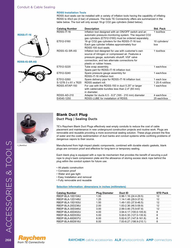
Conduit & Cable Sealing
RDSS-IT-16
RDSS-IG-SR-AS
Catalog Number Description Std. PackRDSS-IT-16 InflationtooldesignedwithanON/OFFswitchandan 1tool/box
automatic pressure-monitoring system . The required CO2 gas cylinders (E7512-0160) must be ordered separately .
E7512-0160 16-grCO2gascylindersfortheRDSS-IT-16tool. 10cylinders/ Each gas cylinder inflates approximately four box RDSS-100 duct seals .RDSS-IG-SR-AS Inflationtooldesignedforusewithcustomer’sown 1tool/box
source of nitrogen or compressed air . Features a pressure gauge, automatic shutoff, VGF valve connection, and two alternate connections for plastic or rubber hoses .
E7512-0220 Tubesnapassembly. 1each/box Spare part for RDSS-IT-16 inflation tool .
E7512-0240 Sparepressuregaugeassemblyfor 1each/box RDSS-IT-16 inflation tool .
E7512-0260 Spare delivery pipe for RDSS-IT-16 inflation tool . 1 each boxS-1278-3x61x7620 RDSSsealantroll. 125-ftroll/boxRDSS-AT/AP-150 ForusewiththeRDSS-150induct5.25"orlarger 1each/box
withcable/cablebundleslessthan2.4"(60mm) in diameter .
RDSS-AD-210 Adapterforducts6.5-8.0"(165-210mm)diameter 4each/boxE4540-1250 RDSS-LUBEfor installationofRDSS. 25each/box
RDSS Installation ToolsRDSS duct seals can be installed with a variety of inflation tools having the capability of inflating RDSS to 45±3 psi (3 bar) of pressure . The tools TE Connectivity offers are summarized in the table below . The tool will only accept 16-gr CO2 gas cylinders (listed below) .
AC
CE
SS
OR
IES
& T
OO
LS C_BlankDuct
AC
CE
SS
OR
IES
& T
OO
LS
Blank Duct PlugDuct Plug | Sealing Ducts
TE’sRaychemBlankDuctPlugseffectivelysealemptyconduitstoreducethecostofcableplacement and maintenance in new underground construction projects and routine work . Plugs are removable and reusable providing a more economical sealing solution . These plugs prevent the flow of water and the costly sedimentation of duct banks and conduit systems while confining problems of dangerous vapors to their source .
Manufactured from high-impact plastic components, combined with durable elastic gaskets, blank plugs are corrosion proof and effective for long-term or temporary sealing .
Each blank plug is equipped with a rope tie mechanism that provides the benefit of securing a pull ropetoplug’sbackcompressionplateandtheallowanceofstoringexcessslackropebehindtheplug within the conduit system for future use .
•Allplasticconstruction•Corrosionproof•Waterandgastight•EasyInstallationandremoval•Fullyremovableandreusable
Selection Information: dimensions in inches (millimeters)
Catalog Number Plug Diameter Duct ID STD PackRBDP-BLA-10D104U 1 .00 0 .96-1 .16 (24 .4-29 .5) 12RBDP-BLA-12D148U 1 .25 1 .14-1 .48 (29 .0-37 .6) 12RBDP-BLA-15D183U 1 .50 1 .49-1 .83 (37 .8-46 .5) 12RBDP-BLA-20D236U 2 .00 1 .83-2 .36 (46 .5-59 .9) 12RBDP-BLA-30D346U 3 .00 2 .99-3 .46 (75 .9-87 .9) 12RBDP-BLA-40D402U 4 .00 3 .94-4 .17 (100 .0-105 .9) 8RBDP-BLA-50D535U 5 .00 5 .00-5 .35 (127 .0-135 .9) 8RBDP-BLA-60D637U 6 .00 5 .82-6 .37 (147 .8-161 .8) 8RBDP-BLA-80D816U 8 .00 7 .83-8 .27 (198 .9-210 .1) 8
RAYCHEM cable accessories ALR photocontrols AMP connectors 268268
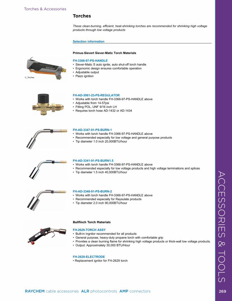
Torches & Accessories
Torches
These clean-burning, efficient, heat-shrinking torches are recommended for shrinking high voltage products through low voltage products
Selection information
Primus-Sievert Siever-Matic Torch Materials
FH-3366-97-PS-HANDLE • Siever-MaticSautoignite,autoshut-offtorchhandle• Ergonomicdesignensurescomfortableoperation• Adjustableoutput• Piezoignition
FH-AD-3061-23-PS-REGULATOR • WorkswithtorchhandleFH-3366-97-PS-HANDLEabove• Adjustablefrom14-57psi• FittingPOL,UNF9/16inchLH• RequirestorchhoseAD-1432orAD-1434
FH-AD-3347-91-PS-BURN-1 • WorkswithtorchhandleFH-3366-97-PS-HANDLEabove• Recommendedespeciallyforlowvoltageandgeneralpurposeproducts• Tipdiameter1.0inch20,000BTU/hour
FH-AD-3341-91-PS-BURN1.5• WorkswithtorchhandleFH-3366-97-PS-HANDLEabove•Recommendedespeciallyforlowvoltageproductsandhighvoltageterminationsandsplices• Tipdiameter1.5inch40,000BTU/hour
FH-AD-3348-91-PS-BURN-2• WorkswithtorchhandleFH-3366-97-PS-HANDLEabove• RecommendedespeciallyforRaysulateproducts• Tipdiameter2.0inch90,000BTU/hour
Bullfinch Torch Materials
FH-2629-TORCH ASSY• Built-iningnitorrecommendedforallproducts• Generalpurpose,heavy-dutypropanetorchwithcomfortablegrip•Providesacleanburningflameforshrinkinghighvoltageproductsorthick-walllowvoltageproducts.• Output:Approximately30,000BTU/Hour
FH-2629-ELECTRODE •ReplacementignitorforFH-2629torch
C_Torches
AC
CE
SS
OR
IES
& T
OO
LS
RAYCHEM cable accessories ALR photocontrols AMP connectors 269 269
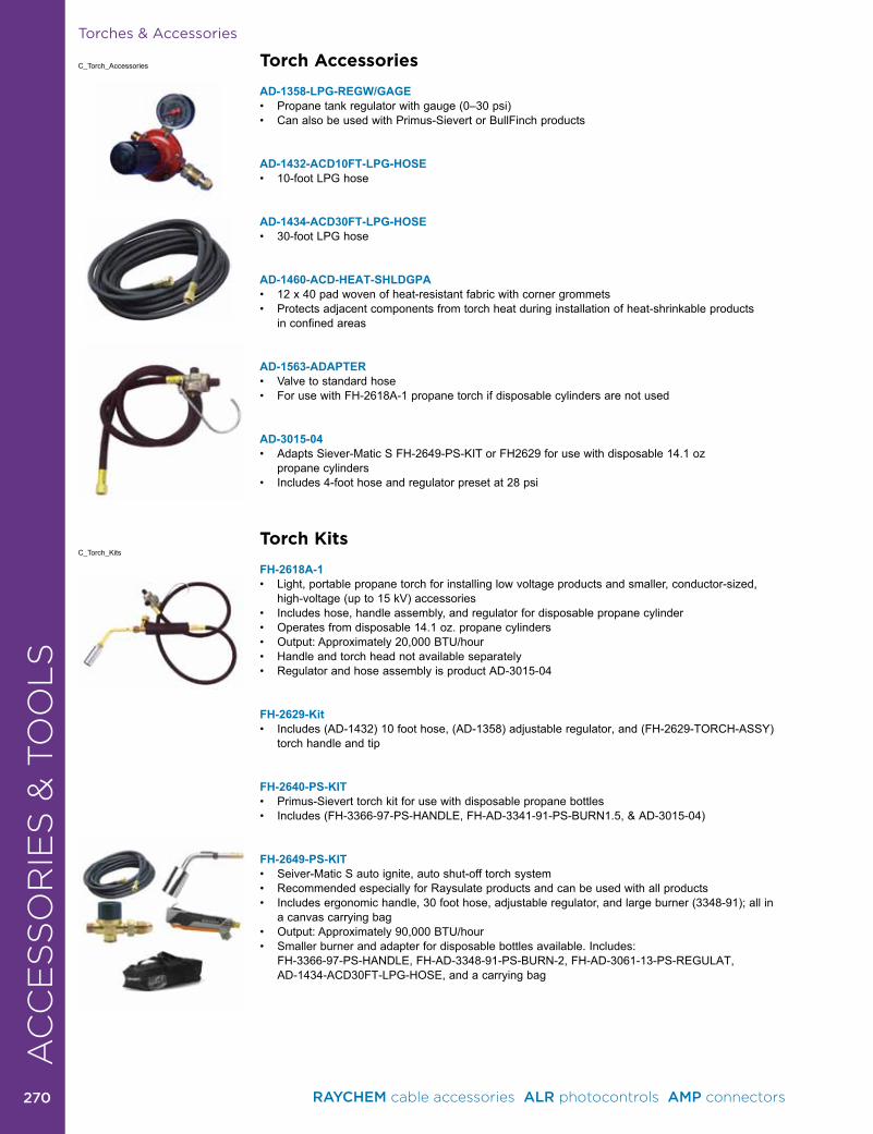
Torch Accessories
AD-1358-LPG-REGW/GAGE • Propanetankregulatorwithgauge(0–30psi)• Can also be used with Primus-Sievert or BullFinch products
AD-1432-ACD10FT-LPG-HOSE • 10-footLPGhose
AD-1434-ACD30FT-LPG-HOSE• 30-footLPGhose
AD-1460-ACD-HEAT-SHLDGPA • 12x40padwovenofheat-resistantfabricwithcornergrommets• Protectsadjacentcomponentsfromtorchheatduringinstallationofheat-shrinkableproducts
in confined areas
AD-1563-ADAPTER• Valvetostandardhose• ForusewithFH-2618A-1propanetorchifdisposablecylindersarenotused
AD-3015-04 • AdaptsSiever-MaticSFH-2649-PS-KITorFH2629forusewithdisposable14.1oz propane cylinders• Includes4-foothoseandregulatorpresetat28psi
Torch Kits
FH-2618A-1• Light,portablepropanetorchforinstallinglowvoltageproductsandsmaller,conductor-sized,
high-voltage (up to 15 kV) accessories• Includeshose,handleassembly,andregulatorfordisposablepropanecylinder• Operatesfromdisposable14.1oz.propanecylinders• Output:Approximately20,000BTU/hour• Handle and torch head not available separately• RegulatorandhoseassemblyisproductAD-3015-04
FH-2629-Kit • Includes (AD-1432) 10 foot hose, (AD-1358) adjustable regulator, and (FH-2629-TORCH-ASSY)
torch handle and tip
FH-2640-PS-KIT• Primus-Sieverttorchkitforusewithdisposablepropanebottles• Includes(FH-3366-97-PS-HANDLE,FH-AD-3341-91-PS-BURN1.5,&AD-3015-04)
FH-2649-PS-KIT• Seiver-MaticSautoignite,autoshut-offtorchsystem• RecommendedespeciallyforRaysulateproductsandcanbeusedwithallproducts• Includesergonomichandle,30foothose,adjustableregulator,andlargeburner(3348-91);allin
a canvas carrying bag• Output:Approximately90,000BTU/hour• Smallerburnerandadapterfordisposablebottlesavailable. Includes:
FH-3366-97-PS-HANDLE, FH-AD-3348-91-PS-BURN-2, FH-AD-3061-13-PS-REGULAT, AD-1434-ACD30FT-LPG-HOSE, and a carrying bag
C_Torch_Accessories
C_Torch_Kits
Torches & AccessoriesM
ED
IUM
/ H
IGH
VO
LTA
GE
CA
BL
E A
CC
ES
SO
RIE
SA
CC
ES
SO
RIE
S &
TO
OL
S
RAYCHEM cable accessories ALR photocontrols AMP connectors 270270

AC
CE
SS
OR
IES
& T
OO
LS
Torches & Accessories
CUS ListedHeat Gun 16C6
Heat Guns
These hot-air heat guns are ideal for shrinking small low voltage products and identification marking sleeves . Heat guns are not recommended for shrinking high voltage products or thick-wall low voltage products .
FH-PS-2001 Primus-Sievertmodelwithincreasedairflowallowsfastershrinking.120V,1750watt,80°F–1100°F, Variable air flow: 21 cfm max ., double insulated LED read out . This heat gun can be used for shrinking thick-wall low voltage products .
HG-501A 115 Volts 462047500°F–750°Fhot-airgunidealforshrinkingShrinkMarkorTMSmarkingproducts,andthin-walltubing . Includes stand . Reflector must beordered separately .
HG-751A-C 120 Volts 926935750°F–1000°Fhot-airgunforshrinkinglowvoltageandmarkingproducts.Includesstand.Reflector must be ordered separately .
Heat Gun Accessories
Catalog Number DescriptionTG-12Reflector Useontubingupto3/4inchindiameter.TG-13 Reflector Use on tubing up to 2 inches in diameter .TG-23Reflector Useontubingandcablebreakoutsupto13/4inchesindiameter.TG-24Reflector Useontubingandcablebreakoutsupto31/4inchesindiameter.
Ordering InformationStandardpackage:1each/box.
Glow Torch
• Lightweight,portable,andergonomicdesign• Providesawide-flametorchoutputforinstantcontrolledheating• AutomaticPiezoElectronicsIgnitionSystem• Attachesdirectlyto1lbor2lbdisposablepropanebottles• Installsthinwall,dualwallandadhesivelinedheat-shrinktubingandsleeves
Selection Information:
Catalog Number Description Std. PackCPGI-GLOW-TORCH Wide-Flame Torch 10
C_Heat_Guns
C_Glow_Torch
Glow Gun
• Lightweight,portable,andergonomicdesign• Providesawide-flametorchoutputforinstantcontrolledheating• AutomaticPiezoElectronicsIgnitionSystem• Attachesdirectlyto1lbor2lbdisposablepropanebottles• Installsthinwall,dualwallandadhesivelinedheat-shrinktubingandsleeves
Selection Information:
Catalog Number Description Std. PackCPGI-GLOW-GUN Flameless heat gun 10
C_Glow_Gun
AC
CE
SS
OR
IES
& T
OO
LS
RAYCHEM cable accessories ALR photocontrols AMP connectors 271 271

Tools
Splicing Tools
EXRM-1004-US - Insulation Removal Tool • Description–handtoolformakingringcutsoncablejacketsandEPRinsulation.• Length=7.5inches• Ringcutrange-.50-2.00inches
EXRM-0607 - Cable Splice Knife • Specialpurposeshortblade• Comfortablefull-sizehandle• Finestcutterysteel,toughandcarefullytemperedtoholditsedge
Impact Wrench
IT-1000-033-US - Cordless Impact Wrench • EasyandquickinstallationofmechanicalShearBoltconnectors• Powerfuldesign,classleadingtorque-1,460in-lbs• Includesbatterychargertwo12voltNI-Mltbatteriescarryingcase,sockets1/2"hexagonalsocket
sizes10,13,17,19,22,27,1/4"hexagonaladapter
CA7478-000 - Battery for Cordless Impact Wrench CA7476-000 - Charger for Battery
Wire Cutters
605744-1 - 350 MCM Cutter • Suitableforcopperandaluminumupto350MCM• Steelhandles• NotforsteelorACSRcable
605742-1 - 500 MCM Cutter • Suitableforcopperandaluminumupto500MCM• 21inchesoveralllength• Fiberglasshandles• NotforsteelorACSRcable
C_Splicing_Tools
C_WireCutters
AC
CE
SS
OR
IES
& T
OO
LS
RAYCHEM cable accessories ALR photocontrols AMP connectors 272272

C_CableCutters
C_CableVise
Tools
Cable Cutters
1490489-1• Suitableforcopperoraluminum,solidorstrandedto350MCM• Ratchetmechanismkeepshandleforcelow• Handleslocktogetherforsafety/storage• Compactdesignforeasyfitintotightplaces• Quick-releaseleverforeasytake-up• Idealforcuttingcableupto2/0• AlsocutscoaxcableuptoRG-9
607453-2 1• Greatforcopperandaluminumcableupto1.5”diameter• Lightweighttubularsteelhandleswithvinylhandgrips• Fixedandmovingblademadefromhighgradealloysteel• Fastadvancebuttontominimizerequiredmotion• Combineslightweightandratchetedmechanicaladvantageinitscircularcuttingmotion• Weight3.27Lb[1.49Kg]• NotforsteelorACSRcable
169415-1• Solidandstrandedcopperandaluminiumcables• SolidCu185mm²• SolidAl240mm²• StrandedCu/AlØ25• HiFlexCuØ32
734045-1• Solidandstrandedcopperandaluminiumcables• SolidCu185mm²• SolidAl185mm²• StrandedCu/AlØ52• HiFlexCuØ52
1-1579002-8• Solidandstrandedcopperandaluminiumcables(noASCR)• SolidCu480mm²• SolidAl480mm²• StrandedCu/AlØ54
KMS-K-INT • CableSheathcutter
Cable Vise
IT 1000-002 The IT-1000-002 cable vice is for fast and easy installation of joints and the repair of cables . An adaptor is included which enables the cable vice to be used for the installation of terminations . Suitable for field installation and for workshop use . When fixed to a work bench, the upper part with the clamps can be used without the legs . Cable vice for the installation of joints and the repair of cables .
Cable Vise Adaptor and Clamp (comes with Cable Vise) Adaptor and clamp for the installation of termations
AC
CE
SS
OR
IES
& T
OO
LS
RAYCHEM cable accessories ALR photocontrols AMP connectors 273 273

Tools
Tool Sets
IT-1000-006 - Assortment of Tools • 1xPipeWrench,size9.84"(250mm)• 1xSidecutter,size6.30"(160mm)• 1xPincers,size7.08"(180mm)• 1xCombinationPliers,size7.08"(180mm)• 1xScissors,size7.87"(200mm)
IT-1000-019 - Installation tool for mechanical connectors This tool avoids the cable cores being over bend during installation of mechanical connectors Application diameter range: .59"-2 .36" (15-60 mm) . Length of handle: 8 .07" (205 mm)
734587-1 - Cable Tie Gun • Forcableties3.3-4.8mm• Thicknessupto1.6mm• Automaticcut-off• Adjustabletensionsetting
Stripping Tools
IT-1000-030-2 - Screen Removal Tool• ScreenRemovalToolIT-1000-030-2forbondedscreensonroundconductorsofMVCables
includes: 1 spare blade, silicone grease and allen key delivered in a roburst polypropylene box . • Suitableforoneandthreecorecables.• Applicationrangeoverinsulation.39”-1.97”(10-50mm),Minscreencutback.39”(10mm),variable
cutting thickness
IT-1000-030-2-BLADE - SIML 0-711744-1 • CableJacket/leadremovaltool
SIMIL 0711744-1Cablejacket/leadremovaltoolPG2,cablediameter.83”-1.37”(21-33mm)
SIML 0-711745-1CableJacket/leadremovaltool-PG3CableDiameter1.02”-2.04”(26-52mm)
SIML 0-711746-1CableJacket/leadremovaltool-PG3CableDiameter1.85”-2.95”(47-75mm)
SIML 0-0711748-1StripinsulationofMVcablesofdiameterbetween.55”-1.57”(14-40mm)
SIML 0-0711749-1StripinsulationofMVcablesofdiameterbetween1.50”-2.36”(38-60mm)
LHM 1R 30/45 - 0-0716541-1Tostripnon-bondedsemiconductivescreenofMVcablesofdiameterbetween.55”-1.57”(14-40mm)
AC
CE
SS
OR
IES
& T
OO
LS
C_StrippingTools
C_ToolSets
RAYCHEM cable accessories ALR photocontrols AMP connectors 274274

Applications by Cable Type . . . . . . . . . . . . . . . . . . . . . . . . . . . . . . 276Low Voltage Tubing and Wraparound Sleeves . . . . . . . . . . . . . . . 285Splices . . . . . . . . . . . . . . . . . . . . . . . . . . . . . . . . . . . . . . . . . . . . . . 289Terminations . . . . . . . . . . . . . . . . . . . . . . . . . . . . . . . . . . . . . . . . . . 294Busbar/Wildlife Protection . . . . . . . . . . . . . . . . . . . . . . . . . . . . . . . 299
APPLICATIONS & TECHNICAL SPECIFICATIONS
RAYCHEM cable accessories ALR photocontrols AMP connectors 275 275
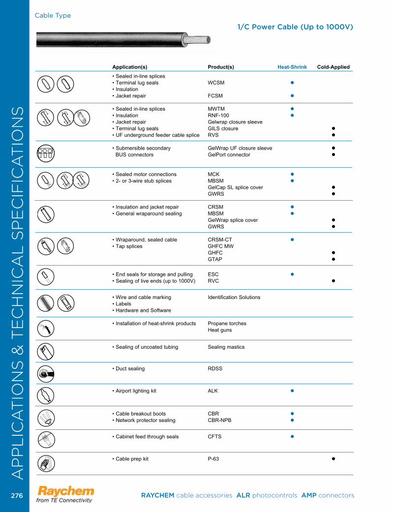
Cable Type
Application(s) Product(s) Heat-Shrink Cold-Applied
• Sealed in-line splices • Terminal lug seals WCSM • Insulation • Jacket repair FCSM
• Sealed in-line splices MWTM • Insulation RNF-100 • Jacket repair Gelwrap closure sleeve• Terminal lug seals GILS closure • UF underground feeder cable splice RVS
• Submersible secondary GelWrap UF closure sleeve BUS connectors GelPort connector
• Sealed motor connections MCK • 2- or 3-wire stub splices MBSM GelCap SL splice cover GWRS
• Insulation and jacket repair CRSM • General wraparound sealing MBSM GelWrap splice cover GWRS
• Wraparound, sealed cable CRSM-CT • Tap splices GHFC MW GHFC GTAP
• End seals for storage and pulling ESC • Sealing of live ends (up to 1000V) RVC
• Wire and cable marking Identification Solutions• Labels • Hardware and Software
• Installation of heat-shrink products Propane torches Heat guns
• Sealing of uncoated tubing Sealing mastics
• Duct sealing RDSS
• Airport lighting kit ALK
• Cable breakout boots CBR • Network protector sealing CBR-NPB
• Cabinet feed through seals CFTS
• Cable prep kit P-63
1/C Power Cable (Up to 1000V)A
PP
LIC
AT
ION
S &
TE
CH
NIC
AL
SP
EC
IFIC
AT
ION
S
RAYCHEM cable accessories ALR photocontrols AMP connectors 276276
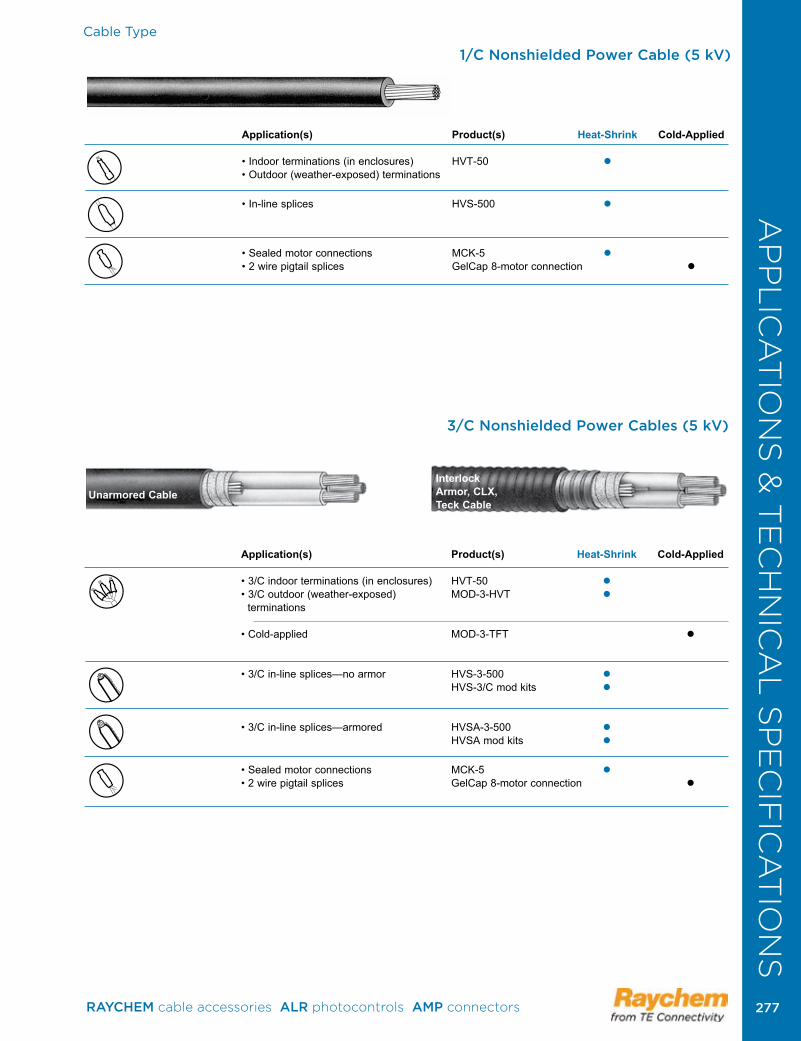
Cable Type
Application(s) Product(s) Heat-Shrink Cold-Applied
• 3/C indoor terminations (in enclosures) HVT-50 • 3/C outdoor (weather-exposed) MOD-3-HVT terminations
• Cold-applied MOD-3-TFT
• 3/C in-line splices—no armor HVS-3-500 HVS-3/C mod kits
• 3/C in-line splices—armored HVSA-3-500 HVSA mod kits
• Sealed motor connections MCK-5 • 2 wire pigtail splices GelCap 8-motor connection
Unarmored CableInterlock Armor, CLX, Teck Cable
3/C Nonshielded Power Cables (5 kV)
Application(s) Product(s) Heat-Shrink Cold-Applied
• Indoor terminations (in enclosures) HVT-50 • Outdoor (weather-exposed) terminations
• In-line splices HVS-500
• Sealed motor connections MCK-5 • 2 wire pigtail splices GelCap 8-motor connection
1/C Nonshielded Power Cable (5 kV)A
PP
LIC
AT
ION
S &
TE
CH
NIC
AL
SP
EC
IFIC
AT
ION
S
RAYCHEM cable accessories ALR photocontrols AMP connectors 277 277
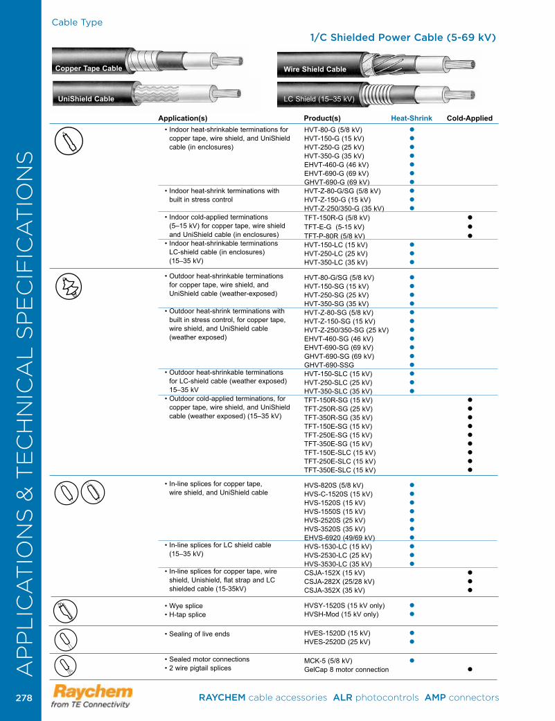
Cable Type
• Indoor heat-shrinkable terminations for copper tape, wire shield, and UniShield cable (in enclosures)
• Indoor heat-shrink terminations with built in stress control
• Indoor cold-applied terminations (5–15 kV) for copper tape, wire shield and UniShield cable (in enclosures)
• Indoor heat-shrinkable terminations LC-shield cable (in enclosures) (15–35 kV)
• Outdoor heat-shrinkable terminations for copper tape, wire shield, and UniShield cable (weather-exposed)
• Outdoor heat-shrink terminations with built in stress control, for copper tape, wire shield, and UniShield cable (weather exposed)
• Outdoor heat-shrinkable terminations
for LC-shield cable (weather exposed) 15–35 kV
• Outdoor cold-applied terminations, for copper tape, wire shield, and UniShield cable (weather exposed) (15–35 kV)
• In-line splices for copper tape, wire shield, and UniShield cable
• In-line splices for LC shield cable (15–35 kV)
• In-line splices for copper tape, wire shield, Unishield, flat strap and LC shielded cable (15-35kV)
• Wye splice • H-tap splice
• Sealing of live ends
• Sealed motor connections• 2 wire pigtail splices
HVT-80-G (5/8 kV) HVT-150-G (15 kV) HVT-250-G (25 kV) HVT-350-G (35 kV) EHVT-460-G (46 kV) EHVT-690-G (69 kV) GHVT-690-G (69 kV) HVT-Z-80-G/SG (5/8 kV) HVT-Z-150-G (15 kV) HVT-Z-250/350-G (35 kV) TFT-150R-G (5/8 kV) TFT-E-G (5-15 kV) TFT-P-80R (5/8 kV) HVT-150-LC (15 kV) HVT-250-LC (25 kV) HVT-350-LC (35 kV)
HVT-80-G/SG (5/8 kV) HVT-150-SG (15 kV) HVT-250-SG (25 kV) HVT-350-SG (35 kV) HVT-Z-80-SG (5/8 kV) HVT-Z-150-SG (15 kV) HVT-Z-250/350-SG (25 kV) EHVT-460-SG (46 kV) EHVT-690-SG (69 kV) GHVT-690-SG (69 kV) GHVT-690-SSG HVT-150-SLC (15 kV) HVT-250-SLC (25 kV) HVT-350-SLC (35 kV) TFT-150R-SG (15 kV) TFT-250R-SG (25 kV) TFT-350R-SG (35 kV) TFT-150E-SG (15 kV) TFT-250E-SG (15 kV) TFT-350E-SG (15 kV) TFT-150E-SLC (15 kV) TFT-250E-SLC (15 kV) TFT-350E-SLC (15 kV)
HVS-820S (5/8 kV) HVS-C-1520S (15 kV) HVS-1520S (15 kV) HVS-1550S (15 kV) HVS-2520S (25 kV) HVS-3520S (35 kV) EHVS-6920 (49/69 kV) HVS-1530-LC (15 kV) HVS-2530-LC (25 kV) HVS-3530-LC (35 kV) CSJA-152X (15 kV) CSJA-282X (25/28 kV) CSJA-352X (35 kV)
HVSY-1520S (15 kV only) HVSH-Mod (15 kV only)
HVES-1520D (15 kV) HVES-2520D (25 kV)
MCK-5 (5/8 kV) GelCap 8 motor connection
1/C Shielded Power Cable (5-69 kV)
Copper Tape Cable
UniShield Cable
Wire Shield Cable
LC Shield (15–35 kV)
Application(s) Product(s) Heat-Shrink Cold-Applied
AP
PL
ICA
TIO
NS
& T
EC
HN
ICA
L S
PE
CIF
ICA
TIO
NS
RAYCHEM cable accessories ALR photocontrols AMP connectors 278278
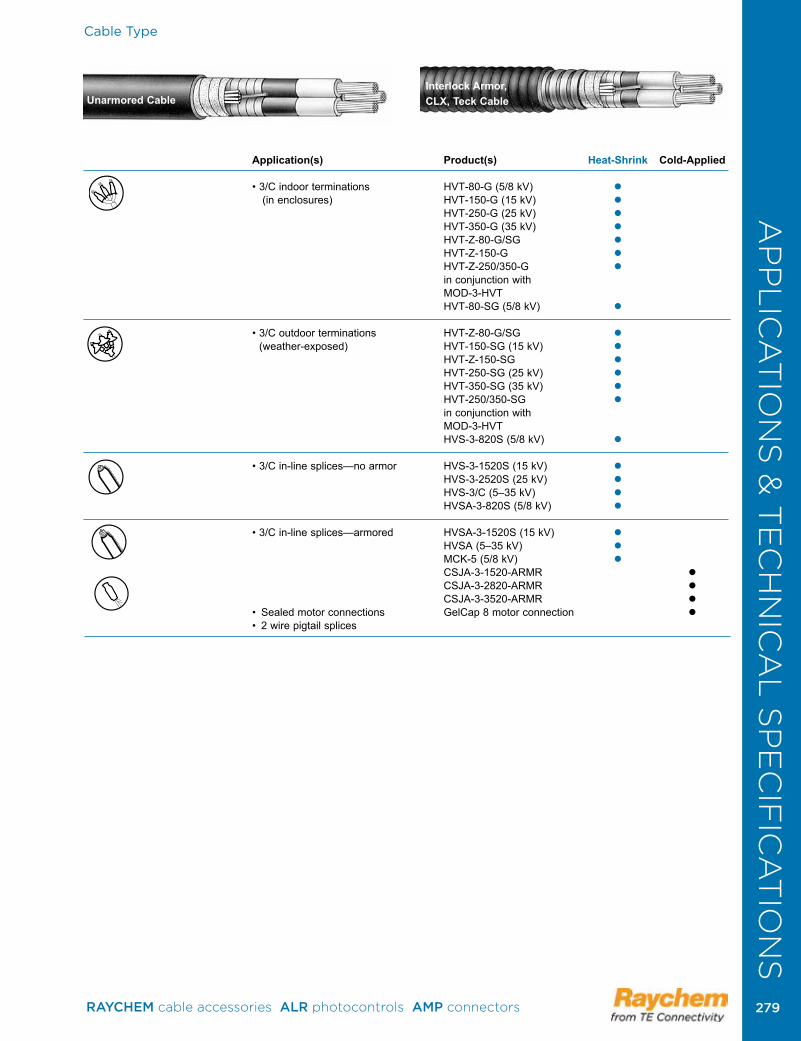
Cable Type
Unarmored CableInterlock Armor, CLX, Teck Cable
Application(s) Product(s) Heat-Shrink Cold-Applied
• 3/C indoor terminations HVT-80-G (5/8 kV) (in enclosures) HVT-150-G (15 kV) HVT-250-G (25 kV)
HVT-350-G (35 kV) HVT-Z-80-G/SG HVT-Z-150-G HVT-Z-250/350-G in conjunction with MOD-3-HVT HVT-80-SG (5/8 kV)
• 3/C outdoor terminations HVT-Z-80-G/SG (weather-exposed) HVT-150-SG (15 kV)
HVT-Z-150-SG HVT-250-SG (25 kV) HVT-350-SG (35 kV) HVT-250/350-SG in conjunction with MOD-3-HVT HVS-3-820S (5/8 kV)
• 3/C in-line splices—no armor HVS-3-1520S (15 kV) HVS-3-2520S (25 kV) HVS-3/C (5–35 kV) HVSA-3-820S (5/8 kV)
• 3/C in-line splices—armored HVSA-3-1520S (15 kV) HVSA (5–35 kV) MCK-5 (5/8 kV) CSJA-3-1520-ARMR CSJA-3-2820-ARMR CSJA-3-3520-ARMR • Sealed motor connections GelCap 8 motor connection • 2 wire pigtail splices
AP
PL
ICA
TIO
NS
& T
EC
HN
ICA
L S
PE
CIF
ICA
TIO
NS
RAYCHEM cable accessories ALR photocontrols AMP connectors 279 279
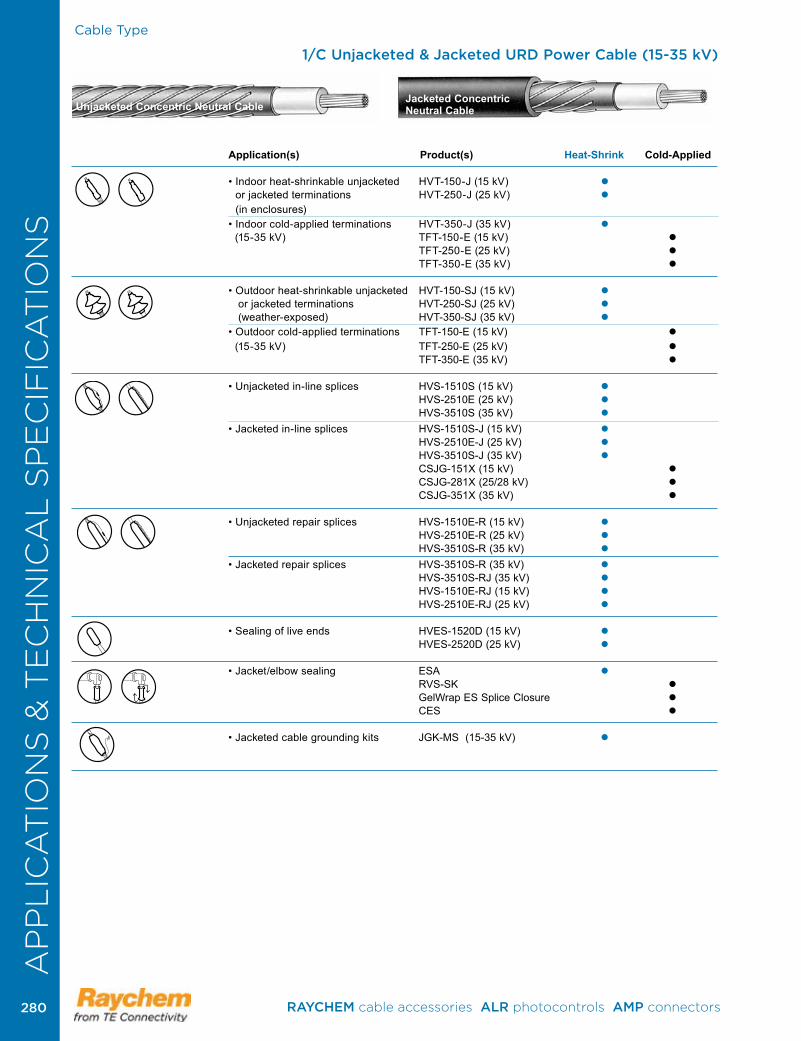
Cable Type
1/C Unjacketed & Jacketed URD Power Cable (15-35 kV)
Unjacketed Concentric Neutral CableJacketed Concentric Neutral Cable
Application(s) Product(s) Heat-Shrink Cold-Applied
• Indoor heat-shrinkable unjacketed HVT-150-J (15 kV) or jacketed terminations HVT-250-J (25 kV) (in enclosures)
• Indoor cold-applied terminations HVT-350-J (35 kV) (15-35 kV) TFT-150-E (15 kV) TFT-250-E (25 kV) TFT-350-E (35 kV)
• Outdoor heat-shrinkable unjacketed HVT-150-SJ (15 kV) or jacketed terminations HVT-250-SJ (25 kV) (weather-exposed) HVT-350-SJ (35 kV) • Outdoor cold-applied terminations TFT-150-E (15 kV) (15-35 kV) TFT-250-E (25 kV) TFT-350-E (35 kV)
• Unjacketed in-line splices HVS-1510S (15 kV) HVS-2510E (25 kV) HVS-3510S (35 kV)
• Jacketed in-line splices HVS-1510S-J (15 kV) HVS-2510E-J (25 kV) HVS-3510S-J (35 kV)
CSJG-151X (15 kV) CSJG-281X (25/28 kV) CSJG-351X (35 kV)
• Unjacketed repair splices HVS-1510E-R (15 kV) HVS-2510E-R (25 kV)
HVS-3510S-R (35 kV)
• Jacketed repair splices HVS-3510S-R (35 kV) HVS-3510S-RJ (35 kV)
HVS-1510E-RJ (15 kV) HVS-2510E-RJ (25 kV)
• Sealing of live ends HVES-1520D (15 kV) HVES-2520D (25 kV)
• Jacket/elbow sealing ESA RVS-SK GelWrap ES Splice Closure CES
• Jacketed cable grounding kits JGK-MS (15-35 kV)
AP
PL
ICA
TIO
NS
& T
EC
HN
ICA
L S
PE
CIF
ICA
TIO
NS
AP
PL
ICA
TIO
NS
& T
EC
HN
ICA
L S
PE
CIF
ICA
TIO
NS
RAYCHEM cable accessories ALR photocontrols AMP connectors 280280
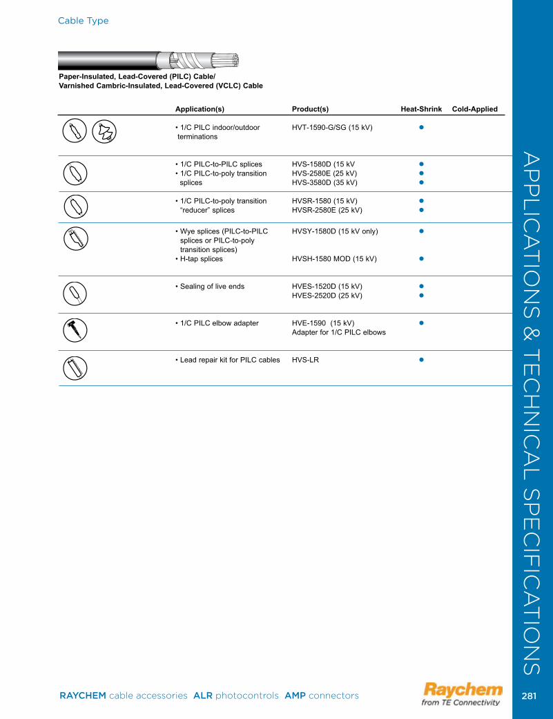
AP
PL
ICA
TIO
NS
& T
EC
HN
ICA
L S
PE
CIF
ICA
TIO
NS
Application(s) Product(s) Heat-Shrink Cold-Applied
• 1/C PILC indoor/outdoor HVT-1590-G/SG (15 kV) terminations
• 1/C PILC-to-PILC splices HVS-1580D (15 kV • 1/C PILC-to-poly transition HVS-2580E (25 kV) splices HVS-3580D (35 kV)
• 1/C PILC-to-poly transition HVSR-1580 (15 kV) “reducer” splices HVSR-2580E (25 kV)
• Wye splices (PILC-to-PILC HVSY-1580D (15 kV only) splices or PILC-to-poly transition splices)
• H-tap splices HVSH-1580 MOD (15 kV)
• Sealing of live ends HVES-1520D (15 kV) HVES-2520D (25 kV)
• 1/C PILC elbow adapter HVE-1590 (15 kV) Adapter for 1/C PILC elbows
• Lead repair kit for PILC cables HVS-LR
Cable Type
Paper-Insulated, Lead-Covered (PILC) Cable/ Varnished Cambric-Insulated, Lead-Covered (VCLC) Cable
AP
PL
ICA
TIO
NS
& T
EC
HN
ICA
L S
PE
CIF
ICA
TIO
NS
RAYCHEM cable accessories ALR photocontrols AMP connectors 281 281
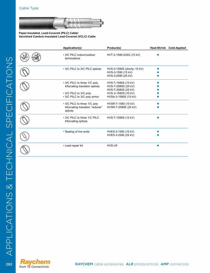
Cable Type
Paper-Insulated, Lead-Covered (PILC) Cable/ Varnished Cambric-Insulated Lead-Covered (VCLC) Cable
Application(s) Product(s) Heat-Shrink Cold-Applied
• 3/C PILC indoor/outdoor HVT-3-1590-G/SG (15 kV) terminations
• 3/C PILC to 3/C PILC splices HVS-3-1590S (shorty–15 kV) HVS-3-1590 (15 kV) HVS-3-2590 (25 kV)
• 3/C PILC to three 1/C poly HVS-T-1580S (15 kV) trifurcating transition splices HVS-T-2580D (25 kV)
HVS-T-3580S (25 kV) • 3/C PILC to 3/C poly HVS-3-1580S (15 kV) • 3/C PILC to 3/C poly armor HVSA-3-1580S (15 kV)
• 3/C PILC to three 1/C poly HVSR-T-1580 (15 kV) trifurcating transition “reducer” HVSR-T-2580E (25 kV) splices
• 3/C PILC to three 1/C PILC HVS-T-1590S (15 kV) trifurcating splices
• Sealing of live ends HVES-3-1590 (15 kV) HVES-3-2590 (25 kV)
• Lead repair kit HVS-LR
AP
PL
ICA
TIO
NS
& T
EC
HN
ICA
L S
PE
CIF
ICA
TIO
NS
RAYCHEM cable accessories ALR photocontrols AMP connectors 282282
Application(s) Product Heat-Shrink Cold-Applied
• Indoor terminations HVT-M (in enclosures) • Outdoor (weather-exposed) terminations (5–25 kV)
• Sealed, in-line 3/C HV-MSK splices (5–8 kV)
• Insulation (2 kV) and jacket MRS repair • General wraparound sealing
• Cable jacket repair CRPS
Cable Type
W-Round
W-, G-Flat G-, GC-Flat
G-, GC-Round
Flexible Cable (Up to 2 kV)
Flexible Cable (5-25 kV)
MP-GC
-MSHA
P-137-
-MSHA
P
SHD-GC-Round
Application(s) Product(s) Heat-Shrink Cold-Applied
• Sealed, in-line splices LV-MSK • Multiconductor splices
• General wraparound sealing MRS
• Cable jacket repair CRPS-MSHA
P-137-
-MSHA
P
AP
PL
ICA
TIO
NS
& T
EC
HN
ICA
L S
PE
CIF
ICA
TIO
NS
RAYCHEM cable accessories ALR photocontrols AMP connectors 283 283
Cable Type
Bus Insulation Configuration
Application(s) Product(s)
• Bus insulation— LVIT slide-on access required BPTM/BBIT
• Bus insulation— LVBT slide-on access not required HVBT
• Field-fabricated HVIS insulating covers
Cable-to-Bus Connection Configurations1-4 Cable(s) Phase
Bends and Edgewise Elbows
Flat Elbow Connections
Straight Bus Runs
Bolted Bus Connections
Tee Connections
Application(s) Product
• Switchgear in-line HVBC cable-to-bus connections
AP
PL
ICA
TIO
NS
& T
EC
HN
ICA
L S
PE
CIF
ICA
TIO
NS
RAYCHEM cable accessories ALR photocontrols AMP connectors 284284

Low-Voltage Tubing and Wraparound Sleeves
General Purpose Cable Accessories (1000 V)TE offers a complete line of Raychem brand general purpose heat-shrinkable and cold-applied power cable accessories that consistently provide outstanding mechanical protection, complete moisture sealing, and excellent electrical insulation for a broad range of low voltage applications.
Heat-shrink ProductsRaychem invented heat-shrinkable products in 1959 and the Raychem brand contiunes to be the world leader in heat-shrink technology and design.Our heat-shrink products continue to be upgraded and improved to provide the best performance and value possible.
Rugged mechanical protection—every timeThe tough, abrasion-resistant, cross-linked polyolefin construction of general-purpose products provides mechanical protection equal to the cable jacket. In addition, the one-piece solid protective layer cannot unravel or slip off .
Watertight seals—every timeMost heat-shrinkable products are coated with a high-performance adhesive that melts and flows when heated, forming a durable bond that seals out water and dirt.
General purpose sealants are also available for use with uncoated tubings and other moisture sealing applications .
Superior electrical insulation—every timeHeat-shrinkable products not only conform tightly to the connection, but they are also pre-engineered to shrink consistently to the required insulation thickness.
Cold-applied ProductsCold-applied products offer superior sealing and electrical insulation. Our revolutionary PowerGel sealant provides the best and quickest cold-applied seal. By combining the properties of solids and liquids, PowerGel sealant conforms to intricate shapes to completely seal out water and contaminants.
AP
PL
ICA
TIO
NS
& T
EC
HN
ICA
L S
PE
CIF
ICA
TIO
NS
RAYCHEM cable accessories ALR photocontrols AMP connectors 285 285
Low-Voltage Tubing and Wraparound Sleeves
Material Properties WCSM FCSM MWTM RNF-100 CRSM Test Method Test Method Heavy Wall Heavy Wall Medium Wall Thin Wall Wrap-Around
PhysicalTensile strength ASTM D 412 1750 psi min. 1750 psi min. 2000 psi min. 1500 psi min. 2450 psi min.Ultimate elongation ASTM D 412 350% min. 350% min. 350% min. 200% min. 350% min.Accelerated aging (168 hrs at 150°±2°C) ASTM D 2671Tensile strength ASTM D 412 1750 psi min. 1600 psi min. 2000 psi min. 2000 psi min.Ultimate elongation ASTM D 412 350% min. 200% min. 300% min. 300% min.Low-temperature flexibility ASTM D 2671 No cracking No cracking No cracking No cracking No cracking (4 hrs. at temp. indicated) (–55°C) (–40°C) (–40°C) (–55°C) (–40°C)Flammability ASTM D 2671 Self-extinguishing (60 sec max.) ElectricalDielectric strength ASTM D 149 430 V/mil min. 330 V/mil min. 500 V/mil min. 500 V/mil min. 500 V/mil min. (at 0.04 inch) (at 0.10 inch) (at 0.04 inch) (at 0.04 inch)Volume resistivity ASTM D 257 1 x 10¹² 1 x 10¹³ 1 x 10¹² 1 x 10¹⁴ 1 x 10¹² ohm-cm min. ohm-cm min. ohm-cm min. ohm-cm min. ohm-cm min. ChemicalResistance to liquids ASTM D 543 Tensile strength ASTM D 412 1450 psi min. 1600 psi min. 2000 psi min. 1000 psi min. 2000 psi min.Ultimate elongation ASTM D 412 300% min. 300% min. 300% min. 300% min.Corrosive effect ASTM D 2671 No corrosion No corrosion (16 hours at 150°±2°C) at 175°CFungus resistance ASTM G 21 Pass rating 1 Pass rating 1 Pass rating 1 Pass rating 1 Pass rating 1 Technical specificationsANSI C119.1-1986 UL 486D-1986 UL Standard 224 CSA 22 .2 Western Underground Guide 2.5MIL-I-23053/15, CIass 1 & 2Flame-retardant per IEEE 383, ICEA-S-19-81*Flame-RetardantNote: Blank space indicates that property was not measured during product qualification.
AP
PL
ICA
TIO
NS
& T
EC
HN
ICA
L S
PE
CIF
ICA
TIO
NS
RAYCHEM cable accessories ALR photocontrols AMP connectors 286286
Material Properties
Physical Test method MCK ESC CBRTensile strength ASTM D 412 1450 psi min. 1750 psi min. 1500 psi min.Ultimate elongation ASTM D 412 300% min. 200% min. 300% min.Accelerated aging ASTM D 2671 (168 hours at temperature indicated) Tensile strength ASTM D 412 1000 psi min. 1750 psi min. 1250 psi min. (175°±2°C) (150°±2°C) (150°±2°C) Ultimate elongation ASTM D 412 200% min. 200% min. 100% min. (175°±2°C) (150°±2°C) (150°±2°C) Low-temperature flexibility ASTM D 2671 No cracking No cracking No cracking (4 hours at –40°±3°C)Flammability ASTM D 635 Self-extinguish (120 sec. max.) ElectricalDielectric strength (at .075 inch) ASTM D 149 250 V/mil min. 200 V/mil min. 250 V/mil min.Volume resistivity ASTM D 257 1 x 10¹² 1 x 10¹² 1 x 10¹² ohm-cm min. ohm-cm min. ohm-cm min. ChemicalResistance to liquids, transformer oil to VDE 0370 (168 hours at 23°±2°C) ASTM D 543 Tensile strength ASTM D 412 1150 psi min. 1750 psi min. 1250 psi min. Ultimate elongation ASTM D 412 240% min. 200% min. 240% min.Corrosive effect(16 hours at 175°±2°C) ASTM D 2671 No corrosionResistance to fungi ASTM G 21 Pass rating 1 Pass rating 1 Pass rating 1 Technical specificationsANSI C119.1-1986 Flame-retardant per IEEE 383, ICEA-S-19-81Note: Blank space indicates that property was not measured during product qualification.
Material Properties
Physical Test Method S1052 S1085 S1171 S1174 S1251Softening point ASTM E 28 70°C min. 140°C min. 140°C min. Adhesive peel strength: Polyethylene 1 lb/in min. 5.5 lb/in min. 5 lb/in min. 6 lb/in min. Steel 2 lb/in min . 5 lb/in min . Aluminum 4 .4 lb/in min . Copper 4 .4 lb/in min .Low-temperature ASTM D 2671 No cracking No cracking No cracking No cracking flexibility (4 hours at (–40°C±3°C) (–30°C±2°C) (–40°C±3°C) (–40°C±3°C) temperature indicated) ElectricalDielectric strength min. ASTM D 149 300 V/mil min. 200 V/mil min. 200 V/mil min. 300 V/mil min. 300 V/mil (0.04 inch) Volume resistivity ASTM D 257 1 x 10¹² 1 x 10¹² 1 x 10¹² 1 x 10¹² 1 x 10¹² ohm-cm min. ohm-cm min. ohm-cm min. ohm-cm min. ohm-cm min.Tracking & erosion resistance ASTM D 2303 No tracking or erosion to top surface or flame failure after: 1 hr at 2.00 kV 1 hr at 2.25 kV 1 hr at 2.50 kV ChemicalCorrosive effect (16 hours at 121°±2°C) ASTM D 2671 No corrosion No corrosion No corrosion Fungus resistance ASTM G 21 Pass rating 1 Pass rating 1Note: Blank space indicates that property was not measured during product specification.
Low-Voltage Tubing and Wraparound SleevesA
PP
LIC
AT
ION
S &
TE
CH
NIC
AL
SP
EC
IFIC
AT
ION
S
RAYCHEM cable accessories ALR photocontrols AMP connectors 287 287
Low-Voltage Tubing and Wraparound Sleeves
Material Properties
PowerGel Testing Test Methods S.I. Units Imperial UnitsDielectric strength
(4 mm/016 inch wall thickness) 40 kV/cm min. 100 V/mil min.
Volume Resistivity 1 x 10¹² Ohm cm min. 1 x 10¹² Ohm cm min.
Resistance to Liquids ASTM D543 modified: No visible cracking, max. 2% No visible cracking, max. 2% Chemicals: 1 N na2SO4 10.0 cm x 1.0 cm x 0.4 cm, test weight change, 80% retention weight change, 80% retention 0,1 N NaOH; 0, 1 N NaCl; bar supported on wire mesh, 24 of elongation and tensile strength of elongation and tensile water; Ethylene Glycol hours immersion, IPA rinse after strength immersion, 24 hr. drying
Corrosive Effect ASTM D2671 No corrosion No corrosion
Resistance to Fungi ISO 846 Pass rating1 or less Pass rating 1 or less 4.5 cm diameter x 0.4 cm thickness petridish
UV Resistance ISO 4892/3 80% tensile strength retention, 80% tensile strength retention, 10.0 cm x 1.0 cm x 0.4 cm no visible cracking no visible cracking est bar, UVB 313; 250 cycles (2000 hrs); 4 hours UV at 60°C then 4 hours at 50°C with condensation
AP
PL
ICA
TIO
NS
& T
EC
HN
ICA
L S
PE
CIF
ICA
TIO
NS
RAYCHEM cable accessories ALR photocontrols AMP connectors 288288
Superior Long-Term PerformanceEven in the harshest environments,TE’s Raychem brand cable splices are ideal for the following direct-burial and manhole applications: copper tape, wire shield, UniShield, LC-shield, PILC, and jacketed/unjacketed URD cables. The splices not only match the requirements of cable test specifications but also meet or exceed the requirements of IEEE-404. Throughout the world, TE Raychem splices are meeting the needs of industrial, utility, and mining customers with outstanding performance and reliability .
Positive Moisture Sealing and High Abrasion-ResistanceInternal moisture seals protect the cable from water that may enter the cable through a damaged jacket outside of the splice area. In addition, the adhesive-lined rejacketing sleeve provides a moisture-resistant seal that is field-tested and superior to interference fits. Under water cyclic aging tests per ANSI C119.1-1986 and IEEE 404 specifications confirm this. In addition, the outer jacket is superior to tape in abrasion resistance and cannot unravel or fray .
Fast, Consistent InstallationsSimple heat-shrinking techniques reduce installation time and training. Pre-engineered kits help to ensure consistent performance while minimizing potential installation errors.
Unique Repair SplicesSpecially designed to speed URD cable repair, TE’s Raychem brand URD repair splices reduce cable preparation and required excavation space, thus minimizing total repair costs. With our superior heat-shrink adhesive system, our splices reliably seal fault-deformed cables. In addition, one splice repair kit may replace two conventional splices for most repairs.
The typical TE Raychem brand splice—based on heat-shrink technology, specialized materials, and pre-engineered designs—delivers reliable performance.
A close look at one of our polymeric cable splices shows how each component draws on TE technical excellence and field experience to rebuild every function of the cable.
All cable splices must rebuild these critical cable functions:• Electrical stress control• Insulation and semiconductive layer• Shielding and grounding• Environmental and mechanical protection
Splices
Heat-shrink, high-voltage splice kits install quickly and uniformly.
Polymeric wye and H-tap splices produce dependable water tight seals between the main and tap cable(s) with no taping.
Electrical Stress ControlStress relief material
Minimizes stress around the connector and at the
shield cutback.
Heat-Shrinkable Stress Control Tubing
• Reduces electrical stress to safe operating levels .
• Delivers long-term, stable electrical performance .
Grounding and Shielding* • Ground braid provides continuity
across the splice.• Ground clamp provides secure
grounding without soldering.• Shielding mesh surrounds the splice for personnel protection .
* Grounding components not included with URD cable splices.
Moisture Sealing and Mechanical ProtectionMoisture sealant Internal moisture seal inhibits migration of moisture even on cables with jacket damage.
Heat-Shrinkable Adhesive-Lined Wraparound Jacket• Heat-activated adhesive promotes
a positive moisture seal between the cable and splice.
• Tough, crosslinked polyolefin materials provide impact and abrasion-resistance .
Insulation & Semi-conductive LayerHeat-shrinkable dual-layer insulation/conductive tube delivers consistent insulation thickness without field measurements, in a factory-engineered system . • Outer conductive layer reconstructs the cable’s
insulation shield. • Inner insulating wall provides insulation
thickness to meet or exceed that of the cable. • Both layers are factory-bonded to help ensure
a void-free interface between the insulation and shield.
AP
PL
ICA
TIO
NS
& T
EC
HN
ICA
L S
PE
CIF
ICA
TIO
NS
RAYCHEM cable accessories ALR photocontrols AMP connectors 289 289
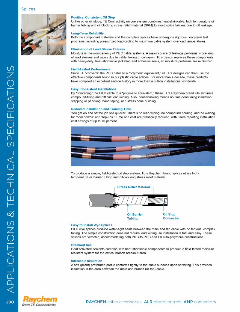
Splices
Positive, Consistent Oil StopUnlike other oil stops, TE Connectivity unique system combines heat-shrinkable, high temperature oil barrier tubing and oil blocking stress relief material (SRM) to avoid splice failures due to oil leakage.
Long-Term Reliability Both the component materials and the complete splices have undergone rigorous, long-term test programs, including pressurized load-cycling to maximum cable system overload temperatures.
Elimination of Lead Sleeve FailuresMoisture is the worst enemy of PILC cable systems. A major source of leakage problems is cracking of lead sleeves and wipes due to cable flexing or corrosion. TE’s design replaces these components with heavy-duty, heat-shrinkable jacketing and adhesive seals, so moisture problems are minimized.
Field-Tested Performance Since TE “converts” the PILC cable to a “polymeric equivalent,” all TE’s designs can then use the effective components found in our plastic cable splices. For more than a decade, these products have compiled an excellent service history in more than a million installations worldwide.
Easy, Consistent InstallationsBy “converting” the PILC cable to a “polymeric equivalent,” these TE’s Raychem brand kits eliminate compound-filling and difficult lead-wiping. Also, heat-shrinking means no time-consuming insulation, stepping or penciling, hand taping, and stress cone building.
Reduced Installation and Training TimeYou get on and off the job site quicker. There’s no lead-wiping, no compound pouring, and no waiting for “cool downs” and “top-ups.” Time and cost are drastically reduced, with users reporting installation cost savings of up to 75 percent .
To produce a simple, field-tested oil stop system, TE’s Raychem brand splices utilize high-temperature oil barrier tubing and oil-blocking stress relief material.
Easy to Install Wye Splices PILC wye splices produce water-tight seals between the main and tap cable with no tedious, complex taping. The simple construction does not require lead wiping, so installation is fast and easy. These splices are versatile, accommodating both PILC-to-PILC and PILC-to-polymeric constructions.
Breakout SealHeat-activated sealants combine with heat-shrinkable components to produce a field-tested moisture resistant system for the critical branch breakout area.
Intercable InsulationA soft (pliant) preformed profile conforms tightly to the cable surfaces upon shrinking. This provides insulation in the area between the main and branch (or tap) cable.
Oil Barrier Tubing
Oil Stop Connector
Stress Relief Material
AP
PL
ICA
TIO
NS
& T
EC
HN
ICA
L S
PE
CIF
ICA
TIO
NS
RAYCHEM cable accessories ALR photocontrols AMP connectors 290290
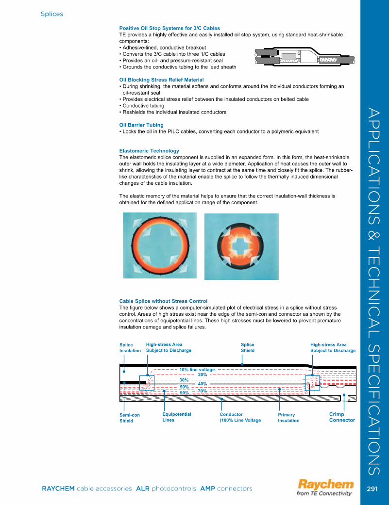
Splices
Positive Oil Stop Systems for 3/C Cables TE provides a highly effective and easily installed oil stop system, using standard heat-shrinkable components:• Adhesive-lined, conductive breakout• Converts the 3/C cable into three 1/C cables• Provides an oil- and pressure-resistant seal• Grounds the conductive tubing to the lead sheath
Oil Blocking Stress Relief Material• During shrinking, the material softens and conforms around the individual conductors forming an
oil-resistant seal• Provides electrical stress relief between the insulated conductors on belted cable• Conductive tubing• Reshields the individual insulated conductors
Oil Barrier Tubing• Locks the oil in the PILC cables, converting each conductor to a polymeric equivalent
Elastomeric Technology The elastomeric splice component is supplied in an expanded form. In this form, the heat-shrinkable outer wall holds the insulating layer at a wide diameter. Application of heat causes the outer wall to shrink, allowing the insulating layer to contract at the same time and closely fit the splice. The rubber-like characteristics of the material enable the splice to follow the thermally induced dimensional changes of the cable insulation.
The elastic memory of the material helps to ensure that the correct insulation-wall thickness is obtained for the defined application range of the component.
Cable Splice without Stress ControlThe figure below shows a computer-simulated plot of electrical stress in a splice without stress control. Areas of high stress exist near the edge of the semi-con and connector as shown by the concentrations of equipotential lines. These high stresses must be lowered to prevent premature insulation damage and splice failures .
SpliceInsulation
High-stress AreaSubject to Discharge
SpliceShield
High-stress AreaSubject to Discharge
Semi-conShield
EquipotentialLines
Conductor(100% Line Voltage
Primary Insulation
Crimp Connector
10% line voltage20%
30%40%70%90%
50%
AP
PL
ICA
TIO
NS
& T
EC
HN
ICA
L S
PE
CIF
ICA
TIO
NS
RAYCHEM cable accessories ALR photocontrols AMP connectors 291 291
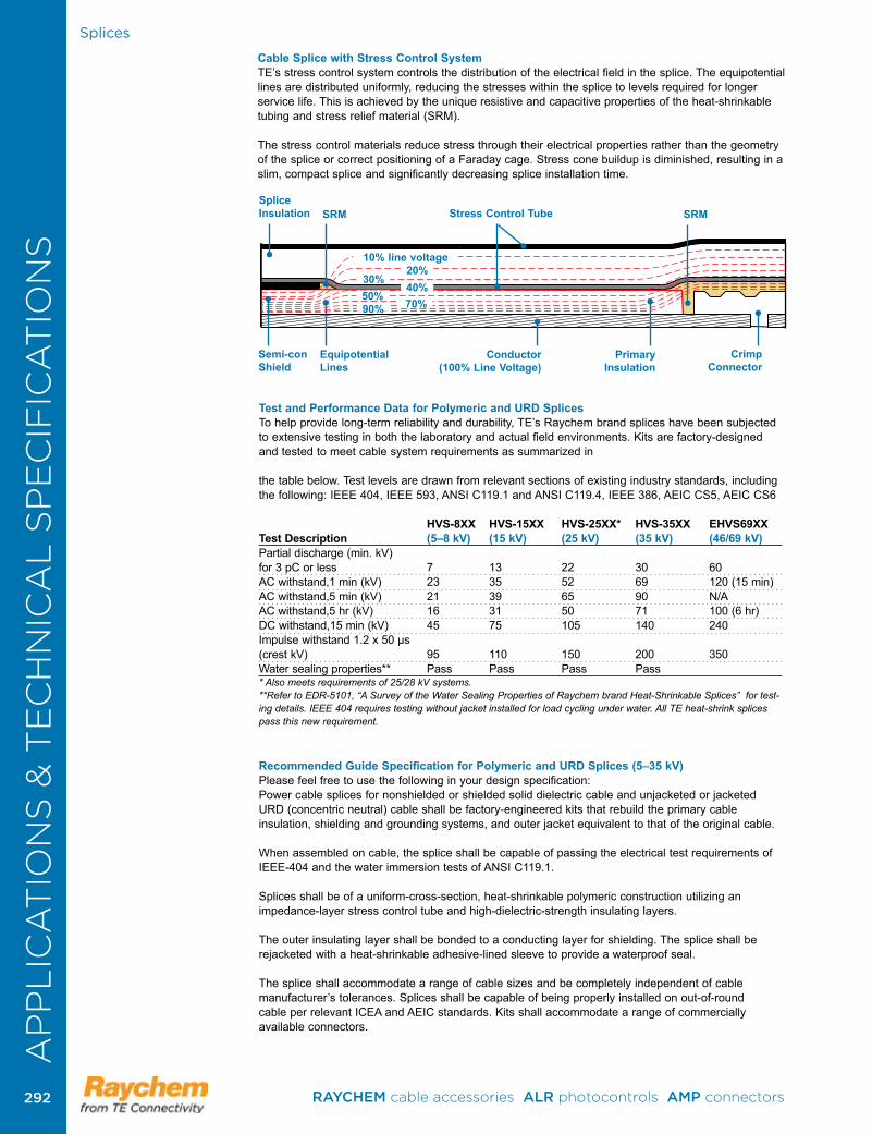
Splices
Cable Splice with Stress Control SystemTE’s stress control system controls the distribution of the electrical field in the splice. The equipotential lines are distributed uniformly, reducing the stresses within the splice to levels required for longer service life. This is achieved by the unique resistive and capacitive properties of the heat-shrinkable tubing and stress relief material (SRM).
The stress control materials reduce stress through their electrical properties rather than the geometry of the splice or correct positioning of a Faraday cage. Stress cone buildup is diminished, resulting in a slim, compact splice and significantly decreasing splice installation time.
SpliceInsulation SRM SRMStress Control Tube
Semi-conShield
EquipotentialLines
Conductor(100% Line Voltage)
Primary Insulation
Crimp Connector
10% line voltage20%
30%40%70%90%
50%
Test and Performance Data for Polymeric and URD SplicesTo help provide long-term reliability and durability, TE’s Raychem brand splices have been subjected to extensive testing in both the laboratory and actual field environments. Kits are factory-designed and tested to meet cable system requirements as summarized in the table below. Test levels are drawn from relevant sections of existing industry standards, including the following: IEEE 404, IEEE 593, ANSI C119.1 and ANSI C119.4, IEEE 386, AEIC CS5, AEIC CS6 HVS-8XX HVS-15XX HVS-25XX* HVS-35XX EHVS69XX Test Description (5–8 kV) (15 kV) (25 kV) (35 kV) (46/69 kV)Partial discharge (min. kV) for 3 pC or less 7 13 22 30 60 AC withstand,1 min (kV) 23 35 52 69 120 (15 min)AC withstand,5 min (kV) 21 39 65 90 N/AAC withstand,5 hr (kV) 16 31 50 71 100 (6 hr)DC withstand,15 min (kV) 45 75 105 140 240Impulse withstand 1.2 x 50 µs (crest kV) 95 110 150 200 350Water sealing properties** Pass Pass Pass Pass * Also meets requirements of 25/28 kV systems.**Refer to EDR-5101, “A Survey of the Water Sealing Properties of Raychem brand Heat-Shrinkable Splices” for test-ing details. IEEE 404 requires testing without jacket installed for load cycling under water. All TE heat-shrink splices pass this new requirement.
Recommended Guide Specification for Polymeric and URD Splices (5–35 kV)Please feel free to use the following in your design specification:Power cable splices for nonshielded or shielded solid dielectric cable and unjacketed or jacketed URD (concentric neutral) cable shall be factory-engineered kits that rebuild the primary cable insulation, shielding and grounding systems, and outer jacket equivalent to that of the original cable.
When assembled on cable, the splice shall be capable of passing the electrical test requirements of IEEE-404 and the water immersion tests of ANSI C119.1.
Splices shall be of a uniform-cross-section, heat-shrinkable polymeric construction utilizing an impedance-layer stress control tube and high-dielectric-strength insulating layers.
The outer insulating layer shall be bonded to a conducting layer for shielding. The splice shall be rejacketed with a heat-shrinkable adhesive-lined sleeve to provide a waterproof seal.
The splice shall accommodate a range of cable sizes and be completely independent of cable manufacturer’s tolerances. Splices shall be capable of being properly installed on out-of-round cable per relevant ICEA and AEIC standards. Kits shall accommodate a range of commercially available connectors .
AP
PL
ICA
TIO
NS
& T
EC
HN
ICA
L S
PE
CIF
ICA
TIO
NS
RAYCHEM cable accessories ALR photocontrols AMP connectors 292292
AP
PL
ICA
TIO
NS
& T
EC
HN
ICA
L S
PE
CIF
ICA
TIO
NS
Splices
Splices for armored cables shall provide a means of reinstating the armor over the span of the installed splices. Wye splices shall include a sealant profile to seal the area between the branch and the main cable.
The splice manufacturer shall provide a test report demonstrating compliance with the above requirements. Splices shall be manufactured by TE or approved equivalent.
Test and Performance Data for PILC SplicesPILC splices are fully engineered to provide a long, trouble-free service life. They are factory-designed and tested to meet PILC cable system requirements, as summarized in the table below.
Test levels are drawn from relevant sections of existing industry standards, including those that follow: • IEEE 404 (power cable splices) • IEEE 48 (terminations) • AEIC-1 (paper cable) • AEIC-CS5 (XLPE cable) • AEIC-CS6 (EPR cable) • ANSI C119.1 (sealed insulated underground connection system)
Test and Performance Data for PILC Splices Voltage ClassElectrical 15 kV 25 kV 35 kV AC withstand test, 6 hours 35 kV 58 kV 80 kV DC withstand test, 15 minutes 55 kV 75 kV 100 kV Impulse withstand (BIL) 1.2 x 50 µs 110 kV 150 kV 200 kV
Load Cycle/Pressure Current load cycling1, 2 cycles of 5 hours heating, Pass Pass Pass 3 hours cooling to conductor temperature of 110°C with applied overvoltage and maximum continuous internal oil pressure; no breakdown, oil leakage Maximum continuous internal oil pressure 15 psig 15 psig 15 psigMaximum continuous conductor temperature 90°C 90°C 90°CMaximum overload conductor temperature 110°C 110°C 110°C
SealingWater immersion outer jacketing system ANSI C119.1 ANSI C119.1 ANSI C119.1Proof test on oil blocking system: TE test method—no oil diffusion Pass Pass Pass1. Not applicable to live end seals.2. Maximum continuous/emergency conductor temperature for wye splices: 70°C.3. Test methods discussed in IEEE paper 84 T&D 340-6, “The extension of heat-shrinkable components for use with 1/C transition and paper cable splices,” by Mackevich, et al.
Recommended Guide Specification for PILC Splices (15–35 kV)Please feel free to use the following in your design specification: Splices shall be factory-manufactured kits to suit the specific type and size of the cables to be spliced.
The electric field distribution in the splice shall be controlled by a heat-shrinkable tubing having a complex impedance when energized with an AC voltage. A dual-wall tubing with a co-extruded outer conductive layer to form a void-free interface between the insulation and shield shall be used.
Kits shall be factory-engineered to contain all necessary materials, except connector, and provide an oil block and oil seal, electrical stress control, insulation, shielding, and environmental sealing. The kit shall allow for external grounding. Major kit components shall be heat-shrinkable.
The splice insulation shall not require a lead sleeve, lead wipe, or any kind of filling.
The splice manufacturer shall provide a test report, upon request, demonstrating that the splice performance is equivalent to the cables per rel e vant sections of IEEE-404, AEIC-1. Splices shall be load cycled with 15 psig internal oil pressure at 2.5x rated line-to-ground voltage at 110°C emergency overload rating. Splices shall also be subjected to a voltage withstand test sequence per listed standards .
Wye splices on PILC cable shall be tested to the requirements of ANSI C119.1. The test shall demonstrate the mechanical integrity, water sealing, and electrical properties of the outer jacket system.
Splices shall be manufactured by TE Connectivity or approved equivalent .
AP
PL
ICA
TIO
NS
& T
EC
HN
ICA
L S
PE
CIF
ICA
TIO
NS
RAYCHEM cable accessories ALR photocontrols AMP connectors 293 293
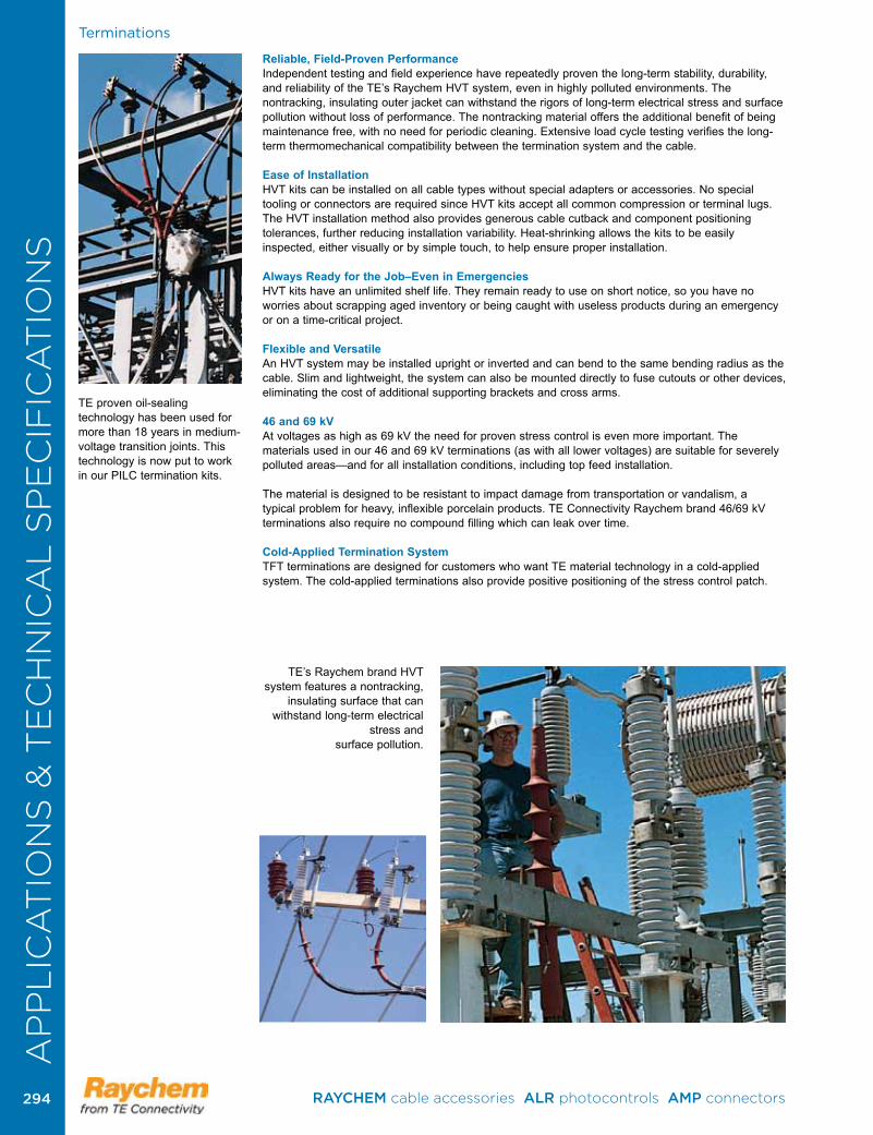
AP
PL
ICA
TIO
NS
& T
EC
HN
ICA
L S
PE
CIF
ICA
TIO
NS
Terminations
Reliable, Field-Proven PerformanceIndependent testing and field experience have repeatedly proven the long-term stability, durability, and reliability of the TE’s Raychem HVT system, even in highly polluted environments. The nontracking, insulating outer jacket can withstand the rigors of long-term electrical stress and surface pollution without loss of performance. The nontracking material offers the additional benefit of being maintenance free, with no need for periodic cleaning. Extensive load cycle testing verifies the long-term thermo mechanical compatibility between the termination system and the cable.
Ease of InstallationHVT kits can be installed on all cable types without special adapters or accessories. No special tooling or connectors are required since HVT kits accept all common compression or terminal lugs. The HVT installation method also provides generous cable cutback and component positioning tolerances, further reducing installation variability. Heat-shrinking allows the kits to be easily inspected, either visually or by simple touch, to help ensure proper installation.
Always Ready for the Job–Even in EmergenciesHVT kits have an unlimited shelf life. They remain ready to use on short notice, so you have no worries about scrapping aged inventory or being caught with useless products during an emergency or on a time-critical project.
Flexible and VersatileAn HVT system may be installed upright or inverted and can bend to the same bending radius as the cable. Slim and lightweight, the system can also be mounted directly to fuse cutouts or other devices, eliminating the cost of additional supporting brackets and cross arms.
46 and 69 kVAt voltages as high as 69 kV the need for proven stress control is even more important. The materials used in our 46 and 69 kV terminations (as with all lower voltages) are suitable for severely polluted areas—and for all installation conditions, including top feed installation.
The material is designed to be resistant to impact damage from transportation or vandalism, a typical problem for heavy, inflexible porcelain products. TE Connectivity Raychem brand 46/69 kV terminations also require no compound filling which can leak over time. Cold-Applied Termination SystemTFT terminations are designed for customers who want TE material technology in a cold-applied system. The cold-applied terminations also provide positive positioning of the stress control patch.
TE’s Raychem brand HVT system features a nontracking,
insulating surface that can withstand long-term electrical
stress and surface pollution .
TE proven oil-sealing technology has been used for more than 18 years in medium-voltage transition joints. This technology is now put to work in our PILC termination kits.
AP
PL
ICA
TIO
NS
& T
EC
HN
ICA
L S
PE
CIF
ICA
TIO
NS
RAYCHEM cable accessories ALR photocontrols AMP connectors 294294
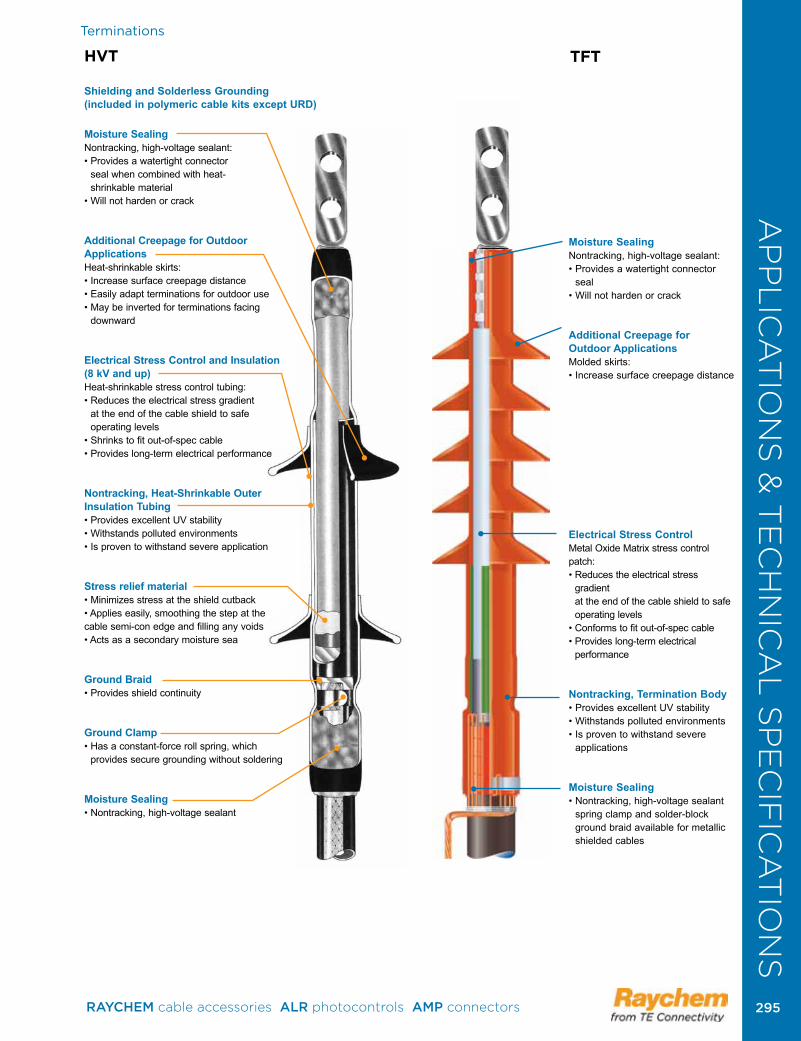
AP
PL
ICA
TIO
NS
& T
EC
HN
ICA
L S
PE
CIF
ICA
TIO
NS
Terminations
HVT
Shielding and Solderless Grounding (included in polymeric cable kits except URD)
Moisture SealingNontracking, high-voltage sealant: • Provides a watertight connector
seal when combined with heat- shrinkable material
• Will not harden or crack
Additional Creepage for Outdoor ApplicationsHeat-shrinkable skirts: • Increase surface creepage distance • Easily adapt terminations for outdoor use • May be inverted for terminations facing
downward
Electrical Stress Control and Insulation (8 kV and up)Heat-shrinkable stress control tubing: • Reduces the electrical stress gradient
at the end of the cable shield to safe operating levels
• Shrinks to fit out-of-spec cable• Provides long-term electrical performance
Nontracking, Heat-Shrinkable Outer Insulation Tubing• Provides excellent UV stability• Withstands polluted environments• Is proven to withstand severe application
Stress relief material• Minimizes stress at the shield cutback• Applies easily, smoothing the step at the cable semi-con edge and filling any voids• Acts as a secondary moisture sea
Ground Braid• Provides shield continuity
Ground Clamp• Has a constant-force roll spring, which
provides secure grounding without soldering
Moisture Sealing• Nontracking, high-voltage sealant
TFT
Moisture SealingNontracking, high-voltage sealant:• Provides a watertight connector
seal• Will not harden or crack
Additional Creepage for Outdoor ApplicationsMolded skirts:• Increase surface creepage distance
Electrical Stress Control Metal Oxide Matrix stress control patch:• Reduces the electrical stress
gradient at the end of the cable shield to safe operating levels
• Conforms to fit out-of-spec cable• Provides long-term electrical
performance
Nontracking, Termination Body• Provides excellent UV stability• Withstands polluted environments• Is proven to withstand severe
applications
Moisture Sealing• Nontracking, high-voltage sealant
spring clamp and solder-block ground braid available for metallic shielded cables
AP
PL
ICA
TIO
NS
& T
EC
HN
ICA
L S
PE
CIF
ICA
TIO
NS
RAYCHEM cable accessories ALR photocontrols AMP connectors 295 295
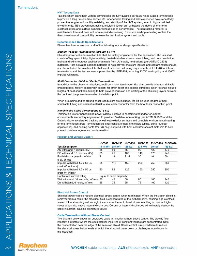
Terminations
HVT Testing DataTE’s Raychem brand high-voltage terminations are fully qualified per IEEE-48 as Class I terminations to provide a long, trouble-free service life. Independent testing and field experience have repeatedly proven the long-term durability, reliability, and stability of the HVT system, even in highly polluted environments. TE‘s proven nontracking, insulating jacket can withstand the rigors of long-term electrical stress and surface pollution without loss of performance. The nontracking material is maintenance free and does not require periodic cleaning. Extensive load-cycle testing verifies the thermomechanical compatibility between the termination system and cable.
Recommended Guide Specifications Please feel free to use one or all of the following in your design specifications:
Medium-Voltage Terminations (through 69 kV)Shielded power cable termination kits shall be factory engineered for the application. The kits shall consist of high-permittivity, high-resistivity, heat-shrinkable stress control tubing, and outer insulation tubing and skirts (outdoor applications) made from UV-stable, nontracking (per ASTM D 2303) materials. Heat-activated sealant materials to help prevent moisture ingress and contamination should also be included. Termination kits shall meet or exceed all rating requirements of IEEE-48 for Class I terminations and the test sequence prescribed by IEEE-404, including 130°C load cycling and 130°C impulse withstand.
Multi-Conductor Shielded Cable TerminationsIn addition to the phase terminations, multi-conductor termination kits shall provide a heat-shrinkable breakout boot, factory-coated with sealant for strain-relief and sealing purposes. Each kit shall include lengths of heat-shrinkable tubing to help prevent corrosion and shifting of the shielding layers between the boot and the phase-termination installation point.
When grounding and/or ground check conductors are included, the kit includes lengths of heat-shrinkable tubing and sealant material to seal each conductor from the boot to its connection point.
Nonshielded Cable Terminations (2–5 kV)Termination kits for nonshielded power cables installed in contami nated indoor or outdoor environments are factory engineered to provide UV-stable, nontracking (per ASTM D 2303 and the Ontario Hydro accelerated tracking wheel test) exterior surfaces and complete environmental sealing for the termination area. Termination kits shall consist of heat-shrinkable tubing, skirts (outdoor applications), and sealing boots (for 3/C only) supplied with heat-activated sealant materials to help prevent moisture ingress and contamination .
Product and Voltage Class 1
HVT-80 HVT-150 HVT-250 HVT-350 EHVT-460 EHVT-690 Test Description (5–8 kV) (15 kV) (25 kV) (35 kV) (46 kV) (69 kV)AC withstand, 1 minute, (kV) 35 50 65 90 120 175DC withstand, 15 minutes, (kV) 65 75 105 140 170 245Partial discharge (min. kV) for 9 13 21.5 30 40 60 5 pC or lessImpulse withstand 1.2 x 50 µs, 95 110 150 200 250 350 crest kV (outdoor)Impulse withstand 1.2 x 50 µs, 80 95 125 150 250 350 crest kV (indoor)Continuous current rating Equal to cable ampacityWet withstand, 10 seconds, kV rms 30 45 60 80 100 145Dry withstand, 6 hours, kV rms 25 35 55 75 100 120
Electrical Stress Control Shielded power cables require electrical stress control when terminated. When the insulation shield is removed from a cable, the electrical field is concentrated at the cutback point, causing high electrical stress. If the stress is great enough, it can cause the air to break down, resulting in corona. High-stress areas also cause internal discharges. Corona or internal discharges will ultimately destroy the cable insulation, causing pre mature failure.
Cable Termination Without Stress ControlThe diagram below shows an energized cable termination without stress control. The electric field intensity is greatest where the equipotential lines (line of constant voltage) are concentrated. Note the concentration near the edge of the semi-con shield. Stress control is required here to reduce the electrical stress below levels at which the air would break down or discharges would occur in the insulation.
AP
PL
ICA
TIO
NS
& T
EC
HN
ICA
L S
PE
CIF
ICA
TIO
NS
RAYCHEM cable accessories ALR photocontrols AMP connectors 296296
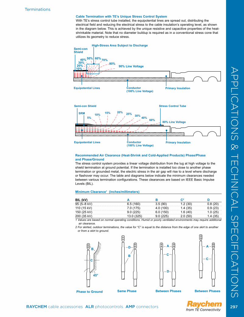
Terminations
Cable Termination with TE’s Unique Stress Control SystemWith TE’s stress control tube installed, the equipotential lines are spread out, distributing the electrical field and reducing the electrical stress to the cable insulation’s operating level, as shown in the diagram below. This is achieved by the unique resistive and capacitive properties of the heat-shrinkable material. Note that no diameter buildup is required as in a conventional stress cone that utilizes its geometry to reduce stress.
10%20%30%
40% 60%50% 70%80%
90% Line Voltage
Semi-conShield
High-Stress Area Subject to Discharge
Equipotential Lines Conductor (100% Line Voltage)
Primary Insulation
Equipotential Lines Conductor (100% Line Voltage)
Primary Insulation
5%10% 15% 20% 25% 30%
40%60%
80% Line Voltage
Semi-con Shield
SRM
Stress Control Tube
Recommended Air Clearance (Heat-Shrink and Cold-Applied Products) Phase/Phase and Phase/Ground The stress control system provides a linear voltage distribution from the lug at high voltage to the shield termination at ground potential. If the termination is installed too close to another phase termination or grounded metal, the electric stress in the air gap will rise to a level where discharge or flashover may occur. The table and diagrams below indicate the minimum clearances needed between various termination configurations. These clearances are based on IEEE Basic Impulse Levels (BIL).
Minimum Clearance1 (inches/millimeters)
BIL (kV) A B C2 D95 (5–8 kV) 6.5 (160) 3.5 (90) 1.2 (30) 0.8 (20)110 (15 kV) 7.0 (175) 4.0 (100) 1.4 (35) 0.9 (23)150 (25 kV) 9.0 (225) 6.0 (150) 1.6 (40) 1.0 (25)200 (35 kV) 13.0 (325) 9.0 (225) 2.0 (50) 1.4 (35)1 Values are based on normal operating conditions. Humid or poorly ventilated environments may require additional
air clearance.2 For skirted, outdoor terminations, the value for “C” is equal to the distance from the edge of one skirt to another
or from a skirt to ground.
Phase to Ground
C
B
45°
B
D
Same Phase
A
C
Between Phases
A
C
Between Phases
D
AP
PL
ICA
TIO
NS
& T
EC
HN
ICA
L S
PE
CIF
ICA
TIO
NS
RAYCHEM cable accessories ALR photocontrols AMP connectors 297 297
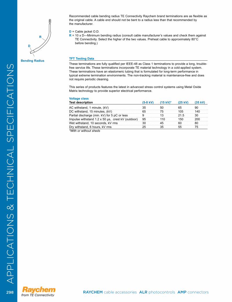
Recommended cable bending radius TE Connectivity Raychem brand terminations are as flexible as the original cable. A cable end should not be bent to a radius less than that recommended by the manufacturer.
D = Cable jacket O.D.R = 10 x D—Minimum bending radius (consult cable manufacturer’s values and check them against
TE Connectivity. Select the higher of the two values. Preheat cable to approximately 80°C before bending.)
TFT Testing DataThese terminations are fully qualified per IEEE-48 as Class 1 terminations to provide a long, trouble-free service life. These terminations incorporate TE material technology in a cold-applied system. These terminations have an elastomeric tubing that is formulated for long-term performance in typical extreme termination environments. The non-tracking material is maintenance-free and does not require periodic cleaning .
This series of products features the latest in advanced stress control systems using Metal Oxide Matrix technology to provide superior electrical performance.
Voltage class Test description (5-8 kV) (15 kV)* (25 kV) (35 kV)AC withstand, 1 minute, (kV) 35 50 65 90DC withstand, 15 minutes, (kV) 65 75 105 140Partial discharge (min. kV) for 5 pC or less 9 13 21.5 30Impulse withstand 1.2 x 50 µs, crest kV (outdoor) 95 110 150 200 Wet withstand, 10 seconds, kV rms 30 45 60 80Dry withstand, 6 hours, kV rms 25 35 55 75*With or without sheds
Bending Radius
D
R
AP
PL
ICA
TIO
NS
& T
EC
HN
ICA
L S
PE
CIF
ICA
TIO
NS
RAYCHEM cable accessories ALR photocontrols AMP connectors 298298

Busbar/Wildlife Protection
The Raychem Raysulate electrical insulation family of products offers easy-to-install busbar insulation systems for both the field engineer and the manufacturer. Raysulate electrical insulation products provide flashover protection against the accidental bridging of conductors commonly caused by birds and animals.
The system is ideal for both enclosed and exposed bus work and for connections in switchgear lineups, substations, and other electrical apparatus. It also permits clearance reduction in many applications.
Excellent Electrical and Thermal PerformanceRaysulate electrical insulation products are manufactured from high dielectric strength, radiation-crosslinked, heat-shrinkable materials. The high-voltage materials are specially formulated to provide high resistance to arcing and tracking. All high-voltage and low-voltage materials provide high-thermal endurance throughout the range of switchgear operating temperatures. They offer field-proven reliability and long service life in harsh environments. In addition, these heat-shrink tubing, tape, and sheet products can be preformed and preshrunk in the customer’s shop, allowing easy, quick installation in the field.
Compatibility with Other Insulating MaterialsAll Raysulate heat-shrinkable electrical insulation products are compatible with other solid switchgear insulating materials. Raysulate electrical insulating materials are not subject to stress crazing or embrittlement and are not adversely affected by common plasticizers used in conventional switchgear insulating materials .
Flame-retardant MaterialsMost Raysulate heat-shrinkable electrical insulating materials pass the ANSI C37.20 switchgear insulation flammability tests .
Reduced Corrosive and Toxic FumesRaysulate electrical insulation materials contain no chlorine compounds. This minimizes noxious and corrosive effects in case of equipment fault or fire .
For Protection, Repair, and MaintenanceRaysulate heat-shrinkable electrical insulating tubes, tapes, and sheets provide a complete system for electrical repair and maintenance of enclosed or exposed buswork and for connections in switch gear and electrical equipment. They offer:
• Fast, easy installation and removal• A flexible system to cover most conductor shapes and sizes• Consistent, reliable installation• Consistent electrical and thermal performance• Proven corrosion protection• Compatibility with conventional solid insulating materials• Protection against flashovers
For the Electrical Equipment ManufacturersThe Raysulate system of insulation-enhancement components addresses the needs of electrical equipment manufacturers. The superior material properties and versatility of these components enhance the quality and reliability of the final product. Raysulate electrical insulating materials feature:
• Low-hazard formulation• Flexibility• Track resistance• Rugged, easy installation• Excellent electrical and thermal performance • Unlimited shelf life• Corrosion protection of conductor • TE Connectivity assistance and support for testing and applications
HVBC Bus Connection Kit
BBIT/BPTM Bus Insulation Tubing
HVBT Bus Insulation TapeHVBT Bus Insulation Sheet
AP
PL
ICA
TIO
NS
& T
EC
HN
ICA
L S
PE
CIF
ICA
TIO
NS
RAYCHEM cable accessories ALR photocontrols AMP connectors 299 299
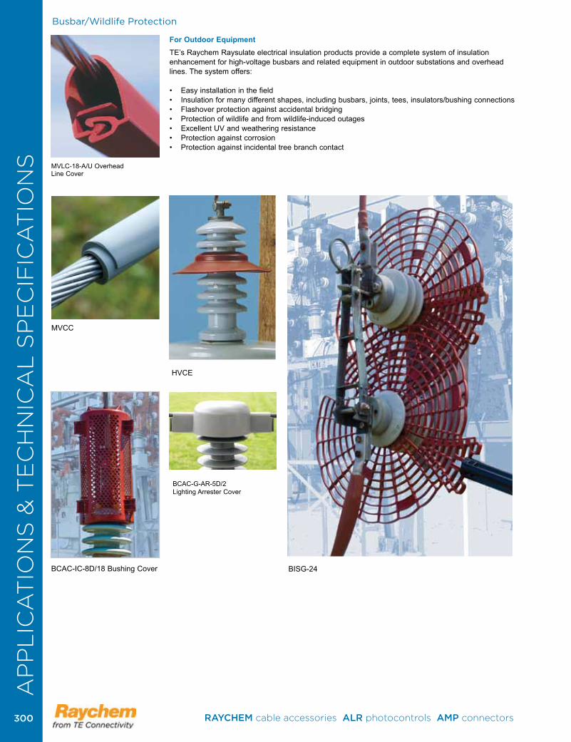
Busbar/Wildlife Protection
For Outdoor EquipmentTE’s Raychem Raysulate electrical insulation products provide a complete system of insulation enhancement for high-voltage busbars and related equipment in outdoor substations and overhead lines. The system offers: • Easy installation in the field• Insulation for many different shapes, including busbars, joints, tees, insulators/bushing connections• Flashover protection against accidental bridging• Protection of wildlife and from wildlife-induced outages• Excellent UV and weathering resistance• Protection against corrosion• Protection against incidental tree branch contact
HVCE
MVCC
MVLC-18-A/U Overhead Line Cover
BISG-24BCAC-IC-8D/18 Bushing Cover
BCAC-G-AR-5D/2Lighting Arrester Cover
AP
PL
ICA
TIO
NS
& T
EC
HN
ICA
L S
PE
CIF
ICA
TIO
NS
RAYCHEM cable accessories ALR photocontrols AMP connectors 300300
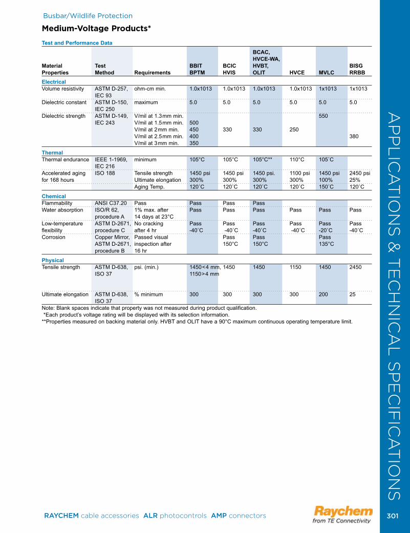
Busbar/Wildlife Protection
Medium-Voltage Products*
Test and Performance Data BCAC, HVCE-WA, Material Test BBIT BCIC HVBT, BISG Properties Method Requirements BPTM HVIS OLIT HVCE MVLC RRBBElectricalVolume resistivity ASTM D-257, ohm-cm min. 1.0x10¹³ 1.0x10¹³ 1.0x10¹³ 1.0x10¹³ 1x10¹³ 1x10¹³ IEC 93 Dielectric constant ASTM D-150, maximum 5.0 5.0 5.0 5.0 5.0 5.0 IEC 250 Dielectric strength ASTM D-149, V/mil at 1.3mm min. 550 IEC 243 V/mil at 1.5mm min. 500 V/mil at 2mm min. 450 330 330 250 V/mil at 2.5mm min. 400 380 V/mil at 3mm min. 350
Thermal Thermal endurance IEEE 1-1969, minimum 105°C 105°C 105°C** 110°C 105˚C IEC 216 Accelerated aging ISO 188 Tensile strength 1450 psi 1450 psi 1450 psi. 1100 psi 1450 psi 2450 psi for 168 hours Ultimate elongation 300% 300% 300% 300% 100% 25% Aging Temp. 120˚C 120˚C 120˚C 120˚C 150˚C 120˚C
Chemical Flammability ANSI C37.20 Pass Pass Pass Pass Water absorption ISO/R 62, 1% max. after Pass Pass Pass Pass Pass Pass procedure A 14 days at 23°CLow-temperature ASTM D-2671, No cracking Pass Pass Pass Pass Pass Pass flexibility procedure C after 4 hr -40˚C -40˚C -40˚C -40˚C -20˚C -40˚CCorrosion Copper Mirror, Passed visual Pass Pass Pass ASTM D-2671, inspection after 150°C 150°C 135°C procedure B 16 hr
Physical Tensile strength ASTM D-638, psi. (min.) 1450<4 mm, 1450 1450 1150 1450 2450 ISO 37 1150>4 mm Ultimate elongation ASTM D-638, % minimum 300 300 300 300 200 25 ISO 37Note: Blank spaces indicate that property was not measured during product qualification. * Each product’s voltage rating will be displayed with its selection information.**Properties measured on backing material only. HVBT and OLIT have a 90°C maximum continuous operating temperature limit.
AP
PL
ICA
TIO
NS
& T
EC
HN
ICA
L S
PE
CIF
ICA
TIO
NS
RAYCHEM cable accessories ALR photocontrols AMP connectors 301 301
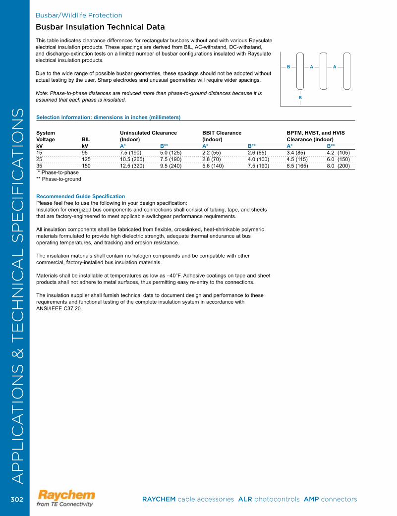
Busbar/Wildlife Protection
Busbar Insulation Technical Data
This table indicates clearance differences for rectangular busbars without and with various Raysulate electrical insulation products. These spacings are derived from BIL, AC-withstand, DC-withstand, and discharge-extinction tests on a limited number of busbar configurations insulated with Raysulate electrical insulation products .
Due to the wide range of possible busbar geometries, these spacings should not be adopted without actual testing by the user. Sharp electrodes and unusual geometries will require wider spacings.
Note: Phase-to-phase distances are reduced more than phase-to-ground distances because it is assumed that each phase is insulated.
B A A
B
Recommended Guide SpecificationPlease feel free to use the following in your design specification:Insulation for energized bus com ponents and connections shall consist of tubing, tape, and sheets that are factory-engineered to meet applicable switch gear performance requirements.
All insulation components shall be fabricated from flexible, crosslinked, heat-shrinkable polymeric materials for mu lated to provide high dielectric strength, adequate thermal endur ance at bus operating temperatures, and tracking and erosion resistance.
The insulation materials shall contain no halogen compounds and be compatible with other commercial, factory-installed bus insulation materials.
Materials shall be installable at temperatures as low as –40°F. Adhesive coatings on tape and sheet products shall not adhere to metal surfaces, thus permitting easy re-entry to the connections.
The insulation supplier shall furnish technical data to document design and performance to these requirements and functional testing of the complete insulation system in accordance with ANSI/IEEE C37.20.
Selection Information: dimensions in inches (millimeters)
System Uninsulated Clearance BBIT Clearance BPTM, HVBT, and HVIS Voltage BIL (Indoor) (Indoor) Clearance (Indoor)kV kV A* B** A* B** A* B**15 95 7.5 (190) 5.0 (125) 2.2 (55) 2.6 (65) 3.4 (85) 4.2 (105)25 125 10.5 (265) 7.5 (190) 2.8 (70) 4.0 (100) 4.5 (115) 6.0 (150)35 150 12.5 (320) 9.5 (240) 5.6 (140) 7.5 (190) 6.5 (165) 8.0 (200) * Phase-to-phase** Phase-to-ground
AP
PL
ICA
TIO
NS
& T
EC
HN
ICA
L S
PE
CIF
ICA
TIO
NS
RAYCHEM cable accessories ALR photocontrols AMP connectors 302302
69437.......................................................2169611 .......................................................2169612.......................................................2169684.......................................................2369816.......................................................2669847.......................................................2369947.......................................................23306814.....................................................23600403............................................... 10, 11600411 ............................................... 10, 11600446............................................... 10, 11600447............................................... 10, 11600448............................................... 10, 11600455............................................... 10, 11600456............................................... 10, 11600458............................................... 10, 11600459............................................... 10, 11600463.....................................................14600465............................................... 10, 11600466............................................... 10, 11600468.....................................................14600469.....................................................14600474.....................................................14602000............................................... 10, 11602001............................................... 10, 11602002............................................... 10, 11602003............................................... 10, 11602004............................................... 10, 11602006............................................... 10, 11602007............................................... 10, 11602013............................................... 10, 11602014............................................... 10, 11602047.....................................................14602080.....................................................20602089.....................................................19602091.....................................................19602093.....................................................19602097.....................................................19602099.....................................................19602104.....................................................14602107.....................................................20602115 .....................................................14602121...............................................10, 12602136.....................................................14602142.....................................................14602143.....................................................14602162.....................................................14602163.....................................................14602173.....................................................14602174.....................................................14602178.....................................................20602179.....................................................20602180...............................................10, 12602201.....................................................14602237.....................................................14602247.....................................................14602248.....................................................14602283............................................... 10, 11602284.....................................................20602285.....................................................19602286.....................................................19602287.....................................................19602300...............................................10, 12
602380............................................... 10, 11602502.....................................................14602585.....................................................14602586.....................................................141-1099898-0 ..............................................51-1099898-1 ..............................................51-1099898-2 ..............................................51-1099898-3 ..............................................51-1099898-4 ..............................................51-1099898-5 ..............................................51-1099899-0 ..............................................51-1099899-1 ..............................................51-1099899-2 ..............................................51-1099899-3 ..............................................51-1099899-4 ..............................................51-1099899-5 ..............................................51-1099899-6 ..............................................51-1099899-7 ..............................................51-1099899-8 ..............................................51-1099899-9 ..............................................51-1099939-0 ..............................................51-1099939-1 ..............................................51-1099939-2 ..............................................51-1099939-3 ..............................................51-1099939-4 ..............................................51-1099939-5 ..............................................51-1443402-0 ..............................................71-1443402-1 ..............................................71-1443402-2 ..............................................71-1443402-3 ..............................................71-1443402-4 ..............................................71-1443402-5 ..............................................71-1443402-6 ..............................................71-1443402-7 ..............................................71-1443403-0 ..............................................71-1443403-1 ..............................................71-1443403-2 ..............................................71-1443403-3 ..............................................71-1443403-4 ..............................................71-1443403-5 ..............................................71-1443403-6 ..............................................71-1443403-7 ..............................................71-1579002-8 ..........................................2731-1710802-0 ............................................241-1710802-1 ............................................241-1710802-2 ............................................241-1710802-3 ............................................241-1710802-4 ............................................241-1710802-5 ............................................241-1710814-0 ............................................251-1710814-1 ............................................251-1710889-0 ............................................251-1710889-1 ............................................251-1710889-2 ............................................251-1710889-3 ............................................251-1710889-4 ............................................251-1710889-5 ............................................251-1710889-6 ............................................251-1710889-7 ............................................251-1710889-8 ............................................251-1710905-0 ............................................251-275187-0 ..............................................331-275187-0 ..............................................34
1-275187-1 ........................................33, 341-275187-2 ..............................................331-275187-2 ........................................33, 341-275187-3 ........................................33, 341-275187-4 ........................................33, 341-275187-5 ........................................33, 341-275187-6 ........................................33, 341-275187-7 ........................................33, 341-275187-8 ........................................33, 341-276337-0 ........................................33, 341-276337-1 ........................................33, 341-276337-2 ........................................33, 341-276337-3 ........................................33, 341-276337-4 ........................................33, 341-276337-7 ........................................33, 341-276337-8 ..............................................331-276337-9 ........................................33, 341-602031-0 ........................................ 10, 111-602031-2 ........................................10, 121-602031-3 ..................................10, 12, 151-602031-4 ........................................10, 121-602031-5 ..................................10, 12, 151-602031-6 ........................................10, 121-602031-7 ..................................10, 12, 151-602031-8 ........................................10, 121-602031-9 ........................................10, 121-602121-0 ........................................10, 121-602121-1 ........................................10, 121-602121-2 ........................................10, 121-602121-3 ........................................10, 121-602121-4 ........................................10, 121-602180-0 ........................................10, 121-602180-1 ........................................10, 121-602180-2 ........................................10, 121-602180-3 ........................................10, 121-602180-4 ........................................10, 121-602180-5 ........................................10, 121-602180-6 ........................................10, 121-602300-0 ........................................10, 121-602300-1 ........................................10, 121-602300-2 ........................................10, 121-602300-3 ........................................10, 121-602300-4 ........................................10, 121-602300-5 ........................................10, 121-602300-6 ........................................10, 121-602300-7 ........................................10, 121-76337-8 ................................................341-81723-0 ................................................331-81723-1 ................................................331-81723-2 ................................................331-81723-3 ................................................331-83592-0 ................................................281-83592-0 ..........................................28, 301-83592-1 ..........................................28, 301-83592-2 ..........................................28, 301-83592-3 ..........................................28, 301-83623-0 ..........................................29, 301-83623-1 ..........................................29, 301-83623-2 ..........................................29, 301-83623-3 ..........................................29, 301-83623-4 ..........................................29, 301-83623-5 ..........................................29, 301-83623-6 ..........................................29, 30
IndexIN
DE
XIN
DE
X
RAYCHEM cable accessories ALR photocontrols AMP connectors 303 303
1443403-3 .................................................71443403-4 .................................................71443403-5 .................................................71443403-6 .................................................71443403-7 .................................................71443403-8 .................................................71443403-9 .................................................71443413-2 ...............................................221443442-1 ...............................................221443448-1 ...............................................221443470-1 ...............................................221443514-1 ...............................................221490489-1 .............................................273169415-1 ...............................................2731710500-1 ...............................................201710501-1 ...............................................201710523-1 ...............................................201710705-1 ...............................................241710705-2 ...............................................241710705-3 ...............................................241710705-5 ...............................................241710705-6 ...............................................241710705-7 ...............................................241710705-8 ...............................................241710705-9 ...............................................241710802-1 ...............................................241710802-2 ...............................................241710802-3 ...............................................241710802-4 ...............................................241710802-5 ...............................................241710802-6 ...............................................241710802-7 ...............................................241710802-8 ...............................................241710802-9 ...............................................241710813-1 ...............................................251710813-2 ...............................................251710813-3 ...............................................251710813-4 ...............................................251710813-5 ...............................................251710813-6 ...............................................251710813-7 ...............................................251710813-8 ...............................................251710814-1 ...............................................251710814-2 ...............................................251710814-3 ...............................................251710814-4 ...............................................251710814-5 ...............................................251710814-6 ...............................................251710814-7 ...............................................251710814-8 ...............................................251710814-9 ...............................................251710837-1 ...............................................231710837-2 ...............................................231710837-3 ...............................................231710839-1 ...............................................231710839-2 ...............................................231710839-3 ...............................................231710889-1 ...............................................251710889-2 ...............................................251710889-3 ...............................................251710889-4 ...............................................251710889-5 ...............................................251710889-6 ...............................................25
1710889-7 ...............................................251710889-8 ...............................................251710889-9 ...............................................251710905-1 ...............................................251710905-2 ...............................................251710905-3 ...............................................251710905-5 ...............................................251710905-6 ...............................................251710905-7 ...............................................251710905-8 ...............................................251710905-9 ...............................................252-1710802-0 ............................................242-1710802-1 ............................................242-1710802-2 ............................................242-1710802-3 ............................................242-1710802-4 ............................................242-1710802-5 ............................................242-1710802-6 ............................................242-1710802-7 ............................................242-1710802-8 ............................................242-1710802-9 ............................................242-1710889-0 ............................................252-1710889-1 ............................................252-1710889-2 ............................................252-1710889-3 ............................................252-1710889-4 ............................................252-1710889-5 ............................................252-1710889-6 ............................................252-1710889-8 ............................................252-1710889-9 ............................................252-226337-1 ..............................................332-275187-8 ........................................33, 342-276337-0 ........................................33, 342-276337-1 ........................................33, 342-276337-2 ........................................33, 342-276337-3 ........................................33, 342-276337-4 ........................................33, 342-276337-5 ........................................33, 342-276337-8 ........................................33, 342-276337-9 ........................................33, 342-602031-0 ........................................10, 122-602031-1 ........................................10, 122-602031-2 ........................................10, 122-83623-0 ..........................................29, 302060-NPS ..............................................2282060-VPS ..............................................2282090-NPS ..............................................2282182075-1 ...............................................232182076-1 ...............................................23273337-6 .................................................33275187-1 ...........................................33, 34275187-2 ...........................................33, 34275187-3 ...........................................33, 34275187-4 ...........................................33, 34275187-5 ...........................................33, 34275187-6 ...........................................33, 34275187-7 ...........................................33, 34275187-8 ...........................................33, 34275187-9 ...........................................33, 34275435-1 .................................................14275436-1 .................................................14276300-1 .................................................13276337-1 ...........................................33, 34
Index
1-83623-7 ..........................................29. 301-83623-8 ..........................................29, 301-83623-9 ..........................................29, 301-83630-0 ..........................................29, 301-83631-1 ..........................................29, 301-83631-2 ..........................................29, 301-83631-3 ..........................................29, 301-83631-4 ..........................................29. 301-83631-5 ..........................................29, 301-83631-6 ..........................................29, 301-83631-7 ..........................................29, 301-83631-8 ..........................................29, 301-83631-9 ..........................................29, 301-83843-0 ................................................181-83843-1 ................................................18109423-1 .................................................13109424-1 .................................................13109433-1 .................................................13109703-1 .................................................131099898-1 .................................................51099898-2 .................................................51099898-3 .................................................51099898-4 .................................................51099898-5 .................................................51099898-6 .................................................51099898-7 .................................................51099898-8 .................................................51099898-9 .................................................51099899-1 .................................................51099899-2 .................................................51099899-3 .................................................51099899-4 .................................................51099899-5 .................................................51099899-6 .................................................51099899-7 .................................................51099899-8 .................................................51099899-9 .................................................51099939-1 .................................................51099939-2 .................................................51099939-3 .................................................51099939-4 .................................................51099939-5 .................................................51099939-6 .................................................51099939-7 .................................................51099939-8 .................................................51099939-9 .................................................51443208-1 ...............................................131443209-1 ...............................................131443259-1 ...............................................131443268-1 ...............................................131443312-1 ...............................................141443316-2 ...............................................131443402-1 .................................................71443402-2 .................................................71443402-3 .................................................71443402-4 .................................................71443402-5 .................................................71443402-6 .................................................71443402-7 .................................................71443402-8 .................................................71443402-9 .................................................71443403-1 .................................................71443403-2 .................................................7
304 RAYCHEM cable accessories ALR photocontrols AMP connectors

276337-2 ...........................................33, 34276337-3 ...........................................33, 34276337-4 ...........................................33, 34276337-5 ...........................................33, 34276337-6 .................................................34276337-7 ...........................................33, 34276337-8 ...........................................33, 34276337-9 ...........................................33, 34276478-1 .................................................14276548-1 .................................................13276762-1 .................................................35276915-1 .................................................13277060-1 ...........................................33, 34277060-2 ...........................................33, 34277060-2 ................................................33277060-3 ...........................................33, 34277060-4 ...........................................33, 343-1710802-0 ............................................243-1710889-0 ............................................253-1710889-1 ............................................253-1710889-2 ............................................253-1710889-3 ............................................253-1710889-4 ............................................253-1710889-5 ............................................253-1710889-6 ............................................253-1710889-7 ............................................253-1710889-8 ............................................253-1710889-9 ............................................253-275187-0 ........................................33, 343-275187-1 ........................................33, 343-275187-3 ........................................33, 343-275187-4 ........................................33, 343-275187-6 ........................................33, 343-275187-7 ........................................33, 343-275187-9 ........................................33, 343-276337-0 ........................................33, 343-276337-1 ........................................33, 343-276337-2 ........................................33, 343-276337-3 ........................................33, 343-276337-4 ........................................33, 343-276337-5 ........................................33, 343-276337-6 ........................................33, 343-276337-7 ........................................33, 343-276337-9 ........................................33, 34306347-1 .................................................26306348-1 .................................................26306349-1 .................................................26306349-2 .................................................26306350-2 .................................................26308967-1 .................................................213090-NPS ..............................................2293090-VFS ..............................................229314196-1 .................................................21314199-1 .................................................234-1710889-0 ............................................254-1710889-1 ............................................254-1710889-2 ............................................254-1710889-3 ............................................254-1710889-4 ............................................254-1710889-5 ............................................254-1710889-6 ............................................254-1710889-7 ............................................254-1710889-8 ............................................25
4-1710889-9 ............................................254-275187-0 ........................................33, 344-276337-1 ........................................33, 344-276337-2 ........................................33, 344-276337-3 ........................................33, 344-276337-4 ........................................33, 344-276337-5 ........................................33, 344-276337-6 ........................................33, 344-276337-7 ........................................33, 344-276337-8 ........................................33, 344-276337-9 ........................................33, 34444031-1 .................................................41444033-1 .................................................41444385-1 .................................................4147667-8 ...................................................215-1710889-0 ............................................255-1710889-1 ............................................255-1710889-2 ............................................255-1710889-3 ............................................255-1710889-4 ............................................255-1710889-5 ............................................255-1710889-6 ............................................255-1710889-7 ............................................255-1710889-8 ............................................255-1710889-9 ............................................255-276337-1 ........................................33, 345-276337-3 ........................................33, 345-276337-4 ........................................33, 345-276337-5 ........................................33, 345-276337-6 ........................................33, 345-276337-7 ........................................33, 345-276337-8 ........................................33, 345-276337-9 ........................................33, 345-304668-3 ..............................................21561118-1 ..................................................22569398-1 .................................................196-1710889-0 ............................................256-1710889-1 ............................................256-1710889-2 ............................................256-1710889-3 ............................................256-1710889-4 ............................................256-1710889-5 ............................................256-1710889-6 ............................................256-1710889-7 ............................................256-1710889-8 ............................................256-1710889-9 ............................................256-276337-0 ........................................33, 346-276337-2 ........................................33, 346-276337-4 ........................................33, 346-276337-5 ........................................33, 34602031-8 ........................................... 10, 11602031-9 ........................................... 10, 11602046-1 ........................................... 10, 11602046-2 ........................................... 10, 11602046-3 ........................................... 10, 11602046-4 ........................................... 10, 11602046-5 ........................................... 10, 11602046-6 ........................................... 10, 11602046-7 ........................................... 10, 11602046-9 ........................................... 10, 11602121-1 ...........................................10, 12602121-2 ...........................................10, 12602121-3 ...........................................10, 12
602121-4 ...........................................10, 12602121-5 .....................................10, 12, 15602121-6 ...........................................10, 12602121-7 ...........................................10, 12602121-8 ...........................................10, 12602121-9 ...........................................10, 12602180-1 ...........................................10, 12602180-2 ...........................................10, 12602180-3 ...........................................10, 12602180-4 ...........................................10, 12602180-5 ...........................................10, 12602180-6 ...........................................10, 12602180-7 ...........................................10, 12602180-8 ...........................................10, 12602180-9 ...........................................10, 12602283-1 ........................................... 10, 11602283-2 ........................................... 10, 11602283-3 ........................................... 10, 11602283-4 ........................................... 10, 11602283-5 ........................................... 10, 11602283-6 ........................................... 10, 11602283-7 ........................................... 10, 11602283-8 ........................................... 10, 11602300-1 ...........................................10, 12602300-2 ...........................................10, 12602300-3 ...........................................10, 12602300-4 ...........................................10, 12602300-5 ...........................................10, 12602300-6 ...........................................10, 12602300-7 ...........................................10, 12602300-8 ...........................................10, 12602300-9 ...........................................10, 12602380-1 ........................................... 10, 11602380-2 ........................................... 10, 11602380-3 ........................................... 10, 11602380-4 ........................................... 10, 11602380-5 ........................................... 10, 11602380-6 ........................................... 10, 11602380-7 ........................................... 10, 11602880-0 .................................................13602880-1 .................................................13605742-1 ...............................................272605744-1 ...............................................2726060-VPS ..............................................230607453-2 1 ............................................273607501-1 .................................................23608338-1 .................................................23608877-1 .................................................236090-VPS ..............................................2306090-VPS-UL ........................................230688652-1 .................................................41688653-1 .................................................41688654-1 .................................................41688655-1 .................................................41688656-1 .................................................41688657-1 .................................................4169338-1 ...................................................2269338-2 ...................................................2269338-4 ...................................................2269338-5 ...................................................2269610-2 ...................................................2269633-2 ...................................................2169685-1 ...................................................23
Index
RAYCHEM cable accessories ALR photocontrols AMP connectors 305
Index
69833-1 ...................................................267060-VPS ..............................................2317090-VPS ..............................................2317090-VPS-BK ........................................231734045-1 ...............................................273734587-1 ...............................................27480408-2 ...................................................3580408-3 ...................................................3580408-4 ...................................................3580408-5 ...................................................3580408-6 ...................................................3580408-7 ...................................................3580665-2 ...................................................2280665-3 ...................................................228090-VPS ..............................................23281673-1 ...................................................1381673-2 ...................................................1381673-3 ...................................................1381698-1 ...................................................1381723-1 ...................................................3381723-2 ...................................................3381723-8 ...................................................3381723-9 ...................................................3383000-1 ...................................................3583005-1 ...................................................1583005-2 ...................................................1583005-3 ...................................................1583005-4 ...................................................1583005-5 ...................................................1583086-1 ...................................................1383086-2 ...................................................1383364-1 ...................................................2083452-1 ...................................................1583452-2 ...................................................1583452-3 ...................................................1583452-4 ...................................................1583470-1 ...................................................1583470-2 ...................................................1583470-3 ...................................................1583470-4 ...................................................1583589-1 ...................................................1683589-2 ...................................................1683589-3 ...................................................1683589-4 ...................................................1683589-6 ...................................................1683589-7 ...................................................1683590-1 ...................................................1683590-2 ...................................................1683590-3 ...................................................1683590-4 ...................................................1683591-1 ...................................................1683591-2 ...................................................1683591-3 ...................................................1683591-4 ...................................................1683592-1 .............................................28, 3083592-2 .............................................28, 3083592-3 .............................................28, 3083592-4 .............................................28, 3083592-5 .............................................28, 3083592-6 .............................................28, 3083592-7 .............................................28, 3083592-8 .............................................28, 3083592-9 .............................................28, 30
83623-1 .............................................29, 3083623-2 .............................................29, 3083623-3 .............................................29, 3083623-4 .............................................29, 3083623-5 .............................................29, 3083623-6 .............................................29, 3083623-7 .............................................29, 3083623-8 .............................................29, 3083623-9 .............................................29, 3083630-1 .............................................29, 3083630-2 .............................................29, 3083630-3 .............................................29, 3083630-4 .............................................29, 3083630-5 .............................................29, 3083630-6 .............................................29, 3083630-7 .............................................29, 3083630-8 .............................................29, 3083630-9 .............................................29, 3083631-1 .............................................28, 3083631-2 .............................................28, 3083631-3 .............................................28, 3083631-4 .............................................28, 3083631-5 .............................................28, 3083631-6 .............................................28, 3083631-7 .............................................28, 3083631-8 .............................................28, 3083631-9 .............................................28, 3083653-1 ...................................................1083653-2 ...................................................1083653-3 ...................................................1083653-4 ...................................................1083653-5 ...................................................1083747-1 .............................................38, 3983747-2 .............................................38, 3983747-3 .............................................38, 3983747-4 .............................................38, 3983748-1 .............................................38, 3983748-2 .............................................38, 3983748-3 .............................................38, 3983748-4 .............................................38, 3983749-1 .............................................38, 3983749-2 .............................................38, 3983749-3 .............................................38, 3983749-4 .............................................38, 3983750-1 .............................................38, 3983750-2 .............................................38, 3983750-3 .............................................38, 3983750-4 .............................................38, 3983750-5 .............................................38, 3983750-6 .............................................38, 3983751-1 .............................................38, 3983751-2 .............................................38, 3983751-3 .............................................38, 3983751-4 .............................................38, 3983843-1 ...................................................1883843-2 ...................................................1883843-3 ...................................................1883843-4 ...................................................1883843-5 ...................................................1883843-6 ...................................................1883843-7 ...................................................1883861-1 ...................................................13881781-1 .................................................41
881783-1 .................................................41881785-1 .................................................41881787-1 .................................................41881789-1 .................................................41
AAA-105 ..................................................225AA-105HA ..............................................225AA-105M................................................225AA-105W ...............................................225AA-1068.................................................225AA-1068M..............................................225AA-1068W .............................................225AA-305...................................................225AD-1358-LPG-REGW/GAGE ................270AD-1432-ACD10FT-LPG-HOSE............270AD-1434-ACD30FT-LPG-HOSE............270AD-1460-ACD-HEAT-SHLDGPA ...........270AD-1563-ADAPTER ..............................270AD-3015-04 ...........................................270ALK-L823............................................... 113AMR3030.2-120V ..................................235AMR3030.2-240V ..................................235AMR3030.3-120V ..................................235AMR3030.3-240V ..................................235ASBS-2-3/0................................................2ASBS-2-350...............................................2ASBS-3/0-500............................................2ASBS-3/0-500-S ........................................2ASBS-350-750...........................................2ASBS-500-750...........................................2ASBS-600-1000.........................................2ASBT-2-350 ...............................................4ASBT-350-750 ...........................................4ASBT-600-1000 .........................................4AT-15 .....................................................224AT-168 ...................................................224AT-19 .....................................................224AT-20 .....................................................224AT-30 .....................................................224AT-368 ...................................................224AT-39 .....................................................224
BBBIT-100/40-A/U ..................................239BBIT-150/60-A/U ..................................239BBIT-175/80-A/U ..................................239BBIT-25/10-A/U .....................................239BBIT-40/16-A/U ....................................239BBIT-65/25-A/U ....................................239BCAC-5D/8 (B12) ..................................243BCAC-7D/10 (B6) ..................................243BCAC-8D/14 (B6) ..................................243BCAC-BYPASS-01 (B6) ........................243BCAC-BYPASS-02 (B6) ........................243BCAC-G-4D/13-2 (B18).........................253BCAC-G-5D/8 (B12) ..............................243BCAC-G-5D/8-01 (B12).........................253BCAC-G-7D/10 (B6) ..............................243BCAC-G-8D/14 (B6) ..............................243BCAC-G-AR-3.75D-2 (B24)...................253BCAC-G-AR-4D-2 (B24) ........................253
IND
EX
IND
EX
RAYCHEM cable accessories ALR photocontrols AMP connectors 306306
BCAC-G-AR-5D-2 (B24) ........................253BCAC-G-CUTOUT-100-01 (B12) ..........253BCAC-G-CUTOUT-200 (B3) ..................253BCAC-G-IC-7D/12 (B6) .........................244BCAC-G-IC-8D/18 (B6) .........................244BCAC-IC-7D/12 (B6) .............................244BCAC-IC-8D/18 (B6 ..............................244BCAC-IC-BYPASS-01 (B1) ...................244BCIC-0270-SCE (B3) ............................247BCIC-0370-SCE (B3) ............................248BCIC-10D/18-3 ......................................246BCIC-115-PH (B1) .................................255BCIC-12/12/5-H (B3) .............................247BCIC-13D/13-H0 (B3)............................248BCIC-14/19/6-U (B3) .............................247BCIC-24/11/12-U (B3) ...........................247BCIC-3212-01 (B3) ................................250BCIC-3D/6-3 ..........................................246BCIC-4/12/4-H (B3) ...............................247BCIC-4/16/4-H (B3) ...............................247BCIC-4411 (B3) .....................................245BCIC-4D/4 (B3) .....................................249BCIC-5.5D/11 (B3) .................................247BCIC-5.5D/16 ........................................246BCIC-5D/6 (B3) .....................................248BCIC-7.5D/18-3 (B3) .............................249BCIC-7/12/7-H (B3) ...............................247BCIC-8/12/2 (B3) ...................................248BCIC-8D/15H0 (B3) ...............................247BCIC-8D/18-H0 (B3)..............................247BCIC-8D/6-3 ..........................................246BCIC-9D/19-3 (B3) ................................245BCIC-BYPASS (B1) ...............................250BCIC-Collar-50/280-5-BP ......................255BCIC-G-ARM-24-01 (B12) ....................252BCIC-G-ARM-48-01 (B12) ....................252BCIC-G-DE/CL-01(B6) .........................252BCIC-G-DPIN-556-01 (B6) ....................252BCIC-G-DPIN-795-01 (B6) ....................252BCIC-G-DSMPIN-795-01 (B6)...............252BCIC-G-HZ-795-01 (B6) ........................252BCIC-G-HZPOR/3.5D-795-01 ...............252BCIC-G-HZPOR/4.5D-795-01 ...............252BCIC-G-PIN-556-01 (B6) ......................252BCIC-G-PIN-556/55-01 (B6)..................252BCIC-G-PIN-795-01 (B6) ......................252BCIC-G-POR-228-795-01 (B6)..............252BCIC-G-Recloser-100 (B6)....................254BCIC-G-Recloser-200 (B6)....................254BCIC-G-Reclosercover (B6) ..................254BCIC-G-SMPIN-795-01 (B6) .................252BCIC-LATCH (B250) .............................250BCIC-SG-101-H2 (B3) ...........................245BCIC-SG-201 (B3).................................249BCIC-TR205-L (B3) ...............................249BCIC-TR205-R (B3) ..............................250BF-120 ...................................................226BF-208-277............................................226BF-PV ....................................................226BISG-24-01 (B10) ..................................242BISG-60/115-02 (B1O) ..........................242BISG-60/115-03-HOT (B1O) .................242BISG-G-24-01 (B10) ..............................242
BISG-G-60/115-02 (B1O) ......................242BISG-G-60/115-03-HOT (B1O) .............242BPTM-100/40-A/U ................................239BPTM-120/50-A/U ................................239BPTM-15/6-A/U ....................................239BPTM-175/70-A/U ................................239BPTM-205/110-A/U ..............................239BPTM-235/130-A/U ..............................239BPTM-30/12-A/U ..................................239BPTM-50/20-A/U ..................................239BPTM-75/30-A/U ..................................239BRKT-1-SS ............................................265BRKT-2-SS ............................................265BRKT-3-SS ............................................265BRKT-4-SS ............................................265
CCA7476-000 ..........................................272CA7478-000 ..........................................272Cable Vise Adaptor/Clamp ....................273CBR-2-2-A .............................................214CBR-2-3-A ............................................214CBR-3-1-A ............................................214CBR-3-2-A .............................................214CBR-3-3-A .............................................214CBR-3-4-A ............................................214CBR-4-1-A ............................................214CBR-4-2-A .............................................214CBR-4-3-A .............................................214CBR-4-4-A .............................................214CBR-6-1-A .....................................162, 214CBR-6-2-A .....................................162, 214CFTS-1 .................................................214CFTS-2 .................................................214CFTS-3 .................................................214CFTS-4 .................................................214CFTS-5 .................................................214CJ-250-3W3W-CU-FT-B1 ......................122CJ-250-5W5W-CU-FT-B1 ......................122CJ-250-7W7W-CU-FT-B1 ......................122CJ-350-3W3W-CU-FT-B1 ......................122CJ-350-5W5W-CU-FT-B1 ......................122CJ-350-7W7W-CU-FT-B1 ......................122CJ-4/0-3W3W-CU-FT-B1 .......................122CJ-4/0-5W5W-CU-FT-B1 .......................122CJ-4/0-7W7W-CU-FT-B1 .......................122CJ-500-3W3W-CU-FT-B1 ......................122CJ-500-5W5W-CU-FT-B1 ......................122CJ-500-7W7W-CU-FT-B1 ......................122CJ-750-3W3W-CU-FT-B1 ......................122CJ-750-5W5W-CU-FT-B1 ......................122CJ-750-7W7W-CU-FT-B1 ......................122CPGI-ALR-ACL-11 ................................236CPGI-ALR-OLC-5C ...............................236CPGI-ALR-PL-120S ..............................236CPGI-ALR-PL-120S-B ...........................236CPGI-GLOW-GUN ................................271CPGI-GLOW-TORCH ............................271CPGI-PPMB-01 .......................................98CPGI-PPMB-02 .......................................98CPGI-PPMB-03 .......................................98CPGI-PPMB-04 .......................................98CPGI-PPMB-05 .......................................98
CPGI-PPMB-06 .......................................98CPGI-PPMB-07 .......................................98CPGI-PPMB-08 .......................................98CPGI-PPMB-09 .......................................98CPGI-PPMB-10 .......................................98CPGI-PPMB-11 .......................................98CPGI-PPMB-12 .......................................98CPGI-PPMB-13 .......................................98CPGI-PPMB-14 .......................................98CPGI-PPMB-15 .......................................98CPGI-PPMB-16 .......................................98CPGI-PPMB-20 .......................................98CPGI-PPMB-21 .......................................98CPGI-PPMB-22 .......................................98CPGI-PPMD-0-9 ......................................98CPGI-PPMD-A-J ......................................98CPGI-PPMD-NEMA .................................98CPGI-PPMDRF-0-9 .................................98CPGI-PPMDRF-A-J .................................98CPGI-PPMDRF-NEMA ............................98CPGI-WOMB-B30 ...................................98CPGI-WOMB-B50 ...................................98CPGI-WOMB-B60 ...................................98CPGI-WOMB-B75 ...................................98CPGI-WOMD-13 ......................................98CPGI-WOMD-16 ......................................98CPGI-WOMD-51 ......................................98CPGI-WOMD-52 ......................................98CRPS-2120 ...........................................218CRPS-248 ............................................218CRPS-260 .............................................218CRPS-290 ............................................218CRSM 107/29-1000 ....................... 110, 205CRSM 107/29-1200 ....................... 110, 205CRSM 143/36-1200 ....................... 110, 205CRSM 198/55-1200 ....................... 110, 205CRSM 34/10-1200 ......................... 110, 205CRSM 34/10-200 ........................... 110, 205CRSM 53/13-1200 ......................... 110, 205CRSM 53/13-200 ........................... 110, 205CRSM 84/20-1200 ......................... 110, 205CRSM 84/20-750 ........................... 110, 205CRSM-CT-34/10-150 ........................... 111CRSM-CT-53/13-200 ............................ 111CRSM-CT-84/20-250 ............................. 111CSBS-20-500-CPR....................................3CSBS-20C-500C-SOS ..............................3CSBS-300-750 ..........................................3CSBS-300C-750C-SOS ............................3CSBS-500-1000 ........................................3CSJ-EG-1 .............................................149CSJ-EG-2 .............................................149CSJ-EG-3 .............................................149CSJA-1521 ...........................................149CSJA-1521M1 ......................................149CSJA-1521M4 ......................................149CSJA-1521M5 ......................................149CSJA-1522 ...........................................149CSJA-1522M1 ......................................149CSJA-1522M2 ......................................149CSJA-1522M6 ......................................149CSJA-1522M7 ......................................149CSJA-1523 ...........................................149
IndexIN
DE
XIN
DE
X
RAYCHEM cable accessories ALR photocontrols AMP connectors 307 307
CSJA-1523M2 ......................................149CSJA-1523M8 ......................................149CSJA-1524 ...........................................149CSJA-1524M9 .....................................149CSJA-2822 ............................................149CSJA-2822M1 ......................................149CSJA-2822M5 ....................................149CSJA-2822M6 ....................................149CSJA-2823 ............................................149CSJA-2823M2 .......................................149CSJA-2823M8 ....................................149CSJA-2824 ............................................149CSJA-2824M2 ......................................149CSJA-2824M8 ....................................149CSJA-2824M9 ....................................149CSJA-3-1521-ARMR ............................155CSJA-3-1521-TECK ..............................156CSJA-3-1521M1-ARMR ........................155CSJA-3-1521M1-TECK ........................156CSJA-3-1521M4-ARMR ........................155CSJA-3-1521M4-TECK ........................156CSJA-3-1521M5-ARMR ........................155CSJA-3-1521M5-TECK ........................156CSJA-3-1522-ARMR ............................155CSJA-3-1522-TECK ..............................156CSJA-3-1522M1-ARMR ........................155CSJA-3-1522M1-TECK ........................156CSJA-3-1522M2-ARMR ........................155CSJA-3-1522M2-TECK ........................156CSJA-3-1522M6-ARMR ........................155CSJA-3-1522M6-TECK ........................156CSJA-3-1522M7-ARMR ........................155CSJA-3-1522M7-TECK ........................156CSJA-3-1523-ARMR ............................155CSJA-3-1523-TECK ..............................156CSJA-3-1523M3-ARMR ........................155CSJA-3-1523M3-TECK ........................156CSJA-3-1523M8-ARMR ........................155CSJA-3-1523M8-TECK ........................156CSJA-3-2822-ARMR ............................155CSJA-3-2822M1-ARMR ........................155CSJA-3-2822M5-ARMR ........................155CSJA-3-2822M6-ARMR ........................155CSJA-3-2823-ARMR ............................155CSJA-3-2823M2-ARMR ........................155CSJA-3-2823M8-ARMR ........................155CSJA-3-3523-ARMR ............................155CSJA-3-3523M1-ARMR ........................155CSJA-3-3523M5-ARMR ........................155CSJA-3-3524-ARMR ............................155CSJA-3-3524M2-ARMR ........................155CSJA-3-3524M8-ARMR ........................155CSJA-3523 ............................................149CSJA-3523M1 ......................................149CSJA-3523M5 .....................................149CSJA-3524 ............................................149CSJA-3524M2 .......................................149CSJA-3524M8 ....................................149CSJA-3524M9 ....................................149CSJA-3525 ............................................149CSJA-3525M10 ....................................149CSJA-JCN/EG-1511 .............................151CSJA-JCN/EG-1511M1 .......................151
CSJA-JCN/EG-1511M4 .......................151CSJA-JCN/EG-1511M5 .......................151CSJA-JCN/EG-1512 .............................151CSJA-JCN/EG-1512M1 .......................151CSJA-JCN/EG-1512M2 .......................151CSJA-JCN/EG-1512M6 .......................151CSJA-JCN/EG-1512M7 .......................151CSJA-JCN/EG-1513 .............................151CSJA-JCN/EG-1513M2 .......................151CSJA-JCN/EG-1513M8 .......................151CSJA-JCN/EG-1514 .............................151CSJA-JCN/EG-1514M9 .......................151CSJA-JCN/EG-2812 ..............................151CSJA-JCN/EG-2812M1 .......................151CSJA-JCN/EG-2812M5 .......................151CSJA-JCN/EG-2812M6 .......................151CSJA-JCN/EG-2813 ..............................151CSJA-JCN/EG-2813M2 .......................151CSJA-JCN/EG-2813M8 .......................151CSJA-JCN/EG-2814 ..............................151CSJA-JCN/EG-2814M2 .......................151CSJA-JCN/EG-2814M8 .......................151CSJA-JCN/EG-2814M9 .......................151CSJA-JCN/EG-3513 ..............................151CSJA-JCN/EG-3513M1 .......................151CSJA-JCN/EG-3513M5 .......................151CSJA-JCN/EG-3514 ..............................151CSJA-JCN/EG-3514M2 .......................151CSJA-JCN/EG-3514M8 .......................151CSJA-JCN/EG-3514M9 .......................151CSJA-JCN/EG-3515 ..............................151CSJA-JCN/EG-3515M10 ......................151CSJA-JCN/EG-3515M9 .......................151CSJG-1511 ...........................................153CSJG-1511M1 ......................................153CSJG-1511M4 ......................................153CSJG-1511M5 ......................................153CSJG-1512 ...........................................153CSJG-1512M1 ......................................153CSJG-1512M2 ......................................153CSJG-1512M6 ......................................153CSJG-1512M7 ......................................153CSJG-1513 ...........................................153CSJG-1513M2 ......................................153CSJG-1513M8 ......................................153CSJG-1514 ...........................................153CSJG-1514M9 ......................................153CSJG-2812 ...........................................153CSJG-2812M1 ......................................153CSJG-2812M5 ......................................153CSJG-2812M6 ......................................153CSJG-2813 ...........................................153CSJG-2813M2 ......................................153CSJG-2813M8 ......................................153CSJG-2814 ...........................................153CSJG-2814M2 ......................................153CSJG-2814M8 ......................................153CSJG-2814M9 ......................................153CSJG-3513 ...........................................153CSJG-3513M1 ......................................153CSJG-3513M5 ......................................153CSJG-3514 ...........................................153
CSJG-3514M2 .....................................153CSJG-3514M8 ......................................153CSJG-3514M9 ......................................153CSJG-3515 ...........................................153CSJG-3515M10 ...................................153
EE4540-1250 ...........................................268E7512-0160 ...........................................268E7512-0220 ...........................................268E7512-0240 ...........................................268E7512-0260 ...........................................268EAKT 1521 ............................................265EAKT 1523 ............................................265EAKT 1524 ............................................265EHVS-6920-W-CXXX ..........................192EHVS-6921-W-CXXX ..........................192EHVS-S .................................................195EHVS-T .................................................194EHVT-462-G ........................................193EHVT-462-SG........................................193EHVT-463-G ........................................193EHVT-463-SG........................................193EHVT-464-G ..........................................193EHVT-464-SG........................................193EHVT-465-G .........................................193EHVT-465-SG .......................................193EHVT-691-G .........................................193EHVT-691-SG........................................193EHVT-692-G .........................................193EHVT-692-SG .......................................193EHVT-693-G ..........................................193EHVT-693-SG .......................................193EHVT-BP ..............................................198EHVT-BRKT-2.00IN ...............................198EHVT-BRKT-2.25IN ...............................198EHVT-BRKT-2.50IN ...............................198EHVT-BRKT-2.75IN ...............................198EHVT-BRKT-3.00IN ..............................198EHVT-BRKT-3.50IN ...............................198EHVT-BRKT-3.75IN ...............................198EHVT-BRKT-4.00IN ..............................198EHVT-BRKT-4.25IN ...............................198ELB-15/28-600 ......................................173ELB-15/28-600-CP-AL ..........................177ELB-15/28-600-CP-CU ........................177ELB-15/28-600-IC ................................176ELB-15/28-600-J2-AL ...........................179ELB-15/28-600-J2-AL-ADJ ....................179ELB-15/28-600-J2-AL-STD .................179ELB-15/28-600-J3-AL ...........................179ELB-15/28-600-J3-AL-ADJ ....................179ELB-15/28-600-J3-AL-STD .................179ELB-15/28-600-J4-AL ...........................179ELB-15/28-600-J4-AL-ADJ ....................179ELB-15/28-600-J4-AL-STD .................179ELB-15/28-600-SP ...............................175ELB-15/28-600-T1WAY .........................180ELB-15/28-600-T2WAY .........................180ELB-15/28-600-T3WAY .........................180ELB-15/28-600-T4WAY .........................180ELB-15/28-610-T1WAY .........................180
IND
EX
IndexIN
DE
X
RAYCHEM cable accessories ALR photocontrols AMP connectors 308308
ELB-15/28-610-T2WAY .........................180ELB-15/28-610-T3WAY .........................180ELB-15/28-610-T4WAY .........................180ELB-15/28-900-J2-CU ..........................179ELB-15/28-900-J2-CU-ADJ ...................179ELB-15/28-900-J2-CU-STD ..................179ELB-15/28-900-J3-CU ..........................179ELB-15/28-900-J3-CU-ADJ ...................179ELB-15/28-900-J3-CU-STD ..................179ELB-15/28-900-J4-CU ..........................179ELB-15/28-900-J4-CU-ADJ ...................179ELB-15/28-900-J4-CU-STD ..................179ELB-35-600 ...........................................174ELB-35-600 ARSTR-27 ........................181ELB-35-600 ARSTR-30 ........................181ELB-35-600 ARSTR-33 ........................181ELB-35-600 ARSTR-36 ........................181ELB-35-600-CP-AL ...............................177ELB-35-600-CP-CU ..............................177ELB-35-600-J2-AL ................................179ELB-35-600-J2-AL-ADJ ........................179ELB-35-600-J2-AL-STD ......................179ELB-35-600-J3-AL ................................179ELB-35-600-J3-AL-ADJ ........................179ELB-35-600-J3-AL-STD ......................179ELB-35-600-J4-AL ................................179ELB-35-600-J4-AL-ADJ ........................179ELB-35-600-J4-AL-STD ......................179ELB-35-600-SP ....................................175ELB-35-600-T1WAY ..............................180ELB-35-600-T2WAY ..............................180ELB-35-600-T3WAY ..............................180ELB-35-600-T4WAY ..............................180ELB-35-610-T1WAY ..............................180ELB-35-610-T2WAY ..............................180ELB-35-610-T3WAY ..............................180ELB-35-610-T4WAY ..............................180ELB-35-900-J2-CU ...............................179ELB-35-900-J2-CU-ADJ .......................179ELB-35-900-J2-CU-STD ......................179ELB-35-900-J3-CU ...............................179ELB-35-900-J3-CU-ADJ .......................179ELB-35-900-J3-CU-STD ......................179ELB-35-900-J4-CU ...............................179ELB-35-900-J4-CU-ADJ .......................179ELB-35-900-J4-CU-STD ......................179ELB-600-CES-1 .....................................182ELB-600-CES-1 ....................................182ELB-600-CES-2 .....................................182ELB-600-CES-2 ....................................182ELB-600-CES-3 .....................................182ELB-600-CES-3 ....................................182EPPA-034-A ...........................................263EPPA-034-E ..........................................263EPPA-034-F ...........................................263EPPA-034-G ..........................................263EPPA-034-H ..........................................263EPPA-034-L ...........................................263EPPA-047-X/Y-L ....................................190EPPA-047-X1/Y1-X2/Y2-L .....................190EPPA-050-X/Y .......................................190EPPA-053-X/Y .......................................190EPPA-054-X/Y ......................................190
EPPA-054-X/Y-A ...................................190EPPA-055-0/1 .......................................197EPPA-055-0/3 ........................................197EPPA-055-3/1 ........................................197EPPA-055-3/3 ........................................197EPPA-055-6/1 ........................................197EPPA-055-6/3 ........................................197EPPA-061-X/Y .......................................190EPPA-063-X1/Y1-X2/Y2-L .....................190EPPA-071-x/y ........................................190EPPA-072-x/y ........................................190EPPA-076-X/Y .......................................190ESA-1 ...................................................183ESA-2 ...................................................183ESC-1/A ................................................213ESC-2/A ................................................213ESC-3/A ................................................213ESC-4/A .................................................213ESC-5/A ................................................213ESC-6/A ................................................213ESC-7/A ................................................213ETP-1818-0-19-20-B .............................217ETP-1818-1-19-20-B .............................217ETP-1818-3-19-20-B ............................217ETP-1818-4-19-20-B .............................217ETP-1818-5-19-20-B .............................217ETP-1818-6-19-20-B ............................217ETP-1818-7-19-20-B ............................217ETP-1818-8-19-20-B ............................217ETP-1818-9-19-20-B ............................217ETP-2020-0-19-33-B .............................217ETP-2020-0-25-33-B .............................217ETP-2020-0-38-33-B ............................217ETP-2020-0-51-33-B ............................217ETP-3030-0-19-20-A ............................217ETP-3030-0-19-20-P-A .........................217ETP-4040-0-19-20-B ............................217ETP-4040-0-25-20-B .............................217ETP-4040-0-38-20-A ............................217ETP-4040-0-38-20-B .............................217ETP-4040-0-51-20-B ............................217ETP-5050-0-19-20-B .............................217ETP-7070-1-13-06-A .............................217ETP-7070-1-19-20-P-A ..........................217ETP-7070-2-13-06-B .............................217ETP-7070-3-13-06-B ............................217ETP-7070-3-19-20-P-A ..........................217ETP-7070-4-13-06-B ............................217ETP-7070-4-19-20-P-A ..........................217ETP-7070-5-13-06-A ............................217ETP-7070-5-19-20-P-A ..........................217ETP-7070-6-13-06-B ............................217ETP-7070-6-19-20-P-A .........................217ETP-7070-7-13-06-A ............................217ETP-7070-7-19-20-P-A .........................217ETP-7070-8-13-06-B ............................217ETP-7070-8-19-20-P-A ..........................217ETP-7070-9-13-06-B ............................217ETP-7070-9-19-20-P-A .........................217ETP-8080-0-19-20-A ............................217ETP-8080-0-19-20-P-A .........................217ETP-8080-0-25-20-A ............................217ETP-8080-0-25-20-B ............................217
ETP-8080-0-38-20-B ............................217EVHS-6922-W-CXXX ..........................192EVHS-6923-W-CXXX ............................192EXRM-0607 ...........................................272EXRM-1004-US .....................................272
FFC-15M ..................................................234FC-30M ..................................................234FC-60M ..................................................234FCSM-120/40-1200-S ...................109, 212FCSM-120/40-1500/U ...................109, 212FCSM-177/63 600-S .....................109, 212FCSM-177/63-1200-S ...................109, 212FCSM-177/63-1500/U ...................109, 212FCSM-19/6-1200-S .......................109, 212FCSM-19/6-150-S ........................109, 212FCSM-19/6-A/U ............................109, 212FCSM-28/9-1200-S .......................109, 212FCSM-28/9-225-S .........................109, 212FCSM-28/9-A/U ............................109, 212FCSM-38/12-1200-S ....................109, 212FCSM-38/12-300-S ......................109, 212FCSM-38/12-A/U ..........................109, 212FCSM-51/16-1200-S ....................109, 212FCSM-51/16-300-S ......................109, 212FCSM-51/16-A/U ..........................109, 212FCSM-68/22-1200-S .....................109, 212FCSM-68/22-A/U ..........................109, 212FCSM-9/3-1200-S ................................109FCSM-9/3-1200-S #14 ..........................212FCSM-9/3-A/U ...............................109, 212FCSM-90/30-1200-S ....................109, 212FCSM-90/30-1500/U .....................109, 212FH-2618A-1 ...........................................270FH-2629-ELECTRODE .........................269FH-2629-Kit ...........................................270FH-2629-TORCH ASSY ........................269FH-2640-PS-KIT ....................................270FH-2649-PS-KIT ....................................270FH-3366-97-PS-HANDLE......................269FH-AD-3061-23-PS-REGULATOR ........269FH-AD-3341-91-PS-BURN1.5 ...............269FH-AD-3347-91-PS-BURN-1.................269FH-AD-3348-91-PS-BURN-2.................269FH-PS-2001...........................................271FSTW-2-1-6 ...........................................219
GGelCap 1 ............................................... 115GelCap 2 .............................................. 115GelCap 3 .............................................. 115GelCap 4 ............................................... 115GELCAP-8-GRD-1 ...............................171GELCAP-8-GRD-2 ...............................171GELCAP-8-NS-1V ................................171GELCAP-8-NS-1VEX ...........................171GELCAP-8-NS-2V ................................171GELCAP-8-S-1V ...................................171GELCAP-8-S-1VEX ..............................171GELCAP-8-S-2V ...................................171GelCap-SL-2/0-3 Hole ......................... 119
IND
EX
IndexIN
DE
X
RAYCHEM cable accessories ALR photocontrols AMP connectors 309 309
GelCap-SL-2/0-3 Hole-B100 ................ 119GelWrap Pad 2x8 .................................222GelWrap-18/4 -200 ...............................104GelWrap-18/4-100 ................................104GelWrap-18/4-150 ................................104GelWrap-18/4-150UL.............................104GelWrap-18/4-200UL ............................104GelWrap-18/4-250 ................................104GelWrap-18/4-250UL ............................104GelWrap-18/4-300 ................................104GelWrap-18/4-300UL ............................104GelWrap-18/4-350UL ............................104GelWrap-18/4-400UL ............................104GelWrap-18/4-450UL ............................104GelWrap-18/4-500UL ............................104GelWrap-18/4-550UL ............................104GelWrap-18/4-600UL ............................104GelWrap-33/10-150 ..............................104GelWrap-33/10-200 ..............................104GelWrap-33/10-250 ..............................104GelWrap-33/10-250-I350M4 ..................104GelWrap-33/10-300 ..............................104GelWrap-33/10-350 ..............................104GelWrap-50/20-200 ..............................104GelWrap-50/20-250 ..............................104GelWrap-50/20-300 ..............................104GelWrap-50/20-350 ..............................104GelWrap-50/20-400 ...............................104GelWrap-ES-65/250150 .......................184GelWrap-MS-GRD-1 ............................187GelWrap-MS-GRD-1 ............................187GelWrap-MS-GRD-2 ............................187GelWrap-MS-GRD-2 ............................187GelWrap-MS-GRD-3 ............................187GelWrap-MS-GRD-3 ............................187GelWrap-MS-GRD-CT-2 .......................187GelWrap-UF-200 ..................................104GelWrap-UF-250UL ...............................104GHFC-1-90 ..........................................120GHFC-2-90 ...........................................120GHFC-2.5-90 .......................................120GHFC-3-90 ...........................................120GHFC-MW ...............................................31GILS-350 ...............................................105GILS-4/0 ................................................105GMRS-100/40-1050 ..............................202GMRS-100/40-1200 ..............................202GMRS-100/40-750 ................................202GMRS-100/40-850 ................................202GMRS-75/25-1050 ................................202GMRS-75/25-1200 ................................202GMRS-75/25-650 ..................................202GMRS-75/25-750 ..................................202GMRS-75/25-850 ..................................202GPRT-350-3P ........................................121GPRT-350-4P ......................................121GPRT-350-5P .......................................121GPRT-350-6P ........................................121GPRT-350-8P .......................................121GPRT-350/4P-500/1P ..........................121GPRT-350/6P-500/2P ...........................121GTAP-1 ................................................. 118GTAP-2 ................................................. 118
HHG-501A ................................................271HG-751A-C ............................................271HV-BRAID-4-1520 .................................262HV-BRAID-6-1520 .................................262HV-BRAID-8-1520 .................................262HV-MSK-3/C-581 ..................................147HV-MSK-3/C-582 ..................................147HV-MSK-3/C-584 ..................................147HVBC-41 ...............................................241HVBC-42 ...............................................241HVBC-43 ...............................................241HVBC-44 ...............................................241HVBS-615/155-01-M-BP .......................259HVBS-665/205-01-M-BP .......................259HVBS-685/225-01-M-BP .......................259HVBS-710/250-01-M-BP .......................259HVBS-740/280-01-M-BP .......................259HVBS-770/310-01-M-BP .......................259HVBT-1-R-01 (B8) .................................221HVBT-1-R-01 (B8) .................................238HVBT-2-R-01 (B4) .................................238HVBT-2-R-01 (B4) ................................221HVBT-4-R-01 (B2) .................................238HVBT-4-R-01 (B2) ................................221HVCE 100/80-01 (B6)............................257HVCE 120/100-01 (B6)..........................257HVCE 140/120-01 (B6)..........................257HVCE 160/140-01 (B6)..........................257HVCE 183/161-01 (B6)..........................257HVCE 205/184-01 (B6)..........................257HVCE 226/206-11 (B6) ..........................257HVCE 247/227-11 (B6) ..........................257HVCE 268/248-11 (B6) ..........................257HVCE 289/269-11 (B6) ..........................257HVCE 310/290-11 (B6) ..........................257HVCE 331/311-11 (B6) ..........................257HVCE 352/332-11 (B6) ..........................257HVCE 373/353-11 (B6) ..........................257HVCE 394/374-11 (B6) ..........................257HVCE-WA-175-02-FT (B6) ....................258HVCE-WA-206-01 (B6) .........................258HVCE-WA-216-01 (B6) .........................258HVCE-WA-221-01 (B6) .........................258HVCE-WA-226-01 (B6) .........................258HVCE-WA-227-01 (B6) .........................258HVCE-WA-234-01 (B6) .........................258HVCE-WA-244-01-FT (B6) ....................258HVCE-WA-248-01 (B6) .........................258HVCE-WA-251-01 (B6) .........................258HVCE-WA-255-01 (B6) .........................258HVCE-WA-267-01 (B6) .........................258HVCE-WA-271-01 (B6) .........................258HVCE-WA-280-01 (B6) .........................258HVCE-WA-281-01 (B6) .........................258HVCE-WA-287-01 (B6) .........................258HVCE-WA-292-01 (B6) .........................258HVCE-WA-303-01 (B6) .........................258HVCE-WA-323-01 (B6) .........................258HVCE-WA-326-01 (B6) .........................258HVCE-WA-330-01 (B6) .........................258HVCE-WA-336-01 (B6) .........................258HVCE-WA-341-01 (B6) .........................258
HVCE-WA-348-01 (B6) .........................258HVCE-WA-349-01 (B6) .........................258HVCE-WA-356-01 (B6) .........................258HVCE-WA-359-01 (B6) .........................258HVCE-WA-364-01 (B6) .........................258HVCE-WA-367-01 (B6) .........................258HVCE-WA-372-01 (B6) .........................258HVCE-WA-373-01 (B6) .........................258HVCE-WA-377-01 (B6) .........................258HVCE-WA-381-01 (B6) .........................258HVCE-WA-392-01 (B6) .........................258HVCE-WA-393-01 (B6) .........................258HVCE-WA-406-01 (B6) .........................258HVCE-WA-407-01 (B6) .........................258HVCE-WA-413-01 (B6) .........................258HVCE-WA-421-01 (B6) .........................258HVCE-WA-426-01 (B6) .........................258HVCE-WA-429-01 (B6) .........................258HVCE-WA-440-01 (B6) .........................258HVCE-WA-442-01 (B6) .........................258HVCE-WA-452-01 (B6) .........................258HVCE-WA-457-01 (B6) .........................258HVCE-WA-463-01 (B6) .........................258HVCE-WA-482-01 (B6) .........................258HVCE-WA-488-01 (B6) .........................258HVCE-WA-490-01 (B6) .........................258HVCE-WA-501-01 (B6) .........................258HVCE-WA-528-01 (B6) .........................258HVCE-WA-551-01 (B6) .........................258HVCE-WA-584-01 (B6) .........................258HVCE-WA-611-01 (B6) ..........................258HVE-1591 ..............................................188HVE-1592 ..............................................188HVE-1593 ..............................................188HVE-1594 ..............................................188HVES-1521D ........................................146HVES-1522D .........................................146HVES-1523D .........................................146HVES-1524D ........................................146HVES-2521D ........................................146HVES-2522D ........................................146HVES-2523D ........................................146HVES-3-1591 .......................................146HVES-3-1592 .......................................146HVES-3-1593 .......................................146HVES-3-1594 .......................................146HVES-3-2591E .....................................146HVES-3-2592E .....................................146HVES-3-2593E .....................................146HVIA-CABLE-HEATING-BLANKET .......199HVIA-SLIDE-RAIL-1580 ........................199HVIA-Stripper 35/90-US ........................198HVIA-Stripper 75/150-US ......................198HVIS-05-(B3) NS ...................................240HVIS-10-(B1) NS ...................................240HVIS-Angle (B12) ..................................240HVIS-Clamp (B25) .................................240HVIS-Flat (B12) .....................................240HVS-1521S............................130, 137, 138HVS-1521S-W ......................................130HVS-1522S............................130, 137, 138HVS-1522S-W ......................................130HVS-1523S............................130, 137, 138
IND
EX
IndexIN
DE
X
RAYCHEM cable accessories ALR photocontrols AMP connectors 310310
HVS-1523S-W ......................................130HVS-1524S............................130, 137, 138HVS-1524S-W ......................................130HVS-1525S............................................130HVS-1525S-W ......................................130HVS-1581D ..........................................139HVS-1582D ..........................................139HVS-1583D ..........................................139HVS-1584D ..........................................139HVS-2511E-J ........................................126HVS-2512E-J ........................................126HVS-2513E-J ........................................126HVS-2521S ...........................130, 137, 138HVS-2522S ...........................130, 137, 138HVS-2523S ...........................130, 137, 138HVS-2531-LC .......................................132HVS-2532-LC .......................................132HVS-2533-LC .......................................132HVS-2582E ...........................................139HVS-2583E ...........................................139HVS-2584E ...........................................139HVS-3-1521S .......................................135HVS-3-1522S .......................................135HVS-3-1523S .......................................135HVS-3-1524S .......................................135HVS-3-1581S ......................................143HVS-3-1582S ......................................143HVS-3-1583S ......................................143HVS-3-1584S ......................................143HVS-3-1591 ..........................................140HVS-3-1591S ......................................140HVS-3-1592 ..........................................140HVS-3-1592S ......................................140HVS-3-1593 ..........................................140HVS-3-1593S ......................................140HVS-3-1594 ..........................................140HVS-3-2521S .......................................135HVS-3-2522S .......................................135HVS-3-2523S .......................................135HVS-3-2591E .......................................140HVS-3-2592E .......................................140HVS-3-501 ...........................................124HVS-3-502 ...........................................124HVS-3-503 .............................................124HVS-3-821S ........................................135HVS-3-822S ........................................135HVS-3-823S ........................................135HVS-3-824S ........................................135HVS-3-825S .........................................135HVS-3/C-1 ...........................................137HVS-3/C-2 ...........................................137HVS-3/C-3 ...........................................137HVS-3/C-4 ...........................................137HVS-3511S-J ........................................126HVS-3512S-J ........................................126HVS-3513S-J ........................................126HVS-3521S ...........................130, 137, 138HVS-3522S ...........................130, 137, 138HVS-3523S ...........................130, 137, 138HVS-3531-LC ........................................132HVS-3532-LC ........................................132HVS-3533-LC ........................................132HVS-3582D .........................................139
HVS-3583D .........................................139HVS-3584D .........................................139HVS-501 ...............................124, 137, 138HVS-502 ...............................124, 137, 138HVS-503 ...............................124, 137, 138HVS-821S .............................130, 137, 138HVS-822S .............................130, 137, 138HVS-823S .............................130, 137, 138HVS-824S .............................130, 137, 138HVS-825S .............................130, 137, 138HVS-C-1511S-J ....................................125HVS-C-1512S-J ....................................125HVS-C-1512S-J-M1 ..............................125HVS-C-1512S-RJ-M4 ..........................127HVS-C-1512S-RJ-M5 ..........................127HVS-C-1513S-J ....................................125HVS-C-1513S-J-M2...............................125HVS-C-1513S-RJ-M7 ..........................127HVS-C-1514S-J ....................................125HVS-C-1514S-RJ-M8 ..........................127HVS-C-1514S-RJ-M9 ..........................127HVS-C-1521S .......................................128HVS-C-1522S .......................................128HVS-C-1522S-M1 .................................128HVS-C-1522S-RJ-M4 ...........................127HVS-C-1522S-RJ-M5 ...........................127HVS-C-1523S .......................................128HVS-C-1523S-M2 .................................128HVS-C-1523S-RJ-M7 ...........................127HVS-C-1524S .......................................128HVS-C-1524S-RJ-M8 ...........................127HVS-C-1524S-RJ-M9 ...........................127HVS-C-1531S ......................................131HVS-C-1532S ......................................131HVS-C-1532S-M1 .................................131HVS-C-1533S ......................................131HVS-C-1533S-M2 .................................131HVS-C-1534S ......................................131HVS-C-2511S-RJ-M4 ..........................127HVS-C-2512S-RJ-M5 ..........................127HVS-C-2513S-RJ-M8 ..........................127HVS-C-2514S-RJ-M9 ..........................127HVS-C-2521S-RJ-M4 ...........................127HVS-C-2522S-RJ-M5 ...........................127HVS-C-2523S-RJ-M8 ...........................127HVS-C-2524S-RJ-M9 ...........................127HVS-EG-1 .............................................129HVS-EG-2 .............................................129HVS-EG-3 .............................................129HVS-EG-3-1 .........................................129HVS-EG-3-2 .........................................129HVS-EG-3-3 .........................................129HVS-GC-0.5 ..........................................263HVS-GC-1.0 ..........................................263HVS-GC-1.5 ..........................................263HVS-LR-160/42-1200 ....................204, 264HVS-LR-160/42-600 ......................204, 264HVS-LR-200/50-1200 ....................204, 264HVS-LR-200/50-600 ......................204, 264HVS-LR-75/15-1200 ......................204, 264HVS-LR-75/15-600 ........................204, 264HVS-MESH-2-5000 ...............................262HVS-S-1512S-J-M4 ..............................125
HVS-S-1512S-J-M5 ..............................125HVS-S-1513S-J-M6 ..............................125HVS-S-1514S-J-M8 ..............................125HVS-S-1514S-J-M9 .............................125HVS-S-1522S-M4 .................................129HVS-S-1522S-M5 .................................129HVS-S-1523S-M6 .................................129HVS-S-1524S-M8 .................................129HVS-S-1524S-M9 .................................129HVS-S-1532S-M4 ................................131HVS-S-1532S-M5 ................................131HVS-S-1533S-M6 ................................131HVS-S-1534S-M8 ................................131HVS-S-1534S-M9 ................................131HVS-SHIM-1 ..........................................134HVS-SHIM-2 ..........................................134HVS-SHIM-3 ..........................................134HVS-SHIM-4 ..........................................134HVS-SHIM-5 ..........................................134HVS-SHIM-6 ..........................................134HVS-T-1581E-S ...................................141HVS-T-1581S .......................................141HVS-T-1582E-S ...................................141HVS-T-1582S .......................................141HVS-T-1583E-S ...................................141HVS-T-1583S .......................................141HVS-T-1584S .......................................141HVS-T-1591S .......................................142HVS-T-1592S .......................................142HVS-T-1593S .......................................142HVS-T-2582E ........................................141HVS-T-2583E ........................................141HVS-T-2584E ........................................141HVS-T-3582S ......................................141HVS-T-3583S ......................................141HVSA-1 ................................................138HVSA-2 ................................................138HVSA-3 ................................................138HVSA-3-1521S .....................................136HVSA-3-1521S-TECK ..........................133HVSA-3-1522S .....................................136HVSA-3-1522S-TECK ..........................133HVSA-3-1523S .....................................136HVSA-3-1523S-TECK ..........................133HVSA-3-1524S .....................................136HVSA-3-1524S-TECK ..........................133HVSA-3-1581S ......................................143HVSA-3-1582S ......................................143HVSA-3-1583S ......................................143HVSA-3-1584S ......................................143HVSA-3-501 ........................................124HVSA-3-502 ........................................124HVSA-3-503 ........................................124HVSA-3-821S ......................................136HVSA-3-822S ......................................136HVSA-3-823S ......................................136HVSA-3-824S ......................................136HVSA-3-825S .......................................136HVSA-4 ................................................138HVSH-1522-MOD .................................145HVSH-1523-MOD .................................145HVSH-1582D-MOD ..............................145HVSH-1583D-MOD ..............................145
IND
EX
IndexIN
DE
X
RAYCHEM cable accessories ALR photocontrols AMP connectors 311 311
HVSR-1582 ..........................................139HVSR-1583 ..........................................139HVSR-1584 ..........................................139HVSR-2583E .........................................139HVSR-2584E .........................................139HVSR-T-1582 ......................................141HVSR-T-1583 ......................................141HVSR-T-1584 ......................................141HVSR-T-2582E ....................................141HVSR-T-2583E ....................................141HVSY-1522S ................................144, 145HVSY-1523S ................................144, 145HVSY-1582D .................................144, 145HVSY-1583D .................................144, 145HVT-1591-G .........................................165HVT-1591-SG ......................................165HVT-1592-G .........................................165HVT-1592-SG ......................................165HVT-1593-G .........................................165HVT-1593-SG ......................................165HVT-1594-G .........................................165HVT-1594-SG ......................................165HVT-3-1591-G ......................................165HVT-3-1591-SG .....................................165HVT-3-1592-G ......................................165HVT-3-1592-SG .....................................165HVT-3-1593-G ......................................165HVT-3-1593-SG .....................................165HVT-51 ..................................................157HVT-52 ..................................................157HVT-53 ..................................................157HVT-M-151 ............................................166HVT-M-151-S ........................................166HVT-M-152 ............................................166HVT-M-152-S ........................................166HVT-M-251 ...........................................166HVT-M-251-S ........................................166HVT-M-252 ...........................................166HVT-M-252-S ........................................166HVT-M-581 ............................................166HVT-M-581-S .......................................166HVT-M-582 ............................................166HVT-M-582-S .......................................166HVT-M-583 ............................................166HVT-M-583-S .......................................166HVT-Z-151-G .........................159, 160, 161HVT-Z-151-G-T5 ............................159, 160HVT-Z-151-J ..........................................158HVT-Z-151-LC/SLC ..............................163HVT-Z-151-SG.......................159, 160, 161HVT-Z-151-SG-T5 .................................159HVT-Z-151-SG-T5 .................................160HVT-Z-151-SJ........................................158HVT-Z-152-G .........................159, 160, 161HVT-Z-152-G-T5 ....................................159HVT-Z-152-G-T5 ....................................160HVT-Z-152-J ..........................................158HVT-Z-152-LC/SLC ..............................163HVT-Z-152-SG.......................159, 160, 161HVT-Z-152-SG-T5 .........................159, 160HVT-Z-152-SJ........................................158HVT-Z-153-G .........................159, 160, 161HVT-Z-153-G-T8 ............................159, 160
HVT-Z-153-G-T9 ............................159, 160HVT-Z-153-J ..........................................158HVT-Z-153-LC/SLC ..............................163HVT-Z-153-SG.......................159, 160, 161HVT-Z-153-SG-T8 .........................159, 160HVT-Z-153-SG-T9 .........................159, 160HVT-Z-153-SJ........................................158HVT-Z-154-G .........................159, 160, 161HVT-Z-154-J ..........................................158HVT-Z-154-LC/SLC ..............................163HVT-Z-154-SG.......................159, 160, 161HVT-Z-154-SJ........................................158HVT-Z-252/352-G ..................159, 160, 161HVT-Z-252/352-G ................................161HVT-Z-252/352-G-T5.....................159, 160HVT-Z-252/352-G-T5.............................160HVT-Z-252/352-J ...................................158HVT-Z-252/352-SG........................159, 160HVT-Z-252/352-SG-T5 ..................159, 160HVT-Z-252/352-SJ.................................158HVT-Z-253/353-G ..................159, 160, 161HVT-Z-253/353-G ................................161HVT-Z-253/353-G-T5.....................159, 160HVT-Z-253/353-G-T8.....................159, 160HVT-Z-253/353-J ...................................158HVT-Z-253/353-SG........................159, 160HVT-Z-253/353-SG-T5 ..................159, 160HVT-Z-253/353-SG-T8 ..................159, 160HVT-Z-253/353-SJ.................................158HVT-Z-254/354-G ..................159, 160, 161HVT-Z-254/354-G ................................161HVT-Z-254/354-G-T9.....................159, 160HVT-Z-254/354-J ...................................158HVT-Z-254/354-SG........................159, 160HVT-Z-254/354-SG-T9 ..................159, 160HVT-Z-254/354-SJ.................................158HVT-Z-80-G/SG .....................159, 160, 161HVT-Z-80-G/SG ....................................161HVT-Z-81-G/SG .....................159, 160, 161HVT-Z-81-G/SG-T5 .......................159, 160HVT-Z-82-G/SG .....................159, 160, 161HVT-Z-82-G/SG-T5 .......................159, 160HVT-Z-82-G/SG-T8 .......................159, 160HVT-Z-83-G/SG .....................159, 160, 161HVT-Z-83-G/SG-T9 .......................159, 160HVT-Z-84-G/SG .....................159, 160, 161HVT-ZL-151-G ......................................164HVT-ZL-151-SG.....................................164HVT-ZL-152-G ......................................164HVT-ZL-152-SG.....................................164HVT-ZL-153-G ......................................164HVT-ZL-153-SG.....................................164HVT-ZL-154-G ......................................164HVT-ZL-154-SG.....................................164HVT-ZL-252-G .......................................164HVT-ZL-252-SG.....................................164HVT-ZL-253-G .......................................164HVT-ZL-253-SG.....................................164HVT-ZL-254-G .......................................164HVT-ZL-254-SG.....................................164HVT-ZL-255-G .......................................164HVT-ZL-255-SG.....................................164HVT-ZL-352-G .......................................164
HVT-ZL-352-SG ....................................164HVT-ZL-353-G .......................................164HVT-ZL-353-SG ....................................164HVT-ZL-354-G .......................................164HVT-ZL-354-SG ....................................164HVT-ZL-355-G .......................................164HVT-ZL-355-SG ....................................164HVT-ZL-80-G .........................................164HVT-ZL-80-SG.......................................164HVT-ZL-81-G .........................................164HVT-ZL-81-SG.......................................164HVT-ZL-82-G .........................................164HVT-ZL-82-SG.......................................164HVT-ZL-83-G .........................................164HVT-ZL-83-SG.......................................164HVT-ZL-84-G .........................................164HVT-ZL-84-SG.......................................164
IIDP-1330-0607-10 .................................101IDP-1330-0607-T200 .............................101IDP-CM-SCE-25-4H-9 .............................93IDP-CM-SCE-50-4H-9 .............................93IDP-CM-SCE-50-6H-9 .............................93IDP-HLX125WE2NEL60S .......................93IDP-HLX125WE4NEL60S .......................93IDP-HLX125YW2NEL60S .......................93IDP-HLX125YW4NEL60S .......................93IDP-MP-101635-2.5-8A ...........................96IDP-MP-191064-10-8A ............................96IDP-MP-203127-10-8A ............................96IDP-MP-254127-10-8A ............................96IDP-MP-254254-10-8A ............................96IDP-MP-381064-10-8A ............................96IDP-MP-381191-5-8A ..............................96IDP-MP-508254-5-8A ..............................96IDP-MP-508318-2.5-8A ...........................96IDP-MP-699254-5-8A ..............................96IDP-MP-762381-2.5-8A ...........................96IDP-MP-762508-2.5-8A ...........................96IDP-NPVF200CL-100 ..............................97IDP-NPVF300CL-100 ..............................97IDP-NPVF400CL-100 ..............................97IDP-PM07507 ..........................................94IDP-PM07507-BLANK .............................94IDP-PM09512 ..........................................94IDP-PM09512-BLANK .............................94IDP-SB050100WE10 ...............................95IDP-SB050100WE5-T200 .......................95IDP-SB050143WE10 ...............................95IDP-SB050143WE5-T200 .......................95IDP-SB080150WE10 ...............................95IDP-SB080150WE5-T200 .......................95IDP-SB100143WE2.5-T200 ....................95IDP-SB100143WE5 .................................95IDP-SB100225WE2.5-T200 ....................95IDP-SB100225WE5 .................................95IDP-SB100375WE1-T200 .......................95IDP-SB100375WE2.5 ..............................95IDP-SB100594WE0.5-T200 ....................95IDP-SB100594WE1 .................................95IDP-SB190594WE1 .................................95IDP-SB200143WE2.5 ..............................95
IND
EX
IndexIN
DE
X
RAYCHEM cable accessories ALR photocontrols AMP connectors 312312
IDP-SB200225WE1-T200 .......................95IDP-SB200225WE2.5 ..............................95IDP-SB200375WE1-T200 .......................95IDP-SB200375WE2.5 ..............................95IDP-SB200743WE0.5-T200 ....................95IDP-SB200743WE1 .................................95IDP-SST141-316 .....................................94IDP-SST71-316 .......................................94IDP-T200-RIBBON-1966 .......................101IDP-T200-SPINDLE...............................102IDP-T208M-C-PRINTER .......................101IDP-T208M-PRINTER ...........................101IDP-T208M-Ribbon................................101IDP-T312M-PRINTER ...........................101IDP-T312S-C-PRINTER ........................101IDP-TE3112-PRINTER ..................100, 101IDP-TMS-RJS-RIBN-4RPSCE ..............101IDP-TTPA100WE-10 ...............................97IDP-TTPA100YW-10 ...............................97IDP-TTPA200MP-10 ................................97IDP-TTPA200WE-10 ...............................97IDP-TTPA300MP-10 ................................97IDP-TTPA300WE-10 ...............................97IDP-TTPA400MP-10 ................................97IDP-TTPA400WE-10 ...............................97IDP-WINTOTAL-SWARE .......................101IDP-WINTOTAL-SWARE-DGLUS .........101IDP-WP-040040-25-9 ..............................96IDP-WP-064064-25-9 ..............................96IDP-WP-080080-10-9 ..............................96IDP-WP-101165-0.85-9 ...........................96IDP-WP-101635-2.5-9 .............................96IDP-WP-114040-25-9 ..............................96IDP-WP-127111-10-9 ..............................96IDP-WP-165051-25-9 ..............................96IDP-WP-165102-10-9 ..............................96IDP-WP-178095-10-9 ..............................96IDP-WP-191064-10-9 ..............................96IDP-WP-203127-10-9 ..............................96IDP-WP-229364-10-9 ..............................96IDP-WP-254097-10-9 ..............................96IDP-WP-254127-10-9 ..............................96IDP-WP-254254-10-9 ..............................96IDP-WP-318064-10-9 ..............................96IDP-WP-381020-10-9 ..............................96IDP-WP-381064-10-9 ..............................96IDP-WP-381190-5-9 ................................96IDP-WP-508064-10-9 ..............................96IDP-WP-508127-10-9 ..............................96IDP-WP-508254-5-9 ................................96IDP-WP-508318-2.5-9 .............................96IDP-WP-523841-1.5-9 .............................96IDP-WP-700254-5-9 ................................96IDP-WP-762381-2.5-9 .............................96IDP-WP-762508-2.5-9 .............................96IDP-WP-950950-10-9 ..............................96IT 1000-002 ...........................................273IT-1000-006 ...........................................274IT-1000-019 ...........................................274IT-1000-023-US .....................................272IT-1000-030-2 ........................................274IT-1000-030-2-BLADE ...........................274
JJGK-MS-1 ......................................186, 262JGK-MS-2 ......................................186, 262JGK-MS-3 ......................................186, 262JGK-MS-HC-2 .....................................186JGK-MS-HC-3 ......................................186
KKMS-K-INT ............................................273
LLC-120 ...................................................226LC-208-277............................................226LHM 1R 30/45 .......................................274Lifting Device .........................................198LM-1-1/4-SL .............................................99LM-1-SL ...................................................99LM-1-TAPE-BK ........................................99LM-1-TAPE-CR ........................................99LM-1-TAPE-WE .......................................99LM-1-TAPE-YW .......................................99LM-1-VINYL-CR ......................................99LM-1-VINYL-RD ......................................99LM-1-VINYL-SR.......................................99LM-1-VINYL-WE ......................................99LM-1-VINYL-YW ......................................99LM-1/2-SL ................................................99LM-1/2-TAPE-BK .....................................99LM-1/2-TAPE-CR .....................................99LM-1/2-TAPE-WE ....................................99LM-1/2-TAPE-YW ....................................99LM-1/2-TUBE-WE ....................................99LM-1/2-TUBE-YW ....................................99LM-1/2-VINYL-CR ...................................99LM-1/2-VINYL-RD ...................................99LM-1/2-VINYL-WE ...................................99LM-1/2-VINYL-YW ...................................99LM-1/4-TUBE-WE ....................................99LM-1/4-TUBE-YW ....................................99LM-1/8-TUBE-WE ....................................99LM-1/8-TUBE-YW ....................................99LM-1000 ................................................227LM-2-1/2-SL .............................................99LM-3/16-TUBE-WE ..................................99LM-3/16-TUBE-YW ..................................99LM-3/4-SL ................................................99LM-4-SL ...................................................99LM-CASE.................................................99LM2020PLUS-2500MAH-NICAD.............99LM2020PLUS-PRINTER-KIT ..................99LV-MSK-045 .......................................... 114LV-MSK-046 .......................................... 114LV-MSK-047 ......................................... 114LV-MSK-058 .......................................... 114LVBT-1-R ..............................................220LVBT-2-R ..............................................220LVBT-4-R ...............................................220LVIT-150/50-A/U ....................................213LVIT-30/10-A/U ......................................213LVIT-75/25-A/U ......................................162LVIT-75/25-A/U ......................................162LVIT-75/25-A/U ......................................213
LVSA-3-1 ............................................... 113LVSA-3-2 ............................................... 113LVSA-3-3 ............................................... 113LVSA-3-4 ............................................... 113
MM-120 ....................................................227M-208-277 .............................................227M-347 ....................................................227M-480 ....................................................227M-PV......................................................227MBSM-125/30-1200 ..............................203MBSM-160/42-1200 ..............................203MBSM-200/50-1200 ..............................203MBSM-43/8-1200 ..................................203MBSM-75/15-1200 ................................203MC-10 ....................................................235MC-10ANSI ...........................................235MCK-1L ................................................. 117MCK-1V ............................................... 117MCK-2L ................................................. 117MCK-2V ................................................ 117MCK-3V ................................................ 117MCK-4V ................................................. 117MCK-5-1L .............................................172MCK-5-1V .............................................172MCK-5-2L .............................................172MCK-5-2V .............................................172MCK-5-3V .............................................172MH-120 ..................................................227MH-208-277...........................................227MH-PV ...................................................227MOD-3A-HVT ........................................161MOD-3B-HVT ........................................161MOD-3D-TFT .........................................170MOD-3X-HVT ........................................161MOD-3Y-HVT.........................................161MOD-3Z-TFT ........................................170MOD-S1-314-Skirts ...............................266MOD-S2-325-Skirts ...............................266MOD-S3-336-Skirts ...............................266MOD-S4-346-Skirts ...............................266MOD-S5-357-Skirts ...............................266MRS-12-10 .................................... 112, 206MRS-12-24 .................................... 112, 206MRS-34-24 .................................... 112, 206MRS-34-30 .................................... 112, 206MRS-56-30 .................................... 112, 206MVCC-10/.40 (B100) .............................251MVCC-19/0.750 (B50) ...........................251MVCC-25/1.0 (B25) ..............................251MVCC-45/1.75 x 4 (B24) .......................251MVCC-G-10/.40 (B100) .........................251MVCC-G-19/0.750 (B50) .......................251MVCC-G-25/1.0 (B25) ...........................251MVCC-G-45/1.75 x4 (B24) ....................251MVFT-G-2-12(B4) ..........................219, 251MVLC 38-A/241-1830 (B18) ..................255MVLC-14-1830/241 (B18) ....................255MVLC-14-1830/U (B18) ........................255MVLC-14-A/241-C-100 .........................255MVLC-14-A/U-C-100 .............................255MVLC-14-TOOL-100 ............................255
IND
EX
IndexIN
DE
X
RAYCHEM cable accessories ALR photocontrols AMP connectors 313 313
MVLC-18-1830/U (B18) ........................255MVLC-18-A/241-1830 (B18) .................255MVLC-18-A/241-C-75 ...........................255MVLC-18-A/U-C-75 ...............................255MVLC-18-TOOL-03-2006 ......................255MVLC-38-A/241-C-50 ...........................255MVLC-38-A/U-1830 (B18) ....................255MVLC-38-A/U-C-50 ..............................255MVLC-38-TOOL-03-2006 .....................255MVLC-HAND-TOOL-02 ........................255MVLC-HAND-TOOL-14 ........................255MVLC-Hydraul-Drill ...............................255MWTM-10/3-1200-S .....................106, 209MWTM-10/3-A/U ...........................106, 209MWTM-115/34-1200-S .................106, 209MWTM-115/34-1500/U .................106, 209MWTM-140/42-1200-S ..................106, 209MWTM-140/42-1500/U ..................106, 209MWTM-16/5-1200-S .....................106, 209MWTM-16/5-1200/U ............................162MWTM-16/5-1500/U ............................162MWTM-16/5-A/U ............................162, 209MWTM-25/8-1200-S .....................106, 209MWTM-25/8-A/U ...........................106, 209MWTM-35/12-1200-S ....................106, 209MWTM-35/12-1200/U ..........................162MWTM-35/12-A/U ..................106, 162, 209MWTM-50/16-1200-S ....................106, 209MWTM-50/16-A/U ..........................106, 209MWTM-85/25-1200-S ...................106, 209MWTM-85/25-1500/U ...........106, 162, 209
NNS-10 ....................................................235NS-10ANSI ............................................235
OOHVT .....................................................196OHVT-D .................................................196
PP63 ........................................................263PC-101R ................................................234PC-103R ................................................234PC-104R ................................................234PHVS/PHVT .........................................197PT-15 .....................................................224PT-168 ...................................................224PT-20 .....................................................224PT-347 ...................................................224
RRBDP-BLA-10D104U ............................268RBDP-BLA-12D148U ............................268RBDP-BLA-15D183U ............................268RBDP-BLA-20D236U ............................268RBDP-BLA-30D346U ............................268RBDP-BLA-40D402U ............................268RBDP-BLA-50D535U ............................268
RBDP-BLA-60D637U ............................268RBDP-BLA-80D816U ............................268RDSS-100 .............................................267RDSS-125 .............................................267RDSS-150 .............................................267RDSS-45 ...............................................267RDSS-60 ...............................................267RDSS-75 ...............................................267RDSS-AD-210 .......................................268RDSS-AT/AP-150 ..................................268RDSS-CLIP-100 ....................................267RDSS-CLIP-125 ....................................267RDSS-CLIP-150 ....................................267RDSS-CLIP-45 ......................................267RDSS-CLIP-75 ......................................267RDSS-IG-SR-AS ...................................268RDSS-IT-16 ...........................................268RNF-100-1 1/2-25-(color) .....................208RNF-100-1-25-(color) ...........................208RNF-100-1/16-25-(color) .......................208RNF-100-1/2-150-(color) .......................208RNF-100-1/2-25-(color) ........................208RNF-100-1/4-25-(color) .........................208RNF-100-1/4-250-(color) .......................208RNF-100-1/8-25-(color ..........................208RNF-100-1/8-500-(color) .......................208RNF-100-2-25-(color) ............................208RNF-100-3/16-25-(color) .......................208RNF-100-3/32-25-(color) .......................208RNF-100-3/4-25-(color) ........................208RNF-100-3/8-200-(color) .......................208RNF-100-3/8-25-(color) ........................208RRBB-2440/1220-6.2-BP ......................241RRBB-6-1.25Mx1.25M-(B3) ..................241RRGS-35/470-FT (B12) .........................259RRGS-35/470-M (B12) ..........................260RRGS-35/600-FT (B12) .........................260RRGS-35/600-M(B12) ...........................260RVC-1V ................................................. 116RVC-2V ................................................ 116RVC-3V ................................................ 116RVC-4V ................................................. 116RVS-11 ..................................................105RVS-12 .................................................105RVS-13 .................................................105RVS-13-SK ...........................................185RVS-14 ..................................................105RVS-14-SK ...........................................185RVS-15 -SK ...........................................185
SS-1052-3-3000 ......................................222S-1171-4-300 ........................................222S-1174-2-300 ........................................222S-1174-4-460 .........................................222S-1189-3-600 .........................................222S-1251-25-300-4 ...................................222S-1251-50-300-1 ...................................222S-1278-3 x 61 x 7620 ....................222, 268S1085-3-380 .........................................162SC-10A ..................................................235SC-10ANSI ............................................235
Screw Clamps .......................................199ShrinkMark-10-2-9 ...................................92ShrinkMark-10-2-S1-9 .............................92ShrinkMark-1000-2-9 ...............................92ShrinkMark-1000-2-S1-9 .........................92ShrinkMark-12-2-9 ...................................92ShrinkMark-12-2-S1-9 .............................92ShrinkMark-18-2-9 ...................................92ShrinkMark-18-2-S1-9 .............................92ShrinkMark-2-2-9 .....................................92ShrinkMark-2-2-S1-9 ...............................92ShrinkMark-250-2-9 .................................92ShrinkMark-250-2-S1-9 ...........................92SIMIL 0711744-1 ...................................274SIML 0-0711748-1 .................................274SIML 0-0711749-1 .................................274SIML 0-711745-1 ...................................274SIML 0-711746-1 ...................................274SIML-1-708052-1.......................................8SIML-1727742-1 ........................................8SL-250-120V-F-01 (B1) .........................122SL-250-120V-NF-FT (B1) ......................122SL-350-120V-F-01 (B1) ........................122SL-350-120V-NF-FT (B1) ......................122SL-4/0-120V-F-01 (B1) ..........................122SL-4/0-120V-NF-FT (B1) .......................122SL-500-120V-F-01 (B1) ........................122SL-500-120V-NF-FT (B1) .....................122SL-750-120V-F-01 (B1) .........................122SL-750-120V-NF-FT (B1) ......................122SPI-0.8P-1050 .......................................200SPI-0.95P-900 .......................................200SPI-0.9P-1470 ......................................200SPI-0.9P-1550 ......................................200SPI-1.17P-1470 .....................................200SPI-1.25P-1050 .....................................200SPI-1.2P-2050 ......................................200SPI-1.2P-2250 .......................................200SPI-1.2P-750 ........................................200SPI-1.45P-1300 ...................................200SPI-1.45P-900 .....................................200SPI-1.4P-1800 .......................................200SPI-1.4P-2400 .......................................200SPI-1.4P-2550 ......................................200SPI-1.4P-650 ........................................200SPI-1.6P-2050 .....................................200SPI-1.6P-2250 .......................................200SPI-1.75P-1470 .....................................200SPI-1.7P-1550 .....................................200SPI-1.7P-550 .......................................200SPI-1.85P-750 .....................................200SPI-1P-1300 ........................................200SPI-1P-2400 ..........................................200SPI-1P-2550 .........................................200SPI-2.2P-2050 .......................................200SPI-2.2P-2250 .....................................200SPI-2.2P-650 .......................................200SPI-2.2P-900 ........................................200SPI-2.3P-1050 .......................................200SPI-2.4P-1550 ......................................200SPI-2.6P-550 .......................................200SPI-2.8P-1800 .......................................200SPI-2P-1300 ........................................200
IND
EX
IndexIN
DE
X
RAYCHEM cable accessories ALR photocontrols AMP connectors 314314
SPI-2P-1800 ........................................200SPI-2P-2400 ..........................................200SPI-2P-2550 .........................................200SPI-3.7P-750 ........................................200SPI-3P-900 ............................................200SPI-4.4P-650 .........................................200SPI-5.2P-550 ........................................200SPT-15...................................................224SPT-168.................................................224SPT-19...................................................224SPT-347.................................................224SST-FAA ................................................233SST-PV ..................................................233SST-PV-IES ...........................................233SST-PV-IES-UL .....................................233STD03W-x ...............................................94STD06W-x ...............................................94STD09W-x ...............................................94STD12W-x ...............................................94STD15MO................................................94STD15W-x ...............................................94STD17MO................................................94STD17W-x ...............................................94STD21MO................................................94STD21W-x ...............................................94STD24MO................................................94STD24W-x ...............................................94
TT208M Printer ........................................100T312M Printer ........................................100TC-101...................................................234TC-101R ................................................234TC-103...................................................234TC-103R ................................................234TC-104...................................................234TC-104R ................................................234TEC K-11 ..............................................133TECK- 41 ..............................................133TECK-10 ..............................................133TECK-12 ...............................................133TECK-13 ...............................................133TECK-14 ...............................................133TECK-42 ...............................................133TECK-43 ...............................................133TECK-44 ...............................................133TECK-531 .............................................133TECK-532 .............................................133TFT-150R-G ..................................167, 170TFT-151E ..............................................169TFT-151E / SG/SLC .............................168TFT-151E-G ..........................................169TFT-151E-SG ......................................169TFT-151E-SLC .....................................169TFT-151R-G ..................................167, 170TFT-151R-SG ................................167, 170TFT-152E ..............................................169TFT-152E/SG/SLC ...............................168TFT-152E-G ..........................................169TFT-152E-SLC .....................................169TFT-152R-G ..................................167, 170TFT-152R-SG ................................167, 170
TFT-153E ..............................................169TFT-153E/SG/SLC ...............................168TFT-153E-G ..........................................169TFT-153E-SG ......................................169TFT-153E-SLC .....................................169TFT-153R-G ..................................167, 170TFT-153R-SG ................................167, 170TFT-154E ..............................................169TFT-154E/SG/SLC ...............................168TFT-154E-SG ......................................169TFT-154E-SLC .....................................169TFT-154R-SG ................................167, 170TFT-251E ..............................................169TFT-251E/SG/SLC ...............................168TFT-251E-SG ........................................169TFT-251E-SLC ....................................169TFT-251R-SG ...............................167, 170TFT-252E ..............................................169TFT-252E/SG/SLC ...............................168TFT-252E-SG ........................................169TFT-252E-SLC ....................................169TFT-252R-SG ...............................167, 170TFT-253E ..............................................169TFT-253E/SG/SLC ...............................168TFT-253E-SG ........................................169TFT-253E-SLC ....................................169TFT-253R-SG ...............................167, 170TFT-254E ..............................................169TFT-254E/SG/SLC ...............................168TFT-254E-SG ........................................169TFT-254E-SLC ....................................169TFT-254R-SG ...............................167, 170TFT-352E ..............................................169TFT-352E/SG/SLC ..............................168TFT-352E-SG ......................................169TFT-352E-SLC .....................................169TFT-352R-SG ................................167, 170TFT-353E ..............................................169TFT-353E/SG/SLC ..............................168TFT-353E-SG ......................................169TFT-353E-SLC .....................................169TFT-353E-T5 ........................................168TFT-353R-SG ...............................167, 170TFT-354E ..............................................169TFT-354E/SG/SLC ..............................168TFT-354E-SG ......................................169TFT-354E-SLC .....................................169TFT-354E-T8 ........................................168TFT-354E-T9 ........................................168TFT-354R-SG ...............................167, 170TFT-50R .......................................167, 170TFT-51R .......................................167, 170TFT-52R .......................................167, 170TFT-53R .......................................167, 170TFT-P-80R ............................................167TG-12 Reflector .....................................271TG-13 Reflector .....................................271TG-23 Reflector .....................................271TG-24 Reflector .....................................271TL-115 ...................................................225TL-1168 .................................................225Tool Box .................................................199
IND
EX
UUS-30 ....................................................236
WWCSM-105/30-1200-S .........................107WCSM-105/30-1200-S3 .......................210WCSM-105/30-300-S ...........................107WCSM-105/30-300-S3 .........................210WCSM-13/4-1200-S .....................107, 210WCSM-13/4-150-S ........................107, 210WCSM-13/4-A/U ............................ 108, 211WCSM-130/36-1200-S .........................107WCSM-130/36-1200-S3 .......................210WCSM-130/36-1500/U .................. 108, 211WCSM-130/36-300-S ...........................107WCSM-130/36-300-S3 ..........................210WCSM-130/36-450-S ...........................107WCSM-130/36-450-S3 .........................210WCSM-20/6-1200-S ......................107, 210WCSM-20/6-150-S ...............107, 162, 210WCSM-20/6-225-S ........................107, 210WCSM-20/6-300-S .......................107, 210WCSM-20/6-A/U ............................ 108, 211WCSM-33/8-1200-S ......................107, 210WCSM-33/8-150-S .......................107, 210WCSM-33/8-225-S .......................107, 210WCSM-33/8-300-S .......................107, 210WCSM-33/8-A/U ............................ 108, 211WCSM-43/12-1200-S ....................107, 210WCSM-43/12-150-S .....................107, 210WCSM-43/12-225-S .....................107, 210WCSM-43/12-300-S .....................107, 210WCSM-43/12-A/U .......................... 108, 211WCSM-51/16-100-S ..............................107WCSM-51/16-100-S3 ...........................210WCSM-51/16-1200-S ....................107, 210WCSM-51/16-225-S .....................107, 210WCSM-51/16-300-S .....................107, 210WCSM-51/16-A/U .......................... 108, 211WCSM-70/21-1200-S ...........107, 162, 210WCSM-70/21-150-S ............................162WCSM-70/21-300-S .....................107, 210WCSM-70/21-450-S .....................107, 210WCSM-70/21-600-S ......................107, 210WCSM-70/21-A/U .......................... 108, 211WCSM-9/3-1200-S .......................107, 210WCSM-9/3-150-S ..................................107WCSM-9/3-300-S ..........................107, 210WCSM-9/3-A/U ............................. 108, 211WCSM-90/30-1500/U .................... 108, 211
IndexIN
DE
X
RAYCHEM cable accessories ALR photocontrols AMP connectors 315 315


![PRODUCT SPECIFICATION · EIA-364-23B 1 mΩ MAXIMUM [initial] 5.1.2 Insulation Resistance Mate connectors: apply a voltage of 500 VDC between adjacent terminals and between terminals](https://img.pdfslide.us/doc/110x75/5e7080150d0dfe4480722de7/product-specification-eia-364-23b-1-m-maximum-initial-512-insulation-resistance.jpg)