Embed Size (px)
Citation preview
DESIGN OF SURFACE-MOUNTED PERMANENT-MAGNET BRUSHLESS DC MOTORSCOMBINED WITH GEAR MECHANISMS
Yi-Chang Wu1 and Hong-Sen Yan21Department of Mechanical Engineering, National Yunlin University of Science & Technology, Taiwan
2Department of Mechanical Engineering, National Cheng Kung University, TaiwanE-mail: [email protected]; [email protected]
ICETI 2012-J1115_SCINo. 13-CSME-65, E.I.C. Accession 3523
ABSTRACTThis paper presents novel design concepts by integrating surface-mounted permanent-magnet brushless DC(BLDC) motors with embedded planetary gear trains (PGTs) to form compact structure assemblies withdesired functions. The operational principles and configurations of surface-mounted permanent-magnetBLDC motors are introduced. With the aid of fundamental circuits, kinematic characteristics of PGTs areidentified. For rationalizing integrated design concepts, design requirements and constraints are concluded.Four feasible design concepts with interior and exterior configurations are successfully generated subject tothese design requirements and constraints. The features of the integrated devices are also indicated.
Keywords: integrated design; brushless DC motor; gear mechanism.
CONCEPTION DE MOTEURS CC SANS BALAIS À AIMANT PERMANENT EN APPLIQUECOMBINÉ AVEC DES MÉCANISMES À ENGRENAGES
RÉSUMÉCet article présente des concepts innovateurs en intégrant des moteurs CC sans balais à aimant permanent enapplique avec des mécanismes à engrenages intégrés pour former une structure compacte ayant les fonctionssouhaitées. Les principes opérationnelles et configurations des moteurs CC sans balais à aimant permanenten applique sont présentés. Avec l’aide de circuits fondamentaux et les caractéristiques cinématiques, desmécanismes à engrenages sont identifiés. Pour la rationalisation des concepts, des exigences de conceptionet contraintes sont déterminées. Quatre concepts possibles avec des configurations intérieures et extérieuressont générés avec succès. Les caractéristiques intégrées du dispositif sont indiquées.
Mots-clés : concept intégré ; moteur CC sans balais ; mécanisme à engrenages.
439Transactions of the Canadian Society for Mechanical Engineering, Vol. 37, No. 3, 2013
NOMENCLATURE
BLDC brushless DC motorDOF degrees of freedomPGT planetary gear trainGKC geared kinematic chainSR speed ratioZi number of gear-teeth of gear i (teeth)
Greek symbolsγ gear ratioωi angular speed of link i (rad/s)
1. INTRODUCTION
Electric motors and gear reducers/multipliers respectively provide required functions of power generationand transmission, which are frequently adopted in present day machinery. In general, these two kinds ofdevices are designed and manufactured independently. To meet the needed drive requirements, gear re-ducers/multipliers are connected to electric motors for transforming speed and torque. In fact, a generalexamination of related patents [1–3] and existing products in the current market [4] reveals that most com-binations of electric motors and gear reducers/multipliers focus merely on connecting casings of gearboxesto stators of electric motors. Besides, intermediary mechanical components, such as couplings or power-transmitting elements, are further employed between their terminals to transmit motion and power from theelectric motor to the gear reducer/multiplier. The existing designs inherently suffer from three main disad-vantages. The first one is the use of couplings or power-transmitting elements, which not only is the primarysource of failure, but also increases the maintenance complexity and manufacturing costs. The second oneis the additional mechanical losses caused by the friction of these intermediary mechanical elements, whichresults in undesirable low efficiency. The last one is the incompact workspace arrangement due to individualdesigns of the electric motor and the gear reducer/multiplier, which makes it difficult to reduce the overallsize. Therefore, the combination of the electric motor and the gear reducer/multiplier should be developedfrom the perspective of system integration to overcome the above shortcomings. During recent years, anincreasing interest in the integrated design of power sources and corresponding driven devices [5, 6] hasevolved. Compared with traditional designs, they offer new opportunities to improve system performance,reliability, safety, and/or reduce manufacturing costs.
The purpose of this paper is to integrate the surface-mounted permanent-magnet brushless DC (BLDC)motor with the basic planetary gear train (PGT) to form a compact structure assembly with the desiredfunctions. The qualitative features of the integrated design required to overcome the drawbacks of traditionalproducts are addressed herein. The reduction of the cogging torque of the integrated device is verified byfinite-element analysis.
2. CONFIGURATIONS OF SURFACE-MOUNTED PERMANENT-MAGNET BRUSHLESS DCMOTORS
The surface-mounted permanent-magnet BLDC motor is essentially configured as alternate magnet polesrotating past stationary conductors that carry the current. Considering the magnetic circuit of such an electricmachine, permanent magnets initially drive the magnetic flux across the air gap and into the stator core.The flux then travels circumferentially along the stator core, and finally returns across the air gap as wellas through the back iron of the rotor to form closed flux loops. The back-EMF of the electric motor isinduced by the magnetic flux, which is also coupled with the winding coils. Thus, the electromagnetic
440 Transactions of the Canadian Society for Mechanical Engineering, Vol. 37, No. 3, 2013
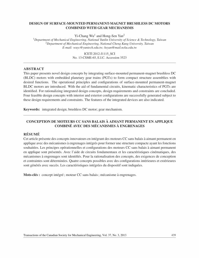
force is produced by mutual interaction between current-carrying coils and the magnetic flux generatedby permanent magnets. Based on the Lorentz force equation, the current should reverse the polarity insynchronism with the rotor position to develop a unidirectional torque on the rotor, hence resulting in motion.Hall sensors, encoders, or similar devices are fixed to the stator to monitor the position of the rotor so thatstator windings can be energized in a proper sequence by the power electronic controller. The BLDC motorspossess a variety of constructions for different industrial applications. The most typical configuration iscylindrical in shape with radial-flux topology. Among these radial-flux BLDC motors, the surface-mountedpermanent-magnet BLDC motor has been used extensively for decades due to the excellent advantages ofsimple rotor structure, high motor efficiency and low manufacturing cost. In this study, only the surface-mounted permanent-magnet configurations with interior-rotor and exterior-rotor types are of concern. Forthe interior-rotor BLDC motor, permanent magnets in even numbers are mounted on the rotating rotor, whilethe stator with fixed polyphase windings appears on the outside of the rotor. Both the rotor and stator aretypically comprised of a lamination of magnetic steel slices to reduce the eddy current loss. Figure 1a showsa cross-sectional view of an interior-rotor BLDC motor. It has six stator slots around which coils are wound.The rotor is constructed by placing four arc-shaped permanent magnets with opposite poles mounted onthe outer surface of a soft-iron cylinder to provide flux return paths. The permanent magnets are usuallymagnetized in the radial or parallel direction. From the structural point of view, such a motor configurationprovides a natural shield to protect the rotor from its surroundings. Besides, an important characteristic is itshigh torque/inertia ratio, which makes this configuration widely employed in servo systems for the purposesof rapid acceleration and deceleration. Conversely, the exterior-rotor BLDC motor is structurally invertedto the interior-rotor type. Figure 1b shows a 3-phase, 4-pole/6-slot, exterior-rotor BLDC motor used intreadmills. According to its configuration, permanent magnets are affixed to the inner surface of the rotoryoke, which prevents the magnets from flying apart, especially in high-speed applications. Since the cross-section of the exterior-rotor BLDC motor is identical to the DC commutator motor, DC armature windingmachines can easily be adopted to wind the stator. Therefore, the main features of the exterior-rotor designare simple to wind and easy to manufacture, resulting in low production cost. In addition, the relativelylarge rotor diameter increases the moments of inertia, which in turn helps to maintain constant rotationalspeed. Such a configuration is frequently used in data storage hard-disk drives, cooling fans, blowers anddirect driven wheel motors for electric scooters and vehicles. In general, when a high-torque and low-speed electric motor is required, the interior-rotor design would be appropriate by using a high number ofmagnet poles because numerous magnet poles usually create greater torque for the same current level. Ifa continuous speed or higher speed is required which is constant or varies only slightly, the exterior-rotordesign can be considered [7]. Both of these two motor configurations are employed to develop innovativedesign concepts of integrated BLDC motors and PGTs.
3. KINEMATIC CHARACTERISTICS OF THE BASIC PLANETARY GEAR TRAIN
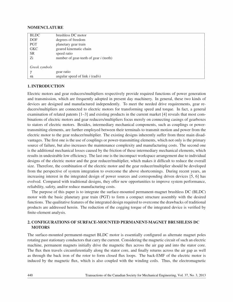
The kinematic characteristics of a PGT are mainly determined by its topological structure that always gov-erns the performance of this mechanism. Hence, the analysis of the kinematic structure, which contains theessential information about which link is connected to which other link by what type of joint, is a major taskfor the study of PGTs [8]. A PGT is a geared mechanism that consists of a geared kinematic chain (GKC)with its central axis supported by bearings housed in the casing. For example, Fig. 2a shows a five-link, two-degrees-of- freedom (DOF) basic PGT used in a 3-speed rear transmission hub of bicycles. It is the simplestPGT in the PGT family. The corresponding functional schematic of the basic PGT is depicted in Fig. 2b. Forreasons of clarity and simplicity, only those functional elements that are essential to the structural topologyare shown in the functional schematic. It consists of a ground link (member 0), a sun gear (member 1), acarrier (member 2), a ring gear (member 3) and a planet gear (member 4). Since the sun gear, carrier and
441Transactions of the Canadian Society for Mechanical Engineering, Vol. 37, No. 3, 2013
Fig. 1. Typically configurations of surface-mounted permanent-magnet BLDC motors: (a) interior-rotor type;(b) Exterior-rotor type.
Fig. 2. Basic planetary gear train: (a) schematic diagram of the PGT; (b) functional schematic of the PGT; and(c) functional schematic of the GKC.
ring gear all rotate about the same central axis mounted on the ground link, they are called coaxial links.The sun gear is adjacent to the planet gear with an external gear pair, while the planet gear is adjacent tothe ring gear with an internal gear pair. The carrier is adjacent to the sun gear and planet gear with revolutepairs. By releasing the ground link of the PGT, the corresponding one-DOF GKC is obtained, as shownin Fig. 2c. The dependent relation between the input and output links of a PGT can be evaluated throughkinematic analysis. In the study of kinematic analysis of PGTs, several methods have been developed overa long period of time. One frequently used approach is the fundamental circuit method. According to thedefinition, a fundamental circuit is made up of one gear pair, which consists of two meshing gears i andj, and one carrier k to maintain a constant center distance between the two gears, which is symbolicallydenoted as (i, j)(k) [9]. For a fundamental circuit, the corresponding fundamental circuit equation is
ωi− γ jiω j +(γ ji−1)ωk = 0 (1)
where ωi is the angular speed of link i, γ ji =±Z j/Zi represents the gear ratio and Zi is the number of teethon gear i. The positive sign of the gear ratio is for an internal gear pair, and negative for an external gearpair. According to the structural characteristics, the number of fundamental circuits is equal to the numberof gear pairs for a PGT. Besides, only the coaxial links connected to the casing can be used as the input,output, or fixed links due to the engineering reality. As can be seen from Fig. 2, there are two gear pairs inthe basic PGT and two fundamental circuits, identified as (1,4)(2) and (3,4)(2), respectively. The related
442 Transactions of the Canadian Society for Mechanical Engineering, Vol. 37, No. 3, 2013
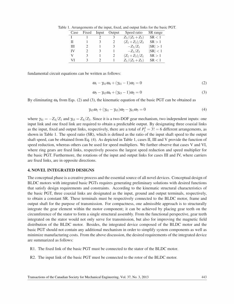
Table 1. Arrangements of the input, fixed, and output links for the basic PGT.Case Fixed Input Output Speed ratio SR rangeI 1 2 3 Z3/(Z1 +Z3) SR < 1II 1 3 2 (Z1 +Z3)/Z3 SR > 1III 2 1 3 −Z3/Z1 |SR|> 1IV 2 3 1 −Z1/Z3 |SR|< 1V 3 1 2 (Z1 +Z3)/Z1 SR > 1VI 3 2 1 Z1/(Z1 +Z3) SR < 1
fundamental circuit equations can be written as follows:
ω1− γ41ω4 +(γ41−1)ω2 = 0 (2)
ω3− γ43ω4 +(γ43−1)ω2 = 0 (3)
By eliminating ω4 from Eqs. (2) and (3), the kinematic equation of the basic PGT can be obtained as
γ43ω1 +(γ41− γ43)ω2− γ41ω3 = 0 (4)
where γ41 =−Z4/Z1 and γ43 = Z4/Z3. Since it is a two-DOF gear mechanism, two independent inputs: oneinput link and one fixed link are required to obtain a predictable output. By designating three coaxial linksas the input, fixed and output links, respectively, there are a total of P3
3 = 3! = 6 different arrangements, asshown in Table 1. The speed ratio (SR), which is defined as the ratio of the input shaft speed to the outputshaft speed, can be obtained from Eq. (4). As depicted in Table 1, cases II, III and V provide the function ofspeed reduction, whereas others can be used for speed multipliers. We further observe that cases V and VI,where ring gears are fixed links, respectively possess the largest speed reduction and speed multiplier forthe basic PGT. Furthermore, the rotations of the input and output links for cases III and IV, where carriersare fixed links, are in opposite directions.
4. NOVEL INTEGRATED DESIGNS
The conceptual phase is a creative process and the essential source of all novel devices. Conceptual design ofBLDC motors with integrated basic PGTs requires generating preliminary solutions with desired functionsthat satisfy design requirements and constraints. According to the kinematic structural characteristics ofthe basic PGT, three coaxial links are designated as the input, ground and output terminals, respectively,to obtain a constant SR. These terminals must be respectively connected to the BLDC motor, frame andoutput shaft for the purpose of transmission. For compactness, one admissible approach is to structurallyintegrate the gear element within the motor component; it can be achieved by placing gear teeth on thecircumference of the stator to form a single structural assembly. From the functional perspective, gear teethintegrated on the stator would not only serve for transmission, but also for improving the magnetic fielddistribution of the BLDC motor. Besides, the integrated device composed of the BLDC motor and thebasic PGT should not contain any additional mechanism in order to simplify system components as well asminimize manufacturing costs. From the above discussion, the desired requirements of the integrated deviceare summarized as follows:
R1. The fixed link of the basic PGT must be connected to the stator of the BLDC motor.
R2. The input link of the basic PGT must be connected to the rotor of the BLDC motor.
443Transactions of the Canadian Society for Mechanical Engineering, Vol. 37, No. 3, 2013
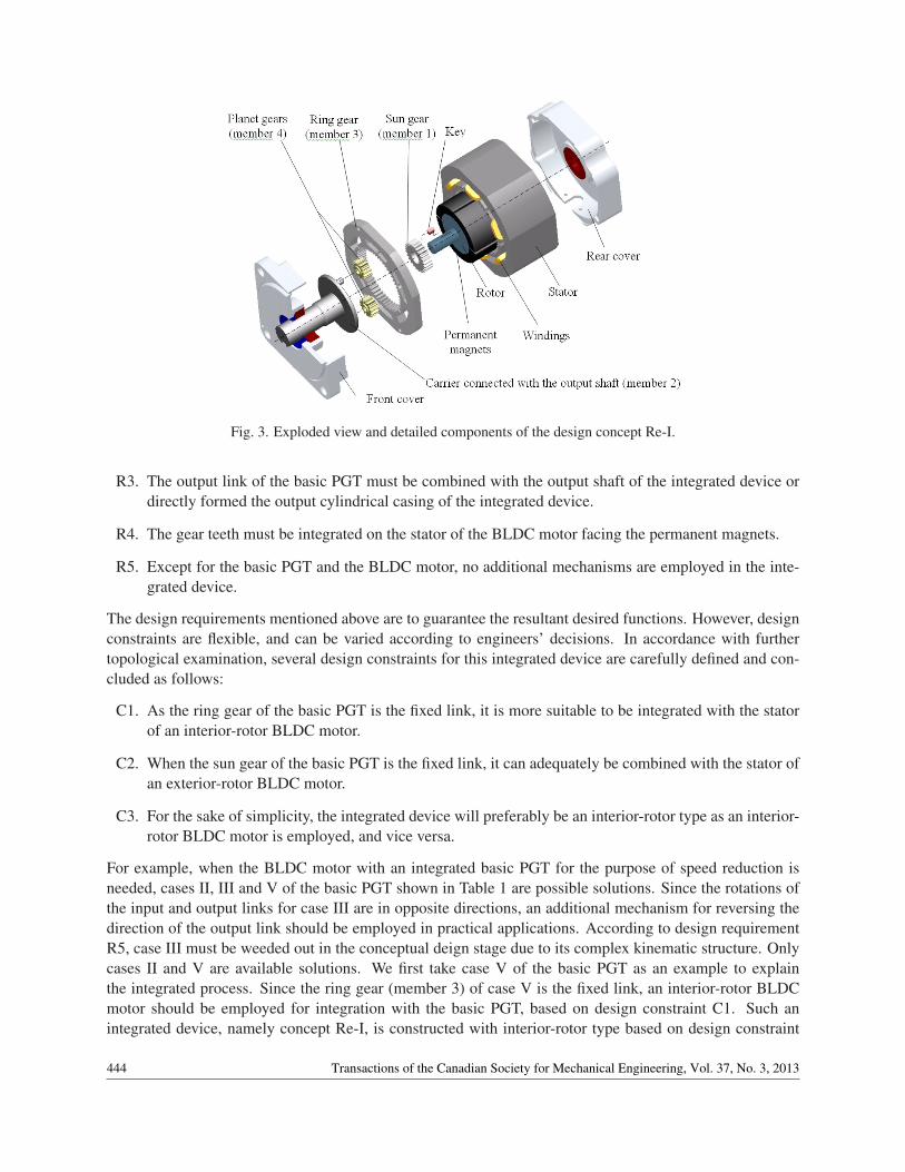
Fig. 3. Exploded view and detailed components of the design concept Re-I.
R3. The output link of the basic PGT must be combined with the output shaft of the integrated device ordirectly formed the output cylindrical casing of the integrated device.
R4. The gear teeth must be integrated on the stator of the BLDC motor facing the permanent magnets.
R5. Except for the basic PGT and the BLDC motor, no additional mechanisms are employed in the inte-grated device.
The design requirements mentioned above are to guarantee the resultant desired functions. However, designconstraints are flexible, and can be varied according to engineers’ decisions. In accordance with furthertopological examination, several design constraints for this integrated device are carefully defined and con-cluded as follows:
C1. As the ring gear of the basic PGT is the fixed link, it is more suitable to be integrated with the statorof an interior-rotor BLDC motor.
C2. When the sun gear of the basic PGT is the fixed link, it can adequately be combined with the stator ofan exterior-rotor BLDC motor.
C3. For the sake of simplicity, the integrated device will preferably be an interior-rotor type as an interior-rotor BLDC motor is employed, and vice versa.
For example, when the BLDC motor with an integrated basic PGT for the purpose of speed reduction isneeded, cases II, III and V of the basic PGT shown in Table 1 are possible solutions. Since the rotations ofthe input and output links for case III are in opposite directions, an additional mechanism for reversing thedirection of the output link should be employed in practical applications. According to design requirementR5, case III must be weeded out in the conceptual deign stage due to its complex kinematic structure. Onlycases II and V are available solutions. We first take case V of the basic PGT as an example to explainthe integrated process. Since the ring gear (member 3) of case V is the fixed link, an interior-rotor BLDCmotor should be employed for integration with the basic PGT, based on design constraint C1. Such anintegrated device, namely concept Re-I, is constructed with interior-rotor type based on design constraint
444 Transactions of the Canadian Society for Mechanical Engineering, Vol. 37, No. 3, 2013
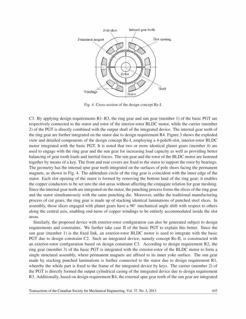
Fig. 4. Cross-section of the design concept Re-I.
C3. By applying design requirements R1–R3, the ring gear and sun gear (member 1) of the basic PGT arerespectively connected to the stator and rotor of the interior-rotor BLDC motor, while the carrier (member2) of the PGT is directly combined with the output shaft of the integrated device. The internal gear teeth ofthe ring gear are further integrated on the stator due to design requirement R4. Figure 3 shows the explodedview and detailed components of the design concept Re-I, employing a 4-pole/6-slot, interior-rotor BLDCmotor integrated with the basic PGT. It is noted that two or more identical planet gears (member 4) areused to engage with the ring gear and the sun gear for increasing load capacity as well as providing betterbalancing of gear tooth loads and inertial forces. The sun gear and the rotor of the BLDC motor are fastenedtogether by means of a key. The front and rear covers are fixed to the stator to support the rotor by bearings.The geometry has the internal spur gear teeth integrated on the surfaces of pole shoes facing the permanentmagnets, as shown in Fig. 4. The addendum circle of the ring gear is coincident with the inner edge of thestator. Each slot opening of the stator is formed by removing the bottom land of the ring gear; it enablesthe copper conductors to be set into the slot areas without affecting the conjugate relation for gear meshing.Since the internal gear teeth are integrated on the stator, the punching process forms the slices of the ring gearand the stator simultaneously with the same punching die. Moreover, unlike the traditional manufacturingprocess of cut gears, the ring gear is made up of stacking identical laminations of punched steel slices. Inassembly, those slices engaged with planet gears have a 90◦ mechanical angle shift with respect to othersalong the central axis, enabling end-turns of copper windings to be entirely accommodated inside the slotareas.
Similarly, the proposed device with exterior-rotor configuration can also be generated subject to designrequirements and constraints. We further take case II of the basic PGT to explain this better. Since thesun gear (member 1) is the fixed link, an exterior-rotor BLDC motor is used to integrate with the basicPGT due to design constraint C2. Such an integrated device, namely concept Re-II, is constructed withan exterior-rotor configuration based on design constraint C3. According to design requirement R2, thering gear (member 3) of the basic PGT is integrated with the exterior-rotor of the BLDC motor to form asingle structural assembly, where permanent magnets are affixed to its inner yoke surface. The sun gearmade by stacking punched laminations is further connected to the stator due to design requirement R1,whereby the whole part is fixed to the frame of the integrated device by keys. The carrier (member 2) ofthe PGT is directly formed the output cylindrical casing of the integrated device due to design requirementR3. Additionally, based on design requirement R4, the external spur gear teeth of the sun gear are integrated
445Transactions of the Canadian Society for Mechanical Engineering, Vol. 37, No. 3, 2013
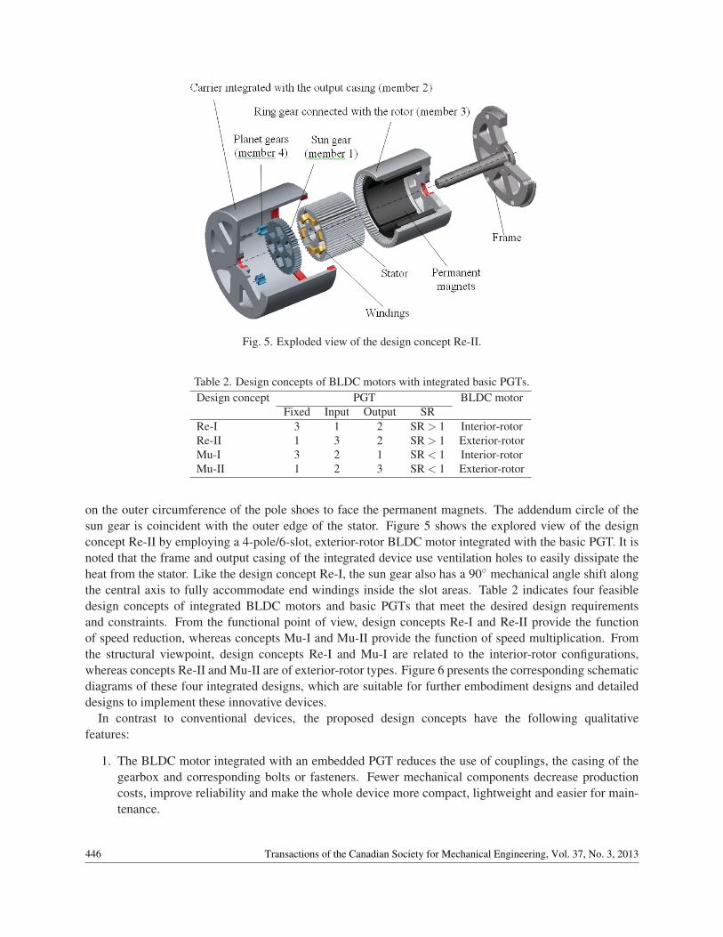
Fig. 5. Exploded view of the design concept Re-II.
Table 2. Design concepts of BLDC motors with integrated basic PGTs.Design concept PGT BLDC motor
Fixed Input Output SRRe-I 3 1 2 SR > 1 Interior-rotorRe-II 1 3 2 SR > 1 Exterior-rotorMu-I 3 2 1 SR < 1 Interior-rotorMu-II 1 2 3 SR < 1 Exterior-rotor
on the outer circumference of the pole shoes to face the permanent magnets. The addendum circle of thesun gear is coincident with the outer edge of the stator. Figure 5 shows the explored view of the designconcept Re-II by employing a 4-pole/6-slot, exterior-rotor BLDC motor integrated with the basic PGT. It isnoted that the frame and output casing of the integrated device use ventilation holes to easily dissipate theheat from the stator. Like the design concept Re-I, the sun gear also has a 90◦ mechanical angle shift alongthe central axis to fully accommodate end windings inside the slot areas. Table 2 indicates four feasibledesign concepts of integrated BLDC motors and basic PGTs that meet the desired design requirementsand constraints. From the functional point of view, design concepts Re-I and Re-II provide the functionof speed reduction, whereas concepts Mu-I and Mu-II provide the function of speed multiplication. Fromthe structural viewpoint, design concepts Re-I and Mu-I are related to the interior-rotor configurations,whereas concepts Re-II and Mu-II are of exterior-rotor types. Figure 6 presents the corresponding schematicdiagrams of these four integrated designs, which are suitable for further embodiment designs and detaileddesigns to implement these innovative devices.
In contrast to conventional devices, the proposed design concepts have the following qualitativefeatures:
1. The BLDC motor integrated with an embedded PGT reduces the use of couplings, the casing of thegearbox and corresponding bolts or fasteners. Fewer mechanical components decrease productioncosts, improve reliability and make the whole device more compact, lightweight and easier for main-tenance.
446 Transactions of the Canadian Society for Mechanical Engineering, Vol. 37, No. 3, 2013
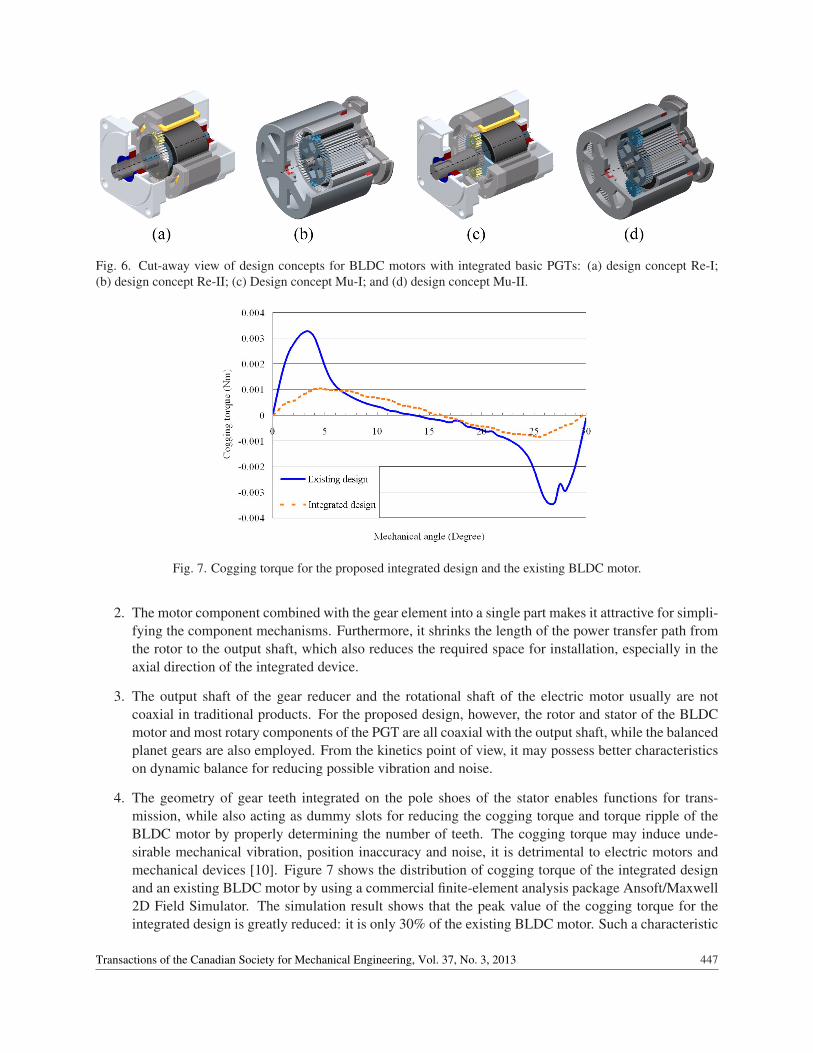
Fig. 6. Cut-away view of design concepts for BLDC motors with integrated basic PGTs: (a) design concept Re-I;(b) design concept Re-II; (c) Design concept Mu-I; and (d) design concept Mu-II.
Fig. 7. Cogging torque for the proposed integrated design and the existing BLDC motor.
2. The motor component combined with the gear element into a single part makes it attractive for simpli-fying the component mechanisms. Furthermore, it shrinks the length of the power transfer path fromthe rotor to the output shaft, which also reduces the required space for installation, especially in theaxial direction of the integrated device.
3. The output shaft of the gear reducer and the rotational shaft of the electric motor usually are notcoaxial in traditional products. For the proposed design, however, the rotor and stator of the BLDCmotor and most rotary components of the PGT are all coaxial with the output shaft, while the balancedplanet gears are also employed. From the kinetics point of view, it may possess better characteristicson dynamic balance for reducing possible vibration and noise.
4. The geometry of gear teeth integrated on the pole shoes of the stator enables functions for trans-mission, while also acting as dummy slots for reducing the cogging torque and torque ripple of theBLDC motor by properly determining the number of teeth. The cogging torque may induce unde-sirable mechanical vibration, position inaccuracy and noise, it is detrimental to electric motors andmechanical devices [10]. Figure 7 shows the distribution of cogging torque of the integrated designand an existing BLDC motor by using a commercial finite-element analysis package Ansoft/Maxwell2D Field Simulator. The simulation result shows that the peak value of the cogging torque for theintegrated design is greatly reduced: it is only 30% of the existing BLDC motor. Such a characteristic
447Transactions of the Canadian Society for Mechanical Engineering, Vol. 37, No. 3, 2013
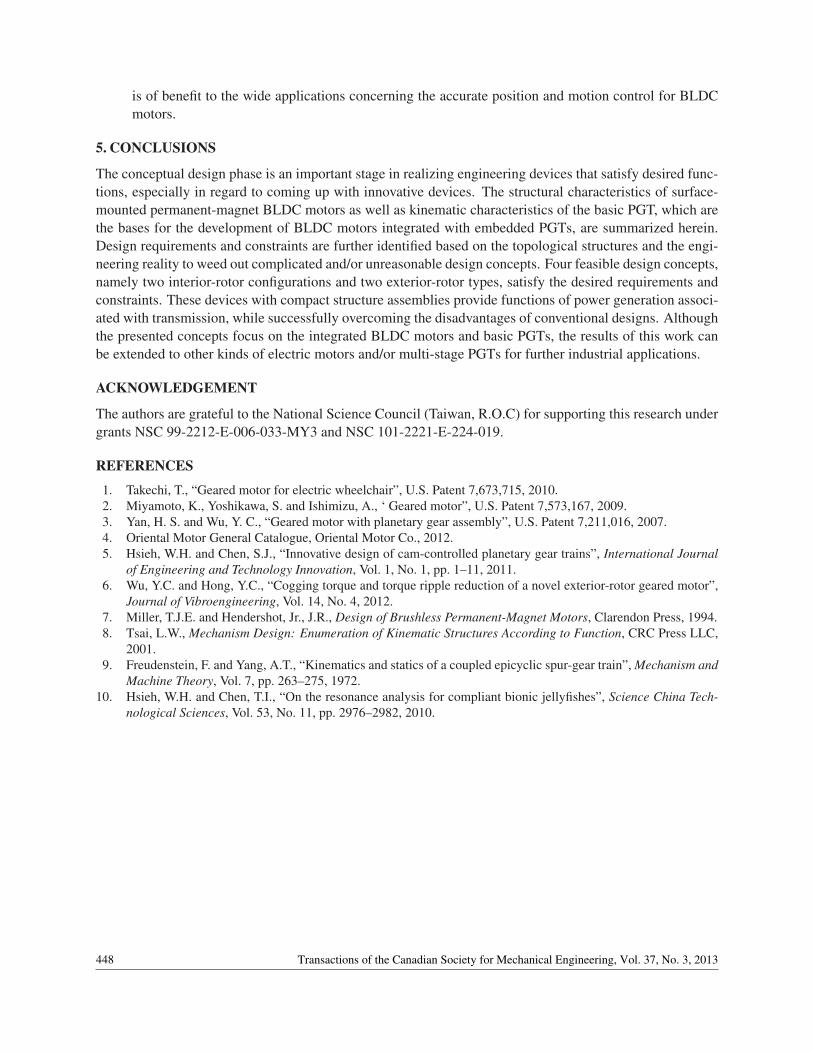
is of benefit to the wide applications concerning the accurate position and motion control for BLDCmotors.
5. CONCLUSIONS
The conceptual design phase is an important stage in realizing engineering devices that satisfy desired func-tions, especially in regard to coming up with innovative devices. The structural characteristics of surface-mounted permanent-magnet BLDC motors as well as kinematic characteristics of the basic PGT, which arethe bases for the development of BLDC motors integrated with embedded PGTs, are summarized herein.Design requirements and constraints are further identified based on the topological structures and the engi-neering reality to weed out complicated and/or unreasonable design concepts. Four feasible design concepts,namely two interior-rotor configurations and two exterior-rotor types, satisfy the desired requirements andconstraints. These devices with compact structure assemblies provide functions of power generation associ-ated with transmission, while successfully overcoming the disadvantages of conventional designs. Althoughthe presented concepts focus on the integrated BLDC motors and basic PGTs, the results of this work canbe extended to other kinds of electric motors and/or multi-stage PGTs for further industrial applications.
ACKNOWLEDGEMENT
The authors are grateful to the National Science Council (Taiwan, R.O.C) for supporting this research undergrants NSC 99-2212-E-006-033-MY3 and NSC 101-2221-E-224-019.
REFERENCES
1. Takechi, T., “Geared motor for electric wheelchair”, U.S. Patent 7,673,715, 2010.2. Miyamoto, K., Yoshikawa, S. and Ishimizu, A., ‘ Geared motor”, U.S. Patent 7,573,167, 2009.3. Yan, H. S. and Wu, Y. C., “Geared motor with planetary gear assembly”, U.S. Patent 7,211,016, 2007.4. Oriental Motor General Catalogue, Oriental Motor Co., 2012.5. Hsieh, W.H. and Chen, S.J., “Innovative design of cam-controlled planetary gear trains”, International Journal
of Engineering and Technology Innovation, Vol. 1, No. 1, pp. 1–11, 2011.6. Wu, Y.C. and Hong, Y.C., “Cogging torque and torque ripple reduction of a novel exterior-rotor geared motor”,
Journal of Vibroengineering, Vol. 14, No. 4, 2012.7. Miller, T.J.E. and Hendershot, Jr., J.R., Design of Brushless Permanent-Magnet Motors, Clarendon Press, 1994.8. Tsai, L.W., Mechanism Design: Enumeration of Kinematic Structures According to Function, CRC Press LLC,
2001.9. Freudenstein, F. and Yang, A.T., “Kinematics and statics of a coupled epicyclic spur-gear train”, Mechanism and
Machine Theory, Vol. 7, pp. 263–275, 1972.10. Hsieh, W.H. and Chen, T.I., “On the resonance analysis for compliant bionic jellyfishes”, Science China Tech-
nological Sciences, Vol. 53, No. 11, pp. 2976–2982, 2010.
448 Transactions of the Canadian Society for Mechanical Engineering, Vol. 37, No. 3, 2013