Embed Size (px)
Citation preview
1 INTRODUCTION
The Mobilizable Strength Design (MSD) method has developed following various advances in the use of plastic deformation mechanisms to predict ground displacements: (Milligan and Bransby, 1975; Bolton and Powrie, 1988; Bolton et al. 1989, 1990a, 1990b). MSD is a general, unified design methodol-ogy, which aims to satisfy both safety and service-ability requirements in a single calculation proce-dure, contrasting with conventional design methodology which treats stability problems and serviceability problems separately. In the MSD method, actual stress-strain data is used to select a design strength that limits ground deformations, and this is used in plastic soil analyses that satisfy equi-librium conditions without the use of empirical safety factors.
Simple plastic mechanisms are used to represent the working state of the geotechnical system. The mechanisms represent both the equilibrium and de-formation of the various soil bodies, especially at their junction with the superstructure. Then, raw stress-strain data from soil tests on undisturbed sam-ples, taken from representative locations, are used directly to link stresses and strains under working conditions. Constitutive laws and soil parameters are unnecessary.
The MSD approach has been successfully im-plemented for shallow foundations (Osman and Bol-
ton, 2005), cantilever retaining walls (Osman and Bolton, 2005), tunneling-induced ground displace-ments (Osman et al, 2006) and also the sequential construction of braced excavations which induce wall displacements and ground deformations (Os-man and Bolton, 2006).
Consider the imposition of certain actions on a soil body, due to construction activities such as stress relief accompanying excavation, or to loads applied in service. The MSD method permits the engineer to use simple hand calculations to estimate the consequential ground displacements accounting for non-linear soil behavior obtained from a single well-chosen test of the undisturbed soil.
The MSD approach firstly requires the engineer to represent the working states of the geotechnical system by a generic mechanism which conveys the kinematics (i.e. the pattern of displacements) of the soil due to the proposed actions. Analysis of the de-formation mechanism leads to a compatibility rela-tionship between the average strain mobilized in the soil and the boundary displacements.
The average shear strength mobilized in the soil due to the imposed actions is then calculated, either from an independent equilibrium analysis using a permissible stress field (equivalent to a lower bound plastic analysis), or from an equation balancing work and energy for the chosen mechanism (equiva-lent to an upper bound plastic analysis).
Supporting excavations in clay - from analysis to decision-making
Bolton, M.D. and Lam, S.Y. University of Cambridge
Osman, A.S. Durham University
Keynote Lecture – 6th International Symposium on Geotechnical Aspects of Underground Construction in Soft Ground, IS-Shanghai, 2008, Vol. 1, 12-25.
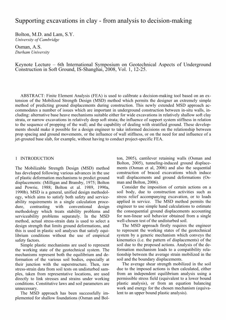
ABSTRACT: Finite Element Analysis (FEA) is used to calibrate a decision-making tool based on an ex-tension of the Mobilized Strength Design (MSD) method which permits the designer an extremely simple method of predicting ground displacements during construction. This newly extended MSD approach ac-commodates a number of issues which are important in underground construction between in-situ walls, in-cluding: alternative base heave mechanisms suitable either for wide excavations in relatively shallow soft clay strata, or narrow excavations in relatively deep soft strata; the influence of support system stiffness in relation to the sequence of propping of the wall; and the capability of dealing with stratified ground. These develop-ments should make it possible for a design engineer to take informed decisions on the relationship between prop spacing and ground movements, or the influence of wall stiffness, or on the need for and influence of a jet-grouted base slab, for example, without having to conduct project-specific FEA.
The location of one or more representative soil elements is then selected, basing this judgment on the soil profile in relation to the location and shape of the selected mechanism. The centroid of the mechanism can serve as a default location if a single location is to be employed. Stress-strain relation-ships are then obtained from appropriate laboratory tests on undisturbed soil samples taken from the se-lected locations and carried out with precise strain measurements. Equivalent in-situ tests such as self-boring pressuremeter tests can alternatively be car-ried out. The mode of deformation in the soil tests should correspond as closely as possible to the mode of shearing in the MSD mechanism. Otherwise, ani-sotropy should somehow be allowed for.
Finally, the mobilized shear strength required for equilibrium under working loads is set against the representative shear stress-strain curve in order to obtain the mobilized soil strain, and thereby the boundary displacements of the simplified MSD mechanism.
2 MSD FOR DEEP EXCAVATION PROBLEM
Osman and Bolton (2006) showed for an in-situ wall supporting a deep excavation that the total deforma-tion could be approximated as the sum of the canti-lever movement prior to propping, and the subse-quent bulging movement that accretes incrementally with every sequence of propping and excavation.
A method for estimating the cantilever movement had been suggested earlier in Osman and Bolton (2004). It begins by considering the lateral earth pressure distribution for a smooth, rigid, cantilever wall rotating about a point some way above its toe, in undrained conditions. A simple mobilized strength ratio is introduced to characterize the aver-age degree of mobilization of undrained shear strength throughout the soil. By using horizontal force and moment equilibrium equations, the two unknowns – the position of the pivot point and the mobilized strength ratio – are obtained. Then, a mo-bilized strain value is read off from the shear stress-strain curve of a soil element appropriate to the rep-resentative depth of the mechanism at the mid-depth of the wall. Simple kinematics for a cantilever wall rotating about its base suggests that the shear strain mobilized in the adjacent soil is double the angle of wall rotation. Accordingly, for the initial cantilever phase, the wall rotation is estimated as one half of the shear strain required to induce the degree of mo-bilization of shear strength necessary to hold the wall in equilibrium. Osman and Bolton (2004) used FEA to show that correction factors up to about 2.0 could be applied to the MSD estimates of the wall crest displacement, depending on a variety of non-dimensional groups of parameters ignored in the
simple MSD theory, such as wall flexibility and ini-tial earth pressure coefficient prior to excavation.
A typical increment of bulging, on the other hand, was calculated in Osman and Bolton (2006) by considering an admissible plastic mechanism for base heave. In this case, the mobilized shear strength was deduced from the kinematically admissible mechanism itself, using virtual work principles. The energy dissipated by shearing was said to balance the virtual loss of potential energy due to the simul-taneous formation of a subsidence trough on the re-tained soil surface and a matching volume of heave inside the excavation. The mobilized strength ratio could then be calculated, and the mobilized shear strain read off from the stress-strain curve of a rep-resentative element, as before. The deformation is estimated using the relationship between the bound-ary displacements and the average mobilized shear strain, in accordance with the original mechanism.
The MSD solutions of Osman and Bolton (2006) compared quite well with some numerical simula-tions using the realistic non-linear MIT-E3 model, and various case studies that provided field data. However, these initial solutions are capable of im-provement in three ways that will contribute to their applicability in engineering practice.
(i) The original mechanism assumed a relatively wide excavation, whereas cut-and-cover tunnel and subway constructions are likely to be much deeper than their width. The MSD mechanism therefore needs to be adapted for the case in which the plastic deformation fields for the side walls interfere with each other beneath the excavation.
(ii) The structural strain energy of the support system can be incorporated. This could be signifi-cant when the soil is weak, and when measures are taken to limit base heave in the excavation, such as by base grouting between the supporting walls. In this case, the reduction of lateral earth pressure due to ground deformation may be relatively small, and it is principally the stiffness of the structural system itself that limits external ground displacements.
(iii) Progressively incorporating elastic strain en-ergy requires the calculation procedure to be fully incremental, whereas Osman and Bolton (2006) had been able to use total energy flows to calculate the results of each stage of excavation separately. A fully incremental solution, admitting ground layer-ing, will permit the accumulation of different mobi-lized shear strengths, and shear strains, at different depths in the ground, thereby improving accuracy.
It is the aim of this paper to introduce an en-hanced MSD solution that includes these three fea-tures. This is then compared with existing FEA of braced excavations which featured a range of ge-ometries and stiffnesses. It will be suggested that MSD provides the ideal means of harvesting FEA simulations for use in design and decision-making.
3 PLASTIC FAILURE MECHANISMS
Limit equilibrium methods are routinely used in sta-bility calculations for soft clay which is idealised, unrealistically, as rigid-plastic. Slip surfaces are se-lected as the assumed focus of all plastic deforma-tions. Failure mechanisms should be kinematically admissible, meaning that unwanted gaps and over-laps should not be produced. Furthermore, in the case of undrained shearing of clays, a constant-volume condition should be respected at every point. A consequence is that undrained plane-strain failure mechanisms must comprise only slip planes and slip circles. The soil on such failure surfaces is taken to mobilize its undrained shear strength divided by a safety factor, to maintain the mechanism in limiting equilibrium under the action of gravity, and any other applied loads. Calculated in this way, the safety factor literally offers an estimate of the factor by which the strength of the soil would have to drop before the soil construction would collapse. Such es-timates might err either on the high side or the low side, depending on the particular assumptions that were made.
In the case of base heave in braced excavations, plastic solutions were derived from slip-line fields based on the method of characteristics. Such solu-tions comprise both slip surfaces, as before, and plastic fans which distribute plastic strains over a fi-nite zone in the shape of a sector of a circle. Not-withstanding these zones of finite strain, the addi-tional presence of slip surfaces still restricts the application of these solutions to the prediction of failure. Furthermore, no such solution can be re-garded automatically as an accurate predictor of failure, notwithstanding their apparent sophistica-tion. All that can be said is that they will lead to an unsafe estimate of stability. Their use in practice can only be justified following back-analysis of actual failures, whether in the field or the laboratory.
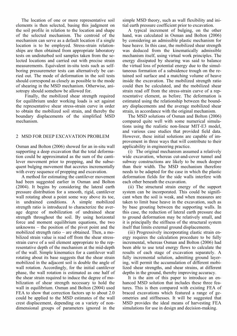
Two typical failure mechanisms as suggested by Terzaghi (1943) and Bjerrum and Eide (1956) are shown in Figure 1. They have each been widely used for the design of multi-propped excavations. Ter-zaghi (1943) suggested a mechanism consisting of a soil column outside the excavation which creates a bearing capacity failure. The failure is resisted by the weight of a corresponding soil column inside the excavation and also by adhesion acting along the vertical edges of the mechanism. Bjerrum and Eide (1956) assumed that the base of the excavation could be treated as a negatively loaded perfectly smooth footing. The bearing capacity factors proposed by Skempton (1951) are used directly in the stability calculations and are taken as stability numbers, N = γH/cu. Eide et al. (1972) modified this approach to account for the increase in basal stability owing to mobilized shear strength along the embedded length of the rigid wall.
Figure 1. Conventional basal stability mechanism and notation (after Ukritchon et al., 2003)
O’Rourke (1993) further modified the basal sta-
bility calculations of Bjerrum and Eide (1956) to in-clude flexure of the wall below the excavation level. It was assumed that the embedded depth of the wall does not change the geometry of the basal failure mechanism. However, an increase in stability was anticipated due to the elastic strain energy stored in flexure. This gave stability numbers that were func-tions of the yield moment and assumed boundary conditions at the base of the wall.
Ukritchon et al. (2003) used numerical limit analysis to calculate the stability of braced excava-tions. Upper and lower bound formulations are pre-sented based on Sloan and Kleeman (1995) and Sloan (1988), respectively. The technique calculates upper bound and lower bound estimates of collapse loads numerically, by linear programming, while spatial discretization and interpolation of the field variables are calculated using the finite element method. No failure mechanism need be assumed and failure both of the soil and the wall are taken care of.
However, both soil and wall are again assumed to be rigid perfectly plastic so the failure mechanism in-cludes a plastic hinge at the lowest level of support.
All these collapse limit analyses provide useful guidance on the possible geometry of plastic defor-mation mechanisms for service conditions. But the key requirement for MSD mechanisms is that dis-placement discontinuities (slip surfaces) must be avoided entirely. In that way, small but finite ground displacements are associated at every internal point with small but finite strains.
4 WALL DEFORMATIONS
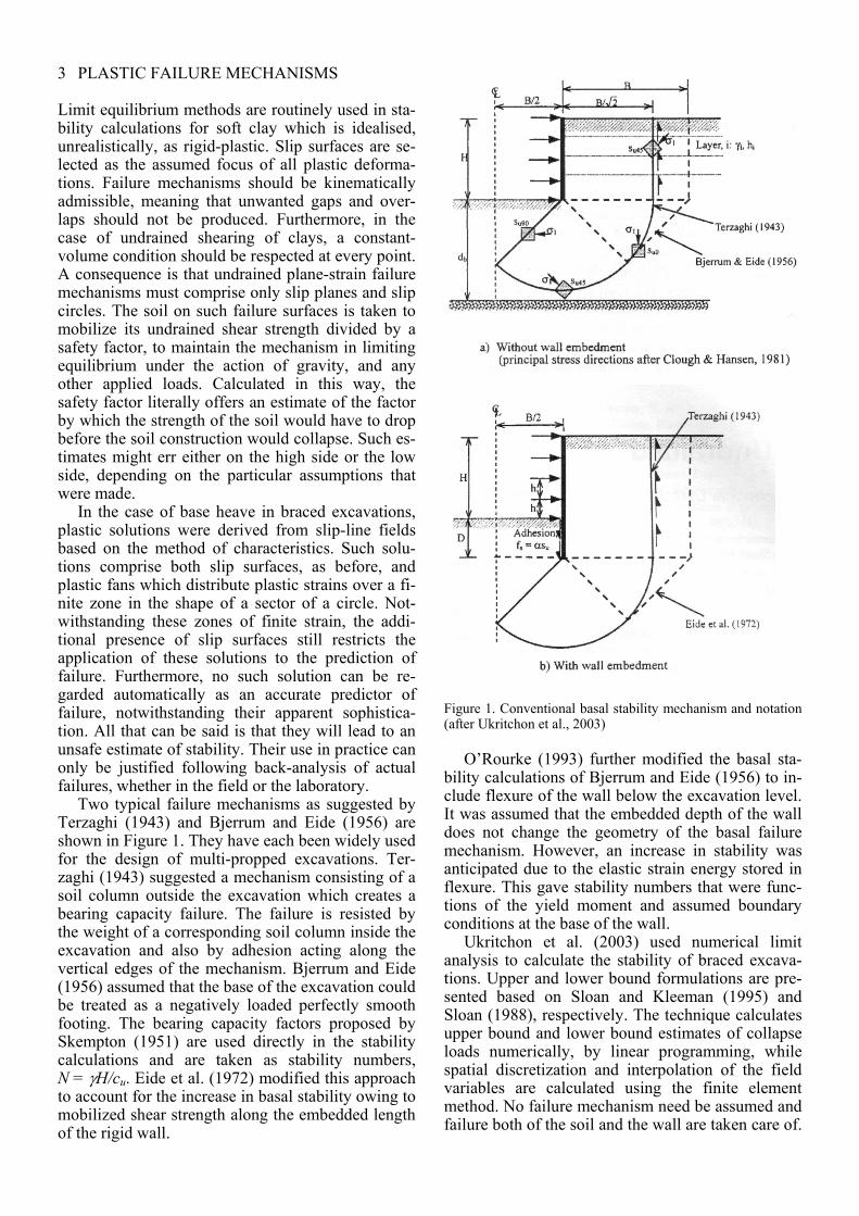
Consider now the deformations of a multi-propped wall supporting a deep excavation in soft, undrained clay. At each stage of excavation the incremental displacement profile (Figure 2) of the ground and the wall below the lowest prop can be assumed to be a cosine function (O’Rourke,1993) as follows:
⎟⎠⎞
⎜⎝⎛ −= )2cos(1
2max
lyw
w πδδ (1)
Here δw is the incremental wall displacement at any distance y below the lowest support, δwmax is its maximum value, and l is the wavelength of the de-formation, regarded as proportional to the length s of the wall below the lowest level of current support:
l = α s (2) O’Rourke (1993) defined the wavelength of the de-formation as the distance from the lowest support level to the fixed base of the wall. Osman and Bol-ton (2006) suggested a definition for the wavelength of the deformation based on wall end fixity. For walls embedded into a stiff layer beneath the soft clay, such that the wall tip is fully fixed in position and direction, the wavelength was set equal to the wall length (α = 1). For short walls embedded in deep soft clay, the maximum wall displacement oc-curs at the tip of the wall so the wavelength was taken as twice the projecting wall length (α = 2). In-termediate cases might be described as restrained-end walls (1<α<2).
Figure 2. Incremental displacements in braced excavation (after O’Rourke, 1993)
However, these definitions applied only to very wide excavations. When a narrow excavation is con-sidered, the wavelength will be limited by the width of the excavation. In addition, in the case of the par-tially restrained wall, the depth of a relatively stiff soil stratum may also limit the depth of the deforma-tion pattern.
5 GEO-STRUCTURAL MECHANISMS
An incremental plastic deformation mechanism conforming to Equation 1 was proposed by Osman and Bolton (2006) for an infinitely wide multi-propped excavation in clay. In this mechanism, the wall is assumed to be fixed incrementally in position and direction at the lowest prop, implying that the wall has sufficient strength to avoid the formation of a plastic hinge. The wall and soil are deforming compatibly and the soil deformation also follows the cosine function of Equation 1. The dimensions of this mechanism depend on the wavelength l.
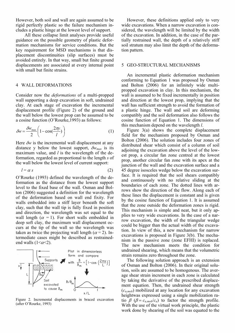
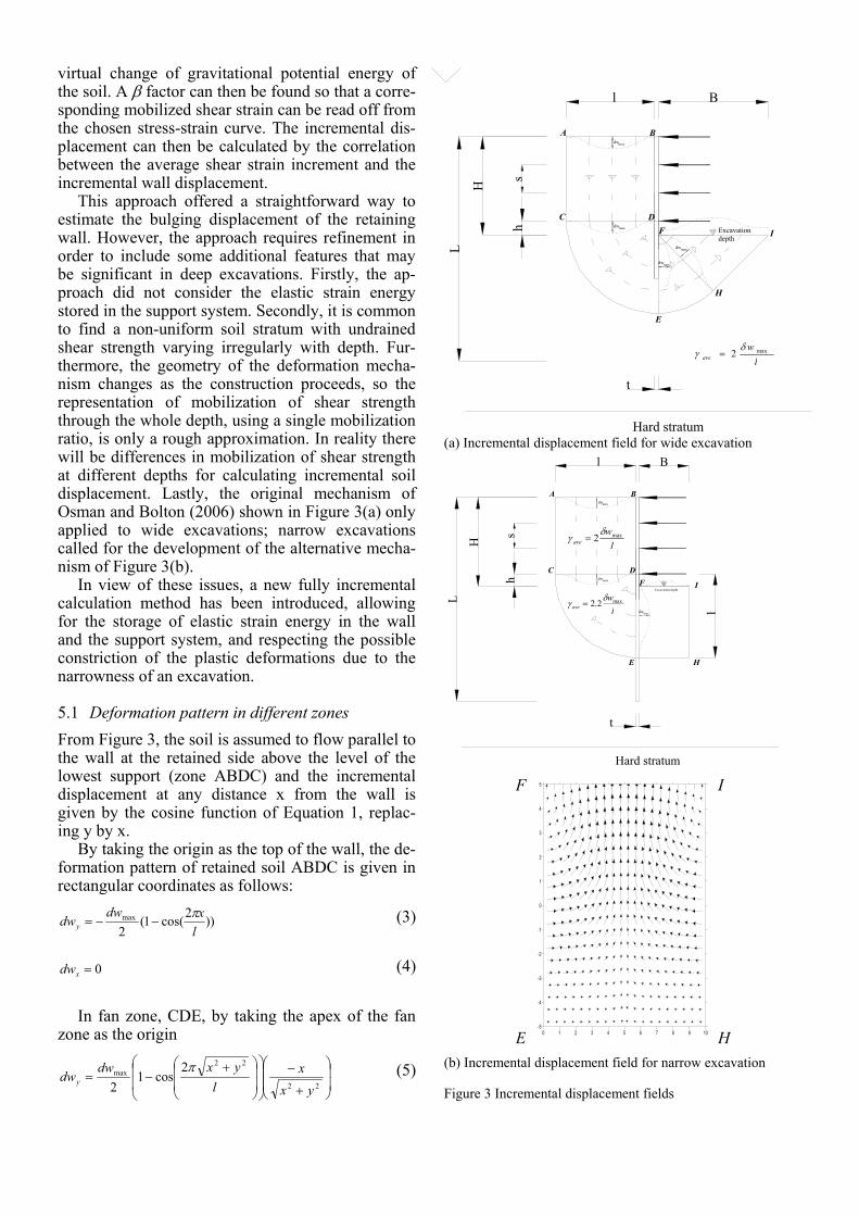
Figure 3(a) shows the complete displacement field for the mechanism proposed by Osman and Bolton (2006). The solution includes four zones of distributed shear which consist of a column of soil adjoining the excavation above the level of the low-est prop, a circular fan zone centred at the lowest prop, another circular fan zone with its apex at the junction of the wall and the excavation surface and a 45 degree isosceles wedge below the excavation sur-face. It is required that the soil shears compatibly and continuously with no relative sliding at the boundaries of each zone. The dotted lines with ar-rows show the direction of the flow. Along each of these lines the displacement is constant and is given by the cosine function of Equation 1. It is assumed that the zone outside the deformation zones is rigid. This mechanism is simple and neat, but it only ap-plies to very wide excavations. In the case of a nar-row excavation, the width of the triangular wedge could be bigger than the actual width of the excava-tion. In view of this, a new mechanism for narrow excavations is proposed in Figure 3(b). The mecha-nism in the passive zone (zone EFHI) is replaced. The new mechanism meets the condition for undrained shearing, which means that the volumetric strain remains zero throughout the zone.
The following solution approach is an extension of Osman and Bolton (2006). In their original solu-tion, soils are assumed to be homogenous. The aver-age shear strain increment in each zone is calculated by taking the derivative of the prescribed displace-ment equation. Then, the undrained shear strength (cu,mob) mobilized at any location for any excavation heightwas expressed using a single mobilization ra-tio β (β = cu,mob/cu) to factor the strength profile. With the use of the virtual work principle, the plastic work done by shearing of the soil was equated to the
virtual change of gravitational potential energy of the soil. A β factor can then be found so that a corre-sponding mobilized shear strain can be read off from the chosen stress-strain curve. The incremental dis-placement can then be calculated by the correlation between the average shear strain increment and the incremental wall displacement.
This approach offered a straightforward way to estimate the bulging displacement of the retaining wall. However, the approach requires refinement in order to include some additional features that may be significant in deep excavations. Firstly, the ap-proach did not consider the elastic strain energy stored in the support system. Secondly, it is common to find a non-uniform soil stratum with undrained shear strength varying irregularly with depth. Fur-thermore, the geometry of the deformation mecha-nism changes as the construction proceeds, so the representation of mobilization of shear strength through the whole depth, using a single mobilization ratio, is only a rough approximation. In reality there will be differences in mobilization of shear strength at different depths for calculating incremental soil displacement. Lastly, the original mechanism of Osman and Bolton (2006) shown in Figure 3(a) only applied to wide excavations; narrow excavations called for the development of the alternative mecha-nism of Figure 3(b).
In view of these issues, a new fully incremental calculation method has been introduced, allowing for the storage of elastic strain energy in the wall and the support system, and respecting the possible constriction of the plastic deformations due to the narrowness of an excavation.
5.1 Deformation pattern in different zones From Figure 3, the soil is assumed to flow parallel to the wall at the retained side above the level of the lowest support (zone ABDC) and the incremental displacement at any distance x from the wall is given by the cosine function of Equation 1, replac-ing y by x.
By taking the origin as the top of the wall, the de-formation pattern of retained soil ABDC is given in rectangular coordinates as follows:
))2cos(1(2max
lxdw
dwyπ
−−= (3)
0=xdw (4)
In fan zone, CDE, by taking the apex of the fan
zone as the origin
⎟⎟
⎠
⎞
⎜⎜
⎝
⎛
+
−⎟⎟
⎠
⎞
⎜⎜
⎝
⎛
⎟⎟
⎠
⎞
⎜⎜
⎝
⎛ +−=
22
22max 2
cos12 yx
xl
yxdwdwy
π (5)
t
H
hs
B
L
Excavation depth
Hard stratum
l
dwmax
maxdw
dwmax
maxdw
A B
C DF
H
I
E
(a) Incremental displacement field for wide excavation
t
H
hs
L
Hard stratum
l
dwmax
maxdw
dwmax
A B
C DF
E
I
H
Excavation depth
l
B
0 1 2 3 4 5 6 7 8 9 10-5
-4
-3
-2
-1
0
1
2
3
4
5
(b) Incremental displacement field for narrow excavation Figure 3 Incremental displacement fields
F I
E H
lw
avemax2
δγ =
lw
avemax2.2 δ
γ =
lw
avemax2
δγ =
⎟⎟
⎠
⎞
⎜⎜
⎝
⎛
+⎟⎟
⎠
⎞
⎜⎜
⎝
⎛
⎟⎟
⎠
⎞
⎜⎜
⎝
⎛ +−=
22
22max 2
cos12 yx
yl
yxdwdwx
π (6)
For fan zone EFH in very wide excavations as in-dicated in Figure 3(a), by taking the junction of the wall and the current excavation level as the origin:
[ ]⎟⎟
⎠
⎞
⎜⎜
⎝
⎛
+⎟⎟
⎠
⎞
⎜⎜
⎝
⎛
⎟⎟
⎠
⎞
⎜⎜
⎝
⎛ ++−=
22
22max 2
cos12 yx
xl
yxhdwdwy
π (7)
[ ]⎟⎟
⎠
⎞
⎜⎜
⎝
⎛
+⎟⎟
⎠
⎞
⎜⎜
⎝
⎛
⎟⎟
⎠
⎞
⎜⎜
⎝
⎛ ++−=
22
22max 2
cos12 yx
yl
yxhdwdwx
π (8)
For the triangular zone FHI in very wide excava-tions, again taking the junction of the excavation and the wall as the origin:
⎟⎟⎟⎟⎟
⎠
⎞
⎜⎜⎜⎜⎜
⎝
⎛
⎟⎟⎟⎟⎟
⎠
⎞
⎜⎜⎜⎜⎜
⎝
⎛⎥⎦
⎤⎢⎣
⎡−+
−==l
yxhdw
dwdw xy
)(222
cos14
2 max
π (9)
For narrow excavations as shown in Figure 3(b), a rectangular zone EFHI of 2D shearing is now pro-posed. The origin is taken as the mid-point of FE, mid-wavelength in the excavation, at the wall.
⎟⎟⎠
⎞⎜⎜⎝
⎛⎟⎠⎞
⎜⎝⎛
⎟⎟⎠
⎞⎜⎜⎝
⎛⎟⎠⎞
⎜⎝⎛++
×=
Bx
ly
ly
Bdwl
dwyππππ sin2sin2
4max (10)
⎟⎟⎠
⎞⎜⎜⎝
⎛⎟⎠⎞
⎜⎝⎛
⎟⎟⎠
⎞⎜⎜⎝
⎛⎟⎠⎞
⎜⎝⎛+=
lx
Bydw
dwxππ cos2cos1
2max (11)
In order to get more accurate solutions, it is sup-
posed that the soil stratum is divided into n layers of uniform thickness t (Figure 4). The average shear strain dγ(m,n) is calculated for n layers in m excava-tion stages. The incremental engineering shear strain in each layer is calculated as follows:
∫
∫ ⎟⎟⎟
⎠
⎞
⎜⎜⎜
⎝
⎛
∂
∂
∂∂
−⎟⎟⎠
⎞⎜⎜⎝
⎛∂
∂+
∂∂
=dVol
dVoly
wx
wx
wy
w
nmd
yxyx 4
),(
2
γ (12)
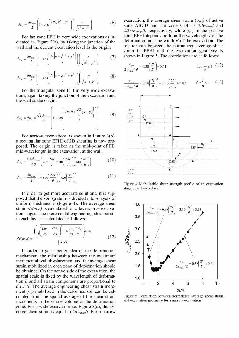
In order to get a better idea of the deformation mechanism, the relationship between the maximum incremental wall displacement and the average shear strain mobilized in each zone of deformation should be obtained. On the active side of the excavation, the spatial scale is fixed by the wavelength of deforma-tion l, and all strain components are proportional to dwmax/l. The average engineering shear strain incre-ment γmob mobilized in the deformed soil can be cal-culated from the spatial average of the shear strain increments in the whole volume of the deformation zone. For a wide excavation i.e. Figure 3(a), the av-erage shear strain is equal to 2dwmax/l. For a narrow
excavation, the average shear strain (γave) of active zone ABCD and fan zone CDE is 2dwmax/l and 2.23dwmax/l, respectively, while γave in the passive zone EFHI depends both on the wavelength l of the deformation and the width B of the excavation. The relationship between the normalized average shear strain in EFHI and the excavation geometry is shown in Figure 5. The correlations are as follows:
61.0238.0/2 max
+⎟⎠⎞
⎜⎝⎛=
Bl
Bwaveγ for 1≥
Bl (13)
83.3216.3298.0/2
2
max
+⎟⎠⎞
⎜⎝⎛−⎟
⎠⎞
⎜⎝⎛=
Bl
Bl
Bwaveγ for 1≤
Bl (14)
l
A B
C DF
E
H
I
σ1
1σ
σ1
σ1
DSS
DSS
PSAPSP
Layer 1
Layer 2
Layer 3
Layer 4
Layer n
Layer (n-1)
Figure 4 Mobilizable shear strength profile of an excavation stage in an layered soil
2l/B0 2 4 6 8 10
γ mob
Β/2wmax
1.0
1.5
2.0
2.5
3.0
3.5
4.0
61.0238.0/2 max
+⎟⎠⎞
⎜⎝⎛=
Bl
Bwaveγ
83.3216.3298.0/2
2
max
+⎟⎠⎞
⎜⎝⎛−⎟
⎠⎞
⎜⎝⎛=
Bl
Bl
Bwaveγ
Figure 5 Correlation between normalized average shear strain and excavation geometry for a narrow excavation
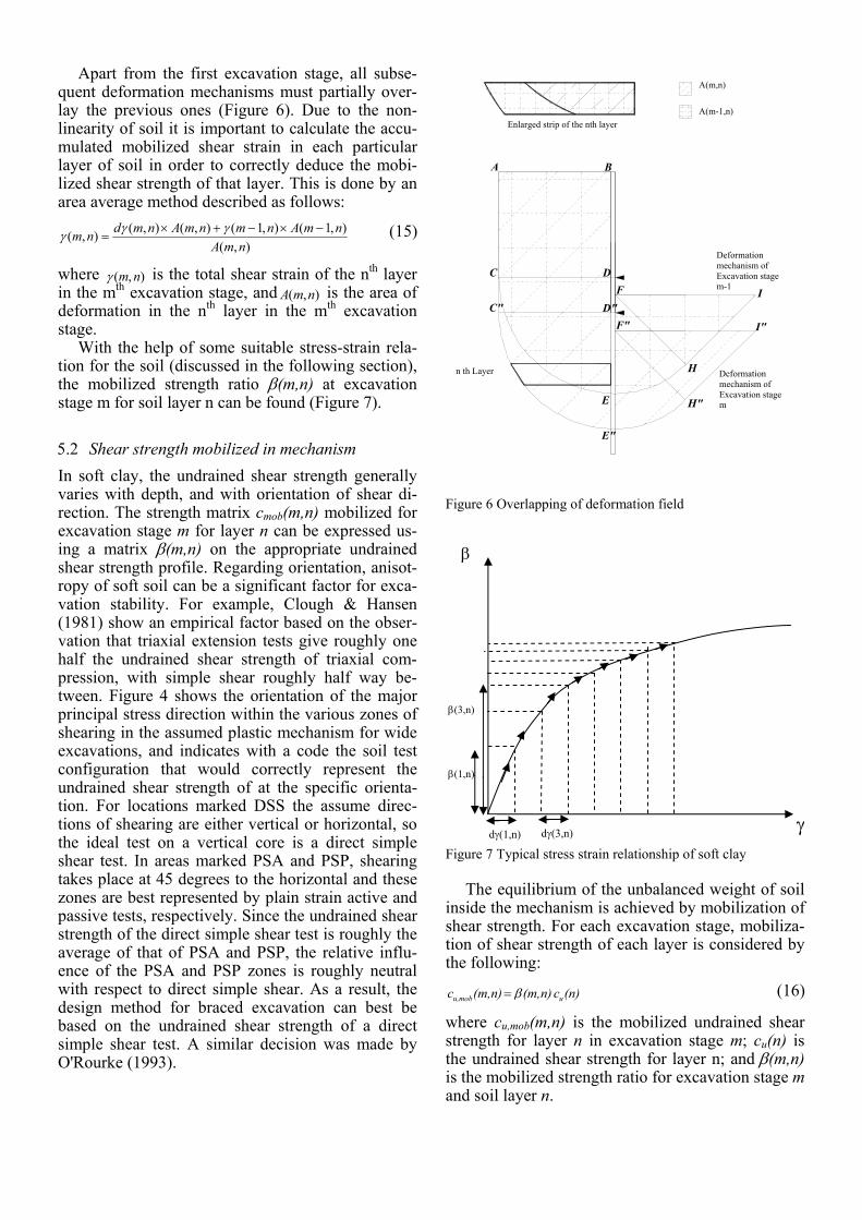
Apart from the first excavation stage, all subse-quent deformation mechanisms must partially over-lay the previous ones (Figure 6). Due to the non-linearity of soil it is important to calculate the accu-mulated mobilized shear strain in each particular layer of soil in order to correctly deduce the mobi-lized shear strength of that layer. This is done by an area average method described as follows:
),(),1(),1(),(),(),(
nmAnmAnmnmAnmdnm −×−+×
=γγγ (15)
where ),( nmγ is the total shear strain of the nth layer in the mth excavation stage, and ),( nmA is the area of deformation in the nth layer in the mth excavation stage.
With the help of some suitable stress-strain rela-tion for the soil (discussed in the following section), the mobilized strength ratio β(m,n) at excavation stage m for soil layer n can be found (Figure 7).
5.2 Shear strength mobilized in mechanism In soft clay, the undrained shear strength generally varies with depth, and with orientation of shear di-rection. The strength matrix cmob(m,n) mobilized for excavation stage m for layer n can be expressed us-ing a matrix β(m,n) on the appropriate undrained shear strength profile. Regarding orientation, anisot-ropy of soft soil can be a significant factor for exca-vation stability. For example, Clough & Hansen (1981) show an empirical factor based on the obser-vation that triaxial extension tests give roughly one half the undrained shear strength of triaxial com-pression, with simple shear roughly half way be-tween. Figure 4 shows the orientation of the major principal stress direction within the various zones of shearing in the assumed plastic mechanism for wide excavations, and indicates with a code the soil test configuration that would correctly represent the undrained shear strength of at the specific orienta-tion. For locations marked DSS the assume direc-tions of shearing are either vertical or horizontal, so the ideal test on a vertical core is a direct simple shear test. In areas marked PSA and PSP, shearing takes place at 45 degrees to the horizontal and these zones are best represented by plain strain active and passive tests, respectively. Since the undrained shear strength of the direct simple shear test is roughly the average of that of PSA and PSP, the relative influ-ence of the PSA and PSP zones is roughly neutral with respect to direct simple shear. As a result, the design method for braced excavation can best be based on the undrained shear strength of a direct simple shear test. A similar decision was made by O'Rourke (1993).
A B
C DF
E
H
IC" D"
F"
E"
H"
I"
n th Layer
Deformation mechanism of Excavation stage m-1
Deformation mechanism of Excavation stage m
Enlarged strip of the nth layerA(m-1,n)
A(m,n)
Figure 6 Overlapping of deformation field
Figure 7 Typical stress strain relationship of soft clay
The equilibrium of the unbalanced weight of soil
inside the mechanism is achieved by mobilization of shear strength. For each excavation stage, mobiliza-tion of shear strength of each layer is considered by the following:
(n)c n)(m, n)(m,c umobu, β= (16)
where cu,mob(m,n) is the mobilized undrained shear strength for layer n in excavation stage m; cu(n) is the undrained shear strength for layer n; and β(m,n) is the mobilized strength ratio for excavation stage m and soil layer n.
β
dγ(3,n) dγ(1,n)
β(1,n)
β(3,n)
γ
5.3 Incremental energy balance By conservation of energy, the total loss of potential energy of the soil (ΔP) must balance the total dissi-pated energy due to plastic shearing of the soil (ΔD) and the total stored elastic strain energy in bending the wall (ΔU).
UDP Δ+Δ=Δ (17) The potential energy loss on the active side of the wall and the potential energy gain of soil on the pas-sive side can be estimated easily. The net change of gravitational potential energy (ΔP) is given by the sum of the potential energy changes in each layer:
∑ ∫=
⎥⎦
⎤⎢⎣
⎡=Δ
n
i volumeysat dVolimdwimP
1
),(),(γ (18)
where dwy (m,i) is the vertical component of dis-placement of soil in the ith layer for the mth construc-tion; γsat (m,i) is the saturated unit weight of soil in the ith layer for the mth construction.
Since there are no displacement discontinuities, the total plastic work done by shearing of soil is given by summing the internal dissipation in each layer:
∑ ∫=
⎥⎦
⎤⎢⎣
⎡=Δ
n
i Volumeu dVolimdimcimD
1),(),(),( γβ (19)
where cu(m,i) is the undrained shear strength of soil in the ith layer for the mth construction; dγ(m,i) is the shear strain increment of soil in the ith layer for the mth construction; and the corresponding mobilized strength ratio is given by:
β(m,i) = ),(
),(,
imcimc
u
mobu
The total elastic strain energy stored in the wall, ΔU, can be evaluated by repeatedly updating the de-flected shape of the wall. It is necessary to do this since U is a quadratic function of displacement:
∫ ⎥⎦
⎤⎢⎣
⎡=Δ
sx dx
dywdEIU
0
2
2
2
2 (20)
where E and I are the elastic modulus and the second moment of area per unit length of wall, and s is the length of the wall in bending. L can be the length of wall s below the lowest prop.
By assuming the cosine waveform equation (Equation 1), the strain energy term can be shown to be as follows:
⎟⎟⎟⎟
⎠
⎞
⎜⎜⎜⎜
⎝
⎛
+=Δ4
)4sin(3
2max
3ls
ls
lEIdw
U
πππ (21)
where l is the wavelength of deformation, dwmax is the maximum deflection of the wall in each excava-tion increment.
5.4 Calculation procedure The following calculation procedure is programmed in Matlab 2006b.
1. At each stage of excavation, a maximum de-formation wmax, which is bounded by an up-per and a lower bound, is assumed. The soil stratum is divided into n layers. The areas on both the active side and the passive side in each layer are calculated.
2. For each layer, with the help of the numeri-cal integration procedure in Matlab, the mo-bilized shear strain and the change in PE on both active and passive sides in different zones is calculated. (Equation 18) The total mobilized shear strain is updated according Equation 15.
3. With the use of a suitable stress-strain curve (Figure 7), the mobilizable strength ratio β can be found.
4. Total change in PE and total energy dissipa-tion and elastic bending energy in the wall can be calculated by Equations 18, 19 & 21, respectively.
5. By considering the conservation of energy of a structure in statical equilibrium, the sum of total energy dissipation and elastic strain en-ergy in the wall balances the total change in PE. To facilitate solving the solution, an er-ror term is introduced as follows:
Error = ΔD + ΔU - ΔP (22) 6. When the error is smaller than a specified
convergence limit, the assumed deformation is accepted as the solution; otherwise, the method of bisection is employed to assume another maximum displacement and the error term is calculated again using steps 1 to 5.
7. Then, the incremental wall movement profile is plotted using the cosine function of equa-tion
8. The cumulative displacement profile is ob-tained by accumulating the incremental movement profiles.
6 VALIDATION BY NUMERICAL ANALYSIS
The finite element method can provide a framework for performing numerical simulations to validate the extended MSD method in evaluating the perform-ance of braced excavations. However, finite element analysis of retaining walls is potentially problematic. One the most difficult problems is the constitutive model used for the soil. The stress-strain relationship can be very complicated when considering stress history and anisotropy of soil (Whittle, 1993).
The validation of the extended MSD method is examined by comparing its predictions with results of comprehensive FE analyses of a plane strain
braced excavation in Boston Blue Clay carried out by Jen (1998). In these analyses, the MIT-E3 consti-tutive model is used (Whittle, 1987). The model is based on Modified Cam clay (Roscoe and Burland 1968). However, several modifications had been made to improve the basic critical state framework. The model can simulate small strain non-linearity, soil anisotropy and the hysteretic behaviour associ-ated with reversal of load paths. Whittle (1993) also demonstrated the ability of the model to accurately represent the behaviour of different clays when sub-jected to a variety of loading paths.
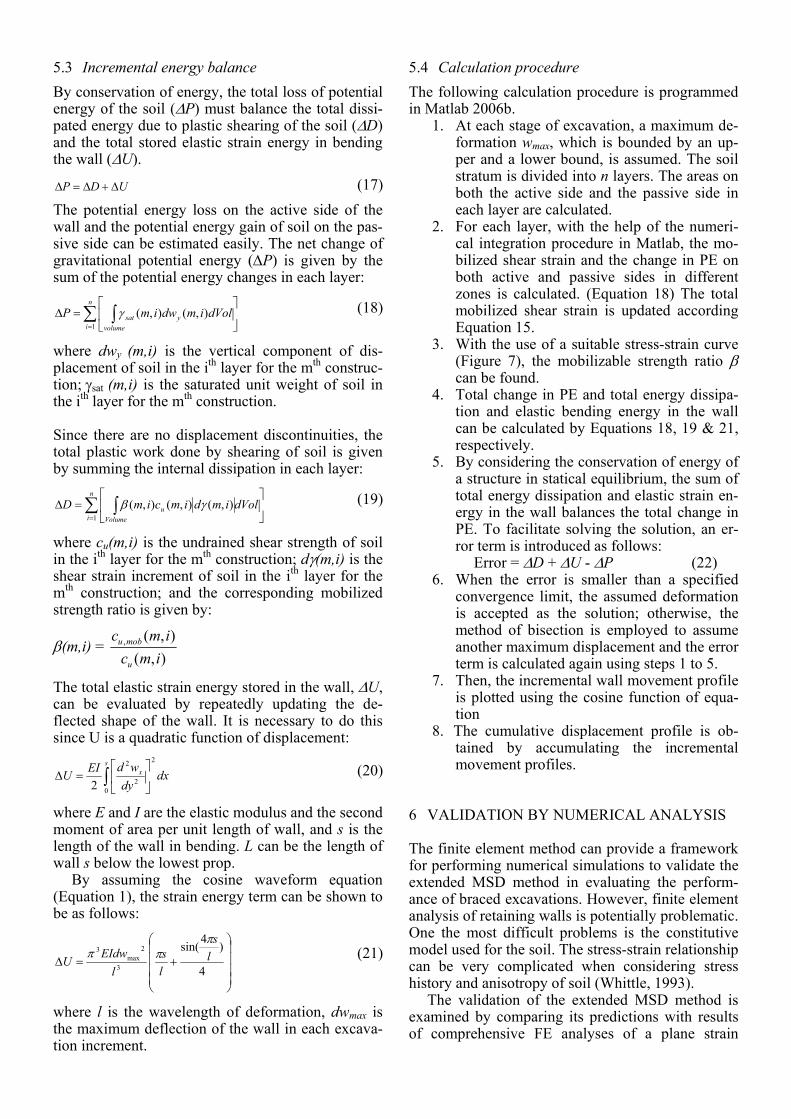
Jen (1998) extended the use of the MIT-E3 model for analyzing cases of deep excavation in a great va-riety of situations. She considered the effect of ex-cavation geometry such as wall length, excavation width and depth of bed rock, the effect of soil profile such as cu/OCR ratio and layered soil, and the effect of structural stiffness such as wall stiffness and strut stiffness. This provides a valuable database for vali-dation of the extended MSD method.
Retaining wall(EI=1440,77 and 19MNm /m)
OCR=1BBC properties
C=37.5, 50 and 100m
L=20, 25, 30, 35 and 40m
B/2=15,20,25 & 30mLC
h=2.5m
s=2.5m
2
Figure 8 Scope of parametric study to examine excavation width effect
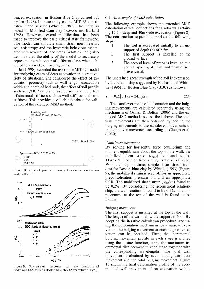
Figure 9. Stress-strain response for Ko consolidated undrained DSS tests on Boston blue clay (After Whittle, 1993)
6.1 An example of MSD calculation The following example shows the extended MSD calculation of wall deflections for a 40m wall retain-ing 17.5m deep and 40m wide excavation (Figure 8). The construction sequence comprises the following steps:
1 The soil is excavated initially to an un-supported depth (h) of 2.5m.
2 The first support is installed at the ground surface.
3 The second level of props is installed at a vertical spacing of 2.5m, and 2.5m of soil is excavated.
The undrained shear strength of the soil is expressed by the relationship suggested by Hashash and Whit-tle (1996) for Boston Blue Clay (BBC) as follows:
[ ]kPazcu 5.2419.821.0 += (23)
The cantilever mode of deformation and the bulg-ing movements are calculated separately using the mechanism of Osman & Bolton (2006) and the ex-tended MSD method as described above. The total wall movements are then obtained by adding the bulging movements to the cantilever movements to the cantilever movement according to Clough et al. (1989).
Cantilever movement By solving for horizontal force equilibrium and moment equilibrium about the top of the wall, the mobilized shear stress (cmob) is found to be 11.43kPa. The mobilized strength ratio β is 0.2886. With the help of direct simple shear stress-strain data for Boston blue clay by Whittle (1993) (Figure 9), the mobilized strain is read off for an appropriate preconsolidation pressure σ’p and an appropriate OCR. The mobilized shear strain (γmob) is found to be 0.2%. By considering the geometrical relation-ship, the wall rotation is found to be 0.1%. The dis-placement at the top of the wall is found to be 39mm.
Bulging movement The first support is installed at the top of the wall. The length of the wall below the support is 40m. By adopting the iterative calculation procedure, and us-ing the deformation mechanism for a narrow exca-vation, the bulging movement at each stage of exca-vation can be obtained. Then, the incremental bulging movement profile in each stage is plotted using the cosine function, using the maximum in-cremental displacement in each stage together with the corresponding wavelengths. The total wall movement is obtained by accumulating cantilever movement and the total bulging movement. Figure 10 shows the final deformation profile of the accu-mulated wall movement of an excavation with a

width of 40m. The maximum wall deflection at an excavation depth of 17.5m is 115mm. The position of the maximum wall displacement is located at 0.75L, where L is the length of the wall.
Wall deflection, w, (m)
0.00 0.04 0.08 0.12 0.16
Dep
th (m
)
05
101520253035404550
H=2.5H=5.0H=7.5H=10.0H=12.5H=15.0H=17.5
Figure 10 Wall deflections from MSD with different excava-tion depths
6.2 Effect of excavation width The effect of excavation width on predicted ground movements is the focus of this section. Underground transportation systems may have excavation widths ranging from 25m (a subway station) to 60m (an un-derground highway). The most widely used design charts generally incorporate the effect of excavation width in estimation of factor of safety against base heave (Bjerrum and Eide, 1956) or as a multiplica-tion factor in estimating the maximum settlement (Mana and Clough, 1981).
The scope of the excavation analyses are shown in Figure 8. In the analyses, the excavation was car-ried out in undrained conditions in a deposit of nor-mally consolidated Boston Blue Clay with depth C taken to be 100m. A concrete diaphragm wall of depth L = 40m, and thickness 0.9m, supported by rigid props spaced at h = 2.5m, was used for sup-porting the simulated excavation. The excavation width varies from 20m to 60m. The wavelength of deformation is chosen according to the sl α= rule, where α was taken to be 1.5 and s is the length of wall below the lowest prop. Computed results by Jen (1998) are used for comparison. Full details of the analysis procedures, assumptions and parameters are given in Jen (1998). In the following section, only results of wall deformation will be taken for com-parison.
Figure 11 (a) and (b) show the wall deflection profile with different excavation widths at an exca-vation depth of 17.5m, as calculated by the extended
MSD method and the MIT-E3 model. Figure 11 (a) shows that the excavation width does not have any effect on the deflected shape of the wall as calcu-lated by the extended MSD method. Figure 11 (b), simularly, shows a limited effect on the deflected shape of the wall by the MIT-E3 model. While the MSD-predicted maximum wall deflection increases by a factor of 1.5 as the width is increased from 30m to 60m, the MIT-E3 computed maximum wall de-formation increased by a factor of 1.6 with the same increase in excavation width.
Wall deflection, w, (m)
0.00 0.04 0.08 0.12 0.16
Dep
th (m
)
0
10
20
30
40
50
B=60B=50B=40B=30
(a) Prediction by Extended MSD
Wall deflection, w, (m)
0.00 0.04 0.08 0.12 0.16
Dep
th (m
)
0
10
20
30
40
50
B=60B=50B=40B=30
(b) Prediction by MIT E3 model (After Jen,1998)
Figure 11 Wall deflection profile of different excavation widths at H = 17.5m
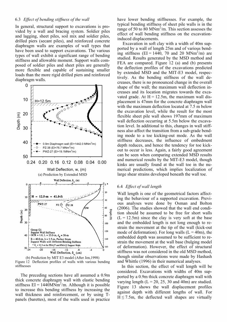
6.3 Effect of bending stiffness of the wall In general, structural support to excavations is pro-vided by a wall and bracing system. Soldier piles and lagging, sheet piles, soil mix and soldier piles, drilled piers (secant piles), and reinforced concrete diaphragm walls are examples of wall types that have been used to support excavations. The various types of wall exhibit a significant range of bending stiffness and allowable moment. Support walls com-posed of soldier piles and sheet piles are generally more flexible and capable of sustaining smaller loads than the more rigid drilled piers and reinforced diaphragm walls.
Wall Deflection, w, (m)
0.000.040.080.120.160.200.24
Dep
th (m
)
0
10
20
30
40
50
0.9m Diaphragm wall (EI=1442.0 MNm2/m)PZ-38 (EI=76.7 MNm2/m)PWZ-27 (EI=19.1MNm2/m)
H=12.5m
(a) Prediction by Extended MSD
(b) Prediction by MIT E3 model (After Jen,1998)
Figure 12 Deflection profiles of walls with various bending stiffnesses
The preceding sections have all assumed a 0.9m
thick concrete diaphragm wall with elastic bending stiffness EI = 1440MNm2/m. Although it is possible to increase this bending stiffness by increasing the wall thickness and reinforcement, or by using T-panels (barettes), most of the walls used in practice
have lower bending stiffnesses. For example, the typical bending stiffness of sheet pile walls is in the range of 50 to 80 MNm2/m. This section assesses the effect of wall bending stiffness on the excavation-induced displacements.
Excavation in soft clay with a width of 40m sup-ported by a wall of length 25m and of various bend-ing stiffness (EI = 1440, 70 and 20 MNm2/m) are studied. Results generated by the MSD method and FEA are compared. Figure 12 (a) and (b) presents the deflection profiles of the excavations predicted by extended MSD and the MIT-E3 model, respec-tively. As the bending stiffness of the wall de-creases, there is no pronounced change in the overall shape of the wall; the maximum wall deflection in-creases and its location migrates towards the exca-vated grade. At H = 12.5m, the maximum wall dis-placement is 47mm for the concrete diaphragm wall with the maximum deflection located at 7.5 m below the excavation level, while the result for the most flexible sheet pile wall shows 197mm of maximum wall deflection occurring at 5.5m below the excava-tion level. In additional to this, changes in wall stiff-ness also affect the transition from a sub-grade bend-ing mode to a toe kicking-out mode. As the wall stiffness decreases, the influence of embedment depth reduces, and hence the tendency for toe kick-out to occur is less. Again, a fairly good agreement can be seen when comparing extended MSD results and numerical results by the MIT-E3 model, though kinks are usually found at the wall toe in the nu-merical predictions, which implies localization of large shear strains developed beneath the wall toe.
6.4 Effect of wall length Wall length is one of the geometrical factors affect-ing the behaviour of a supported excavation. Previ-ous analyses were done by Osman and Bolton (2006). The studies showed that the wall end condi-tion should be assumed to be free for short walls (L = 12.5m) since the clay is very soft at the base and the embedded length is not long enough to re-strain the movement at the tip of the wall (kick-out mode of deformation). For long walls (L = 40m), the embedded depth was assumed to be sufficient to re-strain the movement at the wall base (bulging model of deformation). However, the effect of structural stiffness was not considered in the old MSD method, though similar observations were made by Hashash and Whittle (1996) in their numerical analyses. In this section, the effect of wall length will be considered. Excavations with widths of 40m sup-ported by a 0.9m thick concrete diaphragm wall with varying length (L = 20, 25, 30 and 40m) are studied. Figure 13 shows the wall displacement profiles against depth with different lengths of wall. For H ≤ 7.5m, the deflected wall shapes are virtually
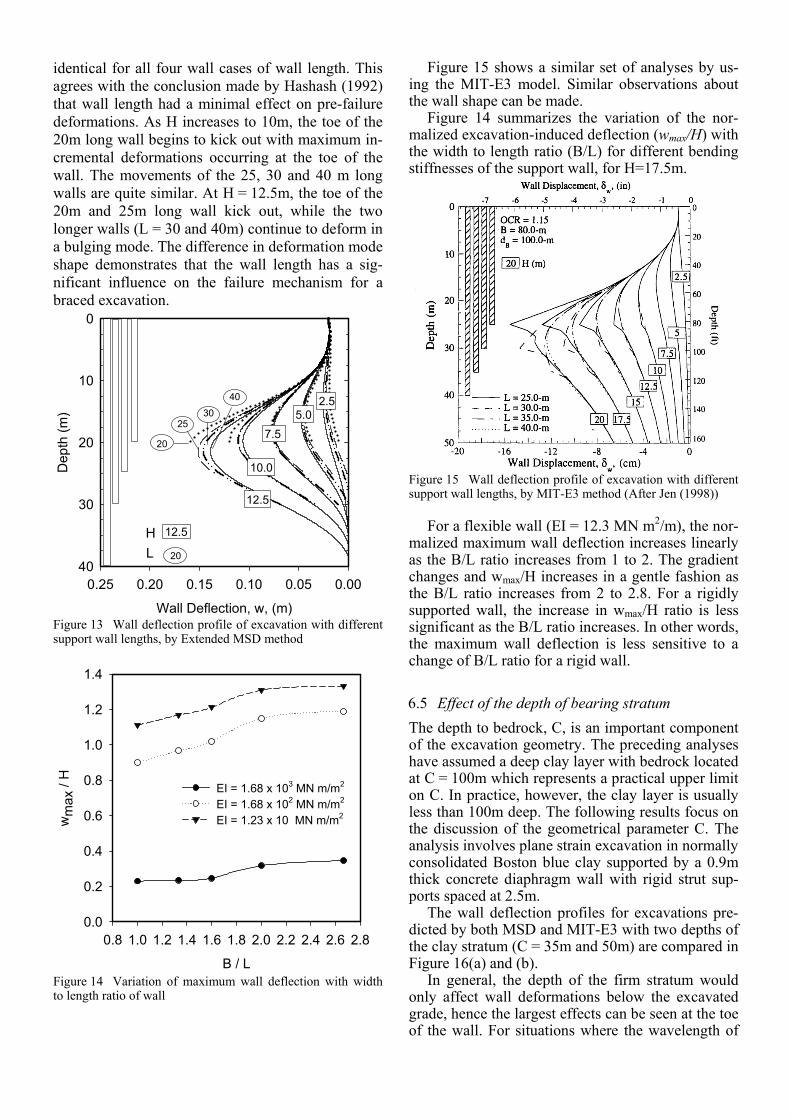
identical for all four wall cases of wall length. This agrees with the conclusion made by Hashash (1992) that wall length had a minimal effect on pre-failure deformations. As H increases to 10m, the toe of the 20m long wall begins to kick out with maximum in-cremental deformations occurring at the toe of the wall. The movements of the 25, 30 and 40 m long walls are quite similar. At H = 12.5m, the toe of the 20m and 25m long wall kick out, while the two longer walls (L = 30 and 40m) continue to deform in a bulging mode. The difference in deformation mode shape demonstrates that the wall length has a sig-nificant influence on the failure mechanism for a braced excavation.
Wall Deflection, w, (m)
0.000.050.100.150.200.25
Dep
th (m
)
0
10
20
30
40
2.55.0
7.5
10.0
12.5
40
3025
20
12.5
20
HL
Figure 13 Wall deflection profile of excavation with different support wall lengths, by Extended MSD method
B / L
0.8 1.0 1.2 1.4 1.6 1.8 2.0 2.2 2.4 2.6 2.8
wm
ax /
H
0.0
0.2
0.4
0.6
0.8
1.0
1.2
1.4
EI = 1.68 x 10³ MN m/m2
EI = 1.68 x 10² MN m/m2
EI = 1.23 x 10 MN m/m2
Figure 14 Variation of maximum wall deflection with width to length ratio of wall
Figure 15 shows a similar set of analyses by us-ing the MIT-E3 model. Similar observations about the wall shape can be made.
Figure 14 summarizes the variation of the nor-malized excavation-induced deflection (wmax/H) with the width to length ratio (B/L) for different bending stiffnesses of the support wall, for H=17.5m.
Figure 15 Wall deflection profile of excavation with different support wall lengths, by MIT-E3 method (After Jen (1998))
For a flexible wall (EI = 12.3 MN m2/m), the nor-
malized maximum wall deflection increases linearly as the B/L ratio increases from 1 to 2. The gradient changes and wmax/H increases in a gentle fashion as the B/L ratio increases from 2 to 2.8. For a rigidly supported wall, the increase in wmax/H ratio is less significant as the B/L ratio increases. In other words, the maximum wall deflection is less sensitive to a change of B/L ratio for a rigid wall.
6.5 Effect of the depth of bearing stratum The depth to bedrock, C, is an important component of the excavation geometry. The preceding analyses have assumed a deep clay layer with bedrock located at C = 100m which represents a practical upper limit on C. In practice, however, the clay layer is usually less than 100m deep. The following results focus on the discussion of the geometrical parameter C. The analysis involves plane strain excavation in normally consolidated Boston blue clay supported by a 0.9m thick concrete diaphragm wall with rigid strut sup-ports spaced at 2.5m.
The wall deflection profiles for excavations pre-dicted by both MSD and MIT-E3 with two depths of the clay stratum (C = 35m and 50m) are compared in Figure 16(a) and (b).
In general, the depth of the firm stratum would only affect wall deformations below the excavated grade, hence the largest effects can be seen at the toe of the wall. For situations where the wavelength of
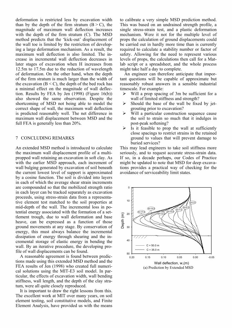
deformation is restricted less by excavation width than by the depth of the firm stratum (B > C), the magnitude of maximum wall deflection increases with the depth of the firm stratum (C). The MSD method predicts that the ‘kick-out’ displacement of the wall toe is limited by the restriction of develop-ing a large deformation mechanism. As a result, the maximum wall deflection is also limited. The in-crease in incremental wall deflection decreases in later stages of excavation when H increases from 12.5m to 17.5m due to the reduction of wavelength of deformation. On the other hand, when the depth of the firm stratum is much larger than the width of the excavation (B < C), the depth of the bed rock has a minimal effect on the magnitude of wall deflec-tion. Results by FEA by Jen (1998) (Figure 16(b)) also showed the same observation. Despite the shortcoming of MSD not being able to model the correct shape of wall, the maximum wall deflection is predicted reasonably well. The net difference in maximum wall displacement between MSD and the full FEA is generally less than 20%.
7 CONCLUDING REMARKS
An extended MSD method is introduced to calculate the maximum wall displacement profile of a multi-propped wall retaining an excavation in soft clay. As with the earlier MSD approach, each increment of wall bulging generated by excavation of soil beneath the current lowest level of support is approximated by a cosine function. The soil is divided into layers in each of which the average shear strain increments are compounded so that the mobilized strength ratio in each layer can be tracked separately as excavation proceeds, using stress-strain data from a representa-tive element test matched to the soil properties at mid-depth of the wall. The incremental loss in po-tential energy associated with the formation of a set-tlement trough, due to wall deformation and base heave, can be expressed as a function of those ground movements at any stage. By conservation of energy, this must always balance the incremental dissipation of energy through shearing and the in-cremental storage of elastic energy in bending the wall. By an iterative procedure, the developing pro-file of wall displacements can be found. A reasonable agreement is found between predic-tions made using this extended MSD method and the FEA results of Jen (1998) who created full numeri-cal solutions using the MIT-E3 soil model. In par-ticular, the effects of excavation width, wall bending stiffness, wall length, and the depth of the clay stra-tum, were all quite closely reproduced. It is important to draw the right lessons from this. The excellent work at MIT over many years, on soil element testing, soil constitutive models, and Finite Element Analysis, have provided us with the means
to calibrate a very simple MSD prediction method. This was based on an undrained strength profile, a single stress-strain test, and a plastic deformation mechanism. Were it not for the multiple level of props the calculation of ground displacements could be carried out in hardly more time than is currently required to calculate a stability number or factor of safety. Allowing for the need to represent various levels of props, the calculations then call for a Mat-lab script or a spreadsheet, and the whole process might take half a day to complete. An engineer can therefore anticipate that impor-tant questions will be capable of approximate but reasonably robust answers in a sensible industrial timescale. For example:
Will a prop spacing of 3m be sufficient for a wall of limited stiffness and strength?
Should the base of the wall be fixed by jet-grouting prior to excavation?
Will a particular construction sequence cause the soil to strain so much that it indulges in post-peak softening?
Is it feasible to prop the wall at sufficiently close spacings to restrict strains in the retained ground to values that will prevent damage to buried services?
This may lead engineers to take soil stiffness more seriously, and to request accurate stress-strain data. If so, in a decade perhaps, our Codes of Practice might be updated to note that MSD for deep excava-tions provides a practical way of checking for the avoidance of serviceability limit states.
Wall deflection, w,(m)
-0.050.000.050.100.150.20
Dep
th (m
)
0
10
20
30
40
50
H=17.5H=15.0
H=12.5H=10.0
H=7.5H=5.0
H=2.5
C = 35.0 m
C = 50.0 m
(a) Prediction by Extended MSD
(b) Prediction by MIT E3 model (After Jen,1998)
Figure 16 Wall deflection profiles of excavation with differ-ent depths to the firm stratum
ACKNOWLEDGEMENT
The authors would like to acknowledge the ear-marked research grant # 618006 provided by the Re-search Grants Council of the HKSAR Government, and also the Platform Grant (GR/T18660/01) awarded by the UK Engineering and Physical Sci-ences Research Council.
REFERENCES
Bjerrum, L., and Eide, O. (1956). Stability of strutted excava-tions in clay. Geotechnique 6, 115-128
Bolton, M.D. and Powrie, W., (1988). Behaviour of diaphragm walls retaining walls prior to collapse. Geotechnique, 37(3),pp 335-353.
Bolton, M.D., Powrie W. and Symons, I.F. (1989). The design of stiff in-situ walls retaining overconsolidated clay part . Ground engineering, 22(8),pp 44-48.
Bolton, M.D., Powrie, W. and Symons, I.F. (1990a). The de-sign of stiff in-situ walls retaining over-consolidated clay part 1, short term behaviour. Ground Engineering, 23(1), pp34-39.
Bolton, M.D., Powrie, W. and Symons, I.F. (1990b). The de-sign of stiff in-situ walls retaining over-consolidated clay, part II, long term behaviour. Ground engineering, 23(2), pp 22-28.
Clough, G.W. and Hansen, L.A., (1981). Clay anisotropy and braced wall behavior. ASCE Journal of Geotechnical Engi-neering, 107(7), 893-913.
Clough, G.W. and Smith, E. W. and Sweeney, B. P. Movement control of excavation support system by iterative design. Foundation Engineering Current Principles and Practices, Vol.2 ASCE, New York, NY, 1989, pp.869-882.
Eide, O., Aas, G., and Josang, T. (1972). Special application of cast-inplace walls for tunnels in soft clay. Proceedings of the 5th European Conference on Soil Mechanics and Foun-dation Engineering, Madrid, Spain, 1, 485-498.
Hashash, Y.M.A. and Whittle, A.J. (1996). Ground movement prediction for deep excavations in soft clay. ASCE Journal of Geotechnical Engineering, 122(6):474-486.
Jen, L.C. (1998). The design and performance of deep excava-tions in clay. PhD thesis, Dept. of Civil and Environmental Engineering, MIT, Cambridge, Mass.
Mana, A.I. and Clough, G.W. 1981. Prediction of movements for braced cut in clay. J. Geo. Engrg., ASCE, Vol.107(GT8), 759-777
Milligan, G.W.E. and Bransby, P.L. (1976). Combined active and passive rotational failure of a retaining wall in sand. Geotechnique, 26(3), 473-494.
O’Rourke, T.D. (1993). Base stability and ground movement prediction for excavations in soft clay. Retaining Struc-tures, Thomas Telford, London,131-139.
Osman, A.S. and Bolton, M.D. (2004) A new design method for retaining walls in clay. Canadian Geotechnical Journal, 41 (3), 451-466.
Osman, A.S. and Bolton, M.D. (2005) Simple plasticity-based prediction of the undrained settlement of shallow circular foundations on clay. Geotechnique, 55 (6), 435-447.
Osman, A.S. and Bolton, M.D. (2006) Ground movement pre-dictions for braced excavations in undrained clay. ASCE Journal of Geotechnical and Geo-environmental Engineer-ing, 132 (4), 465-477.
Osman, A.S., Bolton, M.D. and Mair, R.J. (2006) Predicting 2D ground movements around tunnels in undrained clay. Geotechnique 56 (9), 597-604.
Skempton, A.W. (1951). The bearing capacity of clays. Proc., Building Research Congress, London, 180-189.
Sloan, S.W. (1988). Lower bound limit analysis using finite elements and linear programming. International Journal for Numerical and Analytical Methods in Geomechanics, 12(1): 61-77.
Sloan, S.W. and Kleeman, P.W. (1995). Upper bound limit analysis using discontinuous velocity fields. Computer Methods in Applied Mechanics and Engineering., 127, 293-314.
Terzaghi, K., 1943. Theoretical soil mechanics, John Wiley & Sons, Inc., New York, N.Y.
Ukritchon, B., Whittle, A.J., and Sloan, S.W. (2003). Undrained stability of braced excavations in clay. ASCE Journal of Geotechnical and Geoenvironmental Engineer-ing, 129(8):738-755.
Whittle, A.J. (1987). A constitutive model for overconsolidated clays with application to the cyclic loading of friction piles. PhD thesis, Dept. of Civil and Environmental Engineering, MIT, Cambridge, Mass.
Whittle, A.J. (1993). Evaluation of a constitutive model for overconsolidated clays. Geotechnique, 43(2): 289-313.