Embed Size (px)
DESCRIPTION
Hvac
Citation preview
INSTALLATION, OPERATION & MAIN TE NANCE
AIR-COOLED SCREW LIQUID CHILLERS
Supersedes: Nothing Form 201.23-NM1 (1007)
AIR-COOLED SCREW LIQUID CHILLERSSTYLE A
R134aMODELSYCIV0590-1500, 50 HZ
(590 -1500 KW)E/V HIGH EFFICIENCY AND S/P STANDARD EFFICIENCY
035-21506-100
2 JOHNSON CONTROLS
FORM 201.23-NM1 (1007)
This equipment is a relatively complicated ap pa ra tus. Dur ing installation, operation, maintenance or service, in di vid u als may be exposed to certain com po nents or conditions in clud ing, but not limited to: re frig er ants, oils, materials un der pressure, rotating com po nents, and both high and low voltage. Each of these items has the po ten tial, if misused or handled im prop er ly, to cause bodi ly injury or death. It is the obligation and re spon -si bil i ty of operating/service per son nel to iden ti fy and rec og nize these inherent hazards, protect them selves, and pro ceed safely in completing their tasks. Failure to com ply with any of these requirements could re sult in se ri ous dam age to the equipment and the prop er ty in
IMPORTANT!READ BEFORE PROCEEDING!
GENERAL SAFETY GUIDELINES
which it is sit u at ed, as well as severe personal injury or death to them selves and people at the site.
This document is intended for use by owner-authorized operating/service personnel. It is expected that this in di vid u al possesses independent training that will en- able them to perform their assigned tasks properly and safe ly. It is essential that, prior to performing any task on this equipment, this individual shall have read and un der stood this document and any referenced materials. This in di vid u al shall also be familiar with and comply with all ap pli ca ble governmental standards and regula-tions per tain ing to the task in question.
SAFETY SYMBOLSThe following symbols are used in this document to alert the reader to areas of potential hazard:
CAUTION identifi es a hazard which could lead to damage to the ma chine, damage to other equip ment and/or en vi ron men tal pollution. Usually an in struc tion will be given, together with a brief ex pla na tion.
NOTE is used to highlight ad di tion al information which may be helpful to you.
DANGER indicates an im mi nent ly hazardous situation which, if not avoid ed, will re sult in death or se ri ous injury.
WARNING indicates a potentially haz ard ous sit u a tion which, if not avoid ed, could result in death or se- ri ous in ju ry.
External wiring, unless specifi ed as an optional connection in the man u fac tur er’s prod uct line, is NOT to be connected inside the micro pan el cab i net. De vic es such as re lays, switch es, transducers and controls may NOT be installed inside the pan el. NO external wiring is al- lowed to be run through the micro panel. All wir ing must be in ac cor dance with YORK’s pub lished spec i fi ca tions and must be per formed ONLY by qual i fi ed YORK personnel. YORK will not be re spon si ble for dam ag es/problems re sult ing from im prop er con nec tions to the con trols or ap pli ca tion of im prop er con trol sig nals. Failure to fol low this will void the man u fac tur er’s warranty and cause serious dam age to property or injury to per sons.
3JOHNSON CONTROLS
FORM 201.23-NM1 (1007)
The Control/VSD Cabinet contains lethal High AC and DC voltages. Before performing service inside the cabinet, remove the AC supply feeding the chiller and verify using a non-contact voltage sensor.
The DC Voltage on the VSD DC Bus will take 5 minutes to bleed off, after AC power is removed. Always check the DC Bus Voltage with a Voltmeter to assure the capacitor charge has bled off before working on the system.
•NEVER short out the DC Bus to discharge the fi lter capacitors.
•NEVER place loose tools, debris, or any objects inside the Control Panel/VSD Cabinet.
•NEVER allow the Control Panel VSD Cabinet doors to remain open if there is a potential for rain to enter the panel. Keep doors closed and assure all latches are engaged on each door unless the unit is being serviced.
•ALWAYS lockout the disconnect supplying AC to the chiller.
•The 1L Line Inductor will reach operating temperatures of over 300° F. DO NOT open panel doors during operation. Assure the inductor is cool whenever working near the inductor with power off.
4 JOHNSON CONTROLS
FORM 201.23-NM1 (1007)
CHANGEABILITY OF THIS DOCUMENT
In complying with YORK’s policy for continuous product improvement, the in for ma tion con tained in this document is subject to change without notice. While YORK makes no com mit ment to update or provide current information au to mat i cal ly to the manual owner, that information, if ap pli ca ble, can be ob tained by con tact ing the nearest YORK Engineered Systems Service offi ce.
It is the responsibility of operating/service personnel to verify the ap pli ca bil i ty of these documents to the equip-ment in question. If there is any question in the mind of operating/service personnel as to the applicability of these doc u ments, then prior to work ing on the equipment, they should verify with the owner whether the equip ment has been modifi ed and if current literature is available.
5JOHNSON CONTROLS
FORM 201.23-NM1 (1007)
TABLE OF CONTENTS
TABLE OF CONTENTS .......................................................................................................................5LIST OF FIGURES .............................................................................................................................13LIST OF TABLES ...............................................................................................................................15SECTION 1 - GENERAL CHILLER INFORMATION & SAFETY ......................................................16
INTRODUCTION .........................................................................................................................................16WARRANTY ................................................................................................................................................16SAFETY .......................................................................................................................................................16
Standards for Safety ...........................................................................................................................16RESPONSIBILITY FOR SAFETY ...............................................................................................................17ABOUT THIS MANUAL ..............................................................................................................................17MISUSE OF EQUIPMENT ...........................................................................................................................17
Suitability for Application ...................................................................................................................17Structural Support ...............................................................................................................................17Mechanical Strength ..........................................................................................................................17General Access ....................................................................................................................................17Pressure Systems ...............................................................................................................................18Electrical ...............................................................................................................................................18Rotating Parts ......................................................................................................................................18Sharp Edges .........................................................................................................................................18Refrigerants and Oils ..........................................................................................................................18High Temperature and Pressure Cleaning ........................................................................................18Emergency Shutdown .........................................................................................................................18
SECTION 2 - PRODUCT DESCRIPTION ..........................................................................................19INTRODUCTION .........................................................................................................................................19
General System Description ...............................................................................................................19Compressor .........................................................................................................................................20Evaporator ............................................................................................................................................21Condenser ............................................................................................................................................21Flash Tank Feed Valve/Drain Valves ..................................................................................................22Oil Separator/Oil System ....................................................................................................................22Relief Valves .........................................................................................................................................22Oil Cooling ...........................................................................................................................................23Capacity Control ..................................................................................................................................23Power and Control Panel ....................................................................................................................23Each Power Compartment Contains .................................................................................................23Microprocessor and VSD Controls ....................................................................................................23Display ..................................................................................................................................................24Keypad ..................................................................................................................................................24Unit Switch ...........................................................................................................................................24Variable Speed Drive (VSD) ................................................................................................................25
6 JOHNSON CONTROLS
FORM 201.23-NM1 (1007)
TABLE OF CONTENTS (CON'T)
ACCESSORIES AND OPTIONS .................................................................................................................26Single Point Circuit Breaker ...............................................................................................................26Building Automation System (BAS) Interface ..................................................................................26Condenser Coil Protection .................................................................................................................26
DX COOLER OPTIONS ..............................................................................................................................27SERVICE VALVE OPTION ..........................................................................................................................27UNIT ENCLOSURES ...................................................................................................................................27FANS ...........................................................................................................................................................27SOUND REDUCTION OPTIONS ................................................................................................................27VIBRATION ISOLATION .............................................................................................................................28UNIT MODEL NUMBER NOMENCLATURE ...............................................................................................29COMPLETE PIN NUMBER DESCRIPTION ................................................................................................30
SECTION 3 - HANDLING AND STORAGE .......................................................................................34DELIVERY AND STORAGE ........................................................................................................................34INSPECTION ...............................................................................................................................................34MOVING THE CHILLER ..............................................................................................................................34
Lifting Weights .....................................................................................................................................34UNIT RIGGING ............................................................................................................................................35
SECTION 4 - INSTALLATION ...........................................................................................................37LOCATION REQUIREMENTS ....................................................................................................................37OUTDOOR INSTALLATIONS .....................................................................................................................37INDOOR INSTALLATIONS .........................................................................................................................37
Installation ............................................................................................................................................38SHIPPING BRACES ....................................................................................................................................38CHILLED LIQUID PIPING ...........................................................................................................................38
General Requirements ........................................................................................................................38LOCATION CLEARANCES ........................................................................................................................38VIBRATION ISOLATORS ............................................................................................................................38WATER TREATMENT .................................................................................................................................40PIPEWORK ARRANGEMENT ....................................................................................................................40CONNECTION TYPES & SIZES .................................................................................................................40COOLER CONNECTIONS ..........................................................................................................................40
Option Flanges ....................................................................................................................................40REFRIGERANT RELIEF VALVE PIPING ....................................................................................................41DUCTWORK CONNECTION .....................................................................................................................41
General Requirements .......................................................................................................................41ELECTRICAL CONNECTION .....................................................................................................................41POWER WIRING .........................................................................................................................................42POWER SUPPLY WIRING ..........................................................................................................................42115VAC CONTROL SUPPLY TRANSFORMER .........................................................................................42CONTROL PANEL WIRING ........................................................................................................................42
7JOHNSON CONTROLS
FORM 201.23-NM1 (1007)
TABLE OF CONTENTS (CON'T)
VOLTS FREE CONTACTS ..........................................................................................................................43Chilled Liquid Pump Starter ...............................................................................................................43Run Contact .........................................................................................................................................43Alarm Contacts ....................................................................................................................................43
SYSTEM INPUTS ........................................................................................................................................43Flow Switch ..........................................................................................................................................43Remote Run / Stop ..............................................................................................................................43Remote Print ........................................................................................................................................43Optional Remote Setpoint Offset – Temperature .............................................................................43Optional Remote Setpoint Offset – Current ......................................................................................43Optional Remote Setpoint Offset – Sound Limiting .........................................................................43
SECTION 5 - COMMISSIONING .......................................................................................................44PREPARATION ...........................................................................................................................................44PREPARATION – GENERAL ......................................................................................................................44
Inspection ............................................................................................................................................44Refrigerant Charge ..............................................................................................................................44Service and Oil Line Valves ................................................................................................................44Compressor Oil ....................................................................................................................................44Fans .....................................................................................................................................................44Isolation / Protection ...........................................................................................................................44Control Panel .......................................................................................................................................44Power Connections .............................................................................................................................45Grounding ............................................................................................................................................45Water System .......................................................................................................................................45Flow Switch ..........................................................................................................................................45Temperature Sensor(s) .......................................................................................................................45Programmed Options ..........................................................................................................................46Programmed Settings ........................................................................................................................46Date and Time ......................................................................................................................................46Start/Stop Schedule ............................................................................................................................46Setpoint and Remote Offset ...............................................................................................................46
FIRST TIME START-UP ..............................................................................................................................46Interlocks ..............................................................................................................................................46Unit Switch ...........................................................................................................................................46Start-up .................................................................................................................................................46Oil Pressure .........................................................................................................................................46Refrigerant Flow ..................................................................................................................................47Loading .................................................................................................................................................47Condenser and Fan Rotation .............................................................................................................47Suction Superheat ...............................................................................................................................47Subcooling ...........................................................................................................................................47General Operation ..............................................................................................................................47
8 JOHNSON CONTROLS
FORM 201.23-NM1 (1007)
SECTION 6 - TECHNICAL DATA ......................................................................................................48WATER PRESSURE DROP CHARTS ........................................................................................................48GLYCOL CORRECTION FACTORS ...........................................................................................................52WATER TEMPERATURE AND FLOWS ......................................................................................................53PHYSICAL DATA - ENGLISH .....................................................................................................................55
Standard Effi ciency .............................................................................................................................55High Effi ciency .....................................................................................................................................57
PHYSICAL DATA - SI ..................................................................................................................................59Standard Effi ciency .............................................................................................................................59High Effi ciency .....................................................................................................................................61
OPERATING LIMITATIONS AND SOUND DATA .......................................................................................63ELECTRICAL DATA ....................................................................................................................................64ELECTRICAL NOTES .................................................................................................................................78ELECTRICAL WIRING DIAGRAMS - 2 COMPRESSOR MODELS ...........................................................80
Elementary Control Wiring Diagram ..................................................................................................80Elementary Power Wiring Diagram ....................................................................................................82Power Wiring Connection Diagram ...................................................................................................84Control Wiring Connection Diagram .................................................................................................86Power Elementary Wiring Diagram ....................................................................................................89Location Label .....................................................................................................................................91Panel Layout ........................................................................................................................................92
ELECTRICAL WIRING DIAGRAMS - 3 COMPRESSOR MODELS ...........................................................94Elementary Control Wiring Diagram ..................................................................................................94Control Elementary Diagram ..............................................................................................................96Power Elementary Diagram ................................................................................................................98Control Wiring Connection Diagram ...............................................................................................100Power Wiring Connection Diagram .................................................................................................103Power Elementary Diagram ..............................................................................................................106Location Label ...................................................................................................................................108Panel Layout ......................................................................................................................................109
DIMENSIONS - 2 & 3 COMPRESSOR SI .................................................................................................110TECHNICAL DATA - CLEARANCES ........................................................................................................130WEIGHT DISTRIBUTION AND ISOLATOR MOUNTING POSITIONS .....................................................131ISOLATOR MOUNTING POSITIONS ........................................................................................................132SLRS SEISMIC ISOLATOR SPECIFICATIONS .......................................................................................136SLRS SEISMIC ISOLATOR INSTALLATION AND ADJUSTMENT .........................................................137ND-X NEOPRENE ISOLATOR SPECIFICATIONS ...................................................................................138CIP 1" DEFLECTION RESTRAINED MOUNTING SPECIFICATIONS ....................................................139INSTALLATION OF 1" DEFLECTION MOUNTS ......................................................................................140REFRIGERANT FLOW DIAGRAM ...........................................................................................................141PROCESSES AND INSTRUMENTATION DIAGRAM ...............................................................................142COMPONENT LOCATIONS ......................................................................................................................143GLYCOL SYSTEM COMPONENTS ..........................................................................................................164
TABLE OF CONTENTS (CON'T)
9JOHNSON CONTROLS
FORM 201.23-NM1 (1007)
1COMPRESSOR COMPONENTS ..............................................................................................................166EQUIPMENT START-UP CHECK SHEET ................................................................................................167
Unit Checks (No Power) ....................................................................................................................167Panel Checks (Power On – Both System Switches “Off”) ....................................................................... 169Programmed Values ..........................................................................................................................170Chilled Liquid Setpoint .....................................................................................................................170Date/time, Daily Schedule, and Clock Jumper ................................................................................170Initial Start-up ....................................................................................................................................171Checking Subcooling and Superheat ..............................................................................................171Leak Checking ...................................................................................................................................172
CHILLER ELECTRONIC COMPONENTS ................................................................................................173Keypad ................................................................................................................................................173Display ................................................................................................................................................174Chiller Control Board ........................................................................................................................175Relay Output Boards .........................................................................................................................176VSD (Variable Speed Drive) .............................................................................................................176AC to DC Rectifi er .............................................................................................................................176SCR Trigger Board ............................................................................................................................177DC Link Filter .....................................................................................................................................1771l Line Inductor .................................................................................................................................178DC to AC Inverter ...............................................................................................................................178Laminated Bus Structure ..................................................................................................................178VSD Logic Board ...............................................................................................................................179Control Panel to VSD Communications ..........................................................................................179IGBT Gate Driver Boards ..................................................................................................................180Current Transformers ........................................................................................................................180DV/DT Output Suppression Network ...............................................................................................181Flash Tank Feed and Drain Valve Controller ...................................................................................181Chiller Circuit Breaker .......................................................................................................................182DC Bus Voltage Isolation Board .......................................................................................................182
CHILLER CONFIGURATION JUMPERS ..................................................................................................183Number of Compressors Confi guration Jumper ............................................................................183
VSD LOGIC TO CHILLER MICROPROCESSOR BOARD RS-485 COMMUNICATIONCONFIGURATION JUMPERS ..................................................................................................................183MAXIMUM VSD FREQUENCY/MODEL DESIGNATOR ...........................................................................184
SECTION 7 - OPERATION ..............................................................................................................185OPERATING CONTROLS .........................................................................................................................185BASIC OPERATING SEQUENCE ............................................................................................................187NUMBER OF COMPRESSORS TO START .............................................................................................188
General ...............................................................................................................................................188Standard IPLV ....................................................................................................................................188Optional Optimized High IPLV ..........................................................................................................188
TABLE OF CONTENTS (CON'T)
10 JOHNSON CONTROLS
FORM 201.23-NM1 (1007)
MINIMUM VSD COMPRESSOR START/RUN FREQUENCY ..................................................................189Minimum VSD Start Frequency ........................................................................................................189Minimum VSD Run Frequency .........................................................................................................189
ACCELERATION/DECELERATION RATE WHEN STARTING/STOPPING COMPRESSORS ...............190VSD Acceleration and Deceleration Rates ......................................................................................190
STANDARD IPLV CAPACITY CONTROL .................................................................................................191Fuzzy Logic Control ..........................................................................................................................192Hot Water Starts ................................................................................................................................193Lag Compressor Operation In Load Limiting .................................................................................193
OPTIONAL HIGH IPLV CAPACITY CONTROL .......................................................................................194Fuzzy Logic Control ..........................................................................................................................195Hot Water Starts ................................................................................................................................196
LOAD LIMITING CONTROL .....................................................................................................................197FLASH TANK DRAIN AND FEED VALVE CONTROLLER ......................................................................200
Valve Controller and Control Algorithm Operation ........................................................................200ECONOMIZER CONTROL ........................................................................................................................203CONDENSER FAN CONTROL .................................................................................................................204VSD TEMPERATURE CONTROL, OPERATION OF THE COOLANT PUMP, AND VSD CABINET COOLING FANS .....................................................................................................206REMOTE TEMPERATURE RESET CONTROL ........................................................................................207
Local Current Limit Control ..............................................................................................................208Pulldown Current Limit Setpoint ......................................................................................................208
REMOTE CURRENT LIMIT RESET CONTROL .......................................................................................209SOUND LIMIT CONTROL .........................................................................................................................211
SECTION 8 - MICROPANEL ...........................................................................................................213VSD OPERATION AND CONTROLS ........................................................................................................213
VSD Cooling and Cooling Loop .......................................................................................................215VSD SAFETIES (FAULTS) ........................................................................................................................219
IGBT Gate Driver (Hardware) Fault ..................................................................................................222Power Supply (Hardware) Fault ......................................................................................................224
UNIT WARNINGS ......................................................................................................................................226UNIT SAFETIES ........................................................................................................................................228SYSTEM SAFETIES (FAULTS) ................................................................................................................230STATUS KEY .............................................................................................................................................236UNIT DATA KEY ........................................................................................................................................240SYSTEM DATA KEYS 1-4 .........................................................................................................................242VSD DATA KEY .........................................................................................................................................245OPERATING HOURS / START COUNTER KEY ......................................................................................247
TABLE OF CONTENTS (CON'T)
11JOHNSON CONTROLS
FORM 201.23-NM1 (1007)
HISTORY KEY ...........................................................................................................................................248Unit Data .............................................................................................................................................250VSD Data ............................................................................................................................................250System Data .......................................................................................................................................251Compressor Operating Hours and Starts .......................................................................................253Chilled Liquid Setpoint Cooling Setpoints ......................................................................................253Options ...............................................................................................................................................253Program Values .................................................................................................................................254
SETPOINTS KEY ......................................................................................................................................256PROGRAM KEY ........................................................................................................................................258OPTIONS KEY ..........................................................................................................................................261DATE / TIME & SCHEDULE KEYS ...........................................................................................................265
DATE/TIME Key Operation ................................................................................................................265SCHEDULE Key Operation ...............................................................................................................266Unit Operating Schedule ...................................................................................................................267Sound Limit Schedule .......................................................................................................................268
MANUAL OVERRIDE KEY .......................................................................................................................269PRINT KEY ................................................................................................................................................270
Operating Data Printout ....................................................................................................................271History Data Printout .........................................................................................................................272
SERVICE KEY ...........................................................................................................................................273SYSTEM SWITCHES KEY ........................................................................................................................279SERIAL NUMBER PROGRAMMING ........................................................................................................280ENABLING OPTIMIZED HIGH IPLV MODE .............................................................................................282UNIT SETUP MODE ..................................................................................................................................283DEFAULT PROGRAMMABLE VALUES ...................................................................................................285SERIAL PORT CONNECTIONS ...............................................................................................................286ANALOG INPUT CONNECTIONS ............................................................................................................287DIGITAL INTPUT CONNECTIONS ...........................................................................................................289ANALOG OUTPUT CONNECTIONS ........................................................................................................291DIGITAL OUTPUT CONNECTIONS ..........................................................................................................292ISN COMMUNICATIONS ..........................................................................................................................294ISN TRANSMITTED DATA ........................................................................................................................295ISN FAULT AND INHIBIT CODES ............................................................................................................297ISN OPERATIONAL STATUS CODES .....................................................................................................299
SECTION 9 - MAINTENANCE .........................................................................................................300R-134A CONVERSION TABLES ..............................................................................................................300GENERAL REQUIREMENTS ...................................................................................................................301MAINTENANCE REQUIREMENTS ..........................................................................................................302TROUBLESHOOTING GUIDE .................................................................................................................304EVACUATING A SYSTEM .........................................................................................................................306
TABLE OF CONTENTS (CON'T)
12 JOHNSON CONTROLS
FORM 201.23-NM1 (1007)
WARRANTY POLICY ................................................................................................................................307Warranty on New Equipment ............................................................................................................307Warranty on Reconditioned or Replacement Materials .................................................................307All Warranties and Guarantees Are Void If: .....................................................................................307
CHILLED LIQUID AND SUCTION TEMPERATURE SENSOR INPUT VOLTAGE .................................308OUTSIDE AIR TEMPERATURE SENSOR INPUT VOLTAGE .................................................................309PRESSURE TRANSDUCER OUTPUT VOLTAGE ...................................................................................310MOTOR TEMPERATURE SENSOR RESISTANCE .................................................................................311COMPRESSOR MOTOR OVERLOAD & MAX. VSD FREQUENCY ........................................................312PRINTER WIRING .....................................................................................................................................315
Okidata 184: .......................................................................................................................................316Weigh-tronix Imp 24 Model 2600: .....................................................................................................316Seiko: ..................................................................................................................................................316
OPERATING LOG SHEET ........................................................................................................................317Site and Chiller Information ..............................................................................................................317Programmed Values ..........................................................................................................................317Unit Operating Temperatures and Pressures .................................................................................318System Operating Temperatures, Pressures, & Currents .............................................................318Water System Conditions .................................................................................................................320Condenser Conditions ......................................................................................................................320
RECOMMENDED SPARE PARTS ............................................................................................................321
TABLE OF CONTENTS (CON'T)
13JOHNSON CONTROLS
FORM 201.23-NM1 (1007)
LIST OF FIGURES
FIG. 1 - PWM CURRENT WAVEFORM .............................................................................................................25FIG. 2 - PWM VOLTAGE WAVEFORM ..............................................................................................................25FIG. 3 - PIPEWORK ARRANGEMENT .............................................................................................................40FIG. 4 - VICTAULIC GROOVE ...........................................................................................................................40FIG. 5 - FLANGE ATTACHMENT ......................................................................................................................40FIG. 6 - TWO COMPRESSOR WIRING DIAGRAM WITH CIRCUIT BREAKER ..............................................64FIG. 7 - TWO COMPRESSOR WIRING DIAGRAM WITH TERMINAL BLOCK ...............................................64FIG. 6A - THREE COMPRESSOR WIRING DIAGRAM WITH CIRCUIT BREAKER – SINGLE POINT ..........65FIG. 7A - THREE COMPRESSOR WIRING DIAGRAM WITH TERMINAL BLOCK – SINGLE POINT ...........65FIG. 8 - ELEMENTARY CONTROL WIRING DIAGRAM 2 COMPRESSOR MODELS ....................................80FIG. 8A - ELEMENTARY POWER WIRING DIAGRAM - YCIV0590-1000 2 COMPRESSOR MODELS .........82FIG. 8B - POWER WIRING CONNECTION DIAGRAM - YCIV0590-1000 2 COMPRESSOR MODELS .........84FIG. 8C - CONTROL WIRING CONNECTION DIAGRAM - YCIV0590-1000 2 COMPRESSOR MODELS ....86FIG. 8D - POWER ELEMENTARY WIRING DIAGRAM - YCIV0590-1000 2 COMPRESSOR MODELS .........89FIG. 8E - CONTROL ELEMENTARY DIAGRAM - YCIV1050-1500 3 COMPRESSOR MODELS ....................94FIG. 8F - CONTROL ELEMENTARY DIAGRAM - YCIV1050-1500 3 COMPRESSOR MODELS ....................96FIG. 8G - POWER ELEMENTARY DIAGRAM - YCIV1050-1500 3 COMPRESSOR MODELS .......................98FIG. 8H - CONTROL WIRING CONNECTION DIAGRAM - YCIV1050-1500 3 COMPRESSOR MODELS ...100FIG. 8I - POWER WIRING CONNECTION DIAGRAM - YCIV1050-1500 3 COMPRESSOR MODELS .........103FIG. 8J - POWER ELEMENETARY DIAGRAM - YCIV1050-1500 3 COMPRESSOR MODELS ....................106FIG. 9 - REFRIGERANT FLOW DIAGRAM .....................................................................................................141FIG. 10 - PROCESSES AND INSTRUMENTATION DIAGRAM ......................................................................142FIG. 11 - COMPONENT LOCATIONS .............................................................................................................143FIG. 12 - CONTROL AND VSD CABINET COMPONENTS ............................................................................144FIG. 13 - CHILLER CONTROL BOARD, RELAY BOARDS, MICROGATEWAY, AND OPTIONAL CIRCUIT BREAKER ............................................................................................145FIG. 14 - CHILLER CONTROL BOARD, RELAY BOARDS, AND MICROGATEWAY, 2 COMPRESSOR ....146FIG. 14A - CHILLER CONTROL BOARD, RELAY BOARDS, AND MICROGATEWAY, 3 COMPRESSOR .147FIG. 15 - VSD LOGIC BOARD ........................................................................................................................148FIG. 16 - VSD LOGIC BOARD (ORIGINAL - OBSOLETE), P/N 031-02477-000 ...........................................149FIG. 16A - VSD LOGIC BOARD (NEW), P/N 031-02507-XXX ......................................................................150FIG. 17 - POWER COMPONENTS, 2 COMPRESSOR ...................................................................................151FIG. 17A - POWER COMPONENTS, 3 COMPRESSOR ................................................................................152FIG. 18 - FAN CONTACTORS AND 3T TRANSFORMER, 2 COMPRESSOR ...............................................153FIG. 18A - FAN CONTACTORS, 3 COMPRESSOR ........................................................................................154FIG. 19 - VSD COMPONENTS ........................................................................................................................155FIG. 20 - VSD COMPONENTS, 2 COMPRESSOR .........................................................................................156FIG. 20A - VSD COMPONENTS, 3 COMPRESSOR .......................................................................................157FIG. 21 - VSD COMPONENTS, 2 COMPRESSOR .........................................................................................158FIG. 21A - VSD COMPONENTS, 3 COMPRESSOR .......................................................................................159FIG. 22 - INVERTER POWER COMPONENTS, 2 COMPRESSOR ................................................................160FIG. 22A - INVERTER POWER COMPONENTS, 3 COMPRESSOR .............................................................161FIG. 23 - INVERTER POWER COMPONENTS ...............................................................................................162
14 JOHNSON CONTROLS
FORM 201.23-NM1 (1007)
FIG. 24 - INVERTER POWER COMPONENTS ...............................................................................................163FIG. 24A - INVERTER POWER COMPONENTS ............................................................................................163FIG. 25 - GLYCOL PUMP & FILL TUBE LOCATIONS ....................................................................................164FIG. 26 - GLYCOL PIPING AND FILL TUBE LOCATION ...............................................................................165FIG. 27 - COMPRESSOR COMPONENTS ......................................................................................................166FIG. 28 - CHILLER CONTROL (COOLING) RANGE ......................................................................................187FIG. 29 - NUMBER OF COMPRESSORS TO START ....................................................................................188FIG. 30 - MINIMUM VSD START FREQUENCY .............................................................................................189FIG. 31 - MINIMUM VSD RUN FREQUENCY .................................................................................................189FIG. 32 - LED LOCATIONS .............................................................................................................................201FIG. 33 - POWER AND COMMS LED'S .........................................................................................................202FIG. 34 - POWER, COMMS AND SYSTEM OPEN/CLOSE LED'S ................................................................202FIG. 35 - STANDARD IPLV FAN CONTROL ...................................................................................................205FIG. 36 - HIGH IPLV FAN CONTROL ..............................................................................................................205FIG. 37 - PRINT CABLE - CHILLER TO SERIAL PRINTER ..........................................................................315
LIST OF FIGURES
15JOHNSON CONTROLS
FORM 201.23-NM1 (1007)
LIST OF TABLES
TABLE 1 - COMPRESSORS AND THE APPROPRIATE JUMPER POSITIONS ...........................................183TABLE 2 - VSD LOGIC BOARD ADDRESS JUMPER ...................................................................................183TABLE 3 - MAXIMUM FREQUENCY / MODEL DESIGNATOR JUMPER ......................................................184TABLE 4 - FUZZY LOGIC LOADING/UNLOADINGVS. ERROR ...................................................................193TABLE 5 - FUZZY LOGIC LOADING/UNLOADINGVS. ERROR ...................................................................196TABLE 6 - CURRENT LIMIT LOAD LIMITING/UNLOADING .........................................................................197TABLE 7 - DISCHARGE PRESSURE LOAD LIMITING/UNLOADING ..........................................................197TABLE 8 - SUCTION PRESSURE LOAD LIMITING/UNLOADING ................................................................198TABLE 9 - VSD INTERNAL AMBIENT LOAD LIMITING/UNLOADING .........................................................198TABLE 10 - VSD BASEPLATE TEMPERATURELOAD LIMITING/UNLOADING ..........................................199TABLE 11 - FAN STAGES AND CORRESPONDING OUTPUTS ...................................................................204TABLE 12 - VSD OPERATING DISPLAY PARAMETERS ..............................................................................218TABLE 13 - LOW DIFFERENTIAL OIL PRESSURE CUTOUT .......................................................................232TABLE 14 - START INHIBIT SENSOR THRESHOLDS ..................................................................................234TABLE 15 - SENSOR MIN/MAX OUTPUTS ....................................................................................................244TABLE 16 - SETPOINT LIMITS .......................................................................................................................257TABLE 17 - PROGRAMMABLE OPERATING PARAMETERS ......................................................................260TABLE 18 - PRINTOUT TYPES ......................................................................................................................270TABLE 19 - UNIT SETUP PROGRAMMABLE VALUES ................................................................................283TABLE 20 - SERIAL PORT CONNECTIONS ..................................................................................................286TABLE 21 - ANALOG INPUT CONNECTIONS ...............................................................................................287TABLE 22 - DIGITAL INPUT CONNECTIONS ...............................................................................................289TABLE 23 - ANALOG OUTPUT CONNECTIONS ...........................................................................................291TABLE 24 - DIGITAL OUTPUT CONNECTIONS ............................................................................................292TABLE 25 - MUSTANG CHILLER YORK TALK CONTROL DATA ................................................................294TABLE 26 - DXST / ISN TRANSMITTED DATA (UNIT, SYS 1, SYS 2) ..........................................................295TABLE 27 - FAULT AND INHIBIT CODES ......................................................................................................297TABLE 28 - OPERATIONAL STATUS CODES ...............................................................................................299TABLE 29 - R-134A PRESSURE TO SATURATED TEMPERATURE CONVERSION ...................................300TABLE 30 - TEMPERATURE INPUT VOLTAGE SENSOR (MEASURED SIGNAL TO SHIELD AT THE SENSOR) ..............................................................308TABLE 31 - OUTSIDE AIR TEMPERATURE INPUT VOLTAGE (MEASURED SIGNAL TO SHIELD AT THE SENSOR) ..............................................................309TABLE 32 - PRESSURE TRANSDUCER INPUT VOLTAGE (MEASURED SIGNAL TO RETURN AT THE TRANSDUCER) ..................................................310TABLE 33 - MOTOR TEMPERATURE SENSOR RESISTANCE (CHECK AT THE MOTOR) ........................311TABLE 34 - COMPRESSOR MOTOR OVERLOAD SETTINGS & MAX. VSD FREQUENCY .......................312
16 JOHNSON CONTROLS
FORM 201.23-NM1 (1007)
SECTION 1 - GENERAL CHILLER INFORMATION & SAFETYINTRODUCTION
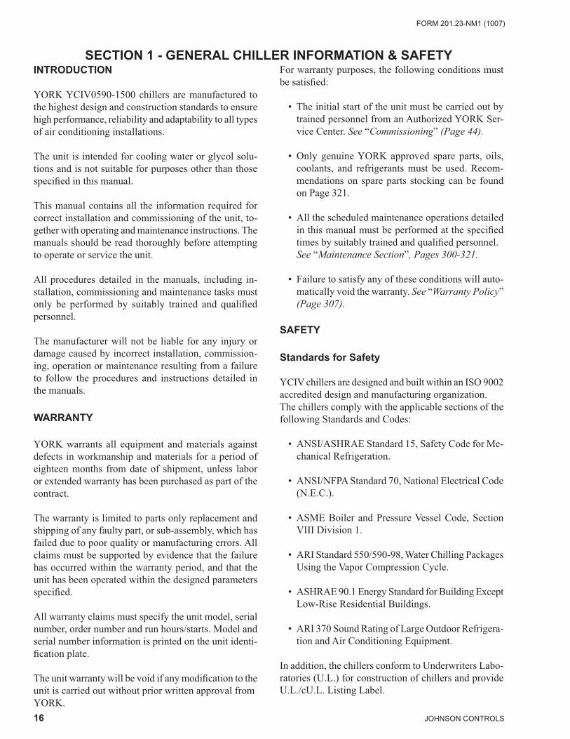
YORK YCIV0590-1500 chillers are manufactured to the highest design and construction standards to ensure high performance, reliability and adaptability to all types of air conditioning installations.
The unit is intended for cooling water or glycol solu-tions and is not suitable for purposes other than those specifi ed in this manual.
This manual contains all the information required for correct installation and commissioning of the unit, to-gether with operating and maintenance instructions. The manuals should be read thoroughly before attempting to operate or service the unit.
All procedures detailed in the manuals, including in-stallation, commissioning and maintenance tasks must only be performed by suitably trained and qualifi ed personnel.
The manufacturer will not be liable for any injury or damage caused by incorrect installation, commission-ing, operation or maintenance resulting from a failure to follow the procedures and instructions detailed in the manuals.
WARRANTY
YORK warrants all equipment and materials against defects in workmanship and materials for a period of eighteen months from date of shipment, unless labor or extended warranty has been purchased as part of the contract.
The warranty is limited to parts only replacement and shipping of any faulty part, or sub-assembly, which has failed due to poor quality or manufacturing errors. All claims must be supported by evidence that the failure has occurred within the warranty period, and that the unit has been operated within the designed parameters specifi ed.
All warranty claims must specify the unit model, serial number, order number and run hours/starts. Model and serial number information is printed on the unit identi-fi cation plate.
The unit warranty will be void if any modifi cation to the unit is carried out without prior written approval fromYORK.
For warranty purposes, the following conditions must be satisfi ed:
• The initial start of the unit must be carried out by trained personnel from an Authorized YORK Ser-vice Center. See “Commissioning” (Page 44).
• Only genuine YORK approved spare parts, oils, coolants, and refrigerants must be used. Recom-mendations on spare parts stocking can be found on Page 321.
• All the scheduled maintenance operations detailed in this manual must be performed at the specifi ed times by suitably trained and qualifi ed personnel.See “Maintenance Section”, Pages 300-321.
• Failure to satisfy any of these conditions will auto-matically void the warranty. See “Warranty Policy” (Page 307).
SAFETY
Standards for Safety
YCIV chillers are designed and built within an ISO 9002 accredited design and manufacturing organization.The chillers comply with the applicable sections of the following Standards and Codes:
• ANSI/ASHRAE Standard 15, Safety Code for Me-chanical Refrigeration.
• ANSI/NFPA Standard 70, National Electrical Code (N.E.C.).
• ASME Boiler and Pressure Vessel Code, Section VIII Division 1.
• ARI Standard 550/590-98, Water Chilling Packages Using the Vapor Compression Cycle.
• ASHRAE 90.1 Energy Standard for Building Except Low-Rise Residential Buildings.
• ARI 370 Sound Rating of Large Outdoor Refrigera-tion and Air Conditioning Equipment.
In addition, the chillers conform to Underwriters Labo-ratories (U.L.) for construction of chillers and provide U.L./cU.L. Listing Label.
17JOHNSON CONTROLS
FORM 201.23-NM1 (1007)
1RESPONSIBILITY FOR SAFETY
Every care has been taken in the design and manufac-ture of the unit to ensure compliance with the safety requirements listed above. However, the individual operating or working on any machinery is primarily responsible for:
• Personal safety, safety of other personnel, and the machinery.
• Correct utilization of the machinery in ac-cordance with the procedures detailed in the manuals.
ABOUT THIS MANUAL
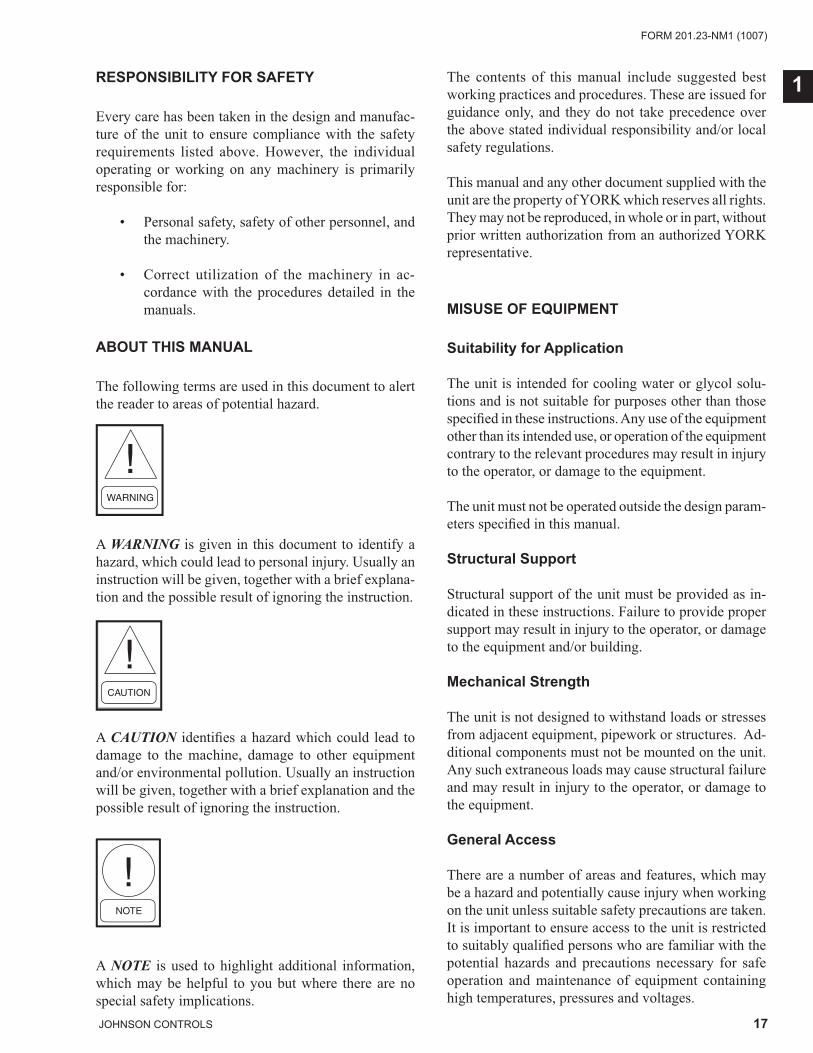
The following terms are used in this document to alert the reader to areas of potential hazard.
A WARNING is given in this document to identify a hazard, which could lead to personal injury. Usually an instruction will be given, together with a brief explana-tion and the possible result of ignoring the instruction.
A CAUTION identifi es a hazard which could lead to damage to the machine, damage to other equipment and/or environmental pollution. Usually an instruction will be given, together with a brief explanation and the possible result of ignoring the instruction.
A NOTE is used to highlight additional information, which may be helpful to you but where there are no special safety implications.
The contents of this manual include suggested best working practices and procedures. These are issued for guidance only, and they do not take precedence over the above stated individual responsibility and/or local safety regulations.
This manual and any other document supplied with the unit are the property of YORK which reserves all rights. They may not be reproduced, in whole or in part, without prior written authorization from an authorized YORK representative.
MISUSE OF EQUIPMENT
Suitability for Application
The unit is intended for cooling water or glycol solu-tions and is not suitable for purposes other than those specifi ed in these instructions. Any use of the equipment other than its intended use, or operation of the equipment contrary to the relevant procedures may result in injury to the operator, or damage to the equipment.
The unit must not be operated outside the design param-eters specifi ed in this manual.
Structural Support
Structural support of the unit must be provided as in-dicated in these instructions. Failure to provide proper support may result in injury to the operator, or damage to the equipment and/or building.
Mechanical Strength
The unit is not designed to withstand loads or stresses from adjacent equipment, pipework or structures. Ad-ditional components must not be mounted on the unit. Any such extraneous loads may cause structural failure and may result in injury to the operator, or damage to the equipment.
General Access
There are a number of areas and features, which may be a hazard and potentially cause injury when working on the unit unless suitable safety precautions are taken. It is important to ensure access to the unit is restricted to suitably qualifi ed persons who are familiar with the potential hazards and precautions necessary for safe operation and maintenance of equipment containing high temperatures, pressures and voltages.
18 JOHNSON CONTROLS
FORM 201.23-NM1 (1007)General Chiller Information & Safety
Pressure Systems
The unit contains refrigerant vapor and liquid under pressure, release of which can be a danger and cause injury. The user should ensure that care is taken during installation, operation and maintenance to avoid dam-age to the pressure system. No attempt should be made to gain access to the component parts of the pressure system other than by suitably trained and qualifi ed personnel.
Electrical
The unit must be grounded. No installation or main-tenance work should be attempted on the electrical equipment without fi rst switching power OFF, isolat-ing and locking-off the power supply. Servicing and maintenance on live equipment must not be attempted. No attempt should be made to gain access to the control panel or electrical enclosures during normal operation of the unit.
Rotating Parts
Fan guards must be fi tted at all times and not removed unless the power supply has been isolated. If ductwork is to be fi tted, requiring the wire fan guards to be removed, alternative safety measures must be taken to protect against the risk of injury from rotating fans.
Sharp Edges
The fi ns on the air-cooled condenser coils have sharp metal edges. Reasonable care should be taken when working in contact with the coils to avoid the risk of minor abrasions and lacerations. The use of gloves is recommended.
Frame rails, brakes, and other components may also have sharp edges. Reasonable care should be taken when working in contact with any components to avoid risk of minor abrasions and lacerations.
Refrigerants and Oils
Refrigerants and oils used in the unit are generally non-toxic, non-fl ammable and non-corrosive, and pose no special safety hazards. Use of gloves and safety glasses is, however, recommended when working on the unit. The build up of refrigerant vapor, from a leak for ex-ample, does pose a risk of asphyxiation in confi ned or enclosed spaces and attention should be given to good ventilation.
High Temperature and Pressure Cleaning
High temperature and pressure cleaning methods (e.g. steam cleaning) should not be used on any part of the pressure system as this may cause operation of the pres-sure relief device(s). Detergents and solvents, which may cause corrosion, should also be avoided.
Emergency Shutdown
In case of emergency, the control panel is fi tted with a Unit Switch to stop the unit in an emergency. When operated, it removes the low voltage 120 VAC electri-cal supply from the inverter system, thus shutting down the unit.
19JOHNSON CONTROLS
FORM 201.23-NM1 (1007)
2
SECTION 2 - PRODUCT DESCRIPTION
INTRODUCTION
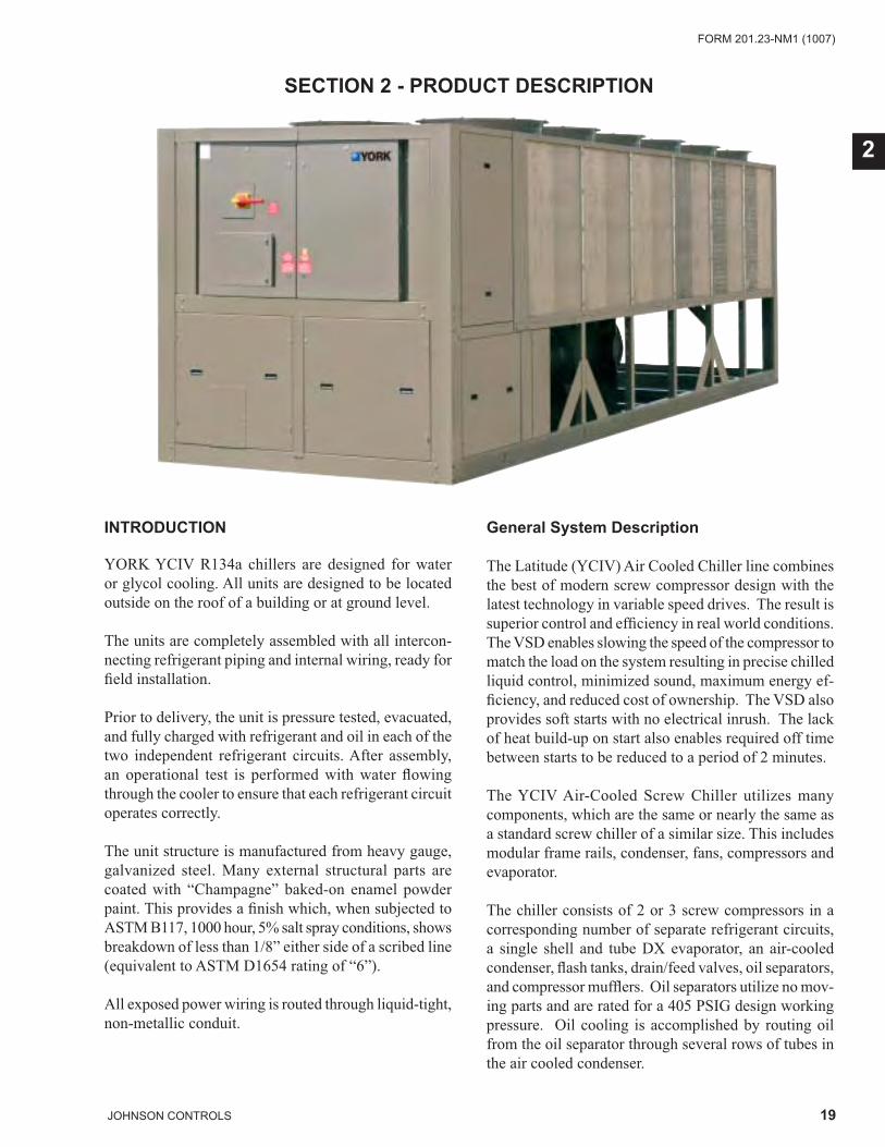
YORK YCIV R134a chillers are designed for water or glycol cooling. All units are designed to be located outside on the roof of a building or at ground level.
The units are completely assembled with all intercon-necting refrigerant piping and internal wiring, ready for fi eld installation.
Prior to delivery, the unit is pressure tested, evacuated, and fully charged with refrigerant and oil in each of the two independent refrigerant circuits. After assembly, an operational test is performed with water fl owing through the cooler to ensure that each refrigerant circuit operates correctly.
The unit structure is manufactured from heavy gauge, galvanized steel. Many external structural parts are coated with “Champagne” baked-on enamel powder paint. This provides a fi nish which, when subjected to ASTM B117, 1000 hour, 5% salt spray conditions, shows breakdown of less than 1/8” either side of a scribed line (equivalent to ASTM D1654 rating of “6”).
All exposed power wiring is routed through liquid-tight, non-metallic conduit.
General System Description
The Latitude (YCIV) Air Cooled Chiller line combines the best of modern screw compressor design with the latest technology in variable speed drives. The result is superior control and effi ciency in real world conditions. The VSD enables slowing the speed of the compressor to match the load on the system resulting in precise chilled liquid control, minimized sound, maximum energy ef-fi ciency, and reduced cost of ownership. The VSD also provides soft starts with no electrical inrush. The lack of heat build-up on start also enables required off time between starts to be reduced to a period of 2 minutes.
The YCIV Air-Cooled Screw Chiller utilizes many components, which are the same or nearly the same as a standard screw chiller of a similar size. This includes modular frame rails, condenser, fans, compressors and evaporator.
The chiller consists of 2 or 3 screw compressors in a corresponding number of separate refrigerant circuits, a single shell and tube DX evaporator, an air-cooled condenser, fl ash tanks, drain/feed valves, oil separators, and compressor muffl ers. Oil separators utilize no mov-ing parts and are rated for a 405 PSIG design working pressure. Oil cooling is accomplished by routing oil from the oil separator through several rows of tubes in the air cooled condenser.
20 JOHNSON CONTROLS
FORM 201.23-NM1 (1007)PRODUCT DESCRIPTION
An integral liquid cooled, transistorized, PWM, Variable Speed Drive (VSD) is controlled by the chiller micro-processor control panel to start/stop, select compressors to run, and select compressor speed. Power Factor is 95% at part or full load.
The chiller microprocessor communicates with the VSD Logic Board via a 3-wire RS-485 opto coupled data link. The VSD Logic Board runs the number of compressors required to meet the load and the compressors to the speed requested by the chiller microprocessor.
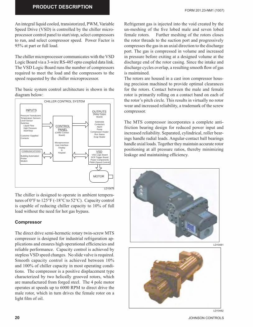
The basic system control architecture is shown in the diagram below:
The chiller is designed to operate in ambient tempera-tures of 0°F to 125°F (-18°C to 52°C). Capacity control is capable of reducing chiller capacity to 10% of full load without the need for hot gas bypass.
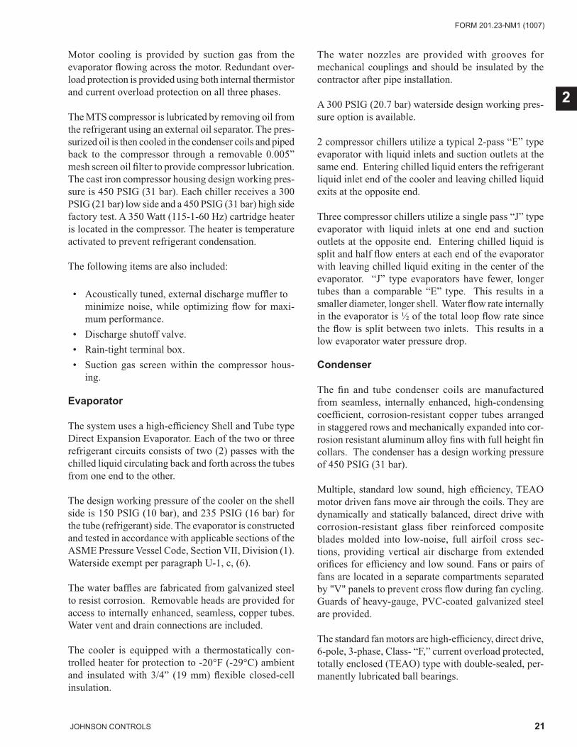
Compressor
The direct drive semi-hermetic rotary twin-screw MTS compressor is designed for industrial refrigeration ap-plications and ensures high operational effi ciencies and reliable performance. Capacity control is achieved by stepless VSD speed changes. No slide valve is required. Smooth capacity control is achieved between 10% and 100% of chiller capacity in most operating condi-tions. The compressor is a positive displacement type characterized by two helically grooved rotors, which are manufactured from forged steel. The 4 pole motor operates at speeds up to 6000 RPM to direct drive the male rotor, which in turn drives the female rotor on a light fi lm of oil.
CHILLER CONTROL SYSTEM
INPUTS
COMMUNICATIONS
OUTPUTS
VSD
MOTOR
CONTROLPANEL
Pressure TransducersTemperature SensorsLevel SensorSwitches Liquid Flow High Pressure Start/Stop
Customer SuppliedContacts
(Chiller ControlBoard)
MicroprocessorUser Interface
Display&
Keypad
Building AutomationPrinterModem
VSD Logic BoardSCR Trigger BoardPower Components
PWM (Speed Control)
(Relay OutputBoard)
SolenoidsContactors
AlarmPump
Compressor Heater Run Status
Evap Heater
Refrigerant gas is injected into the void created by the un-meshing of the fi ve lobed male and seven lobed female rotors. Further meshing of the rotors closes the rotor threads to the suction port and progressively compresses the gas in an axial direction to the discharge port. The gas is compressed in volume and increased in pressure before exiting at a designed volume at the discharge end of the rotor casing. Since the intake and discharge cycles overlap, a resulting smooth fl ow of gas is maintained.The rotors are housed in a cast iron compressor hous-ing precision machined to provide optimal clearances for the rotors. Contact between the male and female rotor is primarily rolling on a contact band on each of the rotor’s pitch circle. This results in virtually no rotor wear and increased reliability, a trademark of the screw compressor.
The MTS compressor incorporates a complete anti-friction bearing design for reduced power input and increased reliability. Separated, cylindrical, roller bear-ings handle radial loads. Angular-contact ball bearings handle axial loads. Together they maintain accurate rotor positioning at all pressure ratios, thereby minimizing leakage and maintaining effi ciency.
LD10478
LD10481
LD10482
21JOHNSON CONTROLS
FORM 201.23-NM1 (1007)
2
Motor cooling is provided by suction gas from the evaporator fl owing across the motor. Redundant over-load protection is provided using both internal thermistor and current overload protection on all three phases.
The MTS compressor is lubricated by removing oil from the refrigerant using an external oil separator. The pres-surized oil is then cooled in the condenser coils and piped back to the compressor through a removable 0.005” mesh screen oil fi lter to provide compressor lubrication. The cast iron compressor housing design working pres-sure is 450 PSIG (31 bar). Each chiller receives a 300 PSIG (21 bar) low side and a 450 PSIG (31 bar) high side factory test. A 350 Watt (115-1-60 Hz) cartridge heater is located in the compressor. The heater is temperature activated to prevent refrigerant condensation.
The following items are also included:
• Acoustically tuned, external discharge muffl er to minimize noise, while optimizing fl ow for maxi-mum performance.
• Discharge shutoff valve. • Rain-tight terminal box. • Suction gas screen within the compressor hous-
ing.
Evaporator
The system uses a high-effi ciency Shell and Tube type Direct Expansion Evaporator. Each of the two or three refrigerant circuits consists of two (2) passes with the chilled liquid circulating back and forth across the tubes from one end to the other.
The design working pressure of the cooler on the shell side is 150 PSIG (10 bar), and 235 PSIG (16 bar) for the tube (refrigerant) side. The evaporator is constructed and tested in accordance with applicable sections of the ASME Pressure Vessel Code, Section VII, Division (1). Waterside exempt per paragraph U-1, c, (6).
The water baffl es are fabricated from galvanized steel to resist corrosion. Removable heads are provided for access to internally enhanced, seamless, copper tubes. Water vent and drain connections are included.
The cooler is equipped with a thermostatically con-trolled heater for protection to -20°F (-29°C) ambient and insulated with 3/4” (19 mm) fl exible closed-cell insulation.
The water nozzles are provided with grooves for mechanical couplings and should be insulated by the contractor after pipe installation.
A 300 PSIG (20.7 bar) waterside design working pres-sure option is available.
2 compressor chillers utilize a typical 2-pass “E” type evaporator with liquid inlets and suction outlets at the same end. Entering chilled liquid enters the refrigerant liquid inlet end of the cooler and leaving chilled liquid exits at the opposite end.
Three compressor chillers utilize a single pass “J” type evaporator with liquid inlets at one end and suction outlets at the opposite end. Entering chilled liquid is split and half fl ow enters at each end of the evaporator with leaving chilled liquid exiting in the center of the evaporator. “J” type evaporators have fewer, longer tubes than a comparable “E” type. This results in a smaller diameter, longer shell. Water fl ow rate internally in the evaporator is ½ of the total loop fl ow rate since the fl ow is split between two inlets. This results in a low evaporator water pressure drop.
Condenser
The fi n and tube condenser coils are manufactured from seamless, internally enhanced, high-condensing coeffi cient, corrosion-resistant copper tubes arranged in staggered rows and mechanically expanded into cor-rosion resistant aluminum alloy fi ns with full height fi n collars. The condenser has a design working pressure of 450 PSIG (31 bar).
Multiple, standard low sound, high effi ciency, TEAO motor driven fans move air through the coils. They are dynamically and statically balanced, direct drive with corrosion-resistant glass fi ber reinforced composite blades molded into low-noise, full airfoil cross sec-tions, providing vertical air discharge from extended orifi ces for effi ciency and low sound. Fans or pairs of fans are located in a separate compartments separated by "V" panels to prevent cross fl ow during fan cycling. Guards of heavy-gauge, PVC-coated galvanized steel are provided.
The standard fan motors are high-effi ciency, direct drive, 6-pole, 3-phase, Class- “F,” current overload protected, totally enclosed (TEAO) type with double-sealed, per-manently lubricated ball bearings.
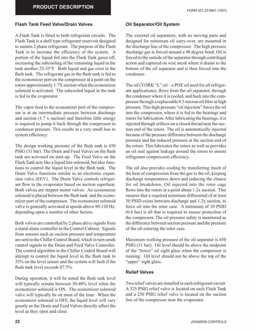
22 JOHNSON CONTROLS
FORM 201.23-NM1 (1007)PRODUCT DESCRIPTION
Flash Tank Feed Valve/Drain Valves
A Flash Tank is fi tted to both refrigerant circuits. The Flash Tank is a shell type refrigerant reservoir designed to sustain 2 phase refrigerant. The purpose of the Flash Tank is to increase the effi ciency of the system. A portion of the liquid fed into the Flash Tank gases off, increasing the subcooling of the remaining liquid in the tank another 25-35°F. Both liquid and gas exist in the fl ash tank. The refrigerant gas in the fl ash tank is fed to the economizer port on the compressor at a point on the rotors approximately 1.7X suction when the economizer solenoid is activated. The subcooled liquid in the tank is fed to the evaporator.
The vapor feed to the economizer port of the compres-sor is at an intermediate pressure between discharge and suction (1.7 x suction) and therefore little energy is required to pump it back through the compressor to condenser pressure. This results in a very small loss to system effi ciency.
The design working pressure of the fl ash tank is 450 PSIG (31 bar). The Drain and Feed Valves on the fl ash tank are activated on start-up. The Feed Valve on the Flash Tank acts like a liquid line solenoid, but also func-tions to control the liquid level in the fl ash tank. The Drain Valve functions similar to an electronic expan-sion valve (EEV). The Drain Valve controls refriger-ant fl ow to the evaporator based on suction superheat. Both valves are stepper motor valves. An economizer solenoid is placed between the fl ash tank and the econo-mizer port of the compressor. The economizer solenoid valve is generally activated at speeds above 90-120 Hz, depending upon a number of other factors.
Both valves are controlled by 2 phase drive signals from a stand-alone controller in the Control Cabinet. Signals from sensors such as suction pressure and temperature are sent to the Chiller Control Board, which in turn sends control signals to the Drain and Feed Valve Controller. The control algorithm in the Chiller Control Board will attempt to control the liquid level in the fl ash tank to 35% on the level sensor and the system will fault if the fl ash tank level exceeds 87.5%.
During operation, it will be noted the fl ash tank level will typically remain between 30-40% level when the economizer solenoid is ON. The economizer solenoid valve will typically be on most of the time. When the economizer solenoid is OFF, the liquid level will vary greatly as the Drain and Feed Valves directly affect the level as they open and close.
Oil Separator/Oil System
The external oil separators, with no moving parts and designed for minimum oil carry-over, are mounted in the discharge line of the compressor. The high pressure discharge gas is forced around a 90 degree bend. Oil is forced to the outside of the separator through centrifugal action and captured on wire mesh where it drains to the bottom of the oil separator and is then forced into the condenser.
The oil (YORK “L” oil – a POE oil used for all refriger-ant applications), fl ows from the oil separator, through the condenser where it is cooled, and back into the com-pressor through a replaceable 0.5 micron oil fi lter at high pressure. This high pressure “oil injection” forces the oil into the compressor, where it is fed to the bearings and rotors for lubrication. After lubricating the bearings, it is injected through orifi ces on a closed thread near the suc-tion end of the rotors. The oil is automatically injected because of the pressure difference between the discharge pressure and the reduced pressure at the suction end of the rotors. This lubricates the rotors as well as provides an oil seal against leakage around the rotors to ensure refrigerant compression effi ciency.
The oil also provides cooling by transferring much of the heat of compression from the gas to the oil, keeping discharge temperatures down and reducing the chance for oil breakdown. Oil injected into the rotor cage fl ows into the rotors at a point about 1.2x suction. This ensures that a required minimum differential of at least 30 PSID exists between discharge and 1.2x suction, to force oil into the rotor case. A minimum of 10 PSID (0.6 bar) is all that is required to ensure protection of the compressor. The oil pressure safety is monitored as the difference between suction pressure and the pressure of the oil entering the rotor case.
Maximum working pressure of the oil separator is 450 PSIG (31 bar). Oil level should be above the midpoint of the “lower” oil sight glass when the compressor is running. Oil level should not be above the top of the “upper” sight glass.
Relief Valves
Two relief valves are installed in each refrigerant circuit. A 325 PSIG relief valve is located on each Flash Tank and a 250 PSIG relief valve is located on the suction line of the compressor near the evaporator.
23JOHNSON CONTROLS
FORM 201.23-NM1 (1007)
2
Oil Cooling
Oil cooling is provided by routing oil from the oil sepa-rator through several of the top rows of the condenser coils and back to the compressor.
Capacity Control
When cooling is needed, one or more compressors, as determined by the system microprocessor based on deviation from setpoint, will start at minimum speed with low inrush current. Variable speed operation of the compressor reduces the capacity and allows smooth balancing of the compressor capacity with the cooling load.
Capacity control is accomplished by varying the number of compressors and the speed of the compressors with the VSD to promote stable, smooth, and precise load-ing/unloading.
Hot Gas Bypass is not required with VSD control of the compressors.
The chiller is available with Standard IPLV or High IPLV software (EPROM). High IPLV software optimizes the performance of the chiller capacity and fan controls. High IPLV chillers also require additional factory programming.
Power and Control Panel
All controls and the VSD are factory-wired and function tested. The panel enclosures are designed to NEMA 3R (IP65) rating and are manufactured from powder-painted steel with hinged, latched, and gasket sealed outer doors with wind struts for safer servicing.
The Power and Micro Control Panels are combined into a single control/power cabinet and include Compressor VSD Controls, Chiller Microprocessor Controls, Fan Controls, and all other chiller controls.
The Display and Keypad are accessible through an access door without opening the main doors to the electrical cabinet.
Each Power Compartment Contains
Incoming single point power is standard utilizing either a lockable circuit breaker or terminal block, 115VAC control transformer, VSD, fan contactors, ON/OFF unit switch, microcomputer keypad and display, Chiller Control and VSD Logic boards, and relay boards.
Current transformers sense each phase of motor current, and send corresponding signals to the Chiller Logic Board. Current monitoring protects the compressor motors from damage due to: low motor current, high motor current, short circuit current, single phasing, and compressor overload.
Short Circuit Withstand Rating of the chiller electrical enclosure is 30,000 Amps for standard terminal block connection. Ratings are in accordance with UL508C. A Circuit Breaker Option can be added to increase the Short Circuit Withstand Rating to 200/230V = 100,000 Amps, 380/460 V = 65,000 Amps, and 575V = 42,000 Amps.
Microprocessor and VSD Controls
Microprocessors on the Chiller Control Board and VSD Logic Board control starting, stopping, loading, unloading, safeties, and chilled liquid temperature control. Chilled liquid control decisions are a function of temperature deviation from setpoint and the rate of change of temperature.
The standard controls include: brine chilling, thermal storage, run signal contacts, unit alarm contacts, chilled liquid pump control, automatic reset after power fail-ure, automatic system optimization to match operating conditions.
Remote cycling, optional current limiting, optional temperature setpoint reset, and optional remote sound limit can be accomplished by connecting user-supplied signals to the microprocessor.
Unit operating software is stored in non-volatile memory. Field programmed setpoints are retained in lithium battery backed real time clock (RTC) memory for 10 years.
24 JOHNSON CONTROLS
FORM 201.23-NM1 (1007)PRODUCT DESCRIPTION
Display
The display consists of a liquid crystal 2 line by 40 characters per line display, with backlighting for outdoor viewing of operating parameters and program points.
Parameters are displayed in 5 languages in either English (°F and PSIG) or Metric (°C and Bars) units, and for each circuit, the following items can be displayed:
• Entering and leaving chilled liquid, and ambient temperature.
• Day, date and time. Daily start/stop times. Holiday and Manual Override status.
• Compressor operating hours and starts. Automatic or manual lead/lag. Lead compressor identifi cation.
• Run permissive status. Compressor run status.
• Anti-recycle timers.
• System suction (and suction superheat), discharge (and discharge superheat), and oil pressures and temperatures.
• Percent full load compressor motor current and average motor current. Compressor motor speed (frequency).
• Cutout status and setpoints for: supply chilled liquid temperature, low suction pressure, high discharge pressure and temperature, high oil temperature, low ambient, and low leaving liquid temperature.
• Unloading limit setpoints for high discharge pres-sure and compressor motor current.
• Status of: evaporator heater, condenser fans, load/unload timers, and chilled water pump.
• “Out of range” message.
• Up to 10 fault shutdown histories.
Keypad
An operator keypad allows complete control of the system from a central location. The keypad utilizes an overlay to allow use in 5 languages. The keypad is a color-coded, 36 button, sealed keypad with keys for Display, Entry, Setpoints, Clock, Print, Program, Unit ON/OFF and other functions. Details on a few of the keys follow.
Status – Allows viewing present unit or system status displayed by the microprocessor.
Entry – Numeric keypad and supporting keys used to confi rm Setpoint changes, cancel inputs, advance day, and change AM/PM.
Setpoints – For setting chilled liquid temperature, chilled liquid range, remote reset temperature range.
Date/Time – Used to set time, daily or holiday start/stop schedule, manual override for servicing, and sound limiting schedule.
Print – Used to display or print operating data or sys-tem fault shutdown history for last ten faults. Printouts are generated through an RS-232 port via a separate printer.
Program – For setting low leaving liquid temperature cutout, average motor current limit, and pulldown de-mand limit.
Displays are also provided for programming low am-bient cutout, low suction pressure cutout, superheat setpoint, etc., under the PROGRAM key.
Unit Switch
A master unit switch allows activation or de-activation of the chiller system. Separate system switches for con-trolling each system are provided as part of the chiller control panel keypad.
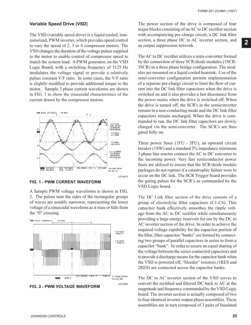
25JOHNSON CONTROLS
FORM 201.23-NM1 (1007)
2
The power section of the drive is composed of four major blocks consisting of an AC to DC rectifi er section with accompanying pre-charge circuit, a DC link fi lter section, a three phase DC to AC inverter section, and an output suppression network.
The AC to DC rectifi er utilizes a semi-converter formed by the connection of three SCR/diode modules (1SCR- 3SCR) in a three phase bridge confi guration. The mod-ules are mounted on a liquid cooled heatsink. Use of the semi-converter confi guration permits implementation of a separate pre-charge circuit to limit the fl ow of cur-rent into the DC link fi lter capacitors when the drive is switched on and it also provides a fast disconnect from the power mains when the drive is switched off. When the drive is turned off, the SCR's in the semiconverter remain in a non-conducting mode and the DC link fi lter capacitors remain uncharged. When the drive is com-manded to run, the DC link fi lter capacitors are slowly charged via the semi-converter. The SCR’s are then gated fully on.
Three power fuses (1FU - 3FU), an optional circuit breaker (1SW) and a standard 5% impedance minimum 3 phase line reactor connect the AC to DC converter to the incoming power. Very fast semiconductor power fuses are utilized to ensure that the SCR/diode module packages do not rupture if a catastrophic failure were to occur on the DC link. The SCR Trigger board provides the gating pulses for the SCR’s as commanded by the VSD Logic board.
The DC Link fi lter section of the drive consists of a group of electrolytic fi lter capacitors (C1-C6). This capacitor bank effectively smoothes the ripple volt-age from the AC to DC rectifi er while simultaneously providing a large energy reservoir for use by the DC to AC inverter section of the drive. In order to achieve the required voltage capability for the capacitor portion of the fi lter, fi lter capacitor “banks” are formed by connect-ing two groups of parallel capacitors in series to form a capacitor “bank”. In order to assure an equal sharing of the voltage between the series connected capacitors and to provide a discharge means for the capacitor bank when the VSD is powered off, “bleeder” resistors (1RES and 2RES) are connected across the capacitor banks.
The DC to AC inverter section of the VSD serves to convert the rectifi ed and fi ltered DC back to AC at the magnitude and frequency commanded by the VSD Logic board. The inverter section is actually composed of two to four identical inverter output phase assemblies. These assemblies are in turn composed of 3 pairs of Insulated
FIG. 2 - PWM VOLTAGE WAVEFORMLD10480
Variable Speed Drive (VSD)
The VSD (variable speed drive) is a liquid cooled, tran-sistorized, PWM inverter, which provides speed control to vary the speed of 2, 3 or 4 compressor motors. The VSD changes the duration of the voltage pulses supplied to the motor to enable control of compressor speed to match the system load. A PWM generator, on the VSD Logic Board, with a switching frequency of 3125 Hz modulates the voltage signal to provide a relatively pulses constant V/F ratio. In some cases, the V/F ratio is slightly modifi ed to provide additional torque to the motor. Sample 3 phase current waveforms are shown in FIG. 1 to show the sinusoidal characteristics of the current drawn by the compressor motors.
FIG. 1 - PWM CURRENT WAVEFORMLD10479
A Sample PWM voltage waveforms is shown in FIG. 2. The pulses near the sides of the rectangular groups of waves are notably narrower, representing the lower voltage of a sinusoidal waveform as it rises or falls from the “0” crossing.
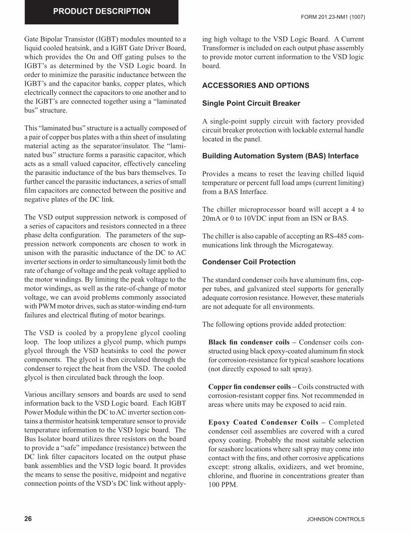
26 JOHNSON CONTROLS
FORM 201.23-NM1 (1007)PRODUCT DESCRIPTION
Gate Bipolar Transistor (IGBT) modules mounted to a liquid cooled heatsink, and a IGBT Gate Driver Board, which provides the On and Off gating pulses to the IGBT’s as determined by the VSD Logic board. In order to minimize the parasitic inductance between the IGBT’s and the capacitor banks, copper plates, which electrically connect the capacitors to one another and to the IGBT’s are connected together using a “laminated bus” structure.
This “laminated bus” structure is a actually composed of a pair of copper bus plates with a thin sheet of insulating material acting as the separator/insulator. The “lami-nated bus” structure forms a parasitic capacitor, which acts as a small valued capacitor, effectively canceling the parasitic inductance of the bus bars themselves. To further cancel the parasitic inductances, a series of small fi lm capacitors are connected between the positive and negative plates of the DC link.
The VSD output suppression network is composed of a series of capacitors and resistors connected in a three phase delta confi guration. The parameters of the sup-pression network components are chosen to work in unison with the parasitic inductance of the DC to AC inverter sections in order to simultaneously limit both the rate of change of voltage and the peak voltage applied to the motor windings. By limiting the peak voltage to the motor windings, as well as the rate-of-change of motor voltage, we can avoid problems commonly associated with PWM motor drives, such as stator-winding end-turn failures and electrical fl uting of motor bearings.
The VSD is cooled by a propylene glycol cooling loop. The loop utilizes a glycol pump, which pumps glycol through the VSD heatsinks to cool the power components. The glycol is then circulated through the condenser to reject the heat from the VSD. The cooled glycol is then circulated back through the loop.
Various ancillary sensors and boards are used to send information back to the VSD Logic board. Each IGBT Power Module within the DC to AC inverter section con-tains a thermistor heatsink temperature sensor to provide temperature information to the VSD logic board. The Bus Isolator board utilizes three resistors on the board to provide a “safe” impedance (resistance) between the DC link fi lter capacitors located on the output phase bank assemblies and the VSD logic board. It provides the means to sense the positive, midpoint and negative connection points of the VSD’s DC link without apply-
ing high voltage to the VSD Logic Board. A Current Transformer is included on each output phase assembly to provide motor current information to the VSD logic board. ACCESSORIES AND OPTIONS
Single Point Circuit Breaker
A single-point supply circuit with factory provided circuit breaker protection with lockable external handle located in the panel.
Building Automation System (BAS) Interface
Provides a means to reset the leaving chilled liquid temperature or percent full load amps (current limiting) from a BAS Interface.
The chiller microprocessor board will accept a 4 to 20mA or 0 to 10VDC input from an ISN or BAS.
The chiller is also capable of accepting an RS-485 com-munications link through the Microgateway.
Condenser Coil Protection
The standard condenser coils have aluminum fi ns, cop-per tubes, and galvanized steel supports for generally adequate corrosion resistance. However, these materials are not adequate for all environments.
The following options provide added protection:
Black fi n condenser coils – Condenser coils con-structed using black epoxy-coated aluminum fi n stock for corrosion-resistance for typical seashore locations (not directly exposed to salt spray).
Copper fi n condenser coils – Coils constructed with corrosion-resistant copper fi ns. Not recommended in areas where units may be exposed to acid rain.
Epoxy Coated Condenser Coils – Completed condenser coil assemblies are covered with a cured epoxy coating. Probably the most suitable selection for seashore locations where salt spray may come into contact with the fi ns, and other corrosive applications except: strong alkalis, oxidizers, and wet bromine, chlorine, and fl uorine in concentrations greater than 100 PPM.
27JOHNSON CONTROLS
FORM 201.23-NM1 (1007)
2
DX COOLER OPTIONS
300 PSIG (21 bar) Waterside Design Working Pres-sure – The DX cooler waterside is designed and con-structed for 300 PSIG (21 bar) working pressure.(Factory-mounted)
1-1/2” (38 mm) Insulation – Double-thickness insula-tion provided for enhanced effi ciency.
Flange Accessory – Consists of raised face fl anges to convert grooved water nozzles to fl anged cooler connec-tions. Includes companion fl anges for fi eld mounting.
Remote DX Cooler – Includes the main condensing unit less the cooler, refrigerant and liquid line devices. The insulated cooler and fi eld accessory kits per refrigerant circuit are supplied separately. The condensing unit is shipped with a dry nitrogen holding charge and the cooler is shipped with a dry nitrogen holding charge.
Flow Switch Accessory – Johnson Controls model F61MG-1C Vapor-proof SPDT, NEMA 4X switch, 150 PSIG (10 bar) DWP, -20°F to 250°F (-29°C to 121°C), with 1” NPT (IPS) connection for upright mounting in horizontal pipe or equivalent. A fl ow switch must be fi eld-installed with each unit. A 300PSIG (20.7 bar) optional fl ow switch is available.
SERVICE VALVE OPTION
Suction Service Valve – Provides a suction and econo-mizer service valve on each refrigerant circuit.
UNIT ENCLOSURES
Wire Enclosure – Heavy-gauge welded wire mesh guards mounted on the exterior of the unit (Factory- or fi eld-mounted).
Louvered Panels and Wired Guards – Louvered pan-els mounted over the exterior condenser coil faces, and heavy-gauge welded wire mesh guards mounted around the bottom of the unit (Factory- or fi eld-mounted).
Louvered Panels (Condenser Coils Only) – Louvered panels are mounted over the exterior condenser coil faces on the sides of the unit to visually screen and protect the coils (Factory- or fi eld-mounted).
Louvered Panels (Full Unit) enclosure – Louvered panels over condenser coils and around the bottom of the unit (Factory- or fi eld-mounted).
FANS
High Static Fans: Fans and motors suitable for High External Static conditions to 100 Pa.
SOUND REDUCTION OPTIONS
The standard chiller has fans that operate at normal speed, no compressor enclosure, and is typically used in non-sensitive sound areas such as industrial areas or locations with loud traffi c background noise. One or more of the following sound reduction options may be employed by the system designer as normally generated machine noise is considered in the overall project design.
Ultra Quiet Fans (Factory Mounted) – With this option, the basic chiller is equipped with specially designed fans and motors to provide lower sound levels and retain appropriate airfl ow. The result is reduced fan generated noise with no adverse effect on the chiller capacity or effi ciency performance.
Two-Speed Fans (Factory Mounted) – With this op-tion, the basic chiller is equipped with fans designed with two operating speeds. At high ambient condi-tions the fans operate at the normal speed with sound levels equivalent to Ultra Quiet Fans. As the ambient temperature falls the fans automatically reduce to slow speed reducing sound levels. If very low sound is required at all ambient conditions normal fan speed can be inhibited.
Reduced Sound Option (Factory Mounted) – With this option the chiller is equipped with an unlined compressor enclosure. This option is typically used for daytime operation where background noise is lower than normal city traffi c etc.
Low Sound Option (Factory Mounted) – This option is only available with the selection of Ultra Quiet Fans or Two-Speed Fans. The chiller is equipped with an acousti-cally lined compressor enclosure. This option is typically for locations near residential areas, hotels, or hospitals etc where background noise is limited. When paired with the Two-Speed Fan option the unit can operate at normal speed during the day, when background noise levels are notice-able, and at low speed in the evening and at night when background levels are lower.
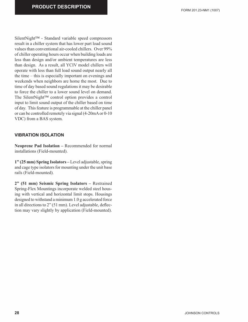
28 JOHNSON CONTROLS
FORM 201.23-NM1 (1007)PRODUCT DESCRIPTION
SilentNight™ - Standard variable speed compressors result in a chiller system that has lower part load sound values than conventional air-cooled chillers. Over 99% of chiller operating hours occur when building loads are less than design and/or ambient temperatures are less than design. As a result, all YCIV model chillers will operate with less than full load sound output nearly all the time – this is especially important on evenings and weekends when neighbors are home the most. Due to time of day based sound regulations it may be desirable to force the chiller to a lower sound level on demand. The SilentNight™ control option provides a control input to limit sound output of the chiller based on time of day. This feature is programmable at the chiller panel or can be controlled remotely via signal (4-20mA or 0-10 VDC) from a BAS system.
VIBRATION ISOLATION
Neoprene Pad Isolation – Recommended for normal installations (Field-mounted).
1” (25 mm) Spring Isolators – Level adjustable, spring and cage type isolators for mounting under the unit base rails (Field-mounted).
2” (51 mm) Seismic Spring Isolators – Restrained Spring-Flex Mountings incorporate welded steel hous-ing with vertical and horizontal limit stops. Housings designed to withstand a minimum 1.0 g accelerated force in all directions to 2” (51 mm). Level adjustable, defl ec-tion may vary slightly by application (Field-mounted).
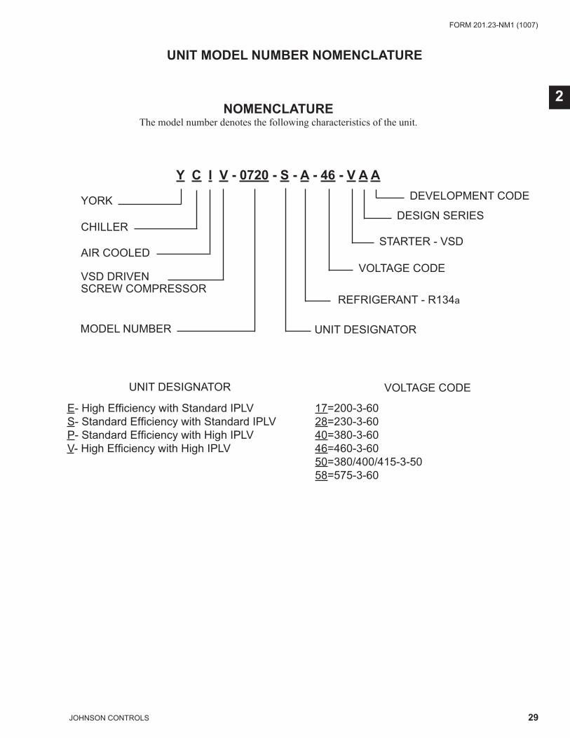
29JOHNSON CONTROLS
FORM 201.23-NM1 (1007)
2NOMENCLATURE
The model number denotes the following characteristics of the unit.
Y C I V - 0720 - S - A - 46 - V A A
UNIT MODEL NUMBER NOMENCLATURE
YORK
CHILLER
AIR COOLED
VSD DRIVEN SCREW COMPRESSOR
MODEL NUMBER UNIT DESIGNATOR
E- High Effi ciency with Standard IPLVS- Standard Effi ciency with Standard IPLVP- Standard Effi ciency with High IPLVV- High Effi ciency with High IPLV
REFRIGERANT - R134a
VOLTAGE CODE
STARTER - VSD
DESIGN SERIES
DEVELOPMENT CODE
VOLTAGE CODEUNIT DESIGNATOR
17=200-3-6028=230-3-6040=380-3-6046=460-3-6050=380/400/415-3-5058=575-3-60
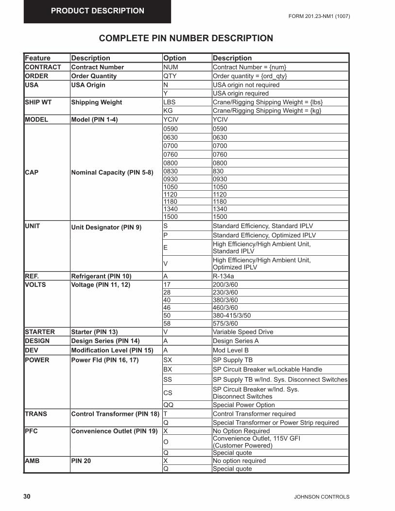
30 JOHNSON CONTROLS
FORM 201.23-NM1 (1007)PRODUCT DESCRIPTION
Feature Description Option DescriptionCONTRACT Contract Number NUM Contract Number = {num}ORDER Order Quantity QTY Order quantity = {ord_qty}USA USA Origin N USA origin not required
Y USA origin requiredSHIP WT Shipping Weight LBS Crane/Rigging Shipping Weight = {lbs}
KG Crane/Rigging Shipping Weight = {kg}MODEL Model (PIN 1-4) YCIV YCIV
CAP Nominal Capacity (PIN 5-8)
0590 05900630 06300700 07000760 07600800 08000830 8300930 09301050 10501120 11201180 11801340 13401500 1500
UNIT Unit Designator (PIN 9) S Standard Effi ciency, Standard IPLVP Standard Effi ciency, Optimized IPLV
E High Effi ciency/High Ambient Unit, Standard IPLV
V High Effi ciency/High Ambient Unit, Optimized IPLV
REF. Refrigerant (PIN 10) A R-134aVOLTS Voltage (PIN 11, 12) 17 200/3/60
28 230/3/6040 380/3/6046 460/3/6050 380-415/3/5058 575/3/60
STARTER Starter (PIN 13) V Variable Speed DriveDESIGN Design Series (PIN 14) A Design Series ADEV Modifi cation Level (PIN 15) A Mod Level BPOWER Power Fld (PIN 16, 17) SX SP Supply TB
BX SP Circuit Breaker w/Lockable HandleSS SP Supply TB w/Ind. Sys. Disconnect Switches
CS SP Circuit Breaker w/Ind. Sys. Disconnect Switches
QQ Special Power OptionTRANS Control Transformer (PIN 18) T Control Transformer required
Q Special Transformer or Power Strip requiredPFC Convenience Outlet (PIN 19) X No Option Required
O Convenience Outlet, 115V GFI (Customer Powered)
Q Special quoteAMB PIN 20 X No option required
Q Special quote
COMPLETE PIN NUMBER DESCRIPTION
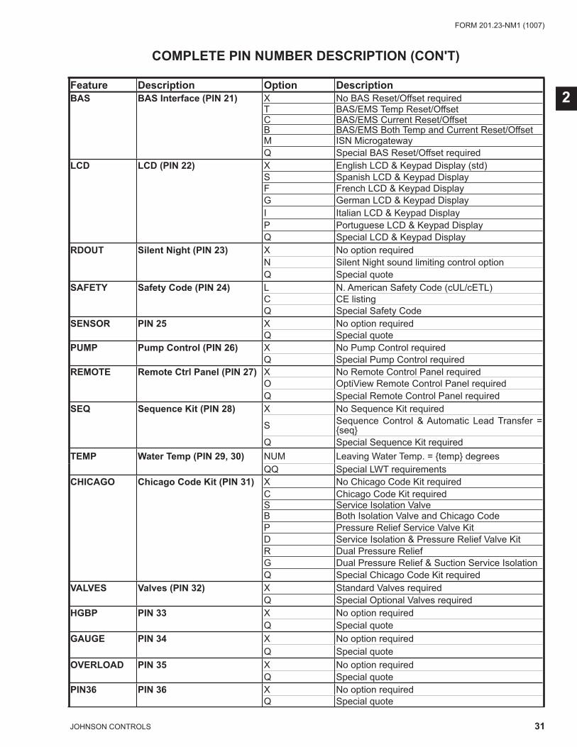
31JOHNSON CONTROLS
FORM 201.23-NM1 (1007)
2
COMPLETE PIN NUMBER DESCRIPTION (CON'T)
Feature Description Option DescriptionBAS BAS Interface (PIN 21) X No BAS Reset/Offset required
T BAS/EMS Temp Reset/OffsetC BAS/EMS Current Reset/OffsetB BAS/EMS Both Temp and Current Reset/OffsetM ISN MicrogatewayQ Special BAS Reset/Offset required
LCD LCD (PIN 22) X English LCD & Keypad Display (std)S Spanish LCD & Keypad DisplayF French LCD & Keypad DisplayG German LCD & Keypad DisplayI Italian LCD & Keypad DisplayP Portuguese LCD & Keypad DisplayQ Special LCD & Keypad Display
RDOUT Silent Night (PIN 23) X No option requiredN Silent Night sound limiting control optionQ Special quote
SAFETY Safety Code (PIN 24) L N. American Safety Code (cUL/cETL) C CE listingQ Special Safety Code
SENSOR PIN 25 X No option requiredQ Special quote
PUMP Pump Control (PIN 26) X No Pump Control requiredQ Special Pump Control required
REMOTE Remote Ctrl Panel (PIN 27) X No Remote Control Panel requiredO OptiView Remote Control Panel requiredQ Special Remote Control Panel required
SEQ Sequence Kit (PIN 28) X No Sequence Kit required
S Sequence Control & Automatic Lead Transfer = {seq}
Q Special Sequence Kit requiredTEMP Water Temp (PIN 29, 30) NUM Leaving Water Temp. = {temp} degrees
QQ Special LWT requirementsCHICAGO Chicago Code Kit (PIN 31) X No Chicago Code Kit required
C Chicago Code Kit requiredS Service Isolation ValveB Both Isolation Valve and Chicago CodeP Pressure Relief Service Valve KitD Service Isolation & Pressure Relief Valve KitR Dual Pressure ReliefG Dual Pressure Relief & Suction Service IsolationQ Special Chicago Code Kit required
VALVES Valves (PIN 32) X Standard Valves requiredQ Special Optional Valves required
HGBP PIN 33 X No option requiredQ Special quote
GAUGE PIN 34 X No option requiredQ Special quote
OVERLOAD PIN 35 X No option requiredQ Special quote
PIN36 PIN 36 X No option requiredQ Special quote
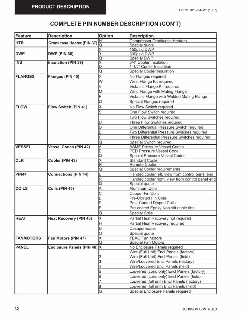
32 JOHNSON CONTROLS
FORM 201.23-NM1 (1007)PRODUCT DESCRIPTION
COMPLETE PIN NUMBER DESCRIPTION (CON'T)
Feature Description Option DescriptionHTR Crankcase Heater (PIN 37) H Compressor Crankcase Heaters
Q Special quote
DWP DWP (PIN 38)X 150psig DWP3 300psig DWPQ Special DWP
INS Insulation (PIN 39) X 3/4” Cooler InsulationD 1-1/2” Cooler InsulationQ Special Cooler Insulation
FLANGES Flanges (PIN 40) X No Flanges requiredW Weld Flange Kit requiredV Victaulic Flange Kit requiredM Weld Flange with Mating FlangeF Victaulic Flange with Welded Mating FlangeQ Special Flanges required
FLOW Flow Switch (PIN 41) X No Flow Switch requiredS One Flow Switch requiredT Two Flow Switches requiredU Three Flow Switches requiredD One Differential Pressure Switch requiredE Two Differential Pressure Switches requiredF Three Differential Pressure Switches requiredQ Special Switch required
VESSEL Vessel Codes (PIN 42) A ASME Pressure Vessel CodesE PED Pressure Vessel CodeQ Special Pressure Vessel Codes
CLR Cooler (PIN 43) X Standard CoolerR Remote CoolerQ Special Cooler requirements
PIN44 Connections (PIN 44) L Handed cooler left, view from control panel endR Handed cooler right, view from control panel endQ Special quote
COILS Coils (PIN 45) A Aluminum CoilsC Copper Fin CoilsB Pre-Coated Fin CoilsP Post-Coated Dipped CoilsE Pre-coated Epoxy Non-slit ripple fi nsQ Special Coils
HEAT Heat Recovery (PIN 46) X Partial Heat Recovery not requiredH Partial Heat Recovery requiredD DesuperheaterQ Special quote
FANMOTORS Fan Motors (PIN 47) X TEAO Fan MotorsQ Special Fan Motors
PANEL Enclosure Panels (PIN 48) X No Enclosure Panels required1 Wire (Full Unit) Encl Panels (factory)2 Wire (Full Unit) Encl Panels (fi eld)3 Wire/Louvered Encl Panels (factory)4 Wire/Louvered Encl Panels (fi eld)5 Louvered (cond only) Encl Panels (factory)6 Louvered (cond only) Encl Panels (fi eld)7 Louvered (full unit) Encl Panels (factory)8 Louvered (full unit) Encl Panels (fi eld)Q Special Enclosure Panels required
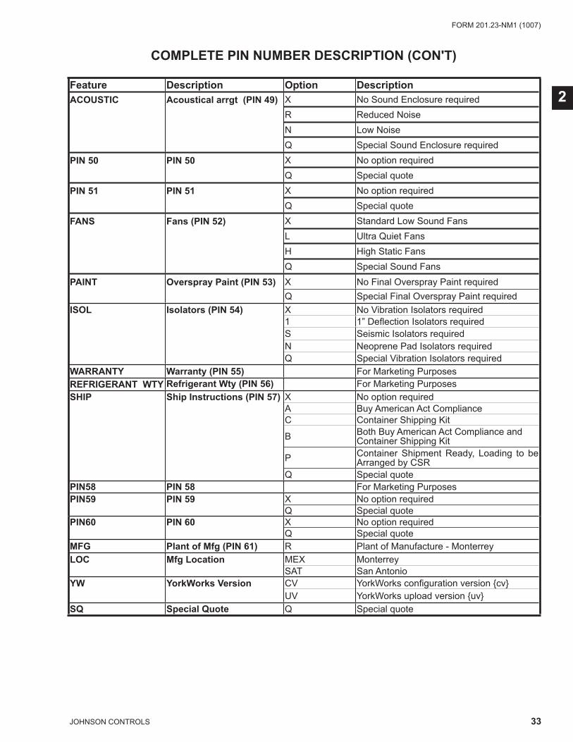
33JOHNSON CONTROLS
FORM 201.23-NM1 (1007)
2
COMPLETE PIN NUMBER DESCRIPTION (CON'T)
Feature Description Option DescriptionACOUSTIC Acoustical arrgt (PIN 49) X No Sound Enclosure required
R Reduced NoiseN Low NoiseQ Special Sound Enclosure required
PIN 50 PIN 50 X No option requiredQ Special quote
PIN 51 PIN 51 X No option requiredQ Special quote
FANS Fans (PIN 52) X Standard Low Sound FansL Ultra Quiet FansH High Static FansQ Special Sound Fans
PAINT Overspray Paint (PIN 53) X No Final Overspray Paint requiredQ Special Final Overspray Paint required
ISOL Isolators (PIN 54) X No Vibration Isolators required1 1” Defl ection Isolators requiredS Seismic Isolators requiredN Neoprene Pad Isolators requiredQ Special Vibration Isolators required
WARRANTY Warranty (PIN 55) For Marketing Purposes REFRIGERANT WTY Refrigerant Wty (PIN 56) For Marketing PurposesSHIP Ship Instructions (PIN 57) X No option required
A Buy American Act ComplianceC Container Shipping Kit
B Both Buy American Act Compliance and Container Shipping Kit
P Container Shipment Ready, Loading to be Arranged by CSR
Q Special quotePIN58 PIN 58 For Marketing PurposesPIN59 PIN 59 X No option required
Q Special quotePIN60 PIN 60 X No option required
Q Special quoteMFG Plant of Mfg (PIN 61) R Plant of Manufacture - MonterreyLOC Mfg Location MEX Monterrey
SAT San AntonioYW YorkWorks Version CV YorkWorks confi guration version {cv}
UV YorkWorks upload version {uv}SQ Special Quote Q Special quote
34 JOHNSON CONTROLS
FORM 201.23-NM1 (1007)HANDLING AND STORAGE
SECTION 3 - HANDLING AND STORAGEDELIVERY AND STORAGE
To ensure consistent quality and maximum reliability, all units are tested and inspected before leaving the factory. Units are shipped completely assembled and containing refrigerant under pressure. Units are shipped without export crating unless crating has been specifi ed on the Sales Order.
If the unit is to be put into storage, prior to installation, the following precautions should be observed:
• The chiller must be “blocked” so that the base is not permitted to sag or bow.
• Ensure that all openings, such as water connections, are securely capped.
• Do not store where exposed to ambient air tempera-tures exceeding 110°F (43°C).
• The condensers should be covered to protect the fi ns from potential damage and corrosion, particularly where building work is in progress.
• The unit should be stored in a location where there is minimal activity in order to limit the risk of ac-cidental physical damage.
• To prevent inadvertent operation of the pressure relief devices the unit must not be steam cleaned.
• It is recommended that the unit is periodically in-spected during storage.
INSPECTION
Remove any transit packing and inspect the unit to en-sure that all components have been delivered and that no damage has occurred during transit. If any damage is evident, it should be noted on the carrier’s freight bill and a claim entered in accordance with the instructions given on the advice note.
Major damage must be reported immediately to your local YORK representative.
MOVING THE CHILLER
Prior to moving the unit, ensure that the installation site is suitable for installing the unit and is easily capable of supporting the weight of the unit and all associated services.
The units are designed to be lifted using cables. A spreader bar or frame should be used in order to prevent damage to the unit from the lifting chains (See Pages 35 and 36).
Units are provided with lifting eyes in the sides of the base frame, which can be attached to directly using shackles or safety hooks (See Pages 35 and 36).
The unit must only be lifted by the base frame at the points provided. Never move the unit on rollers, or lift the unit using a forklift truck.
Care should be taken to avoid damaging the condenser cooling fi ns when moving the unit.
Lifting Weights
For details of weights and weight distribution, refer to the data shipped in the chiller information packet and unit nameplate.
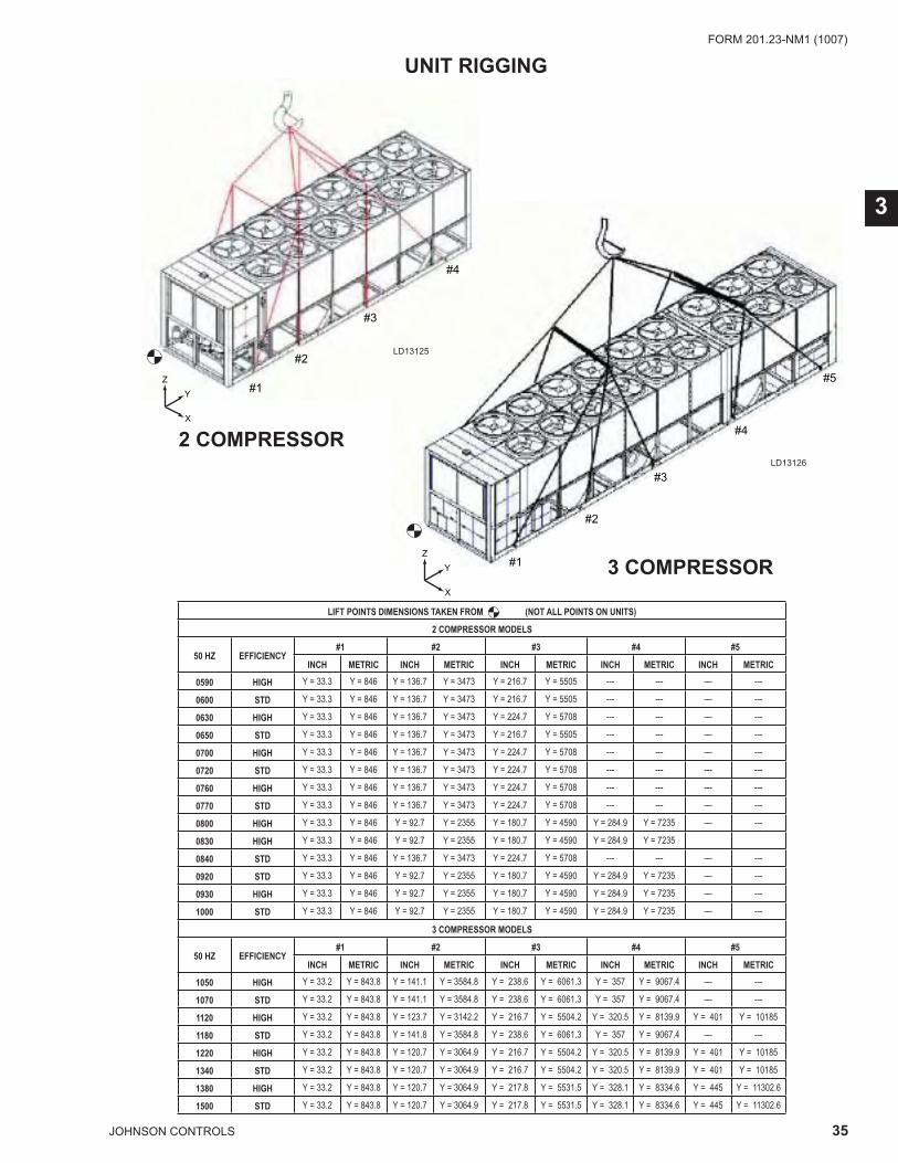
35JOHNSON CONTROLS
FORM 201.23-NM1 (1007)
3
UNIT RIGGING
#1
#2
#3
#4
#5
X
Y
Z
2 COMPRESSOR
3 COMPRESSOR
#1
#2
#3
#4
X
Y
Z
LD13125
LD13126
LIFT POINTS DIMENSIONS TAKEN FROM (NOT ALL POINTS ON UNITS)
2 COMPRESSOR MODELS
50 HZ EFFICIENCY#1 #2 #3 #4 #5
INCH METRIC INCH METRIC INCH METRIC INCH METRIC INCH METRIC
0590 HIGH Y = 33.3 Y = 846 Y = 136.7 Y = 3473 Y = 216.7 Y = 5505 --- --- --- ---
0600 STD Y = 33.3 Y = 846 Y = 136.7 Y = 3473 Y = 216.7 Y = 5505 --- --- --- ---
0630 HIGH Y = 33.3 Y = 846 Y = 136.7 Y = 3473 Y = 224.7 Y = 5708 --- --- --- ---
0650 STD Y = 33.3 Y = 846 Y = 136.7 Y = 3473 Y = 216.7 Y = 5505 --- --- --- ---
0700 HIGH Y = 33.3 Y = 846 Y = 136.7 Y = 3473 Y = 224.7 Y = 5708 --- --- --- ---
0720 STD Y = 33.3 Y = 846 Y = 136.7 Y = 3473 Y = 224.7 Y = 5708 --- --- --- ---
0760 HIGH Y = 33.3 Y = 846 Y = 136.7 Y = 3473 Y = 224.7 Y = 5708 --- --- --- ---
0770 STD Y = 33.3 Y = 846 Y = 136.7 Y = 3473 Y = 224.7 Y = 5708 --- --- --- ---
0800 HIGH Y = 33.3 Y = 846 Y = 92.7 Y = 2355 Y = 180.7 Y = 4590 Y = 284.9 Y = 7235 --- ---
0830 HIGH Y = 33.3 Y = 846 Y = 92.7 Y = 2355 Y = 180.7 Y = 4590 Y = 284.9 Y = 7235
0840 STD Y = 33.3 Y = 846 Y = 136.7 Y = 3473 Y = 224.7 Y = 5708 --- --- --- ---
0920 STD Y = 33.3 Y = 846 Y = 92.7 Y = 2355 Y = 180.7 Y = 4590 Y = 284.9 Y = 7235 --- ---
0930 HIGH Y = 33.3 Y = 846 Y = 92.7 Y = 2355 Y = 180.7 Y = 4590 Y = 284.9 Y = 7235 --- ---
1000 STD Y = 33.3 Y = 846 Y = 92.7 Y = 2355 Y = 180.7 Y = 4590 Y = 284.9 Y = 7235 --- ---
3 COMPRESSOR MODELS
50 HZ EFFICIENCY#1 #2 #3 #4 #5
INCH METRIC INCH METRIC INCH METRIC INCH METRIC INCH METRIC
1050 HIGH Y = 33.2 Y = 843.8 Y = 141.1 Y = 3584.8 Y = 238.6 Y = 6061.3 Y = 357 Y = 9067.4 --- ---
1070 STD Y = 33.2 Y = 843.8 Y = 141.1 Y = 3584.8 Y = 238.6 Y = 6061.3 Y = 357 Y = 9067.4 --- ---
1120 HIGH Y = 33.2 Y = 843.8 Y = 123.7 Y = 3142.2 Y = 216.7 Y = 5504.2 Y = 320.5 Y = 8139.9 Y = 401 Y = 10185
1180 STD Y = 33.2 Y = 843.8 Y = 141.8 Y = 3584.8 Y = 238.6 Y = 6061.3 Y = 357 Y = 9067.4 --- ---
1220 HIGH Y = 33.2 Y = 843.8 Y = 120.7 Y = 3064.9 Y = 216.7 Y = 5504.2 Y = 320.5 Y = 8139.9 Y = 401 Y = 10185
1340 STD Y = 33.2 Y = 843.8 Y = 120.7 Y = 3064.9 Y = 216.7 Y = 5504.2 Y = 320.5 Y = 8139.9 Y = 401 Y = 10185
1380 HIGH Y = 33.2 Y = 843.8 Y = 120.7 Y = 3064.9 Y = 217.8 Y = 5531.5 Y = 328.1 Y = 8334.6 Y = 445 Y = 11302.6
1500 STD Y = 33.2 Y = 843.8 Y = 120.7 Y = 3064.9 Y = 217.8 Y = 5531.5 Y = 328.1 Y = 8334.6 Y = 445 Y = 11302.6
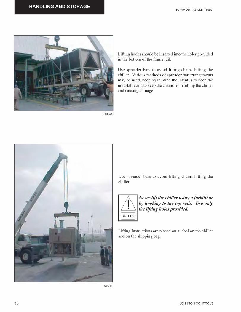
36 JOHNSON CONTROLS
FORM 201.23-NM1 (1007)HANDLING AND STORAGE
Use spreader bars to avoid lifting chains hitting the chiller.
Never lift the chiller using a forklift or by hooking to the top rails. Use only the lifting holes provided.
Lifting Instructions are placed on a label on the chiller and on the shipping bag.
LD10484
Lifting hooks should be inserted into the holes provided in the bottom of the frame rail.
Use spreader bars to avoid lifting chains hitting the chiller. Various methods of spreader bar arrangements may be used, keeping in mind the intent is to keep the unit stable and to keep the chains from hitting the chiller and causing damage.
LD10483
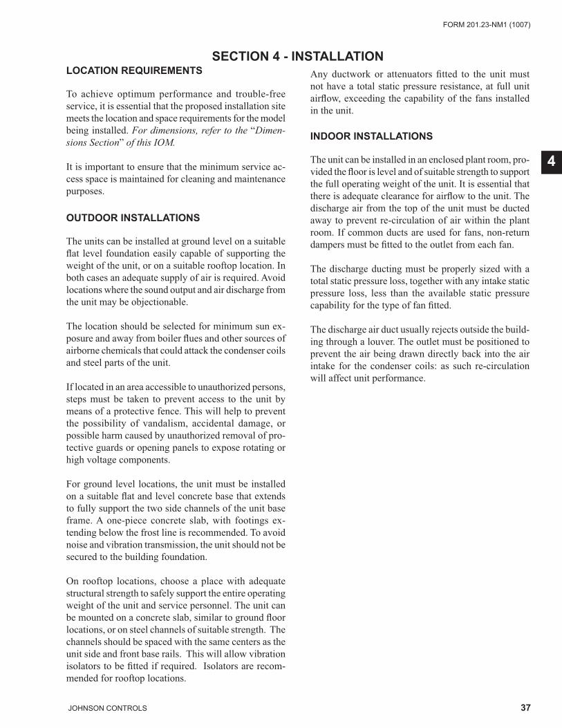
37JOHNSON CONTROLS
FORM 201.23-NM1 (1007)
4
SECTION 4 - INSTALLATIONLOCATION REQUIREMENTS
To achieve optimum performance and trouble-free service, it is essential that the proposed installation site meets the location and space requirements for the model being installed. For dimensions, refer to the “Dimen-sions Section” of this IOM.
It is important to ensure that the minimum service ac-cess space is maintained for cleaning and maintenance purposes.
OUTDOOR INSTALLATIONS
The units can be installed at ground level on a suitable fl at level foundation easily capable of supporting the weight of the unit, or on a suitable rooftop location. In both cases an adequate supply of air is required. Avoid locations where the sound output and air discharge from the unit may be objectionable.
The location should be selected for minimum sun ex-posure and away from boiler fl ues and other sources of airborne chemicals that could attack the condenser coils and steel parts of the unit.
If located in an area accessible to unauthorized persons, steps must be taken to prevent access to the unit by means of a protective fence. This will help to prevent the possibility of vandalism, accidental damage, or possible harm caused by unauthorized removal of pro-tective guards or opening panels to expose rotating or high voltage components.
For ground level locations, the unit must be installed on a suitable fl at and level concrete base that extends to fully support the two side channels of the unit base frame. A one-piece concrete slab, with footings ex-tending below the frost line is recommended. To avoid noise and vibration transmission, the unit should not be secured to the building foundation.
On rooftop locations, choose a place with adequate structural strength to safely support the entire operating weight of the unit and service personnel. The unit can be mounted on a concrete slab, similar to ground fl oor locations, or on steel channels of suitable strength. The channels should be spaced with the same centers as the unit side and front base rails. This will allow vibration isolators to be fi tted if required. Isolators are recom-mended for rooftop locations.
Any ductwork or attenuators fi tted to the unit must not have a total static pressure resistance, at full unit airfl ow, exceeding the capability of the fans installed in the unit.
INDOOR INSTALLATIONS
The unit can be installed in an enclosed plant room, pro-vided the fl oor is level and of suitable strength to support the full operating weight of the unit. It is essential that there is adequate clearance for airfl ow to the unit. The discharge air from the top of the unit must be ducted away to prevent re-circulation of air within the plant room. If common ducts are used for fans, non-return dampers must be fi tted to the outlet from each fan.
The discharge ducting must be properly sized with a total static pressure loss, together with any intake static pressure loss, less than the available static pressure capability for the type of fan fi tted.
The discharge air duct usually rejects outside the build-ing through a louver. The outlet must be positioned to prevent the air being drawn directly back into the air intake for the condenser coils: as such re-circulation will affect unit performance.
38 JOHNSON CONTROLS
FORM 201.23-NM1 (1007)INSTALLATION
LOCATION CLEARANCES
Adequate clearances around the unit(s) are required for the unrestricted airflow for the air-cooled condenser coils and to prevent re-circulation of warm discharge air back onto the coils. If clearances given are not maintained, airflow restriction or re-circulation will cause a loss of unit performance, an increase in power consumption, and may cause the unit to malfunction. Consideration should also be given to the possibility of down drafts, caused by adjacent buildings, which may cause re-cir-culation or uneven unit airflow.
For locations where significant cross winds are expected, such as exposed roof tops, an enclosure of solid or lou-ver type is recommended to prevent wind turbulence interfering with the unit airflow.
When units are installed in an enclosure, the enclosure height should not exceed the height of the unit on more than one side. If the enclosure is of louvered construc-tion, the same requirement of static pressure loss applies as for ducts and attenuators stated above.
Where accumulation of snow is likely, additional height must be provided under the unit to ensure normal airflow to the unit
Clearance dimensions provided else-where are necessary to maintain good airflow and ensure correct unit opera-tion. It is also necessary to consider access requirements for safe operation and maintenance of the unit and power and control panels. Local health and safety regulations, or practical con-siderations for service replacement of large components, may require larger clearances than those given in the Technical Data Section (Page 130).
VIBRATION ISOLATORS
Optional sets of vibration isolators can be supplied loose with each unit.
Using the Isolator tables shipped with the unit in the information pack, refer to the Dimension Section (Pages 110-129), Weight Distribution and Isolator Mounting Position Section (Pages 131-135) and Isolator types (Pages 136-140). Identify each mount and its correct location on the unit.
Installation
Place each mount in its correct position and lower the unit carefully onto the mounts ensuring the mount en-gages in the mounting holes in the unit base frame.
On adjustable mounts, transfer the unit weight evenly to the springs by turning the mount adjusting nuts (located just below the top plate of the mount) counterclockwise to raise and clockwise to lower. This should be done two turns at a time until the top plates of all mounts are between 1/4” and 1/2” (6 and 12 mm) clear of top of their housing and the unit base is level.
A more detailed installation instruction is provided on Pages 136-140.
SHIPPING BRACES
The chiller’s modular design does not require shipping braces.
CHILLED LIQUID PIPING
General Requirements
The following piping recommendations are intended to ensure satisfactory operation of the unit(s). Failure to follow these recommendations could cause damage to the unit, or loss of performance, and may invalidate the warranty.
The maximum flow rate and pressure drop for the cooler must not be exceed-ed at any time. Refer to the Technical Data Section for details.
The liquid must enter the cooler at the inlet connection. The inlet connection for the cooler is at the control panel end of the cooler.
39JOHNSON CONTROLS
FORM 201.23-NM1 (1007)
4
Thermometer and pressure gauge connections should be provided on the inlet and outlet connections of each cooler. Gauges and thermometers are not provided with the unit.
Drain and air vent connections should be provided at all low and high points in the piping to permit drainage of the system and to vent any air in the pipes.
Liquid system lines at risk of freezing, due to low ambi-ent temperatures should be protected using insulation and heater tape and/or a suitable glycol solution. The liquid pump(s) may also be used to ensure liquid is circulated when the ambient temperature approaches freezing point.
Insulation should also be installed around the cooler nozzles. Heater tape of 21 watts per meter under the insulation is recommended, supplied independently and controlled by an ambient temperature thermostat set to switch on at approximately 4°F, above the freezing temperature of the chilled liquid.
The cooler is protected by heater mats placed under the insulation, which are powered from the unit control system power supply. During cold weather when there is a risk of freezing, chiller power should be left switched on to provide the freeze protection function unless the liquid systems have been drained.
Any debris left in the water piping between the strainer and cooler could cause serious damage to the tubes in the cooler and must be avoided. Be sure the piping is clean before connect-ing it to the evaporator. Keep evapo-rator nozzles and chilled liquid piping capped prior to installation to assure construction debris is not allowed to enter.
The installer/user must also ensure that the quality of the water in circulation is adequate, without any dissolved gases, which can cause oxidation of steel parts within the cooler.
A fl ow switch must be installed in the customer pip-ing at the outlet of the cooler and wired back to the control panel using shielded cable.
There should be a straight run of piping of at least 5 pipe diameters on either side. The fl ow switch should be wired to Terminals 2 and 13 on the 1TB terminal block (See FIG. 17 & 17A, Pages 151 & 152). A fl ow switch is required to prevent damage to the cooler caused by the unit operating without adequate liquid fl ow.
The fl ow switch used must have gold plated contacts for low voltage/current operation. Paddle type fl ow switches suitable for 150 PSIG (10 bar) working pressure and hav-ing a 1” N.P.T. connection can be obtained from YORK as an accessory for the unit. Alternatively, a differential pressure switch fi tted across an orifi ce plate may be used, preferably of the high/low limit type.
The chilled liquid pump(s) installed in the piping system(s) should discharge directly into the unit cooler section of the system. The pump(s) may be controlled by the chiller controls or external to the unit. For de-tails, refer to “Electrical Elementary and Connection Diagrams.”
Pipework and fi ttings must be separately supported to prevent any loading on the cooler. Flexible connections are recommended which will also minimize transmis-sion of vibrations to the building. Flexible connections must be used if the unit is mounted on anti-vibration mounts, as some movement of the unit can be expected in normal operation.
Piping and fi ttings immediately next to the cooler should be readily de-mountable to enable cleaning before opera-tion, and to facilitate visual inspection of the exchanger nozzles.
The cooler must be protected by a strainer, prefer-ably of 40 mesh, fi tted as close as possible to the liquid inlet connection, and provided with a means of local isolation.
The cooler must not be exposed to fl ushing velocities or debris released during fl ushing. It is recommended that a suitably sized bypass and valve arrangement is installed to allow fl ushing of the piping system. The bypass can be used during maintenance to isolate the heat exchanger without disrupting fl ow to other units.
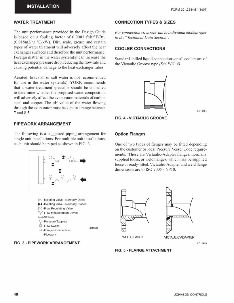
40 JOHNSON CONTROLS
FORM 201.23-NM1 (1007)INSTALLATION
WATER TREATMENT
The unit performance provided in the Design Guide is based on a fouling factor of 0.0001 ft2hr°F/Btu (0.018m2/hr °C/kW). Dirt, scale, grease and certain types of water treatment will adversely affect the heat exchanger surfaces and therefore the unit performance. Foreign matter in the water system(s) can increase the heat exchanger pressure drop, reducing the fl ow rate and causing potential damage to the heat exchanger tubes.
Aerated, brackish or salt water is not recommended for use in the water system(s). YORK recommends that a water treatment specialist should be consulted to determine whether the proposed water composition will adversely affect the evaporator materials of carbon steel and copper. The pH value of the water fl owing through the evaporator must be kept in a range between 7 and 8.5.
PIPEWORK ARRANGEMENT
The following is a suggested piping arrangement for single unit installations. For multiple unit installations, each unit should be piped as shown in FIG. 3.
-Isolating Valve - Normally Open
-Isolating Valve - Normally Closed
-Flow Regulating Valve
-Flow Measurement Device
-Strainer
-Pressure Tapping
-Flow Switch
-Flanged Connection
-Pipework
FIG. 3 - PIPEWORK ARRANGEMENT
CONNECTION TYPES & SIZES
For connection sizes relevant to individual models refer to the “Technical Data Section”.
COOLER CONNECTIONS
Standard chilled liquid connections on all coolers are of the Victaulic Groove type (See FIG. 4).
FIG. 4 - VICTAULIC GROOVE
LD10494
Option Flanges
One of two types of fl anges may be fi tted depending on the customer or local Pressure Vessel Code require-ments. These are Victaulic-Adapter fl anges, normally supplied loose, or weld fl anges, which may be supplied loose or ready-fi tted. Victaulic-Adapter and weld fl ange dimensions are to ISO 7005 - NP10.
FIG. 5 - FLANGE ATTACHMENT
LD10495
WELD FLANGE VICTAULIC ADAPTER
LD10507
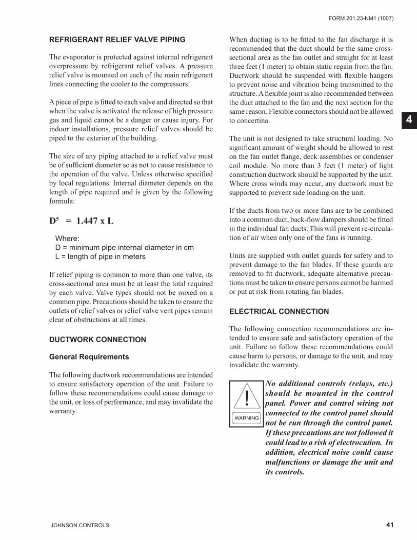
41JOHNSON CONTROLS
FORM 201.23-NM1 (1007)
4
REFRIGERANT RELIEF VALVE PIPING
The evaporator is protected against internal refrigerant overpressure by refrigerant relief valves. A pressure relief valve is mounted on each of the main refrigerant lines connecting the cooler to the compressors.
A piece of pipe is fi tted to each valve and directed so that when the valve is activated the release of high pressure gas and liquid cannot be a danger or cause injury. For indoor installations, pressure relief valves should be piped to the exterior of the building.
The size of any piping attached to a relief valve must be of suffi cient diameter so as not to cause resistance to the operation of the valve. Unless otherwise specifi ed by local regulations. Internal diameter depends on the length of pipe required and is given by the following formula:
D5 = 1.447 x L
Where: D = minimum pipe internal diameter in cmL = length of pipe in meters
If relief piping is common to more than one valve, its cross-sectional area must be at least the total required by each valve. Valve types should not be mixed on a common pipe. Precautions should be taken to ensure the outlets of relief valves or relief valve vent pipes remain clear of obstructions at all times.
DUCTWORK CONNECTION
General Requirements
The following ductwork recommendations are intended to ensure satisfactory operation of the unit. Failure to follow these recommendations could cause damage to the unit, or loss of performance, and may invalidate the warranty.
When ducting is to be fi tted to the fan discharge it is recommended that the duct should be the same cross-sectional area as the fan outlet and straight for at least three feet (1 meter) to obtain static regain from the fan. Ductwork should be suspended with fl exible hangers to prevent noise and vibration being transmitted to the structure. A fl exible joint is also recommended between the duct attached to the fan and the next section for the same reason. Flexible connectors should not be allowed to concertina.
The unit is not designed to take structural loading. No signifi cant amount of weight should be allowed to rest on the fan outlet fl ange, deck assemblies or condenser coil module. No more than 3 feet (1 meter) of light construction ductwork should be supported by the unit. Where cross winds may occur, any ductwork must be supported to prevent side loading on the unit.
If the ducts from two or more fans are to be combined into a common duct, back-fl ow dampers should be fi tted in the individual fan ducts. This will prevent re-circula-tion of air when only one of the fans is running.
Units are supplied with outlet guards for safety and to prevent damage to the fan blades. If these guards are removed to fi t ductwork, adequate alternative precau-tions must be taken to ensure persons cannot be harmed or put at risk from rotating fan blades.
ELECTRICAL CONNECTION
The following connection recommendations are in-tended to ensure safe and satisfactory operation of the unit. Failure to follow these recommendations could cause harm to persons, or damage to the unit, and may invalidate the warranty.
No additional controls (relays, etc.) should be mounted in the control panel. Power and control wiring not connected to the control panel should not be run through the control panel. If these precautions are not followed it could lead to a risk of electrocution. In addition, electrical noise could cause malfunctions or damage the unit and its controls.
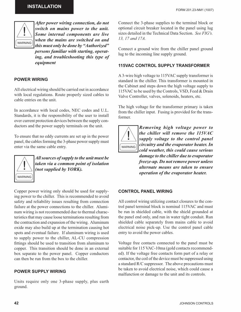
42 JOHNSON CONTROLS
FORM 201.23-NM1 (1007)INSTALLATION
After power wiring connection, do not switch on mains power to the unit. Some internal components are live when the mains are switched on and this must only be done by “Authorized” persons familiar with starting, operat-ing, and troubleshooting this type of equipment
POWER WIRING
All electrical wiring should be carried out in accordance with local regulations. Route properly sized cables to cable entries on the unit.
In accordance with local codes, NEC codes and U.L. Standards, it is the responsibility of the user to install over current protection devices between the supply con-ductors and the power supply terminals on the unit.
To ensure that no eddy currents are set up in the power panel, the cables forming the 3-phase power supply must enter via the same cable entry.
All sources of supply to the unit must be taken via a common point of isolation (not supplied by YORK).
Copper power wiring only should be used for supply-ing power to the chiller. This is recommended to avoid safety and reliability issues resulting from connection failure at the power connections to the chiller. Alumi-num wiring is not recommended due to thermal charac-teristics that may cause loose terminations resulting from the contraction and expansion of the wiring. Aluminum oxide may also build up at the termination causing hot spots and eventual failure. If aluminum wiring is used to supply power to the chiller, AL-CU compression fi ttings should be used to transition from aluminum to copper. This transition should be done in an external box separate to the power panel. Copper conductors can then be run from the box to the chiller.
POWER SUPPLY WIRING
Units require only one 3-phase supply, plus earth ground.
Connect the 3-phase supplies to the terminal block or optional circuit breaker located in the panel using lug sizes detailed in the Technical Data Section. See FIG's. 13, 17 and 17A.
Connect a ground wire from the chiller panel ground lug to the incoming line supply ground.
115VAC CONTROL SUPPLY TRANSFORMER
A 3-wire high voltage to 115VAC supply transformer is standard in the chiller. This transformer is mounted in the Cabinet and steps down the high voltage supply to 115VAC to be used by the Controls, VSD, Feed & Drain Valve Controller, valves, solenoids, heaters, etc.
The high voltage for the transformer primary is taken from the chiller input. Fusing is provided for the trans-former.
Removing high voltage power to the chiller will remove the 115VAC supply voltage to the control panel circuitry and the evaporator heater. In cold weather, this could cause serious damage to the chiller due to evaporator freeze-up. Do not remove power unless alternate means are taken to ensure operation of the evaporator heater.
CONTROL PANEL WIRING
All control wiring utilizing contact closures to the con-trol panel terminal block is nominal 115VAC and must be run in shielded cable, with the shield grounded at the panel end only, and run in water tight conduit. Run shielded cable separately from mains cable to avoid electrical noise pick-up. Use the control panel cable entry to avoid the power cables.
Voltage free contacts connected to the panel must be suitable for 115 VAC-10ma (gold contacts recommend-ed). If the voltage free contacts form part of a relay or contactor, the coil of the device must be suppressed using a standard R/C suppressor. The above precautions must be taken to avoid electrical noise, which could cause a malfunction or damage to the unit and its controls.
43JOHNSON CONTROLS
FORM 201.23-NM1 (1007)
4
VOLTS FREE CONTACTS
Voltage free contacts are rated at 115VAC, 100VA re-sistive load only. Inductive loads must be suppressed across the coil.
Chilled Liquid Pump Starter
Terminals 23 and 24 on 1TB (FIG. 17 & FIG. 17A) close to start the chilled liquid pump. This contact can be used as a master start/stop for the pump in conjunction with the daily start/stop schedule.
Run Contact
Terminals 21 and 22 on 1TB (FIG. 17 & FIG. 17A) close to indicate that a system is running.
Alarm Contacts
The Systems 1/3 & 2/4 each have a single voltage-free contact, which will operate to signal an alarm condition whenever any system locks out, or there is a power failure. To obtain system alarm signal, connect the alarm circuit to volt free Terminals 25 & 26 (Sys 1/3), Terminals 27 and 28 (Sys 2/4) of 1TB (FIG. 17 & FIG. 17A).
SYSTEM INPUTS
Flow Switch
A chilled liquid fl ow switch of suitable type MUST be connected between Terminals 2 and 13 of 1TB (FIG. 17 & FIG. 17A) to provide protection against loss of liquid fl ow, which will cause evaporator freeze-up if the chiller is permitted to run. The fl ow switch circuitry is a 115VAC circuit. Contacts must be rated for low current (10ma). Gold contacts should be used.
Remote Run / Stop
A Remote Run/Stop input is available for each pair of systems (1/3 & 2/4). These inputs require a dry contact to start and stop the system. System 1/3 remote dry contacts are connected between Terminals 2 and 15 of 1TB (FIG. 17 & FIG. 17A) and System 2/4 dry contacts are connected between Terminals 2 and 16 of 1TB (FIG. 17 & FIG. 17A). If remote start/stop is not utilized, a jumper must be paced across the terminals to allow the system to run. The remote run/stop circuitry is a 115VAC circuit. Contacts must be rated for low current (10ma). Gold contacts should be used.
Remote Print
Closure of suitable contacts connected to Terminals 2 and 14 of 1TB (FIG. 17 & FIG. 17A) will cause a hard copy printout of Operating Data/Fault History to be made if an optional printer is connected to the RS-232 port. The remote print circuitry is a 115VAC circuit. Contacts must be rated for low current (10ma). Gold contacts should be used.
Optional Remote Setpoint Offset – Tempera-ture
A current or voltage signal connected to Terminals 17 and 18 will provide a remote offset function of the chilled liquid setpoint, if required. See FIG. 17 & FIG. 17A for the input location and Page 207 for a descrip-tion of the option.
Optional Remote Setpoint Offset – Current
A current or voltage signal connected to Terminals 19 and 20 will provide remote setting of the current limit setpoint, if required. See FIG. 17 & FIG. 17A for the input location and Page 209 for a description of the option.
Optional Remote Setpoint Offset – Sound Limiting
A current or voltage signal connected to Terminals 40 and 41will provide remote setting of sound limit setpoint, if required. See FIG. 17 & FIG. 17A for the input location and Page 211 for a description of the option.
44 JOHNSON CONTROLS
FORM 201.23-NM1 (1007)COMMISSIONING
SECTION 5 - COMMISSIONINGPREPARATION
Commissioning of this unit should only be carried out by YORK Authorized personnel.
Commissioning personnel should be thoroughly familiar with the information contained in this literature, in ad-dition to this section.
Perform the commissioning using the detailed checks outlined in the EQUIPMENT START-UP CHECK SHEET on Page 167 as the commissioning procedure is carried out.
PREPARATION – GENERAL
The following basic checks should be made with the customer power to the unit switched OFF.
Proper electrical lock out and tag pro-cedures must be followed.
Inspection
Inspect unit for installation damage. If found, take action and/or repair as appropriate.
Refrigerant Charge
Packaged units are normally shipped as standard with a full refrigerant operating charge. Check that refrigerant pressure is present in both systems and that no leaks are apparent. If no pressure is present, a leak test must be undertaken, the leak(s) located and repaired. Remote systems and units are supplied with a nitrogen hold-ing charge. These systems must be evacuated with a suitable vacuum pump/recovery unit as appropriate to below 500 microns.
Do not liquid charge with static water in the cooler. Care must also be taken to liquid charge slowly to avoid excessive thermal stress at the charging point. Once the vacuum is broken, charge into the condenser coils with the full operating charge as given in the Technical Data Section.
Service and Oil Line Valves
Open each compressor suction, economizer, and dis-charge service valve. If valves are of the back-seat type, open them fully (counterclockwise) then close one turn of the stem to ensure operating pressure is fed to pressure transducers. Open the liquid line service valve and oil return line ball valve fully in each system.
Compressor Oil
To add oil to a circuit - connect a YORK hand oil pump (Part No. 470-10654-000) to the 1/4” oil charging valve on the oil separator piping with a length of clean hose or copper line, but do not tighten the fl are nut. Using clean oil of the correct type (“L” oil), pump oil until all air has been purged from the hose then tighten the nut. Stroke the oil pump to add oil to the oil system. The oil level should be between the middle of the lower and middle of the upper sight glasses of the oil separa-tor. Approximately 4-5 gallons is present in the each refrigerant system, with typically 1-2 gallons in each oil separator. Oil levels in the oil separators above the top sight glass in either oil separator should be avoided and may cause excessive oil carryover in the system. High oil concentration in the system may cause nuisance trips resulting from incorrect readings on the level sensor and temperature sensors. Temperature sensor errors may result in poor liquid control and resultant liquid overfeed and subsequent damage to the compressor.
Fans
Check that all fans are free to rotate and are not dam-aged. Ensure blades are at the same height when rotated. Ensure fan guards are securely fi xed.
Isolation / Protection
Verify all sources of electrical supply to the unit are taken from a single point of isolation. Check that the maximum recommended fuse sizes given in the Techni-cal Data Section has not been exceeded.
Control Panel
Check the panel to see that it is free of foreign materials (wire, metal chips, etc.) and clean out if required.
45JOHNSON CONTROLS
FORM 201.23-NM1 (1007)
5
Power Connections
Check that the customer power cables are connected cor-rectly to the terminal blocks or optional circuit breaker. Ensure that connections of power cables within the pan-els to the circuit breaker or terminal blocks are tight.
Grounding
Verify that the unit’s protective ground terminal(s) are properly connected to a suitable grounding point. Ensure that all unit internal ground connections are tight.
Water System
Verify the chilled liquid system has been installed cor-rectly, and has been commissioned with the correct di-rection of water fl ow through the cooler. The inlet should be at the refrigerant piping connection end of the cooler. Purge air from the top of the cooler using the plugged air vent mounted on the top of the cooler body.Flow rates and pressure drops must be within the limits given in the Technical Data Section. Operation outside of these limits is undesirable and could cause damage.
If mains power must be switched OFF for extended maintenance or an extended shutdown period, the compressor suction, discharge and economizer service stop valves should be closed (clockwise). If there is a possibility of liquid freezing due to low ambient temperatures, the coolers should be drained or power should be applied to the chiller. This will allow the cooler heater to protect the cooler from freezing down to –20°F. Before placing the unit back in service, valves should be opened and power must be switched on (if power is removed for more than 8 hours) for at least 8 hours (24 hours if ambient temperature is below 86°F [30°C]) before the unit is restarted.
Flow Switch
Verify a chilled water fl ow switch is correctly fi tted in the customer’s piping on the cooler outlet, and wired into the control panel correctly using shielded cable.
There should be a straight run of at least 5 pipe diameters on either side of the fl ow switch. The fl ow switch should be connected to terminals 2 and 13 in the panel.
Temperature Sensor(s)
Ensure the leaving liquid temperature sensor is coated with heat conductive compound (Part No. 013-00890-000) and is inserted to the bottom of the water outlet sensor well in the cooler. This sensor also provides some freeze protection and must always be fully inserted in the water outlet sensor well.
46 JOHNSON CONTROLS
FORM 201.23-NM1 (1007)COMMISSIONING
Programmed Options
Verify that the options factory-programmed into the Micro Panel are in accordance with the customer’s order requirements by pressing the OPTIONS Key on the keypad and reading the settings from the display.
Programmed Settings
Ensure the system cutout and operational settings are in accordance with the operating requirements by pressing the PROGRAM key.
Date and Time
Program the date and time by fi rst ensuring that the CLK jumper JP2 on the chiller control board is in the ON position. See FIG's. 14 and 14A. Then press the DATE/TIME key and set the date and time. (See Page 265.)
Start/Stop Schedule
Program the daily and holiday start/stop by pressing the SCHEDULE key. (See Page 265.)
Setpoint and Remote Offset
Set the required leaving chilled liquid temperature setpoint and control range under the SETPOINTS Key. The chilled liquid temperature control settings need to be set according to the required operating conditions.
If remote temperature reset (offset) is to be used, the maximum reset required must be programmed by press-ing the SETPOINTS Key. (See Page 256.)
FIRST TIME START-UP
During the commissioning period there should be suffi cient heat load to run the unit under stable full load operation to enable the unit controls, and system operation to be set up correctly, and a commissioning log taken. Be sure that the chiller is properly programmed and the System Start-up Checklist (Page 167) is completed.
Interlocks
Verify that liquid is fl owing through the cooler and that heat load is present. Ensure that any remote run inter-locks are in the run position and that the daily schedule requires the unit to run or is overridden.
Unit Switch
Place the “Unit Switch” on the keypad to the ON posi-tion.
Start-up
Press the SYSTEM SWITCHES Key and place the system switch for System 1 to the ON position. There may be a few seconds delay before the fi rst compressor starts because of the anti-recycle timer). Be ready when each compressor starts, to switch the UNIT Switch OFF immediately, if any unusual noises or other adverse conditions develop.
When a compressor is running, the controller monitors oil pressure, motor current, and various other system parameters such as discharge pressure, chilled liquid temperature, etc. Should any problems occur; the control system will immediately take appropriate action and display the nature of the fault.
Oil Pressure
When a compressor starts, press the relevant ‘System Pressures’ key and verify that oil differential pressure (oil pressure-suction pressure) develops immediately. If oil pressure does not develop, the automatic controls will shut down the compressor. Under no circumstances should a restart attempt be made on a compressor, which does not develop oil pressure immediately. Switch the UNIT Switch to the OFF position.
47JOHNSON CONTROLS
FORM 201.23-NM1 (1007)
5
Refrigerant Flow
When a compressor starts, a fl ow of liquid refrigerant will be seen in the liquid line sight glass. After several minutes of operation, and provided a full charge of refrigerant is in the system, the bubbles will disappear and be replaced by a solid column of liquid.
Loading
Once the unit has been started, all operations are fully automatic. After an initial period at minimum capacity, the control system will adjust the unit load depending on the chilled liquid temperature and rate of tempera-ture change. If a high heat load is present, the control-ler will increase the speed of the compressor(s).
Condenser and Fan Rotation
Once a compressor is running, discharge pressure rises as refrigerant is pumped into the air-cooled condenser coils. This pressure is controlled by stages of fans to ensure maximum unit effi ciency while maintaining suffi cient pressure for correct operation of the con-densers and the lubrication system.
As discharge pressure rises, the condenser fans oper-ate in stages to control the pressure. Verify that the fans operate in the correct direction of rotation and operation is correct for the type of unit.
Suction Superheat
Check suction superheat at steady full compres-sor load only. Measure suction temperature with a thermocouple on the copper line about 6” (150 mm) before the compressor suction service valve. Measure suction pressure at the suction transducer access valve or the compressor suction service valve. Superheat should be 10°F to 12°F (5.55 to 6.67°C) and should be reasonably close to the panel display. Superheat setting is programmable on the control panel, but is not mechanically adjustable. The Flash Tank Drain Valve controller modulates the 2-phase drain valve stepper motor to control system superheat. Superheat control is a function of suction pressure and suction temperature measurements from the sensors that are routed to the Chiller Control Board which in turn sends control signals to the Flash Tank Drain and Fill Valve Controller located in the left, back wall of the Chiller Controls Cabinet.
Subcooling
Check liquid subcooling at steady full compressor load only. It is important that all fans are running for the system. Measure liquid line temperature on the copper line at the main liquid line service valve. Measure liquid pressure at the liquid line service valve. Subcooling should be 5 - 7°F (2.77 - 3.88°C). YCIV 0590 subcooling should be 10°F (5.55°C). No bubbles should show in the sight glass. If subcooling is out of range, add or remove refrigerant as required to clear the sight glass. Do not overcharge the unit. Subcooling should be checked with a fl ash tank level of approximately 35% with a clear sight glass.
General Operation
After completion of the above checks for System 1, switch OFF the ‘SYS 1’ switch on the keypad and repeat the process for each subsequent system. When all run correctly, stop the unit, switch all applicable switches to the ‘ON’ position and restart the unit.
Assure all checks are completed in the EQUIPMENT START-UP CHECK SHEET (Pages 167-172). The chiller is then ready to be placed into operation.
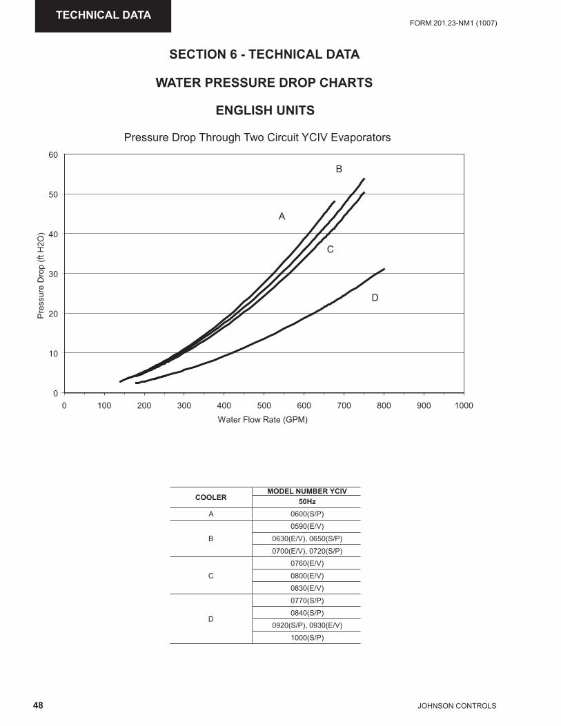
48 JOHNSON CONTROLS
FORM 201.23-NM1 (1007)TECHNICAL DATA
ENGLISH UNITS
�
��
��
��
��
��
��
� ��� ��� ��� ��� ��� ��� ��� �� �� ����
�� ���������� �������
�������������� �!�
"
#
$
�
��������������%&���'&�%���$(�)�( �*$+,�-.����� ���
WATER PRESSURE DROP CHARTS
SECTION 6 - TECHNICAL DATA
COOLERMODEL NUMBER YCIV
50HzA 0600(S/P)
B
0590(E/V)
0630(E/V), 0650(S/P)
0700(E/V), 0720(S/P)
C
0760(E/V)
0800(E/V)
0830(E/V)
D
0770(S/P)
0840(S/P)
0920(S/P), 0930(E/V)
1000(S/P)
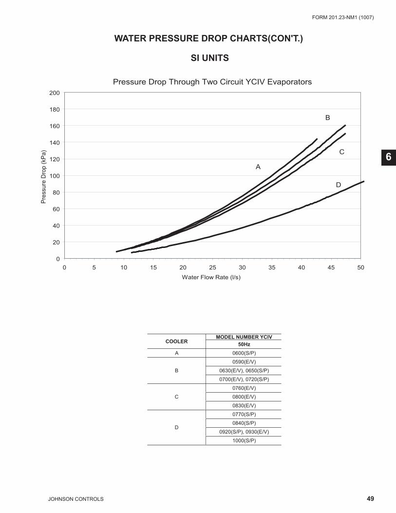
49JOHNSON CONTROLS
FORM 201.23-NM1 (1007)
6
SI UNITS
�
��
��
��
�
���
���
���
���
��
���
� � �� �� �� �� �� �� �� �� ��
�� ���������� ����/��
�������������0���
"
#
$
�
��������������%&���'&�%���$(�)�( �*$+,�-.����� ���
WATER PRESSURE DROP CHARTS(CON'T.)
COOLERMODEL NUMBER YCIV
50HzA 0600(S/P)
B
0590(E/V)
0630(E/V), 0650(S/P)
0700(E/V), 0720(S/P)
C
0760(E/V)
0800(E/V)
0830(E/V)
D
0770(S/P)
0840(S/P)
0920(S/P), 0930(E/V)
1000(S/P)
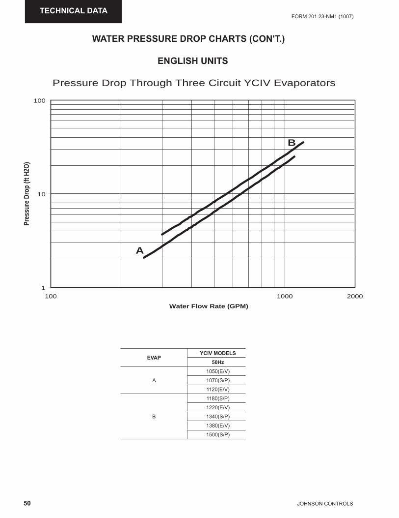
50 JOHNSON CONTROLS
FORM 201.23-NM1 (1007)TECHNICAL DATA
1
10
100
100 1000
Water Flow Rate (GPM)
Pres
sure
Drop
(ftH2
O)
2000
A
B
Pressure Drop Through Three Circuit YCIV Evaporators
ENGLISH UNITS
WATER PRESSURE DROP CHARTS (CON'T.)
EVAPYCIV MODELS
50Hz
A
1050(E/V)
1070(S/P)
1120(E/V)
B
1180(S/P)
1220(E/V)
1340(S/P)
1380(E/V)
1500(S/P)
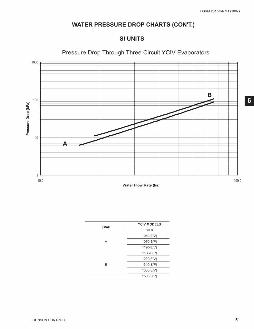
51JOHNSON CONTROLS
FORM 201.23-NM1 (1007)
6
�
��
���
����
��1� ���1�
���������������� ��
���
���
���
��
���
��
�
�
��������������%&���'&�%&����$(�)�( �*$+,�-.����� ���
SI UNITS
WATER PRESSURE DROP CHARTS (CON'T.)
EVAPYCIV MODELS
50Hz
A
1050(E/V)
1070(S/P)
1120(E/V)
B
1180(S/P)
1220(E/V)
1340(S/P)
1380(E/V)
1500(S/P)
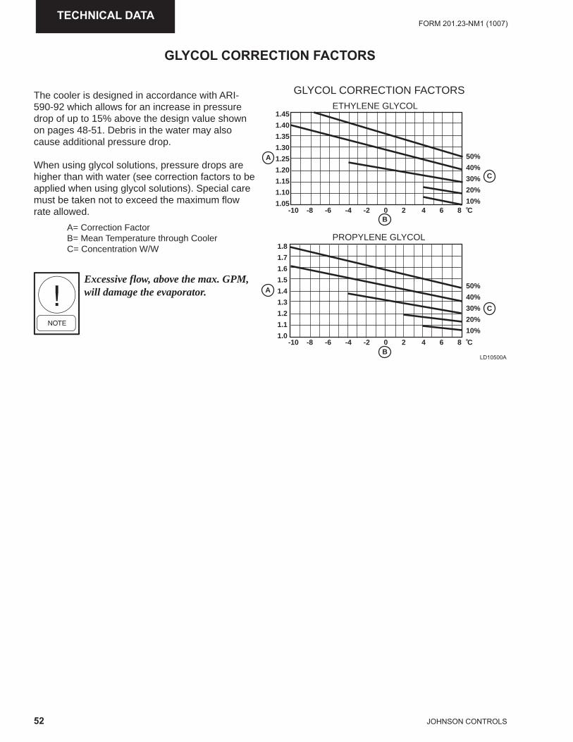
52 JOHNSON CONTROLS
FORM 201.23-NM1 (1007)TECHNICAL DATA
GLYCOL CORRECTION FACTORS
The cooler is designed in accordance with ARI-590-92 which allows for an increase in pressure drop of up to 15% above the design value shown on pages 48-51. Debris in the water may also cause additional pressure drop.
When using glycol solutions, pressure drops are higher than with water (see correction factors to be applied when using glycol solutions). Special care must be taken not to exceed the maximum flow rate allowed.
A= Correction FactorB= Mean Temperature through CoolerC= Concentration W/W
Excessive flow, above the max. GPM, will damage the evaporator.
PROPYLENE GLYCOL
ETHYLENE GLYCOL
GLYCOL CORRECTION FACTORS
A
A
B
B
1.8
1.7
1.6
1.5
1.4
1.3
1.2
1.1
1.0
1.45
1.40
1.35
1.30
1.25
1.20
1.15
1.10
1.05
50%
40%
30%
20%
10%
50%
40%
30%
20%
10%
C
C
-10 -8 -6 -4 -2 0 2 4 6 8 C
-10 -8 -6 -4 -2 0 2 4 6 8 C
LD10500A
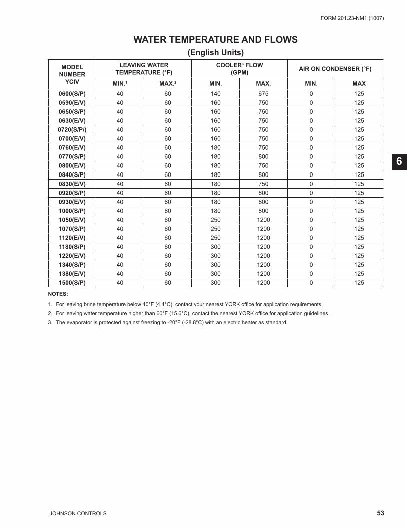
53JOHNSON CONTROLS
FORM 201.23-NM1 (1007)
6
WATER TEMPERATURE AND FLOWS
NOTES:
1. For leaving brine temperature below 40°F (4.4°C), contact your nearest YORK offi ce for application requirements.
2. For leaving water temperature higher than 60°F (15.6°C), contact the nearest YORK offi ce for application guidelines.
3. The evaporator is protected against freezing to -20°F (-28.8°C) with an electric heater as standard.
MODELNUMBER
YCIV
LEAVING WATERTEMPERATURE (°F)
COOLER3 FLOW(GPM) AIR ON CONDENSER (°F)
MIN.1 MAX.2 MIN. MAX. MIN. MAX0600(S/P) 40 60 140 675 0 1250590(E/V) 40 60 160 750 0 1250650(S/P) 40 60 160 750 0 1250630(E/V) 40 60 160 750 0 1250720(S/P/) 40 60 160 750 0 1250700(E/V) 40 60 160 750 0 1250760(E/V) 40 60 180 750 0 1250770(S/P) 40 60 180 800 0 1250800(E/V) 40 60 180 750 0 1250840(S/P) 40 60 180 800 0 1250830(E/V) 40 60 180 750 0 1250920(S/P) 40 60 180 800 0 1250930(E/V) 40 60 180 800 0 1251000(S/P) 40 60 180 800 0 1251050(E/V) 40 60 250 1200 0 1251070(S/P) 40 60 250 1200 0 1251120(E/V) 40 60 250 1200 0 1251180(S/P) 40 60 300 1200 0 1251220(E/V) 40 60 300 1200 0 1251340(S/P) 40 60 300 1200 0 1251380(E/V) 40 60 300 1200 0 1251500(S/P) 40 60 300 1200 0 125
(English Units)
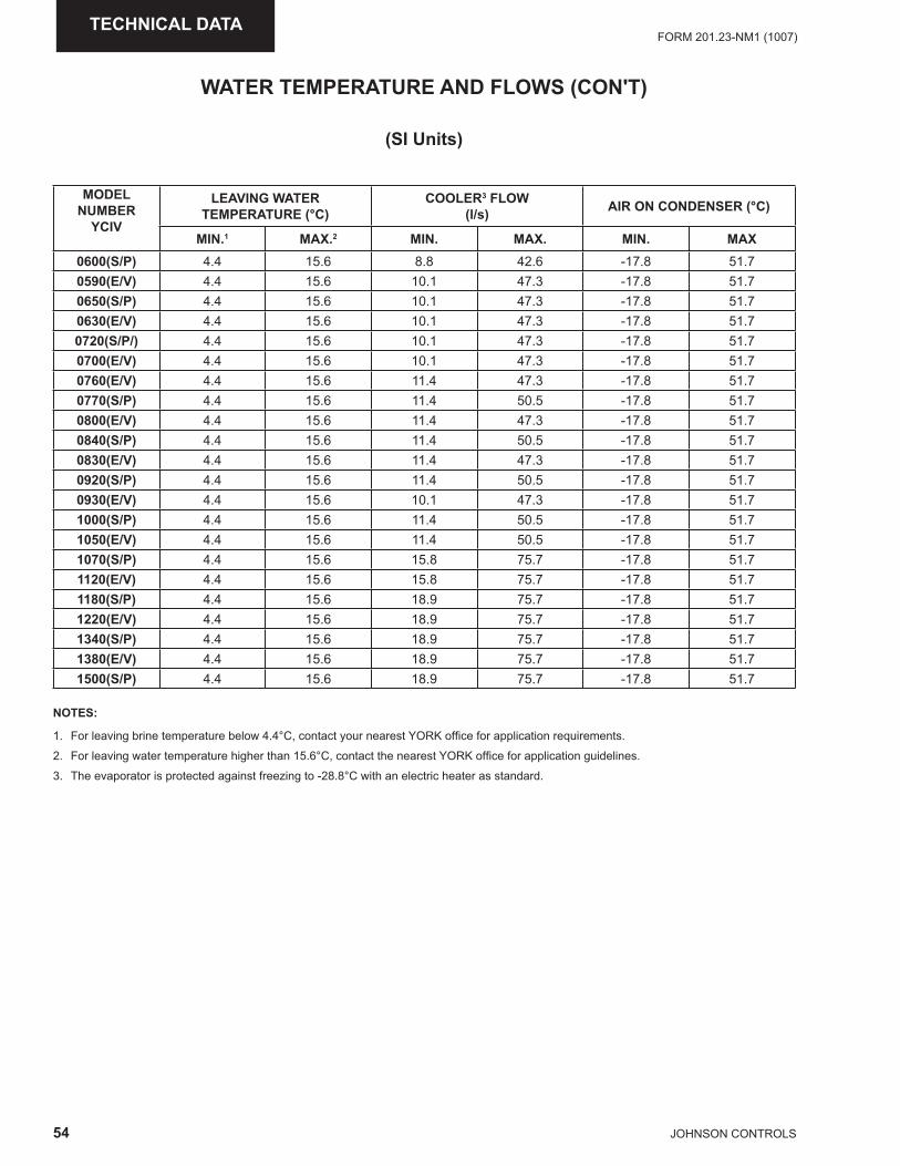
54 JOHNSON CONTROLS
FORM 201.23-NM1 (1007)TECHNICAL DATA
(SI Units)
NOTES:
1. For leaving brine temperature below 4.4°C, contact your nearest YORK offi ce for application requirements.
2. For leaving water temperature higher than 15.6°C, contact the nearest YORK offi ce for application guidelines.
3. The evaporator is protected against freezing to -28.8°C with an electric heater as standard.
MODELNUMBER
YCIV
LEAVING WATERTEMPERATURE (°C)
COOLER3 FLOW(l/s) AIR ON CONDENSER (°C)
MIN.1 MAX.2 MIN. MAX. MIN. MAX0600(S/P) 4.4 15.6 8.8 42.6 -17.8 51.70590(E/V) 4.4 15.6 10.1 47.3 -17.8 51.70650(S/P) 4.4 15.6 10.1 47.3 -17.8 51.70630(E/V) 4.4 15.6 10.1 47.3 -17.8 51.70720(S/P/) 4.4 15.6 10.1 47.3 -17.8 51.70700(E/V) 4.4 15.6 10.1 47.3 -17.8 51.70760(E/V) 4.4 15.6 11.4 47.3 -17.8 51.70770(S/P) 4.4 15.6 11.4 50.5 -17.8 51.70800(E/V) 4.4 15.6 11.4 47.3 -17.8 51.70840(S/P) 4.4 15.6 11.4 50.5 -17.8 51.70830(E/V) 4.4 15.6 11.4 47.3 -17.8 51.70920(S/P) 4.4 15.6 11.4 50.5 -17.8 51.70930(E/V) 4.4 15.6 10.1 47.3 -17.8 51.71000(S/P) 4.4 15.6 11.4 50.5 -17.8 51.71050(E/V) 4.4 15.6 11.4 50.5 -17.8 51.71070(S/P) 4.4 15.6 15.8 75.7 -17.8 51.71120(E/V) 4.4 15.6 15.8 75.7 -17.8 51.71180(S/P) 4.4 15.6 18.9 75.7 -17.8 51.71220(E/V) 4.4 15.6 18.9 75.7 -17.8 51.71340(S/P) 4.4 15.6 18.9 75.7 -17.8 51.71380(E/V) 4.4 15.6 18.9 75.7 -17.8 51.71500(S/P) 4.4 15.6 18.9 75.7 -17.8 51.7
WATER TEMPERATURE AND FLOWS (CON'T)
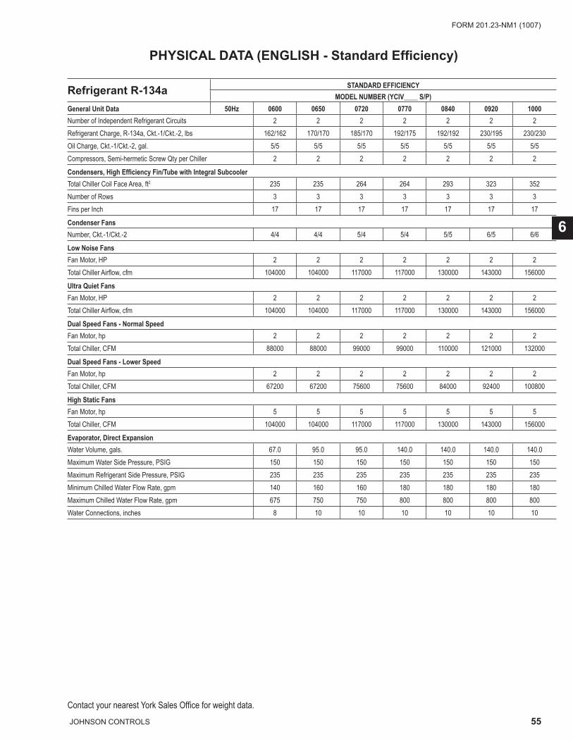
55JOHNSON CONTROLS
FORM 201.23-NM1 (1007)
6
Contact your nearest York Sales Offi ce for weight data.
Refrigerant R-134a STANDARD EFFICIENCYMODEL NUMBER (YCIV____ S/P)
General Unit Data 50Hz 0600 0650 0720 0770 0840 0920 1000Number of Independent Refrigerant Circuits 2 2 2 2 2 2 2Refrigerant Charge, R-134a, Ckt.-1/Ckt.-2, lbs 162/162 170/170 185/170 192/175 192/192 230/195 230/230Oil Charge, Ckt.-1/Ckt.-2, gal. 5/5 5/5 5/5 5/5 5/5 5/5 5/5Compressors, Semi-hermetic Screw Qty per Chiller 2 2 2 2 2 2 2
Condensers, High Effi ciency Fin/Tube with Integral SubcoolerTotal Chiller Coil Face Area, ft2 235 235 264 264 293 323 352Number of Rows 3 3 3 3 3 3 3Fins per Inch 17 17 17 17 17 17 17
Condenser FansNumber, Ckt.-1/Ckt.-2 4/4 4/4 5/4 5/4 5/5 6/5 6/6
Low Noise FansFan Motor, HP 2 2 2 2 2 2 2Total Chiller Airfl ow, cfm 104000 104000 117000 117000 130000 143000 156000
Ultra Quiet FansFan Motor, HP 2 2 2 2 2 2 2Total Chiller Airfl ow, cfm 104000 104000 117000 117000 130000 143000 156000
Dual Speed Fans - Normal SpeedFan Motor, hp 2 2 2 2 2 2 2Total Chiller, CFM 88000 88000 99000 99000 110000 121000 132000
Dual Speed Fans - Lower SpeedFan Motor, hp 2 2 2 2 2 2 2Total Chiller, CFM 67200 67200 75600 75600 84000 92400 100800
High Static FansFan Motor, hp 5 5 5 5 5 5 5Total Chiller, CFM 104000 104000 117000 117000 130000 143000 156000
Evaporator, Direct ExpansionWater Volume, gals. 67.0 95.0 95.0 140.0 140.0 140.0 140.0Maximum Water Side Pressure, PSIG 150 150 150 150 150 150 150Maximum Refrigerant Side Pressure, PSIG 235 235 235 235 235 235 235Minimum Chilled Water Flow Rate, gpm 140 160 160 180 180 180 180Maximum Chilled Water Flow Rate, gpm 675 750 750 800 800 800 800Water Connections, inches 8 10 10 10 10 10 10
PHYSICAL DATA (ENGLISH - Standard Effi ciency)
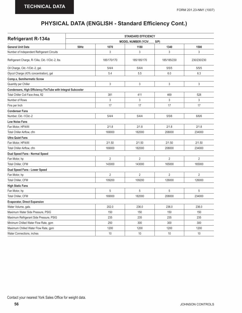
56 JOHNSON CONTROLS
FORM 201.23-NM1 (1007)TECHNICAL DATA
Contact your nearest York Sales Offi ce for weight data.
Refrigerant R-134a STANDARD EFFICIENCYMODEL NUMBER (YCIV____ S/P)
General Unit Data 50Hz 1070 1180 1340 1500Number of Independent Refrigerant Circuits 3 3 3 3
Refrigerant Charge, R-134a, Ckt.-1/Ckt.-2, lbs 185/170/170 185/185/170 185/185/230 230/230/230
Oil Charge, Ckt.-1/Ckt.-2, gal. 5/4/4 5/4/4 5/5/5 5/5/5Glycol Charge (43% concentration), gal 5.4 5.5 6.0 6.3
Comp.s, Semihermetic ScrewQuantity per Chiller 3 3 3 3
Condensers, High Effi ciency Fin/Tube with Integral SubcoolerTotal Chiller Coil Face Area, ft2 381 411 469 528Number of Rows 3 3 3 3Fins per Inch 17 17 17 17
Condenser FansNumber, Ckt.-1/Ckt.-2 5/4/4 5/4/4 5/5/6 6/6/6
Low Noise FansFan Motor, HP/kWi 2/1.8 2/1.8 2/1.8 2/1.8 Total Chiller Airfl ow, cfm 169000 182000 208000 234000
Ultra Quiet FansFan Motor, HP/kWi 2/1.50 2/1.50 2/1.50 2/1.50 Total Chiller Airfl ow, cfm 169000 182000 208000 234000
Dual Speed Fans - Normal SpeedFan Motor, hp 2 2 2 2Total Chiller, CFM 143000 143000 165000 165000
Dual Speed Fans - Lower SpeedFan Motor, hp 2 2 2 2Total Chiller, CFM 109200 109200 126000 126000
High Static FansFan Motor, hp 5 5 5 5Total Chiller, CFM 169000 182000 208000 234000
Evaporator, Direct ExpansionWater Volume, gals. 202.0 236.0 236.0 236.0Maximum Water Side Pressure, PSIG 150 150 150 150Maximum Refrigerant Side Pressure, PSIG 235 235 235 235Minimum Chilled Water Flow Rate, gpm 250 300 300 300Maximum Chilled Water Flow Rate, gpm 1200 1200 1200 1200Water Connections, inches 10 10 10 10
PHYSICAL DATA (ENGLISH - Standard Effi ciency Cont.)
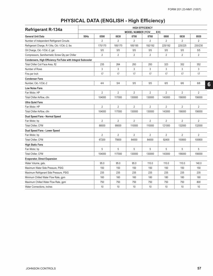
57JOHNSON CONTROLS
FORM 201.23-NM1 (1007)
6
Refrigerant R-134a HIGH EFFICIENCYMODEL NUMBER (YCIV____ E/V)
General Unit Data 50Hz 0590 0630 0700 0760 0800 0830 0930Number of Independent Refrigerant Circuits 2 2 2 2 2 2 2Refrigerant Charge, R-134a, Ckt.-1/Ckt.-2, lbs 170/170 185/170 185/185 192/192 225/192 225/225 230/230Oil Charge, Ckt.-1/Ckt.-2, gal. 5/5 5/5 5/5 5/5 5/5 5/5 5/5Compressors, Semihermetic Screw Qty per Chiller 2 2 2 2 2 2 2
Condensers, High Effi ciency Fin/Tube with Integral SubcoolerTotal Chiller Coil Face Area, ft2 235 264 293 293 323 352 352Number of Rows 3 3 3 3 3 3 3Fins per Inch 17 17 17 17 17 17 17
Condenser FansNumber, Ckt.-1/Ckt.-2 4/4 5/4 5/5 5/5 6/5 6/6 6/6
Low Noise FansFan Motor, HP 2 2 2 2 2 2 2Total Chiller Airfl ow, cfm 104000 117000 130000 130000 143000 156000 156000
Ultra Quiet FansFan Motor, HP 2 2 2 2 2 2 2Total Chiller Airfl ow, cfm 104000 117000 130000 130000 143000 156000 156000
Dual Speed Fans - Normal SpeedFan Motor, hp 2 2 2 2 2 2 2Total Chiller, CFM 88000 99000 110000 110000 121000 132000 132000
Dual Speed Fans - Lower SpeedFan Motor, hp 2 2 2 2 2 2 2Total Chiller, CFM 67200 75600 84000 84000 92400 100800 100800
High Static FansFan Motor, hp 5 5 5 5 5 5 5Total Chiller, CFM 104000 117000 130000 130000 143000 156000 156000
Evaporator, Direct ExpansionWater Volume, gals. 95.0 95.0 95.0 110.0 110.0 110.0 140.0Maximum Water Side Pressure, PSIG 150 150 150 150 150 150 150Maximum Refrigerant Side Pressure, PSIG 235 235 235 235 235 235 235Minimum Chilled Water Flow Rate, gpm 160 160 160 180 180 180 180Maximum Chilled Water Flow Rate, gpm 750 750 750 750 750 750 800Water Connections, inches 10 10 10 10 10 10 10
PHYSICAL DATA (ENGLISH - High Effi ciency)
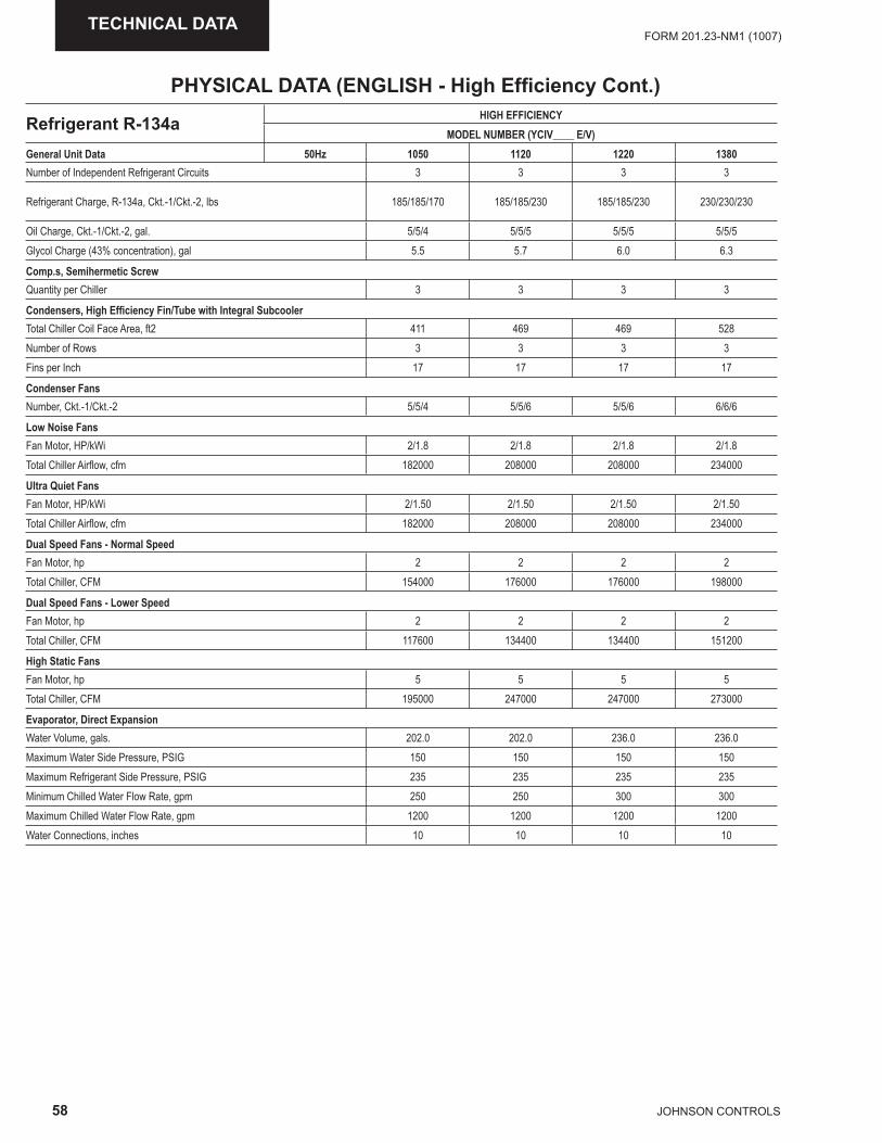
58 JOHNSON CONTROLS
FORM 201.23-NM1 (1007)TECHNICAL DATA
Refrigerant R-134a HIGH EFFICIENCYMODEL NUMBER (YCIV____ E/V)
General Unit Data 50Hz 1050 1120 1220 1380Number of Independent Refrigerant Circuits 3 3 3 3
Refrigerant Charge, R-134a, Ckt.-1/Ckt.-2, lbs 185/185/170 185/185/230 185/185/230 230/230/230
Oil Charge, Ckt.-1/Ckt.-2, gal. 5/5/4 5/5/5 5/5/5 5/5/5Glycol Charge (43% concentration), gal 5.5 5.7 6.0 6.3
Comp.s, Semihermetic ScrewQuantity per Chiller 3 3 3 3
Condensers, High Effi ciency Fin/Tube with Integral SubcoolerTotal Chiller Coil Face Area, ft2 411 469 469 528Number of Rows 3 3 3 3Fins per Inch 17 17 17 17
Condenser FansNumber, Ckt.-1/Ckt.-2 5/5/4 5/5/6 5/5/6 6/6/6
Low Noise Fans Fan Motor, HP/kWi 2/1.8 2/1.8 2/1.8 2/1.8 Total Chiller Airfl ow, cfm 182000 208000 208000 234000
Ultra Quiet FansFan Motor, HP/kWi 2/1.50 2/1.50 2/1.50 2/1.50 Total Chiller Airfl ow, cfm 182000 208000 208000 234000
Dual Speed Fans - Normal SpeedFan Motor, hp 2 2 2 2Total Chiller, CFM 154000 176000 176000 198000
Dual Speed Fans - Lower SpeedFan Motor, hp 2 2 2 2Total Chiller, CFM 117600 134400 134400 151200
High Static FansFan Motor, hp 5 5 5 5Total Chiller, CFM 195000 247000 247000 273000
Evaporator, Direct ExpansionWater Volume, gals. 202.0 202.0 236.0 236.0Maximum Water Side Pressure, PSIG 150 150 150 150Maximum Refrigerant Side Pressure, PSIG 235 235 235 235Minimum Chilled Water Flow Rate, gpm 250 250 300 300Maximum Chilled Water Flow Rate, gpm 1200 1200 1200 1200Water Connections, inches 10 10 10 10
PHYSICAL DATA (ENGLISH - High Effi ciency Cont.)
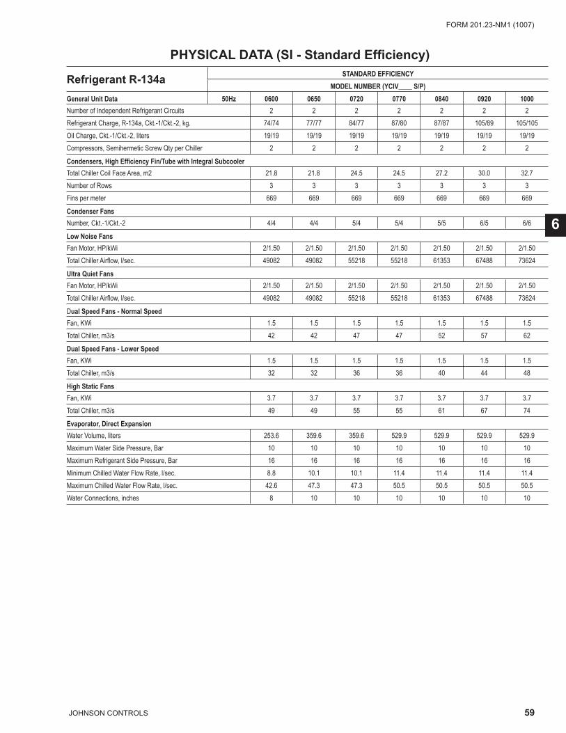
59JOHNSON CONTROLS
FORM 201.23-NM1 (1007)
6
Refrigerant R-134a STANDARD EFFICIENCYMODEL NUMBER (YCIV____ S/P)
General Unit Data 50Hz 0600 0650 0720 0770 0840 0920 1000Number of Independent Refrigerant Circuits 2 2 2 2 2 2 2Refrigerant Charge, R-134a, Ckt.-1/Ckt.-2, kg. 74/74 77/77 84/77 87/80 87/87 105/89 105/105Oil Charge, Ckt.-1/Ckt.-2, liters 19/19 19/19 19/19 19/19 19/19 19/19 19/19Compressors, Semihermetic Screw Qty per Chiller 2 2 2 2 2 2 2
Condensers, High Effi ciency Fin/Tube with Integral SubcoolerTotal Chiller Coil Face Area, m2 21.8 21.8 24.5 24.5 27.2 30.0 32.7Number of Rows 3 3 3 3 3 3 3Fins per meter 669 669 669 669 669 669 669
Condenser FansNumber, Ckt.-1/Ckt.-2 4/4 4/4 5/4 5/4 5/5 6/5 6/6
Low Noise FansFan Motor, HP/kWi 2/1.50 2/1.50 2/1.50 2/1.50 2/1.50 2/1.50 2/1.50 Total Chiller Airfl ow, l/sec. 49082 49082 55218 55218 61353 67488 73624
Ultra Quiet FansFan Motor, HP/kWi 2/1.50 2/1.50 2/1.50 2/1.50 2/1.50 2/1.50 2/1.50 Total Chiller Airfl ow, l/sec. 49082 49082 55218 55218 61353 67488 73624
Dual Speed Fans - Normal SpeedFan, KWi 1.5 1.5 1.5 1.5 1.5 1.5 1.5Total Chiller, m3/s 42 42 47 47 52 57 62
Dual Speed Fans - Lower SpeedFan, KWi 1.5 1.5 1.5 1.5 1.5 1.5 1.5Total Chiller, m3/s 32 32 36 36 40 44 48
High Static FansFan, KWi 3.7 3.7 3.7 3.7 3.7 3.7 3.7Total Chiller, m3/s 49 49 55 55 61 67 74
Evaporator, Direct ExpansionWater Volume, liters 253.6 359.6 359.6 529.9 529.9 529.9 529.9Maximum Water Side Pressure, Bar 10 10 10 10 10 10 10Maximum Refrigerant Side Pressure, Bar 16 16 16 16 16 16 16Minimum Chilled Water Flow Rate, l/sec. 8.8 10.1 10.1 11.4 11.4 11.4 11.4Maximum Chilled Water Flow Rate, l/sec. 42.6 47.3 47.3 50.5 50.5 50.5 50.5Water Connections, inches 8 10 10 10 10 10 10
PHYSICAL DATA (SI - Standard Effi ciency)

60 JOHNSON CONTROLS
FORM 201.23-NM1 (1007)TECHNICAL DATA
Refrigerant R-134aSTANDARD EFFICIENCY
MODEL NUMBER (YCIV____ S/P)General Unit Data 50Hz 1070 1180 1340 1500Number of Independent Refrigerant Circuits 3 3 3 3
Refrigerant Charge, R-134a, Ckt.-1/Ckt.-2, kg. 84 / 77 / 77 84 / 84 / 77 84 / 84 / 105 105 / 105 / 105
Oil Charge, Ckt.-1/Ckt.-2, liters 19 / 15 / 15 19 / 19 / 15 19 / 19 / 19 19 / 19 / 19
Glycol Charge (43% concentration), liters 0 0 0 0
Compressors, Semihermetic ScrewQuantity per Chiller 3 3 3 3
Condensers, High Effi ciency Fin/Tube with Integral SubcoolerTotal Chiller Coil Face Area, m2 35 38 44 49Number of Rows 3 3 3 3Fins per meter 669 669 669 669
Condenser FansNumber, Ckt.-1/Ckt.-2 5/4/4 5/5/4 5/5/6 6/6/6
Low Noise FansFan Motor, HP/kWi 2/1.50 2/1.50 2/1.50 2/1.50 Total Chiller Airfl ow, l/sec. 79768 85904 98176 110448
Ultra Quiet FansFan Motor, HP/kWi 2/1.50 2/1.50 2/1.50 2/1.50 Total Chiller Airfl ow, l/sec. 79768 85904 98176 110448
Dual Speed Fans - Normal SpeedFan, KWi 1.5 1.5 1.5 1.5Total Chiller, m3/s 67 67 78 78
Dual Speed Fans - Lower SpeedFan, KWi 1.5 1.5 1.5 1.5Total Chiller, m3/s 52 52 59 59
High Static FansFan, KWi 3.7 3.7 3.7 3.7Total Chiller, m3/s 80 86 98 110
Evaporator, Direct ExpansionWater Volume, liters 764.6 893.3 893.3 893.3Maximum Water Side Pressure, Bar 10 10 10 10Maximum Refrigerant Side Pressure, Bar 16 16 16 16Minimum Chilled Water Flow Rate, l/sec. 16 19 19 19Maximum Chilled Water Flow Rate, l/sec. 76 76 76 76Water Connections, mm 245 245 245 245
PHYSICAL DATA (SI - Standard Effi ciency Cont.)

61JOHNSON CONTROLS
FORM 201.23-NM1 (1007)
6
Refrigerant R-134a HIGH EFFICIENCYMODEL NUMBER (YCIV____ E/V)
General Unit Data 50Hz 0590 0630 0700 0760 0800 0830 0930Number of Independent Refrigerant Circuits 2 2 2 2 2 2 2Refrigerant Charge, R-134a, Ckt.-1/Ckt.-2, kg. 77/77 84/77 84/84 87/87 102/87 102/102 105/105Oil Charge, Ckt.-1/Ckt.-2, liters 19/19 19/19 19/19 19/19 19/19 19/19 19/19Compressors, Semihermetic Screw Qty per Chiller 2 2 2 2 2 2 2
Condensers, High Effi ciency Fin/Tube with Integral SubcoolerTotal Chiller Coil Face Area, m2 21.8 24.5 27.2 27.2 30.0 32.7 32.7Number of Rows 3 3 3 3 3 3 3Fins per meter 669 669 669 669 669 669 669
Condenser FansNumber, Ckt.-1/Ckt.-2 4/4 5/4 5/5 5/5 6/5 6/6 6/6Low Sound FansFan Motor, HP/kWi 2/1.50 2/1.50 2/1.50 2/1.50 2/1.50 2/1.50 2/1.50 Total Chiller Airfl ow, l/sec. 49082 55218 61353 61353 67488 73624 73624
Ultra Quiet FansFan Motor, HP/kWi 2/1.50 2/1.50 2/1.50 2/1.50 2/1.50 2/1.50 2/1.50 Total Chiller Airfl ow, l/sec. 49082 55218 61353 61353 67488 73624 73624
Dual Speed Fans - Normal SpeedFan, KWi 1.5 1.5 1.5 1.5 1.5 1.5 1.5Total Chiller, m3/s 42 47 52 52 57 62 62
Dual Speed Fans - Lower SpeedFan, KWi 1.5 1.5 1.5 1.5 1.5 1.5 1.5Total Chiller, m3/s 32 36 40 40 44 48 48
High Static FansFan, KWi 3.7 3.7 3.7 3.7 3.7 3.7 3.7Total Chiller, m3/s 49 55 61 61 67 74 74
Evaporator, Direct ExpansionWater Volume, liters 359.6 359.6 359.6 416.4 416.4 416.4 529.9Maximum Water Side Pressure, Bar1 10 10 10 10 10 10 10Maximum Refrigerant Side Pressure, Bar 16 16 16 16 16 16 16Minimum Chilled Water Flow Rate, l/sec. 10.1 10.1 10.1 11.4 11.4 11.4 11.4Maximum Chilled Water Flow Rate, l/sec. 47.3 47.3 47.3 47.3 47.3 47.3 50.5Water Connections, inches 10 10 10 10 10 10 10
PHYSICAL DATA (SI - High Effi ciency)
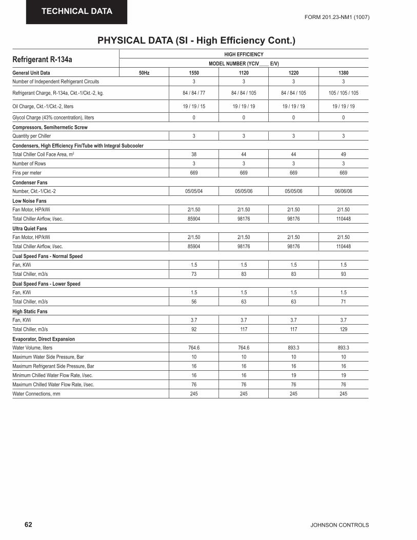
62 JOHNSON CONTROLS
FORM 201.23-NM1 (1007)TECHNICAL DATA
Refrigerant R-134aHIGH EFFICIENCY
MODEL NUMBER (YCIV____ E/V)General Unit Data 50Hz 1550 1120 1220 1380Number of Independent Refrigerant Circuits 3 3 3 3
Refrigerant Charge, R-134a, Ckt.-1/Ckt.-2, kg. 84 / 84 / 77 84 / 84 / 105 84 / 84 / 105 105 / 105 / 105
Oil Charge, Ckt.-1/Ckt.-2, liters 19 / 19 / 15 19 / 19 / 19 19 / 19 / 19 19 / 19 / 19
Glycol Charge (43% concentration), liters 0 0 0 0
Compressors, Semihermetic ScrewQuantity per Chiller 3 3 3 3
Condensers, High Effi ciency Fin/Tube with Integral SubcoolerTotal Chiller Coil Face Area, m2 38 44 44 49Number of Rows 3 3 3 3Fins per meter 669 669 669 669
Condenser FansNumber, Ckt.-1/Ckt.-2 05/05/04 05/05/06 05/05/06 06/06/06
Low Noise FansFan Motor, HP/kWi 2/1.50 2/1.50 2/1.50 2/1.50 Total Chiller Airfl ow, l/sec. 85904 98176 98176 110448
Ultra Quiet FansFan Motor, HP/kWi 2/1.50 2/1.50 2/1.50 2/1.50 Total Chiller Airfl ow, l/sec. 85904 98176 98176 110448
Dual Speed Fans - Normal SpeedFan, KWi 1.5 1.5 1.5 1.5Total Chiller, m3/s 73 83 83 93
Dual Speed Fans - Lower SpeedFan, KWi 1.5 1.5 1.5 1.5Total Chiller, m3/s 56 63 63 71
High Static FansFan, KWi 3.7 3.7 3.7 3.7Total Chiller, m3/s 92 117 117 129
Evaporator, Direct ExpansionWater Volume, liters 764.6 764.6 893.3 893.3Maximum Water Side Pressure, Bar 10 10 10 10Maximum Refrigerant Side Pressure, Bar 16 16 16 16Minimum Chilled Water Flow Rate, l/sec. 16 16 19 19Maximum Chilled Water Flow Rate, l/sec. 76 76 76 76Water Connections, mm 245 245 245 245
PHYSICAL DATA (SI - High Effi ciency Cont.)
63JOHNSON CONTROLS
FORM 201.23-NM1 (1007)
6
OPERATING LIMITATIONS AND SOUND DATA
Contact Product Application Marketing for Sound Power Data
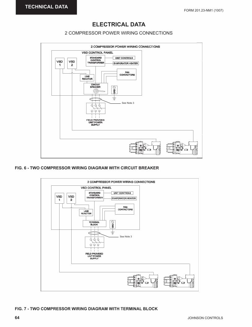
64 JOHNSON CONTROLS
FORM 201.23-NM1 (1007)TECHNICAL DATA
FIG. 6 - TWO COMPRESSOR WIRING DIAGRAM WITH CIRCUIT BREAKER
FIG. 7 - TWO COMPRESSOR WIRING DIAGRAM WITH TERMINAL BLOCK
ELECTRICAL DATA2 COMPRESSOR POWER WIRING CONNECTIONS
,2� $!3%�!4 �"3-4
,2�
�
,2�
�
2%"3�"��
$!3%�!4
%�"32�!��-�
53+% $!3%�!42
-,"�!�"%!� -"%-�
�"3
$!3%"$%!�2
$+�$5+%
#�-"6-�
���
�+-4� ��!,+�-�
53+% �!�-�
25��4*
4+3-
�-"$%!�
� $!���-22!� �!�-� �+�+3� $!33-$%+!32
2���3� ���
,2� $!3%�!4 �"3-4
,2�
�
,2�
�
2%"3�"��
$!3%�!4
%�"32�!��-�
53+% $!3%�!42
-,"�!�"%!� -"%-�
�"3
$!3%"$%!�2
%-��+3"4
#4!$6
���
�+-4� ��!,+�-�
53+% �!�-�
25��4*
4+3-
�-"$%!�
� $!���-22!� �!�-� �+�+3� $!33-$%+!32
2���3� ���
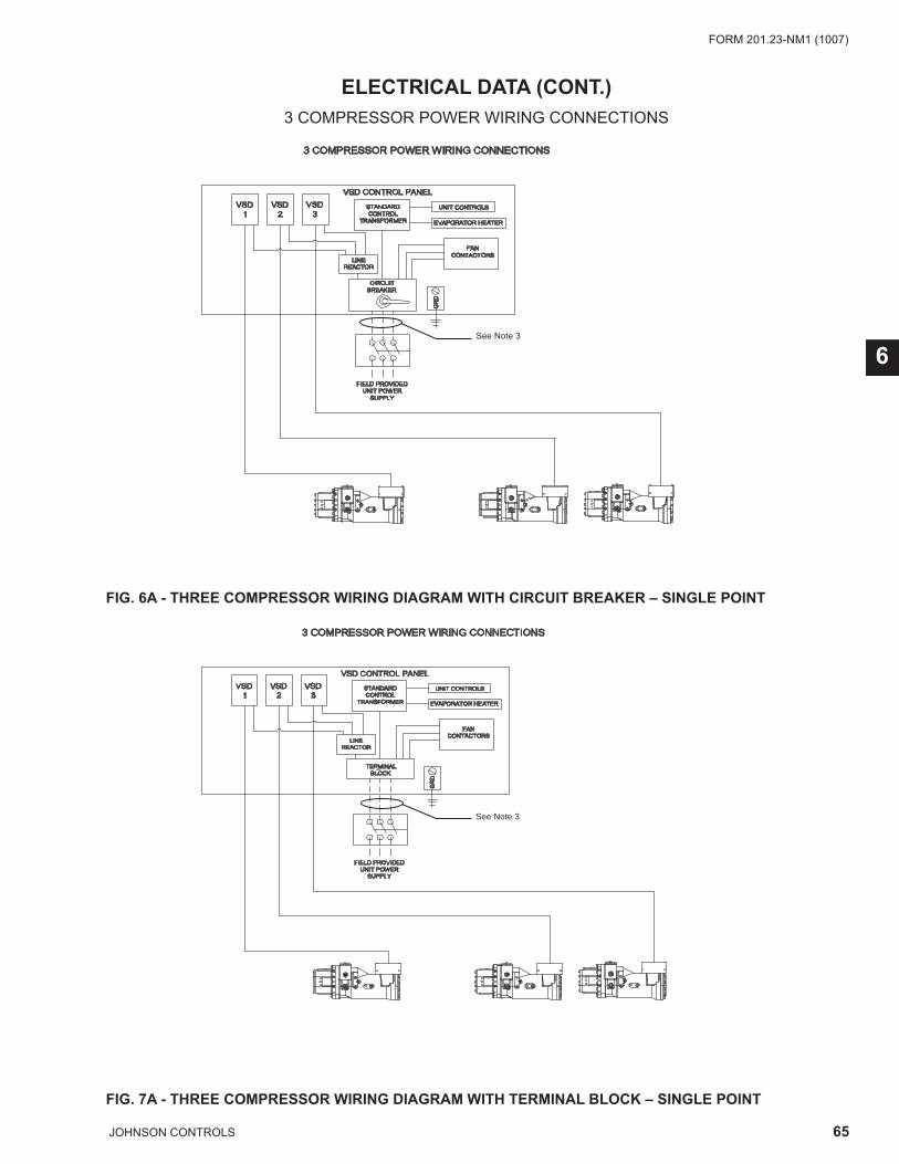
65JOHNSON CONTROLS
FORM 201.23-NM1 (1007)
6
FIG. 6A - THREE COMPRESSOR WIRING DIAGRAM WITH CIRCUIT BREAKER – SINGLE POINT
FIG. 7A - THREE COMPRESSOR WIRING DIAGRAM WITH TERMINAL BLOCK – SINGLE POINT
ELECTRICAL DATA (CONT.)
�"3
$!3%"$%!�2
-,"�!�"%!� -"%-�
53+% $!3%�!42
�+-4� ��!,+�-�
53+% �!�-�
25��4*
,2��
�
,2� $!3%�!4 �"3-4
4+3-
�-"$%!�
,2��
�
,2��
�
$+�$5+%
#�-"6-�
���
2%"3�"��
$!3%�!4
%�"32�!��-�
��$!���-22!� �!�-���+�+3��$!33-$%+!32
2���3� ���
3 COMPRESSOR POWER WIRING CONNECTIONS
VSD CONTROL PANEL
VSD 2
VSD 3
STANDARDCONTROL
TRANSFORMER
UNIT CONTROLS
EVAPORATOR HEATER
FANCONTACTORS
GR
D
FIELD PROVIDEDUNIT POWER
SUPPLY
LINEREACTOR
VSD 1
TERMINALBLOCK
See Note 3
3 COMPRESSOR POWER WIRING CONNECTIONS
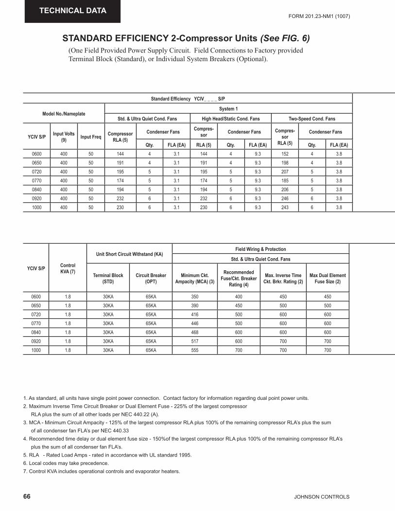
66 JOHNSON CONTROLS
FORM 201.23-NM1 (1007)TECHNICAL DATA
STANDARD EFFICIENCY 2-Compressor Units (See FIG. 6)(One Field Provided Power Supply Circuit. Field Connections to Factory provided Terminal Block (Standard), or Individual System Breakers (Optional).
1. As standard, all units have single point power connection. Contact factory for information regarding dual point power units.2. Maximum Inverse Time Circuit Breaker or Dual Element Fuse - 225% of the largest compressor RLA plus the sum of all other loads per NEC 440.22 (A). 3. MCA - Minimum Circuit Ampacity - 125% of the largest compressor RLA plus 100% of the remaining compressor RLA’s plus the sum of all condenser fan FLA’s per NEC 440.334. Recommended time delay or dual element fuse size - 150%of the largest compressor RLA plus 100% of the remaining compressor RLA’s plus the sum of all condenser fan FLA’s.5. RLA - Rated Load Amps - rated in accordance with UL standard 1995.6. Local codes may take precedence.7. Control KVA includes operational controls and evaporator heaters.
Standard Effi ciency YCIV_ _ _ _ S/P
Model No./NameplateSystem 1
Std. & Ultra Quiet Cond. Fans High Head/Static Cond. Fans Two-Speed Cond. Fans
YCIV S/P Input Volts (9) Input Freq Compressor
RLA (5)Condenser Fans Compres-
sor Condenser Fans Compres-sor
RLA (5)
Condenser Fans
Qty. FLA (EA) RLA (5) Qty. FLA (EA) Qty. FLA (EA)0600 400 50 144 4 3.1 144 4 9.3 152 4 3.80650 400 50 191 4 3.1 191 4 9.3 198 4 3.80720 400 50 195 5 3.1 195 5 9.3 207 5 3.80770 400 50 174 5 3.1 174 5 9.3 185 5 3.80840 400 50 194 5 3.1 194 5 9.3 206 5 3.80920 400 50 232 6 3.1 232 6 9.3 246 6 3.81000 400 50 230 6 3.1 230 6 9.3 243 6 3.8
YCIV S/P ControlKVA (7)
Unit Short Circuit Withstand (KA)Field Wiring & Protection
Std. & Ultra Quiet Cond. Fans
Terminal Block (STD)
Circuit Breaker (OPT)
Minimum Ckt. Ampacity (MCA) (3)
Recommended Fuse/Ckt. Breaker
Rating (4)
Max. Inverse Time Ckt. Brkr. Rating (2)
Max Dual Element Fuse Size (2)
0600 1.8 30KA 65KA 350 400 450 4500650 1.8 30KA 65KA 390 450 500 5000720 1.8 30KA 65KA 416 500 600 6000770 1.8 30KA 65KA 446 500 600 6000840 1.8 30KA 65KA 468 600 600 6000920 1.8 30KA 65KA 517 600 700 7001000 1.8 30KA 65KA 555 700 700 700
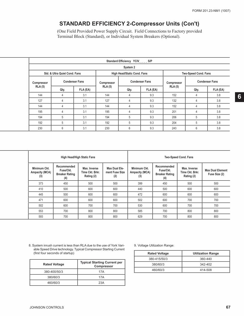
67JOHNSON CONTROLS
FORM 201.23-NM1 (1007)
6
8. System inrush current is less than RLA due to the use of York Vari-able Speed Drive technology. Typical Compressor Starting Current (fi rst four seconds of startup)
9. Voltage Utilization Range:
Rated Voltage Utilization Range380-415/50/3 360-440
380/60/3 342-402
460/60/3 414-508
Rated Voltage Typical Starting Current per Compressor
380-400/50/3 17A
380/60/3 17A
460/60/3 23A
STANDARD EFFICIENCY 2-Compressor Units (Con't)(One Field Provided Power Supply Circuit. Field Connections to Factory provided Terminal Block (Standard), or Individual System Breakers (Optional).
Standard Effi ciency YCIV_ _ _ _ S/P
System 2
Std. & Ultra Quiet Cond. Fans High Head/Static Cond. Fans Two-Speed Cond. Fans
CompressorRLA (5)
Condenser Fans CompressorRLA (5)
Condenser Fans CompressorRLA (5)
Condenser Fans
Qty. FLA (EA) Qty. FLA (EA) Qty. FLA (EA)144 4 3.1 144 4 9.3 152 4 3.8127 4 3.1 127 4 9.3 132 4 3.8144 4 3.1 144 4 9.3 152 4 3.8195 4 3.1 195 4 9.3 201 4 3.8194 5 3.1 194 5 9.3 206 5 3.8192 5 3.1 192 5 9.3 204 5 3.8230 6 3.1 230 6 9.3 243 6 3.8
High Head/High Static Fans Two-Speed Cond. Fans
Minimum Ckt. Ampacity (MCA)
(3)
Recommended Fuse/Ckt.
Breaker Rating (4)
Max. Inverse Time Ckt. Brkr.
Rating (2)
Max Dual Ele-ment Fuse Size
(2)
Minimum Ckt. Ampacity (MCA)
(3)
Recommended Fuse/Ckt.
Breaker Rating (4)
Max. Inverse Time Ckt. Brkr.
Rating (2)
Max Dual Element Fuse Size (2)
373 450 500 500 399 450 500 500410 500 600 600 440 500 600 600445 500 600 600 472 600 600 600471 600 600 600 502 600 700 700502 600 700 700 530 600 700 700553 700 800 800 585 700 800 800593 700 800 800 629 700 800 800

68 JOHNSON CONTROLS
FORM 201.23-NM1 (1007)TECHNICAL DATA
STANDARD EFFICIENCY YCIV_ _ _ _ S/P
MODEL NO./NAMEPLATE FIELD WIRING LUGS
STD TERMINAL BLOCKSTD., U.Q. & TWO-SPD COND. FANS
OPT CIRCUIT BREAKERSTD., U.Q. & 2-SPD
COND. FANS
STD TERMINAL BLOCKHIGH HEAD/HIGH
STATIC COND. FANS
OPT CIRCUIT BREAKERHIGH HEAD/HIGH
STATIC COND. FANSYCIV S/P
INPUT VOLTS
(9)
INPUT FREQ LUGS/
PHASE (1)
LUG WIRE RANGE
LUGS/ PHASE
(1)
LUG WIRE RANGE
LUGS/ PHASE
(1)
LUG WIRE RANGE
LUGS/ PHASE
(1)
LUG WIRE RANGE
0600 400 50 2 #2 - 600 KCM 2 #2/0 - 500 KCM 3 #2 - 600 KCM 3 #2 - 600 KCM0650 400 50 2 #2 - 600 KCM 2 #2/0 - 500 KCM 3 #2 - 600 KCM 3 #2 - 600 KCM0720 400 50 2 #2 - 600 KCM 2 #2/0 - 500 KCM 3 #2 - 600 KCM 3 #2 - 600 KCM0770 400 50 2 #2 - 600 KCM 2 #2/0 - 500 KCM 3 #2 - 600 KCM 3 #2 - 600 KCM0840 400 50 2 #2 - 600 KCM 2 #2/0 - 500 KCM 3 #2 - 600 KCM 3 #2 - 600 KCM0920 400 50 2 #2 - 600 KCM 2 #3/0 - 400 KCM 3 #2 - 600 KCM 3 #2 - 600 KCM1000 400 50 3 #2 - 600 KCM 3 #3/0 - 400 KCM 3 #2 - 600 KCM 3 #3/0 - 400 KCM
STANDARD EFFICIENCY 2-Compressor Units (Con't)

69JOHNSON CONTROLS
FORM 201.23-NM1 (1007)
This page intentionally left blank
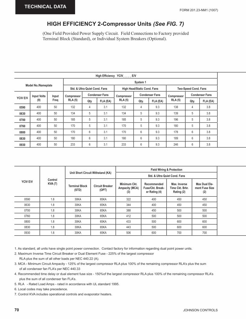
70 JOHNSON CONTROLS
FORM 201.23-NM1 (1007)TECHNICAL DATA
HIGH EFFICIENCY 2-Compressor Units (See FIG. 7)(One Field Provided Power Supply Circuit. Field Connections to Factory provided Terminal Block (Standard), or Individual System Breakers (Optional).
1. As standard, all units have single point power connection. Contact factory for information regarding dual point power units.2. Maximum Inverse Time Circuit Breaker or Dual Element Fuse - 225% of the largest compressor RLA plus the sum of all other loads per NEC 440.22 (A). 3. MCA - Minimum Circuit Ampacity - 125% of the largest compressor RLA plus 100% of the remaining compressor RLA’s plus the sum of all condenser fan FLA’s per NEC 440.334. Recommended time delay or dual element fuse size - 150%of the largest compressor RLA plus 100% of the remaining compressor RLA’s plus the sum of all condenser fan FLA’s.5. RLA - Rated Load Amps - rated in accordance with UL standard 1995.6. Local codes may take precedence.7. Control KVA includes operational controls and evaporator heaters.
High Effi ciency YCIV_ _ _ _ E/V
Model No./NameplateSystem 1
Std. & Ultra Quiet Cond. Fans High Head/Static Cond. Fans Two-Speed Cond. Fans
YCIV E/V Input Volts (9)
Input Freq
CompressorRLA (5)
Condenser Fans CompressorRLA (5)
Condenser Fans CompressorRLA (5)
Condenser Fans
Qty FLA (EA) Qty. FLA (EA) Qty. FLA (EA)
0590 400 50 132 4 3.1 132 4 9.3 138 4 3.8
0630 400 50 134 5 3.1 134 5 9.3 139 5 3.8
0700 400 50 185 5 3.1 185 5 9.3 196 5 3.8
0760 400 50 170 5 3.1 170 5 9.3 180 5 3.8
0800 400 50 170 6 3.1 170 6 9.3 178 6 3.8
0830 400 50 180 6 3.1 180 6 9.3 189 6 3.8
0930 400 50 233 6 3.1 233 6 9.3 246 6 3.8
YCIV E/V ControlKVA (7)
Unit Short Circuit Withstand (KA)Field Wiring & Protection
Std. & Ultra Quiet Cond. Fans
Terminal Block (STD)
Circuit Breaker (OPT)
Minimum Ckt. Ampacity (MCA)
(3)
Recommended Fuse/Ckt. Break-
er Rating (4)
Max. Inverse Time Ckt. Brkr.
Rating (2)
Max Dual Ele-ment Fuse Size
(2)
0590 1.8 30KA 65KA 322 400 450 4500630 1.8 30KA 65KA 344 400 450 4500700 1.8 30KA 65KA 388 450 500 5000760 1.8 30KA 65KA 412 500 500 5000800 1.8 30KA 65KA 433 500 600 6000830 1.8 30KA 65KA 443 500 600 6000930 1.8 30KA 65KA 506 600 700 700
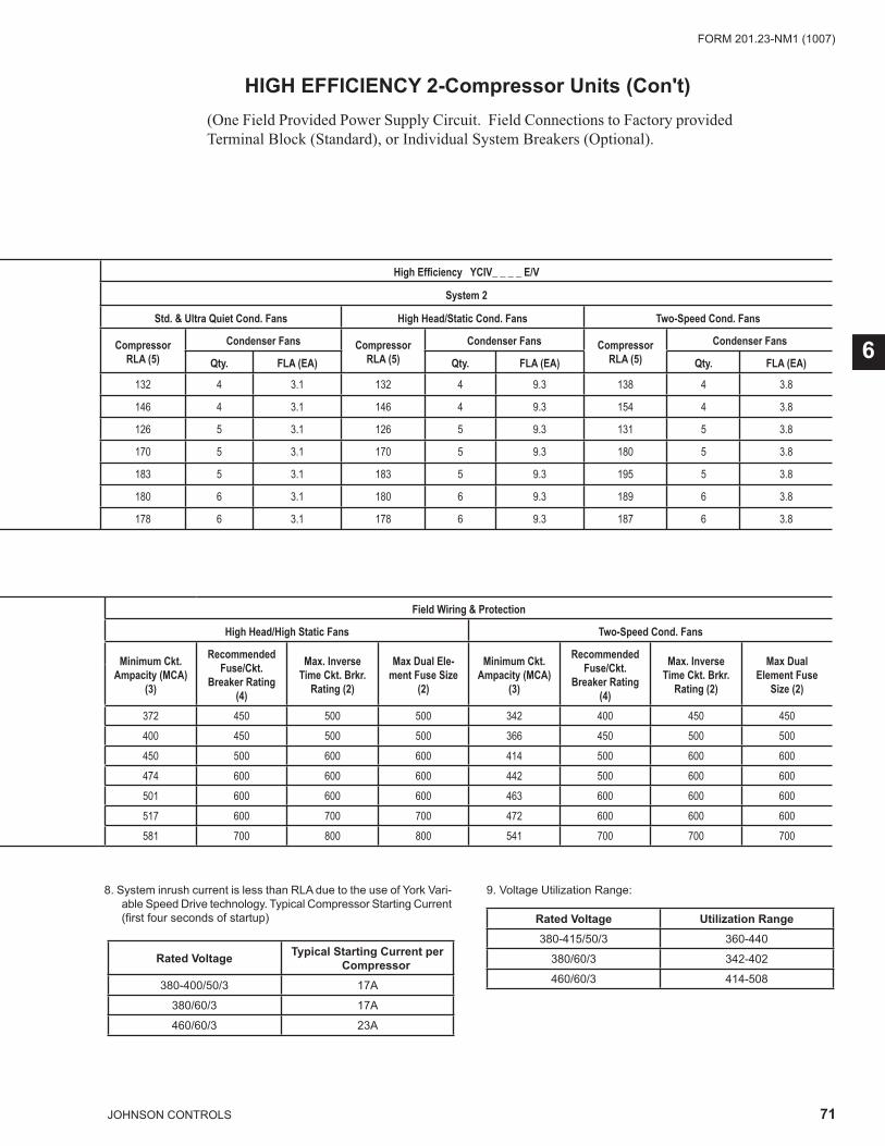
71JOHNSON CONTROLS
FORM 201.23-NM1 (1007)
6
8. System inrush current is less than RLA due to the use of York Vari-able Speed Drive technology. Typical Compressor Starting Current (fi rst four seconds of startup)
9. Voltage Utilization Range:
Rated Voltage Utilization Range380-415/50/3 360-440
380/60/3 342-402
460/60/3 414-508
Rated Voltage Typical Starting Current per Compressor
380-400/50/3 17A
380/60/3 17A
460/60/3 23A
HIGH EFFICIENCY 2-Compressor Units (Con't)(One Field Provided Power Supply Circuit. Field Connections to Factory provided Terminal Block (Standard), or Individual System Breakers (Optional).
High Effi ciency YCIV_ _ _ _ E/V
System 2
Std. & Ultra Quiet Cond. Fans High Head/Static Cond. Fans Two-Speed Cond. Fans
CompressorRLA (5)
Condenser Fans CompressorRLA (5)
Condenser Fans CompressorRLA (5)
Condenser Fans
Qty. FLA (EA) Qty. FLA (EA) Qty. FLA (EA)
132 4 3.1 132 4 9.3 138 4 3.8
146 4 3.1 146 4 9.3 154 4 3.8
126 5 3.1 126 5 9.3 131 5 3.8
170 5 3.1 170 5 9.3 180 5 3.8
183 5 3.1 183 5 9.3 195 5 3.8
180 6 3.1 180 6 9.3 189 6 3.8
178 6 3.1 178 6 9.3 187 6 3.8
Field Wiring & Protection
High Head/High Static Fans Two-Speed Cond. Fans
Minimum Ckt. Ampacity (MCA)
(3)
Recommended Fuse/Ckt.
Breaker Rating (4)
Max. Inverse Time Ckt. Brkr.
Rating (2)
Max Dual Ele-ment Fuse Size
(2)
Minimum Ckt. Ampacity (MCA)
(3)
Recommended Fuse/Ckt.
Breaker Rating (4)
Max. Inverse Time Ckt. Brkr.
Rating (2)
Max Dual Element Fuse
Size (2)
372 450 500 500 342 400 450 450400 450 500 500 366 450 500 500450 500 600 600 414 500 600 600474 600 600 600 442 500 600 600501 600 600 600 463 600 600 600517 600 700 700 472 600 600 600581 700 800 800 541 700 700 700
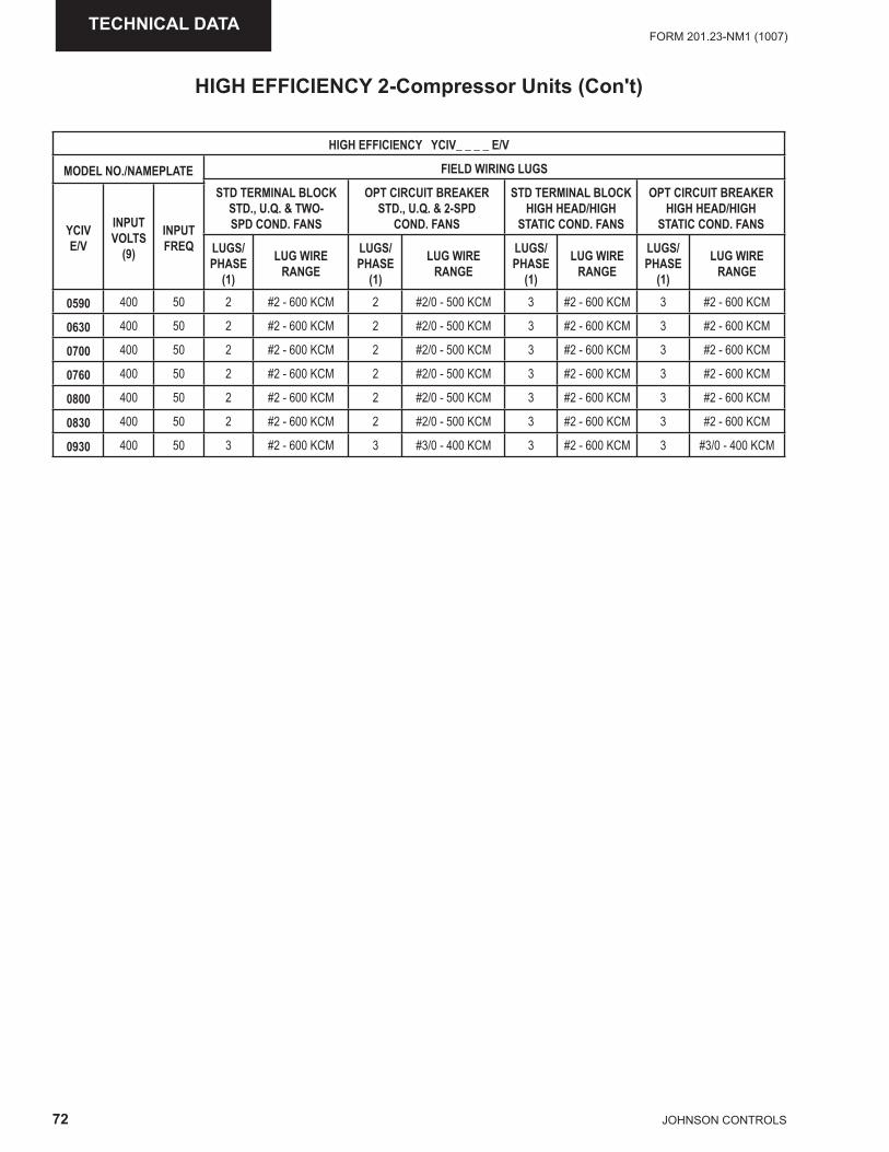
72 JOHNSON CONTROLS
FORM 201.23-NM1 (1007)TECHNICAL DATA
HIGH EFFICIENCY YCIV_ _ _ _ E/V
MODEL NO./NAMEPLATE FIELD WIRING LUGS
STD TERMINAL BLOCK STD., U.Q. & TWO-SPD COND. FANS
OPT CIRCUIT BREAKER STD., U.Q. & 2-SPD
COND. FANS
STD TERMINAL BLOCKHIGH HEAD/HIGH
STATIC COND. FANS
OPT CIRCUIT BREAKERHIGH HEAD/HIGH
STATIC COND. FANSYCIV E/V
INPUT VOLTS
(9)
INPUT FREQ LUGS/
PHASE (1)
LUG WIRE RANGE
LUGS/ PHASE
(1)
LUG WIRE RANGE
LUGS/ PHASE
(1)
LUG WIRE RANGE
LUGS/ PHASE
(1)
LUG WIRE RANGE
0590 400 50 2 #2 - 600 KCM 2 #2/0 - 500 KCM 3 #2 - 600 KCM 3 #2 - 600 KCM
0630 400 50 2 #2 - 600 KCM 2 #2/0 - 500 KCM 3 #2 - 600 KCM 3 #2 - 600 KCM
0700 400 50 2 #2 - 600 KCM 2 #2/0 - 500 KCM 3 #2 - 600 KCM 3 #2 - 600 KCM
0760 400 50 2 #2 - 600 KCM 2 #2/0 - 500 KCM 3 #2 - 600 KCM 3 #2 - 600 KCM
0800 400 50 2 #2 - 600 KCM 2 #2/0 - 500 KCM 3 #2 - 600 KCM 3 #2 - 600 KCM
0830 400 50 2 #2 - 600 KCM 2 #2/0 - 500 KCM 3 #2 - 600 KCM 3 #2 - 600 KCM
0930 400 50 3 #2 - 600 KCM 3 #3/0 - 400 KCM 3 #2 - 600 KCM 3 #3/0 - 400 KCM
HIGH EFFICIENCY 2-Compressor Units (Con't)

73JOHNSON CONTROLS
FORM 201.23-NM1 (1007)
This page intentionally left blank
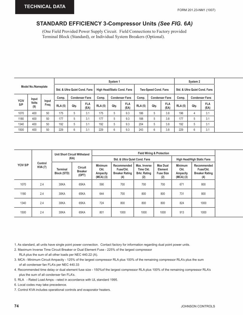
74 JOHNSON CONTROLS
FORM 201.23-NM1 (1007)TECHNICAL DATA
STANDARD EFFICIENCY 3-Compressor Units (See FIG. 6A)(One Field Provided Power Supply Circuit. Field Connections to Factory provided Terminal Block (Standard), or Individual System Breakers (Optional).
1. As standard, all units have single point power connection. Contact factory for information regarding dual point power units.2. Maximum Inverse Time Circuit Breaker or Dual Element Fuse - 225% of the largest compressor RLA plus the sum of all other loads per NEC 440.22 (A). 3. MCA - Minimum Circuit Ampacity - 125% of the largest compressor RLA plus 100% of the remaining compressor RLA’s plus the sum of all condenser fan FLA’s per NEC 440.334. Recommended time delay or dual element fuse size - 150%of the largest compressor RLA plus 100% of the remaining compressor RLA’s plus the sum of all condenser fan FLA’s.5. RLA - Rated Load Amps - rated in accordance with UL standard 1995.6. Local codes may take precedence.7. Control KVA includes operational controls and evaporator heaters.
Model No./NameplateSystem 1 System 2
Std. & Ultra Quiet Cond. Fans High Head/Static Cond. Fans Two-Speed Cond. Fans Std. & Ultra Quiet Cond. Fans
YCIV S/P
Input Volts
(9)
Input Freq
Comp. Condenser Fans Comp. Condenser Fans Comp. Condenser Fans Comp. Condenser Fans
RLA (5) Qty. FLA (EA) RLA (5) Qty. FLA
(EA) RLA (5) Qty. FLA (EA) RLA (5) Qty. FLA
(EA)1070 400 50 175 5 3.1 175 5 9.3 186 5 3.8 196 4 3.11180 400 50 177 5 3.1 177 5 9.3 188 5 3.8 177 5 3.11340 400 50 192 5 3.1 192 5 9.3 204 5 3.8 192 5 3.11500 400 50 229 6 3.1 229 6 9.3 243 6 3.8 229 6 3.1
YCIV S/P ControlKVA (7)
Unit Short Circuit Withstand (KA)
Field Wiring & Protection
Std. & Ultra Quiet Cond. Fans High Head/High Static Fans
Terminal Block (STD)
Circuit Breaker (OPT)
Minimum Ckt.
Ampacity (MCA) (3)
Recommended Fuse/Ckt.
Breaker Rating (4)
Max. Inverse Time Ckt.
Brkr. Rating (2)
Max Dual Element
Fuse Size (2)
Minimum Ckt.
Ampacity (MCA) (3)
Recommended Fuse/Ckt.
Breaker Rating (4)
1070 2.4 30KA 65KA 590 700 700 700 671 800
1180 2.4 30KA 65KA 644 700 800 800 731 800
1340 2.4 30KA 65KA 724 800 800 800 824 1000
1500 2.4 30KA 65KA 801 1000 1000 1000 913 1000
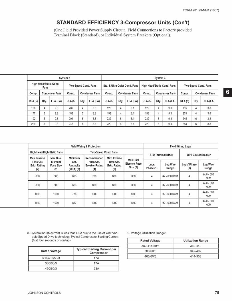
75JOHNSON CONTROLS
FORM 201.23-NM1 (1007)
6
8. System inrush current is less than RLA due to the use of York Vari-able Speed Drive technology. Typical Compressor Starting Current (fi rst four seconds of startup)
9. Voltage Utilization Range:
Rated Voltage Utilization Range380-415/50/3 360-440
380/60/3 342-402
460/60/3 414-508
Rated Voltage Typical Starting Current per Compressor
380-400/50/3 17A
380/60/3 17A
460/60/3 23A
STANDARD EFFICIENCY 3-Compressor Units (Con't)(One Field Provided Power Supply Circuit. Field Connections to Factory provided Terminal Block (Standard), or Individual System Breakers (Optional).
System 2 System 3
High Head/Static Cond. Fans Two-Speed Cond. Fans Std. & Ultra Quiet Cond. Fans High Head/Static Cond. Fans Two-Speed Cond. Fans
Comp. Condenser Fans Comp. Condenser Fans Comp. Condenser Fans Comp. Condenser Fans Comp. Condenser Fans
RLA (5) Qty. FLA (EA) RLA (5) Qty. FLA (EA) RLA (5) Qty. FLA (EA) RLA (5) Qty. FLA (EA) RLA (5) Qty. FLA (EA)
196 4 9.3 202 4 3.8 129 4 3.1 129 4 9.3 135 4 3.8177 5 9.3 188 5 3.8 198 4 3.1 198 4 9.3 203 4 3.8192 5 9.3 204 5 3.8 232 6 3.1 232 6 9.3 245 6 3.8229 6 9.3 243 6 3.8 229 6 3.1 229 6 9.3 243 6 3.8
Field Wiring & Protection Field Wiring Lugs
High Head/High Static Fans Two-Speed Cond. FansSTD Terminal Block OPT Circuit Breaker
Max. Inverse Time Ckt.
Brkr. Rating (2)
Max Dual Element
Fuse Size (2)
Minimum Ckt.
Ampacity (MCA) (3)
Recommended Fuse/Ckt.
Breaker Rating (4)
Max. Inverse Time Ckt.
Brkr. Rating (2)
Max Dual Element Fuse
Size (2)Lugs/
Phase (1)Lug Wire
RangeLugs/ Phase
(1)Lug Wire
Range
800 800 623 700 800 800 4 #2 - 600 KCM 4 #4/0 - 500 KCM
800 800 683 800 800 800 4 #2 - 600 KCM 4 #4/0 - 500 KCM
1000 1000 776 1000 1000 1000 4 #2 - 600 KCM 4 #4/0 - 500 KCM
1000 1000 857 1000 1000 1000 4 #2 - 600 KCM 4 #4/0 - 500 KCM
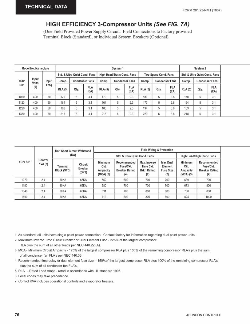
76 JOHNSON CONTROLS
FORM 201.23-NM1 (1007)TECHNICAL DATA
HIGH EFFICIENCY 3-Compressor Units (See FIG. 7A)(One Field Provided Power Supply Circuit. Field Connections to Factory provided Terminal Block (Standard), or Individual System Breakers (Optional).
1. As standard, all units have single point power connection. Contact factory for information regarding dual point power units.2. Maximum Inverse Time Circuit Breaker or Dual Element Fuse - 225% of the largest compressor RLA plus the sum of all other loads per NEC 440.22 (A). 3. MCA - Minimum Circuit Ampacity - 125% of the largest compressor RLA plus 100% of the remaining compressor RLA’s plus the sum of all condenser fan FLA’s per NEC 440.334. Recommended time delay or dual element fuse size - 150%of the largest compressor RLA plus 100% of the remaining compressor RLA’s plus the sum of all condenser fan FLA’s.5. RLA - Rated Load Amps - rated in accordance with UL standard 1995.6. Local codes may take precedence.7. Control KVA includes operational controls and evaporator heaters.
Model No./Nameplate System 1 System 2
YCIV E/V
Input Volts
(9)
Input Freq
Std. & Ultra Quiet Cond. Fans High Head/Static Cond. Fans Two-Speed Cond. Fans Std. & Ultra Quiet Cond. Fans
Comp. Condenser Fans Comp. Condenser Fans Comp. Condenser Fans Comp. Condenser Fans
RLA (5) Qty. FLA (EA) RLA (5) Qty. FLA
(EA) RLA (5) Qty. FLA (EA) RLA (5) Qty. FLA
(EA)1050 400 50 170 5 3.1 170 5 9.3 180 5 3.8 170 5 3.11120 400 50 164 5 3.1 164 5 9.3 173 5 3.8 164 5 3.11220 400 50 183 5 3.1 183 5 9.3 194 5 3.8 183 5 3.11380 400 50 218 6 3.1 218 6 9.3 229 6 3.8 218 6 3.1
YCIV S/P ControlKVA (7)
Unit Short Circuit Withstand (KA)
Field Wiring & Protection
Std. & Ultra Quiet Cond. Fans High Head/High Static Fans
Terminal Block (STD)
Circuit Breaker (OPT)
Minimum Ckt.
Ampacity (MCA) (3)
Recommended Fuse/Ckt.
Breaker Rating (4)
Max. Inverse Time Ckt.
Brkr. Rating (2)
Max Dual Element
Fuse Size (2)
Minimum Ckt.
Ampacity (MCA) (3)
Recommended Fuse/Ckt.
Breaker Rating (4)
1070 2.4 30KA 65KA 552 600 700 700 639 7001180 2.4 30KA 65KA 580 700 700 700 673 8001340 2.4 30KA 65KA 631 700 800 800 730 8001500 2.4 30KA 65KA 713 800 800 800 824 1000
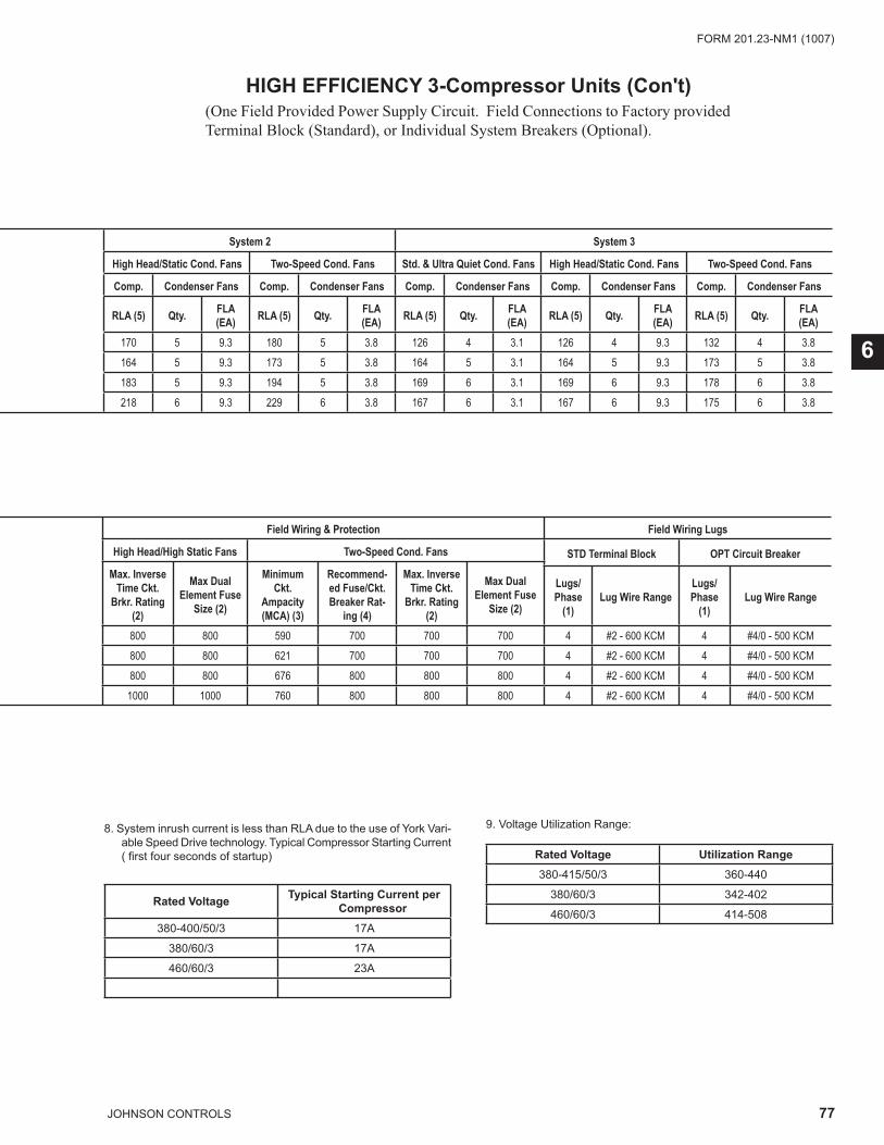
77JOHNSON CONTROLS
FORM 201.23-NM1 (1007)
6
HIGH EFFICIENCY 3-Compressor Units (Con't)(One Field Provided Power Supply Circuit. Field Connections to Factory provided Terminal Block (Standard), or Individual System Breakers (Optional).
8. System inrush current is less than RLA due to the use of York Vari-able Speed Drive technology. Typical Compressor Starting Current ( fi rst four seconds of startup)
Rated Voltage Typical Starting Current per Compressor
380-400/50/3 17A
380/60/3 17A
460/60/3 23A
9. Voltage Utilization Range:
Rated Voltage Utilization Range380-415/50/3 360-440
380/60/3 342-402
460/60/3 414-508
System 2 System 3
High Head/Static Cond. Fans Two-Speed Cond. Fans Std. & Ultra Quiet Cond. Fans High Head/Static Cond. Fans Two-Speed Cond. Fans
Comp. Condenser Fans Comp. Condenser Fans Comp. Condenser Fans Comp. Condenser Fans Comp. Condenser Fans
RLA (5) Qty. FLA (EA) RLA (5) Qty. FLA
(EA) RLA (5) Qty. FLA (EA) RLA (5) Qty. FLA
(EA) RLA (5) Qty. FLA (EA)
170 5 9.3 180 5 3.8 126 4 3.1 126 4 9.3 132 4 3.8164 5 9.3 173 5 3.8 164 5 3.1 164 5 9.3 173 5 3.8183 5 9.3 194 5 3.8 169 6 3.1 169 6 9.3 178 6 3.8218 6 9.3 229 6 3.8 167 6 3.1 167 6 9.3 175 6 3.8
Field Wiring & Protection Field Wiring Lugs
High Head/High Static Fans Two-Speed Cond. Fans STD Terminal Block OPT Circuit BreakerMax. Inverse
Time Ckt. Brkr. Rating
(2)
Max Dual Element Fuse
Size (2)
Minimum Ckt.
Ampacity (MCA) (3)
Recommend-ed Fuse/Ckt. Breaker Rat-
ing (4)
Max. Inverse Time Ckt.
Brkr. Rating (2)
Max Dual Element Fuse
Size (2)
Lugs/ Phase
(1)Lug Wire Range
Lugs/ Phase
(1)Lug Wire Range
800 800 590 700 700 700 4 #2 - 600 KCM 4 #4/0 - 500 KCM800 800 621 700 700 700 4 #2 - 600 KCM 4 #4/0 - 500 KCM800 800 676 800 800 800 4 #2 - 600 KCM 4 #4/0 - 500 KCM1000 1000 760 800 800 800 4 #2 - 600 KCM 4 #4/0 - 500 KCM
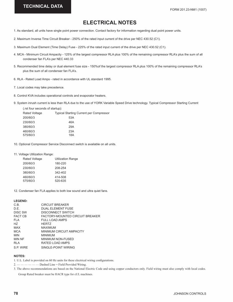
78 JOHNSON CONTROLS
FORM 201.23-NM1 (1007)TECHNICAL DATA
ELECTRICAL NOTES1. As standard, all units have single point power connection. Contact factory for information regarding dual point power units.
2. Maximum Inverse Time Circuit Breaker - 250% of the rated input current of the drive per NEC 430.52 (C1).
3. Maximum Dual Element (Time Delay) Fuse - 225% of the rated input current of the drive per NEC 430.52 (C1).
4. MCA - Minimum Circuit Ampacity - 125% of the largest compressor RLA plus 100% of the remaining compressor RLA’s plus the sum of all condenser fan FLA’s per NEC 440.33
5. Recommended time delay or dual element fuse size - 150%of the largest compressor RLA plus 100% of the remaining compressor RLA’s plus the sum of all condenser fan FLA’s.
6. RLA - Rated Load Amps - rated in accordance with UL standard 1995.
7. Local codes may take precedence.
8. Control KVA includes operational controls and evaporator heaters.
9. System inrush current is less than RLA due to the use of YORK Variable Speed Drive technology. Typical Compressor Starting Current
(.rst four seconds of startup): Rated Voltage Typical Starting Current per Compressor 200/60/3 53A 230/60/3 46A 380/60/3 29A 460/60/3 23A 575/60/3 18A
10. Optional Compressor Service Disconnect switch is available on all units.
11. Voltage Utilization Range: Rated Voltage Utilization Range 200/60/3 180-220 230/60/3 208-254 380/60/3 342-402 460/60/3 414-508 575/60/3 520-635
12. Condenser fan FLA applies to both low sound and ultra quiet fans.
LEGEND:C.B. CIRCUIT BREAKER D.E. DUAL ELEMENT FUSE DISC SW DISCONNECT SWITCH FACT CB FACTORY-MOUNTED CIRCUIT BREAKER FLA FULL LOAD AMPS HZ HERTZ MAX MAXIMUM MCA MINIMUM CIRCUIT AMPACITY MIN MINIMUM MIN NF MINIMUM NON-FUSED RLA RATED LOAD AMPS S.P. WIRE SINGLE-POINT WIRING
NOTES: 1. U.L. Label is provided on 60 Hz units for these electrical wiring confi gurations. 2. –– –– –– –– –– –– Dashed Line = Field Provided Wiring. 3. The above recommendations are based on the National Electric Code and using copper conductors only. Field wiring must also comply with local codes.
Group Rated breaker must be HACR type for cUL machines.

79JOHNSON CONTROLS
FORM 201.23-NM1 (1007)
This page intentionally left blank
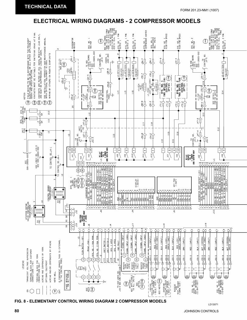
80 JOHNSON CONTROLS
FORM 201.23-NM1 (1007)TECHNICAL DATA
ELECTRICAL WIRING DIAGRAMS - 2 COMPRESSOR MODELS
LD13071FIG. 8 - ELEMENTARY CONTROL WIRING DIAGRAM 2 COMPRESSOR MODELS
LD13072
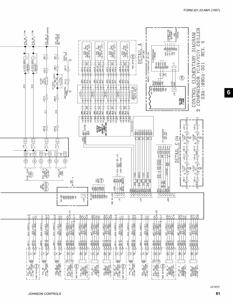
81JOHNSON CONTROLS
FORM 201.23-NM1 (1007)
6
ELECTRICAL WIRING DIAGRAMS - 2 COMPRESSOR MODELS
LD13071FIG. 8 - ELEMENTARY CONTROL WIRING DIAGRAM 2 COMPRESSOR MODELS
LD13072
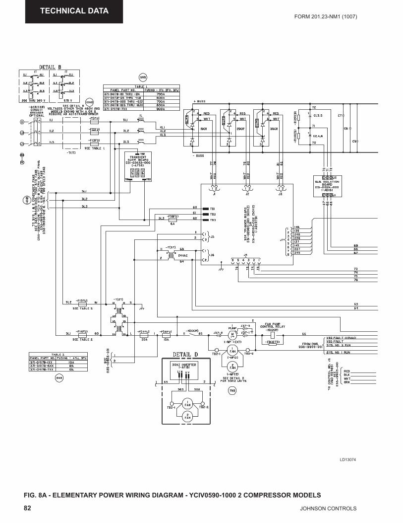
82 JOHNSON CONTROLS
FORM 201.23-NM1 (1007)TECHNICAL DATA
FIG. 8A - ELEMENTARY POWER WIRING DIAGRAM - YCIV0590-1000 2 COMPRESSOR MODELS
LD13074
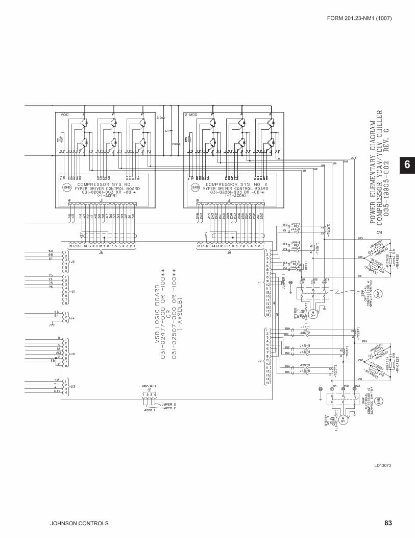
83JOHNSON CONTROLS
FORM 201.23-NM1 (1007)
6
LD13073
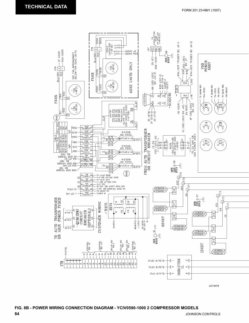
84 JOHNSON CONTROLS
FORM 201.23-NM1 (1007)TECHNICAL DATA
FIG. 8B - POWER WIRING CONNECTION DIAGRAM - YCIV0590-1000 2 COMPRESSOR MODELS
LD13078
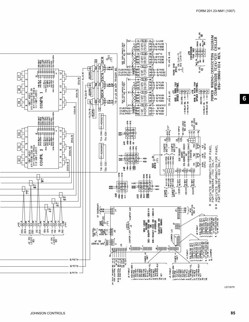
85JOHNSON CONTROLS
FORM 201.23-NM1 (1007)
6
LD13079
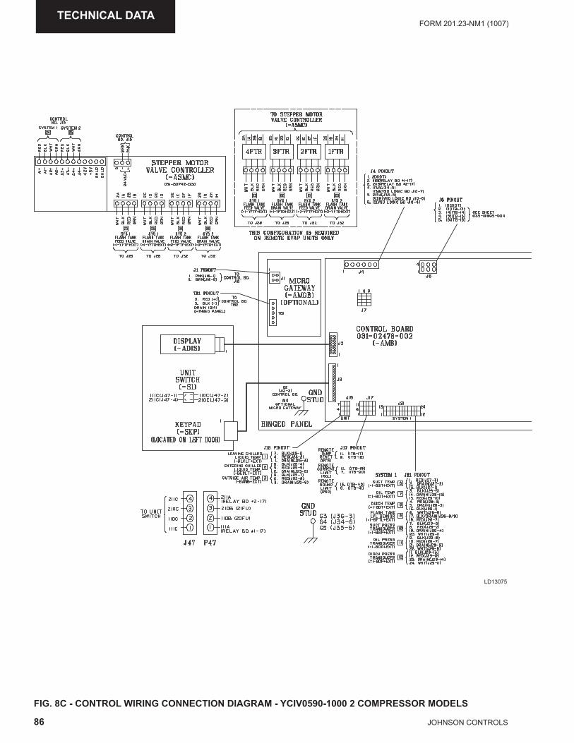
86 JOHNSON CONTROLS
FORM 201.23-NM1 (1007)TECHNICAL DATA
FIG. 8C - CONTROL WIRING CONNECTION DIAGRAM - YCIV0590-1000 2 COMPRESSOR MODELS
LD13075
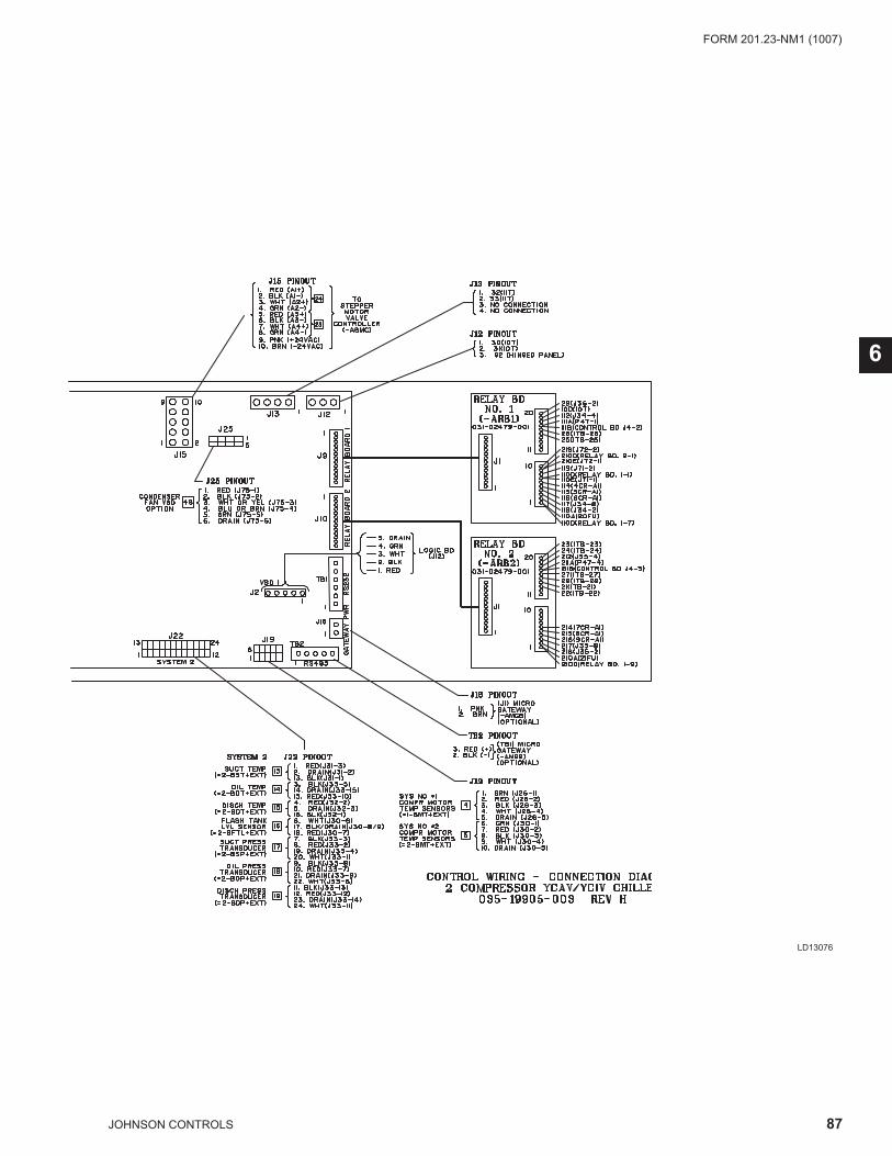
87JOHNSON CONTROLS
FORM 201.23-NM1 (1007)
6
LD13076
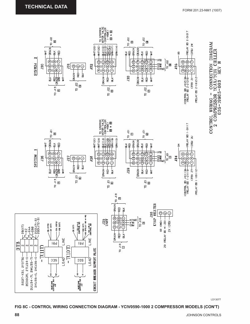
88 JOHNSON CONTROLS
FORM 201.23-NM1 (1007)TECHNICAL DATA
FIG 8C - CONTROL WIRING CONNECTION DIAGRAM - YCIV0590-1000 2 COMPRESSOR MODELS (CON'T)
LD13077
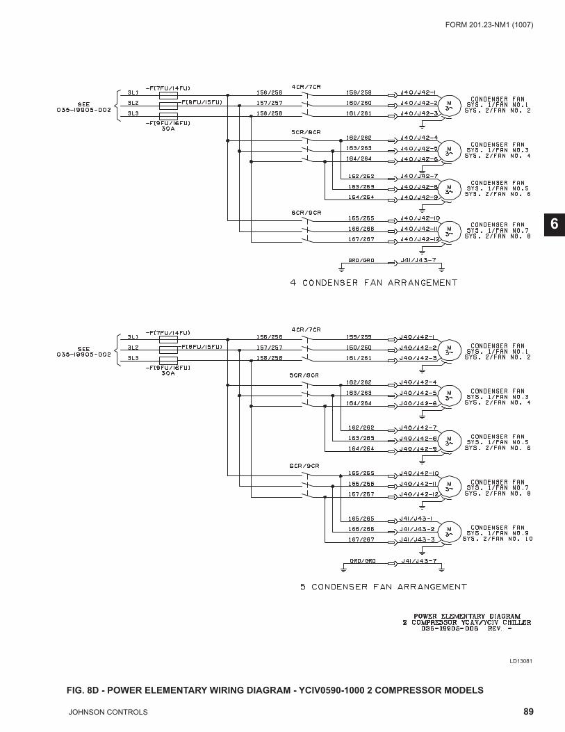
89JOHNSON CONTROLS
FORM 201.23-NM1 (1007)
6
FIG. 8D - POWER ELEMENTARY WIRING DIAGRAM - YCIV0590-1000 2 COMPRESSOR MODELS
LD13081
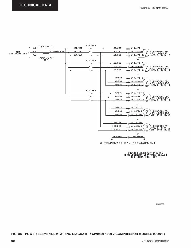
90 JOHNSON CONTROLS
FORM 201.23-NM1 (1007)TECHNICAL DATA
FIG. 8D - POWER ELEMENTARY WIRING DIAGRAM - YCIV0590-1000 2 COMPRESSOR MODELS (CON'T)
LD13082
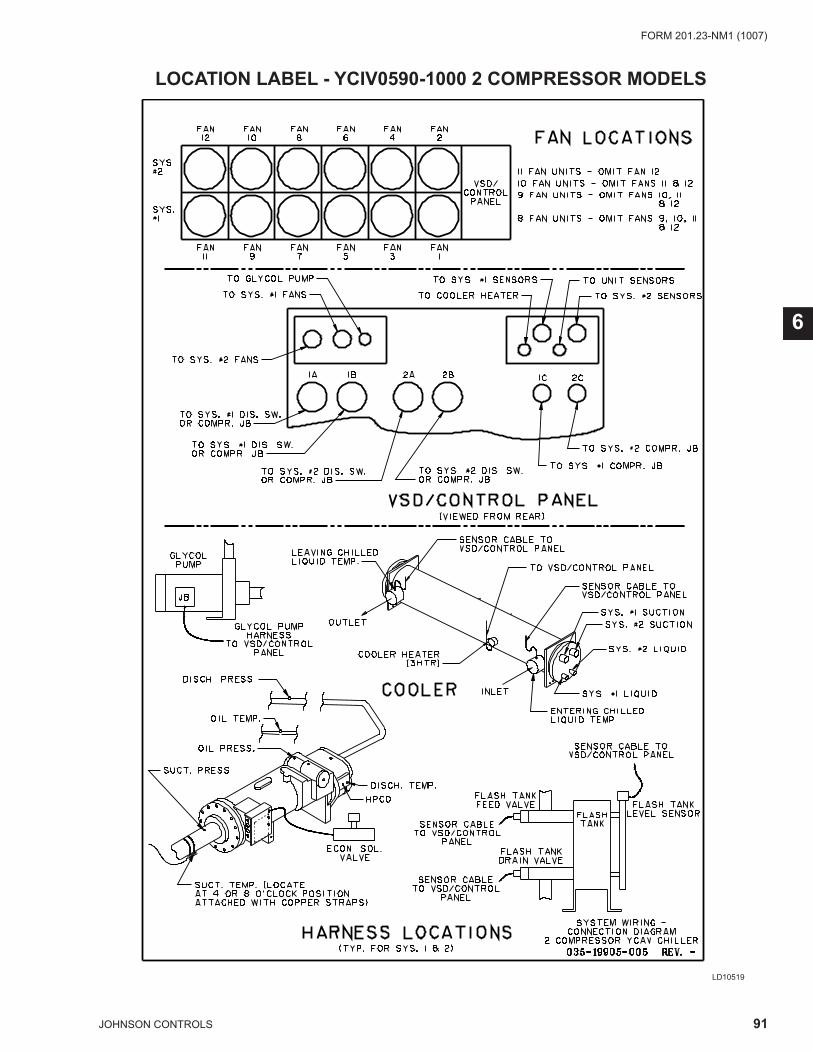
91JOHNSON CONTROLS
FORM 201.23-NM1 (1007)
6
LD10519
LOCATION LABEL - YCIV0590-1000 2 COMPRESSOR MODELS
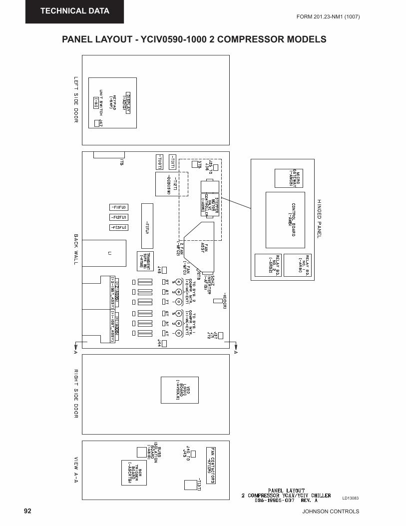
92 JOHNSON CONTROLS
FORM 201.23-NM1 (1007)TECHNICAL DATA
LD13083
PANEL LAYOUT - YCIV0590-1000 2 COMPRESSOR MODELS

93JOHNSON CONTROLS
FORM 201.23-NM1 (1007)
This page intentionally left blank
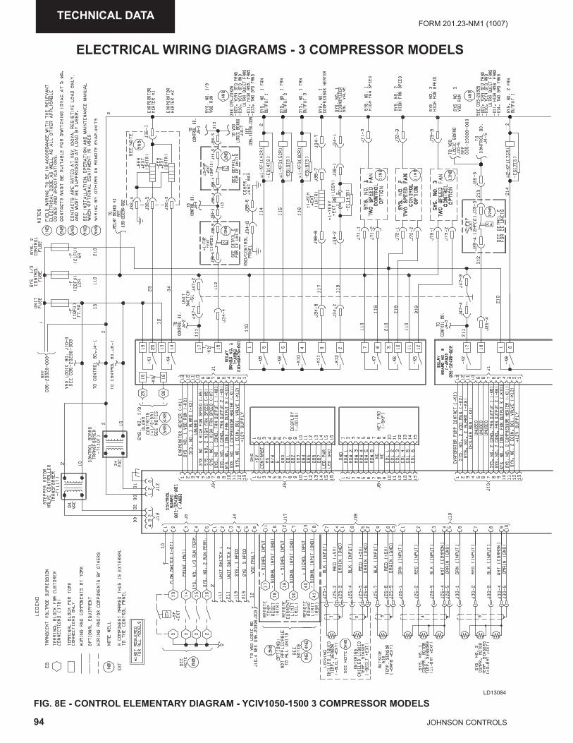
94 JOHNSON CONTROLS
FORM 201.23-NM1 (1007)TECHNICAL DATA
LD13084
FIG. 8E - CONTROL ELEMENTARY DIAGRAM - YCIV1050-1500 3 COMPRESSOR MODELS
ELECTRICAL WIRING DIAGRAMS - 3 COMPRESSOR MODELS
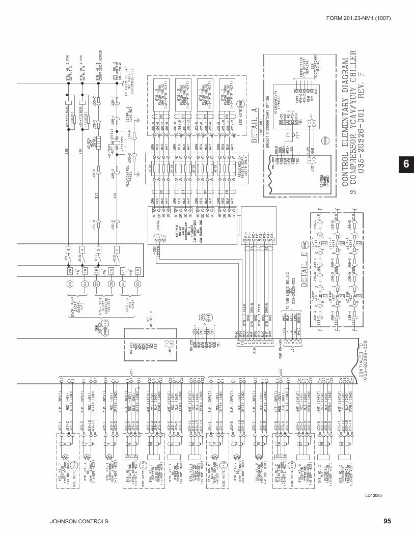
95JOHNSON CONTROLS
FORM 201.23-NM1 (1007)
6
LD13085
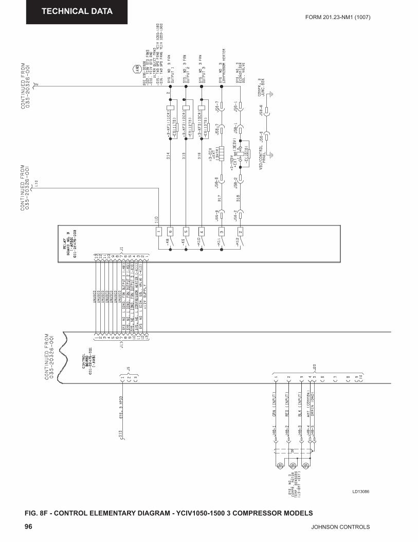
96 JOHNSON CONTROLS
FORM 201.23-NM1 (1007)TECHNICAL DATA
FIG. 8F - CONTROL ELEMENTARY DIAGRAM - YCIV1050-1500 3 COMPRESSOR MODELS
LD13086
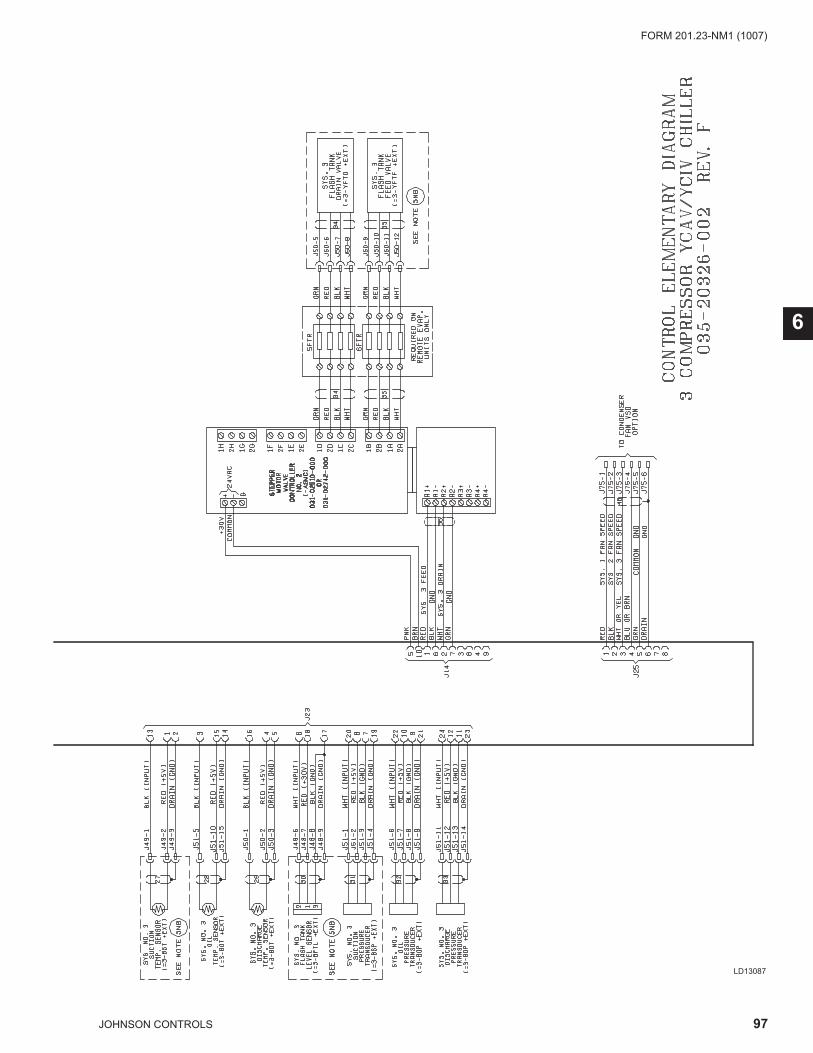
97JOHNSON CONTROLS
FORM 201.23-NM1 (1007)
6
LD13087
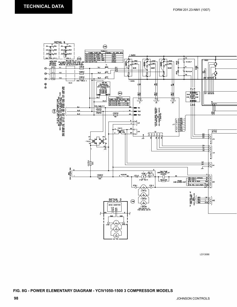
98 JOHNSON CONTROLS
FORM 201.23-NM1 (1007)TECHNICAL DATA
LD13088
FIG. 8G - POWER ELEMENTARY DIAGRAM - YCIV1050-1500 3 COMPRESSOR MODELS
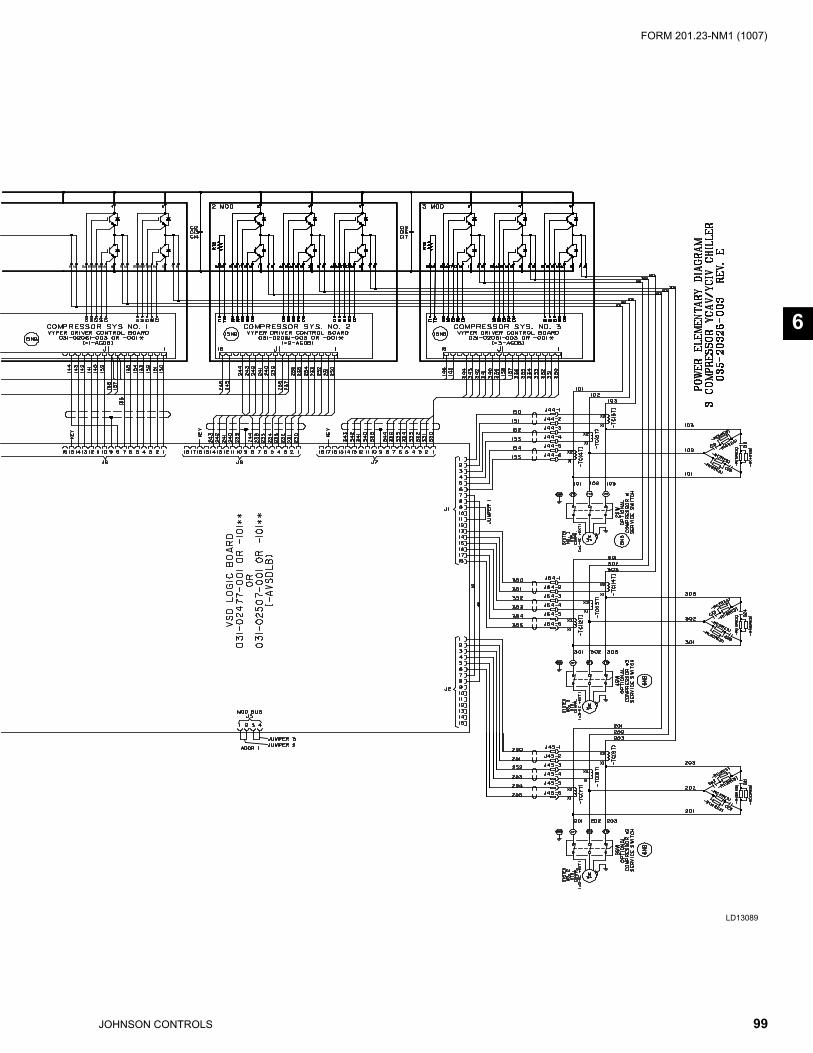
99JOHNSON CONTROLS
FORM 201.23-NM1 (1007)
6
LD13089
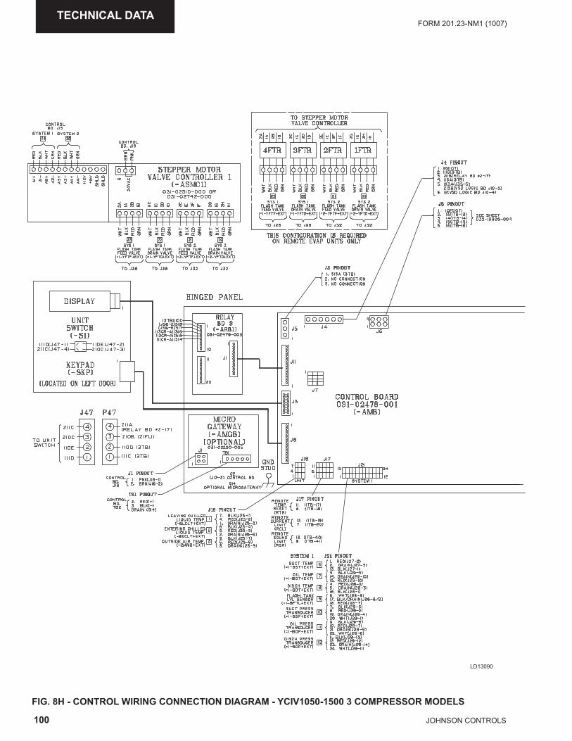
100 JOHNSON CONTROLS
FORM 201.23-NM1 (1007)TECHNICAL DATA
LD13090
FIG. 8H - CONTROL WIRING CONNECTION DIAGRAM - YCIV1050-1500 3 COMPRESSOR MODELS
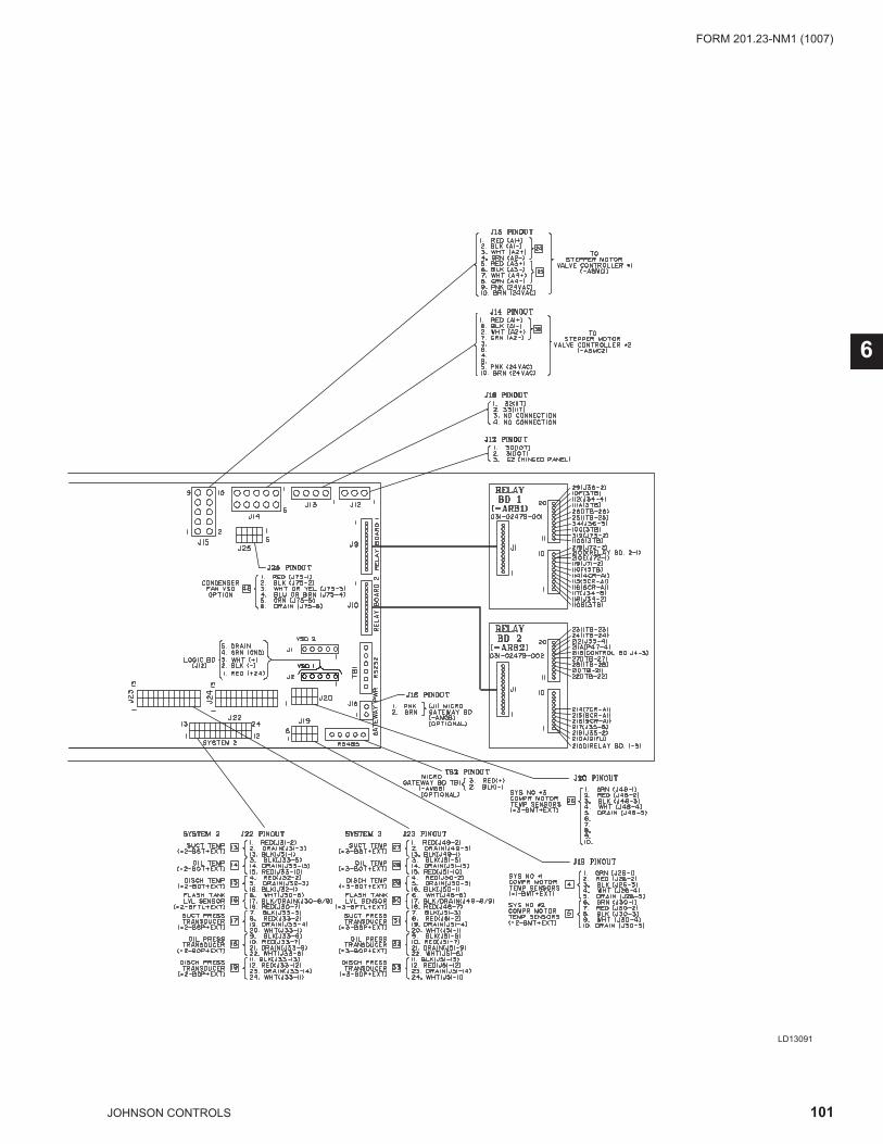
101JOHNSON CONTROLS
FORM 201.23-NM1 (1007)
6
LD13091
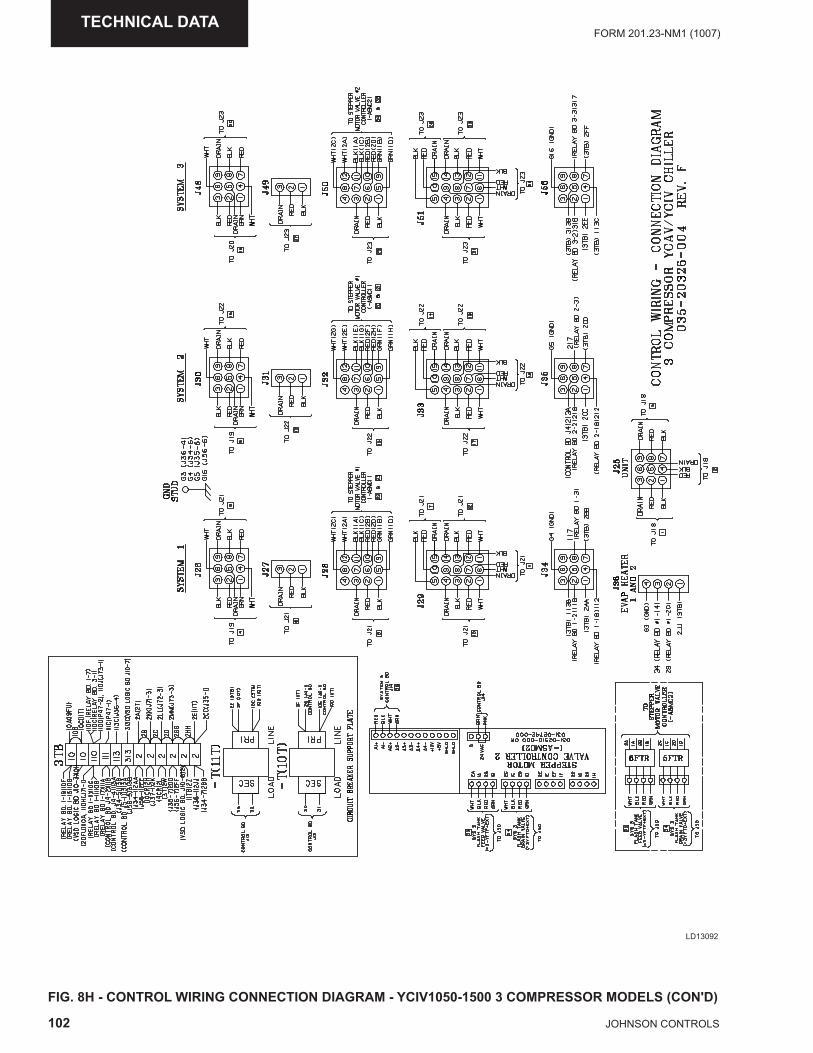
102 JOHNSON CONTROLS
FORM 201.23-NM1 (1007)TECHNICAL DATA
LD13092
FIG. 8H - CONTROL WIRING CONNECTION DIAGRAM - YCIV1050-1500 3 COMPRESSOR MODELS (CON'D)
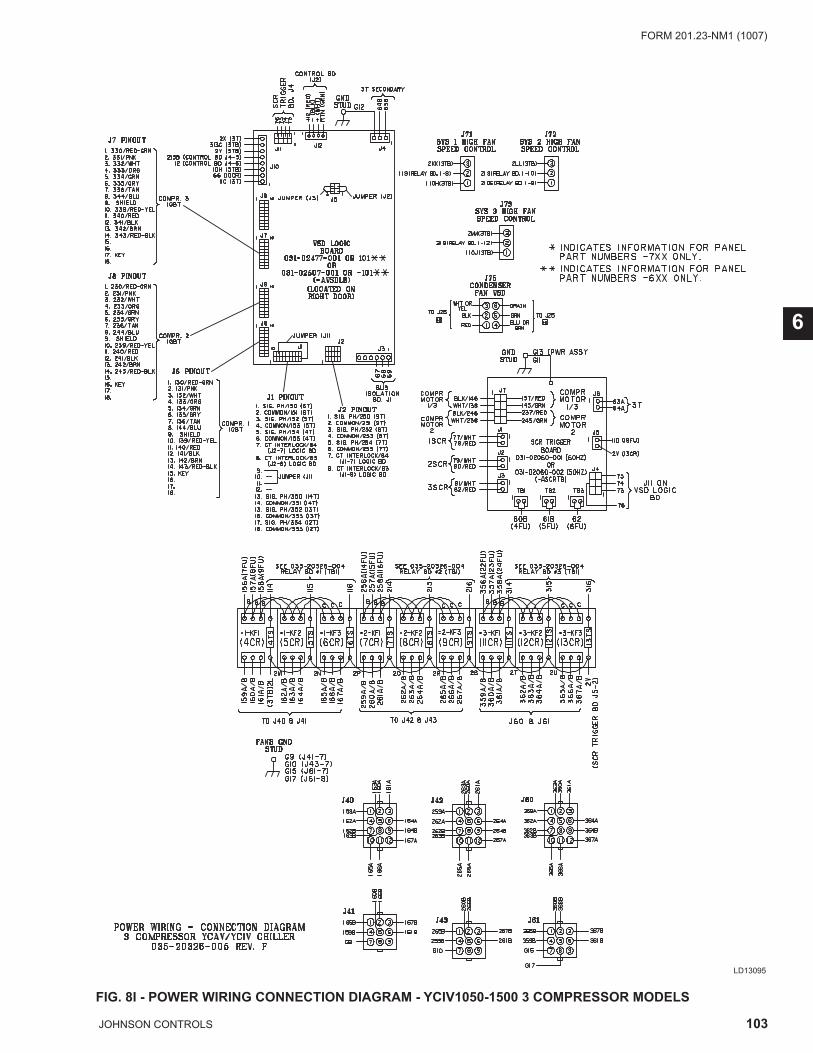
103JOHNSON CONTROLS
FORM 201.23-NM1 (1007)
6
LD13095
FIG. 8I - POWER WIRING CONNECTION DIAGRAM - YCIV1050-1500 3 COMPRESSOR MODELS
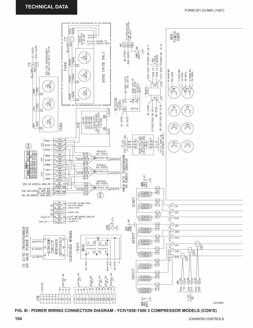
104 JOHNSON CONTROLS
FORM 201.23-NM1 (1007)TECHNICAL DATA
LD13093
FIG. 8I - POWER WIRING CONNECTION DIAGRAM - YCIV1050-1500 3 COMPRESSOR MODELS (CON'D)
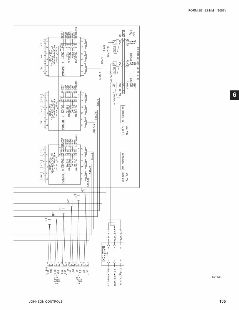
105JOHNSON CONTROLS
FORM 201.23-NM1 (1007)
6
LD13094
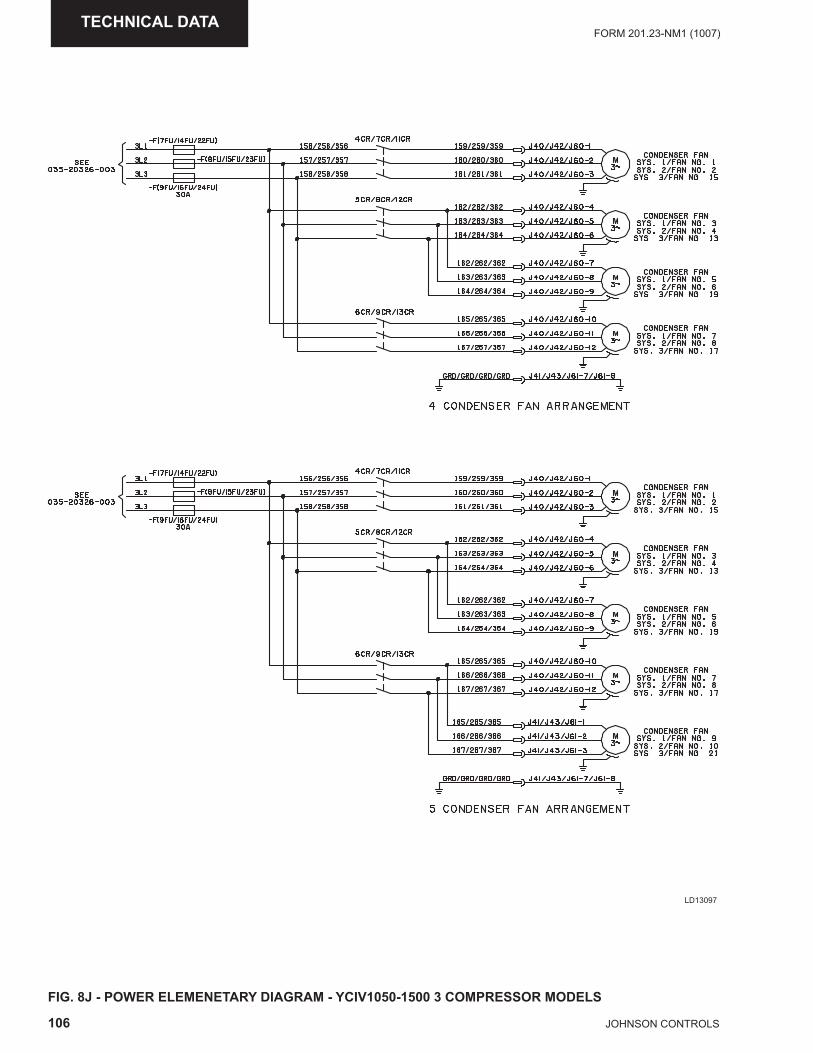
106 JOHNSON CONTROLS
FORM 201.23-NM1 (1007)TECHNICAL DATA
LD13097
FIG. 8J - POWER ELEMENETARY DIAGRAM - YCIV1050-1500 3 COMPRESSOR MODELS
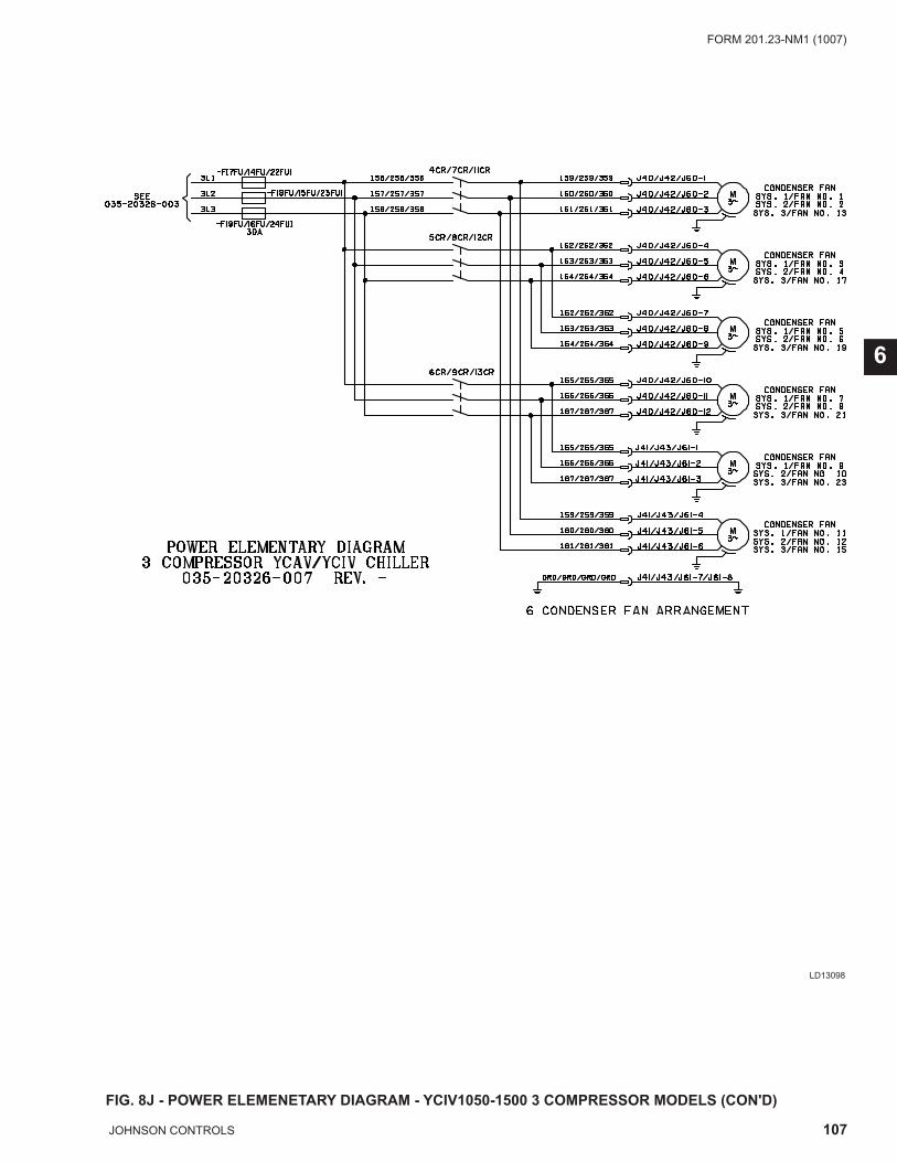
107JOHNSON CONTROLS
FORM 201.23-NM1 (1007)
6
LD13098
FIG. 8J - POWER ELEMENETARY DIAGRAM - YCIV1050-1500 3 COMPRESSOR MODELS (CON'D)
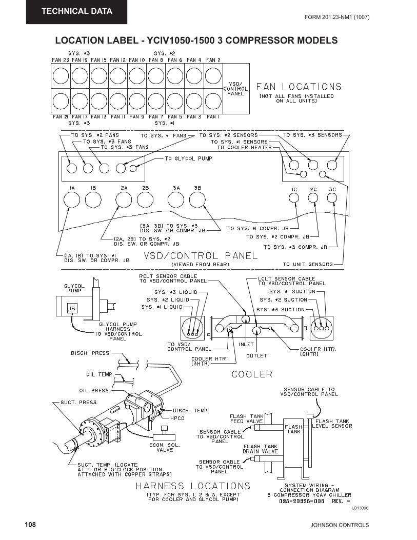
108 JOHNSON CONTROLS
FORM 201.23-NM1 (1007)TECHNICAL DATA
LOCATION LABEL - YCIV1050-1500 3 COMPRESSOR MODELS
LD13096
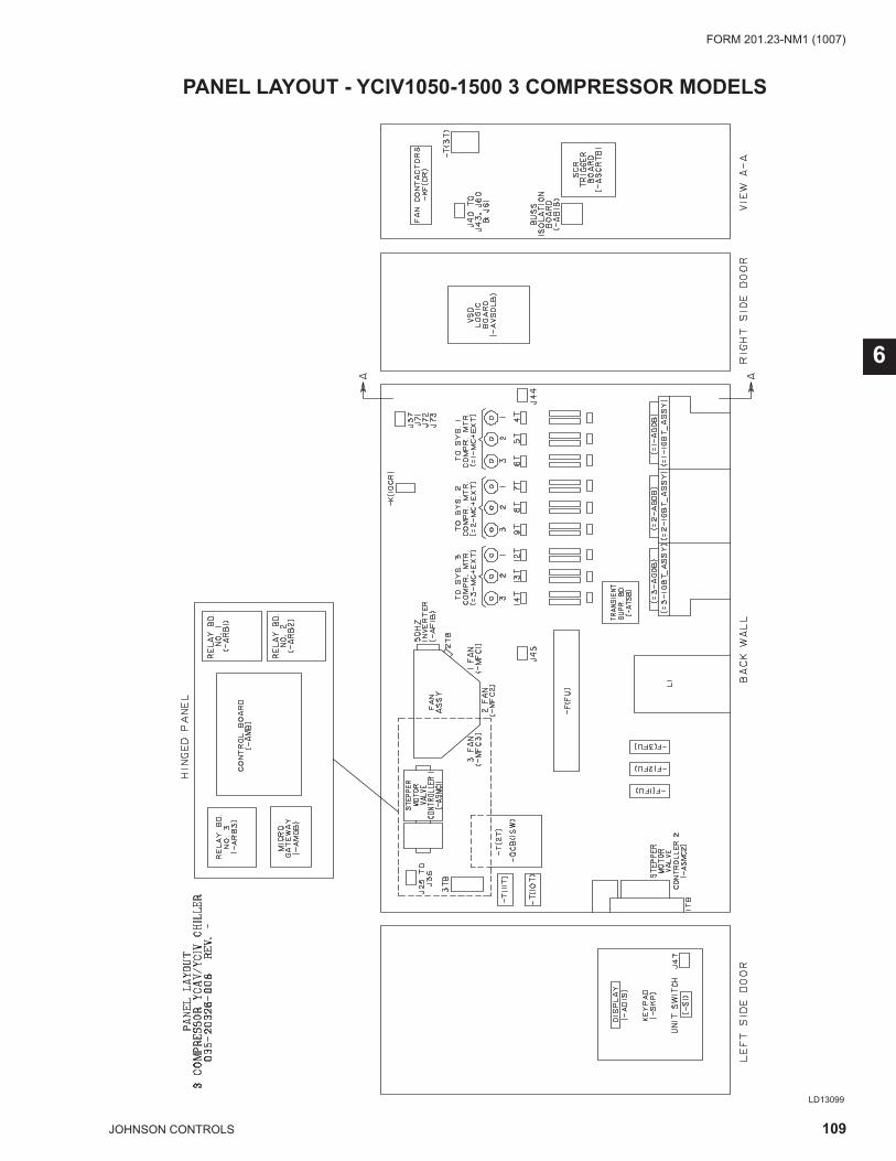
109JOHNSON CONTROLS
FORM 201.23-NM1 (1007)
6
LD13099
PANEL LAYOUT - YCIV1050-1500 3 COMPRESSOR MODELS
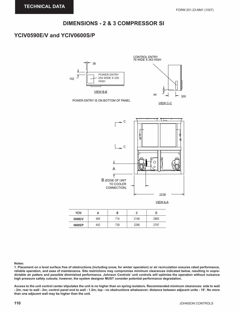
110 JOHNSON CONTROLS
FORM 201.23-NM1 (1007)TECHNICAL DATA
Notes:1. Placement on a level surface free of obstructions (including snow, for winter operation) or air recirculation ensures rated performance, reliable operation, and ease of maintenance. Site restrictions may compromise minimum clearances indicated below, resulting in unpre-dictable air patters and possible diminished performance. Johnson Controls’ unit controls will optimize the operation without nuisance high pressure safety cutouts; however, the system designer MUST consider potential performance degradation.
Access to the unit control center stipulates the unit is no higher than on spring isolators. Recommended minimum clearances: side to wall - 2m; rear to wall - 2m; control panel end to wall - 1.2m; top - no obstructions whatsoever; distance between adjacent units - 10’. No more than one adjacent wall may be higher than the unit.
YCIV A B C D
0590E/V 485 714 2146 2865
0600S/P 442 739 2286 2797
VIEW C-C
VIEW B-B305
CONTROL ENTRY76 WIDE X 343 HIGH
38
102POWER ENTRY254 WIDE X 330 HIGH
44
POWER ENTRY IS ON BOTTOM OF PANEL
B (EDGE OF UNIT TO COOLER
CONNECTION)
2238
A
VIEW A-A
C
C
B B
YCIV0590E/V and YCIV0600S/P
DIMENSIONS - 2 & 3 COMPRESSOR SI
POWER ENTRY254 WIDE X 330 HIGH
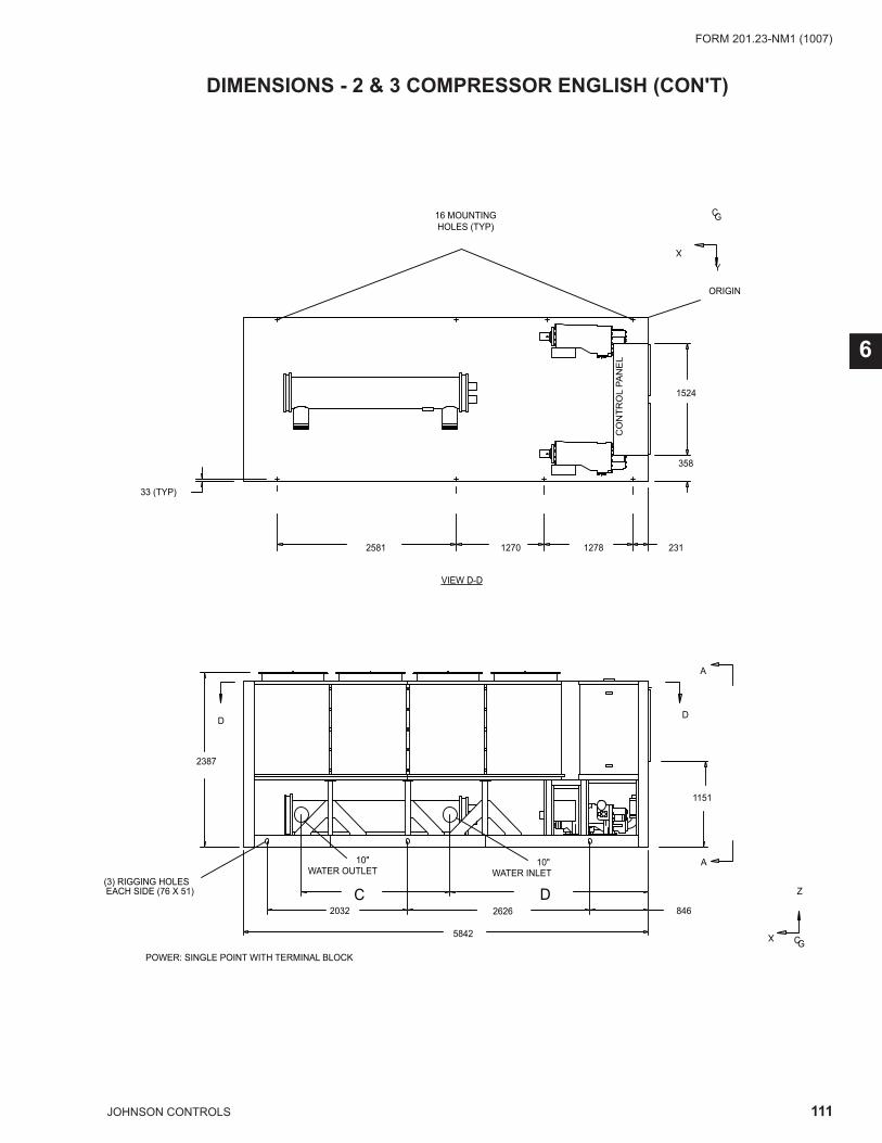
111JOHNSON CONTROLS
FORM 201.23-NM1 (1007)
6
DIMENSIONS - 2 & 3 COMPRESSOR ENGLISH (CON'T)
84626262032DC
5842
2581 1270 1278 231
2387
33 (TYP)
X
GC
Y
(3) RIGGING HOLESEACH SIDE (76 X 51)
10"WATER OUTLET
10"WATER INLET
VIEW D-D
X
GC
Z
DD
A
A
16 MOUNTING HOLES (TYP)
ORIGIN
POWER: SINGLE POINT WITH TERMINAL BLOCK
CO
NTR
OL
PAN
EL
1151
1524
358
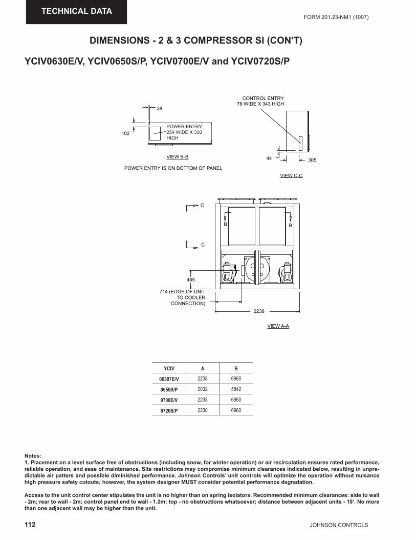
112 JOHNSON CONTROLS
FORM 201.23-NM1 (1007)TECHNICAL DATA
Notes:1. Placement on a level surface free of obstructions (including snow, for winter operation) or air recirculation ensures rated performance, reliable operation, and ease of maintenance. Site restrictions may compromise minimum clearances indicated below, resulting in unpre-dictable air patters and possible diminished performance. Johnson Controls’ unit controls will optimize the operation without nuisance high pressure safety cutouts; however, the system designer MUST consider potential performance degradation.
Access to the unit control center stipulates the unit is no higher than on spring isolators. Recommended minimum clearances: side to wall - 2m; rear to wall - 2m; control panel end to wall - 1.2m; top - no obstructions whatsoever; distance between adjacent units - 10’. No more than one adjacent wall may be higher than the unit.
YCIV0630E/V, YCIV0650S/P, YCIV0700E/V and YCIV0720S/P
VIEW C-C
VIEW B-B305
CONTROL ENTRY76 WIDE X 343 HIGH
38
102POWER ENTRY254 WIDE X 330 HIGH
44
POWER ENTRY IS ON BOTTOM OF PANEL
2238
714 (EDGE OF UNIT TO COOLER
CONNECTION)
485
C
C
BB
VIEW A-A
YCIV A B
06307E/V 2238 6960
0650S/P 2032 5842
0700E/V 2238 6960
0720S/P 2238 6960
DIMENSIONS - 2 & 3 COMPRESSOR SI (CON'T)
POWER ENTRY254 WIDE X 330 HIGH
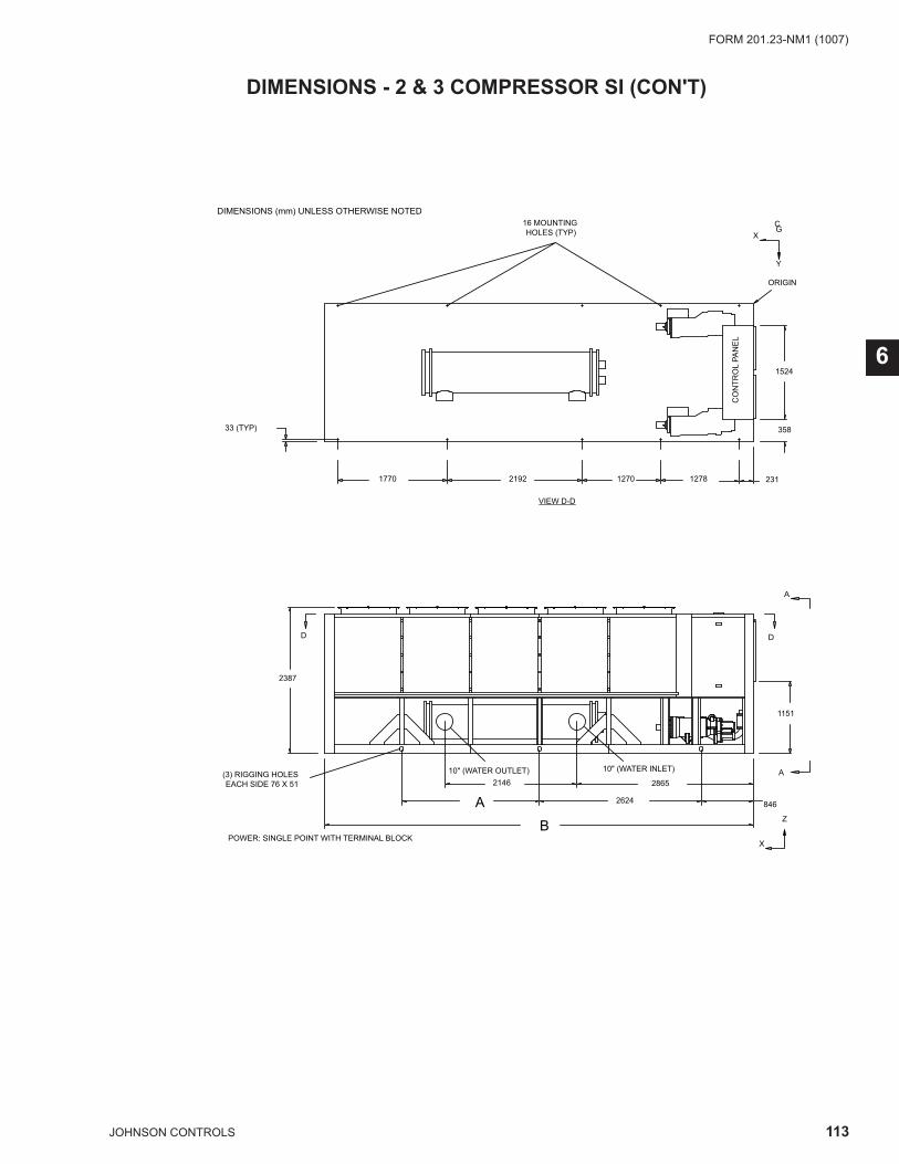
113JOHNSON CONTROLS
FORM 201.23-NM1 (1007)
6
DIMENSIONS - 2 & 3 COMPRESSOR SI (CON'T)
DIMENSIONS (mm) UNLESS OTHERWISE NOTED
POWER: SINGLE POINT WITH TERMINAL BLOCK
XGC
Y
VIEW D-D
B8462624A
28652146
2387
D D
X
Z
10" (WATER INLET)10" (WATER OUTLET)
A
A
2311278127021921770
33 (TYP)
16 MOUNTING HOLES (TYP)
(3) RIGGING HOLES EACH SIDE 76 X 51
ORIGIN
CO
NTR
OL
PAN
EL
1151
1524
358

114 JOHNSON CONTROLS
FORM 201.23-NM1 (1007)TECHNICAL DATA
DIMENSIONS - 2 & 3 COMPRESSOR SI (CON'T)
Notes:1. Placement on a level surface free of obstructions (including snow, for winter operation) or air recirculation ensures rated performance, reliable operation, and ease of maintenance. Site restrictions may compromise minimum clearances indicated below, resulting in unpre-dictable air patters and possible diminished performance. Johnson Controls’ unit controls will optimize the operation without nuisance high pressure safety cutouts; however, the system designer MUST consider potential performance degradation.
Access to the unit control center stipulates the unit is no higher than on spring isolators. Recommended minimum clearances: side to wall - 2m; rear to wall - 2m; control panel end to wall - 1.2m; top - no obstructions whatsoever; distance between adjacent units - 10’. No more than one adjacent wall may be higher than the unit.
YCIV A B C D
0760E/V 518 714 2174 2852
0770S/P 564 660 2009 2878
0890S/P 564 660 2009 2878
VIEW C-C
VIEW B-B305
CONTROL ENTRY76 WIDE X 343 HIGH
38
102
POWER ENTRY254 WIDE X 330 HIGH
44
POWER ENTRY IS ON BOTTOM OF PANEL
2238
B (EDGE OF UNIT TO COOLER
CONNECTION)
A
C
BB
VIEW A-A
C
YCIV0760E/V and YCIV0770S/P
POWER ENTRY254 WIDE X 330 HIGH
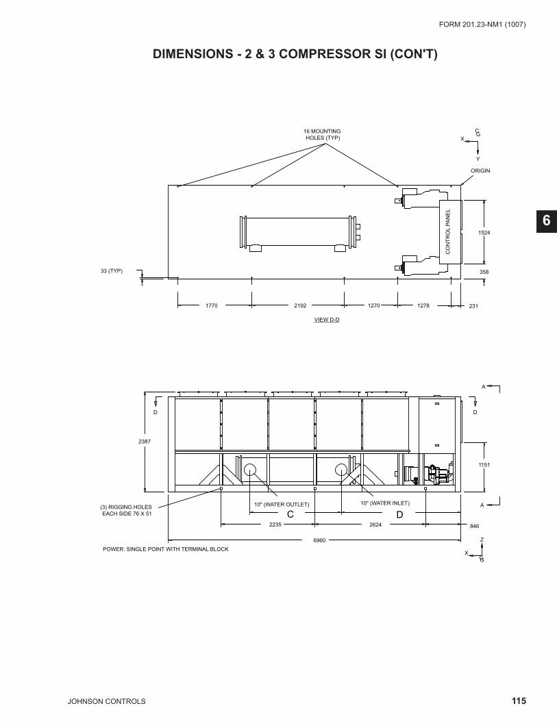
115JOHNSON CONTROLS
FORM 201.23-NM1 (1007)
6
DIMENSIONS - 2 & 3 COMPRESSOR SI (CON'T)
POWER: SINGLE POINT WITH TERMINAL BLOCK
XGC
Y
VIEW D-D
6960
84626242235DC
2387
D D
XGC
Z
10" (WATER INLET)10" (WATER OUTLET)
A
A
2311278127021921770
33 (TYP)
16 MOUNTING HOLES (TYP)
(3) RIGGING HOLES EACH SIDE 76 X 51
ORIGIN
CO
NTR
OL
PAN
EL
1151
358
1524

116 JOHNSON CONTROLS
FORM 201.23-NM1 (1007)TECHNICAL DATA
DIMENSIONS - 2 & 3 COMPRESSOR SI (CON'T)
Notes:1. Placement on a level surface free of obstructions (including snow, for winter operation) or air recirculation ensures rated performance, reliable operation, and ease of maintenance. Site restrictions may compromise minimum clearances indicated below, resulting in unpre-dictable air patters and possible diminished performance. Johnson Controls’ unit controls will optimize the operation without nuisance high pressure safety cutouts; however, the system designer MUST consider potential performance degradation.
Access to the unit control center stipulates the unit is no higher than on spring isolators. Recommended minimum clearances: side to wall - 2m; rear to wall - 2m; control panel end to wall - 1.2m; top - no obstructions whatsoever; distance between adjacent units - 10’. No more than one adjacent wall may be higher than the unit.
YCIV0800E/V and YCIV0830E/V
VIEW C-C
VIEW B-B305
CONTROL ENTRY76 WIDE X 343 HIGH
38
102POWER ENTRY254 WIDE X 330 HIGH
44
POWER ENTRY IS ON BOTTOM OF PANEL
2238
714 (EDGE OF UNIT TO COOLER CONNECTION)
518
C
C
BB
VIEW A-A
POWER ENTRY254 WIDE X 330 HIGH
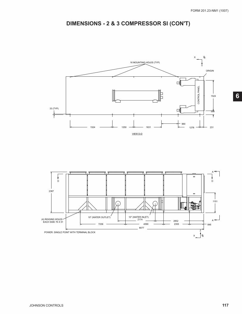
117JOHNSON CONTROLS
FORM 201.23-NM1 (1007)
6
DIMENSIONS - 2 & 3 COMPRESSOR SI (CON'T)
POWER: SINGLE POINT WITH TERMINAL BLOCK
CO
NTR
OL
PAN
EL
VIEW D-D
2311278960
163112501524
8077846235545907236
2852217410" (WATER OUTLET) 10" (WATER INLET)
A
A
DD
2387
16 MOUNTING HOLES (TYP)
(4) RIGGING HOLES EACH SIDE 76 X 51
X GC
Z
ORIGIN
X GC
Y
33 (TYP)
1151
358
1524
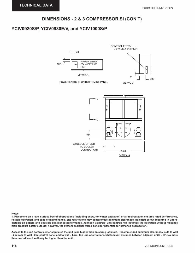
118 JOHNSON CONTROLS
FORM 201.23-NM1 (1007)TECHNICAL DATA
DIMENSIONS - 2 & 3 COMPRESSOR SI (CON'T)
Notes:1. Placement on a level surface free of obstructions (including snow, for winter operation) or air recirculation ensures rated performance, reliable operation, and ease of maintenance. Site restrictions may compromise minimum clearances indicated below, resulting in unpre-dictable air patters and possible diminished performance. Johnson Controls’ unit controls will optimize the operation without nuisance high pressure safety cutouts; however, the system designer MUST consider potential performance degradation.
Access to the unit control center stipulates the unit is no higher than on spring isolators. Recommended minimum clearances: side to wall - 2m; rear to wall - 2m; control panel end to wall - 1.2m; top - no obstructions whatsoever; distance between adjacent units - 10’. No more than one adjacent wall may be higher than the unit.
YCIV0920S/P, YCIV0930E/V, and YCIV1000S/P
VIEW C-C
VIEW B-B305
CONTROL ENTRY76 WIDE X 343 HIGH
38
102POWER ENTRY254 WIDE X 330 HIGH
44
POWER ENTRY IS ON BOTTOM OF PANEL
2238
660 (EDGE OF UNIT TO COOLER CONNECTION)
564
C
C
BB
VIEW A-A
POWER ENTRY254 WIDE X 330 HIGH
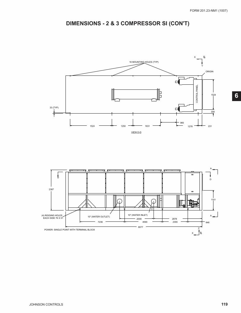
119JOHNSON CONTROLS
FORM 201.23-NM1 (1007)
6
DIMENSIONS - 2 & 3 COMPRESSOR SI (CON'T)
POWER: SINGLE POINT WITH TERMINAL BLOCK
CO
NTR
OL
PAN
EL
VIEW D-D
2311278960
163112501524
8077
84623554590723628782009
10" (WATER OUTLET)10" (WATER INLET)
A
A
DD
2387
16 MOUNTING HOLES (TYP)
(4) RIGGING HOLES EACH SIDE 76 X 51
X GC
Z
ORIGIN
X GC
Y
33 (TYP)
1151
358
1524

120 JOHNSON CONTROLS
FORM 201.23-NM1 (1007)TECHNICAL DATA
DIMENSIONS - 2 & 3 COMPRESSOR SI (CON'T)
Notes:1. Placement on a level surface free of obstructions (including snow, for winter operation) or air recirculation ensures rated performance, reliable operation, and ease of maintenance. Site restrictions may compromise minimum clearances indicated below, resulting in unpre-dictable air patters and possible diminished performance. Johnson Controls’ unit controls will optimize the operation without nuisance high pressure safety cutouts; however, the system designer MUST consider potential performance degradation.
Access to the unit control center stipulates the unit is no higher than on spring isolators. Recommended minimum clearances: side to wall - 2m; rear to wall - 2m; control panel end to wall - 1.2m; top - no obstructions whatsoever; distance between adjacent units - 10’. No more than one adjacent wall may be higher than the unit.
YCIV1050E/V and YCIV1070S/P
VIEW C-C
VIEW B-B305
CONTROL ENTRY76 WIDE X 343 HIGH
38
102POWER ENTRY254 WIDE X 330 HIGH
44
POWER ENTRY IS ON BOTTOM OF PANEL
2238
VIEW A-A
BB
C
C
POWER ENTRY254 WIDE X 330 HIGH
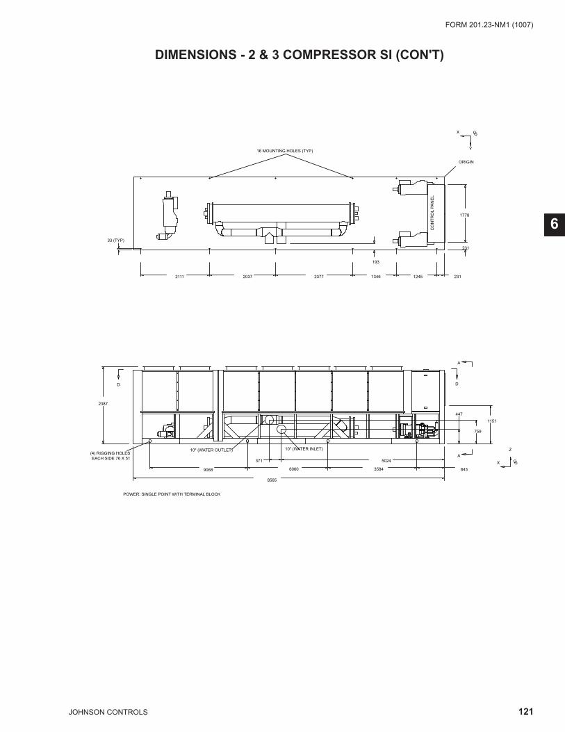
121JOHNSON CONTROLS
FORM 201.23-NM1 (1007)
6
DIMENSIONS - 2 & 3 COMPRESSOR SI (CON'T)
POWER: SINGLE POINT WITH TERMINAL BLOCK
1151
759
447
A
A
X GC
Z
DD
2387
CO
NTR
OL
PAN
EL
8565
5024371
358460609068 843
10" (WATER INLET)10" (WATER OUTLET) (4) RIGGING HOLES
EACH SIDE 76 X 51
1778
231
12451346237720372111 231
ORIGIN
33 (TYP)
16 MOUNTING HOLES (TYP)
X GC
Y
193

122 JOHNSON CONTROLS
FORM 201.23-NM1 (1007)TECHNICAL DATA
DIMENSIONS - 2 & 3 COMPRESSOR SI (CON'T)
Notes:1. Placement on a level surface free of obstructions (including snow, for winter operation) or air recirculation ensures rated performance, reliable operation, and ease of maintenance. Site restrictions may compromise minimum clearances indicated below, resulting in unpre-dictable air patters and possible diminished performance. Johnson Controls’ unit controls will optimize the operation without nuisance high pressure safety cutouts; however, the system designer MUST consider potential performance degradation.
Access to the unit control center stipulates the unit is no higher than on spring isolators. Recommended minimum clearances: side to wall - 2m; rear to wall - 2m; control panel end to wall - 1.2m; top - no obstructions whatsoever; distance between adjacent units - 10’. No more than one adjacent wall may be higher than the unit.
YCIV1120E/V
VIEW C-C
VIEW B-B305
CONTROL ENTRY76 WIDE X 343 HIGH
38
102POWER ENTRY254 WIDE X 330 HIGH
44
POWER ENTRY IS ON BOTTOM OF PANEL
2238
VIEW A-A
C
C
B B
POWER ENTRY254 WIDE X 330 HIGH
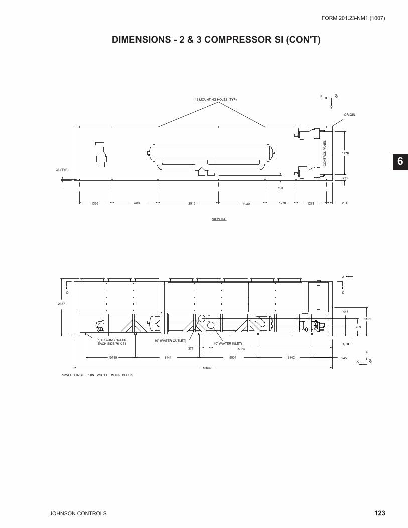
123JOHNSON CONTROLS
FORM 201.23-NM1 (1007)
6
DIMENSIONS - 2 & 3 COMPRESSOR SI (CON'T)
POWER: SINGLE POINT WITH TERMINAL BLOCK
12781270193025154831356 231
33 (TYP)
193
447
759
2387
DD
X GC
Z
X GC
Y
CO
NTR
OL
PAN
EL
ORIGIN
A
A
10699
31425504814110185 945
5024371
10" (WATER OUTLET)10" (WATER INLET)
(5) RIGGING HOLES EACH SIDE 76 X 51
VIEW D-D
16 MOUNTING HOLES (TYP)
1151
231
1778
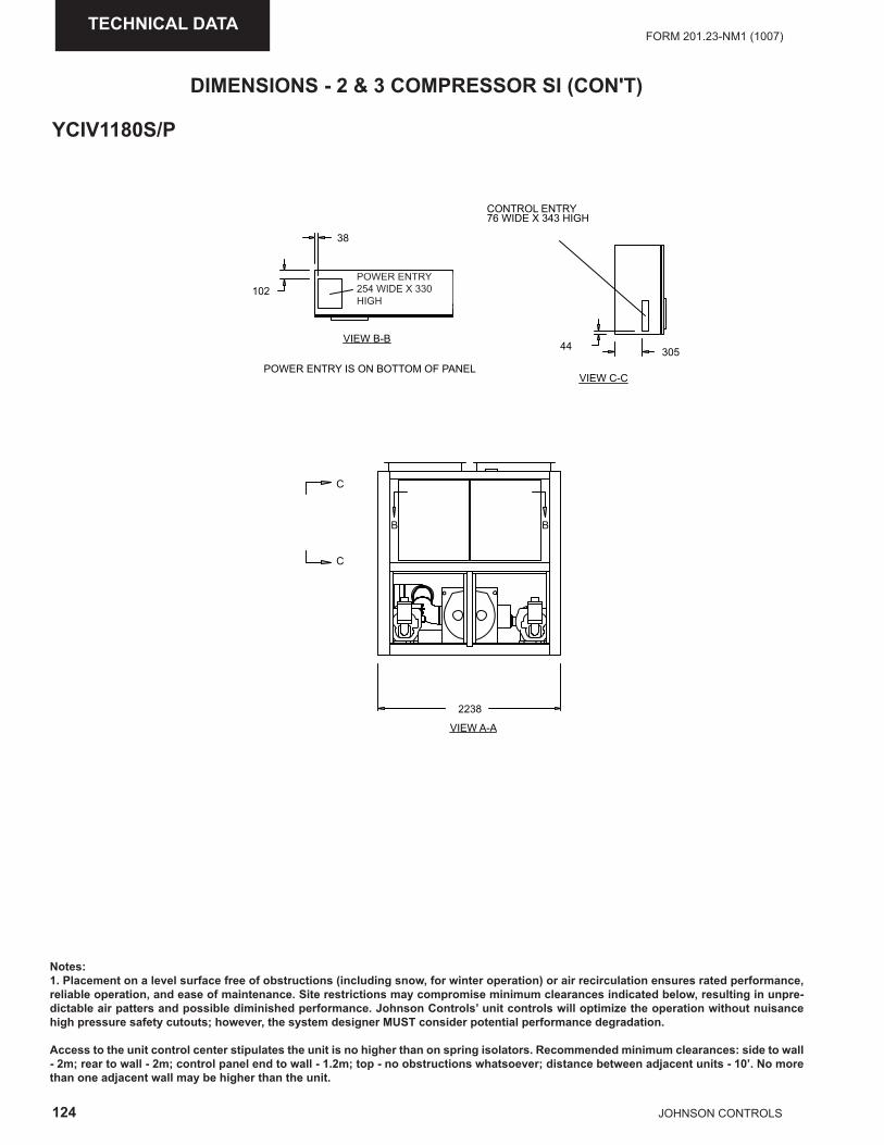
124 JOHNSON CONTROLS
FORM 201.23-NM1 (1007)TECHNICAL DATA
DIMENSIONS - 2 & 3 COMPRESSOR SI (CON'T)
Notes:1. Placement on a level surface free of obstructions (including snow, for winter operation) or air recirculation ensures rated performance, reliable operation, and ease of maintenance. Site restrictions may compromise minimum clearances indicated below, resulting in unpre-dictable air patters and possible diminished performance. Johnson Controls’ unit controls will optimize the operation without nuisance high pressure safety cutouts; however, the system designer MUST consider potential performance degradation.
Access to the unit control center stipulates the unit is no higher than on spring isolators. Recommended minimum clearances: side to wall - 2m; rear to wall - 2m; control panel end to wall - 1.2m; top - no obstructions whatsoever; distance between adjacent units - 10’. No more than one adjacent wall may be higher than the unit.
YCIV1180S/P
VIEW C-C
VIEW B-B305
CONTROL ENTRY76 WIDE X 343 HIGH
38
102POWER ENTRY254 WIDE X 330 HIGH
44
POWER ENTRY IS ON BOTTOM OF PANEL
2238
VIEW A-A
BB
C
C
POWER ENTRY254 WIDE X 330 HIGH
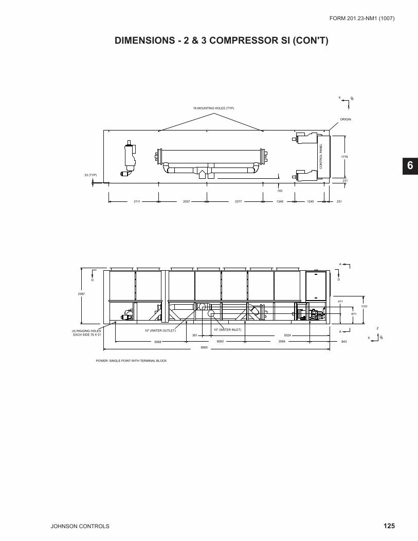
125JOHNSON CONTROLS
FORM 201.23-NM1 (1007)
6
DIMENSIONS - 2 & 3 COMPRESSOR SI (CON'T)
POWER: SINGLE POINT WITH TERMINAL BLOCK
1151
671
411
A
A
X GC
Z
DD
2387
CO
NTR
OL
PAN
EL
8565
5024381
358460609068 843
10" (WATER INLET)10" (WATER OUTLET) (4) RIGGING HOLES EACH SIDE 76 X 51
1778
231
12451346237720372111 231
ORIGIN
33 (TYP)
16 MOUNTING HOLES (TYP)
X GC
Y
193

126 JOHNSON CONTROLS
FORM 201.23-NM1 (1007)TECHNICAL DATA
DIMENSIONS - 2 & 3 COMPRESSOR SI (CON'T)
Notes:1. Placement on a level surface free of obstructions (including snow, for winter operation) or air recirculation ensures rated performance, reliable operation, and ease of maintenance. Site restrictions may compromise minimum clearances indicated below, resulting in unpre-dictable air patters and possible diminished performance. Johnson Controls’ unit controls will optimize the operation without nuisance high pressure safety cutouts; however, the system designer MUST consider potential performance degradation.
Access to the unit control center stipulates the unit is no higher than on spring isolators. Recommended minimum clearances: side to wall - 2m; rear to wall - 2m; control panel end to wall - 1.2m; top - no obstructions whatsoever; distance between adjacent units - 10’. No more than one adjacent wall may be higher than the unit.
YCIV1220E/V and YCIV1340S/P
VIEW C-C
VIEW B-B305
CONTROL ENTRY76 WIDE X 343 HIGH
38
102POWER ENTRY254 WIDE X 330 HIGH
44
POWER ENTRY IS ON BOTTOM OF PANEL
2238
VIEW A-A
C
B B
C
POWER ENTRY254 WIDE X 330 HIGH
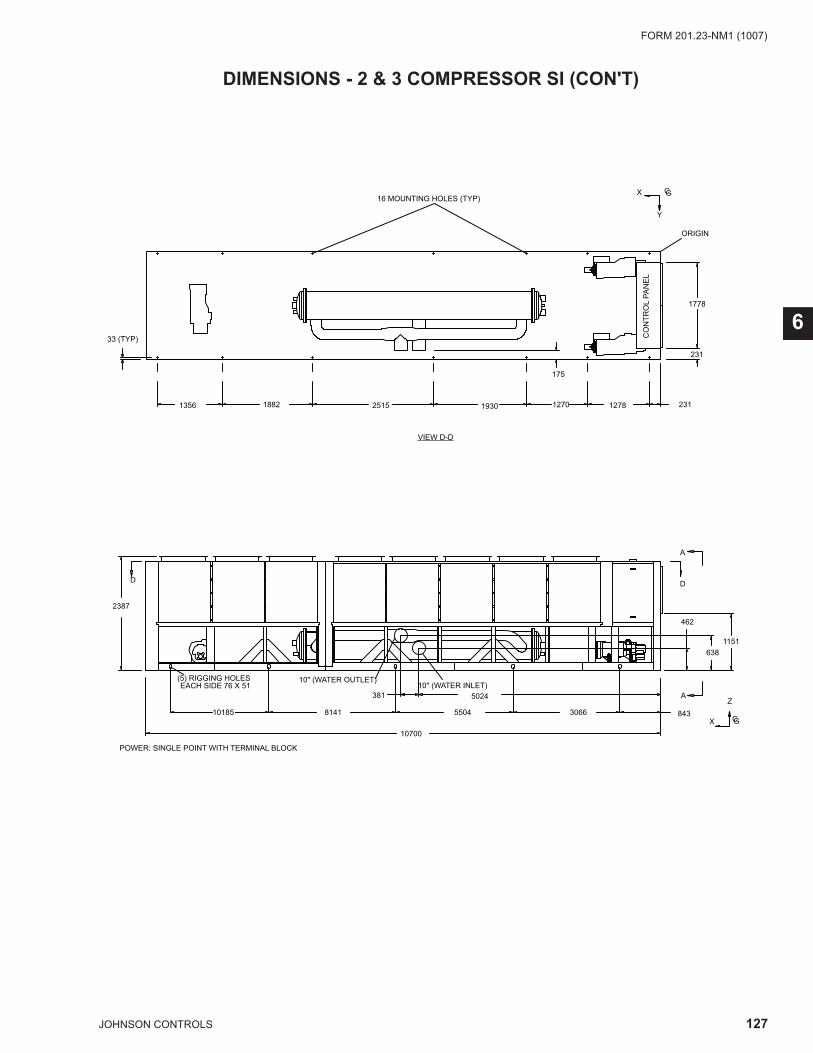
127JOHNSON CONTROLS
FORM 201.23-NM1 (1007)
6
DIMENSIONS - 2 & 3 COMPRESSOR SI (CON'T)
POWER: SINGLE POINT WITH TERMINAL BLOCK
127812701930251518821356 231
33 (TYP)
175
462
638
2387
DD
X GC
Z
X GC
Y
CO
NTR
OL
PAN
EL
ORIGIN
A
A
10700
30665504814110185 843
5024381
10" (WATER OUTLET)10" (WATER INLET)
(5) RIGGING HOLES EACH SIDE 76 X 51
VIEW D-D
16 MOUNTING HOLES (TYP)
1151
231
1778

128 JOHNSON CONTROLS
FORM 201.23-NM1 (1007)TECHNICAL DATA
DIMENSIONS - 2 & 3 COMPRESSOR SI (CON'T)
Notes:1. Placement on a level surface free of obstructions (including snow, for winter operation) or air recirculation ensures rated performance, reliable operation, and ease of maintenance. Site restrictions may compromise minimum clearances indicated below, resulting in unpre-dictable air patters and possible diminished performance. Johnson Controls’ unit controls will optimize the operation without nuisance high pressure safety cutouts; however, the system designer MUST consider potential performance degradation.
Access to the unit control center stipulates the unit is no higher than on spring isolators. Recommended minimum clearances: side to wall - 2m; rear to wall - 2m; control panel end to wall - 1.2m; top - no obstructions whatsoever; distance between adjacent units - 10’. No more than one adjacent wall may be higher than the unit.
YCIV1380E/V and YCIV1500S/P
VIEW C-C
VIEW B-B305
CONTROL ENTRY76 WIDE X 343 HIGH
38
102POWER ENTRY254 WIDE X 330 HIGH
44
POWER ENTRY IS ON BOTTOM OF PANEL
2238
C
B B
C
VIEW A-A
POWER ENTRY254 WIDE X 330 HIGH
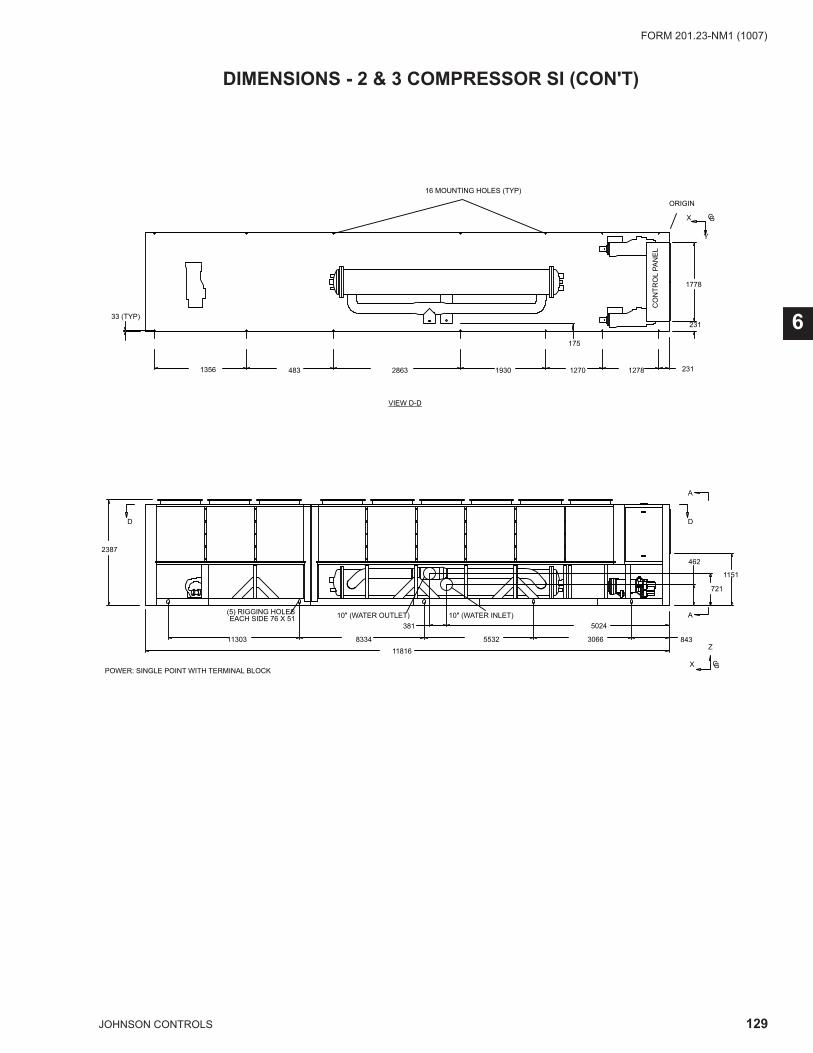
129JOHNSON CONTROLS
FORM 201.23-NM1 (1007)
6
DIMENSIONS - 2 & 3 COMPRESSOR SI (CON'T)
2387
175
CO
NTR
OL
PAN
EL
ORIGIN
1356 2311278127019302863483
POWER: SINGLE POINT WITH TERMINAL BLOCK
VIEW D-D
16 MOUNTING HOLES (TYP)
381 5024
3066 843553283341130311816
462
721
A
A
DD
10" (WATER INLET)10" (WATER OUTLET) (5) RIGGING HOLES EACH SIDE 76 X 51
33 (TYP)
X GC
Y
X GC
Z
1151
1778
231
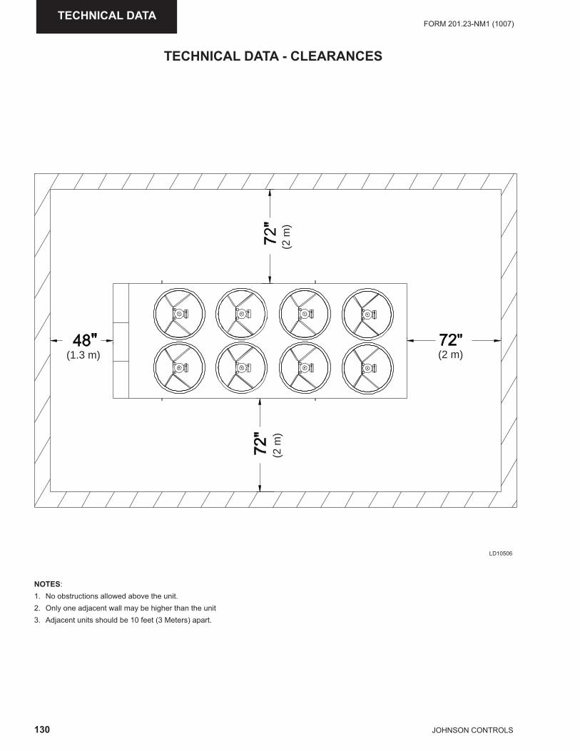
130 JOHNSON CONTROLS
FORM 201.23-NM1 (1007)TECHNICAL DATA
TECHNICAL DATA - CLEARANCES
(1.3 m) (2 m)
(2 m
)(2
m)
NOTES:1. No obstructions allowed above the unit.2. Only one adjacent wall may be higher than the unit3. Adjacent units should be 10 feet (3 Meters) apart.
LD10506
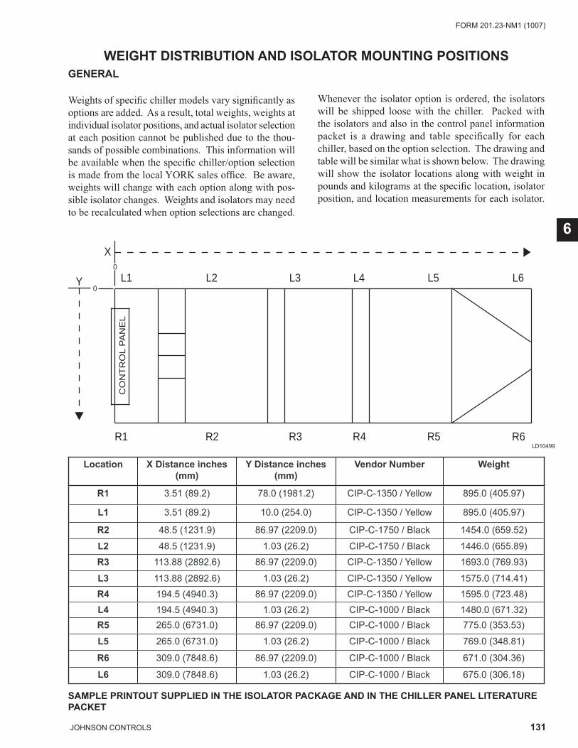
131JOHNSON CONTROLS
FORM 201.23-NM1 (1007)
6
WEIGHT DISTRIBUTION AND ISOLATOR MOUNTING POSITIONSGENERAL
Weights of specifi c chiller models vary signifi cantly as options are added. As a result, total weights, weights at individual isolator positions, and actual isolator selection at each position cannot be published due to the thou-sands of possible combinations. This information will be available when the specifi c chiller/option selection is made from the local YORK sales offi ce. Be aware, weights will change with each option along with pos-sible isolator changes. Weights and isolators may need to be recalculated when option selections are changed.
Whenever the isolator option is ordered, the isolators will be shipped loose with the chiller. Packed with the isolators and also in the control panel information packet is a drawing and table specifi cally for each chiller, based on the option selection. The drawing and table will be similar what is shown below. The drawing will show the isolator locations along with weight in pounds and kilograms at the specifi c location, isolator position, and location measurements for each isolator.
Location X Distance inches (mm)
Y Distance inches (mm)
Vendor Number Weight
R1 3.51 (89.2) 78.0 (1981.2) CIP-C-1350 / Yellow 895.0 (405.97)
L1 3.51 (89.2) 10.0 (254.0) CIP-C-1350 / Yellow 895.0 (405.97)
R2 48.5 (1231.9) 86.97 (2209.0) CIP-C-1750 / Black 1454.0 (659.52)
L2 48.5 (1231.9) 1.03 (26.2) CIP-C-1750 / Black 1446.0 (655.89)
R3 113.88 (2892.6) 86.97 (2209.0) CIP-C-1350 / Yellow 1693.0 (769.93)
L3 113.88 (2892.6) 1.03 (26.2) CIP-C-1350 / Yellow 1575.0 (714.41)
R4 194.5 (4940.3) 86.97 (2209.0) CIP-C-1350 / Yellow 1595.0 (723.48)
L4 194.5 (4940.3) 1.03 (26.2) CIP-C-1000 / Black 1480.0 (671.32)R5 265.0 (6731.0) 86.97 (2209.0) CIP-C-1000 / Black 775.0 (353.53)
L5 265.0 (6731.0) 1.03 (26.2) CIP-C-1000 / Black 769.0 (348.81)
R6 309.0 (7848.6) 86.97 (2209.0) CIP-C-1000 / Black 671.0 (304.36)
L6 309.0 (7848.6) 1.03 (26.2) CIP-C-1000 / Black 675.0 (306.18)
SAMPLE PRINTOUT SUPPLIED IN THE ISOLATOR PACKAGE AND IN THE CHILLER PANEL LITERATURE PACKET
L1 L2 L3 L4 L5 L6
R1 R2 R3 R4 R5 R6
X
Y
�
�
0
0
CO
NT
RO
L P
AN
EL
LD10499
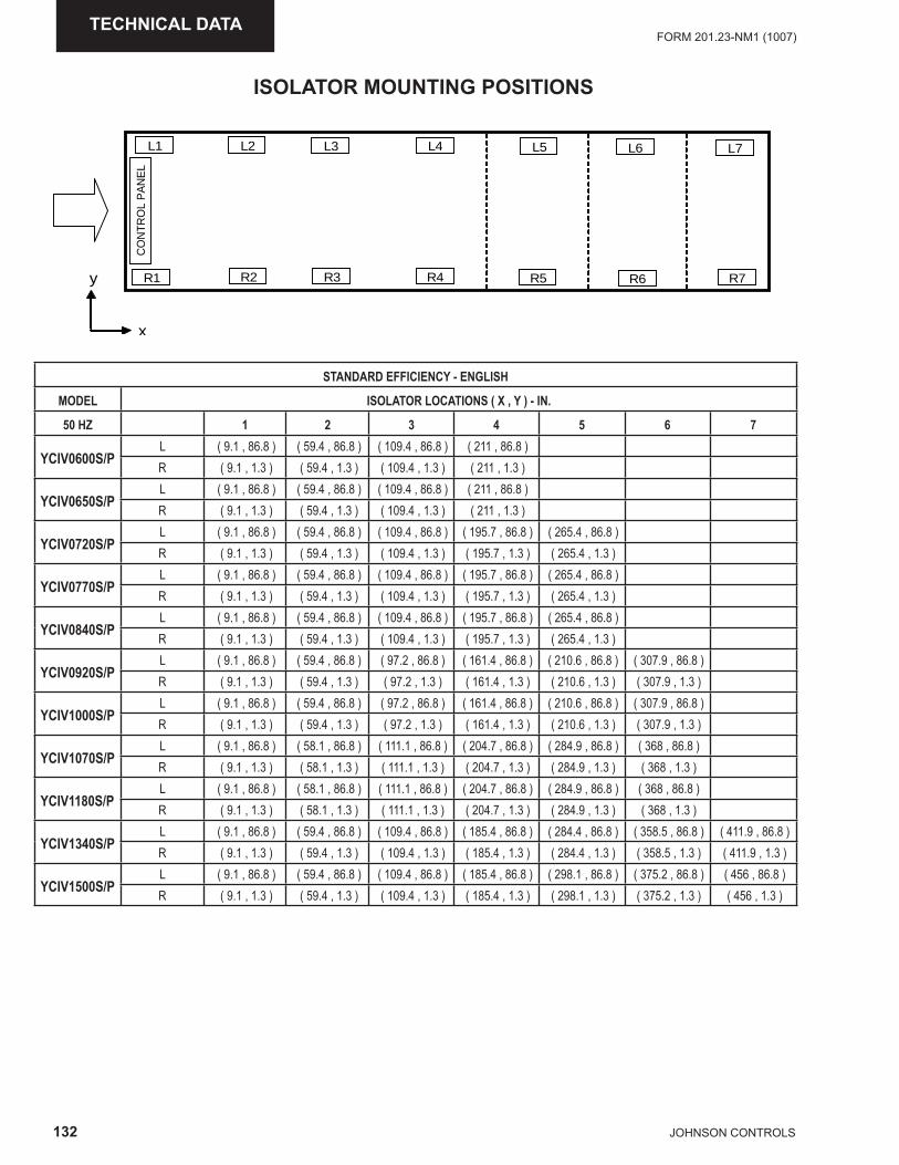
132 JOHNSON CONTROLS
FORM 201.23-NM1 (1007)TECHNICAL DATA
ISOLATOR MOUNTING POSITIONS
CO
NTR
OL
PA
NE
LL1 L2
R6R1
L6L5L4L3
R2 R3 R4 R5 R7
L7
x
y
STANDARD EFFICIENCY - ENGLISH
MODEL ISOLATOR LOCATIONS ( X , Y ) - IN.
50 HZ 1 2 3 4 5 6 7
YCIV0600S/PL ( 9.1 , 86.8 ) ( 59.4 , 86.8 ) ( 109.4 , 86.8 ) ( 211 , 86.8 ) R ( 9.1 , 1.3 ) ( 59.4 , 1.3 ) ( 109.4 , 1.3 ) ( 211 , 1.3 )
YCIV0650S/PL ( 9.1 , 86.8 ) ( 59.4 , 86.8 ) ( 109.4 , 86.8 ) ( 211 , 86.8 ) R ( 9.1 , 1.3 ) ( 59.4 , 1.3 ) ( 109.4 , 1.3 ) ( 211 , 1.3 )
YCIV0720S/PL ( 9.1 , 86.8 ) ( 59.4 , 86.8 ) ( 109.4 , 86.8 ) ( 195.7 , 86.8 ) ( 265.4 , 86.8 ) R ( 9.1 , 1.3 ) ( 59.4 , 1.3 ) ( 109.4 , 1.3 ) ( 195.7 , 1.3 ) ( 265.4 , 1.3 )
YCIV0770S/PL ( 9.1 , 86.8 ) ( 59.4 , 86.8 ) ( 109.4 , 86.8 ) ( 195.7 , 86.8 ) ( 265.4 , 86.8 ) R ( 9.1 , 1.3 ) ( 59.4 , 1.3 ) ( 109.4 , 1.3 ) ( 195.7 , 1.3 ) ( 265.4 , 1.3 )
YCIV0840S/PL ( 9.1 , 86.8 ) ( 59.4 , 86.8 ) ( 109.4 , 86.8 ) ( 195.7 , 86.8 ) ( 265.4 , 86.8 ) R ( 9.1 , 1.3 ) ( 59.4 , 1.3 ) ( 109.4 , 1.3 ) ( 195.7 , 1.3 ) ( 265.4 , 1.3 )
YCIV0920S/PL ( 9.1 , 86.8 ) ( 59.4 , 86.8 ) ( 97.2 , 86.8 ) ( 161.4 , 86.8 ) ( 210.6 , 86.8 ) ( 307.9 , 86.8 ) R ( 9.1 , 1.3 ) ( 59.4 , 1.3 ) ( 97.2 , 1.3 ) ( 161.4 , 1.3 ) ( 210.6 , 1.3 ) ( 307.9 , 1.3 )
YCIV1000S/PL ( 9.1 , 86.8 ) ( 59.4 , 86.8 ) ( 97.2 , 86.8 ) ( 161.4 , 86.8 ) ( 210.6 , 86.8 ) ( 307.9 , 86.8 ) R ( 9.1 , 1.3 ) ( 59.4 , 1.3 ) ( 97.2 , 1.3 ) ( 161.4 , 1.3 ) ( 210.6 , 1.3 ) ( 307.9 , 1.3 )
YCIV1070S/PL ( 9.1 , 86.8 ) ( 58.1 , 86.8 ) ( 111.1 , 86.8 ) ( 204.7 , 86.8 ) ( 284.9 , 86.8 ) ( 368 , 86.8 ) R ( 9.1 , 1.3 ) ( 58.1 , 1.3 ) ( 111.1 , 1.3 ) ( 204.7 , 1.3 ) ( 284.9 , 1.3 ) ( 368 , 1.3 )
YCIV1180S/PL ( 9.1 , 86.8 ) ( 58.1 , 86.8 ) ( 111.1 , 86.8 ) ( 204.7 , 86.8 ) ( 284.9 , 86.8 ) ( 368 , 86.8 ) R ( 9.1 , 1.3 ) ( 58.1 , 1.3 ) ( 111.1 , 1.3 ) ( 204.7 , 1.3 ) ( 284.9 , 1.3 ) ( 368 , 1.3 )
YCIV1340S/PL ( 9.1 , 86.8 ) ( 59.4 , 86.8 ) ( 109.4 , 86.8 ) ( 185.4 , 86.8 ) ( 284.4 , 86.8 ) ( 358.5 , 86.8 ) ( 411.9 , 86.8 ) R ( 9.1 , 1.3 ) ( 59.4 , 1.3 ) ( 109.4 , 1.3 ) ( 185.4 , 1.3 ) ( 284.4 , 1.3 ) ( 358.5 , 1.3 ) ( 411.9 , 1.3 )
YCIV1500S/PL ( 9.1 , 86.8 ) ( 59.4 , 86.8 ) ( 109.4 , 86.8 ) ( 185.4 , 86.8 ) ( 298.1 , 86.8 ) ( 375.2 , 86.8 ) ( 456 , 86.8 ) R ( 9.1 , 1.3 ) ( 59.4 , 1.3 ) ( 109.4 , 1.3 ) ( 185.4 , 1.3 ) ( 298.1 , 1.3 ) ( 375.2 , 1.3 ) ( 456 , 1.3 )
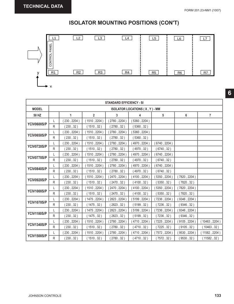
133JOHNSON CONTROLS
FORM 201.23-NM1 (1007)
6
TECHNICAL DATA
ISOLATOR MOUNTING POSITIONS (CON'T)
STANDARD EFFICIENCY - SI
MODEL ISOLATOR LOCATIONS ( X , Y ) - MM
50 HZ 1 2 3 4 5 6 7
YCIV0600S/PL ( 230 , 2204 ) ( 1510 , 2204 ) ( 2780 , 2204 ) ( 5360 , 2204 ) R ( 230 , 32 ) ( 1510 , 32 ) ( 2780 , 32 ) ( 5360 , 32 )
YCIV0650S/PL ( 230 , 2204 ) ( 1510 , 2204 ) ( 2780 , 2204 ) ( 5360 , 2204 ) R ( 230 , 32 ) ( 1510 , 32 ) ( 2780 , 32 ) ( 5360 , 32 )
YCIV0720S/PL ( 230 , 2204 ) ( 1510 , 2204 ) ( 2780 , 2204 ) ( 4970 , 2204 ) ( 6740 , 2204 ) R ( 230 , 32 ) ( 1510 , 32 ) ( 2780 , 32 ) ( 4970 , 32 ) ( 6740 , 32 )
YCIV0770S/PL ( 230 , 2204 ) ( 1510 , 2204 ) ( 2780 , 2204 ) ( 4970 , 2204 ) ( 6740 , 2204 ) R ( 230 , 32 ) ( 1510 , 32 ) ( 2780 , 32 ) ( 4970 , 32 ) ( 6740 , 32 )
YCIV0840S/PL ( 230 , 2204 ) ( 1510 , 2204 ) ( 2780 , 2204 ) ( 4970 , 2204 ) ( 6740 , 2204 ) R ( 230 , 32 ) ( 1510 , 32 ) ( 2780 , 32 ) ( 4970 , 32 ) ( 6740 , 32 )
YCIV0920S/PL ( 230 , 2204 ) ( 1510 , 2204 ) ( 2470 , 2204 ) ( 4100 , 2204 ) ( 5350 , 2204 ) ( 7820 , 2204 ) R ( 230 , 32 ) ( 1510 , 32 ) ( 2470 , 32 ) ( 4100 , 32 ) ( 5350 , 32 ) ( 7820 , 32 )
YCIV1000S/PL ( 230 , 2204 ) ( 1510 , 2204 ) ( 2470 , 2204 ) ( 4100 , 2204 ) ( 5350 , 2204 ) ( 7820 , 2204 ) R ( 230 , 32 ) ( 1510 , 32 ) ( 2470 , 32 ) ( 4100 , 32 ) ( 5350 , 32 ) ( 7820 , 32 )
YCIV1070S/PL ( 230 , 2204 ) ( 1475 , 2204 ) ( 2823 , 2204 ) ( 5199 , 2204 ) ( 7236 , 2204 ) ( 9346 , 2204 ) R ( 230 , 32 ) ( 1475 , 32 ) ( 2823 , 32 ) ( 5199 , 32 ) ( 7236 , 32 ) ( 9346 , 32 )
YCIV1180S/PL ( 230 , 2204 ) ( 1475 , 2204 ) ( 2823 , 2204 ) ( 5199 , 2204 ) ( 7236 , 2204 ) ( 9346 , 2204 ) R ( 230 , 32 ) ( 1475 , 32 ) ( 2823 , 32 ) ( 5199 , 32 ) ( 7236 , 32 ) ( 9346 , 32 )
YCIV1340S/PL ( 230 , 2204 ) ( 1510 , 2204 ) ( 2780 , 2204 ) ( 4710 , 2204 ) ( 7225 , 2204 ) ( 9105 , 2204 ) ( 10463 , 2204 ) R ( 230 , 32 ) ( 1510 , 32 ) ( 2780 , 32 ) ( 4710 , 32 ) ( 7225 , 32 ) ( 9105 , 32 ) ( 10463 , 32 )
YCIV1500S/PL ( 230 , 2204 ) ( 1510 , 2204 ) ( 2780 , 2204 ) ( 4710 , 2204 ) ( 7572 , 2204 ) ( 9530 , 2204 ) ( 11582 , 2204 ) R ( 230 , 32 ) ( 1510 , 32 ) ( 2780 , 32 ) ( 4710 , 32 ) ( 7572 , 32 ) ( 9530 , 32 ) ( 11582 , 32 )
CO
NTR
OL
PA
NE
L
L1 L2
R6R1
L6L5L4L3
R2 R3 R4 R5 R7
L7
x
y
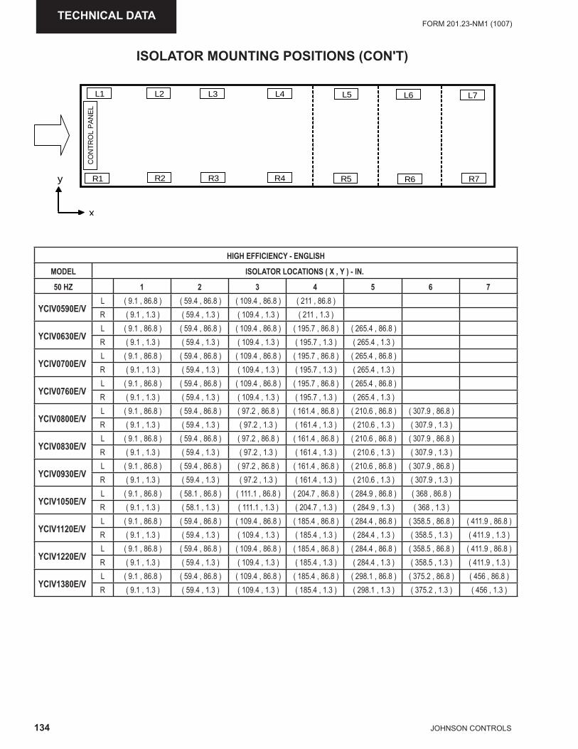
134 JOHNSON CONTROLS
FORM 201.23-NM1 (1007)TECHNICAL DATA
ISOLATOR MOUNTING POSITIONS (CON'T)
HIGH EFFICIENCY - ENGLISH
MODEL ISOLATOR LOCATIONS ( X , Y ) - IN.
50 HZ 1 2 3 4 5 6 7
YCIV0590E/VL ( 9.1 , 86.8 ) ( 59.4 , 86.8 ) ( 109.4 , 86.8 ) ( 211 , 86.8 ) R ( 9.1 , 1.3 ) ( 59.4 , 1.3 ) ( 109.4 , 1.3 ) ( 211 , 1.3 )
YCIV0630E/VL ( 9.1 , 86.8 ) ( 59.4 , 86.8 ) ( 109.4 , 86.8 ) ( 195.7 , 86.8 ) ( 265.4 , 86.8 ) R ( 9.1 , 1.3 ) ( 59.4 , 1.3 ) ( 109.4 , 1.3 ) ( 195.7 , 1.3 ) ( 265.4 , 1.3 )
YCIV0700E/VL ( 9.1 , 86.8 ) ( 59.4 , 86.8 ) ( 109.4 , 86.8 ) ( 195.7 , 86.8 ) ( 265.4 , 86.8 ) R ( 9.1 , 1.3 ) ( 59.4 , 1.3 ) ( 109.4 , 1.3 ) ( 195.7 , 1.3 ) ( 265.4 , 1.3 )
YCIV0760E/VL ( 9.1 , 86.8 ) ( 59.4 , 86.8 ) ( 109.4 , 86.8 ) ( 195.7 , 86.8 ) ( 265.4 , 86.8 ) R ( 9.1 , 1.3 ) ( 59.4 , 1.3 ) ( 109.4 , 1.3 ) ( 195.7 , 1.3 ) ( 265.4 , 1.3 )
YCIV0800E/VL ( 9.1 , 86.8 ) ( 59.4 , 86.8 ) ( 97.2 , 86.8 ) ( 161.4 , 86.8 ) ( 210.6 , 86.8 ) ( 307.9 , 86.8 ) R ( 9.1 , 1.3 ) ( 59.4 , 1.3 ) ( 97.2 , 1.3 ) ( 161.4 , 1.3 ) ( 210.6 , 1.3 ) ( 307.9 , 1.3 )
YCIV0830E/VL ( 9.1 , 86.8 ) ( 59.4 , 86.8 ) ( 97.2 , 86.8 ) ( 161.4 , 86.8 ) ( 210.6 , 86.8 ) ( 307.9 , 86.8 ) R ( 9.1 , 1.3 ) ( 59.4 , 1.3 ) ( 97.2 , 1.3 ) ( 161.4 , 1.3 ) ( 210.6 , 1.3 ) ( 307.9 , 1.3 )
YCIV0930E/VL ( 9.1 , 86.8 ) ( 59.4 , 86.8 ) ( 97.2 , 86.8 ) ( 161.4 , 86.8 ) ( 210.6 , 86.8 ) ( 307.9 , 86.8 ) R ( 9.1 , 1.3 ) ( 59.4 , 1.3 ) ( 97.2 , 1.3 ) ( 161.4 , 1.3 ) ( 210.6 , 1.3 ) ( 307.9 , 1.3 )
YCIV1050E/VL ( 9.1 , 86.8 ) ( 58.1 , 86.8 ) ( 111.1 , 86.8 ) ( 204.7 , 86.8 ) ( 284.9 , 86.8 ) ( 368 , 86.8 ) R ( 9.1 , 1.3 ) ( 58.1 , 1.3 ) ( 111.1 , 1.3 ) ( 204.7 , 1.3 ) ( 284.9 , 1.3 ) ( 368 , 1.3 )
YCIV1120E/VL ( 9.1 , 86.8 ) ( 59.4 , 86.8 ) ( 109.4 , 86.8 ) ( 185.4 , 86.8 ) ( 284.4 , 86.8 ) ( 358.5 , 86.8 ) ( 411.9 , 86.8 ) R ( 9.1 , 1.3 ) ( 59.4 , 1.3 ) ( 109.4 , 1.3 ) ( 185.4 , 1.3 ) ( 284.4 , 1.3 ) ( 358.5 , 1.3 ) ( 411.9 , 1.3 )
YCIV1220E/VL ( 9.1 , 86.8 ) ( 59.4 , 86.8 ) ( 109.4 , 86.8 ) ( 185.4 , 86.8 ) ( 284.4 , 86.8 ) ( 358.5 , 86.8 ) ( 411.9 , 86.8 ) R ( 9.1 , 1.3 ) ( 59.4 , 1.3 ) ( 109.4 , 1.3 ) ( 185.4 , 1.3 ) ( 284.4 , 1.3 ) ( 358.5 , 1.3 ) ( 411.9 , 1.3 )
YCIV1380E/VL ( 9.1 , 86.8 ) ( 59.4 , 86.8 ) ( 109.4 , 86.8 ) ( 185.4 , 86.8 ) ( 298.1 , 86.8 ) ( 375.2 , 86.8 ) ( 456 , 86.8 ) R ( 9.1 , 1.3 ) ( 59.4 , 1.3 ) ( 109.4 , 1.3 ) ( 185.4 , 1.3 ) ( 298.1 , 1.3 ) ( 375.2 , 1.3 ) ( 456 , 1.3 )
CO
NTR
OL
PA
NE
LL1 L2
R6R1
L6L5L4L3
R2 R3 R4 R5 R7
L7
x
y
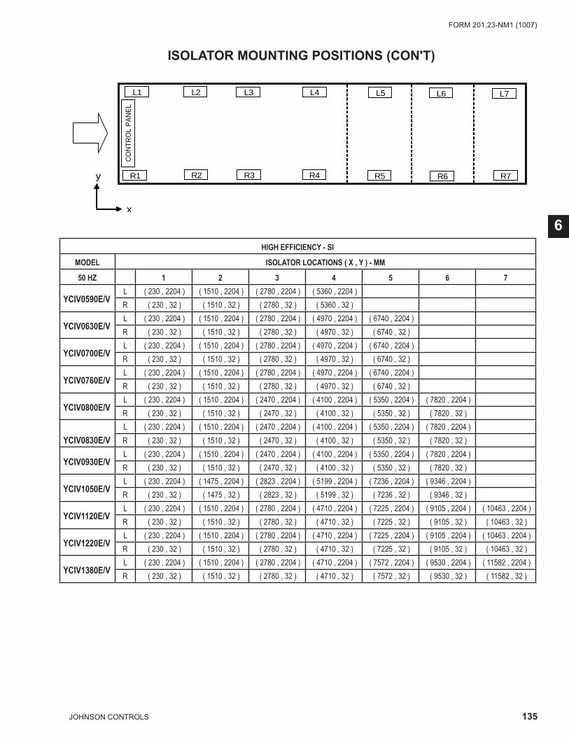
135JOHNSON CONTROLS
FORM 201.23-NM1 (1007)
6HIGH EFFICIENCY - SI
MODEL ISOLATOR LOCATIONS ( X , Y ) - MM
50 HZ 1 2 3 4 5 6 7
YCIV0590E/VL ( 230 , 2204 ) ( 1510 , 2204 ) ( 2780 , 2204 ) ( 5360 , 2204 ) R ( 230 , 32 ) ( 1510 , 32 ) ( 2780 , 32 ) ( 5360 , 32 )
YCIV0630E/VL ( 230 , 2204 ) ( 1510 , 2204 ) ( 2780 , 2204 ) ( 4970 , 2204 ) ( 6740 , 2204 ) R ( 230 , 32 ) ( 1510 , 32 ) ( 2780 , 32 ) ( 4970 , 32 ) ( 6740 , 32 )
YCIV0700E/VL ( 230 , 2204 ) ( 1510 , 2204 ) ( 2780 , 2204 ) ( 4970 , 2204 ) ( 6740 , 2204 ) R ( 230 , 32 ) ( 1510 , 32 ) ( 2780 , 32 ) ( 4970 , 32 ) ( 6740 , 32 )
YCIV0760E/VL ( 230 , 2204 ) ( 1510 , 2204 ) ( 2780 , 2204 ) ( 4970 , 2204 ) ( 6740 , 2204 ) R ( 230 , 32 ) ( 1510 , 32 ) ( 2780 , 32 ) ( 4970 , 32 ) ( 6740 , 32 )
YCIV0800E/VL ( 230 , 2204 ) ( 1510 , 2204 ) ( 2470 , 2204 ) ( 4100 , 2204 ) ( 5350 , 2204 ) ( 7820 , 2204 ) R ( 230 , 32 ) ( 1510 , 32 ) ( 2470 , 32 ) ( 4100 , 32 ) ( 5350 , 32 ) ( 7820 , 32 )
YCIV0830E/VL ( 230 , 2204 ) ( 1510 , 2204 ) ( 2470 , 2204 ) ( 4100 , 2204 ) ( 5350 , 2204 ) ( 7820 , 2204 ) R ( 230 , 32 ) ( 1510 , 32 ) ( 2470 , 32 ) ( 4100 , 32 ) ( 5350 , 32 ) ( 7820 , 32 )
YCIV0930E/VL ( 230 , 2204 ) ( 1510 , 2204 ) ( 2470 , 2204 ) ( 4100 , 2204 ) ( 5350 , 2204 ) ( 7820 , 2204 ) R ( 230 , 32 ) ( 1510 , 32 ) ( 2470 , 32 ) ( 4100 , 32 ) ( 5350 , 32 ) ( 7820 , 32 )
YCIV1050E/VL ( 230 , 2204 ) ( 1475 , 2204 ) ( 2823 , 2204 ) ( 5199 , 2204 ) ( 7236 , 2204 ) ( 9346 , 2204 ) R ( 230 , 32 ) ( 1475 , 32 ) ( 2823 , 32 ) ( 5199 , 32 ) ( 7236 , 32 ) ( 9346 , 32 )
YCIV1120E/VL ( 230 , 2204 ) ( 1510 , 2204 ) ( 2780 , 2204 ) ( 4710 , 2204 ) ( 7225 , 2204 ) ( 9105 , 2204 ) ( 10463 , 2204 ) R ( 230 , 32 ) ( 1510 , 32 ) ( 2780 , 32 ) ( 4710 , 32 ) ( 7225 , 32 ) ( 9105 , 32 ) ( 10463 , 32 )
YCIV1220E/VL ( 230 , 2204 ) ( 1510 , 2204 ) ( 2780 , 2204 ) ( 4710 , 2204 ) ( 7225 , 2204 ) ( 9105 , 2204 ) ( 10463 , 2204 ) R ( 230 , 32 ) ( 1510 , 32 ) ( 2780 , 32 ) ( 4710 , 32 ) ( 7225 , 32 ) ( 9105 , 32 ) ( 10463 , 32 )
YCIV1380E/VL ( 230 , 2204 ) ( 1510 , 2204 ) ( 2780 , 2204 ) ( 4710 , 2204 ) ( 7572 , 2204 ) ( 9530 , 2204 ) ( 11582 , 2204 ) R ( 230 , 32 ) ( 1510 , 32 ) ( 2780 , 32 ) ( 4710 , 32 ) ( 7572 , 32 ) ( 9530 , 32 ) ( 11582 , 32 )
CO
NTR
OL
PA
NE
L
L1 L2
R6R1
L6L5L4L3
R2 R3 R4 R5 R7
L7
x
y
ISOLATOR MOUNTING POSITIONS (CON'T)
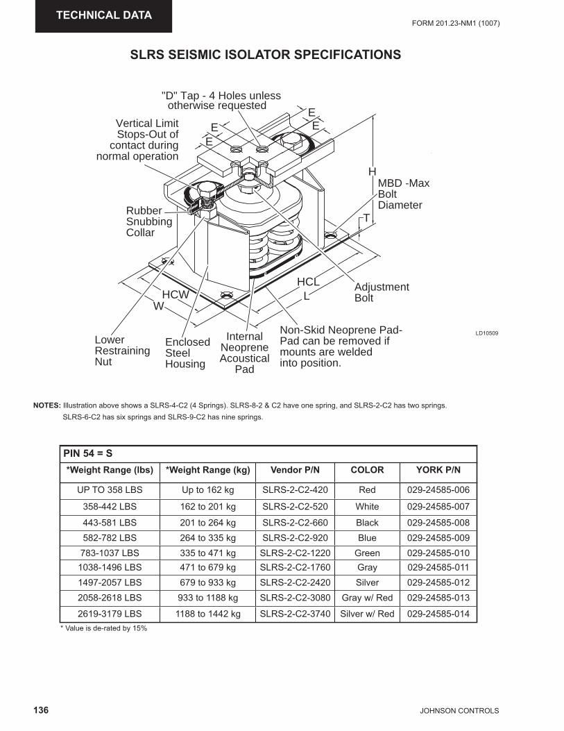
136 JOHNSON CONTROLS
FORM 201.23-NM1 (1007)TECHNICAL DATA
EE
EE
H
T
HCWW
LHCL
"D" Tap - 4 Holes unless otherwise requested
AdjustmentBolt
Vertical LimitStops-Out of
contact duringnormal operation
Non-Skid Neoprene Pad-Pad can be removed ifmounts are weldedinto position.
EnclosedSteelHousing
InternalNeopreneAcoustical
Pad
LowerRestrainingNut
RubberSnubbingCollar
MBD -MaxBoltDiameter
SLRS SEISMIC ISOLATOR SPECIFICATIONS
LD10509
NOTES: Illustration above shows a SLRS-4-C2 (4 Springs). SLRS-8-2 & C2 have one spring, and SLRS-2-C2 has two springs. SLRS-6-C2 has six springs and SLRS-9-C2 has nine springs.
* Value is de-rated by 15%
PIN 54 = S*Weight Range (lbs) *Weight Range (kg) Vendor P/N COLOR YORK P/N
UP TO 358 LBS Up to 162 kg SLRS-2-C2-420 Red 029-24585-006
358-442 LBS 162 to 201 kg SLRS-2-C2-520 White 029-24585-007
443-581 LBS 201 to 264 kg SLRS-2-C2-660 Black 029-24585-008582-782 LBS 264 to 335 kg SLRS-2-C2-920 Blue 029-24585-009
783-1037 LBS 335 to 471 kg SLRS-2-C2-1220 Green 029-24585-0101038-1496 LBS 471 to 679 kg SLRS-2-C2-1760 Gray 029-24585-0111497-2057 LBS 679 to 933 kg SLRS-2-C2-2420 Silver 029-24585-0122058-2618 LBS 933 to 1188 kg SLRS-2-C2-3080 Gray w/ Red 029-24585-013
2619-3179 LBS 1188 to 1442 kg SLRS-2-C2-3740 Silver w/ Red 029-24585-014
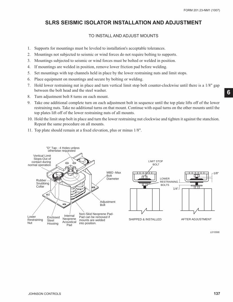
137JOHNSON CONTROLS
FORM 201.23-NM1 (1007)
6
SLRS SEISMIC ISOLATOR INSTALLATION AND ADJUSTMENT
TO INSTALL AND ADJUST MOUNTS
1. Supports for mountings must be leveled to installation's acceptable tolerances.2. Mountings not subjected to seismic or wind forces do not require bolting to supports.3. Mountings subjected to seismic or wind forces must be bolted or welded in position.4. If mountings are welded in position, remove lower friction pad before welding.5. Set mountings with top channels held in place by the lower restraining nuts and limit stops.6. Place equipment on mountings and secure by bolting or welding.7. Hold lower restraining nut in place and turn vertical limit stop bolt counter-clockwise until there is a 1/8" gap
between the bolt head and the steel washer.8. Turn adjustment bolt 8 turns on each mount.9. Take one additional complete turn on each adjustment bolt in sequence until the top plate lifts off of the lower
restraining nuts. Take no additional turns on that mount. Continue with equal turns on the other mounts until the top plates lift off of the lower restraining nuts of all mounts.
10. Hold the limit stop bolt in place and turn the lower restraining nut clockwise and tighten it against the stanchion. Repeat the same procedure on all mounts.
11. Top plate should remain at a fi xed elevation, plus or minus 1/8".
"D" Tap - 4 Holes unless otherwise requested
AdjustmentBolt
Vertical LimitStops-Out of
contact duringnormal operation
Non-Skid Neoprene Pad-Pad can be removed ifmounts are weldedinto position.
EnclosedSteelHousing
InternalNeopreneAcoustical
Pad
LowerRestrainingNut
RubberSnubbingCollar
MBD -MaxBoltDiameter
SHIPPED & INSTALLED AFTER ADJUSTMENT
1/4"
1/8"
LIMIT STOP BOLT
LOWER RESTRAINING BOLTS
LD10568
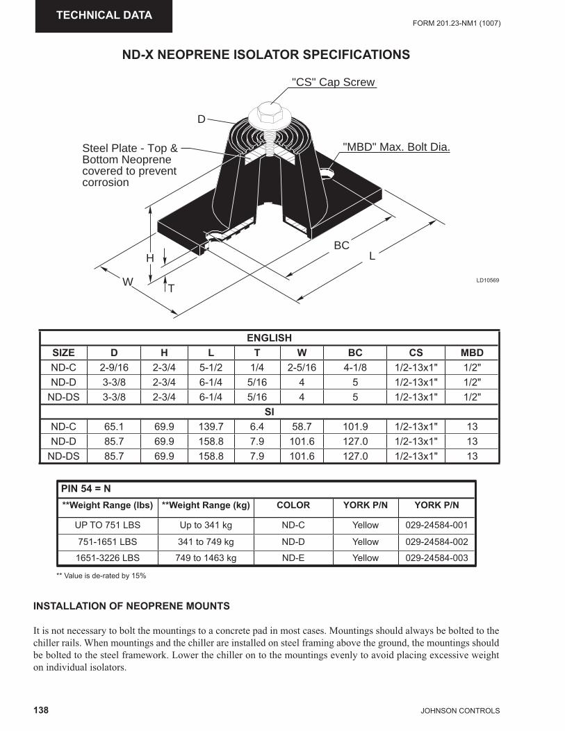
138 JOHNSON CONTROLS
FORM 201.23-NM1 (1007)TECHNICAL DATA
PIN 54 = N**Weight Range (lbs) **Weight Range (kg) COLOR YORK P/N YORK P/N
UP TO 751 LBS Up to 341 kg ND-C Yellow 029-24584-001
751-1651 LBS 341 to 749 kg ND-D Yellow 029-24584-002
1651-3226 LBS 749 to 1463 kg ND-E Yellow 029-24584-003
ND-X NEOPRENE ISOLATOR SPECIFICATIONS
"CS" Cap Screw
BC
"MBD" Max. Bolt Dia.Steel Plate - Top &Bottom Neoprenecovered to preventcorrosion
L
T
H
W
D
** Value is de-rated by 15%
INSTALLATION OF NEOPRENE MOUNTS
It is not necessary to bolt the mountings to a concrete pad in most cases. Mountings should always be bolted to the chiller rails. When mountings and the chiller are installed on steel framing above the ground, the mountings should be bolted to the steel framework. Lower the chiller on to the mountings evenly to avoid placing excessive weight on individual isolators.
LD10569
ENGLISHSIZE D H L T W BC CS MBDND-C 2-9/16 2-3/4 5-1/2 1/4 2-5/16 4-1/8 1/2-13x1" 1/2"ND-D 3-3/8 2-3/4 6-1/4 5/16 4 5 1/2-13x1" 1/2"
ND-DS 3-3/8 2-3/4 6-1/4 5/16 4 5 1/2-13x1" 1/2"SI
ND-C 65.1 69.9 139.7 6.4 58.7 101.9 1/2-13x1" 13ND-D 85.7 69.9 158.8 7.9 101.6 127.0 1/2-13x1" 13
ND-DS 85.7 69.9 158.8 7.9 101.6 127.0 1/2-13x1" 13
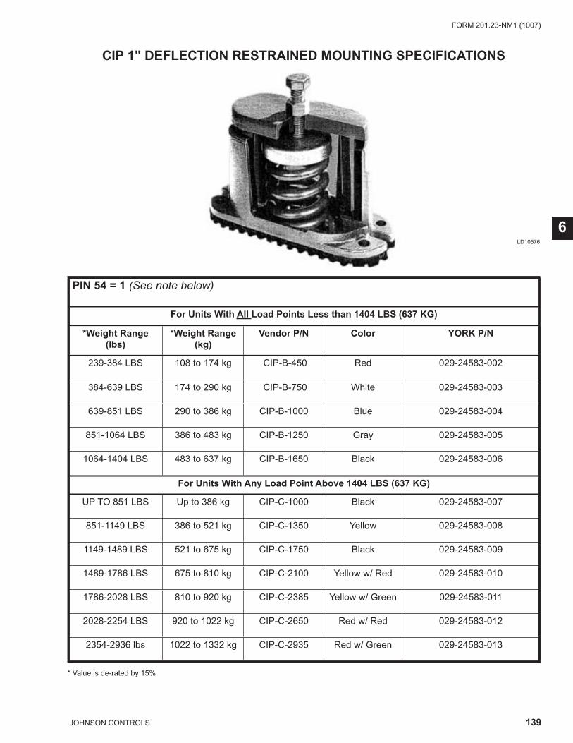
139JOHNSON CONTROLS
FORM 201.23-NM1 (1007)
6
CIP 1" DEFLECTION RESTRAINED MOUNTING SPECIFICATIONS
LD10576
PIN 54 = 1 (See note below)
For Units With All Load Points Less than 1404 LBS (637 KG)
*Weight Range (lbs)
*Weight Range (kg)
Vendor P/N Color YORK P/N
239-384 LBS 108 to 174 kg CIP-B-450 Red 029-24583-002
384-639 LBS 174 to 290 kg CIP-B-750 White 029-24583-003
639-851 LBS 290 to 386 kg CIP-B-1000 Blue 029-24583-004
851-1064 LBS 386 to 483 kg CIP-B-1250 Gray 029-24583-005
1064-1404 LBS 483 to 637 kg CIP-B-1650 Black 029-24583-006
For Units With Any Load Point Above 1404 LBS (637 KG)
UP TO 851 LBS Up to 386 kg CIP-C-1000 Black 029-24583-007
851-1149 LBS 386 to 521 kg CIP-C-1350 Yellow 029-24583-008
1149-1489 LBS 521 to 675 kg CIP-C-1750 Black 029-24583-009
1489-1786 LBS 675 to 810 kg CIP-C-2100 Yellow w/ Red 029-24583-010
1786-2028 LBS 810 to 920 kg CIP-C-2385 Yellow w/ Green 029-24583-011
2028-2254 LBS 920 to 1022 kg CIP-C-2650 Red w/ Red 029-24583-012
2354-2936 lbs 1022 to 1332 kg CIP-C-2935 Red w/ Green 029-24583-013
* Value is de-rated by 15%
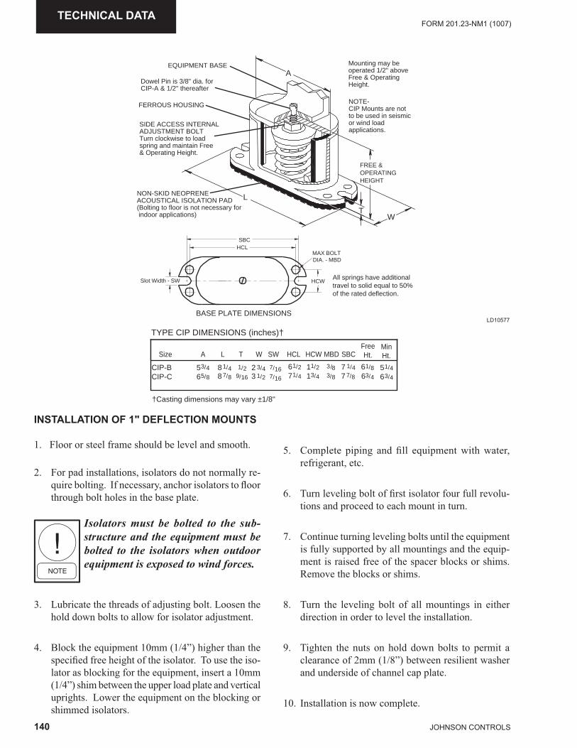
140 JOHNSON CONTROLS
FORM 201.23-NM1 (1007)TECHNICAL DATA
INSTALLATION OF 1" DEFLECTION MOUNTS
1. Floor or steel frame should be level and smooth.
2. For pad installations, isolators do not normally re-quire bolting. If necessary, anchor isolators to fl oor through bolt holes in the base plate.
Isolators must be bolted to the sub-structure and the equipment must be bolted to the isolators when outdoor equipment is exposed to wind forces.
3. Lubricate the threads of adjusting bolt. Loosen the hold down bolts to allow for isolator adjustment.
4. Block the equipment 10mm (1/4”) higher than the specifi ed free height of the isolator. To use the iso-lator as blocking for the equipment, insert a 10mm (1/4”) shim between the upper load plate and vertical uprights. Lower the equipment on the blocking or shimmed isolators.
5. Complete piping and fi ll equipment with water, refrigerant, etc.
6. Turn leveling bolt of fi rst isolator four full revolu-tions and proceed to each mount in turn.
7. Continue turning leveling bolts until the equipment is fully supported by all mountings and the equip-ment is raised free of the spacer blocks or shims. Remove the blocks or shims.
8. Turn the leveling bolt of all mountings in either direction in order to level the installation.
9. Tighten the nuts on hold down bolts to permit a clearance of 2mm (1/8”) between resilient washer and underside of channel cap plate.
10. Installation is now complete.
HCLSBC
Slot Width - SW HCW
MAX BOLTDIA. - MBD
BASE PLATE DIMENSIONS
NON-SKID NEOPRENEACOUSTICAL ISOLATION PAD(Bolting to floor is not necessary for indoor applications)
All springs have additionaltravel to solid equal to 50%of the rated deflection.
A
L
FREE &OPERATINGHEIGHT
TW
FERROUS HOUSING
SIDE ACCESS INTERNALADJUSTMENT BOLTTurn clockwise to loadspring and maintain Free& Operating Height.
Dowel Pin is 3/8" dia. forCIP-A & 1/2" thereafter
Mounting may beoperated 1/2" aboveFree & OperatingHeight.
NOTE-CIP Mounts are notto be used in seismic or wind loadapplications.
EQUIPMENT BASE
TYPE CIP DIMENSIONS (inches)†
†Casting dimensions may vary ±1/8"
Size A L T W SW HCL HCW MBD SBCFreeHt.
CIP-B 8 /4 /2 /16 8CIP-C 6 /8 /16 /85
1 1 77
33
/8 1
6 /4 3/5 /43
8 /87 /1692 /433 /21
/2/4
11
67
/2/4
13
11
/4/8
17
77
MinHt.
5 /4 1
6 /4 3
6
LD10577
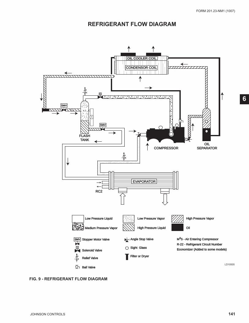
141JOHNSON CONTROLS
FORM 201.23-NM1 (1007)
6
RC2RC2
Low Pressure VaporLow Pressure Vapor
High Pressure LiquidHigh Pressure Liquid
High Pressure VaporHigh Pressure Vapor
OilOil
Low Pressure LiquidLow Pressure Liquid
Medium Pressure VaporMedium Pressure Vapor
Economizer (Added to some models)Economizer (Added to some models)
COMPRESSORCOMPRESSOR
Stopper Motor ValveStopper Motor Valve Angle Stop ValveAngle Stop Valve M3S - Air Entering Compressor S - Air Entering Compressor
R-22 - Refrigerant Circuit NumberR-22 - Refrigerant Circuit NumberSight GlassSight Glass
Filter or DryerFilter or Dryer
Solenoid ValveSolenoid Valve
Relief ValveRelief Valve
Ball ValveBall Valve
OILOILSEPARATORSEPARATOR
EVAPORATOREVAPORATOR
CONDENSOR COILCONDENSOR COIL
OIL COOLER COILOIL COOLER COIL
S
S
SMVSMV
SMVSMV
FLASHFLASHTANKTANK
SMVSMV
FIG. 9 - REFRIGERANT FLOW DIAGRAM
REFRIGERANT FLOW DIAGRAM
LD10505
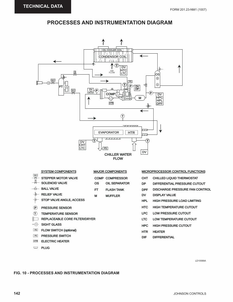
142 JOHNSON CONTROLS
FORM 201.23-NM1 (1007)TECHNICAL DATA
PROCESSES AND INSTRUMENTATION DIAGRAM
FIG. 10 - PROCESSES AND INSTRUMENTATION DIAGRAM
LD10589A
CHILLER WATERCHILLER WATERFLOWFLOW
SYSTEM COMPONENTS
STEPPER MOTOR VALVESTEPPER MOTOR VALVE
SEPARATOROILOIL SEPARATOR
FLASH TANKFLASH TANK
MUFFLER
OS
COMPRESSORCOMP
FT
M
CHILLED LIQUID THERMOSTATCHILLED LIQUID THERMOSTAT
DIFFERENTIAL PRESSURE CUTOUTDIFFERENTIAL PRESSURE CUTOUT
DISCHARGE PRESSURE FAN CONTROLDISCHARGE PRESSURE FAN CONTROL
DISPLAY VALUEDISPLAY VALUE
HIGH PRESSURE LOAD LIMITINGHIGH PRESSURE LOAD LIMITING
HIGH TEMPERATURE CUTOUTHIGH TEMPERATURE CUTOUT
LOW PRESSURE CUTOUTLOW PRESSURE CUTOUT
CHT
DP
DV
HPL
HTC
LPC
LOW TEMPERATURE CUTOUTLOW TEMPERATURE CUTOUT
HIGH PRESSURE CUTOUTHIGH PRESSURE CUTOUT
HEATERHEATER
LTCLTC
HPC
HTR
SOLENOID VALVESOLENOID VALVE
BALL VALVEBALL VALVE
RELIEF VALVERELIEF VALVE
STOP VALVE ANGLE, ACCESSSTOP VALVE ANGLE, ACCESS
PRESSURE SENSORPRESSURE SENSOR
TEMPERATURE SENSORTEMPERATURE SENSOR
REPLACEABLE CORE FILTER/DRYERREPLACEABLE CORE FILTER/DRYER
SIGHT GLASSSIGHT GLASS
FLOW SWITCH (optional)
PRESSURE SWITCHPRESSURE SWITCH
ELECTRIC HEATERELECTRIC HEATER
PLUG
MICROPROCESSOR CONTROL FUNCTIONSMICROPROCESSOR CONTROL FUNCTIONSMAJOR COMPONENTS
P
T
T T
PPT
T
P
S
SMV
FS
PS
HTR
SMV
SMV
DV
M
DVCHTLTCLTC
HTRHTR
S
ZAIR
FLOW
ZZ
DVHTCLTCLTC
T
HTR
DVLPC
CONDENSOR COIL
OIL COOLER COILOIL COOLER COIL
EVAPORATOREVAPORATOR
FS
PS
DVHPCHPLDPF
FT
OS
COMP
DVDVDIFDIF
DIFDIF
DPFDPF
DIFFERENTIALDIFFERENTIAL
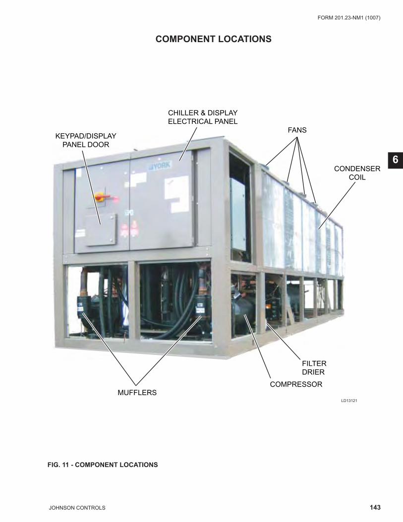
143JOHNSON CONTROLS
FORM 201.23-NM1 (1007)
6
COMPONENT LOCATIONS
FIG. 11 - COMPONENT LOCATIONS
KEYPAD/DISPLAYPANEL DOOR
CHILLER & DISPLAYELECTRICAL PANEL
FANS
CONDENSERCOIL
FILTERDRIER
COMPRESSORMUFFLERS
LD13121
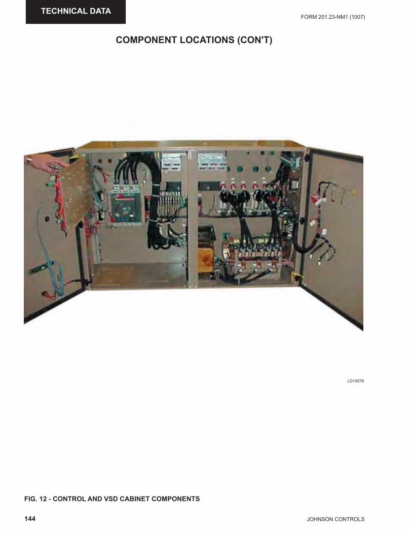
144 JOHNSON CONTROLS
FORM 201.23-NM1 (1007)TECHNICAL DATA
FIG. 12 - CONTROL AND VSD CABINET COMPONENTS
COMPONENT LOCATIONS (CON'T)
LD10578
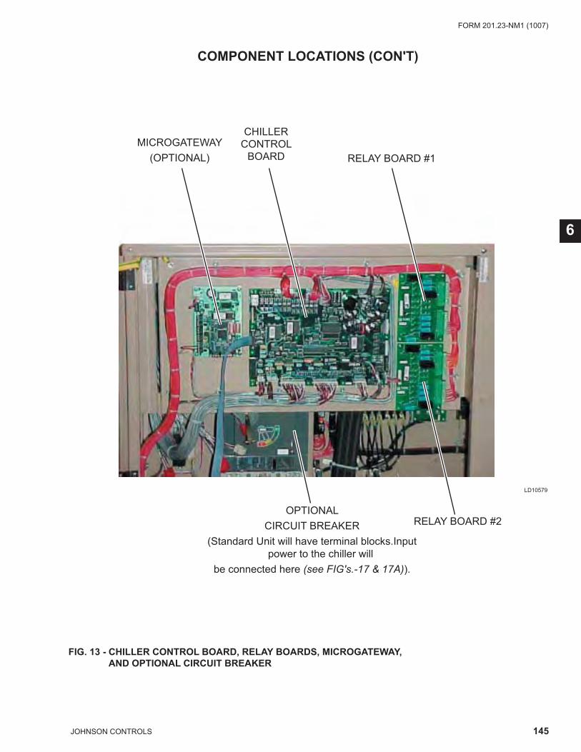
145JOHNSON CONTROLS
FORM 201.23-NM1 (1007)
6
COMPONENT LOCATIONS (CON'T)
FIG. 13 - CHILLER CONTROL BOARD, RELAY BOARDS, MICROGATEWAY, AND OPTIONAL CIRCUIT BREAKER
LD10579
MICROGATEWAY(OPTIONAL)
CHILLERCONTROL
BOARD RELAY BOARD #1
RELAY BOARD #2OPTIONAL
CIRCUIT BREAKER(Standard Unit will have terminal blocks.Input
power to the chiller willbe connected here (see FIG's.-17 & 17A)).
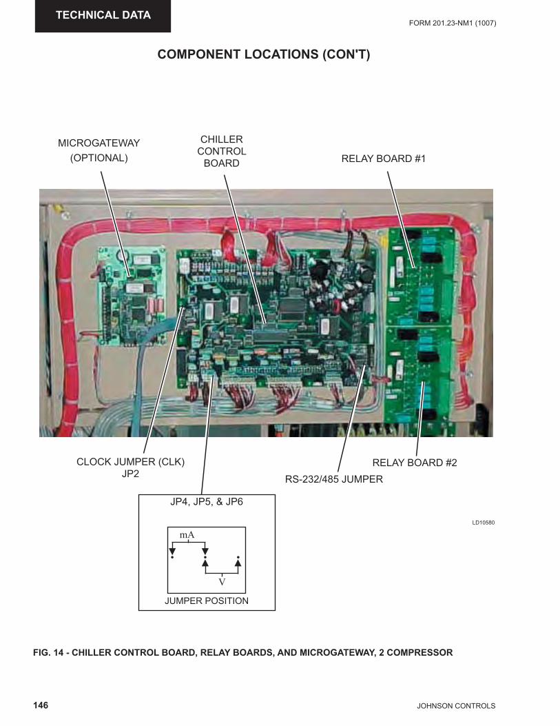
146 JOHNSON CONTROLS
FORM 201.23-NM1 (1007)TECHNICAL DATA
FIG. 14 - CHILLER CONTROL BOARD, RELAY BOARDS, AND MICROGATEWAY, 2 COMPRESSOR
COMPONENT LOCATIONS (CON'T)
LD10580
CHILLERCONTROL
BOARD
MICROGATEWAY(OPTIONAL) RELAY BOARD #1
RELAY BOARD #2RS-232/485 JUMPER
CLOCK JUMPER (CLK)JP2
JP4, JP5, & JP6
mA
• • •
V
▼▲ ▲
▼
JUMPER POSITION
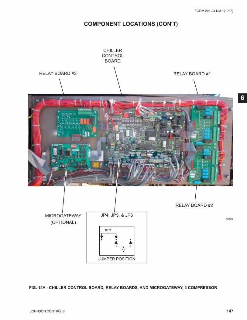
147JOHNSON CONTROLS
FORM 201.23-NM1 (1007)
6
FIG. 14A - CHILLER CONTROL BOARD, RELAY BOARDS, AND MICROGATEWAY, 3 COMPRESSOR
COMPONENT LOCATIONS (CON'T)
50069
CHILLERCONTROL
BOARD
RELAY BOARD #1
RELAY BOARD #2
RELAY BOARD #3
MICROGATEWAY(OPTIONAL)
JP4, JP5, & JP6
mA
• • •
V
▼▲ ▲
▼
JUMPER POSITION
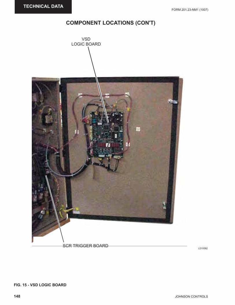
148 JOHNSON CONTROLS
FORM 201.23-NM1 (1007)TECHNICAL DATA
FIG. 15 - VSD LOGIC BOARD
LD10582
COMPONENT LOCATIONS (CON'T)
VSD LOGIC BOARD
SCR TRIGGER BOARD
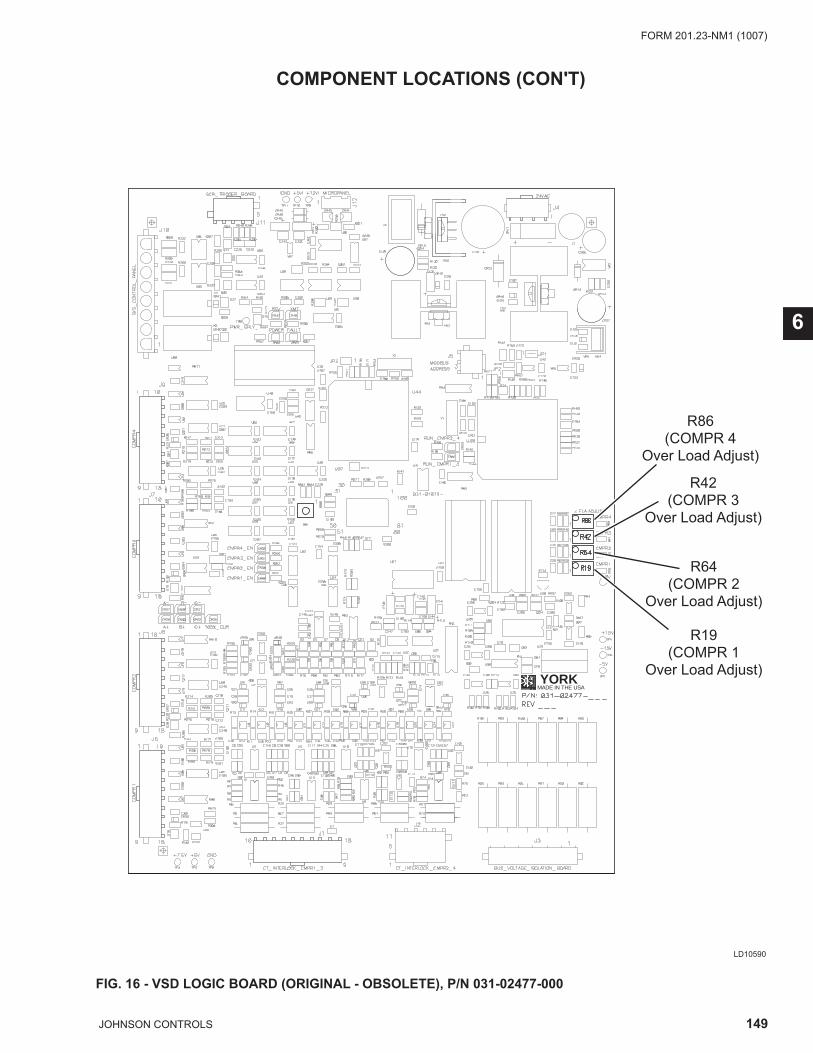
149JOHNSON CONTROLS
FORM 201.23-NM1 (1007)
6
FIG. 16 - VSD LOGIC BOARD (ORIGINAL - OBSOLETE), P/N 031-02477-000
LD10590
COMPONENT LOCATIONS (CON'T)
MADE IN THE USAYORK
R86(COMPR 4
Over Load Adjust)
R42(COMPR 3
Over Load Adjust)
R64(COMPR 2
Over Load Adjust)
R19(COMPR 1
Over Load Adjust)
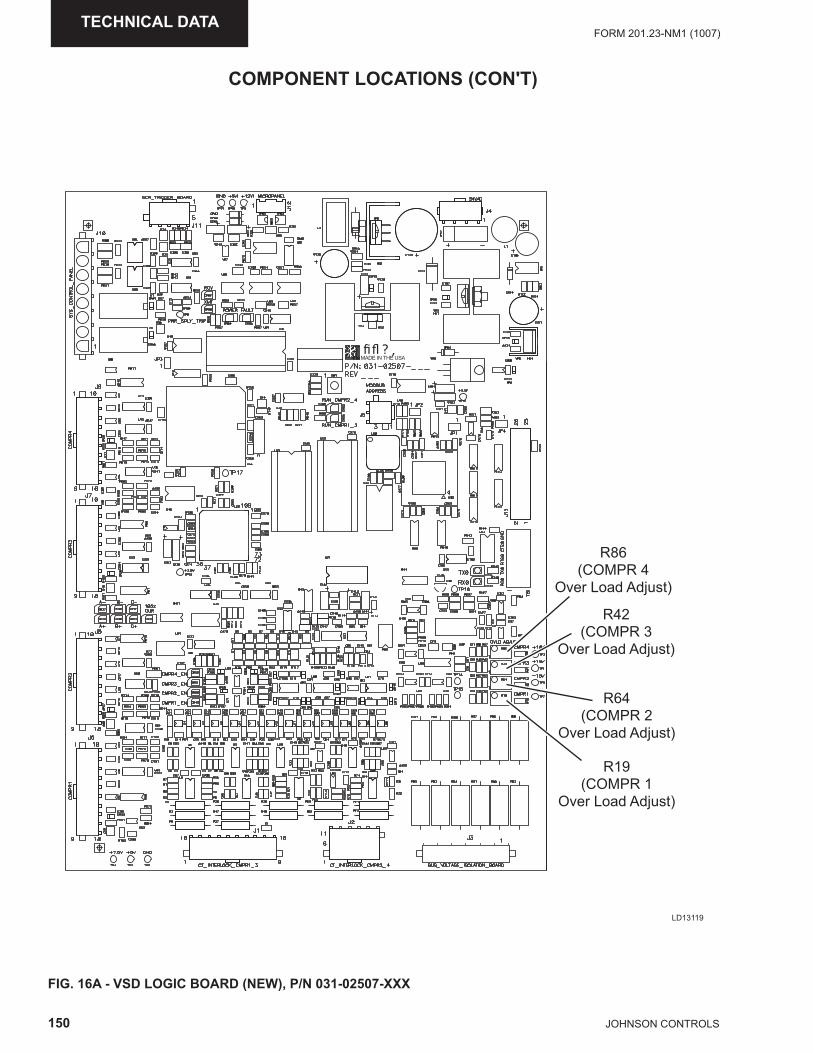
150 JOHNSON CONTROLS
FORM 201.23-NM1 (1007)TECHNICAL DATA
FIG. 16A - VSD LOGIC BOARD (NEW), P/N 031-02507-XXX
COMPONENT LOCATIONS (CON'T)
ASUEHTNIEDAM
LD13119
R86(COMPR 4
Over Load Adjust)
R42(COMPR 3
Over Load Adjust)
R64(COMPR 2
Over Load Adjust)
R19(COMPR 1
Over Load Adjust)
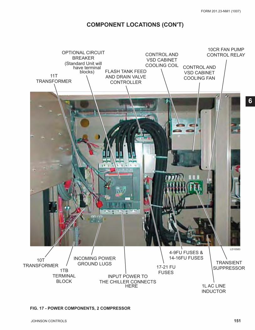
151JOHNSON CONTROLS
FORM 201.23-NM1 (1007)
6
FIG. 17 - POWER COMPONENTS, 2 COMPRESSOR
LD10583
COMPONENT LOCATIONS (CON'T)
11T TRANSFORMER
OPTIONAL CIRCUITBREAKER
(Standard Unit will have terminal
blocks) FLASH TANK FEEDAND DRAIN VALVE
CONTROLLER
CONTROL ANDVSD CABINETCOOLING COIL CONTROL AND
VSD CABINETCOOLING FAN
1TBTERMINAL
BLOCK
10T TRANSFORMER
INCOMING POWERGROUND LUGS
INPUT POWER TOTHE CHILLER CONNECTS
HERE
17-21 FUFUSES
4-9FU FUSES &14-16FU FUSES
TRANSIENT SUPPRESSOR
10CR FAN PUMPCONTROL RELAY
1L AC LINE INDUCTOR
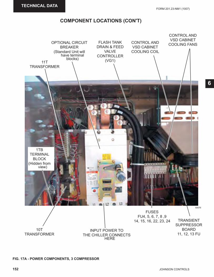
152 JOHNSON CONTROLS
FORM 201.23-NM1 (1007)TECHNICAL DATA
FIG. 17A - POWER COMPONENTS, 3 COMPRESSOR
COMPONENT LOCATIONS (CON'T)
50076
11T TRANSFORMER
OPTIONAL CIRCUITBREAKER
(Standard Unit will have terminal
blocks)
CONTROL ANDVSD CABINETCOOLING COIL
CONTROL ANDVSD CABINET
COOLING FANS
10T TRANSFORMER
INPUT POWER TOTHE CHILLER CONNECTS
HERE
TRANSIENT SUPPRESSOR
BOARD11, 12, 13 FU
6
FUSESFU4, 5, 6, 7, 8 ,9
14, 15, 16, 22, 23, 24
FLASH TANKDRAIN & FEED
VALVE CONTROLLER
(VG1)
1TBTERMINAL
BLOCK(Hidden from
view)
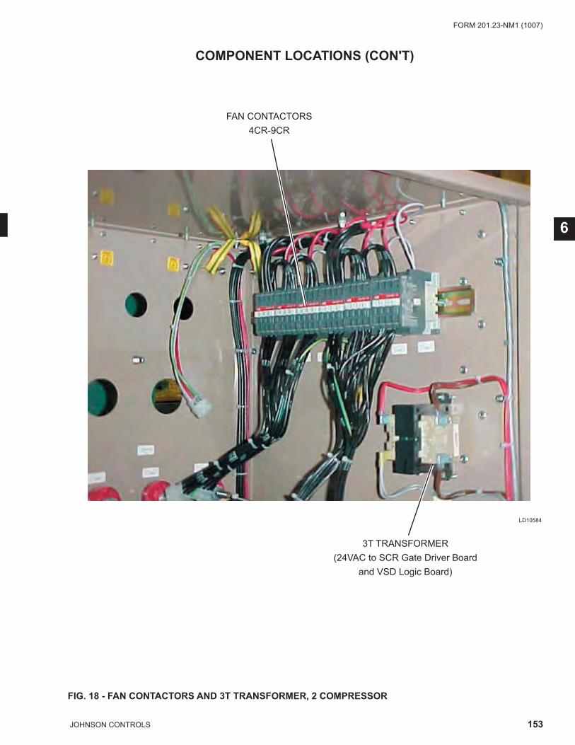
153JOHNSON CONTROLS
FORM 201.23-NM1 (1007)
6
FIG. 18 - FAN CONTACTORS AND 3T TRANSFORMER, 2 COMPRESSOR
COMPONENT LOCATIONS (CON'T)
LD10584
FAN CONTACTORS4CR-9CR
3T TRANSFORMER(24VAC to SCR Gate Driver Board
and VSD Logic Board)
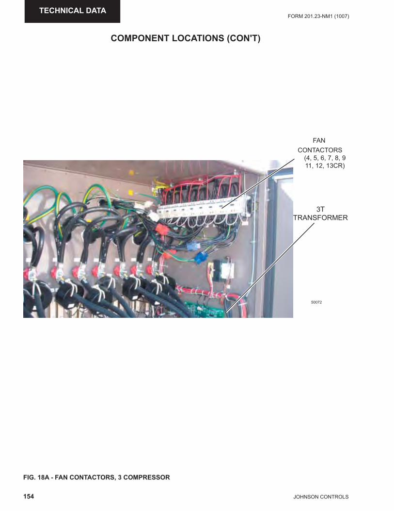
154 JOHNSON CONTROLS
FORM 201.23-NM1 (1007)TECHNICAL DATA
FIG. 18A - FAN CONTACTORS, 3 COMPRESSOR
COMPONENT LOCATIONS (CON'T)
50072
FAN CONTACTORS
(4, 5, 6, 7, 8, 911, 12, 13CR)
3TTRANSFORMER
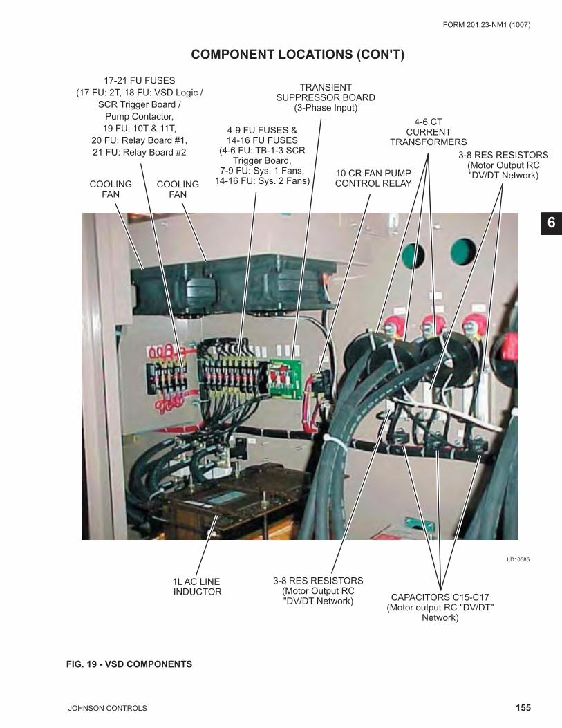
155JOHNSON CONTROLS
FORM 201.23-NM1 (1007)
6
FIG. 19 - VSD COMPONENTS
COMPONENT LOCATIONS (CON'T)
LD10585
COOLINGFAN
17-21 FU FUSES(17 FU: 2T, 18 FU: VSD Logic /
SCR Trigger Board / Pump Contactor,
19 FU: 10T & 11T, 20 FU: Relay Board #1,21 FU: Relay Board #2
COOLINGFAN
4-9 FU FUSES &14-16 FU FUSES
(4-6 FU: TB-1-3 SCRTrigger Board,
7-9 FU: Sys. 1 Fans,14-16 FU: Sys. 2 Fans)
TRANSIENTSUPPRESSOR BOARD
(3-Phase Input)
1L AC LINE INDUCTOR
4-6 CTCURRENT
TRANSFORMERS
10 CR FAN PUMPCONTROL RELAY
CAPACITORS C15-C17(Motor output RC "DV/DT"
Network)
3-8 RES RESISTORS(Motor Output RC"DV/DT Network)
3-8 RES RESISTORS(Motor Output RC"DV/DT Network)
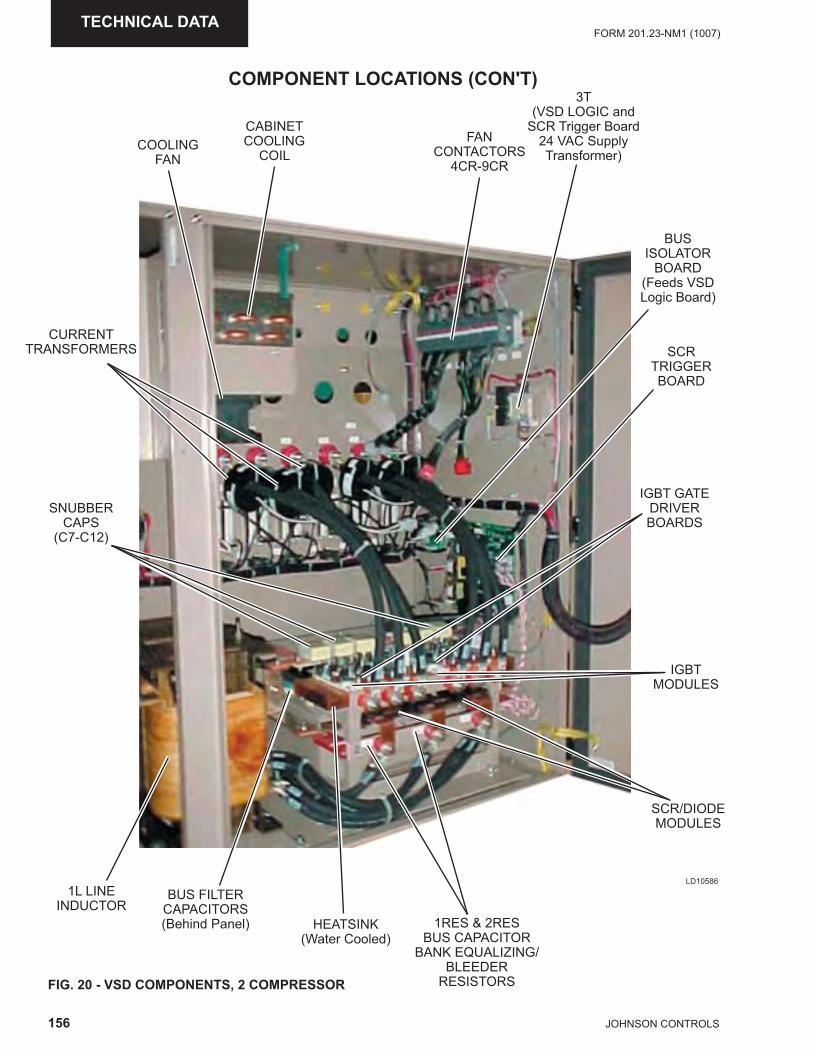
156 JOHNSON CONTROLS
FORM 201.23-NM1 (1007)TECHNICAL DATA
FIG. 20 - VSD COMPONENTS, 2 COMPRESSOR
LD10586
CABINETCOOLING
COILCOOLING
FAN
FANCONTACTORS
4CR-9CR
3T(VSD LOGIC and
SCR Trigger Board24 VAC SupplyTransformer)
CURRENTTRANSFORMERS
SNUBBERCAPS
(C7-C12)
BUSISOLATOR
BOARD(Feeds VSDLogic Board)
SCRTRIGGERBOARD
IGBTMODULES
SCR/DIODEMODULES
1RES & 2RESBUS CAPACITOR
BANK EQUALIZING/BLEEDER
RESISTORS
IGBT GATEDRIVERBOARDS
HEATSINK(Water Cooled)
BUS FILTERCAPACITORS(Behind Panel)
1L LINEINDUCTOR
COMPONENT LOCATIONS (CON'T)
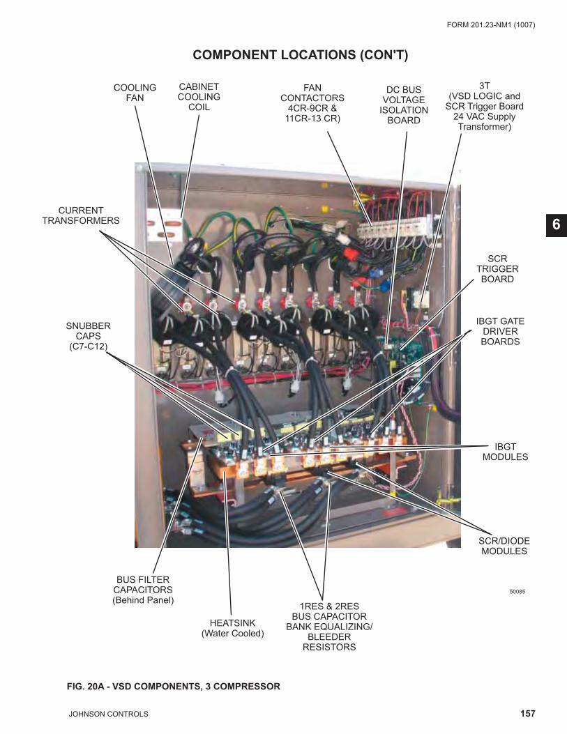
157JOHNSON CONTROLS
FORM 201.23-NM1 (1007)
6
FIG. 20A - VSD COMPONENTS, 3 COMPRESSOR
50085
CABINETCOOLING
COIL
COOLINGFAN
FANCONTACTORS
4CR-9CR &11CR-13 CR)
3T(VSD LOGIC and
SCR Trigger Board24 VAC SupplyTransformer)
CURRENTTRANSFORMERS
SNUBBERCAPS
(C7-C12)
SCRTRIGGERBOARD
SCR/DIODEMODULES
1RES & 2RESBUS CAPACITOR
BANK EQUALIZING/BLEEDER
RESISTORS
IBGT GATEDRIVERBOARDS
HEATSINK(Water Cooled)
BUS FILTERCAPACITORS(Behind Panel)
IBGTMODULES
DC BUSVOLTAGE
ISOLATIONBOARD
COMPONENT LOCATIONS (CON'T)
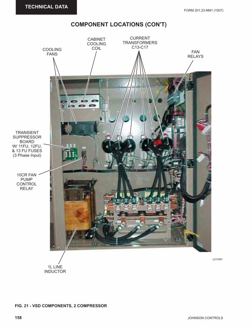
158 JOHNSON CONTROLS
FORM 201.23-NM1 (1007)TECHNICAL DATA
FIG. 21 - VSD COMPONENTS, 2 COMPRESSOR
LD10587
FANRELAYS
CURRENTTRANSFORMERS
C13-C17COOLINGFANS
1L LINEINDUCTOR
CABINETCOOLING
COIL
TRANSIENTSUPPRESSOR
BOARDW/ 11FU, 12FU, & 13 FU FUSES(3 Phase Input)
10CR FANPUMP
CONTROLRELAY
COMPONENT LOCATIONS (CON'T)
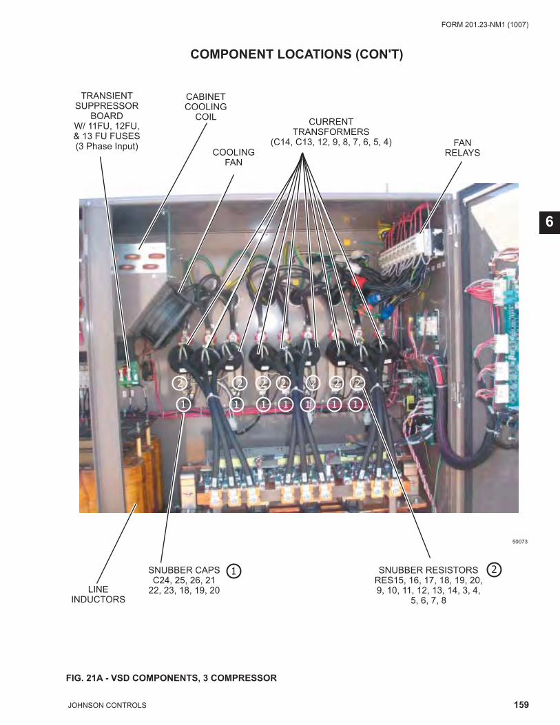
159JOHNSON CONTROLS
FORM 201.23-NM1 (1007)
6
FIG. 21A - VSD COMPONENTS, 3 COMPRESSOR
50073
FANRELAYS
CURRENTTRANSFORMERS
(C14, C13, 12, 9, 8, 7, 6, 5, 4)COOLING
FAN
LINEINDUCTORS
CABINETCOOLING
COIL
TRANSIENTSUPPRESSOR
BOARDW/ 11FU, 12FU, & 13 FU FUSES(3 Phase Input)
1 1 1 1 1 1 1
22 2 2 2 22
SNUBBER CAPSC24, 25, 26, 21
22, 23, 18, 19, 20
SNUBBER RESISTORSRES15, 16, 17, 18, 19, 20,9, 10, 11, 12, 13, 14, 3, 4,
5, 6, 7, 8
1 2
COMPONENT LOCATIONS (CON'T)
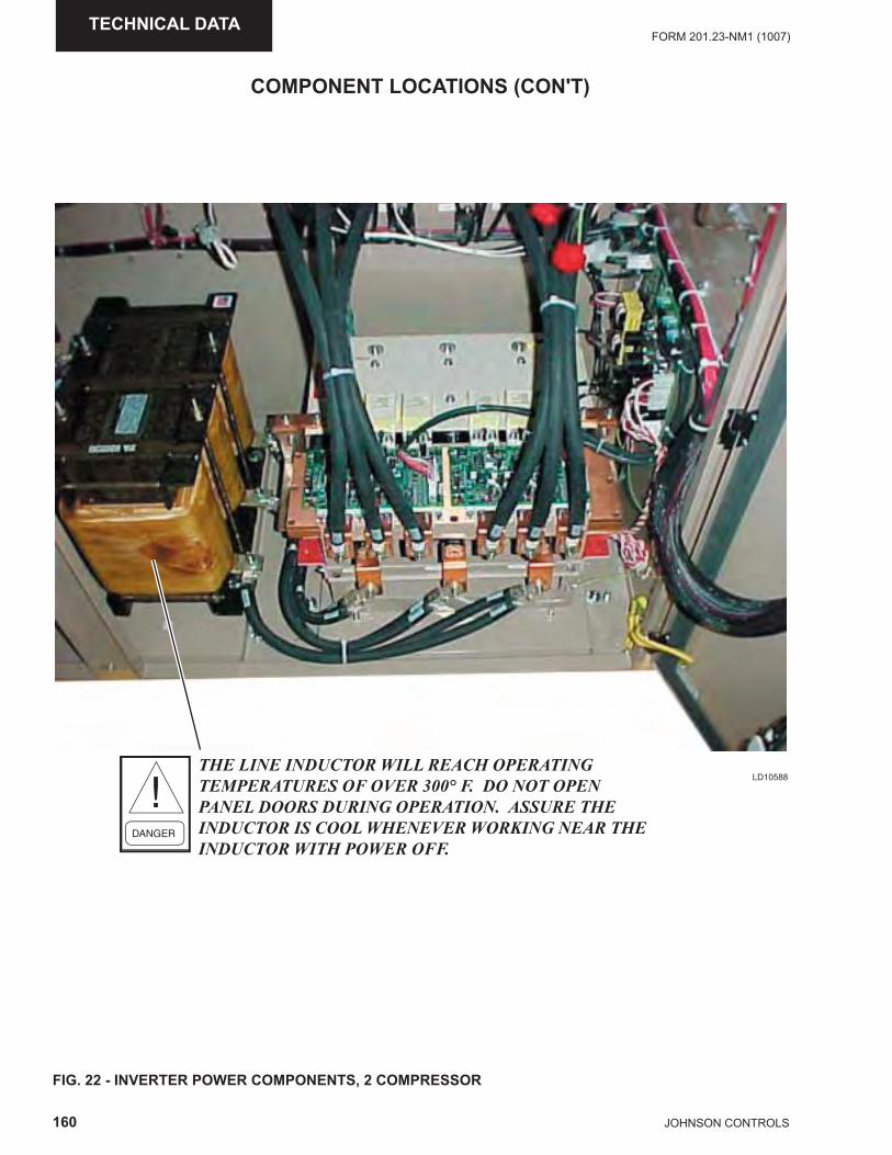
160 JOHNSON CONTROLS
FORM 201.23-NM1 (1007)TECHNICAL DATA
FIG. 22 - INVERTER POWER COMPONENTS, 2 COMPRESSOR
LD10588
COMPONENT LOCATIONS (CON'T)
THE LINE INDUCTOR WILL REACH OPERATING TEMPERATURES OF OVER 300° F. DO NOT OPEN PANEL DOORS DURING OPERATION. ASSURE THE INDUCTOR IS COOL WHENEVER WORKING NEAR THE INDUCTOR WITH POWER OFF.
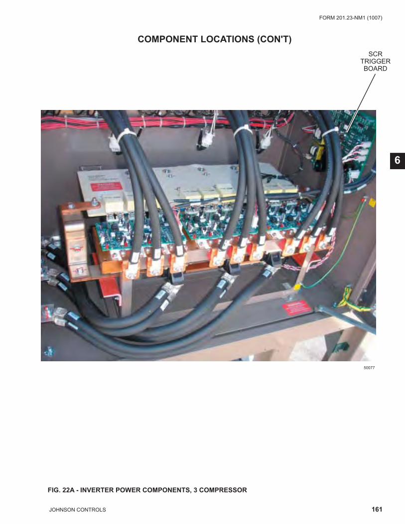
161JOHNSON CONTROLS
FORM 201.23-NM1 (1007)
6
FIG. 22A - INVERTER POWER COMPONENTS, 3 COMPRESSOR
COMPONENT LOCATIONS (CON'T)
50077
SCRTRIGGER BOARD
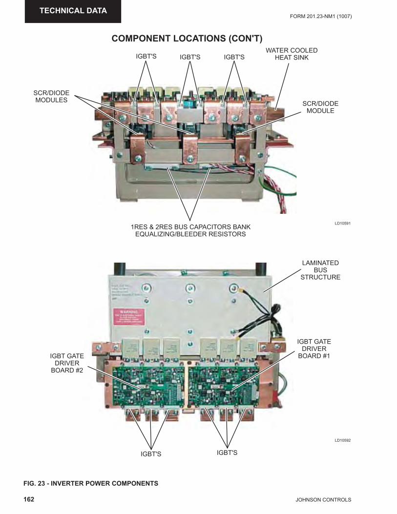
162 JOHNSON CONTROLS
FORM 201.23-NM1 (1007)TECHNICAL DATA
FIG. 23 - INVERTER POWER COMPONENTS
LD10592
COMPONENT LOCATIONS (CON'T)
LD10591
IGBT'SIGBT'S IGBT'SWATER COOLED
HEAT SINK
SCR/DIODEMODULE
SCR/DIODEMODULES
1RES & 2RES BUS CAPACITORS BANKEQUALIZING/BLEEDER RESISTORS
LAMINATEDBUS
STRUCTURE
IGBT'SIGBT'S
IGBT GATEDRIVER
BOARD #1IGBT GATEDRIVER
BOARD #2
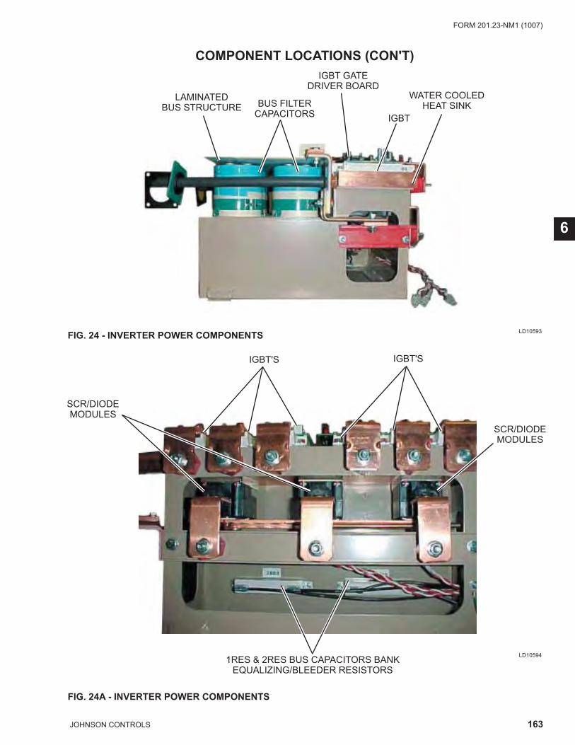
163JOHNSON CONTROLS
FORM 201.23-NM1 (1007)
6
FIG. 24A - INVERTER POWER COMPONENTS
LAMINATEDBUS STRUCTURE BUS FILTER
CAPACITORS
IGBT GATEDRIVER BOARD
IGBT
WATER COOLED HEAT SINK
IGBT'S IGBT'S
SCR/DIODEMODULES
SCR/DIODEMODULES
1RES & 2RES BUS CAPACITORS BANKEQUALIZING/BLEEDER RESISTORS
FIG. 24 - INVERTER POWER COMPONENTS LD10593
LD10594
COMPONENT LOCATIONS (CON'T)
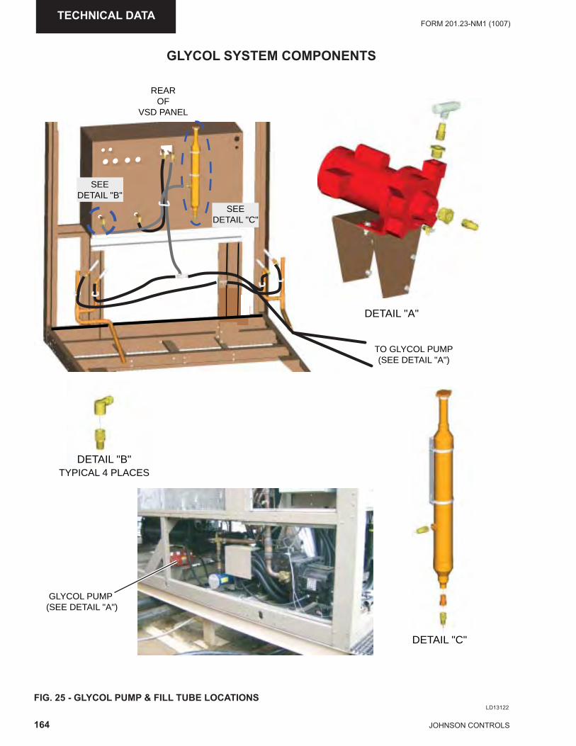
164 JOHNSON CONTROLS
FORM 201.23-NM1 (1007)TECHNICAL DATA
GLYCOL SYSTEM COMPONENTS
LD13122FIG. 25 - GLYCOL PUMP & FILL TUBE LOCATIONS
DETAIL "C"
DETAIL "B"TYPICAL 4 PLACES
GLYCOL PUMP (SEE DETAIL "A")
TO GLYCOL PUMP (SEE DETAIL "A")
SEEDETAIL "C"
SEEDETAIL "B"
REAROF
VSD PANEL
DETAIL "A"
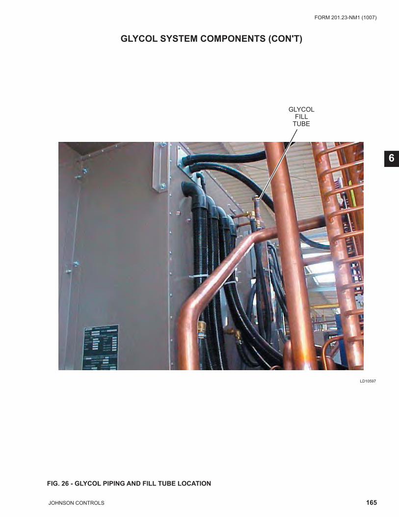
165JOHNSON CONTROLS
FORM 201.23-NM1 (1007)
6
LD10597
FIG. 26 - GLYCOL PIPING AND FILL TUBE LOCATION
GLYCOL FILL
TUBE
GLYCOL SYSTEM COMPONENTS (CON'T)
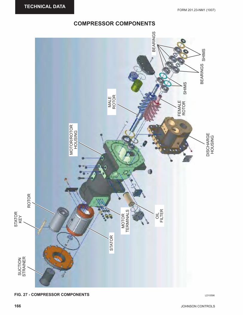
166 JOHNSON CONTROLS
FORM 201.23-NM1 (1007)TECHNICAL DATA
COMPRESSOR COMPONENTS
LD10596FIG. 27 - COMPRESSOR COMPONENTS
SU
CTI
ON
STR
AIN
ER
STA
TOR
KE
Y
RO
TOR
MO
TOR
/RO
TOR
HO
US
ING
MA
LER
OTO
R
FEM
ALE
RO
TOR
BE
AR
ING
S
SH
IMS
SH
IMS
BE
AR
ING
SD
ISC
HA
RG
E
HO
US
ING
OIL
FILT
ER
MO
TOR
TER
MIN
ALS
STA
TOR
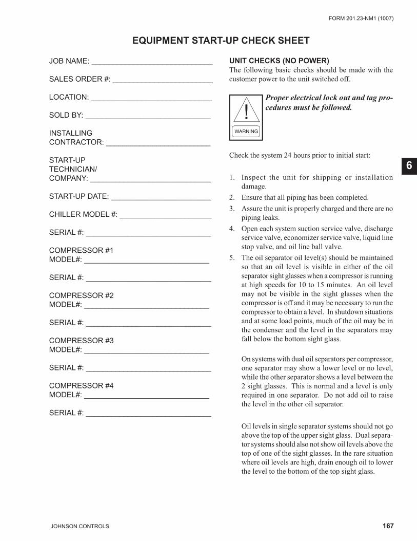
167JOHNSON CONTROLS
FORM 201.23-NM1 (1007)
6
JOB NAME: _____________________________
SALES ORDER #: ________________________
LOCATION: _____________________________
SOLD BY: ______________________________
INSTALLINGCONTRACTOR: _________________________
START-UPTECHNICIAN/COMPANY: _____________________________
START-UP DATE: ________________________
CHILLER MODEL #: ______________________
SERIAL #: ______________________________
COMPRESSOR #1MODEL#: ______________________________
SERIAL #: ______________________________
COMPRESSOR #2MODEL#: ______________________________
SERIAL #: ______________________________
COMPRESSOR #3MODEL#: ______________________________
SERIAL #: ______________________________
COMPRESSOR #4MODEL#: ______________________________
SERIAL #: ______________________________
UNIT CHECKS (NO POWER)The following basic checks should be made with the customer power to the unit switched off.
Proper electrical lock out and tag pro-cedures must be followed.
Check the system 24 hours prior to initial start:
1. Inspect the unit for shipping or installation damage.
2. Ensure that all piping has been completed.3. Assure the unit is properly charged and there are no
piping leaks.4. Open each system suction service valve, discharge
service valve, economizer service valve, liquid line stop valve, and oil line ball valve.
5. The oil separator oil level(s) should be maintained so that an oil level is visible in either of the oil separator sight glasses when a compressor is running at high speeds for 10 to 15 minutes. An oil level may not be visible in the sight glasses when the compressor is off and it may be necessary to run the compressor to obtain a level. In shutdown situations and at some load points, much of the oil may be in the condenser and the level in the separators may fall below the bottom sight glass.
On systems with dual oil separators per compressor, one separator may show a lower level or no level, while the other separator shows a level between the 2 sight glasses. This is normal and a level is only required in one separator. Do not add oil to raise the level in the other oil separator.
Oil levels in single separator systems should not go above the top of the upper sight glass. Dual separa-tor systems should also not show oil levels above the top of one of the sight glasses. In the rare situation where oil levels are high, drain enough oil to lower the level to the bottom of the top sight glass.
EQUIPMENT START-UP CHECK SHEET
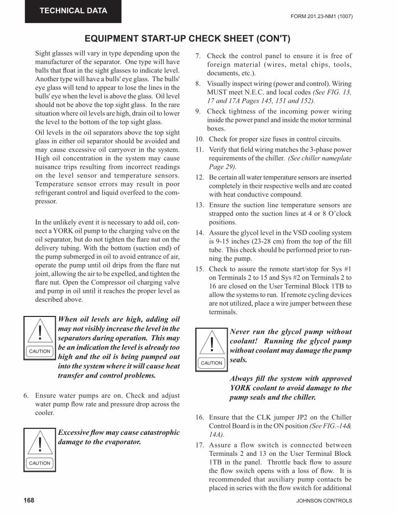
168 JOHNSON CONTROLS
FORM 201.23-NM1 (1007)TECHNICAL DATA
Sight glasses will vary in type depending upon the manufacturer of the separator. One type will have balls that fl oat in the sight glasses to indicate level. Another type will have a bulls' eye glass. The bulls' eye glass will tend to appear to lose the lines in the bulls' eye when the level is above the glass. Oil level should not be above the top sight glass. In the rare situation where oil levels are high, drain oil to lower the level to the bottom of the top sight glass.
Oil levels in the oil separators above the top sight glass in either oil separator should be avoided and may cause excessive oil carryover in the system. High oil concentration in the system may cause nuisance trips resulting from incorrect readings on the level sensor and temperature sensors. Temperature sensor errors may result in poor refrigerant control and liquid overfeed to the com-pressor.
In the unlikely event it is necessary to add oil, con-nect a YORK oil pump to the charging valve on the oil separator, but do not tighten the fl are nut on the delivery tubing. With the bottom (suction end) of the pump submerged in oil to avoid entrance of air, operate the pump until oil drips from the fl are nut joint, allowing the air to be expelled, and tighten the fl are nut. Open the Compressor oil charging valve and pump in oil until it reaches the proper level as described above.
When oil levels are high, adding oil may not visibly increase the level in the separators during operation. This may be an indication the level is already too high and the oil is being pumped out into the system where it will cause heat transfer and control problems.
6. Ensure water pumps are on. Check and adjust water pump fl ow rate and pressure drop across the cooler.
Excessive fl ow may cause catastrophic damage to the evaporator.
EQUIPMENT START-UP CHECK SHEET (CON'T)
7. Check the control panel to ensure it is free of foreign material (wires, metal chips, tools, documents, etc.).
8. Visually inspect wiring (power and control). Wiring MUST meet N.E.C. and local codes (See FIG. 13, 17 and 17A Pages 145, 151 and 152).
9. Check tightness of the incoming power wiring inside the power panel and inside the motor terminal boxes.
10. Check for proper size fuses in control circuits.11. Verify that fi eld wiring matches the 3-phase power
requirements of the chiller. (See chiller nameplate Page 29).
12. Be certain all water temperature sensors are inserted completely in their respective wells and are coated with heat conductive compound.
13. Ensure the suction line temperature sensors are strapped onto the suction lines at 4 or 8 O’clock positions.
14. Assure the glycol level in the VSD cooling system is 9-15 inches (23-28 cm) from the top of the fi ll tube. This check should be performed prior to run-ning the pump.
15. Check to assure the remote start/stop for Sys #1 on Terminals 2 to 15 and Sys #2 on Terminals 2 to 16 are closed on the User Terminal Block 1TB to allow the systems to run. If remote cycling devices are not utilized, place a wire jumper between these terminals.
Never run the glycol pump without coolant! Running the glycol pump without coolant may damage the pump seals.
Always fi ll the system with approved YORK coolant to avoid damage to the pump seals and the chiller.
16. Ensure that the CLK jumper JP2 on the Chiller Control Board is in the ON position (See FIG.-14& 14A).
17. Assure a flow switch is connected between Terminals 2 and 13 on the User Terminal Block 1TB in the panel. Throttle back fl ow to assure the fl ow switch opens with a loss of fl ow. It is recommended that auxiliary pump contacts be placed in series with the fl ow switch for additional
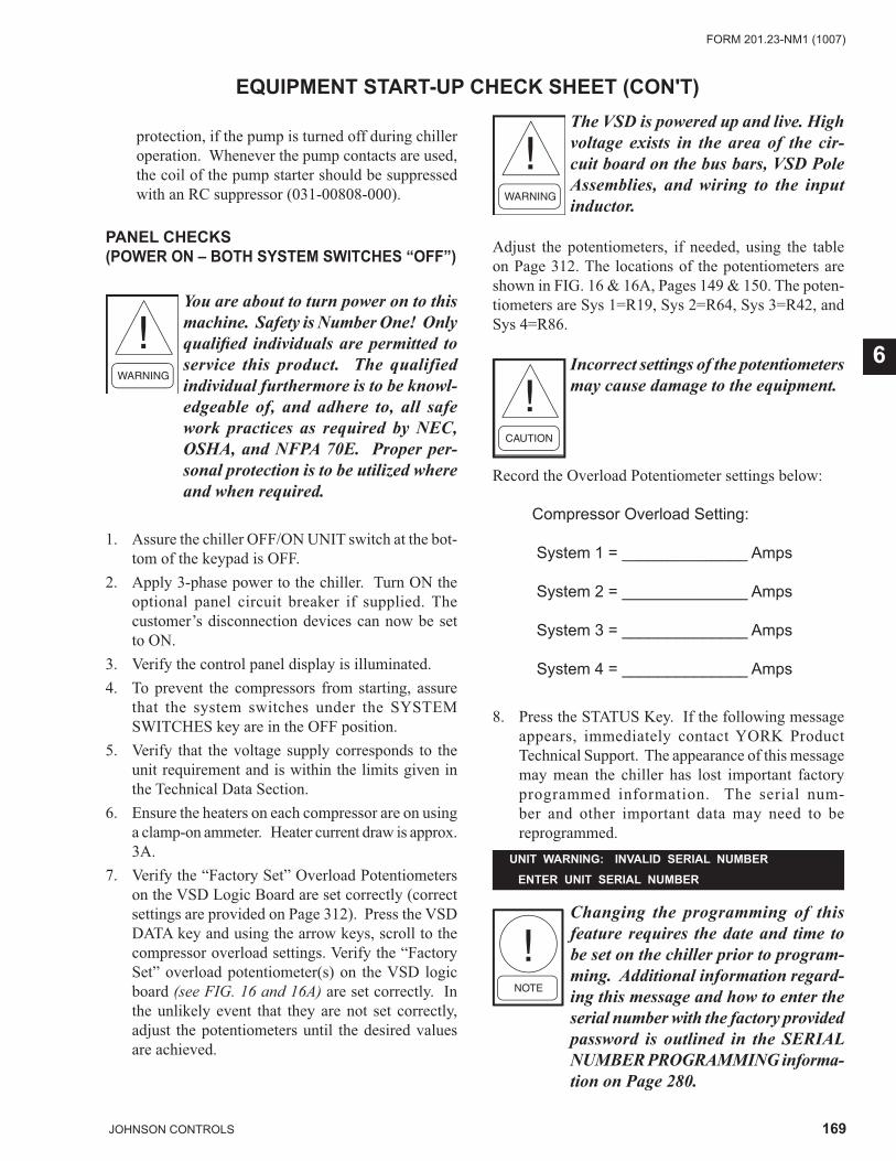
169JOHNSON CONTROLS
FORM 201.23-NM1 (1007)
6
EQUIPMENT START-UP CHECK SHEET (CON'T)
UNIT WARNING: INVALID SERIAL NUMBER
ENTER UNIT SERIAL NUMBER
protection, if the pump is turned off during chiller operation. Whenever the pump contacts are used, the coil of the pump starter should be suppressed with an RC suppressor (031-00808-000).
PANEL CHECKS (POWER ON – BOTH SYSTEM SWITCHES “OFF”)
You are about to turn power on to this machine. Safety is Number One! Only qualifi ed individuals are permitted to service this product. The qualified individual furthermore is to be knowl-edgeable of, and adhere to, all safe work practices as required by NEC, OSHA, and NFPA 70E. Proper per-sonal protection is to be utilized where and when required.
1. Assure the chiller OFF/ON UNIT switch at the bot-tom of the keypad is OFF.
2. Apply 3-phase power to the chiller. Turn ON the optional panel circuit breaker if supplied. The customer’s disconnection devices can now be set to ON.
3. Verify the control panel display is illuminated.4. To prevent the compressors from starting, assure
that the system switches under the SYSTEM SWITCHES key are in the OFF position.
5. Verify that the voltage supply corresponds to the unit requirement and is within the limits given in the Technical Data Section.
6. Ensure the heaters on each compressor are on using a clamp-on ammeter. Heater current draw is approx. 3A.
7. Verify the “Factory Set” Overload Potentiometers on the VSD Logic Board are set correctly (correct settings are provided on Page 312). Press the VSD DATA key and using the arrow keys, scroll to the compressor overload settings. Verify the “Factory Set” overload potentiometer(s) on the VSD logic board (see FIG. 16 and 16A) are set correctly. In the unlikely event that they are not set correctly, adjust the potentiometers until the desired values are achieved.
The VSD is powered up and live. High voltage exists in the area of the cir-cuit board on the bus bars, VSD Pole Assemblies, and wiring to the input inductor.
Adjust the potentiometers, if needed, using the table on Page 312. The locations of the potentiometers are shown in FIG. 16 & 16A, Pages 149 & 150. The poten-tiometers are Sys 1=R19, Sys 2=R64, Sys 3=R42, and Sys 4=R86.
Incorrect settings of the potentiometers may cause damage to the equipment.
Record the Overload Potentiometer settings below:
Compressor Overload Setting:
System 1 = ______________ Amps
System 2 = ______________ Amps
System 3 = ______________ Amps
System 4 = ______________ Amps
8. Press the STATUS Key. If the following message appears, immediately contact YORK Product Technical Support. The appearance of this message may mean the chiller has lost important factory programmed information. The serial num-ber and other important data may need to be reprogrammed.
Changing the programming of this feature requires the date and time to be set on the chiller prior to program-ming. Additional information regard-ing this message and how to enter the serial number with the factory provided password is outlined in the SERIAL NUMBER PROGRAMMING informa-tion on Page 280.
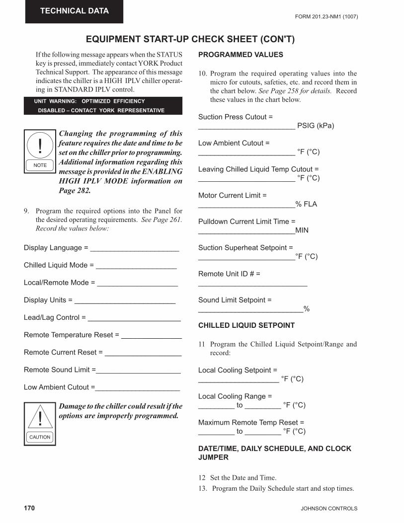
170 JOHNSON CONTROLS
FORM 201.23-NM1 (1007)TECHNICAL DATA
Changing the programming of this feature requires the date and time to be set on the chiller prior to programming. Additional information regarding this message is provided in the ENABLING HIGH IPLV MODE information on Page 282.
9. Program the required options into the Panel for the desired operating requirements. See Page 261. Record the values below:
Display Language = ______________________
Chilled Liquid Mode = ____________________
Local/Remote Mode = ____________________
Display Units = _________________________
Lead/Lag Control = _______________________
Remote Temperature Reset = _______________
Remote Current Reset = ___________________
Remote Sound Limit =_____________________
Low Ambient Cutout =_____________________
Damage to the chiller could result if the options are improperly programmed.
UNIT WARNING: OPTIMIZED EFFICIENCY
DISABLED – CONTACT YORK REPRESENTATIVE
EQUIPMENT START-UP CHECK SHEET (CON'T)PROGRAMMED VALUES
10. Program the required operating values into the micro for cutouts, safeties, etc. and record them in the chart below. See Page 258 for details. Record these values in the chart below.
Suction Press Cutout = ________________________ PSIG (kPa)
Low Ambient Cutout = ________________________ °F (°C)
Leaving Chilled Liquid Temp Cutout =________________________ °F (°C)
Motor Current Limit = ________________________% FLA
Pulldown Current Limit Time =________________________MIN
Suction Superheat Setpoint = ________________________°F (°C)
Remote Unit ID # = ___________________________
Sound Limit Setpoint = __________________________%
CHILLED LIQUID SETPOINT
11 Program the Chilled Liquid Setpoint/Range and record:
Local Cooling Setpoint = ____________________ °F (°C)
Local Cooling Range = _________ to _________ °F (°C)
Maximum Remote Temp Reset = _________ to _________ °F (°C)
DATE/TIME, DAILY SCHEDULE, AND CLOCK JUMPER
12 Set the Date and Time.13. Program the Daily Schedule start and stop times.
If the following message appears when the STATUS key is pressed, immediately contact YORK Product Technical Support. The appearance of this message indicates the chiller is a HIGH IPLV chiller operat-ing in STANDARD IPLV control.
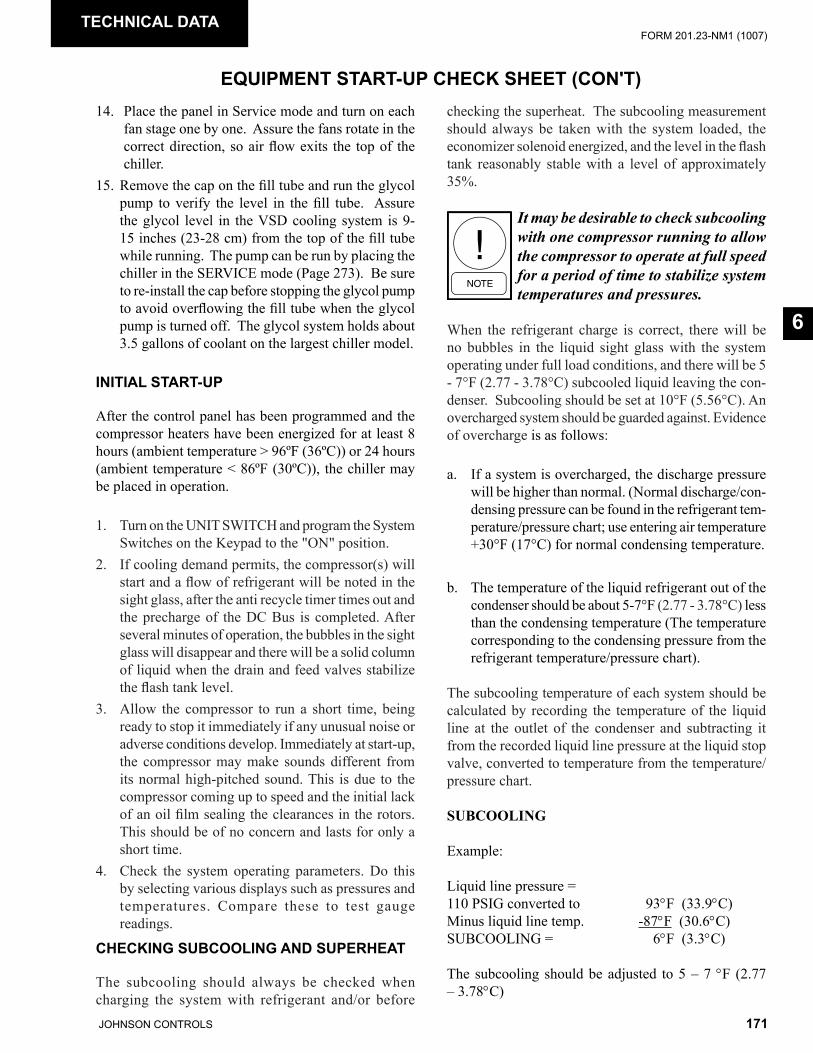
171JOHNSON CONTROLS
FORM 201.23-NM1 (1007)
6
CHECKING SUBCOOLING AND SUPERHEAT
The subcooling should always be checked when charging the system with refrigerant and/or before
EQUIPMENT START-UP CHECK SHEET (CON'T)
TECHNICAL DATA
checking the superheat. The subcooling measurement should always be taken with the system loaded, the economizer solenoid energized, and the level in the flash tank reasonably stable with a level of approximately 35%.
It may be desirable to check subcooling with one compressor running to allow the compressor to operate at full speed for a period of time to stabilize system temperatures and pressures.
When the refrigerant charge is correct, there will be no bubbles in the liquid sight glass with the system operating under full load conditions, and there will be 5 - 7°F (2.77 - 3.78°C) subcooled liquid leaving the con-denser. Subcooling should be set at 10°F (5.56°C). An overcharged system should be guarded against. Evidence of overcharge is as follows:
a. If a system is overcharged, the discharge pressure will be higher than normal. (Normal discharge/con-densing pressure can be found in the refrigerant tem-perature/pressure chart; use entering air temperature +30°F (17°C) for normal condensing temperature.
b. The temperature of the liquid refrigerant out of the condenser should be about 5-7°F (2.77 - 3.78°C) less than the condensing temperature (The temperature corresponding to the condensing pressure from the refrigerant temperature/pressure chart).
The subcooling temperature of each system should be calculated by recording the temperature of the liquid line at the outlet of the condenser and subtracting it from the recorded liquid line pressure at the liquid stop valve, converted to temperature from the temperature/pressure chart.
SUBCOOLING
Example:
Liquid line pressure =110 PSIG converted to 93°F (33.9°C)Minus liquid line temp. -87°F (30.6°C)SUBCOOLING = 6°F (3.3°C)
The subcooling should be adjusted to 5 – 7 °F (2.77 – 3.78°C)
14. Place the panel in Service mode and turn on each fan stage one by one. Assure the fans rotate in the correct direction, so air flow exits the top of the chiller.
15. Remove the cap on the fill tube and run the glycol pump to verify the level in the fill tube. Assure the glycol level in the VSD cooling system is 9-15 inches (23-28 cm) from the top of the fill tube while running. The pump can be run by placing the chiller in the SERVICE mode (Page 273). Be sure to re-install the cap before stopping the glycol pump to avoid overflowing the fill tube when the glycol pump is turned off. The glycol system holds about 3.5 gallons of coolant on the largest chiller model.
INITIAL START-UP
After the control panel has been programmed and the compressor heaters have been energized for at least 8 hours (ambient temperature > 96ºF (36ºC)) or 24 hours (ambient temperature < 86ºF (30ºC)), the chiller may be placed in operation.
1. Turn on the UNIT SWITCH and program the System Switches on the Keypad to the "ON" position.
2. If cooling demand permits, the compressor(s) will start and a flow of refrigerant will be noted in the sight glass, after the anti recycle timer times out and the precharge of the DC Bus is completed. After several minutes of operation, the bubbles in the sight glass will disappear and there will be a solid column of liquid when the drain and feed valves stabilize the flash tank level.
3. Allow the compressor to run a short time, being ready to stop it immediately if any unusual noise or adverse conditions develop. Immediately at start-up, the compressor may make sounds different from its normal high-pitched sound. This is due to the compressor coming up to speed and the initial lack of an oil film sealing the clearances in the rotors. This should be of no concern and lasts for only a short time.
4. Check the system operating parameters. Do this by selecting various displays such as pressures and temperatures. Compare these to test gauge readings.

172 JOHNSON CONTROLS
FORM 201.23-NM1 (1007)TECHNICAL DATA
EQUIPMENT START-UP CHECK SHEET (CON'T)
This may be difficult to measure, due to test instrument error and the diffi culty generally encountered when measuring subcooling on systems operating with very low condenser subcooling.
1. Record the l iquid l ine pressure and i t’s corresponding temperature, liquid line temperature, and subcooling below:
SYS 1 SYS 2Liq Line Press = PSIG (kPa)
Temp = °F (°C)
Liq Line Temp = °F (°C)
Subcooling = °F (°C)
Add or remove charge as necessary to obtain a full sight glass fully loaded while keeping subcooling to about 5-7°F (2.77-3.78°C). After an adjustment is made to the charge, the fl ash tank level may rise or drop from the approx. 35% point. Before another measurement is made, allow the level to stabilize.
After the subcooling is set, the suction superheat should be checked. The superheat should be checked only after steady state operation of the chiller has been established, and the system is running in a fully loaded, stable con-dition. Correct superheat for a system is 8 - 12°F (4.45 - 6.67°C) and should be reasonably close to the system superheat on the chiller display.
The superheat is calculated as the difference between the actual temperature of the returned refrigerant gas in the suction line entering the compressor and the temperature corresponding to the suction pressure as shown in a standard pressure/temperature chart.
SUPERHEAT
Example:
Suction Temp = 46°F (8°C)minus Suction Press30 PSIG converted to Temp - 35°F (1°C)
11°F (6°C)
The suction temperature should be taken 6” (13 mm) before the compressor suction service valve, and the suction pressure is taken at the compressor suction service valve.
No superheat adjustments are necessary and the electronically controlled drain valve need not be adjusted in the fi eld. Ensure that superheat is controlling at 8 - 12°F (4.45 - 6.67°C). The purpose of this check is primarily to verify the transducer and suction temperature sensors in a system are providing reasonably accurate outputs to the chiller controls. It also checks the operation of the Feed and Drain Valves.
2. Record the suction temperature, suction pressure, suction pressure converted to temperature, and superheat of each system below:
SYS 1 SYS 2Suction Press = _______ ______ PSIG (kPa)
SP to Temp = _______ ______ °F (°C)
Suction Temp = _______ ______ °F (°C)
Superheat = _______ ______ °F (°C)
3. Discharge superheat will typically run approx. 28-30°F. This can be checked on the micropanel display. If the suction superheat drops very low or the economizer feeds liquid into the compressor, the superheat will drop sharply to approx. 2-3°F.
LEAK CHECKING
1. Leak check compressors, fi ttings, and piping to ensure no leaks.
If the chiller is functioning satisfactorily during the initial operating period, no safeties trip and the chiller controls chilled liquid temperature; it is now ready to be placed into service.
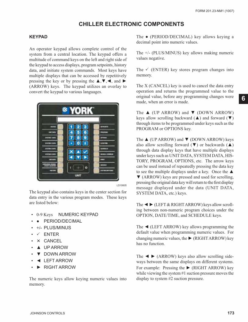
173JOHNSON CONTROLS
FORM 201.23-NM1 (1007)
6
CHILLER ELECTRONIC COMPONENTS
KEYPAD
An operator keypad allows complete control of the system from a central location. The keypad offers a multitude of command keys on the left and right side of the keypad to access displays, program setpoints, history data, and initiate system commands. Most keys have multiple displays that can be accessed by repetitively pressing the key or by pressing the ▲,▼,◄, and ► (ARROW) keys. The keypad utilizes an overlay to convert the keypad to various languages.
LD10605
The keypad also contains keys in the center section for data entry in the various program modes. These keys are listed below:
• 0-9 Keys NUMERIC KEYPAD • ● PERIOD/DECIMAL • +/- PLUS/MINUS • � ENTER • � CANCEL • ▲ UP ARROW • ▼ DOWN ARROW • ◄ LEFT ARROW • ► RIGHT ARROW
The numeric keys allow keying numeric values into memory.
The ● (PERIOD/DECIMAL) key allows keying a decimal point into numeric values.
The +/- (PLUS/MINUS) key allows making numeric values negative.
The � (ENTER) key stores program changes into memory.
The X (CANCEL) key is used to cancel the data entry operation and returns the programmed value to the original value, before any programming changes were made, when an error is made.
The ▲ (UP ARROW) and ▼ (DOWN ARROW) keys allow scrolling backward (▲) and forward (▼) through items to be programmed under keys such as the PROGRAM or OPTIONS key.
The ▲ (UP ARROW) and ▼ (DOWN ARROW) keys also allow scrolling forward (▼) or backwards (▲) through data display keys that have multiple displays under keys such as UNIT DATA, SYSTEM DATA, HIS-TORY, PROGRAM, OPTIONS, etc. The arrow keys can be used instead of repeatedly pressing the data key to see the multiple displays under a key. Once the ▲ ▼ (ARROW) keys are pressed and used for scrolling, pressing the original data key will return to the fi rst display message displayed under the data (UNIT DATA, SYSTEM DATA, etc.) keys.
The ◄ ► (LEFT & RIGHT ARROW) keys allow scroll-ing between non-numeric program choices under the OPTION, DATE/TIME, and SCHEDULE keys.
The ◄ (LEFT ARROW) key allows programming the default value when programming numeric values. For changing numeric values, the ► (RIGHT ARROW) key has no function.
The ◄ ► (ARROW) keys also allow scrolling side-ways between the same displays on different systems. For example: Pressing the ► (RIGHT ARROW) key while viewing the system #1 suction pressure moves the display to system #2 suction pressure.
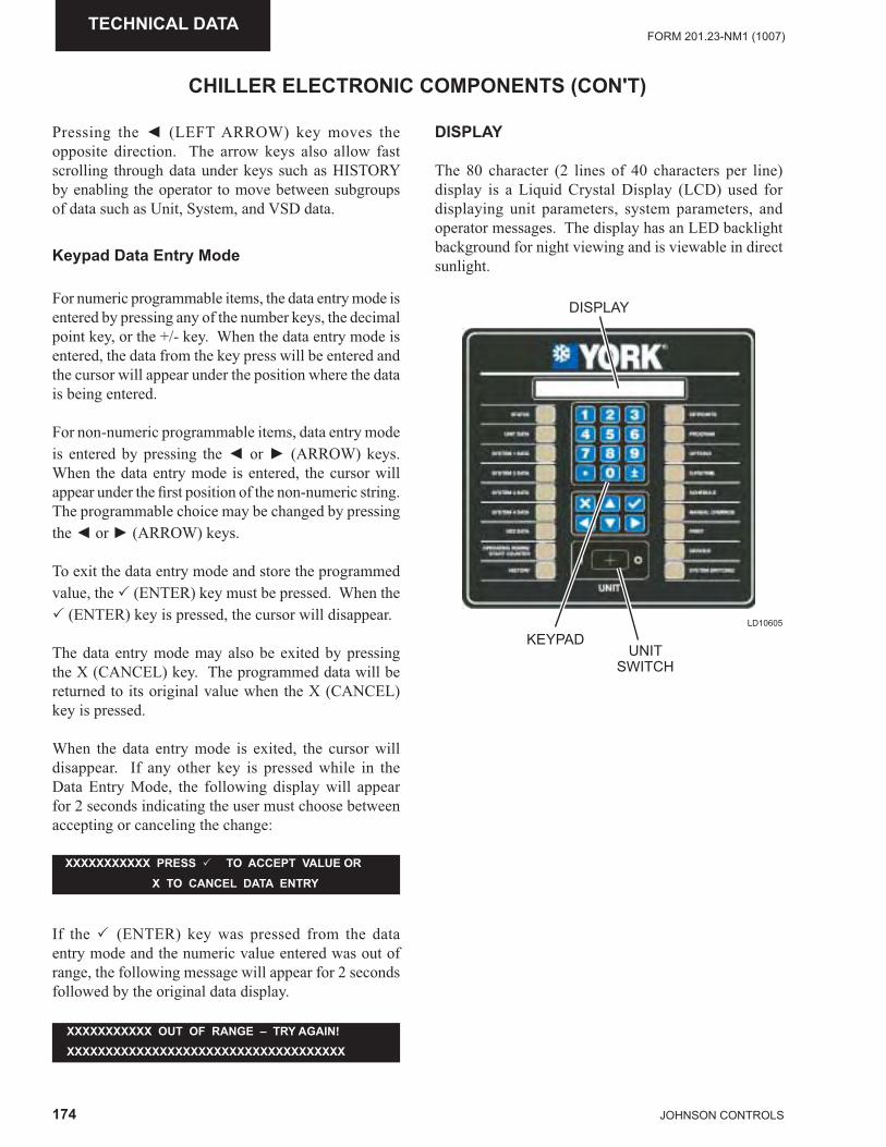
174 JOHNSON CONTROLS
FORM 201.23-NM1 (1007)TECHNICAL DATA
CHILLER ELECTRONIC COMPONENTS (CON'T)
Pressing the ◄ (LEFT ARROW) key moves the opposite direction. The arrow keys also allow fast scrolling through data under keys such as HISTORY by enabling the operator to move between subgroups of data such as Unit, System, and VSD data.
Keypad Data Entry Mode
For numeric programmable items, the data entry mode is entered by pressing any of the number keys, the decimal point key, or the +/- key. When the data entry mode is entered, the data from the key press will be entered and the cursor will appear under the position where the data is being entered.
For non-numeric programmable items, data entry mode is entered by pressing the ◄ or ► (ARROW) keys. When the data entry mode is entered, the cursor will appear under the fi rst position of the non-numeric string. The programmable choice may be changed by pressing the ◄ or ► (ARROW) keys.
To exit the data entry mode and store the programmed value, the � (ENTER) key must be pressed. When the � (ENTER) key is pressed, the cursor will disappear.
The data entry mode may also be exited by pressing the X (CANCEL) key. The programmed data will be returned to its original value when the X (CANCEL) key is pressed.
When the data entry mode is exited, the cursor will disappear. If any other key is pressed while in the Data Entry Mode, the following display will appear for 2 seconds indicating the user must choose between accepting or canceling the change:
XXXXXXXXXXX PRESS � TO ACCEPT VALUE OR
X TO CANCEL DATA ENTRY
If the � (ENTER) key was pressed from the data entry mode and the numeric value entered was out of range, the following message will appear for 2 seconds followed by the original data display.
XXXXXXXXXXX OUT OF RANGE – TRY AGAIN!
XXXXXXXXXXXXXXXXXXXXXXXXXXXXXXXXXXXX
DISPLAY
The 80 character (2 lines of 40 characters per line) display is a Liquid Crystal Display (LCD) used for displaying unit parameters, system parameters, and operator messages. The display has an LED backlight background for night viewing and is viewable in direct sunlight.
LD10605
UNITSWITCH
KEYPAD
DISPLAY
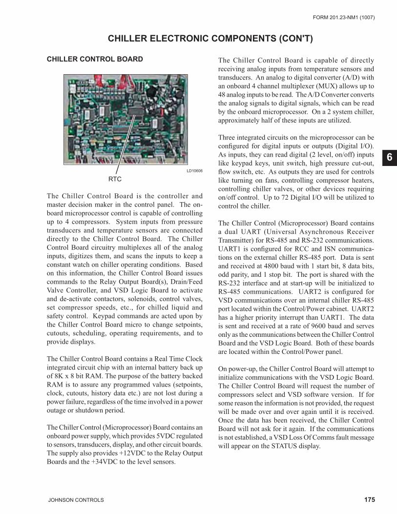
175JOHNSON CONTROLS
FORM 201.23-NM1 (1007)
6
The Chiller Control Board is the controller and master decision maker in the control panel. The on-board microprocessor control is capable of controlling up to 4 compressors. System inputs from pressure transducers and temperature sensors are connected directly to the Chiller Control Board. The Chiller Control Board circuitry multiplexes all of the analog inputs, digitizes them, and scans the inputs to keep a constant watch on chiller operating conditions. Based on this information, the Chiller Control Board issues commands to the Relay Output Board(s), Drain/Feed Valve Controller, and VSD Logic Board to activate and de-activate contactors, solenoids, control valves, set compressor speeds, etc., for chilled liquid and safety control. Keypad commands are acted upon by the Chiller Control Board micro to change setpoints, cutouts, scheduling, operating requirements, and to provide displays.
The Chiller Control Board contains a Real Time Clock integrated circuit chip with an internal battery back up of 8K x 8 bit RAM. The purpose of the battery backed RAM is to assure any programmed values (setpoints, clock, cutouts, history data etc.) are not lost during a power failure, regardless of the time involved in a power outage or shutdown period.
The Chiller Control (Microprocessor) Board contains an onboard power supply, which provides 5VDC regulated to sensors, transducers, display, and other circuit boards. The supply also provides +12VDC to the Relay Output Boards and the +34VDC to the level sensors.
The Chiller Control Board is capable of directly receiving analog inputs from temperature sensors and transducers. An analog to digital converter (A/D) with an onboard 4 channel multiplexer (MUX) allows up to 48 analog inputs to be read. The A/D Converter converts the analog signals to digital signals, which can be read by the onboard microprocessor. On a 2 system chiller, approximately half of these inputs are utilized.
Three integrated circuits on the microprocessor can be confi gured for digital inputs or outputs (Digital I/O). As inputs, they can read digital (2 level, on/off) inputs like keypad keys, unit switch, high pressure cut-out, fl ow switch, etc. As outputs they are used for controls like turning on fans, controlling compressor heaters, controlling chiller valves, or other devices requiring on/off control. Up to 72 Digital I/O will be utilized to control the chiller.
The Chiller Control (Microprocessor) Board contains a dual UART (Universal Asynchronous Receiver Transmitter) for RS-485 and RS-232 communications. UART1 is confi gured for RCC and ISN communica-tions on the external chiller RS-485 port. Data is sent and received at 4800 baud with 1 start bit, 8 data bits, odd parity, and 1 stop bit. The port is shared with the RS-232 interface and at start-up will be initialized to RS-485 communications. UART2 is confi gured for VSD communications over an internal chiller RS-485 port located within the Control/Power cabinet. UART2 has a higher priority interrupt than UART1. The data is sent and received at a rate of 9600 baud and serves only as the communications between the Chiller Control Board and the VSD Logic Board. Both of these boards are located within the Control/Power panel.
On power-up, the Chiller Control Board will attempt to initialize communications with the VSD Logic Board. The Chiller Control Board will request the number of compressors select and VSD software version. If for some reason the information is not provided, the request will be made over and over again until it is received. Once the data has been received, the Chiller Control Board will not ask for it again. If the communications is not established, a VSD Loss Of Comms fault message will appear on the STATUS display.
CHILLER CONTROL BOARD
LD10606
RTC
CHILLER ELECTRONIC COMPONENTS (CON'T)
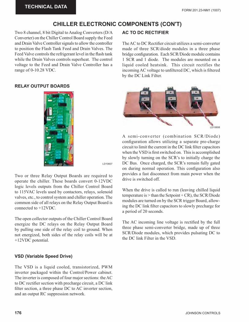
176 JOHNSON CONTROLS
FORM 201.23-NM1 (1007)TECHNICAL DATA
Two 8 channel, 8 bit Digital to Analog Converters (D/A Converter) on the Chiller Control Board supply the Feed and Drain Valve Controller signals to allow the controller to position the Flash Tank Feed and Drain Valves. The Feed Valve controls the refrigerant level in the fl ash tank while the Drain Valves controls superheat. The control voltage to the Feed and Drain Valve Controller has a range of 0-10.28 VDC.
RELAY OUTPUT BOARDS
LD10607
Two or three Relay Output Boards are required to operate the chiller. These boards convert 0-12VDC logic levels outputs from the Chiller Control Board to 115VAC levels used by contactors, relays, solenoid valves, etc., to control system and chiller operation. The common side of all relays on the Relay Output Board is connected to +12VDC.
The open collector outputs of the Chiller Control Board energize the DC relays on the Relay Output Board by pulling one side of the relay coil to ground. When not energized, both sides of the relay coils will be at +12VDC potential.
VSD (Variable Speed Drive)
The VSD is a liquid cooled, transistorized, PWM inverter packaged within the Control/Power cabinet. The inverter is composed of four major sections: the AC to DC rectifi er section with precharge circuit, a DC link fi lter section, a three phase DC to AC inverter section, and an output RC suppression network.
AC TO DC RECTIFIER
The AC to DC Rectifi er circuit utilizes a semi-converter made of three SCR/diode modules in a three phase bridge confi guration. Each SCR/Diode module contains 1 SCR and 1 diode. The modules are mounted on a liquid cooled heatsink. This circuit rectifies the incoming AC voltage to unfi ltered DC, which is fi ltered by the DC Link Filter.
A semi-converter (combination SCR/Diode) confi guration allows utilizing a separate pre-charge circuit to limit the current in the DC link fi lter capacitors when the VSD is fi rst switched on. This is accomplished by slowly turning on the SCR’s to initially charge the DC Bus. Once charged, the SCR’s remain fully gated on during normal operation. This confi guration also provides a fast disconnect from main power when the drive is switched off.
When the drive is called to run (leaving chilled liquid temperature is > than the Setpoint + CR), the SCR/Diode modules are turned on by the SCR trigger Board, allow-ing the DC link fi lter capacitors to slowly precharge for a period of 20 seconds.
The AC incoming line voltage is rectifi ed by the full three phase semi-converter bridge, made up of three SCR/Diode modules, which provides pulsating DC to the DC link Filter in the VSD.
CHILLER ELECTRONIC COMPONENTS (CON'T)
LD10608
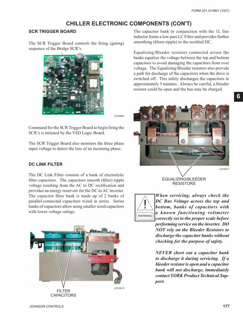
177JOHNSON CONTROLS
FORM 201.23-NM1 (1007)
6
SCR TRIGGER BOARD
The SCR Trigger Board controls the fi ring (gating) sequence of the Bridge SCR’s.
CHILLER ELECTRONIC COMPONENTS (CON'T)
Command for the SCR Trigger Board to begin fi ring the SCR’s is initiated by the VSD Logic Board.
The SCR Trigger Board also monitors the three phase input voltage to detect the loss of an incoming phase.
DC LINK FILTER
The DC Link Filter consists of a bank of electrolytic fi lter capacitors. The capacitors smooth (fi lter) ripple voltage resulting from the AC to DC rectifi cation and provides an energy reservoir for the DC to AC inverter. The capacitor fi lter bank is made up of 2 banks of parallel-connected capacitors wired in series. Series banks of capacitors allow using smaller sized capacitors with lower voltage ratings.
FILTER CAPACITORS
The capacitor bank in conjunction with the 1L line inductor forms a low pass LC Filter and provides further smoothing (fi lters ripple) to the rectifi ed DC.
Equalizing/Bleeder resistors connected across the banks equalize the voltage between the top and bottom capacitors to avoid damaging the capacitors from over voltage. The Equalizing/Bleeder resistors also provide a path for discharge of the capacitors when the drive is switched off. This safely discharges the capacitors in approximately 5 minutes. Always be careful, a bleeder resistor could be open and the bus may be charged.
When servicing, always check the DC Bus Voltage across the top and bottom, banks of capacitors with a known functioning voltmeter correctly set to the proper scale before performing service on the inverter. DO NOT rely on the Bleeder Resistors to discharge the capacitor banks without checking for the purpose of safety.
NEVER short out a capacitor bank to discharge it during servicing. If a bleeder resistor is open and a capacitor bank will not discharge, immediately contact YORK Product Technical Sup-port.
LD10609
LD10610
LD10611
EQUALIZING/BLEEDERRESISTORS
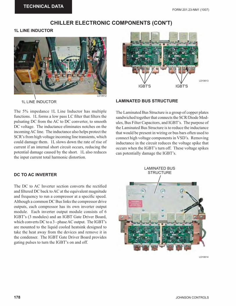
178 JOHNSON CONTROLS
FORM 201.23-NM1 (1007)TECHNICAL DATA
CHILLER ELECTRONIC COMPONENTS (CON'T)1L LINE INDUCTOR
LD10612
1L LINE INDUCTOR
The 5% impedance 1L Line Inductor has multiple functions. 1L forms a low pass LC fi lter that fi lters the pulsating DC from the AC to DC converter, to smooth DC voltage. The inductance eliminates notches on the incoming AC line. The inductance also helps protect the SCR’s from high voltage incoming line transients, which could damage them. 1L slows down the rate of rise of current if an internal short circuit occurs, reducing the potential damage caused by the short. 1L also reduces the input current total harmonic distortion.
DC TO AC INVERTER
The DC to AC Inverter section converts the rectifi ed and fi ltered DC back to AC at the equivalent magnitude and frequency to run a compressor at a specifi c speed. Although a common DC Bus links the compressor drive outputs, each compressor has its own inverter output module. Each inverter output module consists of 6 IGBT’s (3 modules) and an IGBT Gate Driver Board, which converts DC to a 3 - phase AC output. The IGBT’s are mounted to the liquid cooled heatsink designed to take the heat away from the devices and remove it in the condenser. The IGBT Gate Driver Board provides gating pulses to turn the IGBT’s on and off.
LD10613
IGBT'S IGBT'S
LAMINATED BUS STRUCTURE
The Laminated Bus Structure is a group of copper plates sandwiched together that connects the SCR/Diode Mod-ules, Bus Filter Capacitors, and IGBT’s. The purpose of the Laminated Bus Structure is to reduce the inductance that would be present in wiring or bus bars often used to connect high voltage components in VSD’s. Removing inductance in the circuit reduces the voltage spike that occurs when the IGBT’s turn off. These voltage spikes can potentially damage the IGBT’s.
LD10614
LAMINATED BUSSTRUCTURE
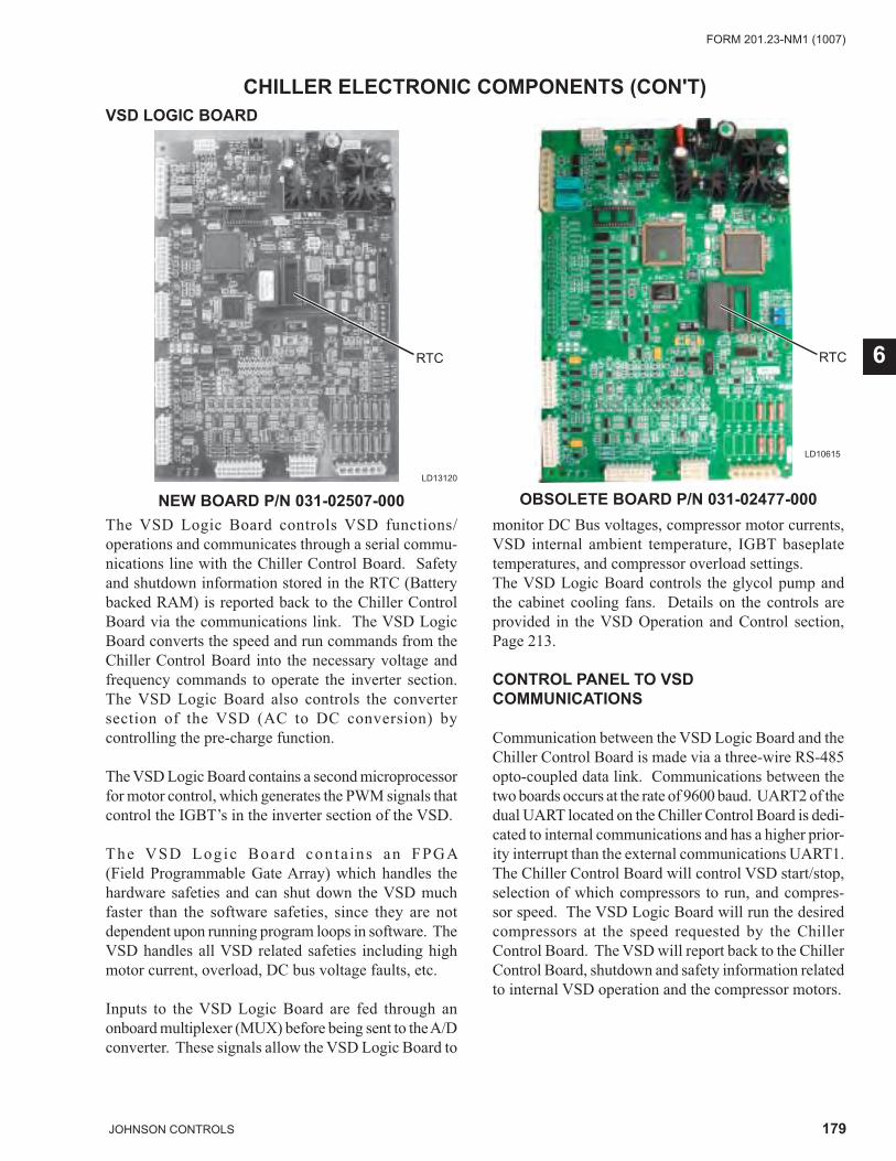
179JOHNSON CONTROLS
FORM 201.23-NM1 (1007)
6
CHILLER ELECTRONIC COMPONENTS (CON'T)VSD LOGIC BOARD
The VSD Logic Board controls VSD functions/operations and communicates through a serial commu-nications line with the Chiller Control Board. Safety and shutdown information stored in the RTC (Battery backed RAM) is reported back to the Chiller Control Board via the communications link. The VSD Logic Board converts the speed and run commands from the Chiller Control Board into the necessary voltage and frequency commands to operate the inverter section. The VSD Logic Board also controls the converter section of the VSD (AC to DC conversion) by controlling the pre-charge function.
The VSD Logic Board contains a second microprocessor for motor control, which generates the PWM signals that control the IGBT’s in the inverter section of the VSD.
The VSD Logic Board conta ins an FPGA (Field Programmable Gate Array) which handles the hardware safeties and can shut down the VSD much faster than the software safeties, since they are not dependent upon running program loops in software. The VSD handles all VSD related safeties including high motor current, overload, DC bus voltage faults, etc.
Inputs to the VSD Logic Board are fed through an onboard multiplexer (MUX) before being sent to the A/D converter. These signals allow the VSD Logic Board to
LD13120
monitor DC Bus voltages, compressor motor currents, VSD internal ambient temperature, IGBT baseplate temperatures, and compressor overload settings. The VSD Logic Board controls the glycol pump and the cabinet cooling fans. Details on the controls are provided in the VSD Operation and Control section, Page 213.
CONTROL PANEL TO VSD COMMUNICATIONS
Communication between the VSD Logic Board and the Chiller Control Board is made via a three-wire RS-485 opto-coupled data link. Communications between the two boards occurs at the rate of 9600 baud. UART2 of the dual UART located on the Chiller Control Board is dedi-cated to internal communications and has a higher prior-ity interrupt than the external communications UART1. The Chiller Control Board will control VSD start/stop, selection of which compressors to run, and compres-sor speed. The VSD Logic Board will run the desired compressors at the speed requested by the Chiller Control Board. The VSD will report back to the Chiller Control Board, shutdown and safety information related to internal VSD operation and the compressor motors.
RTC
NEW BOARD P/N 031-02507-000 OBSOLETE BOARD P/N 031-02477-000
LD10615
RTC
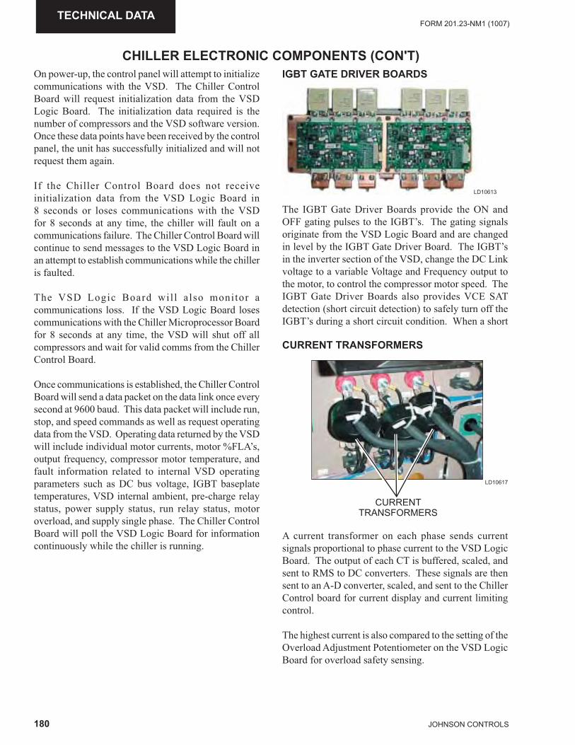
180 JOHNSON CONTROLS
FORM 201.23-NM1 (1007)TECHNICAL DATA
CHILLER ELECTRONIC COMPONENTS (CON'T)On power-up, the control panel will attempt to initialize communications with the VSD. The Chiller Control Board will request initialization data from the VSD Logic Board. The initialization data required is the number of compressors and the VSD software version. Once these data points have been received by the control panel, the unit has successfully initialized and will not request them again.
If the Chiller Control Board does not receive initialization data from the VSD Logic Board in 8 seconds or loses communications with the VSD for 8 seconds at any time, the chiller will fault on a communications failure. The Chiller Control Board will continue to send messages to the VSD Logic Board in an attempt to establish communications while the chiller is faulted.
The VSD Logic Board wil l also monitor a communications loss. If the VSD Logic Board loses communications with the Chiller Microprocessor Board for 8 seconds at any time, the VSD will shut off all compressors and wait for valid comms from the Chiller Control Board.
Once communications is established, the Chiller Control Board will send a data packet on the data link once every second at 9600 baud. This data packet will include run, stop, and speed commands as well as request operating data from the VSD. Operating data returned by the VSD will include individual motor currents, motor %FLA’s, output frequency, compressor motor temperature, and fault information related to internal VSD operating parameters such as DC bus voltage, IGBT baseplate temperatures, VSD internal ambient, pre-charge relay status, power supply status, run relay status, motor overload, and supply single phase. The Chiller Control Board will poll the VSD Logic Board for information continuously while the chiller is running.
IGBT GATE DRIVER BOARDS
LD10613
CURRENT TRANSFORMERS
A current transformer on each phase sends current signals proportional to phase current to the VSD Logic Board. The output of each CT is buffered, scaled, and sent to RMS to DC converters. These signals are then sent to an A-D converter, scaled, and sent to the Chiller Control board for current display and current limiting control.
The highest current is also compared to the setting of the Overload Adjustment Potentiometer on the VSD Logic Board for overload safety sensing.
LD10617
CURRENT TRANSFORMERS
The IGBT Gate Driver Boards provide the ON and OFF gating pulses to the IGBT’s. The gating signals originate from the VSD Logic Board and are changed in level by the IGBT Gate Driver Board. The IGBT’s in the inverter section of the VSD, change the DC Link voltage to a variable Voltage and Frequency output to the motor, to control the compressor motor speed. The IGBT Gate Driver Boards also provides VCE SAT detection (short circuit detection) to safely turn off the IGBT’s during a short circuit condition. When a short
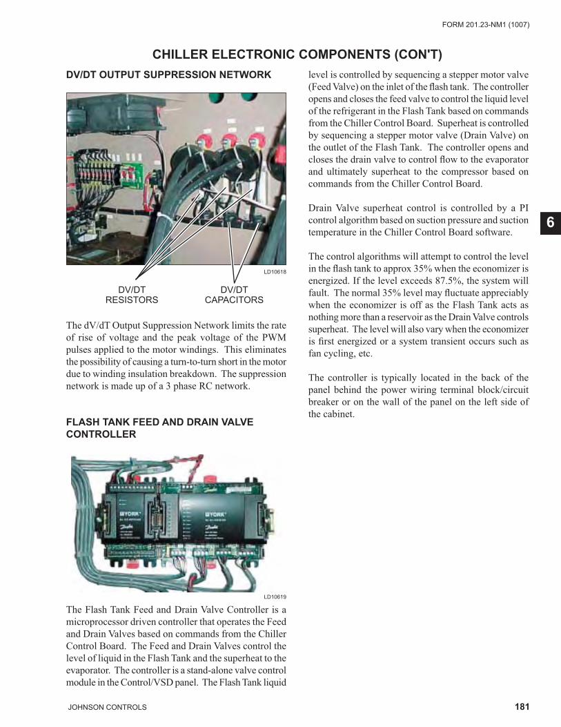
181JOHNSON CONTROLS
FORM 201.23-NM1 (1007)
6
CHILLER ELECTRONIC COMPONENTS (CON'T)DV/DT OUTPUT SUPPRESSION NETWORK
LD10618
DV/DTRESISTORS
DV/DTCAPACITORS
The dV/dT Output Suppression Network limits the rate of rise of voltage and the peak voltage of the PWM pulses applied to the motor windings. This eliminates the possibility of causing a turn-to-turn short in the motor due to winding insulation breakdown. The suppression network is made up of a 3 phase RC network.
FLASH TANK FEED AND DRAIN VALVE CONTROLLER
The Flash Tank Feed and Drain Valve Controller is a microprocessor driven controller that operates the Feed and Drain Valves based on commands from the Chiller Control Board. The Feed and Drain Valves control the level of liquid in the Flash Tank and the superheat to the evaporator. The controller is a stand-alone valve control module in the Control/VSD panel. The Flash Tank liquid
level is controlled by sequencing a stepper motor valve (Feed Valve) on the inlet of the fl ash tank. The controller opens and closes the feed valve to control the liquid level of the refrigerant in the Flash Tank based on commands from the Chiller Control Board. Superheat is controlled by sequencing a stepper motor valve (Drain Valve) on the outlet of the Flash Tank. The controller opens and closes the drain valve to control fl ow to the evaporator and ultimately superheat to the compressor based on commands from the Chiller Control Board.
Drain Valve superheat control is controlled by a PI control algorithm based on suction pressure and suction temperature in the Chiller Control Board software.
The control algorithms will attempt to control the level in the fl ash tank to approx 35% when the economizer is energized. If the level exceeds 87.5%, the system will fault. The normal 35% level may fl uctuate appreciably when the economizer is off as the Flash Tank acts as nothing more than a reservoir as the Drain Valve controls superheat. The level will also vary when the economizer is fi rst energized or a system transient occurs such as fan cycling, etc.
The controller is typically located in the back of the panel behind the power wiring terminal block/circuit breaker or on the wall of the panel on the left side of the cabinet.
LD10619
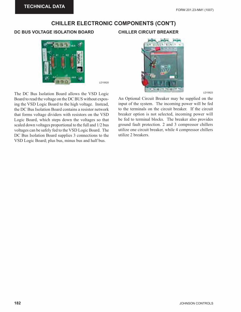
182 JOHNSON CONTROLS
FORM 201.23-NM1 (1007)TECHNICAL DATA
CHILLER ELECTRONIC COMPONENTS (CON'T)DC BUS VOLTAGE ISOLATION BOARD CHILLER CIRCUIT BREAKER
An Optional Circuit Breaker may be supplied on the input of the system. The incoming power will be fed to the terminals on the circuit breaker. If the circuit breaker option is not selected, incoming power will be fed to terminal blocks. The breaker also provides ground fault protection. 2 and 3 compressor chillers utilize one circuit breaker, while 4 compressor chillers utilize 2 breakers.
LD10620
LD10623The DC Bus Isolation Board allows the VSD Logic Board to read the voltage on the DC BUS without expos-ing the VSD Logic Board to the high voltage. Instead, the DC Bus Isolation Board contains a resistor network that forms voltage dividers with resistors on the VSD Logic Board, which steps down the voltages so that scaled down voltages proportional to the full and 1/2 bus voltages can be safely fed to the VSD Logic Board. The DC Bus Isolation Board supplies 3 connections to the VSD Logic Board; plus bus, minus bus and half bus.
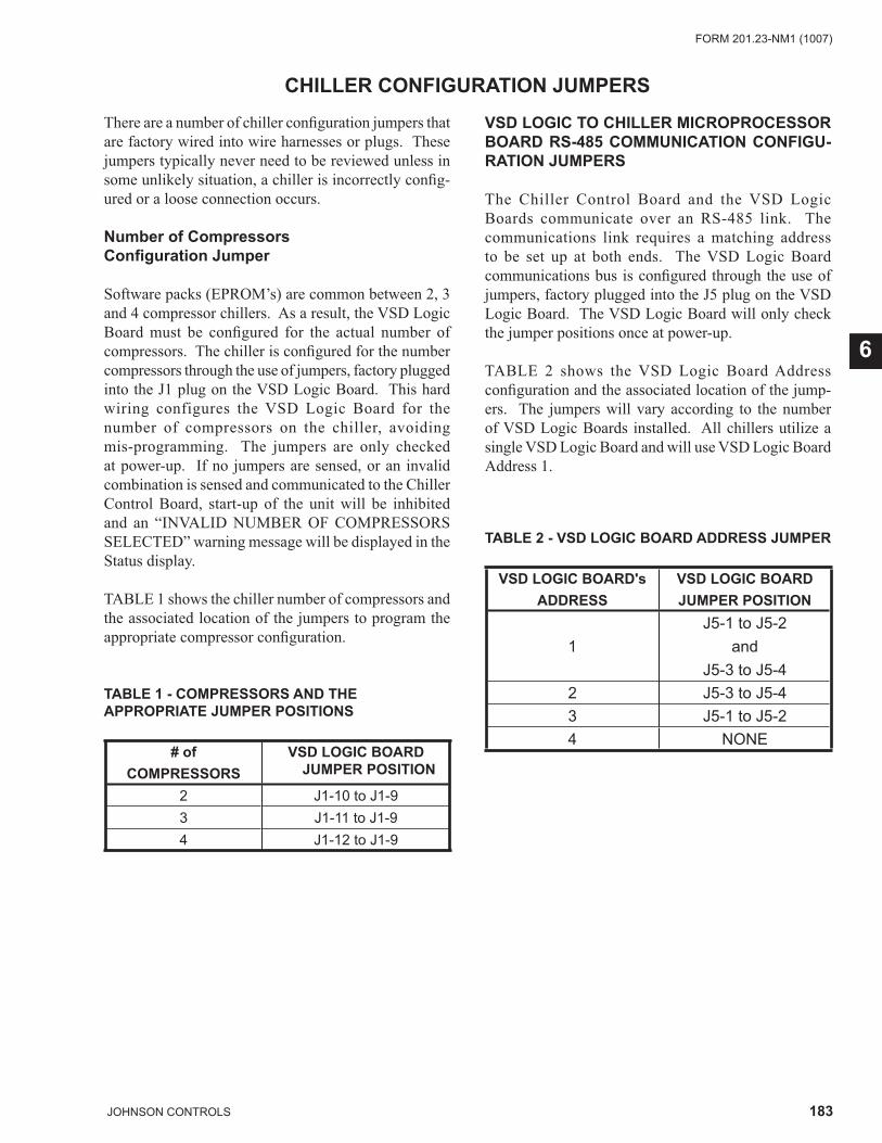
183JOHNSON CONTROLS
FORM 201.23-NM1 (1007)
6
CHILLER CONFIGURATION JUMPERS
There are a number of chiller confi guration jumpers that are factory wired into wire harnesses or plugs. These jumpers typically never need to be reviewed unless in some unlikely situation, a chiller is incorrectly confi g-ured or a loose connection occurs.
Number of Compressors Confi guration Jumper
Software packs (EPROM’s) are common between 2, 3 and 4 compressor chillers. As a result, the VSD Logic Board must be confi gured for the actual number of compressors. The chiller is confi gured for the number compressors through the use of jumpers, factory plugged into the J1 plug on the VSD Logic Board. This hard wiring configures the VSD Logic Board for the number of compressors on the chiller, avoiding mis-programming. The jumpers are only checked at power-up. If no jumpers are sensed, or an invalid combination is sensed and communicated to the Chiller Control Board, start-up of the unit will be inhibited and an “INVALID NUMBER OF COMPRESSORS SELECTED” warning message will be displayed in the Status display.
TABLE 1 shows the chiller number of compressors and the associated location of the jumpers to program the appropriate compressor confi guration.
TABLE 1 - COMPRESSORS AND THE APPROPRIATE JUMPER POSITIONS
# of COMPRESSORS
VSD LOGIC BOARD JUMPER POSITION
2 J1-10 to J1-93 J1-11 to J1-94 J1-12 to J1-9
VSD LOGIC TO CHILLER MICROPROCESSOR BOARD RS-485 COMMUNICATION CONFIGU-RATION JUMPERS
The Chiller Control Board and the VSD Logic Boards communicate over an RS-485 link. The communications link requires a matching address to be set up at both ends. The VSD Logic Board communications bus is confi gured through the use of jumpers, factory plugged into the J5 plug on the VSD Logic Board. The VSD Logic Board will only check the jumper positions once at power-up.
TABLE 2 shows the VSD Logic Board Address confi guration and the associated location of the jump-ers. The jumpers will vary according to the number of VSD Logic Boards installed. All chillers utilize a single VSD Logic Board and will use VSD Logic Board Address 1.
TABLE 2 - VSD LOGIC BOARD ADDRESS JUMPER
VSD LOGIC BOARD'sADDRESS
VSD LOGIC BOARDJUMPER POSITION
1J5-1 to J5-2
andJ5-3 to J5-4
2 J5-3 to J5-43 J5-1 to J5-24 NONE
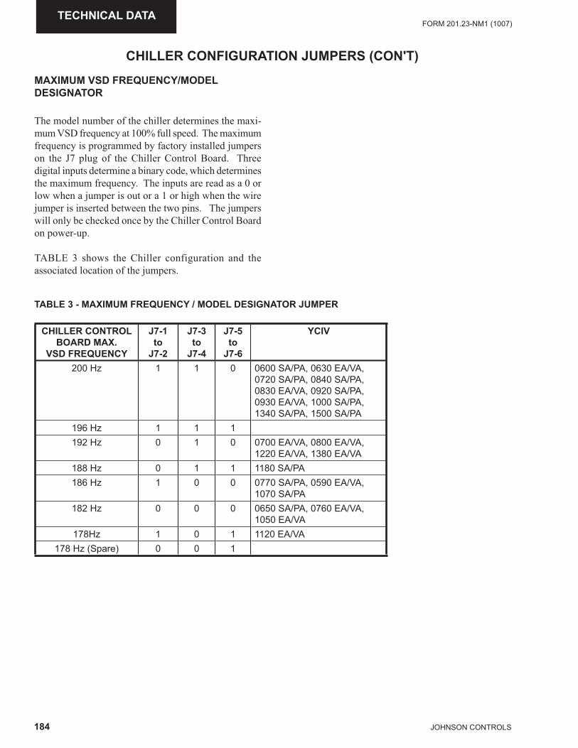
184 JOHNSON CONTROLS
FORM 201.23-NM1 (1007)TECHNICAL DATA
CHILLER CONFIGURATION JUMPERS (CON'T)
MAXIMUM VSD FREQUENCY/MODEL DESIGNATOR
The model number of the chiller determines the maxi-mum VSD frequency at 100% full speed. The maximum frequency is programmed by factory installed jumpers on the J7 plug of the Chiller Control Board. Three digital inputs determine a binary code, which determines the maximum frequency. The inputs are read as a 0 or low when a jumper is out or a 1 or high when the wire jumper is inserted between the two pins. The jumpers will only be checked once by the Chiller Control Board on power-up.
TABLE 3 shows the Chiller configuration and the associated location of the jumpers.
TABLE 3 - MAXIMUM FREQUENCY / MODEL DESIGNATOR JUMPER
CHILLER CONTROL BOARD MAX.
VSD FREQUENCY
J7-1to
J7-2
J7-3to
J7-4
J7-5to
J7-6
YCIV
200 Hz 1 1 0 0600 SA/PA, 0630 EA/VA, 0720 SA/PA, 0840 SA/PA, 0830 EA/VA, 0920 SA/PA, 0930 EA/VA, 1000 SA/PA, 1340 SA/PA, 1500 SA/PA
196 Hz 1 1 1192 Hz 0 1 0 0700 EA/VA, 0800 EA/VA,
1220 EA/VA, 1380 EA/VA188 Hz 0 1 1 1180 SA/PA186 Hz 1 0 0 0770 SA/PA, 0590 EA/VA,
1070 SA/PA182 Hz 0 0 0 0650 SA/PA, 0760 EA/VA,
1050 EA/VA178Hz 1 0 1 1120 EA/VA
178 Hz (Spare) 0 0 1
185JOHNSON CONTROLS
FORM 201.23-NM1 (1007)
7
OPERATING CONTROLSAnti-recycle Timer
A typical 5 or 10 minute anti-recycle timer is not necessary to allow compressor motor cooling, due to the VSD’s ability to provide a low current inrush start. The system does utilize a fi xed 120 second anti-recycle timer to prevent short cycling of systems and to allow positioning the Feed and Drain Valves to a zero (closed) position by the Flash Tank Drain and Feed Valve Con-troller in the event of a power failure.
On power-up of the control panel, the anti-recycle timer for each system will be set to 120 seconds and must time out before a compressor is allowed to start.
Whenever a system starts, the anti-recycle timer for all systems will be set to 120 seconds and will count down from the time the motor starts. The timer must time out before another compressor is allowed to start.
Whenever a system shuts down, the anti-recycle timer for that system will be set to 120 seconds. The timer must time out before the system is allowed to restart.
Evaporator Pump Control
The evaporator pump dry contacts are energized when any of the following conditions are true:
· If a Low Leaving Chilled Liquid Fault occurs.
· Whenever a compressor is running.
· The Daily Schedule is ON and the Unit Switch is ON.
Even if one of above is true, the pump will not run if the panel has been powered up for less than 30 seconds or if the pump has run in the last 30 seconds to prevent pump motor overheating.
Evaporator Heater Control
The evaporator heater is controlled by ambient air temperature. If no systems are running and the ambient temperature drops below 40°F, the heater is turned on. If no systems are running and the temperature rises above 45°F the heater is turned off. Whenever a system is running, the evaporator heater is turned off. Both evaporator heater outputs will always be turned on
and off together. An under voltage condition will keep the heater off until full voltage is restored to the system. The heater will protect the evaporator from freeze-up down to –20°F (-29°C).
Pumpdown Control
The VSD assures a smooth slow compressor start. As a result of this, neither pumpdown on start-up or pumpdown on shutdown is required. The Drain and Feed Valves will close when a compressor stops. This is a similar to a liquid line solenoid valve closing on a conventional chiller.
Compressor Heater Control
Each compressor has its own heater. The purpose of the heater is to assure refrigerant does not condense in the compressor. There is no oil sump, but refrigerant could possibly condense in the rotors or the motor housing. The heater will be off whenever the respective compres-sor is running. As soon as the compressor shuts off, the heater will turn on as long as all motor temperature sensors in the compressor read <158°F. The heater will turn off, if any internal compressor motor temperature sensor reads >160°F.
Alarms
Each system has its own alarm. The Alarm output is ON (dry contact closed) when no fault condition is present and OFF (dry contact open) to indicate an alarm situation. The Alarm should be activated (contact open), if any of the following are true.
· A System is faulted or inhibited from starting for more than 5 seconds.
· The Unit is faulted or inhibited from starting for more than 5 seconds.
· A System is locked out.
· The Unit is locked out.
· Power is removed from the chiller.
SECTION 7 - OPERATION
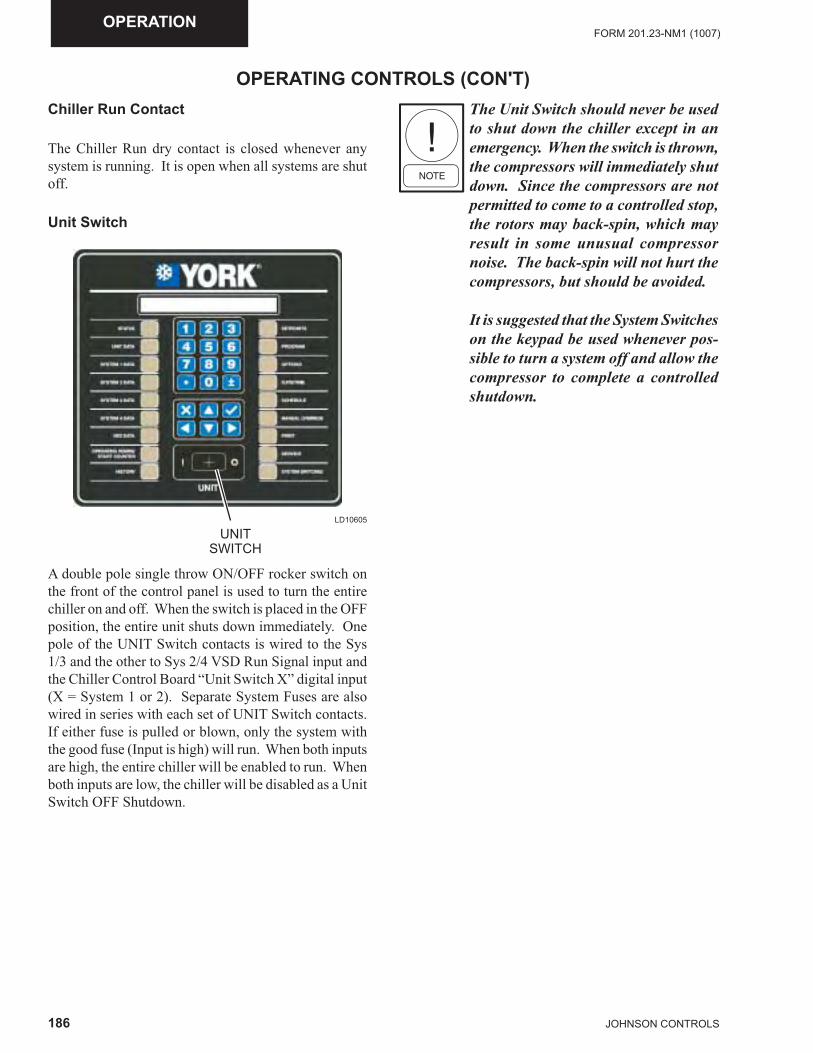
186 JOHNSON CONTROLS
FORM 201.23-NM1 (1007)OPERATION
OPERATING CONTROLS (CON'T)Chiller Run Contact
The Chiller Run dry contact is closed whenever any system is running. It is open when all systems are shut off.
Unit Switch
A double pole single throw ON/OFF rocker switch on the front of the control panel is used to turn the entire chiller on and off. When the switch is placed in the OFF position, the entire unit shuts down immediately. One pole of the UNIT Switch contacts is wired to the Sys 1/3 and the other to Sys 2/4 VSD Run Signal input and the Chiller Control Board “Unit Switch X” digital input (X = System 1 or 2). Separate System Fuses are also wired in series with each set of UNIT Switch contacts. If either fuse is pulled or blown, only the system with the good fuse (Input is high) will run. When both inputs are high, the entire chiller will be enabled to run. When both inputs are low, the chiller will be disabled as a Unit Switch OFF Shutdown.
LD10605
UNITSWITCH
The Unit Switch should never be used to shut down the chiller except in an emergency. When the switch is thrown, the compressors will immediately shut down. Since the compressors are not permitted to come to a controlled stop, the rotors may back-spin, which may result in some unusual compressor noise. The back-spin will not hurt the compressors, but should be avoided.
It is suggested that the System Switches on the keypad be used whenever pos-sible to turn a system off and allow the compressor to complete a controlled shutdown.
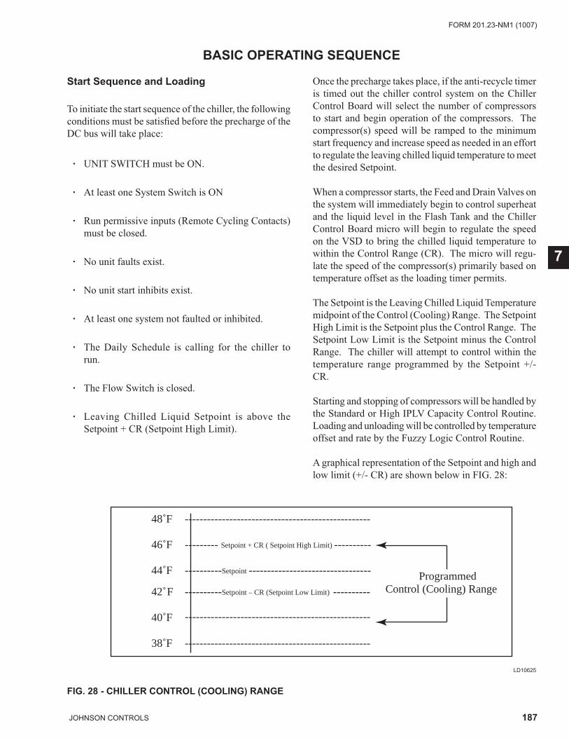
187JOHNSON CONTROLS
FORM 201.23-NM1 (1007)
7
BASIC OPERATING SEQUENCE
Start Sequence and Loading
To initiate the start sequence of the chiller, the following conditions must be satisfi ed before the precharge of the DC bus will take place:
· UNIT SWITCH must be ON.
· At least one System Switch is ON
· Run permissive inputs (Remote Cycling Contacts) must be closed.
· No unit faults exist.
· No unit start inhibits exist. · At least one system not faulted or inhibited.
· The Daily Schedule is calling for the chiller to run.
· The Flow Switch is closed.
· Leaving Chilled Liquid Setpoint is above the Setpoint + CR (Setpoint High Limit).
Once the precharge takes place, if the anti-recycle timer is timed out the chiller control system on the Chiller Control Board will select the number of compressors to start and begin operation of the compressors. The compressor(s) speed will be ramped to the minimum start frequency and increase speed as needed in an effort to regulate the leaving chilled liquid temperature to meet the desired Setpoint.
When a compressor starts, the Feed and Drain Valves on the system will immediately begin to control superheat and the liquid level in the Flash Tank and the Chiller Control Board micro will begin to regulate the speed on the VSD to bring the chilled liquid temperature to within the Control Range (CR). The micro will regu-late the speed of the compressor(s) primarily based on temperature offset as the loading timer permits. The Setpoint is the Leaving Chilled Liquid Temperature midpoint of the Control (Cooling) Range. The Setpoint High Limit is the Setpoint plus the Control Range. The Setpoint Low Limit is the Setpoint minus the Control Range. The chiller will attempt to control within the temperature range programmed by the Setpoint +/- CR.
Starting and stopping of compressors will be handled by the Standard or High IPLV Capacity Control Routine. Loading and unloading will be controlled by temperature offset and rate by the Fuzzy Logic Control Routine.
A graphical representation of the Setpoint and high and low limit (+/- CR) are shown below in FIG. 28:
48˚F -------------------------------------------------- 46˚F --------- Setpoint + CR ( Setpoint High Limit) ----------
Programmed
44˚F ----------Setpoint ---------------------------------
Control (Cooling) Range
42˚F ---------- ----------Setpoint – CR (Setpoint Low Limit)
40˚F
38˚F --------------------------------------------------
--------------------------------------------------
FIG. 28 - CHILLER CONTROL (COOLING) RANGE
LD10625
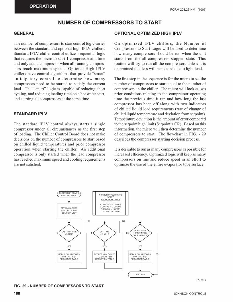
188 JOHNSON CONTROLS
FORM 201.23-NM1 (1007)OPERATION
NUMBER OF COMPRESSORS TO START
GENERAL
The number of compressors to start control logic varies between the standard and optional high IPLV chillers. Standard IPLV chiller control utilizes sequential logic that requires the micro to start 1 compressor at a time and only add a compressor when all running compres-sors reach maximum speed. Optional High IPLV chillers have control algorithms that provide “smart” anticipatory control to determine how many compressors need to be started to satisfy the current load. The “smart” logic is capable of reducing short cycling, and reducing loading time on a hot water start, and starting all compressors at the same time.
STANDARD IPLV
The standard IPLV control always starts a single compressor under all circumstances as the fi rst step of loading. The Chiller Control Board does not make decisions on the number of compressors to start based on chilled liquid temperatures and prior compressor operation when starting the chiller. An additional compressor is only started when the lead compressor has reached maximum speed and cooling requirements are not satisfi ed.
OPTIONAL OPTIMIZED HIGH IPLV
On optimized IPLV chillers, the Number of Compressors to Start Logic will be used to determine how many compressors should be run when the unit starts from the all compressors stopped state. This routine will try to run all the compressors unless it is determined that less will be needed due to light load.
The fi rst step in the sequence is for the micro to set the number of compressors to start equal to the number of compressors in the chiller. The micro will look at two prior conditions relating to the compressor operating time the previous time it ran and how long the last compressor has been off along with two indicators of chilled liquid load requirements (rate of change of chilled liquid temperature and deviation from setpoint). Temperature deviation is the amount of error compared to the setpoint high limit (Setpoint + CR). Based on this information, the micro will then determine the number of compressors to start. The fl owchart in FIG. - 29 describes the compressor starting decision process.
It is desirable to run as many compressors as possible for increased effi ciency. Optimized logic will keep as many compressors on line and reduce speed in an effort to optimize the use of the entire evaporator tube surface.
NUMBER OF COMPSTO START LOGIC NUMBER OF COMPS TO
STARTREDUCTION TABLE
4 COMPS -> 3 COMPS3 COMPS -> 2 COMPS2 COMPS -> 1 COMP1 COMP -> 1 COMP
SET NUM COMPSTO START = NUMCOMPS IN UNIT
LAST RUN TIME< 5 MIN ?
YES
REDUCE NUM COMPSTO START PER
REDUCTION TABLE
OFF TIME< 5 MIN ?
YES
REDUCE NUM COMPSTO START PER
REDUCTION TABLE
NO
CONTINUE
LCHLT RATE< 3 °F/MIN AND
LCHLT < CR+5°F?
NO
YES
REDUCE NUM COMPSTO START PER
REDUCTION TABLE
NO
FIG. 29 - NUMBER OF COMPRESSORS TO STARTLD10626
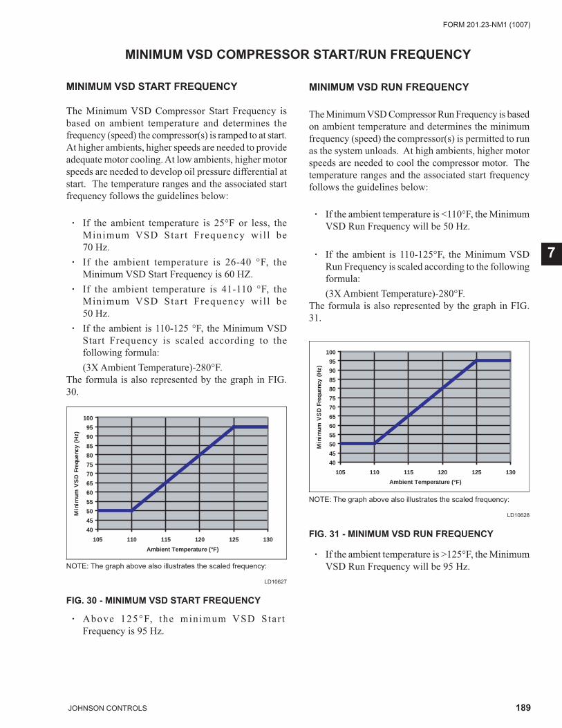
189JOHNSON CONTROLS
FORM 201.23-NM1 (1007)
7
MINIMUM VSD COMPRESSOR START/RUN FREQUENCY
MINIMUM VSD START FREQUENCY
The Minimum VSD Compressor Start Frequency is based on ambient temperature and determines the frequency (speed) the compressor(s) is ramped to at start. At higher ambients, higher speeds are needed to provide adequate motor cooling. At low ambients, higher motor speeds are needed to develop oil pressure differential at start. The temperature ranges and the associated start frequency follows the guidelines below:
· If the ambient temperature is 25°F or less, theMinimum VSD Star t Frequency wil l be 70 Hz.
· If the ambient temperature is 26-40 °F, theMinimum VSD Start Frequency is 60 HZ.
· If the ambient temperature is 41-110 °F, theMinimum VSD Star t Frequency wil l be50 Hz.
· If the ambient is 110-125 °F, the Minimum VSDStart Frequency is scaled according to the following formula:
(3X Ambient Temperature)-280°F.The formula is also represented by the graph in FIG. 30.
NOTE: The graph above also illustrates the scaled frequency:
FIG. 30 - MINIMUM VSD START FREQUENCY
LD10627
40
45
50
55
60
65
70
75
80
85
90
95
100
105 110 115 120 125 130
Ambient Temperature (°F)
Min
imum
VS
D F
requ
ency
(H
z)
NOTE: The graph above also illustrates the scaled frequency:
FIG. 31 - MINIMUM VSD RUN FREQUENCY
LD10628
40
45
50
55
60
65
70
75
80
85
90
95
100
105 110 115 120 125 130
Ambient Temperature (°F)
Min
imum
VS
D F
requ
ency
(H
z)
MINIMUM VSD RUN FREQUENCY
The Minimum VSD Compressor Run Frequency is based on ambient temperature and determines the minimum frequency (speed) the compressor(s) is permitted to run as the system unloads. At high ambients, higher motor speeds are needed to cool the compressor motor. The temperature ranges and the associated start frequency follows the guidelines below:
· If the ambient temperature is <110°F, the Minimum VSD Run Frequency will be 50 Hz.
· If the ambient is 110-125°F, the Minimum VSD Run Frequency is scaled according to the following formula:
(3X Ambient Temperature)-280°F.The formula is also represented by the graph in FIG. 31.
· Above 125°F, the minimum VSD Star t Frequency is 95 Hz.
· If the ambient temperature is >125°F, the Minimum VSD Run Frequency will be 95 Hz.
190 JOHNSON CONTROLS
FORM 201.23-NM1 (1007)OPERATION
ACCELERATION/DECELERATION RATE WHEN STARTING/STOPPING COMPRESSORS
VSD ACCELERATION AND DECELERATION RATES
The acceleration rate changes with frequency and fol-lows the guidelines below:
· Between 0 and 50 Hz, the acceleration is 10 Hz/sec.
· Between 50 and 200 Hz, the acceleration is 30.4 Hz/sec. Even though the accel rate of 30.4 Hz/sec is possible up to 200 Hz, the frequency (speed) is limited by the minimum start frequency and the add a compressor frequency calculation performed by the micro when bringing on an additional compressor.
When decelerating, the deceleration rate changes with frequency and follows the guidelines below:
· Between 200 and 100 Hz, the deceleration time is 30.4 Hz/sec.
· Between 100 and 0 Hz, the deceleration time is 10 Hz/sec.
When a compressor stops, back-spin of the compressor will often occur as the pressure differential between discharge and suction equalizes. This should not be a cause of concern.
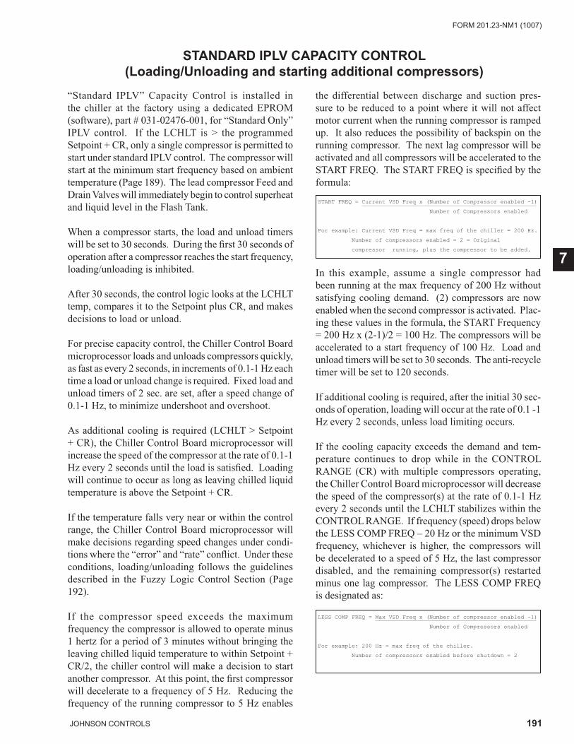
191JOHNSON CONTROLS
FORM 201.23-NM1 (1007)
7
STANDARD IPLV CAPACITY CONTROL(Loading/Unloading and starting additional compressors)
“Standard IPLV” Capacity Control is installed in the chiller at the factory using a dedicated EPROM (software), part # 031-02476-001, for “Standard Only” IPLV control. If the LCHLT is > the programmed Setpoint + CR, only a single compressor is permitted to start under standard IPLV control. The compressor will start at the minimum start frequency based on ambient temperature (Page 189). The lead compressor Feed and Drain Valves will immediately begin to control superheat and liquid level in the Flash Tank.
When a compressor starts, the load and unload timers will be set to 30 seconds. During the fi rst 30 seconds of operation after a compressor reaches the start frequency, loading/unloading is inhibited.
After 30 seconds, the control logic looks at the LCHLT temp, compares it to the Setpoint plus CR, and makes decisions to load or unload.
For precise capacity control, the Chiller Control Board microprocessor loads and unloads compressors quickly, as fast as every 2 seconds, in increments of 0.1-1 Hz each time a load or unload change is required. Fixed load and unload timers of 2 sec. are set, after a speed change of 0.1-1 Hz, to minimize undershoot and overshoot.
As additional cooling is required (LCHLT > Setpoint + CR), the Chiller Control Board microprocessor will increase the speed of the compressor at the rate of 0.1-1 Hz every 2 seconds until the load is satisfi ed. Loading will continue to occur as long as leaving chilled liquid temperature is above the Setpoint + CR.
If the temperature falls very near or within the control range, the Chiller Control Board microprocessor will make decisions regarding speed changes under condi-tions where the “error” and “rate” confl ict. Under these conditions, loading/unloading follows the guidelines described in the Fuzzy Logic Control Section (Page 192).
If the compressor speed exceeds the maximum frequency the compressor is allowed to operate minus 1 hertz for a period of 3 minutes without bringing the leaving chilled liquid temperature to within Setpoint + CR/2, the chiller control will make a decision to start another compressor. At this point, the fi rst compressor will decelerate to a frequency of 5 Hz. Reducing the frequency of the running compressor to 5 Hz enables
the differential between discharge and suction pres-sure to be reduced to a point where it will not affect motor current when the running compressor is ramped up. It also reduces the possibility of backspin on the running compressor. The next lag compressor will be activated and all compressors will be accelerated to the START FREQ. The START FREQ is specifi ed by the formula:
START FREQ = Current VSD Freq x (Number of Compressor enabled -1)
Number of Compressors enabled
For example: Current VSD Freq = max freq of the chiller = 200 Hz.
Number of compressors enabled = 2 = Original
compressor running, plus the compressor to be added.
In this example, assume a single compressor had been running at the max frequency of 200 Hz without satisfying cooling demand. (2) compressors are now enabled when the second compressor is activated. Plac-ing these values in the formula, the START Frequency = 200 Hz x (2-1)/2 = 100 Hz. The compressors will be accelerated to a start frequency of 100 Hz. Load and unload timers will be set to 30 seconds. The anti-recycle timer will be set to 120 seconds.
If additional cooling is required, after the initial 30 sec-onds of operation, loading will occur at the rate of 0.1 -1 Hz every 2 seconds, unless load limiting occurs.
If the cooling capacity exceeds the demand and tem-perature continues to drop while in the CONTROL RANGE (CR) with multiple compressors operating, the Chiller Control Board microprocessor will decrease the speed of the compressor(s) at the rate of 0.1-1 Hz every 2 seconds until the LCHLT stabilizes within the CONTROL RANGE. If frequency (speed) drops below the LESS COMP FREQ – 20 Hz or the minimum VSD frequency, whichever is higher, the compressors will be decelerated to a speed of 5 Hz, the last compressor disabled, and the remaining compressor(s) restarted minus one lag compressor. The LESS COMP FREQ is designated as:
LESS COMP FREQ = Max VSD Freq x (Number of compressor enabled -1)
Number of Compressors enabled
For example: 200 Hz = max freq of the chiller.
Number of compressors enabled before shutdown = 2
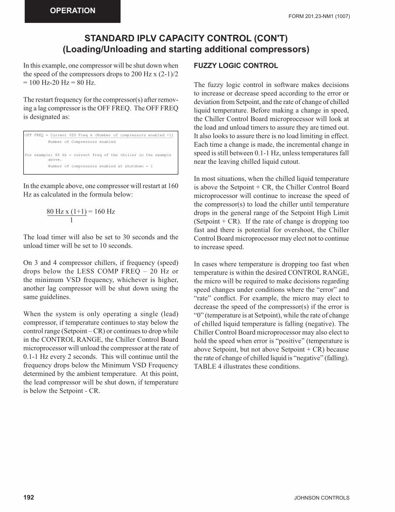
192 JOHNSON CONTROLS
FORM 201.23-NM1 (1007)OPERATION
STANDARD IPLV CAPACITY CONTROL (CON'T)(Loading/Unloading and starting additional compressors)
In this example, one compressor will be shut down when the speed of the compressors drops to 200 Hz x (2-1)/2 = 100 Hz-20 Hz = 80 Hz.
The restart frequency for the compressor(s) after remov-ing a lag compressor is the OFF FREQ. The OFF FREQ is designated as:
In the example above, one compressor will restart at 160 Hz as calculated in the formula below:
80 Hz x (1+1) = 160 Hz 1
The load timer will also be set to 30 seconds and the unload timer will be set to 10 seconds.
On 3 and 4 compressor chillers, if frequency (speed) drops below the LESS COMP FREQ – 20 Hz or the minimum VSD frequency, whichever is higher, another lag compressor will be shut down using the same guidelines.
When the system is only operating a single (lead) compressor, if temperature continues to stay below the control range (Setpoint – CR) or continues to drop while in the CONTROL RANGE, the Chiller Control Board microprocessor will unload the compressor at the rate of 0.1-1 Hz every 2 seconds. This will continue until the frequency drops below the Minimum VSD Frequency determined by the ambient temperature. At this point, the lead compressor will be shut down, if temperature is below the Setpoint - CR.
OFF FREQ = Current VSD Freq x (Number of compressors enabled +1)
Number of Compressors enabled
For example: 80 Hz = current freq of the chiller in the example above.
Number of compressors enabled at shutdown = 1
FUZZY LOGIC CONTROL
The fuzzy logic control in software makes decisions to increase or decrease speed according to the error or deviation from Setpoint, and the rate of change of chilled liquid temperature. Before making a change in speed, the Chiller Control Board microprocessor will look at the load and unload timers to assure they are timed out. It also looks to assure there is no load limiting in effect. Each time a change is made, the incremental change in speed is still between 0.1-1 Hz, unless temperatures fall near the leaving chilled liquid cutout. In most situations, when the chilled liquid temperature is above the Setpoint + CR, the Chiller Control Board microprocessor will continue to increase the speed of the compressor(s) to load the chiller until temperature drops in the general range of the Setpoint High Limit (Setpoint + CR). If the rate of change is dropping too fast and there is potential for overshoot, the Chiller Control Board microprocessor may elect not to continue to increase speed.
In cases where temperature is dropping too fast when temperature is within the desired CONTROL RANGE, the micro will be required to make decisions regarding speed changes under conditions where the “error” and “rate” confl ict. For example, the micro may elect to decrease the speed of the compressor(s) if the error is “0” (temperature is at Setpoint), while the rate of change of chilled liquid temperature is falling (negative). The Chiller Control Board microprocessor may also elect to hold the speed when error is “positive” (temperature is above Setpoint, but not above Setpoint + CR) because the rate of change of chilled liquid is “negative” (falling). TABLE 4 illustrates these conditions.
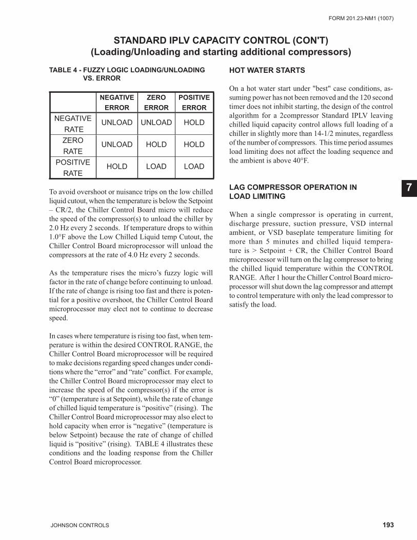
193JOHNSON CONTROLS
FORM 201.23-NM1 (1007)
7
STANDARD IPLV CAPACITY CONTROL (CON'T)(Loading/Unloading and starting additional compressors)
To avoid overshoot or nuisance trips on the low chilled liquid cutout, when the temperature is below the Setpoint – CR/2, the Chiller Control Board micro will reduce the speed of the compressor(s) to unload the chiller by 2.0 Hz every 2 seconds. If temperature drops to within 1.0°F above the Low Chilled Liquid temp Cutout, the Chiller Control Board microprocessor will unload the compressors at the rate of 4.0 Hz every 2 seconds.
As the temperature rises the micro’s fuzzy logic will factor in the rate of change before continuing to unload. If the rate of change is rising too fast and there is poten-tial for a positive overshoot, the Chiller Control Board microprocessor may elect not to continue to decrease speed.
In cases where temperature is rising too fast, when tem-perature is within the desired CONTROL RANGE, the Chiller Control Board microprocessor will be required to make decisions regarding speed changes under condi-tions where the “error” and “rate” confl ict. For example, the Chiller Control Board microprocessor may elect to increase the speed of the compressor(s) if the error is “0” (temperature is at Setpoint), while the rate of change of chilled liquid temperature is “positive” (rising). The Chiller Control Board microprocessor may also elect to hold capacity when error is “negative” (temperature is below Setpoint) because the rate of change of chilled liquid is “positive” (rising). TABLE 4 illustrates these conditions and the loading response from the Chiller Control Board microprocessor.
TABLE 4 - FUZZY LOGIC LOADING/UNLOADINGVS. ERROR
NEGATIVEERROR
ZEROERROR
POSITIVEERROR
NEGATIVE RATE
UNLOAD UNLOAD HOLD
ZERO RATE
UNLOAD HOLD HOLD
POSITIVE RATE
HOLD LOAD LOAD
HOT WATER STARTS
On a hot water start under "best" case conditions, as-suming power has not been removed and the 120 second timer does not inhibit starting, the design of the control algorithm for a 2compressor Standard IPLV leaving chilled liquid capacity control allows full loading of a chiller in slightly more than 14-1/2 minutes, regardless of the number of compressors. This time period assumes load limiting does not affect the loading sequence and the ambient is above 40°F.
LAG COMPRESSOR OPERATION IN LOAD LIMITING
When a single compressor is operating in current, discharge pressure, suction pressure, VSD internal ambient, or VSD baseplate temperature limiting for more than 5 minutes and chilled liquid tempera-ture is > Setpoint + CR, the Chiller Control Board microprocessor will turn on the lag compressor to bring the chilled liquid temperature within the CONTROL RANGE. After 1 hour the Chiller Control Board micro-processor will shut down the lag compressor and attempt to control temperature with only the lead compressor to satisfy the load.
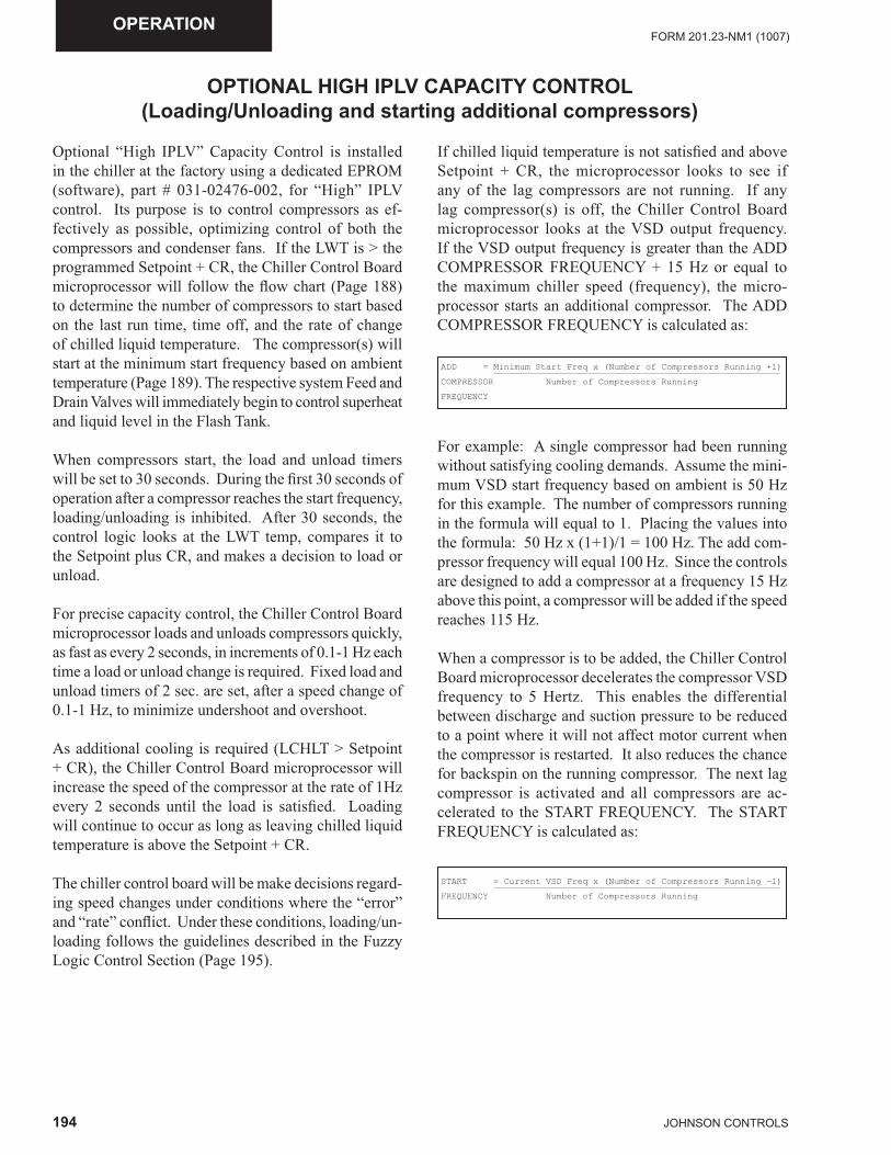
194 JOHNSON CONTROLS
FORM 201.23-NM1 (1007)OPERATION
OPTIONAL HIGH IPLV CAPACITY CONTROL (Loading/Unloading and starting additional compressors)
Optional “High IPLV” Capacity Control is installed in the chiller at the factory using a dedicated EPROM (software), part # 031-02476-002, for “High” IPLV control. Its purpose is to control compressors as ef-fectively as possible, optimizing control of both the compressors and condenser fans. If the LWT is > the programmed Setpoint + CR, the Chiller Control Board microprocessor will follow the fl ow chart (Page 188) to determine the number of compressors to start based on the last run time, time off, and the rate of change of chilled liquid temperature. The compressor(s) will start at the minimum start frequency based on ambient temperature (Page 189). The respective system Feed and Drain Valves will immediately begin to control superheat and liquid level in the Flash Tank.
When compressors start, the load and unload timers will be set to 30 seconds. During the fi rst 30 seconds of operation after a compressor reaches the start frequency, loading/unloading is inhibited. After 30 seconds, the control logic looks at the LWT temp, compares it to the Setpoint plus CR, and makes a decision to load or unload.
For precise capacity control, the Chiller Control Board microprocessor loads and unloads compressors quickly, as fast as every 2 seconds, in increments of 0.1-1 Hz each time a load or unload change is required. Fixed load and unload timers of 2 sec. are set, after a speed change of 0.1-1 Hz, to minimize undershoot and overshoot.
As additional cooling is required (LCHLT > Setpoint + CR), the Chiller Control Board microprocessor will increase the speed of the compressor at the rate of 1Hz every 2 seconds until the load is satisfi ed. Loading will continue to occur as long as leaving chilled liquid temperature is above the Setpoint + CR.
The chiller control board will be make decisions regard-ing speed changes under conditions where the “error” and “rate” confl ict. Under these conditions, loading/un-loading follows the guidelines described in the Fuzzy Logic Control Section (Page 195).
If chilled liquid temperature is not satisfi ed and above Setpoint + CR, the microprocessor looks to see if any of the lag compressors are not running. If any lag compressor(s) is off, the Chiller Control Board microprocessor looks at the VSD output frequency. If the VSD output frequency is greater than the ADD COMPRESSOR FREQUENCY + 15 Hz or equal to the maximum chiller speed (frequency), the micro-processor starts an additional compressor. The ADD COMPRESSOR FREQUENCY is calculated as:
ADD = Minimum Start Freq x (Number of Compressors Running +1)
COMPRESSOR Number of Compressors Running
FREQUENCY
For example: A single compressor had been running without satisfying cooling demands. Assume the mini-mum VSD start frequency based on ambient is 50 Hz for this example. The number of compressors running in the formula will equal to 1. Placing the values into the formula: 50 Hz x (1+1)/1 = 100 Hz. The add com-pressor frequency will equal 100 Hz. Since the controls are designed to add a compressor at a frequency 15 Hz above this point, a compressor will be added if the speed reaches 115 Hz.
When a compressor is to be added, the Chiller Control Board microprocessor decelerates the compressor VSD frequency to 5 Hertz. This enables the differential between discharge and suction pressure to be reduced to a point where it will not affect motor current when the compressor is restarted. It also reduces the chance for backspin on the running compressor. The next lag compressor is activated and all compressors are ac-celerated to the START FREQUENCY. The START FREQUENCY is calculated as:
START = Current VSD Freq x (Number of Compressors Running –1)
FREQUENCY Number of Compressors Running
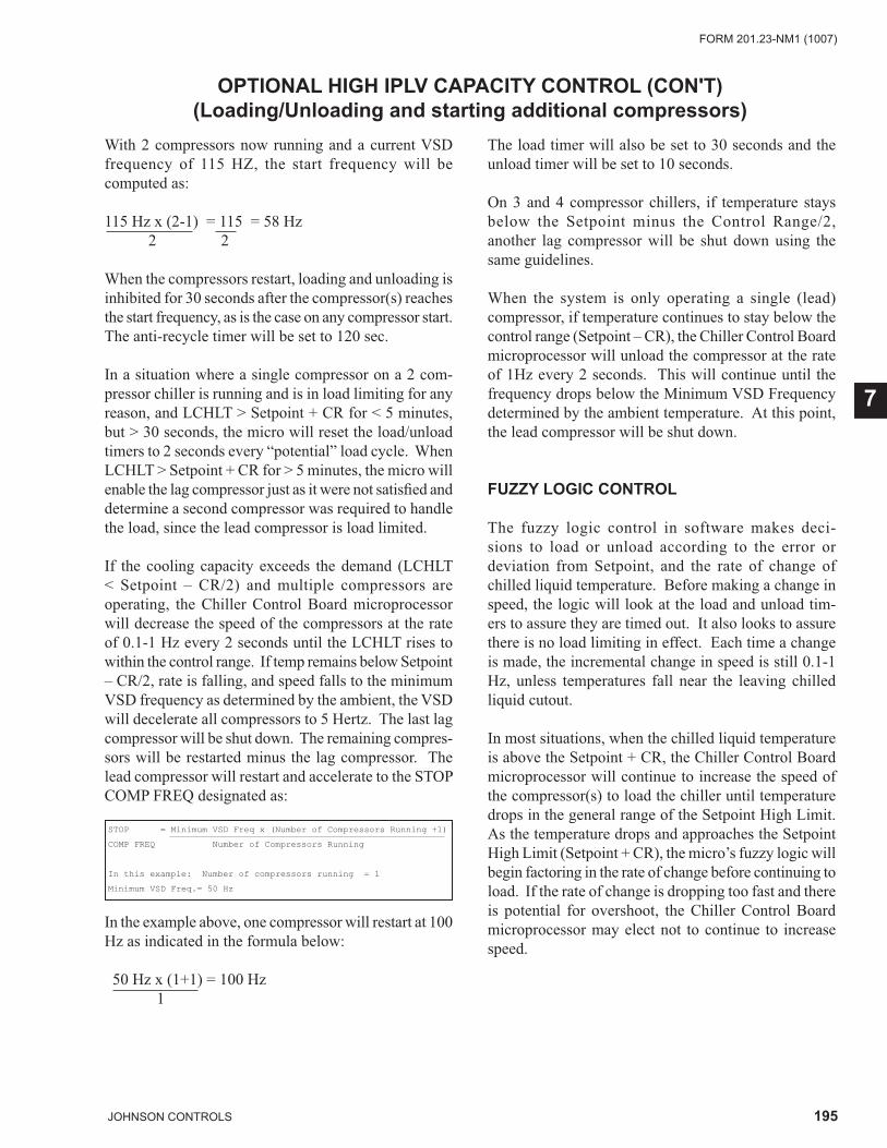
195JOHNSON CONTROLS
FORM 201.23-NM1 (1007)
7
OPTIONAL HIGH IPLV CAPACITY CONTROL (CON'T)(Loading/Unloading and starting additional compressors)
With 2 compressors now running and a current VSD frequency of 115 HZ, the start frequency will be computed as:
115 Hz x (2-1) = 115 = 58 Hz 2 2
When the compressors restart, loading and unloading is inhibited for 30 seconds after the compressor(s) reaches the start frequency, as is the case on any compressor start. The anti-recycle timer will be set to 120 sec.
In a situation where a single compressor on a 2 com-pressor chiller is running and is in load limiting for any reason, and LCHLT > Setpoint + CR for < 5 minutes, but > 30 seconds, the micro will reset the load/unload timers to 2 seconds every “potential” load cycle. When LCHLT > Setpoint + CR for > 5 minutes, the micro will enable the lag compressor just as it were not satisfi ed and determine a second compressor was required to handle the load, since the lead compressor is load limited.
If the cooling capacity exceeds the demand (LCHLT < Setpoint – CR/2) and multiple compressors are operating, the Chiller Control Board microprocessor will decrease the speed of the compressors at the rate of 0.1-1 Hz every 2 seconds until the LCHLT rises to within the control range. If temp remains below Setpoint – CR/2, rate is falling, and speed falls to the minimum VSD frequency as determined by the ambient, the VSD will decelerate all compressors to 5 Hertz. The last lag compressor will be shut down. The remaining compres-sors will be restarted minus the lag compressor. The lead compressor will restart and accelerate to the STOP COMP FREQ designated as:
STOP = Minimum VSD Freq x (Number of Compressors Running +1)
COMP FREQ Number of Compressors Running
In this example: Number of compressors running = 1
Minimum VSD Freq.= 50 Hz
In the example above, one compressor will restart at 100 Hz as indicated in the formula below:
50 Hz x (1+1) = 100 Hz 1
The load timer will also be set to 30 seconds and the unload timer will be set to 10 seconds.
On 3 and 4 compressor chillers, if temperature stays below the Setpoint minus the Control Range/2, another lag compressor will be shut down using the same guidelines.
When the system is only operating a single (lead) compressor, if temperature continues to stay below the control range (Setpoint – CR), the Chiller Control Board microprocessor will unload the compressor at the rate of 1Hz every 2 seconds. This will continue until the frequency drops below the Minimum VSD Frequency determined by the ambient temperature. At this point, the lead compressor will be shut down.
FUZZY LOGIC CONTROL
The fuzzy logic control in software makes deci-sions to load or unload according to the error or deviation from Setpoint, and the rate of change of chilled liquid temperature. Before making a change in speed, the logic will look at the load and unload tim-ers to assure they are timed out. It also looks to assure there is no load limiting in effect. Each time a change is made, the incremental change in speed is still 0.1-1 Hz, unless temperatures fall near the leaving chilled liquid cutout.
In most situations, when the chilled liquid temperature is above the Setpoint + CR, the Chiller Control Board microprocessor will continue to increase the speed of the compressor(s) to load the chiller until temperature drops in the general range of the Setpoint High Limit. As the temperature drops and approaches the Setpoint High Limit (Setpoint + CR), the micro’s fuzzy logic will begin factoring in the rate of change before continuing to load. If the rate of change is dropping too fast and there is potential for overshoot, the Chiller Control Board microprocessor may elect not to continue to increase speed.
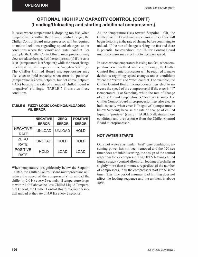
196 JOHNSON CONTROLS
FORM 201.23-NM1 (1007)OPERATION
In cases where temperature is dropping too fast, when temperature is within the desired control range, the Chiller Control Board microprocessor will be required to make decisions regarding speed changes under conditions where the “error” and “rate” confl ict. For example, the Chiller Control Board microprocessor may elect to reduce the speed of the compressor(s) if the error is “0” (temperature is at Setpoint); while the rate of change of chilled liquid temperature is “negative“(falling). The Chiller Control Board microprocessor may also elect to hold capacity when error is “positive” (temperature is above Setpoint, but not above Setpoint + CR) because the rate of change of chilled liquid is “negative” (falling). TABLE 5 illustrates these conditions.
OPTIONAL HIGH IPLV CAPACITY CONTROL (CON'T)(Loading/Unloading and starting additional compressors)
TABLE 5 - FUZZY LOGIC LOADING/UNLOADINGVS. ERROR
NEGATIVEERROR
ZEROERROR
POSITIVEERROR
NEGATIVE RATE
UNLOAD UNLOAD HOLD
ZERO RATE
UNLOAD HOLD HOLD
POSITIVE RATE
HOLD LOAD LOAD
When temperature is signifi cantly below the Setpoint – CR/2, the Chiller Control Board microprocessor will reduce the speed of the compressor(s) to unload the chiller by 2.0 Hz every 2 seconds. If temperature drops to within 1.0°F above the Low Chilled Liquid Tempera-ture Cutout, the Chiller Control Board microprocessor will unload at the rate of 4.0 Hz every 2 seconds.
As the temperature rises toward Setpoint – CR, the Chiller Control Board microprocessor’s fuzzy logic will begin factoring in the rate of change before continuing to unload. If the rate of change is rising too fast and there is potential for overshoot, the Chiller Control Board microprocessor may elect not to decrease speed.
In cases where temperature is rising too fast, when tem-perature is within the desired control range, the Chiller Control Board microprocessor will be required to make decisions regarding speed changes under conditions where the “error” and “rate” confl ict. For example, the Chiller Control Board microprocessor may elect to in-crease the speed of the compressor(s) if the error is “0” (temperature is at Setpoint), while the rate of change of chilled liquid temperature is “positive” (rising). The Chiller Control Board microprocessor may also elect to hold capacity when error is “negative” (temperature is below Setpoint) because the rate of change of chilled liquid is “positive” (rising). TABLE 5 illustrates these conditions and the response from the Chiller Control Board microprocessor.
HOT WATER STARTS
On a hot water start under "best" case conditions, as-suming power has not been removed and the 120 sec timer does not inhibit starting, the design of the control algorithm for a 2 compressor High IPLV leaving chilled liquid capacity control allows full loading of a chiller in slightly more than 6 minutes, regardless of the number of compressors, if all the compressors start at the same time. This time period assumes load limiting does not affect the loading sequence and the ambient is above 40°F.
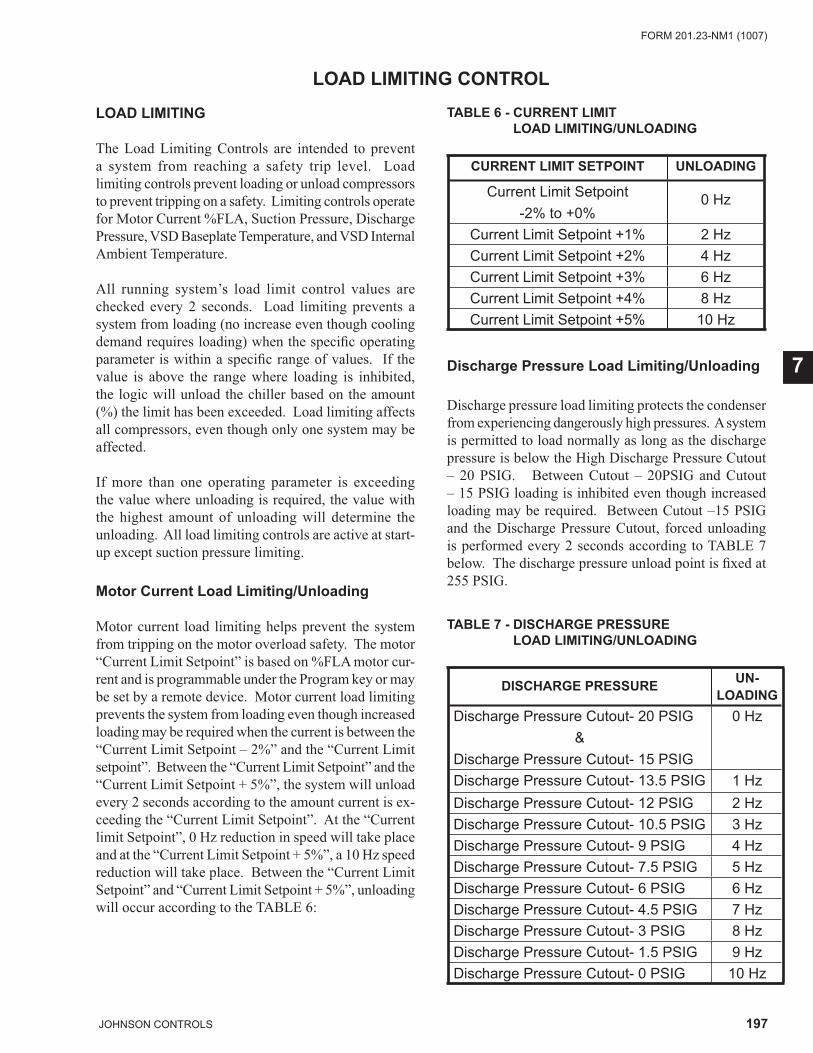
197JOHNSON CONTROLS
FORM 201.23-NM1 (1007)
7
LOAD LIMITING CONTROL
LOAD LIMITING
The Load Limiting Controls are intended to prevent a system from reaching a safety trip level. Load limiting controls prevent loading or unload compressors to prevent tripping on a safety. Limiting controls operate for Motor Current %FLA, Suction Pressure, Discharge Pressure, VSD Baseplate Temperature, and VSD Internal Ambient Temperature.
All running system’s load limit control values are checked every 2 seconds. Load limiting prevents a system from loading (no increase even though cooling demand requires loading) when the specifi c operating parameter is within a specifi c range of values. If the value is above the range where loading is inhibited, the logic will unload the chiller based on the amount (%) the limit has been exceeded. Load limiting affects all compressors, even though only one system may be affected.
If more than one operating parameter is exceeding the value where unloading is required, the value with the highest amount of unloading will determine the unloading. All load limiting controls are active at start-up except suction pressure limiting.
Motor Current Load Limiting/Unloading
Motor current load limiting helps prevent the system from tripping on the motor overload safety. The motor “Current Limit Setpoint” is based on %FLA motor cur-rent and is programmable under the Program key or may be set by a remote device. Motor current load limiting prevents the system from loading even though increased loading may be required when the current is between the “Current Limit Setpoint – 2%” and the “Current Limit setpoint”. Between the “Current Limit Setpoint” and the “Current Limit Setpoint + 5%”, the system will unload every 2 seconds according to the amount current is ex-ceeding the “Current Limit Setpoint”. At the “Current limit Setpoint”, 0 Hz reduction in speed will take place and at the “Current Limit Setpoint + 5%”, a 10 Hz speed reduction will take place. Between the “Current Limit Setpoint” and “Current Limit Setpoint + 5%”, unloading will occur according to the TABLE 6:
TABLE 6 - CURRENT LIMIT LOAD LIMITING/UNLOADING
CURRENT LIMIT SETPOINT UNLOADING
Current Limit Setpoint -2% to +0%
0 Hz
Current Limit Setpoint +1% 2 HzCurrent Limit Setpoint +2% 4 HzCurrent Limit Setpoint +3% 6 HzCurrent Limit Setpoint +4% 8 HzCurrent Limit Setpoint +5% 10 Hz
Discharge Pressure Load Limiting/Unloading
Discharge pressure load limiting protects the condenser from experiencing dangerously high pressures. A system is permitted to load normally as long as the discharge pressure is below the High Discharge Pressure Cutout – 20 PSIG. Between Cutout – 20PSIG and Cutout – 15 PSIG loading is inhibited even though increased loading may be required. Between Cutout –15 PSIG and the Discharge Pressure Cutout, forced unloading is performed every 2 seconds according to TABLE 7 below. The discharge pressure unload point is fi xed at 255 PSIG.
TABLE 7 - DISCHARGE PRESSURE LOAD LIMITING/UNLOADING
DISCHARGE PRESSURE UN-LOADING
Discharge Pressure Cutout- 20 PSIG&
Discharge Pressure Cutout- 15 PSIG
0 Hz
Discharge Pressure Cutout- 13.5 PSIG 1 HzDischarge Pressure Cutout- 12 PSIG 2 HzDischarge Pressure Cutout- 10.5 PSIG 3 HzDischarge Pressure Cutout- 9 PSIG 4 HzDischarge Pressure Cutout- 7.5 PSIG 5 HzDischarge Pressure Cutout- 6 PSIG 6 HzDischarge Pressure Cutout- 4.5 PSIG 7 HzDischarge Pressure Cutout- 3 PSIG 8 HzDischarge Pressure Cutout- 1.5 PSIG 9 HzDischarge Pressure Cutout- 0 PSIG 10 Hz
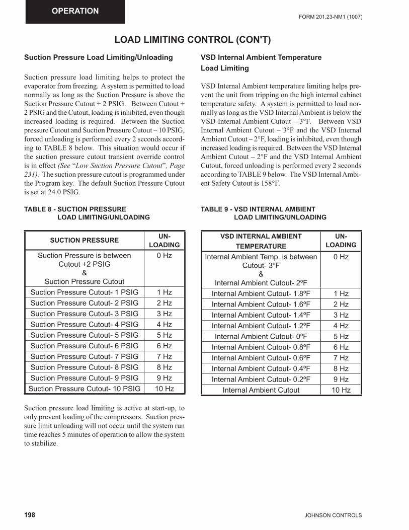
198 JOHNSON CONTROLS
FORM 201.23-NM1 (1007)OPERATION
LOAD LIMITING CONTROL (CON'T)
Suction Pressure Load Limiting/Unloading
Suction pressure load limiting helps to protect the evaporator from freezing. A system is permitted to load normally as long as the Suction Pressure is above the Suction Pressure Cutout + 2 PSIG. Between Cutout + 2 PSIG and the Cutout, loading is inhibited, even though increased loading is required. Between the Suction pressure Cutout and Suction Pressure Cutout – 10 PSIG, forced unloading is performed every 2 seconds accord-ing to TABLE 8 below. This situation would occur if the suction pressure cutout transient override control is in effect (See “Low Suction Pressure Cutout”, Page 231). The suction pressure cutout is programmed under the Program key. The default Suction Pressure Cutout is set at 24.0 PSIG.
TABLE 8 - SUCTION PRESSURE LOAD LIMITING/UNLOADING
SUCTION PRESSURE UN-LOADING
Suction Pressure is betweenCutout +2 PSIG
&Suction Pressure Cutout
0 Hz
Suction Pressure Cutout- 1 PSIG 1 HzSuction Pressure Cutout- 2 PSIG 2 HzSuction Pressure Cutout- 3 PSIG 3 HzSuction Pressure Cutout- 4 PSIG 4 HzSuction Pressure Cutout- 5 PSIG 5 HzSuction Pressure Cutout- 6 PSIG 6 HzSuction Pressure Cutout- 7 PSIG 7 HzSuction Pressure Cutout- 8 PSIG 8 HzSuction Pressure Cutout- 9 PSIG 9 Hz
Suction Pressure Cutout- 10 PSIG 10 Hz
Suction pressure load limiting is active at start-up, to only prevent loading of the compressors. Suction pres-sure limit unloading will not occur until the system run time reaches 5 minutes of operation to allow the system to stabilize.
VSD Internal Ambient Temperature Load Limiting
VSD Internal Ambient temperature limiting helps pre-vent the unit from tripping on the high internal cabinet temperature safety. A system is permitted to load nor-mally as long as the VSD Internal Ambient is below the VSD Internal Ambient Cutout – 3°F. Between VSD Internal Ambient Cutout – 3°F and the VSD Internal Ambient Cutout – 2°F, loading is inhibited, even though increased loading is required. Between the VSD Internal Ambient Cutout – 2°F and the VSD Internal Ambient Cutout, forced unloading is performed every 2 seconds according to TABLE 9 below. The VSD Internal Ambi-ent Safety Cutout is 158°F.
TABLE 9 - VSD INTERNAL AMBIENT LOAD LIMITING/UNLOADING
VSD INTERNAL AMBIENTTEMPERATURE
UN-LOADING
Internal Ambient Temp. is betweenCutout- 3ºF
&Internal Ambient Cutout- 2ºF
0 Hz
Internal Ambient Cutout- 1.8ºF 1 HzInternal Ambient Cutout- 1.6ºF 2 HzInternal Ambient Cutout- 1.4ºF 3 HzInternal Ambient Cutout- 1.2ºF 4 HzInternal Ambient Cutout- 0ºF 5 Hz
Internal Ambient Cutout- 0.8ºF 6 HzInternal Ambient Cutout- 0.6ºF 7 HzInternal Ambient Cutout- 0.4ºF 8 HzInternal Ambient Cutout- 0.2ºF 9 Hz
Internal Ambient Cutout 10 Hz
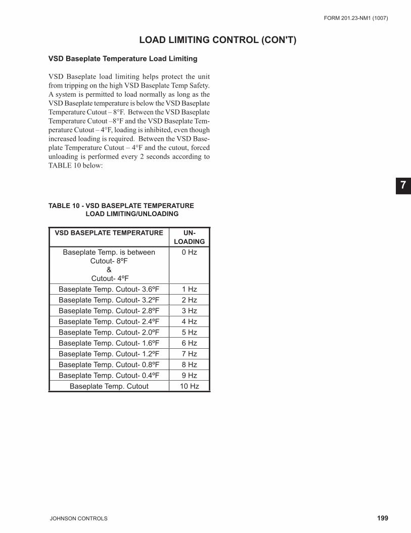
199JOHNSON CONTROLS
FORM 201.23-NM1 (1007)
7
LOAD LIMITING CONTROL (CON'T)
VSD Baseplate Temperature Load Limiting
VSD Baseplate load limiting helps protect the unit from tripping on the high VSD Baseplate Temp Safety. A system is permitted to load normally as long as the VSD Baseplate temperature is below the VSD Baseplate Temperature Cutout – 8°F. Between the VSD Baseplate Temperature Cutout –8°F and the VSD Baseplate Tem-perature Cutout – 4°F, loading is inhibited, even though increased loading is required. Between the VSD Base-plate Temperature Cutout – 4°F and the cutout, forced unloading is performed every 2 seconds according to TABLE 10 below:
TABLE 10 - VSD BASEPLATE TEMPERATURELOAD LIMITING/UNLOADING
VSD BASEPLATE TEMPERATURE UN-LOADING
Baseplate Temp. is betweenCutout- 8ºF
& Cutout- 4ºF
0 Hz
Baseplate Temp. Cutout- 3.6ºF 1 HzBaseplate Temp. Cutout- 3.2ºF 2 HzBaseplate Temp. Cutout- 2.8ºF 3 HzBaseplate Temp. Cutout- 2.4ºF 4 HzBaseplate Temp. Cutout- 2.0ºF 5 HzBaseplate Temp. Cutout- 1.6ºF 6 HzBaseplate Temp. Cutout- 1.2ºF 7 HzBaseplate Temp. Cutout- 0.8ºF 8 HzBaseplate Temp. Cutout- 0.4ºF 9 Hz
Baseplate Temp. Cutout 10 Hz
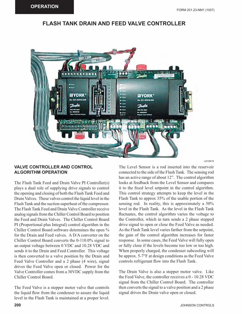
200 JOHNSON CONTROLS
FORM 201.23-NM1 (1007)OPERATION
FLASH TANK DRAIN AND FEED VALVE CONTROLLER
LD10619
VALVE CONTROLLER AND CONTROL ALGORITHM OPERATION
The Flash Tank Feed and Drain Valve PI Controller(s) plays a dual role of supplying drive signals to control the opening and closing of both the Flash Tank Feed and Drain Valves. These valves control the liquid level in the Flash Tank and the suction superheat of the compressor. The Flash Tank Feed and Drain Valve Controller receive analog signals from the Chiller Control Board to position the Feed and Drain Valves. The Chiller Control Board PI (Proportional plus Integral) control algorithm in the Chiller Control Board software determines the open % for the Drain and Feed valves. A D/A converter on the Chiller Control Board converts the 0-110.0% signal to an output voltage between 0 VDC and 10.28 VDC and sends it to the Drain and Feed Controller. This voltage is then converted to a valve position by the Drain and Feed Valve Controller and a 2 phase (4 wire), signal drives the Feed Valve open or closed. Power for the Valve Controller comes from a 30VDC supply from the Chiller Control Board.
The Feed Valve is a stepper motor valve that controls the liquid fl ow from the condenser to assure the liquid level in the Flash Tank is maintained at a proper level.
The Level Sensor is a rod inserted into the reservoir connected to the side of the Flash Tank. The sensing rod has an active range of about 12”. The control algorithm looks at feedback from the Level Sensor and compares it to the fi xed level setpoint in the control algorithm. This control strategy attempts to keep the level in the Flash Tank to approx 35% of the usable portion of the sensing rod. In reality, this is approximately a 50% level in the Flash Tank. As the level in the Flash Tank fl uctuates, the control algorithm varies the voltage to the Controller, which in turn sends a 2 phase stepped drive signal to open or close the Feed Valve as needed. As the Flash Tank level varies farther from the setpoint, the gain of the control algorithm increases for faster response. In some cases, the Feed Valve will fully open or fully close if the levels become too low or too high. When properly charged, the condenser subcooling will be approx. 5-7°F at design conditions as the Feed Valve controls refrigerant fl ow into the Flash Tank.
The Drain Valve is also a stepper motor valve. Like the Feed Valve, the controller receives a 0 - 10.28 VDC signal from the Chiller Control Board. The controller then converts the signal to a valve position and a 2 phase signal drives the Drain valve open or closed.
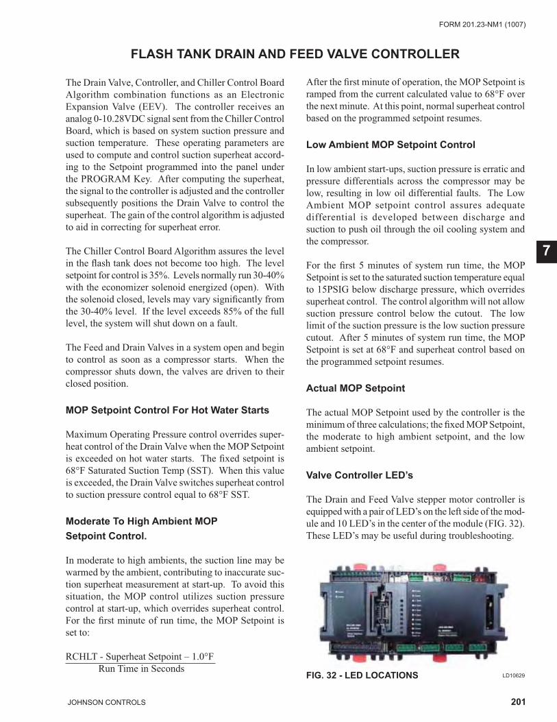
201JOHNSON CONTROLS
FORM 201.23-NM1 (1007)
7
The Drain Valve, Controller, and Chiller Control Board Algorithm combination functions as an Electronic Expansion Valve (EEV). The controller receives an analog 0-10.28VDC signal sent from the Chiller Control Board, which is based on system suction pressure and suction temperature. These operating parameters are used to compute and control suction superheat accord-ing to the Setpoint programmed into the panel under the PROGRAM Key. After computing the superheat, the signal to the controller is adjusted and the controller subsequently positions the Drain Valve to control the superheat. The gain of the control algorithm is adjusted to aid in correcting for superheat error.
The Chiller Control Board Algorithm assures the level in the fl ash tank does not become too high. The level setpoint for control is 35%. Levels normally run 30-40% with the economizer solenoid energized (open). With the solenoid closed, levels may vary signifi cantly from the 30-40% level. If the level exceeds 85% of the full level, the system will shut down on a fault.
The Feed and Drain Valves in a system open and begin to control as soon as a compressor starts. When the compressor shuts down, the valves are driven to their closed position.
MOP Setpoint Control For Hot Water Starts
Maximum Operating Pressure control overrides super-heat control of the Drain Valve when the MOP Setpoint is exceeded on hot water starts. The fi xed setpoint is 68°F Saturated Suction Temp (SST). When this value is exceeded, the Drain Valve switches superheat control to suction pressure control equal to 68°F SST.
Moderate To High Ambient MOP Setpoint Control.
In moderate to high ambients, the suction line may be warmed by the ambient, contributing to inaccurate suc-tion superheat measurement at start-up. To avoid this situation, the MOP control utilizes suction pressure control at start-up, which overrides superheat control. For the fi rst minute of run time, the MOP Setpoint is set to:
RCHLT - Superheat Setpoint – 1.0°F Run Time in Seconds
FLASH TANK DRAIN AND FEED VALVE CONTROLLER
After the fi rst minute of operation, the MOP Setpoint is ramped from the current calculated value to 68°F over the next minute. At this point, normal superheat control based on the programmed setpoint resumes.
Low Ambient MOP Setpoint Control
In low ambient start-ups, suction pressure is erratic and pressure differentials across the compressor may be low, resulting in low oil differential faults. The Low Ambient MOP setpoint control assures adequate differential is developed between discharge and suction to push oil through the oil cooling system and the compressor.
For the fi rst 5 minutes of system run time, the MOP Setpoint is set to the saturated suction temperature equal to 15PSIG below discharge pressure, which overrides superheat control. The control algorithm will not allow suction pressure control below the cutout. The low limit of the suction pressure is the low suction pressure cutout. After 5 minutes of system run time, the MOP Setpoint is set at 68°F and superheat control based on the programmed setpoint resumes.
Actual MOP Setpoint
The actual MOP Setpoint used by the controller is the minimum of three calculations; the fi xed MOP Setpoint, the moderate to high ambient setpoint, and the low ambient setpoint.
Valve Controller LED’s
The Drain and Feed Valve stepper motor controller is equipped with a pair of LED’s on the left side of the mod-ule and 10 LED’s in the center of the module (FIG. 32). These LED’s may be useful during troubleshooting.
FIG. 32 - LED LOCATIONS LD10629
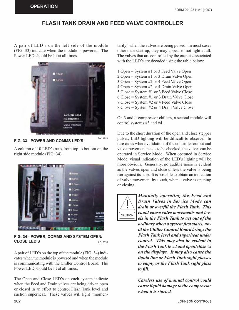
202 JOHNSON CONTROLS
FORM 201.23-NM1 (1007)OPERATION
FLASH TANK DRAIN AND FEED VALVE CONTROLLER
A pair of LED’s on the left side of the module (FIG. 33) indicate when the module is powered. The Power LED should be lit at all times.
FIG. 33 - POWER AND COMMS LED'S LD10630
FIG. 34 - POWER, COMMS AND SYSTEM OPEN/CLOSE LED'S LD10631
A column of 10 LED’s runs from top to bottom on the right side module (FIG. 34).
A pair of LED’s on the top of the module (FIG. 34) indi-cates when the module is powered and when the module is communicating with the Chiller Control Board. The Power LED should be lit at all times.
The Open and Close LED’s on each system indicate when the Feed and Drain valves are being driven open or closed in an effort to control Flash Tank level and suction superheat. These valves will light “momen-
tarily” when the valves are being pulsed. In most cases other than start-up, they may appear to not light at all. The valves that are controlled by the outputs associated with the LED’s are decoded using the table below:
1 Open = System #1 or 3 Feed Valve Open2 Open = System #1 or 3 Drain Valve Open3 Open = System #2 or 4 Feed Valve Open 4 Open = System #2 or 4 Drain Valve Open5 Close = System #1 or 3 Feed Valve Close6 Close = System #1 or 3 Drain Valve Close7 Close = System #2 or 4 Feed Valve Close8 Close = System #2 or 4 Drain Valve Close
On 3 and 4 compressor chillers, a second module will control systems #3 and #4.
Due to the short duration of the open and close stepper pulses, LED lighting will be diffi cult to observe. In rare cases where validation of the controller output and valve movement needs to be checked, the valves can be operated in Service Mode. When operated in Service Mode, visual indication of the LED’s lighting will be more obvious. Generally, no audible noise is evident as the valves open and close unless the valve is being run against its stop. It is possible to obtain an indication of valve movement by touch, when a valve is opening or closing.
Manually operating the Feed and Drain Valves in Service Mode can drain or overfi ll the Flash Tank. This could cause valve movements and lev-els in the Flash Tank to act out of the ordinary when a system fi rst starts, un-til the Chiller Control Board brings the Flash Tank level and superheat under control. This may also be evident in the Flash Tank level and open/close % on the displays. It may also cause the liquid line or Flash Tank sight glasses to empty or the Flash Tank sight glass to fi ll.
Careless use of manual control could cause liquid damage to the compressor when it is started.
203JOHNSON CONTROLS
FORM 201.23-NM1 (1007)
7
ECONOMIZER CONTROL
ECONOMIZER CONTROL
The Economizer Solenoid controls a vapor feed to the economizer port on the compressor from the top of the Flash Tank. When the valve is open, refrigerant gases off in the Flash Tank providing additional subcooling to the liquid in the tank. The subcooled liquid is then fed to the evaporator resulting in additional system capacity and effi ciency.
In normal operation, the Economizer Solenoid on a compressor will be turned on whenever the VSD fre-quency is > 120 Hz, the fl ash tank level is <75%, motor current < 80%FLA, motor temperature sensors are all less than <150°F, and the economizer timer is timed out. Whenever the Economizer Solenoid is turned on, the compressor load timer is set to 35 seconds and econo-mizer timers for every system are set to 30 seconds, unless they are already above 30 seconds.
In low ambient temperatures <40°F, run time on the re-spective compressor is < 5 minutes, and the Flash Tank level is <75%, the system Economizer Solenoid is turned on. Under these conditions, the VSD frequency and the motor temp sensor readings are not factors that could overload the compressor. Energizing the Economizer Solenoid also helps start a system in low ambients and prevents low suction pressure and low oil differential faults by increasing the load.
At ambients above 40°F, once on, the Economizer So-lenoid will remain energized until the VSD frequency drops below 90 Hz. Below 90 Hz, the solenoid will be turned off, regardless of the time remaining on the economizer timers. Under these conditions, the econo-mizer timers will be set to “0” when the solenoids are de-energized. Below 100 Hz, if the economizer timer has timed out, the Economizer Solenoids will be turned off, the unload timer will be set to 30 seconds, the econo-mizer timer will be set to 30 seconds if <30 sec.
If a motor temperature sensor exceeds 240 °F, the Econo-mizer Solenoid will de-energize to avoid overheating the hot motor. When the economizer solenoid is de-ener-gized, the compressor unload timer is set to 30 seconds and the economizer solenoid timer is set to 60 seconds. All other economizer timers for other systems are set to 30 seconds, if they are already < 30 seconds.
The Economizer Solenoid timer prevents the solenoid from cycling too often.
Whenever a compressor is to be turned off, all system Economizer Solenoids will be de-energized when the compressor(s) ramp down. The solenoids on the compressors that will be ramped back up, if any, will remain off for 30 seconds before the Chiller Control Board allows the solenoids to re-energize. Once on, the economizer solenoid(s) must remain on for 30 seconds as determined by the economizer timer for each system.
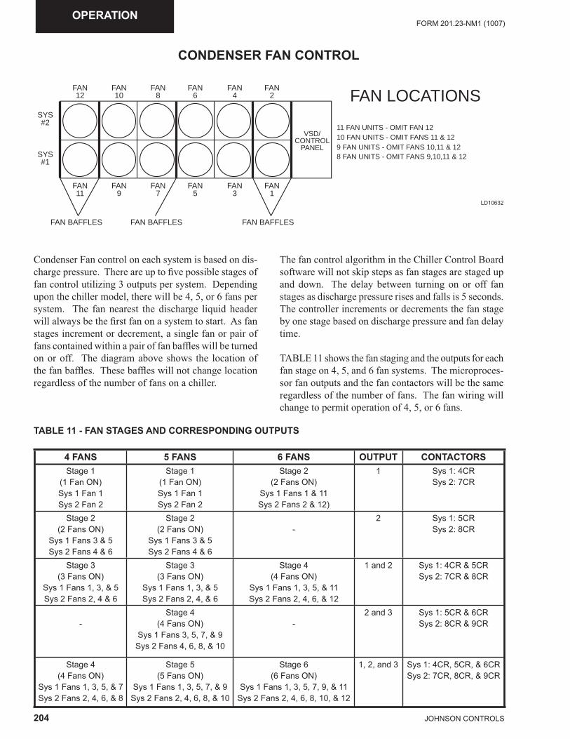
204 JOHNSON CONTROLS
FORM 201.23-NM1 (1007)OPERATION
CONDENSER FAN CONTROL
FAN12
SYS#2
SYS#1
FAN10
FAN8
FAN6
FAN4
FAN2
FAN11
FAN9
FAN7
FAN5
FAN3
FAN1
VSD/CONTROL
PANEL
11 FAN UNITS - OMIT FAN 1210 FAN UNITS - OMIT FANS 11 & 129 FAN UNITS - OMIT FANS 10,11 & 128 FAN UNITS - OMIT FANS 9,10,11 & 12
FAN LOCATIONS
FAN BAFFLES FAN BAFFLESFAN BAFFLES
LD10632
Condenser Fan control on each system is based on dis-charge pressure. There are up to fi ve possible stages of fan control utilizing 3 outputs per system. Depending upon the chiller model, there will be 4, 5, or 6 fans per system. The fan nearest the discharge liquid header will always be the fi rst fan on a system to start. As fan stages increment or decrement, a single fan or pair of fans contained within a pair of fan baffl es will be turned on or off. The diagram above shows the location of the fan baffl es. These baffl es will not change location regardless of the number of fans on a chiller.
The fan control algorithm in the Chiller Control Board software will not skip steps as fan stages are staged up and down. The delay between turning on or off fan stages as discharge pressure rises and falls is 5 seconds. The controller increments or decrements the fan stage by one stage based on discharge pressure and fan delay time.
TABLE 11 shows the fan staging and the outputs for each fan stage on 4, 5, and 6 fan systems. The microproces-sor fan outputs and the fan contactors will be the same regardless of the number of fans. The fan wiring will change to permit operation of 4, 5, or 6 fans.
TABLE 11 - FAN STAGES AND CORRESPONDING OUTPUTS
4 FANS 5 FANS 6 FANS OUTPUT CONTACTORSStage 1
(1 Fan ON)Sys 1 Fan 1Sys 2 Fan 2
Stage 1(1 Fan ON)Sys 1 Fan 1 Sys 2 Fan 2
Stage 2(2 Fans ON)
Sys 1 Fans 1 & 11Sys 2 Fans 2 & 12)
1 Sys 1: 4CRSys 2: 7CR
Stage 2(2 Fans ON)
Sys 1 Fans 3 & 5Sys 2 Fans 4 & 6
Stage 2(2 Fans ON)
Sys 1 Fans 3 & 5Sys 2 Fans 4 & 6
-2 Sys 1: 5CR
Sys 2: 8CR
Stage 3(3 Fans ON)
Sys 1 Fans 1, 3, & 5Sys 2 Fans 2, 4 & 6
Stage 3 (3 Fans ON)
Sys 1 Fans 1, 3, & 5Sys 2 Fans 2, 4, & 6
Stage 4 (4 Fans ON)
Sys 1 Fans 1, 3, 5, & 11Sys 2 Fans 2, 4, 6, & 12
1 and 2 Sys 1: 4CR & 5CRSys 2: 7CR & 8CR
-Stage 4
(4 Fans ON)Sys 1 Fans 3, 5, 7, & 9
Sys 2 Fans 4, 6, 8, & 10
-2 and 3 Sys 1: 5CR & 6CR
Sys 2: 8CR & 9CR
Stage 4 (4 Fans ON)
Sys 1 Fans 1, 3, 5, & 7Sys 2 Fans 2, 4, 6, & 8
Stage 5 (5 Fans ON)
Sys 1 Fans 1, 3, 5, 7, & 9Sys 2 Fans 2, 4, 6, 8, & 10
Stage 6(6 Fans ON)
Sys 1 Fans 1, 3, 5, 7, 9, & 11Sys 2 Fans 2, 4, 6, 8, 10, & 12
1, 2, and 3 Sys 1: 4CR, 5CR, & 6CRSys 2: 7CR, 8CR, & 9CR
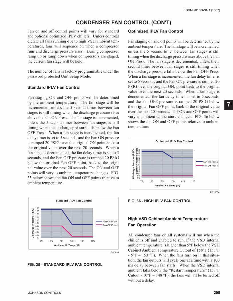
205JOHNSON CONTROLS
FORM 201.23-NM1 (1007)
7
CONDENSER FAN CONTROL (CON'T)Fan on and off control points will vary for standard and optional optimized IPLV chillers. Unless controls dictate all fans running due to high VSD ambient tem-peratures, fans will sequence on when a compressor runs and discharge pressure rises. During compressor ramp up or ramp down when compressors are staged, the current fan stage will be held.
The number of fans is factory programmable under the password protected Unit Setup Mode.
Standard IPLV Fan Control
Fan staging ON and OFF points will be determined by the ambient temperature. The fan stage will be incremented, unless the 5 second timer between fan stages is still timing when the discharge pressure rises above the Fan ON Press. The fan stage is decremented, unless the 5 second timer between fan stages is still timing when the discharge pressure falls below the Fan OFF Press. When a fan stage is incremented, the fan delay timer is set to 5 seconds, and the Fan ON pressure is ramped 20 PSIG over the original ON point back to the original value over the next 20 seconds. When a fan stage is decremented, the fan delay timer is set to 5 seconds, and the Fan OFF pressure is ramped 20 PSIG below the original Fan OFF point, back to the origi-nal value over the next 20 seconds. The ON and OFF points will vary as ambient temperature changes. FIG. 35 below shows the fan ON and OFF points relative to ambient temperature.
Standard IPLV Fan Control
90100110120130140150160170180190
75 85 95 105 115 125
Ambient Air Temp (°F)
Dis
char
ge
Pre
ssu
re (
PS
IG)
Fan On Press
Fan Off Press`
LD10633
FIG. 35 - STANDARD IPLV FAN CONTROL
Optimized IPLV Fan Control
Fan staging on and off points will be determined by the ambient temperature. The fan stage will be incremented, unless the 5 second timer between fan stages is still timing when the discharge pressure rises above the Fan ON Press. The fan stage is decremented, unless the 5 second timer between fan stages is still timing when the discharge pressure falls below the Fan OFF Press. When a fan stage is incremented, the fan delay timer is set to 5 seconds, and the Fan ON pressure is ramped 20 PSIG over the original ON, point back to the original value over the next 20 seconds. When a fan stage is decremented, the fan delay timer is set to 5 seconds, and the Fan OFF pressure is ramped 20 PSIG below the original Fan OFF point, back to the original value over the next 20 seconds. The ON and OFF points will vary as ambient temperature changes. FIG. 36 below shows the fan ON and OFF points relative to ambient temperature.
Optimized IPLV Fan Control
9095
100105110115120125130135140145150155
75 85 95 105 115 125
Ambient Air Temp (°F)
Dis
char
ge
Pre
ssu
re (
PS
IG)
Fan On Press
Fan Off Press`
LD10634
FIG. 36 - HIGH IPLV FAN CONTROL
High VSD Cabinet Ambient Temperature Fan Operation
All condenser fans on all systems will run when the chiller is off and enabled to run, if the VSD internal ambient temperature is higher than 5°F below the VSD Cabinet Ambient Temperature Cutout of 158°F (158°F - 5°F = 153 °F). When the fans turn on in this situa-tion, the fan outputs will cycle one at a time with a 100 ms delay between fan starts. When the VSD internal ambient falls below the “Restart Temperature” (158°F Cutout - 10°F = 148 °F), the fans will all be turned off without a delay.
206 JOHNSON CONTROLS
FORM 201.23-NM1 (1007)OPERATION
VSD TEMPERATURE CONTROL, OPERATION OF THE COOLANT PUMP, AND VSD CABINET COOLING FANS
The Coolant pump and VSD Cabinet Cooling Fans will run to cool the VSD whenever any of the following conditions are met:
· VSD Comp IGBT Baseplate Temperature on a 2 or 4 compressor unit is greater than 10°F below the cutout (Cutout [218°F]-10°F =208°F). When the VSD internal ambient falls below the restart tem-perature (Cutout [218°F] - 15°F = 203°F), the fans and pump will turned off without a time delay.
· VSD Comp IGBT Baseplate Temperature on a 3 compressor unit is greater than 10°F below the cutout (Cutout [232°F] - 10°F = 222°F). When the VSD internal ambient falls below the restart temperature (Cutout - 15°F = 217°F), the fans and pump will be turned off without a time delay.
· Pre-charge Enable 1 from the Chiller Logic Board is ON.
· Pre-charge Enable 2 from the Chiller Logic Board is ON.
· VSD Internal Ambient Temp > 158°F (Cutout) – 10°F = 148°F. When the Internal Ambient Temp falls < 158°F (Cutout) - 15°F = 143 °F the VSD cooling fans and glycol pump will turn off.
· Condenser Fans (as needed) and VSD coolant pump/fans will run whenever a compressor is running. Under these conditions, the condenser fans will run to control discharge pressure and the VSD coolant pump/fans will run to cool the IGBT baseplate and internal cabinet. Additional condenser fans will be brought on, if the IGBT baseplate temperatures or internal cabinet ambient rises to 5°F below the cut-out. Condenser fans will turn off, if the compressor turns off provided VSD cooling is not required. The glycol pump and cabinet fan may continue to run, if VSD cooling is required.
· Glycol Pump and Cabinet Cooling Fans will also run in the Service Mode if the Fan/Pump Run Bit is Set.
207JOHNSON CONTROLS
FORM 201.23-NM1 (1007)
7
REMOTE TEMPERATURE RESET CONTROLTemperature Reset Control
Temperature Reset Control is used to reset the actual LCHLT (Leaving Chilled Liquid Temperature) setpoint used in capacity control. There are several ways to change the LCHLT setpoint. The fi rst is by re-program-ming the Local Cooling Setpoint under the SETPOINTS key. This is the value the unit will control the LCHLT to if neither of the other methods is active.
Remote Temperature Limit Reset is only possible if the option is enabled by both the OPTIONS Key selection and in the factory programmable password protected Unit Setup Mode.
Remote ISN Setpoint Control
The Remote Leaving Chilled Liquid Setpoint Cooling Setpoint can be set via the ISN comms. The control panel will only accept a remote setpoint from the ISN if the control panel is in Remote Control Mode (under the OPTIONS KEY). If the control panel is in Local Control Mode, the ISN setpoint will be ignored and the Remote Cooling Setpoint is set to the Local Cooling Setpoint. The minimum and maximum allowable reset values will be the same as the minimum and maximum allowable programmable values for the Local Cooling Setpoint. If these values are exceeded by the ISN, the minimum or maximum value will be used.
Contact a local YORK ISN Representative for details on ISN controls and capabilities.
Remote Temperature Reset
The Remote Leaving Chilled Liquid Cooling Setpoint can be reset via the Remote Temperature Reset analog input. A zero signal input (0% input) equates to a 0°F offset to the Local Cooling Setpoint. A full scale sig-nal input (100% input) equates to a "positive" offset to the Local Cooling setpoint equal to the programmable Maximum Remote Temp Reset. The offset is linear and may be adjusted anywhere between the 0% and 100% points. The maximum setpoint allowed is the maximum programmable Local Cooling Setpoint and will be capped at this value, if the calculated setpoint with temperature offset exceeds this value.
This input may be used either in Local or Remote Con-trol Mode. This feature will only operate if enabled under the UNIT SETUP and the OPTIONS Key. The input will be ignored if the Remote Temp Reset is dis-abled under the OPTIONS key or if there are valid ISN comms while in Remote Control Mode. Once a change to the input is registered, a timer is set to the value of the Remote Inputs Service Time as programmable un-der the Unit Setup Mode at the factory for the default value of 15 minutes. The low limit is 5 minutes and the high limit is 60 minutes. The Remote input will be ignored until this timer expires. The timer assures that rapid changes in a remote reset signal don’t result in poor temperature control or excessive compressor cycling. In most instances, this timer will not need to be changed, since reset more often than 15 minutes will create problems with chilled liquid temperature control. Factory Service should be contacted if a timer change is required.
Control Board jumper JP4 must be positioned correctly to receive either a voltage (0-10VDC or 2-10VDC) or current (0-20mA or 4-20mA) signal. Place the jumper in the “V” position for a voltage signal or mA for a cur-rent signal (See FIG. 14 & 14A). The software must be confi gured under the OPTIONS key for the specifi c type of input signal to be used.
The maximum temperature reset is achieved at either 10 VDC or 20 mA. Sending the minimum signal (0 VDC, 2 VDC, 0 mA, or 4 mA based on the OPTIONS key setting) causes the setpoint to revert back to its lo-cal programmed value. If the setpoint reset causes the setpoint to go over the maximum programmable value, it will be set to the maximum programmable setpoint.
208 JOHNSON CONTROLS
FORM 201.23-NM1 (1007)OPERATION
0 – 10 VDC Reset Input
A 0 VDC signal produces a 0°F reset. A 10 VDC signal produces the maximum remote temp reset (program-mable under the SETPOINTS key). The setpoint reset is ramped linearly between these limits as the input varies between 0 VDC and 10 VDC. In order for this input to work properly, the Remote Temperature Reset must be programmed for 0 – 10 VDC input (OPTIONS key) and Chiller Control Board jumper JP4 placed in the “V” position.
2 – 10 VDC Reset Input
A 0 - 2 VDC signal produces a 0°F reset. A 10 VDC signal produces the maximum remote temp reset (pro-grammable under the SETPOINTS key). The setpoint reset is ramped linearly between these limits as the input varies between 2 VDC and 10 VDC. In order for this input to work properly, the Remote Temperature Reset must be programmed for 2 – 10 VDC input (OPTIONS key) and Chiller Control Board jumper JP4 placed in the “V” position.
LOCAL CURRENT LIMIT CONTROL
Local Current Limit Control is used to set the actual Cur-rent Limit Setpoint. This is accomplished by changing the Local Current Limit Setpoint under the PROGRAM key. This is the value at which the unit will begin to current limit and override capacity control if remote reset is not actively overriding this control. If any other current limit methods are active, the lowest value will be used.
Keep in mind that limiting current may interfere with capacity control, pulling down chilled liquid tempera-tures on hot water starts, and maintaining chilled liquid setpoints.
REMOTE TEMPERATURE RESET CONTROL (CON'T)
0 – 20 mA Reset Input
A 0 mA signal produces a 0°F reset. A 20 mA signal produces the maximum remote temp reset (program-mable under the SETPOINTS key). The setpoint reset is ramped linearly between these limits as the input varies between 0 mA and 20 mA. In order for this input to work properly, the Remote Temperature Reset must be programmed for 0 – 20 mA input (OPTIONS key) and Chiller Control Board jumper JP4 placed in the “mA” position.
4 – 20 mA Reset Input
A 0 - 4 mA signal produces a 0°F reset. A 20 mA signal produces the maximum remote temp reset (program-mable under the SETPOINTS key). The setpoint reset is ramped linearly between these limits as the input varies between 4 mA and 20 mA. In order for this input to work properly, the Remote Temperature Reset must be programmed for 4 – 20 mA input (OPTIONS key) and Chiller Control Board jumper JP4 placed in the “mA” position.
LOCAL CURRENT LIMIT CONTROL
PULLDOWN CURRENT LIMIT SETPOINT
The Pulldown Current Limit Setpoint can be set under the PROGRAM key. This current limit setpoint is only active on startup for the time defi ned by the Pulldown Current Limit Time under the PROGRAM key. After the run time has exceeded this time, the Pulldown Cur-rent Limit Setpoint is ignored.
This control is useful in limiting current pulldown de-mand during peak usage periods where electric costs are highest.
Keep in mind that limiting current may interfere with capacity control, pulling down chilled liquid tempera-tures on hot water starts, and maintaining chilled liquid setpoints.
209JOHNSON CONTROLS
FORM 201.23-NM1 (1007)
7
REMOTE CURRENT LIMIT RESET CONTROL
Remote Current Limit Reset
Remote Current Limit Reset is used to reset the actual current limit setpoint used in current limit control. There are several ways to change the current limit setpoint. The fi rst is by reprogramming the Local Current Limit Setpoint under the PROGRAM key. This is the value the unit will control the current limit to if neither of the other methods is active.
Remote Current Limit Reset is only possible if the op-tion is enabled by both the OPTIONS Key selection and in the factory programmable password protected Unit Setup Mode.
Remote ISN Current Limit Setpoint
The ISN Current Limit Setpoint can be set via the ISN comms. The control panel will only accept a Current Limit Setpoint from the ISN if the control panel is in Remote Control Mode (under the OPTIONS KEY). If the control panel is in Local Control Mode, the ISN setpoint will be ignored. The minimum and maximum allowable values will be the same as the minimum and maximum allowable reset values for the Current Limit Setpoint under the PROGRAM key. If these values are exceeded, the minimum or maximum value will be used.
Contact a local YORK ISN Representative for details on ISN controls and capabilities.
Remote Current Limit Reset
The Current Limit Setpoint can be set reset via the Remote Current Limit analog input. A zero signal input (0% input) equates to the maximum current limit setpoint as defi ned under the PROGRAM key Current Limit Setpoint. A full scale signal input (100% input) equates to the minimum current limit setpoint as defi ned under the PROGRAM key Current Limit Setpoint. The current limit value is linear and may be adjusted any-where between the maximum and minimum points of 0 (no offset) and 100% (max. current limiting).
This input may be used either in Local or Remote Con-trol Mode. This input will be ignored if the Remote Current Limit is disabled under the OPTIONS key. Once a change to the input is registered, a timer is set to the value of the Remote Inputs Service Time as program-mable under the Unit Setup Mode at the factory for the default value of 15 minutes. The low limit is 5 minutes and the high limit is 60 minutes. The Remote input will be ignored until this timer expires. The timer assures that rapid changes in a remote reset signal don’t result in poor temperature control or excessive compressor cycling. In most instances, this timer will not need to be changed, since reset more often than 15 minutes will create problems with chilled liquid temperature control. Factory Service should be contacted if a timer change is required.
Control board jumper JP5 must be positioned correctly to receive either a voltage (0-10VDC or 2-10VDC) or current (0-20mA or 4-20mA) signal. Place the jumper in the “V” position for a voltage signal or mA for a current signal (See FIG. 14& 14A). The software must be confi gured under the OPTIONS key for the type of input signal to be used.
The minimum current limit setpoint is achieved at either 10 VDC or 20 mA. Sending the minimum signal (0 VDC, 2 VDC, 0 mA, or 4 mA based on the OPTIONS key setting) causes the current limit to revert back to its maximum value.
210 JOHNSON CONTROLS
FORM 201.23-NM1 (1007)OPERATION
0 – 10 VDC Reset Input
A 0 VDC signal sets the current limit to the maximum value. A 10 VDC signal sets the current limit to the minimum value. The current limit is ramped linearly between these limits as the input varies between 0 VDC and 10 VDC. In order for this input to work properly, the Remote Current Limit must be programmed for 0 – 10 VDC input (OPTIONS key) and Chiller Control Board jumper JP5 placed in the “V” position.
2 – 10 VDC Reset Input
A 0 - 2 VDC signal sets the current limit to the maximum value. A 10 VDC signal sets the current limit to the minimum value. The current limit is ramped linearly between these limits as the input varies between 2 VDC and 10 VDC. In order for this input to work properly, the Remote Current Limit must be programmed for 2 – 10 VDC input (OPTIONS key) and Chiller Control Board jumper JP5 placed in the “V” position.
0 – 20 mA Reset Input
A 0 mA signal sets the current limit to the maximum value. A 20 mA signal sets the current limit to the minimum value. The current limit is ramped linearly between these limits as the input varies between 0 mA and 20 mA. In order for this input to work properly, the Remote Current Limit must be programmed for 0 – 20 mA input (OPTIONS key) and Chiller Control Board jumper JP5 placed in the “mA” position.
4 – 20 mA Reset Input
A 0 - 4 mA signal sets the current limit to the maximum value. A 20 mA signal sets the current limit to the minimum value. The current limit is ramped linearly between these limits as the input varies between 4 mA and 20 mA. In order for this input to work properly, the Remote Current Limit must be programmed for 4 – 20 mA input (OPTIONS key) and Chiller Control Board jumper JP5 placed in the “mA” position.
REMOTE CURRENT LIMIT RESET CONTROL (CON'T)
211JOHNSON CONTROLS
FORM 201.23-NM1 (1007)
7
SOUND LIMIT CONTROL(LOCAL AND REMOTE RESET CONTROL)
Sound Limiting and Local Sound LimitSetpoint
Sound limit control to reduce overall chiller noise levels at specifi ed times of the day is accomplished by setting a Sound Limit Setpoint. There are several ways to set the Sound Limit Setpoint. The fi rst is by changing the Local Sound Limit Setpoint under the PROGRAM key. This is the value the unit will use for sound limiting, if neither of the other methods is active. If any other sound limit methods are active, the lowest value will be used. A sound limit of 0% will allow the unit to run up to the unit’s maximum frequency. A sound limit of 100% will not allow the unit to run above the minimum frequency. All other sound limit values are linear between these 2 points.
A sound limit schedule must be programmed under the Schedule key when sound limiting is utilized. The schedule defi nes the time period that sound limiting will be active.
Sound Limiting is only possible if the option is enabled by both the OPTIONS Key selection and the factory programmable password protected Unit Setup Mode.
If Sound Limiting is disabled under the Unit Setup Mode, nothing relating to Sound Limiting will show up on any display screen or printout.
ISN Sound Limit Setpoint
The ISN Sound Limit Setpoint can be set via the ISN II comms. The control panel will only accept a Sound Limit Setpoint from the ISN if the control panel is in Remote Control Mode. If the control panel is in Local Control Mode, the ISN setpoint will be ignored. The minimum and maximum allowable values will be the same as the minimum and maximum allowable values for the Sound Limit Setpoint under the PROGRAM key. If these values are exceeded, the minimum or maximum value will be used.
Contact a local YORK ISN Representative for details on ISN controls and capabilities.
Remote Sound Limit
The Sound Limit Setpoint can be set via the Remote Sound Limit analog input. A zero signal input (0% input) equates to the minimum sound limit setpoint as defi ned under the PROGRAM key Sound Limit Setpoint. A full scale signal input (100% input) equates to the maximum sound limit setpoint as defi ned under the PROGRAM key Sound Limit Setpoint. The input is linear and may be adjusted between 0% (minimum sound limiting) and 100% (maximum sound limiting) points.
This input may be used either in Local or Remote Con-trol Mode. The input will be ignored if the Remote Sound Limit is disabled under the OPTIONS key. Once a change to the input is registered, a timer is set to the value of the Remote Inputs Service Time as program-mable under the Unit Setup Mode at the factory for the default value of 15 minutes. The low limit is 5 minutes and the high limit is 60 minutes. The Remote input will be ignored until this timer expires. The timer assures that rapid changes in a remote reset signal don’t result in poor temperature control and excessive compressor cycling. In most instances, this timer will not need to be changed, since reset more often than 15 minutes will create problems with chilled liquid temperature control. Factory Service should be contacted if a timer change is required.
Control board jumper JP6 must be positioned correctly to receive either a voltage (0-10VDC or 2-10VDC) or current (0-20mA or 4-20mA) signal. Place the jumper in the “V” position for a voltage signal or mA for a current signal (See FIG. 14 & FIG. 14A). The software must be confi gured under the OPTIONS key for the type of input signal to be used.
The maximum sound limit is achieved at either 10 VDC or 20 mA. Sending the minimum signal (0 VDC, 2 VDC, 0 mA, or 4 mA based on the OPTIONS key setting) causes the sound limit to be set to its minimum (no limiting) value.
212 JOHNSON CONTROLS
FORM 201.23-NM1 (1007)OPERATION
SOUND LIMIT CONTROL (CON'T)(LOCAL AND REMOTE RESET CONTROL)
0 – 10 VDC Reset Input
A 0 VDC signal produces a 0% sound limit (no change to max VSD freq). A 10 VDC signal produces a 100% sound limit (max VSD freq = min VSD freq). The sound limit is ramped linearly between these limits as the input varies between 0 VDC and 10 VDC. In order for this input to work properly, the Remote Sound Limit must be programmed for 0 – 10 VDC input (OPTIONS key) and Chiller Control Board jumper JP6 placed in the “V” position.
2 – 10 VDC Reset Input
A 0 - 2 VDC signal produces a 0% sound limit (no change to max VSD freq). A 10 VDC signal produces a 100% sound limit (max VSD freq = min VSD freq). The sound limit reset is ramped linearly between these limits as the input varies between 2 VDC and 10 VDC. In order for this input to work properly, the Remote Sound Limit must be programmed for 2 – 10 VDC input (OPTIONS key) and Chiller Control Board jumper JP6 placed in the “V” position.
0 – 20 mA Reset Input
A 0 mA signal produces a 0% sound limit (no change to max VSD freq). A 20 mA signal produces a 100% sound limit (max VSD freq = min VSD freq). The sound limit reset is ramped linearly between these limits as the input varies between 0 mA and 20 mA. In order for this input to work properly, the Remote Sound Limit must be programmed for 0 – 20 mA input (OPTIONS key) and Chiller Control Board jumper JP6 placed in the “mA” position.
4 – 20 mA Reset Input
A 0 - 4 mA signal produces a 0% sound limit (no change to max VSD freq). A 20 mA signal produces a100% sound limit (max VSD freq = min VSD freq). The sound limit reset is ramped linearly between these limits as the input varies between 4 mA and 20 mA. In order for this input to work properly, the Remote Sound Limit must be programmed for 4 – 20 mA input (OPTIONS key) and Chiller Control Board jumper JP6 placed in the “mA” position.
213JOHNSON CONTROLS
FORM 201.23-NM1 (1007)
8
VSD OPERATION AND CONTROLSVSD Logic Board
The VSD Logic Board communications with the Chiller Control Board via comms and controls the VSD func-tions. It converts the frequency and run commands from the Chiller Control Board into the necessary voltage and frequency commands to operate the inverter section. It also controls the converter section of the drive (AC Line to DC Buss conversion) by controlling the pre-charge function.
The VSD Logic Board contains a 2nd microprocessor (motor controller) that generates the PWM signals that control the IGBT outputs in the inverter section of the VSD.
An FPGA handles the hardware safeties that can shut down the VSD much faster than the software safeties. The VSD Logic Board handles all of the VSD related safeties, which includes motor current, BUS voltage, and other safeties.
The VSD Logic Board reports shutdown information back to the Chiller Control Board via the RS-485 com-munication link.
2, 3 and 4 compressor chillers all use the same software. The microprocessor determines whether the chiller is a 2, 3 or 4 compressor chiller by electronically check-ing for a factory-installed jumper in the system wiring harness. The micro checks for the jumper located in the J1 plug wiring harness at power-up. If no jumper or more than one jumper is sensed, the microprocessor will inhibit start-up. Details regarding the location of the jumper are provided on Page 183 in the CHILLER CONFIGURATION JUMPERS section.
VSD Start/run Initiation
Following a successful precharge of the DC Bus and a run command from the Chiller Control Board, the VSD Logic Board microprocessor will determine the motor output voltage (% modulation) and the output frequency required based on the operating frequency command from the Chiller Control Board. This information will then be sent to the PWM generator located on the VSD Logic Board.
On start-up, the output frequency from the VSD to the motor(s) will be increased from 0 Hz to the operating frequency commanded by the Chiller Control Board. The rate of change of the frequency will also be con-trolled by the VSD Logic Board.
The rate of change of the output frequency at start-up, during acceleration is 10 Hz/sec between 0 and 50 Hz and 30.4 Hz/sec above 50 hertz. The maximum rate of change of the output frequency during deceleration between 200-100 Hz is 30.4 Hz/sec, and 100-0 Hz is 10 Hz/sec.
The VSD Logic Board and its PWM generator will receive operating frequency and voltage commands from the Chiller Control Board based on the load.When a frequency (speed) change is requested from the Chiller Control Board, the chiller micro will send the change to the VSD Logic Board and the VSD Logic Board will acknowledge it ac-cepted the change. Loading and unloading will take place at the rate of 0.1-1Hz every 2 seconds.
PWM Generator Type and Carrier Frequency
The PWM generator is responsible for providing asym-metrical uniform sampled PWM waveforms to the compressor motor at a carrier frequency of 3125 Hz by turning on an off the inverter IGBT’s. The waveform generated is equivalent to a specifi c V/F ratio at a given speed based on the voltage and frequency commands from the Chiller Control Board. The PWM Generator receives operating frequency and voltage commands from the VSD Logic Board control processor.
Short Circuit Protection Minimum OutputPulse Width and Interlock Delay
The PWM generator is programmed to drop all “on” pulses in less than 10 microseconds (and all matching “off” pulses in the mirrored waveform) to permit time for the IGBT gate drivers to detect and self extinguish an inverter short circuit condition.
SECTION 8 - MICROPANEL
214 JOHNSON CONTROLS
FORM 201.23-NM1 (1007)MICRO PANEL
VSD OPERATION AND CONTROLS (CON'T)
Modulating Frequency
The modulating frequency range will range from 0 to 200 Hz. The modulating frequency waveform con-sists of a sinusoidal waveform summed together with 16.66% of the third harmonic component of the sinu-soidal waveform. Utilization of this waveform as the modulating waveform will permit the drive to generate a fundamental line to line voltage equal to the DC bus voltage divided by 1.414.
Maximum VSD Frequency
The maximum VSD frequency will vary for each chiller model. The microprocessor board determines the frequency according to jumpers' factory installed in the wiring on the J7 plug of the microprocessor board. The location of these jumpers' is interpreted as a binary value, which presently allows 7 speed selections plus a default. The maximum frequency may vary from 178 to 200 Hz. If the J7 plug is not installed, the speed will default to 178 Hz. Details on the location of the jump-ers' and the associated maximum speed are provided on Page 184 in the CHILLER CONFIGURATION JUMPERS section.
VSD % Modulation
The voltage and frequency commands issued by the VSD Logic Board microprocessor are determined by the fre-quency command from the Chiller Control Board. The VSD output is a PWM signal (FIG. 2), which has effects on the motor comparable to an AC voltage sinusoidal waveform. To change the speed of an AC motor, the frequency of the AC voltage must be changed. When-ever frequency is changed, the voltage is changed in a linear ratio. Maintaining a relatively constant V/F ratio as speed changes assures motor losses and overheating do not occur.
The output voltage of the VSD is not a sinusoidal wave-form. Instead, the PWM generator provides an output that simulates a true AC waveform by repetitively turn-ing on and off the voltage to the motor to create an aver-age voltage that is equal to a lower AC voltage at lower frequencies and a higher voltage at higher frequencies. The PWM generator also changes the % modulation of the waveform to simulate the frequency change to maintain the V/F ratio with motor speed changes.
The PMW generator is programmed to essentially oper-ate a linear volts/Hz ratio over the 0 – 200 Hz frequency range. The complex control algorithm modifi es the voltage command to boost the voltage of the V/F ratio at lower speeds to provide additional torque.
The 100% modulation operating point occurs at a fundamental frequency of 189.6 Hz. As the output frequency increases above 189.6 Hz, the drive operates in an over-modulated mode. For example, at 200 Hz fundamental modulating frequency the PWM waveform is over-modulated by approximately 18%. This will yield a fundamental output line to line voltage applied to the motor terminals at maximum output frequency that is equal to the input line to line voltage applied to the drive (provided the DC bus current remains continuous).
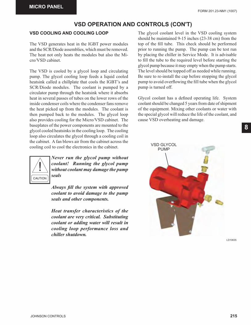
215JOHNSON CONTROLS
FORM 201.23-NM1 (1007)
8
MICRO PANEL
VSD OPERATION AND CONTROLS (CON'T)VSD COOLING AND COOLING LOOP
The VSD generates heat in the IGBT power modules and the SCR/Diode assemblies, which must be removed. The heat not only heats the modules but also the Mi-cro/VSD cabinet.
The VSD is cooled by a glycol loop and circulating pump. The glycol cooling loop feeds a liquid cooled heatsink called a chillplate that cools the IGBT’s and SCR/Diode modules. The coolant is pumped by a circulator pump through the heatsink where it absorbs heat in several passes of tubes on the lower rows of the inside condenser coils where the condenser fans remove the heat picked up from the modules. The coolant is then pumped back to the modules. The glycol loop also provides cooling for the Micro/VSD cabinet. The baseplates of the power components are mounted to the glycol cooled heatsinks in the cooling loop. The cooling loop also circulates the glycol through a cooling coil in the cabinet. A fan blows air from the cabinet across the cooling coil to cool the electronics in the cabinet.
Never run the glycol pump without coolant! Running the glycol pump without coolant may damage the pump seals
Always fi ll the system with approved coolant to avoid damage to the pump seals and other components.
Heat transfer characteristics of the coolant are very critical. Substituting coolant or adding water will result in cooling loop performance loss and chiller shutdown.
The glycol coolant level in the VSD cooling system should be maintained 9-15 inches (23-38 cm) from the top of the fi ll tube. This check should be performed prior to running the pump. The pump can be test run by placing the chiller in Service Mode. It is advisable to fi ll the tube to the required level before starting the glycol pump because it may empty when the pump starts. The level should be topped off as needed while running. Be sure to re-install the cap before stopping the glycol pump to avoid overfl owing the fi ll tube when the glycol pump is turned off.
Glycol coolant has a defi ned operating life. System coolant should be changed 5 years from date of shipment of the equipment. Mixing other coolants or water with the special glycol will reduce the life of the coolant, and cause VSD overheating and damage.
VSD GLYCOLPUMP
LD10635
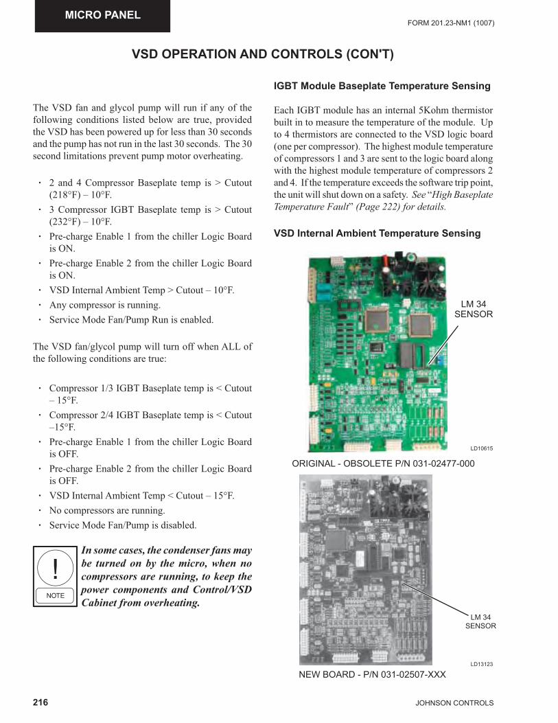
216 JOHNSON CONTROLS
FORM 201.23-NM1 (1007)MICRO PANEL
VSD OPERATION AND CONTROLS (CON'T)
The VSD fan and glycol pump will run if any of the following conditions listed below are true, provided the VSD has been powered up for less than 30 seconds and the pump has not run in the last 30 seconds. The 30 second limitations prevent pump motor overheating.
· 2 and 4 Compressor Baseplate temp is > Cutout (218°F) – 10°F.
· 3 Compressor IGBT Baseplate temp is > Cutout (232°F) – 10°F.
· Pre-charge Enable 1 from the chiller Logic Board is ON.
· Pre-charge Enable 2 from the chiller Logic Board is ON.
· VSD Internal Ambient Temp > Cutout – 10°F. · Any compressor is running. · Service Mode Fan/Pump Run is enabled.
The VSD fan/glycol pump will turn off when ALL of the following conditions are true:
· Compressor 1/3 IGBT Baseplate temp is < Cutout – 15°F.
· Compressor 2/4 IGBT Baseplate temp is < Cutout –15°F.
· Pre-charge Enable 1 from the chiller Logic Board is OFF.
· Pre-charge Enable 2 from the chiller Logic Board is OFF.
· VSD Internal Ambient Temp < Cutout – 15°F. · No compressors are running. · Service Mode Fan/Pump is disabled.
In some cases, the condenser fans may be turned on by the micro, when no compressors are running, to keep the power components and Control/VSD Cabinet from overheating.
IGBT Module Baseplate Temperature Sensing
Each IGBT module has an internal 5Kohm thermistor built in to measure the temperature of the module. Up to 4 thermistors are connected to the VSD logic board (one per compressor). The highest module temperature of compressors 1 and 3 are sent to the logic board along with the highest module temperature of compressors 2 and 4. If the temperature exceeds the software trip point, the unit will shut down on a safety. See “High Baseplate Temperature Fault” (Page 222) for details.
VSD Internal Ambient Temperature Sensing
LD10615
LM 34SENSOR
ORIGINAL - OBSOLETE P/N 031-02477-000
LM 34SENSOR
NEW BOARD - P/N 031-02507-XXXLD13123
217JOHNSON CONTROLS
FORM 201.23-NM1 (1007)
8
A National LM34 temperature sensor located on the VSD Logic Board is used to measure the internal ambi-ent temperature of the Control Panel/VSD enclosure. It has an output voltage that is linearly proportional to the temperature in degrees Fahrenheit. If the temperature exceeds the software trip point, the unit will shut down on a safety. See “High VSD Ambient Temperature Fault” (Page 223) for details.
VSD OPERATION AND CONTROLS (CON'T)
Pre-charge
When cooling is required (LCWT>SPHL), leaving chilled liquid temp is greater than the setpoint high limit), the chiller Control Board will send a Pre-Charge Enable (2 enables on a 4 comp unit) via comms to the VSD Logic Board. The VSD’s DC bus voltage(s) across the Bus Filter Capacitors will slowly be increased to the proper level (>500VDC) through fi ring of the SCR Trigger Board(s) and the associated pre-charge enable control signal(s). The pre-charge time interval is fi xed at 20 seconds. The purpose of the precharge is to limit current when charging an uncharged capacitor bank. When uncharged, the capacitor bank looks like an electrical short. The bus is brought up slowly by only turning on the SCR’s during the trailing half of the + and – portion of the incoming AC sine wave. Follow-ing is the status message displayed while the precharge is taking place.
S YS X VSD DC BUS PRECHARGE
Following successful completion of the pre-charge interval, the SCR’s on the AC to DC semi-converter (SCR/Diode Modules) will be gated fully on by the SCR Trigger Board and the DC bus will be brought up to its full potential. After pre-charge has been success-fully completed, the SCR’s will stay fully on until the Chiller Control Board turns off the Pre-Charge Enable via comms.
There will be a Unit Pre-charge Enable for 2 and 3 com-pressor units and separate System Pre-charge Enables for 4 compressor units.
The pre-charge will only take place when all of the fol-lowing conditions are true, otherwise it is disabled:
· Daily Schedule is ON. · Unit Switch is ON. · System Switch(es) are ON. · Run Permissive(s) are Enabled. · Flow Switch indicates fl ow. · LCHLT > Setpoint High Limit. · Unit not faulted / locked out.
Run Mode / Unit Restart
In order to initiate a system run, two conditions must be met. At least 1 of the 2 systems run signals from the control panel must be present and at least 1 of the 4 possible Compressor RUN bits must be set in the serial communications link between the VSD Logic Board and the Chiller Control Board. Following successful completion of pre-charge and receipt of the system run signals, the motor output voltage (% modulation) and output frequency commands will be determined by the VSD microprocessor located on the VSD Logic Board. These two parameters will be sent to the PWM generator located on the VSD Logic Board for waveform process-ing at a rate of once every 10 msec.
The voltage and frequency commands issued by the VSD microprocessor are determined by the operating frequency command received on the communications link from the Chiller Control Board and by the present operating frequency of the drive. Upon receipt of a legiti-mate run command communication, the VSD’s output frequency will be increased from 0 Hz to the operating frequency command from the communications link.
DC Bus Voltage Sensing and Scaling
Full DC Bus voltage and ½ DC Bus voltages are sensed for up to 2 DC Buses. 2 and 3 compressor chillers share a common DC Bus, while 4 compressor chillers utilize 2 DC Buses (1/3 and 2/4). The DC Bus is wired to the DC Bus Isolation Board, the voltage is divided down through a resistance voltage divider, and the reduced voltage is fed to the VSD Logic Board for safety monitoring.
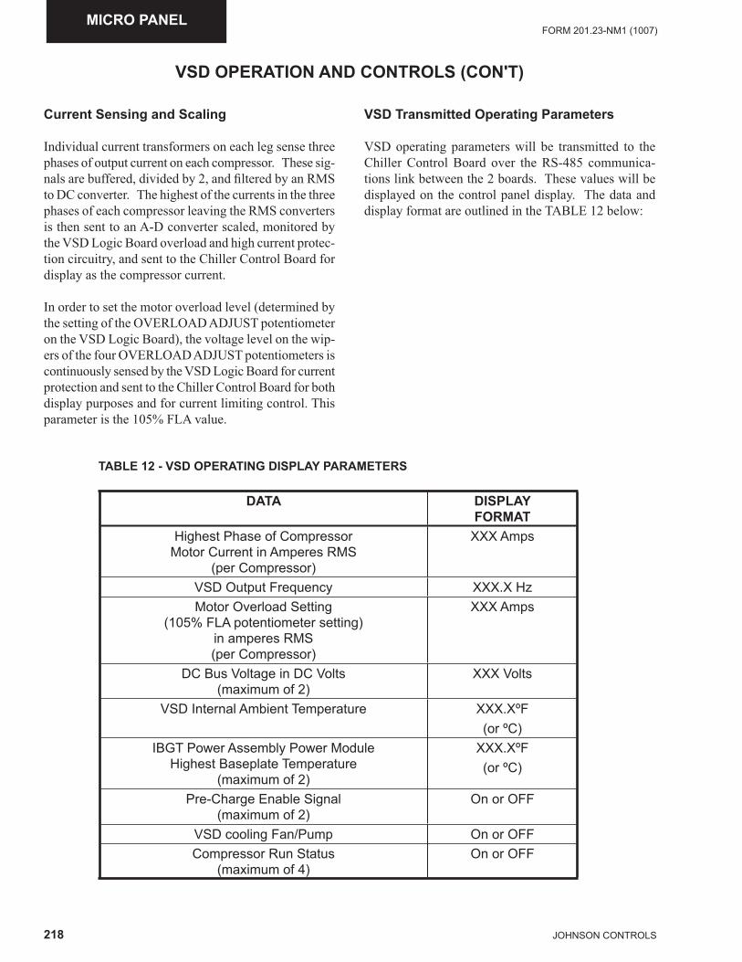
218 JOHNSON CONTROLS
FORM 201.23-NM1 (1007)MICRO PANEL
VSD Transmitted Operating Parameters
VSD operating parameters will be transmitted to the Chiller Control Board over the RS-485 communica-tions link between the 2 boards. These values will be displayed on the control panel display. The data and display format are outlined in the TABLE 12 below:
VSD OPERATION AND CONTROLS (CON'T)
TABLE 12 - VSD OPERATING DISPLAY PARAMETERS
DATA DISPLAYFORMAT
Highest Phase of Compressor Motor Current in Amperes RMS
(per Compressor)
XXX Amps
VSD Output Frequency XXX.X HzMotor Overload Setting
(105% FLA potentiometer setting)in amperes RMS(per Compressor)
XXX Amps
DC Bus Voltage in DC Volts(maximum of 2)
XXX Volts
VSD Internal Ambient Temperature XXX.XºF(or ºC)
IBGT Power Assembly Power Module Highest Baseplate Temperature
(maximum of 2)
XXX.XºF(or ºC)
Pre-Charge Enable Signal (maximum of 2)
On or OFF
VSD cooling Fan/Pump On or OFFCompressor Run Status
(maximum of 4)On or OFF
Current Sensing and Scaling
Individual current transformers on each leg sense three phases of output current on each compressor. These sig-nals are buffered, divided by 2, and fi ltered by an RMS to DC converter. The highest of the currents in the three phases of each compressor leaving the RMS converters is then sent to an A-D converter scaled, monitored by the VSD Logic Board overload and high current protec-tion circuitry, and sent to the Chiller Control Board for display as the compressor current.
In order to set the motor overload level (determined by the setting of the OVERLOAD ADJUST potentiometer on the VSD Logic Board), the voltage level on the wip-ers of the four OVERLOAD ADJUST potentiometers is continuously sensed by the VSD Logic Board for current protection and sent to the Chiller Control Board for both display purposes and for current limiting control. This parameter is the 105% FLA value.
219JOHNSON CONTROLS
FORM 201.23-NM1 (1007)
8
VSD SAFETIES (FAULTS)
VSD operating conditions are monitored by both soft-ware algorithms and hardware circuitry. Both types exist as a result of the need for both extremely fast protection requirements such as a short circuit condition or a slow reacting trip such as a slow rising overload condition. To eliminate nuisance unit trips, the sensor inputs for the VSD’s operating parameters are averaged four times before “Software” generated unit/system fault trips from the VSD Logic Board are initiated. These faults cause single compressor or total unit controlled “ramped” shutdown. Other parameters that are not fed to the VSD Logic Board microprocessor are protected by “Hardware” generated fault trips. Hardware trips involve electronic circuitry that measures voltages or currents and activate level sensitive comparators con-nected to programmable gate arrays on the VSD Logic Board FPGA (Field Programmable Gate Array). These safeties operate extremely fast and provide “immediate” shutdown, because they are not dependent upon software program loops that operate in seconds or fractions of a second. Outputs from the gate arrays provide a digital signal to indicate whether a safety threshold has been reached.
Immediate Fault shutdowns are often accompanied by audible motor backspin due to equalizing of the differen-tial between discharge and suction when the compressor is turned off while rotating at high speeds. This should not cause concern and will not damage the chiller.
Each fault outlined in the descriptions that follow will indicate whether it is a hardware or software generated fault.
It will be noted the “ramped” shutdown results in minimal compressor backspin and noise associated with backspin. “Immediate” shutdowns will result in com-pressor backspin and a higher noise level based upon the differential pressure between discharge and suction.
When a VSD fault occurs, the VSD Logic Board cap-tures VSD data in the onboard battery backed RAM. At the same time, the VSD Board “Fault Relay” will open, signaling the Chiller Control Board microproces-sor to save a snapshot of system data. The VSD Logic Board then transmits the fault data to the Chiller Control Board microprocessor on the next comms between the two boards. If the Chiller Control Board receives the comms fault indication before the Fault Relay signal, it will immediately save a snapshot of system data when the comms fault is recognized. This also enables the
micro to capture fault data if the Fault relay fails. Both the system and VSD fault data are then stored in the Chiller Control Board history buffers. Any additional faults that may occur during shutdown on the fi rst fault or between the fi rst fault and the next comms will also be stored and transmitted to the Chiller Control Board along with the original fault data. This data will be stored as “ALL FAULT” data.
When the control panel acknowledges a fault (via the fault acknowledge bit in comms) the fault relay will be reset (closed) by the VSD Logic Board and the fault indication fl ag (in comms) will be reset.
The fault relay will not open when a non-running fault occurs. In this case, the system will be inhibited from running until the fault condition is corrected. An inhibit message will be displayed on the panel display indicat-ing the system is not allowed to run. Examples of this type of fault would be the High Internal Ambient fault and the VSD CT Plug Fault. When the chiller receives the transmitted fault data via comms, it will save a snap-shot of system data in the history buffer even though the chiller is not running.
Some faults will be unit faults; other faults will be system (specifi c compressor or compressor pairs) faults, de-pending upon the number of compressors in the chiller. Most faults will shut down the unit/ system and allow restart once the fault clears and the 120 sec anti-recycle timer times out. These faults will allow up to 3 faults in 90 minutes before locking out the unit/system. Other faults lock out the unit/system after only a single fault. Details on individual faults are provided in the follow-ing explanations.
A start inhibit will take place if a VSD fault condition exists and a compressor that is not running is called to start. The start inhibit will be cleared when the fault condition goes away and the compressor will be per-mitted to start.
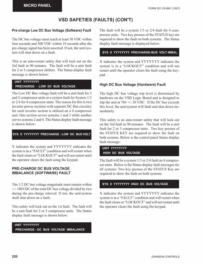
220 JOHNSON CONTROLS
FORM 201.23-NM1 (1007)MICRO PANEL
Pre-charge Low DC Bus Voltage (Software) Fault
The DC bus voltage must reach at least 50 VDC within four seconds and 500 VDC within 19 seconds after the pre-charge signal has been asserted. If not, the unit/sys-tem will shut down on a fault.
This is an auto-restart safety that will lock out on the 3rd fault in 90 minutes. The fault will be a unit fault for 2 or 3 compressor chillers. The Status display fault message is shown below:
UNIT YYYYYYYY PRECHARGE - LOW DC BUS VOLTAGE
The Low DC Bus voltage fault will be a unit fault for 2 and 3 compressor units or a system fault for System 1/3 or 2/4 for 4 compressor units. The reason for this is two inverter power sections with separate DC Bus circuitry for each inverter section is utilized on a 4 compressor unit. One section serves systems 1 and 3 while another serves systems 2 and 4. The Status display fault message is shown below:
X indicates the system and YYYYYYY indicates the system is in a “FAULT” condition and will restart when the fault clears or “LOCKOUT” and will not restart until the operator clears the fault using the keypad.
PRE-CHARGE DC BUS VOLTAGE IMBALANCE (SOFTWARE) FAULT
The 1/2 DC bus voltage magnitude must remain within +/- 100VDC of the total DC bus voltage divided by two during the pre-charge interval. If not, the unit/system shall shut down on a fault.
This safety will lock out on the 1st fault. The fault will be a unit fault for 2 or 3 compressor units. The Status display fault message is shown below:
SYS X YYYYYYYY PRECHARGE - LOW DC BUS VOLT
UNIT YYYYYYYY PRECHARGE - DC BUS VOLTAGE IMBALANCE
The fault will be a system 1/3 or 2/4 fault for 4 com-pressor units. Two key presses of the STATUS key are required to show the fault on both systems. The Status display fault message is displayed below:
VSD SAFETIES (FAULTS) (CON'T)
SYS X YYYYYYYY PRECHARGE-BUS VOLT IMBAL
X indicates the system and YYYYYYY indicates the system is in a “LOCKOUT” condition and will not restart until the operator clears the fault using the key-pad.
High DC Bus Voltage (Hardware) Fault
The high DC bus voltage trip level is determined by hardware on the VSD Logic Board and is designed to trip the unit at 766 +/- 30 VDC. If the DC bus exceeds this level, the unit/system will fault and shut down im-mediately.
This safety is an auto-restart safety that will lock out on the 3rd fault in 90 minutes. The fault will be a unit fault for 2 or 3 compressor units. Two key presses of the STATUS KEY are required to show the fault on both systems. Below is the control panel Status display fault message:
The fault will be a system 1/3 or 2/4 fault on 4 compres-sor units. Below is the Status display fault messages for all systems: Two key presses of the STATUS Key are required to show the fault on both systems.
UNIT YYYYYYYY HIGH DC BUS VOLTAGE
SYS X YYYYYYYY HIGH DC BUS VOLTAGE
X indicates the system and YYYYYYY indicates the system is in a “FAULT” condition and will restart when the fault clears or “LOCKOUT” and will not restart until the operator clears the fault using the keypad.
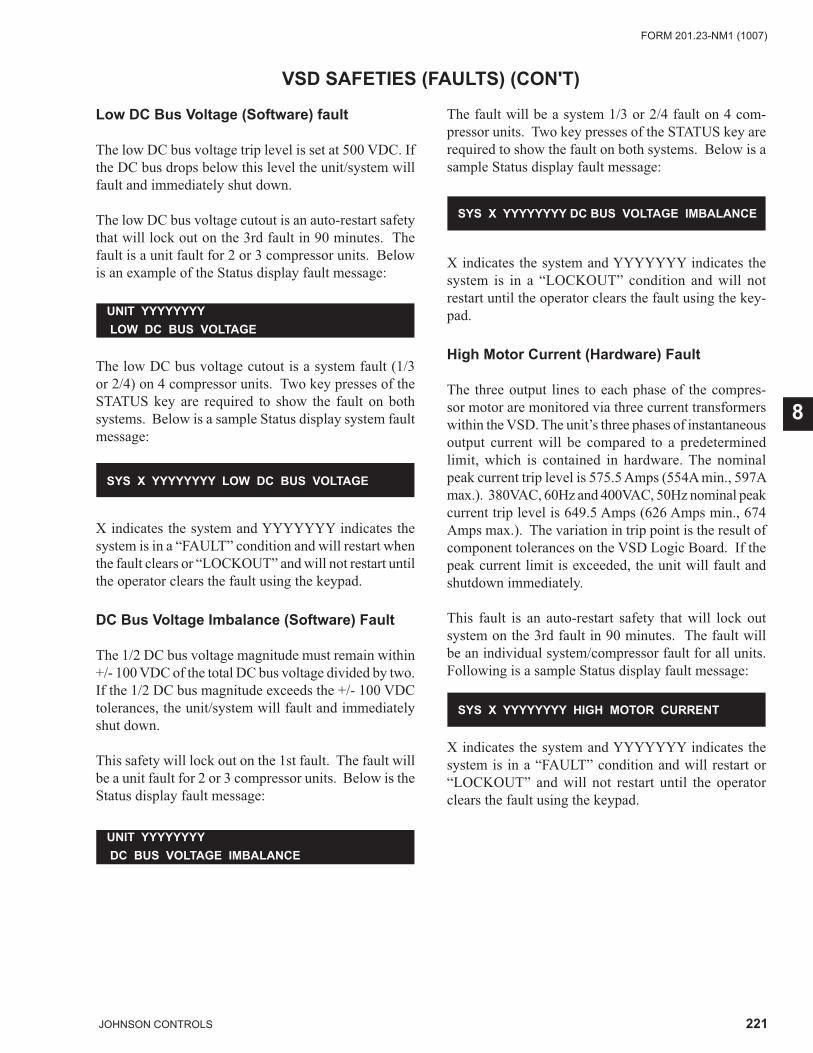
221JOHNSON CONTROLS
FORM 201.23-NM1 (1007)
8
VSD SAFETIES (FAULTS) (CON'T)
Low DC Bus Voltage (Software) fault
The low DC bus voltage trip level is set at 500 VDC. If the DC bus drops below this level the unit/system will fault and immediately shut down.
The low DC bus voltage cutout is an auto-restart safety that will lock out on the 3rd fault in 90 minutes. The fault is a unit fault for 2 or 3 compressor units. Below is an example of the Status display fault message:
The low DC bus voltage cutout is a system fault (1/3 or 2/4) on 4 compressor units. Two key presses of the STATUS key are required to show the fault on both systems. Below is a sample Status display system fault message:
SYS X YYYYYYYY LOW DC BUS VOLTAGE
UNIT YYYYYYYY DC BUS VOLTAGE IMBALANCE
UNIT YYYYYYYY LOW DC BUS VOLTAGE
X indicates the system and YYYYYYY indicates the system is in a “FAULT” condition and will restart when the fault clears or “LOCKOUT” and will not restart until the operator clears the fault using the keypad.
DC Bus Voltage Imbalance (Software) Fault
The 1/2 DC bus voltage magnitude must remain within +/- 100 VDC of the total DC bus voltage divided by two. If the 1/2 DC bus magnitude exceeds the +/- 100 VDC tolerances, the unit/system will fault and immediately shut down.
This safety will lock out on the 1st fault. The fault will be a unit fault for 2 or 3 compressor units. Below is the Status display fault message:
The fault will be a system 1/3 or 2/4 fault on 4 com-pressor units. Two key presses of the STATUS key are required to show the fault on both systems. Below is a sample Status display fault message:
X indicates the system and YYYYYYY indicates the system is in a “LOCKOUT” condition and will not restart until the operator clears the fault using the key-pad.
High Motor Current (Hardware) Fault
The three output lines to each phase of the compres-sor motor are monitored via three current transformers within the VSD. The unit’s three phases of instantaneous output current will be compared to a predetermined limit, which is contained in hardware. The nominal peak current trip level is 575.5 Amps (554A min., 597A max.). 380VAC, 60Hz and 400VAC, 50Hz nominal peak current trip level is 649.5 Amps (626 Amps min., 674 Amps max.). The variation in trip point is the result of component tolerances on the VSD Logic Board. If the peak current limit is exceeded, the unit will fault and shutdown immediately.
This fault is an auto-restart safety that will lock out system on the 3rd fault in 90 minutes. The fault will be an individual system/compressor fault for all units. Following is a sample Status display fault message:
SYS X YYYYYYYY DC BUS VOLTAGE IMBALANCE
X indicates the system and YYYYYYY indicates the system is in a “FAULT” condition and will restart or “LOCKOUT” and will not restart until the operator clears the fault using the keypad.
SYS X YYYYYYYY HIGH MOTOR CURRENT
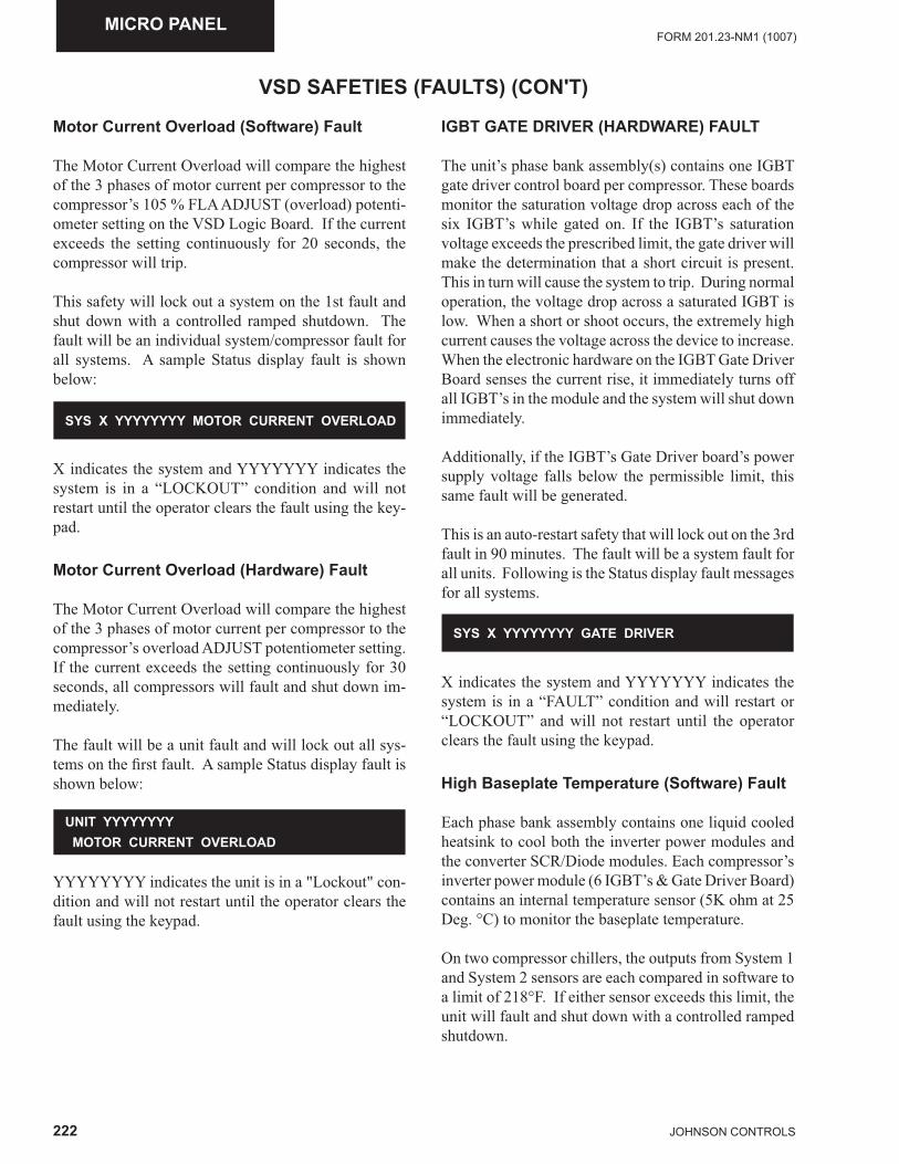
222 JOHNSON CONTROLS
FORM 201.23-NM1 (1007)MICRO PANEL
VSD SAFETIES (FAULTS) (CON'T)
Motor Current Overload (Software) Fault
The Motor Current Overload will compare the highest of the 3 phases of motor current per compressor to the compressor’s 105 % FLA ADJUST (overload) potenti-ometer setting on the VSD Logic Board. If the current exceeds the setting continuously for 20 seconds, the compressor will trip.
This safety will lock out a system on the 1st fault and shut down with a controlled ramped shutdown. The fault will be an individual system/compressor fault for all systems. A sample Status display fault is shown below:
X indicates the system and YYYYYYY indicates the system is in a “LOCKOUT” condition and will not restart until the operator clears the fault using the key-pad.
Motor Current Overload (Hardware) Fault
The Motor Current Overload will compare the highest of the 3 phases of motor current per compressor to the compressor’s overload ADJUST potentiometer setting. If the current exceeds the setting continuously for 30 seconds, all compressors will fault and shut down im-mediately.
The fault will be a unit fault and will lock out all sys-tems on the fi rst fault. A sample Status display fault is shown below:
SYS X YYYYYYYY MOTOR CURRENT OVERLOAD
YYYYYYYY indicates the unit is in a "Lockout" con-dition and will not restart until the operator clears the fault using the keypad.
UNIT YYYYYYYY MOTOR CURRENT OVERLOAD
IGBT GATE DRIVER (HARDWARE) FAULT
The unit’s phase bank assembly(s) contains one IGBT gate driver control board per compressor. These boards monitor the saturation voltage drop across each of the six IGBT’s while gated on. If the IGBT’s saturation voltage exceeds the prescribed limit, the gate driver will make the determination that a short circuit is present. This in turn will cause the system to trip. During normal operation, the voltage drop across a saturated IGBT is low. When a short or shoot occurs, the extremely high current causes the voltage across the device to increase. When the electronic hardware on the IGBT Gate Driver Board senses the current rise, it immediately turns off all IGBT’s in the module and the system will shut down immediately.
Additionally, if the IGBT’s Gate Driver board’s power supply voltage falls below the permissible limit, this same fault will be generated.
This is an auto-restart safety that will lock out on the 3rd fault in 90 minutes. The fault will be a system fault for all units. Following is the Status display fault messages for all systems.
X indicates the system and YYYYYYY indicates the system is in a “FAULT” condition and will restart or “LOCKOUT” and will not restart until the operator clears the fault using the keypad.
High Baseplate Temperature (Software) Fault
Each phase bank assembly contains one liquid cooled heatsink to cool both the inverter power modules and the converter SCR/Diode modules. Each compressor’s inverter power module (6 IGBT’s & Gate Driver Board) contains an internal temperature sensor (5K ohm at 25 Deg. °C) to monitor the baseplate temperature.
On two compressor chillers, the outputs from System 1 and System 2 sensors are each compared in software to a limit of 218°F. If either sensor exceeds this limit, the unit will fault and shut down with a controlled ramped shutdown.
SYS X YYYYYYYY GATE DRIVER
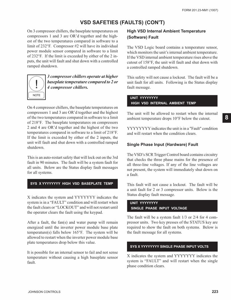
223JOHNSON CONTROLS
FORM 201.23-NM1 (1007)
8
On 3 compressor chillers, the baseplate temperatures on compressors 1 and 3 are OR’d together and the high-est of the two temperatures compared in software to a limit of 232°F. Compressor #2 will have its individual power module sensor compared in software to a limit of 232°F. If the limit is exceeded by either of the 2 in-puts, the unit will fault and shut down with a controlled ramped shutdown.
3 compressor chillers operate at higher baseplate temperature compared to 2 or 4 compressor chillers.
On 4 compressor chillers, the baseplate temperatures on compressors 1 and 3 are OR’d together and the highest of the two temperatures compared in software to a limit of 218°F. The baseplate temperatures on compressors 2 and 4 are OR’d together and the highest of the two temperatures compared in software to a limit of 218°F. If the limit is exceeded by either of the 2 inputs, the unit will fault and shut down with a controlled ramped shutdown.
This is an auto-restart safety that will lock out on the 3rd fault in 90 minutes. The fault will be a system fault for all units. Below are the Status display fault messages for all systems.
VSD SAFETIES (FAULTS) (CON'T)
X indicates the system and YYYYYYY indicates the system is in a “FAULT” condition and will restart when the fault clears or “LOCKOUT” and will not restart until the operator clears the fault using the keypad.
After a fault, the fan(s) and water pump will remain energized until the inverter power module base plate temperature(s) falls below 165°F. The system will be allowed to restart when the inverter power module base plate temperatures drop below this value.
It is possible for an internal sensor to fail and not sense temperature without causing a high baseplate sensor fault.
SYS X YYYYYYYY HIGH VSD BASEPLATE TEMP
High VSD Internal Ambient Temperature (Software) Fault
The VSD Logic board contains a temperature sensor, which monitors the unit’s internal ambient temperature. If the VSD internal ambient temperature rises above the cutout of 158°F, the unit will fault and shut down with a controlled ramped shutdown.
This safety will not cause a lockout. The fault will be a unit fault for all units. Following is the Status display fault message.
The unit will be allowed to restart when the internal ambient temperature drops 10°F below the cutout.
YYYYYYYY indicates the unit is in a "Fault" condition and will restart when the condition clears.
Single Phase Input (Hardware) Fault
The VSD’s SCR Trigger Control board contains circuitry that checks the three phase mains for the presence of all three-line voltages. If any of the line voltages are not present, the system will immediately shut down on a fault.
This fault will not cause a lockout. The fault will be a unit fault for 2 or 3 compressor units. Below is the Status display fault message.
UNIT YYYYYYYY HIGH VSD INTERNAL AMBIENT TEMP
The fault will be a system fault 1/3 or 2/4 for 4 com-pressor units. Two key presses of the STATUS key are required to show the fault on both systems. Below is the fault message for all systems.
UNIT YYYYYYYY SINGLE PHASE INPUT VOLTAGE
X indicates the system and YYYYYYY indicates the system is “FAULT” and will restart when the single phase condition clears.
SYS X YYYYYYYY SINGLE PHASE INPUT VOLTS
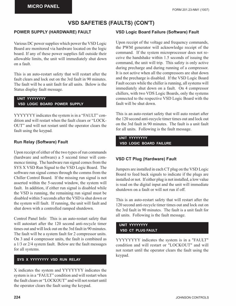
224 JOHNSON CONTROLS
FORM 201.23-NM1 (1007)MICRO PANEL
VSD SAFETIES (FAULTS) (CON'T)POWER SUPPLY (HARDWARE) FAULT
Various DC power supplies which power the VSD Logic Board are monitored via hardware located on the logic board. If any of these power supplies fall outside their allowable limits, the unit will immediately shut down on a fault.
This is an auto-restart safety that will restart after the fault clears and lock out on the 3rd fault in 90 minutes. The fault will be a unit fault for all units. Below is the Status display fault message.
YYYYYYY indicates the system is in a “FAULT” con-dition and will restart when the fault clears or “LOCK-OUT” and will not restart until the operator clears the fault using the keypad.
Run Relay (Software) Fault
Upon receipt of either of the two types of run commands (hardware and software) a 5 second timer will com-mence timing. The hardware run signal comes from the SYS X VSD Run Signal to the VSD Logic Board. The software run signal comes through the comms from the Chiller Control Board. If the missing run signal is not asserted within the 5-second window, the system will fault. In addition, if either run signal is disabled while the VSD is running, the remaining run signal must be disabled within 5 seconds after the VSD is shut down or the system will fault. If running, the unit will fault and shut down with a controlled ramped shutdown.
Control Panel Info: This is an auto-restart safety that will autostart after the 120 second anti-recycle timer times out and will lock out on the 3rd fault in 90 minutes. The fault will be a system fault for 2 compressor units. On 3 and 4 compressor units, the fault is combined as a 1/3 or 2/4 system fault. Below are the fault messages for all systems.
UNIT YYYYYYYY VSD LOGIC BOARD POWER SUPPLY
X indicates the system and YYYYYYY indicates the system is in a “FAULT” condition and will restart when the fault clears or “LOCKOUT” and will not restart until the operator clears the fault using the keypad.
SYS X YYYYYYYY VSD RUN RELAY
VSD Logic Board Failure (Software) Fault
Upon receipt of the voltage and frequency commands, the PWM generator will acknowledge receipt of the command. If the system microprocessor does not re-ceive the handshake within 1.5 seconds of issuing the command, the unit will trip. This safety is only active during precharge and during running of a compressor. It is not active when all the compressors are shut down and the precharge is disabled. If the VSD Logic Board Fault occurs while the chiller is running, all systems will immediately shut down on a fault. On 4 compressor chillers, with two VDS Logic Boards, only the systems connected to the respective VSD Logic Board with the fault will be shut down.
This is an auto-restart safety that will auto restart after the 120 second anti-recycle timer times out and lock out on the 3rd fault in 90 minutes. The fault is a unit fault for all units. Following is the fault message.
VSD CT Plug (Hardware) Fault
Jumpers are installed in each CT plug on the VSD Logic Board to feed back signals to indicate if the plugs are installed or not. If either plug is not installed, a low value is read on the digital input and the unit will immediate shutdown on a fault or will not run if off.
This is an auto-restart safety that will restart after the 120 second anti-recycle timer times out and lock out on the 3rd fault in 90 minutes. The fault is a unit fault for all units. Following is the fault message.
UNIT YYYYYYYY VSD LOGIC BOARD FAILURE
UNIT YYYYYYYY VSD CT PLUG FAULT
YYYYYYYY indicates the system is in a "FAULT" condition and will restart or "LOCKOUT" and will not restart until the operator clears the fault using the keypad.
225JOHNSON CONTROLS
FORM 201.23-NM1 (1007)
8
VSD SAFETIES (FAULTS) (CON'T)VSD Fault Data
When a fault has occurred, the VSD Logic Board will capture fault data. This data will be stored in the on-board battery backed RAM for safekeeping and trans-ferred to the panel via the communications link as soon as possible.
A fault code will be set for the fault that initiated the system shutdown. This fault will appear as a specifi c fault in the Status message.
Any faults that occur after the initial fault, which occur within the comms transmission time frame following the inception of the fi rst fault, will be stored and transmitted to the Micro Logic Board together with the fi rst fault data. These faults will appear in the "All Fault" display in the History.
A snapshot of the operating parameters of the VSD is continuously updated in battery-backed memory once every program loop. Upon receipt of a fi rst fault, the snapshot of the operating parameters will be stored in memory and are transmitted to the panel as the fault data.
Fault Relay/Fault Acknowledge Bit
Control of the Fault Relay is from the VSD Logic Board. The Fault Relay on the VSD will be closed during a non-fault condition.
When a running or pre-charge fault occurs on the VSD, the fault relay will immediately open. The relay will not open for non-running faults that occur.
When the Chiller Control Board sees the VSD fault relay open, it will immediately take a snapshot of system data and save it to the history buffer.
A fault acknowledge bit from the Chiller Control Board is sent to the VSD via comms after receiving valid fault data from the VSD. When the VSD Logic Board re-ceives the fault acknowledge via comms from the panel it will reset (close) the Fault Relay. The fault acknowl-edge is reset by the Chiller Control Board after the Fault Relay is closed by the VSD Logic Board.
VSD Fault Compressor Start Inhibit
If a VSD fault condition exists while the compressor is not running or pre-charging, the Chiller Control Board will not try to start the faulted compressor(s). The start inhibit will be automatically cleared when the fault condition goes away.
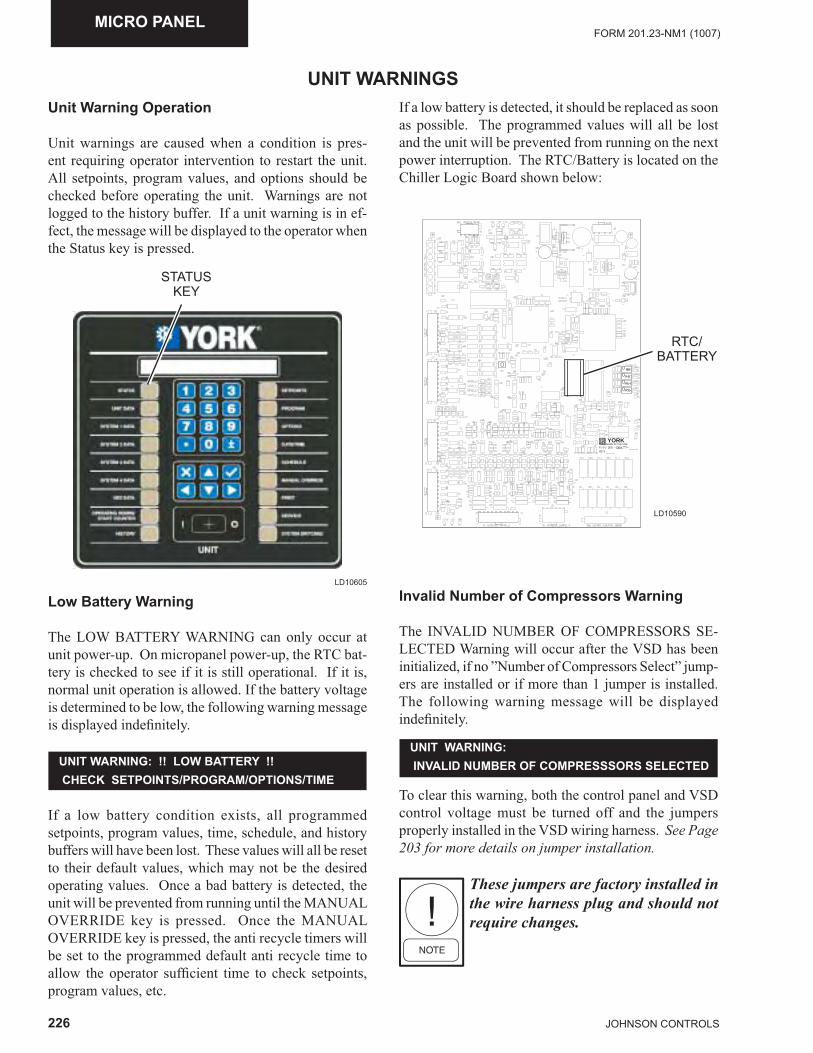
226 JOHNSON CONTROLS
FORM 201.23-NM1 (1007)MICRO PANEL
UNIT WARNINGSUnit Warning Operation
Unit warnings are caused when a condition is pres-ent requiring operator intervention to restart the unit. All setpoints, program values, and options should be checked before operating the unit. Warnings are not logged to the history buffer. If a unit warning is in ef-fect, the message will be displayed to the operator when the Status key is pressed.
LD10605
STATUS KEY
Low Battery Warning
The LOW BATTERY WARNING can only occur at unit power-up. On micropanel power-up, the RTC bat-tery is checked to see if it is still operational. If it is, normal unit operation is allowed. If the battery voltage is determined to be low, the following warning message is displayed indefi nitely.
If a low battery condition exists, all programmed setpoints, program values, time, schedule, and history buffers will have been lost. These values will all be reset to their default values, which may not be the desired operating values. Once a bad battery is detected, the unit will be prevented from running until the MANUAL OVERRIDE key is pressed. Once the MANUAL OVERRIDE key is pressed, the anti recycle timers will be set to the programmed default anti recycle time to allow the operator suffi cient time to check setpoints, program values, etc.
UNIT WARNING: !! LOW BATTERY !! CHECK SETPOINTS/PROGRAM/OPTIONS/TIME
If a low battery is detected, it should be replaced as soon as possible. The programmed values will all be lost and the unit will be prevented from running on the next power interruption. The RTC/Battery is located on the Chiller Logic Board shown below:
MADE IN THE USAYORK
RTC/BATTERY
Invalid Number of Compressors Warning
The INVALID NUMBER OF COMPRESSORS SE-LECTED Warning will occur after the VSD has been initialized, if no ”Number of Compressors Select” jump-ers are installed or if more than 1 jumper is installed. The following warning message will be displayed indefi nitely.
UNIT WARNING: INVALID NUMBER OF COMPRESSSORS SELECTED
To clear this warning, both the control panel and VSD control voltage must be turned off and the jumpers properly installed in the VSD wiring harness. See Page 203 for more details on jumper installation.
These jumpers are factory installed in the wire harness plug and should not require changes.
LD10590
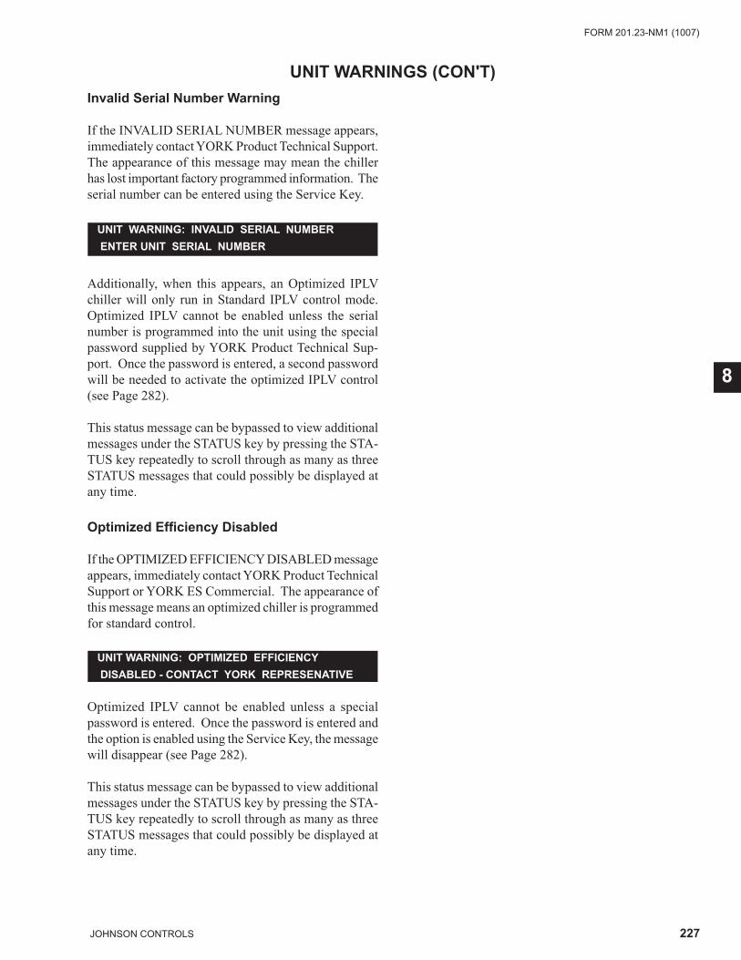
227JOHNSON CONTROLS
FORM 201.23-NM1 (1007)
8
UNIT WARNINGS (CON'T)Invalid Serial Number Warning
If the INVALID SERIAL NUMBER message appears, immediately contact YORK Product Technical Support. The appearance of this message may mean the chiller has lost important factory programmed information. The serial number can be entered using the Service Key.
Additionally, when this appears, an Optimized IPLV chiller will only run in Standard IPLV control mode. Optimized IPLV cannot be enabled unless the serial number is programmed into the unit using the special password supplied by YORK Product Technical Sup-port. Once the password is entered, a second password will be needed to activate the optimized IPLV control (see Page 282).
This status message can be bypassed to view additional messages under the STATUS key by pressing the STA-TUS key repeatedly to scroll through as many as three STATUS messages that could possibly be displayed at any time.
Optimized Effi ciency Disabled
If the OPTIMIZED EFFICIENCY DISABLED message appears, immediately contact YORK Product Technical Support or YORK ES Commercial. The appearance of this message means an optimized chiller is programmed for standard control.
UNIT WARNING: INVALID SERIAL NUMBER ENTER UNIT SERIAL NUMBER
UNIT WARNING: OPTIMIZED EFFICIENCY DISABLED - CONTACT YORK REPRESENATIVE
Optimized IPLV cannot be enabled unless a special password is entered. Once the password is entered and the option is enabled using the Service Key, the message will disappear (see Page 282).
This status message can be bypassed to view additional messages under the STATUS key by pressing the STA-TUS key repeatedly to scroll through as many as three STATUS messages that could possibly be displayed at any time.
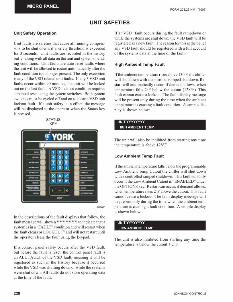
228 JOHNSON CONTROLS
FORM 201.23-NM1 (1007)MICRO PANEL
UNIT SAFETIES
Unit Safety Operation
Unit faults are safeties that cause all running compres-sors to be shut down, if a safety threshold is exceeded for 3 seconds. Unit faults are recorded in the history buffer along with all data on the unit and system operat-ing conditions. Unit faults are auto reset faults where the unit will be allowed to restart automatically after the fault condition is no longer present. The only exception is any of the VSD related unit faults. If any 3 VSD unit faults occur within 90 minutes, the unit will be locked out on the last fault. A VSD lockout condition requires a manual reset using the system switches. Both system switches must be cycled off and on to clear a VSD unit lockout fault. If a unit safety is in effect, the message will be displayed to the operator when the Status key is pressed.
In the descriptions of the fault displays that follow, the fault message will show a YYYYYYY to indicate that a system is in a “FAULT” condition and will restart when the fault clears or LOCKOUT” and will not restart until the operator clears the fault using the keypad.
If a control panel safety occurs after the VSD fault, but before the fault is reset, the control panel fault is an ALL FAULT of the VSD fault, meaning it will be registered as such in the History because it occurred while the VSD was shutting down or while the systems were shut down. All faults do not store operating data at the time of the fault.
LD10605
STATUS KEY
If a “VSD” fault occurs during the fault rampdown or while the systems are shut down, the VSD fault will be registered as a new fault. The reason for this is the belief any VSD fault should be registered with a full account of the systems data at the time of the fault.
High Ambient Temp Fault
If the ambient temperature rises above 130 F, the chiller will shut down with a controlled ramped shutdown. Re-start will automatically occur, if demand allows, when temperature falls 2°F below the cutout (128°F). This fault cannot cause a lockout. The fault display message will be present only during the time when the ambient temperature is causing a fault condition. A sample dis-play is shown below:
The unit will also be inhibited from starting any time the temperature is above 128°F.
Low Ambient Temp Fault
If the ambient temperature falls below the programmable Low Ambient Temp Cutout the chiller will shut down with a controlled ramped shutdown. This fault will only occur if the Low Ambient Cutout is “ENABLED” under the OPTIONS key. Restart can occur, if demand allows, when temperature rises 2°F above the cutout. This fault cannot cause a lockout. The fault display message will be present only during the time when the ambient tem-perature is causing a fault condition. A sample display is shown below:
UNIT YYYYYYYY HIGH AMBIENT TEMP
UNIT YYYYYYYY LOW AMBIENT TEMP
The unit is also inhibited from starting any time the temperature is below the cutout + 2°F.
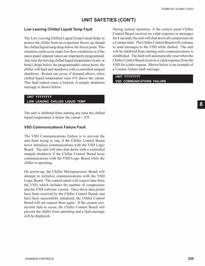
229JOHNSON CONTROLS
FORM 201.23-NM1 (1007)
8
UNIT SAFETIES (CON'T)
Low Leaving Chilled Liquid Temp Fault
The Low Leaving Chilled Liquid Temp Cutout helps to protect the chiller from an evaporator freeze-up should the chilled liquid temp drop below the freeze point. This situation could occur under low fl ow conditions or if the micro panel setpoint values are improperly programmed. Any time the leaving chilled liquid temperature (water or brine) drops below the programmable cutout point, the chiller will fault and shutdown with a controlled ramped shutdown. Restart can occur, if demand allows, when chilled liquid temperature rises 4°F above the cutout. This fault cannot cause a lockout. A sample shutdown message is shown below:
The unit is inhibited from starting any time the chilled liquid temperature is below the cutout + 4°F.
VSD Communications Failure Fault
The VSD Communications Failure is to prevent the unit from trying to run, if the Chiller Control Board never initializes communications with the VSD Logic Board. The unit will also shut down with a controlled ramped shutdown if the Chiller Control Board loses communications with the VSD Logic Board while the chiller is operating.
On power-up, the Chiller Microprocessor Board will attempt to initialize communications with the VSD Logic Board. The control panel will request data from the VSD, which includes the number of compressors and the VSD software version. Once these data points have been received by the Chiller Control Board, and have been successfully initialized, the Chiller Control Board will not request them again. If the comms con-nection fails to occur, the Chiller Control Board will prevent the chiller from operating and a fault message will be displayed.
UNIT YYYYYYYYLOW LEAVING CHILLED LIQUID TEMP
During normal operation, if the control panel Chiller Control Board receives no valid response to messages for 8 seconds, the unit will shut down all compressors on a Comms fault. The Chiller Control Board will continue to send messages to the VSD while faulted. The unit will be inhibited from starting until communications is established. The fault will automatically reset when the Chiller Control Board receives a valid response from the VSD for a data request. Shown below is an example of a Comms Failure fault message:
UNIT YYYYYYYYVSD COMMUNICATIONS FAILURE
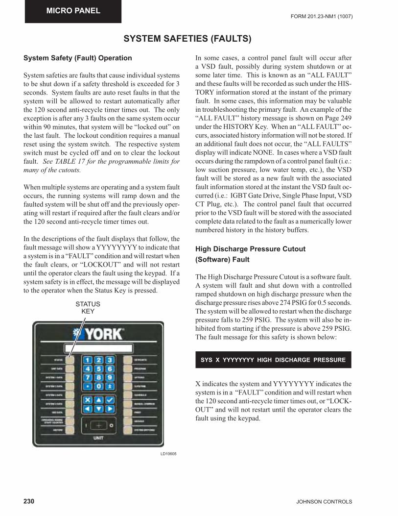
230 JOHNSON CONTROLS
FORM 201.23-NM1 (1007)MICRO PANEL
System Safety (Fault) Operation
System safeties are faults that cause individual systems to be shut down if a safety threshold is exceeded for 3 seconds. System faults are auto reset faults in that the system will be allowed to restart automatically after the 120 second anti-recycle timer times out. The only exception is after any 3 faults on the same system occur within 90 minutes, that system will be “locked out” on the last fault. The lockout condition requires a manual reset using the system switch. The respective system switch must be cycled off and on to clear the lockout fault. See TABLE 17 for the programmable limits for many of the cutouts.
When multiple systems are operating and a system fault occurs, the running systems will ramp down and the faulted system will be shut off and the previously oper-ating will restart if required after the fault clears and/or the 120 second anti-recycle timer times out.
In the descriptions of the fault displays that follow, the fault message will show a YYYYYYYY to indicate that a system is in a “FAULT” condition and will restart when the fault clears, or “LOCKOUT” and will not restart until the operator clears the fault using the keypad. If a system safety is in effect, the message will be displayed to the operator when the Status Key is pressed.
SYSTEM SAFETIES (FAULTS)
LD10605
STATUS KEY
In some cases, a control panel fault will occur after a VSD fault, possibly during system shutdown or at some later time. This is known as an “ALL FAULT” and these faults will be recorded as such under the HIS-TORY information stored at the instant of the primary fault. In some cases, this information may be valuable in troubleshooting the primary fault. An example of the “ALL FAULT” history message is shown on Page 249 under the HISTORY Key. When an “ALL FAULT” oc-curs, associated history information will not be stored. If an additional fault does not occur, the “ALL FAULTS” display will indicate NONE. In cases where a VSD fault occurs during the rampdown of a control panel fault (i.e.: low suction pressure, low water temp, etc.), the VSD fault will be stored as a new fault with the associated fault information stored at the instant the VSD fault oc-curred (i.e.: IGBT Gate Drive, Single Phase Input, VSD CT Plug, etc.). The control panel fault that occurred prior to the VSD fault will be stored with the associated complete data related to the fault as a numerically lower numbered history in the history buffers.
High Discharge Pressure Cutout (Software) Fault
The High Discharge Pressure Cutout is a software fault. A system will fault and shut down with a controlled ramped shutdown on high discharge pressure when the discharge pressure rises above 274 PSIG for 0.5 seconds. The system will be allowed to restart when the discharge pressure falls to 259 PSIG. The system will also be in-hibited from starting if the pressure is above 259 PSIG. The fault message for this safety is shown below:
SYS X YYYYYYYY HIGH DISCHARGE PRESSURE
X indicates the system and YYYYYYYY indicates the system is in a “FAULT” condition and will restart when the 120 second anti-recycle timer times out, or “LOCK-OUT” and will not restart until the operator clears the fault using the keypad.
231JOHNSON CONTROLS
FORM 201.23-NM1 (1007)
8
SYSTEM SAFETIES (FAULTS)(CON'T)
High Discharge Pressure Cutout(HPCO)(Hardware) Fault
The mechanical High Pressure Cutout protects the system from experiencing dangerously high discharge pressure. A system will fault and shut down immediately when the mechanical high pressure cutout contacts open. The fault will occur immediately and not wait 3 seconds, which is typical of most system faults. The HPCO is wired in series with the VSD Run Signal and will only be checked by the Chiller Control Board when the system is running. The mechanical cutout opens at 297+/-8 PSIG and closes at 230 +/-10 PSIG. The Status display fault message for this system is shown below:
X indicates the system and YYYYYYY indicates the system is in a “FAULT” condition and will restart when the 120 second anti-recycle timer times out or “LOCK-OUT” and will not restart until the operator clears the fault using the keypad.
Low Suction Pressure Cutout (Software) Fault
The programmable Low Suction Pressure Cutout is a secondary back-up for the fl ow switch and protects against operation with low refrigerant charge, which helps protect the chiller from an evaporator freeze-up, should the system attempt to run with a low refrigerant charge. The Status display fault message for this cut-out is shown below:
SYS X YYYYYYYY HPCO FAULT
X indicates the system and YYYYYYY indicates the system is in a “FAULT” condition and will restart when the 120 second anti-recycle timer times out or “LOCK-OUT” and will not restart until the operator clears the fault using the keypad. Typically, the cutout will be set at 24 PSIG for chilled water applications.
The cutout is ignored for the fi rst 30 seconds of system run time. During the next 3 minutes of run time the cutout point is linearly ramped from 10% of the cutout value up to the programmed cutout point. If at any time during the fi rst 3 minutes of operation the suction pres-
SYS X YYYYYYYY LOW SUCTION PRESSURE
sure falls below the ramped cutout point, the system will shut down with a controlled ramped shutdown.
The cutout pressure during operating periods of 30 seconds to 210 seconds is ramped and can be calculated by:
Cutout = (Programmed Cutout x Run Time)–1.2 PSIG 200 After the fi rst 3 minutes and 30 seconds of run time, if the suction pressure falls below the cutout as a result of a transient in the system, a transient timer is set at 30 seconds and a linearly ramped cutout is set starting at 10% of the programmed cutout. If over the next 30 seconds, the suction pressure does not stay above the ramped cutout, which ramps between 10% of the cutout and the programmed cutout over the 30 second period, the system will fault on low suction pressure.
Low Motor Current Cutout Fault
The Motor Current Cutout shuts the system down with a controlled ramped shutdown when the microprocessor detects the absence of motor current (<10%FLA), usu-ally indicating that a compressor is not running. This safety is ignored for the fi rst 10 seconds of operation.
The status display fault message for this safety is shown below:
SYS X YYYYYYYY LOW MOTOR CURRENT
X indicates the system and YYYYYYY indicates the system is in a “FAULT” condition and will restart when the 120 second anti-recycle timer times out or “LOCK-OUT” and will not restart until the operator clears the fault using the keypad.
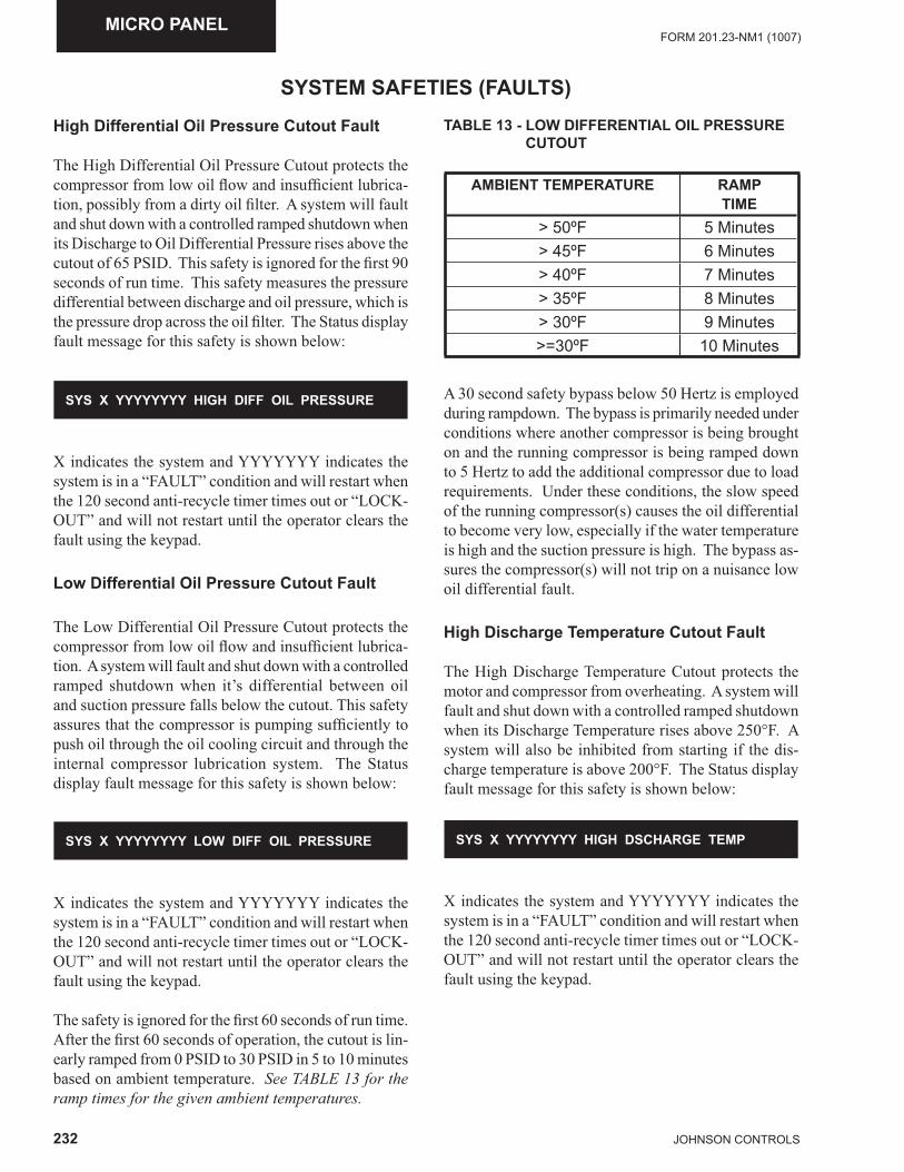
232 JOHNSON CONTROLS
FORM 201.23-NM1 (1007)MICRO PANEL
High Differential Oil Pressure Cutout Fault
The High Differential Oil Pressure Cutout protects the compressor from low oil fl ow and insuffi cient lubrica-tion, possibly from a dirty oil fi lter. A system will fault and shut down with a controlled ramped shutdown when its Discharge to Oil Differential Pressure rises above the cutout of 65 PSID. This safety is ignored for the fi rst 90 seconds of run time. This safety measures the pressure differential between discharge and oil pressure, which is the pressure drop across the oil fi lter. The Status display fault message for this safety is shown below:
SYSTEM SAFETIES (FAULTS)
SYS X YYYYYYYY HIGH DIFF OIL PRESSURE
X indicates the system and YYYYYYY indicates the system is in a “FAULT” condition and will restart when the 120 second anti-recycle timer times out or “LOCK-OUT” and will not restart until the operator clears the fault using the keypad.
Low Differential Oil Pressure Cutout Fault
The Low Differential Oil Pressure Cutout protects the compressor from low oil fl ow and insuffi cient lubrica-tion. A system will fault and shut down with a controlled ramped shutdown when it’s differential between oil and suction pressure falls below the cutout. This safety assures that the compressor is pumping suffi ciently to push oil through the oil cooling circuit and through the internal compressor lubrication system. The Status display fault message for this safety is shown below:
SYS X YYYYYYYY LOW DIFF OIL PRESSURE
X indicates the system and YYYYYYY indicates the system is in a “FAULT” condition and will restart when the 120 second anti-recycle timer times out or “LOCK-OUT” and will not restart until the operator clears the fault using the keypad.
The safety is ignored for the fi rst 60 seconds of run time. After the fi rst 60 seconds of operation, the cutout is lin-early ramped from 0 PSID to 30 PSID in 5 to 10 minutes based on ambient temperature. See TABLE 13 for the ramp times for the given ambient temperatures.
TABLE 13 - LOW DIFFERENTIAL OIL PRESSURE CUTOUT
AMBIENT TEMPERATURE RAMPTIME
> 50ºF 5 Minutes> 45ºF 6 Minutes> 40ºF 7 Minutes> 35ºF 8 Minutes> 30ºF 9 Minutes>=30ºF 10 Minutes
A 30 second safety bypass below 50 Hertz is employed during rampdown. The bypass is primarily needed under conditions where another compressor is being brought on and the running compressor is being ramped down to 5 Hertz to add the additional compressor due to load requirements. Under these conditions, the slow speed of the running compressor(s) causes the oil differential to become very low, especially if the water temperature is high and the suction pressure is high. The bypass as-sures the compressor(s) will not trip on a nuisance low oil differential fault.
High Discharge Temperature Cutout Fault
The High Discharge Temperature Cutout protects the motor and compressor from overheating. A system will fault and shut down with a controlled ramped shutdown when its Discharge Temperature rises above 250°F. A system will also be inhibited from starting if the dis-charge temperature is above 200°F. The Status display fault message for this safety is shown below:
SYS X YYYYYYYY HIGH DSCHARGE TEMP
X indicates the system and YYYYYYY indicates the system is in a “FAULT” condition and will restart when the 120 second anti-recycle timer times out or “LOCK-OUT” and will not restart until the operator clears the fault using the keypad.
233JOHNSON CONTROLS
FORM 201.23-NM1 (1007)
8
SYSTEM SAFETIES (FAULTS) (CON'T)
High Oil Temperature Cutout Fault
The High Oil Temperature Cutout protects the compres-sor from insuffi cient lubrication. A system will fault and shut down with a controlled ramped shutdown when its oil temperature rises above 225°F. The system will be inhibited from starting if the oil temperature is above 175°F. The Status display fault message for this safety is shown below:
SYS X YYYYYYYY HIGH OIL TEMP
X indicates the system and YYYYYYY indicates the system is in a “FAULT” condition and will restart when the fault clears or “LOCKOUT” and will not restart until the operator clears the fault using the keypad.
Low Suction Superheat Cutout Fault
The Low Suction Superheat Cutout helps protect the compressor from liquid fl oodback due to low suction superheat. This safety is ignored for the fi rst 30 seconds of compressor operation. Low suction superheat will fault a system when any one of the following condi-tions occur: · After the fi rst 30 seconds of run time, if the suction
superheat falls below 2.0°F, the discharge superheat is < 15°F, and the run time is <5 minutes, the super-heat safety will be ignored for the next 30 seconds followed by setting the superheat cutout to 0°F and linearly ramping it up to 2.0°F over the next 60 seconds. If at any time during these 60 seconds the suction superheat falls below the ramped cutout, the system will fault and shut down with a controlled ramped shutdown.
· If the suction superheat < 2°F, the discharge super-heat < 15°F for 10 seconds, and the run time is = or >5 minutes, the system will fault and shutdown with a controlled ramped shutdown.
· If the suction superheat < 0.5°F and discharge superheat is > 15°F for 60 seconds and run time = or > 5 minutes, the system will fault and shutdown with a controlled ramped shutdown.
· If suction superheat < 5°F for 10 minutes, the system will fault and shutdown with a controlled ramped shutdown.
The Status display fault message for this safety is shown below:
X indicates the system and YYYYYYYY indicates the system is “FAULT” and will restart after the 120 second anti-recycle timer times out or “LOCKOUT” and will not restart until the operator clears the fault.
Low Discharge Superheat Cutout Fault
The Low Discharge Superheat Cutout helps protect the compressor primarily from liquid fl oodback through the economizer line due to a high fl ash tank level. It also provides protection from liquid fl oodback through the suction line in conjunction with the low superheat safety. This safety is ignored for the fi rst 5 minutes of compressor operation.
After the fi rst 5 minutes of run time, if the discharge superheat falls below 10.0°F for 5 minutes, the system will fault and shut down with a controlled ramped shutdown.
The Status display fault message for this safety is shown below:
SYS X YYYYYYYY LOW SUCTION SUPERHEAT
X indicates the system and YYYYYYY indicates the system is in a “FAULT” condition and will restart when the 120 second anti-recycle timer times out or “LOCK-OUT” and will not restart until the operator clears the fault using the keypad.
SYS X YYYYYYYY LOW DISCHARGE SUPERHEAT
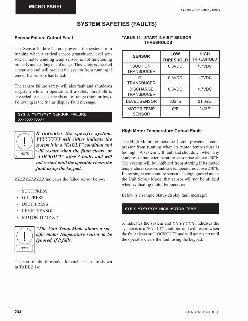
234 JOHNSON CONTROLS
FORM 201.23-NM1 (1007)MICRO PANEL
SYSTEM SAFETIES (FAULTS)
Sensor Failure Cutout Fault
The Sensor Failure Cutout prevents the system from running when a critical sensor (transducer, level sen-sor, or motor winding temp sensor) is not functioning properly and reading out of range. This safety is checked at start-up and will prevent the system from running if one of the sensors has failed.
The sensor failure safety will also fault and shutdown a system while in operation, if a safety threshold is exceeded or a sensor reads out of range (high or low). Following is the Status display fault message.
X indicates the specific system. YYYYYYYY will either indicate the system is in a “FAULT” condition and will restart when the fault clears, or “LOCKOUT” after 3 faults and will not restart until the operator clears the fault using the keypad.
ZZZZZZZZZZZ indicates the failed sensor below:
· SUCT PRESS · OIL PRESS · DSCH PRESS · LEVEL SENSOR · MOTOR TEMP X *
*The Unit Setup Mode allows a spe-cifi c motor temperature sensor to be ignored, if it fails.
The start inhibit thresholds for each sensor are shown in TABLE 14:
SYS X YYYYYYYY SENSOR FAILURE: ZZZZZZZZZZZZ
TABLE 14 - START INHIBIT SENSOR THRESHOLDS
SENSOR LOWTHRESHOLD
HIGHTHRESHOLD
SUCTION TRANSDUCER
0.3VDC 4.7VDC
OIL TRANSDUCER
0.3VDC 4.7VDC
DISCHARGE TRANSDUCER
0.3VDC 4.7VDC
LEVEL SENSOR 3.0ma 21.0ma
MOTOR TEMP. SENSOR
0ºF 240ºF
High Motor Temperature Cutout Fault
The High Motor Temperature Cutout prevents a com-pressor from running when its motor temperature is too high. A system will fault and shut down when any compressor motor temperature sensor rises above 250°F. The system will be inhibited from starting if its motor temperatures sensors indicate temperatures above 240°F. If any single temperature sensor is being ignored under the Unit Set-up Mode, that sensor will not be utilized when evaluating motor temperature.
Below is a sample Status display fault message:
X indicates the system and YYYYYYY indicates the system is in a “FAULT” condition and will restart when the fault clears or “LOCKOUT” and will not restart until the operator clears the fault using the keypad.
SYS X YYYYYYYY HIGH MOTOR TEMP
235JOHNSON CONTROLS
FORM 201.23-NM1 (1007)
8
High Flash Tank Level Cutout Fault
The Flash tank level Cutout prevents the system from running when the liquid level in the fl ash tank is too high. The safety will be ignored for the fi rst 15 seconds of system operation.
A fault will occur if the tank level is greater than 85% for 10 seconds.
Below is a sample Status fault display fault message:
SYSTEM SAFETIES (FAULTS) (CON'T)
SYS X YYYYYYYY HIGH FLASH TANK LEVEL
X indicates the system and YYYYYYY indicates the system is in a “FAULT” condition and will restart when the 120 second anti-recycle timer times out or “LOCK-OUT” and will not restart until the operator clears the fault using the keypad.
System Control Voltage Cutout Fault
The System Control Voltage Cutout alerts the operator the 115VAC Control voltage to one of the systems is missing. This could be due to a system fuse that has been removed or is blown. The affected system will fault and shut down immediately when the 115VAC supply is lost.
The safety will “not” shut down a system if the Unit Switch is OFF, which electrically removes the 115VAC to “all” systems. The safety is only used to indicate a situation where a single system is missing the 115VAC. The safety will not cause a lockout and the system fault will reset when power is returned. A sample message is shown below:
SYS X YYYYYYYY CONTROL VOLTAGE
X indicates the system and YYYYYYY indicates the system is in a “FAULT” condition and will restart when the fault clears or “LOCKOUT” and will not restart until the operator clears the fault using the keypad.
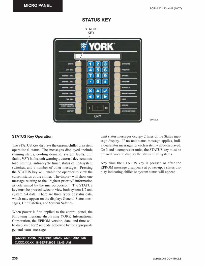
236 JOHNSON CONTROLS
FORM 201.23-NM1 (1007)MICRO PANEL
STATUS KEY
LD10605
STATUS KEY
STATUS Key Operation
The STATUS Key displays the current chiller or system operational status. The messages displayed include running status, cooling demand, system faults, unit faults, VSD faults, unit warnings, external device status, load limiting, anti-recycle timer, status of unit/system switches, and a number of other messages. Pressing the STATUS key will enable the operator to view the current status of the chiller. The display will show one message relating to the “highest priority” information as determined by the microprocessor. The STATUS key must be pressed twice to view both system 1/2 and system 3/4 data. There are three types of status data, which may appear on the display: General Status mes-sages, Unit Safeties, and System Safeties.
When power is fi rst applied to the control panel, the following message displaying YORK International Corporation, the EPROM version, date, and time will be displayed for 2 seconds, followed by the appropriate general status message:
Unit status messages occupy 2 lines of the Status mes-sage display. If no unit status message applies, indi-vidual status messages for each system will be displayed. On 3 and 4 compressor units, the STATUS key must be pressed twice to display the status of all systems.
Any time the STATUS key is pressed or after the EPROM message disappears at power-up, a status dis-play indicating chiller or system status will appear.
(C)2004 YORK INTERNATIONAL CORPORATIONC.XXX.XX.XX 18-SEPT-2005 12:45: AM
237JOHNSON CONTROLS
FORM 201.23-NM1 (1007)
8
Multiple STATUS messages may appear and can be viewed by pressing the STATUS key repeatedly to allow scrolling through as many as three STATUS messages, that could possibly be displayed at any time on a 2 com-pressor chiller or 4 messages that could be displayed on a 3 or 4 compressor chiller.
Examples of the typical Status messages are shown below:
General Status Messages
STATUS KEY (CON'T)
This message indicates the chiller is operating in MANUAL OVERRIDE mode. This message is a pri-ority message and cannot be overridden by any other STATUS message. When in Manual Override, no other status message will ever be present.
This message indicates the UNIT SWITCH is in the off position and not allowing the unit to run.
This message indicates that either the daily or holiday schedule programmed is keeping the chiller from run-ning.
This message indicates that either an ISN or RCC has turned the chiller off and is not allowing it to run.
UNIT STATUS MANUAL OVERRIDE
UNIT STATUS UNIT SWITCH OFF SHUTDOWN
UNIT STATUS DAILY SCHEDULE SHUTDOWN
UNIT STATUS REMOTE CONTROLLED SHUTDOWN
This message indicates the fl ow switch is not allowing the chiller to run. There is a 1 second delay on this safety to assure the fl ow switch did not momentarily open.
UNIT STATUS FLOW SWITCH SHUTDOWN
This message indicates the chiller is shutdown, but running all the condenser fans, VSD glycol pump, and VSD fan in an effort to bring the internal VSD ambient temperature down to an acceptable level before allowing the chiller to start.
UNIT STATUS VSD COOLING SHUTDOWN
This message indicates the remote start/stop contact between 2-15 or 2-16 of the 1TB terminal block is open. There is a 1 second delay on this safety to assure the remote contacts did not momentarily open.
This message indicates the system switch (software via keypad) is turned off. The system will not be al-lowed to run until the system switch is turned ON via the keypad.
This message indicates the system is not running because the chilled liquid is below the setpoint or the micro has not loaded the lead system far enough into the loading sequence to bring the lag system on. This message will be displayed on the lag system until the loading sequence is ready for the lag system to start.
This message is only displayed in the Normal Shut-down History display to indicate a capacity control shutdown.
This message indicates the system is running as a result of cooling demand.
SYS X REMOTE RUN CONTACT IS OPEN
SYS X SYSTEM SWITCH IS OFF
SYS X NOT RUNNING
SYS X COOLING DEMAND SHUTDOWN
SYS X COMPRESSOR RUNNING
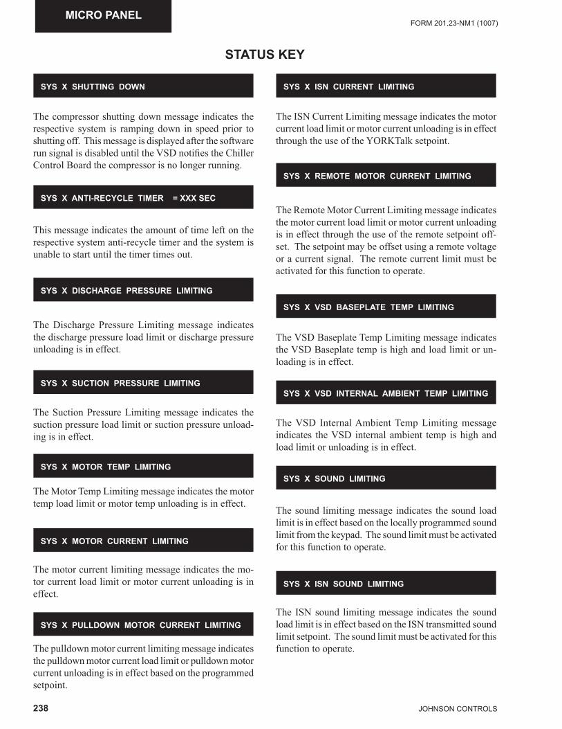
238 JOHNSON CONTROLS
FORM 201.23-NM1 (1007)MICRO PANEL
The compressor shutting down message indicates the respective system is ramping down in speed prior to shutting off. This message is displayed after the software run signal is disabled until the VSD notifi es the Chiller Control Board the compressor is no longer running.
SYS X SHUTTING DOWN
SYS X ANTI-RECYCLE TIMER = XXX SEC
SYS X DISCHARGE PRESSURE LIMITING
SYS X SUCTION PRESSURE LIMITING
STATUS KEY
This message indicates the amount of time left on the respective system anti-recycle timer and the system is unable to start until the timer times out.
SYS X MOTOR CURRENT LIMITING
SYS X MOTOR TEMP LIMITING
SYS X ISN CURRENT LIMITING
The Discharge Pressure Limiting message indicates the discharge pressure load limit or discharge pressure unloading is in effect.
The Suction Pressure Limiting message indicates the suction pressure load limit or suction pressure unload-ing is in effect.
The Motor Temp Limiting message indicates the motor temp load limit or motor temp unloading is in effect.
SYS X VSD BASEPLATE TEMP LIMITING
SYS X REMOTE MOTOR CURRENT LIMITING
The motor current limiting message indicates the mo-tor current load limit or motor current unloading is in effect.
SYS X PULLDOWN MOTOR CURRENT LIMITING
SYS X VSD INTERNAL AMBIENT TEMP LIMITING
The pulldown motor current limiting message indicates the pulldown motor current load limit or pulldown motor current unloading is in effect based on the programmed setpoint.
SYS X SOUND LIMITING
SYS X ISN SOUND LIMITING
The ISN Current Limiting message indicates the motor current load limit or motor current unloading is in effect through the use of the YORKTalk setpoint.
The Remote Motor Current Limiting message indicates the motor current load limit or motor current unloading is in effect through the use of the remote setpoint off-set. The setpoint may be offset using a remote voltage or a current signal. The remote current limit must be activated for this function to operate.
The VSD Baseplate Temp Limiting message indicates the VSD Baseplate temp is high and load limit or un-loading is in effect.
The VSD Internal Ambient Temp Limiting message indicates the VSD internal ambient temp is high and load limit or unloading is in effect.
The sound limiting message indicates the sound load limit is in effect based on the locally programmed sound limit from the keypad. The sound limit must be activated for this function to operate.
The ISN sound limiting message indicates the sound load limit is in effect based on the ISN transmitted sound limit setpoint. The sound limit must be activated for this function to operate.
239JOHNSON CONTROLS
FORM 201.23-NM1 (1007)
8
The Remote sound limiting message indicates the sound load limit is in effect based on the Remote controlled sound limit setpoint. The setpoint may be offset using a remote voltage or current signal. The sound limit option must be activated for this function to operate.
Unit Safety (Fault) Status Messages
A complete listing of the unit safeties and the corre-sponding status messages is provided on Page 228.
System Safety (Fault) Status Messages
A complete listing of the system safeties and the cor-responding status messages is provided on Page 230.
VSD Safety (Fault) Status Messages
A complete listing of VSD safeties and the correspond-ing status messages is provided on Page 219.
Unit Warning Messages
A complete listing of the unit warnings and the corre-sponding status messages is provided on Page 226.
SYS X REMOTE SOUND LIMITING
STATUS KEY (CON'T)
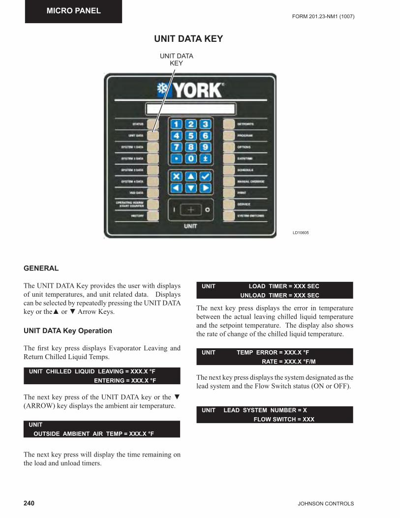
240 JOHNSON CONTROLS
FORM 201.23-NM1 (1007)MICRO PANEL
UNIT DATA KEY
LD10605
UNIT DATAKEY
GENERAL
The UNIT DATA Key provides the user with displays of unit temperatures, and unit related data. Displays can be selected by repeatedly pressing the UNIT DATA key or the▲ or ▼ Arrow Keys.
UNIT DATA Key Operation
The fi rst key press displays Evaporator Leaving and Return Chilled Liquid Temps.
UNIT CHILLED LIQUID LEAVING = XXX.X °F ENTERING = XXX.X °F
The next key press of the UNIT DATA key or the ▼ (ARROW) key displays the ambient air temperature.
UNIT LOAD TIMER = XXX SEC UNLOAD TIMER = XXX SEC
UNIT OUTSIDE AMBIENT AIR TEMP = XXX.X °F
UNIT TEMP ERROR = XXX.X °F RATE = XXX.X °F/M
The next key press will display the time remaining on the load and unload timers.
UNIT LEAD SYSTEM NUMBER = X FLOW SWITCH = XXX
The next key press displays the error in temperature between the actual leaving chilled liquid temperature and the setpoint temperature. The display also shows the rate of change of the chilled liquid temperature.
The next key press displays the system designated as the lead system and the Flow Switch status (ON or OFF).
241JOHNSON CONTROLS
FORM 201.23-NM1 (1007)
8
UNIT DATA KEY (CON'T)The next key press displays the status of the evaporator pump and heater, where XXX is either ON or OFF.
The next key press displays the status of Active Remote Control.
UNIT EVAP PUMP RUN = XXX EVAP HEATER = XXX
UNIT ACTIVE REMOTE CONTR0L = XXXXXX TYPE: RCC ISN CURR TEMP SOUND
XXXXX is either ACTIVE or NONE.
If no remote keys are active, the items on the second line are all blanked out. Any remote items that are ac-tive will be displayed, while the inactive items will be blanked out.
The types of remote control are listed below:
· NONE: No remote control is actively controlling the chiller; however, remote monitoring by a remote device may still be active.
· RCC: A Remote Control Center is providing remote control. The chiller is in remote mode.
· ISN: YorkTalk via ISN. The chiller in remote mode.
· CURR: Remote Current Limiting is enabled. · TEMP: Remote Temperature Reset is enabled. · SOUND: Remote Sound Limiting is enabled.
The next key press displays the sound limit values as set under the PROGRAM Key by the Local, ISN, and the Remote Sound Limit Inputs. Any sound limits that are inactive will display XXX instead of a numeric value.
UNIT SOUND LIMIT LOCAL = XXX % ISN = XXX REMOTE = XXX %
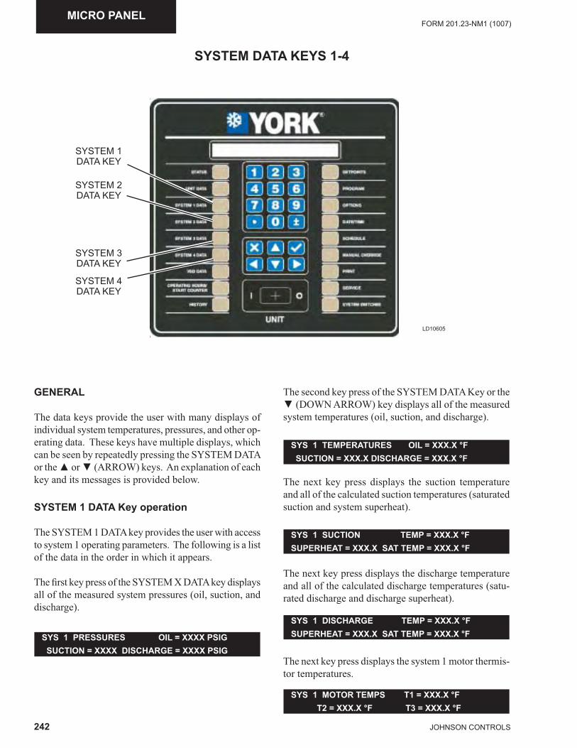
242 JOHNSON CONTROLS
FORM 201.23-NM1 (1007)MICRO PANEL
SYSTEM DATA KEYS 1-4
LD10605
SYSTEM 1 DATA KEY
SYSTEM 2 DATA KEY
SYSTEM 3 DATA KEY
SYSTEM 4 DATA KEY
GENERAL
The data keys provide the user with many displays of individual system temperatures, pressures, and other op-erating data. These keys have multiple displays, which can be seen by repeatedly pressing the SYSTEM DATA or the ▲ or ▼ (ARROW) keys. An explanation of each key and its messages is provided below.
SYSTEM 1 DATA Key operation
The SYSTEM 1 DATA key provides the user with access to system 1 operating parameters. The following is a list of the data in the order in which it appears.
The fi rst key press of the SYSTEM X DATA key displays all of the measured system pressures (oil, suction, and discharge).
The second key press of the SYSTEM DATA Key or the ▼ (DOWN ARROW) key displays all of the measured system temperatures (oil, suction, and discharge).
SYS 1 PRESSURES OIL = XXXX PSIG SUCTION = XXXX DISCHARGE = XXXX PSIG
The next key press displays the suction temperature and all of the calculated suction temperatures (saturated suction and system superheat).
SYS 1 TEMPERATURES OIL = XXX.X °F SUCTION = XXX.X DISCHARGE = XXX.X °F
The next key press displays the discharge temperature and all of the calculated discharge temperatures (satu-rated discharge and discharge superheat).
SYS 1 SUCTION TEMP = XXX.X °F SUPERHEAT = XXX.X SAT TEMP = XXX.X °F
SYS 1 DISCHARGE TEMP = XXX.X °FSUPERHEAT = XXX.X SAT TEMP = XXX.X °F
The next key press displays the system 1 motor thermis-tor temperatures.
SYS 1 MOTOR TEMPS T1 = XXX.X °F T2 = XXX.X °F T3 = XXX.X °F
243JOHNSON CONTROLS
FORM 201.23-NM1 (1007)
8
SYSTEM DATA KEYS 1-4 (CON'T)
If any motor temp sensor is being ignored, (selectable under Unit Set-up Mode), that sensor’s value will be displayed as XXXXX.
The next key press indicates the % of compressor load-ing and status of the economizer solenoid as determined by the operating frequency.
SYS 1 COMPRESSOR SPEED = XXX.X % ECONOMIZER SOLENOID = XXX
SYS 1 FLASH TANK LEVEL = XXX.X % FEED VALVE PERCENT OPEN = XXX.X %
SYS 1 CONDENSER FANS ON = X COMPRESSOR HEATER = XXX
SYS 1 RUN TIMEXX DAYS XX HOURS XX MINUTES XX SECONDS
SYS 1 SUCTION SUPERHEAT = XXX.X °F DRAIN VALVE PERCENT OPEN = XXX.X %
SYS 1 RUN SIGNALS RELAY = XXXRUN PERM = XXX SOFTWARE = XXX
XXX indicates whether the economizer solenoid is either ON or OFF.
The next key press displays the liquid level in the fl ash tank and an indicator of the % the Flash Tank Feed Valve is open.
The next key press displays the system suction superheat and an indicator of the % the Flash Tank Drain Valve is open.
The next key press displays the system fan stage and the status of the compressor heater.
X = the number of fans ON. XXX indicates either the heater is ON or OFF.
The next key press displays the system run time in days, hours, minutes, and seconds.
The next key press displays the status of several system signals.
XXX indicates either ON or OFF.
SYS 3 DATA NOT AVAILABLE
SYS 4 DATA NOT AVAILABLE
SYSTEM 2 - 4 DATA Key Operation
These keys function the same as the SYSTEM 1 DATA key except that it displays data for system 2 through 4.
On a 2 compressor system, the SYSTEM 3 and SYS-TEM 4 data keys will display the following messages:
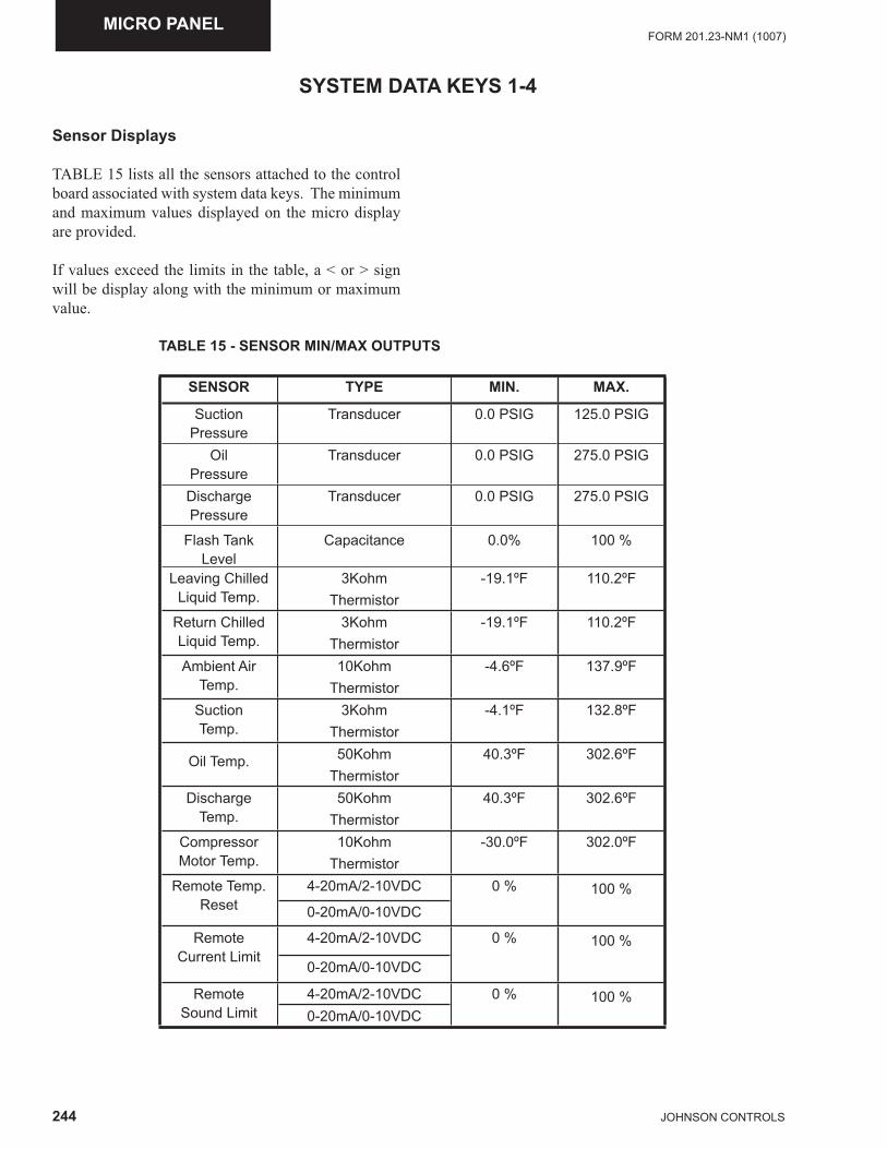
244 JOHNSON CONTROLS
FORM 201.23-NM1 (1007)MICRO PANEL
Sensor Displays
TABLE 15 lists all the sensors attached to the control board associated with system data keys. The minimum and maximum values displayed on the micro display are provided.
If values exceed the limits in the table, a < or > sign will be display along with the minimum or maximum value.
SYSTEM DATA KEYS 1-4
TABLE 15 - SENSOR MIN/MAX OUTPUTS
SENSOR TYPE MIN. MAX.
SuctionPressure
Transducer 0.0 PSIG 125.0 PSIG
Oil Pressure
Transducer 0.0 PSIG 275.0 PSIG
Discharge Pressure
Transducer 0.0 PSIG 275.0 PSIG
Flash TankLevel
Capacitance 0.0% 100 %
Leaving ChilledLiquid Temp.
3Kohm Thermistor
-19.1ºF 110.2ºF
Return ChilledLiquid Temp.
3Kohm Thermistor
-19.1ºF 110.2ºF
Ambient AirTemp.
10Kohm Thermistor
-4.6ºF 137.9ºF
Suction Temp.
3Kohm Thermistor
-4.1ºF 132.8ºF
Oil Temp. 50Kohm Thermistor
40.3ºF 302.6ºF
DischargeTemp.
50Kohm Thermistor
40.3ºF 302.6ºF
CompressorMotor Temp.
10Kohm Thermistor
-30.0ºF 302.0ºF
Remote Temp.Reset
4-20mA/2-10VDC 0 % 100 %0-20mA/0-10VDC
Remote Current Limit
4-20mA/2-10VDC 0 % 100 %
0-20mA/0-10VDC
Remote Sound Limit
4-20mA/2-10VDC 0 % 100 %0-20mA/0-10VDC
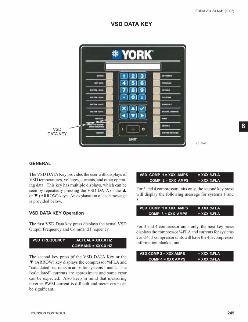
245JOHNSON CONTROLS
FORM 201.23-NM1 (1007)
8
VSD DATA KEY
LD10605
VSDDATA KEY
GENERAL
The VSD DATA Key provides the user with displays of VSD temperatures, voltages, currents, and other operat-ing data. This key has multiple displays, which can be seen by repeatedly pressing the VSD DATA or the ▲ or ▼ (ARROW) keys. An explanation of each message is provided below.
VSD DATA KEY Operation
The fi rst VSD Data key press displays the actual VSD Output Frequency and Command Frequency.
The second key press of the VSD DATA Key or the ▼ (ARROW) key displays the compressor %FLA and “calculated” currents in amps for systems 1 and 2. The “calculated” currents are approximate and some error can be expected. Also keep in mind that measuring inverter PWM current is diffi cult and meter error can be signifi cant.
VSD FREQUENCY ACTUAL = XXX.X HZ COMMAND = XXX.X HZ
For 3 and 4 compressor units only, the second key press will display the following message for systems 1 and 3:
VSD COMP 1 = XXX AMPS = XXX %FLA COMP 2 = XXX AMPS = XXX %FLA
For 3 and 4 compressor units only, the next key press displays the compressor %FLA and currents for systems 2 and 4. 3 compressor units will have the 4th compressor information blanked out.
VSD COMP 1 = XXX AMPS = XXX %FLA COMP 3 = XXX AMPS = XXX %FLA
VSD COMP 2 = XXX AMPS = XXX %FLA COMP 4 = XXX AMPS = XXX %FLA
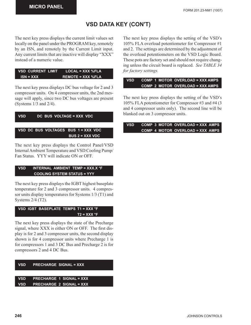
246 JOHNSON CONTROLS
FORM 201.23-NM1 (1007)MICRO PANEL
The next key press displays the current limit values set locally on the panel under the PROGRAM key, remotely by an ISN, and remotely by the Current Limit input. Any current limits that are inactive will display “XXX” instead of a numeric value.
VSD DATA KEY (CON'T)
The next key press displays DC bus voltage for 2 and 3 compressor units. On 4 compressor units, the 2nd mes-sage will apply, since two DC bus voltages are present (Systems 1/3 and 2/4).
VSD CURRENT LIMIT LOCAL = XXX %FLA ISN = XXX REMOTE = XXX %FLA
The next key press displays the Control Panel/VSD Internal Ambient Temperature and VSD Cooling Pump/Fan Status. YYY will indicate ON or OFF.
VSD DC BUS VOLTAGE = XXX VDC
The next key press displays the IGBT highest baseplate temperature for 2 and 3 compressor units. 4 compres-sor units display temperatures for Systems 1/3 (T1) and Systems 2/4 (T2).
VSD DC BUS VOLTAGES BUS 1 = XXX VDC BUS 2 = XXX VDC
VSD COMP 3 MOTOR OVERLOAD = XXX AMPS COMP 4 MOTOR OVERLOAD = XXX AMPS
VSD COMP 1 MOTOR OVERLOAD = XXX AMPS COMP 2 MOTOR OVERLOAD = XXX AMPS
VSD INTERNAL AMBIENT TEMP = XXX.X °F COOLING SYSTEM STATUS = YYY
VSD IGBT BASEPLATE TEMPS T1 = XXX °F T2 = XXX °F
The next key press displays the state of the Precharge signal, where XXX is either ON or OFF. The fi rst dis-play is for 2 and 3 compressor units, the second display shown is for 4 compressor units where Precharge 1 is for compressors 1 and 3 DC Bus and Precharge 2 is for compressors 2 and 4 DC Bus.
VSD PRECHARGE SIGNAL = XXX
VSD PRECHARGE 1 SIGNAL = XXX VSD PRECHARGE 2 SIGNAL = XXX
The next key press displays the setting of the VSD’s 105% FLA overload potentiometer for Compressor #1 and 2. The settings are determined by the adjustment of the overload potentiometers on the VSD Logic Board. These pots are factory set and should not require chang-ing unless the circuit board is replaced. See TABLE 34 for factory settings.
The next key press displays the setting of the VSD’s 105% FLA potentiometer for Compressor #3 and #4 (3 and 4 compressor units only). The second line will be blanked out on 3 compressor units.
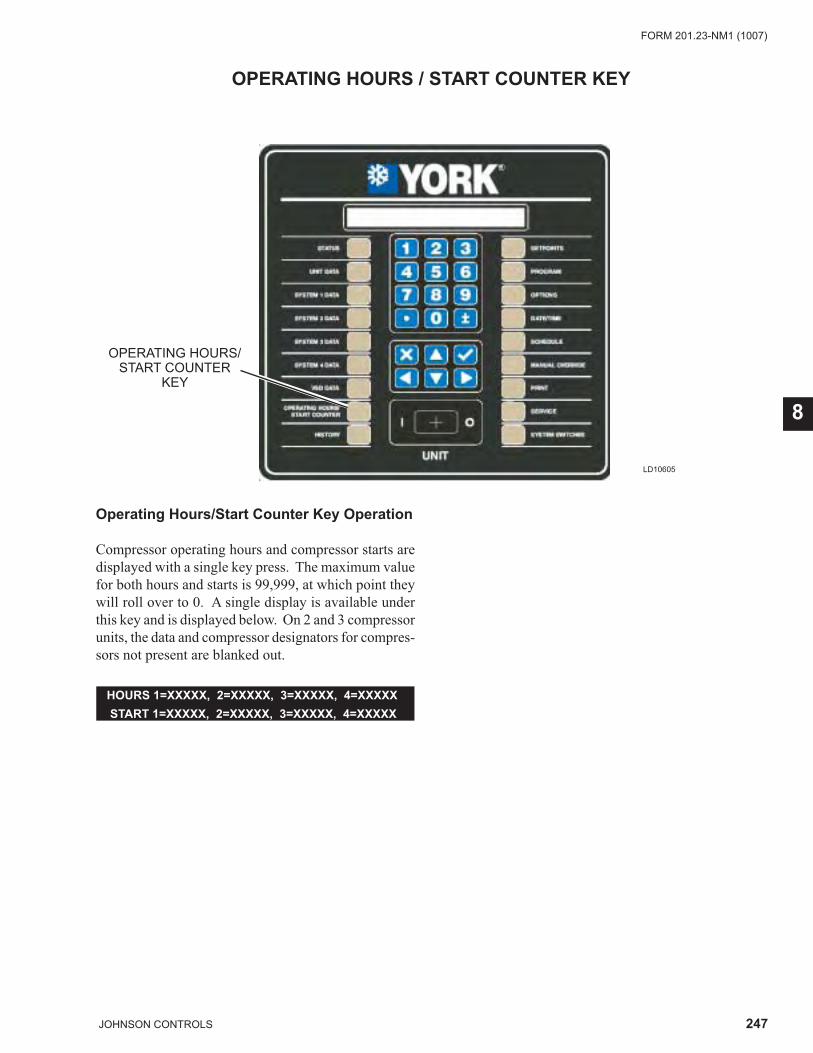
247JOHNSON CONTROLS
FORM 201.23-NM1 (1007)
8
OPERATING HOURS / START COUNTER KEY
LD10605
OPERATING HOURS/START COUNTER
KEY
Operating Hours/Start Counter Key Operation
Compressor operating hours and compressor starts are displayed with a single key press. The maximum value for both hours and starts is 99,999, at which point they will roll over to 0. A single display is available under this key and is displayed below. On 2 and 3 compressor units, the data and compressor designators for compres-sors not present are blanked out.
HOURS 1=XXXXX, 2=XXXXX, 3=XXXXX, 4=XXXXX START 1=XXXXX, 2=XXXXX, 3=XXXXX, 4=XXXXX
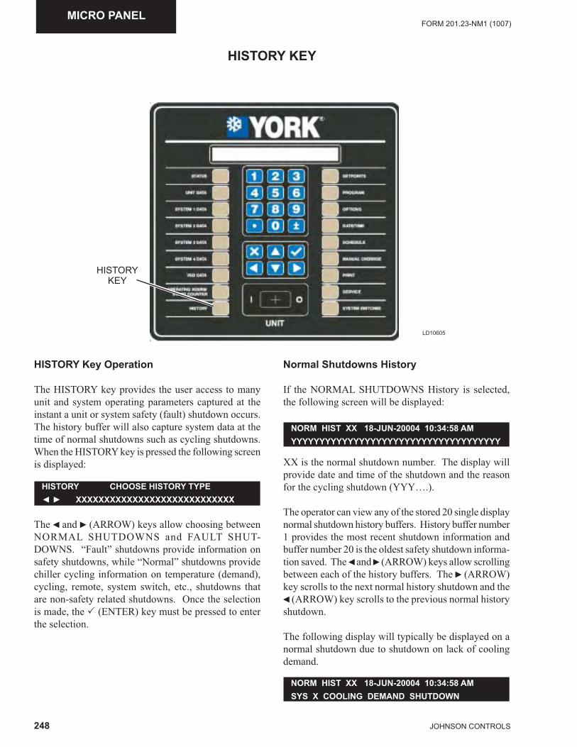
248 JOHNSON CONTROLS
FORM 201.23-NM1 (1007)MICRO PANEL
HISTORY KEY
LD10605
HISTORY KEY
HISTORY Key Operation
The HISTORY key provides the user access to many unit and system operating parameters captured at the instant a unit or system safety (fault) shutdown occurs. The history buffer will also capture system data at the time of normal shutdowns such as cycling shutdowns. When the HISTORY key is pressed the following screen is displayed:
The ◄ and ► (ARROW) keys allow choosing between NORMAL SHUTDOWNS and FAULT SHUT-DOWNS. “Fault” shutdowns provide information on safety shutdowns, while “Normal” shutdowns provide chiller cycling information on temperature (demand), cycling, remote, system switch, etc., shutdowns that are non-safety related shutdowns. Once the selection is made, the � (ENTER) key must be pressed to enter the selection.
HISTORY CHOOSE HISTORY TYPE◄ ► XXXXXXXXXXXXXXXXXXXXXXXXXXXX
NORM HIST XX 18-JUN-20004 10:34:58 AMSYS X COOLING DEMAND SHUTDOWN
NORM HIST XX 18-JUN-20004 10:34:58 AMYYYYYYYYYYYYYYYYYYYYYYYYYYYYYYYYYYYYY
Normal Shutdowns History
If the NORMAL SHUTDOWNS History is selected, the following screen will be displayed:
XX is the normal shutdown number. The display will provide date and time of the shutdown and the reason for the cycling shutdown (YYY….).
The operator can view any of the stored 20 single display normal shutdown history buffers. History buffer number 1 provides the most recent shutdown information and buffer number 20 is the oldest safety shutdown informa-tion saved. The ◄ and ► (ARROW) keys allow scrolling between each of the history buffers. The ► (ARROW) key scrolls to the next normal history shutdown and the ◄ (ARROW) key scrolls to the previous normal history shutdown.
The following display will typically be displayed on a normal shutdown due to shutdown on lack of cooling demand.
249JOHNSON CONTROLS
FORM 201.23-NM1 (1007)
8
Fault Shutdowns History
If the FAULT SHUTDOWNS History is selected, the following screen will be displayed:
HISTORY KEY
XX is the FAULT HISTORY shutdown number. The display will provide the date, time, and a description of the specifi c type of fault that occurred (YYY….).
The operator can view any of the stored 10 fault history buffers. History buffer number 1 provides the most recent safety shutdown information and buffer number 10 is the oldest safety shutdown information saved. The ◄ and ► arrow keys allow scrolling between each of the FAULT HIST buffers 1-10. The ▲ (UP) and ▼ (DOWN) arrow keys can be used to scroll forwards and backwards through the data in a specifi c history buffer, once it is displayed.
There is a large amount of data provided under each history. Rather than scroll sequentially through the data in a history, which is possible using the ▼ arrow key, the use of a combination of the ◄, ►, ▲‚ and ▼ arrow keys allows fast scrolling to specifi c data the user desires to view. To use this feature, the user needs to be aware the ◄ and ► arrow keys allow scrolling to the top of the data subgroups. Once a specifi c history is selected, the history data is divided under the subgroups of Unit Data, VSD Data, System Data, Hours/Starts, Setpoints, Options, and Program data. The ◄ and ► arrow keys allow moving to the fi rst display under the next or pre-vious subgroup at any time. Once the fi rst display of a subgroup is displayed, the ▲‚ and ▼ arrow keys allow scrolling though the data in the subgroup. The ▼ arrow key allows scrolling though the data from fi rst to last. When the last piece of data is displayed, the next press of the ▼ arrow key scrolls to the fi rst piece of data in the next subgroup. The ▲ arrow key allows going to the previous display.
Listed below is a description of the fault data displays and their meaning. Data will be displayed in a specifi c order starting with the Status Display (System Faults only), Fault Display, All Fault Display, Unit Data, VSD Data, System Data, Operating Hours/Starts, Setpoints, Options, and Program Values at the time of the fault.
FAULT HIST XX 18-JUN-20004 10:34:58 AMYYYYYYYYYYYYYYYYYYYYYYYYYYYYYYYYYYYYY
Status Fault Type
This message indicates the type of system fault. This screen is skipped if a UNIT Fault caused the shut-down.
Unit Fault Type
This message indicates the type of unit fault. This screen is skipped if a SYSTEM Fault caused the shutdown.
All Fault Data
SYS X COMPRESSOR RUNNINGSYS X YYYYYYYY HIGH DIFF OIL PRESSURE
UNIT FAULT LOW AMBIENT TEMP
The ALL FAULT display indicates whether a fault occurred while the unit is shutting down on another fault.
If a control panel fault occurred while the unit is shutting down on a VSD fault before it is reset, the control panel fault is an ALL FAULT of the VSD fault.
If another VSD fault occurs while the unit is shutting down on a VSD fault, the next VSD fault will be regis-tered as an ALL FAULT of the VSD fault.
If a VSD fault occurs during the ramp down shutdown of a control panel fault, the VSD fault is registered as a new fault, not an ALL FAULT
XX is the history number, YYY is the ALL FAULT description, ZZ is the ALL FAULT number and WW is the total number of All Faults for the current his-tory. Sometimes, multiple faults may occur during the shutdown and multiple displays will be observed when scrolling through the data using the ▼ arrow. In most cases, the ALL FAULT display will indicate NONE. The ALL FAULT display will only indicate the cause of the fault. No additional chiller information will be displayed under the ALL FAULT, since a snapshot of all chiller data was taken at the time of the fi rst fault.
FAULT HIST XX ALL FAULTS ZZ OF WWYYYYYYYYYYYYYYYYYYYYYYYYYYYYYYYYYYYYY
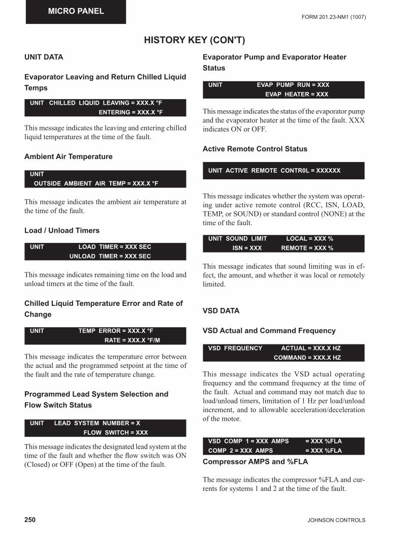
250 JOHNSON CONTROLS
FORM 201.23-NM1 (1007)MICRO PANEL
HISTORY KEY (CON'T)UNIT DATA
Evaporator Leaving and Return Chilled LiquidTemps
This message indicates the leaving and entering chilled liquid temperatures at the time of the fault.
Ambient Air Temperature
UNIT CHILLED LIQUID LEAVING = XXX.X °F ENTERING = XXX.X °F
This message indicates the ambient air temperature at the time of the fault.
Load / Unload Timers
UNIT OUTSIDE AMBIENT AIR TEMP = XXX.X °F
UNIT LOAD TIMER = XXX SEC UNLOAD TIMER = XXX SEC
This message indicates remaining time on the load and unload timers at the time of the fault.
Chilled Liquid Temperature Error and Rate ofChange
UNIT ACTIVE REMOTE CONTR0L = XXXXXX
UNIT EVAP PUMP RUN = XXX EVAP HEATER = XXX
UNIT SOUND LIMIT LOCAL = XXX % ISN = XXX REMOTE = XXX %
VSD FREQUENCY ACTUAL = XXX.X HZ COMMAND = XXX.X HZ
UNIT TEMP ERROR = XXX.X °F RATE = XXX.X °F/M
This message indicates the temperature error between the actual and the programmed setpoint at the time of the fault and the rate of temperature change.
Programmed Lead System Selection and Flow Switch Status
This message indicates the designated lead system at the time of the fault and whether the fl ow switch was ON (Closed) or OFF (Open) at the time of the fault.
UNIT LEAD SYSTEM NUMBER = X FLOW SWITCH = XXX
Evaporator Pump and Evaporator Heater Status
This message indicates the status of the evaporator pump and the evaporator heater at the time of the fault. XXX indicates ON or OFF.
Active Remote Control Status
This message indicates whether the system was operat-ing under active remote control (RCC, ISN, LOAD, TEMP, or SOUND) or standard control (NONE) at the time of the fault.
This message indicates that sound limiting was in ef-fect, the amount, and whether it was local or remotely limited.
VSD DATA
VSD Actual and Command Frequency
This message indicates the VSD actual operating frequency and the command frequency at the time of the fault. Actual and command may not match due to load/unload timers, limitation of 1 Hz per load/unload increment, and to allowable acceleration/deceleration of the motor.
VSD COMP 1 = XXX AMPS = XXX %FLA COMP 2 = XXX AMPS = XXX %FLA
Compressor AMPS and %FLA
The message indicates the compressor %FLA and cur-rents for systems 1 and 2 at the time of the fault.
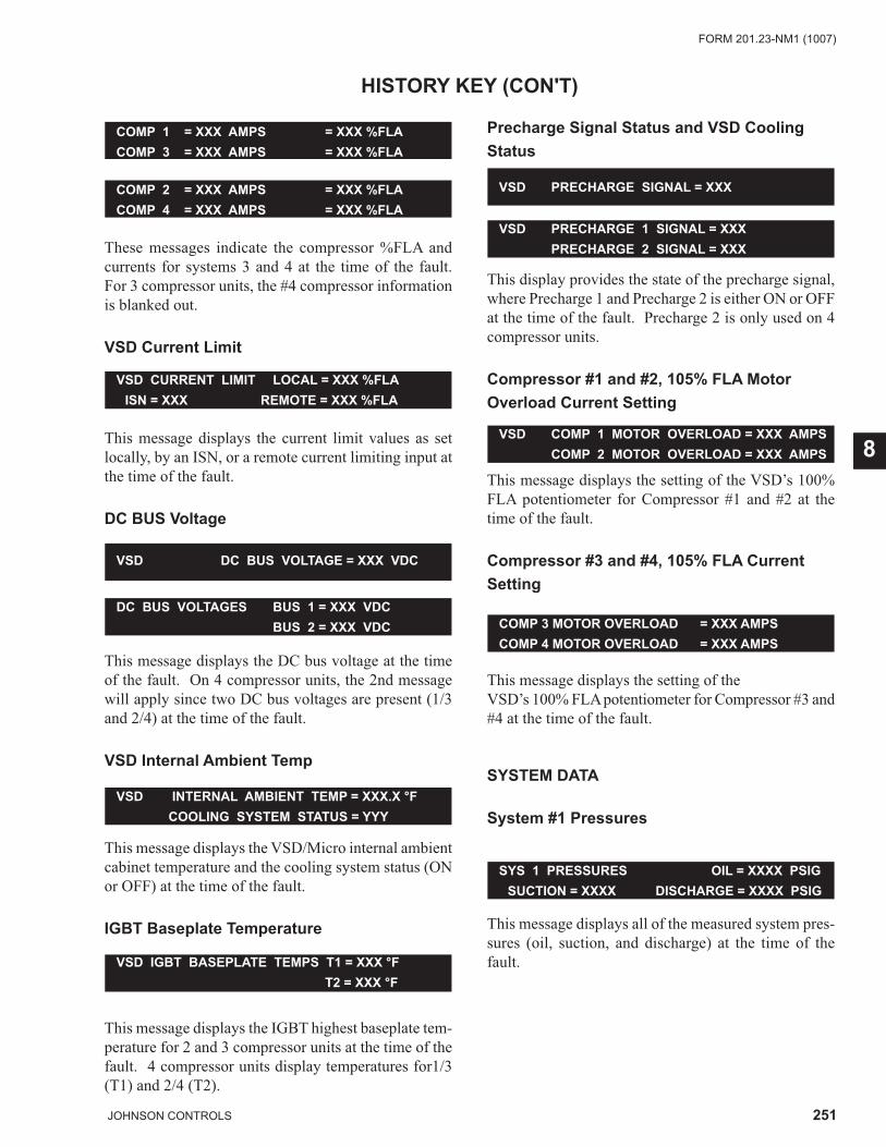
251JOHNSON CONTROLS
FORM 201.23-NM1 (1007)
8
These messages indicate the compressor %FLA and currents for systems 3 and 4 at the time of the fault. For 3 compressor units, the #4 compressor information is blanked out.
VSD Current Limit
HISTORY KEY (CON'T)
COMP 1 = XXX AMPS = XXX %FLACOMP 3 = XXX AMPS = XXX %FLA
COMP 2 = XXX AMPS = XXX %FLACOMP 4 = XXX AMPS = XXX %FLA
This message displays the current limit values as set locally, by an ISN, or a remote current limiting input at the time of the fault.
DC BUS Voltage
VSD CURRENT LIMIT LOCAL = XXX %FLA ISN = XXX REMOTE = XXX %FLA
VSD DC BUS VOLTAGE = XXX VDC
VSD PRECHARGE SIGNAL = XXX
VSD PRECHARGE 1 SIGNAL = XXX PRECHARGE 2 SIGNAL = XXX
This message displays the DC bus voltage at the time of the fault. On 4 compressor units, the 2nd message will apply since two DC bus voltages are present (1/3 and 2/4) at the time of the fault.
VSD Internal Ambient Temp
DC BUS VOLTAGES BUS 1 = XXX VDC BUS 2 = XXX VDC
This message displays the VSD/Micro internal ambient cabinet temperature and the cooling system status (ON or OFF) at the time of the fault.
IGBT Baseplate Temperature
VSD INTERNAL AMBIENT TEMP = XXX.X °F COOLING SYSTEM STATUS = YYY
VSD COMP 1 MOTOR OVERLOAD = XXX AMPS COMP 2 MOTOR OVERLOAD = XXX AMPS
VSD IGBT BASEPLATE TEMPS T1 = XXX °F T2 = XXX °F
This message displays the IGBT highest baseplate tem-perature for 2 and 3 compressor units at the time of the fault. 4 compressor units display temperatures for1/3 (T1) and 2/4 (T2).
Precharge Signal Status and VSD CoolingStatus
COMP 3 MOTOR OVERLOAD = XXX AMPSCOMP 4 MOTOR OVERLOAD = XXX AMPS
This display provides the state of the precharge signal, where Precharge 1 and Precharge 2 is either ON or OFF at the time of the fault. Precharge 2 is only used on 4 compressor units.
Compressor #1 and #2, 105% FLA MotorOverload Current Setting
This message displays the setting of the VSD’s 100% FLA potentiometer for Compressor #1 and #2 at the time of the fault.
Compressor #3 and #4, 105% FLA Current Setting
This message displays the setting of the VSD’s 100% FLA potentiometer for Compressor #3 and #4 at the time of the fault.
SYSTEM DATA
System #1 Pressures
SYS 1 PRESSURES OIL = XXXX PSIG SUCTION = XXXX DISCHARGE = XXXX PSIG
This message displays all of the measured system pres-sures (oil, suction, and discharge) at the time of the fault.
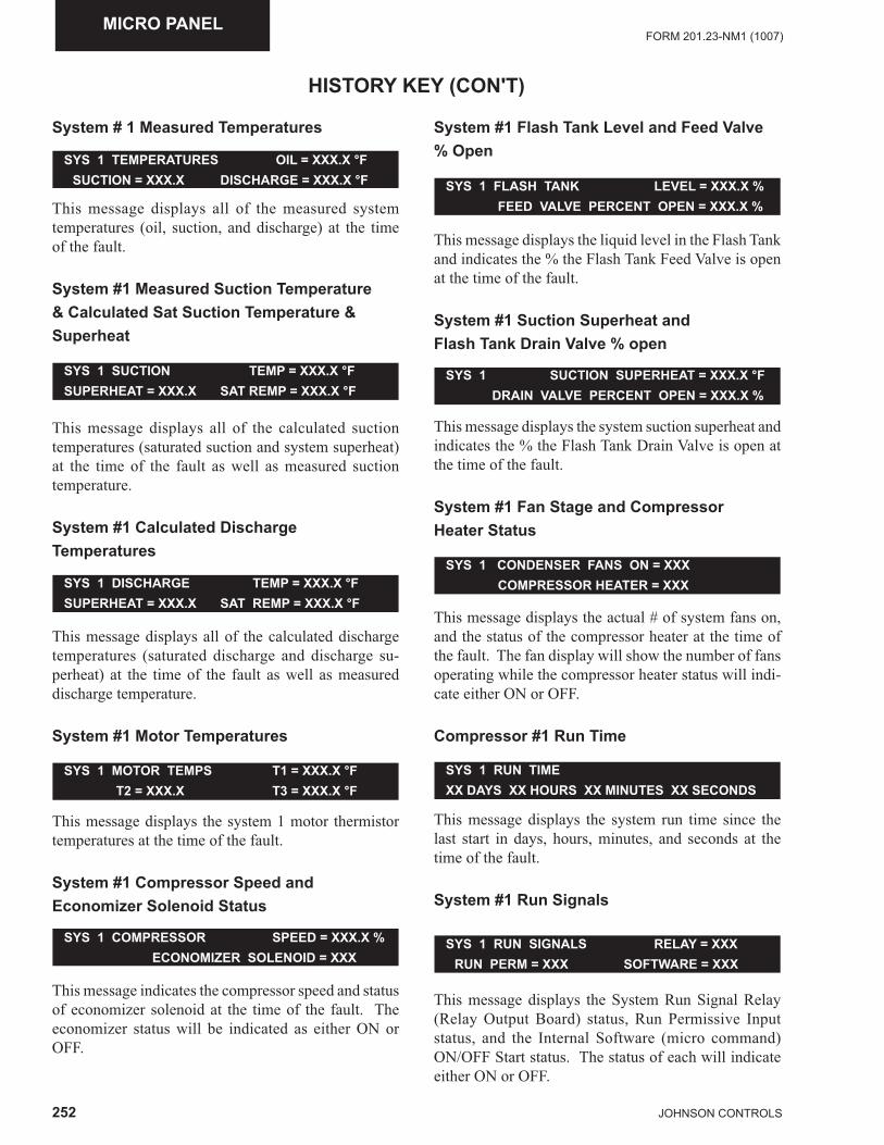
252 JOHNSON CONTROLS
FORM 201.23-NM1 (1007)MICRO PANEL
System # 1 Measured Temperatures
This message displays all of the measured system temperatures (oil, suction, and discharge) at the time of the fault.
System #1 Measured Suction Temperature& Calculated Sat Suction Temperature & Superheat
SYS 1 SUCTION TEMP = XXX.X °FSUPERHEAT = XXX.X SAT REMP = XXX.X °F
SYS 1 TEMPERATURES OIL = XXX.X °F SUCTION = XXX.X DISCHARGE = XXX.X °F
SYS 1 MOTOR TEMPS T1 = XXX.X °F T2 = XXX.X T3 = XXX.X °F
SYS 1 DISCHARGE TEMP = XXX.X °FSUPERHEAT = XXX.X SAT REMP = XXX.X °F
SYS 1 COMPRESSOR SPEED = XXX.X % ECONOMIZER SOLENOID = XXX
This message displays all of the calculated suction temperatures (saturated suction and system superheat) at the time of the fault as well as measured suction temperature.
System #1 Calculated Discharge Temperatures
This message displays all of the calculated discharge temperatures (saturated discharge and discharge su-perheat) at the time of the fault as well as measured discharge temperature.
System #1 Motor Temperatures
This message displays the system 1 motor thermistor temperatures at the time of the fault.
System #1 Compressor Speed and Economizer Solenoid Status
This message indicates the compressor speed and status of economizer solenoid at the time of the fault. The economizer status will be indicated as either ON or OFF.
System #1 Flash Tank Level and Feed Valve % Open
HISTORY KEY (CON'T)
SYS 1 FLASH TANK LEVEL = XXX.X % FEED VALVE PERCENT OPEN = XXX.X %
This message displays the liquid level in the Flash Tank and indicates the % the Flash Tank Feed Valve is open at the time of the fault.
System #1 Suction Superheat and Flash Tank Drain Valve % open
This message displays the system suction superheat and indicates the % the Flash Tank Drain Valve is open at the time of the fault.
System #1 Fan Stage and Compressor Heater Status
SYS 1 SUCTION SUPERHEAT = XXX.X °F DRAIN VALVE PERCENT OPEN = XXX.X %
This message displays the actual # of system fans on, and the status of the compressor heater at the time of the fault. The fan display will show the number of fans operating while the compressor heater status will indi-cate either ON or OFF.
Compressor #1 Run Time
SYS 1 CONDENSER FANS ON = XXX COMPRESSOR HEATER = XXX
This message displays the system run time since the last start in days, hours, minutes, and seconds at the time of the fault.
System #1 Run Signals
SYS 1 RUN TIMEXX DAYS XX HOURS XX MINUTES XX SECONDS
This message displays the System Run Signal Relay (Relay Output Board) status, Run Permissive Input status, and the Internal Software (micro command) ON/OFF Start status. The status of each will indicate either ON or OFF.
SYS 1 RUN SIGNALS RELAY = XXX RUN PERM = XXX SOFTWARE = XXX
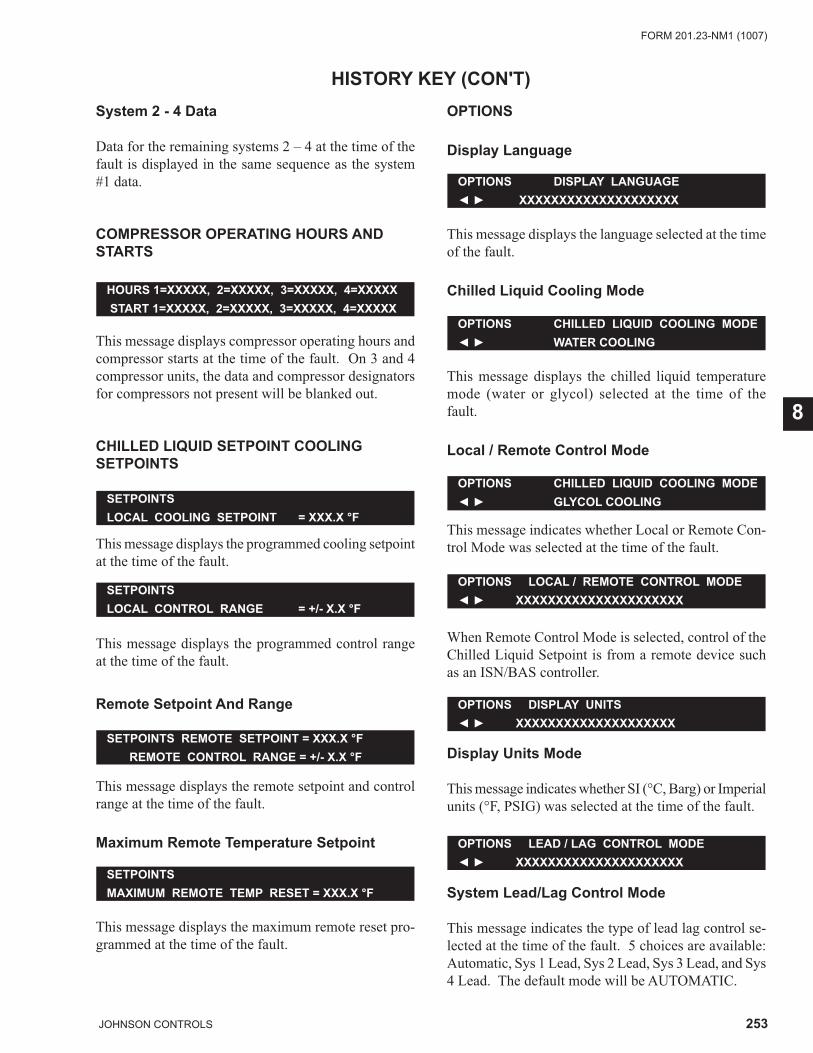
253JOHNSON CONTROLS
FORM 201.23-NM1 (1007)
8
System 2 - 4 Data
Data for the remaining systems 2 – 4 at the time of the fault is displayed in the same sequence as the system #1 data.
COMPRESSOR OPERATING HOURS AND STARTS
HISTORY KEY (CON'T)
HOURS 1=XXXXX, 2=XXXXX, 3=XXXXX, 4=XXXXX START 1=XXXXX, 2=XXXXX, 3=XXXXX, 4=XXXXX
This message displays compressor operating hours and compressor starts at the time of the fault. On 3 and 4 compressor units, the data and compressor designators for compressors not present will be blanked out.
CHILLED LIQUID SETPOINT COOLING SETPOINTS
This message displays the programmed cooling setpoint at the time of the fault.
SETPOINTSLOCAL COOLING SETPOINT = XXX.X °F
This message displays the programmed control range at the time of the fault.
Remote Setpoint And Range
SETPOINTSLOCAL CONTROL RANGE = +/- X.X °F
OPTIONS DISPLAY LANGUAGE◄ ► XXXXXXXXXXXXXXXXXXXX
OPTIONS CHILLED LIQUID COOLING MODE◄ ► GLYCOL COOLING
OPTIONS LOCAL / REMOTE CONTROL MODE◄ ► XXXXXXXXXXXXXXXXXXXXX
OPTIONS DISPLAY UNITS◄ ► XXXXXXXXXXXXXXXXXXXX
OPTIONS CHILLED LIQUID COOLING MODE◄ ► WATER COOLING
SETPOINTS REMOTE SETPOINT = XXX.X °F REMOTE CONTROL RANGE = +/- X.X °F
This message displays the remote setpoint and control range at the time of the fault.
Maximum Remote Temperature Setpoint
This message displays the maximum remote reset pro-grammed at the time of the fault.
SETPOINTS MAXIMUM REMOTE TEMP RESET = XXX.X °F
OPTIONS
Display Language
This message displays the language selected at the time of the fault.
Chilled Liquid Cooling Mode
This message displays the chilled liquid temperature mode (water or glycol) selected at the time of the fault.
Local / Remote Control Mode
This message indicates whether Local or Remote Con-trol Mode was selected at the time of the fault.
When Remote Control Mode is selected, control of the Chilled Liquid Setpoint is from a remote device such as an ISN/BAS controller.
Display Units Mode
This message indicates whether SI (°C, Barg) or Imperial units (°F, PSIG) was selected at the time of the fault.
OPTIONS LEAD / LAG CONTROL MODE◄ ► XXXXXXXXXXXXXXXXXXXXX
System Lead/Lag Control Mode
This message indicates the type of lead lag control se-lected at the time of the fault. 5 choices are available: Automatic, Sys 1 Lead, Sys 2 Lead, Sys 3 Lead, and Sys 4 Lead. The default mode will be AUTOMATIC.
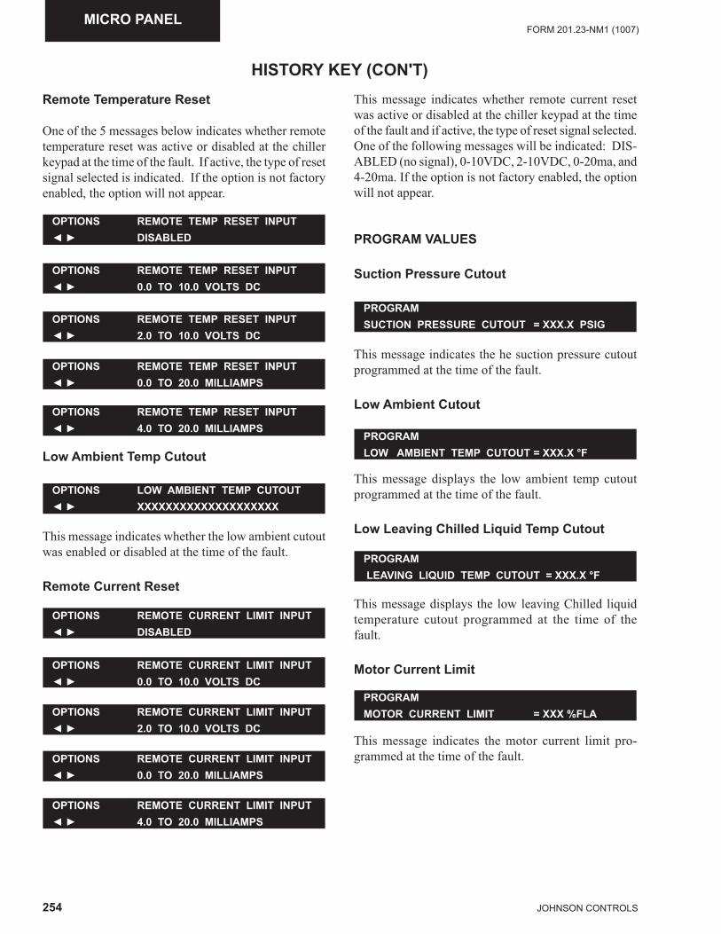
254 JOHNSON CONTROLS
FORM 201.23-NM1 (1007)MICRO PANEL
HISTORY KEY (CON'T)Remote Temperature Reset
One of the 5 messages below indicates whether remote temperature reset was active or disabled at the chiller keypad at the time of the fault. If active, the type of reset signal selected is indicated. If the option is not factory enabled, the option will not appear.
OPTIONS REMOTE TEMP RESET INPUT◄ ► 4.0 TO 20.0 MILLIAMPS
OPTIONS REMOTE TEMP RESET INPUT◄ ► 0.0 TO 20.0 MILLIAMPS
OPTIONS REMOTE TEMP RESET INPUT◄ ► 2.0 TO 10.0 VOLTS DC
OPTIONS REMOTE TEMP RESET INPUT◄ ► 0.0 TO 10.0 VOLTS DC
OPTIONS REMOTE TEMP RESET INPUT◄ ► DISABLED
PROGRAMSUCTION PRESSURE CUTOUT = XXX.X PSIG
PROGRAMLOW AMBIENT TEMP CUTOUT = XXX.X °F
PROGRAM LEAVING LIQUID TEMP CUTOUT = XXX.X °F
Low Ambient Temp Cutout
OPTIONS LOW AMBIENT TEMP CUTOUT◄ ► XXXXXXXXXXXXXXXXXXXX
This message indicates whether the low ambient cutout was enabled or disabled at the time of the fault.
Remote Current Reset
OPTIONS REMOTE CURRENT LIMIT INPUT◄ ► 4.0 TO 20.0 MILLIAMPS
OPTIONS REMOTE CURRENT LIMIT INPUT◄ ► 0.0 TO 20.0 MILLIAMPS
OPTIONS REMOTE CURRENT LIMIT INPUT◄ ► 2.0 TO 10.0 VOLTS DC
OPTIONS REMOTE CURRENT LIMIT INPUT◄ ► 0.0 TO 10.0 VOLTS DC
OPTIONS REMOTE CURRENT LIMIT INPUT◄ ► DISABLED
This message indicates whether remote current reset was active or disabled at the chiller keypad at the time of the fault and if active, the type of reset signal selected. One of the following messages will be indicated: DIS-ABLED (no signal), 0-10VDC, 2-10VDC, 0-20ma, and 4-20ma. If the option is not factory enabled, the option will not appear.
PROGRAM VALUES
Suction Pressure Cutout
This message indicates the he suction pressure cutout programmed at the time of the fault.
Low Ambient Cutout
This message displays the low ambient temp cutout programmed at the time of the fault.
Low Leaving Chilled Liquid Temp Cutout
This message displays the low leaving Chilled liquid temperature cutout programmed at the time of the fault.
Motor Current Limit
PROGRAMMOTOR CURRENT LIMIT = XXX %FLA
This message indicates the motor current limit pro-grammed at the time of the fault.
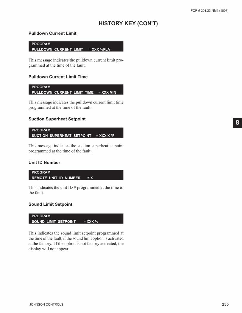
255JOHNSON CONTROLS
FORM 201.23-NM1 (1007)
8
Pulldown Current Limit
HISTORY KEY (CON'T)
PROGRAMPULLDOWN CURRENT LIMIT = XXX %FLA
This message indicates the pulldown current limit pro-grammed at the time of the fault.
Pulldown Current Limit Time
PROGRAMPULLDOWN CURRENT LIMIT TIME = XXX MIN
This message indicates the pulldown current limit time programmed at the time of the fault.
Suction Superheat Setpoint
PROGRAMSUCTION SUPERHEAT SETPOINT = XXX.X °F
This message indicates the suction superheat setpoint programmed at the time of the fault.
Unit ID Number
PROGRAMREMOTE UNIT ID NUMBER = X
This indicates the unit ID # programmed at the time of the fault.
Sound Limit Setpoint
This indicates the sound limit setpoint programmed at the time of the fault, if the sound limit option is activated at the factory. If the option is not factory activated, the display will not appear.
PROGRAMSOUND LIMIT SETPOINT = XXX %
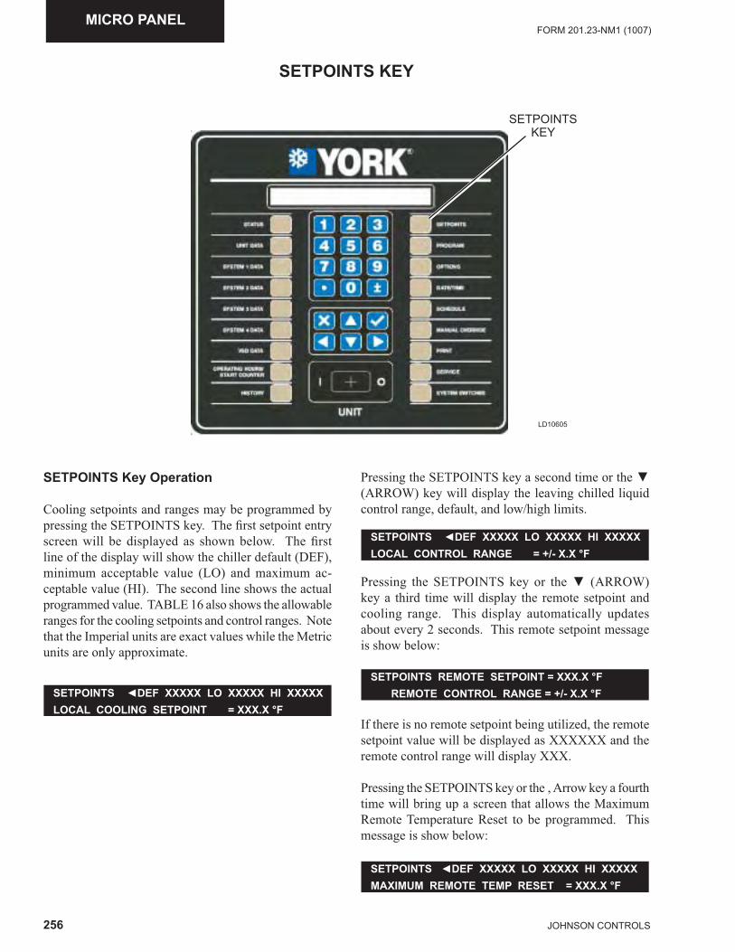
256 JOHNSON CONTROLS
FORM 201.23-NM1 (1007)MICRO PANEL
LD10605
SETPOINTSKEY
SETPOINTS KEY
SETPOINTS Key Operation
Cooling setpoints and ranges may be programmed by pressing the SETPOINTS key. The fi rst setpoint entry screen will be displayed as shown below. The fi rst line of the display will show the chiller default (DEF), minimum acceptable value (LO) and maximum ac-ceptable value (HI). The second line shows the actual programmed value. TABLE 16 also shows the allowable ranges for the cooling setpoints and control ranges. Note that the Imperial units are exact values while the Metric units are only approximate.
SETPOINTS ◄DEF XXXXX LO XXXXX HI XXXXXLOCAL COOLING SETPOINT = XXX.X °F
Pressing the SETPOINTS key a second time or the ▼ (ARROW) key will display the leaving chilled liquid control range, default, and low/high limits.
SETPOINTS ◄DEF XXXXX LO XXXXX HI XXXXXLOCAL CONTROL RANGE = +/- X.X °F
Pressing the SETPOINTS key or the ▼ (ARROW) key a third time will display the remote setpoint and cooling range. This display automatically updates about every 2 seconds. This remote setpoint message is show below:
SETPOINTS REMOTE SETPOINT = XXX.X °F REMOTE CONTROL RANGE = +/- X.X °F
If there is no remote setpoint being utilized, the remote setpoint value will be displayed as XXXXXX and the remote control range will display XXX.
Pressing the SETPOINTS key or the ‚ Arrow key a fourth time will bring up a screen that allows the Maximum Remote Temperature Reset to be programmed. This message is show below:
SETPOINTS ◄DEF XXXXX LO XXXXX HI XXXXXMAXIMUM REMOTE TEMP RESET = XXX.X °F
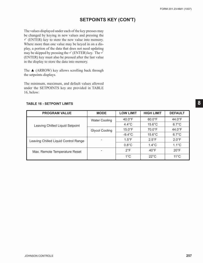
257JOHNSON CONTROLS
FORM 201.23-NM1 (1007)
8
The values displayed under each of the key presses may be changed by keying in new values and pressing the � (ENTER) key to store the new value into memory. Where more than one value may be keyed in on a dis-play, a portion of the data that does not need updating may be skipped by pressing the � (ENTER) key. The � (ENTER) key must also be pressed after the last value in the display to store the data into memory.
The ▲ (ARROW) key allows scrolling back through the setpoints displays.
The minimum, maximum, and default values allowed under the SETPOINTS key are provided in TABLE 16, below:
SETPOINTS KEY (CON'T)
TABLE 16 - SETPOINT LIMITS
PROGRAM VALUE MODE LOW LIMIT HIGH LIMIT DEFAULT
Leaving Chilled Liquid SetpointWater Cooling 40.0°F 60.0°F 44.0°F
4.4°C 15.6°C 6.7°C
Glycol Cooling 15.0°F 70.0°F 44.0°F-9.4°C 15.6°C 6.7°C
Leaving Chilled Liquid Control Range - 1.5°F 2.5°F 2.0°F0.8°C 1.4°C 1.1°C
Max. Remote Temperature Reset - 2°F 40°F 20°F
1°C 22°C 11°C
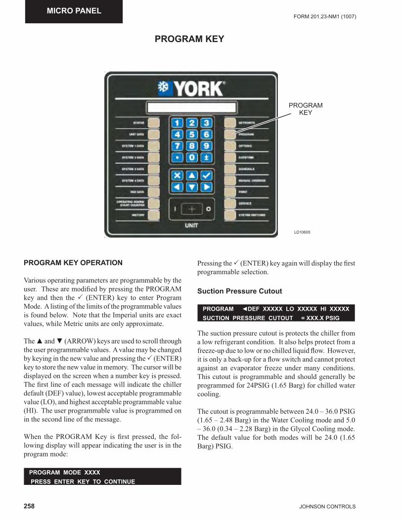
258 JOHNSON CONTROLS
FORM 201.23-NM1 (1007)MICRO PANEL
LD10605
PROGRAM KEY
PROGRAM KEY
PROGRAM KEY OPERATION
Various operating parameters are programmable by the user. These are modifi ed by pressing the PROGRAM key and then the � (ENTER) key to enter Program Mode. A listing of the limits of the programmable values is found below. Note that the Imperial units are exact values, while Metric units are only approximate.
The ▲ and ▼ (ARROW) keys are used to scroll through the user programmable values. A value may be changed by keying in the new value and pressing the � (ENTER) key to store the new value in memory. The cursor will be displayed on the screen when a number key is pressed. The fi rst line of each message will indicate the chiller default (DEF) value), lowest acceptable programmable value (LO), and highest acceptable programmable value (HI). The user programmable value is programmed on in the second line of the message.
When the PROGRAM Key is fi rst pressed, the fol-lowing display will appear indicating the user is in the program mode:
Pressing the � (ENTER) key again will display the fi rst programmable selection.
Suction Pressure Cutout
PROGRAM MODE XXXX PRESS ENTER KEY TO CONTINUE
The suction pressure cutout is protects the chiller from a low refrigerant condition. It also helps protect from a freeze-up due to low or no chilled liquid fl ow. However, it is only a back-up for a fl ow switch and cannot protect against an evaporator freeze under many conditions. This cutout is programmable and should generally be programmed for 24PSIG (1.65 Barg) for chilled water cooling.
The cutout is programmable between 24.0 – 36.0 PSIG (1.65 – 2.48 Barg) in the Water Cooling mode and 5.0 – 36.0 (0.34 – 2.28 Barg) in the Glycol Cooling mode. The default value for both modes will be 24.0 (1.65 Barg) PSIG.
PROGRAM ◄DEF XXXXX LO XXXXX HI XXXXXSUCTION PRESSURE CUTOUT = XXX.X PSIG
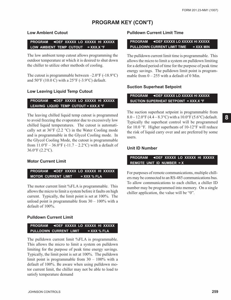
259JOHNSON CONTROLS
FORM 201.23-NM1 (1007)
8
Low Ambient Cutout
PROGRAM KEY (CON'T)
The low ambient temp cutout allows programming the outdoor temperature at which it is desired to shut down the chiller to utilize other methods of cooling.
The cutout is programmable between –2.0°F (-18.9°C) and 50°F (10.0 C) with a 25°F (-3.9°C) default.
Low Leaving Liquid Temp Cutout
PROGRAM ◄DEF XXXXX LO XXXXX HI XXXXXLEAVING LIQUID TEMP CUTOUT = XXX.X °F
PROGRAM ◄DEF XXXXX LO XXXXX HI XXXXXMOTOR CURRENT LIMIT = XXX % FLA
PROGRAM ◄DEF XXXXX LO XXXXX HI XXXXXPULLDOWN CURRENT LIMIT = XXX % FLA
PROGRAM ◄DEF XXXXX LO XXXXX HI XXXXXLOW AMBIENT TEMP CUTOUT = XXX.X °F
The leaving chilled liquid temp cutout is programmed to avoid freezing the evaporator due to excessively low chilled liquid temperatures. The cutout is automati-cally set at 36°F (2.2 °C) in the Water Cooling mode and is programmable in the Glycol Cooling mode. In the Glycol Cooling Mode, the cutout is programmable from 11.0°F – 36.0°F (-11.7 – 2.2°C) with a default of 36.0°F (2.2°C).
Motor Current Limit
The motor current limit %FLA is programmable. This allows the micro to limit a system before it faults on high current. Typically, the limit point is set at 100%. The unload point is programmable from 30 – 100% with a default of 100%.
Pulldown Current Limit
The pulldown current limit %FLA is programmable. This allows the micro to limit a system on pulldown limiting for the purpose of peak time energy savings. Typically, the limit point is set at 100%. The pulldown limit point is programmable from 30 – 100% with a default of 100%. Be aware when using pulldown mo-tor current limit, the chiller may not be able to load to satisfy temperature demand
Pulldown Current Limit Time
The pulldown current limit time is programmable. This allows the micro to limit a system on pulldown limiting for a defi ned period of time for the purpose of peak time energy savings. The pulldown limit point is program-mable from 0 – 255 with a default of 0 Min.
Suction Superheat Setpoint
PROGRAM ◄DEF XXXXX LO XXXXX HI XXXXXPULLDOWN CURRENT LIMIT TIME = XXX MIN
The suction superheat setpoint is programmable from 8.0 – 12.0°F (4.4 – 8.3°C) with a 10.0°F (5.6°C) default. Typically the superheat control will be programmed for 10.0 °F. Higher superheats of 10-12°F will reduce the risk of liquid carry over and are preferred by some users.
Unit ID Number
PROGRAM ◄DEF XXXXX LO XXXXX HI XXXXXSUCTION SUPERHEAT SETPOINT = XXX.X °F
For purposes of remote communications, multiple chill-ers may be connected to an RS-485 communications bus. To allow communications to each chiller, a chiller ID number may be programmed into memory. On a single chiller application, the value will be “0”.
PROGRAM ◄DEF XXXXX LO XXXXX HI XXXXXREMOTE UNIT ID NUMBER = X
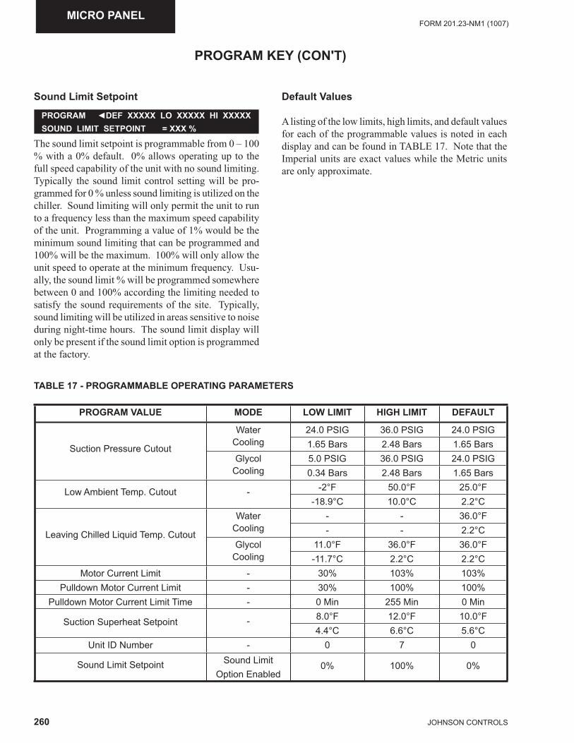
260 JOHNSON CONTROLS
FORM 201.23-NM1 (1007)MICRO PANEL
Sound Limit Setpoint
PROGRAM ◄DEF XXXXX LO XXXXX HI XXXXXSOUND LIMIT SETPOINT = XXX %
The sound limit setpoint is programmable from 0 – 100 % with a 0% default. 0% allows operating up to the full speed capability of the unit with no sound limiting. Typically the sound limit control setting will be pro-grammed for 0 % unless sound limiting is utilized on the chiller. Sound limiting will only permit the unit to run to a frequency less than the maximum speed capability of the unit. Programming a value of 1% would be the minimum sound limiting that can be programmed and 100% will be the maximum. 100% will only allow the unit speed to operate at the minimum frequency. Usu-ally, the sound limit % will be programmed somewhere between 0 and 100% according the limiting needed to satisfy the sound requirements of the site. Typically, sound limiting will be utilized in areas sensitive to noise during night-time hours. The sound limit display will only be present if the sound limit option is programmed at the factory.
Default Values
A listing of the low limits, high limits, and default values for each of the programmable values is noted in each display and can be found in TABLE 17. Note that the Imperial units are exact values while the Metric units are only approximate.
PROGRAM KEY (CON'T)
TABLE 17 - PROGRAMMABLE OPERATING PARAMETERS
PROGRAM VALUE MODE LOW LIMIT HIGH LIMIT DEFAULT
Suction Pressure Cutout
WaterCooling
24.0 PSIG 36.0 PSIG 24.0 PSIG1.65 Bars 2.48 Bars 1.65 Bars
GlycolCooling
5.0 PSIG 36.0 PSIG 24.0 PSIG0.34 Bars 2.48 Bars 1.65 Bars
Low Ambient Temp. Cutout - -2°F 50.0°F 25.0°F-18.9°C 10.0°C 2.2°C
Leaving Chilled Liquid Temp. Cutout
WaterCooling
- - 36.0°F- - 2.2°C
Glycol Cooling
11.0°F 36.0°F 36.0°F-11.7°C 2.2°C 2.2°C
Motor Current Limit - 30% 103% 103%Pulldown Motor Current Limit - 30% 100% 100%
Pulldown Motor Current Limit Time - 0 Min 255 Min 0 Min
Suction Superheat Setpoint - 8.0°F 12.0°F 10.0°F4.4°C 6.6°C 5.6°C
Unit ID Number - 0 7 0
Sound Limit Setpoint Sound LimitOption Enabled
0% 100% 0%
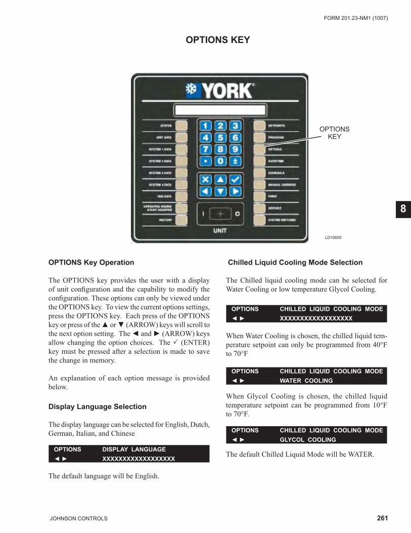
261JOHNSON CONTROLS
FORM 201.23-NM1 (1007)
8
OPTIONS KEY
LD10605
OPTIONSKEY
OPTIONS Key Operation
The OPTIONS key provides the user with a display of unit confi guration and the capability to modify the confi guration. These options can only be viewed under the OPTIONS key. To view the current options settings, press the OPTIONS key. Each press of the OPTIONS key or press of the ▲ or ▼ (ARROW) keys will scroll to the next option setting. The ◄ and ► (ARROW) keys allow changing the option choices. The � (ENTER) key must be pressed after a selection is made to save the change in memory.
An explanation of each option message is provided below.
Display Language Selection
The display language can be selected for English, Dutch, German, Italian, and Chinese
The default language will be English.
OPTIONS DISPLAY LANGUAGE◄ ► XXXXXXXXXXXXXXXXXX
OPTIONS CHILLED LIQUID COOLING MODE◄ ► XXXXXXXXXXXXXXXXXX
Chilled Liquid Cooling Mode Selection
The Chilled liquid cooling mode can be selected for Water Cooling or low temperature Glycol Cooling.
OPTIONS CHILLED LIQUID COOLING MODE◄ ► WATER COOLING
When Water Cooling is chosen, the chilled liquid tem-perature setpoint can only be programmed from 40°F to 70°F
OPTIONS CHILLED LIQUID COOLING MODE◄ ► GLYCOL COOLING
When Glycol Cooling is chosen, the chilled liquid temperature setpoint can be programmed from 10°F to 70°F.
The default Chilled Liquid Mode will be WATER.
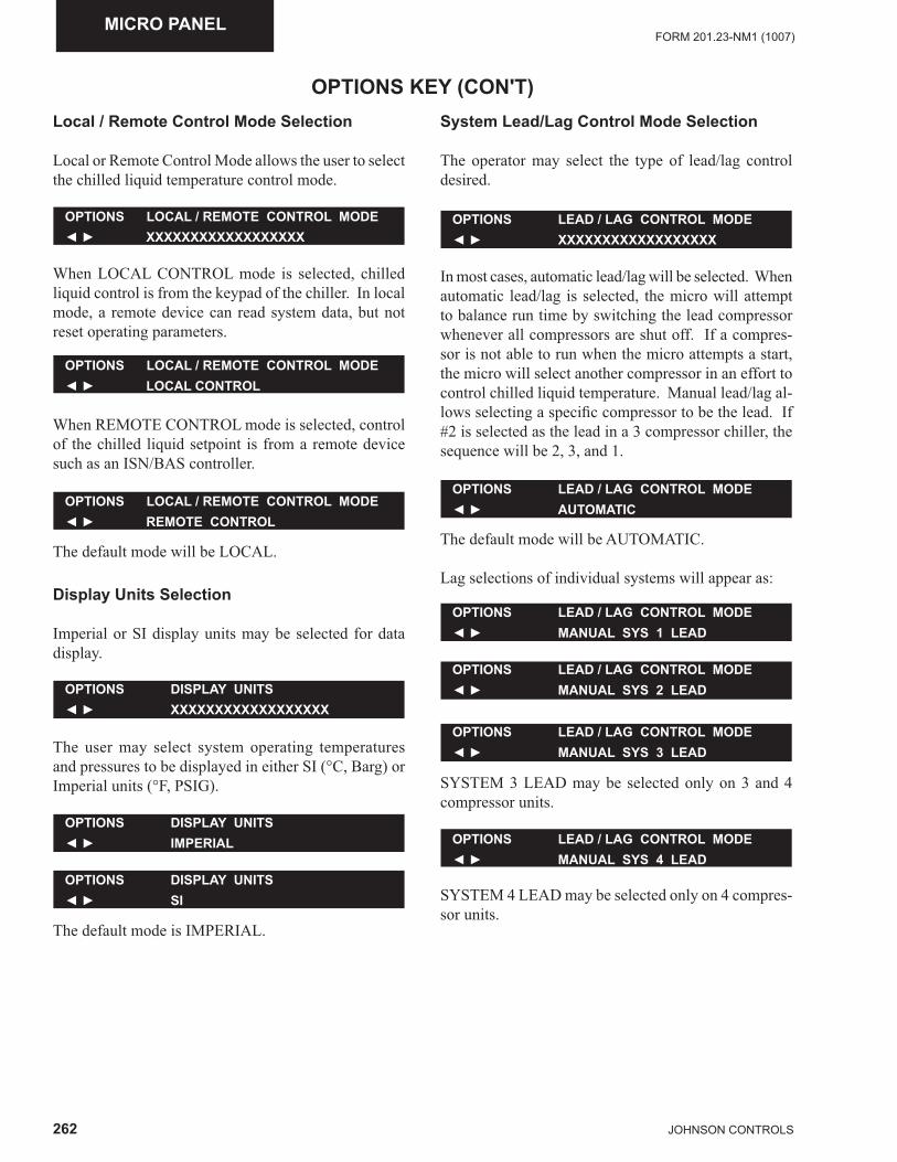
262 JOHNSON CONTROLS
FORM 201.23-NM1 (1007)MICRO PANEL
OPTIONS KEY (CON'T)Local / Remote Control Mode Selection
Local or Remote Control Mode allows the user to select the chilled liquid temperature control mode.
When LOCAL CONTROL mode is selected, chilled liquid control is from the keypad of the chiller. In local mode, a remote device can read system data, but not reset operating parameters.
OPTIONS LOCAL / REMOTE CONTROL MODE◄ ► XXXXXXXXXXXXXXXXXX
OPTIONS LOCAL / REMOTE CONTROL MODE◄ ► LOCAL CONTROL
When REMOTE CONTROL mode is selected, control of the chilled liquid setpoint is from a remote device such as an ISN/BAS controller.
OPTIONS LOCAL / REMOTE CONTROL MODE◄ ► REMOTE CONTROL
The default mode will be LOCAL.
Display Units Selection
Imperial or SI display units may be selected for data display.
OPTIONS LEAD / LAG CONTROL MODE◄ ► XXXXXXXXXXXXXXXXXX
OPTIONS DISPLAY UNITS◄ ► XXXXXXXXXXXXXXXXXX
The user may select system operating temperatures and pressures to be displayed in either SI (°C, Barg) or Imperial units (°F, PSIG).
OPTIONS DISPLAY UNITS◄ ► IMPERIAL
OPTIONS LEAD / LAG CONTROL MODE◄ ► AUTOMATIC
OPTIONS DISPLAY UNITS◄ ► SI
OPTIONS LEAD / LAG CONTROL MODE◄ ► MANUAL SYS 1 LEAD
The default mode is IMPERIAL.
OPTIONS LEAD / LAG CONTROL MODE◄ ► MANUAL SYS 2 LEAD
System Lead/Lag Control Mode Selection
The operator may select the type of lead/lag control desired.
In most cases, automatic lead/lag will be selected. When automatic lead/lag is selected, the micro will attempt to balance run time by switching the lead compressor whenever all compressors are shut off. If a compres-sor is not able to run when the micro attempts a start, the micro will select another compressor in an effort to control chilled liquid temperature. Manual lead/lag al-lows selecting a specifi c compressor to be the lead. If #2 is selected as the lead in a 3 compressor chiller, the sequence will be 2, 3, and 1.
OPTIONS LEAD / LAG CONTROL MODE◄ ► MANUAL SYS 3 LEAD
The default mode will be AUTOMATIC.
Lag selections of individual systems will appear as:
OPTIONS LEAD / LAG CONTROL MODE◄ ► MANUAL SYS 4 LEAD
SYSTEM 3 LEAD may be selected only on 3 and 4 compressor units.
SYSTEM 4 LEAD may be selected only on 4 compres-sor units.
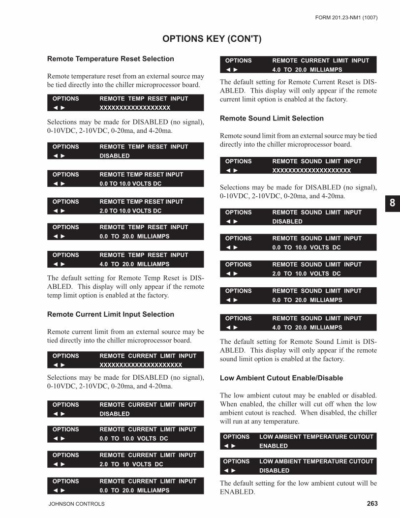
263JOHNSON CONTROLS
FORM 201.23-NM1 (1007)
8
Remote Temperature Reset Selection
Remote temperature reset from an external source may be tied directly into the chiller microprocessor board.
OPTIONS KEY (CON'T)
OPTIONS REMOTE TEMP RESET INPUT◄ ► XXXXXXXXXXXXXXXXXX
Selections may be made for DISABLED (no signal), 0-10VDC, 2-10VDC, 0-20ma, and 4-20ma.
OPTIONS REMOTE TEMP RESET INPUT◄ ► DISABLED
OPTIONS REMOTE TEMP RESET INPUT◄ ► 0.0 TO 10.0 VOLTS DC
OPTIONS REMOTE TEMP RESET INPUT◄ ► 2.0 TO 10.0 VOLTS DC
OPTIONS REMOTE TEMP RESET INPUT◄ ► 0.0 TO 20.0 MILLIAMPS
OPTIONS REMOTE SOUND LIMIT INPUT◄ ► XXXXXXXXXXXXXXXXXXXX
OPTIONS REMOTE SOUND LIMIT INPUT◄ ► 4.0 TO 20.0 MILLIAMPS
OPTIONS LOW AMBIENT TEMPERATURE CUTOUT◄ ► DISABLED
OPTIONS LOW AMBIENT TEMPERATURE CUTOUT◄ ► ENABLED
OPTIONS REMOTE SOUND LIMIT INPUT◄ ► 0.0 TO 20.0 MILLIAMPS
OPTIONS REMOTE SOUND LIMIT INPUT◄ ► 2.0 TO 10.0 VOLTS DC
OPTIONS REMOTE SOUND LIMIT INPUT◄ ► 0.0 TO 10.0 VOLTS DC
OPTIONS REMOTE SOUND LIMIT INPUT◄ ► DISABLED
OPTIONS REMOTE CURRENT LIMIT INPUT◄ ► 4.0 TO 20.0 MILLIAMPS
OPTIONS REMOTE TEMP RESET INPUT◄ ► 4.0 TO 20.0 MILLIAMPS
The default setting for Remote Temp Reset is DIS-ABLED. This display will only appear if the remote temp limit option is enabled at the factory.
Remote Current Limit Input Selection
Remote current limit from an external source may be tied directly into the chiller microprocessor board.
OPTIONS REMOTE CURRENT LIMIT INPUT◄ ► XXXXXXXXXXXXXXXXXXXXX
Selections may be made for DISABLED (no signal), 0-10VDC, 2-10VDC, 0-20ma, and 4-20ma.
OPTIONS REMOTE CURRENT LIMIT INPUT◄ ► DISABLED
OPTIONS REMOTE CURRENT LIMIT INPUT◄ ► 0.0 TO 10.0 VOLTS DC
OPTIONS REMOTE CURRENT LIMIT INPUT◄ ► 2.0 TO 10 VOLTS DC
OPTIONS REMOTE CURRENT LIMIT INPUT◄ ► 0.0 TO 20.0 MILLIAMPS
The default setting for Remote Current Reset is DIS-ABLED. This display will only appear if the remote current limit option is enabled at the factory.
Remote Sound Limit Selection
Remote sound limit from an external source may be tied directly into the chiller microprocessor board.
Selections may be made for DISABLED (no signal), 0-10VDC, 2-10VDC, 0-20ma, and 4-20ma.
The default setting for Remote Sound Limit is DIS-ABLED. This display will only appear if the remote sound limit option is enabled at the factory.
Low Ambient Cutout Enable/Disable
The low ambient cutout may be enabled or disabled. When enabled, the chiller will cut off when the low ambient cutout is reached. When disabled, the chiller will run at any temperature.
The default setting for the low ambient cutout will be ENABLED.

264 JOHNSON CONTROLS
FORM 201.23-NM1 (1007)
This page intentionally left blank
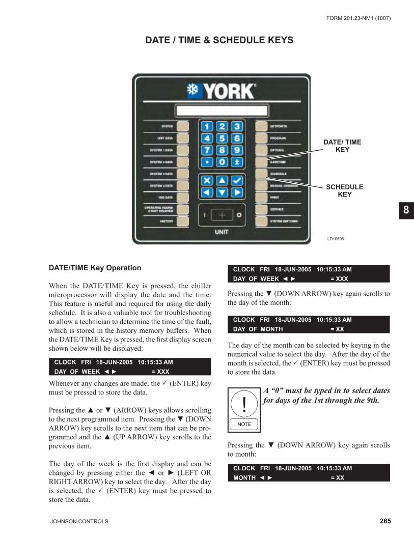
265JOHNSON CONTROLS
FORM 201.23-NM1 (1007)
8
LD10605
DATE/ TIMEKEY
DATE / TIME & SCHEDULE KEYS
SCHEDULEKEY
DATE/TIME Key Operation
When the DATE/TIME Key is pressed, the chiller microprocessor will display the date and the time. This feature is useful and required for using the daily schedule. It is also a valuable tool for troubleshooting to allow a technician to determine the time of the fault, which is stored in the history memory buffers. When the DATE/TIME Key is pressed, the fi rst display screen shown below will be displayed:
CLOCK FRI 18-JUN-2005 10:15:33 AM DAY OF WEEK ◄ ► = XXX
Whenever any changes are made, the � (ENTER) key must be pressed to store the data. Pressing the ▲ or ▼ (ARROW) keys allows scrolling to the next programmed item. Pressing the ▼ (DOWN ARROW) key scrolls to the next item that can be pro-grammed and the ▲ (UP ARROW) key scrolls to the previous item.
The day of the week is the fi rst display and can be changed by pressing either the ◄ or ► (LEFT OR RIGHT ARROW) key to select the day. After the day is selected, the � (ENTER) key must be pressed to store the data.
Pressing the ▼ (DOWN ARROW) key again scrolls to the day of the month:
CLOCK FRI 18-JUN-2005 10:15:33 AM DAY OF WEEK ◄ ► = XXX
CLOCK FRI 18-JUN-2005 10:15:33 AM DAY OF MONTH = XX
The day of the month can be selected by keying in the numerical value to select the day. After the day of the month is selected, the � (ENTER) key must be pressed to store the data.
A “0” must be typed in to select dates for days of the 1st through the 9th.
Pressing the ▼ (DOWN ARROW) key again scrolls to month:
CLOCK FRI 18-JUN-2005 10:15:33 AM MONTH ◄ ► = XX
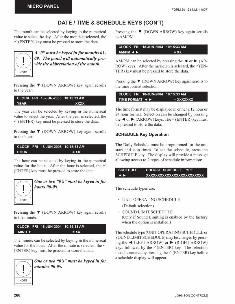
266 JOHNSON CONTROLS
FORM 201.23-NM1 (1007)MICRO PANEL
DATE / TIME & SCHEDULE KEYS (CON'T)The month can be selected by keying in the numerical value to select the day. After the month is selected, the � (ENTER) key must be pressed to store the data.
A “0” must be keyed in for months 01-09. The panel will automatically pro-vide the abbreviation of the month.
Pressing the ▼ (DOWN ARROW) key again scrolls to the year:
CLOCK FRI 18-JUN-2005 10:15:33 AM YEAR = XXXX
The year can be selected by keying in the numerical value to select the year. After the year is selected, the � (ENTER) key must be pressed to store the data.
Pressing the ▼ (DOWN ARROW) key again scrolls to the hour:
CLOCK FRI 18-JUN-2005 10:15:33 AM HOUR = XX
The hour can be selected by keying in the numerical value for the hour. After the hour is selected, the � (ENTER) key must be pressed to store the data.
One or two “0’s” must be keyed in for hours 00-09.
Pressing the ▼ (DOWN ARROW) key again scrolls to the minute:
The minute can be selected by keying in the numerical value for the hour. After the minute is selected, the � (ENTER) key must be pressed to store the data.
One or two “0’s” must be keyed in for minutes 00-09.
CLOCK FRI 18-JUN-2004 10:15:33 AMAM/PM ◄ ► = XX
CLOCK FRI 18-JUN-2004 10:15:33 AM TIME FORMAT ◄ ► = XXXXXXX
CLOCK FRI 18-JUN-2004 10:15:33 AM MINUTE = XX
Pressing the ▼ (DOWN ARROW) key again scrolls to AM/PM:
AM/PM can be selected by pressing the ◄ or ► (AR-ROW) keys. After the meridian is selected, the �(EN-TER) key must be pressed to store the data.
Pressing the ▼ (DOWN ARROW) key again scrolls to the time format selection:
The time format may be displayed in either a 12 hour or 24 hour format. Selection can be changed by pressing the ◄ or ► (ARROW) keys. The �(ENTER) key must be pressed to store the data.
SCHEDULE Key Operation
The Daily Schedule must be programmed for the unit start and stop times. To set the schedule, press the SCHEDULE key. The display will provide a message allowing access to 2 types of schedule information:
SCHEDULE CHOOSE SCHEDULE TYPE◄ ► XXXXXXXXXXXXXXXXXXXXXXXXX
The schedule types are:
· UNIT OPERATING SCHEDULE (Default selection) · SOUND LIMIT SCHEDULE
(Only if Sound Limiting is enabled by the factory when the option is installed.)
The schedule type (UNIT OPERATING SCHEDULE or SOUND LIMIT SCHEDULE) may be changed by press-ing the ◄ (LEFT ARROW) or ► (RIGHT ARROW) keys followed by the �(ENTER) key. The selection must be entered by pressing the � (ENTER) key before a schedule display will appear.
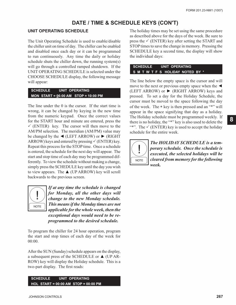
267JOHNSON CONTROLS
FORM 201.23-NM1 (1007)
8
The line below the empty space is the cursor and will move to the next or previous empty space when the ◄ (LEFT ARROW) or ► (RIGHT ARROW) keys and pressed. To set a day for the Holiday Schedule, the cursor must be moved to the space following the day of the week. The * key is then pressed and an “*” will appear in the space signifying that day as a holiday. The Holiday schedule must be programmed weekly. If there is no holiday, the “*” key is also used to delete the “*”. The � (ENTER) key is used to accept the holiday schedule for the entire week.
The HOLIDAY SCHEDULE is a tem-porary schedule. Once the schedule is executed, the selected holidays will be cleared from memory for the following week.
DATE / TIME & SCHEDULE KEYS (CON'T)
SCHEDULE UNIT OPERATINGHOL START = 00:00 AM STOP = 00:00 PM
SCHEDULE UNIT OPERATINGS M T W T F S HOLIDAY NOTED BY *
UNIT OPERATING SCHEDULE
The Unit Operating Schedule is used to enable/disable the chiller unit on time of day. The chiller can be enabled and disabled once each day or it can be programmed to run continuously. Any time the daily or holiday schedule shuts the chiller down, the running system(s) will go through a controlled ramped shutdown. If the UNIT OPERATING SCHEDULE is selected under the CHOOSE SCHEDULE display, the following message will appear:
SCHEDULE UNIT OPERATINGMON START = 06:00 AM STOP = 10:00 PM
The line under the 0 is the cursor. If the start time is wrong, it can be changed by keying in the new time from the numeric keypad. Once the correct values for the START hour and minute are entered, press the � (ENTER) key. The cursor will then move to the AM/PM selection. The meridian (AM/PM) value may be changed by the ◄ (LEFT ARROW) or ► (RIGHT ARROW) keys and entered by pressing � (ENTER) key. Repeat this process for the STOP time. Once a schedule is entered, the schedule for the next day will appear. The start and stop time of each day may be programmed dif-ferently. To view the schedule without making a change, simply press the SCHEDULE key until the day you wish to view appears. The ▲ (UP ARROW) key will scroll backwards to the previous screen.
If at any time the schedule is changed for Monday, all the other days will change to the new Monday schedule. This means if the Monday times are not applicable for the whole week, then the exceptional days would need to be re-programmed to the desired schedule.
To program the chiller for 24 hour operation, program the start and stop times of each day of the week for 00:00.
After the SUN (Sunday) schedule appears on the display, a subsequent press of the SCHEDULE or ▲ (UP AR-ROW) key will display the Holiday schedule. This is a two-part display. The fi rst reads:
The holiday times may be set using the same procedure as described above for the days of the week. Be sure to press the � (ENTER) key after setting the START and STOP times to save the change in memory. Pressing the SCHEDULE key a second time, the display will show the individual days:
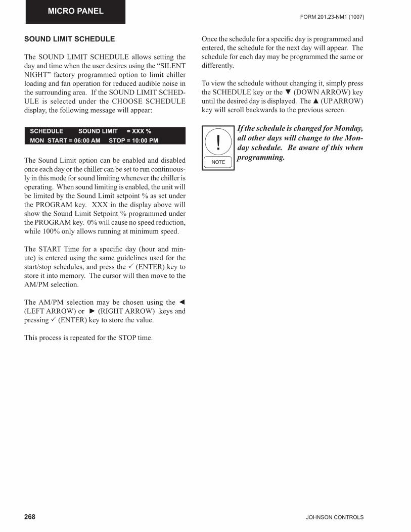
268 JOHNSON CONTROLS
FORM 201.23-NM1 (1007)MICRO PANEL
SCHEDULE SOUND LIMIT = XXX %MON START = 06:00 AM STOP = 10:00 PM
SOUND LIMIT SCHEDULE
The SOUND LIMIT SCHEDULE allows setting the day and time when the user desires using the “SILENT NIGHT” factory programmed option to limit chiller loading and fan operation for reduced audible noise in the surrounding area. If the SOUND LIMIT SCHED-ULE is selected under the CHOOSE SCHEDULE display, the following message will appear:
The Sound Limit option can be enabled and disabled once each day or the chiller can be set to run continuous-ly in this mode for sound limiting whenever the chiller is operating. When sound limiting is enabled, the unit will be limited by the Sound Limit setpoint % as set under the PROGRAM key. XXX in the display above will show the Sound Limit Setpoint % programmed under the PROGRAM key. 0% will cause no speed reduction, while 100% only allows running at minimum speed.
The START Time for a specifi c day (hour and min-ute) is entered using the same guidelines used for the start/stop schedules, and press the � (ENTER) key to store it into memory. The cursor will then move to the AM/PM selection.
The AM/PM selection may be chosen using the ◄ (LEFT ARROW) or ► (RIGHT ARROW) keys and pressing � (ENTER) key to store the value.
This process is repeated for the STOP time.
Once the schedule for a specifi c day is programmed and entered, the schedule for the next day will appear. The schedule for each day may be programmed the same or differently.
To view the schedule without changing it, simply press the SCHEDULE key or the ▼ (DOWN ARROW) key until the desired day is displayed. The ▲ (UP ARROW) key will scroll backwards to the previous screen.
If the schedule is changed for Monday, all other days will change to the Mon-day schedule. Be aware of this when programming.
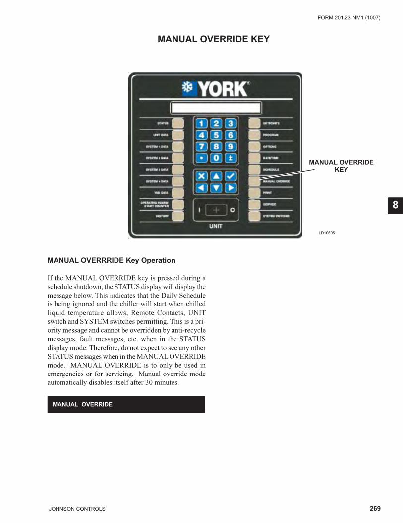
269JOHNSON CONTROLS
FORM 201.23-NM1 (1007)
8
LD10605
MANUAL OVERRIDEKEY
MANUAL OVERRIDE KEY
MANUAL OVERRIDE
MANUAL OVERRRIDE Key Operation If the MANUAL OVERRIDE key is pressed during a schedule shutdown, the STATUS display will display the message below. This indicates that the Daily Schedule is being ignored and the chiller will start when chilled liquid temperature allows, Remote Contacts, UNIT switch and SYSTEM switches permitting. This is a pri-ority message and cannot be overridden by anti-recycle messages, fault messages, etc. when in the STATUS display mode. Therefore, do not expect to see any other STATUS messages when in the MANUAL OVERRIDE mode. MANUAL OVERRIDE is to only be used in emergencies or for servicing. Manual override mode automatically disables itself after 30 minutes.
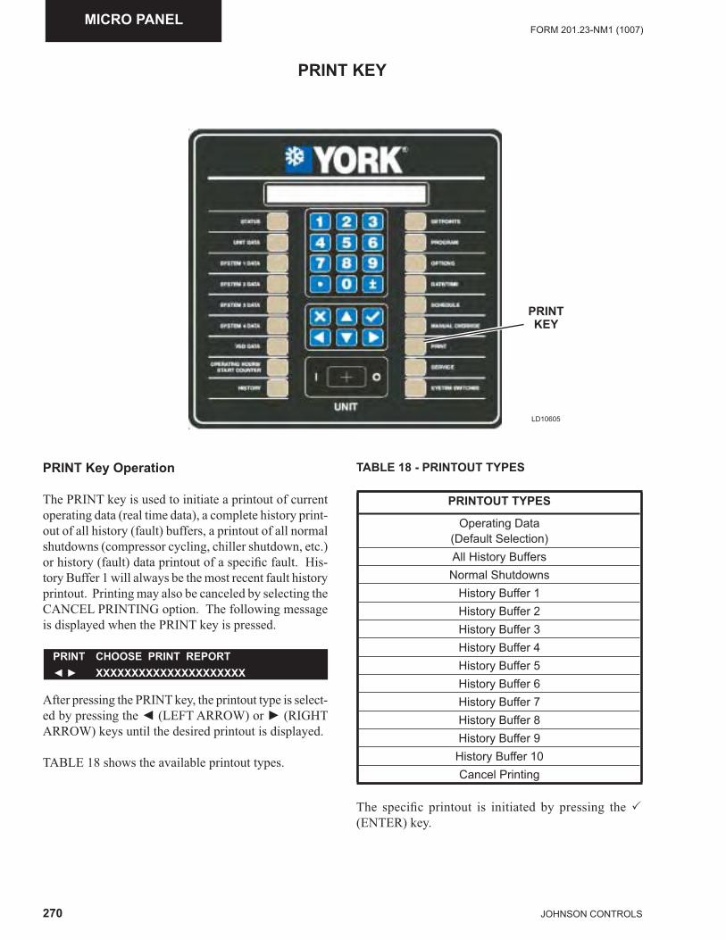
270 JOHNSON CONTROLS
FORM 201.23-NM1 (1007)MICRO PANEL
LD10605
PRINTKEY
PRINT KEY
PRINT Key Operation
The PRINT key is used to initiate a printout of current operating data (real time data), a complete history print-out of all history (fault) buffers, a printout of all normal shutdowns (compressor cycling, chiller shutdown, etc.) or history (fault) data printout of a specifi c fault. His-tory Buffer 1 will always be the most recent fault history printout. Printing may also be canceled by selecting the CANCEL PRINTING option. The following message is displayed when the PRINT key is pressed.
PRINT CHOOSE PRINT REPORT◄ ► XXXXXXXXXXXXXXXXXXXXX
After pressing the PRINT key, the printout type is select-ed by pressing the ◄ (LEFT ARROW) or ► (RIGHT ARROW) keys until the desired printout is displayed.
TABLE 18 shows the available printout types.
TABLE 18 - PRINTOUT TYPES
PRINTOUT TYPES
Operating Data(Default Selection)All History BuffersNormal Shutdowns
History Buffer 1History Buffer 2History Buffer 3History Buffer 4History Buffer 5History Buffer 6History Buffer 7History Buffer 8History Buffer 9
History Buffer 10Cancel Printing
The specifi c printout is initiated by pressing the � (ENTER) key.
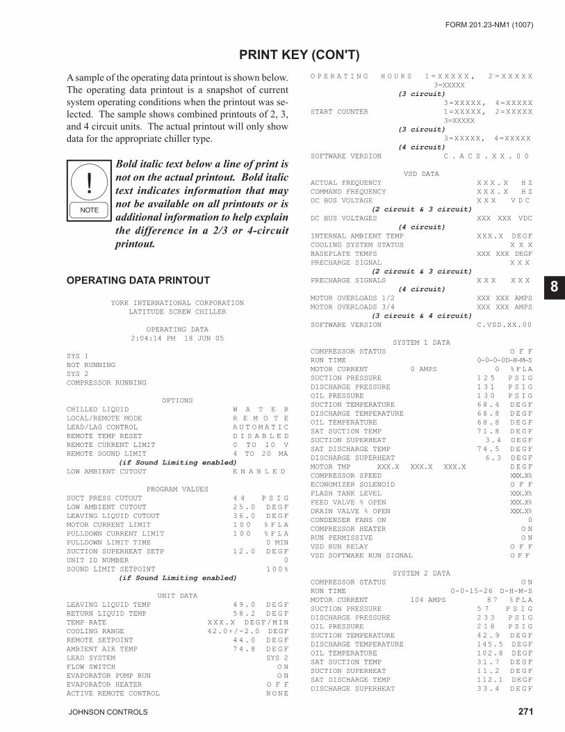
271JOHNSON CONTROLS
FORM 201.23-NM1 (1007)
8
PRINT KEY (CON'T)A sample of the operating data printout is shown below. The operating data printout is a snapshot of current system operating conditions when the printout was se-lected. The sample shows combined printouts of 2, 3, and 4 circuit units. The actual printout will only show data for the appropriate chiller type.
Bold italic text below a line of print is not on the actual printout. Bold italic text indicates information that may not be available on all printouts or is additional information to help explain the difference in a 2/3 or 4-circuit printout.
OPERATING DATA PRINTOUT
YORK INTERNATIONAL CORPORATIONLATITUDE SCREW CHILLER
OPERATING DATA2:04:14 PM 18 JUN 05
SYS 1 NOT RUNNINGSYS 2 COMPRESSOR RUNNING
OPTIONSCHILLED LIQUID W A T E RLOCAL/REMOTE MODE R E M O T ELEAD/LAG CONTROL A U T O M A T I CREMOTE TEMP RESET D I S A B L E DREMOTE CURRENT LIMIT 0 TO 10 VREMOTE SOUND LIMIT 4 TO 20 MA
(if Sound Limiting enabled)LOW AMBIENT CUTOUT E N A B L E D
PROGRAM VALUESSUCT PRESS CUTOUT 4 4 P S I GLOW AMBIENT CUTOUT 2 5 . 0 D E G FLEAVING LIQUID CUTOUT 3 6 . 0 D E G FMOTOR CURRENT LIMIT 1 0 0 % F L APULLDOWN CURRENT LIMIT 1 0 0 % F L APULLDOWN LIMIT TIME 0 MINSUCTION SUPERHEAT SETP 1 2 . 0 D E G FUNIT ID NUMBER 0SOUND LIMIT SETPOINT 1 0 0 %
(if Sound Limiting enabled)
UNIT DATALEAVING LIQUID TEMP 4 9 . 0 D E G FRETURN LIQUID TEMP 5 8 . 2 D E G FTEMP RATE XXX.X DEGF/MINCOOLING RANGE 42.0+/-2.0 DEGFREMOTE SETPOINT 4 4 . 0 D E G FAMBIENT AIR TEMP 7 4 . 8 D E G FLEAD SYSTEM SYS 2FLOW SWITCH O NEVAPORATOR PUMP RUN O NEVAPORATOR HEATER O F FACTIVE REMOTE CONTROL N O N E
O P E R A T I N G H O U R S 1 = X X X X X , 2 = X X X X X 3=XXXXX
(3 circuit) 3=XXXXX, 4=XXXXX START COUNTER 1=XXXXX, 2=XXXXX 3=XXXXX
(3 circuit) 3=XXXXX, 4=XXXXX
(4 circuit)SOFTWARE VERSION C . A C S . X X . 0 0
VSD DATAACTUAL FREQUENCY X X X . X H ZCOMMAND FREQUENCY X X X . X H ZDC BUS VOLTAGE X X X V D C
(2 circuit & 3 circuit)DC BUS VOLTAGES XXX XXX VDC
(4 circuit)INTERNAL AMBIENT TEMP XXX.X DEGFCOOLING SYSTEM STATUS X X XBASEPLATE TEMPS XXX XXX DEGFPRECHARGE SIGNAL X X X
(2 circuit & 3 circuit)PRECHARGE SIGNALS X X X X X X
(4 circuit)MOTOR OVERLOADS 1/2 XXX XXX AMPSMOTOR OVERLOADS 3/4 XXX XXX AMPS
(3 circuit & 4 circuit)SOFTWARE VERSION C.VSD.XX.00
SYSTEM 1 DATACOMPRESSOR STATUS O F FRUN TIME 0- 0- 0- 0 D-H-M-SMOTOR CURRENT 0 AMPS 0 % F L ASUCTION PRESSURE 1 2 5 P S I GDISCHARGE PRESSURE 1 3 1 P S I GOIL PRESSURE 1 3 0 P S I GSUCTION TEMPERATURE 6 8 . 4 D E G FDISCHARGE TEMPERATURE 6 8 . 8 D E G FOIL TEMPERATURE 6 8 . 8 D E G FSAT SUCTION TEMP 7 1 . 8 D E G FSUCTION SUPERHEAT 3.4 DEGFSAT DISCHARGE TEMP 7 4 . 5 D E G FDISCHARGE SUPERHEAT 6.3 DEGFMOTOR TMP XXX.X XXX.X XXX.X D E G FCOMPRESSOR SPEED XXX.X %ECONOMIZER SOLENOID O F FFLASH TANK LEVEL XXX.X %FEED VALVE % OPEN XXX.X %DRAIN VALVE % OPEN XXX.X %CONDENSER FANS ON 0COMPRESSOR HEATER O NRUN PERMISSIVE O NVSD RUN RELAY O F FVSD SOFTWARE RUN SIGNAL O F F
SYSTEM 2 DATACOMPRESSOR STATUS O NRUN TIME 0-0-15-26 D-H-M-SMOTOR CURRENT 104 AMPS 8 7 % F L ASUCTION PRESSURE 5 7 P S I GDISCHARGE PRESSURE 2 3 3 P S I GOIL PRESSURE 2 1 8 P S I GSUCTION TEMPERATURE 4 2 . 9 D E G FDISCHARGE TEMPERATURE 145.5 DEGFOIL TEMPERATURE 102.8 DEGFSAT SUCTION TEMP 3 1 . 7 D E G FSUCTION SUPERHEAT 1 1 . 2 D E G FSAT DISCHARGE TEMP 112.1 DEGFDISCHARGE SUPERHEAT 3 3 . 4 D E G F
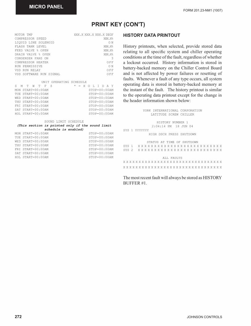
272 JOHNSON CONTROLS
FORM 201.23-NM1 (1007)MICRO PANEL
MOTOR TMP XXX.X XXX.X XXX.X DEGFCOMPRESSOR SPEED XXX.X%LIQUID LINE SOLENOID O NFLASH TANK LEVEL XXX.X %FEED VALVE % OPEN XXX.X %DRAIN VALVE % OPEN XXX.X %CONDENSER FANS ON 3COMPRESSOR HEATER OFFRUN PERMISSIVE O NVSD RUN RELAY OFFVSD SOFTWARE RUN SIGNAL OFF
UNIT OPERATING SCHEDULES M T W T F S * = H O L I D A YMON START=00:00AM STOP=00:00AMTUE START=00:00AM STOP=00:00AMWED START=00:00AM STOP=00:00AMTHU START=00:00AM STOP=00:00AMFRI START=00:00AM STOP=00:00AMSAT START=00:00AM STOP=00:00AMHOL START=00:00AM STOP=00:00AM
SOUND LIMIT SCHEDULE (This section is printed only if the sound limit
schedule is enabled)MON START=00:00AM STOP=00:00AMTUE START=00:00AM STOP=00:00AMWED START=00:00AM STOP=00:00AMTHU START=00:00AM STOP=00:00AMFRI START=00:00AM STOP=00:00AMSAT START=00:00AM STOP=00:00AMHOL START=00:00AM STOP=00:00AM
HISTORY DATA PRINTOUT
History printouts, when selected, provide stored data relating to all specifi c system and chiller operating conditions at the time of the fault, regardless of whether a lockout occurred. History information is stored in battery-backed memory on the Chiller Control Board and is not affected by power failures or resetting of faults. Whenever a fault of any type occurs, all system operating data is stored in battery-backed memory at the instant of the fault. The history printout is similar to the operating data printout except for the change in the header information shown below:
YORK INTERNATIONAL CORPORATIONLATITUDE SCREW CHILLER
HISTORY NUMBER 12:04:14 PM 18 JUN 04
SYS 1 YYYYYYYHIGH DSCH PRESS SHUTDOWN
STATUS AT TIME OF SHUTDOWNSYS 1 X X X X X X X X X X X X X X X X X X X X X X X X X XSYS 2 X X X X X X X X X X X X X X X X X X X X X X X X X X
ALL FAULTSX X X X X X X X X X X X X X X X X X X X X X X X X X X X X X X X
X X X X X X X X X X X X X X X X X X X X X X X X X X X X X X X X
The most recent fault will always be stored as HISTORY BUFFER #1.
PRINT KEY (CON'T)
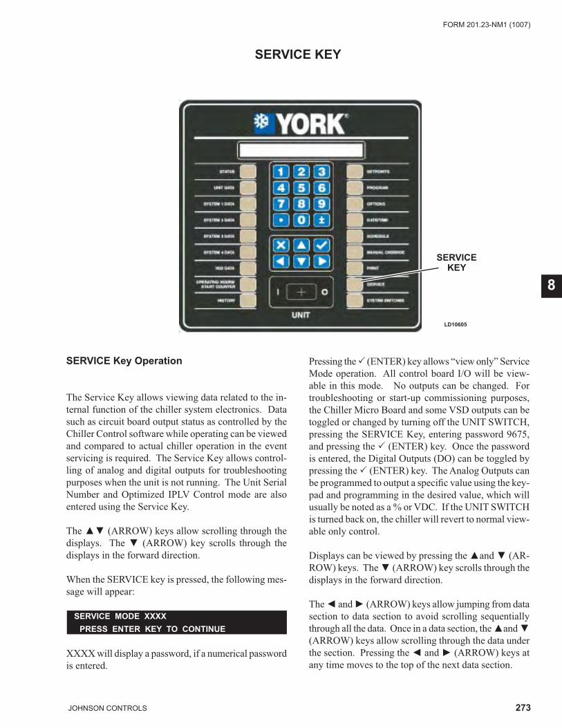
273JOHNSON CONTROLS
FORM 201.23-NM1 (1007)
8
LD10605
SERVICEKEY
SERVICE KEY
SERVICE Key Operation
The Service Key allows viewing data related to the in-ternal function of the chiller system electronics. Data such as circuit board output status as controlled by the Chiller Control software while operating can be viewed and compared to actual chiller operation in the event servicing is required. The Service Key allows control-ling of analog and digital outputs for troubleshooting purposes when the unit is not running. The Unit Serial Number and Optimized IPLV Control mode are also entered using the Service Key.
The ▲▼ (ARROW) keys allow scrolling through the displays. The ▼ (ARROW) key scrolls through the displays in the forward direction.
When the SERVICE key is pressed, the following mes-sage will appear:
XXXX will display a password, if a numerical password is entered.
SERVICE MODE XXXX PRESS ENTER KEY TO CONTINUE
Pressing the � (ENTER) key allows “view only” Service Mode operation. All control board I/O will be view-able in this mode. No outputs can be changed. For troubleshooting or start-up commissioning purposes, the Chiller Micro Board and some VSD outputs can be toggled or changed by turning off the UNIT SWITCH, pressing the SERVICE Key, entering password 9675, and pressing the � (ENTER) key. Once the password is entered, the Digital Outputs (DO) can be toggled by pressing the � (ENTER) key. The Analog Outputs can be programmed to output a specifi c value using the key-pad and programming in the desired value, which will usually be noted as a % or VDC. If the UNIT SWITCH is turned back on, the chiller will revert to normal view-able only control.
Displays can be viewed by pressing the ▲and ▼ (AR-ROW) keys. The ▼ (ARROW) key scrolls through the displays in the forward direction.
The ◄ and ► (ARROW) keys allow jumping from data section to data section to avoid scrolling sequentially through all the data. Once in a data section, the ▲and ▼ (ARROW) keys allow scrolling through the data under the section. Pressing the ◄ and ► (ARROW) keys at any time moves to the top of the next data section.
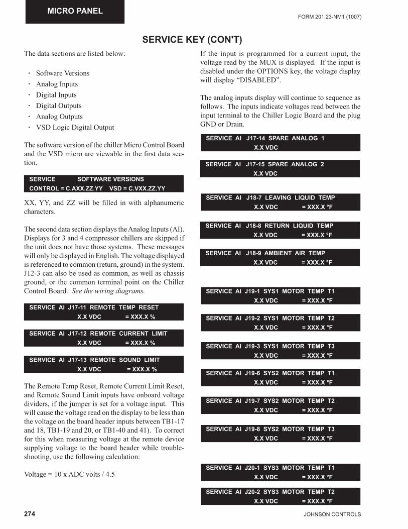
274 JOHNSON CONTROLS
FORM 201.23-NM1 (1007)MICRO PANEL
The data sections are listed below:
· Software Versions · Analog Inputs · Digital Inputs · Digital Outputs · Analog Outputs · VSD Logic Digital Output
The software version of the chiller Micro Control Board and the VSD micro are viewable in the fi rst data sec-tion.
SERVICE KEY (CON'T)
SERVICE SOFTWARE VERSIONSCONTROL = C.AXX.ZZ.YY VSD = C.VXX.ZZ.YY
XX, YY, and ZZ will be fi lled in with alphanumeric characters.
The second data section displays the Analog Inputs (AI). Displays for 3 and 4 compressor chillers are skipped if the unit does not have those systems. These messages will only be displayed in English. The voltage displayed is referenced to common (return, ground) in the system. J12-3 can also be used as common, as well as chassis ground, or the common terminal point on the Chiller Control Board. See the wiring diagrams.
SERVICE AI J17-11 REMOTE TEMP RESET X.X VDC = XXX.X %
SERVICE AI J17-12 REMOTE CURRENT LIMIT X.X VDC = XXX.X %
SERVICE AI J17-13 REMOTE SOUND LIMIT X.X VDC = XXX.X %
The Remote Temp Reset, Remote Current Limit Reset, and Remote Sound Limit inputs have onboard voltage dividers, if the jumper is set for a voltage input. This will cause the voltage read on the display to be less than the voltage on the board header inputs between TB1-17 and 18, TB1-19 and 20, or TB1-40 and 41). To correct for this when measuring voltage at the remote device supplying voltage to the board header while trouble-shooting, use the following calculation:
Voltage = 10 x ADC volts / 4.5
If the input is programmed for a current input, the voltage read by the MUX is displayed. If the input is disabled under the OPTIONS key, the voltage display will display “DISABLED”.
The analog inputs display will continue to sequence as follows. The inputs indicate voltages read between the input terminal to the Chiller Logic Board and the plug GND or Drain.
SERVICE AI J17-14 SPARE ANALOG 1 X.X VDC
SERVICE AI J17-15 SPARE ANALOG 2 X.X VDC
SERVICE AI J18-7 LEAVING LIQUID TEMP X.X VDC = XXX.X °F
SERVICE AI J18-8 RETURN LIQUID TEMP X.X VDC = XXX.X °F
SERVICE AI J18-9 AMBIENT AIR TEMP X.X VDC = XXX.X °F
SERVICE AI J19-1 SYS1 MOTOR TEMP T1 X.X VDC = XXX.X °F
SERVICE AI J19-2 SYS1 MOTOR TEMP T2 X.X VDC = XXX.X °F
SERVICE AI J19-3 SYS1 MOTOR TEMP T3 X.X VDC = XXX.X °F
SERVICE AI J19-6 SYS2 MOTOR TEMP T1 X.X VDC = XXX.X °F
SERVICE AI J19-7 SYS2 MOTOR TEMP T2 X.X VDC = XXX.X °F
SERVICE AI J19-8 SYS2 MOTOR TEMP T3 X.X VDC = XXX.X °F
SERVICE AI J20-1 SYS3 MOTOR TEMP T1 X.X VDC = XXX.X °F
SERVICE AI J20-2 SYS3 MOTOR TEMP T2 X.X VDC = XXX.X °F
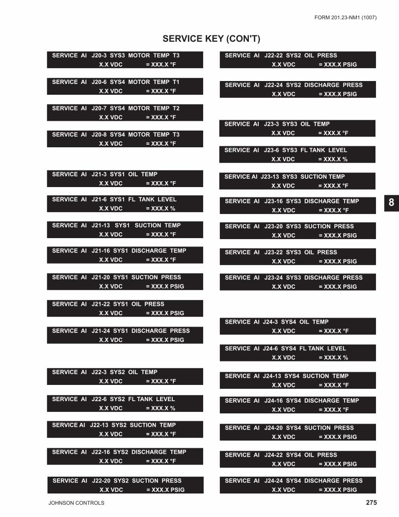
275JOHNSON CONTROLS
FORM 201.23-NM1 (1007)
8
SERVICE KEY (CON'T)
SERVICE AI J20-6 SYS4 MOTOR TEMP T1 X.X VDC = XXX.X °F
SERVICE AI J20-7 SYS4 MOTOR TEMP T2 X.X VDC = XXX.X °F
SERVICE AI J20-8 SYS4 MOTOR TEMP T3 X.X VDC = XXX.X °F
SERVICE AI J21-3 SYS1 OIL TEMP X.X VDC = XXX.X °F
SERVICE AI J21-6 SYS1 FL TANK LEVEL X.X VDC = XXX.X %
SERVICE AI J21-13 SYS1 SUCTION TEMP X.X VDC = XXX.X °F
SERVICE AI J21-16 SYS1 DISCHARGE TEMP X.X VDC = XXX.X °F
SERVICE AI J21-20 SYS1 SUCTION PRESS X.X VDC = XXX.X PSIG
SERVICE AI J21-22 SYS1 OIL PRESS X.X VDC = XXX.X PSIG
SERVICE AI J21-24 SYS1 DISCHARGE PRESS X.X VDC = XXX.X PSIG
SERVICE AI J22-3 SYS2 OIL TEMP X.X VDC = XXX.X °F
SERVICE AI J22-6 SYS2 FL TANK LEVEL X.X VDC = XXX.X %
SERVICE AI J22-13 SYS2 SUCTION TEMP X.X VDC = XXX.X °F
SERVICE AI J22-16 SYS2 DISCHARGE TEMP X.X VDC = XXX.X °F
SERVICE AI J22-20 SYS2 SUCTION PRESS X.X VDC = XXX.X PSIG
SERVICE AI J22-22 SYS2 OIL PRESS X.X VDC = XXX.X PSIG
SERVICE AI J22-24 SYS2 DISCHARGE PRESS X.X VDC = XXX.X PSIG
SERVICE AI J23-3 SYS3 OIL TEMP X.X VDC = XXX.X °F
SERVICE AI J23-6 SYS3 FL TANK LEVEL X.X VDC = XXX.X %
SERVICE AI J23-13 SYS3 SUCTION TEMP X.X VDC = XXX.X °F
SERVICE AI J23-16 SYS3 DISCHARGE TEMP X.X VDC = XXX.X °F
SERVICE AI J23-20 SYS3 SUCTION PRESS X.X VDC = XXX.X PSIG
SERVICE AI J23-22 SYS3 OIL PRESS X.X VDC = XXX.X PSIG
SERVICE AI J23-24 SYS3 DISCHARGE PRESS X.X VDC = XXX.X PSIG
SERVICE AI J24-3 SYS4 OIL TEMP X.X VDC = XXX.X °F
SERVICE AI J24-6 SYS4 FL TANK LEVEL X.X VDC = XXX.X %
SERVICE AI J24-13 SYS4 SUCTION TEMP X.X VDC = XXX.X °F
SERVICE AI J24-16 SYS4 DISCHARGE TEMP X.X VDC = XXX.X °F
SERVICE AI J24-20 SYS4 SUCTION PRESS X.X VDC = XXX.X PSIG
SERVICE AI J24-22 SYS4 OIL PRESS X.X VDC = XXX.X PSIG
SERVICE AI J24-24 SYS4 DISCHARGE PRESS X.X VDC = XXX.X PSIG
SERVICE AI J20-3 SYS3 MOTOR TEMP T3 X.X VDC = XXX.X °F
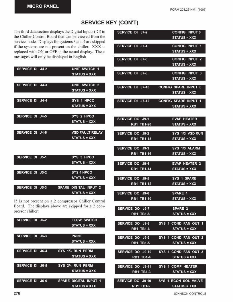
276 JOHNSON CONTROLS
FORM 201.23-NM1 (1007)MICRO PANEL
SERVICE KEY (CON'T)
SERVICE DI J4-2 UNIT SWITCH 1 STATUS = XXX
The third data section displays the Digital Inputs (DI) to the Chiller Control Board that can be viewed from the service mode. Displays for systems 3 and 4 are skipped if the systems are not present on the chiller. XXX is replaced with ON or OFF in the actual display. These messages will only be displayed in English.
SERVICE DI J4-3 UNIT SWITCH 2 STATUS = XXX
SERVICE DI J4-4 SYS 1 HPCO STATUS = XXX
SERVICE DI J4-5 SYS 2 HPCO STATUS = XXX
SERVICE DI J4-6 VSD FAULT RELAY STATUS = XXX
SERVICE DI J5-1 SYS 3 HPCO STATUS = XXX
SERVICE DI J5-2 SYS 4 HPCO STATUS = XXX
J5 is not present on a 2 compressor Chiller Control Board. The displays above are skipped for a 2 com-pressor chiller:
SERVICE DI J5-3 SPARE DIGITAL INPUT 2 STATUS = XXX
SERVICE DI J6-2 FLOW SWITCH STATUS = XXX
SERVICE DI J6-3 PRINT STATUS = XXX
SERVICE DI J6-5 SYS 2/4 RUN PERM STATUS = XXX
SERVICE DI J6-6 SPARE DIGITAL INPUT 1 STATUS = XXX
SERVICE DI J7-2 CONFIG INPUT 0 STATUS = XXX
SERVICE DI J7-4 CONFIG INPUT 1 STATUS = XXX
SERVICE DI J7-6 CONFIG INPUT 2 STATUS = XXX
SERVICE DI J7-8 CONFIG INPUT 3 STATUS = XXX
SERVICE DI J7-10 CONFIG SPARE INPUT 0 STATUS = XXX
SERVICE DI J7-12 CONFIG SPARE INPUT 1 STATUS = XXX
SERVICE DO J9-1 EVAP HEATER RB1 TB1-20 STATUS = XXX
SERVICE DO J9-2 SYS 1/3 VSD RUN RB1 TB1-18 STATUS = XXX
SERVICE DO J9-3 SYS 1/3 ALARM RB1 TB1-16 STATUS = XXX
SERVICE DO J9-4 EVAP HEATER 2 RB1 TB1-14 STATUS = XXX
SERVICE DO J9-5 SYS 1 SPARE RB1 TB1-12 STATUS = XXX
SERVICE DO J9-6 SPARE 1 RB1 TB1-10 STATUS = XXX
SERVICE DO J9-7 SPARE 2 RB1 TB1-8 STATUS = XXX
SERVICE DO J9-8 SYS 1 COND FAN OUT 1 RB1 TB1-6 STATUS = XXX
SERVICE DO J9-9 SYS 1 COND FAN OUT 2 RB1 TB1-5 STATUS = XXX
SERVICE DO J9-10 SYS 1 COND FAN OUT 3 RB1 TB1-4 STATUS = XXX
SERVICE DO J9-11 SYS 1 COMP HEATER RB1 TB1-3 STATUS = XXX
SERVICE DO J9-10 SYS 1 ECON SOL VALVE RB1 TB1-2 STATUS = XXX
SERVICE DI J6-4 SYS 1/3 RUN PERM STATUS = XXX
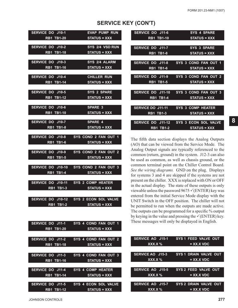
277JOHNSON CONTROLS
FORM 201.23-NM1 (1007)
8
SERVICE KEY (CON'T)SERVICE DO J10-1 EVAP PUMP RUN RB1 TB1-20 STATUS = XXX
SERVICE DO J10-2 SYS 2/4 VSD RUN RB1 TB1-18 STATUS = XXX
SERVICE DO J10-3 SYS 2/4 ALARM RB1 TB1-16 STATUS = XXX
SERVICE DO J10-4 CHILLER RUN RB1 TB1-14 STATUS = XXX
SERVICE DO J10-5 SYS 2 SPARE RB1 TB1-12 STATUS = XXX
SERVICE DO J10-6 SPARE 3 RB1 TB1-10 STATUS = XXX
SERVICE DO J10-7 SPARE 4 RB1 TB1-8 STATUS = XXX
SERVICE DO J10-8 SYS COND 2 FAN OUT 1 RB1 TB1-6 STATUS = XXX
SERVICE DO J10-9 SYS COND 2 FAN OUT 2 RB1 TB1-5 STATUS = XXX
SERVICE DO J10-10 SYS COND 2 FAN OUT 3 RB1 TB1-4 STATUS = XXX
SERVICE DO J10-11 SYS 2 COMP HEATER RB1 TB1-3 STATUS = XXX
SERVICE DO J10-12 SYS 2 ECON SOL VALVE RB1 TB1-2 STATUS = XXX
SERVICE DO J11-1 SYS 4 COND FAN OUT 1 RB1 TB1-20 STATUS = XXX
SERVICE DO J11-2 SYS 4 COND FAN OUT 2 RB1 TB1-18 STATUS = XXX
SERVICE DO J11-3 SYS 4 COND FAN OUT 3 RB1 TB1-16 STATUS = XXX
SERVICE DO J11-4 SYS 4 COMP HEATER RB1 TB1-14 STATUS = XXX
SERVICE DO J11-5 SYS 4 ECON SOL VALVE RB1 TB1-12 STATUS = XXX
SERVICE DO J11-6 SYS 4 SPARE RB1 TB1-10 STATUS = XXX
SERVICE DO J11-7 SYS 3 SPARE RB1 TB1-8 STATUS = XXX
SERVICE DO J11-8 SYS 3 COND FAN OUT 1 RB1 TB1-6 STATUS = XXX
SERVICE DO J11-9 SYS 3 COND FAN OUT 2 RB1 TB1-5 STATUS = XXX
SERVICE DO J11-10 SYS 3 COND FAN OUT 3 RB1 TB1-4 STATUS = XXX
SERVICE DO J11-11 SYS 3 COMP HEATER RB1 TB1-3 STATUS = XXX
SERVICE DO J11-12 SYS 3 ECON SOL VALVE RB1 TB1-2 STATUS = XXX
The fi fth data section displays the Analog Outputs (AO) that can be viewed from the Service Mode. The Analog Output signals are typically referenced to the common (return, ground) in the system. J12-3 can also be used as common, as well as chassis ground, or the common terminal point on the Chiller Control Board. See the wiring diagrams. GND on the plug. Displays for systems 3 and 4 are skipped if the systems are not present on the chiller. XXX is replaced with ON or OFF in the actual display. The state of these outputs is only viewable unless the password 9675 �(ENTER) key was entered from the initial Service Mode display with the UNIT Switch in the OFF position. The chiller will not be permitted to run when the outputs are made active. The outputs can be programmed for a specifi c % output by keying in the value and pressing the �(ENTER) key. These messages will only be displayed in English.
SERVICE AO J15-1 SYS 1 FEED VALVE OUT XXX.X % = XX.X VDC
SERVICE AO J15-3 SYS 1 DRAIN VALVE OUT XXX.X % = XX.X VDC
SERVICE AO J15-5 SYS 2 FEED VALVE OUT XXX.X % = XX.X VDC
SERVICE AO J15-7 SYS 2 DRAIN VALVE OUT XXX.X % = XX.X VDC
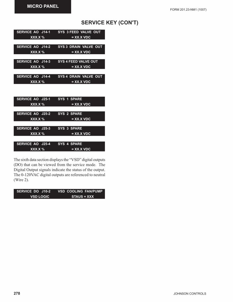
278 JOHNSON CONTROLS
FORM 201.23-NM1 (1007)MICRO PANEL
SERVICE KEY (CON'T)SERVICE AO J14-1 SYS 3 FEED VALVE OUT XXX.X % = XX.X VDC
SERVICE AO J14-2 SYS 3 DRAIN VALVE OUT XXX.X % = XX.X VDC
SERVICE AO J14-3 SYS 4 FEED VALVE OUT XXX.X % = XX.X VDC
SERVICE AO J14-4 SYS 4 DRAIN VALVE OUT XXX.X % = XX.X VDC
SERVICE AO J25-1 SYS 1 SPARE XXX.X % = XX.X VDC
SERVICE AO J25-2 SYS 2 SPARE XXX.X % = XX.X VDC
SERVICE AO J25-3 SYS 3 SPARE XXX.X % = XX.X VDC
SERVICE AO J25-4 SYS 4 SPARE XXX.X % = XX.X VDC
The sixth data section displays the “VSD” digital outputs (DO) that can be viewed from the service mode. The Digital Output signals indicate the status of the output. The 0-120VAC digital outputs are referenced to neutral (Wire 2).
SERVICE DO J10-2 VSD COOLING FAN/PUMP VSD LOGIC STAUS = XXX
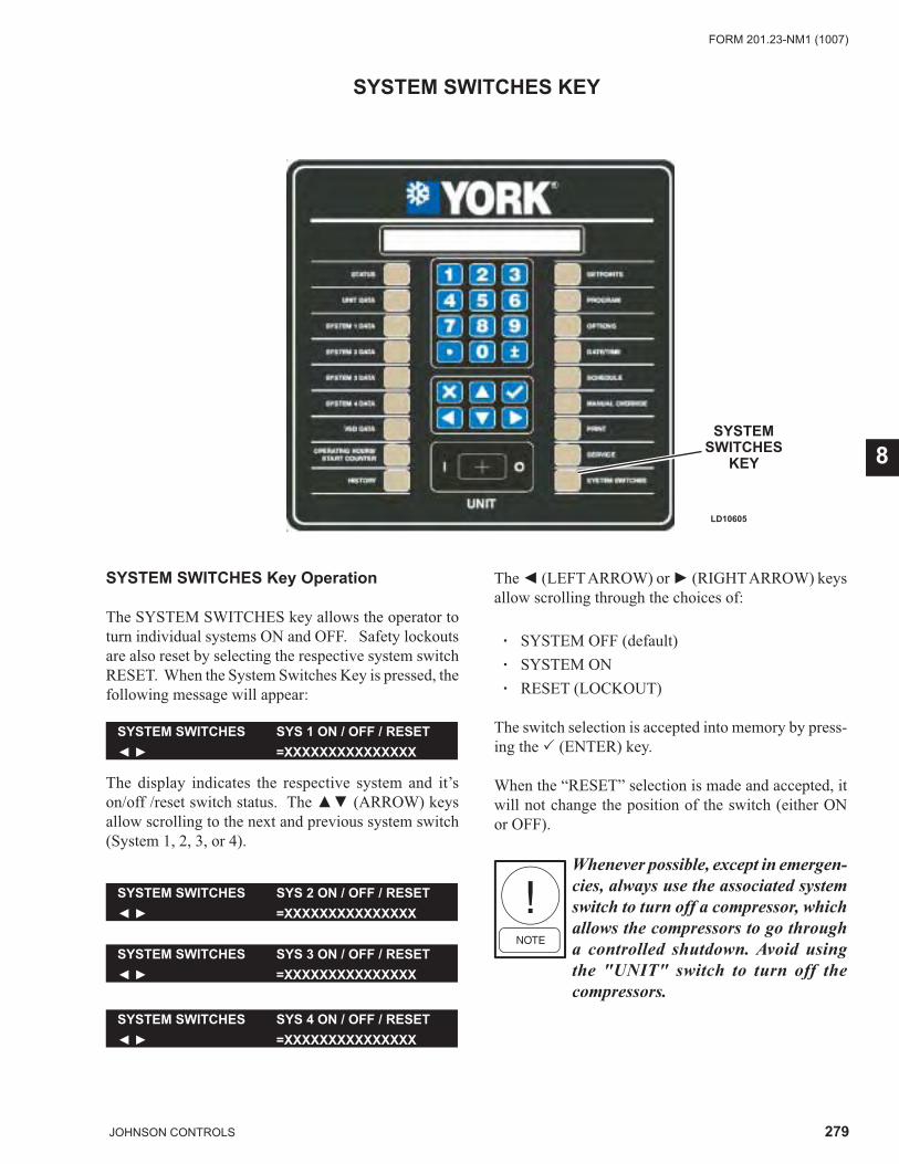
279JOHNSON CONTROLS
FORM 201.23-NM1 (1007)
8
LD10605
SYSTEM SWITCHES
KEY
SYSTEM SWITCHES KEY
SYSTEM SWITCHES Key Operation
The SYSTEM SWITCHES key allows the operator to turn individual systems ON and OFF. Safety lockouts are also reset by selecting the respective system switch RESET. When the System Switches Key is pressed, the following message will appear:
The display indicates the respective system and it’s on/off /reset switch status. The ▲▼ (ARROW) keys allow scrolling to the next and previous system switch (System 1, 2, 3, or 4).
SYSTEM SWITCHES SYS 1 ON / OFF / RESET◄ ► =XXXXXXXXXXXXXXX
SYSTEM SWITCHES SYS 2 ON / OFF / RESET◄ ► =XXXXXXXXXXXXXXX
SYSTEM SWITCHES SYS 3 ON / OFF / RESET◄ ► =XXXXXXXXXXXXXXX
SYSTEM SWITCHES SYS 4 ON / OFF / RESET◄ ► =XXXXXXXXXXXXXXX
The ◄ (LEFT ARROW) or ► (RIGHT ARROW) keys allow scrolling through the choices of:
· SYSTEM OFF (default) · SYSTEM ON · RESET (LOCKOUT)
The switch selection is accepted into memory by press-ing the � (ENTER) key.
When the “RESET” selection is made and accepted, it will not change the position of the switch (either ON or OFF).
Whenever possible, except in emergen-cies, always use the associated system switch to turn off a compressor, which allows the compressors to go through a controlled shutdown. Avoid using the "UNIT" switch to turn off the compressors.
280 JOHNSON CONTROLS
FORM 201.23-NM1 (1007)MICRO PANEL
SERIAL NUMBER PROGRAMMING
When changing a Chiller Control Board, a Chiller Control Board EPROM, or if a situation occurs where a chiller is not programmed from the factory, the chiller serial number will need to be programmed into the chiller. The serial number is the actual serial number displayed on the unit Data Plate. The serial number will be in a format similar to RABM000000, where the fi rst 4 characters are letters and the next 6 are numbers. The lack of a serial number programmed into the panel will not prevent a chiller from operating, but a High IPLV chiller will only operate in the Standard IPLV mode. The STATUS display will inform the operator a serial number problem exists by displaying the following message:
If the following message appears, immediately contact YORK Product Technical Support. The appearance of this message may also mean the chiller has lost impor-tant factory programmed information and may need to be reprogrammed. Additional STATUS messages can be viewed by pressing the STATUS key repetitively to enable the technician to view any other messages that may be preventing the chiller from operating.
Changing the programming of this feature requires the date and time to be set on the chiller prior to program-ming. The password is also time sensi-tive and must be used the same day it is received.
YORK Product Technical Support will provide a factory password to allow programming the serial number into the chiller. You will need to supply Factory Technical Support with the version of the Chiller Control Board EPROM. The version will be written on the EPROM label and typically will be in the format Version C.ACS.XX.XX.
After obtaining the password, the following steps will need to be followed to input the serial number. As the serial number is input, the characters keyed in will ap-pear in the display indicating the panel has recognized the entry.
UNIT WARNING: INVALID SERIAL NUMBERENTER UNIT SERIAL NUMBER
First press the SERVICE Key. The following message will appear:
SERVICE MODE XXXXXPRESS ENTER KEY TO CONTINUE
Key in the 5 digit alphanumeric password provided by Product Technical Support and press the � (ENTER) key. The following display will appear:
S/N ENTRY UNIT SERIAL NUMBER POS 1◄ ► X
S/N ENTRY UNIT SERIAL NUMBER POS 2◄ ► XX
Key in the fi rst letter (A through Z) of the serial num-ber using the ◄ and ► (ARROW) keys and press the � (ENTER) key. Press the ▼(DOWN ARROW) key to scroll to position 2 and the following message will appear:
Key in the second letter (A through N) of the serial number using the ◄ and ► (ARROW) keys and press the � (ENTER) key. Press the ▼(DOWN ARROW) key to scroll to position 3 and the following message will appear:
S/N ENTRY UNIT SERIAL NUMBER POS 3◄ ► XXX
Key in the third letter (A through Z) of the serial num-ber using the ◄ and ► (ARROW) keys and press the � (ENTER) key. Press the ▼(DOWN ARROW) key to scroll to position 4 and the following message will appear:
S/N ENTRY UNIT SERIAL NUMBER POS 4◄ ► XXXX
Key in the fourth letter (A through Z) of the serial number using the ◄ and ► (ARROW) keys and press the � (ENTER) key. Press the ▼(DOWN ARROW) key to scroll to positions 5-7 and the following message will appear:
S/N ENTRY UNIT S/N = YYYY XXX ZZZUNIT SERIAL NUMBER POS 5-7 = XXX
281JOHNSON CONTROLS
FORM 201.23-NM1 (1007)
8
At this point, the letters entered for the YYYY inputs should now appear in the top line of the display and should match the fi rst 4 characters of the serial number on the unit Data Plate. The next three digits of the serial number should now be keyed in. Press the � (ENTER) key to store the input. Press the ▼ (DOWN ARROW) key to scroll to positions 8-10 and the following mes-sage will appear:
SERIAL NUMBER PROGRAMMING (CON'T)
At this point, the letters entered for the YYYY and XXX inputs should now appear in the top line of the display and should match the fi rst 7 characters of the serial number on the unit Data Plate. The next three digits of the serial number should now be keyed in. Press the � (ENTER) key to store the input. The full serial number should now be displayed across the top of the display and the cursor should disappear.
Press the STATUS key to go to the next STATUS display to determine if additional Status messages are preventing the chiller from operating.
S/N ENTRY UNIT S/N = YYYY XXX ZZZUNIT SERIAL NUMBER POS 8-10 = XXX
282 JOHNSON CONTROLS
FORM 201.23-NM1 (1007)MICRO PANEL
ENABLING OPTIMIZED HIGH IPLV MODE
When changing a Chiller Control Board, a Chiller Con-trol Board EPROM, or if a situation occurs where a chill-er is not programmed from the factory, the chiller will not be capable of operating High IPLV mode. The serial number of the unit will fi rst need to be programmed into the panel, if the Invalid Serial Number display appears (See Page 281). The Invalid Serial Number message will override the Optimized Effi ciency Disabled mes-sage. If the chiller was purchased with the High IPLV Option and does not have the High IPLV mode enabled, it will not prevent the chiller from operating, but the chiller will only operate in the Standard IPLV mode. Additional STATUS messages can be viewed by press-ing the STATUS key repetitively to enable the technician to view any other messages that may be preventing the chiller from operating.
Changing the programming of this feature requires the date and time to be set on the chiller prior to program-ming the password. The password is also time sensitive and must be used “immediately” when it is received.
The STATUS display will inform the operator when a HIGH IPLV chiller is operating with the High IPLV mode disabled by displaying the following STATUS message:
If the message above appears, immediately contact YORK Product Technical Support or YORK ES Com-mercial for a password to enable the High IPLV mode. You will need to provide YORK Product Technical Support or YORK ES Commercial with the Unit Serial Number located on the chiller nameplate. The date and time will also need to be current on the chiller, and will need to be provided to YORK Product Technical Sup-port or YORK ES Commercial. It is essential YORK Product Technical Support or, YORK ES Commercial is aware of the “local” time to allow adjustments for time differences from Eastern Standard Time.
After obtaining the password, the fol-lowing steps will need to be carried out “immediately” to input the serial num-ber. If the password is not immediately input, the panel will not accept it.
UNIT WARING: OPTIMZED EFFICIENCYDISABLED - CONTACT YORK REPRESENATIVE
To enable HIGH IPLV Mode, fi rst press the SERVICE Key. The following message will appear:
Key in the 6 digit alphanumeric password provided by YORK Technical Support or YORK ES Commercial and press the � (ENTER) key. The following display will appear:
IPLV OPTIMZED EFFICIENCY CONTROL◄ ► XXXXXXXXXXXXXXXXXXXXXXXXX
When the Optimized (High IPLV) is enabled, the display will indicate, “ENABLED”. When not enabled, the display will indicate, “DISABLED”. Use the ◄ and ► (ARROW) keys to enable/disable and press the � (ENTER) key to store the selection.
SERVICE MODE XXXXXPRESS ENTER KEY TO CONTINUE
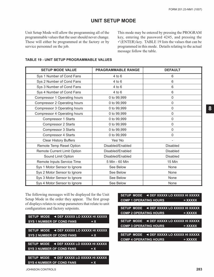
283JOHNSON CONTROLS
FORM 201.23-NM1 (1007)
8
UNIT SETUP MODE
Unit Setup Mode will allow the programming all of the programmable values that the user should never change. These will either be programmed at the factory or by service personnel on the job.
TABLE 19 - UNIT SETUP PROGRAMMABLE VALUES
SETUP MODE VALUE PRAGRAMMABLE RANGE DEFAULT
Sys 1 Number of Cond Fans 4 to 6 6Sys 2 Number of Cond Fans 4 to 6 6Sys 3 Number of Cond Fans 4 to 6 6Sys 4 Number of Cond Fans 4 to 6 6
Compressor 1 Operating hours 0 to 99,999 0Compressor 2 Operating hours 0 to 99,999 0Compressor 3 Operating hours 0 to 99,999 0Compressor 4 Operating hours 0 to 99,999 0
Compressor 1 Starts 0 to 99,999 0Compressor 2 Starts 0 to 99,999 0Compressor 3 Starts 0 to 99,999 0Compressor 4 Starts 0 to 99,999 0Clear History Buffers Yes/ No -
Remote Temp Reset Option Disabled/Enabled DisabledRemote Current Limit Option Disabled/Enabled Disabled
Sound Limit Option Disabled/Enabled DisabledRemote Inputs Service Time 5 Min - 60 Min 15 MinSys 1 Motor Sensor to Ignore See Below NoneSys 2 Motor Sensor to Ignore See Below NoneSys 3 Motor Sensor to Ignore See Below NoneSys 4 Motor Sensor to Ignore See Below None
The following messages will be displayed for the Unit Setup Mode in the order they appear. The fi rst group of displays relates to setup parameters that relate to unit confi guration and factory setpoints.
SETUP MODE ◄ DEF XXXXX LO XXXXX HI XXXXXSYS 1 NUMBER OF COND FANS = X
SETUP MODE ◄ DEF XXXXX LO XXXXX HI XXXXXSYS 2 NUMBER OF COND FANS = X
SETUP MODE ◄ DEF XXXXX LO XXXXX HI XXXXXSYS 3 NUMBER OF COND FANS = X
SETUP MODE ◄ DEF XXXXX LO XXXXX HI XXXXXSYS 4 NUMBER OF COND FANS = X
SETUP MODE ◄ DEF XXXXX LO XXXXX HI XXXXXCOMP 1 OPERATING HOURS = XXXXX
SETUP MODE ◄ DEF XXXXX LO XXXXX HI XXXXXCOMP 2 OPERATING HOURS = XXXXX
SETUP MODE ◄ DEF XXXXX LO XXXXX HI XXXXXCOMP 3 OPERATING HOURS = XXXXX
SETUP MODE ◄ DEF XXXXX LO XXXXX HI XXXXXCOMP 4 OPERATING HOURS = XXXXX
This mode may be entered by pressing the PROGRAM key, entering the password 4245, and pressing the �(ENTER) key. TABLE 19 lists the values that can be programmed in this mode. Details relating to the actual message follow the table.
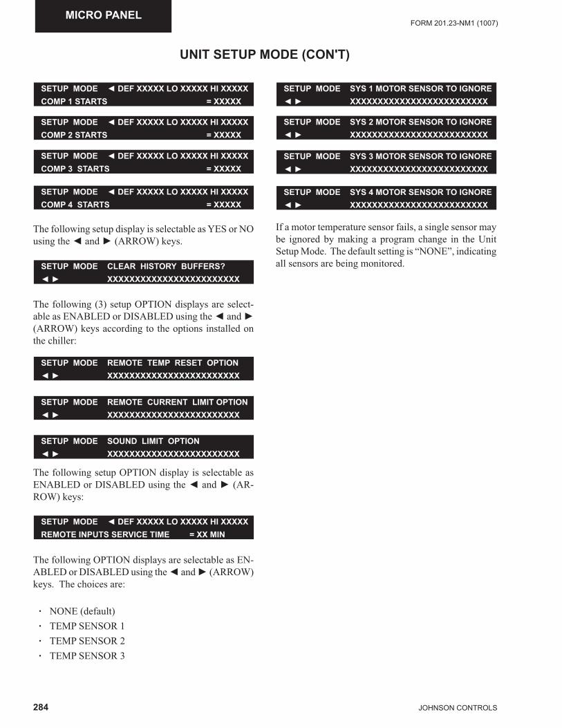
284 JOHNSON CONTROLS
FORM 201.23-NM1 (1007)MICRO PANEL
UNIT SETUP MODE (CON'T)
SETUP MODE ◄ DEF XXXXX LO XXXXX HI XXXXXCOMP 1 STARTS = XXXXX
SETUP MODE ◄ DEF XXXXX LO XXXXX HI XXXXXCOMP 2 STARTS = XXXXX
SETUP MODE ◄ DEF XXXXX LO XXXXX HI XXXXXCOMP 3 STARTS = XXXXX
SETUP MODE ◄ DEF XXXXX LO XXXXX HI XXXXXCOMP 4 STARTS = XXXXX
The following setup display is selectable as YES or NO using the ◄ and ► (ARROW) keys.
The following (3) setup OPTION displays are select-able as ENABLED or DISABLED using the ◄ and ► (ARROW) keys according to the options installed on the chiller:
SETUP MODE CLEAR HISTORY BUFFERS?◄ ► XXXXXXXXXXXXXXXXXXXXXXXX
SETUP MODE REMOTE TEMP RESET OPTION◄ ► XXXXXXXXXXXXXXXXXXXXXXXX
SETUP MODE REMOTE CURRENT LIMIT OPTION◄ ► XXXXXXXXXXXXXXXXXXXXXXXX
SETUP MODE SOUND LIMIT OPTION◄ ► XXXXXXXXXXXXXXXXXXXXXXXX
The following setup OPTION display is selectable as ENABLED or DISABLED using the ◄ and ► (AR-ROW) keys:
SETUP MODE ◄ DEF XXXXX LO XXXXX HI XXXXXREMOTE INPUTS SERVICE TIME = XX MIN
The following OPTION displays are selectable as EN-ABLED or DISABLED using the ◄ and ► (ARROW) keys. The choices are:
· NONE (default) · TEMP SENSOR 1 · TEMP SENSOR 2 · TEMP SENSOR 3
If a motor temperature sensor fails, a single sensor may be ignored by making a program change in the Unit Setup Mode. The default setting is “NONE”, indicating all sensors are being monitored.
SETUP MODE SYS 1 MOTOR SENSOR TO IGNORE◄ ► XXXXXXXXXXXXXXXXXXXXXXXXX
SETUP MODE SYS 2 MOTOR SENSOR TO IGNORE◄ ► XXXXXXXXXXXXXXXXXXXXXXXXX
SETUP MODE SYS 3 MOTOR SENSOR TO IGNORE◄ ► XXXXXXXXXXXXXXXXXXXXXXXXX
SETUP MODE SYS 4 MOTOR SENSOR TO IGNORE◄ ► XXXXXXXXXXXXXXXXXXXXXXXXX
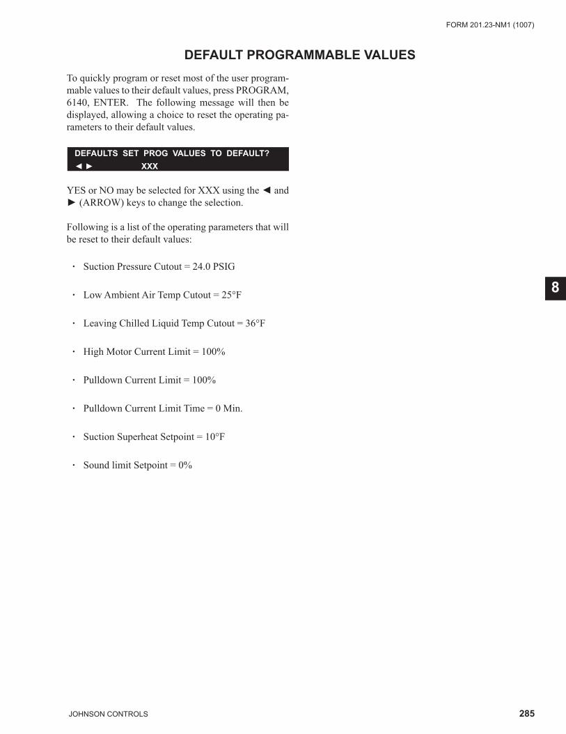
285JOHNSON CONTROLS
FORM 201.23-NM1 (1007)
8
DEFAULT PROGRAMMABLE VALUESTo quickly program or reset most of the user program-mable values to their default values, press PROGRAM, 6140, ENTER. The following message will then be displayed, allowing a choice to reset the operating pa-rameters to their default values.
YES or NO may be selected for XXX using the ◄ and ► (ARROW) keys to change the selection.
Following is a list of the operating parameters that will be reset to their default values:
· Suction Pressure Cutout = 24.0 PSIG
· Low Ambient Air Temp Cutout = 25°F
· Leaving Chilled Liquid Temp Cutout = 36°F
· High Motor Current Limit = 100%
· Pulldown Current Limit = 100%
· Pulldown Current Limit Time = 0 Min.
· Suction Superheat Setpoint = 10°F
· Sound limit Setpoint = 0%
DEFAULTS SET PROG VALUES TO DEFAULT?◄ ► XXX
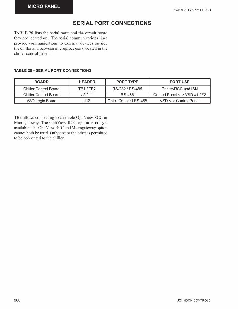
286 JOHNSON CONTROLS
FORM 201.23-NM1 (1007)MICRO PANEL
SERIAL PORT CONNECTIONSTABLE 20 lists the serial ports and the circuit board they are located on. The serial communications lines provide communications to external devices outside the chiller and between microprocessors located in the chiller control panel.
TABLE 20 - SERIAL PORT CONNECTIONS
BOARD HEADER PORT TYPE PORT USE
Chiller Control Board TB1 / TB2 RS-232 / RS-485 Printer/RCC and ISNChiller Control Board J2 / J1 RS-485 Control Panel <-> VSD #1 / #2
VSD Logic Board J12 Opto- Coupled RS-485 VSD <-> Control Panel
TB2 allows connecting to a remote OptiView RCC or Microgateway. The OptiView RCC option is not yet available. The OptiView RCC and Microgateway option cannot both be used. Only one or the other is permitted to be connected to the chiller.
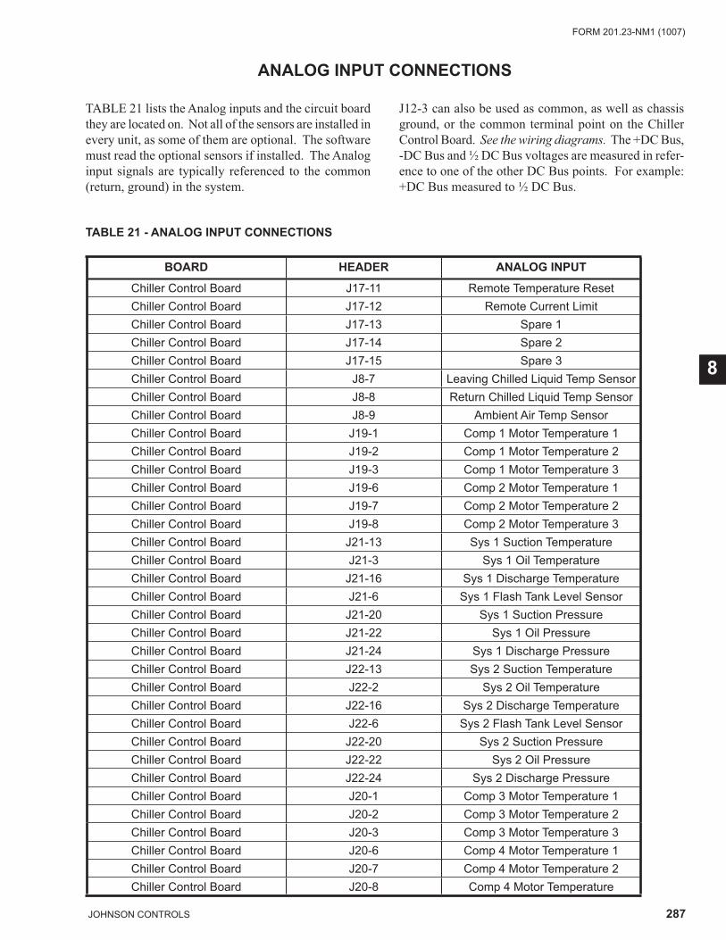
287JOHNSON CONTROLS
FORM 201.23-NM1 (1007)
8
ANALOG INPUT CONNECTIONS
TABLE 21 lists the Analog inputs and the circuit board they are located on. Not all of the sensors are installed in every unit, as some of them are optional. The software must read the optional sensors if installed. The Analog input signals are typically referenced to the common (return, ground) in the system.
J12-3 can also be used as common, as well as chassis ground, or the common terminal point on the Chiller Control Board. See the wiring diagrams. The +DC Bus, -DC Bus and ½ DC Bus voltages are measured in refer-ence to one of the other DC Bus points. For example: +DC Bus measured to ½ DC Bus.
TABLE 21 - ANALOG INPUT CONNECTIONS
BOARD HEADER ANALOG INPUT
Chiller Control Board J17-11 Remote Temperature ResetChiller Control Board J17-12 Remote Current LimitChiller Control Board J17-13 Spare 1 Chiller Control Board J17-14 Spare 2Chiller Control Board J17-15 Spare 3Chiller Control Board J8-7 Leaving Chilled Liquid Temp SensorChiller Control Board J8-8 Return Chilled Liquid Temp SensorChiller Control Board J8-9 Ambient Air Temp SensorChiller Control Board J19-1 Comp 1 Motor Temperature 1Chiller Control Board J19-2 Comp 1 Motor Temperature 2Chiller Control Board J19-3 Comp 1 Motor Temperature 3Chiller Control Board J19-6 Comp 2 Motor Temperature 1Chiller Control Board J19-7 Comp 2 Motor Temperature 2Chiller Control Board J19-8 Comp 2 Motor Temperature 3Chiller Control Board J21-13 Sys 1 Suction TemperatureChiller Control Board J21-3 Sys 1 Oil TemperatureChiller Control Board J21-16 Sys 1 Discharge TemperatureChiller Control Board J21-6 Sys 1 Flash Tank Level SensorChiller Control Board J21-20 Sys 1 Suction PressureChiller Control Board J21-22 Sys 1 Oil PressureChiller Control Board J21-24 Sys 1 Discharge PressureChiller Control Board J22-13 Sys 2 Suction TemperatureChiller Control Board J22-2 Sys 2 Oil Temperature Chiller Control Board J22-16 Sys 2 Discharge TemperatureChiller Control Board J22-6 Sys 2 Flash Tank Level SensorChiller Control Board J22-20 Sys 2 Suction PressureChiller Control Board J22-22 Sys 2 Oil PressureChiller Control Board J22-24 Sys 2 Discharge PressureChiller Control Board J20-1 Comp 3 Motor Temperature 1Chiller Control Board J20-2 Comp 3 Motor Temperature 2Chiller Control Board J20-3 Comp 3 Motor Temperature 3Chiller Control Board J20-6 Comp 4 Motor Temperature 1Chiller Control Board J20-7 Comp 4 Motor Temperature 2Chiller Control Board J20-8 Comp 4 Motor Temperature
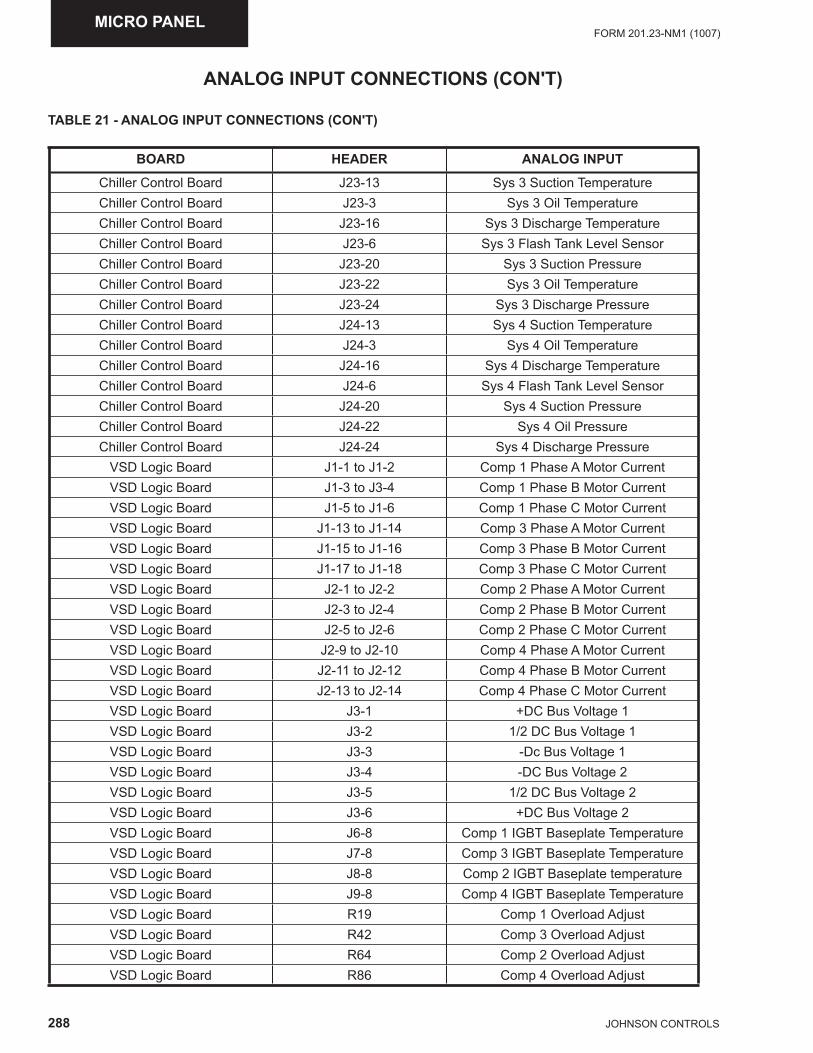
288 JOHNSON CONTROLS
FORM 201.23-NM1 (1007)MICRO PANEL
ANALOG INPUT CONNECTIONS (CON'T)
TABLE 21 - ANALOG INPUT CONNECTIONS (CON'T)
BOARD HEADER ANALOG INPUT
Chiller Control Board J23-13 Sys 3 Suction TemperatureChiller Control Board J23-3 Sys 3 Oil TemperatureChiller Control Board J23-16 Sys 3 Discharge TemperatureChiller Control Board J23-6 Sys 3 Flash Tank Level SensorChiller Control Board J23-20 Sys 3 Suction PressureChiller Control Board J23-22 Sys 3 Oil TemperatureChiller Control Board J23-24 Sys 3 Discharge PressureChiller Control Board J24-13 Sys 4 Suction TemperatureChiller Control Board J24-3 Sys 4 Oil TemperatureChiller Control Board J24-16 Sys 4 Discharge TemperatureChiller Control Board J24-6 Sys 4 Flash Tank Level SensorChiller Control Board J24-20 Sys 4 Suction PressureChiller Control Board J24-22 Sys 4 Oil PressureChiller Control Board J24-24 Sys 4 Discharge Pressure
VSD Logic Board J1-1 to J1-2 Comp 1 Phase A Motor CurrentVSD Logic Board J1-3 to J3-4 Comp 1 Phase B Motor CurrentVSD Logic Board J1-5 to J1-6 Comp 1 Phase C Motor CurrentVSD Logic Board J1-13 to J1-14 Comp 3 Phase A Motor CurrentVSD Logic Board J1-15 to J1-16 Comp 3 Phase B Motor CurrentVSD Logic Board J1-17 to J1-18 Comp 3 Phase C Motor CurrentVSD Logic Board J2-1 to J2-2 Comp 2 Phase A Motor CurrentVSD Logic Board J2-3 to J2-4 Comp 2 Phase B Motor CurrentVSD Logic Board J2-5 to J2-6 Comp 2 Phase C Motor CurrentVSD Logic Board J2-9 to J2-10 Comp 4 Phase A Motor CurrentVSD Logic Board J2-11 to J2-12 Comp 4 Phase B Motor CurrentVSD Logic Board J2-13 to J2-14 Comp 4 Phase C Motor CurrentVSD Logic Board J3-1 +DC Bus Voltage 1VSD Logic Board J3-2 1/2 DC Bus Voltage 1VSD Logic Board J3-3 -Dc Bus Voltage 1 VSD Logic Board J3-4 -DC Bus Voltage 2VSD Logic Board J3-5 1/2 DC Bus Voltage 2VSD Logic Board J3-6 +DC Bus Voltage 2VSD Logic Board J6-8 Comp 1 IGBT Baseplate TemperatureVSD Logic Board J7-8 Comp 3 IGBT Baseplate TemperatureVSD Logic Board J8-8 Comp 2 IGBT Baseplate temperatureVSD Logic Board J9-8 Comp 4 IGBT Baseplate TemperatureVSD Logic Board R19 Comp 1 Overload AdjustVSD Logic Board R42 Comp 3 Overload AdjustVSD Logic Board R64 Comp 2 Overload AdjustVSD Logic Board R86 Comp 4 Overload Adjust
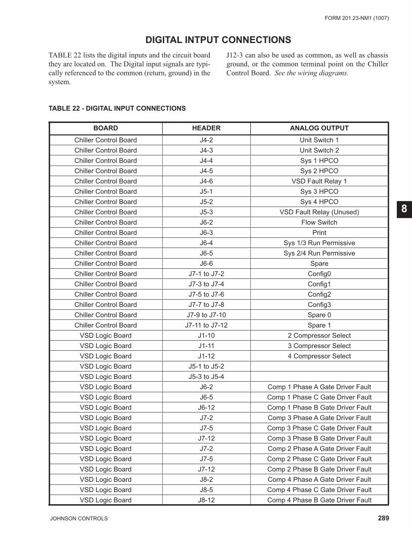
289JOHNSON CONTROLS
FORM 201.23-NM1 (1007)
8
TABLE 22 - DIGITAL INPUT CONNECTIONS
BOARD HEADER ANALOG OUTPUT
Chiller Control Board J4-2 Unit Switch 1Chiller Control Board J4-3 Unit Switch 2Chiller Control Board J4-4 Sys 1 HPCOChiller Control Board J4-5 Sys 2 HPCOChiller Control Board J4-6 VSD Fault Relay 1Chiller Control Board J5-1 Sys 3 HPCOChiller Control Board J5-2 Sys 4 HPCOChiller Control Board J5-3 VSD Fault Relay (Unused)Chiller Control Board J6-2 Flow SwitchChiller Control Board J6-3 PrintChiller Control Board J6-4 Sys 1/3 Run PermissiveChiller Control Board J6-5 Sys 2/4 Run PermissiveChiller Control Board J6-6 SpareChiller Control Board J7-1 to J7-2 Confi g0Chiller Control Board J7-3 to J7-4 Confi g1Chiller Control Board J7-5 to J7-6 Confi g2Chiller Control Board J7-7 to J7-8 Confi g3Chiller Control Board J7-9 to J7-10 Spare 0Chiller Control Board J7-11 to J7-12 Spare 1
VSD Logic Board J1-10 2 Compressor SelectVSD Logic Board J1-11 3 Compressor SelectVSD Logic Board J1-12 4 Compressor SelectVSD Logic Board J5-1 to J5-2VSD Logic Board J5-3 to J5-4VSD Logic Board J6-2 Comp 1 Phase A Gate Driver FaultVSD Logic Board J6-5 Comp 1 Phase C Gate Driver FaultVSD Logic Board J6-12 Comp 1 Phase B Gate Driver FaultVSD Logic Board J7-2 Comp 3 Phase A Gate Driver FaultVSD Logic Board J7-5 Comp 3 Phase C Gate Driver FaultVSD Logic Board J7-12 Comp 3 Phase B Gate Driver FaultVSD Logic Board J7-2 Comp 2 Phase A Gate Driver FaultVSD Logic Board J7-5 Comp 2 Phase C Gate Driver FaultVSD Logic Board J7-12 Comp 2 Phase B Gate Driver FaultVSD Logic Board J8-2 Comp 4 Phase A Gate Driver FaultVSD Logic Board J8-5 Comp 4 Phase C Gate Driver FaultVSD Logic Board J8-12 Comp 4 Phase B Gate Driver Fault
DIGITAL INTPUT CONNECTIONSTABLE 22 lists the digital inputs and the circuit board they are located on. The Digital input signals are typi-cally referenced to the common (return, ground) in the system.
J12-3 can also be used as common, as well as chassis ground, or the common terminal point on the Chiller Control Board. See the wiring diagrams.
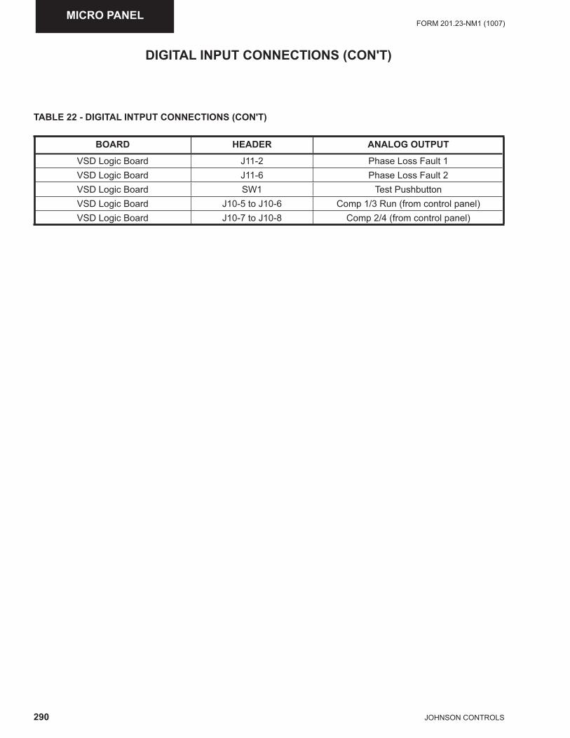
290 JOHNSON CONTROLS
FORM 201.23-NM1 (1007)MICRO PANEL
TABLE 22 - DIGITAL INTPUT CONNECTIONS (CON'T)
BOARD HEADER ANALOG OUTPUT
VSD Logic Board J11-2 Phase Loss Fault 1 VSD Logic Board J11-6 Phase Loss Fault 2VSD Logic Board SW1 Test PushbuttonVSD Logic Board J10-5 to J10-6 Comp 1/3 Run (from control panel)VSD Logic Board J10-7 to J10-8 Comp 2/4 (from control panel)
DIGITAL INPUT CONNECTIONS (CON'T)
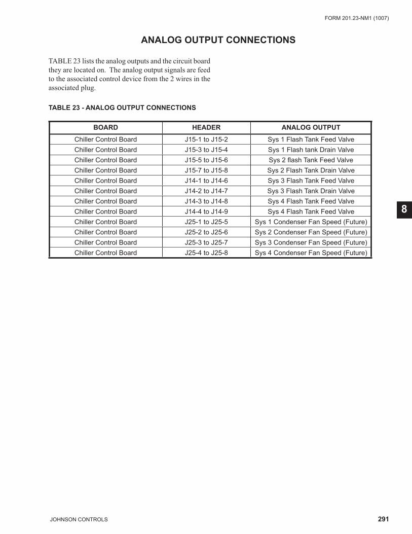
291JOHNSON CONTROLS
FORM 201.23-NM1 (1007)
8
ANALOG OUTPUT CONNECTIONS
TABLE 23 lists the analog outputs and the circuit board they are located on. The analog output signals are feed to the associated control device from the 2 wires in the associated plug.
TABLE 23 - ANALOG OUTPUT CONNECTIONS
BOARD HEADER ANALOG OUTPUT
Chiller Control Board J15-1 to J15-2 Sys 1 Flash Tank Feed ValveChiller Control Board J15-3 to J15-4 Sys 1 Flash tank Drain ValveChiller Control Board J15-5 to J15-6 Sys 2 fl ash Tank Feed ValveChiller Control Board J15-7 to J15-8 Sys 2 Flash Tank Drain ValveChiller Control Board J14-1 to J14-6 Sys 3 Flash Tank Feed ValveChiller Control Board J14-2 to J14-7 Sys 3 Flash Tank Drain ValveChiller Control Board J14-3 to J14-8 Sys 4 Flash Tank Feed ValveChiller Control Board J14-4 to J14-9 Sys 4 Flash Tank Feed ValveChiller Control Board J25-1 to J25-5 Sys 1 Condenser Fan Speed (Future)Chiller Control Board J25-2 to J25-6 Sys 2 Condenser Fan Speed (Future)Chiller Control Board J25-3 to J25-7 Sys 3 Condenser Fan Speed (Future)Chiller Control Board J25-4 to J25-8 Sys 4 Condenser Fan Speed (Future)
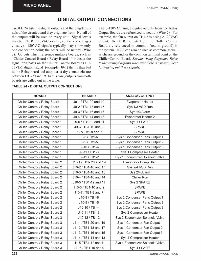
292 JOHNSON CONTROLS
FORM 201.23-NM1 (1007)MICRO PANEL
DIGITAL OUTPUT CONNECTIONS
TABLE 24 lists the digital outputs and the plug/termi-nals of the circuit board they originate from. Not all of the outputs will be used on every unit. Signal levels may be 12VDC, 120VAC, or a dry contact (no voltage) closure). 120VAC signals typically may show only one connection point; the other will be neutral (Wire 2). Outputs which reference multiple boards, such as “Chiller Control Board / Relay Board 1” indicate the signal originates on the Chiller Control Board as a 0-12VDC digital signal (example: J9-1) that is then fed to the Relay board and output as a dry contact closure between TB1-20 and 19. In this case, outputs from both boards are called out in the table.
The 0-120VAC single digital outputs from the Relay Output Boards are referenced to neutral (Wire 2). For example, the fan output on TB1-6 is a single 120VAC output. 0-12VDC outputs from the Chiller Control Board are referenced to common (return, ground) in the system. J12-3 can also be used as common, as well as chassis ground, or the common terminal point on the Chiller Control Board. See the wiring diagrams. Refer to the wiring diagrams whenever there is a requirement for tracing out these signals.
TABLE 24 - DIGITAL OUTPUT CONNECTIONS
BOARD HEADER ANALOG OUTPUT
Chiller Control / Relay Board 1 J9-1 / TB1-20 and 19 Evaporator HeaterChiller Control / Relay Board 1 J9-2 / TB1-18 and 17 Sys 1/3 VSD RunChiller Control / Relay Board 1 J9-3 / TB1-16 and 15 Sys 1/3 AlarmChiller Control / Relay Board 1 J9-4 / TB1-14 and 13 Evaporator Heater 2Chiller Control / Relay Board 1 J9-5 / TB1-12 and 11 Sys 1 SPAREChiller Control / Relay Board 1 J9-6 / TB1-10 and 9 SPAREChiller Control / Relay Board 1 J9-7/ TB1-8 and 7 SPAREChiller Control / Relay Board 1 J9-8 / TB1-6 Sys 1 Condenser Fans Output 1Chiller Control / Relay Board 1 J9-9 / TB1-5 Sys 1 Condenser Fans Output 2Chiller Control / Relay Board 1 J9-10 / TB1-4 Sys 1 Condenser Fans Output 3Chiller Control / Relay Board 1 J9-11 / TB1-3 Sys 1 Compressor HeaterChiller Control / Relay Board 1 J9-12 / TB1-2 Sys 1 Economizer Solenoid ValveChiller Control / Relay Board 2 J10-1 / TB1- 20 and 19 Evaporator Pump StartChiller Control / Relay Board 2 J10-2 / TB1-18 and 17 Sys 2/4 VSD RunChiller Control / Relay Board 2 J10-3 / TB1-18 and 15 Sys 2/4 AlarmChiller Control / Relay Board 2 J10-4 / TB1-16 and 14 Chiller RunChiller Control / Relay Board 2 J10-5 / TB1-12 and 11 Sys 2 SPAREChiller Control / Relay Board 2 J10-6 / TB1-10 and 9 SPAREChiller Control / Relay Board 2 J10-7 / TB1-8 and 7 SPAREChiller Control / Relay Board 2 J10-8 / TB1-6 Sys 2 Condenser Fans Output 1Chiller Control / Relay Board 2 J10-9 / TB1-5 Sys 2 Condenser Fans Output 2Chiller Control / Relay Board 2 J10-10 / TB1-4 Sys 2 Condenser Fans Output 3Chiller Control / Relay Board 2 J10-11 / TB1-3 Sys 2 Compressor HeaterChiller Control / Relay Board 3 J10-12 / TB1-2 Sys 2 Economizer Solenoid ValveChiller Control / Relay Board 3 J11-1 / TB1-20 and 19 Sys 4 Condenser Fan Output 1Chiller Control / Relay Board 3 J11-2 / TB1-18 and 17 Sys 4 Condenser Fan Output 2Chiller Control / Relay Board 3 J11-3 / TB1-16 and 15 Sys 4 Condenser Fan Output 3Chiller Control / Relay Board 3 J11-4 / TB1-14 and 13 Sys 4 Compressor HeaterChiller Control / Relay Board 3 J11-5 / TB1-12 and 11 Sys 4 Economizer Solenoid ValveChiller Control / Relay Board 3 J11-6 / TB1-10 and 9 Sys 4 SPARE
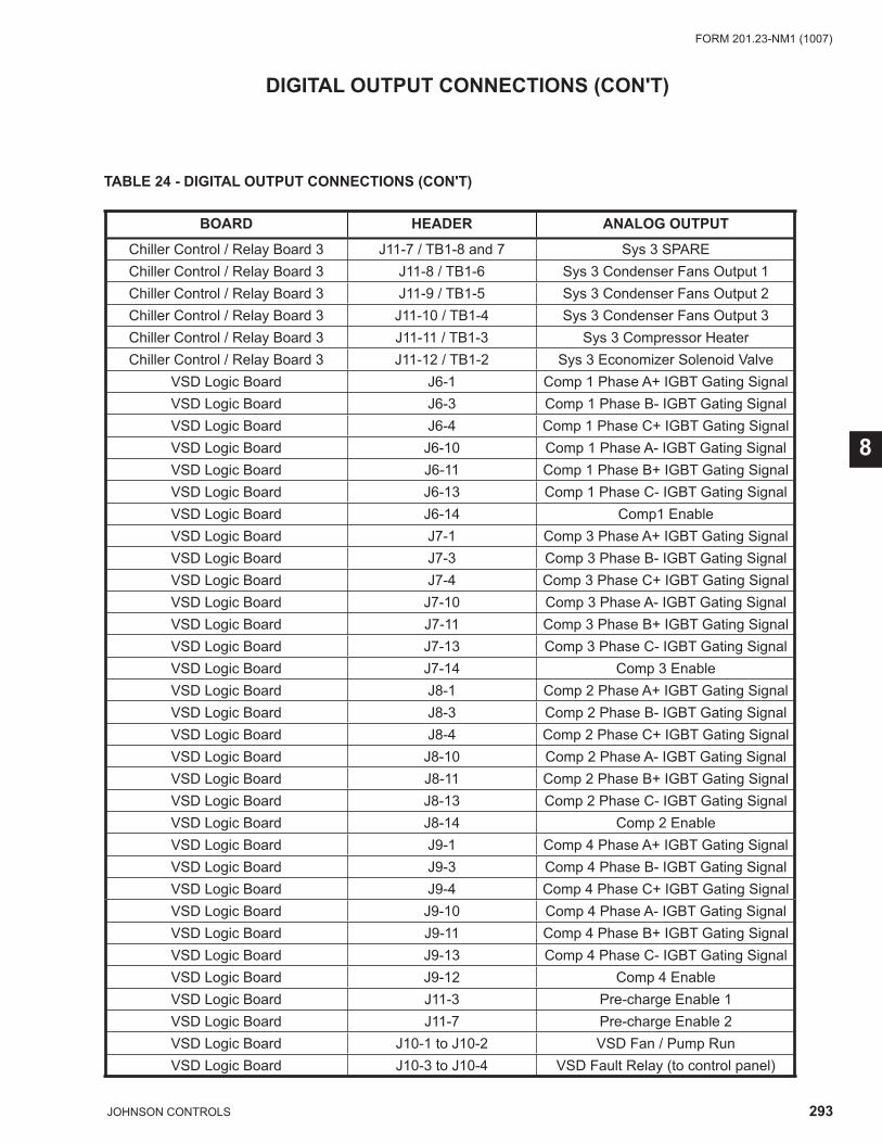
293JOHNSON CONTROLS
FORM 201.23-NM1 (1007)
8
TABLE 24 - DIGITAL OUTPUT CONNECTIONS (CON'T)
BOARD HEADER ANALOG OUTPUT
Chiller Control / Relay Board 3 J11-7 / TB1-8 and 7 Sys 3 SPAREChiller Control / Relay Board 3 J11-8 / TB1-6 Sys 3 Condenser Fans Output 1Chiller Control / Relay Board 3 J11-9 / TB1-5 Sys 3 Condenser Fans Output 2Chiller Control / Relay Board 3 J11-10 / TB1-4 Sys 3 Condenser Fans Output 3Chiller Control / Relay Board 3 J11-11 / TB1-3 Sys 3 Compressor HeaterChiller Control / Relay Board 3 J11-12 / TB1-2 Sys 3 Economizer Solenoid Valve
VSD Logic Board J6-1 Comp 1 Phase A+ IGBT Gating SignalVSD Logic Board J6-3 Comp 1 Phase B- IGBT Gating SignalVSD Logic Board J6-4 Comp 1 Phase C+ IGBT Gating SignalVSD Logic Board J6-10 Comp 1 Phase A- IGBT Gating SignalVSD Logic Board J6-11 Comp 1 Phase B+ IGBT Gating SignalVSD Logic Board J6-13 Comp 1 Phase C- IGBT Gating SignalVSD Logic Board J6-14 Comp1 EnableVSD Logic Board J7-1 Comp 3 Phase A+ IGBT Gating SignalVSD Logic Board J7-3 Comp 3 Phase B- IGBT Gating SignalVSD Logic Board J7-4 Comp 3 Phase C+ IGBT Gating SignalVSD Logic Board J7-10 Comp 3 Phase A- IGBT Gating SignalVSD Logic Board J7-11 Comp 3 Phase B+ IGBT Gating SignalVSD Logic Board J7-13 Comp 3 Phase C- IGBT Gating SignalVSD Logic Board J7-14 Comp 3 EnableVSD Logic Board J8-1 Comp 2 Phase A+ IGBT Gating SignalVSD Logic Board J8-3 Comp 2 Phase B- IGBT Gating SignalVSD Logic Board J8-4 Comp 2 Phase C+ IGBT Gating SignalVSD Logic Board J8-10 Comp 2 Phase A- IGBT Gating SignalVSD Logic Board J8-11 Comp 2 Phase B+ IGBT Gating SignalVSD Logic Board J8-13 Comp 2 Phase C- IGBT Gating SignalVSD Logic Board J8-14 Comp 2 EnableVSD Logic Board J9-1 Comp 4 Phase A+ IGBT Gating SignalVSD Logic Board J9-3 Comp 4 Phase B- IGBT Gating SignalVSD Logic Board J9-4 Comp 4 Phase C+ IGBT Gating SignalVSD Logic Board J9-10 Comp 4 Phase A- IGBT Gating SignalVSD Logic Board J9-11 Comp 4 Phase B+ IGBT Gating SignalVSD Logic Board J9-13 Comp 4 Phase C- IGBT Gating SignalVSD Logic Board J9-12 Comp 4 EnableVSD Logic Board J11-3 Pre-charge Enable 1 VSD Logic Board J11-7 Pre-charge Enable 2VSD Logic Board J10-1 to J10-2 VSD Fan / Pump RunVSD Logic Board J10-3 to J10-4 VSD Fault Relay (to control panel)
DIGITAL OUTPUT CONNECTIONS (CON'T)
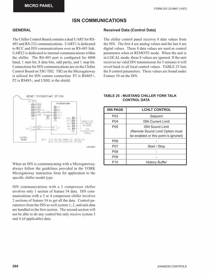
294 JOHNSON CONTROLS
FORM 201.23-NM1 (1007)MICRO PANEL
ISN COMMUNICATIONS
GENERAL
The Chiller Control Board contains a dual UART for RS-485 and RS-232 communications. UART1 is dedicated to RCC and ISN communications over an RS-485 link. UART2 is dedicated to internal communications within the chiller. The RS-485 port is confi gured for 4800 baud, 1 start bit, 8 data bits, odd parity, and 1 stop bit. Connections for ISN communications are on the Chiller Control Board on TB1/TB2. TB2 on the Microgateway is utilized for ISN comms connection. P3 is RS485+, P2 is RS485-, and USHL is the shield.
When an ISN is communicating with a Microgateway, always follow the guidelines provided in the YORK Microgateway instruction form for application to the specifi c chiller model type.
ISN communications with a 2 compressor chiller involves only 1 section of feature 54 data. ISN com-munications with a 3 or 4 compressor chiller involves 2 sections of feature 54 to get all the data. Control pa-rameters from the ISN as well system 1, 2, and unit data are handled in the fi rst section. The second section will not be able to do any control but only receive system 3 and 4 (if applicable) data.
Received Data (Control Data)
The chiller control panel receives 8 data values from the ISN. The fi rst 4 are analog values and the last 4 are digital values. These 8 data values are used as control parameters when in REMOTE mode. When the unit is in LOCAL mode, these 8 values are ignored. If the unit receives no valid ISN transmission for 5 minutes it will revert back to all local control values. TABLE 25 lists the 8 control parameters. These values are found under Feature 54 on the ISN.
TABLE 25 - MUSTANG CHILLER YORK TALK CONTROL DATA
ISN PAGE LCHLT CONTROL
P03 SetpointP04 ISN Current LimitP05 ISN Sound Limit
(Remote Sound Limit Option mustbe enabled or this point is ignored)
P06 -P07 Start / StopP08 -P09 -P10 History Buffer
LD10637
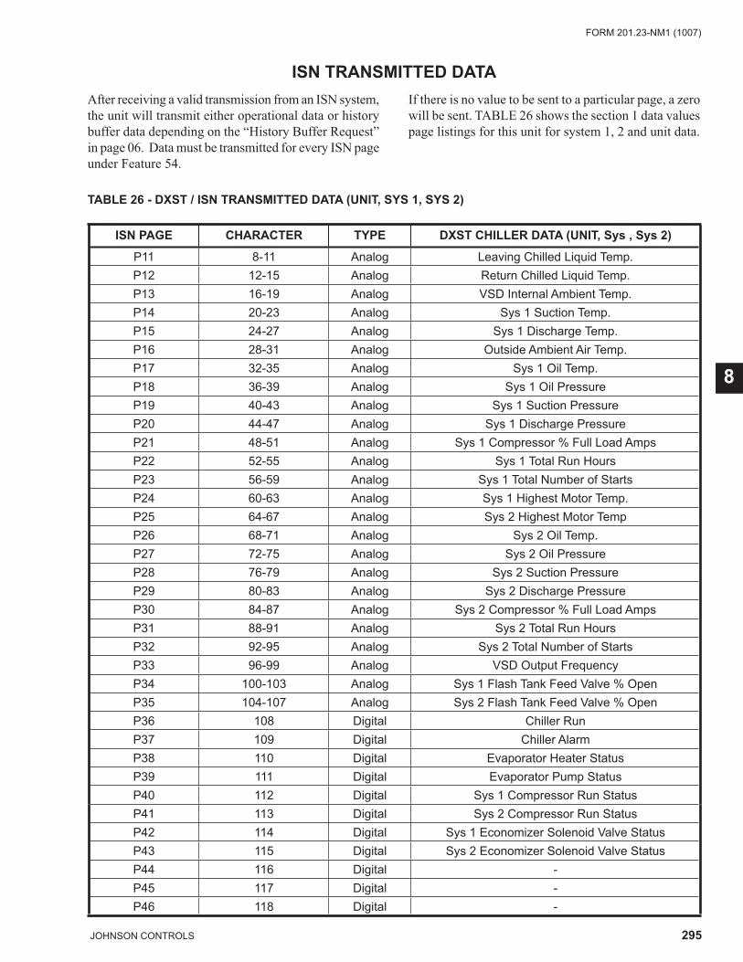
295JOHNSON CONTROLS
FORM 201.23-NM1 (1007)
8
ISN TRANSMITTED DATA
TABLE 26 - DXST / ISN TRANSMITTED DATA (UNIT, SYS 1, SYS 2)
ISN PAGE CHARACTER TYPE DXST CHILLER DATA (UNIT, Sys , Sys 2)
P11 8-11 Analog Leaving Chilled Liquid Temp.P12 12-15 Analog Return Chilled Liquid Temp.P13 16-19 Analog VSD Internal Ambient Temp.P14 20-23 Analog Sys 1 Suction Temp.P15 24-27 Analog Sys 1 Discharge Temp.P16 28-31 Analog Outside Ambient Air Temp.P17 32-35 Analog Sys 1 Oil Temp.P18 36-39 Analog Sys 1 Oil PressureP19 40-43 Analog Sys 1 Suction PressureP20 44-47 Analog Sys 1 Discharge PressureP21 48-51 Analog Sys 1 Compressor % Full Load AmpsP22 52-55 Analog Sys 1 Total Run HoursP23 56-59 Analog Sys 1 Total Number of StartsP24 60-63 Analog Sys 1 Highest Motor Temp.P25 64-67 Analog Sys 2 Highest Motor TempP26 68-71 Analog Sys 2 Oil Temp.P27 72-75 Analog Sys 2 Oil PressureP28 76-79 Analog Sys 2 Suction PressureP29 80-83 Analog Sys 2 Discharge PressureP30 84-87 Analog Sys 2 Compressor % Full Load Amps P31 88-91 Analog Sys 2 Total Run HoursP32 92-95 Analog Sys 2 Total Number of StartsP33 96-99 Analog VSD Output FrequencyP34 100-103 Analog Sys 1 Flash Tank Feed Valve % OpenP35 104-107 Analog Sys 2 Flash Tank Feed Valve % OpenP36 108 Digital Chiller RunP37 109 Digital Chiller AlarmP38 110 Digital Evaporator Heater StatusP39 111 Digital Evaporator Pump StatusP40 112 Digital Sys 1 Compressor Run StatusP41 113 Digital Sys 2 Compressor Run StatusP42 114 Digital Sys 1 Economizer Solenoid Valve StatusP43 115 Digital Sys 2 Economizer Solenoid Valve StatusP44 116 Digital -P45 117 Digital -P46 118 Digital -
After receiving a valid transmission from an ISN system, the unit will transmit either operational data or history buffer data depending on the “History Buffer Request” in page 06. Data must be transmitted for every ISN page under Feature 54.
If there is no value to be sent to a particular page, a zero will be sent. TABLE 26 shows the section 1 data values page listings for this unit for system 1, 2 and unit data.
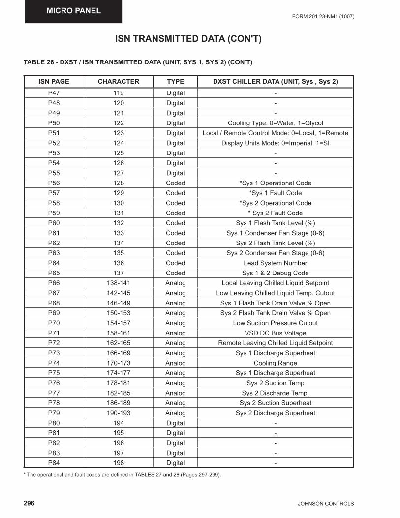
296 JOHNSON CONTROLS
FORM 201.23-NM1 (1007)MICRO PANEL
ISN TRANSMITTED DATA (CON'T)
TABLE 26 - DXST / ISN TRANSMITTED DATA (UNIT, SYS 1, SYS 2) (CON'T)
ISN PAGE CHARACTER TYPE DXST CHILLER DATA (UNIT, Sys , Sys 2)
P47 119 Digital -P48 120 Digital -P49 121 Digital -P50 122 Digital Cooling Type: 0=Water, 1=GlycolP51 123 Digital Local / Remote Control Mode: 0=Local, 1=RemoteP52 124 Digital Display Units Mode: 0=Imperial, 1=SIP53 125 Digital -P54 126 Digital -P55 127 Digital -P56 128 Coded *Sys 1 Operational CodeP57 129 Coded *Sys 1 Fault CodeP58 130 Coded *Sys 2 Operational CodeP59 131 Coded * Sys 2 Fault CodeP60 132 Coded Sys 1 Flash Tank Level (%)P61 133 Coded Sys 1 Condenser Fan Stage (0-6)P62 134 Coded Sys 2 Flash Tank Level (%)P63 135 Coded Sys 2 Condenser Fan Stage (0-6)P64 136 Coded Lead System NumberP65 137 Coded Sys 1 & 2 Debug CodeP66 138-141 Analog Local Leaving Chilled Liquid SetpointP67 142-145 Analog Low Leaving Chilled Liquid Temp. CutoutP68 146-149 Analog Sys 1 Flash Tank Drain Valve % OpenP69 150-153 Analog Sys 2 Flash Tank Drain Valve % OpenP70 154-157 Analog Low Suction Pressure CutoutP71 158-161 Analog VSD DC Bus VoltageP72 162-165 Analog Remote Leaving Chilled Liquid SetpointP73 166-169 Analog Sys 1 Discharge SuperheatP74 170-173 Analog Cooling RangeP75 174-177 Analog Sys 1 Discharge SuperheatP76 178-181 Analog Sys 2 Suction TempP77 182-185 Analog Sys 2 Discharge Temp.P78 186-189 Analog Sys 2 Suction SuperheatP79 190-193 Analog Sys 2 Discharge SuperheatP80 194 Digital -P81 195 Digital -P82 196 Digital -P83 197 Digital -P84 198 Digital -
* The operational and fault codes are defi ned in TABLES 27 and 28 (Pages 297-299).

297JOHNSON CONTROLS
FORM 201.23-NM1 (1007)
8
ISN FAULT AND INHIBIT CODES
TABLE 27 contains the fault and inhibit code with its associated meaning to be used for decoding ISN Op-erational and Fault Codes on ISN Pages 57 and 59 in TABLE 26.
The table also classifi es each fault/inhibit as a unit or system type and lists which board (Chiller Control Board (panel) or VSD Logic Board) generates the fault/inhibit.
TABLE 27 - FAULT AND INHIBIT CODES
CODE TYPE SOURCE FAULT or INHIBIT CODES
1 Unit Panel Low Ambient Temp.2 Unit Panel High Ambient Temp.3 Unit Panel Low Chilled Liquid Temp.4 Unit Panel SPARE 05 Unit Panel Low RTC Battery Voltage6 Unit Panel Invalid Number of Compressors Selected7 Unit Panel VSD Communications Failure8 Unit VSD Pre-charge Low DC Bus Voltage9 Unit VSD Pre-charge DC Bus Voltage Imbalance
10 Unit VSD High DC Bus Voltage11 Unit VSD Low DC Bus Voltage12 Unit VSD DC Bus Voltage Imbalance13 Unit VSD High VSD Ambient Temp.14 Unit VSD Single Phase Input15 Unit VSD VSD Power Supply Fault16 Unit VSD VSD Logic Board Fault17 Unit VSD Motor Current Overload (Hardware)18 Unit VSD CT Plug Fault19 Unit - SPARE 120 Unit - SPARE 221 Unit - SPARE 322 Unit - SPARE 423 Unit - SPARE 524 Unit - SPARE 6 25 Unit - SPARE 726 Unit - SPARE 827 System Panel High Discharge Pressure (Software)28 System Panel High Differential Oil Pressure29 System Panel Low Differential Oil Pressure30 System Panel Low Suction Pressure31 System Panel High Discharge Temp.32 System Panel High Oil Temp.33 System Panel Low Suction Superheat34 System Panel Sensor Failure35 System Panel Low Motor Current36 System Panel High Motor Temperature
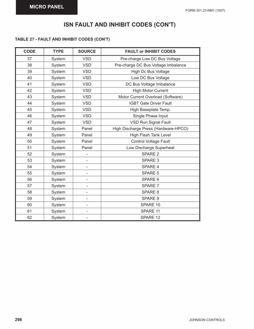
298 JOHNSON CONTROLS
FORM 201.23-NM1 (1007)MICRO PANEL
ISN FAULT AND INHIBIT CODES (CON'T)
TABLE 27 - FAULT AND INHIBIT CODES (CON'T)
CODE TYPE SOURCE FAULT or INHIBIT CODES
37 System VSD Pre-charge Low DC Bus Voltage38 System VSD Pre-charge DC Bus Voltage Imbalance39 System VSD High Dc Bus Voltage40 System VSD Low DC Bus Voltage41 System VSD DC Bus Voltage Imbalance42 System VSD High Motor Current43 System VSD Motor Current Overload (Software)44 System VSD IGBT Gate Driver Fault45 System VSD High Baseplate Temp.46 System VSD Single Phase Input47 System VSD VSD Run Signal Fault48 System Panel High Discharge Press (Hardware-HPCO)49 System Panel High Flash Tank Level50 System Panel Control Voltage Fault51 System Panel Low Discharge Superheat52 System - SPARE 253 System - SPARE 354 System - SPARE 455 System - SPARE 556 System - SPARE 657 System - SPARE 758 System - SPARE 859 System - SPARE 960 System - SPARE 1061 System - SPARE 1162 System - SPARE 12
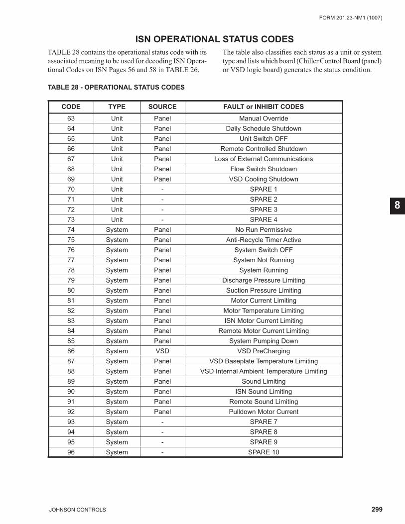
299JOHNSON CONTROLS
FORM 201.23-NM1 (1007)
8
ISN OPERATIONAL STATUS CODESTABLE 28 contains the operational status code with its associated meaning to be used for decoding ISN Opera-tional Codes on ISN Pages 56 and 58 in TABLE 26.
The table also classifi es each status as a unit or system type and lists which board (Chiller Control Board (panel) or VSD logic board) generates the status condition.
TABLE 28 - OPERATIONAL STATUS CODES
CODE TYPE SOURCE FAULT or INHIBIT CODES
63 Unit Panel Manual Override64 Unit Panel Daily Schedule Shutdown65 Unit Panel Unit Switch OFF66 Unit Panel Remote Controlled Shutdown67 Unit Panel Loss of External Communications68 Unit Panel Flow Switch Shutdown69 Unit Panel VSD Cooling Shutdown70 Unit - SPARE 1 71 Unit - SPARE 272 Unit - SPARE 3 73 Unit - SPARE 474 System Panel No Run Permissive75 System Panel Anti-Recycle Timer Active76 System Panel System Switch OFF77 System Panel System Not Running78 System Panel System Running79 System Panel Discharge Pressure Limiting80 System Panel Suction Pressure Limiting81 System Panel Motor Current Limiting82 System Panel Motor Temperature Limiting83 System Panel ISN Motor Current Limiting84 System Panel Remote Motor Current Limiting85 System Panel System Pumping Down86 System VSD VSD PreCharging87 System Panel VSD Baseplate Temperature Limiting88 System Panel VSD Internal Ambient Temperature Limiting89 System Panel Sound Limiting90 System Panel ISN Sound Limiting91 System Panel Remote Sound Limiting92 System Panel Pulldown Motor Current93 System - SPARE 794 System - SPARE 895 System - SPARE 996 System - SPARE 10
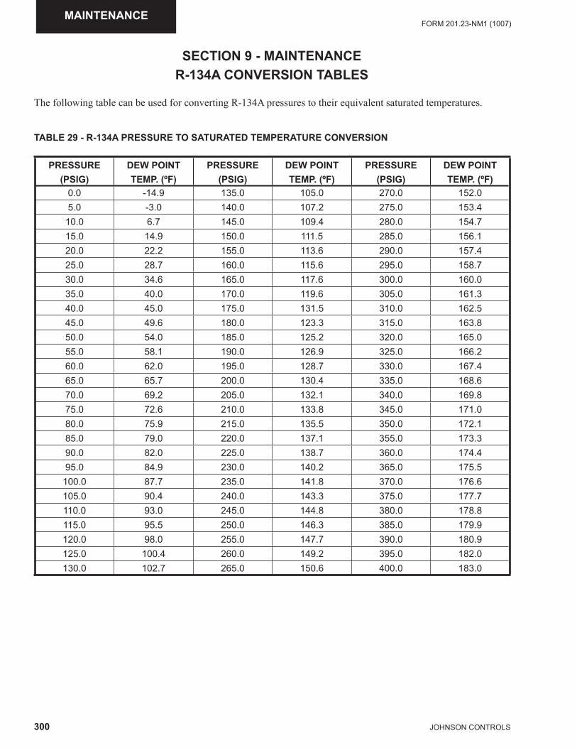
300 JOHNSON CONTROLS
FORM 201.23-NM1 (1007)MAINTENANCE
R-134A CONVERSION TABLES
The following table can be used for converting R-134A pressures to their equivalent saturated temperatures.
TABLE 29 - R-134A PRESSURE TO SATURATED TEMPERATURE CONVERSION
PRESSURE(PSIG)
DEW POINT TEMP. (ºF)
PRESSURE(PSIG)
DEW POINT TEMP. (ºF)
PRESSURE(PSIG)
DEW POINT TEMP. (ºF)
0.0 -14.9 135.0 105.0 270.0 152.05.0 -3.0 140.0 107.2 275.0 153.4
10.0 6.7 145.0 109.4 280.0 154.715.0 14.9 150.0 111.5 285.0 156.120.0 22.2 155.0 113.6 290.0 157.425.0 28.7 160.0 115.6 295.0 158.730.0 34.6 165.0 117.6 300.0 160.035.0 40.0 170.0 119.6 305.0 161.340.0 45.0 175.0 131.5 310.0 162.545.0 49.6 180.0 123.3 315.0 163.850.0 54.0 185.0 125.2 320.0 165.055.0 58.1 190.0 126.9 325.0 166.260.0 62.0 195.0 128.7 330.0 167.465.0 65.7 200.0 130.4 335.0 168.670.0 69.2 205.0 132.1 340.0 169.875.0 72.6 210.0 133.8 345.0 171.080.0 75.9 215.0 135.5 350.0 172.185.0 79.0 220.0 137.1 355.0 173.390.0 82.0 225.0 138.7 360.0 174.495.0 84.9 230.0 140.2 365.0 175.5
100.0 87.7 235.0 141.8 370.0 176.6105.0 90.4 240.0 143.3 375.0 177.7110.0 93.0 245.0 144.8 380.0 178.8115.0 95.5 250.0 146.3 385.0 179.9120.0 98.0 255.0 147.7 390.0 180.9125.0 100.4 260.0 149.2 395.0 182.0130.0 102.7 265.0 150.6 400.0 183.0
SECTION 9 - MAINTENANCE
301JOHNSON CONTROLS
FORM 201.23-NM1 (1007)
9
GENERAL REQUIREMENTS
The units have been designed to operate continuously, provided they are regularly maintained and operated within the limitations given in this manual. Each unit should be included in a routine schedule of daily main-tenance checks by the operator/customer, backed up by regular service inspection and maintenance visits by a suitably qualifi ed Service Engineer.
It is entirely the responsibility of the owner to provide for these regular maintenance requirements and/or enter into a maintenance agreement with a YORK International service organization to protect the operation of the unit. If damage or a system failure occurs due to improper maintenance during the warranty period, YORK shall not be liable for costs incurred to return the unit to sat-isfactory condition.
This maintenance section applies to the basic unit only and may, on indi-vidual contracts, be supplemented by additional requirements to cover any modifi cations or ancillary equipment as applicable.
The Safety Section of this manual should be read carefully before at-tempting any maintenance operations on the unit.
Daily Maintenance
The following maintenance checks should be carried out on a daily basis by the operator/customer. Please note that the units are not generally user serviceable and no attempt should be made to rectify faults or prob-lems found during daily checks unless competent and equipped to do so. If in any doubt, contact your local YORK Service Agent.
Unit Status
Press the ‘STATUS’ key on the keypad and ensure no fault messages are displayed.
Refrigerant Leaks
Visually check the heat exchangers, compressors and pipework for damage and gas leaks.
Operating Conditions
Read the operating pressures and temperatures at the control panel using the display keys and check that these are within the operating limitations given in the manual.
Compressor Oil Level
Check the compressor oil level after the compressor has been operating on ‘FULL LOAD’ for approximately half an hour. The oil level should be between the upper and lower sight glasses on the oil separators.
Refrigerant Charge
When a system starts up, or sometimes after a change of capacity, a fl ow of bubbles will be seen in the liquid line sight glass. After a few minutes of stable operation, the bubbles should clear leaving just liquid refrigerant showing in the sight glass.
Scheduled Maintenance
The maintenance operations detailed in the following table should be carried out on a regular basis by a suit-ably qualifi ed Service Engineer. It should be noted that the interval necessary between each ‘minor’ and ‘major’ service can vary depending on, for instance, applica-tion, site conditions and expected operating schedule. Normally a ‘minor’ service should be carried out every three to six months and a ‘major’ service once a year. It is recommended that your local YORK Service Center is contacted for recommendations for individual sites.
Chiller / Compressor Operating Log
A Chiller/Compressor Operating Log is supplied on Page 317 for logging compressor and chiller operating data.
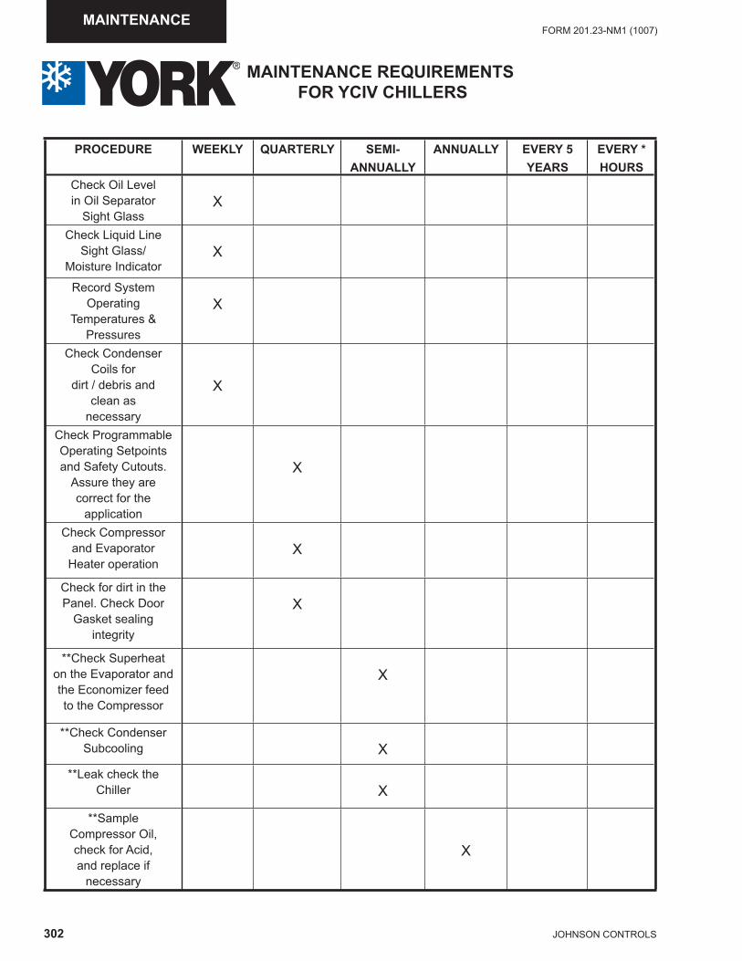
302 JOHNSON CONTROLS
FORM 201.23-NM1 (1007)MAINTENANCE
PROCEDURE WEEKLY QUARTERLY SEMI-ANNUALLY
ANNUALLY EVERY 5YEARS
EVERY *HOURS
Check Oil Levelin Oil Separator
Sight GlassX
Check Liquid Line Sight Glass/
Moisture IndicatorX
Record SystemOperating
Temperatures &Pressures
X
Check CondenserCoils for
dirt / debris and clean as
necessary
X
Check ProgrammableOperating Setpointsand Safety Cutouts.
Assure they arecorrect for the
application
X
Check Compressor and Evaporator
Heater operationX
Check for dirt in the Panel. Check Door
Gasket sealing integrity
X
**Check Superheat on the Evaporator andthe Economizer feedto the Compressor
X
**Check CondenserSubcooling X
**Leak check the Chiller X
**SampleCompressor Oil,check for Acid,and replace if
necessary
X
MAINTENANCE REQUIREMENTS FOR YCIV CHILLERS
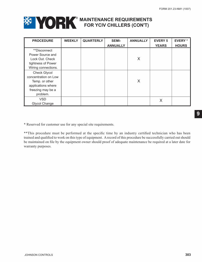
303JOHNSON CONTROLS
FORM 201.23-NM1 (1007)
9
PROCEDURE WEEKLY QUARTERLY SEMI-ANNUALLY
ANNUALLY EVERY 5YEARS
EVERY *HOURS
**Disconnect Power Source andLock Out. Check
tightness of Power Wiring connections.
X
Check Glycolconcentration on Low
Temp. or otherapplications wherefreezing may be a
problem.
X
VSDGlycol Change
X
MAINTENANCE REQUIREMENTS FOR YCIV CHILLERS (CON'T)
* Reserved for customer use for any special site requirements.
**This procedure must be performed at the specifi c time by an industry certifi ed technician who has been trained and qualifi ed to work on this type of equipment. A record of this procedure be successfully carried out should be maintained on fi le by the equipment owner should proof of adequate maintenance be required at a later date for warranty purposes.
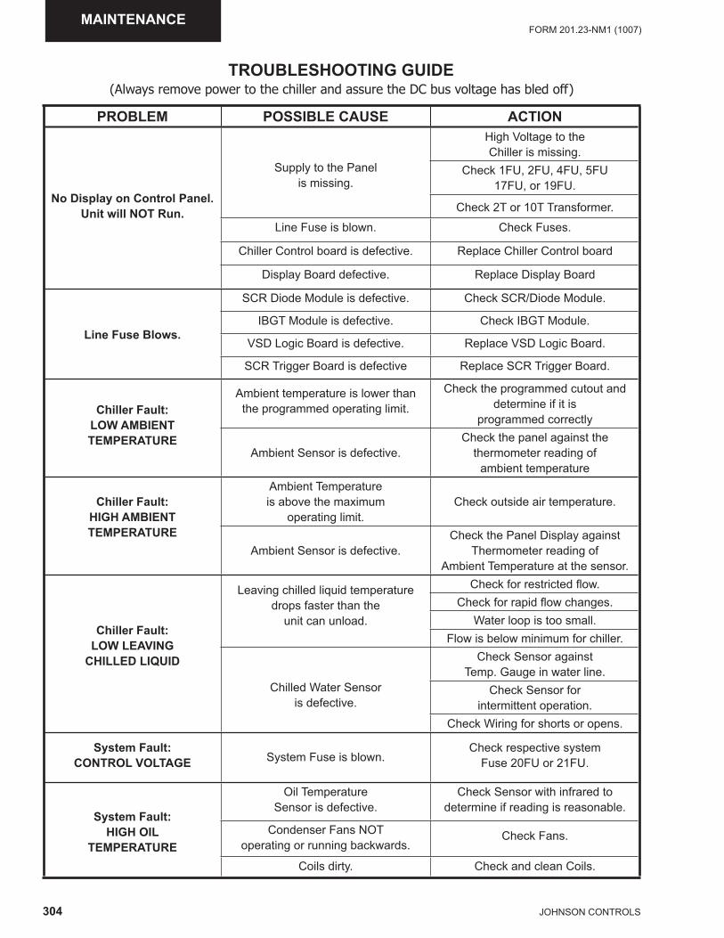
304 JOHNSON CONTROLS
FORM 201.23-NM1 (1007)MAINTENANCE
TROUBLESHOOTING GUIDE
PROBLEM POSSIBLE CAUSE ACTION
No Display on Control Panel.Unit will NOT Run.
Supply to the Panelis missing.
High Voltage to the Chiller is missing.
Check 1FU, 2FU, 4FU, 5FU17FU, or 19FU.
Check 2T or 10T Transformer.
Line Fuse is blown. Check Fuses.
Chiller Control board is defective. Replace Chiller Control board
Display Board defective. Replace Display Board
Line Fuse Blows.
SCR Diode Module is defective. Check SCR/Diode Module.
IBGT Module is defective. Check IBGT Module.
VSD Logic Board is defective. Replace VSD Logic Board.
SCR Trigger Board is defective Replace SCR Trigger Board.
Chiller Fault:LOW AMBIENTTEMPERATURE
Ambient temperature is lower than the programmed operating limit.
Check the programmed cutout and determine if it is
programmed correctly
Ambient Sensor is defective.Check the panel against the
thermometer reading of ambient temperature
Chiller Fault:HIGH AMBIENTTEMPERATURE
Ambient Temperatureis above the maximum
operating limit.Check outside air temperature.
Ambient Sensor is defective.Check the Panel Display against
Thermometer reading of Ambient Temperature at the sensor.
Chiller Fault:LOW LEAVING
CHILLED LIQUID
Leaving chilled liquid temperaturedrops faster than the
unit can unload.
Check for restricted fl ow.Check for rapid fl ow changes.
Water loop is too small.Flow is below minimum for chiller.
Chilled Water Sensoris defective.
Check Sensor against Temp. Gauge in water line.
Check Sensor forintermittent operation.
Check Wiring for shorts or opens.
System Fault:CONTROL VOLTAGE System Fuse is blown.
Check respective systemFuse 20FU or 21FU.
System Fault:HIGH OIL
TEMPERATURE
Oil TemperatureSensor is defective.
Check Sensor with infrared to determine if reading is reasonable.
Condenser Fans NOToperating or running backwards.
Check Fans.
Coils dirty. Check and clean Coils.
(Always remove power to the chiller and assure the DC bus voltage has bled off)
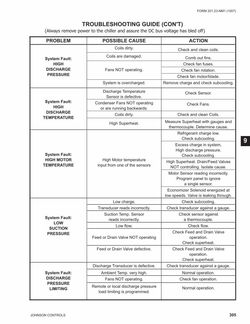
305JOHNSON CONTROLS
FORM 201.23-NM1 (1007)
9
PROBLEM POSSIBLE CAUSE ACTION
System Fault:HIGH
DISCHARGEPRESSURE
Coils dirty. Check and clean coils.Coils are damaged. Comb out fi ns.
Fans NOT operating.Check fan fuses.
Check fan rotation.Check fan motor/blade.
System is overcharged. Remove charge and check subcooling.
System Fault:HIGH
DISCHARGETEMPERATURE
Discharge TemperatureSensor is defective.
Check Sensor.
Condenser Fans NOT operating or are running backwards.
Check Fans.
Coils dirty. Check and clean Coils.
High Superheat. Measure Superheat with gauges and thermocouple. Determine cause.
System Fault:HIGH MOTOR
TEMPERATUREHigh Motor temperature
input from one of the sensors
Refrigerant charge low.Check subcooling.
Excess charge in system, High discharge pressure.
Check subcooling.High Superheat. Drain/Feed Valves
NOT controlling. Isolate cause.Motor Sensor reading incorrectly.
Program panel to ignore a single sensor.
Economizer Solenoid energized atlow speeds. Valve is leaking through.
System Fault:LOW
SUCTIONPRESSURE
Low charge. Check subcooling.Transducer reads incorrectly. Check transducer against a gauge.
Suction Temp. Sensor reads incorrectly.
Check sensor againsta thermocouple.
Low fl ow. Check fl ow.
Feed or Drain Valve NOT operatingCheck Feed and Drain Valve
operation.Check superheat.
Feed or Drain Valve defective. Check Feed and Drain Valve operation.
Check superheat.
System Fault:DISCHARGE PRESSURE
LIMITING
Discharge Transducer is defective. Check transducer against a gauge.
Ambient Temp. very high. Normal operation.Fans NOT operating. Check fan operation.
Remote or local discharge pressureload limiting is programmed.
Normal operation.
TROUBLESHOOTING GUIDE (CON'T)(Always remove power to the chiller and assure the DC bus voltage has bled off)
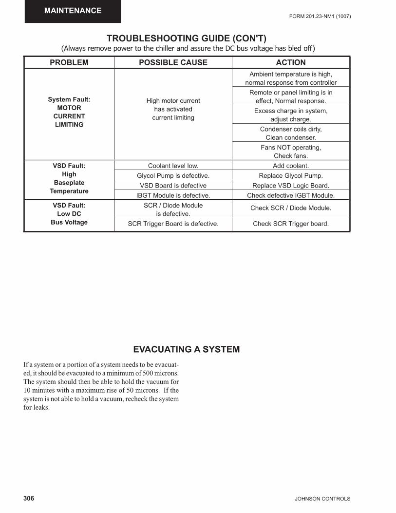
306 JOHNSON CONTROLS
FORM 201.23-NM1 (1007)MAINTENANCE
EVACUATING A SYSTEMIf a system or a portion of a system needs to be evacuat-ed, it should be evacuated to a minimum of 500 microns. The system should then be able to hold the vacuum for 10 minutes with a maximum rise of 50 microns. If the system is not able to hold a vacuum, recheck the system for leaks.
TROUBLESHOOTING GUIDE (CON'T)
PROBLEM POSSIBLE CAUSE ACTION
System Fault:MOTOR
CURRENTLIMITING
High motor currenthas activated
current limiting
Ambient temperature is high,normal response from controller
Remote or panel limiting is in effect, Normal response.Excess charge in system,
adjust charge.Condenser coils dirty,
Clean condenser.Fans NOT operating,
Check fans.VSD Fault:
HighBaseplate
Temperature
Coolant level low. Add coolant.Glycol Pump is defective. Replace Glycol Pump.VSD Board is defective Replace VSD Logic Board.
IBGT Module is defective. Check defective IGBT Module.VSD Fault:
Low DCBus Voltage
SCR / Diode Module is defective.
Check SCR / Diode Module.
SCR Trigger Board is defective. Check SCR Trigger board.
(Always remove power to the chiller and assure the DC bus voltage has bled off)
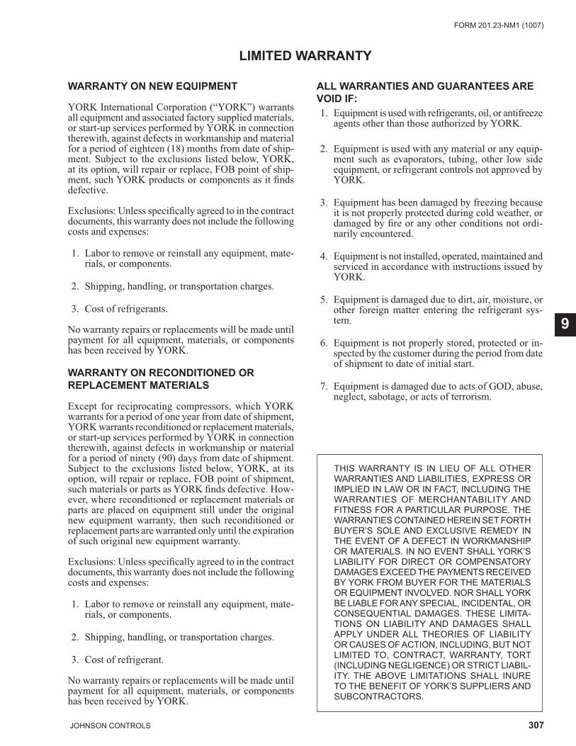
307JOHNSON CONTROLS
FORM 201.23-NM1 (1007)
9
LIMITED WARRANTY
WARRANTY ON NEW EQUIPMENT
YORK International Corporation (“YORK”) warrants all equip ment and associated factory supplied materials, or start-up services performed by YORK in connection therewith, against defects in workmanship and material for a period of eigh teen (18) months from date of ship-ment. Subject to the exclusions listed below, YORK, at its option, will re pair or replace, FOB point of ship-ment, such YORK prod ucts or components as it fi nds de fec tive.
Exclusions: Unless specifi cally agreed to in the con tract documents, this warranty does not include the following costs and expenses:
1. Labor to remove or reinstall any equip ment, ma te -ri als, or components.
2. Shipping, handling, or transportation charges.
3. Cost of refrigerants.
No warranty repairs or replacements will be made until payment for all equipment, materials, or components has been received by YORK.
WARRANTY ON RECONDITIONED OR REPLACEMENT MATERIALS
Except for reciprocating compressors, which YORK warrants for a period of one year from date of ship ment, YORK warrants reconditioned or re place ment ma te ri als, or start-up ser vic es performed by YORK in connection therewith, against defects in work man ship or material for a period of ninety (90) days from date of shipment. Sub ject to the exclusions listed be low, YORK, at its option, will repair or replace, FOB point of shipment, such materials or parts as YORK fi nds defective. How-ever, where reconditioned or replacement materials or parts are placed on equipment still under the original new equipment warranty, then such re con di tioned or replacement parts are warranted only until the ex pi ra tion of such original new equipment warranty.
Exclusions: Unless specifi cally agreed to in the con tract documents, this warranty does not include the following costs and expenses:
1. Labor to remove or reinstall any equip ment, ma te -ri als, or components.
2. Shipping, handling, or transportation charges.
3. Cost of refrigerant.
No warranty repairs or replacements will be made until payment for all equipment, materials, or components has been received by YORK.
ALL WARRANTIES AND GUARANTEES ARE VOID IF: 1. Equipment is used with refrigerants, oil, or an ti freeze
agents other than those authorized by YORK.
2. Equipment is used with any material or any equip- ment such as evaporators, tubing, other low side equip ment, or refrigerant controls not approved by YORK.
3. Equipment has been damaged by freezing because it is not properly protected during cold weather, or dam aged by fi re or any other conditions not or di -nari ly en coun tered.
4. Equipment is not installed, operated, maintained and serviced in accordance with instructions issued by YORK.
5. Equipment is damaged due to dirt, air, moisture, or oth er foreign matter entering the refrigerant sys-tem.
6. Equipment is not properly stored, protected or in- spect ed by the customer during the period from date of ship ment to date of initial start.
7. Equipment is damaged due to acts of GOD, abuse, neglect, sabotage, or acts of terrorism.
THIS WARRANTY IS IN LIEU OF ALL OTHER WAR RAN TIES AND LIABILITIES, EXPRESS OR IM PLIED IN LAW OR IN FACT, INCLUDING THE WAR RAN TIES OF MERCHANTABILITY AND FITNESS FOR A PARTICULAR PURPOSE. THE WAR RAN TIES CONTAINED HEREIN SET FORTH BUY ER’S SOLE AND EXCLUSIVE REM E DY IN THE EVENT OF A DEFECT IN WORK MAN SHIP OR MA TE RI ALS. IN NO EVENT SHALL YORK’S LIABILITY FOR DIRECT OR COMPENSATORY DAMAGES EX CEED THE PAYMENTS RECEIVED BY YORK FROM BUY ER FOR THE MATERIALS OR EQUIP MENT INVOLVED. NOR SHALL YORK BE LIABLE FOR ANY SPECIAL, INCIDENTAL, OR CON SE QUEN TIAL DAMAGES. THESE LIMITA-TIONS ON LI A BIL I TY AND DAMAGES SHALL APPLY UN DER ALL THEORIES OF LIABILITY OR CAUSES OF ACTION, INCLUDING, BUT NOT LIMITED TO, CONTRACT, WARRANTY, TORT (INCLUDING NEGLIGENCE) OR STRICT LIABIL-ITY. THE ABOVE LIMITATIONS SHALL INURE TO THE BEN E FIT OF YORK’S SUPPLIERS AND SUB CON TRAC TORS.
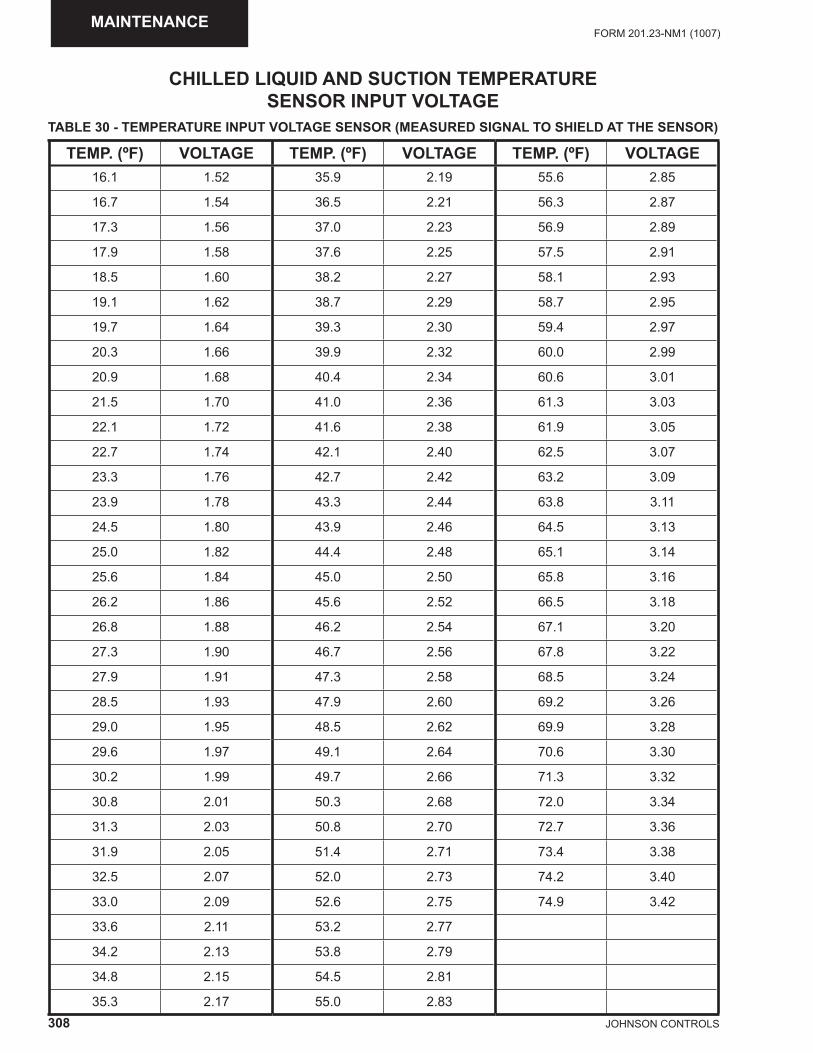
308 JOHNSON CONTROLS
FORM 201.23-NM1 (1007)MAINTENANCE
CHILLED LIQUID AND SUCTION TEMPERATURE SENSOR INPUT VOLTAGE
TEMP. (ºF) VOLTAGE TEMP. (ºF) VOLTAGE TEMP. (ºF) VOLTAGE16.1 1.52 35.9 2.19 55.6 2.85
16.7 1.54 36.5 2.21 56.3 2.87
17.3 1.56 37.0 2.23 56.9 2.89
17.9 1.58 37.6 2.25 57.5 2.91
18.5 1.60 38.2 2.27 58.1 2.93
19.1 1.62 38.7 2.29 58.7 2.95
19.7 1.64 39.3 2.30 59.4 2.97
20.3 1.66 39.9 2.32 60.0 2.99
20.9 1.68 40.4 2.34 60.6 3.01
21.5 1.70 41.0 2.36 61.3 3.03
22.1 1.72 41.6 2.38 61.9 3.05
22.7 1.74 42.1 2.40 62.5 3.07
23.3 1.76 42.7 2.42 63.2 3.09
23.9 1.78 43.3 2.44 63.8 3.11
24.5 1.80 43.9 2.46 64.5 3.13
25.0 1.82 44.4 2.48 65.1 3.14
25.6 1.84 45.0 2.50 65.8 3.16
26.2 1.86 45.6 2.52 66.5 3.18
26.8 1.88 46.2 2.54 67.1 3.20
27.3 1.90 46.7 2.56 67.8 3.22
27.9 1.91 47.3 2.58 68.5 3.24
28.5 1.93 47.9 2.60 69.2 3.26
29.0 1.95 48.5 2.62 69.9 3.28
29.6 1.97 49.1 2.64 70.6 3.30
30.2 1.99 49.7 2.66 71.3 3.32
30.8 2.01 50.3 2.68 72.0 3.34
31.3 2.03 50.8 2.70 72.7 3.36
31.9 2.05 51.4 2.71 73.4 3.38
32.5 2.07 52.0 2.73 74.2 3.40
33.0 2.09 52.6 2.75 74.9 3.42
33.6 2.11 53.2 2.77
34.2 2.13 53.8 2.79
34.8 2.15 54.5 2.81
35.3 2.17 55.0 2.83
TABLE 30 - TEMPERATURE INPUT VOLTAGE SENSOR (MEASURED SIGNAL TO SHIELD AT THE SENSOR)
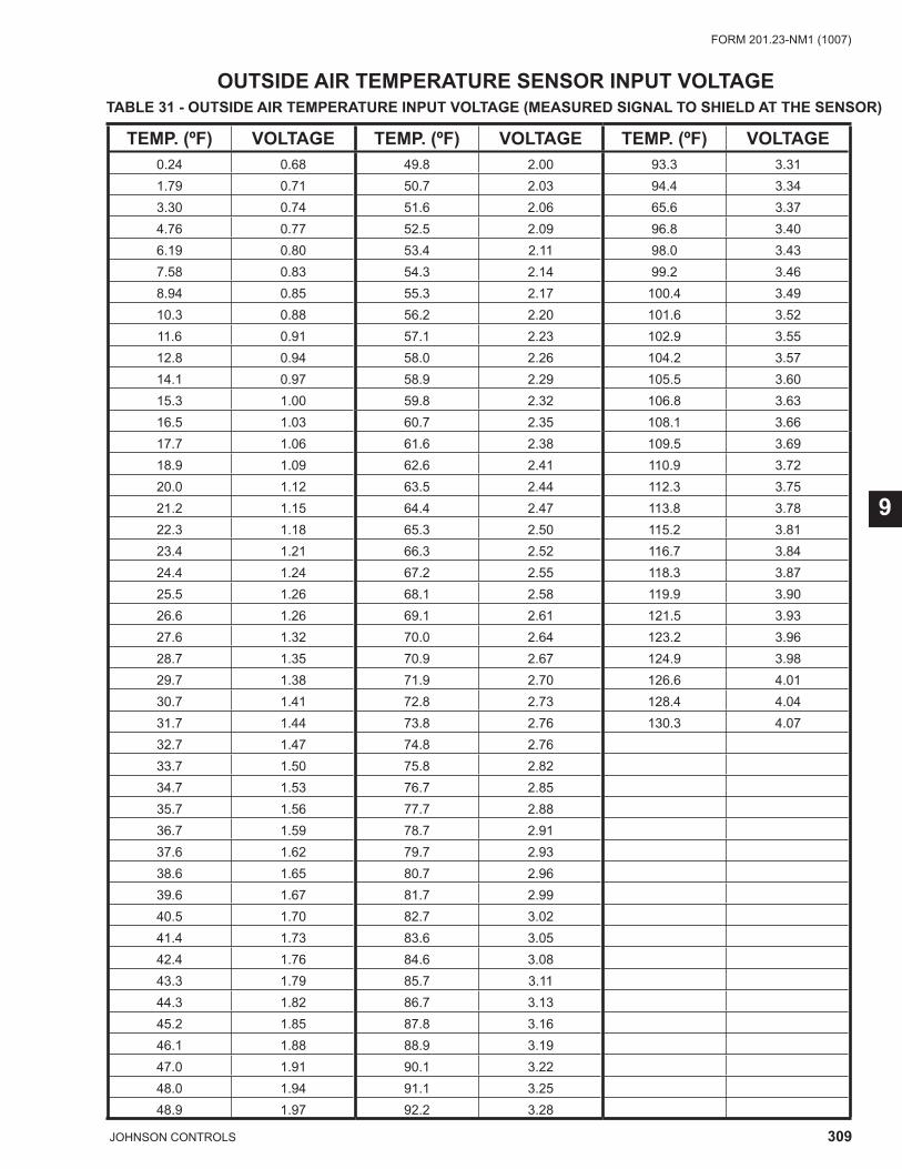
309JOHNSON CONTROLS
FORM 201.23-NM1 (1007)
9
OUTSIDE AIR TEMPERATURE SENSOR INPUT VOLTAGE
TEMP. (ºF) VOLTAGE TEMP. (ºF) VOLTAGE TEMP. (ºF) VOLTAGE0.24 0.68 49.8 2.00 93.3 3.311.79 0.71 50.7 2.03 94.4 3.343.30 0.74 51.6 2.06 65.6 3.374.76 0.77 52.5 2.09 96.8 3.406.19 0.80 53.4 2.11 98.0 3.437.58 0.83 54.3 2.14 99.2 3.468.94 0.85 55.3 2.17 100.4 3.4910.3 0.88 56.2 2.20 101.6 3.5211.6 0.91 57.1 2.23 102.9 3.5512.8 0.94 58.0 2.26 104.2 3.5714.1 0.97 58.9 2.29 105.5 3.6015.3 1.00 59.8 2.32 106.8 3.6316.5 1.03 60.7 2.35 108.1 3.6617.7 1.06 61.6 2.38 109.5 3.6918.9 1.09 62.6 2.41 110.9 3.7220.0 1.12 63.5 2.44 112.3 3.7521.2 1.15 64.4 2.47 113.8 3.7822.3 1.18 65.3 2.50 115.2 3.8123.4 1.21 66.3 2.52 116.7 3.8424.4 1.24 67.2 2.55 118.3 3.8725.5 1.26 68.1 2.58 119.9 3.9026.6 1.26 69.1 2.61 121.5 3.9327.6 1.32 70.0 2.64 123.2 3.9628.7 1.35 70.9 2.67 124.9 3.9829.7 1.38 71.9 2.70 126.6 4.0130.7 1.41 72.8 2.73 128.4 4.0431.7 1.44 73.8 2.76 130.3 4.0732.7 1.47 74.8 2.7633.7 1.50 75.8 2.8234.7 1.53 76.7 2.8535.7 1.56 77.7 2.8836.7 1.59 78.7 2.9137.6 1.62 79.7 2.9338.6 1.65 80.7 2.9639.6 1.67 81.7 2.9940.5 1.70 82.7 3.0241.4 1.73 83.6 3.0542.4 1.76 84.6 3.0843.3 1.79 85.7 3.1144.3 1.82 86.7 3.1345.2 1.85 87.8 3.1646.1 1.88 88.9 3.1947.0 1.91 90.1 3.2248.0 1.94 91.1 3.2548.9 1.97 92.2 3.28
TABLE 31 - OUTSIDE AIR TEMPERATURE INPUT VOLTAGE (MEASURED SIGNAL TO SHIELD AT THE SENSOR)
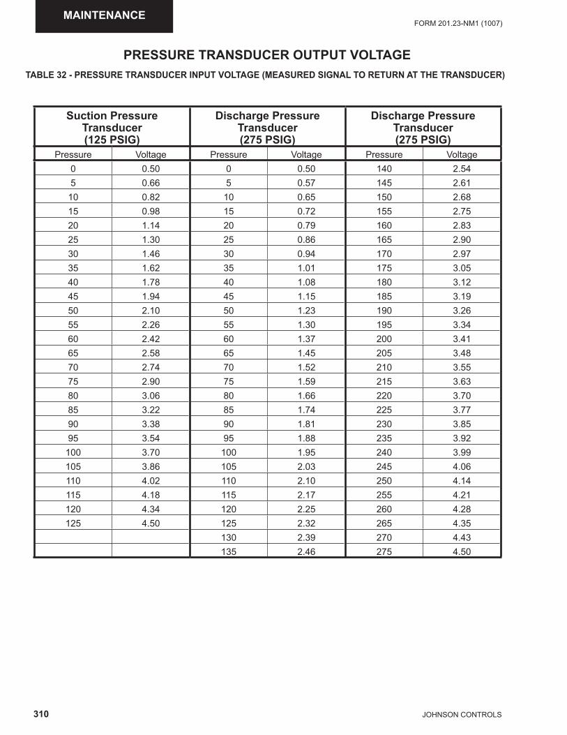
310 JOHNSON CONTROLS
FORM 201.23-NM1 (1007)MAINTENANCE
PRESSURE TRANSDUCER OUTPUT VOLTAGE
Suction PressureTransducer(125 PSIG)
Discharge PressureTransducer(275 PSIG)
Discharge PressureTransducer(275 PSIG)
Pressure Voltage Pressure Voltage Pressure Voltage0 0.50 0 0.50 140 2.545 0.66 5 0.57 145 2.61
10 0.82 10 0.65 150 2.6815 0.98 15 0.72 155 2.7520 1.14 20 0.79 160 2.8325 1.30 25 0.86 165 2.9030 1.46 30 0.94 170 2.9735 1.62 35 1.01 175 3.0540 1.78 40 1.08 180 3.1245 1.94 45 1.15 185 3.1950 2.10 50 1.23 190 3.2655 2.26 55 1.30 195 3.3460 2.42 60 1.37 200 3.4165 2.58 65 1.45 205 3.4870 2.74 70 1.52 210 3.5575 2.90 75 1.59 215 3.6380 3.06 80 1.66 220 3.7085 3.22 85 1.74 225 3.7790 3.38 90 1.81 230 3.8595 3.54 95 1.88 235 3.92
100 3.70 100 1.95 240 3.99105 3.86 105 2.03 245 4.06110 4.02 110 2.10 250 4.14115 4.18 115 2.17 255 4.21120 4.34 120 2.25 260 4.28125 4.50 125 2.32 265 4.35
130 2.39 270 4.43135 2.46 275 4.50
TABLE 32 - PRESSURE TRANSDUCER INPUT VOLTAGE (MEASURED SIGNAL TO RETURN AT THE TRANSDUCER)
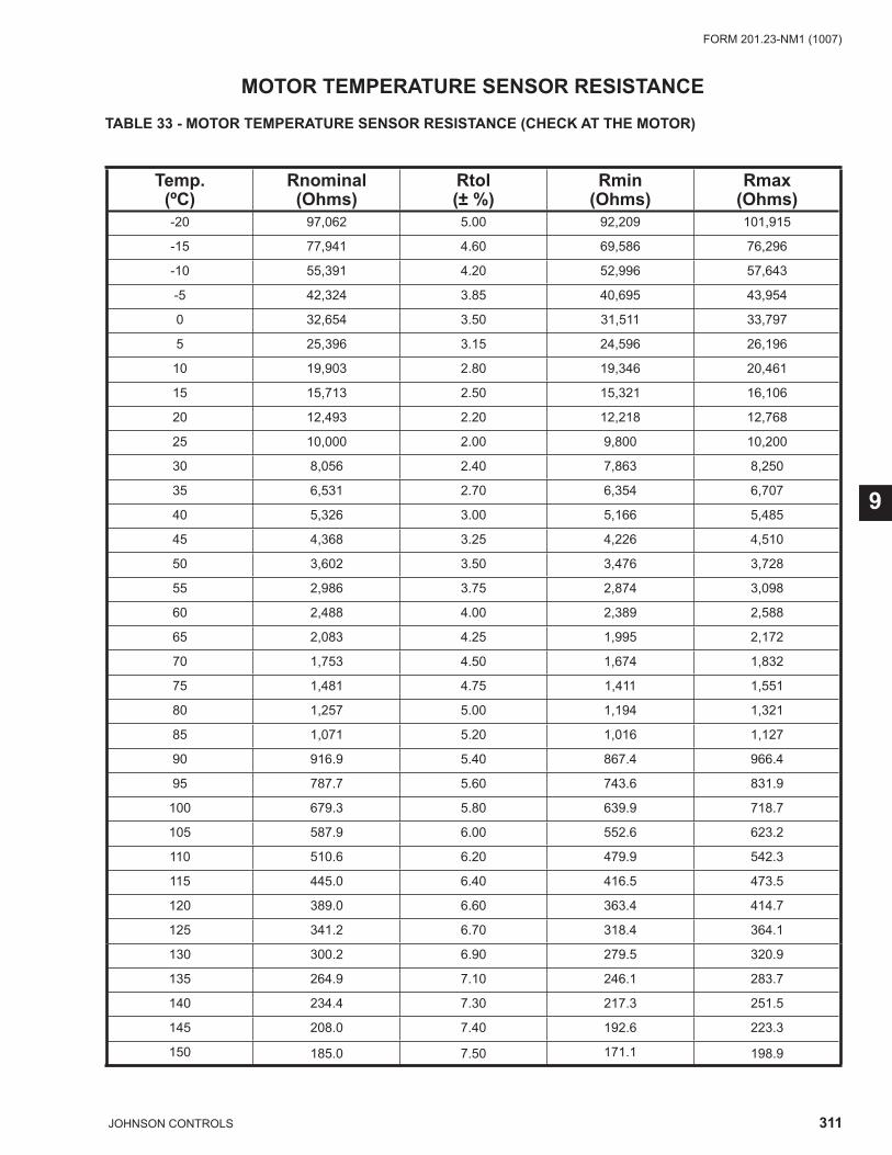
311JOHNSON CONTROLS
FORM 201.23-NM1 (1007)
9
MOTOR TEMPERATURE SENSOR RESISTANCE
Temp.(ºC)
Rnominal(Ohms)
Rtol(± %)
Rmin(Ohms)
Rmax(Ohms)
-20 97,062 5.00 92,209 101,915
-15 77,941 4.60 69,586 76,296
-10 55,391 4.20 52,996 57,643
-5 42,324 3.85 40,695 43,954
0 32,654 3.50 31,511 33,797
5 25,396 3.15 24,596 26,196
10 19,903 2.80 19,346 20,461
15 15,713 2.50 15,321 16,106
20 12,493 2.20 12,218 12,768
25 10,000 2.00 9,800 10,200
30 8,056 2.40 7,863 8,250
35 6,531 2.70 6,354 6,707
40 5,326 3.00 5,166 5,485
45 4,368 3.25 4,226 4,510
50 3,602 3.50 3,476 3,728
55 2,986 3.75 2,874 3,098
60 2,488 4.00 2,389 2,588
65 2,083 4.25 1,995 2,172
70 1,753 4.50 1,674 1,832
75 1,481 4.75 1,411 1,551
80 1,257 5.00 1,194 1,321
85 1,071 5.20 1,016 1,127
90 916.9 5.40 867.4 966.4
95 787.7 5.60 743.6 831.9
100 679.3 5.80 639.9 718.7
105 587.9 6.00 552.6 623.2
110 510.6 6.20 479.9 542.3
115 445.0 6.40 416.5 473.5
120 389.0 6.60 363.4 414.7
125 341.2 6.70 318.4 364.1
130 300.2 6.90 279.5 320.9
135 264.9 7.10 246.1 283.7
140 234.4 7.30 217.3 251.5
145 208.0 7.40 192.6 223.3
150 185.0 7.50 171.1 198.9
TABLE 33 - MOTOR TEMPERATURE SENSOR RESISTANCE (CHECK AT THE MOTOR)
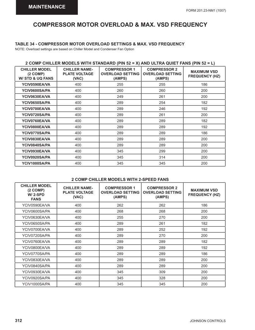
312 JOHNSON CONTROLS
FORM 201.23-NM1 (1007)MAINTENANCE
COMPRESSOR MOTOR OVERLOAD & MAX. VSD FREQUENCY
TABLE 34 - COMPRESSOR MOTOR OVERLOAD SETTINGS & MAX. VSD FREQUENCYNOTE: Overload settings are based on Chiller Model and Condenser Fan Option
2 COMP CHILLER MODELS WITH STANDARD (PIN 52 = X) AND ULTRA QUIET FANS (PIN 52 = L)CHILLER MODEL
(2 COMP)W/ STD & UQ FANS
CHILLER NAME-PLATE VOLTAGE
(VAC)
COMPRESSOR 1 OVERLOAD SETTING
(AMPS)
COMPRESSOR 2 OVERLOAD SETTING
(AMPS)
MAXIMUM VSD FREQUENCY (HZ)
YCIV0590EA/VA 400 255 255 186YCIV0600SA/PA 400 260 260 200YCIV0630EA/VA 400 249 261 200YCIV0650SA/PA 400 289 254 182YCIV0700EA/VA 400 289 246 192YCIV0720SA/PA 400 289 261 200YCIV0760EA/VA 400 289 289 182YCIV0800EA/VA 400 289 289 192YCIV0770SA/PA 400 289 289 186YCIV0830EA/VA 400 289 289 200YCIV0840SA/PA 400 289 289 200YCIV0930EA/VA 400 345 299 200YCIV0920SA/PA 400 345 314 200YCIV1000SA/PA 400 345 345 200
2 COMP CHILLER MODELS WITH 2-SPEED FANSCHILLER MODEL
(2 COMP)W/ 2-SPD
FANS
CHILLER NAME-PLATE VOLTAGE
(VAC)
COMPRESSOR 1 OVERLOAD SETTING
(AMPS)
COMPRESSOR 2 OVERLOAD SETTING
(AMPS)
MAXIMUM VSD FREQUENCY (HZ)
YCIV0590EA/VA 400 262 262 186YCIV0600SA/PA 400 268 268 200YCIV0630EA/VA 400 255 270 200YCIV0650SA/PA 400 289 261 182YCIV0700EA/VA 400 289 252 192YCIV0720SA/PA 400 289 270 200YCIV0760EA/VA 400 289 289 182YCIV0800EA/VA 400 289 289 192YCIV0770SA/PA 400 289 289 186YCIV0830EA/VA 400 289 289 200YCIV0840SA/PA 400 289 289 200YCIV0930EA/VA 400 345 309 200YCIV0920SA/PA 400 345 328 200YCIV1000SA/PA 400 345 345 200
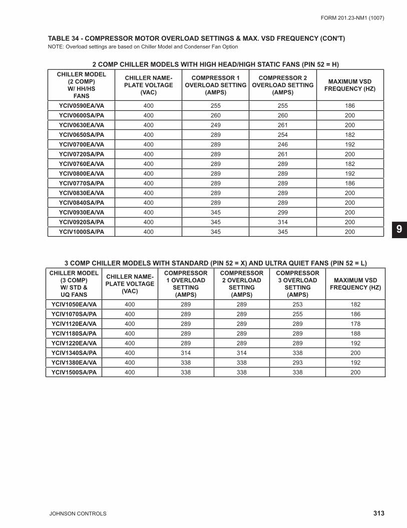
313JOHNSON CONTROLS
FORM 201.23-NM1 (1007)
9
TABLE 34 - COMPRESSOR MOTOR OVERLOAD SETTINGS & MAX. VSD FREQUENCY (CON'T)NOTE: Overload settings are based on Chiller Model and Condenser Fan Option
2 COMP CHILLER MODELS WITH HIGH HEAD/HIGH STATIC FANS (PIN 52 = H)CHILLER MODEL
(2 COMP)W/ HH/HS
FANS
CHILLER NAME-PLATE VOLTAGE
(VAC)
COMPRESSOR 1 OVERLOAD SETTING
(AMPS)
COMPRESSOR 2 OVERLOAD SETTING
(AMPS)
MAXIMUM VSD FREQUENCY (HZ)
YCIV0590EA/VA 400 255 255 186YCIV0600SA/PA 400 260 260 200YCIV0630EA/VA 400 249 261 200YCIV0650SA/PA 400 289 254 182YCIV0700EA/VA 400 289 246 192YCIV0720SA/PA 400 289 261 200YCIV0760EA/VA 400 289 289 182YCIV0800EA/VA 400 289 289 192YCIV0770SA/PA 400 289 289 186YCIV0830EA/VA 400 289 289 200YCIV0840SA/PA 400 289 289 200YCIV0930EA/VA 400 345 299 200YCIV0920SA/PA 400 345 314 200YCIV1000SA/PA 400 345 345 200
3 COMP CHILLER MODELS WITH STANDARD (PIN 52 = X) AND ULTRA QUIET FANS (PIN 52 = L)CHILLER MODEL
(3 COMP)W/ STD & UQ FANS
CHILLER NAME-PLATE VOLTAGE
(VAC)
COMPRESSOR 1 OVERLOAD
SETTING (AMPS)
COMPRESSOR 2 OVERLOAD
SETTING (AMPS)
COMPRESSOR 3 OVERLOAD
SETTING (AMPS)
MAXIMUM VSD FREQUENCY (HZ)
YCIV1050EA/VA 400 289 289 253 182YCIV1070SA/PA 400 289 289 255 186YCIV1120EA/VA 400 289 289 289 178YCIV1180SA/PA 400 289 289 289 188YCIV1220EA/VA 400 289 289 289 192YCIV1340SA/PA 400 314 314 338 200YCIV1380EA/VA 400 338 338 293 192YCIV1500SA/PA 400 338 338 338 200
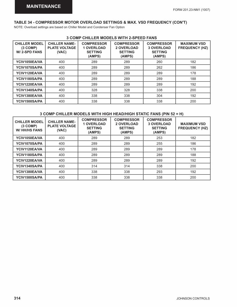
314 JOHNSON CONTROLS
FORM 201.23-NM1 (1007)MAINTENANCE
TABLE 34 - COMPRESSOR MOTOR OVERLOAD SETTINGS & MAX. VSD FREQUENCY (CON'T)NOTE: Overload settings are based on Chiller Model and Condenser Fan Option
3 COMP CHILLER MODELS WITH 2-SPEED FANSCHILLER MODEL
(3 COMP)W/ 2-SPD FANS
CHILLER NAME-PLATE VOLTAGE
(VAC)
COMPRESSOR 1 OVERLOAD
SETTING (AMPS)
COMPRESSOR 2 OVERLOAD
SETTING (AMPS)
COMPRESSOR 3 OVERLOAD
SETTING (AMPS)
MAXIMUM VSD FREQUENCY (HZ)
YCIV1050EA/VA 400 289 289 260 182YCIV1070SA/PA 400 289 289 262 186YCIV1120EA/VA 400 289 289 289 178YCIV1180SA/PA 400 289 289 289 188YCIV1220EA/VA 400 289 289 289 192YCIV1340SA/PA 400 328 328 338 200YCIV1380EA/VA 400 338 338 304 192YCIV1500SA/PA 400 338 338 338 200
3 COMP CHILLER MODELS WITH HIGH HEAD/HIGH STATIC FANS (PIN 52 = H)
CHILLER MODEL(3 COMP)
W/ HH/HS FANS
CHILLER NAME-PLATE VOLTAGE
(VAC)
COMPRESSOR 1 OVERLOAD
SETTING (AMPS)
COMPRESSOR 2 OVERLOAD
SETTING (AMPS)
COMPRESSOR 3 OVERLOAD
SETTING (AMPS)
MAXIMUM VSD FREQUENCY (HZ)
YCIV1050EA/VA 400 289 289 253 182YCIV1070SA/PA 400 289 289 255 186YCIV1120EA/VA 400 289 289 289 178YCIV1180SA/PA 400 289 289 289 188YCIV1220EA/VA 400 289 289 289 192YCIV1340SA/PA 400 314 314 338 200YCIV1380EA/VA 400 338 338 293 192YCIV1500SA/PA 400 338 338 338 200
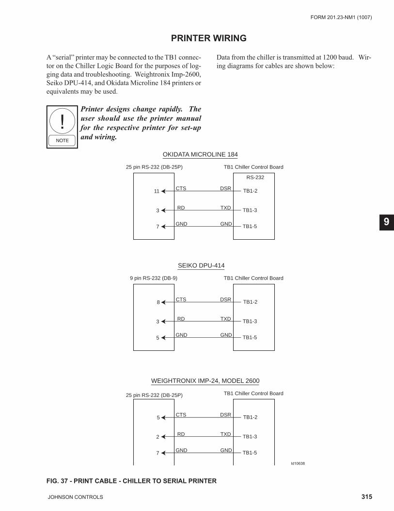
315JOHNSON CONTROLS
FORM 201.23-NM1 (1007)
9
PRINTER WIRING
A “serial” printer may be connected to the TB1 connec-tor on the Chiller Logic Board for the purposes of log-ging data and troubleshooting. Weightronix Imp-2600, Seiko DPU-414, and Okidata Microline 184 printers or equivalents may be used.
Printer designs change rapidly. The user should use the printer manual for the respective printer for set-up and wiring.
Data from the chiller is transmitted at 1200 baud. Wir-ing diagrams for cables are shown below:
OKIDATA MICROLINE 184
25 pin RS-232 (DB-25P)
25 pin RS-232 (DB-25P)
TB1 Chiller Control Board
11 CTS
RD
GND
DSR
RS-232
TXD
GND
TB1-2
TB1-3
TB1-5
3
7
SEIKO DPU-414
9 pin RS-232 (DB-9) TB1 Chiller Control Board
8 CTS
RD
GND
DSR
TXD
GND
TB1-2
TB1-3
TB1-5
3
5
WEIGHTRONIX IMP-24, MODEL 2600
TB1 Chiller Control Board
5 CTS
RD
GND
DSR
TXD
GND
TB1-2
TB1-3
TB1-5
2
7
FIG. 37 - PRINT CABLE - CHILLER TO SERIAL PRINTER
ld10638
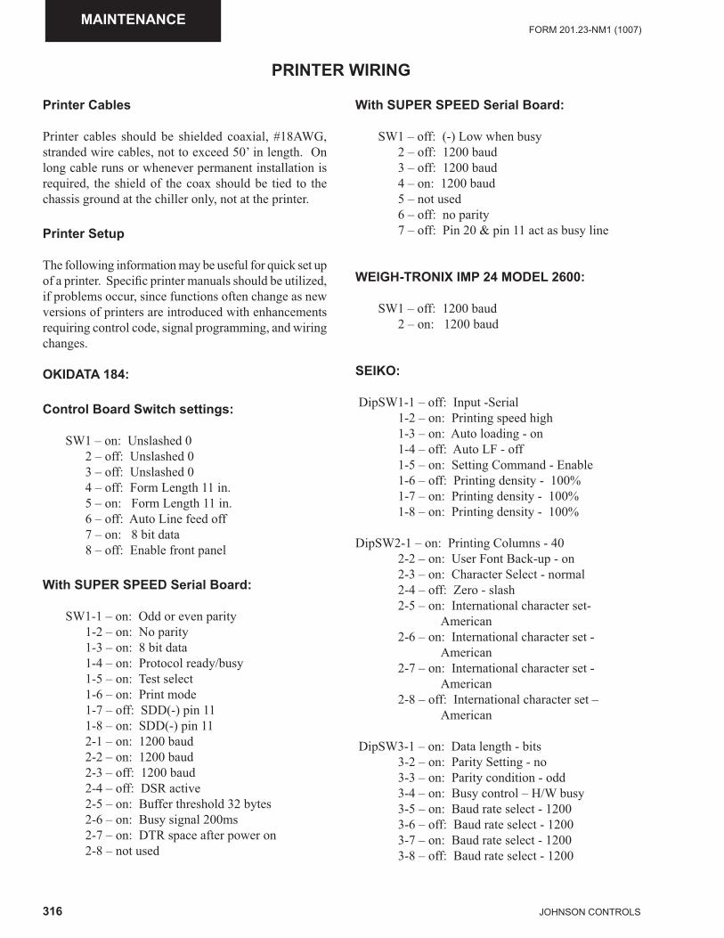
316 JOHNSON CONTROLS
FORM 201.23-NM1 (1007)MAINTENANCE
PRINTER WIRING
Printer Cables
Printer cables should be shielded coaxial, #18AWG, stranded wire cables, not to exceed 50’ in length. On long cable runs or whenever permanent installation is required, the shield of the coax should be tied to the chassis ground at the chiller only, not at the printer.
Printer Setup
The following information may be useful for quick set up of a printer. Specifi c printer manuals should be utilized, if problems occur, since functions often change as new versions of printers are introduced with enhancements requiring control code, signal programming, and wiring changes.
OKIDATA 184:
Control Board Switch settings:
SW1 – on: Unslashed 0 2 – off: Unslashed 0 3 – off: Unslashed 0 4 – off: Form Length 11 in. 5 – on: Form Length 11 in. 6 – off: Auto Line feed off 7 – on: 8 bit data 8 – off: Enable front panel
With SUPER SPEED Serial Board:
SW1-1 – on: Odd or even parity 1-2 – on: No parity 1-3 – on: 8 bit data 1-4 – on: Protocol ready/busy 1-5 – on: Test select 1-6 – on: Print mode 1-7 – off: SDD(-) pin 11 1-8 – on: SDD(-) pin 11 2-1 – on: 1200 baud 2-2 – on: 1200 baud 2-3 – off: 1200 baud 2-4 – off: DSR active 2-5 – on: Buffer threshold 32 bytes 2-6 – on: Busy signal 200ms 2-7 – on: DTR space after power on 2-8 – not used
With SUPER SPEED Serial Board:
SW1 – off: (-) Low when busy 2 – off: 1200 baud 3 – off: 1200 baud 4 – on: 1200 baud 5 – not used 6 – off: no parity 7 – off: Pin 20 & pin 11 act as busy line
WEIGH-TRONIX IMP 24 MODEL 2600:
SW1 – off: 1200 baud 2 – on: 1200 baud
SEIKO:
DipSW1-1 – off: Input -Serial 1-2 – on: Printing speed high 1-3 – on: Auto loading - on 1-4 – off: Auto LF - off 1-5 – on: Setting Command - Enable 1-6 – off: Printing density - 100% 1-7 – on: Printing density - 100% 1-8 – on: Printing density - 100%
DipSW2-1 – on: Printing Columns - 40 2-2 – on: User Font Back-up - on 2-3 – on: Character Select - normal 2-4 – off: Zero - slash 2-5 – on: International character set- American 2-6 – on: International character set - American 2-7 – on: International character set - American 2-8 – off: International character set – American
DipSW3-1 – on: Data length - bits 3-2 – on: Parity Setting - no 3-3 – on: Parity condition - odd 3-4 – on: Busy control – H/W busy 3-5 – on: Baud rate select - 1200 3-6 – off: Baud rate select - 1200 3-7 – on: Baud rate select - 1200 3-8 – off: Baud rate select - 1200
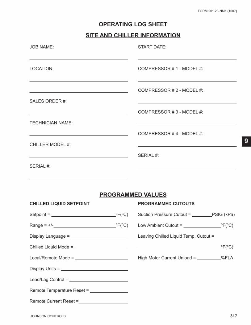
317JOHNSON CONTROLS
FORM 201.23-NM1 (1007)
9
OPERATING LOG SHEET
SITE AND CHILLER INFORMATION
JOB NAME:
LOCATION:
SALES ORDER #:
TECHNICIAN NAME:
CHILLER MODEL #:
SERIAL #:
START DATE:
COMPRESSOR # 1 - MODEL #:
COMPRESSOR # 2 - MODEL #:
COMPRESSOR # 3 - MODEL #:
COMPRESSOR # 4 - MODEL #:
SERIAL #:
PROGRAMMED VALUESCHILLED LIQUID SETPOINT
Setpoint = ºF(ºC)
Range = +/- ºF(ºC)
Display Language =
Chilled Liquid Mode =
Local/Remote Mode =
Display Units =
Lead/Lag Control =
Remote Temperature Reset =
Remote Current Reset =
PROGRAMMED CUTOUTS
Suction Pressure Cutout = PSIG (kPa)
Low Ambient Cutout = ºF(ºC)
Leaving Chilled Liquid Temp. Cutout =
ºF(ºC)
High Motor Current Unload = %FLA
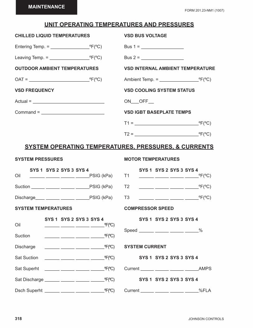
318 JOHNSON CONTROLS
FORM 201.23-NM1 (1007)MAINTENANCE
CHILLED LIQUID TEMPERATURES
Entering Temp. = ºF(ºC)
Leaving Temp. = ºF(ºC)
OUTDOOR AMBIENT TEMPERATURES
OAT = ºF(ºC)
VSD FREQUENCY
Actual =
Command =
UNIT OPERATING TEMPERATURES AND PRESSURES
VSD BUS VOLTAGE
Bus 1 =
Bus 2 =
VSD INTERNAL AMBIENT TEMPERATURE
Ambient Temp. = ºF(ºC)
VSD COOLING SYSTEM STATUS
ON OFF
VSD IGBT BASEPLATE TEMPS
T1 = ºF(ºC)
T2 = ºF(ºC)
SYSTEM OPERATING TEMPERATURES, PRESSURES, & CURRENTS
SYSTEM PRESSURES
SYS 1 SYS 2 SYS 3 SYS 4Oil PSIG (kPa)
Suction PSIG (kPa)
Discharge PSIG (kPa)
SYSTEM TEMPERATURES
SYS 1 SYS 2 SYS 3 SYS 4Oil ºF(ºC)
Suction ºF(ºC)
Discharge ºF(ºC)
Sat Suction ºF(ºC)
Sat Superht ºF(ºC)
Sat Discharge ºF(ºC)
Dsch Superht ºF(ºC)
MOTOR TEMPERATURES
SYS 1 SYS 2 SYS 3 SYS 4T1 ºF(ºC)
T2 ºF(ºC)
T3 ºF(ºC)
COMPRESSOR SPEED
SYS 1 SYS 2 SYS 3 SYS 4
Speed %
SYSTEM CURRENT
SYS 1 SYS 2 SYS 3 SYS 4
Current AMPS
SYS 1 SYS 2 SYS 3 SYS 4
Current %FLA
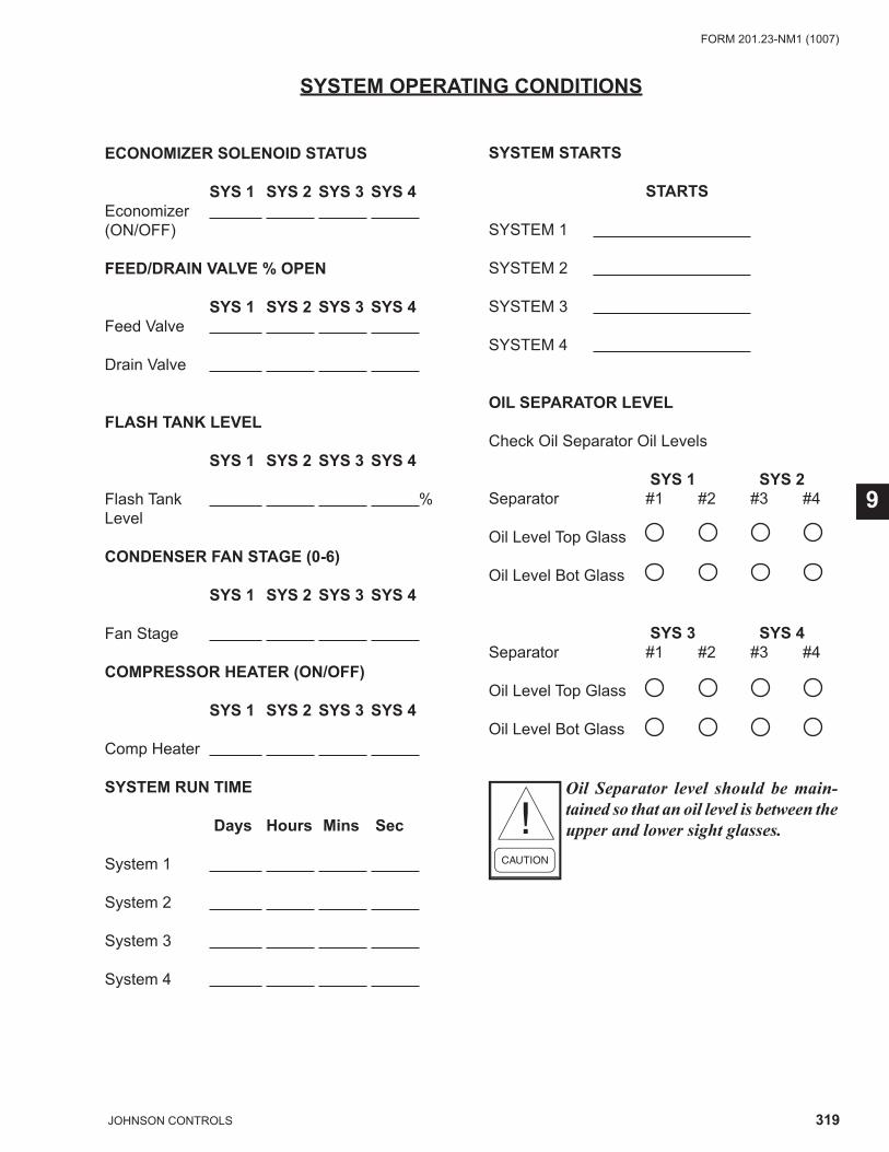
319JOHNSON CONTROLS
FORM 201.23-NM1 (1007)
9
SYSTEM OPERATING CONDITIONS
ECONOMIZER SOLENOID STATUS
SYS 1 SYS 2 SYS 3 SYS 4Economizer (ON/OFF)
FEED/DRAIN VALVE % OPEN
SYS 1 SYS 2 SYS 3 SYS 4Feed Valve
Drain Valve
FLASH TANK LEVEL
SYS 1 SYS 2 SYS 3 SYS 4
Flash Tank %Level
CONDENSER FAN STAGE (0-6)
SYS 1 SYS 2 SYS 3 SYS 4
Fan Stage
COMPRESSOR HEATER (ON/OFF)
SYS 1 SYS 2 SYS 3 SYS 4
Comp Heater
SYSTEM RUN TIME
Days Hours Mins Sec
System 1
System 2
System 3
System 4
SYSTEM STARTS
STARTS
SYSTEM 1
SYSTEM 2
SYSTEM 3
SYSTEM 4
OIL SEPARATOR LEVEL
Check Oil Separator Oil Levels
SYS 1 SYS 2Separator #1 #2 #3 #4
Oil Level Top Glass
Oil Level Bot Glass
SYS 3 SYS 4Separator #1 #2 #3 #4
Oil Level Top Glass
Oil Level Bot Glass
Oil Separator level should be main-tained so that an oil level is between the upper and lower sight glasses.
320 JOHNSON CONTROLS
FORM 201.23-NM1 (1007)MAINTENANCE
WATER SYSTEM CONDITIONS
EVAPORATOR FLOW
Flow Rate GPM
Evap Pressure Drop FT / LBS (Circle One)
Glycol Freeze Point ºF (ºC)
CONDENSER CONDITIONS
AIR TEMPERATURE
Air ON Temperature ºF (ºC)
Air OFF Temperature ºF (ºC)
NOTES
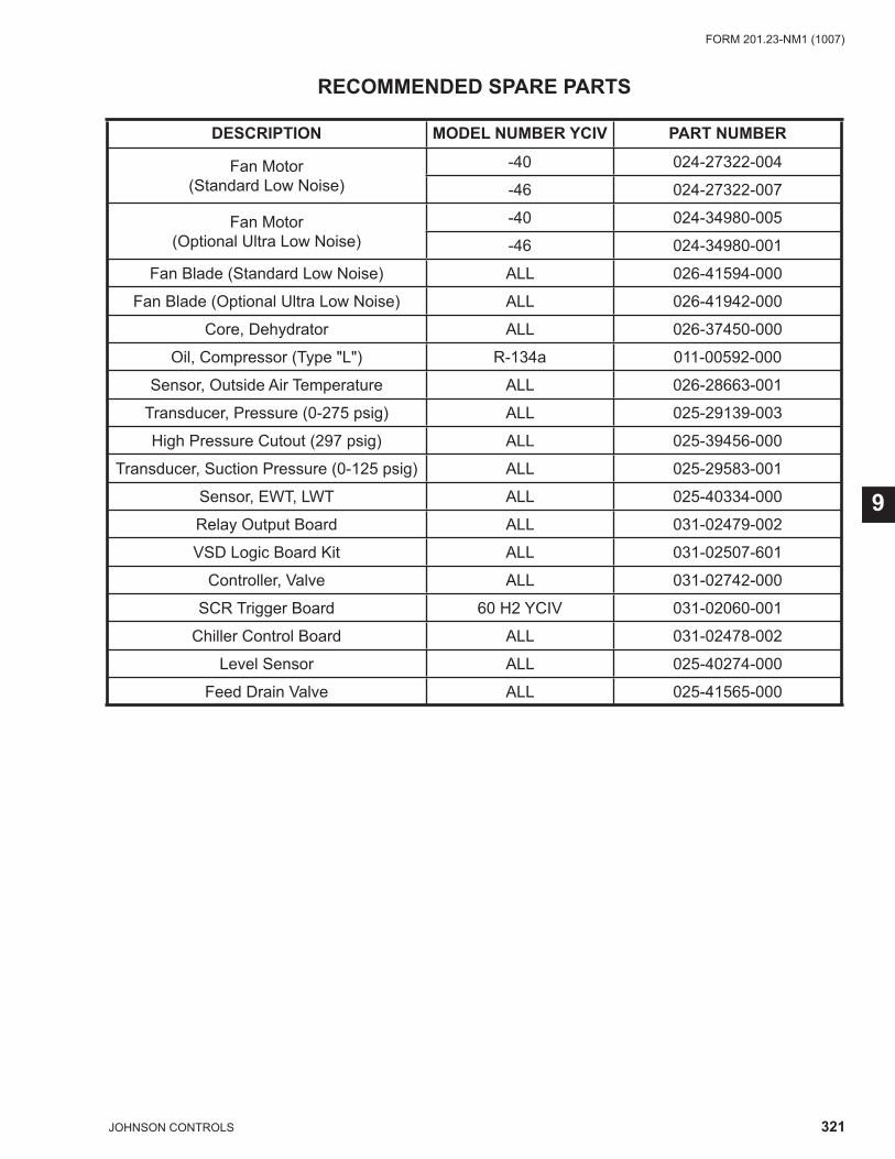
321JOHNSON CONTROLS
FORM 201.23-NM1 (1007)
9
RECOMMENDED SPARE PARTS
DESCRIPTION MODEL NUMBER YCIV PART NUMBER
Fan Motor (Standard Low Noise)
-40 024-27322-004
-46 024-27322-007
Fan Motor (Optional Ultra Low Noise)
-40 024-34980-005
-46 024-34980-001
Fan Blade (Standard Low Noise) ALL 026-41594-000
Fan Blade (Optional Ultra Low Noise) ALL 026-41942-000
Core, Dehydrator ALL 026-37450-000
Oil, Compressor (Type "L") R-134a 011-00592-000
Sensor, Outside Air Temperature ALL 026-28663-001
Transducer, Pressure (0-275 psig) ALL 025-29139-003
High Pressure Cutout (297 psig) ALL 025-39456-000
Transducer, Suction Pressure (0-125 psig) ALL 025-29583-001
Sensor, EWT, LWT ALL 025-40334-000
Relay Output Board ALL 031-02479-002
VSD Logic Board Kit ALL 031-02507-601
Controller, Valve ALL 031-02742-000
SCR Trigger Board 60 H2 YCIV 031-02060-001
Chiller Control Board ALL 031-02478-002
Level Sensor ALL 025-40274-000
Feed Drain Valve ALL 025-41565-000
322 JOHNSON CONTROLS
FORM 201.23-NM1 (1007)MAINTENANCE
NOTES
323JOHNSON CONTROLS
FORM 201.23-NM1 (1007)
9
NOTES

Tele. 800-861-1001www.york.com
P.O. Box 1592, York, Pennsylvania USA 17405-1592 Subject to change without notice. Printed in USACopyright © by Johnson Controls 2007 ALL RIGHTS RESERVEDForm 201.23-NM1 (1007) Supersedes Nothing